Research on Ultra-Low-Frequency Communication Based on ...
12
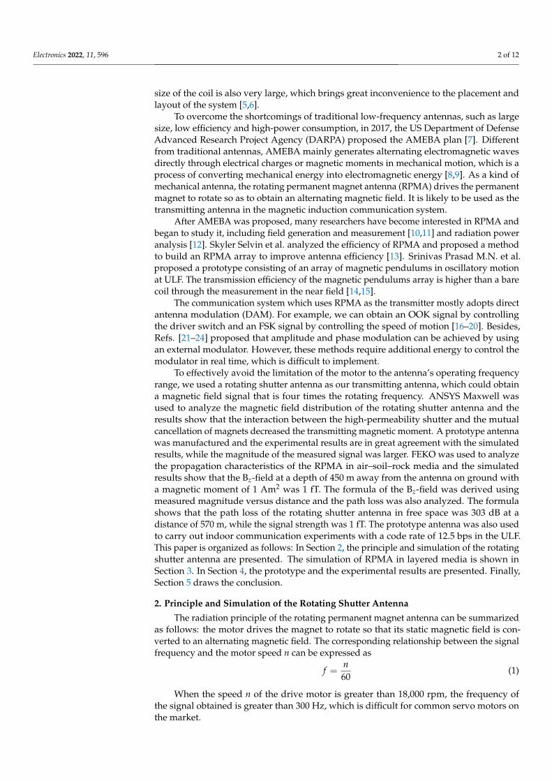
Citation: Sun, F.; Zhang, F.; Ma, X.; Gong, Z.; Ji, Y.; Fang, G. Research on Ultra-Low-Frequency Communication Based on the Rotating Shutter Antenna. Electronics 2022, 11, 596. https://doi.org/ 10.3390/electronics11040596 Academic Editor: Naser Ojaroudi Parchin Received: 6 January 2022 Accepted: 14 February 2022 Published: 15 February 2022 Publisher’s Note: MDPI stays neutral with regard to jurisdictional claims in published maps and institutional affil- iations. Copyright: © 2022 by the authors. Licensee MDPI, Basel, Switzerland. This article is an open access article distributed under the terms and conditions of the Creative Commons Attribution (CC BY) license (https:// creativecommons.org/licenses/by/ 4.0/). electronics Article Research on Ultra-Low-Frequency Communication Based on the Rotating Shutter Antenna Faxiao Sun 1,2,3 , Feng Zhang 1,2, *, Xiaoya Ma 1,2,3 , Zhaoqian Gong 1,2 , Yicai Ji 1,2,3 and Guangyou Fang 1,2,3 1 Aerospace Information Research Institute, Chinese Academy of Sciences, Beijing 100190, China; [email protected] (F.S.); [email protected] (X.M.); [email protected] (Z.G.); [email protected] (Y.J.); [email protected] (G.F.) 2 Key Laboratory of Electromagnetic Radiation and Sensing Technology, Chinese Academy of Sciences, Beijing 100190, China 3 School of Electronic, Electrical and Communication Engineering, University of Chinese Academy of Sciences, Beijing 100049, China * Correspondence: [email protected] Abstract: This paper proposes a rotating shutter antenna that can directly generate 2FSK signals in the ULF band and it is expected to be used as the transmitter for magnetic induction (MI) underground communication systems. The antenna was modeled using ANSYS Maxwell and the magnetic field distribution was simulated. The results show that the interaction between the high-permeability shutter and the mutual cancellation of magnets decreased the transmitting magnetic moment of the antenna. A prototype antenna was manufactured and the time and frequency properties of the measured B z field were the same as the simulated results, while the magnitude of the measured signal was larger. The propagation characteristics of the antenna in air–soil–rock were simulated using FEKO and the results show that the signal strength was greater than 1 fT at a depth of 450 m from the antenna whose magnetic moment as 1 Am 2 . The relationship between different magnetic components and azimuth could be used to enhance the signal strength. The formula of the B z field was derived using the measured magnitude versus distance and the path loss was also analyzed. Finally, the 2FSK modulation property of the antenna was verified by indoor communication experiments with a code rate of 12.5 bps in the ULF band. Keywords: ultra-low-frequency communication; mechanical antenna; layered media; rotating shutter antenna 1. Introduction The electromagnetic waves at radio frequencies have short wavelengths and poor penetrating capabilities, which make them lose part of their energy in a complex electromag- netic environment [1]. For example, the permittivity and conductivity of soil have a great relationship with the water content, which causes significant attenuation of high-frequency electromagnetic waves. This leads to the fact that radio-frequency communication cannot be widely used in underground communication. To overcome this problem, magnetic induction communication technology with ultra-low-frequency magnetic fields is widely used in underground communication, such as Through-The-Earth communication [2]. The permeability of non-magnetic materials is almost the same, which provides a relatively stable channel for the propagation of magnetic field signals and the stable channel enables the magnetic induction communication to avoid the shortcomings of multipath propaga- tion, large propagation delay and high bit error rate of acoustic transmission through the ground [3]. Normally, magnetic inductive communication systems use coils to generate and receive magnetic field signals in near-field zone [4]. However, in the ultra-low-frequency band, the Electronics 2022, 11, 596. https://doi.org/10.3390/electronics11040596 https://www.mdpi.com/journal/electronics
-
Upload
khangminh22 -
Category
Documents
-
view
3 -
download
0
Transcript of Research on Ultra-Low-Frequency Communication Based on ...
�����������������
Citation: Sun, F.; Zhang, F.; Ma, X.;
Gong, Z.; Ji, Y.; Fang, G. Research on
Ultra-Low-Frequency
Communication Based on the
Rotating Shutter Antenna. Electronics
2022, 11, 596. https://doi.org/
10.3390/electronics11040596
Academic Editor: Naser Ojaroudi
Parchin
Received: 6 January 2022
Accepted: 14 February 2022
Published: 15 February 2022
Publisher’s Note: MDPI stays neutral
with regard to jurisdictional claims in
published maps and institutional affil-
iations.
Copyright: © 2022 by the authors.
Licensee MDPI, Basel, Switzerland.
This article is an open access article
distributed under the terms and
conditions of the Creative Commons
Attribution (CC BY) license (https://
creativecommons.org/licenses/by/
4.0/).
electronics
Article
Research on Ultra-Low-Frequency Communication Based onthe Rotating Shutter AntennaFaxiao Sun 1,2,3 , Feng Zhang 1,2,*, Xiaoya Ma 1,2,3, Zhaoqian Gong 1,2, Yicai Ji 1,2,3 and Guangyou Fang 1,2,3
1 Aerospace Information Research Institute, Chinese Academy of Sciences, Beijing 100190, China;[email protected] (F.S.); [email protected] (X.M.); [email protected] (Z.G.);[email protected] (Y.J.); [email protected] (G.F.)
2 Key Laboratory of Electromagnetic Radiation and Sensing Technology, Chinese Academy of Sciences,Beijing 100190, China
3 School of Electronic, Electrical and Communication Engineering, University of Chinese Academy of Sciences,Beijing 100049, China
* Correspondence: [email protected]
Abstract: This paper proposes a rotating shutter antenna that can directly generate 2FSK signals in theULF band and it is expected to be used as the transmitter for magnetic induction (MI) undergroundcommunication systems. The antenna was modeled using ANSYS Maxwell and the magnetic fielddistribution was simulated. The results show that the interaction between the high-permeabilityshutter and the mutual cancellation of magnets decreased the transmitting magnetic moment ofthe antenna. A prototype antenna was manufactured and the time and frequency properties of themeasured Bz field were the same as the simulated results, while the magnitude of the measured signalwas larger. The propagation characteristics of the antenna in air–soil–rock were simulated usingFEKO and the results show that the signal strength was greater than 1 fT at a depth of 450 m from theantenna whose magnetic moment as 1 Am2. The relationship between different magnetic componentsand azimuth could be used to enhance the signal strength. The formula of the Bz field was derivedusing the measured magnitude versus distance and the path loss was also analyzed. Finally, the 2FSKmodulation property of the antenna was verified by indoor communication experiments with a coderate of 12.5 bps in the ULF band.
Keywords: ultra-low-frequency communication; mechanical antenna; layered media; rotatingshutter antenna
1. Introduction
The electromagnetic waves at radio frequencies have short wavelengths and poorpenetrating capabilities, which make them lose part of their energy in a complex electromag-netic environment [1]. For example, the permittivity and conductivity of soil have a greatrelationship with the water content, which causes significant attenuation of high-frequencyelectromagnetic waves. This leads to the fact that radio-frequency communication cannotbe widely used in underground communication. To overcome this problem, magneticinduction communication technology with ultra-low-frequency magnetic fields is widelyused in underground communication, such as Through-The-Earth communication [2]. Thepermeability of non-magnetic materials is almost the same, which provides a relativelystable channel for the propagation of magnetic field signals and the stable channel enablesthe magnetic induction communication to avoid the shortcomings of multipath propaga-tion, large propagation delay and high bit error rate of acoustic transmission through theground [3].
Normally, magnetic inductive communication systems use coils to generate and receivemagnetic field signals in near-field zone [4]. However, in the ultra-low-frequency band, the
Electronics 2022, 11, 596. https://doi.org/10.3390/electronics11040596 https://www.mdpi.com/journal/electronics
Electronics 2022, 11, 596 2 of 12
size of the coil is also very large, which brings great inconvenience to the placement andlayout of the system [5,6].
To overcome the shortcomings of traditional low-frequency antennas, such as largesize, low efficiency and high-power consumption, in 2017, the US Department of DefenseAdvanced Research Project Agency (DARPA) proposed the AMEBA plan [7]. Differentfrom traditional antennas, AMEBA mainly generates alternating electromagnetic wavesdirectly through electrical charges or magnetic moments in mechanical motion, which is aprocess of converting mechanical energy into electromagnetic energy [8,9]. As a kind ofmechanical antenna, the rotating permanent magnet antenna (RPMA) drives the permanentmagnet to rotate so as to obtain an alternating magnetic field. It is likely to be used as thetransmitting antenna in the magnetic induction communication system.
After AMEBA was proposed, many researchers have become interested in RPMA andbegan to study it, including field generation and measurement [10,11] and radiation poweranalysis [12]. Skyler Selvin et al. analyzed the efficiency of RPMA and proposed a methodto build an RPMA array to improve antenna efficiency [13]. Srinivas Prasad M.N. et al.proposed a prototype consisting of an array of magnetic pendulums in oscillatory motionat ULF. The transmission efficiency of the magnetic pendulums array is higher than a barecoil through the measurement in the near field [14,15].
The communication system which uses RPMA as the transmitter mostly adopts directantenna modulation (DAM). For example, we can obtain an OOK signal by controllingthe driver switch and an FSK signal by controlling the speed of motion [16–20]. Besides,Refs. [21–24] proposed that amplitude and phase modulation can be achieved by usingan external modulator. However, these methods require additional energy to control themodulator in real time, which is difficult to implement.
To effectively avoid the limitation of the motor to the antenna’s operating frequencyrange, we used a rotating shutter antenna as our transmitting antenna, which could obtaina magnetic field signal that is four times the rotating frequency. ANSYS Maxwell wasused to analyze the magnetic field distribution of the rotating shutter antenna and theresults show that the interaction between the high-permeability shutter and the mutualcancellation of magnets decreased the transmitting magnetic moment. A prototype antennawas manufactured and the experimental results are in great agreement with the simulatedresults, while the magnitude of the measured signal was larger. FEKO was used to analyzethe propagation characteristics of the RPMA in air–soil–rock media and the simulatedresults show that the Bz-field at a depth of 450 m away from the antenna on ground witha magnetic moment of 1 Am2 was 1 fT. The formula of the Bz-field was derived usingmeasured magnitude versus distance and the path loss was also analyzed. The formulashows that the path loss of the rotating shutter antenna in free space was 303 dB at adistance of 570 m, while the signal strength was 1 fT. The prototype antenna was also usedto carry out indoor communication experiments with a code rate of 12.5 bps in the ULF.This paper is organized as follows: In Section 2, the principle and simulation of the rotatingshutter antenna are presented. The simulation of RPMA in layered media is shown inSection 3. In Section 4, the prototype and the experimental results are presented. Finally,Section 5 draws the conclusion.
2. Principle and Simulation of the Rotating Shutter Antenna
The radiation principle of the rotating permanent magnet antenna can be summarizedas follows: the motor drives the magnet to rotate so that its static magnetic field is con-verted to an alternating magnetic field. The corresponding relationship between the signalfrequency and the motor speed n can be expressed as
f =n60
(1)
When the speed n of the drive motor is greater than 18,000 rpm, the frequency ofthe signal obtained is greater than 300 Hz, which is difficult for common servo motors onthe market.
Electronics 2022, 11, 596 3 of 12
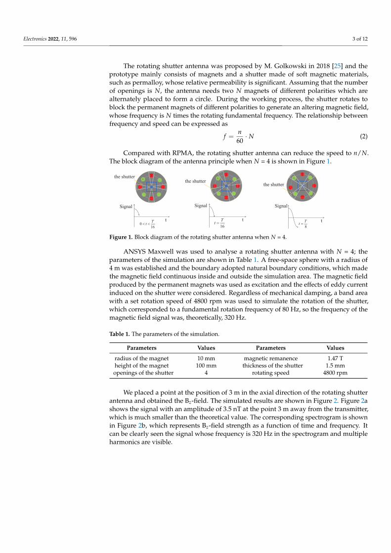
The rotating shutter antenna was proposed by M. Golkowski in 2018 [25] and theprototype mainly consists of magnets and a shutter made of soft magnetic materials,such as permalloy, whose relative permeability is significant. Assuming that the numberof openings is N, the antenna needs two N magnets of different polarities which arealternately placed to form a circle. During the working process, the shutter rotates toblock the permanent magnets of different polarities to generate an altering magnetic field,whose frequency is N times the rotating fundamental frequency. The relationship betweenfrequency and speed can be expressed as
f =n60
· N (2)
Compared with RPMA, the rotating shutter antenna can reduce the speed to n/N.The block diagram of the antenna principle when N = 4 is shown in Figure 1.
N
S
N
S
Signal
t0
16
Tt
N
Sthe shutter
t
16
Tt
t
8
Tt
the shutterthe shutter
Signal Signal
Figure 1. Block diagram of the rotating shutter antenna when N = 4.
ANSYS Maxwell was used to analyse a rotating shutter antenna with N = 4; theparameters of the simulation are shown in Table 1. A free-space sphere with a radius of4 m was established and the boundary adopted natural boundary conditions, which madethe magnetic field continuous inside and outside the simulation area. The magnetic fieldproduced by the permanent magnets was used as excitation and the effects of eddy currentinduced on the shutter were considered. Regardless of mechanical damping, a band areawith a set rotation speed of 4800 rpm was used to simulate the rotation of the shutter,which corresponded to a fundamental rotation frequency of 80 Hz, so the frequency of themagnetic field signal was, theoretically, 320 Hz.
Table 1. The parameters of the simulation.
Parameters Values Parameters Values
radius of the magnet 10 mm magnetic remanence 1.47 Theight of the magnet 100 mm thickness of the shutter 1.5 mmopenings of the shutter 4 rotating speed 4800 rpm
We placed a point at the position of 3 m in the axial direction of the rotating shutterantenna and obtained the Bz-field. The simulated results are shown in Figure 2. Figure 2ashows the signal with an amplitude of 3.5 nT at the point 3 m away from the transmitter,which is much smaller than the theoretical value. The corresponding spectrogram is shownin Figure 2b, which represents Bz-field strength as a function of time and frequency. Itcan be clearly seen the signal whose frequency is 320 Hz in the spectrogram and multipleharmonics are visible.

Electronics 2022, 11, 596 4 of 12
0 0.02 0.04
Time(s)
-2
0
2
Bz(n
T)
(a) (b)
Figure 2. (a) Field at the point 3 m away from the shutter antenna. (b) Spectrogram of field.
The magnetic field intensity distribution on the rotating shutter at different timesis shown in Figure 3. It is clear that a large part of the energy was concentrated on theshutter, which may be one of the reasons for the field strength being smaller than thetheoretical calculation.
(a) (b)
(c)
Figure 3. B-field distribution on the rotating shutter at different times: (a) t = 0 s; (b) t = 0.667 ms;(c) t = 1.67 ms.
The side view and top view of the distribution of the B-field by intercepting differentplanes in the simulation are shown in Figure 4. The fast attenuation of the signal can beascribed to both the interaction of the high-permeability shutter and the mutual cancellationof magnets.

Electronics 2022, 11, 596 5 of 12
(a) (b)
Figure 4. B-field distribution from different viewing angles: (a) side view; (b) top view.
3. Propagation Characteristics in Layered Media
It is promising that RPMA can be used as the transmitting antenna in magnetic induc-tive underground communication and it is particularly important to study the radiationcharacteristics of RPMA in layered media. Layered media cause interface emission lossand transmission medium loss because of different permittivity and conductivity.
This paper used FEKO to construct an equivalent model of a rotating permanentmagnet antenna that rotated vertically on the ground and analyzed its magnetic fieldcharacteristics in three-layer media, such as air–soil–rock. The simulation parameters areshown in Table 2.
Table 2. The parameters of the simulation.
Parameters Values
antenna frequency 320 Hzmoment 1 Am2
soildepth 1500 m
permittivity 10conductivity 0.01 S/m
rock permittivity 10conductivity 0.01 S/m
The curves of magnetic flux intensity versus distance are shown in Figure 5 and itis clear that the maximum penetrating depth could reach 450 m for magnetic inductioncommunication.
101 102 103
Distance (m)
10-16
10-14
10-12
10-10
10-8
Mag
net
ic F
lux D
ensi
ty B
(T)
depth=0m
depth=100m
depth=200m
depth=300m
depth=400m
depth=450m
Figure 5. Change in magnetic flux density with the distance at different depths.

Electronics 2022, 11, 596 6 of 12
The curves of Br and Bϕ with azimuth at different depths shown in Figure 6 show that,at the same depth, the phase between the two magnetic field components was constant. Ifwe used a two-axis magnetic field sensor to receive, we could obtain an enhanced signalby shifting the ϕ-direction component with a constant phase and then adding it to ther-direction component.
0 100 200 300 400
phi (deg)
0
100
200
300
400
500phas
e (d
eg)
Br
Bphi
0 100 200 300 400
phi (deg)
-200
0
200
400
600
phas
e (d
eg)
Br
Bphi
(a) (b)
0 100 200 300 400
phi (deg)
-200
0
200
400
600
phas
e (d
eg)
Br
Bphi
0 100 200 300 400
phi (deg)
-200
0
200
400
600
phas
e (d
eg)
Br
Bphi
(c) (d)
Figure 6. Change in Br and Bϕ with azimuth at different depths: (a) depth = 0 m; (b) depth = 150 m;(c) depth = 300 m; (d) depth = 450 m.
4. Experimental Results
The experimental results are presented in two sub-sections, i.e., (a) measurement ofthe rotating shutter antenna and (b) communication based on the rotating shutter antenna.
4.1. Measurement of the Rotating Shutter Antenna
A prototype, as shown in Figure 7, with the same size as shown in Table 2 wasmanufactured and magnets were fixed on an aluminum plate through an aluminum alloycover. The YASKAWA servo AC motors with model SGM7J-01AFC6S were used as thedriver, which could provide a rated torque of 637 mN·m and a rated power of 200 W. Therotation axis of the shutter antenna and the ULF receiver shown in Figure 8 were placed inline to measure the Bz-field. The distance between the antenna and the receiver was 3 m, asthat in simulation. In the communication experiment, the information symbols were sentto the servo through software named MPE720 Ver. 7 to control the rotating shutter antennain real time.
The portable ULF receiver, shown in Figure 8, consisted of a magnetic sensor and anNI collector. The conversion coefficient of the magnetic sensor was 8 mV/nT, so we coulddirectly convert the received voltage signal into field strength. The NI collector was utilizedto digitize and store the received signal with a sampling rate of 3 Ksps.

Electronics 2022, 11, 596 7 of 12
Figure 7. The rotating shutter antenna.
(a) (b)
Figure 8. ULF receiver: (a) magnetic sensor; (b) NI sampler.
The measured result shown in Figure 9 shows that, when the motor speed was set to4800 rpm, the frequency of the signal obtained was in good agreement with the simulatedresult, but the amplitude was larger than that obtained in the simulation, which may beascribed to the fact that the material in the simulation was not consistent with our prototypeand the metal substances in the experimental environment may also have had a certaininfluence on the signal strength. From the spectrogram of the field shown in Figure 9b, wecan clearly see the 320 Hz signal.
0 0.02 0.04
Time(s)
-10
-5
0
5
10
15
Bz(n
T)
simulated
measured
(a) (b)
Figure 9. (a) Field at the point 3 m away from the shutter antenna. (b) Spectrogram of field.
Electronics 2022, 11, 596 8 of 12
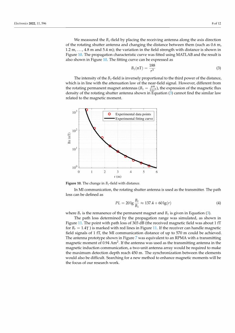
We measured the Bz-field by placing the receiving antenna along the axis directionof the rotating shutter antenna and changing the distance between them (such as 0.6 m,1.2 m, . . . , 4.8 m and 5.4 m); the variation in the field strength with distance is shown inFigure 10. The propagation characteristic curve was fitted using MATLAB and the result isalso shown in Figure 10. The fitting curve can be expressed as
Bz(nT) =188r3 (3)
The intensity of the Bz-field is inversely proportional to the third power of the distance,which is in line with the attenuation law of the near-field signal. However, different fromthe rotating permanent magnet antennas (Bz =
µm2πr3 ), the expression of the magnetic flux
density of the rotating shutter antenna shown in Equation (3) cannot find the similar lawrelated to the magnetic moment.
0 1 2 3 4 5 6
r (m)
100
101
102
103
Bz
(nT
)
Experimental data points
Experimental fitting curve
Figure 10. The change in Bz-field with distance.
In MI communication, the rotating shutter antenna is used as the transmitter. The pathloss can be defined as
PL = 20 lgBr
Bz≈ 137.4 + 60 lg(r) (4)
where Br is the remanence of the permanent magnet and Bz is given in Equation (3).The path loss determined by the propagation range was simulated, as shown in
Figure 11. The point with path loss of 303 dB (the received magnetic field was about 1 fTfor Br = 1.4T ) is marked with red lines in Figure 11. If the receiver can handle magneticfield signals of 1 fT, the MI communication distance of up to 570 m could be achieved.The antenna prototype shown in Figure 7 was equivalent to an RPMA with a transmittingmagnetic moment of 0.94 Am2. If the antenna was used as the transmitting antenna in themagnetic induction communication, a two-unit antenna array would be required to makethe maximum detection depth reach 450 m. The synchronization between the elementswould also be difficult. Searching for a new method to enhance magnetic moments will bethe focus of our research work.

Electronics 2022, 11, 596 9 of 12
0 200 400 600 800 1000
r (m)
-200
-100
0
100
200
300
400
Path
lo
ss (
dB
)
Figure 11. Path loss versus propagation range.
4.2. Communication Based on the Rotating Shutter Antenna
We changed the distance between the transmitter and the receiver antenna to 4.5 m,while the other experimental parameters were the same as those mentioned above. Usingcontrol software to rotate the motor between 4800 rpm and 4950 rpm, we theoreticallyobtained 320 Hz and 330 Hz signals, which can represent different binary informationsymbols such as ‘1’ and ‘0’. The time required for the motor to switch between differentspeeds was set to 100 ms and the time for a constant rotation was 80 ms, which determinedthe code rate of communication.
The modulated signal after bandpass filtering is shown in Figure 12a. Its correspondingspectrum, shown in Figure 12b, demonstrates that the frequency of the 2FSK signal did notreach the theoretical value, which may have been due to insufficient control accuracy. Inaddition, there was a very obvious frequency component between the frequency spectra ofthe 303.7 Hz and 316.2 Hz signals, which was introduced during the motor speed switchingprocess. This problem could be solved by increasing the constant speed time of the motor,but this would reduce the communication code rate.
0 1 2 3 4 5
time (s)
-1
0
1
Bz
(nT
)
Modulated signal f1=304Hz
Modulated signal f2=316Hz
0 200 400 600
Frequency (Hz)
10-5
100
Bz
(nT
)
Spectrum of signal f1=304Hz
Spectrum of signal f2=316Hz
(a) (b)
Figure 12. (a) Modulated signals at the point 5.4 m away from the rotating shutter antenna;(b) spectrum of signals.
It can be clearly observed from the spectrogram shown in Figure 13a that the signalswith frequencies of 303.7 Hz and 316.2 Hz appeared alternately in sequence, which meansthat the information symbol ‘1010101. . . ’ was received. The received signal is processed byfiltering out the power–frequency signal, passing through bandpass filtering and extractingthe envelope of the filtered signal; then, the information symbol shown in Figure 13b can

Electronics 2022, 11, 596 10 of 12
be obtained through amplitude judgment. It was found, from the demodulated infor-mation, that there were 12.5 symbols in one second, which means that the code rate ofcommunication was 12.5 bps.
1 2 3 4 5
Time (s)
-0.5
0
0.5
1
1.5
Dem
odula
tion c
ode
(a) (b)
Figure 13. (a) Spectrogram of 2FSK signal; (b) demodulated code.
Table 3 summarizes the performance comparison between the previously proposedsystems and the system adopted in this paper. It can be found that the frequency of thesignal, the communication rate and the communication distance could not be taken intoaccount simultaneously in the existing research study. Our system mainly considers ahigher communication code rate, but the communication range was not the longest, whichis also a focus for our future research work.
Table 3. Performance comparison of rotating permanent magnet antennas.
Reference Frequency Data Rate Detection Distance
Ref. [10] 500 Hz / <130 mRef. [11] 22 Hz 8 bps 0.7 mRef. [14] 1.03 kHz 2 bps 30 mRef. [17] 100 Hz 0.25 bps 5 mRef. [20] 30 Hz 5 bps 100 mRef. [22] 40 Hz <2 bps 5 mRef. [23] 50 Hz 40 bps 0.25 m
Our work 320 Hz 12.5 bps 5 m
Since the antenna operates in its near-field region, the signal strength decays withthe third power of the distance, which limits the maximum communication distance ofthe communication system. Similarly, due to the low carrier frequency of the system, thedata rate cannot be too high, which limits the diversity of communication. For example,the communication rate is only suitable for message transmission. In addition, an arraywith more shutter antennas would be a good choice to increase the magnetic moment, butassuring the control accuracy of the motor would be necessary and difficult to achieve.
5. Conclusions
This paper used ANSYS Maxwell to analyze the magnetic field distribution of the rotat-ing shutter antenna and the results show that the interaction between the high-permeabilityshutter and the mutual cancellation of magnets decreased the transmitting magnetic mo-ment. A prototype was manufactured; the measured results are in great agreement withthe simulated results, while the magnitude of the measured signal was larger. We usedFEKO to analyze the propagation characteristics of RPMA in air–soil–rock and the sim-ulated results show that the signal strength was greater than 1 fT at a depth of 450 mfrom the antenna, whose moment was 1 Am2. Since the phase difference between Br andBϕ remained constant at ±90◦, we could use a multi-directional receiver to receive themulti-directional field components; then, the signal strength could be enhanced by shifting
Electronics 2022, 11, 596 11 of 12
the phases of the Br-field component and adding it to another component, such as a Bϕ-fieldcomponent. The formula shows that the path loss of the rotating shutter antenna at 570 mwas 303 dB, which means that the signal strength was 1 fT. The rotating shutter antennawas equivalent to an RPMA with a transmitting magnetic moment of 0.94 Am2. If theantenna was used as the transmitting antenna in the magnetic induction communication,a two-element antenna array would be required to make the maximum detection depthreach 450 m. The synchronization between the elements would make the control of thesystem very difficult. Finding a new method to increase the transmitting magnetic momentand the synchronization of the elements will be the focus of our next research studies. FSKmodulation could be realized by controlling the motion state of the motor and the constanttime of the motor determined the symbol rate. The prototype was used to achieve indoorcommunication with a code rate of 12.5 bps in the ULF.
Author Contributions: Conceptualization, F.S., X.M. and F.Z.; methodology, F.S. and X.M.; software,F.S. and Z.G.; validation, F.S. and F.Z.; formal analysis, F.S.; investigation, F.S. and X.M.; resources, Y.J.;data curation, F.Z. and Z.G.; writing—original draft preparation, F.S.; writing—review and editing,F.Z. and Y.J.; visualization, F.S.; supervision, G.F.; project administration, Y.J.; funding acquisition, G.F.All authors have read and agreed to the published version of the manuscript.
Funding: This research study was funded by the National Natural Science Foundation of China,grant number 61827803.
Institutional Review Board Statement: Not applicable.
Informed Consent Statement: Not applicable.
Data Availability Statement: Not applicable.
Conflicts of Interest: The authors declare no conflict of interest.
References1. Kilinc, D.; Akan, O.B. Nanoscale magneto-inductive communication. In Proceedings of the 2013 Asilomar Conference on Signals,
Systems and Computers, Pacific Grove, CA, USA, 3–6 November 2013; pp. 1061–1065.2. Yan, L.; Waynert, J.; Sunderman, C.; Damiano, N. Statistical analysis and modeling of VLF/ELF noise in coal mines for through-
the-earth wireless communications. In Proceedings of the 2014 IEEE Industry Application Society Annual Meeting, Vancouver,BC, Canada, 5–9 October 2014; pp. 1–5.
3. Domingo, M.C. Magnetic Induction for Underwater Wireless Communication Netwvorks. IEEE Trans. Antennas Propag. 2012,60, 2929–2939. [CrossRef]
4. Sun, Z.; Akyildiz, I.F. Magnetic Induction Communications for Wireless Underground Sensor Networks. IEEE Trans. AntennasPropag. 2010, 58, 2426–2435. [CrossRef]
5. Gulbahar, B.; Akan, O.B. A communication theoretical modeling and analysis of underwater magneto-inductive wireless channels.IEEE Trans. Wireless Commun. 2010, 11, 3326–3334. [CrossRef]
6. Akyildiz, I.F.; Wang, P.; Sun, Z. Realizing underwater communication through magnetic induction. IEEE Commun. Mag. 2015,53, 42–48. [CrossRef]
7. Ding, H. DARPA mechanical antenna project may set off a military communications revolution. Conmilit 2017, 26, 71–73.8. Bickford, J.A.; McNabb, R.S.; Ward, P.A.; Freeman, D.K.; Weinberg, M.S. Low frequency mechanical antennas: Electrically short
transmitters from mechanically-actuated dielectrics. In Proceedings of the 2017 IEEE International Symposium on Antennas andPropagation & USNC/URSI National Radio Science Meeting, San Diego, CA, USA, 9–14 July 2017; pp. 1475–1476.
9. Manteghi, M. A navigation and positining system for unmanned underwater vehicles based on a mechanical antenna. InProceedings of the 2017 IEEE International Symposium on Antennas and Propagation & USNC/URSI National Radio ScienceMeeting, San Diego, CA, USA, 9–14 July 2017; pp. 1997–1998.
10. Burch, H.C.; Garraud, A.; Mitchell, M.F.; Moore , R.C.; Arnold, D.P. Experimental Generation of ELF Radio Signals Using aRotating Magnet. IEEE Trans. Antennas Propag. 2018, 66, 6265–6272. [CrossRef]
11. Fawole, O.C.; Tabib-Azar, M. An Electromechanically Modulated Permanent Magnet Antenna for Wireless Communication inHarsh Electromagnetic Environments. IEEE Trans. Antennas Propag. 2017, 65, 6927–6936. [CrossRef]
12. Bickford, J.A.; Duwel, A.E.; Weinberg, M.S.; McNabb, R.S.; Freeman, D.K.; Ward, P.A. Performance of Electrically SmallConventional and Mechanical Antennas. IEEE Trans. Antennas Propag. 2019, 67, 2209–2223. [CrossRef]
13. Selvin, S.; Srinivas, P.M.N.; Huang, Y.; Wang, E. Spinning magnet antenna for VLF transmitting. In Proceedings of the 2017 IEEEInternational Symposium on Antennas and Propagation & USNC/URSI National Radio Science Meeting, San Diego, CA, USA,9–14 July 2017; pp. 1477–1478.

Electronics 2022, 11, 596 12 of 12
14. Srinivas, P.M.N.; Tok, R.U.; Wang, Y.E. Magnetic pendulum arrays for ULF transmission. In Proceedings of the 2018 IEEEInternational Symposium on Antennas and Propagation & USNC/URSI National Radio Science Meeting, Boston, MA, USA, 8–13July 2018; pp. 71–72.
15. Srinivas, P.M.N.; Fereidoony, F.; Wang, Y.E. 2D Stacked magnetic pendulum arrays for efficient ULF transmission. In Proceedingsof the 2020 IEEE International Symposium on Antennas and Propagation and North American Radio Science Meeting, Montreal,QC, Canada, 5–10 July 2020; pp.1305–1306.
16. Liu, Y.; Hou, M.; Gong, S. A Rotating Permanent magnet transmitter for magnetic induction communication in RF-impenetrableenvironment. In Proceedings of the 2020 IEEE MTT-S International Conference on Numerical Electromagnetic and MultiphysicsModeling and Optimization (NEMO), Hangzhou, China, 7–9 December 2020; pp.1–3.
17. Glickstein, J.S.; Liang, J.; Choi, S.; Madanayake, A.; Mandal, S. Power-efficient ELF wireless communications using electro-mechanical transmitters. IEEE Access 2020, 8, 2455–2471. [CrossRef]
18. Tarek, M.T.B.; Dharmasena, S.; Madanayake, A.; Choi, S.; Glickstein, J.; Liang, J.; Mandal, S. Power-efficient data modulation forall-mechanical ULF/VLF transmitters. In Proceedings of the 2018 IEEE 61st International Midwest Symposium on Circuits andSystems (MWSCAS), Windsor, ON, Canada, 5–8 August 2018; pp.759–762.
19. Cao, J.; Liu, Y.; Gong, S. Low frequency mechanical antenna for underwater communication. In Proceedings of the 2019International Conference on Electronic Engineering and Informatics (EEI), Nanjing, China, 8–10 November 2019; pp.140–142.
20. Liu, Y.; Gong, S.; Liu, Q.; Hou, M. A Mechanical Transmitter for Undersea Magnetic Induction Communication. IEEE Trans.Antennas Propag. 2021, 69, 6391–6400. [CrossRef]
21. Strachen, N.D.; Booske, J.H.; Behdad, N. Mechanical Super-Low Frequency (SLF) transmitter using electrically-modulatedreluctance. In Proceedings of the 2018 IEEE International Symposium on Antennas and Propagation & USNC/URSI NationalRadio Science Meeting, Boston, MA, USA, 8–13 July 2018; pp.67–68.
22. Zhang, J.; Song, Z.; Zhang, D.; Xi, X. Amplitude modulation method of the mechanically rotating-based antenna. Electron. Lett.2020, 56, 321–323 [CrossRef]
23. Barani, N.; Sarabandi, K. A phase modulation scheme for super-low frequency handheld mechanical antennas. In Proceedings ofthe 2020 IEEE International Symposium on Antennas and Propagation and North American Radio Science Meeting, Montreal,QC, Canada, 5–10 July 2020; pp.467–468.
24. Barani, N.; Sarabandi, K. A frequency multiplier and phase modulation approach for mechanical antennas operating at Super LowFrequency (SLF) Band. In Proceedings of the 2019 IEEE International Symposium on Antennas and Propagation and USNC-URSIRadio Science Meeting, Atlanta, GA, USA, 7–12 July 2019; pp. 2169–2170.
25. Gołkowski, M.; Park, J.; Bittle, J.; Babaiahgari, B.; Rorrer, R.A.L.; Celinski, Z. Novel mechanical magnetic shutter antenna forELF /VLF radiation. In Proceedings of the 2018 IEEE International Symposium on Antennas and Propagation & USNC/URSINational Radio Science Meeting, Boston, MA, USA, 8–13 July 2018; pp. 65–66.