proposed ultra-modern library on plot lr no 209/11606 ...
404
PROPOSED ULTRA-MODERN LIBRARY ON PLOT L.R NO 209/11606 - NAIROBI COUNTY PHASE 1 & 2 TENDER NO. AMIU/15/01/2021/001 CLIENT AMREF INTERNATIONAL UNIVERSITY P. O. BOX 30125-00100 NAIROBI ARCHITECT QUANTITY SURVEYOR TEJ ARCHITECTS, ECOSPACE CONSULTANTS P.O. BOX 27644-00506 P.O. BOX 74885 - 00200 NAIROBI NAIROBI STRUCTURAL & CIVIL ENGINEER MECHANICAL & ELECTRICAL ENGINEER ENGINEERING IDEALS KENYA LIMITED GEDOX ASSOCIATES LIMITED P.O. BOX 51288 - 00200 P.O. BOX 64441 - 00620 NAIROBI NAIROBI JANUARY 2021
-
Upload
khangminh22 -
Category
Documents
-
view
0 -
download
0
Transcript of proposed ultra-modern library on plot lr no 209/11606 ...

PROPOSED ULTRA-MODERN LIBRARY ON PLOT L.R NO 209/11606 - NAIROBI COUNTY
PHASE 1 & 2
TENDER NO. AMIU/15/01/2021/001
CLIENT
AMREF INTERNATIONAL UNIVERSITY
P. O. BOX 30125-00100
NAIROBI
ARCHITECT QUANTITY SURVEYOR TEJ ARCHITECTS, ECOSPACE CONSULTANTS P.O. BOX 27644-00506 P.O. BOX 74885 - 00200 NAIROBI NAIROBI STRUCTURAL & CIVIL ENGINEER MECHANICAL & ELECTRICAL ENGINEER ENGINEERING IDEALS KENYA LIMITED GEDOX ASSOCIATES LIMITED P.O. BOX 51288 - 00200 P.O. BOX 64441 - 00620 NAIROBI NAIROBI
JANUARY 2021

PROPOSED LIBRARY ON PLOT L.R NO 209/11606 - NAIROBI COUNTY FOR AMREF
INTERNATIONAL UNIVERSITY
TENDER DOCUMENTS Consisting A Contents page (i) B Signature and Special notes page (ii) C Standard Tender Documents for Procurement of Works:
Section i: Invitation to Tender 4 Section ii: Instructions To Tenderers 5 –16 Appendix to Instructions to Tenderers 17-18 Tender Evaluation Criteria 19-23 Section iii: Conditions of Contract 24-44 Section iv: Appendix to Conditions of Contract 45-47 Section vii: Specifications 48 Section viii: Drawings 49 Section ix: Bills of Quantities 50-52 Section x: Standard Forms 53-72
D Particular Preliminaries 1/1 – 1/7 E General Preliminaries 1/8 – 1/16 F Specifications 2/1 – 2/44 G Measured Works:
1. PHASE 1 MS 1
2. PHASE 2 MS 2 H Appendix AP/A & AP/B
(i)

PROPOSED LIBRARY ON PLOT L.R NO 209/11606 - NAIROBI COUNTY FOR AMREF
INTERNATIONAL UNIVERSITY
SIGNATURE PAGE AND SPECIAL NOTES
Supplied as part of the TENDER NO. AMIU/15/01/2021/001
Issued by: - Ecospace Consultants, P. O. Box 74885 - 00200, NAIROBI. The contract for the above mentioned works entered into this………. day of …………………. 2021 by the undersigned refers to these Tender Documents and Amref International University and public General Specification dated March, 1976 (together with any amendments issued thereto) shall be read and construed as part of the said contract. …………………………………………. ……………………………………………………
THE CONTRACTOR AMREF INTERNATIONAL UNIVERSITY Date: …………………………… Date: ………………………………………….. SPECIAL NOTES The Contractor is required to check the numbers of the pages of these Bills of Quantities and should he find any missing or in duplicate or figures indistinct he must inform the Quantity Surveyor at once and have the same rectified. Should the Contractor be in doubt about the precise meaning of any item or figure for any reason whatsoever, he must inform the Quantity Surveyor in order that the correct meaning may be decided before the date for submission of tenders. No liability will be admitted nor claim allowed in respect of errors in the Contractor’s Tender due to mistakes in the specifications, which should have been rectified in the manner, described above.
(ii)

(BUILDING AND ASSOCIATED CIVIL ENGINEERING WORKS)
PUBLIC PROCUREMENT
(BUILDING AND ASSOCIATED CIVIL ENGINEERING WORKS)
PUBLIC PROCUREMENT
STANDARD TENDER DOCUMENT
PROCUREMENT OF WORKS
(BUILDING AND ASSOCIATED CIVIL ENGINEERING WORKS)
PUBLIC PROCUREMENT
P.O.BOX 30007
STANDARD TENDER DOCUMENT
FOR
PROCUREMENT OF WORKS
(BUILDING AND ASSOCIATED CIVIL ENGINEERING WORKS)
PUBLIC PROCUREMENT REGULATORY AUTHORITY (PPR
P.O.BOX 30007
NAIROBI.
REVISED
STANDARD TENDER DOCUMENT
PROCUREMENT OF WORKS
(BUILDING AND ASSOCIATED CIVIL ENGINEERING WORKS)
REGULATORY AUTHORITY (PPR
P.O.BOX 30007 – 00200,
NAIROBI.
REVISED 2007
STANDARD TENDER DOCUMENT
PROCUREMENT OF WORKS
(BUILDING AND ASSOCIATED CIVIL ENGINEERING WORKS)
REGULATORY AUTHORITY (PPR
(BUILDING AND ASSOCIATED CIVIL ENGINEERING WORKS)
REGULATORY AUTHORITY (PPRA)

STD/2
INSTRUCTIONS TO TENDERERS
TABLE OF CONTENTS
CLAUSE PAGE INTRODUCTION ……………………………………………… 3 SECTION I: INVITATION TO TENDER …………………………………… 4 SECTION II: INSTRUCTIONS TO TENDERERS …………………………… 5-16 APPENDIX TO INSTRUCTIONS TO TENDERERS ………… 17-18 TENDER EVALUATION CRITERIA ………………….……… 19-23 SECTION III: CONDITIONS OF CONTRACT ……………………………...... 24-44 SECTION IV: APPENDIX TO CONDITIONS OF CONTRACT……………… 45-47 PRE-TENDER CONFERENCE/SITE VISIT …………………… 48 APPENDIX TO INSTRUCTIONS TO TENDERERS…….…….. 49-46 SECTION V: SPECIFICATIONS ………………………………………………. 49 SECTION VI: DRAWINGS ……………………………………………………… 50 SECTION VII: BILLS OF QUANTITIES ……………………………………. 51-53 SECTION VIII: STANDARD FORMS ………………………………………… 54-73

STD/3
INTRODUCTION 1.1 This standard tender document for procurement of works has been prepared for use by
procuring entities in Kenya in the procurement of works (i.e. Buildings and associated Civil Engineering Works).
1.2 The following guidelines should be observed when using the document:-
(a) Specific details should be furnished in the Invitation to tender and in the special conditions of contract (where applicable). The tender document issued to tenderers should not have blank spaces or options.
(b) The instructions to tenderers and the General Conditions of Contract should remain
unchanged. Any necessary amendments to these parts should be made through Appendix to instructions to tenderers and special conditions of contract respectively.
1.3
(a) Information contained in the invitation to tender shall conform to the data and information in the tender documents to enable prospective tenderers to decide whether or not to participate in the tender and shall indicate any important tender requirements.
(b) The invitation to tender shall be as an advertisement in accordance with the
regulations or a letter of invitation addressed to tenderers who have been prequalified following a request for prequalification.
1.4 The cover of the document shall be modified to include:-
I. Tender number.
II. Tender name. III. Name of procuring entity. IV. Delete name and address of PPOA.

STD/4
SECTION I INVITATION FOR TENDERS
TENDER NOTICE
TENDER NO. AMIU/15/01/2021/001
PROPOSED CONSTRUCTION OF MODERN LIBRARY AT AMREF INTERNATIONAL
UNIVERSITY Amref International University, a world class health science education institution, intends to construct an ultra-modern Library as part of its commitment to progressively develop innovative programmes catering for the present and future needs of Africa population. The site is located along Langata Road opposite Wilson Airport and the University hereby invites sealed tenders from eligible Contractors, who MUST be currently registered with National Construction Authority (NCA) for categories 1 and 2. Interested eligible candidates may view the tender document and download from our website on the following link ................................................. upon payment of non-refundable fee of Ksh. 5,000.00. The payment should be made through the Bank account as detailed below:
Bank Name: Standard Chartered Bank Account Name: Amref International University Registered Trustees Account Number: 0108087631000 Currency: KES Swift Code: SCBLKENXXXX Branch: Upperhill All Tenders must be accompanied by a Bid Bond in the form of a bank guarantee from a reputable bank or from an approved insurance company. Completed Tender Documents accompanied with a copy of official receipt for the fee paid are to be enclosed in plain sealed envelope clearly marked with the tender name, tender reference and should be addressed and delivered/posted to the following address:-
The Vice Chancellor
Amref International University P. O. BOX 30125-00100
NAIROBI
Or be deposited in the Tender Box at Amref International University at the Main Reception, to be received on or before 29th January2021at 12.00 Noon. Bids will be opened immediately thereafter in the presence of the candidates’ representatives or Bidders who choose to attend at Amref International University, Board Room.

STD/5
SECTION II
INSTRUCTIONS TO TENDERERS
TABLE OF CONTENTS PAGE
CLAUSE PAGE 1. General …………………………………………………. 6-9 2. Tender Documents ………………………………… 10-11 3. Preparation of Tenders ………………………………… 11-12 4. Submission of Tenders ………………………………… 13 5. Tender Opening and Evaluation ……………………… 13– 16 6. Award of Contract ………………………………………… 16-18

STD/6
INSTRUCTIONS TO TENDERERS.
1. 1. General/Eligibility/Qualifications/Joint venture/Cost of tendering
1.1 The Employer as defined in the Appendix to Conditions of Contract invites tenders for Works Contract as described in the tender documents. The successful tenderer will be expected to complete the Works by the Intended Completion Date specified in the tender documents.
1.2 All tenderers shall provide the Qualification Information, a statement that the tenderer
(including all members of a joint venture and subcontractors) is not associated, or has not been associated in the past, directly or indirectly, with the Consultant or any other entity that has prepared the design, specifications, and other documents for the project or being proposed as Project Manager for the Contract. A firm that has been engaged by the Employer to provide consulting services for the preparation or supervision of the Works, and any of its affiliates, shall not be eligible to tender.
1.3 All tenderers shall provide in the Form of Tender and Qualification Information, a
preliminary description of the proposed work method and schedule, including drawings and charts, as necessary.
1.4 In the event that pre-qualification of potential tenderers has been undertaken, only tenders
from pre-qualified tenderers will be considered for award of Contract. These qualified tenderers should submit with their tenders any information updating their original pre-qualification applications or, alternatively, confirm in their tenders that the originally submitted pre-qualification information remains essentially correct as of the date of tender submission.
1.5 Where no pre-qualification of potential tenderers has been done, all tenderers shall
include the following information and documents with their tenders , unless otherwise stated:
(a) Copies of original documents defining the constitution or legal status, place of
registration, and principal place of business; written power of attorney of the signatory of the tender to commit the tenderer:
(b) Total monetary value of construction work performed for each of the last five
years:
(c) Experience in works of a similar nature and size for each of the last five years, and details of work under way or contractually committed; and names and addresses of clients who may be contacted for further information on these contracts;
(d) Major items of construction equipment proposed to carry out the Contract and an
undertaking that they will be available for the Contract.

STD/7
(e) Qualifications and experience of key site management and technical personnel proposed for the Contract and an undertaking that they shall be available for the Contract.
(f) Reports on the financial standing of the tenderer, such as profit and loss
statements and auditor’s reports for the past five years;
(g) Evidence of adequacy of working capital for this Contract (access to line(s) of credit and availability of other financial resources);
(h) Authority to seek references from the tenderer’s bankers;
(i) Information regarding any litigation, current or during the last five years, in which
the tenderer is involved, the parties concerned and disputed amount; and
(j) Proposals for subcontracting components of the Works amounting to more than 10 percent of the Contract Price.
1.6 Tenders submitted by a joint venture of two or more firms as partners shall comply with
the following requirements, unless otherwise stated:
(a) the tender shall include all the information listed in clause 1.5 above for each joint venture partner;
(b) the tender shall be signed so as to be legally binding on all partners;
(c) all partners shall be jointly and severally liable for the execution of the Contract in accordance with the Contract terms;
(d) one of the partners will be nominated as being in charge,
authorized to incur liabilities, and receive instructions for and on behalf of all partners of the joint venture; and
(e) the execution of the entire Contract, including payment, shall be
done exclusively with the partner in charge.
1.7 To qualify for award of the Contract, tenderers shall meet the following minimum qualifying criteria;
(a) Annual volume of construction work of at least 2.5 times the estimated annual cash
flow for the Contract;
(b) Experience as main contractor in the construction of at least two works of a nature and complexity equivalent to the Works over the last 10 years (to comply with this requirement, works cited should be at least 70 percent complete);

STD/8
(c) Proposals for the timely acquisition (own, lease, hire, etc.) of the essential equipment listed as required for the Works;
(d) A Contract manager with at least five years’ experience in works of an equivalent
nature and volume, including no less than three years as Manager; and
(e) Liquid assets and/or credit facilities, net of other contractual commitments and exclusive of any advance payments which may be made under the Contract, of no less than 4 months of the estimated payment flow under this Contract.
1.8 The figures for each of the partners of a joint venture shall be added together to determine
the tenderer’s compliance with the minimum qualifying criteria of clause 1.7 (a) and (e); however, for a joint venture to qualify, each of its partners must meet at least 25 percent of minimum criteria 1.7 (a), (b) and (e) for an individual tenderer, and the partner in charge at least 38 percent of those minimum criteria. Failure to comply with this requirement will result in rejection of the joint venture’s tender. Subcontractors’ experience and resources will not be taken into account in determining the tenderer’s compliance with the qualifying criteria, unless otherwise stated.
1.9 Each tenderer shall submit only one tender, either individually or as a partner in a joint
venture. A tenderer who submits or participates in more than one tender (other than as a subcontractor or in cases of alternatives that have been permitted or requested) will cause all the proposals with the tenderer’s participation to be disqualified.
1.10 The tenderer shall bear all costs associated with the preparation and submission of his
tender, and the Employer will in no case be responsible or liable for those costs.
1.11 The tenderer, at the tenderer’s own responsibility and risk, is encouraged to visit and examine the Site of the Works and its surroundings, and obtain all information that may be necessary for preparing the tender and entering into a contract for construction of the Works. The costs of visiting the site shall be at the tenderer’s own expense.
1.12 The procuring entity’s employees, committee members, board members and their relative
(spouse and children) are not eligible to participate in the tender.
1.13 The price to be charged for the tender document shall not exceed Kshs.5,000/=
1.14 The procuring entity shall allow the tenderer to review the tender document free of charge before purchase.
2. Tender Documents
2.1 The complete set of tender documents comprises the documents listed below and any addenda issued in accordance with Clause 2.4.
(a) These Instructions to Tenderers (b) Form of Tender and Qualification Information (c) Conditions of Contract

STD/9
(d) Appendix to Conditions of Contract (e) Specifications (f) Drawings (g) Bills of Quantities (h) Forms of Securities
2.2 The tenderer shall examine all Instructions, Forms to be filled and Specifications in the
tender documents. Failure to furnish all information required by the tender documents, or submission of a tender not substantially responsive to the tendering documents in every respect will be at the tenderer’s risk and may result in rejection of his tender.
2.3 A prospective tenderer making an inquiry relating to the tender documents may notify the
Employer in writing or by cable, telex or facsimile at the address indicated in the letter of invitation to tender. The Employer will only respond to requests for clarification received earlier than seven days prior to the deadline for submission of tenders. Copies of the Employer’s response will be forwarded to all persons issued with tendering documents, including a description of the inquiry, but without identifying its source.
2.4 Before the deadline for submission of tenders, the Employer may modify the tendering
documents by issuing addenda. Any addendum thus issued shall be part of the tendering documents and shall be communicated in writing or by cable, telex or facsimile to all tenderers. Prospective tenderers shall acknowledge receipt of each addendum in writing to the Employer.
2.5 To give prospective tenderers reasonable time in which to take an addendum into account
in preparing their tenders, the Employer shall extend, as necessary, the deadline for submission of tenders, in accordance with Clause 4.2 here below.
3. Preparation of Tenders
3.1 All documents relating to the tender and any correspondence shall be in English language.
3.2 The tender submitted by the tenderer shall comprise the following:
(a) These Instructions to Tenderers, Form of Tender, Conditions of Contract, Appendix to Conditions of Contract and Specifications;
(b) Tender Security;
(c) Priced Bill of Quantities ;
(d) Qualification Information Form and Documents;

STD/10
(e) Alternative offers where invited; and
(f) Any other materials required to be completed and submitted by the tenderers.
3.3 The tenderer shall fill in rates and prices for all items of the Works described in the Bill of Quantities. Items for which no rate or price is entered by the tenderer will not be paid for when executed and shall be deemed covered by the other rates and prices in the Bill of Quantities. All duties, taxes, and other levies payable by the Contractor under the Contract, or for any other cause relevant to the Contract, as of 30 days prior to the deadline for submission of tenders, shall be included in the tender price submitted by the tenderer.
3.4 The rates and prices quoted by the tenderer shall only be subject to adjustment during the
performance of the Contract if provided for in the Appendix to Conditions of Contract and provisions made in the Conditions of Contract.
3.5 The unit rates and prices shall be in Kenya Shillings.
3.6 Tenders shall remain valid for a period of sixty(60) days from the date of submission.
However, in exceptional circumstances, the Employer may request that the tenderers extend the period of validity for a specified additional period. The request and the tenderers’ responses shall be made in writing. A tenderer may refuse the request without forfeiting the Tender Security. A tenderer agreeing to the request will not be required or permitted to otherwise modify the tender, but will be required to extend the validity of Tender Security for the period of the extension, and in compliance with Clause 3.7 - 3.11 in all respects.
3.7 The tenderer shall furnish, as part of the tender, a Tender Security in the amount and form
specified in the appendix to invitation to tenderers. This shall be in the amount not exceeding 2 percent of the tender price
3.8 The format of the Tender Security should be in accordance with the form of Tender
Security included in Section G - Standard forms or any other form acceptable to the Employer. Tender Security shall be valid for 30 days beyond the validity of the tender.
3.9 Any tender not accompanied by an acceptable Tender Security shall be rejected. The
Tender Security of a joint venture must define as “Tenderer” all joint venture partners and list them in the following manner: a joint venture consisting of”…………”,”…………”,and “…………”.
3.10 The Tender Securities of unsuccessful tenderers will be returned within 28 days of the
end of the tender validity period specified in Clause 3.6.
3.11 The Tender Security of the successful tenderer will be discharged when the tenderer has signed the Contract Agreement and furnished the required Performance Security.

STD/11
3.12 The Tender Security may be forfeited
(a) if the tenderer withdraws the tender after tender opening during the period of
tender validity; (b) if the tenderer does not accept the correction of the tender price, pursuant to
Clause 5.7;
(c) in the case of a successful tenderer, if the tenderer fails within the specified time limit to
(i) sign the Agreement, or
(ii) Furnish the required Performance Security.
3.13 Tenderers shall submit offers that comply with the requirements of the tendering documents, including the basic technical design as indicated in the Drawings and Specifications. Alternatives will not be considered, unless specifically allowed in the invitation to tender. If so allowed, tenderers wishing to offer technical alternatives to the requirements of the tendering documents must also submit a tender that complies with the requirements of the tendering documents, including the basic technical design as indicated in the Drawings and Specifications. In addition to submitting the basic tender, the tenderer shall provide all information necessary for a complete evaluation of the alternative, including design calculations, technical specifications, breakdown of prices, proposed construction methods and other relevant details. Only the technical alternatives, if any, of the lowest evaluated tender conforming to the basic technical requirements shall be considered.
3.14 The tenderer shall prepare one original of the documents comprising the tender
documents as described in Clause 3.2 of these Instructions to Tenderers, bound with the volume containing the Form of Tender, and clearly marked “ORIGINAL”. In addition, the tenderer shall submit copies of the tender, in the number specified in the invitation to tender, and clearly marked as “COPIES”. In the event of discrepancy between them, the original shall prevail.
3.15 The original and all copies of the tender shall be typed or written in indelible ink and
shall be signed by a person or persons duly authorized to sign on behalf of the tenderer, pursuant to Clause 1.5 (a) or 1.6 (b), as the case may be. All pages of the tender where alterations or additions have been made shall be initialed by the person or persons signing the tender.
3.16 Clarification of tenders shall be requested by the tenderer to be received by the procuring
entity not later than 7 days prior to the deadline for submission of tenders.
3.17 The procuring entity shall reply to any clarifications sought by the tenderer within 3 days of receiving the request to enable the tenderer to make timely submission of its tender.

STD/12
3.18 The tender security shall be in the amount of 0.5 – 2 per cent of the tender price.
4. Submission of Tenders
4.1 The tenderer shall seal the original and all copies of the tender in two inner envelopes and one outer envelope, duly marking the inner envelopes as “ORIGINAL” and “COPIES” as appropriate. The inner and outer envelopes shall: (a) be addressed to the Employer at the address provided in the invitation to tender;
(b) bear the name and identification number of the Contract as defined in the
invitation to tender; and
(c) provide a warning not to open before the specified time and date for tender opening.
4.2 Tenders shall be delivered to the Employer at the address specified above not later than
the time and date specified in the invitation to tender. However, the Employer may extend the deadline for submission of tenders by issuing an amendment in accordance with Sub-Clause 2.5 in which case all rights and obligations of the Employer and the tenderers previously subject to the original deadline will then be subject to the new deadline.
4.3 Any tender received after the deadline prescribed in clause 4.2 will be returned to the
tenderer un-opened.
4.4 Tenderers may modify or withdraw their tenders by giving notice in writing before the deadline prescribed in clause 4.2. Each tenderer’s modification or withdrawal notice shall be prepared, sealed, marked, and delivered in accordance with clause 3.13 and 4.1, with the outer and inner envelopes additionally marked “MODIFICATION” and “WITHDRAWAL”, as appropriate. No tender may be modified after the deadline for submission of tenders.
4.5 Withdrawal of a tender between the deadline for submission of tenders and the expiration
of the period of tender validity specified in the invitation to tender or as extended pursuant to Clause 3.6 may result in the forfeiture of the Tender Security pursuant to Clause 3.11.
4.6 Tenderers may only offer discounts to, or otherwise modify the prices of their tenders by
submitting tender modifications in accordance with Clause 4.4 or be included in the original tender submission.

STD/13
5. Tender Opening and Evaluation
5.1 The tenders will be opened by the Employer, including modifications made pursuant to Clause 4.4, in the presence of the tenderers’ representatives who choose to attend at the time and in the place specified in the invitation to tender. Envelopes marked “WITHDRAWAL” shall be opened and read out first. Tenderers’ and Employer’s representatives who are present during the opening shall sign a register evidencing their attendance.
5.2 The tenderers’ names, the tender prices, the total amount of each tender and of any
alternative tender (if alternatives have been requested or permitted), any discounts, tender modifications and withdrawals, the presence or absence of Tender Security, and such other details as may be considered appropriate, will be announced by the Employer at the opening. Minutes of the tender opening, including the information disclosed to those present will be prepared by the Employer.
5.3 Information relating to the examination, clarification, evaluation, and comparison of
tenders and recommendations for the award of Contract shall not be disclosed to tenderers or any other persons not officially concerned with such process until the award to the successful tenderer has been announced. Any effort by a tenderer to influence the Employer’s officials, processing of tenders or award decisions may result in the rejection of his tender.
5.4 To assist in the examination, evaluation, and comparison of tenders, the Employer at his
discretion, may ask any tenderer for clarification of the tender, including breakdowns of unit rates. The request for clarification and the response shall be in writing or by cable, telex or facsimile but no change in the price or substance of the tender shall be sought, offered, or permitted except as required to confirm the correction of arithmetic errors discovered in the evaluation of the tenders in accordance with Clause 5.7.
5.5 Prior to the detailed evaluation of tenders, the Employer will determine whether each
tender (a) meets the eligibility criteria defined in Clause 1.7;(b) has been properly signed; (c) is accompanied by the required securities; and (d) is substantially responsive to the requirements of the tendering documents. A substantially responsive tender is one, which conforms to all the terms, conditions and specifications of the tendering documents, without material deviation or reservation. A material deviation or reservation is one (a) which affects in any substantial way the scope, quality, or performance of the works; (b) which limits in any substantial way, inconsistent with the tendering documents, the Employer’s rights or the tenderer’s obligations under the Contract; or (c) whose rectification would affect unfairly the competitive position of other tenderers presenting substantially responsive tenders.
5.6 If a tender is not substantially responsive, it will be rejected, and may not subsequently be
made responsive by correction or withdrawal of the nonconforming deviation or reservation.
5.7 Tenders determined to be substantially responsive will be checked for any arithmetic
errors. Errors will be corrected as follows:

STD/14
(a) where there is a discrepancy between the amount in figures and the amount in words, the amount in words will prevail; and
(b) where there is a discrepancy between the unit rate and the line item total resulting
from multiplying the unit rate by the quantity, the unit rate as quoted will prevail, unless in the opinion of the Employer, there is an obvious typographical error, in which case the adjustment will be made to the entry containing that error.
(c) In the event of a discrepancy between the tender amount as stated in the Form of
Tender and the corrected tender figure in the main summary of the Bill of Quantities, the amount as stated in the Form of Tender shall prevail.
(d) The Error Correction Factor shall be computed by expressing the difference
between the tender amount and the corrected tender sum as a percentage of the corrected Builder’s Work (i.e. Corrected tender sum less P.C. and Provisional Sums)
(e) The Error Correction Factor shall be applied to all Builder’s Work (as a rebate or
addition as the case may be) for the purposes of valuations for Interim Certificates and valuation of variations.
(f) The amount stated in the tender will be adjusted in accordance with the above
procedure for the correction of errors and, with concurrence of the tenderer, shall be considered as binding upon the tenderer. If the tenderer does not accept the corrected amount, the tender may be rejected and the Tender Security may be forfeited in accordance with clause 3.11.
5.8 The Employer will evaluate and compare only the tenders determined to be substantially
responsive in accordance with Clause 5.5.
5.9 In evaluating the tenders, the Employer will determine for each tender the evaluated tender price by adjusting the tender price as follows:
(a) Making any correction for errors pursuant to clause 5.7;
(b) Excluding provisional sums and the provision, if any, for contingencies in the Bill
of Quantities, but including Dayworks where priced competitively.
(c) Making an appropriate adjustment for any other acceptable variations, deviations, or alternative offers submitted in accordance with clause 3.12; and
(d) Making appropriate adjustments to reflect discounts or other price modifications
offered in accordance with clause 4.6
5.10 The Employer reserves the right to accept or reject any variation, deviation, or alternative offer. Variations, deviations, and alternative offers and other factors which are in excess of the requirements of the tender documents or otherwise result in unsolicited benefits for the Employer will not be taken into account in tender evaluation.

STD/15
5.11 The tenderer shall not influence the Employer on any matter relating to his tender from
the time of the tender opening to the time the Contract is awarded. Any effort by the Tenderer to influence the Employer or his employees in his decision on tender evaluation, tender comparison, or Contract award may result in the rejection of the tender.
5.12 Firms incorporated in Kenya where indigenous Kenyans own 51% or more of the share
capital shall be allowed a 10% preferential bias provided that they do not sub-contract work valued at more than 50% of the Contract Price excluding Provisional Sums to an non-indigenous sub-contractor.
6. Award of Contract
6.1 Subject to Clause 6.2, the award of the Contract will be made to the tenderer whose tender has been determined to be substantially responsive to the tendering documents and who has offered the lowest evaluated tender price, provided that such tenderer has been determined to be (a) eligible in accordance with the provision of Clauses 1.2, and (b) qualified in accordance with the provisions of clause 1.7 and 1.8.
6.2 Notwithstanding clause 6.1 above, the Employer reserves the right to accept or reject any
tender, and to cancel the tendering process and reject all tenders, at any time prior to the award of Contract, without thereby incurring any liability to the affected tenderer or tenderers or any obligation to inform the affected tenderer or tenderers of the grounds for the action.
6.3 The tenderer whose tender has been accepted will be notified of the award prior to
expiration of the tender validity period in writing or by cable, telex or facsimile. This notification (hereinafter and in all Contract documents called the “Letter of Acceptance”) will state the sum (hereinafter and in all Contract documents called the “Contract Price”)that the Employer will pay the Contractor in consideration of the execution, completion, and maintenance of the Works by the Contractor as prescribed by the Contract. At the same time, the other tenderers shall be informed that their tenders have not been successful.
The contract shall be formed on the parties signing the contract.
6.4 The Agreement will incorporate all agreements between the Employer and the successful
tenderer. Within 14 days of receipt, the successful tenderer will sign the Agreement and return it to the Employer.
6.5 Within 21 days after receipt of the Letter of Acceptance, the successful tenderer shall
deliver to the Employer a Performance Security in the amount stipulated in the Appendix to Conditions of Contract and in the form stipulated in the Tender documents. The Performance Security shall be in the amount and specified form
6.6 Failure of the successful tenderer to comply with the requirements of clause 6.5 shall
constitute sufficient grounds for cancellation of the award and forfeiture of the Tender Security.

STD/16
6.7 Upon the furnishing by the successful tenderer of the Performance Security, the Employer will promptly notify the other tenderers that their tenders have been unsuccessful.
6.8 Preference where allowed in the evaluation of tenders shall not be allowed for contracts
not exceeding one year (12 months)
6.9 The tender evaluation committee shall evaluate the tender within 30 days of the validity period from the date of opening the tender.
6.10 The parties to the contract shall have it signed within 30 days from the date of notification of contract award unless there is an administrative review request.
6.11 Contract price variations shall not be allowed for contracts not exceeding one year (12
months)
6.12 Where contract price variation is allowed, the valuation shall not exceed 15% of the original contract price.
6.13 Price variation request shall be processed by the procuring entity within 30 days of
receiving the request.
6.14 The procuring entity may at any time terminate procurement proceedings before contract award and shall not be liable to any person for the termination.
6.15 The procuring entity shall give prompt notice of the termination to the tenderers and on
request give its reasons for termination within 14 days of receiving the request from any tenderer.
6.16 A tenderer who gives false information in the tender document about its qualification or
who refuses to enter into a contract after notification of contract award shall be considered for debarment from participating in future public procurement.
7. Corrupt and Fraudulent practices
7.1 The procuring entity requires that tenderers observe the highest standards of ethics during procurement process and execution of contracts. A tenderer shall sign a declaration that he has not and will not be involved in corrupt and fraudulent practices.
8. Project Phasing
8.1 The project has been into phase 1 and phase 2 and the contractor may be allowed to
proceed to undertake the second phase by the project manager subject to availability of funds and the contractor’s compliance on phase 1 in regards to quality of workmanship and conditions of contract.
8.2 No claims shall arise whatsoever if the works shall be terminated after completion of Phase 1.

STD/17
APPENDIX TO INSTRUCTIONS TO TENDERERS
The following appendix to instructions to tenderers shall complement or amend the provisions of the instructions to tenderers (Section II). Wherever there is a conflict between the provisions of the instructions to tenderers and the provisions of the appendix, the provisions of the appendix herein shall prevail over those of the instructions to tenderers.
CLAUSE Clause 1.4 Delete the entire clause Clause 1.5 To read “This invitation to tender is “open to all eligible tenderers as per the
tender invitation notice” Clause 1.5(a) For the requirement of this clause; add the following:
i)A copy of current registration certificate with relevant statutory body and National Construction Authority (NCA) under the relevant category (Evidence of current annual practicing license registration is required);
ii)Submit a Valid Tax Compliance Certificate;
Clause 1.5(d) Delete the word ‘Major’ and substitute with the word ‘Relevant’ Key equipment
required to carry out the works include:- Clause 1.7 Add the following after the words ‘qualifying criteria;’ (attach the relevant
supporting documents as evidence) Clause 1.7(d) Delete the words ‘contract manager’ and ‘manager’ at the beginning and end of
the sub clause and substitute with the words ‘general foreman’ and ‘foreman’ respectively
Clause 1.7(e) Delete the figure ‘4’ and substitute with figure ‘2’ Clause 3.6 Amend the first sentence to read as follows: ‘Tenders shall remain valid for a
period of 120 days from the date of submission’ Clause 3.14 Delete the entire clause and substitute with the following;
The tenderer shall prepare one original of the volume of tender documents comprising the documents as described in clause 3.2 of these instructions and clearly marked ‘ORIGINAL’
Clause 3.15 Delete the words ‘original and all copies’ and insert the word ‘original’ after the
word ‘the’

STD/18
Clause3.16 For clarification purposes only, the Employer’s address is: Attention: Chief Executive Officer Amref International University P. O. BOX 30125- 00100, NAIROBI.
Telephone: 0722516454/0737516454 E-mail: Clause 3.3 The rates and prices set down by the tenderer against the items in the Bills of
Quantities are to be the full inclusive value of the finished work described thereunder and are to include forprofits, taxes and all obligations and liabilities of every kind which under the contract are to be borne by the Contractor. The tenderer’s attention is particularly drawn to the Preliminaries section, where provision is made for the pricing of the contractor’s general obligations. Any item not priced either in this section or elsewhere in the Bills of Quantities will be deemed to have been allowed for the prices inserted against other items in the Bills of Quantities.
The pricing should be inclusive of Value added Tax (VAT); the contractor shall include his/her allowance for VAT in the all-in rates for individual items. The VAT should not be added as a separate item on the GRAND SUMMARY page.
Clause 4.1 Delete the first paragraph and insert the words ‘The tenderer shall seal the original
of the tender documents in one envelop duly marked ‘original’ Clause 6.5 The amount of Performance Security shall be five percent (5%) of the contract
price and shall be in form of a Bank Guarantee or from an approved insurance company.
Clause 6.12 Delete figure ‘15%’ and substitute with figure ‘25%’ Clause 5.8 & 5.9 Tenders will be evaluated as per the following criteria:-

STD/19
TENDER EVALUATION CRITERIA After tender opening, the tenders will be evaluated in 4 stages, namely:
1. Preliminary examination; 2. Technical evaluation; 3. Financial Evaluation; and 4. Recommendation for Award.
STAGE 1: PRELIMINARY EXAMINATION
This stage of evaluation shall involve examination of the pre-qualification conditions as set out in the Letter of Invitation to Tender and any other conditions stated in the bid document. These conditions include the following:
1. Certificate of company incorporation / Firm Registration 2. Current Category of Registration with National Construction Authority (NCA) in the relevant
trade; category NCA 2 and above (Building Works), Electrical subcontractor category NCA 2, Mechanical subcontractor category NCA 2 and above.
3. Contractors Annual Practicing license from the NCA for the current year. 4. Mechanical and Electrical sub - contractors Annual Practicing license from the NCA for the
current year. 5. Provision of a tender Security, that is in the required format, amount and that the tender is valid
for the period required; 6. Dully filled form of Tender (Properly filled, signed and stamped) 7. Valid Tax Compliance Certificate 8. Details of any current (last five years) litigation or arbitration proceedings in which the bidder is
involved as one of the parties. Indicate if None signed by commissioner of oaths 9. Submission of valid CR12 form showing the list of directors /shareholding (issued within the last
12 months) or Identification Card(s) copies for Sole Proprietorship / Partnership. 10. Submission of original of tender document properly TAPE BOUND and paginated in the correct
sequence and all pages must be initialed/signed/stamped. NB: Spiral Binding and use of Spring or Box Files will not be allowed and will result in automatic disqualification.
11. The Bid has been submitted in the format required by the procuring entity; 12. Ligation history of the company (both court and arbitration). 13. Valid Trading/Business Permit (County License/Permit) 14. Duly signed Statement of Compliance 15. Declaration that the firm has not been convicted of corrupt or fraudulent practices and that it
will not engage in any corrupt or fraudulent practice (Must be commissioned by a Commissioner for Oaths).

STD/20
Note:
The employer/procuring entity may seek further clarification/confirmation if necessary to confirm authenticity/compliance of any condition of the tender. Further, in case of a discrepancy between the amounts stated in the appendix to instruction to tenderers and the one stated in the advertisement or invitation letter, the bid security shall be taken as the amount in the advertisement/ letter of invitation. The bidders’ who do not satisfy any of the above requirements shall be considered Non-Responsive and their tenders will not be evaluated further. STAGE 2: TECHNICAL EVALUATION Assessment for eligibility The tender document shall be examined based on clause 2.2 of the Instruction to Tenderers which states as follows: ‘In accordance with clause 2.2 of Instruction to Tenderers, the tenderers will be required to provide evidence for eligibility of the award of the tender by satisfying the employer of their eligibility under sub clause 2.1 of Instruction to Tenderers and adequacy of resources to effectively carry out the subject contract. The tenderers shall be required to fill the Standard Forms provided for the purposes of providing the required information. The tenderers may also attach the required information if they so desire.
The award of points for the STANDARD FORMS considered in this section shall be as shown below;
Parameter Maximum Points (i) Tender Questionnaire -------------------------------------------------- 5
(ii) Key personnel -------------------------------------------------------------- 20
(iii) Contract Completed in the last Five (5) years ----------------------- 20
(iv) Schedules of on-going projects ---------------------------------------- 3
(v) Schedules of contractors equipment ---------------------------------- 10
(vi) Audited Financial Report for the last 3 years ---------------------- 15
(vii) Evidence of Financial Resources ------------------------------------ 20
(viii) Name, Address and Telephone of Banks (Contractor to provide) 5
(ix) Litigation History ------------------------------------------------------- 2
TOTAL 100

STD/21
The detailed scoring plan shall be as shown in table 1 below: -
TABLE 1: Assessment for Eligibility Item Description Point
Scored Max. Point
i. Tender Questionnaire Form Completely filled -------------------------------------------------- 5 Not filled ------------------------------------------------------------ 0
5
ii Key Personnel (Attach evidence- certificates that have been certified by an advocate)
20
Director of the firm
Holder of degree in relevant Engineering/ Building Construction field ------------ 6
Holder of diploma in relevant Engineering/ Building Construction field ----------- 5
Holder of certificate in relevant Engineering/ Building Construction Engineering/ Building Construction field---------- 3
Holder of trade test certificate in relevant Engineering/ Building Construction field -------------------------------------- 2
No relevant certificate -------------------------------- 1
6
At least 1No. degree/diploma holder of key personnel in relevant field With over 10 years relevant experience ---------------------- 6 With over 5 years relevant experience-------------------------- 4 With under 5 years relevant experience ----------------------- 2
6
At least 1No certificate holder of key personnel in relevant field With over 10 years relevant experience------------------------ 4 With over 5 years relevant experience ------------------------- 3 With under 5 years relevant experience ------------------------1
4
At least 2No artisan (trade test certificate in relevant field) Artisan with over 10 years relevant experience ------------ 2 Artisan with under 10 years relevant experience ------------ 1 Non skilled worker with over 10 years relevant experience ---- 1
4
iii Contract completed in the last five (5) years (Max of 5No. Projects)- (certified copies of completion certificates must be provided as evidence) Project of similar nature, complexity or magnitude -------- 4 Project of similar nature but of lower value than the one in
consideration --------------------------------------------------------- 3 No completed project of similar nature -----------------------0
20
iv On-going projects – Provide Evidence (certified copies of award letters must be provided as evidence)
No Project of similar nature, complexity and magnitude -- 0
3

STD/22
Three and below Projects of similar, nature complexity and magnitude –-------------------------------------------------------3
Four and above Projects of similar nature, complexity and magnitude -------------------------------------------------------- 0
v Schedule of contractors equipment and transport (proof or evidence of ownership/Lease) a)Relevant Transport
Means of transport (Vehicle) ---------------------------------- 5 No means of transport --------------------------------------------- 0
5
10
b)Relevant Equipment Has relevant equipment for work being tendered ---------5 No relevant equipment for work being tendered ---------- 0
5
vi
15
Audited financial report (last three (3) years, 2019,2018 &2017) (copies must be certified by an advocate and signed by auditors) Average Annual Turn-over equal to or greater than the cost of the
project ------------------------------------------------------------- 15 Average Annual Turn-over above 50% but below 100% of the cost of
the project --------------------------------------------------- 6 Average Annual Turn-over below 50% of the cost of the project – 3
vii Evidence of Financial Resources (cash in hand, lines of credit, over draft
facility etc ) Has financial resources to finance the projected monthly cash flow* for
three months ------------------------------------------20 Has financial resources equal to the projected monthly cash flow*--10 Has financial resources less the projected monthly cash flow*--5 Has not indicated sources of financial resources -------------- 0
20
viii Name, Address and Telephone of Banks (Contractor to provide)
• Duly Filled ----------------------------------------------------- 5
• Not filled ------------------------------------------------------ 0
5
ix Litigation History
Has no construction-related litigation or arbitration case in the last five years -----2
Has construction-related litigation or arbitration case in the last five years ------------------------------------------------------ 0
2
TOTAL 100

STD/23
Any bidder who scores 70 points and above shall be considered for further evaluation
*Monthly Cash Flow =Tender Sum/Contract Period STAGE 3 - FINANCIAL EVALUATION Upon completion of the technical evaluation a detailed financial evaluation shall follow. The financial evaluation shall proceed in the manner described in the Public Procurement and Disposal Act (2005) of the laws of Kenya (Section 66) and the Public Procurement and Disposal Regulations, 2006 specifically section 50 (1), (2), and (3). The evaluation shall be in two stages;
a) Comparison of Rates; and b) Consistency of the Rates.
A) Comparison of rates-
Items that are underpriced or overpriced may indicate potential for non-delivery and front loading respectively. The committee shall promptly write to the tenderer asking for detailed breakdown of costs for any of the quoted items, relationship between those prices, proposed construction/installation methods and schedules. The evaluation committee shall evaluate the responses and make an appropriate recommendation to the procuring entity giving necessary evidence. Such recommendations may include but not limited to:
a) Recommend no adverse action to the tenderer after a convincing response; b) Employer requiring that the amount of the performance bond be raised at the expense of
the successful tenderer to a level sufficient to protect the employer against potential financial losses;
c) Recommend non-award based on the response provided and the available demonstratable evidence that the scope, quality, completion timing, administration of works to be undertaken by the tenderer, would adversely be affected or the rights of the employer or the tenderers obligations would be limited in a substantial way.
B) Consistency of the Rates The evaluation committee will compare the consistency of rates for similar items and note all inconsistencies of the rates for similar items. STAGE 4 - RECOMMENDATION FOR AWARD The successful bidder shall be the tenderer with the lowest evaluated tender price.

STD/24
SECTION III
CONDITIONS OF CONTRACT
Table of Contents 1 Definitions ………………………………………………… 29
2 Interpretation……………………………………………… 31
3 Language and Law ………………………………………… 32
4 Project Manager’s Decisions……………………………… 32
5 Delegation………………………………………………… 32
6 Communications ………………………………………… 32
7 Sub Contracting ………………………..………………… 32
8 Other Contractors ………………………………………… 32
9 Personnel ………………………………………………… 33
10 Works……………………………………………………… 33
11 Safety and temporary works ……………………………… 33
12 Discoveries ………………………………………………… 33-34
13 Work Programme ………………………………………… 34
14 Possession of site ………………………………………… 34
15 Access to site …………………………………………….. 34
16 Instructions ……………………………………………..… 34
17 Extension or Acceleration of completion date …………… 35
18 Management Meetings …………………………………… 35
19 Early Warning …………………………………………… 35
20 Defects …………………………………………………… 36
21 Bills of Quantities ………………………………………… 36
22 Variations ………………………………………………… 36- 37
23 Payment certificates, currency of payments and
Advance Payments …………………………….………… 37-39
24 Compensation events …………………………………..… 39 - 41
25 Price Adjustment …………………………………………. 41-43
26 Retention ………………………………………………… 43
27 Liquidated Damages……………………………………… 43
28 Securities ………………………………………………… 43

STD/25
29 Day Works ……………………………………………… 43 - 44
30 Liability and Insurance …………………………………… 44-45
31 Completion and taking over ……………………………… 45
32 Final Account ………………………………………………45
33 Termination ……………………………………………… 46
34 Payment upon termination ………………………………… 46-47
35 Release from performance ………………………………… 47
36 Corrupt gifts and payments of commission ……………… 48
37 Settlement of Disputes ……………………………………..48-50

STD/26
CONDITIONS OF CONTRACT
1. Definitions
1.1 In this Contract, except where context otherwise requires, the following terms shall be interpreted as indicated;
“Bill of Quantities” means the priced and completed Bill of Quantities forming part of the tender.
“Compensation Events” are those defined in Clause 24 hereunder.
“The Completion Date” means the date of completion of the Works as certified by the Project Manager, in accordance with Clause 31.
“The Contract” means the agreement entered into between the Employer and the Contractor as recorded in the Agreement Form and signed by the parties including all attachments and appendices thereto and all documents incorporated by reference therein to execute, complete, and maintain the Works,
“The Contractor” refers to the person or corporate body whose tender to carry out the Works has been accepted by the Employer.
“The Contractor’s Tender” is the completed tendering document submitted by the Contractor to the Employer.
“The Contract Price” is the price stated in the Letter of Acceptance and thereafter as adjusted in accordance with the provisions of the Contract.
“Days” are calendar days; “Months” are calendar months.
“A Defect” is any part of the Works not completed in accordance with the Contract.
“The Defects Liability Certificate” is the certificate issued by Project Manager upon correction of defects by the Contractor.
“The Defects Liability Period” is the period named in the Contract Data and calculated from the Completion Date.
“Drawings” include calculations and other information provided or approved by the Project Manager for the execution of the Contract.
“Dayworks” are Work inputs subject to payment on a time basis for labor and the associated materials and plant.
“Employer”, orthe“Procuring entity” as defined in the Public Procurement Regulations (i.e. Central or Local Government administration, Universities, Public Institutions and Corporations, etc) is the party who employs the Contractor to carry out the Works.

STD/27
“Equipment” is the Contractor’s machinery and vehicles brought temporarily to the Site for the execution of the Works.
“The Intended Completion Date” is the date on which it is intended that the Contractor shall complete the Works. The Intended Completion Date may be revised only by the Project Manager by issuing an extension of time or an acceleration order.
“Materials” are all supplies, including consumables, used by the Contractor for incorporation in the Works.
“Plant” is any integral part of the Works that shall have a mechanical, electrical, chemical, or biological function.
“Project Manager” is the person named in the Appendix to Conditions of Contract (or any other competent person appointed by the Employer and notified to the Contractor, to act in replacement of the Project Manager) who is responsible for supervising the execution of the Works and administering the Contract and shall be an “Architect” or a “Quantity Surveyor” registered under the Architects and Quantity Surveyors Act Cap 525 or an “Engineer” registered under Engineers Registration Act Cap 530.
“Site” is the area defined as such in the Appendix to Condition of Contract.
“Site Investigation Reports” are those reports that may be included in the tendering documents which are factual and interpretative about the surface and subsurface conditions at the Site. “Specifications” means the Specifications of the Works included in the Contract and any modification or addition made or approved by the Project Manager. “Start Date” is the latest date when the Contractor shall commence execution of the Works. It does not necessarily coincide with the Site possession date(s).
“A Subcontractor” is a person or corporate body who has a Contract with the Contractor to carry out a part of the Work in the Contract, which includes Work on the Site. “Temporary works” are works designed, constructed, installed, and removed by the Contractor, which are needed for construction or installation of the Works. “A Variation” is an instruction given by the Project Manager which varies the Works.
“The Works” are what the Contract requires the Contractor to construct, install, and turnover to the Employer, as defined in the Appendix to Conditions of Contract.

STD/28
2. Interpretation
2.1 In interpreting these Conditions of Contract, singular also means plural, male also means female or neuter, and the other way around. Headings have no significance. Words have their normal meaning in English Language unless specifically defined. The Project Manager will provide instructions clarifying queries about these Conditions of Contract.
2.2 If sectional completion is specified in the Appendix to Conditions of Contract, reference
in the Conditions of Contract to the Works, the Completion Date and the Intended Completion Date apply to any section of the Works (other than references to the Intended Completion Date for the whole of the Works).
2.3 The following documents shall constitute the Contract documents and shall be interpreted
in the following order of priority;
(1) Agreement,
(2) Letter of Acceptance,
(3) Contractor’s Tender,
(4) Appendix to Conditions of Contract,
(5) Conditions of Contract,
(6) Specifications,
(7) Drawings,
(8) Bill of Quantities,
(9) Any other documents listed in the Appendix to Conditions of Contract as forming part of the Contract.
Immediately after the execution of the Contract, the Project Manager shall furnish both the Employer and the Contractor with two copies each of all the Contract documents. Further, as and when necessary the Project Manager shall furnish the Contractor [always with a copy to the Employer] with three [3] copies of such further drawings or details or descriptive schedules as are reasonably necessary either to explain or amplify the Contract drawings or to enable the Contractor to carry out and complete the Works in accordance with these Conditions.

STD/29
3. Language and Law
3.1 Language of the Contract and the law governing the Contract shall be English language and the Laws of Kenya respectively unless otherwise stated.
4 Project Manager’s Decisions
4.1 Except where otherwise specifically stated, the Project Manager will decide contractual matters between the Employer and the Contractor in the role representing the Employer.
5 Delegation
5.1 The Project Manager may delegate any of his duties and responsibilities to others after notifying the Contractor.
6 Communications
6.1 Communication between parties shall be effective only when in writing. A notice shall be effective only when it is delivered.
7 Subcontracting
7.1 The Contractor may subcontract with the approval of the Project Manager, but may not assign the Contract without the approval of the Employer in writing. Subcontracting shall not alter the Contractor’s obligations.
8 Other Contractors
8.1 The Contractor shall cooperate and share the Site with other contractors, public
authorities, utilities etc. as listed in the Appendix to Conditions of Contract and also with the Employer, as per the directions of the Project Manager. The Contractor shall also provide facilities and services for them. The Employer may modify the said List of Other Contractors etc., and shall notify the Contractor of any such modification.
9 Personnel
9.1 The Contractor shall employ the key personnel named in the Qualification Information, to carry out the functions stated in the said Information or other personnel approved by the Project Manager. The Project Manager will approve any proposed replacement of key personnel only if their relevant qualifications and abilities are substantially equal to or better than those of the personnel listed in the Qualification Information. If the Project Manager asks the Contractor to remove a person who is a member of the Contractor’s staff or work force, stating the reasons, the Contractor shall ensure that the person leaves the Site within seven days and has no further connection with the Work in the Contract.
10 Works
10.1 The Contractor shall construct and install the Works in accordance with the Specifications and Drawings. The Works may commence on the Start Date and shall be carried out in accordance with the Program submitted by the Contractor, as updated with

STD/30
the approval of the Project Manager, and complete them by the Intended Completion Date.
11 Safety and Temporary Works
11.1 The Contractor shall be responsible for the design of temporary works. However before erecting the same, he shall submit his designs including specifications and drawings to the Project Manager and to any other relevant third parties for their approval. No erection of temporary works shall be done until such approvals are obtained.
11.2 The Project Manager’s approval shall not alter the Contractor’s responsibility for design
of the Temporary works and all drawings prepared by the Contractor for the execution of the temporary or permanent Works, shall be subject to prior approval by the Project Manager before they can be used.
11.3 The Contractor shall be responsible for the safety of all activities on the Site.
12. Discoveries
12.1 Anything of historical or other interest or of significant value unexpectedly discovered on Site shall be the property of the Employer. The Contractor shall notify the Project Manager of such discoveries and carry out the Project Manager’s instructions for dealing with them.
13. Work Program
13.1 Within the time stated in the Appendix to Conditions of Contract, the Contractor shall
submit to the Project Manager for approval a program showing the general methods, arrangements, order, and timing for all the activities in the Works. An update of the program shall be a program showing the actual progress achieved on each activity and the effect of the progress achieved on the timing of the remaining Work, including any changes to the sequence of the activities.
The Contractor shall submit to the Project Manager for approval an updated program at intervals no longer than the period stated in the Appendix to Conditions of Contract. If the Contractor does not submit an updated program within this period, the Project Managermay withhold the amount stated in the said Appendix from the next payment certificate and continue to withhold this amount until the next payment after the date on which the overdue program has been submitted. The Project Manager’s approval of the program shall not alter the Contractor’s obligations. The Contractor may revise the program and submit it to the Project Manager again at any time. A revised program shall show the effect of Variations and Compensation Events.

STD/31
14. Possession of Site
14.1 The Employer shall give possession of all parts of the Site to the Contractor. If possession of a part is not given by the date stated in the Appendix to Conditions of Contract, the Employer will be deemed to have delayed the start of the relevant activities, and this will be a Compensation Event.
15. Access to Site
15.1 The Contractor shall allow the Project Manager and any other person authorized by the Project Manager, access to the Site and to any place where work in connection with the Contract is being carried out or is intended to be carried out.
16. Instructions
16.1 The Contractor shall carry out all instructions of the Project Manager which are in accordance with the Contract.
17. Extension or Acceleration of Completion Date
17.1 The Project Manager shall extend the Intended Completion Date if a Compensation Event
occurs or a variation is issued which makes it impossible for completion to be achieved by the Intended Completion Date without the Contractor taking steps to accelerate the remaining Work, which would cause the Contractor to incur additional cost. The Project Manager shall decide whether and by how much to extend the Intended Completion Date within 21 days of the Contractor asking the Project Manager in writing for a decision upon the effect of a Compensation Event or variation and submitting full supporting information. If the Contractor has failed to give early warning of a delay or has failed to cooperate in dealing with a delay, the delay caused by such failure shall not be considered in assessing the new (extended) Completion Date.
17.2 No bonus for early completion of the Works shall be paid to the Contractor by the
Employer.
18. Management Meetings
18.1 A Contract management meeting shall be held monthly and attended by the Project
Manager and the Contractor. Its business shall be to review the plans for the remaining Work and to deal with matters raised in accordance with the early warning procedure. The Project Manager shall record the minutes of management meetings and provide copies of the same to those attending the meeting and the Employer. The responsibility of the parties for actions to be taken shall be decided by the Project Manager either at the

STD/32
management meeting or after the management meeting and stated in writing to all who attended the meeting.
19. Early Warning
19.1 The Contractor shall warn the Project Manager at the earliest opportunity of specific
likely future events or circumstances that may adversely affect the quality of the Work, increase the Contract Price or delay the execution of the Works. The Project Manager may require the Contractor to provide an estimate of the expected effect of the future event or circumstance on the Contract Price and Completion Date. The estimate shall be provided by the Contractor as soon as reasonably possible.
19.2 The Contractor shall cooperate with the Project Manager in making and considering proposals on how the effect of such an event or circumstance can be avoided or reduced by anyone involved in the work and in carrying out any resulting instructions of the Project Manager.
20. Defects
20.1 The Project Manager shall inspect the Contractor’s work and notify the Contractor of any defects that are found. Such inspection shall not affect the Contractor’s responsibilities. The Project Manager may instruct the Contractor to search for a defect and to uncover and test any Work that the Project Manager considers may have a defect. Should the defect be found, the cost of uncovering and making good shall be borne by the Contractor, However, if there is no defect found, the cost of uncovering and making good shall be treated as a variation and added to the Contract Price.
20.2 The Project Manager shall give notice to the Contractor of any defects
before the end of the Defects Liability Period, which begins at Completion, and is defined in the Appendix to Conditions of Contract. The Defects Liability Period shall be extended for as long as defects remain to be corrected.
20.3 Every time notice of a defect is given, the Contractor shall correct the notified defect
within the length of time specified by the Project Manager’s notice. If the Contractor has not corrected a defect within the time specified in the Project Manager’s notice, the Project Manager will assess the cost of having the defect corrected by other parties and such cost shall be treated as a variation and be deducted from the Contract Price.
21. Bills Of Quantities
21.1 The Bills of Quantities shall contain items for the construction, installation, testing and commissioning of the Work to be done by the Contractor. The Contractor will be paid for the quantity of the Work done at the rate in the Bills of Quantities for each item.
21.2 If the final quantity of the Work done differs from the quantity in the Bills of Quantities
for the particular item by more than 25 percent and provided the change exceeds 1 percent of the Initial Contract price, the Project Manager shall adjust the rate to allow for the change.

STD/33
21.3 If requested by the Project Manager, the Contractor shall provide the Project Manager with a detailed cost breakdown of any rate in the Bills of Quantities.
22. Variations
22.1 All variations shall be included in updated programs produced by the Contractor. 22.2 The Contractor shall provide the Project Manager with a quotation for carrying out the
variations when requested to do so. The Project Manager shall assess the quotation, which shall be given within seven days of the request or within any longer period as may be stated by the Project Manager and before the Variation is ordered.
22.3 If the work in the variation corresponds with an item description in the Bills of Quantities and if in the opinion of the Project Manager, the quantity of work is not above the limit stated in Clause 21.2 or the timing of its execution does not cause the cost per unit of quantity to change, the rate in the Bills of Quantities shall be used to calculate the value of the variation. If the cost per unit of quantity changes, or if the nature or timing of the work in the variation does not correspond with items in the Bills of Quantities, the quotation by the Contractor shall be in the form of new rates for the relevant items of Work.
22.4 If the Contractor’s quotation is unreasonable, the Project Manager may order the variation and make a change to the Contract price, which shall be based on the Project Manager’s own forecast of the effects of the variation on the Contractor’s costs.
22.5 If the Project Manager decides that the urgency of varying the Work would prevent a quotation being given and considered without delaying the Work, no quotation shall be given and the variation shall be treated as a Compensation Event.
22.6 The Contractor shall not be entitled to additional payment for costs that could have been avoided by giving early warning.
22.7 When the Program is updated, the Contractor shall provide the Project Manager with an updated cash flow forecast.
23. Payment Certificates, Currency of Payments and Advance Payments
23.1 The Contractor shall submit to the Project Manager monthly applications for payment giving sufficient details of the Work done and materials on Site and the amounts which the Contractor considers himself to be entitled to. The Project Manager shall check the monthly application and certify the amount to be paid to the Contractor within 14 days. The value of Work executed and payable shall be determined by the Project Manager.

STD/34
23.2 The value of Work executed shall comprise the value of the quantities of the items in the Bills of Quantities completed, materials delivered on Site, variations and compensation events. Such materials shall become the property of the Employer once the Employer has paid the Contractor for their value . Thereafter, they shall not be removed from Site without the Project Manager’s instructions except for use upon the Works.
23.3 Payments shall be adjusted for deductions for retention. The Employer shall pay the Contractor the amounts certified by the Project Manager within 30 days of the date of issue of each certificate. If the Employer makes a late payment, the Contractor shall be paid simple interest on the late payment in the next payment. Interest shall be calculated on the basis of number of days delayed at a rate three percentage points above the Central Bank of Kenya’s average rate for base lending prevailing as of the first day the payment becomes overdue.
23.4 If an amount certified is increased in a later certificate or as a result of an award by an
Arbitrator, the Contractor shall be paid interest upon the delayed payment as set out in this clause. Interest shall be calculated from the date upon which the increased amount would have been certified in the absence of dispute.
23.5 Items of the Works for which no rate or price has been entered in will not be paid for by
the Employer and shall be deemed covered by other rates and prices in the Contract.
23.6 The Contract Price shall be stated in Kenya Shillings. All payments to the Contractor shall be made in Kenya Shillings and foreign currency in the proportion indicated in the tender, or agreed prior to the execution of the Contract Agreement and indicated therein. The rate of exchange for the calculation of the amount of foreign currency payment shall be the rate of exchange indicated in the Appendix to Conditions of Contract. If the Contractor indicated foreign currencies for payment other than the currencies of the countries of origin of related goods and services the Employer reserves the right to pay the equivalent at the time of payment in the currencies of the countries of such goods and services. The Employer and the Project Manager shall be notified promptly by the Contractor of an changes in the expected foreign currency requirements of the Contractor during the execution of the Works as indicated in the Schedule of Foreign Currency Requirements and the foreign and local currency portions of the balance of the Contract Price shall then be amended by agreement between Employer and the Contractor in order to reflect appropriately such changes.
23.7 In the event that an advance payment is granted, the following shall apply:-
a) On signature of the Contract, the Contractor shall at his request, and without
furnishing proof of expenditure, be entitled to an advance of 10% (ten percent) of the original amount of the Contract. The advance shall not be subject to retention money.
b) No advance payment may be made before the Contractor has submitted proof of
the establishment of deposit or a directly liable guarantee satisfactory to the Employer in the amount of the advance payment. The guarantee shall be in the same currency as the advance.

STD/35
c) Reimbursement of the lump sum advance shall be made by deductions from the Interim payments and where applicable from the balance owing to the Contractor. Reimbursement shall begin when the amount of the sums due under the Contract reaches 20% of the original amount of the Contract. It shall have been completed by the time 80% of this amount is reached.
The amount to be repaid by way of successive deductions shall be calculated by means of the formula: R = A(x1 – x11)
80 – 20 Where: R = the amount to be reimbursed A = the amount of the advance which has been granted
X1 = the amount of proposed cumulative payments as a percentage of the original amount of the Contract. This figure will exceed 20% but not exceed 80%.
X11 = the amount of the previous cumulative payments as a percentage of
the original amount of the Contract. This figure will be below 80%but not less than 20%.
d) with each reimbursement the counterpart of the directly liable guarantee may be
reduced accordingly.
24. Compensation Events
24.1 The following issues shall constitute Compensation Events:
(a) The Employer does not give access to a part of the Site by the Site Possession Date stated in the Appendix to Conditions of Contract.
(b) The Employer modifies the List of Other Contractors, etc., in a way that affects
the Work of the Contractor under the Contract.
(c) The Project Manager orders a delay or does not issue drawings, specifications or instructions required for execution of the Works on time.
(d) The Project Manager instructs the Contractor to uncover or to carry out additional
tests upon the Work, which is then found to have no defects.
(e) The Project Manager unreasonably does not approve a subcontract to be let.

STD/36
(f) Ground conditions are substantially more adverse than could reasonably have been assumed before issuance of the Letter of Acceptance from the information issued to tenderers (including the Site investigation reports), from information available publicly and from a visual inspection of the Site.
(g) The Project Manager gives an instruction for dealing with an unforeseen
condition, caused by the Employer or additional work required for safety or other reasons.
(h) Other contractors, public authorities, utilities, or the Employer does not work
within the dates and other constraints stated in the Contract, and they cause delay or extra cost to the Contractor.
(i) The effects on the Contractor of any of the Employer’s risks.
(j) The Project Manager unreasonably delays issuing a Certificate of Completion.
(k) Other compensation events described in the Contract or determined by the Project
Manager shall apply.
24.2 If a compensation event would cause additional cost or would prevent the Work being completed before the Intended Completion Date, the Contract Price shall be increased and/or the Intended Completion Date shall be extended. The Project Manager shall decide whether and by how much the Contract Price shall be increased and whether and by how much the Intended Completion Date shall be extended.
24.3 As soon as information demonstrating the effect of each compensation event upon the
Contractor’s forecast cost has been provided by the Contractor, it shall be assessed by the Project Manager, and the Contract Price shall be adjusted accordingly. If the Contractor’s forecast is deemed unreasonable, the Project Manager shall adjust the Contract Price based on the Project Manager’s own forecast. The Project Manager will assume that the Contractor will react competently and promptly to the event.
24.4 The Contractor shall not be entitled to compensation to the extent that the Employer’s
interests are adversely affected by the Contractor not having given early warning or not having co-operated with the Project Manager.
24.5 Prices shall be adjusted for fluctuations in the cost of inputs only if provided for in the
Appendix to Conditions of Contract.
24.6 The Contractor shall give written notice to the Project Manager of his intention to make a claim within thirty days after the event giving rise to the claim has first arisen. The claim shall be submitted within thirty days thereafter.
Provided always that should the event giving rise to the claim of continuing effect, the Contractor shall submit an interim claim within the said thirty days and a final claim within thirty days of the end of the event giving rise to the claim.

STD/37
25. Price Adjustment
25.1 The Project Manager shall adjust the Contract Price if taxes, duties and other levies are changed between the date 30 days before the submission of tenders for the Contract and the date of Completion. The adjustment shall be the change in the amount of tax payable by the Contractor.
25.2 The Contract Price shall be deemed to be based on exchange rates current at the date of
tender submission in calculating the cost to the Contractor of materials to be specifically imported (by express provisions in the Contract Bills of Quantities or Specifications) for permanent incorporation in the Works. Unless otherwise stated in the Contract, if at any time during the period of the Contract exchange rates shall be varied and this shall affect the cost to the Contractor of such materials, then the Project Manager shall assess the net difference in the cost of such materials. Any amount from time to time so assessed shall be added to or deducted from the Contract Price, as the case may be.
25.3 Unless otherwise stated in the Contract, the Contract Price shall be deemed to have been
calculated in the manner set out below and in sub-clauses 25.4 and 25.5 and shall be subject to adjustment in the events specified thereunder;
(i) The prices contained in the Contract Bills of Quantities shall be deemed to be
based upon the rates of wages and other emoluments and expenses as determined by the Joint Building Council of Kenya (J.B.C.) and set out in the schedule of basic rates issued 30 days before the date for submission of tenders. A copy of the schedule used by the Contractor in his pricing shall be attached in the Appendix to Conditions of Contract.
(ii) Upon J.B.C. determining that any of the said rates of wages or other emoluments
and expenses are increased or decreased, then the Contract Price shall be increased or decreased by the amount assessed by the Project Manager based upon the difference, expressed as a percentage, between the rate set out in the schedule of basic rates issued 30 days before the date for submission of tenders and the rate published by the J.B.C. and applied to the quantum of labor incorporated within the amount of Work remaining to be executed at the date of publication of such increase or decrease.
(iii) No adjustment shall be made in respect of changes in the rates of wages and other
emoluments and expenses which occur after the date of Completion except during such other period as may be granted as an extension of time under clause 17.0 of these Conditions.
25.4 The prices contained in the Contract Bills of Quantities shall be deemed to be based upon
the basic prices of materials to be permanently incorporated in the Works as determined by the J.B.C. and set out in the schedule of basic rates issued 30 days before the date for submission of tenders. A copy of the schedule used by the Contractor in his pricing shall be attached in the Appendix to Conditions of Contract.

STD/38
25.5 Upon the J.B.C. determining that any of the said basic prices are increased or decreased then the Contract Price shall be increased or decreased by the amount to be assessed by the Project Manager based upon the difference between the price set out in the schedule of basic rates issued 30 days before the date for submission of tenders and the rate published by the J.B.C. and applied to the quantum of the relevant materials which have not been taken into account in arriving at the amount of any interim certificate under clause 23 of these Conditions issued before the date of publication of such increase or decrease.
25.6 No adjustment shall be made in respect of changes in basic prices of materials which
occur after the date for Completion except during such other period as may be granted as an extension of time under clause 17.0 of these Conditions.
25.7 The provisions of sub-clause 25.1 to 25.2 herein shall not apply in respect of any
materials included in the schedule of basic rates. 26. Retention
26.1 The Employer shall retain from each payment due to the Contractor the proportion stated in the Appendix to Conditions of Contract until Completion of the whole of the Works. On Completion of the whole of the Works, half the total amount retained shall be repaid to the Contractor and the remaining half when the Defects Liability Period has passed and the Project Manager has certified that all defects notified to the Contractor before the end of this period have been corrected.
27. Liquidated Damages
27.1 The Contractor shall pay liquidated damages to the Employer at the rate stated in the Appendix to Conditions of Contract for each day that the actual Completion Date is later than the Intended Completion Date. The Employer may deduct liquidated damages from payments due to the Contractor. Payment of liquidated damages shall not alter the Contractor’s liabilities.
27.2 If the Intended Completion Date is extended after liquidated damages have been paid, the
Project Manager shall correct any overpayment of liquidated damages by the Contractor by adjusting the next payment certificate. The Contractor shall be paid interest on the overpayment, calculated from the date of payment to the date of repayment, at the rate specified in Clause 23.30
28. Securities
28.1 The Performance Security shall be provided to the Employer no later than the date specified in the Letter of Acceptance and shall be issued in an amount and form and by a reputable bank acceptable to the Employer, and denominated in Kenya Shillings. The Performance Security shall be valid until a date 30 days beyond the date of issue of the Certificate of Completion.

STD/39
29. Dayworks
29.1 If applicable, the Dayworks rates in the Contractor’s tender shall be used for small additional amounts of Work only when the Project Manager has given written instructions in advance for additional work to be paid for in that way.
29.2 All work to be paid for as Dayworks shall be recorded by the Contractor on Forms
approved by the Project Manager. Each completed form shall be verified and signed by the Project Manager within two days of the Work being done.
29.3 The Contractor shall be paid for Dayworks subject to obtaining signed Dayworks forms. 30. Liability and Insurance
30.1 From the Start Date until the Defects Correction Certificate has been issued, the
following are the Employer’s risks:
(a) The risk of personal injury, death or loss of or damage to property (excluding the Works, Plant, Materials and Equipment), which are due to;
(i) use or occupation of the Site by the Works or for the purpose of the
Works, which is the unavoidable result of the Works, or
(ii) negligence, breach of statutory duty or interference with any legal right by the Employer or by any person employed by or contracted to him except the Contractor.
(b) The risk of damage to the Works, Plant, Materials, and Equipment to the extent
that it is due to a fault of the Employer or in Employer’s design, or due to war or radioactive contamination directly affecting the place where the Works are being executed.
30.2 From the Completion Date until the Defects Correction Certificate has been issued, the
risk of loss of or damage to the Works, Plant, and Materials is the Employer’s risk except loss or damage due to;
(a) a defect which existed on or before the Completion Date.
(b) an event occurring before the Completion Date, which was not itself the
Employer’s risk
(c) the activities of the Contractor on the Site after the Completion Date.
30.3 From the Start Date until the Defects Correction Certificate has been issued, the risks of personal injury, death and loss of or damage to property (including, without limitation, the Works, Plant, Materials, and Equipment) which are not Employer’s risk are Contractor’s risks.

STD/40
The Contractor shall provide, in the joint names of the Employer and the Contractor, insurance cover from the Start Date to the end of the Defects Liability Period, in the amounts stated in the Appendix to Conditions of Contract for the following events; (a) loss of or damage to the Works, Plant, and Materials; (b) loss of or damage to Equipment; (c) loss of or damage to property (except the Works, Plant, Materials, and
Equipment) in connection with the Contract, and (d) personal injury or death.
30.4 Policies and certificates for insurance shall be delivered by the Contractor to the Project
Manager for the Project Manager’s approval before the Start Date. All such insurance shall provide for compensation required to rectify the loss or damage incurred.
30.5 If the Contractor does not provide any of the policies and certificates required, the
Employer may effect the insurance which the Contractor should have provided and recover the premiums from payments otherwise due to the Contractor or, if no payment is due, the payment of the premiums shall be a debt due.
30.6 Alterations to the terms of an insurance shall not be made without the approval of the
Project Manager. Both parties shall comply with any conditions of insurance policies. 31. Completion and taking over
31.1 Upon deciding that the Works are complete, the Contractor shall issue a written request
to the Project Manager to issue a Certificate of Completion of the Works. The Employer shall take over the Site and the Works within seven [7] days of the Project Manager’s issuing a Certificate of Completion.
32. Final Account
32.1 The Contractor shall issue the Project Manager with a detailed account of the total
amount that the Contractor considers payable to him by the Employer under the Contract before the end of the Defects Liability Period. The Project Manager shall issue a Defects Liability Certificate and certify any final payment that is due to the Contractor within 30 days of receiving the Contractor’s account if it is correct and complete. If it is not, the Project Manager shall issue within 30 days a schedule that states the scope of the corrections or additions that are necessary. If the final account is still unsatisfactory after it has been resubmitted, the Project Manager shall decide on the amount payable to the Contractor and issue a Payment Certificate. The Employer shall pay the Contractor the amount due in the Final Certificate within 60 days.
33. Termination
33.1 The Employer or the Contractor may terminate the Contract if the other party causes a fundamental breach of the Contract. These fundamental breaches of Contract shall include, but shall not be limited to, the following;

STD/41
(a) the Contractor stops work for 30 days when no stoppage of work is shown on the current program and the stoppage has not been authorized by the Project Manager;
(b) the Project Manager instructs the Contractor to delay the progress of the Works,
and the instruction is not withdrawn within 30 days;
(c) the Contractor is declared bankrupt or goes into liquidation other than for a reconstruction or amalgamation;
(d) a payment certified by the Project Manager is not paid by the Employer to the
Contractor within 30 days (for Interim Certificate) or 60 days (for Final Certificate)of issue.
(e) the Project Manager gives notice that failure to correct a particular defect is a
fundamental breach of Contract and the Contractor fails to correct it within a reasonable period of time determined by the Project Manager;
(f) the Contractor does not maintain a security, which is required.
33.2 When either party to the Contract gives notice of a breach of Contract to the Project
Manager for a cause other than those listed under Clause 33.1 above, the Project Manager shall decide whether the breach is fundamental or not.
33.3 Notwithstanding the above, the Employer may terminate the Contract for convenience.
33.4 If the Contract is terminated, the Contractor shall stop work immediately, make the Site
safe and secure, and leave the Site as soon as reasonably possible. The Project Manager shall immediately thereafter arrange for a meeting for the purpose of taking record of the Works executed and materials , goods, equipment and temporary buildings on Site.
34. Payment Upon Termination
34.1 If the Contract is terminated because of a fundamental breach of Contract by the
Contractor, the Project Manager shall issue a certificate for the value of the Work done and materials ordered and delivered to Site up to the date of the issue of the certificate. Additional liquidated damages shall not apply. If the total amount due to the Employer exceeds any payment due to the Contractor, the difference shall be a debt payable by the Contractor.
34.2 If the Contract is terminated for the Employer’s convenience or because of a fundamental
breach of Contract by the Employer, the Project Manager shall issue a certificate for the value of the Work done, materials ordered, the reasonable cost of removal of equipment, repatriation of the Contractor’s personnel employed solely on the Works, and the Contractor’s costs of protecting and securing the Works.

STD/42
34.3 The Employer may employ and pay other persons to carry out and complete the Works and to rectify any defects and may enter upon the Works and use all materials on the Site, plant, equipment and temporary works.
34.4 The Contractor shall, during the execution or after the completion of the Works under
this clause remove from the Site as and when required, within such reasonable time as the Project Manager may in writing specify, any temporary buildings, plant, machinery, appliances, goods or materials belonging to or hired by him, and in default the Employer may (without being responsible for any loss or damage) remove and sell any such property of the Contractor, holding the proceeds less all costs incurred to the credit of the Contractor. Until after completion of the Works under this clause the Employer shall not be bound by any other provision of this Contract to make any payment to the Contractor, but upon such completion as aforesaid and the verification within a reasonable time of the accounts therefore the Project Manager shall certify the amount of expenses properly incurred by the Employer and, if such amount added to the money paid to the Contractor before such determination exceeds the total amount which would have been payable on due completion in accordance with this Contract the difference shall be a debt payable to the Employer by the Contractor; and if the said amount added to the said money be less than the said total amount, the difference shall be a debt payable by the Employer to the Contractor.
35. Release from Performance
35.1 If the Contract is frustrated by the outbreak of war or by any other event entirely outside
the control of either the Employer or the Contractor, the Project Manager shall certify that the Contract has been frustrated. The Contractor shall make the Site safe and stop Work as quickly as possible after receiving this certificate and shall be paid for all Work carried out before receiving it.
36. Corrupt gifts and payments of commission
The Contractor shall not; (a) Offer or give or agree to give to any person in the service of the
Employer any gift or consideration of any kind as an inducement or reward for doing or forbearing to do or for having done or forborne to do any act in relation to the obtaining or execution of this or any other Contract for the Employer or for showing or forbearing to show favor or dis-favor to any person in relation to this or any other contract for the Employer.
(b) Enter into this or any other contract with the Employer in connection with which
commission has been paid or agreed to be paid by him or on his behalf or to his knowledge, unless before the Contract is made particulars of any such commission and of the terms and conditions of any agreement for the payment thereof have been disclosed in writing to the Employer.

STD/43
Any breach of this Condition by the Contractor or by anyone employed by him or acting on his behalf (whether with or without the knowledge of the Contractor) shall be an offence under the provisions of the Public Procurement Regulations issued under The Exchequer and Audit Act Cap 412 of the Laws of Kenya.
37. Settlement Of Disputes
37.1 In case any dispute or difference shall arise between the Employer or the Project Manager on his behalf and the Contractor, either during the progress or after the completion or termination of the Works, such dispute shall be notified in writing by either party to the other with a request to submit it to arbitration and to concur in the appointment of an Arbitrator within thirty days of the notice. The dispute shall be referred to the arbitration and final decision of a person to be agreed between the parties. Failing agreement to concur in the appointment of an Arbitrator, the Arbitrator shall be appointed by the Chairman or Vice Chairman of any of the following professional institutions;
(i) Architectural Association of Kenya
(ii) Institute of Quantity Surveyors of Kenya
(iii) Association of Consulting Engineers of Kenya
(iv) Chartered Institute of Arbitrators (Kenya Branch)
(v) Institution of Engineers of Kenya
On the request of the applying party. The institution written to first by the aggrieved party shall take precedence over all other institutions.
37.2 The arbitration may be on the construction of this Contract or on any matter or thing of
whatsoever nature arising thereunder or in connection therewith, including any matter or thing left by this Contract to the discretion of the Project Manager, or the withholding by the Project Manager of any certificate to which the Contractor may claim to be entitled to or the measurement and valuation referred to in clause 23.0 of these conditions, or the rights and liabilities of the parties subsequent to the termination of Contract.
37.3 Provided that no arbitration proceedings shall be commenced on any dispute or difference
where notice of a dispute or difference has not been given by the applying party within ninety days of the occurrence or discovery of the matter or issue giving rise to the dispute.
37.4 Notwithstanding the issue of a notice as stated above, the arbitration of such a dispute or difference shall not commence unless an attempt has in the first instance been made by the parties to settle such dispute or difference amicably with or without the assistance of third parties. Proof of such attempt shall be required.
37.5 Notwithstanding anything stated herein the following matters may be referred to
arbitration before the practical completion of the Works or abandonment of the Works or termination of the Contract by either party:

STD/44
37.5.1 The appointment of a replacement Project Manager
upon the said person ceasing to act.
37.5.2 Whether or not the issue of an instruction by the Project Manager is empowered by these Conditions.
37.5.3 Whether or not a certificate has been improperly withheld
or is not in accordance with these Conditions.
37.5.4 Any dispute or difference arising in respect of war risks or war damage.
37.6 All other matters shall only be referred to arbitration after the completion or alleged
completion of the Works or termination or alleged termination of the Contract, unless the Employer and the Contractor agree otherwise in writing.
37.7 The Arbitrator shall, without prejudice to the generality of his powers, have powers to
direct such measurements, computations, tests or valuations as may in his opinion be desirable in order to determine the rights of the parties and assess and award any sums which ought to have been the subject of or included in any certificate.
37.8 The Arbitrator shall, without prejudice to the generality of his powers,
have powers to open up, review and revise any certificate, opinion, decision, requirement or notice and to determine all matters in dispute which shall be submitted to him in the same manner as if no such certificate, opinion, decision requirement or notice had been given.
37.9 The award of such Arbitrator shall be final and binding upon the parties.

STD/45
SECTION IV APPENDIX TO CONDITIONS OF CONTRACT
THE EMPLOYER IS Name: AMREF INTERNATIONAL UNIVERSITY, Address: P.O.BOX 30125 - 00100, NAIROBI. Name of Authorized Representative: MERCY K. SMITH Address: P.O.BOX 30125 - 00100, NAIROBI. Telephone: 0722516454/0737516454 The Project Manager is Name: TEJ ARCHITECTS Address: P.O BOX 27644 - 00506, NAIROBI Telephone: 0722511600 Email: [email protected] The name (and identification number) of the Contract PROPOSED CONSTRUCTION OF MODERN LIBRARY AT AMREF INTERNATIONAL UNIVERSITY ON PLOT L.R NO 20911606 – NAIROBI COUNTY The works consist of: Construction of a modern Library building. This entails basement and 3 storeys including the terrace. Wall finishes shall comprise of Yellow stone cladding Externally, Render, plaster and egg shell paint internally. Floor finishes shall comprise of Granito, Mazera and granite. Ceiling finishes shall comprise of suspended gypsum ceiling, plaster and paintwork. Doors shall include but not limited to frameless glass door, fire rated doors, solid core flush doors, anodized aluminium doors, mild steel louvred doors. Windows shall comprise of aluminium windows. Electrical works include installation of heavy gauge PVC Conduits for power points, wiring of power points, installation of light fittings and power accessories, installation of Outdoor lighting and lamps with LED lamps. Mechanical works include supply, delivery, installation, testing and commissioning of sanitary fittings, internal plumbing and drainage as well as connection to existing truck sewer.

STD/46
The Start Date shall be AGREED WITH THE PROJECT MANAGER The Intended Completion Date for the whole of the Works shall be ………………… FROM DATE OF SITE POSSESSION The following documents also form part of the Contract: DOCUMENTS LISTED IN CLAUSE 2.3 CONDITIONS OF CONTRACT The Contractor shall submit a revised program for the Works within 7days of delivery of the Letter of Acceptance. The Site Possession Date shall be AGREED WITH THE PROJECT MANAGER The site is located along Langata Road opposite Wilson Airport. The Defects Liability period is 6 months. Other Contractors, utilities etc., to be engaged by the Employer on the Site Include those for the execution of;
1. ELECTRICAL INSTALLATIONS 2. MECHANICAL INSTALLATIONS
The minimum insurance covers shall be; 1. The minimum cover for insurance of the Works and of Plant and Materials in respect of the Contractor’s faulty design is NIL
2. The minimum cover for loss or damage to Equipment is NIL 3. The minimum for insurance of other property is Kshs 5,000,000.00 4. The minimum cover for personal injury or death insurance
For the Contractor’s employees isKshs1,000,000.00 And for other people isKshs1,000,000.00
The following events shall also be Compensation Events: 1. None, only those listed in the conditions of contract Clause 24 The period between Program updates is 7days. The amount to be withheld for late submission of an updated Program is THE FULL CERTIFICATE

STD/47
The proportion of payments retained is 10% percent. The Price Adjustment Clause SHALL apply The liquidated damages for the whole of the Works is Kshs. 50,000.00 (per week or part thereof)
The Performance Security shall be for the following minimum amounts equivalent as a percentage of the Contract Price 5 percent (%) The rate of exchange for calculation of foreign currency payments IS NOT APPLICABLE The schedule of basic rates used in pricing by the Contractor is as attached [Contractor to attach]. Advance Payment SHALL NOT BE GRANTED. ADD CLAUSE 38.0 38.1 In pursuant to clause 37 of these Conditions of Contract, it shall be a condition that no dispute shall be referred to arbitration unless and until the matter has dealt with through Alternative Dispute Resolution (ADR) mechanism. 38.2 The person or persons who conduct the Alternative Dispute Resolution shall be agreed upon between the parties. 38.3 The Alternative Dispute Resolution shall involve Reconciliation, Mediation or Adjudication. PARTICULARS OF INSERTION TO THE CONTRACT AGREEMENT Period of final measurements–3Months from Practical Completion Defects Liability period – 6 Months from Practical Completion Date for possession – to be agreed with the Project Manager Date for Completion – …………….. from Date for possession Liquidated and ascertained damages – Kshs. 50,000 (per week or part thereof) Period of interim certificates – Monthly Period of honoring certificates – 28 days Percentage value retained – 10% Limit of amount certified retained – 5% Prime cost sums for which the contractor desires to tender - ………………………

STD/48
SECTION V - SPECIFICATIONS
Notes for preparing Specifications 1.0 Specifications must be drafted to present a clear and precise statement of the required standards
of materials, and workmanship for tenderers to respond realistically and competitively to the requirements of the Employer and ensure responsiveness of tenders. The Specifications should require that all materials, plant, and other supplies to be permanently incorporated in the Works be new, unused, of the most recent or current models, and incorporating all recent improvements in design and materials unless provided otherwise in the Contract. Where the Contractor is responsible for the design of any part of the permanent Works, the extent of his obligations must be stated.
2.0 Specifications from previous similar projects are useful and may not be necessary to re-write
specifications for every Works Contract. 3.0 There are considerable advantages in standardizing General Specifications for repetitive Works
in recognized public sectors, such as highways, urban housing, irrigation and water supply. The General Specifications should cover all classes of workmanship, materials and equipment commonly involved in constructions, although not necessarily to be used in a particular works contract. Deletions or addenda should then adapt the General Specifications to the particular Works.
4.0 Care must be taken in drafting Specifications to ensure they are not restrictive. In the
Specifications of standards for materials, plant and workmanship, existing Kenya Standards should be used as much as possible, otherwise recognized international standards may also be used.
5.0 The Employer should decide whether technical solutions to specified parts of the Works are to be
permitted. Alternatives are appropriate in cases where obvious (and potentially less costly) alternatives are possible to the technical solutions indicated in tender documents for certain elements of the Works, taking into consideration the comparative specialized advantage of potential tenderers.
The Employer should provide a description of the selected parts of the Works with appropriate reference to Drawings, Specifications, Bills of Quantities, and Design or Performance criteria, stating that the alternative solutions shall be at least structurally and functionally equivalent to the basic design parameters and Specifications.
Such alternative solutions shall be accompanied by all information necessary for a complete evaluation by the Employer, including drawings, design calculations, technical specifications, breakdown of prices, proposed construction methodology, and other relevant details. Technical alternatives permitted in this manner shall be considered by the Employer each on its own merits and independently of whether the tenderer has priced the item as described in the Employer’s design included with the tender documents.

STD/49
SECTION VI - DRAWINGS
Note 1. A list of drawings should be inserted here (to be provided)

STD/50
SECTION VII - BILL OF QUANTITIES
Notes for preparing Bills of Quantities 1.0 The objectives of the Bills of Quantities are;
(a) to provide sufficient information on the quantities of Works to be performed to enable tenders to be prepared efficiently and accurately; and
(b) when a Contract has been entered into, to provide a priced Bill of Quantities for use in the periodic valuation of Works executed.
In order to attain these objectives, Works should be itemized in the Bill of Quantities in sufficient detail to distinguish between the different classes of Works, or between Works of the same nature carried out in different locations or in other circumstances which may give rise to different considerations of cost. Consistent with these requirements, the layout and content of the Bill of Quantities should be as simple and brief as possible.
2.0 The Bills of Quantities should be divided generally into the following sections:
(a) Preliminaries.
The preliminaries should indicate the inclusiveness of the unit prices, and should state the methods of measurement which have been adopted in the preparation of the Bill of Quantities and which are to be used for the measurement of any part of the Works.
The number of preliminary items to be priced by the tenderer should be limited to tangible items such as site office and other temporary works, otherwise items such as security for the Works which are primarily part of the Contractor’s obligations should be included in the Contractor’s rates.
(b) Work Items
(i) The items in the Bills of Quantities should be grouped into sections to distinguish
between those parts of the Works which by nature, location, access, timing, or any other special characteristics may give rise to different methods of construction, or phasing of the Works, or considerations of cost. General items common to all parts of the Works may be grouped as a separate section in the Bill of Quantities.
(ii) Quantities should be computed net from the Drawings, unless directed otherwise
in the Contract, and no allowance should be made for bulking, shrinkage or waste. Quantities should be rounded up or down where appropriate.
(iii) The following units of measurement and abbreviations are recommended for use.
Unit Abbreviation Unit Abbreviation cubic meter hectare
m3 or cu m ha
millimeter month
mm mon

STD/51
hour kilogram lump sum meter metric ton (1,000 kg)
h kg sum m t
number square meter square millimeter week
nr m2 or sq m mm2 or sq mm wk
(iv) The commencing surface should be identified in the description of each item for
Work involving excavation, boring or drilling, for which the commencing surface is not also the original surface. The excavated surface should be identified in the description of each item for Work involving excavation for which the excavated surface is not also the final surface. The depths of Work should be measured from the commencing surface to the excavated surface, as defined.
(c) Daywork Schedule
A Daywork Schedule should be included if the probability of unforeseen work, outside the items included in the Bill of Quantities, is relatively high. To facilitate checking by the Employer of the realism of rates quoted by the tenderers, the Daywork Schedule should normally comprise:
(i) a list of the various classes of labour, and materials for which basic Day work rates
or prices are to be inserted by the tenderer, together with a statement of the conditions under which the Contractor will be paid for
Work executed on a Day work basis; and (ii) a percentage to be entered by the tenderer against each basic Day work Subtotal
amount for labour, materials and plant representing the Contractor’s profit, overheads, supervision and other charges.
(c) Provisional Quantities and Sums (i) Provision for quantity contingencies in any particular item or class of Work with a
high expectation of quantity overrun should be made by entering specific “Provisional Quantities” or “Provisional Items” in the Bill of Quantities, and not by increasing the quantities for that item or class of Work beyond those of the Work normally expected to be required. To the extent not covered above, a general provision for physical contingencies (quantity overruns) should be made by including a “Provisional Sum” in the Summary of the Bill of Quantities. Similarly, a contingency allowance for possible price increases should be provided as a “Provisional Sum” in the Summary of the Bill of Quantities. The inclusion of such provisional sums often facilitates budgetary approval by avoiding the need to request periodic supplementary approvals as the future need arises.
(ii) Provisional sums to cover specialized works normally carried out by Nominated
Sub Contractors should be avoided and instead Bills of Quantities of the specialised Works should be included as a section of the main Bills of Quantities

STD/52
to be priced by the Main Contractor. The Main Contractor should be required to indicate the name (s) of the specialised firms he proposes to engage to carry out the specialized Works as his approved domestic sub-contractors. Only provisional sums to cover specialized Works by statutory authorities should be included in the Bills of Quantities.
(e) Summary The Summary should contain a tabulation of the separate parts of the Bills of
Quantities carried forward, with provisional sums for Daywork, for physical (quantity) contingencies, and for price contingencies (upward price adjustment) where applicable.

STD/53
SECTION VIII STANDARD FORMS
(i) Form of Invitation for Tenders (ii) Form of Tender (iii) Letter of Acceptance (iv) Form of Agreement (v) Form of Tender Security (vi) Performance Bank Guarantee (vii) Bank Guarantee for Advance Payment (viii) Qualification Information (ix) Tender Questionnaire (x) Confidential Business Questionnaire (xi) Statement of Foreign Currency Requirement (xii) Details of Sub-Contractors (xiii) Request for Review Form

STD/54
FORM OF INVITATION FOR TENDERS
_______________________[date] To: _____________________________________ [name of Contractor] _____________________________________[address] _____________________________________ _____________________________________ Dear Sirs: Reference:______________________________________________[Contract Name] You have been prequalified to tender for the above project. We hereby invite you and other prequalified tenderers to submit a tender for the execution and completion of the above Contract. A complete set of tender documents may be purchased by you from ____ ________________________________________________________________________ [mailing address, cable/telex/facsimile numbers]. Upon payment of a non-refundable fee of Kshs __________________________ All tenders must be accompanied by ________________number of copies of the same and a security in the form and amount specified in the tendering documents, and must be delivered to ________________________________________________________________________ [address and location] at or before _______________________(time and date). Tenders will be opened immediately thereafter, in the presence of tenderers’ representatives who choose to attend. Please confirm receipt of this letter immediately in writing by cable/facsimile or telex. Yours faithfully, _____________________________________ Authorized Signature _____________________________________ Name and Title

STD/55
FORM OF TENDER
TO: …………………………..……………………………………………………[Name of Employer)
……………….[Date]…………………………………………………………………………………………………
………………………………………………………………………. [Name of Contract]
Dear Sir, 1. In accordance with the Conditions of Contract, Specifications, Drawings and Bills of Quantities
for the execution of the above named Works, we, the undersigned offer to construct, install and complete such Works and remedy any defects therein for the sum of Kshs………………………………………[Amount in figures]Kenya Shillings ……………………………………………………………………………………………………………………………………………………………………………………..[Amount in words]
2. We undertake, if our tender is accepted, to commence the Works as
soon as is reasonably possible after the receipt of the Project Manager’s notice to commence, and to complete the whole of the Works comprised in the Contract within the time stated in the Appendix to Conditions of Contract.
3. We agree to abide by this tender until ……………………[Insert date], and it shall remain
binding upon us and may be accepted at any time before that date. 4. Unless and until a formal Agreement is prepared and executed this tender together with your
written acceptance thereof, shall constitute a binding Contract between us. 5. We understand that you are not bound to accept the lowest or any tender you may receive.
Dated this ____________________ day of _______20________________ Signature __________________in the capacity of___________________ duly authorized to sign tenders for and on behalf of ……………………………………………………………………………..[Name ofEmployer] of……………………………………………………………………….[Address of Employer] Witness; Name______________________________________ Address_____________________________________ Signature___________________________________ Date_______________________________________

STD/56
LETTER OF ACCEPTANCE [letterhead paper of the Employer] _______________________[date] To: _______________________ [name of the Contractor] _____________________ [address of the Contractor] Dear Sir, This is to notify you that your Tender dated ___________________________ for the execution of ________________________________________________ [name of the Contract and identification number, as given in the Tender documents] for the Contract Price of Kshs. __________________________ [amount in figures][Kenya Shillings______________________________(amount in words) ] in accordance with the Instructions to Tenderers is hereby accepted. You are hereby instructed to proceed with the execution of the said Works in accordance with the Contract documents. Authorized Signature ………………………………………………………………… Name and Title of Signatory ………………………………………………………… Attachment : Agreement

STD/57
FORM OF AGREEMENT
THIS AGREEMENT, made the _________________ day of ________ 20 ______ between________________________________________________of[or whose registered office is situated at]__________________________________________ (hereinafter called “the Employer”) of the one part AND ________________________________________________________of[or whose registered office is situated at]_________________________________________ (hereinafter called “the Contractor”) of the other part. WHEREAS THE Employer is desirous that the Contractor executes ________________________________________________________________________ (name and identification number of Contract ) (hereinafter called “the Works”) located at______________________________[Place/location of theWorks]and the Employer has accepted the tender submitted by the Contractor for the execution and completion of such Works and the remedying of any defects therein for the Contract Price of Kshs___________________________[Amount in figures],Kenya Shillings_____________________________________________[Amount inwords]. NOW THIS AGREEMENT WITNESSETH as follows: 1. In this Agreement, words and expressions shall have the same meanings as are respectively
assigned to them in the Conditions of Contract hereinafter referred to. 2. The following documents shall be deemed to form and shall be read and construed as part of this
Agreement i.e.
(i) Letter of Acceptance
(ii) Form of Tender
(iii) Conditions of Contract Part I
(iv) Conditions of Contract Part II and Appendix to Conditions of Contract
(v) Specifications
(vi) Drawings
(vii) Priced Bills of Quantities
3. In consideration of the payments to be made by the Employer to the Contractor as hereinafter mentioned, the Contractor hereby
covenants with the Employer to execute and complete the Works and remedy any defects therein in conformity in all respects with the provisions of the Contract.
4. The Employer hereby covenants to pay the Contractor in

STD/58
consideration of the execution and completion of the Works and the remedying of defects therein, the Contract Price or such other sum as may become payable under the provisions of the Contract at the times and in the manner prescribed by the Contract. IN WITNESS whereof the parties thereto have caused this Agreement to be executed the day and year first before written. The common Seal of _________________________________________________ Was hereunto affixed in the presence of ________________________________ Signed Sealed, and Delivered by the said ______________________________ Binding Signature of Employer ________________________________________ Binding Signature of Contractor _______________________________________ In the presence of (i) Name_______________________________________
Address_____________________________________
Signature___________________________________
[ii] Name _______________________________________
Address_____________________________________
Signature___________________________________

STD/59
FORM OF TENDER SECURITY
WHEREAS ……………………………………….. (hereinafter called “the Tenderer”) has submitted his tender dated ………………………… for the construction of ……………………………………………………………………… …………………… (Name of Contract) KNOW ALL PEOPLE by these presents that WE ……………………… having our registered office at ………………(hereinafter called “the Bank”), are bound unto ……………………………(hereinafter called “the Employer”) in the sum of Kshs.……………………… for which payment well and truly to be made to the said Employer, the Bank binds itself, its successors and assigns by these presents sealed with the Common Seal of the said Bank this ……………. Day of ………20………… THE CONDITIONS of this obligation are: 1. If after tender opening the tenderer withdraws his tender during the period of tender validity
specified in the instructions to tenderers Or
2. If the tenderer, having been notified of the acceptance of his tender by the Employer during the period of tender validity:
(a) fails or refuses to execute the form of Agreement in accordance with the Instructions to
Tenderers, if required; or (b) fails or refuses to furnish the Performance Security, in accordance with the Instructions to
Tenderers; We undertake to pay to the Employer up to the above amount upon receipt of his first written demand, without the Employer having to substantiate his demand, provided that in his demand the Employer will note that the amount claimed by him is due to him, owing to the occurrence of one or both of the two conditions, specifying the occurred condition or conditions. This guarantee will remain in force up to and including thirty (30) days after the period of tender validity, and any demand in respect thereof should reach the Bank not later than the said date.
___________________________ ______________________________ [Date [ [signature of the Bank] ___________________________ ______________________________ [Witness] [Seal]

STD/60
PERFORMANCE BANK GUARANTEE To: _________________________(Name of Employer) ___________(Date) __________________________(Address of Employer) Dear Sir, WHEREAS ______________________(hereinafter called “the Contractor”) has undertaken, in pursuance of Contract No. _____________ dated _________ to execute _______________ (hereinafter called “the Works”); AND WHEREAS it has been stipulated by you in the said Contract that the Contractor shall furnish you with a Bank Guarantee by a recognised bank for the sum specified therein as security for compliance with his obligations in accordance with the Contract; AND WHEREAS we have agreed to give the Contractor such a Bank Guarantee: NOW THEREFORE we hereby affirm that we are the Guarantor and responsible to you, on behalf of the Contractor, up to a total of Kshs. ________________ (amount of Guarantee in figures) Kenya Shillings__________________________________________ (amount of Guarantee in words), and we undertake to pay you, upon your first written demand and without cavil or argument, any sum or sums within the limits of Kenya Shillings _________________________ (amount ofGuarantee in words) as aforesaid without your needing to prove or to show grounds or reasons for your demand for the sum specified therein. We hereby waive the necessity of your demanding the said debt from the Contractor before presenting us with the demand. We further agree that no change, addition or other modification of the terms of the Contract or of the Works to be performed thereunder or of any of the Contract documents which may be made between you and the Contractor shall in any way release us from any liability under this Guarantee, and we hereby waive notice of any change, addition, or modification. This guarantee shall be valid until the date of issue of the Certificate of Completion.
SIGNATURE AND SEAL OF THE GUARANTOR ___________________ Name of Bank ____________________________________________
Address ________________________________________________
Date ______________________________________________________

STD/61
BANK GUARANTEE FOR ADVANCE PAYMENT To: ________________________ [name of Employer] ___________(Date) ________________________[address of Employer] Gentlemen, Ref: _______________________________________________[name of Contract] In accordance with the provisions of the Conditions of Contract of the above-mentioned Contract, We,_______________________________________[name and Address of Contractor] (hereinafter called “the Contractor”) shall deposit with _______________________________[name of Employer] a bank guarantee to guarantee his proper and faithful performance under the said Contract in an amount of Kshs._____________[amount of Guarantee in figurers] Kenya Shillings_____________________________________[amount of Guarantee in words]. We, ________________[bank or financial institution], as instructed by the Contractor, agree unconditionally and irrevocably to guarantee as primary obligator and not as Surety merely, the payment to ___________________________[name of Employer] on his first demand without whatsoever right of objection on our part and without his first claim to the Contractor, in the amount not exceeding Kshs________________________[amount of Guarantee in figures] Kenya Shillings _____________________________________________________________[amount of Guarantee in words], such amount to be reduced periodically by the amounts recovered by you from the proceeds of the Contract. We further agree that no change or addition to or other modification of the terms of the Contract or of the Works to be performed thereunder or of any of the Contract documents which may be made between ________________________[name of Employer] and the Contractor, shall in any way release us from any liability under this guarantee, and we hereby waive notice of any such change, addition or modification. No drawing may be made by you under this guarantee until we have received notice in writing from you that an advance payment of the amount listed above has been paid to the Contractor pursuant to the Contract. This guarantee shall remain valid and in full effect from the date of the advance payment under the Contract until ______________________________________________(name of Employer) receives full payment of the same amount from the Contract. Yours faithfully, Signature and Seal __________________________________________________ Name of the Bank or financial institution ______________________________

STD/62
Address ______________________________________________________________ Date _________________________________________________________________ Witness: Name: ____________________________________________________ Address: __________________________________________________ Signature: ________________________________________________ Date: _____________________________________________________

STD/63
QUALIFICATION INFORMATION 1. Individual Tenderers or Individual Members of Joint Ventures
1.1 Constitution or legal status of tenderer (attach copy or Incorporation Certificate); Place of registration: ____________________________ Principal place of business _____________________________ Power of attorney of signatory of tender ____________________
1.2 Total annual volume of construction work performed in the last five years
Year Volume
Currency Value
1.3 Work performed as Main Contractor on works of a similar nature and volume over the
last five years. Also list details of work under way or committed, including expected completion date.
Project name Name of client Type of work Value of and contact performed and Contract person year of completion
_________ ___________ __________ ________ _________ ___________ __________ ________ ________ __________ __________ _______
1.4 Major items of Contractor’s Equipment proposed for carrying out the Works. List all
information requested below.
Item of Equipment
Description, Make and age (years)
Condition(new, good, poor) and number available
Owned, leased (from whom?), or to be purchased (from whom?)
__________________ _________(etc.)
____________________________________
_________________________________
1.5 Qualifications and experience of key personnel proposed for administration and execution of the Contract. Attach biographical data.
Position Name Years of Years of experience

STD/64
experience (general)
in proposed position
Project Manager __________________ ___________________ (etc.)
1.6 Financial reports for the last five years: balance sheets, profit and loss statements,
auditor’s reports, etc. List below and attach copies. ________________________________________________________________________________________________________________________
1.7 Evidence of access to financial resources to meet the qualification requirements: cash in hand, lines of credit, etc. List below and attach copies of supportive documents. ____________________________________________________________ ____________________________________________________________
_____________________________________________
1.8 Name, address and telephone, telex and facsimile numbers of banks that may provide reference if contacted by the Employer.
__________________________________________________________________
____________________________________________________________
1.9 Statement of compliance with the requirements of Clause 1.2 of the Instructions to Tenderers. ____________________________________________________________ ____________________________________________________________ _____________________________________________
1.10 Proposed program (work method and schedule) for the whole of the Works.
2 Joint Ventures
2.4 The information listed in 1.1 – 1.10 above shall be provided for each partner of the joint venture.
2.5 The information required in 1.11 above shall be provided for the joint venture.

STD/65
2.6 Attach the power of attorney of the signatory(ies) of the tender authorizing signature of the tender on behalf of the joint venture
2.7 Attach the Agreement among all partners of the joint venture ( and which is legally
binding on all partners), which shows that:
a) all partners shall be jointly and severally liable for the execution of the Contract in accordance with the Contract terms;
b) one of the partners will be nominated as being in charge, authorized to incur
liabilities and receive instructions for and on behalf of any and all partners of the joint venture; and
c) The execution of the entire Contract, including payment, shall be done
exclusively with the partner in charge.

STD/66
TENDER QUESTIONNAIRE
Please fill in block letters. 1. Full names of tenderer
……………………………………………………………………………………… 2. Full address of tenderer to which tender correspondence is to be sent (unless an agent has been
appointed below)
……………………………………………………………………………………… 3. Telephone number (s) of tenderer
……………………………………………………………………………………… 4. Telex address of tenderer
……………………………………………………………………………………… 5. Name of tenderer’s representative to be contacted on matters of the tender during the tender
period
……………………………………………………………………………………… 6. Details of tenderer’s nominated agent (if any) to receive tender notices. This is essential if the
tenderer does not have his registered address in Kenya (name, address, telephone, telex)
……………………………………………………………………………………… ……………………………………………………………………………………… _______________________ Signature of Tenderer Make copy and deliver to:_____________________(Name of Employer)

STD/67
CONFIDENTIAL BUSINESS QUESTIONNAIRE
You are requested to give the particulars indicated in Part 1 and either Part 2 (a), 2 (b) or 2 (c) and 2 (d) whichever applies to your type of business. You are advised that it is a serious offence to give false information on this Form. Part 1 – General Business Name ……………………………………………………………………… Location of business premises; Country/Town………………………. Plot No……………………………………… Street/Road ………………………… Postal Address……………………………… Tel No……………………………….. Nature of Business………………………………………………………………….. Current Trade License No…………………… Expiring date………………… Maximum value of business which you can handle at any time: K. pound……………………….. Name of your bankers……………………………………………………………… Branch………………………………………………………………………………… Part 2 (a) – Sole Proprietor Your name in full…………………………………… Age………………………… Nationality………………………………… Country of Origin………………… *Citizenship details ………………………………………………………………… Part 2 (b) – Partnership Give details of partners as follows: Name in full Nationality Citizenship Details Shares 1…………………………………………………………………………………… 2…………………………………………………………………………………… 3……………………………………………………………………………………
Part 2(c) – Registered Company: Private or public……………………………………………………………

STD/68
State the nominal and issued capital of the Company- Nominal Kshs………………………………………………………………… Issued Kshs…………………………………………………………………… Give details of all directors as follows: Name in full . Nationality. Citizenship Details*. Shares. 1. ……………………………………………………………………………………… 2. ……………………………………………………………………………………… 3. ……………………………………………………………………………………… 4. ……………………………………………………………………………………… Part 2(d) – Interest in the Firm: Is there any person / persons in …………… ………(Name of Employer) who has interest in this firm? Yes/No………………………(Delete as necessary) I certify that the information given above is correct. ……………………… ……………………… ………………… (Title) (Signature) (Date)
Attach proof of citizenship

STD/69
STATEMENT OF FOREIGN CURRENCY REQUIREMENTS
(See Clause 23] of the Conditions of Contract)
In the event of our Tender for the execution of____________________ __________________________(name of Contract) being accepted, we would require in accordance with Clause 21 of the Conditions of Contract, which is attached hereto, the following percentage: (Figures)………………………… (Words)………………………………… of the Contract Sum, (Less Fluctuations) to be paid in foreign currency. Currency in which foreign exchange element is required: ……………………………………………………………………………………… Date: The ………… Day of …………….. 20……………. Enter 0% (zero percent) if no payment will be made in foreign currency. Maximum foreign currency requirement shall be _____________(percent) of the Contract Sum, less Fluctuations.
_____________________ (Signature of Tenderer)

STD/70
DETAILS OF SUB-CONTRACTORS
If the Tenderer wishes to sublet any portions of the Works under any heading, he must give below details of the sub-contractors he intends to employ for each portion. Failure to comply with this requirement may invalidate the tender. (1) Portion of Works to be sublet: ……………………………… [i) Full name of Sub-contractor
and address of head office: ……………………………… ………………………………
(ii) Sub-contractor’s experience
of similar works carried out in the last 3 years with Contract value: ……………………………… ………………………………
(2) Portion of Works to sublet: ……………………………… (i) Full name of sub-contractor and address of head office: ……………………………… ………………………………
(ii) Sub-contractor’s experience of similar works carried out in the last 3 years with contract value: …………………………… …………………………… ____________________ _______________________ [Signature of Tenderer) Date

STD/71
LETTER OF NOTIFICATION OF AWARD
Address of Procuring Entity _____________________ _____________________ To: RE: Tender No. Tender Name This is to notify that the contract/s stated below under the above mentioned tender have been awarded to you.
1. Please acknowledge receipt of this letter of notification signifying your acceptance. 2. The contract/contracts shall be signed by the parties within 30 days of the date of this letter but
not earlier than 14 days from the date of the letter.
3. You may contact the officer(s) whose particulars appear below on the subject matter of this letter
of notification of award. (FULL PARTICULARS)
SIGNED FOR ACCOUNTING OFFICER

STD/72
FORM RB 1 REPUBLIC OF KENYA
PUBLIC PROCUREMENT ADMINISTRATIVE REVIEW BOARD
APPLICATION NO……………………………….OF………………20………….
BETWEEN
………………………………………………………………………APPLICANT
AND
……………………………………………………RESPONDENT (procuring entity)
Request for review of the decision of the ……………………………………………………… (Name of procuring entitity) of…………………………dated the ……………….20………..in the matter of tender no. …………….of …………..20…………
REQUEST FOR REVIEW
I/We …………………………………, the above named Applicant(s), of address: Physical address……………………Fax No……………tel. No………..Email……………, hereby request the Public Procurement Administrative Review Board to review the whole/part of the above mentioned decision on the following grounds, namely:- 1. 2. 3. Etc. By this memorandum, the applicant requests the Board for order/orders that:- 1. 2. Etc Signed…………………………………(Applicant) Dated on………………………………day of ………………/20……..
FOR OFFICIAL USE ONLY Lodged with the secretary public procurement administrative review board on………………….day of .……….20………….. Signed Board secretary

SECTION 1 - PRELIMINARIES

PROPOSED LIBRARY BLOCK NAIROBI COUNTY
FOR AMREF INTERNATIONAL UNIVERSITY
ISSUED BY:-
Ecospace Consultants,P.O Box 74885 - 00200,Nairobi.
The Contract for the above-mentioned Works, entered into on the
_____________________________day of__________________________2020
by the undersigned parties refers to these Bills of Quantities
which shall be read and construed as part of the said Contract.
………………………………………………… ………………………………………………..CONTRACTOR
…………………………………………………………2020…………………………………………………………2020Date Date
i
BILLS OF QUANTITIES
EMPLOYER

SPECIAL NOTES
1 The Contractor is required to check the numbers of the pages and should any be found to be missing orin duplicate or the figures or writing indistinct, they must inform the Quantity Surveyors at once and havethe same rectified. Should the Contractor be in doubt about the precise meaning of any item, word or figure, for any reason whatsoever, or observe any apparent omission of words or figures they must informthe Quantity Surveyor in order that the correct meaning may be decided upon before the date for thesubmission of the Tender.
2 No liability whatever will be admitted nor claim allowed in respect of errors in the Contractor's Tenderdue to mistakes in the Bills of Quantities which should have been rectified in the manner described above.
3 Any doubt or obscurity as to the meaning or intention of any part of the tender documents, or any question arising, shall be taken up in writing, before submission of the tender so that the same can be clarified.
4 The Contractor shall not alter or otherwise qualify the text of these Bills of Quantities. Any alteration or qualification made without authority will be ignored and the text of the Bills of Quantities as printed will be adhered to.
5 The Contractor shall be deemed to have made allowance in their prices generally to cover items of Preliminaries or additions to Prime Cost Sums or other items, if these have not been priced against the respective items.
6 All items of measured work shall be priced in detail and tenders containing lump sums to cover trades or groups of work must be broken down to show prices for each item before they will be accepted.Lump sums to cover items of Preliminaries shall likewise be broken down if so required.
7 In no case will any expenses incurred by Contractors in preparation of this Tender be reimbursed.
8 The copyright of these Bills of Quantities is vested in the Quantity Surveyors and no part thereof may be reproduced without their express permission given in writing.
9 The Contractor is solely responsible for the accurate ordering of materials in accordance with the Drawings and Architect's instructions and no claims for any loss or expense will be entertained fororders for materials based upon the Bills of Quantities.
10 The Bills of Quantities must be priced in Kenyan Currency, i.e. Shillings and Cents.
11 The tender documents must be priced in ink. 12 The tenderer's shall be required to choose a domestic Mechanical and Electrical Sub-Contractor(s) from the
appended list herewith
ii

FORM OF TENDER
SECTION NO. 1 PRELIMINARIES
SECTION NO. 2 TRADE PREAMBLES/SPECIFICATIONS
SECTION NO. 3 LIBRARY BLOCK
SECTION NO. 4 EXTERNAL WORKS
SECTION NO. 5 DAY WORKS
SECTION NO. 6 PRIME COST & PROVISIONAL SUMS
APPENDIX A LIST OF DRAWINGS
iii
INDEX

PROPOSED LIBRARY BLOCK FOR AMREF INTERNATIONAL UNIVERSITY
NAIROBI COUNTY
Amref International Univesrsity,P. O. Box 27691 - 00506,Nairobi.
Sir(s)
*I / We, having read the conditions of contract and bills of quantities delivered to *me /us and havingexamined the drawings referred to, hereby offer to execute and complete in accordance with Agreementand Schedule of Conditions of Building Contract (with quantities) for the sum and within the time stated below
………………………………………………………………………………………………………………………
………………..…………..…………………………………………………..…………………………(WORDS)
KSHS. ………………………………..………………………………...(FIGURES)
TIME FOR COMPLETION ………………………. WEEKS FROM THE DATE OFCOMMENCEMENT OF THE WORKS
*I/We, the undersigned, agree that if our tender is accepted we will enter into a Bond for the dueperformance of the Contract with the Guarantor described in the Form of Surety Undertaking ( annexedhereto), who shall be either a Bank, Insurance Company or Finance House to whom you shall notunreasonably object within fourteen days accepted of our tender.
*I/We, the undersigned, agree that unless and until a form agreement is executed, this Tender, together withyour acceptance thereof, shall constitute a binding contract between *me/us and yourself, and this Tender shall remain valid for ninety (90) days from delivery of Tenders.
* I/ We, the undersigned, have examined all the documents detailed previously which shall form part of thiscontract and have no objections relating to them.
* I/We, the undersigned, understand that the lowest, or any portion of Tender, will not necessarily be acceptednor will any expences incurred by *me/us in the preparation of this Tender be reimbursed.
* Delete whichever is not applicable
iv
KENYAN SHILLINGS ………………………………………………………………………………………….

TENDERER
NAME ………………………………………………………………………………………………
SIGNATURE ………………………………………………………………………………………………
ADDRESS ………………………………………………………………………………………………
OFFICIALSTAMP ………………………………………………………………………………………………
TELEPHONE ………………………………………………………………………………………………CONTACT
DATE ………………………………………………………………………………………………
WITNESS
NAME ………………………………………………………………………………………………
SIGNATURE ………………………………………………………………………………………………
ADDRESS …………………….…………………………………………………………………………
OFFICIALSTAMP ………………………………………………………………………………………………
TELEPHONE ………………………………………………………………………………………………CONTACT
DATE ………………………………………………………………………………………………
v

Amref International Univesrsity,P. O. Box 27691 - 00506,Nairobi.
Sir(s)
We ……………………………………………………………………………………….. (Surety)
of …………………………………………..…………………………………………. (Address)
are willing to act as Surety and to be bound to you for the Erection and Completion of the Proposed Residential development for M/s. Amref International University in the amount equivalent to 10.0% of the contract sum and according to the terms and conditions of the Contract, together with the variations made thereto in the Preliminaries Section of the Bills of Quantities, a copy of which has been inspected by us.
We agree to enter into a Bond under the above terms within seven days of being called upon to do so.
SIGNATURE & OFFICIALSTAMP of SURETY. ………………………………………………………………………………………………
DATE ………………………………………………………………………………………………
WITNESSED BY
NAME ………………………………………………………………………………………………
SIGNATURE ………………………………………………………………………………………………
ADDRESS ………………………………………………………………………………………………
………………………………………………………………………………………………
TELEPHONECONTACT ………………………………………………………………………………………………
DATE ………………………………………………………………………………………………
vi
SURETY UNDERTAKING

SECTION NO. 1
PRELIMINARIES
PRELIMINARY PARTICULARS
A. PARTIES
The "Employer" is Amref International Univesrsity,P. O. Box 27691 - 00506,Nairobi
The "Architect" is Tej Architects,P.O. Box 27664 - 00506,Nairobi.
The " Quantity Surveyor" is Ecospace Consultants,P.O. Box 74885 - 00200,Nairobi.
The " Civil / Structural Engineer" is Engineering Ideals Kenya Limited,P.O Box 51288 - 00200,Nairobi.
The " Service Engineer" is Gedox Associates Limited,P.O Box 64441 - 00620,Nairobi.
For the purpose of the works which are under the control of the consultant above, the respective consultant shall be deemed to be invested with the duties and be representatives of the Architect.
B. SITEThe site is located on Plot L.R NO. 209/11606 - NAIROBI COUNTY The site of the works shall be used solely for the purpose of executing and completing the Contractto the satisfaction of the Architect.
The Contractor shall obtain the Architect's approval for the siting of all temporary storage areas for materials.
NOTE
The Contractor shall visit the site to acquaint themselves with its nature and position, scope of demolition works, the nature of the ground, sub- strata and other local conditions, position of power and water supplies, access roads or any other limitations, and no claims for extras will be considered on account of lack of knowledge in this respect.
The Contractor's attention is drawn to the fact that they shall confine themselves to the area necessary for executing the works as instructed by the Architect.
The contractor must obtain the Architect's approval and directions regarding the use of any materialfound on the Site. Any such material utilized in the execution of the Contract shall be measured and value assessed by the Quantity Surveyor and the amount credited to the Employer.
Carried to Collection
1/1

A. ACCESS TO SITE
Access to the site is as per Architects instruction.
B. WORKING AND STORAGE SPACE
Working and storage space will be confined to the area designated by the Architectwithin the plot boundary.
C. DESCRIPTION OF THE MAIN CONTRACT WORKS
The Contract covers the construction of a Library Block and the associated services and part external works.
Construction shall involve Hollow Block suspended slab, vibrated reinforced concrete terrace/roof slab, column and beams, Masonry walling and mangalore roof tiles.
Finishes shall be mainly granito, mazeras and graite tiles to floors, glazed wall tiles and key pointing in yellow stone external finish and internally to be plaster and painted walls including glass/aluminium.partitions.
Doors shall be frameless glass, aluminium glass doors, fire rated doors, mahogany doors and semi solid flush and windows shall be anodized aluminium.
Plinth Area is as follows for guidance only:-
Basement Floor 450 SmGround Floor 388 SmUpper Floors 795 Sm
1,633 Sm
D. DRAWINGS
The Drawings used in preparing the Bills of Quantities are scheduled in Appendix "A" at the end ofthese Bills. Drawings may be inspected at the offices of the Architect or Quantity Surveyor by priorappointment
Carried to Collection
1/2

CONTRACT PARTICULARS
A. FORM OF CONTRACTThe Contractor will be required to enter into a Contract which will be the current Form of Agreement and Conditions of Contract for Building Works published by the Joint Building Council of Kenya(1999 Edition with Quantities) excepting in so far as varied hereafter.
The Contractor's attention is called to the following Clauses of the Conditions of Contract which shall be read as incorporated herein and they shall allow any sums which they consider necessary for the carrying out and observance of such Conditions.
Clause l Definitions.
Clause 2 Articles of Agreement.
Clause 3 General Obligations of the Employer.
Clause 4 General Obligations of the Contractor.
Clause 5 General Obligations of the Architect.
Clause 6 General Obligations of the Quantity Surveyor.
Clause 7 Contract Documents.
Clause 8 Contract Bills and Contract Price.
The Contract Bills have been prepared in accordance with The Standard Method of Measurement of Building Works for East Africa, First Edition (Metric) 1970, published by the Architectural Associationof Kenya, Chapter of QuantitySurveyors, which is available for inspection at the offices of the Quantity Surveyor by appointment.
Clause 9 Contractor's Site Agent and Other Staff.
Clause 10 Clerk-of-Works.
Clause 11 Liability against Injury to Persons and Property.
Clause 12 Insurance against Injury to Persons and Property.
The Contractor shall effect and maintain the following insurances as required by Clause 12.1.1 and 12.1.2 and shall allow for all costs thereof:
(i) Employers' Liability (Workmen's Compensation).
(ii) Third Party (Public Liability) for an Indemnity of not less than Kshs.5,000,000:00 for any one accident or series of accidents arising from the same event (unlimited in aggregate).
Should the Contractor already hold annual Insurance covering the whole of their activities, and the Indemnity required under this Contract exceeds the Indemnity under the existing policy/is, then further insurance shall be effected and maintained to cover such excess.
The Contractor shall ensure that all Sub-Contractors effect and maintain such insurances as are necessary to cover their liabilities in respect of injury to persons and property and Workmen's Compensation.
Carried to Collection
1/3

Form of contract (continued)
Clause 13 Insurance of the Works (Contractor's Liability).
Clause 14 Insurance of the Works (Employer's Liability).
Clause 15 Insurance of Works (Works of Alteration etc).Insurance of the Works against Fire, etc. Alternative Clauses (14) and (15) will be deleted.
Clause 16 Performance Bond.
Section 16.2 of clause 16 will be deleted.
Clause 17 Compliance with Regulations, Notices etc.
Clause 18 Programme of Works.
Clause 19 Access to the Works.
Clause 20 Possession of Site and Commencement of Works.
Clause 21 Levelling and Setting Out.
Clause 22 Architect's Instructions.
Clause 23 Specification of Goods, Materials and Workmanship.
Clause 24 Samples and Tests.
Clause 25 Royalties and Patent Rights.
Clause 26 Assignment.
Clause 27 Subletting.
Clause 28 Suspension of the Works by the Architect.
Clause 29 Suspension of the Works by the Contractor.
Clause 30 Variations.
Section 30.3 of clause 30 will be deleted.
Daywork Rates: Any Daywork ordered under Sub-Clause (4)(c) of last Clause shall be executed at the following rates:-
Labour: The Prime Cost to which *_______________ per centum shall be added.
Materials: The Prime Cost (delivered to Site)to which *___________________________ per centum shall be added.
Plant: The Nett Hire Charge to which *___________ per centum shall be added.
Carried to Collection
1/4

Form of contract (continued)
These percentage additions shall cover all insurances, use of small tools and non-mechanical plant, sharpening tools, water, supervision, watching, lighting, establishment and overhead charges and profit.
Dayworks will be allowed only where specifically ordered by the Architect in writing.
All Daywork Sheets must be signed by the Architect and the Contractor or their authorised representatives.
Clause 31 Nominated Sub-Contractors.
The Contractor will be required to ensure that all Nominated Sub-Contractors enter into the Sub-Contract Agreement issued under the authority of the Kenya Association of Building and Civil Engineering Contractors and as amplified or varied hereinafter and they must deposit with the Quantity Surveyor a signed extract of the relevant details thereof.
Clause 32 Nominated Suppliers.The Contractor will not receive any cash, trade or other discounts on Prime Cost and Provisional Sums. Any profit in lieu of these discounts which the Contractor desires must be priced by them against the appropriate item provided in the Bills of Quantities.
When tendering for works covered by Prime Cost and Provisional Sums the Contractor will be treated as any other Nominated Supplier or Sub-Contractor.
The Employer reserves the right to pay direct on the Certificates of the Architect some or all accounts in respect of works and materials covered by Prime Cost and Provisional Sums due to NominatedSub-Contractors or Nominated Suppliers and to deduct any amounts so paid from any sums otherwise payable to the Contractor. Should this reservation be adopted due to default on the part of the Contractor, any profits which the Contractor may have allowed on Prime Cost and Provisional Sums will be omitted from the Contract. Direct payment will not be deemed to construe omission of the work from the Contract and the Contractor will continue to be responsible for the work or goods in accordance with the terms of the Contract.
Clause 33 Works by Other Persons engaged by The Employer.Clause 34 PaymentsAt the intervals stated, Certificates shall be issued provided the amounts of such Certificates are considered reasonable by the Quantity Surveyor, in accordance with the value of the Contract. Whenapplying for a Certificate, the Contractor shall furnish the Quantity Surveyor with a detailed approximatestatement of the value of the work executed and all materials on Site in order to expedite the issue of the Certificate.Subsequent Certificates will not be issued to the Contractor by the Architect until satisfactory proof has been given by the Contractor that Nominated Sub-Contractors and Nominated Suppliers have been paid the amounts included for them in previous Certificates issued to the Contractor.
Section 34.15 of clause 34 shall be deleted
Clause 35 Fluctuations.
Sub-Clauses 35.3 to 35.8 (inclusive) will be deleted.
Clause 36 Extension of Time.
Clause 37 Loss and Expense caused by Disturbance of Regular Progress of The Works.
Carried to Collection
1/5

Form of contract (continued)
Clause 38 Termination of the Contract by the Employer.
Clause 39 Termination of the Contract by the Contractor.
Clause 40 Termination of the Contract by either Party.
Clause 41 Practical Completion and Defects Liability.
Clause 42 Sectional Completion.
Clause 43 Damages for Delay in Completion.
Clause 44 Antiquities and Other Objects of Value.
Clause 45 Settlements of Disputes.
A. APPENDIX TO THE CONDITIONS OF CONTRACT
The Appendix to the Conditions of Contract will be filled in as follows:
Clause 13.0 Percentage to cover Professional Fees
Clause 16.1 Amount of Contractor's Surety
Clause 16.2 Amount of Employer's Surety
Clause 18.1 Period for Submission of Programme
Clause 20.1 Period for Possession of Site
Clause 20.2 Contract Period
Clause 20.2 Date for Commencement of Works
Clause 20.2 Date for Practical Completion
Clause 31.14 Name of the bank for purposes of 32.4.5 interest calculation
34.6
Clause 34.1 Intervals for application of Payment Certificates
Clause 34.4 Minimum amount of Payment Certificates
Clause 34.12 Percentage ofCertified ValueRetained
Carried to Collection
1/6

Form of contract (continued)
Clause 34.12 Limit of Retention Fund
Clause 34.12 Periods for Release of Intereston Retention Money to Contractor
Clause 34.17 Period of Final Measurement and Valuation
Clause 41.6 Defects Liability Period
Clause 43.1 Liquidated andAscertained Damages
Carried to Collection
1/7

GENERAL MATTERS
A. SUFFICIENCY OF TENDER
The Contractor shall be deemed to have satisfied themselves before tendering as to the correctness and sufficiency of their Tender for the Works and of the rates and prices stated in the priced Bills of Quantities, which rates and prices shall cover all their obligations under the Contract and all matters and things necessary for the proper completion and maintenance of the Works.
B. STAMP CHARGES
The Contractor shall allow for the payment of all Stamp Charges in connection with the Surety Bond and Contract Agreement.
C. DEFINITIONS AND ABBREVIATIONS
Terms used in these Bills of Quantities shall be interpreted as follows:
Approved shall mean approved by the Architect.
"as directed" shall mean as directed by the Architect.
"B.S." Shall mean the current British StandardSpecification published by the BritishStandards Institution, 2 Park Street,London W.1., England.
"C.M." shall mean Cubic Metres.
"S.M." shall mean Square Metres.
"L.M." shall mean Linear Metres.
"mm" shall mean Millimetres.
"Kg." shall mean Kilogrammes.
"No." shall mean Number.
D. PROGRESS SCHEDULE
The Contractor shall, upon receiving instructions to proceed with the work, draw up a Time and Progress Schedule setting out the order in which the Works are to be carried out with the appropriate dates thereof. This Time and Progress Schedule is to be agreed with the Architect and no deviation from the order set out in this Schedule will be permitted without the written consent of the Architect.
The Main Contractor will be responsible for arranging the above programme with all Sub-Contractors including the Nominated Sub-Contractors and Nominated Suppliers.
E. FIGURED DIMENSIONS
Figured dimensions are to be followed in preference to dimensions scaled from the Drawings; but whenever possible dimensions are to be taken on the Site or from the Buildings. Before any work is commenced by Sub-Contractors or Specialist Firms, dimensions must be checked on the Site and/or buildings and agreed with the Contractor, irrespective of the comparable dimensions shown on the Drawings. The Contractor shall be responsible for the accuracy of such dimensions.
Carried to Collection
1/8

A. PROVISIONAL WORK
All "provisional" and other work liable to adjustment under this Contract shall be left uncovered for a reasonable time to allow all measurements needed for such adjustment to be taken by the Quantity Surveyor. Immediately the work is ready for measurement, the Contractor shall give notice to the Quantity Surveyor.
If the Contractor makes default in these respects he shall, if the Architect so directs, uncover the work at his own expense to enable the measurements to be taken.
B. EXISTING SERVICES
Prior to commencement of any work the Contractor is to ascertain from the relevant Authorities the exact position, depth and level of all existing electric cables, water pipes or other services in the area and they shall make whatever provisions may be required by the Authorities concerned for the support and protection of such services. Any damage or disturbance caused to any services shall be reported immediately to the Architect and the relevant Authority and shall be made good to their satisfaction at the Contractor's expense.
C. TRANSPORT TO AND FROM THE SITE
The Contractor shall include in their prices for the transport of materials, workmen, etc., to and from the Site of the proposed Works, at such hours and by such routes as are permitted by the Authorities.
D. OVERTIME
The Contractor shall allow in their tender for any extra costs for overtime working they consider will be necessary in order to complete the works by the contract Date of Completion.
If during the course of the Contract overtime is worked for a specific purpose in accordance with a written instruction issued by the Architect, the Contractor will be reimbursed in respect of such overtime to the extent only of the additional net cost of unproductive time payable over and above the basic hourly rates as laid down by the Regulations of Wages and Conditions of Employment Act, Building and Construction Industry Wages council and excluding any bonuses, profitsand overheads.
E. PUBLIC AND PRIVATE ROADS, PAVEMENTS, ETC.
The Contractor will be required to make good, at their own expense, any damage they may cause to the present road surfaces and pavements within or beyond the boundary of the Site, during the period of the Works. In particular, all existing trees, shrubs, plants, etc., which may be destroyed or damaged during the progress of the Works are to be made good by the Contractor to the approval of the Architect.
F. POLICE REGULATIONS
The Contractor is to allow for complying with all instructions and regulations of the Police Authorities.
Carried to Collection
1/9

A. CONTRACTORS' SUPERINTENDENCE
The Contractor shall constantly keep on the Works a literate English-speaking Agent or Representative, competent and experienced in the kind of work involved, who shall give his whole time to the superintendence of the Works. Such Agent or Representative shall receive on behalf of the Contractor, directions and instructions from the Architect and such directions and instructions shall be deemed given to the Contractor in accordance with the Conditions of Contract. The Agent shall not be replaced without the specific approval of the Architect.
It is to be a specific condition of this Contract that the successful Tenderer shall provide on site throughout the period from the completion of the substructure to the Date for Practical Completion a suitably qualified, experienced and competent person to ensure that the works are carried out to the standard required by the specification and detailed on the Drawings; and shall ensure that upon any termination of employment a suitable replacement is found.
Before the Tenderer's offer is accepted the Architect will personally interview the Contractor's proposed Representative. A curriculum vitae of past experience and qualifications must be provided for the Architect's scrutiny.
The Architect's decision will be final regarding the suitability of the proposed Representative.
B. WATER
All water shall be fresh, clean and pure, free from earthy vegetable or organic matter, acid or alkaline substance in solution or suspension.
The Contractor shall provide at their own risk and cost all water for use in connection with the Works (including the work of Sub-Contractors). The Contractor shall provide at their own expense all temporary distribution pipes, storage tanks, meters, etc., and they shall clear away same uponcompletion of the Works.
C. LIGHTING AND POWER
The Contractor shall provide at their own risk and cost all artificial lighting and power for use on the Works, including all Sub-Contractors' and Specialists' requirements and including all temporary connections, wiring, fittings, etc., and clearing away on completion. The Contractor shall pay all fees and obtain all permits in connection therewith.
D. SAFETY
The Contractor shall comply at all times with the requirements of the Factory Act (Cap 514), Building Construction Rules, Supplement 18, Legal Notice No. 40 dated 5th April, 1984 ensure that the safety of their workpeople and authorised visitors to the Site is protected at all times. In particular there shall be proper provision of planked footways and guard-rails to scaffolding, etc.; protection against falling materials and tools and the Site shall be kept tidy and clear of dangerous rubbish.
The Contractor shall appoint a Safety Officer as required by the Factory Act and notify the Factory Inspector of his name. The Safety Officer shall be qualified in compliance with the Factory Act and shall have experience in First Aid. The Safety Officer shall be on site at all times and all directions given by the Architect to the Safety Officer shall be deemed to be Architect's Instructions, and shall be complied with promptly without additional cost to the contract.
The Architect shall be empowered to suspend work on the Site should he consider these conditions are not being observed, and no claim arising from such a suspension will be allowed.
Carried to Collection
1/10

A. PROTECTIVE CLOTHINGThe Contractor shall provide all protective or any other special clothing or equipment for their employees that may be necessary. These shall include, inter-alia, safety helmets, gloves, goggles, earmuffs, gumboots, steel toed boots,. overalls, etcaccording to the type of work. The Contractor shall ensure that all safetyand protective gear are worn by all staff on site at all times
MATERIALS AND WORKMANSHIP
B. GENERALLYAll materials shall be new unless otherwise directed or permitted by the Architect and in all cases where the quality of goods or materials is not described or otherwise specified, is to be the best qualityobtainable in the ordinary meaning of the word "best" and not merely a trade signification of that word.
All materials and workmanship shall, unless otherwise specified or described, conform to the appropriate Kenya Bureau of Standards or British Standards Institution Specification current at the date of tender.
The Contractor shall order all materials to be obtained from overseas immediately after the Contract is signed and shall also order materials to be obtained from local sources as early as necessary to ensure that such materials are on Site when required for use in the Works.
The Contractor shall be responsible for and shall replace or make good at their own expense any materials lost or damaged.
The Works throughout shall be executed by skilled workmen well versed in their respective trades.
C. REJECTED WORKMANSHIP OR MATERIALS
Any workmanship or materials not complying with the specific requirements or approved samples or which have been damaged, contaminated or have deteriorated, must immediately be removed from the Site and replaced at the Contractor's expense, as required.
D. PROPRIETARY MATERIALS
Where proprietary materials are specified herein-after the Contractor may propose the use of materials of other manufacture but equal quality for approval by the Architect.
All materials and goods, where specified to be obtained from a particular manufacturer or supplier are to be used or fixed strictly in accordance with their instructions.
E. SAMPLES
The Contractor shall furnish at the earliest possible opportunity before work commences and at his own cost, any samples of materials or workman-ship that may be called for by the Architect for his approval orrejection, and any further samples in the case of rejection until such samples are approved by the Architect and such samples, when approved, shall be the minimum standard for the work to which they apply.
Carried to Collection
1/11

A CONCRETE TESTS
Concrete test cubes I.e. per set of three as later described, including testing fees, labour and materials, making moulds, transport and handling e.t.c. and ensuing copies of tests are promptly dispatched to the Architect's and Quantity Surveyor's offices. Successful tests only (Provisional)
Sets of three: No. …………….. @ KShs.…………………
(tenderer must insert rate and extend)
TEMPORARY WORKS
B SPACE AND SERVICES FOR THE ARCHITECT
The Contractor shall provide where directed within the site, site offices and clean toilet facilities for the sole use of the Architect and their representatives to the satisfaction of the Local Authorities. The offices shall be provided with adequate furniture and the contractor shall provide the services of a sweeper, pay all charges and keep the facilities in a clean and sanitary condition during the whole period of the Works. In particular, the Contractor is to note that the premise will continue with operations during the period of the works and the contractor shall ensure that construction activitiesdo not interfere with such operations by way of noise, obstruction, dust, vibrations or trespass. Thecontractor shall allow for all cost necessary to comply with the above to the satisfaction of the Architect.
C TELEPHONE
The Contractor shall provide a telephone connection to the town exchange for the period of the Works, and shall pay all fees and rental for the same. The telephone connection shall remain on site until completion of the works
D SANITATION
The Contractor shall make arrangements for the necessary toilet facilities for their staff and workmen to the requirements and satisfaction of the Health authorities and maintain the same in a thoroughly clean and sanitary condition and pay all conservancy fees during the period of the Works and remove when no longer required.
E PLANT, TOOLS AND SCAFFOLDING
The Contractor shall provide all necessary hoists, tackle, plant, vehicles, tools and appliances of every description for the due and satisfactory completion of the Works and shall remove same on completion.
The Contractor shall provide, erect and maintain all temporary scaffolding, sufficiently strong and efficient for the due performance of the Works, including Sub-contract Works, provide special scaffolding as and when required during the Works and remove on completion and make good.
Such scaffolding shall be constructed of tubular steel or timber of sufficient scantlings and be providedwith planked footways and guard-rails to approval.
All such plant, tools and scaffolding shall comply with all regulations whether general or local, in forcethroughout the period of the Contract and shall be altered or adapted during the Contract as may be necessary to comply with any amendments in or additions to such regulations.
Scaffolding is not measured hereinafter, and the Contractor must allow here or in his rates for the above.
Carried to Collection
1/12

A EXISTING AND ADJACENT PROPERTY
The Contractor must take all steps necessary to safeguard existing and adjacent property, make good at their own expense any damage to persons or property caused thereon, and hold the Employer indemnified against any such claim arising.
The Contractor will be held fully responsible for the safety of the existing and adjacent buildings and for any damage caused in consequence of these Works. They must reinstate all damages at his own expense and indemnify the Employer against any loss.
The Contractor must take such steps and exercise such care and diligence as to minimise nuisance from dust, noise or any other cause to the occupiers of the existing and adjacent property.
B HOARDING
The Contractor shall enclose the site, with a hoarding 2.40 metres high, with openings and gates asrequired, constructed of substantial timbers to approval and covered with reasonably new corrugated galvanised iron sheeting painted to approval
The contractors attention is drawn to the fact that some areas of the site are already built up and shallbe in use during the currency of this project. As such the contractor must allow for keeping his/heremployees from interfering with such other users and preventing and minimising any nuisance arisingfrom dust, noise or by way of trespass.
C WATCHING AND LIGHTING
The Contractor shall provide at their risk and cost all watching and lighting as necessary to safeguard the Works, plant and materials against damage and theft.
D SIGNBOARD
The Signboard and lettering on same for the display of the General and Sub-Contractors' names shallbe of an approved size with the Employer's name painted thereon. The Architect's, Quantity Surveyor'sand other Consultants' names shall be printed in 50 mm letters all to the Architect's approved design.No other signboard or advertising will be permitted without prior permission from the Architect.
Carried to Collection
1/13

NOMINATED SUB-CONTRACTORS AND SUPPLIERS
(See also under FORM OF CONTRACT Clauses 31 and 32)
A. NOMINATED SUB-CONTRACTORS
The Contractor shall be responsible for Nominated Sub- Contractors in every respect and in particular it shall be the Contractor's responsibility to ensure that each Sub- Contractor commences and completes the work in such manner and is ready on the Site with their materials, labour and special plant at such times so as to conform with the Progress Schedule, as specified previously, and to ensure satisfactory progress.
The Contractor shall also accept liability for and bear the cost of General Attendance on Nominated Sub-Contractors which shall be deemed to include for:
Allowing the use of standing scaffolding, maintenance and alteration of all scaffolding, retention of all scaffolding until such time as all relevant Sub-Contractors' works are complete and removal of all scaffolding on completion. Providing space for office accommodation, and for storage of plant and materials; allowing use of sanitary accommodation; the supply of all necessary water, and lighting; and clearing away all rubbish.
The items for "General Attendance" given herein-after following P.C. Sums in respect of Sub-Contractors' work shall be deemed to include all the above.
The Contractor shall also accept liability for and bear the cost of Special Attendance on Nominated Sub-Contractors which shall include for one or more of the following:
Unloading, storing, hoisting, placing in position, providing power, provision of special scaffolding.
The items of "Special Attendance" given herein-after following P.C. Sums shall include any one or more of the above items as set out in the particular reference.
Cutting away for and making good after the work of Sub- Contractors as may be required will be priced and allowed for separately under Builder's work to the Specialist trade.
B. NOMINATED SUPPLIERS
The Cost of "Fix Only" materials to be obtained from Nominated Suppliers which are covered by Prime Cost or Provisional Sums shall include for taking delivery where directed, checking with invoices or indents, reporting and claiming damages for shortages and damaged goods, defraying demurrage, signing for as having been received in good order, transporting, unloading, storing, covering and protecting until the time of fixing, unpacking, replacing anything lost or damaged, sorting, assembling, hoisting to required levels and fixing as described.
Before placing any orders with Nominated Sub-Contractors or Nominated Suppliers the Contractor must ascertain that the terms and conditions of the quotations and the dates of delivery of materials or execution of works comply with the terms of Contract and the Progress Schedule.
Carried to Collection
1/14

A. PRIME COST RATES
Where description of items include a P.C. rate per unit this rate is to cover the nett supply cost of the unit only. The Contractor's price must include for the cost of the unit at the rate stated, plus
waste, taking delivery, storage, fixing in position, profit and overheads.
The actual nett cost per unit will be adjusted within the Final Account against the P.C. rate stated.
PROTECTION AND CLEANING
B. PROTECTION
The Contractor shall cover up and protect from damage, including damage from inclement weather, all finished work and unfixed materials, including that of Sub-Contractors, etc., to the satisfaction of the Architect until the completion of the Contract.
C. CLEANING
The Contractor shall, upon completion of the Works, at their own expense, remove and clear away all surplus excavated materials, plant, rubbish and unused materials and shall leave the whole of the Site and Works in a clean and tidy state to the satisfaction of the Architect, including clearing away and making good all traces of temporary access roads, offices, sheds, camps, etc. Particular care shall be taken to leave clean all floors and windows and to remove all paint and cement stains.
They shall also, at the discretion of the Architect, remove all rubbish and dirt as it accumulates. The Contractor is to find their own dump and shall pay all charges in connection therewith.
D. OCCUPATION CERTIFICATE
The Architect will provide to the Contractor a duly completed application together with the requisite"As Built" drawings. The contractor will be required to submit the application and obtain theOccupation Certificate from the Local Authority no later than the end of the Defects Lability Period.The Contractor will deliver the original certificate to the owner with a copy to the Architect.
Carried to Collection
1/15

A. CONTINGENCIES
Provide the Provisional Sum of Kenyan Shillings Eight Million Only for contingencies to be omitted or expended in whole or in part at the discretion of the Architect
B. LITHOGRAPHIC CHARGES
Provide the Provisional Sum of Shillings Twenty five thousand for lithographic charges to bepaid by the Contractor to the Quantity Surveyor
C. TRAINING LEVY
The Contractor's attention is drawn to Legal Notice No. 237 of October 1971, which requires payment by the Contractor of Training Levy on all Contracts of more than KShs.50,000 in value and his Tender must include for all costs arising or resulting therefrom.
D. VALUE ADDED TAX
The Contractor's attention is drawn to the Finance Act 1993 which requires payment by the contractor of Value Added Tax on construction services rendered. The contractor shall allow for the requirements of this tax in their rates.
E. OCCUPATION CERTIFICATE
The Contractor shall be responsible for obtaining the Occupation Certificate from the relevantAuthorities and shall allow for all processes and procedures for expeditiously obtaining thesame.
F. STANDARDS LEVY
The Contractor's attention is drawn to Legal Notice No. 267 of 22nd June 1990, which requires payment by the Contractor of Standards Levy. his Tender must include for all costs arising orresulting therefrom.
G. OTHER STATUTORY OBLIGATIONS, NOTICES, FEES AND CHARGES
Not withstanding any other statutory obligations, notices, fees and charges not listed above,the contractor shall allow in his tender for all such costs incurred in complying with all statutoryrequirements and payment of all leviers currently in force and affecting the construction industry.
Carried to Collection
1/16

From Page 1/1
From Page 1/2
From Page 1/3
From Page 1/4
From Page 1/5
From Page 1/6
From Page 1/7
From Page 1/8
From Page 1/9
From Page 1/10
From Page 1/11
From Page 1/12
From Page 1/13
From Page 1/14
From Page 1/15
From Page 1/16
SECTION NO. 1 PRELIMINARIES
1/17
COLLECTION
TOTAL CARRIED TO GRAND SUMMARY

EC/001/2020 SECTION 2 PROPOSED LIBRARY AT AMREF INTERNATIONAL UNIVERSITY
SECTION 2 - SPECIFICATIONS
Ecospace Consultants Specifications

EC/001/2020 SECTION 2 PROPOSED LIBRARY AT AMREF INTERNATIONAL UNIVERSITY
The Following apply to all sections hereafter.
QUALITY, SAMPLES, TESTING AND APPROVAL
A MATERIALS
Materials, commodities, components and equipment are to be new and unused unless otherwise specified.
Handles, store, fix and protect all commodities with care to ensure that they are in perfect condition when incorporated into the work and handed over on completion.
B MANUFACTURER'S RECOMMENDATIONS
Handles, store and fix every commodity strictly in accordance with the printed or written recommendations of themanufacturer and /or suppliers. Supply the architect with copies of manufacturers. recommendations.
Inform the architect if the manufacturers., recommendations conflicts with any other specified requirements, and obtain his instructions before proceeding.
C STANDARDS
Where commodities or workmanship are specified by reference to British standards (B.S.) or Codes of practice (C.P) or international (I.S.O.) or other Standards are deemed to be the latest published at the time of tendering. The contractors will be allowed. The substitutions of commodities or standards of workmanship complying with other standards may be allowed at the discretions of the Architect, but applications for permission for such substitution must be made in writing in sufficient time to allow adequate investigation.
Obtain Certificate of compliance with standard and supply to the Architect on request.
D LOCAL CONDITIONS
All materials, commodities, components and equipment must be suitable for use in tropical climates.
E SAMPLES
Where samples of commodities or specimens of finished, submit samples or specimens to the Architect and obtain his approval before confirming orders or carrying out the work. Retain approved samples and specimens on site for comparison with the finished work. Finished work must conform in all respects with the samples and specimen approved. Remove samples and specimens when no longer required. The cost of supplying samples and specimensmust be borne by the contractor, but specimens may form part of the finished work where approved by the Architect.
2/1
GENERAL DESCRIPTION OF MATERIALS AND WORKMANSHIP
Ecospace Consultants Specifications

EC/001/2020 SECTION 2 PROPOSED LIBRARY AT AMREF INTERNATIONAL UNIVERSITY
The following apply to all sections hereinafter
A UNDERPINNING
1. FOUNDATIONS
The following sequence of construction will be followed for any underpinning work to foundations:
a. Excavate under foundation footing to a length of 100 mm by 500mm wide by 500 mm deep, 2000 mm centers.b. Fill the excavated cavity with concrete mix 1:3:6c. Allow the concrete to set for two days.d. Repeat the above operations for the next panels until the whole foundations is underpinnede. Break off the projecting foundation and leave flush with mass concrete surface.
2. SUPPORT TO EXISTING SLAB
a. Prop up the first floor slab next to the wall to be demolished until new walling or column is built to carry universal beam.
b. Erect in position universal beam to support existing slab as designed.c. Remove props seven days after erection of the beam.
EXCAVATIONS
B EXAMINE THE SITE
The contractor is assumed to have examined the site carefully and ascertained for himself its nature and the kind of materials to be excavated.
C EXCAVATIONS
Excavations shall be to the widths and depths indicated on the drawing or to such lesser or greater depths as the Architect may deem necessary and so instruct the contractors in order to obtain satisfactory foundations.
Any difference in the quantity of work actually executed under such instructions and that provided in the bills of Quantities shall be measured and valued by the surveyors as a variation under the relevant conditions of contract.
If, however, the contractor excavate to any greater depths or width than are shown on the Drawing or directed, then the Contractor shall, at his own expense, satisfactorily fill in such extra depth and width with concrete similar to that described for foundations.
D BOTTOM OF EXCAVATIONS TO RECEIVE FOUDATIONS
The contactor shall report to the Architect when secure bottoms to the excavations have obtained. Any concrete or other work executed before the excavations have been inspected and approved shall, if so directed, be removed and new work substituted after the excavations have been approved, all at the contractor.s expense.
The surface of the bottoms to excavations to receive foundations shall be leveled or graded to falls as required.
E SIDES OF EXCAVATIONS
Sides of excavations shall be maintained vertical by means approved by the Architect, and the Architect, and the contractor shall also allow for keeping the same free from fallen materials in his rates for excavations.
2/2
GENERAL DESCRIPTIONS OF MATERIALS AND WORKMANSHIP
Ecospace Consultants Specifications

EC/001/2020 SECTION 2 PROPOSED LIBRARY AT AMREF INTERNATIONAL UNIVERSITY
A ROCK
Excavation in rock shall exclude all materials which can be removed by hand and does not necessarily require the use of compressors or other mechanical equipment to loosen the materials for ease of its removal. All topsoil, black cotton and other clay soil, murram, stone and other fill and all similar materials will NOT be classified as rock.
Rock has been measured hereafter as extra over excavating in soft or hard rock.
Soft rock shall be deemed to mean any material which cannot reasonably be removed without the use of mechanical plant such as rippers, compressors, excavators, but which does not require drilling, wedging or blasting.
Local tuffs, magadi highly- consolidated laterite, weathered lavas, boulder or outcrop of harder rock not exceeding one cubic meter in volume , Nairobi building stone and similar materials shall be classified as soft rock.
Hard rock shall be classified as material which is massive and geologically homogeneous and which requires the use of drilling, wedging or blasting for is removal such as black trap or similar materials.
The Engineer.s decision shall be final with regard to the classification of excavated materials.
The contractor shall also allow for keeping excavations free from, water and mud by baling, pumping or otherwise, in his rates for excavations.
B STARTING LEVEL
Unless otherwise described the starting level of all excavations has been measured from the level remaining after completion of reduced level excavation. However, the contractor.s prices should include for carrying out the excavation work in any alternative sequence that he may require.
C BLASTING
No blasting will be permitted without the prior approval of local Authorities and the Architect.
D CART AWAY
All surplus excavated materials where so directed and all rubbish are to be removed from the site and the is to find his own dump and shall pay all charges.
E BORROW PITS
No borrow pits will be opened on the site.
F FILLING OBTAINED FROM THE EXCAVATION
Filling obtained from surplus excavated materials will only be incorporated if suitable materials arises and is to be free from all weeds , roots, vegetable soil or other unstable materials and is to be filled in layers each of not more than 250mm finished thickness Each layer to be well wetted and consolidated as described hereafter.
2/3
Ecospace Consultants Specifications

EC/001/2020 SECTION 2 PROPOSED LIBRARY AT AMREF INTERNATIONAL UNIVERSITY
A HARDCORE FILLING
Hardcore for filling under floors, etc., shall be good hard stone ballast or quarry waste to the approval of the Architect broken to pass not greater than a 150mm ring or to be 75% of the finished thickness of the layer being compacted mass after rolling. Hardcore shall be free from all weeds, roots, vegetable soil, clay, black cotton soil or other unstable materials.
It shall be well graded with smaller stones and fine materials to give a dense compact mass after consolidation. Sufficient fine materials shall be added to each layer to give gradation of materials as necessary to obtain a solid compact mass after rolling. Hardcore filling is to be laid in layer each of a consolidated thickness not exceeding 250mm.Each layer shall be compacted by at least 8 passes of a 10 tonne smooth . wheeled roller or a 2 tonne vibrating roller until all movement ceases.
Sufficient water is to be added to obtain maximum compaction to the Architect.s approval. To each layer a 25 mm thick layer of sand complying with the specification for fine aggregate for concrete shall be spread over the surface and forced into the hardcore by the use of a vibrating roller weighing not less than 2 tonnes ; this operations should be carried out when the materials are dry and repeated whilst the sand is well watered . Should all the sand be absorbed the Architect may require a further layer to be applied and the process repeated.
The top surface of the hardcore shall be leveled or graded to falls as required, and shall be blinded with a layer of similar materials broken to 25mm gauge and finished with a 10 ton smooth- wheeled roller. The surface so obtained of the Architect.s approval.
B MATERAILS FOUND IN EXCAVATIONS
No sand, aggregate, murram or other materials found in the excavations is to be used in the works without the written permission of the Architect.
C RATES FOR EXCAVATIONS
The rate excavation, including excavation in rock, MUST INCLUDE for trimming, leveling and preparing bottoms and all faces to receive concrete, etc, and for any extra excavation required for planking and strutting prices shall include for excavating in any materials encountered unless specifically otherwise described, handling, etc, of extra bulk after excavating, or before consolidating, any extra excavation required for formwork or planking and strutting, circular work, grubbing up any old drains, rots etc, that may be encountered, for trimming sides and leveling and ramming bottoms , forming stepping and trimming excavation or filing to embankments and batters as required.
In his prices for the item "allow for keeping the whole of the excavations free from water" the contractors shall allow and make provision for keeping the whole of the works thoroughly drained and clear of water below the lowest level of any part of them so long as may be required and if considered necessary by the Architect, continuously day and night by petrol or hand pumps or other mechanical appliances, pipes chutes, dams, manholes, sups, diversions or any other means necessary for that purpose. Water pumped from the trenches shall not be allowed to run down the road channels but shall be conveyed or the nearest surface water sewer, ditch or river through troughs, chutes or pipes.
1 RATES FOR DISPOSAL
Rates for disposal of excavated materials are to include for the selection of spoil as it arises and for all double handling and re-excavation from spoil heaps not specifically ordered by the Architect.
2 DIOTHENE SHEETING
Diothene sheeting shall be 500 gauge or 1000 gauge as shown, and as manufactured by polythene industries Limited, P.O. Box 17931, Nairobi or other equal and approved. Joints in sheeting shall be treble folded with 150mm fold and taped at 300 intervals with 500mm wide black plastic adhesive tape as manufactured by cellotape-Limited. The sheeting shall not be stretched but shall be laid loose with sufficient wrinkles to permit shrinkage up to 15 %.
2/4
Ecospace Consultants Specifications

EC/001/2020 SECTION 2 PROPOSED LIBRARY AT AMREF INTERNATIONAL UNIVERSITY
A CUTTING DOWN TREES.
The contractor must consult the Architect before cutting down or pruning any tree or shrubs encountered on the site.
CONCRETE WORK
B ARCHITECT / ENGINEER
For the purpose of the concrete structure the structural Engineer, hereafter referred to as "the Engineer", shall be deemed invested with the duties and be the representative of the Architect.
C CODE PF PRACTICE
All workmanship, materials, tests and performance in connection with the reinforced concrete work are to be in conformity with the latest edition of the British Standard Code of Practice (B.S. 8110 for "the Structural use of Concrete") where not inconsistent with these preambles.
D CONTRACTOR'S PLANT, EQUIPMENT AND CONSTRUCTION PROCEDURES
Not less than 30 days prior to the installation of the Contractor.s plant and equipment for processing , handling transporting , storing and proportioning ingredients, and for mixing , transporting and placing concrete, the contractor a general description of the equipment he proposes to use.
After completion of installation, the operations of the plant and equipment shall be subject to the approval of the Engineer.
Where these preamble, the bills of Quantities of the Drawing require specific procedures to be followed, such requirements are not to be construed as prohibiting use by contractors of alternative procedures if it can be demonstrated to the satisfaction of the Engineer that Equal results will be obtained the quality of the materials or of the finished work.
Where suspended floor slabs are to constructed without expansion joints, concreting is to be in panels of size and positions to the approval of the Engineer. To permit setting shrinkages to occur, some panels will be left unconcreted until 7 days or more after main area have been concreted. The contractor must include for this methodof construction in his pricing.
E SUPERVISION
A competent person approved by the Engineer shall be employed by the Contactors whose duty it will be to supervise al stages in the preparation and placing of the concrete. All cubes shall be made and site tests carried out under his direct supervision, in consultation with the engineer.
F TOLERANCE
On all setting out dimension of 5 metres and over a maximum non- accumulative tolerance of plus or minus 5 millimeters will be allowed. On all setting out dimension under 5 metre maximum non- accumulative tolerance of plus or minus 3 millimeters will be allowed. On the cross- sectional dimensions of structural members, unless otherwise required by the drawings, a maximum tolerance of plus or minus 3 millimetre will be permitted.
The top surface of concrete floor slabs and beams shall be within 6 millimeters of the normal level and line shown on the Drawing. Columns shall be truly plumb and non- accumulative tolerance of 3 millimetres in each storey and not more than 15 millimeter out of plumb in their full height will be permitted. The contactor shall be responsible for the cost of all corrective measures required by the Engineer to rectify work which is not constructed within the tolerance set out below.
2/5
Ecospace Consultants Specifications

EC/001/2020 SECTION 2 PROPOSED LIBRARY AT AMREF INTERNATIONAL UNIVERSITY
A MATERIALS GENERALLY
All materials which have been damaged, contaminated or have deteriorated or do not or do not comply in any way with the requirement of these preambles shall be removed immediately from the site at the contractor.s expense. No materials shall be stored or stacked in floor without the engineer's prior approval.
The resources of supply for all materials used for concrete work shall be approved by the Engineer before these materials are delivered on the site. All materials shall comply with the requirement of the latest appropriate British standard unless otherwise agreed with the Engineer, whose approval shall be obtained in writing.
The suppliers of materials shall give the Engineer access to their premises when directed for the purpose of obtaining samples of the materials for testing.
B SAMPLES
Samples of materials shall be submitted as soon as possible after the contract is let. No delivers in bulk shall be made until the samples are approved by the Engineer. All condemned materials shall be removed from the site. Within 24 hrs.
Every facility shall be provided to enable the Engineering to obtain samples and carry out tests on the materials and constructs . If these tests show that any of the materials or construction do not comply with the requirements of this specification, the contractors will be responsible for the costs of the tests and the replacement of defective materials and/or construction.
Samples of all materials proposed to be used shall be submitted to the Engineer and shall be tested, by the materials Branch of the ministry of works or other approved testing place, and receive his approval prior to being delivered in bulk upon the works.
The contractor.s attention is drawn to the fact that the testing of samples of aggregate, sand and cement by the materials Branch, M.O.W., takes time and it is of the utmost importance that the samples should be submitted for testing as soon as possible after the letting of the contact. The ministry will not accept any responsibility whatsoever for delay in the commencement of the contract due to delay on the part of the contractor.s in submitting samples.
C CEMENT
Cement, unless otherwise specified, shall be Portland cement of a brand approved by the Engineer and shall comply with the requirements of B.S. 12 with the exceptions that it may contain reactive volcanic ash (of not more than 10%of the total weight) and the quantity of insoluble residue permitted in B.S. 12 may be exceeded. A manufacturer's certificate of Test in Accordance with B.S. 12 shall be supplied for each consignment delivered to the site.
Should the contractor require to use cement of the rapid hardening variety , he shall obtain the approval of the Engineer and also obtain any instruction regarding modifications to these preambles caused thereby .Any additional cost that may be caused by the use of rapid hardening cement shall be at the contractor.s expense.
Cement may be delivered to the site either in bags or in bulk.
If delivered in bags, each bag shall be properly sealed and marked with the manufacturer.s name and on the site is to be stored in weather- proof shed of adequate dimension with a raised floor. Each consignment shall be kept separate and marked so that it may be used in the sequence in which is received. Any bag found to contain cement which has set or party set, shall be completely discarded and not used in the works. Bags shall not be stored more than 1,500 mm in height.
If delivered in bulk the cement shall be stored in a weather-proof silo either by the cement supplier or by the contractor, but in either case the silo be to the approval of the Engineer.
2/6
Ecospace Consultants Specifications

EC/001/2020 SECTION 2 PROPOSED LIBRARY AT AMREF INTERNATIONAL UNIVERSITY
A AGGREGATES
The aggregate shall conform with the requirement of B.S. 882 and the sources and types of all aggregates are to be approved in all respects by the Engineer before commences.
The grading of aggregates shall be one within the limit set out in B.S. 882 as later specified and the grading once approved, shall be adhered to throughout the works and not varied without the approval of the Engineer. Fine aggregate shall be clean, coarse, siliceous sand of good, sharp, hard quality and shall be free from lumps of stones earth. Loam, dust, salt, organic mater and any other deleterious substances. It shall be graded within the limits of zone 1 or 2 of Table 2 of B.S. 882.
Coarse aggregate shall be good, hard, clean approved blacktrap or similar stone, free from dust, decomposed stone, clay, earthy matter, foreign substance or friable thin elongated or laminated pieces. It shall be graded within the limits of Table 1 of B.S. 882 for its respective nominal size.
If in the opinion of the Engineer the aggregate meets with the above requirement but is dirty or adulterated in any manner it shall be screened and /or washed with clean water if he so directs at the contractor's expense.
Aggregate shall be delivered to the site in their prescribed sizes or gradings and shall be stockpiled on paved areas or boarded platforms in separate units to avoid intermixing. On no account shall aggregate be stockpiled on the ground.
B WATER
The water used for mixing concrete shall be from an approved source, clean, fresh and free from harmful matter and comply with the requirements of B.S. 3148
C READY MIXED CONCRETE
Ready-mixed concrete may only be sued with the prior permission of the Engineer, subject to special additional conditions laid down by the Engineer.
D CONCRETE MIXES
Concrete mixes have been described either by the volumetric proportions or by the 28 .day cube strength.
E CONCRETE STRENGTHS
Concrete mixes shall have the following minimum strengths as given by works cube tests:-
Minimum Crushing strength at 28 DaysN/mm2
Class 30 39Class 25 32.5Class 20 26
The average strength obtained from cube tests shall be 10% higher than the minimum strength shown above.Works cube Tests will not be required for grade E Blinding concrete which shall comprise 1:4:8 by volume.Volumetric mixes shall comprise the following:
Mixes Cement/Kgs Fine Aggregate/Cm Coarse Aggregate /CMa. 1 : 1 : 2 50 0.03 0.07b. 1 : 1.5 : 3 50 0.05 0.10c. 1 : 2 : 4 50 0.07 0.14d. 1 : 3 : 6 50 0.10 0.20e. 1 : 4 : 8 50 0.13 0.26
2/7
Ecospace Consultants Specifications

EC/001/2020 SECTION 2 PROPOSED LIBRARY AT AMREF INTERNATIONAL UNIVERSITY
A MEASURED PROPORTIONS OF CONCRETE
CementThe quantity of cement.AggregatesConcrete aggregate shall be measured by weight in a weight batching machine. Weigh batching machine shall be of an approved type and shall be properly maintained and checked for accuracy at regular intervals.
B CONCRETE CLASS 30, 25, & 19
The weights of fine and coarse aggregate to be used in concrete classes 30 to 20 shall be limited in accordance with the table below. The proportions of fine to coarse aggregate and cement which the contractor proposed to use for each of the mixes specified shall first be approved by the Engineer. The contractor will then be required to prepare preliminary test cubes and have these cubes tested as described for work cubes tests. The test results should be submitted to the Engineer in sufficient time for further tests to be carried out should they prove unsatisfactory. Cube strength in the preliminary tests must show crushing strengths at least 25% higher than the strength specified for works cube tests. If the contractor is unable to produce specified cube strength, he will required at his own cost to increase the content of the mix until satisfactory results are produced.
The Engineer may require at any time during the contract the proportions of fine to coarse aggregate to be altered in order to produce a mix of greater strength or improved workability and providing that the total proportions of aggregate to cement remain uncharged, no claim for additional cost will be considered.
C MINIMUM CEMENT CONTENT
Concrete Grade Minimum Cement ContentBy weight to combinedTotal weight of aggregate
Class 30 1 to 4.5Class 25 1 to 5.5Class 20 1 to 7
D WATER PROOF CONCRETE
Where waterproof concrete is specified, "sealopruf integral water proofing compound" and "sealoplaz concrete plasticizer" as manufactured by sealocrete group sales Ltd., Antlatic works, Hythe road, London NW10 5RD, England , are to be added to the mixing water strictly in accordance with the manufacturer.s instructions and at the rate of 0.50 litres and 0.25 litres respectively to each 50 kg bag of cement to which the aggregate have already been added and mixed . Not more than 25 litres of water per 50 kg bag of cement are to be used unless otherwise approved by the Engineer.
E VANDEX WATERPROOFING
Where vandex waterproofing products are specified, the productions shall besupplied by vandex (E.A) Ltd of P. O. Box 75282 Nairobi and laid in strict accordance with the manufacturer.s instructions.
F EXPANSION JOINTING
Expansion joint filler shall be "flexcell" as manufactured by Expandite Ltd., or "resilex" as manufactured by Evomastics ltd, or other equal and approved.
G JOINT SEALER
Sealers shall be either hot or cold applied. Hot applied sealers shall comply with B.S. 2499. Cold mastics shall be applied by gun and where more than 12 mm deep shall include filling with loose packing yarn to within 2 mm from the outer face. All joint sealer are to be approved by the Engineer prior to their use.
2/8
Ecospace Consultants Specifications

EC/001/2020 SECTION 2 PROPOSED LIBRARY AT AMREF INTERNATIONAL UNIVERSITY
A WATER BAR
Waterbar shall be PVC waterbar as manufactured by expandite Ltd, or the approved type and shall be provided in the position indicated on the Drawings. Joint shall be heat welded in accordance with the manufacturer's instructions and where the waterbar is to be fixed vertically, metal clips as manufactured by the supplier of the waterbar or of other approved design shall be provided to suspend the waterbar from the reinforcement.
Where waterproof concrete is used the contractor shall adhere strictly to the position and type of construction joints as detailed on the drawings. Any deviation from this procedure or the provision of additional construction joints will require the prior approval of the engineer and any additional waterbar so required will be at the contractor.s expense.
Formwork shall be designed with sufficient timber formers and blocking pieces to support the waterbar and ensure that it is not displayed during concreting.
In the case of horizontal joints in vertical walling and similar members the formwork shall be contracted as to permit the starter or upstand of concrete surrounding the lower half of the waterbar to be poured in the same operation as the slab or other concrete from which it springs. Formwork to walls or similar members where the waterbar is positioned at the base of the lift shall have sufficient openings not less than 300mm square at approximately 200mm above the level of the waterbar to permit checking that the waterbar is correctly positioned and not displaced during concreting.
No concreting will be permitted to portions where upstand starters form an integral part until the formwork to the starter has been fixed and approved.
B TESTING EQUIPMENT
The contactor shall provide the following equipment for carrying out control tests on the site:
(a) Straight edges 3 meters and 1 meter long for testing the accuracy of the finished concrete;(b) A glass graduated cylinder for use in the silt test for organic impurities in the sand;(c) Slump test apparatus;(d) Four 150 mm steel cube moulds with base plates and tamping rods to B.S. 1881.
C WORKS CUBE TESTS
Works cubes are to be made at intervals as required by the engineer in accordance with C.P 114, and the contractor shall provide a continues record of the concrete work. The cubes shall be made in approved 150 mm moulds in strict accordance with the code of practice.
Three cubes shall be made on each occasion.
Each cube shall be marked with a distinguishing number (number) to run consecutively and the date, and a record shall be kept on site giving the following particulars:-
a. Cube No.b. Date madec. Location in workd. 7- days test
DateStrength
e. 28- days testDateStrength
2/9
Ecospace Consultants Specifications

EC/001/2020 SECTION 2 PROPOSED LIBRARY AT AMREF INTERNATIONAL UNIVERSITY
Cubes shall be forwarded, carriage paid , to an approved Testing Authority, in time to be tested two at 7 days and the remaining one at the discretion of the Engineer. No cube shall be dispatched within 3 days of casting.Copies of all works cubes Tests shall be forwarded to the Engineer and one shall be retained on the sites.
If the strengths required above are not attained, and maintained throughout the carrying out of contract, the contractor will be required to increase the proportion of cement and / or substitute better aggregate so as to give concrete which does comply with the requirements of the contract. The contractor may be require to remove and replace at his own cost any concrete which fails to attain the required strength as ascertained by works cube Tests.
A MIXING AND PLACING OF CONCRETEThe concrete shall be mixed only in approved power- driven mixers of a type and capacity suitable for the work, and in any event not smaller than 0.40/ 0. 28 cu.m capacity.
The mixer shall be equipped with accurate water measuring device. All materials shall be thoroughly mixed dry before the water is added and the mixing of each batch shall continue for a period of not less than two minutes after the water has been added and until there is a uniform distribution of the materials and the mass in uniform in colour.
The entire contents of the mixed drum shall be discharged before recharging. The volume of mixed material shall not exceed the rated capacity of the mixer. Whenever the mixer is started, 10% extra cement shall be to the first batch and no extra payment will be made on this account.
As a check on concrete consistency slump tests may be carried out and shall be in accordance with B.S 1881. The contractors shall provide the necessary apparatus and carry out such tests as are required. The slump of the concrete made with the specified water context, using dry materials, shall be determined and the water to be added under wet conditions shall be so reduce as to give approximately the same slump.
The concrete shall be mixed as near to the place where it is required as is practicable, and only as much as is required for a specified section of the work shall be mixed at one time, such sections being commenced and finished in one operation without delay. All concrete must be efficiently handled and used in the works within twenty (20) minutes of mixing . It shall be discharged from the mixer direct either into receptacles or barrows and shall be distributed by approval means which do not cause separation or otherwise impair the quality of the concrete approved mechanical means of handling will be encouraged, but the use of chutes for placing concrete is subject to prior approval of the Engineer.
Concrete shall be placed from a height not exceeding 1,500 mm directly into its permanent position and shall not be worked along the shutters to that position. Unless otherwise approved, concrete shall be placed in a single operation to the full thickness of slabs, beams, and similar members, and shall be placed in horizontal layer not exceeding 1,500 mm deep in walls and similar members.
Concrete in columns may be placed to a height of 4 metres with careful placing and vibration and satisfactory results where the height of the column exceeds 4 metres suitable openings must be left in the shutters so that this maximum lift is not exceeded.
Concrete shall be placed continuously until completion of the part of the work between construction joints as specified hereinafter or of a part of approved extent. At the completion of a specified or approved part a construction joint of the form and in the position hereinafter specified shall be made. If stopping of concreting be unavoidable elsewhere, a construction joint shall be made where the work is stopped. a record of all such joint must be made by the contractor and a copy supplied to the Engineer.
Any accumulation of set concrete on the reinforcement shall be removed by wire brushing before further concrete is placed.
The contractor shall provide runways for concreting to the satisfaction of the Engineer. Under no circumstances will the runways be allowed to rest on the reinforcement.
Care still be taken that the concrete is not disturbed or subjected to vibrating and shocks during the setting period.
2/10
Ecospace Consultants Specifications

EC/001/2020 SECTION 2 PROPOSED LIBRARY AT AMREF INTERNATIONAL UNIVERSITY
Mixing machines, platforms and barrows shall be clean before commencing mixing and be cleaned on every cessation of work.
Where concrete is laid on hardcore or other absorbent materials , the base shall suitable and sufficiently wetted before the concrete is deposited.
A COMPACTION
At all times during which concrete is being placed the contractor shall provide adequate trained and experienced labor to ensure that the concrete is compacted in the forms to the satisfaction of the Engineer.
Concrete shall not be placed at a rate greater than will permit satisfactory compaction nor to a depth greater than 400mm before it is compacted.
During and immediately after placing, the concrete shall be thoroughly compacted by means of continuously tamping spading, slicing and vibration. Vibration is required for all concrete of classes 40, 35, 25-20.
Care shall be taken to fill every part of the forms, to work the concrete under shall be removed and no further concrete shall be placed thereon until such water is removed.
Any water accumulating on the surface of newly placed concrete shall be removed and no further concrete shall be placed thereon until such water is removed.
Internal vibrators shall be of a frequency of not less than 7,000 cycles per minute and shall have a rotating eccentric weight of at least 0.50kg, with an eccentricity of not more than 12 mm. Such vibrators shall visibly affect the concrete within a radius of 250 mm from the vibrator
Internal vibrators shall not between layers or reinforcement less than one and one half times the diameter of the vibrators apart. Contact between vibrators and reinforcement and vibrators and framework shall be avoided.
Internal vibrators shall be inserted vertically into the concrete wherever possible at not more than 500 mm centres and shall constantly be moved from place to place. No internal vibrators and shall permitted to remain in any one position for more than ten seconds and it shall be withdrawn very slowly the concrete.
In consolidating each layer of concrete the vibrating head shall be allowed to penetrate and re- vibrate the concrete in the upper portion of the underlying layer. In the area where newly placed concrete in each layer joins previously placed concrete more than usual vibration shall be performed , the vibrator penetrating deeply at close intervals along these contacts. Layers of concrete shall not be placed until layers previously placed have been vibrated thoroughly as specified.
Vibrators shall not be used to move concrete from place to place in the formwork.
At least one internal vibratos shall be operated for every 1.5 cubic metres of concrete placed per hour and least one spare vibrators shall be maintained on site in case of breakdown during concreting operations.
External formwork vibrators shall be of the high frequency low amplitude type applied with the principal direction of vibration in the horizontal plane. They shall be attached directly to the form of not more that 1,200 mm centers. In addition to internal and external vibration the upper surface of suspended floor slabs shall be leveled by tamping.
Or vibrating to receive finishes. Vibrating elements shall be of the low frequency high amplitude type operating at a speed of not less than 3,000 r.p.m.
2/11
Ecospace Consultants Specifications

EC/001/2020 SECTION 2 PROPOSED LIBRARY AT AMREF INTERNATIONAL UNIVERSITY
A CONSTRUCTION JOINTS
Construction joints shall be permitted only at the positions pre- determined on the drawing or as instructed on the site by the Engineer. In general they shall be perpendicular to the lines of principal stress and shall be located at points of minimum shear, viz, vertically at, or near, mid- spans of slabs, ribs and beams.
Suspended concrete slabs are generally to be cast using alternate bay construction in bays not exceeding 20 metres in length. No two adjacent bays are to be cast within a minimum period of 48 hrs of each other. The joints between adjacent bays are to in positions agreed with the Engineer.
Under no circumstance shall concrete be allowed to tail off, but it shall be deposited against stopping . off boards.
Before placing new concrete against concrete already hardened, the face of the old concrete shall be thoroughly hacked, roughened and cleaned, and laitance and loose materials removed there from, and immediately before placing the new concrete the surface shall be saturated with water and covered with a coat of mortar at least 25mm in thickness composed of cement and fine aggregate in the proportions used in the concrete.
B CURING AND PROTECTION
Care must be taken that no concrete is allowed to become prematurely dry and the fresh concrete must to carefully protected within two hours of placing from rain, sun and wind by means of Hessian sacking, polythene sheeting , or other approved means. This protective layer and the concrete itself must be kept continuously wet for at least seven days after the concrete has been placed. The contactor will be required to provide complete coverage of all fresh concrete for period of 7 days. Hessian or polythene sheeting shall be in the maximum widths obtained and shall be secured against wind. The contactor will not be permitted to use old cement bags, hessin or other materials in small pieces.
Concrete in foundation and other underground work shall be protected from admixture with falling earth during and after placing.
Traffic or loading must not be allowed on the concrete until the concrete is sufficiently matured, and in no case shall traffic or loading be of such magnitude as to cause deflection or other movement in the form work or damage to the concrete members. where directed by the Engineer props may be required to be left in position under slabs and other members for greater periods than those specified hereafter.
C FAULTY CONCRETE
Any concrete which fails to comply with these preambles or which shows signs of setting before it is placed shall be taken out and removed from the site . where concrete is found to be defective after it has set, the concrete shall be cut out and replaced in accordance with the Engineer.s instructions. On no account shall any faulty, honey combed, or otherwise defective concrete be repaired or patched until the Engineer has made an inspection and issued instructions for the repair. The whole of the cost whatsoever, which may be occasioned by the need to remove faulty concrete, shall be borne by the concrete.
D ROD REINFORCEMENT
The steel reinforcement shall comply with the latest requirement of the following British Standards:-Hot rolled bars for the reinforcement of concrete to B.S. 4449:1988 (metric units)Cold worked steel for the reinforcement of concrete to B.S 449: 1988( metric units )
The contractor will be required to submit a test certificate of the rolling. Reinforcement shall be stored on racks above ground level. All reinforcement shall be free from loose mill scale or rust, grease, paint or other substances likely to reduce the bond between the steel and concrete.
2/12
Ecospace Consultants Specifications

EC/001/2020 SECTION 2 PROPOSED LIBRARY AT AMREF INTERNATIONAL UNIVERSITY
A FABRIC REINFROCEMENT
To be electrically cross-welded steel wire mesh reinforcement to B.S 4483, 1969 and of the size and weight specified.
B FIXING ROD REINFORCEMENT
Reinforcement shall be accurately bent to the shapes and dimension shown on the Drawing and schedules and in accordance with B.S. 4466 (1969) reinforcement must be cut and bent cold and no welded joints will be permitted unless so detailed.
Reinforcement shall be accurately placed in position as shown on the Drawing , and before and during concreting, shall be secured against displacement by using No. 18 S.W.G. annaled binding wire or suitable clips at intersections, and shall be supported by concrete or metal hangers to ensure the correct position and cover.
No concreting shall be commenced until the engineer has inspected the reinforcement in position and until his approval has been obtained and the contractor shall give two clear day.s notice of his intention to concrete.
The contractor is responsible for maintaining the reinforcement in its correct position, according to the drawings, before and during concreting. During concreting a component steel fix must be in attendance to adjust and correct the position of any reinforcement which may be displaced. The vibrators are not to come into contact with the reinforcement.
C POSITION AND CORECTNESS OF REINFORCEMENT
Irrespective of whether any inspection and /or approval of the fixing of the reinforcement has been carried out as above, it shall be the contractors sole responsibility to ensure that the reinforcement complies with the details on the Drawing or Schedules and is fixed exactly in the positions shown therein and in the and in the positions to givethe prescribed cover. The contractor will be held entirely responsible for any failure or defect in any portion of the reinforced concrete structure and including any consequent delay, claims, third party claims, etc., where it is reinforcement complies with the details on the drawing or Schedules and is fixed exactly in the positions shown therein and in the positions to give the prescribed cover. The contractor will be held entirely responsible for any failure or defect in any portions of the reinforced concrete structure and including any consequent delay, claims , third party claims , etc, where it is shown that the reinforcement has been incorrectly positioned or is incorrect in size or quantity with respect to the detailed Drawing or schedules.
D SPACER BLOCKS
Spacer blocks or approval size and shape made of concrete similar to that used in the surrounding construction and fixed to the reinforcement or frame work by No. 18 S.W. G wires set into the spacer blocks or other approved means shall be provided where necessary to ensure that the requisite cover is obtained,. Where hollow concrete block constructions is used , spacer blocks are to be provided as shown on the Drawing . These will consist of concrete blocks as described above made to fit the width of the rib less 3 mm tolerance and with single or double groves (depending on the number of reinforcement bars used per rib) in the top surface with wire ties at each groove.
E CONCRETE COVER TO REINFROCEMENT
Unless otherwise directed the concrete cover to rod reinforcement over main bars in any faces shall be :-
Foundation against each face 75mmFoundation against blinding 50mmColumn 40mmBeams 25mmSlabs 15mm
2/13
Ecospace Consultants Specifications

EC/001/2020 SECTION 2 PROPOSED LIBRARY AT AMREF INTERNATIONAL UNIVERSITY
A FIXING FABRIC REINFORCEMENT
The fabric shall be free from scale, rust, grease or other substance likely to reduce the bond between the steel and the concrete and shall be laid with minimum 300 mm laps and bound with NO. 18.S.W.G. annaled iron wire.
B PROJECTING REINFROCEMENT
Where reinforcement project from a concreted section of the structure and his reinforcement is expected to remain exposed for some time, it is to be coated with a cement grout to prevent rust staining on the finished concrete. This grout is to be brushed off the reinforcement prior to the continuation of concreting.
C FIXTURES
No openings, chases, holes or other voids shall be formed in the concrete without the prior approval of the Engineer. Details of any fixtures to be permanently built into the concrete including the proposed position of all electrical conduits 25 mm and over in diameter shall be submitted to the Engineer for his approval before being placed.
D CHASES , HOLES , ETC IN CONCRETE
The contractor shall be responsible for the co-ordination with the Electrical and other sub- contractors for incorporating electrical conduit, pipes, fixing blocks, chases, holes and the like in concrete members as required and must ensure that adequate notice is given to such sub- contractors informing them when concrete members incorporating the above are to be poured. The contractor shall submit full details items to the Engineer for approval before the work ids put in hand. All fixing blocks, chases, holes, etc., to be left in the concrete shall be accurately set out and cast with the concrete.
E POSITION OF ELECTRICAL CONDUCT
Unless otherwise instructed by the Engineer all electrical conduit to be positioned within the reinforced concrete shall be fixed inside the steel cages of beams and column and between the top and bottom steel layer in slabs and similar members.
The proposal position of all electrical conduits 25 mm and over in diameter which are to be enclosed in the concrete shall be shown accurately on a plan to be submitted to the Engineer, whose approval shall be obtained before any such conduit is placed.
F FORM WORK
The method and system of formwork which the contractor proposes to use shall be approved by the Engineer before construction commences. Formwork shall be substantially and rigidly constructed of timber or steel or precast concrete or other approved materials.
G CONSTRUCTION OF FORMWORK
All formwork shall be of sufficient thickness and with joint close enough to prevent undue leakage of liquid from the concrete and fixed to proper alignment , level and plumb and supported on sufficiently strong bearer shore, braces, plates , etc., Property held together by bolts or other fastening to prevent displacement, vibrations or movement by the weight of materials, men and plant on same and so wedged and clamped as to permit of easing and removal of the work without jarring the concrete. Where formwork is supposed on previously constructed portions of the reinforced concrete structural frame, the contractor shall by consultation with the Engineer ensurethat the supporting concrete structure is capable of carrying the load and /or sufficiently propped from lower floors or portions of the frame to permit the load to be temporarily carried during construction.
Soffits shall be erected with an upward camber 5mm for each 5 metres of horizontal span or as directed by the Engineer.
2/14
Ecospace Consultants Specifications

EC/001/2020 SECTION 2 PROPOSED LIBRARY AT AMREF INTERNATIONAL UNIVERSITY
Greater care shall be taken to make and maintain all joints in the formwork as tight as possible, to prevent the leakage of gout during vibration, All faulty joints shall caulked to the Engineer's approval before concreting.
The framework shall be sufficiently rigid to ensure that no distortion or building occurs under the effects of vibration.If at any time the formwork is insufficiently rigid or in any way defective the contractor shall strengthen or improve such formwork as the Engineer may direct.
The contractor.s attention is drawn to the various surface textures and applied finishes required and the faces of formwork next to the concrete must be of such material and construction and be sufficiently true to provide a concrete surface which will in each particular case permit the specified surface treatment or applied finish.
All surface which will be in contact with concrete shall be oiled or greased to prevent adhesion of mortar. Oil or grease shall be of non- staining mineral type applied as a thin film before the reinforcement is placed. Surplus moisture shall be removed from the forms prior to placing of the concrete.
Temporary openings shall be provided at the base of columns, wall and beam forms and at any other points where necessary to facilitate cleaning and inspection immediately before the pouring of concrete. Before the concrete is placed the shuttering shall be trued-up and any water accumulated therein shall be removed. All the sawdust, chips, nails and other debris shall be washed out or otherwise removed from within the formwork. The reinforcement shall then be inspected for accuracy of fixing. Immediately before placing the concrete the formwork shall be well wetted and inspection openings shall be closed. The erection easing, striking and removing of all formwork must be done under the personal supervision of a competent foreman, and any damage occurringthrough faulty formwork or its incorrect removal shall be made good by the Contractor at his own expense.
After removal of formwork, all projections, fins, etc, on the concrete surface shall be chipped off, and made good to the requirements of the Engineer. Any voids or honeycombing shall be treated as described in "Faulty Concrete"
A STRIPPING WORK
All formwork shall be removed without undue vibration or shock and without damage to the concrete. No formwork shall be removed without the prior consent of the Engineer and the minimum periods that shall elapse between the placing of the concrete and the striking of the formwork will be as follows:-
Beam sides, wall and columns (unloaded) 2 daysSlab soffits (props left down) 3 daysBeam soffits (props left under) 7 days
Removal of props (partly subject to 7 days concrete cube strength being satisfactory to:-
Slabs 10 daysBeam 14 daysCantilevered beams and slabs 28 days
If the contractor wishes to take advantage of the shorter stripping times permitted for the beam and the slab soffits when props left in place, he must so design his formwork that the sufficient props as agreed with Engineer can remain in their original positions without being moved in any way until expiry of the minimum time for the removal of props.
Stripping and re-propping will not permitted.
The above times may be reduced in certain circumstances, at the discretion of the Engineer, provided an approved method adopted at the Contractor.s expense to ensure that the required concrete strength is attained before the forms are stripped.
Solids strips in composite slabs shall be considered as beams. The tops of retaining walls shall be adequately supported with stout raking props intervals required by the Engineer. These props are not to be removed until 7 days after casting of the floor slab over.
2/15
Ecospace Consultants Specifications

EC/001/2020 SECTION 2 PROPOSED LIBRARY AT AMREF INTERNATIONAL UNIVERSITY
A SUPPORTING PROPS TO WALL AND BEAM SOFFITS
Where directed by the Engineer supporting props to wall and the beam soffits are to be left in positions until completion of the whole of the reinforced concrete structure.
The props are to be to the approval of the Engineer and the Contractor must submit the suggested method of propping to the Engineer prior to removal of formwork to the relevant surface.
EXPOSED CONCRETE FINISHES
B GENERAL
Contractors will be required at an early stagein the contact, to prepare samples for the approval of the Architect of the various concrete finishes specified hereafter. Samples are to be prepared using the same materials and the same methods of construction, compaction, curing , etc, as the contractor proposes to use for executing the full quantity of the work. A record of the mix, water content, methods of compaction, any additives used, etc., is to be kept for each sample prepared. When the Architect has approve a sample it will be kept on site in an approved location. The finishes in construction will be expected to be up to a standard equal to the approved sample. The contractor is to include for all costs in preparing samples in his rates for the respective finish.
Consistency in cement colour and colour, grading and quality of aggregate must be maintained in all finished concrete work.
C TAMPED FINISH
Areas so specified shall be finished at the time of casting with a tamped finish to the Architect.s approval, produced by an edge board. Board marks are to be made to a true pattern and will generally be at right angles to the traffic flow. Haphazard or diagonal tamping will not e accepted.
D CHAMFERS AND REBATES TO EXPOSED CONCRETE
Wherever concrete surface are to remain exposed and otherwise where specified or shown on the Drawings, rebates and chamfers are tobe provided at junctions, corners, and changes in direction of concrete members.
Rebates will also be required to surround to chisel- dressed, brushed, or similar concrete finishes.
Rebates and chamfers are to have a fair finish.
Unless otherwise instructed concrete pours to column and to other members where applicable are to terminated only at the pre-determined rebate positions.
E FAIR FACE
Fair face surface shall be clean, smooth, even, true to form, line and level, and free from all board marks, joint marks, and honeycombing, pitting and other blemishes. Forms are to be provided with a smooth lining of plywood, steel, or other approved material which will achive the required finish without any general rubbing down. Rubbing down will only be permitted to remove any projecting fins at corners or joints.
F FINE FACE
Fine face surface shall be above but to a higher standard obtained from forms provided with an impervious sheet lining of metal or plastic faced plywood in large panels arranged in an approved pattern.
Rubbing down shall only be permitted after inspection by the Engineer. The finished surface shall be capable of receiving a painted finish.
2/16
Ecospace Consultants Specifications

EC/001/2020 SECTION 2 PROPOSED LIBRARY AT AMREF INTERNATIONAL UNIVERSITY
A BRUSHED CONCRETE FINISH
Brushed concrete finish shall be provided to precast concrete members where specified or shown on the drawings.
The surface is to be sprayed with water and brushed within 2 hours of casting to expose the aggregate to an extent to be approved by the Architect.
The brush face will generally be contained within a surround of fair concrete and the Contractor is to allow for retaining the fair face forms or otherwise protecting the surround whilst achieving the brushed finish.
B BOARD MARKED FINISH
The required finish is to be a board-marked pattern and the boards are to be arranged vertically or horizontally to the patterns shown on the Drawings or as otherwise agreed by the Architect.
Formwork shall be made from timber of sufficiently strong grain to the Architect's approval in matching widths with straight sawn staggered joints. Short mark-up lengths will not be permitted and boards shall generally be in the longest lengths practical. Construction joints shall be at predetermined positions and at recesses where so detailed.
C CHISEL-DRESSED FINISH
Chisel-dressed finish is to be carried out on any grade of concrete but not until it is at least 30 days old.
The surfaces are to be fully chisel-dressed to remove a maximum of 12 mm (average 9mm ) of the surface by shearing and exposing the aggregate without excessive cracking of the surrounding matrix.
Arises of columns, beams, etc, are pre-formed fair face with timber fillets ( which have been measured separately) set in the formwork and care must be taken in working up to these to preserve a clean line.
For vertical surfaces of walls and columns particular care must be taken to remove all sharp projections. For beam soffits this requirement is not necessary.
All surfaces requiring this treatment are to have the margins chisel-dressed by hand for a minimum width of 75mm commencing from the fillet edge. Thereafter mechanical chisel-dressing may be used but the contractor must ensure that a uniform texture and even plane surface is achieved.
The use of sharply pointed steel tools for both hand and mechanical chisel-dressing is essential.
Upon completion the surfaces are to be thoroughly wire brushed and washed down.
D PROTECTION OF FINISHES
Wherever possible, in-situ exposed commenced at the highest level and worked progressively down the building.
Precaution shall be taken to avoid staining or discolouration of previously finished concrete faces by leakage of grout from newly placed concrete. The contractor shall during all stages of construction adequately protect all concrete finishes from damage by leaking grout, knocking, paint stains, falling plaster, etc. in cases of balustrade walls to staircases and members where damage is otherwise likely, concrete finishes shall be protected by claddings with timber, celotex, or other approved sheeting. All Sub-Contractors shall be informed accordingly on the precautions to be taken.
2/17
Ecospace Consultants Specifications

EC/001/2020 SECTION 2 PROPOSED LIBRARY AT AMREF INTERNATIONAL UNIVERSITY
A PRECAST CONCRETE
The maximum size of coarse aggregate in precast concrete shall not exceed 20 mm except for thicknesses less than 75mm where it shall not exceed 10mm.
The compaction of precast concrete shall conform with requirements given elsewhere in these Preambles except for thin slabs where use of immersion type vibrators is not practicable. The concrete in these slabs may be consolidated on a vibrating table or by any other methods approved by the Engineer.
Steam curing of precast concrete will be permitted. The procedure for steam curing shall be subject to the approval of the Engineer.
The precast work shall be made under cover and shall remain under cover for seven days. During thos period and for a further seven days the concrete shall be shielded by sacking or other approved material kept constantly wet. It shall then be stacked in the open for at least a further seven days to season being set in position. Where steam curing is used these times may be reduced subject to the approval of the engineer.
Precast concrete units shall be constructed in individual forms. The method of handling the precast concrete units after casting, during curing and during transport and erection shall be subject to the approval of the engineer, providing that such approval shall not relieve the Contractor of responsibility for damage to precast concrete resulting from careless handling.
Repair of damage to the precast concrete units, except for minor abrasions of the edge which will not impair the installation and/ or appearance of the units will not be permitted and the damaged units shall be replaced by the Contractor at his own expense.
Except where precast work described as "fair face" the moulds shall be made of suitably strong sawn timber true in form to the shapes required. Unless otherwise described faces are to be left rough from the sawn moulds.
Where precast work described as "fair face" the moulds are to be made of metal or are have metal or plywood linings or are to be other approved moulds which will produce a smooth dense fair face to the finished concrete suitable to receive a painted finish direct and free from all shutter marks, holes , pittances, etc.
The precast units shall be installed to the lines, gradients and dimensions shown on the Drawing or as directed by the Engineer.
B CONCRETE SURFACE BEDS.
The concrete shall be placed as soon as possible after being mixed. In transporting the concrete adequate precautions shall be taken to avoid damage to the prepared base. The concrete shall be spread to such a thickness that when compacted it shall have the finished thickness as specified or shown on the Drawing. A layer of concrete 50 mm less than the finished thickness shall first be spread and struck off at the correct level to receive the top fabric reinforcement . The top layer shall then be added . Not more than 30 minutes shall elapse between spreading the reinforcement in its correct position during the placing and compaction of the concrete.
The compacting and finishing of the concrete shall be affected by immersion vibrators and hand or mechanical tamper weighing not less than 10kg. Per linear metre and having a tamping edge shod with a steel strip 75m wide fixed to the tamper by countersunk screws. Immersion vibrators with ¡°spade¡± attachments will be permitted compaction shall be continued until a dense, scaled surface finish is achieved . Over compaction causing an excessive amount of fines to be brought to the surface shall be avoided.
The surface of the concrete shall be finished with a wood float finish to he levels, falls and cross falls, as directed or shown on the Drawing and shall be subject to the following tolerances:-
1. The level shall be within + or-6 mm of the level directed2. the falls shall be within 10% of the falls directed3. The smoothens shall be such that departures from a 3 metre straight edge laid in any direction shall not exceed 3mm
2/18
Ecospace Consultants Specifications

EC/001/2020 SECTION 2 PROPOSED LIBRARY AT AMREF INTERNATIONAL UNIVERSITY
Minor irregularities shall be made good bye use of a steel float but in no circumstance shall mortar be used to make good the surface . Before the concrete has finally set and after completion of the floating the concrete shall be brushed with a strong headed broom to produce a grooved a grooved finish in parallel lines to the satisfaction of the Engineer.
As soon as the surface has been finished it shall be protected against too- rapid drying by means of dump Hessian, polythene sheeting or other approved means placed carefully on the surface and kept damp and in position for 7 days and the concrete shall be kept wet for a further 21 days . The most critical period is the first 24 hours after placing and curing during that time shall be very thorough. The contractor is to obtain the Engineer.s approval to the materials and method he proposes to use for curing and no concreting will be permitted until sufficient such material is on site.
Forms shall not be removed from freshly placed concrete until it is at least 24 hours old. Care shall be taken that in their removal no damage is done to the concrete, but should any damage occur the contractor shall be responsible for making it good.
A HOLLOW CLAY POTS
The hollow clay pots for suspended floor shall be manufactured by messrs. Claywork Ltd , P.O. Box 4820, Nairobi and shall be suspended floor units size 350 mm x 300 mm x 230mm deep. Care shall be taken in unloading, stacking and placing hollow pots in position. Damaged units shall not be incorporate in the works shall be removed from side.
B HOLLOW BLOCK SUSPENDED FLOORS
The hollow blocks shall be set out to the dimension shown on the drawings. Slip tiles will not be required. Care shall be taken when placing and vibrating the concrete to avoid damage to or displacement of the pots.
C NOTES CONCERNING PRICING
The contractor must allow for all costs incurred during the progress of the contract for complying with the provision concerning the preparation and use of graded mixes.
Prices for plain reinforced concrete shall include for mixing, hoisting, depositing, compacting, curing, and protection at the various level required throughout the building, and shall also include for forming or hacking a satisfactory key for all faces receiving asphalt and plaster work. Prices for slab shall includes for forming construction joints at bay edges, including all necessary temporary formwork and supplying records of such joints to the Engineer.
Prices for steel rod reinforcement shall include for cutting to length and all labour in bending and cranking, forming hooked ends, handling, hoisting and fixing in position and for providing al necessary tying wire, spacer blocks and supports. Prices for fabric reinforcement shall include for all straight cutting and waste, handling , hoisting and fixing in position, providing all necessary tying wire, and supports and all straight extra materials in laps.
The pries for formwork shall include for extra materials at joint, extra labour and waste for narrow widths, small quantities, overlaps, passing at angles , straight cutting and waste, splayed edges , notching etc. and for fixing at the various level including battens , structs, and supports and for bolting , wedging ,easing , striking and removal. Prices for linear items such as boxing shall include for angels and ends.
Prices of all precast concrete shall include for all moulds, finishing as described, handling , reinforcement, hoisting and fixing at the required levels and for casting or cutting to the exact lengths required and any waste resulting from such cutting.
Prices for expansion joint shall include for cutting to size and all temporary support and prices for expansion joint sealers shall include for all temporary battens or fillers required to form the necessary grooves.
2/19
Ecospace Consultants Specifications

EC/001/2020 SECTION 2 PROPOSED LIBRARY AT AMREF INTERNATIONAL UNIVERSITY
Prices for hollow concrete block suspended construction must be "all inclusive" to include for concrete hollow tiles, in- suit concrete ribs. Concrete toping , concrete filling to open ends of hollow concrete tiles and soil concrete bearing and beams.
The constructor is to allow in his prices for carrying out all tests as speciefied in this section apart from work cube test for which a provisional item is included in the preliminaries section of these Bills of Quantities.
The price for wrough formwork shall include for fair finish either by rubbing down or by smooth lining , all as described in these preambles.
WALLING
A STONE
Stone for walling shall be hard, dense, stone from an approved quarry with accurately dressed faces on all sides.
Stone walling described as load .bearing shall have a minimum crushing strength of 14.00 Newton per square millimeter and shall comply with the latest British standards
B CONCRETE BLOCKS
All hollow or concrete blocks for general use shall comply with B.S.2028, type .A. and with latest British standard , of minimum crushing strength of 3.5 Newton per square millimeter , and must be obtained from and approved by the architect
Concrete walling described as load-bearing shall have a minimum crushing strength of 7.0 Newton per square millimeter
All concrete blocks must be cured for a minimum period of four weeks before use and all testing of blocks is to be carried out by the ministry of works materials testing laboratory
C WALL REIFORCEMENT
All walling of thickness 150mm and less shall be reinforced with hoop iron 25mm wide or similar reinforcement central in every alternate joint (vertically for the full length of the walls , lapped and crimped 300mm at running joints and full width of wall at angles and intersections).
D WALL TIES
20 gauge hoop iron ties 25mm wide x 450 mm long to be provided for every alternate course at all connection between block walls and reinforced concrete columns or walls . one end to be cast into concrete and other end bent and build into mortar joint of walling.
E CHASING
Chasing in load-bearing walling of electrical conduit, pipes, etc, is to be kept to a minimum size of cut and positions and runs of chases are to be approved by the architect before any cutting is commenced. Horizontal runs will not be permitted
F CEMENT
The cement shall be as described in "concrete work"
G SAND
The sand for mortars shall be as described as "concrete work" except it shall be fine sand.
2/20
Ecospace Consultants Specifications

EC/001/2020 SECTION 2 PROPOSED LIBRARY AT AMREF INTERNATIONAL UNIVERSITY
A LIME
The lime for plastering shall comply with B. S. 890, class .A. for non .hydraulic lime and shall be as rich as obtainable and to approval. It must be freshly burnt and shall be slaked at least one month before being used by drenching with water, well broken up and mixed and the wet mixture shall be passed through a sieve of sixty-four meshes to the square inch. lime putty shall consist of freshly slaked lime as above described, saturated with water until semi-fluid and passed through a fine sieve; it shall then be allowed to stand until super fluous water has evaporated and it has become of consistency of thick paste, in no case for a shorter period than one month before being used, during which it must be kept damp and clean and no portion of it allowed to become dry.
Alternatively, hydrated lime with 70% average calcium oxide content may be used and it must be protected from.
Damp until required for use. It shall be soaked to putty at least 24 hours before use.
B MORTAR
Cement mortar shall consist of one part of Portland cement, to three parts of sand by volume.
The cement / lime mortar shall consist of one part of Portland cement , one pert of lime and six parts of sand by volume.
The ingredients of mortar shall be measured in proper gauge boxes on a boarded platform, the ingredients being thoroughly mixed dry, and again whilst adding water. In the case of cement/ lime mortar the sand and lie shall be mixed first and then the cement added.
All mortar is to be thoroughly mixed to a uniform consistency with only sufficient water to obtain a plastic condition suitable for trowelling. No mortar that has commenced to set is to be used or mixed for use.
C SETTING OUT
The contractor shall provide proper setting out rods and set out on the same all work showing openings, heights sills and lintels and shall build the various walls and piers to the thickness, width and heights shown upon the Drawings. No part of the waling shall be carried up more than one metre higher at one time than any other part and in such cases the jointing shall be made in long steps so as to prevent cracks arising and all walls shall be leveled round at floor and wall heads.
D BONDING WALLING
All blocks shall be properly bonded together and in such a manner that no vertical joint in any one course shall be within 100 mm of a similar joint in the course immediately above and below. Alternatively courses of walling at all angles and intersections shall be carried through the full thickness of the adjoining walls.
All perpends, reveals, quoins and other angles and joint of the walls etc., shall be built strictly true and square.
E LAYING AND JOINTING
All bricks and brocks are to be well wetted before laying and tops of walls where left shall be well wetted before commencing building. All joint are to be 10mm thick and flush up and grouted in solid as the work proceeds.
All exposed faces of walls for plastering are to be left rough and the joints raked out with mortar is green to form adequately key.
All other faces shall be cleaned down on completion with a wire brush or as necessary and mortar droppings, smear marks, etc., removed and rates must include for this.
2/21
Ecospace Consultants Specifications

EC/001/2020 SECTION 2 PROPOSED LIBRARY AT AMREF INTERNATIONAL UNIVERSITY
A PUTLOG HOLES
All putlog holes shall be carefully, property and completely filled up on completion of walling and before plastering is commenced.
B FAIR FACE
Walling described as fair- faced shall be built with selected blocks and pointed with neat flush joints. Stone walling shall be fine chisel dressed.
C BRICKS
All bricks shall be obtained from Clay works limited, P.O. Box 45154, Nairobi, of sizes as required and shall be hard, sound, square, well-burnt, uniform in shape and free from cracks, stones and other defects.
Samples of bricks shall be deposited with and be approved by the Architect before being used and all subsequent bricks are used in the works shall be equal to the approved sample.
D DAMP- PROOF COURSE
Damp- proof courses shall be bituminous felt to B.S. 743 weighing 7 Ibs. Per square yard, free from tears and holes and be laid with 150mm minimum laps on and including a leveling screed of cement mortar.
E PRICES TO INCLUDE
The rate for walling shall include for all reinforcement, all straight cutting, bonding, plumbing angles, forming reveals,pinning up to underside of concrete soffits and cutting up to sides of columns and building in ends of lintels and sills.
F BRICK WORK
Brick work shall be built to a gauge of 4 courses to 340mm of wall height including 10mm bed joints.
Facing walls shall be built in stretcher bond and be tied to the blockworks or concrete backing walls with 10 gauge galvanized wire wall ties 500 mm girth, formed to a figure 8 and twisted at the lap.
Three wall ties per square metre are to be used, wall ties for concrete backing walls shall be cast into the concrete including all temporary fixing to formwork.
Facing walls shall be pointed as the work proceeds. External walls shall have recessed joints and internal walls shall have flush joints. Facing wall shall be kept perfectly clean and no rubbing down of blockwork will be allowed.
G FAIR FACE
Walling described as fair faced shall be built with selected bricks and pointed with neat recessed joints.
H PREPARARTION OF SURFACE
All surface to receive roofing shall be clean, dry, free from fins or projections and loose materials, and with cracks or void filled with cement mortar.
I LIGHTWEIGHT ROOF SCREED
Roofs screeds will be executed to the approval of the specialist Roofing Sub- Contractor and will consist of cement sand and pumice (1:3:7) finished with 6mm layer of cement and sand (1:4) topping . Screeds shall not be laid in areas exceeding ten square metres during any period of 24hours. As bays are formed batten strips must be used to retain the exposed edge of the screed. Screed shall be finished to falls and currents to receive roofing.
2/22
Ecospace Consultants Specifications

EC/001/2020 SECTION 2 PROPOSED LIBRARY AT AMREF INTERNATIONAL UNIVERSITY
A CABRO SHIELD ROOFING
Cabro shield roofing will be carried out by an approved specialist Roofing sub- contactor. A site survey before application shall be done to determine the preliminary work to be carried out. Before any application of roofing, the contractor is to ensure that all roof surface are thoroughly cleaned by sweeping.
All angels and corner shall be rounded off, bumps flattened, holes filed and leveled, blisters crossed out and patched. The aligned with 100mm (4") side overlap, starting from the drain to the roof center. The contractor shall ensure that each sheet is carefully bonded for 1 metre at both ends when re-rolling.
When applying mineral Cabroshield, particular attention shall be paid to the head overlapping avoiding any direct flame onto the mineral chippings side so as to avoid discolouring the cap sheet membrane.
All seems shall be re-checked and edges heated with a pre-heated trowel.
Roofing applications shall be single layer application, nominal thickness 4mm.
B PROTECTION
All roof surface shall be kept executed to the Architect.s satisfaction and roof left water tight.
C EDPM AND BUTYL MEMBRANES
Where specified EDPM and BUTYL membranes shall be varnamo elastomeric, waterproofing systems as manufactured by Trelleborg Products AB OF Box 1010, S-331 29, Varnamo, Sweden, as supplied by Rooftech (k) Ltd of P.O. Box 75282 Nairobi.
Before any application the contractor shall ensure that all roof surface are thoroughly cleaned . On concrete or uneven surface a protective layer of 150-200 g/m2 non- woven polyester or similar shall be used.
Where thermal insulation is specified the following shall be the minimum acceptable weights:
Rockwoll: 70- 150kg/m3: The upper 50mmm section shall be with minimum density of 135kg/m3,or a 20mm board.
Fibreglasswoll: 55- 100kg/m3 : The upper 50mm section will minimum density of100kg/m3, or a 20mm board.
Polysterene: 20 kg/m3
Butyl or EDPM Membrane shall be loose applied direct on the roof and then covered with gravel. The sheet shall be mechanically fixed to the roof and perimeter walls.
The recommended roof sheet thickness is 1.2mm but for more severe conditions 1.5.mm shall be used
D HIGH PERFOMANCE EDPM RUBBER MEMBRANES
Where specified high performance edpm rubber membranes shall be superseal Roofing systemas manufactured by Treleborg Building Products AB of Box 1010, S-331 29, Varnamo, Sweden, as aupplied by Rooftech (K) Ltd of P.O. Box 75282Nairobi . They shall be laid by an approved specialist roofing contractors.
Superseal FR membrane shall be used for exposed roofs wheras Superseal S Shall be sued used for ballasted roofs and deck constructions.
The following laying system shall be used depending on the specific circumstances:
1 Superseal system M, Mechanically secured roofing membranes shall be used on lightweight roofing roof structures and no substrates that are unsuitable for adhesive bonding . The membrane shall be laid along the slope of the roof with a 5cm overlap at edges. It shall be mechanically fixed through both layers of membrane.
2/23
Ecospace Consultants Specifications

EC/001/2020 SECTION 2 PROPOSED LIBRARY AT AMREF INTERNATIONAL UNIVERSITY
The seams shall be sealed with 150mm wide Thermobond splicing strips machine applied. Suitable substrate are TRP metal decking with insulation, timber and lightweight concrete (with or without felt covering) the membrane shall be superseal FR 1.. 1-2 . 1mm thick, 130 cm wide.
2 Superseal system K, where membrane is partially bonded using cold adhesive. Beads of cold adhesive are applied over approximately 25% of the roof structure. The membrane shall be laid transverse to the slope of the roof, with a 50mm overlap. The seams shall be sealed with a hot air machine suitable substrate are roofing felt, timber, concrete and lightweight concrete. The membrane shall be superseal FR 1. 1-2 -1mm thick, 174 cm wide.
3 Superseal system V, Where membrane is fully or hot bonded in polymermodified bonding bitumen. The bonding bitumen is heated in kettle. The membrane shall be laid in bitmen parallel transverse to the slope of the roof, with a 50mm overlap.
The seams shall be sealed with a hot air machine. Suitable substarte are roofing felt and concrete. The membrane shall be superseal FR1.1-2, 1mm thick, 174cm wide.
4 Superseal system S, where membrane is laid loose and covered with 16-32mm coarse gravel. The membrane is laid loose on substrate with 5cm oerlap at membrane edges. Seams are sealed with a hot air machine. A protective barrier of non-woven polyester laid loose with overlapping seams shall be laid over the membrane. Thereafter the 16-32mm gravel is spread on roof. Suitable substrates are lightweight concrete, concrete with form insulation, timber, roofing felt previously gravel covered. The membrane shall be superseal S.1.25-2.25mm thick, 174cm wide; or larger factory prefabricated sheets jointed to suit roof dimensions.
5 Superseal system B shall be used for weatherproofing decks, roof gardens, terraces and parking decks.System B:08 shall be used for concrete slabs, with the membrane loose laid under concrete slabs on sand or spacers. The membrane shall be superseal S, 1.5-2.5mm thick, prefabricated to specific size.
System B:0.7 shall be used for timber decks, with the membrane loose laid under the timber deck. The membrane shall be superseal S, 1.5-2mm thick, prefabricated to specific size.
System B:0.4 shall be used for road asphalt, where the membrane is fully bonded using hot bitumen, under sand asphalt AB 4 or concrete slurry and road asphalt AB 12E. The membrane shall be superseal S,1.5-2.5mmthick, prefabricated to specific size.
System B. 03 Shall be used for concrete, with the membrane loose laid under reinforced concrete. The membrane shall be superseal S, 1.5-2.5mm thick, prefabricated to specific size.
System B:06 shall be used for troof gardens, with the membrane loose laid under soil and plants. The membrane shall be superseal S, 1.5-2.5mm thick prefabricated to specific size.
CARPENTRY, JOINERY AND IRONMONGERY
A ALL TIMBER
All timber shall be in accordance with the latest approved Grading Rules issued by the Government of Kenya (Legal Notice No. 358.) Timber for carpentry shall be SECOND (OR SELECT)GRADE and timber for joinery shall be FIRST (OR PRIME) GRADE.
B GENERALLY
All timber as it arrives on the site shall be inspected by the contractor, and any timber brought on the site and not complying with the specification or not approved, must be removed forthwith from the site and only timber as approved shall be in the works.
The contractor shall upon signing the contract purchase sufficient supplies of specified hardwoods to avoid possible shortage at a later date.
2/24
Ecospace Consultants Specifications

EC/001/2020 SECTION 2 PROPOSED LIBRARY AT AMREF INTERNATIONAL UNIVERSITY
A SPECIES OF TIMBER
The following timber shall be used
Standard common Name Botanical NameCypress Cypress spp.Podocarpus Podocarpus spp.Cedar Juniperus proceraE.A Camphor wood Ocotea usambarensisAfricn Mahogany (Munyama) Khaya anthothecaMninga Pterocarpus AngolensisMvule Clorophora ExcelsaElgon Olive Olea welwitschii
B TOLERANCES IN THICKNESS
Shall conform with the following extracts of Government of Kenya Grading Rules:-
(1) Hardwood Grading (First and second Grades)
The following tolerances in thickness will be admitted
a. 15mm oversize on piece up to 25mm in thickness. Undersize will not be permittedb. 3mm oversize on piece over 25mm and up to 50mm in thicknessc. 6mm oversize on piece over 50mm in thickness
(2) Soft wood Grading Strength Grades (for carpentry)
First and second Grades Undersize not allowed
Oversize: all timber to be sawn oversize by 1.5mm for 25mm thickness and width. Not more than 3mm in thickness and not more than 6 mm in width.
(3) Soft wood Grading Appearance Grade (For joinery)
First and second Grades.All as for strength Grades above.
C SEASONING OF TIMBER
All timber shall be seasoned to a moisture content of not more than 22% for carpentry and 15% for joinery.
D PRESSURE IMPREGNATION PRESERVATIVE TREATMENT
All carpentry timber, sawn joinery and timber ground for fixing joinery shall be treated with pressure impregnated "celcure" or "tanalith" solution with a minimum nett retention of 0.35ibs of dry alt per cubic foot . If so required "Charge sheets" issued after treatment with "Celcure" or "Tanalith" shall submitted by the Contactor to the Architect for his retention. All cut ends and any other cut face of timbers sawn after treatment shall be treated before fixing with "Celcure B" or "Wolmanol" Solution brushed on.
The contractor's prices for such timber hereinafter must allow for the above treatment.
2/25
Ecospace Consultants Specifications

EC/001/2020 SECTION 2 PROPOSED LIBRARY AT AMREF INTERNATIONAL UNIVERSITY
A INSECT DAMAGE
All timber shall be free of live borer beetle or other insect attack when brought upon the site. The contactor shall be responsible up to the end of the maintenance period for executing at his own cost all work necessary to eradicate insect attack of timber which becomes evident, including the replacement of timber attacked or suspected of being attacked , not withstanding that the timber concerned may have already been inspected and passed as fit for use.
B SEASONING OF TIMBER
All timber shall be seasoned to a moisture content of not more than 22% Carpentry and 15% for joinery.
C PRESSURE IMPREGNATION PRESERVATIVE TREATMENT
All carpentry timbers, sawn joinery and timber grounds for fixing joinery shall be treated with pressure impreganated "celcure" or "tanalith" solution with a minimum nett retention of 0.35 Ibs of dry salt per cubic foot. If so required "Charge sheets" issued after treatment with "celcure or tanalith" shall be submitted by the contactor to the Archtect .for his retention. All cut ends and any other cut faces of timbers sawn after treatment shall be treated before fixing with "celcure B or Wolmanol" solution brushed on.
The contractor.s prices for such timber hereinafter must allow for the above treatment.
D INSPECTION AND TESTING
The Architect shall be given facilities for inspection of all works in progress whether in workshop or on site. The Contactor is to allow for testing of Prototypes of special construction units and the Architects shall be liberty to select any sample he may require for the purpose of testing, i.e. for moisture content, or identification, species strength, etc,; such tests will be carried out by the Forestry Department.
E CLEARING UPThe contractor is to clear out and destroy or remove all cut ends, shaving and other wood waste from all parts of the building and the site generally, as the work progresses and at the conclusion of the work.
This is to prevent accidental borer infestation and to discourage termites and decay.
F WORKMANSHIP
All carpenter's work shall be accurately set out in strict accordance with the Drawing and shall be framed together and securely fixed in the best possible manner with properly made joints; al brads , nails and screw , etc, shall be provided as necessary, directed and approved, and the contractor.s prices shall allow for all the foregoing.
All workmanship hall be of the best quality.
All carpenter.s work shall be left with sawn surfaces except where particularly specified to be wrought.
G DIMENSION
Dimension of timber for carpentry left with sawn faces shall comply with the previous Clause specifying tolerances in thickness. Dimension for wrought members shall be as directed in "Joinery"
H JOINTING
All timber shall be as along as possible and practicable to eliminate joints. Where joints are unavoidable surface shall be in contact over the whole area of the joint before fastening are applied.No nails, screws, or bolts are to fixed in any split end. If splitting is likely, or is encountered in the course of and work, holes for nails are to be preboerd at diameter not exceeding 4/5th of the diameter nails. Clenched nails must be bent at right angles to the grain.
2/26
Ecospace Consultants Specifications

EC/001/2020 SECTION 2 PROPOSED LIBRARY AT AMREF INTERNATIONAL UNIVERSITY
Lead holes are to be bored for all screw. When the sue of bolts is specified the holes are to be bored from both side of the timber and are to be of the diameter D + D/16 , where D is the diameter of the bolt. Nuts must be brought up tight but care is to be taken to avoid crushing of the timber under the washers.
JOINERY
A GENERALLY.
All joiners work shall be accurately set out on boards full size for the information and guidance of the artisans before commencing the respective works, with all joints, iron work and other works connected therewith fully delineated. Such setting out must be submitted to the Architect and approved before such respective work are commenced.
All joiner.s works shall be cut out and framed together as soon after the commencement of the building as is practicable, but not to be wedged up or glued until the building is ready for fixing same. Any portions that wrap, wind or develop shakes or other defects within six months after completion of the works shall be removed and new fixed their place together within all other work which may be affected thereby, all at the contractor.s own expense.
All work e properly mortised, tenoned, housed, shouldered, dove-tailed, notched, pinned, bradded, etc. as directed and to the satisfaction of the architect and all properly glued up with best quality glue. All horns to be cut off neat and square with back of jambs before incorporating into the walls. The feet of all door jambs are to be cut off with floor finish and are to be dowelled to the structure with steel dowels.
Joints in joinery must be specified or detailed and so designed and secured as to resist or compensate for any stresses to which they be subjected. All nails, sprigs, etc. are to be punched and puttied. Loose joints are to be made where provision must be made for shrinkage, glued joints where shrinkage need not to be considered and where sealed joints are required. Glue for load-bearing joints or where dry conditions may be guaranteed casein or organic glues may be used.
All exposed surfaces of joinery work shall be wrought and all arises "eased off" by planning and sandpapering to an approved finish suitable to the specified treatment.
B DIMENSIONS
All joinery has been described by normal sizes and a 3mm reduction off specified sizes will be allowed for each wrought face except where described as finishes sizes in which case joinery shall hold up full dimensions.
C FIXING JOINERY
All beads, fillets and small members shall be fixed with round or oval brads or nails well punched in and stopped. All large members shall be fixed with screws. Brass screws shall be used for fixing of all hardwoods, the heads let in and pelleted over with wood pellets to match the grain.
D BEDDING FRAMES, ETC.
The contractor.s rates must include for bedding frames, sills etc in mortar or dressing surfaces of walls, etc, in lieu.
E PLUGGING CONCRETE AND WALLS
Round wood plugs shall not be used. All work described as plugged shall be fixed with screws to plugs formed by drilling concrete, walls, etc wit proper tool of suitable size at 750mm spacing and filling the holes completely with "Philplug" rawl plastic or "Rawplugs" in accordance with the manufacturer.s instructions. Alternatively and where so agreed by the architect, hardwood dovetailed fixing clips in "Wolmanol" or "Celcure B" solution cut and pinned or bedded in cement mortar (1:3) may be used.
2/27
Ecospace Consultants Specifications

EC/001/2020 SECTION 2 PROPOSED LIBRARY AT AMREF INTERNATIONAL UNIVERSITY
A FIRBEBOARD
Firbeboard shall be 12mm "Celotex" or other equal approved termite proofed softboard , cut to panels with V-edges.
B PLYWOOD
Plywood shall be manufactured to comply with B.S. 1455 (Grades 1 or 2, type INT for interior work, type WBP exterior work.) Marine plywood shall comply with B.S 1088.
C BLOCKBOARD
Blockboard shall be laminated board to approval and exposed edges shall be lipped with 20mm hardwood.
D CHIPBOARD
Chipboard shall be manufactured to comply with B.S 55669
E PLASTIC SHEETING
Plastic sheeting shall "Formica" sheeting 1.5mm thick and securely fixed with approved type waterproof adhesive, and in the colors approved by the Architect before any works commence.
F SELECTED FOR CLEAR FINISH
All timber and joinery work described as selected for clear finish shall be executed by specialized joinery firm. The name of the firm shall be submitted to the Architect before any works commence.
G PROTECT JOINERY
Any fixed joinery which in the opinion of the architect is liable to become bruised or damaged in any way, shall be completely cased and protected by the contractor until the completion of the works. The casing shall consist of two layers of polythene sheeting or plywood coverings.
H FLUSH DOORSSemi solid flush doors shall be manufactured to the thickness specified and consist of 100mm wide framing all round with minimum 25mm thick horizontal core battens not more than 75mm centers, pressure-impregnated as described and bored with 15mm diameter ventilation holes at 300mm centers. Doors shall have two locks blocks and faced both sides with 6mm plywood and have 25mm mahogany twice rebated lipping all round and otherwise be equal to the requirements of B.S part and equal to an approved sample.
I BOTTOM EDGES
Bottom edges of doors shall be painted with one coat of approved primer before fixing.
J IRONMONGERY
All locks and ironmongery shall be fixed with screws etc to match. Before the woodwork is painted, handles shall be removed carefully stored and re-fixed after completion of painting and locks oiled left in perfect working order. All keys shall be labeled with door reference marked on labels handing to the Architect on completion.
K PRICES TO INCLUDE
Prices of items hereafter shall include for the foregoing labours, etc and in addition the prices for linear items are to include all internal and external angles, either mitred or tongued, all fair, fitted , stopped , notched or returned ends all similar incidental labours and all short lengths.
2/28
Ecospace Consultants Specifications

EC/001/2020 SECTION 2 PROPOSED LIBRARY AT AMREF INTERNATIONAL UNIVERSITY
METAL WORK
A ALL MATERIALS
All materials shall be of the best quality, free from defects. The materials in all stages of transport S
B STRUCTURAL STEEL WORK
Materials and workmanship shall conform with the requirement of B.S. 449. Steel frames, trusses and purlins shall be carried out by a nominated sub- contractor.
C NAILS, SCREW AND BOLTS.
Nails , screw and bolts shall be of best quality mild steel of lengths and weights approved by the Architect. Nails shall be to B.S. 1202 and bolts to B.S 916.
Bolts shall project at least two through nuts and all bolts passing through timber have washers under head and nuts.
D WORKMANSHIP
All work shall be carried out in the in the most workmanlike manner and strictly as directed by the Architect.
Welding shall be neatly cleaned off and units shall be prefabricated in the workshop wherever possible, the minimum of site welding being employed.
All screwed work shall have full internal and external threads and holes shall have been cleaned off. Countersinking must be concentric.
E RAINWATER
Prices shall include for building in, casting in or cutting mortices for fastening, all making good, jointing, short lengths and all extra joints in the case of fittings
F METAL WINDOWS AND DOORS
Metal windows and doors shall be manufactured to B.S. 990 from hot rolled mild steel sections produced by reputable mills and to be of dimensions and weights laid down in B.S.990. Where specified all casements and door are to be made from heavy sections. Corners of frames are to be mitred and welded, and glazing bars, etc, either tenon rivened or welded into frames. Top- huge casements are to be hung on steel hinges and fitted with bronze peg stays. Side- hung casements are to hung on projecting hinges and fitted with bronze single point handle and cabin hook with concealed sliding stays.
G FIXING METAL WINDOWS, DOORD ETC.
The contactor.s prices for fixing metal windows, doors etc, shall include for assembling and fixing , including screwing to wood frames or cutting mortices for lugs in concrete or walling and running with cement mortar(1:4) bedding frames in similar mortar and pointing in mastic, bedding sills, transoms and mullions in mastic, making good plaster around both sides, and fixing , oiling and adjusting all fittings and frames.
2/29
Ecospace Consultants Specifications

EC/001/2020 SECTION 2 PROPOSED LIBRARY AT AMREF INTERNATIONAL UNIVERSITY
A QUALITY OF MATERAILS AND WORKMANSHIP
The quality and workmanship of materials used in this contract shall conform to the requirement of the following British Standards:-
B.S. 15 Mild steel for general structural purposesB.S. 5950 The use of structural steel in buildingB.S. 4p. 2 Hot rolled Hollow sectionsB.S. 994 Cold Rolled Steel SectionsB.S. 938 General requirement for the metal Arc welding of Structural
steel tubes to B.S. 1775B.S. 1856 General requirement for the Metal Arc Welding of Mild steelB.S. 639 Covered electrodes for the Metal Arc Welding of mild steel
Materials may be required at nay time to be tested in accordance with the British Standards listen below.
The cost of successful tests will be borne by the Client, but the sub-contractor shall supply at his own expense test specimens when required. The cost of tests which do not comply with the standards will be borne by the sub-contactor.
B STRUCTURAL HOLLOW SECTIONS
All hollow sections are to be connected by electric welding.
For but welds the fusion surface of each members must be properly aligned and prepared.
C ELECTRIC WELDING
All welding is to be in accordance with the requirements of B.S. 1856 and 938 and the electrodes shall comply with B.S. 639.
Fusion faces shall be free from irregularities which could interfere with the welding materials. These faces shall also be free from any deleterious materials such as rust, grease and paint.
All welds shall be of the specified finished sizes and the sequence of the of the welding materials. These faces shall also be free from any deleterious materials such as rust, grease and paint.
Edge for welding shall be prepared by planning or machine flame cutting.
During welding all parts will be maintained in their correct position.
Welds shall be carried out with each run closely following the one prior with sufficient time between to allow for removal of slag.
Each run of weld is to be inspected and the sub- contactor shall ensure that unsatisfactory welds are cut out or remade to the required standard.
The minimum size of fillet weld shall be 6mm.
All complete welds shall have a regular and smooth surface. The weld materials shall be solid with complete fusion throughout the weld and to the fare cut metals.
Any defects shall be cut out or made good to approval.
External faces ob but welds to be ground smooth.
2/30
Ecospace Consultants Specifications

EC/001/2020 SECTION 2 PROPOSED LIBRARY AT AMREF INTERNATIONAL UNIVERSITY
A PAINTING
All steel is to be brushed and any loose scale, dirt or grease shall be removed before any painting is commenced. One coat of red oxide primer Type A TO B.S. 2523 shall be applied at the shop.Any damage to the priming paint shall be good to the Architect.s satisfaction.
PLASTERWORK AND OTHER FINISHINGS
MATERIALS
B CEMENT
The cement shall be as previously described in "Concrete work"
C SAND
The sand shall be described for fine aggregate but that for plastering shall be light in colour and well graded to a suitable fineness in accordance with the nature of the work in order to obtain the finish directed.
D LIME
The lime for plastering shall comply with B.S 890 Class "A" for non- hydraulic lime shall be as rich as obtainable and to approval. It must be freshly burnt and shall be slaked at least one month before being used by drenching with water, well broken up and mixed and the wet mixture shall be passed through a sieve of sixty- four meshes to the square inch. Lime putty shall consist of freshly slaked lime as above described, saturated with water until semi-fluid and passed through a fine sieve; it shall then be allowed to stand until superfluous water has evaporated and it has become of the consistency of thick paste, in no case for a shorter period than one month before being used, during which it must be kept damp and clean and no portions of it allowed to become dry.
Alternatively, hydrated lime with 70% average calcium oxide content may be and it must be protected from damp until required for use. It shall be soaked to a putty at least 24 hours before use.
E LIME PLASTER
Lime plaster shall consist of a backing coat in cement, lime and sand (1:2:9) and a finishing coat of lime putty skim with 10% cement added
F POLISHED GRANOLITHIC
Polished granolithic shall consist of one part cement (by volume) coloured light brown with an approved dye, to two parts( by volume) of metamorphic coral chippings graded from 6mm down to 3mm with not more than 15% to pass a No. 40 B.S. Sieve.
G POLISHED TERREZZO
All terrazzo work shall be carried out by an approved sub- contactor. Polished terrazzo shall consist of a first coat of cement and sand (1:3) and a 12mm finishing coat of "Snow create" and marble chippings (1:2), coloured with "cementone No. 1" colouring compound mix in the proportions of 1:10, compound to cement The overall thickness will be as specified in the measured work.
Where terrazzo paving is specified as incorporation especially selected large aggregate the thickness of the finishing coat shall be increased as required.
H VINYL ASBESTOS TILES
The vinyl asbestos floor tiles shall be 300 x 300 x 2mm thick and shall comply with B.S. 3260. They shall be of selected pattern and colour from the "Marley Heavy Duty Range" or equal and approved.
2/31
Ecospace Consultants Specifications

EC/001/2020 SECTION 2 PROPOSED LIBRARY AT AMREF INTERNATIONAL UNIVERSITY
A GLAZED WALL TILES
White glazed wall tiles shall be size 150 x 150 x 6 mm thick, manufactured to comply with B.S. 1281
B QUARRY TILES
Quarry tiles shall be manufactured to B.S. 1286 type A and shall be chosen from the manufacture.s standard colour
C PRECAST TERRAZZO TILES
Pre-cast terrazzo tiles are to be as manufactured by the Linotic Flooring Company Ltd. P.o. box 42290, Nairobi or equal and approved.
D ASBESTOS CEMENT PROMENADE TILES
Shall be manufactured by Eternit Building Products Ltd.
E MARBLE GLOMERATE TILES
Marble glomerate tiles shall be as manufactured by the linotic flooring company Ltd. All edges shall be square and faces polished , or equal and approved.
F BEDS AND BACKINGS
Beds and backings shall be composed of cement and sand in the volumetric proportion stated in the measured work.
WORKMANSHIP
G GENERALLY
All screeds and paving shall be finished smooth, even and truly level unless otherwise specified and paving shall be steel trowelled.
Rendering and plastering shall be finished plumb, square, smooth, hard and even, and junctions between surfaces shall be perfectly true, straight and square.
At the junction of all concrete work and block walling a 150mm wide strip of expanded metal lathing must be included to avoid plaster cracks.
All arises and angels shall be clean and sharp or slightly rounded or thumb coved as directed including neatly forming mitres.
All surface to be paved or plastered must be brushed clean and well wetted before each coat is applied. All cement paving and plaster shall be kept continually damp in the interval between application of coats and for seven days after the application of coats and for seven days after the application of the final coat.
Where dubbing out is required, shall be composed for one part cement to six parts of sand.
Partially or wholly set materials will not be allowed to be sued or remixed. The plaster, etc mixes must be used within two hours of being combined with water.
H SAMPLESThe contractors shall prepare samples minimum one square metre of each of the screeds, paving and plastering for the approval of the Architect, after which al work exceuted shall conform with the approved samples.
2/32
Ecospace Consultants Specifications

EC/001/2020 SECTION 2 PROPOSED LIBRARY AT AMREF INTERNATIONAL UNIVERSITY
A LIME PLASTERING
Lime plastering shall be carried out in two coats having a total thickness of not less than 15mm to walls and 10mm to ceiling.
The first coat shall be trowelled to a perfectly true and even surface and finished with a wood float, the surface being sprinkled with water from a brush during the process and before it has set thoroughly scratched to form a key. The finishing coat shall not be less than 1.5mm thick, thoroughly worked with a steel trowel, sprinkled with water as before and be brought to a uniform smooth and hard surface.
B TYROLEAN RENDERING
Tyrolean rendering shall consist of a trowelled backing coat in cement and sand mortar (1:4) gauged with 10% lime, to a thickness of 10mm and a finishing coat of cement sand mortar (1:4) applied with an approved machine to a thickness of between 5 to 10mm, to provide an even and uniform texture. Coloured cement or pigment is to be used if so directed by the Architect.
C GRANOLITHIC AND TERRAZO PAVING
Granolithic terrazzo paving shall be spread and well compacted and given only sufficient trowelling to produce a perfectly level surface immediately after laying. When the granolithic or terrazzo has stiffened sufficiently so that a hard surface can be obtained without laitance, then the surface shal be machine ground to a perfectly even and smooth surface. On no account will dusting with neat cement to the surface be permitted.
D VINYL TILING
Vinyl asbestos floor tiles shall be stored and laid in accordance with the manufacturer.s written recommendations using a bitumen- based adhesive. The tiles shall be laid with butt joints straight both ways. Tiling shall start from the centre of a room or area.
E QUARRY TILES
Quarry tiles shall be bedded in 10mm thick cement mortar (1:3) with 10mm joint laid straight both ways. The joint shall be filled with cement mortar neatly flush pointed. The tiles are to be soaked in water before laying.
F MARBLE TILES AND TEERAZZO TILES
The tiles are to be bedded in 10mm thick cement mortar (1:3) with fine butt joints. The surface is to be washed and polished on completion.
G CERAMIC WALL TILES
Wall tiles shall be fixed with a cement- based adhesive with 3mm wide joints straight both ways. When an area of tile is complete the joint should be grouted with white cement.
H CEMENT AND SAND TILES
The tiles are to be bedded I5mm thick cement mortar (1:3) with fine butt joint. The surface is to be washed on completion.
2/33
Ecospace Consultants Specifications

EC/001/2020 SECTION 2 PROPOSED LIBRARY AT AMREF INTERNATIONAL UNIVERSITY
A BEDS AND BARRACKS
Floor screeds shall not be laid in areas exceeding ten square meters during any period of 24 hours. As bays are formed steel edge strips must be used to retain the exposed edge of the screed.
The thicknesses and mixes of the screeds shall be adjusted to suit the various top dressing and the Contactor must first ascertain what finish is intended to each specified area before the work of laying screeds is put in hand.
Screed shall be finished with a wood float for wood blocks and steel trowel for thermoplastic and similar tiles.
B MAKING GOOD
All making good shall be cut out to a rectangular shape, the edges undercut to form a dovetail key and finished flushwith the face of surrounding paving. Cut out and make good all cracks, blisters, and other defects and leave the whole of the work perfect on completion.
C PRICES GENERALLY.
In addition to the foregoing, prices of superficial items are to include for work in narrow widths, all linear labours, angles and arrise , all fair edges, from making good up to or stopping to a line at the required level at top of skirtingor dadoes where directed and for making good up to windows, door frames and similar.
The prices of all linear items unless otherwise measured are to include for all short lengths, angels and arrises, mitres, and ends of every description.
Prices for paving are to include for adequate covering and protection during the progress of the works to ensure that the floors are handed over in perfect condition on completion.
Prices for all paving and plastering , etc, shall include for hacking concrete surface and for raking out joints of walls 12mm deep and for cross .scoring undercoats to form a proper key.
Plastering on walls generally shall be taken to include flush of lintels, beams, etc in same.
D PROTECTION
The contractor.s rates for all finishing shall allow for adequate protection against damage by all following trades or any other causes, to the satisfaction of the Architect.
GLAZING
E GLASS
All glass shall be manufactured complying with B.S 952. free flaws, bubbles, specks and other imperfections.
Glass panes shall be cut to sizes to fit the opening with not more than 1.5 mm play all round and where puttied shall be sprigged to wood or clipped to metal frames.
Clear sheet shall be ordinary glazing (O.Q) quality. Polished plate glass shall be (G.C) quality. Anti . bandit glass shall be 9 mm thick laminated glass of approved type.
2/34
Ecospace Consultants Specifications

EC/001/2020 SECTION 2 PROPOSED LIBRARY AT AMREF INTERNATIONAL UNIVERSITY
A PUTTY
Putty for glazing in wood frames shall be composed of pure linseed oil powdered whiting free from grittiness in accordance with B.S 544 Type 1 putty.
Putty for glazing in metal frames shall be quick hard setting tropical putty specially manufactured for use with steel windows.
Rebates of metal frames receiving glass be prepared and treated with primer for putty prior to glazing and putty shall be primed ten days after glazing.
B BEDDING STRIPS
Bedding strips shall be of plastic or wash-leather approved by the Architect and shall be cut to fit exactly the line of frame and beads.
C ON COMPLETION
Remove all broken, scratched or cracked panes and replace with new to the satisfaction of the Architect. Clean inside and out with an approved cleaner. On no account t shall windows be cleaned by scraping with glass.
PAINTING AND DECORATING
D APPROVED SPECIALIST
All work under this trade must be executed by an approved specialist.
E GENERALLY
The Contractor shall so arrange his programme of work that all other trades are completed and away from the area to be painted, when painting begins. Before painting the contractor must remove all concrete and mortar droppings and the like from all work to be decorated and remove all stains from and obtain uniform colour to work to be oiled and polished.
All plaster, metal, wood or other surfaces which are to receive finishes of paint, stain, polish, distemper or paintwork of any description are to be carefully inspected by the Contractor before he allows any of his painters to commence work. The contractor will be held soley responsible for all defective work condemned as a result of his painter's failure to insist on receiving from the other trades surface in the proper condition to allow first class finishes of the various kinds specified being applied to them.
F PAINTING GENERALLY
All materials are to be of the best quality and shall be of an approved propriety brand selected from the latest schedule of approved paints issued by the Ministry of Works.
All materials to be applied externally shall be of exterior quality and / or recommended by the manufactured for external use.
All materials shall be delivered on site intact in the original sealed drums or tins and shall be mixed and applied strictly in accordance with the manufacturer's instructions and to the approval of the Architect.
Unless specially instructed or approved by the Architect, no paints, distemper, etc are to be thinned, or otherwise adulterated, but are to be supplied by the manufacturers and direct from the tins.
If required by the Architect the contractor is to provide at his own expense samples of paints, etc with containers and cases to be forwarded carriage paid by the contractor for analysis to a laboratory.
2/35
Ecospace Consultants Specifications

EC/001/2020 SECTION 2 PROPOSED LIBRARY AT AMREF INTERNATIONAL UNIVERSITY
The priming, undercoats and finishing coats shall each be of differing tints and the priming and undercoat shall be the correct brands and tints to suit the respective finishing coats, in accordance with the manufacturer's instructions. All finishing coats shall be of colours and tints selected by the Architect. Each coat must be approved by the Architect before the next coat is applied.
Each coat shall be properly dry and in the case of oil or enamel paints shall be well rubbed down with fine glass paper before the next coat is applied. The paintwork shall be finished smooth and free from brush marks.
Colour cards of all paints, etc. shall be submitted to, and samples prepared for approval of the Architect before lying on, and such samples, when approved, shall become the standard for work.
All paints, emulsion paints, and distempers shall be applied by means of a brush or spray gun or rollers on an approved type, where so agreed by the Architect.
No painting is to done in wet weather or on surfaces which are not thoroughly dry.
Prices of paint, distemper, etc shall include for preparations of surfaces, rubbing down between each coat, stopping, knotting etc. and all other work in connection and as described and as necessary to obtain a first- class and proper finish to approval.
Emulsion paint on ceilings and all undercoats of emulsion paint and complete oil painting on walls shall be completed before thermoplastic floorings are laid. Final coats of emulsion paints on walls shall be applied after suchflooring has been laid complete.
A SAMPLES
The contractor shall furnish at the earliest possible opportunity before work commences and at his own cost, samples of painting for the Architect.s approval and any further samples in the case of rejection until such samples are approved by the Architect and such samples, when approved, shall be the minimum standard for the work to which they apply.
The Architect may reject any materials or workmanship not in his opinion up to the approved samples and these must be removed from the site without delay.
B WOOD PRESERVATIVE
All woodwork in contact with walling or plaster shall be treated after cutting and preparation but before assembly or fixing with one coat of "TIMCIDE" wood preservative manufactured by Timsales Ltd P.O Box 18080, Nairobi. The solution is to be brushed on all faces of all timbers, unless exposed to view and painted.
The contractor shall note that this solution is POISONOUS and shall take all necessary precautions and instruct hisworkmen accordingly.
C WAX POLISH
Wax polish shall be furniture polish of an approved brand and wood surfaces shall be clean, smooth, and free from oil or grease or any other blemishes. A minimum of two coats shall be applied to approval.
D PREPARATION AND PRIMING OF PLASTER, ETC, SURFACES
Plaster surfaces shall be perfectly smooth, free from defects and ready for decoration. All such surfaces shall be allowed to dry for minimum period of six weeks, stopped with approved plaster compound stopping and rubbed down flush, as necessary, and then be thoroughly brushed down and left free from all efflorescence, dirt and dust immediately prior to decorating.
2/36
Ecospace Consultants Specifications

EC/001/2020 SECTION 2 PROPOSED LIBRARY AT AMREF INTERNATIONAL UNIVERSITY
Plaster surfaces which are to be finished with emulsion, oil or enamel paint, shall be primed with an alkali resisting primer complying with the particular paint manufacturer.s specification and applied in accordance with their instructions.
Fibreboard or similar surfaces shall be lightly brushed down to remove all dirt, dust and loose particles and have all nail holes or other defects stopped with an approved plaster compound stopping rubbed down flush and left with a texture to match surrounding material and shall receive one coat petrifying liquid as last.
A PREPARATION AND PRIMING OF METAL, ETC, SURFACES
All surfaces shall be thoroughly brushed down with wire brushed and scraped where necessary to remove all scale,rust etc. immediately prior to decorating. Where severe rust exists and if approved by the Architect a proprietary the - rusting solution may be used in accordance with the manufacturer's instructions.
Shop - primed and unprimed surfaces shall be given one coat of metal chromate primer.
Galvanized surfaces shall be treated before painting with an approved proprietary mordant or de- greasing solution before priming.
Coated surfaces already treated with bituminous solution shall be scraped to remove soft parts and then receive two isolating coats of aluminium primer or other approved anti - tar primer.
B PREPARATION AND PRIMING OF WOODWORK.
All woodwork shall be rubbed down, all knots covered with a thick coat of good shellac or aluminium knotting, primed with one coat of approved ready mixed proprietary wood primer and all cracks , nails holes, defects and uneven surfaces etc. stopped and faced up with hard stopping rubbed down flush.
C PREPARATION OF PREVIOUSLY PAINTED METAL SURFACES
Thoroughly wash down with water containing an approved cleansing agent and rinse with clean water. Wire brush to remove all rust and loose paint and touch up bare patches with zinc- rich primer.
D PREPARATION OF PREVIOUSLY PAINTED WOODWORK
Thoroughly wash down with water containing an approved cleansing agent and rinse with clean water. Lightly rub down with glass paper and prime and bring forward all bare patches for decoration.
E PREPARATION OF PREVIOUSLY PAINTED PLASTER , ETC, SURFACES
Thoroughly wash down with water containing an approved cleansing agent and rinse with clean water. Cut out small cracks and other blemished and fill with an approved plaster compound stopping rubbed down flush. Bring forward all bare patches for decoration.
F EMULSION PAINT
After preparation as specified above a minimum of THREE coats, unless otherwise specified, shall be applied using a thinning medium of water only if and as recommended by the manufacturer.
An approved plaster primer tinted to match may be substituted for the first coat in three coat works.
G ENAMEL PAINT
Apply two undercoats and one finishing coat, after preparation and priming as specified above.
2/37
Ecospace Consultants Specifications

EC/001/2020 SECTION 2 PROPOSED LIBRARY AT AMREF INTERNATIONAL UNIVERSITY
A CLEAR POLYURETHANE VARNISH
Surfaces are to be treated with "Ronseal" or other equal and approved, in three coats. The first coat is to be applied with a linen pad and well rubbed in and second and successive coats are to be applied by brush. The first and second coats are to be lightly rubbed with Grade "O" and grade "OO" wire wool respectively.
B POLYURETHANE CLEAR LACQUER
To be applied strictly as per the manufacturer's instructions.
C IRONMONGERY
All ironmongery shall be removed from joinery, steel windows and louvers before painting is commenced, and shall be cleared and renovated if necessary and refixed after completion of painting.
D PAINTING ITEMS
Painting items as billed hereafter shall include for preparing all priming surfaces as above described.
E COVER UP
Cover up all floors, fittings etc. with dust sheets when executing all painting and decorating work.
F CLEAN AND TOUCH UP
Painting splashes, spots and stains shall be removed from floors, woodwork etc, any damaged surfaces touched up and the whole of the work left clean and perfect upon completion.
PLUMBING AND DRAINAGE WORKS
G EXECUTION OF THE WORKS
The works shall be carried out strictly in accordance with: -a) By laws of the Local Authority
b) British Standard Code of Practice C.P 301: 1971, Building Drainage.
c) British Standard Code of Practice C.P 301: 1965, Water Supply.
d) British Standard Code of Practice C.P 304: 1968, Sanitary Pipework above Ground.
e) British Standard Code of Practice C.P 305: 1974, Sanitary Appliances.
f) British Standard Code of Practice C.P 342: 1970 Centralized Hot Water Supply.
g) All other relevant British Standard Specifications and Codes of Practice (hereinafter referred to as B.S and C.P respectively).
h) The Working Drawings.
i) The Architect.s instructions.
H EXTENT OF THE WORK
The work include, unless otherwise specified, the supply, installation, testing and commissioning , and delivery up clean and in work order of the installations shown on the drawings and specified in the Specifications, including all details such as:-
2/38
Ecospace Consultants Specifications

EC/001/2020 SECTION 2 PROPOSED LIBRARY AT AMREF INTERNATIONAL UNIVERSITY
Cold and hot water pipes, discharge pipes (the term discharge pipe as a comprehensive all embracing description in place of the traditional soil and waste terms) , drain and ventilating pipes, valves, fire fighting installations and equipment, thermal insulation, etc. and all labour materials, tools, instruments and scaffolding necessary to execute the work in a first class manner.
The contractor shall undertake all modifications demanded by the Authorities in order to comply with the current regulations and produce all certificates, if any, from the Authorities without extra charge.
A EXTENT OF THE CONTRACTOR'S DUTIES
At the commencement of the work, the contractor shall investigate and report to the Architect the availability of all materials and equipment to be used in the work. If not available, the contractor shall at this stage place orders for the materials in question and copy the orders to the Architec. Failure to do so shall no way relieve the contractor from supplying the specified materials and equipment in time.
The contractor shall be responsible for verifying all dimensions relative to his work by actual measurements taken on the site.
B RECORD DRAWING
During the execution of the Work on the contractor shall, in a manner approved by the Architect , record on working Drawings and contract drawings all information necessary for preparing Record Drawings of the installed Contract Works. Marked - up Drawings and other documents shall be made available to the Architect as he may require for inspection and checking.
Record Drawings may, subject to the approval of the Architect, include approved working Drawings adjusted as a correct record of the installation of the Contract Works.
Record Drawings shall be prepared on approved translucent linen or plastic material suitable for reproduction by the dyeline process or similar.
C MATERIALS AND WORKMANSHIP GENERALLY.
All materials equipped and accessories are to be new in accordance with the requirements of the current rules and regulations where such exist, or in their absence with the relevant B.S.
Uniformity of type and manufacture of equipment or accessories is to be preserved as far as practicable throughoutthe whole work.
The contractor shall if required by the Architect, submit samples of materials to the Architect for his approval before placing an order.
Where a particular item is specified as a particular firm's product "or similar" it is to be clearly understood that this is to indicate the type and quality of the equipment required. No attempt is being made to give preference to the equipment supplied by the firm whose name or products are quoted.
Where particular manufacturers are specified herein, no alternative make will be considered, and the Architect shall be allowed to reject any other makes.
The contractor will be entirely responsible for all materials, apparatus, equipment, etc, furnished by him in connection with his work, and shall take all special care to protect all parts of finished work from damage until handed over to the Employer.
The work shall be carried out by competent workmen under skilled supervision. The Architect shall have the authority to have any of the work taken down or changed, which is executed in an unsatisfactory manner.
2/39
Ecospace Consultants Specifications

EC/001/2020 SECTION 2 PROPOSED LIBRARY AT AMREF INTERNATIONAL UNIVERSITY
A TUBING GENERALLY
All tubing exposed on faces of walls shall, unless otherwise specified, be fixed at least 25mm clear of adjacent surfaces with approved holderbat built into walls, cut and pinned to walls in cement mortar where fixed to woodwork, suitable clips shall be used.
All tubing specified as fixed to ceilings, roofs or roof structures shall be fixed with approved mild steel hangers cut and pinned to ceilings, roofs or roof structures. Where three or more tubes are fixed to ceilings, roofs or roof structures close to each other, they shall be fixed in positions which leave the lower surfaces at the same horizontallevel, unless otherwise specified.
Where insulated, tubing shall be fixed with the insulation at least 25 mm clear of adjacent surfaces and with at leastthe same clearance between insulated pipes.
Tube fixings and supports shall, if nothing else is specified, be arranged at intervals not greater than those given in the following tables:
B LAYING PIPES
Each pipe shall be carefully examined on arrival any defective pipes shall be removed immediately from the site and not used in the works. Minor damage to the protective coating of cast iron pipes shall be made good by painting with hot tar, if major defects in the coating exist, such pipes shall be rejected and removed from the site.
Drains shall be laid in straight lines and to even gradients ass required and to the satisfaction of the Architect.
Great care shall be exercised in setting out and determining the levels of the pipes and the contractor shall provide suitable instruments and set up and maintain all sight rails, boning rods and bench marks, etc, necessary for the purpose. All drains shall be kept free from earth, debris, superfluous cement and other obstructions or water during laying and until completion of contract when they shall be handed over in a clean condition. Pipes shall be laid with the sockets leading uphill and shall rest on solid and even foundations for the full length of the barrel. Socket recesses shall be formed in the foundation as short as practicable but sufficiently deep to allow the pipe jointer room to work right round the pipe. Such recesses shall be filled with cement mortar (1:4) on completion of lying.
C INSPECTION CHAMBERS
Inspection chamber shall be constructed in the positions indicated on the drawings or as required by the Architect. Such chambers shall be to the depths required to obtain even gradients in the drain and off sufficient size to contain the requisite main channel and any branches thereto and all entire satisfaction of the Architect and the local authority.
Rendering shall be trowelled smooth, coved at all internal angles and rounded on arises.
D TESTING
Each length of drain and manhole shall be tested as described hereinafter and approved by the engineer before any backfilling of the trench takes place.
Testing shall not be carried out until at least 12 hours have elapsed after the jointing of the last pipe.
The test shall be as follows:
i. The lower end of the pipe and all junctions shall be securely stoppered and the whole length under test filled with water.
ii. When full, a further stopper shall be inserted at the top leaving a pipe attached to the drain plug. This pipe shall be bent through 90 degrees and shall terminate in a header tank 225 mm square. The vertical distance between the centre line of the drain plug and the top of the header tank shall be not less than 900mm.
2/40
Ecospace Consultants Specifications

EC/001/2020 SECTION 2 PROPOSED LIBRARY AT AMREF INTERNATIONAL UNIVERSITY
iii. Water shall then be poured into the header tank which shall be kept full for a minimum period of 3 hours to allow absorption to take place. At the expiration of this period the header tank shall be topped up and the testing of the drain commenced. If, after a further periods of 30 minutes the water level in the header tank has not fallen by more than 2mm the test will be considered satisfactory.
iv. In the event of a pipe failing to withstand the test, the point of failure shall be completely surrounded, at the contractor.s expense, with class 25 concrete 19 mm maximum aggregate so that there is a minimum cover of 150 mm in all directions. The length shall then be re- tested.
v. Immediately a length of drain has been mapproved the trench shall be backfilled for a depth of at least 300 mm above the top of the pipes.
A GULLEYS
Gulleys shall be approved 100mm salt glazed stoneware or cast iron trapped gulleys with 150 x 150 mm cast iron gratings to receive the wastes from waste fittings. Bed the gulleys on and surround with Class 25 concrete 100mm thickness, carried up to form a 75 x 75 mm kerb with all exposed surfaces finished in cement and sand (1:2) trowelled hard and smooth and all angles rounded. Make good cement point to drain pipe run drain to adjacent manhole.
B MEASUREMENT
Drain pipes have been measured over all bends, junctions and other fittings, and the contractor shall include in his prices for all joints, short lengths, cutting and waste. Prices for bends, junctions etc, shall include for the extra joints cutting and waste and any extra labour required.
EXTERNAL WORKS
C SURFACE FINISH
The surface of the bitumenm macadam shall be finished to the levels, contours and slopes shown on the drawings with the following tolerances.
i) The level shall be within + or _ 6 mm of the level shown on the drawings.ii) The gradient shall be within 10% of the gradient shown on the Drawingsiii) The smoothness shall be such that departures from a 3 metrestraight edge laid in any direction shall not exceed 6mm
D SEAL COAT
The seal coat shall consist of precoated fines consisting of crushed blacktrap stone graded from 3 mm to dust, or coarse sand. The binder shall consist of 4.5% by weight of MC/RC2. The seal coat shall be spread and brushed into the macadam surface at the rate of 180 square meters per toned and compacted by rolling as for the macadam.
E CABRO PAVING
Paving blocks shall be laid so that the surface levels are within the following tolerances (maximum deviation from design level:
Sub layer: sub- base (+/-) 20mmRoad base (+/-) 15mm
Surface course: overall (+/-) 6mm
Flatness 10 under a 3 m straighede, 2 between blocksAdjacent to gullies, surfaceDrainage channels and outlets + 6,0
2/41
Ecospace Consultants Specifications

EC/001/2020 SECTION 2 PROPOSED LIBRARY AT AMREF INTERNATIONAL UNIVERSITY
Laying shall be done in an order that maintains an open working face and does not trap paving blocks. Paving blocks shall be trimmed to shape and size to form boundaries. No pieces of a size less than one third the size of a block shall be inserted.
Compaction of block paving surface course shall be done using a plate compactor with a plate area of not less than 0.25m2 transmitting an effective force of not less than 75 Kn/M2 of plate at a frequency of vibration in the range 75Hz TO 100 Hz. Compaction should be carried out as soon as possible after laying but not within 1 meter of any laying face.
Joint filling shall be carried out by spreading sand or crushed rock fines over the compacted surface. Unless otherwise stated sand liable to cause staining of the pavement shall not be used. Vibrate the block paving to ensure complete filling of the block to block joint by the surface applied sand. Where necessary sand shall be assed and further revibration of the paving done.
FENCING
A CONCRETE POSTS AND STRUTS, GENERALLY
Concrete posts and struts shall be manufactured to BS 1922:Part 1, Appendix A by an approved manufacturer,using concrete class 20 (10mm) and reinforced in accordance with the following table:
Intermediate posts not exceeding 2450mm long 4 No. 6mm barsIntermediate posts exceeding 2450 mm long 4 No. 8mm barsStraining posts not exceeding 2450 mm long 4 No. 8mm barsStraining posts exceeding 2450mm long 4 No. 10mm barsStruts not exceeding 2450 mm long 4No. 6mm barsStruts exceeding 2450 mm long 4 No. 8mm bars
Bars shall be made up into cages with 12 s.w.g stirrups at centers not exceeding 380mm. Bars shall extend to 25mm from the end of the post or strut and have minimum cover of 16mm.
B CONCRETE POSTS AND STRUTS FOR CHAINLINK FENCES
Concrete posts and struts for chain link fences shall be to B.S 1722: Part 1, Table 3.
C CONCRETE POSTS AND STRUTS FOR STRAINED WIRE FENCES
Concrete posts and struts for trained wire fences shall be to B.S 1722: Part 3,Table 2.
D STEEL ANGLE POSTS AND STRUTS GENERALLY
Steel angle posts and struts shall be to B.S 1722: part 1&3.Angles shall be to B.S 4: Part 1 and B.S 4360 with ends ragged for casting in and supplied primed with one coat of red oxide to B.S 2524.
E STEEL HOLLOW SECTION POSTS AND STRUTS
Steel hollow section posts and struts shall be to B.S 1722:part 1&3. Sections shall be to B.S 4: Part 2 and B.S 4360 with ragged ends for casting in and supplied primed with one coat of red oxide to B.S 2524.
F STEEL TUBE POSTS AND STRUTS
Steel tubes for posts and struts shall be to B.S 1775, with ragged ends for casting in and supplied primed with one coat of red oxide to B.S 2524.
2/42
Ecospace Consultants Specifications

EC/001/2020 SECTION 2 PROPOSED LIBRARY AT AMREF INTERNATIONAL UNIVERSITY
A STEEL ANGLE, HOLLOW SECTION AND TUBE POSTS AND STRUTS FOR CHAINLINK FENCING
Steel angle, hollow section and tube posts and struts for chainlink fencing shall be to B.S 1722: Part 1, Tables 4A and 4B.
B TIMBER POSTS AND STRUTS FOR STRAINED WIRE FENCING
Timber posts and struts for strained wire fencing shall be cedar of diameters specified, reasonably straight and freefrom bark and excessive sapwood with tops cut at a slight angle to shed water. Straining posts shall be notched for struts.
C GALVANISED LINE WIRE
Galvanized line wire for chainlink fencing shall be B.S 4102 of the following diameters.
Medium pattern chain link 3 mmHeavy pattern chain link 3.55 mmExtra heavy pattern chain link 4 mmGalvanized line wire for strained wire fencing shall be to B.S 4102 and 4mm diameter.
D GALVANISED TYING WIRE
Galvanized typing shall be to B.S 4102 and 2 MM diameter.
E GALVANISED BARBED WIRE
Galvanized barbed wire shall be to B.S 4102 of two strands of 2.5 mm line wire wit barbs of 2 mm point wire at centers not exceeding 90mm.
F GALVANISED CHAINLINK
Galvanized chainlink shall be to B.S 4102: Table 6 of the pattern specified, of 50 mm mesh and of the following wire diameters:
Medium pattern chain link 2.5mmHeavy pattern chain link 3mmExtra heavy pattern chain link 3mm
G EXTENSION ARMS
Extension arms for barbed wire shall be of mild to B.S 1722: Part 1, cranked at 45 degrees and slotted for three strands of barbed wire at centers no exceeding 150mm.
Arms for concrete, steel and timber intermediate posts shall be of 35 x 6 mm mild steel flat. Arms for concrete and timber straining posts shall be of 50 x 50 x 6 mm mild steel angle. Arms for steel straining posts shall be of similar section to the post.
H SUNDRIES
Galvanized steel eye bolt strainers and winding brackets shall be to B.S 1722Bolts, nuts and washers shall be ISO metric to B.S 4190Galvanized wire staples shall be to B.S 1494:Part 2: - 9 s.w.g x 32 mm.Black bitumen coating solution shall be to B.S 3416: Type 1.
2/43
Ecospace Consultants Specifications

EC/001/2020 SECTION 2 PROPOSED LIBRARY AT AMREF INTERNATIONAL UNIVERSITY
A PREPARING POSTS
Timber posts shall be drilled for line wire at the height specified notched for struts in the top third of the exposed pole, and coated at the bottom end with bitumen to a height 300mm above ground level.
Steel posts and struts shall be drilled for connection by two 10 mm diameter bolts at a point in the top third of the exposed post.
B FIXING POSTS
Straining posts shall be provided at all ends and changes of direction or level and in straight runs at intervals not exceeding 50meters.
Struts shall be fitted to straining post in the direction of each line of fencing.
Intermediate posts shall be provided at intervals not exceeding 3 metres.
Post and strut holes shall be excavated not less than 450 x 450mm on plan: 600mm deep for fences not exceeding
1400mm high and 750mm deep for fences exceeding 1400mm high.
Concrete bases shall be as specified and not less than half the depth of the post holes.
Wires and fencing shall not exert strain until at least seven days after posts are fixed in bases.
C FIXING LINE WIRES
Lines wires shall be threaded through posts, connected to eye bolt strainers at ends and angles and strained taut toapproval.
D FIXING BARBED WIRE
Barbed wire shall be slotted into steel extension arms, stapled to timber posts or wired firmly to concrete posts as specified and strained taut to approval.
E FIXING CHAIN LINK
Chain link fencing shall be wired firmly to each line wire at horizontal centres not exceeding 600mm.
2/44
Ecospace Consultants Specifications

ARCHITECT QUANTITY SURVEYOR
Tej Architects, Ecospace ConsultantsP.O Box 27644 - 00506, P.O Box 74885 - 00200,Nairobi. Nairobi.
STRUCTURAL & CIVIL ENGINEER MECHANICAL & ELECTRICAL ENGINEER
Engineering Ideals Kenya Limited, Gedox Associates Limited,P.O Box 51288 - 00200, P.O Box 64441 - 00620,Nairobi. Nairobi.
December, 2020
PROPOSED LIBRARY BLOCK
ON
PLOT L.R NO 209/11606 - NAIROBI COUNTY
FOR AMREF INTERNATIONAL UNIVERSITY
BILLS OF QUANTITIES
PHASE 1

EC/001/2020 SECTION 3 PROPOSED LIBRARY AT AMREF INTERNATIONAL UNIVERSITY
SECTION 3 - BUILDER'S WORKS
PHASE 1
Ecospace Consultants Builder's works

EC/001/2020 SECTION 3 PROPOSED LIBRARY AT AMREF INTERNATIONAL UNIVERSITY
ITEM DESCRIPTION UNIT QUANTITY RATE (Kshs) AMOUNT (Kshs)
SECTION NO. 3
LIBRARY BLOCK
ELEMENT NO. 1
SUBSTRUCTURES / BASEMENT (PROVISIONAL)
Site preparation
A Clear site of works off grass, shrubs and small trees, grub up their roots and burn debris at a location directed within the site. SM 628
Excavations
B Excavate for vegetable soil average 200 mm deep: and store on site for reuse during landscaping SM 628
C Excavate mechanically to reduced levels not exceeding 1.5 meters deep commencing from stripped level CM 942
D Ditto: over 1.5 but not exceeding 3.0 meters deep CM 942
E Ditto: over 3.0 but not exceeding 4.5 meters deep CM 471
F Excavate foundation trenches not exceeding 1.5 metres deep starting from the reduced level CM 82
G Excavate for column bases not exceeding 1.5 metres deep from the reduced level CM 436
H Excavate for 400mm thick for retaining wall thicknessing from bottoms of basement excavations SM 178
I Excavate pits for lift shaft base not exceeding 1.5m from the bottoms of stripped level of lower ground floor excavations CM 34
J Ditto: over 1.5 but not exceeding 3.0 meters deep CM 18
K Extra over all descriptions of excavations and removal from site for breaking up hard rock class I CM 2,979
Disposal of excavated material
L Backfill and compact in 150 mm layers: selected excavated materials CM 518
M Load and cart away surplus excavated material to a location designated by Nairobi County Council outside the site as instructed by the Project Architect. CM 2,979
Carried to Collection
3/1
PROPOSED LIBRARY BLOCK FOR
AMREF INTERNATIONAL UNIVERSITY - KENYAMEASURED WORKS
Ecospace Consultants Builder's works

EC/001/2020 SECTION 3 PROPOSED LIBRARY AT AMREF INTERNATIONAL UNIVERSITY
ITEM DESCRIPTION UNIT QUANTITY RATE (Kshs) AMOUNT (Kshs)
Trimming to Bottom of foundation
A Trimming to bottom of excavation to level average 300mm deep; ready to receive blinding (measured separately) SM 628
Planking and strutting
B Planking and strutting to sides of all excavations: keep excavations free from all fallen materials ITEM 1
Disposal of water
C Allow for keeping all excavations free from all water including spring or running water ITEM 1
Fillings
D 300mm Thick murram fillings: deposited, spread levelled and compacted to the Structural Engineer's approval to receive hardcore. SM 628
E 300mm Thick hardcore filling to make up levels: deposited and compacted to Engineer's approval SM 628
F Ditto vertically around lift shaft CM 42
G Ditto: to slopes not exceeding 10 degrees (Pedestrial Ramps) CM 28
H Ditto: to staircases and steps CM 84
I 50 mm Stone dust blinding to surfaces of hardcore SM 628
Anti-termite treatment
J Approved antitermite treatment such a 'TERMIDOR or GLADIATOR' or other equally approved with 10 years guarantee, sprayed to surfaces of hardcore blinding strictly in accordance with manufacturer's instructions. SM 628
Insitu concrete class 15/20 mm aggregates: vibrated:
K 75 mm Thick blinding under foundation SM 41
L Ditto under concrete retaining wall thicknessing SM 274
M Ditto: under column bases SM 276
N Ditto: under lift shaft bases SM 24
O Ditto: under (Pedestrial) Ramps SM 46
P Ditto: under steps SM 126
Q Ditto: under basement SM 864
Carried to Collection
3/2
Ecospace Consultants Builder's works

EC/001/2020 SECTION 3 PROPOSED LIBRARY AT AMREF INTERNATIONAL UNIVERSITY
ITEM DESCRIPTION UNIT QUANTITY RATE (Kshs) AMOUNT (Kshs)
In- situ vibrated reinforced concrete Class 25 (20mm aggregates): in:
A Strip foundation CM 20
B Column bases CM 120
C Stub Columns CM 16
D Columns CM 32
E Lift shaft base CM 12
F Beams CM 48
G 150 mm Thick lower ground floor slab SM 450
H Ditto suspended floor slab SM 158
I Extra over 150mm thick ground floor slab for thicknessing for walls CM 2
J Steps landing and pedestrial ramps CM 6
K 150mm Thick steps and pedestrial ramps landings SM 16
L 200 mm Thick retaining wall SM 1,332
M Ditto lift shaft walls SM 98
N Ditto data centre walls SM 80
O 150 mm Thick wall SM 210
P 1700mm x 300mm Thick thicknessing below R.C retaining walls LM 178
Hollow block suspended floors
Q Slabs consisting of 380 x 225 x 225mm concrete hollow potblocks at 555mm centres, 175mm class 25 concrete ribsand 50mm class 25 concrete topping, overall thickness300mm SM 388
Ribbed reinforcement steel bars to BS4449: 2005: including bends, hooks, tying wire and distance blocks;(Provisional) :
R 8 mm Diameter bars KG 2,232
S 10 mm Diameter bars KG 5,712
T 12 mm Diameter bars KG 17,842
U 16mm Diameter bars KG 10,509
V 20mm Diameter bars KG 3,072
W 25mm Diameter bars KG 2,208
Carried to Collection
3/3
Ecospace Consultants Builder's works

EC/001/2020 SECTION 3 PROPOSED LIBRARY AT AMREF INTERNATIONAL UNIVERSITY
ITEM DESCRIPTION UNIT QUANTITY RATE (Kshs) AMOUNT (Kshs)
Mesh fabric reinforcement to BS 4483 BRC A142; 200 x 200mm, weighing 2.22kg/m² (measured net - no allowance) for laps; in two layers - top & bottom; including bends, tying wire and spacer blocks
A In lower ground floor slab SM 450
B In suspended hollow block slab SM 388
Modular steel frame with 5mm thick steel plates covering formwork and/or marine board formwork: to:
C Soffits of suspended hollow block slab SM 388
D Sides and soffits of beams SM 538
E Sides of column bases SM 280
F Sides stub columns SM 194
G Sides of columns SM 374
H Sides of retaining wall SM 1,404
I Sides of lift shaft walls SM 186
J Sides of data centre walls SM 160
K Sides of dwarf walls SM 420
L Sides of strip foundation SM 68
M Sides of lift shaft base SM 14
N Edges of suspended floor slab: exceeding 150mm but not exceeding 225mm width LM 166
O Edges of basement slab: exceeding 75mm but not exceeding 150mm width LM 93
Waterproofing
"Penetron" or approved equivalent waterproofing; 1.4 -1.6 kg/m2; applied in strict accordance with the manufacturer's printed instructions; under 10 years guarantee; to:
P Retaining walls and lift shaft SM 1,430
Q Basement floor slab SM 450
Carried to Collection
3/4
Ecospace Consultants Builder's works

EC/001/2020 SECTION 3 PROPOSED LIBRARY AT AMREF INTERNATIONAL UNIVERSITY
ITEM DESCRIPTION UNIT QUANTITY RATE (Kshs) AMOUNT (Kshs)
French Drains
A 150mm Diameter perforated 150mm UPVC diameter pipeslaid on and including wrapping the pipe with requisite netting and 20mm thick aggregated ground to the Structural Engineer's approval. LM 55
PVC water bar as described to:-
B 200mm wide flexible PVC water bar/stops placed in-between concrete constructions joints on the retaining wall and lift shaft LM 14
Expansion joint
C 25mm Thick; fibrous, compressible, flexible board, such as Flexcell' or “Fibre Expansion Joint' or equal and approved material SM 2
D 25 x 50mm Mastic joint sealant LM 14
Labours and Sundries
Damp-proofing
E 1000 Gauge damp proof membrane; 300 mm laps (measured nett); 1 No. layer: bedded in and including cement and sand (1:3) mortar SM 450
F 200mm Wide damp proof course to B.S 743 Type A bitumen hessian based 150 mm laps (no allowance madefor laps); horizontal, 1 No. layer, bedded in and including cement and sand (1:3) mortar LM 68
Walling
Natural quarry stones rough dressed; bedded in and including cement and sand (1:3) mortar; reinforced with and including 45 mm wide hoop iron gauge in alternate courses: in:
G 200mm Thick foundation walling SM 37
Natural hard machine cut quarry stone; bedded in and including cement mortar; reinforced with and and sand (1:3) including 25 mm wide hoop iron gauge at alternate courses: in:
H 200mm Thick skin walling SM 213
STAIRCASES
MAIN STAIRCASE
Insitu concrete: class 25 (20 mm aggregate): vibrated: reinforced
I Staircases CM 2
Carried to Collection
3/5
Ecospace Consultants Builder's works

EC/001/2020 SECTION 3 PROPOSED LIBRARY AT AMREF INTERNATIONAL UNIVERSITY
ITEM DESCRIPTION UNIT QUANTITY RATE (Kshs) AMOUNT (Kshs)
A 150 mm Thick suspended landing SM 5
Ribbed reinforcement steel bars to BS4449: 2005: including bends, hooks, tying wire and distance blocks;(Provisional) :
B 10 mm Diameter bars KG 73
C 12 mm Diameter bars KG 276
Steel Formwork: to
D Sloping soffits of staircase SM 12
E Vertical risers: over 75 but not exceeding 150 mm high LM 33
F Ditto: edges of landings LM 3
Polished 20mm thick Granite tiles laid with approved adhesive and pointed neatly in cement on screeded bed and polished to desired quality
G Landings SM 5
H 300 mm Wide treads : rounded edge 150 mm high risers LM 32
I 10mm Thick x 150 mm high skirting: with rounded top and coved junction with floor LM 22
J Ditto: raking: to profile of treads and risers LM 33
K Extra over tile on treads for non-slip grooves LM 32
L 25mm Thick x 150 mm high skirting: with rounded top and coved junction with floor LM 22
12 mm Thick lime plaster: steel trowelled: on concrete or blockwork: to
M Horizontal soffits: landings SM 5
N Slopping soffits: staircases SM 12
O Vertical: edges of landings 150 mm wide LM 3
Prepare and apply three coats first grade ''egg shell''emulsion paint with teflon surface protector asmanufactured by Crown Solo Paints or equal and approved paint : on plastered surfaces: to
P Soffits: landings SM 5
Q Ditto: slopping staircases SM 12
R Vertical: edges of landings over 100 but not exceeding 200 mm high LM 3
Carried to Collection
3/6
Ecospace Consultants Builder's works

EC/001/2020 SECTION 3 PROPOSED LIBRARY AT AMREF INTERNATIONAL UNIVERSITY
ITEM DESCRIPTION UNIT QUANTITY RATE (Kshs) AMOUNT (Kshs)
20 mm Thick cement and sand screeded beds on concrete: to
A Landings: finished to receive 20mm granite tiles SM 5
B Ditto: 300 mm wide treads: ditto LM 32
C Ditto: 150 mm risers: ditto LM 22
MAIN STAIRCASE BALUSTRADING
First quality Stainless steel ( Grade 316) in tubes,sections and plates: with and including welding and or bolting to members; polished: or equal and approved as described in
D 60mm Diameter x 4mm thick stainless steel rolled tube handrail fixed to wall with curved stainless steel support rosette rods size 25mm Diameter x 4mm thick tomanufacturer's specifications and as per the Architectural details LM 22
PEDESTRIAL RAMP BALUSTRADING
20 mm Thick insitu terrrazzo paving with and including approved marble chips: polished: on screeded beds(m/s): to
E Landings and sloping levels SM 15
F 30mm x 50 mm wide non-slip carborundum inserts to slopes LM 75
G 3mm x 25 mm Deep aluminium dividing strips set into terrazzo paving (provisional) LM 12
Mild steel in bars,sections and plates: with one coat two-pack epoxy zinc chromate primer before fixing or equal and approved as described in:
H 60 mm Diameter x 3mm thick CHS mild steel handrail LM 29
I 25 mm Diameter x 3mm thick CHS mild steel Bottom rails LM 58
J 60mm diameter x 3 mm Thick CHS balusters 1050 mm long:at 600mm centres; one end exposed (900mm high) and twice welded onto bottom and hand rail; and the other end fish tailed and grouted in epoxy mortar in 150mm deepmortice concrete NO 49
Prepare and apply aerosol spray painting in two finishing coats of first grade as manufactured by Crown paints or equal and approved paint as described in
K Surfaces: not exceeding 100 mm girth LM 58
L Surfaces: over 100 but not exceeding 200 mm girth LM 80
Carried to Collection
3/7
Ecospace Consultants Builder's works

EC/001/2020 SECTION 3 PROPOSED LIBRARY AT AMREF INTERNATIONAL UNIVERSITY
ITEM DESCRIPTION UNIT QUANTITY RATE (Kshs) AMOUNT (Kshs)
Precast concrete class 20 (12mm,aggregate), including formwork, finishing fair face on all exposed surfaces, and hoisting and placing in position, bedding and jointing in cement and sand (1:3) mortar
A 150 x 50mm single throated concrete coping LM 29
20 mm Thick cement and sand screeded beds on concrete: to
B Landings: finished to receive terrazzo floorings SM 15
FIRE ESCAPE STAIRCASES
Insitu concrete: class 25 (20 mm aggregate): vibrated: reinforced
C Staircases CM 2
D 150 mm Thick suspended landing SM 3
Ribbed reinforcement steel bars to BS4449: 2005: including bends, hooks, tying wire and distance blocks;(Provisional) :
E 10 mm Diameter bars KG 50
F 12 mm Diameter bars KG 158
Steel / sawn Softwood Formwork: to
G Sloping soffits of staircases SM 8
H Vertical risers: over 75 but not exceeding 150mm high LM 22
I Ditto: edges of landings LM 3
J Sides: sloping staircase strings 350 mm wide (extreme): cut to profile LM 8
K Soffits: suspended landings SM 3
20 mm Thick insitu terrrazzo paving with and including approved marble chips: polished: on screeded beds(m/s): to
L Landings SM 3
M 300 mm Wide treads : rounded edge 150 mm high risers LM 24
N 10mm Thick x 150 mm high skirting: with rounded top and coved junction with floor LM 13
O Ditto: raking: to profile of treads and risers LM 22
P 30mm x 50 mm wide non-slip carborundum inserts to treads LM 24
Carried to Collection
3/8
Ecospace Consultants Builder's works

EC/001/2020 SECTION 3 PROPOSED LIBRARY AT AMREF INTERNATIONAL UNIVERSITY
ITEM DESCRIPTION UNIT QUANTITY RATE (Kshs) AMOUNT (Kshs)
A 3mm x 25 mm deep aluminium dividing strips set into terrazzo paving (provisional) LM 9
12 mm Thick lime plaster: steel trowelled: on concrete or blockwork: to
B Horizontal soffits: landings SM 3
C Slopping soffits: staircases SM 10
D Sides: sloping staircase strings SM 8
E Vertical: edges of landings 150 mm wide LM 2
Prepare and apply three coats first grade ''egg shell''emulsion paint with teflon surface protector asmanufactured by Crown Solo Paints or equal and approved paint : on plastered surfaces: to
F Soffits: landings SM 3
G Ditto: slopping staircases SM 10
H Sides: slopping staircase strings SM 2
I Vertical: edges of landings over 100 but not exceeding 200 mm high LM 2
20 mm thick Cement and sand screeded beds on concrete: to
J Landings: finished to receive terrazzo flooring SM 3
K Ditto: 300 mm wide treads: ditto LM 24
L Ditto: 150 mm risers: ditto LM 22
FIRE ESCAPE STAIRCASE BALUSTRADING
Mild steel in bars,sections and plates: with one coat two-pack epoxy zinc chromate primer before fixing or equal and approved as described in:
M 60 mm Diameter x 3mm thick CHS mild steel wall mountedhandrail LM 8
N 60 mm Diameter x 3mm thick CHS mild steel handrail welded to vertical balustrades at 900mm centre to centreto architect's approval LM 16
O 25 mm Diameter x 3mm thick mild steel horizontal balusters at 150mm centre to centre. LM 112
P 50 mm x 10mm thick flat bars vertical balusters 1000mm long at 900mm centre to centre fixed into concrete to detail NO 18
Carried to Collection
3/9
Ecospace Consultants Builder's works

EC/001/2020 SECTION 3 PROPOSED LIBRARY AT AMREF INTERNATIONAL UNIVERSITY
ITEM DESCRIPTION UNIT QUANTITY RATE (Kshs) AMOUNT (Kshs)
Prepare and apply aerosol spray painting in two finishing coats of first grade as manufactured by Crown paints or equal and approved paint as described in
A Surfaces: not exceeding 100 mm girth LM 112
B Surfaces: over 100 but not exceeding 200 mm girth LM 42
EXTERNAL STEPS
Insitu concrete: class 25 (20 mm aggregate): vibrated: reinforced
C Steps CM 2
D 150 mm Thick suspended landing SM 5
Ribbed reinforcement steel bars to BS4449: 2005: including bends, hooks, tying wire and distance blocks;(Provisional) :
E 10 mm Diameter bars KG 50
F 12 mm Diameter bars KG 158
Steel Formwork: to
G Vertical risers: over 75 but not exceeding 150 mm high LM 64
H Ditto: edges of landings LM 2
20 mm Thick insitu terrrazzo paving with and including approved marble chips: polished: on screeded beds(m/s): to
I Landings SM 5
J 300 mm Wide treads : rounded edge 150 mm high risers LM 62
K 10mm Thick x 150 mm high skirting: with rounded top and coved junction with floor LM 15
L Ditto: raking: to profile of treads and risers LM 64
M 30mm x 50 mm wide non-slip carborundum inserts to treads LM 62
N 3mm x 25 mm Deep aluminium dividing strips set into terrazzo paving (provisional) LM 11
12 mm Thick lime plaster: steel trowelled: on concrete or blockwork: to
O Horizontal soffits: landings SM 5
P Vertical: edges of landings 150 mm wide LM 2
Carried to Collection
3/10
Ecospace Consultants Builder's works

EC/001/2020 SECTION 3 PROPOSED LIBRARY AT AMREF INTERNATIONAL UNIVERSITY
ITEM DESCRIPTION UNIT QUANTITY RATE (Kshs) AMOUNT (Kshs)
20 mm Thick cement and sand screeded beds on concrete: to
A Landings: finished to receive terrazzo floorings SM 5
B Ditto: 300 mm wide treads: ditto LM 62
C Ditto: 150 mm risers: ditto LM 64
STEPS BALUSTRADING
First quality Stainless steel ( Grade 316) in tubes,sections and plates: with and including welding and or bolting to members; polished: or equal and approved as described in
D 60 mm Diameter x 4mm thick CHS mild steel handrail welded to vertical balustrades at 900mm centre to centreto architect's approval LM 10
E 25 mm Diameter x 4mm thick mild steel horizontal balusters at 150mm centre to centre. LM 20
F 25 mm Diameter x 4mm vertical balusters 1000mm long at 900mm centre to centre fixed into concrete to detail NO 18
Carried to Collection
3/11
Ecospace Consultants Builder's works

EC/001/2020 SECTION 3 PROPOSED LIBRARY AT AMREF INTERNATIONAL UNIVERSITY
ITEM DESCRIPTION UNIT QUANTITY RATE (Kshs) AMOUNT (Kshs)
WALLS
INTERNAL WALLS
Machine cut natural stone walling with a minimum of 7.0 N/mm2 average compressive strength to B.S 5390; bedded and jointed in cement and sand (1:4) mortar ; reinforced with 25 x 3 mm thick hoop iron strips at alternate courses to: -
A 200 mm Thick walls SM 33
Carried to Collection
3/12
Ecospace Consultants Builder's works

EC/001/2020 SECTION 3 PROPOSED LIBRARY AT AMREF INTERNATIONAL UNIVERSITY
ITEM DESCRIPTION UNIT QUANTITY RATE (Kshs) AMOUNT (Kshs)
WINDOWS
Details correspond to the referred drawings. Where discrepancies arise the drawings takes precedence.
ALUMINIUM WINDOWS
Natural anodised aluminium section windows including accessories to Architects approval : 75 x 50 mm frames : aluminium glazing beads, alumnium window cills and wash leather, neoprene gaskets strip: permanent vents in aluminium louvre to be integral to window and proofed : complete with and including 5mm thick clear glass for louvres and 8mm thick laminated glass for windows as specified by architect including butt jointed glazing with silicone sealant where shown and as directed by the Architect: with and including aluminium louvre jambs where detailed and louvre glass blades with smooth edges:installed by an approved domestic sub-contractor: to Architects window schedule: all opening windows to have "Bonn Series" or equal and approved friction stay hinges with restrictor stay, satin anodised aluminium window handles and locking device : fixed to partitions : frames fixed with screws plugged : pointed externally in mastic
A Window type W01 size 2400 x 550 mm high; 4No. Top hung opening leaf size 600 x 450mm high; as per the window schedules. NO 1
B Window type W02 size 2100 x 550 mm high; 4No. Top hung opening leaf size 500 x 450mm high; as per the window schedules. NO 2
C Window type W03 size 1800 x 550 mm high; 4No. Top hung opening leaf size 425 x 450mm high; as per the window schedules. NO 8
D Window type W04 size 1500 x 550 mm high; 3No. Top hung opening leaf size 467 x 450mm high; as per the window schedules. NO 8
E Window type W05 size 3640 x 550 mm high; 7No. Top hung opening leaf size 506 x 450mm high; as per the window schedules. NO 1
F Window type W06 size 1700 x 550 mm high; 4No. Top hung opening leaf size 400 x 450mm high; as per the window schedules. NO 5
G Window type W07 size 2750 x 550 mm high; 5No. Top hung opening leaf size 530 x 450mm high; as per the window schedules. NO 1
Carried to Collection
3/13
Ecospace Consultants Builder's works

EC/001/2020 SECTION 3 PROPOSED LIBRARY AT AMREF INTERNATIONAL UNIVERSITY
ITEM DESCRIPTION UNIT QUANTITY RATE (Kshs) AMOUNT (Kshs)
ALUMINIUM WINDOWS contd
A Window type W08 size 2200 x 550 mm high; 4No. Top hung opening leaf size 525 x 450mm high; as per the window schedules. NO 1
B Window type W* size 400 x 550 mm high; 2No. Top hung opening leaf size 200 x 450mm high; as per the window schedules. NO 1
Burglar Proofing
Purpose made mild steel window burglar proofing comprising 25 x 25 x 3mm RHS frame, 25 x 25 x 3mm RHS mullions at 460mm centres and 16mm square bars at 150mm centres vertically welded to transoms and units assembled together with 2 No. 50 x 50 mm RHS mullions SM 28
General joinery: wrot mahogany: selected and kept clean
C 200 x 25 mm Window board: plugged, screwed and pellated LM 50
Window blinds
D Supply and fix VENETIAN horizontal folding window blinds complete with all accessories as per Manufacturer's printed specifications and instructions to Client's approval SM 28
Precast concrete units class 20 (19 mm aggregates): vibrated: reinforced with 2 No. 6 mm diameter steel bars
E 265 x 75 mm Thick weathered and throated window cill: fairfaced on exposed surfaces: bedded jointed and pointed in cement and sand (1:4) mortar LM 50
Prepare and apply one coat first quality aluminium wood primer before fixing: on wood: to
F Surfaces exceeding 100mm but not exceeding 200 mm girth LM 50
Prepare and apply three coats of first quality polyurethane clear varnish: on wood: to
G Window board. LM 50
Carried to Collection
3/14
Ecospace Consultants Builder's works

EC/001/2020 SECTION 3 PROPOSED LIBRARY AT AMREF INTERNATIONAL UNIVERSITY
ITEM DESCRIPTION UNIT QUANTITY RATE (Kshs) AMOUNT (Kshs)
DOORS
Fire rated timber doors.
45mm thick asbestos free composite fire/smoke check solid core flush door of 120 minutes fire resistance rating conforming to BS : 476 Part - 22 & IS : 3614 Part II comprising of two 12mm thick calcium silicate boardssandwhiching 25mm thick proprietory fire resitanceinsulation material faced both sides with mahogany vaneer,including heat activated intumescent fire seal stripof size 20 x 4mm mounted on grooves on three sides except bottom and one coat of anti-termite fire retardentpowder; stainless steel horizontal panic exit including ex 50 x 150mm rebated mahogany frame
A Single leaf door D3 size 900 x 2100mm high (fire resistanceescape doors) including 6mm thick georgian clear glass panel size 200 x 650mm high NO 1
Duct Doors
B 25mm Thick blockboard double leaf door D18 overall size 1000 x 2100mm high; in 2No. Equal opennable leaves size 500 x 2100mm high; 2 Nos. 6mm thick clear glass panelssize 200 x 650mm high each in ex 50 x 150mm mahoganyframe NO 1
Frames and linings: mahogany or equal approved hardwood: selected and kept clean
C 150mm x 50mm Frames with heat activate intumescent fire seal strip size 20 x 4mm including one coat fire and anti-termite primer LM 5
D 150 x 50 mm Frames: Three labours: plugged LM 5
E 20 x 40 mm Architrave: screwed and pellated LM 10
F 20 x 20 mm Quadrant beading: one labour: ditto LM 10
G 10 x 20 mm Glazing beads LM 3
0
Carried to Collection
3/15
Ecospace Consultants Builder's works

EC/001/2020 SECTION 3 PROPOSED LIBRARY AT AMREF INTERNATIONAL UNIVERSITY
ITEM DESCRIPTION UNIT QUANTITY RATE (Kshs) AMOUNT (Kshs)
Supply and fix the following ironmongery to timber complete with matching screws and keys as per 'UNION' manufucturers ( reference to a particular catalogue are given as a guide to type and quality only, other equal and approved alternatives may be used)
A Polished Stainless steel five lever mortice door lock and handle furniture set; ( keyhole escutcheons, cylinder and latch ); Reference to "UNION" Catalogue NO. 5L-2201-SC or equal and approved NO 1
B Polished Stainless steel three lever mortice cupboard lock NO 1
C Polished Stainless steel D-Pull/Push handles; NO 1
D Stainless Steel; spec night latch Cylinder mortice lock NO 1
E 900mm Lockwood 9000/9100 Rim Type Panic Exit Device NO 1
F 100mm stainless steel double washered hingeswith aluminium pin and screws; Reference to "UNION" Catalogue NO. HN-DW-403020-SSS or equal and approved PRS 3
G 100 mm stainless steel ball bearing hinges Reference to "UNION" Catalogue NO. HN-4BB-403030-SSS PRS 6
H 38mm Diameter Oval chrome rubber door stop Union ref. DS-01 CH NO 4
I Aluminium door closers including all accessories:Rack-and Pinion projecting Arm Closers with Pull side Hold open Arm; latching action via arm;dual speed valve control; Reference to Briston series 2003 or equal and approved NO 1
Prepare and apply one coat aluminium wood primer: before fixing: on wood: to
J Surfaces not exceeding 100 mm girth LM 5
K Ditto: over 100 but not exceeding 200 mm girth LM 5
Prepare and apply three coats polyurethane clear varnish: on wood: to
L General surfaces ( both sides measured overall ) SM 8
M Frames: over 100 but not exceeding 200 mm girth LM 10`
N Architraves: not exceeding 100 mm girth LM 10
O Quadrant beading : not exceeding 100 mm girth LM 10
P Glazing beads: ditto LM 10
Carried to Collection
3/16
Ecospace Consultants Builder's works

EC/001/2020 SECTION 3 PROPOSED LIBRARY AT AMREF INTERNATIONAL UNIVERSITY
ITEM DESCRIPTION UNIT QUANTITY RATE (Kshs) AMOUNT (Kshs)
Prepare and apply aerosol spray painting in two finishing coats of first grade as manufactured by Crown paints or equal and approved paint as described in
A General metal Surfaces SM 8
FINISHES
WALL FINISHES
External wall finishes
B Thoroughly wire brush and clean surface SM 99
Carried to Collection
3/17
Ecospace Consultants Builder's works

EC/001/2020 SECTION 3 PROPOSED LIBRARY AT AMREF INTERNATIONAL UNIVERSITY
ITEM DESCRIPTION UNIT QUANTITY RATE (Kshs) AMOUNT (Kshs)
COLLECTION
PAGE NO. 3/1
PAGE NO. 3/2
PAGE NO. 3/3
PAGE NO. 3/4
PAGE NO. 3/5
PAGE NO. 3/6
PAGE NO. 3/7
PAGE NO. 3/8
PAGE NO. 3/9
PAGE NO. 3/10
PAGE NO. 3/11
PAGE NO. 3/12
PAGE NO. 3/13
PAGE NO. 3/14
PAGE NO. 3/15
PAGE NO. 3/16
PAGE NO. 3/17
TOTAL CARRIED TO SUMMARY
3/18
Ecospace Consultants Builder's works

EC/001/2020 SECTION 3 PROPOSED LIBRARY AT AMREF INTERNATIONAL UNIVERSITY
ITEM DESCRIPTION UNIT QUANTITY RATE (Kshs) AMOUNT (Kshs)
SECTION NO. 3
LIBRARY BLOCK
ELEMENT NO. 2
REINFORCED CONCRETE SUPERSTRUCTURE
Insitu concrete class 25 (20 mm aggregate): vibrated: reinforced
A Beams CM 117
B Columns CM 55
C 175mm Thick suspended roof slab SM 329
D 150mm Thick suspended slab SM 250
E Ditto roof tank slab SM 55
F Ditto suspended lift slab SM 6
G 200mm Thick lift shaft walls SM 136
Hollow block suspended floors
H Slabs consisting of 380 x 225 x 225mm concrete hollow potblocks at 555mm centres, 175mm class 25 concrete ribsand 50mm class 25 concrete topping, overall thickness300mm SM 795
Ribbed reinforcement steel bars to BS4449: 2005: including bends, hooks, tying wire and distance blocks;(Provisional) :
I 8 mm Diameter bars KG 3,820
J 10 mm Diameter bars KG 9,289
K 12 mm Diameter bars KG 7,290
L 16mm Diameter bars KG 9,620
M 20mm Diameter bars KG 2,988
N 25mm Diameter bars KG 2,958
Steel / sawn softwood formwork: to
O Sides and soffits: beams SM 1,472
P Vertical sides: columns SM 678
Carried to Collection
3/19
PROPOSED LIBRARY BLOCK FOR
AMREF INTERNATIONAL UNIVERSITY - KENYAMEASURED WORKS
Ecospace Consultants Builder's works

EC/001/2020 SECTION 3 PROPOSED LIBRARY AT AMREF INTERNATIONAL UNIVERSITY
ITEM DESCRIPTION UNIT QUANTITY RATE (Kshs) AMOUNT (Kshs)
A Ditto: Columns: Circular to a radius not exceeding 1200mm SM 139
B Ditto: Lift walls SM 290
C Soffits of suspended hollow pot floor slabs SM 795
D Ditto: Soffits of suspended roof slabs SM 384
E Ditto: suspended lift slabs SM 6
F Edges of suspended floor slab: 300mm wide SM 72
G Ditto: Edges of suspended floor slab: over 75 but not 150mm high LM 114
H Ditto: Edges of suspended roof slab exceeding 150 but not exceeding 225mm high LM 35
Thermal Expansion joints; laid in concrete work (Provisional )
I 25mm Thick; fibrous, compressible, flexible board, such as Flexcell' or “Fibre Expansion Joint' or equal and approved material SM 7
J 25 x 50mm Mastic joint sealant LM 34
Mesh fabric reinforcement to BS 4483 BRC A142; 200 x 200mm, weighing 2.22kg/m² (measured net - no allowance) for laps; in two layers - top & bottom; including bends, tying wire and spacer blocks
K In suspended hollow block slab SM 795
Carried to Collection
COLLECTION
PAGE NO. 3/19
FROM ABOVE
TOTAL CARRIED TO SUMMARY
3/20
Ecospace Consultants Builder's works

EC/001/2020 SECTION 3 PROPOSED LIBRARY AT AMREF INTERNATIONAL UNIVERSITY
ITEM DESCRIPTION UNIT QUANTITY RATE (Kshs) AMOUNT (Kshs)
SECTION NO. 3
LIBRARY BLOCK
ELEMENT NO. 3
MAIN STAIRCASE (3 NO. FLIGHTS)
Insitu concrete: class 25 (20 mm aggregate): vibrated: reinforced
A Staircases CM 6
B 150 mm Thick suspended landing SM 15
Ribbed reinforcement steel bars to BS4449: 2005: including bends, hooks, tying wire and distance blocks;(Provisional) :
C 10 mm Diameter bars KG 219
D 12 mm Diameter bars KG 831
Steel / sawn Softwood Formwork: to
E Sloping soffits of staircases SM 36
F Vertical risers: over 75 but not exceeding 150 mm high LM 99
G Ditto: edges of landings LM 9
H Soffits: suspended landings SM 36
Polished 20mm thick Granite tiles laid with approved adhesive and pointed neatly in cement on screeded bed and polished to desired quality
I Landings SM 15
J 300 mm Wide treads : rounded edge LM 96
K 150 mm high risers LM 66
L Extra over tile on treads for non-slip grooves LM 96
Carried to Collection
3/21
PROPOSED LIBRARY BLOCK FOR
AMREF INTERNATIONAL UNIVERSITY - KENYAMEASURED WORKS
Ecospace Consultants Builder's works

EC/001/2020 SECTION 3 PROPOSED LIBRARY AT AMREF INTERNATIONAL UNIVERSITY
ITEM DESCRIPTION UNIT QUANTITY RATE (Kshs) AMOUNT (Kshs)
A 25mm Thick x 150 mm high skirting: with rounded top and coved junction with floor LM 66
B Ditto: raking: to profile of treads and risers LM 99
12 mm Thick lime plaster: steel trowelled: on concrete or blockwork: to
C Horizontal soffits: landings SM 15
D Slopping soffits: staircases SM 36
E Vertical: edges of landings 150 mm wide LM 9
Prepare and apply three coats first grade ''egg shell''emulsion paint with teflon surface protector asmanufactured by Crown Solo Paints or equal and approved paint : on plastered surfaces: to
F Soffits: landings SM 15
G Ditto: slopping staircases SM 36
H Vertical: edges of landings over 100 but not exceeding 200 mm high. LM 9
20 mm thick Cement and sand screeded beds on concrete: to
I Landings: finished to receive 20mm thick granite SM 15
J Ditto: 300 mm wide treads: ditto LM 36
K Ditto: 150 mm risers: ditto LM 66
MAIN STAIRCASE BALUSTRADING
First quality Stainless steel ( Grade 316) in tubes,sections and plates: with and including welding and or bolting to members; polished: or equal and approved as described in
L 60mm Diameter x 4mm thick stainless steel rolled tube handrail fixed to wall with curved stainless steel support rosette rods size 25mm Diameter x 4mm thick tomanufacturer's specifications and as per the Architectural details LM 66
Carried to Collection
3/22
Ecospace Consultants Builder's works

EC/001/2020 SECTION 3 PROPOSED LIBRARY AT AMREF INTERNATIONAL UNIVERSITY
ITEM DESCRIPTION UNIT QUANTITY RATE (Kshs) AMOUNT (Kshs)
FIRE ESCAPE STAIRCASES (1NO)
Insitu concrete: class 25 (20 mm aggregate): vibrated: reinforced
A Staircases CM 6
B 150 mm Thick suspended landing SM 9
Ribbed reinforcement steel bars to BS4449: 2005: including bends, hooks, tying wire and distance blocks;(Provisional) :
C 10 mm Diameter bars KG 151
D 12 mm Diameter bars KG 473
Steel / sawn Softwood Formwork: to
E Sloping soffits of staircases SM 24
F Vertical risers: over 75 but not exceeding 150 mm high LM 66
G Ditto: edges of landings LM 9
H Sides: sloping staircase strings 350 mm wide (extreme): cut to profile LM 24
I Soffits: suspended landings SM 9
20 mm Thick insitu terrrazzo paving with and including approved marble chips: polished: on screeded beds(m/s): to
J Landings SM 9
K 300 mm Wide treads : rounded edge LM 72
L 150 mm high risers LM 66
M 10mm Thick x 150 mm high skirting: with rounded top and coved junction with floor LM 39
N Ditto: raking: to profile of treads and risers LM 66
O 30mm x 50 mm wide non-slip carborundum inserts to treads LM 72
P 3mm x 25 mm deep aluminium dividing strips set into terrazzo paving (provisional) LM 27
Carried to Collection
3/23
Ecospace Consultants Builder's works
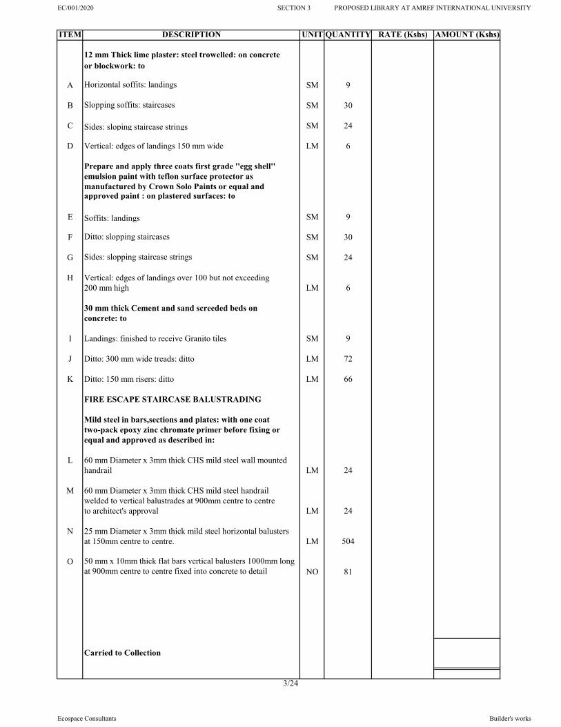
EC/001/2020 SECTION 3 PROPOSED LIBRARY AT AMREF INTERNATIONAL UNIVERSITY
ITEM DESCRIPTION UNIT QUANTITY RATE (Kshs) AMOUNT (Kshs)
12 mm Thick lime plaster: steel trowelled: on concrete or blockwork: to
A Horizontal soffits: landings SM 9
B Slopping soffits: staircases SM 30
C Sides: sloping staircase strings SM 24
D Vertical: edges of landings 150 mm wide LM 6
Prepare and apply three coats first grade ''egg shell''emulsion paint with teflon surface protector asmanufactured by Crown Solo Paints or equal and approved paint : on plastered surfaces: to
E Soffits: landings SM 9
F Ditto: slopping staircases SM 30
G Sides: slopping staircase strings SM 24
H Vertical: edges of landings over 100 but not exceeding 200 mm high LM 6
30 mm thick Cement and sand screeded beds on concrete: to
I Landings: finished to receive Granito tiles SM 9
J Ditto: 300 mm wide treads: ditto LM 72
K Ditto: 150 mm risers: ditto LM 66
FIRE ESCAPE STAIRCASE BALUSTRADING
Mild steel in bars,sections and plates: with one coat two-pack epoxy zinc chromate primer before fixing or equal and approved as described in:
L 60 mm Diameter x 3mm thick CHS mild steel wall mountedhandrail LM 24
M 60 mm Diameter x 3mm thick CHS mild steel handrail welded to vertical balustrades at 900mm centre to centreto architect's approval LM 24
N 25 mm Diameter x 3mm thick mild steel horizontal balusters at 150mm centre to centre. LM 504
O 50 mm x 10mm thick flat bars vertical balusters 1000mm long at 900mm centre to centre fixed into concrete to detail NO 81
Carried to Collection
3/24
Ecospace Consultants Builder's works

EC/001/2020 SECTION 3 PROPOSED LIBRARY AT AMREF INTERNATIONAL UNIVERSITY
ITEM DESCRIPTION UNIT QUANTITY RATE (Kshs) AMOUNT (Kshs)
Prepare and apply aerosol spray painting in two finishing coats of first grade as manufactured by Crown paints or equal and approved paint as described in
A Surfaces: not exceeding 100 mm girth LM 129
B Surfaces: over 100 but not exceeding 200 mm girth LM 504
Carried to Collection
COLLECTION
PAGE NO. 3/21
PAGE NO. 3/22
PAGE NO. 3/23
PAGE NO. 3/24
FROM ABOVE
TOTAL CARRIED TO SUMMARY
3/25
Ecospace Consultants Builder's works

EC/001/2020 SECTION 3 PROPOSED LIBRARY AT AMREF INTERNATIONAL UNIVERSITY
ITEM DESCRIPTION UNIT QUANTITY RATE (Kshs) AMOUNT (Kshs)
SECTION NO. 3
LIBRARY BLOCK
ELEMENT NO. 4
WALLING
EXTERNAL WALLS
Machine cut natural yellow stone walling with a minimum of 7.0 N/mm2 average compessive strength to B.S 5390; bedded and jointed in cement and sand (1:4) mortar ; reinforced with 25 x 3 mm thick hoop iron strips atalternate courses to: -
A 200 mm Thick walls SM 763
B Ditto: Dwarf wall in balconies and parapet SM 115
Precast Concrete
C 250 x 45mm thick coping: twice weathered and throated;fair finshed to all exposed faces LM 89
INTERNAL WALLS
D 200 mm Thick Walls: ditto SM 322
E Ditto: Curved Walls in various radii: ditto SM 41
F 150 mm Thick Walls: ditto SM 134
Damp - proof course: bituminous felt: bedded in cement and sand (1:3) mortar: 300 mm laps
G Horizontal: 200 mm wide LM 123
H Ditto: 150 mm wide LM 14
Aluminium Partitions
Supply, assemble and fix purpose made natural anodised aluminium framing; transoms and middle rail; draught & strips; snap on glazing beads ; plugging or fixing to concrete, blockwork or stone work; with and including first quality and matching ironmongery; sealing with flexible rubber strips and adjusting on completion
I 125 x 75 x 2.5 mm Thick bottom box frames (1.687 kg/m) LM 47
Carried to Collection
3/26
PROPOSED LIBRARY BLOCK FOR
AMREF INTERNATIONAL UNIVERSITY - KENYAMEASURED WORKS
Ecospace Consultants Builder's works

EC/001/2020 SECTION 3 PROPOSED LIBRARY AT AMREF INTERNATIONAL UNIVERSITY
ITEM DESCRIPTION UNIT QUANTITY RATE (Kshs) AMOUNT (Kshs)
A 100 x 75 x 2.5 mm Thick middle section frames (1.336 kg/m) LM 47
B 75 x 75 x 2.5 mm Thick top box frames (0.985 kg/m) LM 47
C 75 x 75 x 2.5 mm Thick intermediate frames (0.985 kg/m) LM 47
D 75 x 75 x 2.5 mm Thick vertical frames (0.985 kg/m) LM 160
E 25 x 25 x 2.5mm Thick beading (0.281 kg/m) LM 704
Glazing
F 6mm Thick clear glass panes as manufactured by Impala Glass Kenya Ltd or equal and approved:; complete with all fixing accessories and screws: on aluminium frames (m/s) SM 20
G 8mm Thick laminated glass as manufactured by Impala Glass Kenya Ltd or equal and approved:; complete with allfixing accessories and screws: on aluminium frames (m/s) SM 182
Carried to Collection
COLLECTION
PAGE NO. 3/26
FROM ABOVE
TOTAL CARRIED TO SUMMARY
3/27
Ecospace Consultants Builder's works

EC/001/2020 SECTION 3 PROPOSED LIBRARY AT AMREF INTERNATIONAL UNIVERSITY
ITEM DESCRIPTION UNIT QUANTITY RATE (Kshs) AMOUNT (Kshs)
SECTION NO. 3
LIBRARY BLOCK
ELEMENT NO. 5
ROOFING
Flat Roof Finishes
Cement and sand (1:4) screeded beds: on concrete: complete with coloured pigmentation additives and hardener to
A 50mm( Average ) thick to roofs :laid to falls and crossfalls: finished to receive APP water proofing SM 370
B Ditto: Balconies ; ditto SM 52
C Cut groove size 20 x 50 mm deep into concrete for turning in flashing: grout in cement and sand mortar LM 121
Waterproofing
Prepare and apply to vertical/horizontal surfaces 4mm thick APP water proofing or other equal and approved, byan approved specialist all in accordance with the manufacturers instructions including provision of a writtenten (10) year anti leak guarantee. Rate to include all necessary surface preparation chasing, forming skirting, fillets, works over outlets
D 4m thick APP water proofing to exposed surfaces on roofand tank slab in horizontal falls not exceeeding 15 degrees as per suppliers specifications and structural engineer's approval SM 370
E Balconies: Horizontal falls not exceeding 15 degrees SM 52
F Dress and dish around 150 mm outlets NO 30
G Penetron Admix or equal and approved SM 422
200 x 200 x 12 mm Thick concrete interlocking tiles:
H Roofs SM 370
Skylight
I Sky light, with 12mm thick laminated toughened glass raised by 600mm with side louvre vents of mild steel lined internally with mosquito wire gauze on expanded metal mesh on steel support structure to SE's instructions ITEM 1
Carried to Collection
3/28
MEASURED WORKS
PROPOSED LIBRARY BLOCK FOR
AMREF INTERNATIONAL UNIVERSITY - KENYA
Ecospace Consultants Builder's works

EC/001/2020 SECTION 3 PROPOSED LIBRARY AT AMREF INTERNATIONAL UNIVERSITY
ITEM DESCRIPTION UNIT QUANTITY RATE (Kshs) AMOUNT (Kshs)
Structural Steel Roof Structure
The following in mild steel with and including two pack epoxy zinc chromate primer before fixing; and fixed according to Engineer's details and including all necessary welding, rivetting and bolting; girder and gusset plates; anchor bolts, rawl bolts, 5/8" to 3" and or 1/2" to 2" mild steel bolts and 12mm diameter antisag rods; hoisting above ground level (aproximately 18 m high from ground level) to the roof space. Including hacking to accomodate members in walling and grouting in cement sand (1:3)
Roof truss type T2; spanning 6683mm wide x 1443mm high,all as per Structural Engineer's details (2Nos.)
A 75 x 50 x 4mm (7.34 kg/m) RHS External members KG 226
B 60 x 40 x 3mm (4.43 kg/m) RHS Internal members KG 83
Roof truss type T3; spanning 6683mm wide x 1443mm high,all as per Structural Engineer's details (1 No.)
C 75 x 50 x 4mm (7.34 kg/m) RHS External members KG 117
D 60 x 40 x 3mm (4.43 kg/m) RHS Internal members KG 55
Roof truss type T4; spanning 5600mm wide x 1616mm high,all as per Structural Engineer's details (2Nos.)
E 75 x 50 x 4mm (7.34 kg/m) RHS External members KG 201
F 60 x 40 x 3mm (4.43 kg/m) RHS Internal members KG 57
Roof truss type T4a; spanning 5600mm wide x 1616mm high,all as per Structural Engineer's details (1 No.)
G 75 x 50 x 4mm (7.34 kg/m) RHS External members KG 94
H 60 x 40 x 3mm (4.43 kg/m) RHS Internal members KG 29
Roof truss type T5; spanning 11296mm wide x 1617mm high,all as per Structural Engineer's details (1 No.)
I 75 x 50 x 4mm (7.34 kg/m) RHS External members KG 183
J 60 x 40 x 3mm (4.43 kg/m) RHS Internal members KG 95
Roof truss type T6; spanning 11296mm wide x 2605mm high,all as per Structural Engineer's details (1 No.)
K 75 x 50 x 4mm (7.34 kg/m) RHS External members KG 242
L 60 x 40 x 3mm (4.43 kg/m) RHS Internal members KG 101
Carried to Collection
3/29
Ecospace Consultants Builder's works

EC/001/2020 SECTION 3 PROPOSED LIBRARY AT AMREF INTERNATIONAL UNIVERSITY
ITEM DESCRIPTION UNIT QUANTITY RATE (Kshs) AMOUNT (Kshs)
Roof truss type T6a; spanning 8053mm wide x 2605mm high,all as per Structural Engineer's details (1 No.)
A 75 x 50 x 4mm (7.34 kg/m) RHS External members KG 197
B 60 x 40 x 3mm (4.43 kg/m) RHS Internal members KG 84
Roof truss type T7; spanning 8053mm wide x 1443mm high,all as per Structural Engineer's details (1 No.)
C 75 x 50 x 4mm (7.34 kg/m) RHS External members KG 138
D 60 x 40 x 3mm (4.43 kg/m) RHS Internal members KG 71
Roof truss type T8; spanning 2860mm wide x 983mm high,all as per Structural Engineer's details (6 Nos.)
E 50 x 40 x 3mm (3.84 kg/m) RHS All members KG 209
Roof truss type T8a; spanning 2000mm wide x 983mm high,all as per Structural Engineer's details (2 Nos.)
F 50 x 40 x 3mm (3.84 kg/m) RHS All members KG 47
Roof truss type T8b; spanning 3951mm wide x 933mm high,all as per Structural Engineer's details (2 Nos.)
G 50 x 40 x 3mm (3.84 kg/m) RHS All members KG 116
Roof truss type T9; spanning 6300mm wide x 933mm high,all as per Structural Engineer's details (1 No.)
H 50 x 40 x 3mm (3.84 kg/m) RHS All members KG 76
Roof truss type T10; spanning 4090mm wide x 954mm high,all as per Structural Engineer's details (1 No.)
I 50 x 40 x 3mm (3.84 kg/m) RHS All members KG 54
Roof truss type T11; spanning 3100mm wide x 723mm high,all as per Structural Engineer's details (1 No.)
J 50 x 40 x 3mm (3.84 kg/m) RHS All members KG 42
Roof truss type T12; spanning 2295mm wide x 1616mm high,all as per Structural Engineer's details (2 Nos.)
K 75 x 50 x 4mm (7.34 kg/m) RHS External members KG 116
L 60 x 40 x 3mm (4.43 kg/m) RHS Internal members KG 20
Roof truss type T13; spanning 3958mm wide x 1616mm high,all as per Structural Engineer's details (1 No.)
M 75 x 50 x 4mm (7.34 kg/m) RHS External members KG 80
N 60 x 40 x 3mm (4.43 kg/m) RHS Internal members KG 21
Carried to Collection
3/30
Ecospace Consultants Builder's works

EC/001/2020 SECTION 3 PROPOSED LIBRARY AT AMREF INTERNATIONAL UNIVERSITY
ITEM DESCRIPTION UNIT QUANTITY RATE (Kshs) AMOUNT (Kshs)
Roof truss type T14; spanning 7461mm wide x 2105mm high,all as per Structural Engineer's details (2 Nos.)
A 75 x 50 x 4mm (7.34 kg/m) RHS External members KG 269
B 60 x 40 x 3mm (4.43 kg/m) RHS Internal members KG 103
Roof truss type T15; spanning 4586mm wide x 1443mm high,all as per Structural Engineer's details (1 No.)
C 75 x 50 x 4mm (7.34 kg/m) RHS External members KG 83
D 60 x 40 x 3mm (4.43 kg/m) RHS Internal members KG 28
Roof truss type T16; spanning 1834mm wide x 1443mm high,all as per Structural Engineer's details (2 Nos.)
E 75 x 50 x 4mm (7.34 kg/m) RHS External members KG 101
F 60 x 40 x 3mm (4.43 kg/m) RHS Internal members KG 17
End of Trusses
Wall Plates
G Wall plate; 100mm wide x 50 x 4mm thick (8.86 kg/m) with including 150mm anchor bolts KG 1,232
Steel Plates
H 300 x 300 x 12mm thick base plate welded to holding downwelded to holding down bolts NO 9
Steel truss support columns
I 100mm diameter x 3mm thick (7.30 kg/m) CHS verticalmembers KG 99
Sawn Cypress timber as treated
The following in assorted timber trusses hoisting andfixing in position 18000 mm above ground floor includingall necessary jointing
J 150 x 50mm Rafters LM 610
K 150 x 50mm Under-purlins LM 437
L 125 x 50mm Ridge board LM 45
Carried to Collection
3/31
Ecospace Consultants Builder's works

EC/001/2020 SECTION 3 PROPOSED LIBRARY AT AMREF INTERNATIONAL UNIVERSITY
ITEM DESCRIPTION UNIT QUANTITY RATE (Kshs) AMOUNT (Kshs)
Clay roofing tiles
Mangalore Clay tiles on 50x25mm battens spaced to manufacturer's specification on gauge 26 minicorrugated galvanized iron sheets underlay on purlins on steel roof structure anchored to beam tostructural Engineers specifications.
A Roof covering at 30 degrees pitch from horizontal including 50 x 25mm timber battens and fixtures SM 458
B Extra over roof tiles for cutting valley tiles LM 63
C Matching and appropriate ridges LM 45
Sheet metal underlay
GCI sheet underlay
D gauge 26 mini corrugated galvanized iron sheets underlay on purlins on steel roof structure anchored to beam tostructural Engineers specifications SM 458
FASCIA/EAVES
Wrot prime grade podo as described in:-
E Ex75 x 25mm T &G secretly nailed to and including 50 x 50mm sawn celcured cypress battens at 600mm c/c SM 82
F Ex 20mm Quarter round beading to junctions of fascia boards and Eaves slats; eaves slats and eaves walling LM 276
G Ex250 x 38mm fascia/Barge boards fixed to roof structure LM 138
H Extra over eaves boarding for 200 x 200mm mosquito gauze vents SM 8
Painting and Decorating
Prepare fill up joints with approved wood filler and apply three coats polyurethane clear varnish to:
I General surfaces of T& G soffits. SM 82
J Surface of wood work 0-100mm girth. LM 276
Prepare, knot, prime, stop and apply three coats gloss oil paint from approved source to:
K Surface of fascia boards, 200-300mm girth. LM 138
Carried to Collection
3/32
Ecospace Consultants Builder's works

EC/001/2020 SECTION 3 PROPOSED LIBRARY AT AMREF INTERNATIONAL UNIVERSITY
ITEM DESCRIPTION UNIT QUANTITY RATE (Kshs) AMOUNT (Kshs)
Mild Steel Pergola
A Pergola comprised of steel frames 50 x 50 mm painted off spray painted black enamel Anti rust paint, metal casing fixed to stone cuts and stone walls, rafters 500 mm centered painted varnish including metal channels between and all fixing accessories as shown on Architectural Detailed Drawing. SM 19
The following in cat ladder
Mild steel weldable; BS.449 Part 2 Framed; bolted and welded site connections
B 50 x 50 x 3mm thick cut and welded together as directed LM 3
C 40 x 40 x 5mm thick: ditto LM 2
D 25mm diameter rungs at 300mm centre to centre LM 4
Painting and decoration
Prepare and spray paint one undercoat; three coats full gloss oil paint; to Crown 'Solo' paints or other equal and approved; to general surfaces
E General surfaces; 100 to 200 mm girth; internally LM 8
Mild steel roof hatch
F 1,000x800mm Spray painted Mild Steel hatch with MS 4mm thick plate on both sides framed by 25x25mm Mild Steel SHS with 2 No handles and padlock hasp SM 1
G 40x40x4mm MS Angle around edge LM 4
Carried to Collection
3/33
Ecospace Consultants Builder's works

EC/001/2020 SECTION 3 PROPOSED LIBRARY AT AMREF INTERNATIONAL UNIVERSITY
ITEM DESCRIPTION UNIT QUANTITY RATE (Kshs) AMOUNT (Kshs)
COLLECTION
PAGE NO. 3/28
PAGE NO. 3/29
PAGE NO. 3/30
PAGE NO. 3/31
PAGE NO. 3/32
PAGE NO. 3/33
TOTAL CARRIED TO SUMMARY
3/34
Ecospace Consultants Builder's works

EC/001/2020 SECTION 3 PROPOSED LIBRARY AT AMREF INTERNATIONAL UNIVERSITY
ITEM DESCRIPTION UNIT QUANTITY RATE (Kshs) AMOUNT (Kshs)
SECTION NO. 3
LIBRARY BLOCK
ELEMENT NO. 6
WINDOWS
ALUMINIUM WINDOWS
Natural anodised aluminium section windows including accessories to Architects approval : 75 x 50 mm frames : aluminium glazing beads, alumnium window cills and wash leather, neoprene gaskets strip: permanent vents in aluminium louvre to be integral to window and proofed : complete with and including 5mm thick clear glass for louvres and 8mm thick laminated glass for windows as specified by architect including butt jointed glazing with silicone sealant where shown and as directed by the Architect: with and including aluminium louvre jambs where detailed and louvre glass blades with smooth edges:installed by an approved domestic sub-contractor: to Architects window schedule: all opening windows to have "Bonn Series" or equal and approved friction stay hinges with restrictor stay, satin anodised aluminium window handles and locking device : fixed to partitions : frames fixed with screws plugged : pointed externally in mastic
A Window type W10 size 1200 x 1950 mm high; Comprising of 1Nos. Sliding leaf size 563 x 1275mm high and3 Nos. fixed leaves sizes 563 x 1275mm high and 2Nos. Sizes 563 x 525mm high each ; all in 8mm thick laminated glass ; as per the window schedules. NO 11
B Window type W11 size 2200 x 1950 mm high; Comprising of 1No. Sliding leaf size 595 x 1050mm high and2 Nos. fixed leaves each size 596 x 1050mm high; all in 8mm laminated glass ; 12 Nos. 5mm thick clear glass size 595 x 105mm wide each as per the window schedules. NO 3
C Window type W12 size 2800 x 2500 mm high; Comprising of 1No. Sliding leaf size 840 x 2080mm high and2 Nos. fixed leaves each size 830 x 2080mm high; all in 8mm laminated glass ; 12 Nos. 5mm thick clear glass size 830 x 105mm wide each as per the window schedules. NO 3
Carried to Collection
3/35
PROPOSED LIBRARY BLOCK FOR
AMREF INTERNATIONAL UNIVERSITY - KENYAMEASURED WORKS
Ecospace Consultants Builder's works

EC/001/2020 SECTION 3 PROPOSED LIBRARY AT AMREF INTERNATIONAL UNIVERSITY
ITEM DESCRIPTION UNIT QUANTITY RATE (Kshs) AMOUNT (Kshs)
A Window type W13 size 1771 x 2000 mm high; Comprising of 1No. Sliding leaf size 773 x 1580mm high and1No fixed leaf size 773 x 1580mm high; all in 8mm thick laminated glass ; 8 Nos. 5mm thick clear glass size 773 x 105mm wide each as per the window schedules. NO 5
B Window type W14 size 1725 x 2000 mm high; Comprising of 1No. Sliding leaf size 773 x 1580mm high and1No fixed leaf size 773 x 1580mm high; all in 8mm thick laminated glass ; 8 Nos. 5mm thick clear glass size 773 x 105mm wide each as per the window schedules. NO 3
C Window type W15 size 3640 x 2500 mm high; Comprising of 4Nos. Sliding leaves each size 816 x 2050mm high in 8mm thick laminated glass ; 16 Nos.5mm thick clear glass size 816 x 105mm wide each as per the window schedules. NO 3
D Window type W16 size 1665 x 2000 mm high; Comprising of 1No. Sliding leaf size 773 x 1580mm high and1No fixed leaf size 773 x 1580mm high; all in 8mm thick laminated glass ; 8 Nos. 5mm thick clear glass size 773 x 105mm wide each as per the window schedules. NO 3
E Window type W17 size 1400 x 2000 mm high; Comprising of 1No. Sliding leaf size 587 x 1580mm high and1No fixed leaf size 587 x 1580mm high; all in 8mm thick laminated glass ; 8 Nos. 5mm thick clear glass size 587 x 105mm wide each as per the window schedules. NO 3
F Window type W18 size 1800 x 2000 mm high; Comprising of 1No. Fixed leaf size 938 x 1100mm high and 1No. Slidingleaf size 938 x 1100mm high in 8mm thick laminated glass ; 8 Nos.5mm thick clear glass size 788 x 105mm wide each.as per the window schedules. NO 14
G Window type W19 size 2400 x 2500 mm high; Comprising of 2Nos. Sliding leave each size 696 x 8000mm high and1 No. fixed leaf size 708 x 800mm high; all in 8mm thick laminated glass ; 12 Nos. 5mm thick clear glass size 708 x 105mm wide each as per the window schedules. NO 3
H Window type W20 with panels sizes 946 x 2000 mm high and 946 x 700mm high L-shaped comprising of 3Nos. Fixed leaves each size 946 x 700mm high and 1 No. fixed sliding size 946 x 700mm high; all in 8mm thick laminated glass ; as per the window schedules. NO 1
I Window type W21 size 1600 x 2700 mm high; Comprising of 1No. Sliding leaf size 773 x 2280mm high and1No fixed leaf size 773 x 2280mm high; all in 8mm thick laminated glass ; 8 Nos. 5mm thick clear glass size 773 x 105mm wide each as per the window schedules. NO 16
Carried to Collection
3/36
Ecospace Consultants Builder's works

EC/001/2020 SECTION 3 PROPOSED LIBRARY AT AMREF INTERNATIONAL UNIVERSITY
ITEM DESCRIPTION UNIT QUANTITY RATE (Kshs) AMOUNT (Kshs)
A Window type W22 size 1500 x 2250 mm high; Comprising of 1Nos. Sliding leaf size 638 x 1600mm high and2 Nos. fixed leaves sizes 638 x 1600mm high and 2Nos. Sizes 638 x 525mm high each ; all in 8mm thick laminated glass ; as per the window schedules. NO 8
B Window type W23 size 1200 x 900 mm high; 1No. Top hung opening leaf size 1050 x 750mm high; as per the window schedules.; all in 8mm thick laminated glass ; as per the window schedules. NO 15
C Window type W24 size 900 x 900 mm high; 1No. Top hung opening leaf size 750 x 750mm high; as per the window schedules.; all in 8mm thick laminated glass ; as per the window schedules. NO 3
D Window type W25 size 2100 x 2000 mm high; Comprising of 1No. Sliding leaf size 450 x 1580mm high and2 Nos. fixed leaves each size 450 x 1580mm high; all in 8mm laminated glass ; 12 Nos. 5mm thick clear glass size 450 x 105mm wide each as per the window schedules. NO 2
E Window type W26 size 1578 x 2350 mm high; Comprising of 1No. Sliding leaf size 752 x 1875mm high and3 Nos. fixed leaves sizes 752 x 1875mm high and 2Nos. Sizes 752 x 525mm high each ; all in 8mm thick laminated glass ; as per the window schedules. NO 3
F Window type W27 size 1800 x 2793 mm high; Comprising of 1Nos. Sliding leaf size 862 x 1500mm high and1 No. fixed leaves sizes 862 x 1500mm high, 2Nos. Sizes 862 x 663mm high each and 2Nos. 862 x 650mm high each ; all in 8mm thick laminated glass ; as per the window schedules. NO 1
G Window type W28 size 2608 x 2700 mm high; Comprising of 1No. Sliding leaf size 875 x 1050mm high and1 No. fixed leaves sizes 875 x 1050mm high, 1 No. size 633 x 1050mm high, 2 Nos. size 633 x 725mm high each,and 4Nos. 875 x 725mm high each ; all in 8mm thick laminated glass ; as per the window schedules. NO 1
H Window type W29 size 800 x 800 mm high; 1No. Top hung opening leaf size 600 x 600mm high; as per the window schedules. NO 8
I Window type W30 size 1813 x 2700 mm high; Comprising of 1No. Sliding leaf size 788 x 975mm high and3 Nos. fixed leaves sizes 788 x 975mm high and 2Nos. Sizes 800 x 725mm high each and 800 x 1000mm high ; all in 8mm thick laminated glass ; as per the window schedules. NO 1
Carried to Collection
3/37
Ecospace Consultants Builder's works

EC/001/2020 SECTION 3 PROPOSED LIBRARY AT AMREF INTERNATIONAL UNIVERSITY
ITEM DESCRIPTION UNIT QUANTITY RATE (Kshs) AMOUNT (Kshs)
General joinery: wrot mahogany: selected and kept clean
A 300 x 25 mm Window board: plugged, screwed and pellated LM 176
Window blinds
B Supply and fix VENETIAN horizontal folding window blinds complete with all accessories as per Manufacturer's printed specifications and instructions to Client's approval SM 361
Precast concrete units class 20 (19 mm aggregates): vibrated: reinforced with 2 No. 6 mm diameter steel bars
C 265 x 75 mm Thick weathered and throated window cill: fairfaced on exposed surfaces: bedded jointed and pointed in cement and sand (1:4) mortar LM 198
Prepare and apply one coat first quality aluminium wood primer before fixing: on wood: to
D Surfaces exceeding 100mm but not exceeding 200 mm girth LM 176
Prepare and apply three coats of first quality polyurethane clear varnish: on wood: to
E Window board: LM 176
Sun Shades
Supply, assemble and fix; Natural anodized aluminium sun breaker fins: comprising of 100 x 50 x 2.5 mm Thick frames and 100 x 2.5mm fins fixed to frames at an approved angle plugged to concrete work: and including 15 x 10mm aluminium fixing beads and approved gaskets: plugged screwed to concrete or blockwork: including brass fastenings and stays, lugs; ironmongery and accessories: all as per Architects schedule: oiling
F 900mm wide Horizontal fixed aluminium sun shading louvres anchored to RC columns/fins to detail. SM 150
Cover Gratings
3 mm spray painted mild steel gratings (serrated type) welded on 2 inch angle bars base frame.
G Over the exterior ducts 450mm wide LM 42
Carried to Collection
3/38
Ecospace Consultants Builder's works

EC/001/2020 SECTION 3 PROPOSED LIBRARY AT AMREF INTERNATIONAL UNIVERSITY
ITEM DESCRIPTION UNIT QUANTITY RATE (Kshs) AMOUNT (Kshs)
COLLECTION
PAGE NO. 3/35
PAGE NO. 3/36
PAGE NO. 3/37
PAGE NO. 3/38
TOTAL CARRIED TO SUMMARY
3/39
Ecospace Consultants Builder's works

EC/001/2020 SECTION 3 PROPOSED LIBRARY AT AMREF INTERNATIONAL UNIVERSITY
ITEM DESCRIPTION UNIT QUANTITY RATE (Kshs) AMOUNT (Kshs)
SECTION NO. 3
LIBRARY BLOCK
ELEMENT NO. 7
DOORS
Entrance Doors
Frameless Glass Doors
8mm Thick toughened frameless glass door; complete with and including heavy duty floor springs, pull bar handles, wall clumps, floor door closer, half moon door stop, centre stike patch, 5-lever union lock:- all in stainless steel as per ''Assa Abloy'' union catalogue or equal and approved; bevelled edges, sand blasted graphic film; stainless steel transome and patch fittings and fixing accessories
A Double leaf door D1 overall size 1800 x 3150 mm high comprising of 2No. Openable leaves size 900 x 2400mm high and 1No. Fixed top fanlight panel overall size 1800 x 750mm.high (above openinig portion) NO 2
Fire rated timber doors.
45mm thick asbestos free composite fire/smoke check solid core flush door of 120 minutes fire resistance rating conforming to BS : 476 Part - 22 & IS : 3614 Part II comprising of two 12mm thick calcium silicate boardssandwhiching 25mm thick proprietory fire resitanceinsulation material faced both sides with mahogany vaneer,including heat activated intumescent fire seal stripof size 20 x 4mm mounted on grooves on three sides except bottom and one coat of anti-termite fire retardentpowder; stainless steel horizontal panic exit including ex 50 x 150mm rebated mahogany frame
B Single leaf door D3 size 900 x 2100mm high (fire resistanceescape doors) including 6mm thick georgian clear glass panel size 200 x 650mm high NO 3
45 mm Thick Solid cored flush doors to B.S. 459 part 2:mahogany veneered both sides: mahogany hardwood finish to Architect's approval
C Single leaf disabled toilet door D5 overall size 1100 x 2100mm high; comprising of 1No. Opennable leaf size1000 x 1950mm high NO 2
Carried to Collection
3/40
PROPOSED LIBRARY BLOCK FOR
AMREF INTERNATIONAL UNIVERSITY - KENYAMEASURED WORKS
Ecospace Consultants Builder's works

EC/001/2020 SECTION 3 PROPOSED LIBRARY AT AMREF INTERNATIONAL UNIVERSITY
ITEM DESCRIPTION UNIT QUANTITY RATE (Kshs) AMOUNT (Kshs)
A Single leaf door D6 overall size 900 x 2100mm high; comprising of 1No. Opennable leaf size 800 x 2000mm high including 150 x 100mm PVC louvred vent as per the door schedule NO 4
B Single leaf door D7 overall size 900 x 2850mm high; comprising of 1No. Opennable leaf size 800 x 2000mm high and fanlight size 900 x 750mm high NO 4
C Single leaf door D8 overall size 800 x 1850mm high; NO 10
D Single leaf door D17 overall size 1000 x 2400mm high; comprising of 1No. Opennable leaf size 800 x 2000mm high and varnished mahogany louvres including fanlight size 1000 x 300mm high as per the Architectural details NO 3
Anodized Aluminium Doors
Purpose made door: supply, assemble and fix purpose made natural anodised aluminium door and framing size 100 x 75mm; 100x50mm stiles, bottom, top and vertical rails; 8 mm thick laminated glass: complete with stainless steel ironmongery and accessories as per union catalogue or equal and approved; fixing with stainless steel screws; plugging or fixing to concrete, blockwork or stone work;
E Door type D13 overall size 2700 x 2700 mm high; Comprising of 2Nos. Fixed panels each size 638 x 2100mm high and 2Nos. Sliding leaves each size 600 x 2100mm high and fanlight size 2700 x 600mm high all in 8mm thick laminated glass ; as per the door schedules. NO 1
F Door type D15 overall size 3600 x 2700 mm high; Comprising of 2Nos. Fixed panels each size 788 x 2100mm high and 2Nos. Sliding leaves each size 788 x 2100mm high and fanlight size 3600 x 600mm high all in 8mm thick laminated glass ; as per the door schedules. NO 1
G Door type D16 overall size 2400 x 2700 mm high; Comprising of 2Nos. Fixed panels each size 513 x 2100mm high and 2Nos. Sliding leaves each size 513 x 2100mm high and fanlight size 3600 x 600mm high all in 8mm thick laminated glass ; as per the door schedules. NO 1
H Single leaf door D2 size 900 x 2400mm high (overall); comprising of 1No.opennable leaf size 900 x 2100mm high and fanlight size 900 x 300mm high NO 10
Duct Doors
I 25mm Thick blockboard double leaf door D18 overall size 1000 x 2000mm high; in 2No. Equal opennable leaves size 500 x 2000mm high; complete with first quality ironmongery; 6mm clear glass panels to the architects approval NO 7
J 25mm Thick blockboard double leaf door D9 overall size 650 x 2300mm high NO 4
Carried to Collection
3/41
Ecospace Consultants Builder's works

EC/001/2020 SECTION 3 PROPOSED LIBRARY AT AMREF INTERNATIONAL UNIVERSITY
ITEM DESCRIPTION UNIT QUANTITY RATE (Kshs) AMOUNT (Kshs)
Fire rated steel doors.
A Single leaf steel door D4 as per '' Assa Abloy'' fire rated doors of 120 minutes fire resistance rating overall size 1000 x 2100mm high in 150 x 50mm steel frame, 20 x 4mm intumescent strip and faced with stainless steel sheets grade 304 on both sides including panic bar handle and stainless steel ironmongery as per the architectural details NO 1
Mild Steel louvred Door
Mild steel louvred double doors; comprising 75 x 75 x 3mm rebated pressed steel frame plugged to wall; 75 x 50 x 3 mm hollow section top rail, bottom rail and stiles, angles cut, mitred and welded; 150 x 50 x 3 mm hollow section middle; ends welded and angles cut, mitred and welded; two open panels per door leaf infilled with 16 gauge cranked louvres 575 mm wide at 60 mm centres welded to stiles; all welded ground to smooth finish ;including iron mongery as per architectural details
A Door D20 overall size 1000 x 2100mm high in 2Nos. Equalleaves each size 500 x 2100mm high including ironmongery No 1
Frames and linings: mahogany or equal approved hardwood: selected and kept clean
B 150mm x 50mm Frames with heat activate intumescent fire seal strip size 20 x 4mm including one coat fire and anti-termite primer LM 27
C 150 x 50 mm Frames: Three labours: plugged LM 233
D 20 x 40 mm Architrave: screwed and pellated LM 233
E 20 x 20 mm Quadrant beading: one labour: ditto LM 233
F 10 x 20 mm Glazing beads LM 36
Supply and fix the following ironmongery to timber complete with matching screws and keys as per 'UNION' manufucturers ( reference to a particular catalogue are given as a guide to type and quality only, other equal and approved alternatives may be used)
G Polished Stainless steel five lever mortice door lock and handle furniture set; ( keyhole escutcheons, cylinder and latch ); Reference to "UNION" Catalogue NO. 5L-2201-SC or equal and approved NO 9
H Polished Stainless steel three lever mortice door lock and brass handle furniture set;( keyhole escutcheons, cylinder and latch ); Reference to "UNION" Catalogue NO. 3L-2277-PL or equal and approved NO 20
Carried to Collection
3/42
Ecospace Consultants Builder's works

EC/001/2020 SECTION 3 PROPOSED LIBRARY AT AMREF INTERNATIONAL UNIVERSITY
ITEM DESCRIPTION UNIT QUANTITY RATE (Kshs) AMOUNT (Kshs)
A Ditto: But Two Lever mortice as per "UNION" cataloque NO. 2L-2295-PB or equal and approved NO 13
B Polished Stainless steel three lever mortice cupboard lock NO 11
C Polished Stainless steel D-Pull/Push handles; NO 15
D Stainless Steel; spec night latch Cylinder mortice lock NO 4
E 100mm stainless steel double washered hinges PRS 44
F with aluminium pin and screws; Reference to "UNION" Catalogue NO. HN-DW-403020-SSS or equal and approved PRS 84
G 100 mm stainless steel ball bearing hinges Reference to "UNION" Catalogue NO. HN-4BB-403030-SSS PRS 6
H 38mm Diameter Oval chrome rubber door stop I Union ref. DS-01 CH NO 56
J Polished Stainless Steel Escutcheon with indicators; Reference to UNION Catalogue 87045C NO 15
K Aluminium door closers including all accessories:Rack-and Pinion projecting Arm Closers with Pull side Hold open Arm; latching action via arm;dual speed valve control; Reference to Briston series 2003 or equal and approved NO 3
L 1 mm thick stainless steel kicking plates size 1100mm x 150mm High NO 3
M Ditto: Size 1000mm x 150mm high NO 3
N Ditto: Size 900mm x 150mm high NO 33
O Polished Stainless steel Hat and coat hooks: Reference to Dorma Catalogue 2011/12 DHC-SS-170 NO 15
6 mm Thick clear sheet glass: fixed with 25 x 25mm grooved hardwood beading all round; to timber doors
P Door fan lights: over 0.1 but not exceeding 0.5 square meters SM 7
Prepare and apply one coat aluminium wood primer: before fixing: on wood: to
Q Surfaces not exceeding 100 mm girth LM 233
R Ditto: over 100 but not exceeding 200 mm girth LM 233
Carried to Collection
3/43
Ecospace Consultants Builder's works

EC/001/2020 SECTION 3 PROPOSED LIBRARY AT AMREF INTERNATIONAL UNIVERSITY
ITEM DESCRIPTION UNIT QUANTITY RATE (Kshs) AMOUNT (Kshs)
Prepare and apply three coats polyurethane clear varnish: on wood: to
A General surfaces ( both sides measured overall ) SM 144
B Frames: over 100 but not exceeding 200 mm girth LM 233
C Frames: not exceeding 100 mm girth LM 233
D Transomes: over 100mm but not 200mm girth LM 233
E Architraves: not exceeding 100 mm girth LM 233
F Quadrant beading : not exceeding 100 mm girth LM 233
G Glazing beads: ditto LM 0
Carried to Collection below
COLLECTION
PAGE NO. 3/40
PAGE NO. 3/41
PAGE NO. 3/42
PAGE NO. 3/43
FROM ABOVE
TOTAL CARRIED TO SUMMARY
3/44
Ecospace Consultants Builder's works

EC/001/2020 SECTION 3 PROPOSED LIBRARY AT AMREF INTERNATIONAL UNIVERSITY
ITEM DESCRIPTION UNIT QUANTITY RATE (Kshs) AMOUNT (Kshs)
SECTION NO. 3
LIBRARY BLOCK
ELEMENT NO. 8
FINISHES
FLOOR FINISHES
Cement and sand (1:4) screeded beds: on concrete : to:
A 20 mm Thick to receive Granite tiles SM 44
B 30 mm Thick to receive Ceramic tiles SM 116
C 15 mm Thick to receive Granito tiles SM 788
D 20 mm Thick to receive Mazera tiles SM 37
600 x 600 x 20mm thick polished Granite tiles laid with approved adhesive and pointed neatly in cement onscreeded bed and polished to desired quality
E Floors SM 44
600 x 300 x 10mm Thick polished non-slip ceramic tiles as manufactured by Saj Industries or equal and approved: on bed: bedded and jointed in screeded and waterproofed cement grout using serrated stainless steel trowels: to
F Floors SM 116
G Ditto: 10 mm Thick x 100 mm high skirting LM 162
Approved full boarded polished Granito tiles size 600 x 600 x 25 mm thick; 95% free from visible defects; plus or minus 5% maximum side straightness deviation; group 5 or PEI 5 surface abrasion ; PEI5 stain resistant; less than 0.5 % water absorption ; frost resistant ; chemical resistant ; bedding and jointing in approved porcelain adhesive; to
H Floors SM 788
I Ditto: 25 mm Thick x 100 mm high skirting LM 332
300 x 20 mm Mazzera stones or its equivalent finished with clear varnish to approvals.
J Floors SM 37
K Ditto: 12 mm Thick x 100 mm high skirting LM 59
Carried to Collection
3/45
MEASURED WORKS
PROPOSED LIBRARY BLOCK FOR
AMREF INTERNATIONAL UNIVERSITY - KENYA
Ecospace Consultants Builder's works

EC/001/2020 SECTION 3 PROPOSED LIBRARY AT AMREF INTERNATIONAL UNIVERSITY
ITEM DESCRIPTION UNIT QUANTITY RATE (Kshs) AMOUNT (Kshs)
Waterproofing
Seal Proof' by sealocrete products ltd or equal and approved waterproofing additive mixed with concrete at a ratio of 500ML per 50Kg of concrete all as per manufacturer's instructions.
A 32 mm Thick to floors SM 153
WALL FINISHES
External wall finishes
B Thoroughly wire brush and clean surface SM 848
Yellow Stone Cladding
Natural quarry stone wall cladding: Yellow Stone: fine dressed to one face bedded, jointed and pointed in cement sand (1:3) mortar: flush vertical and horizontal joints :in
C 50mm wall cladding SM 611
19 mm Cement and sand (1:3) render: wood floated: on concrete or blockwork: to
D Beams SM 112
E Columns SM 26
Internal wall finishes
12 mm Lime plaster: steel trowelled: on concrete or block work : to
F Walls & Beams surfaces SM 1,400
G Columns SM 106
Prepare and apply three coats first grade ''egg shell''emulsion paint with teflon surface protector asmanufactured by Crown Solo Paints or equal and approved paint : on plastered surfaces: to
H Plastered walls & Beams surfaces SM 1,400
I Ditto: Columns surfaces SM 106
300 x 200 x 10 mm Thick coloured glazed ceramic wall tiles on backings (m/s) pointed and jointed in matching cement mortar: to
J Walls SM 194
K Plastic beading for fair edges LM 108
Carried to Collection
3/46
Ecospace Consultants Builder's works

EC/001/2020 SECTION 3 PROPOSED LIBRARY AT AMREF INTERNATIONAL UNIVERSITY
ITEM DESCRIPTION UNIT QUANTITY RATE (Kshs) AMOUNT (Kshs)
Cement and sand (1:4) screeded beds: on concrete : to:
A Walls: finished to receive ceramic tiles SM 194
B Lift walls: finished to receive granito tiles SM 55
600 x 300 x 10 mm Thick coloured granito wall tiles on backings (m/s) pointed and jointed in matching cement mortar: to
C Lift walls SM 194
D Plastic beading for fair edges LM 19
CEILING FINISHES
12 mm Thick lime plaster: steel trowelled: on concrete : to
E Plaster to soffits of suspended slab SM 787
Suspended gypsum ceiling
F 12mm thick Gypsum board ceiling spray painted on 75mm thick galvanized steel stud as DONN ULTRA STEEL complete with metal edge, upstands, curved edges and associated raked cutting to details SM 582
G 100mm matching gypsum cornice moulded with four labours SM 600
Prepare and apply three coats first grade ''egg shell''emulsion paint with teflon surface protector asmanufactured by Crown Solo Paints or equal and approved paint : on plastered surfaces: to
H Plastered Ceiling soffites SM 787
Carried to Collection
3/47
Ecospace Consultants Builder's works

EC/001/2020 SECTION 3 PROPOSED LIBRARY AT AMREF INTERNATIONAL UNIVERSITY
ITEM DESCRIPTION UNIT QUANTITY RATE (Kshs) AMOUNT (Kshs)
BALUSTRADES
BALCONIES BALUSTRADING
Mild steel in bars,sections and plates: with one coat two-pack epoxy zinc chromate primer before fixing or equal and approved as desribed in:
A 50 mm x 50 mm x 3mm thick RHS handrail LM 49
B Ditto bottom rail LM 49
C Ditto Diagonal members LM 147
Prepare and apply one undercoat and two finishing coats of first grade two pack epoxy paint as manufactured by Crown paints or equal and approved paint as desribed in
D Surfaces: over 100 but not exceeding 200 mm girth LM 245
Precast concrete class 20 (12mm,aggregate), including formwork, finishing fair face on all exposed surfaces, and hoisting and placing in position, bedding and jointing in cement and sand (1:3) mortar
E 150 x 50mm single throated concrete coping LM 49
Carried to Collection
COLLECTION
PAGE NO. 3/45
PAGE NO. 3/46
PAGE NO. 3/47
FROM ABOVE
TOTAL CARRIED TO SUMMARY
3/48
Ecospace Consultants Builder's works

EC/001/2020 SECTION 3 PROPOSED LIBRARY AT AMREF INTERNATIONAL UNIVERSITY
ITEM DESCRIPTION UNIT QUANTITY RATE (Kshs) AMOUNT (Kshs)
SECTION NO. 3
LIBRARY BLOCK
ELEMENT NO. 9
FITTINGS & FIXTURES (ALL PROVISIONAL)
Main reception desk
A Round shaped Counter overall size 9080mm circumfrence x 800 x 1050mm high inlcuding 20mm thick mahogany laminated particle board facing in 50 x 50 mild steel RHS frame; 20mm thick granite top slab size 9080mm circumfrence x 350mm wide and 9080mm circumfrence x 750mm wide laminated particle board all on blockboard decking supported on 30 x 30 x 3mm thick mild steel R.H.S sections at 300mm c/c; MDF meru oak veneered 4 Nos. cabinets with drawers and door leaves; 25mm widestainless strips fixed at 125mm centres; 100mm high x 2mmstainless steel skirting; first quality ironmongery and finishes to Architectural details. NO 1
Reading top on first floor
B Curved reading top size 20000 mm x 600 x 750mm high inlcuding 20mm thick mahogany laminated particle board facing and hardwood lipping on exposed edges in 50 x 50 mild steel RHS frame mounted on 200mm dwarf wall as per Architectural details. NO 1
Store shelving
C Store shelving overall size 8267 x 300 x 2200mm high comprising of 20mm x 300mm Wide blockboard shelves : mahogany veneered on all exposed surfaces : hardwood lipped on all exposed edges : 60 x 25mm sawn cypress bearers plugged and screwed to wall : 20mm thick MDF doors spray painted and fixed with malphae hinges;three coats polyurethane or other equal and approved clear finish to all exposed surfaces unless otherwise stated NO 1
TOTAL CARRIED TO SUMMARY
3/49
PROPOSED LIBRARY BLOCK FOR
AMREF INTERNATIONAL UNIVERSITY - KENYAMEASURED WORKS
Ecospace Consultants Builder's works

EC/001/2020 SECTION 3 PROPOSED LIBRARY AT AMREF INTERNATIONAL UNIVERSITY
ITEM DESCRIPTION UNIT QUANTITY RATE (Kshs) AMOUNT (Kshs)
SECTION NO. 3
LIBRARY BLOCK
ELEMENT NO. 10
MECHANICAL ENGINEERING SERVICES (PROVISIONAL)
Builders work in connection to mechanical Engineering services: cut and/or leave and make good thereafter for sanitary fittings, equipments and pipe work therein: concealed type plumbing and ducting: for
A W.C. Suite NO 18
B Wash hand basins NO 21
C Urinals bowls NO 3
D Fire horse reel / Sprinkler system NO 3
E Hand Driers NO 9
F A.C unit NO 3
TOTAL CARRIED TO SUMMARY
3/50
PROPOSED LIBRARY BLOCK FOR
AMREF INTERNATIONAL UNIVERSITY - KENYAMEASURED WORKS
Ecospace Consultants Builder's works

EC/001/2020 SECTION 3 PROPOSED LIBRARY AT AMREF INTERNATIONAL UNIVERSITY
ITEM DESCRIPTION UNIT QUANTITY RATE (Kshs) AMOUNT (Kshs)
SECTION NO. 3
LIBRARY BLOCK
ELEMENT NO. 11
ELECTRICAL ENGINEERING SERVICES (PROVISIONAL)
Builders work in connection to electrical services cut and/or chase and make good thereafter for electrical installations including associated switches and concealed conduits therewith: for
A Lighting points and switches NO 120
B Power points NO 75
C Consumer unit NO 1
D Metre Board NO 1
E Data Points NO 150
F Telephone Points NO 8
G Distribution Board NO 1
H Fire alarm & Smoke Detector points NO 8
I T.V aerial output point NO 6
J Generator Unit NO 1
TOTAL CARRIED TO SUMMARY
3/51
MEASURED WORKS
PROPOSED LIBRARY BLOCK FOR
AMREF INTERNATIONAL UNIVERSITY - KENYA
Ecospace Consultants Builder's works

EC/001/2020 SECTION 3 PROPOSED LIBRARY AT AMREF INTERNATIONAL UNIVERSITY
ITEM DESCRIPTION UNIT QUANTITY RATE (Kshs) AMOUNT (Kshs)
SECTION NO. 3
LIBRARY BLOCK
BUILDERS WORK SUMMARY
PAGE NO.ELEMENTS
1 SUBSTRUCTURE/ BASEMENT 3/18
2 REINFORCED CONCRETE SUPERSTRUCTURE 3/20
3 STAIRCASES 3/25
4 WALLING 3/27
5 ROOFING 3/34
6 WINDOWS 3/49
7 DOORS 3/44
8 FINISHES 3/48
9 FITTINGS & FIXTURES 3/49
10 B.W.I.C MECHANICAL ENGINEERING SERVICES 3/50
11 B.W.I.C ELECTRICAL ENGINEERING SERVICES 3/51
TOTAL CARRIED TO MAIN SUMMARY
3/52
MEASURED WORKS
PROPOSED LIBRARY BLOCK FOR
AMREF INTERNATIONAL UNIVERSITY - KENYA
Ecospace Consultants Builder's works

EC/001/2020 SECTION 4 PROPOSED LIBRARY AT AMREF INTERNATIONAL UNIVERSITY
SECTION 4 - EXTERNAL WORKS
Ecospace Consultants External Works

EC/001/2020 SECTION 4 PROPOSED LIBRARY AT AMREF INTERNATIONAL UNIVERSITY
ITEM DESCRIPTION UNIT QUANTITY RATE (Kshs) AMOUNT (Kshs)
SECTION NO. 4
EXTERNAL WORKS (PROVISIONAL)
ELEMENT NO. 1
SITE CLEARANCE
A Fell trees: grub up roots and remove from site: trunk exceeding 900mm but not exceeding 1200mm girth NO 3
B 1200mm but not exceeding 1500mm girth NO 2
Note: The Contractor is specifically requested to visit the site and ascertain for himself the items of Demolition described hereunder before pricing this section. The Contractor is refered to Section C: DEMOLITIONS ANDALTERATIONS of the Standard Method of Measurementand should note in particular that his rates should includefor all shoring and scaffolding incidental to Demolitionsand for making good all other works so disturbed.
C Carefully remove existing heavy duty Paving blocks,Kerbs and channels (approximately 736 square metres) laid on and including cement/sand on hardcore. ITEM 1
D Carefully remove existing 40feet container from base and transport to designated location as instructed by theClient. ITEM 1
E Demolish completely to the ground including grubbing up foundations and carting away debris for 40 feet containerand other structures on site. ITEM 1
TOTAL CARRIED TO SUMMARY
4/1
PROPOSED LIBRARY BLOCK FOR
AMREF INTERNATIONAL UNIVERSITY - KENYAMEASURED WORKS
Ecospace Consultants External Works

EC/001/2020 SECTION 4 PROPOSED LIBRARY AT AMREF INTERNATIONAL UNIVERSITY
ITEM DESCRIPTION UNIT QUANTITY RATE (Kshs) AMOUNT (Kshs)
SECTION NO. 4
EXTERNAL WORKS (PROVISIONAL)
ELEMENT NO. 2
INTERNAL ROADS , CARPARKS AND PAVED AREAS
Site preparation
A Excavate vegetable soil 200 mm (average) deep: remove from site SM 300
B Hyvar X as manufactured by Twiga Chemicals Limited or equal approved weed killer applied at the rate of 0.10 litresper square metre SM 300
Excavations
C Excavate to reduce levels, not exceeding 1.5 metres deep CM 180
D Extra over excavations and disposal from site for rock CM 36
Disposal of Excavated material
E Remove surplus spoil from site CM 180
F Backfill and compact in 150 mm layers: selected excavated materials: compacted to 95MDD (AASHTO 180 ) CM 180
Surface Treament
G Grade and compact to falls and crossfalls: bottoms of excavations: compact to 100% B.S compaction SM 300
Fillings
H 300 mm Gravel filings: deposited and compacted in 150 mm layers: laid to falls and crossfalls: compacted to 100% B.S compaction SM 300
I 300 mm Thick hand-packed stone: graded to falls and crossfalls: compacted to 100% B.S standard compaction: in 150 mm layers SM 300
J 50 mm Sand blinding to surfaces of hardcore: finished toreceive cabro blocks (M/s) SM 300
TOTAL CARRIED TO SUMMARY
4/2
PROPOSED LIBRARY BLOCK FOR
AMREF INTERNATIONAL UNIVERSITY - KENYAMEASURED WORKS
Ecospace Consultants External Works

EC/001/2020 SECTION 4 PROPOSED LIBRARY AT AMREF INTERNATIONAL UNIVERSITY
ITEM DESCRIPTION UNIT QUANTITY RATE (Kshs) AMOUNT (Kshs)
SECTION NO. 4
EXTERNAL WORKS (PROVISIONAL)
ELEMENT NO. 3
DRAINAGE
STORM WATER DRAINAGE
Excavate, part backfill and remove surplus spoil from site: plank and strut sides of excavation including removing fallen materials: keep excavations free from all water: grade and compact bottoms of excavation to falls
A For 300 mm Diameter pipes 1000 mm (average) deep: not exceeding 1.5 metres deep LM 3
B For 300 x 300mm deep channel: ditto LM 158
C Extra over for excating in hard rock CM 9
Insitu concrete: class 15 (20 mm aggregate): vibrated
D 150 mm Bed and surround to 300 mm diameter pipe: formwork LM 3
E 300 x 300 x 100 mm Thick U-shaped channel: formwork LM 158
Precast concrete "ogee" pipes to B.S 556 part 2: socket and spigot jointed: jointed and pointed with yarn and cement mortar (1:3)
F 300 mm Diameter pipe LM 3
Terrain UPVC class D pipes: solvent cement welded joints
G 150 mm Diameter pipe: fixed to concrete ceiling LM 166
Standard circular precast concrete class 25/12 mm aggregate rainwater gullies: to B.S 556 cast in 100 mm concrete 1:3:6 bed and surround: 150 mm concrete 1:2:4 diameter bars at 75 mm centres both ways: 12 mm thick cement and sand (1:3) water- proofed rendering internally: concrete filled standard heavy duty gully grating and frame to B.S 497: holes for extra large pipes: channels: excavation and disposal from site: formwork
H Gully size 460 mm diameter (internally) x 850 mm deep NO 2
Carried to Collection
4/3
PROPOSED LIBRARY BLOCK FOR
AMREF INTERNATIONAL UNIVERSITY - KENYAMEASURED WORKS
Ecospace Consultants External Works

EC/001/2020 SECTION 4 PROPOSED LIBRARY AT AMREF INTERNATIONAL UNIVERSITY
ITEM DESCRIPTION UNIT QUANTITY RATE (Kshs) AMOUNT (Kshs)
Mild steel in plates, bars and sections: one coat red oxide primer before erection: welded connections
A 300 mm wide steel grating: 20 x 20 x 3 mm RHS cross members at 50 mm centres welded to 50 x 50 x 3mm angle frames: paint LM 9
B 50 x 50 x 3mm Angle frame: plugged and srewed to concrete at 300 mm centres LM 18
Precast concrete units class 20/12 mm aggregates: vibrated: fairfaced on exposed faces
C 200 x 50 mm Thick coping: single weathered and throated : bedded, jointed and pointed in cement and sand ( 1: 3) mortar LM 5
Carried to Collection
COLLECTION
PAGE NO. 4/4
FROM ABOVE
TOTAL CARRIED TO SUMMARY
4/4
Ecospace Consultants External Works

EC/001/2020 SECTION 4 PROPOSED LIBRARY AT AMREF INTERNATIONAL UNIVERSITY
ITEM DESCRIPTION UNIT QUANTITY RATE (Kshs) AMOUNT (Kshs)
SECTION NO. 4
EXTERNAL WORKS (PROVISIONAL)
ELEMENT NO. 4
FOUL WATER DRAINAGE
The following in 9No. Manholes overall size 1000 x 850 x 1200mm high.
Excavations
Excavations including mainataining and supporting sides of excavations as before.
A For manholes, 0-1500mm deep and load and cart away. CM 11
Mass concrete class 15/20 aggregate as described in:-
B 100mm thick base slab. SM 8
C Benching size 600 x 450mm average 300mm deep including forming main branch channels and finishing with 12mm water proof sulphate resistance render steel trowelled smooth. NO 9
Walling
Approved natural stone walling of minimum crushing stregth of 7.5N/mm2 built in courses of cement/sand (1;3) mortar mix.
D 200mm thick medium dressed stone wall reinforced at each alternate course with and including 24gauge galvanized mild steel hoop iron and staggered. SM 40
E Extra over for forming 150mm diameter holes through walls. NO 9
Render to walls
F 16mm thick sulphate resistant cement/sand (1:4) render as described steel trowelled smooth. SM 40
Manhole covers
G 600 x 450 x 50mm precast concrete manhole cover complete with cast iron frames built into and including concrete boxing. NO 9
Carried to Collection
4/5
PROPOSED LIBRARY BLOCK FOR
AMREF INTERNATIONAL UNIVERSITY - KENYAMEASURED WORKS
Ecospace Consultants External Works

EC/001/2020 SECTION 4 PROPOSED LIBRARY AT AMREF INTERNATIONAL UNIVERSITY
ITEM DESCRIPTION UNIT QUANTITY RATE (Kshs) AMOUNT (Kshs)
Pipe runs
A 150mm diameter heavy duty UPVC brown pipes laid into trenches. LM 37
Pipe sorrounds
B 100mm thick mass concrete class 15/20 in beds and haunched for 150mm diameter pipes. LM 37
C Excavate for pipe runs, 600mm wide x 400mm (average) for pipes, part LM 37
Step iron
D 16mm solid bars bent to shapes to form step iron and bedded in masonry NO 27
The following in 3NO. Radial Arms 10.0 metres long each
Excavate the following trenches part backfill and compact excavated materials and remove surplus from site: gradeand compact bottoms including planking and strutting: for perforated concrete pipes
E For 150 mm Diameter pipe 1800 mm (average) deep: exceeding 1.5 but not exceeding 3.0 m LM 6
F Murram fillings: levelled and well compacted CM 4
Graded rubble stone fill
G Fillings: levelled and compacted in 300 mm layers CM 4
H Tar paper or other equal and approved material LM 6
Precast concrete perforated drain pipes to B.S 556: spigot and socket jointed: laid in trenches
I 150 mm Diameter pipes LM 6
Carried to Collection
COLLECTION
PAGE NO. 4/6
FROM ABOVE
TOTAL CARRIED TO SUMMARY
4/6
Ecospace Consultants External Works

EC/001/2020 SECTION 4 PROPOSED LIBRARY AT AMREF INTERNATIONAL UNIVERSITY
ITEM DESCRIPTION UNIT QUANTITY RATE (Kshs) AMOUNT (Kshs)
SECTION NO. 4
EXTERNAL WORKS (PROVISIONAL)
SUMMARYPAGE NO.
ELEMENTS
1 SITE CLEARANCE 4/1
2 PAVED AREA & CARPARK 4/2
3 STORM WATER DRAINAGE 4/4
4 FOUL WATER DRAINAGE 4/6
TOTAL CARRIED TO MAIN SUMMARY
4/7
PROPOSED LIBRARY BLOCK FOR
AMREF INTERNATIONAL UNIVERSITY - KENYAMEASURED WORKS
Ecospace Consultants External Works

EC/OO1/2020 SECTION 5 PROPOSED LIBRARY AT AMREF INTERNATIONAL UNIVERSITY
SECTION 5 - DAYWORKS
Ecospace Consultants Dayworks

EC/OO1/2020 SECTION 5 PROPOSED LIBRARY AT AMREF INTERNATIONAL UNIVERSITY
ITEM DESCRIPTION UNIT QUANTITY RATE (Kshs) AMOUNT (Kshs)
SECTION NO. 5
DAYWORKS (PROVISIONAL)
Notes:
The following will only apply to Dayworks authorised in writing by the Architect in accordance with Clause 29 of the Conditions of Contract
Labour
The rates inserted herein are to include for all costs of labour, such as insurance, accommodation, travelling time, overtime, use and maintenance of small tools of the trade, supervision, overheads, and profits. Only the actualtime engaged upon the work will be paid for
A Unskilled labour HRS 1
B Stone Mason - Grade 1 HRS 1
- Grade 2 HRS 1
- Grade 3 HRS 1
C Carpenter - Grade 1 HRS 1
- Grade 2 HRS 1
- Grade 3 HRS 1
D Joiner - Grade 1 HRS 1
- Grade 2 HRS 1
- Grade 3 HRS 1
E Concretor HRS 1
F Pipe layer HRS 1
G Painter HRS 1
H Site Agent HRS 1
I Tile roofers HRS 1
J Watchman HRS 1
K Foreman HRS 1
L Plant operators HRS 1
Carried to Collection
5/1
PROPOSED LIBRARY BLOCK FOR
AMREF INTERNATIONAL UNIVERSITY - KENYAMEASURED WORKS
Ecospace Consultants Dayworks

EC/OO1/2020 SECTION 5 PROPOSED LIBRARY AT AMREF INTERNATIONAL UNIVERSITY
ITEM DESCRIPTION UNIT QUANTITY RATE (Kshs) AMOUNT (Kshs)
Materials
All materials are to comply with the specification. The rates inserted herein are to include for delivery to the site, storage, handling, overheads and profit
A Coarse aggregate CM 1
B Fine aggregate CM 1
C Building sand TON 1
D Ordinary Portland Cement TON 1
E 200 mm Solid concrete blocks NO 1
F 225 x 225 mm Building stone LM 1
G Mild steel reinforcement( any diameter) TON 1
H High Yield steel reinforcement( any diameter) TON 1
I Cypress sawn timber 100 x 50 mm LM 1
J 150 x 50 mm Wrot camphor LM 1
K 100 x 25 mm Wrot mahogany LM 1
L Cutback bitumen MC 30 LIT 1
Plant
The rates inserted herein are to include all operations and maintenance costs, fuel, oil, grease, drivers and turnboys wages, supervision, overheads and profits. Only time actually employed upon the work will be paid for and the rates should include for idle time, travelling and overtime. All types of plant must be priced.
M D6 Tractor or equivalent with PCU with doser attachment HRS 1
N Motor Grader CAT 140G or equivalent(complete with scarifier) HRS 1
O Drawn vibrating roller HRS 1
P 10 Ton pneumatic self-propelled roller HRS 1
Q 10 - 12 Smooth wheel roller HRS 1
R Small hand propelled vibrating roller HRS 1
S 7-Ton tipper lorry HRS 1
T 1 Ton capacity pickup HRS 1
U Concrete mixer 14/10 HRS 1
Carried to Collection
5/2
Ecospace Consultants Dayworks

EC/OO1/2020 SECTION 5 PROPOSED LIBRARY AT AMREF INTERNATIONAL UNIVERSITY
ITEM DESCRIPTION UNIT QUANTITY RATE (Kshs) AMOUNT (Kshs)
A Concrete vibrator (Pocket type) HRS 1
B Excavator, mechanical 1 Cubic metre bucket or equivalent HRS 1
C Self propelled water tanker 9000 litres minimum capacity with pickup HRS 1
D Pressure bitumen distributor 2000 litres capacity HRS 1
Carried to Collection
COLLECTION
PAGE NO. 5/1
PAGE NO. 5/1
FROM ABOVE
TOTAL CARRIED TO MAIN SUMMARY
5/3
Ecospace Consultants Dayworks

PROPOSED STUDENTS LIBRARY DEVELOPMENT AT AMREF INTERNATIONAL UNIVERSITY
BILL OF QUANTITIES FOR STRUCTURED CABLING INSTALLATION WORKS
Rates should include VAT
Item DESCRIPTION UNIT QTY RATE TOTALNO. KSHS. KSHS.
PRELIMINARIES AND GENERAL CONDITIONS NOTE: TRADE NAMESWhere Trade Names are mentioned below, it is intended toindicate the level of quality required. The tenderer MAYsupply alternatives which must be approved in writing by theEngineer/Architect.
A Allow for project site administration works which includespreparation of program of works, compliance to construction sumcode, construction safety code and other neccesary siteadministration works
B Allow for all the neccesary submittals comprising shopdrawings, illustrations, schedules, product data, bronchures, sumsamples
C Allow for training of the Client's maintainance personnel in allaspect of operation and maintainance of the structured sumcabling & data centre services
D Allow for preparation of detailed working drawings for thestructured cabling installations under this contract (3-sets of sumdrawings to be submitted after approval)
E Allow for preparation of all "As Built" drawings after sumcompletion of the electrical installations (3 sets)
F Allow for 3 No. soft copies (PDF & DWG) of "As Built"drawings test reports, operation and maintainance manuals sumsaved in compact disk (CD) ROM
G Allow for identification and labelling of installations on sumcompletion of the works to engineers satisfaction/Approval.
H Provide bond as stated in the published conditions of Sumsub-contract.
I Provide insurance as required in the sub contract conditions. Sum
J Provide insurance as required in the sub contract conditions. Sum
K Preparation for registration of the project with National SumConstruction Authority
TOTAL CARRIED FORWARD TO SUMMARY PAGE -
Gedox Associates Limited 1 of 4 AMREF

ITEM DESCRIPTION UNIT QTY RATE TOTALNO. KSHS. KSHS.
STRUCTURED CABLING WORKSSupply, install, lay and set to work structured cabling systemdrawn in conduits; Average length of UTP 55m Rates toinclude, Vat, labour & any others charges
A Category 6 4 pair UTP cable as Siemon fully wired for No 180network points - approximately 55meters per point
B Dual RJ 45 category 6 UTP dual outlets plate complete with No 90flush mounting plate as Siemon.
C Category 6 4 pair UTP 1m patch cord as Siemon No. 180
D Category 6 4 pair UTP 3m patch cord as Siemon No. 90
E Category 6 4 pair UTP 5m patch cord as Siemon No. 50
F Category 6 24port patch panel as Siemon No. 20
G 2U Horizontal patch lead organiser No. 10
H Fiber trays No. 6
I 24 port fiber panel No 4
J SFP Transceivers as Cisco No 8
K Duplex Multimode SC connectors with adaptors No. 8
L 8 Core Multimode fiber cable to other floors LM 80
M 24 Core Multimode fiber cable to other floors/blocks LM 120
N Multimode fiber patchcords No. 12
O Cisco Wireless access point router as Cisco Aironet 3800series for wireless internet. Fully wired, with mountingbracket, terminated, configured and functional complete with No. 6Wifi controller.
P Router as cisco 2911 series with fall over provisions No. 2
TOTAL CARRIED TO NEXT PAGE
Gedox Associates Limited 2 of 4 AMREF

ITEM DESCRIPTION UNIT QTY RATE TOTALNO. KSHS. KSHS.
A 42 U Powder coated size 600x800x2200mm free standingcabinet complete with locking glass, 4 fans 6 power outletPower cable 1No. Sollatek surge protector, and signalgrounding key. as TOTEM No. 1
B 12U Powder coated wall mounted cabinet complete withlocking glass, 4fans 6 power outlet Power cable 1No. No. 4Sollatek surge protector, and signal grounding key. asTOTEM
C UPS 1500VA Double conversion online 1/1, 230/220VAC NO 4/50Hz Including Batteries for 30 minutes autonomy.
D UPS 3000VA Double conversion online 1/1, 230/220VAC NO 1/50Hz Including Batteries for 30 minutes autonomy.
E Category 6A 48port Siemon shielded patch panel 1U No. 6
F 48-port Cisco switch as catalyst WS C3650-12X48URCatalyst 3850 36PoE+ 10/100/1000 Cisco UPOE with dual No. 2redundant power supply - Core switch
G 48-port Cisco switch as Catalyst WS C2960- 48PS-LL Plus48 10/100 PoE smart managed switch with 2 SFP, 4 SFP, or No. 34 SFP+ uplinks.
H 24-port Cisco switch as Catalyst 2960 Plus 24 10/100 PoE + 21000BT +2 SFP LAN Lite No. 3
I 2X1U Horizontal patch lead organiser as Nexan No. 8
J Rack mountable source transfer switch with 2No. power No. 4inputs and 10 power outputs for 230/240V as APC
K Power distribution units (PDUs) with 8No power outputs to No. 6be mounted on existing 42U racks
L Price for mounting of client supplied servers, fire walls, Item 1routers, and core switches in racks above. This to includecost of jointly configuring switches and equipment withAMREF IT team within the data center
M Equipment installation, termination and programming No. 1
N Testing and commissioning of the new installation item
TOTAL CARRIED TO SUMMARY PAGE
Gedox Associates Limited 3 of 4 AMREF

SUMMARY PAGE TO STRUCTURED CABLING INSTALLATION WORKS
ITEM DESCRIPTION AMOUNT NO. KSHS.
TOTAL BROUGHT FORWARD FROM:
1 Preliminaries and General conditions - BF page 1
2 Structured cabling works - page - BF page 2
2 Structured cabling works - page - BF page 3
3 PC sum for future provisions for PABX
4 CONTIGENCY SUM -
TOTAL CARRIED CARRIED ON THE FORM OF TENDER
Total cost in words (Kenya shillings)...............................................................................................
Name of Tenderer.............................................................................................................................
Address.............................................................................................................................................
Terms of Payment ………………………………………………………………………………..
Deliver Period …………………………………………………………………………………….
Warranty …………………………………………………………………………………………
Official Stamp...................................................................................................................................
P.I.N No...........................................................V.A.T Reg. No........................................................
Witness to Tenderer............................................................................................................................
Signature............................................................................................................................................
Date...................................................................................................................................................
Gedox Associates Limited 4 of 4 AMREF

PROPOSED LIBRARY AT AMREF INTERNATIONAL UNIVERSITY
PLUMBING DRAINAGE AD FIRE FIGHTING BILL OF QUANTITIES
All Rates to include VAT where applicable
PHASE I WORKS
ITEM DESCRIPTION UNIT QTY RATE TOTAL
NO. KSHS. KSHS.
PRELIMINARIES AND GENERAL CONDITIONS
A Provide bond as stated in the published conditions of sub-contract. Sum
B Provide insurance as required in the sub contract conditions. Sum
C Preparation of "As installed" record drawings Sum
D Printing of paper copies of item 'C' above. Sum
TOTAL CARRIED TO SUMMARY PAGE
Page 1 of 14

ITEM DESCRIPTION UNIT QTY RATE TOTAL
NO. KSHS. KSHS.
1.0 SANITARY FITTINGS:
To supply and install the following sanitary fittings including all necessary
joints to service overflow and waste pipes, jointings and motices, plugs,
screws, bolts, and making good. Sanitary fittings will be to Architect's
/Engineer approval of the relevant samples Supply and install the
following Sanitary Fittings,
WC SUITES
A DURAVIT D-CODE #211509 dimensions 355x560mm back to wall, for
independent water supply, washdown model, fixings included,
horizontal outlet or equal and equilvalent. NO. 10
B DISABLED UNIT
Disabled toilet suite comprising: WC with horozontal outlet, wash hand
basin, with no overflow and no chain waste fitting, 5 No. Doc M support
rails, Doc M hinged support rail, toilet roll holder, pair wall hanger, grid
waste, Doc M cistern and fittings, Doc M seat ring, stainless steel seat
hinges, S-trap connector. As Duravit or equal and approved. NO. 2
WASH HAND BASIN - Countertop
C Duravit D-CODE vanity basin countertop basin to code 033754: -
single centre tap hole, in white vitreous China,bottle trap 32mm as
Hansgrohe ,CP#52053000 Diameter: 540mm or equal and approved NO 12
D Delayed Action tap
Docol:Push Tap Delay,Lever 1/2' ,CP #00490706 with all necessary
accessories or equal and approved NO 12
E Tissue Paper dispenser
Mediclinics Toilet roll dispenser ,white metal #PR0787,Ø 250x125mm or
equal and approved NO 4
F Sanitary waste receptacle bins with self closing lid as mediclinics ref.
PP0080C or equal and approved NO 4
G Toilet Roll Holder
Duravit D-CODE roll holder (No.FR 6856 WH) 200x130mm ceramic
recessed to wall or equal and approved NO 10
H Automatic Soap dispenser as mediclinics or equal and approved NO 4
I Chrome plated coat hook for wall mounting NO 10
J Toilet Brush holder NO 10
K WALL MIRRORS
Twyford bevelled edge polished glass mirror size 900 x 600 x 6mm thick
with silver backing with chromium plated dome shaped nuts and brass
screws plugged. NO 12
L Ditto but 1800 x 900 to ladies washrooms NO 2
TOTAL CARRIED FORWARD TO NEXT PAGE
Page 2 of 14

ITEM DESCRIPTION UNIT QTY RATE TOTAL
NO. KSHS. KSHS.
TOTAL BROUGHT FROM PREVOIUS PAGE
A Kitchen Sink (DBDD)
Heavy gauge Stainless steel kitchen sink as FRANKE "Quinline QLX
621-120". Range cat. No. 101.0039.866 overall size 1200 x 500mm and
bowl size 343 x 410 x 149mm. Double bowl, double drainer complete
with 40mm diameter Chrome plate chain waste and plug, Chrome
plated “P” trap and 15mm diameter swivel sprout HANGSGROHE
FOCUS swivel mixer tap. No. 13815000, 2No. 15mm Chrome plated
angle valves as HANSGROHE "Angle Valve E" No. 13902000 Or Equal and NO 1
approved
B URINALS
Urinal bowl as Duravit D code#280630 complete with concealed
inlet 1/2" connection, jet nozzle, inlet-set, waste, bottle trap Ø 32 mm
and all necessary fixings NO 6
C Sensor Urinal flush valve as Docol ref.17015006 NO 6
D Duravit Urinal partition D-Code 8500000 c/with fixing and all NO 4
necessary accessories
E Cobra push tap with delay Model #001243 or equal and approved. NO 12
F Arabic shower complete with all the accessories NO 12
G Automatic 2100 W Hand driers as Mediclinics; Capacity: 18 m/s or NO 4
equal and approved
H Angle valves as Cobra or equal and approved NO 24
I Flexible tubings NO 24
TOTAL CARRIED TO SUMMARY PAGE
Page 3 of 14

ITEM DESCRIPTION UNIT QTY RATE TOTAL
NO. KSHS. KSHS.
2.0 COLD WATER SUPPLY
Supply and install INDO GREEN PPR pipe to DIN 8077,8078 manufactured
as per DIN 16962 and conforming to ISO and EN 15874 standard. All pipe
and fitting to conform to PN25
Tenderers must allow for jointing, clippings reducerscouplings etc.
necessary for the proper and satisfactory functioning of the
installation when pricing. All pipework and fittings including all
the necessary fixings, supports, accessories, access panels, covers,
blanked connections including any required builders works and
coring as where necessary shall be the responsibility of
the contractor whether shown on the drawings or not.
A 50 mm Pipe Lm 100
B 40mm ditto Lm 80
C 32 mm ditto Lm 120
D 25 mm ditto Lm 88
Extra Over Tubbing For:-
BEND /ELBOWS
E 50 mm ditto NO 18
F 40 mm ditto NO 32
G 32 mm ditto NO 45
H 25mm ditto NO 60
TOTAL CARRIED FORWARD TO NEXT PAGE
Page 4 of 14

ITEM DESCRIPTION UNIT QTY RATE TOTAL
NO. KSHS. KSHS.
TOTAL BROUGHT FROM PREVOIUS PAGE
GATE VALVES
A 50mm diameter gate valve as peglar NO 2
B 40mm diameter gate valve as peglar NO 4
C 32mm diameter gate valve as peglar NO 24
Male PPR Adaptors
D 25mm x 20mm diameter NO 12
E 32mm x20mm diameter NO 14
F 32mm x25mm diameter NO 14
PPR Male Screwed Bend
G 32 x 25mm Dia NO 12
H 25mm x 20mm Dia NO 10
PPR Female Adaptor
I 25mm x 20mm diameter NO 14
J 32mm x20mm diameter NO 10
K 32mm x25mm diameter NO 15
L OVERHEAD WATER TANKS
3000 litres cylindrical plastic water tanks with all accessories No 6
TOTAL CARRIED TO SUMMARY PAGE
Page 5 of 14

ITEM DESCRIPTION UNIT QTY RATE TOTAL
NO. KSHS. KSHS.
3.0 FOUL WATER DRAINAGE
Supply and fix uPVC soil system to BS 4660 and BS 4515 and MuPVC
waste system to BS 5255 with screwed and socketed joints to BS 21,
solvent welded joints shall be as per the manufacture's written
instructions. Tenders must allow in their pipework prices for all the
running lengths of pipework and also where necessary for pipe fixing
clips, holder bats, plugs and screwed. The installation must comply
with BS 5572. All pipework to be as KEY TERRAIN.
A Ditto but 40mm LM 48
B Ditto but 50mm LM 33
C 100mm Grey soil waste pipe LM 20
D 100mm Golden Brown soil waste pipe LM 150
Extra over drain pipe
E 40m sweep bend NO 24
F 50m sweep bend NO 10
G Ditto but 100mm NO 20
H 40mm tee NO 20
I Ditto but 100mm NO 20
J 40mm diameter access cap NO 13
K 100mm diameter WC connector NO 20
TOTAL CARRIED FORWARD TO NEXT PAGE
Page 6 of 14

ITEM DESCRIPTION UNIT QTY RATE TOTAL
NO. KSHS. KSHS.
TOTAL BROUGHT FROM PREVOIUS PAGE -
A 100mm diameter Vent cowl (150.4) NO 4
B 100mm diameter Weathering slate (149.18.22) NO 4
C FLOOR TRAP
Floor trap as “ Key Terrain” 281.3 trapped Floor gully, 282.6 Floor
gully inlet and grating. NO 12
D GULLY TRAP
Gully trap chamber size 300 x 300mm, approximately 400mm deep in
150mm block work with cement mortar joints, on 150mm thick mass
concrete slab, and plastered inside, for 100mm trap and hopper. 40mm
thick , 250 x 250mm p.c.c. cover to gully trap chamber and provided
with 40mm ventilating hole. NO 3
E INSPECTION CHAMBERS
Internal chambers not to exceed 1070 x 910mm and depth not to
exceed 2000mm below finished floor or ground level. Wall thickness
should be 150mm blockwork and it should have concrete base and
rendered concrete benching 1:3:6 mix. The cover to be cast iron The
cover to be cast iron Grade "B" medium duty to BS 497 with double
seal. The chambers deeper than 1000mm to be 900mm x 1200mm and
provided with step irons or access rungs. NO 4
TOTAL CARRIED FORWARD TO SUMMARY PAGE
Page 7 of 14

ITEM DESCRIPTION UNIT QTY RATE TOTAL
NO. KSHS. KSHS.
4.0 RAIN WATER DRAINAGE
Supply, Install Test and Commission the following rain water pipework and
fittings:
All pipe, gutters and fittings are manufactured to B.S. 4576 and bear where
applicable the kite mark. The should also comply with the recommendation of
the British Standard Code of Practice 6367 : 1983 and Building Regulations
1976
All pipe and fittings shall be colour white to B.S. 5252 : 1976 10. A .07
Prices for pipework shall include the cost for couplings, connectors, tangit,
gutter and downpipe clips and joiners,fixing brackets, woodscrews as well as
any other item required in the pipework installation, together with marking
pipe routes on walls.
GUTTER
A GMS Box profile gutter, size 300 x 200mm Lm 122
B GMS Box profile gutter, size 300 x 150mm Lm 66
DROP OUTLETS
C 100mm diameter UPVC Drop outlets No 18
DOWN PIPES
D 100mm diameter UPVC down pipes Lm 340
DISCHARGE SHOE
E 100mm diameter UPVC discharge shoes No 24
UPVC ELBOW
F 100mm diameter UPVC Elbows No 48
SWAN NECK
G 100mm diameter UPVC Swan neck No 48
FULBORA OUTLETS
H100mm diameter dome shaped stainless steel rain water fullbora outlet. To be
as ACO or equal and approved. No 22
I BALCONIES FLOOR TRAPS
Floor trap as “ Key Terrain” 281.3 trapped Floor gully, 282.6 Floor
gully inlet and grating. NO 24
`
TOTAL CARRIED FORWARD TO SUMMARY PAGE
Page 8 of 14

ITEM DESCRIPTION UNIT QTY RATE TOTAL
NO. KSHs KSHs
6.0 FIRE HOSEREEL AND PORTABLE FIRE EXTINGUISHERS
EXTINGUISHERS
Supply and Install Test and Commission the following equipment and
fittings as described: Fire hose reel pipework and pipe fittings to be GI
class B and in accordance to NFPA 13 and any other applicable fire
regulations and standards
A 50mm Dia LM 154
B 25mm Dia LM 84
Extra over pipe for fitting Elbow/Bend
C 50mm Dia NO 18
D 25mm Dia NO 28
Equal Tee
E 50mm Dia NO 17
Unequal Tees
F 50 x 50 x 25 mm dia NO 12
Reducing Bush
G 50 x 25mm dia NO 6
Nipple
H 25mm Dia NO 8
I 50mm Dia NO 28
Socket
J 50mm Dia NO 15
K 25mm Dia NO 12
TOTAL CARRIED TO THE NEXT PAGE
Page 9 of 14

ITEM DESCRIPTION UNIT QTY RATE TOTAL
NO. KSHs KSHs
TOTAL BROUGHT FROM PREVOIUS PAGE
Union
A 50mm Dia NO 7
B 25mm Dia NO 6
Gate Valve
C 50mm Dia NO 4
D 25mm Dia NO 12
E 9 Litres discharge controlled type water portable extinguisher
manufactured to BS 5423 with normal charge NO 8
F 10 Kg dry powder fire extinguisher discharge conntrol fire ball to BS
5423 standards NO 8
G 4.5 Litres discharge controlled type carbon dioxide gas portable fire
extinguisher manufactured to BS 5423 with normal charge NO 8
H ABC Class automatic 20kg roof mounted fire extinguisher NO 1
I Automatic non recessed swing type hose reel as Angus fire amour
model 'L' or equal and approved The hose reel shall have the
following characteristics
`- Full 1800 swing
`- Delivery value 25mm BSP inlet to BS 5274
`- 25mm diameter by 30m long hose pipe
`- Mild steel feed pipe to BS 1382 Class C NO 4
FIRE HOSEREEL PUMP
J Shall be as " DAYLIFF" automatic booster pump Model: DFS5 or
approved equivalent Capacity: 6m3/hr, Head: 50m Power Supply:
1.7kW, 3 Phase, 415V 50Hz Duty and Stand-by. Complete with:
Matching pressure vessel, pressure switch, pressure cell, valves, and
any other accessories necessary for efficient operation. Pump and 1 Set
accessories mounted on a steel framework.
PUMP CONTROLS
K Supply, deliver and install a control panel with removable front access
cover, motor control gear, internal buttons with automatic changeover
"running" and "trip" neon lights control system, overload protection,
power surge protection, button for change for change from automatic 1 Set
to manual operation plus any other necessary controls
ELECTRICAL POWER SUPPLY
L Allow for pumps wiring to local isolator Item Sum
TOTAL CARRIED TO SUMMARY PAGE
Page 10 of 14

ITEM DESCRIPTION UNIT QTY RATE TOTAL
NO. KSHS. KSHS.
7.0 EXTERNAL WATER RETICULATION
Supply and install INDO GREEN PPR pipe to DIN 8077,8078
manufactured as per DIN 16962 and conforming to ISO and EN 15874
standard. All pipe and fitting to conform to PN25
Tenderers must allow for jointing, clippings reducerscouplings etc.
necessary for the proper and satisfactory functioning of the
installation when pricing. All pipework and fittings including all
the necessary fixings, supports, accessories, access panels, covers,
blanked connections including any required builders works and
coring as where necessary shall be the responsibility of
the contractor whether shown on the drawings or not.
A 40mm dia. Pipe LM 14
B 32mm dia. Rising mains LM 140
Extra over pipe for:-
Bend
C 32mm dia. NO 22
D 40mm dia. NO 18
Tees
E 40 x 40 x 32mm dia NO 8
F 40 x 32 x 32mm dia NO 5
Reducer
G 40 x 32mm dia NO 2
Union/socket
H 40mm dia. NO 8
I 32mm dia NO 32
Nipples
J 32mm dia NO 4
Plugs
K 32mm dia NO 2
ANCILLARIES.
L 32mm dia. Non Return Valves NO 2
M Excavate trench for large diameter pipe average width 750mm and
depth not exceeding 750mm in red soil, refill ram and back fill with
suitable soil, and cut away surplus LM 200
TOTAL CARRIED FORWARD TO NEXT PAGE
Page 11 of 14

ITEM DESCRIPTION UNIT QTY RATE TOTAL
NO. KSHS. KSHS.
TOTAL BROUGHT FROM PREVOIUS PAGE
A WATER BOOSTER PUMPS
Supply and install Water Booster Pump, Cap.20.5m3/hr at Calculated
head of 53m; unit as Grundfos CM 15-4 A-R- A-E-AVBE, with 5.5 kW, 3
phase motor. Pumps to be horizontal centrifugal type with all vital parts
in contact with water including chambers, impellers and shaft made in
stainless steel, all complete and factory tested. Set 1
B Supply and install Pump Control Panel for automatic operation of the
above booster pumps, comprising DOL starters with thermal/overload
protection, voltmeter with selector switch, hour-meter, indicator lights
(pump-running, pump failure), and auto-cycle change-over for
duty/standby system switch,all housed in a wall mounted mild steel
weather-proof ( to IPES) enclosure No. 1
TOTAL CARRIED TO NEXT PAGE
Page 12 of 14

All Rates to include VAT where applicable
ITEM DESCRIPTION AMOUNT
NO KSHS.
1 PRELIMINARIES AND GENERAL CONDITIONS
2 SANITARY FITTINGS INSTALLATIONS
3 COLD WATER SUPPLY ISTALLATIONS
4 FOUL & WASTE WATER DRAINAGE INSTALLTIONS
6 ROOF RAIN WATER DRAINAGE
7 FIRE HOSEREEL & PORTABLES
8 EXTERNAL WATER RETICULATION
9 CONTIGENCY SUM 500,000.00
TOTAL CARRIED TO FORM OF TENDER
Total in words: ……………….……………………………………………………………………………….
….............................................................................................................................................
Completion Period: …………………………………………………………………………………………
Name of Contractor: …………………………………………………………………………………………
Address: …………………………………………………………………………………………………..
Telephone:………………………………………………………………………………………………….
Signature: ………………………………………………………………………………………………….
Official Stamp/Date: ……………………………………………………………………………………….
Page 13 of 14

PROPOSED STUDENTS LIBRARY DEVELOPMENT AT AMREF INTERNATION UNIVERSITY
BILL OF QUANTITIES FOR ELECTRICAL INSTALLATION WORKS
RATES TO INCLUDE VAT
ITEM DESCRIPTION UNIT QTY RATE TOTALNO. KSHS. KSHS.
PRELIMINARIES AND GENERAL CONDITIONS NOTE: TRADE NAMESWhere Trade Names are mentioned below, it is intended toindicate the level of quality required. The tenderer MAY supplyalternatives which must be approved in writing by theEngineer/Architect.
A Allow for project site administration works which includespreparation of program of works, compliance to construction code, sumconstruction safety code and other neccesary site administrationworks
B Allow for all the neccesary submittals comprising shop drawings,illustrations, schedules, product data, bronchures, samples sum
C Allow for training of the Client's maintainance personnel in allaspect of operation and maintainance of the specialist services sumincluding pv solar, batteries, fire alarm etc of the electrical systemsinstalled.
D Allow for preparation of detailed working drawings for the electricalinstallations under this contract (3-sets of drawings to be submitted sumafter approval)
E Allow for preparation of all "As Built" drawings after completion of sumthe electrical installations (3 sets)
F Allow for 3 No. soft copies (PDF & DWG) of "As Built" drawingstest reports, operation and maintainance manuals saved in compact sumdisk (CD) ROM
G Allow for identification and labelling of installations on completion sumof the works to engineers satisfaction/Approval.
H Provide bond as stated in the published conditions of Sumsub-contract.
I Provide insurance as required in the sub contract conditions. Sum
J Provide insurance as required in the sub contract conditions. Sum
K Preparation for registration of the project with National SumConstruction Authority
TOTAL CARRIED TO MAIN SUMMARY PAGE
Gedox Associates Ltd Page 1 of 40 AMREF Electrical Installation

BASEMENT FLOOR
ITEM DESCRIPTION UNIT QTY RATE TOTALNO. KSHS. KSHS.
BASEMENT FLOOR AND POWER Final sub-circuits complete with accessories and fittings asdetailed below wired in 20mm diameter conduits clipped onto theceiling using spacer saddles on one part and in partitioning boardon the other part.
A Lighting points, wired in 3x1.5mm sq single core cables forone/two way switching NO. 80
B Signage outlet points, wired in 3x 2.5mm sq single core cablesin ring circuit enclosed and concealed in PVC conduitsintegrated to photocell NO. 2
C 13A single power points, wired in 3x 2.5mm sq single core NO. 8cables in ring circuit enclosed and concealed in PVC conduits
D 13A twin power points, wired in 3 x 2.5mm sq single core cables in NO. 12ring circuit enclosed and concealed PVC conduits
E 13A twin power points, wired in 3 x 2.5mm sq single core cables in NO. 65ring circuit enclosed and concealed in trunking
F 200x50mm Powder coated metallic trunking complete completewith tees, crossover, bends end cap, jacking, mounting bracketsetc. and bonded to earth LM 120
G 4X32mm diameter PVC conduits for interlinking trunking whereit has to pass in the floor. Otherwise all trunking crossing thedoors should go above it LM 72
H Single outlet phase plate for the trunking. This should be thesame colour as the trunking and coated at the same time astrunking. NO. 70
I Ditto but Twin phase plates NO. 70
J 300x50mm Heavy duty metallic perforated cable tray complete with tees, crossover, bends end cap, jacking, mounting bracketsetc. and bonded to earth. Thicknss not less than 2mm. LM 60
K Voice/Data outlet point with a draw-wire left inside 25mm dia.PVC heavy gauge conduits concealed in the floor and walls butwithout the outlet plate. NO. 60
L Discussion/meeting room presentation media outlet point completewith draw wire for HDMI/USB/RCA drawn inside 38mm dia. PVC NO. 5heavy gauge conduits concealed in ceiling or floor.
M Projector presentation media outlet point complete with draw wire forVGA/ HDMI/USB/RCA drawn inside 50mm dia. PVC heavy gauge NO. 5conduits concealed in ceiling or floor.
N Access control and security equipment outlet point with draw NO. 8wire left in 25mm dia. PVC heavy gauge conduits concealed in thefloor and walls
TOTAL CARRIED TO COLLECTION PAGE
Gedox Associates Ltd Page 2 of 40 AMREF Electrical Installation

ITEM DESCRIPTION UNIT QTY RATE TOTALNO. KSHS. KSHS.
A Fire alarm outlet point with draw wire left in 25mm dia. PVC heavygauge conduits concealed in the floor and walls from control NO. 20panel located in the service duct
B CCTV outlet point with draw wire left in 25mm dia. PVC heavy NO. 6gauge conduits concealed in the floor and walls
C TV outlet point with coaxial cable drawn in 25mm dia. PVC NO. 4heavy gauge conduits concealed in the floor and walls
D Extract fan outlet points, wired in 4C,6mm sq PVC/SWA/PVCCopper cables enclosed and concealed in PVC conduits NO. 4
E Air conditioning outlet points, wired in 4C, 6mm sqPVC/SWA/PVC Copper cables enclosed and concealed in PVCconduits NO. 10
F Occupancy sensor outlet point wired in 3x1.5mm sq single corecables inside 25mm dia. PVC heavy gauge conduits concealed inthe floor and walls but without the sensor. NO. 10
G Audio/Visual outlet point with draw wire left in 25mm dia. NO. 10PVC heavy gauge conduits concealed in the floor and walls
LIGHT FITTINGS AND ACCESSORIES
Lighting control accessories complete with wiring terminations andfixing materials
Provide rates for supply & fixing the following ElectricalFittings and accessories to be screwless
H 10A One gang one way as - MK S8870/S4781 WHI NO. 12
I 10A one gang two way as - MK S8871/4781 WHI NO. 4
J 10A two gang one way as - MK S8872 W1 WHI NO. 4
K 10A two gang two way as - MK S8872 WHI NO. 6
L 10A three gang two way as - MK S8873 W1 WHI NO. 4
M 10A Four gang one way as - MK S8874 WHI NO. 3
N 10A Four gang two way as - MK S8874 WHI NO. 4
O 10A Six gang one way as - MK S8876 WHI NO. 4
Lighting fittings as shown in the drawings complete withLED drivers, control gears and lamps where applicable:-
P Vulcan LED Corrosion proof Double 1200mm IP65 luminaire NO. 2with polycarbonate cover Complete with the followingfeatures emergency, dimmable , stainless steel clipsamong other mounting and termination accessories. AsTYPE W as ROBUS/V-TAC or Thorn
TOTAL CARRIED TO COLLECTION PAGE
Gedox Associates Ltd Page 3 of 40 AMREF Electrical Installation

ITEM DESCRIPTION UNIT QTY RATE TOTALNO. KSHS. KSHS.
A 24W Oyster SMD LED circular luminaire with aluminiumbase, lock trim and frosted diffuser to provide excellent heat NO. 4conduction and maximising light output AS RobusR24WLEDCAU - 01 as TYPE B
B 15W Recessed 175ф Horizontal LED down lighter with NO. 16white diffuser Eternity LED Downlight with energy saving inexcess of 50% TYPE E as EGLO/ Robus/Thorn
C Caspian Polypropylene bulkhead Wall mounted luminaire in NO. 1black die - cast aluminium body as MICROMARK MM7496 or PARK 88302 as TYPE F/L
D Suspended decorative elaborate main entrance light pendant NO. 4complete with dimmable lamps with all the mounting accessoriesas Thorn Fata Morgana
E 600x600mm, LED PANELS recessed light fitting a clear diffuseras OSRAM / Vtac NO. 50
E Ditto as Above but with wmwergency kits NO. 10
F Self illuminated Emergency Exit light with sign With arrows for NO. 4directions as Thorn/Sapphire and approved
Supply and install power point accessories & equipmentcomplete with associated wiring terminations & fixingmaterials
G 13amps single switched screwless power socket outlet plate inIvory white finish glad and as Crabtree or MK S2757DP WHI NO 8
H 13amps twin switched screwless power socket outlet plate inIvory white finish and as Crabtree or MK S2747DP WHI NO 77
I 20A DP screwless switch in Ivory white finish for handdrier/ac unit with neon indicator and as Crabtree or MK S8423 NO 6WHI
J Universal 360 degrees PIR Recessed or surface mountedLighting control available in standard or remote control. Time NO 10settings 10sec to 40min adjustable as Robus
K Single Screw less Blanking covers in Ivory white finish NO 4for data outlet points as Crabtree or MK S3827 WHI
L Twin Screw less Blanking covers in Ivory white finish for NO 4data outlet points as Crabtree or MK S3828 WHI
M TV screwless Face plate in Ivory white finish for TV/FM & NO 4Satellite MK S3553 WHI
TOTAL CARRIED TO COLLECTION PAGE
Gedox Associates Ltd Page 4 of 40 AMREF Electrical Installation

ITEM DESCRIPTION UNIT QTY RATE TOTALNO. KSHS. KSHS.
POWER DISTRIBUTIONSupply, install and commission the following: -
A 4 Compartment 300x300x50mm Heavy duty metallic floor box completecomplete with cover and cable knock out points linked using 2x32mmdiameter Heavy gauge conduits etc and bonded to earth NO. 18
B 4x32mm diameter Heavy Gauge PVC conduits interlinking the floorboxes and linking the floor boxes with trunking complete with bends, LM 36coupler. saddles etc
C 50mm diameter sub-mains PVC conduits from riser duct toCU and DB complete with bends, coupler. saddles etc. LM 100
D 38mm diameter sub-mains PVC conduits from riser duct toCU and DB complete with bends, coupler. saddles etc. LM 100
E 12 Way TPN distribution board DB incorporating 100A integralisolator, lockable cover and labelling but without MCB and asSapphire/Terasaki screwless or equivalent NO 2
F 9 way SPN Consumer Units CU incorporation 100A integralisolator, lockable cover and labelling but without MCB's and as NO. 1Crabtree/Sapphire/Terasaki
G Single phase MCB's rating as in schematics as NO 28Schneider/Terasaki
H Three phase MCB's rating as in schematics as NO 12Schneider/Terasaki
I Blanking plates NO 20
J 4C, 16mm2 PVC/SWA/PVC copper cable for distribution of powerfrom meter board to DB in Cable tray complete with glands and LM 20shrouds
K 4C, 25mm2 PVC/SWA/PVC copper cable for distribution ofpower from Low voltage sub-board to DB in Cable tray LM 20complete with glands and shrouds
L 2C, 10mm2 PVC/SWA/PVC copper cable for distribution ofpower from LV Switch Board to Consumer Units in Cable traycomplete with glands and shrouds LM 30
M 2C, 6mm2 PVC/SWA/PVC copper cable for distribution ofpower from Distribution Board to AC Units in Cable traycomplete with glands and shrouds LM 20
M 4C, 6mm2 PVC/SWA/PVC copper cable for distribution ofpower from Distribution Board to AC Units in Cable traycomplete with glands and shrouds LM 20
N 300x300x50mm Heavy duty metallic adaptable box complete LM 2complete with heavy duty cover and bonded to earth
TOTAL CARRIED TO COLLECTION PAGE
Gedox Associates Ltd Page 5 of 40 AMREF Electrical Installation

BASEMENT FLOOR ELECTRICAL INSTALLATION COLLECTION PAGE
ITEM DESCRIPTION AMOUNT NO. KSHS.
TOTAL BROUGHT FORWARD FROM:
1 PAGE 2
2 PAGE 3
3 PAGE 4
4 PAGE 5
TOTAL CARRIED TO SUMMARY PAGE
Gedox Associates Ltd Page 6 of 40 AMREF Electrical Installation

GROUND FLOOR INSTALLATIONS WORKS
ITEM DESCRIPTION UNIT QTY RATE TOTALNO. KSHS. KSHS.
LIGHTING AND POWER Final sub-circuits complete with accessories and fittings asdetailed below wired in 20mm diameter conduits clipped ontothe ceiling using spacer saddles on one part and in partitioningboard on the other part.
A Lighting points, wired in 3x1.5mm sq single core cables forone/two way switching NO. 82
B Lighting points, wired in 3x2.5mm sq single core cables forone/two way switching NO. 15
C 13A single power points, wired in 3x 2.5mm sq single corecables in ring circuit enclosed and concealed in PVC conduits NO. 6
D 13A twin power points, wired in 3x 2.5mm sq single core cablesin ring circuit enclosed and concealed PVC conduits NO. 12
E 13A twin power points, wired in 3x 2.5mm sq single core NO. 35cables in ring circuit enclosed and concealed in trunking
F 200x50mm Powder coated metallic trunking complete completewith tees, crossover, bends end cap, jacking, mounting bracketsetc. and bonded to earth LM 100
G 4X32mm diameter PVC conduits for interlinking trunking where ithas to pass in the floor. Otherwise all trunking crossing the doorsshould go above it LM 36
H Single outlet phase plate for the trunking. This should be thesame colour as the trunking and coated at the same time astrunking. NO. 45
I Ditto but Twin phase plates NO. 40
J 300x50mm Heavy duty metallic perforated cable tray complete with tees, crossover, bends end cap, jacking, mounting brackets LM 60etc. and bonded to earth
K Voice/Data outlet point with a draw-wire left inside 25mmdia. PVC heavy gauge conduits concealed in the floor andwalls but without the outlet plate. NO. 35
TOTAL CARRIED TO COLLECTION PAGE
Gedox Associates Ltd Page 7 of 40 AMREF Electrical Installation

ITEM DESCRIPTION UNIT QTY RATE TOTALNO. KSHS. KSHS.
A Cooker circuit included being a cooker connection point, wired using2x6mm2+4mm2 ECC PVC insulated copper cable drawn in 25mm dim. NO 1PVC heavy gauge conduits, but excluding the cooker control connectionunits.
B Fire alarm outlet point with draw wire left in 25mm dia. PVC heavygauge conduits concealed in the floor and walls from controlpanel located in the service duct NO. 20
C CCTV outlet point with draw wire left in 25mm dia. PVC heavy NO. 8gauge conduits concealed in the floor and walls
D Access control and security equipment outlet point with draw NO. 8wire left in 25mm dia. PVC heavy gauge conduits concealed in thefloor and walls
E TV outlet point with coaxial cable drawn in 25mm dia. PVC NO. 4heavy gauge conduits concealed in the floor and walls
F Extract fan outlet points, wired in 4C,6mm sq PVC/SWA/PVCCopper cables enclosed and concealed in PVC conduits NO. 4
G Security equipment outlet points, wired in 3C,2.5mm sq pvc/xlpeflex Copper cables enclosed and concealed in PVC conduits NO. 10
H Hand drier outlet point, wired using 3 x 4mm2 single core PVCinsulated copper cables drawn in 25mm diameter PVC heavy gaugeconduits concealed in the floors and roof space but without theoutlet plate NO. 2
I Undersink heater outlet point, wired using 3 x 4mm2 single core PVCinsulated copper cables drawn in 25mm diameter PVC heavy gaugeconduits concealed in the floors and roof space but without the outletplate NO. 1
J Occupancy sensor outlet point wired in 3x1.5mm sq single corecables inside 25mm dia. PVC heavy gauge conduits concealed inthe floor and walls but without the sensor. NO. 10
K Audio/Visual outlet point with draw wire left in 25mm dia. NO. 5PVC heavy gauge conduits concealed in the floor and walls
LIGHT FITTINGS AND ACCESSORIESLighting control accessories complete with wiring terminationsand fixing material. Provide rates for supply & fixing thefollowing Electrical Fittings and accessories to be screwless
L 10A One gang one way as - MK S8870/S4781 WHI NO. 6
M 10A one gang two way as - MK S8871/4781 WHI NO. 4
N 10A two gang two way as - MK S8872 WHI NO. 6
O 10A three gang two way as - MK S8873 W1 WHI NO. 2
P 10A Four gang two way as - MK S8874 WHI NO. 2
Q 10A Six gang one way as - MK S8876 WHI NO. 2
TOTAL CARRIED TO COLLECTION PAGE
Gedox Associates Ltd Page 8 of 40 AMREF Electrical Installation

ITEM DESCRIPTION UNIT QTY RATE TOTALNO. KSHS. KSHS.
Lighting fittings as shown in the drawings complete withLED drivers, control gears and lamps where applicable:-
A Vulcan LED Corrosion proof Double 1200mm IP65 luminaire with NO. 2polycarbonate cover Complete with the following featuresemergency, dimmable , stainless steel clips among other mountingand termination accessories. As TYPE W as ROBUS/V-TAC orThorn
B Recessed Infinity LED Downlight 10W dimmable 108ф Downlight NO. 16as Eglo,RR or Robus TYPE A
C External Wall mounted luminaire in black die - cast aluminium body NO. 15complete with warm white energy saving bulb as EGLO PARK88302 for security lights
D 24W Oyster SMD LED circular luminaire with aluminium base,lock trim and frosted diffuser to provide excellent heat conduction NO. 7and maximising light output AS Robus R24WLEDCAU - 01 asTYPE B/C
E 15W Recessed 175ф Horizontal LED down lighter with NO. 14white diffuser Eternity LED Downlight with energy saving inexcess of 50% TYPE E as EGLO/ Robus/Thorn
F Caspian Polypropylene bulkhead Wall mounted luminaire in black NO. 1die - cast aluminium body as MICROMARK MM 7496 or PARK88302 as TYPE F
G 600x600mm, LED PANELS surface mounted light fitting a cleardiffuser as OSRAM/Vtac complete with mounting brackets. Etc NO. 25
H Ditto as above but with emergency kit NO. 10
I Ground mounted plantae/Garden spot lights as Vtac VT-857-B or NO. 10Equivalent and Approved.
J Wall up-down lighter as Vtac VT 7652RD or equivalent and NO. 5approved
I Self illuminated Emergency Exit light with sign With arrows for NO. 6directions as Thorn/Sapphire and approved
TOTAL CARRIED TO COLLECTION PAGE
Gedox Associates Ltd Page 9 of 40 AMREF Electrical Installation

ITEM DESCRIPTION UNIT QTY RATE TOTALNO. KSHS. KSHS.
Supply and install power point accessories & equipmentcomplete with associated wiring terminations & fixing materials
A 13amps single switched screwless power socket outletplate in Ivory white finish glad and as Crabtree or MK NO 6S2757DP WHI
B 13amps twin switched screwless power socket outlet plate inIvory white finish and as Crabtree or MK S2747DP WHI NO 47
C 45A rated cooker control unit incorporating a 13A switched socket NO 1outlet and fitted with pilot lamps and as MK Cat No S5061 WH1
D Cooker connection unit capable of terminating 2x10mm2 conductorsas MK Cat No S5045 WH1 NO 1
E 20A DP screwless switch in Ivory white finish for hand drier/ac unit with neon indicator and as Crabtree or MK S8423 WHI NO 7
F Universal 360 degrees PIR Recessed or surface mountedLighting control available in standard or remote control. Time NO 10settings 10sec to 40min adjustable as Robus
G Single Screw less Blanking covers in Ivory white finish NO 6for data outlet points as Crabtree or MK S3827 WHI
H Twin Screw less Blanking covers in Ivory white finish for NO 6data outlet points as Crabtree or MK S3828 WHI
I TV screwless Face plate in Ivory white finish for TV/FM & NO 4Satellite MK S3553 WHI
TOTAL CARRIED TO COLLECTION PAGE
Gedox Associates Ltd Page 10 of 40 AMREF Electrical Installation

ITEM DESCRIPTION UNIT QTY RATE TOTALNO. KSHS. KSHS.
POWER DISTRIBUTIONSupply, install and commission the following: -
A 4 Compartment 300x300x50mm Heavy duty metallic floor box completecomplete with cover and cable knock out points linked using 2x32mmdiameter Heavy gauge conduits etc and bonded to earth NO. 8
B 4x32mm diameter Heavy Gauge PVC conduits interlinkingthe floor boxes and linking the floor boxes with trunking LM 36complete with bends, coupler. saddles etc
C 50mm diameter sub-mains PVC conduits from riser duct toCU complete with bends, coupler. saddles etc. LM 40
D 12 Way TPN distribution board DB incorporating 100A integralisolator, lockable cover and labelling but without MCB and asSapphire/Terasaki screwless or equivalent NO 2
E 9 way SPN Consumer Units CU incorporation 100A integralisolator, lockable cover and labelling but without MCB's and as NO. 1Crabtree/Sapphire/Terasaki
F Single phase MCB's rating as in schematics as NO 32Schneider/Terasaki
G Three phase MCB's rating as in schematics as NO 6Schneider/Terasaki
H Blanking plates NO 20
I 4C, 16mm2 PVC/SWA/PVC copper cable for distribution ofpower from meter board to DB in Cable tray complete LM 30with glands and shrouds
J 2C, 10mm2 PVC/SWA/PVC copper cable for distribution ofpower from LV Switch Board to Consumer Units in Cable traycomplete with glands and shrouds LM 80
K 2C, 6mm2 PVC/SWA/PVC copper cable for distribution of powerfrom Distribution Board to AC Units and security equipments inCable tray complete with glands and shrouds LM 50
L 300x300x50mm Heavy duty metallic adaptable box complete LM 3complete with heavy duty cover and bonded to earth
TOTAL CARRIED TO COLLECTION PAGE
Gedox Associates Ltd Page 11 of 40 AMREF Electrical Installation

GROUND FLOOR ELECTRICAL INSTALLATION COLLECTION PAGE
ITEM DESCRIPTION AMOUNT NO. KSHS.
TOTAL BROUGHT FORWARD FROM:
1 PAGE 7
2 PAGE 8
3 PAGE 9
4 PAGE 10
5 PAGE 11
TOTAL CARRIED TO SUMMARY PAGE
Gedox Associates Ltd Page 12 of 40 AMREF Electrical Installation

FIRST FLOOR
ITEM DESCRIPTION UNIT QTY RATE TOTALNO. KSHS. KSHS.
LIGHTING AND POWER
Final sub-circuits complete with accessories and fittings asdetailed below wired in 20mm diameter conduits clipped ontothe ceiling using spacer saddles on one part and in partitioningboard on the other part.
A Lighting points, wired in 3x1.5mm sq single core cables forone/two way switching NO. 88
B 13A single power points, wired in 3x 2.5mm sq single core cablesin ring circuit enclosed and concealed in PVC conduits NO. 6
C 13A twin power points, wired in 3x 2.5mm sq single core cables inring circuit enclosed and concealed PVC conduits NO. 12
D 13A twin power points, wired in 3x 2.5mm sq single core cables in NO. 40ring circuit enclosed and concealed in trunking
E Hand Drier power points, wired in 3x 4mm sq single core NO. 2cables in ring circuit enclosed and concealed in conduits.
F 200x50mm Powder coated metallic trunking complete completewith tees, crossover, bends end cap, jacking, mounting bracketsetc. and bonded to earth LM 100
G 4X32mm diameter PVC conduits for interlinking trunkingwhere it has to pass in the floor. Otherwise all trunkingcrossing the doors should go above it LM 36
H Single outlet phase plate for the trunking. This should be thesame colour as the trunking and coated at the same time astrunking. NO. 40
I Ditto but Twin phase plates NO. 45
J 300x50mm Heavy duty metallic perforated cable tray complete with tees, crossover, bends end cap, jacking, mounting bracketsetc. and bonded to earth LM 30
K Voice/Data outlet point with a draw-wire left inside 25mm dia. PVCheavy gauge conduits concealed in the floor and walls butwithout the outlet plate. NO. 38
L Access control, intruder and security equipment outlet point with NO. 8draw wire left in 25mm dia. PVC heavy gauge conduits concealedin the floor and walls
TOTAL CARRIED TO COLLECTION PAGE
Gedox Associates Ltd Page 13 of 40 AMREF Electrical Installation

ITEM DESCRIPTION UNIT QTY RATE TOTALNO. KSHS. KSHS.
A Fire alarm outlet point with draw wire left in 25mm dia. PVCheavy gauge conduits concealed in the floor and walls fromcontrol panel located in the service duct NO. 15
B CCTV outlet point with draw wire left in 25mm dia. PVC NO. 8heavy gauge conduits concealed in the floor and walls
C TV outlet point with coaxial cable drawn in 25mm dia. PVC NO. 4heavy gauge conduits concealed in the floor and walls
D Extract fan outlet points, wired in 4C,6mm sq PVC/SWA/PVCCopper cables enclosed and concealed in PVC conduits NO. 4
E Occupancy sensor outlet point wired in 3x1.5mm sq singlecore cables inside 25mm dia. PVC heavy gauge conduitsconcealed in the floor and walls but without the sensor. NO. 6
F Audio/Visual outlet point with draw wire left in 25mm dia. NO. 10PVC heavy gauge conduits concealed in the floor and walls
LIGHT FITTINGS AND ACCESSORIES
Lighting control accessories complete with wiringterminations and fixing materials
Provide rates for supply & fixing the following ElectricalFittings and accessories to be screwless
G 10A One gang one way as - MK S8870/S4781 WHI NO. 9
H 10A one gang two way as - MK S8871/4781 WHI NO. 4
J 10A two gang two way as - MK S8872 WHI NO. 6
K 10A three gang two way as - MK S8873 W1 WHI NO. 4
L 10A Four gang one way as - MK S8874 WHI NO. 3
M 10A Four gang two way as - MK S8874 WHI NO. 1
N 10A Six gang one way as - MK S8876 WHI NO. 1
Lighting fittings as shown in the drawings complete withLED drivers, control gears and lamps where applicable:-
O Vulcan LED Corrosion proof Double 1200mm IP65 luminaire with NO. 4polycarbonate cover Complete with the following featuresemergency, dimmable , stainless steel clips among other mountingand termination accessories. As TYPE W as ROBUS/V-TAC orThorn
TOTAL CARRIED TO COLLECTION PAGE
Gedox Associates Ltd Page 14 of 40 AMREF Electrical Installation

ITEM DESCRIPTION UNIT QTY RATE TOTALNO. KSHS. KSHS.
A Recessed Infinity LED Downlight 10W dimmable 108ф NO. 16Downlight as Eglo,RR or Robus TYPE A
B 24W Oyster SMD LED circular luminaire with aluminiumbase, lock trim and frosted diffuser to provide excellent heat NO. 8conduction and maximising light output AS RobusR24WLEDCAU - 01 as TYPE B
C 15W Recessed 175ф Horizontal LED down lighter with NO. 4white diffuser Eternity LED Downlight with energy saving inexcess of 50% TYPE E as EGLO/ Robus/Thorn
D Caspian Polypropylene bulkhead Wall mounted luminaire in black NO. 2die - cast aluminium body as MICROMARK MM 7496 or PARK88302 as TYPE F
E 600x600mm, LED PANELS suraface mounted light fitting a cleardiffuser as OSRAM/Vtac complete with mounting brackets.atc NO. 33
F Ditto as above but with emergency kit NO. 12
G Three step dimmable black chandelier pendant light as Vtac NO. 4VT-82-3-B or equivalent and approved
H Shallow LED Downlight 10W dimmable 145ф Downlight as NO. 12Eglo,RR or Robus
I Self illuminated Emergency Exit light with sign With arrows for NO. 6directions as Thorn/Sapphire and approved
Supply and install power point accessories & equipmentcomplete with associated wiring terminations & fixingmaterials
J 13amps single switched screwless power socket outlet plate inIvory white finish glad and as Crabtree or MK S2757DP WHI NO 6
K 13amps twin switched screwless power socket outlet plate inIvory white finish and as Crabtree or MK S2747DP WHI NO 52
L 20A DP screwless switch in Ivory white finish for hand drier/acunit with neon indicator and as Crabtree or MK S8423 WHI NO 8
M Universal 360 degrees PIR Recessed or surface mounted Lightingcontrol available in standard or remote control. Time settings 10sec NO 6to 40min adjustable as Robus
N Single Screw less Blanking covers in Ivory white finish for data NO 5outlet points as Crabtree or MK S3827 WHI
O Twin Screw less Blanking covers in Ivory white finish for NO 3data outlet points as Crabtree or MK S3828 WHI
P TV screwless Face plate in Ivory white finish for TV/FM & NO 4Satellite MK S3553 WHI
TOTAL CARRIED TO COLLECTION PAGE
Gedox Associates Ltd Page 15 of 40 AMREF Electrical Installation

ITEM DESCRIPTION UNIT QTY RATE TOTALNO. KSHS. KSHS.
POWER DISTRIBUTIONSupply, install and commission the following: -
A 4 Compartment 300x300x50mm Heavy duty metallic floor boxcomplete complete with cover and cable knock out points linkedusing 2x32mm diameter Heavy gauge conduits etc and bonded to NO. 12earth
B 4x32mm diameter Heavy Gauge PVC conduits interlinkingthe floor boxes and linking the floor boxes with trunking LM 36complete with bends, coupler. saddles etc
C 50mm diameter sub-mains PVC conduits from riser duct toCU complete with bends, coupler. saddles etc. LM 80
D 12 Way TPN distribution board DB incorporating 100A integralisolator, lockable cover and labelling but without MCB and asSapphire/Terasaki screwless or equivalent NO 2
E 9 way SPN Consumer Units CU incorporation 100A integralisolator, lockable cover and labelling but without MCB's and as NO. 1Crabtree/Sapphire/Terasaki
F Single phase MCB's rating as in schematics as Schneider/ NO 30Terasaki/SIEMENS
G Three phase MCB's rating as in schematics as Schneider NO 6/Terasaki/ SIEMENS
H Blanking plates NO 20
I 4C, 16mm2 PVC/SWA/PVC copper cable for distribution ofpower from meter board to DB in Cable tray complete LM 40with glands and shrouds
J 2C, 10mm2 PVC/SWA/PVC copper cable for distribution of powerfrom LV Switch Board to Consumer Units in Cable tray completewith glands and shrouds LM 80
K 300x300x50mm Heavy duty metallic adaptable box complete LM 4complete with heavy duty cover and bonded to earth
TOTAL CARRIED TO COLLECTION PAGE
Gedox Associates Ltd Page 16 of 40 AMREF Electrical Installation

FIRST FLOOR ELECTRICAL INSTALLATION COLLECTION PAGE
ITEM DESCRIPTION AMOUNT NO. KSHS.
TOTAL BROUGHT FORWARD FROM:
1 PAGE 13
2 PAGE 14
3 PAGE 15
4 PAGE 16
TOTAL CARRIED TO SUMMARY PAGE
Gedox Associates Ltd Page 17 of 40 AMREF Electrical Installation

SECOND FLOOR ELECTRICAL INSTALLATION ITEM DESCRIPTION UNIT QTY RATE TOTALNO. KSHS. KSHS.
LIGHTING AND POWER Final sub-circuits complete with accessories and fittings asdetailed below wired in 20mm diameter conduits clipped ontothe ceiling using spacer saddles on one part and in partitioningboard on the other part.
A Lighting points, wired in 3x1.5mm sq single core cables forone/two way switching NO. 84
B 13A single power points, wired in 3x 2.5mm sq single core NO. 6cables in ring circuit enclosed and concealed in PVC conduits
C 13A twin power points, wired in 3x 2.5mm sq single core cables NO. 12in ring circuit enclosed and concealed PVC conduits
D 13A twin power points, wired in 3x 2.5mm sq single core NO. 51cables in ring circuit enclosed and concealed in trunking
E Hand Drier power points, wired in 3x 4mm sq single core NO. 2cables in ring circuit enclosed and concealed in conduits.
F 200x50mm Powder coated metallic trunking complete completewith tees, crossover, bends end cap, jacking, mounting bracketsetc. and bonded to earth LM 80
G 4X32mm diameter PVC conduits for interlinking trunking where ithas to pass in the floor. Otherwise all trunking crossing the doorsshould go above it LM 36
H Single outlet phase plate for the trunking. This should bethe same colour as the trunking and coated at the sametime as trunking. NO. 50
I Ditto but Twin phase plates NO. 55
J 300x50mm Heavy duty metallic perforated cable tray complete with tees, crossover, bends end cap, jacking, mounting bracketsetc. and bonded to earth LM 60
K Voice/Data outlet point with a draw-wire left inside 25mmdia. PVC heavy gauge conduits concealed in the floor andwalls but without the outlet plate. NO. 40
L Access control, intruder and security equipment outlet point with NO. 8draw wire left in 25mm dia. PVC heavy gauge conduits concealedin the floor and walls
TOTAL CARRIED TO COLLECTION PAGE
Gedox Associates Ltd Page 18 of 40 AMREF Electrical Installation

ITEM DESCRIPTION UNIT QTY RATE TOTALNO. KSHS. KSHS.
A Fire alarm outlet point with draw wire left in 25mm dia. PVCheavy gauge conduits concealed in the floor and walls fromcontrol panel located in the service duct NO. 15
B CCTV outlet point with draw wire left in 25mm dia. PVC NO. 6heavy gauge conduits concealed in the floor and walls
C TV outlet point with coaxial cable drawn in 25mm dia. PVC NO. 4heavy gauge conduits concealed in the floor and walls
D Extract fan outlet points, wired in 4C,6mm sq PVC/SWA/PVCCopper cables enclosed and concealed in PVC conduits NO. 3
E Occupancy sensor outlet point wired in 3x1.5mm sq single corecables inside 25mm dia. PVC heavy gauge conduits concealed inthe floor and walls but without the sensor. NO. 10
F Audio/Visual outlet point with draw wire left in 25mm dia. NO. 10PVC heavy gauge conduits concealed in the floor and walls
LIGHT FITTINGS AND ACCESSORIESLighting control accessories complete with wiring terminations andfixing materials
Provide rates for supply & fixing the following ElectricalFittings and accessories to be screwless
G 10A One gang one way as - MK S8870/S4781 WHI NO. 20
H 10A one gang two way as - MK S8871/4781 WHI NO. 6
I 10A two gang one way as - MK S8872 W1 WHI NO. 1
J 10A two gang two way as - MK S8872 WHI NO. 3
K 10A three gang two way as - MK S8873 W1 WHI NO. 2
L 10A Four gang one way as - MK S8874 WHI NO. 2
M 10A Four gang two way as - MK S8874 WHI NO. 4
N 10A Six gang one way as - MK S8876 WHI NO. 2
Lighting fittings as shown in the drawings complete with LEDdrivers, control gears and lamps where applicable:-
O Vulcan LED Corrosion proof Double 1200mm IP65 luminaire with NO. 4polycarbonate cover Complete with the following featuresemergency, dimmable , stainless steel clips among other mountingand termination accessories. As TYPE W as ROBUS/V-TAC orThorn
TOTAL CARRIED TO COLLECTION PAGE
Gedox Associates Ltd Page 19 of 40 AMREF Electrical Installation

ITEM DESCRIPTION UNIT QTY RATE TOTALNO. KSHS. KSHS.
A Recessed Infinity LED Downlight 10W dimmable 108ф Downlight as NO. 16Eglo,RR or Robus TYPE A
B 24W Oyster SMD LED circular luminaire with aluminium base,lock trim and frosted diffuser to provide excellent heat conduction NO. 8and maximising light output AS Robus R24WLEDCAU - 01 asTYPE B
C 15W Recessed 175ф Horizontal LED down lighter with NO. 12white diffuser Eternity LED Downlight with energy saving inexcess of 50% TYPE E as EGLO/ Robus/Thorn
D Caspian Polypropylene bulkhead Wall mounted luminaire in black NO. 2die - cast aluminium body as MICROMARK MM 7496 or PARK88302 as TYPE F
E 600x600mm, LED PANELS surface mounted light fitting a clear NO. 35diffuser as OSRAM/Vtac complete with mpounting brackets.
F Ditto as above but with emergency kit NO. 10
G Self illuminated Emergency Exit light with sign With arrows for NO. 6directions as Thorn/Sapphire and approved
Supply and install power point accessories & equipment completewith associated wiring terminations & fixing materials
H 13amps single switched screwless power socket outlet plate inIvory white finish glad and as Crabtree or MK S2757DP WHI NO 6
I 13amps twin switched screwless power socket outlet plate inIvory white finish and as Crabtree or MK S2747DP WHI NO 63
J 20A DP screwless switch in Ivory white finish for hand drier/acunit with neon indicator and as Crabtree or MK S8423 WHI NO 10
K Universal 360 degrees PIR Recessed or surface mounted Lightingcontrol available in standard or remote control. Time settings 10sec NO 10to 40min adjustable as Robus
L Single Screw less Blanking covers in Ivory white finish NO 8for data outlet points as Crabtree or MK S3827 WHI
M Twin Screw less Blanking covers in Ivory white finish for NO 6data outlet points as Crabtree or MK S3828 WHI
N TV screwless Face plate in Ivory white finish for TV/FM & NO 4Satellite MK S3553 WHI
TOTAL CARRIED TO COLLECTION PAGE
Gedox Associates Ltd Page 20 of 40 AMREF Electrical Installation

ITEM DESCRIPTION UNIT QTY RATE TOTALNO. KSHS. KSHS.
POWER DISTRIBUTION
Supply, install and commission the following: -
A 4 Compartment 300x300x50mm Heavy duty metallic floor box completecomplete with cover and cable knock out points linked using 2x32mmdiameter Heavy gauge conduits etc and bonded to earth NO. 10
B 4x32mm diameter Heavy Gauge PVC conduits interlinking the floorboxes and linking the floor boxes with trunking complete with bends, LM 36coupler. saddles etc
C 50mm diameter sub-mains PVC conduits from riser duct toCU complete with bends, coupler. saddles etc. LM 50
D 12 Way TPN distribution board DB incorporating 100A integralisolator, lockable cover and labelling but without MCB and asSapphire/Terasaki screwless or equivalent NO 2
E 9 way SPN Consumer Units CU incorporation 100A integralisolator, lockable cover and labelling but without MCB's and as NO. 1Crabtree/Sapphire/Terasaki
F Single phase MCB's rating as in schematics as Schneider NO 30/Terasaki/Siemens
G Three phase MCB's rating as in schematics as Schneider NO 4/Terasaki/Siemens
H Blanking plates NO 20
I 4C, 16mm2 PVC/SWA/PVC copper cable for distribution of powerfrom meter board to DB in Cable tray complete with glands and LM 40shrouds
J 2C, 10mm2 PVC/SWA/PVC copper cable for distribution of powerfrom LV Switch Board to Consumer Units in Cable tray completewith glands and shrouds LM 80
TOTAL CARRIED TO COLLECTION PAGE
Gedox Associates Ltd Page 21 of 40 AMREF Electrical Installation

SECOND FLOOR ELECTRICAL INSTALLATION COLLECTION PAGE
ITEM DESCRIPTION AMOUNT NO. KSHS.
TOTAL BROUGHT FORWARD FROM:
1 PAGE 18
2 PAGE 19
3 PAGE 20
4 PAGE 21
TOTAL CARRIED TO SUMMARY PAGE
Gedox Associates Ltd Page 22 of 40 AMREF Electrical Installation

ROOF TERRACE ELECTRICAL INSTALLATION ITEM DESCRIPTION UNIT QTY RATE TOTALNO. KSHS. KSHS.
LIGHTING AND POWER Final sub-circuits complete with accessories and fittings asdetailed below wired in 20mm diameter conduits clipped ontothe ceiling using spacer saddles on one part and in partitioningboard on the other part.
A Lighting points, wired in 3x1.5mm sq single core cables forone/two way switching NO. 26
B 13A single power points, wired in 3x 2.5mm sq single core NO. 4cables in ring circuit enclosed and concealed in PVC conduits
C 13A twin power points, wired in 3x 2.5mm sq single core cables inring circuit enclosed and concealed PVC conduits. NO. 10
D 300x50mm Heavy duty metallic perforated cable tray complete with tees, crossover, bends end cap, jacking, mounting bracketsetc. and bonded to earth LM 60
E Voice/Data outlet point with a draw-wire left inside 25mmdia. PVC heavy gauge conduits concealed in the floor andwalls but without the outlet plate. NO. 2
F Fire alarm outlet point with draw wire left in 25mm dia. PVC heavygauge conduits concealed in the floor and walls from control panellocated in the service duct NO. 4
G CCTV outlet point with draw wire left in 25mm dia. PVC NO. 3heavy gauge conduits concealed in the floor and walls
H Occupancy sensor outlet point wired in 3x1.5mm sq singlecore cables inside 25mm dia. PVC heavy gauge conduitsconcealed in the floor and walls but without the sensor. NO. 1
LIGHT FITTINGS AND ACCESSORIESLighting control accessories complete with wiring terminations andfixing materials
Provide rates for supply & fixing the following ElectricalFittings and accessories to be screwless
I 10A One gang one way as - MK S8870/S4781 WHI NO. 1
J 10A two gang two way as - MK S8872 WHI NO. 2
K 10A three gang two way as - MK S8873 W1 WHI NO. 2
L 10A Four gang one way as - MK S8874 WHI NO. 2
TOTAL CARRIED TO COLLECTION PAGE
Gedox Associates Ltd Page 23 of 40 AMREF Electrical Installation

ITEM DESCRIPTION UNIT QTY RATE TOTALNO. KSHS. KSHS.
Lighting fittings as shown in the drawings complete with LEDdrivers, control gears and lamps where applicable:-
A Vulcan LED Corrosion proof Double 1200mm IP65 luminaire with NO. 10polycarbonate cover Complete with the following featuresemergency, dimmable , stainless steel clips among other mountingand termination accessories. As TYPE W as ROBUS/V-TAC orThorn
B 24W Oyster SMD LED circular luminaire with aluminiumbase, lock trim and frosted diffuser to provide excellent heat NO. 8conduction and maximising light output AS RobusR24WLEDCAU - 01 as TYPE B
C Caspian Polypropylene bulkhead Wall mounted luminaire in black NO. 2die - cast aluminium body as MICROMARK MM 7496 or PARK88302 as TYPE F
D External Wall mounted luminaire in black die - cast aluminium body NO. 10complete with warm white energy saving bulb as EGLO PARK 88302 forsecurity lights
E Self illuminated Emergency Exit light with sign With arrows for NO. 2directions as Thorn/Sapphire and approved
Supply and install power point accessories & equipmentcomplete with associated wiring terminations & fixingmaterials
F 13amps single switched screwless weatherproof power socketoutlet plate in Ivory white finish glad and as Crabtree or MK NO 4S2757DP WHI
G 13amps twin switched screwless weatherproof power socketoutlet plate in Ivory white finish and as Crabtree or NO 10 MK S2747DP WHI
H 20A DP screwless switch in Ivory white finishfor hand drier/ac unit with neon indicator and as NO 2Crabtree or MK S8423 WHI
I Universal 360 degrees PIR Recessed or surface mountedLighting control available in standard or remote control. Time NO 5settings 10sec to 40min adjustable as Robus
J Single Screw less Blanking covers in Ivory white finish for data NO 6outlet points as Crabtree or MK S3827 WHI
K Twin Screw less Blanking covers in Ivory white finish for data NO 4outlet points as Crabtree or MK S3828 WHI
TOTAL CARRIED TO COLLECTION PAGE
Gedox Associates Ltd Page 24 of 40 AMREF Electrical Installation

ITEM DESCRIPTION UNIT QTY RATE TOTALNO. KSHS. KSHS.
POWER DISTRIBUTION
Supply, install and commission the following: -
A 50mm diameter sub-mains PVC conduits from riser duct toCU complete with bends, coupler. saddles etc. LM 40
B 12 Way TPN distribution board DB incorporating 100A integralisolator, lockable cover and labelling but without MCB and asSapphire/Terasaki screwless or equivalent NO 1
C Single phase MCB's rating as in schematics as Schneider/Terasaki NO 10
D Three phase MCB's rating as in schematics as Schneider Electric NO 2acti 9 series
E Blanking plates NO 20
F 4C, 16mm2 PVC/SWA/PVC copper cable for distribution of powerfrom meter board to DB in Cable tray complete with glands and LM 40shrouds
G 2C, 10mm2 PVC/SWA/PVC copper cable for distribution of powerfrom LV Switch Board to Consumer Units in Cable tray completewith glands and shrouds LM 40
TOTAL CARRIED TO COLLECTION PAGE
Gedox Associates Ltd Page 25 of 40 AMREF Electrical Installation

ROOF TERRACE FLOOR ELECTRICAL INSTALLATION COLLECTION PAGE
ITEM DESCRIPTION AMOUNT NO. KSHS.
TOTAL BROUGHT FORWARD FROM:
1 PAGE 23
2 PAGE 24
3 PAGE 25
TOTAL CARRIED TO SUMMARY PAGE
Gedox Associates Ltd Page 26 of 40 AMREF Electrical Installation

POWER DISTRIBUTION/RETICULATIONITEM DESCRIPTION UNIT QTY RATE TOTALNO. KSHS. KSHS.
A 3x150mm diameter sub-mains PVC conduits for Power Supply andtelephone cable entry from existing power house to the proposed LM 125Library.
B Trenching, sifting, cable laying, tiling, and laying 3 X 150mmdiameter heavy gauge PVC ducts with concrete surround under roads and plot entrances LM 120
C Trenching at a minimum of 600mmx450 laying of conduit andback filling LM 120
D 600x600x450mm Tel/power manholes along the duct linecomplete with heavy duty rust proof steel cover No 6
E 4C, 10mm2 PVC/PVC/PVC cable to emergency shunt trip LM 30button for fireman's switch drawn in 32mm diameter conduit.
F Cable glands and shroud for terminating 4C, 10mm2PVC/PVC/PVC cable NO 2
G Fireman's switch to be installed at the main entrance complete NO. 2with appropriate contactor
H Supply and installation of the airplane/Aviation LED warningstrobe light as Thorn Complete with battery, solar, mountingpillar and accessories. wired using 2c, 4mm2 PVC/SWA/PVC NO 2copper armoured cable
I 12 Way TPN distribution board DB incorporating 100A integralisolator, lockable cover and labelling but without MCB and asSapphire/Terasaki screwless for AC & Water pumps. NO 2
J 32A SP MCB as Schneider/Terasaki NO 10
K 32A TP MCB as Schneider/Terasaki NO 10
L 63A TP MCB as Schneider/Terasaki NO 5
M Blanking Covers NO 12
TOTAL CARRIED TO COLLECTION PAGE
Gedox Associates Ltd Page 27 of 40 AMREF Electrical Installation

ITEM DESCRIPTION UNIT QTY RATE TOTALNO. KSHS. KSHS.
LIBRARY LV SWITCHBOARD C Powder coated to IP54 LV switchboard as manufactured by
either Schneider electric or Nationwide Power Systems with thefollowing: -a) 2No. 4P 250A MCCB 45kA with shunt trip coilb) 2No. TP 160 A MCCB to data centrec) 2No. TP 125 A MCCB to DB'sd) 6 No. TP 100 A MCCB to DB'se) 2 No. TP 63 A MCCB to DB'sf) 2 No. TP 32 A MCCB to DB'sg) 1No. 4P 250A BURSBARh) 1No. Neutral copper BURSBARi) 1No. Earth copper BURSBARj) 1No. Digital power analysers as PM 5500 series.k) 1No. Full load surger arrestor Type 1 & 2.l)Set of pilot lightsm)4No. BMS contacts n) 250A genset Autochangeover complete with AMFo)75kVAR PFCU
SPACE FORa) Appropriate knockouts for incoming out going cables item 1
E 4C, 120 mm2 XLPE/SWA/PVC copper cable for Powercirculation from meterboard to sub-board LM 120
F Earthing comprising of copper earth electrode of size1500mm longx15mm diameter and a 900mm x 900mm Earth mat (factory made)enclosed by a concrete manhole of size 450x450x450mm with removable NO 1concrete cover and a 75mm diameter PVC heavy gauge conduit lead-induct and bonded to the board using 25mm2 SC cable to approval
TOTAL CARRIED TO COLLECTION PAGE
Gedox Associates Ltd Page 28 of 40 AMREF Electrical Installation

ITEM DESCRIPTION UNIT QTY RATE TOTALNO. KSHS. KSHS.
A 4C, 16mm2 PVC/SWA/PVC cable to fire fighting pump LM 60
B Cable glands and shroud for terminating 4C, 16mm2 PVC/PVC/PVCcable NO 8
C 4C, 10mm2 PVC/SWA/PVC cable to water booster pumps LM 60
D Cable glands and shroud for terminating 4C, 10mm2 PVC/PVC/PVCcable NO 8
E 4C, 10mm2 PVC/SWA/PVC copper cable for distribution of powerto LIFT. LM 30
F Cable glands and shroud for terminating 4C, 10mm2 PVC/PVC/PVCcable NO 8
G 4C, 35mm2 PVC/SWA/PVC copper cable to Data centre LM 60
H Cable glands and shroud for terminating 4C, 35mm2 PVC/PVC/PVCcable NO 8
I 32A TPN isolator for above pumps NO. 8
J 32A SPN isolator for above pumps NO. 6
K 63A TP isolators as MEM for lifts and mechanical loads NO 6
TOTAL CARRIED TO COLLECTION PAGE
Gedox Associates Ltd Page 29 of 40 AMREF Electrical Installation

ITEM DESCRIPTION UNIT QTY RATE TOTALNO. KSHS. KSHS.
STABILISED POWER POINTSFinal sub-circuits complete with accessories and fittings asdetailed below and marked in red UPS power.
A 13A single power points, wired in 3x 2.5mm sq single corecables in ring circuit enclosed in trunking from DB 'B' to outletpoints as indicated in the drawing NO. 12
B 13A twin power points, wired in 3x 2.5mm sq single core cablesin ring circuit enclosed in trunking/conduits NO. 167
C Allow for attendnace to the UPS subcontractor item
D Allow for provision of flexible conduits for all exposedcables near UPS item
E 13amps NON Standard twin switched socket outlet plate forUPS power and as MK or equivalent and approved. Complete NO 167with Top Plugs
F 13amps NON Standard single switched socket outlet plate forUPS power and as MK or equivalent and approved. Complete NO 12with Top Plugs.
G 12 Way TPN distribution board DB incorporating 100A integralisolator, lockable cover and labelling but without MCB and asSapphire/Terasaki screwless or equivalent NO 4
H 9 way SPN Consumer Units CU incorporation 100A integralisolator, lockable cover and labelling but without MCB's and as NO. 2Crabtree/Sapphire/Terasaki
I Single phase MCB's rating as in schematics as Schneider NO 24/Terasaki/siemens//Schneider
J Three phase MCB's rating as in schematics as Schneider/ NO 6Terasaki/siemens/Schneider
K 2C, 10mm2 PVC/SWA/PVC copper cable to UPS consumer LM 80Units
L Cable glands and shroud for terminating 2C, 10mm2PVC/PVC/PVC copper cable NO 8
M 4C, 10mm2 PVC/SWA/PVC copper cable for distribution ofpower to UPS DB's LM 70
N Cable glands and shroud for terminating 4C, 10mm2PVC/PVC/PVC copper cable. NO 8
O 4C, 16mm2 PVC/SWA/PVC copper cable for distribution ofpower to UPS LM 35
P Cable glands and shroud for terminating 4C, 16mm2PVC/PVC/PVC copper cable. NO 8
TOTAL CARRIED TO COLLECTION PAGE
Gedox Associates Ltd Page 30 of 40 AMREF Electrical Installation

ITEM DESCRIPTION UNIT QTY RATE TOTALNO. KSHS. KSHS.
AUTOMATIC VOLTAGE STABILIZERA Supply, install & commission a 160 kVA Automatic three phase
voltage Stabilizer (AVS) as ORTEA SIRIUS Y150-20 orequal/equivalent and approved with the following specifications:
Attach product cataloguesi) Frequency 50Hzii) Admitted Load Variation from 0 up to 100%iii) Admitted Load Unbalance up to 100%iv) Mains Waveform Distortion Increment <0.2%v) Cooling Natural Air (aided over 40OC)vi) Ambient Temperature -15/+45OCvii) Storage Temperature -25/+60OCviii) Input Voltage 415+_20%ix) Output voltage 415+_1%ix) Admitted Overload 200% 2minx) Colour RAL 7032xi) Protection IP 30 NO 1xii) LCD/Digital two multi- task digital network analysersxiii) Regulator overload protection - digital standby controlxiiv) Communication system - Ethernet/GPRS/USBxix) Inbuilt power surge protector
B 2No. 250A MCCB changeover bypass LM 2
C 300x50mm Perforated metallic cable tray complete with mountingbrackets, bends, screws, end caps and with adequate cable ties. LM 20for proper cable management
D Earthing comprising of copper earth electrode of size1500mm longx15mm diameter enclosed by a concrete manhole of size NO 1450x450x450mm with removable concrete cover and a 38mmdiameter PVC heavy gauge conduit lead-in duct and bonded to theAVR
E Allow for interconnection between LV Switch board and AVRby a qualified electrician Item Item
F Any other item required for proper operation of the AVR; Item ItemSpecify
TOTAL CARRIED TO COLLECTION PAGE
Gedox Associates Ltd Page 31 of 40 AMREF Electrical Installation

POWER RETICULATION ELECTRICAL INSTALLATION COLLECTION PAGE
ITEM DESCRIPTION AMOUNT NO. KSHS.
TOTAL BROUGHT FORWARD FROM:
1 PAGE 27
2 PAGE 28
3 PAGE 29
4 PAGE 30
5 PAGE 31
TOTAL CARRIED TO SUMMARY PAGE
Gedox Associates Ltd Page 32 of 40 AMREF Electrical Installation

ADDRESSABLE FIRE ALARM INSTALLATIONITEM DESCRIPTION UNIT QTY RATE TOTALNO. KSHS. KSHS.
ADDRESSABLE FIRE ALARM SYSTEM INSTALLATION
Supply, install, test and commission the following
All detectors to be as MENVIER/PROTEC model numbersindicated. All detectors to be complete with mounting base
Fire alarm points, wired in 2 loops using 2C, 2.5mm2 fire resistantscreened cable FP200 drawn in 25mm diameter PVC heavy gaugeconduits concealed in roof space and wall from control panelthrough the detectors.
A Basement Floor No. 20
B Ground Floor No. 22
C First Floor No. 20
D Second Floor No. 20
E Roof Floor No. 6
Intelligent addressable Optical smoke detectors asMAP820/6000PLUS/OP complete with base plate as MAB800The sensors to have the following features; soft addressed, withintelligent short circuit isolator, wide range sensing and 360degrees visibility LED
The bases to have the following features; sensor shorting link,separate loop in and loop out terminals, stand off fixing feature,accepts side entry cables and selectable sensor locking feature
F Basement Floor No. 16
G Ground Floor No. 18
H First Floor No. 16
I Second Floor No. 16
J Roof Floor No. 2
TOTAL CARRIED TO COLLECTION PAGE
Gedox Associates Ltd Page 33 of 40 AMREF Electrical Installation

ITEM DESCRIPTION UNIT QTY RATE TOTALNO. KSHS. KSHS.
Intelligent Addressable call point units The call points to have the following features; Fast it clip onfront cover, high visibility status LED with heavy dutyterminals. To come complete with inbuilt short circuiti solators
A Basement as MBG817 OR 6000/MCP (Weather proof) No. 2
B Ground as MBG817 OR 6000/MCP (Weather proof) No. 2
C First Floor as MBG817 OR 6000/MCP (Weather proof) No. 2
D second Floor as MBG817 OR 6000/MCP(Weather proof) No. 2
E Roof Floor as MBG817 OR 6000/MCP (Weather proof) No. 2
Intelligent addressable multi-mode heat sensors/detectorsas MAP830/600PLUS/OPHT complete with base plate asMAB800The sensors to have the following features; soft addressed, withintelligent short circuit isolator, wide range sensing and 360degrees visibility LED
The bases to have the following features; sensor shorting link,separate loop in and loop out terminals, stand off fixing feature,accepts side entry cables and selectable sensor locking feature
A Basement Floor No. 3
B Ground Floor No. 2
C First Floor No. 2
D Second Floor No. 2
E Roof floor No. 0
TOTAL CARRIED TO COLLECTION PAGE
Gedox Associates Ltd Page 34 of 40 AMREF Electrical Installation

ITEM DESCRIPTION UNIT QTY RATE TOTALNO. KSHS. KSHS.
Intelligent Fire alarm electronic sounders with flasherThe sounders to have the following features; Loop powered,combined sounder beacon, high efficiency design, selectabletones controlled by the panel and adjustable volume controlledby the panel.To come complete with inbuilt short circuitisolators
A Basement Floor as MASB860WP or 6000/SSR2/LED/RED No. 2with IP66 rating
B Ground Floor as MASB860WP or 6000/SSR2/LED/RED with No. 2IP66 rating
C First Floor as MASB860WP or 6000/SSR2/LED/RED with No. 2IP66 rating
D Second Floor as MASB860WP or No. 26000/SSR2/LED/RED with IP66 rating
E Roof Floor as MASB860WP or 6000/SSR2/LED/RED with No. 1IP66 rating
F 4 loop Intelligent addressable control panel complete withintegral printer, graphite finish, integral battery & power supplyunit 72 hr ref no. DF60004PGEB or 6304/P/C/N The control No. 1panel to have full network capability, spur torent softaddressing, 200addresses per loop, charger with temperaturecompensation built in and checks battery capacity
G Ditto but Intelligent addressable Touch screen repeater panel No. 1REF. NO. DTPR6000 or 6300/NRPT/C/0 With the followingfeatures; plug & play, touch screen display, intergrated networkcapabiltiy, multilanguage capanility, Upto 126 repeaters can beconnected to the networks and to be programmable as an activeo passive repeater.
TOTAL CARRIED TO COLLECTION PAGE
Gedox Associates Ltd Page 35 of 40 AMREF Electrical Installation

ITEM DESCRIPTION UNIT QTY RATE TOTALNO. KSHS. KSHS.
A Short circuit isolators MSI750 No. 2
B Addressable input/output interface unit MIO230 No. 1
C Plug in module for address 61 to 120 MAM60 No. 2
D Serial communication interface unit MFASC No. 1
E Analogue communications driver unit MFACI No. 1
F Pentium IV, 250GB, 3GHz Duo core , 8GB RAM computerwith 24" TFT flat screen monitor as DELL No. 1
G Printer for the control panel MFAXA4/P No. 1
H Fire alarm Graphics software No. 1
I System programming and downloading loops 5
J Allow for training of personnel on the usage and operation Item Itemof fire alarm system
K Allow for interphase/Connection between HVAC and BMS withFire Alarm detection and Alarm system. Item Item
TOTAL CARRIED TO COLLECTION PAGE
Gedox Associates Ltd Page 36 of 40 AMREF Electrical Installation

ADDRESSABLE FIRE ALARM INSTALLATION COLLECTION PAGE
ITEM DESCRIPTION AMOUNT NO. KSHS.
TOTAL BROUGHT FORWARD FROM:
1 PAGE 34
2 PAGE 35
3 PAGE 36
4 PAGE 37
TOTAL CARRIED TO SUMMARY PAGE
Gedox Associates Ltd Page 37 of 40 AMREF Electrical Installation

ITEM DESCRIPTION UNIT QTY RATE TOTALNO. KSHS. KSHS.
LIGHTENING ARRESTOR AS FURSE
A 1000x25mm diameter air terminal spike complete NO. 4with base
B 25x3mm copper tape complete with mounting clips Lm 60
C Bonding of copper tape to steel structure NO 4
D Test clamp NO 4
E Allow for testing of resistivity of the soil No 4
F Earthing comprising of copper earth electrode of size600mm x 300mmlattice/solid plate enclosed by a concrete NO 4manhole of size450x450x450mm with removable concretecover
TOTAL CARRIED TO SUMMARY PAGE
Gedox Associates Ltd Page 38 of 40 AMREF Electrical Installation

MATV INSTALLATIONS
ITEM DESCRIPTION UNIT QTY RATE TOTALNO. KSHS. KSHS.
Supply, install, and set to work the following;
A Satelite dish (c/ku-band) complete with dish clamp and NO 3mounting set
B Grid UHF & VHF aerials NO 2
C Aluminium aerials mast for mounting the aerials NO 2
D Multiswitch, IF amplifier/combiner, power supply unit, NO 2distribution amplifiers and accessories
E High resolution TV cable ROLL 4
F 4- way splitter (5-2300mhz) NO 4
G DSTV explora decoder fully subscribed for 3 months NO 4
H Testing and commissioning the entire MATV installation Item
I Any other materials necessary to complete the works, Specify Item
TOTAL CARRIED TO MAIN SUMMARY PAGE
Gedox Associates Ltd Page 39 of 40 AMREF Electrical Installation

PROPOSED STUDENTS LIBRARY DEVELOPMENT AT AMREF INTERNATION UNIVERSITY
ELECTRICAL INSTALLATIONS EXECUTIVE SUMMARY PAGE
ITEM DESCRIPTION AMOUNT NO. KSHS.
1 PRELIMINARIES AND GENERAL CONDITIONS
2 BASEMENT FLOOR
3 GROUND FLOOR
4 FIRST FLOOR
5 SECOND FLOOR
6 ROOF FLOOR
7 POWER RETICULATION, LV SWITCH BOARD & AVR
8 ADDRESSABLE FIRE ALARM INSTALLATION
9 LIGHTENING ARRESTOR
10 SMATV INSTALLATION WORKS
11 PC SUM OCCUPANCY SENSOR CONTROL SYSTEM 700,000.00
12 CONTINGENCY SUM -
TOTAL FOR ELECTRICAL INSTALLATION
Total in words: ……………….……………………………………………………………………………
Name of Contractor: ……………………………………………………………………………………
Address: ………………………………………………………………………………..………………………
Telephone:……………………………………………………………………..…………………
Pin No. …………………………………………Vat Reg. No.…..……………………………………………
Signature: …………………………………………………………………………………….……………….
Official Stamp/Date: …………………………………………………….……………………………….
Gedox Associates Ltd Page 40 of 40 AMREF Electrical Installation

PROPOSED STUDENTS LIBRARY DEVELOPMENT AT AMREF INTERNATION UNIVERSITY
BILL OF QUANTITIES FOR ELECTRICAL INSTALLATION WORKS - PHASE I
RATES TO INCLUDE VAT
ITEM DESCRIPTION UNIT QTY RATE TOTALNO. KSHS. KSHS.
PRELIMINARIES AND GENERAL CONDITIONS NOTE: TRADE NAMESWhere Trade Names are mentioned below, it is intended toindicate the level of quality required. The tenderer MAY supplyalternatives which must be approved in writing by theEngineer/Architect.
A Allow for project site administration works which includespreparation of program of works, compliance to construction code, sumconstruction safety code and other neccesary site administrationworks
B Allow for all the neccesary submittals comprising shop drawings,illustrations, schedules, product data, bronchures, samples sum
C Allow for training of the Client's maintainance personnel in allaspect of operation and maintainance of the specialist services sumincluding pv solar, batteries, fire alarm etc of the electrical systemsinstalled.
D Allow for preparation of detailed working drawings for the electricalinstallations under this contract (3-sets of drawings to be submitted sumafter approval)
E Allow for preparation of all "As Built" drawings after completion of sumthe electrical installations (3 sets)
F Allow for 3 No. soft copies (PDF & DWG) of "As Built" drawingstest reports, operation and maintainance manuals saved in compact sumdisk (CD) ROM
G Allow for identification and labelling of installations on completion sumof the works to engineers satisfaction/Approval.
H Provide bond as stated in the published conditions of Sumsub-contract.
I Provide insurance as required in the sub contract conditions. Sum
J Provide insurance as required in the sub contract conditions. Sum
K Preparation for registration of the project with National SumConstruction Authority
TOTAL CARRIED TO MAIN SUMMARY PAGE
Gedox Associates Ltd Page 1 of 34 AMREF Electrical Installation

BASEMENT FLOOR
ITEM DESCRIPTION UNIT QTY RATE TOTALNO. KSHS. KSHS.
BASEMENT FLOOR AND POWER Final sub-circuits complete with accessories and fittings asdetailed below wired in 20mm diameter conduits clipped onto theceiling using spacer saddles on one part and in partitioning boardon the other part.
A Lighting points, wired in 3x1.5mm sq single core cables forone/two way switching NO. 80
B Signage outlet points, wired in 3x 2.5mm sq single core cablesin ring circuit enclosed and concealed in PVC conduitsintegrated to photocell NO. 2
C 13A single power points, wired in 3x 2.5mm sq single core NO. 8cables in ring circuit enclosed and concealed in PVC conduits
D 13A twin power points, wired in 3 x 2.5mm sq single core cables in NO. 12ring circuit enclosed and concealed PVC conduits
E 13A twin power points, wired in 3 x 2.5mm sq single core cables in NO. 65ring circuit enclosed and concealed in trunking
F 200x50mm Powder coated metallic trunking complete completewith tees, crossover, bends end cap, jacking, mounting bracketsetc. and bonded to earth LM 120
G 4X32mm diameter PVC conduits for interlinking trunking whereit has to pass in the floor. Otherwise all trunking crossing thedoors should go above it LM 72
H Single outlet phase plate for the trunking. This should be thesame colour as the trunking and coated at the same time astrunking. NO. 70
I Ditto but Twin phase plates NO. 70
J 300x50mm Heavy duty metallic perforated cable tray complete with tees, crossover, bends end cap, jacking, mounting bracketsetc. and bonded to earth. Thicknss not less than 2mm. LM 60
K Voice/Data outlet point with a draw-wire left inside 25mm dia.PVC heavy gauge conduits concealed in the floor and walls butwithout the outlet plate. NO. 60
L Discussion/meeting room presentation media outlet point completewith draw wire for HDMI/USB/RCA drawn inside 38mm dia. PVC NO. 5heavy gauge conduits concealed in ceiling or floor.
M Projector presentation media outlet point complete with draw wire forVGA/ HDMI/USB/RCA drawn inside 50mm dia. PVC heavy gauge NO. 5conduits concealed in ceiling or floor.
N Access control and security equipment outlet point with draw NO. 8wire left in 25mm dia. PVC heavy gauge conduits concealed in thefloor and walls
TOTAL CARRIED TO COLLECTION PAGE
Gedox Associates Ltd Page 2 of 34 AMREF Electrical Installation

ITEM DESCRIPTION UNIT QTY RATE TOTALNO. KSHS. KSHS.
A Fire alarm outlet point with draw wire left in 25mm dia. PVC heavygauge conduits concealed in the floor and walls from control NO. 20panel located in the service duct
B CCTV outlet point with draw wire left in 25mm dia. PVC heavy NO. 6gauge conduits concealed in the floor and walls
C TV outlet point with coaxial cable drawn in 25mm dia. PVC NO. 4heavy gauge conduits concealed in the floor and walls
D Extract fan outlet points, wired in 4C,6mm sq PVC/SWA/PVCCopper cables enclosed and concealed in PVC conduits NO. 4
E Air conditioning outlet points, wired in 4C, 6mm sqPVC/SWA/PVC Copper cables enclosed and concealed in PVCconduits NO. 10
F Occupancy sensor outlet point wired in 3x1.5mm sq single corecables inside 25mm dia. PVC heavy gauge conduits concealed inthe floor and walls but without the sensor. NO. 10
G Audio/Visual outlet point with draw wire left in 25mm dia. NO. 10PVC heavy gauge conduits concealed in the floor and walls
POWER DISTRIBUTIONSupply, install and commission the following: -
A 4 Compartment 300x300x50mm Heavy duty metallic floor box completecomplete with cover and cable knock out points linked using 2x32mmdiameter Heavy gauge conduits etc and bonded to earth NO. 18
B 4x32mm diameter Heavy Gauge PVC conduits interlinking the floorboxes and linking the floor boxes with trunking complete with bends, LM 36coupler. saddles etc
C 50mm diameter sub-mains PVC conduits from riser duct toCU and DB complete with bends, coupler. saddles etc. LM 100
D 38mm diameter sub-mains PVC conduits from riser duct toCU and DB complete with bends, coupler. saddles etc. LM 100
E 12 Way TPN distribution board DB incorporating 100A integralisolator, lockable cover and labelling but without MCB and asSapphire/Terasaki screwless or equivalent NO 2
F 9 way SPN Consumer Units CU incorporation 100A integralisolator, lockable cover and labelling but without MCB's and as NO. 1Crabtree/Sapphire/Terasaki
N 300x300x50mm Heavy duty metallic adaptable box complete LM 2complete with heavy duty cover and bonded to earth
TOTAL CARRIED TO COLLECTION PAGE
Gedox Associates Ltd Page 3 of 34 AMREF Electrical Installation
BASEMENT FLOOR ELECTRICAL INSTALLATION COLLECTION PAGE
ITEM DESCRIPTION AMOUNT NO. KSHS.
TOTAL BROUGHT FORWARD FROM:
1 PAGE 2
2 PAGE 3
TOTAL CARRIED TO SUMMARY PAGE
Gedox Associates Ltd Page 4 of 34 AMREF Electrical Installation
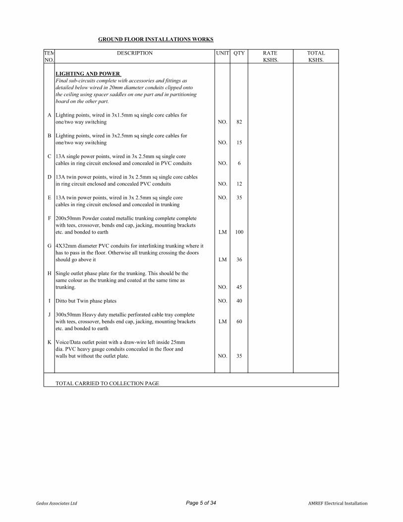
GROUND FLOOR INSTALLATIONS WORKS
ITEM DESCRIPTION UNIT QTY RATE TOTALNO. KSHS. KSHS.
LIGHTING AND POWER Final sub-circuits complete with accessories and fittings asdetailed below wired in 20mm diameter conduits clipped ontothe ceiling using spacer saddles on one part and in partitioningboard on the other part.
A Lighting points, wired in 3x1.5mm sq single core cables forone/two way switching NO. 82
B Lighting points, wired in 3x2.5mm sq single core cables forone/two way switching NO. 15
C 13A single power points, wired in 3x 2.5mm sq single corecables in ring circuit enclosed and concealed in PVC conduits NO. 6
D 13A twin power points, wired in 3x 2.5mm sq single core cablesin ring circuit enclosed and concealed PVC conduits NO. 12
E 13A twin power points, wired in 3x 2.5mm sq single core NO. 35cables in ring circuit enclosed and concealed in trunking
F 200x50mm Powder coated metallic trunking complete completewith tees, crossover, bends end cap, jacking, mounting bracketsetc. and bonded to earth LM 100
G 4X32mm diameter PVC conduits for interlinking trunking where ithas to pass in the floor. Otherwise all trunking crossing the doorsshould go above it LM 36
H Single outlet phase plate for the trunking. This should be thesame colour as the trunking and coated at the same time astrunking. NO. 45
I Ditto but Twin phase plates NO. 40
J 300x50mm Heavy duty metallic perforated cable tray complete with tees, crossover, bends end cap, jacking, mounting brackets LM 60etc. and bonded to earth
K Voice/Data outlet point with a draw-wire left inside 25mmdia. PVC heavy gauge conduits concealed in the floor andwalls but without the outlet plate. NO. 35
TOTAL CARRIED TO COLLECTION PAGE
Gedox Associates Ltd Page 5 of 34 AMREF Electrical Installation

ITEM DESCRIPTION UNIT QTY RATE TOTALNO. KSHS. KSHS.
A Cooker circuit included being a cooker connection point, wired using2x6mm2+4mm2 ECC PVC insulated copper cable drawn in 25mm dim. NO 1PVC heavy gauge conduits, but excluding the cooker controlconnection units.
B Fire alarm outlet point with draw wire left in 25mm dia. PVC heavygauge conduits concealed in the floor and walls from controlpanel located in the service duct NO. 20
C CCTV outlet point with draw wire left in 25mm dia. PVC heavy NO. 8gauge conduits concealed in the floor and walls
D Access control and security equipment outlet point with draw NO. 8wire left in 25mm dia. PVC heavy gauge conduits concealed in thefloor and walls
E TV outlet point with coaxial cable drawn in 25mm dia. PVC NO. 4heavy gauge conduits concealed in the floor and walls
F Extract fan outlet points, wired in 4C,6mm sq PVC/SWA/PVCCopper cables enclosed and concealed in PVC conduits NO. 4
G Security equipment outlet points, wired in 3C,2.5mm sq pvc/xlpeflex Copper cables enclosed and concealed in PVC conduits NO. 10
H Hand drier outlet point, wired using 3 x 4mm2 single core PVCinsulated copper cables drawn in 25mm diameter PVC heavy gaugeconduits concealed in the floors and roof space but without theoutlet plate NO. 2
I Undersink heater outlet point, wired using 3 x 4mm2 single core PVCinsulated copper cables drawn in 25mm diameter PVC heavy gaugeconduits concealed in the floors and roof space but without theoutlet plate NO. 1
J Occupancy sensor outlet point wired in 3x1.5mm sq singlecore cables inside 25mm dia. PVC heavy gauge conduitsconcealed in the floor and walls but without the sensor. NO. 10
K Audio/Visual outlet point with draw wire left in 25mm dia. NO. 5PVC heavy gauge conduits concealed in the floor and walls
LIGHT FITTINGS AND ACCESSORIESLighting control accessories complete with wiring terminationsand fixing material. Provide rates for supply & fixing thefollowing Electrical Fittings and accessories to be screwless
L 10A One gang one way as - MK S8870/S4781 WHI NO. 6
M 10A one gang two way as - MK S8871/4781 WHI NO. 4
N 10A two gang two way as - MK S8872 WHI NO. 6
O 10A three gang two way as - MK S8873 W1 WHI NO. 2
P 10A Four gang two way as - MK S8874 WHI NO. 2
Q 10A Six gang one way as - MK S8876 WHI NO. 2
TOTAL CARRIED TO COLLECTION PAGE
Gedox Associates Ltd Page 6 of 34 AMREF Electrical Installation

ITEM DESCRIPTION UNIT QTY RATE TOTALNO. KSHS. KSHS.
Lighting fittings as shown in the drawings complete withLED drivers, control gears and lamps where applicable:-
A Vulcan LED Corrosion proof Double 1200mm IP65 luminaire with NO. 2polycarbonate cover Complete with the following featuresemergency, dimmable , stainless steel clips among other mountingand termination accessories. As TYPE W as ROBUS/V-TAC orThorn
B Recessed Infinity LED Downlight 10W dimmable 108ф Downlight NO. 16as Eglo,RR or Robus TYPE A
C External Wall mounted luminaire in black die - cast aluminium body NO. 15complete with warm white energy saving bulb as EGLO PARK88302 for security lights
D 24W Oyster SMD LED circular luminaire with aluminium base,lock trim and frosted diffuser to provide excellent heat conduction NO. 7and maximising light output AS Robus R24WLEDCAU - 01 asTYPE B/C
E 15W Recessed 175ф Horizontal LED down lighter with NO. 14white diffuser Eternity LED Downlight with energy saving inexcess of 50% TYPE E as EGLO/ Robus/Thorn
F Caspian Polypropylene bulkhead Wall mounted luminaire in NO. 1black die - cast aluminium body as MICROMARK MM7496 or PARK 88302 as TYPE F
G 600x600mm, LED PANELS recessed light fitting a cleardiffuser as OSRAM NO. 25
H Ditto as above but with emergency kit NO. 10
I Ground mounted plantae/Garden spot lights as Vtac VT-857-B or NO. 10Equivalent and Approved.
J Wall up-down lighter as Vtac VT 7652RD or equivalent and NO. 5approved
I Self illuminated Emergency Exit light with sign With arrows for NO. 6directions as Thorn/Sapphire and approved
TOTAL CARRIED TO COLLECTION PAGE
Gedox Associates Ltd Page 7 of 34 AMREF Electrical Installation

ITEM DESCRIPTION UNIT QTY RATE TOTALNO. KSHS. KSHS.
Supply and install power point accessories & equipmentcomplete with associated wiring terminations & fixing materials
A 13amps single switched screwless power socket outletplate in Ivory white finish glad and as Crabtree or MK NO 6S2757DP WHI
B 13amps twin switched screwless power socket outlet plate inIvory white finish and as Crabtree or MK S2747DP WHI NO 47
C 45A rated cooker control unit incorporating a 13A switched socket NO 1outlet and fitted with pilot lamps and as MK Cat No S5061 WH1
D Cooker connection unit capable of terminating 2x10mm2 conductorsas MK Cat No S5045 WH1 NO 1
E 20A DP screwless switch in Ivory white finish for hand drier/ac unit with neon indicator and as Crabtree or MK S8423 WHI NO 7
F Universal 360 degrees PIR Recessed or surface mountedLighting control available in standard or remote control. Time NO 10settings 10sec to 40min adjustable as Robus
G Single Screw less Blanking covers in Ivory white finish NO 6for data outlet points as Crabtree or MK S3827 WHI
H Twin Screw less Blanking covers in Ivory white finish for NO 6data outlet points as Crabtree or MK S3828 WHI
I TV screwless Face plate in Ivory white finish for TV/FM & NO 4Satellite MK S3553 WHI
TOTAL CARRIED TO COLLECTION PAGE
Gedox Associates Ltd Page 8 of 34 AMREF Electrical Installation

ITEM DESCRIPTION UNIT QTY RATE TOTALNO. KSHS. KSHS.
POWER DISTRIBUTIONSupply, install and commission the following: -
A 4 Compartment 300x300x50mm Heavy duty metallic floor box completecomplete with cover and cable knock out points linked using 2x32mmdiameter Heavy gauge conduits etc and bonded to earth NO. 8
B 4x32mm diameter Heavy Gauge PVC conduits interlinkingthe floor boxes and linking the floor boxes with trunking LM 36complete with bends, coupler. saddles etc
C 50mm diameter sub-mains PVC conduits from riser duct toCU complete with bends, coupler. saddles etc. LM 40
D 12 Way TPN distribution board DB incorporating 100A integralisolator, lockable cover and labelling but without MCB and asSapphire/Terasaki screwless or equivalent NO 2
E 9 way SPN Consumer Units CU incorporation 100A integralisolator, lockable cover and labelling but without MCB's and as NO. 1Crabtree/Sapphire/Terasaki
F Single phase MCB's rating as in schematics as NO 32Schneider/Terasaki
G Three phase MCB's rating as in schematics as NO 6Schneider/Terasaki
H Blanking plates NO 20
I 4C, 16mm2 PVC/SWA/PVC copper cable for distribution ofpower from meter board to DB in Cable tray complete LM 30with glands and shrouds
J 2C, 10mm2 PVC/SWA/PVC copper cable for distribution ofpower from LV Switch Board to Consumer Units in Cable traycomplete with glands and shrouds LM 80
K 2C, 6mm2 PVC/SWA/PVC copper cable for distribution of powerfrom Distribution Board to AC Units and security equipments inCable tray complete with glands and shrouds LM 50
L 300x300x50mm Heavy duty metallic adaptable box complete LM 3complete with heavy duty cover and bonded to earth
TOTAL CARRIED TO COLLECTION PAGE
Gedox Associates Ltd Page 9 of 34 AMREF Electrical Installation
GROUND FLOOR ELECTRICAL INSTALLATION COLLECTION PAGE
ITEM DESCRIPTION AMOUNT NO. KSHS.
TOTAL BROUGHT FORWARD FROM:
1 PAGE 7
2 PAGE 8
3 PAGE 9
4 PAGE 10
5 PAGE 11
TOTAL CARRIED TO SUMMARY PAGE
Gedox Associates Ltd Page 10 of 34 AMREF Electrical Installation

FIRST FLOORITEM DESCRIPTION UNIT QTY RATE TOTALNO. KSHS. KSHS.
LIGHTING AND POWER
Final sub-circuits complete with accessories and fittings as detailedbelow wired in 20mm diameter conduits clipped onto the ceilingusing spacer saddles on one part and in partitioning board on theother part.
A Lighting points, wired in 3x1.5mm sq single core cables forone/two way switching NO. 88
B 13A single power points, wired in 3x 2.5mm sq single core cablesin ring circuit enclosed and concealed in PVC conduits NO. 6
C 13A twin power points, wired in 3x 2.5mm sq single core cables inring circuit enclosed and concealed PVC conduits NO. 12
D 13A twin power points, wired in 3x 2.5mm sq single core cables in NO. 40ring circuit enclosed and concealed in trunking
E Hand Drier power points, wired in 3x 4mm sq single core NO. 2cables in ring circuit enclosed and concealed in conduits.
F 200x50mm Powder coated metallic trunking complete completewith tees, crossover, bends end cap, jacking, mounting bracketsetc. and bonded to earth LM 100
G 4X32mm diameter PVC conduits for interlinking trunkingwhere it has to pass in the floor. Otherwise all trunkingcrossing the doors should go above it LM 36
H Single outlet phase plate for the trunking. This should be thesame colour as the trunking and coated at the same time astrunking. NO. 40
I Ditto but Twin phase plates NO. 45
J 300x50mm Heavy duty metallic perforated cable tray complete with tees, crossover, bends end cap, jacking, mounting bracketsetc. and bonded to earth LM 30
K Voice/Data outlet point with a draw-wire left inside 25mm dia. PVCheavy gauge conduits concealed in the floor and walls butwithout the outlet plate. NO. 38
L Access control, intruder and security equipment outlet point with NO. 8draw wire left in 25mm dia. PVC heavy gauge conduits concealedin the floor and walls
TOTAL CARRIED TO COLLECTION PAGE
Gedox Associates Ltd Page 11 of 34 AMREF Electrical Installation

ITEM DESCRIPTION UNIT QTY RATE TOTALNO. KSHS. KSHS.
A Fire alarm outlet point with draw wire left in 25mm dia. PVCheavy gauge conduits concealed in the floor and walls fromcontrol panel located in the service duct NO. 15
B CCTV outlet point with draw wire left in 25mm dia. PVC NO. 8heavy gauge conduits concealed in the floor and walls
C TV outlet point with coaxial cable drawn in 25mm dia. PVC NO. 4heavy gauge conduits concealed in the floor and walls
D Extract fan outlet points, wired in 4C,6mm sq PVC/SWA/PVCCopper cables enclosed and concealed in PVC conduits NO. 4
E Occupancy sensor outlet point wired in 3x1.5mm sq singlecore cables inside 25mm dia. PVC heavy gauge conduitsconcealed in the floor and walls but without the sensor. NO. 6
F Audio/Visual outlet point with draw wire left in 25mm dia. NO. 10PVC heavy gauge conduits concealed in the floor and walls
LIGHT FITTINGS AND ACCESSORIES
Lighting control accessories complete with wiringterminations and fixing materials
Provide rates for supply & fixing the following ElectricalFittings and accessories to be screwless
G 10A One gang one way as - MK S8870/S4781 WHI NO. 9
H 10A one gang two way as - MK S8871/4781 WHI NO. 4
J 10A two gang two way as - MK S8872 WHI NO. 6
K 10A three gang two way as - MK S8873 W1 WHI NO. 4
L 10A Four gang one way as - MK S8874 WHI NO. 3
M 10A Four gang two way as - MK S8874 WHI NO. 1
N 10A Six gang one way as - MK S8876 WHI NO. 1
Lighting fittings as shown in the drawings complete withLED drivers, control gears and lamps where applicable:-
O Vulcan LED Corrosion proof Double 1200mm IP65 luminaire with NO. 4polycarbonate cover Complete with the following featuresemergency, dimmable , stainless steel clips among other mountingand termination accessories. As TYPE W as ROBUS/V-TAC orThorn
TOTAL CARRIED TO COLLECTION PAGE
Gedox Associates Ltd Page 12 of 34 AMREF Electrical Installation

ITEM DESCRIPTION UNIT QTY RATE TOTALNO. KSHS. KSHS.
A Recessed Infinity LED Downlight 10W dimmable 108ф NO. 16Downlight as Eglo,RR or Robus TYPE A
B 24W Oyster SMD LED circular luminaire with aluminiumbase, lock trim and frosted diffuser to provide excellent heat NO. 8conduction and maximising light output AS RobusR24WLEDCAU - 01 as TYPE B
C 15W Recessed 175ф Horizontal LED down lighter with NO. 4white diffuser Eternity LED Downlight with energy saving inexcess of 50% TYPE E as EGLO/ Robus/Thorn
D Caspian Polypropylene bulkhead Wall mounted luminaire in black NO. 2die - cast aluminium body as MICROMARK MM 7496 or PARK88302 as TYPE F
E 600x600mm, LED PANELS recessed light fitting a clear diffuser asOSRAM NO. 33
F Ditto as above but with emergency kit NO. 12
G Three step dimmable black chandelier pendant light as Vtac NO. 4VT-82-3-B or equivalent and approved
H Shallow LED Downlight 10W dimmable 145ф Downlight as NO. 12Eglo,RR or Robus
I Self illuminated Emergency Exit light with sign With arrows for NO. 6directions as Thorn/Sapphire and approved
Supply and install power point accessories & equipmentcomplete with associated wiring terminations & fixingmaterials
J 13amps single switched screwless power socket outlet plate inIvory white finish glad and as Crabtree or MK S2757DP WHI NO 6
K 13amps twin switched screwless power socket outlet plate inIvory white finish and as Crabtree or MK S2747DP WHI NO 52
L 20A DP screwless switch in Ivory white finish for hand drier/acunit with neon indicator and as Crabtree or MK S8423 WHI NO 8
M Universal 360 degrees PIR Recessed or surface mounted Lightingcontrol available in standard or remote control. Time settings 10sec NO 6to 40min adjustable as Robus
N Single Screw less Blanking covers in Ivory white finish for data NO 5outlet points as Crabtree or MK S3827 WHI
O Twin Screw less Blanking covers in Ivory white finish for NO 3data outlet points as Crabtree or MK S3828 WHI
P TV screwless Face plate in Ivory white finish for TV/FM & NO 4Satellite MK S3553 WHI
TOTAL CARRIED TO COLLECTION PAGE
Gedox Associates Ltd Page 13 of 34 AMREF Electrical Installation

ITEM DESCRIPTION UNIT QTY RATE TOTALNO. KSHS. KSHS.
POWER DISTRIBUTIONSupply, install and commission the following: -
A 4 Compartment 300x300x50mm Heavy duty metallic floor boxcomplete complete with cover and cable knock out points linkedusing 2x32mm diameter Heavy gauge conduits etc and bonded to NO. 12earth
B 4x32mm diameter Heavy Gauge PVC conduits interlinkingthe floor boxes and linking the floor boxes with trunking LM 36complete with bends, coupler. saddles etc
C 50mm diameter sub-mains PVC conduits from riser duct toCU complete with bends, coupler. saddles etc. LM 80
D 12 Way TPN distribution board DB incorporating 100A integralisolator, lockable cover and labelling but without MCB and asSapphire/Terasaki screwless or equivalent NO 2
E 9 way SPN Consumer Units CU incorporation 100A integralisolator, lockable cover and labelling but without MCB's and as NO. 1Crabtree/Sapphire/Terasaki
F Single phase MCB's rating as in schematics as Schneider/ NO 30Terasaki/SIEMENS
G Three phase MCB's rating as in schematics as Schneider NO 6/Terasaki/ SIEMENS
H Blanking plates NO 20
I 4C, 16mm2 PVC/SWA/PVC copper cable for distribution ofpower from meter board to DB in Cable tray complete LM 40with glands and shrouds
J 2C, 10mm2 PVC/SWA/PVC copper cable for distribution of powerfrom LV Switch Board to Consumer Units in Cable tray completewith glands and shrouds LM 80
K 300x300x50mm Heavy duty metallic adaptable box complete LM 4complete with heavy duty cover and bonded to earth
TOTAL CARRIED TO COLLECTION PAGE
Gedox Associates Ltd Page 14 of 34 AMREF Electrical Installation

FIRST FLOOR ELECTRICAL INSTALLATION COLLECTION PAGE
ITEM DESCRIPTION AMOUNT NO. KSHS.
TOTAL BROUGHT FORWARD FROM:
1 PAGE 13
2 PAGE 14
3 PAGE 15
4 PAGE 16
TOTAL CARRIED TO SUMMARY PAGE
Gedox Associates Ltd Page 15 of 34 AMREF Electrical Installation

SECOND FLOOR ELECTRICAL INSTALLATION ITEM DESCRIPTION UNIT QTY RATE TOTALNO. KSHS. KSHS.
LIGHTING AND POWER Final sub-circuits complete with accessories and fittings asdetailed below wired in 20mm diameter conduits clipped ontothe ceiling using spacer saddles on one part and in partitioningboard on the other part.
A Lighting points, wired in 3x1.5mm sq single core cables forone/two way switching NO. 84
B 13A single power points, wired in 3x 2.5mm sq single core NO. 6cables in ring circuit enclosed and concealed in PVC conduits
C 13A twin power points, wired in 3x 2.5mm sq single core cables NO. 12in ring circuit enclosed and concealed PVC conduits
D 13A twin power points, wired in 3x 2.5mm sq single core NO. 51cables in ring circuit enclosed and concealed in trunking
E Hand Drier power points, wired in 3x 4mm sq single core NO. 2cables in ring circuit enclosed and concealed in conduits.
F 200x50mm Powder coated metallic trunking complete completewith tees, crossover, bends end cap, jacking, mounting bracketsetc. and bonded to earth LM 80
G 4X32mm diameter PVC conduits for interlinking trunking where ithas to pass in the floor. Otherwise all trunking crossing the doorsshould go above it LM 36
H Single outlet phase plate for the trunking. This should bethe same colour as the trunking and coated at the sametime as trunking. NO. 50
I Ditto but Twin phase plates NO. 55
J 300x50mm Heavy duty metallic perforated cable tray complete with tees, crossover, bends end cap, jacking, mounting bracketsetc. and bonded to earth LM 60
K Voice/Data outlet point with a draw-wire left inside 25mmdia. PVC heavy gauge conduits concealed in the floor andwalls but without the outlet plate. NO. 40
L Access control, intruder and security equipment outlet point with NO. 8draw wire left in 25mm dia. PVC heavy gauge conduits concealedin the floor and walls
TOTAL CARRIED TO COLLECTION PAGE
Gedox Associates Ltd Page 16 of 34 AMREF Electrical Installation

ITEM DESCRIPTION UNIT QTY RATE TOTALNO. KSHS. KSHS.
A Fire alarm outlet point with draw wire left in 25mm dia. PVCheavy gauge conduits concealed in the floor and walls fromcontrol panel located in the service duct NO. 15
B CCTV outlet point with draw wire left in 25mm dia. PVC NO. 6heavy gauge conduits concealed in the floor and walls
C TV outlet point with coaxial cable drawn in 25mm dia. PVC NO. 4heavy gauge conduits concealed in the floor and walls
D Extract fan outlet points, wired in 4C,6mm sq PVC/SWA/PVCCopper cables enclosed and concealed in PVC conduits NO. 3
E Occupancy sensor outlet point wired in 3x1.5mm sq single corecables inside 25mm dia. PVC heavy gauge conduits concealed inthe floor and walls but without the sensor. NO. 10
F Audio/Visual outlet point with draw wire left in 25mm dia. NO. 10PVC heavy gauge conduits concealed in the floor and walls
POWER DISTRIBUTION
Supply, install and commission the following: -
A 4 Compartment 300x300x50mm Heavy duty metallic floor box completecomplete with cover and cable knock out points linked using 2x32mmdiameter Heavy gauge conduits etc and bonded to earth NO. 10
B 4x32mm diameter Heavy Gauge PVC conduits interlinking the floorboxes and linking the floor boxes with trunking complete with bends, LM 36coupler. saddles etc
C 50mm diameter sub-mains PVC conduits from riser duct toCU complete with bends, coupler. saddles etc. LM 50
D 12 Way TPN distribution board DB incorporating 100A integralisolator, lockable cover and labelling but without MCB and asSapphire/Terasaki screwless or equivalent NO 2
E 9 way SPN Consumer Units CU incorporation 100A integralisolator, lockable cover and labelling but without MCB's and as NO. 1Crabtree/Sapphire/Terasaki
TOTAL CARRIED TO COLLECTION PAGE
Gedox Associates Ltd Page 17 of 34 AMREF Electrical Installation

SECOND FLOOR ELECTRICAL INSTALLATION COLLECTION PAGE
ITEM DESCRIPTION AMOUNT NO. KSHS.
TOTAL BROUGHT FORWARD FROM:
1 PAGE 16
4 PAGE 17
TOTAL CARRIED TO SUMMARY PAGE
Gedox Associates Ltd Page 18 of 34 AMREF Electrical Installation

ROOF TERRACE ELECTRICAL INSTALLATION ITEM DESCRIPTION UNIT QTY RATE TOTALNO. KSHS. KSHS.
LIGHTING AND POWER Final sub-circuits complete with accessories and fittings asdetailed below wired in 20mm diameter conduits clipped ontothe ceiling using spacer saddles on one part and in partitioningboard on the other part.
A Lighting points, wired in 3x1.5mm sq single core cables forone/two way switching NO. 26
B 13A single power points, wired in 3x 2.5mm sq single core NO. 4cables in ring circuit enclosed and concealed in PVC conduits
C 13A twin power points, wired in 3x 2.5mm sq single core cables inring circuit enclosed and concealed PVC conduits. NO. 10
D 300x50mm Heavy duty metallic perforated cable tray complete with tees, crossover, bends end cap, jacking, mounting bracketsetc. and bonded to earth LM 60
E Voice/Data outlet point with a draw-wire left inside 25mmdia. PVC heavy gauge conduits concealed in the floor andwalls but without the outlet plate. NO. 2
F Fire alarm outlet point with draw wire left in 25mm dia. PVC heavygauge conduits concealed in the floor and walls from control panellocated in the service duct NO. 4
G CCTV outlet point with draw wire left in 25mm dia. PVC NO. 3heavy gauge conduits concealed in the floor and walls
H Occupancy sensor outlet point wired in 3x1.5mm sq singlecore cables inside 25mm dia. PVC heavy gauge conduitsconcealed in the floor and walls but without the sensor. NO. 1
POWER DISTRIBUTION
Supply, install and commission the following: -
A 50mm diameter sub-mains PVC conduits from riser duct toCU complete with bends, coupler. saddles etc. LM 40
B 12 Way TPN distribution board DB incorporating 100A integralisolator, lockable cover and labelling but without MCB and asSapphire/Terasaki screwless or equivalent NO 1
C Single phase MCB's rating as in schematics as Schneider/Terasaki NO 10
D Three phase MCB's rating as in schematics as Schneider Electric NO 2acti 9 series
E Blanking plates NO 20
F 4C, 16mm2 PVC/SWA/PVC copper cable for distribution of powerfrom meter board to DB in Cable tray complete with glands and LM 40shrouds
G 2C, 10mm2 PVC/SWA/PVC copper cable for distribution of powerfrom LV Switch Board to Consumer Units in Cable tray completewith glands and shrouds LM 40
TOTAL CARRIED TO COLLECTION PAGE
Gedox Associates Ltd Page 19 of 34 AMREF Electrical Installation

Gedox Associates Ltd Page 20 of 34 AMREF Electrical Installation

POWER DISTRIBUTION/RETICULATIONITEM DESCRIPTION UNIT QTY RATE TOTALNO. KSHS. KSHS.
A 3x150mm diameter sub-mains PVC conduits for Power Supply andtelephone cable entry from existing power house to the proposed LM 125Library.
B Trenching, sifting, cable laying, tiling, and laying 3 X 150mmdiameter heavy gauge PVC ducts with concrete surround under roads and plot entrances LM 120
C Trenching at a minimum of 600mmx450 laying of conduit andback filling LM 120
D 600x600x450mm Tel/power manholes along the duct linecomplete with heavy duty rust proof steel cover No 6
E 4C, 10mm2 PVC/PVC/PVC cable to emergency shunt trip LM 30button for fireman's switch drawn in 32mm diameter conduit.
F Cable glands and shroud for terminating 4C, 10mm2PVC/PVC/PVC cable NO 2
G Fireman's switch to be installed at the main entrance complete NO. 2with appropriate contactor
H Supply and installation of the airplane/Aviation LED warningstrobe light as Thorn Complete with battery, solar, mountingpillar and accessories. wired using 2c, 4mm2 PVC/SWA/PVC NO 2copper armoured cable
I 12 Way TPN distribution board DB incorporating 100A integralisolator, lockable cover and labelling but without MCB and asSapphire/Terasaki screwless for AC & Water pumps. NO 2
J 32A SP MCB as Schneider/Terasaki NO 10
K 32A TP MCB as Schneider/Terasaki NO 10
L 63A TP MCB as Schneider/Terasaki NO 5
M Blanking Covers NO 12
TOTAL CARRIED TO COLLECTION PAGE
Gedox Associates Ltd Page 21 of 34 AMREF Electrical Installation

ITEM DESCRIPTION UNIT QTY RATE TOTALNO. KSHS. KSHS.
LIBRARY LV SWITCHBOARD C Powder coated to IP54 LV switchboard as manufactured by either
Schneider electric as BLOKSET or Nationwide Power Systemswith the following: -a) 2No. 4P 250A MCCB 45kA with shunt trip coilb) 2No. TP 160 A MCCB to data centrec) 2No. TP 125 A MCCB to DB'sd) 2 No. TP 100 A MCCB to DB'se) 4 No. TP 63 A MCCB to DB'sf) 2 No. TP 32 A MCCB to DB'sg) 1No. 4P 315A BURSBARh) 1No. Neutral copper BURSBARi) 1No. Earth copper BURSBARj) 1No. Digital power analysers as PM 5560 series.k) 1No. Full load surger arrestor Type 1 & 2.l)Set of pilot lightsm)4No. BMS contacts n) 250A genset Autochangeover complete with AMFo)75kVAR PFCU
SPACE FORa) Appropriate knockouts for incoming out going cables item 1
E 4C, 120 mm2 XLPE/SWA/PVC copper cable for Powercirculation from meterboard to sub-board LM 120
F Earthing comprising of copper earth electrode of size1500mm longx15mm diameter and a 900mm x 900mm Earth mat (factory made)enclosed by a concrete manhole of size 450x450x450mm with removable NO 1concrete cover and a 75mm diameter PVC heavy gauge conduit lead-induct and bonded to the board using 25mm2 SC cable to approval
TOTAL CARRIED TO COLLECTION PAGE
Gedox Associates Ltd Page 22 of 34 AMREF Electrical Installation

ITEM DESCRIPTION UNIT QTY RATE TOTALNO. KSHS. KSHS.
A 4C, 16mm2 PVC/SWA/PVC cable to fire fighting pump LM 60
B Cable glands and shroud for terminating 4C, 16mm2 PVC/PVC/PVCcable NO 8
C 4C, 10mm2 PVC/SWA/PVC cable to water booster pumps LM 60
D Cable glands and shroud for terminating 4C, 10mm2 PVC/PVC/PVCcable NO 8
E 4C, 10mm2 PVC/SWA/PVC copper cable for distribution of powerto LIFT. LM 30
F Cable glands and shroud for terminating 4C, 10mm2 PVC/PVC/PVCcable NO 8
G 4C, 35mm2 PVC/SWA/PVC copper cable to Data centre LM 60
H Cable glands and shroud for terminating 4C, 35mm2 PVC/PVC/PVCcable NO 8
I 32A TPN isolator for above pumps NO. 8
J 32A SPN isolator for above pumps NO. 6
K 63A TP isolators as MEM for lifts and mechanical loads NO 6
TOTAL CARRIED TO COLLECTION PAGE
Gedox Associates Ltd Page 23 of 34 AMREF Electrical Installation

ITEM DESCRIPTION UNIT QTY RATE TOTALNO. KSHS. KSHS.
STABILISED POWER POINTSFinal sub-circuits complete with accessories and fittings asdetailed below and marked in red UPS power.
A 13A single power points, wired in 3x 2.5mm sq single corecables in ring circuit enclosed in trunking from DB 'B' to outletpoints as indicated in the drawing NO. 6
B 13A twin power points, wired in 3x 2.5mm sq single core cablesin ring circuit enclosed in trunking/conduits NO. 80
C Allow for attendnace to the UPS subcontractor item
D Allow for provision of flexible conduits for all exposedcables near UPS item
E 13amps NON Standard twin switched socket outlet plate forUPS power and as MK or equivalent and approved. Complete NO 80with Top Plugs
F 13amps NON Standard single switched socket outlet plate forUPS power and as MK or equivalent and approved. Complete NO 6with Top Plugs.
G 12 Way TPN distribution board DB incorporating 100A integralisolator, lockable cover and labelling but without MCB and asSapphire/Terasaki screwless or equivalent NO 2
H 9 way SPN Consumer Units CU incorporation 100A integralisolator, lockable cover and labelling but without MCB's and as NO. 1Crabtree/Sapphire/Terasaki
I Single phase MCB's rating as in schematics as Schneider NO 12/Terasaki/siemens//Schneider
J Three phase MCB's rating as in schematics as Schneider/ NO 6Terasaki/siemens/Schneider
K 2C, 10mm2 PVC/SWA/PVC copper cable to UPS consumer LM 80Units
L Cable glands and shroud for terminating 2C, 10mm2PVC/PVC/PVC copper cable NO 8
M 4C, 10mm2 PVC/SWA/PVC copper cable for distribution ofpower to UPS DB's LM 70
N Cable glands and shroud for terminating 4C, 10mm2PVC/PVC/PVC copper cable. NO 8
O 4C, 16mm2 PVC/SWA/PVC copper cable for distribution ofpower to UPS LM 35
P Cable glands and shroud for terminating 4C, 16mm2PVC/PVC/PVC copper cable. NO 8
TOTAL CARRIED TO COLLECTION PAGE
Gedox Associates Ltd Page 24 of 34 AMREF Electrical Installation

ITEM DESCRIPTION UNIT QTY RATE TOTALNO. KSHS. KSHS.
AUTOMATIC VOLTAGE STABILIZERA Supply, install & commission a 160 kVA Automatic three phase
voltage Stabilizer (AVS) as ORTEA SIRIUS Y150-20 orequal/equivalent and approved with the following specifications:
Attach product cataloguesi) Frequency 50Hzii) Admitted Load Variation from 0 up to 100%iii) Admitted Load Unbalance up to 100%iv) Mains Waveform Distortion Increment <0.2%v) Cooling Natural Air (aided over 40OC)vi) Ambient Temperature -15/+45OCvii) Storage Temperature -25/+60OCviii) Input Voltage 415+_20%ix) Output voltage 415+_1%ix) Admitted Overload 200% 2minx) Colour RAL 7032xi) Protection IP 30 NO 1xii) LCD/Digital two multi- task digital network analysersxiii) Regulator overload protection - digital standby controlxiiv) Communication system - Ethernet/GPRS/USBxix) Inbuilt power surge protector
B 2No. 250A MCCB changeover bypass LM 2
C 300x50mm Perforated metallic cable tray complete with mountingbrackets, bends, screws, end caps and with adequate cable ties. LM 20for proper cable management
D Earthing comprising of copper earth electrode of size1500mm longx15mm diameter enclosed by a concrete manhole of size NO 1450x450x450mm with removable concrete cover and a 38mmdiameter PVC heavy gauge conduit lead-in duct and bonded to theAVR
E Allow for interconnection between LV Switch board and AVRby a qualified electrician Item Item
F Any other item required for proper operation of the AVR; Item ItemSpecify
TOTAL CARRIED TO COLLECTION PAGE
Gedox Associates Ltd Page 25 of 34 AMREF Electrical Installation

POWER RETICULATION ELECTRICAL INSTALLATION COLLECTION PAGE
ITEM DESCRIPTION AMOUNT NO. KSHS.
TOTAL BROUGHT FORWARD FROM:
1 PAGE 27
2 PAGE 28
3 PAGE 29
4 PAGE 30
5 PAGE 31
TOTAL CARRIED TO SUMMARY PAGE
Gedox Associates Ltd Page 26 of 34 AMREF Electrical Installation

ADDRESSABLE FIRE ALARM INSTALLATIONITEM DESCRIPTION UNIT QTY RATE TOTALNO. KSHS. KSHS.
ADDRESSABLE FIRE ALARM SYSTEM INSTALLATION
Supply, install, test and commission the following
All detectors to be as MENVIER/PROTEC model numbersindicated. All detectors to be complete with mounting base
Fire alarm points, wired in 2 loops using 2C, 2.5mm2 fire resistantscreened cable FP200 drawn in 25mm diameter PVC heavy gaugeconduits concealed in roof space and wall from control panelthrough the detectors.
A Basement Floor No. 20
B Ground Floor No. 22
C First Floor No. 20
D Second Floor No. 20
E Roof Floor No. 6
Intelligent addressable Optical smoke detectors asMAP820/6000PLUS/OP complete with base plate as MAB800The sensors to have the following features; soft addressed, withintelligent short circuit isolator, wide range sensing and 360degrees visibility LED
The bases to have the following features; sensor shorting link,separate loop in and loop out terminals, stand off fixing feature,accepts side entry cables and selectable sensor locking feature
F Basement Floor No. 0
G Ground Floor No. 18
H First Floor No. 16
I Second Floor No. 0
J Roof Floor No. 0
TOTAL CARRIED TO COLLECTION PAGE
Gedox Associates Ltd Page 27 of 34 AMREF Electrical Installation
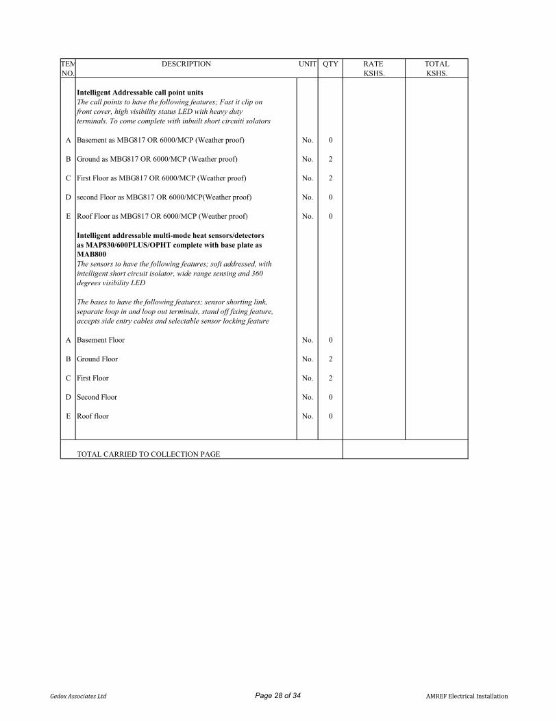
ITEM DESCRIPTION UNIT QTY RATE TOTALNO. KSHS. KSHS.
Intelligent Addressable call point units The call points to have the following features; Fast it clip onfront cover, high visibility status LED with heavy dutyterminals. To come complete with inbuilt short circuiti solators
A Basement as MBG817 OR 6000/MCP (Weather proof) No. 0
B Ground as MBG817 OR 6000/MCP (Weather proof) No. 2
C First Floor as MBG817 OR 6000/MCP (Weather proof) No. 2
D second Floor as MBG817 OR 6000/MCP(Weather proof) No. 0
E Roof Floor as MBG817 OR 6000/MCP (Weather proof) No. 0
Intelligent addressable multi-mode heat sensors/detectorsas MAP830/600PLUS/OPHT complete with base plate asMAB800The sensors to have the following features; soft addressed, withintelligent short circuit isolator, wide range sensing and 360degrees visibility LED
The bases to have the following features; sensor shorting link,separate loop in and loop out terminals, stand off fixing feature,accepts side entry cables and selectable sensor locking feature
A Basement Floor No. 0
B Ground Floor No. 2
C First Floor No. 2
D Second Floor No. 0
E Roof floor No. 0
TOTAL CARRIED TO COLLECTION PAGE
Gedox Associates Ltd Page 28 of 34 AMREF Electrical Installation

ITEM DESCRIPTION UNIT QTY RATE TOTALNO. KSHS. KSHS.
Intelligent Fire alarm electronic sounders with flasherThe sounders to have the following features; Loop powered,combined sounder beacon, high efficiency design, selectabletones controlled by the panel and adjustable volume controlledby the panel.To come complete with inbuilt short circuitisolators
A Basement Floor as MASB860WP or 6000/SSR2/LED/RED No. 0with IP66 rating
B Ground Floor as MASB860WP or 6000/SSR2/LED/RED with No. 2IP66 rating
C First Floor as MASB860WP or 6000/SSR2/LED/RED with No. 2IP66 rating
D Second Floor as MASB860WP or No. 06000/SSR2/LED/RED with IP66 rating
E Roof Floor as MASB860WP or 6000/SSR2/LED/RED with No. 0IP66 rating
F 4 loop Intelligent addressable control panel complete withintegral printer, graphite finish, integral battery & power supplyunit 72 hr ref no. DF60004PGEB or 6304/P/C/N The control No. 1panel to have full network capability, spur torent softaddressing, 200addresses per loop, charger with temperaturecompensation built in and checks battery capacity
G Ditto but Intelligent addressable Touch screen repeater panel No. 1REF. NO. DTPR6000 or 6300/NRPT/C/0 With the followingfeatures; plug & play, touch screen display, intergrated networkcapabiltiy, multilanguage capanility, Upto 126 repeaters can beconnected to the networks and to be programmable as an activeo passive repeater.
TOTAL CARRIED TO COLLECTION PAGE
Gedox Associates Ltd Page 29 of 34 AMREF Electrical Installation

ITEM DESCRIPTION UNIT QTY RATE TOTALNO. KSHS. KSHS.
A Short circuit isolators MSI750 No. 2
B Addressable input/output interface unit MIO230 No. 1
C Plug in module for address 61 to 120 MAM60 No. 2
D Serial communication interface unit MFASC No. 1
E Analogue communications driver unit MFACI No. 1
F Pentium IV, 250GB, 3GHz Duo core , 8GB RAM computerwith 24" TFT flat screen monitor as DELL No. 1
G Printer for the control panel MFAXA4/P No. 1
H Fire alarm Graphics software No. 1
I System programming and downloading loops 5
J Allow for training of personnel on the usage and operation Item Itemof fire alarm system
K Allow for interphase/Connection between HVAC and BMS withFire Alarm detection and Alarm system. Item Item
TOTAL CARRIED TO COLLECTION PAGE
Gedox Associates Ltd Page 30 of 34 AMREF Electrical Installation

ADDRESSABLE FIRE ALARM INSTALLATION COLLECTION PAGE
ITEM DESCRIPTION AMOUNT NO. KSHS.
TOTAL BROUGHT FORWARD FROM:
1 PAGE 26
2 PAGE 27
3 PAGE 28
4 PAGE 29
TOTAL CARRIED TO SUMMARY PAGE
Gedox Associates Ltd Page 31 of 34 AMREF Electrical Installation

ITEM DESCRIPTION UNIT QTY RATE TOTALNO. KSHS. KSHS.
LIGHTENING ARRESTOR AS FURSE
A 1000x25mm diameter air terminal spike complete NO. 4with base
B 25x3mm copper tape complete with mounting clips Lm 60
C Bonding of copper tape to steel structure NO 4
D Test clamp NO 4
E Allow for testing of resistivity of the soil No 4
F Earthing comprising of copper earth electrode of size600mm x 300mmlattice/solid plate enclosed by a concrete NO 4manhole of size450x450x450mm with removable concretecover
TOTAL CARRIED TO SUMMARY PAGE
Gedox Associates Ltd Page 32 of 34 AMREF Electrical Installation
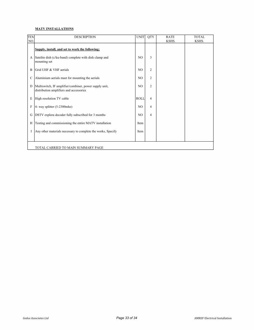
MATV INSTALLATIONS
ITEM DESCRIPTION UNIT QTY RATE TOTALNO. KSHS. KSHS.
Supply, install, and set to work the following;
A Satelite dish (c/ku-band) complete with dish clamp and NO 3mounting set
B Grid UHF & VHF aerials NO 2
C Aluminium aerials mast for mounting the aerials NO 2
D Multiswitch, IF amplifier/combiner, power supply unit, NO 2distribution amplifiers and accessories
E High resolution TV cable ROLL 4
F 4- way splitter (5-2300mhz) NO 4
G DSTV explora decoder fully subscribed for 3 months NO 4
H Testing and commissioning the entire MATV installation Item
I Any other materials necessary to complete the works, Specify Item
TOTAL CARRIED TO MAIN SUMMARY PAGE
Gedox Associates Ltd Page 33 of 34 AMREF Electrical Installation
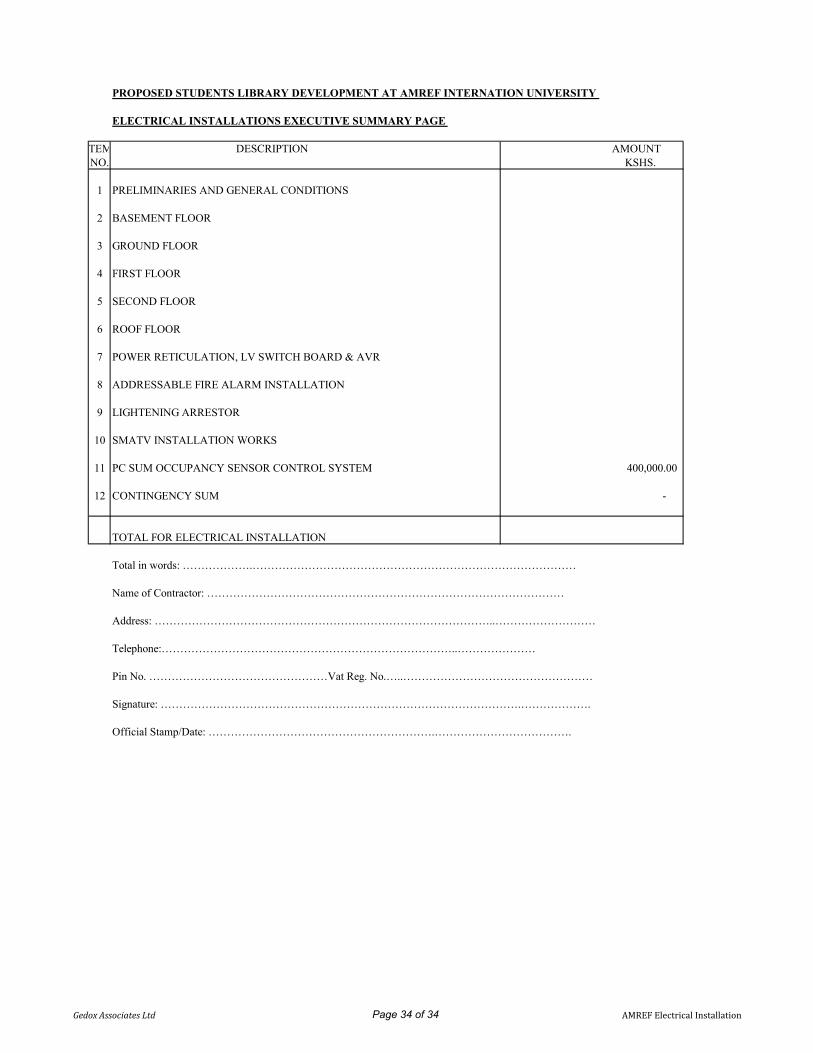
PROPOSED STUDENTS LIBRARY DEVELOPMENT AT AMREF INTERNATION UNIVERSITY
ELECTRICAL INSTALLATIONS EXECUTIVE SUMMARY PAGE
ITEM DESCRIPTION AMOUNT NO. KSHS.
1 PRELIMINARIES AND GENERAL CONDITIONS
2 BASEMENT FLOOR
3 GROUND FLOOR
4 FIRST FLOOR
5 SECOND FLOOR
6 ROOF FLOOR
7 POWER RETICULATION, LV SWITCH BOARD & AVR
8 ADDRESSABLE FIRE ALARM INSTALLATION
9 LIGHTENING ARRESTOR
10 SMATV INSTALLATION WORKS
11 PC SUM OCCUPANCY SENSOR CONTROL SYSTEM 400,000.00
12 CONTINGENCY SUM -
TOTAL FOR ELECTRICAL INSTALLATION
Total in words: ……………….……………………………………………………………………………
Name of Contractor: ……………………………………………………………………………………
Address: ………………………………………………………………………………..………………………
Telephone:……………………………………………………………………..…………………
Pin No. …………………………………………Vat Reg. No.…..……………………………………………
Signature: …………………………………………………………………………………….……………….
Official Stamp/Date: …………………………………………………….……………………………….
Gedox Associates Ltd Page 34 of 34 AMREF Electrical Installation

EC/001/2020 SECTION 6 PROPOSED LIBRARY AT AMREF INTERNATIONAL UNIVERSITY
SECTION 6 - PRIME COST &
PROVISIONAL SUMS
Ecospace Consultants Prime costs and Provisional sums
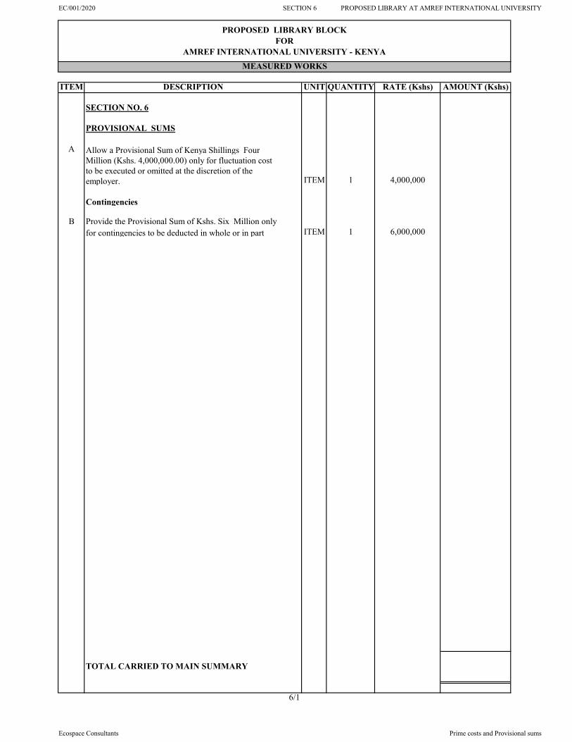
EC/001/2020 SECTION 6 PROPOSED LIBRARY AT AMREF INTERNATIONAL UNIVERSITY
ITEM DESCRIPTION UNIT QUANTITY RATE (Kshs) AMOUNT (Kshs)
SECTION NO. 6
PROVISIONAL SUMS
A Allow a Provisional Sum of Kenya Shillings FourMillion (Kshs. 4,000,000.00) only for fluctuation costto be executed or omitted at the discretion of the employer. ITEM 1 4,000,000
Contingencies
B Provide the Provisional Sum of Kshs. Six Million only for contingencies to be deducted in whole or in part ITEM 1 6,000,000
TOTAL CARRIED TO MAIN SUMMARY
6/1
PROPOSED LIBRARY BLOCK FOR
AMREF INTERNATIONAL UNIVERSITY - KENYAMEASURED WORKS
Ecospace Consultants Prime costs and Provisional sums

EC/001/2020 PROPOSED LIBRARY AT AMREF INTERNATIONAL UNIVERSITY
MAIN SUMMARY
PHASE 1
Ecospace Consultants Main Summary

EC/001/2020 PROPOSED LIBRARY AT AMREF INTERNATIONAL UNIVERSITY
ITEM
PHASE 1
SECTIONS PAGE NO.
1 PARTICULAR PRELIMINARIES 1/7
2 GENERAL PRELIMINARIES 1/16
3 BUILDER'S WORKS 3/52
4 EXTERNAL WORKS 4/7
5 DAYWORKS 5/3
6 PRIME COST AND PROVISIONAL SUMS 6/1
7 STRUCTURED CABLING 4 of 4
8 MECHANICAL WORKS 13 of 14
9 ELECTRICAL WORKS 34 of 34
TOTAL CARRIED TO GRAND SUMMARY
MS/1
PROPOSED LIBRARY BLOCK FOR
AMREF INTERNATIONAL UNIVERSITY - KENYAMEASURED WORKS
AMOUNT (Kshs)DESCRIPTION
Ecospace Consultants Main Summary

ARCHITECT QUANTITY SURVEYOR
Tej Architects, Ecospace ConsultantsP.O Box 27644 - 00506, P.O Box 74885 - 00200,Nairobi. Nairobi.
STRUCTURAL & CIVIL ENGINEER MECHANICAL & ELECTRICAL ENGINEER
Engineering Ideals Kenya Limited, Gedox Associates Limited,P.O Box 51288 - 00200, P.O Box 64441 - 00620,Nairobi. Nairobi.
December, 2020
PROPOSED LIBRARY BLOCK
ON
PLOT L.R NO 209/11606 - NAIROBI COUNTY
FOR AMREF INTERNATIONAL UNIVERSITY
BILLS OF QUANTITIES
PHASE 2

EC/001/2020 SECTION 3 PROPOSED LIBRARY AT AMREF INTERNATIONAL UNIVERSITY
SECTION 3 - BUILDER'S WORKS
PHASE 2
Ecospace Consultants Builder's works

EC/001/2020 SECTION 3 PROPOSED LIBRARY AT AMREF INTERNATIONAL UNIVERSITY
ITEM DESCRIPTION UNIT QUANTITY RATE (Kshs) AMOUNT (Kshs)
SECTION NO. 3
LIBRARY BLOCK
ELEMENT NO. 1
BASEMENT COMPLETION
WALLS
Aluminium Partitions
Supply, assemble and fix purpose made natural anodised aluminium framing; transoms and middle rail; draught & strips; snap on glazing beads ; plugging or fixing to concrete, blockwork or stone work; with and including first quality and matching ironmongery; sealing with flexible rubber strips and adjusting on completion
A 125 x 75 x 2.5 mm Thick bottom box frames (1.687 kg/m) LM 70
B 100 x 75 x 2.5 mm Thick middle section frames (1.336 kg/m) LM 70
C 75 x 75 x 2.5 mm Thick top box frames (0.985 kg/m) LM 70
D 75 x 75 x 2.5 mm Thick intermediate frames (0.985 kg/m) LM 70
E 75 x 75 x 2.5 mm Thick vertical frames (0.985 kg/m) LM 214
F 25 x 25 x 2.5mm Thick beading (0.281 kg/m) LM 848
Glazing
G 6mm Thick clear glass panes as manufactured by Impala Glass Kenya Ltd or equal and approved:; complete with all fixing accessories and screws: on aluminium frames (m/s) SM 21
H 8mm Thick laminated glass as manufactured by Impala Glass Kenya Ltd or equal and approved:; complete with allfixing accessories and screws: on aluminium frames (m/s) SM 168
Carried to Collection
3/1
PROPOSED LIBRARY BLOCK FOR
AMREF INTERNATIONAL UNIVERSITY - KENYAMEASURED WORKS
Ecospace Consultants Builder's works

EC/001/2020 SECTION 3 PROPOSED LIBRARY AT AMREF INTERNATIONAL UNIVERSITY
ITEM DESCRIPTION UNIT QUANTITY RATE (Kshs) AMOUNT (Kshs)
DOORS
Anodized Aluminium Doors
Purpose made door: supply, assemble and fix purpose made natural anodised aluminium door and framing size 100 x 75mm; 100x50mm stiles, bottom, top and vertical rails; 8 mm thick laminated glass: complete with stainless steel ironmongery and accessories as per union catalogue or equal and approved; fixing with stainless steel screws; plugging or fixing to concrete, blockwork or stone work;
A Double door D11 size 1300 x 2400mm high (overall);comprising of 2No. Unequal opennable leaves sizes 800 x 2100mm high and 350 x 2100mm high includinganodized aluminium louvres overall size 1300 x 300mm high NO 1
B Single leaf door D2 size 900 x 2400mm high (overall); comprising of 1No.opennable leaf size 900 x 2100mm high NO 8
C Single leaf door D12 size 1300 x 2400mm high (overall); comprising of 1No.opennable leaf size 900 x 2100mm high and side light size 400 x 2100mm high including aluminium louvred fanlight fanlight size 1300 x 300mm high NO 1
Steel Doors
Mild steel louvred double doors; comprising 75 x 75 x 3mm rebated pressed steel frame plugged to wall; 75 x 50 x 3 mm hollow section top rail, bottom rail and stiles, angles cut, mitred and welded; 150 x 50 x 3 mm hollow section middle; ends welded and angles cut, mitred and welded; two open panels per door leaf infilled with 16 gauge cranked louvres 575 mm wide at 60 mm centres welded to stiles; all welded ground to smooth finish ;including iron mongery as per architectural details
D Double door D10 size 1500 x 2400 mm high including 8 No. purpose made hinges welded to frame and post, 4 No. 300 mm drop bolts and 2 No. padlock hasp and staple all welded to frame NO 1
Carried to Collection
3/2
Ecospace Consultants Builder's works

EC/001/2020 SECTION 3 PROPOSED LIBRARY AT AMREF INTERNATIONAL UNIVERSITY
ITEM DESCRIPTION UNIT QUANTITY RATE (Kshs) AMOUNT (Kshs)
Supply and fix the following ironmongery to timber complete with matching screws and keys as per 'UNION' manufucturers ( reference to a particular catalogue are given as a guide to type and quality only, other equal and approved alternatives may be used)
A Polished Stainless steel five lever mortice door lock and handle furniture set; ( keyhole escutcheons, cylinder and latch ); Reference to "UNION" Catalogue NO. 5L-2201-SC or equal and approved NO 2
B Polished Stainless steel three lever mortice cupboard lock NO 8
C Polished Stainless steel D-Pull/Push handles; NO 10
D 100mm stainless steel double washered hingeswith aluminium pin and screws; Reference to "UNION" Catalogue NO. HN-DW-403020-SSS or equal and approved PRS 6
E 38mm Diameter Oval chrome rubber door stop Union ref. DS-01 CH NO 12
F Aluminium door closers including all accessories:Rack-and Pinion projecting Arm Closers with Pull side Hold open Arm; latching action via arm;dual speed valve control; Reference to Briston series 2003 or equal and approved NO 10
Carried to Collection
3/3
Ecospace Consultants Builder's works

EC/001/2020 SECTION 3 PROPOSED LIBRARY AT AMREF INTERNATIONAL UNIVERSITY
ITEM DESCRIPTION UNIT QUANTITY RATE (Kshs) AMOUNT (Kshs)
FINISHES
FLOOR FINISHES
Cement and sand (1:4) screeded beds: on concrete : to:
A 15 mm Thick to receive granito tiles SM 396
Approved full boarded polished Granito tiles size 600 x 600 x 25 mm thick; 95% free from visible defects; plus or minus 5% maximum side straightness deviation; group 5 or PEI 5 surface abrasion ; PEI5 stain resistant; less than 0.5 % water absorption ; frost resistant ; chemical resistant ; bedding and jointing in approved porcelain adhesive; to
B Floors SM 396
C Ditto: 25 mm Thick x 100 mm high skirting; rounded edge LM 120
WALL FINISHES
Internal wall finishes
12 mm Lime plaster: steel trowelled: on concrete or block work : to
D Walls & Beams surfaces SM 786
E Columns SM 53
Prepare surfaces and apply three coats of first quality silk vinyl emulsion paint: on plastered or rendered surfaces: to
F Plastered walls & Beams surfaces SM 786
G Ditto: Columns surfaces SM 53
CEILING FINISHES
Suspended gypsum ceiling
H 12mm thick Gypsum board ceiling spray painted on 75mm thick galvanized steel stud as DONN ULTRA STEEL complete with metal edge, upstands, curved edges and associated raked cutting to details SM 386
I 100mm matching gypsum cornice moulded with four labours SM 151
Carried to Collection
3/4
Ecospace Consultants Builder's works

EC/001/2020 SECTION 3 PROPOSED LIBRARY AT AMREF INTERNATIONAL UNIVERSITY
ITEM DESCRIPTION UNIT QUANTITY RATE (Kshs) AMOUNT (Kshs)
COLLECTION
PAGE NO. 3/1
PAGE NO. 3/2
PAGE NO. 3/3
PAGE NO. 3/4
TOTAL CARRIED TO SUMMARY
3/5
Ecospace Consultants Builder's works

EC/001/2020 SECTION 3 PROPOSED LIBRARY AT AMREF INTERNATIONAL UNIVERSITY
ITEM DESCRIPTION UNIT QUANTITY RATE (Kshs) AMOUNT (Kshs)
SECTION NO. 3
LIBRARY BLOCK
ELEMENT NO. 2
PARTITIONS
Aluminium Partitions
Supply, assemble and fix purpose made natural anodised aluminium framing; transoms and middle rail; draught & strips; snap on glazing beads ; plugging or fixing to concrete, blockwork or stone work; with and including first quality and matching ironmongery; sealing with flexible rubber strips and adjusting on completion
A 125 x 75 x 2.5 mm Thick bottom box frames (1.687 kg/m) LM 50
B 100 x 75 x 2.5 mm Thick middle section frames (1.336 kg/m) LM 50
C 75 x 75 x 2.5 mm Thick top box frames (0.985 kg/m) LM 50
D 75 x 75 x 2.5 mm Thick intermediate frames (0.985 kg/m) LM 50
E 75 x 75 x 2.5 mm Thick vertical frames (0.985 kg/m) LM 132
F 25 x 25 x 2.5mm Thick beading (0.281 kg/m) LM 462
Glazing
G 6mm Thick clear glass panes as manufactured by Impala Glass Kenya Ltd or equal and approved:; complete with all fixing accessories and screws: on aluminium frames (m/s) SM 9
H 8mm Thick laminated glass as manufactured by Impala Glass Kenya Ltd or equal and approved:; complete with allfixing accessories and screws: on aluminium frames (m/s) SM 109
Wrot Mahogany coping in;
I 250 x 25 mm thick timber LM 40
Three coats Two-Pack polyurethane varnish; to "Crown Paints" or equal and approved
Wood surfaces; generally to :-
J 250 x 25 mm thick timber LM 40
TOTAL CARRIED TO SUMMARY
3/6
PROPOSED LIBRARY BLOCK FOR
AMREF INTERNATIONAL UNIVERSITY - KENYAMEASURED WORKS
Ecospace Consultants Builder's works

EC/001/2020 SECTION 3 PROPOSED LIBRARY AT AMREF INTERNATIONAL UNIVERSITY
ITEM DESCRIPTION UNIT QUANTITY RATE (Kshs) AMOUNT (Kshs)
SECTION NO. 3
LIBRARY BLOCK
ELEMENT NO. 3
DOORS
Fire rated timber doors.
45mm thick asbestos free composite fire/smoke check solid core flush door of 120 minutes fire resistance rating conforming to BS : 476 Part - 22 & IS : 3614 Part II comprising of two 12mm thick calcium silicate boardssandwhiching 25mm thick proprietory fire resitanceinsulation material faced both sides with mahogany vaneer,including heat activated intumescent fire seal stripof size 20 x 4mm mounted on grooves on three sides except bottom and one coat of anti-termite fire retardentpowder; stainless steel horizontal panic exit including ex 50 x 150mm rebated mahogany frame
45 mm Thick Solid cored flush doors to B.S. 459 part 2:mahogany veneered both sides: mahogany hardwood finish to Architect's approval
A Single leaf disabled toilet door D5 overall size 1100 x 2100mm high; comprising of 1No. Opennable leaf size1000 x 1950mm high NO 1
B Single leaf door D21 for kitchennette size 900 x 2100mm high NO 1
C Single leaf door D6 overall size 900 x 2100mm high; comprising of 1No. Opennable leaf size 800 x 2000mm high including 150 x 100mm PVC louvred vent as per the door schedule NO 2
D Single leaf door D7 overall size 900 x 2850mm high; comprising of 1No. Opennable leaf size 800 x 2000mm high and fanlight size 900 x 750mm high NO 2
E Single leaf door D8 overall size 800 x 1850mm high; NO 5
F Single leaf door D17 overall size 1000 x 2400mm high; comprising of 1No. Opennable leaf size 800 x 2000mm high and varnished mahogany louvres including fanlight size 1000 x 300mm high as per the Architectural details NO 1
Carried to Collection
3/7
PROPOSED LIBRARY BLOCK FOR
AMREF INTERNATIONAL UNIVERSITY - KENYAMEASURED WORKS
Ecospace Consultants Builder's works

EC/001/2020 SECTION 3 PROPOSED LIBRARY AT AMREF INTERNATIONAL UNIVERSITY
ITEM DESCRIPTION UNIT QUANTITY RATE (Kshs) AMOUNT (Kshs)
Anodized Aluminium Doors
Purpose made door: supply, assemble and fix purpose made natural anodised aluminium door and framing size 100 x 75mm; 100x50mm stiles, bottom, top and vertical rails; 8 mm thick laminated glass: complete with stainless steel ironmongery and accessories as per union catalogue or equal and approved; fixing with stainless steel screws; plugging or fixing to concrete, blockwork or stone work;
A Door type D13 overall size 2700 x 2700 mm high; Comprising of 2Nos. Fixed panels each size 638 x 2100mm high and 2Nos. Sliding leaves each size 600 x 2100mm high and fanlight size 2700 x 600mm high all in 8mm thick laminated glass ; as per the door schedules. NO 1
B Door type D15 overall size 3600 x 2700 mm high; Comprising of 2Nos. Fixed panels each size 788 x 2100mm high and 2Nos. Sliding leaves each size 788 x 2100mm high and fanlight size 3600 x 600mm high all in 8mm thick laminated glass ; as per the door schedules. NO 1
C Door type D16 overall size 2400 x 2700 mm high; Comprising of 2Nos. Fixed panels each size 513 x 2100mm high and 2Nos. Sliding leaves each size 513 x 2100mm high and fanlight size 3600 x 600mm high all in 8mm thick laminated glass ; as per the door schedules. NO 2
D Single leaf door D19 size 900 x 2400mm high (overall); comprising of 1No.opennable leaf size 900 x 2100mm high and fanlight size 900 x 900mm high NO 1
E Single leaf door D2 size 900 x 2400mm high (overall); comprising of 1No.opennable leaf size 900 x 2100mm high and fanlight size 900 x 300mm high NO 4
F Single leaf door D14 size 900 x 2100mm high (overall); comprising of 1No.opennable leaf size 900 x 2000mm high NO 7
G Single leaf door D12 size 1300 x 2400mm high (overall); comprising of 1No.opennable leaf size 900 x 2100mm high and side light size 400 x 2100mm high including aluminium louvred fanlight fanlight size 1300 x 300mm high NO 1
Carried to Collection
3/8
Ecospace Consultants Builder's works

EC/001/2020 SECTION 3 PROPOSED LIBRARY AT AMREF INTERNATIONAL UNIVERSITY
ITEM DESCRIPTION UNIT QUANTITY RATE (Kshs) AMOUNT (Kshs)
Frames and linings: mahogany or equal approved hardwood: selected and kept clean
A 150mm x 50mm Frames with heat activate intumescent fire seal strip size 20 x 4mm including one coat fire and anti-termite primer LM 27
B 150 x 50 mm Frames: Three labours: plugged LM 233
C 20 x 40 mm Architrave: screwed and pellated LM 233
D 20 x 20 mm Quadrant beading: one labour: ditto LM 233
E 10 x 20 mm Glazing beads LM 36
Supply and fix the following ironmongery to timber complete with matching screws and keys as per 'UNION' manufucturers ( reference to a particular catalogue are given as a guide to type and quality only, other equal and approved alternatives may be used)
F Polished Stainless steel five lever mortice door lock and handle furniture set; ( keyhole escutcheons, cylinder and latch ); Reference to "UNION" Catalogue NO. 5L-2201-SC or equal and approved NO 4
G Polished Stainless steel three lever mortice door lock and brass handle furniture set;( keyhole escutcheons, cylinder and latch ); Reference to "UNION" Catalogue NO. 3L-2277-PL or equal and approved NO 15
H Ditto: But Two Lever mortice as per "UNION" cataloque NO. 2L-2295-PB or equal and approved NO 4
I Polished Stainless steel three lever mortice cupboard lock NO 12
J Polished Stainless steel D-Pull/Push handles; NO 15
K Stainless Steel; spec night latch Cylinder mortice lock NO 4
Carried to Collection
3/9
Ecospace Consultants Builder's works

EC/001/2020 SECTION 3 PROPOSED LIBRARY AT AMREF INTERNATIONAL UNIVERSITY
ITEM DESCRIPTION UNIT QUANTITY RATE (Kshs) AMOUNT (Kshs)
A 100mm stainless steel double washered hingeswith aluminium pin and screws; Reference to "UNION" Catalogue NO. HN-DW-403020-SSS or equal and approved PRS 84
B 100 mm stainless steel ball bearing hinges Reference to "UNION" Catalogue NO. HN-4BB-403030-SSS PRS 6
C 38mm Diameter Oval chrome rubber door stop Union ref. DS-01 CH NO 56
D Polished Stainless Steel Escutcheon with indicators; Reference to UNION Catalogue 87045C NO 15
E Aluminium door closers including all accessories:Rack-and Pinion projecting Arm Closers with Pull side Hold open Arm; latching action via arm;dual speed valve control; Reference to Briston series 2003 or equal and approved NO 3
F 1 mm thick stainless steel kicking plates size 1100mm x 150mm High NO 3
G Ditto: Size 1000mm x 150mm high NO 3
H Ditto: Size 900mm x 150mm high NO 33
I Polished Stainless steel Hat and coat hooks: Reference to Dorma Catalogue 2011/12 DHC-SS-170 NO 15
6 mm Thick clear sheet glass: fixed with 25 x 25mm grooved hardwood beading all round; to timber doors
J Door fan lights: over 0.1 but not exceeding 0.5 square meters SM 7
Prepare and apply one coat aluminium wood primer: before fixing: on wood: to
K Surfaces not exceeding 100 mm girth LM 233
L Ditto: over 100 but not exceeding 200 mm girth LM 233
Prepare and apply three coats polyurethane clear varnish: on wood: to
M General surfaces ( both sides measured overall ) SM 144
N Frames: over 100 but not exceeding 200 mm girth LM 233
O Frames: not exceeding 100 mm girth LM 233
P Transomes: over 100mm but not 200mm girth LM 233
Q Architraves: not exceeding 100 mm girth LM 233
R Quadrant beading : not exceeding 100 mm girth LM 233
S Glazing beads: ditto LM 0
Carried to Collection
3/10
Ecospace Consultants Builder's works

EC/001/2020 SECTION 3 PROPOSED LIBRARY AT AMREF INTERNATIONAL UNIVERSITY
ITEM DESCRIPTION UNIT QUANTITY RATE (Kshs) AMOUNT (Kshs)
COLLECTION
PAGE NO. 3/7
PAGE NO. 3/8
PAGE NO. 3/9
PAGE NO. 3/10
TOTAL CARRIED TO SUMMARY
3/11
Ecospace Consultants Builder's works

EC/001/2020 SECTION 3 PROPOSED LIBRARY AT AMREF INTERNATIONAL UNIVERSITY
ITEM DESCRIPTION UNIT QUANTITY RATE (Kshs) AMOUNT (Kshs)
SECTION NO. 3
LIBRARY BLOCK
ELEMENT NO. 4
FINISHES
FLOOR FINISHES
Cement and sand (1:4) screeded beds: on concrete : to:
A 30 mm Thick to receive Ceramic tiles SM 58
B 15 mm Thick to receive Granito tiles SM 645
C 20 mm Thick to receive Mazera tiles SM 37
600 x 300 x 10mm Thick polished non-slip ceramic tiles as manufactured by Saj Industries or equal and approved: on bed: bedded and jointed in screeded and waterproofed cement grout using serrated stainless steel trowels: to
D Floors SM 58
E Ditto: 10 mm Thick x 100 mm high skirting LM 162
Approved full boarded polished Granito tiles size 600 x 600 x 25 mm thick; 95% free from visible defects; plus or minus 5% maximum side straightness deviation; group 5 or PEI 5 surface abrasion ; PEI5 stain resistant; less than 0.5 % water absorption ; frost resistant ; chemical resistant ; bedding and jointing in approved porcelain adhesive; to
F Floors SM 645
G Ditto: 25 mm Thick x 100 mm high skirting LM 332
300 x 20 mm Mazzera stones or its equivalent finished with clear varnish to approvals.
H Floors SM 37
I Ditto: 12 mm Thick x 100 mm high skirting LM 59
Carried to Collection
3/12
MEASURED WORKS
PROPOSED LIBRARY BLOCK FOR
AMREF INTERNATIONAL UNIVERSITY - KENYA
Ecospace Consultants Builder's works

EC/001/2020 SECTION 3 PROPOSED LIBRARY AT AMREF INTERNATIONAL UNIVERSITY
ITEM DESCRIPTION UNIT QUANTITY RATE (Kshs) AMOUNT (Kshs)
Waterproofing
Seal Proof' by sealocrete products ltd or equal and approved waterproofing additive mixed with concrete at a ratio of 500ML per 50Kg of concrete all as per manufacturer's instructions.
A 32 mm Thick to floors SM 95
WALL FINISHES
Internal wall finishes
12 mm Lime plaster: steel trowelled: on concrete or block work : to
B Walls & Beams surfaces SM 917
C Columns SM 53
Prepare and apply three coats first grade ''egg shell''emulsion paint with teflon surface protector asmanufactured by Crown Solo Paints or equal and approved paint : on plastered surfaces: to
D Plastered walls & Beams surfaces SM 917
E Ditto: Columns surfaces SM 53
300 x 200 x 10 mm Thick coloured glazed ceramic wall tiles on backings (m/s) pointed and jointed in matching cement mortar: to
F Walls SM 97
G Plastic beading for fair edges LM 54
Cement and sand (1:4) screeded beds: on concrete : to:
H Walls: finished to receive ceramic tiles SM 97
I Lift walls: finished to receive granito tiles SM 55
600 x 300 x 10 mm Thick coloured granito wall tiles on backings (m/s) pointed and jointed in matching cement mortar: to
J Lift walls SM 97
K Plastic beading for fair edges LM 19
Carried to Collection
3/13
Ecospace Consultants Builder's works

EC/001/2020 SECTION 3 PROPOSED LIBRARY AT AMREF INTERNATIONAL UNIVERSITY
ITEM DESCRIPTION UNIT QUANTITY RATE (Kshs) AMOUNT (Kshs)
CEILING FINISHES
12 mm Thick lime plaster: steel trowelled: on concrete : to
A Plaster to soffits of suspended slab SM 745
Suspended gypsum ceiling
B 12mm thick Gypsum board ceiling spray painted on 75mm thick galvanized steel stud as DONN ULTRA STEEL complete with metal edge, upstands, curved edges and associated raked cutting to details SM 58
C 100mm matching gypsum cornice moulded with four labours SM 60
Prepare and apply three coats first grade ''egg shell''emulsion paint with teflon surface protector asmanufactured by Crown Solo Paints or equal and approved paint : on plastered surfaces: to
D Plastered Ceiling soffites SM 745
Carried to Collection below
COLLECTION
PAGE NO. 3/12
PAGE NO. 3/13
FROM ABOVE
TOTAL CARRIED TO SUMMARY
3/14
Ecospace Consultants Builder's works

EC/001/2020 SECTION 3 PROPOSED LIBRARY AT AMREF INTERNATIONAL UNIVERSITY
ITEM DESCRIPTION UNIT QUANTITY RATE (Kshs) AMOUNT (Kshs)
SECTION NO. 3
LIBRARY BLOCK
ELEMENT NO. 5
SIGNAGE AND ARTWORK
EXTERIOR SIGNAGE
A Stainless steel illuminated 3D sky sign in mirror polished border in RGB LED light source; whole lit illuminated;3000 k – 6500 k colour temperature for the ''LIBRARY'' signage NO 1
DOOR SIGNAGE
B Supply and fix the following door signage overall size300mm long x 300mm high : Comprising 3mm Polishedstainless steel plate background engraved with corporate font lettering : mounted on doors : All to details ;- NO 4
C Ditto size 300mm x 75mm high NO 32
D Ditto size 75mm x 50mm high NO 5
E "MALE" reflective symbol signages NO 3
F "FEMALE" reflective symbol signages NO 3
G "DISABLED TOILET" reflective symbol signages NO 3
H "FIRE EXIT" reflective symbol signages NO 9
I Symbol plates: 150 x 150 x 2mm Thick ; Brushed stainless steel and screws; Reference to Dorma Catalogue 2011/12 DSS series NO 1
J 450 x 150mm high extinguisher, hose reel/ arrow vinylsticker NO 5
K Warning vinyl sticker NO 1
TOTAL CARRIED TO SUMMARY
3/15
PROPOSED LIBRARY BLOCK FOR
AMREF INTERNATIONAL UNIVERSITY - KENYAMEASURED WORKS
Ecospace Consultants Builder's works

EC/001/2020 SECTION 3 PROPOSED LIBRARY AT AMREF INTERNATIONAL UNIVERSITY
ITEM DESCRIPTION UNIT QUANTITY RATE (Kshs) AMOUNT (Kshs)
SECTION NO. 3
LIBRARY BLOCK
ELEMENT NO. 6
FITTINGS & FIXTURES (ALL PROVISIONAL)
Reading top on second floor
A Curved reading tops size 15000 mm x 600 x 750mm high and size 3200mm x 600mm x 750mm high inlcuding 20mm thick mahogany laminated particle board facing and hardwood lipping on exposed edges in 50 x 50 mild steel RHS frame mounted on 200mm dwarf wall as per Architectural details. NO 1
Studying table
B Studying table: overall size 900 x 450mm wide comprising 50 x 25mm wrot frames : 25 x 25mm sawn cypress bearers 20mm blockboard surfaces faced with mahogany veneer : NO 7
Kitchen cupboards
Kitchen cupboards : comprising 50 x 25mm wrot frames : 25 x 25mm sawn cypress bearers plugged and screwed : 20mm blockboard doors, shelves, partitions, sides and divisions : hardwood lipped on all exposed edges : all exposed blockboard surfaces faced with mahogany veneer 100mm aluminium D-handles : 75mm brass piano hinges : magnetic ball catches : prepare and apply three coats polyurethane or other equal and approved clear finish to exposed surfaces unless otherwise stated as per the Architectural details
C Low level cleaners "L" shaped cupboard and worktop unit size 2500 mm long x 600mm wide x 900mm high : comprising 15mm granite on 18mm thick particle board ; 7 nos partitions : one full length shelf : 6No doors size 500 x 600mm high NO 1
TOTAL CARRIED TO SUMMARY
3/16
PROPOSED LIBRARY BLOCK FOR
AMREF INTERNATIONAL UNIVERSITY - KENYAMEASURED WORKS
Ecospace Consultants Builder's works

EC/001/2020 SECTION 3 PROPOSED LIBRARY AT AMREF INTERNATIONAL UNIVERSITY
ITEM DESCRIPTION UNIT QUANTITY RATE (Kshs) AMOUNT (Kshs)
Vanity tops
Concrete Work
A 75mm Thick insitu concrete (class 20/20) worktop :including 6mm diameter mild steel reinforcement bars at150mm centres bothways SM 8
B Sawn formwork to : horizontal soffits of worktop SM 8
C Sawn formwork to : vertical edge of worktop over 75 but notexceeding 150mm high LM 13
Granite
Dworktop SM 8
E 20 x 100mm Granite tile fascia LM 13
Carried to Collection
COLLECTIONPAGE NO. 3/16
FROM ABOVE
TOTAL CARRIED TO SUMMARY
3/17
Ecospace Consultants Builder's works

EC/001/2020 SECTION 3 PROPOSED LIBRARY AT AMREF INTERNATIONAL UNIVERSITY
ITEM DESCRIPTION UNIT QUANTITY RATE (Kshs) AMOUNT (Kshs)
SECTION NO. 3
LIBRARY BLOCK
ELEMENT NO. 7
MECHANICAL ENGINEERING SERVICES (PROVISIONAL)
Builders work in connection to mechanical Engineering services: cut and/or leave and make good thereafter for sanitary fittings, equipments and pipe work therein: concealed type plumbing and ducting: for
A W.C. Suite NO 18
B Wash hand basins NO 21
C Urinals bowls NO 3
D Fire horse reel / Sprinkler system NO 3
E Hand Driers NO 9
F A.C unit NO 3
TOTAL CARRIED TO SUMMARY
3/18
MEASURED WORKS
PROPOSED LIBRARY BLOCK FOR
AMREF INTERNATIONAL UNIVERSITY - KENYA
Ecospace Consultants Builder's works

EC/001/2020 SECTION 3 PROPOSED LIBRARY AT AMREF INTERNATIONAL UNIVERSITY
ITEM DESCRIPTION UNIT QUANTITY RATE (Kshs) AMOUNT (Kshs)
SECTION NO. 3
LIBRARY BLOCK
ELEMENT NO. 8
ELECTRICAL ENGINEERING SERVICES (PROVISIONAL)
Builders work in connection to electrical services cut and/or chase and make good thereafter for electrical installations including associated switches and concealed conduits therewith: for
A Lighting points and switches NO 120
B Power points NO 75
C Consumer unit NO 1
D Metre Board NO 1
E Data Points NO 150
F Telephone Points NO 8
G Distribution Board NO 1
H Fire alarm & Smoke Detector points NO 8
I T.V aerial output point NO 6
J Generator Unit NO 1
TOTAL CARRIED TO SUMMARY
3/19
PROPOSED LIBRARY BLOCK FOR
AMREF INTERNATIONAL UNIVERSITY - KENYAMEASURED WORKS
Ecospace Consultants Builder's works

EC/001/2020 SECTION 3 PROPOSED LIBRARY AT AMREF INTERNATIONAL UNIVERSITY
ITEM DESCRIPTION UNIT QUANTITY RATE (Kshs) AMOUNT (Kshs)
SECTION NO. 3
LIBRARY BLOCK
BUILDERS WORK SUMMARY
PAGE NO.ELEMENTS
1 BASEMENT COMPLETION 3/4
2 PARTITIONS 3/5
3 DOORS 3/11
4 FINISHES 3/14
5 SIGNAGE AND ARTWORK 3/15
6 FITTINGS & FIXTURES 3/17
7 B.W.I.C MECHANICAL ENGINEERING SERVICES 3/18
8 B.W.I.C ELECTRICAL ENGINEERING SERVICES 3/19
TOTAL CARRIED TO MAIN SUMMARY
3/20
MEASURED WORKS
PROPOSED LIBRARY BLOCK FOR
AMREF INTERNATIONAL UNIVERSITY - KENYA
Ecospace Consultants Builder's works

EC/001/2020 SECTION 4 PROPOSED LIBRARY AT AMREF INTERNATIONAL UNIVERSITY
SECTION 4 - EXTERNAL WORKS
Ecospace Consultants External Works

EC/001/2020 SECTION 4 PROPOSED LIBRARY AT AMREF INTERNATIONAL UNIVERSITY
ITEM DESCRIPTION UNIT QUANTITY RATE (Kshs) AMOUNT (Kshs)
SECTION NO. 4
EXTERNAL WORKS (PROVISIONAL)
ELEMENT NO. 1
INTERNAL ROADS , CARPARKS AND PAVED AREAS
Paving Works
Precast concrete units: Mix 1:2:4 (12 mm aggregate): vibrated
A 125 x 250 mm Kerb: half battered: with and including 200 x 100 mm rectangular channel: bedded and pointed in cement and sand(1:3) mortar: laid on and including 400 x 100 mm concrete (1:3:6) base: 100 x 200 mm haunching earthworks: formwork: to roads LM 152
B Ditto: curved LM 6
C Quadrant with radius not exceeding 5.0 metres bedding: haunching: earthwork: formwork NO 24
Approved heavy duty concrete paving blocks: on sand or quarry stone chippings (measured separately)
D 80 mm Road paving SM 80
Prepare and prime concrete paving block surfaces and apply three coats of approved road marking paint: to
E Roads: 100 mm wide LM 20
F 600 x 600 x 50 mm Thick paving slabs: smooth finished: pointed and jointed in cement and sand(1:4) mortar: bedded on and including 50 mm thick compacted murram bed (Provisional) SM 220
TOTAL CARRIED TO SUMMARY
4/1
PROPOSED LIBRARY BLOCK FOR
AMREF INTERNATIONAL UNIVERSITY - KENYAMEASURED WORKS
Ecospace Consultants External Works

EC/001/2020 SECTION 4 PROPOSED LIBRARY AT AMREF INTERNATIONAL UNIVERSITY
ITEM DESCRIPTION UNIT QUANTITY RATE (Kshs) AMOUNT (Kshs)
SECTION NO. 4
EXTERNAL WORKS (PROVISIONAL)
ELEMENT NO. 2
LANDSCAPING:
EXTERNAL LANDSCAPPING
A Dig over surfaces of filling of all configurations and remove debris and large stones from sites bring to fine tilth SM 303
B Excavate 900 mm diameter x 600 mm deep hole: for shrubs: part backfill and remove surplus spoil from site NO 25
C Excavate 1500 mm diameter x 1000 mm deep hole for trees: ditto NO 10
D 200 mm Bed of imported red soil: fee from weeds, stones,roots, rubbish: spread and levelled to receive grass seedlings SM 303
E Imported red spoil-ditto: deposited and lightly compacted to receive shrubs or trees CM 91
F Plant "Mudriver" or equal and approved grass seedlingsat 150 mm centres both ways: water, nuture, cut and roll until established SM 303
G Supply, plant and maintain including fertilization: build barricades all round: "Gardenia" or equal approved shrubs NO 15
H Ditto "Pride of India" NO 5
I Ditto "Fabouchia Boungainvillea" NO 5
J Supply, plant and maintain including fertilization: build barricades all round: "Jacaranda" tree NO 5
K Gladioulus: tree NO 2
L Ditto "Palm" tree NO 3
TOTAL CARRIED TO SUMMARY
4/2
PROPOSED LIBRARY BLOCK FOR
AMREF INTERNATIONAL UNIVERSITY - KENYAMEASURED WORKS
Ecospace Consultants External Works

EC/001/2020 SECTION 4 PROPOSED LIBRARY AT AMREF INTERNATIONAL UNIVERSITY
ITEM DESCRIPTION UNIT QUANTITY RATE (Kshs) AMOUNT (Kshs)
SECTION NO. 4
EXTERNAL WORKS (PROVISIONAL)
SUMMARYPAGE NO.
ELEMENTS
1 PAVED AREA & CARPARK 4/1
2 LANDSCAPING 4/2
TOTAL CARRIED TO MAIN SUMMARY
4/3
PROPOSED LIBRARY BLOCK FOR
AMREF INTERNATIONAL UNIVERSITY - KENYAMEASURED WORKS
Ecospace Consultants External Works

EC/OO1/2020 SECTION 5 PROPOSED LIBRARY AT AMREF INTERNATIONAL UNIVERSITY
SECTION 5 - DAYWORKS
Ecospace Consultants Dayworks

EC/OO1/2020 SECTION 5 PROPOSED LIBRARY AT AMREF INTERNATIONAL UNIVERSITY
ITEM DESCRIPTION UNIT QUANTITY RATE (Kshs) AMOUNT (Kshs)
SECTION NO. 5
DAYWORKS (PROVISIONAL)
Notes:
The following will only apply to Dayworks authorised in writing by the Architect in accordance with Clause 29 of the Conditions of Contract
Labour
The rates inserted herein are to include for all costs of labour, such as insurance, accommodation, travelling time, overtime, use and maintenance of small tools of the trade, supervision, overheads, and profits. Only the actualtime engaged upon the work will be paid for
A Unskilled labour HRS 1
B Stone Mason - Grade 1 HRS 1
- Grade 2 HRS 1
- Grade 3 HRS 1
C Carpenter - Grade 1 HRS 1
- Grade 2 HRS 1
- Grade 3 HRS 1
D Joiner - Grade 1 HRS 1
- Grade 2 HRS 1
- Grade 3 HRS 1
E Concretor HRS 1
F Pipe layer HRS 1
G Painter HRS 1
H Site Agent HRS 1
I Tile roofers HRS 1
J Watchman HRS 1
K Foreman HRS 1
L Plant operators HRS 1
Carried to Collection
5/1
PROPOSED LIBRARY BLOCK FOR
AMREF INTERNATIONAL UNIVERSITY - KENYAMEASURED WORKS
Ecospace Consultants Dayworks

EC/OO1/2020 SECTION 5 PROPOSED LIBRARY AT AMREF INTERNATIONAL UNIVERSITY
ITEM DESCRIPTION UNIT QUANTITY RATE (Kshs) AMOUNT (Kshs)
Materials
All materials are to comply with the specification. The rates inserted herein are to include for delivery to the site, storage, handling, overheads and profit
A Coarse aggregate CM 1
B Fine aggregate CM 1
C Building sand TON 1
D Ordinary Portland Cement TON 1
E 200 mm Solid concrete blocks NO 1
F 225 x 225 mm Building stone LM 1
G Mild steel reinforcement( any diameter) TON 1
H High Yield steel reinforcement( any diameter) TON 1
I Cypress sawn timber 100 x 50 mm LM 1
J 150 x 50 mm Wrot camphor LM 1
K 100 x 25 mm Wrot mahogany LM 1
L Cutback bitumen MC 30 LIT 1
Plant
The rates inserted herein are to include all operations and maintenance costs, fuel, oil, grease, drivers and turnboys wages, supervision, overheads and profits. Only time actually employed upon the work will be paid for and the rates should include for idle time, travelling and overtime. All types of plant must be priced.
M D6 Tractor or equivalent with PCU with doser attachment HRS 1
N Motor Grader CAT 140G or equivalent(complete with scarifier) HRS 1
O Drawn vibrating roller HRS 1
P 10 Ton pneumatic self-propelled roller HRS 1
Q 10 - 12 Smooth wheel roller HRS 1
R Small hand propelled vibrating roller HRS 1
S 7-Ton tipper lorry HRS 1
T 1 Ton capacity pickup HRS 1
U Concrete mixer 14/10 HRS 1
Carried to Collection
5/2
Ecospace Consultants Dayworks

EC/OO1/2020 SECTION 5 PROPOSED LIBRARY AT AMREF INTERNATIONAL UNIVERSITY
ITEM DESCRIPTION UNIT QUANTITY RATE (Kshs) AMOUNT (Kshs)
A Concrete vibrator (Pocket type) HRS 1
B Excavator, mechanical 1 Cubic metre bucket or equivalent HRS 1
C Self propelled water tanker 9000 litres minimum capacity with pickup HRS 1
D Pressure bitumen distributor 2000 litres capacity HRS 1
Carried to Collection
COLLECTION
PAGE NO. 5/1
PAGE NO. 5/1
FROM ABOVE
TOTAL CARRIED TO MAIN SUMMARY
5/3
Ecospace Consultants Dayworks

PROPOSED LIBRARY AT AMREF INTERNATIONAL UNIVERSITY
BILL OF QUANTITIES FOR AIR CONDITIONING AND FIRE SUPPRESSION EQUIPMENTAll Rates to include VAT where applicable
PHASE II WORKSITEM DESCRIPTION QTY UNIT RATE TOTALNO. KSHs KSHs
PRELIMINARIES AND GENERAL CONDITIONS:
A Provide bond as stated in the published conditions Sumof subcontract
B Provide insurance as required in the subcontract Sumconditions
C Preparation of "As installed" record drawings Sum
D Printing of paper copies of item 'C' above. Sum
TOTAL CARRIED TO EXECUTIVE SUMMARY PAGE

RESEARCH COMMONS FIRE SUPRESSION SYSTEMITEM DESCRIPTION QTY UNIT RATE AMOUNT
Kshs. Kshs. DATA CENTER ROOM (Room Void = 20m2)
A 125lbs HFC 227ea cylinder filled with 125lbs HFC 227ea gas ,C/W:
impulse discharge valve ,nipple, Victaulic coupling, mountingStrap,and Pressure gauge No. 1
B Impulse Valve Operator W/ Manual Strike Button Kit C/W impulvevalve operator, reset tool, wire lead w/connector and impulserelease. No. 1
C Pressure Switch (Low pressure) No. 1
D Discharge nozzle No. 2
E impulse valve operator w/manual strike button kit No. 1
F Extinguishing Control Panel (2) Detection Zone and Releasing Area(1) C/W 24VDC Back up Battery, SET 1
G Optical Smoke Detector With Base shield No. 4
H Abort Switch w/ back box, model;S111R-AB shield No. 1
I FIRE BELL 6"c/w back box, model HR-SHIELD No. 1
J Strobe horn c/w back box model, model P2R No. 1
K XENON / strobe light w/back box model SR No. 1
L Warning signs No. 1
Pipework Supply and install Schedule 40/GMS pipework and threadedfittings as follows:-
A 25mm diameter pipe Lm. 12
B 15mm diameter pipe Lm 21
BendsC 25mm diameter bend No 10
D 15mm diameter bend No. 9
TeesE 25mm diameter tee No 3
F 15mm diameter tee No. 6
SocketsG 25mm diameter socket No 5
H 15mm diameter socket No. 5
UnionsI 25mm diameter unions No 6
J 15mm diameter unions No. 8
K Allow for Paintworks/Anchorage installations and Configurations PC sum
L Allow for electrical connection PC sum
M Allow for testing and commissioning PC sum
TOTAL CARRIED TO COLLECTION PAGE
MAIN SUMMARY FOR

ITEM DESCRIPTION AMOUNT NO. KSHS.
BROUGHT FORWARD FROM
1 PRELIMINARIES
4 RESEARH COMMONS FIRE SUPRESSION SYSTEM
5 CONTIGENCIES
TOTAL CARRIED TO FORM OF TENDER
Total in words: …………………………………………………………………………………………
Name of Contractor: ………………………………………………………………………………
Address: …………………………………………………………………………………………………
Telephone:………………..……………………………………………………………………………….
Pin. No. ……………………………………. Vat Reg. No. ………………………………………
Signature: …………………………………………………………………………………………
Official Stamp/Date: ………………………………………………………………………………

PROPOSED STUDENTS LIBRARY DEVELOPMENT AT AMREF INTERNATION UNIVERSITY
BILL OF QUANTITIES FOR 1NO. PASSANGER LIFTS
RATES TO INCLUDE VAT ON VATABLE ITEMS
ALL BIDDERS MUST PRICE FOR EVERY ITEM AS DETAILED BELOW
ALL BIDDERS MUST ATTACH COMPANY PROFILES AND TECHNICAL BRONCHURES OFPROPOSED LIFTS CLEARLY INDICATING COUNTRY OF ORIGIN
Item DESCRIPTION UNIT QTYNO.
PRELIMINARIES AND GENERAL CONDITIONS
PRELIMINARIES AND GENERAL CONDITIONS NOTE: TRADE NAMESWhere Trade Names are mentioned below, it is intended toindicate the level of quality required. The tenderer MAY supplyalternatives which must be approved in writing by theEngineer/Architect.
A Allow for project site administration works which includespreparation of program of works, compliance to construction code, sumconstruction safety code and other neccesary site administrationworks
B Allow for all the neccesary submittals comprising shop drawings,illustrations, schedules, product data, bronchures, samples sum
C Allow for training of the Client's maintainance personnel in all aspectof operation and maintainance of the Lifts. sum
D Allow for preparation of detailed working drawings for the Liftinstallations under this contract (3-sets of drawings to be submitted sumafter approval)
E Allow for preparation of all "As Built" drawings after completion of sumthe Lift installations (3 sets)
F Allow for 3 No. soft copies (PDF & DWG) of "As Built" drawingstest reports, operation and maintainance manuals saved in compact sumdisk (CD) ROM
G Allow for identification and labelling of installations on completion sumof the works to engineers satisfaction/Approval.
H Provide bond as stated in the published conditions of Sumsub-contract.
I Provide insurance as required in the sub contract conditions. Sum
J Provide insurance as required in the sub contract conditions. Sum
K Preparation for registration of the project with National SumConstruction Authority
TOTAL CARRIED FORWARD TO SUMMARY PAGE
Gedox associates Ltd Page 1 of 4 AMREF LIFTS

PASSENGER LIFTS - ALL THE CONTROL PADS/CAR CALL BUTTONS TO BE OUTSIDE OF LIFTITEM DESCRIPTION UNIT QTYNO.
Supply, install and commission the following:-
A Price for supply, installation and commissioning of importedmaterials for the 1150kg, 13 person passenger lift with 5NO. NO 1stops Lift with door opening of 1000mm wide .
The lifts should have the following specification;a) Fully disability compliant for use by the individualswith reduced mobilityb) Indirect lighting systemc) Side hand rails in stainless steel finishd) Corner profiles with mirror polished steele) Mirror polished steel call buttons with blue LEDback lightf) Floor landing voice controlsg) Fully wired music and lift car radio systemh) Fully wired lifts car emergency telephone headseti) The lift to have VIP override switch/key on every level j) Efficient car ventilation systemAvailable Shaft size - 2000 x 2000mm
B Price for supply, installation and commissioning oflocally sourced materials for the 1150kg, 16 person NO 1passenger lift 5NO. with stops in A above
C Allow for associated electrical works includingprovision of shaft lighting and socket outlet point item item
Other works related to all liftsD Price for emergency stop of all the above lift cars at nearest
landing in direction of travel with doors open for emergency item itemrelease of passengers incase of power black-outs or hazard.Includes automatic restart of lift car movement after all alarmsare cleared. The car should stop at the next floor and doorsopen depending on the direction of movement
E Allow for inbuilt Surge protector and suitably sized Digital automaticvoltage regulator as Ortea Sirrus for all lifts depending on the rating of the motors. The AVR to be as Orion plus Ortea Sirrus NO 1
F Allow for associated electrical works including provision of shaftlighting and socket outlet point item item
G Allow for 30no override VIP Keys item item
TOTAL CARRIED TO MAIN SUMMARY
Gedox associates Ltd Page 2 of 4 AMREF LIFTS

Item DESCRIPTION UNIT QTY RATE TOTALNO. KSHS. KSHS.
INSTALLATIONS AND WARRANTY
A Allow for maintenance of all the lifts during the 12 monthsdefects liability period item item
B Allow for statutory inspection of the lifts on commissioningand thereafter two times during the 12 months defects item itemliability period
C Allow for 2no. factory inspection by 2 Engineers & 2 clientrepresentatives, and architect where the lifts are to be item itemmanufactured. This is mandatory and has to be priced.
D Allow for training of 4NO. Technicians on the operation of the lifts. item item
E Any other item necessary for the completion of the item itemworks specify
TOTAL FOR INSTALLATIONS AND WARRANTY CARRIED TO MAIN SUMMARY
Gedox associates Ltd Page 3 of 4 AMREF LIFTS

1NO. PASSANGER LIFTS INSTALLATION COLLECTION PAGE
ITEM DESCRIPTION AMOUNT NO. KSHS.
TOTAL BROUGHT FORWARD FROM:
1 PRELIMINARIES AND GENERAL CONDITIONS
2 PAGE 2 (Lifts)
3 PAGE 3
4 CONTINGENCY -
TOTAL CARRIED TO FORM OF TENDER
Total cost in words (Kenya shillings)...............................................................................................
..........................................................................................................................................................
Name of Tenderer.............................................................................................................................
Address.............................................................................................................................................
Terms of Payment ………………………………………………………………………………..
Deliver Period …………………………………………………………………………………….
Warranty …………………………………………………………………………………………
Official Stamp...................................................................................................................................
P.I.N No...........................................................V.A.T Reg. No........................................................
Witness to Tenderer............................................................................................................................
Signature............................................................................................................................................
Date...................................................................................................................................................
Gedox associates Ltd Page 4 of 4 AMREF LIFTS

PROPOSED LIBRARY AT AMREF INTERNATIONAL UNIVERSITY
PLUMBING DRAINAGE AD FIRE FIGHTING BILL OF QUANTITIES
All Rates to include VAT where applicable
PHASE II WORKS
ITEM DESCRIPTION UNIT QTY RATE TOTAL
NO. KSHS. KSHS.
PRELIMINARIES AND GENERAL CONDITIONS
A Provide bond as stated in the published conditions of sub-contract. Sum
B Provide insurance as required in the sub contract conditions. Sum
C Preparation of "As installed" record drawings Sum
D Printing of paper copies of item 'C' above. Sum
TOTAL CARRIED TO SUMMARY PAGE
Page 1 of 6

ITEM DESCRIPTION UNIT QTY RATE TOTAL
NO. KSHS. KSHS.
1.0 SANITARY FITTINGS:
To supply and install the following sanitary fittings including all necessary
joints to service overflow and waste pipes, jointings and motices, plugs,
screws, bolts, and making good. Sanitary fittings will be to Architect's
/Engineer approval of the relevant samples Supply and install the
following Sanitary Fittings,
WC SUITES
A DURAVIT D-CODE #211509 dimensions 355x560mm back to wall, for
independent water supply, washdown model, fixings included,
horizontal outlet or equal and equilvalent. NO. 5
B DISABLED UNIT
Disabled toilet suite comprising: WC with horozontal outlet, wash hand
basin, with no overflow and no chain waste fitting, 5 No. Doc M support
rails, Doc M hinged support rail, toilet roll holder, pair wall hanger, grid
waste, Doc M cistern and fittings, Doc M seat ring, stainless steel seat
hinges, S-trap connector. As Duravit or equal and approved. NO. 1
WASH HAND BASIN - Countertop
C Duravit D-CODE vanity basin countertop basin to code 033754: -
single centre tap hole, in white vitreous China,bottle trap 32mm as
Hansgrohe ,CP#52053000 Diameter: 540mm or equal and approved NO 6
D Delayed Action tap
Docol:Push Tap Delay,Lever 1/2' ,CP #00490706 with all necessary
accessories or equal and approved NO 6
E Tissue Paper dispenser
Mediclinics Toilet roll dispenser ,white metal #PR0787,Ø 250x125mm or
equal and approved NO 2
F Sanitary waste receptacle bins with self closing lid as mediclinics ref.
PP0080C or equal and approved NO 2
G Toilet Roll Holder
Duravit D-CODE roll holder (No.FR 6856 WH) 200x130mm ceramic
recessed to wall or equal and approved NO 5
H Automatic Soap dispenser as mediclinics or equal and approved NO 2
I Chrome plated coat hook for wall mounting NO 5
J Toilet Brush holder NO 5
K WALL MIRRORS
Twyford bevelled edge polished glass mirror size 900 x 600 x 6mm thick
with silver backing with chromium plated dome shaped nuts and brass
screws plugged. NO 3
L Ditto but 1800 x 900 to ladies washrooms NO 1
TOTAL CARRIED FORWARD TO NEXT PAGE
Page 2 of 6

ITEM DESCRIPTION UNIT QTY RATE TOTAL
NO. KSHS. KSHS.
TOTAL BROUGHT FROM PREVOIUS PAGE
B URINALS
Urinal bowl as Duravit D code#280630 complete with concealed
inlet 1/2" connection, jet nozzle, inlet-set, waste, bottle trap Ø 32 mm
and all necessary fixings NO 3
C Sensor Urinal flush valve as Docol ref.17015006 NO 3
D Duravit Urinal partition D-Code 8500000 c/with fixing and all NO 2
necessary accessories
E Cobra push tap with delay Model #001243 or equal and approved. NO 6
F Arabic shower complete with all the accessories NO 6
G Automatic 2100 W Hand driers as Mediclinics; Capacity: 18 m/s or NO 2
equal and approved
H Angle valves as Cobra or equal and approved NO 2
I Flexible tubings NO 2
TOTAL CARRIED TO SUMMARY PAGE
Page 3 of 6

ITEM DESCRIPTION UNIT QTY RATE TOTAL
NO. KSHS. KSHS.
3.0 BASEMENT EMERGENCY DRAINAGE
Sump/Emergency drain pump
Allow for supply and installation of 2 No. Centrifugal submersible pump
with flow rate of 27m3/hr ,power 1.1 Kw, head 6m as Pedrollo
VXm15/50 ( Duty & standby) complete with control pannel including
A float switch which shall set on/off the pump depending on the water
level in the sump and wiring kit for proper functionability. NO 2
B Allow for sleeves, puddle flanges &bends for suction pipes
to drain water from basement to storm ater drains in ground floor lm 30
TOTAL CARRIED TO SUMMARY PAGE
Page 4 of 6

All Rates to include VAT where applicable
ITEM DESCRIPTION AMOUNT
NO KSHS.
1 PRELIMINARIES AND GENERAL CONDITIONS
2 SANITARY FITTINGS INSTALLATIONS
3 BASEMENT EMERGENCY DRAINAGE
4 CONTIGENCY SUM
TOTAL CARRIED TO FORM OF TENDER
Total in words: …………………...........................................……………………………………………………………………………….
…..................................................................................................................................................................................
Completion Period: …………………………………………………………………………………………
Name of Contractor: …………………………………………………………………………………………
Address: …………………………………………………………………………………………………..
Telephone:………………………………………………………………………………………………….
Signature: ………………………………………………………………………………………………….
Official Stamp/Date: ……………………………………………………………………………………….
Page 5 of 6

PROPOSED STUDENTS LIBRARY DEVELOPMENT AT AMREF INTERNATION UNIVERSITY
BILL OF QUANTITIES FOR ELECTRICAL INSTALLATION WORKS - PHASE II
RATES TO INCLUDE VAT
ITEM DESCRIPTION UNIT QTY RATE TOTALNO. KSHS. KSHS.
PRELIMINARIES AND GENERAL CONDITIONS NOTE: TRADE NAMESWhere Trade Names are mentioned below, it is intended toindicate the level of quality required. The tenderer MAY supplyalternatives which must be approved in writing by theEngineer/Architect.
A Allow for project site administration works which includespreparation of program of works, compliance to construction code, sumconstruction safety code and other neccesary site administrationworks
B Allow for all the neccesary submittals comprising shop drawings,illustrations, schedules, product data, bronchures, samples sum
C Allow for training of the Client's maintainance personnel in allaspect of operation and maintainance of the specialist services sumincluding pv solar, batteries, fire alarm etc of the electrical systemsinstalled.
D Allow for preparation of detailed working drawings for the electricalinstallations under this contract (3-sets of drawings to be submitted sumafter approval)
E Allow for preparation of all "As Built" drawings after completion of sumthe electrical installations (3 sets)
F Allow for 3 No. soft copies (PDF & DWG) of "As Built" drawingstest reports, operation and maintainance manuals saved in compact sumdisk (CD) ROM
G Allow for identification and labelling of installations on completion sumof the works to engineers satisfaction/Approval.
H Provide bond as stated in the published conditions of Sumsub-contract.
I Provide insurance as required in the sub contract conditions. Sum
J Provide insurance as required in the sub contract conditions. Sum
K Preparation for registration of the project with National SumConstruction Authority
TOTAL CARRIED TO MAIN SUMMARY PAGE
Gedox Associates Ltd Page 1 of 18 AMREF Electrical Installation

BASEMENT FLOOR
ITEM DESCRIPTION UNIT QTY RATE TOTALNO. KSHS. KSHS.
LIGHT FITTINGS AND ACCESSORIES
Lighting control accessories complete with wiring terminations andfixing materials
Provide rates for supply & fixing the following ElectricalFittings and accessories to be screwless
A 10A One gang one way as - MK S8870/S4781 WHI NO. 12
B 10A one gang two way as - MK S8871/4781 WHI NO. 4
C 10A two gang one way as - MK S8872 W1 WHI NO. 4
D 10A two gang two way as - MK S8872 WHI NO. 6
E 10A three gang two way as - MK S8873 W1 WHI NO. 4
F 10A Four gang one way as - MK S8874 WHI NO. 3
G 10A Four gang two way as - MK S8874 WHI NO. 4
H 10A Six gang one way as - MK S8876 WHI NO. 4
Lighting fittings as shown in the drawings complete withLED drivers, control gears and lamps where applicable:-
I Vulcan LED Corrosion proof Double 1200mm IP65 luminaire NO. 2with polycarbonate cover Complete with the followingfeatures emergency, dimmable , stainless steel clipsamong other mounting and termination accessories. AsTYPE W as ROBUS/V-TAC or Thorn
TOTAL CARRIED TO COLLECTION PAGE
Gedox Associates Ltd Page 2 of 18 AMREF Electrical Installation

ITEM DESCRIPTION UNIT QTY RATE TOTALNO. KSHS. KSHS.
A 24W Oyster SMD LED circular luminaire with aluminiumbase, lock trim and frosted diffuser to provide excellent heat NO. 4conduction and maximising light output AS RobusR24WLEDCAU - 01 as TYPE B
B 15W Recessed 175ф Horizontal LED down lighter with NO. 16white diffuser Eternity LED Downlight with energy saving inexcess of 50% TYPE E as EGLO/ Robus/Thorn
C Caspian Polypropylene bulkhead Wall mounted luminaire in NO. 1black die - cast aluminium body as MICROMARK MM7496 or PARK 88302 as TYPE F/L
D Suspended decorative elaborate main entrance light pendant NO. 4complete with dimmable lamps with all the mounting accessoriesas Thorn Fata Morgana
E 600x600mm, LED PANELS surface mounted light fitting a cleardiffuser as OSRAM / Vtac complete with mounting accessories NO. 50
F Ditto as Above but with emergency kits NO. 10
G Self illuminated Emergency Exit light with sign With arrows for NO. 4directions as Thorn/Sapphire and approved
Supply and install power point accessories & equipmentcomplete with associated wiring terminations & fixingmaterials
H 13amps single switched screwless power socket outlet plate inIvory white finish glad and as Crabtree or MK S2757DP WHI NO 8
I 13amps twin switched screwless power socket outlet plate inIvory white finish and as Crabtree or MK S2747DP WHI NO 77
J 20A DP screwless switch in Ivory white finish for handdrier/ac unit with neon indicator and as Crabtree or MK S8423 NO 6WHI
K Universal 360 degrees PIR Recessed or surface mountedLighting control available in standard or remote control. Time NO 10settings 10sec to 40min adjustable as Robus
L Single Screw less Blanking covers in Ivory white finish NO 4for data outlet points as Crabtree or MK S3827 WHI
M Twin Screw less Blanking covers in Ivory white finish for NO 4data outlet points as Crabtree or MK S3828 WHI
N TV screwless Face plate in Ivory white finish for TV/FM & NO 12Satellite MK S3553 WHI
TOTAL CARRIED TO COLLECTION PAGE
Gedox Associates Ltd Page 3 of 18 AMREF Electrical Installation

ITEM DESCRIPTION UNIT QTY RATE TOTALNO. KSHS. KSHS.
POWER DISTRIBUTIONSupply, install and commission the following: -
A Single phase MCB's rating as in schematics as Schneider/Terasaki NO 28
B Three phase MCB's rating as in schematics as Schneider/Terasaki NO 12
C Blanking plates NO 20
D 4C, 16mm2 PVC/SWA/PVC copper cable for distribution of powerfrom meter board to DB in Cable tray complete with glands and LM 20shrouds
E 4C, 25mm2 PVC/SWA/PVC copper cable for distribution ofpower from Low voltage sub-board to DB in Cable tray LM 20complete with glands and shrouds
F 2C, 10mm2 PVC/SWA/PVC copper cable for distribution ofpower from LV Switch Board to Consumer Units in Cable traycomplete with glands and shrouds LM 30
G 2C, 6mm2 PVC/SWA/PVC copper cable for distribution ofpower from Distribution Board to AC Units in Cable traycomplete with glands and shrouds LM 20
H 4C, 6mm2 PVC/SWA/PVC copper cable for distribution ofpower from Distribution Board to AC Units in Cable traycomplete with glands and shrouds LM 20
I 300x300x50mm Heavy duty metallic adaptable box complete LM 2complete with heavy duty cover and bonded to earth
TOTAL CARRIED TO COLLECTION PAGE
Gedox Associates Ltd Page 4 of 18 AMREF Electrical Installation

BASEMENT FLOOR ELECTRICAL INSTALLATION COLLECTION PAGE
ITEM DESCRIPTION AMOUNT NO. KSHS.
TOTAL BROUGHT FORWARD FROM:
1 PAGE 2
2 PAGE 3
3 PAGE 4
TOTAL CARRIED TO SUMMARY PAGE
Gedox Associates Ltd Page 5 of 18 AMREF Electrical Installation

SECOND FLOOR ELECTRICAL INSTALLATION ITEM DESCRIPTION UNIT QTY RATE TOTALNO. KSHS. KSHS.
LIGHTING AND POWER Final sub-circuits complete with accessories and fittings asdetailed below wired in 20mm diameter conduits clipped ontothe ceiling using spacer saddles on one part and in partitioningboard on the other part as done in phase 1
LIGHT FITTINGS AND ACCESSORIESLighting control accessories complete with wiring terminations andfixing materials
Provide rates for supply & fixing the following ElectricalFittings and accessories to be screwless
G 10A One gang one way as - MK S8870/S4781 WHI NO. 20
H 10A one gang two way as - MK S8871/4781 WHI NO. 6
I 10A two gang one way as - MK S8872 W1 WHI NO. 1
J 10A two gang two way as - MK S8872 WHI NO. 3
K 10A three gang two way as - MK S8873 W1 WHI NO. 2
L 10A Four gang one way as - MK S8874 WHI NO. 2
M 10A Four gang two way as - MK S8874 WHI NO. 4
N 10A Six gang one way as - MK S8876 WHI NO. 2
Lighting fittings as shown in the drawings complete with LEDdrivers, control gears and lamps where applicable:-
O Vulcan LED Corrosion proof Double 1200mm IP65 luminaire with NO. 4polycarbonate cover Complete with the following featuresemergency, dimmable , stainless steel clips among other mountingand termination accessories. As TYPE W as ROBUS/V-TAC orThorn
TOTAL CARRIED TO COLLECTION PAGE
Gedox Associates Ltd Page 6 of 18 AMREF Electrical Installation

ITEM DESCRIPTION UNIT QTY RATE TOTALNO. KSHS. KSHS.
A Recessed Infinity LED Downlight 10W dimmable 108ф Downlight as NO. 16Eglo,RR or Robus TYPE A
B 24W Oyster SMD LED circular luminaire with aluminium base,lock trim and frosted diffuser to provide excellent heat conduction NO. 8and maximising light output AS Robus R24WLEDCAU - 01 asTYPE B
C 15W Recessed 175ф Horizontal LED down lighter with NO. 12white diffuser Eternity LED Downlight with energy saving inexcess of 50% TYPE E as EGLO/ Robus/Thorn
D Caspian Polypropylene bulkhead Wall mounted luminaire in black NO. 2die - cast aluminium body as MICROMARK MM 7496 or PARK88302 as TYPE F
E 600x600mm, LED PANELS surface mounted light fitting a clear NO. 35diffuser as OSRAM/Vtac complete with mouting accessories.
F Ditto as above but with emergency kit NO. 10
G Self illuminated Emergency Exit light with sign With arrows for NO. 6directions as Thorn/Sapphire and approved
Supply and install power point accessories & equipment completewith associated wiring terminations & fixing materials
H 13amps single switched screwless power socket outlet plate inIvory white finish glad and as Crabtree or MK S2757DP WHI NO 6
I 13amps twin switched screwless power socket outlet plate inIvory white finish and as Crabtree or MK S2747DP WHI NO 63
J 20A DP screwless switch in Ivory white finish for hand drier/acunit with neon indicator and as Crabtree or MK S8423 WHI NO 10
K Universal 360 degrees PIR Recessed or surface mounted Lightingcontrol available in standard or remote control. Time settings 10sec NO 10to 40min adjustable as Robus
L Single Screw less Blanking covers in Ivory white finish NO 8for data outlet points as Crabtree or MK S3827 WHI
M Twin Screw less Blanking covers in Ivory white finish for NO 6data outlet points as Crabtree or MK S3828 WHI
N TV screwless Face plate in Ivory white finish for TV/FM & NO 19Satellite MK S3553 WHI
TOTAL CARRIED TO COLLECTION PAGE
Gedox Associates Ltd Page 7 of 18 AMREF Electrical Installation

ITEM DESCRIPTION UNIT QTY RATE TOTALNO. KSHS. KSHS.
POWER DISTRIBUTION
Supply, install and commission the following: -
F Single phase MCB's rating as in schematics as Schneider NO 30/Terasaki/Siemens
G Three phase MCB's rating as in schematics as Schneider NO 4/Terasaki/Siemens
H Blanking plates NO 20
I 4C, 16mm2 PVC/SWA/PVC copper cable for distribution of powerfrom meter board to DB in Cable tray complete with glands and LM 40shrouds
J 2C, 10mm2 PVC/SWA/PVC copper cable for distribution of powerfrom LV Switch Board to Consumer Units in Cable tray completewith glands and shrouds LM 80
TOTAL CARRIED TO COLLECTION PAGE
Gedox Associates Ltd Page 8 of 18 AMREF Electrical Installation

SECOND FLOOR ELECTRICAL INSTALLATION COLLECTION PAGE
ITEM DESCRIPTION AMOUNT NO. KSHS.
TOTAL BROUGHT FORWARD FROM:
2 PAGE 6
3 PAGE 7
4 PAGE 8
TOTAL CARRIED TO SUMMARY PAGE
Gedox Associates Ltd Page 9 of 18 AMREF Electrical Installation

ROOF TERRACE ELECTRICAL INSTALLATION ITEM DESCRIPTION UNIT QTY RATE TOTALNO. KSHS. KSHS.
LIGHT FITTINGS AND ACCESSORIESLighting control accessories complete with wiring terminations andfixing materials
Provide rates for supply & fixing the following ElectricalFittings and accessories to be screwless
I 10A One gang one way as - MK S8870/S4781 WHI NO. 1
J 10A two gang two way as - MK S8872 WHI NO. 2
K 10A three gang two way as - MK S8873 W1 WHI NO. 2
L 10A Four gang one way as - MK S8874 WHI NO. 2
Lighting fittings as shown in the drawings complete with LEDdrivers, control gears and lamps where applicable:-
A Vulcan LED Corrosion proof Double 1200mm IP65 luminaire with NO. 10polycarbonate cover Complete with the following featuresemergency, dimmable , stainless steel clips among other mountingand termination accessories. As TYPE W as ROBUS/V-TAC orThorn
B 24W Oyster SMD LED circular luminaire with aluminiumbase, lock trim and frosted diffuser to provide excellent heat NO. 8conduction and maximising light output AS RobusR24WLEDCAU - 01 as TYPE B
C Caspian Polypropylene bulkhead Wall mounted luminaire in black NO. 2die - cast aluminium body as MICROMARK MM 7496 or PARK88302 as TYPE F
D External Wall mounted luminaire in black die - cast aluminium body NO. 10complete with warm white energy saving bulb as EGLO PARK 88302 forsecurity lights
E Self illuminated Emergency Exit light with sign With arrows for NO. 2directions as Thorn/Sapphire and approved
Supply and install power point accessories & equipmentcomplete with associated wiring terminations & fixingmaterials
F 13amps single switched screwless weatherproof power socketoutlet plate in Ivory white finish glad and as Crabtree or MK NO 4S2757DP WHI
G 13amps twin switched screwless weatherproof power socketoutlet plate in Ivory white finish and as Crabtree or MK S2747DP NO 10WHI
H 20A DP screwless switch in Ivory white finish for hand drier/acunit with neon indicator and as Crabtree or MK S8423 WHI NO 2
TOTAL CARRIED TO COLLECTION PAGE
Gedox Associates Ltd Page 10 of 18 AMREF Electrical Installation

ITEM DESCRIPTION UNIT QTY RATE TOTALNO. KSHS. KSHS.
A Universal 360 degrees PIR Recessed or surface mounted Lightingcontrol available in standard or remote control. Time settings 10sec NO 5to 40min adjustable as Robus
B Single Screw less Blanking covers in Ivory white finish for data NO 6outlet points as Crabtree or MK S3827 WHI
C Twin Screw less Blanking covers in Ivory white finish for data NO 4outlet points as Crabtree or MK S3828 WHIPOWER DISTRIBUTION
Supply, install and commission the following: -
D 50mm diameter sub-mains PVC conduits from riser duct toCU complete with bends, coupler. saddles etc. LM 40
E 12 Way TPN distribution board DB incorporating 100A integralisolator, lockable cover and labelling but without MCB and asSapphire/Terasaki screwless or equivalent NO 1
F Single phase MCB's rating as in schematics as Schneider/Terasaki NO 10
G Three phase MCB's rating as in schematics as Schneider Electric NO 2acti 9 series
H Blanking plates NO 20
I 4C, 16mm2 PVC/SWA/PVC copper cable for distribution of powerfrom meter board to DB in Cable tray complete with glands and LM 40shrouds
J 2C, 10mm2 PVC/SWA/PVC copper cable for distribution of powerfrom LV Switch Board to Consumer Units in Cable tray completewith glands and shrouds LM 40
TOTAL CARRIED TO COLLECTION PAGE
Gedox Associates Ltd Page 11 of 18 AMREF Electrical Installation
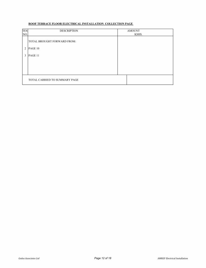
ROOF TERRACE FLOOR ELECTRICAL INSTALLATION COLLECTION PAGE
ITEM DESCRIPTION AMOUNT NO. KSHS.
TOTAL BROUGHT FORWARD FROM:
2 PAGE 10
3 PAGE 11
TOTAL CARRIED TO SUMMARY PAGE
Gedox Associates Ltd Page 12 of 18 AMREF Electrical Installation

ITEM DESCRIPTION UNIT QTY RATE TOTALNO. KSHS. KSHS.
STABILISED POWER POINTSFinal sub-circuits complete with accessories and fittings asdetailed below and marked in red UPS power.
A 13A single power points, wired in 3x 2.5mm sq single corecables in ring circuit enclosed in trunking from DB 'B' to outletpoints as indicated in the drawing NO. 6
B 13A twin power points, wired in 3x 2.5mm sq single core cablesin ring circuit enclosed in trunking/conduits NO. 80
C Allow for attendnace to the UPS subcontractor item
D Allow for provision of flexible conduits for all exposedcables near UPS item
E 13amps NON Standard twin switched socket outlet plate forUPS power and as MK or equivalent and approved. Complete NO 80with Top Plugs
F 13amps NON Standard single switched socket outlet plate forUPS power and as MK or equivalent and approved. Complete NO 6with Top Plugs.
G 12 Way TPN distribution board DB incorporating 100A integralisolator, lockable cover and labelling but without MCB and asSapphire/Terasaki screwless or equivalent NO 2
H 9 way SPN Consumer Units CU incorporation 100A integralisolator, lockable cover and labelling but without MCB's and as NO. 2Crabtree/Sapphire/Terasaki
I Single phase MCB's rating as in schematics as Schneider NO 24/Terasaki/siemens//Schneider
J Three phase MCB's rating as in schematics as Schneider/ NO 6Terasaki/siemens/Schneider
K 2C, 10mm2 PVC/SWA/PVC copper cable to UPS consumer LM 40Units
L Cable glands and shroud for terminating 2C, 10mm2PVC/PVC/PVC copper cable NO 4
M 4C, 10mm2 PVC/SWA/PVC copper cable for distribution ofpower to UPS DB's LM 35
N Cable glands and shroud for terminating 4C, 10mm2PVC/PVC/PVC copper cable. NO 4
O 4C, 16mm2 PVC/SWA/PVC copper cable for distribution ofpower to UPS LM 20
P Cable glands and shroud for terminating 4C, 16mm2PVC/PVC/PVC copper cable. NO 4
TOTAL CARRIED TO COLLECTION PAGE
Gedox Associates Ltd Page 13 of 18 AMREF Electrical Installation

ADDRESSABLE FIRE ALARM INSTALLATIONITEM DESCRIPTION UNIT QTY RATE TOTALNO. KSHS. KSHS.
ADDRESSABLE FIRE ALARM SYSTEM INSTALLATION
Supply, install, test and commission the following
All detectors to be as MENVIER/PROTEC model numbersindicated. All detectors to be complete with mounting base
Fire alarm points, wired in 2 loops using 2C, 2.5mm2 fire resistantscreened cable FP200 drawn in 25mm diameter PVC heavy gaugeconduits concealed in roof space and wall from control panelthrough the detectors.
A Basement Floor No. 0
B Ground Floor No. 0
C First Floor No. 0
D Second Floor No. 0
E Roof Floor No. 0
Intelligent addressable Optical smoke detectors asMAP820/6000PLUS/OP complete with base plate as MAB800The sensors to have the following features; soft addressed, withintelligent short circuit isolator, wide range sensing and 360degrees visibility LED
The bases to have the following features; sensor shorting link,separate loop in and loop out terminals, stand off fixing feature,accepts side entry cables and selectable sensor locking feature
F Basement Floor No. 16
G Ground Floor No. 0
H First Floor No. 0
I Second Floor No. 16
J Roof Floor No. 2
TOTAL CARRIED TO COLLECTION PAGE
Gedox Associates Ltd Page 14 of 18 AMREF Electrical Installation

ITEM DESCRIPTION UNIT QTY RATE TOTALNO. KSHS. KSHS.
Intelligent Addressable call point units The call points to have the following features; Fast it clip onfront cover, high visibility status LED with heavy dutyterminals. To come complete with inbuilt short circuiti solators
A Basement as MBG817 OR 6000/MCP (Weather proof) No. 2
B Ground as MBG817 OR 6000/MCP (Weather proof) No. 0
C First Floor as MBG817 OR 6000/MCP (Weather proof) No. 0
D second Floor as MBG817 OR 6000/MCP(Weather proof) No. 2
E Roof Floor as MBG817 OR 6000/MCP (Weather proof) No. 2
Intelligent addressable multi-mode heat sensors/detectorsas MAP830/600PLUS/OPHT complete with base plate asMAB800The sensors to have the following features; soft addressed, withintelligent short circuit isolator, wide range sensing and 360degrees visibility LED
The bases to have the following features; sensor shorting link,separate loop in and loop out terminals, stand off fixing feature,accepts side entry cables and selectable sensor locking feature
A Basement Floor No. 3
B Ground Floor No. 0
C First Floor No. 0
D Second Floor No. 2
E Roof floor No. 0
TOTAL CARRIED TO COLLECTION PAGE
Gedox Associates Ltd Page 15 of 18 AMREF Electrical Installation

ITEM DESCRIPTION UNIT QTY RATE TOTALNO. KSHS. KSHS.
Intelligent Fire alarm electronic sounders with flasherThe sounders to have the following features; Loop powered,combined sounder beacon, high efficiency design, selectabletones controlled by the panel and adjustable volume controlledby the panel.To come complete with inbuilt short circuitisolators
A Basement Floor as MASB860WP or 6000/SSR2/LED/RED No. 2with IP66 rating
B Ground Floor as MASB860WP or 6000/SSR2/LED/RED with No. 0IP66 rating
C First Floor as MASB860WP or 6000/SSR2/LED/RED with No. 0IP66 rating
D Second Floor as MASB860WP or No. 26000/SSR2/LED/RED with IP66 rating
E Roof Floor as MASB860WP or 6000/SSR2/LED/RED with No. 1IP66 rating
TOTAL CARRIED TO COLLECTION PAGE
Gedox Associates Ltd Page 16 of 18 AMREF Electrical Installation

ADDRESSABLE FIRE ALARM INSTALLATION COLLECTION PAGE
ITEM DESCRIPTION AMOUNT NO. KSHS.
TOTAL BROUGHT FORWARD FROM:
1 PAGE 14
2 PAGE 15
3 PAGE 16
TOTAL CARRIED TO SUMMARY PAGE
Gedox Associates Ltd Page 17 of 18 AMREF Electrical Installation

PROPOSED STUDENTS LIBRARY DEVELOPMENT AT AMREF INTERNATION UNIVERSITY
ELECTRICAL INSTALLATIONS EXECUTIVE SUMMARY PAGE
ITEM DESCRIPTION AMOUNT NO. KSHS.
1 PRELIMINARIES AND GENERAL CONDITIONS
2 BASEMENT FLOOR
5 SECOND FLOOR
6 ROOF FLOOR
8 ADDRESSABLE FIRE ALARM INSTALLATION
11 PC SUM OCCUPANCY SENSOR CONTROL SYSTEM 300,000.00
12 CONTINGENCY SUM -
TOTAL FOR ELECTRICAL INSTALLATION
Total in words: ……………….……………………………………………………………………………
Name of Contractor: ……………………………………………………………………………………
Address: ………………………………………………………………………………..………………………
Telephone:……………………………………………………………………..…………………
Pin No. …………………………………………Vat Reg. No.…..……………………………………………
Signature: …………………………………………………………………………………….……………….
Official Stamp/Date: …………………………………………………….……………………………….
Gedox Associates Ltd Page 18 of 18 AMREF Electrical Installation

EC/001/2020 SECTION 6 PROPOSED LIBRARY AT AMREF INTERNATIONAL UNIVERSITY
SECTION 6 - PRIME COST &
PROVISIONAL SUMS
Ecospace Consultants Prime costs and Provisional sums

EC/001/2020 SECTION 6 PROPOSED LIBRARY AT AMREF INTERNATIONAL UNIVERSITY
ITEM DESCRIPTION UNIT QUANTITY RATE (Kshs) AMOUNT (Kshs)
SECTION NO. 6
PROVISIONAL SUMS
A Allow a Provisional Sum of Kenya Shillings SixMillion (Kshs. 6,000,000.00) only for fluctuation costto be executed or omitted at the discretion of the employer. ITEM 1 6,000,000
Contingencies
B Provide the Provisional Sum of Kshs. Four Million only for contingencies to be deducted in whole or in part ITEM 1 4,000,000
TOTAL CARRIED TO MAIN SUMMARY
6/1
PROPOSED LIBRARY BLOCK FOR
AMREF INTERNATIONAL UNIVERSITY - KENYAMEASURED WORKS
Ecospace Consultants Prime costs and Provisional sums

EC/001/2020 PROPOSED LIBRARY AT AMREF INTERNATIONAL UNIVERSITY
MAIN SUMMARY
PHASE 2
Ecospace Consultants Main SummaryEcospace Consultants Main Summary

EC/001/2020 PROPOSED LIBRARY AT AMREF INTERNATIONAL UNIVERSITY
ITEM
PHASE 2
SECTIONS PAGE NO.
1 PARTICULAR PRELIMINARIES 1/7
2 GENERAL PRELIMINARIES 1/16
3 BUILDER'S WORKS 3/19
4 EXTERNAL WORKS 4/3
5 DAYWORKS 5/3
6 PRIME COST AND PROVISIONAL SUMS 6/1
7 AIR CONDITIONING & FIRE SUPPRESSION EQUIPMENT 3 of 3
PROPOSED LIBRARY BLOCK FOR
AMREF INTERNATIONAL UNIVERSITY - KENYAMEASURED WORKS
AMOUNT (Kshs)DESCRIPTION
Ecospace Consultants Main Summary
7 AIR CONDITIONING & FIRE SUPPRESSION EQUIPMENT 3 of 3
8 LIFT INSTALLATION 4 of 4
9 MECHANICAL WORKS 5 of 6
10 ELECTRICAL WORKS 18 of 18
TOTAL CARRIED TO GRAND SUMMARY
MS/2MS/2
Ecospace Consultants Main Summary

EC/001/2020 PROPOSED LIBRARY AT AMREF INTERNATIONAL UNIVERSITY
GRAND SUMMARY
PHASE 1 & PHASE 2
Ecospace Consultants Main Summary
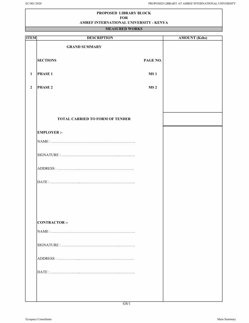
EC/001/2020 PROPOSED LIBRARY AT AMREF INTERNATIONAL UNIVERSITY
ITEM
GRAND SUMMARY
SECTIONS PAGE NO.
1 PHASE 1 MS 1
2 PHASE 2 MS 2
TOTAL CARRIED TO FORM OF TENDER
EMPLOYER :-
NAME : ………………………………………………………….
SIGNATURE : ……………………………………….………….
ADDRESS : ……………...………………………….………….
DATE : ……………….…...………………………….………….
CONTRACTOR :-
NAME : ………………………………………………………….
SIGNATURE : ……………………………………….………….
ADDRESS : ……………...………………………….………….
DATE : ……………….…...………………………….………….
GS/1
PROPOSED LIBRARY BLOCK FOR
AMREF INTERNATIONAL UNIVERSITY - KENYAMEASURED WORKS
DESCRIPTION AMOUNT (Kshs)
Ecospace Consultants Main Summary

EC/001/2020 PROPOSED LIBRARY AT AMREF INTERNATIONAL UNIVERSITY
APPENDIX A
ARCHITECTURAL DRAWINGS
Ecospace Consultants Main Summary

GSPublisherVersion 0.0.100.100
Job title:
Client Signature ..................................................
REMARKS.
date : revision
scale
cad file name
Drawing title:
checked. drawn by:
DATE.
Job number.
NO.REVISIONS.
10 Contractors must verify all figured dimensions and level on site before commencement of works and any descripancy must be reported to the architect for clarification.
13 Depth of foundation to be decided on site and trenches to be minimum 600mm below reduced ground level.
14 All pipes and services passing under road works to be encased in 150mm thick concrete surround and atleast 450mm below reduced ground level.
1 This drawing is protected under the copyright act and cannot be used or reproduced in part or in whole without the authors consent
2 Read only figured dimensions.
3 All construction work is to comply with the latest K.B.S. standard code of practice, local authority By- Laws, and fire regulations.
4 P.v. denotes permanent ventillation and must be provided above all openings where indicated or shown
6 Water meters to be 300mm above ground level.
7 D.p.c. denotes damp proof course and to be of bituminous felt placed under every wall and must be atleast 150mm above ground level
8 All r.c. works to structural engineers details
9 Provide atleast one row of precast concrete 600x600x50mm paving slabs around the building unless otherwise shown.
11 All levels shown are finished levels unless otherwise stated
12 All surface beds to be cast on well compacted and well consolidated filling
Drawing number.
5 All walls to be reinforced with hoop iron at every alternating course.
NOTES.
March, 2020.
Tej Architects.Jitegemee flats F1 Jabavu Road, KilimaniP.O. BOX 27644-00506 NAIROBI, KENYA,TEL :- 020-2719086, Mobile 0722-511600,FAX :- 202729085 E-Mail:- [email protected],website :- www.tej-architects.com.
Kipketer
PROPOSED LIBRARY ONPLOT L.R NO. 209/11606,NAIROBI COUNTY, FORAMREF INTERNATIONALUNIVERSITY
J50/10/19
Architect:
Client:
AMREF INTERNATIONAL UNIVERSITYPO BOX 27691- 00506 Nairobi, Kenya
AMREF
Emmanuel1:75
J50/10/19
C F HB
1
3
4
5
6
JI
11
7
10
A D
2
G
8
9
E
2,900 4,000 2,170 2,264 3,901 585 3,410 2,570 2,914
950
1,75
01,
180
2,85
61,
608
3,90
05,
750
4,65
065
02,
800
26,0
93
200 200 5,970 200 1,446 75 7,126
200 5,376 75 4,964 75 3,888 75 5,21520
02,
500
200
5,45
675
3,87
575
5,67
575
5,16
320
02,
600
200
200 200 5,970 200 5,350 1,200 2001,156
200 14,076200 5,970 200 6,550 200
200
647
200
5,59
720
05,
400
200
3,53
875
2,00
075
7,96
320
0
200 2,677 200 2,313 200 1,305 200 2,014 75 1,508 75 4,507 75 6,016
200
647
200
5,65
975
5,52
575
3,60
075
2,00
075
5,16
320
02,
600
200
200
24,715
3,215400
2,200200
2,750150 200
1501,725
2001,875
2001,725
5003,640
5001,665
2001,530
172200
500 4,160 400 2,404 400 2,347 200 1,000 200 2,425 150 1,025 200 1,800 200 1,800 200 1,800 200 1,800 200 1,519
200 24,701
200300
1,200 9,913 2,400 3,200 200 1,800 200 1,800 200 1,800 200 1,519
200
6,50
675
11,2
7575
5,16
320
02,
600
200
200
200 1,500 200 2,000 200 5,010 75 6,090 75 6,650
200 1,321 1,800 1,000 1,850 5,250 1,500 200
19,779
400
3,138
200
25,8
9320
0
200
12,0
4420
01,
000
1,50
01,
400
1,55
040
01,
675
675
1,80
01,
430
1,80
042
020
0
1,800
369
3,43
020
01,
500
200
2,00
020
01,
500
200
600
200
2,73
875
2,00
075
1,83
720
05,
925
200
200
200 6,033 75 6,090 75 4,586
1,30
03,215
200 2002,200
2002,750
150 200150
1,725200
1,875200
1,725 150200150
3,640150 200
1501,665
2001,530 172
200
200
1,50
020
032
51,
350
325
200
1,50
020
0
200 600 200
600
-3,500
-3750
-3,750
-3,750
-3750
-3750
RC staircase to S.E's detailsTreads=300mmRiser=150mmfinished with terrazzo
25 No. StepsRC staircase to S.E's detailsTreads=300mmRiser=150mmfinished with terrazzo
400 mm diameter RC column toS.E's details
500x200m RC column to S.E's details
400x400m RC column toS.E's details
200mm thick concrete wall plastered oninner side to S.E. details.
200mm thick concretewall plastered on innerside to S.E. details.
aluminium framed glass partition
aluminium framed glass partition
AUDIO VISUAL ROOM
UPS ROOM
DATA CENTRE
ARCHIVES
LIFTSHAFT
VendingMachines
BASEMENT FLOOR PLAN
VOIDABOVE
BREAK OUT LOBBY
DISCUSSION ROOM 01
DISCUSSION ROOM 05
IT OFFICE
ELE.. [01]
600x600 Aluminium raised floor panels
pv
pv
pv
pv
pv
pv
pv
pv
pv
pv
pv
pv pv
pv
pv
pv
pv
ELE.
. [02
]
ELE.. [03]
ELE.
. [04
]
pv
pv
pv
pv
pv
pv
pv
pv
pvpvpvpv
pv
pv
pv pv
granito tiles
granito tiles
granito tiles
Ramp
Granito tiles
granito tiles
pv
granito tiles
granito tiles
granito tiles
granito tiles
up
granito tiles granito tiles
SEC
.. [X
-X]
SEC
.. [X
-X]
D3
D12
D2
D10
D2
D2
D2
D2
D2D2
D11
D2
D18
W1
W2
W3 W3 W3 W3
W3
W4
W4
W5
W6
W3
W3
W7
W8
W9
W3
W4
W4
W9
W9
W9
pv
fire fighting
terrazzo
UP
FIRE ESCAPESTAIRCASE
Sump
Floor Drainagechannel to detail.
Fall
Fall
Fall
Fall
SEC.. [Y-Y]SEC.. [Y-Y]
Sump
SEC
.. [X
-X]
W2
W4
W4
W4 W4
TECHNICAL
DISCUSSION ROOM 03
DISCUSSIONROOM 02
DISCUSSION ROOM 04
BASEMENT FLOOR PLAN
02

GSPublisherVersion 0.0.100.100
Job title:
Client Signature ..................................................
REMARKS.
date : revision
scale
cad file name
Drawing title:
checked. drawn by:
DATE.
Job number.
NO.REVISIONS.
10 Contractors must verify all figured dimensions and level on site before commencement of works and any descripancy must be reported to the architect for clarification.
13 Depth of foundation to be decided on site and trenches to be minimum 600mm below reduced ground level.
14 All pipes and services passing under road works to be encased in 150mm thick concrete surround and atleast 450mm below reduced ground level.
1 This drawing is protected under the copyright act and cannot be used or reproduced in part or in whole without the authors consent
2 Read only figured dimensions.
3 All construction work is to comply with the latest K.B.S. standard code of practice, local authority By- Laws, and fire regulations.
4 P.v. denotes permanent ventillation and must be provided above all openings where indicated or shown
6 Water meters to be 300mm above ground level.
7 D.p.c. denotes damp proof course and to be of bituminous felt placed under every wall and must be atleast 150mm above ground level
8 All r.c. works to structural engineers details
9 Provide atleast one row of precast concrete 600x600x50mm paving slabs around the building unless otherwise shown.
11 All levels shown are finished levels unless otherwise stated
12 All surface beds to be cast on well compacted and well consolidated filling
Drawing number.
5 All walls to be reinforced with hoop iron at every alternating course.
NOTES.
March, 2020.
Tej Architects.Jitegemee flats F1 Jabavu Road, KilimaniP.O. BOX 27644-00506 NAIROBI, KENYA,TEL :- 020-2719086, Mobile 0722-511600,FAX :- 202729085 E-Mail:- [email protected],website :- www.tej-architects.com.
Kipketer
PROPOSED LIBRARY ONPLOT L.R NO. 209/11606,NAIROBI COUNTY, FORAMREF INTERNATIONALUNIVERSITY
J50/10/19
Architect:
Client:
AMREF INTERNATIONAL UNIVERSITYPO BOX 27691- 00506 Nairobi, Kenya
AMREF
Emmanuel1:75
J50/10/19
C F HB
1
3
4
5
6
JI
11
7
10
A D
2
G
RG
Fridge
8
9
E
200
3,58
175
5,75
075
3,74
275
4,66
515
060
01,
081
60020
0 650
1,30
0150150
200 1,700 150 1,963 200 1,957 200 1,750 3,600 1,200 200
2,900 4,000 2,175 2,265 3,895 585 3,410 2,570 2,915
200
2,10
020
02,
800
200
2,60
020
01,
700
200
1,20
01,
317
200
1,50
020
02,
000
200
1,50
020
0
200
25,8
9320
0
500 1,600 875 200 3,818 200 614 100 4,101 150 3,214 75 5,637
24,715
200 2,377 150150
200 3,815 200 1,955 200 6,550 200 9,040200 24,839
200 1,900 1,075 1,200 700 1,200 1,970 2,400 3,750 1,500 200 9,058
200
6,44
520
05,
400
200
5,55
020
01,
00015
0 1,00
015
02,
150
200
900
150
90015
060
0150
400
200
200
6,44
420
05,
400
200
13,6
5020
0
950
1,75
01,
180
2,76
41,
700
3,90
05,
750
4,65
065
02,
800
26,0
93
200
6,44
520
020
01,
600
1,79
51,
600
1,25
01,
500
900
1,50
01,
950
1,20
070
01,
200
1,35
01,
200
1,30
020
0
200 1,500 200 2,000 200 17,941
200
1,50
020
02,
000
200
1,50
080
020
04,
750
200
1,00
0150 1,
000
150
2,15
020
090
015
090
015
01,
150
200
600
2001,700
150 1,971 200 600 100 3,576 75 3,789 75 1,184 75 2,404
7,57
820
060
020
04,
750
200
80015
01,
150
200
1,02
5150
975
200 1,
00015
02,
100
200
1,70
020
0
200 3,200 150 1,270150
1,400 2,125 75 3,790 75
500
1,400
2001,665
500
3,640
500
1,725
200
1,875
200
1,725
500
2,750
2,401
200 3,875 4,561
8,730
200 1,801 8,200 1,400 2,400 5,199 200 3,800 200
9,44
4
15,000 200 9,650
600 200 3,200 150 1,270150
1,200 200 2,126 75 3,790 1502,042
550
1,665
500
1,400
2001,665
500
3,640
150200
150
1,725
200
1,875
200
1,725150
200150
2,750
2,401
200
1,50
020
032
51,
350
325
200
1,50
020
0
±0
-1,350
±0
±0
-150
-100
-1,350
R 6,500
R 1,800
2.4m High aluminiumframed partitions todetail.
25 No. StepsRC staircase to S.E's detailsTreads=300mmRiser=150mmfinished with terrazzo
25 No. StepsRC staircase to S.E's detailsTreads=300mmRiser=150mmfinished with terrazzo
Ramp to S.E's details
line of balcony above
line of balcony above
line of balcony above
Aluminium louvered sunshaders anchored toconcrete columns to details
Aluminium louvered sun shaders to details
aluminium framedglass partition
8 No StepsRC staircase to S.E's detailsTreads=300mmRiser=150mmfinished with terrazzo
3 No. Rows of 600x600x50mm onsand beddings laid to 2o fall awayfrom buildingPCC paving slabs
1 No. row of 600x600x50mmPCC paving slabs on sandbedding on well compactedsurface laid to 2o fall away frombuilding
200x500m RC column to S.E's details
Storm drainage channel to Civil Eng'sspecification
Storm drainage channel toCivil Eng's specification
LADIES
GENTS
CHILDREN'SSECTION
BAGGAGEDEPOSIT
VOID
SEATING
NEW ARRIVALS/DISPLAY AREA
Ramp
8 No. rc stepsTreads- 300mmRisers-150 mm
Planter
Planter
MainEntry/Exit
Planter
CLEANER'SSTORE
LIFTSHAFT
PHOTO-COPYING
KITCHENETTE
LIBRARIANOFFICE
ASS.LIBRARIANOFFICE
GROUND FLOOR PLANELE.. [01]
ELE.
. [02
]
ELE.. [03]
ELE.
. [04
]
pv
pv
pv
pv pv pv pv pv
pv
pv
pv
pv
pv
pv
pv
pv
pv
pv pv
pv
pv
pv
pv
pv
pv
pv
pv
pv
pv
pv
pv
pvpvpvpv
pv
pv
pv
ceramic tiles
ceramic tiles
wc
wc
wc
whb
whb
whb
whb
whb
whb
wc
whb
whb
wc
wc
granito tiles
granito tiles
granito tiles
ceramic tiles
cooker s.s.sink
FIRE ESCAPESTAIRCASE
Urinals
Ceramic tilesCeramic tiles
granito tiles
pv
pv
pv
8No. rc stepsTreads- 300mmRisers-150 mm
granito tiles
VOIDABOVE
ENTRANCELOBBY
Granito tiles
granito tiles
granite tiles
fire fighting
DUCTS
DUCTS
svp
svp
IC
IC
IC
IC
gtTO SEWER LINE
FALL
FALL
FALL
granito tiles
granito tiles
RWDPRWDP
RWDP
RWDPRWDP
RWDP
RWDP
RWDP
RWDP
RWDP
RWDP
UP
D2
D2
D2D8
D8
D3
D4
D5D6D8
D8
D8
D7
D2
D2
D1
D1
D9
D7 D6
D2
D18
D17
D18
D21
svp
W10
W10
W11
W12
W13
W18
W15
W14
W16
W17
W18
W18W18W18W18
W19
W20
W30W21
W21
W21W21
W22
W22
W23
W23
W23
W23 W23 W24
rwdp
Ramp
RWDP
RWDP RWDP
RWDP RWDP RWDP
RWDP
RWDP
RWDP
RWDP
rwdp
svp
UP
ft
ft
ft
ft
ft
ft ft
ft
RWDP
top
granite floorfinish up
gt
FALL
FALL
FALL
FALL
FALL
FALL
SEC.. [Y-Y]SEC.. [Y-Y]99
020
02,
550
150
9,44
015
04,
116
150
1,30
075
5,16
320
02,
600
200
1,70
020
0
550
±0
R 1,250
LOUNGE(NEWSPAPERREADING)
FOYER
STUDY/SEATINGSPACE
DISCUSSIONROOM
MAINRECEPTION DESK
GROUND FLOOR PLAN
03

GSPublisherVersion 0.0.100.100
Job title:
Client Signature ..................................................
REMARKS.
date : revision
scale
cad file name
Drawing title:
checked. drawn by:
DATE.
Job number.
NO.REVISIONS.
10 Contractors must verify all figured dimensions and level on site before commencement of works and any descripancy must be reported to the architect for clarification.
13 Depth of foundation to be decided on site and trenches to be minimum 600mm below reduced ground level.
14 All pipes and services passing under road works to be encased in 150mm thick concrete surround and atleast 450mm below reduced ground level.
1 This drawing is protected under the copyright act and cannot be used or reproduced in part or in whole without the authors consent
2 Read only figured dimensions.
3 All construction work is to comply with the latest K.B.S. standard code of practice, local authority By- Laws, and fire regulations.
4 P.v. denotes permanent ventillation and must be provided above all openings where indicated or shown
6 Water meters to be 300mm above ground level.
7 D.p.c. denotes damp proof course and to be of bituminous felt placed under every wall and must be atleast 150mm above ground level
8 All r.c. works to structural engineers details
9 Provide atleast one row of precast concrete 600x600x50mm paving slabs around the building unless otherwise shown.
11 All levels shown are finished levels unless otherwise stated
12 All surface beds to be cast on well compacted and well consolidated filling
Drawing number.
5 All walls to be reinforced with hoop iron at every alternating course.
NOTES.
March, 2020.
Tej Architects.Jitegemee flats F1 Jabavu Road, KilimaniP.O. BOX 27644-00506 NAIROBI, KENYA,TEL :- 020-2719086, Mobile 0722-511600,FAX :- 202729085 E-Mail:- [email protected],website :- www.tej-architects.com.
Kipketer
PROPOSED LIBRARY ONPLOT L.R NO. 209/11606,NAIROBI COUNTY, FORAMREF INTERNATIONALUNIVERSITY
J50/10/19
Architect:
Client:
AMREF INTERNATIONAL UNIVERSITYPO BOX 27691- 00506 Nairobi, Kenya
AMREF
Emmanuel1:75
J50/10/19
C F HB
1
3
4
5
6
JI
11
7
10
A D
2
G
8
9
E
7,09
175
2,78
175
2,81
920
02,
100
200
2,15
020
01,
000
150
2,10
020
0
200 2,677 200 3,813 200 1,957 200 6,550 200
200 15,597 200
2,900 4,000 2,175 2,265 3,895 585 3,410 2,570 2,914
24,715
950
1,75
01,
180
2,76
41,
700
3,90
05,
750
4,65
065
02,
800
26,0
93
200
6,44
420
01,
500
200
2,00
020
01,
500
200
600
200
1,85
675
2,81
920
090
015
090
015
02,
350
200
900
150
900
150
1,15
020
0
200 1,500 200 2,000 200 19,527
200
6,44
520
05,
400
200
5,55
020
090
015
090
015
02,
350
200
900
150
900
150
1,15
020
0
200
6,44
520
020
01,
600
1,80
01,
600
200
200
850
1,50
090
01,
500
1,95
01,
200
700
1,20
01,
350
1,20
01,
300
200
200
25,8
9320
0
200
2,50
020
020
,393
200
2,60
020
0
200 1,700 150 1,963 200 1,957 200 1,750 3,600 1,200 200
200 4,645 75 11,835
200
6,44
420
01,
500
2,40
01,
500
200
777 200 1,200 750 1,200 1,720 1,500 1,300 3,550 1,300
500
2,600500
1,725200
1,875200
5,864
5001,665
2001,402
500
200 1,801 8,200 200 1,200 2,400 3,199 200 1,800 200 1,800 200 1,800 200
200 23,000 200
2761,615
475
1,850
317
1,615
732
1,615
150150
200 1,700 150 1,971200
700 1,250 200
200
200
150 200150
2,600500
1,725200
1,875200
1,874200
3,790
5001,665
2001,402
500
500 1,600 875
200 3,200 150 1,270150
1,200 200 8,357
150 1,270 150
200
1,50
020
032
51,
350
325
200
1,50
020
0
2,061
5,000
3,876
3,876
1,777
6,27
8
17,156
+3,750
+3,750
+3,750
+3,750
+3,750
+3,650
+3,650
R 2,358
R 6,483
R 6,400
86°
25 No. StepsRC staircase to S.E's detailsTreads=300mmRiser=150mmfinished with terrazzo
25 No. StepsRC staircase to S.E's detailsTreads=300mmRiser=150mmfinished with terrazzo
Aluminium louvered sun shaders to details
Aluminium louveredsun shaders todetails
50mmx50mm spray painted mildsteel balustrades to muchexisting
50mmx50mm spraypainted mild steelbalustrades to muchexisting
50mmx50mm spray paintedmild steel balustrades to muchexisting
aluminium framed glass partition
wall mounted 600 mm wide 18mm thicklaminated particle board top, 750 mm high fromfinished floor level with hardwood lipping onexposed edge.
400x400m RC columnto S.E's details
Aluminium louveredsun shaders to details
line of building above
VOID
OPEN STACKS &SEATING(113PAX)
REFERENCE
CLEANER'SSTORE
LIFTSHAFT
DEP.LIBRARIANOFFICE
ELE.. [01]
ELE.
. [02
]
ELE.. [03]
ELE.
. [04
]
SEC.. [Y-Y]SEC.. [Y-Y]
FIRST FLOOR PLAN
LADIES
pv pv
ceramic tiles
whb wc
whbFIRE ESCAPESTAIRCASE
GENTSceramic tiles
wc
wc
wc
whb
whb
whb
wc
pvpv
pv
pv
pv
pv
pv
pv
pv
pv
pvpv
pv
pv
pv
pv
pv
pv pv pv pv
pv
pv
pv
pv
pv
pv
pv
pv
pv
pv
pv
pv
pv
pv
Urinals
wc
FALL
FALL
granito tiles
granito tiles
granito tiles
mazeras tiles
mazeras tiles
FALL
FALL
ft
ft
ft
ft
FALL
FALLsvp
RWDPRWDP
RWDP
RWDP
RWDP
RWDP
RWDP
RWDP
RWDP
RWDP
RWDP
D3
D8
D8
D5D6D8
D8
D8
D7
D9
D7 D6
D2
D2
D13D18
D17
D18
D15
D16
svp
W21W21
W22
W22
W21
W21
W23
W23
W23
W23 W23 W24W10W10
W10
W11
W12
W13
W13
W15
W14
W16
W17
W18W18W18W18
W25
W19
W26
W27
W26
W26
mazeras tiles
rwdp
ft
ft
whb
whb
RWDP
RWDP
RWDP RWDP
RWDP RWDP RWDP RWDP
RWDP
RWDP
RWDP
RWDP
svprwdp
svp
fire fighting
ft
ft
ft
ft
ft ft
ft
up
granite floorfinish up
UP
FALL
FALL
FALL
FALL
FALL
FALL
terrazzo
BALCONY
BALCONY
BALCONY
FIRST FLOOR PLAN
04

GSPublisherVersion 0.0.100.100
Job title:
Client Signature ..................................................
REMARKS.
date : revision
scale
cad file name
Drawing title:
checked. drawn by:
DATE.
Job number.
NO.REVISIONS.
10 Contractors must verify all figured dimensions and level on site before commencement of works and any descripancy must be reported to the architect for clarification.
13 Depth of foundation to be decided on site and trenches to be minimum 600mm below reduced ground level.
14 All pipes and services passing under road works to be encased in 150mm thick concrete surround and atleast 450mm below reduced ground level.
1 This drawing is protected under the copyright act and cannot be used or reproduced in part or in whole without the authors consent
2 Read only figured dimensions.
3 All construction work is to comply with the latest K.B.S. standard code of practice, local authority By- Laws, and fire regulations.
4 P.v. denotes permanent ventillation and must be provided above all openings where indicated or shown
6 Water meters to be 300mm above ground level.
7 D.p.c. denotes damp proof course and to be of bituminous felt placed under every wall and must be atleast 150mm above ground level
8 All r.c. works to structural engineers details
9 Provide atleast one row of precast concrete 600x600x50mm paving slabs around the building unless otherwise shown.
11 All levels shown are finished levels unless otherwise stated
12 All surface beds to be cast on well compacted and well consolidated filling
Drawing number.
5 All walls to be reinforced with hoop iron at every alternating course.
NOTES.
March, 2020.
Tej Architects.Jitegemee flats F1 Jabavu Road, KilimaniP.O. BOX 27644-00506 NAIROBI, KENYA,TEL :- 020-2719086, Mobile 0722-511600,FAX :- 202729085 E-Mail:- [email protected],website :- www.tej-architects.com.
Kipketer
PROPOSED LIBRARY ONPLOT L.R NO. 209/11606,NAIROBI COUNTY, FORAMREF INTERNATIONALUNIVERSITY
J50/10/19
Architect:
Client:
AMREF INTERNATIONAL UNIVERSITYPO BOX 27691- 00506 Nairobi, Kenya
AMREF
Emmanuel1:75
J50/10/19
C F HB
1
3
4
5
6
JI
11
7
10
A D
2
G
8
9
E
2,900 4,000 2,175 6,160 585 3,410 2,570 2,915
24,715
200 2,677 200 1,625 150 2,013 200 1,957 200 6,550 200
200 15,597 200
200 1,900 875 200 1,600250
1,200 1,620 900 2,100 3,550 1,500 200
200
20,3
9320
02,
600
200
200
650
1,30
065
020
0
200
1,59
420
090
610
01,
832
200
2,56
420
01,
500
200
2,00
020
01,
500
200
600
200
4,75
020
01,
00015
0 1,00
015
02,
150
200
900
150
900
150
1,15
020
0
200 1,650 150 1,404150
1,266150
1,200 200 4,561 75 3,637
200
64120
090
610
04,
596
200
6,20
020
04,
750
200
2,10
020
01,
02515
097
520
0 1,00
015
02,
100
200
200 1,800 2,015 200 1,957 200 1,750 3,600 1,200 200
950
1,75
01,
180
2,76
41,
700
3,90
05,
750
4,65
065
02,
800
200 1,500 200 2,000 200 11,992
200 3,883 75 6,774 75 5,936
26,0
93
200
1,59
420
090
610
01,
832
200
2,56
420
01,
500
200
2,00
020
01,
500
200
600
200
4,75
020
01,
00015
0 1,00
015
02,
150
200
900
150
900
150
1,15
020
0
200
25,8
9320
0
200
4,40
01,
500
945
1,60
01,
800
1,60
01,
200
1,50
01,
243
1,50
01,
650
1,20
070
61,
200
1,35
01,
200
1,30
020
0
200 4,460 200 2,700 200 2,450 200 4,800 200 3,800 200 3,800 200 1,373
500
1,400
200
1,825
200
3,780
150200
150
1,725
200
1,875
200
1,725
500
2,600
500
200 23,000 200
200
1,51
710
04,
926
5,60
010
,950
200
2,60
020
0
200 1,600 200 2,729 100 2,648 75 90075
90075
90075
90075
900 200
2,660 1,930 1,650 1,500 1,873 2,400 1,200 200 1,800 150 1,850 200 1,800 200 1,800 200
10,217
75
2,086
75
8,186
200 1,850 1,971 200 700 1,250 200 4,561 75 4,973
200 200
3,925
75
1,668
500 1,600 875 200 2,313 200 1,305 200
2002,750
500
500
1,400
200
1,816
200
3,790
150200
150
1,725
200
1,875
200
1,725150
200150
2,600
150200
150
322
1,62
750
8
9,94
2
200
1,50
020
032
51,
350
325
200
1,50
020
0
2,084
5,053
3,816
3,886
+7,500+7,400
+7,400
+7,400+7,500
+7,500
+7,400
R 3,248
6,515
95°
25 No. StepsRC staircase to S.E's detailsTreads=300mmRiser=150mmfinished with terrazzo
Aluminium louvered sunshaders to details
Aluminium louvered sunshaders to details
50mmx50mm spraypainted mild steelbalustrades to detail
400 mm diameter RC columnto S.E's details
50mmx50mm spraypainted mild steelbalustrades to muchexisting
500mm high, 50mmx50mm spray painted mild steelbalustrades on 450mm high walling with fair faced singlethroated 250x50mm concrete copingaluminium framed glass
partition
25 No. StepsRC staircase to S.E's detailsTreads=300mmRiser=150mmfinished with terrazzo
1,100mm high and 200mmthick walling plastered andpainted walling with250x25mm varnishedmahogany coping
wall mounted 600 mm wide 18mm thicklaminated particle board top, 750 mm highfrom finished floor level with hardwood lippingon exposed edge.
wall mounted 600 mm wide 18mm thick laminatedparticle board top, 750 mm high from finished floorlevel with hardwood lipping on exposed edge.
500mm high, 50mmx50mm spray painted mildsteel balustrades on 450mm high walling withfair faced single throated 250x50mm concretecoping
E-LIBRARY
POST GRADUATE AREA(34PAX)
OPEN STACKS &SEATING (46PAX)
CLEANER'SSTORE
BALCONY
VOID
STUDY CARRELS
LIFTSHAFT
RESEARCH COMMONSROOM
SECOND FLOOR PLAN
STUDY CARRELS
SYSTEMLIBRARIAN
ELE.. [01]
ELE.. [03]
ELE.
. [04
]
SEC
.. [X
-X]
LADIES
pv pv
ceramic tiles
wc
whbFIRE ESCAPESTAIRCASE
GENTSceramic tiles
wc
wc
wc
whb
whb
whb
pv
pv
whb
whb
whb
pv
pv
pv
pv
pv
pv
pv
pv
pv
pv
pv
pvpv pvpv pv pv pv
pv
pv pv pv pv
pv
pv
pv
pv
pv
pv
pv
pv
pv
pv
pv
pv
pv
ceramic tiles
ceramic tiles
mazeras tiles
mazeras tiles
pv
mazeras tiles
FALLft
ft
FALL
FALLft
ft
FALL
ft
FALL
ft
wc Urinals
wc DUCT
svp
ft
ft
RWDPRWDP
RWDP
RWDPRWDP
RWDP
RWDP
RWDP
RWDP
rwdp
RWDP
RWDP
D8
D8
D5D6D8
D8
D8
D7
D9
D18
D7D6
D2
D2
D2
D2
D14D14 D14 D14 D14 D14 D14
D13
D15
D16
D17
D18
D3
svp
W21W21
W22
W22
W21
W21
W23
W23
W23
W23 W23 W24
W22
W28W22
W18W18W18W18
W25
W19
W10W10
W10
W11
W12
W13
W13
W15
W14
W16
W17
rwdp
pv
mazeras tiles
RWDP
RWDP RWDP
RWDP
RWDP
svprwdp
svp
granito tiles
granito tiles
granito tilesgranito tiles
granito tiles
fire fighting
ft
ft
ft
ft
ft ft
ft
RWDP
granite floorfinish
up
UP
FALL
FALL
FALL
FALL
FALL
FALL
terrazzo
DUCT
SEC.. [Y-Y]SEC.. [Y-Y]
BALCONY
BALCONY
BALCONY
SECOND FLOOR PLAN
05

GSPublisherVersion 0.0.100.100
Job title:
Client Signature ..................................................
REMARKS.
date : revision
scale
cad file name
Drawing title:
checked. drawn by:
DATE.
Job number.
NO.REVISIONS.
10 Contractors must verify all figured dimensions and level on site before commencement of works and any descripancy must be reported to the architect for clarification.
13 Depth of foundation to be decided on site and trenches to be minimum 600mm below reduced ground level.
14 All pipes and services passing under road works to be encased in 150mm thick concrete surround and atleast 450mm below reduced ground level.
1 This drawing is protected under the copyright act and cannot be used or reproduced in part or in whole without the authors consent
2 Read only figured dimensions.
3 All construction work is to comply with the latest K.B.S. standard code of practice, local authority By- Laws, and fire regulations.
4 P.v. denotes permanent ventillation and must be provided above all openings where indicated or shown
6 Water meters to be 300mm above ground level.
7 D.p.c. denotes damp proof course and to be of bituminous felt placed under every wall and must be atleast 150mm above ground level
8 All r.c. works to structural engineers details
9 Provide atleast one row of precast concrete 600x600x50mm paving slabs around the building unless otherwise shown.
11 All levels shown are finished levels unless otherwise stated
12 All surface beds to be cast on well compacted and well consolidated filling
Drawing number.
5 All walls to be reinforced with hoop iron at every alternating course.
NOTES.
March, 2020.
Tej Architects.Jitegemee flats F1 Jabavu Road, KilimaniP.O. BOX 27644-00506 NAIROBI, KENYA,TEL :- 020-2719086, Mobile 0722-511600,FAX :- 202729085 E-Mail:- [email protected],website :- www.tej-architects.com.
Kipketer
PROPOSED LIBRARY ONPLOT L.R NO. 209/11606,NAIROBI COUNTY, FORAMREF INTERNATIONALUNIVERSITY
J50/10/19
Architect:
Client:
AMREF INTERNATIONAL UNIVERSITYPO BOX 27691- 00506 Nairobi, Kenya
AMREF
Emmanuel1:75
J50/10/19
C F HB
1
3
4
5
6
JI
11
7
10
A D
2
G
8
9
E
2,900 4,000 2,175 2,265 3,895 585 3,410 2,570 2,91524,715
950
1,75
01,
180
2,76
41,
700
3,90
05,
750
4,65
065
02,
800
26,0
93
200 1,500 200 2,000 200 1,522 200 1,074 200 8,117 200
200
12,0
4420
010
,850
200
2,60
020
0
200 3,813 200 1,957 200 1,500 3,550 1,300200
200300 12,970 200
200
64120
030
6 800
542
800
600
800
600
800
755
1,60
01,
800
1,60
020
020
013
,900
200
200
26,1
4320
0
200
1,50
020
02,
000
200
1,50
020
013
,900
200
200 6,270 200 1,750 3,600 1,200 200
1,844 1,000200
1,074 200 8,117 200
200
11,2
0220
060
020
010
,050
200
2,60
020
030
0
400 1,600 2,660 200200
800 600 800 600 800 750 5,801 200
200 4,460 200 10,350 200
200 300 1,601476
100
200
325
1,35
032
520
0
+11,250
+11,100
+11,100
11,250
25 No. StepsRC staircase to S.E's detailsTreads=300mmRiser=150mmfinished with terrazzo
600x200m RC column to S.E's details
25 No. StepsRC staircase to S.E's detailsTreads=300mmRiser=150mmfinished with terrazzo
50mmx150mm Spray paintedMild Steel RHS pergola @500mm c/c
RWDP
RWDP
LIFTSHAFT
ROOF TERRACE PLAN
VOID BELOW
ELE.. [01]
ELE.. [03]
ELE.
. [04
]
SEC
.. [X
-X]
pv
pv
pv
pv
pv
pv
pv
pv
pv pv pv pv
pv
pv pv
pv
1200 mm high dwarf walling with 50mm thick coping
fall
fulbora
1200 mm high dwarf wallingwith 50 mm thick coping
ROOF TERRACEOPEN TO SKY
Roof slope 50
fall
fall
fallfall
fulbora
fulbora
fulbora fulbora fulbora
flat roof of concrete tiles on screed layer on(APP) modified bitumen waterproofing membraneon screed laid to concrete
FIRE ESCAPESTAIRCASE
100 mm diameter RHS to S.E's details
fall
fall
pvRWDP
RWDP
D19
D20
D3
W21W21
W21
W21
W10W10
W10
W29
W29
W29
W29
W29 W29 W29 W29
fulbora
fulbora
fulbora
fall
fall
fall fulbora
fulbora
fulbora
fulbora
fulborafulbora
fall
fall
fallfall
fall
RWDP
water tank access ladder to detail
fulbora
fall fall
300mmx300mmx200mmhigh concrete pad
fire fighting
fulbora
granite floorfinish up
UP
terrazzo
3,150 mm high line of carrel ceiling todetails
DUCT
DUCT
SEC.. [Y-Y]SEC.. [Y-Y]
300mmx300mmx200mmhigh concrete pad
175 mm solid slab
200
2,60
020
0
200
650
1,30
065
020
0
ROOF TERRACE PLAN
06

GSPublisherVersion 0.0.100.100
Job title:
Client Signature ..................................................
REMARKS.
date : revision
scale
cad file name
Drawing title:
checked. drawn by:
DATE.
Job number.
NO.REVISIONS.
10 Contractors must verify all figured dimensions and level on site before commencement of works and any descripancy must be reported to the architect for clarification.
13 Depth of foundation to be decided on site and trenches to be minimum 600mm below reduced ground level.
14 All pipes and services passing under road works to be encased in 150mm thick concrete surround and atleast 450mm below reduced ground level.
1 This drawing is protected under the copyright act and cannot be used or reproduced in part or in whole without the authors consent
2 Read only figured dimensions.
3 All construction work is to comply with the latest K.B.S. standard code of practice, local authority By- Laws, and fire regulations.
4 P.v. denotes permanent ventillation and must be provided above all openings where indicated or shown
6 Water meters to be 300mm above ground level.
7 D.p.c. denotes damp proof course and to be of bituminous felt placed under every wall and must be atleast 150mm above ground level
8 All r.c. works to structural engineers details
9 Provide atleast one row of precast concrete 600x600x50mm paving slabs around the building unless otherwise shown.
11 All levels shown are finished levels unless otherwise stated
12 All surface beds to be cast on well compacted and well consolidated filling
Drawing number.
5 All walls to be reinforced with hoop iron at every alternating course.
NOTES.
March, 2020.
Tej Architects.Jitegemee flats F1 Jabavu Road, KilimaniP.O. BOX 27644-00506 NAIROBI, KENYA,TEL :- 020-2719086, Mobile 0722-511600,FAX :- 202729085 E-Mail:- [email protected],website :- www.tej-architects.com.
Kipketer
PROPOSED LIBRARY ONPLOT L.R NO. 209/11606,NAIROBI COUNTY, FORAMREF INTERNATIONALUNIVERSITY
J50/10/19
Architect:
Client:
AMREF INTERNATIONAL UNIVERSITYPO BOX 27691- 00506 Nairobi, Kenya
AMREF
Emmanuel1:75
J50/10/19
C F HB
1
3
4
5
6
JI
11
7
10
A D
2
G
8
9
E
2,900 4,000 2,175 2,265 3,895 585 3,410 2,570 2,915
24,715
950
1,75
01,
180
2,76
41,
700
3,90
05,
750
4,65
065
02,
800
26,0
93
750
200
2,22
575
070
020
0
200 5,620
line of building below
RWDP
RWDP
RWDP
Box profile 150x150mm Gauge 24 paintedGalvanised iron rain water gutters on brackets at1,000mm centres and 100mm dia. heavy duty upvcdown pipes on brackets welded to CHS columns at900mm centres
ROOF SPECIFICATIONSRoof pitch 300 slopeMangalore Clay tiles on 50x25mm battens spaced tomanufacturer's specification on gauge 26 mini corrugatedgalvanized iron sheets underlay on 125x75 timber purlinson steel roof structure anchored to beam to structuralEngineers specifications. Eaves of varnished primegrade 75x25mm T&G timber boaring on 50x50mmbrandering 600mm wide.Painted 250x38mm timber Fascia board
Cold Water tanks to M.E'sspecifications
RWDP
RWDP
ROOF SPECIFICATIONSRoof pitch 250 slopeMangalore Clay tiles on 50x25mm battens spaced tomanufacturer's specification on gauge 30 mini corrugatedgalvanized iron sheets underlay on 125x75 timber purlinson steel roof structure anchored to beam to structuralEngineers specifications. Eaves of varnished primegrade 75x25mm T&G timber boaring on 50x50mmbrandering 600mm wide.Painted 250x38mm timber Fascia board
Box profile 150x150mm Gauge 24 painted Galvanisediron rain water gutters on brackets at 1,000mm centresand 100mm dia. heavy duty upvc down pipes onbrackets welded to CHS columns at 900mm centres
Solar panels
ELE.. [01]
ELE.. [03]
ELE.
. [04
]
SEC
.. [X
-X]
ROOF TERRACEBELOW
1200 mm high dwarf wallingwith 50 mm thick coping
ROOF PLAN
fallft
fulborafall
ft
fallft
fulbora
ROOF TERRACE OPEN TO SKY
Roof slope 50
flat roof of concrete tiles on screed layeron (APP) modified bitumen waterproofingmembrane on screed laid to concrete
fallft
fallft
Roof Accesshatch
SEC.. [Y-Y]SEC.. [Y-Y]
SEC.. [Y-Y]
FALL
FALL
FALL
FALL
FALL
FALL
FALL
FALL
FALL
FALLFALL SKYLIGHT
Water Tanks
Water Tanks
FALL
FALL
FALL
FALL
FALL
FALL
FALL
FALL
FALL
FALL
FALL
ROOF PLAN
ROOF PLAN
07

EC/001/2020 PROPOSED LIBRARY AT AMREF INTERNATIONAL UNIVERSITY
APPENDIX B
STRUCTURAL DRAWINGS
Ecospace Consultants Main Summary

-3.750
-3.750
-3.750
A B C D E F G H I J
1
2
3
4
5
6
7
8
9
10
11
2900
4000 2175 2265 585 3410 2570 2915
24715
2800
650
2675
5750
3900
1700
2085
1180
1750
950
27995
680
C5
C5
C14
CB10
C12
CB4
C12
CB4
C12
C3
CB1
C1
CB1
C1
CB1
C3
CB1
C3
CB1
C4
CB2
C2
CB2
C2
CB2
C2
C1
CB1
C1
CB1
CB6
C7
CB6
CB2
CB2
CB5
CB6
C11
CB6
C13
C10
CB7
C9
CB4
C9
CB4
C9
CB4
2
4
0
0
3
1
0
0
2
0
7
5
2
0
7
5
2
1
0
5
1
9
0
0
2
4
5
5
2513
800
1723
1690
1500
Stair Up
Stair Up
C8
2900 1380 2215 1105 1200 2000 1995 2005 2000 1480
24715
A142 mesh.
1
2
5
m
m
T
h
i
c
k
S
l
a
C
B
r
e
i
n
f
o
r
c
e
d
w
i
t
h
C
B
R
C
1
4
2
M
e
s
h
1845
1250
FOUNDATION LAYOUT
SCALE 1:50
C9
1023
100
100
AA
1200
Sump
600
600
2131
3380
1240
4170
4960
1345
2120
1410
C6
C6
4
1
6
0
170
1580
950
475
425
CB4a
CB4a
CB4a
2
0
1
0
5
C13
CB6
435
C2
2600
95
C10a
CB7
1
9
3
5
4
1
9
0
150mm wide RC wall
2340
685 3210
E1
C9
C9
CB4
CB4
1360 1520
2100
C8
C8
C8
C8
C8
C8a
C12
C16
C16
C16
C12
2200
2200
CB2
CB2
1500
1500
CB3
CB3
CB3
CB3
1400
1400
CB4
CB4
1800
2150
CB2
CB8
CB9
1900
C15
CB9
C15
CB9
1200
1200
1975
CC
D
D
500x150 RCC fin
500x150 RCC fin
500x150
RCC fin
500x150 RCC fin
500x150 RCC fin
500x150 RCC fin
500x150 RCC fin
-3.750
1200 850
Sump
2200
2200
Approved material Hardcore fill
laid and compacted in layers
not exceeding 200mm
Mesh A142
Gauge 1000 polythene D.P.M
50mm. quarry dust blinding
125 mm. concrete slab
Determ
ine on site
Assum
ed 1200m
m.
200
EXTERNAL WALL STRIP FOOTING
Scale 1:25
INTERNAL WALL STRIP FOOTING
Scale 1:25
Approved material Hardcore fill
laid and compacted in layers
not exceeding 200mm
Mesh A142
Gauge 1000 polythene D.P.M
Y10-01-250B1
50mm. quarry dust blinding
125mm. concrete slab
3Y10-02-250B2
50 mm. thick 1:3:6
blinding concrete
Determ
ine on site
Assum
ed 1200m
m.
200
200
200
600
200
200 mm concrete base
250
Y10-01-250B1
3Y10-02-250B2
50 mm. thick 1:3:6
blinding concrete
200
200
200
600
200 mm concrete base
250
8nos.risers@
150=
1200
7nos.Treads@300=2100
150mm thick class 25
A142 Mesh
8 No. STEPS DETAILS
SECTION B--B
(SCALE 1:25)
50mm thick
quarry dust
blinding
Approved material Hardcore fill
laid and compacted in layers
not exceeding 200mm
SFL
-0.150
SFL
-1.350
455
150 mm thick slab
(class 25)
50 mm quarry dust
A 142 Mesh
1100
section R-R
Scale 1:25
200mm thick masonry
10
0
Approved material Hardcore fill
laid and compacted in layers
not exceeding 200mm
54
0
SFL
-0.100
A142 BRC Mesh
150mm Thick slab
R
R
1
0
0
50mm thick
quarry dust
blinding
Approved material Hardcore fill
laid and compacted in layers
not exceeding 200mm
42
5
1150 2500 1200
4850
71
0
12
50
-1.350
RAMP TYPE DETAILS
(SCALE 1:25)
SFL
-0.640
SFL
-0.925
SECTION A--A
900
2200
A
900400
A
900
2200
900
400
13T20-01-175B2
13T20-01-175B1
COL. BASE TYPE CB1
(7Nos.Thus)
(SCALE 1:25)
8T25-03
600 mm concrete base
5T8-02-200
A1A1
50
600
2200
900 400 900
50 mm. thick 1:3:6
blinding concrete
Section:A1--A1
SECTION B--B
550
15
00
B
550400
B
550
1500
550
40
0
7T16-01-250B2
7T16-01-250B1
COL. BASE TYPE CB2
(4Nos.Thus)
(SCALE 1:25)
10T16-03
400 mm concrete base
6T8-02-175
1000
75
mm
K
icker
B1B1
50
400
1500
550 400 550
50 mm. thick 1:3:6
blinding concrete
Section:B1--B1
Section:C1--C1
SECTION C--C
500
14
00
C
500400
C
500
1400
500
40
0
7T16-01-250B2
7T16-01-250B1
8T16-03
400 mm concrete base
6T8-02-175
C1C1
50
400
1400
500 400 500
-02-
400
400
03
03
03
03
03
03
03
03
50 mm. thick 1:3:6
blinding concrete
COL. BASE TYPE CB3
(4Nos.Thus)
(SCALE 1:25)
SECTION D--D
650
18
00
D
800200
D
800
1800
650
50
0
8T16-01-200B2
8T16-01-200B1
COL. BASE TYPE CB4
(13Nos.Thus)
(SCALE 1:25)
8T16-03
500 mm concrete base
6T8-02-175
D1D1
50
500
1800
800 200 800
50 mm. thick 1:3:6
blinding concrete
Section:D1--D1
03 03
03 03
200
500
02
03 03
03 03
10
00
75m
m K
icker
1000
75
mm
K
icker
1000
75
mm
K
icker
400
-02-
03
03
03
03
03
03
03
03
03
03
400
-02-
03
03
03
03
03
03
03
03
03
03
Foundation level to be determined on site by the engineer
Grid settingout to be checked by the structural engineer.
Masonry walls to be reinforced with hoop iron at every alternate course, 25mmx20mm
All concrete works must be compacted by poker vibrator to satiFFaction of engineer
Concrete to be :Substructure :class 25(20) ,Superstucture : class 25(20)
All foundations to have class 15 (20) concrete blinding minimum 50mm thick.
Cover to main reinforcement :Foundation 50mm, Columns 40mm, Beams 25mm
REVISIONS:
1.
6.
5.
4.
3.
2.
NOTES:
and Slab 20mm.
Reinforcement notation in accordance with KS 02-101: 1983, E.g
This drawing to be read in conjunction with the architect's drawings.
04 at 150 c/c bottom layer, TT upper top layer, R mild steel round bars.
12Y12-04-150B. 12 Nos. high yield square twisted steel dia. 12mm Mark
8.
9.
gauge, well lapped at junctions & joints & carried into abutting walls 150mm minmum.
7.
AS SHOWN
Scale
DRAWING TITLE
R.O.O
PROJECT
Designed
Drawn
Approved
Checked
DRAWING No.
JOB No.
DATE.
CLIENT
R.O.O
001
WS/2020/007
C.O.
C.O.
BASEMENT AND GROUND FLOOR LAYOUTS
MAY 2020
ENGINEER
ENGINEERING IDEALS KENYA LTD
16 Mucai Road
P.O. Box 51288 - 00200 Nairobi, Kenya.
Tel :0720957456
Email: [email protected]
www.eng-ideals.com
ARCHITECTS: TEJ ARCHITECTSJITEGEMEE FLATS F1, JABAVU ROAD
P.O.BOX 27644-00506,NAIROBI
Civil & Structural En g i n e e r s
PROPOSED LIBRARY ON PLOT L.R NO. 209/11606, NAIROBI COUNTY,FOR AMREF
INTERNATIONAL UNIVERSITY
AMREF INTERNATIONAL UNIVERISTY
P.O BOX 27691-00506 NAIROBI, KENYA

550
100
8nos.risers@
150=
1200
32T10-05-200(16B1+16T1)
7T12-04-200T1
2
0
T
1
0
-
0
3
-
2
0
0
(
1
2
B
2
+
8
T
2
)
7T12-02-200B1
7T12-01-200B1
STAIRS TYPE3 REINFORCEMENT DETAILS
(SCALE 1:25)
-1.350
SFL
-0.150
200x200 RC column200x200 RC column
Notes
Risers=150
Treads=300
Waist=150
2950
SeNtion:N1--N1
SENTION N--N
75
0
20
00
N
750500
N
750
2000
75
0
50
0
10T16-01-200B2
10T16-01-200B1
12T16-03
500 mm concrete base
N1N1
50
0
2000
750 500 750
-02-
50
0
500
03
03
03
03
03
03
03
03
50 mm. thick 1:3:6
blinding concrete
COL. BASE TYPE CB10
(1Nos.Thus)
(SCALE 1:25)
10
00
75
mm
K
icke
r
0303
03
03
-02b-
-02b-
6T8-02-175+
6T8-02a-175+
6T8-02b-175
T12-03-150
T12-02-150
50mm thick class 15
(mix 1:3:6) blinding Concrete.
2 x2
0T
10
-0
4-2
00
(2
0 E
.F
)
T12-05-150
T12-06-150
1100
14T12-01-200 B2
30mm thick horizontal mastic
asphalt applied in three coats
over concrete base
GROUND FLOOR
10T12-01-200 T2
40
0
T12-03a-150
60
02
40
0
28
00
Fabric Mesh Ref. A 142
12
5
150mm Thick Masonry
T8-07-200
2x3T10-08-200
(3B1+3T1)
13
50
Ground Level
200250
1550
EXTERNAL MASTIC ASPHALT TANKING
Retaining Wall Length-91,900mm
Sec:- A-A
1:25
B
65
0
10
0
37
50
100mm Thick mass concrete base
20mm thick vertical mastic
asphalt applied in three coats
to rough concrete phase
50x50 two coat
angle fillet
2200 2200
C E
Section:E1--E1
SECTION E--E
65
0
18
00
E
650200
E
650
1500
65
0
50
0
7T16-01-250B2
8T16-02-250B1
COL. BASE TYPE CB5
(1Nos.Thus)
(SCALE 1:25)
8T16-03
450 mm concrete base
6T8-04-175
E1E1
50
45
0
1500
650 200 650
50 mm. thick 1:3:6
blinding concrete
03 03
03 03
200
50
0
04
03 03
03 03
SECTION F--F
85
0
22
00
F
1000200
F
1000
2200
85
0
50
0
11T20-01-200B2
11T20-01-200B1
COL. BASE TYPE CB6
(4Nos.Thus)
(SCALE 1:25)
10T25-03
600 mm concrete base
6T8-02-200
F1F1
50
60
0
2200
1000 200 1000
50 mm. thick 1:3:6
blinding concrete
Section:F1--F1
03 03
03 03
200
50
0
02
03 03
03 03
Section:G1--G1
SECTION G--G
11T16-03
400 mm concrete base
2x6T8-02-175
G1G1
50
40
0
1800
700 400 700
8T16-01-250B2
8T16-01-250B1
COL. BASE TYPE CB7
(2Nos.Thus)
(SCALE 1:25)
650500
650
1800
65
0
18
00
65
0
20
03
00
G
G
50
0
500
-02-
03 03
0303
030303 03
03 03
650
200
650 500
2x11T16-01-250
(11B2+11T2)
2x8T16-02-250
(8B1+8T1)
500
2500
30
05
00
20
0
80
0
18
00
650
200
650 500 500
2500
50
0
50
500 mm concrete base
8T16-03
6T8-04-175
H1H1
Section:H1--H1
03 03
03 03
200
50
0
04
03 03
03 03
8T16-03
6T8-04-175
H
H
SECTION H--H
COL. BASE TYPE CB8
(1Nos.Thus)
(SCALE 1:25)
H2H2
Section:H2--H2
03
03
20
0
500
03 03
03
03
03 03
04
2x13T16-01-250
(13B2+13T2)
2x7T16-02-250
(7B1+7T1)
550 500 1086 500 365
3000
65
0
20
0
65
0
15
00
8T16-03
6T8-04-175
8T16-03
6T8-04-175
COL. BASE TYPE CB9
(1Nos.Thus)
(SCALE 1:25)
SECTION J--J
550 500 1086 500 365
3000
J
J
J1
J1
J1J1
Section:J1--J1
03
03
20
0
500
03 03
03
03
03 03
04
SECTION K--K
50
0
12
00
K
500200
K
500
1200
50
02
00
8T16-01-250B2
8T16-01-250B1
COL. BASE TYPE CB9
(2Nos.Thus)
(SCALE 1:25)
4T16-03
300 mm concrete base
10T8-05-175
10
00
75
mm
K
icke
r
K1K1
50
30
0
1200
500 200 500
125 mm. concrete slab
50 mm. thick 1:3:6
blinding concrete
Section:D1--D1
03 03
03 03
200
20
0
02
10
00
75
mm
K
icke
r
75
mm
K
icke
r
10
00
10
00
10
00
75
mm
K
icke
r
75
mm
K
icke
r
10
00
75
mm
K
icke
r
50
0
50
500 mm concrete base
To
b
e d
ete
rm
in
ed
o
n site
(M
in
im
um
=
1
80
0m
m)
Section:M1--M1
SECTION M--M
12T16-06
400 mm concrete base
6T8-02-175
M1M1
50
40
0
1800
650 500 650
COL. BASE TYPE CB4a
(3Nos.Thus)
(SCALE 1:25)
60
0
18
00
650500
650
1800
70
0
30
0
8T16-01-250B2
8T16-01-250B1
20
0
M
M
6T8-02a-175
10
00
03
0303
03
03
03 03 03
03
03
03
03
-02-
-02a-
-02b-
6T8-02b-175
50 mm. thick 1:3:6
blinding concrete
500
50
0
50 mm. thick 1:3:6
blinding concrete
50 mm. thick 1:3:6
blinding concrete
50 mm. thick 1:3:6
blinding concrete
03 03
Foundation level to be determined on site by the engineer
Grid settingout to be checked by the structural engineer.
Masonry walls to be reinforced with hoop iron at every alternate course, 25mmx20mm
All concrete works must be compacted by poker vibrator to satiFFaction of engineer
Concrete to be :Substructure :class 25(20) ,Superstucture : class 25(20)
All foundations to have class 15 (20) concrete blinding minimum 50mm thick.
Cover to main reinforcement :Foundation 50mm, Columns 40mm, Beams 25mm
REVISIONS:
1.
6.
5.
4.
3.
2.
NOTES:
and Slab 20mm.
Reinforcement notation in accordance with KS 02-101: 1983, E.g
This drawing to be read in conjunction with the architect's drawings.
04 at 150 c/c bottom layer, TT upper top layer, R mild steel round bars.
12Y12-04-150B. 12 Nos. high yield square twisted steel dia. 12mm Mark
8.
9.
gauge, well lapped at junctions & joints & carried into abutting walls 150mm minmum.
7.
AS SHOWN
Scale
DRAWING TITLE
R.O.O
PROJECT
Designed
Drawn
Approved
Checked
DRAWING No.
JOB No.
DATE.
CLIENT
R.O.O
002
WS/2020/007
C.O.
C.O.
COLUMN BASES, RETAINING WALL AND STAIR TYPE 3 REINFORCEMENT
DETAILS AND SECTION A--A
MAY 2020ARCHITECTS: TEJ ARCHITECTS
JITEGEMEE FLATS F1, JABAVU ROADP.O.BOX 27644-00506,
NAIROBI
ENGINEER
ENGINEERING IDEALS KENYA LTD
16 Mucai Road
P.O. Box 51288 - 00200 Nairobi, Kenya.
Tel :0720957456
Email: [email protected]
www.eng-ideals.com
Civil & Structural En g i n e e r s
PROPOSED LIBRARY ON PLOT L.R NO. 209/11606, NAIROBI COUNTY,FOR AMREF
INTERNATIONAL UNIVERSITY
AMREF INTERNATIONAL UNIVERISTY
P.O BOX 27691-00506 NAIROBI, KENYA

T12-03-150
T12-02-150
50mm thick class 15
(mix 1:3:6) blinding Concrete.
2 x20T
10-04-200 (20 E
.F
)
T12-05-150
T12-06-150
1100
14T12-01-200 B2
30mm thick horizontal mastic
asphalt applied in three coats
over concrete base
GROUND FLOOR
10T12-01-200 T2
400
T12-03a-150
600
2400
2800
Fabric Mesh Ref. A 142
125
150mm Thick Masonry
T8-07-200
2x3T10-08-200
(3B1+3T1)
13
50
Ground Level
200
1300
EXTERNAL MASTIC ASPHALT TANKING
Retaining Wall Length-91,900mm
1:25
B
650
10
0
3750
100mm Thick mass concrete base
20mm thick vertical mastic
asphalt applied in three coats
to rough concrete phase
2 x 20T
10-04-200 (18 E
.F
)
EXTERNAL MASTIC ASPHALT TANKING TO
DATA CENTRE RC WALL
SECTION C--C
Length-12,300mm
1:25
125
Fabric Mesh Ref. A 142
BASEMENT FLOOR
T12-03-200
T12-05-200
600
GROUND FLOOR
200
600
3150
3750
4T10-02-250B2
50 mm. thick 1:3:6
blinding concrete
200
200
T10-01-250B1
600
400
Angle fillets
30mm thick horizontal mastic
asphalt applied in three coats
over concrete base
75mm Thick mass
concrete base
Fabric Mesh Ref. A 142
50 mm. thick 1:3:6
blinding concrete
75mm Thick mass
concrete base
Angle fillets
30mm thick horizontal mastic
asphalt applied in three coats
over concrete base
125mm thick slab
EXTERNAL MASTIC ASPHALT
TANKING TO COLUMN BASES
1:25
900x1200x100mm thick
Class 20 Mass concrete
100mm thick masonry formwork
(All round)
125 mm. concrete slab
Fabric Mesh Ref. A 142
Basement slab level
1000 125
1250
500
125
SECTION D--D
SECTION THROUGH THE SUMP
30mm thick horizontal mastic
asphalt applied in three coats
over concrete base
200
150mm
pickup
50x50 two coat
angle fillet
125
Detail A
150mm thick
protective walling
TERRACE FLOOR
WATERPROOFING DEATAIL
SCALE 1:25
Interlocking blocks with
sand-filled stabilised
joints
50mm Screed setting bed to fall
(3:1 Sand to cement)
APP Waterproofing membrane
25mm screed
175mm RCC slab
50x50 two coat
angle fillet
Penetron 1.4kg.-1.6kg./m
2
applied by brush or
spray equipment.
200x15mm. p.v.c water bar by
sika or as approved by Engineer
construction joint
A1 A1
SECTION A1--A1
SCALE 1:25
200mm thick retaining wall
150mm Thick Masonry
RC Column RC fin
20mm thick vertical mastic
asphalt applied in three coats
to rough concrete phase
25 x 25 splayed
chase
200mm thick
retaining wall
150mm thick
protective walling
20mm thick vertical mastic
asphalt applied in three coats
to rough concrete phase
DETAIL A
SCALE 1:10
Foundation level to be determined on site by the engineer
Grid settingout to be checked by the structural engineer.
Masonry walls to be reinforced with hoop iron at every alternate course, 25mmx20mm
All concrete works must be compacted by poker vibrator to satiFFaction of engineer
Concrete to be :Substructure :class 25(20) ,Superstucture : class 25(20)
All foundations to have class 15 (20) concrete blinding minimum 50mm thick.
Cover to main reinforcement :Foundation 50mm, Columns 40mm, Beams 25mm
REVISIONS:
1.
6.
5.
4.
3.
2.
NOTES:
and Slab 20mm.
Reinforcement notation in accordance with KS 02-101: 1983, E.g
This drawing to be read in conjunction with the architect's drawings.
04 at 150 c/c bottom layer, TT upper top layer, R mild steel round bars.
12Y12-04-150B. 12 Nos. high yield square twisted steel dia. 12mm Mark
8.
9.
gauge, well lapped at junctions & joints & carried into abutting walls 150mm minmum.
7.
AS SHOWN
Scale
DRAWING TITLE
R.O.O
PROJECT
Designed
Drawn
Approved
Checked
DRAWING No.
JOB No.
DATE.
CLIENT
R.O.O
003
WS/2020/007
C.O.
C.O.
BASEMENT WATERPROOFING DETAILS
MAY 2020ARCHITECTS: TEJ ARCHITECTS
JITEGEMEE FLATS F1, JABAVU ROADP.O.BOX 27644-00506,
NAIROBI
ENGINEER
ENGINEERING IDEALS KENYA LTD
16 Mucai Road
P.O. Box 51288 - 00200 Nairobi, Kenya.
Tel :0720957456
Email: [email protected]
www.eng-ideals.com
Civil & Structural En g i n e e r s
PROPOSED LIBRARY ON PLOT L.R NO. 209/11606, NAIROBI COUNTY,FOR AMREF
INTERNATIONAL UNIVERSITY
AMREF INTERNATIONAL UNIVERISTY
P.O BOX 27691-00506 NAIROBI, KENYA

75 mm.kicker
3150
16T8-02-200
10T25-01
Basement
A1
600
A1
800 M
IN
.
COL. TYPE C1
(4Nos.Thus)
(SCALE 1:25)
75 mm.kicker
3150
16T8-02-200
10T20-03
A2
600
A2
800 M
IN
.
First Floor
Ground Floor
75 mm.kicker
3150
A3
600
A3
800 M
IN
.
SECOND FLOOR
3150
ROOF TERRACE
600
800 M
IN
.
Section:A1--A1
400
-02-
01
01
01
01
A4 A4
16T8-02-200
8T20-03
18T8-02-175
10T16-04
75 mm.kicker
3150
18T8-02-175
10T16-01
Basement
B1
600
B1
800 M
IN
.
COL. TYPE C2
(4Nos.Thus)
(SCALE 1:25)
75 mm.kicker
3150
18T8-02-175
10T16-03
B2
600
B2
800 M
IN
.
First Floor
Ground Floor
75 mm.kicker
3150
B3
600
B3
800 M
IN
.
SECOND FLOOR
1125
18T8-02-175
10T16-04
6T8-02-175
75 mm.kicker
3150
16T8-02-200
10T25-01
Basement
C1
600
C1
800 M
IN
.
COL. TYPE C3
(3Nos.Thus)
(SCALE 1:25)
75 mm.kicker
3150
16T8-02-200
10T20-03
C2
600
C2
800 M
IN
.
First Floor
Ground Floor
75 mm.kicker
3150
C3
600
C3
800 M
IN
.
SECOND FLOOR
3150
ROOF TERRACE
600
800 M
IN
.
C4 C4
18T8-02-175
10T16-04
18T8-02-175
10T12-05
3150
ROOF LEVEL
450
800 M
IN
.
C5 C5
18T8-02-175
10T12-06
75 mm.kicker
3150
18T8-02-175
8T16-01
Basement
D1
600
D1
800 M
IN
.
COL. TYPE C4
(1Nos.Thus)
(SCALE 1:25)
Ground Floor
75 mm.kicker
3150
18T8-02-175
8T16-01
Basement
E1
600
E1
800 M
IN
.
COL. TYPE C5
(2Nos.Thus)
(SCALE 1:25)
75 mm.kicker
6900
39T8-02-175
8T16-03
800 M
IN
.
First Floor
Ground Floor
E2
600
E2
SECOND FLOOR
3150
ROOF TERRACE
600
800 M
IN
.
E3 E3
18T8-02-175
8T12-04
Section:E1--E1
-02-
400
400
01
01
01
01
01
01
01
01
Section:E2--E2
-02-
400
400
03
03
03
03
03
03
03
03
Section:E3--E3
-02-
400
400
04
04
04
04
04
04
04
04
3150
ROOF TERRACE
450
E4 E4
75 mm.kicker
800 M
IN
.
75 mm.kicker
10650
61T8-02-175
8T16-01
Basement
F1 F1
800 M
IN
.
COL. TYPE C6
(2Nos.Thus)
(SCALE 1:25)
800 M
IN
.
First Floor
Ground Floor
F2
600
F2
SECOND FLOOR
Section:F1--F1
-02-
400
400
01
01
01
01
01
01
01
01
Section:F2--F2
-02-
400
400
03
03
03
03
03
03
03
03
75 mm.kicker
3150
10T25-01
Basement
G1
600
G1
800 M
IN
.
COL. TYPE C7
(1Nos.Thus)
(SCALE 1:25)
Section:G1--G1
75 mm.kicker
3150
G2
600
G2
800 M
IN
.
First Floor
01 01
01 01
200
500
02
01 01
Ground Floor
75 mm.kicker
3150
G3
600
G3
800 M
IN
.
SECOND FLOOR
3150
ROOF TERRACE
600
800 M
IN
.
G4 G4
10T25-01
10T16-04
10T20-03
01
Section:A2--A2
Section:C1--C1
Section:C2--C2
Section:C3--C3
Section:C4--C4
Section:C4--C4
Section:B1--B1
Section:B2--B2
Section:B2--B2
Section:A3--A3
Section:A4--A4
Section:D1--D1
400
-02-
01
01
01
01
01
01
01
01
18T8-02-175
8T12-05
Section:E4--E4
-02-
400
400
05
05
05
05
05
05
05
05
8T16-03
01 01
Section:G2--G2
Section:G3--G3
Section:G4--G4
75 mm.kicker
75 mm.kicker
1650
9T8-02-175
4T16-01
Ground Level
R1
450
R1
COL. TYPE C15
(2Nos.Thus)
(SCALE 1:25)
Ground Floor
2100
Section:R1--R1
01 01
01 01
200
200
02
75 mm.kicker
3150
18T8-02-175
4T12-01
FIRST FLOOR
Y1
600
Y1
800 M
IN
.
300x200
Dummy Column
(1Nos.Thus)
(SCALE 1:25)
Second Floor
Section:Y1--Y1
01 01
01 01
200
300
02
01
01
01
01
01
400
-02-
03
03
03
03
03
03
03
03
03
03
400
-02-
03
03
03
03
03
03
03
03
03
03
400
-02-
04
04
04
04
04
04
04
04
04
04
400
-02-
01
01
01
01
01
01
01
01
01
01
400
-02-
03
03
03
03
03
03
03
03
03
03
400
-02-
04
04
04
04
04
04
04
04
04
04
400
-02-
01
01
01
01
01
01
01
01
01
01
400
-02-
03
03
03
03
03
03
03
03
03
03
400
-02-
04
04
04
04
04
04
04
04
04
04
400
-02-
05
05
05
05
05
05
05
05
05
05
400
-02-
06
06
06
06
06
06
06
06
06
06
01 01
02a
01 01
01 01
200
500
02
01 01
01 01
01 01
02a
03 03
03 03
200
500
02
03 03
03 03
03 03
02a
04 04
04 04
200
500
02
04 04
04 04
04 04
02a
18T8-02-175
+18T8-02a-175
16T8-02-200
+16T8-02a-200
16T8-02-200
+16T8-02a-200
16T8-09-200
+16T8-02a-200
Foundation level to be determined on site by the engineer
Grid settingout to be checked by the structural engineer.
Masonry walls to be reinforced with hoop iron at every alternate course, 25mmx20mm
All concrete works must be compacted by poker vibrator to satiFFaction of engineer
Concrete to be :Substructure :class 25(20) ,Superstucture : class 25(20)
All foundations to have class 15 (20) concrete blinding minimum 50mm thick.
Cover to main reinforcement :Foundation 50mm, Columns 40mm, Beams 25mm
REVISIONS:
1.
6.
5.
4.
3.
2.
NOTES:
and Slab 20mm.
Reinforcement notation in accordance with KS 02-101: 1983, E.g
This drawing to be read in conjunction with the architect's drawings.
04 at 150 c/c bottom layer, TT upper top layer, R mild steel round bars.
12Y12-04-150B. 12 Nos. high yield square twisted steel dia. 12mm Mark
8.
9.
gauge, well lapped at junctions & joints & carried into abutting walls 150mm minmum.
7.
AS SHOWN
Scale
DRAWING TITLE
R.O.O
PROJECT
Designed
Drawn
Approved
Checked
DRAWING No.
JOB No.
DATE.
CLIENT
R.O.O
004
WS/2020/007
C.O.
C.O.
COLUMNS REINFORCEMENT DETAILS
MAY 2020ARCHITECTS: TEJ ARCHITECTS
JITEGEMEE FLATS F1, JABAVU ROADP.O.BOX 27644-00506,
NAIROBI
ENGINEER
ENGINEERING IDEALS KENYA LTD
16 Mucai Road
P.O. Box 51288 - 00200 Nairobi, Kenya.
Tel :0720957456
Email: [email protected]
www.eng-ideals.com
Civil & Structural En g i n e e r s
PROPOSED LIBRARY ON PLOT L.R NO. 209/11606, NAIROBI COUNTY,FOR AMREF
INTERNATIONAL UNIVERSITY
AMREF INTERNATIONAL UNIVERISTY
P.O BOX 27691-00506 NAIROBI, KENYA

75 mm.kicker
31
50
18T8-02-175
8T16-01
Basement
H1
60
0
H1
80
0 M
IN
.
COL. TYPE C8
(8Nos.Thus)
(SCALE 1:25)
75 mm.kicker
31
50
H2
60
0
H2
80
0 M
IN
.
First Floor
Ground Floor
75 mm.kicker
31
50
H3
60
0
H3
80
0 M
IN
.
SECOND FLOOR
31
50
ROOF TERRACE
60
0
80
0 M
IN
.
H4 H4
18T8-02-175
8T16-03
18T8-09-175
8T12-03
8T12-03
16T8-02-200
31
50
ROOF LEVEL
45
0
80
0 M
IN
.
H5 H5
18T8-09-175
8T12-04
75 mm.kicker
31
50
18T8-02-175
8T16-01
Basement
J1
60
0
J1
80
0 M
IN
.
COL. TYPE C9
(5Nos.Thus)
(SCALE 1:25)
75 mm.kicker
31
50
J2
60
0
J2
80
0 M
IN
.
First Floor
Ground Floor
75 mm.kicker
31
50
J3
60
0
J3
80
0 M
IN
.
SECOND FLOOR
31
50
ROOF TERRACE
60
0
80
0 M
IN
.
J4 J4
18T8-02-175
8T16-01
18T8-02-175
8T12-03
8T12-03
18T8-02-175
24
00
ROOF LEVEL
45
0
80
0 M
IN
.
J5 J5
18T8-02-175
8T12-04
75 mm.kicker
31
50
2x18T8-02-175
11T12-01
Basement
L1
60
0
L1
80
0 M
IN
.
COL. TYPE C10
(1Nos.Thus)
(SCALE 1:25)
75 mm.kicker
31
50
L2
60
0
L2
80
0 M
IN
.
First Floor
Ground Floor
75 mm.kicker
31
50
L3
60
0
L3
80
0 M
IN
.
SECOND FLOOR
31
50
ROOF TERRACE
60
0
80
0 M
IN
.
L4 L4
Section:L1--L1
50
0
500
-02-
01 01
0101
010101
2x18T8-02-175
11T12-01
2x18T8-02-175
11T12-01
2x18T8-05-175
11T12-01
24
00
45
0
80
0 M
IN
.
2x18T8-02-175
11T12-03
L5 L5
ROOF TERRACE
Section:H1--H1
01 01
01 01
200
50
0
02
01 01
01 01
Section:H2--H2
01 01
01 01
200
50
0
02
01 01
01 01
Section:H3--H3
03 03
03 03
200
50
0
02
03 03
03 03
Section:H4--H4
03 03
03 03
200
50
0
09
03 03
03 03
Section:H4--H4
04 04
04 04
200
50
0
09
04 04
04 04
75 mm.kicker
31
50
10T20-01
Basement
H1
60
0
H1
80
0 M
IN
.
COL. TYPE C8a
(1Nos.Thus)
(SCALE 1:25)
75 mm.kicker
31
50
H2
60
0
H2
80
0 M
IN
.
First Floor
Ground Floor
75 mm.kicker
31
50
H3
60
0
H3
80
0 M
IN
.
SECOND FLOOR
31
50
ROOF TERRACE
60
0
80
0 M
IN
.
H4 H4
10T20-01
10T16-03
10T16-03
31
50
ROOF LEVEL
45
0
80
0 M
IN
.
H5 H5
8T12-04
Section:H1--H1
Section:H2--H2
Section:H3--H3
Section:H4--H4
Section:H5--H5
Section:J1--J1
01 01
01 01
200
50
0
02
01 01
01 01
Section:J2--J2
01 01
01 01
200
50
0
02
01 01
01 01
Section:J3--J3
03 03
03 03
200
50
0
02
03 03
03 03
Section:J4--J4
03 03
03 03
200
50
0
02
03 03
03 03
Section:J5--J5
04 04
04 04
200
50
0
02
04 04
04 04
75 mm.kicker
31
50
10T25-01
Basement
K1
60
0
K1
80
0 M
IN
.
COL. TYPE C13
(2Nos.Thus)
(SCALE 1:25)
75 mm.kicker
31
50
K2
60
0
K2
80
0 M
IN
.
First Floor
Ground Floor
75 mm.kicker
31
50
K3
60
0
K3
80
0 M
IN
.
SECOND FLOOR
31
50
ROOF TERRACE
60
0
80
0 M
IN
.
K4 K4
8T25-01
10T20-03
10T20-03
24
00
ROOF LEVEL
45
0
80
0 M
IN
.
K5 K5
18T8-02-175
8T12-04
Section:K1--K1
Section:K2--K2
Section:K3--K3
Section:K4--K4
Section:K5--K5
01
01 01
Section:L2--L2
50
0
500
-02-
01 01
0101
010101 01
01 01
Section:L3--L3
50
0
500
-02-
01 01
0101
010101 01
01 01
Section:L4--L4
50
0
500
-02-
01 01
0101
010101 01
01 01
Section:L5--L5
50
0
500
-02-
03 03
03
03
030303 03
03 03
ROOF LEVEL
01 01
01 01
200
50
0
02
01 01
01 01
01 01
02a
01 01
01 01
200
50
0
02
01 01
01 01
01 01
02a
03 03
03 03
200
50
0
02
03 03
03 03
03 03
02a
03 03
03 03
200
50
0
02
03 03
03 03
03 03
02a
18T8-09-175
18T8-02-175
+18T8-02a-175
18T8-02-175
+18T8-02a-175
16T8-02-200
+16T8-02a-200
16T8-02-200
+16T8-02a-200
01 01
01 01
200
50
0
02
01 01
01 01
01 01
02a
01 01
01 01
200
50
0
02
01 01
01 01
01 01
02a
03 03
03 03
200
50
0
02
03 03
03 03
03 03
02a
03 03
03 03
200
50
0
02
03 03
03 03
03 03
02a
16T8-02-200
+16T8-02a-200
16T8-02-200
+16T8-02a-200
16T8-02-200
+16T8-02-200
16T8-02-200
+16T8-02-200
04 04
04 04
200
50
0
02
04 04
04 04
04 04
04 04
200
50
0
02
04 04
04 04
Foundation level to be determined on site by the engineer
Grid settingout to be checked by the structural engineer.
Masonry walls to be reinforced with hoop iron at every alternate course, 25mmx20mm
All concrete works must be compacted by poker vibrator to satiFFaction of engineer
Concrete to be :Substructure :class 25(20) ,Superstucture : class 25(20)
All foundations to have class 15 (20) concrete blinding minimum 50mm thick.
Cover to main reinforcement :Foundation 50mm, Columns 40mm, Beams 25mm
REVISIONS:
1.
6.
5.
4.
3.
2.
NOTES:
and Slab 20mm.
Reinforcement notation in accordance with KS 02-101: 1983, E.g
This drawing to be read in conjunction with the architect's drawings.
04 at 150 c/c bottom layer, TT upper top layer, R mild steel round bars.
12Y12-04-150B. 12 Nos. high yield square twisted steel dia. 12mm Mark
8.
9.
gauge, well lapped at junctions & joints & carried into abutting walls 150mm minmum.
7.
AS SHOWN
Scale
DRAWING TITLE
R.O.O
PROJECT
Designed
Drawn
Approved
Checked
DRAWING No.
JOB No.
DATE.
CLIENT
R.O.O
005
WS/2020/007
C.O.
C.O.
COLUMNS REINFORCEMENT DETAILS
MAY 2020ARCHITECTS: TEJ ARCHITECTS
JITEGEMEE FLATS F1, JABAVU ROADP.O.BOX 27644-00506,
NAIROBI
ENGINEER
ENGINEERING IDEALS KENYA LTD
16 Mucai Road
P.O. Box 51288 - 00200 Nairobi, Kenya.
Tel :0720957456
Email: [email protected]
www.eng-ideals.com
Civil & Structural En g i n e e r s
PROPOSED LIBRARY ON PLOT L.R NO. 209/11606, NAIROBI COUNTY,FOR AMREF
INTERNATIONAL UNIVERSITY
AMREF INTERNATIONAL UNIVERISTY
P.O BOX 27691-00506 NAIROBI, KENYA

75 mm.kicker
3150
18T8-02-175
8T20-01
Basement
N1
600
N1
800 M
IN
.
COL. TYPE C11
(1Nos.Thus)
(SCALE 1:25)
75 mm.kicker
3150
N2
600
N2
800 M
IN
.
First Floor
Ground Floor
75 mm.kicker
3150
N3
600
N3
800 M
IN
.
SECOND FLOOR
3150
ROOF TERRACE
600
800 M
IN
.
N4 N4
18T8-02-175
8T16-03
18T8-09-175
8T12-04
1200
8T16-03
18T8-02-175
7T8-09-175
75 mm.kicker
3150
2x18T8-02-175
11T12-01
Basement
M1
600
M1
800 M
IN
.
COL. TYPE C10a
(1Nos.Thus)
(SCALE 1:25)
75 mm.kicker
3150
M2
600
M2
800 M
IN
.
First Floor
Ground Floor
75 mm.kicker
3150
M3
600
M3
800 M
IN
.
SECOND FLOOR
3150
ROOF TERRACE
600
800 M
IN
.
M4 M4
2x18T8-02-175
11T12-01
2x18T8-02-175
11T12-01
2x18T8-02-175
11T12-01
3150
450
800 M
IN
.
2x18T8-02-175
11T12-03
M5 M5
Section:L1--L1
500
500
-02-
01 01
0101
010101 01
01 01
Section:L2--L2
500
500
-02-
01 01
0101
010101 01
01 01
Section:L3--L3
500
500
-02-
01 01
0101
010101 01
01 01
Section:L4--L4
500
500
-02-
01 01
0101
010101 01
01 01
Section:L5--L5
500
500
-02-
03 03
03
03
030303 03
03 03
75 mm.kicker
3150
12T16-01
Basement
P1
600
P1
800 M
IN
.
COL. TYPE C14
(1Nos.Thus)
(SCALE 1:25)
75 mm.kicker
3150
P2
600
P2
800 M
IN
.
First Floor
Ground Floor
75 mm.kicker
3150
P3
600
P3
800 M
IN
.
SECOND FLOOR
3150
ROOF TERRACE
600
800 M
IN
.
P4 P4
12T16-01
12T12-01
12T16-01
3150
ROOF LEVEL
450
800 M
IN
.
P5 P5
8T12-04
Section:P1--P1
Section:P5--P5
04 04
04 04
200
500
02
04 04
04 04
75 mm.kicker
Section:P2--P2
Section:P3--P3
Section:P4--P4
Section:N1--N1
01 01
01 01
200
500
02
01 01
01 01
Section:N2--N2
03 03
03 03
200
500
02
03 03
03 03
Section:N3--N3
03 03
03 03
200
500
02
03 03
03 03
Section:N4--N4
04 04
04 04
200
500
02
04 04
04 04
75 mm.kicker
3150
18T8-02-175
8T16-01
Basement
Q1
600
Q1
800 M
IN
.
COL. TYPE C12
(8Nos.Thus)
(SCALE 1:25)
Section:Q1--Q1
75 mm.kicker
3150
Q2
600
Q2
800 M
IN
.
First Floor
01 01
01 01
200
500
09
01 01
Ground Floor
75 mm.kicker
3150
Q3
600
Q3
800 M
IN
.
SECOND FLOOR
3150
ROOF TERRACE
600
800 M
IN
.
Q4 Q4
18T8-02-175
8T16-01
18T8-02-175
8T12-03
8T16-01
18T8-02-175
01 01
Section:Q2--Q2
01 01
01 01
200
500
02
01 01
01 01
Section:Q3--Q3
01 01
01 01
200
500
02
01 01
01 01
Section:Q4--Q4
03 03
03 03
200
500
02
03 03
03 03
75 mm.kicker
3150
18T8-02-175
8T12-01
Basement
T1
600
T1
800 M
IN
.
500x150mm RC Fin
(8Nos.Thus)
(SCALE 1:25)
75 mm.kicker
3150
T2
600
T2
800 M
IN
.
First Floor
Ground Floor
75 mm.kicker
3150
T3
600
T3
800 M
IN
.
SECOND FLOOR
3150
ROOF TERRACE
600
800 M
IN
.
T4 T4
18T8-02-175
8T12-03
18T8-09-175
8T12-04
8T12-03
18T8-02-175
Section:T1--T1
01 01
01 01
150
500
02
01 01
01 01
Section:T2--T2
03 03
0303
150
500
02
03 03
03 03
Section:T3--T3
03 03
03 03
150
500
02
03 03
03 03
Section:T4--T4
04 04
04 04
150
500
02
04 04
04 04
75 mm.kicker
3150
18T8-02-175 +
12T16-01
Basement
D2
600
D2
800 M
IN
.
COL. TYPE C16
(3Nos.Thus)
(SCALE 1:25)
75 mm.kicker
3150
12T16-01
D3
600
D3
800 M
IN
.
First Floor
Ground Floor
75 mm.kicker
3150
D4
600
D4
800 M
IN
.
SECOND FLOOR
3150
ROOF TERRACE
600
800 M
IN
.
D5 D5
12T16-01
12T16-03
Section:D2--D2
18T8-02a-175+
Section:D3--D3
Section:D4--D4
Section:D5--D5
18T8-02b-175
18T8-02-175 +
18T8-02a-175+
18T8-02b-175
18T8-02-175 +
18T8-02a-175+
18T8-02b-175
18T8-02-175 +
18T8-02a-175+
18T8-02b-175
01
0101
01
01
0101 01
01
01
01
01
-02-
-02a-
-02b-
03
0303
03
03
03 03 03
03
03
03
03
-02-
-02a-
-02b-
01
0101
01
01
01 01 01
01
01
01
01
-02-
-02a-
-02b-
01
0101
01
01
0101 01
01
01
01
01
-02-
-02a-
-02b-
ROOF LEVEL
-02-
500
500
01
01
01
01
01
01
01
01
0101
01
01
-02b-
-02b-
-02-
500
500
01
01
01
01
01
01
01
01
0101
01
01
-02b-
-02b-
-02-
500
500
01
01
01
01
01
01
01
01
0101
01
01
-02b-
-02b-
-02-
500
500
03
03
03
03
03
03
03
03
0303
03
03
-02b-
-02b-
18T8-02-175+
18T8-02a-175+
18T8-02b-175
18T8-02-175+
18T8-02a-175+
18T8-02b-175
18T8-02-175+
18T8-02a-175+
18T8-02b-175
18T8-02-175+
18T8-02a-175+
18T8-02b-175
18T8-02-175+
18T8-02a-175+
18T8-02b-175
Foundation level to be determined on site by the engineer
Grid settingout to be checked by the structural engineer.
Masonry walls to be reinforced with hoop iron at every alternate course, 25mmx20mm
All concrete works must be compacted by poker vibrator to satiFFaction of engineer
Concrete to be :Substructure :class 25(20) ,Superstucture : class 25(20)
All foundations to have class 15 (20) concrete blinding minimum 50mm thick.
Cover to main reinforcement :Foundation 50mm, Columns 40mm, Beams 25mm
REVISIONS:
1.
6.
5.
4.
3.
2.
NOTES:
and Slab 20mm.
Reinforcement notation in accordance with KS 02-101: 1983, E.g
This drawing to be read in conjunction with the architect's drawings.
04 at 150 c/c bottom layer, TT upper top layer, R mild steel round bars.
12Y12-04-150B. 12 Nos. high yield square twisted steel dia. 12mm Mark
8.
9.
gauge, well lapped at junctions & joints & carried into abutting walls 150mm minmum.
7.
AS SHOWN
Scale
DRAWING TITLE
R.O.O
PROJECT
Designed
Drawn
Approved
Checked
DRAWING No.
JOB No.
DATE.
CLIENT
R.O.O
006
WS/2020/007
C.O.
C.O.
COLUMNS REINFORCEMENT DETAILS
MAY 2020ARCHITECTS: TEJ ARCHITECTS
JITEGEMEE FLATS F1, JABAVU ROADP.O.BOX 27644-00506,
NAIROBI
ENGINEER
ENGINEERING IDEALS KENYA LTD
16 Mucai Road
P.O. Box 51288 - 00200 Nairobi, Kenya.
Tel :0720957456
Email: [email protected]
www.eng-ideals.com
Civil & Structural En g i n e e r s
PROPOSED LIBRARY ON PLOT L.R NO. 209/11606, NAIROBI COUNTY,FOR AMREF
INTERNATIONAL UNIVERSITY
AMREF INTERNATIONAL UNIVERISTY
P.O BOX 27691-00506 NAIROBI, KENYA

550
12
5
BASEMENT
9n
os.rise
rs@
15
0=
13
50
8n
os.rise
rs@
15
0=
12
00
7n
os.rise
rs@
15
0=
12
00
37
50
20T10-05-200(10B1+10T1)
7T12-04-200T1
2
0
T
1
0
-
0
3
-
2
0
0
(
1
2
B
2
+
8
T
2
)
7T12-02-200B1
7T12-01-200B1
FLIGHT 1
06
06
06
06
06
06
06
06
06
06
06
06
06
06
06
06
7T12-08-200T1
2
1
T
1
0
-
0
3
-
2
0
0
(
1
4
B
2
+
7
T
2
)
10
Refer to slab
09
07
11
GROUND FLOOR
2
2
T
1
0
-
0
3
-
2
0
0
(
1
4
B
2
+
7
T
2
)
7T12-11-200B1
7T12-12-200T1
7T12-10-200T1
20T10-05-200(10B1+10T1)
7T12-08-200T1
7T12-07-200B1
7T12-09-200T1
9n
os.rise
rs@
15
0=
13
50
8n
os.rise
rs@
15
0=
12
00
7n
os.rise
rs@
15
0=
12
00
37
50
06
06
06
06
06
06
06
06
06
06
06
06
06
06
06
06
7T12-08-200T1
2
1
T
1
0
-
0
3
-
2
0
0
(
1
4
B
2
+
7
T
2
)
10
Refer to slab
09
07
11
2
2
T
1
0
-
0
3
-
2
0
0
(
1
4
B
2
+
8
T
2
)
7T12-11-200B1
7T12-12-200T1
7T12-10-200T1
20T10-05-200(10B1+10T1)
7T12-08-200T1
7T12-07-200B1
7T12-09-200T1
9n
os.rise
rs@
15
0=
13
50
8n
os.rise
rs@
15
0=
12
00
7n
os.rise
rs@
15
0=
12
00
37
50
06
06
06
06
06
06
06
06
06
06
06
06
06
06
06
06
2
1
T
1
0
-
0
3
-
2
0
0
(
1
4
B
2
+
7
T
2
)
10
Refer to slab
09
07
11
2
2
T
1
0
-
0
3
-
2
0
0
(
1
4
B
2
+
8
T
2
)
7T12-11-200B1
7T12-12-200T1
7T12-10-200T1
20T10-05-200(10B1+10T1)
7T12-08-200T1
7T12-07-200B1
7T12-09-200T1
9n
os.rise
rs@
15
0=
13
50
8n
os.rise
rs@
15
0=
12
00
7n
os.rise
rs@
15
0=
13
50
39
00
06
06
06
06
06
06
06
06
06
06
06
06
06
06
06
06
7T12-08-200T1
2
3
T
1
0
-
0
3
-
2
0
0
(
1
5
B
2
+
8
T
2
)
10
Refer to slab
09
07
11
7T12-08-200T1
7T12-07-200B1
7T12-09-200T1
FLIGHT 3
FLIGHT 4
FLIGHT 6
FLIGHT 7
FLIGHT 9
FLIGHT 10
FLIGHT 12
FIRST FLOOR
SECOND FLOOR
TERRACE FLOOR
06
04
04
04
04
04
04
04
04
04
04
04
04
04
04
04
04
04
04
06
8T10-07-200B2/T2)
05
Notes
Risers=150
Treads=300
Waist=150
2
8
T
1
0
-
0
3
-
2
0
0
(
1
4
B
2
+
4
T
2
)
06
8T12-06-200B1
FLIGHT 2
8T12-06-200T1
06
8nos.Treads@300=2400
1500 1500
06
12
12
12
12
06
8T10-07-200B2/T2)
05
Notes
Risers=150
Treads=300
Waist=150
2
8
T
1
0
-
0
3
-
2
0
0
(
1
4
B
2
+
4
T
2
)
06
8T12-06-200B1
FLIGHT 5
8T12-06-200T1
06
8nos.Treads@300=2400
1500 1500
12
12
12
12
12
12
12
12
12
12
12
12
12
12
06
12
12
12
12
06
8T10-07-200B2/T2)
05
Notes
Risers=150
Treads=300
Waist=150
2
8
T
1
0
-
0
3
-
2
0
0
(
1
4
B
2
+
4
T
2
)
06
8T12-06-200B1
FLIGHT 5
8T12-06-200T1
06
8nos.Treads@300=2400
1500 1500
12
12
12
12
12
12
12
12
12
12
12
12
12
12
06
12
12
12
12
06
8T10-07-200B2/T2)
05
Notes
Risers=150
Treads=300
Waist=150
2
8
T
1
0
-
0
3
-
2
0
0
(
1
4
B
2
+
4
T
2
)
06
8T12-06-200B1
FLIGHT 5
8T12-06-200T1
06
8nos.Treads@300=2400
1500 1500
12
12
12
12
12
12
12
12
12
12
12
12
12
12
1600
7nos.Treads@300=2400
STAIRS TYPE1 REINFORCEMENT DETAILS
(SCALE 1:25)
12
5
550
BASEMENT
9T12-01-200B1
02
18T10-05-200(9B2+9T2)
2
6
T
1
0
-
0
3
-
2
0
0
(
1
8
B
2
+
8
T
2
)
9T12-02-150B1
9T12-04-150T1
Notes
Risers=150
Treads=300
Waist=150
refer to floor slab
9T12-06-150B1
9T12-07-150T1
GROUND FLOOR
3
0
T
1
0
-
0
3
-
2
0
0
(
2
3
B
2
+
7
T
2
)
02
18T10-05-200(9B2+9T2)
2
9
T
1
0
-
0
3
-
2
0
0
(
2
1
B
2
+
8
T
2
)
9T12-02-150B1
9T12-04-150T1
refer to floor slab
9T12-06-150B1
9T12-07-150T1
FIRST FLOOR
02
18T10-05-200(9B2+9T2)
9T12-02-150B1
9T12-04-150T1
refer to floor slab
9T12-06-150B1
9T12-07-150T1
SECOND FLOOR
02
18T10-05-200(9B2+9T2)
9T12-02-150B1
9T12-04-150T1
refer to floor slab
9T12-06-150B1
9T12-07-150T1
ROOF TERRACE
9T12-08-150T1
3
0
T
1
0
-
0
3
-
2
0
0
(
2
3
B
2
+
7
T
2
)
2
9
T
1
0
-
0
3
-
2
0
0
(
2
1
B
2
+
8
T
2
)
3
0
T
1
0
-
0
3
-
2
0
0
(
2
3
B
2
+
7
T
2
)
2
9
T
1
0
-
0
3
-
2
0
0
(
2
1
B
2
+
8
T
2
)
3
0
T
1
0
-
0
3
-
2
0
0
(
2
3
B
2
+
7
T
2
)
9T12-08-150T1
9T12-08-150T1
12
no
s.rise
rs@
15
0=
18
00
13
no
s.rise
rs@
15
0=
19
50
37
50
37
50
37
50
39
00
12
no
s.rise
rs@
15
0=
18
00
13
no
s.rise
rs@
15
0=
19
50
12
no
s.rise
rs@
15
0=
18
00
13
no
s.rise
rs@
15
0=
19
50
12
no
s.rise
rs@
15
0=
18
00
14
no
s.rise
rs@
15
0=
21
00
STAIRS TYPE2 REINFORCEMENT DETAILS
(SCALE 1:25)
9T12-09-150T1
9T12-09-150T1
9T12-09-150T1
9T12-09-150T1
10
0
10
0
Foundation level to be determined on site by the engineer
Grid settingout to be checked by the structural engineer.
Masonry walls to be reinforced with hoop iron at every alternate course, 25mmx20mm
All concrete works must be compacted by poker vibrator to satiFFaction of engineer
Concrete to be :Substructure :class 25(20) ,Superstucture : class 25(20)
All foundations to have class 15 (20) concrete blinding minimum 50mm thick.
Cover to main reinforcement :Foundation 50mm, Columns 40mm, Beams 25mm
REVISIONS:
1.
6.
5.
4.
3.
2.
NOTES:
and Slab 20mm.
Reinforcement notation in accordance with KS 02-101: 1983, E.g
This drawing to be read in conjunction with the architect's drawings.
04 at 150 c/c bottom layer, TT upper top layer, R mild steel round bars.
12Y12-04-150B. 12 Nos. high yield square twisted steel dia. 12mm Mark
8.
9.
gauge, well lapped at junctions & joints & carried into abutting walls 150mm minmum.
7.
AS SHOWN
Scale
DRAWING TITLE
R.O.O
PROJECT
Designed
Drawn
Approved
Checked
DRAWING No.
JOB No.
DATE.
CLIENT
R.O.O
007
WS/2020/007
C.O.
C.O.
STAIR TYPE 1 AND TYPE 2 REINFORCEMENT DETAILS
MAY 2020ARCHITECTS: TEJ ARCHITECTS
JITEGEMEE FLATS F1, JABAVU ROADP.O.BOX 27644-00506,
NAIROBI
ENGINEER
ENGINEERING IDEALS KENYA LTD
16 Mucai Road
P.O. Box 51288 - 00200 Nairobi, Kenya.
Tel :0720957456
Email: [email protected]
www.eng-ideals.com
Civil & Structural En g i n e e r s
PROPOSED LIBRARY ON PLOT L.R NO. 209/11606, NAIROBI COUNTY,FOR AMREF
INTERNATIONAL UNIVERSITY
AMREF INTERNATIONAL UNIVERISTY
P.O BOX 27691-00506 NAIROBI, KENYA

20
02
00
02
00
200 1700 200
200 2000 200
150 150
24T16-02-200 (12B2+12T2)
FOUNDATION : LIFT SHAFT
SCALE 1:25
Wall 2
Wall 1
Wall 3
A
-07-
-06- -06-
-0
6-
-0
6-
-06-
18T10-05-200 (9N.F+9F.F)
18T10-03-200 (9N.F+9F.F)
18T10-03-200 (9N.F+9F.F)
18T10-04-200 (9N.F+9F.F)
24T16-01-200
(12B1+12T1)
1 No. thus
WALL 1
(SCALE 1:25)
50
01
80
0
-01-
-02-
28T10-06-200
(14 N.F+14 F.F)
2001600200
20T10-06-200(11E.F)
SECTION A - A
SCALE 1:25
-06-
-0
4-
50
01
80
0
50
-0
5-
20
00
200 2000 200
8T10-09-250 B1
150mm TOP COVER SLAB : LIFT SHAFT
SCALE 1:25
8T10-11-250 T1
8T10-12-250 T2
8T10-14-250 T1
20
0
2002000
200
8T10-10-250 B2
1 No. thus
WALL 2
(SCALE 1:25)
ELEVATIONS : LIFT SHAFT
SCALE 1:25
50
01
80
0
2 No. thus
WALL 3/4
(SCALE 1:25)
50
01
80
0
37
50
37
50
37
50
37
50
37
50
37
50
BASEMENT
GROUND FLOOR
FIRST FLOOR
A
21
00
10
50
60
02
10
01
05
06
00
2x1
8T
10
-1
7-2
00
20T10-16-200 (10N.F+10F.F)
16T10-16-200 (8N.F+8F.F)
(4)(4)
12
T1
0-1
9-2
00
R
in
gs
12
T1
0-1
9-2
00
R
in
gs
2x1
8T
10
-1
7-2
00
20T10-16-200 (10N.F+10F.F)
20T10-15-200 (10N.F+10F.F)
2x1
8T
10
-1
7-2
00
10T10-15-200 (5N.F+5F.F)
(5) (5)
12
T1
0-1
9-2
00
R
in
gs
12
T1
0-1
9-2
00
R
in
gs
20T10-15-200 (10N.F+10F.F)
2x1
8T
10
-1
7-2
00
2x6
T1
0-1
7-2
00
2x3
T1
0-1
7-2
00
12
75
0
28T10-06-200
(14 N.F+14 F.F)
8T10-13-250 T1
Wall 4
37
50
37
50
37
50
21
00
10
50
60
0
2x1
8T
10
-1
7-2
00
20T10-16-200 (10N.F+10F.F)
16 T10-16-200 (8N.F+8F.F)
(4)(4)
12
T1
0-1
9-2
00
R
in
gs
12
T1
0-1
9-2
00
R
in
gs
2x1
8T
10
-1
7-2
00
20T10-16-200 (10N.F+10F.F)
2x6
T1
0-1
7-2
00
37
50
37
50
37
50
21
00
10
50
60
0
2x1
8T
10
-1
7-2
00
20T10-16-200 (10N.F+10F.F)
16T10-16-200 (8N.F+8F.F)
(4)(4)
12
T1
0-1
9-2
00
R
in
gs
12
T1
0-1
9-2
00
R
in
gs
2x1
8T
10
-1
7-2
00
20T10-16-200 (10N.F+10F.F)
2x6
T1
0-1
7-2
00
SECOND FLOOR
TERRACE FLOOR
20T10-18-200 (10N.F+10F.F)
2x8
T1
0-1
7-2
00
20T10-18-200 (10N.F+10F.F)
2x8
T1
0-1
7-2
00
20T10-18-200 (10N.F+10F.F)
2x8
T1
0-1
7-2
00
37
50
15
00
37
50
15
00
37
50
15
00
2x1
8T
10
-1
7-2
00
20T10-16-200 (10N.F+10F.F)
16T10-16-200 (8N.F+8F.F)
(4)(4)
12
T1
0-1
9-2
00
R
in
gs
12
T1
0-1
9-2
00
R
in
gs
2x1
8T
10
-1
7-2
00
20T10-16-200 (10N.F+10F.F)
2x6
T1
0-1
7-2
00
400x400x300mm
deep sump
Foundation level to be determined on site by the engineer
Grid settingout to be checked by the structural engineer.
Masonry walls to be reinforced with hoop iron at every alternate course, 25mmx20mm
All concrete works must be compacted by poker vibrator to satiFFaction of engineer
Concrete to be :Substructure :class 25(20) ,Superstucture : class 25(20)
All foundations to have class 15 (20) concrete blinding minimum 50mm thick.
Cover to main reinforcement :Foundation 50mm, Columns 40mm, Beams 25mm
REVISIONS:
1.
6.
5.
4.
3.
2.
NOTES:
and Slab 20mm.
Reinforcement notation in accordance with KS 02-101: 1983, E.g
This drawing to be read in conjunction with the architect's drawings.
04 at 150 c/c bottom layer, TT upper top layer, R mild steel round bars.
12Y12-04-150B. 12 Nos. high yield square twisted steel dia. 12mm Mark
8.
9.
gauge, well lapped at junctions & joints & carried into abutting walls 150mm minmum.
7.
AS SHOWN
Scale
DRAWING TITLE
R.O.O
PROJECT
Designed
Drawn
Approved
Checked
DRAWING No.
JOB No.
DATE.
CLIENT
R.O.O
008
WS/2020/007
C.O.
C.O.
LIFT SHAFT FOUNDATION, WALLS AND TOP COVER REINFORCEMENT DETAILS
MAY 2020ARCHITECTS: TEJ ARCHITECTS
JITEGEMEE FLATS F1, JABAVU ROADP.O.BOX 27644-00506,
NAIROBI
ENGINEER
ENGINEERING IDEALS KENYA LTD
16 Mucai Road
P.O. Box 51288 - 00200 Nairobi, Kenya.
Tel :0720957456
Email: [email protected]
www.eng-ideals.com
Civil & Structural En g i n e e r s
PROPOSED LIBRARY ON PLOT L.R NO. 209/11606, NAIROBI COUNTY,FOR AMREF
INTERNATIONAL UNIVERSITY
AMREF INTERNATIONAL UNIVERISTY
P.O BOX 27691-00506 NAIROBI, KENYA

A B C D E F G H I J
2900 4000 2175 2265 685 585 3410 2570 2915
24715
1
2
3
4
5
6
7
8
9
10
11
28
00
65
04
65
05
75
03
90
01
70
02
08
61
18
01
75
09
50
26
09
5
67
8
8
n
o
s
t
e
p
s
u
p
T
r
e
a
d
s
=
3
0
0
m
m
R
i
s
e
r
s
=
1
5
0
m
m
8no steps up
Treads=300mm
Risers=150mm
Ramp up
-0.100
+0.000
+0.000
+0.000
-0.150
-1.350
2430
3
4
3
0
4
6
5
5
32
0
1
8
1
7
10
00
Stair Up
Stair Down
600x200 BEAM 02
600x200 BEAM 04
600x200 BEAM 05
600x200 BEAM 06
60
0x
20
0 B
EA
M 2
2
60
0x
20
0 B
EA
M 2
3
60
0x
20
0 B
EA
M 1
2
60
0x
20
0 B
EA
M 1
3
60
0x
20
0 B
EA
M 1
4
600x200 BEAM 03
-1.350
19
00
5255
1010
8 no steps up
Risers=150mm
Stair Up
Stair Down
GROUND FLOOR LAYOUT
SCALE 1:50
49
00
2400
1000
200
1000
A98 mesh
3
0
0
m
m
H
o
l
l
o
w
p
o
t
S
l
a
b
300x200 BEAM 13
150mm Solid Slab
600x200 BEAM 01
600x200 BEAM 07500x200 BEAM 07
600x200 BEAM 08
150mm wide RC wall
6
0
0
x
2
0
0
B
E
A
M
2
0
60
0x
20
0 B
EA
M 0
9
60
0x
20
0 B
EA
M 1
0
600x200 B
EA
M 11
60
0x
20
0 B
EA
M 1
5
6
0
0
x
2
0
0
B
E
A
M
1
6
60
0x
20
0 B
EA
M 1
7
6
0
0
x
2
0
0
B
E
A
M
1
8
500x200 BEAM 21
5
0
0
x
2
0
0
B
E
A
M
1
9
B
B
60
0x
20
0 B
EA
M 2
0
26T10-05-200B2
11T10-06-200B2
24T16-08-B1
(2Per Rib)
24T16-01-B1
(2Per Rib)
22T16-10-B1
(2Per Rib)
6T16-12-B1
(2Per Rib)
18T16-14-B1
(2Per Rib)
40T16-13-B1
(2Per Rib)
16T16-15-B1
(2Per Rib)
8T16-16-B1
(2Per Rib)
2X20T10-19-200
(20B1+20T1)
28T10-04-200B1
(28)
13T10-02-200T2
(4) (9)
28T10-03-200T1
(19) (9)
26T10-07-200T2
(4
)
(1
5)
(1
1)
2x8T10-11-200
(8B2+8T2)
2x13T10-09-200
(13B1+13T1)
2x14T10-17-200
(14B2+14T2)
(8
)(6
)
2x11T10-18-200
(11B2+11T2)
19
00
3210
2x9T10-20-200
(9B1+9T1)
E1
30
0x
20
0 U
ps
ta
nd
b
ea
m
400x200 BEAM 24
40
0x
20
0 B
EA
M 2
4
EE2x2T10-20-200
(2B2+2T2)
2x31T10-21-150
(31B1+31T1)
-0.640
-0.925
(9
)
(4
)(5
)(4
)
600x200 BEAM 05
Length: 21,800mm
Scale 1:25
60
0
2T12-02
2T12-01
110T8-03-200c/c
200
600x200 BEAM 06
Length: 19,200mm
Scale 1:25
60
0
2T12-02
2T12-01
97T8-03-200c/c
200
25T8-03-200c/c
2T16-02
200
2T16-01
60
0
600x200 BEAM 08
Length=5,000mm
Scale 1:25
28T8-03-200c/c
2T16-02
200
2T16-01
60
0
600x200 BEAM 09
Length=5,600mm
Scale 1:25
14T8-03-200c/c
2T12-02
200
2T12-01
60
0
600x200 BEAM 15
Length=2,800mm
Scale 1:25
300x200 BEAM 13
Length: 4,000mm
Scale 1:25
30
0
2T12-02
2T16-01
21T8-03-200c/c
200
600x200 BEAM 18
Length: 2,500mm
Scale 1:25
600
2T12-03
2T16-01
13T8-02-200c/c
200
24T8-03-200c/c
2T12-02
200
2T16-01
600
600x200 BEAM 21
Length=4,680mm
Scale 1:25
39T8-03-200c/c
2T12-02
200
2T12-01
150
300x200 Upstand Beam
Length=7,800mm
Scale 1:25
1503
00
600x200 BEAM 23
Length: 5,600mm
Scale 1:25
600
2T16-02
2T20-01
28T8-03-200c/c
200
600x200 BEAM 21
Length=1,900mm
Scale 1:25
400
2T12-03
2T12-01
10T8-02-200c/c
200
600x200 BEAM 24
Length=1,900mm
Scale 1:25
400
2T12-03
2T16-01
10T8-02-200c/c
200
990
2950
1170
1320
3795 1240
D
2T12-02
2T16-01
E1
2T16-04
2T12-05
G
2T16-06
13T8-03-200 centres 16T8-03-200 centres 5T8-03-200 centres
600x200 GF BEAM 02
(1No.Thus)
Scale 1:25
1045 1050
6175
B
3T25-04
3T25-01
2T16-02
D
34T8-03-175 centres
600x200 GF BEAM 03
(1No.Thus)
Scale 1:25
960 960
5750
5
2T16-05
3T25-012T16-02
4
24T8-03-175 centres
600x200 GF BEAM 11
(1No.Thus)
Scale 1:25
5645
9
2T16-02
3T16-01
6
27T8-03-200 centres
600x200 GF BEAM 17
(1No.Thus)
Scale 1:25
Foundation level to be determined on site by the engineer
Grid settingout to be checked by the structural engineer.
Masonry walls to be reinforced with hoop iron at every alternate course, 25mmx20mm
All concrete works must be compacted by poker vibrator to satiFFaction of engineer
Concrete to be :Substructure :class 25(20) ,Superstucture : class 25(20)
All foundations to have class 15 (20) concrete blinding minimum 50mm thick.
Cover to main reinforcement :Foundation 50mm, Columns 40mm, Beams 25mm
REVISIONS:
1.
6.
5.
4.
3.
2.
NOTES:
and Slab 20mm.
Reinforcement notation in accordance with KS 02-101: 1983, E.g
This drawing to be read in conjunction with the architect's drawings.
04 at 150 c/c bottom layer, TT upper top layer, R mild steel round bars.
12Y12-04-150B. 12 Nos. high yield square twisted steel dia. 12mm Mark
8.
9.
gauge, well lapped at junctions & joints & carried into abutting walls 150mm minmum.
7.
AS SHOWN
Scale
DRAWING TITLE
R.O.O
PROJECT
Designed
Drawn
Approved
Checked
DRAWING No.
JOB No.
DATE.
CLIENT
R.O.O
009
WS/2020/007
C.O.
C.O.
GROUND FLOOR SLAB REINFORCEMENT AND BEAMS REINFORCEMENT
DETAILS
MAY 2020ARCHITECTS: TEJ ARCHITECTS
JITEGEMEE FLATS F1, JABAVU ROADP.O.BOX 27644-00506,
NAIROBI
ENGINEER
ENGINEERING IDEALS KENYA LTD
16 Mucai Road
P.O. Box 51288 - 00200 Nairobi, Kenya.
Tel :0720957456
Email: [email protected]
www.eng-ideals.com
Civil & Structural En g i n e e r s
PROPOSED LIBRARY ON PLOT L.R NO. 209/11606, NAIROBI COUNTY,FOR AMREF
INTERNATIONAL UNIVERSITY
AMREF INTERNATIONAL UNIVERISTY
P.O BOX 27691-00506 NAIROBI, KENYA

680
4000 2175 2950 3795
B
2T16-04
2T16-01
C D E1
2T12-05
2T16-02
G
19T8-03-200 centres 10T8-03-200 centres 13T8-03-200 centres 17T8-03-200 centres
600x200 GF BEAM 01
(1No.Thus)
Scale 1:25
680
1290
4000
1360 1305
4440
1175
3895 3995
B
2T12-05
2T16-01
C
2T25-06
2T12-07
2T25-02
E
2T20-08
2T12-04
F
2T12-09
H
18T8-03-200 centres 20T8-03-200 centres 18T8-03-200 centres 18T8-03-200 centres
600x200 GF BEAM 04
(1No.Thus)
Scale 1:25
680
1195
3986
1595 1500
5435
1370
3995 4005
2T12-04
2T16-01
2T20-06
2T12-07
F
2T16-08
2T12-02
H
2T12-09
H1
18T8-03-200 centres17T8-03-200 centres26T8-03-200 centres
19T8-03-200 centres
2T20-05
600x200 GF BEAM 07
(1No.Thus)
Scale 1:25
500x200 GF BEAM 07
(1No.Thus)
Scale 1:25
1120
1540
5750
1270
4650 3450
5
2T16-04
2T25-01
4
2T25-05
2T16-06
2T16-02
3 1
13T8-03-125 centres 15T8-03-100 centres14T8-03-200 centres 22T8-03-200 centres 16T8-03-200 centres
600x200 GF BEAM 10
(1No.Thus)
Scale 1:25
1180
685
1315
1330
4465
1190
1190
3900
1630
5750
9
2T20-04
8
2T12-05
2T20-01
6
3T25-06
2T12-07
5
3T20-082T16-09
2T16-02
4
15T8-03-200centres4T8-03-200 centres 7T8-03-175centres 7T8-03-150centres 9T8-03-200centres 6T8-03-175centres 27T8-03-200centres
600x200 GF BEAM 12
(1No.Thus)
Scale 1:25
11T8-03-200 centres
2650
500x200 GF BEAM 19
(1No.Thus)
Scale 1:25
10
4060
87
2750
18T8-03-200 centres12T8-03-200 centres
2T20-01
2T16-02
ANGLED INTERSECTION
(Detailed as straight)
9
600
450
150
150
750
200350200
750
21
21
21
A98 mesh
E
-20-
-20-
SECTION E--E
Scale 1:25
Foundation level to be determined on site by the engineer
Grid settingout to be checked by the structural engineer.
Masonry walls to be reinforced with hoop iron at every alternate course, 25mmx20mm
All concrete works must be compacted by poker vibrator to satiFFaction of engineer
Concrete to be :Substructure :class 25(20) ,Superstucture : class 25(20)
All foundations to have class 15 (20) concrete blinding minimum 50mm thick.
Cover to main reinforcement :Foundation 50mm, Columns 40mm, Beams 25mm
REVISIONS:
1.
6.
5.
4.
3.
2.
NOTES:
and Slab 20mm.
Reinforcement notation in accordance with KS 02-101: 1983, E.g
This drawing to be read in conjunction with the architect's drawings.
04 at 150 c/c bottom layer, TT upper top layer, R mild steel round bars.
12Y12-04-150B. 12 Nos. high yield square twisted steel dia. 12mm Mark
8.
9.
gauge, well lapped at junctions & joints & carried into abutting walls 150mm minmum.
7.
AS SHOWN
Scale
DRAWING TITLE
R.O.O
PROJECT
Designed
Drawn
Approved
Checked
DRAWING No.
JOB No.
DATE.
CLIENT
R.O.O
010
WS/2020/007
C.O.
C.O.
GROUND FLOOR BEAMS REINFORCEMENT DETAILS
MAY 2020ARCHITECTS: TEJ ARCHITECTS
JITEGEMEE FLATS F1, JABAVU ROADP.O.BOX 27644-00506,
NAIROBI
ENGINEER
ENGINEERING IDEALS KENYA LTD
16 Mucai Road
P.O. Box 51288 - 00200 Nairobi, Kenya.
Tel :0720957456
Email: [email protected]
www.eng-ideals.com
Civil & Structural En g i n e e r s
PROPOSED LIBRARY ON PLOT L.R NO. 209/11606, NAIROBI COUNTY,FOR AMREF
INTERNATIONAL UNIVERSITY
AMREF INTERNATIONAL UNIVERISTY
P.O BOX 27691-00506 NAIROBI, KENYA

1120
5645 3900
900
5750
9
2T20-05
2T20-01
6
2T25-06
2T12-07
5
3T20-08
2T16-04
2T16-02
4
9T8-03-175centres 9T8-03-175centres13T8-03-200centres 17T8-03-200centres 17T8-03-200centres
600x200 GF BEAM 14
(1No.Thus)
Scale 1:25
1720 840
200
6
2T12-05
5
2T20-06
2T12-07
2T20-02
4
2T20-08
2T16-04
2T12-09
2
3870 4220 6220 3100 2400
2T16-01
18T8-03-200centres 20T8-03-200centres 30T8-03-200centres 14T8-03-200centres 12T8-03-200centres
600x200 GF BEAM 16
(1No.Thus)
Scale 1:25
2T20-02
4470
600x200 FF BEAM 22
(1No.Thus)
1950
2T20-01
20T8-03-200 centres 8T8-03-200 centres
2350
7 11
9T8-03-200 centres
950
1300
4650
1400
3450
4
2T12-04
2T25-01
3
2T25-05
2T20-06
2T12-07
2T20-02
1
4T8-03-200 c/c
22T8-03-200centres 16T8-03-200centres
600x200 FF BEAM 20
(1No.Thus)
2x1T16-04-250
9T8-03-200centres
1900
ANGLED INTERSECTION
(Detailed as straight)
1700 1200 1200 1700
1200 1800
1400
2700 5645 3900 5750
11
2T12-06
2T16-01
9
2T25-072T12-08
3T20-02
6
2T25-09
2T12-10
2T16-04
5
2T20-112T12-12
8T8-03-175centres 22T8-03-200centres 18T8-03-200centres 27T8-03-200centres11T8-03-200centres
600x200 GF BEAM 13
(1No.Thus)
Scale 1:25
1700
1700
1200 1200 1700
1700
900
5750 5300
2T12-12
4
2T25-13
2T12-14
2T25-05
2
27T8-03-200centres 8T8-03-175centres 18T8-03-200centres
600x200 GF BEAM 13 CONT'
(1No.Thus)
Scale 1:25
1600
Foundation level to be determined on site by the engineer
Grid settingout to be checked by the structural engineer.
Masonry walls to be reinforced with hoop iron at every alternate course, 25mmx20mm
All concrete works must be compacted by poker vibrator to satiFFaction of engineer
Concrete to be :Substructure :class 25(20) ,Superstucture : class 25(20)
All foundations to have class 15 (20) concrete blinding minimum 50mm thick.
Cover to main reinforcement :Foundation 50mm, Columns 40mm, Beams 25mm
REVISIONS:
1.
6.
5.
4.
3.
2.
NOTES:
and Slab 20mm.
Reinforcement notation in accordance with KS 02-101: 1983, E.g
This drawing to be read in conjunction with the architect's drawings.
04 at 150 c/c bottom layer, TT upper top layer, R mild steel round bars.
12Y12-04-150B. 12 Nos. high yield square twisted steel dia. 12mm Mark
8.
9.
gauge, well lapped at junctions & joints & carried into abutting walls 150mm minmum.
7.
AS SHOWN
Scale
DRAWING TITLE
R.O.O
PROJECT
Designed
Drawn
Approved
Checked
DRAWING No.
JOB No.
DATE.
CLIENT
R.O.O
011
WS/2020/007
C.O.
C.O.
GROUND FLOOR BEAMS REINFORCEMENT DETAILS
MAY 2020ARCHITECTS: TEJ ARCHITECTS
JITEGEMEE FLATS F1, JABAVU ROADP.O.BOX 27644-00506,
NAIROBI
ENGINEER
ENGINEERING IDEALS KENYA LTD
16 Mucai Road
P.O. Box 51288 - 00200 Nairobi, Kenya.
Tel :0720957456
Email: [email protected]
www.eng-ideals.com
Civil & Structural En g i n e e r s
PROPOSED LIBRARY ON PLOT L.R NO. 209/11606, NAIROBI COUNTY,FOR AMREF
INTERNATIONAL UNIVERSITY
AMREF INTERNATIONAL UNIVERISTY
P.O BOX 27691-00506 NAIROBI, KENYA

A B C D E F GH
I J
2900 4000 2175 2265 585 3410 2570 2915
24715
1
2
3
4
5
6
7
8
9
10
11
2800
650
4650
5750
3900
1700
2086
1180
1750
950
26095
678
+3.750
+3.750
+3.750
Stair Up
Stair Down
Stair Up
FIRST FLOOR LAYOUT
SCALE 1:50
1
9
5
0
4
1
9
0
3
1
0
0
1
9
5
0
B
3100
2990
1779
2345
985
Stair Down
B
60
0x
20
0 B
EA
M 0
6
6
0
0
x
2
0
0
B
E
A
M
1
6
6
0
0
x
2
0
0
B
E
A
M
2
4
a
6
0
0
x
2
0
0
B
E
A
M
2
4
a
6
0
0
x
2
0
0
B
E
A
M
2
4
6
0
0
x
2
0
0
B
E
A
M
2
4
6
0
0
x
2
0
0
B
E
A
M
2
4
6
0
0
x
2
0
0
B
E
A
M
2
4
6
0
0
x
2
0
0
B
E
A
M
1
8
+3.650
+3.650
+3.650
+3.750
A98 mesh
3
0
0
m
m
H
o
l
l
o
w
p
o
t
S
l
a
b
150mm Solid Slab
150mm Solid Slab
600x200 BEAM 02
600x200 BEAM 04
600x200 BEAM 05
600x200 BEAM 06a
600x200 B
EA
M 12
600x200 B
EA
M 13
600x200 B
EA
M 14
600x200 BEAM 03
300x200 BEAM 13
600x200 BEAM 01
600x200 BEAM 07
600x200 BEAM 08
6
0
0
x
2
0
0
B
E
A
M
2
0
600x200 B
EA
M 09
600x200 B
EA
M 10
600x200 B
EA
M 11
60
0x
20
0 B
EA
M 1
5
600x200 B
EA
M 17
6
0
0
x
2
0
0
B
E
A
M
1
9
+3.750
+3.750
150mm Solid Slab
150x200 S
lab
b
eam
26T10-05-200B2
11T10-06-200B2
24T16-08-B1
(2Per Rib)
24T16-01-B1
(2Per Rib)
22T16-12-B1
(2Per Rib)
34T16-33-B1
(2Per Rib)
22T16-31-B1
(2Per Rib)
28T10-04-200B1
12T10-02-200T2
28T10-03-200T1
14T10-07-200T1
2x8T10-13-200
(8B2+8T2)
2x13T10-09-200
(13B1+13T1)
12T16-35-B1(2Per Rib)
20T16-34-B1(2Per Rib)
(Varies)
(19) (9)
(5)(4) (3)
(19)
(9)
(9)
(5)
(15)
(11)
6T16-32-B1(2Per Rib)
(Varies)
2x9T10-24-200
(9B2+9T2)
4T12-39-100T1
2T10-20-200B1
2x9T10-18-200
(9B2+9T2)
16T10-19-200B2(Varies)
10T10-17-200T2
(5) (5)
13T10-14-200B1
26T10-11-200T1
14T10-16-200B1
18T10-27-200B2(Varies)
14T10-23-200B1
10T10-26-200T2
(5) (5)
12T10-22-200T1
(18)
(18)
21T10-21-200B1
6T10-15-200T2
6T10-25-200T2
2x4T10-10-200B1
(4B2+4T2)
600x200 B
EA
M 22
600x200 BEAM 21
600x200 BEAM 23
17T10-36-200T2
(3)
(5)
(9)
E1
685 3210
600x200 BEAM 06
600x200 BEAM 25
26T12-36-100T1
4T16-37-100T1
2x14T10-29-150
(14B2+14T2)
2x25T10-30-150
(25B1+25T1)
300x200 U
pstan
d b
eam
175mm Solid Slab
175mm Solid Slab
36T12-38-100T1
4T10-28-200B1
300x200 dummy
RC column
1330
1690
section B-B
Scale 1:25
2050
10
01
00
40
0
60
0
SFL
+3.750
SFL
+3.650
10
0m
m ste
p
600x200 Beam
36
18
18
16
600x200 BEAM 05
Length: 21,800mm
Scale 1:25
60
0
2T12-02
2T12-01
110T8-03-200c/c
200
600x200 BEAM 06
Length: 5,600mm
Scale 1:25
60
0
2T16-02
2T20-01
28T8-03-200c/c
200
25T8-03-200c/c
2T16-02
200
2T16-01
60
0
600x200 BEAM 08
Length=5,000mm
Scale 1:25
28T8-03-200c/c
2T16-02
200
2T16-01
60
0
600x200 BEAM 09
Length=5,600mm
Scale 1:25
14T8-03-200c/c
2T12-02
200
2T12-01
60
0
600x200 BEAM 15
Length=2,800mm
Scale 1:25
300x200 BEAM 13
Length: 4,000mm
Scale 1:25
30
0
2T12-02
2T16-01
21T8-03-200c/c
200
14T8-03-200c/c
600x200 BEAM 18
Length: 2,500mm
Scale 1:25
600
2T12-03
2T16-01
13T8-02-200c/c
200
24T8-03-200c/c
2T12-02
200
2T16-01
600
600x200 BEAM 21
Length=4,680mm
Scale 1:25
24T8-03-200c/c
2T20-02
200
2T20-01
150
150x200 SLAB BEAM
Length=8,100mm
Scale 1:25
24T8-03-200c/c
2T12-02
200
2T12-01
150
300x200 Upstand Beam
Length=6,600mm
Scale 1:25
1503
00
40T8-02-200c/c
2T20-03
200
2T12-01
600
70
230
600x200 BEAM 24
Length=7,800mm
Scale 1:25
600x200 BEAM 23
Length=3,900mm
Scale 1:25
600
2T12-02
2T16-01
20T8-03-200c/c
200
36T8-02-200c/c
2T12-03
200
2T12-01
60
0
70
23
0
600x200 BEAM 24a
Length=7,190mm
Scale 1:25
21T8-02-200c/c
2T12-03
200
2T12-01
60
0
70
23
0
600x200 BEAM 25
Length=4,150mm
Scale 1:25
680
990
2950
680
680
1170
1320
3795 1240
D
2T12-02
2T16-01
E1
2T16-04
2T12-05
G
2T16-06
13T8-03-200 centres 16T8-03-200 centres 5T8-03-200 centres
600x200 FF BEAM 02
(1No.Thus)
Scale 1:25
1045 1050
6175
B
3T25-04
3T25-01
2T16-02
D
10T8-03-175 centres 14T8-03-200centres
600x200 FF BEAM 03
(1No.Thus)
Scale 1:25
5645
9
2T16-02
2T16-01
6
27T8-03-200 centres
600x200 GF BEAM 17
(1No.Thus)
Scale 1:25
10T8-03-175 centres
T25 spacers
@1000c/c
Foundation level to be determined on site by the engineer
Grid settingout to be checked by the structural engineer.
Masonry walls to be reinforced with hoop iron at every alternate course, 25mmx20mm
All concrete works must be compacted by poker vibrator to satiFFaction of engineer
Concrete to be :Substructure :class 25(20) ,Superstucture : class 25(20)
All foundations to have class 15 (20) concrete blinding minimum 50mm thick.
Cover to main reinforcement :Foundation 50mm, Columns 40mm, Beams 25mm
REVISIONS:
1.
6.
5.
4.
3.
2.
NOTES:
and Slab 20mm.
Reinforcement notation in accordance with KS 02-101: 1983, E.g
This drawing to be read in conjunction with the architect's drawings.
04 at 150 c/c bottom layer, TT upper top layer, R mild steel round bars.
12Y12-04-150B. 12 Nos. high yield square twisted steel dia. 12mm Mark
8.
9.
gauge, well lapped at junctions & joints & carried into abutting walls 150mm minmum.
7.
AS SHOWN
Scale
DRAWING TITLE
R.O.O
PROJECT
Designed
Drawn
Approved
Checked
DRAWING No.
JOB No.
DATE.
CLIENT
R.O.O
012
WS/2020/007
C.O.
C.O.
FIRST FLOOR SLAB AND BEAMS REINFORCEMENT DETAILS
MAY 2020ARCHITECTS: TEJ ARCHITECTS
JITEGEMEE FLATS F1, JABAVU ROADP.O.BOX 27644-00506,
NAIROBI
ENGINEER
ENGINEERING IDEALS KENYA LTD
16 Mucai Road
P.O. Box 51288 - 00200 Nairobi, Kenya.
Tel :0720957456
Email: [email protected]
www.eng-ideals.com
Civil & Structural En g i n e e r s
PROPOSED LIBRARY ON PLOT L.R NO. 209/11606, NAIROBI COUNTY,FOR AMREF
INTERNATIONAL UNIVERSITY
AMREF INTERNATIONAL UNIVERISTY
P.O BOX 27691-00506 NAIROBI, KENYA

680
4000 2175
680
2950 3795
B
2T16-04
2T16-01
C D E1
2T12-05
2T16-02
G
19T8-03-200 centres 10T8-03-200 centres 13T8-03-200 centres 17T8-03-200 centres
600x200 FF BEAM 01
(1No.Thus)
Scale 1:25
680
4000 4440
680
3895 3995
B
2T12-05
2T16-01
C
2T25-06
2T12-07
2T20-02
E
2T20-08
2T16-04
F
2T12-09
H
18T8-03-200 centres 20T8-03-200 centres 18T8-03-200 centres 18T8-03-200 centres
600x200 FF BEAM 04
(1No.Thus)
Scale 1:25
1120
1700
5750
900
680
1300
4650 3450
5
2T16-04
2T25-01
4
2T25-05
2T16-06
2T16-02
3 1
13T8-03-125 centres 15T8-03-100 centres14T8-03-200 centres 22T8-03-200 centres 16T8-03-200 centres
600x200 FF BEAM 10
(1No.Thus)
Scale 1:25
600x200 GF BEAM 11
(1No.Thus)
Scale 1:25
1950
2T20-10
ANGLED INTERSECTION
(Detailed as straight)
1150
8T8-03-200 centres
18T8-03-200 centres6T8-03-200 centres
2T25-02
1685 4000
600x200 FF BEAM 06a
(1No.Thus)
Scale 1:25
3960
F
2T16-01
17T8-03-200 centres
1200
2T20-04
1800
2T12-05
H
680
3995
1110
4005 2349
F
2T16-02
2T16-01
H
2T12-04
2T20-05
18T8-03-200 centres 19T8-03-200 centres 11T8-03-200 centres
600x200 FF BEAM 07
(1No.Thus)
Scale 1:25
900
3900 5750
6
2T16-04
5
2T25-05
2T16-06
2T25-02
4
2T20-02
2T16-07
20T8-03-200 centres13T8-03-125 centres18T8-03-200 centres
2240
1200
5750
2T16-01
5
3T25-05 2T25-06
2T25-02
4
1T25-04
15T8-03-125 centres 10T8-03-150 centres 12T8-03-200centres 10T8-03-150centres
600x200 GF BEAM 12
(1No.Thus)
Scale 1:25
680
1400
2700
1550
1800
5645
1200
1200
3900
1800
1800
5750
1550
5300
11
2T12-06
2T12-01
9
2T25-07
2T12-08
2T16-02
6
2T20-092T12-10
5
2T25-11
2T12-12
2T20-04
4
2T25-13
2T16-14
2T12-15
2T25-05
2
11T8-03-200centres 10T8-03-150centres 20T8-03-200centres 17T8-03-200centres 9T8-03-175centres 13T8-03-200centres 9T8-03-175centres 9T8-03-175centres 18T8-03-200centres
600x200 FF BEAM 13
(1No.Thus)
Scale 1:25
T25 spacers
@1000c/c
T25 spacers
@1000c/c
T25 spacers
@1000c/c
1300 1350 1350 1200
1200 1550
Foundation level to be determined on site by the engineer
Grid settingout to be checked by the structural engineer.
Masonry walls to be reinforced with hoop iron at every alternate course, 25mmx20mm
All concrete works must be compacted by poker vibrator to satiFFaction of engineer
Concrete to be :Substructure :class 25(20) ,Superstucture : class 25(20)
All foundations to have class 15 (20) concrete blinding minimum 50mm thick.
Cover to main reinforcement :Foundation 50mm, Columns 40mm, Beams 25mm
REVISIONS:
1.
6.
5.
4.
3.
2.
NOTES:
and Slab 20mm.
Reinforcement notation in accordance with KS 02-101: 1983, E.g
This drawing to be read in conjunction with the architect's drawings.
04 at 150 c/c bottom layer, TT upper top layer, R mild steel round bars.
12Y12-04-150B. 12 Nos. high yield square twisted steel dia. 12mm Mark
8.
9.
gauge, well lapped at junctions & joints & carried into abutting walls 150mm minmum.
7.
AS SHOWN
Scale
DRAWING TITLE
R.O.O
PROJECT
Designed
Drawn
Approved
Checked
DRAWING No.
JOB No.
DATE.
CLIENT
R.O.O
013
WS/2020/007
C.O.
C.O.
FIRST FLOOR BEAMS REINFORCEMENT DETAILS
MAY 2020ARCHITECTS: TEJ ARCHITECTS
JITEGEMEE FLATS F1, JABAVU ROADP.O.BOX 27644-00506,
NAIROBI
ENGINEER
ENGINEERING IDEALS KENYA LTD
16 Mucai Road
P.O. Box 51288 - 00200 Nairobi, Kenya.
Tel :0720957456
Email: [email protected]
www.eng-ideals.com
Civil & Structural En g i n e e r s
PROPOSED LIBRARY ON PLOT L.R NO. 209/11606, NAIROBI COUNTY,FOR AMREF
INTERNATIONAL UNIVERSITY
AMREF INTERNATIONAL UNIVERISTY
P.O BOX 27691-00506 NAIROBI, KENYA

1120
1700
5645
1200
1200
3900
900
1800
5750
9
2T20-05
2T20-01
6
2T25-06
2T12-07
5
2T20-08
2T16-04
2T16-02
4
9T8-03-175centres 9T8-03-175centres13T8-03-200centres 17T8-03-200centres 17T8-03-200centres
600x200 FF BEAM 14
(1No.Thus)
Scale 1:25
1200 1860
1860 850
200
6
2T16-05
5
2T20-06
2T12-07
2T20-02
4
2T20-08
2T16-04
2T12-09
2
3870 4220 6220 3100 2400
2T16-01
18T8-03-200centres 20T8-03-200centres 30T8-03-200centres 14T8-03-200centres 12T8-03-200centres
600x200 FF BEAM 16
(1No.Thus)
Scale 1:25
2T16-02
4470
600x200 FF BEAM 22
(1No.Thus)
1950
2T16-01
20T8-03-200 centres 8T8-03-200 centres
2350
7 11
9T8-03-200 centres
950
1300
4650
1400
3450
4
2T12-04
2T25-01
3
2T25-05
2T20-06
2T12-07
2T20-02
1
4T8-03-200 c/c
22T8-03-200centres 16T8-03-200centres
600x200 FF BEAM 20
(1No.Thus)
ANGLED INTERSECTIONS
(Detailed as straight)
2T20-10
2260
1200
2172
8T8-03-200 centres
2T16-01
2T16-04
4760
2T16-07
58752888 1885
600x200 FF BEAM 19
(1No.Thus)
900 1800
600 1400
2T16-05 2T16-06
2T16-08
1800 600
2T16-02
22T8-03-200 centres 12T8-03-200 centres 27T8-03-200 centres 7T8-03-200 centres
87 E 6
ANGLED INTERSECTIONS
(Detailed as straight)
2x1T16-09-250 2x1T16-10-250
2x1T16-04-250
10T8-03-200centres
850 1050
Foundation level to be determined on site by the engineer
Grid settingout to be checked by the structural engineer.
Masonry walls to be reinforced with hoop iron at every alternate course, 25mmx20mm
All concrete works must be compacted by poker vibrator to satiFFaction of engineer
Concrete to be :Substructure :class 25(20) ,Superstucture : class 25(20)
All foundations to have class 15 (20) concrete blinding minimum 50mm thick.
Cover to main reinforcement :Foundation 50mm, Columns 40mm, Beams 25mm
REVISIONS:
1.
6.
5.
4.
3.
2.
NOTES:
and Slab 20mm.
Reinforcement notation in accordance with KS 02-101: 1983, E.g
This drawing to be read in conjunction with the architect's drawings.
04 at 150 c/c bottom layer, TT upper top layer, R mild steel round bars.
12Y12-04-150B. 12 Nos. high yield square twisted steel dia. 12mm Mark
8.
9.
gauge, well lapped at junctions & joints & carried into abutting walls 150mm minmum.
7.
AS SHOWN
Scale
DRAWING TITLE
R.O.O
PROJECT
Designed
Drawn
Approved
Checked
DRAWING No.
JOB No.
DATE.
CLIENT
R.O.O
014
WS/2020/007
C.O.
C.O.
FIRST FLOOR BEAMS REINFORCEMENT DETAILS
MAY 2020ARCHITECTS: TEJ ARCHITECTS
JITEGEMEE FLATS F1, JABAVU ROADP.O.BOX 27644-00506,
NAIROBI
ENGINEER
ENGINEERING IDEALS KENYA LTD
16 Mucai Road
P.O. Box 51288 - 00200 Nairobi, Kenya.
Tel :0720957456
Email: [email protected]
www.eng-ideals.com
Civil & Structural En g i n e e r s
PROPOSED LIBRARY ON PLOT L.R NO. 209/11606, NAIROBI COUNTY,FOR AMREF
INTERNATIONAL UNIVERSITY
AMREF INTERNATIONAL UNIVERISTY
P.O BOX 27691-00506 NAIROBI, KENYA

A B C D E F GH
I J
2900 4000 2175 2265 585 3410 2570 2915
24715
1
2
3
4
5
6
7
8
9
10
11
2800
650
4650
5750
3900
1700
2086
1180
1750
950
27050
678
+7.500
+7.500
Stair Up
Stair Down
Stair Up
SECOND FLOOR LAYOUT
SCALE 1:50
1
9
5
0
4
1
9
0
3
1
0
0
1
9
5
0
10T16-01-B1(2Per Rib)
3100
1780
2345
Stair Down
B
B
600x200 B
EA
M 06
6
0
0
x
2
0
0
B
E
A
M
1
6
6
0
0
x
2
0
0
B
E
A
M
2
4
a
6
0
0
x
2
0
0
B
E
A
M
2
4
a
6
0
0
x
2
0
0
B
E
A
M
2
4
6
0
0
x
2
0
0
B
E
A
M
2
4
6
0
0
x
2
0
0
B
E
A
M
2
4
6
0
0
x
2
0
0
B
E
A
M
2
4
6
0
0
x
2
0
0
B
E
A
M
0
8
+7.400
+7.500
A98 mesh
3
0
0
m
m
H
o
l
l
o
w
p
o
t
S
l
a
b
150mm Solid Slab
150mm Solid Slab
600x200 BEAM 02
600x200 BEAM 04
600x200 BEAM 05
600x200 BEAM 06a
600x200 B
EA
M 06
600x200 B
EA
M 12
600x200 B
EA
M 13
600x200 B
EA
M 14
600x200 BEAM 03
300x200 BEAM 13
600x200 BEAM 01
600x200 BEAM 07
600x200 BEAM 08
6
0
0
x
2
0
0
B
E
A
M
2
0
600x200 B
EA
M 09
600x200 B
EA
M 10
600x200 B
EA
M 11
600x200 B
EA
M 15
600x200 B
EA
M 17
6
0
0
x
2
0
0
B
E
A
M
1
9
955
150mm Solid Slab
300x200 UPSTAND BEAM
+7.400
+7.500
+7.500
+7.500
+7.400
+7.500
+7.400
150mm Solid
Slab
600x200 BEAM 25
600x200 B
EA
M 26
5
0
0
x
2
0
0
B
E
A
M
2
8
5
0
0
x
2
0
0
B
E
A
M
2
7
5
0
0
x
2
0
0
B
E
A
M
2
7
150mm Solid Slab
15
0x
20
0 S
la
b b
ea
m
30
0x
20
0 U
ps
ta
nd
b
ea
m
26T10-05-200B2
11T10-06-200B2
24T16-08-B1
(2Per Rib)
24T16-01-B1
(2Per Rib)
22T16-12-B1
(2Per Rib)
34T16-33-B1
(2Per Rib)
22T16-31-B1
(2Per Rib)
28T10-04-200B1
12T10-02-200T2
28T10-03-200T1
14T10-07-200T1
2x13T10-09-200
(13B1+13T1)
12T16-35-B1(2Per Rib)
20T16-34-B1(2Per Rib)
(Varies)
(19) (9)
(5)(4) (3)
(19) (9)
(9)
(5)
(15)
(11)
6T16-32-B1(2Per Rib)
(Varies)
16T10-19-200B2(Varies)
10T10-17-200T2
(5) (5)
13T10-14-200B1
26T10-11-200T1
14T10-16-200B1
18T10-27-200B2(Varies)
14T10-23-200B1
10T10-26-200T2
(5) (5)
12T10-22-200T1
(18)
(18)
21T10-21-200B1
2x17T10-36-200
(17B2+17T2)
2x13T10-38-200
(13B2+13T2)
2x14T10-42-200
(14B1+14T1)
2x11T10-41-200
(11B1+11T1)
8T10-40-200T2
8T10-39-200T2
17T10-36-200T2
(5)
(9)
2x9T10-24-200
(9B2+9T2)
3T10-28-200B1
2T10-20-200B1
2x9T10-18-200
(9B2+9T2)
6T10-15-200T2
6T10-25-200T2
(3)
E1
685 3210
600x200 BEAM 23
60
0x
20
0 B
EA
M 2
2
32T10-43-200 BI/T1
(Varies)
27T16-37-100T1
(Varies)
26T16-42-100T1
4T16-43-100T1
2x14T10-29-150
(14B2+14T2)
2x25T10-30-150
(25B1+25T1)
1750
300x300x200mm
high concrete pad
4T12-44-100T1
36T12-44-100T1
175mm Solid Slab
175mm Solid Slab
600x200 BEAM 05
Length: 21,800mm
Scale 1:25
600
2T12-02
2T12-01
110T8-03-200c/c
200
600x200 BEAM 06
Length: 3,000mm
Scale 1:25
600
2T12-02
2T12-01
157T8-03-200c/c
200
25T8-03-200c/c
2T16-02
200
2T16-01
60
0
600x200 BEAM 08
Length=5,000mm
Scale 1:25
28T8-03-200c/c
2T16-02
200
2T16-01
60
0
600x200 BEAM 09
Length=5,600mm
Scale 1:25
14T8-03-200c/c
2T12-02
200
2T12-01
60
0
600x200 BEAM 15
Length=2,800mm
Scale 1:25
600x200 BEAM 18
Length: 2,500mm
Scale 1:25
600
2T12-03
2T16-01
13T8-02-200c/c
200
300x200 BEAM 13
Length: 4,000mm
Scale 1:25
300
2T12-02
2T16-01
21T8-03-200c/c
200
section B-B
Scale 1:25
2050
100
100
400
600
SFL
+7.500
SFL
+7.450
50m
m step
600x200 Beam
08
10
10
10
10
24T8-03-200c/c
2T12-02
200
2T16-01
60
0
600x200 BEAM 21
Length=4,680mm
Scale 1:25
24T8-03-200c/c
2T20-02
200
2T20-01
15
0
150x200 SLAB BEAM
Length=8,100mm
Scale 1:25
24T8-03-200c/c
2T12-02
200
2T12-01
15
0
300x200 Upstand Beam
Length=14,200mm
Scale 1:25
15
030
0
40T8-02-200c/c
2T20-03
200
2T12-01
60
0
70
23
0
600x200 BEAM 24
Length=7,800mm
Scale 1:25
36T8-02-200c/c
2T12-03
200
2T12-01
60
0
70
23
0
600x200 BEAM 24a
Length=7,190mm
Scale 1:25
600x200 BEAM 23
Length=3,900mm
Scale 1:25
600
2T12-02
2T16-01
20T8-03-200c/c
200
500x200 BEAM 27
Length:5,700mm
Scale 1:25
500
2T12-03
2T12-01
29T8-02-200c/c
200
500
500x200 BEAM 28
Length:5,400mm
Scale 1:25
50
0
2T16-03
3T20-01
28T8-02-200c/c
200
680
990
2950
680
680
1170
1320
3795
680
740
1240
D
2T12-02
2T16-01
E1
2T16-04
2T12-05
G
2T16-06
G1
13T8-03-200 centres 16T8-03-200 centres 5T8-03-200 centres
600x200 FF BEAM 02
(1No.Thus)
Scale 1:25
1045 1050
6175
B
3T25-04
3T25-01
2T16-02
D
34T8-03-175 centres
600x200 FF BEAM 03
(1No.Thus)
Scale 1:25
Foundation level to be determined on site by the engineer
Grid settingout to be checked by the structural engineer.
Masonry walls to be reinforced with hoop iron at every alternate course, 25mmx20mm
All concrete works must be compacted by poker vibrator to satiFFaction of engineer
Concrete to be :Substructure :class 25(20) ,Superstucture : class 25(20)
All foundations to have class 15 (20) concrete blinding minimum 50mm thick.
Cover to main reinforcement :Foundation 50mm, Columns 40mm, Beams 25mm
REVISIONS:
1.
6.
5.
4.
3.
2.
NOTES:
and Slab 20mm.
Reinforcement notation in accordance with KS 02-101: 1983, E.g
This drawing to be read in conjunction with the architect's drawings.
04 at 150 c/c bottom layer, TT upper top layer, R mild steel round bars.
12Y12-04-150B. 12 Nos. high yield square twisted steel dia. 12mm Mark
8.
9.
gauge, well lapped at junctions & joints & carried into abutting walls 150mm minmum.
7.
AS SHOWN
Scale
DRAWING TITLE
R.O.O
PROJECT
Designed
Drawn
Approved
Checked
DRAWING No.
JOB No.
DATE.
CLIENT
R.O.O
015
WS/2020/007
C.O.
C.O.
SECOND FLOOR SLAB AND BEAMS REINFORCEMENT DETAILS
MAY 2020ARCHITECTS: TEJ ARCHITECTS
JITEGEMEE FLATS F1, JABAVU ROADP.O.BOX 27644-00506,
NAIROBI
ENGINEER
ENGINEERING IDEALS KENYA LTD
16 Mucai Road
P.O. Box 51288 - 00200 Nairobi, Kenya.
Tel :0720957456
Email: [email protected]
www.eng-ideals.com
Civil & Structural En g i n e e r s
PROPOSED LIBRARY ON PLOT L.R NO. 209/11606, NAIROBI COUNTY,FOR AMREF
INTERNATIONAL UNIVERSITY
AMREF INTERNATIONAL UNIVERISTY
P.O BOX 27691-00506 NAIROBI, KENYA

1200
680
1300
4000
680
1360 1360
4440
1200
3895 3995
B
2T12-05
2T16-01
C
2T25-06
2T12-07
2T20-02
E
2T20-08
2T16-04
F
2T12-09
H
18T8-03-200 centres 20T8-03-200 centres 18T8-03-200 centres 18T8-03-200 centres
600x200 FF BEAM 04
(1No.Thus)
Scale 1:25
1120
1700
5750
680
1400
4650 3450
5
2T16-04
2T25-01
4
2T25-05
2T16-06
2T16-02
3 1
13T8-03-125 centres 15T8-03-100 centres14T8-03-200 centres 22T8-03-200 centres 16T8-03-200 centres
600x200 FF BEAM 10
(1No.Thus)
Scale 1:25
600x200 GF BEAM 11
(1No.Thus)
Scale 1:25
5645
9
2T16-02
2T16-01
6
27T8-03-200 centres
600x200 GF BEAM 17
(1No.Thus)
Scale 1:25
1950
2T20-10
ANGLED INTERSECTION
(Detailed as straight)
1200
8T8-03-200 centres
18T8-03-200 centres6T8-03-200 centres
2T25-02
1685 4000
600x200 FF BEAM 06a
(1No.Thus)
Scale 1:25
3960
F
2T16-01
17T8-03-200 centres
1200
2T20-04
1800
2T12-05
H
680
3995
1200
4005 2349
F
2T16-02
2T16-01
H
2T12-04
2T20-05
18T8-03-200 centres 19T8-03-200 centres 11T8-03-200 centres
600x200 FF BEAM 07
(1No.Thus)
Scale 1:25
900
1100
3900
1540
5750
2T16-04
2T25-05
2T16-06
2T25-022T20-02
2T16-07
20T8-03-200 centres13T8-03-125 centres18T8-03-200 centres
2240 5750
2T16-01
5
3T25-05 2T25-06
2T25-02
4
1T25-04
15T8-03-125 centres 10T8-03-150 centres 12T8-03-200centres 10T8-03-150centres
600x200 GF BEAM 12
(1No.Thus)
Scale 1:25
1400
2700
1700
1700
5645
1200
1200
3900
1800
1800
1100
1350
5750
1800
1100
5300
11
2T12-06
2T12-01
9
2T25-07
2T12-08
2T16-02
6
2T20-092T12-10
5
2T25-11
2T12-12
2T20-04
4
2T25-13
2T16-14
2T12-15
2T25-05
2
11T8-03-200centres 10T8-03-150centres 20T8-03-200centres 17T8-03-200centres 9T8-03-175centres 13T8-03-200centres 9T8-03-175centres 9T8-03-175centres 18T8-03-200centres
600x200 FF BEAM 13
(1No.Thus)
Scale 1:25
2900
680
1200
2650
2T16-01
2T25-02
2T16-04
2T12-05
13T8-03-200 centres 10T8-03-200 centres
600x200 SF BEAM 25
(1No.Thus)
Scale 1:25
3030
1200
2765
8 7
600x200 SF BEAM 26
(1No.Thus)
Scale 1:25
2T16-01
13T8-03-200 centres 10T8-03-200 centres
2T25-02
2T16-04
2T12-05
5 46
Foundation level to be determined on site by the engineer
Grid settingout to be checked by the structural engineer.
Masonry walls to be reinforced with hoop iron at every alternate course, 25mmx20mm
All concrete works must be compacted by poker vibrator to satiFFaction of engineer
Concrete to be :Substructure :class 25(20) ,Superstucture : class 25(20)
All foundations to have class 15 (20) concrete blinding minimum 50mm thick.
Cover to main reinforcement :Foundation 50mm, Columns 40mm, Beams 25mm
REVISIONS:
1.
6.
5.
4.
3.
2.
NOTES:
and Slab 20mm.
Reinforcement notation in accordance with KS 02-101: 1983, E.g
This drawing to be read in conjunction with the architect's drawings.
04 at 150 c/c bottom layer, TT upper top layer, R mild steel round bars.
12Y12-04-150B. 12 Nos. high yield square twisted steel dia. 12mm Mark
8.
9.
gauge, well lapped at junctions & joints & carried into abutting walls 150mm minmum.
7.
AS SHOWN
Scale
DRAWING TITLE
R.O.O
PROJECT
Designed
Drawn
Approved
Checked
DRAWING No.
JOB No.
DATE.
CLIENT
R.O.O
016
WS/2020/007
C.O.
C.O.
SECOND FLOOR BEAMS REINFORCEMENT DETAILS
MAY 2020ARCHITECTS: TEJ ARCHITECTS
JITEGEMEE FLATS F1, JABAVU ROADP.O.BOX 27644-00506,
NAIROBI
ENGINEER
ENGINEERING IDEALS KENYA LTD
16 Mucai Road
P.O. Box 51288 - 00200 Nairobi, Kenya.
Tel :0720957456
Email: [email protected]
www.eng-ideals.com
Civil & Structural En g i n e e r s
PROPOSED LIBRARY ON PLOT L.R NO. 209/11606, NAIROBI COUNTY,FOR AMREF
INTERNATIONAL UNIVERSITY
AMREF INTERNATIONAL UNIVERISTY
P.O BOX 27691-00506 NAIROBI, KENYA

680
4000 2175
680
2950 3795
B
2T16-04
2T16-01
C D E1
2T12-05
2T16-02
G
19T8-03-200 centres 10T8-03-200 centres 13T8-03-200 centres 17T8-03-200 centres
600x200 FF BEAM 01
(1No.Thus)
Scale 1:25
1120
1800
5645
680
1200
1200
3900
1800
5750
9
2T20-05
2T20-01
6
2T25-06
2T12-07
2T12-02
5
2T20-08
2T16-09
2T16-04
4
9T8-03-175centres 9T8-03-175centres13T8-03-200centres 17T8-03-200centres 17T8-03-200centres
600x200 FF BEAM 14
(1No.Thus)
Scale 1:25
1200 1850
1850 900
200
6
2T16-05
5
2T20-06
2T12-07
2T20-02
4
2T20-08
2T16-04
2T12-09
2
3870 4220 6220 3100 2400
2T16-01
18T8-03-200centres 20T8-03-200centres 30T8-03-200centres 14T8-03-200centres 12T8-03-200centres
600x200 FF BEAM 16
(1No.Thus)
Scale 1:25
2T20-02
4470
600x200 FF BEAM 22
(1No.Thus)
1950
2T20-01
20T8-03-200 centres 8T8-03-200 centres
2350
7 11
9T8-03-200 centres
950
680
1400
4650
680
680
1400
3450
4
2T12-04
2T25-01
3
2T25-05
2T20-06
2T12-07
2T20-02
1
4T8-03-200 c/c
22T8-03-200centres 16T8-03-200centres
600x200 FF BEAM 20
(1No.Thus)
ANGLED INTERSECTION
(Detailed as straight)
2T20-10
2260
680
1200
2172
8T8-03-200 centres
2T16-01
2T16-04
4760
2T16-07
58752888 1885
600x200 FF BEAM 19
(1No.Thus)
900 1800
600 1400
2T16-05 2T16-06
2T16-08
1800 600
2T16-02
22T8-03-200 centres 12T8-03-200 centres 27T8-03-200 centres 7T8-03-200 centres
87 E 6
ANGLED INTERSECTION
(Detailed as straight)
2x1T16-09-250 2x1T16-10-250
2x1T16-04-250
10T8-03-200centres
Foundation level to be determined on site by the engineer
Grid settingout to be checked by the structural engineer.
Masonry walls to be reinforced with hoop iron at every alternate course, 25mmx20mm
All concrete works must be compacted by poker vibrator to satiFFaction of engineer
Concrete to be :Substructure :class 25(20) ,Superstucture : class 25(20)
All foundations to have class 15 (20) concrete blinding minimum 50mm thick.
Cover to main reinforcement :Foundation 50mm, Columns 40mm, Beams 25mm
REVISIONS:
1.
6.
5.
4.
3.
2.
NOTES:
and Slab 20mm.
Reinforcement notation in accordance with KS 02-101: 1983, E.g
This drawing to be read in conjunction with the architect's drawings.
04 at 150 c/c bottom layer, TT upper top layer, R mild steel round bars.
12Y12-04-150B. 12 Nos. high yield square twisted steel dia. 12mm Mark
8.
9.
gauge, well lapped at junctions & joints & carried into abutting walls 150mm minmum.
7.
AS SHOWN
Scale
DRAWING TITLE
R.O.O
PROJECT
Designed
Drawn
Approved
Checked
DRAWING No.
JOB No.
DATE.
CLIENT
R.O.O
017
WS/2020/007
C.O.
C.O.
SECOND FLOOR BEAMS REINFORCEMENT DETAILS
MAY 2020ARCHITECTS: TEJ ARCHITECTS
JITEGEMEE FLATS F1, JABAVU ROADP.O.BOX 27644-00506,
NAIROBI
ENGINEER
ENGINEERING IDEALS KENYA LTD
16 Mucai Road
P.O. Box 51288 - 00200 Nairobi, Kenya.
Tel :0720957456
Email: [email protected]
www.eng-ideals.com
Civil & Structural En g i n e e r s
PROPOSED LIBRARY ON PLOT L.R NO. 209/11606, NAIROBI COUNTY,FOR AMREF
INTERNATIONAL UNIVERSITY
AMREF INTERNATIONAL UNIVERISTY
P.O BOX 27691-00506 NAIROBI, KENYA

A B C D E F GH
I J
2900 4000 2175 2265 585 3410 2570 2915
24715
1
2
3
4
5
6
7
8
9
10
11
2800
650
4650
5750
3900
1700
2765
1180
1750
950
26095
+11.250
Stair Up
Stair Down
Stair Up
ROOF TERRACE FLOOR LAYOUT
SCALE 1:50
2
5
5
0
4
1
9
0
3
1
0
0
Stair Down
B
B
6
0
0
x
2
0
0
B
E
A
M
1
6
6
0
0
x
2
0
0
B
E
A
M
2
4
a
6
0
0
x
2
0
0
B
E
A
M
2
4
a
6
0
0
x
2
0
0
B
E
A
M
2
4
6
0
0
x
2
0
0
B
E
A
M
2
4
6
0
0
x
2
0
0
B
E
A
M
2
4
6
0
0
x
2
0
0
B
E
A
M
1
8
+7.400
+11.100
175mm Solid Slab
175mm Solid Slab
600x200 BEAM 02
600x200 BEAM 04
600x200 BEAM 05
600x200 BEAM 06
600x200 B
EA
M 13
600x200 B
EA
M 12
600x200 B
EA
M 13
600x200 B
EA
M 14
600x200 BEAM 03
450x200 BEAM 13
600x200 BEAM 01
600x200 BEAM 07
600x200 BEAM 08
600x200 B
EA
M 09
600x200 B
EA
M 10
600x200 B
EA
M 11
600x200 B
EA
M 15
600x200 B
EA
M 17
+11.250
+11.100
600x200 BEAM 19
600x200 B
EA
M 20
+11.100
600x200 B
EA
M 21
50mmx150mm Spray painted
Mild Steel RHS pergola @500mm c/c
3500
2
9
6
0
3
5
0
0
3
5
0
0
3
5
0
0
3
5
0
0
3500
3
5
0
0
+11.100
+11.100
242
1578
2913
1387
1848
4249
1127
1590
1792
1050
2926
257
15
0x
20
0 S
la
b b
ea
m
30
0x
20
0 U
ps
ta
nd
b
ea
m
300x300x200mm
high concrete pad
26T10-16-200B2
11T10-17-200B2
28T10-15-200B1
12T10-13-200T2
28T10-14-200T1
14T10-19-200T1
(19) (9)
(5)(4) (3)
(19) (9)
(9)
(15)
17T10-18-200T2
(5)
(9)
24T10-06-200B1
14T10-27-200B1
11T10-23-200B1
28T10-57-200B1
vary
45T10-56-200B1
27T10-52-200B1
vary
2x28T10-59-200
(28B1+28T1)
14T10-32-200B1
18T10-41-200B1
3T10-46-200B1
2T10-37-200B1
(18)
27
8T10-01-200B2
13T10-04-200B2
5T10-03-200B2
41T10-08-200B2
(19)(22)
21T10-11-200B2
10T10-10-200B2
17T10-36-200B2
2x9T10-42-200
(9B2+9T2)
2x9T10-34-200
(9B2+9T2)
35T10-45-200B2
(19) (16)
38T10-49-200B2
(19) (19)
2x8T10-51-200 (8B2+8T2)
vary
70T10-09-200T1
(16) (6) (10) (19) (19)
27T10-44-200T1
(16) (11)
33T10-47-200T1
(16) (17)
16T10-21-200T1
16T10-25-200T1
16T10-30-200T1
17T10-24-200T1
17T10-28-200T1
69T10-54-200T1
(27)
(19)
(23)
(3)
12T10-39-200T2
(6) (6)
20T10-40-200T2
(7) (6)
(7)
9T10-05-200T2
(3) (6)
9T10-35-200T2
19T10-26-200T2
(5)
(7)
(7)
5T10-58-200T2
15T10-48-200T2
69T10-00-200T1
(3) (6) (6)
33T10-55-200T2
(8)
(6)
(6)
(8)
(5)
2x8T10-29-200
(8B2+8T2)
2x13T10-22-200
(13B1+13T1)
6T10-33-200T2
6T10-43-200T2
E1
685 3210
14T10-02-200T2
(6)
(8)
2x2T10-12-200
(2B2+2T)
2x2T10-07-200
(2B2+2T)
2x2T10-20-200
(2B2+2T)
2x2T10-31-200
(2B2+2T)
2x2T10-38-200
(2B2+2T)
2x2T10-50-200
(2B2+2T)
2x2T10-53-200
(2B2+2T)
60
0x
20
0 B
EA
M 2
2
1965
600x200 BEAM 23
2x2T10-60-200
(2B2+2T)
26T16-61-100T1
4T16-62-100T1
30
0x
20
0 U
ps
ta
nd
b
ea
m
300x200 Upstand beam
300x200 Upstand beam
F
F
4T12-64-100T1
36T12-63-100T1
600x200 BEAM 06
Length: 3,000mm
Scale 1:25
600
2T12-02
2T16-01
157T8-03-200c/c
200
25T8-03-200c/c
2T12-02
200
2T16-01
600
600x200 BEAM 08
Length=5,000mm
Scale 1:25
28T8-03-200c/c
2T16-02
200
2T12-01
600
600x200 BEAM 09
Length=5,600mm
Scale 1:25
14T8-03-200c/c
2T12-02
200
2T12-01
600
600x200 BEAM 15
Length=2,800mm
Scale 1:25
600x200 BEAM 18
Length: 2,500mm
Scale 1:25
600
2T12-03
2T16-01
13T8-02-200c/c
200
300x200 BEAM 13
Length: 5,600mm
Scale 1:25
450
2T16-02
2T20-01
21T8-03-200c/c
200
600x200 BEAM 21
Length=5,600mm
Scale 1:25
24T8-03-200c/c
2T20-02
200
2T20-01
15
0
150x200 SLAB BEAM
Length=8,100mm
Scale 1:25
338T8-03-200c/c
2T12-02
200
2T12-01
15
0
300x200 Upstand Beam
Length=67,450mm
Scale 1:25
15
030
0
40T8-02-200c/c
2T20-03
200
2T12-01
60
0
70
23
0
600x200 BEAM 24
Length=7,800mm
Scale 1:25
36T8-02-200c/c
2T12-03
200
2T12-01
60
0
70
23
0
600x200 BEAM 24a
Length=7,190mm
Scale 1:25
60
0
2T12-03
3T20-01
29T8-02-200c/c
200
2950
680
3795 1240
D
2T12-02
2T16-01
E1
2T16-04
2T12-05
G
2T16-06
13T8-03-200 centres 16T8-03-200 centres 5T8-03-200 centres
600x200 TF BEAM 02
(1No.Thus)
Scale 1:25
1045 1050
6175
B
3T25-04
3T25-01
2T16-02
D
10T8-03-175 centres 22T8-03-200centres
600x200 TF BEAM 03
(1No.Thus)
Scale 1:25
600x200 FF BEAM 23
(1No.Thus)
5750
5
2T20-01
4
2T20-02
28T8-03-200 centres
600x200 TF BEAM 12
(1No.Thus)
Scale 1:25
4685
A
2T20-03
2T12-01
2T12-02
19T8-03-200 centres 4T8-03-200 c/C
960
1000 1200
1300
Foundation level to be determined on site by the engineer
Grid settingout to be checked by the structural engineer.
Masonry walls to be reinforced with hoop iron at every alternate course, 25mmx20mm
All concrete works must be compacted by poker vibrator to satiFFaction of engineer
Concrete to be :Substructure :class 25(20) ,Superstucture : class 25(20)
All foundations to have class 15 (20) concrete blinding minimum 50mm thick.
Cover to main reinforcement :Foundation 50mm, Columns 40mm, Beams 25mm
REVISIONS:
1.
6.
5.
4.
3.
2.
NOTES:
and Slab 20mm.
Reinforcement notation in accordance with KS 02-101: 1983, E.g
This drawing to be read in conjunction with the architect's drawings.
04 at 150 c/c bottom layer, TT upper top layer, R mild steel round bars.
12Y12-04-150B. 12 Nos. high yield square twisted steel dia. 12mm Mark
8.
9.
gauge, well lapped at junctions & joints & carried into abutting walls 150mm minmum.
7.
AS SHOWN
Scale
DRAWING TITLE
R.O.O
PROJECT
Designed
Drawn
Approved
Checked
DRAWING No.
JOB No.
DATE.
CLIENT
R.O.O
018
WS/2020/007
C.O.
C.O.
TERRACE FLOOR SLAB AND BEAMS REINFORCEMENT DETAILS
MAY 2020ARCHITECTS: TEJ ARCHITECTS
JITEGEMEE FLATS F1, JABAVU ROADP.O.BOX 27644-00506,
NAIROBI
ENGINEER
ENGINEERING IDEALS KENYA LTD
16 Mucai Road
P.O. Box 51288 - 00200 Nairobi, Kenya.
Tel :0720957456
Email: [email protected]
www.eng-ideals.com
Civil & Structural En g i n e e r s
PROPOSED LIBRARY ON PLOT L.R NO. 209/11606, NAIROBI COUNTY,FOR AMREF
INTERNATIONAL UNIVERSITY
AMREF INTERNATIONAL UNIVERISTY
P.O BOX 27691-00506 NAIROBI, KENYA

680
4000 2175 2950 3795
B
2T16-04
2T16-01
C D E1
2T12-05
2T16-02
G
19T8-03-200 centres 10T8-03-200 centres 13T8-03-200 centres 17T8-03-200 centres
600x200 TF BEAM 01
(1No.Thus)
Scale 1:25
680
1300
4000
680
1350
4440 3895 3995
B
2T12-05
2T16-01
C
2T25-06
2T12-07
2T20-02
E
2T25-08
2T16-04
F
2T12-11
H
18T8-03-200 centres 20T8-03-200 centres 18T8-03-200 centres 18T8-03-200 centres
600x200 FF BEAM 04
(1No.Thus)
Scale 1:25
960
5750
900
1400
4650 3450
5
2T16-04
2T16-01
4
2T16-05
2T16-02
3 1
13T8-03-125 centres 15T8-03-100 centres14T8-03-200 centres 22T8-03-200 centres 16T8-03-200 centres
600x200 FF BEAM 10
(1No.Thus)
Scale 1:25
600x200 TF BEAM 11
(1No.Thus)
Scale 1:25
5645
9
2T16-02
2T16-01
6
27T8-03-200 centres
600x200 GF BEAM 17
(1No.Thus)
Scale 1:25
600x200 FF BEAM 22
(1No.Thus)
680
1300
820
4650
1400
1040
3450
4
2T12-04
2T25-01
3
2T25-05
2T20-06
2T12-07
2T20-02
1
22T8-03-200centres 16T8-03-200centres
1950
2T20-12
ANGLED INTERSECTION
(Detailed as straight)
1150
8T8-03-200 centres
680
3995
1200
4005 2349
F
2T16-02
2T16-01
H
2T12-04
2T20-05
18T8-03-200 centres 19T8-03-200 centres 11T8-03-200 centres
600x200 FF BEAM 07
(1No.Thus)
Scale 1:25
5750
5
2T25-01
4
2T16-02
28T8-03-200 centres
2900
680
1200
2650
2T12-01
2T25-02
2T12-04
13T8-03-200 centres 10T8-03-200 centres
600x200 SF BEAM 19
(1No.Thus)
Scale 1:25
3030
680
1200
2765
8 7
600x200 SF BEAM 20
(1No.Thus)
Scale 1:25
2T12-01
13T8-03-200 centres 10T8-03-200 centres
2T25-02
2T12-04
2T12-09 2T20-10
680
1200
3995
1250
1200
1950
F
2T12-02
2T16-01
H
2T16-04 2T12-05
ANGLED INTERSECTION
(Detailed as straight/edit as required)
2T20-06
600x200TF BEAM 06
(1No.Thus)
Scale 1:25
18T8-03-200 centres 18T8-03-200 centres
4000
8T8-03-200 centres
1350 1200
Foundation level to be determined on site by the engineer
Grid settingout to be checked by the structural engineer.
Masonry walls to be reinforced with hoop iron at every alternate course, 25mmx20mm
All concrete works must be compacted by poker vibrator to satiFFaction of engineer
Concrete to be :Substructure :class 25(20) ,Superstucture : class 25(20)
All foundations to have class 15 (20) concrete blinding minimum 50mm thick.
Cover to main reinforcement :Foundation 50mm, Columns 40mm, Beams 25mm
REVISIONS:
1.
6.
5.
4.
3.
2.
NOTES:
and Slab 20mm.
Reinforcement notation in accordance with KS 02-101: 1983, E.g
This drawing to be read in conjunction with the architect's drawings.
04 at 150 c/c bottom layer, TT upper top layer, R mild steel round bars.
12Y12-04-150B. 12 Nos. high yield square twisted steel dia. 12mm Mark
8.
9.
gauge, well lapped at junctions & joints & carried into abutting walls 150mm minmum.
7.
AS SHOWN
Scale
DRAWING TITLE
R.O.O
PROJECT
Designed
Drawn
Approved
Checked
DRAWING No.
JOB No.
DATE.
CLIENT
R.O.O
019
WS/2020/007
C.O.
C.O.
TERRACE FLOOR BEAMS REINFORCEMENT DETAILS
MAY 2020ARCHITECTS: TEJ ARCHITECTS
JITEGEMEE FLATS F1, JABAVU ROADP.O.BOX 27644-00506,
NAIROBI
ENGINEER
ENGINEERING IDEALS KENYA LTD
16 Mucai Road
P.O. Box 51288 - 00200 Nairobi, Kenya.
Tel :0720957456
Email: [email protected]
www.eng-ideals.com
Civil & Structural En g i n e e r s
PROPOSED LIBRARY ON PLOT L.R NO. 209/11606, NAIROBI COUNTY,FOR AMREF
INTERNATIONAL UNIVERSITY
AMREF INTERNATIONAL UNIVERISTY
P.O BOX 27691-00506 NAIROBI, KENYA

200
6
2T16-05
5
2T20-06
2T12-07
2T20-02
4
2T20-08
2T16-04
2T12-09
2
3870 4220 6220 3100 2400
2T16-01
18T8-03-200centres 20T8-03-200centres 30T8-03-200centres 14T8-03-200centres 12T8-03-200centres
600x200 FF BEAM 16
(1No.Thus)
Scale 1:25
2T20-10
2260
1260
2900
1400
4000
680
875
4440 3895
680
3995 2583 1771
A
2T12-05
2T16-01
B
2T16-06
C
2T12-07
E
2T16-08
2T12-09
2T16-02
F
2T16-10
2T12-11
H
2T16-12
I
ANGLED INTERSECTION
(Detailed as straight/edit as required)
2T20-13
2T12-04
13T8-03-200 centres 18T8-03-200 centres 19T8-03-200 centres 18T8-03-200 centres 18T8-03-200 centres 8T8-03-200 centres11T8-03-200 centres
600x200TF BEAM 05
(1No.Thus)
Scale 1:25
680
680
1400
2700
680
1800
1800
5645
1200
1200
3900
1800 1800
5750 5300
11
2T12-06
2T12-01
9
2T25-07
2T12-08
2T16-02
6
2T16-09 2T12-10
5
2T20-11
2T12-12
2T20-04
4
2T20-132T12-14
2T20-05
2
11T8-03-200centres 27T8-03-200centres 17T8-03-200centres 27T8-03-200centres 25T8-03-200centres
600x200 TF BEAM 13
(1No.Thus)
Scale 1:25
5645
12001200
3900
1750
5812
9
2T20-05
2T20-01
6
2T12-06
5
2T20-07
2T16-02
H
2T12-04
27T8-03-200 centres 17T8-03-200 centres 27T8-03-200 centres
600x200 TF BEAM 14
(1No.Thus)
Scale 1:25
10T8-03-200centres
1600
1850
9501850
850
1300 1200
1200 1200
950
1260
Foundation level to be determined on site by the engineer
Grid settingout to be checked by the structural engineer.
Masonry walls to be reinforced with hoop iron at every alternate course, 25mmx20mm
All concrete works must be compacted by poker vibrator to satiFFaction of engineer
Concrete to be :Substructure :class 25(20) ,Superstucture : class 25(20)
All foundations to have class 15 (20) concrete blinding minimum 50mm thick.
Cover to main reinforcement :Foundation 50mm, Columns 40mm, Beams 25mm
REVISIONS:
1.
6.
5.
4.
3.
2.
NOTES:
and Slab 20mm.
Reinforcement notation in accordance with KS 02-101: 1983, E.g
This drawing to be read in conjunction with the architect's drawings.
04 at 150 c/c bottom layer, TT upper top layer, R mild steel round bars.
12Y12-04-150B. 12 Nos. high yield square twisted steel dia. 12mm Mark
8.
9.
gauge, well lapped at junctions & joints & carried into abutting walls 150mm minmum.
7.
AS SHOWN
Scale
DRAWING TITLE
R.O.O
PROJECT
Designed
Drawn
Approved
Checked
DRAWING No.
JOB No.
DATE.
CLIENT
R.O.O
020
WS/2020/007
C.O.
C.O.
TERRACE FLOOR BEAMS REINFORCEMENT DETAILS
MAY 2020ARCHITECTS: TEJ ARCHITECTS
JITEGEMEE FLATS F1, JABAVU ROADP.O.BOX 27644-00506,
NAIROBI
ENGINEER
ENGINEERING IDEALS KENYA LTD
16 Mucai Road
P.O. Box 51288 - 00200 Nairobi, Kenya.
Tel :0720957456
Email: [email protected]
www.eng-ideals.com
Civil & Structural En g i n e e r s
PROPOSED LIBRARY ON PLOT L.R NO. 209/11606, NAIROBI COUNTY,FOR AMREF
INTERNATIONAL UNIVERSITY
AMREF INTERNATIONAL UNIVERISTY
P.O BOX 27691-00506 NAIROBI, KENYA

A B C D E F GH
I J
2900 4000 2175 2265 585 3410 2570 2915
24715
1
2
3
4
5
6
7
8
9
10
11
28
00
65
04
65
05
75
03
90
01
70
02
76
51
18
01
75
09
50
26
09
5
+14.100
ROOF LAYOUT
SCALE 1:50
+11.100
+11.100
3119
2
1
7
5
3
5
0
0
3
5
0
0
3
5
0
0
3
5
0
0
3119
3
5
0
0
+11.100
TR
US
S T
13
TR
US
S T
13
T
R
U
S
S
T
1
6
T
R
U
S
S
T
1
3
T
R
U
S
S
T
1
3
T
R
U
S
S
T
1
7
TR
US
S T
14
T
R
U
S
S
T
1
4
T
R
U
S
S
T
1
5
T
R
U
S
S
T
1
3
T
R
U
S
S
T
8
1
5
3119
T
R
U
S
S
T
1
8
3 Lines of 150x50 timber under-purlins.
Roof below
300x200 Upstand Beam
450x200 RING BEAM
450x200 R
IN
G B
EA
M
450x200 RING BEAM
450x200 R
IN
G B
EA
M
450x200 R
IN
G B
EA
M
E1
685 3210
150mm Thick solid slab
2x62 T10-02-200
(62B2+62T2)
(18)(14)(30)
2x15 T10-01-200
(15B1+15T1)
(1
3)
(2
)
450x200SF BM1
450x200 SF BM3
450x200 S
F B
M2
2x15 T10-03-200
(15B1+15T1)
(1
3)
(2
)
300x200 Upstand Beam
450x200 S
F B
M2
450x200 S
F B
M2
450x200 S
F B
M2
Y
T
R
U
S
S
T
1
3
Y
TRUSS T19
T
R
U
S
S
T
2
0
450x200 RING BEAM
TRUSS T8
TRUSS T9
TR
US
S T
3
TR
US
S T
4
TR
US
S T
4
TR
US
S T
4a
TR
US
S T
5
TR
US
S T
6
TRUSS T7
T
R
U
S
S
T
1
2
T
R
U
S
S
T
1
2
TRUSS T1
TRUSS T2
TRUSS T7a
TR
US
S T
6
TR
US
S T
3
TR
US
S T
6
TR
US
S T
6a
TR
US
S T
6b
T
R
U
S
S
T
1
0
T
R
U
S
S
T
1
0
T
R
U
S
S
T
1
1
T
R
U
S
S
T
1
1
5
0
x
5
0
x
3
.
0
R
H
S
50x50x3.0 RHS
5
0
x
5
0
x
3
.
0
R
H
S
Lines of 150x50 timber Rafters
@600mm c/c max
Lines of 75x50x4.0mm RHS under-purlins.
3119
T
R
U
S
S
T
2
0
T
R
U
S
S
T
2
0
T
R
U
S
S
T
2
0
T
R
U
S
S
T
2
0
T
R
U
S
S
T
2
0
T
R
U
S
S
T
2
1
TRUSS T19
3
0
°
2376
1417
6
9
3
6
3
8
6
3
8
6
3
8
6
3
8
6
3
8
6
3
8
2
3
1
5
2
1
4
930930930930
3720
2
3
1
6
8
9
6
1
3
6
6
3
6
3
8
2
3
1
3
0
6
5
2454 3720 3416
9590
4
0
0
462
TRUSS T1
1 Nos. THUS
SCALE 1:50
4
6
2
1100
3
0
°
6
9
3
6
3
8
6
3
8
6
3
8
6
3
8
6
3
8
6
3
8
2
3
1
5
2
1
4
4
6
2
2376
930930930930
3720
462
6
9
3
6
3
8
6
3
8
6
3
8
6
3
8
6
3
8
6
3
8
2
3
1
5
2
1
4
4
6
2
3416 3720 3416
10551
TRUSS T2
1 Nos. THUS
SCALE 1:50
1100 1100
462
763 761 761 761 761 763
4569
TRUSS T3
2 Nos. THUS
SCALE 1:50
2041 1518 2041
5600
4
6
2
1100
6
9
3
5
6
0
5
6
0
5
6
0
5
6
0
2
3
1
8
7
6
4
5
0
2
900
1120
5
6
0
5
6
0
5
6
0
5
6
0
2
3
1
8
7
6
3
3
4
8
TRUSS T4a
1 Nos. THUS
SCALE 1:50
2041 1518 2041
5600
4
6
2
11001100
6
9
3
5
6
0
5
6
0
5
6
0
5
6
0
2
3
1
8
7
6
4
5
0
2
900
1120
4
6
2
6
9
3
5
6
0
5
6
0
5
6
0
5
6
0
2
3
1
8
7
6
4
5
0
2
TRUSS T4
2 Nos. THUS
SCALE 1:50
4
6
2
6
9
3
6
0
0
6
0
0
6
0
0
6
0
0
7
1
8
2
3
1
616
1559
462
4
5
0
4
TRUSS T5
1 Nos. THUS
SCALE 1:50
3417
2
3
1
3
0
°
6
9
3
5
2
1
4
3416
4
6
2
1100
2376
6
0
0
6
0
0
6
0
0
6
0
0
6
0
0
6
0
0
2
2
8
2
3
1
TRUSS T7
1 Nos. THUS
SCALE 1:50
4
0
0
4
0
0
4
0
0
4
0
0
4
0
0
4
0
0
External members=75x50x4.0mm RHS
Internal members=50x25x3.0mm RHS
External members=75x50x4.0mm RHS
Internal members=50x25x3.0mm RHS
External members=75x50x4.0mm RHS
Internal members=50x25x3.0mm RHS
External members=75x50x4.0mm RHS
Internal members=50x25x3.0mm RHS
External members=75x50x4.0mm RHS
Internal members=50x25x3.0mm RHS
External members=75x50x4.0mm RHS
Internal members=50x25x3.0mm RHS
External members=75x50x4.0mm RHS
Internal members=50x25x3.0mm RHS
Foundation level to be determined on site by the engineer
Grid settingout to be checked by the structural engineer.
Masonry walls to be reinforced with hoop iron at every alternate course, 25mmx20mm
All concrete works must be compacted by poker vibrator to satiFFaction of engineer
Concrete to be :Substructure :class 25(20) ,Superstucture : class 25(20)
All foundations to have class 15 (20) concrete blinding minimum 50mm thick.
Cover to main reinforcement :Foundation 50mm, Columns 40mm, Beams 25mm
REVISIONS:
1.
6.
5.
4.
3.
2.
NOTES:
and Slab 20mm.
Reinforcement notation in accordance with KS 02-101: 1983, E.g
This drawing to be read in conjunction with the architect's drawings.
04 at 150 c/c bottom layer, TT upper top layer, R mild steel round bars.
12Y12-04-150B. 12 Nos. high yield square twisted steel dia. 12mm Mark
8.
9.
gauge, well lapped at junctions & joints & carried into abutting walls 150mm minmum.
7.
AS SHOWN
Scale
DRAWING TITLE
R.O.O
PROJECT
Designed
Drawn
Approved
Checked
DRAWING No.
JOB No.
DATE.
CLIENT
R.O.O
021
WS/2020/007
C.O.
C.O.
ROOF AND TRUSS ARRANGEMENT LAYOUT
MAY 2020ARCHITECTS: TEJ ARCHITECTS
JITEGEMEE FLATS F1, JABAVU ROADP.O.BOX 27644-00506,
NAIROBI
ENGINEER
ENGINEERING IDEALS KENYA LTD
16 Mucai Road
P.O. Box 51288 - 00200 Nairobi, Kenya.
Tel :0720957456
Email: [email protected]
www.eng-ideals.com
Civil & Structural En g i n e e r s
PROPOSED LIBRARY ON PLOT L.R NO. 209/11606, NAIROBI COUNTY,FOR AMREF
INTERNATIONAL UNIVERSITY
AMREF INTERNATIONAL UNIVERISTY
P.O BOX 27691-00506 NAIROBI, KENYA

745
1755
6175
740
940
2265
740
1320
4480
B
2T12-01
2T20-02
D
2T25-06
E1
2T12-05
2T16-04
G
28T8-03-200c/c 13T8-03-200c/c 17T8-03-200c/c
450x200 SF BM1
2 Nos. Thus
Scale 1:25
680
1100
4000
680
740
2175
680
680
840
880
680
1320
B
2T12-01
2T12-02
C
2T16-08
D
2T12-04
E1
2T16-05 2T12-06
2T16-07
G
19T8-03-200 centres 9T8-03-200 centres 13T8-03-200 centres 17T8-03-200 centres
450x200 SF BM1
2 Nos. Thus
Scale 1:25
2950 3795
All members=50x40x3.0mm RHS
TRUSS 13
6 Nos. THUS
SCALE 1:50
860 1000 1000
2500 700
699
9
4
9
1
1
0
3
1
1
0
3
7
7
2
2
9
7
9
2
5
°
933
All members=50x40x3.0mm RHS
TRUSS T14
2 Nos. THUS
SCALE 1:50
775 775 1166 1166 1168
933
4
9
1
0
TRUSS T16
1 Nos. THUS
SCALE 1:50
All members=50x40x3.0mm RHS
521
8
0
2
8
0
2
1
2
0
7
1
2
0
7
1250
1
2
0
9
1
2
9
4
TRUSS T815
2 Nos. THUS
SCALE 1:50
All members=50x40x3.0mm RHS
500 778 1157 1157
699
9
4
98
5
8
570
933
1023 1023 1023 1023
600 4090 600
954
6
6
2
1
1
2
8
1
1
2
8
2
9
1
8
6
6
2
1
1
2
8
1
1
2
8
2
9
1
8
TRUSS T17
1 Nos. THUS
SCALE 1:50
775 775
8
5
5
8
5
5
6
6
2
2
3
7
2
775775
8
5
5
2
3
7
28
5
5
6
6
2
723
600 3100 600
TRUSS T18
1 Nos. THUS
SCALE 1:50
All members=50x40x3.0mm RHS
All members=50x40x3.0mm RHS
360 2092 1499
360
500 1000 1000
2500 700
699
5
5
2
1
1
0
3
1
1
0
3
7
7
2
2
9
7
9
2
5
°
933
699
875 875 875 875
3500
All members=50x40x3.0mm RHS
TRUSS T20
5 Nos. Thus
SCALE 1:50
All members=50x40x3.0mm RHS
TRUSS T19
2 Nos. Thus
SCALE 1:50
1039 1040 1040
3119
699
All members=50x40x3.0mm RHS
TRUSS T21
1 Nos. Thus
SCALE 1:50
1088 1088
2175
699
250
38 175 38
100x3.0x7.3 Kg/m
CHS
250x250x12.0mm
M/S Plate
20
0
300x300x200mm RC
stub
300x300mm RC
Stub
100x3.0x7.3 Kgs
Circular-Section
25
0
38
17
53
8
250x250x12.0mm Base
Plate with 4no. 18mm holes
for 350mm long M16 bolts
250x250x12.0mm
M/S plate
17
5
175mm thick slab
350mm long 4M16 L
bolts cast into the slab
4
6
2
6
9
3
6
0
0
6
0
0
6
0
0
6
0
0
2376
5
2
1
5
TRUSS T6
3 Nos. THUS
SCALE 1:50
3417
6
0
0
6
0
0
2
3
0
2
3
1
3
0
°
4
0
5
9
3416
2376
6
0
0
6
0
0
6
0
0
6
0
0
6
0
0
6
0
0
2
2
8
2
3
1
TRUSS T7a
1 Nos. THUS
SCALE 1:50
2
3
1
6
0
0
6
0
0
6
0
0
6
0
0
2376
4
2
9
2
TRUSS T6a
1 Nos. THUS
SCALE 1:50
3417
6
0
0
6
0
0
2
3
0
2
3
1
2
3
1
3
7
1
6
0
0
6
0
0
6
0
0
6
0
0
6
9
3
4
6
2
4
1
5
7
2
3
1
3
7
1
6
0
0
6
0
0
5
0
5
2
8
9
2
9
1
2
8
8
7
2500 2500
5000
TRUSS T8
1 Nos. THUS
SCALE 1:50
2
3
1
3
7
1
6
0
0
6
0
0
6
0
0
6
0
0
6
9
3
4
6
2
4
1
5
7
915 2500
3415
TRUSS T9
1 Nos. THUS
SCALE 1:50
4
0
0
4
0
0
4
0
0
4
0
0
1848
452
462
458 458
TRUSS T6b
1 Nos. THUS
SCALE 1:50
2
3
1
4
0
0
462
552 572
6
8
9
6
0
0
6
0
0
1522
1328
2264 1555
7
8
6
9
3
2
6
0
0
6
0
0
6
0
0
4
6
5
1
7
2
4
1
5
5
TRUSS T10
2 Nos. THUS
SCALE 1:50
4
0
0
4
0
0
External members=75x50x4.0mm RHS
Internal members=50x25x3.0mm RHS
External members=75x50x4.0mm RHS
Internal members=50x25x3.0mm RHS
External members=75x50x4.0mm RHS
Internal members=50x25x3.0mm RHS
External members=75x50x4.0mm RHS
Internal members=50x25x3.0mm RHS
External members=75x50x4.0mm RHS
Internal members=50x25x3.0mm RHS
External members=75x50x4.0mm RHS
Internal members=50x25x3.0mm RHS
External members=75x50x4.0mm RHS
Internal members=50x25x3.0mm RHS
2376
462
1
7
3
3
0
3
6
0
0
6
0
0
6
0
0
6
0
0
6
0
0
6
0
0
6
0
0
6
0
0
1
0
5
8
5
5
6
4830 1041 515
490 490
6
8
9
0
462
1155
1
7
1
6
7
2
6
0
0
6
0
0
5
3
9
5
3
9
5
3
5
1839 1060 497
TRUSS T12
2 Nos. THUS
SCALE 1:50
TRUSS T11
2 Nos. THUS
SCALE 1:50
External members=75x50x4.0mm RHS
Internal members=50x25x3.0mm RHS
External members=75x50x4.0mm RHS
Internal members=50x25x3.0mm RHS
1100
Mangalore Clay tiles
to Architect's details
3
0
°
50x25mm battens spaced to
clay tile manufacturer's
specification
Gauge 26 mini corrugated
galvanized iron sheets
underlay on 75x50 timber
purlins
Eaves clay tile to
manufacturer's
specification
150x50mm timber
rafter to flush with
the truss top chord
75x50x4.0mm RHS
50x25x3.0mm RHS
spacing: check truss
detail
75x50 timber purlins
connected between
150x50 timber rafters
75x50x4.0mm RHS underpurlin
@1300 c/c welded on internal
members of the trusses
1
5
0
ROOF INSTALLATION DETAIL
SCALE 1:25
4 /M16 J bolts cast into
beam, grade 8.8
200x200x4.0mm
MS plate
cast into beam
75
450x200 RING BEAM
Length: 60,600mm
Scale 1:25
450
2T12-03
2T12-01
304T8-02-200c/c
200
450x200 SF BM2
4Nos. Thus
Scale 1:25
450
2T12-03
2T12-01
20T8-02-200c/c
200
152T8-03-200c/c
2T12-02
200
2T12-01
15
0
300x200 Upstand Beam
Length=30,400mm
Scale 1:25
15
030
0
Foundation level to be determined on site by the engineer
Grid settingout to be checked by the structural engineer.
Masonry walls to be reinforced with hoop iron at every alternate course, 25mmx20mm
All concrete works must be compacted by poker vibrator to satiFFaction of engineer
Concrete to be :Substructure :class 25(20) ,Superstucture : class 25(20)
All foundations to have class 15 (20) concrete blinding minimum 50mm thick.
Cover to main reinforcement :Foundation 50mm, Columns 40mm, Beams 25mm
REVISIONS:
1.
6.
5.
4.
3.
2.
NOTES:
and Slab 20mm.
Reinforcement notation in accordance with KS 02-101: 1983, E.g
This drawing to be read in conjunction with the architect's drawings.
04 at 150 c/c bottom layer, TT upper top layer, R mild steel round bars.
12Y12-04-150B. 12 Nos. high yield square twisted steel dia. 12mm Mark
8.
9.
gauge, well lapped at junctions & joints & carried into abutting walls 150mm minmum.
7.
AS SHOWN
Scale
DRAWING TITLE
R.O.O
PROJECT
Designed
Drawn
Approved
Checked
DRAWING No.
JOB No.
DATE.
CLIENT
R.O.O
022
WS/2020/007
C.O.
C.O.
BEAMS REINFORCEMENT,COLUMN STUB, BASE PLATE DETAILS TRUSS DETAILS
MAY 2020ARCHITECTS: TEJ ARCHITECTS
JITEGEMEE FLATS F1, JABAVU ROADP.O.BOX 27644-00506,
NAIROBI
ENGINEER
ENGINEERING IDEALS KENYA LTD
16 Mucai Road
P.O. Box 51288 - 00200 Nairobi, Kenya.
Tel :0720957456
Email: [email protected]
www.eng-ideals.com
Civil & Structural En g i n e e r s
PROPOSED LIBRARY ON PLOT L.R NO. 209/11606, NAIROBI COUNTY,FOR AMREF
INTERNATIONAL UNIVERSITY
AMREF INTERNATIONAL UNIVERISTY
P.O BOX 27691-00506 NAIROBI, KENYA

175
200
1480
1700
100x3.0x7.3 Kg/m
Circular-Section
300 200
2500
10
70
200
1480
70
70
120x120x10.0mm
M/S plate
200x100x10.0xmm
M/S U-plate
25
25
120
SECTION Y-Y
SCALE 1:25
2100
175
CHS COLUMN DETAIL
SCALE 1:25
100x3.0x7.3 Kg/m
Circular-Section
3750
150x50x3.0mm RHS
150x50x3.0mm RHS welded
to rafter usiing 6.0mm fillet
weld all round.
16.0mm holding down J bolt.
250mm long
1750
100x75x10.0mm angle
8.0mm stiffener
at points of support
2 Nos. M16 bolts
@ 250mm c/c
section F-F
Scale 1:25
75
30
30
250
30
30
100
Ø
1
8
RAFTER SUPPORT DETAIL
SCALE 1:10
250
40
40
100x75x10.0mm angle
150x50x3.0mm RHS
150x50x3.0mm RHS
J
J
8.0mm stiffener
at points of support
Foundation level to be determined on site by the engineer
Grid settingout to be checked by the structural engineer.
Masonry walls to be reinforced with hoop iron at every alternate course, 25mmx20mm
All concrete works must be compacted by poker vibrator to satiFFaction of engineer
Concrete to be :Substructure :class 25(20) ,Superstucture : class 25(20)
All foundations to have class 15 (20) concrete blinding minimum 50mm thick.
Cover to main reinforcement :Foundation 50mm, Columns 40mm, Beams 25mm
REVISIONS:
1.
6.
5.
4.
3.
2.
NOTES:
and Slab 20mm.
Reinforcement notation in accordance with KS 02-101: 1983, E.g
This drawing to be read in conjunction with the architect's drawings.
04 at 150 c/c bottom layer, TT upper top layer, R mild steel round bars.
12Y12-04-150B. 12 Nos. high yield square twisted steel dia. 12mm Mark
8.
9.
gauge, well lapped at junctions & joints & carried into abutting walls 150mm minmum.
7.
AS SHOWN
Scale
DRAWING TITLE
R.O.O
PROJECT
Designed
Drawn
Approved
Checked
DRAWING No.
JOB No.
DATE.
CLIENT
R.O.O
023
WS/2020/007
C.O.
C.O.
MAY 2020
PROPOSED LIBRARY ON PLOT L.R NO. 209/11606, NAIROBI COUNTY,FOR AMREF
INTERNATIONAL UNIVERSITY
AMREF INTERNATIONAL UNIVERISTY
P.O BOX 27691-00506 NAIROBI, KENYA
ARCHITECTS: TEJ ARCHITECTSJITEGEMEE FLATS F1, JABAVU ROAD
P.O.BOX 27644-00506,NAIROBI
ENGINEER
ENGINEERING IDEALS KENYA LTD
16 Mucai Road
P.O. Box 51288 - 00200 Nairobi, Kenya.
Tel :0720957456
Email: [email protected]
www.eng-ideals.com
Civil & Structural En g i n e e r s
SECTION F-F AND SECTION Y-Y

Connection of foul drainage to
adjacent existing manhole
EXISTING GATEHOUSE
MH
MH MH
1
2
M
W
I
D
E
R
O
A
D
A
C
C
E
S
S
R
O
A
D
MHMH
MH
MH
LANDSCAPEDLAWN
LANDSCAPED LAWN
EXISTING BUILDING
ENTRANCE/EXIT
600x600mm precast
concrete paving slabs
Fall 2.5%Fall
Fall
Fall Fall
EXISTING PAVED PARKING
EXISTING PAVED DRIVEWAYHeavy Duty pcc paving blocks
EXISTING PAVED DRIVEWAYHeavy Duty pcc paving blocks
LAWN
MH
Existing paved Area
Exiting Storm water drainage channel
±0
-1,350
±0
±0
-150
-100
-1.350
IC
±0
3 No. Rows of 600x600x50mmPCC
paving slabs on sand beddings laid
to 2% fall away from building
open u-drain
with cover slabs
Ø300 PCC pipe to
connect to existing
1row of 600x600x50mm
PCC paving slabs
O
P
E
N
U
-
D
R
A
I
N
W
I
T
H
C
O
V
E
R
S
L
A
B
S
OPEN
U
-D
RAIN
W
ITH
CO
VER SLABS
2500 2500 2500 2500 2500
R
1
2
0
0
R
1
5
0
0
open u-drain with
cover slabs
Raised kerbs w
ith slots
Raised kerb
1860
4920
3
N
o
.
R
o
w
s
o
f
6
0
0
x
6
0
0
x
5
0
m
m
P
C
C
p
a
v
i
n
g
s
l
a
b
s
o
n
s
a
n
d
b
e
d
d
i
n
g
s
l
a
i
d
t
o
2
%
f
a
l
l
a
w
a
y
f
r
o
m
b
u
i
l
d
i
n
g
9600
Raised kerb
1 2 3 4 5
5000
4150
Raised kerb
6625R
1
2
0
0
PROPOSED LIBRARY
5000
Parking reinstatement
allow=80m
2
∅100∅150
∅100
∅150
∅150∅150
∅100
C
C
500x300x250
collection
chamber
Foundation level to be determined on site by the engineer
Grid settingout to be checked by the structural engineer.
Masonry walls to be reinforced with hoop iron at every alternate course, 25mmx20mm
All concrete works must be compacted by poker vibrator to satiFFaction of engineer
Concrete to be :Substructure :class 25(20) ,Superstucture : class 25(20)
All foundations to have class 15 (20) concrete blinding minimum 50mm thick.
Cover to main reinforcement :Foundation 50mm, Columns 40mm, Beams 25mm
REVISIONS:
1.
6.
5.
4.
3.
2.
NOTES:
and Slab 20mm.
Reinforcement notation in accordance with KS 02-101: 1983, E.g
This drawing to be read in conjunction with the architect's drawings.
04 at 150 c/c bottom layer, TT upper top layer, R mild steel round bars.
12Y12-04-150B. 12 Nos. high yield square twisted steel dia. 12mm Mark
8.
9.
gauge, well lapped at junctions & joints & carried into abutting walls 150mm minmum.
7.
AS SHOWN
Scale
DRAWING TITLE
R.O.O
PROJECT
Designed
Drawn
Approved
Checked
DRAWING No.
JOB No.
DATE.
CLIENT
R.O.O
001
WS/2020/007
C.O.
C.O.
PARKING LOT LAYOUT AND STORM DRAIN DETAILS
MAY 2020
PROPOSED LIBRARY AT AMREF INTERNATIONAL UNIVERSITY
AMREF
ARCHITECTS: TEJ ARCHITECTSJITEGEMEE FLATS F1, JABAVU ROAD
P.O.BOX 27644-00506,NAIROBI
ENGINEER
ENGINEERING IDEALS KENYA LTD
16 Mucai Road
P.O. Box 51288 - 00200 Nairobi, Kenya.
Tel :0720957456
Email: [email protected]
www.eng-ideals.com
Civil & Structural En g i n e e r s

150
D + 300
D150
F. LEVEL
CONCRETE
CLASS 15/20
CONCRETE
CLASS 15/20
SCALE 1:10
ROAD/BUILDING
MAKE UP
CONCRETE SURROUND TYPE "C"
FOR UPVC/PC PIPE SECTIONS UNDER ROADS
LENGTH=2500mm
VA
RIE
S
MIN
. 150
KERB & CHANNEL DETAIL
SCALE 1:10
KERB DETAIL
SCALE 1:10
VARIES (2500 M
AX)
F.G.L
Down spout
300
1800
Paving slabs
RC Column
500x300x250mm high
collection chamber
100mm thick masonry
∅75mm pvc Pipe set to
gradients as required.
open u-drain
with cover slabs
SECTION C-C
SCALE 1:20
700
500
75mm ∅ upvc pipe
250
∅75mm pvc Pipe set to
gradients as required.
700x500x100 class 20
concrete
50 mm. thick 1:3:6
blinding concrete
100mm thick masonry
COLLECTION CHAMBER PLAN
SCALE 1:20
E
E
SECTION E-E
SCALE 1:20
Foundation level to be determined on site by the engineer
Grid settingout to be checked by the structural engineer.
Masonry walls to be reinforced with hoop iron at every alternate course, 25mmx20mm
All concrete works must be compacted by poker vibrator to satiFFaction of engineer
Concrete to be :Substructure :class 25(20) ,Superstucture : class 25(20)
All foundations to have class 15 (20) concrete blinding minimum 50mm thick.
Cover to main reinforcement :Foundation 50mm, Columns 40mm, Beams 25mm
REVISIONS:
1.
6.
5.
4.
3.
2.
NOTES:
and Slab 20mm.
Reinforcement notation in accordance with KS 02-101: 1983, E.g
This drawing to be read in conjunction with the architect's drawings.
04 at 150 c/c bottom layer, TT upper top layer, R mild steel round bars.
12Y12-04-150B. 12 Nos. high yield square twisted steel dia. 12mm Mark
8.
9.
gauge, well lapped at junctions & joints & carried into abutting walls 150mm minmum.
7.
AS SHOWN
Scale
DRAWING TITLE
R.O.O
PROJECT
Designed
Drawn
Approved
Checked
DRAWING No.
JOB No.
DATE.
CLIENT
R.O.O
002
WS/2020/007
C.O.
C.O.
EXTERNAL WORKS
JUNE 2020
ENGINEER
PROPOSED LIBRARY AT AMREF INTERNATIONAL UNIVERSITY
AMREF
ARCHITECTS: TEJ ARCHITECTSJITEGEMEE FLATS F1, JABAVU ROAD
P.O.BOX 27644-00506,NAIROBI
ENGINEERING IDEALS KENYA LTD
16 Mucai Road
P.O. Box 51288 - 00200 Nairobi, Kenya.
Tel :0720957456
Email: [email protected]
www.eng-ideals.com
Civil & Structural En g i n e e r s