Research Article The Application Design of an Improved PLC ...
7
Research Article The Application Design of an Improved PLC Linked Network Communication in the Production Line Fanghong Tang , 1 Feihu Zhu, 1 and Huarong Hu 2 1 Dongguan Polytechnic, Dongguan 523808, Guangdong, China 2 Hunan University of Science and Technology, Xiangtan 411100, Hunan, China Correspondence should be addressed to Fanghong Tang; [email protected] Received 16 July 2021; Revised 16 August 2021; Accepted 1 September 2021; Published 26 September 2021 AcademicEditor:Sang-BingTsai Copyright © 2021 Fanghong Tang et al. is is an open access article distributed under the Creative Commons Attribution License, which permits unrestricted use, distribution, and reproduction in any medium, provided the original work is properly cited. ispapermainlyintroducesanimprovedPLCcommunicationprogrambasedonPLClinknetworkcommunication.Readand writecorrespondingproductiondataatdifferenttimeperiodsthroughthesharedlinkarea,anduselinklocationsoftelementsas interactive handshake signal. e main station download module and slave station upload module are designed to complete the largerangeofdatatransmissioninteractionbetweenmasterandslavestations,andthecontrolsystemisrealizedintheautomatic production line for drum brake pad processing. 1.Preface Inthedesignoftheautomatedproductionlinecontrolsystem,if the line body has more than three stations and it is modularly distributed, the distributed network control mode is generally adopted. It is a control mode in which each workstation cor- respondstooneormorePLCsandthenformsanetworkforthe PLCs to realize data interaction. e PLC networks usually consist of level 3 or 4 subnets specifically. e communication protocol determines the communication process of all levels of subnets. In the communication protocol, the communication methodisitskeyfactor.Communicationmethodsincludeaccess control methods and data transmission methods. e former is also called the access control method, which means how can a communication initiator obtain the right to use the communi- cation network. e latter means how does a communication initiatortransmitdataafterobtainingtherighttousethenetwork. Common communication methods include cycle I/O communication,linknetworkcommunication,master-slavebus communication, token bus communication, floating master communication, and CSMA/CD communication. e link network communication method is widely used in the PLC controlnetworkofthemedium-sizedautomatedproductionline due to its simple structure and stable and reliable performance. However,asawholenetwork,itisthecommunicationmodefor sharing a specified memory area, and its communication data volume is limited and is greatly restricted. From the related literature, Zhang Tianyu et al. described the application of PLC network in industrial field control from the perspective of conceptintroduction[1].Maetal.introducedacommunication realization based on Mitsubishi Q series PLC network system [2].WeiTingetal.introducedtheapplicationofthedistributed PLCnetworkcontrolsysteminoilfieldpumps[3].eresearch on the PLC link network communication method is less in- volved, especially the related research on optimization and improvement of its shortcomings, which has not yet been discovered. Based on the PLC link network communication method, this article takes another approach and proposes an improved PLC communication program design method. And, inthedrumbrakepad,theautomaticprocessingproductionline control system has been realized and has achieved good results. 2. Introduction to Link Network Communication e link network communication method is a communi- cationmethodofserialsharedstoragearea.Itismainlyused for communication between PLCs with link area. e basic Hindawi Mobile Information Systems Volume 2021, Article ID 9788974, 7 pages https://doi.org/10.1155/2021/9788974
-
Upload
khangminh22 -
Category
Documents
-
view
0 -
download
0
Transcript of Research Article The Application Design of an Improved PLC ...

Research ArticleThe Application Design of an Improved PLC Linked NetworkCommunication in the Production Line
Fanghong Tang ,1 Feihu Zhu,1 and Huarong Hu2
1Dongguan Polytechnic, Dongguan 523808, Guangdong, China2Hunan University of Science and Technology, Xiangtan 411100, Hunan, China
Correspondence should be addressed to Fanghong Tang; [email protected]
Received 16 July 2021; Revised 16 August 2021; Accepted 1 September 2021; Published 26 September 2021
Academic Editor: Sang-Bing Tsai
Copyright © 2021 Fanghong Tang et al. (is is an open access article distributed under the Creative Commons AttributionLicense, which permits unrestricted use, distribution, and reproduction in any medium, provided the original work isproperly cited.
(is paper mainly introduces an improved PLC communication program based on PLC link network communication. Read andwrite corresponding production data at different time periods through the shared link area, and use link location soft elements asinteractive handshake signal. (e main station download module and slave station upload module are designed to complete thelarge range of data transmission interaction between master and slave stations, and the control system is realized in the automaticproduction line for drum brake pad processing.
1. Preface
In the design of the automated production line control system, ifthe line body has more than three stations and it is modularlydistributed, the distributed network control mode is generallyadopted. It is a control mode in which each workstation cor-responds to one or more PLCs and then forms a network for thePLCs to realize data interaction. (e PLC networks usuallyconsist of level 3 or 4 subnets specifically. (e communicationprotocol determines the communication process of all levels ofsubnets. In the communication protocol, the communicationmethod is its key factor. Communicationmethods include accesscontrol methods and data transmission methods. (e former isalso called the access control method, which means how can acommunication initiator obtain the right to use the communi-cation network. (e latter means how does a communicationinitiator transmit data after obtaining the right to use the network.
Common communication methods include cycle I/Ocommunication, link network communication, master-slave buscommunication, token bus communication, floating mastercommunication, and CSMA/CD communication. (e linknetwork communication method is widely used in the PLCcontrol network of themedium-sized automated production linedue to its simple structure and stable and reliable performance.
However, as a whole network, it is the communicationmode forsharing a specified memory area, and its communication datavolume is limited and is greatly restricted. From the relatedliterature, Zhang Tianyu et al. described the application of PLCnetwork in industrial field control from the perspective ofconcept introduction [1]. Ma et al. introduced a communicationrealization based on Mitsubishi Q series PLC network system[2]. Wei Ting et al. introduced the application of the distributedPLC network control system in oil field pumps [3].(e researchon the PLC link network communication method is less in-volved, especially the related research on optimization andimprovement of its shortcomings, which has not yet beendiscovered. Based on the PLC link network communicationmethod, this article takes another approach and proposes animproved PLC communication program design method. And,in the drum brake pad, the automatic processing production linecontrol system has been realized and has achieved good results.
2. Introduction to LinkNetwork Communication
(e link network communication method is a communi-cation method of serial shared storage area. It is mainly usedfor communication between PLCs with link area. (e basic
HindawiMobile Information SystemsVolume 2021, Article ID 9788974, 7 pageshttps://doi.org/10.1155/2021/9788974
idea is that a certain range of the memory of each PLC in thenetwork is as a link area. Each link area uses a mailboxstructure [4, 5]. (e sending area with the same number hasthe same size as the receiving area, and they occupy the sameaddress segment: one is the sending area, and the others areall receiving areas. It uses broadcast communication. (especific implementation is as follows. 1#PLC sends the datain its sending area to the network, and other PLCs receive thedata and store it in its corresponding 1#PLC receiving area.2#PLC sends the data in its sending area to the network, andother PLCs receive the data and store it in their corre-sponding 2#PLC receiving area. In this way, each PLCbroadcasts and sends data in turn. It can be seen from theabove implementation that the data in the link area of eachPLC in the PLC network should be consistent. It can becalled the equalization communication process. (e linkarea contains not only the data sent by this PLC but also thedata received from other PLCs. (erefore, the PLC onlyneeds to visit its own link area; that is, it visits the link area ofother PLCs, thus realizing the data interaction of each PLCin the network [6].
(e refresh mode of the PLC link area can be refreshedasynchronously or synchronously. Asynchronous refreshhas nothing to do with the user program in the PLC, and thecommunication processors of each PLC carry out broadcastcommunication in sequence. It goes over and over again,keeping all the link areas equalized [7]. Refresh in thesynchronous mode is to start a refresh by sending in-structions to the link area in the user program. In this way, itis refreshed only when the data in the sending area of the linkarea changes [8]. Refresh in the asynchronous mode isgenerally used.
TakeMitsubishi FX5/FX3 series PLC as an example; its linknetwork control block diagram and link area distribution areshown in Figure 1. Its hardware connection mode adoptsRS485 module for networking. In actual operation, it can berealized by using built-in 485 port or external 485 commu-nication adapter. (e details are shown in Figure 2 [9].
3. Control System Analysis
Drum brake pad processing automatic line is an automaticproduction line after transformation and upgrading.(is is atypical significance. It is based on the production process ofdrum brake pads and integrates mechanical automation,servo control, PLC control, and other technologies to realizeautomated production. (e whole production line can bedivided into front and rear parts. (e front part is forgrinding and the back part is for drilling. (ere is a relaytruss connection in the middle. It can be divided into au-tomatic feeder, cylindrical grinder feeder and cylindricalgrinder, inner arc grinder feeder and inner arc grinder, endgrinder feeder and end grinder, chamfer grinder feeder andchamfer grinder, chamfer grinder cutting machine, transfertruss, servo drilling machine, feeding truss, and automaticrewinding machine. Four of the grinders and servo drillingmachines are the original processing equipment, and theothers are newly designed equipment for this automatic line.
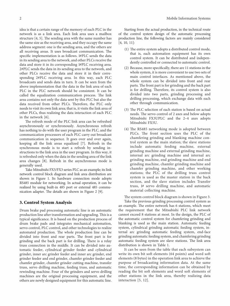
Starting from the actual production, in the technical routeof the control system design of the automatic processingproduction line, the following factors are mainly considered[4, 10, 11]:
(1) (e entire system adopts a distributed control mode,that is, each automation equipment has its owncontrol system. It can be distributed and indepen-dently controlled or connected to automatic control.
(2) Because, more specifically, there are 11 stations in thewhole system, it is more convenient to use two sets ofmain control interfaces. As mentioned above, thewhole system can be divided into front and rearparts. (e front part is for grinding and the back partis for drilling. (erefore, its control system is alsodivided into two parts, grinding processing anddrilling processing, which exchange data with eachother through communication.
(3) (e PLC selection of each station is based on actualneeds. (e servo control of 2 axes and below adoptsMitsubishi FX3UPLC and the 2–4 axes adoptsMitsubishi FX5U.
(4) (e RS485 networking mode is adopted betweenPLCs. (e front section uses the PLC of thechamfering grinding and blanking machine con-trol system as the main station; the slave stationsinclude automatic feeding machine, externalgrinding machine and external grinding machine,internal arc grinding machine and internal arcgrinding machine, end grinding machine and endgrinding machine, chamfer grinding machine andchamfer grinding machine, and other workingstations; the PLC of the drilling truss controlsystem is used as the master station in the backsection, and the slave station includes Transfertruss, 1# servo drilling machine, and automaticmaterial collecting machine.
(e system control block diagram is shown in Figure 3.Take the previous grinding processing control system as
an example. (e entire network has 6 stations, which meetthe requirement that the Mitsubishi PLC link networkcannot exceed 8 stations at most. In the design, the PLC ofthe automatic control system for chamfering grinding andblanking is used as the main station. Automatic feedingsystem, cylindrical grinding automatic feeding system, in-ternal arc grinding automatic feeding system, end-facegrinding automatic feeding system, and chamfering grindingautomatic feeding system are slave stations. (e link areadistribution is shown in Table 1.
It can be seen from the table that each subsystem canwrite its own bit soft elements (64 points) and word softelements (8 bytes) in the operation link area to achieve thepurpose of broadcasting information data. At the sametime, the corresponding information can be obtained byreading the bit soft elements and word soft elements ofother stations in the link area, thereby realizing datainteraction [5, 12].
2 Mobile Information Systems

4. Communication Program Design
It can be seen from the above that there are 6 stations in theentire network of the grinding process control system. Now,take the automatic feeding system of the end-face mill as anexample to illustrate its communication program design.
(e realization function of the automatic feeding systemof the end-face grinder is to suck the product from thedischarge position of the inner arc grinder.(en, turn it overto transform the product posture from the concave surface
up to the convex surface up and then place it in the feedingposition of the end-face grinding feeder. (e control ele-ments include four sets of servo motors, a set of rotatingcylinders, two sets of vacuum suction cups, and the start andstop of the end-face grinder. (e communication data in-cludes bit soft elements with input state (X) 40 points andoutput state (Y) 40 points. Manual operation button has 56points and other signals have 28 points. (e word device has80 bytes of parameter data register (D). (e data register (D)of the current position, target position, and alarm
SDA
(TXD+)
(TXD–)
(TXD–)
(TXD+)
(TXD–)
(TXD–)
(TXD+)
(TXD–)
(TXD–)
(TXD+)
(TXD+) (TXD+)
SDA SDA
SDA
SDB SDB SDB
SDB
SG SG SG
SDB SDB
SDA SDA
Terminalresistance110Ω∗2
Terminalresistance110Ω∗2
Figure 2: FX5/FX3 series PLC link block diagram.
Built-inRS-485 port
Built-inRS-485 port
RS-485 communicationequipment
Bit so� element
Word so� element Word so� element Word so� element
Bit so� element Bit so� element
(Bit so� element number: M0)
(Word so� element number: D100) (Word so� element number: D2000) (Word so� element number: fixed)
(Bit so� element number: M200) (Bit so� element number: Fixed)
M0 ~ M63
M64 ~ M27
M448 ~ M511
D100 ~ D107 D2000 ~ D2007
D2010 ~ D2017
D2020 ~ D2027
D2070 ~ D2077
D110 ~ D117
D120 ~ D127
D170 ~ D177
M200 ~ M263
D0 ~ D7
D10 ~ D17
D20 ~ D27
D70 ~ D77
M1000 ~ M1063
M1064 ~ M1127
M1128 ~ M1191
M1448 ~ M1511
M264 ~ M327
M328 ~ M391
M648 ~ M711
Figure 1: FX5/FX3 series PLC link block diagram.
Mobile Information Systems 3

information of the motor is 36 bytes. (e timing of the datacommunication interaction is when the system starts; themaster station downloads the data in the parameter dataregister to the slave station. When setting parameters, storethe corresponding parameter data register to the corre-sponding register of the slave station. When operating themotor, write information such as the target position of themotor to the slave.(e slave station uploads the input status,output status, manual operation and other bit soft elements,motor current position, alarm information, and other softelement data to the master station for processing and dis-play. (ere are 5 slave stations, and the amount of datauploaded and downloaded from each slave station is similar.(e data bit soft elements that can be operated by the masterstation and the slave station are only 64 points and 8 bytes ofsoft elements; this memory is not sufficient, which is ob-viously far from enough [13].
From the perspective of communication nature, theprocess is nothing more than the download of data from themaster station and the upload of data from the slave station[2, 14]. Combined with modular programming ideas, thispaper proposes a two-way read-write module design mode.(at is, the master station download is used by the masterstation write module and the slave station read module tocomplete the download of the master station data, and theslave station data upload is combined by the slave stationwrite module and the master station read module tocomplete the slave station data upload. (e master stationand the slave station call the corresponding modules in realtime as needed during their work. (erefore, it is definedthat D0∼D1 are the current register numbers written into themaster station, and D2∼D7 are the data of the 3 groups ofregisters corresponding to the register numbers in sequence.For example, if D0∼D1 are 200, write the contents of the
D200∼D201 registers of the master station into D2∼D3. (econtents of the D202∼D203 registers of the master stationare written into D4∼D5. (e contents of the D204∼D205registers of the master station are written into D6∼D7.M1001 writes the flag bit of the automatic feeding system ofthe end-face grinder of the slave station 2 for the masterstation. (at is to say, this bit indicates that the currentD0∼D7 operation is writing to slave 2. In the same way, theregister corresponding to the automatic feeding system ofthe slave station end-face grinder is assigned to defineD20∼D21 to write the current register number of the masterstation. D22∼D27 are the data of the 3 groups of registerscorresponding to the register number in sequence. Forexample, if D20∼D21 are 300, write the contents of theD300∼D301 registers of the master station into D22∼D23.(e contents of the D302∼D303 registers of the masterstation are written into D24∼D25. (e contents of theD304∼D305 registers of the master station are written intoD26∼D27. M1128 is the slave station 2 to write the masterstation standard bit, that is, this bit is set to indicate that thecurrent D0∼D7 operation is to write to the master station.
(e parameter download module needs to be executedwhen the master station starts or sets the parameters. (eparameters that need to be written to slave station 2 arestored in the D400∼D479 registers, which are stored in theform of double bytes. After writing to slave station 2, it needsto be saved in the D200∼D279 registers. When M141 is set,the parameter download of slave 2 is started. First, preset theinitial value of Z3 index register to K194 and then add K6 toZ3 every time you start writing; until Z3 is greater than 279,it means that all parameters have been written to reset M141and stop writing. It can be seen that Z3 is K200 when writingfor the first time; execute MOVP Z3 D0, DMOVP D200Z3D2, DMOVPD202Z3D4, and DMOVPD204Z3D6 in order
Automatic receiptControl System
Internal arcgrinding feedingcontrol system
Chamferinggrinding feedingcontrol system
Cylindricalgrinding feedingcontrol system
Chamfer grinding cutting control
system
End millfeeding control
system
Automaticfeeding control
system
Automatic drillingcontrol system
Drilling truss controlSystem
Transit TrussControl System
Industrial touchscreen
Industrialtouch screen
485 totallines
485 totallines
232 totallines
232 totallines
10 signal
10 signal
Figure 3: System control block diagram.
Table 1: Distribution table of the link area of the grinding processing control system.
Station number Name Bit soft element Soft elementMain site 0 Automatic control system for chamfering grinding M1000∼M1063 D0∼D7
Follow station
1 Automatic feeding system for chamfering mill M1064∼M1127 D10∼D172 Automatic feeding system for face mill M1128∼M1191 D20∼D273 Internal arc grinding automatic feeding system M1192∼M1255 D30∼D374 Cylindrical grinding automatic feeding system M1256∼M1319 D40∼D475 Automatic feeding system M1320∼M1383 D50∼D57
4 Mobile Information Systems
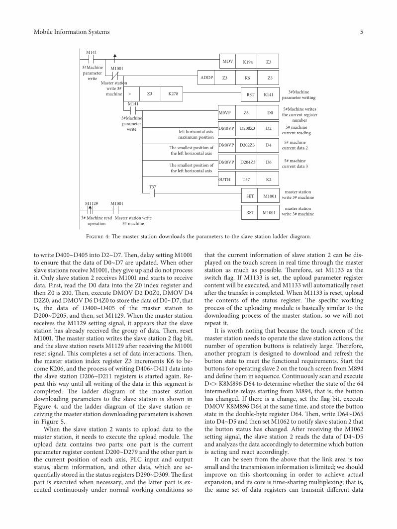
to write D400∼D405 into D2∼D7.(en, delay settingM1001to ensure that the data of D0∼D7 are updated. When otherslave stations receiveM1001, they give up and do not processit. Only slave station 2 receives M1001 and starts to receivedata. First, read the D0 data into the Z0 index register andthen Z0 is 200. (en, execute DMOV D2 D0Z0, DMOV D4D2Z0, and DMOVD6D4Z0 to store the data of D0∼D7, thatis, the data of D400∼D405 of the master station toD200∼D205, and then, set M1129. When the master stationreceives the M1129 setting signal, it appears that the slavestation has already received the group of data. (en, resetM1001. (e master station writes the slave station 2 flag bit,and the slave station resets M1129 after receiving the M1001reset signal. (is completes a set of data interactions. (en,the master station index register Z3 increments K6 to be-come K206, and the process of writing D406∼D411 data intothe slave station D206∼D211 registers is started again. Re-peat this way until all writing of the data in this segment iscompleted. (e ladder diagram of the master stationdownloading parameters to the slave station is shown inFigure 4, and the ladder diagram of the slave station re-ceiving the master station downloading parameters is shownin Figure 5.
When the slave station 2 wants to upload data to themaster station, it needs to execute the upload module. (eupload data contains two parts: one part is the currentparameter register content D200∼D279 and the other part isthe current position of each axis, PLC input and outputstatus, alarm information, and other data, which are se-quentially stored in the status registers D290∼D309.(e firstpart is executed when necessary, and the latter part is ex-ecuted continuously under normal working conditions so
that the current information of slave station 2 can be dis-played on the touch screen in real time through the masterstation as much as possible. (erefore, set M1133 as theswitch flag. If M1133 is set, the upload parameter registercontent will be executed, and M1133 will automatically resetafter the transfer is completed. When M1133 is reset, uploadthe contents of the status register. (e specific workingprocess of the uploading module is basically similar to thedownloading process of the master station, so we will notrepeat it.
It is worth noting that because the touch screen of themaster station needs to operate the slave station actions, thenumber of operation buttons is relatively large. (erefore,another program is designed to download and refresh thebutton state to meet the functional requirements. Start thebuttons for operating slave 2 on the touch screen fromM894and define them in sequence. Continuously scan and executeD<> K8M896 D64 to determine whether the state of the 64intermediate relays starting from M894, that is, the buttonhas changed. If there is a change, set the flag bit, executeDMOV K8M896 D64 at the same time, and store the buttonstate in the double-byte register D64. (en, write D64∼D65into D4∼D5 and then set M1062 to notify slave station 2 thatthe button status has changed. After receiving the M1062setting signal, the slave station 2 reads the data of D4∼D5and analyzes the data accordingly to determine which buttonis acting and react accordingly.
It can be seen from the above that the link area is toosmall and the transmission information is limited; we shouldimprove on this shortcoming in order to achieve actualexpansion, and its core is time-sharing multiplexing; that is,the same set of data registers can transmit different data
M141
M141
M1129 M1001
T37
M10013#Machineparameter
write
3#Machineparameter
write
3#Machineparameter writing
5#Machine writesthe current register
number5# machine
current reading
5# machinecurrent data 3
5# machinecurrent data 2
Master stationwrite 3#machine
master stationwrite 3# machine
master stationwrite 3# machine
Master station write3# machine
3# Machine readoperation
> Z3 K278 K141RST
M0VP
K194
K6
D0
D200Z3
D204Z3
D202Z3
DM0VP
DM0VP
DM0VP
0UTH
D4
D6
K2
D2
T37
Z3
Z3
Z3
Z3
SET
RST M1001
M1001
MOV
ADDP
le� horizontal axismaximum position
�e smallest position ofthe le� horizontal axis
�e smallest position ofthe le� horizontal axis
Figure 4: (e master station downloads the parameters to the slave station ladder diagram.
Mobile Information Systems 5

under different conditions at different times, such as the softelements D0∼D7 controlled by the master station. It candownload data from one to five hundreds of parameterregisters of the slave station and can also set the targetposition and running speed of dozens of servo motors in theslave station in pseudoreal time. At the same time, buttonoperations can be performed on hundreds of actions of eachslave. (e fundamental problem is to operate the linkregister in time intervals and, at the same time, realizeoperation selection and handshake interaction with thecorresponding bit soft elements. Priority settings are per-formed in time-sharing multiplexing to determine whenthere are data transmission requirements at the same timeand execute them in order, from the highest to the lowest, toavoid data conflicts or confusion. In this way, the PLCcommunication program is designed and the link area isimproved. Use the index register to store the register numberand register data, respectively, in the soft element of the linkarea, and cooperate with the operation of the correspondingbit soft element to carry out the handshake operation. In thisway, the link area of limited data can be used to achieve moredata interaction.
5. Conclusion
Based on the PLC link network communicationmethod, thispaper proposes an improved PLC communication programdesign method. (e time-sharing multiplexing method isadopted, the soft elements in the link area are used forregister address and data transmission, and the bit soft el-ements in the link area are used as interactive handshakesignals. In this way, a large-scale data transmission inter-action between the master and slave stations is completed,and the control system of the drum brake pad automaticprocessing production line can be realized, and good resultshave been achieved. After nearly a year of long-term op-eration, the data interaction performance is stable, and thedelay caused by the time-sharing interaction is extremelyshort and does not affect the operation, and the overall effectis good. (is proves that this design method has high re-liability, stability, and scalability in application and has
certain reference significance and reference value in PLCdistributed link network control systems such as automatedproduction lines.
Data Availability
(e data that support the findings of this study are availablefrom the corresponding author upon reasonable request.
Conflicts of Interest
(e authors declare no conflicts of interest with respect tothe research, authorship, and/or publication of this article.
Acknowledgments
(is work was supported by (1) Dongguan Polytechnic 2020horizontal project: (e development of an online dis-charging machine for automatic drum brake pad processing(no. 2020PH09), (2) Guangdong Provincial Department ofEducation 2020 Industry-Education Integration PlatformProject (project no. 2020CJPT019), and (3) general project ofHunan Provincial Department of Education (project no.17C0620).
References
[1] T. Zhang and P. Zhang, “(e application of PLC networkcommunication in the on-site control of industry,” ElectronicProduction, vol. 10, no. 09, pp. 168-169, 2015.
[2] J. Ma, F. Wang, and Z. Fan, “Communication realizationbased on Q series PLC network system,” Technological In-novation and Application, vol. 23, no. 05, p. 78, 2016.
[3] W. Ting, W. Gong, D. Meng, and S. Yang, “Design of dis-tributed PLC network control system for oil field pumps,”Journal of Xi’an Technological University, vol. 39, no. 06,pp. 696–702, 2019.
[4] R. Jian, “Application of Siemens PLC network in advancedmanufacturing production line,” Science and Technology In-novation, vol. 14, no. 14, pp. 37-38, 2019.
[5] H.Wu, Y. Zheng, and Y. Liu, “(e application of PLC networkin the automatic welding line of vehicle axle,” +ermal pro-cessing technology, vol. 48, no. 03, pp. 235–238, 2019.
5#Machine writesthe current register
number
5#Machine writesthe current register
number
5# machinecurrent data 1
5# machinecurrent data 2
5# machinecurrent data 2
5# machinecurrent data 3
5# machinecurrent data 1
Read operation
Read operation
Masterstation write3# machine
Masterstation write3# machine
M1001
M1001
M0V
DM0V
DM0V
DM0V
D0
D2
Z0
D0Z0
D4
D6
SET
RST
D2Z0
D4Z0
M1129
M1129
Figure 5: Ladder diagram of downloading parameters from the master station.
6 Mobile Information Systems

[6] Y. Shi, H. Fang, and W. Wang, “Design of airport terminallighting monitoring system based on PLC network andconfiguration technology,” Microcomputer Applications,vol. 36, no. 16, pp. 102–105+109, 2017.
[7] J. Jiang, “Optimization of the PLC network communication ofthe heating furnace combustion control system of the hotrolling line,” Equipment management and maintenance, vol. 2,no. 02, pp. 92-93, 2020.
[8] J. Han, “(e establishment and monitoring of PLC controlnetwork,” Computer Knowledge and Technology, vol. 16,no. 01, pp. 15-16+22, 2020.
[9] Mitsubishi Electric Automation (China) Co. Ltd, FX5 UserManual (Serial Communication), pp. 12–41, MitsubishiElectric Automation (China) Co. Ltd, Shanghai, China, 2015.
[10] S. Bai and B. Liu, “Design of PLC distributed control pro-duction line based on fieldbus,” J). Precision Manufacturingand Automation, vol. 35, no. 04, pp. 17-18+45, 2019.
[11] K. Xue and D. Wang, “Realization of RS-485 communicationfor extruder control system based on Omron PLC,” Rubberand Plastics Technology and Equipment, vol. 45, no. 05,pp. 42–46, 2019.
[12] M. Shao, J. Wang, S. Zhang, and W. Qin, “(e application ofPLC network control system in the automated production lineof optical fiber materials,”Manufacturing Automation, vol. 39,no. 05, pp. 19–21, 2017.
[13] Blessing and F. Gao, “PLC network control technology forlarge shipbuilding gantry cranes,” Guangdong Shipbuilding,vol. 35, no. 02, pp. 44–46, 2016.
[14] T. Zhang and P. Zhang, “(e application of PLC networkcommunication in industrial field control,” Electronic Pro-duction, vol. 10, no. 09, pp. 168-169, 2015.
Mobile Information Systems 7