
research 1..9 - Femius Koenderink
9
Spin-Dependent Emission from Arrays of Planar Chiral Nanoantennas Due to Lattice and Localized Plasmon Resonances Michele Cotrufo,* ,†,‡ Clara I. Osorio, ‡ and A. Femius Koenderink ‡ † COBRA Research Institute, Eindhoven University of Technology, 5600 MB Eindhoven, The Netherlands ‡ Center for Nanophotonics, FOM Institute AMOLF, Science Park 104, 1098 XG Amsterdam, The Netherlands * S Supporting Information ABSTRACT: Chiral plasmonic nanoantennas manifest a strong asymmetric response to circularly polarized light. Particularly, the geometric handedness of a plasmonic structure can alter the circular polarization state of light emitted from nearby sources, leading to a spin-dependent emission direction. In past experiments, these effects have been attributed entirely to the localized plasmonic resonances of single antennas. In this work, we demonstrate that, when chiral nanoparticles are arranged in diffractive arrays, lattice resonances play a primary role in determining the spin- dependent emission of light. We fabricate 2D diffractive arrays of planar chiral metallic nanoparticles embedded in a light- emitting dye-doped slab. By measuring the polarized photo- luminescence enhancement, we show that the geometric chirality of the array’s unit cell induces a preferential circular polarization, and that both the localized surface plasmon resonance and the delocalized hybrid plasmonic−photonic mode contribute to this phenomenon. By further mapping the angle-resolved degree of circular polarization, we demonstrate that strong chiral dissymmetries are mainly localized at the narrow emission directions of the surface lattice resonances. We validate these results against a coupled dipole model calculation, which correctly reproduces the main features. Our findings demonstrate that, in diffractive arrays, lattice resonances play a primary role into the light spin−orbit effect, introducing a highly nontrivial behavior in the angular spectra. KEYWORDS: localized plasmon resonances, surface lattice resonances, k-space polarimetry, chirality, plasmonic nanoantennas, spin−orbit P lasmonic nanoantennas can control, manipulate, and redirect emission of light by providing an interface between plane waves in the far-field and localized emitters in the near-field. 1 While intrinsically based on the material resonance of free electrons, shape and aspect ratio of these nanoantennas can be used to tune antenna performance in terms of resonance frequency, near-field enhancement, and spontaneous emission decay rate enhancement. 2 Moreover, antenna shape can impart preferential polarization on the emission of nearby emitters. 2 Indeed, localized surface plasmon resonances (LSPRs) supported by anisotropic structures such as nanorods, bowtie antennas, patch antennas, or split rings can strongly favor particular electric field components. 3,4 Therefore, light polarization plays a key role in the behavior of nanoantennas. Strong polarization responses are not exclusive to linear polarization: plasmonic antennas can be highly selective with respect to the helicity of light if they possess a geometric chirality. 5 Chiral objects cannot be superimposed onto their mirror image by mere rotations and translations and interact differently with right-handed (RCP) and left-handed (LCP) circularly polarized light (CPL). For chiral molecular matter, this interaction is usually described in terms of far-field quantities like optical activity, which describes the rotation of incident linear polarization, or circular dichroism, which accounts for preferential absorption of right- or left-handed circularly polarized light. Several experimental and theoretical studies have shown that planar chiral structures such as gammadions 6 or spirals 7 and 3D chiral structures like helices 8,9 can exhibit large optical activity and circular dichroism 10−14 and can enhance the weak circular dichroism signals obtained from biological chiral molecules. 5,15 Chiral nanostructures can also Received: November 16, 2015 Accepted: February 8, 2016 Article www.acsnano.org © XXXX American Chemical Society A DOI: 10.1021/acsnano.5b07231 ACS Nano XXXX, XXX, XXX−XXX
-
Upload
khangminh22 -
Category
Documents
-
view
2 -
download
0
Transcript of research 1..9 - Femius Koenderink
Spin-Dependent Emission from Arrays ofPlanar Chiral Nanoantennas Due to Lattice andLocalized Plasmon ResonancesMichele Cotrufo,*,†,‡ Clara I. Osorio,‡ and A. Femius Koenderink‡
†COBRA Research Institute, Eindhoven University of Technology, 5600 MB Eindhoven, The Netherlands‡Center for Nanophotonics, FOM Institute AMOLF, Science Park 104, 1098 XG Amsterdam, The Netherlands
*S Supporting Information
ABSTRACT: Chiral plasmonic nanoantennas manifest astrong asymmetric response to circularly polarized light.Particularly, the geometric handedness of a plasmonicstructure can alter the circular polarization state of lightemitted from nearby sources, leading to a spin-dependentemission direction. In past experiments, these effects havebeen attributed entirely to the localized plasmonic resonancesof single antennas. In this work, we demonstrate that, whenchiral nanoparticles are arranged in diffractive arrays, latticeresonances play a primary role in determining the spin-dependent emission of light. We fabricate 2D diffractive arraysof planar chiral metallic nanoparticles embedded in a light-emitting dye-doped slab. By measuring the polarized photo-luminescence enhancement, we show that the geometric chirality of the array’s unit cell induces a preferential circularpolarization, and that both the localized surface plasmon resonance and the delocalized hybrid plasmonic−photonic modecontribute to this phenomenon. By further mapping the angle-resolved degree of circular polarization, we demonstrate thatstrong chiral dissymmetries are mainly localized at the narrow emission directions of the surface lattice resonances. Wevalidate these results against a coupled dipole model calculation, which correctly reproduces the main features. Ourfindings demonstrate that, in diffractive arrays, lattice resonances play a primary role into the light spin−orbit effect,introducing a highly nontrivial behavior in the angular spectra.
KEYWORDS: localized plasmon resonances, surface lattice resonances, k-space polarimetry, chirality, plasmonic nanoantennas,spin−orbit
Plasmonic nanoantennas can control, manipulate, andredirect emission of light by providing an interfacebetween plane waves in the far-field and localized
emitters in the near-field.1 While intrinsically based on thematerial resonance of free electrons, shape and aspect ratio ofthese nanoantennas can be used to tune antenna performancein terms of resonance frequency, near-field enhancement, andspontaneous emission decay rate enhancement.2 Moreover,antenna shape can impart preferential polarization on theemission of nearby emitters.2 Indeed, localized surface plasmonresonances (LSPRs) supported by anisotropic structures suchas nanorods, bowtie antennas, patch antennas, or split rings canstrongly favor particular electric field components.3,4 Therefore,light polarization plays a key role in the behavior ofnanoantennas.Strong polarization responses are not exclusive to linear
polarization: plasmonic antennas can be highly selective withrespect to the helicity of light if they possess a geometric
chirality.5 Chiral objects cannot be superimposed onto theirmirror image by mere rotations and translations and interactdifferently with right-handed (RCP) and left-handed (LCP)circularly polarized light (CPL). For chiral molecular matter,this interaction is usually described in terms of far-fieldquantities like optical activity, which describes the rotation ofincident linear polarization, or circular dichroism, whichaccounts for preferential absorption of right- or left-handedcircularly polarized light. Several experimental and theoreticalstudies have shown that planar chiral structures such asgammadions6 or spirals7 and 3D chiral structures like helices8,9
can exhibit large optical activity and circular dichroism10−14 andcan enhance the weak circular dichroism signals obtained frombiological chiral molecules.5,15 Chiral nanostructures can also
Received: November 16, 2015Accepted: February 8, 2016
Artic
lewww.acsnano.org
© XXXX American Chemical Society A DOI: 10.1021/acsnano.5b07231ACS Nano XXXX, XXX, XXX−XXX
alter the far-field polarization state of fluorescent sourcespositioned in their near-field. Split-ring resonators, for example,have been shown to provide spin control16 of photons emittedfrom II−VI semiconductor quantum dots. In a recentexperiment by Meinzer et al.,17 it was shown that a planarchiral arrangement of two silver nanorods embedded in a slabof achiral emitters gives rise to a substantial asymmetry in theintensity of LCP and RCP light emitted normal to the sample.In this experiment, the handedness of emission is inheritedfrom the handed nature of the localized plasmonic resonancesof the antennas.In this work, we investigate periodic arrays of planar chiral
antennas interacting with achiral emitters and show thatdiffractive resonances play a dominant role in determiningthe spin-dependent directional emission. Plasmonic antennaarrays with pitches comparable to the wavelength are known toexhibit hybrid plasmonic−photonic modes with very narrowline widths18 known as surface lattice resonances (SLRs).19
These modes arise from radiative coupling between LSPRs andwaves diffracted into the plane of the array. For simple antennashapes, like rods, this hybrid resonance has been shown tostrongly improve the photoluminescence properties of nearbyemitters20 and, in particular, to drastically modify their angularemission pattern.21 While Meinzer et al.17 and Kruk et al.16
attributed chiral emission properties to the physics of singleantennas, their structures were actually arranged in arrays,triggering the question of how surface lattice resonances impacthandedness in emission.We report k-space polarimetry measurements22,23 that
quantify how asymmetries in circularly polarized light emissionare distributed over an angle, as mapped across the back
aperture of a microscope objective. We demonstrate that theSLR introduces much larger CPL asymmetries at selectedangles than what is observed in experiments that only consideremission normal to the array.
Sample Design, Optimization, and Characterization.In this work, we study periodic arrays of chiral and achiraldimer antennas fabricated on a glass substrate and embedded ina thin dye-doped polymer layer. We emphasize that, apart fromthe small refractive index contrast introduced by the substrate,the structures considered in this work are not 3D chiral, butthey possess a planar chirality. Previous works have shown24
that planar chiral structures feature strong asymmetric responsefor the transmission of CPL because the handedness is reversedwhen they are observed from opposite sides.The achiral dimers consist of two identical silver rod
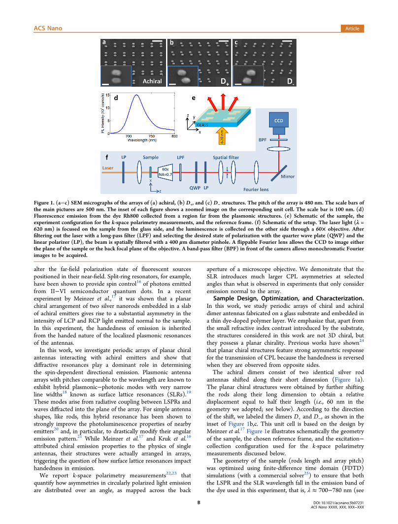
antennas shifted along their short dimension (Figure 1a).The planar chiral structures were obtained by further shiftingthe rods along their long dimension to obtain a relativedisplacement equal to half their length (i.e., 60 nm in thegeometry we adopted; see below). According to the directionof the shift, we labeled the dimers D+ and D−, as shown in theinset of Figure 1b,c. This unit cell is based on the design byMeinzer et al.17 Figure 1e illustrates schematically the geometryof the sample, the chosen reference frame, and the excitation−collection configuration used for the k-space polarimetrymeasurements discussed below.The geometry of the sample (rods length and array pitch)
was optimized using finite-difference time domain (FDTD)simulations (with a commercial solver25) to ensure that boththe LSPR and the SLR wavelength fall in the emission band ofthe dye used in this experiment, that is, λ ≈ 700−780 nm (see
Figure 1. (a−c) SEM micrographs of the arrays of (a) achiral, (b) D+, and (c) D− structures. The pitch of the array is 480 nm. The scale bars ofthe main pictures are 500 nm. The inset of each figure shows a zoomed image on the corresponding unit cell. The scale bar is 100 nm. (d)Fluorescence emission from the dye Rh800 collected from a region far from the plasmonic structures. (e) Schematic of the sample, theexperiment configuration for the k-space polarimetry measurements, and the reference frame. (f) Schematic of the setup. The laser light (λ =620 nm) is focused on the sample from the glass side, and the luminescence is collected on the other side through a 60× objective. Afterfiltering out the laser with a long-pass filter (LPF) and selecting the desired state of polarization with the quarter wave plate (QWP) and thelinear polarizer (LP), the beam is spatially filtered with a 400 μm diameter pinhole. A flippable Fourier lens allows the CCD to image eitherthe plane of the sample or the back focal plane of the objective. A band-pass filter (BPF) in front of the camera allows monochromatic Fourierimages to be acquired.
ACS Nano Article
DOI: 10.1021/acsnano.5b07231ACS Nano XXXX, XXX, XXX−XXX
B
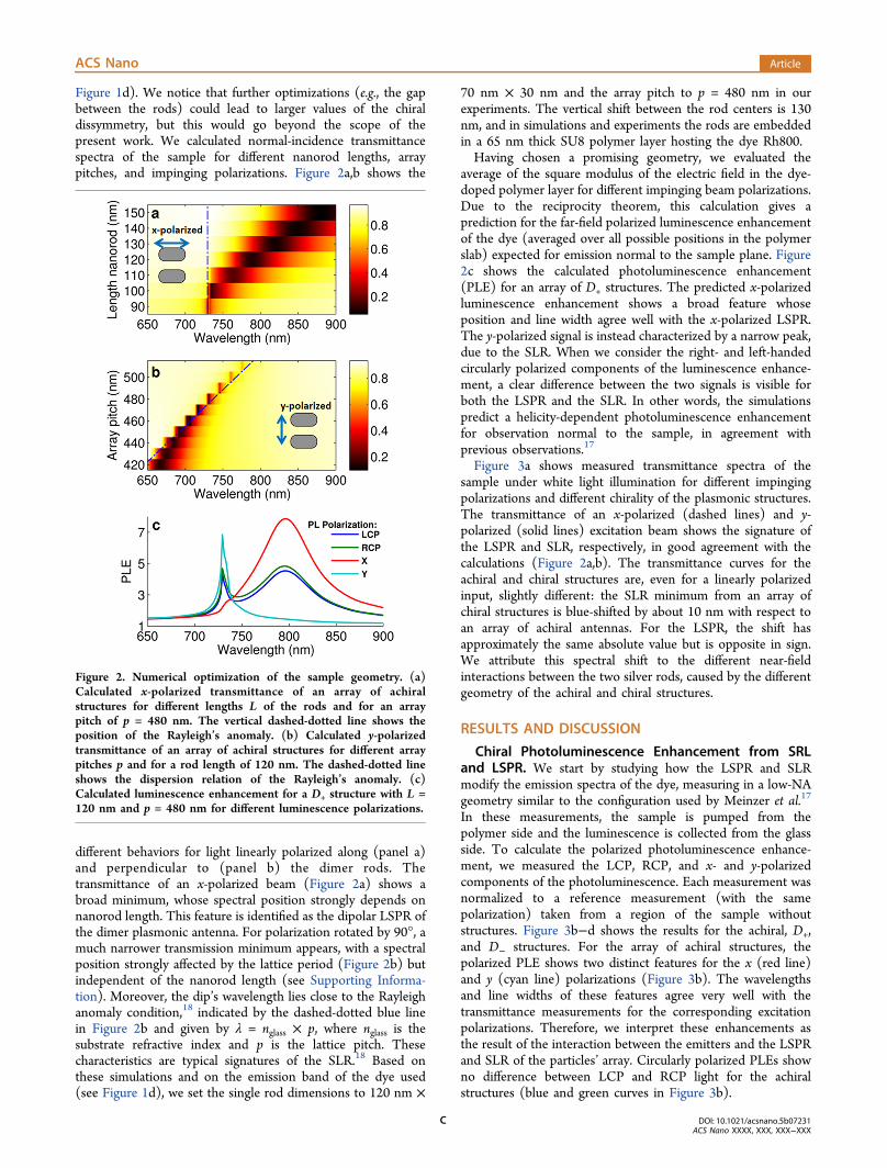
Figure 1d). We notice that further optimizations (e.g., the gapbetween the rods) could lead to larger values of the chiraldissymmetry, but this would go beyond the scope of thepresent work. We calculated normal-incidence transmittancespectra of the sample for different nanorod lengths, arraypitches, and impinging polarizations. Figure 2a,b shows the
different behaviors for light linearly polarized along (panel a)and perpendicular to (panel b) the dimer rods. Thetransmittance of an x-polarized beam (Figure 2a) shows abroad minimum, whose spectral position strongly depends onnanorod length. This feature is identified as the dipolar LSPR ofthe dimer plasmonic antenna. For polarization rotated by 90°, amuch narrower transmission minimum appears, with a spectralposition strongly affected by the lattice period (Figure 2b) butindependent of the nanorod length (see Supporting Informa-tion). Moreover, the dip’s wavelength lies close to the Rayleighanomaly condition,18 indicated by the dashed-dotted blue linein Figure 2b and given by λ = nglass × p, where nglass is thesubstrate refractive index and p is the lattice pitch. Thesecharacteristics are typical signatures of the SLR.18 Based onthese simulations and on the emission band of the dye used(see Figure 1d), we set the single rod dimensions to 120 nm ×
70 nm × 30 nm and the array pitch to p = 480 nm in ourexperiments. The vertical shift between the rod centers is 130nm, and in simulations and experiments the rods are embeddedin a 65 nm thick SU8 polymer layer hosting the dye Rh800.Having chosen a promising geometry, we evaluated the
average of the square modulus of the electric field in the dye-doped polymer layer for different impinging beam polarizations.Due to the reciprocity theorem, this calculation gives aprediction for the far-field polarized luminescence enhancementof the dye (averaged over all possible positions in the polymerslab) expected for emission normal to the sample plane. Figure2c shows the calculated photoluminescence enhancement(PLE) for an array of D+ structures. The predicted x-polarizedluminescence enhancement shows a broad feature whoseposition and line width agree well with the x-polarized LSPR.The y-polarized signal is instead characterized by a narrow peak,due to the SLR. When we consider the right- and left-handedcircularly polarized components of the luminescence enhance-ment, a clear difference between the two signals is visible forboth the LSPR and the SLR. In other words, the simulationspredict a helicity-dependent photoluminescence enhancementfor observation normal to the sample, in agreement withprevious observations.17
Figure 3a shows measured transmittance spectra of thesample under white light illumination for different impingingpolarizations and different chirality of the plasmonic structures.The transmittance of an x-polarized (dashed lines) and y-polarized (solid lines) excitation beam shows the signature ofthe LSPR and SLR, respectively, in good agreement with thecalculations (Figure 2a,b). The transmittance curves for theachiral and chiral structures are, even for a linearly polarizedinput, slightly different: the SLR minimum from an array ofchiral structures is blue-shifted by about 10 nm with respect toan array of achiral antennas. For the LSPR, the shift hasapproximately the same absolute value but is opposite in sign.We attribute this spectral shift to the different near-fieldinteractions between the two silver rods, caused by the differentgeometry of the achiral and chiral structures.
RESULTS AND DISCUSSION
Chiral Photoluminescence Enhancement from SRLand LSPR. We start by studying how the LSPR and SLRmodify the emission spectra of the dye, measuring in a low-NAgeometry similar to the configuration used by Meinzer et al.17
In these measurements, the sample is pumped from thepolymer side and the luminescence is collected from the glassside. To calculate the polarized photoluminescence enhance-ment, we measured the LCP, RCP, and x- and y-polarizedcomponents of the photoluminescence. Each measurement wasnormalized to a reference measurement (with the samepolarization) taken from a region of the sample withoutstructures. Figure 3b−d shows the results for the achiral, D+,and D− structures. For the array of achiral structures, thepolarized PLE shows two distinct features for the x (red line)and y (cyan line) polarizations (Figure 3b). The wavelengthsand line widths of these features agree very well with thetransmittance measurements for the corresponding excitationpolarizations. Therefore, we interpret these enhancements asthe result of the interaction between the emitters and the LSPRand SLR of the particles’ array. Circularly polarized PLEs showno difference between LCP and RCP light for the achiralstructures (blue and green curves in Figure 3b).
Figure 2. Numerical optimization of the sample geometry. (a)Calculated x-polarized transmittance of an array of achiralstructures for different lengths L of the rods and for an arraypitch of p = 480 nm. The vertical dashed-dotted line shows theposition of the Rayleigh’s anomaly. (b) Calculated y-polarizedtransmittance of an array of achiral structures for different arraypitches p and for a rod length of 120 nm. The dashed-dotted lineshows the dispersion relation of the Rayleigh’s anomaly. (c)Calculated luminescence enhancement for a D+ structure with L =120 nm and p = 480 nm for different luminescence polarizations.
ACS Nano Article
DOI: 10.1021/acsnano.5b07231ACS Nano XXXX, XXX, XXX−XXX
C
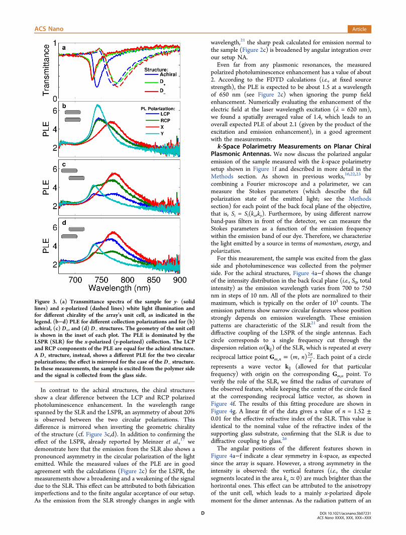
In contrast to the achiral structures, the chiral structuresshow a clear difference between the LCP and RCP polarizedphotoluminescence enhancement. In the wavelength rangespanned by the SLR and the LSPR, an asymmetry of about 20%is observed between the two circular polarizations. Thisdifference is mirrored when inverting the geometric chiralityof the structure (cf. Figure 3c,d). In addition to confirming theeffect of the LSPR, already reported by Meinzer et al.,17 wedemonstrate here that the emission from the SLR also shows apronounced asymmetry in the circular polarization of the lightemitted. While the measured values of the PLE are in goodagreement with the calculations (Figure 2c) for the LSPR, themeasurements show a broadening and a weakening of the signaldue to the SLR. This effect can be attributed to both fabricationimperfections and to the finite angular acceptance of our setup.As the emission from the SLR strongly changes in angle with
wavelength,21 the sharp peak calculated for emission normal tothe sample (Figure 2c) is broadened by angular integration overour setup NA.Even far from any plasmonic resonances, the measured
polarized photoluminescence enhancement has a value of about2. According to the FDTD calculations (i.e., at fixed sourcestrength), the PLE is expected to be about 1.5 at a wavelengthof 650 nm (see Figure 2c) when ignoring the pump fieldenhancement. Numerically evaluating the enhancement of theelectric field at the laser wavelength excitation (λ = 620 nm),we found a spatially averaged value of 1.4, which leads to anoverall expected PLE of about 2.1 (given by the product of theexcitation and emission enhancement), in a good agreementwith the measurements.
k-Space Polarimetry Measurements on Planar ChiralPlasmonic Antennas. We now discuss the polarized angularemission of the sample measured with the k-space polarimetrysetup shown in Figure 1f and described in more detail in theMethods section. As shown in previous works,16,22,23 bycombining a Fourier microscope and a polarimeter, we canmeasure the Stokes parameters (which describe the fullpolarization state of the emitted light; see the Methodssection) for each point of the back focal plane of the objective,that is, Si = Si(kx,ky). Furthermore, by using different narrowband-pass filters in front of the detector, we can measure theStokes parameters as a function of the emission frequencywithin the emission band of our dye. Therefore, we characterizethe light emitted by a source in terms of momentum, energy, andpolarization.For this measurement, the sample was excited from the glass
side and photoluminescence was collected from the polymerside. For the achiral structures, Figure 4a−f shows the changeof the intensity distribution in the back focal plane (i.e., S0, totalintensity) as the emission wavelength varies from 700 to 750nm in steps of 10 nm. All of the plots are normalized to theirmaximum, which is typically on the order of 103 counts. Theemission patterns show narrow circular features whose positionstrongly depends on emission wavelength. These emissionpatterns are characteristic of the SLR21 and result from thediffractive coupling of the LSPR of the single antennas. Eachcircle corresponds to a single frequency cut through thedispersion relation ω(k∥) of the SLR, which is repeated at every
reciprocal lattice point = πm nG ( , )m n d,2 . Each point of a circle
represents a wave vector k∥ (allowed for that particularfrequency) with origin on the corresponding Gm,n point. Toverify the role of the SLR, we fitted the radius of curvature ofthe observed feature, while keeping the center of the circle fixedat the corresponding reciprocal lattice vector, as shown inFigure 4f. The results of this fitting procedure are shown inFigure 4g. A linear fit of the data gives a value of n = 1.52 ±0.01 for the effective refractive index of the SLR. This value isidentical to the nominal value of the refractive index of thesupporting glass substrate, confirming that the SLR is due todiffractive coupling to glass.26
The angular positions of the different features shown inFigure 4a−f indicate a clear symmetry in k-space, as expectedsince the array is square. However, a strong asymmetry in theintensity is observed: the vertical features (i.e., the circularsegments located in the area kx ≃ 0) are much brighter than thehorizontal ones. This effect can be attributed to the anisotropyof the unit cell, which leads to a mainly x-polarized dipolemoment for the dimer antennas. As the radiation pattern of an
Figure 3. (a) Transmittance spectra of the sample for y- (solidlines) and x-polarized (dashed lines) white light illumination andfor different chirality of the array’s unit cell, as indicated in thelegend. (b−d) PLE for different collection polarizations and for (b)achiral, (c) D+, and (d) D− structures. The geometry of the unit cellis shown in the inset of each plot. The PLE is dominated by theLSPR (SLR) for the x-polarized (y-polarized) collection. The LCPand RCP components of the PLE are equal for the achiral structure.A D+ structure, instead, shows a different PLE for the two circularpolarizations; the effect is mirrored for the case of the D− structure.In these measurements, the sample is excited from the polymer sideand the signal is collected from the glass side.
ACS Nano Article
DOI: 10.1021/acsnano.5b07231ACS Nano XXXX, XXX, XXX−XXX
D
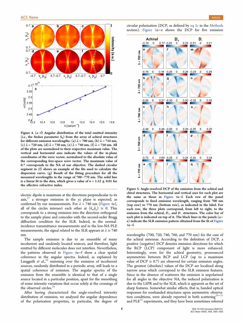
electric dipole is maximum at the directions perpendicular to itsaxis,27 a stronger emission in the yz plane is expected, asconfirmed by our measurements. For λ = 740 nm (Figure 4e),all of the circles intersect each other at (kx,ky) ≃ 0. Thiscorresponds to a strong emission into the direction orthogonalto the sample plane and coincides with the second-order Braggdiffraction condition for the SLR. Indeed, in the normal-incidence transmittance measurements and in the low-NA PLEmeasurements, the signal related to the SLR appears at λ ≃ 740nm.The sample emission is due to an ensemble of many
incoherent and randomly located sources, and therefore, lightemitted by different molecules does not interfere. Nevertheless,the patterns observed in Figure 4a−f show a clear spatialcoherence in the angular spectra. Indeed, as explained byLangguth et al.,28 summing over the emission of incoherentsources, randomly distributed in a periodic array, still leads to aspatial coherence of emission. The angular spectra of theemission from the ensemble is identical to that of a singlesource located in a particular position, apart for the smoothingof some intensity variations that occur solely at the crossings ofthe observed circles.28
After having characterized the angle-resolved intensitydistribution of emission, we analyzed the angular dependenceof the polarization properties, in particular, the degree of
circular polarization (DCP, as defined by eq 2c in the Methodssection). Figure 5a−e shows the DCP for five emission
wavelengths (700, 720, 740, 760, and 770 nm) for the case ofthe achiral antennas. According to the definition of DCP, apositive (negative) DCP denotes emission directions for whichthe RCP (LCP) component of light is more enhanced.Interestingly, even for the achiral geometry, pronouncedasymmetries between RCP and LCP (up to a maximumvalue of DCP ≃ 0.7) are observed for certain emission angles.The greatest (absolute) values of the DCP are localized alongnarrow areas which correspond to the SLR emission features.Since in the absence of scatterers the emission is unpolarizedfor all angles in the objective NA, the induced polarization isdue to the LSPR and to the SLR, which is apparent as the set ofsharp features. Somewhat similar effects, that is, handed opticalresponses for nonhanded structures upon asymmetric observa-tion conditions, were already reported in both scattering29−31
and PLE16 experiments, and they have been sometimes referred
Figure 4. (a−f) Angular distribution of the total emitted intensity(i.e., the Stokes parameter S0) from the array of achiral structuresfor different emission wavelengths: (a) λ = 700 nm, (b) λ = 710 nm,(c) λ = 720 nm, (d) λ = 730 nm, (e) λ = 740 nm, (f) λ = 750 nm. Allof the plots are normalized to their respective maximum value. Thevertical and horizontal axes indicate the values of the in-planecoordinates of the wave vector, normalized to the absolute value ofthe corresponding free-space wave vector. The maximum value of0.7 corresponds to the NA of our objective. The dashed circularsegment in (f) shows an example of the fits used to calculate thedispersion curve. (g) Result of the fitting procedure for all themeasured wavelengths in the range of 700−770 nm. The solid lineis a linear fit to the data, which gives a value of n = 1.52 ± 0.01 forthe effective refractive index.
Figure 5. Angle-resolved DCP of the emission from the achiral andchiral structures. The horizontal and vertical axes for each plot arethe same as those in Figure 4a−f. Each row of the panelcorresponds to fixed emission wavelength, ranging from 700 nm(top row) to 770 nm (bottom row), as indicated in the label. Foreach row, the three plots correspond, from left to right, to theemission from the achiral, D+, and D− structures. The color bar ofeach plot is indicated on top of it. The black lines in the panels (a−e) indicate the SLR emission pattern obtained from the fit of Figure4a−f.
ACS Nano Article
DOI: 10.1021/acsnano.5b07231ACS Nano XXXX, XXX, XXX−XXX
E
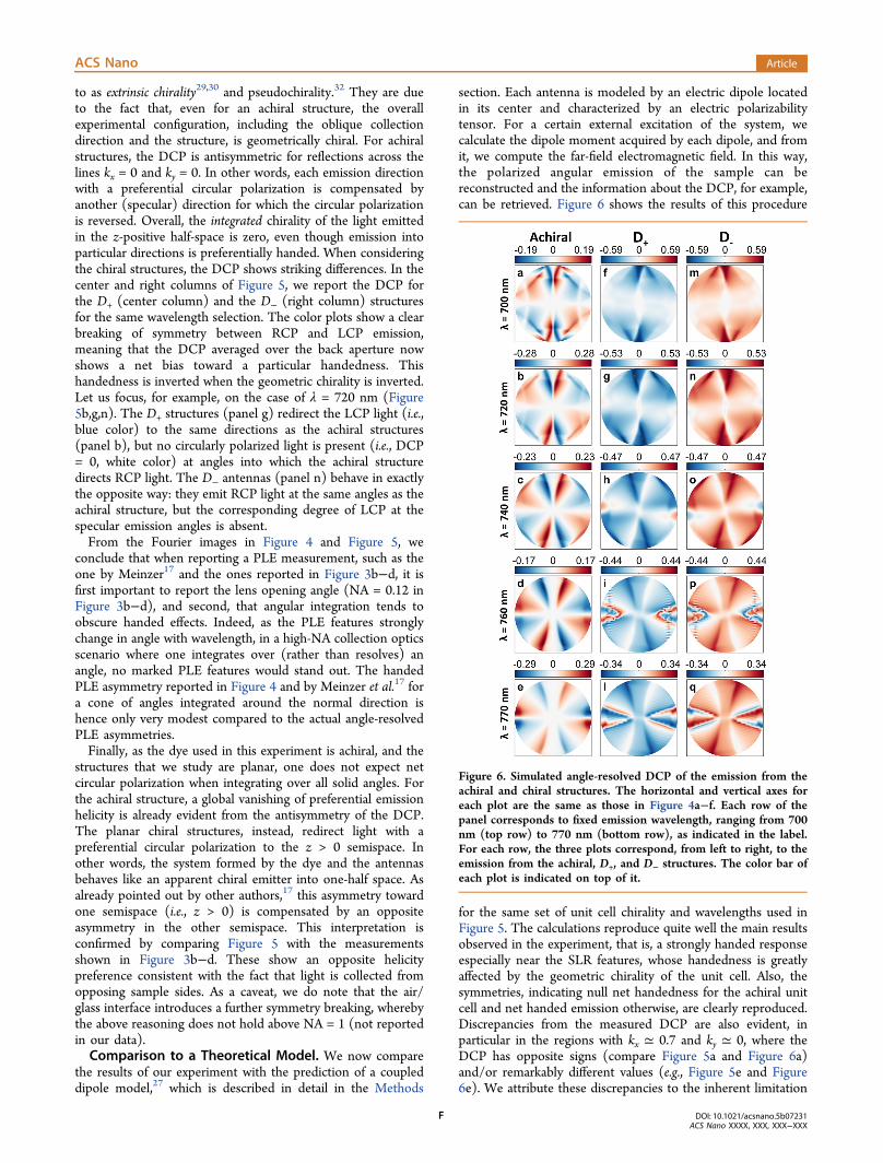
to as extrinsic chirality29,30 and pseudochirality.32 They are dueto the fact that, even for an achiral structure, the overallexperimental configuration, including the oblique collectiondirection and the structure, is geometrically chiral. For achiralstructures, the DCP is antisymmetric for reflections across thelines kx = 0 and ky = 0. In other words, each emission directionwith a preferential circular polarization is compensated byanother (specular) direction for which the circular polarizationis reversed. Overall, the integrated chirality of the light emittedin the z-positive half-space is zero, even though emission intoparticular directions is preferentially handed. When consideringthe chiral structures, the DCP shows striking differences. In thecenter and right columns of Figure 5, we report the DCP forthe D+ (center column) and the D− (right column) structuresfor the same wavelength selection. The color plots show a clearbreaking of symmetry between RCP and LCP emission,meaning that the DCP averaged over the back aperture nowshows a net bias toward a particular handedness. Thishandedness is inverted when the geometric chirality is inverted.Let us focus, for example, on the case of λ = 720 nm (Figure5b,g,n). The D+ structures (panel g) redirect the LCP light (i.e.,blue color) to the same directions as the achiral structures(panel b), but no circularly polarized light is present (i.e., DCP= 0, white color) at angles into which the achiral structuredirects RCP light. The D− antennas (panel n) behave in exactlythe opposite way: they emit RCP light at the same angles as theachiral structure, but the corresponding degree of LCP at thespecular emission angles is absent.From the Fourier images in Figure 4 and Figure 5, we
conclude that when reporting a PLE measurement, such as theone by Meinzer17 and the ones reported in Figure 3b−d, it isfirst important to report the lens opening angle (NA = 0.12 inFigure 3b−d), and second, that angular integration tends toobscure handed effects. Indeed, as the PLE features stronglychange in angle with wavelength, in a high-NA collection opticsscenario where one integrates over (rather than resolves) anangle, no marked PLE features would stand out. The handedPLE asymmetry reported in Figure 4 and by Meinzer et al.17 fora cone of angles integrated around the normal direction ishence only very modest compared to the actual angle-resolvedPLE asymmetries.Finally, as the dye used in this experiment is achiral, and the
structures that we study are planar, one does not expect netcircular polarization when integrating over all solid angles. Forthe achiral structure, a global vanishing of preferential emissionhelicity is already evident from the antisymmetry of the DCP.The planar chiral structures, instead, redirect light with apreferential circular polarization to the z > 0 semispace. Inother words, the system formed by the dye and the antennasbehaves like an apparent chiral emitter into one-half space. Asalready pointed out by other authors,17 this asymmetry towardone semispace (i.e., z > 0) is compensated by an oppositeasymmetry in the other semispace. This interpretation isconfirmed by comparing Figure 5 with the measurementsshown in Figure 3b−d. These show an opposite helicitypreference consistent with the fact that light is collected fromopposing sample sides. As a caveat, we do note that the air/glass interface introduces a further symmetry breaking, wherebythe above reasoning does not hold above NA = 1 (not reportedin our data).Comparison to a Theoretical Model. We now compare
the results of our experiment with the prediction of a coupleddipole model,27 which is described in detail in the Methods
section. Each antenna is modeled by an electric dipole locatedin its center and characterized by an electric polarizabilitytensor. For a certain external excitation of the system, wecalculate the dipole moment acquired by each dipole, and fromit, we compute the far-field electromagnetic field. In this way,the polarized angular emission of the sample can bereconstructed and the information about the DCP, for example,can be retrieved. Figure 6 shows the results of this procedure
for the same set of unit cell chirality and wavelengths used inFigure 5. The calculations reproduce quite well the main resultsobserved in the experiment, that is, a strongly handed responseespecially near the SLR features, whose handedness is greatlyaffected by the geometric chirality of the unit cell. Also, thesymmetries, indicating null net handedness for the achiral unitcell and net handed emission otherwise, are clearly reproduced.Discrepancies from the measured DCP are also evident, inparticular in the regions with kx ≃ 0.7 and ky ≃ 0, where theDCP has opposite signs (compare Figure 5a and Figure 6a)and/or remarkably different values (e.g., Figure 5e and Figure6e). We attribute these discrepancies to the inherent limitation
Figure 6. Simulated angle-resolved DCP of the emission from theachiral and chiral structures. The horizontal and vertical axes foreach plot are the same as those in Figure 4a−f. Each row of thepanel corresponds to fixed emission wavelength, ranging from 700nm (top row) to 770 nm (bottom row), as indicated in the label.For each row, the three plots correspond, from left to right, to theemission from the achiral, D+, and D− structures. The color bar ofeach plot is indicated on top of it.
ACS Nano Article
DOI: 10.1021/acsnano.5b07231ACS Nano XXXX, XXX, XXX−XXX
F
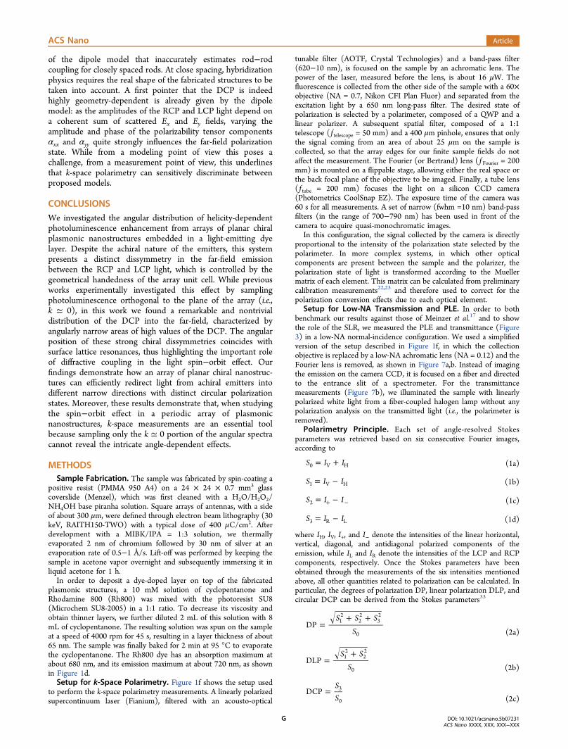
of the dipole model that inaccurately estimates rod−rodcoupling for closely spaced rods. At close spacing, hybridizationphysics requires the real shape of the fabricated structures to betaken into account. A first pointer that the DCP is indeedhighly geometry-dependent is already given by the dipolemodel: as the amplitudes of the RCP and LCP light depend ona coherent sum of scattered Ex and Ey fields, varying theamplitude and phase of the polarizability tensor componentsαxx and αyy quite strongly influences the far-field polarizationstate. While from a modeling point of view this poses achallenge, from a measurement point of view, this underlinesthat k-space polarimetry can sensitively discriminate betweenproposed models.
CONCLUSIONSWe investigated the angular distribution of helicity-dependentphotoluminescence enhancement from arrays of planar chiralplasmonic nanostructures embedded in a light-emitting dyelayer. Despite the achiral nature of the emitters, this systempresents a distinct dissymmetry in the far-field emissionbetween the RCP and LCP light, which is controlled by thegeometrical handedness of the array unit cell. While previousworks experimentally investigated this effect by samplingphotoluminescence orthogonal to the plane of the array (i.e.,k ≃ 0), in this work we found a remarkable and nontrivialdistribution of the DCP into the far-field, characterized byangularly narrow areas of high values of the DCP. The angularposition of these strong chiral dissymmetries coincides withsurface lattice resonances, thus highlighting the important roleof diffractive coupling in the light spin−orbit effect. Ourfindings demonstrate how an array of planar chiral nanostruc-tures can efficiently redirect light from achiral emitters intodifferent narrow directions with distinct circular polarizationstates. Moreover, these results demonstrate that, when studyingthe spin−orbit effect in a periodic array of plasmonicnanostructures, k-space measurements are an essential toolbecause sampling only the k ≃ 0 portion of the angular spectracannot reveal the intricate angle-dependent effects.
METHODSSample Fabrication. The sample was fabricated by spin-coating a
positive resist (PMMA 950 A4) on a 24 × 24 × 0.7 mm3 glasscoverslide (Menzel), which was first cleaned with a H2O/H2O2/NH4OH base piranha solution. Square arrays of antennas, with a sideof about 300 μm, were defined through electron beam lithography (30keV, RAITH150-TWO) with a typical dose of 400 μC/cm2. Afterdevelopment with a MIBK/IPA = 1:3 solution, we thermallyevaporated 2 nm of chromium followed by 30 nm of silver at anevaporation rate of 0.5−1 Å/s. Lift-off was performed by keeping thesample in acetone vapor overnight and subsequently immersing it inliquid acetone for 1 h.In order to deposit a dye-doped layer on top of the fabricated
plasmonic structures, a 10 mM solution of cyclopentanone andRhodamine 800 (Rh800) was mixed with the photoresist SU8(Microchem SU8-2005) in a 1:1 ratio. To decrease its viscosity andobtain thinner layers, we further diluted 2 mL of this solution with 8mL of cyclopentanone. The resulting solution was spun on the sampleat a speed of 4000 rpm for 45 s, resulting in a layer thickness of about65 nm. The sample was finally baked for 2 min at 95 °C to evaporatethe cyclopentanone. The Rh800 dye has an absorption maximum atabout 680 nm, and its emission maximum at about 720 nm, as shownin Figure 1d.Setup for k-Space Polarimetry. Figure 1f shows the setup used
to perform the k-space polarimetry measurements. A linearly polarizedsupercontinuum laser (Fianium), filtered with an acousto-optical
tunable filter (AOTF, Crystal Technologies) and a band-pass filter(620−10 nm), is focused on the sample by an achromatic lens. Thepower of the laser, measured before the lens, is about 16 μW. Thefluorescence is collected from the other side of the sample with a 60×objective (NA = 0.7, Nikon CFI Plan Fluor) and separated from theexcitation light by a 650 nm long-pass filter. The desired state ofpolarization is selected by a polarimeter, composed of a QWP and alinear polarizer. A subsequent spatial filter, composed of a 1:1telescope ( f telescope = 50 mm) and a 400 μm pinhole, ensures that onlythe signal coming from an area of about 25 μm on the sample iscollected, so that the array edges for our finite sample fields do notaffect the measurement. The Fourier (or Bertrand) lens ( f Fourier = 200mm) is mounted on a flippable stage, allowing either the real space orthe back focal plane of the objective to be imaged. Finally, a tube lens( f tube = 200 mm) focuses the light on a silicon CCD camera(Photometrics CoolSnap EZ). The exposure time of the camera was60 s for all measurements. A set of narrow (fwhm =10 nm) band-passfilters (in the range of 700−790 nm) has been used in front of thecamera to acquire quasi-monochromatic images.
In this configuration, the signal collected by the camera is directlyproportional to the intensity of the polarization state selected by thepolarimeter. In more complex systems, in which other opticalcomponents are present between the sample and the polarizer, thepolarization state of light is transformed according to the Muellermatrix of each element. This matrix can be calculated from preliminarycalibration measurements22,23 and therefore used to correct for thepolarization conversion effects due to each optical element.
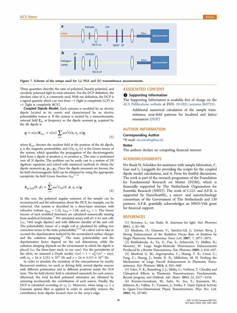
Setup for Low-NA Transmission and PLE. In order to bothbenchmark our results against those of Meinzer et al.17 and to showthe role of the SLR, we measured the PLE and transmittance (Figure3) in a low-NA normal-incidence configuration. We used a simplifiedversion of the setup described in Figure 1f, in which the collectionobjective is replaced by a low-NA achromatic lens (NA = 0.12) and theFourier lens is removed, as shown in Figure 7a,b. Instead of imagingthe emission on the camera CCD, it is focused on a fiber and directedto the entrance slit of a spectrometer. For the transmittancemeasurements (Figure 7b), we illuminated the sample with linearlypolarized white light from a fiber-coupled halogen lamp without anypolarization analysis on the transmitted light (i.e., the polarimeter isremoved).
Polarimetry Principle. Each set of angle-resolved Stokesparameters was retrieved based on six consecutive Fourier images,according to
= +S I I0 V H (1a)
= −S I I1 V H (1b)
= −+ −S I I2 (1c)
= −S I I3 R L (1d)
where IH, IV, I+, and I− denote the intensities of the linear horizontal,vertical, diagonal, and antidiagonal polarized components of theemission, while IL and IR denote the intensities of the LCP and RCPcomponents, respectively. Once the Stokes parameters have beenobtained through the measurements of the six intensities mentionedabove, all other quantities related to polarization can be calculated. Inparticular, the degrees of polarization DP, linear polarization DLP, andcircular DCP can be derived from the Stokes parameters33
=+ +S S S
SDP 1
222
32
0 (2a)
=+S S
SDLP 1
222
0 (2b)
=SS
DCP 3
0 (2c)
ACS Nano Article
DOI: 10.1021/acsnano.5b07231ACS Nano XXXX, XXX, XXX−XXX
G
These quantities describe the ratio of polarized, linearly polarized, andcircularly polarized light to total emission. For the DCP definition, theabsolute value of S3 is commonly used. With our definition, the DCP isa signed quantity which can vary from −1 (light is completely LCP) to+1 (light is completely RCP).Coupled Dipole Model. Each antenna is modeled by an electric
dipole located in its center and characterized by an electricpolarizability tensor α. If the system is excited by a monochromaticexternal field Einc at frequency ω, the dipole moment pi acquired bythe ith dipole is
∑α ω α ω μω ω= +≠
Gp E r r p( ) ( ) ( , , )i ij i
i j jinc,2
(3)
where Einc,i denotes the incident field at the position of the ith dipole,μ is the magnetic permeability, and G(ri, rj, ω) is the Green tensor ofthe system, which quantifies the propagation of the electromagneticfield from a dipole at position rj to position ri. The sum is performedover all N dipoles. The problem can be easily cast in a system of 3Nalgebraic equations and solved with numerical methods to obtain thedipole moments p1, p2,...pN. Once the dipole moments are known, thefar-field electromagnetic field can be obtained by using the appropriateasymptotic far-field Green function GFF
27,34
∑θ ϕ μω θ ϕ ω==
GE r p( , ) ( , , , )i
N
i ifar field1
2FF
(4)
In this way, the polarized angular emission of the sample can bereconstructed and the information about the DCP, for example, can beretrieved. Our system is described by a three-layer structure withrefractive indexes nglass = 1.52, nSU8 = 1.58, and nair = 1. The Greentensors of such stratified structures are calculated numerically startingfrom analytical formulas.27 We simulated arrays with 61 × 61 unit cells(i.e., 7442 single dipoles) and with different chirality of the unit cell.The polarizability tensor of a single rod is calculated by adding twocorrection terms to the static polarizability35,36 of a silver rod to take inaccount the depolarization induced by the accumulated surface chargesand the radiation damping.36 The static polarizability and thedepolarization factor depend on the rod dimensions, while theradiation damping depends on the environment in which the dipole isplaced (i.e., the three-layer stack, in our case). For the permittivity ofthe silver, we assumed a Drude model, ϵ(ω) = 1 − ωp
2/(ω2 − iωγ),with ωp = 2π × 2.321 × 1015 Hz and γ = 2π × 5.513 × 1012 Hz.In order to simulate the excitation of the nanoantennas by nearby
fluorescent emitters, we used, as driving field, several dipolar sourceswith different polarization and in different positions inside the SU8layer. The far-field electric field is calculated separately for each source.Afterward, the total far-field polarized intensities are obtained bysumming incoherently the contribution of each source. Finally, theDCP is calculated according to eq 2c. Moreover, when using eq 4, aGaussian spatial filter is applied in order to smoothly remove thecontribution from dipoles located close to the array’s edge.
ASSOCIATED CONTENT
*S Supporting InformationThe Supporting Information is available free of charge on theACS Publications website at DOI: 10.1021/acsnano.5b07231.
Additional numerical calculation of the sample trans-mittance, near-field patterns for localized and latticeresonances (PDF)
AUTHOR INFORMATION
Corresponding Author*E-mail: [email protected].
NotesThe authors declare no competing financial interest.
ACKNOWLEDGMENTS
We thank H. Schokker for assistance with sample fabrication, C.Guo and L. Langguth for providing the scripts for the coupleddipole model calculations, and A. Fiore for fruitful discussions.The work is part of the research programme of the Foundationfor Fundamental Research on Matter (FOM), which isfinancially supported by The Netherlands Organisation forScientific Research (NWO). The work of C.I.O. and A.F.K. issupported by NanoNextNL, a micro- and nanotechnologyconsortium of the Government of The Netherlands and 130partners. A.F.K. gratefully acknowledges an NWO-Vidi grantfor financial support.
REFERENCES(1) Novotny, L.; van Hulst, N. Antennas for light. Nat. Photonics2011, 5, 83−90.(2) Muskens, O.; Giannini, V.; Sanchez-Gil, J.; Gomez Rivas, J.Strong Enhancement of the Radiative Decay Rate of Emitters bySingle Plasmonic Nanoantennas. Nano Lett. 2007, 7, 2871−2875.(3) Kinkhabwala, A.; Yu, Z.; Fan, S.; Avlasevich, Y.; Mullen, K.;Moerner, W. Large Single-Molecule Fluorescence EnhancementsProduced by a Bowtie Nanoantenna. Nat. Photonics 2009, 3, 654−657.(4) Akselrod, G. M.; Argyropoulos, C.; Hoang, T. B.; Ciracì, C.;Fang, C.; Huang, J.; Smith, D. R.; Mikkelsen, M. H. Probing theMechanisms of Large Purcell Enhancement in Plasmonic Nano-antennas. Nat. Photonics 2014, 8, 835−840.(5) Valev, V. K.; Baumberg, J. J.; Sibilia, C.; Verbiest, T. Chirality andChiroptical Effects in Plasmonic Nanostructures: Fundamentals,Recent progress, and Outlook. Adv. Mater. 2013, 25, 2517−2534.(6) Kuwata-Gonokami, M.; Saito, N.; Ino, Y.; Kauranen, M.;Jefimovs, K.; Vallius, T.; Turunen, J.; Svirko, Y. Giant Optical Activityin Quasi-Two-Dimensional Planar Nanostructures. Phys. Rev. Lett.2005, 95, 227401.
Figure 7. Scheme of the setups used for (a) PLE and (b) transmittance measurements.
ACS Nano Article
DOI: 10.1021/acsnano.5b07231ACS Nano XXXX, XXX, XXX−XXX
H
(7) Gorodetski, Y.; Shitrit, N.; Bretner, I.; Kleiner, V.; Hasman, E.Observation of Optical Spin Symmetry Breaking in Nanoapertures.Nano Lett. 2009, 9, 3016−3019.(8) Kuzyk, A.; Schreiber, R.; Fan, Z.; Pardatscher, G.; Roller, E.-M.;Hogele, A.; Simmel, F. C.; Govorov, A. O.; Liedl, T. DNA-Based Self-Assembly of Chiral Plasmonic Nanostructures with Tailored OpticalResponse. Nature 2012, 483, 311−314.(9) Song, C.; Blaber, M. G.; Zhao, G.; Zhang, P.; Fry, H. C.; Schatz,G. C.; Rosi, N. L. Tailorable Plasmonic Circular Dichroism Propertiesof Helical Nanoparticle Superstructures. Nano Lett. 2013, 13, 3256−3261.(10) Decker, M.; Ruther, M.; Kriegler, C.; Zhou, J.; Soukoulis, C.;Linden, S.; Wegener, M. Strong Optical Activity from Twisted-CrossPhotonic Metamaterials. Opt. Lett. 2009, 34, 2501−2503.(11) Gorkunov, M.; Ezhov, A.; Artemov, V.; Rogov, O.; Yudin, S.Extreme Optical Activity and Circular Dichroism of Chiral Metal HoleArrays. Appl. Phys. Lett. 2014, 104, 221102.(12) Eftekhari, F.; Davis, T. J. Strong Chiral Optical Response fromPlanar Arrays of Subwavelength Metallic Structures Supporting SurfacePlasmon Resonances. Phys. Rev. B: Condens. Matter Mater. Phys. 2012,86, 075428.(13) Fan, Z.; Govorov, A. O. Plasmonic Circular Dichroism of ChiralMetal Nanoparticle Assemblies. Nano Lett. 2010, 10, 2580−2587.(14) Schaferling, M.; Dregely, D.; Hentschel, M.; Giessen, H.Tailoring Enhanced Optical Chirality: Design Principles for ChiralPlasmonic Nanostructures. Phys. Rev. X 2012, 2, 031010.(15) Hendry, E.; Carpy, T.; Johnston, J.; Popland, M.; Mikhaylovskiy,R. V.; Lapthorn, A. J.; Kelly, S. M.; Barron, L. D.; Gadegaard, N.;Kadodwala, M. Ultrasensitive Detection and Characterization ofBiomolecules Using Superchiral Fields. Nat. Nanotechnol. 2010, 5,783−787.(16) Kruk, S. S.; Decker, M.; Staude, I.; Schlecht, S.; Greppmair, M.;Neshev, D. N.; Kivshar, Y. S. Spin-Polarized Photon Emission byResonant Multipolar Nanoantennas. ACS Photonics 2014, 1, 1218−1223.(17) Meinzer, N.; Hendry, E.; Barnes, W. L. Probing the ChiralNature of Electromagnetic Fields Surrounding Plasmonic Nanostruc-tures. Phys. Rev. B: Condens. Matter Mater. Phys. 2013, 88, 041407.(18) Vecchi, G.; Giannini, V.; Gomez Rivas, J. Surface Modes inPlasmonic Crystals Induced by Diffractive Coupling of Nanoantennas.Phys. Rev. B: Condens. Matter Mater. Phys. 2009, 80, 201401.(19) Rodriguez, S.; Schaafsma, M.; Berrier, A.; Gomez Rivas, J.Collective Resonances in Plasmonic Crystals: Size Matters. Phys. B2012, 407, 4081−4085.(20) Lozano, G.; Louwers, D. J.; Rodríguez, S. R.; Murai, S.; Jansen,O. T.; Verschuuren, M. A.; Gomez Rivas, J. Plasmonics for Solid-StateLighting: Enhanced Excitation and Directional Emission of HighlyEfficient Light Sources. Light: Sci. Appl. 2013, 2, e66.(21) Lozano, G.; Grzela, G.; Verschuuren, M. A.; Ramezani, M.;Rivas, J. G. Tailor-Made Directional Emission in NanoimprintedPlasmonic-Based Light-emitting Devices. Nanoscale 2014, 6, 9223−9229.(22) Osorio, C. I.; Mohtashami, A.; Koenderink, A. K-spacePolarimetry of Bullseye Plasmon Antennas. Sci. Rep. 2015, 5, 9966.(23) Mohtashami, A.; Osorio, C. I.; Koenderink, A. F. Angle-Resolved Polarimetry Measurements of Antenna-Mediated Fluores-cence. arXiv:1506.00140 2015.(24) Fedotov, V.; Mladyonov, P.; Prosvirnin, S.; Rogacheva, A.;Chen, Y.; Zheludev, N. Asymmetric Propagation of ElectromagneticWaves through a Planar Chiral Structure. Phys. Rev. Lett. 2006, 97,167401.(25) Lumerical Solutions, Inc. http://www.lumerical.com/tcad-products/fdtd/.(26) Murai, S.; Verschuuren, M.; Lozano, G.; Pirruccio, G.;Rodriguez, S.; Rivas, J. G. Hybrid Plasmonic-Photonic Modes inDiffractive Arrays of Nanoparticles Coupled to Light-Emitting OpticalWaveguides. Opt. Express 2013, 21, 4250−4262.(27) Novotny, L.; Hecht, B. Principles of Nano-Optics; CambridgeUniversity Press: New York, 2006.
(28) Langguth, L.; Schokker, A.; Guo, K.; Koenderink, A. PlasmonicPhase-Gradient Metasurface for Spontaneous Emission Control. Phys.Rev. B: Condens. Matter Mater. Phys. 2015, 92, 205401.(29) Plum, E.; Fedotov, V.; Zheludev, N. Extrinsic ElectromagneticChirality in Metamaterials. J. Opt. A: Pure Appl. Opt. 2009, 11, 074009.(30) Lu, X.; Wu, J.; Zhu, Q.; Zhao, J.; Wang, Q.; Zhan, L.; Ni, W.Circular Dichroism from Single Plasmonic Nanostructures withExtrinsic Chirality. Nanoscale 2014, 6, 14244−14253.(31) Sersic, I.; van de Haar, M. A.; Bernal Arango, F.; Koenderink, A.F. Ubiquity of Optical Activity in Planar Metamaterial Scatterers. Phys.Rev. Lett. 2012, 108, 223903.(32) Lindell, I. V.; Sihvola, A. H.; Tretyakov, S. A.; Viitanen, A. J.Electromagnetic Waves in Chiral and Bi-isotropic Media; Artech House:Norwood, MA, 1994.(33) Goldstein, D. H. Polarized Light; CRC Press: Boca Raton, FL,2010.(34) Lukosz, W. Light Emission by Magnetic and Electric DipolesClose to a Plane Dielectric Interface. III. Radiation Patters of Dipoleswith Arbitrary Orientation. J. Opt. Soc. Am. 1979, 69, 1495−1503.(35) Maier, S. A. Plasmonics: Fundamentals and Applications; SpringerScience & Business Media: Berlin, 2007.(36) Hofmann, H. F.; Kosako, T.; Kadoya, Y. Design Parameters fora Nano-Optical Yagi-Uda Antenna. New J. Phys. 2007, 9, 217.
ACS Nano Article
DOI: 10.1021/acsnano.5b07231ACS Nano XXXX, XXX, XXX−XXX
I