Requirements and Potential for Enhanced EVA Information Interfaces
19
400 Commonwealth Drive, Warrendale, PA 15096-0001 U.S.A. Tel: (724) 776-4841 Fax: (724) 776-5760 Web: www.sae.org SAE TECHNICAL PAPER SERIES 2003-01-2413 Requirements and Potential for Enhanced EVA Information Interfaces Edward Hodgson and Ronald Sidgreaves Hamilton Sundstrand Space Systems International, Inc. Stephen Braham Simon Fraser University Jeffrey Hoffman and Christopher Carr Massachusetts Institute of Technology Pascal Lee SETI Institute (NASA Haughton-Mars Project) & Mars Institute Jose Marmolejo and Jonathan Miller NASA, Johnson Space Center Ilia Rosenberg The Boeing Company Steven Schwartz Symbol Technologies Inc. 33rd International Conference on Environmental Systems (ICES) Vancouver, B.C., Canada July 7-10, 2003
Transcript of Requirements and Potential for Enhanced EVA Information Interfaces

400 Commonwealth Drive, Warrendale, PA 15096-0001 U.S.A. Tel: (724) 776-4841 Fax: (724) 776-5760 Web: www.sae.org
SAE TECHNICALPAPER SERIES 2003-01-2413
Requirements and Potential for EnhancedEVA Information Interfaces
Edward Hodgson and Ronald SidgreavesHamilton Sundstrand Space Systems International, Inc.
Stephen BrahamSimon Fraser University
Jeffrey Hoffman and Christopher CarrMassachusetts Institute of Technology
Pascal Lee SETI Institute (NASA Haughton-Mars Project) & Mars Institute
Jose Marmolejo and Jonathan MillerNASA, Johnson Space Center
Ilia RosenbergThe Boeing Company
Steven SchwartzSymbol Technologies Inc.
33rd International Conference onEnvironmental Systems (ICES)
Vancouver, B.C., CanadaJuly 7-10, 2003

All rights reserved. No part of this publication may be reproduced, stored in a retrieval system, ortransmitted, in any form or by any means, electronic, mechanical, photocopying, recording, or otherwise,without the prior written permission of SAE.
For permission and licensing requests contact:
SAE Permissions400 Commonwealth DriveWarrendale, PA 15096-0001-USAEmail: [email protected]: 724-772-4891Tel: 724-772-4028
For multiple print copies contact:
SAE Customer ServiceTel: 877-606-7323 (inside USA and Canada)Tel: 724-776-4970 (outside USA)Fax: 724-776-1615Email: [email protected]
ISSN 0148-7191Copyright © 2003 Hamilton Sundstrand Space Systems International, Inc. Reprinted by SAE International with permission.Positions and opinions advanced in this paper are those of the author(s) and not necessarily those of SAE.The author is solely responsible for the content of the paper. A process is available by which discussionswill be printed with the paper if it is published in SAE Transactions.
Persons wishing to submit papers to be considered for presentation or publication by SAE should send themanuscript or a 300 word abstract of a proposed manuscript to: Secretary, Engineering Meetings Board, SAE.
Printed in USA

2003-01-2413
Hamilton Sundstrand Space Systems International, Inc.
Simon Fraser University
Massachusetts Institute of Technology
SETI Institute (NASA Haughton-Mars Project) & Mars Institute
NASA, Johnson Space Center
Steven Schwartz Symbol Technologies Inc.
ABSTRACT
NASA has long recognized the advantages of providing improved information interfaces to EVA astronauts andhas pursued this goal through a number of development programs over the past decade. None of these activities or parallel efforts in industry and academia has so farresulted in the development of an operational system to replace or augment the current extravehicular mobility unit (EMU) Display and Controls Module (DCM) display and cuff checklist. Recent advances in display,communications, and information processing technologies offer exciting new opportunities for EVA informationinterfaces that can better serve the needs of a variety of NASA missions. Hamilton Sundstrand Space Systems International (HSSSI) has been collaborating with SimonFraser University and others on the NASA Haughton Mars Project and with researchers at the MassachusettsInstitute of Technology (MIT), Boeing, and SymbolTechnologies in investigating these possibilities. Theobjectives of this research so far have been to better understand the ways in which an improved informationinterface may be applied in a variety of mission settings and to refine the definition of system design requirements to best support those applications.
Research efforts have combined the results of concept definition and mission requirements studies withexperiments in pressurized spacesuits in the laboratory and in lower fidelity test-beds in field settings. Several promising approaches for the integration of highly capable information interfaces with EVA systems have evolvedand have been evaluated in preliminary proof-of-concepttests. The results show considerable promise that anadvanced information interface could be adapted tosupport near-term orbital EVA missions and could beevolved to provide robust support for future planetaryexploration missions.
INTRODUCTION
Extravehicular activity (EVA) uniquely places humanintelligence, sensory capabilities, and manipulativeabilities where the action is in space missions. The result is a degree of flexibility and capability that has not yet been approached by any remotely operated, automated, or robotic system. Repeatedly, operational experiencehas demonstrated the value this provides for exploration, science, construction and maintenance in space.However, the key to effectively using this capability is the information that is provided to the human intellect on the scene. In general, the required information extends well beyond what can be directly seen and felt on the objects
Stephen Braham
Pascal Lee
Jose Marmolejo and Jonathan Miller
Ilia Rosenberg
Edward Hodgson and Ronald Sidgreaves
Jeffrey Hoffman and Christopher Carr
Copyright © 2003 Hamilton Sundstrand Space Systems International, Inc. Reprinted by SAE International with permission.
Information InterfacesRequirements and Potential for Enhanced EVA
The Boeing Company

to be explored or manipulated. Information supportsystems are required and have, historically, been animportant part of every EVA mission.
However, these information support systems have also resulted in additional significant overhead. They haveentailed extensive, highly specific training to ensure that the EVA astronaut is armed with most of the neededinformation before the event. This internal information is supplemented by relatively simple reminders and cues in a “cuff check list” and verbal support over the radio from ground or vehicle-based personnel or another EVAastronaut. Limited real-time information about the status of the EVA systems has been provided by a simple (25 character) text display.
This paper combines insights and contributions from a number of investigators within NASA, industry, andacademia who have been exploring alternative ways inwhich information can be provided to the EVA astronaut to better support his or her work in space. It includes consideration of what information will be most useful in future missions, how it can be presented to best help the astronaut, and how it can respond more flexibly tochanging or unanticipated mission needs while reducing the mission cost of providing it.
HISTORICAL PERSPECTIVE, NEEDS AND POTENTIAL
Experience with current operational systems and priorattempts to develop more capable alternatives provides an historical perspective on both the needs and potential for EVA information interfaces. Seen from the viewpoints of both technology developers and astronaut users, this provides important guidance in identifying goals andpromising avenues of exploration for current and longer term EVA information interface research.
EXPERIMENTAL HELMET-MOUNTED DISPLAYS (HMDS) AND CUFF CHECK LIST
Research was conducted at the NASA/Johnson SpaceCenter (NASA/JSA) in the mid-to-late 1980s (References 1 & 2) in order to investigate new spacesuit technologies that could be utilized to provide the astronaut with "hands-free" access to key information while performing an EVA.Specifically, this research focused on incorporatinghelmet-mounted display (HMD) technology and the use of voice control within the next generation of spacesuits to improve EVA productivity and to reduce trainingdemands. During this period, NASA completed four HMD feasibility development projects for the design anddevelopment of an EMU HMD, each resulting in thedelivery of a binocular or biocular HMD breadboard unit utilizing conventional optical elements (i.e., glass lenses and beamsplitters) and/or holographic optics. The goal of each project was to provide a low-profile, transparent screen, conveniently located above the EVAcrewmember’s normal field-of-view that is capable ofdisplaying text, graphics, and video. The HMDs werethen coupled with additional research into voicerecognition technology (References 3 - 8) in order toprovide the EVA astronaut with "hands-free" access to information. Table 1 summarizes the principalcharacteristics of each HMD design.
The results of these projects were valuable in determining key requirements and identifying key integration issues for incorporation of the HMD into the spacesuit.Unfortunately, HMD integration costs for the Shuttleextravehicular mobility unit (EMU) were exceptionallyhigh, and the decision was made to attempt to integrate the HMD into the next generation of spacesuit only.
Table 1. Summary of NASA/JSC Experimental HMD Projects Major Design CharacteristicsWright-Patterson AFB Hamilton Standard
HMDAPA HMD Technology Innovative
GroupViewing: Binocular w/ 20 mm exit
pupilsBinocular w/ 26 mm cubed eye-box
Binocular w/ 26 mm exit pupils
Bi-ocular w/ 2" x 1" x 5" eye-box
Image Source: 25 mm CRT (2) LCDs (2) 17 mm CRT (2) CRT (modified Sony Watchman )
Resolution: 525 lines 320 x 220 pixel 525 lines 525 linesField-of-View: 47° diagonal (1/3 overlap) 17° diagonal 25° diagonal 25° diagonalOptics: Conventional only Conventional only Conventional and
holographicConventional and Holographic
Image Focal Distance:
~ 3 feet ~ 4 feet to infinity (60 feet)
~ 4 feet ~ 4 feet
Power Consumption: > 20 watts ~ 7 watts < 10 watts < 5 watts
Data input: RS-170 RS-170 RS-170 RS-170Volume: Large, > 18" diameter
dome requiredLarge, > 17" diameter dome required
Small, ~15.5" to 16"diameter dome required
Small, ~15.5" diameter dome required

As a result, NASA has opted, in the near term, to create an information display system consisting of an electronic version of the paper checklist that is currently flown. This "electronic checklist" is expected to improve astronaut EVA productivity by providing a portable, self-containedinformation display system allowing the crewmember to have ready access to a much larger database. This database is even capable of being modified on-orbit.
The electronic checklist developed as shown in Figure 1 consists of an off-the-shelf liquid crystal display, touch screen (for screen selection), driver electronics (including micro-controller, memory, and serial data programmingport), and battery pack enclosed in an aluminum frame protected, thermally, by softgoods (Reference 9). Access to the memory contents is accomplished via the touch screen through a unique "sextant" screen protocol. Worn over the space suit arm assembly (as is the current papercuff checklist), the electronic cuff checklist provides an easy access to text and graphics databases of greater than 500 pages. This database is both reprogrammable and expandable via a serial data port to accommodate the data requirements of various Shuttle and expectedInternational Space Station (ISS) EVA mission tasks.Software training tools were also designed to allowefficient creation of "pages" and for loading of thechecklist's database.
Figure 1. NASA’s electronic cuff check list prototype used a liquid crystal display and touch screen control interface.
An in-flight EVA evaluation of the electronic checklist was performed on Shuttle Flights STS-63, STS-64, STS-69,and STS-72. Although some design modifications were made between these experiments to address designdeficiencies identified, in the end, performance of theelectronic checklist was only marginal. The key areas for improvement for the electronic checklist were packaging
(around the suit arm) and the need for a more robust display.
A second-generation electronic checklist is currentlyunder development by NASA/JSC and is expected to be flown in late 2004.
A USER’S PERSPECTIVE, ISSUES AND FUTURENEEDS
The environment in which EVAs are conducted is hostile, unforgiving of mechanical failures or human errors. The ultimate goal of EVA suit designers is to make suiting up for EVA no harder than putting on the sort of protective gear needed to go outside in other hostile environments such as Antarctica or cold-water SCUBA diving. However,this EVA utopia is probably several generations of new materials in the future, and at present part of the task of an EVA astronaut is to learn through training how to use a spacesuit as a tool through which to interact with theenvironment. The perception that “I am making my suit move in such a way as to accomplish this task” isfundamentally different from “I am doing this task.”Familiarity with spacesuits gained during years of training allows astronauts to use spacesuits without a lot ofconscious thought about suit mechanics, just as drivers learn to use a standard gearshift almost subconsciously. But a competent EVA astronaut can never forget aspacesuit’s limitations, and the fact that in a sense he is ultimately a tele-operator, using the suit as anintermediary to manipulate the environment.
A critical factor in successful tele-operation activities is to maximize situational awareness. An EVA astronaut has far more situational awareness than observers inside the Shuttle/Station or on the ground, but suit constraintsseverely limit this awareness. Even a simple act liketurning one’s head to see what is behind is impossible in a spacesuit. Astronauts carry TV cameras on theirhelmets to share views of their workspaces with theircolleagues, but they currently have no way of using this TV capability to increase their own situational awareness. Even if they had pointable helmet- or body-mounted TV cameras that could in principle show them what is going on in different directions, astronauts have no way at present to display such information for their own use. The same would be true if a “god’s-eye view” were madeavailable by a Sprint-AERCam (an experimental tele-operated free flying camera flown by NASA on STS-87) or some similar technology. Such a view can be immensely useful to observers for monitoring clearances, pathplanning, and numerous other purposes, but theastronaut, who could probably make the most use of such a view, currently has no way of seeing it.
Moreover, even if they could see the views, astronauts have no capability to use the images generated by their TV cameras to communicate with their colleagues with any precision. Suppose, for example, that an astronaut is

working on a repair task and comes across a detail worth bringing to the attention of ground experts. A camera can be pointed at the work area and the astronaut can try to describe in words the detail at issue, or if the geometry is favorable the astronaut may be able to point with herfinger. How primitive! TV sports viewers are used toseeing cursors used all the time to point out areas of interest in a scene, but this elementary form oftelecommunication is beyond the scope of EVAastronauts.
When an astronaut is communicating with human beings, the use of verbal descriptions to indicate an area of interest in a visual scene, while often inefficient, is at least possible. The situation changes if we imagine future astronauts trying to interact with robotic systems. Theefficiency of space-suited explorers on remote planetarysurfaces will be enhanced immeasurably if they can work with robots accompanying them on their geologicaltraverses and carrying out tasks at their request. Imagine setting up a temporary sample collection base at astrategic location. Rather than have to walk or drivearound from rock to rock, an astronaut could work at a central location and tell a robot to “Go bring me that rock.” But how can you indicate which rock you are talkingabout? Describing the size, shape and color of the rock might work with a human assistant, but until artificial intelligence becomes a lot more sophisticated, it won’t work with a robot. A simple cursor placed on a scene generated by the robot’s TV vision system would be far more efficient. Dealing with computer displays is secondnature to even elementary students these days, but this technology is not available to astronauts.
How can an astronaut constrained in a spacesuit control computer displays: select pages, scroll up and down, and move cursors? A glove-compatible keyboard is onepossibility, but an astronaut’s hands are too valuable to have their time consumed by controlling computerdisplays. Hand control might be reasonable as a backup, but it is appropriate to consider what other effectors are available. Voice is a possibility, but you can’t talk to your computer and your colleagues at the same time, and you don’t want your computer to mistake a comment to acolleague for a command. Astronauts inside the Shuttle or Station have “push to talk” buttons, but using these takes up one hand. To avoid this, EVA astronautscurrently are always on “hot mike.” Could one create the vocal equivalent of a “push to talk” button? Othereffectors are possible. For instance, EVA astronautsperiodically sip on a straw connected to a water baginside their spacesuits. Could blowing or sucking on astraw be an efficient hands-off way of controllingcommunications modes and computer displays?
If we have learned anything from complex EVA activities such as repair and servicing missions for the HubbleSpace Telescope or ISS construction missions, it is that where EVA is concerned, the most valuable and limited resource is “useful human time outside.” Part of the quest
to maximize the ratio of useful time outside to the total time devoted to EVA is to reduce the overhead involved in pre- and post-EVA activities such as suit preparation, prebreathing, and suit cleanup. However, it is just as important to increase the efficiency of the time astronauts spend outside, and the efficient use of informationtechnology can be an important aspect of this effort.
Many new EVA information technologies can be tested on the ground and in water tanks. However, real confidence in space systems only comes when they have been used in space. The International Space Station is the focus of a huge amount of EVA activity. Once construction is complete, the ISS will hopefully become not only avaluable scientific laboratory but also a test-bed for new space technology, including EVA technology. When we have demonstrated in space the ability of EVA astronauts to use advanced information technology to increase their situational awareness, to communicate with theircolleagues, and to control robotic systems, then we will be much farther along in our readiness to extend humanexploration farther from the Earth.
EXPANDED UTILITY IN EXPLORATION SETTINGS –DESIGN IMPLICATIONS
As suggested by the preceding user’s viewpointdiscussion, information interfaces for future explorationEVA and near-term orbital missions may be expected to share many demands and design characteristics. Thefundamental functional needs and constraints are notexpected to change dramatically. However, significant growth in the need for flexibility and autonomy can be anticipated and must be supported by increasingly flexible information interfaces.
EVA information interfaces must support basic activities such as life support and comfort control,communications, mission and task planning, localization and situational awareness, navigation, and taskexecution. Information interface requirements are strongly dependent upon the desired level of autonomy, flexibility, and coordination (with other crewmembers, roboticagents, and other mission support elements), as driven by the uncertainty of the environment and requirements of the EVA system (Figure 2).
Figure 2. Flexibility allows a system to respond to change in its objectives and requirements after it has been fielded. Information
interfaces must support operational flexibility in dynamic environments when uncertainty is high. Adapted from [Reference 10].

Because the spacesuit is such a physically constraining environment, information interfaces must also minimizethe movement and forces required for their operation.This is especially important during long-duration space flight when an astronaut may be operating with reduced physiological capabilities. Because of the exposure risks and mental concentration required to work in the EVA environment, information interfaces should be designed to minimize the cognitive load required for operation.
Here we discuss challenges and opportunities forinformation interfaces to support the aforementionedbasic activities as we move beyond operations in Low Earth Orbit (LEO) (including Shuttle and ISS), and toward extended operations on the Moon or Mars.
Life Support and Comfort Control
Life support control and comfort control for the EMU are provided by the chest-mounted DCM, which can interfere with the work area of the astronaut. Life supportinformation can be viewed by the EVA astronaut on the DCM or by support personnel monitoring telemetered life-support data. Current limitations of the DCM display make its presentation of life support data useful primarily for intermittent status checks in which it is scrolledthrough the various parameters of interest or for theinvestigation of alarms or warnings automaticallygenerated by fault detection logic. Routine awareness of activity levels, thermal state, expendables status, etc., is primarily maintained by support personnel and, to theextent that the EVA astronaut’s involvement is required, communicated by voice link.
Future EVA information interfaces for life support control and comfort control are likely to maintain dedicatedcontrols for critical life support functions. Integration of life support status information into improved information displays could reduce communications chatter, andprovide the capability for more autonomous operation in environments with reduced real-time mission-control type support (e.g., reduced local mission supportcrewmembers and/or long light-travel-time delays). This would provide astronauts with the capability to monitorand manage their own work rates and to manageconstraints including thermal loads and consumablesmargins.
Communication
Current EVA communications interfaces are limited tovoice communications, one-way telemetry of astronaut life support and physiological data, and one-way video via the EMU helmet-mounted camera [Reference 11]. Data automation during the Apollo lunar mission was limited by technological capabilities. Current operations suffer from a dearth of communications infrastructure components, which have the potential to dramatically improve theflexibility and robustness of future EVA operations.
A wireless network is required for future EVA systems to provide the backbone for information delivery, dataautomation, synchronization, and coordination betweencomponents of the EVA system. In LEO/ISS operations, blockage by space structures may limit networkcoverage, but network optimization can minimizeblockage and maximize performance. During futureplanetary exploration, wireless network coverage may be limited by topography, power, multipath propagation, and mass and deployment complexity of communicationsinfrastructure components [References 12-15]. FutureEVA information interfaces should function across arange of communication data rates and should permit a variety of interaction modes including voicecommunications, text, graphics, video, and perhaps inter-conversion between modes [Reference 16].
Mission and Task Planning
During current operations, astronauts participate inmission and task planning as part of their training, but do not generally plan whole sequences of actions or tasks on-orbit because of the extensive verification andvalidation required to develop a viable EVA plan. Current operations can be described as an attempt to “dance a ballet” – the goal of the EVA is to execute apredetermined, practiced plan, follow rehearsedcontingencies when necessary, and improvise only as absolutely required.
Future EVA’s are likely to entail dramatically increased task uncertainty and an increased number of potential contingencies, making current levels of preparationimpractical. EVA astronauts will take on a larger mission and task planning role by making observations andmeasurements that will affect the remainder of their EVA goals and objectives. One example might be theinspection of a failed piece of equipment external to the ISS; the remaining goals and objectives for the EVA could depend strongly on a surface inspection orelectrical measurements made by the astronaut. During planetary exploration, a geologic traverse could be driven largely by observations made earlier in the geologictraverse. Thus, information interfaces should enableastronauts to acquire, record, analyze, and communicate the data required to support mission and task planning (see Task Execution, below).
In addition, when more autonomous operations arerequired, EVA information interfaces should enableastronauts to perform their own mission and task planning to the extent required to maximize the value of EVA within operational constraints. With one-way line-of-sightlight-travel-time delays of 4.5 to 21 minutes betweenEarth and Mars, EVA operations on the Martian surface are likely to be autonomous or semi-autonomous. One might imagine a geologist replanning the rest of theirgeologic traverse for the day based on an importantdiscovery. The geologist might use an informationinterface to specify limited temporal, spatial, and other

characteristics of their new planned traverse and submit an ‘EVA plan’ (analogous to a pilot filing a flight plan) after validating that the new traverse meets all applicable ‘flight rules’ including expected thermal loads and consumables margins [Reference 17].
Localization and Situational Awareness
Localization and situational awareness continue to be a problem in microgravity EVA operations due to spatial disorientation (including inversion illusions), a lack ofdirection cues, contrast challenges, and limited visibility (especially to the rear of the spacesuit). While the same orientation challenges experienced in microgravity are not encountered in partial gravity, the Apollo lunar surfaceastronauts had difficulty with localization because of the undulating and self-similar nature of the lunar surface.
The EVA information interface should assist inlocalization by providing cues to astronaut orientation and position relative to visible landmarks. Likewise,information interfaces should enhance situationalawareness by making available to the astronaut basic status information (for example, time on EVA or time on task), progress compared to plan, consumables,upcoming events (for example, time to events like sun-upor sun-down), or other contextual information.
In microgravity, tactile displays [Reference 18] and visual displays have been proposed to provide localization cues. Visual displays could also highlight landmarks, keep-outzones, or other hazards, and could illustrate the location and characteristics of other EVA events. Providingbehind-the-back clearance sensing might also be useful –because of suit-limited visibility and proprioception,astronauts may bump into and potentially damage objects that are behind them.
Many traditional localization techniques can be applied to planetary surface operations, including identification oflandmarks, observation of sun-angle, radiolocation, and localization schemes like the global positioning system (GPS). Because localization is likely to be such a routine activity during planetary surface exploration, EVAinformation interfaces for localization should be highlyautomated. Localization schemes can be built uponsurface-based communications and networkinginfrastructure if a GPS-like localization scheme is not available.
Information interfaces for planetary exploration could use a traditional map view to illustrate topography, landmarks, keep-out zones, locations of ongoing EVA events, and temporal events such as comparing actual progress on a geologic traverse to the nominal planned traverse. Avisual display might serve as the EVA equivalent forplanetary exploration to today’s multifunction flightdisplays for pilots, integrating temporal and spatial data into a single view. An augmented reality display would also be highly desirable.
Navigation
During microgravity operations, translation routes arelearned during ground-based training or via study prior to EVA. Nevertheless, translation can be disorienting over significant distances on large space structures. DuringApollo lunar surface exploration, navigation washampered by a lack of landmarks, self-similarity of the terrain, hummocky ground, reduced line-of-sightdistances, and visual challenges with some sun-relativedirections of travel [References 19 and 20]. In addition, reliance on dead-reckoning navigation sharply reducednavigational accuracy until the deployment of the lunar rover.
During microgravity operations, visual display of preferredtranslation routes or techniques could be used to assist astronauts while translating from site to site, for example, during an unplanned EVA. Visual displays have also been proposed for navigation of the Manned Maneuvering Unit (MMU) [Reference 2] or use of the Simplified Aid For EVA Rescue (SAFER) system [Reference 21]. Extensivesurface data is likely to be available for most, if not all, future planetary surface missions. An integrated display of these data combined with aforementioned data such as landmarks, hazards, and keep-out zones could provide a highly functional aid to navigation.
Task Execution
Task execution during extravehicular activity has beenenhanced by continued (but limited) improvement inmobility of spacesuit joints and gloves, standardization of mechanical interfaces, and evolution of a limited butpowerful set of tools that provide position and orientation control and mechanical advantage. Task execution often includes one or more (and often many repetitions of)steps including physical manipulation, measurement,recording, processing, communication and verification.During Apollo, astronauts read out measurements from a gravimeter over their radios. LEO operations still utilize the same techniques – when tightening a bolt, an EVA astronaut will count out loud the number of cranks and degrees per crank made while turning a torque wrench.
EVA information interfaces should be developed thatreduce the time and energy (mental and physical) required to execute a task. Significantly improved data automation is required to achieve this goal by improving the task efficiency or the efficiency with which task outcomes are communicated.
Efficient task execution requires that EVA astronautshave access to accurate task-related information,especially for complex tasks or for tasks for which an astronaut has not recently trained. EVA informationinterfaces could deliver video, text, and graphics,possibly acquired in real time over a wireless network, to the astronauts. These information interfaces should also permit real-time collaboration among members of the EVA
team to support routine discussions, troubleshooting, and contingency or emergency operations. Delivery or display of information could be initiated by a remote operator on request by an EVA astronaut [Reference 21], in response to voice commands [Reference 3], or based on contextual data such as tool usage, position, orientation, posture, or time.
For example, an electronic torque wrench could measure and wirelessly transmit the total number of degrees of rotation it has been turned since being reset. Grasping or resetting the torque wrench could wirelessly activate atorque-wrench display, and data from the device could be displayed on a visual display in the space suit or viewedby support personnel.
In the context of planetary exploration, geographicalinformation systems (GIS) may serve as a useful model for automation of many of the components of taskexecution. Physical manipulations, observations andmeasurements can be tied to contextual data (such as position, time, etc.) and integrated into a virtual world-model that can be subsequently analyzed orcommunicated. Attempts should be made to enableactivities that are common during terrestrial field work such as imaging, note taking and sketching. Interfaces for these activities may require some physical movement or may be based on voice commands (e.g., limitedannotation of images, with opportunity for sketching upon doffing of the spacesuit).
RECENT ENABLING TECHNOLOGY DEVELOPMENTSAND NEAR TERM POTENTIAL
Challenges that face engineers when designing wireless information systems for the current generation ofspacesuits include:
o Safety,o Human Factors, o Reliability,o Form Factor, o Systems Integration, o Power Consumption, o Thermal Characteristics, o Electromagnetic Interference, o Operational Performance, and o Mechanical Engineering.
There is a high degree of interdependency for theseissues. At the core is power consumption which is central to achieving safety, size, thermal and operational targets.
Advancements in low-power microprocessors (Reference 22) and wireless network chipsets (Reference 23) used in current mobile computers have enabled substantialimprovements in miniaturization and performance.Embedded, hand-held and wearable computer systems are now used in a variety of applications to collect,
process and deliver information in mobile workenvironments (References 24- 26).
Display technology has a considerable impact onengineering issues and selection of components is tightly coupled with system design. Silicon Microdisplays(Reference 27), available in sample quantities since the early 1990’s and combined with appropriate optics(Reference 28), have been used in near-eye applications to enable “Hands-Free” and “Head-Up” operation of mobile information systems. Sizes have ranged from .2-inchdiagonal, 320x240 qVGA (Reference 29) Active Matrix Liquid Crystal Displays (AMLCD) embedded inside ofprescription eyeglasses (Reference 30) to 1.3” 1280x1024 SXGA resolution in helmet-mounted systems (Reference 31). AMLCD with .4-inch diagonal, 640x480 VGAresolution, sequential color LED backlit displays havebeen shown to function with the EMU pressure suit in ground tests. A color monocular display using anarticulated arm can be attached to non-corrective orprescription eyeglasses (Reference 32) and worn inside the EMU helmet with a field-of-view of 17 degrees,positioned between 5-10 degrees above line of sight.
Distribution of components with body conformalpackaging can be achieved using a modular electronic design using flexible interconnections (Reference 33).Placement of the flexible modules was found to beoptimum attached to the upper back of the liquid cooling and ventilation garment (LCVG) between the O2 vent return plenums that extend to the arms (Reference 34). This allows for minimum cable length between theelectronics and the near-eye display and maintainscomfort given the minimal space available.
Currently available commercial off-the-shelf (COTS)components have been evaluated for power consumption. This has shown that a complete system can be operated as an I-Safe device (Reference 35) with electricalcharacteristics within the safety constraints required for use in the O2 pressure suit. Currently available COTS components require separate power and fusing for thecomputer with display, wireless network client and micro-drive (Reference 21), but recent advancements incomponents due to be available during 2003 would clear the way to design a single device capable of meeting the constraints (Reference 36).
Additional features that can be enabled using thistechnology include Voice over Internet Protocol(Reference 37) for redundant voice communications,voice recognition, text to speech, enhanced biomedical sensor interfaces (References 38 & 39.), remotestreaming video / mega pixel imager over IP and location aware services (Reference 40.) over 802.11 wirelessnetwork to support context-driven applications.Improvements to the communications carrier assembly (CCA) headset performance by inclusion of Blind Source Separation or ICA, phased array microphones, and noise

canceling earphones can be incorporated along with the wearable computer system (Reference 41).
It has been demonstrated that a wearable computer andwireless communications system can be made fromavailable commercial components to meet functionalrequirements for delivering text, graphics, images andvideo to an individual inside of a ground test EMUpressure suit (Reference 42). Constructing a spacequalified version now appears to be achievable in the near term using COTS components.
INTEGRATION AND INFORMATION FLOW MODELS
The preceding discussion of EVA information systemapplications and needs makes it evident that much of the potential value they offer is connected with the ability to share information in real time. The ability to store and access data and images and to display the output of sensors and systems that are part of the spacesuitsystem has great value. However, the ability to sharethat information in effective collaboration with other EVA or support personnel and to gain effective access toinformation generated outside the spacesuit system inresponse to changing mission needs and conditionssignificantly multiplies the benefits. In addition, theinformation interface will be most valuable if it can also serve the astronaut’s need to interact directly andeffectively with supporting robotic systems.
These interactions require the information interface within the EVA spacesuit system to be effectively integratedwith a wider net of data communication systems. They demand tools for not only accessing and displaying data, but also for annotating, modifying, and describing them and controlling their transmittal. The development anduse of these networks and tools in the context of both the ISS and future planetary exploration missions are being investigated in current research studies.
POTENTIAL FOR IMMEDIATE AND LONG-TERMASTRONAUT SUPPORT ON ISS
Wireless communication technology, coupled with recent advances in miniaturization of computers and head-updisplays, as well as human factors science, offer us new capabilities that have not been available in the past.Whether we are considering the immediate future, or long-term astronaut support, there are two ultimate goals,interrelated to each other: 1) enhancing crew performance to enable new tasks and operational modes or decrease training requirements and 2) preventing performancedeterioration by refreshing or supplementing task training while maintaining safety on at least the same level as before. Below, we outline several opportunities for anEVA information system coupled to an external wireless data network on ISS to support these goals and play an important role in future EVAs.
Annotated Graphics
Published sources indicate that annotations added tofeatures in real-world scenes provide a significantimprovement to the technical workflow process.Annotations provide substantial advantages forcommunicating task details, and in conjunction with the augmented reality (AR) technology, can be used toimprove human performance (Reference 44).
A comprehensive database for EVA may incorporatecollections of voice annotations, previous EVA still and video footage, Neutral Buoyancy Laboratory training,mockup assembly, or real-time footage from remotecameras deployed at the workplace. The augmentation process would include adding annotations and othermedia features, as necessary. The end product would be an integrated uplink to the astronaut and could be played on demand. With the envisioned information interfaceand network, this kind of task support could be provided to an EVA astronaut in real time during an EVA andadjusted flexibly as required by variations in task flow orhardware conditions.
A simple example of such annotation was created for the deployment sequence of International Space Station(ISS) S0 truss segment strut during flight 8A and isillustrated in Fig 3.
Fig. 3 Visual and text aid annotations that identify the locations on the vehicle and operations to be performed. The procedure could be
annotated by voice or supported by real-time voice communications.

Spatial Disorientation and Tactiles
When determining orientation in 1-g environments, thehuman brain utilizes input from a number of sensorychannels and vision, the phenomenon known asproprioception. This sensory information also gives us a sense of movement and force. In aerospaceenvironments, however, the proprioceptive sense oftenprovides useless or illusory information (Reference 44).The fact that the U.S. military loses roughly 20 aircraft and 20 officers per year as a result of spatialdisorientation mishaps illustrates the seriousness of this problem. As a result, orientation in such environments is currently performed by vision alone. Providing an EVA crew member with an indication of contact with thestructure and type of contact (flat surface or sharp,temperature, etc.) and force feedback will significantly contribute to task performance and safety. The concept of a Tactor Locator System (TLS) has been developed to increase an astronaut’s situational awareness. Theprototype was characterized as a non-intrusive, intuitive display capable of conveying position and velocityinformation via a vibrotactile stimulus applied to thesubject's neck and torso (Reference 18). The ability to track the astronaut’s location and orientation and send the resulting data to the tactile display will significantlyreduce the level of spatial disorientation and, therefore, improve safety during EVA.
EMU Interfaces
Designing smart interfaces between the EMU andimagery, operational and other pertinent informationdatabases on board the vehicle and on the ground is imperative for improving EVA performance and mission safety. Redundancy, advanced error correction protocols and decentralized approach to the suit information system will allow not just sensors, but entire components to fail without degrading the performance of the entire system.In the long term, the idea of context awareness for the EVA should be extended to better correlate with the EVA location and task. Real-time dynamic link of the context to the specific support information will be crucial toproductivity and mission safety. A significant effort on application of a wearable situational awareness terminal for EVA and development of software requirements may be found in Reference 21.
Summary
Based on recent progress in the field of informationtechnology and sensor applications, EVA operationalinformation software and hardware can be easilyreconfigurable and, in the long term, plug-and-play, much like modern ad hoc wireless local area networks(WLANs). In order to aid a future EVA crew member to conduct routine or emergency operations, the following features are deemed essential:
o navigational information in the form of local 3D map and astronaut current position and orientation,updated with sufficient frequency (optical tracking, IR, RF, etc.) to the video display (short term) and tactiledisplay (long term)
o Visual information related to the task (short term).Augmented panoramic or local view (long term).
o Audio and text to complement visual information(short term)
o Visual information on the EMU critical systems (long term)
o Real-time collaboration with remote resources (ISS -short term; ground – long term)
TOWARD PLANETARY EXPLORATION EVA INFORMATION SUPPORT
The most significant differences between ISS operations and planetary exploration mission demands on theintegration of EVA information interfaces are expected to be in the distances over which information must flow and in the uncertainty that characterizes the process.Together these factors may dictate significant differences in appropriate technology and system solutions.
On ISS, EVA network communication distances can be limited to the scale of the space station itself with relays used for linkage to the Tracking and Data Relay Satellite (TDRS) and ground support. All aspects of the system and its application can be well characterized a priori. The size, shape and arrangement of modules, location of task sites and EVA translation paths, etc., are all well known, and the communications infrastructure supporting theEVA wireless network can be selected to optimizeperformance. Likewise, the information content andformats required can be anticipated with a high degree of confidence even while providing significant flexibility ininformation support to a particular EVA.
For planetary exploration EVA missions, networkcommunication distances will be substantially greater.EVA’s during the course of an extended planetaryexploration mission can be expected to range at least tens of kilometers from the landing site and habitat. With pressurized rovers envisioned in some mission scenarios,these distances could expand to hundreds of kilometers.By the very nature of exploration, the precise routescovered in these EVA’s will be subject to change and the terrain characteristics for radio propagation somewhatuncertain. Mission constraints will ensure that datacommunications must be supported by a sparseinfrastructure with a limited number of ground relaystations and orbiting satellites to support networkcontinuity throughout the EVA’s. Constraints on EVA system mass and volume also mandate limited power for EVA communications, especially from systems within the EVA spacesuit itself.
To respond to these challenges, it is essential tounderstand the real needs for EVA information support in
exploration mission contexts as accurately as possible.Definition of the types and amounts of data to betransferred, and of acceptable limits on quality of service parameters such as availability, latency, etc., is essential to make sure that the mission can be accomplishedwithout unacceptable penalties.
To minimize the penalties that are imposed to achieve information support, a robust network architecture isenvisioned. The system must be flexible and respond to changing links among EVA astronauts, rovers, robotic assets, orbiting satellites, ground relay stations, habitats, and Earth as exploration traverse routes and terrainfeatures open and close specific communication paths in largely unpredictable patterns. Within such anarchitecture, relatively low-power communications inastronaut-worn systems can be linked to the habitat or landing vehicle, and ultimately Earth through higher power systems on rovers, satellites, or ground relay stations to minimize the adverse effects of distance. Line of sight or other terrain related problems can be overcome through the ability of the system to develop changing relaylinkage patterns as conditions change through the EVA and by using next-generation Non-Line-of-Sight (NLOS) communication systems. Advanced radio communication technology will support this architecture by minimizing the adverse impacts and using the positive results ofmultipath and optimizing the use of available power and bandwidth [References 45 – 47).
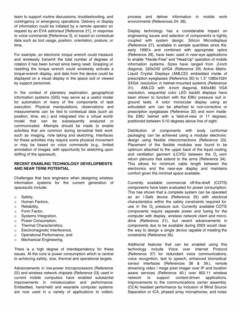
Over the past five years, the NASA Haughton MarsProject (HMP) has provided an important venue forevaluating and developing these needs, architectures and solutions. By combining scientific activity andtechnology in a geographic area and geological settingsimilar to anticipated Mars planetary exploration sites, it provides an essential complement to existing commercial and military networking and communications development activities. This has included the development of fieldexperience that highlights the limitations of commoncommercial protocols (such as 802.11b) in this setting[References 16 & 47] and the evolution of advancedcollaboration systems (Figure 4) for dealing with thebarriers of space and time (including long propagationdelays) inherent in earth-based support for Martianexploration EVA’s [Reference 45].
SOME RECENT EXPERIMENTATION AND RESULTS
During 2003, collaborative experimental programs aimed at the use of commercially available hardware to develop a better understanding of EVA information interface usage and integration continued with both laboratory and field experiments. Laboratory experiments provided relatively high fidelity experience in a pressurized space suit, while the field program offered lower fidelity testing using mock-ups but took place in an operationally relevant remoteexploration setting. Together, they have allowed theinvestigation of a variety of potential applications andmodes of use for the information interface.
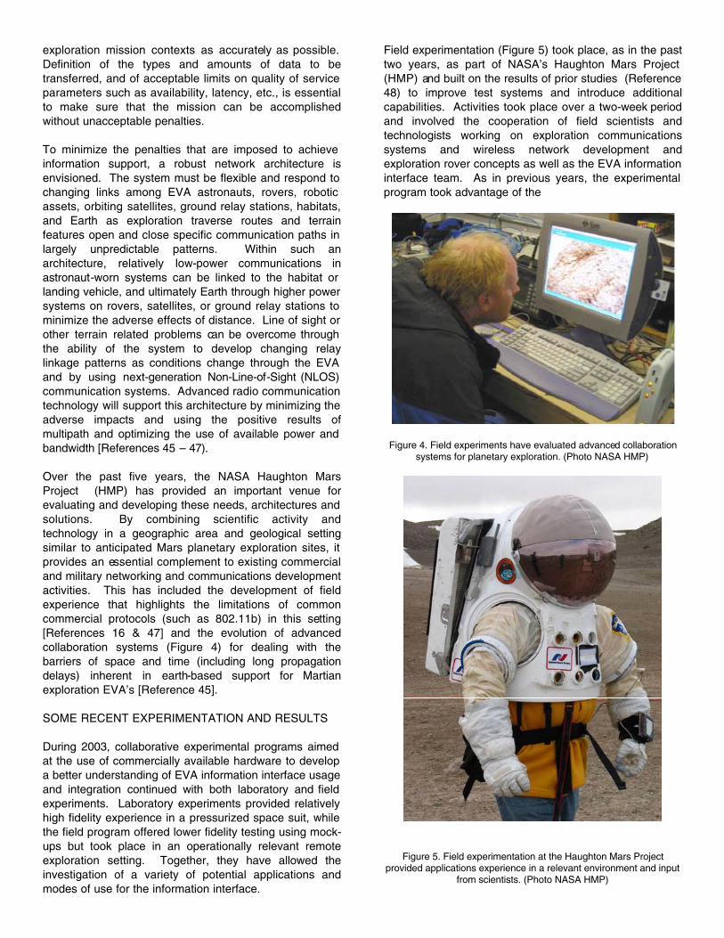
Field experimentation (Figure 5) took place, as in the past two years, as part of NASA’s Haughton Mars Project (HMP) and built on the results of prior studies (Reference 48) to improve test systems and introduce additionalcapabilities. Activities took place over a two-week period and involved the cooperation of field scientists andtechnologists working on exploration communicationssystems and wireless network development andexploration rover concepts as well as the EVA information interface team. As in previous years, the experimental program took advantage of the
Figure 4. Field experiments have evaluated advanced collaboration systems for planetary exploration. (Photo NASA HMP)
Figure 5. Field experimentation at the Haughton Mars Project provided applications experience in a relevant environment and input
from scientists. (Photo NASA HMP)

flexibility provided by the mock-up test bed and thepresence of multiple investigators and varied equipment at HMP. Two different display configurations, several computers, and multiple input devices and networkingconfigurations were investigated. Highlights this fieldseason included:
o Integration of sun-visor and sun-shade with the field test mock-up suit to better test information display operation under ambient lighting conditions.
o Tests with augmented vision using a small camera at the end of a staff to produce near real-time images displayed on the EVA information interface.
o Integration of navigation aids and mapping software.o Enhanced information system voice control
experimentation.o Enhanced wireless networking experiments and
extended tests with remote control of informationinterfaces by support personnel.
In addition, support was provided to NASA experiments comparing the application of telerobotic exploration and telescience to human EVA exploration and field science as part of the NASA Ames Research Center MEX-HORSE study (Reference 49).
Field test results confirmed the advantage of an in-helmetinformation display. Use of a very low-power, full color VGA display in full daylight was successful with goodreadability of the display with the use of sun visor and sun-shade as anticipated in an operational EVA system.This contrasted with experience without the sun visor and shade the previous year when it was necessary tooperate the display in a higher brightness, monochrome mode under daylight conditions. This earlier experience is indicative of the need for substantially higher power in a display outside the helmet.
Suit-integrated augmented vision tests extended earlierremote camera and wearable computing-basedaugmented vision experiments at HMP to integrate thecamera with the mock-up EVA system. Theydemonstrated significant potential value for planetaryexploration and field science by allowing safe examination of locations (e.g. over the lip of a cliff) that could not otherwise be reached by the EVA explorer. Theyestablished the fact that useful visual information could be provided even with rudimentary systems and showed what camera and display control interfaces were likely to be required in the field.
Experimental use of mapping software and navigationaids demonstrated the ability to use topographic mapinformation with the in-helmet display and the potential utility of these tools over a wireless network to enhance collaboration between EVA crew and support personnel in a habitat or vehicle. Unfortunately, software integration issues in the field prevented planned experimentation of mark-up of mapping data using varying EVA information interface input modalities. Collaborative mapping,supported by remote IVA crew control of EVA computer
system was, however, successful, consistent with prior years’ experience. This demonstrates one use of thewireless networking connection to relieve crewmembers of complex human-computer interactions during EVAs.These and other processing-intensive experimentshighlighted the importance of providing capableprocessors to meet the varied and somewhat unknown demands of the planetary exploration environment(References 16 and 46). Field equipment failures also reinforced the need for robust field hardened equipment like the Xybernaut computers used for some of theexperiments. (Reference 50).
Significant progress in information system voice control was demonstrated as a result of work on the development of a limited vocabulary control interface. Results withlarge vocabulary speech recognition for the capture of field notes, sample records, etc., continued to bedisappointing, indicating a need for substantial furtherdevelopment in this area. One significant factor in this result was the impact of wind noise in this year’sexperiments. This may be an artifact of the terrestrial analog environment (Mars’ atmosphere is much lessdense) and of the partial mock-up used in these tests which allowed wind and ambient noise to enter at thebottom of the HUT. Base camp-based tests of context-dependent VXML-based speech recognition andinteraction with remote computing resources in the windy Devon environment continue to be highly successful.
The results of wireless networking experiments werecompromised by interference among multiple commercial systems assembled to implement local and wider areacommunication nets, but significant progress wasachieved. Effective operation of the interface as an EVA support collaboration tool was demonstrated. Thisincluded its use to display relevant field science support imagery in response to real-time exploration events. Both remote operation of the display system by supportpersonnel with conventional input devices, (mouse andkeyboard), and direct control by the EVA crew usingvoice control and touch pad were successful, althoughsignificant room for interface improvement remains.
Integration and use of a head-mounted informationinterface in a pressurized space suit was investigated in two tests using a ground test EMU in a laboratory setting.In these tests, a Micro-optical display was mounted to the temple of a pair of eyeglasses (with plane or prescription lenses depending on the needs of the test subject). In the first of these tests, the display was driven by anIPAQ pocket PC inside the suit which, in turn, wasnetworked through a wireless card to test controlcomputers outside the pressure suit. In the second test, the configuration was similar, but the IPAQ was replaced by a similarly sized Toshiba e740 with a more capable processor and integrated 802.11b wireless, and thedisplay was upgraded from 320x240 pixels to a full VGA unit with wider (17o vs. 10o) field of view. This provided an extremely compact hardware configuration in the suit,
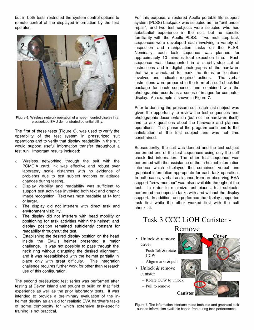
but in both tests restricted the system control options to remote control of the displayed information by the test operator.
Figure 6. Wireless network operation of a head-mounted display in a pressurized EMU demonstrated potential utility.
The first of these tests (Figure 6), was used to verify the operability of the test system in pressurized suitoperations and to verify that display readability in the suit would support useful information transfer throughout atest run. Important results included:
o Wireless networking through the suit with thePCMCIA card link was effective and robust overlaboratory scale distances with no evidence ofproblems due to test subject motions or attitudechanges during testing.
o Display visibility and readability was sufficient tosupport test activities involving both text and graphic image recognition. Text was most readable at 14 font or larger.
o The display did not interfere with direct task andenvironment visibility.
o The display did not interfere with head mobility orpositioning for task activities within the helmet, and display position remained sufficiently constant forreadability throughout the test.
o Establishing the desired display position on the head inside the EMU’s helmet presented a majorchallenge. It was not possible to pass through the neck ring without disrupting the desired alignment, and it was reestablished with the helmet partially in place only with great difficulty. This integrationchallenge requires further work for other than research use of this configuration.
The second pressurized test series was performed after testing at Devon Island and sought to build on that field experience as well as the prior laboratory tests. It was intended to provide a preliminary evaluation of the in-helmet display as an aid for realistic EVA hardware tasks of some complexity for which extensive task-specifictraining is not practical.
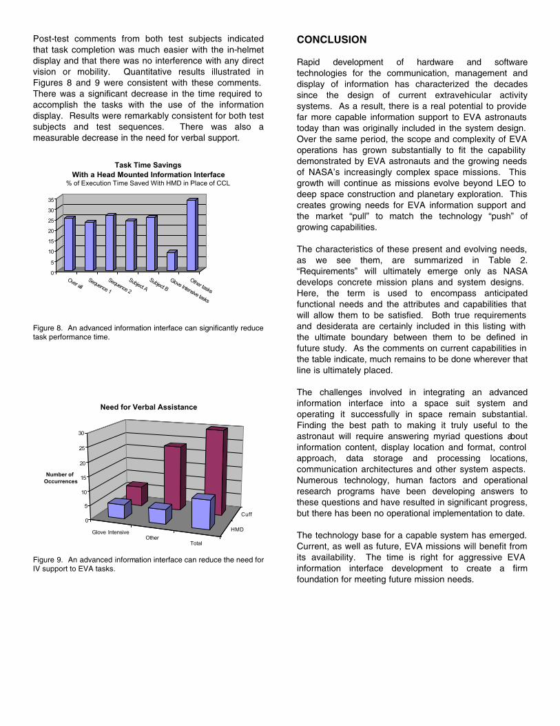
For this purpose, a restored Apollo portable life support system (PLSS) backpack was selected as the “unit under repair”, and two test subjects were selected who hadsubstantial experience in the suit, but no specificfamiliarity with the Apollo PLSS. Two multi-step task sequences were developed each involving a variety of inspection and manipulation tasks on the PLSS.Nominally, each task sequence was planned forapproximately 10 minutes total execution time. Eachsequence was documented in a step-by-step set ofinstructions and in digital photographs of the hardwarethat were annotated to mark the items or locationsinvolved and indicate required actions. The verbalinstructions were prepared in the form of a cuff check-listpackage for each sequence, and combined with thephotographic records as a series of images for computer display. An example is shown in Figure 7.
Prior to donning the pressure suit, each test subject was given the opportunity to review the test sequences and photographic documentation (but not the hardware itself) and to ask questions about the hardware and plannedoperations. This phase of the program continued to the satisfaction of the test subject and was not timeconstrained.
Subsequently, the suit was donned and the test subject performed one of the test sequences using only the cuff check list information. The other test sequence wasperformed with the assistance of the in-helmet informationinterface which displayed the combined verbal andgraphical information appropriate for each task operation.In both cases, verbal assistance from an observing EVA support “crew member” was also available throughout the test. In order to minimize test biases, test subjects performed the opposite tasks with and without the display support. In addition, one performed the display-supportedtask first while the other worked first with the cuffchecklist.
Task 3 CCC LiOH Canister -Remove
• Unlock & remove cover– Push Tab & rotate
CCW
– Align marks & pull
• Unlock & remove canister– Rotate CCW to unlock
– Pull to remove
Cover
Canister
Figure 7. The information interface made both text and graphical task support information available hands-free during task performance.
Post-test comments from both test subjects indicatedthat task completion was much easier with the in-helmetdisplay and that there was no interference with any directvision or mobility. Quantitative results illustrated inFigures 8 and 9 were consistent with these comments.There was a significant decrease in the time required to accomplish the tasks with the use of the informationdisplay. Results were remarkably consistent for both test subjects and test sequences. There was also ameasurable decrease in the need for verbal support.
0
5
10
15
20
25
30
35
Over allSequence 1
Sequence 2
Subject A
Subject B
Glove Intensive tasks
Other tasks
Task Time Savings With a Head Mounted Information Interface
% of Execution Time Saved With HMD in Place of CCL
Figure 8. An advanced information interface can significantly reduce task performance time.
Glove IntensiveOther
Total
HMD
Cuff0
5
10
15
20
25
30
Number of Occurrences
Need for Verbal Assistance
Figure 9. An advanced information interface can reduce the need for IV support to EVA tasks.
CONCLUSION
Rapid development of hardware and softwaretechnologies for the communication, management anddisplay of information has characterized the decadessince the design of current extravehicular activitysystems. As a result, there is a real potential to provide far more capable information support to EVA astronauts today than was originally included in the system design.Over the same period, the scope and complexity of EVA operations has grown substantially to fit the capability demonstrated by EVA astronauts and the growing needs of NASA’s increasingly complex space missions. This growth will continue as missions evolve beyond LEO to deep space construction and planetary exploration. This creates growing needs for EVA information support and the market “pull” to match the technology “push” ofgrowing capabilities.
The characteristics of these present and evolving needs, as we see them, are summarized in Table 2.“Requirements” will ultimately emerge only as NASAdevelops concrete mission plans and system designs.Here, the term is used to encompass anticipatedfunctional needs and the attributes and capabilities that will allow them to be satisfied. Both true requirements and desiderata are certainly included in this listing with the ultimate boundary between them to be defined infuture study. As the comments on current capabilities in the table indicate, much remains to be done wherever that line is ultimately placed.
The challenges involved in integrating an advancedinformation interface into a space suit system andoperating it successfully in space remain substantial.Finding the best path to making it truly useful to theastronaut will require answering myriad questions aboutinformation content, display location and format, control approach, data storage and processing locations,communication architectures and other system aspects.Numerous technology, human factors and operationalresearch programs have been developing answers tothese questions and have resulted in significant progress, but there has been no operational implementation to date.
The technology base for a capable system has emerged.Current, as well as future, EVA missions will benefit from its availability. The time is right for aggressive EVA information interface development to create a firmfoundation for meeting future mission needs.

Table 2. EVA information interface requirements and potential capabilities are well beyond those of current systems.
Requirements Major Capabilities / Attributes CurrentOperationalCapability
General Non-InterferenceEnvironmental toleranceSystem compatibilityAvailability in all light levels
NoYesYesYes
Task Execution Support Hands-freeText displayGraphics displayFlexible accessData input / capture
NoYesLimitedLimitedNo
Situational awareness
Safety
Hardware
Work Flow
Navigation
Always availableReal-time graphics display, video?
Text displayReal time graphics display
Text displayData input / capture
Directional data displayReal time graphics displayText display
YesNo
YesNo
YesNo
NoNoNo
Collaboration Real time graphics displayGraphics mark-upVerbal communicationImage transmission
NoNoYesYes
In-Flight Training Graphics displayText displayAuthoring / near real time
LimitedYesNo
Robotic / Automatic Systems Interface
Real time graphics displayGraphics mark-upPrecise positioning display and designationText generation / mark-up
NoNoNoNo
Real-time planning Real time graphics displayGraphics mark-upText generation / mark-upData analysis / real time modeling
NoNoNoNo
Documentation Real time graphics displayGraphics captureGraphics mark-upText generation / mark-up
NoPhotographyNoNo
ACKNOWLEDGMENTS
The material presented in this paper reflects thecumulative results of numerous research anddevelopment programs and flight experiments spanningnearly two decades. The authors would like toacknowledge those who have supported those effortsfinancially and technically and make our present work possible. First, we must acknowledge the financialsupport of the NASA which has supported many of the cited efforts and continues to do so through flight
experiments and technology development efforts at the Johnson Space Center and the Ames Research Center as well as through the Haughton Mars Project. We must also acknowledge our technical debt to many researchers in EVA systems at the Johnson Space Center and inIntelligent Systems at the Ames Research Center whohave generously shared information and insights over the years.
Gratitude is also due to the Canadian Space Agency for funding of the PlanetNet and MarsCanada projects, which

provided the major funding for Simon Fraser University’s HMP-based EVA research as well as the Canadian Space Agency and the European Space Agency for fundingunder the REMSAT National Extension and REMSAT II projects, respectively, which provided computinghardware for EVA tests on Devon Island, as a component Technical Investigation of those projects.
In addition, we must acknowledge the contributions of those companies, including Hamilton Sundstrand Space Systems International and the Boeing Company, whichhave supported portions of this work through internalresearch funds or participation in the MIT MediaLaboratory.
Finally, we would like to apologize in advance for any oversight in acknowledging the many contributors to the work upon which we have drawn.
REFERENCES
1. Marmolejo, Jose A.; Gernux, Carolyn G.; and Blaser, Robert W. "A Helmet Mounted DisplayDemonstration Unit for a Space Station Application."Proceedings of the Society of Automotive Engineers 19th Intersociety Conference on EnvironmentalSystems, July 1989.
2. Lednicky, Cheryl L., and Marmolejo, Jose A. "A Helmet Mounted Information Display for the NASA Manned Maneuvering Unit." Proceeding of the Joint Applications in Instrumentation Process & Computer Control Symposium, March 1990.
3. Marmolejo, Jose A. "Use of Voice Commands toProvide a "Hands-Free" Information System forSpace Station Extravehicular Activity." Proceeding of Speech Tech '87, April 1987.
4. Shepherd, Charles K., Jr., and Marmolejo, Jose A."A Voice Controlled Information System for SpaceStation Extravehicular Activity." Speech Technology Magazine, March-April 1988.
5. Marmolejo, Jose A., and Shepherd, Charles K., Jr."An Information System for Space StationExtravehicular Activity." Proceeding of Speech Tech '88, April 1988.
6. Shepherd, Charles K., Jr., and Marmolejo, Jose A."A Procedure for Updating Voice Templates Through Voice Commands During Extravehicular Activity."Proceeding of Speech Tech '88, April 1988.
7. Marmolejo, Jose A., and Shepherd, Charles K., Jr."A Simulation System for Space StationExtravehicular Activity." Proceeding of the Societyof Automotive Engineers 18th IntersocietyConference on Environmental Systems, July 1988.
8. Shepherd, Charles K., Jr. "Human FactorsInvestigation of a Speech-Controlled Bench-ModelExtravehicular Mobility Unit Information System in a Construction Task." NASA Document Number JSC-23632, May 1989.
9. Marmolejo, Jose A. "An Electronic Cuff Checklist Information Display for Extravehicular Activity."Proceedings of the Society of Automotive Engineers 26th Intersociety Conference on EnvironmentalSystems, July 1996.
10. Saleh, Joseph H., Weaving Time Into SystemsArchitecture: New Perspectives on Flexibility,Spacecraft Design Lifetime, and On-Orbit Servicing, Doctoral Thesis, Massachusetts Institute ofTechnology, November 2001.
11. Extravehicular Activities Space-To-SpaceCommunication System Training Workbook (JSC-36345), Lyndon B. Johnson Space Center, National Aeronautics and Space Administration, Houston,Texas, March 2000.
12. S. P. Braham, P. Anderson, P. Lee, and R. Alena, “Canada and Analogue Sites for Mars Exploration”,published in Proceedings of the Second CanadianSpace Exploration Workshop (Canadian SpaceAgency), Calgary, 1999.
13. S. Braham, P. Anderson, R. Alena, B. Glass, and P. Lee, “Internet communications for planetaryexploration”, Proceedings of the First Space Internet Workshop, NASA GSFC, 2000.
14. S. P. Braham, R. Alena, B. Gilbaugh, and B. Glass, “Space Networking and Protocols for PlanetaryExploration and Analog Planetary Sites”, published in Proceedings of the 2001 IEEE AerospaceConference, Big Sky, Montana, 2001.
15. R. Alena, B. Gilbaugh, B. Glass, and S. P. Braham, “Communication System Architecture for PlanetaryExploration”, published in Proceedings of the 2001IEEE Aerospace Conference, Big Sky, Montana,2001.
16. S. Braham, “Towards COTS Protocols for PlanetaryExploration”, published in Proceedings of the Second Space Internet Workshop, NASA GSFC, 2002.
17. C.E. Carr, D.J. Newman, and K.V. Hodges. “Geologic Traverse Planning for Planetary EVA”, 33rdInternational Conference on Environmental Systems, 2003 (submitted).
18. Rochlis, J. and D.J. Newman. “A Tactile Display for International Space Station (ISS) ExtravehicularActivity (EVA)”, Aviation, Space, and Environmental Medicine, 71(6):571-578, June 2000.
19. Jones, E. M. (editor), Apollo Lunar Surface Journal, July 2000(http://www.hq.nasa.gov/office/pao/History/alsj/).
20. C.E. Carr and D.J. Newman. “Supporting MartianField Geology”, Geological Society of America,Annual Meeting, Boston, Massachusetts, October,2001.
21. C.E. Carr, S.J. Schwartz, and I. Rosenberg, AWearable Computer to Support AstronautExtravehicular Activity, IEEE Transactions on 6thAnnual International Symposium of WearableComputers, October, 2002.
22. ARM Processor Cores Overviewhttp://www.arm.com/armtech/cpus?OpenDocument

23. Tutorial on 802.11 to 802, Prepared by Vic Hayes, Chair IEEE P802.11, Copyright ©1996 IEEE
24. Intrinsyc Cerf Boardhttp://www.intrinsyc.com/pdfs/productsheets/CerfBoard_250_DevKit_Linux_1.0.pdf
25. Symbol Technologies PDT-8000http://www.symbol.com/products/mobile_computers/mobile_pdt8000.html
26. MIT Wearable Computing Project MIThrilhttp://www.media.mit.edu/wearables/
27. Society for Information Display Microdisplay 2001Conferencehttp://www.sid.org/conf/microdisplay2002/agenda.pdf
28. SID HMD Hardware and Integrationhttp://www.spie.org/web/abstracts/pdfs/cdp11.pdf
29. Kopin cyber display 320http://www.kopin.com/html/cyberdisplay.html
30. Micro Optical Corporation EG-7http://www.microopticalcorp.com/docs/EG-7_Spec.pdf
31. SAAB AddVisorhttp://www.cs.umu.se/kurser/TDBD12/HT02/lectures/hardware.pdf
32. Micro Optical CO-3http://www.microopticalcorp.com/docs/CO-3_VGA_Specs.pdf
33. Lukowicz, Paul, et. al., “The WearARM Modular, Low-Power Computing Core”, IEEE Micro May/June 2001(Vol. 21, No. 3)
34. WearSAT MIT Boeing Projecthttp://web.media.mit.edu/~schwartz/wearsat/index.html
35. Symbol Technologies I-Safe Series Mobile Computer for Hazardous Environmentshttp://www.symbol.com/products/mobile_computers/mobile_i_sseies.html
36. Intel PXA262http://developer.intel.com/design/pca/prodbref/251671.htm
37. Symbol Technologies Netvision Phonehttp://www.symbol.com/news/pressreleases/press_releases_wirelesslans_vo.html
38. Fullerton, Richard K., Vann, Richard D., “Options For Extravehicular Activity (EVA): Now and Future.”Bioastronautics Investigators' Workshop 2001,http://www.dsls.usra.edu/dsls/meetings/bio2001/pdf/305.pdf
39. Advanced Technology for Human Support in Space NAP 1997http://www.nap.edu/books/0309057442/html/10.html
40. INCITS 2001INTEGRATED MULTI MODE - 433 MHz REAL TIME LOCATION SYSTEMSwww.qed.org/INCITS/T20_2002/INCITS/T20/N02-041/433/MHz/Contribution.doc
41. S. Basu et. al., “Wearable Phased Arrays for Sound Localization and Enhancement”, IEEE FourthInternational Symposium on Wearable Computers, 2000
42. P. Ronzani et al., “Is there Space for Wearables?” Keynote Address IEEE Sixth International Symposium on Wearable Computers, 2002
43. U. Neumann and A. Majoros Augmented Reality for Space Flight, Proc. of 2nd Biennial Space Human Factors Workshop, January 23-24, 2002, Center for Advanced Space Studies, Houston, Texas
44. A. Raj, L. Roetzer, P. Fatolitis, R. Cholewiak, S. Kass, A. Rupert Haptic Interfaces to augmentHuman Machine Interactions in Space Activities.Proc. of 2nd Biennial Space Human FactorsWorkshop, January 23-24, 2002, Center for Advanced Space Studies, Houston, Texas.
45. The Canadian Space Agency PlanetNet Project,Simon Fraser University,http://polylab.sfu.ca/spacesystems/planetnet/
46. S. Braham, P. Anderson, and P. Lee, “MobileWireless Networking for Planetary Exploration,”Keynote Topic, ESA Wireless Data Communications Onboard -Spacecraft Technology and ApplicationsWorkshop,ftp://ftp.estec.esa.nl/pub/ws/wsd/WLAN/Workshop/WirelessWorkshop.htm, 2003.
47. S. Braham, “Multicarrier communications in planetary and large spacecraft environments: W-OFDM as a solution,” ESA Wireless Data CommunicationsOnboard - Spacecraft Technology and Applications Workshop,ftp://ftp.estec.esa.nl/pub/ws/wsd/WLAN/Workshop/WirelessWorkshop.htm, 2003.
48. Boucher, M., Hodgson E., Murray, S., Lee, P.Braham, S., “Investigation of EVA InformationInterface Technology in a Mars Analog Arctic Field Science Setting”, SAE 2001-01-2312, San Antonio, Texas, July 2002.
49. “Mobile Exploration System (MEX) – HumanOperated Robotic Science Evaluation (HORSE)”,http://www.marsonearth.org/exploration/robotics/2002/index.html#mex
50. Xybernaut MA-V Mobile Assistant V,http://www.xybernaut.com/Solutions/product/mav_product.htm
DEFINITIONS, ACRONYMS, ABBREVIATIONS
3D: 3 dimensional imagery. Usually viewed usingstenographic, binocular equipment, but can also refer to computer graphics imagery and other specialized electro-optical systems.
802.11: IEEE standard for wireless networking using unlicensed frequency bands. Currently in the 2.4GHz (B and G) and 5 GHz (A) spectrum.
AMLCD: Active Matrix Liquid Crystal Displays. A type of Silicon Microdisplay also common in flat panel andnotebook computer displays.
AR: Augmented Reality. The addition of sensoryinformation to real world information found in the use of see through head mounted displays using prisms

CCL: Cuff Check List. Laminated paper checklistattached to the cuff of the EMU in use since the Apolloprogram.
CCA: communications carrier assembly
CCC: contamination control canister
COTS: Commercial Off The Shelf. Readily availableequipment, peripherals, components, software andaccessories that can be obtained directly frommanufacturers and distributors without special order.
DCM: Display and Control Module
e740: A COTS handheld computer or Pocket PC made by Toshiba with integrated 802.11b and user accessiblecompact flash adapter socket in a very thin form factor
EMU: Extravehicular Mobility Unit
EVA: Extra-Vehicular Activity. Activities conductedoutside of a space vehicle.
GPS: Global Positioning System
Hands-Free: User interface where use of hand controls is kept to a minimum
Head Mounted: Attached to the head by an adjustable band, to a helmet, headset or eyeglass.
Head-Up: Information display superimposed on user’sfield of view.
HMD: head mounted display
ICA: Independent Component Analysis. A form of signal processing used for blind source separation of audiosources to remove noise and other unwanted sounds from a speech processing system.
IP: Internet Protocol
IPAQ: Brand name for a popular Handheld Computersimilar to most Pocket PC products used by consumers for high performance mobile computing.
IR: Infrared
I-Safe: Intrinsically Safe. A rigorous set of standards for spark free equipment used around combustible sources such as oil rigs, gasses and flammable materials.
ISS: International Space Station
IV: Intra Vehicular. Activities coonducted inside a space vehicle.
LAB - ISS Laboratory module
LCVG: Liquid Cooling and Ventilation Garment.
LED: Light Emitting Diode
LEO: Low Earth Orbit
Micro-optical display: A complete optical assemblyincluding silicon microdisplay, optics, head mount andcable produced by the Micro Optical Corporation,Westwood, Massachusetts, USA
MMU: Manned Maneuvering Unit
NLOS Non-Line of Sight
02: Oxygen
PCMCIA: Personal Computer Memory Card International Association. International standards body and tradeassociation founded in 1989 to establish standards forIntegrated Circuit cards used in mobile computers.Evolved into the PC Card Standard.
PLSS: Portable Life Support System used on the EMU
qVGA: Quarter VGA typically found in PDA hand helddevices and equal to a resolution of 320x240 pixels
RF: Radio Frequency
SAFER: Simplified Aid For EVA Rescue
Silicon Microdisplays: An electronic display using silicon transistors and optics to present an image in a small form factor. Typically less than 25mm in diagonal
S0: Starboard Truss Assembly Number 0 on theInternational Space Station
SXGA: Super VGA
TDRS: Tracking Data Relay Satellite
TLS - tactor locator system
Touch Pad: A touch sensitive finger activated inputdevice usually employed as a user interface on mobile computers.
VGA: Video Graphics Adapter. Standard computergraphics display developed in the early 1980s with640x480 pixels resolution
VoIP: Voice over Internet Protocol. A method oftransmitting audio over the Internet.
VXML: Voice Extensible Mark-up Language. Voice xML is a Meta Language similar to HTML (hyper text meta language) that provides for reuse of content acrossdifferent computing platforms and viewing apparatus and supports a large number of specific implementations.
WLAN wireless local area network


![2-[Eva Fedi]-Formazione “Aree Comuni” Operatori Sportivi [Eva Fedi]](https://static.fdokumen.com/doc/165x107/63209e83c5de3ed8a70dcef1/2-eva-fedi-formazione-aree-comuni-operatori-sportivi-eva-fedi.jpg)