Report on Floating and Float-In Concrete Structures
45
ACI 357.2R-10 Reported by ACI Committee 357 Report on Floating and Float-In Concrete Structures Copyright American Concrete Institute Provided by IHS under license with ACI Licensee=University of Texas Revised Sub Account/5620001114, User=opioui, rty Not for Resale, 01/26/2015 01:50:35 MST No reproduction or networking permitted without license from IHS --`````,`,,`,`,,,,`,`,,`,,,`,`-`-`,,`,,`,`,,`--- Daneshlink.com
-
Upload
khangminh22 -
Category
Documents
-
view
8 -
download
0
Transcript of Report on Floating and Float-In Concrete Structures

ACI 357.2R-10
Reported by ACI Committee 357
Report on Floating and Float-InConcrete Structures
Copyright American Concrete Institute Provided by IHS under license with ACI Licensee=University of Texas Revised Sub Account/5620001114, User=opioui, rty
Not for Resale, 01/26/2015 01:50:35 MSTNo reproduction or networking permitted without license from IHS
--`````,`,,`,`,,,,`,`,,`,,,`,`-`-`,,`,,`,`,,`---
daneshlink.com
Daneshlink.com

Report on Floating and Float-In Concrete Structures
First PrintingJuly 2010
ISBN 978-0-87031-384-4
American Concrete Institute®
Advancing concrete knowledge
Copyright by the American Concrete Institute, Farmington Hills, MI. All rights reserved. This materialmay not be reproduced or copied, in whole or part, in any printed, mechanical, electronic, film, or otherdistribution and storage media, without the written consent of ACI.
The technical committees responsible for ACI committee reports and standards strive to avoid ambiguities,omissions, and errors in these documents. In spite of these efforts, the users of ACI documents occasionallyfind information or requirements that may be subject to more than one interpretation or may beincomplete or incorrect. Users who have suggestions for the improvement of ACI documents arerequested to contact ACI. Proper use of this document includes periodically checking for errata atwww.concrete.org/committees/errata.asp for the most up-to-date revisions.
ACI committee documents are intended for the use of individuals who are competent to evaluate thesignificance and limitations of its content and recommendations and who will accept responsibility for theapplication of the material it contains. Individuals who use this publication in any way assume all risk andaccept total responsibility for the application and use of this information.
All information in this publication is provided “as is” without warranty of any kind, either express or implied,including but not limited to, the implied warranties of merchantability, fitness for a particular purpose ornon-infringement.
ACI and its members disclaim liability for damages of any kind, including any special, indirect, incidental,or consequential damages, including without limitation, lost revenues or lost profits, which may resultfrom the use of this publication.
It is the responsibility of the user of this document to establish health and safety practices appropriate tothe specific circumstances involved with its use. ACI does not make any representations with regard tohealth and safety issues and the use of this document. The user must determine the applicability of allregulatory limitations before applying the document and must comply with all applicable laws and regulations,including but not limited to, United States Occupational Safety and Health Administration (OSHA) healthand safety standards.
Order information: ACI documents are available in print, by download, on CD-ROM, through electronicsubscription, or reprint and may be obtained by contacting ACI.
Most ACI standards and committee reports are gathered together in the annually revised ACI Manual ofConcrete Practice (MCP).
American Concrete Institute38800 Country Club DriveFarmington Hills, MI 48331U.S.A.Phone: 248-848-3700Fax: 248-848-3701
www.concrete.org
Copyright American Concrete Institute Provided by IHS under license with ACI Licensee=University of Texas Revised Sub Account/5620001114, User=opioui, rty
Not for Resale, 01/26/2015 01:50:35 MSTNo reproduction or networking permitted without license from IHS
--`````,`,,`,`,,,,`,`,,`,,,`,`-`-`,,`,,`,`,,`---
daneshlink.com
Daneshlink.com

ACI 357.2R-10 supersedes ACI 357.2R-88 and was adopted and published July 2010.Copyright © 2010, American Concrete Institute.All rights reserved including rights of reproduction and use in any form or by any
means, including the making of copies by any photo process, or by electronic ormechanical device, printed, written, or oral, or recording for sound or visual reproduc-tion or for use in any knowledge or retrieval system or device, unless permission inwriting is obtained from the copyright proprietors.
1
ACI Committee Reports, Guides, Manuals, and Commentariesare intended for guidance in planning, designing, executing,and inspecting construction. This document is intended for theuse of individuals who are competent to evaluate thesignificance and limitations of its content and recommendationsand who will accept responsibility for the application of thematerial it contains. The American Concrete Institute disclaimsany and all responsibility for the stated principles. The Instituteshall not be liable for any loss or damage arising therefrom.
Reference to this document shall not be made in contractdocuments. If items found in this document are desired by theArchitect/Engineer to be a part of the contract documents, theyshall be restated in mandatory language for incorporation bythe Architect/Engineer.
Report on Floating and Float-In Concrete StructuresReported by ACI Committee 357
ACI 357.2R-10
This report addresses the practical experience and engineering consider-ations for the design and construction of floating concrete structures.Recommendations for design loads and design criteria are presented.Design procedures and methods of analysis are discussed to betteracquaint the reader with the design considerations unique to floatingmarine structures. Methods used to construct floating concrete structuresplay a major role in the success of each application. Construction methodsand materials used for recent applications are presented to demonstratethe importance of the construction process during the planning and designof marine concrete structures. Important aspects of delivery, from theconstruction site and installation at the deployment site, are presented. Thedurability and serviceability of floating structures at remote sites areimportant considerations to project planners and developers. Constructionexecution, materials selection and inspection, maintenance, and repairtechniques are discussed. The materials, processes, quality controlmeasures, and inspections described in this document should be tested,monitored, or performed as applicable only by individuals holding theappropriate ACI Certifications or equivalent.
Keywords: abrasion; accidents; admixtures; aggregates; concrete construction;concrete durability; detailing; dynamic loads; fatigue (materials); finiteelement method; floating structures; inspection; installing; lightweightconcretes; limit design method; loads forces; maintenance moorings; perme-ability; post-tensioning; precast concrete; prestressed concrete; prestressingsteels; quality control; reinforced concrete; reinforcing steels; repairs;serviceability; ships, stability; structural design surveys; towing.
CONTENTSChapter 1—Introduction and scope, p. 2
1.1—Introduction1.2—Scope
Chapter 2—Notation, definitions, and acronyms, p. 22.1—Notation2.2—Definitions2.3—Acronyms
Chapter 3—Applications, p. 33.1—Introduction3.2—Historical background3.3—Ships and barges3.4—Industrial plantships3.5—Floating piers and docks3.6—Floating bridges3.7—Immersed tunnels3.8—Navigation structures3.9—Summary
Chapter 4—Materials and durability, p. 134.1—Introduction4.2—Testing and quality control4.3—Structural marine concrete4.4—Reinforcement and concrete cover4.5—Special considerations4.6—Summary
Jal N. Birdy Per Fidjestøl George C. Hoff Thomas E. Spencer
Theodore W. Bremner* Humayun Hashmi Mohammad S. Khan John A. Tanner
Valery M. Buslov Ron Heffron Jorge L. Quiros, Jr. Paul G. Tourney
Lewis J. Cook Kare Hjorteset Karl-Heinz Reineck Samuel X. Yao*†
Domenic D’Argenzio
*Member of subcommittee that prepared this report.†Chair of subcommittee that prepared this report.
Michael J. Garlich*
ChairThomas G. Weil*
Secretary
Copyright American Concrete Institute Provided by IHS under license with ACI Licensee=University of Texas Revised Sub Account/5620001114, User=opioui, rty
Not for Resale, 01/26/2015 01:50:35 MSTNo reproduction or networking permitted without license from IHS
--`````,`,,`,`,,,,`,`,,`,,,`,`-`-`,,`,,`,`,,`---
daneshlink.com
Daneshlink.com

2 FLOATING AND FLOAT-IN CONCRETE STRUCTURES (ACI 357.2R-10)
American Concrete Institute Copyrighted Material—www.concrete.org
Chapter 5—Evaluation of loads, p. 175.1—Introduction5.2—Types of loads5.3—Load determination5.4—Summary
Chapter 6—Design approaches, p. 216.1—Introduction6.2—Overview of design code requirements6.3—Fatigue6.4—Serviceability6.5—Hull arrangements6.6—Analysis methodology6.7—Design and detailing6.8—Summary
Chapter 7—Construction, p. 277.1—Introduction7.2—Construction methods7.3—Concrete construction7.4—Construction afloat7.5—Segmental construction—joining while afloat7.6—Summary
Chapter 8—Towing and installation, p. 318.1—Introduction8.2—Design considerations8.3—Tow route8.4—Summary
Chapter 9—Maintenance, inspection, and repair,p. 34
9.1—Introduction9.2—Structural deterioration9.3—Surveys and periodic inspection9.4—Repairs9.5—Summary
Chapter 10—References, p. 3810.1—Referenced standards and reports10.2—Cited references
CHAPTER 1—INTRODUCTION AND SCOPE1.1—Introduction
Prestressed or reinforced concrete structures are used aseither permanently floating structures or temporary float-instructures to facilitate marine construction. In this report, thedefinition of a floating structure is a structure that istemporarily, intermittently, or continuously afloat. For thosefloating structures that have a bow or stern, the bow or sternmay be raked or shaped as required. Certain floating structuresincluded within this definition are designed for towing andsubsequent grounding, and afterward function as fixed struc-tures. Later, these structures may be refloated and transported toa new location. Other structures are designed to remaincontinuously afloat, with or without permanent mooring.
Permanently floating structures serve a variety of usessuch as industrial plantships, floating bridges, floating drydocks, offshore terminals, navigation structures, and parking
and hotel structures. Applications of temporary float-instructures include the bridge pier foundations, offshoregravity-based structures, locks and dams, immersed concretetunnels, and storm or tidal surge barriers.
In 1943, the first prestressed concrete barge was built bythe U.S. Navy (U.S. Department of Transportation[USDOT] 1981). Today, the preferred construction approachfor large structures is to use prestressed concrete instead ofordinary reinforced concrete. The ability of prestressedstructures to control net tensile stresses and to close cracksthat develop from temporary overload situations enhanceswater tightness and durability. Composite concrete-steelconstruction is also becoming popular. Concrete is used inthe exterior bulkheads and base to provide durability, andsteel is used for the internal framing and deck to provideweight savings (Gerwick 1975a, 1978).
The design of concrete floating structures requires knowl-edge of many disciplines. The designer should have a thoroughunderstanding of concrete design principles, concrete as a mate-rial, and construction practice. Also, the designer should havean understanding of environmental loadings, marine operations,requirements for vessel certification, and the importance ofstructure inspection, maintenance, and repair. All of theseaspects have been addressed in this report to provide the readerwith a background in the subject of concrete floating structures.
1.2—ScopeThis report is intended to further the development of
floating concrete structures by presenting relevant design,materials, construction, installation, maintenance, andrepair. Application of available technology is demonstratedfor a range of floating concrete structures to show thattechnological risks are at a known and acceptable level.
The report starts with a historical presentation of floatingstructures and design concepts to establish both the versatilityand technical viability of concrete floating marine structures.The durability and serviceability of floating structures atremote sites are important considerations to project plannersand developers. Recommendations for design loads anddesign criteria are presented. Design procedures and methodsof analysis are discussed to better acquaint the reader with thedesign considerations unique to floating marine structures.
CHAPTER 2—NOTATION, DEFINITIONS,AND ACRONYMS
2.1—NotationAi = free surface in partially filled compartment, ft2 (m2)B = beam (width) of a floating structure, in. (m)BM = distance from center of buoyancy to metacentric
point, in., (m)D = draft, in. (m)F(t) = external force due to waves, lb (kN)j = total number of load blocks consideredKB = distance from keel to center of buoyancy, in. (m)KG = distance from keel to center of gravity, in. (m)l = length, in. (m)Msw = still-water bending moment, in.-lb (m-kN)Mt = total bending moment, in.-lb (m-kN)
Copyright American Concrete Institute Provided by IHS under license with ACI Licensee=University of Texas Revised Sub Account/5620001114, User=opioui, rty
Not for Resale, 01/26/2015 01:50:35 MSTNo reproduction or networking permitted without license from IHS
--`````,`,,`,`,,,,`,`,,`,,,`,`-`-`,,`,,`,`,,`---
daneshlink.com
Daneshlink.com

FLOATING AND FLOAT-IN CONCRETE STRUCTURES (ACI 357.2R-10) 3
American Concrete Institute Copyrighted Material—www.concrete.org
Mwi = wave-induced bending moment, in.-lb (m-kN)mm1 = vessel mass, lb (kg)mm2 = added mass, lb (kg)Ni = number of load cycles causing failure if load
block i acts aloneni = actual number of load cycles for load block iri = distance from free surface to axis of waterplane of
entire structure in direction of rotation, in. (m)Vsw = maximum still-water hull-girder shearing force,
lb (kN)Vt = total hull-girder shear, lb (kN)Vwi = maximum shearing force induced by waves, lb (kN)x = displacement of the motion, in. (m)
= velocity of the motion, in./s (m/s)= acceleration of the motion, in./s2 (m/s2)
β = linearized damping coefficient, lb-s/in. (kN-s/m)γ = hydrostatic restoration coefficient, lb/ft (kN/m)η = Minor’s sum in accumulative fatigue damage
analysis
2.2—DefinitionsACI provides a comprehensive list of definitions through
an online resource, “ACI Concrete Terminology,” http://terminology.concrete.org. Definitions provided hereincomplement that resource.
ballast—any solid or liquid weight placed in a ship toincrease the draft, to change the trim, or to regulate thestability.
ballast tank—watertight compartment to hold water ballast.beam—width of the vessel or floating structure.bow—the forward end of a ship.bulkhead—vertical partition walls, which subdivide the
interior of a vessel into compartments or rooms. Bulkheadsthat contribute to the strength of a vessel are called strengthbulkheads, those which are essential to the watertight or oil-tight bulkheads, and gas-tight bulkheads serve to prevent thepassage of gas or fumes.
bullard pull—pull force on a bullard.draft—the depth of the ship below the water measured
vertically to the lowest part of the hull, propellers, or otherreference point.
hogging—straining of the ship that tends to make the bowand stern lower than the middle portion.
keel—the principal fore- and aft-component of a ship’sframing, located along the centerline of the bottom.
metacenter or metacentric point—the intersection of avertical line drawn through the center of buoyancy of aslightly listed vessel and the centerline plane.
sagging—straining of the ship that tends to make themiddle portion lower than the bow and stern.
sea state—the overall sea condition to be used for design.stability—the tendency of a ship to remain upright, or the
ability to return to a normal upright position when heeled bythe action of waves and wind.
stern—after end of ship.trim—the difference between the draft forward and the
draft aft.
2.3—AcronymsABS—American Bureau of ShippingAPI—American Petroleum InstituteCIP—cast-in-placeDnV—Det Norske VeritasLNG—liquid natural gasLPG—liquid petroleum gasLR—Lloyd’s Register of Shipping RAO—response amplitude operatorTLP—tension-leg platformULS—ultimate limit stateUSDOT—U.S. Department of Transportation
CHAPTER 3—APPLICATIONS3.1—Introduction
Chapter 3 presents a brief historical background on the useof concrete for floating structures, and describes examples ofconcrete ships, barges, plantships, storage facilities, piers,docks, and breakwaters that have been constructed or are beingdeveloped. The selection of examples is not intended to providea comprehensive list of applications, but rather to illustratethe wide variety of marine applications for which concrete hasprovided safe, functional, durable, and economical solutions.These applications not only illustrate the versatility of floatingconcrete structures, but also highlight some creative andnovel engineering solutions to complex engineering problems.
3.2—Historical backgroundThe first use of reinforced concrete in floating vessels is
attributed to Lambot who, in 1848, constructed a boat byapplying sand-cement mortar over a framework of iron bars andmesh. The first self-propelled reinforced concrete ship waslaunched in 1917. This was the M.S. Namsenfjord, built byN. K. Fougner in Norway. Fougner went on to build severallarger self-propelled reinforced concrete vessels (USDOT 1981).
The first self-propelled concrete ship in the U.S. was theS.S. Faith, which was launched in 1918. It was built in SanFrancisco and was, at that time, the largest concrete ship inthe world, with a design deadweight of 5000 tons (4540tonnes). It had an overall length of 320 ft (97.5 m), a beam of44.5 ft (13.5 m), and a depth of 30 ft (9.1 m) (Fiorato 1981).
A principal impetus for continued development of concreteships was the shortage of steel that occurred during WorldWars I and II. In 1918, the U.S. Emergency Fleet Corporationinstituted a program that resulted in the construction of 12reinforced concrete vessels with deadweights up to 7500 tons(6800 tonnes) (Fiorato 1981). These vessels used lightweightconcrete extensively. Expanded clay and shale aggregateswere developed to obtain concretes with 28-day compressivestrengths in excess of 4000 psi (28 MPa) and unit density ofapproximately 110 lb/ft3 (1760 kg/m3).
Although a few concrete vessels were built after WorldWar I, it was not until World War II that another majorconcrete ship program was undertaken (Fiorato 1981). TheU.S. Maritime Commission initiated a project in mid-1941that eventually resulted in the construction of 104 vessels, 20of which were self-propelled. These vessels had lightweightconcrete strength requirements of 5000 psi (35 MPa) at 28 days.
x·
x··
Copyright American Concrete Institute Provided by IHS under license with ACI Licensee=University of Texas Revised Sub Account/5620001114, User=opioui, rty
Not for Resale, 01/26/2015 01:50:35 MSTNo reproduction or networking permitted without license from IHS
--`````,`,,`,`,,,,`,`,,`,,,`,`-`-`,,`,,`,`,,`---
daneshlink.com
Daneshlink.com

4 FLOATING AND FLOAT-IN CONCRETE STRUCTURES (ACI 357.2R-10)
American Concrete Institute Copyrighted Material—www.concrete.org
Concrete produced at the different yards had fresh unitdensities ranging from 108 to 128 lb/ft3 (1730 to 2050 kg/m3)and 28-day compressive strengths ranging from 5085 to6920 psi (35 to 48 MPa). Some of the World War I or IIvessels saw extensive service, and most were eventuallyused for storage barges or breakwaters.
Not all of the reinforced concrete vessels constructedduring World War II were ships or barges (Anderson 1975).A number of large floating concrete dry docks were alsoconstructed, including ones in Philadelphia, PA; Norfolk,VA; and Hunter’s Point, CA. One had a length in excess of400 ft (120 m) and could dry dock a 7000 ton (6350 tonne)vessel. It is still in use for the Port of Bellingham, WA.
Two prestressed concrete vessels were also constructedduring World War II. One was a landing craft and the othera barge (Anderson 1975). They were constructed of precastegg-crate cells with prestressing steel tensioned along thespace between cells (Fig. 3.1). The steel was then coveredwith a layer of shotcrete.
Since World War II, the primary applications for floatingconcrete structures have been barges, oil drilling and storage
platforms, floating bridges, docks, floating breakwaters, andpontoons.
3.3—Ships and bargesAlong the U.S. Gulf Coast in Louisiana and Texas,
concrete barges serve as float-in-place foundations for oilproduction, processing, and storage facilities (The Society ofNaval Architects and Marine Engineers [SNAME] 1967).The barges are used to support pump and compressorinstallations, processing equipment, water and wastewatertreatment plants, settling basins, skimmer tanks, and livingquarters (Fig. 3.2). They can also serve as floating docks.One type of barge, the Belden system, consists of an egg-cratehull made of precast reinforced concrete panels. The assembledpanels are wrapped with welded wire fabric reinforcement,and shotcrete is applied to the exterior. Various topsideconfigurations can be constructed on the hull, depending onthe intended use of the barge. Once constructed, the fullyoutfitted facility can be towed to its destination and ballastedinto position. These structures are designed to be deballasted,refloated, and relocated. More than 400 of these structuresare in use (USDOT 1981).
Fig. 3.1—Prestressed concrete landing craft.
Fig. 3.2—Floating concrete bridge.
Copyright American Concrete Institute Provided by IHS under license with ACI Licensee=University of Texas Revised Sub Account/5620001114, User=opioui, rty
Not for Resale, 01/26/2015 01:50:35 MSTNo reproduction or networking permitted without license from IHS
--`````,`,,`,`,,,,`,`,,`,,,`,`-`-`,,`,,`,`,,`---
daneshlink.com
Daneshlink.com

FLOATING AND FLOAT-IN CONCRETE STRUCTURES (ACI 357.2R-10) 5
American Concrete Institute Copyrighted Material—www.concrete.org
Prestressed concrete transport barges constructed in thePhilippines have been in service since 1964 (Yee et al. 1975;Sare and Yee 1977). Sixteen were built for general cargo useand three were built for bulk petroleum transport (Fig. 3.3).The typical configuration includes an inner steel framingsystem supporting a mild steel-reinforced and prestressedconcrete hull. Deadweights range from 700 to 2000 tons (630 to1810 tonnes). The vessels saw considerable service, includingtransport of ammunition, explosives, and petroleum productsduring the Vietnam War. The concrete in these smaller bargeshas resisted severe exposure from cargoes such as industrialsalts and fertilizers. The interior structural steel framing,however, has been susceptible to corrosion.
To overcome the durability and maintenance limitationsof the transverse structural steel framing, a concrete honeycombframing system was developed that provides an efficientstrength-weight ratio (American Concrete Institute (ACI)1982; Anderson 1977). The total volume of internalframing occupies only a small fraction of the enclosedvolume of the hull.
3.4—Industrial plantshipsA floating terminal facility for liquefaction and storage of
LPG was built for Atlantic Richfield Indonesia (Vialon andBellbeoch 1997). The 65,000 ton (59,000 tonne) vessel, theArdjuna Sakti, was designed as a post-tensioned segmentalstructure (Fig. 3.4(a) and (b)). Segments were individuallymatch-cast and then post-tensioned together to form the hull.This structure was constructed in Tacoma, WA, and towed10,000 miles (16,000 km) across the Pacific Ocean to theArdjuna oil and gas fields in the Java Sea. It has been inservice since 1976.
The N’Kossa Oil Production Unit, located 37 miles (60 km)off the coast of the Congo in 500 ft (150 m) of water, is one ofthe world’s largest floating post-tensioned concrete struc-tures. The main hull of the floating unit contains 35,000yd3 (27,000 m3) of concrete, 5000 tons (4500 tonnes) of rein-forcing steel, and 2350 tons (2100 tonnes) of prestressing
strands (Fig. 3.5(a) and (b)). The successful construction andoperation of N’Kossa have demonstrated the competitiveadvantages of a concrete ship over a steel ship in an offshoreenvironment (Vialon and Bellbeoch 1997).
Offshore concrete gravity-based structures have beensuccessfully built in the North Sea since the early 1970s(Gerwick and Hognestad 1973; Fidjestøl et al. 2004). TheHibernia offshore concrete platform, built in Newfoundland,Canada for oil production, is the first large offshore concreteplatform to be built in North America and represents thelargest single-use—199,000 yd3 (152,000 m3)—of high-strength concrete in North America (Hoff and Hitz 1997).The specified compressive strength of the concrete is 11,600 psi(80 MPa). The structure is designed to resist the impact oficebergs as well as the severe wave-loading of the NorthAtlantic Ocean. It is located in 260 ft (80 m) of water. Thestructure is barrel shaped, with the lower portion of the structurebeing 280 ft (85 m) tall and 350 ft (106 m) in diameter. Fourshafts extend another 85 ft (26 m) from the roof of the
Fig. 3.3—General cargo barge.
(a)
(b)
Fig. 3.4—(a) Liquid petroleum gas processing and storagefacility (Ardjuna Sakti); and (b) cross section of ArdjunaSakti.
Copyright American Concrete Institute Provided by IHS under license with ACI Licensee=University of Texas Revised Sub Account/5620001114, User=opioui, rty
Not for Resale, 01/26/2015 01:50:35 MSTNo reproduction or networking permitted without license from IHS
--`````,`,,`,`,,,,`,`,,`,,,`,`-`-`,,`,,`,`,,`---
daneshlink.com
Daneshlink.com
6 FLOATING AND FLOAT-IN CONCRETE STRUCTURES (ACI 357.2R-10)
American Concrete Institute Copyrighted Material—www.concrete.org
structure to support the topsides equipment (Fig. 3.6). Thestructure is designed to store 1.3 million barrels of oil.
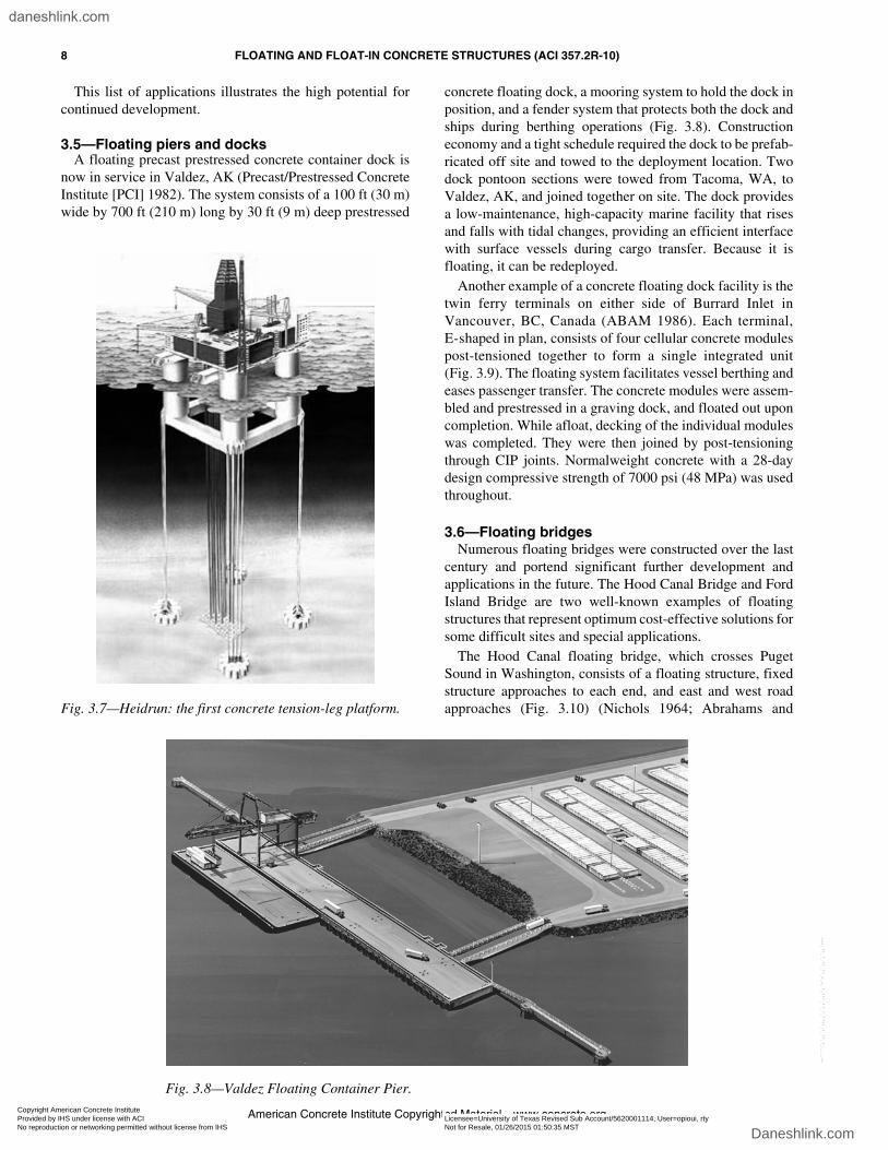
The first concrete tension-leg platform (TLP), Heidrun, wasconstructed and installed in the Norwegian Sea at a depth of1130 ft (345 m) in 1993-1994. The TLP is made of prestressedlightweight concrete with a gross topside weight of close to90,000 tons (82,000 tonnes) (Birkeland et al. 1979). Theconcrete hull has four circular cylindrical columns 100 ft(31 m) in diameter. The columns are spaced at a center-to-center distance of 260 ft (80 m), and are interconnected byrectangular pontoons. Two rectangular modular supportbeams rest on brackets on the inner side of the columns. Thetopside modules rest on top of the beams (Fig. 3.7). Buoyancyof the hull is primarily provided by the columns and pontoons.
Four groups of tethers securely anchor the TLP hull tofour individual foundations. These foundations are precastconcrete boxes that were transported and installed at the site byfloat-in method. The vertical tether loads are taken by acombination of gravity and suction in the skirt compartment.
There are three primary types of concrete floating plant-ships (Fjeld 1988):
• Type 1—Wet-towed and moored at an installation site;
• Type 2—Wet-towed and grounded at an installationsite; and
• Type 3—Dry-towed by barge that is capable of beingsubmerged so as to offload the structure at the installationsite.
(a)
(b)
Fig. 3.5—(a) N’Kossa Oil Production Unit being towed to a deep water outfitting site;and (b) a general layout of N’Kossa.
Copyright American Concrete Institute Provided by IHS under license with ACI Licensee=University of Texas Revised Sub Account/5620001114, User=opioui, rty
Not for Resale, 01/26/2015 01:50:35 MSTNo reproduction or networking permitted without license from IHS
--`````,`,,`,`,,,,`,`,,`,,,`,`-`-`,,`,,`,`,,`---
daneshlink.com
Daneshlink.com
FLOATING AND FLOAT-IN CONCRETE STRUCTURES (ACI 357.2R-10) 7
American Concrete Institute Copyrighted Material—www.concrete.org
Each type may be capable of redeployment, beingremoved and installed at another site for production.
Design criteria selected for the different vessel typesshould address whether the hull is to be considered as a ship.When classed as a ship by a certification agency such as theAmerican Bureau of Shipping (ABS), Det Norske Veritas(DnV), or Lloyd’s Register of Shipping (LRS), criteria foritems such as intact stability, damage stability, seaworthi-ness, and crew safety, are similar to those of conventionalvessels. For Type 3, the hull is normally designed as atemporary floating structure. Care should be taken duringdesign, however, to fully account for the interaction of the
concrete vessel and the supporting semisubmersible bargewhen afloat in the seaway.
Process applications for concrete plantships include:• Fertilizer production;• Manufacturing plants;• Refineries;• Desalination plants;• Electric power stations;• Chemical treatment facilities;• Liquid natural gas (LNG) and liquid petroleum gas
(LPG) terminals; and• Tidal power generator modules.
Fig. 3.6—Hibernia offshore GBS under construction.
Copyright American Concrete Institute Provided by IHS under license with ACI Licensee=University of Texas Revised Sub Account/5620001114, User=opioui, rty
Not for Resale, 01/26/2015 01:50:35 MSTNo reproduction or networking permitted without license from IHS
--`````,`,,`,`,,,,`,`,,`,,,`,`-`-`,,`,,`,`,,`---
daneshlink.com
Daneshlink.com
8 FLOATING AND FLOAT-IN CONCRETE STRUCTURES (ACI 357.2R-10)
American Concrete Institute Copyrighted Material—www.concrete.org
This list of applications illustrates the high potential forcontinued development.
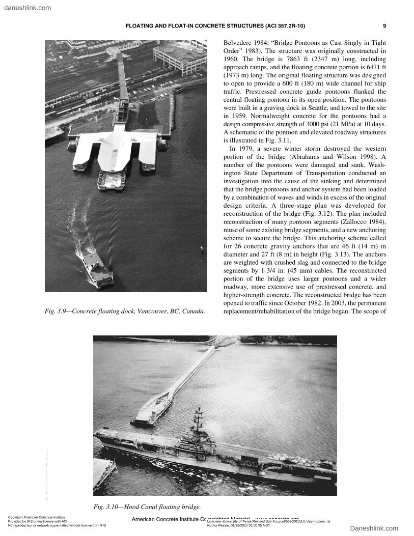
3.5—Floating piers and docksA floating precast prestressed concrete container dock is
now in service in Valdez, AK (Precast/Prestressed ConcreteInstitute [PCI] 1982). The system consists of a 100 ft (30 m)wide by 700 ft (210 m) long by 30 ft (9 m) deep prestressed
concrete floating dock, a mooring system to hold the dock inposition, and a fender system that protects both the dock andships during berthing operations (Fig. 3.8). Constructioneconomy and a tight schedule required the dock to be prefab-ricated off site and towed to the deployment location. Twodock pontoon sections were towed from Tacoma, WA, toValdez, AK, and joined together on site. The dock providesa low-maintenance, high-capacity marine facility that risesand falls with tidal changes, providing an efficient interfacewith surface vessels during cargo transfer. Because it isfloating, it can be redeployed.
Another example of a concrete floating dock facility is thetwin ferry terminals on either side of Burrard Inlet inVancouver, BC, Canada (ABAM 1986). Each terminal,E-shaped in plan, consists of four cellular concrete modulespost-tensioned together to form a single integrated unit(Fig. 3.9). The floating system facilitates vessel berthing andeases passenger transfer. The concrete modules were assem-bled and prestressed in a graving dock, and floated out uponcompletion. While afloat, decking of the individual moduleswas completed. They were then joined by post-tensioningthrough CIP joints. Normalweight concrete with a 28-daydesign compressive strength of 7000 psi (48 MPa) was usedthroughout.
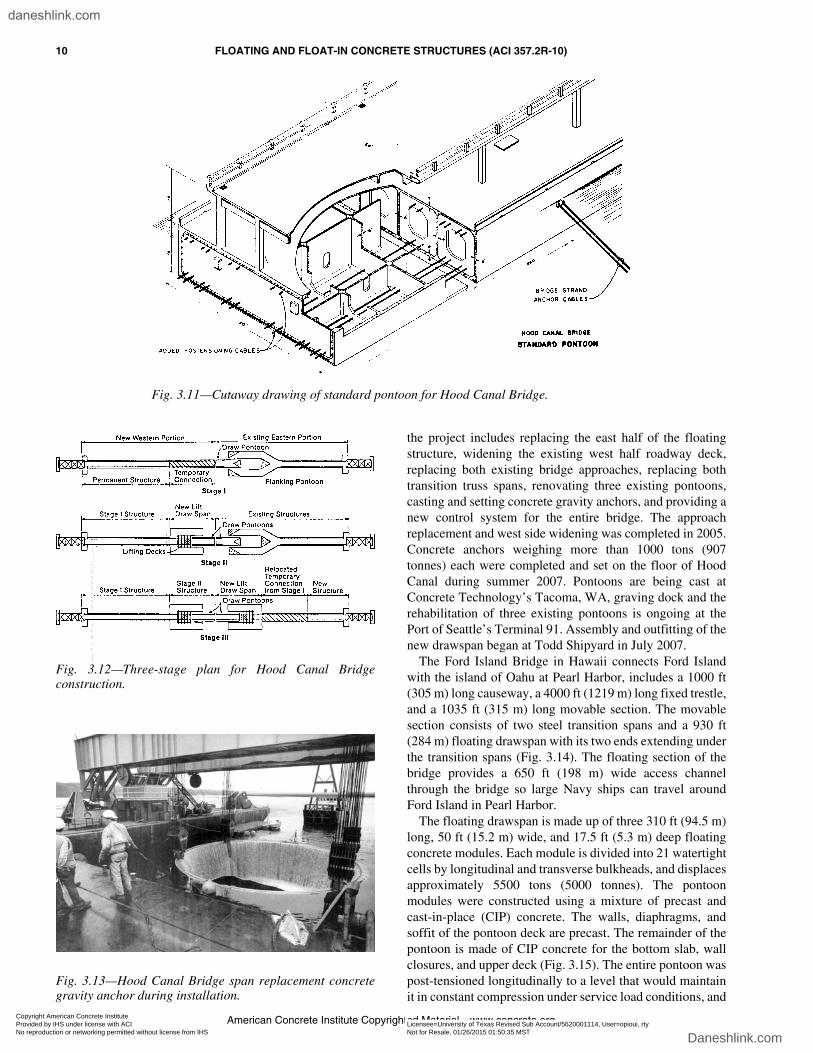
3.6—Floating bridgesNumerous floating bridges were constructed over the last
century and portend significant further development andapplications in the future. The Hood Canal Bridge and FordIsland Bridge are two well-known examples of floatingstructures that represent optimum cost-effective solutions forsome difficult sites and special applications.
The Hood Canal floating bridge, which crosses PugetSound in Washington, consists of a floating structure, fixedstructure approaches to each end, and east and west roadapproaches (Fig. 3.10) (Nichols 1964; Abrahams andFig. 3.7—Heidrun: the first concrete tension-leg platform.
Fig. 3.8—Valdez Floating Container Pier.Copyright American Concrete Institute Provided by IHS under license with ACI Licensee=University of Texas Revised Sub Account/5620001114, User=opioui, rty
Not for Resale, 01/26/2015 01:50:35 MSTNo reproduction or networking permitted without license from IHS
--`````,`,,`,`,,,,`,`,,`,,,`,`-`-`,,`,,`,`,,`---
daneshlink.com
Daneshlink.com
FLOATING AND FLOAT-IN CONCRETE STRUCTURES (ACI 357.2R-10) 9
American Concrete Institute Copyrighted Material—www.concrete.org
Belvedere 1984; “Bridge Pontoons as Cast Singly in TightOrder” 1983). The structure was originally constructed in1960. The bridge is 7863 ft (2347 m) long, includingapproach ramps, and the floating concrete portion is 6471 ft(1973 m) long. The original floating structure was designedto open to provide a 600 ft (180 m) wide channel for shiptraffic. Prestressed concrete guide pontoons flanked thecentral floating pontoon in its open position. The pontoonswere built in a graving dock in Seattle, and towed to the sitein 1959. Normalweight concrete for the pontoons had adesign compressive strength of 3000 psi (21 MPa) at 10 days.A schematic of the pontoon and elevated roadway structuresis illustrated in Fig. 3.11.
In 1979, a severe winter storm destroyed the westernportion of the bridge (Abrahams and Wilson 1998). Anumber of the pontoons were damaged and sank. Wash-ington State Department of Transportation conducted aninvestigation into the cause of the sinking and determinedthat the bridge pontoons and anchor system had been loadedby a combination of waves and winds in excess of the originaldesign criteria. A three-stage plan was developed forreconstruction of the bridge (Fig. 3.12). The plan includedreconstruction of many pontoon segments (Zallocco 1984),reuse of some existing bridge segments, and a new anchoringscheme to secure the bridge. This anchoring scheme calledfor 26 concrete gravity anchors that are 46 ft (14 m) indiameter and 27 ft (8 m) in height (Fig. 3.13). The anchorsare weighted with crushed slag and connected to the bridgesegments by 1-3/4 in. (45 mm) cables. The reconstructedportion of the bridge uses larger pontoons and a widerroadway, more extensive use of prestressed concrete, andhigher-strength concrete. The reconstructed bridge has beenopened to traffic since October 1982. In 2003, the permanentreplacement/rehabilitation of the bridge began. The scope ofFig. 3.9—Concrete floating dock, Vancouver, BC, Canada.
Fig. 3.10—Hood Canal floating bridge.
Copyright American Concrete Institute Provided by IHS under license with ACI Licensee=University of Texas Revised Sub Account/5620001114, User=opioui, rty
Not for Resale, 01/26/2015 01:50:35 MSTNo reproduction or networking permitted without license from IHS
--`````,`,,`,`,,,,`,`,,`,,,`,`-`-`,,`,,`,`,,`---
daneshlink.com
Daneshlink.com
10 FLOATING AND FLOAT-IN CONCRETE STRUCTURES (ACI 357.2R-10)
American Concrete Institute Copyrighted Material—www.concrete.org
the project includes replacing the east half of the floatingstructure, widening the existing west half roadway deck,replacing both existing bridge approaches, replacing bothtransition truss spans, renovating three existing pontoons,casting and setting concrete gravity anchors, and providing anew control system for the entire bridge. The approachreplacement and west side widening was completed in 2005.Concrete anchors weighing more than 1000 tons (907tonnes) each were completed and set on the floor of HoodCanal during summer 2007. Pontoons are being cast atConcrete Technology’s Tacoma, WA, graving dock and therehabilitation of three existing pontoons is ongoing at thePort of Seattle’s Terminal 91. Assembly and outfitting of thenew drawspan began at Todd Shipyard in July 2007.
The Ford Island Bridge in Hawaii connects Ford Islandwith the island of Oahu at Pearl Harbor, includes a 1000 ft(305 m) long causeway, a 4000 ft (1219 m) long fixed trestle,and a 1035 ft (315 m) long movable section. The movablesection consists of two steel transition spans and a 930 ft(284 m) floating drawspan with its two ends extending underthe transition spans (Fig. 3.14). The floating section of thebridge provides a 650 ft (198 m) wide access channelthrough the bridge so large Navy ships can travel aroundFord Island in Pearl Harbor.
The floating drawspan is made up of three 310 ft (94.5 m)long, 50 ft (15.2 m) wide, and 17.5 ft (5.3 m) deep floatingconcrete modules. Each module is divided into 21 watertightcells by longitudinal and transverse bulkheads, and displacesapproximately 5500 tons (5000 tonnes). The pontoonmodules were constructed using a mixture of precast andcast-in-place (CIP) concrete. The walls, diaphragms, andsoffit of the pontoon deck are precast. The remainder of thepontoon is made of CIP concrete for the bottom slab, wallclosures, and upper deck (Fig. 3.15). The entire pontoon waspost-tensioned longitudinally to a level that would maintainit in constant compression under service load conditions, and
Fig. 3.11—Cutaway drawing of standard pontoon for Hood Canal Bridge.
Fig. 3.12—Three-stage plan for Hood Canal Bridgeconstruction.
Fig. 3.13—Hood Canal Bridge span replacement concretegravity anchor during installation.
Copyright American Concrete Institute Provided by IHS under license with ACI Licensee=University of Texas Revised Sub Account/5620001114, User=opioui, rty
Not for Resale, 01/26/2015 01:50:35 MSTNo reproduction or networking permitted without license from IHS
--`````,`,,`,`,,,,`,`,,`,,,`,`-`-`,,`,,`,`,,`---
daneshlink.com
Daneshlink.com

FLOATING AND FLOAT-IN CONCRETE STRUCTURES (ACI 357.2R-10) 11
American Concrete Institute Copyrighted Material—www.concrete.org
exceed the required strength calculated for the condition ofone cell flooded. The three pontoons were tied together withhigh-strength bolts to provide the entire drawspan. Thefloating section was fabricated in Tacoma, WA, and towedto Hawaii for on-site assembly and installation. The bridgewas completed and opened in 1998.
3.7—Immersed tunnelsReinforced concrete segments were used to construct an
underwater tunnel to connect Amsterdam with surroundingareas (Gimsing and Iversen 2001). The reinforced concretesegments were constructed in a dry dock in 70 ft (21 m) wideby 73 ft (22 m) long pieces that were assembled into 440 ft(135 m) long units before being floated to the tunnel site(Fig. 3.16). Each unit was outfitted with instrumentation topermit survey control during placement. The underwatertunnel length is 4840 ft (1475 m). Because of the uniquenature of the project, special care was taken to carefullycontrol the unit weight of the reinforced concrete segments.
This permitted accurate control of launching, sinking, andfinal positioning.
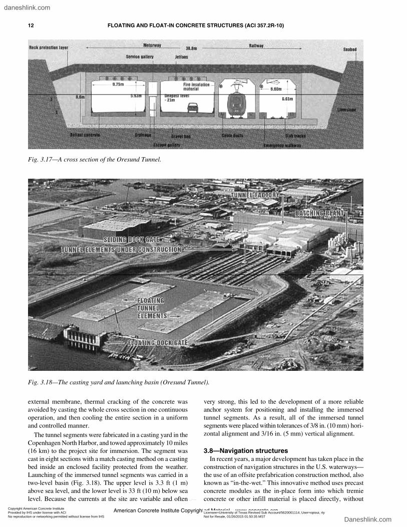
The Oresund Crossing is a fixed traffic link betweenDenmark and Sweden. The link, completed in the year 2000,consists of a 13,290 ft (4050 m) long immersed concretetunnel, a 13,250 ft (4044 m) long artificial island, and a21,850 ft (6660 m) long bridge. It was the largest immersedtunnel at the time. The immersed tunnel consists of 20 precastconcrete segments. Each segment is approximately 574 ft(175 m) long, 127 ft (39 m) wide, and 28 ft (8.6 m) in depth,and weighs 62,000 tons (56,000 tonnes). A typical crosssection of the tunnel is shown in Fig. 3.17. The concretemixture was developed to enhance durability and watertight-ness of the tunnel. Closure pours between the segments weremade with self-consolidating concrete. Because waterproofdesign relies entirely on the concrete quality without any
Fig. 3.14—Precast prestressed floating drawspan being retracted under fixed bridge spans.
Fig. 3.15—A typical cross section of the floating drawspanof 50 ft (15.2 m) width and 17.5 ft (5.2 m) depth.
Fig. 3.16—Tunnel elements being towed into position.
Copyright American Concrete Institute Provided by IHS under license with ACI Licensee=University of Texas Revised Sub Account/5620001114, User=opioui, rty
Not for Resale, 01/26/2015 01:50:35 MSTNo reproduction or networking permitted without license from IHS
--`````,`,,`,`,,,,`,`,,`,,,`,`-`-`,,`,,`,`,,`---
daneshlink.com
Daneshlink.com
12 FLOATING AND FLOAT-IN CONCRETE STRUCTURES (ACI 357.2R-10)
American Concrete Institute Copyrighted Material—www.concrete.org
external membrane, thermal cracking of the concrete wasavoided by casting the whole cross section in one continuousoperation, and then cooling the entire section in a uniformand controlled manner.
The tunnel segments were fabricated in a casting yard in theCopenhagen North Harbor, and towed approximately 10 miles(16 km) to the project site for immersion. The segment wascast in eight sections with a match casting method on a castingbed inside an enclosed facility protected from the weather.Launching of the immersed tunnel segments was carried in atwo-level basin (Fig. 3.18). The upper level is 3.3 ft (1 m)above sea level, and the lower level is 33 ft (10 m) below sealevel. Because the currents at the site are variable and often
very strong, this led to the development of a more reliableanchor system for positioning and installing the immersedtunnel segments. As a result, all of the immersed tunnelsegments were placed within tolerances of 3/8 in. (10 mm) hori-zontal alignment and 3/16 in. (5 mm) vertical alignment.
3.8—Navigation structuresIn recent years, a major development has taken place in the
construction of navigation structures in the U.S. waterways—the use of an offsite prefabrication construction method, alsoknown as “in-the-wet.” This innovative method uses precastconcrete modules as the in-place form into which tremieconcrete or other infill material is placed directly, without
Fig. 3.17—A cross section of the Oresund Tunnel.
Fig. 3.18—The casting yard and launching basin (Oresund Tunnel).
Copyright American Concrete Institute Provided by IHS under license with ACI Licensee=University of Texas Revised Sub Account/5620001114, User=opioui, rty
Not for Resale, 01/26/2015 01:50:35 MSTNo reproduction or networking permitted without license from IHS
--`````,`,,`,`,,,,`,`,,`,,,`,`-`-`,,`,,`,`,,`---
daneshlink.com
Daneshlink.com

FLOATING AND FLOAT-IN CONCRETE STRUCTURES (ACI 357.2R-10) 13
American Concrete Institute Copyrighted Material—www.concrete.org
the use of a cofferdam. Many investigations conclude thatthe innovative construction method can provide substantialbenefits in cost, construction time, risk reduction, andfacility utilization, while minimizing disruption of rivertraffic and reducing environmental impact (Yao and Gerwick2002). The float-in construction entails transportation of largeprefabricated concrete modules from their casting yard to theproject site by floatation. The precast modules are usuallythin-shelled floating structures with internal ballastingcompartments. The Braddock Dam and the Olmsted Damapproach walls are two well-known examples of in-the-wetconstruction of locks and dams.
The Braddock Dam is located on the Monongahela Riveroutside Pittsburgh, PA. The gated portion of the dam isapproximately 600 ft (180 m) in length. The main feature ofthe dam construction was the fabrication, assembly, anddelivery of the two large floating segments that form the baseof the dam. This total length of the dam was divided into twofloat-in segments. Float-in Segment 1, approximately 333 ft(102 m) long and 106 ft (32 m) wide, includes the fixed weirbay, water-quality bay, and one of the standard gate bays.Float-in Segment 2, approximately 265 ft (81 m) long and106 ft (32 m) wide, includes two standard gate bays. Eachfloat-in dam segment comprises the gate sills, a portion ofthe stilling basin, the pier walls, and bulkheads. Thesegments were constructed in a graving dock and towed to anoutfitting site, and then to the dam site (Fig. 3.19). At the site,the segments were positioned and ballasted down onto pre-
installed set-down drilled shafts (Fig. 3.20). Tremie concretewas placed inside the segments to make the underwaterportion of the dam. The tremie concrete was designed towork in composite action with the precast concrete modules.The above-water portion of the dam was constructed withthe conventional formed concrete. This construction methodeliminated the need for obstructive and expensive cellularcofferdam and the associated risks of increased flood levelsduring construction.
3.9—SummaryThe aforementioned structures indicate the variety of
applications that are embodied by the concrete floatingstructure concept. For these applications, the economicdisadvantage of the high dead-weight-to-displacement ratioof concrete has been partially overcome by the simple geometryof the structures, the selected internal framing, and, in somecases, the use of lightweight concrete. Concrete structuresprovide advantages that include stability during sea operations,low vibration levels, noncorrosive cargo environments,adaptability to all types of cargo, durability, high fatigue andfire resistance, low maintenance, ease of repair, and extensiveuse of common construction materials.
CHAPTER 4—MATERIALS AND DURABILITY4.1—Introduction
The development of both normalweight and lightweightmarine concretes parallels the history of concrete ships andother floating structures. The last two decades havewitnessed extensive research and widespread applicationson high-strength, high-performance concrete, especially onlightweight concrete (Hoff 1992, 2003; U.S. Coast Guard1984). At present, normalweight concretes having designcompressive strengths of 12,000 psi (83 MPa) and light-weight concretes having design compressive strengths of9000 psi (62 MPa) are normally achievable.
To obtain improved buoyancy and resulting cargoeconomy, lightweight-aggregate concrete was introducedfor ship construction during World War I. In recent years,prestressed lightweight concrete has been used for marinestructures to allow additional weight reduction, with accom-
Fig. 3.19—Transporting a floating concrete dam segment toan outfitting site (Braddock Dam in Pennsylvania).
Fig. 3.20—An illustration of positioning and installing afloat-in precast concrete floating segment (Braddock Damin Pennsylvania).
Copyright American Concrete Institute Provided by IHS under license with ACI Licensee=University of Texas Revised Sub Account/5620001114, User=opioui, rty
Not for Resale, 01/26/2015 01:50:35 MSTNo reproduction or networking permitted without license from IHS
--`````,`,,`,`,,,,`,`,,`,,,`,`-`-`,,`,,`,`,,`---
daneshlink.com
Daneshlink.com

14 FLOATING AND FLOAT-IN CONCRETE STRUCTURES (ACI 357.2R-10)
American Concrete Institute Copyrighted Material—www.concrete.org
panying shallower launch draft, and construction benefitsthrough segmental construction. Reduced weight also aidsconstruction speed and economy when handling precastsegments. The use of floating structures for liquefied gas andpetroleum products has created additional concrete durabilityrequirements. Documentation of previous satisfactoryperformance for the proposed materials or sufficient backuptest data instead of such documentation is necessary forvessel certification.
In general, Chapter 4 is applicable to concrete floatingstructures, specifically addressing important issues forfloating concrete structures.
4.2—Testing and quality controlTests for concrete and other construction materials should
be in accordance with the applicable ASTM standards citedin ACI 318. Concrete field and lab technicians and theinspector should be certified by ACI as evidence of theirqualifications. The testing and inspection agencies should beaccredited according to the requirements of ASTM E329.Due to the varied use of floating structures, complete recordsshould be made available for inspection during constructionand retained by the owner for the lifetime of the structure.Such records may be valuable in the formulation of mainte-nance and repair procedures.
As new materials are developed, new standard tests mayalso need to be developed to assess compliance with specifieddurability and quality specifications. A case in point is theincreased use of mineral admixtures as cementitious materialsfor reduced permeability, increased durability, and higher-strength concretes (Hoff 1992, 2003).
Providing day-to-day quality control functions duringconstruction of a marine concrete structure is normally theresponsibility of the construction contractor. Within thecontractor’s organization, the overall management of thequality control program is often assigned to a professionalengineer who has specific knowledge in materials technologyand construction methods, and who also has a clear under-standing of materials test methods, acceptance standards,and the statistical nature of acceptance testing of in-placeconcrete. This individual typically reports directly to uppermanagement of the construction firm.
Material testing and quality control are especially importantfor innovative design of floating concrete structures and newconstruction methods that are to be used for the first time. Insuch instances, the owner will want to specify additionalquality assurance functions at the job site to augment thequality-control function provided by the contractor. Suchquality assurance may be necessary to meet owner require-ments for vessel certification by a regulatory agency;because of the complex nature of the structure assembly; orbecause of the load sensitivity of certain portions of thestructure. In such instances, it is common to expect thatrepresentatives of the regulatory agency—for example,ABS, U.S. Coast Guard, or the DnV—and the designconsultant will be in residence during construction. Theirfunction is to provide the contractor with an in-depth under-standing of acceptable marine construction standards and the
design intent and service operation of the vessel, and toassure the owner’s financial and insurance interests that thevessel has been constructed to the required standards.
A summary of testing and quality-control considerationsfor floating structures under construction can be found inFiorato (1981).
4.3—Structural marine concrete4.3.1 General—Both normalweight and lightweight
concretes have been used in the construction of floatingconcrete structures. Lightweight concretes are used forvessels such as ships and barges, where maximizing payloadand reducing power requirements are important. Forstationary vessels, such as moored barges, floating bridges,breakwaters, and floating docks, normalweight concretes arefrequently used. Marine concrete frequently requires the useof supplementary cementitious materials and high-rangewater-reducing admixtures, specification of a low water-cementitious material ratio (w/cm), and moist curing withacceptance criterion at 56 or 91 days. It is possible fornormalweight concrete and lightweight concrete to reachstrengths of 12,000 psi (83 MPa) and 9000 psi (62 MPa),respectively.
Until recently, high-strength lightweight concretes havenot been widely specified for floating marine structures. Thisis changing because high-strength lightweight concrete withhigh durability can now be economically produced in theconstruction field.
4.3.2 Marine lightweight concretes—It is common toconsistently produce high-quality, lightweight marineconcretes with fresh unit weights of 120 to 125 lb/ft3 (1920to 2000 kg/m3) and design compressive strengths fc′ inexcess of 9000 psi (62 MPa). Research in the U.S. and Japanindicates that marine lightweight concretes having a unitweight of 110 to 120 lb/ft3 (1760 to 1920 kg/m3) andcompressive strength of 9000 psi (62 MPa) can be madecommercially (Fiorato 1981; Fiorato et al. 1984). Theseconcretes typically have a w/cm of 0.40 or less andcementitious contents of 690 to 830 lb/yd3 (410 to 490 kg/m3).Batching these concretes using prequalified materials andexercising proper construction supervision, such as having acomprehensive quality-control program, can ensure theproduction of durable floating concrete structures. Ships andbarges constructed using conventional, lower-strengthlightweight concrete during World War II have shown gooddurability for several decades.
Given a normalweight and a lightweight concrete of equalstrength and permeability, the high-strength lightweightconcrete may offer advantages over the normalweightconcrete for reasons that go beyond those associated withreduced vessel draft. High-strength lightweight concretescan offer the following advantages for marine structures:
• Higher resistance to microcracking due to the reducedmodulus of elasticity of the aggregates;
• Lower stress concentrations within the matrix to partiallycompensate for the reduced aggregate strength;
Copyright American Concrete Institute Provided by IHS under license with ACI Licensee=University of Texas Revised Sub Account/5620001114, User=opioui, rty
Not for Resale, 01/26/2015 01:50:35 MSTNo reproduction or networking permitted without license from IHS
--`````,`,,`,`,,,,`,`,,`,,,`,`-`-`,,`,,`,`,,`---
daneshlink.com
Daneshlink.com

FLOATING AND FLOAT-IN CONCRETE STRUCTURES (ACI 357.2R-10) 15
American Concrete Institute Copyrighted Material—www.concrete.org
• Lower modulus of elasticity, which results in reducedstresses caused by shrinkage, creep, and thermaleffects; and
• Lower values of thermal conductivity and thermalexpansion, which produces improved resistance tothermal cracking.
Considerable discussions on these subjects are providedby Hoff (1992).
Lightweight aggregate concretes can also present disadvan-tages to both designer and constructor. The ratio of tensilestrength to compressive strength of lightweight concrete isfrequently less than that for normalweight concrete. Hence,care should be taken during design to provide for additionalmild steel reinforcing in areas of high flexure and shear(diagonal tension). During construction, aggregate stock-piling should be controlled to prevent variations in moisturecontent of the aggregates that can affect uniformity ofbatching. Concrete consolidation and placing methodsshould address the tendency for aggregates to absorb waterduring mixing and handling, and to float during placing.
There are several precedents for the use of lightweightconcretes in marine structures (Hoff 2003). The S.S. Selmawas constructed in 1919 using lightweight concrete with adry unit weight of 119 lb/ft3 (1910 kg/m3) and a 28-daycompressive strength of 5000 psi (35 MPa). The concretemixture had a w/cm of 0.49 and a very high cement contentof 1034 lb/yd3 (613 kg/m3). In 1953, when S.S. Selma’s hullwas inspected, the core samples taken indicated concretestrengths exceeding 8000 psi (55 MPa). The hull was againinspected in 1980, and concrete test samples indicated acompressive strength of 10,000 psi (69 MPa). More recentexamples include the Tarsiut Arctic caisson, constructed forDome Petroleum and deployed in the Canadian Beaufort Seain 1981 (Holm 1980); and the Global Marine Super-CIDSarctic caisson, constructed in Japan in 1984 (Seabrook andWilson 1986).
Typical marine concretes have relatively high cementcontents of 650 to 950 lb/yd3 (385 to 565 kg/m3), and manycontain mineral admixtures (slag, fly ash, and silica fume).Mixtures such as these can have low cement paste permeability,which is a definite benefit for marine concrete structures. Highcement factors and highly reactive cementitious materials, suchas silica fume, may, however, produce undesirable heat ofhydration, which can lead to potentially detrimental thermalcracking of the concrete. For these reasons, selection of curingtechniques for marine concrete structures needs carefulconsideration and strict control during construction. Extendedmoist curing or use of insulated formwork is often employed.
ACI 221R and 213R provide information on aggregates;and ACI 211.1 and 211.2 provide data on mixture propor-tions for normalweight and lightweight concretes.
4.3.3 Constituent materials
4.3.3.1 Cement—Special cements are not required formarine concretes. Cement Types I, II, and III, in accordancewith ASTM C150/C150M, and hydraulic cement in accor-dance with ASTM C1157, were widely used. Blendedcements in accordance with ASTM C595/C595M have also
been used. ACI 225R provides information on the selectionand use of hydraulic cements.
To provide resistance to sulfate attack in the marineenvironment, specifications commonly limit the tricalciumaluminate (C3A) content of the cement. Suggested limits forallowable C3A content of the cement vary but, in general,range from 4 to 10% (Hoff 2003). The minimum limit is usedto provide a corrosion-resistant environment for embeddedreinforcement. The maximum limit is used to reduce thedetrimental effects of sulfate on the matrix. The addition ofpozzolans, such as fly ashes, has been found to be beneficialin reducing sulfate attack (ACI 225R).
The alkali content of the cement may also be limited usingoptional requirements of ASTM C150/C150M, if alkali-aggregate reactivity is a consideration for the combination ofconstituent materials being used (ACI 225R).
4.3.3.2 Aggregates—Normalweight aggregates shouldconform to the specifications of ASTM C33/C33M, andlightweight aggregates to ASTM C330/C330M. Lightweightaggregates that absorb significant quantities of mixing waterduring batching and placing can cause rapid slump loss andpoor workability. This can lead to extreme difficulty inplacing the concrete in congested reinforcing areas commonto light draft floating structures. The slump loss and poorworkability can be overcome by pre-wetting the aggregatesas outlined in ACI 211.2 and 213R. Concrete made withfully saturated aggregates may be more vulnerable tofreezing and thawing than concrete made with damp, light-weight aggregates, unless the concrete is properly protectedin accordance with ACI requirements.
Excess free water in stockpiled aggregates should bedrained and the aggregate stockpiles sampled to assess howthe batching proportions should be modified to compensatefor the moisture content of the aggregate.
In some countries, lightweight aggregates are batched in adry or semi-dry condition, causing concrete placementproblems. It is standard practice in North America to batch theaggregates at greater than 60% of their moisture contentwhen submerged for 24 hours. This normally limits subsequentabsorption of the aggregates in the concrete mixture suchthat slump loss is not a problem. In unusual circumstances,where lightweight aggregates are used in concrete wherethey will not be properly protected or given some opportunityfor the concrete to dry before freezing and thawing (such aswhen infilling steel-enclosed spaces), then lightweightaggregates with a high moisture content should not be used.
Water absorbed by the lightweight aggregates beforebeing added to the concrete mixture is recognized forreducing the potential for slump loss and acting as a sourceof additional water for enhanced moist curing, whichbecomes available to the concrete at the end of the normalmoist-curing period to further enhance the properties of thehardened concrete (Bentz et al. 2005).
4.3.3.3 Mixing water—Mixing water should be cleanand meet the requirements of ACI 318 and ASTM C1602/C1602M. In some very controlled instances, using non-portable water is allowed, provided that trial batches andsample mortar cubes indicate satisfactory strength capacity
Copyright American Concrete Institute Provided by IHS under license with ACI Licensee=University of Texas Revised Sub Account/5620001114, User=opioui, rty
Not for Resale, 01/26/2015 01:50:35 MSTNo reproduction or networking permitted without license from IHS
--`````,`,,`,`,,,,`,`,,`,,,`,`-`-`,,`,,`,`,,`---
daneshlink.com
Daneshlink.com
16 FLOATING AND FLOAT-IN CONCRETE STRUCTURES (ACI 357.2R-10)
American Concrete Institute Copyrighted Material—www.concrete.org
and the accepted limits on the chemical composition of themixing water are met. Chemical composition limits addressthe chloride and sulfate content of the water. These limits areestablished to ensure sufficient durability and resistance tochemical attack and corrosion.
4.3.3.4 Admixtures—Admixtures are used in concretestructures for a variety of reasons. An admixture is anymaterial, other than hydraulic cement, aggregate, mixingwater, or fiber reinforcement that has been intentionallyadded to the concrete to modify its properties or performance,either in the fresh or hardened state. Commonly used admixturetypes include:• Pozzolans (including fly ash and silica fume);• Set-retarding admixtures;• Air-entraining admixtures;• Water-reducing admixtures;• Set-accelerating admixtures (non-chloride);• Workability agents; and• Miscellaneous admixtures, such as air detrainers and
waterproofing agents.Careful consideration should be given before selecting an
admixture to enhance concrete properties. Some admixturesmay contain excessive amounts of chlorides or other corrosion-contributing components. It is suggested that such admixturesonly be used to the extent that suggested limits for durability,such as the overall chloride content of the concrete, are notexceeded.
Because concrete durability in the marine environment isa critical design concern, many marine concretes are airentrained and have a low w/cm. Air-entraining and water-reducing admixtures are commonly used in marineconcretes. Successful use of these admixtures duringconstruction requires a thorough understanding of theireffects on the time-dependent properties of fresh concrete.ACI 212.3R provides guidance for admixture use.
4.4—Reinforcement and concrete coverFor most general-purpose concrete floating structures,
requirements for reinforcement and prestressing steelsystems are identical to those used in more commonconstruction, for example, buildings, bridges, and piers.Even floating structures intended for Arctic service weredesigned using existing standards as base documents.
There are exceptions regarding requirements for concretereinforcement. For low-temperature applications, such as thosefor Arctic service, mechanical couplers of reinforcing bars orthreadbar systems should be tested for ductility when loadedbeyond yield stress at service temperatures. The designer maywish to prepare a specification outlining requirements for suchtests on systems that are otherwise not substantiated by testsor prequalified for Arctic low-temperature use.
For cryogenic applications such as LNG facilities, use ofcold-drawn wire strands for prestressing tendons and mild-steel reinforcement per ASTM A706/A706M should beconsidered due to their good ductility property at lowtemperatures. As is the case for other prestressing systems,the supplier should demonstrate the capacity of theanchorage system to sustain a load of at least 90% or the
ultimate strength of the strand or bar for bonded systems, and100% for unbonded systems. For marine concrete structuresin seawater, bonded post-tensioning systems should be used.
Concrete cover requirements are important and should beconsidered during design of a concrete floating structure.Concrete cover is that amount of concrete that surrounds oroverlays the reinforcement and establishes a barrier betweenthe concrete and the environment. Requirements forminimum cover are frequently listed as mandates by designcodes and classifying agencies such as ABS and DnV). Theserequirements vary depending upon where the reinforcement islocated in the vessel, such as the splash zone, atmosphericzone, or submerged zone. All of these apparent mandates arebased on the common goal to prevent corrosion of thereinforcing steel, to ensure proper concrete/steel bondbehavior, and to prevent future reduced function of the vessel.
The amount of necessary cover depends on crack controlconsiderations, the permeability of the concrete itself, andthe likelihood of surface degradation of the concrete duringnormal service. Undamaged, low-permeability concrete canprovide adequate corrosion protection for the reinforcementwith cover as low as 0.4 to 0.6 in. (10 to 15 mm). Oldermarine structures, such as harbor facilities and vessels, wereinspected and found to be virtually free of corroded reinforce-ment while having surprisingly little concrete cover.Conversely, highly permeable concretes overlaying reinforce-ment with substantial cover (as much as 3 in. [75 mm]) maynot provide adequate protection. Industry recommendationsneed to be followed regarding concrete cover to minimizecostly repairs. Current industry trends include the developmentof very low-permeability concretes. The use of low-permeability concrete may allow reduction of concretecover. In such cases, laboratory testing of the concretemixtures, such as ASTM C1202, should be conducted toconfirm the required concrete properties.
4.5—Special considerationsFor deck structures, areas subjected to spillage of caustic
or corrosive materials, or other areas of a concrete structurewhere heavy wear is anticipated, corrosion-resistant (dual-phase or stainless) steel reinforcement, epoxy-coated steelreinforcement, proper coatings, or a combination of these,are frequently used.
For thin sections or sections subjected to abnormal loadings,steel fibers, mixed with the fresh concrete, may be used toenhance toughness and increase member shear resistance.
4.6—SummaryConsiderable precedents have been established for the use
of various materials for concrete structures. High-quality,highly durable materials are available economically in largequantities for marine construction. Virtually all of the materialsin use today—for example, concretes, reinforcement, andcoatings—have well-established performance records. Themarine concrete construction industry has developed cost-effective methods for using these materials for constructionof floating structures. Designers and classifying agencieshave established comprehensive guidelines to be used in
Copyright American Concrete Institute Provided by IHS under license with ACI Licensee=University of Texas Revised Sub Account/5620001114, User=opioui, rty
Not for Resale, 01/26/2015 01:50:35 MSTNo reproduction or networking permitted without license from IHS
--`````,`,,`,`,,,,`,`,,`,,,`,`-`-`,,`,,`,`,,`---
daneshlink.com
Daneshlink.com

FLOATING AND FLOAT-IN CONCRETE STRUCTURES (ACI 357.2R-10) 17
American Concrete Institute Copyrighted Material—www.concrete.org
preparation of construction specifications for industry use.As with any complex structure, comprehensive and rigorousquality assurance and quality control programs are requiredto ensure the successful construction.
The materials industry and the technology base for thisindustry are growing. Higher-strength, lighter, and moredurable concretes are being developed and tested that allowconstruction of improved marine structures in the future.
CHAPTER 5—EVALUATION OF LOADS5.1—Introduction
Chapter 5 addresses the identification, definition, anddetermination of the loads to which a floating concrete structuremay be exposed. The various loads that should be identifiedand accounted for in the design and operation of the structureinclude dead loads, live loads, deformation loads, accidentalloads, construction loads, and environmental loads.
The definition of loads, with the exception of deformationloads, does not vary between a concrete structure and thoseconstructed of other materials. The structure’s response tothese loads, however, may differ substantially. Temperaturedifferences will cause structural responses unique to thecharacteristics of the construction material. In addition, thedynamic response and distortion of the vessel is, in part, afunction of the mass distribution of the vessel. This distributionmay vary significantly between concrete and steel construction.For simple cargo-carrying applications, dynamic response isgenerally not considered. If the structure, however, is to carrymotion-sensitive equipment or slender, tall appurtenances suchas those that may be used in process systems, then dynamicanalysis procedures are to be used to evaluate the structuralresponses to dynamic loads.
For floating structures, the predominant environmentalconsideration in vessel strength is wave effects. For vesselsused in general transportation services, no other environmentalload is generally considered for the structural analysis.Vessels for certain specialized services, such as for ice-breaking or transporting low-temperature cargoes like liquefiedgases, are considered unique and would require specific loaddefinition on a case-by-case basis. While there have been fullocean-service self-propelled concrete vessels (Morgan 1977)for such vessels, it is likely that concrete vessels will be limitedin the near future to use as barges, which have no propulsionmachinery. Barges are generally intended for use in a specificservice and, accordingly, marine practice is to differentiatebetween barges used in full ocean, short coastwise, or riverservice, with regard to the applicable wave criteria.
Site-specific structures, such as those intended to remainmoored on station for 1 year or longer, are also designedpredominantly considering wave load. Current, wind, andtidal range are also considered. In ice regions, ice loads andthermal effects are also considered. Some site-specific struc-tures, such as floating nuclear power plants or generatingstations, are also designed for unique vertical pressures andaccelerations caused by undersea earthquakes called seaquakes.
Section 5.2 discusses the load definitions for vesseldesign. The usual procedure in determining global momentsand shears is to consider a still-water condition and a transient
condition. The still-water condition represents the balance ofthe dead and live load and buoyancy in calm seas. The tran-sient condition is caused by deformation, environmental, oraccidental loads. Calculating the still-water loads is a simpleprocedure, considering static conditions of load, upwardbuoyancy, and hydrostatic pressure. The transient componentof load can be considered either as a quasi-static load or, usingstatistical procedures, as a time- or frequency-dependent load.
5.2—Types of loads5.2.1 Dead loads—Dead loads associated with the structure
are loads that do not change during the mode of operationunder consideration. Dead loads include:• Weight of the structure;• Weight of permanent ballast and the weight of permanent
machinery including liquids at operating levels; and• External hydrostatic pressure and buoyancy in calm sea
conditions, assuming the vessel is submerged to thedesign waterline.
5.2.2 Live loads—Live loads associated with the normaloperation of the structure are loads that could change duringthe mode of operation considered, and are controllablethrough operating procedures. Live loads include:• Weight of production equipment that can be removed;• Weight of crew and consumable supplies;• Weight and sloshing of liquids in storage tanks;• Forces exerted on the structure during the operation of
cranes and vehicles;• Forces exerted on the structure from moorings or
towing; and• Anticipated cargo.
When applicable, the dynamic effects on the structurefrom Items 3, 4 and 5 should be considered (Gerwick 2007).
5.2.3 Deformation loads—Deformation loads are thoseresulting from temperature variations leading to thermalstresses in the structure; effects of prestress, creep, andshrinkage; and, where appropriate, those resulting from soildisplacements such as differential settlements or lateraldisplacements. Topside structures for floating vessels will beaffected by the global hull deflections. These deflections areconsidered boundary conditions in the design of topsidestructures.
5.2.4 Accidental loads—Accidental loads occur as a resultof an accident or exceptional conditions, such as:• Impact caused by vessels of the size anticipated to be in
the vicinity of the structure;• Impact caused by dropped objects and floating debris;• Loss of internal overpressure required to resist hydro-
static loading and to maintain buoyancy;• Explosion;• Fire; and• Ice collision.
5.2.5 Construction loads—Construction loads include:• Launching;• Topside erection; and• Equipment installation.
5.2.6 Environmental loads—Environmental loads include:• Waves;
Copyright American Concrete Institute Provided by IHS under license with ACI Licensee=University of Texas Revised Sub Account/5620001114, User=opioui, rty
Not for Resale, 01/26/2015 01:50:35 MSTNo reproduction or networking permitted without license from IHS
--`````,`,,`,`,,,,`,`,,`,,,`,`-`-`,,`,,`,`,,`---
daneshlink.com
Daneshlink.com

18 FLOATING AND FLOAT-IN CONCRETE STRUCTURES (ACI 357.2R-10)
American Concrete Institute Copyrighted Material—www.concrete.org
• Winds;• Currents;• Earthquakes;• Ice;• Snow; and• Tides.
5.3—Load determination5.3.1 Procedures—Dead and live loads are determined
from weight and load distributions on the hull. These loadsare compiled during the design process and are balanced byhydrostatic pressure distributions. Deformation loads due tothermal effects are determined considering air, water, andinternal space temperature patterns and the thermal charac-teristics of the construction material. Deformation loadsresulting from prestress and material effects are calculatedfollowing standard concrete design practice. Accidentalloads are, in general, estimates of possible impact loads oroverpressures that could result from anticipated conditions.
The possible approaches for calculating environmentalloads include a quasi-static procedure and a time- orfrequency-domain dynamic procedure. For most applications, asuitably formulated quasi-static approach is sufficient andwill result in a safe design.
5.3.2 Quasi-static procedure5.3.2.1 General—The quasi-static approach has been
widely used for designing vessels in general cargo service.The assumption made in this procedure is that the vesselcan be analyzed at some instant when local dynamic effectsare maximized and the global loads are determined consid-ering the vessel poised with either the design wave crest ortrough amidships.
This approach can also be used directly when applied tosite-specific vessels that are moored in such a way that theywill weather vane around a mooring where
Mt = Msw + Mwi (5-1)
where Mt is the total bending moment; Msw is the still-waterbending moment; and Mwi is the wave-induced bendingmoment.
Similarly, the total structural hull shear can be expressed as
Vt = Vsw + Vwi (5-2)
where Vt is the total hull-girder shear; Vsw is the maximumstill-water hull-girder shearing force; and Vwi is themaximum shearing force induced by waves.
The longitudinal distribution of both bending moment andshearing forces can be expressed mathematically. Expressionsfor the aforementioned forces and moments can be found inseveral sources (ABS 2004; Bureau Veritas [BV] 1999; DnV1997; LRS 2007; Nippon Kaiji Kyokai 1998). Commonparameters used in these expressions are vessel length, beamand block coefficient, and nominal design wave height. Inaddition to longitudinal hull-girder loads, transverse andtorsional loads are often considered directly in design.Combining longitudinal, transverse, and torsional loads
requires special attention by the designer to provide a safeyet economical design.
The empirical formulas provided by the classificationsocieties are appropriate for determining the still-watercomponents for preliminary design; however, it is generallyrecommended that the calculation of final design still-waterbending moment and shear be based on the actual load distri-bution. It is accepted practice to use the empirical formulasfor wave effects throughout the design process. It is alsoacceptable to reduce the wave components, depending on theanticipated area of service. Vessels intended for use on riversand in harbors are often designed for 1/3 of the full wave-induced values; designs for short coastwise service (within12 miles [19.3 km] of shore) often use 2/3 of the full value.These reductions recognize the lower wave heights of theselocations and the increased proximity to harbors as comparedwith the open ocean. Using these reductions in the design willlimit the use of the floating structure during its life.
5.3.2.2 Local loads—Local loads, which include theeffects of external water pressure, cargo loads, and equipmentloads, can also be determined by superimposing static anddynamic load components.
The external water pressure is generally calculated as thestatic pressure consistent with the vessel floating at its designwaterline in combination with a dynamic component dependentupon the vessel design. Kim (1982) provides a discussion of theexperimental work undertaken to determine the dynamiccomponent of external pressure. Several references providepractical design guidelines for estimating external designpressures (Lewis 1988; Taggert 1980; Hughes 1983; ABS 2004;BV 1999; DnV 1977; LRS 2007; Nippon Kaiji Kyokai 1998).
Internal liquid pressures are calculated as a static compo-nent taken to the height of the overflows plus a dynamiccomponent that is a function of the dynamic response of thevessel. Lewis (1988), Taggert (1980), and Hughes (1983)provide design methods for predicting the dynamic component.Large tanks are also subject to sloshing loads. The provisionof slosh bulkheads can limit this phenomenon; however, thepossibility of large dynamic pressures caused by sloshing, asdiscussed in USDOT (1982), should also be investigated.
Bulk dry cargos such as grain, coal, and iron ore areassumed to load the structure similarly to liquid cargoes;however, the height of cargo is limited by the height of thecargo space, the angle of repose of the cargo, and anassumed amount of shifting related to the dynamic char-acteristics of the vessel. Cargoes carried in containers orindependent tanks load the structure similarly to machineryand the local structural design follows usual foundationdesign procedures.
5.3.3 Dynamic procedure5.3.3.1 General—Procedures are available to conduct
wave-induced dynamic response analyses on floatingstructures. Generally, such analyses are performed usingfrequency domain procedures; however, time domain solu-tions are also available. Both methods involve the use ofcomputer programs, which should be validated for accu-racy using model test results or applicable closed-formtheoretical solutions.
Copyright American Concrete Institute Provided by IHS under license with ACI Licensee=University of Texas Revised Sub Account/5620001114, User=opioui, rty
Not for Resale, 01/26/2015 01:50:35 MSTNo reproduction or networking permitted without license from IHS
--`````,`,,`,`,,,,`,`,,`,,,`,`-`-`,,`,,`,`,,`---
daneshlink.com
Daneshlink.com

FLOATING AND FLOAT-IN CONCRETE STRUCTURES (ACI 357.2R-10) 19
American Concrete Institute Copyrighted Material—www.concrete.org
A frequency domain analysis can involve:1. Establishing a statistically described definition of the
wave conditions;2. Calculating system mass, damping, and the varying
pressure on the vessel for a range of unit wave heights;3. Determining the dynamic response of the structure, that
is, the displacements, velocities, accelerations, and inertialloads of the structure;
4. Computing the influence of moorings on systemresponse, as applicable;
5. Completing a load analysis that establishes a responsecomponent, such as vertical hull-girder bending momentover a range of wave frequencies in the form of a responseamplitude operator (RAO); and
6. Combining the RAO with the statistical representation ofthe wave climate to establish the design loads on the structure.
This procedure was originally developed for naval vesselsand unique designs such as LNG carriers and high-speedcontainer vessels. Its application to a particular design will bebased on the function of the vessel rather than the constructionmaterial (Kim 1966, 1982; USDOT 1982; U.S. Department ofthe Interior 1979; Korvin-Kroukovsky and Jabob 1957; Ogilvieand Tuck 1969; Salvesen et al. 1970; U.S. Coast Guard 1972;Kim et al. 1980; Faltinsen and Michelson 1974; Shin 1979; Baiand Yeung 1979; Bai 1981; Lewis 1966; Ochi 1973, 1978; Liuet al. 1981).
5.3.3.2 Environmental conditions—Considerable workhas been undertaken to collect data and develop statisticaldefinitions of the ocean wave environment. In addition,hindcast techniques that define oceanographic conditionsbased on meteorological conditions were developed. Asthese are specialized areas of study, it is generally prudentfor the designer to use meteorologists, oceanographers, andother specialists in developing the wave environment. Thewave conditions are generally represented by the probabilityof occurrence of various significant wave height groups clas-sified by direction and range of characteristic periods. Inaddition, the average storm duration for various significantwave-height groups can be estimated.
The appropriateness of the statistical methods used in aspecific analysis can be demonstrated by relevant statisticaltests, confidence limits, and other measures of statisticalsignificance. To compute the dynamic loadings acting on avessel, a spectral representation of the wave data is necessary.If spectral data are not available in adequate quantities forthe intended application, appropriate mathematical formula-tions, such as those attributed to Pierson-Moskowitz,Bretschneider, JONSWOP, and Information and Telecom-munication Technology Committee (ITTC) are used (Corn-stock 1967; Michel 1968; Mansour and Faulkner 1973).
As previously mentioned, vessels in general cargo serviceare generally designed for the effects of waves, independentof wind and current. The design environmental conditionsfor site-specific designs, however, should represent somerational combination of the environmental loads producedby waves, wind, current, and, where appropriate, ice.
Wind intensity and direction are commonly assumed to bedirectly correlated with wave conditions. Accordingly, site-
specific designs considering a certain wave probability ofoccurrence include wind intensity of the same probability.
Wind velocities are classified on the basis of their duration.Wind velocities with a duration of less than 1 minute arecalled gust winds. Wind velocities having a duration equal toor greater than 1 minute are called sustained winds. The stan-dard reference elevation for wind measures is 33 ft (10 m)above still-water level (SWL). Wind predictions can also bemade by statistical methods. A quasi-static representation ofwind load, however, is generally employed in analysis eventhough the waves are characterized by a wave spectrum.
Tidal current, wind-generated current, density current,circulation current, and river-outflow current are oftencombined on the basis of their probability of simultaneousoccurrence to determine a design current velocity. Currentvelocity profiles are estimated on the basis of site-specificstudies or defensible empirical relationships. Unless a detailedstudy of current directions is made, currents are generallyassumed to run in any direction. Sufficient data generally donot exist for a spectral definition of currents and, accordingly,the current load is often treated quasi-statically.
Ice loads are considered for a number of situations.Predicted extreme ice conditions with a probability ofoccurrence consistent with the life of the vessel are generallyconsidered independent of wave, wind, and current. Lesserlevels of ice conditions are combined with wave, wind, andcurrent load levels having probabilities of occurring inconjunction with these ice loads. The statistical representationof these conditions is specific to the site and, accordingly,special studies are generally necessary to define the loadconditions associated with these events.
The design environmental condition for site-specificdesigns is a statistical estimate of the most probable extremeenvironmental conditions to occur at the installation sitewithin some chosen return period. The return period of aprobable extreme event may be as high as five times thedesign life of the structure (U.S. Department of Interior1979). Therefore, a structure with a 20-year design life maybe designed for conditions having a return period of 100years. This is considered an extreme event, and relates to theultimate strength limit state. For ocean-going vessels, thespectral analysis procedures are based upon a wave with aprobability of exceedance of 10–8, which corresponds to aprobability of one occurrence in 20 years, assuming anaverage wave period of 6.3 seconds.
5.3.3.3 Hydrodynamic pressure calculations—Forstructural configurations that substantially alter theundisturbed, include incident flow field, forces due to theincident, diffracted, and radiated waves. Available hydrody-namic theories used to compute the wave forces on afloating structure can be grouped into two categories—two-dimensional strip and three-dimensional exactmethods. Two-dimensional theories available are:• Two-dimensional Lewis (1929) transformation method;• Frank (1967) close-fit method using two-dimensional
source distribution;• Generalized mapping technique; and• Two-dimensional fluid finite element method.
Copyright American Concrete Institute Provided by IHS under license with ACI Licensee=University of Texas Revised Sub Account/5620001114, User=opioui, rty
Not for Resale, 01/26/2015 01:50:35 MSTNo reproduction or networking permitted without license from IHS
--`````,`,,`,`,,,,`,`,,`,,,`,`-`-`,,`,,`,`,,`---
daneshlink.com
Daneshlink.com

20 FLOATING AND FLOAT-IN CONCRETE STRUCTURES (ACI 357.2R-10)
American Concrete Institute Copyrighted Material—www.concrete.org
Among the three-dimensional methods, three-dimensionalsource distribution methods and three-dimensional finiteelement methods are available.
The use of procedures based on two-dimensional theory isgenerally acceptable for design, particularly for vessels andother floating structures with ship-like, length-to-beamratios (L/B), up to 4:1. When such a method is used, the wavefield is described by a wave spectra characterizationappropriate to the wave heights, wave periods, and waterdepth at the location being considered. Wave impact loadson structural members above and below the design waterlineelevation are accounted for by theoretical methods, or byusing relevant models or full-scale data. The inertial loadcomponent due to rigid body motion of the structure fromflow-induced cyclic loading is also considered.
In an analysis using the two-dimensional strip theory, thestructure is idealized as having many two-dimensional transversesections. The wave forces on the structure are then calculatedsection-by-section, assuming there is no hydrodynamicinteraction between them. The sectional forces are thensummed along the vessel’s length to obtain the total forcesand moments. Detailed descriptions of the various two-dimensional procedures can be found in Korvin-Kroukovskyand Jabob (1957), Ogilvie and Tuck (1969), Salvesen et al.(1970), U.S. Coast Guard (1972); and Kim et al. (1980).
For a nonslender structure, that is, one with an L/B less than4, the hydrodynamic interaction between sections and thethree-dimensional effects near bow and stern sections maynot be negligible. In this case, a three-dimensional hydro-dynamic theory is more appropriate for calculating thehydrodynamic forces. Existing three-dimensional methodscan be separated into two computational methods—a three-dimensional source distribution method and one that employs afluid finite element technique. The three-dimensional sourcemethod uses three-dimensional wave sources distributedover the submerged part of the structure. By solving theboundary value problem, the velocity potential and pressurefield are determined. Many references (Kim [1966];Faltinsen and Michelson [1974]; Shin [1979]) are availablefor the three-dimensional source method.
The fluid finite element method solves the fluid fieldequation, thereby satisfying the boundary conditions on thevessel’s surface. In general, the size of the matrix used tosolve the boundary value problem is much larger than thesource distribution method. Details can be found in Bai andYeung (1979) and Bai (1981).
5.3.3.4 Determination of rigid body motions and inertialloading—The dynamic component of the vessel’s motionrepresents the oscillatory displacement about its static positiondue to wave loads. The inertial loads are produced by theacceleration of the vessel. The oscillatory rigid body motionof the structure in six degrees of freedom—surge, sway,heave, roll, pitch, and yaw—can be evaluated by frequencyor time domain solutions.
The equations of motion are described by a set of sixsecond-order differential equations for the translational androtational displacements of the vessel from the mean referenceposition. These equations can be written in the following form
(Mm1 + Mm2) + β + + γx = F(t) (5-3)
where Mm1 is vessel mass; Mm2 is added mass; β is thelinearized damping coefficient; γ is the hydrostatic restora-tion coefficient; F(t) is the external force due to waves; x isthe displacement of the motion; is the velocity of themotion; and is the acceleration of the motion.
The external forces that cause the motion of the structureare those due to the relative motion between the structure andthe surrounding fluid. The greatest computational difficultylies in the calculation of the fluid forces on the structure,which can be accomplished using the techniques discussedin Section 5.3.3.3.
The motion analysis of the structure involves variousnonlinear phenomena. The major nonlinear effects areproduced by viscous drag (which is a nonlinear function ofthe fluid velocity), finite motions, and wave amplitude effects.In comparison to a linear frequency domain technique, thetime domain technique involves a direct numerical integrationof the equations of motion, accounting for those nonlineareffects of the relevant wave and motion variables. Therefore,the time domain solution can be used to investigate nonlinearand finite amplitude phenomena. Time domain analysis ofmotion, however, is time-consuming and costly.
Accordingly, the equations of motion are generally solvedin the frequency domain that assumes a linear relationshipbetween the forces and the resultant motion of the vessel.This solution is considered adequate for applications wherea certain level of past experience can be relied upon fordesign guidance. Relatively novel design concepts, such astension leg platforms, should be analyzed using time domainprocedures. Lewis (1966) details the frequency domainanalysis for vessel motions.
5.3.3.5 Response amplitude operator calculation—Response amplitude operators are computed for each of thesix degrees of freedom. Once the rigid body motion of thestructure is determined by solving the equations of motion,the inertial forces due to the acceleration of the structuremotion are calculated in conjunction with wave-induced andmotion-induced hydrodynamic loading along the length ofthe structure. This loading is applied to the vessel model forsubsequent structural analyses.
The shear forces and torsional and bending moments atany section of the structure can be calculated from the shipmotion analysis if the weight distribution along the vessellength is known. These load-effect RAOs are used to predictthe root mean square (RMS) value of the random process forthe load effect.
5.3.3.6 Response spectrum—The response spectrum iscalculated by multiplying the wave spectral ordinate by thesquare of the value of the RAO at the corresponding wavefrequency. Once the response spectrum is determined, it isintegrated to compute the various statistical parameters ofthe response spectrum. From these parameters, the initialprobability density function of the response can be determinedfor a given wave spectrum. Because there are many wavespectra of different wave periods for a design significant
x·· x·
x·
x··
Copyright American Concrete Institute Provided by IHS under license with ACI Licensee=University of Texas Revised Sub Account/5620001114, User=opioui, rty
Not for Resale, 01/26/2015 01:50:35 MSTNo reproduction or networking permitted without license from IHS
--`````,`,,`,`,,,,`,`,,`,,,`,`-`-`,,`,,`,`,,`---
daneshlink.com
Daneshlink.com

FLOATING AND FLOAT-IN CONCRETE STRUCTURES (ACI 357.2R-10) 21
American Concrete Institute Copyrighted Material—www.concrete.org
wave height level, the statistical parameters, RMS, andprobability density function of response should be determinedfor the range of zero crossing wave periods up to 95%confidence level.
5.3.3.7 Design values—To predict the extreme value ofthe response, two methods are commonly used. The first isthe short-term extreme value based on the worst single stormthat could occur in the lifetime of the structure. To predictthe probability of extreme value, the response is assumed tobe a stationary random process for which statistical parametersdo not change during the storm. The second method is basedon a long-term prediction technique for the lifetime of thestructure. The response to each wave spectrum is determinedand weighed according to the probability of occurrence ofeach wave spectrum. Ochi (1973, 1978) and Liu et al. (1981)provide discussions of determining extreme values.
5.4—SummaryFloating concrete structures can be designed for both
transportation and site-specific service. Although most of theexisting design tools, for example, classification agencyrules and dynamic analysis theories, were initially developedfor steel ships and barges, they are applicable to concretevessels as described herein. The designer has a choice ofwhich of these tools to apply. The use of quasi-static designloads is generally considered conservative, but may beadequate if structural weight considerations are not critical.The probabilistic dynamic procedures will generally result ina more optimal design, but are time-consuming.
CHAPTER 6—DESIGN APPROACHES6.1—Introduction
The design of floating structures is controlled by thenature of the marine environment. It is particularly affectedby the global and local effects of repeated wave loading andthe deleterious effects of the seawater. In addition, marineconcerns for compartmentation, watertightness, and tankventing should be considered to assure the integrity of thefloating structures. Hence, the design and arrangement of theframing of a floating concrete structure is dependent uponboth structural requirements and requirements for stabilityand safety.
6.2—Overview of design code requirementsThe recognized standard agencies for the marine industry
are called classification societies. There are several suchsocieties in existence, such as: The ABS, BV, DnV,Germanischer Lloyds (GL), LRS, and Nippon Kaiji Kyokai(NKK). When a structure is designed, constructed, andinspected in accordance with established codes, called rulesof a particular classification society, it is said to be classedwith the society. Several of these societies have establishedrules or design guides for floating concrete structures. Atpresent, the limit state design approach is the predominantdesign method for floating concrete structures.
In the limit state design, the designer examines all thepossible conditions that might lead to structural failure orfailure to perform the intended service. When a structure or
part of a structure ceases to render its proper function or nolonger satisfies the conditions for which it was designed, alimit state condition is said to be reached. Four limit stateswere adopted for use in the design of floating concretestructures. A description of each follows.
6.2.1 Ultimate limit state—This limit state corresponds tothe maximum load-carrying capacity of the structure. Designfor the ultimate limit state (ULS) is concerned with providingadequate structural strength to mitigate the probability ofcollapse when subjected to the design loads. For the ULS,the load factors are specified for various load combinations.The strength reduction factors to use in the design are alsospecified in DnV (1997); ABS et al. (2006); ACI 357.1R;and ACI 318).
Due to the random nature of the loadings and the variablematerial properties common to floating concrete structures,designers may consider using probabilistic theory to assessthe various limit states. In this approach, the structural safetyis assessed by verifying that the design load will not exceedthe design strength of the structure. The design strength,which is related to a specified limit state, is the product of thenominal strength and strength-reduction factor. The strength-reduction factors are specified for various loading conditions,such as flexure, shear, and compression, in applicable designcodes. The design load for a given type of load and limit stateis obtained as the product of the characteristic load and thecorresponding load factor. The reliability or safety of thestructure with regard to a specified limit state for the designlife is indicated by a reliability index, which in turn is relatedto the probability of failure. In the semi-probabilistic approach,the structure is to be designed such that the probability ofattaining a particular state is sufficiently small.
6.2.2 Fatigue limit state—This limit state addresses theeffects of repeated loading due to the often cyclic nature ofenvironmental loads. Design for the fatigue limit state (FLS)addresses selection of preferred element geometry andproviding structure ductility (often by proper confinement ofthe concrete). The design strengths of construction materials(concrete and reinforcement) are defined by characteristic S-Nor Wohler diagrams. The “S” represents a characteristicstress of a loading cycle and the “N” is the number of cyclesto failure. The S-values are divided by γm, the material factor.
6.2.3 Progressive collapse limit state—Design for thislimit state is intended to ensure a sufficient margin to resistprogressive collapse in the event of partial damage to thestructure. The analysis process typically involves modelingthe structure and assuming local damage, then assessing thecapacity of the structure to resist further collapse. Models arebased on elastic, plastic, and yield-line theories.
6.2.4 Serviceability limit state—This limit state addressesperformance of the structure during normal use. Whendesigning for the serviceability limit state (SLS), the structure isproportioned to prevent:
• Large deflections of the structure or member part,which may in turn cause reduced function and efficiencyof the operation of the structure;
• Reinforcement corrosion and deterioration of the concrete;Copyright American Concrete Institute Provided by IHS under license with ACI Licensee=University of Texas Revised Sub Account/5620001114, User=opioui, rty
Not for Resale, 01/26/2015 01:50:35 MSTNo reproduction or networking permitted without license from IHS
--`````,`,,`,`,,,,`,`,,`,,,`,`-`-`,,`,,`,`,,`---
daneshlink.com
Daneshlink.com

22 FLOATING AND FLOAT-IN CONCRETE STRUCTURES (ACI 357.2R-10)
American Concrete Institute Copyrighted Material—www.concrete.org
• Cracking of sufficient severity, which may causeprogressive structure deterioration (requirements forminimum reinforcement and reinforcing spacing areoften used to ensure satisfactory crack distribution);
• Excessive vibration, which may result in discomfort,damage, or interference with other functions; and
• Leakage, corrosion, and pollution in areas wherecontainment is required.
Serviceability requirements are often controlled by speci-fying the permissible stresses for load combinations that maybe encountered in the life of the structure.
6.3—FatigueConcrete floating structures are subjected to millions of
cycles of wave action over their entire service life span. Inaddition, these structures are occasionally subjected to high-magnitude cyclic loads such as breaking storm waves. Theobjective of the FLS design is to establish an acceptablesafety margin against these cyclic loading of variable magni-tudes within the service life of the structures. In the fatigueanalysis, the load factor is taken as 1.0. The modulus ratio ofsteel to concrete, Es/Ec, is commonly taken as 10 to reflectthe degradation of concrete stiffness under cyclic loading.All analyses should be based upon transformed sectionproperties according to elastic theory.
In practice, there are two distinctive design methods availablefor evaluation of structural components against fatiguefailure: (1) the stress limit control; and (2) the comprehensivefatigue analysis. The stress limitation control is a simplifieddesign method that evaluates the fatigue strength on the basisof a set of allowable stress criteria for concrete and reinforcingand prestressing steel. The design method is based upon theassumption that a structural element is safe against fatiguefailure if certain stress conditions are satisfied. The stresscriteria are established in ACI 357R.
For floating structures, additional requirements are oftenimposed. For example, if lap splices of reinforcement orpretensioning anchorage are subjected to cyclic tensilestresses greater than 50% of the allowable static stresses, thelap length or prestressing development length should beincreased by 50%.
If the established threshold values of the stress ranges areexceeded, or where fatigue resistance is likely to be a seriousproblem (which only occurs for a few members in a structure),the comprehensive fatigue analysis should be carried out.The comprehensive fatigue analysis is based on the theory oflinear cumulative damage. The design method requires thatthe long-term distribution of wind, wave, and current forcesupon floating structures be established and subdivided into anumber of wave blocks in the form of a histogram. Thedynamic response of the structure is then analyzed for eachwave block, including appropriate dynamic amplification.On the basis of the analysis results, total cumulative fatiguedamage under the entire variable loading spectrum can bedetermined in accordance with the linear theory of cumulativedamage, that is, Miner hypothesis together with proper S-logNcurves for concrete and reinforcing/prestressing steel. Thebasic assumption of the theory is that the long-term distribution
of stress range can be represented by a stress histogramconsisting of a number of constant amplitude stress rangeblocks, each with the appropriate number of stress repetitions
where j is the total number of load blocks considered; ni isthe actual number of load cycles for load block i; and Ni isthe number of load cycles causing failure if load block i actsalone.
Extensive research showed that a Miner’s sum η of 0.2 to0.5 is appropriate for predicting the cumulative usagecapacity of concrete in marine environments (Yao et al.2000). In the lack of the test results, the Miner’s sum of 0.2should be used in design. Hughes (1983) discusses the appli-cation of this method to vessel design. The SNAME (1979)specifically addressed concrete vessel design.
Fatigue failure of concrete is caused primarily by progressiveinternal microcracking, although external surface crackingcan often be observed long before actual fatigue failure(Gerwick and Venuti 1979). The microcracks usually initiateat the aggregate-to-paste interface and spread around theaggregates into the concrete matrix. Intensive developmentof internal cracking before failure causes a significantincrease in both longitudinal and transverse deformation.When compressive stress reaches 0.7fc′ , microcracking initiatesand stiffness decreases, leading to potential dynamic ampli-fication under cyclic loading (Gerwick and Venuti 1979).There is evidence that Poisson’s ratio also increases underthe circumstances (Gerwick and Venuti 1979). Unlikecompression failure of concrete under static loading, fatiguefailure of concrete in compression is ductile in nature. Thelocal concentration of compressive stress under repeatedloading will be relieved and redistributed before rupture.Tensile cracking is initiated when the tensile strength of theconcrete is exceeded, either by excessive stress excursions intothe tensile range that overcome both the prestress and the staticstrength of the concrete, or by repeated cycling that leads totensile fatigue of the concrete. Tests show that cyclic loading atapproximately 50% of the static tensile strength of the concretecan cause fatigue cracking (Gerwick and Venuti 1979).
Although concrete does suffer progressive loss of strengthwith an increasing number of loading cycles, a comparison ofthe S-N curves developed on the basis of laboratory tests withthe probable distribution of compressive stresses during aservice life of floating structures shows an extremely lowprobability of cumulative damage at the high-cycle end of theload spectrum. For a typical floating concrete structure, high-cyclic fatigue has not been considered as a significantproblem. Significant damage, however, can occur at the low-cycle, high-amplitude end of the load spectrum. That is, arelatively small number of load cycles of high magnitude cancause a sizable reduction in stiffness and rapid increases instrains that leads to cracking and spalling. A combination oflow-cycle, high-magnitude load and high-cycle, low-magni-tude load can lead to potential failure. In addition, repeated
ni
Ni
----- η≤
i 1=
j
∑
Copyright American Concrete Institute Provided by IHS under license with ACI Licensee=University of Texas Revised Sub Account/5620001114, User=opioui, rty
Not for Resale, 01/26/2015 01:50:35 MSTNo reproduction or networking permitted without license from IHS
--`````,`,,`,`,,,,`,`,,`,,,`,`-`-`,,`,,`,`,,`---
daneshlink.com
Daneshlink.com
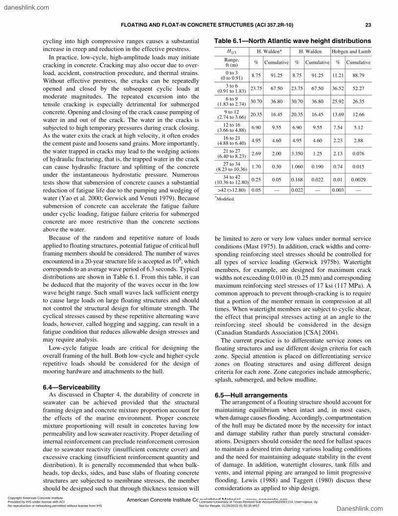
FLOATING AND FLOAT-IN CONCRETE STRUCTURES (ACI 357.2R-10) 23
American Concrete Institute Copyrighted Material—www.concrete.org
cycling into high compressive ranges causes a substantialincrease in creep and reduction in the effective prestress.
In practice, low-cycle, high-amplitude loads may initiatecracking in concrete. Cracking may also occur due to over-load, accident, construction procedure, and thermal strains.Without effective prestress, the cracks can be repeatedlyopened and closed by the subsequent cyclic loads atmoderate magnitudes. The repeated excursion into thetensile cracking is especially detrimental for submergedconcrete. Opening and closing of the crack cause pumping ofwater in and out of the crack. The water in the cracks issubjected to high temporary pressures during crack closing.As the water exits the crack at high velocity, it often erodesthe cement paste and loosens sand grains. More importantly,the water trapped in cracks may lead to the wedging actionsof hydraulic fracturing, that is, the trapped water in the crackcan cause hydraulic fracture and splitting of the concreteunder the instantaneous hydrostatic pressure. Numeroustests show that submersion of concrete causes a substantialreduction of fatigue life due to the pumping and wedging ofwater (Yao et al. 2000; Gerwick and Venuti 1979). Becausesubmersion of concrete can accelerate the fatigue failureunder cyclic loading, fatigue failure criteria for submergedconcrete are more restrictive than the concrete sectionsabove the water.
Because of the random and repetitive nature of loadsapplied to floating structures, potential fatigue of critical hullframing members should be considered. The number of wavesencountered in a 20-year structure life is accepted as 108, whichcorresponds to an average wave period of 6.3 seconds. Typicaldistributions are shown in Table 6.1. From this table, it canbe deduced that the majority of the waves occur in the lowwave height range. Such small waves lack sufficient energyto cause large loads on large floating structures and shouldnot control the structural design for ultimate strength. Thecyclical stresses caused by these repetitive alternating waveloads, however, called hogging and sagging, can result in afatigue condition that reduces allowable design stresses andmay require analysis.
Low-cycle fatigue loads are critical for designing theoverall framing of the hull. Both low-cycle and higher-cyclerepetitive loads should be considered for the design ofmooring hardware and attachments to the hull.
6.4—ServiceabilityAs discussed in Chapter 4, the durability of concrete in
seawater can be achieved provided that the structuralframing design and concrete mixture proportion account forthe effects of the marine environment. Proper concretemixture proportioning will result in concretes having lowpermeability and low seawater reactivity. Proper detailing ofinternal reinforcement can preclude reinforcement corrosiondue to seawater reactivity (insufficient concrete cover) andexcessive cracking (insufficient reinforcement quantity anddistribution). It is generally recommended that when bulk-heads, top decks, sides, and base slabs of floating concretestructures are subjected to membrane stresses, the membershould be designed such that through thickness tension will
be limited to zero or very low values under normal serviceconditions (Mast 1975). In addition, crack widths and corre-sponding reinforcing steel stresses should be controlled forall types of service loading (Gerwick 1975b). Watertightmembers, for example, are designed for maximum crackwidths not exceeding 0.010 in. (0.25 mm) and correspondingmaximum reinforcing steel stresses of 17 ksi (117 MPa). Acommon approach to prevent through-cracking is to requirethat a portion of the member remain in compression at alltimes. When watertight members are subject to cyclic shear,the effect that principal stresses acting at an angle to thereinforcing steel should be considered in the design(Canadian Standards Association [CSA] 2004).
The current practice is to differentiate service zones onfloating structures and use different design criteria for eachzone. Special attention is placed on differentiating servicezones on floating structures and using different designcriteria for each zone. Zone categories include atmospheric,splash, submerged, and below mudline.
6.5—Hull arrangementsThe arrangement of a floating structure should account for
maintaining equilibrium when intact and, in most cases,when damage causes flooding. Accordingly, compartmentationof the hull may be dictated more by the necessity for intactand damage stability rather than purely structural consider-ations. Designers should consider the need for ballast spacesto maintain a desired trim during various loading conditionsand the need for maintaining adequate stability in the eventof damage. In addition, watertight closures, tank fills andvents, and internal piping are arranged to limit progressiveflooding. Lewis (1988) and Taggert (1980) discuss theseconsiderations as applied to ship design.
Table 6.1—North Atlantic wave height distributionsH1/3 H. Walden* H. Walden Hobgen and Lumb
Range,ft (m) % Cumulative % Cumulative % Cumulative
0 to 3(0 to 0.91) 8.75 91.25 8.75 91.25 11.21 88.79
3 to 6(0.91 to 1.83) 23.75 67.50 23.75 67.50 36.52 52.27
6 to 9(1.83 to 2.74) 30.70 36.80 30.70 36.80 25.92 26.35
9 to 12(2.74 to 3.66) 20.35 16.45 20.35 16.45 13.69 12.66
12 to 16(3.66 to 4.88) 6.90 9.55 6.90 9.55 7.54 5.12
16 to 21(4.88 to 6.40) 4.95 4.60 4.95 4.60 2.23 2.88
21 to 27(6.40 to 8.23) 2.69 2.00 3.350 1.25 2.13 0.076
27 to 34(8.23 to 10.36) 1.70 0.30 1.060 0.190 0.74 0.015
34 to 42(10.36 to 12.80) 0.25 0.05 0.168 0.022 0.01 0.0029
>42 (>12.80) 0.05 — 0.022 — 0.003 —*Modified.
Copyright American Concrete Institute Provided by IHS under license with ACI Licensee=University of Texas Revised Sub Account/5620001114, User=opioui, rty
Not for Resale, 01/26/2015 01:50:35 MSTNo reproduction or networking permitted without license from IHS
--`````,`,,`,`,,,,`,`,,`,,,`,`-`-`,,`,,`,`,,`---
daneshlink.com
Daneshlink.com
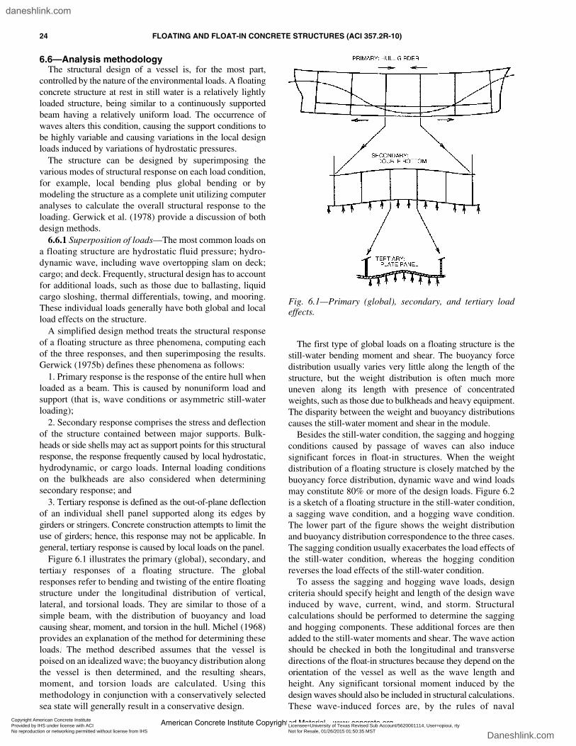
24 FLOATING AND FLOAT-IN CONCRETE STRUCTURES (ACI 357.2R-10)
American Concrete Institute Copyrighted Material—www.concrete.org
6.6—Analysis methodologyThe structural design of a vessel is, for the most part,
controlled by the nature of the environmental loads. A floatingconcrete structure at rest in still water is a relatively lightlyloaded structure, being similar to a continuously supportedbeam having a relatively uniform load. The occurrence ofwaves alters this condition, causing the support conditions tobe highly variable and causing variations in the local designloads induced by variations of hydrostatic pressures.
The structure can be designed by superimposing thevarious modes of structural response on each load condition,for example, local bending plus global bending or bymodeling the structure as a complete unit utilizing computeranalyses to calculate the overall structural response to theloading. Gerwick et al. (1978) provide a discussion of bothdesign methods.
6.6.1 Superposition of loads—The most common loads ona floating structure are hydrostatic fluid pressure; hydro-dynamic wave, including wave overtopping slam on deck;cargo; and deck. Frequently, structural design has to accountfor additional loads, such as those due to ballasting, liquidcargo sloshing, thermal differentials, towing, and mooring.These individual loads generally have both global and localload effects on the structure.
A simplified design method treats the structural responseof a floating structure as three phenomena, computing eachof the three responses, and then superimposing the results.Gerwick (1975b) defines these phenomena as follows:
1. Primary response is the response of the entire hull whenloaded as a beam. This is caused by nonuniform load andsupport (that is, wave conditions or asymmetric still-waterloading);
2. Secondary response comprises the stress and deflectionof the structure contained between major supports. Bulk-heads or side shells may act as support points for this structuralresponse, the response frequently caused by local hydrostatic,hydrodynamic, or cargo loads. Internal loading conditionson the bulkheads are also considered when determiningsecondary response; and
3. Tertiary response is defined as the out-of-plane deflectionof an individual shell panel supported along its edges bygirders or stringers. Concrete construction attempts to limit theuse of girders; hence, this response may not be applicable. Ingeneral, tertiary response is caused by local loads on the panel.
Figure 6.1 illustrates the primary (global), secondary, andtertiary responses of a floating structure. The globalresponses refer to bending and twisting of the entire floatingstructure under the longitudinal distribution of vertical,lateral, and torsional loads. They are similar to those of asimple beam, with the distribution of buoyancy and loadcausing shear, moment, and torsion in the hull. Michel (1968)provides an explanation of the method for determining theseloads. The method described assumes that the vessel ispoised on an idealized wave; the buoyancy distribution alongthe vessel is then determined, and the resulting shears,moment, and torsion loads are calculated. Using thismethodology in conjunction with a conservatively selectedsea state will generally result in a conservative design.
The first type of global loads on a floating structure is thestill-water bending moment and shear. The buoyancy forcedistribution usually varies very little along the length of thestructure, but the weight distribution is often much moreuneven along its length with presence of concentratedweights, such as those due to bulkheads and heavy equipment.The disparity between the weight and buoyancy distributionscauses the still-water moment and shear in the module.
Besides the still-water condition, the sagging and hoggingconditions caused by passage of waves can also inducesignificant forces in float-in structures. When the weightdistribution of a floating structure is closely matched by thebuoyancy force distribution, dynamic wave and wind loadsmay constitute 80% or more of the design loads. Figure 6.2is a sketch of a floating structure in the still-water condition,a sagging wave condition, and a hogging wave condition.The lower part of the figure shows the weight distributionand buoyancy distribution correspondence to the three cases.The sagging condition usually exacerbates the load effects ofthe still-water condition, whereas the hogging conditionreverses the load effects of the still-water condition.
To assess the sagging and hogging wave loads, designcriteria should specify height and length of the design waveinduced by wave, current, wind, and storm. Structuralcalculations should be performed to determine the saggingand hogging components. These additional forces are thenadded to the still-water moments and shear. The wave actionshould be checked in both the longitudinal and transversedirections of the float-in structures because they depend on theorientation of the vessel as well as the wave length andheight. Any significant torsional moment induced by thedesign waves should also be included in structural calculations.These wave-induced forces are, by the rules of naval
Fig. 6.1—Primary (global), secondary, and tertiary loadeffects.
Copyright American Concrete Institute Provided by IHS under license with ACI Licensee=University of Texas Revised Sub Account/5620001114, User=opioui, rty
Not for Resale, 01/26/2015 01:50:35 MSTNo reproduction or networking permitted without license from IHS
--`````,`,,`,`,,,,`,`,,`,,,`,`-`-`,,`,,`,`,,`---
daneshlink.com
Daneshlink.com

FLOATING AND FLOAT-IN CONCRETE STRUCTURES (ACI 357.2R-10) 25
American Concrete Institute Copyrighted Material—www.concrete.org
architecture, applied to develop the maximum bendingmoments and shears in the float-in structures.
Local load effects (that is, secondary and tertiary responses)refer to structural effects, for example, stresses and deflectionof individual structural elements under localized loads(Fig. 6.1). In floating structures, an individual member oftenconsists of a flat or slightly curved panel strengthened bystiffeners or bulkheads. Cracking caused by secondary andtertiary response modes is normally flexure cracking whereone face of the member remains in compression.
The local load analysis is to determine the distribution ofboth in-plane and normal loading, deflection, and stressesover the length and width of a local panel and their effects onstiffeners or bulkheads. The analysis is essentially a two-dimensional problem. There are traditionally four analysisprocedures for local plate analysis: (1) orthotropic platetheory; (2) theory of beams-on-elastic-foundation; (3) grillagetheory; and (4) the finite element method. Lewis (1988)provides detailed discussions on the first three procedures.
The most severe likely combination of these responses canbe used to design the various structural components. Themajor shortcoming of this procedure is that end conditionsare approximated by assumptions of fixity. The tendency bydesigners is to make conservative assumptions and, thus, aconservative design generally results. The use of computer-aided analysis will generally provide greater accuracy inobtaining the structural response because the otherwise time-consuming process of assessing the structure’s stiffness andload distribution capacity can be accomplished rapidly byusing available computer software. These methods areespecially appropriate for complex structures. Section 6.6.2contains a general introduction and references for the finiteelement analysis method.
In general, the simple design approach in this sectionapplies to rectangular-shaped floating structures. Determinationof global loads on special configurations of a floating structurewill need consultation of professional naval architects.Michel (1968), Mansour and Faulkner (1973), and Chapter 5introduce the spectral approach to the design of the hull,which can be used to predict design loadings by consideringthe random nature of ocean waves and the various joint prob-abilities of vessel heading and wave encounter.
6.6.2 Finite element modeling and analysis techniques—Current advances in the state of the art in finite elementanalysis of reinforced concrete structures allow the analyst/designer a wide range of analysis sophistication that can beapplied to particular applications. The level of sophisticationis generally dictated by the design stage and load level andtype of structure under investigation, but can also be selectedand varied for economic reasons.
In preliminary design stages, first-order estimates ofgeneral behavior are used for initial sizing. Economicallinear modeling is normally justified, especially for low loadlevels such as operational loads. For ULS design, use ofnonlinear techniques that model the brittle plastic behaviorof the constituent materials in a structure (including theincreased compressive strength of confined concrete) can beincluded, and may be essential. A comprehensive presentationof the various finite elements and their material models isfound in American Society of Civil Engineers (ASCE)(1982). A brief summary of the reference follows for variouslevels of modeling sophistication.
The most common modeling procedure for reinforcedconcrete structures assumes that the composite materialbehaves as a linear elastic, isotropic material. A standardlinear finite element model is straightforward to prepare andrelatively inexpensive to solve using a wide variety ofavailable computer programs. For low levels of loading andfor evaluating the system of internal forces in the global orcomplete structural system, the linear analysis is effectiveand efficient.
The results of the linear analysis, however, can be difficultto interpret or even inappropriate if the load levels are highand significant nonlinear behavior exists. If significantnonlinear response is inherent in the design, a more accuraterepresentation of the local behavior is required.
Specialized finite elements can be used that are capable ofsimulating many of the complex nonlinear characteristics ofconcrete. Elements exist that can simulate the effects ofcracking in the concrete, commonly the major source ofnonlinearity within the concrete. The stiffness of these finiteelements is automatically modified when the maximumprincipal tensile stress within the finite element has reacheda user-specified concrete rupture strength.
Other finite elements are available that can simulate thecomplex nonlinear compressive behavior of concrete. Atcompressive stresses above approximately 0.30 times theuniaxial compressive strength of concrete, fc′ , concrete beginsto behave in an increasingly nonlinear manner characterized byprogressive softening. This continues until the concretereaches its ultimate compressive strength. Additionally, the
Fig. 6.2—Shear force and moment distributions under thestill-water, sagging, and hogging conditions.
Copyright American Concrete Institute Provided by IHS under license with ACI Licensee=University of Texas Revised Sub Account/5620001114, User=opioui, rty
Not for Resale, 01/26/2015 01:50:35 MSTNo reproduction or networking permitted without license from IHS
--`````,`,,`,`,,,,`,`,,`,,,`,`-`-`,,`,,`,`,,`---
daneshlink.com
Daneshlink.com

26 FLOATING AND FLOAT-IN CONCRETE STRUCTURES (ACI 357.2R-10)
American Concrete Institute Copyrighted Material—www.concrete.org
strength and the stress-strain characteristics of concrete incompression were quantified by experiment to be highlydependent upon the state of multiaxial stress existing withinthe concrete. Concrete under conditions of triaxial compression,for instance, exhibits strengths many times higher than itsuniaxial compressive strength. Finite elements now exist thatare able to simulate much of this behavior, making use of theavailable experimental data. The simplest of these elementsuse nonlinear elasticity as the basis for their information,whereas other, more complex elements make use of plas-ticity theory or the endochronic theory of concrete behaviordescribed in Gerwick et al. (1978).
Linear elastic elements can be used effectively if theconcrete is subjected to monotonic, proportional loading.Proportional loading implies that the load pattern is fixed.Nonlinear elements can be more accurate in cases where theconcrete is subjected to nonproportional loading andunloading. Creep and shrinkage of concrete can also bemodeled using specialized concrete elements.
Steel reinforcement within the concrete can be modeled intwo primary ways. One way is to make use of a representationwherein the effects of steel reinforcement are distributedover the surface or volume of a concrete element. Alternatively,reinforcement can be modeled using a discrete representationutilizing truss bars or beam elements. These elements arethen superimposed upon the existing plain concrete mesh.The type of representation that is best for an analysis dependsprimarily upon the nature of the structure. Heavily reinforcedbeams normally require discrete modeling of the reinforce-ment to obtain good prediction of behavior, whereas shearpanels with uniform reinforcing grids can be modeled using adistributed representation of the reinforcement.
6.7—Design and detailing6.7.1 Weight control—In general terms, the capacity of a
vessel to carry cargo is the difference between the weight ofthe water displaced by the vessel and the lightship weight(that is, the weight of the vessel without cargo aboard). Oncethe vessel’s external dimensions have been established,increasing local structural sizes will reduce the cargo-carrying capacity. For certain applications—in particular, oilstorage—this could result in an actual limitation in theamount of cargo capacity. Accordingly, weight control isconsidered an important design parameter by the marinestructural designer. Detailed design weight estimates shouldallow for concrete placement tolerances and weight growthdue to formwork spreading. Concrete mixture proportionsare selected to achieve weight control. Batching of theconcrete at the construction yard is monitored closely toassure conformance with design intent.
6.7.2 Inspection—A major advantage of concrete vesselsis their low maintenance requirements compared with steel.To fully benefit from the advantage, the concrete vesselshould be designed to dispense with requirements forperiodic dry docking for inspection. For this to be acceptableto various regulatory bodies, the vessel should be fullyinternally inspectable. This requires that the design incorporate
safe access to all compartments, with adequate provisionsfor venting during inspection.
6.7.3 Detailing—Durability and trouble-free operation inthe marine environment is often a function of properdetailing. For example, an epoxy patch over a tendon anchorpoint that deteriorates does not immediately jeopardize thestructure. In the long term it may, however, and its repair,especially if underwater, may be difficult and expensive.Similar examples, such as seepage through constructionjoints and local damage due to impact from supply boats, canrequire expensive repairs. The designer should strive toavoid these problems by considering maintenance and repairwhen detailing the construction drawings.
6.8—SummaryThe use of established design codes (rules) and attention to
detail are essential to ensure a safe, highly serviceablefloating structure. Where allowance for a reasonably conser-vative design approach provides performance withinaccepted standards with little or no appreciable cost penalty,the use of existing design codes or classification societyrules can provide rapid, competent design formulations. Whereit may be necessary to optimize a structure design to meet verystringent conditions (for example, the need for a very light-weight structure subjected to high-magnitude loads), morerigorous design techniques, such as dynamic response analysesand finite element stress analyses, may be warranted. Bothapproaches are acceptable, and it is left to the discretion of thedesigner to select the design methodology most appropriate.
In addition to concerns for accurate assessment of designloads and stresses imposed on structures exposed to a highlyvariable set of service conditions, the designer should payclose attention to structural detailing as a means ofenhancing the service performance of a vessel. The struc-tural serviceability and, in some cases, the ultimate strengthperformance of a floating concrete structure will be greatlyaffected by details such as:• Reinforcing steel lap splice and bond lengths in fatigue
critical areas of the structure;• Control of concrete crack width and induced reinforcing
steel stresses under service conditions;• Adequate preparation of construction joints in the
concrete structure;• Adequate concrete cover over reinforcing and
prestressing steel;• Concrete mixture proportions that emphasize low
permeability and high cement content; and• Proper grouting and bonding of post-tensioning
tendons, and proper preparation of post-tensioningblockouts and anchorages.
There is much experience in the use of concrete in themarine environment to provide attention to details as notedpreviously. Perhaps the most comprehensive compilation ofsuch experience is available through the various marineclassification societies. Designers, constructors, and ownersof concrete floating structures should develop a dialoguewith such societies and agencies to assure the best possiblecontrol of structure performance.
Copyright American Concrete Institute Provided by IHS under license with ACI Licensee=University of Texas Revised Sub Account/5620001114, User=opioui, rty
Not for Resale, 01/26/2015 01:50:35 MSTNo reproduction or networking permitted without license from IHS
--`````,`,,`,`,,,,`,`,,`,,,`,`-`-`,,`,,`,`,,`---
daneshlink.com
Daneshlink.com

FLOATING AND FLOAT-IN CONCRETE STRUCTURES (ACI 357.2R-10) 27
American Concrete Institute Copyrighted Material—www.concrete.org
CHAPTER 7—CONSTRUCTION7.1—Introduction
The state of the art for construction of floating structuresis well developed and regulatory agencies have establishedcomprehensive codes and guidelines for the design andconstruction of such structures. Numerous structures havebeen built and construction techniques are well established.Large marine concrete structure fabrication yards existthroughout the world.
Floating structures can be constructed in accordance withhigh-technology construction industry standards. Theconstruction process is often monitored by the design agentand inspection is provided by authorized inspectors. Aconstruction plan, which includes, but is not limited to, plansfor materials control, quality control, and quality assurance;forming techniques; post-tensioning and prestressing tech-niques; repair techniques; and launching, is often prepared inadvance of construction.
Large floating concrete structures can be constructed indedicated facilities (graving docks and slipways) specificallyconstructed for the purpose. Such facilities are available.Because these structures will have large displacements,structure draft will be an important design/constructionparameter. Construction often allows for partial completionon a slipway or in a graving dock facility with completionafloat after launch. Hence, significant construction may takeplace over water.
7.2—Construction methods7.2.1 Construction on slipways—Construction of a
floating concrete structure on a slipway requires specialattention not commonly associated with construction in a drydock or graving dock facility. Important considerations include:
1. Construction of the slipway—The slipway supportstructure should have the capability to support the structureloads and loads due to construction equipment. It should alsohave sufficient stiffness and rigidity to prevent largedistortions that may induce racking and distortions in theconcrete formwork or in the completed concrete structure.
2. Moving the structure—The slipway should be designedto allow freedom of motion between the structure base slaband slipway during repositioning and launching. Highcontact pressures and possible suction forces should beconsidered. The slipway surface should be designed tominimize concentrated loadings on the structure base slab.
3. Structure launching—An analysis should be made thatconsiders the bridging effects of a structure partially afloatand partially on the slipway during launch. The slipwayangle and the buoyancy distribution of the structure shouldbe considered. The calculations should be included as part ofthe structure design using applicable construction loadfactors with allowance for the variable conditions.
7.2.2 Construction in graving dock—Floating structuresmay be constructed in a large graving dock or dry dockfacility. Should the structure be sufficiently small, it may beconstructed as a single piece within the dock. Alternatively,large structures can be made in segments having dimensionscompatible with dock dimensions and draft restrictions, then
launched and joined or mated with other segments. Concretestructures can be designed for segmenting in the plan dimensionto avoid horizontal construction joints in exterior bulkheads.
The decision to segment the structure is made early duringthe design stage. Key factors to consider are:• Construction facility length, width, and draft restrictions;• Draft and width restrictions in waterways and estuaries
away from the construction facility;• Weight distribution of the segments (still-water
loading);• Stability characteristics of the segments and of the
joined structure;• Design wave characteristics at the construction facility
and during tow to the integration site;• Structure internal framing arrangements;• Allowable deflections of the structure in both the still-
water and wave-loaded conditions;• The method for joining the segments;• The construction schedule and its relation to concrete
design strength requirements; and• The effects of construction loading both in the dry and
while afloat.The graving or dry dock facility used for construction of
floating concrete structure should be equipped with:• A level, structural floor with sufficient strength to resist
heavy, local construction loads from equipment andheavy precast elements;
• A floor that will not adhere to the structure duringlaunch;
• A dewatering system to prevent seawater contaminationof the work;
• Sufficient land space around the dock to allow for aconcrete batch plant and construction materials stock-piling and storing precast panels and concrete form-work; and
• If an on-site batch plant is used, it should be equippedwith a testing facility and supplemented with qualityassurance.
7.3—Concrete construction 7.3.1 Precast/cast-in-place construction—A high degree
of production repetition and reduced construction time canbe achieved by fabricating the structure segments fromjoined, similar precast wall and deck elements (Zinserlingand Cichanski 1982; Mast et al. 1985). The precast elementscan be fabricated to close tolerances in formwork erected inprecast plant facilities where material and labor qualitycontrol is easily maintained (Fig. 7.1 and 7.2).
Precast wall panels can be erected in the graving dockusing standard lifting equipment. Bracing of members isusually required. The walls or bulkheads of a large structureare subdivided into a series of precast panels separated byCIP closure pours. The closure pours are sized to allowsplicing of mild steel reinforcing and post-tensioning ducts.Closure pours are cast to the full height of the panel joints,usually after casting the structure base slab (Fig. 7.3). As analternate to closure pours, precast members can be match
Copyright American Concrete Institute Provided by IHS under license with ACI Licensee=University of Texas Revised Sub Account/5620001114, User=opioui, rty
Not for Resale, 01/26/2015 01:50:35 MSTNo reproduction or networking permitted without license from IHS
--`````,`,,`,`,,,,`,`,,`,,,`,`-`-`,,`,,`,`,,`---
daneshlink.com
Daneshlink.com

28 FLOATING AND FLOAT-IN CONCRETE STRUCTURES (ACI 357.2R-10)
American Concrete Institute Copyrighted Material—www.concrete.org
cast (Fig. 7.2) and epoxy bonded before post-tensioning(Anderson 1977).
A high-integrity closure pour joint between the as-castprecast elements, and the CIP pour requires special consider-ation. The as-cast faces of the precast panels need rougheningbefore erection. Allowance should be made to prevent jointseparation and distortion of formwork during concrete place-ment. The mating surfaces of the precast panels can becoated with an epoxy bonding agent before casting theclosure pour. Figures 7.4 and 7.5 illustrate this type of hullconstruction in a graving dock.
7.3.2 Cast-in-place construction—Major portions of thestructure may be CIP concrete construction. Base slabs,closure pours, and top deck overlays are common examples.Allowances are made during concrete mixture proportioningfor transporting the concrete from the batch plant to the jobsite, possibly over long distances. Because critical elements(for example, exterior bulkheads and base slabs) may beheavily reinforced, concrete slump and compaction duringplacement deserve special attention. Pumping may also berequired. When pumping is warranted, the concrete mixtureproportion should be reviewed to assess possible deleteriouseffects on performance caused by the pumping operation inaccordance with ACI 304.2R.
The effects of heat of hydration should be considered, notonly for possible impact on concrete quality, but also forpossible introduction of unwanted stresses in the structure.The heat generated by the concrete in a mass pour may besufficient to induce significant stresses in adjacent membersthat are already restrained by the surrounding structure. Thestresses induced due to such conditions are frequently assessedduring design. To prevent extensive surface cracking that mayoccur due to rapid heat loss in such pours, consideration is alsogiven to the use of insulated formwork and protection ofexposed surfaces. A detailed thermal control plan may benecessary for massive concrete elements or elements thatcould be damaged by excessive thermal gradients.
7.3.3 Post-tensioning—Floating concrete structures arefrequently prestressed by post-tensioning approximatelymore than one principal structure axis. Typically, the topdeck and base slab are post-tensioned both longitudinallyand transversely to account for delivery voyage hog/sagloading, base slab hydrostatic and grounding forces, anddeck loadings. In addition, external bulkheads may be post-tensioned vertically to control cracking due to hydrostaticpressures and externally applied environmental forces suchas ice and waves. Precast members may be prestressed tocontrol cracking during lifting and handling.
During design, allowance is often made for the possibleoccurrence of blocked tendon ducts at critical sections of thefloating structure. If possible, additional tendon ducts areoften specified to account for this eventuality. As aminimum, a certain percentage of the tendon ducts are over-
Fig. 7.1—Precast pontoon element, Valdez Terminal.
Fig. 7.2—Precast hull element, ARCO LPG Barge.
Fig. 7.3—Precast hull panel, showing closure pour.
Copyright American Concrete Institute Provided by IHS under license with ACI Licensee=University of Texas Revised Sub Account/5620001114, User=opioui, rty
Not for Resale, 01/26/2015 01:50:35 MSTNo reproduction or networking permitted without license from IHS
--`````,`,,`,`,,,,`,`,,`,,,`,`-`-`,,`,,`,`,,`---
daneshlink.com
Daneshlink.com

FLOATING AND FLOAT-IN CONCRETE STRUCTURES (ACI 357.2R-10) 29
American Concrete Institute Copyrighted Material—www.concrete.org
sized to allow for incorporation of tendons having morestrands than those specified.
An analysis is commonly undertaken to assess the effects ofthe proposed stressing sequence on the structure. Considerationis given for post-tensioning the partially completed structurebelow the waterline before launch from the graving dock and tothe effects on the final stressed condition by post-tensioningconducted after float-out. An inspection of sensitive areas isoften made before and after the post-tensioning operation.
7.3.4 Grouting of anchorages—Bonded post-tensioningsystems are often specified for floating concrete structures.A bonded system requires injection of grout into the post-tensioning ducts. The procedures for grouting post-tensioningducts and anchorage blockouts are outlined as follows.
7.3.4.1 Grouting tendon ducts—Grout is composed ofportland cement, water, and admixtures proportioned toensure a flowable grout with minimum bleeding or separation.The maximum recommended w/cm for the grout is often
Fig. 7.4—Hull construction, ARCO LPG Barge.
Fig. 7.5—Hull construction, Valdez Container Terminal.
Copyright American Concrete Institute Provided by IHS under license with ACI Licensee=University of Texas Revised Sub Account/5620001114, User=opioui, rty
Not for Resale, 01/26/2015 01:50:35 MSTNo reproduction or networking permitted without license from IHS
--`````,`,,`,`,,,,`,`,,`,,,`,`-`-`,,`,,`,`,,`---
daneshlink.com
Daneshlink.com

30 FLOATING AND FLOAT-IN CONCRETE STRUCTURES (ACI 357.2R-10)
American Concrete Institute Copyrighted Material—www.concrete.org
0.44. For vertical or near-vertical tendon ducts, a combinationof a chemical admixture that produces thixotropic behaviorof the grout and special grouting procedures may benecessary to prevent formation of trapped air pockets, whichwill inhibit complete filling of the duct. Horizontal or near-horizontal ducts should be fitted with vents to allow removalof trapped air and bleed water, and to allow complete fillingof the duct. The Post-Tensioning Institute (PTI) (2001)offers guidance on this subject.
7.3.4.2 Tendon anchorages—Tendon anchorages arefrequently recessed in precast blockouts. Followingprestressing, these blockouts need to be filled to protect thetendon anchor. After the post-tensioning duct grout hascured, the anchorages are cleaned and roughened, commonlyby sandblasting. Epoxy bonding agents are often used tocover the blockout, the anchor, and the ends of tendon strand.A positive mechanical means of retaining the entire blockoutpatch is necessary. Techniques include hooking reinforcingbar into the anchorage blockout or providing a cast-inkeyway in the blockout perimeter. If a keyway is used, it isproportioned so that it will be uniformly filled during theblockout grouting operation. Blockouts can be filled withgrout using forms to retain the grout and to ensure expansionof the grout into the keyway during curing. If cement groutis used to fill the anchorage zone, it should be made with thesame cement used for the concrete structure containing theprestressing.
7.3.5 Suction bond—Precautions should be taken toprovide a mechanism to effectively break the suction bondthat may occur when the base slab is cast directly against thedry dock or graving dock floor. One method is to dischargecompressed air or water through ducts in the structureframing that exit at the dry dock floor interface. This methodwas used during construction of the Valdez ContainerTerminal floating dock pontoons (Zinserling and Cichanski1982). The compressed air or water was used as a bondbreaker to facilitate structure liftoff during graving dockflooding. Alternately, the dry dock floor may be overlainwith a permeable membrane to reduce the suction forces.This method was used during construction of the concretecaisson for the Glomar Beaufort Sea I Arctic drilling structurediscussed in Section 7.4.
7.4—Construction afloatCompleting the structure while afloat presents unusual
design and construction challenges (Gerwick 1975c).Precautions are taken to assure a high-integrity structure.Several important considerations are:
• Still-water weight distribution and wind-, wave-, andcurrent-induced loadings;
• Stability (intact and damage);
• Post-tensioning sequences;
• Resolution of local, temporary construction loads;
• Concrete mixture with the required strength to preventtensile cracking and leakage while the structure is afloat;
• Concrete curing methods;
• Protection of concrete materials, reinforcing steel, andprestressing steel, and anchorages from seawatercontamination; and
• Construction joint preparation to remove laitance,marine growth, and salts.
The freeboard of the floating structure is an importantconstruction parameter. In some cases, minimum freeboardrequirements are specified by regulatory agencies. The free-board, trim, and stability characteristics of the structure aremonitored throughout the construction process to assurestability in the still-water condition and to prevent waveovertopping.
7.5—Segmental construction—joining while afloatMany methods for joining large precast floating structure
segments are available. Each embodies some type ofconstruction splice joint. The details vary generally becauseof the specific nature of the splice joint design. Thesemethods, however, share common features:• Two or more similar, but not necessarily identical,
floating concrete segments or pontoons;• A splice joint consisting of a CIP closure pour
surrounding grouted post-tensioning tendons, mild steelreinforcement, and mating/alignment fittings;
• A method of sealing and dewatering the closure pourduring mating; and
• A method of differentially ballasting the floatingsegments to control loads.
A typical segment may be outfitted with CIP steel male/female pin/socket fittings near the top deck and steel rockerbearing assemblies near the base slab below waterline. Thepin socket fittings provide for positive, visual, and mechanicalalignment of the segments. Figure 7.6 illustrates the topfittings for the Valdez Container Terminal. A typical joiningsequence is outlined as follows:• Inspect alignment hardware cast in the segments at the
joining interface bulkhead;• Ballast each segment to a level trim and clean all mating
surfaces to remove salts, marine growth, and laitance;• Ballast each segment to a trim by the stern to bring only
the rocker bearings into contact;
Fig. 7.6—Valdez Container Terminal, upper mating fittings.
Copyright American Concrete Institute Provided by IHS under license with ACI Licensee=University of Texas Revised Sub Account/5620001114, User=opioui, rty
Not for Resale, 01/26/2015 01:50:35 MSTNo reproduction or networking permitted without license from IHS
--`````,`,,`,`,,,,`,`,,`,,,`,`-`-`,,`,,`,`,,`---
daneshlink.com
Daneshlink.com

FLOATING AND FLOAT-IN CONCRETE STRUCTURES (ACI 357.2R-10) 31
American Concrete Institute Copyrighted Material—www.concrete.org
• When contact is made, hold segments in place bycables and temporary deck winches or by post-tensioning tendons spanning the joint;
• Ballast the segments to close the joint and mate thealignment hardware;
• Dewater the joint to allow for uncapping of previouslysealed post-tensioning tendon ducts. Provide a sealedclosure that can be dewatered either by constructing thesegments with deformable perimeter seals, or byaffixing a portable sealed cofferdam assembly to thesegment joint. Figure 7.7 shows the cofferdam in placeat the Valdez Container Terminal;
• After the closure is sealed and dewatered, inspect themating surfaces and clean the surfaces by jetting orsandblasting;
• Uncap tendon ducts, and put duct splices in place.Splice mild steel reinforcement to bars protruding fromthe floating precast segments. Figure 7.8 shows splicedtendon ducts;
• Pull post-tensioning tendons through the ducts andplace anchorage hardware. All post-tensioning can beaccomplished from inside the floating segments.Include abutment and anchorage details in the structuredesign effort;
• Place formwork for the CIP closure pour and make theclosure pour;
• When the concrete has reached acceptable strength,post-tension the joint using a predetermined sequencedeveloped to control induced loads and to account forthe time-dependent gain in concrete strength;
• Remove the temporary mating equipment andcofferdam; and
• Grout the post-tensioning ducts. Important design checkpoints for segmental construction
are:• Temporary mating equipment should be affixed and
preloaded to restrain the two structures while afloat;
• A detailed post-tensioning procedure should beestablished;
• A prejoining and postjoining inspection should bemade; and
• Forces in the mated joint should be identified at eachstep in the procedure. Allowances are made for wind,wave, and current forces; forces from temporaryconstruction equipment; effects due to ballasting;weight of CIP closure pour; and the effects of buoyancydue to the dewatering cofferdam if used.
7.6—SummaryThe section presents some common construction methods
and techniques that have been well established forconstructing floating concrete structures. Many structuresthat were built with these construction methods and techniqueshave served owners well. Because construction loadsfrequently govern the structural design of floating concretestructures, the construction methods and techniques havesignificant influence on design and structural detailing. Forthe construction methods to work well, the designer shouldwork closely with regulatory agents and constructors toensure the construction means and methods are fully consideredin the design. Constructors and owners need to work togetherto establish construction methods and schedules that arecompatible with project requirements and resources.
CHAPTER 8—TOWING AND INSTALLATION8.1—Introduction
Towing a large-displacement, floating structure requiresthat special attention be given to design considerations forstrength, maneuverability, and stability. These concerns areespecially important when the vessel is to be constructed atone location, then towed, possibly over great distances in anocean environment, to a remote location. For recent applicationsof the concept, refer to the Valdez Container Terminal(Zinserling and Cichanski 1982), the Rofomex concrete hullphosphate plant, and the ARCO LPG barge (Mast 1975),where the anticipated delivery voyage towing loads werehighly influential in sizing the primary barge hull scantlings(dimensions). Structural hull strength (bending and shear)and freeboard requirements can be more critical during the
Fig. 7.7—Dewatering cofferdam, Valdez Container Terminal.
Fig. 7.8—Tendon duct splices, Valdez Container Terminal.
Copyright American Concrete Institute Provided by IHS under license with ACI Licensee=University of Texas Revised Sub Account/5620001114, User=opioui, rty
Not for Resale, 01/26/2015 01:50:35 MSTNo reproduction or networking permitted without license from IHS
--`````,`,,`,`,,,,`,`,,`,,,`,`-`-`,,`,,`,`,,`---
daneshlink.com
Daneshlink.com

32 FLOATING AND FLOAT-IN CONCRETE STRUCTURES (ACI 357.2R-10)
American Concrete Institute Copyrighted Material—www.concrete.org
delivery voyage than during service at more sheltered locations.Therefore, towing and installation considerations, such asselection of tow route and time of year for the tow, towingconfiguration, associated towing and rigging forces, andattachment to mooring systems at the service site, need closeattention during the structural design process.
8.2—Design considerations8.2.1 Intact and damage stability—Recommendations for
minimum intact and damage stability characteristics areprovided by the classification societies and published invarious design guideline documents by professional societies;DnV (1997), ABS et al. (2006), and Yao and Gerwick (2002)provide many examples.
These references, which discuss both damage and intactstability, require that the floating structures possess anadequate range of static stability during conditions ofexpected loading, plus reserve righting energy to withstandthe overturning moment due to a horizontal wind conditionof specified magnitude. In essence, the structures should beable to remain floating upright for all afloat conditions,including launching and ballasting, and under all thepossible environmental conditions pertaining to the site andthe period. They should also have adequate reserves ofstability when certain accidental damage occurs.
A floating structure may lose its stability due to severaldestabilizing effects, such as flooding of its compartments oruncontrolled lifts from a mounted crane. A stability checkaccording to naval architecture principles should be madeagainst all potential destabilizing effects.
There are three important parameters controlling thestability of a floating structure (Fig. 8.1): (1) The center ofgravity G; (2) The center of buoyancy B; and (3) The waterplane moment of inertia I. A reference point is often establishedat midship on the keel K. When a floating structure heels ortrims, the buoyancy force acts vertically upward through B tointersect the axis of the structure at the metacentric point M.The buoyancy force also imposes a righting moment on thestructure. The righting moment is the product of thedisplacement and righting arm GM(sinθ). The term sinθ maybe replaced by θ for small angles of list. Stability of thestructure requires that the righting moment restore the struc-ture to the upright floating position once external forcescausing the heel or trim are removed. In naval architecture,this stability requirement implies that the metacentric height
should always be positive. In practice, the metacentric heightis usually kept above 3 ft (1 m) for all directions of inclination.This stability requirement can be translated into thefollowing mathematical equation
GM = KB – KG + BM ≥ 0.1 m
where KB and KG are the distance from the keel to the centerof buoyancy and the center of gravity, respectively. BM isthe distance from the center of buoyancy to the metacentricpoint. BM can be calculated as
For any rectangular structure, I = b3l /12 and V = bld; b,l, and d are the beam, length, and draft of the structure,respectively.
Floating stability should be checked for all the possiblecases of flooding. There are a number of causes for floodinga floating structure, for example, boat impact, incorrectvalve operation, or ballasting down a floating structure. Oneprincipal method of controlling stability is to subdivide afloating structure into a sufficient number of small compart-ments so that accidental flooding is limited to a small part ofthe structure.
If one or more compartments are partially filled with wateror other liquid, the internal waterplanes will cause a shift ofthe center of gravity further away from the center of buoyancyupon heel or trim of the structure. The net effect, often calledfree surface effect, is a reduction in stability and the metacentricheight. The free surface effect on the change in metacentricpoint can be approximately accounted by calculating BM asfollows
where Ai is the free surface area in a partially filledcompartment, and ri is the distance from the free surface tothe axis of the waterplane of the entire structure in thedirection of rotation.
Some floating structures have partially or fully open topsduring transport. Adequate consideration should be given to thepotential for overtopping, such as by waves or due tounintended list, and even to rain water, because even a smallamount of flood water can lead to significant free surface effects.
The aforementioned formulas are useful tools for quickassessment of the hydrostatic stability of a floating structure.They are valid for small heel/trim rotational angles. If afloating structure might experience substantial trim/heelrotation, stability calculation should be based upon the rightingmoment stability criterion, as specified by Fiorato (1981).
To provide protection against accidental flooding, damagecontrol measures require that all manholes, hatches, andbulkheads in the compartments be sealed watertight anddesigned to withstand the maximum pressure head of the
BM 1V--- moment of inertia of waterplane
displacement of structure-----------------------------------------------------------------------------= =
BM 1V--- Airi
2
i∑–=
Fig. 8.1—Center of buoyancy, center of gravity, metacenter,and metacentric height.
Copyright American Concrete Institute Provided by IHS under license with ACI Licensee=University of Texas Revised Sub Account/5620001114, User=opioui, rty
Not for Resale, 01/26/2015 01:50:35 MSTNo reproduction or networking permitted without license from IHS
--`````,`,,`,`,,,,`,`,,`,,,`,`-`-`,,`,,`,`,,`---
daneshlink.com
Daneshlink.com

FLOATING AND FLOAT-IN CONCRETE STRUCTURES (ACI 357.2R-10) 33
American Concrete Institute Copyrighted Material—www.concrete.org
accidental flooding. The design also requires that all pipesand ducts be closed off during non-usage periods so thatflooding does not spread through those systems.
For floating concrete structures that are towed infrequently,single-compartment damage conditions are often assumed.Various codes and regulations require that the damagedvessel have sufficient minimum righting energy to withstanda short-duration (seasonal storm) wind force without loss ofstability, and that compartmentation be arranged to precludeprogressive flooding if damaged.
For a floating structure that is intended for frequent towingor for Arctic service, two-compartment damage stability isrecommended. Additionally, the design should ensure thatwhen the structure is damaged, the resulting heel or trim ofthe vessel with one or more compartments flooded to theequilibrium waterline does not cause progressive flooding ofadjacent compartments through vents, hatches, or other non-watertight openings.
8.2.2 Strength—All aspects of towing should be investigatedto ensure that the structure is not exposed to loadings greaterthan those for which it was designed. The design bendingmoment capacity should be sufficient to withstand a wavecomparable to a 10-year return significant wave height andfor a range of wave periods for the towing season. For arectangular-shaped floating structure, wave lengths nearlyequal to the length of the structure will produce critical wavebending loads at the assumed design wave height.Strengthening at the waterline is an important consideration foroperations involving contact with ice during transportationand installation of the vessel. For floating concrete structures,special attention is given to control of cracking, particularlymembrane cracking due to the design delivery voyage waveconditions. In addition, consideration is given to the controlof structural hull deflections due to combined dead load andwave effects to assure that structures or systems affixed to thestructure are not excessively loaded. For a more completedefinition of these strength-related matters, refer to Chapter 6.
8.2.3 Response to motion—The response of the structureto motion in all degrees of freedom can be determined for theassumed towing conditions. Many computer programs areavailable to make these determinations. These programstypically require as input data overall vessel size and shape,added mass, center of gravity location, and radii of gyrationabout the three axes of rotation. Computer programs areoften verified against model test results. Where the shape ofthe structure makes it sensitive to undesirable motions (forexample, dynamic uplift, nosediving, and yaw), thehydrodynamic control of the structure under tow should beadequate to minimize this effect. Checks are made to ensurethat the motions of the unit in the most severe expectedenvironmental conditions do not result in unacceptablestresses or increases in draft.
Adequate tiedowns are provided to prevent damage to thesuperstructure and equipment caused by dynamic accelerationsduring the tow. Again, motion analyses computer programsare capable of providing anticipated accelerations withrespect to the six degrees of freedom at any point on thefloating structure. Several existing programs provide
coupled motion responses. These data can be used to designrequired additional holddowns and bracing. The resultingtiedown design loads should consist of the coupled analysisloads multiplied by a suitable factor to account for slammingand high-frequency oscillation effects.
8.2.4 Towing connections—An adequate number oftowing connections, suitably placed, are normally fitted tothe structure to permit the towing vessels (tugs) to be easilysecured and released. Design of the towing connection to thefloating structure provides sufficient load capacity such thatthe strength of the connection exceeds the strength of the towline by approximately 25 to 50%.
Towing contractors generally recommend that two separatesets of quick-release clench plates, chain bridles, and wirepennants be available forward, with one complete set as abackup. The pennant line is used to allow tugs to make fastwithout approaching the hull too closely. If the unit is to betowed through ice-laden waters, two sets of quick-releaseclench plates should be available at the stern in case additionaltugs are needed to assist with steering and stoppage. Thisarrangement can prevent the towed unit from overrunningthe towing vessels should the lead vessel become beset byice. For towing in ice conditions, towing connections shouldbe strategically placed so as not to interfere with ice movementaround the structure.
Towing connections often have an ultimate strength of atleast two times the breaking load of the tow wire, equal tofour times the bollard pull, of the largest tug, which would beenvisaged for such tow. This allows for substitution of largertowing vessels if necessary. Emergency towing arrangementsshould include a spare pennant wire connected to an emergencybridle. This bridle, in turn, may be lashed back along the sideof the unit and connected to a polypropylene floating rope ofbright color connected at the end of a bright-colored marker.If a unit is manned during the tow, the emergency arrangementsare secured onboard and streamed overboard as directed bythe tow master. In the case of an unmanned tow, the floatingrope and marker buoy trail behind the tow.
8.2.5 Moorings—Vessel mooring design is consideredeither as part of a contingency plan during towing or at theintended final location. It is often considered together withthe effect of ice if such exposure is anticipated. The envi-ronmental extremes used to design the mooring system oftentake into account the length and season of exposure. In theabsence of further guidance, a 10-year seasonal return periodis commonly recommended for temporary installations (lessthan 4 weeks), and a 100-year return period for permanentinstallations, including ice conditions where a 100-yearreturn period is also recommended. It is not normallyrequired to include the combined effects of ice and waves.Slow drift forces are an important consideration in the designof a mooring system.
The mooring system is often designed for mooring loadsthat will not exceed 60% of the breaking strength for wirerope and 70% for chain. The design of moorings is coveredin API RP-2P specification (API 2000).
8.2.6 Other considerations—Considerations are alsogiven to improving the safety of the tow by providing suitable
Copyright American Concrete Institute Provided by IHS under license with ACI Licensee=University of Texas Revised Sub Account/5620001114, User=opioui, rty
Not for Resale, 01/26/2015 01:50:35 MSTNo reproduction or networking permitted without license from IHS
--`````,`,,`,`,,,,`,`,,`,,,`,`-`-`,,`,,`,`,,`---
daneshlink.com
Daneshlink.com

34 FLOATING AND FLOAT-IN CONCRETE STRUCTURES (ACI 357.2R-10)
American Concrete Institute Copyrighted Material—www.concrete.org
manning, emergency anchor(s), access ladders, flood detectionsystems, emergency generators, and navigation lights inaccordance with regulations established by the Intergovern-mental Maritime Consultation Organization (1973). Thesafety of the tow will be enhanced by providing accompanyingvessels, developing contingency plans, providing soundingsand adequate pumping arrangements, and using onboardweather facsimile equipment and weather routing. For somespecific applications, outfitting the structure with skegs, a falsebow, or both, may be necessary to provide directional control.
8.3—Tow route8.3.1 Depth of water—A properly selected towing route
ensures that the structure is afloat at all times with anadequate underkeel clearance. Calculations of the underkeelclearance should take into account the increase in draft dueto roll, pitch, heave, squat effect (the tendency for a vessel toincrease draft while under way in very shallow water),towline forces, and wind heel. Attention should be focusedon the fact that shallow water (less than 165 ft [50 m])bottom clearance may affect computations for drag, sway,and dynamic surge.
Where the soundings shown on the largest scale navigationalchart available are of questionable accuracy (for example,where the charts are based on incomplete hydrographicsurveys or they are of areas subject to changes in seabedtopography), a pretow survey of the selected route should beperformed. The planning and conduct of surveys are basedon the accuracy and repeatability of the navigation of the surveyvessel and on the size and draft characteristics of the towedobject. Where sand waves occur that could obstruct the tow,their shapes and locations are determined by a sufficient numberof surveys to enable their movements to be predicted. The effectof storms on sand waves is often considered.
Typical nautical charts indicate spot water depths thatwere measured below the instantaneous water level by leadline or echo-sounder. In some areas of the world, these datapoints may be a mile apart, and may be out of date. Verificationof data using methods such as side-scan sonar or bar sweepsis a prudent way to map a proposed tow route.
8.3.2 Towing in restricted water—Towing in restrictedwater often receives special attention. Such waters mayoffer shelter from the wind, and the fetch may be such thatwaves are small. Currents, the proximity of navigationalhazards, shipping density, and the need to tow with shortenedtow lines, however, may necessitate a higher towinghorsepower for safety than would be required in openwater. Assistance is often obtained from a pilot havingknowledge of the local waters.
The selected route should provide adequate sea room forthe maneuvering of tugs and the width of channel at theseabed is carefully considered in relation to the width of thestructure being towed and to the tidal, current, and weatherconditions. In restricted waters, the selected navigable channelshould permit the passage to be made with a minimumnumber of course changes. Where available, information onthe strength and direction of tidal streams and currents may
be inadequate; a survey should be made to determine suchcurrents at the surface and its variation with depth.
8.3.3 Towing at sea—For towing at sea, towing vessels areselected that have sufficient power to safely hold the unit ingale-force winds and associated waves together with acurrent of at least 1 knot. Greater current or tidal streamvelocities are considered in certain localities. The calculatedforces on the structure imposed by wind, waves, and currentsshould be verified by model tests, if necessary.
Tugs should be adequately equipped with spare towinghardware, chain and line, and have sufficient reserve fuel forany reasonable contingency. A full complement of replacementsupplies should be provided if the tow enters a remote areawhere emergency assistance is unavailable.
8.3.4 Environmental criteria and weather limitations—Towsare generally scheduled to be completed within a periodcovered by a reliable weather forecast, and are often scheduledto take place within a period of mild weather. Tows generally donot commence other than in good weather and with a favorableweather forecast. It is common to identify potential safe harborsalong the tow route before beginning the tow.
When the tow is expected to last beyond the periodcovered by a reliable weather forecast, it should be plannedto deal safely with the most severe wind speed, wave height,and current that would be reasonable to expect during thetow. A 10-year statistical return period is often consideredfor the season of the tow. Special consideration may be givento towages of shorter duration. The climate along the towroute should be investigated and towing avoided duringseasons or periods when unacceptable weather is frequent orwhen solid ice or pack ice may be expected.
8.4—SummaryThe technical feasibility and, in some extreme cases, the
insurability of a floating structure, may depend heavily onthe attention given during design to towing and installationconsiderations. Although damage is unlikely, vessels arecommonly designed assuming that damage could occur duringthe tow. The consequences of intercompartmental floodingshould be considered and appropriate attention should be givento the dynamic accelerations of the vessel in the seaway.Towing forces and towline redundancy, along with vesselmaneuverability, are also considered. Experienced towingcontractors, consultants, and regulatory agencies can providethe best source of such information to the vessel designer.
In spite of the necessary concerns noted herein, the towingand mooring of floating concrete structures can be accom-plished by the same state-of-the-art methods used for steelvessels. The major difference between steel and concretevessels is one of displacement. The larger displacement ofconcrete vessels means increased towing horsepower require-ments, but also decreased motions in the seaway.
CHAPTER 9—MAINTENANCE, INSPECTION,AND REPAIR
9.1—IntroductionFloating concrete structures and marine concrete structures in
general continue to demonstrate low maintenance and highCopyright American Concrete Institute Provided by IHS under license with ACI Licensee=University of Texas Revised Sub Account/5620001114, User=opioui, rty
Not for Resale, 01/26/2015 01:50:35 MSTNo reproduction or networking permitted without license from IHS
--`````,`,,`,`,,,,`,`,,`,,,`,`-`-`,,`,,`,`,,`---
daneshlink.com
Daneshlink.com

FLOATING AND FLOAT-IN CONCRETE STRUCTURES (ACI 357.2R-10) 35
American Concrete Institute Copyrighted Material—www.concrete.org
serviceability characteristics. The serviceability performancecan be greatly enhanced by attention to detail during designand preparation of construction specifications, followed byimplementation of high-quality concrete constructiontechniques and methods. Regular, well-planned surveysof the in-place structure can greatly mitigate the need forextensive maintenance and can be instrumental in preventingcostly repairs.
The occurrence of accidents such as impact, collision, andfire; use of substandard construction materials and techniques;abrasion; or a variety of other causes, may require that thestructure be repaired. Should a repair be necessary, measuresshould be taken to enhance the ease with which the repair canbe made to ensure the highest-quality end result. In anyevent, all repairs should be performed as closely as possiblein accordance with recommendations for new construction.A comprehensive guide to the subject of maintenance,inspection, and repair can be found in FIP’s Maintenance ofPrestressed Concrete Structures (1978).
Professionals involved with the repair work should have fullknowledge of the following related facts where applicable:• The causes of concrete structure deterioration;• The design purpose or service requirements of the part
of the structure to be repaired;• The extent and urgency of the required repair;• The composition and intended purpose of the materials
used for the repair; and• Available repair methods and techniques.
Because of the heterogeneous composition of a concretestructure, the basic procedure for any repair is to remove thedamaged material until sound parent material is exposed,replace the damaged structure with selected replacementmaterials, and cure the repaired concrete properly to ensurebond and integration with the undamaged structure.
The proper implementation of a repair can be accomplishedonly after the cause of the deterioration is thoroughly under-stood. High-quality repairs are not a guarantee againstcontinued deterioration. Every repair should begin with anassessment of the cause for the deterioration.
9.2—Structural deterioration The following is a list of major sources of deterioration in
a concrete structure. Any one of these, or a combinationthereof, may suggest the need for a repair:• Poor design or substandard construction practice, leading
to cracking, spalling, or collapse of a framing member;• Excessive overload;• Fire damage;• Accidental impact;• Abrasion by tidal action and currents, especially in
Arctic waters or industrial waterways;• Sulfates in seawater reacting with certain cements and
causing surface softening (the softened surface wouldthen be more susceptible to abrasion damage);
• Cyclic wetting and drying in the splash zone, whichcan undermine the bond between the aggregate andcement paste;
• Freezing and thawing, which may cause spalling andscaling of the concrete from the expansion of freezingwater in the concrete matrix;
• Saline intrusion and expansion upon recrystallization,causing a pitting, scaling, and spalling condition(Geymayr 1980); and
• Corrosion of reinforcement caused by cracking or bythe penetration of the combined effects of chloride andsulfate solutions through the concrete cover, which canlead to further formation of cracking, which in turn maycause progressive reinforcement corrosion and deteriora-tion of the concrete.
Other causes and forms of deterioration may exist, but canbe associated with one or more of the types listed previously.Many of the aforementioned forms of damage can beprevented by proper selection and use of construction materials,concrete mixture proportion, and high-quality constructionpractices.
9.3—Surveys and periodic inspectionPeriodic inspections and preventive maintenance are effective
methods for keeping a structure in serviceable condition. It isoften recommended that floating structures be surveyedannually to determine when any damage or deterioration hasoccurred. Special surveys of primary load-carrying membersor watertight boundaries are advisable after an accident,exposure to extreme environmental conditions, such asstorms, or a sudden noticeable change in the rate of structuraldeterioration or a reduced capacity of the structure to performin an acceptable, serviceable manner. Results of annual surveysshould be reviewed every 5 years to determine if undesirabletrends in structural performance or condition have occurred.
An important adjunct to any survey is a reliable set of as-built drawings for the structure. These drawings shoulddefine reinforcing and prestressing locations, positions ofembedments and penetrations, and requirements for post-tension tendon stressing, as appropriate.
Because of the diverse applications for which floatingconcrete structures may be used, there is no single surveychecklist that is applicable to all structures. A partial list ofcommon condition assessments is presented as follows:• Visual inspection of the general condition, both
external and internal, if possible, and appearance of thestructure. Inspection of interior compartments, especiallyon vessels where compartments are used for ballastwater, storage of consumables, or as enclosures fortankage (such as LNG and LPG), should be conductedto the fullest extent possible. Provisions should be madeduring vessel design for access to such compartments andfor purging them of harmful contaminants. Surfaces tobe inspected should be cleaned;
• An assessment of the amount and location of concretedeterioration and cracking. Key areas for investigationinclude the splash zone, post-tensioning anchorblockout patches, areas subject to frequent berthing andmooring of supply vessels, the top deck, materialshandling areas, and areas exposed to chemical spillage.
Copyright American Concrete Institute Provided by IHS under license with ACI Licensee=University of Texas Revised Sub Account/5620001114, User=opioui, rty
Not for Resale, 01/26/2015 01:50:35 MSTNo reproduction or networking permitted without license from IHS
--`````,`,,`,`,,,,`,`,,`,,,`,`-`-`,,`,,`,`,,`---
daneshlink.com
Daneshlink.com

36 FLOATING AND FLOAT-IN CONCRETE STRUCTURES (ACI 357.2R-10)
American Concrete Institute Copyrighted Material—www.concrete.org
Crack extent and width should be noted and recordedby photographs;
• An assessment of the condition and function of corrosion-protection systems;
• An assessment of the condition (corrosion, joint andconnection tightness, and appearance) of exposedmetallic components, such as marine risers, vesselmooring, and berthing fittings; towing hardware;attachments to the primary mooring system; and otherload- or function-related metallic hardware; and
• An assessment of the nature and severity of marinegrowth, if any. Adequate visual inspection of the exteriorsurface in the splash zone and under water may not bepossible due to accumulation of marine growth. Removalof growth may be required to complete the survey.
Surveys should be documented with adequate definitivedata and filed for future reference, such as just before thenext scheduled survey. Visual signs of distress or unusualappearance that may indicate a need for concern or possiblerepair are cracking, splitting or spalling of concrete, ruststaining of the concrete surface by reinforcing bars, impactdamage, leaching of effluent deposits from cured concretejoints, discontinuity of surface condition in the area of post-tensioning anchor blockouts, or accumulation of leakagewater in internal compartments. Leaching of lime-rich depositsfrom cracks in relatively new concrete is normal and notnecessarily indicative of distress. Such deposits may continueto react with seawater and can eventually seal cracks.
9.4—Repairs9.4.1 Approaches to repair—Following an inspection,
certain areas of the structure may be identified as possiblyrequiring repair. Minor distress of a large marine structuremay not adversely affect the safety and serviceability of thevessel or require repair. Understanding the vessel designintent and service history along with combining that knowledgewith common sense, may prevent unnecessary and, perhaps,costly repairs.
If a repair is necessary, following the systematic approachoutlined as follows will assist in assuring its success:
1. Locate (by survey or inspection) the type and extent ofdistress in the structure;
2. Determine the probable cause for deterioration andadvise the vessel operator;
3. Evaluate the strength of the structure in the damagedcondition to assess the urgency and complexity of the repair,if required;
4. Evaluate potential repair procedures and select a procedurewith due consideration of first cost and degree of difficultyand risk, as well as life-cycle cost, safety, and possibleremedial future repairs. The selected procedure should alsoconsider the prevailing operating circumstances;
5. Implement the repair procedure; and6. Advise the vessel operator of recommended surveys of
the repaired areas to monitor performance.All of the aforementioned steps may influence the perfor-
mance of the repaired structure. Central to this approach is anunderstanding of the severity and cause of the damage and
the selection of a cost-effective repair procedure that will notbe detrimental to the function of the structure.
The repair process itself often consists first of the develop-ment of a detailed stepwise repair procedure documented bysufficient plans and specifications for control of the work.The procedures and documents should be reviewed by theowner/operator, the repair contractor, and regulatory agenciesas applicable. Following this review, a presentation of theneed for the repair and a description of the repair procedureshould be discussed with all interested parties. Adequateplanning and achieving a thorough understanding of thenature of the repair can enhance the success of the repairprocess.
9.4.2 Materials9.4.2.1 Introduction—In general, the materials selected for
the repair should, wherever possible, meet the same standardsand specifications as used for the original construction.Where repairs need to be undertaken at remote locations,quality standards for materials and workmanship may beunavoidably compromised. For such cases, allowances aremade in the repair by overdesign to allow for reduced strengthand less-than-optimum performance of the repair materials.
More importantly, repair materials should be selected thatare compatible with the damaged concrete structure.Compatibility is often assessed on the basis of strength,extent of repair, modulus of elasticity, thermal properties,and chemical stability in a marine environment.
Repair methods for floating concrete structures shouldembody the recommendations provided by ACI 357R, ACI201.1R, and API RP-2A (API 2000), plus specific instruc-tions provided by suppliers and manufacturers of the repairmaterials. Special care is taken for the storage of repairmaterials, especially at remote locations where conditionsmay be less than optimum. A brief discussion regardingimportant considerations that should be given in the selection ofcommon repair materials follows.
As much as practicable, repairs should be designed tominimize adverse working conditions, should be attemptedunder favorable environmental conditions, and shouldcommence only after the cause for the damage has beenidentified.
9.4.2.2 Cement—Cement for the repair should conformto ASTM C150/C150M, or blended hydraulic cements perASTM C595/C595M or ASTM C1157. Most important,selection of cement should be to match the requirements ofthe original construction. Type I or II cements are recom-mended for common repairs. Type III should be consideredwhere high early strength is desirable and where the additionalheat of hydration that results is not detrimental to the repair.Cements with tricalcium aluminate (C3A) contents of 4 to10% are recommended. Mineral admixtures, such aspozzolans, may be used to enhance the complete hydrationof the concrete matrix. Where used, pozzolans shouldconform to ASTM C618 and mixture proportions should bemodified as needed to provide proper workability.
9.4.2.3 Aggregates—Aggregates should consist ofnatural sand and either dense coarse aggregate or suitablelightweight coarse aggregates. The selected maximum
Copyright American Concrete Institute Provided by IHS under license with ACI Licensee=University of Texas Revised Sub Account/5620001114, User=opioui, rty
Not for Resale, 01/26/2015 01:50:35 MSTNo reproduction or networking permitted without license from IHS
--`````,`,,`,`,,,,`,`,,`,,,`,`-`-`,,`,,`,`,,`---
daneshlink.com
Daneshlink.com

FLOATING AND FLOAT-IN CONCRETE STRUCTURES (ACI 357.2R-10) 37
American Concrete Institute Copyrighted Material—www.concrete.org
aggregate size should be compatible with reinforcementdetails and forming and placing techniques. Nominal maximumaggregate size also depends on the extent of the repair.
9.4.2.4 Resins—If resins are required, moisture-resistantresins should be specified for marine concrete repairs. Suchmaterials tend to retain bond strength and chemical stabilityin damp marine environments. The climate at the location ofthe repair and the planned method of curing could influencethe selection of a resin. Epoxy- and polyester-based resinsare generally suitable for repair of floating concrete structures.Strict adherence to recommended mixing and applicationprocedures by resin manufacturers and development ofactual experience in handling and using the resins byperforming prerepair trials are necessary for completing asuccessful repair.
9.4.2.5 Concrete composition—Conventional portland-cement concrete, fiber-reinforced concrete, latex-modifiedportland-cement concrete, and polymer concrete, are allcandidate materials for the repair of a marine structure. Port-land-cement concrete is a common material for newconstruction and is used where low price, high strength, anddurability are required. As for all marine concretes, mixtureproportions should be selected to achieve high strength withlow w/c, low permeability, and good workability.
Latex-modified concretes and polymer concrete arebecoming increasingly popular because of their compati-bility with ordinary portland-cement concrete and their goodbond characteristics, high strength, and low permeabilityproperties. The consistency of latex-modified concretes inthe unhardened state makes them suitable for application onvertical surfaces and other difficult locations. Not all latexesare compatible with seawater. Some will re-imulsify uponcontact with seawater, and care should be taken whenselecting a specific latex. Fiber-reinforced concrete, whilemore difficult to work with, provides a tough material forareas subject to repeated impact and abrasion. Suchconcretes are more costly than ordinary concretes, but unlessthe repair is very extensive, requiring that considerablequantities be used, differences in concrete price may beoffset by the technical or logistic benefits of their use.
9.4.3 Repair methods9.4.3.1 Cracks—Cracks can be repaired in dry or
submerged conditions. There is no apparent industryconsensus regarding the maximum width a crack may reachbefore a repair is mandatory. Campbell et al. (1977) suggestthat cracks in excess of 0.005 in. (0.13 mm) in width berepaired. Det Norske Veritas’ “Recommendations for theDesign, Construction, and Classification of FloatingConcrete Structures” recommends that cracks smaller than0.008 in. (0.20 mm) be left alone, while larger cracks berecorded and monitored with each periodic inspection(Campbell et al. 1977). ACI Committee 357 defines narrowcracks as those less than 0.01 in. (0.25 mm) wide. Suchcracks, if dormant (assumed determined by repeatedsurveys), may only need to be sealed against moistureingress by filling the crack with a low-viscosity epoxy resin.Although filling can be accomplished by gravity feed,pressure injection is preferred.
ACI 224.1R provides guidance for crack repair. Cracksexceeding 0.02 in. (0.51 mm) in width are to be cleaned freeof dust, laitance, oil, or other foreign matter before repair.Cleaning narrower cracks may prove impractical.
The epoxy resin to be introduced into the crack shouldbond to fresh concrete and be adequately cured under moistor submerged conditions. The rate at which the epoxy isplaced in the crack should be controlled to displace anywater in the crack without allowing the water to mix with anddilute or disperse the epoxy. When injection methods areused, the injection pressure should be controlled to preventfurther splitting and opening of the crack.
9.4.3.2 Surface damage—Surface damage can bedefined as abrasion, spalling, chipping, delamination, orscaling of the concrete to a sufficiently shallow depth toavoid compromising the function of the reinforcement. Thedamage may expose some reinforcement, but should not beso severe as to compromise the reinforcing cage. This typeof damage is often repaired using an overlay patch.
The initial step in making this repair is to remove all looseor unsound concrete to an extent to where the exposedconcrete is sound. This may include exposing concretearound the reinforcement. When this is required, concrete,whether damaged or sound, should be removed to a distanceor depth of at least 1 in. (25 mm) around the bar. This is doneto assure proper bond of the patching material. After theunsound concrete is removed, the surface should be cleanedof all loose particles and laitance. It is advisable to apply acoating of portland-cement mortar slurry, latex-modifiedportland cement slurry, or epoxy resin to the reinforcement.The reinforcement should be cleaned of laitance and sea salts.
The patching material can be ordinary portland-cementconcrete, latex portland-cement concrete, fiber-reinforcedconcrete, or epoxy concrete. Care should be taken whenapplying patches during weather extremes. The patchingmaterial should be flowable and workable to ensurecomplete filling of the void. In some cases, as when water-tightness of the patch is of special importance, epoxybonding agents are applied to the sound concrete andallowed to partially cure before application of the patchingmaterial. Repair curing techniques should be selected thatare compatible with the chosen patching materials. Wheneverpossible, the patch should be protected from direct sun,wind, damage, or disturbance while curing.
9.4.3.3 Major damage—Major damage is damage thatmay directly reduce the present load-carrying capacity of thestructure. Impact, fire, and structural overload are primecauses. For this type of damage, it is extremely importantthat the structural adequacy of the vessel be assessed byinspection before beginning a repair. Numerous repair tech-niques can be used to restore the serviceability of the vessel.
As for all repairs, removal of damaged material is a firststep. Should the damage to the structure be extensive, analysesshould be made to determine if shoring or bracing of themember is warranted to reduce the likelihood of furtherdamage. All concrete surfaces should be cleaned to enhancebond strength with the replacement material. Mild steel rein-forcement should be inspected for brittle cracking or
Copyright American Concrete Institute Provided by IHS under license with ACI Licensee=University of Texas Revised Sub Account/5620001114, User=opioui, rty
Not for Resale, 01/26/2015 01:50:35 MSTNo reproduction or networking permitted without license from IHS
--`````,`,,`,`,,,,`,`,,`,,,`,`-`-`,,`,,`,`,,`---
daneshlink.com
Daneshlink.com

38 FLOATING AND FLOAT-IN CONCRETE STRUCTURES (ACI 357.2R-10)
American Concrete Institute Copyrighted Material—www.concrete.org
yielding. All suspect mild steel reinforcement should bereplaced by lap splicing or welding of replacement steel oflike specification. Bars should be lapped according to ACI318. When welding, preheating is required for the commonlyused reinforcing steels. Butt welds should be avoided.Welding of reinforcing steel should be accomplished inaccordance with the American Welding Society (2005) D1.4procedures. All damage to prestressing tendons should beconsidered major. An analysis should be made to assess theneed for the replacement of damaged tendons.
Before replacing the repair concrete, a detailed inspectionof the reinforcing bar cage and concrete surfaces should bemade. Methods used to replace large volumes of concrete areCIP concrete (in formwork similar to the original construction),using preplaced aggregate concrete, or shotcreting. Ingeneral, better consistency of concrete properties is achievedif CIP concrete is used. Certain repair restrictions, however,such as accessibility or available equipment, may dictate thatone of the alternate methods be used.
Whatever method is used, proper curing techniques shouldbe used to assure a high-quality, well-bonded repair.
9.4.3.4 Corrosion damage—Concrete suffering fromreinforcing bar or prestressing tendon corrosion may exhibitspalling, staining, and delamination damage. All such unsoundor loose concrete should be removed and the corrodedreinforcement cleaned. Should the reinforcement be severelycorroded, it may no longer meet ASTM specifications andshould be replaced by splicing in new reinforcing steel.Should replacement be necessary, the structural capacity shouldbe checked in the region where the removal of reinforcing steelis to occur. Epoxy-coated reinforcing bars are often used inrepairs necessary due to corrosion damage.
Before replacing the concrete patch, the source of thecorrosion should be ascertained. A patch having a low w/cmshould be provided. If acceptable to the function of thestructure, an increased concrete cover over the reinforcementshould be considered. After placing and curing the repairconcrete, it may also be advantageous to apply a protectivecoating over the affected area. Vapor-permeable coatingsproviding low resistance to vapor transmission should beused above the waterline, except in areas that are never indirect sunlight. Vapor barrier coatings with a high resistanceto vapor transmission should be used in the splash zone,under water, and on the underside of the structure wheresunlight is uncommon. Applying these coatings on an in-service vessel requires dewatering and cleaning of theaffected areas. The effectiveness of a coating depends uponits ability to remain in place (good bond). If vapor pressureswithin the structure build, the coating may be pushed off ofthe surface, possibly taking with it a layer of concrete.Hence, vapor barrier coatings should normally not beapplied on both sides of a concrete element because theymay encapsulate the concrete and prevent relief of vaporpressure.
9.4.3.5 Underwater repairs—Repairs can be madeunder water. Certain epoxy resins can be used to patchsurfaces and seal cracks under water. Injection pumping ofepoxy mortars is also a viable method. A World War II
floating concrete dry dock sustained keel damage such thatcompartment flooding had occurred. The work was accom-plished for the Port of Bellingham, Bellingham, WA, inAugust 1983. This vessel was repaired by placing a sealablesteel cofferdam structure over the affected area, pumping thearea dry, removing the damaged keel slab (with reinforce-ment), and replacing the reinforcement and concrete frominside the compartment while the dry dock was afloat. Allrepair work was done in the dry condition. After the concretehad cured, the cofferdam was removed and the vessel wasput back into service. This method was far less costly thantowing the vessel to a larger dry dock for repair.
9.5—SummaryThe state-of-the-art repair of marine concrete structures is
advanced, and many materials and methods are available foruse in repair situations. A large amount of reference materialfor concrete structure repair can be found in ACI 546R, ACI546.3R, ACI 224.1R, and Fiorato (1981). Cautionary notesinclude that adequate inspection and isolation of the extent ofthe damage precede the actual repair process. Furthermore, asuccessful repair is highly dependent upon the correct use ofselected materials, and manufacturer’s recommendationsshould be followed at all times. Successful repairs are cost-effective because they extend the service life of a vessel.
CHAPTER 10—REFERENCES10.1—Referenced standards and reports
The standards and reports listed below were the latesteditions at the time this document was prepared. Becausethese documents are revised frequently, the reader is advisedto contact the proper sponsoring group if it is desired to referto the latest version.
American Concrete Institute201.1R Guide for Conducting a Visual Inspection
of Concrete in Service211.1 Standard Practice for Selecting Proportions
for Normal, Heavyweight, and Mass Concrete211.2 Standard Practice for Selecting Proportions
for Structural Lightweight Concrete212.3R Chemical Admixtures for Concrete213R Guide for Structural Lightweight-Aggregate
Concrete221R Guide for Normal Weight and Heavyweight
Aggregates in Concrete224.1R Causes, Evaluation, and Repair of Cracks in
Concrete Structures225R Guide to the Selection and Use of Hydraulic
Cements304.2R Placing Concrete by Pumping Methods318 Building Code Requirements for Structural
Concrete and Commentary357R Guide for the Design and Construction of
Fixed Offshore Concrete Structures357.1R Report on Offshore Concrete Structures for
the Arctic546R Concrete Repair Guide
Copyright American Concrete Institute Provided by IHS under license with ACI Licensee=University of Texas Revised Sub Account/5620001114, User=opioui, rty
Not for Resale, 01/26/2015 01:50:35 MSTNo reproduction or networking permitted without license from IHS
--`````,`,,`,`,,,,`,`,,`,,,`,`-`-`,,`,,`,`,,`---
daneshlink.com
Daneshlink.com

FLOATING AND FLOAT-IN CONCRETE STRUCTURES (ACI 357.2R-10) 39
American Concrete Institute Copyrighted Material—www.concrete.org
546.3R Guide for the Selection of Materials for theRepair of Concrete
ASTM InternationalA706/A706M Standard Specification for Low-Alloy Steel
Deformed and Plain Bars for ConcreteReinforcement
C33/C33M Standard Specification for ConcreteAggregates
C150/C150M Standard Specification for Portland CementC330/C330M Standard Specification for Lightweight
Aggregates for Structural ConcreteC595/C595M Standard Specification for Blended
Hydraulic CementsC618 Standard Specification for Coal Fly Ash and
Raw or Calcined Natural Pozzolan for Usein Concrete
C1157 Standard Performance Specification forHydraulic Cement
C1202 Standard Test Method for Electrical Indicationof Concrete’s Ability to Resist Chloride IonPenetration
C1602/C1602MStandard Specification for Mixing WaterUsed in the Production of HydraulicCement Concrete
E329 Standard Specification for Agencies Engagedin Construction Inspection and/or Testing
These publications may be obtained from these organizations:
American Concrete Institute38800 Country Club DriveFarmington Hills, MI 48331www.concrete.org
ASTM International100 Barr Harbor Dr.West Conshohocken, PA 19428-2959www.astm.org
10.2—Cited referencesABAM, 1986, “Floating Ferry Terminals,” Burrard Inlet,
Vancouver, BC,” ABAM Engineers, Inc., Federal Way, WA.Abrahams, M. J., and Belvedere, J. A., 1984, “Hood Canal
Bridge,” ACI Symposium on Offshore Structures, New York,NY, Oct.
Abrahams, M. J., and Wilson, G., 1998, “PrecastPrestressed Segmental Floating Drawspan for AdmiralClarey Bridge,” PCI Journal, V. 43, No. 4, pp. 60-79.
ABS, 2004, “Rules for Building and Classing SteelVessels,” American Bureau of Shipping, Paramus, NJ, July.
ABS; DnV; and Lloyd’s Register, 2006, “Common Struc-tural Rules for Double Hull Oil Tankers,” American Bureauof Shipping, Houston, TX, 681 pp.
ACI, 1982, “Concrete Barge Supports Mining Facility,”Concrete International, V. 4, No. 3, Mar., pp. 35-38.
American Welding Society, 2005, “Structural WeldingCode—Reinforcing Steel (ANSI/AWS D1.4/D1.4M),” sixthedition, American Welding Society, Inc., Miami, FL, 3 pp.
Anderson, A. R., 1975, Prestressed Concrete FloatingStructures (State-of-the-Art), SNAME, Jersey City, NJ,pp. 123-136.
Anderson, A. R., 1977, “World’s Largest Prestressed LPGFloating Vessel,” PCI Journal, V. 22, No. 1, Jan.-Feb., 21 pp.
API, 2000, “Recommended Practice for Planning,Designing and Constructing Fixed Offshore Platform,” APIRP-2P, American Petroleum Institute, Washington, DC.
ASCE, 1982, “Finite Element Analysis of ReinforcedConcrete, State-of-the-Art Report,” American Society ofCivil Engineers, Reston, VA, 553 pp.
Bai, K. J., 1981, “A Localized Finite Element Method forThree-Dimensional Ship Motion Problems,” Proceedings,Third International Conference on Numerical Ship Hydrody-namics, Office of Naval Research, Arlington, VA, pp. 449-464.
Bai, K. J., and Yeung, R. W., 1979, “Numerical Solutionsto Free Surface Problems,” Proceedings, 10th Symposium onNaval Hydrodynamic Coefficients and Wave ExcitingForces Used in Predicting Motions of Ships, Report No. 210,Department of Naval Architecture and Marine Engineering,The University of Michigan, Ann Arbor, MI.
Bentz, D. P.; Lura, P.; and Roberts, J., 2005, “MixtureProportioning for Internal Curing,” Concrete International,V. 27, No. 2, Feb., pp. 35-44.
Birkeland, P. W.; LaNier, M. W.; Magura, D. D.; andMast, R. F., 1979, “Prestressed Concrete Hulls for BargeMounted Plants,” Chemical Engineering Progress, Nov.,pp. 44-45.
“Bridge Pontoons as Cast Singly in Tight Order,” 1983,Engineering News-Record, Sept. 29, p. 70.
BV, 1999, Rules and Regulations for the Construction andClassification of Steel Vessels, Bureau Veritas, Paris,France.
Campbell, R. A.; Chang, K. T.; and Stiansen, S. C., 1977,“Classification of Concrete Ships: Historical Backgroundand Current Practice,” Concrete Afloat, Thomas TelfordLtd., London, UK, pp. 51-70.
Cornstock, J., ed., 1967, Principles of Naval Architecture,Jersey City, NJ.
CSA, 2004, “Code for the Design, Construction, andInstallation of Offshore Structure (CSA S474-4),” CanadianStandards Association, Mississauga, ON, Canada, 80 pp.
DnV, 1977, Rules for the Construction and Classificationof Steel Ships, Det Norske Veritas, Oslo, Norway, June.
DnV, 1997, Rules for the Design, Construction, and Inspec-tion of Offshore Structures, Det Norske Veritas, Oslo, Norway.
Faltinsen, O. M., and Michelson, F. C., 1974, “Motions ofLarge Structures in Waves at Zero Froude Number,” Proceed-ings, International Symposium on the Dynamics of MarineVehicles and Structures in Waves, London, UK, pp. 99-114.
Fidjestøl, P.; Moksnes, J.; and Olsen, T. O., 2004,“Offshore Concrete Structures—Norwegian Experience andthe Legacy,” George C. Hoff Symposium on High-Perfor-mance Concrete and Concrete for Marine Environment,May, pp. 873-875.
Copyright American Concrete Institute Provided by IHS under license with ACI Licensee=University of Texas Revised Sub Account/5620001114, User=opioui, rty
Not for Resale, 01/26/2015 01:50:35 MSTNo reproduction or networking permitted without license from IHS
--`````,`,,`,`,,,,`,`,,`,,,`,`-`-`,,`,,`,`,,`---
daneshlink.com
Daneshlink.com

40 FLOATING AND FLOAT-IN CONCRETE STRUCTURES (ACI 357.2R-10)
American Concrete Institute Copyrighted Material—www.concrete.org
Fiorato, A. E., 1981, “Inspection Guide for ReinforcedConcrete Vessels,” Report CG-M-11-81, Commentary,Construction Technology Labs, Skokie, IL, V. 2, Oct., 143 pp.
Fiorato, A. E.; Person, A.; and Pfeifer, D. W., 1984, “TheFirst Large Scale Use of High-Strength LightweightConcrete in the Arctic Environment,” TP-040684, SecondArctic Offshore Symposium, Houston, TX, Apr.
FIP, 1978, “Maintenance of Prestressed Concrete Structures,”International Federation for Structural Concrete, Lausanne,Switzerland, 14 pp.
FIP, 1981, “Recommendations for Acceptance and Appli-cation of Post-Tensioning Systems,” International Federa-tion for Structural Concrete, Lausanne, Switzerland, 32 pp.
Fjeld, S., ed., 1988, “The Concrete TLP,” Proceedings ofFourth International Conference on Floating ProductionSystem, London, UK, 8 pp.
Frank, W., 1967, “Oscillation of Cylinders in or Below theFree Surface of Deep Fluids,” Technical Report 2375, DavidW. Taylor Naval Ship Research and Development Center,Department of Hydromechanics, Bethesda, MD, Oct., 49 pp.
Gerwick, B. C., Jr., 1975a, “A Presentation of the ExpandingUse of Prestressed Concrete for Ocean Structures and Shipswith Guides to Effective Design and Construction Practice,”Prestressed Concrete Ocean Structures and Ships, PrestressedConcrete Institute, Chicago, IL, Sept., pp. 607-622.
Gerwick, B. C., Jr., 1975b, “Practical Methods of EnsuringDurability of Prestressed Concrete Ocean Structures,”Durability of Concrete, SP-47, American Concrete Institute,Farmington Hills, MI, pp. 317-324.
Gerwick, B. C., Jr., 1975c, “Construction Considerations II,Assembly and Launching of Concrete Ships,” Proceedingsof the Conference on Concrete Ships and Floating Structures,University of California, Berkeley, CA, Sept. 15-19,pp. 175-179.
Gerwick, B. C., Jr., 2007, Construction of Marine andOffshore Structures, third edition, CRC Press Publication,pp. 117-160.
Gerwick, B. C., Jr., and Hognestad, E., 1973, “ConcreteOil Storage Tank Placed on North Sea Floor,” CivilEngineering, ASCE, V. 43, Aug., pp. 81-85.
Gerwick, B. C., Jr., and Venuti, W. J., 1979, “High andLow Fatigue Behavior of Prestressed Concrete in OffshoreStructures,” OTC 3381, Proceedings, 11th Annual OffshoreTechnology Conference, V. 4, Houston, TX, 8 pp.
Gerwick, B. C., Jr.; Mansour, A. E.; Price, E.; andThayamballi, A., 1978, “Feasibility and ComparativeStudies for the Use of Prestressed Concrete in LargeStorage/Processing Vessels,” Transactions, SNAME,Jersey City, NJ, pp. 163-196.
Geymayr, G. W., 1980, “Repair of Concrete in TropicalMarine Environment,” Performance of Concrete inMarine Environment, SP-65, V. M. Malhotra, ed., AmericanConcrete Institute, Farmington Hills, MI, pp. 527-556.
Gimsing, N., and Iversen, C., 2001, eds., “The Tunnel,”The Oresund Technical Publications, pp. 96-111.
Hoff, G. C., 1992, “High Strength Lightweight Aggre-gate Concrete for Arctic Applications,” Structural Light-weight Concrete Aggregate Performance, SP-136, T. A.
Holm and A. M. Vaysburd, eds., American ConcreteInstitute, Farmington Hills, MI, pp. 1-175.
Hoff, G. C., 2003, “Internal Curing of Concrete UsingLightweight Aggregates,” Theodore Bremner Symposiumon High-Performance Lightweight Concrete, Proceedingsof the Sixth CANMET/ACI International Conference onDurability of Concrete, J. P. Ries and T. A. Holm, eds.,pp. 185-204.
Hoff, G. C., and Hitz, H., 1997, Proceedings of FIPSymposium 1997, The Concrete Way to Development,Johannesburg, South Africa, V. 1, Mar. 9-12, pp. 297-305.
Holm, T. A., 1980, “Physical Properties of HighStrength Lightweight Aggregate Concretes,” SecondInternational Congress on Lightweight Concrete, London,UK, Apr.
Hughes, O., 1983, Ship Structural Design, John Wiley& Sons, New York, 582 pp.
Intergovernmental Maritime Consultative Organiza-tion, 1973, “Proceedings of the International Conferenceon Revision of the International Regulations forPreventing Collisions at Sea, 1972,” IntergovernmentalMaritime Consultative Organization, London, UK.
Kim, C. H., 1982, “Hydrodynamic Loads on the HullSurface of a Seagoing Vessel,” Proceedings, STARSymposium, SNAME, Jersey City, NJ, pp. 103-124.
Kim, C. H.; Chou, F. S.; and Tien, D., 1980, “Motionsand Hydrodynamic Loads of a Ship Advancing in ObliqueWaves,” Transactions, SNAME, Jersey City, NJ, V. 88,pp. 225-256.
Kim, W. D., 1966, “On a Free Floating Ship in Waves,”Journal of Ship Research, SNAME, Jersey City, NJ, pp.182-191.
Korvin-Kroukovsky, B. V., and Jabob, W. R., 1957,“Pitching and Heaving Motions of a Ship in Regular Waves,”Transactions, SNAME, Jersey City, NJ, V. 65, pp. 590-632.
Lewis, E. V., 1966, “The Motion of Ships in Waves,”Principles of Naval Architecture, Chapter IX, J. P.Comstock, ed., SNAME, Jersey City, NJ, Aug., p. 423.
Lewis, E. V., ed., 1988, Principles of Naval Architecture,SNAME, Jersey City, NJ, 327 pp.
Lewis, F. M., 1929, “The Inertia of Water Surrounding aVibrating Ship,” Transactions, SNAME, Jersey City, NJ,V. 27, pp. 1-20.
Liu, D.; Chen, H.; and Lee, F., 1981, “Application ofLoading Predictions to Ship Structure Design: A ComparativeAnalysis of Methods,” Proceedings, Extreme Loads ResponseSymposium, SNAME, Jersey City, NJ, pp. 249-260.
LRS, 2007, Rules and Regulations for the Classification ofShips, Lloyd’s Register of Shipping, London, UK.
Mansour, A. E., and Faulkner, P., 1973, “On Applying theStatistical Approach to Extreme Sea Loads and Ship HullStrength,” Transactions, Royal Institution of Naval Architects(RINA), London, UK, V. 115, pp. 277-314.
Mast, R. F., 1975, “The ARCO LPG Terminal,” Proceedingsof Concrete Ships and Vessels, University of California,Berkeley, CA, 1975, Sept., pp. 3-16.
Copyright American Concrete Institute Provided by IHS under license with ACI Licensee=University of Texas Revised Sub Account/5620001114, User=opioui, rty
Not for Resale, 01/26/2015 01:50:35 MSTNo reproduction or networking permitted without license from IHS
--`````,`,,`,`,,,,`,`,,`,,,`,`-`-`,,`,,`,`,,`---
daneshlink.com
Daneshlink.com

FLOATING AND FLOAT-IN CONCRETE STRUCTURES (ACI 357.2R-10) 41
American Concrete Institute Copyrighted Material—www.concrete.org
Mast, R. F.; Cichanski, W. J.; and Magura, D. D., 1985,“Cost-Effective Arctic Concrete Structures,” Proceedings ofthe Conference Arctic 85, ASCE, Mar., pp. 1229-1242.
Michel, W. H., 1968, “Sea Spectra Simplified,” MarineTechnology, SNAME, Jersey City, NJ, Jan., pp. 17-30.
Morgan, R. G., 1977, “Development of the ConcreteHull,” Concrete Afloat, Thomas Telford Ltd., London, UK,p. 122.
Nichols, C. C., 1964, “Construction and Performance ofHood Canal Floating Bridge,” Symposium on ConcreteConstruction in Aqueous Environments, SP-8, AmericanConcrete Institute, Farmington Hills, MI, pp. 97-106.
Nippon Kaiji Kyokai, 1998, Rules and Regulations for theConstruction and Classification of Ships, Tokyo, Japan.
Ochi, M., 1973, “On Prediction of Extreme Values,”Journal of Ship Research, SNAME, Jersey City, NJ, V. 17,No. 1, Mar., pp. 29-37.
Ochi, M., 1978, “Wave Statistics for the Design of Shipsand Ocean Structures,” Transactions, SNAME, Jersey City,NJ, V. 86, pp. 47-76.
Ogilvie, T. F., and Tuck, E. O., 1969, “A Rational StripTheory of Ship Motion: Part I,” Report No. 013, Departmentof Naval Architecture and Marine Engineering, The Universityof Michigan, Ann Arbor, MI, 92 pp.
PCI, 1982, “Floating Container Terminal,” PCI Journal,V. 27, No. 4, July-Aug., pp. 132-139.
Post-Tensioning Institute, 2001, “Guide Specification forGrouting of Post-Tensioned Structures,” Post-TensioningInstitute, Farmington Hills, MI, http://post-tensioning.org/product/x_xITPk3lGcmgY2lkPT/Specifications (accessedFeb. 15, 2010).
Salvesen, N.; Tuck, E. O.; and Faltinsen, O., 1970, “ShipMotions and Sea Loads,” Transactions, V. 78, SNAME,Jersey City, NJ, pp. 250-287.
Sare, P. N., and Yee, A. A., 1977, “Operational Experiencewith Prestressed Concrete Barges,” Concrete Afloat,Thomas Telford Ltd., London, UK, pp. 71-81.
Seabrook, P., and Wilson, H. S., 1986, “High-StrengthSemi-Lightweight Concrete for Use in Offshore Structures:Utilization of Fly Ash and Silica Fume,” CSCE/CANMETInternational Workshop on Concrete for Offshore Structures,St. John’s, NL, Canada, Sept. 10-11.
Shin, Y. S., 1979, “Three Dimensional Effects on theHydrodynamic Coefficients and Wave Exciting Forces Usedin Predicting Motions of Ships,” Report No. 210, Departmentof Naval Architecture and Marine Engineering, The Universityof Michigan, Ann Arbor, MI.
SNAME, 1967, “Concrete Barges Multiply in Gulf,”Concrete Products, The Society of Architects and MarineEngineers, Jersey City, NJ, V. 70, No. 1, Jan., pp. 56-58.
SNAME, 1979, “Fatigue Behavior of Prestressed Concretein a Ship Hull,” Technical and Research Bulletin 2-24, TheSociety of Naval Architects and Marine Engineers, JerseyCity, NJ.
Taggert, R., ed., 1980, Ship Design and Construction,SNAME, Jersey City, NJ, 737 pp.
U.S. Coast Guard, 1972, “Program SCORES—ShipStructures Response in Waves,” Report SSC-230, ShipStructures Committee, Washington, DC, Aug., 73 pp.
U.S. Coast Guard, 1984, “Survey of Experience usingReinforced Concrete in Floating Marine Structures,” ShipStructure Committee, Washington, DC, Mar., 258 pp.
U.S. Department of the Interior, 1979, “Outer ContinentalShelf Order,” Platforms and Structures, Minerals ManagementService, Washington, DC, No. 8, Apr.
USDOT, 1981, “Inspection Guide for ReinforcedConcrete Vessels,” Commentary, Report CG-M-11-81, A. E.Fiorato, ed., U.S. Coast Guard, Washington, DC, V. 2, Oct.
USDOT, 1982, “A Numerical Analysis of Large AmplitudeLiquid Sloshing in Baffled Containers,” Report No. MA-RD-940-82046, Maritime Administration, Washington, DC.
Vialon, J. P., and Bellbeoch, H., 1997, “The N’KossaConcrete Barge: Prestressing and Methods,” FIP Notes1997/4.
Yao, S., and Gerwick, B. C., 2002, “Positioning Systems forFloat-in and Lift-in Construction in Inland Waterways,” TR-02-22, U.S. Army Corps of Engineers Publication, pp. 39-63.
Yao, S.; Gerwick, B. C.; and Berner, D. E., 2000, “Overviewof Current Prestressing Technology in Offshore Structures,”ERDC/GSL TR-00-1, U.S. Army Corps of EngineersPublications, pp. 58-69.
Yee, A. A.; Lum, K. B. T.; and Golveo, V. S., 1975,“Design and Construction of Oceangoing PrestressedConcrete Barges,” ACI JOURNAL, Proceedings V. 72, No. 4,Apr., pp. 125-134.
Zallocco, G., 1984, “A Sunken Segments Railway Tunnelin Amsterdam,” L’Industria Italiana Del Cemento, V. 14,Rome, Sept., pp. 506-523.
Zinserling, M. H., and Cichanski, W. J., 1982, “Design andFunctional Requirements for the Floating Container Terminalat Valdez, Alaska,” Proceedings, Offshore TechnologyConference, OTC Paper No. 4397, Houston, TX, 10 pp.
Copyright American Concrete Institute Provided by IHS under license with ACI Licensee=University of Texas Revised Sub Account/5620001114, User=opioui, rty
Not for Resale, 01/26/2015 01:50:35 MSTNo reproduction or networking permitted without license from IHS
--`````,`,,`,`,,,,`,`,,`,,,`,`-`-`,,`,,`,`,,`---
daneshlink.com
Daneshlink.com

As ACI begins its second century of advancing concrete knowledge, its original chartered purposeremains “to provide a comradeship in finding the best ways to do concrete work of all kinds and inspreading knowledge.” In keeping with this purpose, ACI supports the following activities:
· Technical committees that produce consensus reports, guides, specifications, and codes.
· Spring and fall conventions to facilitate the work of its committees.
· Educational seminars that disseminate reliable information on concrete.
· Certification programs for personnel employed within the concrete industry.
· Student programs such as scholarships, internships, and competitions.
· Sponsoring and co-sponsoring international conferences and symposia.
· Formal coordination with several international concrete related societies.
· Periodicals: the ACI Structural Journal and the ACI Materials Journal, and Concrete International.
Benefits of membership include a subscription to Concrete International and to an ACI Journal. ACImembers receive discounts of up to 40% on all ACI products and services, including documents, seminarsand convention registration fees.
As a member of ACI, you join thousands of practitioners and professionals worldwide who share acommitment to maintain the highest industry standards for concrete technology, construction, andpractices. In addition, ACI chapters provide opportunities for interaction of professionals and practitionersat a local level.
American Concrete Institute38800 Country Club DriveFarmington Hills, MI 48331U.S.A.Phone: 248-848-3700Fax: 248-848-3701
www.concrete.org
American Concrete Institute®
Advancing concrete knowledge
Copyright American Concrete Institute Provided by IHS under license with ACI Licensee=University of Texas Revised Sub Account/5620001114, User=opioui, rty
Not for Resale, 01/26/2015 01:50:35 MSTNo reproduction or networking permitted without license from IHS
--`````,`,,`,`,,,,`,`,,`,,,`,`-`-`,,`,,`,`,,`---
daneshlink.com
Daneshlink.com

The AMERICAN CONCRETE INSTITUTE
was founded in 1904 as a nonprofit membership organization dedicated to publicservice and representing the user interest in the field of concrete. ACI gathers anddistributes information on the improvement of design, construction andmaintenance of concrete products and structures. The work of ACI is conducted byindividual ACI members and through volunteer committees composed of bothmembers and non-members.
The committees, as well as ACI as a whole, operate under a consensus format,which assures all participants the right to have their views considered. Committeeactivities include the development of building codes and specifications; analysis ofresearch and development results; presentation of construction and repairtechniques; and education.
Individuals interested in the activities of ACI are encouraged to become a member.There are no educational or employment requirements. ACI’s membership iscomposed of engineers, architects, scientists, contractors, educators, andrepresentatives from a variety of companies and organizations.
Members are encouraged to participate in committee activities that relate to theirspecific areas of interest. For more information, contact ACI.
www.concrete.org
Report on Floating and Float-In Concrete Structures
American Concrete Institute®
Advancing concrete knowledge
Copyright American Concrete Institute Provided by IHS under license with ACI Licensee=University of Texas Revised Sub Account/5620001114, User=opioui, rty
Not for Resale, 01/26/2015 01:50:35 MSTNo reproduction or networking permitted without license from IHS
--`````,`,,`,`,,,,`,`,,`,,,`,`-`-`,,`,,`,`,,`---
daneshlink.com
Daneshlink.com