Report of Task Force on Cyclone Resilient Robust Electricity ...
227
-
Upload
khangminh22 -
Category
Documents
-
view
3 -
download
0
Transcript of Report of Task Force on Cyclone Resilient Robust Electricity ...


सत्यमेव जयते
GOVERNMENT OF INDIA MINISTRY OF POWER
CENTRAL ELECTRICITY AUTHORITY
MAY 2021
REPORT OF TASK FORCE ON CYCLONE RESILIENT
ROBUST ELECTRICITY TRANSMISSION AND
DISTRIBUTION INFRASTRUCTURE IN THE
COASTAL AREAS

REPORT OF TASK FORCE ON
CYCLONE RESILIENT ROBUST ELECTRICITY TRANSMISSION AND DISTRIBUTION (T&D)
INFRASTRUCTURE IN COASTAL AREA
Government of India Ministry of Power
Central Electricity Authority
May 2021
सत्यमेव जयत े


| iii P a g e
REPORT OF TASK FORCE ON CYCLONE RESILIENT ROBUST ELECTRICITY TRANSMISSION AND DISTRIBUTION (T&D) INFRASTRUCTURE IN COASTAL AREA
CONTENTS
S.no. Title Page no. A. List of Abbreviations and Acronyms 1 B. Executive Summary 3 C. REPORT OF TASK FORCE ON CYCLONE
RESILIENT ROBUST ELECTRICITY TRANSMISSION AND DISTRIBUTION (T&D) INFRASTRUCTURE IN COASTAL AREA
8
1. Background 8 2. Proceedings of the task force 10 3. Some Terminologies Relating To Weather Events
(High Speed Wind & Flood) 12
4. Cyclones in India and Impact Of Climatic Disaster (Cyclone & Flood) on Power Infrastructure of Coastal States
15
4.1 Details of Infrastructure and damages due to cyclone in different coastal states
19
5. International Practices to Minimize Damage to Power Infrastructure due to High Intensity Wind
24
6. Different Stages of Planning for Disaster Management and Standard Operating Procedure (SOP) For Cyclone Prone Coastal Areas
27
7. Existing System and Present Design Practices in Brief
31
8. Disaster Resilient T&D Infrastructure
33
9. Recommended Measures for Creating Resilient
T&D Infrastructure
36
9.1 Planning Aspect 36
9.2 Design & Technology Aspect 41
9.2.1 Measures for Strengthening of Existing
Infrastructure
41
9.2.2 Measures for Future / New T&D Infrastructure 46
9.3 Capacity Building 58
10. Future Road map
58
11. APPENDIX- 62

| iv P a g e
REPORT OF TASK FORCE ON CYCLONE RESILIENT ROBUST ELECTRICITY TRANSMISSION AND DISTRIBUTION (T&D) INFRASTRUCTURE IN COASTAL AREA
Typical Check list in respect Of SOP
12. Annexure-A-
Minutes of the First Meeting of Task Force held
on 12th June 2020
67
13. Annexure-B-
Minutes of the Second Meeting of Task Force held
on 29th July 2020
84
14. Annexure-C –
Minutes of the Third Meeting of Task Force held
on 19th January 2021
128
15. Annexure-D –
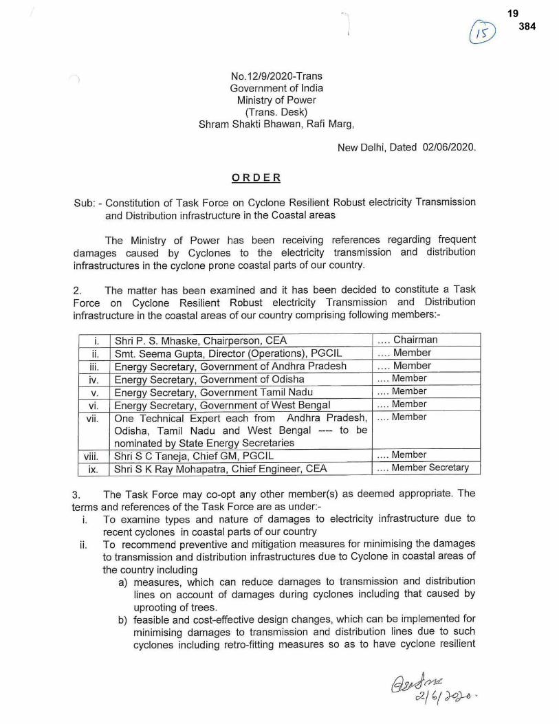
MOP order no. No. 12/9/2020-Trans dated
02.06.2020 for Constitution of Task Force on
Cyclone Resilient Robust electricity Transmission
and Distribution infrastructure in the Coastal
areas
216

P a g e | 1
REPORT OF TASK FORCE ON CYCLONE RESILIENT ROBUST ELECTRICITY TRANSMISSION AND DISTRIBUTION (T&D) INFRASTRUCTURE IN COASTAL AREA
List of Abbreviations and Acronyms
AC: Alternating Current
ACSR: Aluminium Conductor Steel Reinforced
AAAC: All Aluminium Alloy Conductor
ABC: Aerial Bunched Cable
AIS: Air Insulated Substation
AB Switch: Air Break Switch
AI: Artificial Intelligence
AMI: Advanced Metering Infrastructure
ARC: Annual Rate Contract
BIS: Bureau of Indian Standards
CESC: Calcutta Electric Supply Corporation
CEA: Central Electricity Authority
CT: Current Transformers
CVT: Capacitor Voltage Transformer
D/C: Double Circuit
DG: Diesel Generator
DMP: Disaster Management Plan
DER: Distributed Energy Resource
DP: Double Pole
EHV: Extra High Voltage
ERS: Emergency Restoration System
FRP: Fibre Reinforced Plastic
GI: Galvanised Iron
GIL: Gas Insulated Lines
GIS: Gas Insulated Substation / Switchgear
GPS: Global Positioning System
HFL: Highest Flood Level
HIW: High Intensity Wind
HT: High Temperature
HTLS: High Tension Low Sag

P a g e | 2
REPORT OF TASK FORCE ON CYCLONE RESILIENT ROBUST ELECTRICITY TRANSMISSION AND DISTRIBUTION (T&D) INFRASTRUCTURE IN COASTAL AREA
HV: High Voltage
HVDC: High Voltage Direct Current
HVDS: High Voltage Distribution System
IMD: India Meteorological Department
IOT: Internet of Things
IS: Indian Standard
KEC: KEC International
KPTL: Kalpataru Power Transmission Limited
LCC: Life Cycle Cost
LV: Low Voltage
OPTCL: Odisha Power Transmission Corporation Limited
NBC: National Building Code
NDMA: National Disaster Management Authority
NCMRP: National Cyclone Risk Mitigation Project
APFCR: Automatic Power Factor Correction Relay
PSS: Package Substation
PCC: Plain Cement Concrete
RCC: Reinforced Cement Concrete
RfP: Request for Proposal
RMU: Ring Main Unit
RoW: Right of Way
SAP software: Systems Applications and Products software
SCADA: Supervisory Control and Data Acquisition
SOP: Standard Operating Procedure
SERC: Structural Engineering Research Centre
TBCB: Tariff Based Competitive Bidding
T&D: Transmission & Distribution
UAV: Unmanned Arial Vehicle
UHV: Ultra High Voltage
WMO: World Meteorological Organization
XLPE: Cross Linked Poly Ethylene

P a g e | 3
REPORT OF TASK FORCE ON CYCLONE RESILIENT ROBUST ELECTRICITY TRANSMISSION AND DISTRIBUTION (T&D) INFRASTRUCTURE IN COASTAL AREA
Executive Summary
The growth of Indian Power sector is phenomenal. Commensurating with increase in Installed Generation capacity over the years, the expansion of transmission network has resulted in formation of one of the largest single synchronous grid in the world by linking all five regions of the country together through a vast transmission network. The vast Transmission & Distribution (T&D) network spread across the country forms the backbone of Indian power delivery chain connecting all generation sources with ultimate consumers. A robust T&D network would enhance the reliability & availability of power supply to the consumers.
The global warming and growing incidences of extreme weather events like droughts, heat waves, heavy rains and cyclonic storm etc. are the serious effect of global climate change in the last 30 years. India is vulnerable to natural Disasters such as drought, earthquakes, flash floods, cyclones/ windstorms, landslides, avalanches etc. in varying degrees. As per National Disaster Management Authority (NDMA), close to 5,700 km (out of the 7,516 km long coastal line) are prone to cyclones and tsunamis.
The frequency of occurrences and intensity of cyclonic wind have increased over the years causing large scale damage to T&D infrastructures of coastal states of India, particularly Odisha, West Bengal (WB), Andhra Pradesh (AP), and Tamil Nadu (TN), leading to long outage of power supply to affected areas. In view of above, Ministry of Power (MoP), vide their order no. 12/9/2020-Trans dated 02.06.2020, had constituted a Task Force on Cyclone Resilient Robust electricity Transmission & Distribution infrastructure in the coastal areas of the country to examine types & nature of damages to electricity infrastructure and to recommend preventive & mitigation measures for minimizing the damages to T&D infrastructures. The committee had co-opted technical experts from the States located on the western coast of the Country, which are affected by the cyclones, namely Maharashtra, Gujarat and Kerala, and from Calcutta Electric Supply Corporation (CESC), Tata Power, KEC International Ltd., Kalpataru Power Transmission Limited (KPTL) and Indian Meteorological Department (IMD).
The members of the committee deliberated on the subject matter through Virtual Conference (VC). Three (3) meetings were held through Virtual Conference (VC) with members of the committee on 12th June 2020, 29th July 2020, and 19th January 2021. The draft report was prepared and circulated to Members of the committee before the third meeting and report was discussed in detail during the meeting. The report has been prepared based on the inputs from members and experts. The broad overview of impact of cyclones in coastal areas of India in last seven years covering details of wind speed observed, no. of districts affected, damage to T&D infrastructure in Cyclones Phailin (2013), Hud Hud (2014), Vardah (2016), Gaja (2018), Titli,(2018), Fani (2019) etc. have been highlighted. The extent of damage to distribution infrastructure was much more compared to transmission infrastructure. It has been observed that the impact of cyclones progressively decreases while moving from sea towards land area and in most of the cases, the damage of

P a g e | 4
REPORT OF TASK FORCE ON CYCLONE RESILIENT ROBUST ELECTRICITY TRANSMISSION AND DISTRIBUTION (T&D) INFRASTRUCTURE IN COASTAL AREA
infrastructure is limited to about 60 km from the coastline. However, the damages have also taken place beyond 60 km. The major impact is in the form of damage of towers / poles of T&D lines, damage of substation equipment & structure, flooding of sub-stations, snapping of conductors etc.
In the report, the various international practices (codes and design practices) to minimize damage to power infrastructure due to High Intensity Wind of countries such as USA, Australia & New Zealand, Argentina, South Africa, Bangladesh, Philippians and recommendation of ASCE manual & CIGRE Technical Brochures have been covered in brief. Different stages of Planning for Disaster Management and Standard Operating Procedure (SOP) to be followed by utilities to minimize the impact of cyclone covering three different actions i.e. advance preparedness measures, early warning phase / preparedness after receiving cyclone alert, response & restoration phase has been made as part of the report. A good emergency preparedness plan, accompanied by strategic investments, can shorten restoration time and limit the impact of disaster. The utilities should have a detailed Disaster Management Plan (DMP) and Standard Operating Procedures (SOP) for reducing the damage and restoration in shortest possible time. The SOP brought out in the report should be followed by utilities of coastal states. The brief of existing system and present design practices being followed by utilities have also been highlighted. A multipronged approach, which encompasses the change in design philosophy, better planning and adoption of modern technological solutions, is required to safeguard the T&D infrastructure from natural disasters and to increase resilience, reliability and availability of the system.
The measures for creating resilient Transmission & Distribution infrastructure have been recommended for Existing infrastructure as well as for creation of future/new Transmission & Distribution system. The recommended measures include various Planning aspect, Design & Technological aspect and steps to be taken by utilities for capacity building to create cyclone resilient infrastructure. The future road map to be adopted by utilities has been clearly brought out.
The planning aspect covers redundancy level to be considered to reduce risk of outages, critical Infrastructure Protection Framework, mapping of T&D infrastructure in cyclone affected zones, designing of Distribution network, provision for ERS & mobile Substation, material bank, digitalization of system and use of UAV etc.
T&D infrastructure includes transmission & distribution lines / underground cable system and associated terminal substations. The measures recommended for existing Transmission lines are as follows:
a) The replacement of failed / damaged tower (s) [designed as per old standard] with new tower (s) designed according to latest standard in case of irreparable damage to foundation (replacement can be with similar tower/ tension type tower

P a g e | 5
REPORT OF TASK FORCE ON CYCLONE RESILIENT ROBUST ELECTRICITY TRANSMISSION AND DISTRIBUTION (T&D) INFRASTRUCTURE IN COASTAL AREA
/ Steel pole) and strengthening of the towers using hip bracing below the bottom cross arm level
b) Regular Monitoring, Patrolling and Maintenance of transmission lines and use of epoxy-based paint coating for protection of steel structures etc.
The measures recommended for existing Distribution lines are as follows:
a) Refurbishment of existing line by use of rail poles / joist / Spun Poles / Double Pole (DP) structure,
b) Introduction of additional poles in between span c) Conversion of overhead lines to underground cable system at 33 kV and 11kV
level in urban areas located within 20km of coast line and similar action to be taken in stages for areas located beyond 20km & up to 60km based on importance of connectivity with load centres
d) Use of epoxy-based paint coating for protection against corrosion of steel structures
e) Installation of distribution transformer on plinth mounted structure f) Use of Aerial Bunched cable for 11kV & LT overhear lines g) Splitting the large network into smaller systems for fast restoration etc.
The operational risk associated with existing infrastructure need to be reviewed periodically.
The measures recommended for existing Transmission & Distribution substations are as follows:
a) Exploring the possibilities of conversion of existing AIS to GIS substation for transmission substations
b) Examining the feasibility of conversion of Air insulated distribution substations to indoor installation with conventional switchgear / GIS without affecting power supply etc.
The measures recommended for future / new Transmission lines are as follows:
a) The modifications in design loads considering reliability level as per CEA Regulations, wind speed as per revised wind map & consideration of higher of two wind zones up to a distance of 50km (from the boundary of two wind zones) and by introduction of K4 factor (in line with IS 875) & changing the drag coefficients for tower members
b) Reduction in number of consecutive spans between the section / angle points. c) Modification in configuration of transmission line towers d) Use of narrow base lattice towers or steel Poles e) Use of underground cable system for connecting to important load centres f) Use of New generation conductors g) To provide protection to tower member against corrosion h) To adopt proper measures for foundations & reinforcement of foundation
including use of raised chimney in flood prone areas i) Focus on material quality, workmanship in construction and good maintenance
practice etc.

P a g e | 6
REPORT OF TASK FORCE ON CYCLONE RESILIENT ROBUST ELECTRICITY TRANSMISSION AND DISTRIBUTION (T&D) INFRASTRUCTURE IN COASTAL AREA
The measures recommended for future / new Distribution lines are as follows:
a) The designing of underground cable system within 20km from coast line and similar action for areas located beyond 20km & up to 60km based on importance of the connectivity with load centres
b) Use of Aerial Bunched Cable for 11kV & LT lines c) Use of robust steel monopoles, galvanized steel poles / rails / joists/ Double pole
structures, tubular poles of concrete / composite material / galvanised steel lattice structure
d) Method of testing of structures used for overhead Distribution lines to be formulated to ensure reliability of structure
e) Use of HVDS system to avoid long LT line and for other benefits f) Use of structures with reduced span of 40-50m (designed for span of 60-100m) g) Use of plinth mounted Distribution transformers, designing of Ring Main Unit
(RMU) and Feeder Pillars etc.
The measures recommended for future / new Transmission substations are as follows:
a) The construction of compact & modular indoor GIS installations up to 60km from the coastline above the historical water stagnation/ logging level (based on locally available data) or Highest Flood Level (HFL)
b) Use of high ductile strength steel for construction of buildings etc.
The measures recommended for future / new Distribution substations are as follows:
a) Use of indoor installation (with conventional switchgear / GIS) for all new Distribution Substation and compact substation with underground cable system
b) Adoption of concept of smart grid, automation, AMI and robust communication system etc.
The future road map to be adopted by utilities has been clearly bought out separately in the report.
Although cyclones affect the entire coastal areas (east & west coast) of India, the impact of cyclonic storm is much more in east coast compared to west coast. On the East coast, Odisha is the worst affected State by cyclone followed by the states of Andhra Pradesh, Tamil Nadu and West Bengal. The impact of cyclones is not significant on the West coast and not much damage to T&D infrastructures have been observed in past in the states of Gujarat, Maharashtra, Karnataka and Kerala due to cyclone. Hence, the states of Odisha, Andhra Pradesh, Tamil Nadu and West Bengal, on the east coast, should implement recommended measures. However, considering the damages to T&D infrastructures due to recent cyclone in Gujarat (Tauktae), the implementation of above recommended measures shall also be taken up by states on west coast in order to improve the resiliency of T&D infrastructures.

P a g e | 7
REPORT OF TASK FORCE ON CYCLONE RESILIENT ROBUST ELECTRICITY TRANSMISSION AND DISTRIBUTION (T&D) INFRASTRUCTURE IN COASTAL AREA
It may not be desirable / practicable to implement all recommendations in one go for existing infrastructures as it would involve huge capital expenditure and long shut down period. Utility may plan to implement various measures for existing T&D infrastructure in phased manner prioritizing implementation plan on the basis of criticality / importance of the asset in the system. The effect of cyclonic storms is largely felt in a belt of approximately 60 km from the coast line. The recommended measures should be taken up early for areas within 20km of coastline. The decision regarding implementation of measures beyond 20km & up to 60km from coast line may be taken up based on following considerations:
a) Vital installations such as hospitals, water supply, telecommunication system, railways, airports, bus stands etc.
b) Importance / Criticality of the Line and population of connected consumers c) Past Incidents of failure due to heavy wind/ cyclones d) Availability of Right of Way and funds
The complete assessment / review of activities should be undertaken before, during & after the cyclone. This includes the shortfalls, the bottlenecks & hindrances observed in execution of planned work and areas requiring further improvement to minimize the impact on the system. The review shall be taken up at each level of response team and areas are to be clearly identified for further improvement. The damage due to natural disaster cannot be ruled out completely because such events are likely / expected to occur during service life of installation. Hence objective of all measures suggested in the report is how best to mitigate the potential impact of HIW, minimize damage to T&D infrastructure and restore the power supply as quickly as possible post cyclone.
****************************

P a g e | 8
REPORT OF TASK FORCE ON CYCLONE RESILIENT ROBUST ELECTRICITY TRANSMISSION AND DISTRIBUTION (T&D) INFRASTRUCTURE IN COASTAL AREA
REPORT OF TASK FORCE ON CYCLONE RESILIENT ROBUST ELECTRICITY TRANSMISSION AND DISTRIBUTION (T&D) INFRASTRUCTURE IN COASTAL AREA 1. BACKGROUND
a) The electricity has become the basic necessity of life and power being one of the critical infrastructure, is key to economic development. The growth of Indian Power sector is phenomenal. Commensurating with increase in Installed Generation capacity over the years, the expansion of transmission network has resulted in formation of one of the largest single synchronous grid in the world by linking all five regions of the country together through a vast transmission network (about 4.3 lakhs CKm of lines & 1000GVA transformation capacity of 220kV and above voltage level including the highest transmission voltage of 765kV AC and +/- 800kV HVDC). The vast Transmission & Distribution (T&D) network spread across the country forms the backbone of Indian power delivery chain connecting all generation sources with ultimate consumers. A robust T&D network would enhance the reliability & availability of power supply to the consumers.
b) The global warming and growing incidences of extreme weather events like droughts, heat waves, heavy rains and cyclonic storm etc. are the serious effect of global climate change in the last 30 years. India is vulnerable to natural Disasters such as drought, earthquakes, flash floods, cyclones/ windstorms, landslides, avalanches etc. in varying degrees. As per National Disaster Management Authority (NDMA), more than 58.6% of the landmass is prone to earthquakes of moderate to very high intensity; over 40 million hectares (12%) of its land is prone to floods and river erosion; close to 5,700 km (out of the 7,516 km long coastal line) are prone to cyclones and tsunamis.
c) Odisha have a coast line of about 480 km long along the Bay of Bengal. Andhra Pradesh (AP) is located on the South coast and have 2nd longest coast line of 975 km long covering 7 districts. Tamil Nadu (TN) have 3rd longest coast line of 910 km long, known as Coromondel coast. West Bengal (WB) have a coast line of about 160 km long. Maharashtra have a coast line of 650 km long, known as Konkan coast. Gujarat have the longest coast line of about 1215 km long. Kerala have the 5th longest coast line of 570 km long. Along the east coast line, the states of TN, AP, Odisha, WB (covering about 2500km out of 7516km long coast line) are more prone to cyclones and tsunamis.
d) In India, some of the world‟s biggest and fastest growing urban
conurbations are located on coastal areas, which are exposed to severe wind speed conditions during the cyclonic activity and being the low-lying areas exposed to flooding and storm surges. Their growth is coupled with

P a g e | 9
REPORT OF TASK FORCE ON CYCLONE RESILIENT ROBUST ELECTRICITY TRANSMISSION AND DISTRIBUTION (T&D) INFRASTRUCTURE IN COASTAL AREA
increasing energy demand, thus increasing pressures of incessant reliability of power infrastructure. The vulnerability of the electricity sector to extreme events and the rapid urbanization in the coastal regions have exacerbated cyclone impact.
e) Constitution of Task Force and Terms of Reference (TOR):
The frequency of occurrences and intensity of cyclonic wind have increased over the years causing large scale damage to T&D infrastructures of these states, particularly Odisha, West Bengal, Andhra Pradesh, and Tamil Nadu, leading to long outage of power supply to affected areas. In view of above, Ministry of Power (MoP), vide their order no. 12/9/2020-Trans dated 02.06.2020 (copy attached as Annexure-D) have constituted a Task Force on Cyclone Resilient Robust electricity Transmission and Distribution infrastructure in the coastal areas of the country comprising of following members:
The Terms of Reference of the Committee are as under:
i) To examine types and nature of damages to electricity infrastructure due to recent cyclones in coastal parts of our country.
ii) To recommend preventive and mitigation measures for minimizing the damages to transmission and distribution infrastructures due to Cyclone in coastal areas of the country including measures, which can reduce damages to transmission and
distribution lines on account of damages during cyclones including that caused by uprooting of trees.
feasible and cost-effective design changes, which can be implemented for minimizing damages to transmission and distribution lines due to such cyclones including retro-fitting
1. Shri P. S. Mhaske, Chairperson, CEA Chairman
2. Smt. Seema Gupta, Director (Operations), POWERGRID
Member
3. Energy Secretary, Government of Andhra Pradesh Member
4. Energy Secretary, Government of Odisha Member
5. Energy Secretary, Government of Tamil Nadu Member
6. Energy Secretary, Government of West Bengal Member 7. One Technical Expert each from Andhra Pradesh,
Odisha, Tamil Nadu and West Bengal ---- to be nominated by State Energy Secretaries
Member
8. Shri S C Taneja, Chief GM, POWERGRID Member
9. Shri S K Ray Mohapatra, Chief Engineer, CEA Member Secretary

P a g e | 10
REPORT OF TASK FORCE ON CYCLONE RESILIENT ROBUST ELECTRICITY TRANSMISSION AND DISTRIBUTION (T&D) INFRASTRUCTURE IN COASTAL AREA
measures so as to have cyclone resilient robust electricity transmission and distribution infrastructure in the Coastal areas.
study of the composition of material used in the construction and laying down of Transmission and Distribution systems (e.g. poles, conductors, towers etc.) and suggesting suitable material and/or changes in composition of existing material so as to have robust cyclone resilient transmission and distribution systems in coastal areas.
f) The committee had co-opted technical experts from the States located on
the western coast of the Country, which are affected by the cyclones, namely Maharashtra, Gujarat and Kerala, and from Calcutta Electric Supply Corporation (CESC), Tata Power, KEC International Ltd., Kalpataru Power Transmission Limited (KPTL) and Indian Meteorological Department (IMD).
2. PROCEEDINGS OF THE TASK FORCE
a) Three (3) meetings were held through Virtual Conference (VC) with members of the committee due to COVID-19 pandemic to discuss the issue in detail,. The first e- meetings of the Task Force was held on 12th June 2020. The minutes of the meeting is attached as Annexure-A. During the meeting, the members of Task force agreed for the following:
i) The lessons learned, practices being followed & steps being taken to improve the resilience of T&D infrastructure in cyclone prone areas to reduce the impact of cyclone and the experience regarding fast restoration of T&D infrastructure would be shared by all utilities.
ii) To co-opt experts from Calcutta Electric Supply Corporation (CESC), Tata Power, KEC Ltd., Kalpataru and India Meteorological Department (IMD).
b) The second e-meeting of the task force was held on 29th July 2020 via Video Conferencing. The minutes of the meeting is attached as Annexure-B. During the meeting, the members of Task force agreed for the following:
i) The experience, suggestions and practices being followed including Standard Operating Procedure (SOP) for preparedness to face the challenge and for fast restoration of the T&D infrastructure and design philosophy being followed for coastal area affected by cyclone would be shared by states of Andhra Pradesh, Odisha, Tamil Nadu, West Bengal, Maharashtra, Gujarat, Kerala and POWERGRID. The experts nominated from various organizations (KEC, KPTL, Tata Power, CSEC and IMD) would share their views / suggestions in detail for inclusion in the report of task force.
P a g e | 11
REPORT OF TASK FORCE ON CYCLONE RESILIENT ROBUST ELECTRICITY TRANSMISSION AND DISTRIBUTION (T&D) INFRASTRUCTURE IN COASTAL AREA
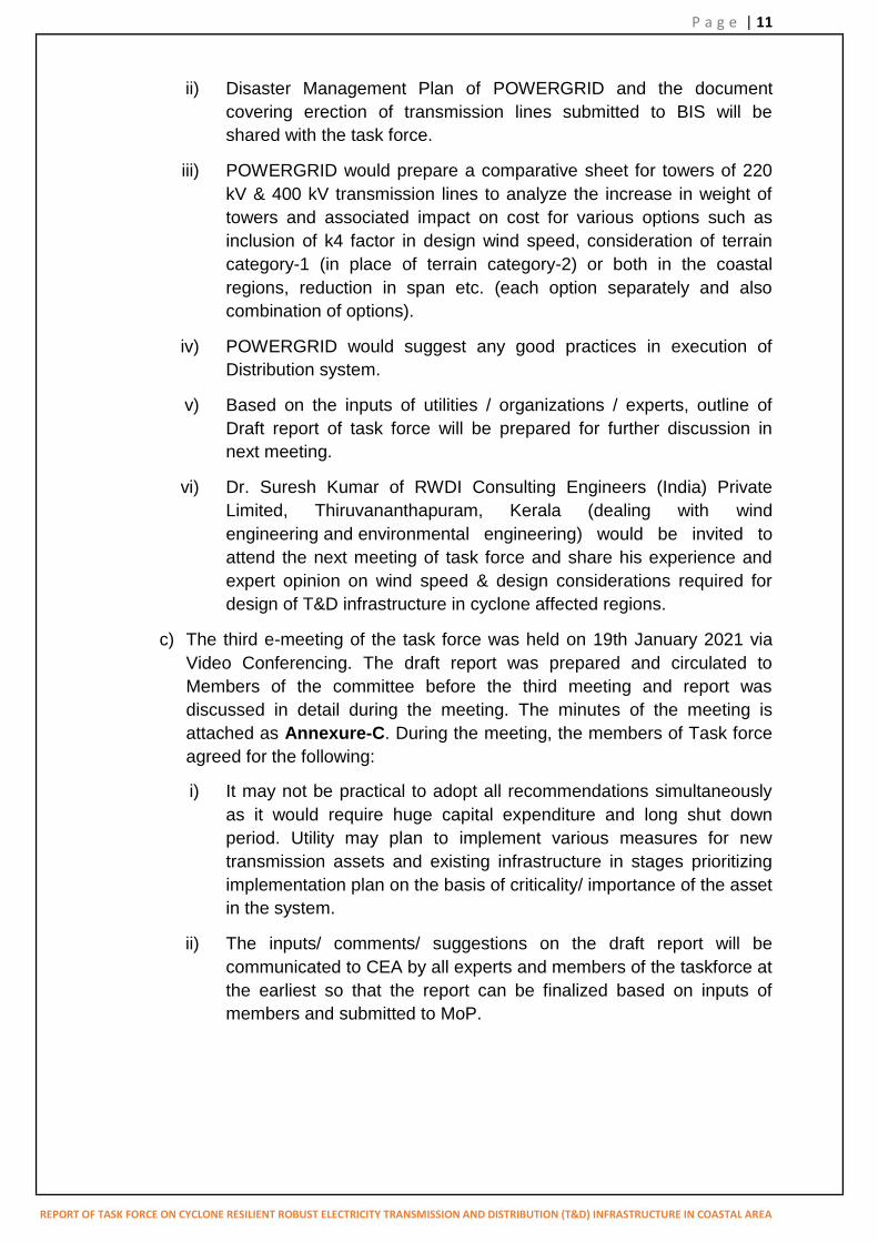
ii) Disaster Management Plan of POWERGRID and the document covering erection of transmission lines submitted to BIS will be shared with the task force.
iii) POWERGRID would prepare a comparative sheet for towers of 220 kV & 400 kV transmission lines to analyze the increase in weight of towers and associated impact on cost for various options such as inclusion of k4 factor in design wind speed, consideration of terrain category-1 (in place of terrain category-2) or both in the coastal regions, reduction in span etc. (each option separately and also combination of options).
iv) POWERGRID would suggest any good practices in execution of Distribution system.
v) Based on the inputs of utilities / organizations / experts, outline of Draft report of task force will be prepared for further discussion in next meeting.
vi) Dr. Suresh Kumar of RWDI Consulting Engineers (India) Private Limited, Thiruvananthapuram, Kerala (dealing with wind engineering and environmental engineering) would be invited to attend the next meeting of task force and share his experience and expert opinion on wind speed & design considerations required for design of T&D infrastructure in cyclone affected regions.
c) The third e-meeting of the task force was held on 19th January 2021 via Video Conferencing. The draft report was prepared and circulated to Members of the committee before the third meeting and report was discussed in detail during the meeting. The minutes of the meeting is attached as Annexure-C. During the meeting, the members of Task force agreed for the following:
i) It may not be practical to adopt all recommendations simultaneously as it would require huge capital expenditure and long shut down period. Utility may plan to implement various measures for new transmission assets and existing infrastructure in stages prioritizing implementation plan on the basis of criticality/ importance of the asset in the system.
ii) The inputs/ comments/ suggestions on the draft report will be communicated to CEA by all experts and members of the taskforce at the earliest so that the report can be finalized based on inputs of members and submitted to MoP.

P a g e | 12
REPORT OF TASK FORCE ON CYCLONE RESILIENT ROBUST ELECTRICITY TRANSMISSION AND DISTRIBUTION (T&D) INFRASTRUCTURE IN COASTAL AREA
3. SOME TERMINOLOGIES RELATING TO WEATHER EVENTS (HIGH
SPEED WIND & FLOOD)
a) Synoptic winds are those associated with large moving pressure systems and usually cover hundreds or thousands of kilometres.
b) Major tropical storms are hurricanes, typhoons, cyclones and extra-
tropical storms. c) Sub-tropical thunderstorms are convective storms in sub-tropical
regions that occur within frontal systems and that can have embedded destructive wind cells. These cells can form severe downdrafts and tornadoes, which can also occur in isolation.
d) Downburst is a strong convective downdraft inducing an outward flow of
damaging winds when reaching the ground. The downdraft makes contact with the ground and then spreads outwards, causing severe winds at low altitudes. These events are often associated with thunderstorms because they involve thermal convection but they can occur without precipitation or lightning. The downdrafts are further divided into macro bursts (extending more than 4 km of high velocity wind front) and microbursts (extending less than 4 km).
e) Cyclone is a rapid rotating storm originating over oceans from where it draws the energy to develop. It has a low pressure centre and clouds spiralling towards the eye wall surrounding the "eye", the central part of the system where the weather is normally calm and free of clouds. Its diameter is typically around 200 to 500 km, but can reach 1000 km. Different terminology is used for this weather phenomenon depending on the location:
In the Caribbean Sea, the Gulf of Mexico, the North Atlantic Ocean and the eastern and central North Pacific Ocean, it is called "hurricane"
In the western North Pacific, it is called "typhoon"
In the Bay of Bengal and Arabian Sea, it is called "cyclone"
The cyclones that occur between Tropics of Cancer and Capricorn are known as Tropical Cyclones. Tropical cyclones are weather systems in which winds equal or exceed speed of 34 knot (i.e., 62 kmph). These cyclones bring very violent winds, tornadoes, lightening, torrential rain, high waves, very destructive storm surges and coastal flooding. All these hazards cause significant impact on life and property.
India Meteorological Department (IMD) had formulated the following criteria (Table-1) which classifies the low pressure systems in the Bay of Bengal and the Arabian Sea on the basis of capacity to damage. The

P a g e | 13
REPORT OF TASK FORCE ON CYCLONE RESILIENT ROBUST ELECTRICITY TRANSMISSION AND DISTRIBUTION (T&D) INFRASTRUCTURE IN COASTAL AREA
same criteria have been adopted by the World Meteorological Organization (WMO).
Table 1: Intensity scale for classifying storms issued by IMD
Type of Disturbances Wind Speed in Km/h Wind Speed in Knots
Low Pressure Less than 31 Less than 17
Depression 31-50 17-27
Deep Depression 51-62 28-33
Cyclonic Storm 62-87 34-47
Severe Cyclonic Storm 89-117 48-63
Very Severe Cyclonic Storm
118-165 64-89
Extremely Severe Cyclonic Storm
166-220 90-119
Super Cyclone More than 221 More than 120
f) Tornado
The most severe winds that can be produced by thunderstorms occur through tornadoes. A tornado is a rotating column of air originating from a convective cloud. It takes the appearance of a narrow funnel, cylinder or rope that extends from the base of the thunderstorm cloud to the ground, often reaching the ground with devastating consequences. The visible shape of the tornado is mostly due to the presence of water droplets. The width of path of damaging winds in tornadoes that covers a distance much larger than the funnel itself is generally less than a few hundred meters, and rarely reaches to one kilometre. Their path length varies according to their strength, and can exceed 50 kilometres. The recorded tornado wind speed has gone up to 240kmph (67m/sec) to 270kmph (70m/sec). Given the infrequent occurrence and damage potential of the phenomenon, tornadoes are categorized as „extreme weather events‟. Occurrence of Tornadoes in India is very rare however eastern parts of India, particularly West Bengal and Odisha, are more vulnerable in comparison to other parts.

P a g e | 14
REPORT OF TASK FORCE ON CYCLONE RESILIENT ROBUST ELECTRICITY TRANSMISSION AND DISTRIBUTION (T&D) INFRASTRUCTURE IN COASTAL AREA
(Fig. 1: Tornado)
g) Whirlwind
A whirlwind is defined as a vertical column of wind, or vortex, which is formed by sudden changes in atmospheric pressure. The energy produced by these winds enable them to pick up the debris. Whirlwinds last for an unspecified period of time, ranging from a few minutes to several hours. Whirlwinds also vary in size, from small dust devils a few feet in width to monstrous tornadoes with widths as large as two miles. Whirlwinds are classified as either major or minor based on how they are formed and the intensity & speed of the wind.
Major whirlwinds are formed during supercell thunderstorms, during which a condensation funnel forms underneath a cumuliform cloud. The condensation funnel is made up of powerful winds which can reach 110 miles per hour. Winds produced in some of the most powerful tornadoes have speeds exceeding 200 miles per hour.
Minor whirlwinds are formed by the spiralling of local winds which form
a funnel. Snow and dust particles picked up by minor whirlwinds create their visibility. Unlike major whirlwinds which can last for hours, minor whirlwinds have a short lifespan and normally dissipate after a few minutes. However, huge dust storms can take more than 20 minutes to dissipate.

P a g e | 15
REPORT OF TASK FORCE ON CYCLONE RESILIENT ROBUST ELECTRICITY TRANSMISSION AND DISTRIBUTION (T&D) INFRASTRUCTURE IN COASTAL AREA
(Fig. 2: Whirlwind)
h) Gusts are short but rapid bursts in wind speed.
i) Squall: Squalls are longer periods of increased wind speed and are generally associated with the bands of thunderstorms that make up the spiral bands around the cyclone.
j) Torrential rain: Rainfall more than 30 cm per 24 hours is considered to be Torrential rain.
k) Storm Surge: A Storm Surge can be defined as an abnormal rise of sea level near the coast caused by a severe tropical cyclone; as a result of which sea water inundates low lying areas of coastal regions drowning of substations and power lines.
4. CYCLONES IN INDIA AND IMPACT OF CLIMATIC DISASTER (CYCLONE
& FLOOD) ON POWER INFRASTRUCTURE OF COASTAL STATES
a) India is highly vulnerable to natural hazards especially earthquakes, floods, drought, cyclones and landslides. Among the coastal disasters, tropical cyclones followed by storm surges are one of the catastrophic natural disasters occurring in India. India is surrounded by Indian Ocean in the south, Bay of Bengal on the southeast and Arabian Sea on the southwest. Indian sub-continent, having a coast line of 7516 km. (5400 km along the mainland, 132 km in Lakshadweep and 1900 km in Andaman and Nicobar Islands), is being exposed to nearly 10% of the worlds‟
Tropical Cyclones and is one of the worst affected region of the world. There are 13 coastal states/UTs encompassing 84 coastal districts which are affected by cyclones of which Four States (Andhra Pradesh, Odisha, Tamil Nadu and West Bengal) on the East Coast and one State (Gujarat) on the West Coast are more vulnerable to cyclone disasters.

P a g e | 16
REPORT OF TASK FORCE ON CYCLONE RESILIENT ROBUST ELECTRICITY TRANSMISSION AND DISTRIBUTION (T&D) INFRASTRUCTURE IN COASTAL AREA
b) Tropical cyclones that hit India are originated mainly from the two basins namely Arabian Sea and Bay of Bengal. Although cyclones affect the entire coast of India, the East Coast is more prone to impact of cyclones compared to the West Coast. Out of the cyclones that develop in the Bay of Bengal, over 58% approach and cross the East Coast in October and November. Only 25 % of the cyclones that develop over the Arabian Sea approach the West Coast. The main cyclone season in the South Indian Ocean is May-July and September-December with significant occurrences of storms in April and August. Coastal areas are the most vulnerable to the cyclone hits and are followed by storm surges compared to the inland regions.
c) As per data of Regional Specialised Meteorological Centre (RSMC, IMD), New Delhi, out of the total 80 cyclonic storms developed in the region, 28 cyclones were weakened over sea and there was no impact on the land. Thirteen (13) cyclonic storms, observed since 2000, had a maximum intensity of wind greater than 100 knots and 8 such cyclones were observed in the past 7 years. (since 2013).
d) List of some of the major Cyclones in coastal area of Andhra Pradesh, Odisha, Tamil Nadu and West Bengal is given in Table 2. In addition, various tropical cyclones of low severity class (such as Okchi, Vardah, Kyant, Mora, Roanu etc.) have impacted the Indian coast in past years.
Table -2
S.no. Name of Cyclone
Date States Affected Severity class
1. Nivar November 2020
Tamil Nadu, Andhra Pradesh & Puduchery
Very Severe Cyclonic Storm
2. Nisarga June 2020 Maharashtra Sever Cyclonic Storm
3. Amphan May 2020 Odisha ,West Bengal & Andaman Islands
Super Cyclonic Storm
4. BulBul November 2019
Odisha & West Bengal Very Severe Cyclonic Storm
5. Fani April-May 2019
Odisha & Andhra Pradesh
Extremely Severe Cyclonic Storm
6. Gaja November 2018
Tamilnadu Very severe Cyclonic
storm
7. Titli October
2018 Odisha, Andhra
Pradesh & West Bengal
Very Severe Cyclonic Strom
8. Phailin October Andhra pradesh, Extremely Severe

P a g e | 17
REPORT OF TASK FORCE ON CYCLONE RESILIENT ROBUST ELECTRICITY TRANSMISSION AND DISTRIBUTION (T&D) INFRASTRUCTURE IN COASTAL AREA
2013 Orissa, West Bengal, Jharkhand, Chattisgarh
Cyclonic Storm
9. Hudhud October 2014
Andhra Pradesh,Orissa & Andaman & Nicobar
Islands
Extremely Severe Cyclonic Storm
e) In the last Fifteen years, the coastal states of India have faced twenty-three (23) incidences of cyclonic storms, out of which seventeen (17) cyclone were of severe category. The details of cyclones and affected coastal states are as follows and the state which is most affected by severe category cyclones is Odisha.
Table 3
[Frequency of all Cyclones (>34 Knots i.e.63 km/hr.) impacted Indian Coasts in past 15 years]
Year/ State 2006 2007 2008 2009 2010 2011 2012 2013 2014 2015 2016 2017 2018 2019 2020 Total
WB 1* 1* 1* 3*
Odisha 1* 2 (1*)
2* 1* 6 (5*)
Andhra Pradesh
1* 1* 1* 1* 3 (1*)
7 (5*)
Tamil Nadu 1 1* 1 1* 1* 5 (3*)
Gujarat 0
Maharashtra 1 1* 2 (1*)
Karnataka 0
Kerala 0
(Source: Regional Specialised Meteorological Centre for Tropical Cyclones over North Indian Ocean)
* Corresponds to cyclones >47 Knots (i.e. 87 km/hr.)
f) The east coast of India is one of the most affected area in the world due to cyclone. During last decade, the States of Andhra Pradesh, Odisha, Tamil Nadu and West Bengal has faced one or other forms of disaster like flood, thunderstorm or cyclone every year. Odisha, among the coastal states, is the most vulnerable state in the country frequently affected due to cyclone as compared to other eastern states and has turned out to be a “Disaster
Zone”. The state of Maharashtra was affected due to cyclonic storm in 2020.
g) Very strong winds (more than 62 kmph) are generally associated with cyclonic storm. A feature of the cyclonic storms over the Indian area is that they rapidly weaken after crossing the coasts and move as depressions / lows inland. The impact of a severe storm after striking the coast does not, in general exceed about 60km from the coastline,

P a g e | 18
REPORT OF TASK FORCE ON CYCLONE RESILIENT ROBUST ELECTRICITY TRANSMISSION AND DISTRIBUTION (T&D) INFRASTRUCTURE IN COASTAL AREA
though sometimes, it may extend beyond 60km.The extent of damage is observed to be inversely proportional to the distance from coast.
h) Recurring cyclones account for large number of deaths, loss of livelihood opportunities, loss of public & private property and severe damage to infrastructure, thus seriously reversing the developmental gains at regular intervals. India is a developing nation with many of the cities, which acts as centres / hubs of economic activities, are located in the coastal regions. As power is the prerequisite for any economic centre to thrive, the resilience of the critical infrastructure is undoubtedly important to sustain this growth. There exists sufficient density of the Power infrastructure, which brings the required power to these load centres. Past disasters in India show a trend of disruption of critical infrastructures and services, mainly the power sector. Thus the damage caused to the power infrastructure results in huge revenue loss / economic loss to the utilities & the Government and requires a huge capital input for restoration purposes.
i) Power infrastructure is the critical infrastructure and all other infrastructure are closely interlinked with the power infrastructure (Figure-3). Robust electrical network ensure an uninterrupted power supply and improve the government‟s ability to recover from disasters in a faster and stronger
manner. It has been observed that the Power infrastructure being vital in comparison to the other infrastructure it requires immediate restoration after the disasters, since all other essential services, like water supply, telecommunication service, health care service and search & rescue operation etc. depend on the restoration of the power supply.
Fig 3 : The interlinkages of the critical infrastructure
j) The power infrastructure comprises of generating stations, high voltage (66 kV & above) transmission lines & associated substations required for transmission of power from generating stations to load centres and the low voltage distribution network which establishes the link between

P a g e | 19
REPORT OF TASK FORCE ON CYCLONE RESILIENT ROBUST ELECTRICITY TRANSMISSION AND DISTRIBUTION (T&D) INFRASTRUCTURE IN COASTAL AREA
transmission system and the ultimate consumers. Distribution network also comprises of distribution lines and associated substations. The transmission & distribution infrastructures are linear in nature and the probability of power infrastructure getting affected due to cyclone increases in the coastal regions due to high density of the T&D infrastructure.
4.1 Details of Infrastructure and damages due to cyclone in different coastal states
a) It is observed that the extent of damage to distribution infrastructure was much more compared to transmission infrastructure. The impact of cyclones progressively decreases while moving from sea towards land area and in most of the cases, the damage of infrastructure is limited to about 60 km from the coastline. However, the damages have also taken place beyond 60 km.
b) The major impact is in the form of damage of towers/ poles of T&D lines, flooding of sub-stations, snapping of conductors etc. The cyclonic storms, states affected & the nature of damages to T&D infrastructure in brief are as follows:
i) 2013 Cyclone Phailin: A very severe cyclone named Phailin made landfall on the 12th October 2013, followed by flooding in Odisha. In total, 18 out of 30 districts in the state were affected The majority of the damages were due to high winds speeds of up to 220 km/hr, followed by flooding due to heavy rainfall. The power Transmission and Distribution infrastructure was severely affected among all the other public infrastructures. A total of 1756 feeders, 38,997 substations, 36,133.9 km of LT (low tension) line, 4074 km of EHT (extra high tension) line and 211,014 electric poles got damaged due to the combined effects of the cyclone and floods. Furthermore, seventy one (71) towers of 220 kV and twenty one (21) towers of 132 kV were damaged. A total of 38.09 lakh consumers were affected.
ii) 2014 Cyclone Hud Hud: Cyclone Hud Hud made landfall on 12th
October 2014. It impacted as many as 15 districts of the State of Odisha. The distribution infrastructure, particularly 11 kV, 33 kV and LT lines and Distribution Transformers suffered heavy damage due to cyclone Hud Hud and subsequent rainfall. A massive 700,000 consumers were affected and 239.95 km of 33 kV lines, 2155.99 km of 11 kV lines, 1088.75 km of LT lines, 1754 distribution transformers and 8 power transformers were damaged. The wind speed was 80-100 kmph.
During Hud Hud cyclone three (3) transmission towers at 400kV level and thirty-three (33) towers at 200kV level were damaged in Andhra Pradesh. Damages caused due to Hud Hud cyclone was around Rs.

P a g e | 20
REPORT OF TASK FORCE ON CYCLONE RESILIENT ROBUST ELECTRICITY TRANSMISSION AND DISTRIBUTION (T&D) INFRASTRUCTURE IN COASTAL AREA
200 crores in Vishakhapatnam district and it took about 15 days for restoration. The load crash of about 1000MW had occurred due to failure of downstream transmission/sub-transmission & distribution network in Andhra Pradesh.
iii) December 2015, flood in Chennai (Tamil Nadu): The flood badly
affected the city infrastructure including large scale disruption of power and communication network in Chennai. Tower foundations suffered damage due to flash flooding. Total 7 nos. of 230 kV sub-stations of M/s TANTRANSCO were affected.
iv) 2016 Cyclone Vardah: In 2016, about fifty (50) towers at 230kV &
110kV level had collapsed and 390.55 km of 230kV and 110 kV lines were affected in Tamil Nadu due to Vardah cyclone. The transmission lines in Chennai, Thiruvallur and Kancheepuram districts are severely affected in Vardha cyclone.
v) 2018 Cyclone Gaja: In 2018, twenty-nine (29) towers at 110kV level
had collapsed and 194.69 km of lines were affected in Tamil Nadu due to Gaja Cyclone. Tanjavur, Thiuvarur, Pudhukottai and Nagapattinum districts were affected during Gaja cyclone.
Kanyakumari district was affected in OCKHI cyclone. But there was no damage to EHT Lines. Only distribution networks poles were damaged heavily.
vi) 2018 Cyclone Titli: In October 2018, the severe cyclonic windstorm affected the coastal areas of Odisha (17 districts) & North Andhra Pradesh. There was no significant damage to T&D infrastructure in Odisha due to Titli Cyclone. The wind speed was 130-140 kmph.
vii) August 2018, flood in Kerala: The flood badly affected Kerala state
due to unusually high rainfall during the monsoon season.
viii) 2019 Cyclone Fani: The severe cyclonic storm „Fani‟ of 2019 caused
huge damage to infrastructures resulting in disruption of critical services in 14 districts of Odisha including Bhubaneswar, Cuttack, Puri & Khurdha districts. The wind speed was reported to be more than 215 km/hr along with heavy rainfall for about four (4) hours. Cyclone Fani caused major damage to the power Transmission and Distribution sector. The massive damage to power Distribution infrastructure included about 450 substations, and 66,000 distribution transformers, about 41,000 km of sub-transmission lines and 72,000 km of distribution lines. Similarly, the transmission system had also suffered large scale damage, which included about 160km of 220kV line (with damage of 75 nos. of towers), 90km of 132kV line (with damage of 33 nos. of towers) and 31 nos. EHV substations.
P a g e | 21
REPORT OF TASK FORCE ON CYCLONE RESILIENT ROBUST ELECTRICITY TRANSMISSION AND DISTRIBUTION (T&D) INFRASTRUCTURE IN COASTAL AREA
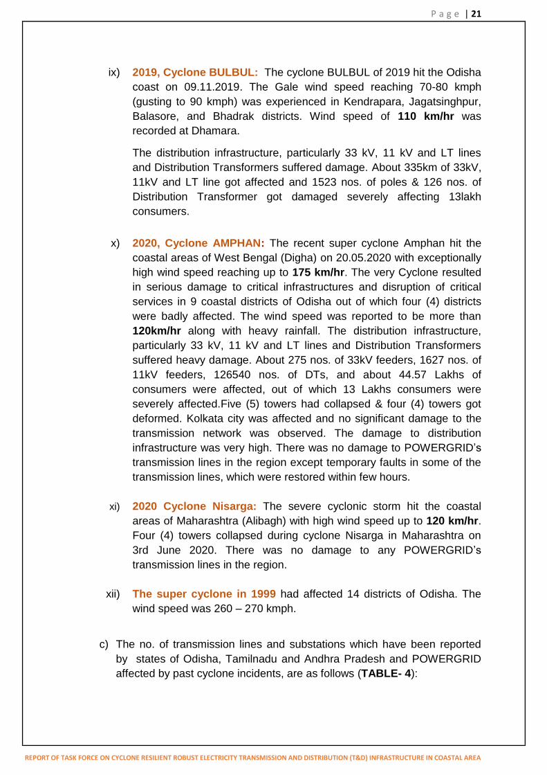
ix) 2019, Cyclone BULBUL: The cyclone BULBUL of 2019 hit the Odisha coast on 09.11.2019. The Gale wind speed reaching 70-80 kmph (gusting to 90 kmph) was experienced in Kendrapara, Jagatsinghpur, Balasore, and Bhadrak districts. Wind speed of 110 km/hr was recorded at Dhamara.
The distribution infrastructure, particularly 33 kV, 11 kV and LT lines and Distribution Transformers suffered damage. About 335km of 33kV, 11kV and LT line got affected and 1523 nos. of poles & 126 nos. of Distribution Transformer got damaged severely affecting 13lakh consumers.
x) 2020, Cyclone AMPHAN: The recent super cyclone Amphan hit the coastal areas of West Bengal (Digha) on 20.05.2020 with exceptionally high wind speed reaching up to 175 km/hr. The very Cyclone resulted in serious damage to critical infrastructures and disruption of critical services in 9 coastal districts of Odisha out of which four (4) districts were badly affected. The wind speed was reported to be more than 120km/hr along with heavy rainfall. The distribution infrastructure, particularly 33 kV, 11 kV and LT lines and Distribution Transformers suffered heavy damage. About 275 nos. of 33kV feeders, 1627 nos. of 11kV feeders, 126540 nos. of DTs, and about 44.57 Lakhs of consumers were affected, out of which 13 Lakhs consumers were severely affected.Five (5) towers had collapsed & four (4) towers got deformed. Kolkata city was affected and no significant damage to the transmission network was observed. The damage to distribution infrastructure was very high. There was no damage to POWERGRID‟s transmission lines in the region except temporary faults in some of the transmission lines, which were restored within few hours.
xi) 2020 Cyclone Nisarga: The severe cyclonic storm hit the coastal areas of Maharashtra (Alibagh) with high wind speed up to 120 km/hr. Four (4) towers collapsed during cyclone Nisarga in Maharashtra on 3rd June 2020. There was no damage to any POWERGRID‟s transmission lines in the region.
xii) The super cyclone in 1999 had affected 14 districts of Odisha. The wind speed was 260 – 270 kmph.
c) The no. of transmission lines and substations which have been reported by states of Odisha, Tamilnadu and Andhra Pradesh and POWERGRID affected by past cyclone incidents, are as follows (TABLE- 4):

P a g e | 22
REPORT OF TASK FORCE ON CYCLONE RESILIENT ROBUST ELECTRICITY TRANSMISSION AND DISTRIBUTION (T&D) INFRASTRUCTURE IN COASTAL AREA
Table 4
Cyclone / State
Phalin Fani Titli Total
Voltage level of
transmission towers affected
220kV
132kV
400kV
220kV
132kV
220kV
132kV
400kV
220kV
132kV
Odisha 71 21 - 73 42 0 0 147 63
Tamil Nadu 0 0 - 0 0 0 0 38 26
Andhra Pradesh
0 0 - 0 0 0 6 0 6
POWERGRID (in Odisha)
1 1
d) The damage to the transmission and distribution substations was due to the high speed winds developed during the cyclones and the associated rains. Rise in sea levels during the cyclones also affected the substations located near the coastline.
e) In most of the States, number of AISs, which are vulnerable to failure in the cyclone affected areas, are much more as compared to GIS substations. Most of the AISs were affected during cyclones in comparison to GIS substations. This is due to the fact that most of the equipment in GIS installations are placed indoor and hence inherently less susceptible to damage due to cyclones.
f) Out of 23 substations affected during cyclones, only one substation each in the state of Odisha & Tamilnadu was of Gas Insulated Substation (GIS) type. Due to heavy winds, damages were observed to substation equipment like Surge Arrestors, Current Transformers (CTs), Capacitor Voltage Transformers (CVTs), Wave Traps, Isolators, snapping of Jumpers, damage to control room and DG sets etc. in AIS. Water logging in the switchyard areas of the substations due to heavy rain was also observed.
g) The distribution of cyclone affected substations in different states with reference to distance from the coast line is given below (Table - 5).

P a g e | 23
REPORT OF TASK FORCE ON CYCLONE RESILIENT ROBUST ELECTRICITY TRANSMISSION AND DISTRIBUTION (T&D) INFRASTRUCTURE IN COASTAL AREA
Table 5
Distance from coast line
Up to 20km
21 - 40km 41 - 60km >60km
Type of substation
AIS GIS AIS GIS AIS GIS AIS GIS
Odisha 9 1 2 0 5 0 0 0
Andhra Pradesh
3 0 0 0 1 0 0 0
Tamil Nadu 0 1 0 0 0 0 1 0
It can be observed that out of 23 substations affected by cyclone, thirteen (56 %) were located within 20 km from the coastline.
h) Some Snapshots of damaged electrical infrastructure during cyclone:

P a g e | 24
REPORT OF TASK FORCE ON CYCLONE RESILIENT ROBUST ELECTRICITY TRANSMISSION AND DISTRIBUTION (T&D) INFRASTRUCTURE IN COASTAL AREA
5. INTERNATIONAL PRACTICES TO MINIMIZE DAMAGE TO POWER
INFRASTRUCTURE DUE TO HIGH INTENSITY WIND
a) In many regions of the world, localized High Intensity Winds (HIWs) pose
the greatest risk to failure of overhead lines. However, only a few countries have put in place codified procedures that provide a level of mitigation of the effects and provide increased security of overhead lines.
b) In many countries, High Intensity Wind (HIW) gusts exceeding 45 m/s are not considered when designing overhead lines, either because they do not exist, or they may be considered to have a low probability of occurrence, and as such present an acceptable risk to the network owner. In other areas, they are more frequently occurring seasonal events that again most probably are not generally considered in design and have been assessed to provide an acceptable risk.
c) In a deregulated environment of electricity industry and open market for trading of electricity, the importance of maintaining higher availability for important electricity networks may require a closer consideration / review of design provisions and operational performance of existing and new overhead line works.
d) Varying practices are adopted around the world in assessing and determining wind loading due to the impact of High Intensity Winds for design of overhead lines. The structural design of overhead lines is governed to a major extent in most parts of the world by wind gusts and the loads that they impose on the structural system elements. These high winds have also been one of the major causes of failures of the overhead line networks internationally. In some region of the globe it is an annual expectation that there will be severe windstorm events that will significantly disrupt electricity supplies. Overhead line networks have a high exposure to such wind events due to their spatial extent and exposure to topographical and local variations.
e) In USA, utilities use hurricane wind velocities for design of their coastal installations. Coastal wind maps provide zone reference to wind velocity considered in the design. Ultimate design wind speed used in design for Hurricanes ranges from 71.5 to 74 m/s depending on location and distance from sea coast.
f) The Australian and New Zealand failure analysis have indicated that failures can and do continue to occur in lines specifically designed for HIW, during severe wind storm events. This is due to the fact that either the design threshold limit for failure is perhaps too low or the frequency & and intensity of the more severe events can be expected to occur at some point during the service life of the line. It also suggests that the operational risk to the line may need to be periodically reviewed.
g) Wind speed is the sole criteria in the designing of the transmission and
distribution towers / poles. Wind zone 3 considered as per codal practice of Philippines is almost similar to wind zone 3 of IS 802 used in India and

P a g e | 25
REPORT OF TASK FORCE ON CYCLONE RESILIENT ROBUST ELECTRICITY TRANSMISSION AND DISTRIBUTION (T&D) INFRASTRUCTURE IN COASTAL AREA
loading comes out to be almost similar. Philippines have specified maximum wind speed of 270 km/hr (75 m/sec) for coastal areas. The similar wind speed is observed during cyclone in coastal regions of Odisha and Andhra Pradesh.
h) The maximum wind velocity is estimated to be 36 m/s at 10 m height above ground, and 100 years return period throughout Venezuela. No allowance is made for high intensity wind gust effects from tornadoes, downbursts and other effects
i) Various codes and design Practices:
IEC- 60826
Localised High intensity wind need to be treated separately from normal synoptic winds.
Argentina
Static analysis is carried out and tower is subjected to a wind loading from any direction corresponding to wind speeds (60-67 m/s).
South Africa
A tornado wind speed of 70 m/s is applied on to the tower only.
Canada
A tornado wind speed of 67 m/s is applied on the tower only.
Australian standard ENA C (b) 1- 2006
Design procedure for microburst loading similar to normal synoptic wind loading. The Wind velocity multiplied by a factor and wind forces on conductor are also considered.
It recommends to design the tower with wind velocity of 60 m/s for the tower body only for tornado loading without any wind force on the conductor.
ASCE Manual 74 (199, 2005)
It recommends to design the tower with wind velocity of 70 m/s for the tower body in any direction for tornado loading. The wind on conductor is usually neglected because of limited path and weight of conductor taken as Zero as the vertical wind can possibly lift the conductor.
CIGRE Technical Brochure 256(2004)
This CIGRÉ document describes the characteristics of all major types of wind events. For tornado, it recommends to consider uniform tornado wind from any direction on the tower only along with torsional loads. As Micro-burst and Macro-burst winds will engulf the both side of a tower, it

P a g e | 26
REPORT OF TASK FORCE ON CYCLONE RESILIENT ROBUST ELECTRICITY TRANSMISSION AND DISTRIBUTION (T&D) INFRASTRUCTURE IN COASTAL AREA
recommends to consider wind on tower body as well as on the conductor for complete wind span.
Bangladesh:
Bangladesh is frequently affected by cyclones and similar HIW is observed in east coast of India. Bangladesh follows ACSE-74 for wind load calculation on tower. For design of transmission line towers following requirement is generally specified.
The wind load factor of 1.15 is being considered in most of the
specifications. Accordingly, load on tower as considered in Bangladesh for costal Region is about two (2) times that of load being considered in coastal area of nearby India territory and no wind is considered on conductor.
3 sec. gust wind speed is considered as 80m/sec (for 220kV & 400kV towers) and 77.5m/sec (for 132kV towers)
HIW on tower body is considered at 00, 22.50, 450, 67.50 and 900
Phillipines:
There is no provision of High intensity wind in specification of National Grid Corporation of Phillipines (NGC). However, the wind velocity for Minimum wind zone (Wind zone-1) is 270 km/hr (75m/s). The equivalent wind pressure of on conductor is 210 Kg/m2, which is 1.24 times the wind pressure (inclusive gust and drag) being considered for Indian coastal region.
Saudi Electricity Company:
The towers for 380 kV transmission lines are being designed to resist High Intensity Wind (Tornado) loading corresponding to wind speed of 250 km/hour (Fujita Scale F2) as per procedures defined in ASCE Manual # 74 with following assumptions:
Wind load is to be considered on tower body only over the full height. Wind pressure shall be calculated using ASCE-74 considering γw, Kz,
Kzt, and G equal to 1.0. Force coefficients shall be calculated as per ASCE-74.
Vertical weight of conductors and ground wires taken as zero. Wind load on conductors and ground wires are neglected. The wind load is considered in three (3) directions (i.e. 00 , 900 and 450)
j) The characteristics and frequency of occurrence of HIW events, will vary
slightly from country to country. Work by Behnke and White in 1994 indicates that an increased allowance in design loadings to provide for HIW gusts, has an indicative associated incremental cost of tower structure of 5 – 10% in order to provide for the increased HIW loading, and associated higher security against failure from wind overload. This work

P a g e | 27
REPORT OF TASK FORCE ON CYCLONE RESILIENT ROBUST ELECTRICITY TRANSMISSION AND DISTRIBUTION (T&D) INFRASTRUCTURE IN COASTAL AREA
uses simple increased wind velocities/ wind pressures to structures. Adoption of a higher level of wind speed and associated parameters, will not however, provide a guarantee against failure, but rather a reduction in the probability of failure. Therefore, there is a need to consider how best to mitigate the potential damage from the various forms of HIW in any new overhead line designs based on operational experience and research studies into this field and restore the system as early as possible.
6. DIFFERENT STAGES OF PLANNING FOR DISASTER MANAGEMENT
AND STANDARD OPERATING PROCEDURE (SOP) FOR CYCLONE
PRONE COASTAL AREAS
a) The main objective of Disaster management is to handle / manage situation in a structured and planned manner with effective & optimum utilization of time, effort & resources so that its adverse impacts are minimized.
The following objectives are built in the plan:
• To improve state of preparedness to meet any contingency. • To reduce response time in organizing the assistance. • To identify major resources, man power, materials & equipment
needed to make the plan operational. • Making optimum use of available resources. • Improving the plan periodically based on learning over the time.
The management Plan helps in better preparation / planning for effective handling of disaster situation for taking swift actions pre and post disaster conditions and for speedy restoration of damaged power infrastructure.
b) Standard Operating Procedure (SOP) for Disaster Management in Cyclone prone coastal areas
The Transmission & Distribution (T&D) lines generally traverse through different types of terrain, which makes them vulnerable to various kinds of

P a g e | 28
REPORT OF TASK FORCE ON CYCLONE RESILIENT ROBUST ELECTRICITY TRANSMISSION AND DISTRIBUTION (T&D) INFRASTRUCTURE IN COASTAL AREA
natural disasters like flash floods, cyclones/ windstorms etc. The damage in power Transmission & Distribution system due to natural disasters cannot be ruled out completely even after enhancement of resilience in the system. Hence, advance preparations/ proactive actions need to be planned for minimizing the duration of outage, in case of any future eventuality.
The framework should include contingency plans and institutional arrangements that clearly allocate responsibility during the recovery period. A good emergency preparedness plan, accompanied by strategic investments, can shorten restoration time and limit the impact of disaster.
Though the damage caused by a cyclonic event is humongous, but fortunately, the cyclone does not impact suddenly, like earthquake which appears without prior warning. With modern technological tools and expertise developed over past decades, the India Meteorological Department Issues Cyclone alert bulletins and also predicts the states/zones to be affected by the impeding cyclone. The utility should have a detailed Disaster Management Plan (DMP) and Standard Operating Procedures (SOP) for reducing the damage and restoration in shortest possible time. The SOP should include following three different actions to be taken during various phases of disaster:
I. Advance Preparedness Measures
Due to uncertainty of genesis of disaster situations, the Power utilities are required to have certain degree of advanced preparedness to face such situations. This is required to reduce the scale of damage of the utilities infrastructure due to cyclone and for early & efficient recovery from the incident. Generally, well before the start of monsoon, the preparedness plan for Cyclone & flood prone areas are to be ensured to face any eventualities to ensure readiness to respond to any future natural disaster. The following preparedness measures are to be ensured by utilities for being in a state of readiness to respond for any future natural disaster.
(i) Mapping of T&D infrastructure & assessing vulnerability of infrastructure regularly and improving operations based on lessons learned from past disasters / events.
(ii) Material bank is to be prepared & digitalised and should be reviewed periodically to ensure availability of adequate equipment / material and spares for transmission & Distribution lines & sub-station equipment at strategic locations. CEA Guidelines for Availability of Spares and Inventories for Power Transmission System (Transmission & Distribution Lines & Substation/Switchyard) Assets may be followed.
(iii) Assessment of availability of Emergency Restoration System (ERS) towers, cranes, and pole mounted tractors, sand bags,

P a g e | 29
REPORT OF TASK FORCE ON CYCLONE RESILIENT ROBUST ELECTRICITY TRANSMISSION AND DISTRIBUTION (T&D) INFRASTRUCTURE IN COASTAL AREA
pulley, cable jointing tools, gas cutter, emergency light, safety equipment, portable DG sets, inflatable emergency lights, first aid kits with sufficient medicines and other tools & tackles etc. and mobile substation at strategic locations in the region for immediate deployment.
(iv) Trained skilled gangs / workforce, contractors need to be kept ready for any eventualities
(v) Patrolling & monitoring of transmission & Distribution assets, identifying vulnerable assets and implement preventive measures. The liquidation of all identified defects i.e. replacement / repair of defective components in the system and clearing of RoW to minimize the risk of falling trees, is to be taken up.
(vi) Mock drills for maintaining preparedness of various teams (vii) The concept Annual Rate Contract (ARC) need to be introduced
for cyclone prone coastal areas to avoid delay in tendering process for procurement of equipment / material / engagement of work force etc. required for early restoration of T&D system.
II. Early Warning Phase / Preparedness after receiving cyclone alert
The readiness of a system to brace impact of cyclone can be increased by taking certain measures in advance. During this phase, the following necessary measures are to be taken timely & sensibly based on the warnings issued by Government authorities / media regarding any upcoming natural calamity.
(i) To follow Weather information sources (like Indian Meteorological
Department) regularly (on hourly / 3 hourly basis) for getting advance weather information like the expected wind speed and likely affected areas. Control room is to be setup at utility‟s
corporate level, circle & division level or as per requirement of utility for monitoring all developments relating to likely event of a disaster for effective deployment of manpower and materials etc.
(ii) Areas, which could get affected during upcoming natural calamity, are to be identified & marked on the Power map of the utility for identification of section of T&D infrastructures (Transmission & distribution lines & sub-stations) which could fall under impact of disaster.
(iii) Clear hierarchy of command system with defined roles and responsibilities including delegation of financial power with availability of sufficient fund for procurement of material & engagement of additional man power etc. on emergency basis
(iv) Communication plan to deal with the impact i.e. availability of healthy communication links at probable affected site is to be ensured

P a g e | 30
REPORT OF TASK FORCE ON CYCLONE RESILIENT ROBUST ELECTRICITY TRANSMISSION AND DISTRIBUTION (T&D) INFRASTRUCTURE IN COASTAL AREA
(v) Segregation of spare towers / poles and other spares / equipment for T&D substation (s) and identification of trained manpower, vehicles in advance for quick response during any disaster.
(vi) Arrangement of sufficient diesel for DG set in Sub-stations which could be affected during upcoming disaster.
(vii) Advance tie-up for Crane, Excavators, transportation, additional manpower, safety equipment, T&Ps like pole mounted tractors, power crane, pulley, cable jointing tools, gas cutter, emergency light and other tools & tackles, portable DG sets etc. for quick restoration
(viii) Advance meetings with critical consumers like railways authority, industries, electricity generators and the distribution companies to plan for the systematic reduction and subsequent restoration of electrical loads in order to prevent total outage of power supply.
(ix) The enlisted vendors, existing EPC contractors, rate contract holders etc. are to contacted in advance for early dispatch of men / material / both, if required and to speed up restoration work.
(x) RLDC/SLDC shall plan in advance to manage the Real time operation of Power system during and immediately after the Cyclone to balance load, generation and voltage. As a safety measure, when wind speed exceeds 50 Km per hour, the power supply of respective distribution feeders which are certain to be affected by the cyclone may be switched off.
(xi) If line trips due to HIW, 2nd attempt for charging should be avoided till through patrolling is done.
III. Response & Restoration Phase
The time period post cyclone incident is crucial for early restoration of power. Since all other services, such as water supply, telecommunication service and medical / health care service, search and rescue operation depend on the restoration of the power, it is essential to take all necessary measures for quick restoration of power supply. The Post Cyclone Plan of Action for restoration & priorities / protocols shall be chalked out in advance and expenditure modalities shall also be finalised by the utilities for early completion of restoration works. The following activities shall be taken up by the utilities immediately after the cyclonic incident for quick restoration of affected T&D elements in shortest possible time after the impact of disaster: (i) Immediate Damage assessment of affected T&D lines/ sub-
station equipment (UAV can also be used for damage assessment).
(ii) Finalization of Strategic locations for prioritizing the restoration work
(iii) Management of funds & mobilization of resources (men & material): Allocation of required funds & resources like

P a g e | 31
REPORT OF TASK FORCE ON CYCLONE RESILIENT ROBUST ELECTRICITY TRANSMISSION AND DISTRIBUTION (T&D) INFRASTRUCTURE IN COASTAL AREA
deployment of technical experts, manpower (skilled & unskilled), equipment, T&Ps, spares etc. to affected area
(iv) Transportation arrangement for spares / ERS sets to the affected site for restoration of collapsed towers and movement of mobile substation.
(v) Arrangement of required vehicles for quick movement of manpower and materials to affected site
(vi) Co-ordination with various departments & local authorities to address the issue of access, particularly in relation to road closures, right of way, security etc.
(vii) Deployment of senior level officials to vulnerable sites to ensure physical monitoring of work, on site assessment of damage, requirement of additional men & material and co-ordination with other departments for smooth execution of work.
(viii) Day wise review at highest level of concerned Transmission / Distribution/ DISCOM units to assess physical achievement with respect to the targets specified, bottlenecks in progress of work and necessary support & services required from Govt. & other agencies.
(ix) Preservation of media clippings, wind data from authentic sources like IMD etc. as evidences for further study and analysis.
A typical checklist in respect of SOP is enclosed as an Appendix.
c) Analysis of Disaster and Planning for facing similar challenge in future
Once the power transmission and distribution network are restored, a complete assessment of the disaster management is required to be taken up by the utilities. This shall include the review of activities undertaken before, during & after the cyclone, the shortfalls observed in the assigned works, the bottlenecks & hindrances observed in execution of planned work and areas requiring further improvement to minimize the impact on the system. The review shall be taken up at each level of response team and areas are to be clearly identified for further improvement.
7. EXISTING SYSTEM AND PRESENT DESIGN PRACTICES IN BRIEF
a) Generally, self-supporting lattice structures are being used for transmission of power on overhead lines. The use of steel poles (single / multiple poles) is slowly increasing due to smaller foot print and other benefits compared to lattice structure although cost is higher. PCC or H-poles / lattice structures are being used for overhead distribution lines.
b) The towers of existing overhead line with lattice structures are being designed according to IS 802. The towers of number of overhead line in operation have been designed according to old IS 802 (1977 / 1995). The design of towers according to IS 802 -1977 were based on working load

P a g e | 32
REPORT OF TASK FORCE ON CYCLONE RESILIENT ROBUST ELECTRICITY TRANSMISSION AND DISTRIBUTION (T&D) INFRASTRUCTURE IN COASTAL AREA
multiplied by factor of safety and three wind zones (light, medium and heavy). In 1995, the ultimate load concept and six wind zones based on the modified wind map of the country were introduced. The wind speed is based on peak gust velocity, averaged over 3 seconds‟ duration, as per the wind map of India given in IS 875 (Part 3). Wind loads on towers and conductors was revised. Reference wind speed averaged over 10 minutes duration has been used for determination of wind loads. The Risk coefficient (K1) and Terrain roughness coefficient (K2) have been taken into consideration in working out the design wind speed. In addition to above, narrow front wind with 1.5 times of wind velocity is considered in design for suspension tower. Further in 2015, code has been revised to include oblique wind loading. In order to optimize the tower designs, the drag coefficient considered for tower members were reduced in the revision of IS: 802 (Part-1/Section-1) - 2015 which has reduced the design margin.
c) To optimise the cost of the overhead transmission line, the suspension / tangent towers are designed differently from tension / angle towers. Reported failures clearly indicates that failure of suspension towers is much more compared to tension towers. The revision of IS 802 has always brought improvement in design concept to minimise the failure. IS 802 has included the load due to oblique wind on tower body as well as conductor.
d) In other countries, the wind map contours are used, whereas the Indian wind map (incorporated in IS 875/ IS 802) does not take into consideration the gradual change in the various wind zones and it becomes difficult to decide velocity of wind which is to be considered for design of transmission line towers in the vicinity / boundary of two wind zones.
e) There is no special consideration for design of overhead lines in coastal areas, prone to high intensity winds.
f) Special care is not being taken for design of foundation of overhead distribution lines resulting uprooting of structures during cyclones.
g) Use of double pole mounted transformers, which are vulnerable to failure during cyclonic events, are still in practice.
h) The radial mode of operation (instead of ring / mesh configuration) of distribution network is more common.
i) The underground cable system is not fully implemented in distribution network for power supply to important installations & essential consumers in coastal areas.
j) Most of the transmission and distribution substations are Air Insulated Substations (AIS), which are exposed to high speed wind during cyclones.
k) GPS based mapping of entire transmission and distribution assets is not in place and availability of adequate ERS / spare towers / spares for substation equipment to meet any eventualities is under question.
l) Mobile substation along with ERS for overhead lines is still not available with utilities for faster restoration of power supply.

P a g e | 33
REPORT OF TASK FORCE ON CYCLONE RESILIENT ROBUST ELECTRICITY TRANSMISSION AND DISTRIBUTION (T&D) INFRASTRUCTURE IN COASTAL AREA
m) Digitalisation of assets, inventories, spares etc. are yet to taken up in a big way.
n) Use of Distributed energy resources to meet any emergency situation and for fast restoration of power supply is still not being considered.
o) Implementation of Advance Metering Infrastructure (AMI), Distribution Automation system and smart grid concept etc. are under various stages of implementation.
8. DISASTER RESILIENT T&D INFRASTRUCTURE
a) In fact, the overhead line will continue to remain as the primary mode of transmission of power due to techno-economic reasons. In India self-supporting lattice structures and pole structures are most commonly used for T&D of power on overhead lines. The transmission & Distribution system includes overhead lines / underground cables and associated terminal substations. The overhead line (transmission / distribution lines) comprises of poles / lattice towers, conductors, earthwire & associated accessories, insulators & hardware fittings. The underground cable system comprises of cable, joints, terminations, accessories, supporting structures etc. and is directly buried in the soil or laid in pipes or trenches/ducts in different formations (flat / trefoil / vertical formation etc.).
b) The overhead T&D structures are vulnerable to failure (due to height) during the cyclones. Electric overhead lines (T&D lines) generally traverse through different types of terrain (varying from the maritime coast to the continental inland, from sea level to high mountains, from flood prone areas to dry desert) and get severely affected over the years due to unprecedented natural calamities leading to disruption in power supply. The high speed of wind, experienced during a cyclonic event, is primarily responsible for damage of overhead T&D structure. The high wind speed during the cyclones increases the wind load on conductor and tower / pole structure causing partial damage / tilting / buckling / collapse of structures / uprooting of structure, snapping of conductor / earthwire and breakage of insulators etc.
c) The effects of localized HIW on overhead line structures depend on whether the dominant pressure loads are transferred from the conductors to the support or directly applied to the support. The load on conductor is transferred through the primary structural system i.e. from the conductor attachment point, through the supporting cross arm, beam or earth wire peak and then through the main legs and bracing members (for self-supporting lattice towers). In a typical synoptic wind loading acting transversely to the line, the wind load distributed to the structure through the conductors, represents a large part of the total horizontal load on the supports. The position of the resultant transverse load is then very high on the support, near the geometric centre of the conductors. This applies in general to most line supports such as poles / tubular / lattice / H-frames.

P a g e | 34
REPORT OF TASK FORCE ON CYCLONE RESILIENT ROBUST ELECTRICITY TRANSMISSION AND DISTRIBUTION (T&D) INFRASTRUCTURE IN COASTAL AREA
d) The falling of nearby trees on the overhead distribution lines also causes damage / collapsing of the towers/poles and snapping of conductor / earthwire.
e) The soil erosion in & around the foundation of tower / pole structure, sometimes lead to collapse of structure. Accumulation of water for long time results in rusting of structure in some cases.
f) At present, transmission towers are designed based on basic design wind speeds (also called synoptic wind) as given in Indian standard IS 802, the design code for transmission line tower. Wind speed is converted to a static pressure and applied to the conductors, towers and insulator strings. Gust response factor accounting for the dynamic effects of gusts on the response of transmission lines is among other factors that is multiplied to the wind speed. It has been proven that in many regions, high intensity winds are larger threat to transmission lines than the synoptic wind. Wind loading as specified in the codes continue to be based on synoptic winds and does not provide any clear guidelines to take into account the possibility of severe cyclonic wind affecting the transmission lines.
g) The structural integrity of transmission towers depends on many factors including adequacy of technical standard / codal provisions for designing the structure, quality of material used, construction methodology, workmanship, erection practices, and Operations & Maintenance practices of the transmission utilities etc. The extent of damage to distribution infrastructure is generally much more than that of transmission infrastructures.
h) The terminal T&D substations can be Air Insulated Substation (AIS) / Gas Insulated Substation (GIS) / compact Hybrid substation / combination of AIS & GIS / AIS & Hybrid substations. The damage to AIS is much more compared to GIS / hybrid installations. The torrential / heavy rainfall and storm surge associated with the cyclones leads to flooding of substations located in low lying area near to coast line and soil erosion.
i) Resilience, in the context of critical infrastructure is defined as the ability of an asset or system assets, which continues to provide essential services when threatened by an unusual event (e.g. a flood or cyclone) as well as its speed of recovery and ability to return to normal operation after the threat has receded. In a world that relies increasingly on electricity services, building the resilience of power systems is critical to provide reliable and sustainable services, energy security, economic wellbeing, and quality of life. As per IPCC 2012, “Resilience is defined as the ability of a system and its component parts to anticipate, absorb, accommodate, or recover from the effects of a potentially hazardous event in a timely and efficient manner, including through ensuring the preservation, restoration, or improvement of its essential basic structures and functions.”
j) The disaster Resilient Infrastructure encompasses structural and non-structural measures. Structural measures involve adjusting engineering designs and standards to reflect disaster risk. Non-structural measures

P a g e | 35
REPORT OF TASK FORCE ON CYCLONE RESILIENT ROBUST ELECTRICITY TRANSMISSION AND DISTRIBUTION (T&D) INFRASTRUCTURE IN COASTAL AREA
refer to risk sensitive planning, enabling institutional framework, hazard mapping, ecosystem based management, and disaster risk financing. In a situation like COVID-19 pandemic, the resilience of T&D infrastructure plays a greater role in maintaining uninterrupted power supply to consumers
Resiliency in the system can be defined as the capacity to prevent, prepare for, respond to and recover from the impact of disasters. Figure below shows the various aspects of resilience.
k) Climate change studies around the world have indicated the probability of increase in the frequency and intensity of severe weather events. Wind is a serious challenge for the overhead transmission and distribution line. Flooding also causes damage to T&D infrastructures.
There are five categories of wind in general: Synoptic winds; Major tropical storms; Sub-tropical thunderstorms; Downbursts (not necessary for overhead line design as most
downdrafts have a wind front dimension exceeding typical wind spans); Tornadoes.
l) The overhead T&D lines are generally designed for synoptic winds. High
speed wind storm/ cyclonic storm/ localized whirlwind can cause snapping of the conductors / groundwire or partial damage / complete collapse of towers of overhead transmission line due to excessive torsional wind loading. In Air Insulated Substation (AIS), various equipment like CT, CVT, Circuit Breaker, Disconnectors, Surge Arresters, Wave traps etc. may be affected by high wind speed. Flash floods may cause soil erosion endangering the foundations of towers which could lead to uprooting / collapse of tower or flooding of substation / control room leading to

P a g e | 36
REPORT OF TASK FORCE ON CYCLONE RESILIENT ROBUST ELECTRICITY TRANSMISSION AND DISTRIBUTION (T&D) INFRASTRUCTURE IN COASTAL AREA
disruption in sub-station operation. Further, foundation of support structure of various substation equipment and gantry structure may also be affected.
m) The concept of resilience has traditionally been applied to the physical protection of critical infrastructure. However, with the growth of digital technologies to manage energy systems, resilience must now be expanded to include protection from cyberattacks and the capacity to restore systems to full operation as soon as possible after such an attack. As the digitization of the energy sector has accelerated, the mutual dependence of Internet access and power grids are clear. Key components of energy systems such as smart meters, smart grids, Supervisory Control and Data Acquisition (SCADA) systems as well as block chain technologies require the Internet in order to function. The resilience of the Internet is therefore increasingly important as the electricity sector plays a greater role in transport and industry as well as in powering buildings. In turn, all the systems and the economies on which they depend will be increasingly vulnerable to cyberattacks without the right safeguards in place.
n) A multipronged approach, which encompasses the change in design philosophy, better planning and adoption of modern technological solutions, is required to safeguard the T&D infrastructure from natural disasters and to increase resilience, reliability and availability of the system.
9. RECOMMENDED MEASURES FOR CREATING RESILIENT T&D
INFRASTRUCTURE
Although different safety factors are considered during design of power transmission & distribution elements for smooth & reliable operation, damage due to natural disasters cannot be ruled out completely. Adoption of a higher level of design wind speed and associated parameters will reduce the probability of failure, but does not guarantee against failure. On the other hand, it is also equally important that such lines are not built stronger and more expensively than they need to be, in order not to over-invest in more security than needed and also to avoid structures that are much heavier and visually more predominant than the public can or will accept. However, the main objective should be to minimize damage to power infrastructure so that Power supply is restored as quick as possible.
Keeping in view the impact of cyclone on existing T&D infrastructure and need of future resilient infrastructure, following recommendations regarding Planning, Design & Technology and Capacity Building aspect are made.
9.1. Planning Aspect
Proper planning in advance always helps to face any eventualities and improves resilience of the complete system as a whole. The following

P a g e | 37
REPORT OF TASK FORCE ON CYCLONE RESILIENT ROBUST ELECTRICITY TRANSMISSION AND DISTRIBUTION (T&D) INFRASTRUCTURE IN COASTAL AREA
planning aspect need to be considered to minimize the impact of high speed wind during cyclone and for faster restoration of power supply.
a) (N-1/N-1-1/N-2) contingency level Planning for Critical Load Centres
Power outages cannot be avoided completely and attempting to do so would require huge capital investment. Effort has to be made for minimization of the impact of natural calamities on T&D network. T&D networks are typically designed with some level of redundancy to reduce the risk of outages due to planned and unplanned events. General practice is to have N-1 contingency level. However, depending on the sensitivity of the load centre, the supply network in a particular area may be planned & designed by system planning cell to operate within limits in the event of a double contingencies (N-1-1 / N-2).
b) Critical Infrastructure Protection Framework
Power supply to critical load centres such as hospitals / health care centres, water supply, defence, telecommunication service, and administrative establishments etc. are of great importance during natural disaster. Power supply has to be restored quickly to such load centres. Identification of such loads, feeder separation, multi-feeding arrangement, indoor substations, automation & AMI, Micro grids, underground cabling, rooftop solar power etc. may be considered to ensure lifeline supply in the event and aftermath of natural disasters.
c) Mapping of T&D infrastructure in cyclone affected zones
Utility (ies) should take steps to identify the Generation, Transmission & Distribution infrastructure which have been affected in the past or is prone to cyclonic impact. T&D assets (transmission & distribution lines & towers and substations), particularly in cyclone prone areas (upto 60km from coast line) must be GPS mapped and vulnerable assets should be identified for taking any preventive action, if required.
d) Designing of Distribution network in Ring or Mesh configuration
The resilience of a system can be enhanced by increasing redundancy level. A more effective way is to design the distribution network using ring or mesh configuration providing multiple supply / feed points for urban & industrial area to ensure reliable & uninterrupted power supply to the consumers. Mesh network also provides the ability to quickly switch loads between feeders or supply points.
e) Emergency Restoration System (ERS), spare towers, material banks, spares for substation equipment
The fast restoration of power infrastructure is always the priority after the cyclone. Emergency Restoration System (ERS) / available spare towers are used to bring the transmission line back to normalcy. For quick restoration of the power transmission system, the use of ERS is vital and

P a g e | 38
REPORT OF TASK FORCE ON CYCLONE RESILIENT ROBUST ELECTRICITY TRANSMISSION AND DISTRIBUTION (T&D) INFRASTRUCTURE IN COASTAL AREA
is the first line of action to restore important links during emergency. Adequate quantity of spare towers / ERS along with all accessories / spares should be available at strategic locations along the coast lines and these locations should be easily accessible in order to minimize transportation time in the event of any natural disaster. Further, utilities should have information readily available, on digital platform so that decision making becomes faster & easier for deployment of these structures / spares at required locations. The utility‟s personnel should
have been properly trained to handle and erect ERS.
Utilities should keep provision for adequate number of spare towers, conductor, insulators, associated material & accessories so that damaged towers and parts can be replaced by normal tower at the earliest and quantity of these spares should be periodically reviewed. These spare towers/parts shall be stored at different locations near to the main highway in the State depending upon the location of critical lines to make them easily accessible for minimizing transportation time in the event of any probable disaster.
All concerned power utilities shall take up digitization of spares and inventory management of transmission system assets using suitable software like SAP (Systems Applications and Products in Data Processing) at the earliest so that status of availability of the spares at any point of time could be assessed by the utility and necessary action for replenishment can be taken up accordingly.
For assessing requirement of minimum spares and ERS, Central Electricity Authority‟s “Guidelines for availability of spares and inventories for power transmission system (transmission lines & substation / switchyard) assets” issued in July 2020 (available on CEA
website: www.cea.nic.in) may be followed.

P a g e | 39
REPORT OF TASK FORCE ON CYCLONE RESILIENT ROBUST ELECTRICITY TRANSMISSION AND DISTRIBUTION (T&D) INFRASTRUCTURE IN COASTAL AREA
f) Mobile Substation
The vehicle mounted mobile GIS substation (comprising of trailer, incoming and outgoing HV and LV GIS switchgears, power transformer, and associated connectors) can be put into immediate service as a quick substitute to conventional substation (upto 132 kV) to resume power supply in short time in case of emergency/natural or other disasters leading to total collapse/disruption of power supply, allowing time to procure certain long lead-time grid components. Location of mobile substation can be properly planned to meet any emergency requirement.
g) Mobile Transformers
Mobile Power Transformers (33/11kV) & Distribution Transformers, which can be deployed in 12-24 hours, can also be used for quick restoration of electrical service during an outage caused by a cyclone or other disaster, otherwise restoration of power supply in disaster affected areas may take several days to weeks.
h) Mobile DG Set
Sufficient number of mobile DG sets of adequate capacity should be made available at all distribution circles and should be moved immediately to critical locations on priority basis to provide emergency relief. As far as possible, alternate environmental friendly sources should be considered to avoid use of DG set.
i) Digitalization of system
Digitalization is the trend of the future and will radically change the operation of power system through application of Information & Communication Technology (ICT), The deployment of digital technologies will increase efficiency, flexibility and reliability. Digitalization of T&D

P a g e | 40
REPORT OF TASK FORCE ON CYCLONE RESILIENT ROBUST ELECTRICITY TRANSMISSION AND DISTRIBUTION (T&D) INFRASTRUCTURE IN COASTAL AREA
assets, spares / material bank would ensure early decision making and faster deployment of desired resources and would help in crisis management. Global Positioning System (GPS) based mapping of all T&D assets would help in carrying out restoration work faster.
j) Distributed Energy Resources (DERs)
DERs usually include generation from renewable sources, back-up energy storage system like batteries. Distributed energy resources would reduce the dependency on conventional generation sources and generation sources becomes closer to the load centre / end consumer. DER would help in restoring power supply to critical installation at faster pace as devastation can impact conventional generation sources and / or transmission & distribution infrastructure. A micro-grid with DER can segregate and isolate itself from the utility network seamlessly with minimum disruption of power supply during cyclone. The micro-grid can include critical loads like hospitals, defence establishments, water supply system, telecommunication service etc. During Cyclone, critical section of Distribution network can be decoupled from the transmission system grid and can be operated in islanding mode using DERs to feed essential loads. DERs can help the system / network operator in increasing resilience of the system, relieving congestion and avoiding the construction of additional Transmission Network.
k) Use of Unmanned Arial Vehicles (Drones)
The Unmanned Arial Vehicles (UAV) / Drones can be used for route survey, erection & commissioning and periodic inspection & monitoring of transmission lines. The analysis of the pictures & video taken by high resolution cameras used in UAV provides valuable information (including inaccessible areas) regarding the condition of tower structure, missing members / bolts, damaged insulators etc. which can also be observed remotely and remedial measures can be taken accordingly. UAV can also be used for assessment of damages after the impact of cyclone.
l) Standardization and use of Energy efficient equipment
Standardization of equipment would facilitate faster procurement process & delivery to affected sites, interchangeability, optimization of spares & inventories and reduce overall capital and operating expenses. Use of energy efficient equipment would save energy and reduce the demand from energy sources at critical time and available additional energy can be used by other essential loads.
m) The structural integrity of transmission & distribution infrastructure
The structural integrity of transmission & distribution infrastructure depends on many factors including adequacy of technical standard, codal provision considered in the design, quality of material used for the structure, construction methodology, workmanship, erection and

P a g e | 41
REPORT OF TASK FORCE ON CYCLONE RESILIENT ROBUST ELECTRICITY TRANSMISSION AND DISTRIBUTION (T&D) INFRASTRUCTURE IN COASTAL AREA
Operations & Maintenance practices of the transmission & distribution utilities etc. The guidelines for construction of foundation, erection methodology should be framed and made available to Contractor to follow in order to ensure quality of construction.
n) Underground transmission corridor along coastal highway project
The Sagarmala Programme is an initiative by the Government of India to enhance the performance of the country's logistics sector. In Odisha, 451km long Digha-Gopalpur coastal highway has been approved at a cost out lay of Rs. 7500 crores. This will touch Puri – Konark – Astarang – Ratanpur – Dhamara – Basudevpur -Chandipur. The highway will act as an economic corridor and will also play an important role in movement of supplies during natural disasters such as cyclones and floods. Technical feasibility of underground transmission corridor along such coastal highway project, having proper interconnection points with the existing grid, may be explored as a long term solution to ensure reliability of power supply.
o) Use of Gas Insulated Lines (GIL)
The GIL is in operation at Extra High Voltage (EHV) / Ultra High Voltage (UHV) level in some part of the world as an alternative for transmission of power. GIL can be run upto a maximum length of about 60 to 100km. . The cost of High voltage GIL is exorbitantly high and could be about 20 to 25 times the cost of overhead lines with lattice structure. Such system may be considered in EHV / UHV level to avoid use of multi-run of cables per phase and for use in section (s) where quantum of power flow requirement is very high in order to provide a reliable solution. [e.g. crossing of 400kV (with quad bundle conductor) / 800kV (with hexa zebra) D/C lines with similar voltage level lines or conversion of overhead lines at such voltage level requiring underground cable system in some sections due to some constraint etc.]. Utility may explore the possibility of use of such technology based on techno-economic analysis.
9.2 Design & Technology Aspects
The change in design philosophy is also necessary for making the future transmission and distribution infrastructure more resilient to the impact of cyclones. Similarly, technology is the key for building efficient, resilient T&D infrastructure. The available technological solutions can also help in fast restoration of T&D infrastructure. The following measures may be considered for T&D system.
9.2.1 Measures for Strengthening of Existing Infrastructure
The existing Power infrastructure in coastal regions are being affected by the repeated impacts of cyclones. The replacement of existing infrastructure with new structures designed for higher design loads or better resilient characteristic to withstand high speed wind during the cyclonic conditions is

P a g e | 42
REPORT OF TASK FORCE ON CYCLONE RESILIENT ROBUST ELECTRICITY TRANSMISSION AND DISTRIBUTION (T&D) INFRASTRUCTURE IN COASTAL AREA
neither practical nor desirable due to involvement of very high cost and long shut down / outage of power supply. Hence specific measures, as recommended in following paragraphs, are required for increasing resilience of existing infrastructure:
a) Measure for Existing Transmission lines
(i) Reconstruction of damaged infrastructure and Strengthening of existing Transmission line towers
Many of the transmission lines, which were designed according to pre-revised codes (IS 802: 1977 / IS 802: 1995), are still in operation in cyclone affected regions. IS 802 was revised in 2015 and not many towers have been designed as per revised IS. Further, wind speed has increased in some of the areas as per latest wind map prepared by Structural Engineering Research Centre (SERC) in 2009. Accordingly, the revised wind map has been included in National Building Code (NBC) in 2016.
It may not be desirable to re-design and replace or strengthen all existing towers of transmission lines in cyclone affected areas as per new codes (IS 802- 2015) & revised wind map as it may require long outage of line and may create constraint in smooth flow of power. However, depending upon the failure history of existing transmission lines in cyclone prone area, modification/strengthening of existing transmission lines should be planned on case to case basis as per revised standard, if repeated failures are observed in a particular line. The understanding of risk of failure of network assets is important. The network owners have to decide the acceptance level of risk and plan accordingly for upgradation of the system network to higher reliability level.
The fast restoration of power infrastructure is always the priority after the cyclone. ERS / available spare towers, mobile substation are used to bring back normalcy. However, during reconstruction of damaged assets and strengthening of existing assets, following aspects should be considered to have higher wind speed sustainability:
• In cases where complete collapse of tower has taken place along
with irreparable damage to foundation (requiring rebuilding of foundation), emphasis should be given for replacement of failed / damaged tower (s) [designed as per old standard] with new tower (s) designed according to latest standard. The failed suspension / tangent towers can be replaced by tension tower considering the criticality of the line and past incidents of failure due to heavy wind

P a g e | 43
REPORT OF TASK FORCE ON CYCLONE RESILIENT ROBUST ELECTRICITY TRANSMISSION AND DISTRIBUTION (T&D) INFRASTRUCTURE IN COASTAL AREA
/ cyclone. The drag coefficient considered for flat sided tower members of the designed tower shall be as follows:
Solidity Ratio Drag Coefficient
Up to 0.05 3.6 0.1 3.4 0.2 2.9 0.3 2.5 0.4 2.2 0.5 and above 2.0
Use of steel pole (single / multiple pole) structure, wherever feasible, may be considered to replace the failed lattice towers as poles are less susceptible to damage during cyclones.
• The towers in service, which have been designed as per IS 802-
1977 or do not have hip bracings, may be strengthened using hip bracing below bottom cross arm level. Such strengthening may not require shut down / outage of line to carry out the work. There is need to review / examine the suitability of existing towers of the line to withstand high speed cyclone / storm and criticality of line. Accordingly, strengthening of existing towers should be taken up.
(ii) Regular Monitoring, Patrolling and Maintenance of transmission
lines Transmission line towers are subjected to various climatic loads and vibrations. Over a period of time, these climatic conditions and operation related wear and tear may cause loosening of nuts, cracks in insulators, bending of members, rusting of member & reinforcement in foundation, soil erosion in & around the foundation, change in verticality of tower etc.
Further, the theft of tower members, which takes place mostly during night time, has also been observed to be one of causes of tower failure. It is recommended to ensure use of tack welding of bolts up to bottom cross-arm/Waist level. Regular monitoring & patrolling of transmission lines (ground as well as tower top) and rectification of all identified defects are essential, particularly before the monsoon season / cyclone seasons.
Transmission lines are subjected to continuous vibrations which are different in different sections of the line. As a practice, Nuts & Bolts of towers is generally welded up to bottom cross-arm/Waist level. However, over a period of time, due to constant and varying levels of vibrations, the nuts & bolts of the un-welded upper part of the tower

P a g e | 44
REPORT OF TASK FORCE ON CYCLONE RESILIENT ROBUST ELECTRICITY TRANSMISSION AND DISTRIBUTION (T&D) INFRASTRUCTURE IN COASTAL AREA
become loose as seen from the past tower failures. Most of the failures have triggered from the top portion during cyclone. Hence, nuts & bolts of section above bottom cross arm level should be rechecked & re-tightened after 5 years of commissioning of the transmission line and every 10 years of service thereafter.
Considering the saline environment in coastal areas, condition of earthing may be checked after 10 years of commissioning of transmission line & every 5 years of service thereafter and corrective action, if required may be taken
(iii) Anti-corrosive paint coating
The corrosion of steel structure due to flooding and saline environment in coastal areas reduces the structural strength of towers, which become vulnerable to failure during high speed wind. To mitigate the corrosion effect, epoxy based coating should be used over the steel structures. For lattice towers with chimney height below historical water stagnation/ logging level (based on locally available data) or HFL, three coats of anti-corrosive paint should be applied on the stub in 50mm coping portion as well as up to 350 mm above Concrete Level (CL) to avoid the damage due to submergence of tower parts in water logging areas.
b) Measure for Existing substations
In case of substantial damage / flooding, possibility of shifting the loads of exiting Air Insulated Substation (AIS) to nearby station and conversion of the existing installation to a GIS installation [located above historical water stagnation/ logging level (based on locally available data) or HFL] should be explored. The flood protection wall may be provided to protect the substations in coast line where damage due to storm surge is encountered and facility may also be provided for pumping of water.
c) Measure for Existing overhead Distribution lines
Overhead distribution lines in Coastal areas also face severe environmental impact like wide variation in temperature, sand abrasion, salt pollution, coastal fog and overnight dew formation. Further, the overhead line components like steel pole, cross arm, back clamp, all metal supporting structure, building etc. get corroded very quickly and weakens the structural strength, thereby, increase the probability of failure during cyclone. Not only the poles/towers but also the distribution transformers get damaged during the high wind conditions and heavy rainfall. The following measures may be taken up in cyclone affected areas for existing overhead distribution lines:

P a g e | 45
REPORT OF TASK FORCE ON CYCLONE RESILIENT ROBUST ELECTRICITY TRANSMISSION AND DISTRIBUTION (T&D) INFRASTRUCTURE IN COASTAL AREA
(i) Refurbishment of existing lines by use of rail poles / joist / Spun Poles and introduction of additional poles in between span to strengthening the existing line should be taken up. The additional pole would reduce the existing span length and thereby, increase the strength of existing structure by reducing the impact of high speed wind. The feasibility of replacement of damaged pole (s) by H-pole (double pole structure) should be explored.
(ii) Double Pole (DP) structure with Air Break (AB) Switch should be
introduced after every 10 no. of poles to reduce damage to distribution infrastructure during Cyclone by limiting the damage to the affected section.
(iii) In urban areas, 33 kV and 11kV overhead lines should be converted
to underground cable system within 20km of coast line in order to provide reliable & uninterruptible power supply during cyclone or any other disaster. Since conversion of all existing overhead lines into the underground cable system in urban areas will require huge capital expenditure, the decision for conversion of existing overhead lines into the underground cable system beyond 20km & up to 60km from coast line may be taken up in stages and should be prioritized based on following considerations: Vital installations such as hospitals, water supply,
telecommunication system, railways, airports, bus stands etc. Importance / criticality of the line / feeder and the population of
connected consumers Past Incidents of failure due to heavy wind/ cyclones
(iv) All steel structures including poles/towers for distribution transformers
and other equipment, which are located in coastal areas, should be coated with epoxy-based paint to reduce the risk of corrosion due to the saline weather in the coastal areas.
(v) The double pole mounted 3-phase distribution transformers, which
run the risk of falling under the impact of high speed wind condition during cyclone, should be installed on a plinth mounted structure. Single-phase transformers up to 25KVA capacity are normally installed on single pole or H-pole structure at appropriate height. Such structures need to be properly strengthened to avoid damage to transformers.
(vi) Aerial Bunched Cable
In rural part of coastal areas, Aerial Bunched Cable (ABC) should replace the existing 11 kV & LT overhead lines with bare conductor. However, the cost of AB cables is about 2 to 3 times that of overhead

P a g e | 46
REPORT OF TASK FORCE ON CYCLONE RESILIENT ROBUST ELECTRICITY TRANSMISSION AND DISTRIBUTION (T&D) INFRASTRUCTURE IN COASTAL AREA
lines with bare conductors. The advantages, therefore, need to be balanced carefully against the capex requirement.
(vii) For underground Cable system, proper sealing arrangement may be
used in flood prone areas to prevent water ingress.
(viii) The civil foundation of the poles/ towers may be strengthened by RCC foundation in a phased manner to reduce the risk of uprooting of poles/ towers due to high wind conditions during cyclone. Pre-casted foundation can also be used for early restoration of the distribution line post cyclone. These pre-casted foundations also eliminate the concern of poor workmanship.
(ix) For minimizing the risk of falling of trees on the overhead distribution
lines, clearing of Right of Way should be done on the regular basis.
(x) Regular patrolling of all distribution lines should be carried out and rectification of all identified defects should be done as early as possible to avoid damage due to high speed cyclonic wind.
(xi) Use of multiple utility cables on electric pole should be avoided.
d) Measure for Existing Distribution substations and Control room
It has been observed in the past cyclone incidents that the distribution substations are flooded because of storm surge and heavy rainfall during cyclones. The most effective way to reduce this type of damage is to raise / elevate the plinth level of support structure of old substation equipment above the historical water stagnation/ logging level (based on locally available data) or Highest Flood Level (HFL) and by providing flood protection walls or convert conventional outdoor Air Insulated Distribution substations in coastal areas to indoor installation with conventional switchgear / GIS (located above the historical water stagnation/ logging level or HFL), wherever feasible, without affecting the power supply.
e) Distribution Network Design
The power distribution network can be made more resilient and reliable by modifying the existing network by splitting the large network into smaller systems so that restoration time can be reduced to a great extent
9.2.2 Measures for future / new T&D infrastructure
a) For Transmission Lines:
(i) Change in Design Loads

P a g e | 47
REPORT OF TASK FORCE ON CYCLONE RESILIENT ROBUST ELECTRICITY TRANSMISSION AND DISTRIBUTION (T&D) INFRASTRUCTURE IN COASTAL AREA
Wind is a serious challenge for the transmission lines and from past failure records, it is evident that high intensity wind is the prime factor for most of the tower failures. Various technical papers also highlight that in 80-85% cases, the cyclonic wind speed is observed to be in the range of 60-75 m/s. Presently, the lattice structures are designed as per IS 802, which has undergone various revisions incorporating modifications like change in no. of wind zones, shifting to probabilistic concept in the design, use of peak gust velocity wind & introduction of K1 & K2 factors (in 1995) and introduction of oblique wind loading concept & reduction in drag coefficient (in 2015). The design wind load acting on the transmission line towers is calculated based on wind map of India. As per the map, the coastal region of states located on eastern coast of India comes under Wind Zone 5, the corresponding design wind speed for this zone is 50 m/s (180 km/hr). In some of the cyclone incidents, the recorded wind velocity (about 250 km/hr. or 69m/sec) has exceeded the design wind speed.
To address the issue of high wind load during cyclones and to increase the strength of towers following measures may be adopted:
• Reliability Level as per Central Electricity Authority (Technical
Standards for Construction of Electrical Plants and Electric Lines) Regulations
Reliability level- 1 corresponding to 50 year return period design loads due to wind as per relevant IS shall be considered for design of towers for transmission lines up to 400 kV. For transmission lines of 400 kV and above, reliability level-2 corresponding to 150 year return period wind loads shall be considered. However, triple and quadruple circuit towers and towers with more than two sub- conductors per phase up to 400 kV shall also be designed corresponding to the reliability level- 2 (150 year return period).
• Wind zones as per revised wind map
Wind speed has increased in some of the areas as per latest wind map prepared by Structural Engineering Research Centre (SERC) in 2009. Accordingly, the revised wind map has been included in National Building Code (NBC) in 2016 and the same should be followed for design of all new towers till the time IS 802 is revised. Indian wind map (incorporated in NBC / IS 875 / IS 802) does not show contours of various wind speeds and hence it becomes difficult to decide the wind speed in the areas around the boundary of two wind zones. Hence, for a transmission line traversing through two wind zones, up to a distance of 50 km (from the
P a g e | 48
REPORT OF TASK FORCE ON CYCLONE RESILIENT ROBUST ELECTRICITY TRANSMISSION AND DISTRIBUTION (T&D) INFRASTRUCTURE IN COASTAL AREA
boundary of two wind zones) in the lower wind zone, higher of the two wind zones may be considered for design of towers.
• Use of terrain Category- I for transmission lines
Usually transmission line towers are designed as per IS: 802 for different terrain category depending on location of towers. Accordingly, terrain roughness coefficient (K2) is considered as per IS 802. Presently, terrain category 2 (with K2=1.0), which is applicable to areas having obstruction height between 1.5m to 10m, is being used by utilities for designing of transmission lines located in coastal regions. In some coastal area, the transmission lines exposed to direct impact of high speed wind without any obstruction. The terrain category -1 is considered for exposed open terrain with few or no obstruction and also includes open sea coasts, open stretch of water, desert and flat treeless plains. The terrain category-1 (K2=1.08) should be considered for designing of transmission towers in such section of coastal areas.
• Introduction of K4 factor
The wind speed during the cyclones often exceeds the basic wind speed of the coastal area as per the wind map of the country. The effect of cyclonic storms is largely felt in a belt of approximately 60 km from the coast line. In order to ensure safety of structures in coastal areas, IS 875 (Part 3) 2015 recommends use of importance factor for cyclonic region i.e. K4 which is 1.3 for structures of post-cyclone importance (such as cyclone shelters, hospitals, school and community buildings, communication towers, power-plant structures, and water tanks) and 1.15 for industrial structures. Currently K4 factor is not considered for design of transmission towers. Structure of power transmission line can be considered as structures of post cyclone importance due to its relevance for various emergency services and K4 factor of 1.3 may be considered for design of transmission line structure to take care of cyclonic wind condition.
• Change in drag coefficient
In order to optimize the tower designs, the drag coefficient for tower members were reduced in the revised version [IS: 802 (Part-1/Section-1) - 2015]. In the process the design margins have been reduced. Hence, the “Standing Committee of Experts to Investigate Failure of Transmission Towers”, constituted by CEA, had recommended that although the lattice type towers shall be

P a g e | 49
REPORT OF TASK FORCE ON CYCLONE RESILIENT ROBUST ELECTRICITY TRANSMISSION AND DISTRIBUTION (T&D) INFRASTRUCTURE IN COASTAL AREA
designed as per IS 802: 2015, the drag coefficient considered for flat sided tower members shall be as follows:
Solidity Ratio Drag Coefficient
Up to 0.05 3.6
0.1 3.4
0.2 2.9
0.3 2.5
0.4 2.2
0.5 and above 2.0
The above drag coefficients should be considered in the design of towers in coastal areas.
It has been observed that failure of suspension towers of
transmission lines is more common compared to tension towers. Hence it is advisable to reduce the maximum section length of suspension towers. The number of consecutive spans between the section points / angle point shall not exceed 10 spans or 3km instead of conventional practice of 15 spans or 5km in order to reduce the failure of such towers in coastal areas due to cascading effect. The section shall be terminated with tension towers / angle towers and angle of deviation should be based on the site requirement.
(ii) Modification in configuration of transmission towers
Tall structures are more susceptible to failure/collapse during high intensity wind. Towers with lower overall height is preferred for cyclone prone areas. Following configuration may be considered. • The vertical double delta configuration type of towers or Horizontal
configuration for Double Circuit line • Truncated towers (designed for normal span) may also be used
with reduced span in critical areas having ROW problems. • Reduction in height of towers by use of insulated cross arm on
lattice / pole structure

P a g e | 50
REPORT OF TASK FORCE ON CYCLONE RESILIENT ROBUST ELECTRICITY TRANSMISSION AND DISTRIBUTION (T&D) INFRASTRUCTURE IN COASTAL AREA
Double Circuit with vertical Delta configuration
Double Circuit with Horizontal Configuration
(iii) Use of Narrow base lattice towers in coastal areas
Narrow based lattice towers can also be used in cyclone prone areas to reduce wind induced load on tower body. These towers are more expensive compared to broad based lattice structure due to increase in weight, but are less expensive compared to steel pole structures

P a g e | 51
REPORT OF TASK FORCE ON CYCLONE RESILIENT ROBUST ELECTRICITY TRANSMISSION AND DISTRIBUTION (T&D) INFRASTRUCTURE IN COASTAL AREA
(iv) Use of steel Poles for lines in coastal areas
The use of steel pole (single / multiple poles) type structures having less foot print can be considered in coastal areas up to 20km from coast line and in urban areas for EHV transmission lines up to 400kV because such structures are inherently more reliable against the high intensity winds compared to lattice structure. Complete collapse of steel pole structure generally does not take place like self-supporting lattice structure. Difficulty in transportation to site and requirement of high capacity crane for erection are some of the limitations in use of pole structures and hence pole type structures are more suitable for locations, which are approachable by roads and suitable for movement of heavy machinery / crane. The steel poles are also being used in transmission lines of 400kV and 765kV. The cost of EHV line with steel poles could be 2.5 to 3 times the cost of overhead lines with lattice structure. The cost of steel pole structure may be comparable to lattice structure depending on the voltage level considering the benefit of less foot print & foundation requirement and overall Life Cycle Cost (LCC).
(v) Use of underground cables
The use of underground cables (XLPE) for length up to 20 to 30km (due to technical limitations) depending on the voltage level (up to 220 kV level) could be considered in coastal areas and urban areas to avoid overhead lines. The cost of High voltage cable could be 6 to 7 times the cost of overhead lines with lattice structure respectively. However, the requirement of reactive compensation and cable charging current for circuit breakers need to be studied properly for underground cable system. Because of high investment cost, the underground system (Cable) may be considered only for critical locations / connectivity of important load centres, which are likely to be affected by cyclone.
(vi) Foundation and reinforcement of foundation of transmission towers
Ready mix concrete shall be used to avoid use of locally available
saline water and minimum cement content shall not be less than 330kg/m3.
The foundations for transmission line towers in coastal area should be designed considering suitable exposure condition in line with IS 456 with M30 (minimum) grade of concrete.
The surface of the reinforced steel may be treated with epoxy based coating to enhance corrosion performance of foundation in coastal areas. Use of epoxy coated reinforcement in foundation shall be as per IS 13620. In addition, two (2) coats of bituminous

P a g e | 52
REPORT OF TASK FORCE ON CYCLONE RESILIENT ROBUST ELECTRICITY TRANSMISSION AND DISTRIBUTION (T&D) INFRASTRUCTURE IN COASTAL AREA
painting of minimum 1.6kg/m2 per coat shall be applied on all exposed faces of foundation (i.e. pedestal & base slab)
Double coat 20mm thick cement plaster shall be provided on all exposed concrete surface as well up to 300mm below Ground level to give protection to concrete surface from environmental and saline effect.
As per lS 456 potable water shall be used for construction and curing purposes in coastal areas.
Use of Pile foundation Pile type foundation/ embankment structure may be considered for towers in flood prone area based on soil investigation report and high flood data.
Raised Chimney for flood prone areas
The raised chimney foundation is to be provided in areas prone to flooding/water stagnation like paddy field / agricultural field & undulated areas to avoid direct contact of water with steel part of tower. The top of the chimney of foundation should be at least above HFL or the historical water stagnation/ logging level (based on locally available data) or above High Tide Level or 500mm above Natural Ground level (whichever is higher). This may be standardised by utilities.
(vii) Minimising corrosion of tower members
Provision of higher thickness of galvanisation on tower members for towers/ poles in coastal areas should be incorporated in technical specifications. For coastal areas, the fabricated tower parts and stubs shall have a minimum overall zinc coating of 900 gm/m2 of surface area except for plates and sections below 5 mm, which shall have a minimum overall zinc coating of 610 gm/m2 of surface area. The average thickness of zinc coating for all sections and plates of 5 mm and above shall be maintained at 127 microns and that for plates and sections below 5 mm shall be maintained at 87 microns.
After concreting the chimney portion to the required height, in the top 50mm portion between concrete Level (CL) & Ground level (GL), the coping shall be done after erection of tower and the top surface should be finished smooth with a slight slope towards the outer edge for draining rain water. Before coping of chimney top portion, three coats of anti-corrosive paint of minimum 30-35 microns dry film thickness each shall be applied on the stub in the 50mm coping portion as well as up to 350mm above CL portion.

P a g e | 53
REPORT OF TASK FORCE ON CYCLONE RESILIENT ROBUST ELECTRICITY TRANSMISSION AND DISTRIBUTION (T&D) INFRASTRUCTURE IN COASTAL AREA
(viii) Earthing & Lightning Protection of Transmission lines
Proper design of lightning protection system and earthing systems for overhead transmission lines are essential so that frequency of flashovers in critical lines carrying bulk power is brought down to an acceptable level. Line Surge Arresters, if required, may be used in lightning prone areas to prevent back flashover and damage to terminal substation equipment.
Line Surge Arresters may be considered in lightning prone areas to prevent back flashovers and to provide protection to substation equipment against shielding failure.
Considering the saline environment in coastal areas, condition of earthing may be checked after 10 years of commissioning of transmission line & every 5 years of service thereafter and corrective action, if required, may be taken.
(ix) Use of New Generation conductors
Use of High Tension Low Sag (HTLS) conductors/ aerodynamic conductors would increase the power flow in the line with reduced number of conductors per phase and reduce loads on the tower due to conductors under high speed wind condition enhancing the resilience of structure. HTLS conductors enables the use of towers of shorter height compared to conventional conductor for same quantum of power flow due to reduction in maximum sag.
Similarly, conventional conductors with aerodynamic design and smooth surface, which would allow lower drag forces resulting in reduced wind load on towers due to conductor, can also be used.
(x) Material Quality, workmanship & maintenance practices
Apart from proper design of T&D infrastructure, use of good quality material, workmanship in construction of lines and good maintenance practice are essential to ensure a reliable T&D infrastructure.
b) Transmission substations (i) It has been observed during past cyclone incidents that transmission
substations were flooded because of heavy rainfall during cyclones. The substations located at low lying areas are also affected due storm surges. Hence the most effective way to reduce this type of damage is to raise / elevate substation level. The substation or switchyard should be constructed above the historical water stagnation/ logging level (based on locally available data) or Highest Flood Level (HFL) and wherever required, flood protection walls should also be provided.
P a g e | 54
REPORT OF TASK FORCE ON CYCLONE RESILIENT ROBUST ELECTRICITY TRANSMISSION AND DISTRIBUTION (T&D) INFRASTRUCTURE IN COASTAL AREA
(ii) Steel is a fundamental construction material of building. For resilient construction of buildings and other structures, it is recommended to use high ductile strength steel as (Fe- 500D).
(iii) In coastal areas up to 60km from the coastline all transmission
substations should be compact & modular indoor GIS installations located above the historical water stagnation/ logging level (based on locally available data) or Highest Flood Level (HFL).
(iv) Conventional PLCC should not be used where duplicate optical fibre
communication links are available between stations.
c) For Distribution system
(i) Designing of underground cable system in Coastal Area
The major cause of damage to the overhead distribution lines is the high speed wind associated with the cyclone. The cyclonic wind speed exceeds the wind speed for which the distribution towers/poles are designed and causes collapse/damage to these structures. Use of underground cable system in place of overhead lines eliminates their susceptibility to damage due to high speed wind and impact of direct lightning strikes.
Overhead lines are preferred to cables due to ease of operation & maintenance, ease of identification of faults, less time for rectification of faults and much less initial cost as compared to underground cable system. The estimated cost of construction of underground transmission lines ranges from 3 to 5 times that of overhead lines (for same voltage and same distance). Hence, overhead network of distribution lines cannot be avoided completely. However, in order to provide uninterrupted power supply during cyclone or any other natural disaster, all 33kV and 11kV lines should be planned for underground cable system within 20km from coast line. Critical links like hospitals, water supply system may be considered with (N-1) contingency level. Decision for use of Underground Cable system in place of overhead distribution lines beyond 20km & up to 60km from coast line may be taken up based on following considerations: Vital installations such as hospitals, water supply,
telecommunication system, railways, airports, bus stands etc. Importance / Criticality of the Line and population of connected
consumers Past Incidents of failure due to heavy wind/ cyclones Availability of Right of Way and funds

P a g e | 55
REPORT OF TASK FORCE ON CYCLONE RESILIENT ROBUST ELECTRICITY TRANSMISSION AND DISTRIBUTION (T&D) INFRASTRUCTURE IN COASTAL AREA
(ii) Use of Aerial Bunched Cable
In rural part of coastal areas, Aerial Bunched Cable (ABC) should replace the existing 11 kV & LT overhead lines with bare conductor. However, the cost of AB cables is about 2 to 3 times that of overhead lines with bare conductors. The advantages, therefore, need to be balanced carefully against the capex requirement.
(iii) Upgradation of PCC poles / structures
The common practice of the distribution utilities is to use PCC type poles in overhead distribution lines. The robust steel monopoles, galvanized steel poles / rails / joists, tubular poles of concrete / composite material / galvanised steel lattice structure can be used in overhead distribution lines in place of PCC type poles beyond 20km of coast line. Double pole (DP) structure (with AB switches) should be used after every 10 Nos. of poles to reduce cascade failure of distribution infrastructure. The method of testing of structures used for overhead distribution lines should be formulated in line with testing of overhead transmission line structures to ensure reliability of structure.
(iv) Civil foundation for pole / towers
The civil foundation of the poles/ towers structures should be RCC foundation to reduce the risk of uprooting of poles/ towers due to high wind conditions during cyclone. Pre-casted foundation can also be used to eliminate the concern of poor workmanship.
(v) Reduction in span length
Reducing the distance between the consecutive poles/ towers will reduce the wind span and decrease the wind pressure on the distribution poles/ towers and strengthen the overhead structure against the high speed wind during cyclones. The normal design span of the overhead distribution line varies from 60m to 100 m depending on type of poles used (Rail pole / joist pole) and height of pole varies from 8m to 11m. The structures designed for 60-100m span can be used with reduced span of 40-50m to enhance resilience of the structures against high speed cyclonic wind.
(vi) Use of Plinth mounted Distribution transformers
In general, 3-phase distribution transformers up to 500KVA are put on the double pole structure which are vulnerable to the high velocity winds and heavy rainfall. All 3-phase distribution transformers in coastal areas should be placed on a plinth mounted structure to minimize the impact of high speed wind and flood. The plinth height

P a g e | 56
REPORT OF TASK FORCE ON CYCLONE RESILIENT ROBUST ELECTRICITY TRANSMISSION AND DISTRIBUTION (T&D) INFRASTRUCTURE IN COASTAL AREA
should be above the historical water stagnation/ logging level (based on locally available data) or Highest Flood Level (HFL) and suitable provision should be made for access to transformer.
Plinth Mounted DT
(vii) Ring Main Unit (RMU) and Feeder Pillars
Ring Main Unit (RMU) is compact, all-in-one solution, easy to install, sealed for life with maintenance free metal-enclosed switchgear helps to manage the distribution lines, improve reliability & availability of the network and reduces the operational cost. RMU is considered to be one of the most effective cyclone resilient distribution system which can ensure uninterrupted power supply to the area even during exigencies. Installation of RMU should be on an elevated platform / in indoor substation located above the historical water stagnation/ logging level (based on locally available data) or Highest Flood Level (HFL). Feeder pillars should also be installed above such water levels.
Ring Main Unit
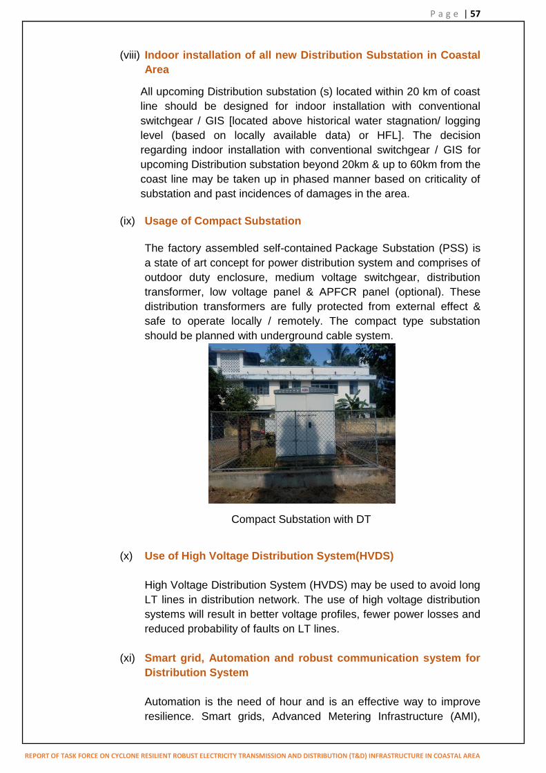
P a g e | 57
REPORT OF TASK FORCE ON CYCLONE RESILIENT ROBUST ELECTRICITY TRANSMISSION AND DISTRIBUTION (T&D) INFRASTRUCTURE IN COASTAL AREA
(viii) Indoor installation of all new Distribution Substation in Coastal Area
All upcoming Distribution substation (s) located within 20 km of coast line should be designed for indoor installation with conventional switchgear / GIS [located above historical water stagnation/ logging level (based on locally available data) or HFL]. The decision regarding indoor installation with conventional switchgear / GIS for upcoming Distribution substation beyond 20km & up to 60km from the coast line may be taken up in phased manner based on criticality of substation and past incidences of damages in the area.
(ix) Usage of Compact Substation
The factory assembled self-contained Package Substation (PSS) is a state of art concept for power distribution system and comprises of outdoor duty enclosure, medium voltage switchgear, distribution transformer, low voltage panel & APFCR panel (optional). These distribution transformers are fully protected from external effect & safe to operate locally / remotely. The compact type substation should be planned with underground cable system.
Compact Substation with DT
(x) Use of High Voltage Distribution System(HVDS)
High Voltage Distribution System (HVDS) may be used to avoid long LT lines in distribution network. The use of high voltage distribution systems will result in better voltage profiles, fewer power losses and reduced probability of faults on LT lines.
(xi) Smart grid, Automation and robust communication system for
Distribution System
Automation is the need of hour and is an effective way to improve resilience. Smart grids, Advanced Metering Infrastructure (AMI),

P a g e | 58
REPORT OF TASK FORCE ON CYCLONE RESILIENT ROBUST ELECTRICITY TRANSMISSION AND DISTRIBUTION (T&D) INFRASTRUCTURE IN COASTAL AREA
substation automation, and remote sensing etc. will help to improve reliability and mitigate the risks of natural hazards. Smart grids and advanced metering infrastructure both improve situational awareness and facilitate rapid restoration of service. SCADA systems play a key role in cyclone response & recovery by enabling utility‟s controllers to identify damaged assets and helps the repair / maintenance team / crew to reach the affected area quickly. Substation automation can work along with SCADA system or independently. SCADA system also helpful for system planning, contingency planning, creation of real time disaster event simulation which will help the utility to prepare in a better way in advance to restore the power supply during the Disaster. Automated switches enable quick reconfigurations of the network & fault isolation, and prevent isolation of entire feeders. Since they do not require manual intervention, replacement of traditional fuses with automated switches can greatly improve network adaptability while reducing operational cost.
9.3 Capacity Building
Power utilities need to build, strengthen, and maintain their capabilities by conducting trainings at all levels, exercises, and periodic drills to prepare staff at all levels to respond to emergencies. The training programs may be organised for contractors & their work forces so that their service can be available in short notice. Utilities are required to continuously improve their operations based on lessons learned from past events and need to focus on periodic training of employees, enhance their capacities to tackle the emergency situations and enhance their knowledge and managerial capability in association with the local technical / management institutes. Proper training of personals responsible for handling ERS and mobile substations is also essential.
10. FUTURE ROAD MAP
a) The recommended measures will definitely enhance the resilience against HIW and reduce the probability of failure, increase reliability & availability of T&D infrastructure. However, the damage due to natural disaster cannot be ruled out completely because such events are likely / expected to occur during service life of installation. The operational risk need to be reviewed periodically. Hence objective of all such measures is how best to mitigate the potential impact of HIW, minimize damage to T&D infrastructure and restore the power supply as quickly as possible post cyclone.

P a g e | 59
REPORT OF TASK FORCE ON CYCLONE RESILIENT ROBUST ELECTRICITY TRANSMISSION AND DISTRIBUTION (T&D) INFRASTRUCTURE IN COASTAL AREA
b) Although cyclones affect the entire coastal areas (east & west coast) of India, the impact of cyclonic storm is much more in east coast compared to west coast. On the East coast, Odisha is the worst affected State by cyclone followed by the states of Andhra Pradesh, Tamil Nadu and West Bengal. The impact of cyclones is not significant on the West coast and not much damage to T&D infrastructures have been observed in past in the states of Gujarat, Maharashtra, Karnataka and Kerala due to cyclone. Hence, the states of Odisha, Andhra Pradesh, Tamil Nadu and West Bengal, on the east coast, should implement above recommended measures. However, considering the damages to T&D infrastructures due to recent cyclone in Gujarat (Tauktae), the implementation of above recommended measures shall also be taken up by states on west coast in order to improve the resiliency of T&D infrastructures.
c) It may not be desirable / practicable to implement all recommendations in one go for existing infrastructures as it would involve huge capital expenditure and long shut down period. Utility may plan to implement various measures for existing T&D infrastructure in phased manner prioritizing implementation plan on the basis of criticality / importance of the asset in the system.
d) The effect of cyclonic storms is largely felt in a belt of approximately 60 km from the coast line. The recommended measures should be taken up early for areas within 20km of coastline. The decision regarding implementation of measures beyond 20km & upto 60km from coast line may be taken up based on following considerations:
Vital installations such as hospitals, water supply, telecommunication system, railways, airports, bus stands etc.
Importance / Criticality of the Line and population of connected consumers
Past Incidents of failure due to heavy wind/ cyclones Availability of Right of Way and funds
e) The complete assessment / review of activities should be undertaken
before, during & after the cyclone. This includes the shortfalls, the bottlenecks & hindrances observed in execution of planned work and areas requiring further improvement to minimize the impact on the system. The review shall be taken up at each level of response team and areas are to be clearly identified for further improvement.
f) The structural integrity of T&D infrastructure depends on many factors like design, quality of material used, construction methodology, workmanship, erection and Operations & Maintenance practices etc. of the transmission & distribution utilities. The best practices should be followed to ensure long and trouble free service of T&D system.

P a g e | 60
REPORT OF TASK FORCE ON CYCLONE RESILIENT ROBUST ELECTRICITY TRANSMISSION AND DISTRIBUTION (T&D) INFRASTRUCTURE IN COASTAL AREA
g) Digitalization & periodic review of material bank of T&D assets, regular patrolling & monitoring of T&D assets, identifying vulnerable assets, timely rectification of all identified defects, implementation of preventive measures, mock drills for maintaining preparedness of various team and regular capacity building of employees and improving operation based on the lessons learned from past are essential. The Standard Operating Procedure (SOP) brought out in the report should be followed by the utilities of coastal states.
h) Method of testing of structures used for overhead Distribution lines needs to be formulated to ensure reliability of structure.
i) Further, due to climatic change wind speed has increased in some of the areas as per latest wind map prepared by Structural Engineering Research Centre (SERC) and the same has been included in National Building Code in 2016, which should be considered for design of all new towers/poles of transmission lines. The wind map included in National Building Code 2016 was prepared by SERC in 2009. Almost 12 years has elapsed and change in wind speed might be there in some areas. Hence, there is need for reassessment / study of wind speed by IMD / SERC. Action should be taken in that direction.
j) The recommended changes in design philosophy to enhance resilience in T&D structure in coast line, requiring revision in relevant Indian Standard, should be communicated to BIS for taking necessary action. The recommended changes are also to be followed for transmission projects being executed through RTM and to be included in the RfP documents of transmission projects being executed under TBCB route.
Name: Prakash S. Mhaske Chairperson, CEA, Chairman of the Task Force
Energy Secretary, Govt. of Andhra Pradesh
Energy Secretary, Govt. of Odisha
Energy Secretary, Govt. of West Bengal
Energy Secretary, Govt. of Tamilnadu
Director (Operations), POWERGRID

P a g e | 61
REPORT OF TASK FORCE ON CYCLONE RESILIENT ROBUST ELECTRICITY TRANSMISSION AND DISTRIBUTION (T&D) INFRASTRUCTURE IN COASTAL AREA
Chief GM, POWERGRID
Director, WBSETCL
Director (Operation), OPTCL
Chief Engineer (Transmission),APTRANSCO
Chief Engineer (Civil Transmission), TANTRANSCO
Chief Engineer (Distribution, South region), TANGEDCO
Chief Engineer,PSETD Division, CEA
Co-opted members of the Committee:
S. no. Name Designation
1. Shri. Sanjay Taksande Director (Operations), MSETCL 2. Shri R B Patel I/c Chief Engineer (Technical), GUVNL 3. Dr. Rajan P Director Transmission, KSEBL
4. Mrs. Sunitha Devi Scientist „E, India Meteorological Department
5. Mr. E V Rao KEC International Ltd 6. Mr. Milind Nene Deputy President, Kalpataru Power
Transmission Ltd. 7. Mr. Kaushal Thakkar Senior Manager, Kalpataru Power
Transmission Ltd. 8. Mr. Susobhan Bhattacharya General Manager (Construction), CESC
Limited 9. Mr. Parveen Verma Tata Power Central Odisa Distribution Ltd.

P a g e | 62
REPORT OF TASK FORCE ON CYCLONE RESILIENT ROBUST ELECTRICITY TRANSMISSION AND DISTRIBUTION (T&D) INFRASTRUCTURE IN COASTAL AREA
APPENDIX
TYPICAL CHECK LIST IN RESPECT OF SOP

P a g e | 63
REPORT OF TASK FORCE ON CYCLONE RESILIENT ROBUST ELECTRICITY TRANSMISSION AND DISTRIBUTION (T&D) INFRASTRUCTURE IN COASTAL AREA
TYPICAL CHECK LIST IN RESPECT OF SOP
(a) Advance Preparedness Measures
The following preparedness measures are to be ensured by utilities:
Sl. No.
Description Transmission system
Distribution System
1. Mapping of Transmission & Distribution (T&D) infrastructure completed
Y/N Y/N
2. Vulnerable assets identified Y/N Y/N 3. Availability of designs / drawings of tower and
technical details of equipment at relevant substations and site offices ensured
Y/N Y/N
4. Material bank prepared & digitalized and reviewed
Y/N Y/N
5. Availability of adequate equipment / material and spares for T&D lines (towers / poles, conductor, earthwire, their accessories, insulators & their hardware fittings, etc.) & sub-station (CBs, Isolators, CT, PT/CVT, Surge Arresters, Wave traps etc.) ensured
Y/N Y/N
6. Assessment of availability of ERS towers completed
Y/N Y/N
7. Assessment of availability of DG sets completed
Y/N Y/N
8. Assessment of availability of tractors mounted with cranes and pole erection machine, JCB machines, power cranes, sand bags, pulley, cable jointing tools, gas cutter, emergency light, safety equipment, inflatable emergency lights, first aid kits with sufficient medicines and other tools & tackles etc. completed
Y/N Y/N
9. Deployment of mobile substation at strategic locations in the region completed
Y/N Y/N
10. Patrolling & monitoring of T&D assets completed
Y/N Y/N
11. The rectification of all identified defects i.e. replacement / repair of defective components in the system taken up
Y/N Y/N
12. The clearing of RoW including pruning of tress to minimize the risk of falling trees taken up
Y/N Y/N
13. Mock drills for preparedness of various teams completed
Y/N Y/N
14. The Annual Rate Contract (ARC) is in place for cyclone prone coastal areas to avoid delay in tendering process for procurement of equipment / material / engagement of work force etc. required for early restoration of T&D
Y/N Y/N

P a g e | 64
REPORT OF TASK FORCE ON CYCLONE RESILIENT ROBUST ELECTRICITY TRANSMISSION AND DISTRIBUTION (T&D) INFRASTRUCTURE IN COASTAL AREA
system 15. Availability of updated list and contact details of
heavy equipment providers, EPC contractors, major equipment / material manufacturers, skilled fitters and erectors, trained manpower for ERS etc. ensured
Y/N Y/N
Note: Y: Yes, N: No
(b) Early Warning Phase / Preparedness after receiving cyclone alert
The following readiness are to be ensured by utilities based on the warnings issued
by Government authorities / media regarding any upcoming natural calamity:
Sl. No.
Description Transmission system
Distribution System
1. Areas likely to be affected during upcoming natural calamity identified & marked on the Power map
Y/N Y/N
2. Availability of updated weather related information like the expected wind speed and likely affected areas from sources like Indian Meteorological Department on hourly / 3 hourly basis ensured
Y/N Y/N
3. Control room setup at utility‟s corporate level, circle & division level for monitoring development and effective deployment of manpower and materials etc.
Y/N Y/N
4. Nodal officer identified for control room with Clear hierarchy of command system with defined roles and responsibilities including delegation of financial power
Y/N Y/N
5. Formation of separate teams for power supply, communication, material supply, tools and machinery, food and water provision, accommodation and travel, first aid, safety & security, contract management, transportation, co-ordination with neighboring States, supervision etc.
Y/N Y/N
6. Availability of sufficient fund for procurement of material & engagement of additional man power etc. ensured
Y/N Y/N
7. Availability of healthy communication links at probable affected site ensured
Y/N Y/N
8. Availability of spare towers / poles and other spares for T&D lines ensured for quick response
Y/N Y/N
9. Availability of spares / equipment for T&D substation (s) ensured for quick response
Y/N Y/N
10. Identification & availability of trained manpower, vehicles ensured for quick response
Y/N Y/N
11. Arrangement of sufficient diesel for DG set in Y/N Y/N

P a g e | 65
REPORT OF TASK FORCE ON CYCLONE RESILIENT ROBUST ELECTRICITY TRANSMISSION AND DISTRIBUTION (T&D) INFRASTRUCTURE IN COASTAL AREA
Sub-stations likely to affected completed 12. Advance tie-up for Crane, Excavators,
transportation, additional manpower, safety equipment, T&Ps like tractors mounted with cranes and pole erection machine,, power crane, pulley, cable jointing tools, gas cutter, emergency light and other tools & tackles, portable DG sets etc. for quick restoration ensured
Y/N Y/N
13. Advance meetings completed with critical consumers like railways authority, industries, electricity generators and the distribution companies to plan for the systematic reduction and subsequent restoration of electrical loads in order to prevent total outage of power supply
Y/N Y/N
14. The enlisted vendors, existing EPC contractors, rate contract holders etc. contacted in advance for early dispatch of men / material / both
Y/N Y/N
15. Instruction passed on to concerned System operator / officer in charge to switched off the power supply of respective distribution feeders which are certain to be affected by the cyclone when wind speed exceeds 50 Km per hour as a safety measure
Y/N Y/N
16. Instruction passed on to concerned System operator / officer in charge not to go for 2nd attempt for charging if line trips due to HIW till through patrolling is done
Y/N Y/N
Note: Y: Yes, N: No
(c) Response & Restoration Phase
The following activities shall be taken up by the utilities immediately after the cyclonic
incident for quick restoration of affected T&D elements for early restoration of power
supply:
Sl. No.
Description Transmission system
Distribution System
1. Immediate Damage assessment of affected T&D lines/ sub-station equipment completed
Y/N Y/N
2. Finalization of Strategic locations for prioritizing the restoration work
Y/N Y/N
3. Deployment of ERS towers, cranes, and tractors mounted with cranes and pole erection machine, JCB machines, power cranes, sand bags, pulley, cable jointing tools, gas cutter, emergency light, safety equipment, portable DG sets, inflatable emergency lights, first aid kits with sufficient medicines and
Y/N Y/N

P a g e | 66
REPORT OF TASK FORCE ON CYCLONE RESILIENT ROBUST ELECTRICITY TRANSMISSION AND DISTRIBUTION (T&D) INFRASTRUCTURE IN COASTAL AREA
other tools & tackles etc. ensured 4. Management of funds & mobilization of
resources (men & material): Allocation of required funds & resources like deployment of technical experts, manpower (skilled & unskilled), equipment, T&Ps, spares etc. to affected area
Y/N Y/N
5. Transportation arrangement for spares / ERS sets to the affected site and movement of mobile substation ensured
Y/N Y/N
6. Arrangement of required vehicles for quick movement of manpower and materials to affected site ensured
Y/N Y/N
7. Necessary arrangement for stay, food & water at site for officers and additional manpower ensured
Y/N Y/N
8. Deployment of round the clock security at stores and at affected sites to avoid theft & misuse etc. ensured
Y/N Y/N
9. Co-ordination with various departments & local authorities to address the issue of access, particularly in relation to road closures, right of way, security etc. completed
Y/N Y/N
10. Deployment of senior level officials to vulnerable sites to ensure physical monitoring of work, on site assessment of damage, requirement of additional men & material and co-ordination with other departments for smooth execution of work completed
Y/N Y/N
Note: Y: Yes, N: No

P a g e | 67
REPORT OF TASK FORCE ON CYCLONE RESILIENT ROBUST ELECTRICITY TRANSMISSION AND DISTRIBUTION (T&D) INFRASTRUCTURE IN COASTAL AREA
ANNEXURE A
Minutes of the First Meeting of Task Force on Cyclone Resilient Robust
Electricity Transmission and Distribution Infrastructure in the Coastal areas held
on 12th June 2020

Minutes of the First Meeting of Task Force on Cyclone Resilient Robust ElectricityTransmission and Distribution infrastructure in the Coastal areas held on 12thJune 2020 through Video Conferencing
The list of participants is enclosed as Annexure I.
1. Chairperson, CEA and Chairman of the task force welcomed the participants andinformed that in view of frequent damages caused by Cyclones to the electricityTransmission and Distribution (T&D) infrastructures in the cyclone prone coastalparts of our country, Ministry of Power vide its order dated 02.06.2020 hasconstituted a Task Force on Cyclone Resilient Robust Electricity Transmission andDistribution infrastructure in the Coastal areas. He further informed that the TaskForce is to submit its Report to Ministry within three (3) months and requested ChiefEngineer (PSETD) to proceed with the presentation.
2. Chief Engineer (PSETD), CEA welcomed all the participants to the meeting and gavea brief presentation on the subject. (Copy of presentation attached as Annex). Heinformed the participants about the composition and terms of reference of the TaskForce as constituted by the Ministry. As per the terms of reference, the Task force isto examine the Type & Nature of damage to electricity infrastructure during cyclones,suggest feasible & cost effective design change to minimise the damage, suggestimprovements in use of material in construction (Pole, tower, Conductor etc.) andlaying of T&D system and recommend mitigation measures for minimising damage.
3. He briefed about some of the major cyclones which had affected Indian coastal regionin the past six years and suggested two approaches for development of Powerinfrastructure in the cyclone affected states. One approach could be to go for aresilient and robust system with least damage and the other approach is to keepprovision for emergency infrastructure for immediate restoration of the system. Thecost associated with both approaches will be different. Moreover, past experienceshows that the impact of cyclone is observed upto a certain distance from the coastline (Indian Standard mentions about the impact of cyclone /storm, in general, upto60km from coast line.), beyond which its impact gets reduced. The cyclone affectedareas could be divided into three (3) zones and different measures could be adoptedfor different zones / areas. Accordingly, zones could be areas very close to coast line(upto 20 km), areas beyond 20 km and upto 40 km and areas beyond 40 km and upto60 km. The remedial measures to be adopted for existing infrastructure and newinfrastructure in the cyclone affected areas needs to be different. He suggested someof the steps for consideration by the Task Force for minimization of damage to Powerinfrastructure. The available technology options could be use of underground system(cable / Gas Insulated Lines), steel poles instead of lattice structure for transmission /distribution system, installation of Gas Insulated Switchgear (GIS) / MixedTechnology Switchgear (MTS) / Hybrid substations, provision for mobile substationfor quick restoration etc. The routing of transmission lines away from Cyclone
File No.CEA-PS-14-180/1/2020-PSETD DivisionI/10279/2020
48

affected areas, strengthening of existing towers, close monitoring & patrolling oftransmission assets before expected cyclone, change in design philosophy along withamendments to existing Indian standards / codes for changing / introducing newreliability level, change in terrain category, consideration of oblique wind on towerbody & conductor, reduction in span length, provision for adequate spares for earlyrestoration and provision for ERS etc. could also be considered as some of themeasures. The applicability of these measures may be considered for different zonesdepending on severity of damage expected during cyclone, for example, exclusiveunderground system for distribution network upto 20km from coast line. It is fact thatfast restoration of power infrastructure is always the priority after the cyclone. Fortransmission system ERS / available spare towers are used to bring back normalcy.The replacement of these failed towers by towers of same design is not proper as suchtowers are vulnerable to failure under high speed cyclone / storm. There is need toreview / examine the suitability of existing towers of the line to withstand high speedcyclone / storm. He informed that CEA is formulating a guideline for provision ofspares to be kept by utilities to meet any exigency / eventualities like electricalfailure / mechanical damage to assets during operation and failure of towers duringcyclone / storms.
4. He further informed that as per mandate, Task Force can co-opt other member(s) asdeemed appropriate and proposed to co-opt technical experts from Calcutta ElectricSupply Corporation (CESC), Tata Power, KEC Ltd. and Indian MeteorologicalDepartment (IMD). The information regarding the transmission and distributionsystem in cyclone prone coastal areas of AP, TN, Odisha & WB was requested forassessment of infrastructure affected by cyclones and same may please be provided, ifnot submitted so far. He further requested all participating utilities for sharing theircurrent practices and methodologies being adopted in cyclone prone areas to reducethe impact of cyclone and for early restoration of power infrastructure.
5. Chief Engineer (Transmission) from Andhra Pradesh, stated that Standard OperatingProcedure (SOP) is being followed by APTRANSCO for restoration of transmissionand distribution infrastructure. This procedure is based on the past experience and theobjective is to minimise the damages due to cyclones and fast restoration of thesystem after cyclones. The steps being taken for minimization of damage due tocyclone and the experience regarding early restoration of T&D infrastructure will beshared with the Task Force.
6. Principal Secretary to Govt. (Govt. of Orissa), emphasised that both distribution aswell as transmission infrastructure is required to be cyclone resilient. The last cycloneFani had severely affected Orissa and it took about two months to restore thetransmission network in the Puri District and the restoration activities involved hugecost. Resilient system is required as cyclone has become recurring phenomenon inIndia and speed of cyclonic wind has also increased over the years. He emphasisedthat for early restoration of power network post cyclone, there is need for maintainingadequate spares as well as the required manpower. The fast restoration of Power
File No.CEA-PS-14-180/1/2020-PSETD DivisionI/10279/2020
49

network post Amphan cyclone was possible because of availability of EmergencyRestoration System (ERS) and other materials. He also agreed with the need ofcalibrated approach based on different zones, but informed that routing oftransmission line away from the coastal areas may be not possible as coastal areas arebecoming hub of economic activities and electricity requirements are increasing inthese regions. Based on past experiences, Odisha has developed a Standard OperatingProcedures (SOP), which are being followed by state utility in such emergencysituation. The practice being followed along with SOP, details of infrastructureaffected due to cyclone and the experience of Odisha regarding fast restoration ofT&D infrastructure will be shared with Task Force.
7. Chief Engineer (Distribution) from Tamil Nadu informed that three (3) cyclones haveaffected their network in the past 5 years, about 50 towers were damaged and 3995km of transmission line got affected. There is need to strengthen the old transmissiontowers in phases to minimize the damage of towers during cyclones in future. asthese towers are not designed to withstand the rising wind speeds of the cyclones. Thework of replacing distribution lines by underground cables is in progress in Chennairegion. The experience and practices being followed by Tamil Nadu in the cycloneaffected area would be shared along with the detail information about T&Dinfrastructure as requested by CEA.
8. Additional Chief Secretary (Govt. of West Bengal) stated that construction of towersof transmission lines are as per CEA regulations and BIS Codes. There is need toincrease design margin / specify more stringent design parameters for towers in viewof increased speed of wind during cyclones. West Bengal government is planning tobuild underground transmission & distribution network in Kolkata region, but itcannot be implemented everywhere because of involvement of high cost incomparison to overhead lines. Further, because of high consumer population andpower density, it is difficult to go for underground system at all places. The evaluationof resilience of existing system to withstand cyclones of Category 3 or Category 4 isrequired to be done and some external consultant may be consulted for this purpose.He informed that NDMA had also published a guideline regarding impact of cyclonesand floods. However, the document is general in nature and the same may be referredto make it more specific for Power sector. The countries like Philippines, Thailandcome across cyclones with speed of wind reaching upto 400 km/hr. The practicesbeing followed by power utilities of these countries regarding risk proofing of T&Dinfrastructure may also be looked into by the Task Force. He suggested that theexperiences and practices of different states affected by cyclones may be clubbed sothat comprehensive information is available for the benefit of all. The informationregarding cyclone affected infrastructure as well experience and methodologiesadopted by state utilities to restore the system will be shared with the Task Force.
9. Director (Operation), PGCIL stated that separate criteria is to be adopted fortransmission network and distribution network as damages observed in Distribution
File No.CEA-PS-14-180/1/2020-PSETD DivisionI/10279/2020
50

system is higher compared to transmission system. Further, developing cycloneresilient infrastructure must be evaluated based on the cost involved forimplementation of such measures. She agreed that the design parameters oftransmission and distribution systems can be made more stringent for the cycloneprone areas and higher design margins can be adopted for such infrastructure. Sheinformed that PGCIL had approached BIS for amendments in the relevant IS code.She suggested that technical advice /input can be taken from multiple privatetransmission licensees / EPC agencies like KEC & Kalpataru. She agreed to share thedetails of infrastructure and past experience of the PGCIL in restoring the T&Dinfrastructure damaged during cyclones.
10. Chief Engineer (DP&T), CEA informed that during his visit to Odisha after thecyclone Fani as a member of team, it was observed that 90% of distribution systemwas damaged whereas damage to transmission system was only 10%. Paucity of fundis the major bottleneck for the power utilities in implementation of various suggestedmeasures and strengthening of power infrastructure in coastal states. Proper planningand assessment of fund requirement is required to done by respective states. He alsosuggested to include the experience of states like Maharashtra, Gujarat & Kerala, inwestern coast line of India and may also be included as part of the committee.
11. The committee decided to include EPC executing agencies associated withtransmission lines as expert of the technical committee and the technical experts fromeach state, PGCIL along with EPC agencies etc. would discuss and deliberate in detailon the subject.
12. The members of Task force agreed for the following:
a) The lessons learned, practices being followed & steps being taken to improve theresilience of T&D infrastructure in cyclone prone areas to reduce the impact ofcyclone and the experience regarding fast restoration of T&D infrastructurewould be shared by all utilities.
b) To co-opt experts from Calcutta Electric Supply Corporation (CESC), TataPower, KEC Ltd., Kalpataru and Indian Meteorological Department (IMD).
The meeting ended with a vote of thanks to the chair.
File No.CEA-PS-14-180/1/2020-PSETD DivisionI/10279/2020
51

Annexure – I
List of Participants
Central Electricity Authority:
1. Shri P.S. Mhaske, Chairperson, CEA2. Shri S.K. Ray Mohapatra, Chief Engineer, PSE&TD Division3. Shri Vivek Goel, Chief Engineer, DP&T Division4. Shri Y.K. Swarnkar, Director, PSE&TD Division5. Shri Praveen Kamal, Director, DP&T division 6. Shri Bhanwar Singh Meena, Deputy Director, PSE&TD Division7. Shri Mohit Mudgal, Deputy Director, PSE&TD Division8. Ms. Bhaavya Pandey, Assistant Director, PSE&TD Division9. Shri Apoorv Goyal, Assistant Director, PSE&TD Division
State of Orissa:
1. Shri Nikunja Bihari Dhal, Principal Secretary to Govt., Department of Energy2. Shri Pradipta Kishore Satapathy, Additional Secretary to Govt., Department of
Energy3. Shri Upendra Kumar Pati, Director (Operations), Orissa Power Transmission
Limited(OPTL)
State of West Bengal:
1. Shri S. Suresh Kumar, Additional Chief Secretary2. Shri Sabyasachi Roy, Director(Operations), WBSETCL
State of Tamil Nadu :
1. Shri R Manivanan, Chief Engineer, Distribution, South Region2. Shri R. Thangasamy , Chief Engineer, Civil Transmission
State of Andhra Pradesh:
1. Shri K. Surendra Babu, Chief Engineer (Transmission), APTRANSCO
Powergrid Corporation of India Ltd.:
1. Ms. Seema Gupta, Director (Operations)2. Shri Subash C. Taneja, Chief General Manager
File No.CEA-PS-14-180/1/2020-PSETD DivisionI/10279/2020
52

Meeting of Task Force on
Cyclone Resilient Robust Electricity
Transmission and Distribution Infrastructure in the Coastal areas
12th June 2020

Composition of Task Force: MoP, vide their letter no. 12/9/2020-Trans dated 02.06.2020 have constituted a Task Force on Cyclone
Resilient Robust electricity transmission and Distribution infrastructure in the coastal areas of thecountry comprising of following members:
The Task Force may co-opt any other member(s) as deemed appropriate.
S.no. Name1. Shri P. S. Mhaske, Chairperson, CEA … Chairman
2. Smt. Seema Gupta, Director (Operations), PGCIL … Member
3. Energy Secretary, Government of Andhra Pradesh … Member
4. Energy Secretary, Government of Odisha … Member5. Energy Secretary, Government Tamil Nadu … Member6. One Technical Expert each from Andhra Pradesh,
Odisha, Tamil Nadu and West Bengal ---- to benominated by State Energy Secretaries
… Member
7. Shri S C Taneja, Chief GM, PGCIL … Member8. Shri S K Ray Mohapatra, Chief Engineer, CEA …Member Secretary

Terms of Reference: To examine types and nature of damages to electricity infrastructure due to recent cyclones in
coastal parts of our country.
To recommend preventive and mitigation measures for minimizing the damages totransmission and distribution infrastructures due to Cyclone in coastal areas of the countryincluding
measures, which can reduce damages to transmission and distribution lines on account ofdamages during cyclones including that caused by uprooting of trees.
feasible and cost-effective design changes, which can be implemented for minimizingdamages to transmission and distribution lines due to such cyclones including retro-fitting measures so as to have cyclone resilient robust electricity transmission anddistribution infrastructure in the Coastal areas.
study of the composition of material used in the construction and laying down ofTransmission and Distribution systems (e.g. poles, conductors, towers etc.) andsuggesting suitable material and/or changes in composition of existing material so as tohave robust cyclone resilient transmission and distribution systems in coastal areas.
The Task force shall submit its report to the Ministry of Power within 3 months positively.

Term of reference of Task force
Type & Nature of damage to electricity infrastructure(Transmission and Distribution System : Lines and associatedSubstations)
Feasible & cost effective Design Change to minimise Damage
Material to be used in construction (Pole, tower, Conductoretc.) and laying down of T&D system
Recommendations & mitigation measures for minimisingdamage
The Task force shall submit its report to the Ministry of Powerwithin 3 months positively.

List of some of the Cyclones in coastal area of Andhra Pradesh, Odisha, Tamil Nadu and West Bengal
In addition various tropical cyclones of low severity class (such as Okchi, Vardah, Kyant, Mora, Roanu etc. ) have impacted Indian coast in past years
S.no. Name of Cyclone
Date States Affected Severity class
1. Amphan 16-21 May 2020 Odisha & West Bengal Super Cyclonic Storm (Category 5)
2. BulBul 5-11 November 2019 Odisha & West Bengal Very Severe Cyclonic Storm (Category 2)
3. Fani 26 April- 5 May 2019 Odisha & Andhra Pradesh Extremely Severe Cyclonic Storm(Category 4)
4. Gaja 10-19 November 2018 Tamilnadu Very severe Cyclonic storm (Category 1)
5. Titli 8-12 October 2018 Odisha, Andhra Pradesh & West Bengal
Very Severe Cyclonic Strom (Category 3)
6. Hudhud 7-12 October 2014 Andhra Pradesh & Orissa Extremely Severe Cyclonic Storm(Category 4)
7. Phailin 4-14 October ,2014 Andhra pradesh, Orissa, West Bengal, Jharkhand,
Chattisgarh
Extremely Severe Cyclonic Storm(Category 5)

Agenda for DiscussionWHETHER TO GO FOR A RESILIENT & ROBUST
SYSTEM WITH LEAST DAMAGE
(or)
ALLOW DAMAGE TO SOME EXTENT AND RESTORE THE SYSTEM AS EARLY AS POSSIBLE.
Cost associated with each system will be different.

Agenda for Discussion Zoning of Cyclone affected area (assumed to be 60km from coastal line)
based on severity of Damage
Area very close to Coast line (say upto 20km)
Area beyond 20km and upto 40km
Areas beyond 40km and upto 60km
Steps to be taken:
For Existing Infrastructure
For New Infrastructure

Agenda for DiscussionVarious Steps:Adoption of available technological options
(Underground system, Use of pole steel poles instead of lattice structure,Installation of GIS / Hybrid Substations, Provision of mobile substation etc.)
Routing of transmission line away from coast line
Strengthening of existing tower
Change in Design philosophy and change in existing BIS standards / codesfor design (Change in reliability level, change in terrain category,consideration of oblique wind on tower body and conductor, reduction spanlength etc.)
Provision for adequate spares for early restoration
Provision of ERS
Close monitoring and patrolling of transmission assets before expectedcyclone
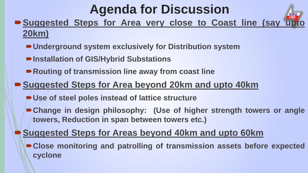
Agenda for DiscussionSuggested Steps for Area very close to Coast line (say upto
20km)Underground system exclusively for Distribution system
Installation of GIS/Hybrid Substations
Routing of transmission line away from coast line
Suggested Steps for Area beyond 20km and upto 40kmUse of steel poles instead of lattice structure
Change in design philosophy: (Use of higher strength towers or angletowers, Reduction in span between towers etc.)
Suggested Steps for Areas beyond 40km and upto 60kmClose monitoring and patrolling of transmission assets before expected
cyclone

Agenda for DiscussionProposal for Co-opting experts from CESCTata PowerKECIMD

THANK YOU

P a g e | 84
REPORT OF TASK FORCE ON CYCLONE RESILIENT ROBUST ELECTRICITY TRANSMISSION AND DISTRIBUTION (T&D) INFRASTRUCTURE IN COASTAL AREA
ANNEXURE B
Minutes of the Second Meeting of Task Force on Cyclone Resilient Robust
Electricity Transmission and Distribution infrastructure in the Coastal areas held
on 29th July 2020

Minutes of the Second Meeting of Task Force on Cyclone Resilient RobustElectricity Transmission and Distribution infrastructure in the Coastal areasheld on 29th July 2020 through Video Conferencing
List of Participants is attached as Annexure I.
1. Chairperson, CEA and Chairman of the task force welcomed all the participants to themeeting. He stated that the committee had a fruitful discussion in the previous meetingheld in June and informed that the Task Force is required to submit its Report toMinistry of power within three (3) months. He requested all the participants to discuss indetail and provide their inputs and suggestions, which will help the Task Force to comeout with practical solutions for Cyclone Resilient Robust Electricity Transmission andDistribution (T&D) infrastructure in the Coastal areas of the country. He furtherrequested Chief Engineer (PSETD) to proceed with the agenda for discussion.
2. Chief Engineer (PSETD), CEA welcomed all the participants to the meeting and briefedabout the terms of reference of the Task Force as constituted by the Ministry of powerand the discussions held in the first meeting on 12th June 2020. In the first meeting, itwas decided to co-opt technical experts from the States located on the western coast ofthe Country, which are affected by the cyclones, namely Maharashtra, Gujarat andKerala, and from Calcutta Electric Supply Corporation (CESC), Tata Power, KECInternational Ltd., Kalpataru Power Transmission Limited (KPTL) and IndianMeteorological Department (IMD). He informed that nominations of experts from allthese States and other organizations have been received and introduced all co-optedexperts.
3. He gave a brief presentation on the agenda for discussion (Copy of presentation attachedas Annex I). As per the terms of reference, the key areas of focus of the Task force areto (a) examine the Type & Nature of damage to electricity infrastructure duringcyclones, (b) suggest feasible & cost effective design change to minimize the damage,(c) suggest improvements in use of material in construction (Pole, tower, Conductoretc.), (d) laying of T&D system and (e) recommend mitigation measures for minimizingdamage.
4. He requested utilities to share the details of current practices including technical detailsof the existing transmission and distribution infrastructure (material for tower/pole,design span, foundation type etc.), preparedness after receiving cyclone alert, actionstaken by them after cyclone for early restoration & planning done for facing similarchallenge in future, Standard Operating Procedures (SOP) followed by them, practice ofmaintaining Spares, engagement of manpower, use of Emergency Restoration System(ERS), monitoring and patrolling of transmission & distribution assets etc. He furtherrequested all participating utilities to share the lessons learned by them after facing thesecyclones. He requested all participants to provide suggestions for modification in designphilosophy for designing of new T&D infrastructure as well as for strengthening ofexisting T&D infrastructure in coastal areas. He stated that currently the wind speed datais measured by IMD observatories and requested representative from IMD to explain
File No.CEA-PS-14-180/1/2020-PSETD DivisionI/11124/2020
114

how these data can be correlated with the design wind speed of transmission line towers.He requested representative of Maharashtra and Gujarat to share their experienceregarding the latest cyclone Nisarga which affected the western coast of country.
The details of deliberations, information & suggestions of representatives from variousutilities / organizations / experts are as follows:
5. Director (Operations), MSETCL, informed that a) Four (4) towers collapsed during cyclone Nisarga in Maharashtra on 3rd June 2020
and around twenty (20) towers at various voltage levels had collapsed due to variouscyclones in the past 5 years.
b) The towers failed during Nisarga cyclone were located on hilly terrain. Thesuspension type towers were used in place of tension type tower despite havingdeviation in the line route and the mistake has been rectified by replacing failedtowers with tension type tower at these locations.
c) One of the towers constructed with HT steel collapsed during cyclone due to rustingof tower members.
He stated that use of proper designed towers, regular patrolling and assessment ofcondition of towers are essential to avoid such failures.
6. Representative from Gujarat stated that the cyclone has no impact on powerinfrastructure in Gujarat in the last five (5) years and informed that Gujarat does nothave much experience on cyclone related failures. However, during monsoon season,Control rooms are set up at circle level by the distribution companies to monitor andassess the damages caused to the power infrastructure due to high speed winds & heavyrains.
7. Director (Operations), Odisha Power Transmission Corporation Limited (OPTCL)gave a brief presentation (Copy of presentation attached as Annex II) on theirexperience of past cyclones which affected Odisha state and their learning from theseincidents. He informed the following:a) Odisha have faced many cyclones in the past two decades such as the super cyclone
in 1999, Phailin in 2013, HudHud in 2014, Titli in 2018, Fani and Bulbul in 2019,Amphan in 2020 as well as severe floods which have caused severe devastation inOdisha.
b) The efficient disaster management group and coordination among variousdepartments have helped Government of Odisha in achieving zero casualties duringrecent cyclones. However, rebuilding damaged infrastructure and bringing backnormalcy after the disruptions was a great challenge.
c) Immediate restoration of infrastructure of Power sector is the most crucial for allother essential services like telecommunication, health care & water supply etc. andsearch and rescue operation.
File No.CEA-PS-14-180/1/2020-PSETD DivisionI/11124/2020
115

d) It has been observed that the Power infrastructure located within 60-70kM from thecoastline was severely affected due to tropical cyclone more than once in a year.
e) The towers & poles of T&D infrastructure was damaged due to high wind pressure& saline effects and the substation equipment had submerged due to surge of seasaline water as well as flooding resulting in huge revenue loss to the Utilities andGovernment of Odisha in reconstruction of T&D infrastructure.
He shared the details of damages caused to T&D infrastructure (date of failureincidences, no. of towers failed at various voltage levels, highest wind speedobserved by IMD during the cyclones, type of substation which got damaged,distance of substation from the coast lines etc.) by each cyclone since 2013 in theState of Odisha.
8. Principal Secretary to Govt., Department of Energy (Govt. of Odisha) informed that:a) The transmission system has been designed with towers suitable for wind zone V
(Speed of wind < 200 km/hr). The transmission system has been affected during thecyclones when recorded wind speed is higher than 200 km/hr, as in case of Fanicyclone.
b) The distribution system has poles/towers, which are designed for wind speed of 60-70 km/hr and more severe damage is observed in the distribution system by cyclonicwinds of speeds lower than 100 km/hr.
c) The flooding of substation premises is also a major problem faced during cyclones.d) Most of the substations in which damage was observed during cyclones were of AIS
type and it is required to convert them into GIS type to reduce such damages infuture.
e) The cyclone preparedness measures adopted by Odisha Govt. are based on theexperiences of previous cyclones.
f) The creation of Odisha Disaster Response Force, pre-positioning of trained gangs forrestoration work; arrangement of Transport vehicles with adequate oil & other T&Plike gen-sets, cutters, emergency lights, etc. locally at Divisions level; formation ofteams at Control Center for effective deployment of manpower, material, andemergency procurement of materials, authorization of field level officers &delegation of financial powers to them for hiring gangs & buying essentialequipment, daily review by higher level officers & Hon’ble Minister of Energy toassess the progress in restoration works etc. are some of the measures beingpracticed for early restoration of power in the affected areas.
g) The failure of suspension type towers was found to be higher in comparison totension type towers.
h) Most of the important cities in Odisha such as Paradeep, Behrampur, Cuttack,Dhamera etc. which act as economic hub are located within 20 to 40 km from thecoast line. It took around two (2) months to rebuild the damaged infrastructure inPuri district after the Fani cyclone. Hence as per past experiences of cycloneincidences, building of disaster resilient infrastructure is very much essential for
File No.CEA-PS-14-180/1/2020-PSETD DivisionI/11124/2020
116

Odisha and should be the 1st step. The measures for faster restoration of T&Dinfrastructure after disaster should be considered as the next step.
He suggested the following measures:
a) The change in the design parameters and increase in the design wind speed upto atleast 250 km/hr for transmission lines traversing in cyclone affected areas.
b) The reduction of tower span, use of different material for tower structure for theaffected lines and use of k4 factor (as per IS 875) in the design of transmissiontowers for cyclone prone areas.
c) Improvement in quality of material used and workmanship in construction of lines.d) Keeping the power infrastructure healthy following good maintenance practices as
the uncertainty is involved in occurrence of cyclone. e) Development of trained pool of manpower including crew members and supervisors
to ensure quality in construction and maintenance.f) Use narrow base towers for transmission lines and H type / GI poles for 33 kV lines.g) Conversion of 33kV, 11kV and LT Overhead lines to Underground cabling system
for distribution network in urban areas. h) Conversion of AIS to GIS substations in cyclone prone areas.i) Creation of material bank.j) Increasing the skills of gangs and use of mechanized tools.
Odisha is facing cyclones very frequently and had faced three cyclones in 2019. Heemphasized the need of cyclone resilient infrastructure and requested CEA to adviseMoP for modification in the various guidelines and cost norms for cyclone affected areasso that cyclone resilient infrastructure are created.
9. Chief Engineer (Transmission), APTRANSCO informed the following: a) Andhra Pradesh have around 950 km of coastal line covering 7 districts in which
there are two (2) 400kV substations, fifty (50) 220kV substations and forty-four (44)132kV substations.
b) During Hud Hud cyclone (in 2014) three (3) transmission towers of 400kV level andthirty-three (33) towers of 200kV level were damaged. Damages caused due to HudHud cyclone was around Rs. 200 crores in Vishakhapatnam district and it took about15 days for restoration.
c) Disaster Management Plan has been prepared and responsibilities have beenassigned at three levels: State, District and Circle level.
d) To continuously monitor the preparedness measures to reduce the damages of powerinfrastructure due to cyclones, headquarter have been set up at Vijaywada and loadmonitoring center is also located at Vijaywada for coordination with distributioncompanies.
e) Towers in coastal areas are designed for wind speed corresponding to wind zone 5(180 km/hr). He supported the suggestion of Odisha regarding designing of towers
File No.CEA-PS-14-180/1/2020-PSETD DivisionI/11124/2020
117

suitable for higher wind speed of 250 km/hr and use of narrow based latticestructures for transmission towers and H-pole type structures for distribution system.
f) Adequate spares have been procured as per CEA guidelines.
The past experience and practices being followed by Andhra Pradesh in the cyclone affectedarea would be shared along with the detail information about T&D infrastructure as requestedby CEA.
10. Chief Engineer (Distribution), Tamilnadu informed the following:a) The Standard Operating Procedures (SOP) and practices are similar to that of Govt.
of Odisha. b) The GIS mapping of all the 11kV feeders in the coastal area has been done and there
is plan convert overhead distribution lines into underground cable system in thecoastal areas.
c) REC standard is being followed in the distribution sector and AAAC conductor isused in coastal areas.
11. Chief Engineer (Civil Transmission), Tamilnadu informed the following: a) Three (3) cyclones have affected their network in the past 5 years. In 2016, about
fifteen (15) towers at 400kV and 200kV level had collapsed due to Vardah cyclone.In 2018, twenty-nine (29) towers had collapsed due to Gaja Cyclone.
b) These towers were designed for wind speed upto 160-170 km/hr, but the recordedwind speed was higher than 185 km/hr during the cyclones in 2016 and 2018. Theuprooting/ uplifting of some of the towers located in coastal areas was also observedduring these cyclones.
c) No damage to EHV transmission lines was observed during cyclone Okchi whichimpacted in year 2017.
d) Mild steel towers are currently being used in transmission lines and use of the HighTensile steel towers in coastal areas is being planned.
e) For existing transmission lines located within the 20 kms region from the coastalline, there is plan to place intermittent towers in between the existing towers toreduce the span length.
f) Earlier PCC type foundations were being used for towers, now Reinforced Concretecement (RCC) type foundations are being used.
g) In case, cyclone alert is issued by IMD, availability of at least 20 transmissiontowers in the store is being ensured, alert to various stakeholders are issued, gangsfor restoration works are arranged to face the challenge.
h) To avoid decapping of porcelain insulators, polymer type insulators are being usedin the upcoming transmission line and the disc insulators used in existing lines arebeing replaced by polymer insulators.
i) The strengthening of chimney & foundation work of existing transmission towers isbeing undertaken wherever necessary.
File No.CEA-PS-14-180/1/2020-PSETD DivisionI/11124/2020
118

j) The use of pile type foundations is being planned for towers in coastal areas whereuprooting of foundations has been observed.
k) The purchase of ERS for early restoration of transmission lines has also beenplanned.
l) Most of the damages are generally observed in transmission lines at 110 kV & 220kV level and no damages were observed at higher voltage levels.
m) All steps are being taken for minimization of damage due to cyclone.
He suggested the following measures:
n) To introduce additional towers in existing lines to reduce the span and to reduce thenormal design span (from 320m to 250m) of 132 kV & 220 kV transmission lines incoastal areas.
o) Wind Zone 6 be considered for cyclone affected areas as high wind speeds aregenerally observed in these areas during cyclones.
The past experience regarding early restoration of T&D infrastructure and other practices ofTamil Nadu will be shared with the Task Force.
12. Director (Operations), WBSETCL informed the following:a) West Bengal have been affected by the recent cyclone Amphan only in the last five
(5) years during which five (5) towers had collapsed and four (4) towers gotdeformed.
b) Normally suspension type towers fail, but failed towers were special DD+6 tensiontowers.
c) ERS were utilized to restore the transmission lines.d) The wind speed during the cyclone crossed 200 kmph, but only nine (9) transmission
towers were affected.e) The damage to distribution sector was extensive.f) WBSETCL is planning to go for underground cable network in urban load centers in
coastal regions.g) In contrast to experience of Odisha, not much damage was observed to AIS type
substations during cyclones.
He suggested the following measures:
a) Emphasis should be given for modifications in tower design with higher factor ofsafety for towers located in the coastal areas.
b) High Tensile steel (HTS) should be used instead of current practice of use of Mildsteel (MS) for transmission towers in coastal areas to reduce the risk of collapse oftower.
c) Other type of structure such as steel pole or lattice structure (in place of PCC / HPole) should be used for distribution lines.
File No.CEA-PS-14-180/1/2020-PSETD DivisionI/11124/2020
119

The past experience regarding early restoration of T&D infrastructure and other practices ofWest Bengal will be shared with the Task Force.
13. Chief Engineer, Kerala State Electricity Board (KSEB) stated the following:a) Transmission system is more stable & reliable and it is the distribution system which
is affected to greater extent by the cyclones.b) The damages to distribution system in Kerala is observed in certain areas and no
massive damage has been observed in past years. c) Most of the times damages were due to falling of trees on the distribution lines.d) A Quick Response Team (QRT) of trained manpower has been set up to quickly act
after disaster to ensure early restoration of the network and a control room has beenset up for effective utilization of resources.
e) For minimizing the risk of falling of trees on the distribution network, clearing ofROW is done on the regular basis.
f) The 11 kV overhead distribution lines are being converted into underground cablesystem in the urban areas of coastal regions. The overhead lines for LT systemcannot be avoided.
He suggested that there should be modification in design of electric pole in thedistribution network.
The steps are being taken for minimization of damage due to cyclone and the past experienceregarding early restoration of T&D infrastructure will be shared with the Task Force.
14. Representatives from PGCIL informed the following:
a) Wind is a serious challenge for the transmission lines and based on past failurerecords, it is evident that high intensity wind is the main factor for most of the towerfailures.
b) In the various technical papers, it has been observed that in 80-85% cases, thecyclonic wind speed is observed to be in the range of 60-65 m/s.
c) The towers are designed as per IS 802 which has undergone various revisionsincorporating modifications like change in no. of wind zones, shifting toprobabilistic concept in design of transmission line, use of peak gust velocity wind& introduction of k2 & k3 factors (in 1995) and introduction of oblique windloading concept (in 2015).
d) Based on CIGRE papers and discussions held in the Standing Committee on towerfailure regarding cyclonic high intensity winds, PGCIL had advised BIS to bringchanges including introduction of K4 factor for coastal regions in the IS 802 and theamendments are expected to be issued by BIS in near future.
e) PGCIL had shared with BIS a draft document covering erection of transmissionlines, which will be included as IS 802 (Part 5) in near future.
File No.CEA-PS-14-180/1/2020-PSETD DivisionI/11124/2020
120

f) Lattice structure is made with both Mild steel (MS) and High-Tensile (HT) steel. HTsteel is more brittle compared to Mild Steel, use of only HT steel in tower may leadto catastrophic failure of towers.
g) PGCIL have a detailed Disaster Management Plan (DMP) and Standard OperatingProcedures (SOP) for reducing the damage and early restoration. The SOPs isdivided into three parts:
Advance preparedness: These preparedness are to be ensured before in a state ofreadiness for any future natural disaster.
Early Warning Phase preparedness: These measures are taken timely based onthe warning issued by media/ Govt. agencies regarding any upcoming naturalcalamity.
Response and Restoration phase preparedness: These measures are taken forquick restoration of affected transmission elements after the impact of disaster.
The specific checklist to be followed by officials is also part of these documents.Based on warning issued by IMD, a pre assessment of probable lines which may getaffected during cyclone is done and necessary measures including arrangement ofman & material and desired equipment is done before the impact of cyclone. Beforethe impact of Cyclone Amphan, the patrolling and maintenance of the transmissionwas done, as a result of which no significant damage was observed to thetransmission line. During Fani cyclone, only one tower had collapsed.
He suggested the following measures:
a) The use of more robust Pole type structure for overhead transmission anddistribution lines in place of lattice structure in the coastal regions
b) Tall towers are more susceptible to failure due to high intensity winds and use ofsmaller/ lower height towers should be preferred in coastal regions. Single circuitlines having horizontal or delta configuration or Double circuit lines having doubledelta configuration may be adopted.
c) High Tension Low Sag (HTLS) & high ampacity conductors can be used in thecoastal areas as low sag of these conductors for same ampacity will result in lowerheight of transmission towers.
d) Truncated towers with lower span may also be considered. e) For flooding during cyclones, which causes submerging of transmission tower
foundations and tower legs, measures like increasing concrete level from groundlevel (from 225 mm to 500 mm), use of anti-corrosion paints, use of raisedchimneys, use of M30 type concrete and epoxy coated resins for reinforcement infoundations etc. can be adopted.
f) Emphasized for use of higher thickness of galvanization and additional earthingarrangement like double pipe type earthing to reduce tower footing impedance oftowers in coastal regions. These practices have already been adopted by PGCIL forcoastal areas.
g) For quick restoration of the power network, the use of Emergency RestorationSystem (ERS) is vital as this system is the first line of action to restore vital links
File No.CEA-PS-14-180/1/2020-PSETD DivisionI/11124/2020
121

during emergency. Adequate quantity of ERS should be kept along with spares atstrategic locations along the coastal lines and these locations should be easilyaccessible in order to minimize transportation time in the event of any probabledisaster.
h) Establishment of ERS training institutes and training of personnel from differentutilities by experienced trainers are essential along with mock drills.
i) Since many of the existing transmission line towers have been designed consideringIS 802 - 1977, 1995 and 2015 and it would require longer shutdown if strengthening/modification is to be carried out as per revised standard, and hence modification /strengthening of towers in existing transmission lines falling under cyclone pronearea should be carried out on case to case basis depending upon the failure history.
j) Transmission lines are subjected to continuous vibrations. As a standard practice,Nuts & Bolts of towers are welded upto bottom cross-arm/Waist level. However, theunwelded upper part of the tower become more vulnerable and should be re-tightened after every 5 years in old lines.
k) If a line has tripped due to high intensity winds, second attempt for charging shouldbe made only after thorough patrolling.
l) Emphasis should be given to replace damaged towers (designed as per old designstandard) with new towers designed according to latest standard.
m) Conversion of overhead distribution lines into underground cable system in thecoastal areas.
Disaster Management Plan of PGCIL and the document covering erection of transmissionlines submitted to BIS will be shared with the task force.
15. Representative from IMD informed the following:a) Maximum speed of cyclone mentioned in the IMD bulletin is the wind speed
averaged for 3 minutes, and it is assumed that the maximum instantaneous speed ofcyclonic winds may be 10-20% more than the speed specified in the IMD bulletin.In some instances, tornadoes formed during cyclones are more damaging in naturedue to high wind speeds.
Chief Engineer, PSETD informed that in design of transmission towers, 3 secondgust wind speed is considered and all the wind zones are defined based on this windspeed. This wind speed is reduced further by converting it to 10minute average (atheight of 10m) using a division factor of 1.375. He requested her to suggest how tolink the wind speed mentioned by IMD in its bulletins and the wind speed used fordesigning transmission towers. She informed that there is no empirical formulaavailable to convert 3minutes average gust wind speed mentioned by IMD duringcyclones to 3 sec gust wind speed and only interpolation & extrapolation techniquesare used to calculate the instantaneous / 3 second gust wind. On an average, 20 % ofthe value may be added to the wind speed mentioned in the IMD bulletins to accountfor these gusty winds.
File No.CEA-PS-14-180/1/2020-PSETD DivisionI/11124/2020
122

b) Doppler weather radar is used for deducing the wind speed mainly at coastal areas,but can also be used for inland parts of the country.
c) The observatories of the IMD are at limited locations (70 observatories across India)and though use of Doppler weather radar is an extrapolative method, the calculationsto arrive at specific wind speed at particular location is still dependable.
d) IMD is planning to install next generation automated weather stations which willmeasure continuous wind speed data and provide per second gust wind speed.
e) Twenty (20) nos. of High wind speed recorder along the coastline are being plannedwhich will help in getting more accurate wind data.
Representative from KEC added that IEC 60826 provides mechanism to convertwind speed for a particular observation period to various observation periods andrequested IMD to clearly state the time period of the wind speed in the IMDbulletins.
16. CESC, General Manager (Construction), stated the following:a) During cyclone many trees get uprooted and fall on the distribution network
resulting in tripping of distribution lines. To minimize the risk of falling of treesmonitoring and clearing of the ROW is done on the regular basis.
b) In the last cyclone which affected Kolkata, no significant damage in the transmissionnetwork was observed. The damage to distribution infrastructure was very high.
c) ERS are being used for early restoration of transmission lines and mock drills aredone for maintaining preparedness of the various teams.
d) In CESC distribution network, only steel type poles are used and concrete pole arenot used. The damages observed are mostly due to uprooting of nearby trees.
He suggested the following measures:a) Wherever feasible, the conversion of overhead distribution lines into underground
cable system may be thought of as an option particularly in the coastal areas havinghigh trees density, though it involves huge capital investment.
The information regarding cyclone affected infrastructure, CESC’s experience andmethodologies being adopted by CESC to restore the system will be shared with the TaskForce.
17. Representative from TPPDL suggested the followings:
a) Epoxy based coating should be used to over the structures located in coastal areas asdistribution infrastructure gets corroded by the saline weather in the coastal areaswhich leads to failure.
b) Distribution network in the rural parts of coastal areas is huge and converting theoverhead distribution lines into underground cable system in these areas will require
File No.CEA-PS-14-180/1/2020-PSETD DivisionI/11124/2020
123

huge capital expenditure and hence such option should be considered for distributionnetwork in urban areas only.
c) For rural areas, measures like improvement in design of the foundations of polestructure and refurbishment of existing lines with use of H-poles in between spanmay be adopted.
d) At present, distribution transformers are put on the double pole structure and there isrisk of falling of these transformers under high wind condition and he suggested forplacing distribution transformers on a plinth.
e) For early restoration, material bank is required to be updated regularly.f) Lot of damages is observed in 33/11 kV substation in the coastal areas due to
cyclones. Container type or mobile type substation may be adopted in those areas toreduce the risk.
g) Currently 33/11 kV & 66/11 kV mobile distribution transformers are used forrestoration purposes only, but for coastal areas in principle such type of substationscan be planned, which can be moved to safer places during cyclones.
h) Underground cable system with (n-1) contingency, Distribution Automation (DA)System, SCADA and Demand Side Management (DMS) should form part ofDistribution system
The experience, practices and recommendations of TPPDL regarding urban and ruraldistribution network will be shared with the Task Force.
18. Representative from KEC Ltd. informed the following:a) The wind speed is major factor in designing of the transmission and distribution line
structures, therefore it is important that proper wind speed data & the correspondingperiod of measurement of wind speed should be provided by the IMD in their Pressreleases as 3minutes average gust speed of 250 km/hr may come out to be threesecond gust wind speed of 300 km/hr.
b) Since distribution line towers/poles are designed for wind speed of 70-80 km/hr,their failure rate is much higher in comparison to transmission line towers.
He suggested the following measures:
c) Bangladesh have modified design parameters and the towers are designed towithstand the wind of speed of 288 km/hr (against the earlier design wind speed of200 km/hr.) and suggested for similar modification in designing of tower in view ofhigh wind speeds observed in coastal areas.
d) Generally, various parts of towers are designed based on loads acting on them.Critical members such as Leg members of tower can be designed with HT steel andnon-critical members such as redundant members or bracings are generally designedwith Mild steel (MS). The use of the combination of both type of material (HT &MS) in tower structure gives best performance.
File No.CEA-PS-14-180/1/2020-PSETD DivisionI/11124/2020
124

e) KEC is using drones to monitor the quality of erection of new transmission lines andfor regular maintenance of old transmission lines. The analysis of the pictures (takenby high resolution cameras used in drones) of the transmission lines indicates thecondition of tower structure, which can also be observed remotely. During executionand before stringing of tower structures, KEC employ their own gangs to examinethe erected structures.
f) Most of the distribution utilities is following old REC standards which are based onconcept of working stress and there is need to update these standards in line withregular updation of IS 802, being used for transmission line designing.
g) Methods for Testing of poles used for distribution system should be introduced h) Increase in galvanization thickness is required in coastal areas. i) Additional towers may be put between span(s) in the existing transmission lines to
reduce the span length and these new towers should have been designed as per latestIS.If terrain category -1 is considered for designing of transmission towers in coastalareas, then there is no need of introducing K4 factor in calculation of design windspeed, provided the correct wind speed data is used for design. The use of terraincategory-1 in coastal areas will increase the load on towers by approximately 15%.
Representative from PGCIL, stated that currently terrain category-2 is used forcoastal areas with reduced span.
Chief Engineer, PSETD stated that the reduced span will increase the no. of towersand overall cost will increase & hence reduction in span may be considered uptocertain distance (say 20km) from coastal line / based on the past experience offailure during cyclones.
j) For foundation of the transmission line towers near rivers, geomorphology study oflast 40 years regarding change in course of river and highest water flow level shouldbe done before deciding the type of foundations to be used for transmission towersnear rivers.
Bangladesh has adopted the practice of using pile type foundations upto 12 towerlocations situated on the river bank based on past data.
19. Representative from Kalpatru Power Transmission Ltd. (KPTL) stated thefollowing:
a) Wind speed is the sole criteria in the designing of the transmission and distributiontowers / poles. Wind zone 3 considered as per codal practice of Philippines is almostsimilar to wind zone 3 of IS 802 used in our country and loading comes out to bealmost similar. It is to be noted that they have specified maximum wind speed of 270km/hr for coastal areas. The similar wind speed is observed in coastal regions ofOdisha and Andhra Pradesh and requested IMD to look into the matter.
File No.CEA-PS-14-180/1/2020-PSETD DivisionI/11124/2020
125

b) The failures of the wide base towers are observed to be more than the narrow-basedtowers and the oblique wind consideration as per new IS 802, will take care of thisissue.
c) There is no significant change in strength of the tower if we change the towermaterial from Mild steel (MS) completely HT steel (HTS).
d) In other countries, the wind map contours are used, whereas the Indian wind map(incorporated in IS 875/ IS 802) does not take into consideration of gradual changein the various wind zones and it becomes difficult to decide how much velocity ofwind is to be considered for design of transmission line towers in the vicinity ofboundary of two wind zones.
Representative from PGCIL informed that 30 km of overlap for higher of the twowind zones is being considered.
Representative from IMD stated that discreet boundaries in wind map are not correctpractice and overlapping zones is required. The wind speed is also affected by theterrain category. In the hilly terrain the wind is reduced rapidly and smalleroverlapping wind zones (say about 10km) is required whereas in plain areas largeroverlapping zone (say 20-30 km) is required.
Director (PSETD division), CEA informed that this issue was deliberated inprevious meeting of the Standing Committee of experts on tower failure and it wasdecided to consider an overlapping zone of 50 kms in which the higher of the twowind zones is to be considered for designing of towers of transmission lines. Thisprovision can be incorporated in the CEA regulations which are under revision.
He suggested the following measures:
a) Instead of considering Terrain category-1 for design of towers in coastal areas, thedesign of towers considering terrain category-2 with reduced tower span length willdo away with the requirement of keeping multiple set of designed towers.
b) The factor k4 can be considered for inclusion in design criteria for transmission lineslocated in coastal areas.
c) Dr. Suresh Kumar of RWDI (a wind engineering & environmental engineeringInternational consulting firm having one of the offices in Kerala) is an expert in fieldof wind energy and he may be invited to the meeting to give his view on nature ofwind and design criteria for coastal regions.
Chief Engineer, PSETD informed that he had discussed with Dr. Suresh Kumar andhe had agreed to share his experience. If everyone agrees he can also be invited toattend next meeting of task force to provide his expert opinion on wind speed &design considerations required for T&D infrastructure in cyclone affected regions.
File No.CEA-PS-14-180/1/2020-PSETD DivisionI/11124/2020
126

d) In pile foundations for river crossing towers, tie beam should be considered to takecare of scouring effect in the river, horizontal force due to wind, cantilever load anduniform distribution of load.
Representative from KEC stated that the use of tie beams increases the possibility ofdamage to foundations due to accumulation of debris at the time of floods in theriver and pile type foundation can be used with increased diameter to take care ofcantilever loads.
Representative from PGCIL also stated that use of tie beams is not required andnormal pile type foundations can be designed for any type of load conditions.
20. Chief Engineer (DP&T), CEA stated the following:a) There is need to convert distribution overhead lines into underground cable system
in the coastal areas, which requires huge capital expenditure. b) In coastal regions, the distribution transformer should be kept indoors instead of
putting it on the poles. c) On receiving warning from IMD, the utilities should arrange DG sets at the areas
which are likely to be affected by the cyclones for functioning of essential services. d) The arrangement of anticipated material & skilled workforce, delegation of financial
powers to local team to avoid the delays due to tendering process etc. are some ofthe measures which may be included in the recommendations of this Task Force.
21. Director (DP&R division) CEA
a) She agreed with the suggestion that DG sets should be installed in cyclone affectedareas.
b) CEA (Technical Standard for Construction of Electric Plants and Electric lines) iscurrently under revision. The provision of GIS substations, underground cablesystem and indoor transformers are being considered in the cyclone affected areasfor inclusion in the revised Regulations.
22. Director (PSETD), CEA a) He suggested to discuss and analyze the cost impact of the various options such as
consideration of k4 factor in design, consideration of terrain category-1 (in place ofterrain category-2) or both in the coastal regions, usage of reduced span resulting inhigher no. of towers etc. A comparison in excel sheet giving details of increasedweight of tower for each of the options & the associated cost may be prepared andthe same can also be made part of the report of Task Force.
Chief Engineer (PSETD), requested PGCIL to prepare such comparative sheet fortowers of 220 kV & 400 kV lines. PGCIL agreed to submit the comparative excelsheet before next meeting of the Task Force.
File No.CEA-PS-14-180/1/2020-PSETD DivisionI/11124/2020
127

The members of Task force agreed for the following:
a) The experience, suggestions and practices being followed including SOP forpreparedness to face the challenge and for fast restoration of the T&D infrastructure anddesign philosophy being followed for coastal area affected by cyclone would be sharedby states of Andhra Pradesh, Odisha, Tamil Nadu, West Bengal, Maharashtra, Gujarat,Kerala and PGCIL. The experts nominated from various organizations (KEC, KPTL,Tata Power, CSEC and IMD) would share their views / suggestions in detail forinclusion in the report of task force.
b) Disaster Management Plan of PGCIL and the document covering erection oftransmission lines submitted to BIS will be shared with the task force.
c) PGCIL would prepare a comparative sheet for towers of 220 kV & 400 kV transmissionlines to analyze the increase in weight of towers and associated impact on cost forvarious options such as inclusion of k4 factor in design wind speed, consideration ofterrain category-1 (in place of terrain category-2) or both in the coastal regions, reductionin span etc. (each option separately and also combination of options).
d) PGCIL would suggest any good practices in execution of Distribution system.e) Based on the inputs of utilities / organizations / experts, outline of Draft report of task
force will be prepared for further discussion in next meeting.f) Dr. Suresh Kumar of RWDI Consulting Engineers (India) Private Limited,
Thiruvananthapuram, Kerala (dealing with wind engineering and environmentalengineering) would be invited to attend the next meeting of task force and share hisexperience and expert opinion on wind speed & design considerations required fordesign of T&D infrastructure in cyclone affected regions.
The meeting ended with a vote of thanks to the chair.
*******************************************
File No.CEA-PS-14-180/1/2020-PSETD DivisionI/11124/2020
128

Annexure – I
List of Participants
Central Electricity Authority:
1. Shri P.S. Mhaske, Chairperson, CEA 2. Shri S.K. Ray Mohapatra, Member Secretary & Chief Engineer, PSE&TD Division 3. Shri Vivek Goel, Chief Engineer, DP&T Division 4. Shri Y.K. Swarnkar, Director, PSE&TD Division 5. Ms. Shivani Sharma, Director, DP&R Division6. Shri Bhanwar Singh Meena, Deputy Director, PSE&TD Division 7. Shri Mohit Mudgal, Deputy Director, PSE&TD Division 8. Ms. Bhaavya Pandey, Assistant Director, PSE&TD Division 9. Shri Karan Sareen, Assistant Director, PSE&TD Division10. Shri Apoorv Goyal, Assistant Director, PSE&TD Division
State of Odisha:
1. Shri Nikunja Bihari Dhal, Principal Secretary to Govt. of Odisha, Department of Energy
2. Shri Upendra Kumar Pati, Director (Operations), Odisha Power Transmission Limited(OPTL)
State of West Bengal:
1. Shri Sabyasachi Roy, Director (Operations), WBSETCL
State of Tamil Nadu :
1. Shri R Manivanan, Chief Engineer, Distribution, South Region 2. Shri R. Thangasamy , Chief Engineer, Civil Transmission
State of Andhra Pradesh:
1. Shri K. Surendra Babu, Chief Engineer (Transmission), APTRANSCO
State of Maharashtra:
1. Shri Sanjay Taksande, Director (Operations), MSETCL
State of Gujrat:
File No.CEA-PS-14-180/1/2020-PSETD DivisionI/11124/2020
129

1. Shri Hiren Shah, GUVNL
State of Kerala:
1. Shri Suresh T R, Chief Engineer, Kerala State Electricity Board (KSEB)
Powergrid Corporation of India Ltd.:
1. Shri Nitesh Kumar Sinha2. Shri Manoj Kumar Singh
Indian Meteorological Department:
1. Ms. Sunitha Devi, Scientist ‘E’
Tata Power Delhi Distribution Ltd.:
1. Shri Parveen Verma
Calcutta Electricity Supply Corporation:
1. Shri Susobhan Bhattacharya, General Manager (Construction)
KEC International Ltd.:
1. Shri E.V.Rao
Kalpatru Power Transmission Ltd.:
1. Shri Milind Nene, Deputy President2. Shri Kaushal Thakkar, Senior Manager
File No.CEA-PS-14-180/1/2020-PSETD DivisionI/11124/2020
130

2nd Meeting of Task Force on
Cyclone Resilient Robust ElectricityTransmission and Distribution
infrastructure in the Coastal areas
29th July 2020

Term of Reference of Task force
Type & Nature of damage to electricity infrastructure
(Transmission and Distribution System: Lines andassociated Substations)
Feasible & cost effective Design Change to minimiseDamage
Material to be used in construction (Pole, tower,Conductor etc.) and laying down of Transmission &Distribution system
Recommendations & mitigation measures for minimisingdamage

Sharing of Practice, Experience, Lessons learnt & Suggestions of States & PGCIL, and Experts1. Practice of Utility
Technical details of existing transmission and distributioninfrastructure (material for tower/pole, design span,foundation type etc.)
Preparedness after receiving Cyclone alert
Actions taken after Cyclone
For Early restoration and
Planning for facing similar challenge in future
Any Standard Operating Procedures (SOP) followed.

Sharing of Practice, Experience, Lessons learnt & Suggestions of States & PGCIL, and Experts Practice of maintaining Spares, engagement of manpower, use of Emergency
Restoration System (ERS), Monitoring and patrolling of transmission &Distribution assets
2. Lessons learnt
3. What should be the approach for resilient robust electricity T&Dinfrastructure in coastal areas
4. Suggestions for Modification in the Design philosophyFor designing of new infrastructure.For strengthening of existing infrastructure
5. Any other Suggestion

Thank You

Cyclone Resilient Robust Electricity Transmission and Distribution infrastructure in Coastal area
Department of Energy,Govt. of Odisha
2nd meeting of Task Force on 29.07.2020

1.0 Introduction
Odisha is multi-hazard-prone state in the eastern part of India. Among the
various disasters, the frequency and severity of cyclones have increased at an
alarming rate in the last two decades, which is attributed to climatic change.
Intense and more frequent cyclones such as the 1999 super cyclone, Phailin in
2013, HudHud in 2014, Titli in 2018, Fani and Bulbul in 2019, Amphan in 2020
as well as severe floods have resulted in severe devastation in Odisha.

Year Name of the Cyclone Districts Affected Peak Wind Speed (km/h)
1999 Super cyclone 14 260–270
2013 Phailin 19 214
2014 Hudhud 11 80–100
2018 Titli 17 130–140
2019 Fani 14 215
2019 Bulbul 9 110
2020 AMPHAN 4 120
While efficient disaster preparedness in Odisha has helped to achieve Zero
casualty, there remain significant challenges in rebuilding damaged
infrastructure and returning to normalcy after the disruptions. Power
infrastructure is considered as a critical infrastructure and has been affected
significantly by different past disasters. Further, it was observed that the power
sector became the most crucial vital infrastructure in comparison to the other
sectors, and was required to be restored immediately after the disasters, since
all other services, such as search and rescue, water supply, telecommunication
and health care, depended on the restoration of the power sectors.

2.0 Impact of Cyclone on Power Infra
Damages of Power system:
• Power infra located within 60-70kM from the Odisha coastline getsseverely affected due to tropical cyclone more than once in a year.
• Towers, poles damages due to high wind pressure and saline effects
• Substation equipments gets submerged due to surge of sea salinewater as well as flooding.
• Huge revenue loss to the Utilities and Govt besides repeatedreconstruction costs

2.1 TRANSMISSION LINES FAILED/AFFECTED DUE TO CYCLONE (66kV & above)
StateTransmissio
n UtilityCyclone
Voltage Level
No. of Type of Towers Wind Speed
Name date/time Suspension Tension
Odisha OPTCL
Phailin 12.10.2013
220kV 15 13 2
21456 49 7
132kV19 17 21 1 -1 1 -
Hudhud October'2014NO DAMAGE
80-100
Titli October'2018NO DAMAGE
130-140
Fani 03.05.2019
220kV
65 45 20
215
2 1 11 1 -5 5 -
132kV
9 9 -3 2 16 6 -
17 17 -3 3 -2 2 -2 2 -
Bulbul Nov'2019
Amphan 20.05.2020 110

2.3 SUBSTATIONS FAILED/AFFECTED DUE TO CYCLONE (66kV & above)
State Utility/Type
(AIS/ GIS/ Hybrid)
Distance from
Coast line
Highest system voltage
level (kV)
Transformation Voltage Ratio(s)
Transformation
Capacity (MVA)
Details of cycloneWind Speed
observed during the Cyclone
Damage OF EQUIPMENT
occurredName date/time (Km/h)
Odisha OPTCL
AIS 14 220220/132 420
Phailin 12.10.2013 214
LA, CTs, Wave Traps, Snapping of jumpers, Damage of Civil infrastructure
132/33 140
AIS 20 132 132/33 100
AIS 10 132 132/33 60
AIS 5 132 132/33 25
AIS 60 132 132/33 189
FANI 03.05.2019 215LA, CTs, Wave Traps, Snapping of jumpers,
AIS 60 220220/132 520
132/33 189
GIS 60 220220/132 320
132/33 80
AIS 60 132 132/33 189
AIS 55 132 132/33 126
AIS 60 400
400/220 945
220/132 200
220/33 40
Odisha OPTCL
AIS 25 132 132/33 120
FANI 03.05.2019 215
LA, CTs, Wave Traps, Snapping of jumpers, Damage of Civil infrastructure
AIS 5 132 132/33 40
AIS 1 220220/132 320
132/33 40
AIS 1 132 132/33 120
AIS 1 132 132/33 63
AIS 1 220220/132 420
132/33 60
AIS 40 132 132/33 40

PTR33KV LINE in
KM11KV LINE in
KM DTR LT LINE IN KM POLES
PHAILIN1756 HT feeders 38997 S/S 36134 211014
TITLI 16 52 1120 2450 470 17846
FANI 26 6078 34814 12042 72142 219405
AMPHAN 4 431 4327 1282 4056 37045
2.4 Details of distribution Substations & Lines damaged (below 66kV)

3.0 CYCLONE PREPAREDNESS MEASURES
Immediately after receiving cyclone alert, emergency meetings were conducted and
following cyclone preparedness measures taken for both Transmission & distribution
Sector:
1) All leaves were cancelled
2) Control rooms were set up at Energy Department, SLDC, Utility Corporate Office
and Circle and Division Offices.
3) Existing stock of materials like Poles, Transformers & line materials etc. were
diverted to vulnerable locations for early restoration.
4) ERS gangs & towers were kept ready for Transmission failure work.
5) Transport vehicles with adequate oil & other T&P like gen-sets, cutters, emergency
lights, etc were arranged locally at Divisions.
6) Enlisted vendors were coordinated for despatch of materials at short notice.

CYCLONE PREPAREDNESS MEASURES
7) Existing EPC contractors, rate contract holders & utility workmen were placed at
strategic locations to speed up restoration works.
8) Financial delegations were enhanced at Circle & Division level for taking up
emergency procurement.
9) Advance funds were placed with Divisions to meet contingent expenses.
10) As a safety measure, it was decided to switch off power supply of respective
distribution feeders when wind speed exceeds 50 Km per hour.
11) Program for pruning and managing trees near transmission and distribution lines
implemented.
12) SLDC framed plans to manage the Real time operation of Power system during
Cyclone to balance load , generation and voltage.

CYCLONE PREPAREDNESS MEASURES
13) Post Cyclone Plan of action for restoration priorities/ protocols were chalked out in
advance and expenditure modalities were finalised for restoration works.
14) Deployment of senior level officers to vulnerable sites for physical monitoring of
work, assessment of additional men & material and co-ordination with other
departments for smooth execution of work.
15) Formation of Teams at Control center for effective deployment of manpower,
material, and emergent procurement of materials.
16) Day wise review by higher level officials including Hon’ble Minister, Energy, with
concerned TRANSMISSION/ DISCOM unit heads to assess physical achievement
w.r.t. the targets specified, bottlenecks in progress of work and to provide
necessary support and services from Govt. and other agencies.

4.0 Existing Electrical Network and its reliability
• Existing Transmission Towers and Distribution poles are notdesigned as per wind zone-VI to withstand wind pressure of250 Km/hr.
• Substations are located at low laying areas in coastal region,hence flooding can not be restricted.
• DP mounted Distribution substations are not designed towithstand wind pressure.
• Due to lengthy span, conductor load couple with windpressure becomes more on the supports which leads tobending or twisting due to heavy wind pressure.

5.0 Causes attributed to failure of EHV towers
1. The high wind velocity during cyclone have exceeded the design windspeed for which the tower is designed.
2. The erection deficiency, such as missing cover plates, theft of members,missing bolts in joints in leg member, unplugged holes etc.
3. It is observed that the failure rate of suspension towers is much higherin comparison to tension towers. This may be because the Suspensiontowers are not designed to take horizontal forces in the longitudinaldirection and hence the failures of one suspension type tower causesa chain reaction and the towers fail in cascade due to the pulling forceof conductors.
4. Quality of material grade used in tower body

6.0 Risk to Transmission & Distribution Utilities
• Reconstruction / rectification of damaged power infra after cyclone is a challenging task.
• Huge revenue required to bringing back to normal condition within very limited period.
• During restoration period, it is difficult to maintain the quality of work.
• Due to power outage for long period, utilities incur huge revenue loss
• Huge Impact on the economic and emergency activities in addition to public inconvenience

7.0 Cyclone resilient Power infra- Characteristic
• characteristic of climate-resilient infrastructure is that it is
planned, designed, built and operated in a way that
anticipates, prepares for, and adapts to changing climate
conditions.
• It can also withstand, respond to, and recover rapidly from
disruptions caused by these climate conditions.
• Cyclone-resilient infrastructure reduces, but may not fullyeliminate, the risk of climate-related disruptions.
• The extent to which climate change translates into risks forinfrastructure depends upon the interaction of changingclimate hazards with the location of assets and vulnerability.

7.1 Cyclone resilient Power infra (TRANSMISSION)
• Changing climatic condition/wind pattern should be deeply studied with thehelp of IMD. For the transmission lines to be laid within 60 Kms of the coastalzones, may be designed with higher wind zones.
• As per IS 875 (Part3)2015, importance factor for cyclonic region i.e. k4 factoris used to include impact of cyclonic storm in a belt of 60 km from coastal area.However, this factor is not considered for tower design. Hence, K4 factor maybe introduced to take care of cyclonic wind condition.
• The guidelines for construction of tower erection methodology and stringingshould be framed so that the same may be made available to Contractor tofollow for quality establishment in construction and installation of tower. It isalso necessary to impart minimum training to crew members and thesupervisors to maintain a degree of quality in the construction.
• For towers in the areas where whirlwind is a regular phenomenon, span lengthmay be reduced.

7.2 Cyclone resilient Power infra (DISTRIBUTION)
• Renovation/reconstruction/conversion of 33kV lines with NBLS / H-Type GI poles.
• Conversion of 33kV, 11kV and LT Overhead lines to UG cabling system in urban areas with provision of 11kV RMUs and CSS in UG cabling System.
• Renovation/reconstruction/conversion of 11kV lines with H-Type GI poles.
• Renovation/reconstruction/conversion of LT lines with AB Cables.
• Renovation of existing substation switchyards and making themcyclone resilient is also one of the prime objectives.

7.3 Cyclone resilient Power infra (DISTRIBUTION)
• Institutional set up for disaster response to Distribution network
Mechanised Tools and Equipment: Each of the Supply Circle in the state shall haveone Disaster Management Cell (DMC). The DMC shall have the emergency supplyrestoration equipment such as pole mounting tractors, Mobile substations,Emergency restoration system for HT line, Hydraulic jacks, Hydraulic poolingmachine, Cable jointing tools, gas cutters, power cutters, Trifor, Tripod and singlederricks, chain pulley block, Pulley, manila/ PP rope, wielding machine, drilling,insulation megger, earth tester, Tounge Tester, spanner sets, portable 5kvagenerator sets, etc.
Skilled manpower: Adequate number of staffs (linemen, helper and officers) shall be identified and trained to meet the exigency during disaster time..
• Material Banks : Availability of materials and advanced positioning of men &materials at strategic locations had resulted quick restoration of electricity supplyto the consumers during the cyclone. From the experiences, restoration of supplyof electricity in the affected areas in the shortest possible time with the existinginfrastructure need to keep an emergency stock of materials to meet the futurecontingencies..

8.0 Benefits and opportunities from climate resilient Infrastructure
Climate-resilient infrastructure can yield a range of benefits relative to
business-as-usual, depending on the measures that have been implemented.
These include:
Increased reliability of service provision – reliable infrastructure has benefits
ex-post, by reducing the frequency and severity of disruption. It also has
benefits ex-ante, as it reduces the need for users to invest in backup
measures.
Increased asset life, reduced repair and maintenance costs - preparing for
climate change at the outset can avoid the need for costly retrofitting and
reduce the risk of the asset becoming prematurely obsolete.
Increased efficiency of service provision – in some cases, considering the
impacts of climate change can reduce the unit costs of providing a service
relative to business-as-usual.
This new system will ensure safety to life and property and minimum
accident.

9.0 Cyclone Resilient Line Supports and DT Retrofitting
NBLS TOWERS for 33kV Lines H-Type GI Poles for 11kV and 33kV Lines
Retrofitting of DT

8.0 Cyclone Resilient Equipments for UG Network
Plinth Mounted DT
UG Cabling for 33kV &11kV
Compact Substation with DT
11kV Ring Main Units

THANK YOU

P a g e | 128
REPORT OF TASK FORCE ON CYCLONE RESILIENT ROBUST ELECTRICITY TRANSMISSION AND DISTRIBUTION (T&D) INFRASTRUCTURE IN COASTAL AREA
ANNEXURE C
Minutes of the Third Meeting of Task Force on Cyclone Resilient Robust
Electricity Transmission and Distribution infrastructure in the Coastal areas held
on 19th January 2021

Minutes of the Third Meeting of Task Force on Cyclone Resilient RobustElectricity Transmission and Distribution infrastructure in the Coastalareas held on 19th January 2021 through Video Conferencing
List of Participants is attached as Annexure I.
1. Chairperson, CEA and Chairman of the task force welcomed all the participants to themeeting. He stated that the committee had a fruitful discussion in the previous twomeetings and this will be final meeting of the task force. He requested all theparticipants to discuss in detail and provide their inputs and suggestions on the draftReport of Task Force on Cyclone Resilient Robust Electricity Transmission andDistribution infrastructure in the Coastal areas so that the same can be finalized andsubmitted to Ministry of Power at the earliest. He further requested Chief Engineer(PSETD) to proceed with the agenda for discussion.
2. Chief Engineer (PSETD), CEA welcomed all the participants to the meeting andbriefed about the terms of reference of the Task Force and the discussions held in thefirst & second meetings held on 12th June 2020 and 29th July 2020 respectively. In thesecond meeting it was decided to invite Dr. Suresh Kumar from RWDI ConsultingEngineers (India) Private Limited to share his experience and expert opinion on windspeed & design considerations required for design of T&D infrastructure in cycloneaffected regions. He informed that a draft report has been prepared based on theinputs received from utilities like OPTCL, Tata Power, GETCO, and POWERGRIDand same was circulated to all members along with the meeting notice. He requestedall the experts and members of the taskforce to give comments and suggestions on thedraft report.
3. Chief Engineer (PSETD) briefed about the contents of the draft report and informedthat in India, around twenty-three cyclones in last fifteen years have caused lot ofdamage to the Transmission and Distribution (T&D) infrastructure in the coastalregions. Over the years the frequency of cyclones & wind velocity observed duringcyclone have increased significantly and so also the damage to the Transmission anddistribution infrastructure. The draft report includes the details regarding the damageof T&D infrastructure in coastal states like Odisha, West Bengal, Tamil Nadu,Andhra Pradesh, Maharashtra, Gujarat and Kerala, recommendations forstrengthening the existing infrastructure to make them more resilient and how to plan& construct resilient infrastructure for future projects, best practices and Standardoperating procedures (SOP) etc. He highlighted that even after enhancing theresilience of transmission and distribution infrastructure, damage to it due to cyclonescannot be ruled out completely. Hence, the focus should be on minimization ofdamage to the T&D infrastructure and for early restoration of the power supply.
File No.CEA-PS-14-180/1/2020-PSETD Division

Further, complete replacement of the existing system will require huge capitalexpenditure and utilities may take decisions for strengthening of existing system asper measures recommended by the Committee, based on criticality of line, techno-economic evaluations of available options and their risk taking capabilities. Hehighlighted that this will be the last meeting of the task force and requested allparticipants to discuss in detail the various aspects of draft report and submit theirobservations/ comments/ suggestions through mail so that the report can be finalizedand submitted to Ministry of Power at the earliest.
4. Sh. Mohit Mudgal, Deputy Director (PSETD), CEA made a presentation (Copy ofpresentation attached as Annexure II) highlighting about the contents of the draftreport, the different measures suggested for mitigation of the impact of cyclone ontransmission and distribution infrastructure (existing as well as future), minimizationof the damages and early restoration of power supply.
5. Director (Operations), POWERGRID, highlighted that for clarity to the bidder underTBCB route, the coastal area for which special measures are to be adopted shall bevery clearly defined in the recommendations. She further highlighted that use ofinsulated cross arm based towers in cyclone affected areas, which will lead toreduction in ROW and height of the towers, may also be incorporated in the report.This would decrease probability of tower failure in cyclone affected areas. The use ofmobile substation is more prudent for use at lower voltage levels and hence the samemay be recommended up to a certain voltage level in the report. Further, measureslike incorporation of additional tower to reduce span of towers and use of GIL are notpractical situations due to non-availability of long shutdown and high initial cost,respectively. During a cyclone, the transmission line tower structures are affected themost instead of conductor or ground wire snapping, hence usage of high strengthconductor and ground wire can be reviewed. She assured that detailed comments ofPOWERGRID on the draft report will be submitted at the earliest.
6. Principal Secretary to Govt., Department of Energy (Govt. of Odisha) stated thefollowing:
a. At present the guidelines for post disaster restoration work of Ministry of HomeAffairs (MHA), restrict the restoration work of distribution lines upto 11 kVlevel. He suggested that 33 kV lines should also be included in theaforementioned guidelines and specific recommendation for the same may bemade by the taskforce.
b. The transmission and distribution sector in coastal regions have almostsaturated, therefore the implementation of suggested measures for existinginfrastructure in the cost effective manner, may be focused in the report.
File No.CEA-PS-14-180/1/2020-PSETD Division

c. The draft report highlights measures adopted by Bangladesh and Philippines forcoastal areas. Recommended regarding modification in design aspects of thetowers adopted by these Countries can be further elaborated.
d. The taskforce may recommend Ministry of Power (MoP) to adopt higher costnorms for centrally sponsored schemes in the cyclone affected states.
7. Representative from KEC Ltd. stated the following:
a. The measures recommended in the draft report will significantly reduce thedamage of T&D infrastructure in coastal areas. However, the implementation ofrecommended measures shall be done by the utilities on the basis of merit of thesituation and considering parameters specific to the site such as recorded windspeed, distance from the coastal line, design parameters of existing line etc. Thereport may act as guideline to the utilities and based on merit of case, differentmeasures are to be adopted by utilities for different areas of the states.
b. In Bangladesh, the towers are designed for the wind velocity of 288 km/hr incyclone affected region and that of 210 km/hr for other regions and narrow basetowers, which are less susceptible to damage compared to broad based towers,are adopted. In Philippines, the towers are designed for the wind velocity of 275km/hr in cyclone affected region.
c. Recommended measures may be categorized based on the distance from thecoastal line and it should be clearly indicated about the distance from the seacoast up to which the impact of cyclone needs to be considered.
d. The recommendation for using monopole structure in coastal areas may bereviewed as these towers are 2.5 times costlier than the normal towers. In placeof steel pole, narrow base towers may be considered.
e. Further, he suggested that foundation of poles in overhead distribution linesshould be built with Reinforced Concrete Cement (RCC) design.
f. The inputs & suggestions of KEC on the draft report including the internationalbest practices being followed for cyclone affected areas, will be communicatedto CEA for inclusion in the final report.
8. Representative from Gridco Ltd., Odisha, stated the following:
a. The radius of the eye of the cyclones that has occurred in Odisha state wasobserved to be 66 km in Hudhud, 21 km in Titli, 50 km in Phailin and hesuggested that measures recommended in the report may be implemented up tothe distance of 60 km from the coastal line in a phased manner with morepriority to urban areas.
b. The committee may recommend CEA to come out with a technical standard fordesigning of transmission and distribution infrastructure for cyclone affectedareas.
File No.CEA-PS-14-180/1/2020-PSETD Division

c. Govt. of India (GoI) may plan a disaster resilient transmission highway projectin coastal areas similar to GoI’s road express way project for road transportationin these areas.
d. The inputs & suggestions, regarding the draft report will be communicated toCEA for inclusion in the final report.
9. The Additional Chief Secretary (Power), Govt. of West Bengal stated that a. The difference between the current practices being followed and suggested
practices to be followed may be incorporated in the report as an Annexure. b. Measures for storm surges in coastal areas may be highlighted in the report as
significant damage is observed to T&D infrastructure due to the storm surges. c. Measures recommended in National Cyclone Risk Mitigation Project (NCMRP)
document for coastal region upto 30 km from coastal line can be incorporated inthe draft report.
d. Some urban areas which are prone to cyclones may be mentioned in report forunderground cabling system for power distribution sector.
e. Measures adopted by other countries like Bangladesh and Philippines may behighlighted in the report as Annexure.
f. Cost implication likely to arise due to implementation of recommendedmeasures may be added to the draft report.
g. The inputs & suggestions on the draft report will be communicated in writing toCEA for inclusion in the final report.
10. Representative from IMD stated that a. Measures recommended in National Cyclone Risk Mitigation Project for coastal
region can be incorporated in the draft report. The details given in the NCRMPdocuments regarding exposure and vulnerability due to cyclone will be greattool for utilities to assess actual requirement for strengthening of T&Dinfrastructure. The data regarding damage to the existing transmission anddistribution infrastructure is available in the NCRMP documents.
b. IMD in its reports mentions the maximum sustained wind speeds, however,gusty wind speeds are higher than the maximum sustained wind speeds.Gustiness of wind is calculated based on the certain formula and SERC,Chennai, is the proper authority to provide inputs related to gust wind speeds.
11. Representative from RWDI Consulting Engineers (India) Pvt. Ltd, made apresentation and stated the following:a. The probable causes of the failure of the transmission towers other than high
intensity winds during cyclone are Dynamic loading on transmission towers,complex loading patterns developed on structures affected duringthunderstorms, surrounding debris and trees falling on the existing lines (mostly
File No.CEA-PS-14-180/1/2020-PSETD Division

in case of distribution lines), poor design due to lack of robust codes, inferiorworkmanship and improper maintenance.
b. He informed about the practices being followed in the other countries andhighlighted that if K4 factor is considered for design of structures, in conjunctionwith the factor of safety which is already considered for design of civilstructures, the design wind speed value (86 m/s) will become higher than what isconsidered in the most affected locations of the world [like Miami (85 m/s) &Taipei (84.7 m/s)] and hence the wind speed mentioned in the existing IS codesneed not to be changed and introduction of K4 factor in the existing code maynot be necessary as K1 factor alone is good enough for design of transmissionline towers. The structures designed adequately as per standard, withoutconsidering the K4 factor, performed well in extreme cyclones. Use of K1 factoralong with proper reliability level and factor of safety may be adopted for designof transmission towers, as the same practice is being followed in other codesused for design of structures.
c. The Monte Carlo simulations (which are used for creating wind maps based onhistorical data) and the diagnostic cyclone wind speed assessment for Indiancoastal states highlight that winds prescribed in the existing codes, are on safeside.
d. Thunderstorms, which are highly localized phenomenon, produce much higherwind speed and damage the transmission towers. Further investigation on thisfront is required.
e. Before adoption of such wind speeds for designing of towers, as has beenconsidered for designing in other countries like Philippians, Bangladesh etc., thereturn period associated with subject wind speeds needs to be studied properly.
f. Just for the sake of increasing the design wind speed, the terrain category shallnot be changed from category 2 to category 1 without proper justification.
12. Director (PSETD), CEA, agreed that the terrain category factor depends on the heightof obstruction faced in the area and changing terrain category of coastal region fromCategory-2 to Category-1 may not be necessary as it may lead to overdesigning of thetransmission towers. He further highlighted that the factor of safety considered indesign of civil structures are not considered in design of transmission towers andenquired about the consideration of K1 & K4 factors considering the above fact.
Representative from RWDI responded that in such case, the K1 factor shall be usedand additional factor of 1.22 (i.e. √1.5, where 1.5 is safety factor which is generallyused for design of civil structures) is to be multiplied for designing of the transmissiontowers for ultimate design corresponding to return period of 500 years or 1000 years.
Representative of KEC added that wind load is the main consideration for design oftransmission line towers whereas the same is not in the case of buildings and for
File No.CEA-PS-14-180/1/2020-PSETD Division

designing the transmission line towers the 3 second gust wind speed is converted to10 minutes average speed. He enquired whether this practice is appropriate or not.Representative from RWDI responded that the other factors such as gust responsefactor, drag coefficients etc. considered in design are adjusted appropriatelyconsidering the type of wind speed (3 second gust or 10minute average) consideredfor designing and ultimately similar loading effect are obtained in both the cases.
13. Representative from CESC informed that major damage to their distribution networkduring Amphan cyclone was due to falling of trees on the overhead lines. Propermaintenance of distribution lines are required as conversion to ABC cables does notprovide protection against falling trees. RCC type foundation should be used for thedistribution poles. The inputs on the draft report will be communicated to CEA.
14. Representative from Tata Power Ltd., informed that damage of distribution system ismuch more compared to transmission system assets in coastal regions due tocyclones, hence emphasis should be given to increase its resiliency and robustness ofthe distribution system. Further, power distribution utilities need to strengthen thedistribution poles using RCC foundation. Pre-casted foundation can also be used forearly restoration of the distribution line post cyclone. These pre-casted foundationsalso eliminate the problem of poor workmanship. The detail input on the draft reportwill be communicated to CEA.
15. Director (PSETD), CEA, highlighted that the extent of damage due to cyclones isobserved to be much more on the East coast of India than the West coast, hence allmeasures recommended by the Committee need not be followed for the infrastructureon West Coast as it would lead in unnecessary expenditure. Accordingly,recommendations in the draft report will be modified. All members agreed with thisproposal.
16. Chief Engineer (PSETD), CEA, informed that the reduced span measure suggested inthe draft report may be adopted by utilities for sections of transmission lines locatedwithin 20 km from the coast line and prioritized based on criticality/vulnerability ofthe line and failure history. Once the report is finalized, BIS can be requested tosuitably incorporate the necessary measures recommended by the task force in theappropriate IS codes. The necessary modification in RfP documents can be done forprojects being implemented through TBCB route in the cyclone prone areas. He onceagain requested all the experts and members of the taskforce to share their valuableinputs/ comments/ suggestions on the draft report by email at the earliest.
17. The members of Taskforce agreed for the following:a) It may not be practical to adopt all recommendations simultaneously as it would
require huge capital expenditure and long shut down period. Utility may plan to
File No.CEA-PS-14-180/1/2020-PSETD Division

implement various measures for new transmission assets and existinginfrastructure in stages prioritizing implementation plan on the basis of criticality/importance of the asset in the system.
b) The inputs/ comments/ suggestions on the draft report will be communicated toCEA by all experts and members of the taskforce at the earliest so that the reportcan be finalized based on inputs of members and submitted to MoP.
The meeting ended with vote of thanks to the Chair.
Annexure – I
List of Participants
Central Electricity Authority:
File No.CEA-PS-14-180/1/2020-PSETD Division

1. Shri P.S. Mhaske, Chairperson, CEA2. Shri S.K. Ray Mohapatra, Chief Engineer, PSE&TD Division 3. Shri Vivek Goel, Chief Engineer, DP&T Division4. Shri J. R. Boro, Chief Engineer, TCD Division5. Smt. Vandana Singhal, Chief Engineer, DP&R Division6. Shri Y.K. Swarnkar, Director, PSE&TD Division 7. Shri Bhanwar Singh Meena, Deputy Director, PSE&TD Division8. Shri Mohit Mudgal, Deputy Director, PSE&TD Division9. Shri Akshay Dubey, Deputy Director, PSE&TD Division10. Shri Karan Sareen. Assistant Director, PSE&TD Division11. Shri Apoorv Goyal, Assistant Director, PSE&TD Division
State of Odisha:
1. Shri Nikunja Bihari Dhal, Principal Secretary to Govt. of Odisha, Department of Energy2. Shri Upendra Kumar Pati, Director (Operations), Odisha Power Transmission Limited
(OPTL)
State of West Bengal:
1. Shri Suresh Kumar, Additional Chief Secretary2. Shri Sabyasachi Roy, Director (Operations), WBSETCL
State of Tamil Nadu:
1. Shri R Manivanan, Chief Engineer, Distribution, South Region2. Shri R. Thangasamy , Chief Engineer, Civil Transmission
State of Andhra Pradesh:
1. Shri K. Surendra Babu, Chief Engineer (Transmission), APTRANSCO
State of Maharashtra:
1. Shri Sanjay Taksande, Director (Operations), MSETCL
State of Gujrat:
1. Shri Hiren Shah, GUVNL2. Shri B. N. Trivedi, GETCO
State of Kerala:
1. Shri Suresh T R, Chief Engineer, Kerala State Electricity Board (KSEB)2. Shri Sasankan Nair, Chief Engineer, Kerala State Electricity Board (KSEB)
File No.CEA-PS-14-180/1/2020-PSETD Division

Powergrid Corporation of India Ltd.:
1. Ms. Seema Gupta, Director (Operations)
2. Shri Subash C. Taneja, Chief General Manager
3. Shri Nitesh Kumar Sinha
India Meteorological Department:
1. Ms. Sunitha Devi, Scientist ‘E’
Gridco Ltd.
1. Shri Niladri Khadanga
Tata Power Delhi Distribution Ltd.:
1. Shri Parveen Misra2. Shri K.C. Bhardwaj
Calcutta Electricity Supply Corporation:
1. Shri Sushobhan Bhattacharya, General Manager (Construction)
KEC International Ltd.:
1. Shri E.V.Rao
Kalpatru Power Transmission Ltd.:
1. Shri Milind Nene, Deputy President
2. Shri Kaushal Thakkar, Senior Manager
RWDI Consulting Engineers (India) Pvt. Ltd
1. Shri Suresh Kumar
File No.CEA-PS-14-180/1/2020-PSETD Division

CENTRAL ELECTRICITY AUTHORITY
PSETD DIVISION
CENTRAL ELECTRICITY AUTHORITY
MINISTRY OF POWER
GOVERNMENT OF INDIA
19th January 2021

CENTRAL ELECTRICITY AUTHORITY
MoP, vide their letter no. 12/9/2020-Trans dated 02.06.2020 have constituted a Task Force on Cyclone ResilientRobust electricity transmission and Distribution infrastructure in the coastal areas of the country comprising offollowing members:
➢ Shri P. S. Mhaske-- Chairman
➢ Smt. Seema Gupta -- Member
➢ Energy Secretary, Govt. Of Andhra Pradesh -- Member
➢ Energy Secretary, Govt. Of Odisha -- Member
➢ Energy Secretary, Govt. Of Tamil Nadu– Member
➢ One Technical Expert each from Andhra Pradesh, Odisha,
Tamil Nadu and West Bengal ---- to be nominated by State
Energy Secretaries – Member
➢ Shri S C Taneja, Chief GM, PGCIL -- Member
➢ Shri S. K. Ray Mohapatra – Member Secretary

CENTRAL ELECTRICITY AUTHORITY
• Type & Nature of damage to electricity infrastructure(Transmission and Distribution System: Lines and associatedSubstations)
• Feasible & cost effective Design Change to minimise Damage
• Material to be used in construction (Pole, tower, Conductor etc.) andlaying down of Transmission & Distribution system
• Recommendations & mitigation measures for minimising damage

CENTRAL ELECTRICITY AUTHORITY
➢To discuss the issue in detail, Two (2) meetings were held through VC with members of the committee.
➢ First meeting : 12.06.2020➢The lessons learned, practices being followed & steps being taken to improve the
resilience of T&D infrastructure in cyclone prone areas to reduce the impact of cyclone and the experience regarding fast restoration of T&D infrastructure would be shared by all utilities.
➢To co-opt experts from Calcutta Electric Supply Corporation (CESC), Tata Power, KEC Ltd., Kalpataru and Indian Meteorological Department (IMD).

CENTRAL ELECTRICITY AUTHORITY
➢ Second meeting : 29.07.2020➢ States of Andhra Pradesh, Odisha, Tamil Nadu, West Bengal, Maharashtra, Gujarat, Kerala
and PGCIL will share:➢ The experience, suggestions and practices being followed.➢ Standard Operating Procedure (SOP) for preparedness to face the challenge and for
fast restoration of the T&D infrastructure ➢ Design philosophy being followed for coastal area affected by cyclone
➢ The experts nominated from various organizations (KEC, KPTL, Tata Power, CSEC and IMD) would share their views / suggestions in detail for inclusion in the report of task force.
➢ Based on the inputs of utilities / organizations / experts, outline of Draft report of task
force will be prepared for further discussion in next meeting.

CENTRAL ELECTRICITY AUTHORITY
OVERVIEW OF THE DRAFT REPORT
➢ Background➢ Proceedings of the task force➢ Some terminologies relating to weather events (high speed wind & flood)➢ Cyclones and their impact in India➢ Impact of climatic disaster (cyclone & flood) on power infrastructure of coastal states➢ International practices to minimize damage to power infrastructure due to high
intensity wind➢ Different stages of planning for disaster management and Standard Operating
Procedure (SOP) for cyclone prone coastal areas➢ Existing system and present design practices in brief➢ Disaster resilient T&D infrastructure➢ Recommended measures for creating resilient T&D infrastructurea. Planning Aspectb. Measures for Strengthening of Existing Infrastructurec. Measures for future / new T&D infrastructured. Capacity Building➢ Financial implication

• List of some of the major Cyclones
CENTRAL ELECTRICITY AUTHORITY
List of some of the major CyclonesS.no.
Name of
CycloneDate States Affected Severity class
1. Nisarga 1-4 June 2020 Maharashtra Sever Cyclonic Storm (Category 1)
2. Amphan 16-21 May 2020Odisha ,West Bengal & Andaman
IslandsSuper Cyclonic Storm (Category 5)
3. BulBul5-11 November
2019Odisha & West Bengal
Very Severe Cyclonic Storm (Category
3)
4. Fani26 April- 5 May
2019Odisha & Andhra Pradesh
Extremely Severe Cyclonic Storm
(Category 4)
5. Gaja10-19 November
2018Tamil Nadu
Very severe Cyclonic storm
(Category 1)
6. Titli 8-12 October 2018Odisha, Andhra Pradesh & West
BengalVery Severe Cyclonic Strom
(Category 3)
7. Hudhud 7-12 October 2014Andhra Pradesh, Orissa & Andaman
& Nicobar Islands
Extremely Severe Cyclonic Storm
(Category 4)
8. Phailin4-14 October
,2014
Andhra pradesh, Orissa, West
Bengal, Jharkhand, Chattisgarh
Extremely Severe Cyclonic Storm
(Category 5)
In addition, various tropical cyclones of low severity class (such as Okchi, Vardah, Kyant, Mora, Roanuetc.) have impacted the Indian coast in past years.

CENTRAL ELECTRICITY AUTHORITY
SOME TERMINOLOGIES RELATING TO WEATHER EVENTS (HIGH SPEED WIND & FLOOD)
➢ Synoptic Winds➢Major Tropical Storms➢ Sub-Tropical Thunderstorm➢Downburst➢Cyclone➢Tornado➢Whirlwind➢Gust➢ Strong Winds/Squall➢Torrential Rain➢ Storm Gust

CENTRAL ELECTRICITY AUTHORITY
Cyclone (hurricane/typhoon) :
• A rapid rotating storm originating over oceans-- draws the energy to developfrom it.
• Low pressure centre and clouds spiralling towards the eye wall surroundingthe "eye", the central part of the system where the weather is normally calmand free of clouds.
• Diameter --around 200 to 500 km, but can reach 1000 km.
• Bring very violent winds, tornadoes, lightening, torrential rain, high waves,
very destructive storm surges and coastal flooding.
• All these hazards cause significant impact on life and property.

CENTRAL ELECTRICITY AUTHORITY
Intensity scale for classifying storms issued by IMD
Type of Disturbances Wind Speed in Km/h Wind Speed in Knots
Low Pressure Less than 31 Less than 17
Depression 31-50 17-27
Deep Depression 51-62 28-33
Cyclonic Storm 62-87 34-47
Severe Cyclonic Storm 89-117 48-63
Very Severe Cyclonic Storm 118-165 64-89
Extremely Severe Cyclonic
Storm
166-220 90-119
Super Cyclone More than 221 More than 120

CENTRAL ELECTRICITY AUTHORITY
CYCLONES AND THEIR IMPACT IN INDIA:
• Indian sub-continent--- coast line of 7516 kms ---exposed to nearly 10% ofthe worlds’ Tropical Cyclones --one of the worst affected region of the world.
• Since 2000---• Total 13 cyclonic storms – which had a Maximum intensity of wind
greater than 100 knots,• 8 such cyclones were observed in the past 7 years. (since 2013).
• In the last fifteen (15) years, the coastal states of India have faced twenty-three (23) incidences of cyclonic storms, out of which sixteen (16) cyclonewere of severe category.

CENTRAL ELECTRICITY AUTHORITY
Frequency of all Cyclones (>62 Km/h) / (>87 Km/h) impacted Indian Coasts in past 15 years
(Source: Regional Specialised Meteorological Centre for Tropical Cyclones over North Indian Ocean)
Year/
State
2006 2007 2008 2009 2010 2011 2012 2013 2014 2015 2016 2017 2018 2019 2020 Total
WB 1* 1* 1* 3*
Odisha 1* 2 (1*) 2* 1* 6 (5*)
Andhra
Pradesh
1* 1* 1* 1* 3 (1*) 7 (5*)
Tamil
Nadu
1 1* 1 1* 1* 5 (3*)
Gujarat 0
Maharash
tra
1 1* 2 (1*)
Karnataka 0
Kerala 0

CENTRAL ELECTRICITY AUTHORITY
IMPACT OF CYCLONES ON POWER INFRASTRUCTURE
• High probability of power infrastructure getting affected in the coastal regions : • T&D infrastructures--- linear in nature • Due to high density of the infrastructure in coastal regions.
• The East Coast • more prone to impact of cyclones compared to the West Coast• one of the most affected area in the world
• Extent of damage --distribution infrastructure was much more compared to transmission infrastructure.
• The major impact is in the form of damage of towers / poles of T&D lines, flooding of sub-stations, snapping of conductors etc.

CENTRAL ELECTRICITY AUTHORITY
IMPACT OF CYCLONES ON POWER INFRASTRUCTURE
• Damage to the T&D substations is due to• The high speed winds developed during the cyclones• The associated rains.• Rise in sea levels during the cyclones also affected the substations located near the
coastline.• Majorly Air Insulated Substations (AISs) were damaged during cyclones in comparison to GIS
substations.• Out of 23 substations, only two were of Gas Insulated Substation (GIS) type.
• Damages were observed to• Lightning Arrestors, Current Transformers (CTs), Isolators, snapping of Jumpers, damage to
control room and DG sets etc.• In AIS. Water logging in the switchyard areas of the substations due to heavy rain was also
observed.

CENTRAL ELECTRICITY AUTHORITY
IMPACT OF CYCLONES ON POWER INFRASTRUCTURE
• The impact of cyclones is faced upto certain distance from the coastline.• In most of the cases the damage is limited to about 60 kms from
the coastline• Extent of damage --inversely proportional to the distance from
coast.• The trajectories & path followed by cyclones are unpredictable
• In some of the cases --the damages beyond 60 kms.• Out of 23 substations affected by cyclone, thirteen (56 %) were
located within 20 km from the coastline.

CENTRAL ELECTRICITY AUTHORITY
Distance of Cyclone Affected Substations from Coast
9
3
0
1
2
0
5
1 1
0 0
1
0
1
2
3
4
5
6
7
8
9
10
AIS GIS AIS GIS AIS GIS
Odisha Tamil Nadu Andhra Pradesh
Distance of Cyclone Affected Substations from Coast
0<x<= 20 Kms 20<x<= 40 Kms 40<x<= 60 Kms Above 60 Kms

CENTRAL ELECTRICITY AUTHORITY
Details of Infrastructure and damages due to cyclone in different coastal states

CENTRAL ELECTRICITY AUTHORITY
Details of Infrastructure and damages due to cyclone in different coastal states
• 2013 Cyclone Phailin:• In Odisha A total of 1756 feeders, 38,997 substations, 36,133.9 km of LT (low tension) line, 4074 km of
EHT (extra high tension) line and 211,014 electric poles got damaged due to the combined effects ofthe cyclone and floods.
• 2014 Cyclone Hud Hud:• In Odisha
• Impacted 15 districts.• Affected 700,000 consumers.• Damaged 239.95 km of 33 kV lines, 2155.99 km of 11 kV lines, 1088.75 km of LT lines, 1754
distribution transformers and 8 power transformers.• In Andhra Pradesh
• Three (3) transmission towers at 400kV level and thirty-three (33) towers at 200kV level weredamaged.
• December 2015, flood in Chennai (Tamil Nadu):• Badly affected the city infrastructure ---large scale disruption of power and communication network in
Chennai.➢ Tower foundations suffered damage due to flash flooding.➢ Total 7 nos. of 230 kV sub-stations of M/s TANTRANSCO were affected.

CENTRAL ELECTRICITY AUTHORITY
Details of Infrastructure and damages due to cyclone in different coastal states
2016 Cyclone Vardah: About fifty (50) towers at 230 kV and 110 kV level had collapsed in Tamil Nadu due to Vardah cyclone. There was no damage in 400 kV level towers.
2018 Cyclone Gaja: Twenty-nine (29) towers at 110 kV had collapsed in Tamil Nadu due to Gaja Cyclone.
August 2018, flood in Kerala: The flood badly affected Kerala state due to unusually high rainfall during the monsoon season.
2019 Cyclone Fani: T Huge damage to infrastructures-- disruption of critical services in 14 districts of Odisha including
Bhubaneswar, Cuttack, Puri & Khurdha districts. The massive damage to power Distribution infrastructure
450 substations, 66,000 distribution transformers, about 160kms of 220kV line (with damage of 75 nos. of towers), 90kms of 132kV line (with damage of 33 nos. of towers) and 31 nos. EHV substations.

CENTRAL ELECTRICITY AUTHORITY
Details of Infrastructure and damages due to cyclone in different coastal states
• 2019, Cyclone BULBUL :• About 335km of 33kV, 11kV and LT line got affected and 1523 nos. of poles & 126 nos. of
Distribution Transformer got damaged severely affecting 13lakh consumers.• 2020, Cyclone AMPHAN :
• About 275 nos. of 33kV feeders, 1627 nos. of 11kV feeders, 126540 nos. of DTs, and about44.57 Lakhs of consumers were affected.
• Kolkata city was also affected and no significant damage to the transmission network wasobserved. The damage to distribution infrastructure was very high.
• 2020 Cyclone Nisarga :• The severe cyclonic storm hit the coastal areas of Maharashtra (Alibagh) with high wind
speed up to 120 km/hr. Four (4) towers collapsed during cyclone Nisarga in Maharashtraon 3rd June 2020. There was no damage to any POWERGRID’s transmission lines in theregion.
• The super cyclone in 1998 had affected 14 districts of Odisha. The wind speed was 260 – 270kmph.

CENTRAL ELECTRICITY AUTHORITY
Details of Infrastructure and damages due to cyclone in different coastal states

CENTRAL ELECTRICITY AUTHORITY
Details of Infrastructure and damages due to cyclone in different coastal states

CENTRAL ELECTRICITY AUTHORITY
International Practices for High Intensity Winds:
➢ Only a few countries have put in place codified procedures that provide a level of mitigation of the effectsand provide increased security of overhead lines.
➢ In many countries, High Intensity Wind (HIW) gusts exceeding 45 m/s are not considered when designingoverhead lines.➢ either because they do not exist, or➢ they may be considered to have a low probability of occurrence, and as such present an acceptable
risk to the network owner.➢ In other areas, they are more frequently occurring seasonal events that again most probably are not
generally considered in design and have been assessed to provide an acceptable risk.➢ The Australian and New Zealand failure analysis --indicated that failures can and do continue to occur in
lines specifically designed for HIW, during severe wind storm events.➢ Either the design threshold limit for failure is perhaps too low or➢ The frequency & and intensity of the more severe events can be expected to occur at some point
during the service life of the line.➢ It suggests ---the operational risk to the line may need to be periodically reviewed.

CENTRAL ELECTRICITY AUTHORITY
International Practices for High Intensity Winds:
➢ Wind zone 3 considered as per codal practice of Philippines is almost similar to wind zone 3 of IS802 used in India and loading comes out to be almost similar.➢ Philippines have specified maximum wind speed of 270 km/hr (75 m/sec) for coastal areas.
The similar wind speed is observed in coastal regions of Odisha and Andhra Pradesh.
➢ Bangladesh have modified design parameters and the towers are designed to withstand thewind of speed of 288 km/hr (against the earlier design wind speed of 200 km/hr (55.6 m/sec).Similar high wind speeds are observed in coastal areas of India.

CENTRAL ELECTRICITY AUTHORITY
Various codes and design Practices
➢ IEC- 60826: Localised High intensity wind need to be treated separately from normalsynoptic winds.
➢ Australian standard ENA C (b) 1- 2006:➢ Design procedure for microburst loading similar to normal synoptic wind loading.➢ The Wind velocity multiplied by a factor and wind forces on conductor are also
considered. I➢ t recommends to design the tower with wind velocity of 60 m/s for the tower
body only for tornado loading without any wind force on the conductor.➢ ASCE Manual 74 (1991,2005):
➢ It recommends to design the tower with wind velocity of 70 m/s for the towerbody in any direction for tornado loading.
➢ The wind on conductor is usually neglected because of limited path and weightof conductor taken as Zero as the vertical wind can possibly lift the conductor.

CENTRAL ELECTRICITY AUTHORITY
Various codes and design Practices
➢ CIGRE Technical Brochure 256 (2004): Design overhead lines for a uniformtornado wind from any direction on the tower only and to consider torsionalloads.
➢ Direct Gust Wind Method: 3-second gusts are applied directly to the structureand to part of the cables also.
➢ Cigre Technical brochure no 485: High intensity wind loading on tower andcable both
➢ Argentina: Static analysis is carried out and tower is subjected to a windloading from any direction corresponding to wind speeds (60-67 m/s) andcoming.
➢ South Africa: A tornado wind speed of 70 m/s is applied on to the tower.➢ Canada: A tornado wind speed of 67 m/s is applied on the tower.

CENTRAL ELECTRICITY AUTHORITY
EXISTING SYSTEM AND PRESENT DESIGN PRACTICES
➢Self-supporting lattice structures are being used for transmission of poweron overhead lines. The use of steel poles (single / multiple poles) is slowlyincreasing due to smaller foot print compared to lattice structure althoughcost is higher.
➢PCC or H-poles / lattice structures are being used for overhead distributionlines.
➢The towers of number of overhead line in operation have been designedaccording to old IS 802 (1977 / 1995).
➢Failure of suspension towers is much more compared to tension towers.The revision of IS 802 has always brought improvement in design conceptto minimise the failure. IS 802 has included the load due to oblique windon tower body and same is under consideration for conductor.

CENTRAL ELECTRICITY AUTHORITY
EXISTING SYSTEM AND PRESENT DESIGN PRACTICES
➢ It has been proven that in many regions, high intensity winds are largerthreat to transmission lines than the synoptic wind.
➢Wind loading on transmission towers, as specified in the codes, continueto be based on basic design wind speeds (also called synoptic wind) asgiven in Indian standard IS 802 and does not provide any clearguidelines to take into account the possibility of severe cyclonic windaffecting the transmission lines.

CENTRAL ELECTRICITY AUTHORITY
EXISTING SYSTEM AND PRESENT DESIGN PRACTICES
➢ In other countries, the wind map contours are used, whereas the Indianwind map (incorporated in IS 875/ IS 802) does not take intoconsideration the gradual change in the various wind zones
➢There is no special consideration for design of overhead lines incoastal areas, prone to high intensity winds.
➢Special care is not being taken for design of foundation of overheaddistribution lines resulting uprooting of structures during cyclones.

CENTRAL ELECTRICITY AUTHORITY
EXISTING SYSTEM AND PRESENT DESIGN PRACTICES
➢ Use of double pole mounted transformers, which are vulnerable tofailure during cyclonic events, are still in practice.
➢ The radial mode of operation (instead of ring / mesh configuration) ofdistribution network is more common.
➢ The underground cable system is not fully implemented in distributionnetwork for power supply to important installations & essential consumersin coastal areas.
➢ Most of the transmission and distribution substations are AirInsulated Substations (AIS), which are exposed to high speed windduring cyclones.

CENTRAL ELECTRICITY AUTHORITY
EXISTING SYSTEM AND PRESENT DESIGN PRACTICES
➢GPS based mapping of entire transmission and distributionassets is not in place.
➢Availability of adequate ERS / spare towers / spares forsubstation equipment to meet any eventualities is underquestion.
➢Mobile substation along with ERS for overhead lines is still notavailable with utilities for faster restoration of power supply.
➢Digitalisation of assets, inventories, spares etc. are yet to takenup in a big way.

CENTRAL ELECTRICITY AUTHORITY
EXISTING SYSTEM AND PRESENT DESIGN PRACTICES
➢ Use of Distributed energy resources to meet any emergencysituation and for fast restoration of power supply is still notbeing considered.
➢ Implementation of Advance Metering Infrastructure (AMI),Distribution Automation system and smart grid concept etc. areunder various stages of implementation.

CENTRAL ELECTRICITY AUTHORITY
RECOMMENDED MEASURES FOR CREATING
RESILIENT T&D INFRASTRUCTURE

CENTRAL ELECTRICITY AUTHORITY
➢ System Planning Cell for Criticality Analysis:➢ T&D networks ---typically designed with some level of redundancy --- to cater
planned and unplanned events-- Have N-1 contingency level.➢ Depending on the sensitivity of the load centre, the supply network in a particular
area may be planned & designed to operate within limits in the event of adouble contingencies (N-1-1 / N-2).
➢ Critical Infrastructure Protection Framework:➢ Critical load centres --hospitals / health care centres, water supply, defence,
telecommunication service, and administrative establishments etc. --- greatimportance during natural disaster.-- Power supply has to be restored quickly
➢ To ensure lifeline supply in the event and aftermath of natural disasters.➢ Identification of critical loads,➢ feeder separation, multi-feeding arrangement,➢ indoor substations, automation & AMI, Micro grids, underground cabling,
rooftop solar power.etc. may be considered.

CENTRAL ELECTRICITY AUTHORITY
➢ Mapping of T&D infrastructure in cyclone affected zones:➢ To identify the generation, Transmission & Distribution infrastructure which have been affected in the past / is
prone to cyclonic impact.➢ T&D assets in cyclone prone areas (up to 60km from coast line) must be GPS mapped and vulnerable
assets should be identified
➢ Designing of Distribution network in Ring or Mesh configuration:➢ For increasing redundancy level.➢ Design the distribution network using ring or mesh configuration➢ Providing multiple supply / feed points for urban & industrial area➢ Also provides the ability to quickly switch loads between feeders or supply points.
➢ Emergency Restoration System (ERS), spare towers, material banks, spares:➢ For quick restoration of the power transmission system,➢ Adequate quantity of spare towers / ERS along with all accessories / spares should be available at strategic
locations along the coast lines➢ Locations should be easily accessible in order to minimize transportation time in the event of any natural
disaster.

CENTRAL ELECTRICITY AUTHORITY
➢ Mobile Substation:➢ To resume power supply in short time in case of emergency/natural or other disasters leading
to total collapse/disruption of power supply,➢ Allows time to procure certain long lead-time grid components.➢ Location of mobile substation can be properly planned to meet any emergency requirement.
➢ Mobile Transformers:➢ Mobile Power Transformers (33/11kV) & Distribution Transformers---can be deployed in 12-
24 hours ---can also be used for quick restoration of electrical service.
➢ Mobile DG Set:➢ Sufficient number of mobile DG sets should be made available at all distribution circles and
should be moved immediately to critical locations on priority basis to provide emergencyrelief.

CENTRAL ELECTRICITY AUTHORITY
➢ Digitalization of system: ➢ Digitalization of T&D assets, spares / material bank --- to ensure early
decision making and faster deployment of desired resources.➢ Global Positioning System (GPS) based mapping of all T&D assets would
help in carrying out restoration work faster.
➢ Distributed Energy Resources (DERs):➢ Reduce the dependency on conventional generation sources.➢ Generation sources becomes closer to the load centre/ end consumer.➢ Reatore power supply to critical installation at faster pace as devastation
can impact conventional generation sources and / or transmission &distribution infrastructure.

CENTRAL ELECTRICITY AUTHORITY
➢ Use of Unmanned Arial Vehicles (Drones): ➢ Used for route survey, erection & commissioning and maintenance of old
transmission lines.➢ The analysis of the pictures taken by high resolution cameras used in UAV
provides valuable information ➢ UAV can also be used for assessment of damages after the impact of
cyclone.➢ Standardization and use of Energy efficient equipment:
➢ Faster procurement process & delivery to affected sites, interchangeability,optimization of spares & inventories and reduce overall capital andoperating expenses.
➢ Use of energy efficient equipment --reduce the demand from energysources at critical time and available additional energy can be used byother essential loads.

CENTRAL ELECTRICITY AUTHORITY
Transmission Lines➢ Standing Committee of Experts to Investigate Failure of Transmission Towers” had recommended
that although the lattice type towers shall be designed as per IS 802: 2015, the drag coefficient considered for flat sided tower members shall be as follows:
➢ Many of the transmission lines, designed according to pre-revised codes (IS 802: 1977 / IS 802: 1995,), are still in operation.
➢ The wind speed observed during past cyclonic events may be higher than the designed wind speed.➢ Modification/strengthening in existing transmission lines in line with revised standard
➢ on case to case basis--depending upon the failure history of existing transmission lines ➢ if repeated failures are observed in a particular line.
Solidity Ratio Drag CoefficientUp to 0.05 3.60.1 3.40.2 2.90.3 2.50.4 2.20.5 and above 2.0

CENTRAL ELECTRICITY AUTHORITY
Transmission Lines➢ Network owners --decide the acceptance level of risk and plan accordingly for
upgradation of the system network to higher reliability level.
➢Reducing Span in existing transmission lines• on case to case basis considering the following factors:
• Criticality of the Line• Past Incidents of failure due to heavy wind/ cyclones• Availability of land for tower erection
➢Regular Monitoring, Patrolling and Maintenance of transmissionlines➢ Rectification of all identified defects before any high wind cyclonic event.

CENTRAL ELECTRICITY AUTHORITY
Transmission Lines➢Reconstruction of damaged infrastructure
➢Need to review / examine the suitability of existing towers of the line towithstand high speed cyclone / storm and criticality of line.
➢Use of steel pole (single / multiple pole) structure to replace the failedtowers.
➢Reduction in span
➢Anti-corrosive paint coating➢To mitigate the corrosion effect, epoxy based coating should be used
over the steel structures

CENTRAL ELECTRICITY AUTHORITY
Transmission Substations
➢ In case of substantial damage / flooding, exiting Air Insulated Substation (AIS) should planned for conversion to a GIS installation located above Highest Flood Level.

CENTRAL ELECTRICITY AUTHORITY
Overhead Distribution Lines➢ Use of H-poles (Railway) & Spun Poles and introduction of additional poles in between
span.➢ Double Pole (DP) structure [with Air Break (AB) Switch] after every 10 no. of poles.➢ In urban areas,
➢ 33 kV overhead lines should be converted to underground cable system.➢ 11 kV underground cables may be used for important areas, main road, and
crowded places➢ Decision for conversion ---may be taken up in stages considering the following
factors:➢ Importance / criticality of the line / feeder and the connected consumers➢ Past Incidents of failure due to heavy wind/ cyclones
➢ All the 11 kV / 33kV overhead lines in the City area should be converted tounderground cable system & all spun poles be replaced by H type joist pole.

CENTRAL ELECTRICITY AUTHORITY
Overhead Distribution Lines➢ All the structures --poles/towers for distribution transformers and other equipment, --
coated with epoxy-based paint to reduce the risk of corrosion due to the salineweather.
➢ The double pole mounted distribution transformers, should be installed on a plinthmounted structure.
➢ In rural areas,➢ 11 kV & 1.1 kV Aerial Bunched Cable (ABC) should be used instead of bare
conductor.➢ Advantages, therefore, need to be balanced carefully against the capex
requirement. ( 2 to 15 times cost)➢ In coastal areas, porcelain based insulator may be replaced by epoxy-based polymer
insulator in the distribution lines.
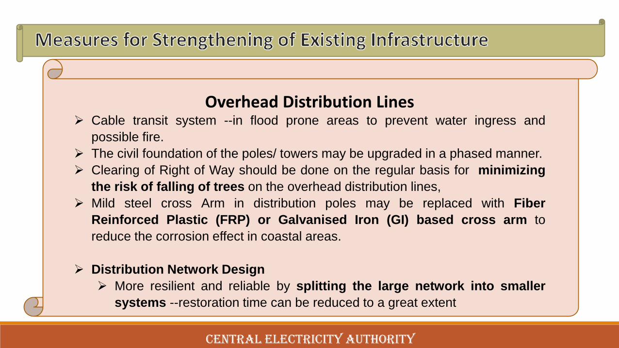
CENTRAL ELECTRICITY AUTHORITY
Overhead Distribution Lines➢ Cable transit system --in flood prone areas to prevent water ingress and
possible fire.➢ The civil foundation of the poles/ towers may be upgraded in a phased manner.➢ Clearing of Right of Way should be done on the regular basis for minimizing
the risk of falling of trees on the overhead distribution lines,➢ Mild steel cross Arm in distribution poles may be replaced with Fiber
Reinforced Plastic (FRP) or Galvanised Iron (GI) based cross arm toreduce the corrosion effect in coastal areas.
➢ Distribution Network Design➢ More resilient and reliable by splitting the large network into smaller
systems --restoration time can be reduced to a great extent

CENTRAL ELECTRICITY AUTHORITY
Distribution Substation and Control Room➢ The switchgears and auxiliary equipment in existing substation buildings may
be shifted to upper floors.➢ Protection from flood by:
➢ Flood protection walls➢ Increasing the height of existing flood walls around the substation building➢ Raising the height of critical infrastructure above HFL.
➢ To raise / elevate the substation level above the Highest Flood Level (HFL)➢ To convert conventional Air Insulated Distribution substations in coastal areas
to indoor type GIS installation.

CENTRAL ELECTRICITY AUTHORITY
Change in Design Loads for transmission lines➢ As per the wind map, the coastal region of states located on eastern coast of India comes
under Wind Zone 5, the corresponding design wind speed for this zone is 50 m/s (180 km/hr).➢ In some of the cyclone incidents, the recorded wind velocity (about 250 km/hr or 69m/sec)
has exceeded the design wind speed.
➢ Oblique wind on tower body as well as on conductor
➢ IS 802 (2015) has included load due to oblique wind on tower body and same should also beconsidered for conductor to increase the resilience to HIW.
➢ Special wind zones for coastal zones
➢ Changing climatic condition/wind pattern should be studied in association with IMD.
➢ The overhead transmission lines, to be laid within 60kms of the coastal line, may bedesigned with higher wind zones i.e. wind zone 6 (55m/sec) instead of wind zone 5(50m/sec) and 50km of overlap for higher of two zones may be considered in the design.

CENTRAL ELECTRICITY AUTHORITY
Transmission Lines➢ Introduction of K3 & K4 factor in IS 802
➢ As per IS 875 (Part3) 2015, importance factor for cyclonic region i.e. k4 factor isused to include impact of cyclonic storm in a belt of 60 km from coastal area.
➢ Currently this factor is not considered for tower design. Hence, K4 factor maybe introduced to take care of cyclonic wind condition.
➢ K3 factor for topography may also be introduced as being considered forcalculation of Design wind speed in IS 875.

CENTRAL ELECTRICITY AUTHORITY
Transmission Lines➢ Use of terrain category I for transmission lines located in coastal areas
➢ Presently terrain category 2 is being used by utilities for designing oftransmission lines located in coastal regions.
➢ The lines passing through coastal area ---mostly on open terrain without anyobstruction.--- terrain category -1 should be considered.
➢ The use of terrain category-1 in coastal areas will increase the load on towers byabout 15% and there will be no need of introducing K4 factor in calculation ofdesign wind speed, provided the correct wind speed data is used for design.However, this may account for increase in tower weights by 8-10 %.
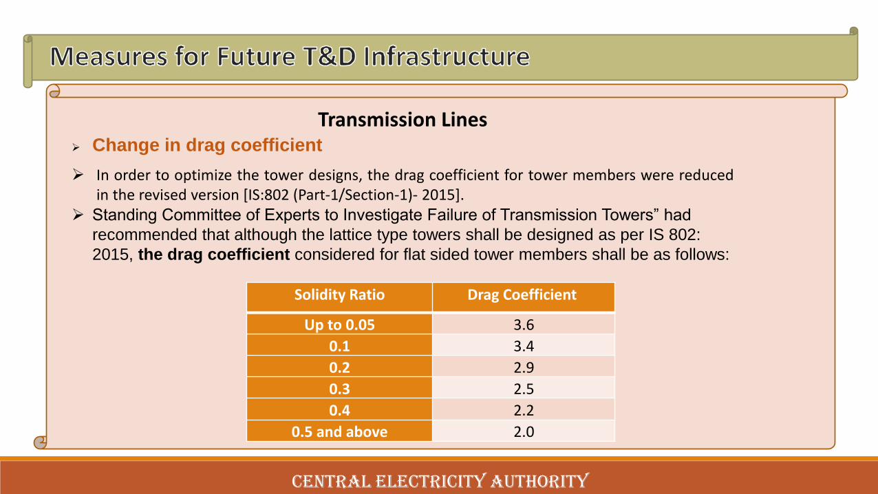
CENTRAL ELECTRICITY AUTHORITY
Transmission Lines➢ Change in drag coefficient
➢ In order to optimize the tower designs, the drag coefficient for tower members were reducedin the revised version [IS:802 (Part-1/Section-1)- 2015].
➢ Standing Committee of Experts to Investigate Failure of Transmission Towers” had
recommended that although the lattice type towers shall be designed as per IS 802: 2015, the drag coefficient considered for flat sided tower members shall be as follows:
Solidity Ratio Drag Coefficient
Up to 0.05 3.6
0.1 3.4
0.2 2.9
0.3 2.5
0.4 2.2
0.5 and above 2.0

CENTRAL ELECTRICITY AUTHORITY
Sl. No. Wind Zone -5 Wind Zone -6 One factor
Wind Speed 50m/s 55m/s
1 Wind zone factor 1 1.1 1.1
2 Risk Coefficient (K1) 1.14
of different Reliability Level
(a) Reliability Level -1 1 1
(b) Reliability Level -2 1.13 1.14
3 Terrain roughness (K2) 1.08
(a) 1 1.08 1.08
(few or no obstructions: average height of any object surrounding the structure<1.5m and includes open sea coast)
(b) 2 1 1
(Open terrain with well scattered obstructions having heights generally between I.5 to 10 m.1.5m )

CENTRAL ELECTRICITY AUTHORITY
4 Topography factor (K3) 1 1 to 1.36
[Loacl topographic features such as hills, valleys, cliffs, escarpments,
or ridges, which can significantly affect the wind speed in their vicinity]
The effect of topography will be significant at a site when the upwind slope (theta) is greater than about 3 degree and below that, the valueof k3 may be taken to be equal to 1.0. The value of k3 is confined in the range of 1.0 to 1.36 for slopes greater than 3 degree. The value of k3 varies with height above ground level, maximum near the ground, and reducing to 1.0 at higher levels.
5 Importance factor for Cyclonic Region (K4) 1.3
[The effect of cyclonic storm is largely felt in a belt of approximately 60km width at the sea coast]
(a) Structures of post cyclone importance for emergency services (such as cyclone shelters, hospitals, schools, communication towers etc.)
1.3 1.3
(b) Industrial Structures 1.15 1.15
(c) All other structures 1 1
Sl. No. Wind Zone -5 Wind Zone -6 One factor

CENTRAL ELECTRICITY AUTHORITY
Transmission Lines➢ For cyclonic wind, wind pressure is expected to be in the range of
300-400 Kg/m2 and to account for such high wind speed, highstrength conductors/Earth wire/OPGE, high strength insulatorsshall be required in addition to reduction in span up to 20-30 %.

CENTRAL ELECTRICITY AUTHORITY
Transmission Lines➢ Modification in configuration of transmission towers:
• For double circuit lines, vertical double delta configurationtype towers may be preferred.
• Truncated towers with reduced spans may also be used incritical areas having ROW problems.

CENTRAL ELECTRICITY AUTHORITY
.

CENTRAL ELECTRICITY AUTHORITY
Transmission Lines➢ Reducing Span of transmission lines
➢ Reduced span of transmission lines may be considered for transmission lineswithin 20km from coast line / based on the past experience of failure duringcyclone.
Voltage Level Normal Span Reduced Span
765kV / 400kV 400 250
230 kV/ 220kV 350 200
132kV 320 150
110kV 305 150
66kV 250 100

CENTRAL ELECTRICITY AUTHORITY
Transmission Lines➢ Use of steel Poles for lines in coastal areas
➢ Can be considered in coastal areas upto 20 km from coast line and in urban areas for EHVtransmission lines upto 220kV.
➢ Difficulty in transportation to site and requirement of high capacity crane for erection are some ofthe limitations.
➢ 2.5 to 3 times the cost of overhead lines with lattice structure.
➢ Use of underground cables / Gas Insulated Lines (GIL)
➢ Underground cables (XLPE) for length upto 20 to 30km (due to technical limitations) dependingon the voltage level (upto 400kV level)
➢ For coastal areas and urban areas to avoid overhead lines.
➢ The GIL --an alternative to cable even upto 800kV--can be run upto a length of about 100km.
➢ The cost of High voltage cable and GIL could be 6 to 7 times and 30 to 35 times the cost ofoverhead lines with lattice structure respectively.

CENTRAL ELECTRICITY AUTHORITY
Transmission Lines➢ Foundation of transmission towers
➢ Should be designed considering suitable exposure condition in line with IS 456 with M30(minimum) grade of concrete.
➢ The surface of the reinforcement steel may be treated by cement wash / epoxy coating
➢ Use of Pile foundation
➢ Pile type foundation/ embankment structure may be considered for towers in flood pronearea based on soil investigation report and high flood data.
➢ Raised Chimney for flood prone areas
➢ Chimney height of 500mm above Natural Ground level
➢ raised chimney is to be provided in areas prone to flooding/water stagnation & undulatedareas.

CENTRAL ELECTRICITY AUTHORITY
Transmission Lines➢ Minimising corrosion of tower members and reinforcement in foundation
➢ For coastal areas, the fabricated tower parts and stubs shall have a minimum overall zinccoating of 900 gm/m2 of surface area---Average thickness of zinc coating 127 microns
➢ For plates and sections below 5 m--- 610 gm/m2 of surface area. --Thickness 87 microns
➢ Earthing & Lightning Protection of Transmission lines
➢ Line Surge Arresters, if required, may be used in lightning prone areas to prevent backflashover and damage to terminal substation equipment.
➢ Line Surge Arresters ---
➢ to prevent back flashovers and
➢ to provide protection to substation equipment against shielding failure.

CENTRAL ELECTRICITY AUTHORITY
Transmission Lines➢ Use of High Performance conductors
➢ Use of High Temperature (HT) / High Tension Low Sag (HTLS) / aerodynamic conductors–
➢ reduce wind load on towers due to conductor and
➢ increase the power flow in the line with reduced number of conductors per phase and
➢ reduce point loads on the tower due to conductors
➢ Enables the use towers of shorter height compared to conventional conductor forsame quantum of power flow.
➢ Material Quality, workmanship & maintenance practices
➢ Use of good quality material, workmanship in construction of lines and good maintenancepractice are essential to ensure a reliable T&D infrastructure.

CENTRAL ELECTRICITY AUTHORITY
Transmission Substations➢ The substation or switchyard should be constructed above the
Highest Flood Level (HFL) and wherever required, floodprotection walls should also be provided.
➢ For resilient construction of buildings and other structures, it isrecommended to use high ductile strength steel as (Fe- 500D).
➢ In coastal areas upto 60km from the coastline all transmissionsubstations should be compact & modular indoor GISinstallations located above the HFL.

CENTRAL ELECTRICITY AUTHORITY
Distribution System➢ Designing of underground cable system in Coastal Area
➢ Overhead network of distribution lines may be restricted to non-coastal areas andunderground cables should be used in areas upto 20kms from coast line.
➢ Decision for use of Underground Cable system in place of overhead distributionlines beyond 20km from coast line should be based on following considerations:
➢ Criticality of the Line and connected consumers
➢ Past Incidents of failure due to heavy wind/ cyclones
➢ Availability/ cost of right of way

CENTRAL ELECTRICITY AUTHORITY
Distribution System➢ Upgradation of PCC poles / structures
➢ The robust steel monopoles, H-Type galvanized steel poles, tubular poles ofconcrete / composite material / galvanised steel lattice structure can be used inoverhead distribution lines in place of PCC type poles beyond 20kms of coastline.
➢ Double pole (DP) structure (with AB switches) should be used after every 10 Nos.of poles to reduce cascade failure of distribution infrastructure.
➢ The method of testing of structures used for overhead distribution lines should beformulated in line with testing overhead transmission line structures.
➢ Reduction in span length
➢ The average span can be reduced to 40-50m from 60m to 100 m

CENTRAL ELECTRICITY AUTHORITY
Distribution System➢ Use of Plinth mounted Distribution transformers
➢ Distribution transformers should be placed on a plinth mounted structure tominimize the impact of high speed wind and flood.
➢ Ring Main Unit (RMU) and Feeder Pillars
➢ RMU can ensure uninterrupted power supply to the area even during exigencies.Installation of RMU should be on an elevated platform / in indoor substationlocated above the Highest Flood Level (HFL). Feeder pillars should also beinstalled above HFL.
➢ Indoor GIS for all new Distribution Substation in Coastal Area
➢ All upcoming Distribution substation (s) located within 20 km of coastal area(prone to cyclones) should be designed for Indoor type GIS and located aboveHighest Flood Level.

CENTRAL ELECTRICITY AUTHORITY
Distribution System➢ Usage of Compact Substation
➢ Factory assembled self-contained Package Substation (PSS) is a state of artconcept for power distribution system and comprises of outdoor duty enclosure,medium voltage switchgear, distribution transformer, low voltage panel & AFPCRpanel (optional).
➢ Fully protected from external effect & safe to operate locally / remotely.
➢ The compact type substation is proposed with underground cable system.
➢ Smart grid, Automation and robust communication system for DistributionSystem
➢ Smart grids, Advanced Metering Infrastructure (AMI), substation automation, andremote sensing etc. will help to improve reliability and mitigate the risks of naturalhazards.
➢ SCADA systems play a key role in cyclone response & recovery by enablingutility’s controllers to identify damaged assets and helps the repair / maintenanceteam / crew to reach the affected area quickly.

CENTRAL ELECTRICITY AUTHORITY
Distribution System➢ SCADA systems play a key role in cyclone response & recovery by enabling
utility’s controllers to identify damaged assets and helps the repair / maintenanceteam / crew to reach the affected area quickly.
➢ Automated switches enable quick reconfigurations of the network & faultisolation, and prevent isolation of entire feeders.

CENTRAL ELECTRICITY AUTHORITY
Distribution System

CENTRAL ELECTRICITY AUTHORITY
Distribution System

CENTRAL ELECTRICITY AUTHORITY
➢ Power utilities need to build, strengthen, andmaintain their capabilities by conductingtrainings, exercises, and periodic drills toprepare staff at all levels to respond toemergencies.
➢ Utilities are required to continuously improvetheir operations based on lessons learnedfrom past events
Capacity Building

CENTRAL ELECTRICITY AUTHORITY
➢ Details of damages of the transmission infrastructure in past 5 years:➢ Tamil Nadu and Andhra Pradesh : Information regarding year of incidence and/or name of
cyclone causing damage to the infrastructure is required.➢ Details of cyclone affected Distribution infrastructure still awaited from Tamil Nadu and Andhra
Pradesh state.➢ (No. of feeders, poles, distribution transformers and length of conductors according to the
voltage level).➢ The PDF provided by Orissa state is faded and illegible.➢ West Bengal State and PGCIL has not provided the details of the affected substation and T&D lines
from cyclone in last 15 years.➢ No information regarding existing T&D infrastructure in cyclone prone areas and details of the
cyclone affected infrastructure in last 5 years have been received from Maharashtra, Karnataka andKerala.

CENTRAL ELECTRICITY AUTHORITY
ISSUED TO BE DISSCUSSED

CENTRAL ELECTRICITY AUTHORITY
Thank You


5. Director (Operations), POWEGRID, highlighted that for clarity to the bidder under TBCB route, the coastal area for which special measures are to be adopted should be very clearly defined in the recommendations. She further highlighted that for reducing tower loading and ROW requirement, use of Insulated cross arm can also be explored. The use of mobile substation is more prudent for use at lower voltage levels and hence the same may be recommended up to a certain voltage level in the report. Further, measures like incorporation of additional tower to reduce span of towers and use of GIL in existing lines may not be a prudent solution due to non-availability of long shutdown and high initial cost respectively. During a cyclone, the transmission line tower structures are affected the most instead of conductor or ground wire snapping, hence uses of high strength conductor and ground wire may be reviewed. She assured that detailed comments of POWERGRID on the draft report will be submitted at the earliest.

P a g e | 216
REPORT OF TASK FORCE ON CYCLONE RESILIENT ROBUST ELECTRICITY TRANSMISSION AND DISTRIBUTION (T&D) INFRASTRUCTURE IN COASTAL AREA
ANNEXURE D
MOP order no. No. 12/9/2020-Trans dated 02.06.2020 for Constitution of Task Force on
Cyclone Resilient Robust electricity Transmission and Distribution
Infrastructure in the Coastal areas

No. 12/9/2020-TransGovernment of India
Ministry of Power(Trans. Desk)
Shra n Shakti Bhawan, Rafi Marg,
New Delhi, Dated 02/06/2020.
ORDER
Sub: - Constitution of Task Force on Cyclone Resilient Robust electricity Transmissionand Distribution infrastruc ure in the Coastal areas
The Ministry of Power has been receiving references regarding frequentdamages caused by Cyclon es to the electricity transmission and distributionnfrastructures in the cyclone pre ne coastal parts of our country.
2 The matter has been examined and it has been decided to constitute a TaskForce on Cyclone Resilient Robust electricity Transmission and Distributionnfrastructure in the coastal areas of our country comprising following members:-
i. Shri P. S. Mhaske, Chs irperson, CEA .... Chairmanii. Smt. Seema Gupta, Di ector (Operations), PGCIL .... Member
III. Energy Secretary, Government of Andhra Pradesh .... Memberiv. Energy Secretary, Government of Odisha 00 00 Memberv. Energy Secretary, Government Tamil Nadu 00 •• Member
VI. Energy Secretary, Government of West Bengal 00 •• MemberVII. One Technical Expert each from Andhra Pradesh, 00 •• Member
Odisha, Tamil Nadu and West Bengal ---- to benominated by State Energy Secretaries
viii. Shri S C Taneja, Chief GM, PGCIL 00 •• MemberIX. Shri S K Ray Mohapat a, Chief Engineer, CEA .... Member Secretary
3 The Task Force may co opt any other member(s) as deemed appropriate. Theterms and references of the Task Force are as under:-
i. To examine types and nature of damages to electricity infrastructure due torecent cyclones in coast 31 parts of our country
ii. To recommend preventi te and mitigation measures for minimising the damagesto transmission and distr bution infrastructures due to Cyclone in coastal areas ofthe country including
a) measures, which can reduce damages to transmission and distributionlines on account of damages during cyclones including that caused byuprooting of trees.
b) feasible and cost-effective design changes, which can be implemented forminimising dama es to transmission and distribution lines due to suchcyclones includin retro-fitting measures so as to have cyclone resilient

robust electricity transmission and distribution infrastructure in the Coastalareas.
c) study of the composition of material used in the construction and layingdown of Transmission and Distribution systems (e.g. poles, conductors,towers etc.) and suggesting suitable material and/or changes incomposition of existing material so as to have robust cyclone resilienttransmission and distribution systems in coastal areas.
4. The Task Force shall submit its Report to the Ministry of Power within 3 monthspositively.
To
Copy to:-
This issues with the approval of Secretary(Power}. (}vd~t9--1y')a~
(Bihari Lal)Under Secretary (Trans)
Tele-fax: 2332 5242Email: [email protected]
All Members of the Task Force
1. Chairman, Central Electricity Authority, New Delhi,2. CMD, POWERGRID, Gurugram, Haryana.