Relational Database Management System - WordPress.com
78
Relational Database Management System Welcome to this course on Relational Database Management System!
-
Upload
khangminh22 -
Category
Documents
-
view
0 -
download
0
Transcript of Relational Database Management System - WordPress.com

1
Relational Database Management System
Welcome to this course on Relational Database Management System!

2
ER/CORP/CRS/DB07/003
Version No: 2.02Copyright © 2004,
Infosys Technologies Ltd
Course Objectives
• To introduce basic RDBMS concepts
• To create familiarity with SQL
• To introduce the concept of transaction processing and discuss certain issues in the same

3
ER/CORP/CRS/DB07/003
Version No: 2.03Copyright © 2004,
Infosys Technologies Ltd
Session Plan (1of 3)
Day1– Traditional Approach, Why DBMS, People Using DBMS– Data Models– RDBMS, Keys– ER Modeling– ERD Case Study
Day2– Transforming an ER model to Relational Schema– Functional Dependencies– Normalization
Day3– Introduction to SQL and SQL Plus– DDL– DML (Till Order By)– Aggregate Functions

4
ER/CORP/CRS/DB07/003
Version No: 2.04Copyright © 2004,
Infosys Technologies Ltd
Session Plan (2 of 3)
Day 4– Group By and Having, Relational Algebra– Joins– Independent Sub Queries– Use of EXISTS and NOT EXISTS
Day 5– Correlated Sub queries + Exists– Views– DCL + Embedded SQL
Day 6– Transaction, OLTP, ACID– Serial Transactions and Serializability– Issues of Concurrency– Locking

5
ER/CORP/CRS/DB07/003
Version No: 2.05Copyright © 2004,
Infosys Technologies Ltd
Session Plan (3 of 3)
Day 7– Time Stamping– Immediate Update + Deferred Update + Check Point– Difference between OLTP and OLAP– OLAP– Data Ware Housing– Data Mart– Summary

6
ER/CORP/CRS/DB07/003
Version No: 2.06Copyright © 2004,
Infosys Technologies Ltd
References
• “Database system concepts”, Henry F Korth, Abraham Silberschatz, Second ed., McGraw-Hill International editions, Computer Science Series(1991)
• "Fundamentals of Database Systems", Elmasri, Navathe, Third ed, Addison Wesley
• "An introduction to Database Systems", C.J.Date, Sixth ed., NarosaPublications

7
RDBMS-Day1• Data Processing• Basic DBMS concepts• Basic RDBMS concepts• Conceptual Database Design• ER Modeling Notations

8
ER/CORP/CRS/DB07/003
Version No: 2.08Copyright © 2004,
Infosys Technologies Ltd
Data processing
• Data Collection
• Recording
• Sorting
• Classifying
• Calculating
• Retrieving
• Summarizing
• Communicating

9
ER/CORP/CRS/DB07/003
Version No: 2.09Copyright © 2004,
Infosys Technologies Ltd
Data processing modes
Batch processing:Transactions are collected in a group & processed together.
On-line (interactive) processing:Transactions are processed as & when they appear.
Real-time processing:It is a parallel time relationship with on-going activity & the information produced is useful in controlling the current / dynamic activity.

10
ER/CORP/CRS/DB07/003
Version No: 2.010Copyright © 2004,
Infosys Technologies Ltd
Traditional Method of Data Storage
•In the traditional approach, we used to store information in flat files which are maintained by the file system under the operating system’s control.
•Application programs go through the file system to access these flat files

11
ER/CORP/CRS/DB07/003
Version No: 2.011Copyright © 2004,
Infosys Technologies Ltd
Ways of storing data in files – customer data
4176 Aniruddha Sarkar SBU14181 Manoj Saha SBU14183 Moushumi Dharchoudhury SBU14203 Suryanarayana D.V.S.S. SBU14204 Vivek Rai SBU1
4176 AniruddhaSarkar SBU14181 ManojSaha SBU14183 MoushumiDharchoudhury SBU14203 SuryanarayanaD.V.S. SBU14204 Vivek Rai SBU1
Predefined length
•Data used to be stored in the form of records in the files.
•Records consist of various fields which are delimited by a space , comma , tab etc.
•There used to be special characters to mark end of records and end of files.

12
ER/CORP/CRS/DB07/003
Version No: 2.012Copyright © 2004,
Infosys Technologies Ltd
Problems: traditional approach
• Data Security
• Data Redundancy
• Data Isolation
• Program / Data Dependence
• Lack of Flexibility
• Concurrent Access Anomalies
Disadvantages of the traditional approach
Data Security: The data as maintained in the flat file(s) is easily accessible and therefore not secureExample: Consider the Banking System. The Customer_Transaction file has details about the total available balance of all customers. A Customer wants information about his account balance. In a file system it is difficult to give the Customer access to only his data in the file. Thus enforcing security constraints for the entire file or for certain data items are difficult.
Data Redundancy: Often the same information is duplicated in two or more files.This duplication of data (redundancy) leads to higher storage and access cost. In addition it may lead to data inconsistency[2]. For Example, assume the same data is repeated in two or more files. If change is made to data in one file, it is required that the change be made to the data in the other file as well. If this is not done, it will lead to error during access to the data. Example: Assume Customer’s details such as Cust_Last_Name, Cust_Mid_Name, Cust_First_Name, Cust_Email is stored both in the Customer_Details file and the Customer_Fixed_Deposit file. If the Email ID of one Customer, for example, Langer S. Justin changes from [email protected] to [email protected], the Cust_Email has to be updated in both the files; otherwise it will lead to inconsistent data.However, one can design file systems with minimal redundancy. Data redundancy is sometimes preferred. Example: Assume the Customer’s details such as Cust_Last_Name, Cust_Mid_Name, Cust_First_Name and Cust_Email are not stored in the Customer_Fixed_Deposit file. If it is required to get this information about the customer along with his fixed deposit details, it would mean that the details be retrieved from two files. This would mean an increased overhead. It is thus preferred to store the information in the Customer_Fixed Deposit file itself.
Data Isolation: Data Isolation means that all the related data is not available in one file. Generally, the data is scattered in various files, and the files may be in different formats, therefore writing new application programs to retrieve the appropriate data is difficult.

13
ER/CORP/CRS/DB07/003
Version No: 2.013Copyright © 2004,
Infosys Technologies Ltd
The Database Technology
Database• Computer based record-keeping system• Organized collection of interrelated (persistent) data• Records & maintains data
Database Management System
• Collection of interrelated files and set of programs which allows users to access and
modify files
• Primary Goal is to provide a convenient and efficient way to store, retrieve
and modify information
• Layer of abstraction between the application programs and the file system
•Application programs request the DBMS to retrieve, modify, insert or delete data for them

14
ER/CORP/CRS/DB07/003
Version No: 2.014Copyright © 2004,
Infosys Technologies Ltd
Where does the DBMS fit in?Position of DBMS
• Now, the DBMS acts as a layer of abstraction on top of the File system.
• You might have observed that, for interacting with the file system, we were using high level language functions for example, the ‘c’ file handling functions. For interacting with the DBMS we would be using a Query language called SQL

15
ER/CORP/CRS/DB07/003
Version No: 2.015Copyright © 2004,
Infosys Technologies Ltd
Difference Between File and DBMS Operations

16
ER/CORP/CRS/DB07/003
Version No: 2.016Copyright © 2004,
Infosys Technologies Ltd
Types of Databases
Centralized Database Distributed Database

17
ER/CORP/CRS/DB07/003
Version No: 2.017Copyright © 2004,
Infosys Technologies Ltd
TYPES OF DATABASES
• The database is stored on several computers - from personal computers up to mainframe systems • Computers in a distributed system communicate with one another through various communication media, such as high speed networks or telephone lines• Distributed databases are geographically separated and managed• Distributed databases are separately administered• Distributed databases have a slower interconnectionExample: Consider the bank system. The bank’s head office is located at Chicago and the branch offices are at Melbourne and Tokyo. The bank database is distributed across the branch offices. The branch offices are connected through a network
• All data is located at a single site• Allows for greater control over accessing and updating data• Vulnerable to failure as they depend on the availability of resources at the central siteExample: The account information of customers is stored in a particular branch office of a bank. This information must be shared across all Automated Teller Machines (ATM), so that customers can withdraw money from their accounts. Instead of storing the customer information in every ATM machine it can be stored at a common place (the branch office of the bank) and shared over a network.
DistributedCentralized

18
ER/CORP/CRS/DB07/003
Version No: 2.018Copyright © 2004,
Infosys Technologies Ltd
Conceptual Schema
Internal Schema
ExternalSchema B
ExternalSchema A
ExternalSchema C
Three-layer Architecture
Internal Level
(Storage View)
Conceptual View
(Common User View)
External / View Level
(Individual User View)
Services provided by a DBMS
•Data management •Data definition•Transaction support •Concurrency control•Recovery•Security & integrity•Utilities- facilities like data import & export, user management, backup, performance analysis, logging & audit, physical storage control
19
ER/CORP/CRS/DB07/003
Version No: 2.019Copyright © 2004,
Infosys Technologies Ltd
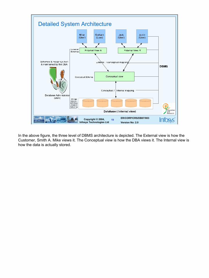
Detailed System Architecture
In the above figure, the three level of DBMS architecture is depicted. The External view is how the Customer, Smith A. Mike views it. The Conceptual view is how the DBA views it. The Internal view is how the data is actually stored.

20
ER/CORP/CRS/DB07/003
Version No: 2.020Copyright © 2004,
Infosys Technologies Ltd
CREATE TABLE Customer_Loan ( Cust_ID NUMBER(4) Loan_No NUMBER(4) Amount_in_Dollars NUMBER(7,2))
Customer_Loan Cust_ID : 101 Loan_No : 1011 Amount_in_Dollars : 8755.00
Cust_ID TYPE = BYTE (4), OFFSET = 0 Loan_No TYPE = BYTE (4), OFFSET = 4 Amount_in_Dollars TYPE = BYTE (7), OFFSET = 8
Conceptual
External
Internal
An example of the three levels
21
ER/CORP/CRS/DB07/003
Version No: 2.021Copyright © 2004,
Infosys Technologies Ltd
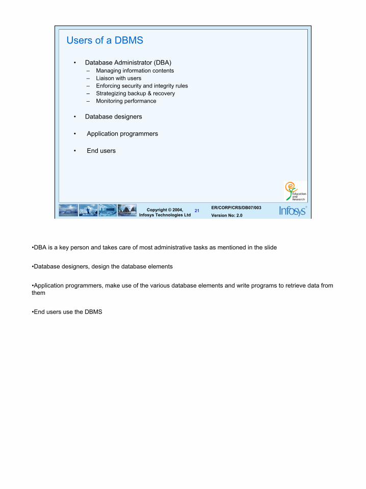
Users of a DBMS
• Database Administrator (DBA)– Managing information contents– Liaison with users– Enforcing security and integrity rules– Strategizing backup & recovery– Monitoring performance
• Database designers
• Application programmers
• End users
•DBA is a key person and takes care of most administrative tasks as mentioned in the slide
•Database designers, design the database elements
•Application programmers, make use of the various database elements and write programs to retrieve data from them
•End users use the DBMS

22
ER/CORP/CRS/DB07/003
Version No: 2.022Copyright © 2004,
Infosys Technologies Ltd
Advantages of a DBMS
• Data independence
• Reduction in data redundancy
• Better security
• Better flexibility
• Effective data sharing
• Enforces integrity constraints
• Enables backup and recovery
1. Users and application programs need not know exactly where or how the data is stored in order to access it
2. Proper database design can reduce or eliminate data redundancy and confusion
3.Support for unforeseen (ad hoc) information requests are better supported - better flexibility
4. Data can be more effectively shared between users and/or application programs
Data can be stored for long term analysis (data warehousing)

23
ER/CORP/CRS/DB07/003
Version No: 2.023Copyright © 2004,
Infosys Technologies Ltd
Definition of data model :
A conceptual tool used to describe • Data • Data relationships• Data semantics• Consistency constraints
Data Models
Commercial Packages
•Hierarchical Model - IMS•Network Model - IDMS•Relational Model - Oracle, DB2

24
ER/CORP/CRS/DB07/003
Version No: 2.024Copyright © 2004,
Infosys Technologies Ltd
Types of data models
• Object based logical model
– Entity relationship model
• Record based logical model
– Hierarchical data model
– Network data model
– Relational data model

25
ER/CORP/CRS/DB07/003
Version No: 2.025Copyright © 2004,
Infosys Technologies Ltd
Record based data model – Hierarchical data model

26
ER/CORP/CRS/DB07/003
Version No: 2.026Copyright © 2004,
Infosys Technologies Ltd
Record based data model – Network data model

27
ER/CORP/CRS/DB07/003
Version No: 2.027Copyright © 2004,
Infosys Technologies Ltd
Record based data model – Relational data model

28
ER/CORP/CRS/DB07/003
Version No: 2.028Copyright © 2004,
Infosys Technologies Ltd
Relational model basics
• Data is viewed as existing in two dimensional tables known as relations
• A relation (table) consists of unique attributes (columns) and tuples (rows)
• Tuples are unique
• Sometimes the value to be inserted into a particular cell may be unknown, or it may have no value. This is represented by a null
• Null is not the same as zero, blank or an empty string
• Relational Database: Any database whose logical organization is based on relational data model.
• RDBMS: A DBMS that manages the relational database.
•Though logically data is viewed as existing in the form of two dimensional tables, actually, the data is stored under the file system only.
•The RDBMS provides an abstraction on top of the file system and gives an illusion that data resides in the form of tables.

29
ER/CORP/CRS/DB07/003
Version No: 2.029Copyright © 2004,
Infosys Technologies Ltd
Keys• Candidate key
– A Candidate key is a set of one or more attributes that can uniquely identify a row in a given table.
• Assumptions• One customer can have only one account• An account can belong to only one customer
Superkey
An attribute, or group of attributes, that is sufficient to distinguish every tuple in the relation from every other one.Each super key is called a candidate key
A candidate key is all those set of attributes which can uniquely identify a row. However, any subset of these set of attributes would not identify a row uniquely
For example, in a shipment table, “S#, P#” is a candidate key. But, S# alone or P# alone would not uniquely identify a row of the shipment table.
Primary key
The candidate key that is chosen to perform the identification task is called the primary key and any others are alternate keysEvery tuple must have, by definition, a unique value for its primary key. A primary key which is a combination of more than one attribute is called a composite primary key
Foreign key•A foreign key is a “copy” of a primary key that has been exported from one relation into another to represent the existence of a relationship between them. A foreign key is a copy of the whole of its parent primary key i.e if the primary key is composite, then so is the foreign key•Foreign key values do not (usually) have to be unique•Foreign keys can also be null•A composite foreign key cannot have some attribute(s) null and others non-null
Overlapping candidate keys: Two candidate keys overlap if they involve any attribute in common. For e.g, in an Employee table, E#, Enameand Emailid, Ename are two overlapping candidate keys. (they have Ename in common)
Attribute that does not participate in any candidate key is called a Non-key attribute

30
ER/CORP/CRS/DB07/003
Version No: 2.030Copyright © 2004,
Infosys Technologies Ltd
Keys
• Super key– Any superset of a candidate Key is a super key.

31
ER/CORP/CRS/DB07/003
Version No: 2.031Copyright © 2004,
Infosys Technologies Ltd
Keys
• Primary key– During the creation of the table, the Database Designer chooses one of the
Candidate Key from amongst the several available, to uniquely identify row in the given table.
– Give preference to numeric column(s)– Give preference to single attribute– Give preference to minimal composite key

32
ER/CORP/CRS/DB07/003
Version No: 2.032Copyright © 2004,
Infosys Technologies Ltd
Keys• Foreign key
– A Foreign Key is a set of attribute (s) whose values are required to match values of a Candidate key in the same or another table.
• Point to remember– A Foreign Key is a set of attributes of a table, whose values are required to match values of
some Candidate Key in the same or another table– The constraint that values of a given Foreign Key must match the values of the corresponding
Candidate Key is known as Referential constraint– A table which has a Foreign Key referring to its own Candidate Key is known as Self-
Referencing table– Any superset of a Candidate Key is a Super Key– The attributes other than the Primary Key attributes in a table/relation are called Non-Key
attributes

33
ER/CORP/CRS/DB07/003
Version No: 2.033Copyright © 2004,
Infosys Technologies Ltd
Keys
• Non-Key Attributes– The attributes other than the Candidate Key attributes in a table/relation are called
Non-Key attributes.OR
– The attributes which do not participate in any of the Candidate keys..

34
Conceptual designEntity Relationship modeling

35
ER/CORP/CRS/DB07/003
Version No: 2.035Copyright © 2004,
Infosys Technologies Ltd
Database Design Techniques
• Top down Approach
– E R Modeling
• Bottom Up approach
– Normalization

36
ER/CORP/CRS/DB07/003
Version No: 2.036Copyright © 2004,
Infosys Technologies Ltd
ER modeling
• ER modeling: A graphical technique for understanding and organizing the data independent of the actual database implementation
• Entity: Any thing that may have an independent existence and about which we intend to collect data.Also known as Entity type.
• Entity instance: a particular member of the entity type e.g. a particular student
• Attributes: Properties/characteristics that describe entities
• Relationships: Associations between entities
37
ER/CORP/CRS/DB07/003
Version No: 2.037Copyright © 2004,
Infosys Technologies Ltd
Attributes
• The set of possible values for an attribute is called the domain of the attributeExample: – The domain of attribute marital status is just the four values: single, married,
divorced, widowed
– The domain of the attribute month is the twelve values ranging from January to December
• Key attribute: The attribute (or combination of attributes) that is unique for every entity instance– E.g the account number of an account, the employee id of an employee etc.
• If the key consists of two or more attributes in combination, it is called a composite key

38
ER/CORP/CRS/DB07/003
Version No: 2.038Copyright © 2004,
Infosys Technologies Ltd
Simple Vs composite attribute
• Simple attribute: cannot be divided into simpler components E.g age of an employee
• Composite attribute: can be split into componentsE.g Date of joining of the employee.
– Can be split into day, month and year
39
ER/CORP/CRS/DB07/003
Version No: 2.039Copyright © 2004,
Infosys Technologies Ltd
Single Vs Multi-valued Attributes
• Single valued : can take on only a single value for each entity instanceE.g. age of employee. There can be only one value for this
• Multi-valued: can take many valuesE.g. skill set of employee

40
ER/CORP/CRS/DB07/003
Version No: 2.040Copyright © 2004,
Infosys Technologies Ltd
Stored Vs Derived attribute
• Stored Attribute: Attribute that need to be stored permanently.
• E.g. name of an employee
• Derived Attribute: Attribute that can be calculated based on other attributes
• E.g. : years of service of employee can be calculated from date of joining and current date

41
ER/CORP/CRS/DB07/003
Version No: 2.041Copyright © 2004,
Infosys Technologies Ltd
Regular Vs. Weak entity type
• Regular Entity: Entity that has its own key attribute.
E.g.: Employee, student ,customer, policy holder etc.
• Weak entity: Entity that depends on other entity for its existence and doesn’t have key attribute of its own
E.g. : spouse of employee
The spouse data is identified with the help of the employee id to which it is related

42
ER/CORP/CRS/DB07/003
Version No: 2.042Copyright © 2004,
Infosys Technologies Ltd
Relationships
• A relationship type between two entity types defines the set of all associations between these entity types
• Each instance of the relationship between members of these entity types is called a relationship instance
E.g if Works-for is the relationship between the Employee entity and the department entity, then Ram works for Comp.sc department, shyam works –for electrical department ..etc are relationship instances of the relationship, works-for
43
ER/CORP/CRS/DB07/003
Version No: 2.043Copyright © 2004,
Infosys Technologies Ltd
Degree of a Relationship
• Degree: the number of entity types involved• One Unary• Two Binary• Three Ternary
E.g.: employee manager-of employee is unaryemployee works-for department is binarycustomer purchase item, shop keeper is a ternary relationship

44
ER/CORP/CRS/DB07/003
Version No: 2.044Copyright © 2004,
Infosys Technologies Ltd
Cardinality
• Relationships can have different connectivity– one-to-one (1:1)– one-to-many (1:N)– many-to- One (M:1)– many-to-many (M:N)
E.g.: Employee head-of department (1:1)Lecturer offers course (1:n) assuming a course is taught by a single lecturerStudent enrolls course (m:n)
The minimum and maximum values of this connectivity is called the cardinality of the relationship

45
ER/CORP/CRS/DB07/003
Version No: 2.045Copyright © 2004,
Infosys Technologies Ltd
Cardinality – One - To - One
P1
P2
P3
P4
C1
C2
C3
C4
P1
P2
P3
P4
C1
C2
C3
C4
Person Chair
One instance of entity type Person is related to one instance of the entity type Chair.

46
ER/CORP/CRS/DB07/003
Version No: 2.046Copyright © 2004,
Infosys Technologies Ltd
Cardinality – One -to- Many
One instance of entity type Organization is related to multiple instances of entity type Employee
O1
O2
O3
E1
E2
E3
E4
E5
O1
O2
O3
E1
E2
E3
E4
E5
Organization Employee

47
ER/CORP/CRS/DB07/003
Version No: 2.047Copyright © 2004,
Infosys Technologies Ltd
Cardinality – Many-to-One
D1
D2
D3
E1
E2
E3
E4
E5
D1
D2
D3
E1
E2
E3
E4
E5
Reverse of the One to Many relationship.
Employee Department

48
ER/CORP/CRS/DB07/003
Version No: 2.048Copyright © 2004,
Infosys Technologies Ltd
Cardinality – Many-to-Many
S1
S2
S3
S4
C1
C2
C3
C4
S1
S2
S3
S4
C1
C2
C3
C4
Multiple instances of one Entity are related to multiple instances of another Entity.
Student Course

49
ER/CORP/CRS/DB07/003
Version No: 2.049Copyright © 2004,
Infosys Technologies Ltd
Relationship Participation• Total : Every entity instance must be connected through the relationship to another
instance of the other participating entity types
• Partial: All instances need not participate
E.g.: Employee Head-of DepartmentEmployee: partialDepartment: total
All employees will not be head-of some department. Soonly few instances of employee entity participate in theabove relationship. But each department will be headed
by some employee. So department entity’s participation is total and employee entity’s participation is partial in the above relationship

50
ER Modeling -Notations

51
ER/CORP/CRS/DB07/003
Version No: 2.051Copyright © 2004,
Infosys Technologies Ltd
ER Modeling -NotationsAn Entity is an object or concept about which business user wants to store information.
A weak Entity is dependent on another Entity to exist. Example Order Item depends upon Order Number for its existence. Without Order Number it is impossible to identify Order Item uniquely.
Attributes are the properties or characteristics of an Entity
A key attribute is the unique, distinguishing characteristic of the Entity
A multivalued attribute can have more than one value. For example, an employee Entity can have multiple skill values.

52
ER/CORP/CRS/DB07/003
Version No: 2.052Copyright © 2004,
Infosys Technologies Ltd
ER Modeling -NotationsA derived attribute is based on another attribute. For example, an employee's monthly salary is based on the employee's basic salary and House rent allowance.
Relationships illustrate how two entities share information in the database structure.
To connect a weak Entity with others, you should use a weak relationship notation.

53
ER/CORP/CRS/DB07/003
Version No: 2.053Copyright © 2004,
Infosys Technologies Ltd
ER Modeling -Notations
Cardinality specifies how many instances of an Entity relate to one instance of another Entity. M,N both represent ‘MANY’ and 1 represents ‘ONE’ Cardinality
In some cases, entities can be self-linked. For example, employees can supervise other employees

54
ER/CORP/CRS/DB07/003
Version No: 2.054Copyright © 2004,
Infosys Technologies Ltd
Attributes
EmployeeE#
NameDOB
Address
Designation
Represented by ellipses connected to the entity type by straight lines

55
ER/CORP/CRS/DB07/003
Version No: 2.055Copyright © 2004,
Infosys Technologies Ltd
Key attribute
EmployeeE#
NameDOB
Address
Designation
The key attributeis underlined

56
ER/CORP/CRS/DB07/003
Version No: 2.056Copyright © 2004,
Infosys Technologies Ltd
Multivalued Attribute
EmployeeE#
NameDOB Address
Designation
skill set
Indicated by a double lined ellipse as shown in the figure
57
ER/CORP/CRS/DB07/003
Version No: 2.057Copyright © 2004,
Infosys Technologies Ltd
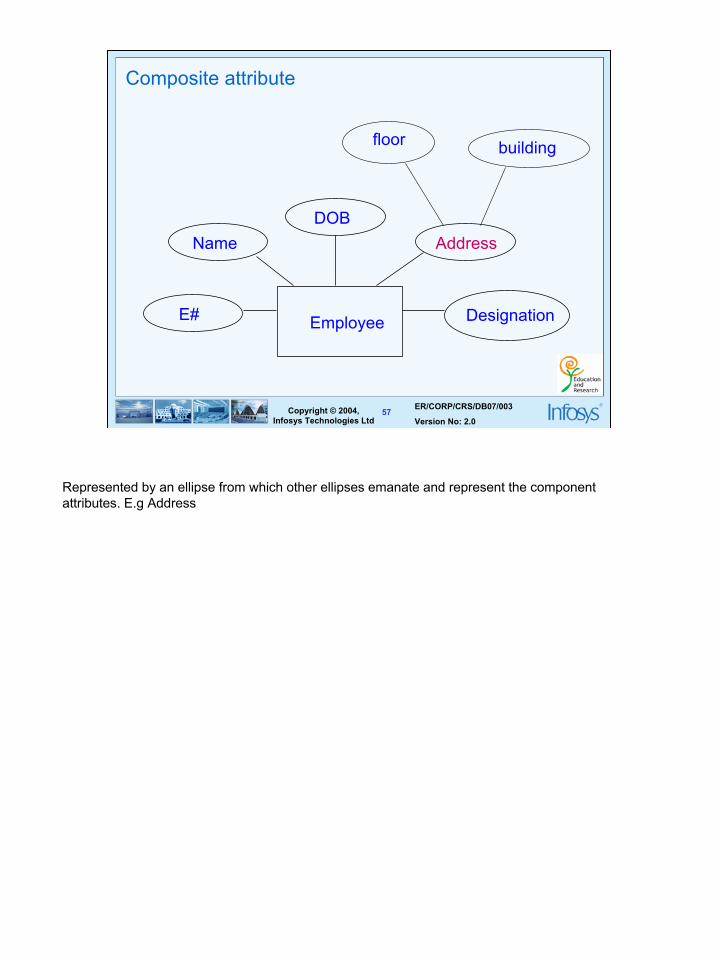
Composite attribute
EmployeeE#
NameDOB
Address
Designation
floor building
Represented by an ellipse from which other ellipses emanate and represent the component attributes. E.g Address

58
ER/CORP/CRS/DB07/003
Version No: 2.058Copyright © 2004,
Infosys Technologies Ltd
Relationship
student enrolsin
course
•A relationship is represented as a diamond between two entity types.
•It has a label that explains the relationship. Usually the convention is to read the ER diagram from top to bottom and from left to right. •So, the relationship name is so chosen as to make sense when read from left to right.
•The relationship above is read as student enrolls-in course

59
ER/CORP/CRS/DB07/003
Version No: 2.059Copyright © 2004,
Infosys Technologies Ltd
Unary Relationship
EmployeeManages
•A unary relationship is represented as a diamond which connects one entity to itself as a loop.
•The relationship above means, some instances of employee manage other instances of Employee.

60
ER/CORP/CRS/DB07/003
Version No: 2.060Copyright © 2004,
Infosys Technologies Ltd
Role names
• Role names may be added to make the meaning more explicit
EmployeeManages
Manager
subordinate

61
ER/CORP/CRS/DB07/003
Version No: 2.061Copyright © 2004,
Infosys Technologies Ltd
Binary Relationship
Employee Works for
Department
A relationship between two entity types

62
ER/CORP/CRS/DB07/003
Version No: 2.062Copyright © 2004,
Infosys Technologies Ltd
Ternary Relationship
Doctor
Medicine
PatientPrescription
A relationship connecting three entity types.

63
ER/CORP/CRS/DB07/003
Version No: 2.063Copyright © 2004,
Infosys Technologies Ltd
Relationship participation
departmentEmployee headof
1 1
partial Total
•All instances of the entity type Employee don’t participate in the relationship, Head-of.
•Every employee doesn’t head a department. So, employee entity type is said to partially participate in the relationship.
•But, every department would be headed by some employee.
•So, all instances of the entity type Department participate in this relationship. So, we say that it is total participation from the department side.

64
ER/CORP/CRS/DB07/003
Version No: 2.064Copyright © 2004,
Infosys Technologies Ltd
Attributes of a Relationship
Doctor
Medicine
PatientPrescription
dosage
Number of days
These attributes best describe the relationship rather than any individual entity
65
ER/CORP/CRS/DB07/003
Version No: 2.065Copyright © 2004,
Infosys Technologies Ltd
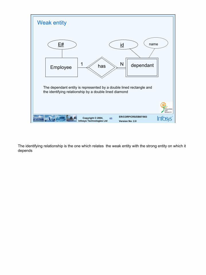
Weak entity
Employee
E#
has dependant
id
1 N
name
The dependant entity is represented by a double lined rectangle and the identifying relationship by a double lined diamond
The identifying relationship is the one which relates the weak entity with the strong entity on which it depends

66
ER/CORP/CRS/DB07/003
Version No: 2.066Copyright © 2004,
Infosys Technologies Ltd
Assumptions :
• A college contains many departments • Each department can offer any number of courses • Many instructors can work in a department • An instructor can work only in one department • For each department there is a Head • An instructor can be head of only one department • Each instructor can take any number of courses • A course can be taken by only one instructor• A student can enroll for any number of courses • Each course can have any number of students
Case Study – ER Model For a college DB

67
ER/CORP/CRS/DB07/003
Version No: 2.067Copyright © 2004,
Infosys Technologies Ltd
Steps in ER Modeling
• Identify the Entities
• Find relationships
• Identify the key attributes for every Entity
• Identify other relevant attributes
• Draw complete E-R diagram with all attributes including Primary Key
• Review your results with your Business users

68
ER/CORP/CRS/DB07/003
Version No: 2.068Copyright © 2004,
Infosys Technologies Ltd
Step 1: Identify the Entities
• DEPARTMENT• STUDENT• COURSE• INSTRUCTOR
Step 2: Find the relationships
• One course is enrolled by multiple students and one student enrolls for multiple courses, hence the cardinality between course and student is Many to Many.
• The department offers many courses and each course belongs to only one department, hence the cardinality between department and course is One to Many.
• One department has multiple instructors and one instructor belongs to one and only one department , hence the cardinality between department and instructor is one to Many.
• Each department there is a “Head of department” and one instructor is “Head of department “,hence the cardinality is one to one .
• One course is taught by only one instructor, but the instructor teaches many courses, hence the cardinality between course and instructor is many to one.

69
ER/CORP/CRS/DB07/003
Version No: 2.069Copyright © 2004,
Infosys Technologies Ltd
Step 3: Identify the key attributes
• Deptname is the key attribute for the Entity “Department”, as it identifies the Department uniquely.
• Course# (CourseId) is the key attribute for “Course” Entity. • Student# (Student Number) is the key attribute for “Student” Entity.• Instructor Name is the key attribute for “Instructor” Entity.
Step 4: Identify other relevant attributes
• For the department entity, the relevant attribute is location• For course entity, course name,duration,prerequisite• For instructor entity, room#, telephone#• For student entity, student name, date of birth

70
ER/CORP/CRS/DB07/003
Version No: 2.070Copyright © 2004,
Infosys Technologies Ltd
Step 5: Draw complete E-R diagram with all attributes including Primary Key

71
ER/CORP/CRS/DB07/003
Version No: 2.071Copyright © 2004,
Infosys Technologies Ltd
Case Study – Banking Business Scenario
Assumptions :
• There are multiple banks and each bank has many branches. Each branch has multiple customers
• Customers have various types of accounts
• Some Customers also had taken different types of loans from these bank branches
• One customer can have multiple accounts and Loans

72
ER/CORP/CRS/DB07/003
Version No: 2.072Copyright © 2004,
Infosys Technologies Ltd
Steps in ER Modeling
• Identify the Entities
• Find relationships
• Identify the key attributes for every Entity
• Identify other relevant attributes
• Draw complete E-R diagram with all attributes including Primary Key
• Review your results with your Business users

73
ER/CORP/CRS/DB07/003
Version No: 2.073Copyright © 2004,
Infosys Technologies Ltd
Step 1: Identify the Entities
• BANK• BRANCH• LOAN• ACCOUNT• CUSTOMER
Step 2: Find the relationships
• One Bank has many branches and each branch belongs to only one bank, hence the cardinality between Bank and Branch is One to Many.
• One Branch offers many loans and each loan is associated with one branch, hence the cardinality between Branch and Loan is One to Many.
• One Branch maintains multiple accounts and each account is associated to one and only one Branch, hence the cardinality between Branch and Account is One to Many
• One Loan can be availed by multiple customers, and each Customer can avail multiple loans, hence the cardinality between Loan and Customer is Many to Many.
• One Customer can hold multiple accounts, and each Account can be held by multiple Customers, hence the cardinality between Customer and Account is Many to Many

74
ER/CORP/CRS/DB07/003
Version No: 2.074Copyright © 2004,
Infosys Technologies Ltd
Step 3: Identify the key attributes
• BankCode (Bank Code) is the key attribute for the Entity “Bank”, as it identifies the bank uniquely.
• Branch# (Branch Number) is the key attribute for “Branch” Entity. • Customer# (Customer Number) is the key attribute for “Customer” Entity.• Loan# (Loan Number) is the key attribute for “Loan” Entity. • Account No (Account Number) is the key attribute for “Account” Entity.
Step 4: Identify other relevant attributes
• For the “Bank” Entity, the relevant attributes other than “BankCode” would be “Name”and “Address”.
• For the “Branch” Entity, the relevant attributes other than “Branch#” would be “Name”and “Address”.
• For the “Loan” Entity, the relevant attribute other than “Loan#” would be “Loan Type”.• For the “Account” Entity, the relevant attribute other than “Account No” would be
“Account Type”. • For the “Customer” Entity, the relevant attributes other than “Customer#” would be
“Name”, “Telephone#” and “Address”.

75
ER/CORP/CRS/DB07/003
Version No: 2.075Copyright © 2004,
Infosys Technologies Ltd
Step 5: Draw complete E-R diagram with all attributes including Primary Key

76
ER/CORP/CRS/DB07/003
Version No: 2.076Copyright © 2004,
Infosys Technologies Ltd
Merits and Demerits of ER Modeling
Merits • Easy to understand. Represented in Business Users Language. Can be
understood by non-technical specialist. • Intuitive and helps in Physical Database creation.• Can be generalized and specialized based on needs.• Can help in database design.• Gives a higher level description of the system.
Demerits• Physical design derived from E-R Model may have some amount of
ambiguities or inconsistency. • Sometime diagrams may lead to misinterpretations

77
ER/CORP/CRS/DB07/003
Version No: 2.077Copyright © 2004,
Infosys Technologies Ltd
Summary
• Most of the application errors are because of miscommunication between the application user and the designer and between the designer and the developer.
• It is always better to represent business findings in terms of picture to avoid miscommunication
• It is practically impossible to review the complete requirement document by business users.
• An E-R diagram is one of the many ways to represent business findings in pictorial format.
• E-R Modeling will also help the database design• E-R modeling has some amount of inconsistency and anomalies associated
with it.

78
ER/CORP/CRS/DB07/003
Version No: 2.078Copyright © 2004,
Infosys Technologies Ltd
Thank You!