AGO1-miR173 complex initiates phased siRNA formation in plants

Progress In Electromagnetics Research, PIER 53, 227–237, 2005
RECTANGULAR SLOT ANTENNA WITH PATCH STUBFOR ULTRA WIDEBAND APPLICATIONS ANDPHASED ARRAY SYSTEMS
A. A. Eldek, A. Z. Elsherbeni, and C. E. Smith
Department of Electrical EngineeringCenter of Applied Electromagnetic Systems Research (CAESR)The University of MississippiUniversity, MS 38677, USA
Abstract—This paper presents a coplanar waveguide fed rectangularslot antenna tuned by a patch stub. The presented antenna has98% impedance bandwidth, and 6 dB average gain. The antennacan be used in phased array applications with more than 61% usablebandwidth.
1 Introduction
2 Antenna Geometry and Parametric Study
3 Final Antenna Design
4 Conclusion
References
1. INTRODUCTION
In applications where size, weight, cost, performance, ease ofinstallation, and aerodynamic profile are constraints, low profileantennas like microstrip and printed slot antennas are required.Printed slot antennas fed by a coplanar waveguide (CPW) haveseveral advantages over microstrip patch antennas. Slot antennasexhibit wider bandwidth, lower dispersion and lower radiation lossthan microstrip antennas, and when fed by a coplanar waveguide theyalso provide an easy means of parallel and series connection of activeand passive elements that are required for improving the impedancematching and gain [1].
228 Eldek, Elsherbeni, and Smith
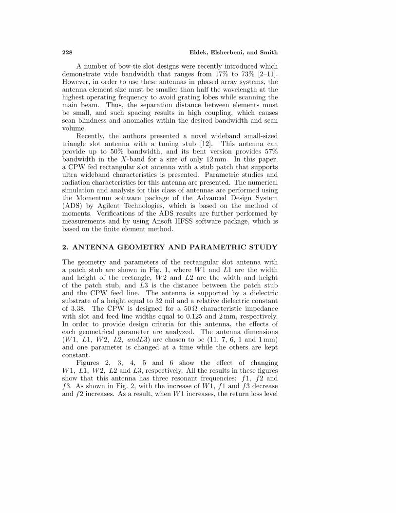
A number of bow-tie slot designs were recently introduced whichdemonstrate wide bandwidth that ranges from 17% to 73% [2–11].However, in order to use these antennas in phased array systems, theantenna element size must be smaller than half the wavelength at thehighest operating frequency to avoid grating lobes while scanning themain beam. Thus, the separation distance between elements mustbe small, and such spacing results in high coupling, which causesscan blindness and anomalies within the desired bandwidth and scanvolume.
Recently, the authors presented a novel wideband small-sizedtriangle slot antenna with a tuning stub [12]. This antenna canprovide up to 50% bandwidth, and its bent version provides 57%bandwidth in the X-band for a size of only 12 mm. In this paper,a CPW fed rectangular slot antenna with a stub patch that supportsultra wideband characteristics is presented. Parametric studies andradiation characteristics for this antenna are presented. The numericalsimulation and analysis for this class of antennas are performed usingthe Momentum software package of the Advanced Design System(ADS) by Agilent Technologies, which is based on the method ofmoments. Verifications of the ADS results are further performed bymeasurements and by using Ansoft HFSS software package, which isbased on the finite element method.
2. ANTENNA GEOMETRY AND PARAMETRIC STUDY
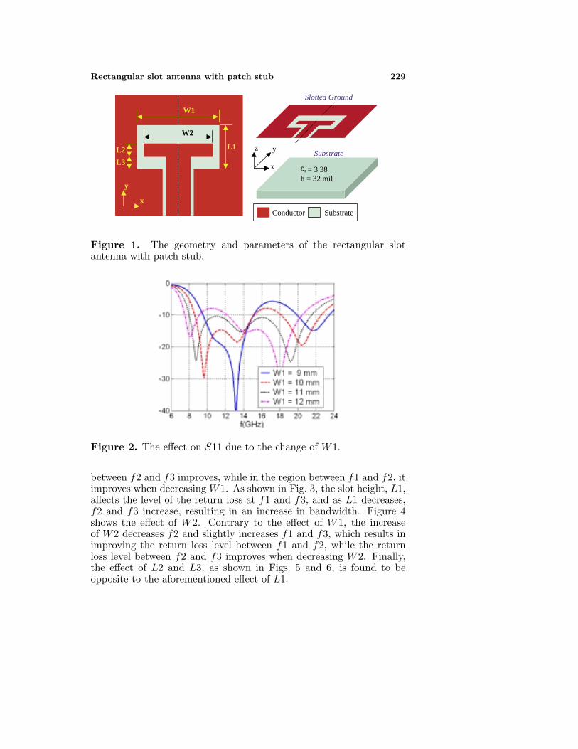
The geometry and parameters of the rectangular slot antenna witha patch stub are shown in Fig. 1, where W1 and L1 are the widthand height of the rectangle, W2 and L2 are the width and heightof the patch stub, and L3 is the distance between the patch stuband the CPW feed line. The antenna is supported by a dielectricsubstrate of a height equal to 32 mil and a relative dielectric constantof 3.38. The CPW is designed for a 50 Ω characteristic impedancewith slot and feed line widths equal to 0.125 and 2 mm, respectively.In order to provide design criteria for this antenna, the effects ofeach geometrical parameter are analyzed. The antenna dimensions(W1, L1, W2, L2, andL3) are chosen to be (11, 7, 6, 1 and 1 mm)and one parameter is changed at a time while the others are keptconstant.
Figures 2, 3, 4, 5 and 6 show the effect of changingW1, L1, W2, L2 and L3, respectively. All the results in these figuresshow that this antenna has three resonant frequencies: f1, f2 andf3. As shown in Fig. 2, with the increase of W1, f1 and f3 decreaseand f2 increases. As a result, when W1 increases, the return loss level
Rectangular slot antenna with patch stub 229
r = 3.38 h = 32 mil
Substrate z
x
y L1
Conductor Substrate
x
y
Slotted Ground
L2
L3
W1
W2
ε
Figure 1. The geometry and parameters of the rectangular slotantenna with patch stub.
Figure 2. The effect on S11 due to the change of W1.
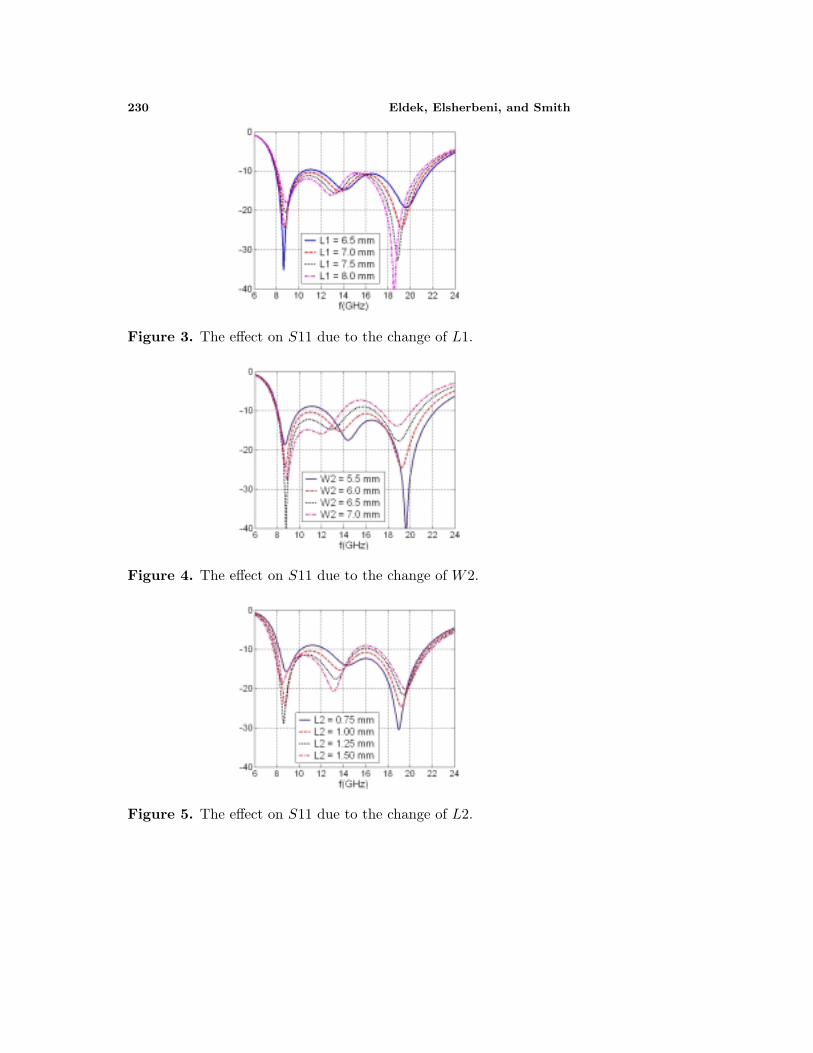
between f2 and f3 improves, while in the region between f1 and f2, itimproves when decreasing W1. As shown in Fig. 3, the slot height, L1,affects the level of the return loss at f1 and f3, and as L1 decreases,f2 and f3 increase, resulting in an increase in bandwidth. Figure 4shows the effect of W2. Contrary to the effect of W1, the increaseof W2 decreases f2 and slightly increases f1 and f3, which results inimproving the return loss level between f1 and f2, while the returnloss level between f2 and f3 improves when decreasing W2. Finally,the effect of L2 and L3, as shown in Figs. 5 and 6, is found to beopposite to the aforementioned effect of L1.
230 Eldek, Elsherbeni, and Smith
Figure 3. The effect on S11 due to the change of L1.
Figure 4. The effect on S11 due to the change of W2.
Figure 5. The effect on S11 due to the change of L2.

Rectangular slot antenna with patch stub 231
Figure 6. The effect on S11 due to the change of L3.
Antenna
prototype
(a) (b)
Figure 7. Comparison between the measured and computed (a)return loss, and (b) VSWR, for the rectangular slot antenna ofW1, L1, W2, L2 and L3 = 11, 7, 6, 1, and 1.
3. FINAL ANTENNA DESIGN
A rectangular slot antenna with a patch stub of (W1, L1, W2, L2 andL3) = (11, 7, 6, 1, and 1 mm) is simulated using HFSS to verify theresults of ADS simulations. In HFSS, a finite ground plane of a size of20× 25 mm2 is used. The return loss and VSWR are computed usingADS and Ansoft HFSS, and measured using a 8510 vector networkanalyzer and are shown in Fig. 7 along with a prototype of the finalantenna design. Although good agreement can be seen, there aresmall discrepancies between the computed and measured results, whichmay occur because of the effect of the SMA connector and fabrication

232 Eldek, Elsherbeni, and Smith
imperfections. The measured results show that the antenna operatesover a wide range that extends from 8 GHz to more than 23.5 GHz,with an impedance bandwidth of more than 98%. Compared to thetriangle slot antenna presented in [12], this antenna has a much widerbandwidth (42% more) and a smaller size (1 mm less) that allows formore separation distance between elements in an array environment,which in turn reduces the coupling and improves the scanning range.
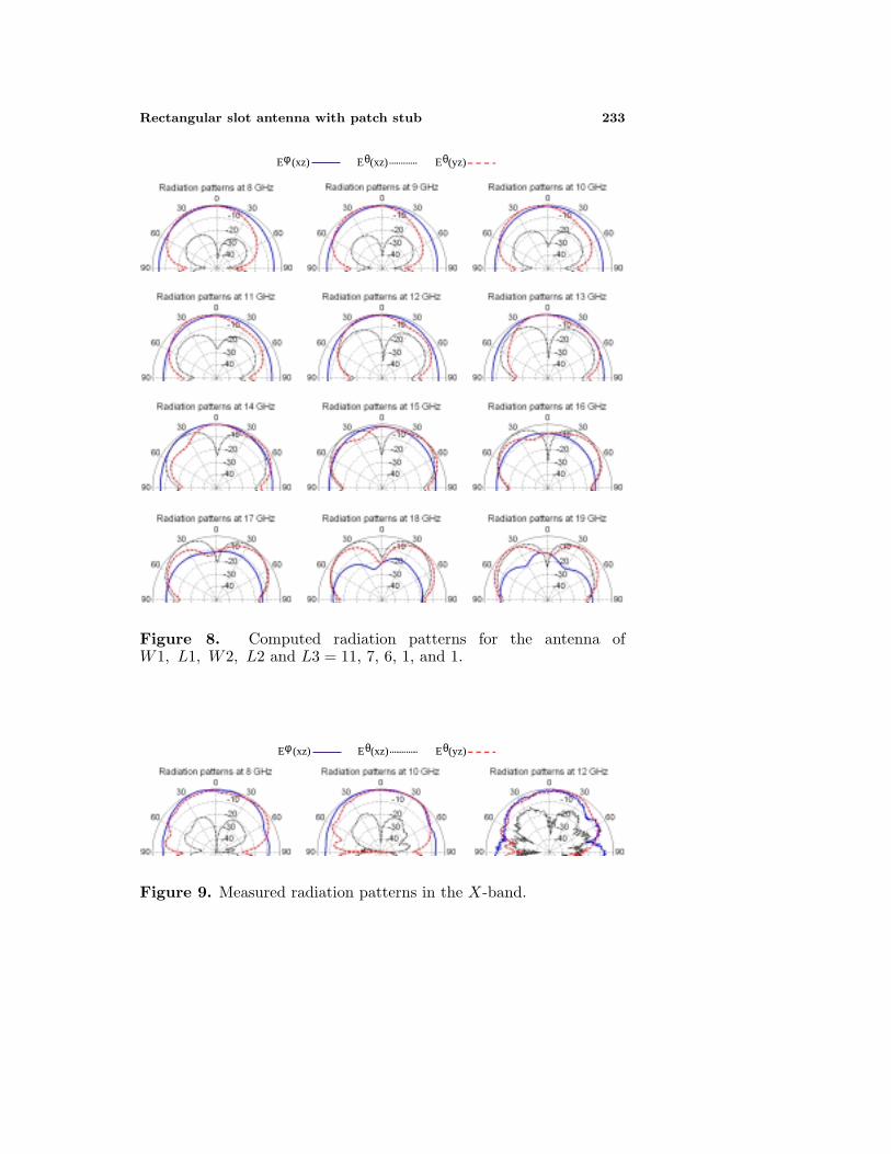
ADS Momentum considers an infinite substrate even when theantenna has a finite ground plane, and as a result, it produces zerofields in the x-y plane. Therefore, HFSS is used instead to computethe radiation pattern. The gain in the x-z (H-plane) and the y-z (E-plane) is computed for frequencies from 8 to 19 GHz, whichalmost covers the entire operating band, and the results are shownin Fig. 8. All patterns are normalized to a maximum and minimum of6 and −44 dB, respectively, with 10 dB/div. The lower half is removedbecause of the pattern symmetry around the z-axis. The minimum,maximum, and average gains in the entire operating band are 4, 6,and 5 dB, respectively. A good radiation pattern is obtained between8 and 15 GHz. Low cross polarization is obtserved between 8 and12 GHz, and the level starts to exceed −10 dB at 13 GHz, and startsto exceed the co-polarized fields at 16 GHz. Consequently, the usablebandwidth depends on the application for which this antenna will beused. The applications that accept high cross polarization levels canuse this antenna up to 16 GHz. In wireless communication applicationswhere the antenna is required to receive the signal from any directionwith any polarization, the entire operating band of this antenna can beutilized. For many radar applications and phased arrays, the usablebandwidth is confined between 8 and 12 GHz, which still covers theentire X-band. The radiation patterns are measured at 8, 10 and12 GHz, and presented in Fig. 9. Good agreement is obtained betweenthe measurements and the simulation results of HFSS.
Unconventional array configurations can further improve theradiation patterns and significantly decrease the cross polarization levelat high frequencies, and consequently increase the usable bandwidth forthis antenna for such applications. To prove this, a two-element arrayin y-axis is constructed as shown in Fig. 10, where the second elementis flipped 180 around the x-axis. This array is simulated using ADSand HFSS, and a comparison between the computed coupling is shownin Fig. 11. The average coupling between elements over the entire bandis around −20 dB. The radiation patterns are computed using HFSSat 8 to 16 GHz, and presented in Fig. 12. The cross polarized fieldsare cancelled because of the symmetry of this array configuration inthe E and H-planes. At the same time, good copolarized fields are
Rectangular slot antenna with patch stub 233
Eφ (xz) Eθ(xz) Eθ(yz)
Figure 8. Computed radiation patterns for the antenna ofW1, L1, W2, L2 and L3 = 11, 7, 6, 1, and 1.
Eφ (xz) Eθ(xz) Eθ(yz)
Figure 9. Measured radiation patterns in the X-band.

234 Eldek, Elsherbeni, and Smith
x
y 14 mm
Figure 10. Two-element array configuration.
Figure 11. Computed coupling for the two-element array in Fig. 9.
obtained in the E and H-planes up to 16 GHz. Therefore, by usingthis array configuration, the usable bandwidth exceeds 67% for phasedarrays and radar applications.
Finally, to show the scanning capability of this antenna in the X-band, the copolarized gain in the x-z plane is computed using HFSSfor a linear array consisting of 32 elements in the x-direction at 0, 30,and 60, and is presented in Fig. 13. Dolph-Tschebyscheff coefficientsare used to obtain a −30 dB sidelobe level. The maximum gain of thearray is 19 dB, and no grating lobe arises up to a 60 scanning angle.

Rectangular slot antenna with patch stub 235
E (xz) E (yz) φ θ − − − −
Figure 12. Computed gain for the two-element array in Fig. 9.
(a) (b) (c)
Figure 13. Computed copolarized gain in the x-z plane for 32-elementarray in x-direction at 10 GHz, with a steering angle of (a) 0, (b) 30,and 60.
4. CONCLUSION
The rectangular slot antenna with a patch stub has a smaller size andwider bandwidth than the triangle slot antenna with a tuning stubpresented in [12]. The antenna has 98% impedance bandwidth, 6 dBaverage gain, and acceptable radiation characteristics that make thisclass of antennas a good candidate for a variety of communicationapplications. An array configuration is suggested for phased arrayapplications that provides more than 61% usable bandwidth with 60scanning range using only 32 elements in a linear array.

236 Eldek, Elsherbeni, and Smith
REFERENCES
1. Wong, K.-L., Compact and Broadband Microstrip Antennas, JohnWiley and Sons Inc., New York, NY, 2002.
2. Lin, Y.-D. and S.-N. Tsai, “Coplanar waveguide-fed uniplanarbow-tie antenna,” IEEE Trans. On Antenna Propagat., Vol. AP-45, No. 2, 305–306, Feb. 2000.
3. Eldek, A. A., A. Z. Elsherbeni, C. E. Smith, and K.-F. Lee,“Wideband slot antennas for radar applications,” Proc. IEEERadar Conf., Huntsville, AL, 79–84, May 2003.
4. Soliman, E. A., S. Berbels, P. Delmotte, G. A. E. Vandenbosch,and E. Beyne, “Bow-tie slot antenna fed by CPW,” Electron Lett.,Vol. 35, 514–515, 1999.
5. Huang, J.-F. and C.-W. Kuo, “CPW-fed bow-tie slot antenna,”Microwave Opt. Technol. Lett., Vol. 19, No. 5, 358–360, Dec. 1998.
6. Miao, M., B. L. Ooi, and P. S. Kooi, “Broadband CPW-fed wideslot antenna,” Microwave Opt. Technol. Lett., Vol. 25, No. 3, 206–211, May 2000.
7. Eldek, A. A., A. Z. Elsherbeni, and C. E. Smith, “Widebandbow-tie slot antennas for radar applications,” 2003 IEEE TopicalConference on Wireless Communication Technology, Honolulu,Hawaii, October 2003.
8. Eldek, A. A., A. Z. Elsherbeni, and C. E. Smith, “Characteristicsof bow-tie slot antenna with tapered tuning stubs for widebandoperation,” Progress In Electromagnetic Research, J. A. Kong(ed.), PIER 49, 53–69, 2004.
9. Allen, C. M., A. A. Eldek, A. Z. Elsherbeni, and C. E. Smith,“Wideband coplanar waveguide def multi-slot antenna for radarapplications,” Microwave and Optical Technology Letters, Vol. 36,October 2003.
10. Eldek, A. A., A. Z. Elsherbeni, C. E. Smith, and K.-F. Lee,“Wideband rectangular slot antenna for personal wirelesscommunication,” IEEE Antennas and Propagations Magazine,Vol. 44, No. 5, 146–155, October 2002.
11. Chen, H.-D., “Broadband CPW-fed square slot antennas witha widened tuning stub,” IEEE Trans. On Antenna Propagat.,Vol. 51, No. 8, 1982–1986, Aug. 2003.
12. Eldek, A. A., A. Z. Elsherbeni, and C. E. Smith, “Design ofwideband triangle slot antennas with tuning stub,” Progress InElectromagnetic Research, J. A. Kong (ed.), PIER 48, 233–248,2004.

Rectangular slot antenna with patch stub 237
Abdelnasser A. Eldek received an honor B.Sc. degree in Electronicsand Communications Engineering from Zagazig University, Zagazig,Egypt, in 1993, an M.S. degree in Electrical Engineering fromEindhoven University of Technology, Eindhoven, The Netherlands, in1999, and a Ph.D. degree in Electrical Engineering from The Universityof Mississippi, Oxford, Mississippi, USA, in 2004. His currentresearch interests include Electromagnetic Theory, Finite DifferenceTime Domain Method, Antenna Design, and Phased Arrays.
Atef Z. Elsherbeni received an honor B.Sc. degree in Electronicsand Communications, an honor B.Sc. degree in Applied Physics, and aM.Eng. degree in Electrical Engineering, all from Cairo University,Cairo, Egypt, in 1976, 1979, and 1982, respectively, and a Ph.D.degree in Electrical Engineering from Manitoba University, Winnipeg,Manitoba, Canada, in 1987. He joined the faculty at the Universityof Mississippi in August 1987 as an Assistant Professor and advancedto the rank of Associate Professor on July 1991, and to the rank ofProfessor on July 1997. Dr. Elsherbeni has published 73 technicaljournal articles and 12 book chapters on applied electromagnetics,antenna design, and microwave subjects, and contributed to 210professional presentations.
Charles E. Smith was born in Clayton, AL, on June 8, 1934. Hereceived the B.E.E., M.S., and Ph.D. degrees from Auburn University,Auburn, AL, in 1959, 1963, and 1968, respectively. In late 1968, heaccepted the position of Assistant Professor of Electrical Engineeringwith The University of Mississippi, University, MS, and he advanced tothe rank of Associate Professor in 1969. He was appointed Chairman ofthe Department of Electrical Engineering in 1975, and he is currentlyProfessor and Chair Emeritus of this department. His recent researchhas been on the application of numerical techniques to microstriptransmission lines, antenna measurements in lossy media, measurementof electrical properties of materials, CAD in microwave circuits, radardesigning, and data acquisition using network analyzers.
Copyright © 2022 FDOKUMEN