
Recommendations for Assembly of Infineon PG-DSOF-8-16 ...
20
Sense & Control Application Note Rev. 2.1, 2011-09-21 Recommendations for Assembly of Infineon PG-DSOF-8-16 Package
-
Upload
khangminh22 -
Category
Documents
-
view
2 -
download
0
Transcript of Recommendations for Assembly of Infineon PG-DSOF-8-16 ...
Sense & Control
Appl icat ion Note Rev. 2.1, 2011-09-21
Recommendat ions for Assembly of Inf ineon PG-DSOF-8-16 Package

Edition 2011-09-21Published byInfineon Technologies AG81726 Munich, Germany© 2011 Infineon Technologies AGAll Rights Reserved.
Legal DisclaimerThe information given in this document shall in no event be regarded as a guarantee of conditions or characteristics. With respect to any examples or hints given herein, any typical values stated herein and/or any information regarding the application of the device, Infineon Technologies hereby disclaims any and all warranties and liabilities of any kind, including without limitation, warranties of non-infringement of intellectual property rights of any third party.
InformationFor further information on technology, delivery terms and conditions and prices, please contact the nearest Infineon Technologies Office (www.infineon.com).
WarningsDue to technical requirements, components may contain dangerous substances. For information on the types in question, please contact the nearest Infineon Technologies Office.Infineon Technologies components may be used in life-support devices or systems only with the express written approval of Infineon Technologies, if a failure of such components can reasonably be expected to cause the failure of that life-support device or system or to affect the safety or effectiveness of that device or system. Life support devices or systems are intended to be implanted in the human body or to support and/or maintain and sustain and/or protect human life. If they fail, it is reasonable to assume that the health of the user or other persons may be endangered.

PG-DSOF-8-16Recommendations for Assembly
Application Note 3 Rev. 2.1, 2011-09-21
Trademarks of Infineon Technologies AG
AURIX™, BlueMoon™, COMNEON™, C166™, CROSSAVE™, CanPAK™, CIPOS™, CoolMOS™, CoolSET™, CORECONTROL™, DAVE™, EasyPIM™, EconoBRIDGE™, EconoDUAL™, EconoPACK™, EconoPIM™, EiceDRIVER™, EUPEC™, FCOS™, HITFET™, HybridPACK™, ISOFACE™, I²RF™, IsoPACK™, MIPAQ™, ModSTACK™, my-d™, NovalithIC™, OmniTune™, OptiMOS™, ORIGA™, PROFET™, PRO-SIL™, PRIMARION™, PrimePACK™, RASIC™, ReverSave™, SatRIC™, SIEGET™, SINDRION™, SMARTi™, SmartLEWIS™, TEMPFET™, thinQ!™, TriCore™, TRENCHSTOP™, X-GOLD™, XMM™, X-PMU™, XPOSYS™.
Other TrademarksAdvance Design System™ (ADS) of Agilent Technologies, AMBA™, ARM™, MULTI-ICE™, PRIMECELL™,REALVIEW™, THUMB™ of ARM Limited, UK. AUTOSAR™ is licensed by AUTOSAR development partnership.Bluetooth™ of Bluetooth SIG Inc. CAT-iq™ of DECT Forum. COLOSSUS™, FirstGPS™ of Trimble NavigationLtd. EMV™ of EMVCo, LLC (Visa Holdings Inc.). EPCOS™ of Epcos AG. FLEXGO™ of Microsoft Corporation.FlexRay™ is licensed by FlexRay Consortium. HYPERTERMINAL™ of Hilgraeve Incorporated. IEC™ ofCommission Electrotechnique Internationale. IrDA™ of Infrared Data Association Corporation. ISO™ ofINTERNATIONAL ORGANIZATION FOR STANDARDIZATION. MATLAB™ of MathWorks, Inc. MAXIM™ ofMaxim Integrated Products, Inc. MICROTEC™, NUCLEUS™ of Mentor Graphics Corporation. Mifare™ of NXP.MIPI™ of MIPI Alliance, Inc. MIPS™ of MIPS Technologies, Inc., USA. muRata™ of MURATAMANUFACTURING CO., MICROWAVE OFFICE™ (MWO) of Applied Wave Research Inc., OmniVision™ ofOmniVision Technologies, Inc. Openwave™ Openwave Systems Inc. RED HAT™ Red Hat, Inc. RFMD™ RFMicro Devices, Inc. SIRIUS™ of Sirius Sattelite Radio Inc. SOLARIS™ of Sun Microsystems, Inc. SPANSION™of Spansion LLC Ltd. Symbian™ of Symbian Software Limited. TAIYO YUDEN™ of Taiyo Yuden Co.TEAKLITE™ of CEVA, Inc. TEKTRONIX™ of Tektronix Inc. TOKO™ of TOKO KABUSHIKI KAISHA TA. UNIX™of X/Open Company Limited. VERILOG™, PALLADIUM™ of Cadence Design Systems, Inc. VLYNQ™ of TexasInstruments Incorporated. VXWORKS™, WIND RIVER™ of WIND RIVER SYSTEMS, INC. ZETEX™ of DiodesZetex Limited.Last Trademarks Update 2010-06-09
Revision History 2011-09-21, Revision 2.1Page or Item Subjects (major changes since previous revision)Page 14 New chapter: Pick-and-Place
PG-DSOF-8-16Recommendations for Assembly
Table of Contents
Application Note 4 Rev. 2.1, 2011-09-21
Table of Contents . . . . . . . . . . . . . . . . . . . . . . . . . . . . . . . . . . . . . . . . . . . . . . . . . . . . . . . . . . . . . . . . 4
List of Figures . . . . . . . . . . . . . . . . . . . . . . . . . . . . . . . . . . . . . . . . . . . . . . . . . . . . . . . . . . . . . . . . . . . 5
List of Tables . . . . . . . . . . . . . . . . . . . . . . . . . . . . . . . . . . . . . . . . . . . . . . . . . . . . . . . . . . . . . . . . . . . . 6
1 Introduction . . . . . . . . . . . . . . . . . . . . . . . . . . . . . . . . . . . . . . . . . . . . . . . . . . . . . . . . . . . . . . . . . . . . . 71.1 Surface Mount Devices . . . . . . . . . . . . . . . . . . . . . . . . . . . . . . . . . . . . . . . . . . . . . . . . . . . . . . . . . . . . . 71.2 Package Description . . . . . . . . . . . . . . . . . . . . . . . . . . . . . . . . . . . . . . . . . . . . . . . . . . . . . . . . . . . . . . . 7
2 Package Handling . . . . . . . . . . . . . . . . . . . . . . . . . . . . . . . . . . . . . . . . . . . . . . . . . . . . . . . . . . . . . . . . 82.1 ESD Protective Measures . . . . . . . . . . . . . . . . . . . . . . . . . . . . . . . . . . . . . . . . . . . . . . . . . . . . . . . . . . . 82.1.1 ESD Protective Measures in the Workplace . . . . . . . . . . . . . . . . . . . . . . . . . . . . . . . . . . . . . . . . . . . 82.1.2 Equipment for personal . . . . . . . . . . . . . . . . . . . . . . . . . . . . . . . . . . . . . . . . . . . . . . . . . . . . . . . . . . . 82.1.3 Production Installation and Processing Tools . . . . . . . . . . . . . . . . . . . . . . . . . . . . . . . . . . . . . . . . . . 82.2 Packing of components . . . . . . . . . . . . . . . . . . . . . . . . . . . . . . . . . . . . . . . . . . . . . . . . . . . . . . . . . . . . 92.3 Moisture Sensitive Components (MSL classification) . . . . . . . . . . . . . . . . . . . . . . . . . . . . . . . . . . . . . 102.4 Storage and Transportation Conditions . . . . . . . . . . . . . . . . . . . . . . . . . . . . . . . . . . . . . . . . . . . . . . . 112.5 Handling Damage and Contamination . . . . . . . . . . . . . . . . . . . . . . . . . . . . . . . . . . . . . . . . . . . . . . . . 122.6 Component Solderability . . . . . . . . . . . . . . . . . . . . . . . . . . . . . . . . . . . . . . . . . . . . . . . . . . . . . . . . . . . 12
3 Assembly . . . . . . . . . . . . . . . . . . . . . . . . . . . . . . . . . . . . . . . . . . . . . . . . . . . . . . . . . . . . . . . . . . . . . . 133.1 Process flow for reflow soldering . . . . . . . . . . . . . . . . . . . . . . . . . . . . . . . . . . . . . . . . . . . . . . . . . . . . 133.2 Solder Paste . . . . . . . . . . . . . . . . . . . . . . . . . . . . . . . . . . . . . . . . . . . . . . . . . . . . . . . . . . . . . . . . . . . . 133.3 Pick-and-Place . . . . . . . . . . . . . . . . . . . . . . . . . . . . . . . . . . . . . . . . . . . . . . . . . . . . . . . . . . . . . . . . . . 133.3.1 Component Placement . . . . . . . . . . . . . . . . . . . . . . . . . . . . . . . . . . . . . . . . . . . . . . . . . . . . . . . . . . 133.3.2 Nozzle . . . . . . . . . . . . . . . . . . . . . . . . . . . . . . . . . . . . . . . . . . . . . . . . . . . . . . . . . . . . . . . . . . . . . . . 143.4 Reflow Soldering . . . . . . . . . . . . . . . . . . . . . . . . . . . . . . . . . . . . . . . . . . . . . . . . . . . . . . . . . . . . . . . . . 143.4.1 Forced Convection Reflow Process . . . . . . . . . . . . . . . . . . . . . . . . . . . . . . . . . . . . . . . . . . . . . . . . . 153.4.2 Reflow Peak Temperature . . . . . . . . . . . . . . . . . . . . . . . . . . . . . . . . . . . . . . . . . . . . . . . . . . . . . . . . 153.4.3 Reflow Profile Classification . . . . . . . . . . . . . . . . . . . . . . . . . . . . . . . . . . . . . . . . . . . . . . . . . . . . . . 153.4.4 PG-DSOF-8-16 Reflow Profile . . . . . . . . . . . . . . . . . . . . . . . . . . . . . . . . . . . . . . . . . . . . . . . . . . . . . 163.5 Cleaning . . . . . . . . . . . . . . . . . . . . . . . . . . . . . . . . . . . . . . . . . . . . . . . . . . . . . . . . . . . . . . . . . . . . . . . 18
References . . . . . . . . . . . . . . . . . . . . . . . . . . . . . . . . . . . . . . . . . . . . . . . . . . . . . . . . . . . . . . . . . . . . 19
Table of Contents

PG-DSOF-8-16Recommendations for Assembly
List of Figures
Application Note 5 Rev. 2.1, 2011-09-21
Figure 1 PG-PDSOF-8-16 with fixed lid . . . . . . . . . . . . . . . . . . . . . . . . . . . . . . . . . . . . . . . . . . . . . . . . . . . . . 7Figure 2 Recommended pick-up nozzle for PG-DSOF package . . . . . . . . . . . . . . . . . . . . . . . . . . . . . . . . . 14Figure 3 Classification Reflow Profile . . . . . . . . . . . . . . . . . . . . . . . . . . . . . . . . . . . . . . . . . . . . . . . . . . . . . . 16Figure 4 Recommended reflow temperature profile for PG-DSOF-8-16. . . . . . . . . . . . . . . . . . . . . . . . . . . . 17
List of Figures

PG-DSOF-8-16Recommendations for Assembly
List of Tables
Application Note 6 Rev. 2.1, 2011-09-21
Table 1 Moisture Sensitivity Level . . . . . . . . . . . . . . . . . . . . . . . . . . . . . . . . . . . . . . . . . . . . . . . . . . . . . . . . 10Table 2 General Storage Conditions - Overview . . . . . . . . . . . . . . . . . . . . . . . . . . . . . . . . . . . . . . . . . . . . . 11Table 3 Package Classfication Reflow Temperature. . . . . . . . . . . . . . . . . . . . . . . . . . . . . . . . . . . . . . . . . . 15Table 4 Reflow Profile Parameters . . . . . . . . . . . . . . . . . . . . . . . . . . . . . . . . . . . . . . . . . . . . . . . . . . . . . . . 17
List of Tables
PG-DSOF-8-16Recommendations for Assembly
Introduction
Application Note 7 Rev. 2.1, 2011-09-21
1 IntroductionThe PG-DSOF package family consists of 3 package types:• PG-DSOF-8-12 with removable cap• PG-DSOF-8-13 with heat sink and removable cap• PG-DSOF-8-16 with fixed lidThis assembly note focuses on package type PG-DSOF-8-16. This package type is used for following Infineon pressure sensor products:• Sideairbag Sensors• Barometric Air Pressure Sensors• Manifold Air Pressure SensorsThe assembly note describes how to handle the PG-DSOF-8-16 package and gives recommendations forprocessing of PG-DSOF-8-16 SMD package with reflow soldering processes.
1.1 Surface Mount DevicesSurface Mount Devices (SMD) are soldered directly onto the surface of PCBs. This technology is called SurfaceMount Technology (SMT)
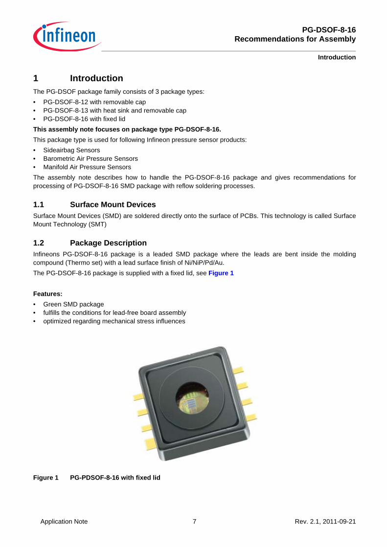
1.2 Package DescriptionInfineons PG-DSOF-8-16 package is a leaded SMD package where the leads are bent inside the moldingcompound (Thermo set) with a lead surface finish of Ni/NiP/Pd/Au.The PG-DSOF-8-16 package is supplied with a fixed lid, see Figure 1
Features:• Green SMD package• fulfills the conditions for lead-free board assembly• optimized regarding mechanical stress influences
Figure 1 PG-PDSOF-8-16 with fixed lid
PG-DSOF-8-16Recommendations for Assembly
Package Handling
Application Note 8 Rev. 2.1, 2011-09-21
2 Package Handling
2.1 ESD Protective MeasuresSemiconductor devices are normally Electrostatic Discharge Sensitive Devices (ESDS) requiring specificprecautionary measures regarding handling and processing. Discharging of electrostatically charged objects overan IC, caused by human touch or processing tools may cause high current respectively high voltage pulses thatcan damage or even destroy sensitive semiconductor structures. On the other hand, ICs may also be chargedduring processing. If discharging takes place too quickly (hard discharge), it may cause load pulses and damages,too. ESD protective measures must therefore prevent contact with charged parts as well as charging of the ICs.Protective measures against ESD include handling, processing and packing of ESDS. A few hints are providedbelow on handling and processing.
2.1.1 ESD Protective Measures in the Workplace
• Standard marking of ESD protected areas• Access control with tester for footwear and wrist strap• Air conditioning• Dissipative and grounded floor• Dissipative and grounded working and storage areas• Dissipative chairs• Earth (“ground”) bonding points for wrist straps• Trolleys or carts with dissipative surfaces and wheels• Suitable shipping and storage containers• No sources of electrostatic fields
2.1.2 Equipment for personal
• Dissipative/conductive footwear or heal grounder• Garments• Wrist straps• Gloves or finger coats which are ESD-proven• Regular training of staff
2.1.3 Production Installation and Processing Tools
• Machine and toolparts made of dissipative or metallic materials• No materials having thin insulating layers for sliding tracks• All parts reliable connected to ground potential• No potential difference between individual machine and tool parts• No sources of electrostatic fieldsDetailed information on ESD protective measures may be obtained from the ESD specialist through Area SalesOffices. Our recommendations are based on the internally applicable standards IEC61340-5-1 and ANSI/ESDS2020.

PG-DSOF-8-16Recommendations for Assembly
Package Handling
Application Note 9 Rev. 2.1, 2011-09-21
2.2 Packing of components
List of relevant standards which should be consideredInfineon packs according to the IEC 60286-* series (IEC 60286-3 is similar to the EIA 481-*).
Moisture sensitive Surface Mount Devices are packed according to IPC/JEDEC J-STD-033*: Handling, Packing, Shipping and Use of Moisture/Reflow Sensitive Surface Mount Devices
Other references:
PDSOF packages are supplied in tapes on reel for feeding in an automatic pick&place machine.Detailed packing drawings: More information are available on www.infineon.com/package
IEC 60286-3 Packaging of components for automatic handling - Part 3: Packaging of surface mount components on continuous tapes
IEC 60286-4 Packaging of components for automatic handling - Part 4:Stick magazines for dual-in-line packages
IEC 60286-5 Packaging of components for automatic handling - Part 5:Matrix trays
ANSI/EIA-481-* EIA Standard8 mm through 200 mm embossed Carrier Taping and8 mm & 12 mm Punched Carrier Taping of Surface Mount Components for Automatic Handling
PG-DSOF-8-16Recommendations for Assembly
Package Handling
Application Note 10 Rev. 2.1, 2011-09-21
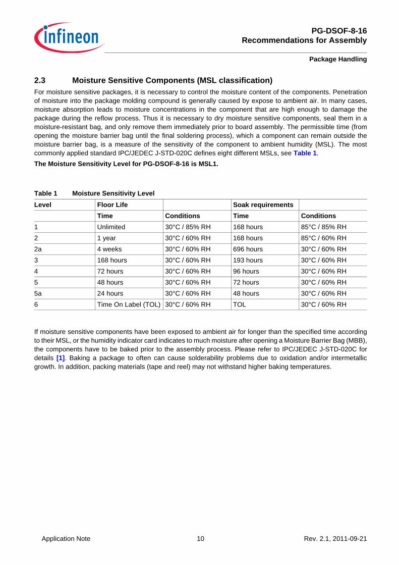
2.3 Moisture Sensitive Components (MSL classification)For moisture sensitive packages, it is necessary to control the moisture content of the components. Penetrationof moisture into the package molding compound is generally caused by expose to ambient air. In many cases,moisture absorption leads to moisture concentrations in the component that are high enough to damage thepackage during the reflow process. Thus it is necessary to dry moisture sensitive components, seal them in amoisture-resistant bag, and only remove them immediately prior to board assembly. The permissible time (fromopening the moisture barrier bag until the final soldering process), which a component can remain outside themoisture barrier bag, is a measure of the sensitivity of the component to ambient humidity (MSL). The mostcommonly applied standard IPC/JEDEC J-STD-020C defines eight different MSLs, see Table 1. The Moisture Sensitivity Level for PG-DSOF-8-16 is MSL1.
If moisture sensitive components have been exposed to ambient air for longer than the specified time accordingto their MSL, or the humidity indicator card indicates to much moisture after opening a Moisture Barrier Bag (MBB),the components have to be baked prior to the assembly process. Please refer to IPC/JEDEC J-STD-020C fordetails [1]. Baking a package to often can cause solderability problems due to oxidation and/or intermetallicgrowth. In addition, packing materials (tape and reel) may not withstand higher baking temperatures.
Table 1 Moisture Sensitivity LevelLevel Floor Life Soak requirements
Time Conditions Time Conditions1 Unlimited 30°C / 85% RH 168 hours 85°C / 85% RH2 1 year 30°C / 60% RH 168 hours 85°C / 60% RH2a 4 weeks 30°C / 60% RH 696 hours 30°C / 60% RH3 168 hours 30°C / 60% RH 193 hours 30°C / 60% RH4 72 hours 30°C / 60% RH 96 hours 30°C / 60% RH5 48 hours 30°C / 60% RH 72 hours 30°C / 60% RH5a 24 hours 30°C / 60% RH 48 hours 30°C / 60% RH6 Time On Label (TOL) 30°C / 60% RH TOL 30°C / 60% RH
PG-DSOF-8-16Recommendations for Assembly
Package Handling
Application Note 11 Rev. 2.1, 2011-09-21
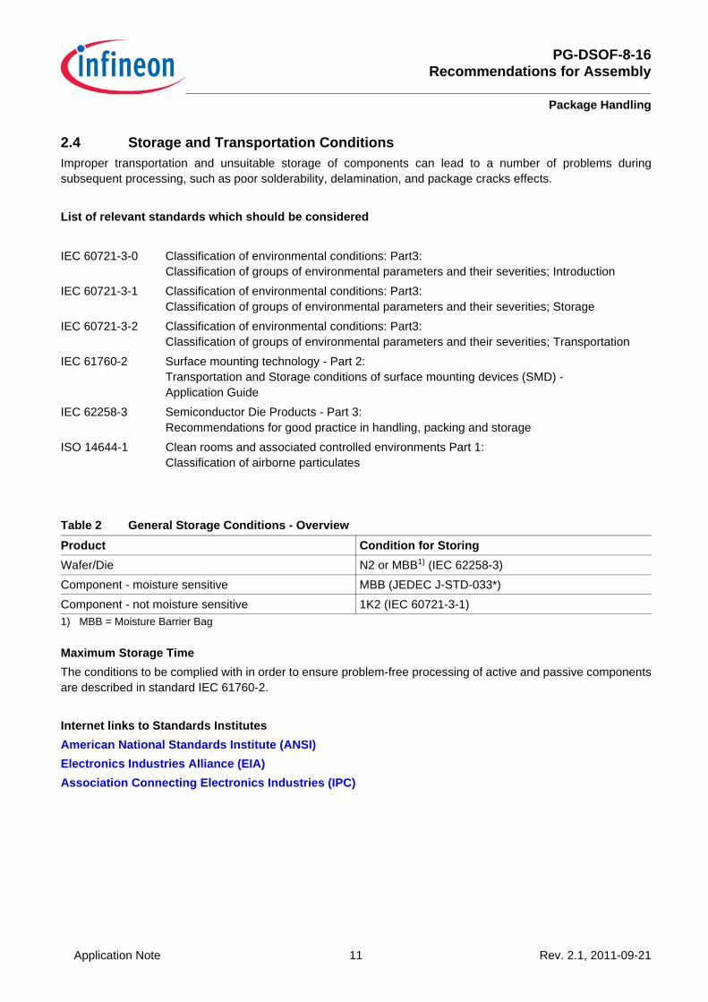
2.4 Storage and Transportation ConditionsImproper transportation and unsuitable storage of components can lead to a number of problems duringsubsequent processing, such as poor solderability, delamination, and package cracks effects.
List of relevant standards which should be considered
Maximum Storage TimeThe conditions to be complied with in order to ensure problem-free processing of active and passive componentsare described in standard IEC 61760-2.
Internet links to Standards InstitutesAmerican National Standards Institute (ANSI)Electronics Industries Alliance (EIA)Association Connecting Electronics Industries (IPC)
IEC 60721-3-0 Classification of environmental conditions: Part3: Classification of groups of environmental parameters and their severities; Introduction
IEC 60721-3-1 Classification of environmental conditions: Part3: Classification of groups of environmental parameters and their severities; Storage
IEC 60721-3-2 Classification of environmental conditions: Part3: Classification of groups of environmental parameters and their severities; Transportation
IEC 61760-2 Surface mounting technology - Part 2:Transportation and Storage conditions of surface mounting devices (SMD) - Application Guide
IEC 62258-3 Semiconductor Die Products - Part 3:Recommendations for good practice in handling, packing and storage
ISO 14644-1 Clean rooms and associated controlled environments Part 1:Classification of airborne particulates
Table 2 General Storage Conditions - OverviewProduct Condition for StoringWafer/Die N2 or MBB1) (IEC 62258-3)
1) MBB = Moisture Barrier Bag
Component - moisture sensitive MBB (JEDEC J-STD-033*)Component - not moisture sensitive 1K2 (IEC 60721-3-1)

PG-DSOF-8-16Recommendations for Assembly
Package Handling
Application Note 12 Rev. 2.1, 2011-09-21
2.5 Handling Damage and ContaminationAutomatic or manual handling of components in or out of the component packing may cause mechanical damageto package leads and/or bodyGenerally the components in the packing are ready to use. The PG-DSOF-8-16 package is supplied with a fixedplastic lid. The flat surface of this lid on top of the package allows handling with standard pick and place tools.Care should be taken during handling to avoid damage to the gel and lid:• the gel can be damaged due to access through the hole in the lid• the lid can be damaged through bending with push/pull forces. Lid bending with pull forces >1N and push
forces >5N should be avoided.
Any contamination applied to the component or packing may cause or induce processes that may lead to devicedamage. The most critical issues are:• Solderability problems• Corrosion• Electrical shorts (due to conductive particles)
2.6 Component SolderabilityThe sufficiently thick and wettable metal surfaces (final plating) of the device pins ensure good solderability, evenafter a long storage time.Note that the cut edges of the pins should be ignored in any assessment of the solderability.Suitable methods for the assessment of solderability can be derived from JESD22B 102 or IEC60068-2-58.
PG-DSOF-8-16Recommendations for Assembly
Assembly
Application Note 13 Rev. 2.1, 2011-09-21
3 AssemblyThe PG-DSOF-8-16 package is qualified for Pb-free reflow soldering process.
3.1 Process flow for reflow solderingTypical flow for mounting SMDs with reflow soldering process:• Application of solder paste to the PCB• Solder paste inspection• Placement of component on PCB• Inspection• Reflow soldering• Inspection
3.2 Solder PasteSolder paste consists of solder alloy and a flux system. Normally the volume is split into about 50% alloy and 50%flux and solvents. In term of mass, this means approximately 90 wt% alloy and 10 wt% flux system and solvents.The flux system has to remove oxides and contaminants from the solder joints during soldering process. Thecapability of removing oxides and contaminants depends on the activation level of the used flux.The contained solvent adjusts the viscosity needed for the solder paste application process. The solvent has toevaporate during reflow process.
3.3 Pick-and-Place
3.3.1 Component PlacementAlthough the self-alignment effect due to the surface tension of the liquid solder will support the formation ofreliable solder joints, the components have to be placed accurately according to the geometry. Positioning thepackage manually is not recommended. For PG-DSOF-8-16 an automatic pick-and-place machine isrecommended to achieve reliable solder joints.For PG-DSOF-8-16 package with a pad width of 0.4 mm (respectively 0.8 mm) and a pitch of 1.27 mm, anautomatic pick-and-place machine is recommended to achieve reliable solder joints. Component placement accuracies of ±50 μm are obtained with modern automatic component placementmachines using vision systems. With these systems, both the PCB and the components are optically measuredand the components are placed on the PCB at their programmed positions. The fiducials on the PCB are locatedeither on the edge of the PCB for the entire PCB or additionally on individual mounting positions (local fiducials).They are detected by a vision system. Recognition of the packages immediately before the mounting process isperformed by a special vision system, enabling the complete package to be correctly centered.The PG-DSOF-8-16 device is delivered in tape and reel packing which is suitable for being used in pick-and-placeequipment.

PG-DSOF-8-16Recommendations for Assembly
Assembly
Application Note 14 Rev. 2.1, 2011-09-21
3.3.2 NozzleA pick-up nozzle suitable for the package body size should be used. Regarding the PG-DSOF package it isrecommended that the used nozzle seals on the package rim. If a smaller nozzle is used this may lead to increasedforce in the package center, nozzle shape and size are more critical in this case.For Pick and Place should be considered:• a dynamic vacuum pressure puls of min. 10 kPa can be applied.• the nozzle should be sealed on the package rim.• if the nozzle is sealed on the lid, push/pull forces >5N should be avoided.
Recommendation for nozzle, sealed on the package rim:
Figure 2 Recommended pick-up nozzle for PG-DSOF package
3.4 Reflow SolderingReflow soldering is the most common technique to attach SMD components to a circuit board. The goal of thereflow process is to melt the powder particles in the solder paste, thereby joining the appropriate surfaces, tocreate a strong metallurgical bond after solidification of the solder.During the reflow process, each solder joint has to be exposed to temperatures above the melting point of solderfor a sufficient time to get optimum solder joint quality, whereas overheating the PCB has to be avoided.It is important that the maximum temperature of the package during reflow does not exceed the specifiedpeak temperature of the moisture level.When using infrared (IR) ovens without convection, special care may be necessary to assure a sufficientlyhomogeneous temperature profile for all solder joints on the PCB, especially on large, complex boards withdifferent thermal masses of the components. Using infrared soldering, the components are heated as a result ofabsorbing IR radiation. Usually the heating is done with radiators positioned on either side in order to heat orpreheat the whole area surrounding of the solder joint, if possible. The temperature of the different componentsmay vary severely. Since the metallic terminals of the components exhibit only low absorption (because they
PG-DSOF-8-16Recommendations for Assembly
Assembly
Application Note 15 Rev. 2.1, 2011-09-21
reflect IR radiation), the heat has to be applied to the solder joints via the component itself, the heated PCB andthe ambient air.Other ovens are based on heat transfer by infrared or vapor-phase.Most reflow ovens use forced convection blowing hot air at different temperatures in different zones.
3.4.1 Forced Convection Reflow ProcessThe recommended reflow process is forced convection where the heat is transferred to the PCB in different zonesby heated air or nitrogen. The number of zones, volume of hot gas and oven design determine the capacity andthe ability to reproduce the optimum reflow profile, which is also influenced by:• Board thickness and layout• Differences in thermal mass of all components• Maximum allowed component temperaturesA nitrogen atmosphere can generally improve solder joint quality, but is normally not necessary for soldering theavailable package lead finishes. For the lead-free process with higher reflow temperatures, a nitrogen atmospheremay reduce oxidation and improve solder joint quality.
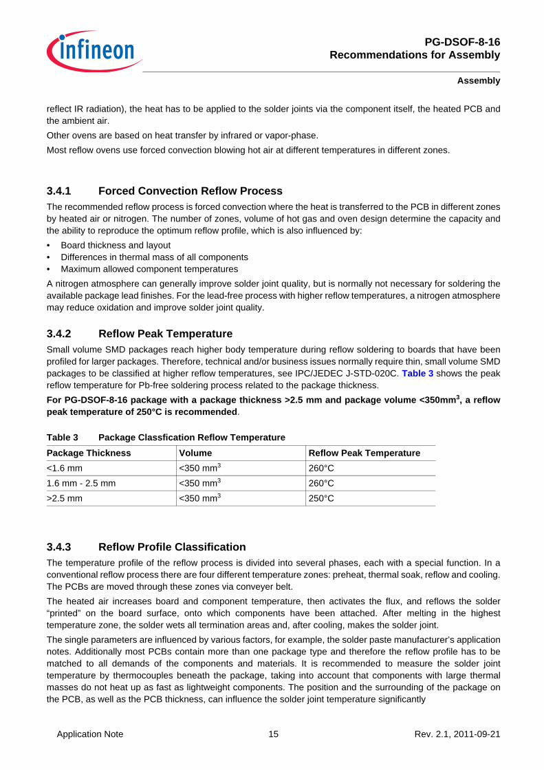
3.4.2 Reflow Peak TemperatureSmall volume SMD packages reach higher body temperature during reflow soldering to boards that have beenprofiled for larger packages. Therefore, technical and/or business issues normally require thin, small volume SMDpackages to be classified at higher reflow temperatures, see IPC/JEDEC J-STD-020C. Table 3 shows the peakreflow temperature for Pb-free soldering process related to the package thickness.For PG-DSOF-8-16 package with a package thickness >2.5 mm and package volume <350mm3, a reflowpeak temperature of 250°C is recommended.
3.4.3 Reflow Profile ClassificationThe temperature profile of the reflow process is divided into several phases, each with a special function. In aconventional reflow process there are four different temperature zones: preheat, thermal soak, reflow and cooling.The PCBs are moved through these zones via conveyer belt. The heated air increases board and component temperature, then activates the flux, and reflows the solder“printed” on the board surface, onto which components have been attached. After melting in the highesttemperature zone, the solder wets all termination areas and, after cooling, makes the solder joint.The single parameters are influenced by various factors, for example, the solder paste manufacturer’s applicationnotes. Additionally most PCBs contain more than one package type and therefore the reflow profile has to bematched to all demands of the components and materials. It is recommended to measure the solder jointtemperature by thermocouples beneath the package, taking into account that components with large thermalmasses do not heat up as fast as lightweight components. The position and the surrounding of the package onthe PCB, as well as the PCB thickness, can influence the solder joint temperature significantly
Table 3 Package Classfication Reflow TemperaturePackage Thickness Volume Reflow Peak Temperature<1.6 mm <350 mm3 260°C1.6 mm - 2.5 mm <350 mm3 260°C>2.5 mm <350 mm3 250°C
PG-DSOF-8-16Recommendations for Assembly
Assembly
Application Note 16 Rev. 2.1, 2011-09-21
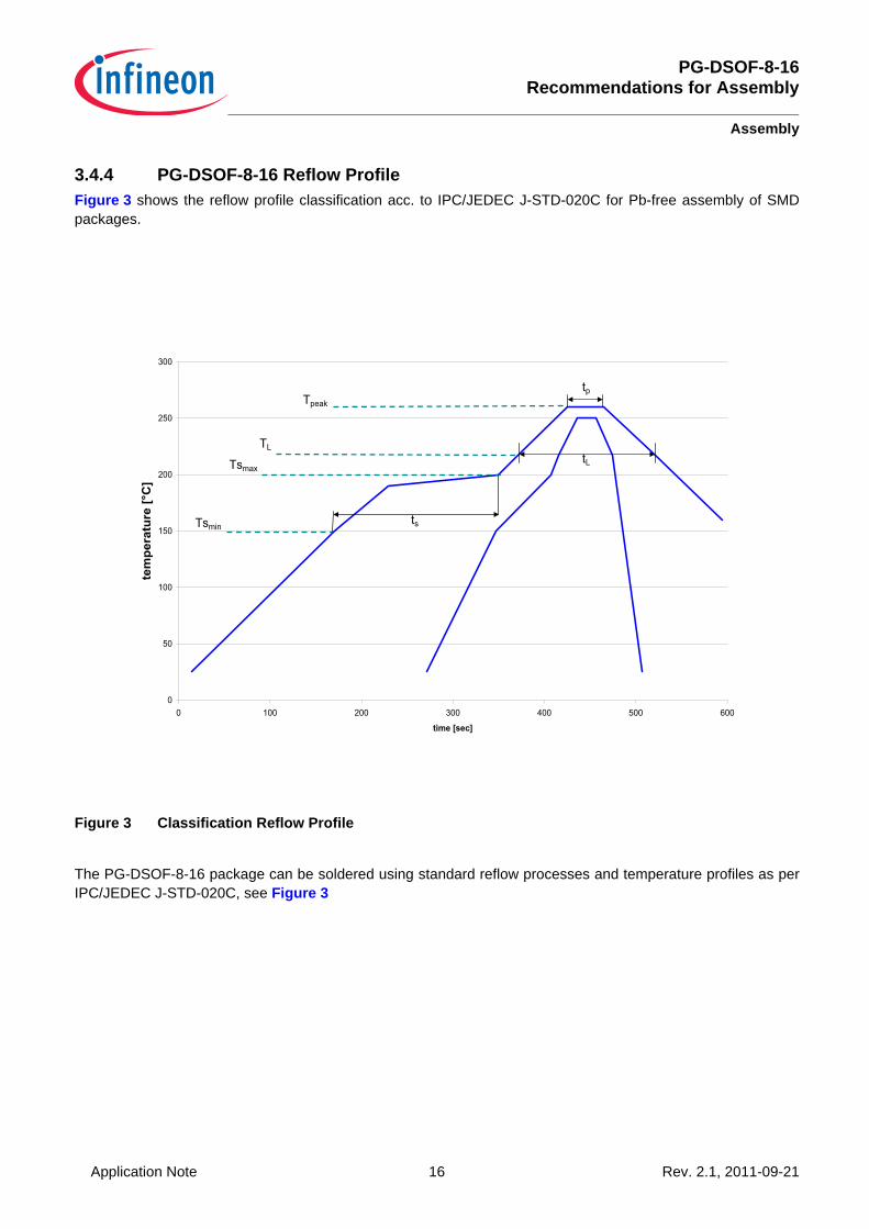
3.4.4 PG-DSOF-8-16 Reflow ProfileFigure 3 shows the reflow profile classification acc. to IPC/JEDEC J-STD-020C for Pb-free assembly of SMDpackages.
Figure 3 Classification Reflow Profile
The PG-DSOF-8-16 package can be soldered using standard reflow processes and temperature profiles as perIPC/JEDEC J-STD-020C, see Figure 3
0
50
100
150
200
250
300
0 100 200 300 400 500 600
time [sec]
tem
pera
ture
[°C
]
Tsmin
Tsmax
TL
Tpeak
ts
tp
tL
PG-DSOF-8-16Recommendations for Assembly
Assembly
Application Note 17 Rev. 2.1, 2011-09-21
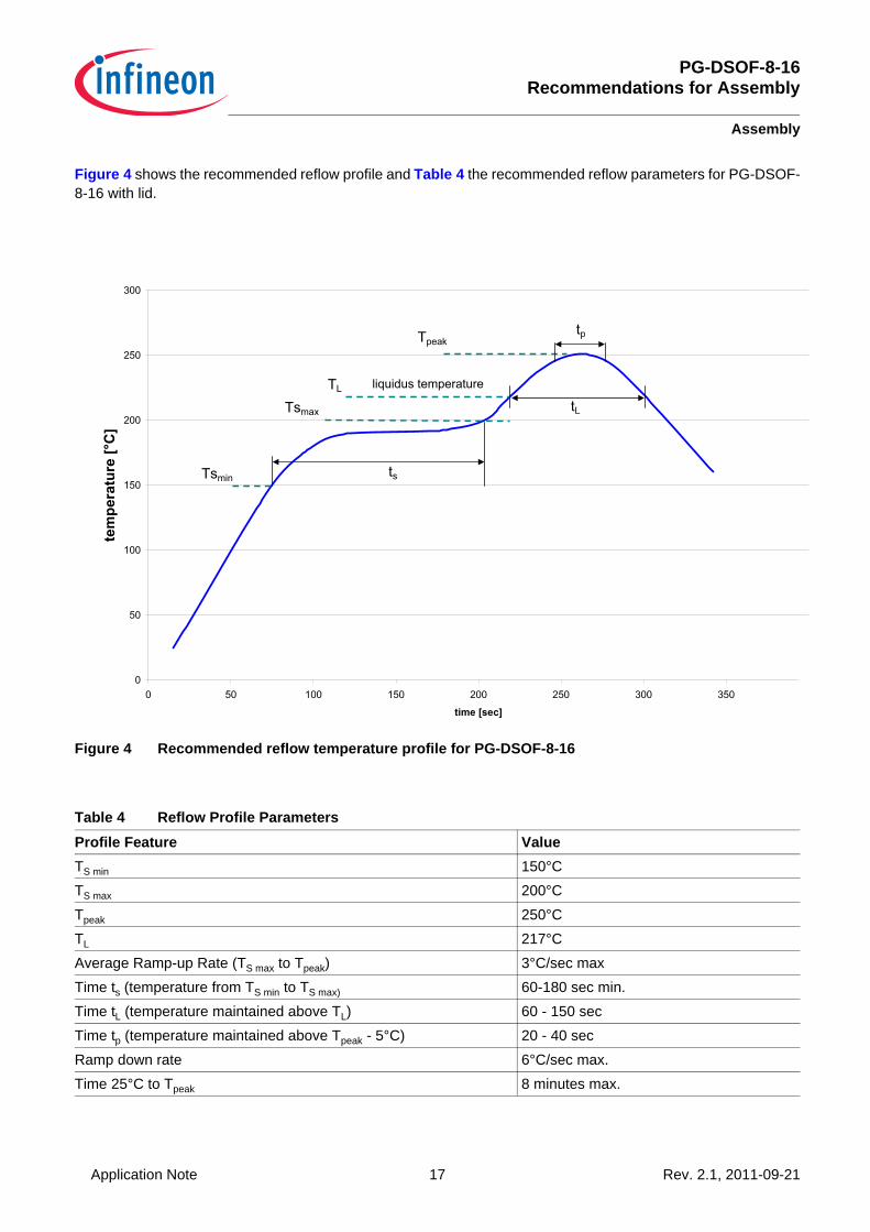
Figure 4 shows the recommended reflow profile and Table 4 the recommended reflow parameters for PG-DSOF-8-16 with lid.
Figure 4 Recommended reflow temperature profile for PG-DSOF-8-16
Table 4 Reflow Profile ParametersProfile Feature ValueTS min 150°CTS max 200°CTpeak 250°CTL 217°CAverage Ramp-up Rate (TS max to Tpeak) 3°C/sec maxTime ts (temperature from TS min to TS max) 60-180 sec min.Time tL (temperature maintained above TL) 60 - 150 secTime tp (temperature maintained above Tpeak - 5°C) 20 - 40 secRamp down rate 6°C/sec max.Time 25°C to Tpeak 8 minutes max.
�
��
���
���
���
���
���
� �� ��� ��� ��� ��� ��� ���
��������
���
���
����
����
���
� �
��
��� �
�
��
��
������������� �����

PG-DSOF-8-16Recommendations for Assembly
Assembly
Application Note 18 Rev. 2.1, 2011-09-21
3.5 CleaningAfter the soldering process, flux residues can be found around the solder joints. If a “no-clean” solder paste hasbeen used for printing, the flux residues usually do not have to be removed after the soldering process. However,if the solder joints should be cleaned, the cleaning methods have to be selected by considering the packagerequirements and environmental and safety aspects.The PG-DSOF-8-16 package is compatible to standard PCB cleaning agents, for example VIGON™ A200 fromZestron (www.zestron.com).During the cleaning process, it should be ensured that there is no contamination inside the lid hole and nomechanical damage to the gel (e.g. by applying a high pressure spray).

PG-DSOF-8-16Recommendations for Assembly
References
Application Note 19 Rev. 2.1, 2011-09-21
References[1] IPC/JEDEC J-STD-020C (Moisture/Reflow Sensitivity Classification for Nonhermetic Solid State Surface
Mount Devices)
[2] JESD22-B102 (Test Method for Solderability)
[3] IEC 60068-2-58 (Test Methods for Solderability, resistance to dissolution of metallization and to soldering heat of surface mounting devices)