PG L2555 PG L2550 PG L2545 PF-320 PF-3100
293
SERVICE MANUAL PG L2555 PG L2550 PG L2545 PF-320 PF-3100
-
Upload
khangminh22 -
Category
Documents
-
view
1 -
download
0
Transcript of PG L2555 PG L2550 PG L2545 PF-320 PF-3100

SER
PG L2PG L2PG L2PF-32PF-31
555 550 545 0 00
VICE MANUAL

RISK OF EXPLOSIONOF USED BATTERIES
It may be illegal to dislocal solid waste offici
IL Y A UN RISQUE D’DE TYPE INCORRECINSTRUCTIONS DON
Il peut être illégal de jefonctionnaires municipet une mise au rebut a
Notation of productsFor the purpose of this
PG L2555
PG L2550
PG L2545
CAUTION
IF BATTERY IS REPLACED BY AN INCORRECT TYPE. DISPOSE ACCORDING TO THE INSTRUCTIONS.
pose of this battery into the municipal waste stream. Check with your als for details in your area for proper disposal.
ATTENTION
EXPLOSION SI LA BATTERIE EST REMPLACEE PAR UN MODELE T. METTRE AU REBUT LES BATTERIES UTILISEES SELON LES NEES.
ter les batteries dans des eaux d’égout municipales. Vérifiez avec les aux de votre région pour les détails concernant des déchets solides ppropriée.
in the manual service manual, products are identified by print speed at A4.
KDJ KDA KDE KDAU
○ ○ ○ ○
55 ppm × ○ ○ ○
50 ppm × ○ ○ ○
45 ppm ○ ○ ○ ○

Revision history
Revision Date
1 20 Septembe
2 27 December
3 27 January 2
pages Revised contents
r 2016 Contents Change: 1-2-3 (3)
Added: 1-6-2 (2)
1-2-14 Correction: Item nameAdded: Note of detaching and refitting
1-4-9 Correction: C0840/1010
1-4-11, 1-4-12 Correction: C1140/1150
1-4-15 Correction: C2330/2340
1-4-17, 1-4-18 Correction: C4200/5100/6000/6030
1-4-20 to 22 Correction: C6130/7100/7400/7410/7800/7810/7900/
F000
Deleted: C7000
1-6-1 Correction: The order of the firmware
1-6-6 Added: (2) Main PWB
2016 1-2-14 Correction: Figure 1-2-24 (Wi-Fi PWB cover)
Added: Caution sentense of precedure 1
1-3-17 Correction: Description of Toner LOG
1-4-25 Correction: Remarks (-/F000/F15x)
2-2-1
2-2-3 to 5
Correction: Machine front →Machine right
017 1-1-1 Correction: A5 printing speed on simplex
1-1-2 Correction: Altitude(8,202→14,482feet)
1-5-22, 1-5-23 Added: Precautions for board replacement
- Added: Service manual (PF-320/PF-3100)

Safety precautions
This booklet provides safety warnings and precautions for our service personnel to ensure the safety of their customers, their machines as well as themselves during maintenance activities. Service personnel are advised to read this booklet carefully to familiarize themselves with the warnings and precautions described here before engaging in maintenance activities.

Safety warnings and precautions
Various symbols are used to protect our service personnel and customers from physical danger and to prevent damage to their property. These symbols are described below:
DANGER: High risk of serious bodily injury or death may result from insufficient attention to or incorrect
compliance with warning messages using this symbol.
WARNING: Serious bodily injury or death may result from insufficient attention to or incorrect compliance
with warning messages using this symbol.
CAUTION: Bodily injury or damage to property may result from insufficient attention to or incorrect com-
pliance with warning messages using this symbol.
Symbols
The triangle ( ) symbol indicates a warning including danger and caution. The specific point of attention is
shown inside the symbol.
General warning. Warning of risk of electric shock.
Warning of high temperature.
indicates a prohibited action. The specific prohibition is shown inside the symbol.
General prohibited action. Disassembly prohibited.
indicates that action is required. The specific action required is shown inside the symbol.
General action required. Remove the power plug from the wall outlet.
Always ground the copier.

1. Installation Precautions
WARNING
• Do not use a power supply with a voltage other than that specified. Avoid multiple connections toone outlet: they may cause fire or electric shock. When using an extension cable, always check thatit is adequate for the rated current. .....................................................................................................
• Connect the ground wire to a suitable grounding point. Not grounding the copier may cause fire orelectric shock. Connecting the earth wire to an object not approved for the purpose may causeexplosion or electric shock. Never connect the ground cable to any of the following: gas pipes, light-ning rods, ground cables for telephone lines and water pipes or faucets not approved by the properauthorities. ..........................................................................................................................................
CAUTION:
• Do not place the copier on an infirm or angled surface: the copier may tip over, causing injury. .........
• Do not install the copier in a humid or dusty place. This may cause fire or electric shock. .................
• Do not install the copier near a radiator, heater, other heat source or near flammable material. Thismay cause fire. ...................................................................................................................................
• Allow sufficient space around the copier to allow the ventilation grills to keep the machine as coolas possible. Insufficient ventilation may cause heat buildup and poor copying performance. ............
• Always handle the machine by the correct locations when moving it. .................................................
• Always use anti-toppling and locking devices on copiers so equipped. Failure to do this may causethe copier to move unexpectedly or topple, leading to injury. ..............................................................
• Avoid inhaling toner or developer excessively. Protect the eyes. If toner or developer is accidentallyingested, drink a lot of water to dilute it in the stomach and obtain medical attention immediately.If it gets into the eyes, rinse immediately with copious amounts of water and obtain medical atten-tion. .....................................................................................................................................................
• Advice customers that they must always follow the safety warnings and precautions in the copier’sinstruction handbook. .........................................................................................................................

2. Precautions for Maintenance
WARNING
• Always remove the power plug from the wall outlet before starting machine disassembly. ................
• Always follow the procedures for maintenance described in the service manual and other relatedbrochures. ..........................................................................................................................................
• Under no circumstances attempt to bypass or disable safety features including safety mechanismsand protective circuits. ........................................................................................................................
• Always use parts having the correct specifications. ............................................................................
• Always use the thermostat or thermal fuse specified in the service manual or other related brochurewhen replacing them. Using a piece of wire, for example, could lead to fire or other serious acci-dent. ...................................................................................................................................................
• When the service manual or other serious brochure specifies a distance or gap for installation of apart, always use the correct scale and measure carefully. ..................................................................
• Always check that the copier is correctly connected to an outlet with a ground connection. ...............
• Check that the power cable covering is free of damage. Check that the power plug is dust-free. If itis dirty, clean it to remove the risk of fire or electric shock. .................................................................
• Never attempt to disassemble the optical unit in machines using lasers. Leaking laser light maydamage eyesight. ...............................................................................................................................
• Handle the charger sections with care. They are charged to high potentials and may cause electricshock if handled improperly. ...............................................................................................................
CAUTION
• Wear safe clothing. If wearing loose clothing or accessories such as ties, make sure they are safelysecured so they will not be caught in rotating sections. ......................................................................
• Use utmost caution when working on a powered machine. Keep away from chains and belts. ..........
• Handle the fixing section with care to avoid burns as it can be extremely hot. ..................................
• Check that the fixing unit thermistor, heat and press rollers are clean. Dirt on them can causeabnormally high temperatures. ...........................................................................................................

• Do not remove the ozone filter, if any, from the copier except for routine replacement. ......................
• Do not pull on the AC power cord or connector wires on high-voltage components when removingthem; always hold the plug itself. ........................................................................................................
• Do not route the power cable where it may be stood on or trapped. If necessary, protect it with acable cover or other appropriate item. ................................................................................................
• Treat the ends of the wire carefully when installing a new charger wire to avoid electric leaks. ..........
• Remove toner completely from electronic components. .....................................................................
• Run wire harnesses carefully so that wires will not be trapped or damaged. ......................................
• After maintenance, always check that all the parts, screws, connectors and wires that wereremoved, have been refitted correctly. Special attention should be paid to any forgotten connector,trapped wire and missing screws. .......................................................................................................
• Check that all the caution labels that should be present on the machine according to the instructionhandbook are clean and not peeling. Replace with new ones if necessary. .......................................
• Handle greases and solvents with care by following the instructions below: ......................................· Use only a small amount of solvent at a time, being careful not to spill. Wipe spills off completely.· Ventilate the room well while using grease or solvents.· Allow applied solvents to evaporate completely before refitting the covers or turning the power
switch on.· Always wash hands afterwards.
• Never dispose of toner or toner bottles in fire. Toner may cause sparks when exposed directly tofire in a furnace, etc. ...........................................................................................................................
• Should smoke be seen coming from the copier, remove the power plug from the wall outlet immedi-ately. ...................................................................................................................................................
3. Miscellaneous
WARNING
• Never attempt to heat the drum or expose it to any organic solvents such as alcohol, other than thespecified refiner; it may generate toxic gas. ........................................................................................
• Keep the machine away from flammable liquids, gases, and aerosols. A fire or an electric shockmight occur. ........................................................................................................................................

This page is intentionally left blank.

CONTENTS
1-1 Specifications1-1-1 Specifications ........................................................................................................................ 1-1-11-1-2 Parts names .......................................................................................................................... 1-1-8
(1) Components at the Front/Right of the Printer................................................................... 1-1-8(2) Components at the Front/Left of the Printer ..................................................................... 1-1-8(3) Internal Components ........................................................................................................ 1-1-9(4) Components at the Rear of the Printer........................................................................... 1-1-10(5) Operation section ...........................................................................................................1-1-11
1-1-3 Machine cross section ......................................................................................................... 1-1-12(1) 60/55/50 ppm model....................................................................................................... 1-1-12(2) 45 ppm model................................................................................................................. 1-1-13
1-2 Installation1-2-1 Installation environment......................................................................................................... 1-2-11-2-2 Unpacking and installation..................................................................................................... 1-2-21-2-3 Installing the optional equipment .........................................................................................1-2-12
(1) Expansion memory......................................................................................................... 1-2-12(2) Memory card (SD card) .................................................................................................. 1-2-13(3) Wireless Network Interface Kit (IB-36) ........................................................................... 1-2-14
1-2-4 Option composition.............................................................................................................. 1-2-15
1-3 Maintenance Mode1-3-1 Service mode......................................................................................................................... 1-3-1
(1) Executing a service mode ................................................................................................ 1-3-1(2) Description of service mode ............................................................................................. 1-3-2
1-4 Troubleshooting1-4-1 Paper misfeed detection........................................................................................................ 1-4-1
(1) Paper misfeed indication .................................................................................................. 1-4-1(2) Paper misfeed detection condition ................................................................................... 1-4-1
(2-1) PF-320 (500 sheets Paper feeder)......................................................................... 1-4-1
(2-2) PF-3100 (Bulk Paper Feeder) ................................................................................ 1-4-2
1-4-2 Self-diagnostic function ......................................................................................................... 1-4-8(1) Self-diagnostic function ....................................................................................................1-4-8(2) Self diagnostic codes........................................................................................................ 1-4-8(3) System Error (Fxxxx) Outline ......................................................................................... 1-4-24
1-4-3 Image formation problems................................................................................................... 1-4-28(1) No image appears (entirely white).................................................................................. 1-4-29(2) No image appears (entirely black).................................................................................. 1-4-29(3) Image is too light. ........................................................................................................... 1-4-30(4) The background is colored. ............................................................................................ 1-4-31(5) White streaks are printed vertically................................................................................. 1-4-31(6) Black streaks are printed vertically. ................................................................................ 1-4-32(7) Streaks are printed horizontally. ..................................................................................... 1-4-32(8) Spots are printed. ........................................................................................................... 1-4-32(9) Image is blurred.............................................................................................................. 1-4-33
(10) Paper is wrinkled. ........................................................................................................... 1-4-33(11) Offset occurs. ................................................................................................................. 1-4-33(12) Part of image is missing. ................................................................................................ 1-4-33(13) Fusing is loose................................................................................................................ 1-4-34

(14) Image is out of focus. .....................................................................................................1-4-34(15) Carrier leaking occurs.....................................................................................................1-4-34
1-4-4 Electric problems ................................................................................................................. 1-4-351-4-5 Mechanical problems........................................................................................................... 1-4-39
1-5 Assembly and disassembly1-5-1 Precautions for assembly and disassembly........................................................................... 1-5-1
(1) Precautions....................................................................................................................... 1-5-1(2) Drum unit .......................................................................................................................... 1-5-1(3) Toner ................................................................................................................................ 1-5-1(4) .......................................................................................................................... 1-5-2
1-5-2 Outer covers .......................................................................................................................... 1-5-3(1) Detaching and refitting the top cover................................................................................ 1-5-3(2) Detaching and refitting the inlet cover and slot cover....................................................... 1-5-3(3) Detaching and refitting the right upper cover.................................................................... 1-5-4(4) Detaching and refitting the right lower cover .................................................................... 1-5-4(5) Detaching and refitting the rear left cover......................................................................... 1-5-5(6) Detaching and refitting the left upper cover...................................................................... 1-5-5(7) Detaching and refitting the left lower cover ...................................................................... 1-5-6(8) Detaching and refitting the rear cover .............................................................................. 1-5-6
1-5-3 Paper feed section................................................................................................................. 1-5-8(1) Detaching and refitting the paper feed roller .................................................................... 1-5-8(2) Detaching and refitting the retard roller ............................................................................ 1-5-8(3) Detaching and refitting the MP paper feed pulley............................................................. 1-5-9
1-5-4 Developer section................................................................................................................ 1-5-13(1) Detaching and refitting the developer unit ...................................................................... 1-5-13
1-5-5 Drum section ....................................................................................................................... 1-5-15(1) Detaching and refitting the drum unit.............................................................................. 1-5-15(2) Detaching and refitting the chager roller unit.................................................................. 1-5-15
1-5-6 Transfer/separation section ................................................................................................. 1-5-16(1) Detaching and refitting the transfer roller assembly ....................................................... 1-5-16(2) Detaching and refitting the separation needle unit ......................................................... 1-5-17
1-5-7 Optical section ..................................................................................................................... 1-5-18(1) Detaching and refitting the laser scanner unit ................................................................ 1-5-18
1-5-8 Fuser section ....................................................................................................................... 1-5-19(1) Detaching and refitting the fuser unit.............................................................................. 1-5-19
1-5-9 ejection section.................................................................................................................... 1-5-21(1) Detaching and refitting the ejection unit ......................................................................... 1-5-21
1-5-10 PWBs................................................................................................................................... 1-5-22(1) Detaching and refitting the main PWB............................................................................ 1-5-22(2) Detaching and refitting the engine PWB......................................................................... 1-5-22(3) Detaching and refitting the relay-L PWB ........................................................................ 1-5-24(4) Detaching and refitting the power source PWB.............................................................. 1-5-25(5) Detaching and refitting the high voltage PWB ................................................................ 1-5-26(6) Detaching and refitting the operation PWB .................................................................... 1-5-28
1-5-11 Others.................................................................................................................................. 1-5-29(1) Detaching and refitting the main driving motor unit ........................................................ 1-5-29(2) Detaching and refitting the paper feed driving motor unit............................................... 1-5-30(3) Detaching and refitting the power source fan motor....................................................... 1-5-30(4) Direction of installing the principal fan motors ................................................................ 1-5-31

1-6 Requirements on PWB Replacement1-6-1 Upgrading the firmware ......................................................................................................... 1-6-11-6-2 Remarks on PWB replacement ............................................................................................ 1-6-6
(1) Engine PWB ..................................................................................................................... 1-6-6(2) Main PWB......................................................................................................................... 1-6-6
2-1 Mechanical Construction2-1-1 Paper feed/conveying section ............................................................................................... 2-1-1
(1) Cassette paper feed section............................................................................................. 2-1-1(2) MP tray paper feed section............................................................................................... 2-1-2(3) Conveying section ............................................................................................................ 2-1-3
2-1-2 Drum section ......................................................................................................................... 2-1-4(1) Charger roller unit............................................................................................................. 2-1-4(2) Cleaning unit..................................................................................................................... 2-1-5
2-1-3 Developer section.................................................................................................................. 2-1-62-1-4 Optical section ....................................................................................................................... 2-1-7
(1) Laser scanner section ...................................................................................................... 2-1-72-1-5 Transfer/Separation section .................................................................................................. 2-1-82-1-6 Fuser section ......................................................................................................................... 2-1-92-1-7 Eject/Feedshift section ........................................................................................................ 2-1-102-1-8 Duplex conveying section.................................................................................................... 2-1-12
2-2 Electrical Parts Layout2-2-1 Electrical parts layout ............................................................................................................ 2-2-1
(1) PWBs................................................................................................................................ 2-2-1(2) Switches and sensors....................................................................................................... 2-2-3(3) Motors............................................................................................................................... 2-2-4(4) Clutches and others.......................................................................................................... 2-2-5
2-3 Operation of the PWBs2-3-1 Main PWB (MPWB) ............................................................................................................... 2-3-12-3-2 Engine PWB (EPWB) ............................................................................................................ 2-3-62-3-3 Power source PWB (PSPWB) ............................................................................................. 2-3-142-3-4 Relay-L PWB (R-LPWB)......................................................................................................2-3-162-3-5 High voltage PWB (HVPWB)............................................................................................... 2-3-19
2-4 Appendixes2-4-1 Appendixes............................................................................................................................ 2-4-1
(1) Maintenance kits............................................................................................................... 2-4-1(2) Repetitive defects gauge .................................................................................................. 2-4-2(3) Firmware environment commands ................................................................................... 2-4-3(4) Maintenance Commands................................................................................................ 2-4-11(5) Wiring diagram (60/55/50 ppm model) ........................................................................... 2-4-21(6) Wiring diagram (45ppm model) ...................................................................................... 2-4-23

Installation Guide500 sheets paper feeder2000 sheets bulk feederSSD (HD-6/HD-7)IEEE1284 InterfaceNetwork interfaceWireless LAN interface

1-1 Specifications
1-1-1 Specifica
Item
Type
Printing method
Paperweight
Cassette
MP tray
Papertype
Cassette
MP tray
Papersize
Cassette
MP tray
Magnification ratio
PrintingSpeeds
Simplex
Duplex
First print time(A4, feed from cassette)
tions
Specifications
45 ppm 50 ppm 55 ppm 60 ppm
Desktop
Electrophotography by semiconductor, single drum system
60 to 120 g/m2
60 to 220 g/m2, 209.5 g/m2 (Cardstock)
Plain, Preprinted, Bond, Recycled, Rough, Letterhead, Color, Prepunched, High Quality, and CUSTOM 1 (to 8)
Plain, Recycled, Bond, Color (Colour), Preprinted, Letterhead, Prepunched, Rough, High quality, Label, Transparency, Cardstock, Vellum, Thick, Envelope, Custom 1 to 8
Envelope DL,Envelope C5,Executive, 8 1/2 ×11"(Letter), 8 1/2 ×14"(Legal), A4, B5, A5, A5-R, ISO B5, Oficio II, 216 ×340 mm, 16K, Statement, Folio,and Custom
Envelope DL, Envelope C5, Executive, 8 1/2 × 11"(Let-ter), 8 1/2 × 14"(Legal), A4, B5, A5, A5-R, A6, B6, ISO B5, Oufuku Hagaki, Oficio II, 216 × 340 mm, 16K, State-ment, Folio, and Custom
Envelope Monarch, Envelope #10, Envelope DL, Envelope C5, Executive, 8 1/2× 11"(Letter), 8 1/2 × 14"(Legal), A4, B5, A5, A5-R, A6, B6, Envelope #9,Envelope #6, ISO B5, Hagaki, Oufuku Hagaki, Oficio II, 216 × 340 mm, 16K,Statement, Folio, Youkei 2, Youkei 4, and Custom
20 to 500%, 1% increments
A4: 45 ppmB5: 36 ppmA5: 23 ppmLetter: 47 ppmLegal: 38 ppm
A4: 50 ppmB5: 40 ppmA5: 27 ppmA6: 27 ppmLetter: 52 ppm
A4: 55 ppmB5: 44 ppmA5: 29 ppmA6: 29 ppmLetter: 57 ppm
A4: 60 ppmB5: 48 ppmA5: 32 ppmA6: 32 ppmLetter: 62 ppm
1-1-1
Legal: 42 ppm Legal: 46 ppm Legal: 50 ppm
A4: 22.5 ppmB5: 18 ppmA5: 11.5 ppmLetter: 23.5 ppmLegal: 19 ppm
A4: 36 ppmB5: 28 ppmA5: 19 ppmLetter: 37 ppmLegal: 21 ppm
A4: 39.5 ppmB5: 20.3 ppmA5: 20.3 ppmLetter: 40.5 ppmLegal: 23 ppm
A4: 42 ppmB5: 34 ppmA5: 23 ppmLetter: 44 ppmLegal: 25 ppm
5.9 s or less 6.2 s or less 6.6 s or less 4.9 s or less
(Excluding time for system stabilization immediately after turning on the main power.)

Warm-up time(22 °C, 60% RH)
Power on
Sleep *1
Paper capacity
Cassette
MP tray
Output tray capacity
Top Tray
Face-up Tray
Photoconductor
Image write system
Charging system
Developer system
Transfer system
Separation system
Cleaning system
Charge erasing system
Fusing system
Continuous printing
Resolution
Operating environment
Temperat
Humidity
Altitude
Illuminati
Controller
Operating system
Interface Standard
Option
Page description langua
Emulation
Main memory
Item
15 s or less 20 s or less 25 s or less 25 s or less
15 s or less 20 s or less 25 s or less 25 s or less
500 sheets (80g/m2)
100 sheets (80 g/m2)
250 sheets 500 sheets
- 250 sheets
a-Si drum (diameter 30 mm)
Semiconductor laser
Contact charger roller method
Mono component dry developing methodToner replenishing: Automatic from the toner container
Transfer roller method
Small diameter separation, dischager needle (DC bias)
Counter blade cleaning + cleaning roller
Exposure by cleaning lamp (LED)
Heat and pressure fusing with the heat roller and the press rollerHeat source: halogen heaterAbnormally high temperature protection devices: thermostat
1 to 999 sheets
Fine 1200 mode, Fast 1200 mode, 600 dpi, 300 dpi
ure 10 to 32.5 °C (50 to 90.5 °F)
15 to 80% RH
3,500 m (11,482 feet) maximum
on 1,500 lux maximum
ARM Cortex-A9, ARM Cortex-M3
Windows XP, Windows Server 2003/R2, Windows Vista, Windows Server 2008/
Specifications
45 ppm 50 ppm 55 ppm 60 ppm
1-1-2
R2, Windows 7, Apple Macintosh OS 10.4 or later
USB Interface Connector: 1USB Host: 2eKUIO slot:1
HD-6/HD-7, IB-50, IB-51, IB-36, IB-32B
ge PRESCRIBE
PCL6 (PCL5e, PCL-XL), KPDL3 (PostScript3 compatible), XPS, Open XPS,TIFF/JPEG Direct Print, IBM Proprinter, LQ-850, Line Printer
512 MB / 2560 MB (Standard / Max)

*1: 60/55/50 ppm model only
Dimensions (W × D × H) 380 × 410 × 285mm15 × 16 9/64 ×11-1/4"
380 × 410 × 320 mm15 × 16 9/64 × 12 5/8"
Weight(with toner container)
Approx. 15.1 kg(33.29 lbs)
Approx. 16.4 kg (33.16 lbs)
Power Requirement 120 V, 60 Hz,9.5 A220-240 V, 50Hz/60 Hz, 5.4 A
120 V, 60 Hz, 10.0 A220-240 V, 50 Hz/60 Hz, 5.6 A
Power source 100 V, 50 Hz/60 Hz, 11.4 A120 V, 60 Hz,9.5 A220-240 V, 50Hz/60 Hz, 5.4 A
100 V, 50/60 Hz, 11.9 A120 V, 60 Hz, 10.0 A220-240 V, 50 Hz/60 Hz, 5.6 A
Options Expanded memory, Paper Feeder (500-sheet × 4), SSD(HD-6/HD-7), SD Card, Network Interface Kit (IB-50),Wireless Network Interface Kit (IB-51), Wireless Network Interface Kit (IB-36), Parallel Interface Kit (IB-32B), Bulk Paper Feeder (PF-3100), Card Authentication Kit(B), Faceup Output Tray (PT-320) *1
Item Specifications
45 ppm 50 ppm 55 ppm 60 ppm
1-1-3

Paper Feeder (PF-320) (Option)
Bulk Paper Feeder (PF-3100) (Option)
SSD(HD-6/HD-7) (Option)
Item Description
The maximum number of papercassettes
4
Paper size × 11"(Letter), 8 1/2 × 14"(Legal), A4, B5, A5, B6, Envelope #9, Envelope #6,ISO B5, Oufuku Hagaki, Oficio II, 216 × 340 mm, 16K, Statement, Folio, Youkei 2, Youkei 4, and Custom
Paper type Plain, Preprinted, Bond, Recycled, Rough, Letterhead, Color, Pre-punched,Envelope, High Quality, and CUSTOM 1 (to 8)
Paper capacity 500 sheets (80 g/m2)
Dimensions (W × D × H) 380 × 410 × 121 mm15 × 16 1/8 × 4 3/4"
Weight 3.8 kg or less (8.4 lbs or less)
Item Description
Paper size Envelope Monarch, Envelope #10, Envelope DL, Envelope C5, Executive,Letter, A4, B5, A5, A6, B6, Envelope #9, Envelope #6, ISO B5, Custom, Hagaki, Oufuku Hagaki, 16K, Statement, Youkei 2 and Youkei 4
Paper type Plain, Transparency, Preprinted, Labels, Bond, Recycled, Vellum, Rough,Letterhead, Color, Prepunched, Envelope, Cardstock, Thick, High Quality, and CUSTOM 1 (to 8)
Paper capacity 2,000 sheets (75 g/m2)
Dimensions (W × D × H) 345 × 420 × 371 mm13 37/64 × 13 17/32 × 14 39/64"
Weight 7.5 kg or less (16.54 lbs or less)
ItemDescription
HD-6 HD-7
Capacity 32GB 128GB
Power supply From the machine
1-1-4

Network Interface Kit (IB-50) (Option)
Item Description
CPU SoC 88F6180
RAM 64 MBytes
Flash ROM 16 MBytes
Connectors 10BASE-T / 100BASE-TX / 1000BASE-T
Printer interface eKUIO?5.0V?
Operating system Windows XP (32bit/64bit) / Vista (32bit/64bit) / 7 (32bit/64bit) /Server 2003 (32bit/64bit) / Server 2008 (32bit/64bit)NetWare 3.x. / 4.x. / 5.x. / 6.xMacOS 9.x / Mac OS X (PowerPC: Ver 10.3.x-Ver 10.5.5 /Intel: Ver 10.4.4-Ver 10.7.x)UNIX
Network protocols IPv6 Apple Bonjour Compatible, DHCPv6, DNSv6, FTP, FTPS,HTTP, HTTPS, ICMPv6, IKEv1, IPP, IPPS, Kerberos, LDAP,LPD, POP3, RawPort, SLP, SMTP, SNMP, SNMPv1/v2c/v3,SNTP, ThinPrint
IPv4 Apple Bonjour Compatible, BOOTP, DHCP, DNS, FTP, FTPS,HTTP, HTTPS, ICMP, IPP, IPPS, KCP, Kerberos, LDAP, LPD,NetBIOS over TCP/IP, POP3, POP3 over SSL, RawPort, SLP,SMTP, SNMP, SNMPv1/v2c/v3, SNTP, ThinPrint, WINS
Other AppleTalk, IPX/SPX, LLTD, NetBEUI, NetWare (NDS/Bindery)
Security protocols EAP-TLS, EAP-TTLS, EAP-FAST, IKE, PEAP, SNMPv3, SSL/TLS (HTTPS)
Operating conditions 0 to 70°C, 20 to 80 % RH, no condensation
Storage conditions -20 to 50°C, 20 to 90 % RH, no condensation
EMI conformity FCC Class B (USA), CE (EU), VCCI Class B (Japan)
1-1-5

Wireless Network Interface Kit (IB-51) (Option)
Item Description
CPU SoC 88F6180
RAM 64 MB
ROM 16 MB
Wireless net-workinterface
IEEE802.11b
Frequency 2.4GHz
Transmis-sionsystem
DS-SS
Transmis-sionspeed
1/2/5.5/11 (Mbps)
Channel 1-11ch
IEEE802.11g
Frequency 2.4GHz
Transmis-sionsystem
OFDM
Transmis-sionspeed
6/9/12/18/24/36/48/54 (Mbps)
Channel 1-11ch
IEEE802.11n
Frequency 2.4GHz
Transmis-sionsystem
OFDM
Transmis-sionspeed
Max 300Mbps
Channel 1-11ch
Authentication method Open System / Shard Key / WPA / WPA2
Encryption mode None / WEP (64bit / 128bit) / TKIP / AESWhen running in IEEE 802.11n, only AES is supported.
Antenna Non-directional antenna × 2
Printer interface eKUIO?5.0V?
Operating system Windows XP (32bit/64bit) / Vista (32bit/64bit) / 7 (32bit/64bit) / Server 2003 (32bit/64bit) / Server 2008 (32bit/64bit)NetWare 3.x. / 4.x. / 5.x. / 6.xMacOS 9.x / Mac OS X (PowerPC: Ver 10.3.x-Ver 10.5.5 /Intel: Ver 10.4.4-Ver 10.7.x)UNIX
1-1-6

Wireless Network Interface Kit (IB-36) (Option)
Parallel Interface KIt (IB-32B) (Option)
NOTE: These specifications are subject to change without notice.
Network protocols IPv6 Apple Bonjour Compatible, DHCPv6, DNSv6, FTP, FTPS,HTTP, HTTPS(IPPS), ICMPv6, IKEv1, IPP, IPPS, Kerberos,LDAP, LPD, POP3, RawPort, SLP, SMTP, SNMP, SNMPv1/v2c/v3, SNTP, ThinPrint
IPv4 Apple Bonjour Compatible, BOOTP, DHCP, DNS, FTP,FTPS, HTTP, HTTPS, ICMP, IPP, IPPS, KCP, Kerberos,LDAP, LPD, NetBIOS over TCP/IP, POP3, POP3 over SSL,RawPort, SLP, SMTP, SNMP, SNMPv1/v2c/v3, SNTP,ThinPrint, WINS
Other AppleTalk, IPX/SPX, LLTD, NetBEUI, NetWare (NDS/Bindery)
Security protocols EAP-TLS, EAP-TTLS, EAP-FAST, IKE, PEAP, SNMPv3,SSL/TLS (HTTPS)
Operating conditions 0 to 60 °C, 20 to 80 % RH, no condensation
Storage conditions -20 to 50 °C, 20 to 90 % RH, no condensation
EMI conformity FCC Class B (USA), CE (EU), VCCI Class B (Japan)
Item Description
Installation Environment Conforms to the machine’s installation environment
Interface Wireless Network Interface × 1 (IEEE802.11n compliant)
Power supply From the machine
Item Description
Installation Environment Conforms to the machine’s installation environment
Interface Parallel Interface × 1 (IEEE-1284 compliant)
Power supply From the machine
Item Description
1-1-7

1-1-2 Parts names
(1) Components at the Front/Right of the Printer
Figure 1-1-1
(2) Components at the Front/Left of the Printer
Figure 1-1-2
6 98
1 2
7
10
3
5
4
11
1. Paper Stopper2. Top Tray3. Paper Width Guides (MP tray)4. MP (Multi-Purpose) Tray5. Support Tray Section of the MP Tray6. Cassette 17. Operation Panel
8. USB Memory Slot9. Power Switch
10. Handholds11. Paper Size Window
12
1314
12. Left Cover13. Waste Toner Box
14. Handholds
1-1-8

(3) Internal Components
Figure 1-1-3
15
16
19
26
22
23
2425
18
20
21
17
15. Top Cover16. Toner Container17. Lock Lever18. Front Cover19. Duplex Front Cover20. Developer Unit21. Registration Roller
22. Paper Width Guides23. Paper Width Adjusting Tab24. Paper Length Guide25. Paper Length Adjusting Tab26. Paper Size Dial
1-1-9

(4) Components at the Rear of the Printer
Figure 1-1-4
33
27
29
28
34
3135
32
45 ppm model
30
37
37
36
27. Option Interface Slot28. Network Interface Connector29. USB Port
(For Card Authentication Kit)30. USB Interface Connector31. Interface Cover32. Power Cord Connector Cover
33. Fuser Cover34. Rear Cover35. Power Cord Connector36. Anti-theft Lock Slot37. Wi-Fi Cover
1-1-10

(5) Operation section
Figure 1-1-5
7
6
1
5
813
12
11
4
3
10
2
14
15
9
1. Ready indicator2. Energy Saver Indicator3. Attention indicator4. Message display5. Left select key6. Logout key
7. Menu key8. Back key9. Numeric keys
10. Right select key11. Cancel key12. Cursor keys
13. OK key14. Clear key15. Document box key
1-1-11
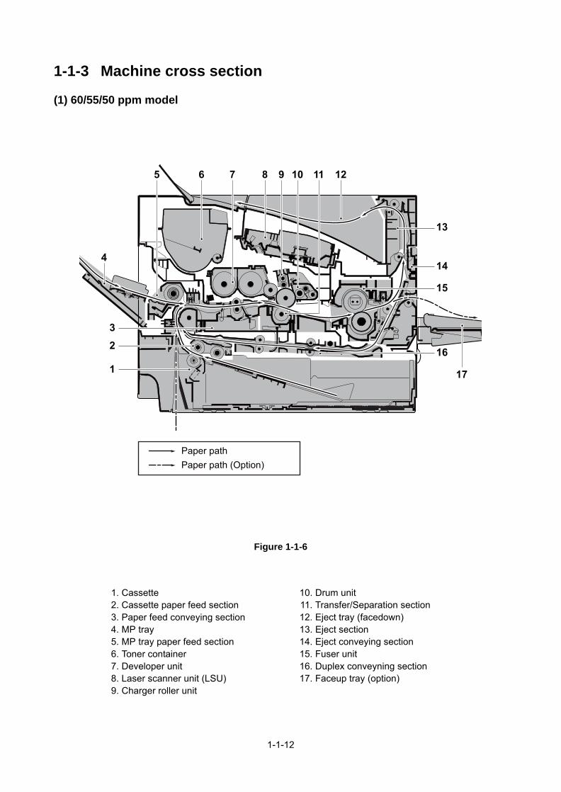
1-1-3 Machine cross section
(1) 60/55/50 ppm model
Figure 1-1-6
Paper pathPaper path (Option)
10 11
17
96 128
13
15
2
116
3
14
7
4
5
1. Cassette2. Cassette paper feed section3. Paper feed conveying section4. MP tray5. MP tray paper feed section6. Toner container7. Developer unit8. Laser scanner unit (LSU)9. Charger roller unit
10. Drum unit11. Transfer/Separation section12. Eject tray (facedown)13. Eject section14. Eject conveying section15. Fuser unit16. Duplex conveyning section17. Faceup tray (option)
1-1-12

(2) 45 ppm model
Figure 1-1-7
Paper pathPaper path (Option)
10 1196 128
13
15
2
116
3
14
7
4
5
1. Cassette2. Cassette paper feed section3. Paper feed conveying section4. MP tray5. MP tray paper feed section6. Toner container7. Developer unit8. Laser scanner unit (LSU)9. Charger roller unit
10. Drum unit11. Transfer/Separation section12. Eject tray (facedown)13. Eject section14. Eject conveying section15. Fuser unit16. Duplex conveyning section
1-1-13

This page is intentionally left blank.
1-1-14

1-2 Installation
1-2-1 Installation environment
1. Temperature: 10 to 32.5°C/50 to 90.5°F2. Humidity: 15 to 80% RH3. Power supply: 100 V AC 50/60 Hz, 11.4A
120 V AC 60 Hz, 9.5 A 220 - 240 V AC 50/60 Hz , 5.4 A
4. Power supply frequency: 50 Hz ±2%/60 Hz ±2%5. Installation location
Avoid direct sunlight or bright lighting. Ensure that the photoconductor will not be exposed to direct sun-light or other strong light when removing paper jams.Avoid locations subject to high temperature and high humidity or low temperature and low humidity; anabrupt change in the environmental temperature; and cool or hot, direct air.Avoid places subject to dust and vibrations.Choose a surface capable of supporting the weight of the machine.Place the machine on a level surface (maximum allowance inclination: 1°).Avoid air-borne substances that may adversely affect the machine or degrade the photoconductor, suchas mercury, acidic of alkaline vapors, inorganic gasses, NOx, SOx gases and chlorine-based organic sol-vents.Select a well-ventilated location.
6. Allow sufficient access for proper operation and maintenance of the machine.
Figure 1-2-1
(45 ppm model)
(60/55/50 ppm models)
300 mm11 13/16”
100 mm3 15/16”
200 mm7 7/8”
500 mm19 11/16”
400 mm15 3/4”
400 mm15 3/4”
300 mm11 13/16”
100 mm3 15/16”
200 mm7 7/8”
500 mm19 11/16”
1-2-1

1-2-2 Unpacking and installation
Figure 1-2-2
Caution: Place the machine on a level surface.
Unpacking
9
1
347
12
10
8
5
6
13
2
11
1. Outer case2. Inner case3. Bottom pad R4. Bottom pad L5. Machine cover (740 × 700)6. Machine7. Upper pad R
8. Upper pad L9. Top tray
10. Operation guide11. Operation sheets Assy *112. Waste toner bottle13. Power cord*1: Except 240V model
1-2-2

1. Remove two tapes.2. Remove the protection sheet.
Figure 1-2-3
3. Remove four tapes.
Figure 1-2-4
Removing the tapes and pads
Protection sheet
Tape
Tape
Tape
Tape
Tape
Tape
1-2-3

(60/50/45 ppm model only)4. Open the top cover.5. Remove the tape and the spacer.
Figure 1-2-5
1. Open the top cover.2. Remove the container label by pulling
forwards.
Caution: Check the contents of thecontainer label and remove a container.
Figure 1-2-6
Tape
Top cover
Spacer
Installing the toner container
Container label
Top cover
1-2-4

3. Rotate the toner container lock lever tothe lock position and then remove thetoner container from the printer byreturning it to the unlock position.
Figure 1-2-7
4. Shake the turned toner container 10times or more as shown in the figure inorder to distribute the toner evenlyinside the container.Caution:Do not press too firmly on thecenter of the toner container or touchthe toner feed slot or the terminal parts.
5. Set the toner container to the printerand then turn the toner container locklever to the lock position.
6. Close the top cover.
Figure 1-2-8
Unlock position
Toner containerlock lever
Lock position
Shipment position
Toner container
Printer
Terminal parts
Tonercontainer
Toner feed slot
1-2-5

1. Openthe left cover.2. Open the cap of the waste toner box.3. Install the waste toner box.4. Close the left cover.
Figure 1-2-9
Installing the waste toner box
Waste toner box
Cap
Left cover
1-2-6
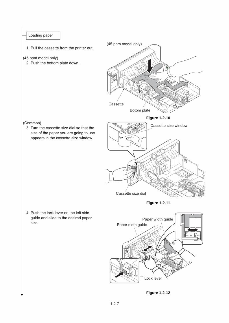
1. Pull the cassette from the printer out.
(45 ppm model only)2. Push the bottom plate down.
Figure 1-2-10 (Common)
3. Turn the cassette size dial so that thesize of the paper you are going to useappears in the cassette size window.
Figure 1-2-11
4. Push the lock lever on the left sideguide and slide to the desired papersize.
Figure 1-2-12
Loading paper
(45 ppm model only)
Botom plateCassette
Cassette size dial
Cassette size window
Paper didth guidePaper width guide
Lock lever
1-2-7

5. Push the lock lever and slide the paperlength guide to the desired paper size.
If you are going to set paper that is lon-ger than A4, pull out the extension cas-settes pushing the lock button one byone and adjust them to the desiredpaper size.
Figure 1-2-13
6. Fan the media (paper/transparencies),then tap it on a level surface to avoidmedia jams or skewed printing.
7. Slide the paper into the paper cassette.8. Insert the cassette into the slot in the
printer. Push it straight in as far as it willgo.
Figure 1-2-14
(Legal/Folio)
Paper length guide
Extension cassette
Lock button
Paper
Paper maximum line
1-2-8

1. Rotate the operation panel ring in thecounterclockwise direction.
2. Remove the operation panel cover.3. Replace it to the operation panel sheet
of the corresponding language.4. Refit all the removed parts.
Figure 1-2-15
5. Stick the language sheet of the corre-sponding language.
Figure 1-2-16
Replace the operation panel sheet (except 240V AC model)
Operation panel sheet
Operation panel cover
Operation panel ring
Language sheet
1-2-9

1. Open the rear cover.2. Remove the inlet cover.3. Connect the USB interface cable to the
printer and PC.
Figure 1-2-17
4. Connect the network interface cable tothe printerand network.
Figure 1-2-18
5. Connect the power cord to the printerand the wall outlet.
6. Refit the inlet cover.7. Close the rear cover.
Figure 1-2-19
Connecting the cable
USB interface cable
Inlet cover
Network interface cable
Power cord
Wall outlet
1-2-10

8. Press the power switch and then checkthe lighting up of ready indicator.
9. Installing the printer driver (refer tooperation guide).
Figure 1-2-20
1. Press the menu key.2. Select [Device Common] using the cursor up/down keys.3. Press the OK key.4. Select [Language] using the cursor up/down keys.5. Press the OK key.6. Select the language to set using the cursor up/down keys.7. Press the OK key.
1. Press the menu key.2. Select [Report Print] using the cursor up/down keys.3. Press the OK key.4. Select [Status Page] using the cursor up/down keys.5. Press the OK key.6. Select the [YES] using the left select key.7. [Accepted] is displayed and the page will be printed.8. Press the menu key.
Power on
ON
ONReady indicator
Power switch
Setting the language
Printout the status page
Completion of the machine installation
1-2-11

1-2-3 Installing the optional equipment
(1) Expansion memory
Procedure1. Remove the inlet cover.2. Remove the slot cover.3. Unplug the power cable.
Caution: Do not insert or remove mainPWB assembly while machine power ison.Doing so may cause damage to themachine and the main PWB.
Figure 1-2-21
4. Remove five screws and then removethe main PWB assembly.
5. Aligning the cutouts of the memorymodule with the matching keys of thesocket, carefully plug the memory mod-ule into the memory socket until it clicksin place.
6. Then, push down the memory moduleto secure.
7. Refit the main PWB assembly and thescrews.
8. Refit the covers.9. Plug the printer into a power outlet.
10. Print a status page to check the mem-ory expansion. (See page 1-3-2)If memory expansion has been properlyperformed, information on the installedmemory is printed with the total memorycapacity has been increased.Standard memory capacity 256 MB.
Figure 1-2-22
Slot cover
Inlet cover
Expansion memory
Memory socket
ScrewScrew
Screw
ScrewMain PWB Assembly
1-2-12

(2) Memory card (SD card)
Procedure1. Remove the inlet cover and slot cover.
(SeePage 1-5-3)2. Remove two screws and the slot cover.3. SD card is inserted in a SD card slot.4. Refit the removed covers.
Figure 1-2-23
SD card slot
Slot cover
ScrewsSD card
1-2-13

(3) Wireless Network
Precedure1. Unplug the power cab
* : Wait for 15 secondsstep 2.
2. After twisting the Wi-Fit.
3. Insert the connector
backside connector o
the connector of the M
4. Reattach the Wi-Fi co
position.
5. Plug the power cable
Note of detaching and re
When attaching the WiFi Pinsert it while aligning it to cover.
Also, take care not to twistassembly in the vertical diavoid the damage when ating it.
Interface Kit (IB-36)
le.
or more, go to the
i cover, remove
while aligning the
f the Wi-Fi PWB to
ain PWB.
ver in the original
.
fitting
WB assembly, the guide on the top
the WiFi PWB rection in order to taching and detach-
Wi-Fi PWB cover
Wi-Fi PWB AssyTop cover
Insert guides
1-2-14
Figure 1-2-24

1-2-4 Option composition
Faceup Output Tray PT-320
Network Interface Kit IB-50
SSDHD-6/HD-7
USB Flash Memory
Paper Feeder PF-320
Parallel Interface Kit IB-32B
Wireless Network Interface Kit IB-36
Software option
Data Security Kit(E)
UG-33
Card Authentication Kit(B)
Bulk Feeder PF-3100
Wireless Network Interface Kit IB-51
Expansion Memory SD Memory CardSDHC Memory
Card
1-2-15

This page is intentionally left blank.
1-2-16

1-3 Maintenance Mode
1-3-1 Service mode
The machine is equipped with a maintenance function which can be used to maintain and service the machine.
(1) Executing a service mode
Press the Menu key.
Select [Adjust/Maint.] using the cursor up/down keys and press the OK key.
The selected service mode is run.
Press the Menu key.
Select [Service Setting] using the cursor up/down keys and press the OK key.
Start
End
The Mode Selection Menu appears.
The Adjust/Maintenance menu appears.
The Service Setting menu appears.
1-3-1

(2) Description of service mode
Service items Description
Service Status Printing a status page for service purpose
DescriptionPrints a status page for service purpose. The status page includes various settings and service cumulative.PurposeTo acquire the current printing environmental parameters and cumulative information.
Method1. Enter the Service Setting menu.2. Select [Status Page] using the cursor up/down keys.3. Press the OK key.4. Select the [YES] using the left select key.
[Accepted] is displayed and two pages will be printed.
1-3-2

Service status page (1)
Figure 1-3-1
Service items Description
Firmware Version 2T6_S000.000.000 2016.08.17
2016/08/17 15:15
[XXXXXXXX] [XXXXXXXX] [XXXXXXXX]
PrinterPG L2555
512 MB
512 MB0 MB
+01:00 _Osaka, Sapporo, Tokyo10/30/2014 02:3310.183.53.13
Card Authentication Kit (B)
K: 4.29 / 776.00 (27/10/2010 - 03/11/2010 08:40)
3.863.86
.
.
.
.
.
.
.
.
.
.
.
.
.
.
.
.
.
.
.
RP Code Code1234 5678 90125678 9012 34569012 3456 78903456 7890 1234
A3+A4/100
Y6
0.0A1+A2/1000.0
0
1
Service Status Page
Controller Information
Standard SizeMemory status
Option SlotTotal Size
TimeLocal Time ZoneDate and TimeTimer ServerInstalled OptionsPaper feeder2
SSD
Installed
Not InstalledNot Installed
Data Security Kit (E) Not InstalledUG-33 InstalledUSB Keyboard ConnectedUSB Keyboard Type US-English
Print CoverageAverage(%)
PeriodLast Page (%)Last Job (%)
/ Usage Page(A4/Letter Conversion)
FRPO StatusUser Top MarginUser Left Margin
e-MPS error control
[XXXXXXXXXX]
(1)
(7)
(8)(9)
(10)
(22)
(23)
(25)(26)
(11)
(16)SD card Not Installed(15)
(17)(18)(19)(20)(21)
(Paper feeder3 Not Installed(12)(Paper feeder4 Not Installed(13)(Paper feeder5 Not Installed(14)(
(27)
(28)(29)(30)(31)
(6)(2)
(3) (4) (5)
(24)
1-3-3

Service status page (2)
Figure 1-3-2
Service items Description
NVRAM Version _CR05A19_CR05A1900:17:C8:3B:41:7E
0/0/0/0/0/0/0/0/0/0/0/0/0/0/
1/4644/600
0/50/0/50/0000064/0000000/0000064/////0000000//0000063/0000063/0000063/F00/U00/0/1/0/0/1/25/27/30/0/0/25/25//5/1/0/1010/9000/2010/4000/3010/1010/4000/2010/1010/1010/5000/6000/5010/1010/1010/1010/1010/1010/1010/1010/1010/1010/0300A000/00000000/544B2D353234314B5300000000000000/36313246303335580000000000000000/0078/00/00
-/0/5/
[2T9_81BR.001.008] [ ] [ ] [ ] [ ][ ] [ ] [ ] [ ] [ ]
1/1/1/0/0/
[2T9_1000.001.083] [2T9_1100.001.002] [2T9_1100.001.002]
2
Engine InformationController Information
MAC AddressAltitude AdjustmentStatus Normal
[ZE76100020]
2016/08/17 19:45
Service Status PagePrinterPG L2555Firmware Version 2T6_S000.001.123 2016.08.17
(33)(34)
(32)
(35) (36)(37)
(39)(38)
(40)(41)
(60)
(63)/0/(62)
(64) (65) (66) (67) (68)
(61)
(71)0/4/ (69) (70)
(42) (43) (44) (45) (46) (47) (48) (49) (50) (51) (52) (53) (54) (55) (56) (57) (58) (59)
(72) (73) (74) (75)
(76) (77) (78) F3B10Z5000110/(79)
1-3-4

Detail of service status page
Service items Description
No. Description Supplement
(1) Firmware version -
(2) System date -
(3) Engine soft version -
(4) Engine boot version -
(5) Operation panel mask version -
(6) Machine serial number -
(7) Total memory size -
(8) Local time zone -
(9) Report output date Day/Month/Year hour:minute
(10) NTP server name -
(11) Presence or absence of the optional paper feeder 2
Installed/Not Installed
(12) Presence or absence of the optional paper feeder 3
Installed/Not Installed
(13) Presence or absence of the optional paper feeder 4
Installed/Not Installed
(14) Presence or absence of the optional paper feeder 5
Installed/Not Installed
(15) Presence or absence of the optional SD card
Installed/Not Installed
(16) Presence or absence of the optional SSD
Installed/Not Installed
(17) Presence or absence of the optional Card Authentication Kit(B)
Installed/Not Installed/Trial
(18) Presence or absence of the optional Security Kit(E)
Installed/Not Installed
(19) Presence or absence of the optional UG-33
Installed/Not Installed
(20) The connection state of an optional USB Keyboard
Connected/Not Connected
(21) Displays setting of optional USB Keyboard
US English/US English with Euro/German/French
(22) Page of relation to the A4/Letter * :Print Coverage provides a close-matching referenceof toner consumption and will not match with theactual toner consumption.
(23) Average printer coverage Black
(24) Cleared date and output date -
1-3-5

Detail of service status page
Service items Description
No. Description Supplement
(25) Coverage on the last output page
-
(26) Last job output date -
(27) FRPO setting -
(28) RP Code Code the engine software version and the date of update.
(29) Code the main software version and the date of update.
(30) Code the engine software version and the date of the previous update.
(31) Code the main software version and the date of the previous update.
(32) High altitude adjustment set data
Normal/1001-2000m/2001-3000m/3001-3500m
(33) NV RAM version _ 1F3 1225 _ 1F3 1225(a) (b) (c) (d) (e) (f)(a) Consistency of the present software version andthe database_ (underscore): OK
* (Asterisk): NG(b) Database version(c) The oldest time stamp of database version(d) Consistency of the present software version andthe ME firmware version_ (underscore): OK* (Asterisk): NG(e) ME firmware version(f) The oldest time stamp of the ME database versionNormal if (a) and (d) are underscored, and (b) and (e)are identical with (c) and (f).
(34) Mac address -
(35) Destination information -
(36) Area information -
(37) Margin settings Top margin/Left margin
(38) Top offset for each paper source MP tray/Paper feeder 1/Paper feeder 2/Paper feeder 3/Paper feeder 4/Duplex/Page rotation
(39) Left offset for each paper source MP tray/Paper feeder 1/Paper feeder 2/Paper feeder 3/Paper feeder 4/Duplex/Page rotation
(40) L value settings Top margin integer part / Top margin decimal part/Left margin integer part / Left margin decimal part/
1-3-6

Service items Description
No. Description Supplement
(41) Life counter (The first line) Machine life/MP tray/Cassette/Paper feeder 1/Paper feeder 2/Paper feeder 3/Paper feeder 4/Duplex
Life counter (The second line) Bulk Feeder counter/Drum counter K/Developer counter K/Maintenance kit counter
(42) Panel lock information F00: OFFF01: Partial Lock 1F02: Partial Lock 2F03: Partial Lock 3F04: Full Lock
(43) USB information U00: Not ConnectedU01: Full speedU02: Hi speed
(44) Paper handling information 0: Paper source unit select/1: Paper source unit
(45) Auto cassette change 0: OFF/ 1: ON
(46) Color printing double count mode
0: All single counts3: Folio (Less than 330 mm length), Single counts
(47) Black and white printing double count mode
0: All single counts3: Folio, Single count, Less than 330 mm (length)
*: The count mode can be changed using a PRE-SCRIBE command.When the double count is set for the paper other than the sizes of A4, B5, A5, Folio, Legal, Letter, and State-ment, the counter value is indicated as "Other 1" in the status page. When in the same way, the single count is set, the counter value is indicated as "Other 2". In the operation panel, the counter values are indicated as "Other 1" or "Other 2".
(48) Temperature (machine inside) -
(49) Temperature (machine outside) -
(50) Relative humidity (machine outside)
-
(51) Absolute humidity (machine outside)
-
(52) Humidity (machine inside) -
(53) LSU temperature -
(54) LSU 2 temperature -
(55) DRT parameter coefficient -
(56) Fixed assets number -
(57) Job end judgment time-out time -
1-3-7

Service items Description
No. Description Supplement
(58) Job end detection mode 0: It is as one job even if it includes multiple jobs in the job received with network connection. 1: If it includes multiple jobs in the job received, detect the break point between jobs and divide them.
(59) PRESCRIBE environmental reset
0: Off1: On
(60) Media type attributes1 to 28 (Not used: 18, 19, 20)
For details on settings, refer to MDAT command in “Prescribe Commands Reference Manual.
Weight settings Fuser settings0: Light 0: High1: Normal 1 1: Middle2: Normal 2 2: Low3: Normal 3 3: Vellum4: Heavy 1 Duplex settings5: Heavy 2 0: Disable6: Heavy 3 1: Enable7: Extra Heavy
(61) RFID information -
(62) Toner install mode information -
(63) Soft version of the optional paper feeder
Paper feeder 1/Paper feeder 2/Paper feeder 3Paper feeder 4
(64) Version of the optional message -
(65) Color table version
(66) Color table 2 version -
(67) Color table version for copy
(68 Color table 2 version for copy
(69) Altitude Adjustment 0: Standard1: High altitude 12: High altitude 2
(70) MC correction 1 to 7
(71) Color conversion automatic judgment
0: Off1: On
(72) Toner Low setting 0:Invalid1: Effective
(73) Toner Low detection level 0 to 100 (%)
(74) Skip Mode (Blank Page) 0:Disabled1:Enabled
1-3-8

Service items Description
No. Description Supplement
(75) Full page printing mode 0:Normal mode (The factory default settings)1:Full page mode
(76) Wake UP mode 0: OFF (Don't wake up)1: ON (Do wake up)
(77) Wake Up Timer Displays the wake-up time
(78) BAM conformity Mode setting 0: Un-suiting Mode1: Conformity Mode
(79) Drum serial number -
Code conversion
A B C D E F G H I J
0 1 2 3 4 5 6 7 8 9
1-3-9

Network Status Printing a status page for network
DescriptionPrints a status page for network.Execution is possible only the model with network.PurposeTo acquire the detailed network setting information.
Method1. Enter the Service Setting menu.2. Select [Network Status] using the cursor up/down keys.3. Press the OK key.4. Select the [YES] using the left select key.
[Accepted] is displayed and Network status page will be printed.
OP Network Status
Printing a status page for optional network
DescriptionPrints a status page for optional network.Execution is possible only the model with optional network.PurposeTo acquire the detailed network setting information.
Method1. Enter the Service Setting menu.2. Select [OP Network Status] using the cursor up/down keys.3. Press the OK key.4. Select the [YES] using the left select key.
[Accepted] is displayed and Network status page will be printed.
Service items Description
1-3-10

Test Page Printing a test page
DescriptionThe test page is printed with halftones.PurposeTo check the activation of the developer and drum units.
Method1. Enter the Service Setting menu.2. Select [Test Page] using the cursor up/down keys.3. Press the OK key.4. Select the [YES] using the left select key.
[Accepted] is displayed and Test page will be printed.
Figure 1-3-3
Service items Description
1-3-11

Event log Printing an event log (EVENT LOG)
DescriptionPrints a history list of occurrences of paper jam, self-diagnostics, toner replacements, etc.PurposeTo allow machine malfunction analysis based on the frequency of paper misfeeds, self diagnostic errors and replacements.
Method1. Enter the Service Setting menu.2. Select [Event Log] using the cursor up/down keys.3. Press the OK key.4. Select the [YES] using the left select key.
[Accepted] is displayed and will be printed.
Service items Description
1-3-12

Detail of event log (1)
Figure 1-3-4
Service items Description
2014/10/19 15:15[XXXXXXXX][XXXXXXXX] [XXXXXXXX]
XXXXXXXXXXXXXXXX
Event LogPrinterPG L2555Firmware version 2T6_S000.000.000 2014.09.19
(2)
(4)(3) (5)(1)
Machine No.:Z7T0000000(6) Life Count:100000(7)
1
(8)
(9) (11)
(10)
Toner Log
# Count. Item Serial Number Date and Time5 9999999 01.00 0123456789ABCDEF 2014/05/01 10:00 4 9999999 01.00 0123456789ABCDEF 2014/04/05 10:00 3 9999999 01.00 0123456789ABCDEF 2014/02/21 10:00 2 9999999 01.00 0123456789ABCDEF 2013/11/30 10:00 1 9999999 01.00 0123456789ABCDEF 2013/11/24 10:00
Paper Jam Log
# Count. Event Descriptions Date and Time16 9999999 4003.01.00.00.00 2014/09/22 10:00 15 8888888 0501.01.00.00.00 2014/09/20 09:22 14 9999999 4201.01.00.00.00 2014/09/11 10:00 13 9999999 4003.01.00.00.00 2014/09/11 10:00 12 9999999 4003.01.00.00.00 2014/09/11 10:00 11 9999999 4003.01.00.00.00 2014/09/03 10:00 10 9999999 4003.01.00.00.00 2014/08/15 10:00 9 9999999 4003.01.00.00.00 2014/08/11 10:00 8 9999999 4003.01.00.00.00 2014/07/05 10:00 7 9999999 4003.01.00.00.00 2014/07/04 10:00 6 9999999 4003.00.00.00.00 2014/06/26 10:00 5 9999999 4003.00.00.00.00 2014/05/01 10:00 4 9999999 4003.00.00.00.00 2014/04/05 10:00 3 9999999 4003.00.00.00.00 2014/02/21 10:00 2 9999999 4003.00.00.00.00 2013/11/3010:00 1 9999999 4003.00.00.00.00 2013/11/24 10:00
Service Call Log
# Count. Service Code Date and Time8 9999999 01.00.0100 2014/07/05 10:00 7 9999999 02.01.0100 2014/07/04 10:00 6 9999999 01.01.0000 2014/06/26 10:00 5 9999999 01.00.0000 2014/05/01 10:00 4 9999999 01.01.0000 2014/04/05 10:00 3 9999999 02.00.0000 2014/02/21 10:00 2 9999999 02.00.0000 2013/11/30 10:00 1 9999999 01.00.0000 2013/11/24 10:00
Maintenance Log
# Count. Item Date and Time8 9999999 02.01 2014/07/05 10:00 7 9999999 02.00 2014/07/04 10:00 6 9999999 02.01 2014/06/26 10:00 5 9999999 02.02 2014/05/01 10:00 4 9999999 02.03 2014/04/05 10:00 3 9999999 02.01 2014/02/21 10:00 2 9999999 02.00 2013/11/30 10:00 1 9999999 02.02 2013/11/24 10:00 4003.01.00.00.00
(a) (b) (c) (d) (e)
1-3-13

Detail of event log (2)
Figure 1-3-5
Service items Description
2014/10/19 15:15[XXXXXXXX][XXXXXXXX] [XXXXXXXX]
XXXXXXXXXXXXXXXX
Event LogPrinterPG L2555Firmware version 2T6_S000.000.000 2014.09.19
(2)
(4)(3) (5)(1)
Machine No.:Z7T0000000(6) Life Count:100000(7)
2
Counter Log
J0000 : 1 J0001 : 2J0002 : 3J0003 : 4J0004 : 5J0005 : 6J0006 : 7J0007 : 8J0008 : 9J0009 : 10J0010 : 20 J0011 : 30 J0012 : 40 J0013 : 50J0014 : 60 J0015 : 70J0016 : 80J0017 : 90J0018 : 100J0019 : 110 J0020 : 120 J0021 : 130 J0022 : 140J0023 : 150J0024 : 160J0025 : 170J0026 : 180J0027 : 190J0028 : 200J0029 : 300 J0030 : 400J0031 : 500J0032 : 600J0033 : 700J0034 : 800J0035 : 900
J0035 : 999 J0036 : 999J0037 : 999J0038 : 999J0039 : 999J0040 : 999C0001 : 1 C0002 : 2C0003 : 3C0004 : 4C0005 : 5C0006 : 6C0007 : 7C0008 : 8C0009 : 9C0010 : 10C0011 : 11C0012 : 12C0013 : 13C0014 : 14C0015 : 15C0016 : 16C0017 : 17C0018 : 18C0019 : 19C0020 : 20CF245: 21 ( 0)CF248: 22 ( 11) CF345: 222 ( 111)T00 : 10T01 : 20T02 : 30T03 : 40M00 : 50M01 : 60M02 : 70M03 : 80M04 : 90
(12)
(f)
(g)
(h)
1-3-14

Description of event log
Service items Description
No. Items Description
(1) System version
(2) System date
(3) Engine soft version
(4) Engine boot version
(5) Operation panel mask version
(6) Machine serial number
(7) LIfe Counter
(8) Paper Jam Log
# Count. Event
Remembers 1 to 16 ofoccurrence.If the past paper jamoccurrence is less than 16, all of them are indicated.The oldest log is deletedwhen exceeding 16events.
The total page count at the time of the paper jam.
Log code (hexadeci-mal, 5 categories)
(a) Cause of a paperjam
(b) Paper source(c) Paper size(d) Paper type(e) Paper eject
(a) Detail of Cause of paper jam (Hexadecimal)
:Refer to "17-1 Paper Misfeed Detection" (See page ),for the detail of Cause of paper jam. (7-9)
(b) Detail of paper source (Hexadecimal)
00: MP tray01: Cassette 102: Cassette 2 (paper feeder)03: Cassette 3 (paper feeder)04: Cassette 4 (paper feeder)05: Cassette 5 (paper feeder)08: Bulk feeder (paper feeder)06, 07, 09: Reserved
1-3-15

Service items Description
No. Items Description
(8)cont.
Paper Jam Log
(c) Detail of paper size (Hexadecimal)
00: (Not specified)01: Monarch02: Business 03: International DL04: International C505: Executive06: Letter-R86: Letter-E07: Legal08: A4R88: A4E09: B5R89: B5E0A: A3
0B: B40C: Ledger0D: A5R0E: A60F: B610: Commercial #911: Commercial #612: ISO B513: Custom size1E: C41F: Postcard20: Reply-paid postcard21: Oficio II
22: Special 123: Special 224: A3 wide25: Ledger wide26: Full bleed paper (12 x 8)27: 8K28: 16K-RA8: 16K-E32: Statement-RB2: Statement-E33: Folio34: Western type 235: Western type 4
(d) Detail of paper type (Hexadecimal)
01: Plain02: Transparency03: Preprinted04: Labels05: Bond06: Recycled07: Vellum08: Rough09: Letterhead
0A: Color0B: Prepunched0C: Envelope0D: Cardstock0E: Coated0F: 2nd side10: Thick11: High quality
15: Custom 116: Custom 217: Custom 318: Custom 419: Custom 51A: Custom 61B: Custom 71C: Custom 8
(e) Detail of paper eject location (Hexadecimal)
01: Face down (FD)02: Face up (FU) (55/50 ppm model only)
1-3-16

Service items
No. Item
(9) Service Log
(10) Mainte-nance L
(11) Toner Lo
Description
s Description
Call # Count. Service Code
Remembers 1 to 8 of occurrence of self diagnostics error. If the occurrence of the previous diag-nostics error is less than 8, all of the diagnostics errors are logged.
The total page count at the time of the self diag-nostics error.
Self diagnostic error code (See page 1-4-8)
Example:01.6000
01: Self diagnostic error6000: Self diagnostic error code number
og# Count. item
Remembers 1 to 8 of occurrence of replacement. If the occurrence of the previous replace-ment of toner con-tainer is less than 8, all of the occur-rences of replace-ment are logged.
The total page count at the time of the replacement of the toner con-tainer.
* :The tonerreplacement log istriggered by tonerempty.This record maycontain such a ref-erence as thetoner container isinserted twice or aused toner con-tainer is inserted.
Code of maintenance replac-ing item (1 byte, 2 categories)
First byte (Replacing item) 01: Toner container Second byte (Type of replacing item) 00: Black
First byte (Replacing item) 02: Maintenance kit Second byte (Type of replacing item) 01: MK-3170/3160
g # Count. item
Remembers 1 to 32 of occurrence of unknown toner detection. If the
The total page count at the time of the toner empty error.
Unknown toner log code (1 byte, 2 categories)
First byte
1-3-17
occurrence of the previous unknown toner detection is less than 32, all of the unknown toner detection are logged.
01: Toner container (Fixed)Second byte00: Black

Service items Description
No. Items Description
(12) Counter Log
Comprised of three log counters including paper jams, self diagnos-tics errors, and replacement of the toner container.
(f) Paper jam (g) Self diagnosticerror
(h) Maintenance item replac-ing
Indicates the log counter of paper jams depending on location.
Refer to Paper Jam Log.
All instances including those are not occurred are displayed.
Indicates the log counter of self diag-nostics errors depending on cause. (See page 1-4-8)
Example: C6000: 4
Self diagnostics error 6000 has hap-pened four times.
Indicates the log counter depending on the mainte-nance item for maintenance.
T: Toner container00: Black
M: Maintenance kit 01: MK-3170/3160 MK-3170/3160 MK-3172/3162 MK-3174/3164
Example:T00: 1The toner container has been replaced once.
* :The toner replacement logis triggered by toner empty.This record may contain sucha reference as the toner con-tainer is inserted twice or aused toner container isinserted.
1-3-18

Maintenance Counter reset for the maintenance kit
DescriptionThe "Install MK" message means that maintenance kit should be replaced at fixed pages of printing. The interval counter must be manually reset using this service item.
:300,000 images :500,000 images
Maintenance kit MK-3160 (45 ppm) MK-3170 (55/50 ppm)
Maintenance kit includes the following units: Drum unit Developer unit Transfer roller assembly Fuser unit Paper feed roller assembly Retard roller assembly
PurposeTo reset the life counter for maintenance kit.
Method Drum unit (see page 1-5-15) Developer unit (see page 1-5-13) Transfer roller assembly (see page 1-5-16) Fuser unit (see page 1-5-19) Paper feed roller assembly (see page 1-5-8) Retard roller assembly (see page 1-5-8)
Method1. Enter the Service Setting menu.2. Select [Maintenance] using the cursor up/down keys.3. Press the OK key.4. Select the [YES] using the left select key.
[Completed] is displayed.The counter for each component is reset immediately.
Note:Occurrences of resetting the maintenance kits are recorded on the service status page or event log in number of pages at which the maintenance kit was replaced (see page 1-3-2, page 1-3-12 ). This may be used to determine the possibility that the counter waserrorneously or unintentionally reset.
Service items Description
1-3-19

Drum Drum surface refreshing
DescriptionThe execution of the drum refresh (no paper)Rotates the drum approximately 3 minutes with toner lightly on the overall drum using the high-voltage output control. The cleaning blade in the drum unit scrapes toner off the drum surface to clean it.
PurposeTo clean the drum surface when image failure occurs due to the drum. This mode is effective when dew condensation on the drum occurs.
Method1. Enter the Service Setting menu.2. Select [Drum] using the cursor up/down keys.3. Press the OK key.4. Select the [YES] using the left select key.
Drum surface refreshing will start.
Drum2 Drum surface refreshing 2
DescriptionThe execution of the drum refresh (with paper)Drum surface refreshing be done by being rubed to the paper that was fed from MP.
PurposeTo clean the drum surface when image failure occurs due to the drum. This mode is effective when dash-mark on the drum occurs.
Method1. Enter the Service Setting menu.2. Select [Drum2] using the cursor up/down keys.3. Press the OK key.4. Select the [YES] using the left select key.
Drum surface refreshing will start.
Service items Description
1-3-20

New Developer Initializing the developing unit (toner install mode)
DescriptionThe new developing unit is shipped from the factory with no toner contained. The devel-oping unit can be automatically replete with toner when a toner container is installed onto it and the printer is turned on. However, because the toner reservoir in the developing unit has a large capacity, it requires a lengthy period of time until a substantial amount of toner has been fed to get the printer ready. (A new developing unit needs approximately 200 g for triggering the sensor inside.)
PurposeTo execute when the developing unit has been replaced.
Method1. Enter the Service Setting menu.2. Select [New Developer] using the cursor up/down keys.3. Press the OK key.4. Select the [YES] using the left select key.
[Accepted] is displayed.The toner installation is performed when power is turned on and off.
NOTE: Toner supply is stopped when toner installation mode is performing.
Auto Drum Refresh
Automatic drum surface refreshing
DescriptionThe drum surface refreshing operation is normally performed when the power is turned on to the printer or during warm-up when the printer is recovering from the Sleep mode, but even then only at those times that the temperature/humidity sensor detects the drum surface to be in a state of dew condensation. By using this mode, it is possible to force the drum surface refreshing operation to be performed automatically at a predetermined period of time, regardless of the status detected by the temperature/humidity sensor.
PurposeTo prevent bleeding of the output image when the printer's operating environment is one of high humidity.
Method1. Enter the Service Setting menu.2. Select [Auto Drum Refresh] using the cursor up/down keys.3. Press the OK key.4. Select the desire mode (Off/Short/Standard/Long) using the cursor up/down keys.5. Press the OK key. The new value is set.
Service items Description
1-3-21

Drum heater Setting drum heater
Description"On/Off" of a drum heater is set up. If it sets to "ON", drum refresh time will become short.
PurposeIn order to improve the picture blot by high humidity.
Method1. Enter the Service Setting menu.2. Select [Drum heater] using the cursor up/down keys.3. Press the OK key.4. Select [Off] or [On] using the cursor up/down keys.5. Press the OK key. The setting is set.
Write Data Write data (USB memory data write)
DescriptionTo write data into a USB memory.Execution is possible only when a USB memory is detected.
MethodInstall the USB memory before attempting to write data.
1. Enter the Service Setting menu.2. Select [Write Data] using the cursor up/down keys.3. Press the OK key.4. Select the [YES] using the left select key.5. [Data waiting] is displayed and the printer waits for data to be written.6. When the data is sent, [Processing] appears and the data is written to USB memory.
When data writing ends, the display returns to [Ready].
Altitude adj. Setting altitude adjustment
DescriptionSets the altitude adjustment mode.PurposeUsed when print quality deteriorates in an installation at the altitude of 1,500 meters or higher.
Method1. Enter the Service Setting menu.2. Select [Altitude Adj.] using the cursor up/down keys.3. Press the OK key.4. Select [Normal], [1001 - 2000m], [2001 - 3000m] or [3001 - 3500m] using the cursor
up/down keys.5. Press the OK key. The setting is set.
Service items Description
1-3-22

MC Setting main charger output
DescriptionSets the main charger output.Execution is possible only when the altitude adjustment mode is set to [Normal].PurposeExecute when the image density declines, dirt of a background or an offset has occurred.
Method1. Enter the Service Setting menu.2. Select [MC] using the cursor up/down keys.3. Press the OK key.4. Select [1] to [7] using the cursor up/down keys.5. Press the OK key. The setting is set.
Service items Description
1-3-23

This page is intentionally left blank.
1-3-24

1-4 Troubleshooting
1-4-1 Paper misfeed detection
(1) Paper misfeed indication
When a paper misfeed occurs, the machine immediately stops printing and displays the paper misfeed mes-sage on the operation panel. To remove paper misfeed in the machine, pull out the cassette, open the front cover or the rear cover.
(2) Paper misfeed detection condition
(2-1) PF-320 (500 sheets Paper feeder)
Figure 1-4-1 Paper jam location
EFS
DUS1ESDUS2
PS1/PS2RS1(3)
RS2MPPS
LS
PFLS1PFPS1PFPFS1
PFLS2PFPS2PFPFS2
PFLS3PFPS3PFPFS3
PFLS4PFPS4PFPFS4
I
J
K
L
E
F
G
H
A
BC
1-4-1
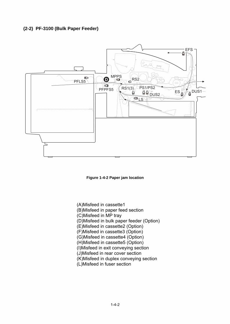
(2-2) PF-3100 (Bulk Paper Feeder)
Figure 1-4-2 Paper jam location
EFS
DUS1ESDUS2
PS1/PS2RS1(3)
RS2MPPS
LS
PFLS5
PFPFS5
D
(A)Misfeed in cassette1(B)Misfeed in paper feed section(C)Misfeed in MP tray(D)Misfeed in bulk paper feeder (Option)(E)Misfeed in cassette2 (Option)(F)Misfeed in cassette3 (Option)(G)Misfeed in cassette4 (Option)(H)Misfeed in cassette5 (Option)(I)Misfeed in exit conveying section(J)Misfeed in rear cover section(K)Misfeed in duplex conveying section(L)Misfeed in fuser section
1-4-2

Code Contents ConditionsJam
location*
0000 Initial jam The power is turned on when a sensor in the con-veying system is on.
-
0100 Secondary paper feed request time out
Secondary paper feed request given by the con-troller is unreachable.
-
0101 Waiting for process package to be ready
Process package won’t be ready. -
0104 Waiting for conveying pack-age to be ready
Conveying package won’t be ready. -
0105 Drive intrerrupt jam A drive does not stop. -
0106 Paper feeding request for duplex printing time out
Paper feeding request for duplex printing given by the controller is unreachable.
-
0107 Waiting for fuser package to be ready
Fuser package won’t be ready. -
0110 Rear cover 1 open The rear cover is opened during printing. -
0111 Top cover openBulk feeder cover open
The top cover or the bulk feeder cover is opened during printing.
-
0120 Receiving a duplex paper feeding request while paper is empty
Paper feed request was received from the duplex section despite the absence of paper in the duplex section.
-
0121 Exceeding number of duplex pages circulated
The controller issued the duplex section a request for more pages than the duplex print cycle con-tains.
-
0501 No paper feed of jam The registration sensor 2 (RS2) does not turn on during paper feed from cassette 1.
A
0502 PF feed sensor 1 (PFPFS1) does not turn on dur-ing paper feed from cassette 2.
E
0503 PF feed sensor 2 (PFPFS2) does not turn on dur-ing paper feed from cassette 3.
F
0504 PF feed sensor 3 (PFPFS3) does not turn on dur-ing paper feed from cassette 4.
G
0505 PF feed sensor 4 (PFPFS4) does not turn on dur-ing paper feed from cassette 5.
H
0508 The registration sensor 2 (RS2) does not turn on during paper feed from duplex section.
B
0509 The registration sensor 2 (RS2) does not turn on during paper feed from MP tray.
C
*: Refer to figure 1-4-1 for paper jam location (see page 1-4-1).
1-4-3

0511 Multiple sheets of jam The registration sensor 2 (RS2) does not turn off during paper feed from cassette 1.
B
0512 PF feed sensor 1 (PFPFS1) does not turn off dur-ing paper feed from cassette 2.
B
0513 PF feed sensor 2 (PFPFS2) does not turn off dur-ing paper feed from cassette 3.
B
0514 PF feed sensor 3 (PFPFS3) does not turn off dur-ing paper feed from cassette 4.
B
0515 PF feed sensor 4 (PFPFS4) does not turn off dur-ing paper feed from cassette 5.
B
0518 The registration sensor 2 (RS2) does not turn off during paper feed from duplex section.
B
0519 The registration sensor 2 (RS2) does not turn off during paper feed from MP tray.
B
0529 No paper feed of jam(Bulk feeder)
The registration sensor 2 (RS2) does not turn on during paper feed from bulk feeder.
D
0539 Multiple sheets of jam(Bulk feeder)
The registration sensor 2 (RS2) does not turn off during paper feed from bulk feeder.
B
1403 PF feed sensor 1 non arrival jam
PF feed sensor 1 (PFPFS1) does not turn on dur-ing paper feed from cassette 3.
E
1404 PF feed sensor 1 (PFPFS1) does not turn on dur-ing paper feed from cassette 4.
E
1405 PF feed sensor 1 (PFPFS1) does not turn on dur-ing paper feed from cassette 5.
E
1413 PF feed sensor 1 stay jam PF feed sensor 1 (PFPFS1) does not turn off dur-ing paper feed from cassette 3.
E
1414 PF feed sensor 1 (PFPFS1) does not turn off dur-ing paper feed from cassette 4.
E
1415 PF feed sensor 1 (PFPFS1) does not turn off dur-ing paper feed from cassette 5.
E
1604 PF feed sensor 2 non arrival jam
PF feed sensor 2 (PFPFS2) does not turn on dur-ing paper feed from cassette 4.
F
1605 PF feed sensor 2 (PFPFS2) does not turn on dur-ing paper feed from cassette 5.
F
1614 PF feed sensor 2 stay jam PF feed sensor 2 (PFPFS2) does not turn off dur-ing paper feed from cassette 4.
F
1615 PF feed sensor 2 (PFPFS2) does not turn off dur-ing paper feed from cassette 5.
F
1805 PF feed sensor 3 non arrival jam
PF feed sensor 3 (PFPFS3) does not turn on dur-ing paper feed from cassette 5.
G
1815 PF feed sensor 3 stay jam PF feed sensor 3 (PFPFS3) does not turn off dur-ing paper feed from cassette 5.
G
Code Contents ConditionsJam
location*
*: Refer to figure 1-4-1 for paper jam location (see page 1-4-1).
1-4-4

4002 Registration sensor 2 non arrival jam
The registration sensor 2 (RS2) does not turn on during paper feed from cassette 2.
B
4003 The registration sensor 2 (RS2) does not turn on during paper feed from cassette 3.
B
4004 The registration sensor 2 (RS2) does not turn on during paper feed from cassette 4.
B
4005 The registration sensor 2 (RS2) does not turn on during paper feed from cassette 5.
B
4012 Registration sensor 2 stay jam
The registration sensor 2 (RS2) does not turn off during paper feed from cassette 2.
B
4013 The registration sensor 2 (RS2) does not turn off during paper feed from cassette 3.
B
4014 The registration sensor 2 (RS2) does not turn off during paper feed from cassette 4.
B
4015 The registration sensor 2 (RS2) does not turn off during paper feed from cassette 5.
B
4101 Registration sensor 3 non arrival jam
The registration sensor 3 (RS3) does not turn on during paper feed from cassette 1.
B
4102 The registration sensor 3 (RS3) does not turn on during paper feed from cassette 2.
B
4103 The registration sensor 3 (RS3) does not turn on during paper feed from cassette 3.
B
4104 The registration sensor 3 (RS3) does not turn on during paper feed from cassette 4.
B
4105 The registration sensor 3 (RS3) does not turn on during paper feed from cassette 5.
B
4108 The registration sensor 3 (RS3) does not turn on during paper feed from duplex section.
B
4109 The registration sensor 3 (RS3) does not turn on during paper feed from MP tray.
B
Code Contents ConditionsJam
location*
*: Refer to figure 1-4-1 for paper jam location (see page 1-4-1).
1-4-5

4111 Registration sensor 3 stay jam
The registration sensor 3 (RS3) does not turn off during paper feed from cassette 1.
B
4112 The registration sensor 3 (RS3) does not turn off during paper feed from cassette 2.
B
4113 The registration sensor 3 (RS3) does not turn off during paper feed from cassette 3.
B
4114 The registration sensor 3 (RS3) does not turn off during paper feed from cassette 4.
B
4115 The registration sensor 3 (RS3) does not turn off during paper feed from cassette 5.
B
4118 The registration sensor 3 (RS3) does not turn off during paper feed from duplex section.
B
4119 The registration sensor 3 (RS3) does not turn off during paper feed from MP tray.
B
4201 Ejetct sensor non arrival jam The eject sensor (ES) does not turn on during paper feed from cassette 1.
I
4202 The eject sensor (ES) does not turn on during paper feed from cassette 2.
I
4203 The eject sensor (ES) does not turn on during paper feed from cassette 3.
I
4204 The eject sensor (ES) does not turn on during paper feed from cassette 4.
I
4205 The eject sensor (ES) does not turn on during paper feed from cassette 5.
I
4208 The eject sensor (ES) does not turn on during paper feed from duplex section.
I
4209 The eject sensor (ES) does not turn on during paper feed from MP tray.
I
4211 Ejetct sensor stay jam The eject sensor (ES) does not turn off during paper feed from cassette 1.
I or L
4212 The eject sensor (ES) does not turn off during paper feed from cassette 2.
I or L
4213 The eject sensor (ES) does not turn off during paper feed from cassette 3.
I or L
4214 The eject sensor (ES) does not turn off during paper feed from cassette 4.
I or L
4215 The eject sensor (ES) does not turn off during paper feed from cassette 5.
I or L
4218 The eject sensor (ES) does not turn off during paper feed from duplex section.
I or L
4219 The eject sensor (ES) does not turn off during paper feed from MP tray.
I or L
Code Contents ConditionsJam
location*
*: Refer to figure 1-4-1 for paper jam location (see page 1-4-1).
1-4-6

4301 Duplex sensor 1 non arrival jam
The duplex sensor 1 (DUS1) does not turn on dur-ing paper feed from cassette 1.
J
4302 The duplex sensor 1 (DUS1) does not turn on dur-ing paper feed from cassette 2.
J
4303 The duplex sensor 1 (DUS1) does not turn on dur-ing paper feed from cassette 3.
J
4304 The duplex sensor 1 (DUS1) does not turn on dur-ing paper feed from cassette 4.
J
4305 The duplex sensor 1 (DUS1) does not turn on dur-ing paper feed from cassette 5.
J
4309 The duplex sensor 1 (DUS1) does not turn on dur-ing paper feed from MP tray or bulk feeder.
J
4401 Duplex sensor 2 non arrival jam
The duplex sensor 2 (DUS2) does not turn on dur-ing paper feed from cassette 1.
K
4402 The duplex sensor 2 (DUS2) does not turn on dur-ing paper feed from cassette 2.
K
4403 The duplex sensor 2 (DUS2) does not turn on dur-ing paper feed from cassette 3.
K
4404 The duplex sensor 2 (DUS2) does not turn on dur-ing paper feed from cassette 4.
K
4405 The duplex sensor 2 (DUS2) does not turn on dur-ing paper feed from cassette 5.
K
4409 The duplex sensor 2 (DUS2) does not turn on dur-ing paper feed from MP tray or bulk feeder.
K
4418 Duplex sensor 2 stay jam The duplex sensor 2 (DUS2) does not turn off dur-ing paper feed from duplex section.
K
Code Contents ConditionsJam
location*
*: Refer to figure 1-4-1 for paper jam location (see page 1-4-1).
1-4-7

1-4-2 Self-diagnostic function
(1) Self-diagnostic function
This machine is equipped with self-diagnostic function. When a problem is detected, the machine stops print-ing and display an error message on the operation panel. An error message consists of a message prompting a contact to service personnel and a four-digit error code indicating the type of the error.
(2) Self diagnostic codes
If the part causing the problem was not supplied, use the unit including the part for replacement.
Code Contents CausesCheck procedures/
corrective measures
0100 Backup memory device error
Defective flash memory.
Replace the main PWB and check for cor-rect operation (see page 1-5-22).
Defective main PWB.
0120 MAC address data error
For data in which the MAC address is invalid.
Defective flash memory.
Replace the main PWB and check for cor-rect operation (see page 1-5-22).
Defective main PWB.
Replace the main PWB and check for cor-rect operation (see page 1-5-22).
0130 Backup memory read/write error (main PWB)
Defective flash memory.
Replace the main PWB and check for cor-rect operation (see page 1-5-22).
Defective main PWB.
0140 Backup memory data error (main PWB)
Defective flash memory.
Replace the main PWB and check for cor-rect operation (see page 1-5-22).
Defective main PWB.
0150 Backup memory read/write error (engine PWB)
Detecting engine PWB EEPROM communication error.
Improper installa-tion engine PWB EEPROM.
Check the installation of the EEPROM and remedy if necessary.
Defective engine PWB.
Replace the engine PWB and check for cor-rect operation (see page 1-5-22).
Device damage of EEPROM.
Contact the Service Administrative Division.
0160 Backup memory data error (engine PWB)
Defective EEPROM.
Replace the engine PWB and check for cor-rect operation (see page 1-5-22).
Defective engine PWB.
Total printing number
Errer code
1-4-8
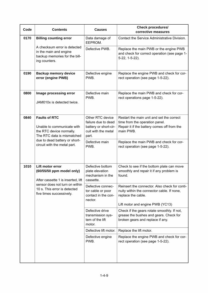
0170 Billing counting error
A checksum error is detected in the main and engine backup memories for the bill-ing counters.
Data damage of EEPROM.
Contact the Service Administrative Division.
Defective PWB. Replace the main PWB or the engine PWB and check for correct operation (see page 1-5-22, 1-5-22).
0190 Backup memory device error (engine PWB)
Defective engine PWB.
Replace the engine PWB and check for cor-rect operation (see page 1-5-22).
0800 Image processing error
JAM010x is detected twice.
Defective main PWB.
Replace the main PWB and check for cor-rect operations page 1-5-22).
0840 Faults of RTC
Unable to communicate with the RTC device normally.The RTC data is mismatched due to dead battery or short-circuit with the metal part.
Other RTC device failure due to dead battery or short-cir-cuit with the metal part.
Restart the main unit and set the correct time from the operation panel.Repair it if the battery comes off from the main PWB.
Defective main PWB.
Replace the main PWB and check for cor-rect operation (see page 1-5-22).
1010 Lift motor error(60/55/50 ppm model only)
After cassette 1 is inserted, lift sensor does not turn on within 10 s. This error is detected five times successively.
Defective bottom plate elevation mechanism in the cassette.
Check to see if the bottom plate can move smoothly and repair it if any problem is found.
Defective connec-tor cable or poor contact in the con-nector.
Reinsert the connector. Also check for conti-nuity within the connector cable. If none, replace the cable.
Lift motor and engine PWB (YC13)
Defective drive transmission sys-tem of the lift motor.
Check if the gears rotate smoothly. If not, grease the bushes and gears. Check for broken gears and replace if any.
Defective lift motor. Replace the lift motor.
Defective engine PWB.
Replace the engine PWB and check for cor-rect operation (see page 1-5-22).
Code Contents CausesCheck procedures/
corrective measures
1-4-9
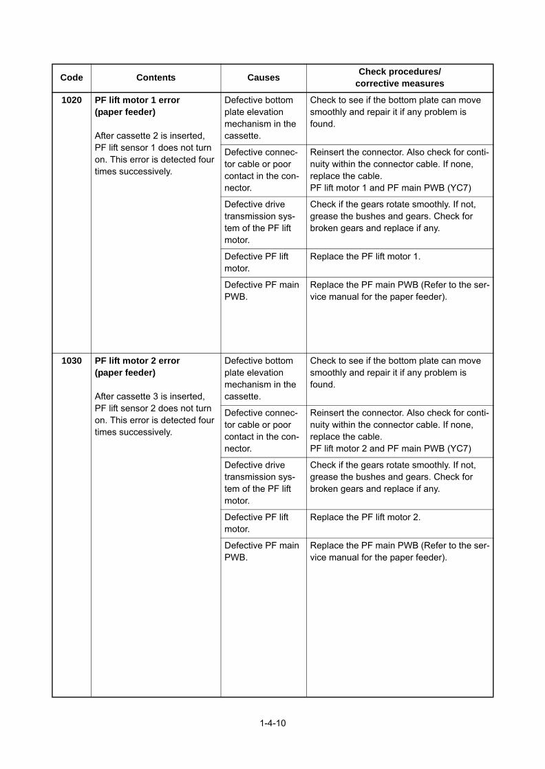
1020 PF lift motor 1 error(paper feeder)
After cassette 2 is inserted, PF lift sensor 1 does not turn on. This error is detected four times successively.
Defective bottom plate elevation mechanism in the cassette.
Check to see if the bottom plate can move smoothly and repair it if any problem is found.
Defective connec-tor cable or poor contact in the con-nector.
Reinsert the connector. Also check for conti-nuity within the connector cable. If none, replace the cable.PF lift motor 1 and PF main PWB (YC7)
Defective drive transmission sys-tem of the PF lift motor.
Check if the gears rotate smoothly. If not, grease the bushes and gears. Check for broken gears and replace if any.
Defective PF lift motor.
Replace the PF lift motor 1.
Defective PF main PWB.
Replace the PF main PWB (Refer to the ser-vice manual for the paper feeder).
1030 PF lift motor 2 error(paper feeder)
After cassette 3 is inserted, PF lift sensor 2 does not turn on. This error is detected four times successively.
Defective bottom plate elevation mechanism in the cassette.
Check to see if the bottom plate can move smoothly and repair it if any problem is found.
Defective connec-tor cable or poor contact in the con-nector.
Reinsert the connector. Also check for conti-nuity within the connector cable. If none, replace the cable.PF lift motor 2 and PF main PWB (YC7)
Defective drive transmission sys-tem of the PF lift motor.
Check if the gears rotate smoothly. If not, grease the bushes and gears. Check for broken gears and replace if any.
Defective PF lift motor.
Replace the PF lift motor 2.
Defective PF main PWB.
Replace the PF main PWB (Refer to the ser-vice manual for the paper feeder).
Code Contents CausesCheck procedures/
corrective measures
1-4-10

1040 PF lift motor 3 error(paper feeder)
After cassette 4 is inserted, PF lift sensor 3 does not turn on. This error is detected four times successively.
Defective bottom plate elevation mechanism in the cassette.
Check to see if the bottom plate can move smoothly and repair it if any problem is found.
Defective connec-tor cable or poor contact in the con-nector.
Reinsert the connector. Also check for conti-nuity within the connector cable. If none, replace the cable.PF lift motor 3 and PF main PWB (YC7)
Defective drive transmission sys-tem of the PF lift motor.
Check if the gears rotate smoothly. If not, grease the bushes and gears. Check for broken gears and replace if any.
Defective PF lift motor.
Replace the PF lift motor 3.
Defective PF main PWB.
Replace the PF main PWB (Refer to the ser-vice manual for the paper feeder).
1050 PF lift motor 4 error(paper feeder)
After cassette 5 is inserted, PF lift sensor 4 does not turn on. This error is detected four times successively.
Defective bottom plate elevation mechanism in the cassette.
Check to see if the bottom plate can move smoothly and repair it if any problem is found.
Defective connec-tor cable or poor contact in the con-nector.
Reinsert the connector. Also check for conti-nuity within the connector cable. If none, replace the cable.PF lift motor 4 and PF main PWB (YC7)
Defective drive transmission sys-tem of the PF lift motor.
Check if the gears rotate smoothly. If not, grease the bushes and gears. Check for broken gears and replace if any.
Defective PF lift motor.
Replace the PF lift motor 4.
Defective PF main PWB.
Replace the PF main PWB (Refer to the ser-vice manual for the paper feeder).
1140 BPF lift motor upward error(Bulk paper feeder)
BPF lift maximum sensor does not turn on.
The lock signal of the motor isdetected continuously three times.
Defective connec-tor cable or poor contact in the con-nector.
Reinsert the connector. Also check for conti-nuity within the connector cable. If none, replace the cable.BPF lift motor and BPF main PWB (YC4)
Defective drive transmission sys-tem of the motor.
Check if the gears rotate smoothly. If not, grease the bushes and gears. Check for broken gears and replace if any.
Defective BPF lift motor.
Replace the BPF lift motor.
Defective BPF main PWB.
Replace the BPF main PWB (Refer to the service manual for the paper feeder).
Code Contents CausesCheck procedures/
corrective measures
1-4-11

1150 BPF lift motor downward error (Bulk paper feeder)
BPF lift minimum sensor does not turn on.
The lock signal of the motor isdetected continuously three times.When detecting an overcur-rent detection signal.
Defective connec-tor cable or poor contact in the con-nector.
Reinsert the connector. Also check for conti-nuity within the connector cable. If none, replace the cable.BPF lift motor and BPF main PWB (YC4)
Defective drive transmission sys-tem of the motor.
Check if the gears rotate smoothly. If not, grease the bushes and gears. Check for broken gears and replace if any.
Defective BPF lift motor.
Replace the BPF lift motor.
Defective BPF main PWB.
Replace the BPF main PWB (Refer to the service manual for the paper feeder).
1800 Paper feeder 1 communica-tion error
A communication error is detected 10 times in succes-sion.
Improper installa-tion paper feeder.
Follow installation instruction carefully again.
Defective connec-tor cable or poor contact in the con-nector.
Reinsert the connector. Also check for conti-nuity within the connector cable. If none, replace the cable.PF main PWB (YC3) and engine PWB (YC22)
Defective engine PWB.
Replace the engine PWB and check for cor-rect operation (see page 1-5-22).
Defective PF main PWB.
Replace the PF main PWB (Refer to the ser-vice manual for the paper feeder).
1810 Paper feeder 2 communica-tion error
A communication error is detected 10 times in succes-sion.
Improper installa-tion paper feeder.
Follow installation instruction carefully again.
Defective connec-tor cable or poor contact in the con-nector.
Reinsert the connector. Also check for conti-nuity within the connector cable. If none, replace the cable.PF main PWB (YC3) and engine PWB (YC22)
Defective PF main PWB.
Replace the PF main PWB (Refer to the ser-vice manual for the paper feeder).
1820 Paper feeder 3 communica-tion error
A communication error is detected 10 times in succes-sion.
Improper installa-tion paper feeder.
Follow installation instruction carefully again.
Defective connec-tor cable or poor contact in the con-nector.
Reinsert the connector. Also check for conti-nuity within the connector cable. If none, replace the cable.PF main PWB (YC3) and engine PWB (YC22)
Defective PF main PWB.
Replace the PF main PWB (Refer to the ser-vice manual for the paper feeder).
Code Contents CausesCheck procedures/
corrective measures
1-4-12

1830 Paper feeder 4 communica-tion error
A communication error is detected 10 times in succes-sion.
Improper installa-tion paper feeder.
Follow installation instruction carefully again.
Defective connec-tor cable or poor contact in the con-nector.
Reinsert the connector. Also check for conti-nuity within the connector cable. If none, replace the cable.PF main PWB (YC3) and engine PWB (YC22)
Defective PF main PWB.
Replace the PF main PWB (Refer to the ser-vice manual for the paper feeder).
1900 Paper feeder 1/BPF paper feeder EEPROM error
When writing the data, the write data and the read data is not in agreement.
Defective PF main PWB.
Replace the PF main PWB or the BPF main PWB (Refer to the service manual for the paper feeder).Device damage of
EEPROM.
1910 Paper feeder 2 EEPROM error
When writing the data, the write data and the read data is not in agreement.
Defective PF main PWB.
Replace the PF main PWB (Refer to the ser-vice manual for the paper feeder).
Device damage of EEPROM.
1920 Paper feeder 3 EEPROM error
When writing the data, the write data and the read data is not in agreement.
Defective PF main PWB.
Replace the PF main PWB (Refer to the ser-vice manual for the paper feeder).
Device damage of EEPROM.
1930 Paper feeder 4 EEPROM error
When writing the data, the write data and the read data is not in agreement.
Defective PF main PWB.
Replace the PF main PWB (Refer to the ser-vice manual for the paper feeder).
Device damage of EEPROM.
2000 Main motor drive error
The main motor is not stabi-lized within 2 s after driving starts.
Defective connec-tor cable or poor contact in the con-nector.
Reinsert the connector. Also check for conti-nuity within the connector cable. If none, replace the cable.Main motor and engine PWB (YC4)
Defective drive transmission sys-tem of the main motor.
Check if the rollers and gears rotate smoothly. If not, grease the bushes and gears. Check for broken gears and replace if any.
Defective main motor.
Replace the main motor.
Defective engine PWB.
Replace the engine PWB and check for cor-rect operation (see page 1-5-22).
Code Contents CausesCheck procedures/
corrective measures
1-4-13

2010 Main motor steady-state error
Stable OFF is detected for 2 s continuously after main motor stabilized.
Defective connec-tor cable or poor contact in the con-nector.
Reinsert the connector. Also check for conti-nuity within the connector cable. If none, replace the cable.Main motor and engine PWB (YC4)
Defective drive transmission sys-tem of the main motor.
Check if the rollers and gears rotate smoothly. If not, grease the bushes and gears. Check for broken gears and replace if any.
Defective main motor.
Replace the main motor.
Defective engine PWB.
Replace the engine PWB and check for cor-rect operation (see page 1-5-22).
2200 Drum motor drive error(60/55/50 ppm model only)
The drum motor is not stabi-lized within 2 s after driving starts.
Defective connec-tor cable or poor contact in the con-nector.
Reinsert the connector. Also check for conti-nuity within the connector cable. If none, replace the cable.Drum motor and engine PWB (YC4)
Defective drive transmission sys-tem of the drum motor.
Check if the rollers and gears rotate smoothly. If not, grease the bushes and gears. Check for broken gears and replace if any.
Defective drum motor.
Replace the drum motor.
Defective engine PWB.
Replace the engine PWB and check for cor-rect operation (see page 1-5-22).
2210 Drum motor steady-state error(60/55/50 ppm model only)
Stable OFF is detected for 2 s continuously after drum motor stabilized.
Defective connec-tor cable or poor contact in the con-nector.
Reinsert the connector. Also check for conti-nuity within the connector cable. If none, replace the cable.Drum motor and engine PWB (YC4)
Defective drive transmission sys-tem of the drum motor.
Check if the rollers and gears rotate smoothly. If not, grease the bushes and gears. Check for broken gears and replace if any.
Defective drum motor.
Replace the drum motor.
Defective engine PWB.
Replace the engine PWB and check for cor-rect operation (see page 1-5-22).
Code Contents CausesCheck procedures/
corrective measures
1-4-14

2330 Fuser pressure release motor error(Over-current)
The over-current detection signal of the motor is detected continuously twenty times.
Defective connec-tor cable or poor contact in the con-nector.
Reinsert the connector. Also check for conti-nuity within the connector cable. If none, replace the cable.Fuser pressure release motor and relay-L PWB(YC11)Relay-L PWB(YC3) and engine PWB(YC2)
Defective drive transmission sys-tem of the fuser pressure release motor.
Check if the gears rotate smoothly. If not, grease the bushes and gears. Check for broken gears and replace if any.
Defective fuser pressure release motor.
Replace the fuser pressure release motor.
Defective PWB. Replace the relay-L PWB or engine PWB. (See Page 1-5-24,1-5-22)
2340 Fuser pressure release motor error(Timeout)
The position detection sensor is not detected continuously for 30 s.
Defective connec-tor cable or poor contact in the con-nector.
Reinsert the connector. Also check for conti-nuity within the connector cable. If none, replace the cable.Fuser pressure release motor and relay-L PWB(YC11)Relay-L PWB(YC1) and engine PWB(YC2)
Defective drive transmission sys-tem of the fuser pressure release motor.
Check if the gears rotate smoothly. If not, grease the bushes and gears. Check for broken gears and replace if any.
Defective fuser pressure release motor.
Replace the fuser pressure release motor.
Defective PWB. Replace the relay-L PWB or engine PWB. (See Page 1-5-24,1-5-22)
2600 PF drive motor 1 error(paper feeder 1)
When the PF drive motor is driven, error signal is detected continuously for 2 s.
Defective connec-tor cable or poor contact in the con-nector.
Reinsert the connector. Also check for conti-nuity within the connector cable. If none, replace the cable.PF drive motor 1 and PF main PWB (YC6)
Defective drive transmission sys-tem of the PF drive motor.
Check if the rollers and gears rotate smoothly. If not, grease the bushes and gears. Check for broken gears and replace if any.
Defective PF drive motor.
Replace the PF drive motor 1.
Defective PF main PWB.
Replace the PF main PWB (Refer to the ser-vice manual for the paper feeder).
Code Contents CausesCheck procedures/
corrective measures
1-4-15

2610 PF drive motor 2 error(paper feeder 2)
When the PF drive motor is driven, error signal is detected continuously for 2 s.
Defective connec-tor cable or poor contact in the con-nector.
Reinsert the connector. Also check for conti-nuity within the connector cable. If none, replace the cable.PF drive motor 2 and PF main PWB (YC6)
Defective drive transmission sys-tem of the PF drive motor.
Check if the rollers and gears rotate smoothly. If not, grease the bushes and gears. Check for broken gears and replace if any.
Defective PF drive motor.
Replace the PF drive motor 2.
Defective PF main PWB.
Replace the PF main PWB (Refer to the ser-vice manual for the paper feeder).
2620 PF drive motor 3 error(paper feeder 3)
When the PF drive motor is driven, error signal is detected continuously for 2 s.
Defective connec-tor cable or poor contact in the con-nector.
Reinsert the connector. Also check for conti-nuity within the connector cable. If none, replace the cable.PF drive motor 3 and PF main PWB (YC6)
Defective drive transmission sys-tem of the PF drive motor.
Check if the rollers and gears rotate smoothly. If not, grease the bushes and gears. Check for broken gears and replace if any.
Defective PF drive motor.
Replace the PF drive motor 3.
Defective PF main PWB.
Replace the PF main PWB (Refer to the ser-vice manual for the paper feeder).
2630 PF drive motor 4 error(paper feeder 4)
When the PF drive motor is driven, error signal is detected continuously for 2 s.
Defective connec-tor cable or poor contact in the con-nector.
Reinsert the connector. Also check for conti-nuity within the connector cable. If none, replace the cable.PF drive motor 4 and PF main PWB (YC6)
Defective drive transmission sys-tem of the PF drive motor.
Check if the rollers and gears rotate smoothly. If not, grease the bushes and gears. Check for broken gears and replace if any.
Defective PF drive motor.
Replace the PF drive motor 4.
Defective PF main PWB.
Replace the PF main PWB (Refer to the ser-vice manual for the paper feeder).
4000 Polygon motor synchroni-zation error
The polygon motor is not sta-bilized within 20 s after driving starts.
Defective connec-tor cable or poor contact in the con-nector.
Reinsert the connector. Also check for conti-nuity within the connector cable. If none, replace the cable.Polygon motor and engine PWB (YC15)
Defective polygon motor.
Replace the laser scanner unit (see page 1-5-18).
Defective engine PWB.
Replace the engine PWB and check for cor-rect operation (see page 1-5-22).
Code Contents CausesCheck procedures/
corrective measures
1-4-16

4200 BD steady-state error
When the value of Register BDSET is 1 after setting Reg-ister BDSET as one and pass-ing by BD1 cycle.
Defective connec-tor cable or poor contact in the con-nector.
Reinsert the connector. Also check for conti-nuity within the connector cable. If none, replace the cable.APC PWB(YC1) and engine PWB (YC16)APC PWB(YC2) and PD PWB(YC1)
Defective PD PWB.
Replace the laser scanner unit (see page 1-5-18).
Defective engine PWB.
Replace the engine PWB and check for cor-rect operation (see page 1-5-22).
5100 Chager current error
When the current value mea-sured at the time of potential adjustment is less than 20 μA.
Defective connec-tor cable or poor contact in the con-nector.
Reinsert the connector. Also check for conti-nuity within the connector cable. If none, replace the cable.Chager unit and high voltage PWBHigh voltage PWB (YC101) and engine PWB (YC19)
Defective high voltage PWB.
Replace the high voltage PWB and check for correct operation (see page 1-5-26).
Defective engine PWB.
Replace the engine PWB and check for cor-rect operation (see page 1-5-22).
6000 Broken fuser heater wire
The detection temperature of fuser thermistor 2 is 100 °C/212°F or less after the fuser heater lamp has been turned on continuously for 30 s.
Defective connec-tor cable or poor contact in the con-nector.
Reinsert the connector. Also check for conti-nuity within the connector cable. If none, replace the cable.Fuser heater and power source PWB (YC2)Fuser thermistor and Fuser thermistor con-nect PWB(YC1 and YC2)Fuser thermistor connect PWB(YC3) and engine PWB (YC21)
Deformed connec-tor pin.
See page 1-4-19.
Defective triac. See page 1-4-19.
Fuser thermostat triggered.
Reinsert the fuser unit (see page 1-5-19).
Broken fuser heater wire.
Defective engine PWB.
Replace the engine PWB and check for cor-rect operation (see page 1-5-22).
Code Contents CausesCheck procedures/
corrective measures
1-4-17

6020 Abnormally high fuser thermistor 2 temperature
The detection temperature of fuser thermistor 2 is higher than 235°C/455°F.In a heater-off state, the detection temperature of fuser thermistor 2 is higher than 195°C/383°F after the detec-tion temperature of fuser thermistor 2 was 155°C/311°F or less.
Deformed connec-tor pin.
See page 1-4-19.
Defective triac. See page 1-4-19.
Shorted fuser thermistor.
Replace the fuser unit (see page 1-5-19).
Defective engine PWB.
Replace the engine PWB and check for cor-rect operation (see page 1-5-22).
6030 Broken fuser thermistor 2 wire
A/D value of the fuser thermis-tor 2 exceeds 1019 bit contin-uously for 4 s during warming up.
Defective connec-tor cable or poor contact in the con-nector.
Reinsert the connector. Also check for conti-nuity within the connector cable. If none, replace the cable.Fuser thermistor and fuser thermistor con-nect PWB(YC2)Fuser thermistor connect PWB(YC3) and engine PWB (YC21)
Deformed connec-tor pin.
See page 1-4-19.
Defective triac. See page 1-4-19.
Defective fuser thermistor.
Replace the fuser unit (see page 1-5-19).
Defective engine PWB.
Replace the engine PWB and check for cor-rect operation (see page 1-5-22).
Code Contents CausesCheck procedures/
corrective measures
1-4-18

6000/6020/
6030/
6120/
6130/
Com-bined
Broken fuser heater wireAbnormally high fuser thermistor 2 temperatureBroken fuser thermistor 2 wireAbnormally high fuser thermistor 1 temperatureBroken fuser thermistor 1 wire
Deformed connec-tor pin.
If the I/F connector pins of the fuser unit and the main unit are deformed owing to foreign matters, replace the connectors or the units including the connectors.
Defective triac. Remove the power cord and check that the resistance between terminals T1 and T2 of the triac TRA31 and triac TRA41 are of sev-eral Mega-Ohms and not shorted (see figure 1-4-3).If failed, replace the power source PWB (seepage 1-5-25).
Figure 1-4-3
Code Contents CausesCheck procedures/
corrective measures
T1
T2
TRA41
TRA31
Power source PWB
1-4-19

6120 Abnormally high fuser thermistor 1 temperature
The detection temperature of fuser thermistor 1 is higher than 245°C/473°F.In a heater-off state, the detection temperature of fuser thermistor 1 is higher than 195°C/383°F after the detec-tion temperature of fuser thermistor 1 was 155°C/311°F or less.
Deformed connec-tor pin.
See page 1-4-19.
Defective triac. See page 1-4-19.
Shorted fuser thermistor.
Replace the fuser unit (see page 1-5-19).
Defective engine PWB.
Replace the engine PWB and check for cor-rect operation (see page 1-5-22).
6130 Broken fuser thermistor 1 wire
A/D value of the fuser thermis-tor 1 exceeds 1019 bit contin-uously for 4 s during warming up.
Defective connec-tor cable or poor contact in the con-nector.
Reinsert the connector. Also check for conti-nuity within the connector cable. If none, replace the cable.Fuser thermistor and fuser thermistor con-nect PWB(YC1)Fuser thermistor connect PWB(YC3) and engine PWB (YC21)
Deformed connec-tor pin.
See page 1-4-19.
Defective triac. See page 1-4-19.
Defective fuser thermistor.
Replace the fuser unit (see page 1-5-19).
Defective engine PWB.
Replace the engine PWB and check for cor-rect operation (see page 1-5-22).
6400 Zero-cross signal error
While fuser heater control is performed, the zero-cross sig-nal is not input within 2 s.
Defective connec-tor cable or poor contact in the con-nector.
Reinsert the connector. Also check for conti-nuity within the connector cable. If none, replace the cable.Power source PWB (YC3) and engine PWB (YC1)
Defective power source PWB or engine PWB.
Replace the power source PWB or the engine PWB and check for correct operation (see page 1-5-22).
Code Contents CausesCheck procedures/
corrective measures
1-4-20

7100 Toner sensor error
Sensor output value of 930 or more continuously for 5 s.
Defective connec-tor cable or poor contact in the con-nector.
Reinsert the connector. Also check for conti-nuity within the connector cable. If none, replace the cable.Toner sensor and drum PWB (YC3)Drum connect PWB(YC2) and relay-L PWB (YC3)Relay-L PWB(YC1) and engine PWB (YC2)
Defective toner sensor.
Replace the developer unit.(See Page 1-5-13)
Defective engine PWB.
Replace the engine PWB and check for cor-rect operation (see page 1-5-22).
7400 Developer unit non-install-ing error
Sensor output value of 31 or less continuously for 5 s.
Defective connec-tor cable or poor contact in the con-nector.
Reinsert the connector. Also check for conti-nuity within the connector cable. If none, replace the cable.Toner sensor and drum PWB (YC3)Drum connect PWB(YC2) and relay-L PWB (YC3)Relay-L PWB(YC1) and engine PWB (YC2)
Defective toner sensor.
Replace the developer unit.(See Page 1-5-13)
Defective engine PWB.
Replace the engine PWB and check for cor-rect operation (see page 1-5-22).
7410 Drum unit type mismatch error
The drum PWB EEPROM does not communicatenormally.
Absence of the drum unitis detected.
Defective connec-tor cable or poor contact in the con-nector.
Reinsert the connector. Also check for conti-nuity within the connector cable. If none, replace the cable.Drum unit and drum connect PWB (YC1)Drum connect PWB(YC2) and relay-L PWB (YC3)Relay-L PWB(YC1) and engine PWB (YC2)
Defective toner sensor.
Replace the drum unit.(See Page 1-5-13)
Defective engine PWB.
Replace the engine PWB and check for cor-rect operation (see page 1-5-22).
Code Contents CausesCheck procedures/
corrective measures
1-4-21

7800 Broken external thermistor wire
The average of thermistor out-put value of 93 or less.
Defective connec-tor cable or poor contact in the con-nector.
Reinsert the connector. Also check for conti-nuity within the connector cable. If none, replace the cable.Operation PWB (YC1) and engine PWB (YC17)
Defective tempera-ture sensor.
Replace the operation PWB.
7810 Short-circuited external thermistor wire
The average of thermistor out-put value of 930 or more.
Defective connec-tor cable or poor contact in the con-nector.
Reinsert the connector. Also check for conti-nuity within the connector cable. If none, replace the cable.Operation PWB (YC1) and engine PWB (YC17)
Defective tempera-ture sensor.
Replace the operation PWB.
7900 Drum unit EEPROM error
No response is issued from the device in reading/writing for 5 ms or more and this problem is repeated five times successively.Mismatch of reading data from two locations occurs eight times successively.Mismatch between writing data and reading data occurs eight times successively.
Defective connec-tor cable or poor contact in the con-nector.
Reinsert the connector. Also check for conti-nuity within the connector cable. If none, replace the cable.Drum unit and drum connect PWB (YC1) Drum connect PWB(YC2) and relay-L PWB (YC3)Relay-L PWB(YC1) and engine PWB (YC2)
Defective drum unit.
Replace the drum unit (see 1-5-15).
F000 Main PWB - operation PWB communication error
Defective connec-tor cable or poor contact in the con-nector.
Reinsert the connector. Also check for conti-nuity within the connector cable. If none, replace the cable.Operation PWB(YC1) and engine PWB (YC17)
Defective main PWB.
Turn the main power switch off/on to restart the machine. If the error is not resolved, replace main PWB (see page 1-5-22).
Defective opera-tion PWB.
Replace the operation PWB and check for correct operation.
F010 Main PWB checksum error Defective main PWB.
Turn the main power switch off/on to restart the machine. If the error is not resolved, replace main PWB (see page 1-5-22).
Code Contents CausesCheck procedures/
corrective measures
1-4-22

F020 Main PWB RAM checksum error
Defective main memory (RAM) in main PWB
Turn the main power switch off/on to restart the machine. If the error is not resolved, replace main PWB (see page 1-5-22).
Defective expended memory (DIMM)
Replace the expansion memory (DIMM).(See Page 1-2-12)Also in the case of the capacity besides specification, it displays.
F040 Main PWB - print engine communication error
Defective main PWB.
Turn the main power switch off/on to restart the machine. If the error is not resolved, replace main PWB (see page 1-5-22).
Defective engine PWB.
Replace the engine PWB and check for cor-rect operation (see page 1-5-22).
F050 Print engine ROM check-sum error
Defective engine PWB.
Turn the main power switch off/on to restart the machine. If the error is not resolved, replace engine PWB (see page 1-5-22).
Code Contents CausesCheck procedures/
corrective measures
1-4-23

(3) System Error (Fxxxx) Outline
The document is subscribed to describe the outline of the factors of the Fxxx errors that are not described in the service manual. Please utilize it to refer to checking the factors.
Note: Please initially check the following when the error (Fxxx) is indicated.Power is partially supplied to this machine when the power is turned off.Unplug the power plug and check if the F-code error is not released when passing one minute or more after turning the power off and then on.
Check the DDR3 memory and neighboring parts : Check the contact with YS1 on the main PWB by releasing and reinserting the memory, and check if the foreign objects such as the dust don’t adhere inside and if the pins aren't deformed. If the error repeats after that, replace the memory. Check the SSD (optional HD-6/HD-7) if the error repeats after replacing the memory. The storage data in the SSD is initialized when formatting or replacing the SSD. Thus, newly install the data in the formatted SSD or new SSD.
Check the SSD: Replace the SSD if the error repeats after formatting the SSD (Note1).
Note1: Procedures for formatting the SSD. (It is also indicated at Operation Manual.)1. Press <MENU>.2. Press the up/down arrow keys and select [Device Common]. Press <OK>.3. Press the up/down arrow keys and select [Format SSD]. Press <OK>.4. The confirmation screen (in the figure below) appears. Press [Yes]. (Press the left arrow key.)5. [Formatting…] appears and formatting SSD starts.→ After finishing the formatting SSD, the screen is recovered to the standby screen.
Caution: Formatting SSD The following storage data in the SSD (optional HD-6/HD-7) is initialized after for-matting the SSD. (Back-up from the SSD is not available.)
Font data, API data, Macro data, Printable data, Document box,Job storage (User box/Quick copy/Proof and hold/Private print/Job storage)
Format.
Are you sure?
--> SSD
[ Yes ] [ No ]
1-4-24

PG L2555/ PG L2550/ PG L2545
0
* note: 60[s]
0
* note: 60[s]
<=> Main IF
card reader
[Main body <=> authentication device]USB-HOST connector[Main boad <=> USB connector]Main boad: YC510
1D4:Randomirmation of set point
ies of a printerpecific printerperation atta and
[Controller failure]Turn power on and off to clear.USB log is required for investigation.[Main PWB]There is no hard components that can be checked in the field.
1-4-25
Code Contents Verification procedure & check point Remarks
― It locks on a Welcome screen.It locks on a start-ing logo (Taskalfa/Ecosys) screen.(Even if time passes for a definite period of time in more than * notes, a screen does not change)
(1) Check the harness, and the connection state of a connector betweenPanel<=>Main boards, and perform an operation check.(2) Check contact of a DDR memory (extracting) and perform an operation check.If exchangeable, it will exchange and will perform an operation check.(3) U021 Controller backup initialization is carried out and an operation check isperformed.(4) Exchange a PanelMain board and perform an operation check.(5) Exchange a Main board and perform an operation check.(6) It will get, if USBLOG is obtainable, and contact service headquarters.
1. Panel <=> Main IF(Engine PWB Relay)
Main PWB: YC2Engine PWB: YC20,YC3Panel PWB: YC12. DDR memory
Main PWB: YS1
F000 CF000 will be displayed if * notes progress is carried out for a definite period of time with a Welcome screen.The communication fault between Panel-Main boardsCommunication fault between Panel Core-Main Core Notes 2
(1) Check the harness, and the connection state of a connector betweenPanel<=>Main boards, and perform an operation check.(2) Check contact of a DDR memory (extracting) and perform an operation check.If exchangeable, it will exchange and will perform an operation check.(3) U021 Controller backup initialization is carried out and an operation check isperformed.(4) Exchange a Main board and perform an operation check.(5) Exchange a PanelMain board and perform an operation check.(6) It will get, if USBLOG is obtainable, and contact service headquarters.
1. Panel <=> Main IF(Engine PWB Relay)
Main PWB: YC2Engine PWB: YC20,YC3Panel PWB: YC12. DDR memory
Main PWB: YS1
F15X Abnormality detecting in an authentication device control section
(1) Check the harness between authentication device <=>Main boards, and theconnection situation of a connector, and perform an operation check.(2) Carry out U021 Main backup initialization and perform an operation check.(3) Exchange a Main board and perform an operation check.(4) Get USBLOG and contact service headquarters.
1.Authentication device Main PWB: YC6Authentication device: ICetc.
F17X Abnormality detecting in a printer data control part
(1) U021 Controller backup initialization is carried out and an operation check isperformed.(2) Exchange a Main board and perform an operation check.(3) Get USBLOG and contact service headquarters.
F18X Abnormality detecting in a Video control section (1) Check the harness between Engine<=>Main boards, and the connection stateof a connector, and perform an operation check.(2) U021 Controller backup initialization is carried out and an operation check isperformed.(3) Exchange an Engine board and perform an operation check.(4) Exchange a Main board and perform an operation check.(5) Get USBLOG and contact service headquarters.
F1DX Abnormality detecting of the image memory Management Department
(1) U021 Controller backup initialization is carried out and an operation check isperformed.(2) Exchange a Main board and perform an operation check.(3) Get USBLOG and contact service headquarters.
* Poor arrangement of FAccess Memory(1) ConfU340(2) Initialization of a(U021)
F21X Abnormality detecting in an image-processing part
(1) Check contact of a DDR memory and perform an operation check.(2) Carry out U021 Main backup initialization and perform an operation check.(3) Exchange a Main board and perform an operation check.(4) Get USBLOG and contact service headquarters.
F22X
F23X
F24X Abnormality detecting in the system Manage-ment Department
(1) Check contact of a DDR memory and perform an operation check.(2) Carry out U021 Main backup initialization and perform an operation check.(3) Exchange a Main board and perform an operation check.(4) Get USBLOG and contact service headquarters.
* F248 is the abnormalitprocess.In recurring by sdata, please give me cooacquisition of capture daUSBLOG.

to a visitor's [Main body <=> External network]Ethernet network
[Main body <=> External network]Ethernet network
[Main body <=> authentication device]USB-HOST connector[Main boad <=> USB connector]Main boad: YC510
ies of a printerpecific printerperation atta and
PG L2555/ PG L2550/ PG L2545
4-26
F25X Abnormality detecting in a network manage-ment department
(1) U021 Controller backup initialization is carried out and an operation check isperformed.(2) Exchange a Main board and perform an operation check.(3) Get USBLOG and contact service headquarters.
* It may occur accordingnetwork environment.
F26X Abnormality detecting in the system Manage-ment Department
(1) U021 Controller backup initialization is carried out and an operation check isperformed.(2) Exchange a Main board and perform an operation check.(3) Get USBLOG and contact service headquarters.
F27X
F28X
F29X
F2AX
F2BX Abnormality detecting in a network control part (1) Carry out U021 Main backup initialization and perform an operation check.(2) Exchange a Main board and perform an operation check.(3) Get USBLOG and contact service headquarters.(Depending on an analysis result, it is packet capture acquisition)
F2CX
F2DX
F2EX
F2FX
F30X
F31X
F32X
F35X Abnormality detecting in the printing controlling Management Department
(1) U021 Controller backup initialization is carried out and an operation check isperformed.(2) Exchange a Main board and perform an operation check.(3) Get USBLOG and contact service headquarters.
F38X Abnormality detecting in the authentication authorized Management Department
(1) U021 Controller backup initialization is carried out and an operation check isperformed.(2) Exchange a Main board and perform an operation check.(3) Get USBLOG and contact service headquarters.
F3AX Abnormality detecting in the Entity Manage-ment Department
(1) U021 Controller backup initialization is carried out and an operation check isperformed.(2) Exchange a Main board and perform an operation check.(3) Get USBLOG and contact service headquarters.
F3BX
F3CX
F3DX
F3EX
F3FX
F40X
F41X
F43X
F44X
F45X
F46X Abnormality detecting of a printer rendering part (1) Exchange boards and perform an operation check.(2) the acquisition wish of USBLOG -- carry out(Depending on the (2) case, it is print capture data acquisition)
* F46F is the abnormalitprocess.In recurring by sdata, please give me cooacquisition of capture daUSBLOG.
Code Contents Verification procedure & check point Remarks

[Main PWB]There is no hard components that can be checked in the field.
diately after r analysis, tion of acquisi-
diately after r analysis, tion of acquisi-
diately after r analysis, tion of acquisi-
[Controller failure]Turn power on and off to clear.USB log is required for investigation.
rror at the time
time of occur-ysis, please cquisition.
time of occur-ysis, please cquisition.
PG L2555/ PG L2550/ PG L2545
4-27
F4DX Abnormality detecting in the Entity Manage-ment Department
(1) U021 Controller backup initialization is carried out and an operation check isperformed.(2) Exchange a Main board and perform an operation check.(3) Get USBLOG and contact service headquarters.
F4EX
F4FX Abnormality detecting in the JOB Management Department
(1) U021 Controller backup initialization is carried out and an operation check isperformed.(2) Exchange a Main board and perform an operation check.(3) Get USBLOG and contact service headquarters.
Since the USB log immeoccurrence is needed foplease give me cooperation.
F52X Abnormality detecting in a JOB execution part "(1) U021 Controller backup initialization is carried out and an operation check is performed.(2) Exchange a Main board and perform an operation check.(3) Get USBLOG and contact service headquarters.
Since the USB log immeoccurrence is needed foplease give me cooperation.
F53X
F55X
F56X
F57X
F61X Abnormality detecting in a report creation part (1) U021 Controller backup initialization is carried out and an operation check isperformed.(2) Exchange a Main board and perform an operation check.(3) Get USBLOG and contact service headquarters.
Since the USB log immeoccurrence is needed foplease give me cooperation.
F63X Abnormality detecting in a device control sec-tion
(1) U021 Controller backup initialization is carried out and an operation check isperformed.(2) Exchange a Main board and perform an operation check.(3) Get USBLOG and contact service headquarters.
F68X Abnormality detecting in a storage device con-trol section
(1) U021 Controller backup initialization is carried out and an operation check isperformed.(2) Exchange a Main board and perform an operation check.(3) Get USBLOG and contact service headquarters.
* F684 is the overwrite eof an HDD security kit.
F90X Abnormality detecting in the extension applica-tion service part
(1) U021 Controller backup initialization is carried out and an operation check isperformed.(2) Exchange a Main board and perform an operation check.(3) Get USBLOG and contact service headquarters.
Since the USB log at therence is needed for analgive me cooperation of a
F93X Abnormality detecting in the extension applica-tion management part
(1) U021 Controller backup initialization is carried out and an operation check isperformed.(2) Exchange a Main board and perform an operation check.(3) Get USBLOG and contact service headquarters.
Since the USB log at therence is needed for analgive me cooperation of a
Code Contents Verification procedure & check point Remarks

1-4-3 Image formation problems
If the part causing the problem was not supplied, use the unit including the part for replacement.
(1) No imageappears (entirely white).
(2) No imageappears (entirely black).
(3) Image is toolight.
(4) The back-ground is col-ored.
(5) White streaksare printed verti-cally.
See page 1-4-29 See page 1-4-29 See page 1-4-30 See page 1-4-31 See page 1-4-31
(6) Black streaksare printed verti-cally.
(7) Streaks areprinted horizon-tally.
(8) Spots areprinted.
(9) Image isblurred.
(10)Paper is wrin-kled.
See page 1-4-32 See page 1-4-32 See page 1-4-32 See page 1-4-33 See page 1-4-33
(11)Offset occurs. (12)Part of image ismissing.
(13)Fusing is loose. (14)Image is out offocus.
(15)Carrier leakingoccurs.
See page 1-4-33 See page 1-4-33 See page 1-4-34 See page 1-4-34 See page 1-4-34
1-4-28
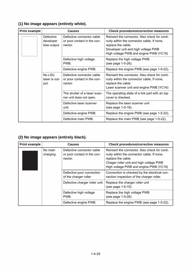
(1) No image appears (entirely white).
(2) No image appears (entirely black).
Print example Causes Check procedures/corrective measures
Defective developer bias output.
Defective connector cable or poor contact in the con-nector.
Reinsert the connector. Also check for conti-nuity within the connector cable. If none, replace the cable.Developer unit and high voltage PWBHigh voltage PWB and engine PWB (YC19)
Defective high voltage PWB.
Replace the high voltage PWB (see page 1-5-26).
Defective engine PWB. Replace the engine PWB (see page 1-5-22).
No LSU laser is out-put.
Defective connector cable or poor contact in the con-nector.
Reinsert the connector. Also check for conti-nuity within the connector cable. If none, replace the cable.Laser scanner unit and engine PWB (YC16)
The shutter of a laser scan-ner unit does not open.
The operating state of a link part with an top cover is checked.
Defective laser scanner unit.
Replace the laser scanner unit (see page 1-5-18).
Defective engine PWB. Replace the engine PWB (see page 1-5-22).
Defective main PWB. Replace the main PWB (see page 1-5-22).
Print example Causes Check procedures/corrective measures
No main charging.
Defective connector cable or poor contact in the con-nector.
Reinsert the connector. Also check for conti-nuity within the connector cable. If none, replace the cable.Chager roller unit and high voltage PWBHigh voltage PWB and engine PWB (YC19)
Defective poor connection of the charger roller
Connection is checked by the electrical con-nection inspection of the charger roller.
Defective charger roller unit. Replace the charger roller unit (see page 1-5-15).
Defective high voltage PWB.
Replace the high voltage PWB (see page 1-5-26).
Defective engine PWB. Replace the engine PWB (see page 1-5-22).
1-4-29

(3) Image is too light.
Print example Causes Check procedures/corrective measures
Dew condensation of the drum surface. Perform the drum surface refreshing in a sys-tem menu.
The paper is moist. The storage state of a paper is checked.
Defective transfer charger out-put.
Defective connector cable or poor contact in the con-nector.
Reinsert the connector. Also check for conti-nuity within the connector cable. If none, replace the cable.Transfer roller unit and high voltage PWBHigh voltage PWB and engine PWB (YC19)
Defective high voltage PWB.
Replace the high voltage PWB (see page 1-5-26).
Defective engine PWB. Replace the engine PWB (see page 1-5-22).
Defective developer bias output.
Defective connector cable or poor contact in the con-nector.
Reinsert the connector. Also check for conti-nuity within the connector cable. If none, replace the cable.Developer unit and high voltage PWBHigh voltage PWB and engine PWB (YC10)
Defective high voltage PWB.
Replace the high voltage PWB (see page 1-5-26).
Defective engine PWB. Replace the engine PWB (see page 1-5-22).
Insufficient toner. If the display shows the message requesting toner replenishment, replace the container.
1-4-30

(4) The background is colored.
(5) White streaks are printed vertically.
Print example Causes Check procedures/corrective measures
Defective main charger out-put.
Defective connector cable or poor contact in the con-nector.
Reinsert the connector. Also check for conti-nuity within the connector cable. If none, replace the cable.Chager roller unit and high voltage PWBHigh voltage PWB and engine PWB (YC19)
Defective high voltage PWB.
Replace the high voltage PWB (see page 1-5-26).
Defective engine PWB. Replace the engine PWB (see page 1-5-22).
Defective developer bias output.
Defective connector cable or poor contact in the con-nector.
Reinsert the connector. Also check for conti-nuity within the connector cable. If none, replace the cable.Developer unit and high voltage PWBHigh voltage PWB and engine PWB (YC10)
Defective developer unit. Replace the developer unit (see page 1-5-13).
Defective high voltage PWB.
Replace the high voltage PWB (see page 1-5-26).
Defective engine PWB. Replace the engine PWB (see page 1-5-22).
Deteriorated toner. Perform the drum surface refreshing opera-tion.
Print example Causes Check procedures/corrective measures
Foreign matter in the devel-oper unit.
Check if the magnetic brush is formed uniformly. Replace the developer unit if any foreign matter (see page 1-5-13).
Adhesion of soiling to transfer roller.
Clean the transfer roller. Replace the transfer roller if it is extremely dirty (see page 1-5-16).
Dust adhesion to the charger roller unit.
Clean the chager roller unit.
Dirty dust shield glass of laser scanner unit.
Clean the dust shield glass of laser scanner unit.
1-4-31

(6) Black streaks are printed vertically.
(7) Streaks are printed horizontally.
(8) Spots are printed.
Print example Causes Check procedures/corrective measures
Dirty or flawed drum. Perform the drum surface refreshing operation.Flawed drum. Replace the drum unit (see page 1-5-15).
Deformed or worn cleaning blade in the drum unit.
Replace the drum unit (see page 1-5-15).
Defective transfer roller. Replace the transfer roller unit (see page 1-5-16).
Defective chager roller. Replace the chager roller unit (see page 1-5-15).
Defective developer roller. Replace the developer unit (see page 1-5-13).
Print example Causes Check procedures/corrective measures
Dirty or flawed drum. Perform the drum surface refreshing operation.Flawed drum. Replace the drum unit (see page 1-5-15).
Dirty developer section. Clean any part contaminated with toner in the developer section.
Poor contact of grounding ter-minal of drum unit.
Check the installation of the drum unit. If it operates incor-rectly, replace it (see page 1-5-15).
The beam detection error of a laser scanner unit
Replace the laser scanner unit (see page 1-5-18).
Print example Causes Check procedures/corrective measures
Dirty or flawed drum. Perform the drum surface refreshing operation.Flawed drum. Replace the drum unit (see page 1-5-15).
Deformed or worn cleaning blade in the drum unit.
Replace the drum unit (see page 1-5-15).
Flawed developer roller. Replace the developer unit (see page 1-5-13).
Dirty heat roller and press roller.
Clean the heat roller and press roller.
1-4-32

(9) Image is blurred.
(10) Paper is wrinkled.
(11) Offset occurs.
(12) Part of image is missing.
Print example Causes Check procedures/corrective measures
Deformed press roller. Replace the fuser unit (see page 1-5-19).
Paper conveying section drive problem.
Check the gears and belts and, if necessary, grease them.
Print example Causes Check procedures/corrective measures
Paper curled. Check the paper storage conditions.
Paper damp.
Defective pressure springs. Replace the fuser unit (see page 1-5-19).
Print example Causes Check procedures/corrective measures
Deformed or worn cleaning blade in the drum unit.
Replace the drum unit (see page 1-5-15).
Defective fuser unit. Replace the fuser unit (see page 1-5-19).
Wrong types of paper. Check if the paper meets specifications. Replace paper.
Print example Causes Check procedures/corrective measures
Paper damp. Check the paper storage conditions.
Paper creased. Replace the paper.
Drum condensation. Perform the drum surface refreshing operation.
Dirty or flawed drum. Perform the drum surface refreshing operation.Flawed drum. Replace the drum unit (see page 1-5-15).
Dirty transfer roller. Clean the transfer roller. Replace the transfer roller if it is extremely dirty (see page 1-5-16).
1-4-33

(13) Fusing is loose.
(14) Image is out of focus.
(15) Carrier leaking occurs.
Print example Causes Check procedures/corrective measures
Wrong types of paper. Check if the paper meets specifications, replace paper.Setup of mediaPractical use of half speed printing
Paper creased. Replace the paper.
Flawed heat roller or press roller.
Replace the fuser unit (see page 1-5-19).
Defective pressure springs.
Defective fuser heater.
Print example Causes Check procedures/corrective measures
Drum condensation. Perform the drum refresh operation.
Print example Causes Check procedures/corrective measures
Paper creased. Replace the paper.
Each of following paper kinds are changed and printed. A paper setup of a printer is changed.
A setup of a driver is changed. By basic setup, the kind of paper is made "CUSTOM 8".
Menu
Paper Settings
Media Type Set.
CUSTOM 8
Paer Weight
Normal 3
Press the [EXIT] key.
Press the [OK] key.
Press the [OK] key.
Press the [OK] key.
Press the [OK] key.
1-4-34

1-4-4 Electric problems
If the part causing the problem was not supplied, use the unit including the part for replacement.Troubleshooting to each failure must be in the order of the numbered symptoms.
Problem Causes Check procedures/corrective measures
(1)The machine does not operate when the power switch is turned on.
1. No electricity at thepower outlet.
Measure the input voltage.
2. The power cord isnot plugged in prop-erly.
Check the contact between the power plug and the outlet.
3. Broken power cord. Check for continuity. If none, replace the cord.
4. Defective powerswitch.
Check for continuity across the contacts. If none, replace the power switch.
5. Defective interlockswitch.
Check for continuity across the contacts of interlock switch. If none, replace the power source PWB (see page 1-5-25).
6. Defective powersource PWB.
Replace the power source PWB or engine PWB (see page 1-5-25,1-5-22).
(2)Eject motor does not operate.
1. Defective connectorcable or poor con-tact in the connector.
Reinsert the connector. Also check for continuity within the connector cable. If none, replace the cable.Eject motor and relay-L PWB (YC12)Relay-L PWB and engine PWB (YC2/YC31)
2. Defective drive trans-mission system.
Check if the rollers and gears rotate smoothly. If not, grease the bushes and gears. Check for broken gears and replace if any.
3. Defective motor. Replace the eject motor.
4. Defective PWB. Replace the engine PWB or the relay-L PWB and check for correct operation (see page 1-5-22, 1-5-24).
(3)Power source fan motor does not operate.
1. Defective connectorcable or poor con-tact in the connector.
Reinsert the connector. Also check for continuity within the connector cable. If none, replace the cable.Power source fan motor and engine PWB (YC10)
2. Defective motor. Replace the power source fan motor.
3. Defective PWB. Replace the engine PWB and check for correct operation (see page 1-5-22).
(4)LSU fan motor does not operate.
1. Defective connectorcable or poor con-tact in the connector.
Reinsert the connector. Also check for continuity within the connector cable. If none, replace the cable.LSU fan motor and relay-L PWB (YC4)Relay-L PWB and engine PWB (YC2/YC31)
2. Defective motor. Replace the LSU fan motor.
3. Defective PWB. Replace the engine PWB or the relay-L PWB and check for correct operation (see page 1-5-22, 1-5-24).
1-4-35

(5)Developer fan motor does not operate.
1. Defective connectorcable or poor con-tact in the connector.
Reinsert the connector. Also check for continuity within the connector cable. If none, replace the cable.Developer fan motor and engine PWB (YC27)
2. Defective motor. Replace the developer fan motor.
3. Defective PWB. Replace the engine PWB and check for correct operation (see page 1-5-22).
(6)Paper feed clutch does not operate.
1. Defective connectorcable or poor con-tact in the connector.
Reinsert the connector. Also check for continuity within the connector cable. If none, replace the cable.Paper feed clutch and engine PWB (YC5)
2. Defective clutch. Replace the paper feed clutch.
3. Defective PWB. Replace the engine PWB and check for correct operation (see page 1-5-22).
(7)Registration clutch does not operate.
1. Defective connectorcable or poor con-tact in the connector.
Reinsert the connector. Also check for continuity within the connector cable. If none, replace the cable.Registration clutch and engine PWB (YC5)
2. Defective clutch. Replace the registration clutch.
3. Defective PWB. Replace the engine PWB and check for correct operation (see page 1-5-22).
(8)Duplex clutch does not operate.
1. Defective connectorcable or poor con-tact in the connector.
Reinsert the connector. Also check for continuity within the connector cable. If none, replace the cable.Duplex clutch and engine PWB (YC5)
2. Defective clutch. Replace the duplex clutch.
3. Defective PWB. Replace the engine PWB and check for correct operation (see page 1-5-22).
(9)Developer clutch does not operate.
1. Defective connectorcable or poor con-tact in the connector.
Reinsert the connector. Also check for continuity within the connector cable. If none, replace the cable.Developer clutch and engine PWB (YC5)
2. Defective clutch. Replace the developer clutch.
3. Defective PWB. Replace the engine PWB and check for correct operation (see page 1-5-22).
(10)Conveying clutch does not operate.
1. Defective connectorcable or poor con-tact in the connector.
Reinsert the connector. Also check for continuity within the connector cable. If none, replace the cable.Conveying clutch and engine PWB (YC5)
2. Defective clutch. Replace the Conveying clutch.
3. Defective PWB. Replace the engine PWB and check for correct operation (see page 1-5-22).
(11)MP solenoid does not operate.
1. Defective connectorcable or poor con-tact in the connector.
Reinsert the connector. Also check for continuity within the connector cable. If none, replace the cable.MP solenoid and engine PWB (YC8)
2. Defective solenoid. Replace the MP solenoid.
3. Defective PWB. Replace the engine PWB and check for correct operation (see page 1-5-22).
Problem Causes Check procedures/corrective measures
1-4-36

(12)Feedshift solenoid does not operate.(60/55/50 ppm model only)
1. Defective connectorcable or poor con-tact in the connector.
Reinsert the connector. Also check for continuity within the connector cable. If none, replace the cable.Feedshift solenoid and relay-L PWB (YC13)Relay-L PWB and engine PWB (YC2/YC31)
2. Defective solenoid. Replace the Feedshift solenoid.
3. Defective PWB. Replace the engine PWB or the relay-L PWB and check for correct operation (see page 1-5-22, 1-5-24).
(13)The message requesting paper to be loaded is shown when paper is present on the cas-sette.
1. Defective connectorcable or poor con-tact in the connector.
Reinsert the connector. Also check for continuity within the connector cable. If none, replace the cable.High voltage PWB and engine PWB (YC19)
2. Deformed actuator ofthe paper sensor.
Check visually and replace if necessary.
3. Defective paper sen-sor.
Replace the engine PWB or the high voltage PWB and check for correct operation (see page 1-5-22,1-5-26).
4. Defective PWB.
(14)The message requesting paper to be loaded is shown when paper is present on the MP tray.
1. Defective connectorcable or poor con-tact in the connector.
Reinsert the connector. Also check for continuity within the connector cable. If none, replace the cable.MP paper sensor and relay-L PWB (YC8)Relay-L PWB and engine PWB (YC2)
2. Deformed actuator of the MP paper sensor.
Check visually and replace if necessary.
3. Defective MP papersensor.
Replace the MP paper sensor.
4. Defective PWB. Replace the engine PWB or the relay-L PWB and check for correct operation (see page 1-5-22, 1-5-24).
(15)The size of paper on the cassette is not displayed cor-rectly.
1. Defective connectorcable or poor con-tact in the connector.
Reinsert the connector. Also check for continuity within the connector cable. If none, replace the cable.Cassette size switch and engine PWB (YC7)
2. Defective cassettesize switch.
Replace the cassette size switch.
3. Defective PWB. Replace the engine PWB and check for correct operation (see page 1-5-22).
Problem Causes Check procedures/corrective measures
1-4-37

(16)A paper jam in the paper feed, paper conveying or eject section is indi-cated when the main power switch is turned on.
1. Defective connectorcable or poor con-tact in the connector.
Reinsert the connector. Also check for continuity within the connector cable. If none, replace the cable.Regist sensor 2 and Drum PWB (YC6)DU sensor 1 and Relay-L PWB (YC9)PF feed sensor and PF main PWBEject full sensor and engine PWB (YC12)Eject sensor and Engine PWB (YC26)
2. A piece of paper tornfrom paper is caughtaround registrationsensor, duplex sen-sor, PF feed sensor,eject full sensor oreject sensor.
Check visually and remove it, if any.
3. Defective sensor. Replace the registration sensor, duplex sensor, PF feed sensor, eject full sensor or eject sensor.
4. Defective PWB. Replace the engine PWB and check for correct operation (see page 1-5-22).
(17)A message indicat-ing cover open is displayed when the top cover is closed.
1. Defective connectorcable or poor con-tact in the connector.
Reinsert the connector. Also check for continuity within the connector cable. If none, replace the cable.Interlock switch and engine PWB (YC6)
2. Defective interlockswitch.
Check and replace if necessary.
3. Defective PWB. Replace the engine PWB and check for correct operation (see page 1-5-22).
(18)A message indicat-ing cover open is displayed when the rear cover is closed.
1. Defective connectorcable or poor con-tact in the connector.
Reinsert the connector. Also check for continuity within the connector cable. If none, replace the cable.Rear cover switch and relay-L PWB (YC10)Relay-L PWB and engine PWB (YC2/YC31)
2. Defective rear coverswitch.
Check and replace if necessary.
3. Defective PWB. Replace the engine PWB or the relay-L PWB and check for correct operation (see page 1-5-22, 1-5-24).
Problem Causes Check procedures/corrective measures
1-4-38

1-4-5 Mechanical problems
If the part causing the problem was not supplied, use the unit including the part for replacement.
Problem Causes/check procedures Corrective measures
(1)No primary paper feed.
Check if the surfaces of the following roll-ers are dirty with paper powder.Pickup rollerPaper feed rollerMP paper feed pulley
Clean with isopropyl alcohol.
Check if the following rollers is deformed.Pickup rollerPaper feed rollerMP paper feed pulley
Check visually and replace any deformed (see page 1-5-8, 1-5-10).
Defective paper feed clutch installation. Check visually and remedy if necessary.
(2)No secondary paper feed.
Check if the surfaces of the following roll-ers are dirty with paper powder.Upper registration rollerLower registration roller
Clean with isopropyl alcohol.
Defective registration clutch installation. Check visually and remedy if necessary.
(3)Skewed paper feed.
Paper width guide in a cassette installed incorrectly.
Check the paper width guide visually and remedy or replace if necessary.
(4)Multiple sheets of paper are fed.
Check if the paper is excessively curled. Change the paper.
Paper is loaded incorrectly. Load the paper correctly.
Check if the retard roller is worn. Replace the retard roller if it is worn (see page 1-5-8).
(5)Paper jams.
Check if the paper is excessively curled. Change the paper.
Check if the contact between the upper and lower registration rollers is correct.
Check visually and remedy if necessary.
Check if the heat roller or press roller is extremely dirty or deformed.
Check visually and replace the fuser unit (see page 1-5-19).
(6)Toner drops on the paper conveying path.
Check if the drum unit or developer unit is extremely dirty.
Clean the drum unit or developer unit.
(7)Abnormal noise is heard.
Check if the rollers, pulleys and gears operate smoothly.
Grease the bushes and gears.
Check if the following clutches are installed correctly.Paper feed clutchRegistration clutchDuplex clutch
Check visually and remedy if necessary.
1-4-39

This page is intentionally left blank.
1-4-40

1-5 Assembly and disassembly
1-5-1 Precautions for assembly and disassembly
(1) Precautions
Before starting disassembly, push the power switch and check the disappeared display of an operation panel certainly. Unplug the power cable from the wall outlet.When handling PWBs (printed wiring boards), do not touch parts with bare hands.The PWBs are susceptible to static charge.Do not touch any PWB containing ICs with bare hands or any object prone to static charge.When removing the hook of the connector, be sure to release the hook.Take care not to get the cables caught.To reassemble the parts, use the original screws. If the types and the sizes of screws are not known, refer to the PARTS LIST.
(2) Drum unit
Note the following when handling or storing the drum unit.When removing the drum unit, never expose the drum surface to strong direct light.Keep the drum unit at an ambient temperature between -20°C/-4°F and 40°C/104°F and at a relative humidity not higher than 85% RH. Avoid abrupt changes in temperature and humidity.Avoid exposure to any substance which is harmful to or may affect the quality of the drum unit.Do not touch the drum surface with any object. Should it be touched by hands or stained with oil, clean it.
(3) Toner
Store the toner containers in a cool, dark place.Avoid exposing the toner containers to direct light and high humidity.
1-5-1

Figure 1-5-2
1-5-2

1-5-2 Outer covers
(1) Detaching and refitting the top cover
Procedure1. Open the rear cover.2. Open the top cover.3. Remove two screws.4. Release two hooks and then lift the top
cover upward.5. Pull out FFC from the connector and
then remove the top cover assembly.
Figure 1-5-3
(2) Detaching and refitting the inlet cover and slot cover
Procedure1. Open the rear cover.2. Remove the inlet cover.3. Release the hook of the slot cover and
then remove the slot cover.
Figure 1-5-4
ScrewTop cover
Screw
Hook Hook
FFC
Connector
Top coverassembly
Slot cover
Inlet cover
Rear cover
Hook
1-5-3

(3) Detaching and refitting the right upper cover
Procedure1. Open the front cover.2. Remove the top cover assembly.
(See page 1-5-3)3. Remove the slot cover.
(See page 1-5-3)4. Remove two screws.5. Release hook A.6. Release two hooks B by sliding the right
upper cover upward and then removethe right upper cover.
Figure 1-5-5
(4) Detaching and refitting the right lower cover
Procedure1. Remove the right upper cover.
(See page 1-5-4)2. Remove the inlet cover.
(See page 1-5-4)3. Pull out the cassette.4. Remove three screws.5. Release two hooks by sliding the right
lower cover upward and then removethe right lower cover.
Figure 1-5-6
Right upper cover
Front cover
Screw
Screw
Hooks BHook A
Right lower coverScrew
Screw
Screw
Hooks
1-5-4

(5) Detaching and refitting the rear left cover
Procedure1. Open the rear cover.2. Release two hooks of the rear left cover
while pulling forward.3. Remove the rear left cover by rotating.
Figure 1-5-7
(6) Detaching and refitting the left upper cover
Procedure1. Open the front cover.2. Remove the top cover assembly.
(See page 1-5-3)3. Remove the rear left cover.
(See page 1-5-5)4. Release the hook A by sliding the left
upper cover upward.5. Release the hook B and hook C and
then remove the left upper cover andthe waste toner box cover.(See page 1-5-5)
Figure 1-5-8
Rear left cover
Hook
Hook
Left upper cover
Hook A
Waste toner box cover
Hook B
Hook C
1-5-5

(7) Detaching and refitting the left lower cover
Procedure1. Remove the left upper cover.
(See page 1-5-5)2. Pull out the cassette.3. Remove the rear left lower cover.
(See page 1-5-5)4. Remove the screw.5. Release the hook A.6. Release two hooks B by sliding the left
lower cover upward and then removethe left lower cover.
Figure 1-5-9
(8) Detaching and refitting the rear cover
Procedure1. Remove the rear left lower cover.
(See page 1-5-5)2. Open the rear cover.
[60/50/45 ppm model only]3. Remove the screw and then the
grounding wire.4. Open the connector cover and then
remove three connectors.
Figure 1-5-10
Screw
Hook B
Hook B
Left lower cover
Hook A
Connector cover
ConnectorsRear cover
Screw
Grounding wire
1-5-6

5. Remove the fulcrum axis by sliding therear cover assembly while avoiding rearcover and then remove the rear coverassembly.
Figure 1-5-11
Rear cover assembly
Fulcrum axis(Rear cover assembly)
Rear cover
1-5-7

1-5-3 Paper feed section
(1) Detaching and refitting the paper feed roller
Procedure1. Pull out the cassette.2. Release the lock by pulling the lever.3. Remove the paper feed roller assembly
by pulling and raising and then sliding forward.
4. Check or replace the paper feed rollerand refit all the removed parts.
Figure 1-5-12
(2) Detaching and refitting the retard roller
Procedure1. Release two hooks in backside of cas-
sette and then remove the retard roller assembly.
Figure 1-5-13
Paper feed roller assembly
Lever
Holder
Retard roller assembly
Hook
Backside in cassette
Cassette
1-5-8

2. Remove the spring.3. Remove the retard roller holder by
rotating.4. Check or replace the retard roller and
refit all the removed parts.
Figure 1-5-14
(3) Detaching and refitting the MP paper feed pulley
Procedure1. Open the top cover.2. Open the front cover.3. Remove the MP tray from the printer
while bending it.
Figure 1-5-15
Retard roller guide
Spring
Retard roller holder
MP tray
Front cover
1-5-9

4. Remove the fulcrum of leftside byextending a cover.
5. Remove the fulcrum of rightside duringtwisting a cover.
6. Remove the front cover forward.
Figure 1-5-16
Front cover
Front cover
1-5-10

7. Remove two screws on the MP paperfeed unit.
Figure 1-5-17
8. Remove the MP paper feed unit fromthe printer.
Figure 1-5-18
MP paper feed unit
Screw
Screw
MP paper feed unit
Printer
1-5-11

9. Release the lock lever and then slidethe MP paper feed pulley axis.
10. Remove MP paper feed pulley.11. Check or replace the MP paper feed
pulley and refit all the removed parts.
Figure 1-5-19
Lock lever
MP paper feed pulley axis
MP paper feed pulley
1-5-12

1-5-4 Developer section
(1) Detaching and refitting the developer unit
Procedure1. Open the top cover.2. Release the lock lever by rotating and
then remove the toner container.
Figure 1-5-20
3. Open the front cover.4. Pull the imaging unit forward.5. Release the hook and then remove the
container guide by sliding backwards.
Figure 1-5-21
Top cover
Toner container
Lock lever
Hook
Imaging unit
Front cover
Top cover
Containerguide
1-5-13

6. Pull the connector out.7. Release the lock lever and then remove
the developer unit upward.8. Check or replace the developer unit and
refit all the removed parts.
Figure 1-5-22
Developer unit
Connector
Connector
Lock lever
1-5-14

1-5-5 Drum section
(1) Detaching and refitting the drum unit
Procedure1. Remove the developer unit.
(See page 1-5-13)2. Remove the lock lever L.3. Remove the lock lever R by sliding
backward.4. Remove the drum unit by sliding
forward.5. Check or replace the drum unit and refit
all the removed parts.
Figure 1-5-23
(2) Detaching and refitting the chager roller unit
Procedure1. Release the lock lever and then remove
the chager roller unit.2. Check or replace the charger roller unit
and refit all the removed parts.
Figure 1-5-24
Drum unit
Lock lever L
Lock lever R
Durm unitLock lever
Main chager roller unit
1-5-15

1-5-6 Transfer/separation section
(1) Detaching and refitting the transfer roller assembly
Procedure1. Release four hooks by sliding to left the
paper chute guide.2. Remove the paper chute guide upward.
Figure 1-5-25
3. Remove the axes of transfer roller fromeach bush.
4. Remove the transfer roller assemblyupward.
5. Check or replace the transfer rollerassembly and refit all the removedparts.
Figure 1-5-26
Paper chute guide
Hooks
Bushing
Axis
Transferroller
AxisTransfer roller
Bushing
Transfer rollerassembly
1-5-16

(2) Detaching and refitting the separation needle unit
Procedure1. Remove the transfer roller unit.
(See page 1-5-16)2. Release four hooks of separation nee-
dle unit by rotating and then remove theseparation needle unit upward.
3. Check or replace the separation needleunit and refit all the removed parts.
Caution: Check certainly being fixed at the time of attachment.
Figure 1-5-27
Separation needle unit
Hooks
1-5-17

1-5-7 Optical section
(1) Detaching and refitting the laser scanner unit
Procedure1. Remove the top cover assembly.
(See page 1-5-3)2. Remove the right upper cover.
(See page 1-5-4)3. Pull the connector and FFC from engine
PWB out.4. Release the wires from the wire guide.5. Remove four screws and then remove
the laser scanner unit upward.6. Check or replace the laser scanner unit
and refit all the removed parts.
Figure 1-5-28
Screw
Screw ScrewScrew
Laser scannerunit
Engine PWB
Wires
FFC
Wire guides
Connector
1-5-18

1-5-8 Fuser section
(1) Detaching and refitting the fuser unit
Procedure1. Remove the rear cover.
(See page 1-5-6)2. Remove the screw and then remove the
connector cover A.3. Pull two connectors out.
Figure 1-5-29
4. Remove the connector cover B byreleasing the hook.
5. Remove the screw of connector coverC.
6. Remove the connector cover C byreleasing the hook.
7. Pull two connectors out.
Figure 1-5-30
connector cover A
ConnectorsScrew
ScrewConnector cover C
Hook
Connectors
HookConnector cover B
1-5-19

[60/50/45 ppm model]8. Remove the screw and then remove the
fuser unit forward.9. Check or replace the fuser unit and refit
all the removed parts.
Caution: when refitting the fuser unit, per-form the following procedures.
(1)Turn on the power switch while opening therear cover after removing the fuser unit.(2)Turn off the power switch after 5-second ormore progress.(release state of fixing pressure)(3)Refit the fuser unit.
Figure 1-5-31
Fuser unit
Screw
1-5-20

1-5-9 ejection section
(1) Detaching and refitting the ejection unit
Procedure1. Remove the top cover assembly.
(See page 1-5-3)2. Remove the right upper cover and the
right lower cover. (See page 1-5-4)3. Remove the left upper cover.
(See page 1-5-5)4. Remove the controller box cover.
(See page 1-5-25)5. Pull the connector out and then release
the wires from Hooks.6. Remove three screws and then remove
the ejection unit.7. Check or replace the ejection unit and
refit all the removed parts.
*1: 60/55/50 ppm model only*2: 45 ppm model only
Figure 1-5-32
*2Screw
*1Screw
Ejection unit
Screw
Screw
Connector
HooksWires
1-5-21

1-5-10 PWBs
(1) Detaching and re
Procedure1. Remove the inlet cov
cover.(See page 1-5-2. Unplug the power cab
Caution: Do not inserPWB assembly whileon.Doing so may cause machine and the mai
3. Remove five screws main PWB assembly
4. Check or replace therefit all the removed p
*: Re-activate the licens1) Card Authenticatio2) UG-33 (ThinPrint)3) Data Security Kit(ERe-input four-digit en
*: Reset the user initial
(2) Detaching and re
Procedure1. Remove the top cove
(See page 1-5-3)2. Remove the right upp
(See page 1-5-4)3. Remove the main PW
(See page 1-5-22)4. Remove the screw an
grounding terminal.5. Remove two FFCs fro6. Release the wires an7. Release the fixing ho
remove the wire guid
fitting the main PWB
er and the slot3)le.
t or remove main machine power is
damage to then PWB.
and then pull the out forward. main PWB andarts.
Figure 1-5-33e if optional licensed product is installed.n Kit(B)
)crypted code that was input at setup.values from the System Menu and Command Center.
fitting the engine PWB
r assembly.
er cover.
B assembly.
d then the
ScrewScrew
Screw
ScrewMain PWB assembly
The hook
Hooks
Screw
Grounding terminal
1-5-22
m inside of frame.d FFC from hooks.ok and thene.
Figure 1-5-34
Wire guide
for fixation
Hook
FFC
HooksWires
FFCs

8. Pull two connectors o9. Remove the screw an
then remove the wire
10. Pull all connectors ou11. Remove four screws
the engine PWB.12. Check or replace the
refit all the removed p
NOTE: When replacing thEEPROM from the PWB athe new PWB.
ut.d two hooks and
guide.
Figure 1-5-35
t from main PWB.and then remove
engine PWB andarts.
e PWB, remove thend then reattach it to
Hook
Connector
Connector Wire guide
Hook
Screw
Screw
Screw
1-5-23
Figure 1-5-36
Engine PWB
Screw
Screw

(3) Detaching and refitting the relay-L PWB
Procedure1. Remove the top cover assembly.
(See page 1-5-3)2. Pull the connectors out from relay-L
PWB and then release the wires fromhooks.
3. Remove the LSU fan motor assemblyupward.
Figure 1-5-37
4. Pull the connectors and FFC out andthen remove the relay-L PWB.
5. Check or replace the relay-L PWB andrefit all the removed parts.
Figure 1-5-38
Connectors
HooksWires
LSU fan motor assembly
Connectors
Hook
FFC
Connect-L PWB
1-5-24

(4) Detaching and refitting the power source PWB
Procedure1. Remove the top cover assembly.
(See page 1-5-3)2. Remove the right upper cover.
(See page 1-5-4)3. Remove the right lower cover.
(See page 1-5-4)4. Remove the main PWB.
(See page 1-5-22)5. Remove the wire guide.
(See page 1-5-22)6. Remove three screws and then remove
the controller box cover.
Figure 1-5-39
7. Remove the grounding wire by remov-ing the screw.
8. Remove two screws and then removethe power source PWB assembly.
9. Check or replace the power sourcePWB and refit all the removed parts.
Figure 1-5-40
Controller box cover
Screw
Screw
Screw
Power source PWB assembly
Screw
Screw
Screw
Grounding wire
1-5-25

(5) Detaching and refitting the high voltage PWB
Procedure1. Remove the cassette.2. Remove the right upper cover and the
right lower cover. (See page 1-5-4)3. Remove the left upper cover and the left
lower cover. (See page 1-5-6)4. Remove the power source fan motor.
(See page1-5-30)5. Remove the power source PWB.
(See page1-5-25)6. Stand the printer front side up.7. Remove four screws each and then
remove the bottom plate 1 and the bot-tom plate 2.
Figure 1-5-41
8. [60/55/50 ppm model only]Release two hooks and then removethe wire cover.Pull the connector of lift sensor out.
Figure 1-5-42
Screw
Screw
ScrewScrew
ScrewBottom plate 2
Screw
Screw
Screw
Bottom plate 1
Lift sensor
Hooks
Connector
Wire cover
1-5-26

9. Remove seven screws.10. Extract the feed roller axis by pushing
the joint part.11. Remove the DU assy to the front.
Figure 1-5-43
12. Remove the screw.13. Pull two connectors out and then
remove the high voltage PWB.14. Check or replace the high voltage PWB
and refit all the removed parts.
Figure 1-5-44
Screws
Screw
DU assy
Screw
ScrewScrews
Paper feed roller axis
Joint part
High voltage PWB
Connector
Connector
Screw
1-5-27

(6) Detaching and refitting the operation PWB
Procedure1. Open the top cover.2. Remove the JAM processing procedure
sheet.3. Remove three screws.
Figure 1-5-45
4. Rotate the operation PWB cover.5. Remove the screw and then remove the
operation PWB.6. Check or replace the operation PWB
and refit all the removed parts.
Figure 1-5-46
JAM processing procedure sheet
Screws
Screw
Top cover
Operation panel PWB
Operation panel PWB cover
Screw
1-5-28

1-5-11 Others
(1) Detaching and refitting the main driving motor unit
Procedure1. Remove the right upper cover.
(See page 1-5-4)2. Remove the right lower cover.
(See page 1-5-4)3. Pull the connector out from the motor
and then release the wires from wireholder.
4. Remove three screws and then removethe main driving motor unit.
5. Check or replace the main driving motorunit and refit all the removed parts.
Figure 1-5-47
Figure 1-5-48
ConnectorWires
Wireholder
Main driving motor unit
Screw
Screw
Screw
Connector(60/55/50 ppm)
Wires
Wireholder
Main driving motor unit
Screw
Screw
Screw
Connector(45 ppm)
1-5-29

(2) Detaching and refitting the paper feed driving motor unit
Procedure1. Remove the right upper cover.
(See page 1-5-4)2. Remove the right lower cover.
(See page 1-5-4)3. Pull the connectors of clutches and
solenoid out.4. Remove three screws and then remove
the paper feed driving motor unit.5. Check or replace the paper feed driving
motor unit and refit all the removedparts.
Figure 1-5-49
(3) Detaching and refitting the power source fan motor
Procedure1. Remove the right upper cover.
(See page 1-5-4)2. Remove the right lower cover.
(See page 1-5-4)3. Pull the connector of the power source
fan motor wire out.4. Release three hooks using flat-blade
screwdriver and then remove the powersource fan motor assembly.
5. Check or replace the power source fanmotor and refit all the removed parts.
Figure 1-5-50
Connector
Connectors
Paper feed driving motor unit
Screw
Screw
Hook
Hooks
Connector
Power source fan motor assembly
Power source fan motor wire
1-5-30

(4) Direction of installing the principal fan motors
When detaching or refitting the fan motor, be careful of the airflow direction (intake or exhaust).
Figure 1-5-51
Developer fan motor(Rating label: inside)
Intake
Intake
LSU fan motor(Rating label: inside)
Power source fan motor(Rating label: inside)
Intake
1-5-31

This page is intentionally left blank.
1-5-32

1-6 Requirements on PWB Replacement
1-6-1 Upgrading the firmware
Execute the following to update the firmware below.* : The processing time is reduced with simultaneous processing by group.
*1: The different alphanumeric for each language is inserted in "xx".*2: PF is connected up to four stages. To Update to every one stage, it also becomes four display.
Verify the signature at firmware updateVerify the signature of the update file to prevent the firmware update with illegally falsified data.
File names of the signature
No Target Group Master file name Message
1 Controller Controller Firmware Package Group1 DL_PKG_CTRL.2T6 CPKG
2 Optional Data Option Language Data(1) Group1 DL_OPT_xx.2T6 *1 OPT1
Option Language Data(2) Group1 OPT2
Option Language Data(3) Group1 OPT3
Option Language Data(4) Group1 OPT4
Option Language Data(5) Group1 OPT5
Option Language Data(Erase) Group1 DL_OPT_ER.2T6 -
3 Sub Board Engine Firmware Group3 DL_ENGN.2T6 ENGN
4 Enhancement Paper Feeder Group3 DL_03NY.2LV PF 1 to 4 *2
No Target Firmware Signature file name
1 Controller Product Line Platform 2T6_CTRL_PLP_sign.bin
2 Extension Service Platform 2T6_CTRL_EXSP_sign.bin
3 Common Basic App 2T6_CTRL_STDAPP_CMN_sign.bin
4 System Setting App 2T6_CTRL_STDAPP_SST_sign.bin
5 Maintenance App 2T6_CTRL_STDAPP_MNT_sign.bin
6 Print App 2T6_CTRL_STDAPP_PRT_sign.bin
7 Box App 2T6_CTRL_STDAPP_BOX_sign.bin
8 Web Page App 2T6_CTRL_STDAPP_WPG_sign.bin
9 Auth App 2T6_CTRL_STDAPP_AUTH_sign.bin
10 Panel Control System App 2T6_CTRL_STDAPP_PCS_sign.bin
11 Service Cooperation App 2T6_CTRL_STDAPP_SCO_sign.bin
12 Package Version Info 2T6_CTRL_VINF_sign.bin
1-6-1

*1: 01 to 99 of a different number for each language is inserted in "xx".
File names of the firmware certificate
*1: 01 to 99 of a different number for each language is inserted in "xx".
13 Optional Data Option Language Data(1) 2T6_OPT_xx_sign.bin *1
Option Language Data(2)
Option Language Data(3)
Option Language Data(4)
Option Language Data(5)
Option Language Data (Erase) 2T6_OPT_ER_sign.bin
14 Sub Board Engine Firmware 2T6_ENGN_sign.bin
15 Enhancement Paper Feeder 2LV_03NY_sign.bin
No Target Firmware Firmware certificate filename
1 Controller Common Basic App 2T6_CTRL_STDAPP_CMN_cert.pem
2 System Setting App 2T6_CTRL_STDAPP_SST_cert.pem
3 Maintenance App 2T6_CTRL_STDAPP_MNT_cert.pem
4 Print App 2T6_CTRL_STDAPP_PRT_cert.pem
5 Box App 2T6_CTRL_STDAPP_BOX_cert.pem
6 Web Page App 2T6_CTRL_STDAPP_WPG_cert.pem
7 Auth App 2T6_CTRL_STDAPP_AUTH_cert.pem
8 Panel Control System App 2T6_CTRL_STDAPP_PCS_cert.pem
9 Service Cooperation App 2T6_CTRL_STDAPP_CMN_cert.pem
10 Product Line Platform 2T6_CTRL_PLP_cert.pem
11 Extension Service Platform 2T6_CTRL_EXSP_cert.pem
12 Package Version Info 2T6_CTRL_VINF_cert.pem
13 Optional Data Option Language Data(1) 2T6_OPT_xx_cert.pem *1
Option Language Data(2)
Option Language Data(3)
Option Language Data(4)
Option Language Data(5)
Option Language Data (Erase) 2T6_OPT_ER_cert.pem
14 Sub Board Engine Firmware 2T6_ENGN_cert.pem
15 Enhancement Paper Feeder 2LV_03NY_cert.pem
No Target Firmware Signature file name
1-6-2
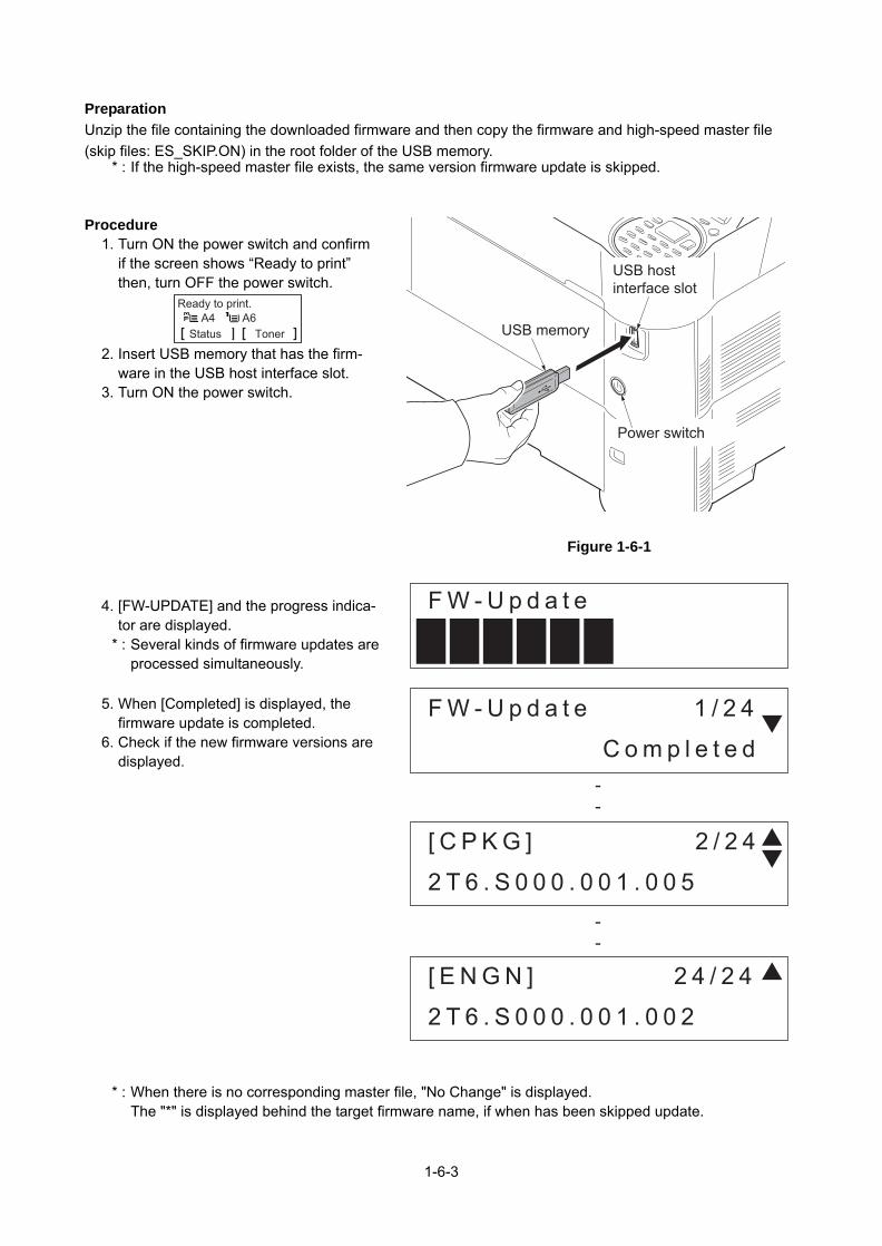
2T6/2T7/2T8/2T9
Preparation
Unzip the file containing the downloaded firmware and then copy the firmware and high-speed master file
(skip files: ES_SKIP.ON) in the root folder of the USB memory.* : If the high-speed master file exists, the same version firmware update is skipped.
Procedure1. Turn ON the power switch and confirm
if the screen shows “Ready to print”then, turn OFF the power switch.
2. Insert USB memory that has the firm-ware in the USB host interface slot.
3. Turn ON the power switch.
Figure 1-6-1
4. [FW-UPDATE] and the progress indica-tor are displayed.
* : Several kinds of firmware updates areprocessed simultaneously.
5. When [Completed] is displayed, thefirmware update is completed.
6. Check if the new firmware versions aredisplayed.
* : When there is no corresponding master file, "No Change" is displayed.The "*" is displayed behind the target firmware name, if when has been skipped update.
USB memory
USB host interface slot
Power switch
Status
Ready to print.A4 A6
Toner
F W - U p d a t e
F W - U p d a t e 1 / 2 4
[ E N G N ] 2 4 / 2 4
[ C P K G ] 2 / 2 4
C o m p l e t e d
2 T 6 . S 0 0 0 . 0 0 1 . 0 0 2
2 T 6 . S 0 0 0 . 0 0 1 . 0 0 5
--
--
1-6-3

In case of the error completion.In case of occurring an error during the firmware update, the process is immediately interrupted and the error message and error code are dis-played.
PrecautionsNever turn the power switch off or disconnect the USB memory during the firmware update.
Error code
*1: The expiration of the FM certification is also included.*2: Since the normal start-up is available next time, it is restarted automatically and starts up normally.*3: As there is a possibility that normal start-up is impossible next time, without restarting automatically, andmove to USB update mode.
The signature verification result display
Code Error contents Code Error contents
0000 Others S000 Other signature verification error *1
0100 There is no master file. S001 Official signature verification file is short.
0200 Master file version discrepancy N001 Unable to connect the network *2(There is no target to update.)03xx There is no download file (No.xx).
04xx File (No.xx) check sum discrepancy N002 Can not connect to the network *3(There is the target to update.)05xx File (No.xx) preparation failure
06xx File (No.xx) preparation failure
08xx File (No.xx) writing failure
Official signature verification file Indicate the result
Both certificate and signature files exist and verification is suc-cessful.
Version number
Both certificate and signature files exist but verification is unsuc-cessful.
S000
Neither certificate nor signature files exist.Or either of them does not exist.
S001
F W - U p d a t e 1 / 2 4
[ E N G N ] 2 4 / 2 4
[ C P K G ] 2 / 2 4
E r r o r
E r r o r 0 8 0 1
2 T 6 . S 0 0 0 . 0 0 1 . 0 0 5
--
--
1-6-4

7. Unplug the power cord and disconnect the USB memory.8. Plug in the power cord and turn the power switch (a) on.9. Check that the "Home" screen is displayed and then turn the power switch (a) off.
Safe-Update
When the firmware update was interrupted by power shut-off or disconnecting the USB memory during thefirmware update, the firmware update is retried at the next power-on.Turn the main power on again while the USB memory is installed.
* : The firmware update that was already completed before power shut-down is skipped.
1-6-5

1-6-2 Remarks on PWB replacement
(1) Engine PWB
NOTE: When replacing the PWB, remove the EEPROM from the PWB and then reattach it to the new PWB.
Figure 1-6-2
(2) Main PWB
1. Re-activate the license if optional licensed product is installed.1) Card Authentication Kit(B)2) UG-33 (ThinPrint)3) Data Security Kit(E)* : Re-input four-digit encrypted code that was input at setup.
2. Reset the user initial values from the System Menu and Command Center.
EEPROM(U21)
Engine PWB
1-6-6

2-1 Mechanical Construction
2-1-1 Paper feed/conveying section
Paper feed/conveying section consists of the paper feed unit that feeds paper from the cassette and the MP tray paper feed unit that feeds paper from the MP tray, and the paper conveying section that conveys the fed paper to the transfer/separation section.
(1) Cassette paper feed section
The cassette can contain 500 sheets. The sheet from the cassette is pulled out by rotation of the pickup roller and sent to the paper conveying section by rotation of the paper feed roller. Also the retard roller prevents mul-tiple feeding of paper.
Figure 2-1-1 Cassette paper feed section
Figure 2-1-2 Cassette paper feed section block diagram
*1: 60/55/50 ppm model only
7 845 1 236
1. Paper feed roller2. Pickup roller3. Feed holder4. Retard roller
5. Retard holder6. Retard guide7. Bottom plate8. Cassette base
YC4-1YC4-2YC4-3YC4-4
YC5-4
YC7-1YC7-2YC7-3YC7-4
YC13-1
YC14-3
MMOTCWMMOTRDYNMMOTCLKNMMOTONN
FEEDCLN
CAS3CAS2
CASSETCAS1
LIFTMOTOR
LSENS
6543
PFCL
CSSW
MM
LM *1
LS *1
EPWB
YC19-11PAPER SEN1N HVPWB YC19-10PAPER SEN2N
PS1PS2
2-1-1

(2) MP tray paper feed section
The MP tray can contain 100 sheets. Feeding from the MP tray is performed by the rotation of the MP paper feed roller. Also, function of the MP separation pad prevents paper from multiple feeding.
Figure 2-1-3 MP tray paper feed section
Figure 2-1-4 MP tray paper feed section block diagram
13 4
6
5 2
1. MP paper feed roller2. MP separation pad3. MP bottom plate
4. MP frame5. MP base6. MP (Multi purpose)tray
YC4-1YC4-2YC4-3YC4-4
YC8-2
MMOTCWMMOTRDYNMMOTCLKNMMOTONN
MPFSLN
6MM 5
43
MPSOL
EPWBYC2-12YC8-3
R-LPWBMPFSENSMPPS MPFSENS
2-1-2

(3) Conveying section
The conveying section conveys paper to the transfer/separation section as paper feeding from the cassette or MP tray, or as paper refeeding for duplex printing. Paper by feeding is conveyed by the paper feed roller to the position where the registration sensor (RS) is turned on, and then sent to the transfer/separation section by the upper registration roller and lower registration roller.
Figure 2-1-5 Conveying section
Figure 2-1-6 Paper conveying section block diagram
*1: 45ppm model only*2: 60/55/50 ppm model only
1 5 6 72 3 4
1. Middle feed roller2. Feed DU pulley3. Upper registration guide4. Actuator
(Registration sensor 1 (RS1)) *1
5. Upper registration roller6. Lower registration roller7. Actuator
(Registration sensor 3 (RS3)) *2
YC4-1YC4-2YC4-3YC4-4
YC5-6
MMOTCWMMOTRDYNMMOTCLKNMMOTONN
REGCLN
6MM 5
43
RCL
EPWB
YC2-21YC3-9
RS1 *1 / RS3 *2
REGSEN2
YC19-12HVPWB
R-LPWB
REGSENSN
RS2 *2 REGSEN2
DRRPWBYC6-2
DRPWB
YC5-8MIDCLNPCCL *2
2-1-3

2-1-2 Drum section
The drum section consists of the drum, the charger roller unit, and the cleaning unit, and the drum surface is uniformly charged in preparation for formation of residual image by laser beam.
(1) Charger roller unit
The drum surface is uniformly chargedby contacting the roller which gave the electric charge and was charged on the drum surface, and rotating it.
Figure 2-1-7 Charger roller unit
Figure 2-1-8 Charger roller unit
1
234
1. Drum2. Charger roller
3. Charger cleaning roller4. Charger case
YC4-7YC4-8YC4-9
YC4-10
YC19-4YC19-5YC19-6
YC2-3YC2-1
DMOTCWDMOTRDYNDMOTCLKNDMOTONN
MHVCLKMACCNTMDCCNT
EESIOEECLK
65 DRM43
HVPWB
R-LPWB DRRPWB DRPWB
EPWB
Ground
Main chargerroller
Drum
2-1-4

(2) Cleaning unit
After transfer is complete, toner remaining on the drum surface is chipped off with the cleaning blade and is collected to the waste toner box with the drum screw. The cleaning lamp (CL) consists of LEDs and removes residual charge on the drum before main charging.
Figure 2-1-9 Cleaning unit
Figure 2-1-10 Cleaning unit block diagram
1
67
5
3 42
1. Cleaning blade2. Cleaning roller3. Control roller4. Sweep roller
5. Drum frame6. Scraper7. Cleaning lamp (CL)
YC3-4
YC5-2
YC2-4ERASERR-LPWB
DRRPWBDRPWB
EPWB
GroundDrum Cleaning lamp
Drum unit
2-1-5

2-1-3 Developer section
The developer unit consists of the developer roller that forms the magnetic brush, the developer blade and the developer screws that agitate the toner.Also, the toner sensor (TS) checks whether or not toner remains in the developer unit.
Figure 2-1-11 Developer section
Figure 2-1-12 Developer section block diagram
6 7 3 2
1
45 89
1. Developer roller2. Developer blade3. Magnet blade4. Developer screw A5. Developer screw B
6. Developer case7. Upper developer cover8. Toner supply roller9. Toner container
MMOTCWMMOTRDYNMMOTCLKNMMOTONN
HVCLK
EESIOTSENS
YC3-2
YC4-1
TMOT
EECLK
TSENS
TMOT
1WIREYC2-6YC2-15
65 MM43
R-LPWB
DLPCLN DEVSCL
CRPWB
TS
TS
TM
YC5-2
DRPWBDRRPWB
HVPWB
YC2-1
YC4-1YC4-2YC4-3YC4-4
YC19-7
YC2-3YC2-1
Developer bias Drum
EPWB
BDCNTYC19-8BACNTYC19-9
2-1-6

2-1-4 Optical section
(1) Laser scanner section
The charged surface of the drum is then scanned by the laser beam from the laser scanner unit. The laser beam is dispersed as the polygon motor (PM) revolves to reflect the laser beam over the drum. Various lenses and mirror are housed in the laser scanner unit, adjust the diameter of the laser beam, and focalize it at the drum surface.
Figure 2-1-13 Laser scanner unit (LSU)
Figure 2-1-14 Laser scanner unit block diagram
123 4 5 6
1. Polygon motor (PM)2. fθ main lens3. Direction change mirrer
4. LSU dust shield glass5. LSU base6. LSU cover
YC15-3YC15-4YC15-5
YC16-2YC16-3YC16-4YC16-5
YC16-7
PLGDRNPLGRDYNPOLCLK
VDATA1PVDATA1NVDATA2PVDATA2N
SAMPLEN2YC16-6 YC2-2 PDPWBSAMPLEN1 PDN
32 PM1
APCPWB
EPWB
Photo sensor
Laserdiode
Drum
Laser light
YC16-8 OUTPENYC16-9 VCONT1
YC16-10 VCONT2
2-1-7

2-1-5 Transfer/Separation section
The transfer and separation section consists mainly of the transfer roller and separation electrode.A high voltage generated by the high voltage PWB (HVPWB) is applied to the transfer roller for transfer charg-ing.Paper after transfer is separated from the drum by applying separation charging that is output from the high voltage PWB (HVPWB) to the separation electrode.
Figure 2-1-15 Transfer/Separation section
Figure 2-1-16 Transfer/Separation section block diagram
32 1 54
1. Transfer roller2. Paper chute guide3. Separation needle
4. Drum5. Drum heater *1
SCNTTRREMTCNT
Transfer roller Separation needle
Separation bias
Transfer biasHVPWB
YC19-15YC19-16YC19-17
EPWB
2-1-8

2-1-6 Fuser section
The paper sent from the transfer/separation section is interleaved between the heat roller and the press roller. The heat roller is heated by the fuser heater (FUH), and the toner is fused by heat and pressure and fixed onto the paper because the press roller is pressed by the fuser press spring. The surface temperature of heat roller is detected by the fuser thermistor (FUTH1,2) and controlled by the engine PWB (EPWB). If the fuser section shows extremely high temperature, the power line will be shut off and the fuser heater (FUH) is forced to turn off.
Figure 2-1-17 Fuser section
Figure 2-1-18 Fuser section block diagram
3 41 522
78910
11
12
13
6
1. Heat roller2. Fuser heater (FUH)3. Fuser thermostat (FUTS)4. Fuser thermistor (FUTH1)5. Separators6. Press roller7. Actuater (Eject sensor (ES))
8. Fuser eject roller9. Fuser eject pulley
10. Upper fuser frame11. Lower Fuser frame12. Pre fuser guide13. Fuser thermistor (FUTH2)
YC1-1YC1-2
YC21-1YC21-2
YC26-3
HEAT2REMHEAT1REM
TH2TH1
EXTSENSN
PSPWBYC2-1YC2-2YC2-3
YC2-2
FUH1
FUH2FUTS1 FUTS2
YC1-2
EPWB Fuser unit
FUTHRPWB
FUTH2FUTH1
ES
2-1-9

2-1-7 Eject/Feedshift section
The paper eject/feedshift section consists of the conveying path which sends the paper that has passed the fuser section to the facedown tray, the faceup tray (60/50/45 ppm model only) or the duplex conveying sec-tion.
Figure 2-1-19 Eject/Feedshift section
*1: 60/55/50 ppm model only
6
7
45
10
8
3 2
12
11
13
1
3 21
9
6
7
45
10
8
9
(60/55/50 ppm model)(45 ppm model)
1. Upper eject roller2. Upper eject pulley3. Actuator
(Eject full sensor (EFS))4. Lower eject roller5. Lower eject pulley6. Vertical guide
7. Paper exit guide8. Top cover9. DU feed pulley
10. Rear cover11. Faceup roller *112. Faceup pulley *113. Feedshift guide *1
2-1-10

Figure 2-1-20 Eject/Feed shift section block diagram
(60/55/50 ppm model)(45 ppm model)
YC12-3
YC12-1YC12-2YC12-3YC12-4
YC26-3
PAPFULN
OUTB3OUTB1OUTA3OUTA1
EXITSENSN
EFS
EM
ES
EPWB
R-LPWB
YC12-3
YC12-1YC12-2YC12-3YC12-4
YC13-1YC13-3
YC26-3
PAPFULN
OUTB3OUTB1OUTA3OUTA1
FACEDDRNFACEUDRN
EXITSENSN
EFS
EM
FSSOL
ES
EPWB
R-LPWB
2-1-11

2-1-8 Duplex conveying section
The duplex conveying section consists of conveying path which sends the paper sent from the eject/feedshift section to the paper feed/conveying section when duplex printing.
Figure 2-1-21 Duplex conveying section
Figure 2-1-22 Duplex conveying section block diagram
*1: 60/55/50 ppm model only
127 5 6124 3
1. DU conveying roller2. DU conveying pulley3. Actuater
(Duplex sensor 1 (DUS1)) *1
4. Actuater(Duplex sensor 2 (DUS2))
5. DU base6. DU lower guide7. Upper feed guide
DUCLN
DUJAMSEN1N
DUCL
DUJAMSEN1N YC9-3
R-LPWB
DUS1 *1
DUJAMSEN2NHVPWB DUS2
YC5-10
YC2-20
EPWB
YC19-13
2-1-12

2-2 Electrical Parts Layout
2-2-1 Electrica
(1) PWBs
1. Main PWB (MPWB) ...
2. Engine PWB (EPWB).
3. Power source PWB (P
4. High voltage PWB (HV5. Drum PWB (DRPWB)
6. Drum relay PWB (DRR
7. Relay-L PWB (R-LPW
8. Operation PWB (OPPW9. Backlight PWB (BLPW
10. Fuser thermistor relay (FUTHRPWB) ............
11. APC PWB (APCPWB)12. PD PWB (PDPWB) ....13. Container PWB (CPW
56
13
4
3
l parts layout
Figure 2-2-1 PWBs
........................... Controls the software such as the print data processing and provides the interface with computers.
........................... Controls printer hardware such as high voltage/bias output con-trol, paper conveying system control, and fuser temperature con-trol, etc.
SPWB) .............. After full-wave rectification of AC power source input, switching for converting to 24 V DC for output. Controls the fuser heater.
PWB) ................ Generates main charging, developing bias, transfer bias............................ Relays wirings from electrical components on the drum unit.
1117 10111228 9
Machine right Machine inside
2-2-1
Drum individual information in EEPROM storage.PWB)................ Consists of wiring relay circuit between engine PWB and the
drum unit.B) ....................... Consists of wiring relay circuit between engine PWB and drum
connect PWB.B-M) ................ Consists the LCD, LED indicators and key switches.
B) ...................... LCD lighting.PWB........................... Consists of wiring relay circuit between engine PWB ,fuser
thermistors and cooling fans........................... Generates and controls the laser beam.
........................... Controls horizontal synchronizing timing of laser beam.B) ....................... Reads the container information.

List of correspondences
No. Name use
1 Main PWB (MPWB
2 Engine PWB (EPW
3 Power source PWB
4 High voltage PWB
5 Drum PWB (DRPW
6 Drum connect PWB
7 Relay-L PWB (R-L
8 Operation PWB (O
9 Backlight PWB (BL
10 Fuser thermistor re
11 APC PWB (APCPW
12 PD PWB (PDPWB
13 Container PWB (C
of PWB names
d in service manual Name used in parts list
) PARTS PWB ASSY MAIN SP
B) PARTS PWB ASSY ENGINE SP
(PSPWB) PARTS SWITCHING REGULATOR 120V SP
(HVPWB) PARTS HIGH VOLTAGE UNIT SP
B) (DK-****)
(DRRPWB) PARTS PWB ASSY DRUM CONNECT SP
PWB) PARTS PWB ASSY CONNECT-L SP
PPWB) PARTS PWB ASSY PANEL SP
PWB)
lay PWB (FUTHRPWB) PARTS PWB ASSY TH CONNECT SP
B) (LK-****)
) (LK-****)
PWB) (DK-****)
2-2-2
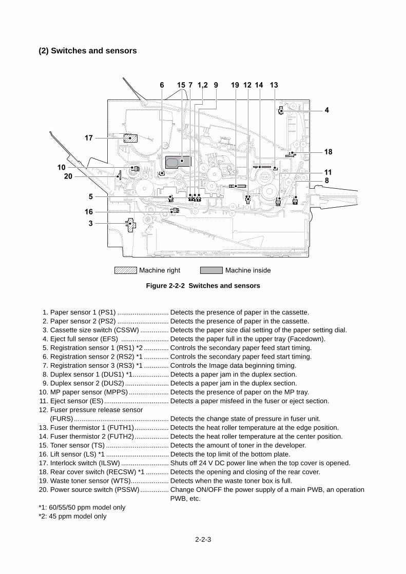
(2) Switches and sen
1. Paper sensor 1 (PS1)2. Paper sensor 2 (PS2)3. Cassette size switch (C4. Eject full sensor (EFS)5. Registration sensor 1 (6. Registration sensor 2 (7. Registration sensor 3 (8. Duplex sensor 1 (DUS9. Duplex sensor 2 (DUS
10. MP paper sensor (MPP11. Eject sensor (ES) .......12. Fuser pressure release
(FURS) .......................13. Fuser thermistor 1 (FU14. Fuser thermistor 2 (FU15. Toner sensor (TS) ......16. Lift sensor (LS) *1 ......17. Interlock switch (ILSW18. Rear cover switch (RE19. Waste toner sensor (W20. Power source switch (
*1: 60/55/50 ppm model o*2: 45 ppm model only
316
17
2010
5
sors
Figure 2-2-2 Switches and sensors
........................... Detects the presence of paper in the cassette.
........................... Detects the presence of paper in the cassette.SSW) ............... Detects the paper size dial setting of the paper setting dial.
......................... Detects the paper full in the upper tray (Facedown).RS1) *2 ............. Controls the secondary paper feed start timing.RS2) *1 ............. Controls the secondary paper feed start timing.RS3) *1 ............. Controls the Image data beginning timing.1) *1................... Detects a paper jam in the duplex section.2) ....................... Detects a paper jam in the duplex section.S) ..................... Detects the presence of paper on the MP tray.
........................... Detects a paper misfeed in the fuser or eject section. sensor
15 7 1,2 96 19 14 1312
4
18
811
Machine right Machine inside
2-2-3
........................... Detects the change state of pressure in fuser unit.TH1).................. Detects the heat roller temperature at the edge position.TH2).................. Detects the heat roller temperature at the center position............................ Detects the amount of toner in the developer............................ Detects the top limit of the bottom plate.) ......................... Shuts off 24 V DC power line when the top cover is opened.CSW) *1 ............ Detects the opening and closing of the rear cover.TS).................... Detects when the waste toner box is full.
PSSW) ............... Change ON/OFF the power supply of a main PWB, an operation PWB, etc.
nly

(3) Motors
1. Main motor (MM)........2. Drum motor (DRM) *13. Eject motor (EM) ........4. Polygon motor (PM) ..5. Fuser pressure release6. Lift motor (LM) *1 .......7. Toner motor (TM) .......8. LSU fan motor (LSUFM9. Power source fan moto
10. Developer fan motor (D
*1: 60/55/50 ppm model on
9
6
Figure 2-2-3 Motors
........................... Drives the paper feed section and conveying section.
........................... Drives the drum unit and transfer roller.
........................... Drives the eject section.
........................... Drives the polygon mirror. motor (FUPRM) *1Drives the change mechanism of fixing pressure in fuser unit.
........................... Operates the bottom plate in the cassette.
........................... Replenishes toner to the developer unit.) ....................... Cools the LSU unit.r (PSFM) .......... Cools the power source PWB.EVFM) ............. Cools the developer unit.
ly
8 3
5
4217 10
Machine right Machine inside
2-2-4

(4) Clutches and oth
1. Paper feed clutch (PFC2. Registration clutch (RC3. Developer clutch (DEV4. Conveying clutch (PCC5. Duplex clutch (DUCL)6. MP solenoid (MPSOL)7. Feedshift solenoid (FS8. LCD (LCD) .................9. Cleaning lamp (CL) ....
10. Fuser heater 1 (FUH1)11. Fuser heater 2 (FUH2)12. Fuser thermostat 1 (FU13. Fuser thermostat 2 (FU
*1: 60/55/50 ppm model on
1
6
ers
Figure 2-2-4 Clutches and others
L) ..................... Primary paper feed from cassette.L)...................... Controls the secondary paper feed.SCL) ................. Controls the drive of the developer.L)...................... Controls the paper conveying.
........................... Controls the drive of the duplex feed roller........................... Controls the MP bottom plate.SOL) *1 ............. Operates the feedshift guide............................ LCD display. Displays an operating state. ........................... Eliminates the residual electrostatic charge on the drum........................... Heats the heat roller........................... Heats the heat roller.
3 12,13 752 84 11109
Machine right Machine inside
2-2-5
TS1) ................. Prevents overheating of the heat roller.TS2) ................. Prevents overheating of the heat roller.
ly

2-3 Operation of the PWBs
2-3-1 Main PWB (MPWB)
Figure 2-3-1 Main PWB silk-screen diagram and Photograph
YC321
60
1
20
YC7
YC31
A1B1
A11B11
YC4
YC9
YC61
4
5
91 4
2 31
10
YC2
1
10
YS1
1
2144
143
2-3-1

Connector Pin Signal I/O Voltage Description
YC2 1 DAT3 I/O DC0V/3.3V Control signal
Connected to the SD card I/F
2 CMD I/O DC0V/3.3V Command control signal
3 VSS - - Ground
4 VDD O DC3.3V Control signal
5 CLK O DC0V/3.3V 3.3 V DC power output
6 VSS - - Ground
7 DAT0 I/O DC0V/3.3V Data bus signal
8 DAT1 I/O DC0V/3.3V Data bus signal
9 DAT2 I/O DC0V/3.3V Data bus signal
10 Delective_Card_Switch
I DC0V/3.3V Control signal
11 Common_Contact
- - Control signal
12 WPSwitch I DC0V/3.3V Control signal
YC4 1 VBUS I DC0V/5.0V 5 V DC power output to USB device
Connected tothe USB Device
2 D- I/O Analog USB data signal
3 D+ I/O Analog USB data signal
4 GND - - Ground
YC6 1 VBUS O DC0V/5.0V 5 V DC power output to USB host
Connected tothe USB HOST
2 D- I/O Analog USB data signal
3 D+ I/O Analog USB data signal
4 GND - - Ground
YC7 1 +5.0V1_C1 O DC5.0V 5 V DC power output to eKUIO
Connected tothe eKUIO
2 GND - - Ground
3 RESET O DC0V/3.3V Reset signal
4 +5.0V2_C O DC5.0V 5 V DC power output to eKUIO
5 GND - - Ground
6 IRQ I DC0V/3.3V Interrupt signal
7 OPEN - - NC
8 OPEN - - NC
9 OPEN - - NC
10 OPEN - - NC
11 GND - - Ground
12 OPEN - - NC
2-3-2

YC7 13 OPEN - - NC
Connected tothe eKUIO
14 GND - - Ground
15 OPEN - - NC
16 OPEN - - NC
17 GND - - Ground
18 DP I/O Analog USB data signal
19 DN I/O Analog USB data signal
20 VBUS O DC0V/3.3V 3.3 V DC power output to eKUIO
YC9 P1 TD1+ I/O Analog Send data
Connected tothe Ethernet
P2 TD1- I/O Analog Send data
P3 TD2+ I/O Analog Send data
P4 TD2- I/O Analog Send data
P5 CT1 I 3.3 V DC 3.3 V DC power output
P6 CT2 I 3.3 V DC 3.3 V DC power output
P7 TD3+ I/O Analog Send data
P8 TD3- I/O Analog Send data
P9 TD4+ I/O Analog Send data
P10 TD4- I/O Analog Send data
YC31 1 +3.3V2 O DC3.3V 3.3 V DC power output to OP
Connected tothe IEEE1284
2 +5.0V2 O DC5.0V 5 V DC power output to OP
3 P1284DIR O DC0V/3.3V Direction input signal
4 NACK O DC0V/3.3V Acknowledge input signal
5 BUSY O DC0V/3.3V Busy input
6 PERROR O DC0V/3.3V Errer signal
7 SELECT O DC0V/3.3V Select signal
8 NFAULT O DC0V/3.3V Errer signal
9 PDATA1 I/O DC0V/3.3V Data signal
10 PDATA2 I/O DC0V/3.3V Data signal
11 PDATA3 I/O DC0V/3.3V Data signal
12 PDATA4 I/O DC0V/3.3V Data signal
13 PDATA5 I/O DC0V/3.3V Data signal
14 PDATA6 I/O DC0V/3.3V Data signal
15 PDATA7 I/O DC0V/3.3V Data signal
16 PDATA8 I/O DC0V/3.3V Data signal
17 NSELECTIN I DC0V/3.3V Select signal
18 NSTROBE I DC0V/3.3V Output signal
19 NAUTOFD I DC0V/3.3V AUTO-FEED signal
Connector Pin Signal I/O Voltage Description
2-3-3

YC31 20 NINIT I DC0V/3.3V Reset signal
Connected tothe IEEE1284
21 PDATECT I DC0V/3.3V OP detection signal
22 GND - - Ground
YC32 1 +24V0 I DC24V 24 V DC power input
Connected tothe enginePWB
2 +24V0 I DC24V 24 V DC power input
3 +24V0 I DC24V 24 V DC power input
4 +3.3V0_PM O DC3.3V 3.3 V DC power output
5 +3.3V3_E O DC3.3V 3.3 V DC power output
6 +3.3V3_E O DC3.3V 3.3 V DC power output
7 +5.0V1_C1 O DC5.0V 5 V DC power output
8 +3.3V1_C O DC3.3V 3.3 V DC power output
9 DUTY_CONTROL
O DC0V/3.3V(pulse) PI / Sensor intermittent control signal
10 E2C_SDAT I DC0V/3.3V Serial communication data output
11 C2E_SDAT O DC0V/3.3V Serial communication data input
12 C2E_SCK O DC0V/3.3V Serial communication clock signal
13 E2C_SDIR I DC0V/3.3V Serial communication direction signal
14 E2C_SBSY I DC0V/3.3V System busy signal
15 GND - - Ground
16 VBUS_USBH_3
O DC0V/5.0V 5 V DC power output to USB
17 GND - - Ground
18 USBH_DP3 I/O Analog USB differential data
19 USBH_DN3 I/O Analog USB differential data
20 GND - - Ground
21 SDIF_DAT0 I/O DC0V/3.3V WiFi input and output data
22 SDIF_DAT1 I/O DC0V/3.3V WiFi input and output data
23 SDIF_DAT2 I/O DC0V/3.3V WiFi input and output data
24 SDIF_DAT3 I/O DC0V/3.3V WiFi input and output data
25 SDIF_SDCLK O DC0V/3.3V WiFi input and output data
26 GND - - Ground
27 SH1D O DC0V/3.3V Sample-and-hold signal
28 GND - - Ground
29 LDOUT_1_DN O LVDS Video data
30 LDOUT_1_DP O LVDS Video data
31 GND - - Ground
32 GND - - Ground
Connector Pin Signal I/O Voltage Description
2-3-4

YC32 33 GND - - Ground
Connected tothe enginePWB
34 GND - - Ground
35 GND - - Ground
36 GND - - Ground
37 GND - - Ground
38 GND - - Ground
39 LVU_SLEEP_N
O DC0V/3.3V LVU energy-saving control signal
40 POWER_SW I DC0V/3.3V PowerSW
41 E2C_IRN I DC0V/3.3V G6 interrupt signal
42 E2C_WKUP_BGD_N
I DC0V/3.3V Engine BGM return trigger
43 ENG_HLDN O DC0V/3.3V Engine Hold signal
44 C2E_QUICK_START
O DC0V/3.3V Speed priority return notification signal
45 PVSYNC I DC0V/3.3V VSYNC
46 GND - - Ground
47 P2C_WKUP_RDY
I DC0V/3.3V Ready return trigger signal
48 ENERGYSAVERKEY_N
I DC0V/3.3V Key input
49 C2P_RST_N O DC0V/3.3V Panel reset signal
50 P2C_SDAT I DC0V/3.3V Panel received data sjgnal
51 C2P_SDAT O DC0V/3.3V Panel transmitted data signal
52 GND - - Ground
53 SDIF_SDCD I DC0V/3.3V Card detect signal
54 SDIF_INTA I DC0V/3.3V Interrupt signal
55 SDIF_CMD I/O DC0V/3.3V Command signal
56 BDN_D I DC0V/3.3V BD signal
57 SH2D O DC0V/3.3V Sample hold signal
58 GND - - Ground
59 LDOUT_2_DN O LVDS Video signal
60 LDOUT_2_DP O LVDS Video signal
Connector Pin Signal I/O Voltage Description
2-3-5

2-3-2 Engine PWB (EPWB)
Figure 2-3-2 Engine PWB silk-screen diagram and Photograph
YC30
1
14
YC31
1
5
YC261
3
YC12
1
3
YC15
1
5
YC7
1
4
YC22 1
YC271
2
YC5
YC13
1
2
YC8
12
YC10
12
YC1
1
YC19
1
18
YC4
1
6
12
YC141
3
YC21
1
8
YC20 160
YC23
1 4
YC181 2
YC6
1
2
1
10
13
YS1
YC16
1
13
1
22
YC2
12
2-3-6

Connector Pin Signal I/O Voltage Description
YC1 1 HEAT2REM O 0/3.3 V DC TH2 remote signal
Connected to the power source PWB
2 HEAT1REM O 0/3.3 V DC TH1 remote signal
3 ZCROSSN I 0/3.3 V DC Zero crossing detection signal
4 RELAY O 0/3.3 V DC Relay driving signal
5 PSLEEPN O 0/3.3 V DC Sleep signal
6 GND - - Ground
7 GND - - Ground
8 GND - - Ground
9 GND - - Ground
10 +24V0 I 24 V DC 24 V DC power input from PSPWB
11 +24V0 I 24 V DC 24 V DC power input from PSPWB
12 +24V0 I 24 V DC 24 V DC power input from PSPWB
13 +24V0 I 24 V DC 24 V DC power input from PSPWB
YC2 1 EECLK O DC0V/3.3V Clock signal
Connected to the relay-L PWB
2 GND - - Ground
3 EESIO I/O 0/3.3 V DC(pulse) Communication data
4 ERASER O DC0V/3.3V CL: On/Off
5 +3.3V3_F2 O DC3.3V 3.3 V DC power output to R-LPWB
6 TSENS I analog TS output signal
7 SBMDIR O DC0V/3.3V SBM: On/Off
8 WTSENS I analog WTS output signal
9 SBMENBLN O DC0V/3.3V SBM enable signal
10 WTLED O DC0V/3.3V LED: On/Off
11 SBMSTEP O 0/3.3 V DC(pulse) SBM clock signal
12 MEFSENS I DC0V/3.3V MPS: On/Off
13 SBMMODE O DC0V/3.3V SBM mode signal
14 +3.3V1_PWM_F2
O DC3.3V 3.3 V DC power output
15 TMOT O DC0V/3.3V TM: On/Off
16 LFANN O DC0V/3.3V CENFM: On/Off
17 FUDR O DC0V/3.3V FSSOL: On/Off
18 ENVMOT O DC0V/3.3V FUPRM: On/Off
19 FDDR O DC0V/3.3V FSSOL: On/Off
20 DUJAMSEN1N
I DC0V/3.3V DUS: On/Off
21 REGSEN2 I DC0V/3.3V RS: On/Off
22 REARSWN I DC0V/3.3V RCS: On/Off
2-3-7

YC4 1 MMOTCW O 0/5 V DC MM drive shift signal
Connected to the drum motor and main motor
*: 7 to 12 of the pin num-ber are used for 60/50/45 ppm model only
2 MMOTRDYN I 0/3.3 V DC MM ready signal
3 MMOTCLKN O 0/5 V DC(pulse) MM clock signal
4 MMOTONN O 0/5 V DC MM: On/Off
5 GND - - Ground
6 +24V3 O 24 V DC 24 V DC power output
7 DMOTCW O 0/5 V DC DRM rotation direction
8 DMOTRDYN I 0/3.3 V DC DRM ready signal
9 DMOTCLKN O 0/5 V DC(pulse) DRM clock signal
10 DMOTONN O 0/5 V DC DRM: On/Off
11 GND - - Ground
12 +24V3 O 24 V DC 24 V DC power output
YC5 1 +24V3_IL O 24 V DC 24 V DC power output to DEVCL
Connected to the duplex cltch,mid cltch,registration clutch,paper feed cltch and developer clutch
2 DLPCLN O 0/3.3 V DC DEVCL: On/Off
3 +24V3_IL O 24 V DC 24 V DC power output to PFCL
4 FEEDCLN O 0/24 V DC PFCL: On/Off
5 +24V3_IL O 24 V DC 24 V DC power output to RCL
6 REGCLN O 0/24 V DC RCL: On/Off
7 +24V3_IL O 24 V DC 24 V DC power output to PCCL
8 MIDCLN O 0/24 V DC PCCL: On/Off
9 +24V3_IL O 24 V DC 24 V DC power output to DUCL
10 DUCLN O 0/24 V DC DUCL: On/Off
YC6 1 +24V0 O 24 V DC 24 V DC power output
Connected to the interlock switch
2 +24V0_IL O 24 V DC 24 V DC power output
YC7 1 CAS3 I 0/24 V DC CSSW: On/Off
Connected to the cassette size switch
2 CAS2 I 0/3.3 V DC CSSW: On/Off
3 CASSET - - CSSW common signal
4 CAS1 I 0/3.3 V DC CSSW: On/Off
YC8 1 +24V3_IL O 24 V DC 24 V DC power output to MPSOL
Connected to the MP sole-noid
2 MEFSOLN O 0/24 V DC MPSOL: On/Off
YC10 1 +24V0 O 24 V DC 24 V DC power output to PSFM
Connected to the power source fan motor
2 FANRN O 0/24 V DC PSFM: On/Off
Connector Pin Signal I/O Voltage Description
2-3-8

YC12 1 +3.3V3_F2 O 3.3 V DC 3.3 V DC power output to EFS
Connected to the eject full sensor
2 GND - - Ground
3 PAPFULN I 0/3.3 V DC EFS: On/Off
YC13 1 LIFTMOTOR O 0/5 V DC LM: On/Off
Connected to the lift motor
*: 60/55/50 ppm model only
2 GND - - Ground
YC14 1 +3.3V9 O 3.3 V DC 3.3 V DC power output to LS
Connected to the lift sensor
*: 60/55/50 ppm model only
2 GND - - Ground
3 LSENS I 0/3.3 V DC LS: On/Off
YC15 1 +24V3_IL_F5 O 24 V DC 24 V DC power output to PM
Connected to the polygon motor
2 GND - - Ground
3 PLGDRN O 0/5 V DC PM: On/Off
4 PLGRDYN I 0/3.3 V DC PM ready signal
5 POLCLK O 0/3.3 V DC(pulse) PM clock signal
YC16 1 +5V3_F1 O 5 V DC 5 V DC power output to APCPWB
Connected to the APC PWB
2 VDATA1P O LVDS Video data 1 signal (+)
3 VDATA1N O LVDS Video data 1 signal (-)
4 VDATA2P O LVDS Video data 2 signal (+)
5 VDATA2N O LVDS Video data 2 signal (-)
6 SAMPLEN1 O 0/3.3 V DC Sample / hold signal 1
7 SAMPLEN2 O 0/3.3 V DC Sample / hold signal 2
8 OUTPEN O 0/3.3 V DC Laser enable
9 VCONT1 O Analog LD-1 Light volume adjustment
10 VCONT2 O Analog LD-2 Light volume adjustment
11 GND - - Ground
12 PDN I 0/3.3 V DC (pulse) Main scanning synchronizing signal
13 +3.3V3_F2 O 3.3 V DC 3.3 V DC power output to APCPWB
YC18 1 GND - - Ground
Connected to the power switch
2 POWERSW I 0/3.3 V DC PSSW: On/Off
Connector Pin Signal I/O Voltage Description
2-3-9

YC19 1 ENVSENSN I 0/3.3 V DC ENVS: On/Off
Connected to the high volt-age PWB
2 GND - - Ground
3 MISENS I Analog MC output signal
4 MHVCLK O 0/3.3 V DC (pulse) MC clock signal
5 MACCNT O Analog MC AC control signal
6 MDCCNT O Analog MC DC control signal
7 HVCLK O 0/3.3 V DC (pulse) DEV clock signal
8 BDCNT O Analog DEV DC control signal
9 BACNT O Analog DEV AC control signal
10 PAPERSEN2N
I 0/3.3 V DC EFS2: On/Off
11 PAPERSEN1N
I 0/3.3 V DC EFS1: On/Off
12 REGSENSN I 0/3.3 V DC RS: On/Off
13 DUJAMSEN2N
I 0/3.3 V DC DUS: On/Off
14 +3.3V3_F2 O 3.3 V DC 3.3 V DC power output to HVPWB
15 SCNT O 0/3.3 V DC Separation output control signal
16 TRREM O 0/3.3 V DC TC remote signal
17 TCNT O Analog TC control signal
18 +24V3_IL O 24 V DC 24 V DC power output to HVPWB
YC20 1 +24V0 O DC24V 24 V DC power output
Connected tothe mainPWB
2 +24V0 O DC24V 24 V DC power output
3 +24V0 O DC24V 24 V DC power output
4 +3.3V0_PM I DC3.3V 3.3 V DC power input
5 +3.3V3_E I DC3.3V 3.3 V DC power input
6 +3.3V3_E I DC3.3V 3.3 V DC power input
7 +5.0V1_C1 I DC5.0V 5 V DC power input
8 +3.3V1_C I DC3.3V 3.3 V DC power input
9 DUTY_CONTROL
I DC0V/3.3V(pulse)
10 E2C_SDAT O DC0V/3.3V Serial communication data input
11 C2E_SDAT I DC0V/3.3V Serial communication data output
12 C2E_SCK I DC0V/3.3V Serial communication clock signal
13 E2C_SDIR O DC0V/3.3V Serial communication direction signal
14 E2C_SBSY O DC0V/3.3V System busy signal
15 GND - - Ground
16 VBUS_USBH_3
I DC0V/5.0V 5 V DC power input to USB
Connector Pin Signal I/O Voltage Description
2-3-10

YC20 17 GND - - Ground
Connected tothe mainPWB
18 USBH_DP3 I/O Analog
19 USBH_DN3 I/O Analog
20 GND - - Ground
21 SDIF_DAT0 I/O DC0V/3.3V
22 SDIF_DAT1 I/O DC0V/3.3V
23 SDIF_DAT2 I/O DC0V/3.3V
24 SDIF_DAT3 I/O DC0V/3.3V
25 SDIF_SDCLK I DC0V/3.3V
26 GND - - Ground
27 SH1D I DC0V/3.3V
28 GND - - Ground
29 LDOUT_1_DN I LVDS
30 LDOUT_1_DP I LVDS
31 GND - - Ground
32 GND - - Ground
33 GND - - Ground
34 GND - - Ground
35 GND - - Ground
36 GND - - Ground
37 GND - - Ground
38 GND - - Ground
39 LVU_SLEEP_N
I DC0V/3.3V
40 POWER_SW O DC0V/3.3V
41 E2C_IRN O DC0V/3.3V
42 E2C_WKUP_BGD_N
O DC0V/3.3V
43 ENG_HLDN I DC0V/3.3V
44 C2E_QUICK_START
I DC0V/3.3V
45 PVSYNC O DC0V/3.3V VSYNC
46 GND - - Ground
47 P2C_WKUP_RDY
O DC0V/3.3V
48 ENERGYSAVERKEY_N
O DC0V/3.3V
49 C2P_RST_N I DC0V/3.3V Panel reset signal
50 P2C_SDAT O DC0V/3.3V Panel received data sjgnal
Connector Pin Signal I/O Voltage Description
2-3-11

YC20 51 C2P_SDAT I DC0V/3.3V Panel transmitted data signal
Connected tothe mainPWB
52 GND - - Ground
53 SDIF_SDCD O DC0V/3.3V Card detect signal
54 SDIF_INTA O DC0V/3.3V Interrupt signal
55 SDIF_CMD I/O DC0V/3.3V Command signal
56 BDN_D O DC0V/3.3V BD signal
57 SH2D I DC0V/3.3V Sample hold signal
58 GND - - Ground
59 LDOUT_2_DN I LVDS
60 LDOUT_2_DP I LVDS
YC21 1 TH3 I Analog FUTH2 output signal
Connected to the fuser thermistor connect PWB
2 TH1 I Analog FUTH1output signal
3 GND - - Ground
4 REARFANN O 24 V DC REFM: On/Off
5 +24V_F3 O 24 V DC 24 V DC power output to FTHPWB
YC22 1 +24V_F2 O 24 V DC 24 V DC power output to PF
Connected to the paper feeder
2 OPSDO O 0/3.3 V DC (pulse) PF communication serial data signal
3 OPSDI I 0/3.3 V DC (pulse) PF communication serial data signal
4 OPCLK O 0/3.3 V DC (pulse) PF communication serial clock signal
5 OPRDYN I 0/3.3 V DC Option communication ready signal
6 +3.3V3_F1 O 3.3 V DC 3.3 V DC power output to PF
7 GND - - Ground
8 OPSEL2 O 0/3.3 V DC PF select signal
9 OPSEL1 O 0/3.3 V DC PF select signal
10 OPSEL0 O 0/3.3 V DC PF select signal
11 OPPAUSEN O 0/3.3 V DC Paper stop signal
12 GND - - Ground
YC23 1 VBUS O 5 V DC 5 V DC power output to USB host
Connected to the USB host
2 UDATAN I/O LVDS USB data signal (-)
3 UDATAP I/O LVDS USB data signal (+)
4 GND - - Ground
5 GND - - Ground
YC26 1 +3.3V_F2 O 3.3 V DC 3.3 V DC power output to ES
Connected to the eject sen-sor
2 GND - - Ground
3 EXITSENSN I 0/3.3 V DC ES: On/Off
Connector Pin Signal I/O Voltage Description
2-3-12

YC30 1 +3.3V1_F1 O 3.3 V DC 3.3 V DC power output to OPPWB
Connected to the opera-tion PWB
2 FUPRSTN O 0/3.3 V DC OPPWB reset signal
3 P2C_OK_KEY I 0/3.3 V DC OK KEY:On/Off
4 C2P_BUZCON
O 0/3.3 V DC Buzzer control signal
5 AIRTEMP I Analog Temperature sensor input signal
6 C2P_LCDCON
O 0/5 V DC LCD: On/Off
7 +5V5 O 5 V DC 5 V DC power output to LCD
8 P2C_SDAT I 0/3.3 V DC Data signal
9 AIRWET I Analog Humid sensor input signal
10 C2P_SDAT O 0/3.3 V DC The data signal between panel main
11 WETCLK O 0/3.3 V DC (pulse) Humid sensor clock signal
12 LED O 0/3.3 V DC READY LED control signal
13 FG - - Ground
14 GND - - Ground
YC31 1 1WIRE - - -
Connected to the relay-L PWB
2 +24V3_IL_F5 O 24 V DC 24 V DC power output
3 GND - - Ground
4 GND - - Ground
5 +24V0_F3 O 24 V DC 24 V DC power output
Connector Pin Signal I/O Voltage Description
2-3-13

2-3-3 Power source PWB (PSPWB)
Figure 2-3-3 Power source PWB silk-screen diagram and Photograph
YC3 113
YC21
12
3
YC1
2-3-14

Connector Pin Signal I/O Voltage Description
YC1 1 LIVE I 100 V AC AC power input
Connected to
the inlet
2 NEUTRAL I 100 V AC AC power input
YC2 1 NEUTRAL1 I 100 V AC Fuser heater
Connected to
the fuser unit
2 LIVE O 100 V AC AC power input
3 NEUTRAL2 I 100 V AC Fuser heater
YC3 1 +24V0 O 24 V DC 24 V DC power output to EPWB
Connected to
the engine
PWB
2 +24V0 O 24 V DC 24 V DC power output to EPWB
3 +24V0 O 24 V DC 24 V DC power output to EPWB
4 +24V0 O 24 V DC 24 V DC power output to EPWB
5 GND - - Ground
6 GND - - Ground
7 GND - - Ground
8 GND - - Ground
9 PSLEEPN I 0/5 V DC Sleep mode signal
10 RELAY I 0/5 V DC Relay control
11 ZCROSSN O 0/5 V DC(pulse) Zero crossing signal
12 HEAT1REM I 0/24 V DC Fuser heater control
13 HEAT2REM I 0/24 V DC Fuser heater control
2-3-15

2-3-4 Relay-L PWB (R-LPWB)
Figure 2-3-4 Relay-L PWB silk-screen diagram and Photograph
YC13
YC12
YC11
YC2
YC3
YC8
YC7YC9
YC4
YC1
YC101
2
1
2
1
3
1
21
22
1
5
1
1
4
1
3
1
3
4
1
10
2-3-16

Connector Pin Signal I/O Voltage Description
YC1 1 EECLK I 0/3.3 V DC(pulse) Clock signal
Connected to the engine PWB
2 GND - - Ground
3 EESIO I/O 0/3.3 V DC Data signal
4 ERASER I 0/3.3 V DC CL control signal
5 +3.3V3_F2 I 3.3 V DC 3.3 V DC power input from EPWB
6 TSENS O Analog TS output signal
7 SBMDIR I 0/5 V DC SBM: On/Off
8 WTSENS O Analog WTS output signal
9 SBMENBLN I 0/3.3 V DC SBM output control signal
10 WTLED I 0/3.3 V DC Waste toner LED control
11 SBMSTEP I 0/3.3 V DC SBM step signal
12 MEFSENS O 0/3.3 V DC MPS: On/Off
13 SBMMODE I 0/3.3 V DC SBM mode control signal
14 +3.3V1_PWM_F2
I 3.3 V DC 3.3 V DC power input from EPWB
15 TMOT I 0/3.3 V DC TM: On/Off
16 LFANN I 0/24 V DC LFM: On/Off
17 FUDR I 0/24 V DC FSSOL: On/Off
18 ENVMOT I 0/5 V DC ENVM: On/Off
19 FDDR I 0/24 V DC FSSOL: On/Off
20 DUJAMSEN1N
O 0/3.3 V DC DUS1: On/Off
21 REGSEN2 O 0/3.3 V DC RS2: On/ Off
22 REARSWN O 0/3.3 V DC RECSW: On/Off
YC2 1 1WIRE - - -
Connected to the engine PWB
2 +24V3_IL_F5 I 24 V DC 24 V DC power input from EPWB
3 GND - Ground
4 GND - Ground
5 +24V0_F3 I 24 V DC 24 V DC power input from EPWB
YC3 1 TSENS I Analog TS output signal
Connected to the drum connect PWB
2 +24V6 O 24 V DC 24 V DC power output to DRRPWB
3 ERASERN O 0/24 V DC CL: On/Off
4 EECLK O 0/24 V DC(pulse) Clock signal
5 EESIO I/O 0/3.3 V DC Data signal
6 TMOT O 0/5 V DC TM control signal
7 +3.3V6 O 3.3 V DC 3.3 V DC power output to DRRPWB
8 GND - - Ground
9 REGSEN2 I 0/3.3 V DC RS2: On/Off
2-3-17
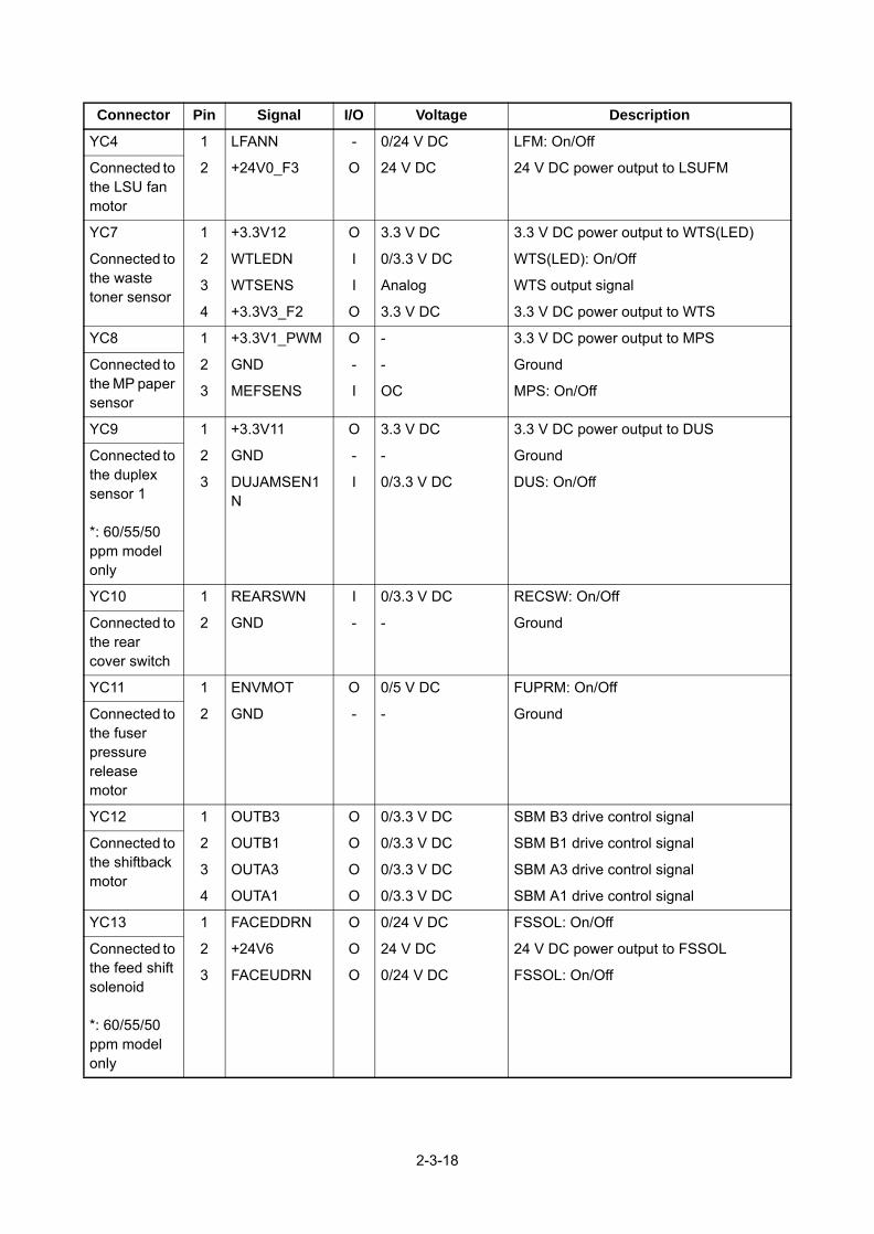
YC4 1 LFANN - 0/24 V DC LFM: On/Off
Connected to the LSU fan motor
2 +24V0_F3 O 24 V DC 24 V DC power output to LSUFM
YC7 1 +3.3V12 O 3.3 V DC 3.3 V DC power output to WTS(LED)
Connected to the waste toner sensor
2 WTLEDN I 0/3.3 V DC WTS(LED): On/Off
3 WTSENS I Analog WTS output signal
4 +3.3V3_F2 O 3.3 V DC 3.3 V DC power output to WTS
YC8 1 +3.3V1_PWM O - 3.3 V DC power output to MPS
Connected to the MP paper sensor
2 GND - - Ground
3 MEFSENS I OC MPS: On/Off
YC9 1 +3.3V11 O 3.3 V DC 3.3 V DC power output to DUS
Connected to the duplex sensor 1
*: 60/55/50 ppm model only
2 GND - - Ground
3 DUJAMSEN1N
I 0/3.3 V DC DUS: On/Off
YC10 1 REARSWN I 0/3.3 V DC RECSW: On/Off
Connected to the rear cover switch
2 GND - - Ground
YC11 1 ENVMOT O 0/5 V DC FUPRM: On/Off
Connected to the fuser pressure release motor
2 GND - - Ground
YC12 1 OUTB3 O 0/3.3 V DC SBM B3 drive control signal
Connected to the shiftback motor
2 OUTB1 O 0/3.3 V DC SBM B1 drive control signal
3 OUTA3 O 0/3.3 V DC SBM A3 drive control signal
4 OUTA1 O 0/3.3 V DC SBM A1 drive control signal
YC13 1 FACEDDRN O 0/24 V DC FSSOL: On/Off
Connected to the feed shift solenoid
*: 60/55/50 ppm model only
2 +24V6 O 24 V DC 24 V DC power output to FSSOL
3 FACEUDRN O 0/24 V DC FSSOL: On/Off
Connector Pin Signal I/O Voltage Description
2-3-18

2-3-5 High voltage PWB (HVPWB)
Figure 2-3-5 High voltage silk-screen diagram and Photograph
YC102
YC101
118
13
2-3-19

Connector Pin Signal I/O Voltage Description
YC101 1 +24V3_IL O 24 V DC 24 V DC power output to EPWB
Connected to the engine PWB
2 TCNT O Analog Transfer control
3 TRREM O 0/3.3 V DC Transfer remote signal
4 SCNT O Analog Separation control
5 +3.3V_F2 O 3.3 V DC 3.3 V DC power output
6 DUJAMSEN2N
I 0/3.3 V DC DUS2:On/Off
7 REGSENSN I 0/3.3 V DC RS:On/Off
8 PAPERSEN1N
I 0/3.3 V DC PS1:On/Off
9 PAPERSEN2N
I 0/3.3 V DC PS2:On/Off
10 BACNT I Analog Developer AC control
11 BDCNT I Analog Developer DC control
12 HVCLK O 0/3.3 V DC Developer clock signal
13 MDCCNT I Analog Charger DC control
14 MACCNT I Analog Charger AC control
15 MHVCLK O 0/3.3 V DC Charger clock signal
16 MISENS O Analog Charger current detection
17 GND - - Ground
18 ENVSENSN I 0/3.3 V DC ES:On/Off
YC102 1 +3.3V14 O 3.3 V DC 3.3 V DC power output to FUPRS
Connected to the fuser pressure release sen-sor
2 GND - - Ground
3 ENVSENSN I 0/3.3 V DC FUPRS:On/Off
2-3-20

2-4 Appendixes
2-4-1 Appendixes
(1) Maintenance kits
1. 55/50 ppm model
2. 45 ppm model
Maintenance part nameParts No.
Alternative part No.Name used in service Name used in parts list
MAINTENANCE KIT(500,000 images)
MK-3170/MAINTENANCE KIT MK-3170/MAINTENANCE KIT MK-3172/MAINTENANCE KIT MK-3174/MAINTENANCE KIT
B12320001702T68NL01702T67US01702T68AS0
072T69JP072T68NL072T67US072T68AS
Transfer roller assembly ROLLER TRANSFER ASSY - -
Drum unit DK-3190(E) ----
----
Developer unit DV-3100 - -
Fuser unit FK-3130(E)
FK-3130(E) :AO Common
----
----
Paper feed roller assembly PARTS HOLDER FEED ASSY SP - -
Retard roller assembly RETARD ROLLER ASSY - -
Maintenance part nameParts No.
Alternative part No.Name used in service Name used in parts list
MAINTENANCE KIT(300,000 images)
MK-3160/MAINTENANCE KIT MK-3160/MAINTENANCE KIT MK-3162/MAINTENANCE KIT MK-3164/MAINTENANCE KIT
B12310001702T98NL01702T97US01702T98AS0
072T99JP072T98NL072T97US072T98AS
Transfer roller assembly ROLLER TRANSFER ASSY - -
Drum unit DK-3170(E) ----
----
Developer unit DV-3100 - -
Fuser unit FK-3170(E)
FK-3170(E) :AO Common
----
----
Paper feed roller assembly PARTS HOLDER FEED ASSY SP - -
Retard roller assembly RETARD ROLLER ASSY - -
2-4-1

(2) Repetitive defects gauge
44.9 mm/1 3/4” Developer roller
36.8 mm/1 7/16” Registration roller
29.9 mm/1 3/16” Chager roller
94.2 mm/3 11/16” Drum/Press roller
109.9 mm/4 5/16” Heat roller
61.2 mm/2 7/16” Transfer roller
First occurrence of defect
2-4-2
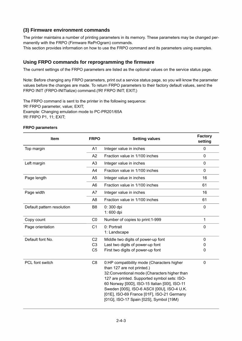
(3) Firmware environment commands
The printer maintains a number of printing parameters in its memory. These parameters may be changed per-manently with the FRPO (Firmware RePrOgram) commands.This section provides information on how to use the FRPO command and its parameters using examples.
Using FRPO commands for reprogramming the firmware
The current settings of the FRPO parameters are listed as the optional values on the service status page.
Note: Before changing any FRPO parameters, print out a service status page, so you will know the parameter values before the changes are made. To return FRPO parameters to their factory default values, send the FRPO INIT (FRPO-INITialize) command.(!R! FRPO INIT; EXIT;)
The FRPO command is sent to the printer in the following sequence:!R! FRPO parameter, value; EXIT;Example: Changing emulation mode to PC-PR201/65A!R! FRPO P1, 11; EXIT;
FRPO parameters
Item FRPO Setting valuesFactory setting
Top margin A1 Integer value in inches 0
A2 Fraction value in 1/100 inches 0
Left margin A3 Integer value in inches 0
A4 Fraction value in 1/100 inches 0
Page length A5 Integer value in inches 16
A6 Fraction value in 1/100 inches 61
Page width A7 Integer value in inches 16
A8 Fraction value in 1/100 inches 61
Default pattern resolution B8 0: 300 dpi1: 600 dpi
0
Copy count C0 Number of copies to print:1-999 1
Page orientation C1 0: Portrait1: Landscape
0
Default font No. C2C3C5
Middle two digits of power-up fontLast two digits of power-up fontFirst two digits of power-up font
000
PCL font switch C8 0:HP compatibility mode (Characters higher than 127 are not printed.)32:Conventional mode (Characters higher than 127 are printed. Supported symbol sets: ISO-60 Norway [00D], ISO-15 Italian [00I], ISO-11 Sweden [00S], ISO-6 ASCII [00U], ISO-4 U.K. [01E], ISO-69 France [01F], ISO-21 Germany [01G], ISO-17 Spain [02S], Symbol [19M)
0
2-4-3

Printing concentration D4 1: Thin. 2: Slightly Thin. 3: Standard 4: Slightly Deep. 5: Deep.
3
Total host buffer size H8 0 to 99 in units of the size defined by FRPO S5 5
Form feed time-out value H9 Value in units of 5 seconds (1 to 99). 1
KIR mode N0 0: Off2: On
2
Duplex binding N4 0: Off1: Long edge2: Short edge
0
Sleep timer time-out time N5 1 to 240 minutes [0: Off] 1
Ecoprint level N6 0: Off2: On
0
Resolution N8 0: 300dpi1: 600dpi3: 1200dpi
1
Parallel interface mode O0 0: Standard Mode 1: Fast Mode 5: Nibble (High Speed) Mode 70: Automatic Mode
70
Parallel interface Error control O2 0: Line Control OFF 2: Compatibility with PCL
2
Default emulation mode P1 0 : Line printer1 : IBM proprinter2 : DIABLO 6305 : Epson LQ-8506 : PCL6 (except PCL XL)8 : KC-GL9 : KPDL11 : PC-PR20112 : IBM 557713 : VP-100014 : N520015 : FMPR-359F1
69(U.S.A)
Carriage-return action * P2 0: Ignores 0x0d1: Carriage-return2: Carriage-return+linefeed
1
Linefeed action * P3 0: Ignores 0x0d1: Linefeed2: Linefeed+carriage-return
1
Item FRPO Setting valuesFactory setting
2-4-4

Automatic emulation sensing (For KPDL3)
P4 0: AES disabled1: AES enabled
01(U.S.A)
Alternative emulation P5 6: PCL 6 6
Automatic emulation switching trigger (For KPDL3)
P7 0: Page eject commands1: None2: Page eject and PRESCRIBE EXIT3: PRESCRIBE EXIT4: Formfeed (^L)6: Page eject, PRESCRIBE EXIT and formfeed10: Page eject commands; if AES fails, resolves to KPDL
1011(U.S.A)
Command recognition character P9 ASCII code of 33 to 126 82 (R)
Default stacker R0 1 (Top tray) Face-down2 (Rear tray) Face-up
1
Default paper size R2 0: Size of the default paper cassette (See R4.)1: Monarch (3-7/8 × 7-1/2 inches)2: Business (4-1/8 × 9-1/2 inches)3: International DL (11 × 22 cm)4: International C5 (16.2 × 22.9 cm)5: Executive (7-1/4 × 10-1/2 inches)6: US Letter (8-1/2 × 11 inches)7: US Legal (8-1/2 × 14 inches)8: A4 (21.0 × 29.7 cm)9: JIS B5 (18.2 × 25.7 cm)10: A3 (29.7 ´ 42 cm)11: B4 (25.7 ´ 36.4 cm)12: US Ledger (11 ´ 17 inches)13: ISO A514: A6 (10.5 × 14.8 cm)15: JIS B6 (12.8 × 18.2 cm)16: Commercial #9 (3-7/8 × 8-7/8 inches)17: Commercial #6 (3-5/8 × 6-1/2 inches)18: ISO B5 (17.6 × 25 cm)19: Custom (11.7 × 17.7 inches)30: C4 (22.9 ´ 32.4 cm)31: Hagaki (10 × 14.8 cm)32: Ofuku-hagaki (14.8 × 20 cm)33: Officio II39: 8K40: 16K42: 216x34050: Statement51: Folio52: Youkei 253: Youkei 4
0
Item FRPO Setting valuesFactory setting
2-4-5

Default cassette R4 0: MP tray1: Cassette 12: Cassette 23: Cassette 3
1
MP tray paper size R7 Same as the R2 values except: 0 86 (U.S.A)
A4/letter equation S4 0: Off1: On
1
Host buffer size S5 0: 10kB (x H8)1: 100kB (x H8)2: 1024kB (x H8)
1
RAM disk size S6 1 to 1024 MB 16
RAM disk mode S7 0: Off1: On
1
Wide A4 T6 0: Off1: On
0
Line spacing U0 Lines per inch (integer value) 6
Line spacing U1 Lines per inch (fraction value) 0
Character spacing U2 Characters per inch (integer value) 10
Character spacing U3 Characters per inch (fraction value) 0
Item FRPO Setting valuesFactory setting
2-4-6

Country code U6 0: US-ASCII1: France2: Germany3: UK4: Denmark5: Sweden6: Italy7: Spain8: Japan9: US Legal10: IBM PC-850 (Multilingual)11: IBM PC-860 (Portuguese)12: IBM PC-863 (Canadian French)13: IBM PC-865 (Norwegian)14: Norway15: Denmark 216: Spain 217: Latin America21: US ASCII (U7 = 50 SET)77: HP Roman-8 (U7 = 52 SET)
41
Code set at power up in daisy-wheel emulation
U7 0: Same as the default emulation mode (P1)1: IBM6: IBM PC-850: US ASCII (U6 = 21 SET)52: HP Roman-8 (U6 = 77 SET)
53
Font pitch for fixed pitch scalable font
U8 Integer value in cpi: 0 to 99 10
U9 Fraction value in 1/100 cpi: 0 to 99 0
Font height for the default scal-able font
V0 Integer value in 100 points: 0 to 9 0
V1 Integer value in points: 0 to 99 12
V2 Fraction value in 1/100 points: 0, 25, 50, 75 0
Default scalable font V3 Name of typeface of up to 32 characters, enclosed with single or double quotation marks
Courier
Default weight (courier and letter Gothic)
V9 0: Courier = darkness Letter Gothic = darkness1: Courier = regular Letter Gothic = darkness4: Courier = darkness Letter Gothic = regular5: Courier = regular
Letter Gothic = regular
5
Item FRPO Setting valuesFactory setting
2-4-7

Paper type for the MP tray X0 1: Plain 12: Transparency3: Preprinted4: Label5: Bond6: Recycle7: Vellum9: Letterhead10: Color11: Prepunched12: Envelope13: Cardstock16: Thick17: High quality21: Custom122: Custom223: Custom324: Custom425: Custom526: Custom627: Custom728: Custom8
1
Paper type for paper cassettes 1 X1 1: Plain3: Preprinted5: Bond6: Recycled9: Letterhead10: Color11: Prepunched17: High quality21: Custom122: Custom223: Custom324: Custom425: Custom526: Custom627: Custom728: Custom8
1
Item FRPO Setting valuesFactory setting
2-4-8
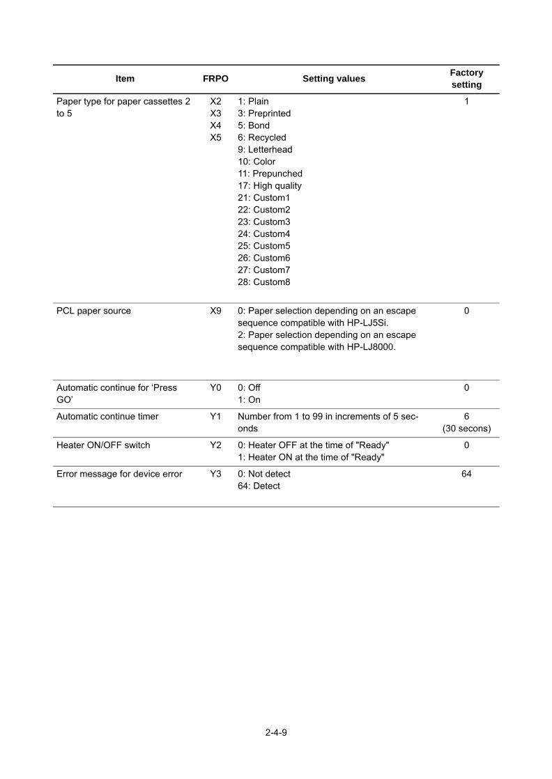
Paper type for paper cassettes 2 to 5
X2X3X4X5
1: Plain3: Preprinted5: Bond6: Recycled9: Letterhead10: Color11: Prepunched17: High quality21: Custom122: Custom223: Custom324: Custom425: Custom526: Custom627: Custom728: Custom8
1
PCL paper source X9 0: Paper selection depending on an escape sequence compatible with HP-LJ5Si.2: Paper selection depending on an escape sequence compatible with HP-LJ8000.
0
Automatic continue for ‘Press GO’
Y0 0: Off1: On
0
Automatic continue timer Y1 Number from 1 to 99 in increments of 5 sec-onds
6(30 secons)
Heater ON/OFF switch Y2 0: Heater OFF at the time of "Ready" 1: Heater ON at the time of "Ready"
0
Error message for device error Y3 0: Not detect64: Detect
64
Item FRPO Setting valuesFactory setting
2-4-9

Forced duplex printing setting
(Media type is Preprinted, Pre-
punched and Letterhead only)
Y4 0: OFF
1: ON
0
PDF direct printing Y5 0: Zoom depending on paper size
1: Loads paper which is the same size as the
image
2: Loads Letter, A4 size paper depending on
the image sizeEnlarges or reduces the
image to fit in the current paper size
3: Loads Letter, A4 size paper depending on
the image size
8: Printed in full magnification
9: Loads Letter, A4 size paper depending on
the image size
10: Loads Letter, A4 size paper depending on
the image sizeEnlarges or reduces the
image to fit in the current paper size
13 to 99: Same action as default value(0)
0
Job box error control Y6 0: No error control
1: Output the error list
2: Displays the error
3: Displays the error and prints the error report
3
Item FRPO Setting valuesFactory setting
2-4-10

2T6/2T7/2T8/2T9
(4) Maintenance Commands
This section provides information on how to use the maintenance command and its parameters using exam-
ples.
Adjusting the print start timing (alternative command for the maintenance mode U034)
Description Adjusts the leading edge registration or left edge.PurposeMake the adjustment if there is a regular error between the leading edges of the copy image and original. Make the adjustment if there is a regular error between the left edges of the copy image and original.
Example: Set the leading edge of MP tray to +30 dots!R! KCFG “PFRC”,0,1,30;EXIT;
Format !R! KCFG“PFRC”,#1 ,#2 ,#3;
Parameter #1 Paper source number 0: MP tray
2-6 : Cassette2-6100: Duplex (e.g. landscape images short-edge bind)200: Rotated duplex (e.g. portrait images long-edge bind)
#2 Edge to adjust 1: Leading edge 2: Left edge
#3 Adjustable range (-70 to +70) number of dot in 600dpi
Correct image Outputexample 1
Outputexample 2
Leading edge registration
Correct image Outputexample 1
Outputexample 2
Left edge of printing
2-4-11

This page is intentionally left blank.
2-4-12

LSUFM
YC6
YC29
YC5YC4YC2
YC4
YC31
EPWB
R-LPWB
YC13YC12YC11YC10YC9
D
Wi-Fi PWB
14 15 16 17 18 19 20 21 22
14 15 16 17 18 19 20 1 2 3 4 5 6 7 8 9 10 11 12 13 14 15 16
SD
_D3
SD
_D2S
SD
_CM
DG
ND
SD
_CLK
GN
DS
D_D
1S
D_D
0G
ND
VIO
VB
AT
GN
DP
AV
DD
GN
DH
OS
TWA
KE
GN
D
21 22
+3.3
V1_
PW
M_F
2TM
OT
LFA
NN
FUD
RE
NV
MO
TFD
DR
DU
JAM
SE
N1N
RE
GS
EN
2R
EA
RS
WN
1 2 3 4
1 2 3 45
5
4 3 2 1
4 3 2 1
+24V
3_IL
_F5
55
1WIR
E
GN
DG
ND
+24V
0_F3
1 2
LFA
NN
+24V
0_F3
1 2 1 2 1 2
12 11 10 9 8 7 6 5 4 3 2
12 11 10 9 8 7 6 5 4 3 2
1 2 3 4 5 6
+24V
3_IL
GN
DD
MO
TON
ND
MO
TCLK
ND
MO
TRD
YN
DM
OTC
W
1 2 3 4 5
1 2 3 4 5 6 1 2 3 4 5
+24V
3_IL
GN
DM
MO
TON
NM
MO
TCLK
NM
MO
TRD
YN
9 8 7 6 5 4 3 2 1
9 8 7 6 5 4 3 2 1
22
1 2
MID
CLN
+24V
3_IL
1 2
1 2 3
RE
GC
LN
+24V
3_IL
1 2 3
1 2
FEE
DC
LN+2
4V3_
IL1 2
1 2
DLP
CLN
+24V
3_IL
1 2
4 3 2 1
OU
TA1
OU
TA3
OU
TB1
OU
TB3
4 3 2 1
3 2 1
1 2 3
3 2 1
3 2 1
1 2 3
+3.3
V11
GN
DD
UJA
MS
EN
1N
1 2 3
1 2 3
3 2 1
3 2 1
FAC
EU
DR
N+2
4V6
FAC
ED
DR
N
3 2 1
1 21 2
1 2
EN
VM
OT
GN
D1 2
2 12 1
1 2
RE
AR
SW
NG
ND
1 2R
CL
PFC
L
DR
M
DE
VS
CL
MM
PC
CL
DU
S1
RE
CS
W
FUP
RM
SB
M
FSS
OL
MO
TPW
B
2-4-21
(5) Wiring diagram (60/55/50 ppm model)
PSFM
CRPWBCPWB
INLET
CL
MOTPWB
TS
TM
RS2
DRRPWBDRPWBYC2
YC3
YC4
YC5
YC1 YC1
YC1
YC6
YC2
YC3
YC3
YC1
YC2
YC1
YC1
YC10
YC13 YC12 YC8 YC5YC6YC7
YC9 YC2
PSPWB
MO
TPW
B
YC7 YC8
DEV UNIT
DR UNITTONERCONTAINER
(Spring contact)
Fuser unit
TON
ER
FU
LL D
ETE
CT
AS
SY
12345678910111213
13121110987654321
123456789101112
GND1WIRETSENS
+24V3_IL_F5ERASERN
EECLKEESIOTMOT
+3.3V3_F2REGSEN2
GNDGND
123456789101112
12345678910111213
13121110987654321
+24V0+24V0+24V0+24V0GNDGNDGNDGNDPSLEEPNRELAYZCROSSNHEAT1REMHEAT2REM
1234
1234
123
123
12
12
21
21
12
1WIRENCNCGND
+24V3_IL_F5TSENSGND
TMOTGND
+24V3_IL_F5ERASERN
12
987654321
91010
87654321
123456789
123456789
REGSEN2GND+3.3V3_F2TMOTEESIOEECLKERASERN+24V3_IL_F5TSENS
10 10 1WIRE
1 2 3 4 5 6 7 8 9 10 11 12 13
1 2 3 4 5 6 7 8 9 10 11 12 13
EE
CLK
GN
DE
ES
IOE
RA
SE
R+3
.3V
3_F2
TSE
NS
SB
MD
IRW
TSE
NS
SB
ME
NB
LMW
TLE
DS
BM
STE
PM
PFS
EN
SS
BM
MO
DE
3 2 1
3 2 1
1 2 3
1 2 3
+3.3
V6
RE
GS
EN
2G
ND
1 21 2
2 1 2 1
2 1
2 12 1
FAN
RN
+24V
0
1010
1D
UC
LN+2
4V3
1
2 12 1
+24V
0_IL
+24V
0
4 3 2 1
4 3 2 1
1 2 3 4
CA
S1
CA
SS
ET
CA
S2
CA
S3
1 2 3 4
1 2 3
1 2 3
3 2 1
+3.3
V3_
F2G
ND
PA
PFU
LN
1 3 5
1 2 3
NE
UTR
AL1
LIV
EN
EU
TRA
L2
3 2 1
2 12 1
MP
FSO
LN+2
4V3_
IL
1 21 2
2 1
LIFT
MO
TOR
GN
D2 1
1 2 3 4
+3.3
V12
WTL
ED
NW
TSE
NS
+3.3
V6
1 2 3 4
3 2 1
3 2 1
1 2 3
+3.3
V8
GN
DM
PFS
EN
S
1 2 3
LM EFS
MP
SO
L
DU
CL
ILS
W
CS
SW
WTS
MP
PS
LIVEGNDNEUTRAL
E
FUH1
FUH2
FUTS1 FUTS2

YC20 YC2123456789
10111213141516171819202122232425262728293031323334353637383940
+24V0+24V0+24V0
+33V0_PM+3.3V3_E+3.3V3_E
+5.0V1_C1+3.3V1_C
LEDPWM_ENE2C_SDATC2E_SDAT
C2E_SCKE2C_SDIR
E2C_SBSYGND
VBUS_USBH_3GND
USBH_DP3USBH_DN3
GNDSDIF_DATA0SDIF_DATA1SDIF_DATA2SDIF_DATA3SDIF_SDCLK
GNDSH1DGND
LDOUT_1_DNLDOUT_1_DP
GNDGNDGNDGNDGNDGNDGNDGND
LVU_SLEEP_NPOWER_SW
E2C_IRNEC2_WKUP_BGD_N
ENG_HLDNC2E_QUICK_START
PVSYNCGND
P2C_WKUP_RDYENERGYSAVERKEY_N
C2P_RST_NP2C_SDATC2P_SDAT
GNDSDIF_SDCDSDIF_INTASDIF_CMD
BDN_DSH2DGND
LDOUT_2_DNLDOUT_2_DP
60595857565554535251504948474645444342414039383736353433323130292827262524232221
4142434445464748495051525354555657585960
2019181716151413121110987654321
B
321
321
FUPRS
USB DEVICE
USB HOST
ETHER
eKU
IO
DD
R3
SO
CK
ET
SD
CA
RD
MPWB
YC4
YC6
YC9
YC2YS1YC7
2-4-22
RS3 PS1 PS2 DUS2
1 22 1
YC1
1 2 3 4 5 6 7 8 9 10 11 12 13 14
1 2 3 4 5 6 7 8 9 10 11 12 13 14
+3.3
V1_
F1FP
RS
TNP
SC
_OK
_KE
YC
2P_B
UZC
ON
AIR
TEM
PC
2P_L
CD
CO
N+5
V5
P2C
_SD
AT
AIR
WE
TC
2P_S
DA
TW
ETC
LKLE
DFG G
ND
5 4 3 2 1
5 4 3 2 1
1 2 3 4 5
1 2 3 4 5
+24V
3_IL
_F5
GN
DP
LGD
RN
PLG
RD
YN
PO
LCLK
YC1
1 2 3 4 5 6 7 8 9 10 11 12 13
1 2 3 4 5 6 7 8 9 10 11 12 13
+5V
3_F1
VD
ATA
1PV
DA
TA1N
VD
ATA
2PV
DA
TA2N
SA
MP
LEN
1S
AM
PLE
N2
OU
TPE
NV
CO
NT1
VC
ON
T2G
ND
PD
N+3
.3V
3_F2
1 21 2
GN
DP
OW
ER
SW
3 2 1
3 2 1
1 2 3
1 2 3
+3.3
V3_
F2G
ND
LSE
NS
YC1YC2123
123
GNDPDN+3.3V6
PDPWB
YC19YC21 YC26
18 17 16 15 14 13 12 11 10 9 8 7 6 5 4 3 2 1
18 17 16 15 14 13 12 11 10 9 8 7 6 5 4 3 2 1
1 2 3 4 5 6 7 8 9 10 11 12 13 14 15 16 17 18
1 2 3 4 5 6 7 8 9 10 11 12 13 14 15 16 17 18
+24V
3_IL
TCN
TTR
RE
MS
CN
T+3
.3V
3_F2
DU
JAM
SE
N2N
RE
GS
EN
SN
PA
PE
RS
EN
1NP
AP
ER
SE
N2N
BA
CN
TB
DC
NT
HV
CLK
MD
CC
NT
MA
CC
NT
MH
VC
LKM
ISE
NS
GN
DE
NV
SE
NS
N
YC22 YC27
1 2 3 4 5 6 7 8 9 10 11 12
1 2 3 4 5 6 7 8 9 10 11 12
1 2 3 4 5 6 7 8 9 10 11 12
1 2 3 4 5 6 7 8 9 10 11 12
+24V
3_F2
OP
SD
OO
PS
DI
OP
CLK
OP
RD
YN
+3.3
V3_
F1G
ND
OP
SE
L2O
PS
EL1
OP
SE
L0O
PP
AU
SE
NG
ND
12
12
+5V5BLIGHT
LSPM
APCPWB
OPPWBLCD
BUZZERPSSW
BLPW
3 2 1
1 2 3
1 2 3
1 2 3
3 2 1
3 2 1
EX
ITS
EN
SN
GN
D+3
.3V
3_F2
ES
DEVFM
FUTH2(Center)
FUTH1(Edge)
1 2 3 4 5
1 2 3 4 5
TH3
TH1
GN
DR
EA
RFA
NN
+24V
0_F3
YC101
123
123
+3.3V14GNDENVSENSN
1 21 2
GN
DTH
1
1 21 2
GN
DTH
2
1 2 1 2 3 4
+24V
0_F3
RE
AR
FAN
N1 2
2 1
HVPWB
PF-320/PF-3100
YC14 YC15 YC18YC17YC16
YC102
YC5 YC1YC2YC4
+24V
1
+3.3
V2
E E
D +24V6 +5V5
+5V3+24V3
EPWB
EF
TEMS
HUS
USB HOST
YC3FUTHRPWB
LSU UNIT
PF (option)
FUSER UNIT
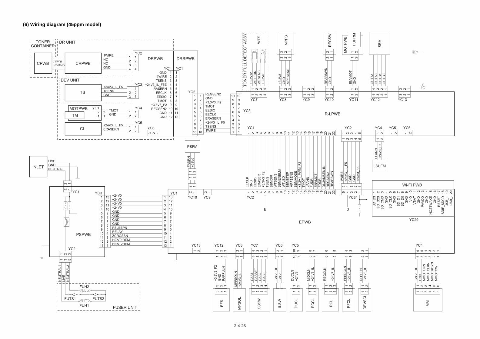
LSUFM
YC6
YC29
YC5YC4YC2
YC4
YC31
R-LPWB
YC13YC12YC11YC10
D
Wi-Fi PWB
19 20 21 22
19 20 1 2 3 4 5 6 7 8 9 10 11 12 13 14 15 16 17 18 19 20
SD
_D3
SD
_D2S
SD
_CM
DG
ND
SD
_CLK
GN
DS
D_D
1S
D_D
0G
ND
VIO
VB
AT
GN
DP
AV
DD
GN
DH
OS
TWA
KE
GN
DR
ES
ET
SD
IF_S
DC
DU
SB
_+U
SB
_-
21 22
FDD
RD
UJA
MS
EN
1NR
EG
SE
N2
RE
AR
SW
N
1 2 3 4
1 2 3 45
5
4 3 2 1
4 3 2 1
+24V
3_IL
_F5
55
1WIR
E
GN
DG
ND
+24V
0_F3
1 2
LFA
NN
+24V
0_F3
1 2 1 2 1 2
6 5 4 3 2 1
6 5 4 3 2 1
1 2 3 4 5 6
1 2 3 4 5 6
+24V
3_IL
GN
DM
MO
TON
NM
MO
TCLK
NM
MO
TRD
YN
MM
OTC
W
6 5 4 3 2 1
6 5 4 3 2 1
1 2 3
RE
GC
LN
+24V
3_IL
1 2 3
1 2
FEE
DC
LN+2
4V3_
IL1 2
1 2
DLP
CLN
+24V
3_IL
1 2
4 3 2 1
OU
TA1
OU
TA3
OU
TB1
OU
TB3
4 3 2 1
3 2 1
3 2 1
1 21 2
1 2
EN
VM
OT
GN
D1 2
2 12 1
1 2
RE
AR
SW
NG
ND
1 2R
CL
PFC
L
DE
VS
CL
MM
RE
CS
W
FUP
RM
SB
M
MO
TPW
B
2-4-23
(6) Wiring diagram (45ppm model)
PSFM
CRPWBCPWB
INLET
CL
MOTPWB
TS
TM
DRRPWBDRPWBYC2
YC3
YC4
YC5
YC1 YC1
YC1
YC6
YC2
YC3
YC3
YC1
YC2
YC1
YC1
YC10
YC13 YC12 YC8 YC5YC6YC7
YC9 YC2
EPWB
PSPWB
YC7 YC9YC8
DEV UNIT
DR UNITTONERCONTAINER
(Spring contact)
TON
ER
FU
LL D
ETE
CT
AS
SY
FUSER UNIT
123456789
10111213
13121110987654321
123456789
101112
GND1WIRETSENS
+24V3_IL_F5ERASERN
EECLKEESIOTMOT
+3.3V3_F2REGSEN2
GNDGND
123456789
101112
123456789
10111213
13121110987654321
+24V0+24V0+24V0+24V0GNDGNDGNDGNDPSLEEPNRELAYZCROSSNHEAT1REMHEAT2REM
1234
1234
123
123
12
12
21
21
12
1WIRENCNCGND
+24V3_IL_F5TSENSGND
TMOTGND
+24V3_IL_F5ERASERN
12
987654321
91010
87654321
123456789
123456789
REGSEN2GND+3.3V3_F2TMOTEESIOEECLKERASERN+24V3_IL_F5TSENS
10 10 1WIRE
1 2 3 4 5 6 7 8 9 10 11 12 13 14 15 16 17 18
1 2 3 4 5 6 7 8 9 10 11 12 13 14 15 16 17 18
EE
CLK
GN
DE
ES
IOE
RA
SE
R+3
.3V
3_F2
TSE
NS
SB
MD
IRW
TSE
NS
SB
ME
NB
LMW
TLE
DS
BM
STE
PM
PFS
EN
SS
BM
MO
DE
+3.3
V1_
PW
M_F
2TM
OT
LFA
NN
FUD
RE
NV
MO
T
3 2 1
1 21 2
2 1 2 1
2 1
2 12 1
FAN
RN
+24V
0
10 9 8 7
10 9 8 7
1 2
DU
CLN
+24V
31 2
2 12 1
+24V
0_IL
+24V
0
4 3 2 1
4 3 2 1
1 2 3 4
CA
S1
CA
SS
ET
CA
S2
CA
S3
1 2 3 4
1 2 3
1 2 3
3 2 1
+3.3
V3_
F2G
ND
PA
PFU
LN
1 3 5
1 2 3
NE
UTR
AL1
LIV
EN
EU
TRA
L2
3 2 1
2 12 1
MP
FSO
LN+2
4V3_
IL
1 2
1 2
MID
CLN
+24V
3_IL
1 2
1 2 3 4
+3.3
V12
WTL
ED
NW
TSE
NS
+3.3
V6
1 2 3 4
1 2 3
1 2 3
3 2 1
3 2 1
1 2 3
+3.3
V8
GN
DM
PFS
EN
S
1 2 3
EFS
MP
SO
L
PC
CL
DU
CL
ILS
W
CS
SW
WTS
MP
PS
LIVEGNDNEUTRAL
E
FUH1
FUH2
FUTS1 FUTS2

YC20 YC2123456789
10111213141516171819202122232425262728293031323334353637383940
+24V0+24V0+24V0
+33V0_PM+3.3V3_E+3.3V3_E
+5.0V1_C1+3.3V1_C
LEDPWM_ENE2C_SDATC2E_SDAT
C2E_SCKE2C_SDIR
E2C_SBSYGND
VBUS_USBH_3GND
USBH_DP3USBH_DN3
GNDSDIF_DATA0SDIF_DATA1SDIF_DATA2SDIF_DATA3SDIF_SDCLK
GNDSH1DGND
LDOUT_1_DNLDOUT_1_DP
GNDGNDGNDGNDGNDGNDGNDGND
LVU_SLEEP_NPOWER_SW
E2C_IRNEC2_WKUP_BGD_N
ENG_HLDNC2E_QUICK_START
PVSYNCGND
P2C_WKUP_RDYENERGYSAVERKEY_N
C2P_RST_NP2C_SDATC2P_SDAT
GNDSDIF_SDCDSDIF_INTASDIF_CMD
BDN_DSH2DGND
LDOUT_2_DNLDOUT_2_DP
60595857565554535251504948474645444342414039383736353433323130292827262524232221
4142434445464748495051525354555657585960
2019181716151413121110987654321
321
FUPRS
USB DEVICE
USB HOST
ETHER
eKU
IO
DD
R3
SO
CK
ET
SD
CA
RD
MPWB
YC4
YC6
YC9
YC2YS1YC7
2-4-24
RS3 PS1 PS2 DUS2
1 22 1
YC1
1 2 3 4 5 6 7 8 9 10 11 12 13 14
1 2 3 4 5 6 7 8 9 10 11 12 13 14
+3.3
V1_
F1FP
RS
TNP
SC
_OK
_KE
YC
2P_B
UZC
ON
AIR
TEM
PC
2P_L
CD
CO
N+5
V5
P2C
_SD
AT
AIR
WE
TC
2P_S
DA
TW
ETC
LKLE
DFG G
ND
5 4 3 2 1
5 4 3 2 1
1 2 3 4 5
1 2 3 4 5
+24V
3_IL
_F5
GN
DP
LGD
RN
PLG
RD
YN
PO
LCLK
YC1
1 2 3 4 5 6 7 8 9 10 11 12 13
1 2 3 4 5 6 7 8 9 10 11 12 13
+5V
3_F1
VD
ATA
1PV
DA
TA1N
VD
ATA
2PV
DA
TA2N
SA
MP
LEN
1S
AM
PLE
N2
OU
TPE
NV
CO
NT1
VC
ON
T2G
ND
PD
N+3
.3V
3_F2
1 21 2
GN
DP
OW
ER
SW
1 2 3
YC1YC2123
123
GNDPDN+3.3V6
PDPWB
YC19YC21 YC26
18 17 16 15 14 13 12 11 10 9 8 7 6 5 4 3 2 1
18 17 16 15 14 13 12 11 10 9 8 7 6 5 4 3 2 1
1 2 3 4 5 6 7 8 9 10 11 12 13 14 15 16 17 18
1 2 3 4 5 6 7 8 9 10 11 12 13 14 15 16 17 18
+24V
3_IL
TCN
TTR
RE
MS
CN
T+3
.3V
3_F2
DU
JAM
SE
N2N
RE
GS
EN
SN
PA
PE
RS
EN
1NP
AP
ER
SE
N2N
BA
CN
TB
DC
NT
HV
CLK
MD
CC
NT
MA
CC
NT
MH
VC
LKM
ISE
NS
GN
DE
NV
SE
NS
N
YC22 YC27
1 2 3 4 5 6 7 8 9 10 11 12
1 2 3 4 5 6 7 8 9 10 11 12
1 2 3 4 5 6 7 8 9 10 11 12
1 2 3 4 5 6 7 8 9 10 11 12
+24V
3_F2
OP
SD
OO
PS
DI
OP
CLK
OP
RD
YN
+3.3
V3_
F1G
ND
OP
SE
L2O
PS
EL1
OP
SE
L0O
PP
AU
SE
NG
ND
12
12
+5V5BLIGHT
PMAPCPWB
OPPWBLCD
BUZZERPSSW
BLPWB
3 2 1
1 2 3
1 2 3
1 2 3
3 2 1
3 2 1
EX
ITS
EN
SN
GN
D+3
.3V
3_F2
ES
DEVFM
FUTH2(Center)
FUTH1(Edge)
1 2 3 4 5
1 2 3 4 5
TH3
TH1
GN
DR
EA
RFA
NN
+24V
0_F3
YC101
123
123
321
+3.3V14GNDENVSENSN
1 21 2
GN
DTH
1
1 21 2
GN
DTH
2
1 2 1 2 3 4
+24V
0_F3
DFA
NR
N1 2
2 1
HVPWB
PF-320/PF-3100
YC14 YC15 YC18YC30YC16
YC102
YC5 YC1YC2YC4
+24V
1
+3.3
V2
E E
D +24V6 +5V5
+5V3+24V3
EPWB
EF
TEMS
HUS
USB HOST
YC3FUTHRPWB
LSU UNIT
FUSER UNIT
PF (option)

Installation Guide
500 sheets paper feederInstallation Guide

PF-320
PF-320PF-320
PF-320PF-320
PF-320
(Legal/Folio/Oficio II)
To install the optional paper feeder unit, contact your service representative.This unit is for use only with Laser Printers, Models FS-2100D, FS-2100DN, FS-4100DN, FS-4200DN and FS-4300DN.
For U.S.A.:
For Canada:This Class B digital apparatus complies with Canadian ICES-003.Cet appareil numérique de la classe B est conforme à la norme NMB-003 du Canada.

Printed in China 303NY5631002 Rev. 1 2012.8

2000 sheets bulk feederInstallation Guide

PF-315+
10 11
1
6 7
13 14 15
설치안내서설치안내서
Installation of PF-315+Installation von PF-315+Installation de PF-315+Installazione di PF-315+Instalación de PF-315+
PF-315+の設置
PF-315+的安装PF-315+ 설치설치
5
8
2
12
9
PF-315+
PB-325
43
To install the optional paper feeder unit, contact your service representative.This unit is for use only with Laser Printers, Models FS-2100D, FS-2100DN, FS-4100DN, FS-4200DN and FS-4300DN.
For U.S.A.:
For Canada:
ON
This Class B digital apparatus complies with Canadian ICES-003.Cet appareil numérique de la classe B est conforme à la norme NMB-003 du Canada.
A
a
A a
Page01_303KF56320_02.eps 1 2012/07/27 9:22:42

Printed in China 303KF5632002 Rev. 1 2012.7
1 2
3 4
1 2 3
1mm
용지 적재용지 적재
PF-315+
종이 잼 제거종이 잼 제거
양면 장치양면 장치
Page02_303KF56320_02.eps 1 2012/07/27 9:12:47

SSD (HD-6/HD-7)Installation Guide


IEEE1284 InterfaceInstallation Guide

IB-32
OFF
OFF
ON
ON
1 32 4
5 6 7
8 109
11 1513 1412(USB model only)
English
Optional Parallel Interface Kit IB-32Installation GuideIntroductionThe IB-32 is an optional parallel interface kit for use with the page printers. Please read this Installation Guide thoroughly so that you understand the correct installation method.This parallel interface kit can be installed in other models using the same installation procedure.
Packing ListIB-32 ...................................................................................................................... 1Plate ...................................................................................................................... 1Screw .................................................................................................................... 2Relay cable ............................................................................................................ 1Seal ....................................................................................................................... 1Installation Guide (this guide) ................................................................................ 1
Precautions for Handling the Parallel Interface KitWhen handling the parallel interface kit, adhere to the following precautions.• The parallel interface kit is delivered in an antistatic bag. To prevent any
damage, briefly touch a large metal object to ensure discharge of static electricity before removing the parallel interface kit from the bag.
• Never touch the parallel interface kit’s connector section directly with hands.• When holding the parallel interface kit, avoid contact with the surface of the
circuit board. Hold it at the edges.• Do not apply undue force when installing.
Installing the Parallel Interface KitCAUTIONBefore installing (or removing) the parallel interface kit, be sure to turn off the machine’s power and disconnect the power cord plug from the AC outlet.Verifying Installation of the Parallel Interface KitTo verify that the parallel interface kit has been correctly installed, try to print out the status page.Refer to the Operation Guide for the method for printing a status page.
Kit d’interface parallèle IB-32 en optionGuide d’installationIntroductionL’IB-32 est un kit d’interface parallèle en option destiné à être utilisé avec les imprimantes par page. Veuillez lire entièrement ce guide d’installation et vous assurer que vous comprenez bien les méthodes d’installation.Ce kit d’interface parallèle peut être installé dans d’autres modèles à l’aide de la même procédure d’installation.
Contenu de l’emballageIB-32....................................................................................................................... 1Plaque .................................................................................................................... 1Vis .......................................................................................................................... 2Câble de relais ....................................................................................................... 1Obturateur .............................................................................................................. 1Guide d’installation (ce manuel) ............................................................................. 1
Précautions de manipulation du kit d’interface parallèleLorsque vous manipulez le kit d’interface parallèle, observez les précautions suivantes.• Le kit d’interface parallèle est livré dans un sac antistatique. Avant de le retirer
du sac, touchez brièvement un grand objet métallique pour vous décharger de toute électricité statique.Vous éviterez ainsi d’endommager le kit d’interface parallèle.
• Ne touchez jamais directement la partie du connecteur du kit d’interface parallèle avec les mains.
• Lorsque vous tenez le kit d’interface parallèle, ne touchez pas la surface de la carte de circuits imprimés. Saisissez-le par les bords.
• N’appliquez aucune force inutile en l’installant.
Installation du kit d’interface parallèleATTENTIONAvant d’installer (ou de retirer) le kit d’interface parallèle, mettez toujours l’imprimante hors tension et débranchez la fiche du cordon d’alimentation de la prise de courant.Vérification de l’installation du kit d’interface parallèlePour vous assurer que le kit d’interface parallèle a été correctement installé, essayez d’imprimer la page d’état de l’imprimante.Pour connaître la méthode d’impression de la page d’état, consultez le manuel d’utilisation.
Kit de interfaz en paralelo IB-32 opcionalGuía de instalaciónIntroducciónEl IB-32 es un kit de interfaz en paralelo opcional para utilizar con la impresora de hojas. Lea completamente esta Guía de instalación de forma que pueda entender los métodos de instalación y operación correctos.Este kit de interfaz en paralelo puede instalarse en otros modelos utilizando el mismo procedimiento de instalación.
Lista del contenido del paqueteIB-32....................................................................................................................... 1Placa ...................................................................................................................... 1Tornillo.................................................................................................................... 2Cable de relé .......................................................................................................... 1Sello ....................................................................................................................... 1Guía de instalación (este folleto) ............................................................................ 1
Precauciones para el manejo del kit de interfaz en paraleloCuando maneje el kit de interfaz en paralelo, tenga en cuenta las siguientes precauciones.• El kit de interfaz en paralelo se entrega en una bolsa antiestática. Para evitar
cualquier daño, antes de sacar el kit de interfaz en paralelo de la bolsa, toque un objeto metálico grande para descargar la electricidad estática de su cuerpo.
• Nunca toque la sección del conector del kit de interfaz en paralelo directamente con las manos.
• Cuando sostenga el kit de interfaz en paralelo, no toque con las manos la superficie de la placa del circuito impreso. Sujétela por los bordes.
• No aplique demasiada fuerza al realizar la instalación.
Instalación del kit de interfaz en paraleloPRECAUCIÓNAntes de instalar (o desmontar) el kit de interfaz en paralelo, asegúrese de desconectar la alimentación de la impresora y de desenchufar el cable de alimentación de la toma de corriente de CA.Verificación de la instalación del kit de interfaz en paraleloPara verificar que el kit de interfaz en paralelo ha sido instalado correctamente, trate de imprimir la página de estado de la impresora.Consulte la Guía de uso para obtener información sobre la impresión de la página de estado de la impresora.
EspañolFrançais
D
1
1
2
2
1
2
3
B
A
A
C
D
D D
E
A
B
C
E
E

Deutsch Italiano
Printed in China 303N55631001 First edition 2012.6
Optionales Parallel Interface Kit IB-32InstallationsanleitungEinführungDas IB-32 ist ein optionales Parallel Interface Kit zur Verwendung mit Seitendruckern. Bitte lesen Sie sich diese Installationsanleitung sorgfältig durch, damit Sie das Gerät korrekt installieren.Dieses Parallel Interface Kit kann mithilfe des selben Installationsvorgangs in anderen Modellen eingebaut werden.
VerpackungsinhaltIB-32....................................................................................................................... 1Platte ...................................................................................................................... 1Schraube ................................................................................................................ 2Relaiskabel ............................................................................................................. 1Dichtung ................................................................................................................. 1Installationsanleitung (diese Anleitung) .................................................................. 1
Vorsichtsmaßnahmen bei der Handhabung des Parallel Interface KitsBitte beachten Sie die folgenden Vorsichtshinweise beim Umgang mit dem Parallel Interface Kit.• Das Parallel Interface Kit wird in einem Antistatikbeutel geliefert. Um eine
Beschädigung zu vermeiden, sollten Sie kurz einen großen Gegenstand aus Metall berühren, um sich von statischer Elektrizität zu entladen, bevor Sie das Parallel Interface Kit aus der Verpackung entfernen.
• Berühren Sie auf keinen Fall die Steckleiste des Parallel Interface Kits mit bloßen Händen.
• Achten Sie beim Halten des Parallel Interface Kits darauf, eine Berührung der Platinenoberfläche zu vermeiden. Halten Sie das Parallel Interface Kit stets an den Kanten der Platine.
• Vermeiden Sie übermäßige Kraftanwendung beim Installieren.
Installation des Parallel Interface KitsVORSICHTAchten Sie vor dem Installieren (bzw. Entfernen) des Parallel Interface Kits unbedingt darauf, den Drucker auszuschalten und das Netzkabel von der Netzsteckdose zu trennen.Überprüfung der Installation des Parallel Interface KitsUm eine korrekte Installation des Parallel Interface Kits zu überprüfen, drucken Sie die Statusseite aus.Die Vorgehensweise für das Ausdrucken einer Statusseite finden Sie in der Bedienungsanleitung.
Kit interfaccia parallela IB-32 opzionaleGuida all’installazioneIntroduzioneIB-32 è un kit interfaccia parallela opzionale per utilizzi con stampanti a pagine. Si prega di leggere attentamente la presente Guida all’installazione per comprendere il corretto metodo di installazione.Questo kit interfaccia parallela può essere installato in altri modelli che utilizzano la stessa procedura di installazione.
Contenuto della confezioneIB-32 ...................................................................................................................... 1Vassoio .................................................................................................................. 1Vite ........................................................................................................................ 2Cavo relè ............................................................................................................... 1Chiusura ................................................................................................................ 1Guida all’installazione (la presente guida).............................................................. 1
Precauzioni d’uso del kit interfaccia parallelaDurante l’utilizzo del kit interfaccia parallela, adottare le precauzioni che seguono.• Il kit interfaccia parallela è spedito in una custodia antistatica. Per evitare
eventuali danni, toccare per pochi istanti un oggetto metallico di grandi dimensioni per assicurarsi di scaricare l’elettricità statica prima di rimuovere il kit interfaccia parallela dalla custodia.
• Non toccare la sezione del connettore del kit interfaccia parallela direttamente con le mani.
• Nell’afferrare il kit interfaccia parallela, evitare il contatto con la superficie della scheda a circuito. Afferrarlo alle estremità.
• Non esercitare una forza eccessiva durante l’installazione.
Istallazione del kit interfaccia parallelaATTENZIONE:prima di installare (o di rimuovere) il kit interfaccia parallela, assicurarsi di aver spento l’alimentazione della macchina e di aver disconnesso la spina del cavo di alimentazione dalla presa CA.Verifica dell’installazione del kit interfaccia parallelaPer verificare che il kit interfaccia parallela sia stato installato correttamente, stampare la pagina di stato.Per scoprire le modalità di stampa della pagina di stato, consultare la Guida alle funzioni.

Network interfaceInstallation Guide

IB-50
OFF
OFF
ON
ON
1 2
3 4 5
7 86
English
Optional Network Interface Kit IB-50Installation GuideIntroductionThe IB-50 is an optional network interface kit for use with the MFPs and the page printers. Please read this Installation Guide thoroughly so that you understand the correct installation method.This network interface kit can be installed in other models using the same installation procedure.
Packing ListIB-50.......................................................................................................................1Installation Guide (this guide) .................................................................................1Setup Guide ...........................................................................................................1CD-ROM.................................................................................................................1
Precautions for Handling the Network Interface KitWhen handling the network interface kit, adhere to the following precautions.• The network interface kit is delivered in an antistatic bag. To prevent any
damage, briefly touch a large metal object to ensure discharge of static electricity before removing the network interface kit from the bag.
• Never touch the network interface kit’s connector section directly with hands.• When holding the network interface kit, avoid contact with the surface of the
circuit board. Hold it at the edges.• Do not apply undue force when installing.
Installing the Network Interface KitCAUTION Before installing (or removing) the network interface kit, be sure to turn off the machine’s power and disconnect the power cord plug from the AC outlet.
Verifying Installation of the Network Interface KitTo verify that the network interface kit has been correctly installed, try to print out the status page.Refer to the Operation Guide for the method for printing a status page.
Network settingsRefer to the Operation guide for the network settings.
Kit d’interface réseau IB-50 en optionGuide d’installationIntroductionL’IB-50 est un kit d’interface réseau en option destiné à être utilisé avec les imprimantes multifonctions et les imprimantes par page. Veuillez lire entièrement ce guide d’installation et vous assurer que vous comprenez bien les méthodes d’installation.
Ce kit d’interface réseau peut être installé dans d’autres modèles à l’aide de la même procédure d’installation.
Contenu de l’emballageIB-50.......................................................................................................................1Guide d’installation (ce manuel) .............................................................................1Guide de mise en service.......................................................................................1CD-ROM.................................................................................................................1
Précautions de manipulation du kit d’interface réseauLorsque vous manipulez le kit d’interface réseau, observez les précautions suivantes.• Le kit d’interface réseau est livré dans un sac antistatique. Avant de le retirer du
sac, touchez brièvement un grand objet métallique pour vous décharger de toute électricité statique.Vous éviterez ainsi d’endommager le kit d’interface réseau.
• Ne touchez jamais directement la partie du connecteur du kit d’interface réseau avec les mains.
• Lorsque vous tenez le kit d’interface réseau, ne touchez pas la surface de la carte de circuits imprimés. Saisissez-le par les bords.
• N’appliquez aucune force inutile en l’installant.
Installation du kit d’interface réseauATTENTIONAvant d’installer (ou de retirer) le kit d’interface réseau, mettez toujours l’imprimante hors tension et débranchez la fiche du cordon d’alimentation de la prise de courant.Vérification de l’installation du kit d’interface réseauPour vous assurer que le kit d’interface réseau a été correctement installé, essayez d’imprimer la page d’état de l’imprimante.Pour connaître la méthode d’impression de la page d’état, consultez le manuel d’utilisation.
Réglages réseauPour connaître les réglages réseau, consultez le manuel d’utilisation.
Kit de interfaz de red IB-50 opcionalGuía de instalaciónIntroducciónEl IB-50 es un kit de interfaz de red opcional para utilizar con la copiadora e impresora de hojas. Lea completamente esta Guía de instalación de forma que pueda entender los métodos de instalación y operación correctos.
Este kit de interfaz de red puede instalarse en otros modelos utilizando el mismo procedimiento de instalación.
Lista del contenido del paqueteIB-50.......................................................................................................................1Guía de instalación (este folleto) ............................................................................1Guía de configuración ............................................................................................1CD-ROM.................................................................................................................1
Precauciones para el manejo del kit de interfaz de redCuando maneje el kit de interfaz de red, tenga en cuenta las siguientes precauciones.• El kit de interfaz de red se entrega en una bolsa antiestática. Para evitar
cualquier daño, antes de sacar el kit de interfaz de red de la bolsa, toque un objeto metálico grande para descargar la electricidad estática de su cuerpo.
• Nunca toque la sección del conector del kit de interfaz de red directamente con las manos.
• Cuando sostenga el kit de interfaz de red, no toque con las manos la superficie de la placa del circuito impreso. Sujétela por los bordes.
• No aplique demasiada fuerza al realizar la instalación.
Instalación del kit de interfaz de redPRECAUCIÓNAntes de instalar (o desmontar) el kit de interfaz de red, asegúrese de desconectar la alimentación de la impresora y de desenchufar el cable de alimentación de la toma de corriente de CA.Verificación de la instalación del kit de interfaz de redPara verificar que el kit de interfaz de red ha sido instalado correctamente, trate de imprimir la página de estado de la impresora.Consulte la Guía de uso para obtener información sobre la impresión de la página de estado de la impresora.
Configuración de la redConsulte la Guía de uso para obtener información sobre la configuración de la red.
EspañolFrançais
1
2

Deutsch Italiano
Printed in China 305JV5673001 First edition 2012.6
Optionales Network Interface Kit IB-50InstallationsanleitungEinführungDas IB-50 ist ein optionales Network Interface Kit zur Verwendung mit den MFPs und den Seitendruckern. Bitte lesen Sie sich diese Installationsanleitung sorgfältig durch, damit Sie das Gerät korrekt installieren.Dieses Network Interface Kit kann mithilfe des selben Installationsvorgangs in anderen Modellen eingebaut werden.
VerpackungsinhaltIB-50.......................................................................................................................1Installationsanleitung (diese Anleitung) ..................................................................1Einrichtungsleitfaden ..............................................................................................1CD-ROM.................................................................................................................1
Vorsichtsmaßnahmen bei der Handhabung des Network Interface KitsBitte beachten Sie die folgenden Vorsichtshinweise beim Umgang mit dem Network Interface Kit.• Das Network Interface Kit wird in einem Antistatikbeutel geliefert. Um eine
Beschädigung des Network Interface Kits zu vermeiden, sollten Sie kurz einen großen Gegenstand aus Metall berühren, um sich von statischer Elektrizität zu entladen, bevor Sie das Network Interface Kit aus der Verpackung entfernen.
• Berühren Sie auf keinen Fall die Steckleiste des Network Interface Kits mit bloßen Händen.
• Achten Sie beim Halten des Network Interface Kits darauf, eine Berührung der Platinenoberfläche zu vermeiden. Halten Sie das Network Interface Kit stets an den Kanten der Platine.
• Vermeiden Sie übermäßige Kraftanwendung beim Installieren.
Installation des Network Interface KitsVORSICHTAchten Sie vor dem Installieren (bzw. Entfernen) des Network Interface Kits unbedingt darauf, den Drucker auszuschalten und das Netzkabel von der Netzsteckdose zu trennen.Überprüfung der Installation des Network Interface KitsUm eine korrekte Installation des Network Interface Kits zu überprüfen, drucken Sie die Statusseite aus.Die Vorgehensweise für das Ausdrucken einer Statusseite finden Sie in der Bedienungsanleitung.
NetzwerkeinstellungenDie Netzwerkeinstellungen finden Sie in der Bedienungsanleitung.
옵션 네트워크 인터페이스 키트 IB-50토너 설치 안내서소개
포장 내용물
네트워크 인터페이스 키트 취급 시 주의사항
네트워크 인터페이스 키트 설치주의사항네트워크 인터페이스 키트를 설치(또는 제거)하기 전, 기기의 전원을 끄고 AC 아우트렛에서 전원선을 분리하십시오.
네트워크 인터페이스 키트 설치 확인
네트워크 설정
Kit interfaccia di rete IB-50 opzionaleGuida all’installazioneIntroduzioneIB-50 è un kit interfaccia di rete opzionale per utilizzi con stampanti multifunzione (MFP) e con stampanti a pagine. Si prega di leggere attentamente la presente Guida all’installazione per comprendere il corretto metodo di installazione.Questo kit interfaccia di rete può essere installato in altri modelli che utilizzano la stessa procedura di installazione.
Contenuto della confezioneIB-50.......................................................................................................................1Guida all’installazione (la presente guida)..............................................................1Guida alla configurazione.......................................................................................1CD-ROM.................................................................................................................1
Precauzioni d’uso del kit interfaccia di reteDurante l’utilizzo del kit interfaccia di rete, adottare le precauzioni che seguono.• Il kit interfaccia di rete è spedito in una custodia antistatica. Per evitare eventuali
danni, toccare per pochi istanti un oggetto metallico di grandi dimensioni per assicurarsi di scaricare l’elettricità statica prima di rimuovere il kit interfaccia di rete dalla custodia.
• Non toccare la sezione del connettore del kit interfaccia di rete direttamente con le mani.
• Nell’afferrare il kit interfaccia di rete, evitare il contatto con la superficie della scheda a circuito. Afferrarlo alle estremità.
• Non esercitare una forza eccessiva durante l’installazione.
Istallazione del kit interfaccia di reteATTENZIONE:prima di installare (o di rimuovere) il kit interfaccia di rete, assicurarsi di aver spento l’alimentazione della macchina e di aver disconnesso la spina del cavo di alimentazione dalla presa CA.Verifica dell’installazione del kit interfaccia di retePer verificare che il kit interfaccia di rete sia stato installato correttamente, stampare la pagina di stato.Per scoprire le modalità di stampa della pagina di stato, consultare la Guida alle funzioni.
Impostazioni di retePer le impostazioni di rete, consultare la Guida alle funzioni.


OS

Wireless LAN interfaceInstallation Guide

IB-51
OFF
OFF
ON
ON
1 2
3 4 5
7 86
English
Optional Wireless Network Interface Kit IB-51Installation GuideIntroductionThe IB-51 is an optional wireless network interface kit for use with the MFPs and the page printers. Please read this Installation Guide thoroughly so that you understand the correct installation method.This wireless network interface kit can be installed in other models using the same installation procedure.
Packing ListIB-51.......................................................................................................................1Installation Guide (this guide) .................................................................................1CD-ROM.................................................................................................................1
Precautions for Handling the Wireless Network Interface KitWhen handling the wireless network interface kit, adhere to the following precautions.• The wireless network interface kit is delivered in an antistatic bag. To prevent any
damage, briefly touch a large metal object to ensure discharge of static electricity before removing the wireless network interface kit from the bag.
• Never touch the wireless network interface kit’s connector section directly with hands.• When holding the wireless network interface kit, avoid contact with the surface of the
circuit board. Hold it at the edges.• Do not apply undue force when installing.
Installing the Wireless Network Interface KitCAUTION Before installing (or removing) the wireless network interface kit, be sure to turn off the machine’s power and disconnect the power cord plug from the AC outlet.Verifying Installation of the Wireless Network Interface KitTo verify that the wireless network interface kit has been correctly installed, try to print out the status page.Refer to the Operation Guide for the method for printing a status page.
Network settingsFor the network settings and operation procedure, refer to the printer’s Operation Guide and the wireless network interface manual.
Kit de interfaz de red inalámbrica IB-51 opcionalGuía de instalaciónIntroducciónEl IB-51 es un kit de interfaz de red inalámbrica opcional para utilizar con la copiadora e impresora de hojas. Lea completamente esta Guía de instalación de forma que pueda entender los métodos de instalación y operación correctos.Este kit de interfaz de red inalámbrica puede instalarse en otros modelos utilizando el mismo procedimiento de instalación.
Lista del contenido del paqueteIB-51.......................................................................................................................1Guía de instalación (este folleto) ............................................................................1CD-ROM.................................................................................................................1
Precauciones para el manejo del kit de interfaz de red inalámbricaCuando maneje el kit de interfaz de red inalámbrica, tenga en cuenta las siguientes precauciones.• El kit de interfaz de red inalámbrica se entrega en una bolsa antiestática. Para evitar
cualquier daño, antes de sacar el kit de interfaz de red inalámbrica de la bolsa, toque un objeto metálico grande para descargar la electricidad estática de su cuerpo.
• Nunca toque la sección del conector del kit de interfaz de red inalámbrica directamente con las manos.
• Cuando sostenga el kit de interfaz de red inalámbrica, no toque con las manos la superficie de la placa del circuito impreso. Sujétela por los bordes.
• No aplique demasiada fuerza al realizar la instalación.
Instalación del kit de interfaz de red inalámbricaPRECAUCIÓNAntes de instalar (o desmontar) el kit de interfaz de red inalámbrica, asegúrese de desconectar la alimentación de la impresora y de desenchufar el cable de alimentación de la toma de corriente de CA.Verificación de la instalación del kit de interfaz de red inalámbricaPara verificar que el kit de interfaz de red inalámbrica ha sido instalado correctamente, trate de imprimir la página de estado de la impresora.Consulte la Guía de uso para obtener información sobre la impresión de la página de estado de la impresora.
Configuración de la redSi desea obtener información sobre la configuración de la red y el procedimiento de operación, consulte la Guía de uso y el manual de la interfaz de red inalámbrica.
Kit d’interface réseau sans fil IB-51 en optionGuide d’installationIntroductionL’IB-51 est un kit d’interface réseau sans fil en option destiné à être utilisé avec les imprimantes multifonctions et les imprimantes par page. Veuillez lire entièrement ce guide d’installation et vous assurer que vous comprenez bien les méthodes d’installation.
Ce kit d’interface réseau sans fil peut être installé dans d’autres modèles à l’aide de la même procédure d’installation.
Contenu de l’emballageIB-51.......................................................................................................................1Guide d’installation (ce manuel) .............................................................................1CD-ROM.................................................................................................................1
Précautions de manipulation du kit d’interface réseau sans filLorsque vous manipulez le kit d’interface réseau sans fil, observez les précautions suivantes.• Le kit d’interface réseau sans fil est livré dans un sac antistatique. Avant de le retirer
du sac, touchez brièvement un grand objet métallique pour vous décharger de toute électricité statique.Vous éviterez ainsi d’endommager le kit d’interface réseau sans fil.
• Ne touchez jamais directement la partie du connecteur du kit d’interface réseau sans fil avec les mains.
• Lorsque vous tenez le kit d’interface réseau sans fil, ne touchez pas la surface de la carte de circuits imprimés. Saisissez-le par les bords.
• N’appliquez aucune force inutile en l’installant.
Installation du kit d’interface réseau sans filATTENTIONAvant d’installer (ou de retirer) le kit d’interface réseau sans fil, mettez toujours l’imprimante hors tension et débranchez la fiche du cordon d’alimentation de la prise de courant.Vérification de l’installation du kit d’interface réseau sans filPour vous assurer que le kit d’interface réseau sans fil a été correctement installé, essayez d’imprimer la page d’état de l’imprimante.Pour connaître la méthode d’impression de la page d’état, consultez le manuel d’utilisation.
Réglages réseauPour les réglages réseau et la procédure d’utilisation, consultez le manuel d’utilisation de l’imprimante et le manuel de l’interface réseau sans fil.
EspañolFrançais
1
2
For European countries and Australia :

Deutsch Italiano
Printed in China 305J55631001 First edition 2012.6
Optionales Wireless Network Interface Kit IB-51InstallationsanleitungEinführungDas IB-51 ist ein optionales Wireless Network Interface Kit zur Verwendung mit den MFPs und den Seitendruckern. Bitte lesen Sie sich diese Installationsanlei-tung sorgfältig durch, damit Sie das Gerät korrekt installieren.Dieses Wireless Network Interface Kit kann mithilfe des selben Installationsvor-gangs in anderen Modellen eingebaut werden.
VerpackungsinhaltIB-51.......................................................................................................................1Installationsanleitung (diese Anleitung) ..................................................................1CD-ROM.................................................................................................................1
Vorsichtsmaßnahmen bei der Handhabung des Wireless Network Interface KitsBitte beachten Sie die folgenden Vorsichtshinweise beim Umgang mit dem Wireless Network Interface Kit.• Das Wireless Network Interface Kit wird in einem Antistatikbeutel geliefert. Um eine
Beschädigung des Wireless Network Interface Kits zu vermeiden, sollten Sie kurz einen großen Gegenstand aus Metall berühren, um sich von statischer Elektrizität zu entladen, bevor Sie das Wireless Network Interface Kit aus der Verpackung entfernen.
• Berühren Sie auf keinen Fall die Steckleiste des Wireless Network Interface Kits mit bloßen Händen.
• Achten Sie beim Halten des Wireless Network Interface Kits darauf, eine Berührung der Platinenoberfläche zu vermeiden. Halten Sie das Wireless Network Interface Kit stets an den Kanten der Platine.
• Vermeiden Sie übermäßige Kraftanwendung beim Installieren.
Installation des Wireless Network Interface KitsVORSICHTAchten Sie vor dem Installieren (bzw. Entfernen) des Wireless Network Interface Kits unbedingt darauf, den Drucker auszuschalten und das Netzkabel von der Netzsteckdose zu trennen.Überprüfung der Installation des Wireless Network Interface KitsUm eine korrekte Installation des Wireless Network Interface Kits zu überprüfen, drucken Sie die Statusseite aus.Die Vorgehensweise für das Ausdrucken einer Statusseite finden Sie in der Bedienungsanleitung.
NetzwerkeinstellungenNetzwerkeinstellungen und Betriebsverfahren finden Sie in Bedienungsanleitung und Anleitung vom Wireless Network Interface.
Kit interfaccia di rete wireless IB-51 opzionaleGuida all’installazioneIntroduzioneIB-51 è un kit interfaccia di rete wireless opzionale per utilizzi con stampanti multifunzione (MFP) e con stampanti a pagine. Si prega di leggere attentamente la presente Guida all’installazione per comprendere il corretto metodo di installazione.Questo kit interfaccia di rete wireless può essere installato in altri modelli che utilizzano la stessa procedura di installazione.
Contenuto della confezioneIB-51.......................................................................................................................1Guida all’installazione (la presente guida)..............................................................1CD-ROM.................................................................................................................1
Precauzioni d’uso del kit interfaccia di rete wirelessDurante l’utilizzo del kit interfaccia di rete wireless, adottare le precauzioni che seguono.• Il kit interfaccia di rete wireless è spedito in una custodia antistatica. Per evitare
eventuali danni, toccare per pochi istanti un oggetto metallico di grandi dimensioni per assicurarsi di scaricare l’elettricità statica prima di rimuovere la il kit interfaccia di rete wireless dalla custodia.
• Non toccare la sezione del connettore del kit interfaccia di rete wireless direttamente con le mani.
• Nell’afferrare il kit interfaccia di rete wireless, evitare il contatto con la superficie della scheda a circuito. Afferrarlo alle estremità.
• Non esercitare una forza eccessiva durante l’installazione.
Istallazione del kit interfaccia di rete wirelessATTENZIONE:prima di installare (o di rimuovere) il kit interfaccia di rete wireless, assicurarsi di aver spento l’alimentazione della macchina e di aver disconnesso la spina del cavo di alimentazione dalla presa CA.Verifica dell’installazione del kit interfaccia di rete wirelessPer verificare che il kit interfaccia di rete wireless sia stato installato corretta-mente, stampare la pagina di stato.Per scoprire le modalità di stampa della pagina di stato, consultare la Guida alle funzioni.
Impostazioni di retePer le impostazioni di rete e la procedura operativa, consultare la Guida alle funzioni della stampante e il manuale dell’interfaccia di rete wireless.
옵션 무선 네트워크 인터페이스 키트 IB-51토너 설치 안내서소개
포장 내용물
무선 네트워크 인터페이스 키트 취급 시 주의사항
무선 네트워크 인터페이스 키트 설치주의사항무선 네트워크 인터페이스 키트를 설치(또는 제거)하기 전, 기기의 전원을 끄고 AC 아우트렛에서 전원선을 분리하십시오.
무선 네트워크 인터페이스 키트 설치 확인
네트워크 설정

SERVICEMANUAL
Published in August 2012843NY110
3NYSM060First Edition
PF-320

CAUTION
RISK OF EXPLOSION IF BATTERY IS REPLACED BY AN INCORRECT TYPE. DISPOSE OF USED BATTERIES ACCORDING TO THE INSTRUCTIONS.
It may be illegal to dispose of this battery into the municipal waste stream. Check with your local solid waste officials for details in your area for proper disposal.
ATTENTION
IL Y A UN RISQUE D’EXPLOSION SI LA BATTERIE EST REMPLACEE PAR UN MODELE DE TYPE INCORRECT. METTRE AU REBUT LES BATTERIES UTILISEES SELON LES INSTRUCTIONS DONNEES.
Il peut être illégal de jeter les batteries dans des eaux d’égout municipales. Vérifiez avec les fonctionnaires municipaux de votre région pour les détails concernant des déchets solides et une mise au rebut appropriée.

CONTENTS
1-1 Specifications1-1-1 Specifications ........................................................................................................................ 1-1-11-1-2 Parts names .......................................................................................................................... 1-1-21-1-3 Machine cross section ........................................................................................................... 1-1-3
1-2 Installation1-2-1 Unpacking and installation..................................................................................................... 1-2-1
(1) Installation procedure ....................................................................................................... 1-2-1
1-3 Troubleshooting1-3-1 Paper misfeed detection........................................................................................................ 1-3-1
(1) Paper misfeed indication .................................................................................................. 1-3-1(2) Paper misfeed detection................................................................................................... 1-3-1
1-3-2 Self-diagnosis ........................................................................................................................ 1-3-2(1) Self-diagnostic function ....................................................................................................1-3-2(2) Self diagnostic codes........................................................................................................ 1-3-2
1-3-3 Electric problems ................................................................................................................... 1-3-81-3-4 Mechanical problems............................................................................................................. 1-3-9
1-4 Assembly and Disassembly1-4-1 Precautions for assembly and disassembly........................................................................... 1-4-1
(1) Precautions....................................................................................................................... 1-4-11-4-2 Assembly and disassembly ................................................................................................... 1-4-2
(1) Removing the conveying roller, paper feed roller and pickup roller.................................. 1-4-2(2) Removing the retard roller ................................................................................................ 1-4-3(3) Remove the drive unit and PF main PWB ........................................................................ 1-4-4
2-1 Mechanical construction2-1-1 Paper feed section................................................................................................................. 2-1-1
(1) Paper feed section............................................................................................................ 2-1-1
2-2 Electrical Parts Layout2-2-1 Electrical parts layout ............................................................................................................ 2-2-1
(1) Electrical parts .................................................................................................................. 2-2-1
2-3 Operation of the PWBs2-3-1 Main PWB.............................................................................................................................. 2-3-1
2-4 Appendixes2-4-1 Appendix................................................................................................................................ 2-4-1
(1) Wiring diagram ................................................................................................................. 2-4-1

1-1-1
1-1 Specifications
1-1-1 Specifications
Item Specifications
Type Loading type feeding unit
Feed system Retard friction roller system
Paper size
Legal, Oficio II, Mexican Oficio, Letter, Executive, Statement, Folio, A4, B5(JIS), A5, B6, Return postcard, B5(ISO), C5, Commercial #10, DL, Commercial #9, Monarch, Commercial #6-3/4, Youkei4, Youkei2, 16K, Custom (92.1mm x 165.1mm / 3 5/8” x 6 1/2”)
Paper typePlain, Recycled, Bond, Color (Colour), Preprinted, Letterhead, Prepunched, Rough, High quality, Envelope, Custom 1 to 8
Paper capacity 500 sheets maximum (80 g/m2)
Dimensions (W × D × H) 380 x 410 x 121 mm / 14 15/16” x 16 1/8” x 4 3/4”
Weight 4.0 kg or less / 8.8 lb or less

1-1-2
1-1-2 Parts names
Figure 1-1-1
4
4
3
1
2
1. Cassette2. Papersize window3. Interface connector4. Pins

1-1-3
1-1-3 Machine cross section
Figure 1-1-2 Machine cross section
Paper path

1-2-1
1-2 Installation
1-2-1 Unpacking and installation
(1) Installation procedure
1. Remove the paper feeder from the con-tainer box and place the feeder whereyou want to install it.
2. Lift the printer up without tilting it, thenput it down onto the paper feeder(s) byfitting the four corners as shown in thefigure.(The number of the maximum stages:Four steps)
Figure 1-2-1
1. Pull the cassette from the paper feederout while griping the release lever.
Figure 1-2-2
Installing the paper feeder
Printer
Paper feeder
Loading paper into the cassette
Release leverPaper feeder
Cassette

1-2-2
2. Turn the cassette size dial so that thesize of the paper you are going to useappears in the paper size window.
Figure 1-2-3
3. Push the lock lever on the left sideguide and slide to the desired papersize.
Figure 1-2-4
Cassette sizedial
Paper sizeWindowCassette
Paper width guide
Paper width guide
Lock lever

1-2-3
4. If you are going to set paper that is lon-ger than A4, pull out the extension cas-settes pushing the lock lbutton one byone and adjust them to the desiredpaper size.
Figure 1-2-5
5. Push the lock lever and slide the paperlength guide to the desired paper size.When using non-standard size paper,move the paper width guides and paperlength guide all the way out, insert thepaper, then adjust the paper widthguides and paper length guide to thesize of the paper. Adjust them so thatthey are in light contact with the paper.
Figure 1-2-6
6. Fan the media (paper/transparencies),then tap it on a level surface to avoidmedia jams or skewed printing.
Figure 1-2-7
Extension cassetteLegal
A4 - A5
Lock button
Lock lever
Paper length guide
Paper
Paper

1-2-4
7. Slide the paper into the paper cassette.
Figure 1-2-8
8. Insert the cassette into the slot in thepaper feeder. Push it straight in as faras it will go.
Figure 1-2-9
Cassette
Maximum line(Envelope)
Maximum line(Plain)
CassettePaper feeder
Completion of the machine installation.

1-3-1
1-3 Troubleshooting
1-3-1 Paper misfeed detection
(1) Paper misfeed indication
When a paper misfeed occurs, the printer immediately stops copying and displays the jam location on the printer operation panel.
Figure 1-3-1 Paper misfeed indication
(2) Paper misfeed detection
Figure 1-3-2 Paper misfeed detection
Paper misfeed location
Paper misfeed message
Paper feeder 1
Paper feeder 2
Paper feeder 3
Paper feeder 4
PrinterCassette 1
Cassette 2
Cassette 3
Cassette 4
Cassette 5
PFPFS1
PFPFS2
PFPFS3
PFPFS4

1-3-2
1-3-2 Self-diagnosis
(1) Self-diagnostic function
This printer is equipped with self-diagnostic function. When a problem is detected, the printer stops printing and display an error message on the operation panel. An error message consists of a message prompting a contact to service personnel, total print count, and a four-digit error code indicating the type of the error. (The display varies depending on the type of the error.)
Figure 1-3-3
(2) Self diagnostic codes
Code Contents CausesCheck procedures/
corrective measures
1020 PF lift motor 1 error(paper feeder 1)After cassette 2 is inserted, PF lift sensor 1 does not turn on within 10 s. This error is detected four timessuccessively.
Defective bot-tom plate eleva-tion mechanism in the cassette.
Check to see if the bottom plate can move smoothly and repair it if any prob-lem is found.
Defective con-nector cable or poor contact in the connector.
Reinsert the connector. Also check for continuity within the connector cable. If none, replace the cable.PF lift motor 1 and PF main PWB (YC7)
Defective drive transmission sys-tem of the PF lift motor.
Check if the gears rotate smoothly. If not, grease the bushes and gears. Check for broken gears and replace if any.
Defective PF lift motor.
Replace the PF lift motor 1.
Defective PF main PWB.
Replace the PF main PWB. (See page 1-4-4)
Total printErrer code
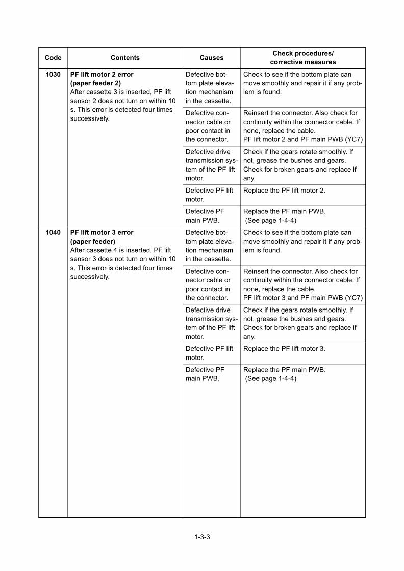
1-3-3
1030 PF lift motor 2 error(paper feeder 2)After cassette 3 is inserted, PF lift sensor 2 does not turn on within 10 s. This error is detected four timessuccessively.
Defective bot-tom plate eleva-tion mechanism in the cassette.
Check to see if the bottom plate can move smoothly and repair it if any prob-lem is found.
Defective con-nector cable or poor contact in the connector.
Reinsert the connector. Also check for continuity within the connector cable. If none, replace the cable.PF lift motor 2 and PF main PWB (YC7)
Defective drive transmission sys-tem of the PF lift motor.
Check if the gears rotate smoothly. If not, grease the bushes and gears. Check for broken gears and replace if any.
Defective PF lift motor.
Replace the PF lift motor 2.
Defective PF main PWB.
Replace the PF main PWB. (See page 1-4-4)
1040 PF lift motor 3 error(paper feeder)After cassette 4 is inserted, PF lift sensor 3 does not turn on within 10 s. This error is detected four timessuccessively.
Defective bot-tom plate eleva-tion mechanism in the cassette.
Check to see if the bottom plate can move smoothly and repair it if any prob-lem is found.
Defective con-nector cable or poor contact in the connector.
Reinsert the connector. Also check for continuity within the connector cable. If none, replace the cable.PF lift motor 3 and PF main PWB (YC7)
Defective drive transmission sys-tem of the PF lift motor.
Check if the gears rotate smoothly. If not, grease the bushes and gears. Check for broken gears and replace if any.
Defective PF lift motor.
Replace the PF lift motor 3.
Defective PF main PWB.
Replace the PF main PWB. (See page 1-4-4)
Code Contents CausesCheck procedures/
corrective measures

1-3-4
1050 PF lift motor 4 error(paper feeder)After cassette 5 is inserted, PF lift sensor 4 does not turn on within 10 s. This error is detected four timessuccessively.
Defective bot-tom plate eleva-tion mechanism in the cassette.
Check to see if the bottom plate can move smoothly and repair it if any prob-lem is found.
Defective con-nector cable or poor contact in the connector.
Reinsert the connector. Also check for continuity within the connector cable. If none, replace the cable.PF lift motor 4 and PF main PWB (YC7)
Defective drive transmission sys-tem of the PF lift motor.
Check if the gears rotate smoothly. If not, grease the bushes and gears. Check for broken gears and replace if any.
Defective PF lift motor.
Replace the PF lift motor 4.
Defective PF main PWB.
Replace the PF main PWB. (See page 1-4-4)
1800 Paper feeder 1 communication errorA communication error is detected 10 times in succession.
Improper installa-tion paper feeder.
Follow installation instruction carefully again.
Defective con-nector cable or poor contact in the connector.
Reinsert the connector. Also check for continuity within the connector cable. If none, replace the cable.PF main PWB (YC3) and engine PWB (YC22)
Defective engine PWB.
Replace the engine PWB and check for correct operation (Refer to the service manual for the printer).
Defective PF main PWB.
Replace the PF main PWB. (See page 1-4-4)
1810 Paper feeder 2 communication errorA communication error is detected 10 times in succession.
Improper installa-tion paper feeder.
Follow installation instruction carefully again.
Defective con-nector cable or poor contact in the connector.
Reinsert the connector. Also check for continuity within the connector cable. If none, replace the cable.PF main PWB (YC3) and PF main PWB (YC4)
Defective PF main PWB.
Replace the PF main PWB. (See page 1-4-4)
Code Contents CausesCheck procedures/
corrective measures

1-3-5
1820 Paper feeder 3 communication errorA communication error is detected 10 times in succession.
Improper installa-tion paper feeder.
Follow installation instruction carefully again.
Defective con-nector cable or poor contact in the connector.
Reinsert the connector. Also check for continuity within the connector cable. If none, replace the cable.PF main PWB (YC3) and PF main PWB (YC4)
Defective PF main PWB.
Replace the PF main PWB. (See page 1-4-4)
1830 Paper feeder 4 communication errorA communication error is detected 10 times in succession.
Improper installa-tion paper feeder.
Follow installation instruction carefully again.
Defective con-nector cable or poor contact in the connector.
Reinsert the connector. Also check for continuity within the connector cable. If none, replace the cable.PF main PWB (YC3) and PF main PWB (YC4)
Defective PF main PWB.
Replace the PF main PWB. (See page 1-4-4)
1900 Paper feeder 1 EEPROM errorWhen writing the data, the write data and the read data is not in agree-ment.
Defective PF main PWB.
Replace the PF main PWB. (See page 1-4-4)
Device damage of EEPROM.
1910 Paper feeder 2 EEPROM errorWhen writing the data, the write data and the read data is not in agree-ment.
Defective PF main PWB.
Replace the PF main PWB. (See page 1-4-4)
Device damage of EEPROM.
1920 Paper feeder 3 EEPROM errorWhen writing the data, the write data and the read data is not in agree-ment.
Defective PF main PWB.
Replace the PF main PWB. (See page 1-4-4)
Device damage of EEPROM.
1930 Paper feeder 4 EEPROM errorWhen writing the data, the write data and the read data is not in agree-ment.
Defective PF main PWB.
Replace the PF main PWB. (See page 1-4-4)
Device damage of EEPROM.
Code Contents CausesCheck procedures/
corrective measures

1-3-6
2600 PF feed motor 1 error(paper feeder 1)When the PF feed motor is driven, error signal is detected continuously for 2 s.
Defective con-nector cable or poor contact in the connector.
Reinsert the connector. Also check for continuity within the connector cable. If none, replace the cable.PF feed motor 1 and PF main PWB (YC6)
Defective drive transmission sys-tem of the PF feed motor.
Check if the rollers and gears rotate smoothly. If not, grease the bushes and gears. Check for broken gears and replace if any.
Defective PF feed motor.
Replace the PF feed motor 1.
Defective PF main PWB.
Replace the PF main PWB. (See page 1-4-4)
2610 PF feed motor 2 error(paper feeder 2)When the PF feed motor is driven, error signal is detected continuously for 2 s.
Defective con-nector cable or poor contact in the connector.
Reinsert the connector. Also check for continuity within the connector cable. If none, replace the cable.PF feed motor 2 and PF main PWB (YC6)
Defective drive transmission sys-tem of the PF feed motor.
Check if the rollers and gears rotate smoothly. If not, grease the bushes and gears. Check for broken gears and replace if any.
Defective PF feed motor.
Replace the PF feed motor 2.
Defective PF main PWB.
Replace the PF main PWB. (See page 1-4-4)
2620 PF feed motor 3 error(paper feeder 3)When the PF feed motor is driven, error signal is detected continuously for 2 s.
Defective con-nector cable or poor contact in the connector.
Reinsert the connector. Also check for continuity within the connector cable. If none, replace the cable.PF feed motor 3 and PF main PWB (YC6)
Defective drive transmission sys-tem of the PF feed motor.
Check if the rollers and gears rotate smoothly. If not, grease the bushes and gears. Check for broken gears and replace if any.
Defective PF feed motor.
Replace the PF feed motor 3.
Defective PF main PWB.
Replace the PF main PWB. (See page 1-4-4)
Code Contents CausesCheck procedures/
corrective measures

1-3-7
2630 PF feed motor 4 error(paper feeder 4)When the PF feed motor is driven, error signal is detected continuously for 2 s.
Defective con-nector cable or poor contact in the connector.
Reinsert the connector. Also check for continuity within the connector cable. If none, replace the cable.PF feed motor 4 and PF main PWB (YC6)
Defective drive transmission sys-tem of the PF feed motor.
Check if the rollers and gears rotate smoothly. If not, grease the bushes and gears. Check for broken gears and replace if any.
Defective PF feed motor.
Replace the PF feed motor 4.
Defective PF main PWB.
Replace the PF main PWB. (See page 1-4-4)
Code Contents CausesCheck procedures/
corrective measures

1-3-8
1-3-3 Electric problems
Problem Causes Check procedures/corrective measures
(1)Defective paperjam detecting.False paper jammessage display.
Actuators of paper feed sensor does not operate smoothly.
Check visually and replace if necessary.
A piece of paper torn from a sheet is caught around actuator of paper feed sensor.
Check visually and remove it, if any.
Defective paper feed sensor.
Replace the paper feed sensor.
Defective PF main PWB. Replace the PF main PWB (See page 1-4-4).
Defective printer’s engine PWB.
Replace printer’s engine PWB.(Refer to the service manual for the printer)
(2)Defective papergauge sensing.False paper gaugeindication.
Defective paper gauge sensors.
Replace the PF main PWB (See page 1-4-4).
Actuator of paper gauge sensors does not oper-ate smoothly.
Check visually and replace if necessary.
Defective PF main PWB. Replace PF main PWB (See page 1-4-4).
Defective printer’s engine PWB.
Replace printer’s engine PWB.(Refer to the service manual for the printer)
(3)Defective papersize detecting.False paper sizemessage display.
Defective cassette size switch.
Replace the cassette size switch.
Defective PF main PWB. Replace the PF main PWB (See page 1-4-4).
Defective printer’s engine PWB.
Replace printer’s engine PWB.(Refer to the service manual for the printer)

1-3-9
1-3-4 Mechanical problems
Problem Causes/check procedures Corrective measures
(1)No paper feed. Check if the surfaces of the following roll-ers are dirty with paper powder: Pickup roller, Paper feed roller
Clean with isopropyl alcohol.
Check if the pickup roller and paper feed roller are deformed.
Check visually and replace any deformed rollers.
Defective installation position of drive unit.
Check the installation position of drive unit.
Defective paper feed motor. Replace the drive unit. (See page 1-4-4)
(2)Skewed paperfeed.
Check if the paper is curled. Change the paper.
(3)Multiple sheets ofpaper are fed at onetime.
Check if the paper is excessively curled. Change the paper.
Deformed guides along the paper con-veying path.
Check visually and replace any deformed guides.
(4)Paper jams. Check if the contact between the pickup roller, paper feed roller and retard roller is correct.
Check visually and remedy if necessary. Replace the pressure spring if it is deformed.
(5)Abnormal noise isheard
Check if the pulleys, rollers and gears operate smoothly.
Grease the bearings and gears.
Check if the drive unit is installed cor-rectly.
Correct.

1-4-1
1-4 Assembly and Disassembly
1-4-1 Precautions for assembly and disassembly
(1) Precautions
Before starting disassembly, press the Power key on the operation panel to off. Make sure that the Power lamp is off before turning off the main power switch. Unplug the power cable from the wall outlet.When handling PWBs (printed wiring boards), do not touch parts with bare hands.The PWBs are susceptible to static charge.Do not touch any PWB containing ICs with bare hands or any object prone to static charge.When removing the hook of the connector, be sure to release the hook.Take care not to get the cables caught.To reassemble the parts, use the original screws. If the types and the sizes of screws are not known, refer to the PARTS LIST.

1-4-2
1-4-2 Assembly and disassembly
(1) Removing the conveying roller, paper feed roller and pickup roller
Procedure1. Remove the cassette from the paper
feeder.2. While pressing the lock lever and then
slide the roller holder.3. Remove the paper feed roller assembly.4. Check or replace the paper feed roller
or the pickup roller and refit all theremoved parts.
Figure 1-4-1
Lock lever
Pickup roller
Paper feed roller
Roller holder
Paper feed roller assembly

1-4-3
(2) Removing the retard roller
1. Remove the cassette from the paperfeeder.
2. Release two hooks in backside of cas-sette and then remove the retard rollerassembly.
Figure 1-4-2
3. Remove the spring.4. Remove the retard holder by rotating.5. Check or replace the retard roller and
refit all the removed parts.
Figure 1-4-3
Retard roller assembly
Hook
Cassette backside
Cassette
Retard roller guide
Spring
Retard roller holder

1-4-4
(3) Remove the drive unit and PF main PWB
1. Remove the right front cover.2. Remove the five screws.3. Pull the upper cover rear ends.4. While pulling out the paper size switch,
and then remove the upper cover.
Figure 1-4-4
5. Release two hooks using the flat screwdriver.
6. Remove the PWB cover by pulling theknob up.
Figure 1-4-5
Upper coverScrew
Screw
Screw
Screw
Cassette sizeswitch
Right front cover
Screw
PWB cover
Knob
Hooks
Upper cover
Flat screwdriver

1-4-5
7. Pull the three connectors out and thenrelease the wires from the wire holders.
8. Remove the three screws and thenremove the drive unit.
Figure 1-4-6
9. Pull the paper feed roller assembly up.10. Remove all connectors from the PF
main PWB.11. Remove the screw and then remove the
PF main PWB.12. Check or replace the drive unit or PF
main PWB and refit all the removedparts.
Figure 1-4-7
Screw
Screw
Screw
Connectors
Wire holdersDrive unit
Wires
Screw
PF main PWB
Paper feed roller assembly

2-1-1
2-1 Mechanical construction
2-1-1 Paper feed section
(1) Paper feed section
The paper feeder conveys paper from the cassette to the printer. Cassette can hold up to 500 sheets of paper. Paper is fed from the paper feeder by the rotation of the pickup roller and paper feed roller. The retard roller prevents multiple sheets from being fed at one time, via the torque limiter.
Figure 2-1-1 Paper feed section
Figure 2-1-2 Paper feed section block diagram
2
8
3
7
9
4
10
11
156
(1)Paper feed roller(2)Pickup roller(3)Retard roller(4)Retard roller guide(5)Conveying roller(6)Conveying pulley
(7)Bottom plate(8)Bottom pad(9)Cassette base(10)Upper cover(11)Paper gauge sensor (actuator)
OPPAUSENOPSEL0OPSEL1OPSEL2OPRDYNOPSCLKOPSDIOPSDO
TMDRVNTMCLKTMLOCKTMDIR
PAPSIZ0PAPSIZ1PAPSIZ2
YC6-4YC6-3YC6-2YC6-1
YC2-1YC2-2YC2-4
YC1-3 OUT
LMOTOR
FEEDCLN
TRANSCLN
YC7-2
YC8-2
YC8-4
YC4-11YC4-10YC4-9YC4-8YC4-5YC4-4YC4-3YC4-2
YC3-11YC3-10YC3-9YC3-8YC3-5YC3-4YC3-3YC3-2
OPPAUSENOPSEL0OPSEL1OPSEL2OPRDYNOPSCLKOPSDIOPSDO
PF main PWB
PFPFMPFLM
ForPRINTER
/Upper PF
ForLower PF
PFCSSW
PFPFSPFPFCL
PFFCL
PFLS
PFPS2
PFPS2

2-2-1
2-2 Electrical Parts Layout
2-2-1 Electrical parts layout
(1) Electrical parts
Figure 2-2-1 Electrical parts
1. PF main PWB (PFMPWB) .................... Controls electrical components in the paper feeder and communi-cations with the printer.
2. PF paper sensor 1 (PFPS1).................. Detects the paper remaining amount level.3. PF paper sensor 2 (PFPS2).................. Detects the paper remaining amount level.4. PF lift sensor (PFLS)............................. Detects the top limit of the bottom plate.5. PF paper feed sensor (PFPFS) ............ Detects paper jam in the paper feeder.6. PF cassette size switch (PFCSSW)...... Detects the paper size dial setting of the paper setting dial.7. PF paper feed motor (PFPFM) ............. Drives the paper feed mechanism in the paper feeder.8. PF lift motor (PFLM).............................. Operates the bottom plate in the cassette.9. PF paper feed clutch (PFPFCL)............ Controls the paper feed from the cassette.
10. PF peed clutch (PFFCL) ....................... Controls the paper conveying.
1
2,3
5
6 8 10
47
9

2-3-1
2-3 Operation of the PWBs
2-3-1 Main PWB
.
Figure 2-3-1 Main PWB silk-screen diagram
YC6YC2 YC8 3 1
4 2181 4
YC7
21
1
131
12Y
C3
YC
4
YC1
1 3

2-3-2
Connector Pin Signal I/O Voltage Description
YC1 1 +3.3V2 - 3.3 V DC 3.3 V DC power output to PFS
Connected to
the PF paper
fed sensor
2 GND - - Ground
3 OUT I 0/3.3 V DC PFPFS: On/Off
YC2 1 PAPSIZ0 I 0/3.3 V DC PFCSSW0: On/Off
Connected to
the PF cas-
sette size
switch
2 PAPSIZ1 I 0/3.3 V DC PFCSSW1: On/Off
3 GND - - Ground
4 PAPSIZ2 I 0/3.3 V DC PFCSSW2: On/Off
YC3 1 +24V1 O 24 V DC 24 V DC power source
Connected to
the printer oy
the upper
paper feeder
2 OPSDO O 0/3.3 V DC(pulse) Synchronous serial receiving data
3 OPSDI O 0/3.3 V DC(pulse) Synchronous serial send data
4 OPSCLK O 0/3.3 V DC(pulse) Synchronous serial clock signal
5 OPRDYN - 0/3.3 V DC SPI ready signal
6 +3.3V1 - 3.3 V DC 3.3 V DC power source
7 GND - - Ground
8 OPSEL2 - 0/3.3 V DC SPI_SEL 2
9 OPSEL1 I 0/3.3 V DC SPI_SEL 1
10 OPSEL0 I 0/3.3 V DC SPI_SEL 0
11 OPPAUSEN O 0/3.3 V DC PF operation stop signal
12 GND I - Ground
YC4 1 +24V1 - 24 V DC 24 V DC power source
Connected to
the lower
paper feeder
2 OPSDO O 0/3.3 V DC(pulse) Synchronous serial receiving data
3 OPSDI I 0/3.3 V DC(pulse) Synchronous serial send data
4 OPSCLK O 0/3.3 V DC(pulse) Synchronous serial clock signal
5 OPRDYN I 0/3.3 V DC SPI ready signal
6 +3.3V1 - 3.3 V DC 3.3 V DC power source
7 GND - - Ground
8 OPSEL2 O 0/3.3 V DC SPI_SEL 2
9 OPSEL1 O 0/3.3 V DC SPI_SEL 1
10 OPSEL0 O 0/3.3 V DC SPI_SEL 0
11 OPPAUSEN O 0/3.3 V DC PF operation stop signal
12 GND - - Ground

2-3-3
YC6 1 TMDIR O 0/3.3 V DC PFPFM rotation direction signal
Connected to
the PF paper
feed motor
2 TMLOCK I 0/3.3 V DC PFPFM rotation stable signal
3 TMCLK O 0/3.3 V DC(pulse) PFPFM clock signal
4 TMDRVN O 0/3.3 V DC PFPFM control signal
5 GND - - Ground
6 +24V2 - 24 V DC 24 V DC power output to PFPFM
YC7 1 GND - - Ground
Connected to
the PF lift
motor
2 LMOTOR O 0/3.3 V DC PFLM control signal
YC8 1 +24V2 - 24 V DC 24 V DC power output to PFFCL
Connected to
the PF paper
feed clutch
and PF feed
clutch
2 FEEDCLN O 0/3.3 V DC PFFCL control signal
3 +24V2 - 24 V DC 24 V DC power output to PFPFCL
4 TRANSCLN O 0/3.3 V DC PFPFCL control signal
Connector Pin Signal I/O Voltage Description

2-4-1
2-4 Appendixes
2-4-1 Appendix
(1) Wiring diagram
GNDOPPAUSENOPSEL0OPSEL1OPSEL2GND+3.3V1OPRDYNOPSCLKOPSDIOPSDO+24V1
GNDRESETNN.C.TXDRXDMODE+3.3V1
123456
123456
654321
+24V2GNDTMDRVNTMCLKTMLOCKTMDIR
4321
1234
PAPSIZ0PAPSIZ1GNDPAPSIZ2
123
4321
123
321
654321
1234
321
OUTGND+3.3V2
12
21
21
GNDLMOTOR
1234
321
321
321
321
+24V2FEEDCLN+24V2TRANSCLN
YC4
YC7
YC8
13121110987654321
12
1234
13121110987654321
YC97654321
121110987654321
121110987654321
121110987654321
121110987654321
GNDOPPAUSENOPSEL0OPSEL1OPSEL2GND+3.3V1OPRDYNOPSCLKOPSDIOPSDO+24V1
YC3
YC2
YC6
YC1
YC1
PFLS
PFPS1
PFPS2
PF main PWB
PFPFMPFLM
ForPRINTER
/ Upper PF
ForLower PF
PFPSW
PFPFS
PFPFCL
PFFCL

SERVICEMANUAL
Published in August 2016843S3110
3S3SM060First edition
PF-3100

CAUTION
RISK OF EXPLOSION IF BATTERY IS REPLACED BY AN INCORRECT TYPE. DISPOSE OF USED BATTERIES ACCORDING TO THE INSTRUCTIONS.
It may be illegal to dispose of this battery into the municipal waste stream. Check with your local solid waste officials for details in your area for proper disposal.
ATTENTION
IL Y A UN RISQUE D’EXPLOSION SI LA BATTERIE EST REMPLACEE PAR UN MODELE DE TYPE INCORRECT. METTRE AU REBUT LES BATTERIES UTILISEES SELON LES INSTRUCTIONS DONNEES.
Il peut être illégal de jeter les batteries dans des eaux d’égout municipales. Vérifiez avec les fonctionnaires municipaux de votre région pour les détails concernant des déchets solides et une mise au rebut appropriée.
The correspondence printer is as follows.
PG L2545PG L2550 PG L2555

CONTENTS
1-1 Specifications1-1-1 Specifications..........................................................................................................................................1-1-11-1-2 Paper specifications................................................................................................................................1-1-2
(1) Paper specifications ..........................................................................................................................1-1-2(2) Selecting the right paper ...................................................................................................................1-1-2
(2-1) Condition of the paper ...............................................................................................................1-1-2 (2-2) Paper size .................................................................................................................................1-1-2 (2-3) Smoothness ..............................................................................................................................1-1-3 (2-4) Basis weight ..............................................................................................................................1-1-3 (2-5) Moisture content........................................................................................................................1-1-3
(3) Paper storage....................................................................................................................................1-1-3(4) Envelopes and postcards ..................................................................................................................1-1-4
(4-1) Envelopes..................................................................................................................................1-1-4 (4-2) Curly envelopes.........................................................................................................................1-1-5 (4-3) Post cards .................................................................................................................................1-1-5
(5) Storage of envelopes and postcards.................................................................................................1-1-5
1-2 Installation1-2-1 Unpacking and installation ......................................................................................................................1-2-1
(1) Installation procedure ........................................................................................................................1-2-11-2-2 Operating the paper feeder.....................................................................................................................1-2-8
(1) Loading paper ...................................................................................................................................1-2-8 (1-1) Loading paper ...........................................................................................................................1-2-8
(2) Loading envelopes and postcards.....................................................................................................1-2-9(3) Loading paper in the printer’s paper cassette ...................................................................................1-2-9(4) Selecting paper feed from the paper feeder......................................................................................1-2-9
(4-1) Selection from the printer’s operation panel..............................................................................1-2-9 (4-2) Selection using prescribe’s PSRC command..........................................................................1-2-10
1-3 Troubleshooting1-3-1 Paper misfeed detection .........................................................................................................................1-3-1
(1) Paper misfeed indication ...................................................................................................................1-3-1(2) Paper misfeed detection conditions ..................................................................................................1-3-2
1-3-2 Self-diagnostic function...........................................................................................................................1-3-3(1) Self-diagnostic function .....................................................................................................................1-3-3(2) Self diagnostic codes ........................................................................................................................1-3-3
1-3-3 Electric problems ....................................................................................................................................1-3-4
1-4 Assembly and Disassembly1-4-1 Precautions for assembly and disassembly............................................................................................1-4-1
(1) Precautions .......................................................................................................................................1-4-11-4-2 Assembly and disassembly.....................................................................................................................1-4-2
(1) Removing the bulk paper feeder from the printer..............................................................................1-4-2(2) Removing the tray cover ...................................................................................................................1-4-2(3) Removing the side covers .................................................................................................................1-4-3(4) Removing the paper outlet and top cover .........................................................................................1-4-3(5) Removing the mounting rail from the printer base ............................................................................1-4-4
2-1 Mechanical construction2-1-1 Paper feed section ..................................................................................................................................2-1-1
(1) FRR System......................................................................................................................................2-1-1(2) The fault detection function of the PWB............................................................................................2-1-3
2-2 Electrical Parts Layout2-2-1 Electrical parts layout..............................................................................................................................2-2-1
(1) Electrical parts...................................................................................................................................2-2-1(2) Electrical parts (PB-325) ...................................................................................................................2-2-2
2-3 Operation of the PWBs2-3-1 Main PWB ...............................................................................................................................................2-3-1

2-4 Appendixes2-4-1 Wiring diagram........................................................................................................................................2-4-1

1-1-1
1-1 Specifications
1-1-1 Specifications
Item Specifications
Paper size Envelope Monarch, Envelope #10, Envelope DL, Envelope C5, Execu-tive, Letter, A4, B5, A5, A6, B6, Envelope #9, Envelope #6, ISO B5, Cus-tom, Hagaki, Oufuku Hagaki, 16K, Statement, Youkei 2 and Youkei 4
Paper type Plain, Transparency, Preprinted, Labels, Bond, Recycled, Vellum, Rough, Letterhead, Color, Prepunched, Envelope, Cardstock, Thick, High Quality, and CUSTOM 1 (to 8)
Paper capacity 2,000 sheets (75 g/m2)
Printer Dimensions (W × D × H)
345 × 420 × 371 mm13 37/64 × 13 17/32 × 14 39/64"
Weight 7.5 kg / 16.5 lb
Attach-ment
Printer base PB-325
Dimensions (W × D × H)
380 × 706 × 184 mm14 15/16 × 27 13/16 × 7 1/4”
Weight 6.5 kg / 14.3 lb

1-1-2
1-1-2 Paper specifications
General guidelinesThe bulk paper feeder is designed for use with various special types of print media such as adhesive backed label, thick paper, envelopes, and post cards, it may not be used to print on paper not satisfying the requirements below.
NoteThe manufacturer assumes no liability for problems that occur when paper not satisfying these requirements is used with the bulk paper feeder.
Selection of the right paper is important. The wrong paper can result in jams, misfeeds, curl, poor print quality, and paper waste, and in extreme cases can damage the bulk paper feeder and/or the printer. The guidelines given below will increase the productivity of your office by ensuring efficient, trouble-free printing and reducing wear and tear on the bulk paper feeder and the printer.
(1) Paper specifications
The following table summarizes the basic paper specifications.
(2) Selecting the right paper
Printer printing is a process involving light beam, electrostatic discharge, toner, and heat. In addition, as the paper passes through the printer it undergoes considerable sliding, bending, and twisting motions. A high- quality printing paper match-ing the requirements withstands all these stresses, enabling the bulk paper feeder and the printer to turn out clean, crisp printed copy consistently.Remember that all paper is not the same. Some of the factors to consider when selecting paper for use with the bulk paper feeder are as follows:
(2-1) Condition of the paper
Avoid using paper that is bent at the edges, curled, dirty, torn, or contaminated with lint, clay, or paper shreds.Use of paper in these conditions can lead to illegible printing, misfeeding, and paper jams, and can shorten the life of the bulk paper feeder and the printer. In particular, avoid using paper with a surface coating or other surface treatment. The paper should have as smooth and even a surface as possible.
(2-2) Paper size
The minimum size of paper loadable in the bulk paper feeder is 76 ´ 148 mm (3 ´ 5.8 inches). The maximum size is 216 ´ 305 mm (8.5 ´ 12 inches). The bulk paper feeder can feed paper of any sizes between these sizes (shaded area in the fig-ure below), including the standard sizes of A4, B5, A5, letter size, etc. The legal size paper is not usable with the bulk paper feeder.Since the printer does not recognize the size of the paper currently loaded in the option bulk paper feeder, it assumes that all paper fed from the bulk paper feeder have the legal size (8-1/2 by 14 inches). You can use the SPSZ (Set Paper SiZe)
Item Specification
Weight 60 to 200 g/m2
Thickness 0.086 to 0.29 mm
Squareness of corners 90°±0.2°
Curl Inream flat within 4 mm
Packaging Moisture-proof ream wrapping required
Moisture content 4 to 6%
Direction of grain Long grain
Pulp content 80% or more

1-1-3
command of the PRESCRIBE command language to tell the printer the size of the paper or envelope. Refer to the printer’s Prescribe II Command reference in the CD-ROM supplied with the printer.
(2-3) Smoothness
The paper should have a smooth, uncoated surface. Paper with a rough or sandy surface can cause voids in the printed output. Paper that is too smooth, however, can cause multiple feeding and fogging problems. (Fogging is a gray back-ground effect.)
(2-4) Basis weight
Basis weight is the weight of a standard quantity of paper. In the traditional system the standard quantity is a ream consist-ing of 500 sheets measuring 17 ´ 22 inches each. In the metric system the standard quantity is 1 square meter.Paper that is too light or too heavy can cause misfeeding, jams, and premature wear of the bulk paper feeder and the printer. Uneven paper weight can cause multiple feeds, print defects, poor toner fusing, blurring, and other print quality
problems. The proper weight is 60 to 200 g/m2 (16 to 53 lbs/ream).
(2-5) Moisture content
Moisture content is defined as the percent ratio of moisture to the dry mass of the paper. Moisture can affect the paper’s appearance, feedability, curl, electrostatic properties, and toner fusing characteristics.The moisture content of the paper varies with the relative humidity in the room. When the relative humidity is high and the paper absorbs moisture, the paper edges expand, becoming wavy in appearance. When the relative humidity is low and paper loses moisture, the edges shrink and tighten, and print contrast may suffer.Wavy or tight edges can cause misfeeding and alignment anomalies. The moisture content of the paper should be 4% to 6%.To ensure the proper moisture content it is important to store the paper in a controlled environment. Some tips on moisture control are:
Store paper in a cool, dry location.Keep the paper in its wrapping as long as possible. Rewrap paper that is not in use.Store paper in its original carton. Place a pallet etc. under the carton to separate it from the floor.After removing paper from storage, let it stand in the same room as the printer for 48 hours before use.Avoid leaving paper where it is exposed to heat, sunlight, or damp.
(3) Paper storage
When the bulk paper feeder is not to be used for a long time of period, the paper must be removed from the bulk paper feeder and wrapped in moisture-proof paper for storage.
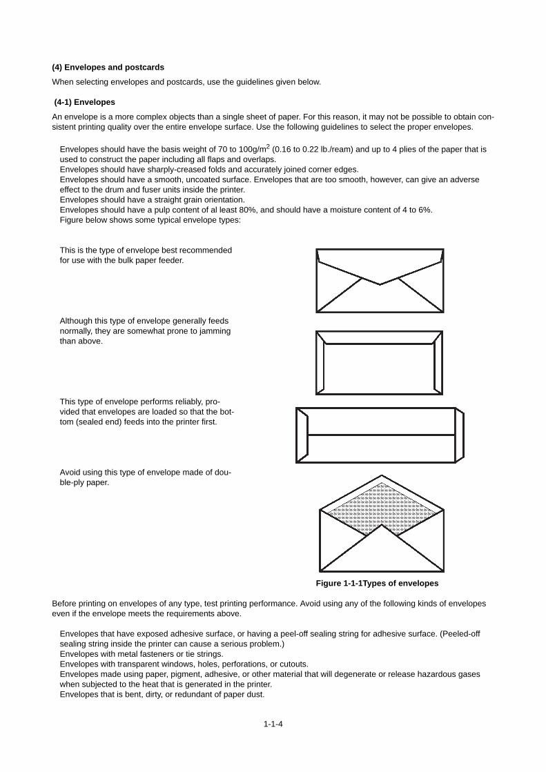
1-1-4
(4) Envelopes and postcards
When selecting envelopes and postcards, use the guidelines given below.
(4-1) Envelopes
An envelope is a more complex objects than a single sheet of paper. For this reason, it may not be possible to obtain con-sistent printing quality over the entire envelope surface. Use the following guidelines to select the proper envelopes.
Envelopes should have the basis weight of 70 to 100g/m2 (0.16 to 0.22 lb./ream) and up to 4 plies of the paper that is used to construct the paper including all flaps and overlaps.Envelopes should have sharply-creased folds and accurately joined corner edges.Envelopes should have a smooth, uncoated surface. Envelopes that are too smooth, however, can give an adverse effect to the drum and fuser units inside the printer.Envelopes should have a straight grain orientation.Envelopes should have a pulp content of al least 80%, and should have a moisture content of 4 to 6%.Figure below shows some typical envelope types:
This is the type of envelope best recommended for use with the bulk paper feeder.
Although this type of envelope generally feeds normally, they are somewhat prone to jamming than above.
This type of envelope performs reliably, pro-vided that envelopes are loaded so that the bot-tom (sealed end) feeds into the printer first.
Avoid using this type of envelope made of dou-ble-ply paper.
Figure 1-1-1Types of envelopes
Before printing on envelopes of any type, test printing performance. Avoid using any of the following kinds of envelopes even if the envelope meets the requirements above.
Envelopes that have exposed adhesive surface, or having a peel-off sealing string for adhesive surface. (Peeled-off sealing string inside the printer can cause a serious problem.)Envelopes with metal fasteners or tie strings.Envelopes with transparent windows, holes, perforations, or cutouts.Envelopes made using paper, pigment, adhesive, or other material that will degenerate or release hazardous gases when subjected to the heat that is generated in the printer.Envelopes that is bent, dirty, or redundant of paper dust.

1-1-5
(4-2) Curly envelopes
An envelope tends to curl excessively or become uneven in its thickness since it is constructed by paper which is folded, creased, and seamed in many parts, making the stack of envelopes on the feeder tray unlevel. To avoid feeding problems, the unlevelness of the stack of envelopes on the paper tray must be less than those specified in the following figures.
Figure 1-1-2Curl limits for envelopes
Reduce the envelopes, if necessary to keep the unlevelness of the stack of envelope within the specified limit.
(4-3) Post cards
The paper used in postcards should have a basis weight of 135 to 190 g/m2 (0.3 to 0.42 lb./ream) and uncoated. The paper should also satisfy the same conditions as white bond paper.
(5) Storage of envelopes and postcards
Store envelopes and postcards, making sure of the following hints.
Avoid leaving paper where it is exposed to sunlight.Store envelopes in a clean, dust-free environment.Temperature in the storage area should be maintained in the range from 50 to 95°F (10 to 35°C), and relative humidity should be kept between 20 and 80%.
Thickness in bottom or top
must be less than 10 mm
Thickness in right or left trails
must be less than 5 mm.
Vertical curl must
be less than 10 mm.
Horizontal curl must
be less than 5 mm.

1-2-1
1-2 Installation
1-2-1 Unpacking and installation
(1) Installation procedure
Removing the MP tray.
Installing the bulk paper feeder.
Installing the printer to the printer base.
Start
End.

1-2-2
In order to install the bulk paper feeder in the printer, the printer’s MP tray must be removed. Proceed as the following instructions:
I
1. Unplug the power source plug.2. Open the front cover.3. Remove the MP tray from the printer while
bending it. Retain the MP tray for future use.
Figure 1-2-1
Removing the MP tray
MP tray
Front cover

1-2-3
4. Remove the fulcrum of leftside by extendinga cover.
5. Remove the fulcrum of rightside duringtwisting a cover.
6. Remove the front cover forward.
Figure 1-2-2
Front cover
Front cover

1-2-4
7. Remove two screws on the MP paper feedunit.
Figure 1-2-3
8. Remove the MP paper feed unit from theprinter. Retain the MP paper feed unit forfuture use.
Figure 1-2-4
MP paper feed unit
Screw
Screw
MP paper feed unit
Printer

1-2-5
9. Attach the spacer by the screw to the printer.10. Refit the removed front cover.11. Close the top cover and the front cover.12. Refit the removed cassette.
Figure 1-2-5
1. Align the positioning pins on the top of theprinter base with the holes in the base of theprinter, then slowly and carefully lower theprinter onto the printer base.
2. Make sure that the connector on the printerbase fits squarely into the correspondingconnector in the base of the printer. See fig-ure right.
Figure 1-2-6
Spacer
ScrewPrinter
Installing the printer base and the printer
Positioning pin
Connector
Printer
Printer base
Positioning pin

1-2-6
1. Mount the bulk paper feeder onto the rail inthe lower deck of the base. The rail is mov-able and must be pulled out before installingthe bulk paper feeder. Pull the rail fully outuntil it stops.
2. Grasp the bulk paper feeder by the two han-dles in the side covers. Facing the paperoutput slot of the bulk paper feeder towardthe printer, align the (four) positioning tabson the rail of the base with the holes in thebase of the bulk paper feeder. Then slowlyand carefully lower the bulk paper feederonto the printer base.
3. Slide the rail with the bulk paper feedermounted back toward the printer until theconnector on the front side of the bulk paperfeeder is fully connected to the connector onthe base, holding the bulk paper feeder bythe both hands.
Caution Ensure that the arrow marks on the rail are cor-rectly aligned with the arrow marks on the front side of the bulk paper feeder before proceeding.
Figure 1-2-7
Installing the bulk paper feeder
Rear view
Arrow mark
Rail
Arrow mark
Rail
Printer base
Rail
Positioning tabs(four)
Printer
Bulk paper feeder

1-2-7
4. Make sure that the output slot of the bulkpaper feeder is properly aligned with the MPtray slot on the front side of the printer.
5. This completes setting up the bulk paperfeeder with the printer. Before using the bulkpaper feeder, plug the printer to power andload paper in the bulk paper feeder.
Figure 1-2-8
Printer
Bulk paper feederOutput slot
Completion of the machine installation.

1-2-8
1-2-2 Operating the paper feeder
(1) Loading paper
Caution When the tray is rising or descending, please observe the following precautions.
Keep your fingers out of the slot on the inner side of the bulk paper feeder.While the tray is descending, keep your hands out from under the tray.Do not push down on the tray or pull it upward.
(1-1) Loading paper
Once the bulk paper feeder has been installed in accordance with the instructions provided previously, you can prepare to load paper. Before loading paper, you must adjust the side plates inside the bulk paper feeder to the actual width of the paper to be loaded.
NoteThe legal-size paper is not usable with the bulk paper feeder.
1. Turn printer power on. The bulk paperfeeder is turned on simultaneously.
2. Gently open the feeder’s tray cover. Thepaper tray will lower.
3. Make sure that the paper tray is lowered andstopped. Then, while watching the sideplates inside the bulk paper feeder, rotatethe paper adjuster knob on top of the bulkpaper feeder clockwise. Stop rotating theknob when the side plates have been set totheir widest settings (outmost positions).See figure right.
4. Place several sheets of the paper you aregoing to use with the bulk paper feeder onthe center of the paper tray.
5. Adjust the side plates by rotating theadjuster knob on top of the bulk paperfeeder counterclockwise so that the left andright side edges of the paper are flush withthe left and right side plates.Then, rotate theadjuster knob half a turn clockwise. Thisallows an approximately 1 mm. gapbetween each side of the paper stack andthe side plate, which is needed to ensurethe proper paper feeding. See figure right.NoteMake sure that the paper edges are evenlyaligned on the center of the tray and thefront edge of the stack fully abuts on thebulk paper feeder’s inside panel.
6. Load up to 2,000 sheets of paper (four stan-
dard reams of packages of 75 g/m2 or 20 lb.paper) onto the tray. Fan and flex each reamas you load it. Load the paper with the sideon which printing is done facing upward inthe bulk paper feeder.
Figure 1-2-9NoteDon’t put in more paper than the limit indi-cated on the inside of the bulk paper feeder.Close the tray cover. The tray will rise and asheet will feed partially into the printer. Theprinter indicates Ready and the bulk paperfeeder is ready for operation.
Tray cover
Paper adjuster knob
Side plates

1-2-9
(2) Loading envelopes and postcards
If you are loading postcards in the bulk paper feeder, load them so that they are fed with the top edge first. For envelopes, make sure that they are fed with the right or bottom edge first.
Figure 1-2-10
(3) Loading paper in the printer’s paper cassette
To gain access to the printer’s paper cassette for loading paper, etc., slide the bulk paper feeder fully backward from the printer. If you are using a Legal size paper cassette in the printer, you will need to remove the bulk paper feeder from the mounting base (rail).
(4) Selecting paper feed from the paper feeder
You can select paper feed from the bulk paper feeder using the Menu key on the printer’s operation panel. You can also select it by including PRESCRIBE’s PSRC command in a file that you send to the printer from the computer. Note that the bulk paper feeder replaces the printer’s MP tray.
(4-1) Selection from the printer’s operation panel
1. First, verify that the printer’s message display shows either Ready or Add paper.2. Next, press the Menu key to change the source of paper feed. The source indication toggles between the follow-
ing sequences:
CassetteBulk feeder
To select the bulk paper feeder as the paper source, select Bulk feeder.Note When printing on special forms such as envelopes, labels, or thick paper, use the printer’s Menu key to select paper out-put to the face up tray.If paper is not loaded into the bulk paper feeder, or the bulk paper feeder is detached from the printer (on the rail which, when pulled, detaches the bulk paper feeder from the printer), the printer shows Add paper. Add paper as explained on the previous pages.
Make sure that the printer is ready and on-line, then begin printing. During printing using the bulk paper feeder, the printer’s message display momentarily shows Add paper between pages. This is normal.
Note When used with the bulk paper feeder, the printer may print in the position which does not fully corresponds to the one the application software requests.
Postcard
Direction of
paper feed
Envelopes

1-2-10
(4-2) Selection using prescribe’s PSRC command
Feed selection can be done using the PSRC command of the Prescribe command language. To switch paper feed to the option paper feeder, place the PSRC command in a file or program as follows.
!R! PSRC 0; EXIT;
When the printer receives the PSRC command, it automatically does a form feed operation.Therefore, the PSRC command should be sent either at the beginning of the file, or at the beginning of an intermediate page.The PRESCRIBE FRPO R4 command changes the printer’s default (power-on) paper cassette setting. To change the power-on paper source to the bulk paper feeder, use the following command sequence.
!R! FRPO R4, 0; EXIT;

1-3-1
1-3 Troubleshooting
1-3-1 Paper misfeed detection
(1) Paper misfeed indication
If the printer’s message display shows [Paper jam] or [Add paper] (even though the feeder has paper loaded inside), detach the bulk paper feeder from the printer by sliding with the rail away from the printer, holding the bulk paper feeder by both hands as shown below.If paper is partially fed out from the bulk paper feeder’s output slot, pull the paper out by hand as shown.
Figure 1-3-1
1. If paper is not stuck at the bulk paperfeeder’s output slot, open the tray cover andpull the paper in the bulk paper feeder.
2. If no paper is found jammed inside the paperfeeder, slide the paper feeder away from theprinter, and check if paper is jammed insidethe printer.
Note: When paper is protruding from thebulk paper feeder’s output slot, alwaysremove it by pulling the paper in its normaldirection of travel. Never pull paper back-wards.
3. After connecting the bulk paper feeder backto the printer, open the printer’s upper unitonce, then close it again and wait for themessage display to show [Ready].
Figure 1-3-2
Paper JamBulk Feeder
Paper misfeed location
Paper misfeed message
Paper misfeed location
Paper misfeed message
Printer
Bulk paper feeder
Tray cover
Output slot
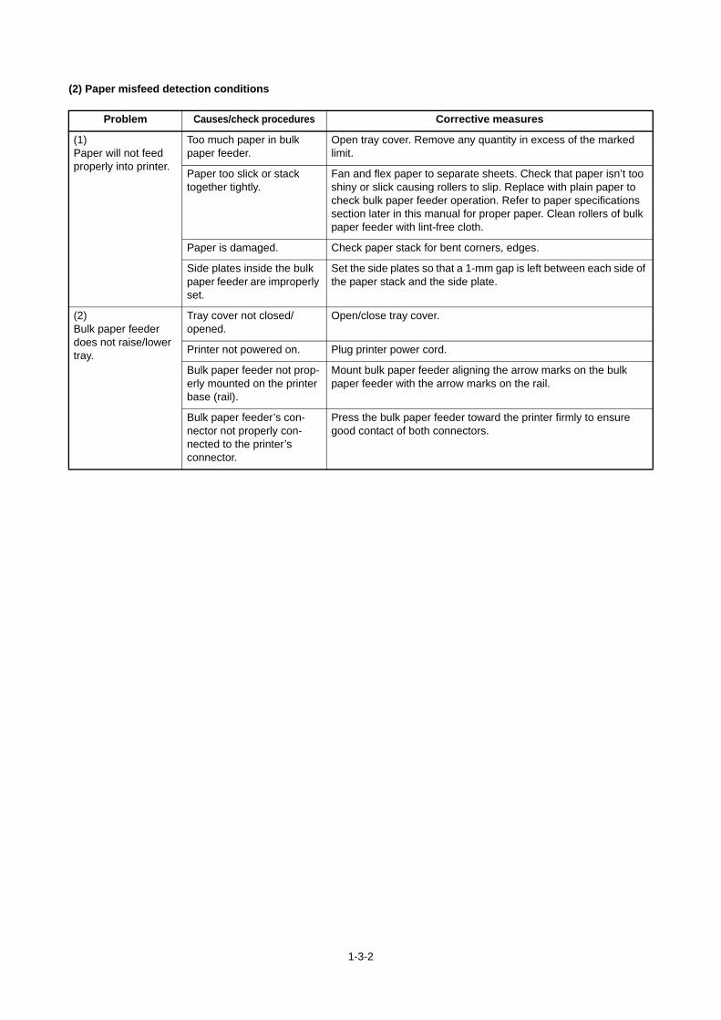
1-3-2
(2) Paper misfeed detection conditions
Problem Causes/check procedures Corrective measures
(1)Paper will not feed properly into printer.
Too much paper in bulk paper feeder.
Open tray cover. Remove any quantity in excess of the marked limit.
Paper too slick or stack together tightly.
Fan and flex paper to separate sheets. Check that paper isn’t too shiny or slick causing rollers to slip. Replace with plain paper to check bulk paper feeder operation. Refer to paper specifications section later in this manual for proper paper. Clean rollers of bulk paper feeder with lint-free cloth.
Paper is damaged. Check paper stack for bent corners, edges.
Side plates inside the bulk paper feeder are improperly set.
Set the side plates so that a 1-mm gap is left between each side of the paper stack and the side plate.
(2)Bulk paper feeder does not raise/lower tray.
Tray cover not closed/opened.
Open/close tray cover.
Printer not powered on. Plug printer power cord.
Bulk paper feeder not prop-erly mounted on the printer base (rail).
Mount bulk paper feeder aligning the arrow marks on the bulk paper feeder with the arrow marks on the rail.
Bulk paper feeder’s con-nector not properly con-nected to the printer’s connector.
Press the bulk paper feeder toward the printer firmly to ensure good contact of both connectors.

1-3-3
1-3-2 Self-diagnostic function
(1) Self-diagnostic function
This printer is equipped with self-diagnostic function. When a problem is detected, the printer stops printing and display an error message on the operation panel. An error message consists of a message prompting a contact to service personnel,total print count, and a four-digit error code indicating the type of the error. (The display varies depending on the type of the error.)
(2) Self diagnostic codes
Code Contents Remarks
Causes Check procedures/corrective measures
1140 Lift motor ascent errorTray top position sensor does not turn on.Lift motor lock error occurred 3 times.
Defective tray top position sensor.
Replace the tray top position sensor.
Defective harness between tray top position sensor and PF main PWB (YC5), or improper connector inser-tion.
Reinsert the connector. Also check for conti-nuity within the connector harness. If none, remedy or replace the harness.
Defective PF main PWB.
Replace the PF main PWB.
1150 Lift motor descent errorTray bottom position sensor does not turn on.Lift motor lock error occurred 3 times.
Defective tray bot-tom position sen-sor.
Replace the tray bottom position sensor.
Defective harness between tray bot-tom position sen-sor and PF main PWB (YC7), or improper connec-tor insertion.
Reinsert the connector. Also check for conti-nuity within the connector harness. If none, remedy or replace the harness.
Defective PF main PWB.
Replace the PF main PWB.
1900 Paper feeder 1/BPF paper feeder EEPROM error
When writing the data, the write data and the read data is not in agreement.
Defective PF main PWB.
Replace the PF main PWB or the BPF main PWB (Refer to the service manual for the paper feeder).
Device damage of EEPROM.
Contact the Service Administrative Division.
Error code Total print
Call service 1140:012345
Total print
Errer code

1-3-4
1-3-3 Electric problems
Problem Causes/check procedures Corrective measures
(1) "Tray elevationmotor does not oper-atte.
Defective wire. Follow the flow chart below.
Defective PF main PWB.
Defective tray elevation motor.
Replace tray elevation motor. After replacing, check whether the operation status is in good status or not.
Replace PF main PWB.
Repair or replace part.
No
No
Yes
Yes
Replace or repair wire.
No
Yes
pin 1 (+)pin 2 (-)
PF main PWB
Capacitor (C5)Measure voltage
End
OK?
Start
YC3
1
14
3
YC9YC211 75
31
YC
5
1 2YC7
YC
41
3Y
C6
2
111
1YC8
C5
U13
YC
1Wire between
PF main PWB and tray elevation motor is in
good status? (no damage coating, or no
connector loosen, etc.?)
Is belt or gearin the tray elevation motor in good status? (No belt damage, no gear crack?) Or, is the driving part in
good status?

1-3-5
(2) "No Paper" sta-tus still has dis-played.
Defective main PWB. Follow the flow chart below.
Defective wire.
Defective paper feed motor.
Problem Causes/check procedures Corrective measures
Replace paper feed sensor, or replace wire between PF main PWB and paper feed sensor.Replace PF main PWB.
Repair actuator or replace the wire material.
Replace or repair wire.
Replace PF main PWB.
Replace PF main PWB or paper feed motor.
No
No
No
No
Yes
Yes
Yes
Yes
Start
Paper is fed to the paper feed
sensor?
Pin 2 of YC3on the PF main PWB with the
paper detected by the paper feed
sensor is 5 V?
The actuator of the paper feed sensor
activates properly?Wire between PF main PWB and paper feed sensor is in good status? (no damage coating, or no connector
loosen, etc.?)
Wire betweenPF main PWB and
paper feed motor is in good status? (no
damage coating, or no connector loosen,
etc.?)

1-3-6
(3) Bulk paper feederis not recognized.
Defective wire. Follow the flow chart below.
Defective printer’s engine PWB.
Problem Causes/check procedures Corrective measures
End
OK?
No Replace or repair wire.
No
No
Yes
Yes
End
Wire betweenprinter base and bulk
paper feeder is in good status?
Is the lamp (green and orange) of a printer
base on?
Pin 10 of YC1 on the PF main PWB is
24 V, and pin 11 is 5 V?
Replace wire between printer base and PF main PWB.
Replace PWB of printer base.
Replace or repair wire.
Replace PF main PWB of the bulk paper feeder.After replacing, check whether the operation status is in good status or not.
Replace engine PWB of the printer.After replacing, check whether the operation status is in good status or not.
Yes
Yes
Is the lamp (green) of a printer
base on?
Wire betweenmain body and printer
base is in good status?
Start
Yes
No
No
OK?

1-3-7
(4) The tray is notdescended eventhough the tray coveris opened.
Defective elevation motor. Follow the flow chart below.
Defective tray bottom posi-tion sensor.
Defective main PWB.
Problem Causes/check procedures Corrective measures
Replace or repair wire.Repair or replace belt of tray elevation motor or driving part.
Replace tray bottom position sensor, or repair/replace the actuator.Replace main PWB.
Replace tray bottom position sensor, or repair/replace the actuator.Repair or replace wire between main PWB and tray bottom position sensor.
Replace engine PWB of the printer.Replace wire between printer engine PWB and printer base.Replace wire between printer
No
No
No
No
Yes
Yes
Yes
Yes
Yes
Yes
Replace tray elevation motor. Replace wire between main PWB and tray elevation motor.
No
NoReplace main PWB.
Start
Replace main PWB.
Pin 3 of YC2 = 3.3 V?
Pin 3 of YC7 = 0 V?
Pin 2 of YC6 = 0 V?
Pin 1 of YC1 = 5 V?
Wire betweenpaper and tray elevation motor is in good status? (no damage coating, or no connector loosen,
etc?)
Is pin 1 of YC4 with the cover opened 24 V , and pin 2 = 0 V? (with the tray be possible to
be descended)

1-3-8
(5)The tray is notdescended eventhough paper isempty.
Defective wire. Follow the flow chart below.
Defective tray bottom posi-tion sensor.
Defective paper feed sen-sor.
Defective PF main PWB.
Defective tray elevation motor.
Problem Causes/check procedures Corrective measures
No
Start
No
No
No
Yes
Yes
Yes
Replace tray elevation motor.Replace the wire between main PWB and tray elevation motor.
Replace main PWB.
Replace/repair tray bottom position sensor, or repair/replace the actuator.Replace/repair wire between main PWB and tray bottom position sensor.Replace main PWB.
Replace paper feed sensor, or repair/replace the actuator.Replace/repair wire between main PWB and paper feed sensor.Replace main PWB.
Yes
Replace or repair wire.
Pin 3 of YC2 = 0 V?
Pin 3 of YC2 = 3.3 V?
Pin 1 of YC1 = 24 V and pin 2 = 0 V?
Wire betweenmain PWB and tray
elevation motor is in good status? (no damage coating, or no connector loosen, etc?)Is belt and driving part of the
tray elevation motor ingood status?

1-3-9
(6)The tray is notascended eventhough the tray coveris closed (andrebooted).
Defective wire. Follow the flow chart below.
Defective tray bottom posi-tion sensor.
Defective PF main PWB.
Defective cover interlock switch.
Defective tray elevation motor.
Problem Causes/check procedures Corrective measures
Replace or repair wire.
Replace/repair belt or gear.
No
No
No
No
No
No
No
Yes
Yes
Yes
Yes
Replace tray elevation motor. Replace wire between main PWB and tray elevation motor.
Replace main PWB.
Replace tray bottom position sensor, or repair/replace actuator.Replace or repair wire between main PWB and tray bottom position sensor.Replace main PWB.
Replace cover interlock switch or replace actuator.Replace or repair wire between main PWB and cover interlock
Yes
Yes
Yes
Replace engine PWB of printer.Replace wire between printer engine PWB and printer base.Replace wire between printer base
Start
Pin 1 of YC6= 0 V
and pin 2 = 0 V with the cover
closed?
Pin 3 ofYC5 = 0 V?
Pin 1 of YC4 = 0 V and pin 2 = 24 V with the cover closed?(with the tray still enables
to be ascended)
Pin 1 ofYC1 = 5 V?
Pin 1 ofYC6 = 3.3 V?
Is belt and driving part of the elevation motor in good status?
Wire between main PWB and tray
elevation motor is in good status? (no damage
coating, or no connector loosen, etc?)

1-3-10
(7) The tray is stillkept on ascendingover the top position.
Defective PF main PWB. Follow the flow chart below.
Defective tray elevation motor.
Defective wire.
Defective tray top position sensor.
Problem Causes/check procedures Corrective measures
No
YesReplace PF main PWB.Replace tray elevation motor.Replace wire between PF main PWB and tray elevation motor.
Replace wire between top position detecting tray top position sensor and PF main PWB.Replace tray top position sensor, or repair/replace actuator.After replacing items described above, check whether the operation status is in good status or not.
OK?
End
Start
Pin 3 of YC5 = 0 V with tray be reached to
the top position?

1-3-11
(8) The tray is stillkept on descendingbeyond the bottomposition.
Defective PF main PWB. Follow the flow chart below.
Defective tray elevation motor.
Defective wire.
Defective tray bottom posi-tion sensor.
Problem Causes/check procedures Corrective measures
No
No
YesReplace PF main PWB.Replace tray elevation motor.Replace wire between PF main PWB and tray elevation motor.
Replace PF main PWB.Replace tray elevation motor.Replace wire between PF main PWB and tray elevation motor.
Replace tray bottom position sensor, or repair/replace actuator.Replace wire between tray bottom position sensor and PF main PWB.After replacing items described above, check whether the operation status is in good status or not.
Yes
OK?
End
Start
Pin 3 of YC7 = 3.3 V with tray be reached to
the bottom position.

1-4-1
1-4 Assembly and Disassembly
1-4-1 Precautions for assembly and disassembly
(1) Precautions
Be sure to turn the power switch off and disconnect the power plug before starting disassembly.When handling PWBs, do not touch connectors with bare hands or damage the board.Do not touch any PWB containing ICs with bare hands or any object prone to static charge.Use only the specified parts to replace the fixing unit thermostat. Never substitute electric wires, as the copier may be seri-ously damaged.

1-4-2
1-4-2 Assembly and disassembly
(1) Removing the bulk paper feeder from the printer
Warning: Before removing the bulk paper feeder, turn printer power off.
1. To remove the bulk paper feeder from theprinter, slide it away from the printer’s opera-tion panel on the rail.
2. Then slowly and carefully raise the printerfrom the bulk paper feeder. This also disen-gages the connectors on the bulk paperfeeder and the one in the base of the printer.
Figure 1-4-1
(2) Removing the tray cover
Note: The tray cover tends to self-open when the bulk paper feeder is put sideways or upside-down for service.
Tape the tray cover to the bulk paper feeder to avoid this situation or remove the tray cover in prior to making service fol-lowing the manner described below.
1. The tray cover is secured to the bulk paperfeeder by hinges at the top and bottom.
2. Remove the screw and remove the bottomhinge.
3. Lift up the tray cover from the top hinge andremove it.
Figure 1-4-2
Slide away
Bulk paper feeder
Mount rail
Tray coverTop hinge
Bottom hinge Screw

1-4-3
(3) Removing the side covers
Note: To gain access to any of the internal parts, the side covers must be removed first.
1. To remove the side cover, remove twoscrews at the bottom side of the side cover.
2. Remove the other side cover using thesame manner.
Figure 1-4-3
(4) Removing the paper outlet and top cover
To remove the paper outlet or the top cover, follow the procedure below. We recommend that the paper outlet is also removed when removing the top cover.
1. To remove the paper outlet, remove twoscrews as follows.
2. To remove the top cover, remove fourscrews as follows.
Note The paper adjuster knob may not beremoved before removing the top cover.
Figure 1-4-4
Side cover
Side cover
Top cover
Paper outlet

1-4-4
(5) Removing the mounting rail from the printer base
1. To remove the rail from the printer base,remove two screws that secure the stopperat the inner end.
2. Then pull the rail outward as shown right.
Figure 1-4-5
Mount rail
Printer base

2-1-1
2-1 Mechanical construction
2-1-1 Paper feed section
(1) FRR System
To avoid paper jam caused when several sheets of paper are fed at one time, the bulk paper feeder uses the friction retarded roller (FRR) system for paper feed. The operating theory for this system follows this section.
Figure 2-1-1 FRR System
Feed roller
Reverse roller
Middle feed roller
(printer)
Subsequently-fed paper

2-1-2
Figure 2-1-2 FRR System
The feed roller is driven counter-clockwise on the shaft in this system.The retard roller has a torque limiter (one-way clutch) at one side to drive the roller freely from the shaft so that it rotates counter-clockwise with the friction applied from the feed roller via paper.
Figure 2-1-3
If one sheet of more paper is fed coincidentally and pinched between the rollers, friction between paper is small and there is no friction between the rollers. Then, the retartd roller stops at the work of the torque limiter. The feed roller continues paper feed from the most upper paper source of the printer and the retard roller stops the second paper and prevents multi feed.
Figure 2-1-4
Feed roller
Retard rollerOne-wayclutch
Feed roller
Retard roller
Directionat shaft
Directionat shaft
Paper
Feed roller
Retard roller
Directionat shaft
Directionat shaft
Top paper
Second paper

2-1-3
(2) The fault detection function of the PWB
Attachment PB-325 is equipped with fault detection LED of an engine PWB and PB PWB.
Figure 2-1-5
* Refer for a check procedure to 1-3-3 electric problems. (see page 1-3-6)
Failure PWB Failure contents LED1 (Orange) LED2 (Green)
Engine PWB +24V fuse disconnectionPutting out lights
Putting out lights
+3.3V fuse disconnection
PB PWB 24V cutoff circuit FET breakage
Lighting5V generation regulator breakage
Level shift breakage
LED1
LED2
PB PWB
LED1
LED2
PB PWB

2-1-4
This page is intentionally left blank.

2-2-1
2-2 Electrical Parts Layout
2-2-1 Electrical parts layout
(1) Electrical parts
Figure 2-2-1 Electrical parts
1. Main PWB.................................................... Controls electrical components in the bulk paper feeder and communica-tions with the printer.
2. Tray top position sensor............................... This sensor, when the top of the paper stack in the paper tray has reached the top most position, ready for feeding paper through the bulk paper feeder output slot.
3. Paper feed sensor........................................ This sensor monitors the presence of paper at the bulk paper feeder out-put slot.
4. Tray bottom position sensor......................... This sensor, when stepped on by the paper tray as the paper tray descends.
5. Cover open switch ....................................... This switch reports CPU as to whether the tray cover is closed or open.6. Tray elevation motor .................................... This is a DC servo motor to raise or descends the paper tray. 7. Paper feed motor ......................................... This paper feed motor drives with the W1-2 corelated excitation mode for
preventing from the paper feed noise. This is a stepping motor which is activated when requested by the paper feed sensor to feed paper toward the bulk paper feeder output slot.
8. Interface connector ...................................... Connects the signal lead and 5/24 V DC power source cord with the printer.
ORGREDBRN
REDWHTBLK
BRNRED
BRN
ORG
RED
REDBRN
BR
NR
ED
OR
G
OR
GR
ED
BR
N
BR
NW
HT
WH
TW
HT
WH
TW
HT
WH
TW
HT
WH
TW
HT
BR
N
REDWHTBLK
BRN
RED
BLK
BR
NO
RG
YE
L
RE
DB
RN
8
5
1
7
3
2
6
4

2-2-2
(2) Electrical parts (PB-325)
Figure 2-2-2 Electrical parts (PB-325)
1. PB PWB....................................................... Consists of wiring relay circuit between engine PWB of printer and main PWB of printer base.
2. Relay interface connector A......................... Connects the printer base and the printer.3. Relay interface connector B......................... Connects the printer base and the bulk paper feeder.
910
11

2-3-1
2-3 Operation of the PWBs
2-3-1 Main PWB
The diagram below shows the main PWB and the components of the bulk paper feeder.
Figure 2-3-1Main PWB block diagram
Tray elevationmotor
Coverinterlockswitch
Tray top positionsensor
Paperfeed
sensor
Traybottom position sensor
Paper feedmotor
Transistorcircuit
YC3
YC1
YC7
YC5
OP3.3V
YC2
CPU
Printer basePrinter
Motordriver
Overcurrentdetectioncircuit
YC4 YC6

2-3-2
.
Figure 2-3-2Main PWB silk-screen diagram
Connector Pin No. Signal I/O Voltage Description
YC1 1 +5V I DC5V 5 V DC power input
Connected to the printer
2 PFSEL2 I DC0V/3.3V PF Select2 signal
3 PFSEL1 I DC0V/3.3V PF Select1 signal
4 PFSEL0 I DC0V/3.3V PF Select0 signal
5 PFRDYN O DC0V/3.3V Serial comunication signal_Ready
6 PFTxD I DC0V/3.3V Serial comunication signal_Data
7 PFRxD O DC0V/3.3V Serial comunication signal_Data
8 PFCLK I DC0V/3.3V(Pulse)
Serial comunication signal_Clock
9 GND I - Ground
10 +24V I DC24V 24 V DC power input
YC2 1 FELED O DC3.3V 3.3 V DC power output
Connected to the paper feed sensor
2 GND O - Ground
3 FEEDN I DC0V/3.3V FEED signal

2-3-3
YC3 1 FEED AN O DC0V/24V Paper feed motor drive output
Connected to the paper feed motor
2 FEED A O DC0V/24V Paper feed motor drive output
3 FEED B O DC0V/24V Paper feed motor drive output
4 FEED BN O DC0V/24V Paper feed motor drive output
YC4 1 MOTOR2 O DC0V/24V Tray elevation motor drive output
Connected to the tray elevation motor
2 MOTOR1 O DC0V/24V Tray elevation motor drive output
YC5 1 UPLED O DC3.3V 3.3 V DC power output
Connected to the tray top position sensor
2 GND O - Ground
3 UPLIMIT I DC0V/3.3V UPLIMIT signal
YC6 1 GND/3.3V O - 3.3 V DC power output
Connected to the cover open switch
2 COVER I DC0V/3.3V COVER signal
YC7 1 DOWNLED O DC3.3V 3.3 V DC power output
Connected to the tray bottom position sensor
2 GND O - Ground
3 DOWNLIMIT I DC0V/3.3V DWNLIMIT signal
Connector Pin No. Signal I/O Voltage Description

2-4-1
2-4 Appendixes
2-4-1 Wiring diagram
YC5
YC2
YC6
YC3
YC7
YC1 DOWNLEDGND
DOWNLIMIT
UPLEDGND
UPLIMIT
FFLEDGND
FEEDN
COVERGND/3.3V
ANABBN
+24VGNDPFCLKPFRxDPFTxDPFRDYNPFSEL0PFSEL1PFSEL2+5V
MOTOR1MOTOR2
YC41
2
1
32
1
32
1
2
1234
12
12
12
21
21
3
123
123
321
321
4
4321
4321
123
123
321
321
123
123
321
3211
23456789
10
123456789
10
Tray elevationmotor
Connected tothe printer
base
PF main PWB
Cover opendetectionswitch
Tray toppositionsensor
Paperfeedsensor
Traybottompositionsensor
Paperfeedmotor
Interfaceconnector