
Recent Advances in Transcritical CO2 (R744) Heat Pump ...
35
energies Review Recent Advances in Transcritical CO 2 (R744) Heat Pump System: A Review Rajib Uddin Rony 1 , Huojun Yang 1, *, Sumathy Krishnan 1 and Jongchul Song 2 1 College of Engineering, North Dakota State University, Fargo, ND 58108, USA; [email protected] (R.U.R.); [email protected] (S.K.) 2 Architectural Engineering and Construction Science, Kansas State University, Manhattan, KS 66506, USA; [email protected] * Correspondence: [email protected]; Tel.: +1-701-231-7194 Received: 7 January 2019; Accepted: 29 January 2019; Published: 31 January 2019 Abstract: Heat pump (HP) is one of the most energy efficient tools for address heating and possibly cooling needs in buildings. Growing environmental concerns over conventional HP refrigerants, chlorofluorocarbons (CFCs), and hydrofluorocarbons (HFCs) have forced legislators and researchers to look for alternatives. As such, carbon dioxide (R744/CO 2 ) has come to light due to its low global warming potential (GWP) and zero ozone depleting characteristics. Even though CO 2 is environmentally benign, the performance of CO 2 HP has been of concern since its inception. To improve the performance of CO 2 HP, research has been playing a pivotal role in developing functional designs of heat exchangers, expansion devices, and compressors to suit the CO 2 transcritical cycle. Different CO 2 HP cycles coupled with auxiliary components, hybrid systems, and refrigerant mixtures along with advanced control strategies have been applied and tested. This paper presents a complete overview of the most recent developments of transcritical CO 2 HPs, their components, and applications. Keywords: CO 2 ; heat pumps; transcritical cycle; COP 1. Introduction The natural refrigerant CO 2 was one of the first refrigerants used in the mechanical refrigeration systems. Subsequently, synthetic refrigerants such as CFCs and HFCs took over due to their superior performance in heating and cooling applications. However, environmental concerns over using CFCs and HFCs have urged researchers to identify alternatives that are environmentally benign and can serve as an effective replacement to the conventionally used working fluids in the heat pumps (HPs) [1]. Additionally, the fluorocarbons are to be phased out, according to the Montreal Protocol [2]. Although there exist several natural refrigerants, not many meet the technical and safety requirements. For example, ammonia (R717, ASHRAE safety class B2) is toxic and flammable and, therefore, not suitable for several applications [3]. On the other hand, water (R718, ASHRAE safety class A1) is non-toxic [3]. However, due to its low density and low working pressure, it cannot serve as an ideal candidate for vapor compression refrigeration cycles [4]. Another drawback of water is that it has a very low heating coefficient of performance (COP) and is not cost-effective [5]. Table 1 represents a comparison of the properties of CO 2 with some of the most commonly used refrigerants. Among natural refrigerants, CO 2 (ASHRAE safety class A1) is one of the few that is non-toxic and non-flammable [3] and can be released to the environment without the need to be recovered from any dismissed equipment. CO 2 has very low GWP (i.e., 1) compared to other commercially available refrigerants. Moreover, CO 2 has no regulatory liability since it has zero ozone depletion potential (ODP). The abundance of CO 2 in the environment (0.04% of the atmospheric air) makes it cost-effective. Energies 2019, 12, 457; doi:10.3390/en12030457 www.mdpi.com/journal/energies
-
Upload
khangminh22 -
Category
Documents
-
view
2 -
download
0
Transcript of Recent Advances in Transcritical CO2 (R744) Heat Pump ...
energies
Review
Recent Advances in Transcritical CO2 (R744) HeatPump System: A Review
Rajib Uddin Rony 1, Huojun Yang 1,*, Sumathy Krishnan 1 and Jongchul Song 2
1 College of Engineering, North Dakota State University, Fargo, ND 58108, USA;[email protected] (R.U.R.); [email protected] (S.K.)
2 Architectural Engineering and Construction Science, Kansas State University, Manhattan, KS 66506, USA;[email protected]
* Correspondence: [email protected]; Tel.: +1-701-231-7194
Received: 7 January 2019; Accepted: 29 January 2019; Published: 31 January 2019�����������������
Abstract: Heat pump (HP) is one of the most energy efficient tools for address heating andpossibly cooling needs in buildings. Growing environmental concerns over conventional HPrefrigerants, chlorofluorocarbons (CFCs), and hydrofluorocarbons (HFCs) have forced legislatorsand researchers to look for alternatives. As such, carbon dioxide (R744/CO2) has come to lightdue to its low global warming potential (GWP) and zero ozone depleting characteristics. Eventhough CO2 is environmentally benign, the performance of CO2 HP has been of concern since itsinception. To improve the performance of CO2 HP, research has been playing a pivotal role indeveloping functional designs of heat exchangers, expansion devices, and compressors to suit theCO2 transcritical cycle. Different CO2 HP cycles coupled with auxiliary components, hybrid systems,and refrigerant mixtures along with advanced control strategies have been applied and tested. Thispaper presents a complete overview of the most recent developments of transcritical CO2 HPs, theircomponents, and applications.
Keywords: CO2; heat pumps; transcritical cycle; COP
1. Introduction
The natural refrigerant CO2 was one of the first refrigerants used in the mechanical refrigerationsystems. Subsequently, synthetic refrigerants such as CFCs and HFCs took over due to their superiorperformance in heating and cooling applications. However, environmental concerns over usingCFCs and HFCs have urged researchers to identify alternatives that are environmentally benign andcan serve as an effective replacement to the conventionally used working fluids in the heat pumps(HPs) [1]. Additionally, the fluorocarbons are to be phased out, according to the Montreal Protocol [2].Although there exist several natural refrigerants, not many meet the technical and safety requirements.For example, ammonia (R717, ASHRAE safety class B2) is toxic and flammable and, therefore, notsuitable for several applications [3]. On the other hand, water (R718, ASHRAE safety class A1) isnon-toxic [3]. However, due to its low density and low working pressure, it cannot serve as an idealcandidate for vapor compression refrigeration cycles [4]. Another drawback of water is that it has avery low heating coefficient of performance (COP) and is not cost-effective [5]. Table 1 represents acomparison of the properties of CO2 with some of the most commonly used refrigerants.
Among natural refrigerants, CO2 (ASHRAE safety class A1) is one of the few that is non-toxicand non-flammable [3] and can be released to the environment without the need to be recovered fromany dismissed equipment. CO2 has very low GWP (i.e., 1) compared to other commercially availablerefrigerants. Moreover, CO2 has no regulatory liability since it has zero ozone depletion potential(ODP). The abundance of CO2 in the environment (0.04% of the atmospheric air) makes it cost-effective.
Energies 2019, 12, 457; doi:10.3390/en12030457 www.mdpi.com/journal/energies
Energies 2019, 12, 457 2 of 35
Chemically, CO2 is an inert gas, and, according to ASHRAE 15 & 34 and ISO 5149 safety standards,CO2 is a safe refrigerant [3]. Therefore, there are minimal leakage concerns.
Table 1. Basic properties of CO2 (R744) compared with other refrigerants [6].
Properties R744 R22 R134A R410A
ODP/GWP 0/1 0.05/1700 0/1300 0/1900
Flammability/toxicity N/N N/N N/N N/N
Molecular mass (kg/kmol) 44.0 86.5 102.0 72.6
Critical pressure (MPa) 7.38 4.97 4.07 4.79
Critical temperature (◦C) 31.1 96.0 101.1 70.2
Refrigeration capacity (kJ/m3) 22545 4356 2868 6763
Additionally, the CO2 refrigerant facilitates the fabrication of lightweight HP systems for a givenspecific energy and pumping power due to its high fluid density and working pressure [6]. A highexothermal temperature glide in the gas cooler further enhances the heating performance of HPsystems [7]. Likewise, the lower compression ratio of CO2 compared to fluorocarbons results in higherisentropic efficiency in a CO2 HP system [8]. Such advantages make CO2 an excellent candidate toserve as an effective replacement to the conventional working fluids like CFCs and HFCs. However,significant challenges of using CO2 are its low critical point (31.1 ◦C and 7.38 MPa) [6] and highoperating pressure (8.0 to 11.0 MPa) [9], which require careful attention while designing the systemcomponents. The transcritical CO2 driven HPs have shown to have high irreversibility caused bythrottling losses and superheated vapor horns, which results in low COP [7]. Due to these downsides,CO2 HP is not yet widely used. Despite this, research on CO2 HP systems has continued due to itshigh potential. Several works have improved the system’s basic components as well as auxiliary unitssuch as internal heat exchanger (IHX). Moreover, research has shown promising improvements in CO2
HP for residential and commercial applications.The objective of this review is to report on various technologies or approaches applied and tested
on CO2 HPs. A comparison between conventional HP cycles with the transcritical cycles is providedto understand the applicability of CO2 in HP applications. The supercritical and two-phase heattransfer characteristics of CO2 in different heat exchanger (HX) configurations are briefly analyzed.Furthermore, recent modifications of each HP component and their impact on heating and coolingapplications concerning different heat sources are detailed and discussed.
2. Comparison of Transcritical and Conventional Heat Pump Cycles
The transcritical cycle is thermodynamically different compared to a conventional vaporcompression HP or refrigeration cycle. One of the distinct differences is in the heat rejection process.In the transcritical cycle, gas cooling takes place in the supercritical state while, in a vapor compressioncycle, heat rejection takes place in the subcritical region through a phase change, which facilitateshigh-energy release. Consequently, the vapor compression cycle is commonly adopted in the HPand refrigeration industry. However, when CO2 is used in such a conventional subcritical cycle,the efficiencies are extremely low and are not cost effective. During the phase change, the amount ofheat rejected by CO2 is significantly low since the heat rejection enthalpy decreases when condensationoccurs near the critical point (31.1 ◦C, 7.38 MPa). However, if the CO2 vapor is compressed beyond thecritical pressure, it can deliver much higher heat rejection enthalpy through sensible cooling. Therefore,the transcritical system regains efficiency.
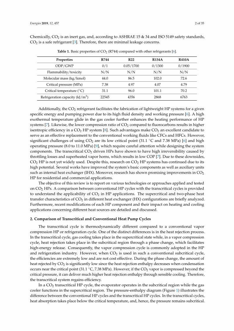
In a CO2 transcritical HP cycle, the evaporator operates in the subcritical region while the gascooler functions in the supercritical region. The pressure-enthalpy diagram (Figure 1) illustrates thedifference between the conventional HP cycles and the transcritical HP cycles. In the transcritical cycles,heat absorption takes place below the critical temperature, and, hence, the pressure remains subcritical.
Energies 2019, 12, 457 3 of 35
Therefore, the evaporator functions similarly to heat the absorption process in a conventional vaporcompression HP system. During the heat rejection process, the refrigerant changes its phase at aconstant temperature in the subcritical cycles whereas, in the transcritical cycles, the refrigeranttemperature decreases continuously throughout the heat rejection process without a phase change.Although latent heat exchange is an efficient heat transfer path, the supercritical properties of CO2
make it a viable candidate for transcritical HP systems. However, in a transcritical cycle, the pressuredifference between heat absorption and heat rejection is much higher than a typical subcritical cycle,which results in significant thermodynamic losses in the expansion process. The large pressuredifference makes it feasible to use expansion work recovery devices in a transcritical cycle, which canpartially compensate for the throttling losses in the transcritical CO2 cycle [10]. In the compressionprocess, the conventional subcritical cycle operates at a pressure ratio up to eight, whereas thetranscritical cycle operates at a pressure ratio within the range of three to four [11]. Such lowcompression ratios are conducive for achieving high isentropic efficiency in an HP system.
Energies 2019, 12, x FOR PEER REVIEW 3 of 33
cycles, the refrigerant temperature decreases continuously throughout the heat rejection process without a phase change. Although latent heat exchange is an efficient heat transfer path, the supercritical properties of CO2 make it a viable candidate for transcritical HP systems. However, in a transcritical cycle, the pressure difference between heat absorption and heat rejection is much higher than a typical subcritical cycle, which results in significant thermodynamic losses in the expansion process. The large pressure difference makes it feasible to use expansion work recovery devices in a transcritical cycle, which can partially compensate for the throttling losses in the transcritical CO2 cycle [10]. In the compression process, the conventional subcritical cycle operates at a pressure ratio up to eight, whereas the transcritical cycle operates at a pressure ratio within the range of three to four [11]. Such low compression ratios are conducive for achieving high isentropic efficiency in an HP system.
(a) (b)
Figure 1. P–h diagrams: (a) Subcritical cycle and (b) Transcritical cycle. Reproduced with permission from [12]. Elsevier, 2011.
3. CO2 Heat Pump Component Modifications
Performance of a CO2 HP depends on the components as a whole. However, individual component design and performance has an impact on the overall performance. Although the interdependency among the components does not allow for isolated improvement of each component, efforts need to be taken to improve the design of components and evaluate their contribution to the overall HP performance.
Exergy analysis (2nd law analysis) of the CO2 HP components can provide understanding on which a component is more sensitive for overall HP performance improvement. Yang et al. [13] employed an exergy analysis to identify the location and quantify irreversibility (exergy loss) in each component. They found that both the throttle valve and gas cooler contributed to a major irreversibility with each contributing a maximum of 38% followed by the compressor, which recorded 35% of the total cycle irreversibility. Robinson et al. [14] carried out a similar study based on 2nd law analysis and reported that the expansion valve had the highest exergy loss followed by the compressor, the gas cooler, and the evaporator.
In contrast, Sarker et al. [15] and Bai et al. [16] found that the maximum exergy loss occurred at the compressor followed by the gas cooler/the evaporator. Similarly, Ghazizade-Ahsaee et al. [17] reported that the most exergy destruction happened in the compressor and the other components had a relatively low exergy destruction rate.
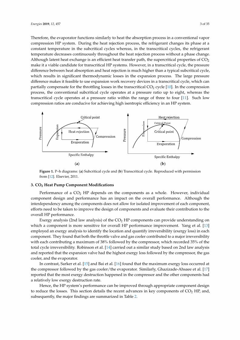
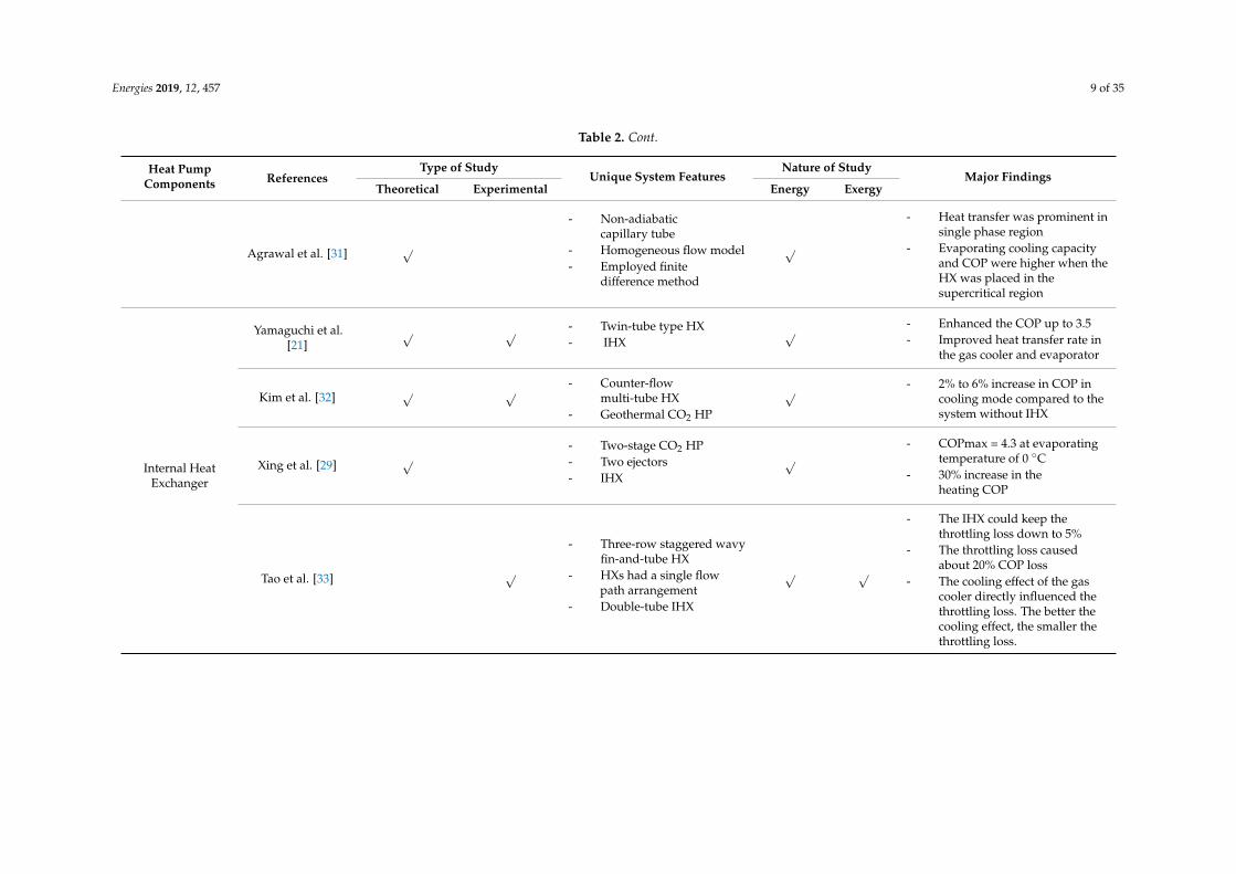
Hence, the HP system’s performance can be improved through appropriate component design to reduce the losses. This section details the recent advances in key components of CO2 HP, and, subsequently, the major findings are summarized in Table 2.
Figure 1. P–h diagrams: (a) Subcritical cycle and (b) Transcritical cycle. Reproduced with permissionfrom [12]. Elsevier, 2011.
3. CO2 Heat Pump Component Modifications
Performance of a CO2 HP depends on the components as a whole. However, individualcomponent design and performance has an impact on the overall performance. Although theinterdependency among the components does not allow for isolated improvement of each component,efforts need to be taken to improve the design of components and evaluate their contribution to theoverall HP performance.
Exergy analysis (2nd law analysis) of the CO2 HP components can provide understanding onwhich a component is more sensitive for overall HP performance improvement. Yang et al. [13]employed an exergy analysis to identify the location and quantify irreversibility (exergy loss) in eachcomponent. They found that both the throttle valve and gas cooler contributed to a major irreversibilitywith each contributing a maximum of 38% followed by the compressor, which recorded 35% of thetotal cycle irreversibility. Robinson et al. [14] carried out a similar study based on 2nd law analysisand reported that the expansion valve had the highest exergy loss followed by the compressor, the gascooler, and the evaporator.
In contrast, Sarker et al. [15] and Bai et al. [16] found that the maximum exergy loss occurred atthe compressor followed by the gas cooler/the evaporator. Similarly, Ghazizade-Ahsaee et al. [17]reported that the most exergy destruction happened in the compressor and the other components hada relatively low exergy destruction rate.
Hence, the HP system’s performance can be improved through appropriate component designto reduce the losses. This section details the recent advances in key components of CO2 HP, and,subsequently, the major findings are summarized in Table 2.
Energies 2019, 12, 457 4 of 35
Table 2. Recent significant studies on CO2 heat pump system components.
Heat PumpComponents References
Type of StudyUnique System Features
Nature of StudyMajor Findings
Theoretical Experimental Energy Exergy
Gas Cooler
Yin et al. [11] √ √- Microchannel
gas cooler- 3-pass tubes
√
- Predicted the gas coolercapacity within ± 2% error
- 3-pass design is the best suitedfor CO2 gas cooler
- Multi-pass gas cooler showedhigher pressure drop
- Multi-slab instead of multi-passcould improve the performance
Xie et al. [14] √ √- Pre-evaporator- IHX- Gas-liquid separator- Oil eliminator
√
- ηmax = 56% at evaporatingtemperature of 5 ◦C
- Optimal pressure was 7.5 Mpa- Optimal gas cooler temperature
was 38 ◦C
Chen [15] √
- Water-cooled system- Microchannel HX- Counter-flow tube in
tube gas cooler- Pinch point analysis
√
- More accurate gas coolerdesign method than LMTD
- LMTD method overestimatesgas cooler conductance
- The gas cooler could beoversized by 30% to 40%
- The pinch point effect was notsignificant for low massflow ratio
Yang et al. [18] √ √- Multi-twisted-tube
type HX- Double pipe
copper HX
√
- To increase the COP water sideheat, the transfer coefficientneeds to be increased
- Increasing the number of innertubes could increase the outletwater temperature
- A gas cooler pressure dropincreases sharply with thenumber of tubes
Energies 2019, 12, 457 5 of 35
Table 2. Cont.
Heat PumpComponents References
Type of StudyUnique System Features
Nature of StudyMajor Findings
Theoretical Experimental Energy Exergy
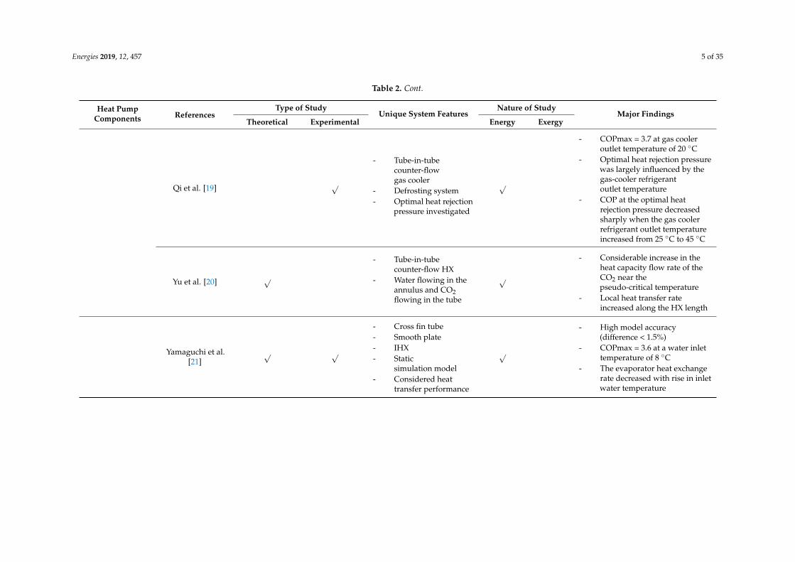
Qi et al. [19] √
- Tube-in-tubecounter-flowgas cooler
- Defrosting system- Optimal heat rejection
pressure investigated
√
- COPmax = 3.7 at gas cooleroutlet temperature of 20 ◦C
- Optimal heat rejection pressurewas largely influenced by thegas-cooler refrigerantoutlet temperature
- COP at the optimal heatrejection pressure decreasedsharply when the gas coolerrefrigerant outlet temperatureincreased from 25 ◦C to 45 ◦C
Yu et al. [20] √
- Tube-in-tubecounter-flow HX
- Water flowing in theannulus and CO2flowing in the tube
√
- Considerable increase in theheat capacity flow rate of theCO2 near thepseudo-critical temperature
- Local heat transfer rateincreased along the HX length
Yamaguchi et al.[21]
√ √
- Cross fin tube- Smooth plate- IHX- Static
simulation model- Considered heat
transfer performance
√
- High model accuracy(difference < 1.5%)
- COPmax = 3.6 at a water inlettemperature of 8 ◦C
- The evaporator heat exchangerate decreased with rise in inletwater temperature
Energies 2019, 12, 457 6 of 35
Table 2. Cont.
Heat PumpComponents References
Type of StudyUnique System Features
Nature of StudyMajor Findings
Theoretical Experimental Energy Exergy
Evaporator
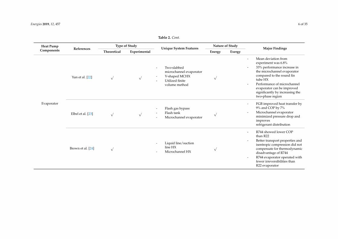
Yun et al. [22] √ √
- Two-slabbedmicrochannel evaporator
- V-shaped MCHX- Utilized finite
volume method
√
- Mean deviation fromexperiment was 6.8%
- 33% performance increase inthe microchannel evaporatorcompared to the round fintube HX
- Performance of microchannelevaporator can be improvedsignificantly by increasing thetwo-phase region
Elbel et al. [23] √ √- Flash gas bypass- Flash tank- Microchannel evaporator
√
- FGB improved heat transfer by9% and COP by 7%
- Microchannel evaporatorminimized pressure drop andimprovesrefrigerant distribution
Brown et al. [24] √- Liquid line/suction
line HX- Microchannel HX
√
- R744 showed lower COPthan R22
- Better transport properties andisentropic compression did notcompensate for thermodynamicdisadvantage of R744
- R744 evaporator operated withfewer irreversibilities thanR22 evaporator
Energies 2019, 12, 457 7 of 35
Table 2. Cont.
Heat PumpComponents References
Type of StudyUnique System Features
Nature of StudyMajor Findings
Theoretical Experimental Energy Exergy
Compressor
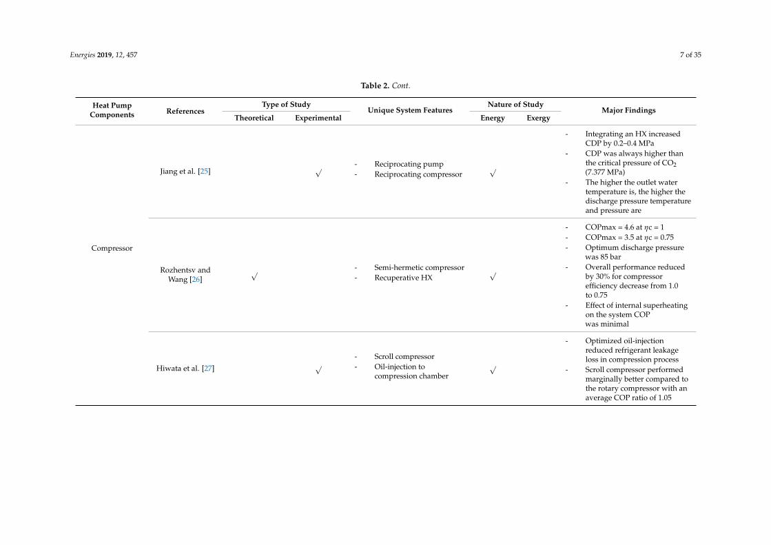
Jiang et al. [25] √ - Reciprocating pump- Reciprocating compressor
√
- Integrating an HX increasedCDP by 0.2–0.4 MPa
- CDP was always higher thanthe critical pressure of CO2(7.377 MPa)
- The higher the outlet watertemperature is, the higher thedischarge pressure temperatureand pressure are
Rozhentsv andWang [26]
√ - Semi-hermetic compressor- Recuperative HX
√
- COPmax = 4.6 at ηc = 1- COPmax = 3.5 at ηc = 0.75- Optimum discharge pressure
was 85 bar- Overall performance reduced
by 30% for compressorefficiency decrease from 1.0to 0.75
- Effect of internal superheatingon the system COPwas minimal
Hiwata et al. [27] √- Scroll compressor- Oil-injection to
compression chamber
√
- Optimized oil-injectionreduced refrigerant leakageloss in compression process
- Scroll compressor performedmarginally better compared tothe rotary compressor with anaverage COP ratio of 1.05
Energies 2019, 12, 457 8 of 35
Table 2. Cont.
Heat PumpComponents References
Type of StudyUnique System Features
Nature of StudyMajor Findings
Theoretical Experimental Energy Exergy
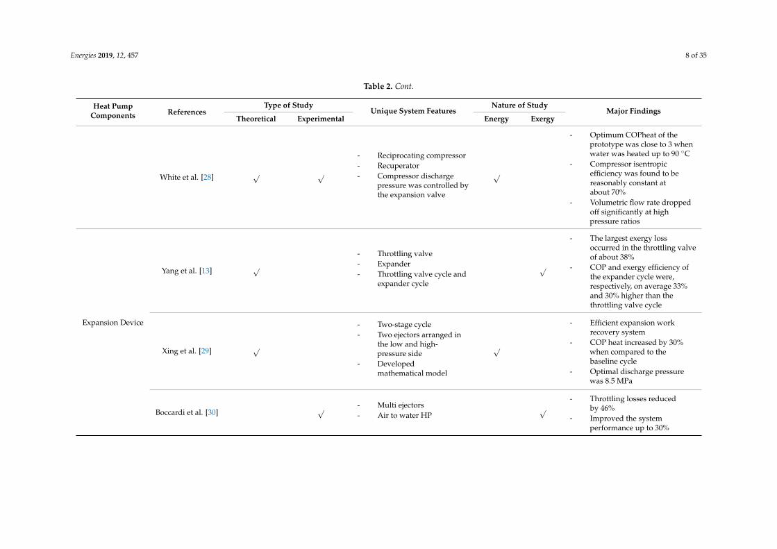
White et al. [28] √ √
- Reciprocating compressor- Recuperator- Compressor discharge
pressure was controlled bythe expansion valve
√
- Optimum COPheat of theprototype was close to 3 whenwater was heated up to 90 ◦C
- Compressor isentropicefficiency was found to bereasonably constant atabout 70%
- Volumetric flow rate droppedoff significantly at highpressure ratios
Expansion Device
Yang et al. [13] √- Throttling valve- Expander- Throttling valve cycle and
expander cycle
√
- The largest exergy lossoccurred in the throttling valveof about 38%
- COP and exergy efficiency ofthe expander cycle were,respectively, on average 33%and 30% higher than thethrottling valve cycle
Xing et al. [29] √
- Two-stage cycle- Two ejectors arranged in
the low and high-pressure side
- Developedmathematical model
√
- Efficient expansion workrecovery system
- COP heat increased by 30%when compared to thebaseline cycle
- Optimal discharge pressurewas 8.5 MPa
Boccardi et al. [30] √ - Multi ejectors- Air to water HP
√- Throttling losses reduced
by 46%- Improved the system
performance up to 30%
Energies 2019, 12, 457 9 of 35
Table 2. Cont.
Heat PumpComponents References
Type of StudyUnique System Features
Nature of StudyMajor Findings
Theoretical Experimental Energy Exergy
Agrawal et al. [31] √
- Non-adiabaticcapillary tube
- Homogeneous flow model- Employed finite
difference method
√
- Heat transfer was prominent insingle phase region
- Evaporating cooling capacityand COP were higher when theHX was placed in thesupercritical region
Internal HeatExchanger
Yamaguchi et al.[21]
√ √ - Twin-tube type HX- IHX
√ - Enhanced the COP up to 3.5- Improved heat transfer rate in
the gas cooler and evaporator
Kim et al. [32] √ √ - Counter-flowmulti-tube HX
- Geothermal CO2 HP
√ - 2% to 6% increase in COP incooling mode compared to thesystem without IHX
Xing et al. [29] √- Two-stage CO2 HP- Two ejectors- IHX
√- COPmax = 4.3 at evaporating
temperature of 0 ◦C- 30% increase in the
heating COP
Tao et al. [33] √
- Three-row staggered wavyfin-and-tube HX
- HXs had a single flowpath arrangement
- Double-tube IHX
√ √
- The IHX could keep thethrottling loss down to 5%
- The throttling loss causedabout 20% COP loss
- The cooling effect of the gascooler directly influenced thethrottling loss. The better thecooling effect, the smaller thethrottling loss.
Energies 2019, 12, 457 10 of 35
3.1. Gas Cooler
In a transcritical CO2 HP, the heat rejection takes place at the supercritical temperature andpressure, and the optimum COP of the system is contingent upon the supercritical properties of CO2
at the gas cooler [34]. A significant number of experimental and numerical studies can be found in theliterature that has analyzed the supercritical CO2 (scCO2) heat transfer characteristics in different typesof channel geometries and arrangements. Since Cabeza et al. [35] have performed a comprehensivereview of scCO2 heat transfer for many applications, several selected, recent studies on the scCO2
heat transfer mechanism in different HX configurations specifically for HP applications are presented.Additionally, different types of HX as a gas cooler and their effect on HP performance are analyzed inthis section.
Liao et al. [36] experimentally analyzed the heat transfer performance of scCO2 in a horizontaland inclined straight tube. The results showed that the heat transfer coefficient (HTC) was at the peaknear the pseudo-critical region due to the enhanced specific heat capacity of CO2. Moreover, the HTCincreased when the bulk temperature was higher than the critical temperature for horizontal andvertical flow. The effect of buoyancy was more prominent in large diameter tubes than in mini-tubes,which caused a reduction in the scCO2 Nusselt number in a mini-channel, and, subsequently, a newNusselt number correlation was proposed based on the experimental results. In a similar study,Dang et al. [37] suggested a modification of the Gnielinski correlation to predict the HTC of scCO2
in a circular, straight tube considering the effects of mass flux, heat flux, and tube diameter on HTC.They found that an increase in mass flux enhances the scCO2 HTC, but the effects of heat flux andtube diameter depend on the scCO2 property variation in a radial direction. Studies on horizontallycircular tube-in-tube HXs showed that the HTC of scCO2 is a combination of free and forced convectionbecause of the buoyancy effect close to the pseudo-critical vicinity [38–40].
Helically coiled tubes HX were found to enhance scCO2 HTC compared to straight tubesHX [41,42]. In helical structures, the centrifugal and buoyancy forces affect the flow field and heattransfer. The effect of buoyancy force can be ignored if the buoyancy number (Bo) is below 5.6 ×10⁻⁷ [43]. Liu et al. [44] numerically analyzed the effects of buoyancy and the centrifugal force on theHTC of scCO2 in horizontal and inclined helically coiled tubes for Bo > 5.6 × 10⁻⁷. The HTC vacillatessignificantly due to a dominating buoyancy force compared to a centrifugal force when the CO2 bulktemperature is lower than the pseudo-critical temperature. Forooghi et al. [45] further explained thebuoyancy induced supercritical heat transfer in vertical and inclined tubes. At a significantly lowbuoyancy number (Bo < 2.26 × 10⁻⁶), the heat transfer deteriorates due to low near-wall turbulence,and the heat transfer starts to increase with the increase of the buoyancy effect due to a velocity gradientrise between the outer tube wall and the centerline. In addition, the scCO2 HTC decreases with theincrease in heat flux due to the reduced heat transfer capacity and thermal conductivity of CO2 [46].However, increasing the CO2 mass flux in the supercritical region enhances the turbulence diffusivityand, as a result, improves the heat transfer performance and the effect of the turbulence Prandtlnumber on heat transfer is insignificant. Furthermore, a comparison demonstrated that the HTC in theinclined helical tube was higher than horizontally helical tubes due to the reduced centrifugal forceand the dominating buoyancy force [47].
A simulation of a finned tube gas cooler indicated that the flow field characteristics and heattransfer depend on the fin configuration, and a slit fin has higher HTC than a continuous fin for boththe air-side and refrigerant-side, which improves heat rejection [48]. Li et al. [49] developed a low-costfin and micro-channel integrated gas cooler, where the fin and flat tube were integrated in a singlealuminum plate to eliminate the contact resistance due to welding, which enhanced the HTC. Theyreported that the fin and micro-channel configuration could avoid air-side mal-distribution and hadbetter performance at higher air velocities. Additionally, Garimella [50] and Chang et al. [34] proposedthe use of near-counter-flow fin and tube type gas cooler.
Yang et al. [18] analyzed a multi-twisted-tube gas cooler where a counter-current double pipecopper HX was used as the gas cooler. In their HX configuration, the inner tubes were twisted together
Energies 2019, 12, 457 11 of 35
and fitted inside a larger tube. The theoretical and experimental results showed that a greater numberof inner tubes increases the outlet water temperature, but, at the same time, the pressure drop increasessharply. Kim et al. [32] developed a multi-tube counter-flow gas cooler consisting of parallel smallertubes bundled together inside a larger tube for a geothermal HP. In this configuration, the CO2 andwater flow in the opposite direction to ensure maximum heat transfer.
Compactness of the gas cooler is another key focus of recent research, which can be achieved byreducing refrigerant charge and tube size, varying the air volume flow rate, and considering fin types.Marcinichen et al. [51] numerically studied these factors to reduce the size of an existing gas coolerused in a beverage vending machine. They found that the existing gas cooler was oversized by a factorof two, and a more compact design could be realized by increasing the air volumetric flow rate andreplacing a plain fin with a wavy fin. In case of an undersized gas cooler, a ‘pinch point’ might occurdue to the strong nonlinear variation of the specific heat capacity of CO2. A high value of pinch pointindicates high thermal losses in the HX due to irreversibility. Chen et al. [52] analyzed the pinch pointoccurrence in a water-cooled CO2 HP using the log mean temperature difference (LMTD) methodand found that the gas cooler was undersized by 30% to 40%. Likewise, Sánchez et al. [53] developedan accurate finite element model for properly sizing a CO2 gas cooler. Yin et al. [54] developed andstudied a compact gas cooler model using a finite element approach where the micro-channel gascooler consisted of three passes of 13, 11, and 10 tubes. They found an increasing number of passesin the gas cooler might improve the performance, but the three-pass design is the best since there isnot much difference between a five-pass and a three-pass gas cooler concerning the exit CO2 enthalpy.Additionally, the simulations showed that using a multi-slab rather than a multi-pass could furtherreduce the gas cooler size due to improved performance of the gas cooler. Similarly, Tsamos et al. [55]carried out an experimental study on two different configurations of fin-tube gas cooler (two-row andthree-row) considering both the supercritical and subcritical pressure at the HX. They found a linearrelationship between the air temperature at the inlet and the pressure while transitioning from thesubcritical to the supercritical stages. A simulation of the same fin-tube gas cooler showed that 90% ofthe pressure drop occurred in the first 17% of the HX length from the inlet [56], and the HX size couldbe reduced if the air flow rate is increased.
If the refrigerant mass flow rate is lower than the optimum amount, the degree of superheat(DSH) at the evaporator outlet increases, which causes an excessive pressure-drop, and, as a result,COP decreases. Conversely, if the refrigerant mass flow rate is excessive, the specific volume of therefrigerant at the compressor inlet increases, which causes a high pressure-drop at the evaporatorand a low specific enthalpy change at the gas cooler. Therefore, for the same compressor powerconsumption, the specific enthalpy exchange becomes less, and the system COP decreases. As such,Liu et al. [57] developed a genetic algorithm for maximizing CO2 HP COP based on gas cooler pressureand the water flow rate. Similarly, to reduce the power consumption in real-time, Hu et al. [58]adopted an extremum seeking control (ESC) strategy considering the gas cooler pressure and outletwater temperature. A similar control strategy was developed by Peñarrocha et al. [59] to reducethe consumption by regulating the high-side pressure. by To optimize the performance of a CO2
refrigeration system, Kim et al. [60] suggested a new control strategy. They utilized the differencebetween the required total HTC in the gas cooler for optimum COP and total HTC at any concurrentgas cooler pressure. When the difference between the total HTCs is zero, the maximum COP is realized.However, this control strategy requires an exact value of total HTC at the gas cooler. Other thanESC, Ge et al. [61] proposed a heat recovery optimization system for a supermarket CO2 refrigerationsystem. The developed system used an opmimum gas cooler pressure to maximize heat recovery.
3.2. Evaporator
The CO2 HP evaporator functions like conventional CFC or HFC HP evaporators except that itexperiences a much higher pressure (2–7 MPa) in the subcritical region. The CO2 evaporator operatesat a reduced pressure higher than 0.36 at a saturation temperature of −10 ◦C whereas an R134a
Energies 2019, 12, 457 12 of 35
evaporator works below 0.10 at a saturation temperature of 10 ◦C [62]. Consequently, the transportproperties of CO2 in the subcritical region (e.g., high vapor density and low vapor viscosity) aresubstantially different from the other refrigerants. The CO2 flow in the evaporator is characterized bytwo-phase flow, and the transport properties drastically influence the nucleate boiling, the convectiveheat transfer, and the CO2 pressure drop in the flow. Recent numerical and experimental studies focuson improving the efficiency of CO2 evaporator considering the flow characteristics. To ensure thefeasibility of a CO2 HP, it is essential to design the evaporator as a compact, lightweight, and reliablesystem [63].
The CO2 two-phase heat transfer in macro-channels and micro-channels depends on therefrigerant mass flux, heat flux, channel geometry, and saturation temperature [62]. In an investigationof CO2 two-phase heat transfer and pressure characteristics in a conventional macro-channel,Yoon et al. [64] reported that CO2 boiling HTC increased with the increase in heat flux at the low vaporquality but decreased with the increase in heat flux when the vapor quality was above a specific value.This can be explained by the inception of vapor dryout at a high vapor quality due to an increase inheat flux, low surface tension, and reduced viscosity. The pressure drop was found to increase withan increase in mass flux, while there was an opposite trend for increasing the saturation temperature.Bredesen et al. [65] and Knudsen et al. [66] found in their experimental studies that the two-phaseheat transfer in large tubes could be enhanced significantly by increasing the heat flux without aconsiderable pressure drop.
From the perspective of the physical aspect, a microchannel and minichannel HXs as the CO2
evaporators rather than macro HXs have been the recent research focus due to enhanced HTC,minimized leakage, and reduced refrigerant charge. Choi et al. [67] investigated CO2 two-phaseheat transfer in horizontal mini-channels and reported that CO2 HTC increases with an increasein vapor quality. Moreover, CO2 HTC was found to be three times higher than R143a. Based ontheir experimental study, they proposed a separate two-phase flow heat transfer model for CO2
flowing in smooth mini-channles. Oh et al. [68] experimentally studied five different refrigerants inmini-channels and found that CO2 has the highest boiling HTC. Wu et al. [69] and Yun et al. [70]further reported that the nucleate boiling is predominant at a lower vapor quality because the heat fluxand saturation temperature dictate the local HTC in this region, while the convective HTC dominatesdue to a high vapor velocity at a higher vapor quality. The pressure drop across the mini-channel wasevaluated in Reference [69] by modifying a frictional factor developed by Cheng et al. [71] to addressthe overprediction of a frictional pressure drop in the mist flow region.
Concerning the evaporator configuration, several types of CO2 HXs have been studied. In astudy of an electric vehicle HP system in a cold climate, Wang et al. [72] found that the micro-channelevaporator had less than 4% exergy loss in all operating conditions. Yun et al. [22] simulated athree-slabbed micro-channel evaporator using R134a and CO2 as the working fluid and compared theirperformance. The numerical results showed that the overall system performance could be enhancedby increasing the two-phase flow region in the micro-channel. There was a 70% increase in thetwo-phase flow region when the fin spacing was manipulated from 1.5 to 2.0 mm, and such a marginalincrease in the spacing not only reduced material cost but also helped to eradicate the defrosting andcondensation drainage problem. Furthermore, the selection of an appropriate circuiting arrangementis found to be imperative to ensure a higher heat transfer in a CO2 evaporator. Bendaoud et al. [73]developed a new model accounting for the thermal and hydrodynamic behavior of a fin and tube HX.The developed tool was used to study a typical CO2 evaporator coil consisting of two circuits in aparallel counter-current configuration. The study showed that the pressure drop was very low forCO2 compared to other refrigerants, and, as a result, the temperature glide was limited considerably.In another study, Yamaguchi et al. [21] experimentally and numerically studied a cross-fin tube HX withsmooth plate fins as a CO2 evaporator for the water heating application, and the results confirmed thatthe heat exchange rate in the evaporator decreased (20 to 12 kW) with a rise in inlet water temperature(8 to 44 ◦C). Yun et al. [22] compared a two-slabbed micro-channel evaporator and a conventional
Energies 2019, 12, 457 13 of 35
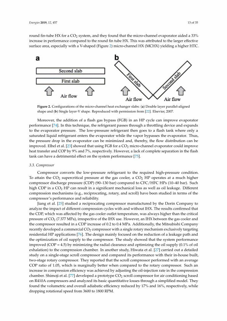
round fin-tube HX for a CO2 system, and they found that the micro-channel evaporator aided a 33%increase in performance compared to the round fin tube HX. This was attributed to the larger effectivesurface area, especially with a V-shaped (Figure 2) micro-channel HX (MCHX) yielding a higher HTC.Energies 2019, 12, x FOR PEER REVIEW 11 of 33
Figure 2. Configurations of the micro-channel heat exchanger slabs: (a) Double layer parallel-aligned shape and (b) Single layer-V shape. Reproduced with permission from [22]. Elsevier, 2007.
Moreover, the addition of a flash gas bypass (FGB) in an HP cycle can improve evaporator performance [74]. In this technique, the refrigerant passes through a throttling device and expands to the evaporator pressure. The low-pressure refrigerant then goes to a flash tank where only a saturated liquid refrigerant enters the evaporator while the vapor bypasses the evaporator. Thus, the pressure drop in the evaporator can be minimized and, thereby, the flow distribution can be improved. Elbel et al. [23] showed that using FGB for a CO2 micro-channel evaporator could improve heat transfer and COP by 9% and 7%, respectively. However, a lack of complete separation in the flash tank can have a detrimental effect on the system performance [75].
3.3. Compressor
Compressor converts the low-pressure refrigerant to the required high-pressure condition. To attain the CO2 supercritical pressure at the gas cooler, a CO2 HP operates at a much higher compressor discharge pressure (CDP) (90-130 bar) compared to CFC/HFC HPs (10–40 bar). Such high CDP in a CO2 HP can result in a significant mechanical loss as well as oil leakage. Different compression mechanisms (e.g., reciprocating, rotary, and scroll) have been studied in terms of the compressor’s performance and reliability.
Jiang et al. [25] studied a reciprocating compressor manufactured by the Dorin Company to analyze the impact of different compression cycles with and without IHX. The results confirmed that the CDP, which was affected by the gas cooler outlet temperature, was always higher than the critical pressure of CO2 (7.377 MPa), irrespective of the IHX use. However, an IHX between the gas cooler and the compressor resulted in a CDP increase of 0.2 to 0.4 MPa. Additionally, the Mitsubishi Company recently developed a commercial CO2 compressor with a single rotary mechanism exclusively targeting residential HP applications [76]. The design mainly focused on the reduction of a leakage path and the optimization of oil supply to the compressor. The study showed that the system performance improved (COP = 4.5) by minimizing the radial clearance and optimizing the oil supply (0.1% of oil exhalation) to the compression chamber. In another study, Hiwata et al. [27] carried out a detailed study on a single-stage scroll compressor and compared its performance with their in-house built, two-stage rotary compressor. They reported that the scroll compressor performed with an average COP ratio of 1.05, which is marginally better when compared to the rotary compressor. Such an increase in compression efficiency was achieved by adjusting the oil-injection rate in the compression chamber. Shimoji et al. [77] developed a prototype CO2 scroll compressor for air conditioning based on R410A compressors and analyzed its basic quantitative losses through a simplified model. They found the volumetric and overall adiabatic efficiency reduced by 17% and 16%, respectively, while dropping rotational speed from 3600 to 1800 RPM.
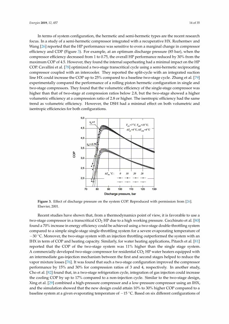
In terms of system configuration, the hermetic and semi-hermetic types are the recent research focus. In a study of a semi-hermetic compressor integrated with a recuperative HX. Rozhentsev and Wang [26] reported that the HP performance was sensitive to even a marginal change in compressor efficiency and CDP (Figure 3). For example, at an optimum discharge pressure (85 bar), when the compressor efficiency decreased from 1 to 0.75, the overall HP performance reduced by 30% from the
Figure 2. Configurations of the micro-channel heat exchanger slabs: (a) Double layer parallel-alignedshape and (b) Single layer-V shape. Reproduced with permission from [22]. Elsevier, 2007.
Moreover, the addition of a flash gas bypass (FGB) in an HP cycle can improve evaporatorperformance [74]. In this technique, the refrigerant passes through a throttling device and expandsto the evaporator pressure. The low-pressure refrigerant then goes to a flash tank where only asaturated liquid refrigerant enters the evaporator while the vapor bypasses the evaporator. Thus,the pressure drop in the evaporator can be minimized and, thereby, the flow distribution can beimproved. Elbel et al. [23] showed that using FGB for a CO2 micro-channel evaporator could improveheat transfer and COP by 9% and 7%, respectively. However, a lack of complete separation in the flashtank can have a detrimental effect on the system performance [75].
3.3. Compressor
Compressor converts the low-pressure refrigerant to the required high-pressure condition.To attain the CO2 supercritical pressure at the gas cooler, a CO2 HP operates at a much highercompressor discharge pressure (CDP) (90–130 bar) compared to CFC/HFC HPs (10–40 bar). Suchhigh CDP in a CO2 HP can result in a significant mechanical loss as well as oil leakage. Differentcompression mechanisms (e.g., reciprocating, rotary, and scroll) have been studied in terms of thecompressor’s performance and reliability.
Jiang et al. [25] studied a reciprocating compressor manufactured by the Dorin Company toanalyze the impact of different compression cycles with and without IHX. The results confirmed thatthe CDP, which was affected by the gas cooler outlet temperature, was always higher than the criticalpressure of CO2 (7.377 MPa), irrespective of the IHX use. However, an IHX between the gas cooler andthe compressor resulted in a CDP increase of 0.2 to 0.4 MPa. Additionally, the Mitsubishi Companyrecently developed a commercial CO2 compressor with a single rotary mechanism exclusively targetingresidential HP applications [76]. The design mainly focused on the reduction of a leakage path andthe optimization of oil supply to the compressor. The study showed that the system performanceimproved (COP = 4.5) by minimizing the radial clearance and optimizing the oil supply (0.1% of oilexhalation) to the compression chamber. In another study, Hiwata et al. [27] carried out a detailedstudy on a single-stage scroll compressor and compared its performance with their in-house built,two-stage rotary compressor. They reported that the scroll compressor performed with an averageCOP ratio of 1.05, which is marginally better when compared to the rotary compressor. Such anincrease in compression efficiency was achieved by adjusting the oil-injection rate in the compressionchamber. Shimoji et al. [77] developed a prototype CO2 scroll compressor for air conditioning basedon R410A compressors and analyzed its basic quantitative losses through a simplified model. Theyfound the volumetric and overall adiabatic efficiency reduced by 17% and 16%, respectively, whiledropping rotational speed from 3600 to 1800 RPM.
Energies 2019, 12, 457 14 of 35
In terms of system configuration, the hermetic and semi-hermetic types are the recent researchfocus. In a study of a semi-hermetic compressor integrated with a recuperative HX. Rozhentsev andWang [26] reported that the HP performance was sensitive to even a marginal change in compressorefficiency and CDP (Figure 3). For example, at an optimum discharge pressure (85 bar), when thecompressor efficiency decreased from 1 to 0.75, the overall HP performance reduced by 30% from themaximum COP of 4.5. However, they found the internal superheating had a minimal impact on the HPCOP. Cavallini et al. [78] optimized a two-stage transcritical cycle using a semi-hermetic reciprocatingcompressor coupled with an intercooler. They reported the split-cycle with an integrated suctionline HX could increase the COP up to 25% compared to a baseline two-stage cycle. Zhang et al. [79]experimentally compared the performance of a rolling piston hermetic configuration in single andtwo-stage compressors. They found that the volumetric efficiency of the single-stage compressor washigher than that of two-stage at compression ratios below 2.8, but the two-stage showed a highervolumetric efficiency at a compression ratio of 2.8 or higher. The isentropic efficiency had the sametrend as volumetric efficiency. However, the DSH had a minimal effect on both volumetric andisentropic efficiencies for both configurations.
Energies 2019, 12, x FOR PEER REVIEW 12 of 33
maximum COP of 4.5. However, they found the internal superheating had a minimal impact on the HP COP. Cavallini et al. [78] optimized a two-stage transcritical cycle using a semi-hermetic reciprocating compressor coupled with an intercooler. They reported the split-cycle with an integrated suction line HX could increase the COP up to 25% compared to a baseline two-stage cycle. Zhang et al. [79] experimentally compared the performance of a rolling piston hermetic configuration in single and two-stage compressors. They found that the volumetric efficiency of the single-stage compressor was higher than that of two-stage at compression ratios below 2.8, but the two-stage showed a higher volumetric efficiency at a compression ratio of 2.8 or higher. The isentropic efficiency had the same trend as volumetric efficiency. However, the DSH had a minimal effect on both volumetric and isentropic efficiencies for both configurations.
Figure 3. Effect of discharge pressure on the system COP. Reproduced with permission from [26]. Elsevier, 2001.
Recent studies have shown that, from a thermodynamics point of view, it is favorable to use a two-stage compressor in a transcritical CO2 HP due to a high working pressure. Cecchinato et al. [80] found a 70% increase in energy efficiency could be achieved using a two-stage double-throttling system compared to a simple single-stage single-throttling system for a severe evaporating temperature of -30 °C. Moreover, the two-stage system with an injection throttling outperformed the system with an IHX in term of COP and heating capacity. Similarly, for water heating applications, Pitarch et al. [81] reported that the COP of the two-stage system was 11% higher than the single stage system. A commercially developed two-stage compressor for residential CO2 HP water heaters equipped with an intermediate gas-injection mechanism between the first and second stages helped to reduce the vapor mixture losses [76]. It was found that such a two-stage configuration improved the compressor performance by 15% and 30% for compression ratios of 3 and 4, respectively. In another study, Cho et al. [82] found that, in a two-stage refrigeration cycle, integration of gas injection could increase the cooling COP by up to 17% compared to a non-injection cycle. Similar to the two-stage design, Xing et al. [29] combined a high-pressure compressor and a low-pressure compressor using an IHX, and the simulation showed that the new design could attain 10% to 30% higher COP compared to a baseline system at a given evaporating temperature of –15 °C. Based on six different configurations of two-stage CO2 refrigeration systems, Liu et al. [83] found that the gas cooler outlet temperature and the low-stage compressor significantly affect the system performance.
Recently, the BoostHEAT Company introduced a new and original concept of a thermal compressor for transcritical CO2 HP. Unlike the rotary or scroll compressors where the mechanical power generates the pressure increase of working fluid, in the new design, a heater provides thermal energy to warm up the working fluid of the compressor and then to increase its pressure. The uniqueness of the system is that the same working fluid can be used in both the thermal engine and
Figure 3. Effect of discharge pressure on the system COP. Reproduced with permission from [26].Elsevier, 2001.
Recent studies have shown that, from a thermodynamics point of view, it is favorable to use atwo-stage compressor in a transcritical CO2 HP due to a high working pressure. Cecchinato et al. [80]found a 70% increase in energy efficiency could be achieved using a two-stage double-throttling systemcompared to a simple single-stage single-throttling system for a severe evaporating temperature of−30 ◦C. Moreover, the two-stage system with an injection throttling outperformed the system with anIHX in term of COP and heating capacity. Similarly, for water heating applications, Pitarch et al. [81]reported that the COP of the two-stage system was 11% higher than the single stage system.A commercially developed two-stage compressor for residential CO2 HP water heaters equipped withan intermediate gas-injection mechanism between the first and second stages helped to reduce thevapor mixture losses [76]. It was found that such a two-stage configuration improved the compressorperformance by 15% and 30% for compression ratios of 3 and 4, respectively. In another study,Cho et al. [82] found that, in a two-stage refrigeration cycle, integration of gas injection could increasethe cooling COP by up to 17% compared to a non-injection cycle. Similar to the two-stage design,Xing et al. [29] combined a high-pressure compressor and a low-pressure compressor using an IHX,and the simulation showed that the new design could attain 10% to 30% higher COP compared to abaseline system at a given evaporating temperature of −15 ◦C. Based on six different configurations of
Energies 2019, 12, 457 15 of 35
two-stage CO2 refrigeration systems, Liu et al. [83] found that the gas cooler outlet temperature andthe low-stage compressor significantly affect the system performance.
Recently, the BoostHEAT Company introduced a new and original concept of a thermalcompressor for transcritical CO2 HP. Unlike the rotary or scroll compressors where the mechanicalpower generates the pressure increase of working fluid, in the new design, a heater providesthermal energy to warm up the working fluid of the compressor and then to increase its pressure.The uniqueness of the system is that the same working fluid can be used in both the thermal engineand the HP to enhance thermal efficiency. To analyze the thermal performance of the compressor,Ibsaine et al. [84] formulated a mathematical model and recommended that a two-stage thermalcompressor is preferred in CO2 HP applications.
3.4. Expansion Device
The prime functions of the expansion device in a CO2 HP are to distribute CO2 to the evaporatoras well as to maintain a pressure difference between the evaporator and the gas cooler. Most of therecent investigations focused on different kinds of expansion device designs (e.g., ejectors, expansionvalves) and their configurations in terms of the numerical modeling, geometrical structure, and systemperformance enhancement.
Theoretical and experimental investigations suggest that an ejector in place of an expansion valvecan improve transcritical cycle performance [85–87]. The refrigerant inside the ejector is characterizedby two-phase and compressible flow. A homogeneous equilibrium model (HEM) and homogeneousrelaxation model (HRM) are the two widely used numerical models for the ejector flow [88]. HEMconsiders liquid and vapor phases are in a homogeneous equilibrium whereas HRM uses the empiricalcorrelation of the relaxation time. Lucas et al. [89] and Palacz et al. [90] employed HEM to predictthe two-phase flow inside an ejector. The HEM accuracy decreases with a decline in a motive nozzletemperature and increases in deviation from the saturation line, which demands a more complex HRMmode. Angielczyk et al. [91] studied HRM for a supersonic flow through the convergent-divergentnozzle of a CO2 ejector and validated their model using three different nozzle diameters. Theydeveloped a widely excepted correlation for relaxation time considering the critical flow parameters,vapor quality, and temperature profile. Through a comparison study, Palacz et al. [92] found thatHRM could predict the flow characteristics better than HEM (overall a 5% increase in accuracy).In addition, Zheng et al. [93] and He et al. [94] proposed dynamic numerical models, which are usefulin predicting the dynamic system response in different operating conditions to optimize the ejectorexpansion performance.
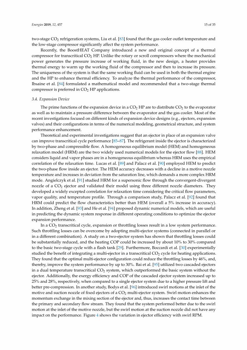
In a CO2 transcritical cycle, expansion or throttling losses result in a low system performance.Such throttling losses can be overcome by adopting multi-ejector systems (connected in parallel orin a different combination). A study on a two-ejector system has shown that throttling losses couldbe substantially reduced, and the heating COP could be increased by about 10% to 30% comparedto the basic two-stage cycle with a flash tank [29]. Furthermore, Boccardi et al. [30] experimentallystudied the benefit of integrating a multi-ejector in a transcritical CO2 cycle for heating applications.They found that the optimal multi-ejector configuration could reduce the throttling losses by 46%, and,thereby, improve the system performance by up to 30%. Bai et al. [95] utilized two cascaded ejectorsin a dual temperature transcritical CO2 system, which outperformed the basic system without theejector. Additionally, the exergy efficiency and COP of the cascaded ejector system increased up to25% and 28%, respectively, when compared to a single ejector system due to a higher pressure lift andbetter pre-compression. In another study, Bodys et al. [96] introduced swirl motions at the inlet of themotive and suction nozzle of fixed ejectors of a CO2 multi-ejector system. Swirl motion enhances themomentum exchange in the mixing section of the ejector and, thus, increases the contact time betweenthe primary and secondary flow stream. They found that the system performed better due to the swirlmotion at the inlet of the motive nozzle, but the swirl motion at the suction nozzle did not have anyimpact on the performance. Figure 4 shows the variation in ejector efficiency with swirl RPM.
Energies 2019, 12, 457 16 of 35Energies 2019, 12, x FOR PEER REVIEW 14 of 33
Figure 4. The ejector efficiencies for the unit with different diameters (mm) and rotational speeds
(RPM) at the inlet duct of the motive nozzle. Reproduced with permission from [96]. Elsevier, 2016.
In addition, the adjustable ejector configuration was found to enhance the system COP up to 30% compared to the fix-geometry ejector [97]. This was attributed to the fact that the adjustable ejector can provide a flexible control over the mass flow rate, which is the key to performance improvement. Lie et al. [98] performed a study to analyze the performance of an adjustable ejector for a simultaneous heating and cooling application. They found that an optimum heating and cooling performance can be achieved by regulating the ejectors’ internal geometries. Xu et al. [99] made an effort to optimize the high-side pressure through an adjustable ejector (Figure 5), which uses a stepper motor moving a needle forward and backward to adjust the nozzle throat area. The study showed that such an ejector could regulate the throttling area for an optimal high-side pressure. The optimized pressure has a positive effect on the system performance and outweighs the low ejector efficiency. Additionally, Xu et al. [99] developed a control strategy to maximize the COP by correlating the CO2 pressure and temperature at the gas cooler exit. A multi-variable adjustable ejector controller [100] and an on-line quasi-cascade controller [101] are among the other control systems for optimizing the performance of adjustable ejectors. For the later one, the nozzle throat area varies with the compressor speed and CO2 mass flow rate, so that a correlation for the optimum nozzle throat area can be derived for a gas cooler pressure based on the dynamic system response.
Figure 5. 3-D model of the adjustable ejector. Reproduced with permission from [99]. Elsevier, 2012.
Among many types of expansion devices, the electronic expansion valve (EEV) and capillary tubes have been studied for CO2 HPs. Zhang et al. [102] experimentally studied the effect of the refrigerant charge amount and EEV opening on the performance of a CO2 HP water heater. The EEV opening of 40% was found to be optimal for their system. Increasing the EEV opening from its optimal value to 60% decreased the heating capacity up to 30% due to an increase in the refrigerant charge and supercritical pressure, but the undercharged condition had a more severe consequence on the
Figure 4. The ejector efficiencies for the unit with different diameters (mm) and rotational speeds(RPM) at the inlet duct of the motive nozzle. Reproduced with permission from [96]. Elsevier, 2016.
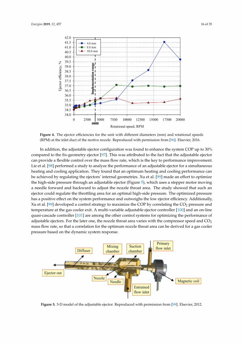
In addition, the adjustable ejector configuration was found to enhance the system COP up to 30%compared to the fix-geometry ejector [97]. This was attributed to the fact that the adjustable ejectorcan provide a flexible control over the mass flow rate, which is the key to performance improvement.Lie et al. [98] performed a study to analyze the performance of an adjustable ejector for a simultaneousheating and cooling application. They found that an optimum heating and cooling performance canbe achieved by regulating the ejectors’ internal geometries. Xu et al. [99] made an effort to optimizethe high-side pressure through an adjustable ejector (Figure 5), which uses a stepper motor movinga needle forward and backward to adjust the nozzle throat area. The study showed that such anejector could regulate the throttling area for an optimal high-side pressure. The optimized pressurehas a positive effect on the system performance and outweighs the low ejector efficiency. Additionally,Xu et al. [99] developed a control strategy to maximize the COP by correlating the CO2 pressure andtemperature at the gas cooler exit. A multi-variable adjustable ejector controller [100] and an on-linequasi-cascade controller [101] are among the other control systems for optimizing the performance ofadjustable ejectors. For the later one, the nozzle throat area varies with the compressor speed and CO2
mass flow rate, so that a correlation for the optimum nozzle throat area can be derived for a gas coolerpressure based on the dynamic system response.
Energies 2019, 12, x FOR PEER REVIEW 14 of 33
Figure 4. The ejector efficiencies for the unit with different diameters (mm) and rotational speeds
(RPM) at the inlet duct of the motive nozzle. Reproduced with permission from [96]. Elsevier, 2016.
In addition, the adjustable ejector configuration was found to enhance the system COP up to 30% compared to the fix-geometry ejector [97]. This was attributed to the fact that the adjustable ejector can provide a flexible control over the mass flow rate, which is the key to performance improvement. Lie et al. [98] performed a study to analyze the performance of an adjustable ejector for a simultaneous heating and cooling application. They found that an optimum heating and cooling performance can be achieved by regulating the ejectors’ internal geometries. Xu et al. [99] made an effort to optimize the high-side pressure through an adjustable ejector (Figure 5), which uses a stepper motor moving a needle forward and backward to adjust the nozzle throat area. The study showed that such an ejector could regulate the throttling area for an optimal high-side pressure. The optimized pressure has a positive effect on the system performance and outweighs the low ejector efficiency. Additionally, Xu et al. [99] developed a control strategy to maximize the COP by correlating the CO2 pressure and temperature at the gas cooler exit. A multi-variable adjustable ejector controller [100] and an on-line quasi-cascade controller [101] are among the other control systems for optimizing the performance of adjustable ejectors. For the later one, the nozzle throat area varies with the compressor speed and CO2 mass flow rate, so that a correlation for the optimum nozzle throat area can be derived for a gas cooler pressure based on the dynamic system response.
Figure 5. 3-D model of the adjustable ejector. Reproduced with permission from [99]. Elsevier, 2012.
Among many types of expansion devices, the electronic expansion valve (EEV) and capillary tubes have been studied for CO2 HPs. Zhang et al. [102] experimentally studied the effect of the refrigerant charge amount and EEV opening on the performance of a CO2 HP water heater. The EEV opening of 40% was found to be optimal for their system. Increasing the EEV opening from its optimal value to 60% decreased the heating capacity up to 30% due to an increase in the refrigerant charge and supercritical pressure, but the undercharged condition had a more severe consequence on the
Figure 5. 3-D model of the adjustable ejector. Reproduced with permission from [99]. Elsevier, 2012.
Energies 2019, 12, 457 17 of 35
Among many types of expansion devices, the electronic expansion valve (EEV) and capillarytubes have been studied for CO2 HPs. Zhang et al. [102] experimentally studied the effect of therefrigerant charge amount and EEV opening on the performance of a CO2 HP water heater. The EEVopening of 40% was found to be optimal for their system. Increasing the EEV opening from its optimalvalue to 60% decreased the heating capacity up to 30% due to an increase in the refrigerant chargeand supercritical pressure, but the undercharged condition had a more severe consequence on theperformance than an overcharged condition. Baek et al. [9] investigated the control methods of the gascooler pressure in a CO2 HP using an EEV. The EEV integrated CO2 HP showed enhanced COP dueto optimized pressure in the gas cooler. Besides EEV, capillary tubes are preferred as an expansiondevice particularly in small vapor compression refrigeration and air conditioning systems due to theirsimplicity, low initial cost, and low starting torque of compressor. However, flow characteristics insidethe capillary tube under adiabatic condition are complex. Song et al. [103] found that the CO2 HPusing a capillary tube is promising with its COP close to (above 80% of) that of a system using an EEV.In addition, in another study of CO2 HP, Madsen et al. [104] found that the use of an adiabatic capillarytube was better than a fixed high-pressure expansion valve but inferior to an adjustable expansionvalve. The study recommended the use of a capillary tube in transcritical CO2 HP when the system isrelatively small. Other than capillary tube, Hu et al. [105] studied and developed an improved designof a two-rolling piston expander for CO2 systems using sealing techniques to minimize the leakage.
3.5. An Auxiliary Component: Internal Heat Exchanger
As discussed in Section 3.3, studies have confirmed that single-stage compression is less efficientthan the two-stage system. More commonly, an IHX has been installed to ensure better and efficientoperation of the compression system [106]. Use of an IHX reduces the possibility of damaging thecompressor when the liquid refrigerant exits from the evaporator and promotes the superheating ofthe vapor entering the compressor.
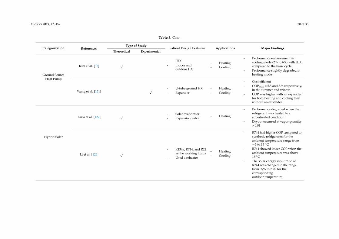
Xian et al. [29] modeled a high-performance two-stage CO2 HP using two ejectors andincorporated an IHX to the model. The researchers found that it could attain a 30% increase in theheating COP than a baseline two-stage HP at a standard operating temperature of −15 ◦C. Likewise,Kim et al. [32] developed a steady-state model to analyze the thermodynamic performance of an IHX ina geothermal CO2 HP, where a counter-flow multi-tube HX with several tubes encompassed in a largertube was used as the IHX. They found that the system with IHX could achieve up to 6% increase inCOP compared to the system without IHX at the 20% EEV opening. The proposed simulation programcan serve as a useful tool for a thermodynamic performance analysis when optimizing complex systemvariables and establishing efficient operating conditions in CO2 geothermal HP systems. Similarly,Yamaguchi et al. [21] formulated a static mathematical model to study a CO2 HP with a twin-tube typeHX as the IHX. They found that the addition of the IHX could enhance the COP up to 3.5 and had apositive influence on the heat transfer in both the gas cooler and evaporator. In a comparative study,Jiang et al. [25] utilized a double pipe copper HX as the IHX in which the high-pressure CO2 flew inthe inner pipe and the low-pressure CO2 flew in between the inner and outer pipe. The experimentalresults demonstrated that, for a gas cooler temperature of 15 ◦C, the system with IHX had 6.5% to11.5% higher COP than that of without IHX.
Energies 2019, 12, 457 18 of 35
Shariatzadeh et al. [107] analyzed four different transcritical refrigeration cycles with and withoutIHX along with an expander and throttling device. They found the COP of the expander cycle isalways higher than the throttling cycle due to the optimized gas cooler pressure and reduced exergyloss in the expander cycle. However, when the system worked in the expander cycle, use of an IHXreduces the average COP from 2.8 to 2.5 due exergy efficiency loss in the gas cooler, but, in case of thethrottling cycle, integration of IHX reduces exergy loss and, as a result, increases the COP from 1.9 to2.0. Zhang et al. [108] carried out a similar study and found that, when IHX is used in an expansionvalve cycle, the system performance could increase by 17%. On the contrary, if IHX is used in an ejectorcycle, the system performance degrades by 16%. This is attributed to a decrease in ejector isentropicefficiency with the integration of IHX.
In addition, the effects of IHX on system parameters rather than efficiency were studied. Froman experimental investigation, Sánchez et al. [109] reported that the integration of IHX increases thecompressor suction temperature, which reduces mass flow rate, and, as a result, specific compressionwork increases. However, this increase is very insignificant. Moreover, superheating induced byIHX increases the discharge temperature, and this effect is high at a low evaporating temperature.Pérez-García et al. [110] found the effectiveness of the IHX largely depends on the gas cooler outletCO2 temperature, and the increased energy efficiency with the IHX is due to the subcooling ofCO2. However, the mechanical subcooling system without an IHX can also improve the energyefficiency [111]. Furthermore, Ituna-Yudonago et al. [112] analyzed the effect of transient thermaleffectiveness of an IHX on a CO2 system, and they reported that increasing the CO2 temperature by10 ◦C at the IHX inlet of the gas cooler side could decrease the COP of about 3% due to reduced HTCand IHX effectiveness.
4. CO2 Heat Pump Systems
The resurrection of CO2 as the working fluid in vapor compression cycles started in the early1990s due to phasing out of ozone-depleting refrigerants. In 1993, Lorentzen et al. [113] developed andtested one of the first prototypes of the CO2 automotive air conditioning system. In 2015, soft drinksmanufacturing giant Coca-Cola announced to utilize CO2 as the refrigerant in all their new vendingmachines as part of the global effort to phase out fluorinated refrigerants [114]. The commercializationof the CO2 HP system started a decade ago in Japan and sales went past 2 million units in October2009 [115]. Research and development on CO2 air conditioning, refrigeration, and HP systems arecontinuing and still has scope for performance improvement.
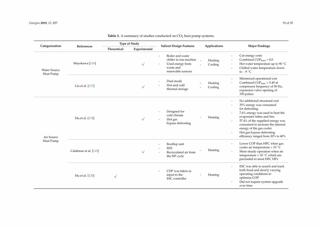
According to the available heat sources at the evaporator side, HPs can be classified as the watersource, the air source, and the ground source HP, while a hybrid HP is defined as an HP using morethan one heat source. In hybrid systems, most commonly solar and geothermal energy are incorporatedwith the conventional heat sources to improve the system performance. In the following subsections,each type of system is discussed and detailed. Table 3 summarizes the salient features of differenttypes of CO2 HP systems found in the literature.
Energies 2019, 12, 457 19 of 35
Table 3. A summary of studies conducted on CO2 heat pump systems.
Categorization ReferencesType of Study
Salient Design Features Applications Major FindingsTheoretical Experimental
Water SourceHeat Pump
Mayekawa [116] √
- Boiler and waterchiller in one machine
- Used energy fromwaste andrenewable sources
- Heating- Cooling
- Cut energy costs- Combined COPmax = 8.0- Hot water temperature up to 90 ◦C- Chilled water temperature down
to −9 ◦C
Liu et al. [117] √- Dual mode- Hot and cold
thermal storage
- Heating- Cooling
- Minimized operational cost- Combined COPmax = 5.49 at
compressor frequency of 50 Hz,expansion valve opening of330 pulses
Air SourceHeat Pump
Hu et al. [118] √- Designed for
cold climate- Hot gas
bypass defrosting
- Heating
- No additional structural cost- 35% energy was consumed
for defrosting- 7.6% energy was used to heat the
evaporator tubes and fins- 57.4% of the supplied energy was
consumed to increase the internalenergy of the gas cooler
- Hot gas bypass defrostingefficiency ranged from 30% to 40%
Calabrese et al. [119] √- Rooftop unit- IHX- Recirculated air from
the HP cycle
- Heating
- Lower COP than HFC when gascooler air temperature > 10 ◦C
- More steady operation when airtemperature < 10 ◦C which areprecluded to most HFC HPs
Hu et al. [120] √- CDP was taken as
input to theESC controller
- Heating
- ESC was able to search and trackboth fixed and slowly varyingoperating conditions tooptimize COP
- Did not require system upgradeover time
Energies 2019, 12, 457 20 of 35
Table 3. Cont.
Categorization ReferencesType of Study
Salient Design Features Applications Major FindingsTheoretical Experimental
Ground SourceHeat Pump
Kim et al. [32] √- IHX- Indoor and
outdoor HX
- Heating- Cooling
- Performance enhancement incooling mode (2% to 6%) with IHXcompared to the basic cycle
- Performance slightly degraded inheating mode
Wang et al. [121] √ - U-tube ground HX- Expander
- Heating- Cooling
- Cost efficient- COPmax = 5.5 and 5.9, respectively,
in the summer and winter- COP was higher with an expander
for both heating and cooling thanwithout an expander
Hybrid Solar
Faria et al. [122] √ - Solar evaporator- Expansion valve
- Heating
- Performance degraded when therefrigerant was heated to asuperheated condition
- Dryout occurred at vapor quantity> 0.81
Li et al. [123] √- R134a, R744, and R22
as the working fluids- Used a reheater
- Heating- Cooling
- R744 had higher COP compared tosynthetic refrigerants for theambient temperature range from−5 to 13 ◦C
- R744 showed lower COP when theambient temperature was above13 ◦C
- The solar energy input ratio ofR744 was changed in the rangefrom 39% to 73% for thecorrespondingoutdoor temperature
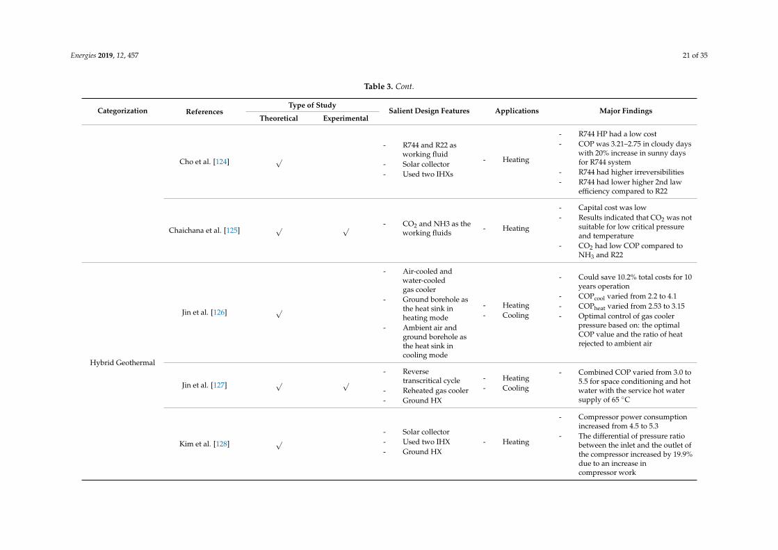
Energies 2019, 12, 457 21 of 35
Table 3. Cont.
Categorization ReferencesType of Study
Salient Design Features Applications Major FindingsTheoretical Experimental
Cho et al. [124] √- R744 and R22 as
working fluid- Solar collector- Used two IHXs
- Heating
- R744 HP had a low cost- COP was 3.21–2.75 in cloudy days
with 20% increase in sunny daysfor R744 system
- R744 had higher irreversibilities- R744 had lower higher 2nd law
efficiency compared to R22
Chaichana et al. [125] √ √ - CO2 and NH3 as theworking fluids - Heating
- Capital cost was low- Results indicated that CO2 was not
suitable for low critical pressureand temperature
- CO2 had low COP compared toNH3 and R22
Hybrid Geothermal
Jin et al. [126] √
- Air-cooled andwater-cooledgas cooler
- Ground borehole asthe heat sink inheating mode
- Ambient air andground borehole asthe heat sink incooling mode
- Heating- Cooling
- Could save 10.2% total costs for 10years operation
- COPcool varied from 2.2 to 4.1- COPheat varied from 2.53 to 3.15- Optimal control of gas cooler
pressure based on: the optimalCOP value and the ratio of heatrejected to ambient air
Jin et al. [127] √ √- Reverse
transcritical cycle- Reheated gas cooler- Ground HX
- Heating- Cooling
- Combined COP varied from 3.0 to5.5 for space conditioning and hotwater with the service hot watersupply of 65 ◦C
Kim et al. [128] √- Solar collector- Used two IHX- Ground HX
- Heating
- Compressor power consumptionincreased from 4.5 to 5.3
- The differential of pressure ratiobetween the inlet and the outlet ofthe compressor increased by 19.9%due to an increase incompressor work
Energies 2019, 12, 457 22 of 35
4.1. Heat Sources
The air source heat pump (ASHP) has gotten attention around the world for its energy savingpotential and environmental footprint. ASHP has been in use in the USA for many years but not muchin regions where the ambient temperature gets below the freezing point during the winter. However,recent technology advances make ASHP viable in cold climate regions.
Hu et al. [118] experimentally studied a CO2 driven ASHP for water heating in a cold climatein which a hot gas bypass defrosting method was utilized to overcome the frosting at low ambienttemperatures. During the defrosting process, the temperature and pressure dropped sharply at thebeginning but remained constant during the melting period. Additionally, the pressure drop was largein the gas cooler during the frosting process with a high CO2 mass flow rate. The energy analysisshowed that the gas cooler consumed 57.4% of the supplied energy to increase the internal energy,while 35% for the frost melting process, which is typically higher than other defrosting methods.The experimental results showed that the hot gas bypass defrosting method could only achieveefficiency as high as 40%. Furthermore, Calabrese et al. [122] conducted an experimental study ona CO2 ASHP installed on a building rooftop to understand the effect of the inlet air temperature atthe gas cooler on the heating capacity and COP. The inlet air at the gas cooler was a combination offresh air supplied from the environment and recirculated air from the HP system. The rooftop HP wasfound to provide better performance in a colder climate, and the COP increased from 2.1 to 2.8 with adecrease in inlet air temperature from 20 to 6 ◦C.
Studies have used advanced control strategies to optimize the performance of CO2 ASHP. As such,Hu et al. [129] proposed an extreme seeking control (ESC) method that has great promise for the efficientoperation of the air source CO2 water heater system over its entire lifespan. As a self-optimizing controlstrategy, the ESC method was able to search and keep the COP at an optimum level. The dischargepressure was taken as the input to the ESC while the COP of the system provided the performancefeedback. Simulation results indicated that the ESC could find and slowly adopt the inputs to keepthe system COP at an optimum level for water outlet temperature from 55 to 80 ◦C without the needfor a system upgrade. Most recently, Hu et al. [58] developed another control system based on ESCto minimize power consumption and maximize COP. In this system, the ESC was based on threeelements: power consumption, gas cooler outlet temperature, and high side pressure.
Water source heat pump (WSHP) is best suited where simultaneous heating and cooling isrequired. The operation of WSHP is much quieter along with a low carbon footprint compared toASHP. In moderate climate conditions, WSHP can be used since the heat rejected at the cooling unitcan be utilized to maintain a certain temperature at the heating unit. However, in a cold climate,the major problem associated with WSHP is the water freezing in the evaporator. Recently, MayekawaCompany from Australia [116] developed a commercial CO2 WSHP for a hot and chilled water supplyin which renewable and waste energy can be used as heat sources. The HP system could achievea combined COP of 8.0 and provide hot water as high as 90 ◦C and chilled water as low as −9 ◦C.Liu et al. [117] conducted an experimental study to examine the influence of the compressor frequencyon the performance of a dual mode CO2 WSHP integrated with hot and cold thermal storage tanks.The experimental results demonstrated that a higher compressor frequency led to a higher transientheating and cooling capacity. Therefore, a better thermal stratification at the tank occurred, which,in turn, resulted in a higher COP. The expansion valve opening had a significant impact on the systemperformance due to its influence on the refrigerant mass flow rate. The optimum overall COP of 5.49could be achieved at the compressor frequency of 50 Hz, the expansion valve pulse of 330 Hz, and thehot and cold-water flow rate of 0.1 m3/h and 0.2 m3/h, respectively.
Development of ground source heat pump (GSHP) has been prompted by the regulations enforcedto protect the environment and save energy. While installing GSHP is expensive than other HP systems,it can reduce energy consumption by 30% to 60% and the increase in expenses can be compensatedthrough energy savings [130]. Studies have shown that the high rejection temperature of the compressorand the great temperature glide of the gas cooler in the CO2 transcritical cycle is very suitable for heat
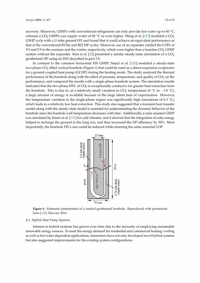
Energies 2019, 12, 457 23 of 35
recovery. Moreover, GSHPs with conventional refrigerants can only provide hot water up to 60 ◦C,whereas a CO2 GSHPs can supply water of 90 ◦C or even higher. Wang et al. [121] modeled a CO2
GSHP cycle with a U-tube ground HX and found that it could achieve an equivalent performance asthat of the conventional R134a and R22 HP cycles. Moreover, use of an expander yielded the COPs of5.5 and 5.9 in the summer and the winter, respectively, which were higher than a baseline CO2 GSHPsystem without the expander. Kim et al. [32] presented a similar steady-state simulation of a CO2
geothermal HP using an IHX described in part 3.5.In contrast to the common horizontal HX GSHP, Nejad et al. [120] modeled a steady-state
two-phase CO2 filled vertical borehole (Figure 6) that could be used as a direct-expansion evaporatorfor a ground coupled heat pump (GCHP) during the heating mode. The study analyzed the thermalperformance of the borehole along with the effect of pressure, temperature, and quality of CO2 on theperformance, and compared the results with a single-phase borehole system. The simulation resultsindicated that the two-phase HTC of CO2 is exceptionally conducive for greater heat extraction fromthe borehole. This is due to, at a relatively small variation in CO2 temperature (0 ◦C to −1.8 ◦C),a large amount of energy is available because of the large latent heat of vaporization. However,the temperature variation in the single-phase region was significantly high (maximum of 6.3 ◦C),which leads to a relatively low heat extraction. This study also suggested that a transient heat transfermodel along with the steady-state model is essential for understanding the dynamic behavior of theborehole since the borehole wall temperature decreases with time. Additionally, a solar assisted GSHPwas simulated by Emmi et al. [131] for cold climates, and it showed that the integration of solar energyhelped to recharge the ground in the long run, and thus increased the HP efficiency by 30%. Mostimportantly, the borehole HX’s size could be reduced while ensuring the same seasonal COP.
Energies 2019, 12, x FOR PEER REVIEW 21 of 33
hot water up to 60 °C, whereas a CO2 GSHPs can supply water of 90 °C or even higher. Wang et al. [121] modeled a CO2 GSHP cycle with a U-tube ground HX and found that it could achieve an equivalent performance as that of the conventional R134a and R22 HP cycles. Moreover, use of an expander yielded the COPs of 5.5 and 5.9 in the summer and the winter, respectively, which were higher than a baseline CO2 GSHP system without the expander. Kim et al. [32] presented a similar steady-state simulation of a CO2 geothermal HP using an IHX described in part 3.5.
In contrast to the common horizontal HX GSHP, Nejad et al. [120] modeled a steady-state two-phase CO2 filled vertical borehole (Figure 6) that could be used as a direct-expansion evaporator for a ground coupled heat pump (GCHP) during the heating mode. The study analyzed the thermal performance of the borehole along with the effect of pressure, temperature, and quality of CO2 on the performance, and compared the results with a single-phase borehole system. The simulation results indicated that the two-phase HTC of CO2 is exceptionally conducive for greater heat extraction from the borehole. This is due to, at a relatively small variation in CO2 temperature (0 °C to −1.8 °C), a large amount of energy is available because of the large latent heat of vaporization. However, the temperature variation in the single-phase region was significantly high (maximum of 6.3 °C), which leads to a relatively low heat extraction. This study also suggested that a transient heat transfer model along with the steady-state model is essential for understanding the dynamic behavior of the borehole since the borehole wall temperature decreases with time. Additionally, a solar assisted GSHP was simulated by Emmi et al. [131] for cold climates, and it showed that the integration of solar energy helped to recharge the ground in the long run, and thus increased the HP efficiency by 30%. Most importantly, the borehole HX’s size could be reduced while ensuring the same seasonal COP.
Figure 6. Schematic presentation of a vertical geothermal borehole. Reproduced with permission from [120]. Elsevier, 2014.
4.2. Hybrid Heat Pump Systems
Interest in hybrid systems has grown over time due to the necessity of employing sustainable renewable energy sources. To meet the energy demand for residential and commercial heating/cooling as well as hot water dependent applications, researchers have not only developed novel hybrid systems but also suggested improvements for the existing system configurations.
4.2.1. Hybrid Solar
Use of low-grade heat sources such as solar energy as an auxiliary energy source integrated with a HP to obtain net zero energy balanced (nZEB) has been considered and explored by many researchers. A solar assisted CO2 HP is typically more energy efficient than baseline HPs. Chen et al. [132] experimentally demonstrated that a solar assisted CO2 HP for space heating could attain an
Figure 6. Schematic presentation of a vertical geothermal borehole. Reproduced with permissionfrom [120]. Elsevier, 2014.
4.2. Hybrid Heat Pump Systems
Interest in hybrid systems has grown over time due to the necessity of employing sustainablerenewable energy sources. To meet the energy demand for residential and commercial heating/coolingas well as hot water dependent applications, researchers have not only developed novel hybrid systemsbut also suggested improvements for the existing system configurations.
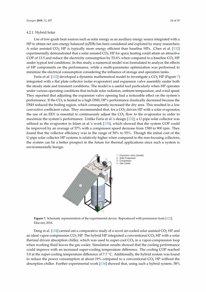
Energies 2019, 12, 457 24 of 35
4.2.1. Hybrid Solar
Use of low-grade heat sources such as solar energy as an auxiliary energy source integrated with aHP to obtain net zero energy balanced (nZEB) has been considered and explored by many researchers.A solar assisted CO2 HP is typically more energy efficient than baseline HPs. Chen et al. [132]experimentally demonstrated that a solar assisted CO2 HP for space heating could attain an attractiveCOP of 13.5 and reduce the electricity consumption by 53.6% when compared to a baseline CO2 HPunder typical test conditions. In this study, a numerical model was formulated to analyze the effectsof HP components on the performance, while a multi-parameter optimization was performed tominimize the electrical consumption considering the influence of storage and operation tanks.
Faria et al. [122] developed a dynamic mathematical model to investigate a CO2 HP (Figure 7)integrated with a flat plate collector (solar evaporator) and expansion valve assembly under boththe steady state and transient conditions. The model is a useful tool particularly when HP operatesunder various operating conditions that include solar radiation, ambient temperature, and wind speed.They reported that adjusting the expansion valve opening had a noticeable effect on the system’sperformance. If the CO2 is heated to a high DSH, HP’s performance drastically decreased because theDSH reduced the boiling region, which consequently increased the dry area. This resulted in a lowconvective coefficient value. They recommended that, for a CO2 driven HP with a solar evaporator,the use of an EEV is essential to continuously adjust the CO2 flow to the evaporator in order tomaximize the system’s performance. Unlike Faria et al.’s design [122], a U-pipe solar collector wasutilized as the evaporator in Islam et al.’s work [133], which showed that the system COP couldbe improved by an average of 57% with a compressor speed decrease from 1500 to 900 rpm. Theyfound that the collector efficiency was in the range of 50% to 55%. Though the initial cost of theU-pipe solar collector HP systems is relatively higher when compared to the non-focusing collectors,the system can be a better prospect in the future for thermal applications since such a system isenvironmentally benign.
Energies 2019, 12, x FOR PEER REVIEW 22 of 33
attractive COP of 13.5 and reduce the electricity consumption by 53.6% when compared to a baseline CO2 HP under typical test conditions. In this study, a numerical model was formulated to analyze the effects of HP components on the performance, while a multi-parameter optimization was performed to minimize the electrical consumption considering the influence of storage and operation tanks.
Faria et al. [122] developed a dynamic mathematical model to investigate a CO2 HP (Figure 7) integrated with a flat plate collector (solar evaporator) and expansion valve assembly under both the steady state and transient conditions. The model is a useful tool particularly when HP operates under various operating conditions that include solar radiation, ambient temperature, and wind speed. They reported that adjusting the expansion valve opening had a noticeable effect on the system’s performance. If the CO2 is heated to a high DSH, HP’s performance drastically decreased because the DSH reduced the boiling region, which consequently increased the dry area. This resulted in a low convective coefficient value. They recommended that, for a CO2 driven HP with a solar evaporator, the use of an EEV is essential to continuously adjust the CO2 flow to the evaporator in order to maximize the system’s performance. Unlike Faria et al.’s design [122], a U-pipe solar collector was utilized as the evaporator in Islam et al.’s work [133], which showed that the system COP could be improved by an average of 57% with a compressor speed decrease from 1500 to 900 rpm. They found that the collector efficiency was in the range of 50% to 55%. Though the initial cost of the U-pipe solar collector HP systems is relatively higher when compared to the non-focusing collectors, the system can be a better prospect in the future for thermal applications since such a system is environmentally benign.
Figure 7. Schematic representation of the experimental device. Reproduced with permission from [122]. Elsevier, 2016.
Deng et al. [134] carried out a comparative study of a novel air-cooled solar assisted CO2 HP and an ideal vapor-compression CO2 HP. The hybrid HP integrated a conventional CO2 HP with a solar thermal driven absorption chiller, which was used to super-cool CO2 in a vapor-compression loop when working fluid leaves the gas cooler. Simulation results showed that the cooling performance could improve with an increased super-cooling temperature difference. The cooling COP reached 3.8 at the super-cooling temperature difference of 7.7 °C. Additionally, the hybrid system was found to reduce the power consumption at about 19% compared to a conventional CO2 HP without the absorption chiller. Further experimental work [134] showed that, using such a hybrid system, 58% of the total energy consumed per year in nZEB apartments could meet the demand for HVAC and domestic hot water (DHW).
Given that the thermophysical properties of a refrigerant play an important role in dictating the HP performance, CO2 has been compared with other conventional refrigerants in hybrid solar HPs. Li et al. [123] presented a simulation on a hybrid solar assisted HP using R134a, R744, and R22 for water heating in a residential apartment. The results showed that the given ambient temperature ranged from -5 to 13 °C while R744 attained a higher COP compared to R134a and R22. However,
Figure 7. Schematic representation of the experimental device. Reproduced with permission from [122].Elsevier, 2016.
Deng et al. [134] carried out a comparative study of a novel air-cooled solar assisted CO2 HP andan ideal vapor-compression CO2 HP. The hybrid HP integrated a conventional CO2 HP with a solarthermal driven absorption chiller, which was used to super-cool CO2 in a vapor-compression loopwhen working fluid leaves the gas cooler. Simulation results showed that the cooling performancecould improve with an increased super-cooling temperature difference. The cooling COP reached3.8 at the super-cooling temperature difference of 7.7 ◦C. Additionally, the hybrid system was foundto reduce the power consumption at about 19% compared to a conventional CO2 HP without theabsorption chiller. Further experimental work [134] showed that, using such a hybrid system, 58%
Energies 2019, 12, 457 25 of 35
of the total energy consumed per year in nZEB apartments could meet the demand for HVAC anddomestic hot water (DHW).
Given that the thermophysical properties of a refrigerant play an important role in dictating theHP performance, CO2 has been compared with other conventional refrigerants in hybrid solar HPs.Li et al. [123] presented a simulation on a hybrid solar assisted HP using R134a, R744, and R22 for waterheating in a residential apartment. The results showed that the given ambient temperature rangedfrom −5 to 13 ◦C while R744 attained a higher COP compared to R134a and R22. However, R134aattained the maximum COP when the ambient temperature was above 13 ◦C, while CO2 HP attaineda low cooling efficiency under all operating conditions. Cho et al. [124] presented a similar study on ahybrid HP system using R744 and R22, and found that, during sunny days, COPs for both R744 andR22 were higher by 20% compared to cloudy days. However, concerning the second law efficiency,the R22 system had a 6.2% higher efficiency compared to the R744 due to the higher irreversibility andperformance sensitivity of the R744 system. Additionally, Chaichana [125] assessed the use of naturalworking fluids-Carbon dioxide (R744) and Ammonia (R717) in solar boosted HPs and compared themwith the HP using Chlorodifluoromethane (R22). The study concluded that choosing R744 for HPapplications would not be an appropriate choice due to its low critical temperature and high workingpressures, which leads to a low COP. Instead of R744, R717 was suggested as a potential naturalworking fluid for solar boosted HP operation due to its similar performance to R22.
4.2.2. Hybrid Geothermal
To further improve the performance of CO2 HP and increase the energy saving potential, hybridgeothermal HP systems with a secondary heat source/sink such as solar energy, ambient air, or waterhas been studied. Jin et al. [126] theoretically analyzed a hybrid GCHP system, which utilized acombination of ambient air and ground boreholes as the heat sink for cooling mode, while onlyboreholes were engaged as the heating source during the heating mode. The system used two separategas coolers known as the air-cooled gas cooler and the water-cooled gas cooler for the heat rejectionprocess to take advantage of the large temperature glide. An optimal control strategy was developedfor the gas cooler to minimize the annual ground thermal imbalance depending on the desired coolingCOP and the heat rejected to the ambient air. The results showed that both heating and coolingperformance of the CO2 hybrid GCHP improved when compared to its baseline ASHP. Depending onthe indoor temperature, the time-dependent COPcool varied from 2.2 to 4.1, while the COPheat variedfrom 2.53 to 3.15. Jin et al. [127] further extended this study using a reverse CO2 transcritical cycle for aCO2 hybrid HCHP system. The system was able to operate under space cooling or heating mode witha simultaneous service water heating. For instance, while operating in the cooling mode, this systemcould simultaneously provide both space cooling and hot water supply. Such an arrangement givesthe possibility to eliminate the underground heat accumulation in a warm climate and, thereby, pavesa way to enhance the system performance in the long-term operation. The results showed that thecombined COP for space conditioning and hot water varied from 3.0 to 5.5 with 65 ◦C of the servicehot water supply.
During the last decade, the hybrid geothermal-solar assisted HPs (GSAHPs) have gainedresearchers’ attention, potentially for both space heating and hot water supply. GSAHP technology hasproven to be efficient not only in the warm climate but also in the cold climatic regions. In a cold climate,the HP works mainly in a heating mode, and the ground temperature gradually decreases due to thecontinuous heat extraction from the ground, which deteriorates the HP performance. Emmi et al. [131]simulated a GSAHP and evaluated its performance in cold climates where the heating and cooling loadprofiles of buildings were not balanced. The integration of solar collector with the HP was found toenhance the efficiency by 30% with the COP ranging from 3.59 to 4.70 for different seasonal conditions.In a real application of CO2 HP, the actual system performance and reliability depend on operatingcharacteristics rather than only on the design conditions. Kim et al. [128] investigated the performanceof a CO2 hybrid GSAHP under different operating conditions such as operating temperature and solar
Energies 2019, 12, 457 26 of 35
radiation. The results showed that changing the operating temperature from 40 ◦C to 48 ◦C resulted inabout a 20% increase in the compressor pressure ratio, which caused an increase of the compressorpower consumption from 4.5 to 5.3 kW. Additionally, with the rise in daily solar radiation from 1.0to 20 MJ/m2, the heat in the collector increased by around 50%. It was suggested to consider theoperational characteristics and design parameters while designing a CO2 GSAHP to increase systemreliability and reduce energy consumption.
5. CO2 Heat Pump Applications
CO2 HPs are environmentally-friendly and energy-efficient, which makes them popular forvarious applications such as hot water production, space heating, and dehumidifying (drying).Moreover, a single CO2 HP unit can be utilized to serve for multiple purposes such as simultaneousheating and cooling. In this section, a comprehensive overview is presented on recent developmentsin CO2 HPs for different applications.
5.1. Water Heating
Roughly one-half of the households in the USA use natural gas and one-third use electricity forspace heating, which accounts for two-thirds of the utility bill in a typical US house [130]. Waterheating accounts for roughly one-fifth of the energy consumption in a typical residential building inthe USA [130]. Hence, water heating is the main purpose of a CO2 HP for providing both service hotwater and space heating. Based on the heat transfer performance of each component in a CO2 HP waterheater, Yamaguchi et al. [21] carried out a numerical simulation showing that the maximum attainableCOP was 3.6 for a given water inlet temperature of 8 ◦C and an outdoor air temperature of 44 ◦C.The effects of the inlet water temperature and outside air temperature on the system characteristicswere analyzed in the study. The study concluded that the CO2 HP water heater instead of an electricor gas water heater can lead to a significant reduction in the primary energy consumption. In addition,a CO2 HP water heater (HPWH) prototype [135] is being developed in Oak Ridge National Laboratory(ORNL) [136], which meets ENERGY STAR standards [137] for HPWHs at a low cost. The main designfeature is that the prototype uses an optimized wrap-around gas cooler (roll flexible HX) instead of anexternal HX. Unlike the external HX, with a wrap around HX, no fouling can occur and there is noneed for a pump to drive the flow. ORNL estimated that the CO2 HPWH can reduce energy use by0.8 quads a year, whereas the annual energy consumed by electric water heaters are approximately1.38 quads.
Tammaro et al. [138] compared two air-to-water natural refrigerant HPs including one that utilizedCO2 and the other used propane as the refrigerant. The results suggested that propane offers betterenergy savings when used in large HP systems for sanitary hot water production in warm and averageclimates. However, under cold climates, both delivered a similar energy performance. Similarly,Saikawa et al. [139] carried out a thermodynamic analysis of an HP using the fluorocarbons andnatural refrigerants. The theoretical study illustrated that, among all the refrigerants tested, the CO2
HP had the highest COP and the theoretical limit was 6.0 from a technical viewpoint. They developeda prototype for residential hot water production, which could attain a COP of 3.0, and emphasized onan energy recovery in the expansion process and the efficiency improvement of the compressor andHXs to further improve the prototype’s COP.
5.2. Drying
In a CO2 HP, cooling capacity can be utilized to dehumidify the moistened air, while the heatingcapacity heats the cold air. Klocker et al. [140] experimentally studied a CO2 HP dryer and comparedits performance with a conventional electric resistance dryer. The results showed that the CO2 HP dryercould reach a temperature of about 60 ◦C whereas the typical electric resistance dryer could reach up to130 ◦C. One advantage of reaching a low temperature is that the temperature sensitive merchandises’safety can be preserved. Moreover, for the compressor with a larger heat capacity, the drying time
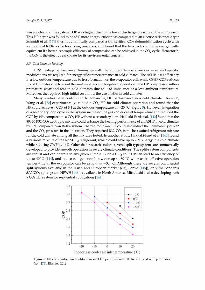
Energies 2019, 12, 457 27 of 35
was shorter, and the system COP was higher due to the lower discharge pressure of the compressor.This HP dryer was found to be 65% more energy-efficient as compared to an electric resistance dryer.Schmidt et al. [141] thermodynamically compared a transcritical CO2 dehumidification cycle witha subcritical R134a cycle for drying purposes, and found that the two cycles could be energeticallyequivalent if a better isentropic efficiency of compression can be achieved in the CO2 cycle. Henceforth,the CO2 is the effective candidate for its environmental concern.
5.3. Cold Climate Heating
HPs’ heating performance diminishes with the ambient temperature decrease, and specificmodifications are required for energy efficient performance in cold climates. The ASHP loses efficiencyin a low outdoor temperature due to frost formation on the evaporator coil, while GSHP COP reducesin cold climates due to a soil thermal imbalance in long-term operation. The HP compressor sufferspremature wear and tear in cold climates due to load imbalance at a low ambient temperature.Moreover, the required high initial cost limits the use of HPs in cold climates.
Many studies have contributed to enhancing HP performance in a cold climate. As such,Wang et al. [72] experimentally studied a CO2 HP for cold climate operation and found that theHP could achieve a COP of 3.1 at the outdoor temperature of −20 ◦C (Figure 8). However, integrationof a secondary loop cycle in the system increased the gas cooler outlet temperature and reduced theCOP by 19% compared to a CO2 HP without a secondary loop. Hakkaki-Fard et al. [142] found that the80/20 R32-CO2 zeotropic mixture could enhance the heating performance of an ASHP in cold climatesby 30% compared to an R410a system. The zeotropic mixture could also reduce the flammability of R32and the CO2 pressure in the operation. They reported R32-CO2 is the best-suited refrigerant mixturefor the cold climate among all the mixtures tested. In another study, Hakkaki-Fard et al. [143] founda variable mixture of the R32-CO2 refrigerant, which could save up to 23% energy in a cold climatewhile reducing GWP by 16%. Other than research studies, several split type systems are commerciallydeveloped to provide smooth operation in severe climate conditions. The split-system componentsare robust and can operate in any given climate. Such a CO2 split HP can lead to an efficiency ofup to 400% [144], and it also can generate hot water up to 80 ◦C whereas its effective operationtemperature at the evaporator can be as low as −30 ◦C. Although there are several commercialsplit-systems available in the Asian and European market (e.g., Sanyo [145]), only the Sanden’sSANCO2 split-system HPWH [146] is available in North America. Mitsubishi is also developing sucha CO2 HP system for residential applications [144].
Energies 2019, 12, x FOR PEER REVIEW 25 of 33
HPs’ heating performance diminishes with the ambient temperature decrease, and specific modifications are required for energy efficient performance in cold climates. The ASHP loses efficiency in a low outdoor temperature due to frost formation on the evaporator coil, while GSHP COP reduces in cold climates due to a soil thermal imbalance in long-term operation. The HP compressor suffers premature wear and tear in cold climates due to load imbalance at a low ambient temperature. Moreover, the required high initial cost limits the use of HPs in cold climates.
Many studies have contributed to enhancing HP performance in a cold climate. As such, Wang et al. [72] experimentally studied a CO2 HP for cold climate operation and found that the HP could achieve a COP of 3.1 at the outdoor temperature of –20 °C (Figure 8). However, integration of a secondary loop cycle in the system increased the gas cooler outlet temperature and reduced the COP by 19% compared to a CO2 HP without a secondary loop. Hakkaki-Fard et al. [142] found that the 80/20 R32-CO2 zeotropic mixture could enhance the heating performance of an ASHP in cold climates by 30% compared to an R410a system. The zeotropic mixture could also reduce the flammability of R32 and the CO2 pressure in the operation. They reported R32-CO2 is the best-suited refrigerant mixture for the cold climate among all the mixtures tested. In another study, Hakkaki-Fard et al. [143] found a variable mixture of the R32-CO2 refrigerant, which could save up to 23% energy in a cold climate while reducing GWP by 16%. Other than research studies, several split type systems are commercially developed to provide smooth operation in severe climate conditions. The split-system components are robust and can operate in any given climate. Such a CO2 split HP can lead to an efficiency of up to 400% [144], and it also can generate hot water up to 80 °C whereas its effective operation temperature at the evaporator can be as low as –30 °C. Although there are several commercial split-systems available in the Asian and European market (e.g., Sanyo [145]), only the Sanden’s SANCO2 split-system HPWH [146] is available in North America. Mitsubishi is also developing such a CO2 HP system for residential applications [144].
Figure 8. Effects of indoor and outdoor air inlet temperatures on COP. Reproduced with permission from [72]. Elsevier, 2016.
5.4. Food Processing
The food processing industry consumes a major portion of energy, and the consumptions are growing rapidly. Brush et al. [147] reported that about $1.5 billion per year is spent only by the dairy food processing industry on fuel and electricity in the U.S. while the fruit and vegetable processing industry spends around $800 million. Liu et al. [148] studied the energy savings and economics of CO2 and NH3 driven HPs in the food processing industry for heating and cooling applications and reported that using CO2 and NH3 HPs could have an annual saving of 32% in food pasteurization,
Figure 8. Effects of indoor and outdoor air inlet temperatures on COP. Reproduced with permissionfrom [72]. Elsevier, 2016.
Energies 2019, 12, 457 28 of 35
5.4. Food Processing
The food processing industry consumes a major portion of energy, and the consumptions aregrowing rapidly. Brush et al. [147] reported that about $1.5 billion per year is spent only by the dairyfood processing industry on fuel and electricity in the U.S. while the fruit and vegetable processingindustry spends around $800 million. Liu et al. [148] studied the energy savings and economics ofCO2 and NH3 driven HPs in the food processing industry for heating and cooling applications andreported that using CO2 and NH3 HPs could have an annual saving of 32% in food pasteurization,44% in beer brewing, and 35% in fluid milk processing. Singh et al. [149] simulated a CO2 HP that useswaste heat from an NH3 refrigeration plant where the evaporator of the CO2 HP was coupled with thecondenser of the NH3-based refrigeration system. In this system, the CO2 HP was used to preheatwater up to 70 ◦C. The results showed that about 33.8% energy could be saved along with 45.7% CO2
emission reduction, which leads to a relatively short payback period of 40 months.
6. Conclusions
A comprehensive review of the advances in CO2 HP systems and their applications are presentedin this paper. Unlike CFCs/HFCs, CO2 has no regulation liability because of its insignificant GWP,and, thermodynamically, the use of CO2 as a working fluid is a feasible option in a transcritical cycle,as shown in the comparison between the subcritical and transcritical cycles.
Research has been playing a pivotal role in developing functional designs for HXs, expansiondevices, and compressors to suit the CO2 transcritical process. Most of the recent studies focus onthe lightweight and compact HX designs since the two-phase and supercritical heat transfer of CO2
is found to be enhanced in compact HXs. In case of finned tube HXs, a slit fin showed a higherHTC for both the air-side and refrigerant-side. The use of IHX has been suggested while usingan expander as the expansion device since the IHX promotes subcooling of liquid refrigerant atthe expense of superheating of the vapor entering the compressor. The energy efficiency can beimproved using a two-stage double-throttling system for a severe evaporating temperature of −30 ◦C.In addition, the adjustable ejector and EEV as an expansion device was found to enhance the systemCOP compared to the fix-geometry expansion devices. To reduce the vapor mixture losses, studieshave been carried out using multi-stage compressor equipped with an intermediate gas-injectionmechanism. The two-stage transcritical cycle using a semi-hermetic reciprocating compressor coupledwith an intercooler is a very promising technology. However, future research studies should betteraddress the irreversibility in the components especially in the expansion process. The use of adjustableand multi-stage expansion need to be thoroughly investigated along with two-stage compression.
In order to further improve the performance of the CO2 HP system, research also integratedrenewable energy sources, other working fluids, and advanced control with a CO2 system. The CO2
GSHP cycle showed an equivalent performance as that of the conventional R134a and R22 HP cycles.Solar assisted CO2 HP could attain an attractive COP of 13.5 and reduce the electricity consumption by53.6% compared to a baseline CO2 HP. The use of CO2 in refrigerant mixtures has shown to improvethe heating and cooling performance. The 60% CO2-propane mixture could yield similar performanceto R134a. The 80/20 R32-CO2 zeotropic mixture could enhance the heating performance of an ASHPin cold climates by 30% compared to an R410a system. In addition, advanced control strategies wereproposed to optimize the CO2 HP performance by controlling the high side pressure and gas cooleroutlet temperature.
In terms of application, CO2 HPs’ applicability in a cold climate and their ability to providethe high- temperature hot water has made them one of the most promising technologies for theresidential as well as industrial sectors. The CO2 HPs operating in cold climates can achieve a COPof 3.1 for an outdoor temperature of −20 ◦C. The commercial CO2 split-system can generate hotwater up to 80 ◦C whereas its effective operating temperature can be as low as −30 ◦C. A CO2 HPwith simultaneous heating and cooling can achieve a combined COP of 8.0 and provide hot water ashigh as 90 ◦C and chilled water as low as −9 ◦C. Nevertheless, in a cold climate, CO2 HP’s COP is
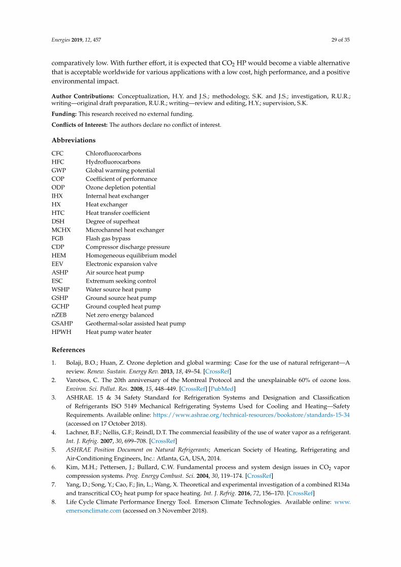
Energies 2019, 12, 457 29 of 35
comparatively low. With further effort, it is expected that CO2 HP would become a viable alternativethat is acceptable worldwide for various applications with a low cost, high performance, and a positiveenvironmental impact.
Author Contributions: Conceptualization, H.Y. and J.S.; methodology, S.K. and J.S.; investigation, R.U.R.;writing—original draft preparation, R.U.R.; writing—review and editing, H.Y.; supervision, S.K.
Funding: This research received no external funding.
Conflicts of Interest: The authors declare no conflict of interest.
Abbreviations
CFC ChlorofluorocarbonsHFC HydrofluorocarbonsGWP Global warming potentialCOP Coefficient of performanceODP Ozone depletion potentialIHX Internal heat exchangerHX Heat exchangerHTC Heat transfer coefficientDSH Degree of superheatMCHX Microchannel heat exchangerFGB Flash gas bypassCDP Compressor discharge pressureHEM Homogeneous equilibrium modelEEV Electronic expansion valveASHP Air source heat pumpESC Extremum seeking controlWSHP Water source heat pumpGSHP Ground source heat pumpGCHP Ground coupled heat pumpnZEB Net zero energy balancedGSAHP Geothermal-solar assisted heat pumpHPWH Heat pump water heater
References
1. Bolaji, B.O.; Huan, Z. Ozone depletion and global warming: Case for the use of natural refrigerant—Areview. Renew. Sustain. Energy Rev. 2013, 18, 49–54. [CrossRef]
2. Varotsos, C. The 20th anniversary of the Montreal Protocol and the unexplainable 60% of ozone loss.Environ. Sci. Pollut. Res. 2008, 15, 448–449. [CrossRef] [PubMed]
3. ASHRAE. 15 & 34 Safety Standard for Refrigeration Systems and Designation and Classificationof Refrigerants ISO 5149 Mechanical Refrigerating Systems Used for Cooling and Heating—SafetyRequirements. Available online: https://www.ashrae.org/technical-resources/bookstore/standards-15-34(accessed on 17 October 2018).
4. Lachner, B.F.; Nellis, G.F.; Reindl, D.T. The commercial feasibility of the use of water vapor as a refrigerant.Int. J. Refrig. 2007, 30, 699–708. [CrossRef]
5. ASHRAE Position Document on Natural Refrigerants; American Society of Heating, Refrigerating andAir-Conditioning Engineers, Inc.: Atlanta, GA, USA, 2014.
6. Kim, M.H.; Pettersen, J.; Bullard, C.W. Fundamental process and system design issues in CO2 vaporcompression systems. Prog. Energy Combust. Sci. 2004, 30, 119–174. [CrossRef]
7. Yang, D.; Song, Y.; Cao, F.; Jin, L.; Wang, X. Theoretical and experimental investigation of a combined R134aand transcritical CO2 heat pump for space heating. Int. J. Refrig. 2016, 72, 156–170. [CrossRef]
8. Life Cycle Climate Performance Energy Tool. Emerson Climate Technologies. Available online: www.emersonclimate.com (accessed on 3 November 2018).
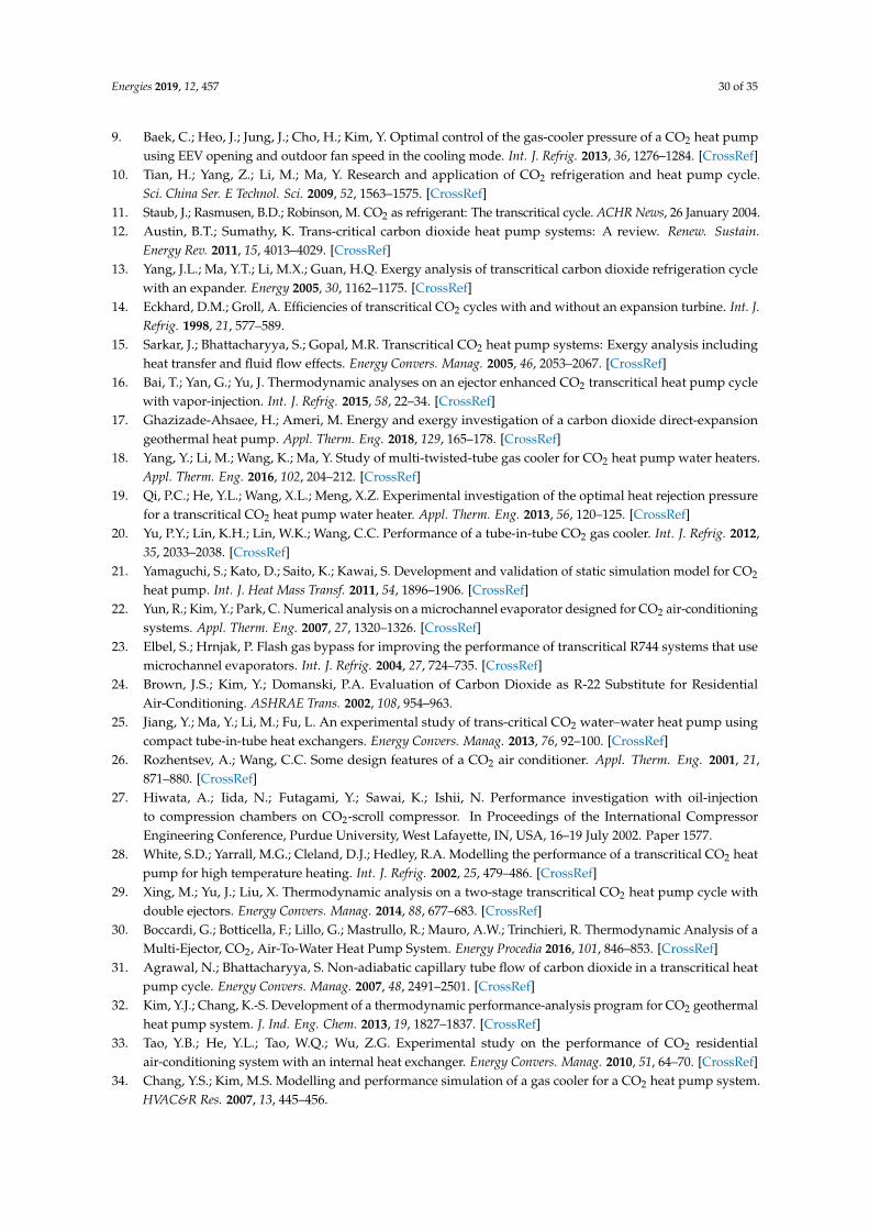
Energies 2019, 12, 457 30 of 35
9. Baek, C.; Heo, J.; Jung, J.; Cho, H.; Kim, Y. Optimal control of the gas-cooler pressure of a CO2 heat pumpusing EEV opening and outdoor fan speed in the cooling mode. Int. J. Refrig. 2013, 36, 1276–1284. [CrossRef]
10. Tian, H.; Yang, Z.; Li, M.; Ma, Y. Research and application of CO2 refrigeration and heat pump cycle.Sci. China Ser. E Technol. Sci. 2009, 52, 1563–1575. [CrossRef]
11. Staub, J.; Rasmusen, B.D.; Robinson, M. CO2 as refrigerant: The transcritical cycle. ACHR News, 26 January 2004.12. Austin, B.T.; Sumathy, K. Trans-critical carbon dioxide heat pump systems: A review. Renew. Sustain.
Energy Rev. 2011, 15, 4013–4029. [CrossRef]13. Yang, J.L.; Ma, Y.T.; Li, M.X.; Guan, H.Q. Exergy analysis of transcritical carbon dioxide refrigeration cycle
with an expander. Energy 2005, 30, 1162–1175. [CrossRef]14. Eckhard, D.M.; Groll, A. Efficiencies of transcritical CO2 cycles with and without an expansion turbine. Int. J.
Refrig. 1998, 21, 577–589.15. Sarkar, J.; Bhattacharyya, S.; Gopal, M.R. Transcritical CO2 heat pump systems: Exergy analysis including
heat transfer and fluid flow effects. Energy Convers. Manag. 2005, 46, 2053–2067. [CrossRef]16. Bai, T.; Yan, G.; Yu, J. Thermodynamic analyses on an ejector enhanced CO2 transcritical heat pump cycle
with vapor-injection. Int. J. Refrig. 2015, 58, 22–34. [CrossRef]17. Ghazizade-Ahsaee, H.; Ameri, M. Energy and exergy investigation of a carbon dioxide direct-expansion
geothermal heat pump. Appl. Therm. Eng. 2018, 129, 165–178. [CrossRef]18. Yang, Y.; Li, M.; Wang, K.; Ma, Y. Study of multi-twisted-tube gas cooler for CO2 heat pump water heaters.
Appl. Therm. Eng. 2016, 102, 204–212. [CrossRef]19. Qi, P.C.; He, Y.L.; Wang, X.L.; Meng, X.Z. Experimental investigation of the optimal heat rejection pressure
for a transcritical CO2 heat pump water heater. Appl. Therm. Eng. 2013, 56, 120–125. [CrossRef]20. Yu, P.Y.; Lin, K.H.; Lin, W.K.; Wang, C.C. Performance of a tube-in-tube CO2 gas cooler. Int. J. Refrig. 2012,
35, 2033–2038. [CrossRef]21. Yamaguchi, S.; Kato, D.; Saito, K.; Kawai, S. Development and validation of static simulation model for CO2
heat pump. Int. J. Heat Mass Transf. 2011, 54, 1896–1906. [CrossRef]22. Yun, R.; Kim, Y.; Park, C. Numerical analysis on a microchannel evaporator designed for CO2 air-conditioning
systems. Appl. Therm. Eng. 2007, 27, 1320–1326. [CrossRef]23. Elbel, S.; Hrnjak, P. Flash gas bypass for improving the performance of transcritical R744 systems that use
microchannel evaporators. Int. J. Refrig. 2004, 27, 724–735. [CrossRef]24. Brown, J.S.; Kim, Y.; Domanski, P.A. Evaluation of Carbon Dioxide as R-22 Substitute for Residential
Air-Conditioning. ASHRAE Trans. 2002, 108, 954–963.25. Jiang, Y.; Ma, Y.; Li, M.; Fu, L. An experimental study of trans-critical CO2 water–water heat pump using
compact tube-in-tube heat exchangers. Energy Convers. Manag. 2013, 76, 92–100. [CrossRef]26. Rozhentsev, A.; Wang, C.C. Some design features of a CO2 air conditioner. Appl. Therm. Eng. 2001, 21,
871–880. [CrossRef]27. Hiwata, A.; Iida, N.; Futagami, Y.; Sawai, K.; Ishii, N. Performance investigation with oil-injection
to compression chambers on CO2-scroll compressor. In Proceedings of the International CompressorEngineering Conference, Purdue University, West Lafayette, IN, USA, 16–19 July 2002. Paper 1577.
28. White, S.D.; Yarrall, M.G.; Cleland, D.J.; Hedley, R.A. Modelling the performance of a transcritical CO2 heatpump for high temperature heating. Int. J. Refrig. 2002, 25, 479–486. [CrossRef]
29. Xing, M.; Yu, J.; Liu, X. Thermodynamic analysis on a two-stage transcritical CO2 heat pump cycle withdouble ejectors. Energy Convers. Manag. 2014, 88, 677–683. [CrossRef]
30. Boccardi, G.; Botticella, F.; Lillo, G.; Mastrullo, R.; Mauro, A.W.; Trinchieri, R. Thermodynamic Analysis of aMulti-Ejector, CO2, Air-To-Water Heat Pump System. Energy Procedia 2016, 101, 846–853. [CrossRef]
31. Agrawal, N.; Bhattacharyya, S. Non-adiabatic capillary tube flow of carbon dioxide in a transcritical heatpump cycle. Energy Convers. Manag. 2007, 48, 2491–2501. [CrossRef]
32. Kim, Y.J.; Chang, K.-S. Development of a thermodynamic performance-analysis program for CO2 geothermalheat pump system. J. Ind. Eng. Chem. 2013, 19, 1827–1837. [CrossRef]
33. Tao, Y.B.; He, Y.L.; Tao, W.Q.; Wu, Z.G. Experimental study on the performance of CO2 residentialair-conditioning system with an internal heat exchanger. Energy Convers. Manag. 2010, 51, 64–70. [CrossRef]
34. Chang, Y.S.; Kim, M.S. Modelling and performance simulation of a gas cooler for a CO2 heat pump system.HVAC&R Res. 2007, 13, 445–456.
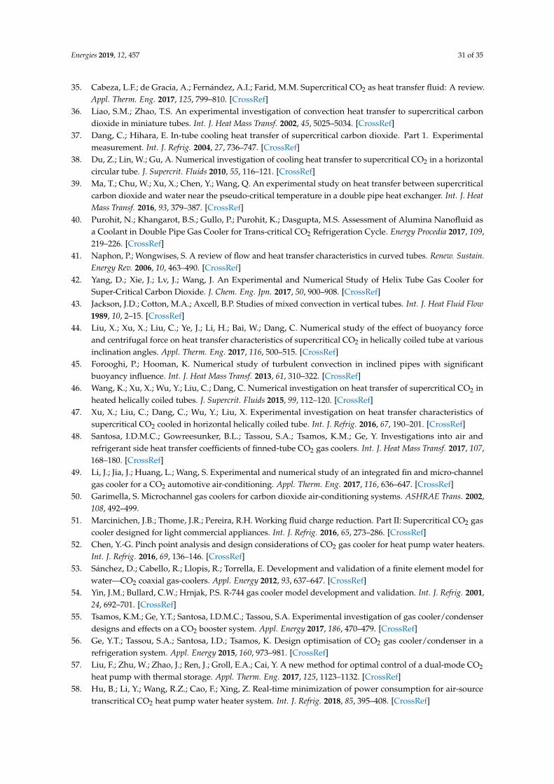
Energies 2019, 12, 457 31 of 35
35. Cabeza, L.F.; de Gracia, A.; Fernández, A.I.; Farid, M.M. Supercritical CO2 as heat transfer fluid: A review.Appl. Therm. Eng. 2017, 125, 799–810. [CrossRef]
36. Liao, S.M.; Zhao, T.S. An experimental investigation of convection heat transfer to supercritical carbondioxide in miniature tubes. Int. J. Heat Mass Transf. 2002, 45, 5025–5034. [CrossRef]
37. Dang, C.; Hihara, E. In-tube cooling heat transfer of supercritical carbon dioxide. Part 1. Experimentalmeasurement. Int. J. Refrig. 2004, 27, 736–747. [CrossRef]
38. Du, Z.; Lin, W.; Gu, A. Numerical investigation of cooling heat transfer to supercritical CO2 in a horizontalcircular tube. J. Supercrit. Fluids 2010, 55, 116–121. [CrossRef]
39. Ma, T.; Chu, W.; Xu, X.; Chen, Y.; Wang, Q. An experimental study on heat transfer between supercriticalcarbon dioxide and water near the pseudo-critical temperature in a double pipe heat exchanger. Int. J. HeatMass Transf. 2016, 93, 379–387. [CrossRef]
40. Purohit, N.; Khangarot, B.S.; Gullo, P.; Purohit, K.; Dasgupta, M.S. Assessment of Alumina Nanofluid asa Coolant in Double Pipe Gas Cooler for Trans-critical CO2 Refrigeration Cycle. Energy Procedia 2017, 109,219–226. [CrossRef]
41. Naphon, P.; Wongwises, S. A review of flow and heat transfer characteristics in curved tubes. Renew. Sustain.Energy Rev. 2006, 10, 463–490. [CrossRef]
42. Yang, D.; Xie, J.; Lv, J.; Wang, J. An Experimental and Numerical Study of Helix Tube Gas Cooler forSuper-Critical Carbon Dioxide. J. Chem. Eng. Jpn. 2017, 50, 900–908. [CrossRef]
43. Jackson, J.D.; Cotton, M.A.; Axcell, B.P. Studies of mixed convection in vertical tubes. Int. J. Heat Fluid Flow1989, 10, 2–15. [CrossRef]
44. Liu, X.; Xu, X.; Liu, C.; Ye, J.; Li, H.; Bai, W.; Dang, C. Numerical study of the effect of buoyancy forceand centrifugal force on heat transfer characteristics of supercritical CO2 in helically coiled tube at variousinclination angles. Appl. Therm. Eng. 2017, 116, 500–515. [CrossRef]
45. Forooghi, P.; Hooman, K. Numerical study of turbulent convection in inclined pipes with significantbuoyancy influence. Int. J. Heat Mass Transf. 2013, 61, 310–322. [CrossRef]
46. Wang, K.; Xu, X.; Wu, Y.; Liu, C.; Dang, C. Numerical investigation on heat transfer of supercritical CO2 inheated helically coiled tubes. J. Supercrit. Fluids 2015, 99, 112–120. [CrossRef]
47. Xu, X.; Liu, C.; Dang, C.; Wu, Y.; Liu, X. Experimental investigation on heat transfer characteristics ofsupercritical CO2 cooled in horizontal helically coiled tube. Int. J. Refrig. 2016, 67, 190–201. [CrossRef]
48. Santosa, I.D.M.C.; Gowreesunker, B.L.; Tassou, S.A.; Tsamos, K.M.; Ge, Y. Investigations into air andrefrigerant side heat transfer coefficients of finned-tube CO2 gas coolers. Int. J. Heat Mass Transf. 2017, 107,168–180. [CrossRef]
49. Li, J.; Jia, J.; Huang, L.; Wang, S. Experimental and numerical study of an integrated fin and micro-channelgas cooler for a CO2 automotive air-conditioning. Appl. Therm. Eng. 2017, 116, 636–647. [CrossRef]
50. Garimella, S. Microchannel gas coolers for carbon dioxide air-conditioning systems. ASHRAE Trans. 2002,108, 492–499.
51. Marcinichen, J.B.; Thome, J.R.; Pereira, R.H. Working fluid charge reduction. Part II: Supercritical CO2 gascooler designed for light commercial appliances. Int. J. Refrig. 2016, 65, 273–286. [CrossRef]
52. Chen, Y.-G. Pinch point analysis and design considerations of CO2 gas cooler for heat pump water heaters.Int. J. Refrig. 2016, 69, 136–146. [CrossRef]
53. Sánchez, D.; Cabello, R.; Llopis, R.; Torrella, E. Development and validation of a finite element model forwater—CO2 coaxial gas-coolers. Appl. Energy 2012, 93, 637–647. [CrossRef]
54. Yin, J.M.; Bullard, C.W.; Hrnjak, P.S. R-744 gas cooler model development and validation. Int. J. Refrig. 2001,24, 692–701. [CrossRef]
55. Tsamos, K.M.; Ge, Y.T.; Santosa, I.D.M.C.; Tassou, S.A. Experimental investigation of gas cooler/condenserdesigns and effects on a CO2 booster system. Appl. Energy 2017, 186, 470–479. [CrossRef]
56. Ge, Y.T.; Tassou, S.A.; Santosa, I.D.; Tsamos, K. Design optimisation of CO2 gas cooler/condenser in arefrigeration system. Appl. Energy 2015, 160, 973–981. [CrossRef]
57. Liu, F.; Zhu, W.; Zhao, J.; Ren, J.; Groll, E.A.; Cai, Y. A new method for optimal control of a dual-mode CO2
heat pump with thermal storage. Appl. Therm. Eng. 2017, 125, 1123–1132. [CrossRef]58. Hu, B.; Li, Y.; Wang, R.Z.; Cao, F.; Xing, Z. Real-time minimization of power consumption for air-source
transcritical CO2 heat pump water heater system. Int. J. Refrig. 2018, 85, 395–408. [CrossRef]
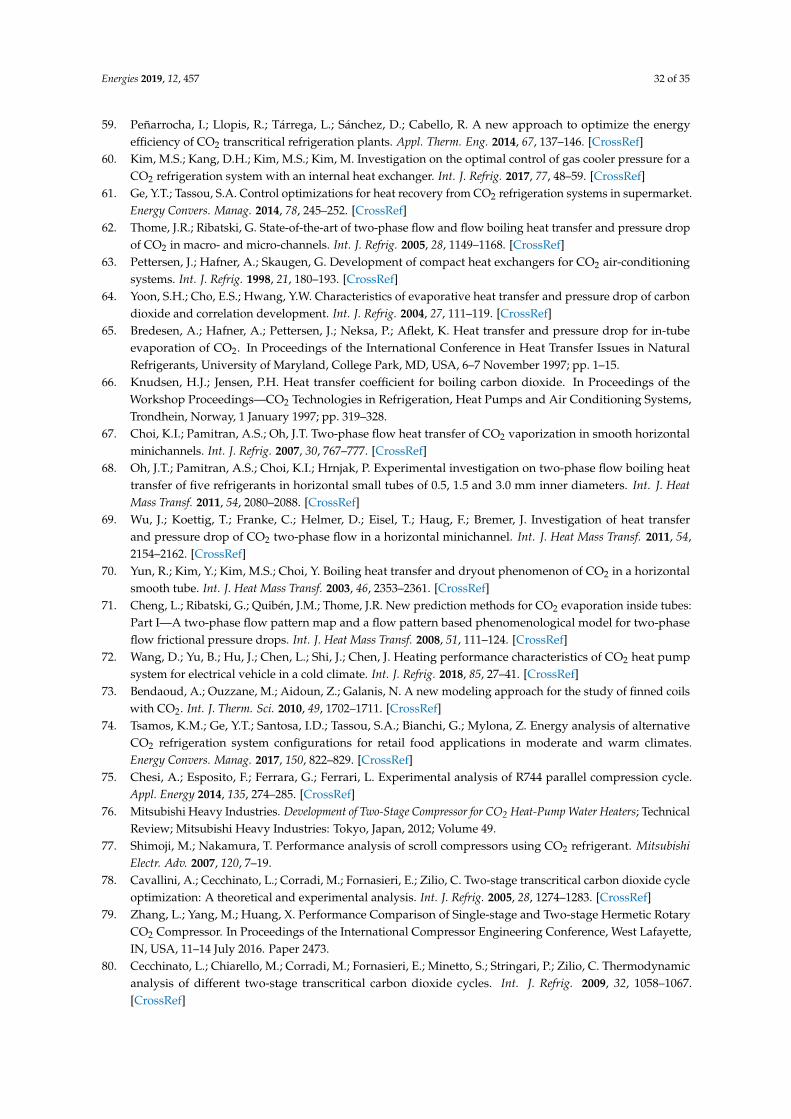
Energies 2019, 12, 457 32 of 35
59. Peñarrocha, I.; Llopis, R.; Tárrega, L.; Sánchez, D.; Cabello, R. A new approach to optimize the energyefficiency of CO2 transcritical refrigeration plants. Appl. Therm. Eng. 2014, 67, 137–146. [CrossRef]
60. Kim, M.S.; Kang, D.H.; Kim, M.S.; Kim, M. Investigation on the optimal control of gas cooler pressure for aCO2 refrigeration system with an internal heat exchanger. Int. J. Refrig. 2017, 77, 48–59. [CrossRef]
61. Ge, Y.T.; Tassou, S.A. Control optimizations for heat recovery from CO2 refrigeration systems in supermarket.Energy Convers. Manag. 2014, 78, 245–252. [CrossRef]
62. Thome, J.R.; Ribatski, G. State-of-the-art of two-phase flow and flow boiling heat transfer and pressure dropof CO2 in macro- and micro-channels. Int. J. Refrig. 2005, 28, 1149–1168. [CrossRef]
63. Pettersen, J.; Hafner, A.; Skaugen, G. Development of compact heat exchangers for CO2 air-conditioningsystems. Int. J. Refrig. 1998, 21, 180–193. [CrossRef]
64. Yoon, S.H.; Cho, E.S.; Hwang, Y.W. Characteristics of evaporative heat transfer and pressure drop of carbondioxide and correlation development. Int. J. Refrig. 2004, 27, 111–119. [CrossRef]
65. Bredesen, A.; Hafner, A.; Pettersen, J.; Neksa, P.; Aflekt, K. Heat transfer and pressure drop for in-tubeevaporation of CO2. In Proceedings of the International Conference in Heat Transfer Issues in NaturalRefrigerants, University of Maryland, College Park, MD, USA, 6–7 November 1997; pp. 1–15.
66. Knudsen, H.J.; Jensen, P.H. Heat transfer coefficient for boiling carbon dioxide. In Proceedings of theWorkshop Proceedings—CO2 Technologies in Refrigeration, Heat Pumps and Air Conditioning Systems,Trondhein, Norway, 1 January 1997; pp. 319–328.
67. Choi, K.I.; Pamitran, A.S.; Oh, J.T. Two-phase flow heat transfer of CO2 vaporization in smooth horizontalminichannels. Int. J. Refrig. 2007, 30, 767–777. [CrossRef]
68. Oh, J.T.; Pamitran, A.S.; Choi, K.I.; Hrnjak, P. Experimental investigation on two-phase flow boiling heattransfer of five refrigerants in horizontal small tubes of 0.5, 1.5 and 3.0 mm inner diameters. Int. J. HeatMass Transf. 2011, 54, 2080–2088. [CrossRef]
69. Wu, J.; Koettig, T.; Franke, C.; Helmer, D.; Eisel, T.; Haug, F.; Bremer, J. Investigation of heat transferand pressure drop of CO2 two-phase flow in a horizontal minichannel. Int. J. Heat Mass Transf. 2011, 54,2154–2162. [CrossRef]
70. Yun, R.; Kim, Y.; Kim, M.S.; Choi, Y. Boiling heat transfer and dryout phenomenon of CO2 in a horizontalsmooth tube. Int. J. Heat Mass Transf. 2003, 46, 2353–2361. [CrossRef]
71. Cheng, L.; Ribatski, G.; Quibén, J.M.; Thome, J.R. New prediction methods for CO2 evaporation inside tubes:Part I—A two-phase flow pattern map and a flow pattern based phenomenological model for two-phaseflow frictional pressure drops. Int. J. Heat Mass Transf. 2008, 51, 111–124. [CrossRef]
72. Wang, D.; Yu, B.; Hu, J.; Chen, L.; Shi, J.; Chen, J. Heating performance characteristics of CO2 heat pumpsystem for electrical vehicle in a cold climate. Int. J. Refrig. 2018, 85, 27–41. [CrossRef]
73. Bendaoud, A.; Ouzzane, M.; Aidoun, Z.; Galanis, N. A new modeling approach for the study of finned coilswith CO2. Int. J. Therm. Sci. 2010, 49, 1702–1711. [CrossRef]
74. Tsamos, K.M.; Ge, Y.T.; Santosa, I.D.; Tassou, S.A.; Bianchi, G.; Mylona, Z. Energy analysis of alternativeCO2 refrigeration system configurations for retail food applications in moderate and warm climates.Energy Convers. Manag. 2017, 150, 822–829. [CrossRef]
75. Chesi, A.; Esposito, F.; Ferrara, G.; Ferrari, L. Experimental analysis of R744 parallel compression cycle.Appl. Energy 2014, 135, 274–285. [CrossRef]
76. Mitsubishi Heavy Industries. Development of Two-Stage Compressor for CO2 Heat-Pump Water Heaters; TechnicalReview; Mitsubishi Heavy Industries: Tokyo, Japan, 2012; Volume 49.
77. Shimoji, M.; Nakamura, T. Performance analysis of scroll compressors using CO2 refrigerant. MitsubishiElectr. Adv. 2007, 120, 7–19.
78. Cavallini, A.; Cecchinato, L.; Corradi, M.; Fornasieri, E.; Zilio, C. Two-stage transcritical carbon dioxide cycleoptimization: A theoretical and experimental analysis. Int. J. Refrig. 2005, 28, 1274–1283. [CrossRef]
79. Zhang, L.; Yang, M.; Huang, X. Performance Comparison of Single-stage and Two-stage Hermetic RotaryCO2 Compressor. In Proceedings of the International Compressor Engineering Conference, West Lafayette,IN, USA, 11–14 July 2016. Paper 2473.
80. Cecchinato, L.; Chiarello, M.; Corradi, M.; Fornasieri, E.; Minetto, S.; Stringari, P.; Zilio, C. Thermodynamicanalysis of different two-stage transcritical carbon dioxide cycles. Int. J. Refrig. 2009, 32, 1058–1067.[CrossRef]
Energies 2019, 12, 457 33 of 35
81. Pitarch, M.; Navarro-Peris, E.; Gonzalvez, J.; Corberan, J.M. Analysis and optimisation of different two-stagetranscritical carbon dioxide cycles for heating applications. Int. J. Refrig. 2016, 70, 235–242. [CrossRef]
82. Cho, H.; Baek, C.; Park, C.; Kim, Y. Performance evaluation of a two-stage CO2 cycle with gas injection inthe cooling mode operation. Int. J. Refrig. 2009, 32, 40–46. [CrossRef]
83. Liu, S.; Sun, Z.; Li, H.; Dai, B.; Chen, Y. Thermodynamic analysis of CO2 transcritical two-stage compressionrefrigeration cycle systems with expanders. HKIE Trans. 2017, 24, 70–77. [CrossRef]
84. Ibsaine, R.; Joffroy, J.-M.; Stouffs, P. Modelling of a new thermal compressor for supercritical CO2 heat pump.Energy 2016, 117, 530–539. [CrossRef]
85. Sumeru, K.; Nasution, H.; Ani, F.N. A review on two-phase ejector as an expansion device in vaporcompression refrigeration cycle. Renew. Sustain. Energy Rev. 2012, 16, 4927–4937. [CrossRef]
86. Elbel, S.; Hrnjak, P. Experimental validation of a prototype ejector designed to reduce throttling lossesencountered in transcritical R744 system operation. Int. J. Refrig. 2008, 31, 411–422. [CrossRef]
87. Lee, J.S.; Kim, M.S.; Kim, M.S. Studies on the performance of a CO2 air conditioning system using an ejectoras an expansion device. Int. J. Refrig. 2014, 38, 140–152. [CrossRef]
88. Elbel, S.; Lawrence, N. Review of recent developments in advanced ejector technology. Int. J. Refrig. 2016, 62,1–18. [CrossRef]
89. Lucas, C.; Rusche, H.; Schroeder, A.; Koehler, J. Numerical investigation of a two-phase CO2 ejector. Int. J.Refrig. 2014, 43, 154–166. [CrossRef]
90. Palacz, M.; Smolka, J.; Nowak, A.J.; Banasiak, K.; Hafner, A. Shape optimisation of a two-phase ejector forCO2 refrigeration systems. Int. J. Refrig. 2017, 74, 210–221. [CrossRef]
91. Angielczyk, W.; Bartosiewicz, Y.; Butrymowicz, D.; Seynhaeve, J.-M. 1-D Modeling Of Supersonic CarbonDioxide Two-Phase Flow Through Ejector Motive Nozzle. In Proceedings of the International Refrigerationand Air Conditioning Conference Purdue e-Pubs, West Lafayette, IN, USA, 12–15 July 2010.
92. Palacz, M.; Haida, M.; Smolka, J.; Nowak, A.J.; Banasiak, K.; Hafner, A. HEM and HRM accuracycomparison for the simulation of CO2 expansion in two-phase ejectors for supermarket refrigeration systems.Appl. Therm. Eng. 2017, 115, 160–169. [CrossRef]
93. Zheng, L.X.; Deng, J.Q.; He, Y.; Jiang, P.X. Dynamic model of a transcritical CO2 ejector expansionrefrigeration system. Int. J. Refrig. 2015, 60, 247–260. [CrossRef]
94. He, Y.; Deng, J.Q.; Zheng, L.X.; Zhang, Z.X. Thermodynamic study on a new transcritical CO2 ejectorexpansion refrigeration system with two-stage evaporation and vapor feedback. HVAC&R Res. 2014, 20,655–664.
95. Bai, T.; Yan, G.; Yu, J. Performance evolution on a dual-temperature CO2 transcritical refrigeration cycle withtwo cascade ejectors. Appl. Therm. Eng. 2017, 120, 26–35. [CrossRef]
96. Bodys, J.; Smolka, J.; Palacz, M.; Haida, M.; Banasiak, K.; Nowak, A.J.; Hafner, A. Performance of fixedgeometry ejectors with a swirl motion installed in a multi-ejector module of a CO2 refrigeration system.Energy 2016, 117, 620–631. [CrossRef]
97. Smolka, J.; Palacz, M.; Bodys, J.; Banasiak, K.; Fic, A.; Bulinski, Z. Performance comparison of fixed- andcontrollable-geometry ejectors in a CO2 refrigeration system. Int. J. Refrig. 2016, 65, 172–182. [CrossRef]
98. Liu, F.; Groll, E.A.; Ren, J. Comprehensive experimental performance analyses of an ejector expansiontranscritical CO2 system. Appl. Therm. Eng. 2016, 98, 1061–1069. [CrossRef]
99. Xu, X.X.; Chen, G.M.; Tang, L.M.; Zhu, Z.J. Experimental investigation on performance of transcritical CO2
heat pump system with ejector under optimum high-side pressure. Energy 2012, 44, 870–877. [CrossRef]100. He, Y.; Deng, J.; Yang, F.; Zhang, Z. An optimal multivariable controller for transcritical CO2 refrigeration
cycle with an adjustable ejector. Energy Convers. Manag. 2017, 142, 466–476. [CrossRef]101. He, Y.; Deng, J.; Zheng, L.; Zhang, Z. Performance optimization of a transcritical CO2 refrigeration system
using a controlled ejector. Int. J. Refrig. 2017, 75, 250–261. [CrossRef]102. Zhang, Z.; Dong, X.; Ren, Z.; Lai, T.; Hou, Y. Influence of Refrigerant Charge Amount and EEV Opening on
the Performance of a Transcritical CO2 Heat Pump Water Heater. Energies 2017, 10, 1521. [CrossRef]103. Song, Y.; Wang, J.; Cao, F.; Shu, P.; Wang, X. Experimental investigation on a capillary tube based transcritical
CO2 heat pump system. Appl. Therm. Eng. 2017, 112, 184–189. [CrossRef]104. Madsen, K.B.; Poulsen, C.S.; Wiesenfarth, M. Study of capillary tubes in a transcritical CO2 refrigeration
system. Int. J. Refrig. 2005, 28, 1212–1218. [CrossRef]
Energies 2019, 12, 457 34 of 35
105. Hu, J.; Li, M.; Zhao, L.; Xia, B.; Ma, Y. Improvement and experimental research of CO2 two-rolling pistonexpander. Energy 2015, 93, 2199–2207. [CrossRef]
106. Navarro-Esbrı, J.; Cabello, R.; Torrella, E. Experimental evaluation of the internal heat exchanger influenceon a vapour compression plant energy efficiency working with R22, R123a and R407C. Energy 2005, 30,621–636. [CrossRef]
107. Shariatzadeh, O.J.; Abolhassani, S.S.; Rahmani, M.; Nejad, M.Z. Comparison of transcritical CO2 refrigerationcycle with expander and throttling valve including/excluding internal heat exchanger: Exergy and energypoints of view. Appl. Therm. Eng. 2016, 93, 779–787. [CrossRef]
108. Zhang, Z.; Tian, L.; Chen, Y.; Tong, L. Effect of an internal heat exchanger on performance of the transcriticalcarbon dioxide refrigeration cycle with an expander. Entropy 2014, 16, 5919–5934. [CrossRef]
109. Sánchez, D.; Patiño, J.; Llopis, R.; Cabello, R.; Torrella, E.; Fuentes, F.V. New positions for an internalheat exchanger in a CO2 supercritical refrigeration plant. Experimental analysis and energetic evaluation.Appl. Therm. Eng. 2014, 63, 129–139. [CrossRef]
110. Pérez-García, V.; Rodríguez-Muñoz, J.L.; Ramírez-Minguela, J.J.; Belman-Flores, J.M.; Méndez-Díaz, S.Comparative analysis of energy improvements in single transcritical cycle in refrigeration mode.Appl. Therm. Eng. 2016, 99, 866–872. [CrossRef]
111. Llopis, R.; Nebot-Andrés, L.; Cabello, R.; Sánchez, D.; Catalán-Gil, J. Experimental evaluation of a CO2
transcritical refrigeration plant with dedicated mechanical subcooling. Int. J. Refrig. 2016, 69, 361–368.[CrossRef]
112. Ituna-Yudonago, J.F.; Belman-Flores, J.M.; Elizalde-Blancas, F.; García-Valladares, O. Numerical investigationof CO2 behavior in the internal heat exchanger under variable boundary conditions of the transcriticalrefrigeration system. Appl. Therm. Eng. 2017, 115, 1063–1078. [CrossRef]
113. Lorentzen, G.; Pettersen, J. A new, efficient and environmentally benign system for car air-conditioning.Int. J. Refrig. 1993, 16, 4–12. [CrossRef]
114. Beyond HFCs Position Paper on CO2 Vending Machines. Available online: http://www.beyondhfcs.org/(accessed on 28 October 2018).
115. EcoCute Shipments Exceed 2 Million Landmark. Available online: http://www.r744.com/articles/2009-11-26-eco-cute-shipments-exceed-2-million-landmark.php (accessed on 26 November 2009).
116. Available online: http://www.mayekawa.com.au/products/heat-pumps/heatcom-water-heat-source/(accessed on 6 September 2018).
117. Liu, F.; Zhu, W.; Cai, Y.; Groll, E.A.; Lei, Y. Experimental performance study on a dual-mode CO2 heat pumpsystem with thermal storage. Appl. Therm. Eng. 2017, 115, 393–405. [CrossRef]
118. Hu, B.; Wang, X.; Cao, F.; He, Z.; Xing, Z. Experimental analysis of an air-source transcritical CO2 heat pumpwater heater using the hot gas bypass defrosting method. Appl. Therm. Eng. 2014, 71, 528–535. [CrossRef]
119. Calabrese, N.; Mastrullo, R.; Mauro, A.W.; Rovella, P.; Tammaro, M. Performance analysis of a rooftop,air-to-air heat pump working with CO2. Appl. Therm. Eng. 2015, 75, 1046–1054. [CrossRef]
120. Eslami-Nejad, P.; Ouzzane, M.; Aidoun, Z. Modeling of a two-phase CO2-filled vertical borehole forgeothermal heat pump applications. Appl. Energy 2014, 114, 611–620. [CrossRef]
121. Wang, J.; Kang, L.; Liu, J. CO2 Transcritical Cycle for Ground Source Heat Pump. In Proceedings of the CSIE’09, 2009 WRI World Congress on Computer Science and Information Engineering, Los Angeles, CA, USA,31 March–2 April 2009; Volume 2, pp. 213–217.
122. Faria, R.N.; Nunes, R.O.; Koury, R.N.N.; Machado, L. Dynamic modeling study for a solar evaporator withexpansion valve assembly of a transcritical CO2 heat pump. Int. J. Refrig. 2016, 64, 203–213. [CrossRef]
123. Li, S.; Li, S.; Zhang, X. Simulation research of a hybrid heat source heat pump using R134a, R744 instead ofR22 for domestic water heating in residential buildings. Energy Build. 2015, 91, 57–64. [CrossRef]
124. Cho, H. Comparative study on the performance and exergy efficiency of a solar hybrid heat pump using R22and R744. Energy 2015, 93, 1267–1276. [CrossRef]
125. Chaichana, C.; Aye, L.; Charters, W.W.S. Natural working fluids for solar-boosted heat pumps. Int. J. Refrig.2003, 26, 637–643. [CrossRef]
126. Jin, Z.; Eikevik, T.M.; Nekså, P.; Hafner, A. A steady and quasi-steady state analysis on the CO2 hybridground-coupled heat pumping system. Int. J. Refrig. 2017, 76, 29–41. [CrossRef]
127. Jin, Z.; Eikevik, T.M.; Nekså, P.; Hafner, A. Investigation on CO2 hybrid ground-coupled heat pumpingsystem under warm climate. Int. J. Refrig. 2016, 62, 145–152. [CrossRef]
Energies 2019, 12, 457 35 of 35
128. Kim, W.; Choi, J.; Cho, H. Performance analysis of hybrid solar-geothermal CO2 heat pump system forresidential heating. Renew. Energy 2013, 50, 596–604. [CrossRef]
129. Hu, B.; Li, Y.; Cao, F.; Xing, Z. Extremum seeking control of COP optimization for air-source transcriticalCO2 heat pump water heater system. Appl. Energy 2015, 147, 361–372. [CrossRef]
130. ENERGY.GOV. Available online: https://energy.gov/ (accessed on 3 September 2018).131. Emmi, G.; Zarrella, A.; de Carli, M.; Galgaro, A. Solar Assisted Ground Source Heat Pump in Cold Climates.
Energy Procedia 2015, 82, 623–629. [CrossRef]132. Chen, J.F.; Dai, Y.J.; Wang, R.Z. Experimental and theoretical study on a solar assisted CO2 heat pump for
space heating. Renew. Energy 2016, 89, 295–304. [CrossRef]133. Islam, M.R.; Sumathy, K.; Gong, J.; Khan, S.U. Performance study on solar assisted heat pump water heater
using CO2 in a transcritical cycle. Renew. Energies Power Qual. 2012. [CrossRef]134. Deng, S.; Dai, Y.J.; Wang, R.Z.; Matsuura, T.; Yasui, Y. Comparison study on performance of a hybrid
solar-assisted CO2 heat pump. Appl. Therm. Eng. 2011, 31, 3696–3705. [CrossRef]135. Residential CO2 Heat Pump Water Heater. Available online: https://energy.gov/eere/buildings/
downloads/residential-CO2-heat-pump-water-heater (accessed on 28 July 2018).136. Available online: https://www.ornl.gov/ (accessed on 28 July 2018).137. Available online: https://www.energystar.gov/ (accessed on 25 August 2018).138. Tammaro, M.; Montagud, C.; Corberán, J.M.; Mauro, A.W.; Mastrullo, R. Seasonal performance assessment of
sanitary hot water production systems using propane and CO2 heat pumps. Int. J. Refrig. 2017, 74, 224–239.[CrossRef]
139. Saikawa, M.; Koyama, S. Thermodynamic analysis of vapor compression heat pump cycle for tap waterheating and development of CO2 heat pump water heater for residential use. Appl. Therm. Eng. 2016, 106,1236–1243. [CrossRef]
140. Klöcker, K.; Schmidt, E.L.; Steimle, F. Carbon dioxide as a working fluid in drying heat pumps. Int. J. Refrig.2001, 24, 100–107. [CrossRef]
141. Schmidt, E.L.; Klöcker, K.; Flacke, N.; Steimle, F. Applying the transcritical CO2 process to a drying heatpump. Int. J. Refrig. 1998, 21, 202–211. [CrossRef]
142. Hakkaki-Fard, A.; Aidoun, Z.; Ouzzane, M. Applying refrigerant mixtures with thermal glide in cold climateair-source heat pumps. Appl. Therm. Eng. 2014, 62, 714–722. [CrossRef]
143. Hakkaki-Fard, A.; Aidoun, Z.; Ouzzane, M. Improving cold climate air-source heat pump performance withrefrigerant mixtures. Appl. Therm. Eng. 2015, 78, 695–703. [CrossRef]
144. Available online: http://zeroenergyproject.org/2017/05/22/CO2-takes-heat-pump-water-heaters-next-level/ (accessed on 25 August 2018).
145. Available online: http://www.esru.strath.ac.uk/EandE/Web_sites/10-11/ASHP_CO2/lit-sanyoEcoCute.html (accessed on 25 August 2018).
146. Available online: https://www.sandenwaterheater.com/ (accessed on 25 August 2018).147. Brush, A.; Masanet, E.; Worrell, E. Energy Efficiency Improvement and Cost Saving Opportunities for the Dairy
Processing Industry. An Energy Star Guide for Energy and Plant Managers; Ernest Orlando Lawrence BerkeleyNational Laboratory, Environmental Energy Technologies Division: Berkeley, CA, USA, 2011.
148. Liu, Y.; Groll, E.A.; Yazawa, K.; Kurtulus, O. Energy-saving performance and economics of CO2 and NH3heat pumps with simultaneous cooling and heating applications in food processing: Case studies. Int. J.Refrig. 2017, 73, 111–124. [CrossRef]
149. Singh, S.; Dasgupta, M.S. CO2 heat pump for waste heat recovery and utilization in dairy industry withammonia based refrigeration. Int. J. Refrig. 2017, 78, 108–120. [CrossRef]
© 2019 by the authors. Licensee MDPI, Basel, Switzerland. This article is an open accessarticle distributed under the terms and conditions of the Creative Commons Attribution(CC BY) license (http://creativecommons.org/licenses/by/4.0/).