
Realization of high capacity transmission in fiber optic communication systems using Absolute Polar...
7
Realization of high capacity transmission in fiber optic communication systems using Absolute Polar Duty Cycle Division Multiplexing (AP-DCDM) technique Amin Malekmohammadi a, * , Ghafour Amouzad Mahdiraji a , Ahmad Fauzi Abas a , Mohamad Khazani Abdullah b , Makhfudzah Mokhtar a , Mohd Fadlee A. Rasid a a Photonics and Fiber Optics Systems Laboratory, Department of Computer and Communication Systems Engineering, Faculty of Engineering, University Putra Malaysia, 43400 Serdang, Selangor, Malaysia b Significant Technologies Sdn. Bhd., 43400 Serdang, Selangor, Malaysia article info Article history: Received 5 August 2008 Revised 1 March 2009 Available online 19 April 2009 Keywords: Optical communication Multiplexing Chromatic dispersion Duty cycle abstract An electrical multiplexing technique, namely Absolute Polar Duty Cycle Division Multiplexing (AP-DCDM) is reported for high-speed optical fiber communication systems. It is demonstrated that 40 Gb/s (4 10 Gb/s) AP-DCDM system shows a clear advantage over conventional 40 Gb/s RZ-OOK with 50% duty cycle in terms of dispersion tolerance and spectral efficiency. At 40 Gb/s its tolerance to chro- matic dispersion (CD) is 124 ps/nm and 194 ps/nm for the worst and the best user, respectively. These values are higher than that of 40 Gb/s RZ-OOK, which is around 100 ps/nm. The spectral efficiency, recei- ver sensitivity and OSNR for different number of channels are discussed. Comparison against other modulation formats namely duobinary, Non-Return-to-Zero (NRZ)-OOK and RZ-Differential Quadrature Phase-Shift Keying (RZ-DQPSK) at 40 Gb/s are made. It is shown that AP-DCDM has the best receiver sensitivity (32 dBm) and better CD tolerance (±200 ps/nm) than NRZ-OOK and RZ-DQPSK. In reference to duobinary, AP-DCDM has better receiver sensitivity but worse dispersion tolerance. Ó 2009 Elsevier Inc. All rights reserved. 1. Introduction Multiplexing is one of the fundamental necessities in today’s digital communications, which allows multiple users to share the bandwidth of the transmission medium. There are several multi- plexing techniques available such as Time Division Multiplexing (TDM) [1] and Wavelength Division Multiplexing (WDM) [2,3]. Many researchers have for some time, examined multilevel signal- ing, e.g. AM-PSK polybinary, M-ary Amplitude-Shift-Keying (ASK) and polyquaternary as a way of improving the system performance against Chromatic Dispersion (CD) and Polarization mode disper- sion (PMD) due to its reduced spectral occupancy [4]. The main is- sues in those techniques are degradation in receiver sensitivity due to the increased number of levels and the signal dependence on signal-spontaneous beat noise [5]. At the same time Differential Quadrature Phase-Shift Keying (DQPSK) [6] and Polarization Divi- sion Multiplexing (PDM) [7] were proposed for realizing high capacity WDM networks. However, both techniques increase the complexity of the receiver by the introduction of the tempera- ture-stabilized Mach-Zehnder Interferometer (MZI) and fast polar- ization controller, respectively [7]. Pulse position modulation (PPM) is another alternative for optical communication systems. In PPM each symbol interval is partitioned into subintervals, or chips, and the transmitter sends an optical pulse during one of these chips. In this system the amplitude and width of the signal is kept constant. Position of each pulse, in relation to the position of a recurrent reference pulse is varied. In comparison to On–Off- Keying (OOK), PPM requires less optical power but higher band- width. Another challenge of this technique is that PPM requires both chip- and symbol-level synchronization [8]. Absolute Polar Duty Cycle Division Multiplexing (AP-DCDM) was reported for the first time in [9,10] as an alternative multiplex- ing technique for wireless transmission based on free space prop- agation model with Adaptive White Gaussian Noise (AWGN). In this paper, AP-DCDM is modeled for optical fiber communi- cation and characterized in dispersive optical transmission medium. AP-DCDM uses different RZ duty cycles and bipolar sig- naling to differentiate the channels. Subsequent users at the mul- tiplexer input have opposite polarity, which results in unique multilevel patterns at the output of the multiplexer. As compared to unipolar input, by using bipolar signaling, the increment of the multiplexed signal amplitude with reference to the number of users is reduced. It is verified that AP-DCDM has smaller spectral width, which leads toward better spectral efficiency and disper- sion tolerance than conventional RZ-OOK with 50% duty cycle. For simplicity throughout this paper, conventional RZ-OOK with 50% duty cycle is referred to as RZ-OOK. Performance of AP-DCDM in comparison to other multilevel modulation formats is also discussed. 1068-5200/$ - see front matter Ó 2009 Elsevier Inc. All rights reserved. doi:10.1016/j.yofte.2009.03.001 * Corresponding author. E-mail address: [email protected] (A. Malekmohammadi). Optical Fiber Technology 15 (2009) 337–343 Contents lists available at ScienceDirect Optical Fiber Technology www.elsevier.com/locate/yofte
Transcript of Realization of high capacity transmission in fiber optic communication systems using Absolute Polar...

Optical Fiber Technology 15 (2009) 337–343
Contents lists available at ScienceDirect
Optical Fiber Technology
www.elsevier .com/locate /yof te
Realization of high capacity transmission in fiber optic communication systemsusing Absolute Polar Duty Cycle Division Multiplexing (AP-DCDM) technique
Amin Malekmohammadi a,*, Ghafour Amouzad Mahdiraji a, Ahmad Fauzi Abas a,Mohamad Khazani Abdullah b, Makhfudzah Mokhtar a, Mohd Fadlee A. Rasid a
a Photonics and Fiber Optics Systems Laboratory, Department of Computer and Communication Systems Engineering, Faculty of Engineering, University Putra Malaysia,43400 Serdang, Selangor, Malaysiab Significant Technologies Sdn. Bhd., 43400 Serdang, Selangor, Malaysia
a r t i c l e i n f o a b s t r a c t
Article history:Received 5 August 2008Revised 1 March 2009Available online 19 April 2009
Keywords:Optical communicationMultiplexingChromatic dispersionDuty cycle
1068-5200/$ - see front matter � 2009 Elsevier Inc. Adoi:10.1016/j.yofte.2009.03.001
* Corresponding author.E-mail address: [email protected] (A. Malek
An electrical multiplexing technique, namely Absolute Polar Duty Cycle Division Multiplexing(AP-DCDM) is reported for high-speed optical fiber communication systems. It is demonstrated that40 Gb/s (4 � 10 Gb/s) AP-DCDM system shows a clear advantage over conventional 40 Gb/s RZ-OOK with50% duty cycle in terms of dispersion tolerance and spectral efficiency. At 40 Gb/s its tolerance to chro-matic dispersion (CD) is 124 ps/nm and 194 ps/nm for the worst and the best user, respectively. Thesevalues are higher than that of 40 Gb/s RZ-OOK, which is around 100 ps/nm. The spectral efficiency, recei-ver sensitivity and OSNR for different number of channels are discussed. Comparison against othermodulation formats namely duobinary, Non-Return-to-Zero (NRZ)-OOK and RZ-Differential QuadraturePhase-Shift Keying (RZ-DQPSK) at 40 Gb/s are made. It is shown that AP-DCDM has the best receiversensitivity (�32 dBm) and better CD tolerance (±200 ps/nm) than NRZ-OOK and RZ-DQPSK. In referenceto duobinary, AP-DCDM has better receiver sensitivity but worse dispersion tolerance.
� 2009 Elsevier Inc. All rights reserved.
1. Introduction
Multiplexing is one of the fundamental necessities in today’sdigital communications, which allows multiple users to share thebandwidth of the transmission medium. There are several multi-plexing techniques available such as Time Division Multiplexing(TDM) [1] and Wavelength Division Multiplexing (WDM) [2,3].Many researchers have for some time, examined multilevel signal-ing, e.g. AM-PSK polybinary, M-ary Amplitude-Shift-Keying (ASK)and polyquaternary as a way of improving the system performanceagainst Chromatic Dispersion (CD) and Polarization mode disper-sion (PMD) due to its reduced spectral occupancy [4]. The main is-sues in those techniques are degradation in receiver sensitivity dueto the increased number of levels and the signal dependence onsignal-spontaneous beat noise [5]. At the same time DifferentialQuadrature Phase-Shift Keying (DQPSK) [6] and Polarization Divi-sion Multiplexing (PDM) [7] were proposed for realizing highcapacity WDM networks. However, both techniques increase thecomplexity of the receiver by the introduction of the tempera-ture-stabilized Mach-Zehnder Interferometer (MZI) and fast polar-ization controller, respectively [7]. Pulse position modulation(PPM) is another alternative for optical communication systems.In PPM each symbol interval is partitioned into subintervals, or
ll rights reserved.
mohammadi).
chips, and the transmitter sends an optical pulse during one ofthese chips. In this system the amplitude and width of the signalis kept constant. Position of each pulse, in relation to the positionof a recurrent reference pulse is varied. In comparison to On–Off-Keying (OOK), PPM requires less optical power but higher band-width. Another challenge of this technique is that PPM requiresboth chip- and symbol-level synchronization [8].
Absolute Polar Duty Cycle Division Multiplexing (AP-DCDM)was reported for the first time in [9,10] as an alternative multiplex-ing technique for wireless transmission based on free space prop-agation model with Adaptive White Gaussian Noise (AWGN).
In this paper, AP-DCDM is modeled for optical fiber communi-cation and characterized in dispersive optical transmissionmedium. AP-DCDM uses different RZ duty cycles and bipolar sig-naling to differentiate the channels. Subsequent users at the mul-tiplexer input have opposite polarity, which results in uniquemultilevel patterns at the output of the multiplexer. As comparedto unipolar input, by using bipolar signaling, the increment of themultiplexed signal amplitude with reference to the number ofusers is reduced. It is verified that AP-DCDM has smaller spectralwidth, which leads toward better spectral efficiency and disper-sion tolerance than conventional RZ-OOK with 50% duty cycle.For simplicity throughout this paper, conventional RZ-OOK with50% duty cycle is referred to as RZ-OOK. Performance of AP-DCDMin comparison to other multilevel modulation formats is alsodiscussed.
338 A. Malekmohammadi et al. / Optical Fiber Technology 15 (2009) 337–343
2. Working principle
AP-DCDM is a multiplexing technique that uses bipolar signalwith different duty cycles to differentiate the channels or users.In this technique, each user transmits bit ‘0’ with zero volts andfor the case of bit one, the odd users transmit ‘+A’ volts while theeven users transmit ‘�A’ volts. Based on the linear distribution(per user assignment) of duty cycle, the ith multiplexing usertransmits bit 1 within Ti second, which is
Ti ¼ i� Ts
nþ 1
� �ð1Þ
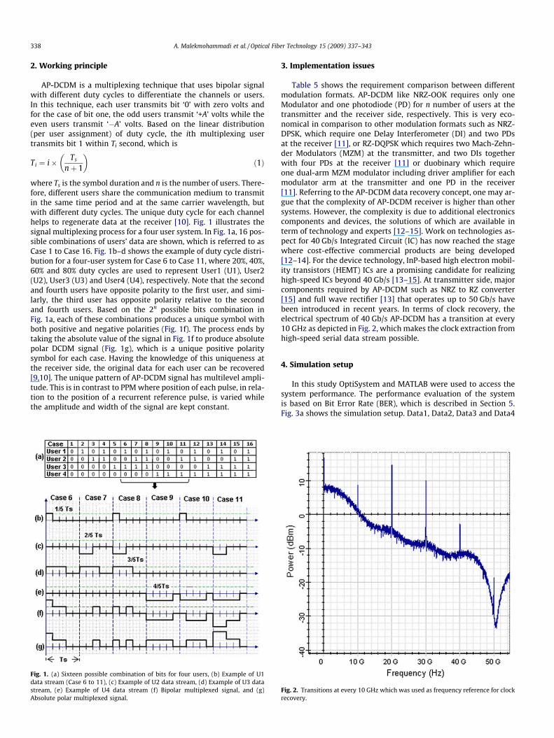
where Ts is the symbol duration and n is the number of users. There-fore, different users share the communication medium to transmitin the same time period and at the same carrier wavelength, butwith different duty cycles. The unique duty cycle for each channelhelps to regenerate data at the receiver [10]. Fig. 1 illustrates thesignal multiplexing process for a four user system. In Fig. 1a, 16 pos-sible combinations of users’ data are shown, which is referred to asCase 1 to Case 16. Fig. 1b–d shows the example of duty cycle distri-bution for a four-user system for Case 6 to Case 11, where 20%, 40%,60% and 80% duty cycles are used to represent User1 (U1), User2(U2), User3 (U3) and User4 (U4), respectively. Note that the secondand fourth users have opposite polarity to the first user, and simi-larly, the third user has opposite polarity relative to the secondand fourth users. Based on the 2n possible bits combination inFig. 1a, each of these combinations produces a unique symbol withboth positive and negative polarities (Fig. 1f). The process ends bytaking the absolute value of the signal in Fig. 1f to produce absolutepolar DCDM signal (Fig. 1g), which is a unique positive polaritysymbol for each case. Having the knowledge of this uniqueness atthe receiver side, the original data for each user can be recovered[9,10]. The unique pattern of AP-DCDM signal has multilevel ampli-tude. This is in contrast to PPM where position of each pulse, in rela-tion to the position of a recurrent reference pulse, is varied whilethe amplitude and width of the signal are kept constant.
Fig. 1. (a) Sixteen possible combination of bits for four users, (b) Example of U1data stream (Case 6 to 11), (c) Example of U2 data stream, (d) Example of U3 datastream, (e) Example of U4 data stream (f) Bipolar multiplexed signal, and (g)Absolute polar multiplexed signal.
3. Implementation issues
Table 5 shows the requirement comparison between differentmodulation formats. AP-DCDM like NRZ-OOK requires only oneModulator and one photodiode (PD) for n number of users at thetransmitter and the receiver side, respectively. This is very eco-nomical in comparison to other modulation formats such as NRZ-DPSK, which require one Delay Interferometer (DI) and two PDsat the receiver [11], or RZ-DQPSK which requires two Mach-Zehn-der Modulators (MZM) at the transmitter, and two DIs togetherwith four PDs at the receiver [11] or duobinary which requireone dual-arm MZM modulator including driver amplifier for eachmodulator arm at the transmitter and one PD in the receiver[11]. Referring to the AP-DCDM data recovery concept, one may ar-gue that the complexity of AP-DCDM receiver is higher than othersystems. However, the complexity is due to additional electronicscomponents and devices, the solutions of which are available interm of technology and experts [12–15]. Work on technologies as-pect for 40 Gb/s Integrated Circuit (IC) has now reached the stagewhere cost-effective commercial products are being developed[12–14]. For the device technology, InP-based high electron mobil-ity transistors (HEMT) ICs are a promising candidate for realizinghigh-speed ICs beyond 40 Gb/s [13–15]. At transmitter side, majorcomponents required by AP-DCDM such as NRZ to RZ converter[15] and full wave rectifier [13] that operates up to 50 Gb/s havebeen introduced in recent years. In terms of clock recovery, theelectrical spectrum of 40 Gb/s AP-DCDM has a transition at every10 GHz as depicted in Fig. 2, which makes the clock extraction fromhigh-speed serial data stream possible.
4. Simulation setup
In this study OptiSystem and MATLAB were used to access thesystem performance. The performance evaluation of the systemis based on Bit Error Rate (BER), which is described in Section 5.Fig. 3a shows the simulation setup. Data1, Data2, Data3 and Data4
Fig. 2. Transitions at every 10 GHz which was used as frequency reference for clockrecovery.
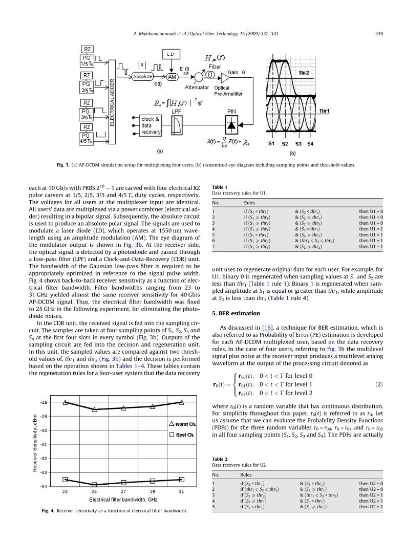
Fig. 3. (a) AP-DCDM simulation setup for multiplexing four users, (b) transmitted eye diagram including sampling points and threshold values.
Table 1Data recovery rules for U1.
No. Rules
1 if (S1 < thr1) & (S2 < thr1) then U1 = 02 if (S1 P thr1) & (S2 P thr1) then U1 = 03 if (S1 P thr2) & (S2 P thr2) then U1 = 04 if (S1 P thr1) & (S2 < thr1) then U1 = 15 if (S1 < thr1) & (S2 P thr1) then U1 = 16 if (S1 P thr2) & (thr1 6 S2 6 thr2) then U1 = 17 if (S1 P thr1) & (S2 P thr2) then U1 = 1
A. Malekmohammadi et al. / Optical Fiber Technology 15 (2009) 337–343 339
each at 10 Gb/s with PRBS 210 � 1 are carved with four electrical RZpulse carvers at 1/5, 2/5, 3/5 and 4/5 Ts duty cycles, respectively.The voltages for all users at the multiplexer input are identical.All users’ data are multiplexed via a power combiner (electrical ad-der) resulting in a bipolar signal. Subsequently, the absolute circuitis used to produce an absolute polar signal. The signals are used tomodulate a laser diode (LD), which operates at 1550 nm wave-length using an amplitude modulation (AM). The eye diagram ofthe modulator output is shown in Fig. 3b. At the receiver side,the optical signal is detected by a photodiode and passed througha low-pass filter (LPF) and a Clock-and-Data-Recovery (CDR) unit.The bandwidth of the Gaussian low-pass filter is required to beappropriately optimized in reference to the signal pulse width.Fig. 4 shows back-to-back receiver sensitivity as a function of elec-trical filter bandwidth. Filter bandwidths ranging from 23 to31 GHz yielded almost the same receiver sensitivity for 40 Gb/sAP-DCDM signal. Thus, the electrical filter bandwidth was fixedto 25 GHz in the following experiment, for eliminating the photo-diode noises.
In the CDR unit, the received signal is fed into the sampling cir-cuit. The samples are taken at four sampling points of S1, S2, S3 andS4 at the first four slots in every symbol (Fig. 3b). Outputs of thesampling circuit are fed into the decision and regeneration unit.In this unit, the sampled values are compared against two thresh-old values of, thr1 and thr2 (Fig. 3b) and the decision is performedbased on the operation shown in Tables 1–4. These tables containthe regeneration rules for a four-user system that the data recovery
Fig. 4. Receiver sensitivity as a function of electrical filter bandwidth.
unit uses to regenerate original data for each user. For example, forU1, binary 0 is regenerated when sampling values at S1 and S2 areless than thr1 (Table 1 rule 1). Binary 1 is regenerated when sam-pled amplitude at S1 is equal or greater than thr1, while amplitudeat S2 is less than thr1 (Table 1 rule 4).
5. BER estimation
As discussed in [16], a technique for BER estimation, which isalso referred to as Probability of Error (PE) estimation is developedfor each AP-DCDM multiplexed user, based on the data recoveryrules. In the case of four users, referring to Fig. 3b the multilevelsignal plus noise at the receiver input produces a multilevel analogwaveform at the output of the processing circuit denoted as
r0ðtÞ ¼r00ðtÞ; 0 < t < T for level 0r01ðtÞ; 0 < t < T for level 1r02ðtÞ; 0 < t < T for level 2
8><>: ð2Þ
where r0(t) is a random variable that has continuous distribution.For simplicity throughout this paper, r0(t) is referred to as r0. Letus assume that we can evaluate the Probability Density Functions(PDFs) for the three random variables r0 = r00, r0 = r01 and r0 = r02
in all four sampling points (S1, S2, S3 and S4). The PDFs are actually
Table 2Data recovery rules for U2.
No. Rules
1 if (S2 < thr1) & (S3 < thr1) then U2 = 02 if (thr1 6 S2 6 thr2) & (S3 P thr1) then U2 = 03 if (S2 P thr2) & (thr1 6 S3 < thr2) then U2 = 14 if (S2 P thr1) & (S3 < thr1) then U2 = 15 if (S2 < thr1) & (S3 P thr1) then U2 = 1
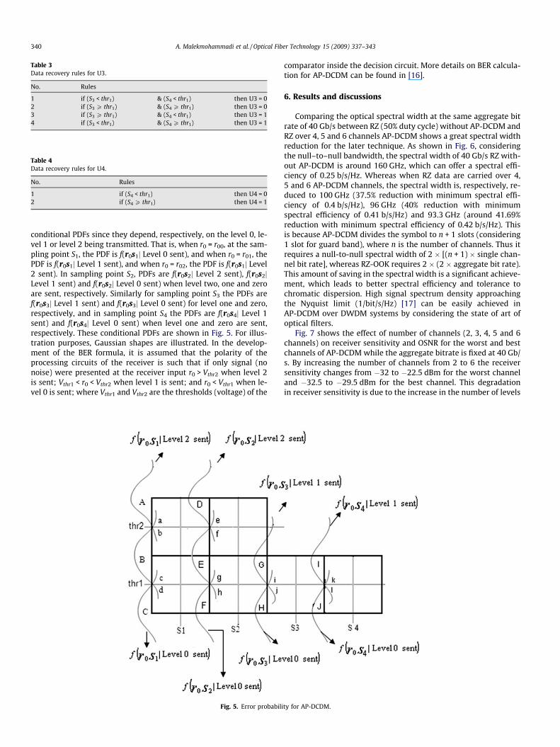
Table 3Data recovery rules for U3.
No. Rules
1 if (S3 < thr1) & (S4 < thr1) then U3 = 02 if (S3 P thr1) & (S4 P thr1) then U3 = 03 if (S3 P thr1) & (S4 < thr1) then U3 = 14 if (S3 < thr1) & (S4 P thr1) then U3 = 1
Table 4Data recovery rules for U4.
No. Rules
1 if (S4 < thr1) then U4 = 02 if (S4 P thr1) then U4 = 1
340 A. Malekmohammadi et al. / Optical Fiber Technology 15 (2009) 337–343
conditional PDFs since they depend, respectively, on the level 0, le-vel 1 or level 2 being transmitted. That is, when r0 = r00, at the sam-pling point S1, the PDF is f(r0s1j Level 0 sent), and when r0 = r01, thePDF is f(r0s1j Level 1 sent), and when r0 = r02, the PDF is f(r0s1j Level2 sent). In sampling point S2, PDFs are f(r0s2j Level 2 sent), f(r0s2jLevel 1 sent) and f(r0s2j Level 0 sent) when level two, one and zeroare sent, respectively. Similarly for sampling point S3 the PDFs aref(r0s3j Level 1 sent) and f(r0s3j Level 0 sent) for level one and zero,respectively, and in sampling point S4 the PDFs are f(r0s4j Level 1sent) and f(r0s4j Level 0 sent) when level one and zero are sent,respectively. These conditional PDFs are shown in Fig. 5. For illus-tration purposes, Gaussian shapes are illustrated. In the develop-ment of the BER formula, it is assumed that the polarity of theprocessing circuits of the receiver is such that if only signal (nonoise) were presented at the receiver input r0 > Vthr2 when level 2is sent; Vthr1 < r0 < Vthr2 when level 1 is sent; and r0 < Vthr1 when le-vel 0 is sent; where Vthr1 and Vthr2 are the thresholds (voltage) of the
Fig. 5. Error probabili
comparator inside the decision circuit. More details on BER calcula-tion for AP-DCDM can be found in [16].
6. Results and discussions
Comparing the optical spectral width at the same aggregate bitrate of 40 Gb/s between RZ (50% duty cycle) without AP-DCDM andRZ over 4, 5 and 6 channels AP-DCDM shows a great spectral widthreduction for the later technique. As shown in Fig. 6, consideringthe null–to–null bandwidth, the spectral width of 40 Gb/s RZ with-out AP-DCDM is around 160 GHz, which can offer a spectral effi-ciency of 0.25 b/s/Hz. Whereas when RZ data are carried over 4,5 and 6 AP-DCDM channels, the spectral width is, respectively, re-duced to 100 GHz (37.5% reduction with minimum spectral effi-ciency of 0.4 b/s/Hz), 96 GHz (40% reduction with minimumspectral efficiency of 0.41 b/s/Hz) and 93.3 GHz (around 41.69%reduction with minimum spectral efficiency of 0.42 b/s/Hz). Thisis because AP-DCDM divides the symbol to n + 1 slots (considering1 slot for guard band), where n is the number of channels. Thus itrequires a null-to-null spectral width of 2 � [(n + 1) � single chan-nel bit rate], whereas RZ-OOK requires 2 � (2 � aggregate bit rate).This amount of saving in the spectral width is a significant achieve-ment, which leads to better spectral efficiency and tolerance tochromatic dispersion. High signal spectrum density approachingthe Nyquist limit (1/bit/s/Hz) [17] can be easily achieved inAP-DCDM over DWDM systems by considering the state of art ofoptical filters.
Fig. 7 shows the effect of number of channels (2, 3, 4, 5 and 6channels) on receiver sensitivity and OSNR for the worst and bestchannels of AP-DCDM while the aggregate bitrate is fixed at 40 Gb/s. By increasing the number of channels from 2 to 6 the receiversensitivity changes from �32 to �22.5 dBm for the worst channeland �32.5 to �29.5 dBm for the best channel. This degradationin receiver sensitivity is due to the increase in the number of levels
ty for AP-DCDM.
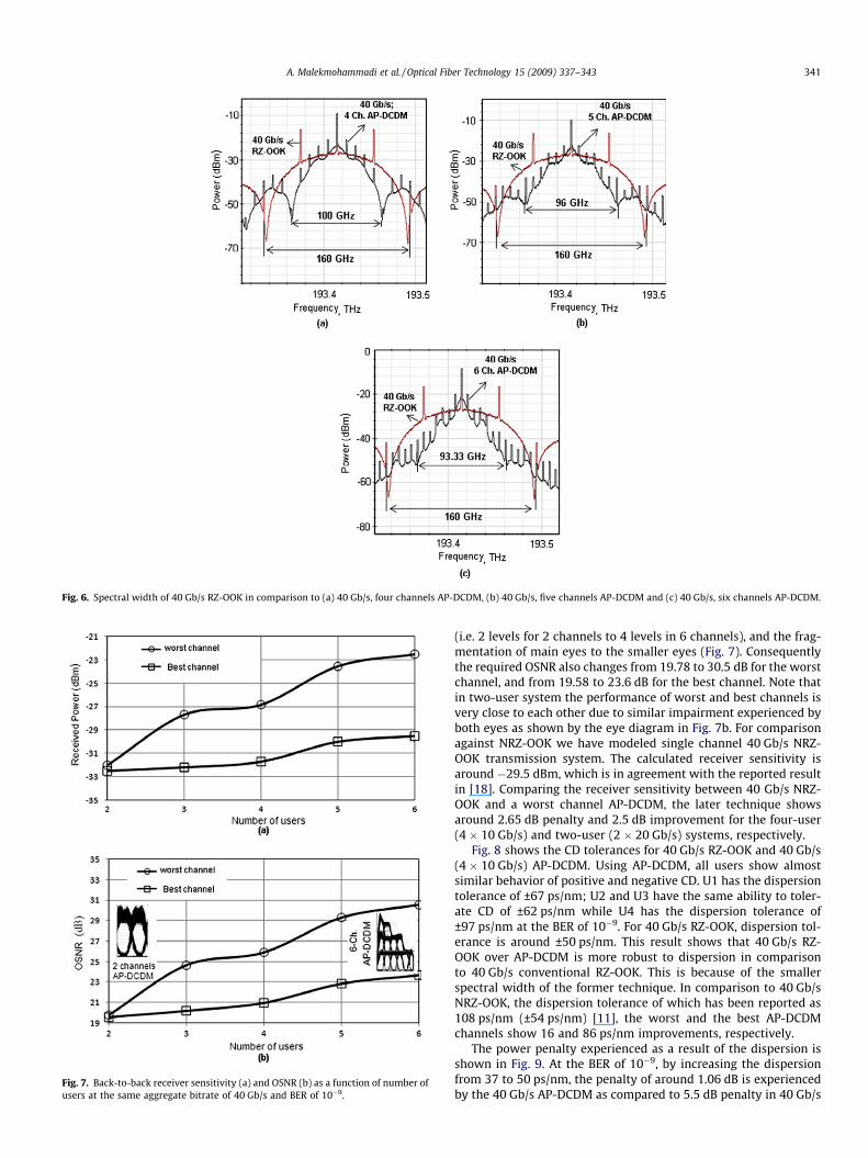
Fig. 6. Spectral width of 40 Gb/s RZ-OOK in comparison to (a) 40 Gb/s, four channels AP-DCDM, (b) 40 Gb/s, five channels AP-DCDM and (c) 40 Gb/s, six channels AP-DCDM.
Fig. 7. Back-to-back receiver sensitivity (a) and OSNR (b) as a function of number ofusers at the same aggregate bitrate of 40 Gb/s and BER of 10�9.
A. Malekmohammadi et al. / Optical Fiber Technology 15 (2009) 337–343 341
(i.e. 2 levels for 2 channels to 4 levels in 6 channels), and the frag-mentation of main eyes to the smaller eyes (Fig. 7). Consequentlythe required OSNR also changes from 19.78 to 30.5 dB for the worstchannel, and from 19.58 to 23.6 dB for the best channel. Note thatin two-user system the performance of worst and best channels isvery close to each other due to similar impairment experienced byboth eyes as shown by the eye diagram in Fig. 7b. For comparisonagainst NRZ-OOK we have modeled single channel 40 Gb/s NRZ-OOK transmission system. The calculated receiver sensitivity isaround �29.5 dBm, which is in agreement with the reported resultin [18]. Comparing the receiver sensitivity between 40 Gb/s NRZ-OOK and a worst channel AP-DCDM, the later technique showsaround 2.65 dB penalty and 2.5 dB improvement for the four-user(4 � 10 Gb/s) and two-user (2 � 20 Gb/s) systems, respectively.
Fig. 8 shows the CD tolerances for 40 Gb/s RZ-OOK and 40 Gb/s(4 � 10 Gb/s) AP-DCDM. Using AP-DCDM, all users show almostsimilar behavior of positive and negative CD. U1 has the dispersiontolerance of ±67 ps/nm; U2 and U3 have the same ability to toler-ate CD of ±62 ps/nm while U4 has the dispersion tolerance of±97 ps/nm at the BER of 10�9. For 40 Gb/s RZ-OOK, dispersion tol-erance is around ±50 ps/nm. This result shows that 40 Gb/s RZ-OOK over AP-DCDM is more robust to dispersion in comparisonto 40 Gb/s conventional RZ-OOK. This is because of the smallerspectral width of the former technique. In comparison to 40 Gb/sNRZ-OOK, the dispersion tolerance of which has been reported as108 ps/nm (±54 ps/nm) [11], the worst and the best AP-DCDMchannels show 16 and 86 ps/nm improvements, respectively.
The power penalty experienced as a result of the dispersion isshown in Fig. 9. At the BER of 10�9, by increasing the dispersionfrom 37 to 50 ps/nm, the penalty of around 1.06 dB is experiencedby the 40 Gb/s AP-DCDM as compared to 5.5 dB penalty in 40 Gb/s
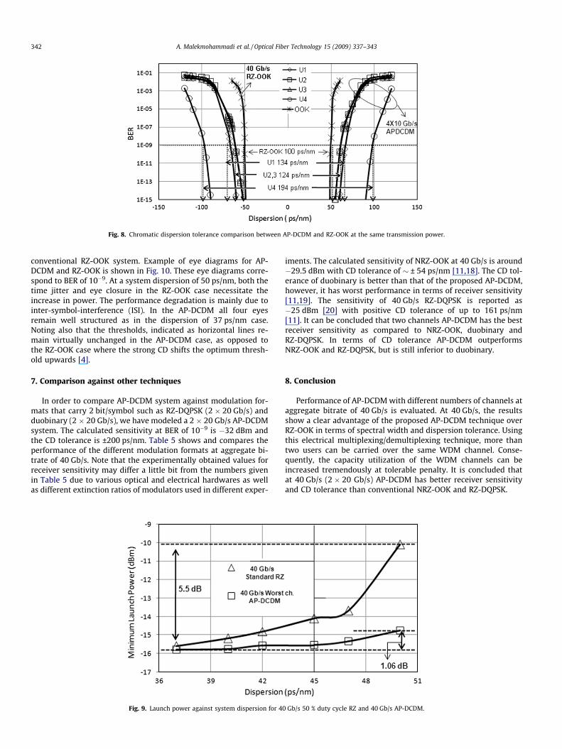
Fig. 8. Chromatic dispersion tolerance comparison between AP-DCDM and RZ-OOK at the same transmission power.
342 A. Malekmohammadi et al. / Optical Fiber Technology 15 (2009) 337–343
conventional RZ-OOK system. Example of eye diagrams for AP-DCDM and RZ-OOK is shown in Fig. 10. These eye diagrams corre-spond to BER of 10�9. At a system dispersion of 50 ps/nm, both thetime jitter and eye closure in the RZ-OOK case necessitate theincrease in power. The performance degradation is mainly due tointer-symbol-interference (ISI). In the AP-DCDM all four eyesremain well structured as in the dispersion of 37 ps/nm case.Noting also that the thresholds, indicated as horizontal lines re-main virtually unchanged in the AP-DCDM case, as opposed tothe RZ-OOK case where the strong CD shifts the optimum thresh-old upwards [4].
7. Comparison against other techniques
In order to compare AP-DCDM system against modulation for-mats that carry 2 bit/symbol such as RZ-DQPSK (2 � 20 Gb/s) andduobinary (2 � 20 Gb/s), we have modeled a 2 � 20 Gb/s AP-DCDMsystem. The calculated sensitivity at BER of 10�9 is �32 dBm andthe CD tolerance is ±200 ps/nm. Table 5 shows and compares theperformance of the different modulation formats at aggregate bi-trate of 40 Gb/s. Note that the experimentally obtained values forreceiver sensitivity may differ a little bit from the numbers givenin Table 5 due to various optical and electrical hardwares as wellas different extinction ratios of modulators used in different exper-
Fig. 9. Launch power against system dispersion for 40
iments. The calculated sensitivity of NRZ-OOK at 40 Gb/s is around�29.5 dBm with CD tolerance of � ± 54 ps/nm [11,18]. The CD tol-erance of duobinary is better than that of the proposed AP-DCDM,however, it has worst performance in terms of receiver sensitivity[11,19]. The sensitivity of 40 Gb/s RZ-DQPSK is reported as�25 dBm [20] with positive CD tolerance of up to 161 ps/nm[11]. It can be concluded that two channels AP-DCDM has the bestreceiver sensitivity as compared to NRZ-OOK, duobinary andRZ-DQPSK. In terms of CD tolerance AP-DCDM outperformsNRZ-OOK and RZ-DQPSK, but is still inferior to duobinary.
8. Conclusion
Performance of AP-DCDM with different numbers of channels ataggregate bitrate of 40 Gb/s is evaluated. At 40 Gb/s, the resultsshow a clear advantage of the proposed AP-DCDM technique overRZ-OOK in terms of spectral width and dispersion tolerance. Usingthis electrical multiplexing/demultiplexing technique, more thantwo users can be carried over the same WDM channel. Conse-quently, the capacity utilization of the WDM channels can beincreased tremendously at tolerable penalty. It is concluded thatat 40 Gb/s (2 � 20 Gb/s) AP-DCDM has better receiver sensitivityand CD tolerance than conventional NRZ-OOK and RZ-DQPSK.
Gb/s 50 % duty cycle RZ and 40 Gb/s AP-DCDM.
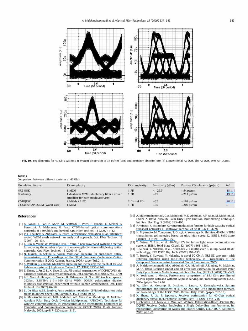
Fig. 10. Eye diagrams for 40 Gb/s systems at system dispersion of 37 ps/nm (top) and 50 ps/nm (bottom) for (a) Conventional RZ-OOK, (b) RZ-OOK over AP-DCDM.
Table 5Comparison between different systems at 40 Gb/s.
Modulation format TX complexity RX complexity Sensitivity (dBm) Positive CD tolerance (ps/nm) Ref.
NRZ-OOK 1-MZM 1 PD ��29.5 �54 ps/nm [18,11]Duobinary 1 dual-arm MZM + duobinary filter + driver
amplifier for each modulator arm1 PD �28 �211 ps/nm [19,11]
RZ-DQPSK 2 MZMs + 1 PC 2 DIs + 4 PDs �25 �161 ps/nm [20,11]2 Channel AP-DCDM (worst user) 1 MZM 1 PD �32 �200 ps/nm —
A. Malekmohammadi et al. / Optical Fiber Technology 15 (2009) 337–343 343
References
[1] A. Bogoni, L. Potì, P. Ghelfi, M. Scaffardi, C. Porzi, F. Ponzini, G. Meloni, G.Berrettini, A. Malacarne, G. Prati, OTDM-based optical communicationsnetworks at 160 Gbit/s and beyond, Opt. Fiber Technol. 13 (2007) 1–12.
[2] V.K. Chaubey, S. Abhirami, G. Peres, Performance evaluation of an intelligentrouted WDM mesh network: an analytical approach, Opt. Fiber Technol. 13(2007) 129–134.
[3] L. Guo, X. Wang, W. Weigang Hou, T. Yang, A new waveband switching methodfor reducing the number of ports in wavelength-division-multiplexing opticalnetworks, Opt. Fiber Technol. 15 (2009) 5–9.
[4] N. Kikuchi, K. Sekine, S. Sasaki, Multilevel signaling for high-speed opticaltransmission, in: Proceedings of the 32nd European Conference OpticalCommunication (ECOC), Cannes, France, 2006. (paper Tu3.2.1).
[5] S. Walklin, J. Conradi, Multilevel signaling for increasing the reach of 10 Gb/slightwave systems, J. Lightwave Technol. 17 (1999) 2235–2248.
[6] Z. Zheng, L. An, Z. Li, X. Zhao, X. Liu, All-optical regeneration of DQPSK/QPSK sig-nals based on phase-sensitive amplification, Opt. Commun. 281 (2008) 2755–2759.
[7] A.F. Abas, A. Hidayat, D. Sandel, B. Milivojevic, R. Noe, 100 km fiber span in292 km, 2.38 Tb/s (16 � 160 Gb/s) WDM DQPSK polarization divisionmultiplex transmission experiment without Raman amplification, Opt. FiberTechnol. 13 (2007) 46–50.
[8] J.I. Da Silva, A.S.B. Sombra, Pulse position modulation (PPM) of ultrashort pulsetrains in optical fibers, Opt. Commun. 152 (1998) 59–64.
[9] A. Malekmohammadi, M.K. Abdullah, A.F. Abas, G.A. Mahdiraji, M. Mokhtar,Absolute Polar Duty Cycle Division Multiplexing (APDCDM); Technique forwireless communications, in: Proceedings of the International Conference onComputer and Communication Engineering (ICCCE 2008), Kuala Lumpur,Malaysia, 2008, pp.617–620 (paper 316).
[10] A. Malekmohammadi, G.A. Mahdiraji, M.K. Abdullah, A.F. Abas, M. Mokhtar, M.Fadlee A. Rasid, Absolute Polar Duty Cycle Division Multiplexing Technique,Int. Rev. Elec. Eng. 3 (2008) 395–400.
[11] P. Winzer, R. Essiambre, Advance modulation formats for high-capacity opticaltransport networks, J. Lightwave Technol. 24 (2006) 4711–4728.
[12] H. Miyamoto, M. Yoneyama, T. Otsuji, K. Yonenaga, N. Shimizu, 40 Gbit/s TDMtransmission technologies based on ultra high-speed IC, IEEE J. Solid-StateCircuits 34 (1999) 1246–1253.
[13] T. Ostsuji, Y. Imai, et al., 40-Gb/s IC’s for future light wave communicationsystems, IEEE J. Solid-State Circuit 32 (1997) 1363–1369.
[14] T. Suzuki, Y. Nakasha, et al., A 90 Gb/s 2:1 multiplexer IC in Inp-based HEMTtechnology, IEEE ISSCC Dig. Tech. (2002) 192–193.
[15] T. Suzuki, Y. Kawano, Y. Nakasha, A novel 50-Gbit/s NRZ-RZ converter withretiming function using Inp-HEMT technology, in: Proceedings of theCompound Semiconductor Integrated Circuit Symposium, 2005.
[16] A. Malekmohammadi, M.K. Abdullah, G.A. Mahdiraji, A.F. Abas, M. Mokhtar,M.F.A. Rasid, Decision circuit and bit error rate estimation for Absolute PolarDuty Cycle Division Multiplexing, Int. Rev. Elec. Eng. (IREE) 3 (2008) 592–599.
[17] N. Yoshikane, I. Morita, Performance comparison of 85.4 Gb/s pre-filteredDQPSK signals with and without RZ pulse carving, in: Proceedings of the ECOC,2004. (paper We3.4.6).
[18] W. Idler, A. Klekamp, R. Dischler, J. Lazaro, A. Konczykowska, Systemperformance and tolerances of 43-Gb/s ASK and DPSK modulation formats,in: Proceedings of the ECOC, 2003, Rimini, Italy, 2003. (paper Th2.6.3).
[19] X. Zheng, F. Liu, P. Jeppesen, Receiver optimization for 40-Gb/s opticalduobinary signal, IEEE Photonic Technol. Lett. 13 (2001) 744–746.
[20] L. Christen, S.R. Nuccio, X. Wu., A.E. Willner, Polarization-Based 43 Gb/s RZ-DQPSK Receiver Design Employing a Single Delay-Line Interferometer, in:Proceedings Conference on Lasers and Electro-Optics, CLEO 2007, Baltimore,2007, pp.1–2.