Corning Recommended Fiber Optic Test Guidelines
12
Corning Recommended Fiber Optic Test Guidelines | LAN-1561-AEN | PAGE 1 Guidelines Corning Recommended Fiber Optic Test Guidelines Table of Contents 1. Introduction ............................................................................................... 1 2. Why Test? ................................................................................................. 1 3. Tier 1 and Tier 2 Testing ........................................................................... 2 4. Encircled Flux ........................................................................................... 3 5. Link-Loss Budgets .................................................................................... 4 6. Proper Reference Procedures.................................................................. 9 7. Documentation ....................................................................................... 11 8. Conclusion .............................................................................................. 12 9. References ............................................................................................. 12 1. Introduction This paper explains the recommended guidelines for testing an installed fiber optic system. Fiber optic testing of a newly installed system not only verifies that the system meets its design requirements, but also creates a performance baseline for all future testing and troubleshooting of that system. Corning recommends that all fiber optic systems be tested to a minimum set of standards. This testing will ensure that the data necessary to properly evaluate any future system malfunctions will be available. 2. Why Test? Imagine your end user calls to report his recently installed cabling system is not functioning. So, you drop everything and investigate. He’s right – it is not working. However, because you followed proper testing procedures, troubleshooting is easy. You can quickly compare current test readings to original records and identify the problem. Because you created the proper as-built documentation in the beginning, you can better service your customer’s needs. You have the information available to quickly evaluate his system, identify the problem, and fix it. Furthermore, your customer is going to feel good about relying on you when he needs you most.
-
Upload
khangminh22 -
Category
Documents
-
view
1 -
download
0
Transcript of Corning Recommended Fiber Optic Test Guidelines

Corning Recommended Fiber Optic Test Guidelines | LAN-1561-AEN | PAGE 1
Guidelines
Corning Recommended Fiber Optic Test Guidelines
Table of Contents
1. Introduction ...............................................................................................1
2. Why Test? .................................................................................................1
3. Tier 1 and Tier 2 Testing ...........................................................................2
4. Encircled Flux ...........................................................................................3
5. Link-Loss Budgets ....................................................................................4
6. Proper Reference Procedures ..................................................................9
7. Documentation ....................................................................................... 11
8. Conclusion ..............................................................................................12
9. References .............................................................................................12
1. IntroductionThis paper explains the recommended guidelines for testing an installed fiber optic system. Fiber optic testing of a newly installed system not only verifies that the system meets its design requirements, but also creates a performance baseline for all future testing and troubleshooting of that system. Corning recommends that all fiber optic systems be tested to a minimum set of standards. This testing will ensure that the data necessary to properly evaluate any future system malfunctions will be available.
2. Why Test?Imagine your end user calls to report his recently installed cabling system is not functioning. So, you drop everything and investigate. He’s right – it is not working. However, because you followed proper testing procedures, troubleshooting is easy. You can quickly compare current test readings to original records and identify the problem.
Because you created the proper as-built documentation in the beginning, you can better service your customer’s needs. You have the information available to quickly evaluate his system, identify the problem, and fix it. Furthermore, your customer is going to feel good about relying on you when he needs you most.
Corning Recommended Fiber Optic Test Guidelines | LAN-1561-AEN | PAGE 2
Guidelines3. Tier 1 and Tier 2 TestingTIA-568.3-D states that there are two tiers of testing for fiber optic systems. The two tiers of testing are Tier 1 and Tier 2.
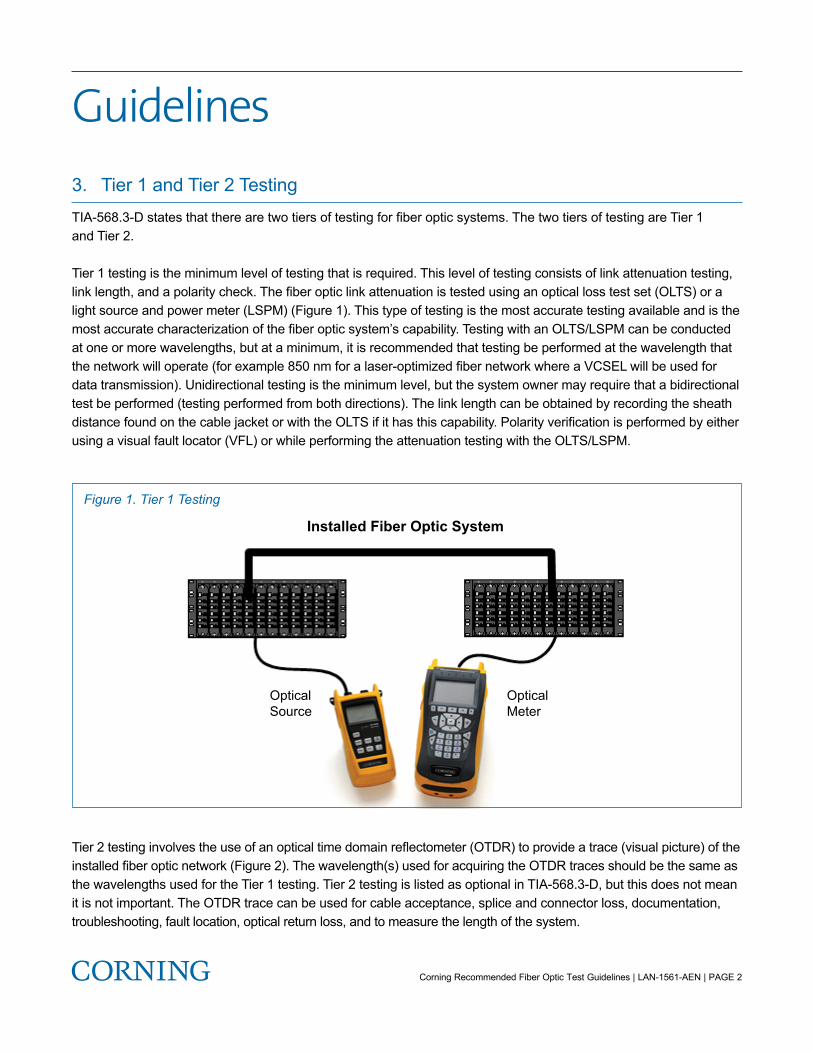
Tier 1 testing is the minimum level of testing that is required. This level of testing consists of link attenuation testing, link length, and a polarity check. The fiber optic link attenuation is tested using an optical loss test set (OLTS) or a light source and power meter (LSPM) (Figure 1). This type of testing is the most accurate testing available and is the most accurate characterization of the fiber optic system’s capability. Testing with an OLTS/LSPM can be conducted at one or more wavelengths, but at a minimum, it is recommended that testing be performed at the wavelength that the network will operate (for example 850 nm for a laser-optimized fiber network where a VCSEL will be used for data transmission). Unidirectional testing is the minimum level, but the system owner may require that a bidirectional test be performed (testing performed from both directions). The link length can be obtained by recording the sheath distance found on the cable jacket or with the OLTS if it has this capability. Polarity verification is performed by either using a visual fault locator (VFL) or while performing the attenuation testing with the OLTS/LSPM.
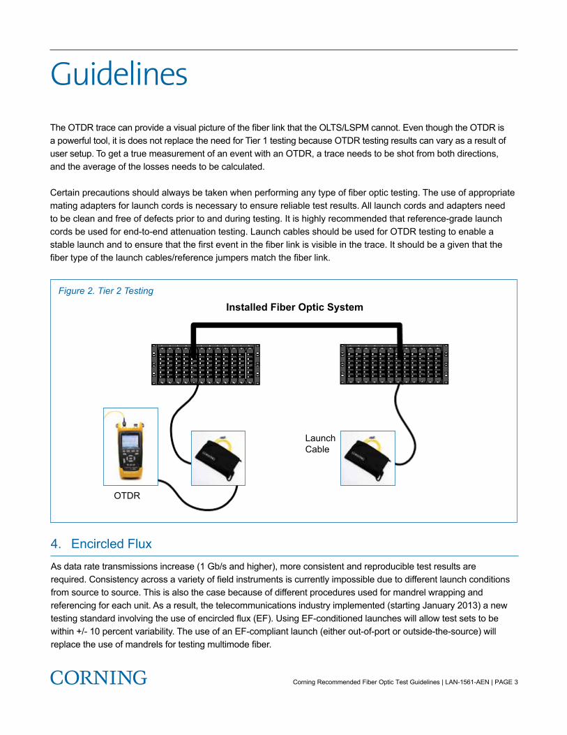
Tier 2 testing involves the use of an optical time domain reflectometer (OTDR) to provide a trace (visual picture) of the installed fiber optic network (Figure 2). The wavelength(s) used for acquiring the OTDR traces should be the same as the wavelengths used for the Tier 1 testing. Tier 2 testing is listed as optional in TIA-568.3-D, but this does not mean it is not important. The OTDR trace can be used for cable acceptance, splice and connector loss, documentation, troubleshooting, fault location, optical return loss, and to measure the length of the system.
Installed Fiber Optic System
OpticalSource
OpticalMeter
Figure 1. Tier 1 Testing
Corning Recommended Fiber Optic Test Guidelines | LAN-1561-AEN | PAGE 3
GuidelinesThe OTDR trace can provide a visual picture of the fiber link that the OLTS/LSPM cannot. Even though the OTDR is a powerful tool, it is does not replace the need for Tier 1 testing because OTDR testing results can vary as a result of user setup. To get a true measurement of an event with an OTDR, a trace needs to be shot from both directions, and the average of the losses needs to be calculated.
Certain precautions should always be taken when performing any type of fiber optic testing. The use of appropriate mating adapters for launch cords is necessary to ensure reliable test results. All launch cords and adapters need to be clean and free of defects prior to and during testing. It is highly recommended that reference-grade launch cords be used for end-to-end attenuation testing. Launch cables should be used for OTDR testing to enable a stable launch and to ensure that the first event in the fiber link is visible in the trace. It should be a given that the fiber type of the launch cables/reference jumpers match the fiber link.
Installed Fiber Optic System
OTDR
LaunchCable
Figure 2. Tier 2 Testing
4. Encircled FluxAs data rate transmissions increase (1 Gb/s and higher), more consistent and reproducible test results are required. Consistency across a variety of field instruments is currently impossible due to different launch conditions from source to source. This is also the case because of different procedures used for mandrel wrapping and referencing for each unit. As a result, the telecommunications industry implemented (starting January 2013) a new testing standard involving the use of encircled flux (EF). Using EF-conditioned launches will allow test sets to be within +/- 10 percent variability. The use of an EF-compliant launch (either out-of-port or outside-the-source) will replace the use of mandrels for testing multimode fiber.
Corning Recommended Fiber Optic Test Guidelines | LAN-1561-AEN | PAGE 4
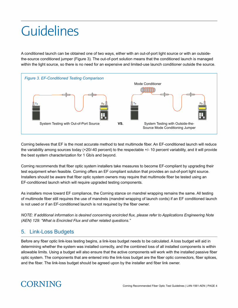
GuidelinesA conditioned launch can be obtained one of two ways, either with an out-of-port light source or with an outside-the-source conditioned jumper (Figure 3). The out-of-port solution means that the conditioned launch is managed within the light source, so there is no need for an expensive and limited-use launch conditioner outside the source.
Corning believes that EF is the most accurate method to test multimode fiber. An EF-conditioned launch will reduce the variability among sources today (+20/-40 percent) to the respectable +/- 10 percent variability, and it will provide the best system characterization for 1 Gb/s and beyond.
Corning recommends that fiber optic system installers take measures to become EF-compliant by upgrading their test equipment when feasible. Corning offers an EF compliant solution that provides an out-of-port light source. Installers should be aware that fiber optic system owners may require that multimode fiber be tested using an EF-conditioned launch which will require upgraded testing components.
As installers move toward EF compliance, the Corning stance on mandrel wrapping remains the same. All testing of multimode fiber still requires the use of mandrels (mandrel wrapping of launch cords) if an EF conditioned launch is not used or if an EF-conditioned launch is not required by the fiber owner.
NOTE: If additional information is desired concerning encircled flux, please refer to Applications Engineering Note (AEN) 129: “What is Encircled Flux and other related questions.”
5. Link-Loss BudgetsBefore any fiber optic link-loss testing begins, a link-loss budget needs to be calculated. A loss budget will aid in determining whether the system was installed correctly, and the combined loss of all installed components is within allowable limits. Using a budget will also ensure that the active components will work with the installed passive fiber optic system. The components that are entered into the link-loss budget are the fiber optic connectors, fiber splices, and the fiber. The link-loss budget should be agreed upon by the installer and fiber link owner.
! "#$%&'( %#$)*+', )$- '. / $#)0%'$- %'! 1/ 23%'4 10%'51*0)$)1*)*+'6/&7%2
! "#$%&'( %#$)*+', )$- '. / $8198: 12$'! 1/ 23%'
4 10%'51*0)$)1*%2
; ! <System Testing with Out-of-Port Source VS. System Testing with Outside-the-Source Mode Conditioning Jumper
Mode ConditionerFigure 3. EF-Conditioned Testing Comparison
Corning Recommended Fiber Optic Test Guidelines | LAN-1561-AEN | PAGE 5
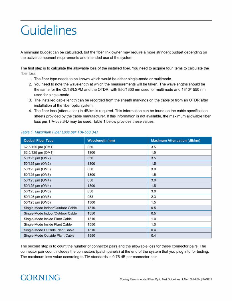
GuidelinesA minimum budget can be calculated, but the fiber link owner may require a more stringent budget depending on the active component requirements and intended use of the system.
The first step is to calculate the allowable loss of the installed fiber. You need to acquire four items to calculate the fiber loss. 1. The fiber type needs to be known which would be either single-mode or multimode. 2. You need to note the wavelength at which the measurements will be taken. The wavelengths should be the same for the OLTS/LSPM and the OTDR, with 850/1300 nm used for multimode and 1310/1550 nm used for single-mode. 3. The installed cable length can be recorded from the sheath markings on the cable or from an OTDR after installation of the fiber optic system. 4. The fiber loss (attenuation) in dB/km is required. This information can be found on the cable specification sheets provided by the cable manufacturer. If this information is not available, the maximum allowable fiber loss per TIA-568.3-D may be used. Table 1 below provides these values.
Table 1. Maximum Fiber Loss per TIA-568.3-D.
Optical Fiber Type Wavelength (nm) Maximum Attenuation (dB/km)
62.5/125 μm (OM1) 850 3.562.5/125 μm (OM1) 1300 1.550/125 μm (OM2) 850 3.550/125 μm (OM2) 1300 1.550/125 μm (OM3) 850 3.050/125 μm (OM3) 1300 1.550/125 μm (OM4) 850 3.050/125 μm (OM4) 1300 1.550/125 μm (OM5) 850 3.050/125 μm (OM5) 953 2.350/125 μm (OM5) 1300 1.5Single-Mode Indoor/Outdoor Cable 1310 0.5Single-Mode Indoor/Outdoor Cable 1550 0.5Single-Mode Inside Plant Cable 1310 1.0Single-Mode Inside Plant Cable 1550 1.0Single-Mode Outside Plant Cable 1310 0.4Single-Mode Outside Plant Cable 1550 0.4
The second step is to count the number of connector pairs and the allowable loss for these connector pairs. The connector pair count includes the connectors (patch panels) at the end of the system that you plug into for testing. The maximum loss value according to TIA standards is 0.75 dB per connector pair.
Corning Recommended Fiber Optic Test Guidelines | LAN-1561-AEN | PAGE 6
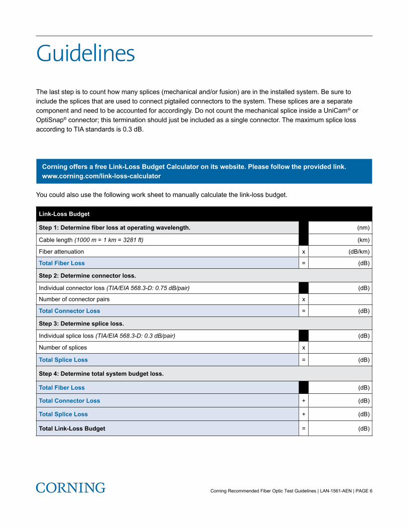
GuidelinesThe last step is to count how many splices (mechanical and/or fusion) are in the installed system. Be sure to include the splices that are used to connect pigtailed connectors to the system. These splices are a separate component and need to be accounted for accordingly. Do not count the mechanical splice inside a UniCam® or OptiSnap® connector; this termination should just be included as a single connector. The maximum splice loss according to TIA standards is 0.3 dB.
Corning offers a free Link-Loss Budget Calculator on its website. Please follow the provided link.
Corning offers a free Link-Loss Budget Calculator on its website. Please follow the provided link.www.corning.com/link-loss-calculator
You could also use the following work sheet to manually calculate the link-loss budget.
Link-Loss Budget
Step 1: Determine fiber loss at operating wavelength. (nm)
Cable length (1000 m = 1 km = 3281 ft) (km)
Fiber attenuation x (dB/km)
Total Fiber Loss = (dB)
Step 2: Determine connector loss.
Individual connector loss (TIA/EIA 568.3-D: 0.75 dB/pair) (dB)
Number of connector pairs x
Total Connector Loss = (dB)
Step 3: Determine splice loss.
Individual splice loss (TIA/EIA 568.3-D: 0.3 dB/pair) (dB)
Number of splices x
Total Splice Loss = (dB)
Step 4: Determine total system budget loss.
Total Fiber Loss (dB)
Total Connector Loss + (dB)
Total Splice Loss + (dB)
Total Link-Loss Budget = (dB)

The following is an example of a fiber optic system (Figure 4), and following that will be the link-loss budget for that system using the TIA/EIA 568.3-D maximum allowable losses for installed components. This will require that the fiber loss value be pulled from Table 1 of this document.
The fiber optic system consists of two closet connector housings (CCH) at each end of the system with CCH patch panels. All fibers will be terminated with single-mode UniCam® connectors. There will be an extension splice located in a splice closure family (SCF) splice closure located at the midpoint of the system. The installed cable will be an ALTOS® loose tube cable with single-mode fiber. There will be 1 km of the ALTOS cable installed. The operating wavelength will be 1550 nm.
Corning Recommended Fiber Optic Test Guidelines | LAN-1561-AEN | PAGE 7
Guidelines
UniCamHigh-Performance
Connectors,LC, Single-Mode
Closet ConnectorHousing (CCH)
Panel
CCH Housing Located at Each Endof the Cable
Splice Closure,Extension Splice
ALTOS Loose Tube Cablewith Single-Mode Fibre
Buffer TubeFan-Out Kit
Figure 4. Fiber Optic System Example
Corning Recommended Fiber Optic Test Guidelines | LAN-1561-AEN | PAGE 8
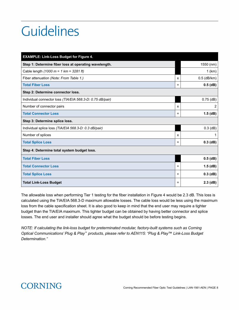
GuidelinesEXAMPLE: Link-Loss Budget for Figure 4.
Step 1: Determine fiber loss at operating wavelength. 1550 (nm)
Cable length (1000 m = 1 km = 3281 ft) 1 (km)
Fiber attenuation (Note: From Table 1.) x 0.5 (dB/km)
Total Fiber Loss = 0.5 (dB)
Step 2: Determine connector loss.
Individual connector loss (TIA/EIA 568.3-D: 0.75 dB/pair) 0.75 (dB)
Number of connector pairs x 2
Total Connector Loss = 1.5 (dB)
Step 3: Determine splice loss.
Individual splice loss (TIA/EIA 568.3-D: 0.3 dB/pair) 0.3 (dB)
Number of splices x 1
Total Splice Loss = 0.3 (dB)
Step 4: Determine total system budget loss.
Total Fiber Loss 0.5 (dB)
Total Connector Loss + 1.5 (dB)
Total Splice Loss + 0.3 (dB)
Total Link-Loss Budget = 2.3 (dB)
The allowable loss when performing Tier 1 testing for the fiber installation in Figure 4 would be 2.3 dB. This loss is calculated using the TIA/EIA 568.3-D maximum allowable losses. The cable loss would be less using the maximum loss from the cable specification sheet. It is also good to keep in mind that the end user may require a tighter budget than the TIA/EIA maximum. This tighter budget can be obtained by having better connector and splice losses. The end user and installer should agree what the budget should be before testing begins.
NOTE: If calculating the link-loss budget for preterminated modular, factory-built systems such as Corning Optical Communications’ Plug & Play™ products, please refer to AEN115: “Plug & Play™ Link-Loss Budget Determination.”

Corning Recommended Fiber Optic Test Guidelines | LAN-1561-AEN | PAGE 9
Guidelines6. Proper Reference ProceduresTo perform Tier 1 testing, an important step needs to be completed which is the referencing of the launch cables (test jumpers). This step needs to be completed before any testing can occur.
NOTE: Corning recommends that reference-grade jumpers be used for testing the installed fiber optic system. Also, all jumper end faces should be visually inspected prior to mating to test equipment and before the reference process begins.
There are three methods of referencing test jumpers. • One-jumper reference • Two-jumper reference • Three-jumper reference
The recommended reference method for the vast majority of end-to-end link testing is the one-jumper reference method (Figure 5). Your test procedure should emulate your system as it will operate.
Test Jumper No. 1
Test Jumper No. 1 Test Jumper No. 2
Test Jumper No. 1 Test Jumper No. 2
Interconnect Sleeve
System Patch Panels
PowerSource
PowerSource
PowerSource
PowerMeter
Received power,hit Reference
Test System
Add jumper 2,check loss≤ 0.5 dBPower
Meter
PowerMeter
Fibre System Under Test
Step 1
Step 2
Step 3
Figure 5. One-Jumper Reference Steps

Corning Recommended Fiber Optic Test Guidelines | LAN-1561-AEN | PAGE 10
GuidelinesIf the fiber optic system to be tested includes a patch panel (connector pair) on each end of the system, then the one-jumper reference method should be used. One-jumper reference measurement results include the loss withinthe installed system plus the loss of two connector pairs (patch panel A, cable B, and patch panel C in Figure 6). If the fiber optic system to be tested includes one patch panel (connector pair) in the system, then the two-jumperreference method should be used. Two-jumper reference measurement results include the loss of the installed system with the loss of one connector pair (patch panel A and cable B in Figure 6). And if the fiber optic systemto be tested has no patch panels (the connectors on the end of the system are plugged directly into the active equipment), the three-jumper reference method should be used. The three-reference jumper measurement resultsinclude only the loss of the cable (cable B in Figure 6).
NOTE: The procedure to reference an OLTS/LSPM can be different from one test equipment manufacturer to another. Please refer to the specific manufacturer’s test equipment reference methods to ensure the test equipment is referenced correctly.
Installed Fiber Optic System
B
A C
OpticalSource
OpticalMeter
Figure 6. Patch Panel A, Fiber Optic System B, and Patch Panel C

Corning Recommended Fiber Optic Test Guidelines | LAN-1561-AEN | PAGE 11
Guidelines7. DocumentationDocumentation is an important part of the service package provided to the fiber optic system owner. Documentation allows for easier planning when performing upgrades. It also allows for seamless moves, adds, and changes (MACs). Proper documentation allows for easier troubleshooting and faster repairs. These benefits not only save time but also save money. Ultimately the fiber optic installer and system owner need to agree on what documentation will be provided before the job is started. It is good to remember that a good documentation package says a lot about the fiber optic installer. Besides the quality of the completed work, the documentation is the last piece that the system owner will see and keep for the life of the system.
Documentation can be broken down into two categories: optical and non-optical. Optical documentation includes link attenuation, component loss, and distance readings (from an OTDR). Non-optical documentation includes cable route diagrams, splice plans, connector labeling schemes, cable sheath markings, cable data sheets/reel numbers, cable/fiber specifications, and a bill of materials used in the installation.
TIA-568.3-D recommends the following be included in the optical documentation.
For OLTS test results: • Date of the test • Test personnel • Description of the field instrument used (manufacturer model number and serial number) • Test equipment calibration date • Type and length of the reference jumpers • Fiber ID • Test procedure and reference method used • Link-loss results
For OTDR test results: • Date of the test • Test personnel • Description of the field instrument used (manufacturer model number and serial number) • Test equipment calibration date • Type and length of the launch cables • Fiber ID • Trace file • Tested wavelengths
Guidelines8. ConclusionThis paper was written to help installers understand the recommended guidelines for testing installed fiber optic systems. It was not meant to replace the standards, but to clarify them and provide guidance to ensure the proper steps are taken before, during, and after testing. These guidelines include building the proper loss budget based on installed components, determining the necessary tests to be performed, using the correct test equipment refer-encing method, and delivering a complete and informative documentation package. Following all the outlined steps in this document will ensure all testing was performed properly, and the fiber optic system is accurately character-ized to include the system’s capabilities and limitations.
9. References1. ANSI/TIA/EIA-568.0-D Generic Telecommunications Cabling For Customer Premises – Addendum 2, General Updates2 ANSI/TIA/EIA-568.1-D Commercial Building Telecommunications Cabling Standard3. ANSI/TIA/EIA-568.3-D Optical Fiber Cabling Components Standard4. ANSI/TIA/EIA-526-7 (OFSTP-7) Measurement of Optical Power Loss of Installed Single-Mode Fiber Cable Plant5. ANSI/TIA/EIA-526-14 (OFSTP-14) Optical Power Loss Measurements of Installed Multimode Fiber Cable Plant6. AEN 068: Improving Multimode Fiber Testing Accuracy with Mandrel Wrapping7. AEN 104: Standards Compliant Optical Test Equipment and Test Procedures8. AEN 115: Plug & Play™ Link-Loss Budget Determination9. AEN 129: What is Encircled Flux and Other Related Questions10. AEN 134: OTDR Testing Basics11. AEN 135: Fiber Optic System Testing Tutorial
Guidelines
Corning Optical Communications LLC • 4200 Corning Place • Charlotte, NC 28216 USA 800-743-2675 • FAX: 828-325-5060 • International: +1-828-901-5000 • www.corning.com/opcommCorning Optical Communications reserves the right to improve, enhance, and modify the features and specifications of Corning Optical Communications products without prior notification. A complete listing of the trademarks of Corning Optical Communications is available at www.corning.com/opcomm/trademarks. All other trademarks are the properties of their respective owners. Corning Optical Communications is ISO 9001 certified. © 2020 Corning Optical Communications. All rights reserved. LAN-1561-AEN / February 2020