Realization of a UAV simulation environment for USARSim-UDK
75
Institute for Software Systems Realization of a UAV simulation environment for USARSim-UDK Diploma Thesis Author: Paul-David Piotrowski Supervisors: Prof. Dr. Ralf Möller Prof. Dr. Herbert Werner July 16, 2012
-
Upload
khangminh22 -
Category
Documents
-
view
0 -
download
0
Transcript of Realization of a UAV simulation environment for USARSim-UDK
Institute for Software Systems
Realization of a UAV simulationenvironment for USARSim-UDK
Diploma Thesis
Author:Paul-David Piotrowski
Supervisors:Prof. Dr. Ralf Möller
Prof. Dr. Herbert Werner
July 16, 2012


Declaration
I, Paul-David Piotrowski, solemnly declare that I have written this diploma thesis independently, and that I have not made use of any aid other than those acknowledged in this diploma thesis. Neither this diploma thesis, nor any other similar work, has been previously submitted to any examination board.
Paul-David Piotrowski


Contents
1 Introduction 2
2 Fundamentals 62.1 Quadrocopters . . . . . . . . . . . . . . . . . . . . . . . . . . . . . . . 6
2.1.1 Coordinate Systems . . . . . . . . . . . . . . . . . . . . . . . . 72.1.2 Quadrocopter Movement . . . . . . . . . . . . . . . . . . . . . 82.1.3 Sensors . . . . . . . . . . . . . . . . . . . . . . . . . . . . . . . 112.1.4 Example: AirRobot AR 100-B . . . . . . . . . . . . . . . . . . 122.1.5 Example: Microdrones md4-1000 . . . . . . . . . . . . . . . . 14
2.2 Simulation . . . . . . . . . . . . . . . . . . . . . . . . . . . . . . . . . 152.2.1 Unreal Engine . . . . . . . . . . . . . . . . . . . . . . . . . . . 152.2.2 USARSim . . . . . . . . . . . . . . . . . . . . . . . . . . . . . 18
3 UAV Scenarios 203.1 Search . . . . . . . . . . . . . . . . . . . . . . . . . . . . . . . . . . . 203.2 Providing Communication Services . . . . . . . . . . . . . . . . . . . 233.3 Tracking . . . . . . . . . . . . . . . . . . . . . . . . . . . . . . . . . . 273.4 Payload delivery . . . . . . . . . . . . . . . . . . . . . . . . . . . . . . 29
4 Implementation 314.1 UAV Model . . . . . . . . . . . . . . . . . . . . . . . . . . . . . . . . 31
4.1.1 Quadrocopter Model . . . . . . . . . . . . . . . . . . . . . . . 314.1.2 Sensor Models . . . . . . . . . . . . . . . . . . . . . . . . . . . 324.1.3 Newly implemented sensors . . . . . . . . . . . . . . . . . . . 344.1.4 Base Equippment of the quadrocopter . . . . . . . . . . . . . 36
4.2 Control Program . . . . . . . . . . . . . . . . . . . . . . . . . . . . . 364.2.1 Overview . . . . . . . . . . . . . . . . . . . . . . . . . . . . . 364.2.2 Architecture . . . . . . . . . . . . . . . . . . . . . . . . . . . . 374.2.3 Implemented Classes . . . . . . . . . . . . . . . . . . . . . . . 384.2.4 A waypoint following agent . . . . . . . . . . . . . . . . . . . 47
5 Tests 535.1 Waypoint following . . . . . . . . . . . . . . . . . . . . . . . . . . . . 535.2 Repeating Experiments . . . . . . . . . . . . . . . . . . . . . . . . . . 545.3 Scalability . . . . . . . . . . . . . . . . . . . . . . . . . . . . . . . . . 54
1

Contents
6 Usage 586.1 Installation of the Simulation Environment . . . . . . . . . . . . . . . 58
6.1.1 Unreal Development Kit . . . . . . . . . . . . . . . . . . . . . 586.1.2 USARSim . . . . . . . . . . . . . . . . . . . . . . . . . . . . . 586.1.3 UAV Control Center . . . . . . . . . . . . . . . . . . . . . . . 59
6.2 Control program usage . . . . . . . . . . . . . . . . . . . . . . . . . . 606.2.1 The main window . . . . . . . . . . . . . . . . . . . . . . . . . 60
6.3 How to create new Agent classes . . . . . . . . . . . . . . . . . . . . . 626.3.1 Deriving a new Agent class . . . . . . . . . . . . . . . . . . . . 636.3.2 Make the class appear in the UI . . . . . . . . . . . . . . . . . 636.3.3 Adapt uccController . . . . . . . . . . . . . . . . . . . . . . . 63
7 Conclusion and future work 64
2

List of Figures
1.1 Predicted trends in UAV autonomy, courtesy of [4] . . . . . . . . . . 3
2.1 Apollo quadrocopter, Hamburg University of Technology, courtesy of[7] . . . . . . . . . . . . . . . . . . . . . . . . . . . . . . . . . . . . . 6
2.2 A quadrocopter oriented in + Mode (left) and x Mode (right) . . . . 72.3 Inertial and local coordinate system . . . . . . . . . . . . . . . . . . . 72.4 Six degrees of freedom, curtesy of [12] . . . . . . . . . . . . . . . . . . 82.5 Horizontal movement of a quadrocopter . . . . . . . . . . . . . . . . . 92.6 Rotor arrangement . . . . . . . . . . . . . . . . . . . . . . . . . . . . 102.7 AirRobot AR 100-B [13] . . . . . . . . . . . . . . . . . . . . . . . . . 132.8 Microdrones md4-1000 [15] . . . . . . . . . . . . . . . . . . . . . . . . 142.9 FPS Client-Server Architecture . . . . . . . . . . . . . . . . . . . . . 162.10 A quadrocopter mesh in the UDK editor . . . . . . . . . . . . . . . . 172.11 USARSim architecture . . . . . . . . . . . . . . . . . . . . . . . . . . 19
3.1 Di↵erent search patterns . . . . . . . . . . . . . . . . . . . . . . . . . 213.2 Di↵erent lane orientation . . . . . . . . . . . . . . . . . . . . . . . . . 223.3 Partitioning of a search area considering distance to base station . . . 233.4 UAV acting as a router for two communication endpoints . . . . . . . 243.5 Covering an area with a wireless network . . . . . . . . . . . . . . . . 253.6 Rotating group of quadrocopters . . . . . . . . . . . . . . . . . . . . . 263.7 A group of quadrocopters connecting two endpoints . . . . . . . . . . 263.8 A single quadrocopter tracking a fire . . . . . . . . . . . . . . . . . . 273.9 Multiple quadrocopters tracking a fire . . . . . . . . . . . . . . . . . . 283.10 Multiple quadrocopters with MANET tracking a fire . . . . . . . . . 29
4.1 Screenshot of the USARSim AirRobot model . . . . . . . . . . . . . . 324.2 AirRobot with a sonar sensor (traces visualized), courtesy of [18] . . . 334.3 Gimbaled Inertial Platform [27] . . . . . . . . . . . . . . . . . . . . . 344.4 USARSim class design for sensors, actuators and decoration . . . . . 354.5 Quadrocopter with sonar (blue) and laser (red) sensors . . . . . . . . 374.6 Control program architecture overview . . . . . . . . . . . . . . . . . 384.7 The control program’s user interface . . . . . . . . . . . . . . . . . . 394.8 Coordinate Class . . . . . . . . . . . . . . . . . . . . . . . . . . . . . 404.9 Mission Class . . . . . . . . . . . . . . . . . . . . . . . . . . . . . . . 414.10 USARClient Class . . . . . . . . . . . . . . . . . . . . . . . . . . . . . 424.11 UAV Class . . . . . . . . . . . . . . . . . . . . . . . . . . . . . . . . . 444.12 Agent Class . . . . . . . . . . . . . . . . . . . . . . . . . . . . . . . . 45
3

List of Figures
4.13 uccController Class . . . . . . . . . . . . . . . . . . . . . . . . . . . . 464.14 BaseAgent Class . . . . . . . . . . . . . . . . . . . . . . . . . . . . . 484.15 Control in the x/y-plane . . . . . . . . . . . . . . . . . . . . . . . . . 494.16 Cosine and sine with marked areas . . . . . . . . . . . . . . . . . . . 494.17 Altitude control . . . . . . . . . . . . . . . . . . . . . . . . . . . . . . 50
5.1 UAV following waypoints . . . . . . . . . . . . . . . . . . . . . . . . . 535.2 UAV following waypoints, overlaid paths . . . . . . . . . . . . . . . . 54
6.1 The main window and its elements . . . . . . . . . . . . . . . . . . . 606.2 AddMission dialog window . . . . . . . . . . . . . . . . . . . . . . . . 616.3 CreateUAV dialog window . . . . . . . . . . . . . . . . . . . . . . . . 62
4
List of Tables
2.1 AR 100-B properties [13] . . . . . . . . . . . . . . . . . . . . . . . . . 132.2 Microdrone md-1000 properties [15] . . . . . . . . . . . . . . . . . . . 14
4.1 Coordinate class properties . . . . . . . . . . . . . . . . . . . . . . . . 404.2 Mission class properties . . . . . . . . . . . . . . . . . . . . . . . . . . 414.3 Events generated in USARClient . . . . . . . . . . . . . . . . . . . . 43
5.1 Testsystems’ specifications . . . . . . . . . . . . . . . . . . . . . . . . 555.2 Multi UAV test results on MacBook . . . . . . . . . . . . . . . . . . . 555.3 Multi UAV test results on single desktop PC . . . . . . . . . . . . . . 565.4 Multi UAV test results with network setup . . . . . . . . . . . . . . . 56
5
Abstract
In this diploma thesis a control program for quadrocopters is implemented based onthe new Unreal Development Kit version of USARSim in order to create a simulationenvironment for UAVs. The purpose of the implemented software is to be helpful inresearch, development and testing of control algorithms for quadrocopters operatingin a three dimensional environment as well as in research of learning algorithms forautonomous quadrocopter behavior. The control program is supposed to act as aframework and a foundation which can easily be extended with new algorithms thatcan then be tested for functionality in the simulated environment without any risk foractual hardware. Furthermore the implemented software should allow users to focuson the implementation of their algorithms, releasing them of the task to create wholenew control programs and deal with low level programming of underlying softwarelayers every time a new algorithm is to be evaluated.

Chapter 1
Introduction
Robotics have been a field of enormous academic interest in which a lot of researchhas been conducted in the last few decades. Especially smaller robots, so calledmicro robots, are an interesting tool for research in the academic world for theyallow to do research in several disciplines at a relatively low cost when compared tothe robots that are available for big commercial companies or institutes. While alot of this research was focused primarily on wheeled robots, flying robots, so calledunmanned air vehicles (UAVs), have gained more and more attention in recent years.
UAVs in contrast to ground based, wheeled robots which operate in an environ-ment that can be mapped into two dimensional space, operate in three dimensionalspace from which a new layer of di�culties and problems arises. Just like groundbased, wheeled robots UAVs can be equipped with a battery of sensors like cam-eras, gyroscopes, laser scanners or GPS navigation receivers in order to allow forautonomous behavior. Autonomous behavior in wheeled robots has been researchedfor some time already and has made a lot of progress in the recent decade as could bewitnessed in events like the DARPA Grand Challenge in 2005 where autonomouslydriving cars have managed to complete the task of driving a 132,2 mile long coursetrough open terrain in the desert within the given time limit of ten hours without hu-man guidance [1] or the DARPA Urban Challenge in 2007 in which six autonomousvehicles managed to absolve a city course of 60 miles in under six hours in whichthey had to interact with other autonomous vehicles and human drivers among otherdi�cult tasks [2]. While autonomous behavior for wheeled ground vehicles has seena lot of research and has progressed in huge steps in the recent years autonomousbehavior for unmanned aerial vehicles is still a relatively young field of researchand high academical interest o↵ering a lot of opportunity for scientific work. Manyof the algorithms used for autonomous robot navigation on the ground need to beadapted to either operate in three dimensional space or to work su�ciently fast inorder to allow for real time control of flying devices. While ground based robots canusually just stop to evaluate their environment and wait until they are done withtheir calculations and ready to proceed this is usually not possible for air vehiclesfor which such a behavior surely would result in a crash.
UAVs provide an opportunity for cost reduction in several fields. The U.S. De-partment of Defense for example calculated that 70% of their non-combat aircraftlosses are attributed to human errors, and a large percentage of the remaining losses
2
Chapter 1. Introduction
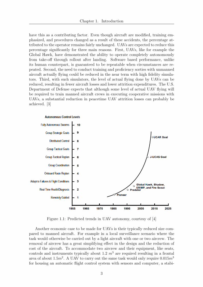
have this as a contributing factor. Even though aircraft are modified, training em-phasized, and procedures changed as a result of these accidents, the percentage at-tributed to the operator remains fairly unchanged. UAVs are expected to reduce thispercentage significantly for three main reasons. First, UAVs, like for example theGlobal Hawk, have demonstrated the ability to operate completely autonomouslyfrom take-o↵ through rollout after landing. Software based performance, unlikeits human counterpart, is guaranteed to be repeatable when circumstances are re-peated. Second, the need to conduct training and proficiency sorties with unmannedaircraft actually flying could be reduced in the near term with high fidelity simula-tors. Third, with such simulators, the level of actual flying done by UAVs can bereduced, resulting in fewer aircraft losses and lower attrition expenditures. The U.S.Department of Defense expects that although some level of actual UAV flying willbe required to train manned aircraft crews in executing cooperative missions withUAVs, a substantial reduction in peacetime UAV attrition losses can probably beachieved. [3]
Figure 1.1: Predicted trends in UAV autonomy, courtesy of [4]
Another economic case to be made for UAVs is their typically reduced size com-pared to manned aircraft. For example in a local surveillance scenario where thetask would otherwise be carried out by a light aircraft with one or two aircrew. Theremoval of aircrew has a great simplifying e↵ect in the design and the reduction ofcost of the aircraft. To accommodate two aircrew and their equipment, like seats,controls and instruments typically about 1.2 m
3 are required resulting in a frontalarea of about 1.5m2. A UAV to carry out the same task would only require 0.015m3
for housing an automatic flight control system with sensors and computer, a stabi-
3
Chapter 1. Introduction
lized high-resolution color TV camera and radio communication links. The frontalarea would be merely 0.04m2. The masses required to be carried by the mannedaircraft, together with the structure, windscreen, doors, frames, and glazing, wouldtotal at least 230kg. The equivalent for the UAV would be about 10kg. Comparedto the UAV the light aircraft has to carry a 220 kg heavier payload and has about35 times the frontal area. On the assumption that the disposable load fraction ofa light aircraft is about 40% and of this 10% is fuel, then its gross mass will betypically of order 750 kg. For the UAV, on the same basis, its gross mass will beof order 35 kg. The reduced size of the aircraft results in lower fuel costs as well aslower hangarage cost while the simpler design of the unmanned aircraft allows forcheaper first costs and lower maintenance costs. [5]
Autonomous UAVs are usually controlled by computer programs. These com-puter programs can, given enough processing power, be run on board the UAV itselfor otherwise on a remote computer system connected to the UAV via a wireless com-munication link which provides enough bandwidth for all sensory information to betransmitted su�ciently fast to the controlling ground station and control commandsto be transmitted back to the UAV. Although on-board processing and decision mak-ing is the more autonomous approach and therefore more desirable, todays UAVsare usually not capable of processing all their sensory data by means of on-boardcomputers and programs and making di�cult decisions in critical situations basedonly on such calculations [4]. Today usually a hybrid approach is used, letting theUAV do the easy processing and decision making tasks with its on-board capabilitieswhile heavy computational tasks like processing and evaluation of high resolutionvideo footage is usually done in a ground station, which receives the data over apowerful enough downlink [4].
UAVs can be equipped with additional communication capabilities allowing themto communicate among each other and thus making it possible for them to groupand create swarms of UAVs. As can be seen in figure 1.1 fully autonomous selfcoordinating swarms of UAVs are treated as one of the highest and most advancedlevels in UAV autonomy which has not been reached yet and is one of the futuregoals of the U.S. Department of Defense.
As stated before simulation can be very helpful in the task of training personnelfor UAV missions but simulation is not restricted to human training alone. It has along-standing tradition in robotics as a useful tool for testing ideas on virtual robotsin virtual settings before trying them out on real robots [6]. Due to the increase inthe computational power of computers, which made it possible to run computation-ally intensive algorithms on personal computers instead of special purpose hardware,and the increased e↵ort of the game industry to create realistic virtual environmentsin computer games, it has been getting even more attention in the last decade [6].Since the goals targeted by the game industry and the requirements for robot sim-ulation lie so close together, game engines and game technology is used for robotsimulation more often, recently.
Taking into consideration the costs for the actual hardware needed to carry out
4

Chapter 1. Introduction
experiments with UAVs and repairs due to crashes, the time spent constructing ex-periments and the restrictions imposed by the number of functional UAVs available,possibly forcing research sta↵ to work on available hardware in a schedule like man-ner, the idea to have a simulation environment for UAVs becomes very enticing. Ina simulation experiments can be carried out repeatedly in the exact same manner,failed experiments and crashes do not result in expensive repairs and loss of time,while, given powerful enough computers, several experiments can be done in paralleland virtual hardware and environments can be replicated as often as necessary toprovide everyone willing with material to work with. While humans can be trainedin a simulation environment to control UAVs, so can computers utilizing machinelearning algorithms. The simulation’s task is to provide an environment which isclose enough to reality that learning and testing of di↵erent control algorithms inthe simulation leads to comparable results as would have been achieved in a realworld environment. While high fidelity simulations have been vastly expensive andnot widely available in the past this has changed in recent years with the adventof the modularized game engines, mentioned earlier. These are highly popular forgame development and are capable of generating high fidelity graphics and doinghighly accurate physical calculations on consumer hardware computers. Due totheir popularity these game engines come at a much more a↵ordable price and insome cases even for free, providing a cost e�cient alternative for robot simulation,further increasing the financial advantage of simulating robots over having to workexclusively with real hardware.
In the course of this diploma thesis a UAV simulation environment will be pre-sented based on a simulation of urban search and rescue robots and environmentswhich again itself is based on a popular 3D game engine. The UAV simulationenvironment is supposed to act as a framework to enable an easy implementationof UAV control algorithms and learning algorithms which can then be tested andevaluated in the simulated environment.
5

Chapter 2
Fundamentals
2.1 Quadrocopters
The kind of UAVs this diploma thesis focuses on are small quadrocopters which dueto their little size are often categorized as micro unmanned air vehicles (MUAVs).Quadrocopters are aircrafts with four propellers mounted on a frame constructionwhich have flying capabilities that are comparable to that of helicopters.
Figure 2.1: Apollo quadrocopter, Hamburg University of Technology, courtesy of [7]
The basic structure of a quadrocopter is depicted in figure 2.1. They are capableof vertical take-o↵, hovering in midair and fast maneuvers like flips or loopings. Inaddition to their flying capabilities come their, compared to a helicopter, much sim-pler and therefore massively less sensitive mechanics [8]. These capabilities togetherwith their usually small size and relatively low costs make these aircrafts attractivefor researchers in the academic field. Scientists have been doing research in machinelearning [9], autonomous navigation of UAVs [10], swarm behavior [11] and otherfields with this kind of devices. Aside from the scientific field quadrocopters arealso used in the military for surveillance, in the civil area for cartography, tra�cmonitoring, observation of big crowds on popular events and by hobbyists aroundthe world for aerobatics, to name just a few applications.
6
Chapter 2. Fundamentals
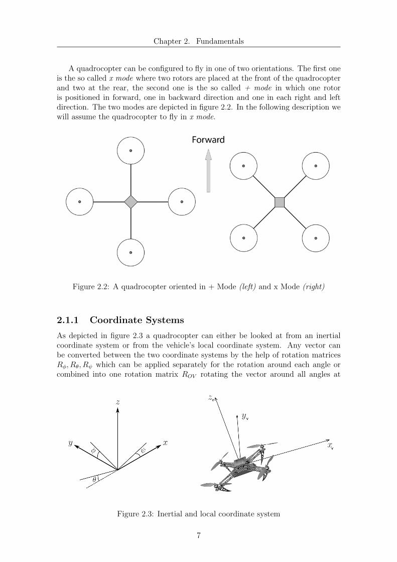
A quadrocopter can be configured to fly in one of two orientations. The first oneis the so called x mode where two rotors are placed at the front of the quadrocopterand two at the rear, the second one is the so called + mode in which one rotoris positioned in forward, one in backward direction and one in each right and leftdirection. The two modes are depicted in figure 2.2. In the following description wewill assume the quadrocopter to fly in x mode.
Figure 2.2: A quadrocopter oriented in + Mode (left) and x Mode (right)
2.1.1 Coordinate Systems
As depicted in figure 2.3 a quadrocopter can either be looked at from an inertialcoordinate system or from the vehicle’s local coordinate system. Any vector canbe converted between the two coordinate systems by the help of rotation matricesR�, R✓, R which can be applied separately for the rotation around each angle orcombined into one rotation matrix ROV rotating the vector around all angles at
Figure 2.3: Inertial and local coordinate system
7

Chapter 2. Fundamentals
once. The conversation from the inertial coordinate system to the local coordinatesystem can be done by the combined matrix ROV given below.
ROV = R�R✓R =
2
4cos✓cos sin�sin✓cos � cos�sin cos�sin✓cos + sin�sin
cos✓sin sin�sin✓sin + cos�cos cos�sin✓sin � sin�cos
�sin✓ sin�cos✓ cos�cos✓
3
5
Since these matrices are rotation matrices the back conversion of a vector fromthe vehicle’s coordinate system to the inertial system can be done by the help of thetransposed of the matrix used before so that
RV O = R
�1OV = R
TOV
2.1.2 Quadrocopter Movement
A quadrocopter being an air vehicle has six degrees of freedom. It can carry outtranslational movements which is moving up/down, left/right and forward/backwardand it can carry out rotational movements as well, which would be roll, pitch andyaw as is depicted in figure 2.4. The four rotors each create a force and a torque onthe quadrocopter’s frame and are the only means by which the quadrocopter is ableto move.
Figure 2.4: Six degrees of freedom, curtesy of [12]
In the following overview of quadrocopter movement we will assume that thequadrocopter’s center of mass lies in the middle of the quadrocopter when viewedfrom top and in the same plane as the four rotors and we will not take into con-sideration any aerodynamic or other e↵ects that might in reality have an additionalimpact on the quadrocopter.
8
Chapter 2. Fundamentals
Vertical Movement
The four rotors create a collective thrust in negative direction of zv. As long as thequadrocopter’s coordinate system’s z-axis is oriented along the inertial coordinatesystem’s z-axis and the the speeds of all four rotors are the same, upward anddownward movement is easily accomplished by increasing or decreasing the rotorspeed of all four rotors simultaneously by the same amount. If the sum of the forcesgenerated by the rotors exceeds the gravitational force mg the quadrocopter movesupward, if it falls below the force mg the vehicle moves downward. If the four forcessum up to match mg exactly the quadrocopter will hover in the air. As long as theforces Fi are all of the same size the moments generated by them will neutralizeeach other since they are working against each other which results in a rotationalacceleration of 0.
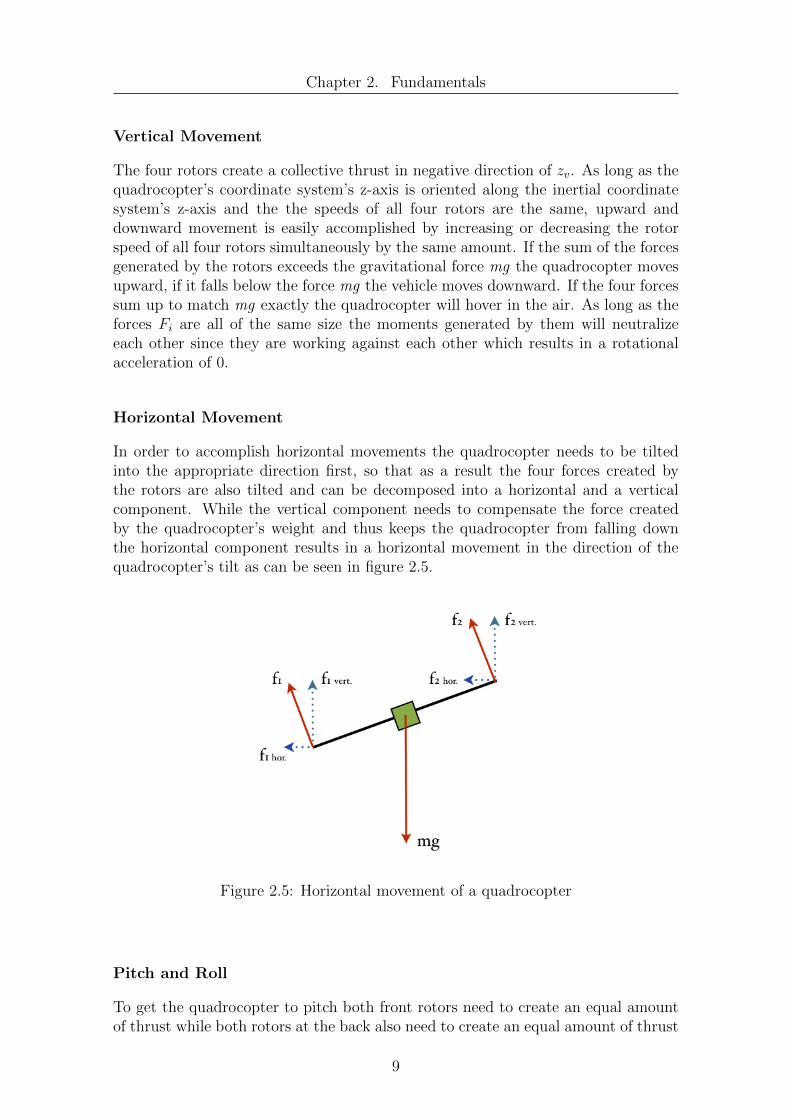
Horizontal Movement
In order to accomplish horizontal movements the quadrocopter needs to be tiltedinto the appropriate direction first, so that as a result the four forces created bythe rotors are also tilted and can be decomposed into a horizontal and a verticalcomponent. While the vertical component needs to compensate the force createdby the quadrocopter’s weight and thus keeps the quadrocopter from falling downthe horizontal component results in a horizontal movement in the direction of thequadrocopter’s tilt as can be seen in figure 2.5.
Figure 2.5: Horizontal movement of a quadrocopter
Pitch and Roll
To get the quadrocopter to pitch both front rotors need to create an equal amountof thrust while both rotors at the back also need to create an equal amount of thrust
9

Chapter 2. Fundamentals
which needs to be di↵erent from the thrust of the front rotors though.
Ffront = F1 = F2,
Fback = F3 = F4,
Ffront 6= Fback
As a result the moments in roll direction will sum up to zero while the moments inpitch direction will be nonzero and the quadrocopter will begin to pitch. Analogousto this the quadrocopter can be made to roll by letting the rotors on the right eachgenerate the same thrust and the ones on the left side generate an equal thrust thatis di↵erent from the thrust generated by the right rotors.
Fright = F2 = F3,
Fleft = F1 = F4,
Fleft 6= Fright
This time the moments in pitch direction will sum up to zero while the sum ofmoments in roll direction will be nonzero resulting in the quadrocopter beginningto roll.
Yaw Movement
Yaw movement is created in a di↵erent way. In order to compensate the torqueresulting from the rotors’ rotation two of the rotors are rotating clockwise while thetwo remaining ones rotate in the opposite direction. Usually rotors rotating in thesame direction lay opposite to one another as is depicted in figure 2.6. Assuming an
Figure 2.6: Rotor arrangement
10

Chapter 2. Fundamentals
arrangement of rotors as depicted in 2.6 the overall torque sums up to
Mtotal =4X
i=1
Mi = (M1 +M3)� (M2 +M4)
As long as Mtotal equals zero there will be no yaw movement. But as soon as Mtotal
is nonzero yaw movement is generated.
Stabilization
Since a human being would not be able to easily stabilize and fly a quadrocopterwithout additional sensor support quadrocopters usually have an on-board controllertaking care of stabilizing the vehicle [8]. To achieve this a quadrocopter is usuallyequipped with a controller board that contains sensors like gyroscopes and accel-eration sensors. The controller board usually implements a PD or PID controllerwhich generates appropriate control signals for the four rotor engines to stabilizethe quadrocopters flight. A human with a remote control usually only tells thequadrocopter to roll, pitch or yaw and to increase or decrease overall thrust gener-ated by the four rotors. He is not supposed to control the quadrocopter’s four rotorsdirectly. The on-board controller will then translate the operator’s commands intoappropriate rotor speeds.
2.1.3 Sensors
Quadrocopters can be equipped with a lot of di↵erent sensors which serve di↵erentpurposes. In order to make flight stabilization possible gyroscopes and accelerationsensors are commonly used which usually are relatively cheap and lightweight. Giventhese sensors a quadrocopter can determine its attitude as well as acceleration andtake measures to achieve a stable position.
Sensors like di↵erent kinds of cameras or measurement instruments like Geigercounters, thermometers or humidity sensors which are not needed for the quadro-copter’s functionality itself can be added to a quadrocopter to make it possible tofulfill certain mission goals like providing live video streams or measured data froma certain destination area the quadrocopter is supposed to operate in. Cameras canalso be used to remotely operate a quadrocopter independent of the fact if the UAVis in sight of the operator or not, increasing the quadrocopter’s range of operabilityand flexibility [13].
Aside from sensors for flight stabilization and information gathering quadro-copters can also be equipped with sensors that enable them to perceive their envi-ronment in order to allow for autonomous behavior. Laser scanners have been usedto allow quadrocopters to perceive obstacles and draw maps of their environments[10], ultrasonic sensors can be used to implement autonomous obstacle evasion be-havior while wireless communication devices can be used for communication betweenquadrocopters and the internal organization of a swarm of quadrocopters [11]. Inorder to allow a quadrocopter to to sense its position a GPS receiver or some other
11

Chapter 2. Fundamentals
kind of positioning system hardware can be carried by the quadrocopter.
With all the di↵erent kinds of sensors available it is necessary to remember thata quadrocopter can only carry a limited amount of payload and in order to notoverload it, it might be necessary to consider the advantages and disadvantages ofdi↵erent sensor combinations in respect to each other and the necessity of each sensortaken into consideration. Further on more payload results in a greater mass whichhas to be lifted into the air by the quadrocopter. This will require a higher thrustgenerated by the quadrocopter’s rotors which in turn means that a quadrocopterneeds to consume more energy and therefore will drain its batteries more quickly,eventually decreasing its employment radius.
2.1.4 Example: AirRobot AR 100-B
The AirRobot AR 100-B is an unmanned aerial vehicle with autonomous flight andnavigation capabilities produced by the company AirRobot. Its primary applicationsare reconnaissance, surveillance, search and rescue missions, intelligence, documen-tation and inspection [13]. It is capable of autonomously holding its position andhovering over a place either via GPS or optical position lock while the optical po-sitioning system can keep the UAV in place even in areas where a GPS signal isnot accessible [13]. Stabilization is achieved with the help of gyroscopic, barometricand magnetic sensors [13]. The AirRobot AR 100-B can be controlled remotely viaa life video feed which makes it unnecessary for the vehicle to be in direct sight ofthe operator, the operator can remotely operate and fly the UAV from a computerseeing through the camera as if sitting in the cockpit [13].
12

Chapter 2. Fundamentals
Figure 2.7: AirRobot AR 100-B [13]
The payloads available for the AR 100-B are build in a modular fashion to allowfor a fast change of equipment. At the moment AirRobot provides a daylight videocamera, a low light black and white camera, a 10 MP still camera and an infraredcamera for their vehicle. All cameras can be tilted up to 100 degrees and can alsolook straight down.
The German army tested the AirRobot AR 100-B in Australia for its capabili-ties in desert environments and is now using it in Afghanistan as a reconnaissancedevice [14]. The AR 100-B has also been used in forest fire detection, mine evic-tion and gas leak detection among other applications [14]. Also autonomous UAVswarms have been created based on AR 100-B quadrocopters which were modified tocarry a smart camera, that controlled the UAV via its serial interface and providedbasic autonomous capabilities like take-o↵, landing and GPS waypoint following [11].
The numbers in the following table are taken from the manufacturer’s specifica-tions and describe some of the vehicle’s key features.
Max. Ceiling 1000mEndurance <30 minMax. Payload 200gDeployable Radius 500m limited by analogue video signal
1500m limited by digital video signalMax. Wind Load 8 m/sMax Airspeed 50 km/hGross Weight 1kgDiameter 1m
Table 2.1: AR 100-B properties [13]
13

Chapter 2. Fundamentals
2.1.5 Example: Microdrones md4-1000
Another example for a mature quadrocopter system being available on the free mar-ket is the md4-1000 quadrocopter manufactured by the Microdrones GmbH. It hasbeen designed for tasks in the field of documentation, coordination, exploration,surveying, communication, inspection and observation [15]. Just as the AirRobotAR100-B it has a GPS receiver integrated, provides modularized payloads, whichare basically the same as for the AR100-B, and can be remotely operated either vialine of sight or a live video feed coming from the quadrocopter’s camera. On top ofthese capabilities it provides a system to autonomously navigate between waypointswhich can be set by the operator of the vehicle so that its operational range is notlimited by the range of its communication interfaces [15].
Figure 2.8: Microdrones md4-1000 [15]
Max. Ceiling 1000mEndurance <70 minMax. Payload 1200gDeployable Radius 500m controlled remotely
up to 40km when following waypointsMax. Wind Load 12 m/sMax Airspeed 54 km/hGross Weight 2.65kgDiameter 1.03m
Table 2.2: Microdrone md-1000 properties [15]
As table 2.2 shows, although the md-1000 has almost the same dimensions as theAR 100-B it has a higher weight, can carry heavier loads, has a higher deployable ra-dius and can stay in the air for a longer time. Since the md-1000 can carry relativelyheavy camera equipment it is also used for panorama and landscape photographyas well as aerial filming for cinematic purposes and special e↵ects [15].
14
Chapter 2. Fundamentals
2.2 Simulation
Simulation makes it possible to test control algorithms and system behaviors ofmachines without the need for a lot of expenses for the actual hardware that issimulated. While a real system does only exist once, a system in a simulation can bereproduced several times if needed, allowing for economies in otherwise particularlyexpensive areas such as multi-robot control. Furthermore a lot of simulations canbe run in parallel if the needed processing power is available, possibly speeding upresearch and development processes. On top of this simulated hardware does notneed to be repaired, maintained or stored. A crash of a prototype system in reallife could mean hours of repairs during which the system is unavailable for furthertests and development, resulting in high costs. A crash in a simulation though needsonly a hand full of mouse clicks and the simulation can be started anew. This canbe especially advantageous in the case of machine learning where new algorithmsmight not always act as expected or where they are expected to produce crashesin the beginning before converting more or less slowly to a desired behavior. In asimulation a machine can learn the basics of how to behave and to get along wellwithin its environment. After that the algorithms developed in the simulation canbe applied to a real machine letting it learn the remaining details in the real world.In some simulations it is also possible to adjust the speed of time and thus let asystem learn much faster than it ever could in a real situation.
2.2.1 Unreal Engine
Typically real-time 3D simulations have always been di�cult, time consuming andexpensive to build and require specialized hardware and personnel [16]. The costof developing ever more realistic simulations has grown so huge that even gamedevelopers can no longer rely on recouping their entire investment from a singlegame [16]. This has led to the emergence of game engines - modular simulation code- written for a specific game but general enough to be used for a family of similargames [16]. The Unreal Engine is such a game engine developed by Epic Games.Its first version was released in 1998 with the popular first person shooter UnrealTournament. Since then many games have been developed based on this game enginelike Bioshock, Deus Ex and a host of other major titles, and the engine itself hasbeen ported to several di↵erent platforms. It is now available for Windows, Linux,Mac OS X, iOS and other operating systems. The engine is capable of creatinghigh quality 3D environments and makes use of nVidia’s PhysX engine in order tocalculate physical e↵ects. At the moment of writing the Unreal Engine is availablein version 3 while version 4 is still under development and has not yet been o�ciallyreleased. The Unreal Engine’s core is written in the C++ programming languagebut a lot of content is also written in the engines own object oriented scriptinglanguage, namely Unreal Script, which also allows for users to create additionalcontent and game-play items on their own.
15

Chapter 2. Fundamentals
Figure 2.9: FPS Client-Server Architecture
Multi-player first person shooter games like Unreal Tournament use a clientserver architecture in which each player takes the role of a client. The fast renderingof graphics is usually done on the client-side while the server is responsible forcoordinating the di↵erent players and environmental interactions as is depicted infigure 2.9.
Unreal Development Kit
In 2009 Epic Games released the first beta version of the Unreal Development Kitwhich is a free version of their engine that is available to the general public. Itcontains the Unreal Editor and other utilities which can be used to create newcontent like maps, models or entire new games for the engine and comes with a hugecollection of art and sound assets including textures, 3D models and animations. Ifthe contents or games built with the UDK are not commercial ones then the UDKcan be used free of charge. Recently new beta versions of the Unreal DevelopmentKit have been released on a monthly schedule and , according to Epic Games, havebeen downloaded more than 1.5 million times as of June 2012.
16

Chapter 2. Fundamentals
Figure 2.10: A quadrocopter mesh in the UDK editor
Unreal Script
Unreal Script is the scripting language of the unreal engine, which allows for con-tent creation and modification of game logic. It was created to provide the Unrealdevelopment team and third party Unreal developers with a powerful, built-in pro-gramming language that maps naturally onto the needs and nuances of game pro-gramming. Its original design was based entirely on the Java programming language,therefore its syntax strongly resembles Java and C++. Unreal Script is an objectoriented programming language which supports inheritance, interfaces and operatoroverloading and provides a pointerless environment with automatic garbage collec-tion. [17]
Time critical and low level functions in the Unreal Engine are usually writtenin the C++ programming language, for compiled C++ code runs much faster thanUnreal Script code. Other, higher level and more abstract functionality is oftenimplemented in Unreal Script only. The use of C++ functions from within UnrealScript is allowed though. These functions are referred to as native code then.[17]
In order to manage time in the simulation, Unreal divides each second of game-
17

Chapter 2. Fundamentals
play into so-called ”ticks”. A tick is the smallest unit in which all actors in a levelare updated and typically takes between 1/10th and 1/100th of a second. The ticktime is limited only by CPU and GPU power. The faster the machine the lowerthe tick duration is. Unreal Script classes which can be added to the simulationcontain a tick-function which is executed every tick. All motion controlling codeof such classes needs to be placed inside the tick-function. While all Unreal scriptsare executed independently of each other and each actor in a level seems to haveits own thread, internally Unreal does not use Windows threads for e�ciency rea-sons. Instead threads are simulated by Unreal Script which is transparent for UnrealScript code but becomes apparent when writing C++ code that interacts with Un-real Script. [17]
2.2.2 USARSim
USARSim is an acronym for Unified System for Automation and Robot Simula-tion [18] or also Urban Search And Rescue Simulation [18]. It was designed asan open source high-fidelity simulation of robots and environments based on theUnreal Tournament game engine. It’s intended as a general purpose research toolwith applications ranging from human computer interfaces to behavior generationfor groups of heterogeneous robots. In addition to research applications, USARSimis the basis for the RoboCup rescue virtual robot competition as well as the IEEEVirtual Manufacturing Automation Competition (VMAC). [18]
USARSim loads o↵ the most di�cult parts of simulation to the Unreal gameengine, so that the developers behind the project and users can concentrate moreon the robot-specific tasks of modeling platforms, control systems, sensors, inter-face tools and environments [18]. The 3D rendering and physics calculations are allhanded by the underlying Unreal Engine. USARSim itself provides several leggedand wheeled robots, aerial robots and even submarine robots, as well as a batteryof sensors and actuators and virtual environments, i.e. maps, that the robots canbe placed in.
The sensors provided by USARSim can be generally divided into three cate-gories. First there are proprioceptive sensors, including battery state and headlightstate, second position estimation sensors, including location, rotation, and velocitysensors and third there are perception sensors, including sonar, laser, sound, andpan-tilt-zoom cameras [18]. USARSim defines a hierarchical architecture for sensormodels as well as for robot models. A sensor class defines a type of sensor and everysensor is defined by a set of attributes stored in a configuration file. Perceptionsensors, for example, are commonly specified by range, resolution, and field of view.Beyond that USARSim provides users with the capability to build their own sensorsand robots.
USARSim is available in an older version for Unreal Tournament 2004, in an Un-real Tournament 3 version and is right now in the process of being ported from theUnreal Tournament 3 system to the newer free Unreal Development Kit. Since this
18

Chapter 2. Fundamentals
process is not finished yet and the UT3 version of USARSim is not compatible withthe UDK version, the UDK version of USARSim does not yet support all Robots,Maps and Sensors the previous versions of USARSim supported and models, mapsand sensors from the previous version of USARSim are usually not usable with thenew UDK version.
USARSim provides a socket based interface which is based on Gamebots [19], amodification for Unreal Tournament, through which it is possible to communicatewith the simulated robots directly, bypassing the Unreal Client. This also enablescontroller applications to reside on di↵erent computers than the Unreal Engine thusallowing to control a virtual robot over a network connection. A sketch of thisarchitecture can be seen in figure 2.11. A brief overview of Gamebots is providedin [20]. The communication protocol implemented by USARSim is based on simpletext messages being sent between the controller application and USARSim. All thisenables users to develop and test their own control programs and user interfaceswithout limitations in programming language and operating system.
Figure 2.11: USARSim architecture
USARSim is an open source project licensed under the Gnu Public Licence andis freely available on the internet.
19

Chapter 3
UAV Scenarios
In this chapter some possible applications for UAVs in general and for quadrocoptersin particular will be presented. General applications for single UAVs will be dis-cussed, showing the versatile possibilities for quadrocopter applications, and wherepossible and useful extended to multi UAV scenarios. Any of the presented scenariosin this chapter can be implemented in the simulation environment developed in thisdiploma thesis if proper agents are provided for quadrocopter control and if anyadditionally needed sensors are attached to the quadrocopter model.
3.1 Search
A common scenario for robots and UAVs is the search scenario in which the robotor the UAV is supposed to search for a certain object in a given area. If the objecthas been found the UAV is either supposed to report to the base station where theobject has been found and then hover over the object’s position or return right awayto the base station. As with other robot scenarios a UAV needs tor return to its basestation regularly in order to refuel or exchange its batteries. This is an importantlimiting factor for the UAV, for it can possibly not reach every location in the searcharea in one visit and still return safely. Furthermore it will be able to only searchsmaller parts of the search area in one visit if these are further away from the basestation since reaching them will already consume some part of the UAVs availableenergy resources.
A UAV can in general take two approaches towards searching a given area. First,it can move in the search area in a random pattern. Given enough time the wholesearch area will be searched by the UAV eventually. This approach has some dis-advantages, though. Assuming that the random search will be interrupted by abattery event when the UAV needs to return to the base to recharge, it becomesless likely for the UAV to visit the areas which are farther away from its startingpoint, because every time when recharged the UAV will begin its random searchat the part of the search area which is closest to its base station, possibly taking aturn before reaching a more distant part, thus depleting its batteries before havingreached the more distant areas after several turns. Another disadvantage of thisapproach is that while more distant parts of the search area are harder to reachother parts of the search area are overflown multiple times where a UAV crisscrosses
20

Chapter 3. UAV Scenarios
its own path.
Figure 3.1: Di↵erent search patterns
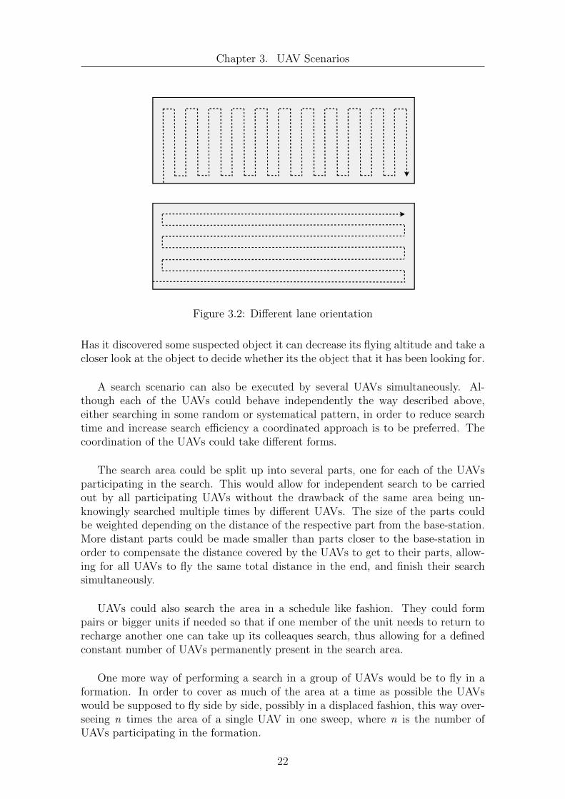
A better approach towards searching in an area is to search the area systemati-cally. This could for example be done in a lane by lane fashion where the UAV fliesthe search area up and down in lanes which are displaced a little bit every time sothat eventually the whole area has been covered. A snail like pattern is thinkabletoo, so that the UAV flies around the perimeter of the search area and after everycompleted round decreases its distance to the area’s center a little. These system-atical approaches have the advantage that less area is covered multiple times andmore distant areas will be reached in a predefined time, not depending on randomdecisions. When searching an area in a lane by lane fashion as stated by [21] the timeneeded to cover the entire search area consists of the time needed to travel along therows plus the time needed to turn around at the end of the rows. Although di↵erentsweep directions result in rows of approximately the same total length there can bea large di↵erence in turns required [21] as illustrated in figure 3.2. Helicopter andquadrocopter turns take a significant amount of time [21], so in order to decreasesearch time a lane pattern should be chosen that yields a relatively small number ofturns.
In order to increase e�ciency even more the ways covered by the UAV in orderto return to its base-station and refuel can be taken into consideration, too, whenplanning the route the UAV is to take in the search area. One could prevent the UAVfrom overflying the same areas multiple times when returning to the base-station orflying to the place where the last search was interrupted.
While ground based robots can only operate in a more or less two dimensionalarea, UAVs can operate in three dimensions providing for other opportunities thanfor ground vehicles. If for example a UAV was to search a given area with thehelp of a video or infrared camera, it could increase its cruising altitude in order tocover a bigger part of the search area in one sweep thus trading image resolution foramount of area searched, or in other words quality for quantity. This could speedup search drastically. A UAV could fly so high it may not immediately recognizethe object it is looking for as what it is but low enough to not accidentally miss it.
21
Chapter 3. UAV Scenarios
Figure 3.2: Di↵erent lane orientation
Has it discovered some suspected object it can decrease its flying altitude and take acloser look at the object to decide whether its the object that it has been looking for.
A search scenario can also be executed by several UAVs simultaneously. Al-though each of the UAVs could behave independently the way described above,either searching in some random or systematical pattern, in order to reduce searchtime and increase search e�ciency a coordinated approach is to be preferred. Thecoordination of the UAVs could take di↵erent forms.
The search area could be split up into several parts, one for each of the UAVsparticipating in the search. This would allow for independent search to be carriedout by all participating UAVs without the drawback of the same area being un-knowingly searched multiple times by di↵erent UAVs. The size of the parts couldbe weighted depending on the distance of the respective part from the base-station.More distant parts could be made smaller than parts closer to the base-station inorder to compensate the distance covered by the UAVs to get to their parts, allow-ing for all UAVs to fly the same total distance in the end, and finish their searchsimultaneously.
UAVs could also search the area in a schedule like fashion. They could formpairs or bigger units if needed so that if one member of the unit needs to return torecharge another one can take up its colleaques search, thus allowing for a definedconstant number of UAVs permanently present in the search area.
One more way of performing a search in a group of UAVs would be to fly in aformation. In order to cover as much of the area at a time as possible the UAVswould be supposed to fly side by side, possibly in a displaced fashion, this way over-seeing n times the area of a single UAV in one sweep, where n is the number ofUAVs participating in the formation.
22

Chapter 3. UAV Scenarios
Figure 3.3: Partitioning of a search area considering distance to base station
The principles of the search scenario can be applied to a couple of other scenarios,too. Area coverage scenarios for example make use of the same considerations asjust presented for the search scenario. While in a search scenario the search endsif the object searched is found, or is at least interrupted, in many area coveragescenarios like for example crop spraying or unmanned aerial mapping there is nosuch interruption. The UAV is supposed to cover the entire area once to eitherspray all plants in the field with a given pesticide or in order to take photos ofevery part of the area so that they can later be stitched together providing a highresolution map of the ground.
3.2 Providing Communication Services
Another application scenario for UAVs and quadrocopters is the provision of com-munication services. For example as proposed in [22] UAVs could be used to pro-vide satellite coverage in urban areas with shadowing reducing visibility time or indisaster areas where terrestrial communication infrastructure is unavailable or in-terrupted. The UAV would be equipped with a link to a satellite on the one sideand on the other provide for example a wireless network access point and act as aproxy for connected devices [22]. In a similar fashion a UAV could also provide alocal communication service acting as a router, bridging the distance between moredistant communication partners as depicted in figure 3.4.
23

Chapter 3. UAV Scenarios
Figure 3.4: UAV acting as a router for two communication endpoints
UAVs could also act as airborne GPS pseudo satellites to provide a stronger andpossibly more accurate GPS signal which is harder to jam than satellite based GPSas proposed in [3].
While this appears as a simple task for a single UAV, for it only needs to placeitself in an advantageous position between the two participating communicationparties things get more interesting when considering multiple UAVs which are toprovide an entire area with a communication infrastructure. The UAVs could beequipped with small wireless network devices like for example the IRIS node manu-factured by the company Crossbow Technology [23]. This network node is so smalland lightweight it could be easily carried by a quadrocopter like the AR 100-B. Thesensor nodes could then be utilizing a routing protocol like Dynamic Source Rout-ing (DSR) [24] to create a mobile ad hoc network and provide a wireless commu-nication network to a certain area without any preexisting infrastructure required.DSR allows the created network to be completely self-organizing and self-configuringwithout the need for administration [24]. The number of UAVs needed to cover acertain area would depend on the area size and the range of the communicationdevices placed on-board the UAVs. Assuming a communication range of 300 metersa group of 9 quadrocopters would easily be able to completely cover an area of onesquare kilometer with a wireless network as depicted in figure 3.5.
24

Chapter 3. UAV Scenarios
Figure 3.5: Covering an area with a wireless network
As in the search scenario the UAVs would need to return to their base stationfrom time to time to recharge their batteries. In order for the MANET to maintainfull coverage of the desired area additional UAVs are required to take the place oftheir colleagues returning to the base station. Due to the self-configuring capabil-ities of DSR this change of network nodes would have no negative e↵ect on thecommunication service provided. While single nodes can leave and join the networkwithout di�culties the UAVs participating in the network setup can also move andchange their relative positions. This could be used for example to move the nodesin the formation in some kind of pattern in order to allow for a constant rotationof nodes. This way quadrocopters which participated in the formation for a longerperiod of time and whose batteries are almost depleted will slowly come into a po-sition from where they can quickly return to the base station. At the same timea new quadrocopter coming from the base-station can immediately take the placeleft by its predecessor minimizing the time each of the quadrocopters is in the airwithout participating in the network thus maximizing the quadrocopter’s e�ciency.
25

Chapter 3. UAV Scenarios
Figure 3.6: Rotating group of quadrocopters
Groups of quadrocopters could also be used to connect two communication end-points which are too far apart for a single quadrocopter to bridge the distancebetween the two. Therefore a long formation of quadrocopters would be necessary.A di�culty with this approach though is that replacement quadrocopters do alwayshave to join the formation before any quadrocopter with depleted batteries leave forthe base station in order to prevent an interruption of the communication betweenthe two endpoints.
Figure 3.7: A group of quadrocopters connecting two endpoints
Furthermore the quadrocopters participating in the creation of the MANETcan not only move in respect to each other but also the entire formation couldmove and thus provide communication services for moving entities, like for examplerescue forces in disaster areas. In such a case the UAVs could also conduct othertasks at the same time like providing video footage of the surrounding area or
26

Chapter 3. UAV Scenarios
measure radioactivity in the case of a nuclear disaster in order to warn rescue forcesshould radioactivity increase to dangerous levels. The approach of UAVs providinga MANET and following a given entity could also be combined with the idea ofa line of UAVs connecting two endpoints. If two entities followed by UAVs movecloser together a small number of UAVs from the MANETs of both entities couldfan out and create a communication link between the two MANETs thus creating asingle network allowing for communication of all participants of the two networks.
3.3 Tracking
Tracking is another possible application for quadrocopters. In a police scenario forexample a car or a pedestrian could be tracked by a quadrocopter equipped witha camera to allow for unobtrusive observation. In an aircraft crash scenario overthe sea or when a ship has sunk in the ocean quadrocopters equipped with infraredcameras could be sent out to find survivors and when having found someone hoverover the victims and following them should strong currents drift them o↵, acting asa beacon to draw helpers to the survivor’s position. Furthermore as proposed in [25]quadrocopters could be used to track forest fires or bush fires in order to provide asaccurate data of the fire’s spread, its spreading velocity and direction as possible.
Since a single quadrocopter would probably be not able to observe the wholearea of the forest fire from one position, in order to track a forest fire’s spread itwould be required to fly around the fire’s perimeter [25]. Furthermore in order tomake the information about the fire available to ground crew as quickly as possibleunder the assumption that the UAV does only have a limited communication rangeand cannot communicate with its base-station all the time it would be required toregularly return close enough to the base-station to deliver the newly collected dataas depicted in figure 3.8.
Figure 3.8: A single quadrocopter tracking a fire
When assigning multiple UAVs the task of tracking the fire, data about the fire’sspread can be delivered more frequently as with a single quadrocopter. Assuming
27
Chapter 3. UAV Scenarios
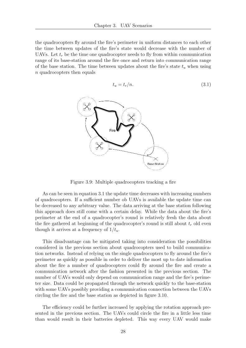
the quadrocopters fly around the fire’s perimeter in uniform distances to each otherthe time between updates of the fire’s state would decrease with the number ofUAVs. Let tr be the time one quadrocopter needs to fly from within communicationrange of its base-station around the fire once and return into communication rangeof the base station. The time between updates about the fire’s state tu when usingn quadrocopters then equals
tu = tr/n. (3.1)
Figure 3.9: Multiple quadrocopters tracking a fire
As can be seen in equation 3.1 the update time decreases with increasing numbersof quadrocopters. If a su�cient number ob UAVs is available the update time canbe decreased to any arbitrary value. The data arriving at the base station followingthis approach does still come with a certain delay. While the data about the fire’sperimeter at the end of a quadrocopter’s round is relatively fresh the data aboutthe fire gathered at beginning of the quadrocopter’s round is still about tr old eventhough it arrives at a frequency of 1/tu.
This disadvantage can be mitigated taking into consideration the possibilitiesconsidered in the previous section about quadrocopters used to build communica-tion networks. Instead of relying on the single quadrocopters to fly around the fire’sperimeter as quickly as possible in order to deliver the most up to date informationabout the fire a number of quadrocopters could fly around the fire and create acommunication network after the fashion presented in the previous section. Thenumber of UAVs would only depend on communication range and the fire’s perime-ter size. Data could be propagated through the network quickly to the base-stationwith some UAVs possibly providing a communication connection between the UAVscircling the fire and the base station as depicted in figure 3.10.
The e�ciency could be further increased by applying the rotation approach pre-sented in the previous section. The UAVs could circle the fire in a little less timethan would result in their batteries depleted. This way every UAV would make
28

Chapter 3. UAV Scenarios
Figure 3.10: Multiple quadrocopters with MANET tracking a fire
exactly one round around the fire’s perimeter and would be required to travel onlya minimum distance from the fire’s perimeter back to the base station in orderto recharge. This would also make complicated scheduling of UAVs that need torecharge, planning of their paths from far-o↵ locations to the base-station and anyconcerns about communication gaps arising from UAVs leaving the formation un-necessary while at the same time saving energy due to the UAVs’ lower cruisingspeed and possibly also increase information quality.
Should the size of the perimeter of the fire increase this can be countered bya higher number of UAVs used and increased overall cruising speed while in theopposite case less UAVs would be required to track the fires perimeter and cruisingspeed could be decreased.
3.4 Payload delivery
One more application for quadrocopters or UAVs in general is the delivery of a pay-load to a certain location. An autonomous UAV supposed to accomplish this taskwould need to possess some kind of waypoint following capability in order to reachthe destination where the payload is to be placed, as well as autonomous take-o↵ andlanding capabilities if the payload is not to be dropped from mid-air. Furthermorethe quadrocopter would need some kind of obstacle evasion algorithms implementedwhen flying at lower altitudes before landing and after take-o↵ and possibly indoornavigation capabilities, too, if required to deliver something into buildings.
The scenarios for payload delivery are numerous. For example quadrocopterscould be used for delivery of documents between o�ces in a building, or in crowdedmetropolitan regions like Tokyo between o�ces situated in very high floors of op-posing skyscrapers. This way documents could be flown directly from one towerto the other through a window making it unnecessary for a person to climb downto the ground floor of the first building and then climb up the second one only to
29

Chapter 3. UAV Scenarios
repeat this procedure after delivering the documents in order to return to its o�ce.Considering the preconditions required for this scenario, like reliable autonomousindoor navigation capabilities in order not to harm any persons, this application israther unlikely to be seen anytime soon and is more an outlook on what is a think-able use for quadrocopters in a more distant future.
Another scenario for payload delivery could be to let a quadrocopter build upa MANET by placing network nodes at di↵erent locations. In contrast to theMANETs with network nodes being carried by a group of quadrocopters presentedearlier this approach to building a MANET would require only one single quadro-copter that would carry a number of network nodes, delivering them one at a timeto their destined positions. While the mobility of the MANET is decreased to zeroonce it is in place this approach allows for minimized costs because only one singleUAV is needed to create the MANET. Further on network nodes could be stored inplaces that are hard to reach by a human like roofs of buildings, lantern posts andothers. The costs saved due to the lower number of UAVs in use could be investedinto network nodes, thus allowing for coverage of a greater area by the MANETbeing deployed. If the UAV can also take up a network node autonomously thiswould allow for easy maintenance of MANETs, the UAV replacing nodes of whichthe batteries are depleted with new ones making it unnecessary for humans to climbon roofs or other dangerous locations.
30

Chapter 4
Implementation
In this chapter first the quadrocopter model used in USARSim and the sensor con-figuration it has been equipped with will be presented after which the implementedcontrol program for the quadrocopter is discussed. The control program itself isentirely written in C++ for Microsoft’s .Net platform while the USARSim depen-dent parts, like sensors, are written in the UnrealScript language. The goal of theprogram is to provide a basis on which control algorithms and learning algorithmsfor autonomous quadrocopters in USARSim can be implemented without the needto care for all the underlying aspects of the simulation environment and to rid devel-opers of the laborious task of implementing a complete control program themselves.Ideally a developer should be able to use the control program and the providedquadrocopter and sensor configuration as is, and to concentrate solely on his controlalgorithms. These should be implemented it in a C++ class that is derived froman agent base class, which is provided in the control program and discussed later inthis chapter, to get the algorithms to work in the control program and test it in thesimulation environment.
4.1 UAV Model
This section will provide an overview of the UAV model and sensors used in thesimulation. The specific properties of both can be adapted in the UDKUSAR.inifile which holds the configurations of most USARSim robots, sensors and actors.
4.1.1 Quadrocopter Model
Although USARSim comes with several robots ready to use the transition to theUDK version of USARSim is not finished yet. At the moment of writing only onequadrocopter model has been ported from the old USARSim to the UDK versionand is available for use. The quadrocopter model provided by USARSim is a modelof the AirRobot AR 100-B presented in chapter 2.1.4. The control possibilities forthe AirRobot model in USARSim are the same as for a human operator who is con-trolling the AirRobot through a remote control which means the AirRobot can movein direction of the x, y and z-axis and turn around the yaw. Direct control of thefour rotors’ rotation speed is not available at the moment but can be implementedif desired by changing the quadrocopter model itself and its properties in the UDK
31

Chapter 4. Implementation
Figure 4.1: Screenshot of the USARSim AirRobot model
Editor and editing the quadrocopter’s UnrealScript implementation file. Since flightstabilization usually takes place within a quadrocopter itself though and the aboveway of quadrocopter control resembles a stabilized quadrocopter it is completelysu�cient for the purposes of this diploma thesis.
4.1.2 Sensor Models
Since sensors are important to robot control USARSim simulates proprioceptivesensors like battery or headlight state sensors, position estimation sensors provid-ing information about location, rotation and velocity and perception sensors whichinclude, lasers, sonar and touch sensors among others. In USARSim every sensor isan instance of a sensor class, which specifies a sensor type. The class hierarchy ofUSARSim sensors is depicted in figure 4.4. Almost all sensors in USARSim can addnoise and apply distortion to their data in order to provide a more realistic sensorbehavior and the quality of sensor data can be adapted via parameters. Several ofthe sensors provided by USARSim can be used together with the AirRobot, someof which will be described here briefly.
Sonar Sensor
The sonar sensor implemented in USARSim, in order to mimic a real sonar sensor,sends out a number of traces which in combination form a cone.
The size of the cone and the number of traces can be specified in the sensor’sconfiguration section in the UDKUSAR.ini file. For the traces inside the cone thedistance from the sensor and any surface within the sensor’s range is measured andthe smallest distance measured is returned by the sensor if this distance lies withinthe minimum and maximum range of the sensor. If an object is detected to becloser than the minimum detection distance then the minimum detection distance isreturned by the sensor, if an object is further away than the maximum distance thesensor can detect the sensor will return the maximum distance. Anything outside
32
Chapter 4. Implementation
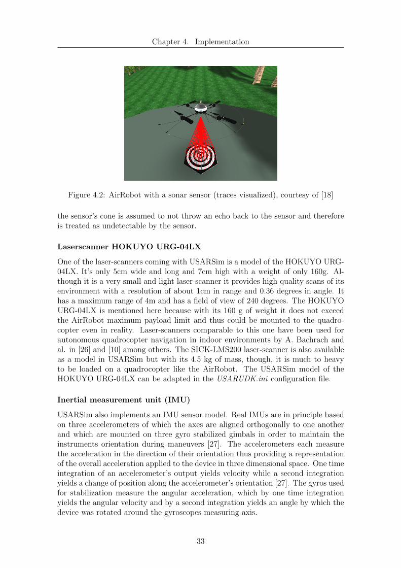
Figure 4.2: AirRobot with a sonar sensor (traces visualized), courtesy of [18]
the sensor’s cone is assumed to not throw an echo back to the sensor and thereforeis treated as undetectable by the sensor.
Laserscanner HOKUYO URG-04LX
One of the laser-scanners coming with USARSim is a model of the HOKUYO URG-04LX. It’s only 5cm wide and long and 7cm high with a weight of only 160g. Al-though it is a very small and light laser-scanner it provides high quality scans of itsenvironment with a resolution of about 1cm in range and 0.36 degrees in angle. Ithas a maximum range of 4m and has a field of view of 240 degrees. The HOKUYOURG-04LX is mentioned here because with its 160 g of weight it does not exceedthe AirRobot maximum payload limit and thus could be mounted to the quadro-copter even in reality. Laser-scanners comparable to this one have been used forautonomous quadrocopter navigation in indoor environments by A. Bachrach andal. in [26] and [10] among others. The SICK-LMS200 laser-scanner is also availableas a model in USARSim but with its 4.5 kg of mass, though, it is much to heavyto be loaded on a quadrocopter like the AirRobot. The USARSim model of theHOKUYO URG-04LX can be adapted in the USARUDK.ini configuration file.
Inertial measurement unit (IMU)
USARSim also implements an IMU sensor model. Real IMUs are in principle basedon three accelerometers of which the axes are aligned orthogonally to one anotherand which are mounted on three gyro stabilized gimbals in order to maintain theinstruments orientation during maneuvers [27]. The accelerometers each measurethe acceleration in the direction of their orientation thus providing a representationof the overall acceleration applied to the device in three dimensional space. One timeintegration of an accelerometer’s output yields velocity while a second integrationyields a change of position along the accelerometer’s orientation [27]. The gyros usedfor stabilization measure the angular acceleration, which by one time integrationyields the angular velocity and by a second integration yields an angle by which thedevice was rotated around the gyroscopes measuring axis.
33

Chapter 4. Implementation
Figure 4.3: Gimbaled Inertial Platform [27]
The IMU sensor model available in USARSim provides information on accelera-tion in direction of the x, y and z-axis, as well as pitch, roll and yaw accelerationsand angles.
4.1.3 Newly implemented sensors
As stated before USARSim allows for the creation of new sensors and sensor types.Sensors in USARSim are derived from the Sensor class, which itself is a subclassof the Item class. The Item class also serves as a base class for the Actuator andDecoration classes, as is depicted in figure 4.4. The Decoration class as the nameimplies is used merely as decoration on a robot, like for example battery packs ormotor boxes whereas actuators are parts for robots which cannot exist on their ownand can be made to perform actions, like for example a tiltable camera or a robotarm. In order to create a new sensor, a new class has to be derived either from thesensor class or one of its subclasses.
Position sensor
Although a GPS sensor is provided with USARSim it seems much easier and moreintuitive to use coordinates in a three dimensional inertial system with an x, yand z-component instead of altitude, latitude and longitude values measured indegrees, minutes and seconds as is done with a GPS system. When implementinga control algorithm it may be a little bit of an overhead to implement a functionunderstanding GPS coordinates and using these to derive quadrocopter motion,especially if the quadrocopter is to be used in an application where there is no realneed for utilization of a GPS signal. This is for example the case in indoor scenariosor when the quadrocopter is to operate in a very limited area or over short distanceswhere GPS coordinates may not even be of high enough resolution. In order tosimplify handling of the quadrocopter’s position data a new position sensor hasbeen implemented. If, for some reason, coordinates in a GPS format are required,the GPS sensor of USARSim can of course still be attached to the quadrocoptermodel and used. The new position sensor class is named stsPositionSensor. It is
34

Chapter 4. Implementation
Figure 4.4: USARSim class design for sensors, actuators and decoration
directly derived from the Sensor class and provides Cartesian coordinates based onthe coordinate system of the simulated environment in meters.
Velocity sensor
While USARSim comes with sensors like a tachometer which allow to determine awheel based ground robot’s velocity it does not provide a sensor which accomplishesthe same for an air vehicle like the used quadrocopter model. In order to compensatefor this a new velocity sensor has been implemented. The new sensor providesvelocity information as well from the view of an inertial coordinate system, as wouldbe measured by a spectator from the ground watching the quadrocopter fly, asvelocity information from the quadrocopter’s local coordinate system. The formeris of interest for example for movement in a global frame like navigating on a mapmaking it possible to see how fast the UAV is going towards which position the latteris interesting if the quadrocopter is to fly maneuvers and needs to plan its movementin the local frame. The new velocity sensor class is named stsVelocitySensor andlike the previous sensor is directly derived from the Sensor class. All values comingfrom this sensor are given in meters per second.
35

Chapter 4. Implementation
4.1.4 Base Equippment of the quadrocopter
In order not to create any conflicts with other USARSim based applications a newinstance of the AirRobot model available in USARSim has been created and namedstsAirRobot. To allow for autonomous behavior the sensor configuration of the orig-inal AirRobot coming with USARSim has been extended in the stsAirRobot model.The stsAirRobot is equipped with the newly implemented velocity sensor mentionedbefore providing the UAV with information about its absolute and relative velocitiesas well as the newly implemented position sensor. Also an IMU sensor allowing theUAV to sense its current linear and angular accelerations as well as orientation andangular velocity has been added to the quadrocopter model. Furthermore the st-sAirRobot is equipped with a battery sensor allowing it to check its current batterystate. In addition to sensing its location, orientation, velocity and battery state aquadrocopter that is supposed to act autonomously also needs to perceive its envi-ronment. In order to recognize and evade obstacles a number of sonar sensors havebeen attached to the quadrocopter model. Eight sonar sensors monitor the hori-zontal plane of the quadrocopter around the perimeter while two sonar sensors aremonitoring the vertical directions. One of them is oriented straight down the otherstraight up from the quadrocopter, so that it is capable of perceiving objects aboveor below it. In addition to the sonar sensors a model of the Hokuyo URG-04LXlaser scanner has been attached to the stsAirRobot in order to allow for a moreprecise measurement of its environment than it is possible with sonar sensors only.The laser scanner covers 240 degrees of the frontal area of the quadrocopter with228 laser beams. With such a fine angular resolution the laser scanner can also beused to generate maps of the environment to allow the quadrocopter to memorizeobstacles and find e�cient ways of moving within its environment. The arrangementof sonar sensors and the laser scanner on the vehicle can be seen in figure 4.5.
The sensor equipment provided with the stsAirRobot model should be enoughto allow for the implementation of algorithms which enable the quadrocopter toautonomously fulfill a number of basic tasks. Should any di↵erent or additionalsensors be needed they can easily be attached to the quadrocopter model by editinga handful of configuration files.
4.2 Control Program
4.2.1 Overview
The control program is generally responsible for steering a quadrocopter in the threedimensional simulation environment created by the Unreal Engine and made acces-sible via USARSim. The program first requires the user to enter some basic dataconsidering the server properties, used quadrocopter model and missions for theUAV to accomplish. The program will create a connection to the communicationsocket of USARSim via which the control program will communicate with the UAVin the simulation. The UAV will send its sensor data and status data over the linkcreated to the control program which then based on this data will decide what ac-tion the UAV is supposed to take and sends the appropriate commands over the
36

Chapter 4. Implementation
Figure 4.5: Quadrocopter with sonar (blue) and laser (red) sensors
communication link back to the UAV.
Because the control program is based on a client-server architecture it is notrestricted to controlling simulated quadrocopters only. Given a real quadrocopterimplemented the USARSim communication protocol the presented control programcould receive sensor readings from and send commands to the quadrocopter and thuscontrol the quadrocopter in a real environment. Further on, since the underlyingUnreal Engine allows for multiple connections at the same time, it is possible tosimultaneously have several quadrocopters in the same simulated environment, eachof which is controlled by another instance of the control program. This allows formulti-UAV scenarios to be tested and evaluated.
4.2.2 Architecture
As stated before the whole simulation environment is based on the Unreal Enginewhich is responsible for generating the graphics and calculating the physics of thethree dimensional virtual environment. On top of this builds USARSim which pro-vides models of robots as well as sensors and their functionalities, a number ofstandardized environments and a communication interface to use for robot control.The control program then is built on top of this basis, as can be seen in figure 2.11and takes responsibility for the interaction between user and simulation environmentand robot control.
To provide an easy to understand and easy to modify structure the control pro-gram is divided into several modules. Each of this modules has its own functionalityand purpose. The modules can be categorized into three main parts in a model-view-controller like fashion. First there is the interface to the user which contains
37

Chapter 4. Implementation
Figure 4.6: Control program architecture overview
the main window and any dialog windows appearing in the program. These are re-sponsible for gathering needed information, reacting to user requests and providingthe user with information about the UAV that is being controlled. Second there isthe part that is responsible for the program’s functionality and models the di↵erentaspects of it. This part contains components like for example a client which handlesthe communication link between control program and USARSim or a UAV compo-nent encapsulating all the di↵erent aspects of a UAV’s functionality and others. Thethird part is a control layer responsible for coordinating the di↵erent componentsamong each other and with the user interface. The basic structure and communica-tion between components can be seen in figure 4.6.
4.2.3 Implemented Classes
The components depicted in figure 4.6 and some additional classes will be describedin more detail in this section.
User Interface
The control program’s user interface is a collection of di↵erent windows contain-ing several Windows forms objects which are to collect data needed for the properfunctionality of the control program, like the server name and portnumber, type ofagent to use for controlling the quadrocopter or the di↵erent missions the controllingagent is supposed to execute. Furthermore the user interface provides informationto the user via a log window showing messages from the diferent components andby displaying certain data like for example the quadrocopter’s position in the main
38
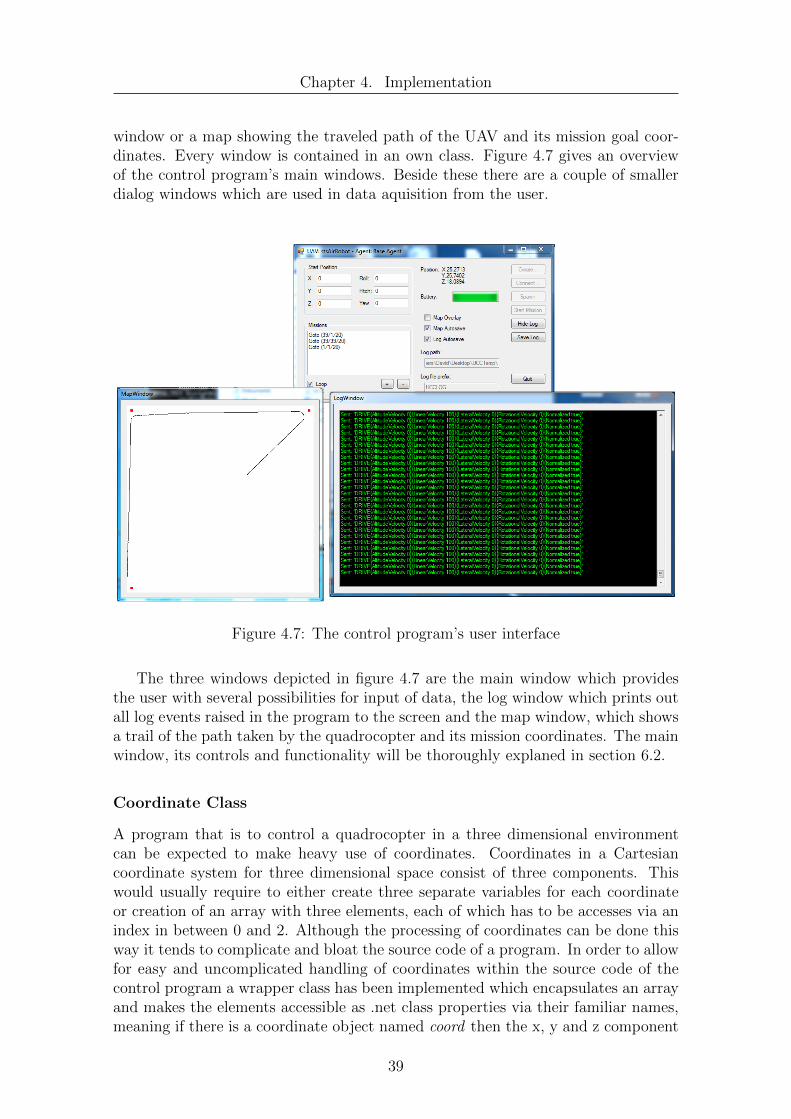
Chapter 4. Implementation
window or a map showing the traveled path of the UAV and its mission goal coor-dinates. Every window is contained in an own class. Figure 4.7 gives an overviewof the control program’s main windows. Beside these there are a couple of smallerdialog windows which are used in data aquisition from the user.
Figure 4.7: The control program’s user interface
The three windows depicted in figure 4.7 are the main window which providesthe user with several possibilities for input of data, the log window which prints outall log events raised in the program to the screen and the map window, which showsa trail of the path taken by the quadrocopter and its mission coordinates. The mainwindow, its controls and functionality will be thoroughly explaned in section 6.2.
Coordinate Class
A program that is to control a quadrocopter in a three dimensional environmentcan be expected to make heavy use of coordinates. Coordinates in a Cartesiancoordinate system for three dimensional space consist of three components. Thiswould usually require to either create three separate variables for each coordinateor creation of an array with three elements, each of which has to be accesses via anindex in between 0 and 2. Although the processing of coordinates can be done thisway it tends to complicate and bloat the source code of a program. In order to allowfor easy and uncomplicated handling of coordinates within the source code of thecontrol program a wrapper class has been implemented which encapsulates an arrayand makes the elements accessible as .net class properties via their familiar names,meaning if there is a coordinate object named coord then the x, y and z component
39

Chapter 4. Implementation
of that coordinate are accessible via coord->x, coord->y and coord->z.
As can be seen in the UML class diagram depicted in figure 4.8 an object of thisclass can be instantiated via its constructors, which as parameters take either threefloating point numbers, one for each coordinate component, or an array of threefloating point numbers in order x, y and z.
Figure 4.8: Coordinate Class
The .net properties of the Coordinate class which are not shown in the classdiagram in figure 4.8 are listed in table 4.1.
Property Descriptionx Gets or sets a float value for the x componenty Gets or sets a float value for the y componentz Gets or sets a float value for the z component
Table 4.1: Coordinate class properties
Mission Class
The task of the quadrocopter which is to be controlled in its environment by thecontrol program is to fulfill some mission goals. Although these missions can behard-coded inside the quadrocopter’s control algorithm this would make any controlprogram terribly inflexible and require the recompilation of the program for everynew mission goal or type of mission the quadrocopter is to accomplish. In order toallow for a more flexible handling of missions a Mission class has been implemented.
Most kinds of missions are somehow related to coordinates. Be it following anumber of waypoints, patrolling between two positions or operating in a certain area.All these examples have one thing in common. They need coordinates to describethe place where a mission has to be accomplished. While coordinates are needed todescribe the location for a mission another distinction between missions has to bemade if there are to be more than just one kind of mission. An agent controllinga quadrocopter not only needs to know where to accomplish its mission but alsowhat kind of mission it is to accomplish. In order to distinguish between di↵erentkinds of missions and to determine what has to be done at or with the mission’scoordinates, in addition to the coordinates the Mission class has a type attribute.This way an agent that is given a number of missions can easily determine what to
40
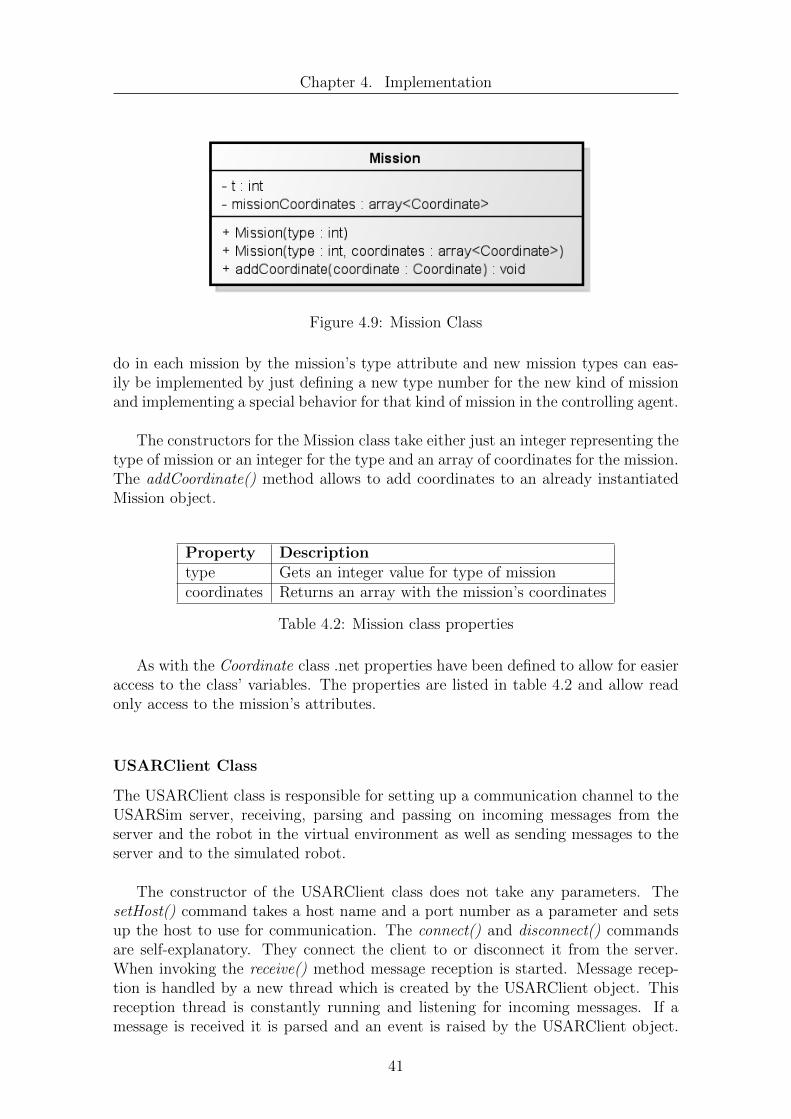
Chapter 4. Implementation
Figure 4.9: Mission Class
do in each mission by the mission’s type attribute and new mission types can eas-ily be implemented by just defining a new type number for the new kind of missionand implementing a special behavior for that kind of mission in the controlling agent.
The constructors for the Mission class take either just an integer representing thetype of mission or an integer for the type and an array of coordinates for the mission.The addCoordinate() method allows to add coordinates to an already instantiatedMission object.
Property Descriptiontype Gets an integer value for type of missioncoordinates Returns an array with the mission’s coordinates
Table 4.2: Mission class properties
As with the Coordinate class .net properties have been defined to allow for easieraccess to the class’ variables. The properties are listed in table 4.2 and allow readonly access to the mission’s attributes.
USARClient Class
The USARClient class is responsible for setting up a communication channel to theUSARSim server, receiving, parsing and passing on incoming messages from theserver and the robot in the virtual environment as well as sending messages to theserver and to the simulated robot.
The constructor of the USARClient class does not take any parameters. ThesetHost() command takes a host name and a port number as a parameter and setsup the host to use for communication. The connect() and disconnect() commandsare self-explanatory. They connect the client to or disconnect it from the server.When invoking the receive() method message reception is started. Message recep-tion is handled by a new thread which is created by the USARClient object. Thisreception thread is constantly running and listening for incoming messages. If amessage is received it is parsed and an event is raised by the USARClient object.
41

Chapter 4. Implementation
Figure 4.10: USARClient Class
These events are then received by the controller object which will be discussed insection 4.2.3 but could also be received by other objects if they registered for it.Di↵erent kinds of messages result in di↵erent kinds of events which trigger a dif-ferent behavior in the controller object. In order to send command messages tothe server the USARClient class provides a send() command which takes a messagestring containing the command as a parameter.
The class’ attributes are almost all self-explanatory. hostName, hostIP and port-Number are needed to describe the USARServer end of the communication link,usarSocket is an object representing the socket used for communication. receiver-Thread is the thread object for reception of incoming messages, while receiveBu↵eris needed for message bu↵ering upon reception. The firstBatteryValue variable is ahelper variable which is needed to determine what value of battery charge is to beinterpreted as a fully charged battery and last but not least the stopReceiveThreadvariable indicates whether the receiver thread is to be stopped.
The events that are generated by the USARClient class are listed in table 4.3
42
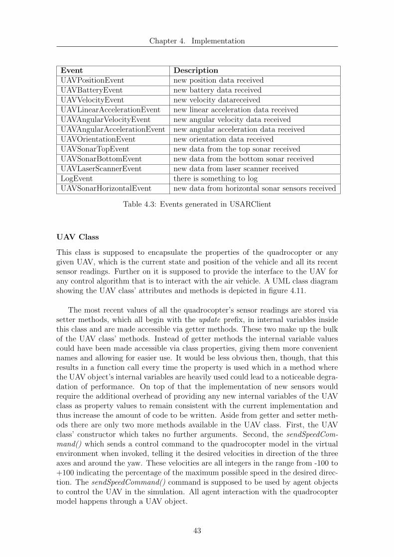
Chapter 4. Implementation
Event DescriptionUAVPositionEvent new position data receivedUAVBatteryEvent new battery data receivedUAVVelocityEvent new velocity datareceivedUAVLinearAccelerationEvent new linear acceleration data receivedUAVAngularVelocityEvent new angular velocity data receivedUAVAngularAccelerationEvent new angular acceleration data receivedUAVOrientationEvent new orientation data receivedUAVSonarTopEvent new data from the top sonar receivedUAVSonarBottomEvent new data from the bottom sonar receivedUAVLaserScannerEvent new data from laser scanner receivedLogEvent there is something to logUAVSonarHorizontalEvent new data from horizontal sonar sensors received
Table 4.3: Events generated in USARClient
UAV Class
This class is supposed to encapsulate the properties of the quadrocopter or anygiven UAV, which is the current state and position of the vehicle and all its recentsensor readings. Further on it is supposed to provide the interface to the UAV forany control algorithm that is to interact with the air vehicle. A UML class diagramshowing the UAV class’ attributes and methods is depicted in figure 4.11.
The most recent values of all the quadrocopter’s sensor readings are stored viasetter methods, which all begin with the update prefix, in internal variables insidethis class and are made accessible via getter methods. These two make up the bulkof the UAV class’ methods. Instead of getter methods the internal variable valuescould have been made accessible via class properties, giving them more convenientnames and allowing for easier use. It would be less obvious then, though, that thisresults in a function call every time the property is used which in a method wherethe UAV object’s internal variables are heavily used could lead to a noticeable degra-dation of performance. On top of that the implementation of new sensors wouldrequire the additional overhead of providing any new internal variables of the UAVclass as property values to remain consistent with the current implementation andthus increase the amount of code to be written. Aside from getter and setter meth-ods there are only two more methods available in the UAV class. First, the UAVclass’ constructor which takes no further arguments. Second, the sendSpeedCom-mand() which sends a control command to the quadrocopter model in the virtualenvironment when invoked, telling it the desired velocities in direction of the threeaxes and around the yaw. These velocities are all integers in the range from -100 to+100 indicating the percentage of the maximum possible speed in the desired direc-tion. The sendSpeedCommand() command is supposed to be used by agent objectsto control the UAV in the simulation. All agent interaction with the quadrocoptermodel happens through a UAV object.
43

Chapter 4. Implementation
Figure 4.11: UAV Class
44

Chapter 4. Implementation
UAV objects, just like objects of USARClient can raise a LogEvent which isuseful for checking certain sensor values when debugging an algorithm.
Agent Class
The Agent class is intended as a base class for agents which control the quadrocoptermodel in the virtual environment.
Figure 4.12: Agent Class
As can be seen in figure 4.12 it has three attributes. First, it has a pointer tothe UAV object which represents the quadrocopter in the simulation it is to control.Second, it contains an array which holds all the missions the agent is supposed toexecute and third, it has an integer which is used as an index to the mission in themissions array which is currently being executed. Furthermore it implements threemethods beside its constructor which takes a pointer to the controlled UAV object.The start() method is supposed to start the execution of the agent and let it sendcontrol commands to the quadrocopter, while the stop() command is supposed tostop the agent and quadrocopter control. The third method is the addMission()method which is supposed to insert additional entries to the list of missions theagent is supposed to execute. These three methods are declared virtual in order togenerate polymorphism in subclasses, so that every class inherited from the Agentclass can implement its own start(), stop() and addMission() methods, containingits own routines and logic while at the same time allowing these methods to becalled from the controller class via a simple pointer to the base class of all agentswhich lies at the top of the inheritance tree.
Objects of the Agent class can raise two di↵erent event types. The first event,LogEvent, results in a log message in the log window containing the provided stringargument. The second event is the AllMissionsDoneEvent which signals that theagent has finished executing its missions, allowing for appropriate actions.
The Agent class itself does not provide any useful functionality concerning thecontrol of a quadrocopter, yet. This has to be implemented by subclasses of theAgent class.
45

Chapter 4. Implementation
uccController Class
The uccController class is responsible for setting up all components from the modellayer presented earlier, according to the data provided by the program’s user in theuser interface section, as well as coordinating all these components in respect toeach other.
Figure 4.13: uccController Class
All objects of the underlying model layer are created and controlled by the uc-cController class. The procedure basicly goes like this. The uccController createsa USARClient object which upon command by the user connects to USARSim andbegins to receive messages sent by the server. Then it creates a UAV object as wellas an Agent and the Agent object is associated with the UAV object it is supposed tooperate on. When the user presses the respective buttons, the quadrocopter modelis spawned in its virtual environment, the Agent object is handed over the missionsit is to accomplish, and then begins to read sensor values from the quadrocopterand generate control commands for it to achieve its missions.
The uccController object is also responsible for receiving all events and messagessent by the underlying objects and forward them to the right destination or take theright actions. These events can be of di↵erent kinds. Each component in the model
46

Chapter 4. Implementation
layer can for example issue a log event. The controller object upon reception of suchan event takes care of printing the log message received in the user interface’s logwindow. If new sensor readings are received by the USARClient object, these resultin an event, too, upon which the uccController object updates the UAV object’sinternal variables according to the new values. All in all there are fourteen methodshandling di↵erent kinds of events defined in the uccController class. They all followthe naming convention onXYZEvent where XYZ is replaced by the event name.
The constructor of the uccController class takes three delegate methods as argu-ments so it can set up the functionality for writing log messages to the log windowand printing position and battery information in the main window. Which meth-ods to call is stored in the log, setUIPosition and setUIBattery attributes of theclass. The agent, uav and client attributes are needed for the model layer ob-jects. The missionLoop attribute defines if missions should be executed in a loopor only once. startPosition, startRotationRoll, startRotationPitch and startRota-tionYaw are needed to save the quadrocopter model’s start position and attitudeto always respawn the model at the same position when missions are executed ina loop. The remaining methods do what their names imply. createUAV() initial-izes the uav and agent attributes, setHost() provides the USARClient object withinformation about the server, connect() makes the USARClient object establish aconnection to the server, spawn() places the quadrocopter at the given position inthe simulation and startMissions() starts the execution of the agent. Missions areadded to an agent by calling the addMissions method and stop() stops the agentand the client and their threads.
4.2.4 A waypoint following agent
As stated in the previous section about the Agent class the class is designed as a abase class for agents to be derived from and does not implement any useful behav-ior itself. Control algorithms are supposed to be implemented in subclasses of theAgent class and because of the polymorphy achieved by declaring the base class’start(), stop() and addMission() methods as virtual methods should work withoutany bigger code modification in the rest of the program. Any code that called oneof the base class’ three methods should be able to use the methods provided by thesubclass right away. In order to verify the functionality of the concept a sub-classingthe Agent class a new agent will be implemented in this section.
One very basic capability of autonomous UAVs is the ability to autonomouslyfollow a given number of waypoints and reach a target destination. In order forthe new agent to do something more useful the task for the new Agent subclasswill be exactly that. It will take control of the quadrocopter in the simulation, useits position and orientation sensors and, using a simple but e↵ective algorithm, willgenerate control commands for the quadrocopter to provide a basic waypoint follow-ing functionality. The new class has been named BaseAgent and its class diagramcan be seen in figure 4.14.
47

Chapter 4. Implementation
Figure 4.14: BaseAgent Class
Control Algorithm
In order to follow a number of waypoints an agent has to be able to reach a singledestination position first. When it is capable of that it can be commanded to fly to asequence of given positions thus producing the desired waypoint following capability.The algorithm used for the BaseAgent class to generate control commands for thequadrocopter will be presented here. As already explained earlier the quadrocoptermodel in USARSim can be commanded to move in three directions and to turnaround the yaw. The algorithm presented here will only generate control outputsfor the quadrocopter’s linear velocity, its altitude velocity and its yaw rotation. Thelateral velocity output generated by the algorithm will always be zero. An approachwith this restriction may not make use of a quadrocopters full maneuvering capa-bilities but this does not prohibit the quadrocopter’s ability of following a sequenceof waypoints.
The control algorithm divides the control problem into two parts. One is controlof the quadrocopter in the x/y-plane while the other is the altitude control of thequadrocopter. Control of the quadrocopter in the plane will be discussed first.
Flight control in the plane: Lets assume we have a quadrocopter in its localframe as depicted in figure 4.15 with the x axis extending in forward direction andthe y axis extending to the right. Let the point P be the destination coordinate thequadrocopter is to reach and ↵ the angle between the y-axis and the direction vectorof the destination. The problem of generating control outputs for the quadrocopterin the plane can be boiled down to the generation of a velocity value for movement indirection of x and an angular velocity for yaw movement. Taking a look at the sineand cosine functions depicted in figure 4.16 the following coherence of the distanceto the destination P, the angle ↵, and the linear velocity can be observed. If thedestination point is situated in front of the quadrocopter the angle ↵ lies between0 and 180 degrees, if it is behind the quadrocopter the angle lies somewhere in therange from 180 to 360 degrees. This means that the sine function of the angle ↵will be equal 1 if the destination is situated directly forward from the quadrocopter,-1 if it is situated directly behind and 0 if it is exactly to the left or right of thequadrocopter. Since the commands for the quadrocopters velocities take values be-tween -100 and +100, which are to be understood as a percentage of the maximum
48

Chapter 4. Implementation
Figure 4.15: Control in the x/y-plane
possible speed at which the quadrocopter is capable of flying, the sine function pro-vides a pretty comfortable way of manipulating the quadrocopters linear velocity.The control algorithm’s output for the linear velocity is generated with the formulashown in equation 4.1
Figure 4.16: Cosine and sine with marked areas
vx =
(100sin(↵), if 0 ↵ 180
0, else(4.1)
As a result the quadrocopter will move forward faster if the destination point isright in front of it and increasingly slowly the further the destination point lies tothe side of the quadrocopter. If the destination point lies behind the quadrocopterthere will be no forward movement at all.
The second component for the quadrocopters movement in the x/y-plane is theyaw velocity. For its value again a trigonometric function is used, this time the co-sine function. Considering the plot of the cosine function depicted in figure 4.16 andour quadrocopter’s coordinate system one can see that if the destination point liesat the left side of the quadrocopter the angle ↵ lies in the range between 90 and 270
49

Chapter 4. Implementation
degrees which results in a value of the cosine function of ↵ in between 0 and -1 andif the destination point lies on the right side of the quadrocopter ↵ lies in between270 and 90 degrees resulting in a cosine of ↵ in the range of 0 and +1. Accordinglythe cosine function of ↵ is a good indicator for the angular velocity around the yaw.Again the allowed control values for the rotational velocity are from -100 to +100 sothat the control algorithm’s yaw velocity is calculated by the formula in equation 4.2.
vyaw = 100cos(↵) (4.2)
As a result of the control values generated by equation 4.1 and 4.2 the quadro-copter’s flight behaviour in the x/y-plane is as follows. The more directly it isheading into the direction of its destination the faster it will fly and the lower itsyaw velocity will be. On the other hand the more the direction the quadrocopteris heading in is deviating from the direction of its destination the slower it will flyand the faster it will turn into the desired direction. Should the destination even liebehind the quadrocopter it will come to a full stop and turn until the destinationenters the front side of the quadrocopter.
Altitude control Since the quadrocopter is not to fly in a two but in a threedimensional environment the agent in control of the quadrocopter also needs togenerate control values for the UAV’s velocity in direction of the z-axis. Let’s assumethat the quadrocopter lies in the z/x-plane as depicted in figure 4.17 where the x-axis again increases to the front of the quadrocopter while the z-axis points fromthe quadrocopter up.
Figure 4.17: Altitude control
Let P again be the destination coordinate and � the angle between the x-axis andthe direction vector of P. This is basicly the same problem as with the quadrocopter’slinear velocity. This time if the destination point P lies above the quadrocopter wewant it to rise with speed increasing the more � approaches a value of 90 degrees
50
Chapter 4. Implementation
and otherwise we want it to decrease its height also with increasing speed the more� approaches a value of 270 degrees. Thus the agent’s velocity output in directionof z is calculated with the formula in equation 4.3.
vz = 100sin(�) (4.3)
Implementation
Before a waypoint following agent could be implemented a new kind of mission forthis purpose had to be defined. This has been done in the Mission.h file by addinga line defining a constant named MISSION GOTO XYZ. Missions of this type aresupposed to contain one coordinate, which to reach is the mission goal. In orderfor the new Agent subclass to be able to add the new kind of mission to its missionarray the addMission() method of the BaseAgent is redefined. Any missions of typeMISSION GOTO XYZ passed to that method are added to the array of missionsinside the agent. All other missions are dropped with a LogEvent announcing thatan attempt was made to pass an unknown mission type to the agent object.
In addition to the methods and attributes provided by the base class two newprotected methods and two new protected attributes have been added to the sub-class. The first new attribute is a thread object named agentThread, the second onea helper variable of boolean type indicating whether the thread should be stoppedor not. The threadLoop() method implements a small loop which first checks if thestopAgentThread variable is true or false. If it is true, the loop will stop immediately.If it is false the missionPlanner() method will be executed, after which the threadis paused for a predefined period of time before the loop begins anew.
The missionPlanner() method is responsible for generating the control com-mands for the simulated quadrocopter and implements the previously describedalgorithm. The missionPlanner() method will guide the quadrocopter to the targetcoordinate of the next mission in the missions array. It does this by constantlygetting the most recent position and orientation data from the UAV and evaluatingequations 4.1, 4.2 and 4.3. After having calculated the appropriate values for thequadrocopter’s velocities it sends a control command to the quadrocopter via thesendSpeedCommand() method of the UAV object. If a waypoint has been reachedthe next waypoint will be targeted by the missionPlanner() method until all mis-sions in the missions array have been executed upon which the loop will be quit andan AllMissionsDoneEvent will be raised.
The start() and stop() methods have also been changed in the new subclass. Thestart() method now resets the mission index to zero in order to point at the firstwaypoint mission and then initializes the thread object to execute the threadLoop()method which will then be started in a new thread. The stop() method will simply
51

Chapter 4. Implementation
set the stopAgentThread variable to true and return after the thread was stopped.
By the relative minor additions of two new variables and methods the newBaseAgent class is in fact capable of following a series of waypoints implement-ing an important base capability for an autonomous air vehicle as will be shown ina series of exemplary tests in chapter 5.1. Furthermore this shows the ability of theprovided framework to allow for an iterative extension of an agent’s capabilities bysub-classing an existing Agent class and adding new features to it.
52
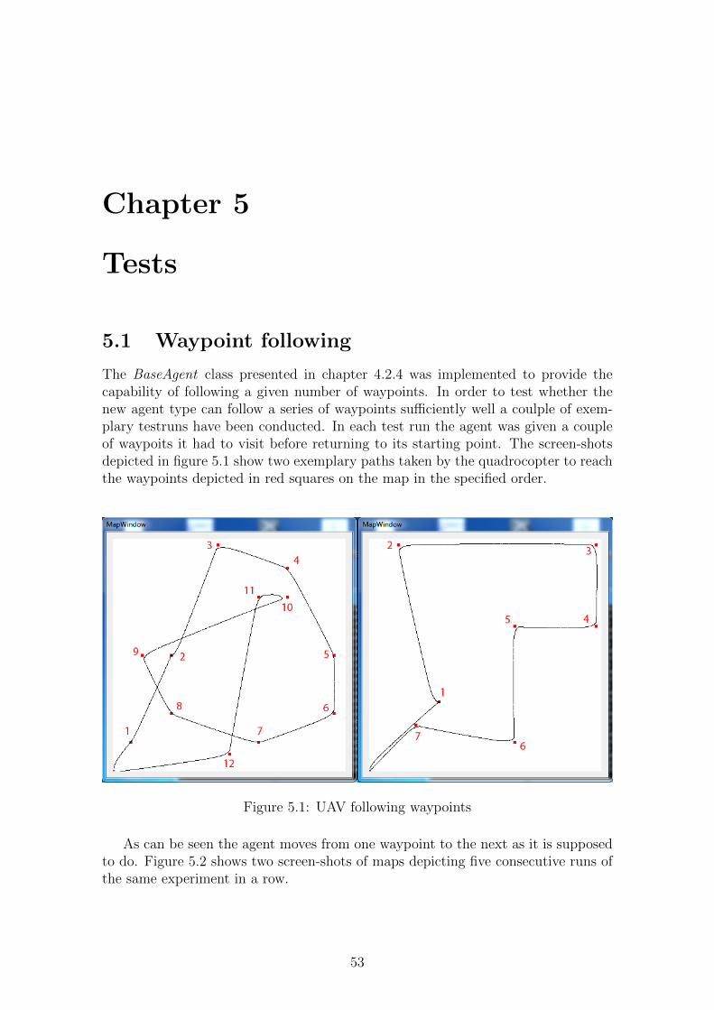
Chapter 5
Tests
5.1 Waypoint following
The BaseAgent class presented in chapter 4.2.4 was implemented to provide thecapability of following a given number of waypoints. In order to test whether thenew agent type can follow a series of waypoints su�ciently well a coulple of exem-plary testruns have been conducted. In each test run the agent was given a coupleof waypoits it had to visit before returning to its starting point. The screen-shotsdepicted in figure 5.1 show two exemplary paths taken by the quadrocopter to reachthe waypoints depicted in red squares on the map in the specified order.
Figure 5.1: UAV following waypoints
As can be seen the agent moves from one waypoint to the next as it is supposedto do. Figure 5.2 shows two screen-shots of maps depicting five consecutive runs ofthe same experiment in a row.
53

Chapter 5. Tests
Figure 5.2: UAV following waypoints, overlaid paths
As can be seen in the overlaid experiment maps in figure 5.2 the paths created bythe algorithm are almost identical in each run. This shows first, that the algorithmcreates reproducible results and second, that the simulation environment allows foralmost identical execution of the same experiment for any given number of times.
5.2 Repeating Experiments
The simulation environment and the control program provided in this diploma thesiswere also supposed to be usable for the case of machine learning algorithms. Aspreviously mentioned many learning algorithms need to perform numerous iterationsof a given experiment optimally every time under the exact same conditions in orderfor noticeable learning to take place. The control program provides the possibilityto execute a once set up experiment in exactly the same way in a loop, over and overagain, as could be seen in the overlaid maps of the waypoint following tests. In orderto test the stability and reliability of the control program an exemplary experimenthas been executed in a loop for a time period of three hours. In the experimentthe simulated quadrocopter had to follow a course of three waypoints after which itwas to return to its starting position. In the course of this test the experiment wasrepeated 237 times without problems or crashes showing that the program can beused for a high number of iterations of experiments over a long period of time andcan be of use in the testing of learning algorithms.
5.3 Scalability
For the simulation environment to be useful for the creation of groups or evenswarms of UAVs the system has to be scalable. In order to test the scalability ofthe simulation environment, tests have been conducted with an increasing numberof UAVs being placed in the simulation environment and the CPU usage of the
54

Chapter 5. Tests
used PCs and the displayed frames per second in the client window being measured.The tests have been conducted with two di↵erent PCs, one being an older MacBookthe other an also older desktop PC. The systems’ specifications are listed in table 5.1.
MacBook Desktop PCCPU type Intel Core2 Duo P8600 AMD Athlon64x2 5200+CPU speed 2.4 GHz 2.6 GHzMemory 8GB 8GBGraphics adapter nVidia GeForce 9400M nVidia GeForce 8600 GTOS Windows 7 Professional Windows 7 ProfessionalNetwork speed 1000Mbps 1000Mbps
Table 5.1: Testsystems’ specifications
Because of the relatively poor hardware the Unreal Client has been executed inwindow mode instead of full screen mode with a reduced resolution of 640x360 pixelson both systems. First tests were done on the MacBook running the Unreal Serveras well as the Unreal Client and all the instances of the control program controllingthe di↵erent quadrocopter models in the simulation. The simulation environmentwas started with no quadrocopters being placed inside the virtual environment, afterwhich successively one quadrocopter after the other has been added to the virtualenvironment. The results of this test are listed in table 5.2.
No. of UAVs FPS CPU usage (%)0 61.96 35.941 61.83 52.092 59.64 58.523 56.6 70.034 52.33 72.555 45.7 75.116 18.13 70.937 3.87 71.25
Table 5.2: Multi UAV test results on MacBook
As can be seen from the test results in table 5.2 the frame rate in the client win-dow drops below 20 frames per second if more than five quadrocopters have beenplaced in the simulation. Frame rates below 20 are impractical for simulation sincethe rendering of movement becomes choppy to the naked eye and the long lags be-tween two successive frames keep the controlling agent from reacting to any eventsin the simulated environment in a reasonable time. A frame rate below 4 frames persecond as is observed with 7 quadrocopters is totally unacceptable because sensordata will be updated only about four times a second and the agent will react to anysensor readings with a delay of at least 0.25 seconds.
55
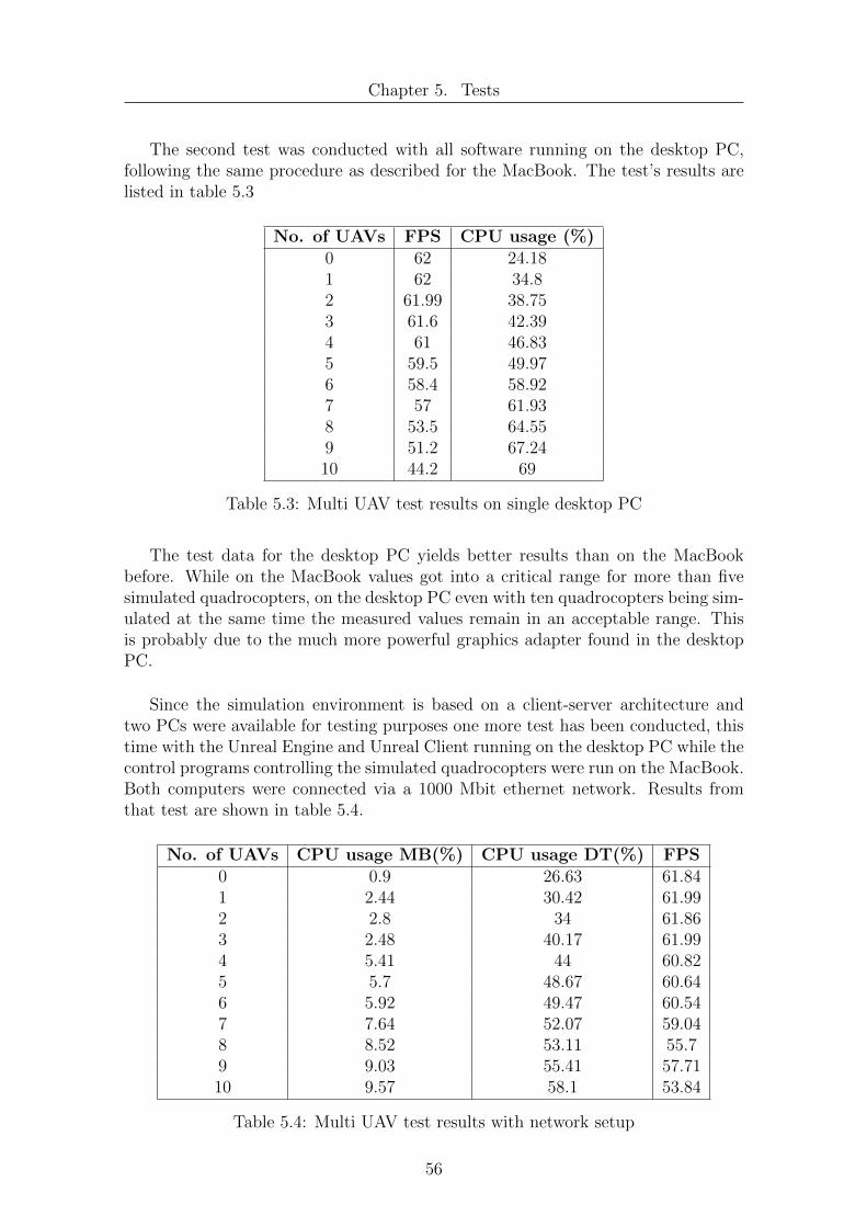
Chapter 5. Tests
The second test was conducted with all software running on the desktop PC,following the same procedure as described for the MacBook. The test’s results arelisted in table 5.3
No. of UAVs FPS CPU usage (%)0 62 24.181 62 34.82 61.99 38.753 61.6 42.394 61 46.835 59.5 49.976 58.4 58.927 57 61.938 53.5 64.559 51.2 67.2410 44.2 69
Table 5.3: Multi UAV test results on single desktop PC
The test data for the desktop PC yields better results than on the MacBookbefore. While on the MacBook values got into a critical range for more than fivesimulated quadrocopters, on the desktop PC even with ten quadrocopters being sim-ulated at the same time the measured values remain in an acceptable range. Thisis probably due to the much more powerful graphics adapter found in the desktopPC.
Since the simulation environment is based on a client-server architecture andtwo PCs were available for testing purposes one more test has been conducted, thistime with the Unreal Engine and Unreal Client running on the desktop PC while thecontrol programs controlling the simulated quadrocopters were run on the MacBook.Both computers were connected via a 1000 Mbit ethernet network. Results fromthat test are shown in table 5.4.
No. of UAVs CPU usage MB(%) CPU usage DT(%) FPS0 0.9 26.63 61.841 2.44 30.42 61.992 2.8 34 61.863 2.48 40.17 61.994 5.41 44 60.825 5.7 48.67 60.646 5.92 49.47 60.547 7.64 52.07 59.048 8.52 53.11 55.79 9.03 55.41 57.7110 9.57 58.1 53.84
Table 5.4: Multi UAV test results with network setup
56

Chapter 5. Tests
As could be expected the number of frames displayed per second in the UnrealClient window were noticeably higher and also the CPU usage on the desktop PCwas noticeably lower than in the second experiment conducted. The measured val-ues also show that the much more resource consuming component of the simulationenvironment is the Unreal Engine and the Unreal Client, doing graphics renderingand physics calculations, while the control program itself makes only moderate useof CPU resources.
It can be concluded from the test results that the provided simulation environ-ment is capable of simulating at least moderately sized groups of quadrocopters onthe hardware used, proving the system to be scalable to a certain degree. Further-more it can be assumed that group size and scalability can be greatly increased ifmore up to date hardware like a decent graphics adapter and more powerful multicore CPU were used to run the simulation environment.
57

Chapter 6
Usage
6.1 Installation of the Simulation Environment
6.1.1 Unreal Development Kit
The latest released version of the Unreal Developer Kit can be found and downloadedfrom http://www.unrealengine.com/udk/. The size of the installation file at themoment of writing has grown to more than 1.7 GB, so that it can take a littlewhile to download. The installer when started will suggest to install the UDK ina directory like C:/UDK/UDK-YYYY-MM where YYYY stands for the year andMM for the month of the UDK’s release. The suggested installation directory isa good choice and can be kept as is since USARSim sometimes fails to install ifthe UDK is installed into a directory with special characters. In the following itwill be assumed that the UDK has been installed in the directory suggested by theinstaller. If that is not the case paths in the following instructions concerning theUDK installation directory have to be adapted to the path actually chosen duringinstallation.
6.1.2 USARSim
In order to install USARSim a working version of the Git source code managementsystem needs to be installed on the computer used. A new directory should be cre-ated and a console window opened. The working directory of the console windowneeds to be changed to the just created directory and there the following commandhas to be issued to download all USARSim files from the USARSim Git repository.
git clone git://usarsim.git.sourceforge.net/gitroot/usarsim/usarsim
Once the download is finished all the files in the subdirectory usarsim have tobe copied into the UDK installation directory. If a dialog pops up and asks whetherexisting files are supposed to be overwritten by the new files this has to be answeredwith yes. After copying of files has completed, the batch program make.bat hasto be executed to compile USARSim on the machine. If the compilation has beensuccessfully finished the installation of USARSim is completed.
58

Chapter 6. Usage
6.1.3 UAV Control Center
In order to make the modifications applied to USARSim in the course of this diplomathesis available the usarsim folder on the CD-Rom coming with this work has to becopied into the installation directory of USARSim. If Windows asks whether alreadyexisting files should be overwritten by new files with the same name this has to beanswered with yes again. Once the files have been copied the USARSim installationneeds to be recompiled, which is done by invoking the make clean.bat batch pro-gram lying in the UDK installation directory. After the compilation has finished allmodifications needed for the control program should have been successfully applied.
The control program can then either be copied from the debug directory in theVisual Studio project folder to any desired directory on the PC and executed, or di-rectly started from the CD-Rom. In order to start the Unreal Server and USARSimand load a virtual environment one of the map files in the directory C:/UDK-YYYY-MM/USARRunMaps needs to be double-clicked. Once the virtual environment hasbeen started the control program can be used to spawn a quadrocopter assign mis-sions and control the UAV.
In order for the program to run the Microsoft Visual C++ 2010 Redistributablelibraries coming with Visual Studio 2010 or separately downloadable from the Mi-crosoft website need to be installed on the system.
59

Chapter 6. Usage
6.2 Control program usage
In this section a description of the main window and its elements will be givenfollowed by a basic introduction into the program’s usage.
6.2.1 The main window
The main window of the control program with its controls is depicted in figure 6.1.Its content can be divided into the six di↵erent parts shown in figure 6.1 of whicheach one has a di↵erent purpose. In the following these will be briefly presented.
Figure 6.1: The main window and its elements
Area 1: This area takes the coordinates at which a quadrocopter model is to bespawned in the virtual environment as well as its orientation. The coordinates aremeasured in meters from the origin of the coordinate system of the map being inuse when spawning the robot. The orientation angles are measured in degrees.
Area 2: This area is used to add missions to the agent being in control of thequadrocopter. The ’+’ button will open the dialog window depicted in figure 6.2 inwhich the mission type can be selected from a drop-down list and the coordinatescan be added to or deleted from the mission with the ’+’ and ’-’ button respectively.Any missions added to the agent will be displayed with coordinates in the whitetext box. In order to remove a mission from the text box it has to be highlightedby clicking on it and then the ’-’ button has to be pressed. The Loop check-box in-dicates whether the missions are to be restarted again once they have been finished.If the check-box is checked the missions will be executed over and over again until
60

Chapter 6. Usage
either the check-box is unchecked or the program is ended.
Figure 6.2: AddMission dialog window
Area 3: The controls in this area are used to define the logging behaviour of thecontrol program. The Map overlay checkbox defines whether the map drawn in eachrun of an experiment is to be reset with the start of the next run or if all tests shouldbe drawn onto the same map. If the Map autosave and Log autosave check-boxesare checked then after every finished experiment the contents of the log window andthe map window will be saved to disk and afterwards reset, unless the Map overlaycheckbox is checked in which case the map will not be reset. The Log path text-boxallows to define a path under which the files are to be saved and the Log file prefixfield allows to define a prefix for all files created during the experiment. All fileswill then be created in the specified directory with the provided prefix and a trailingnumber indicating the number of iteration of the experiment. The maps createdwill be saved as bitmap files, while the log files are saved in the rich text format. Ifthe check-boxes for autosave are unchecked no files will be created and the log willbe written continuously to.
Area 4: This area provides the main functionality of the program. The Create...button opens the dialog window depicted in figure 6.3 which allows to select oneof the UAV models that are known to the application and one of the agent typesthat have been implemented in order to control the UAV. Furthermore server con-figuration data has to be provided in this dialog to setup the Unreal Server thatthe controller program is to connect to. The Connect... button will then connectthe control program to the server after which message reception is turned on. Afterthe connection to the server has been established the quadrocopter model can bespawned in the virtual environment with the Spawn button at the location speci-fied before in the start position area. If missions have been specified then the Start
61

Chapter 6. Usage
Figure 6.3: CreateUAV dialog window
Mission button will start the agent which will then begin to execute its missions.The Hide log button can be used to hide the log window in case its output is of nointerest and the Save Log button can be used to save the current content of the logwindow to an arbitrary file. The Quit button will disconnect the control programfrom the server, stop all running threads and end program execution.
Area 5: This area provides information about the quadrocopter’s status by dis-playing its current position and battery charge level. This information is constantlyupdated as soon as new sensor data from the UAV model is available.
Area 6: The last area in the main window is found in the title bar which displaysthe type of UAV model that is being controlled in the simulation environment aswell as the type of agent that is controlling it.
6.3 How to create new Agent classes
In order to implement any control algorithms in the framework provided it is nec-essary to create a new agent class which is derived from the Agent base class. Thisis basicly a three step process. First of all the new class needs to be implemented,then the class has to be made available in the user interface so that the user canselect it as the controlling instance for the quadrocopter and then the uccControllerclass needs to be adapted so it knows when to create an object of the new class. Thedetailed procedure of adding a new agent is presented below in this section. Afterperforming the steps described here the new agent type is selectable in the userinterface and can take control over the quadrocopter in the simulated environment.
62

Chapter 6. Usage
6.3.1 Deriving a new Agent class
A new Agent is basicly implemented by creating a subclass of the Agent class.The uccController class calls the start() method of all Agent subclasses to startthe agent’s execution and the stop() method to stop it. So in order for the newdeviated agent class to do something useful it is necessary to overwrite the these twofunctions which are defined as virtual in the base class and have no real functionalityimplemented. It is probably a good idea to have the start() method start a threadreading sensor values from the UAV object and generating control commands forit. The stop() method is then supposed to end any running threads when called.Furthermore the addMission() method needs to be overwritten. Any new subclass ofan agent class can possibly execute di↵erent types of missions and therefore needs adi↵erent implementation of this method. On top of overwriting these three methodsany number of new methods and attributes can be added to a new agent subclass.
6.3.2 Make the class appear in the UI
In order to make the new agent type selectable in the user interface the Create UAVDialog has to be opened in the Visual Studio Designer and an entry has to be addedto the ComboBox found under the Agent Type label. Any appropriate name notalready taken can be chosen here.
6.3.3 Adapt uccController
To adapt the controller the uccController.cpp file needs to be edited. First of all theheader for the newly implemented Agent class has to be included at the top of thefile. Then at the bottom of the createUAV() method there is a series of if-statementsthat check for the agent name provided by the ComboBox just edited in the user in-terface. A new if-branch has to be added there resembling the old ones but this timechecking if the aiType variable equals the name just entered for the agent in the userinterface. In the if statement itself the agent variable gas to be assigned an object ofthe new created Agent subclass as can be seen the listing below. The code depictedhere adds a new Agent subclass of type BetterAgent to the series of if statements andthe name of the exemplary agent selected in the user interface is ”My Better Agent”.
// Check f o r known Agent typesi f ( aiType==”Base Agent ”) {
agent = gcnew BaseAgent ( uav ) ;}i f ( aiType==”Base Agent 2”) {
agent = gcnew BaseAgent2 ( uav ) ;}. . . . .i f ( aiType==”My Better Agent ”) {
agent = gcnew BetterAgent ( uav ) ;}
63

Chapter 7
Conclusion and future work
The control program implemented in this work, the provided quadrocopter con-figuration and sensors together with USARSim and the underlying Unreal Engineconstitute a flexible, easy to use and easily expandable simulation environment forUAVs. The modular design of the agent in the program’s architecture and the ap-plied principle of polymorphism allow for development of new agents completelyindependent from the other parts of the control program. This way the remainingparts of the control program can serve as a basis and a foundation for the develop-ment of new agents which implement new behaviors, control algorithms and learningalgorithms. The programmer creating the new agents does not need to handle anycode except the code needed for the algorithms implemented in the agent. In par-ticular does he not have to deal with any programming of network communication,message parsing or user interfaces as this has already been taken care of in the con-trol program.
The sensor configuration provided with the quadrocopter model coming with thecontrol program is broad enough to allow for many di↵erent behavior implementa-tions without the need for any modifications to the quadrocopter model or sensorsthus introducing numerous opportunities for further development. With the pos-sibility to build new sensors in USARSim the provided quadrocopter configurationcan be extended and virtually any scenario can be implemented, considering certainadjustments. Given the control program’s capability to run a set up scenario vir-tually any given number of times in the exact same way the program can also beused for the training and evaluation of learning algorithms before they are appliedto real hardware.
With the Unreal Development Kit being still in its beta phase and USARSim forUDK still standing at the beginning of its transition from the older UT3 to the newUDK a lot of further progress in the development of USARSim can be expected andthe simulation environment should not be outdated any time soon. Although thesimulation already produces visually highly appealing graphics and highly realisticphysical behavior these can be expected to further increase with new upcomingversions of the two software packages. Furthermore it is needless to say that withEpic Games allowing the use of the Unreal Development Kit for absolutely free ifused for noncommercial purposes and USARSim being also free and open source thesimulation environment realized in this thesis comes at no costs whatsoever.
64
Bibliography
[1] M. Buehler, K. Iagnemma, and S. Singh. The 2005 Darpa Grand Challenge:The Great Robot Race. Springer Tracts in Advanced Robotics. Springer, 2007.
[2] M. Buehler, K. Iagnemma, and S. Singh. The Darpa Urban Challenge: Au-tonomous Vehicles in City Tra�c. Springer Tracts in Advanced Robotics.Springer, 2009.
[3] United States. Dept. of Defense. O�ce of the Secretary of Defense. UnmannedAerial Vehicles Roadmap, 2000-2025. Department of Defense, O�ce of theSecretary of Defense, 2001.
[4] United States. Dept. of Defense. O�ce of the Secretary of Defense. UnmannedAircraft Systems Roadmap, 2005-2030. Department of Defense, O�ce of theSecretary of Defense, 2005.
[5] R. Austin. Unmanned Aircraft Systems: UAVs Design, Development and De-ployment. Aerospace Series. John Wiley & Sons, 2010.
[6] Michael Reckhaus, Nico Hochgeschwender, Jan Paulus, Azamat Shakhimardov,and Gerhard K. Kraetzschmar. An overview about simulation and emulationin robotics. Proceedings of SIMPAR 2010 Workshops, Intl. Conf. on SIMULA-TION, MODELING and PROGRAMMING for AUTONOMOUS ROBOTS,pages 365–374, nov 2010.
[7] Robert Kesten. Data fusion of accelerometric, gyroscopic, magnetometric andbarometric information for attitude and altitude estimation of an unmannedquadrocopter.
[8] R. Buchi. Fascination Quadrocopter. Books on Demand GmbH, 2011.
[9] Swiss Federal Institute of Technology Zurich. Flying machine arena.http://www.idsc.ethz.ch/Research DAndrea/FMA/. [Online; 2012].
[10] Abraham Bachrach, Rujijie He, and Nicholas Roy. Autonomous flight in un-known indoor environments. International Journal of Micro Air Vehicles,1(4):217–228, dec 2009.
[11] Axel Burkle, Florian Segor, and Matthias Kollmann. Towards autonomousmicro uav swarms. J. Intell. Robotics Syst., 61(1-4):339–353, January 2011.
[12] Horia Ionescu. Wikimedia commons. http://commons.wikimedia.org/wiki/File:6DOF en.jpg.[Online; 2012].
65

Bibliography
[13] AirRobot Australasia Pty Ltd. AirRobot - Micro Unmanned Aerial VehicleWith Autonomous Flight and Navigation Capabilities and Modular Payloads,2007.
[14] AirRobot GmbH & Co KG. Airrobot homepage. http://www.airrobot.de/.[Online; 2012].
[15] Microdrones GmbH. Microdrones homepage. http://www.microdrones.com/.[Online; 2012].
[16] Michael Lewis and Je↵rey Jacobson. Game engines in scientific research. Com-mun. ACM, pages 27–31, 2002.
[17] Epic Games. Unreal script reference. http://udn.epicgames.com/Three/UnrealScriptReference.html.[Online; 2012].
[18] Usarsim project homepage. http://sourceforge.net/apps/mediawiki/usarsim/.[Online; 2012].
[19] Andrew N. Marshall. Gamebots project homepage.http://gamebots.sourceforge.net/. [Online; 2012].
[20] Gal A. Kaminka, Manuela M. Veloso, Steve Scha↵er, Chris Sollitto, RogelioAdobbati, Andrew N. Marshall, Andrew Scholer, and Sheila Tejada. Gamebots:a flexible test bed for multiagent team research. Commun. ACM, 45(1):43–45,January 2002.
[21] I. Maza and A. Ollero. Multiple UAV cooperative searching operation usingpolygon area decomposition and e�cient coverage algorithms. In Proceedings ofthe 7th International Symposium on Distributed Autonomous Robotic Systems,pages 211–220, Toulouse, France, 2004.
[22] C. E. Palazzi, C. Roseti, M. Luglio, M. Gerla, M. Y. Sanadidi, and J. Stepanek.Satellite coverage in urban areas using unmanned airborne vehicles (uavs). Ve-hicular Technology Conference, 5:2886–2890, may 2004.
[23] Crossbow Technology. Crossbow homepage.http://www.xbow.com/index.html. [Online; 2012].
[24] D. Johnson, Y. Hu, and D. Maltz. The dynamic source routing protocol (dsr)for mobile ad hoc networks for ipv4. RFC 4728, 2007.
[25] Gerry Siegemund. Auris - autonomous robot interaction simulation.
[26] Markus Achtelik, Abraham Bachrach, Rujijie He, Samuel Prentice, andNicholas Roy. Autonomous navigation and exploration of a quadrotor heli-copter in gps-denied indoor environments. In 2009 First Symposium on IndoorFlight Issues, jul 2009.
[27] A. D. King. Inertial navigation: Forty years of evolution. GEC review, pages140–149, January 1998.
66