re-design of pencil sharpener for the ease of assembly
94
Copyright Warning & Restrictions The copyright law of the United States (Title 17, United States Code) governs the making of photocopies or other reproductions of copyrighted material. Under certain conditions specified in the law, libraries and archives are authorized to furnish a photocopy or other reproduction. One of these specified conditions is that the photocopy or reproduction is not to be “used for any purpose other than private study, scholarship, or research.” If a, user makes a request for, or later uses, a photocopy or reproduction for purposes in excess of “fair use” that user may be liable for copyright infringement, This institution reserves the right to refuse to accept a copying order if, in its judgment, fulfillment of the order would involve violation of copyright law. Please Note: The author retains the copyright while the New Jersey Institute of Technology reserves the right to distribute this thesis or dissertation Printing note: If you do not wish to print this page, then select “Pages from: first page # to: last page #” on the print dialog screen
-
Upload
khangminh22 -
Category
Documents
-
view
1 -
download
0
Transcript of re-design of pencil sharpener for the ease of assembly

Copyright Warning & Restrictions
The copyright law of the United States (Title 17, UnitedStates Code) governs the making of photocopies or other
reproductions of copyrighted material.
Under certain conditions specified in the law, libraries andarchives are authorized to furnish a photocopy or other
reproduction. One of these specified conditions is that thephotocopy or reproduction is not to be “used for any
purpose other than private study, scholarship, or research.”If a, user makes a request for, or later uses, a photocopy orreproduction for purposes in excess of “fair use” that user
may be liable for copyright infringement,
This institution reserves the right to refuse to accept acopying order if, in its judgment, fulfillment of the order
would involve violation of copyright law.
Please Note: The author retains the copyright while theNew Jersey Institute of Technology reserves the right to
distribute this thesis or dissertation
Printing note: If you do not wish to print this page, then select“Pages from: first page # to: last page #” on the print dialog screen

The Van Houten library has removed some of thepersonal information and all signatures from theapproval page and biographical sketches of thesesand dissertations in order to protect the identity ofNJIT graduates and faculty.
DESIGN FOR MANUFACTURABILITY: RE-DESIGN OF PENCIL SHARPENERFOR THE EASE OF ASSEMBLY
ByAMIT R. RATHOD
Thesis submitted to the Faculty of The Graduate School of New JerseyInstitute of Technology in the partial fulfillment of the requirements for the
degree. of Master of Science in Manufacturing Engineering
1991

APPROVAL SHEET
Title of Thesis:
Design for Manufacturability: Re-design of Pencil Sharpener For Ease of Assembly
Name of Candidate:
Amit R. Rathod
Master of Science in Manufacturing Engineering, 1991
Thesis and Abstract Approved:
Dr. Nouri Levy Associate Professor Mechanical Engineering
Signature of the other members of committee:
Dr. Raj Sodhi Director Manufacturing Engineering
Dr. Keith O'Brien Professor Mechanical Engineering
Date
I
Date
Date

VITA
NAME: Amit Ramanbhai Rathod
COLLEGE & INSTITUTIONS ATTENDED:
Maharaja Sayajirao University of Baroda, Baroda, India
New Jersey Institute of Technology Newark, New Jersey
DATE DEGREE
1982-85 B.S. (EE)
1989-91 M.S. (Mfg. E.)

ABSTRACT
A Design For Manufacturability (DFM) approach is used to analyze theexisting design of a pencil sharpener, and to reduce and re-design the partsof pencil sharpener for the ease of assembly. The procedure for theselection of a suitable and economical assembly method is based on theBoothroyd and Dewhurst methods. Analysis of the initial design for manualassembly and re-design for automatic as well as manual assembly ispresented. An algorithmic approach for simplified generation of allmechanical assembly sequences and selection of the assembly sequencesis presented using De Fazio and Whitney approach.

To My Parents

ACKNOWLEDGEMENT
It is a great pleasure to express my deep gratitude to Dr. Nouri i Levy,Associate Professor, Mechanical Engineering Department, for his valuableguidance and co-operation, throughout this Master's thesis work.
I sincerely express my thanks to Dr. Raj Sodhi, Director,Manufacturing Engineering, and Dr. Keith O'Brien, Professor, MechanicalEngineering, for reviewing and giving their valuable suggestions.

TABLE OF CONTENT
INTRODUCTION
1. DESIGN FOR MANUFACTURABILITY 11.1 Reasons for Design for Manufacturability 11.2 Integrating the product and process design 4
2. PARAMETERS AFFECTING MANUFACTURABILITY 62.1 Cost 62.2 Finishing 72.3 Tolerances 82.4 Design parameters 8
3. GUIDELINES AND RULES FOR DFM 103.1 Standardization 113.2 Choice of Work Material 113.3 Shape of Work Material 123.4 Shape of Component 123.5 Accuracy and Surface Finish 133.6 Guidelines for Design for Machining 14
3.6.1 Standardization 143.6.2 Raw Material 143.6.3 Component Design 143.6.4 Assembly 163.6.5 Accuracy and Surface Finish 16
4. WAYS TO INCREASE MANUFACTURABILITY 174.1 Background 184.2 DFM: Principle and Rules 19
4.2.1 Rules Based Approach 194.2.2 Aximomatic Design Approach 23
4.3 Quantitative Evaluation Methods 255. ECONOMICS OF ASSEMBLY 26
5.1 Choice of Assembly Method 275.1.1 Design for Manual Assembly 285.1.2 Design for Automatic Assembly 305.1.3 Design for Assembly:Robots 31
6. DESIGN OF THE PENCIL SHARPENER 326.1 Existing Design 326.2 Redesign of the Pencil Sharpener 38
7. ANALYSIS OF THE PENCIL SHARPENER DESIGN 487.1 Analysis of the Existing Design for Manual Assembly 487.2 Analysis of the Re-design for Automatic Assembly 52
8. ASSEMBLY SEQUENCING 648.1 Determination of Assembly Sequence 648.2 Approaches for Generation of Assembly Sequnces 658.3 Choosing Good Assembly Sequence 71
9. FUTURE TRENDS IN DESIGN FOR MANUFACTURABILITY 759.1 Commercial Software 759.2 Research & Developments 76
9.2.1 Artificial Intelligence / Expert Systems 78
CONCLUSION
BIBLIOGRAPHY

INTRODUCTION
Manufacturing cost of a product has an important effect on product
profitability. A product design will determine 70% to 80% of its manufacturing
cost, whatever the efficiencies of the manufacturing plant. It is surveyed that up
to 85% of a product, manufacturing cost is typically determined before the
manufacturing department is involved with the product design. Design engineers
have little experience or virtually no experience about manufacturing operations.
It is too late for making changes in the product design when manufacturing
department is involved in product. So when product reaches the marketplace it
will become overpriced or may lag behind the competition.
To remain competitive, manufacturers must move from an environment in
which product problems are removed by inspection to one in which the design
and process are controlled concurrently. Manufacturing excellence can be
attained only by designing product and its process to address potential
problems before they occur. Manufacturing cost must be considered during
conceptual design phase when less than 50% of a product's costs are
determined.
Design is a strategic activity by intention or by default. Manufacturability is
the measure of a design's ability to consistently satisfy the product goals while
being profitable.
In any industry the design inputs are customer requirements such as
technical performance and price. During the conceptual design phase, the
"functional" design of product is transformed into a "physical design." The design
process includes product definition, product design, a prototype and test. The
primary output is a prototype product that meets customer's requirements.
Manufacturing department determined how the product would be produced,
Page I

assembled including the grouping of major subassemblies. Manufacturing
department then selects appropriate materials, material handling equipments and
integrate the production system into plant layout. The total cost required to
manufacture the product then supplied to finance department which determines
whether the product is viable to produce and with how much profit. If the
product cost is to be reduced then entire design process has to be repeated.
This traditional vertical design process creates friction between various
departments. If the manufacturing department wants to make a change in
design that would simplify the manufacturing process and assembly process, a
typical response from design department might be "We are run out of time or we
cannot simplify more or you must live with the constraint." The problem is simply
pushed up to the level until an inefficient product design that is difficult to
manufacture is implemented. And perhaps, this is the most serious mistake
companies make to get the manufacturing department involved in design issues
at later stage. So what good is a product if it is not designed to be manufactured
competitively?
Page II

CHAPTER 1
DESIGN AND MANUFACTURABILITY
To remain competitive manufacturers must move from an environment in
which problems of products must be handled as they occur to one in which
process and products are designed to overcome possible problems. The
effectiveness of these changes is dependent on consideration of the design
during the development stage. Manufacturability is a measure of a design ability
to satisfy product goals while being profitable. [1].
Design for manufacturability represents a new awareness of the importance of
the integration of product design from idea to production.
1.1 Reasons for Design for Manufacturability
The objectives of the design for manufacturability approaches are to
identify product concepts that are easy to manufacture and assemble.
Manufacturing process and product design must be integrated to ensure the
best matching of needs and requirements. [2]
The design for manufacturability approach is the integration of product
design and process planning into common activity. The design for
manufacturability concept requires communication between all components of
the production systems and should permit flexibilities to adapt and to modify the
design and process during each stage of product realization.
Page 1

ProposedProductConcept
ProposedManufacturing
Plan
Meeting these objectives requires the integration of different and complex
types of information. These includes not only considerations of product form,
function and fabrication but also the organizational and administrative
procedures that increase the manufacturability of the product. The relationship
of this integration is shown in figure 1. [2,3]
Analysis
Evaluation I Yes I Integratedand Product/Process
Acceptability Concept
No
Redesign
Analysis-Redesign Model
Figure 1
Page2

DESIGN PROCESS:
Design process is an iterative procedure involving the following six
phases.
1. Recognition of need.
2. Definition of problem.
3. Synthesis
4. Analysis and Optimization.
5, Evaluation.
6. Presentation.
This six phases are interconnected with each other as shown below in
RECOGNITION OFNEED
DEFINITIONOFPROBLEM
ANAND
OPTIMIZATION
EVALUATION
PRESENTATION
Figure 2 TYPICAL DESIGN PROCESS STAGES

The first phase is to identify the basic features of the product. The product
specification can be set by customer or by marketing team. So the first activity is
usually that of specifications. The designer sets the criteria for the performance
of the product. The designer would like to have information about existing
products of similar types, about the potential market, about the manufacturing
constraints, standards, and so on.
The second phase is that of generation or synthesis of alternative designs. This
is at the very heart of the design process. New designs may be only a
modification of available product designs. New designs are created by
permuating and recombining components or elements in completely new form.
The third activity or phase is that of analysis and evaluation. Here all alternate
designs are tested in turn and compared to see if they meet the specifications.
The test may be theoretical or may be practical using physical models or actual
prototypes. Furthermore, always it is important to estimate the costs of materials
and costs to manufacture. The characteristics of these design phases is that
they tend to move from the general and tentative to more specific and definite.
1.2 Integrating product and process design:
Product design is generally concerned with form, fit and function. How to
manufacture a product and how much it will cost usually asked at the later
stages of product development. At this point, the design may have to be
reworked to solve problems of quality production and to reduce costs. There
should be an effective communication between design engineers and process
Page 4

engineers from the very beginning of the product design. So " hand shaking"
communication with various departments is the fundamental of the design for
manufacturability concept.
Multifunctional teams are the most effective ways for companies to design
product strategically. But, establishing a team is only the beginning. The five
points that should be kept in mind by these teams are
1. Determine the character of product not only in terms of its market but also
in terms of its production.
2. Perform rigorous functional analysis on product by checking for
opportunities to reduce the number of components and to build
robustness into components.
3. Design parts for producibility by exploring available materials, by the
combinational method for part development, and by jigless and fixtureless
manufacturing, where possible.
4. Design the assembly sequence so that parts can be fit with least damage
and quality control testing can be facilitated.
5. Design a factory system by stressing standard work methods, quick repair
of equipment, and employee motivation.
Conception of product, in short, is a company-wide activity requiring
involvement of all departments.
Page 5

Chapter 2PARAMETERS AFFECTING MANUFACTURABILITY
As stated earlier manufacturability has no fixed definition but it is a
measure for manufacturing excellence. It is a process to address potential
problems before they occur. There are numbers of factors that are directly
related to manufacturability of product. The objective of the design for
manufacturability approach is to identify product concept that is inherently easy
to manufacture and to integrate manufacturing process and product design to
ensure the best matching of needs and requirements. We cannot say that this is
the best technique that is universally applicable for increasing manufacturablity.
There are certain parameters that can be directly or indirectly related to
manufacturability concept. These are not all, but least, parameters for increasing
manufacturability for any kind of products. They are as follows:
(1) Materials
(2) Process Flexibility
(3) Output Quality
(4) Packaging/Handling
( 5) Product Lead Time
There are certain attributes that affects above five parameters that in turn
affects the manufacturability. Each parameter is discussed here one by one.
2.1 COST:
Cost is related to materials and processes that in turn effects
manufacturability. Selection of materials is important for any kind of product. For
a particular product, the functionality and reliability depends on the materials we
choose. Some materials are very easy for machining but cost might be more
Page 6

and some materials are less in cost but hard for machining. Material of some
components is not compatible with the material of other components in the
assembly of product. Availability of material is also important. If material is not
easily available then product lead time may increase. To reduce product lead
time we have to increase the capital inventory of raw materials. Substitute of the
raw materials must be considered for increasing manufacturability. To increase
manufacturability, we may use preformed raw material. This will reduce the
machining of materials, increase quality of product and reduce product lead time.
Process flexibility means choice of process that is best suitable for producing
product. This means choosing the economical process for best quality product
is critical. Quality and tolerances must be maintained by this economical
process. What are the alternatives of economical process?. If automation is
required then, we have to consider feasibility of that automation. [4]
2.2 FINISHING:
Some common pitfalls of parts increses finishing problems and these
results in poor quality product or high production costs. Each finishing process
has shortcomings for certain configurations but thorough knowledge of limitation
of each method will help to assure quality product. Take an example of spraying
of product. In spray processes both, liquid and powder, coating particles travel
in straight lines form an atomizer to product. In electrostatic spraying, this lines
are bent allowing some coating of out-of-sight areas. These surfaces are less
protected for environmental corrosion. So to maintain output quality excellent,
hidden product areas must be considered. [5]
Fixturing for finishing is another major factor. Consistent positioning of the
product as it passes through many steps of the finishing process is essential to
high quality product. During finishing, it is important that parts must be held
Page 7
securely to avoid damage. Attachment points must be so arranged that they do
not create finish blemishes by masking portions of the work. Drainage of
processing solutions is greatly affected by part fixturing. We must be carefull
while chasing materials and processes to reduce finishing problems.
Finished products influences handling and packaging. If product is glossy
or ductile then it is essential to choose special kind of packaging materials and
special care should be taken. This will increase post-production costs.
2.3 TOLERANCES:
Tolerance is an important factor for manufacturability. If tolerances of
product are rigid then increasing manufacturability is very hard. Tolerances
depends on the materials, process flexibility and product lead time. Tolerances
depends on the materials we used. If the material is ductile than the stress,
friction force during machining must be bear by materials. Some material can
bear these parameters but it will increase the cost of tooling and machining. To
reduce this cost we may use substitute of this material but then it will increase
material cost. It may be possible that tolerance of product cannot be achieved
by the available process. It requires special type of process. If tolerances are
rigid then the scrap rate may be high. To reduce this, product is manufactured
with some quality standards but it will increase manufacturing lead time. Balance
must be maintained within these attributes. [6]
2.4 GENERAL PARAMETERS:
Following are general parameters that affects the conception of product.1. Creativity2. Knowledge of product3. Knowledge of Interdisciplinary field4. Materials
Ease of availabilitySubstitute for costly raw materialsPerishable/Non-perishable
Page 8

Storage facilityDeterioration of raw materials over a periodSubstitute of imports.
5. TolerancesInterchangeable assemblyLimitsFits
6. CostRaw material costProcessing costStorage costHandling costInventory cost
7. MachinabilityDuctile/NonductileHard to machine surfaceCastingsSoft materials
8. Suitability of Machining processTimeToolsCoolantsSpeedFeed rateOptimum machine utilization
9. Surface FinishingSuperfinishingHonningElectroplatingSpraying
10. FunctionalityMust perform required function with an appropriate and economicalmanner.
11. Easy to use
12. ReliabilityFunction should perform when it is needed
13. Easy to Maintenance and RepairEase of availability of spare partsEasy to replace
14. AestheticsColorFinishingAppearance
15. Type of Coding and Classification be used16. Quality Standards
Methods to be adopted for quality control17. Product Standard Codes for the particular product should be considered.18. Appropriate packing
Easy to handleEasy to shipping
19. Export standard should be match.
Page 9

CHAPTER 3GUIDELINES AND RULES FOR DESIGN FOR MANUFACTURABILITY
Many techniques are available to reduce manufacturing costs and
increase manufacturability. These measures are as follows:
1. Improved materials, tools, and processes
2. More effective organization and factory layout, materials handling, and
assembly techniques.
3. Automation, wherever it increases manufacturability.
Here we discussed two basic processes that converts raw materials into
the product. The processes are primary process or machining process and
secondary process or assembly process. The selection of suitable process
greatly affects the product manufacturability. In the first section we will discuss
the parameters of machining process to increase manufacturability and in the
following and after that we will discuss parameters for assembly process for
increasing manufacturability.
In machining process, extra material is removed. To some extent,
machining is a wasteful process. We should design components that does not
requires machining. Machining should be avoided to increase manufacturability.
But this is impossible, so we must have other ways to deal with it. There are
certain ways to reduce machining.
1. Standardization
2. Choice of work materials.
3. Shape of work materials.
4. Shape of component.
5. Accuracy and surface finish.
We will discuss above parameters one by one
Page 10

3.1 STANDARDIZATION:
The first rule in designing for machining is to use standard components as
much as possible. Many small components, such as nuts, washers, bolts,
screws, seals, bearing, gears, and sprockets, are used in large quantities.
Standard sizes that should be used wherever it is possible. The cost of these
components is much lower than that of similar, nonstandard components.
A second rule is to minimize the amount of machining by pre-shaping the
workpiece if possible. Workpieces can be, sometimes, pre-shaped by using
casting or welded assemblies or metal deformation processes, such as
extrusion, deep drawing, blanking or forging. For small batches the tendency is
to produce the desired shapes by machining. The designer may be able to use
preformed workpieces designed for a previous job, because the necessary
patterns for castings of the tools and dyes for metal-forming processes are
already available.
If standard components or standard preformed workpieces are not
available, then the designer should attempt to standardize the machining feature
incorporated in the design. Standardizing machining features means that the
appropriate tools, jigs, and fixtures will be available for use, which can reduce
manufacturing cost considerably.
3.2 CHOICE OF WORK MATERIAL:
When choosing the material for a component, the designer must consider
applicability, cost, availability, machinability of materials, and the amount of
machining required. Each of these factors influences the others, and the final
optimum choice will generally be a compromise between conflicting
requirements. The applicability of various materials will depend on the
component's eventual function and will be decided by such factors as strength,
Page 11

resistance to wear, appearance, corrosion resistance, and so on. The designer
must consider factors that helps to minimize the final cost of the component. It
should not be assumed, for example, that the least-expensive work material will
automatically result in minimum cost for the component. It might be more
economical to choose a material that is less expensive to machine but has a
higher purchase cost.
3.3 SHAPE OF WORK MATERIAL
With the exception of workpieces that are partially formed before
machining, such as forgings, casting and welded structures, the choice of the
shape of the work material depends mainly on availability. The designer should
check with supplier for the standard sizes and standard shapes of the raw
materials and then design components that require the minimum of machining.
Components manufactured from a circular or hexagonal bar or tube are
generally machined on machine tools that apply a rotary primary motion to the
workpiece. These types of components are called rotational components. The
remaining components are manufactured from square or rectangular bar, plat, or
sheet and are called non-rotational components.
3.4 SHAPE OF COMPONENT
Component shapes can be classified as rotational and non-rotational. The
rotational components are those whose basic shape can be machined on lathes,
boring mills, cylindrical grinders, or any other machine tool that applies a rotary
primary motion to the workpiece. In considering design for machinability, it is
important to know the ways in which the basic shapes can be readily changed
by machining processes. Components having similar features and requiring
similar sequences of machining operations allows to plan efficiently the layout of
Page 12

machines in the factory to reduce the handling and transfer of components as
much as possible. This will also help the designer to standardize components
and avoid specifying machined features that the company is not equipped to
handle.
3.5 ACCURACY AND SURFACE FINISH:
A designer will not generally want to specify an accurate surface with a
rough finish or an inaccurate surface with a smooth finish. When determining the
accuracy and finishing of machined surfaces, it is necessary to take into account
the function intended for the machined surface. The specifications of too-close
tolerances or too-smooth surfaces are the major components that adds
unnecessarily manufacturing costs. The designer should specify the widest
tolerances and roughest surface that would give acceptable performance for
operating surfaces. As a guide to the difficulty of machining within required
tolerances, we can say that
1. Tolerances from 0.127 to 0.25 mm. (0.005 to 0.01 In.) are readily obtained.
2. Tolerances from 0.025 to 0.05 mm. (0.001 to 0.002 In.) are more difficult to
obtain and increase production costs.
3. Tolerances 0.0127 mm. (0.0005 in.) or greater, requires good equipments
and skilled operators and adds significant production costs.
It is observed that any surface with a specified surface finish of 40 micro
inch arithmetical mean or better will generally require separate finishing
operations, which increases costs substantially. Even when the surface can be
finished on the same machine, a smoother surface requirement increases costs.
Page 13

3.6 GUIDE LINES FOR DESIGN FOR MACHINING:
These guidelines were developed over the years by experience from
machining. The designer should keep in mind when considering the design of
product for machining.
3.6.1 STANDARDIZATION:
1. Use standard components as much as possible.
2. Pre-shape the workpiece, if appropriate, by casting, forging, welding, and
so on.
3. Use standard pre-shaped workpieces, if possible.
4. Employ standard machined features wherever possible.
3.6.2 RAW MATERIAL:
1. Choose raw materials that will result in minimum component cost.
2. Use raw material in the standard forms supplied.
3.6.3 COMPONENT DESIGN:
1. Try to design the component so that it can be machined on one machine
tool only.
2. Try to design the component so that machining is not needed on the
unexposed surfaces of the workpiece when the component is gripped in
the work-holding device.
3. Avoid machined features that company is not equipped to handle.
4. Design the component so that the workpiece, when gripped in the work-
holding device, is sufficiently rigid to withstand the machining forces.
Page 14

5. Verify that when features are to be machined, the tool, tool holder, work,
and work-holding device, is sufficiently rigid to withstand the machining
forces.
6. Ensure that auxiliary holes or main bores are cylindrical and have LID
ratios that make it possible to machine them with standard drills or boring
tools.
7. Ensure that auxiliary holes are parallel or normal to the workpiece axis or
reference surface and related by drilling pattern.
8. Ensure that the ends of blind holes are conical and, in a tapped blind hole,
that the tread does not continue to the bottom of the hole.
9. Avoid bent holes or dogleg holes.
10. Try to ensure that cylindrical surfaces are concentric and plane surfaces re
normal to the component axis.
11. Try to ensure that the diameters of external features increase from the
exposed face of the workpiece.
12. Try to ensure that the diameters of internal features decrease from the
exposed face of the workpiece.
13. For internal corners on the component, specify radii equal to the radius of
the rounded tool corner.
14. Avoid internal features for long components.
15. Avoid components with very large or very small LID ratios.
16. Provide a base for work holding and reference.
17. If possible, ensure that the exposed surfaces of the component consist of
a series of mutually perpendicular plane surfaces parallel to and normal to
the base.
18. Ensure that internal corners normal to the base have a radius equal to the
tool radius.
Page 15

19. If possible, restrict plane surface machining (slots, grooves, etc.) to one
surface of the component.
20. Avoid cylindrical bores in long components.
21. Avoid machined surfaces on long components by using work material
preformed to the cross section required.
22. Avoid extremely long or extremely thin components.
23. Avoid blind bores in large cubic components.
24. Avoid internal machined feature in cubic boxlike components.
3.6.4 ASSEMBLY
1. Ensure that assembly is possible.
2. Ensure that each operating machined surface on a component has a
corresponding machined surface on the mating component.
3. Ensure that internal corners do not interfere with a corresponding external
corner on the mating component.
(Design for assembly is discussed as subject in next chapter.)
3.6.5 ACCURACY AND SURFACE FINISH:
1. Specify the widest tolerances and roughest surface that will give
acceptable performance for operating surfaces.
2. Ensure that surfaces to be finish-ground are raised and never intersect to
form internal corners.
Page 16

PROPOSEDPRODUCT CONCEPT
PROPOSEDPROCESS PLAN
DESIGN GOALSOPTIMIZE
PRODUCT/PROCESS
CONCEPT
ENGINEERING RELEASE FA CEPACKAGE.:
•PART DRAWINGS•PART UST•ASSEMBLY DRAWINGS•PROCESS PLAN
SIMPLIFYPRODUCTDESIGN
IMPERATIVES:
•TEAM APPROACH•LEAST COMMITMENT•COPP •
OPTIMIZEPRODUCTFUNCTION
CHAPTER 4
WAYS TO INCREASE MANUFACTURABILITY
Design for manufacturability is concerned with defining product design
alternatives that facilitate optimization of the manufacturing system as a whole. A
manufacturing system comprises of large number of distinct processes or stages
that, individually or collectively, affects product cost, product quality, and
productivity of the overall system. The interactions between these various facets
of a manufacturing system are complex, and decisions made concerning one
aspect have ramifications that extends to the others. This interaction is shown
below. In a broadest sense, design for manufacturability is concerned with
comprehending these interactions and using this knowledge to optimize the
manufacturing system with respect to cost, quality and productivity. Specifically
design is concerned with understanding how product design interacts with the
other components of the manufacturing system. It also concerned with defining
product design alternatives to facilitate "global" optimization of the manufacturing
system as a whole. [1,2,7]Figure 3
Typical DFM Process
ENSURE
PRODUCT/PROCESS
CONFORMANCE
CONTI NUOUS M ELATION OF PRODUCT AND PROCESS
Page 17

DFM can be divided into several sub-areas. Design for machining as
discussed earlier involves the design of product and parts in ways that are
compatible with the method of machining. The greatest single opportunity for
product design improvement, using the concept of DFM, has been in the area of
assembly. This activity involves minimizing the number of parts to be assembled
and also designing the parts that remain to be easy to assemble to increase
manufacturability.
4.1 BACKGROUND
DFM is a new way of looking at a very old problem. The importance of
manufacturability in product design has been recognized for years. The well-
known fact that up to 80% or more production decisions are directly determined
by the product design. In spite of this most product design decision have
historically been based on three major factors: product function, product life and
component cost. The concept of design for manufacturability evolved out of this
experience and is predicated on the recognition that:
Design is the first step in product manufacturing.
Every design decision, if not carefully considered, can cost extra
manufacturing effort and productivity loss.
The product design must be carefully matched to advanced technologies
to realize the manufacturability improvements promised by these
technologies.
To maximize the manufacturability, the quality of early decisions and
thereby minimize the amount of engineering change, the DFM approach seeks to
involve input from each participating department as early as possible. Ideally,
convergence to " globally optimal" product and process decisions should occur
Page 18

MaterialHandling
I \ MaterialSelection &Processing
PurchasedComponentsQualityControl
at the early stage of the project. This approach is depicted in figure below as
simultaneous engineering.Figure 4
Assembly
The learning experience associated with implementing advanced manufacturing
technology with the constraints imposed by the classical approach has caused
DFM to develop in many different ways. One approach to implement DFM is to
use an appropriate sets of principles and rules. These helps in designing of the
product and then evaluating and redesigning the product. Much of the
motivation behind development of the DFM philosophy lies in the need to build
company wide teams that truly work together in the development and
manufacture of a product.
4.2 DESIGN FOR MANUFACTURABILITY: PRINCIPLES AND RULES:
4.2.1 RULES BASED APPROACH
Design for manufacturability principles, rules, guidelines, and many clever
suggestions and tips have been stated in systematic and codified ways. Use of
this human-oriented, largely heuristic body of knowledge helps to narrow the
range of possibilities so that the mass of detail that must be considered is within
Page 19

the capacity of the engineer. Many DFM principles are deeply rooted in the long
history of designing and manufacturing areas. Most have been learned
practically. Knowledge of these principles and the ability to apply them has
always been the hallmark of the experienced expert designer and manufacturing
engineer. These principles are discussed below:
MINIMIZE TOTAL NUMBER OF PARTS:
Less parts means less of everything that is needed to manufacture a
product. This includes engineering time, drawing, production control records,
inventory, stock locations, amount of material handling equipment, amount of
details and calculations, number of items to inspect and type of inspections
required, amount of complexity of part production equipment and facilities,
assembly, and training. We can put it in another way as eliminated costs for
nothing to make, assemble, move, handle, orient, store, purchase, clean, inspect,
rework, service.
A part is a good candidate for elimination if there is (1) no need for relative
motion, (2) no need for subsequent adjustment between parts, (3) no need for
service of repairability, and (4) no need for materials to be different. Part
reduction should not exceed to the point of diminishing return where further part
elimination adds cost and complexity because the remaining parts are too heavy
or too complicated to make and assemble, or are too unmanageable in other
ways.
Integral design, or the combining of two or more parts into one, is another
approach. Integral design reduces the amount of interfacing information
required, and decreases weight and complexity. Although switching to a different
manufacturing process may lead to more costly parts. Experience with part
Page 20

integration has shown that more costly parts often turns out to be more
economical when assembly costs are considered.
USE STANDARD COMPONENTS:
A stock item is always less expensive than a custom-made item. Standard
components require little or no lead time and are more reliable because
characteristics and weakness are known. They can be ordered in any quantity
and at any time. They are usually easier to repair and replacements are easier to
find.
PARTS TO BE MULTIFUNCTIONAL:
Combine the function of parts wherever possible. For example, design a
part to act both as a spring and a structural member, or to act both as an
electrical conductor and structural member. An electronic chassis can be made
to act as electrical ground, a heat sink, and a structural member. These
examples illustrate inclusion of functions that are only needed during
manufacture. [8]
PARTS FOR MULTI-USE:
Many parts can be multi-use. Key to multi-use part design is identification
of part candidates. One approach involves sorting all parts manufactured or
purchased by the company into tow groups consisting of (1) parts that are
unique to particular product or model and (2) parts that are generally needed in
all products and/or models. Multi-use parts are created by standardizing similar
parts. In standardizing, the designer should sequentially seek to (1) minimize the
number of part categories, (2) minimize the number of variation in each category,
Page 21

and (3) minimize the number of design features within each variation. Once
developed, the family of standard parts should be used wherever possible in
existing products and used exclusively in new product designs. Also,
manufacturing processes and tooling based on a composite part family should
be developed. Individual parts can then be obtained by skipping some steps
and features in the manufacturing process. [9]
PARTS FOR EASE OF FABRICATION:
This principle requires that individual parts must be using the least costly
material that just satisfies functional requirements and such that both material
waste and cycle time are minimized. This in turn requires that the most suitable
fabrication process must be used to make each part and that the part must be
properly designed for the chosen process. Also, secondary processing should
be avoided whenever possible. Secondary processing can be avoided by
specifying tolerances and surface finish carefully and then selecting primary
processes. [9]
MINIMIZE ASSEMBLY DIRECTIONS
All parts should be assembled from one direction. Extra erections means
wasted time in motion ,as well as, more transfer stations, more inspection
stations, and more fixture nests. This increases cost and increases wear and tear
on equipment due to added weight of an inertia load, and increases reliability
and quality risks. The best possible assembly is when all parts are added in a
top down fashion to create a z-axis stack. Multimotion insertion should be
avoided. Ideally, the product should resemble a z-axis "club sandwich" with all
parts positively located, as they are added.
Page 22

MINIMIZE HANDLING
Position is the sum of location and orientation. Position costs money.
Therefore, parts should be designed in such a way that its position is easy to
achieve and the production process should maintain that position once it is
achieved. The number of orientations required during production equates with
increased equipment expense, greater quality risk, slower feed rates, and slower
cycle times. To assist in orientation, parts should be made as symmetrical as
possible. If polarity is important, then an existing asymmetry should be
accentuated or an obvious asymmetry should be designed in, or a clear
identifying mark provided. Also, orientation can be assisted by designing
features that helps to guide and to locate parts in the proper positions. Parts
should be designed to avoid tangling, nesting, and shingling in vibratory part
feeders.
4.2.2 AXIOMATIC DESIGN APPROACH
The DFM principles discussed above are empirically derived and verified
for specific design situation. Sakamoto and his associates at MIT have proposed
an alternative approach called "axiomatic approach". In this approach, a small set
of global principles, or axioms, is hypothesized. These axioms constitutes
guidelines or decision rules that can be applied to make decisions throughout
the synthesis of a manufacturing system and if correctly followed, lead to
decisions that maximize the productivity of the total manufacturing systems. By
definition, an axiom must be applicable to the full range of manufacturing
decision. Design axioms cannot be proved, but accepted as general truths
because no violation or counter example has ever been observed. Although
several axioms were originally proposed, these have been reduced to the
following fundamental axioms as stated by Sakamoto.[10]
Page 23

AXIOM 1: In good design, the independence of functional requirements is
maintained.
AXIOM 2: Among the design that satisfy Axiom 1 the best design is the one that
has the minimum information content.
These two axioms imply that, specification of more functional requirements
than necessary results in over-design whereas specification of insufficient
functional requirements results in unacceptable solutions.
Design corollaries are immediate or easily drawn from consequences of
the design axioms. In contrast to the design axioms, corollaries may pertain to
the entire manufacturing system, or may concern only a part of the
manufacturing system. Some important corollaries given by Suh and Yasuhara
are as follows:
1. Decouple or separate parts or aspects of a solution if functional requirements
are coupled in the design of products or processes.
2. Integrate functional requirements into a single physical part or solution, if they
can be independently satisfied in the proposed solution
3. Minimize the functional requirements and the constraints.
4. Use standardized or interchangeable parts whenever possible.
5. Make use of symmetry to reduce the information content.
6. Conserve materials and energy.
The second approach states general rules that will always leads to good
results and, as such, offers a way to proceed from the very general to the
specific than beginning with details. Axiomatic design tends to improve the
quality of early decisions.
Page 24

4.3 QUANTITATIVE EVALUATION METHODS:
A second, very significant part of DFM has been the development of
quantitative evaluation methodologies that allow the designer to rate the
manufacturability of product quantitatively [11]. These methodologies provide
systematic, step-by-step procedures, which ensure that when the DFM rules are
being correctly applied it encourages the designer to improve the
manufacturability of the product and shows the way by providing insight and
stimulating creativity. It rewards the designer with improved qualitative scores, if
he does well.
At present, there are two qualitative evaluation methodologies in use, both
of which focus on ease of product assembly. Perhaps the best known and most
widely used of these methods is the design for assembly method developed by
Boothroyd and Dewhurst at University of Rhode Island [12, 13, 14, 15, 16, 17].
Page 25

CHAPTER 5
ECONOMICS OF ASSEMBLY
Design for assembly is largely based on industrial time study methods.
These methods is used to minimize cost of assembly within constraints imposed
by other design requirements. Design for assembly is a two-step process. First,
reduce the number of parts in a product and second, simplify the remaining
assembly operations. Part reduction provides the greatest opportunity for
savings in manufacturing cost since a reduction in the number of parts can
reduce direct labor, material and overhead cost hence it increases
manufacturability. Fewer parts means fewer parts to assemble, fabricate,
purchase, inspect, store, receive, draw, control (i.e. production, planning and
control) and count (e.g. accounting).[18] Researchers have found that parts can
be combined if
1. they do not move relative to each other during the product's operation or
service;
2. they can use the same materials and
3. they do not require disassembly during service.
Implicit in any analysis of manufacturing cost, there are tradeoffs between
product quality and manufacturing cost and between various categories of
manufacturing costs. Designers make tradeoffs between a product's cost and its
size, appearance, reliability and serviceability. Further, alternative design may
affects assembly, fabrication, purchasing, inventory and other overhead cost
categories in conflicting ways. For example, a new injection molded part may
reduce assembly cost but it may also increase purchasing and inventory costs
because it is a non-standard part. Therefore, design engineers need a simple ,
Page 26

method to estimate, analyze and compare these cost to differences in product
quality of each alternative.
5.1 CHOICE OF ASSEMBLY METHOD
When productivity improvements are sought, design for ease of assembly
must be given the highest priority. Recent studies of various products have
shown that reductions of 20 to 40% in manufacturing cost and increases of 100
to 200% in assembly productivity are readily obtainable through proper
consideration of assembly at the design stage. First step in these techniques is
to identify the assembly process that is most likely to be economic for a particular
product. The important reason for early process selection is that the manual
assembly differs widely from automatic assembly in the requirements it imposes
on product design. An operation that is easy for a person may be impossible for
a robot or special purpose workhead, and operations that are easy for machines
may be difficult for people. Here only basic information is needed for making a
good estimate of the most economical assembly method. Knowledge of
product's design detail is not necessary. Basic information required includes
production volume per shift, number of parts in the assembly, single product or a
variety of products, number of parts required for different styles of the product,
number of major design changes expected during product life, and the company
investment policy regarding labor saving machinery.
The cost of assembly of a product is related to both, the design of the
product and to the assembly process used for its production. Assembly cost is
low when the product is designed in such a way that it can be economically
assembled by the most appropriate process. The three basic processes are
manual assembly, special purpose machine assembly, and programmable
machine assembly.
Page 27

In manual assembly the tools required are generally simple and less costly
than those employed in automatic assembly machines, and the downtime
caused by defective parts is usually negligible. Cost of manual assembly is
relatively constant and independent of production volume. Manual processes
have considerable flexibility and adaptability. It is economical to provide the
assembly operation with mechanical assistance in order to reduce assembly time
Special purpose assembly machines are those that have been built to
assemble a specific product. These machines consist of transfer devices with
single purpose workheads and parts feeders at the various workstation. The
transfer devices can operate on an synchronous principle or a free-transfer(non-
synchronous) principle. These special-purpose machines are costly and require
considerable engineering development before they can be put into service.
Downtime caused by defective parts can be a serious problem unless the parts
have high quality. Also, special-purpose machines work on a fixed cycle time,
with a fixed rate of production. If these machines are underutilized or if cannot
be used for any other purposes these results in increases assembly cost.
Programmable assembly machines are similar to the non-synchronous
special-purpose machines except that the work-heads are general-purpose and
programmable. This arrangement allows more than one assembly operation to
be performed at each workstation. It also provides for considerable flexibility in
production volume and greater adaptability to design changes and different
product styles. For lower production volumes, robotic assembly with a single
robot workstation may be preferable.
5.1.1 Design for manual assembly
The basic Design for Assembly evaluation procedure consists of
comparing an "ideal" assembly time with an estimated "actual" assembly time
Page 28

required for a particular product design. To calculate the "ideal" assembly time,
the theoretical minimum number of parts is first determined by sking the
following questions of each part in the assembly:
1. Does the part move relative to other parts already assembled?
2. Must the part be of a different material than or isolated from all other parts
already assembled?
3. Must the part be separate from all other parts already assembled because
otherwise necessary assembly and disassembly of other parts would be
impossible?
If the answer to the part under consideration is "yes" then the part is enter
into calculation; otherwise a "zero" is assigned. The theoretical minimum number
of parts is the sum of the numbers assigned to each part in the assembly. The
"ideal" assembly time is calculated assuming an assembly containing the
theoretical minimum number of parts, each of which can be assembled in an
"ideal" time of 3 seconds. This ideal time assumes that each part is easy to
handle and insert and that about one-third of the parts are secured immediately
upon insertion with well designed snap-fit elements.
To estimate the "actual" assembly time, penalties in seconds are assessed
for handling difficulties and insertion difficulties associated with each actual part
in the assembly. The penalties are based on a compilation of standard time
study data as well as dedicated time study experiments. This data is tabulated
as a function of part geometry, orientation features, handling features, method of
attachment, etc. in the form of charts, one for manual handling and one for
manual insertion. "Actual" assembly time is the sum of handling and insertion
times obtained from the charts for each part in the "actual" assembly. The
manual assembly design efficiency is computed as the ratio of "ideal" assembly
time to "actual" assembly time.
Page 29

Following evaluation, the assembly is designed for ease of assembly by
first eliminating and combining parts using insights gained from the theoretical
minimum number of parts determination. Following this, the remaining parts are
redesigned to provide features which reduce assembly time, again using insights
gained from the Design for Manufacturability analysis. To measure
improvements in assemblability, the redesigned assembly can be analyzed and
the resulting efficiency compared with that of the old design. An important result
of the Design for Assembly analysis is that it clearly shows that even products
intended for manual assembly can benefit greatly if assemblability is considered
early in the product design process.
5.1.2 Design for Automatic Assembly
The design for automatic assembly analysis consist of four steps:
1. Estimate cost of automate bulk handling and oriented delivery;
2. Estimate cost of automatic part insertion;
3. Decide whether the part must be separate from all other parts in the assembly;
4. Combine the results of steps 1-3 to estimate the total cost of assembly.
Although more computations are involved, basis for the design efficiency
calculation and procedure for product redesign is essentially the same as for
manual assembly. Cost penalties associated with ease of automatically feeding
and orienting of individual parts is assessed based on consideration of part
geometry, and flexibility, weight, size, propensity to nest and tangle, etc.
Automatic workhead cost for part insertion is estimated based on classification of
the insertion processes involved.
Page 30

5.1.3 Design for Assembly : Robots
Robots can slash assembly costs. But as with any other assembly
process, robot-based techniques must be taken into account at the design
stage. The analysis procedure discussed below shows how the right design
decisions can cut the cost of robotic assembly.
Products intended for robotic assembly can be analyzed in much the
same way as those intended for manual assembly or automatic assembly. The is
assembled product and every part or subassembly of the product is analyzed to
determine the cost and time required to add it to the assembly. In addition, the
part is examined to see whether it must be separate, or whether it can be
eliminated or combined with some other component. These results guides
redesign, indicating where additional effort is most likely to cut production cost.
The economic analysis that indicates whether manual, automatic, or robotic
assembly is likely to be most economical can be shortened and made easier with
the aid of newly developed computer programs. The analysis system shows the
effect of design decisions on the cost of robotic assembly. The system can be
updated easily, so that changes in the cost, speed, or cycle time can be factored
into the analysis. The robot used as the basis for cost comparisons has two
area, each with four degree of freedom. These are X, Y, and Z, translations and
wrist rotation about the Z axis, which is at right angles to work fixture. Wrist
rotation is essential to enable the robot to orient rotational parts about their axes
of insertion. The relative cost of the robot arms needed to assemble a particular
product is then determined by the difficulty of the insertions. Time estimates are
made under the assumption that the assembly system has enough compliance
to facilitate part insertions. The compliance may be built into the robot wrist, the
work fixture, or both. Also, either the robot gripper or the work fixture is assumed
to have sensors that detect the presence of parts and verify insertion.
Page 31

Chapter 6
DESIGN OF THE PENCIL SHARPENER
6.1 EXISTING DESIGN
The current design of the pencil sharpener consists of the following parts:
1. Switch
2. Sharpening Device Housing
3, Sharpening Device
4. Divider
5. Plate
6. Screws (2)
7. Fastener
8. Square Plate
9. Gear Mechanism
10. Electrical Motor
11. Square Plate
12. Screws (2)
13. Back Plate
14. Plug
15. Screws(2)
16. Housing
17. Base Plate
18. Screws (2)
19. Plastic Box
The total number of parts in this design are twenty three
Description of the main parts follows:
Page 32

Gear Wheel: The wheel has teethes that are connected to the gear mechanism.
The main function of this metal wheel is to rotate sharpening device. It is
connected to gear mechanism with the help of round metal screw and metal
fasteners. It is a moving part. Basically, this part is used to change the speed of
sharpening device. This part can be eliminated if we use some other type of
mechanism.
Gear Mechanism: The gear mechanism is connected to metal wheel and other
end is connected to the rotor of the motor. When motor is on, it rotates the gear
mechanism and thus metal wheel will also rotate. This in turn rotates sharpening
device. Gear mechanism has three kind of gear ratio. When pencil is inserted
and because of touch button type mechanism motor will start and gear ratio is
low. So sharpening device will rotate slow. When pressure on pencil is
increased the ratio of the gear mechanism is changed, from low to medium to
high, hence sharpening device runs at maximum speed. This part also can be
eliminated if we use other proper mechanism.
Motor Assembly: This is a single phase motor which run on 110V and 60 Hz
power supply. It is mounted on the back plate with the help of plate screws. To
avoid any electrical accident there is a plastic fastener between motor assembly
and back plate.
Plastic Cover: This cover is made from plastic or metal sheet. It provides a
housing for the whole assembly. It is mounted on the base plate with the help of
two screws. It has a hole on the front side for pencil insertion. If the assembly
process is automated difficulties may occur in orienting this part, hence it needs
design changes.
Plastic Box: It's a hollow box which is open at top. It is placed below of the
sharpening device. It is used to collect the remains of the pencil. It can be taken
out easily for cleaning. There is no need for change in design for this part.
Page 33

Plastic Housing: This is used to house pencil sharpening assembly. This is
used to protect other assembly from pencil dust and other particles. It has hole
on the front as well as on the back side. It also consist of push button
mechanism which is connected to the motor. Sharpening device shaft is
connected to wheel. Housing is connect to plastic divider with the help of two
screws. Due to the screws, orientation is difficult. To avoid this, design changes
is required for this part.
Plastic Divider: This divider is used to separate plastic housing and motor
assembly. It is consist of one hole which is used to connect sharpening device
shaft to plastic wheel. It has two grooves for screws. It will be difficult for special
purpose tool/robot to reach correct location for this screws. Difficulties may arise
in orienting this part correctly in to the groove, so design changes is needed for
this part.
Back Plate: Motor is mounted on back plate with the help of two screws. The
orientation of this plate is difficult for automated assembly. This part needs
design changes.
Some of the above parts are shown in figures 7-9.
Page 34

EXISTING DESIGN OFSHARPENING DEVICE HOUSING
Figure 8
Page 35

EXISTING DESIGN OF MOTOR ASSEMBLYAND GEAR MECHANISM
Figure 6
Page 36

EXISTING DESIGN OF HOUSING AND BASE PLAT
Figure 5
Page 37

6.2 RE-DESIGN OF THE PENCIL SHARPENER
Re-design of the pencil sharpener for automatic assembly is carried out
mainly by following the design rules for automatic assembly by Boothroyd and
Dewhurst method.[17] As stated by Boothroyd and Dewhurst, it is important that
while designing any product designer should always keep in mind that assembly
cost will usually increase in proportion to the number of parts in the product.
Because of this reason, attention should be given to design of each individual
parts in assembly operations. Small items such as separate fasteners, screws,
washers, clips etc., which seems not significant in values, can increase the
assembly cost very high. In fact these items, as a group, can often account for
major part of the cost of assembly.
The above statements is equally valid for manual assembly, but the effect
is more evident with automatic assembly or robot assembly since every part to
be added requires a feeding and orienting device, a workhead at least one extra
work carrier, a transfer device, and results in an increase in the size of the basic
machine structure. Study shows that elimination of a single fastener for example,
could save $20,000 or more in the cost of the assembly machine. Moreover, the
resulting machine, because of the reduced number of workstations would
generally operate with increased efficiency.
As each new part is added during assembly it is judged according to
three simple criteria.[17] If it satisfied one or more of the criteria then it is
counted as a separate part. When these criterias have been applied to all the
parts, the sum of the allowable separate parts will then be the theoretical
minimum.
The criteria are:
1. Does the part move relative to all other parts already assembled?
Page 38

2. Must the part be of a different material or be isolated from all other parts
already assembled? Only fundamental reasons concerned with material
properties are accepted.
3. Must the part be separate from all other parts already assembled, because
otherwise necessary assembly or disassembly of other would be impossible?
In the redesign of the pencil sharpener above criteria are applied to each
of the parts and above all design of ease of maintenance is also applied. The
rules are intended to be applied objectively without regard to the apparent
feasibility of eliminating parts or combining parts with others.
Based on the Boothroyd and Dewhurst's rules of design for
maintainability, the criteria for theoretical minimum number of parts is applied to
each part of the existing design of pencil sharpener. The design rules stated in
the previous chapters are also taken in to consideration and few parts are
completely eliminated in the re-design and design of other parts are changed to
achieve ease of assembly. The main change in re-design is the elimination of
gear mechanism and screws. Following is the list of the parts that are completely
eliminated:
1. Base plate screws 2
2. Back plate screws 2
3. Housing screws 2
4. Metal Wheel 1
5. Round metal plate 1
6. Fastener 1
7. Gear mechanism 1
8. Square plastic plate 1
9. Base Plate 1
10 Plug 1
Page 39

Main design change is the elimination of gear mechanism. The gear
mechanism is used to change the speed of sharpening device. Instead of this
the push button mechanism is connected to pressure transducer. This pressure
transducer is connected with PCB assembly which is inserted in the plastic box
with the help of guiding rails. As the pressure increased pressure transducer
gives appropriate signal to variable resistor in such a way that the resistance of
this resistor will be decreased. This in turn increase the speed of the motor
which in turn increase the speed of the shaft of sharpening device. Following is
the description of main part after re-design:
Plastic Housing: The design of housing is changed, but the function remains the
same as original. Instead of two screws which are used to assemble housing
and divider, compliant tab is used. This compliant tab is inserted in the square
cutout of the divider. This are shown in the figure 10.
Divider: The re-design of divider is considerable. Instead of holes for screws, it
has square cutout. In new design, it has pegs which will hold the motor
assembly. It has to wings or compliant tabs which are used to assemble the
divider and the back plate.
Connector: Connector is used to connect the shaft of rotor of motor and the
shaft of pencil sharpening device. It is used to transmit power (to provide
rotation) from motor to sharpening device
Back Plate: New back plate consist to cutout. One cutout holds the devider-
motor assembly while other holds main housing. Inside of back cover there will
be electrical connector which will just not hold the PCB assembly, but also
provide electrical connection to PCB assembly and pressure transducer. It has
two pin that are connected to the coil of the motor assembly. This will help to
hold the motor assembly.
Page 40

PCB Assembly: PCB assembly will contain the required variable resistor which
is connected to motor, as well as, pressure transducer assembly. It will be
inserted into the Housing with the help of guiding rails. Its male end is inserted
into the electrical connector of back plate while front end has pressure-
transducer assembly. It's front end has hole for insertion of pencil.
Housing: Major design modification are made in the Housing. It will now totally
enclosed the whole assembly. The base plate is eliminated. Housing has two
compliant tab which are inserted in the cutout of back plate. It can be easily
taken out for maintenance. The front end has a hole for pencil insertion. Below
the hole, the rubbish collector box is inserted. This box can be taken out very
easily.
Above parts are shown in figures 11-14. Complete re-designed pencil
sharpener is shown in figure 15.
Page 41

RE—DESIGNED MOTOR. ASSEMBLY
Figure 9
Page 42

Re-designed PCB assembly and back plate
Figure 10
Page 43

RE-DESIGNED SHARPENINGDEVICE HOUSING
Figure 11
Page 44

RE—DESIGNED DIVIDER
Figure 12
Page 45

RE—DESIGNED HOUSING
Figure 13
Page 46

Figu
re 1
4 C
ompl
ete
re-d
esig
ned
asse
mbl
y of
pen
cil s
harp
ener

Chapter 7
ANALYSIS OF THE PENCIL SHARPENER
7.1 ANALYSIS OF THE EXISTING DESIGN FOR MANUAL ASSEMBLY
The manual assembly of the pencil sharpener (old design) is analyzed by
following the procedure for the analysis of manually assembled products
proposed by Boothroyd and Dewhurst [17].
The method is used to identify the features that results in high assembly
costs, and then to calculate the design efficiency is presented in the following
steps.
STEP # 1: The disassembled pencil sharpener is assigned an identification
number to each part, as it is removed starting with 1 for the complete assembly .
The numbers are shown in the analysis chart.
STEP # 2: Referring to the design for assembly worksheet given by Boothroyd
and Dewhurst is completed.
STEP # 3: Re-assembling the product is carried out, but first assembling the part
with the highest identification number to the work fixture then the remaining parts
are added one by one.
One row is completed for each part as shown in the figure. The first row
for base part of old design of pencil sharpener is completed as follows:
Column 1: The identification number of the part, the switch is "19 1 .
Column 2: The operation is carried out once, hence "1" is entered.
Column 3: The two digit handling process code is generated from chart 2 of
Boothroyd and Dewhurst [26], "Manual handling estimated times". The code is
Page 48

generated is "08" parts present no additional handling difficulties but required two
hands for manipulation. The size of the switch is 18 mm. It requires no
orientation so angle alpha is less than 180 ° and switch will be severally nest or
tangle but can be grasped and lifted by one hand.
Column 4: The handling time is obtained as 4.1 seconds from chart 2 of
Boothroyd & Dewhurst [26], which corresponds to the two digit code of "08".
Column 5: The assembly process code is a two digit number and it is obtained
from chart 3 of figure Boothroyd & Dewhurst [26], "Manual Insertion Estimated
Times". For the switch, this code is "00" as it is eassy to align and position during
assembly and it is assumed hat is not secured immediately at it is the beginning
of assembly.
Column 6: The insertion time 1.5 seconds is obtained from chart 3 of Manual
[26], figure 13, which corresponds to the two digit code of "00".
Column 7: The total operation time in seconds is calculated by adding the
handling time and insertion time in column 4 and 6 of Chart 3 of Boothroyd &
Dewhurst [26], and multiplying this sum by the number of repeated operations in
column (2), i.e., in the case of switch the total time entered is 5.6 seconds.
Column 8: The total operation cost in cents obtained by multiplying the operation
time in column 7 by 0.4; this figure is taken as a typical operator rate in cents per
seconds, and the number obtained is 2.24 cents for switch.
Column 9: The numbers in this column are entered by answering the following
three questions to evaluate the minimum number of parts
1. Does the part move relative to other parts already assembled?
2. Must the part be a different material than or be isolated from all other parts
already assembled? Only fundamental reasons concerned with material
properties are acceptable.
Page 49
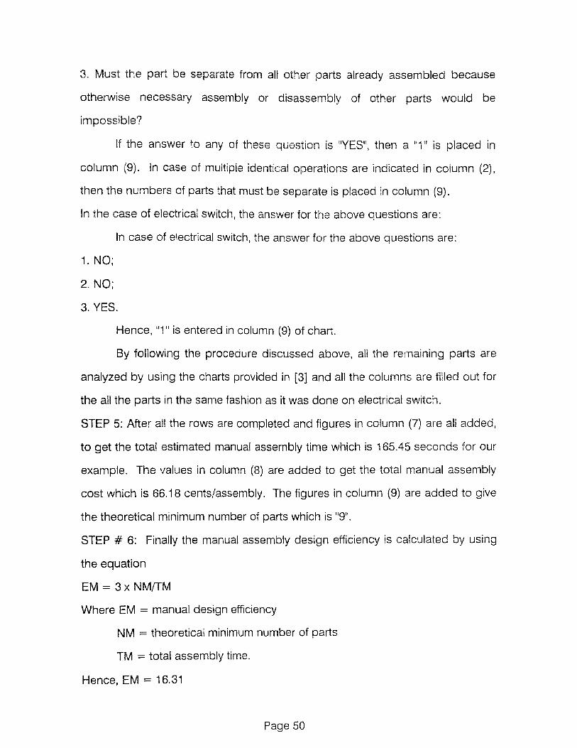
3. Must the part be separate from all other parts already assembled because
otherwise necessary assembly or disassembly of other parts would be
impossible?
If the answer to any of these question is "YES", then a "1" is placed in
column (9). In case of multiple identical operations are indicated in column (2),
then the numbers of parts that must be separate is placed in column (9).
In the case of electrical switch, the answer for the above questions are:
In case of electrical switch, the answer for the above questions are:
1. NO;
2. NO;
3. YES.
Hence, "1" is entered in column (9) of chart.
By following the procedure discussed above, all the remaining parts are
analyzed by using the charts provided in [3] and all the columns are filled out for
the all the parts in the same fashion as it was done on electrical switch.
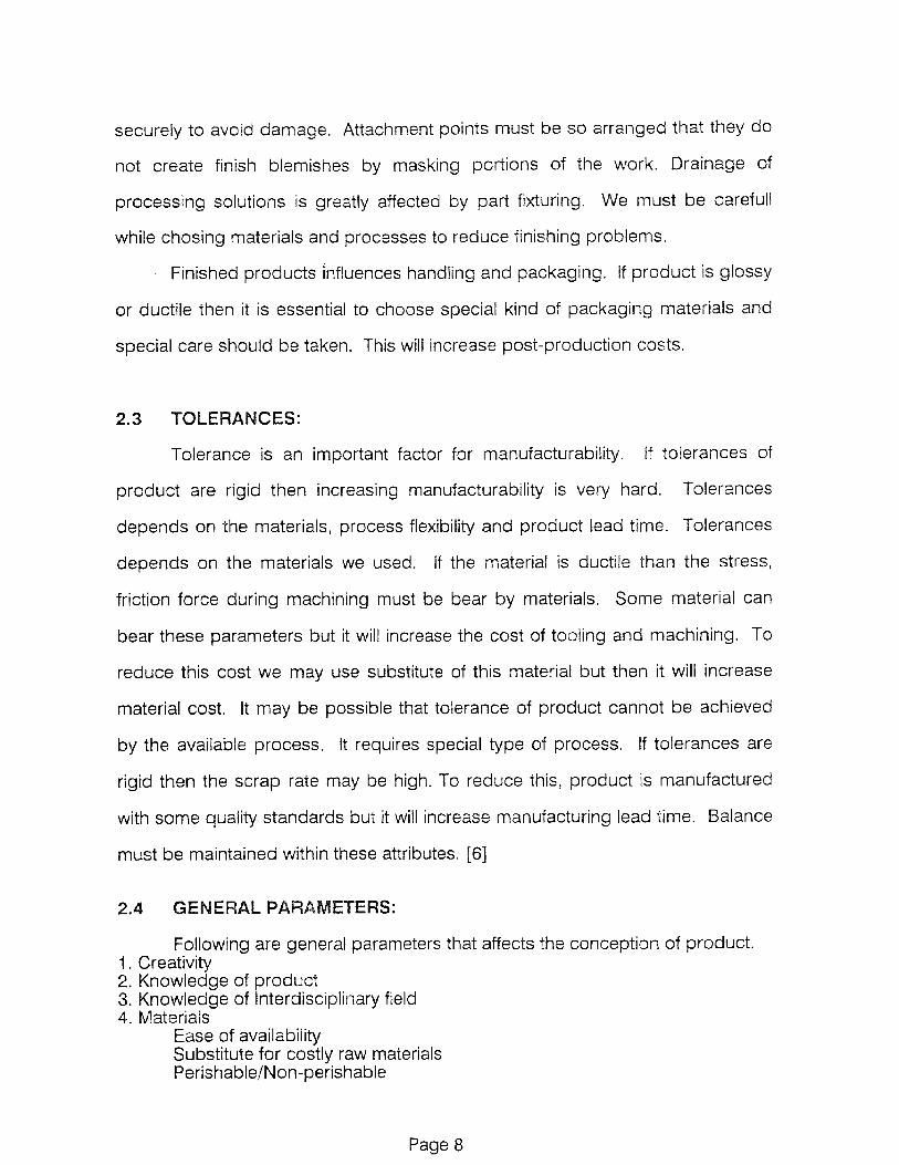
STEP 5: After all the rows are completed and figures in column (7) are all added,
to get the total estimated manual assembly time which is 165.45 seconds for our
example. The values in column (8) are added to get the total manual assembly
cost which is 66.18 cents/assembly. The figures in column (9) are added to give
the theoretical minimum number of parts which is "9".
STEP # 6: Finally the manual assembly design efficiency is calculated by using
the equation
EM = 3x NM/TM
Where EM = manual design efficiency
NM = theoretical minimum number of parts
TM = total assembly time.
Hence, EM = 16.31
Page 50

Nam
e of
Ass
embl
y
SWITCH SHAR
PENI
NG N
ING
aDE
VICEH
OUSI
NG
SHAR
PENIN
G MN
PENIN
G DE \
flu--
\00E
- R
CI T
E
SCREWS
SQUAREPuri
GEARBOX MOTOR
k, -)1
98
2,
19
85
, 1
98
9 B
oo
thro
yd D
ew
hu
rst,
In
c.

Nam
e o
f Ass
em
bly
SQ
UA
RE
PLA
TE
SC
R V
-15
BA
CK
PLA
TE
PLUG
HOUS
ING
BASE
- PLO
T
SCRE
WS
PLAS
TIC
BOX
3 x
NM
desi
gn e
ffic
iency
=
=TM
©1982, 1985, 1989 B
ooth
royd
Dew
hurs
t, I
nc.

7.2 ANALYSIS OF THE RE-DESIGN FOR AUTOMATIC ASSEMBLY
The completed "automatic assembly worksheet" is presented in the similar
manner to that of the "manual assembly work sheet", by following the Boothroyd
and Dewhurst method.[17] The required production rate is assumed to be 30
assemblies per minute, and the total production required is assumed to be
100,000 assemblies per year. The assembly design efficiency is calculated at the
end of the analysis, after the chart for "automatic assembly analysis" is
completed, for the re-designed pencil sharpener.
The analysis is carried out by following these steps:
Step 1: The assembly is taken apart and an identification number is assigned to
each part, the complete assembly is given number "1", and the parts are
numbered in the order of disassembly. Attached charts shows the parts and
their ID numbers.
STEP 2: Re-assembly of the product is done beginning with the part with the
highest identification number. All the rows of the work sheet for automatic
assembly are taken from Boothroyd & Dewhurst [17], are completed for all the
parts. The first row of the work sheet for the electrical switch is completed in the
following way:
Column 1: The ID number of the parts, for the switch is "11".
Column 2: The operation is carried out once. Hence "1" is entered here.
Column 3: The part feeding and orienting code is determined for the part using
charts 4 to 7 of Boothroyd & Dewhurst [17].
For switch, this code is entered as "60063". From Chart 4 of Boothroyd &
Dewhurst [26], the first digit is obtained, this is taken as '6' because the rubber
part is a non-rotational part, and it is considered to be a flat part, as the ration
between the length of the longest side (A=18mm), and the length of the
Page 52

intermediate side (B=16mm) is less than '3', and the ration between the length of
the longest side (A=18) and the length of the shortest side (C=3mm) is greater
than 4.
The next two digits in the code are taken to "00" from chart 6, of
Boothroyd & Dewhurst [17]. As the condition A>1.1B and B>1.1C are satisfied
for the switch and also the part has 180 degrees symmetry about all three axis.
The last tow digits in the code are entered as "63". These are obtained
from chart '7', because the electrical switch is small and non-abrasive, tangle or
nest but not severely, light, non-sticky, delicate, non-flexible, and tend to overlap
during feeding.
Column 4: Operating efficiency is obtained from chart 6 of Boothroyd & Dewhurst
[26], as 0.8 corresponds to "600" of the five digit code.
Column 5: Relative feeder cost for switch is 7 cents. It is obtained by adding the
feeding cost (FC) and additional feeder cost (DC).
Column 6: The size of electrical switch is 18 mm and so the maximum feed rate
from a standard feed rate is given by
FM = 1500 x .9/18 = 75 parts/minute
Column 7: The assembly rate required is 30 assembly/minute, i.e., FR = 30,
since this required rate is less than FM, the difficulty rating for automatic handling
is given by,
DF = 60/FRxCR
DF (for electrical switch) = 60/30x7 = 5.6
Column 8: The cost of feeding and orienting each electrical switch is CF = .3xDF
= .168 cents.
Column 9: The appropriate two digit code obtained from chart '8' of Boothroyd &
Dewhurst [17], is "20" for switch, because the part is added but not secured after
it is assembled as this is beginning of the assembly. It is inserted from vertically
Page 53

above, there is no screwing operation or plastic deformation, easy to align and
position. Similarly the two digit codes are generated using the same chart for
other parts also.
Column 10: The relative workhead cost from chart 8 is, WC = 2 cents.
Column 11: FR = 30, and difficulty rating for automatic insertion is DI = 60 x
WC/FR = 4.
Column 12: The cost of insertion for switch, Cl = .06 x Dl = .24 cents.
Column 13: The total operation cost for feeding and orienting the electrical switch
is the sum of the separate costs per part for these two operations (Column 8 and
12), multiplied by the number of simultaneous operations, i.e., (2)x[(8) + (12)b
where the numbers in the parentheses refer to the data in these columns. In this
case, the total cost obtained is .408 cents. Same calculation is done for the other
pars, and the values are entered in this column.
Column 14: The theoretical minimum number of parts is already calculated, and
all the parts in the new design is separate. Hence '1' is entered in each row.
STEP 3: The data is entered for all the other parts, following the same procedure
and using charts, until the final assembly operation has been performed.
STEP 4: The numbers in column 13 and 14 are added to get the total cost of
automatic handling and insertion CA and the theoretical minimum number of
parts NM. For this pencil sharpener
CA = 3.63 cents and NM = 10.
STEP 5: The estimated design efficiency for automatic assembly, using the
formula 0.09 x NM/CA, is .2479 or 24.79 percent.
Page 54

DE
SIG
N F
OR
MA
NU
AL
AS
SE
MB
LY W
OR
KS
HE
ET
Nam
e o
f Ass
em
bly
N 1:i IA k- 04
7--
ARP
1
C-
HOUS
ING
SHARPE
NINGD
EV
IC
E C
L
I DER
CON
NECT
OR
MBL
Y ASSE
MBL
Y
HO
USIN
G
PLATE
COLL
ECTO
RC
TOR
1.7
.2,
y
L)19
82, 1
985,
198
9 B
ooth
royd
Dew
hurs
t,

DESIG
N F
OR A
UTO
MATIC
ASSEM
BLY
WO
RKSH
EET
requ
ired
rat
e of
ass
embl
yPR
(pe
r m
inut
e)
Nam
e of
Ass
embl
y
AU
TO
MA
TIC
ASS
EMBL
Y \ --
()\--)A
-‘(
SWIT
CH IT
CH
HOUS
ING
SHAR
PENIN
G
DEVIC
E
DEVID
ER
CO
NN
ECTO
R,
ti
ASSE
MBL
Y
ASSE
MBLYp
is SEM
BLY
BLY
Tic
* HO
USING
V._1
40 9
01 T
E
COLLECTOR
BOX

AUTOMATIC HANDLING
FIRST DIGIT
z
C
z0
0
0z

through grooves (2)parallel to —
steps or chamiers (2)parallel to —
AUTOMATIC HANDLING-DATA FOR NON—ROTATIONAL PARTS(first digit 6, 7 or 8)
A 5 1 1B or B 11C
tcode the main feature or features which distinguish theadjacent surfaces having similar dimensions)
code the main feature or it orientation is defined by morethan one feature. then code the feature that gives thelargest third digit
steps 01 chamfers t21parallel bo -
through grooves (2)Parallel to
other -holes or includingrecesses slight> ,118 asymmetrycannot (3). fea-
be seen tures tooin silhouette smail etc
aboutX axis
aboutaxis
aboutZ axis
orienbationdefined byone mainfeature
orientation definedby two mainfeatures and one isa step, chamfer orgroove
other - in-cluding
slight asymmetry (3) etc.
©1982, 1985, 1989 Boothroyd Dewhurst, Inc. CHART 4-3
4-35

9 82,1985, 1989 Boothroyd Dewhurst, Inc. CHART 4-2
PARTS
v v (first digit 0, 1 or 2)
part is not BETA symmetric (code the main feature or featuresrequiring orientation about the principal axis(
sligntlyBETA asymmetric projections, asymmetricsteps. or chamfers BETA, asymmetric grooves or flats or small
(can be seen in silhouette) (can be seen in silhouette) features less than D.10
and L.10ORholes or re-cesses whichcannot beseen ,n outershape orsilhouette
part is ALPHAsymmetric(see note 1)
part can De red in a sic:supported by large end orprotruding flange withcenter of mass below sup-porting surfaces
BETA symmetric steps orchambers onexternal surfaces(see note 3)
on bothside andend
surface(s)
BETAsymmetricgroovesholes orrecesses(see note 3)
on sidesurfaceonly
on endsurface{s)only
BETA symmetric hiddenfeatures with no cor-responding exposedfeatures (see note 4)
BETA asymmetricfeatures on side orend surface(s)
slightly asymmetricor small features;amount of asymmetry orfeature size less than
D/10 and L110
— MANUAL HANDLING REQUIRED—

plastic deformation immediately after insertion
plastic bendingor torsion
rivetting or similaroperation
screw tighteningimmediatelyafter insertion (6)
not easy to align orposition duringassembly
not easy to align orposition duringassembly
mechanical fastening processes(part(s) already in place out notsecured immediately after insertion)
none or localizedplastic deformation
MANUAL INSERTION—ESTIMATED TIMES (seconds)
after assembly no holding down requiredto maintain orientation andlocation (3)
holding down required during subsequentprocesses to maintain orientation
or location (3)
easy to align andposition duringassembly (4)
not easy to align orposition during
assembly
easy to align andposition duringassembly (4)
not easy to align orPosition during
assembly
PART ADDED
but
NOT SECURED
part anc associatedtool (includinghands) can easilyreach the desiredlocation
due to ob-structed-access or re-strictedvision (2)
due to obstructed ac-
cess and re-strictedvision (2)
PART SECURED
IMMEDIATELY
no screwing opera-tion or plasticdeformation im-mediately after in-sertion (snapipressfits. circlips, spirenuts, etc.)
part and associated tootincluding hands, caneasily reach the desiredlocation and bhe too,can be operated easily
due toobstructedaccess orrestrictedvision (2)
due toobstructedaccess andrestrictedvision (2)
SEPARATE
OPERATION
non-mechanical fastening processes(part(s) already in place but notsecured immediately after insertion)
metallurgical processes
additionalmaterial required
non-fasteningprocesses
assembly processeswhere all solidparts are in place
CHART 2-2
2-27Q1982, 1985, 1989 Boothroyd Dewhurst, Inc.

parts can be handled by one person without mechanical assistance
parts do not severely nest or tangle and are not flexible
part weight < 10 lb parts are heavy ( > 10 lb)
parts are easy toi parts present parts are easy tol parts presentgrasp and other handling grasp and other handling
difficulties (1) manipulate difficulties (1)
MANUAL HANDLING—ESTIMATED TIMES (seconds)
parts are easy to grasp and manipulate parts present handling difficulties (1)
!thickness s 2 mm thickness > 2 mm !thickness 5 2 mmthickness > 2 mm
ONE HAND
parts need tweezers for grasping and manipulation
ONE HANDwith
GRASPING AIDS
parts can oe manipulated without parts require optical magnificationoptical magnification for manipulation parts are easy parts present parts are easy parts presentto grasp and handling to grasp and handlingmanipulate difficulties MI manipulate difficulties (11
parts present no additionalhandling difficulties
parts present additional handling difficulties 1(e.g. sticky, delicate. slippery, etc.) (1) .1
TWO HANDSfor
MANIPULATION
parts severely nest ortangle or are flexiblebut can be grasped andlifted by one hand(with the use ofgrasping tools ifnecessary) (2)
TWO HANDSrequired forLARGE SIZE
two hands required forgrasping and transportingparts 9
non -r

AUTOMATIC HANDLING-ADDITIONAL FEEDER COSTS, DC
parts will not tangle or nest tangle or nest but not severely
FIGURES TO BEADDED TO FC,OBTAINED FROMCHARTS 4-2 or 4-3
not light light not light light
not not not -
notsticky sticky sticky sticky
sticky sticky sticky sticky
very small parts large parts
rotational I non-rotational rotational
parts are very small orlarge but are nonabrasive
parts wIl not severely ;angle or nest
small parts large parts I very small part
e-orientation defined b orientation c'tined by non-
geometric features geometric features
non-flexible
do notdo not flexible overlap
overlap overlapoverlap
abrasive parts
--:D1982, 1985, 1989 Boothroyd Dewhurst, Inc.
4-37

easy to alignand position
easy to alignand position (6)
not easy to align orposition ino featuresprovided tor thepurpose,
not easy to align orposition (no featuresprovided for thepurpose)
AUTOMATIC INSERTION-REELATIVE WORKHEAD
after assembly no holding down required tomaintain orientation and location (5)
holding down required during subsequentprocess(es) to maintain orientation andlocation (5)
PART ADDEDbut
NOT SECL RED
noresistancetoinsertion
resistancetoinsertion i7)
noresistancetoinsertion
resistancetoinsertion (7)
noresistancetoinsertion
resistancetoinsertion (7)
noresistancetoinsertion
resistancetoinsertion 17
fromverticallyabove
no: fromvertically
above (3)
insertion notstraight linemotion (4)
no screwing opera-tion or plasticdeformationimmediately afterinsertion !snap orpress tits etc )
Dias::: deformation immediately after insertionsues, ingimmediatelyalterinsertion
plastic pending
not easy to alignor position (nofeatures providedtor the purpose;
rivetting or similarPlastic deformation
not easy to alignor position (nofeatures Providedtor the purpose;
PART SECL R.IMMEDIATELY
fromverticallyabove
notfromverticallyabove 13)
insertion notstraight linemotion (4)
non-mechanical fastening non-fasteningmechanical fastening processes processes (parts already processes(parts already in place) in place)
none or localized metallurgicalplastic deformation processes —
additionalmaterialrequired
SEPARATEOPERATION
assembly process whereall solid parts are inplace or non-solidsadded or parts aremanipulated
1982, 1985, 1989 Boothroyd Dewhurst, Inc. CHART 4-5
4-39

CHAPTER 8
ASSEMBLY SEQUENCE PLANNING
Sequence of assembly of a set of parts plays a key role in determining
important characteristics of the tasks in assembly and of the finished assembly.
Parts are designed and made to meet the specifications, and then are
assembled to configuration that will fulfills the functions of the final product.
Matters, such as the difficulty of assembly steps, the needs for fixturing, the
potential for parts damage during assembly, the ability to do in-process testing,
the occurrence of need for rework, and the unit cost of assembly, are all affected
by the assembly sequence choice.[19, 20, 21, 22]
8.1 DETERMINATION OF ASSEMBLY SEQUENCE
Exploring the choices of assembly sequence is very difficult for two
reason. First, the number of valid sequence can be large even at small number
of parts and rise very high with increasing parts count. Second, seemingly minor
design changes can drastically modify the available choices of assembly
sequence.
Assembly sequence studies require identification of potential jigging and
gripping surface, grip and assembly forces, clearances and tolerances. Basically
there are five reasons for seeking good assembly sequence
(1) Construction: Construction reasons such as access to fasteners or
lubrication points plays important role in determining the sequences.
(2) Ease of assembly: Some sequence may include some tricky part mates
whose success may be doubtful or whose failure might damage some parts.
(3) Quality Control: Ability to test the function of sub-assembly or the avoidance
of a sequence that installs fragile parts easily in the process. Some sequences
Page 64

might not offer the opportunity to test some function until it is buried beneath
many other parts.
(4) Process: Some sequence may not allow a part to be jigged or gripped from
an accurately made surface. This makes assembly's success doubtful. Some
sequences may require many counterproductive moves such as fixture or tool
changes or the need to change sub-assembly over. This change-overs may not
avoidable, but sequences may require flipping before the sub-assembly is fully
fastened together, risking the possibility that it will disassemble spontaneously
unless extra fixtures are provided. Thus sequence without flips and change-over
may be the prime goal of good sequencing operation.
(5) Production strategy: Some sub-assembly can be used in many product so it
is advisable to stock such sub-assembly so that final assembly operation can be
done very fast on the remaining parts.
8.2 APPROACHES FOR GENERATION OF ASSEMBLY SEQUNCES:
Generally, techniques for exploring the choices of assembly sequences
have been informal and incomplete. Means of generating all assembly sequence
is from the records of an exhaustive set of trials involving either all ways of
assembling the component parts into sub-assemblies and assemblies or all the
ways of removing component parts from assembly and each of its sub-
assemblies. [1, 7]
Another systematic approach for generating all physically possible
assembly sequences can be used to generate the possible assembly sequences
is based on the work of Thomas De Fazio and Daniel E. Whitney.[23] This
approach is used in the sequencing of assembly for pencil sharpener. This
algorithmic approach introduces a hierarchy of feasibility condition to reduce the
complexity of the geometric and physical reasoning that must be carried out for
Page 65

sequence generation. According to this approach, introduction contained in a
part list and an assembly drawing to characterize the assembly by a network,
wherein nodes represents parts and lines between the nodes represents any of
certain user-defined relations between parts called "liaisons". User accepted
definitions of "liaisons" means "a close bond or connection" and generally include
physical contact between parts. After assembly is characterized by a networks
of nodes (parts) and lines (liaisons), names are associated with two sets of
element, for example, parts names with the nodes and liaison numbers with lines.
Subsequently, any assembly step is characterized by the establishment of one or
more of the liaisons of the assembly. This method does not precisely create
assembly sequences but rather creates liaison sequences. Instead, parts
liaisons are used in each sequence. Sequences are generated by answering the
following two questions for each liaison. According to De Fazio and Whitney, the
number of liaisons is related to number of parts by:
(N2 - N)/2 > I > (N-1)
Where N = number of parts,
I = number of liaisons.
Hence for pencil sharpener, for N = 10 parts, there are between 9 to 45
questions. Each of the following questions are addressed to each of the liaisons.
01: What liaisons must be done prior to doing liaison i?
Q2: What liaisons must be left to be done after doing liaison i?
Answers are in the form of precedence relations between liaisons and/or
logical combinations or liaisons. Liaison sequences are directly generated from
the answers. The starting state is that of disassembly with no parts is
assembled. Here "state" refers to the state of establishment of liaisons. An
explicit list of which liaisons are and which are not established represents the
Page 66
state of assembly. Assembly proceeds from state to state by adding a part or a
subassembly to another part or subassembly until all liaisons are established.
The imaginary path associated with the attachment of a part or subassembly is
called an assembly state transition or a "state transition". Each state may be
represented by a box with a list of numbers representing established liaisons,
and state transitions may be represented as lines connecting boxes. The
starting state is represented as a box with no entries.
To generate liaison sequence, begin by scanning the liaison list and the
answers for those liaisons which are not precedented. Any of these may serve
the first liaison to be established. Line up representations of each first possible
state across a rank and connect each with the starting state by line. For each
possible first liaison , one explores for all possible subsequent states, by again
scanning the liaison list, the precedence relations (answers) and any other
constraints imposed on the assembly, thus generating another rank. It will be
convenient to show no state more than once, so if it occurs that there are two or
three ways of getting to a state in the second rank, its representation will have
two or three state transition (lines) entering it. In this fashion one precedes
algorithmically to the finish state where all liaisons have been established.
Naming the ranks ordinally, zeroth for the unassembled starting state, first
for the prospective first liaison, and so forth, one sees that there are as many
ranks as parts. Since I > (N-1), one sees that a single liaison is necessary
established per state transition only for assemblies where I = (N-1). for those
assemblies where I > (N-1) some state transitions involve establishing two or
more liaisons. Once can consider that a state transition involves placing a part or
a subassembly, but the bookkeeping is not by part name but by liaison number.
However, it is already known that parts count and liaison count can differ by
more than one. Another manifestation of the same matter is noted on the liaison
Page 67

diagram where closed figures may occur with parts at the vertices. If a last parts
is placed in a set that makes a closed figure, two liaisons (lines) are established.
If a part placement closes two figures, three liaisons are established in the state
transition, and so forth.
In the case of pencil sharpener, there are ten parts. The list of the parts is
given below:
1) Switch
2) Housing
3) Sharpening Device
4) Divider
5) Connector
6) Motor Assembly
7) PCB Assembly
8) Housing Box
9) End Plate
10) Collector
The liaison diagram is shown in the figure.
The liaison diagram is the first step to generating the family of liaisons or
assembly sequences. The next step will be to answer the two questions above
mentioned.
01) What liaison must be done prior to doing liaison (i)?
For i = 1: Nothing precedes switch to assembly.
For i = 2: Liaison 1 must be done before sharpening assembly is fixed, the
reason behind this is that after sharpening device is fixed we cannot put switch in
housing.
Therefore 1 ---> 2
For i = 3: L -1 must be done before Divider is fixed.
Page 68

Therefore 1 ---> 3
If we combine above relationship, we will get
1 ---> (2 and 3)
Comments: Liaison 1 need not precedes Liaison 2, and Liaison 1 need not
precedes Liaison 3, but Liaison 1 must precedes conjuction (and) of Liaison 2
and Liaison 3, meaning that Liaison 1 must be established before Liaison 2 and
Liaison 3.
= 4: Connector cannot be inserted before the completion of Divider.
Therefore (1 and 2 and 3) ---> 4.
i = 5: Nothing precedes motor. However Liaison 5 must precedes L4.
Therefore 5 ---> 4.
Comments: This relationship is stronger than the immediate previous
relationship. Thus writing this relationship implies previous one, which no longer
need be written.
= 6: L6 must be done after motor assembly is connected to connector.
Therefore (1 and 2 and 3 and 4 and 5) ---> 6
i = 7: After Liaison L6, PCB assembly must be inserted in the box before
proceeding for further assembly. This means L8 must precedes L7.
Therefor 8 ---> 7
i = 8: Box and PCB assembly then assemble to end-plate assembly. L1, L2, L3,
L4, L5, L6, L8 should be done prior to L7.
Therefore 1,2,3,4,5,6,8 ---> 7
i = 9: Nothing precedes the whole assembly. So box can be inserted to whole
assembly.
Q2) what liaisons must be left to be done after doing Liaison 'i'?
i = 1: Liaison 2, 3, 4 and 6
Therefore 1 ---> 2, 3, 4, 6
Page 69

comments: After Liaison 1, sharpening device, Divider and connector and
assembly must left to be done, before fixing the housing and switch together.
= 2: Liaison 3, 4, 6 must be left
Therefore 2 ---> 3, 4, 6
Comments: Reason for this are same as above.
i = 3: Liaison 4 and 6 need to be left undone.
i = 4: L5 must be left done for the above said reason
Therefore 5 ---> 4
i = 5: Nothing.
Comment : Motor assembly will be fixed to connector after Divider is fixed.
i = 6: No Liaison.
Comment: Liaison L6 may be left for last, but it is not alone and last. If L6 is left
for the last, so too are L7 and a choice of other liaisons.
i = 7: No Liaison.
i = 8: No Liaison.
i = 9: No Liaison.
The next step is to algorithmically generate sequences of the liaisons
subject to the previous constraining relations. Figure 16 and figure 17 in the next
page, the graphical representation of the possible sequences. In figure each box
representing a state contains nine cells, each representing liaison, one through
nine from left to right.
First line shows from one to five and next line shows form six to nine. A blank cell
implies that the corresponding liaison is not established while a marked cell
implies that the corresponding liaison has been established. Lines connecting
the boxes represent the possible state transition. The whole blank box in the
zeroth rank represents the wholly unassembled starting state, and the wholly
Page 70

marked box in the ninth rank represents the wholly assembled or finished state.
Each path through the diagram starting at the top and moving along lines
through succeeding ranks to the bottom represents a valid liaison sequence.
63 liaison sequences can be verified by counting. A simple procedure for
counting how many sequences there are, involves working upwards answering
and recording for each state in each rank, the question 'From this state, how
many paths to the last rank are there?". The answer to this question for the
single state in the zeroth rank is the number of valid liaison sequences.
8.3 CHOOSING GOOD ASSEMBLY SEQUENCE
After generating all of the physically possible sequences of assembly of a
pencil sharpener, we have to choose the best assembly sequence.
The entire procedure for selecting the best sequencing procedure can be
judgmental, qualitative, quantitative, or a combination of these and can be
followed through any or several paths. Assembly moves may be eliminated
when an acceptable alternative path exists and the move in question is difficult to
accomplish or puts a part or parts at a risk of damage. Second, we can
eliminate unacceptable assembly states to the equivalent of eliminating
corresponding nodes or boxes from the assembly-sequence graph. Assembly
states may be eliminated when an acceptable alternative path exists and the
state in question is awkward, unstable or conditionally unstable under assembly
conditions, or requires undue time, cost or equipment to maintain it between
assembly moves.
One can enforce any of several assembly-sequence constraint. Such
constraint can be arbitrary and may be based on designers/engineer's own
concept of good practice. In the case of pencil sharpener, we can reduce the
assembly sequences to 8, after eliminating few states by following the above
Page 71

discussed methods. Figure 18 shows the reduced number of sequences, and
any one of it can be followed to assemble the pencil sharpener.
Page 72

1-10t
3511
\16.
DIV
IDER
END
SHAR
PEN
ING
DEV
ICE
COLL
ECTO
R SW
ITCH
P03
ASSE
MBL
Y
30X
HOU
SING
CON
NECT
OR
MOTOR ASSEMBLY
Fig
ure
15 SEQUENCING PROCESS FOR PENCIL SHARPENER

AVAILABLE SEQUENCING ALTERNATIVES
Figure 16

CHAPTER 9
FUTURE TRENDS IN DESIGN FOR MANUFACTURABILITY
One approach to implementing Design for Manufacturability is to use an
appropriate set of principles and rules to help guide the design of the product
and then to evaluate and redesign the product using an appropriate evaluation
methodology. To assist this process, a third DFM thrust has been the
development of a variety of computer-based and/or computer-aided design
programs. Developments in this area include commercially available CAD
software, research involving conventional interactive computer programming
approaches, and research involving Al/expert system approaches.
9.1 COMMERCIAL SOFTWARE
A variety of commercial software has become available which provides
Design for Manufacturability concept a great thrust. Programs which assist in the
design of individual parts for a particular fabrication process are most common.
Programs like Moldflow is a computer simulation of molten plastic moving
through the gates, runners, and cavity of an injection mold. Embodied within the
program is a Design for Manufacturability philosophy that encourages moldability
analysis by pointing to part features that might cause warping and failure in
production. The program does this, not by telling the production or design
engineer how to produce or design the part or where to gate the mold, but by
indicating results to be expected from a given choice of design and processing
parameters. By performing "what-if' variations of his design and process, the
engineer is able to converge iteratively to the best solution.
Page 75

Another software is Variation Simulation Analysis Software, better known
as VSAS, is an example of another type of commercial software which embodies
and facilitates the Design for Manufacturability philosophy. This software allows
the engineer to predict assembly tolerance and manufacturing variation before
prototype can be built. This software uses Monte Carlo simulation technique,
and simulates a production run by putting the assembly together, one step at a
time, in the proper processing sequence, in specified number of times. Results
of the simulation are analyzed, and a complete statistical picture of the proposed
process is provided including a population distribution of critical dimensions,
high and low limits, percentage of out-of-specification parts, and percent
contribution of each component and operation to final assembly tolerances.
A major barrier to adopt Design For Manufacturability concept is time.
Product designers are typically operating under very tight schedules and
therefore reluctant to spend time considering Design for Manufacturability issues.
Commercial computer software simplifies the effort and shorten the time required
to implement Design for Manufacturability on daily basis
9.2 RESEARCH DEVELOPMENTS
Another approach to computer aided Design for Manufacturability is called
MAPS-1.[17] Recognizing that material and process alternatives should be
carefully considered in the design process, well before part geometries are
specified, MAPS-1 provides a short list of the best combinations for further
consideration by the designer. MAPS-1 system is intended as general purpose
aid to the designer in making preliminary selections of materials and
manufacturing processes for a given part. This code is used in conjunction with
material and processing data bases to progressively eliminate materials and
Page 76

processes, beginning with obviously unsuitable choices, and then proceeding to
incompatible or difficult material and process combinations. The
material/process combinations which remain are divided into two categories,
usual practice and unusual practice. If the list of material/process combinations
which remain is too large to be easily evaluated, the user may elect to have the
program rank each candidate according to a predetermined criterion. There are
several difficulties in this approach. Significant among these is the need to
differentiate between primary and secondary processing: difficulties in dealing
with process chains and processes such as heat treatment and surface coating
which do not contribute to part geometry; developing and properly representing
the large amounts of data required for the data bases
Another approach is called "Optimal Suggestions".[22] In this approach,
the author accept that creative synthesis, or the design concept phase, will
remain a human task for some time to come, and therefore ask what can be
done to enhance the designer's capabilities in that stage. The solution consists
of creating a program which makes "suggestions" to the designer during the
conceptualization of the design. The suggestions are formulated in such a way
that if they are all followed then optimal solution will be achieved. Hence, the
suggestions act to both stimulate creativity and to show the way to good design.
The suggestion ask the designer to design the individual parts of the product in
such a way that a high assemblability efficiency will be attained. If other design
constraints make it impossible to follow a suggestion, the next best design is
pursued.
Another approach is a computerized approach to design for robotic
assembly. The methodology described seeks to minimize the number of parts
Page 77

used to achieve all required product functions while producing a design requiring
minimum assembly cost in the form of robot and special tooling. This is done by
guiding the product design process in such a way that he must consider and
deal with specific robotic assembly issues as he develops the product design
concept. Guidance is based on numerous design principles which facilitates
robotic assembly.
9.2.1 Artificial Intellegence/Expert Systems
Some of the computer-aided DFM developments discussed above, the
large amount of principles, rules, guidelines, and other heuristic data inherent in
the DFM approach lead to variety of difficulties when conventional computer
programming techniques are employed. The field of artificial intelligence and
expert systems embodies a range of new programming techniques which
appear to be well suited to DFM programming need. As indicated in a review of
expert systems applications in mechanical design given by Dixon and Simmons.
Extensive work on knowledge representation as well as development of Al
techniques which avoid shortcomings associated with rule-based expert systems
currently being used with success in other applications is needed to facilitate
meaningful application of Al to design for manufacturability. Top level goal of this
approach is to develop a theory and practice for mechanical design and
manufacturing processes. The objective includes to learn how to develop expert
systems in CAD environments that can do on-line evaluation of designs for their
manufacturability, to explore the use of design with features as a means for
creating a design data base that will serve manufacturing process planning as
well as design and analysis needs, to develop a new language for knowledge
representation in design that will facilitate the construction of expert systems in
mechanical design. To implement this program, a series of sub-project topics
Page 78

have been selected for use in gaining the theoretical understanding and practical
experience needed to achieve the desired research objectives. Some of the
specific topics under consideration include design of heat sinks, design and
analysis for injection-molded parts, design of plastic extrusions, casting design,
analysis, and process selection, plastic materials selection, and a domain
independent iterative redesign program. It is important to create a single
databases useful for both design and manufacturing.
Page 79

CONCLUSION
Design For Manufacturablity (DFM) has been an effective tool for product design
and analysis. This approach can be applied to any product for increasing design
efficiency as well as overall efficiency. The efficiency of design of the product for
assembly depends on the design of the product and the required assembly rate.
Assembly cost is a major factor on product design. The suitability of any
assembly method can be systematically assessed by the product design
features even when the details of the assembly process are not known.
In the case of pencil sharpener, parts are analyzed and re-design of the
parts are done. The reduction of parts is from 23 to 10. The analysis shows that
the cost of old design for manual assembly is 66.18 cents, and the cost of
assembly of re-designed pencil sharpener for manual assembly is 26.60 cents.
The product design efficiency is increased form 16 % to 45 %. The cost of re-
designed pencil sharpener for automatic assembly is only 3.63 cents. However in
the case of automatic assembly the design efficiency is only 24 %. Time for
assembly is reduced in the case of automatic assembly.
The main contribution of the presented work is the demonstration that the
principles of design for manufacturablity can be applied successfully and with
significant potential economic gains to complex, medium volume product such
as pencil sharpener.
Page 80

BIBLIOGRAPHY:
1. Paul Heidenreich (May,1988), Designing for Manufacturability, QualityAssembly, Machine Design,pp 87-92
2. Henry W. Stoll (January, 1988), Design for Manufacture, ManufacturingManufacturing Review, pp 43-59
3.Danial Whitney (July-August, 1989), Manufacturing by Design,HarvardManufacturing Implications, Manufacturing Review,pp 26-35
4. J.E.Cole (October, 1989), Design-to-Manufacture: an integrated HarvardBusiness Review, pp 120-126.
5. J.L.Stauffer(September, 1988), Product Design for Finish Quality,Manufacturing Engineering,pp 75-77
6. Robert Davis (December, 1989), Design Methodology And IndustrialBusiness Review, pp 83-91
7 Stoll (September, 1986), Design for Manufacture, Applied Mech. Review,Progress, pp 44-47.
8. Robert Cooper (Spring, 1988), The New Product Process: A Decision pp1357-1363.
9. Ravi Venkatesan (March-April, 1990) Cummins Engine Flexes its Factory,Engineering, Industrial Engineering, pp 45-46
10. Shigeyasu Sakamoto (March, 1989), Process Design Concept: A NewGuide for Management, Journal of Marketing Management, pp 19-29.
11. James Dean,Jr. & Gerais Susman (January-February, 1989), Organizinginformation system, Computer Aided Engineering Journal, pp 159-165.
12. Boothroyd & Dewhurst (January,1984). Design for Assembly:AutomaticApproach to 1E, Industrial Engineering, pp 31-34.
13. Boothroyd & Dewhurst (February, 1984), Design for Assembly: Robots,Engineering, pp 44-49
14. Boothroyd & Dewhurst (November, 1983), Design for Assembly: SelectingManufacturing to Deploy Advanced Manufacturing Technology, Interfaces,pp 63-74)
15. Boothroyd & Knight , Design for Machining, Fundamental of Machining forManufacturable Design, Harvard Business Review, pp 28-36.
16. Boothroyd (February, 1988), Design for Assembly, Mechanical MachineDesign, pp 72-74.
17. Boothroyd & Dewhurst (1983),"Design for Assembly Hand Book"the RightMethod, Machine Design, pp 94-97.
18. Gerald Nadler (July, 1989), Design Process and Their Results,Industrialand Machine Tools, pp 399-465.
19. Jeffrey L. Funk (March, 1989) Design for Assembly of Electrical Products,in Better Design, Mechanical Engineering, pp 52-53.

20. Robert U. Ayres (March,1988) Complexity, Reliability and Design:Engineering, pp 28-30.
21. Brazier & Leonard (January, 1990), Concurrent Engineering: ParticipatingEngineering, pp 67-71.
22. Carol Bancroft (September, 1988), Design for Manufacturability: Half23. Thomas De Fazio & Daniel Whitney, Simplified Generation of All
Mechanical Assembly Sequences, IEEE Journal of Robotics &Automation, pp 640-656.
24. John Ettlie & Stacy Reifeis (Nov.-Dec.,1987), Integrating Design andSpeed Ahead, Manufacturing Engineering, pp 67-68.