Quantum-based sensing for PNT Final Presentation - Navisp
34
LP2N Institut d’Optique d’Aquitaine 33400 TALENCE. NAVISP - El1 - 013: Quantum - based sensing for PNT Final Presentation Baptiste Battelier, Simon Templier, Pierrick Cheiney, Brynle Barrett, Philippe Bouyer, Henri Porte and Fabien Napolitano
-
Upload
khangminh22 -
Category
Documents
-
view
0 -
download
0
Transcript of Quantum-based sensing for PNT Final Presentation - Navisp

LP2N
Institut d’Optique d’Aquitaine
33400 TALENCE.
NAVISP-El1-013: Quantum-based sensing for
PNT
Final Presentation
Baptiste Battelier, Simon Templier, Pierrick Cheiney, Brynle Barrett,
Philippe Bouyer, Henri Porte and Fabien Napolitano
✓ Context: Quantum sensors for navigation
✓ Design of the three-axis quantum accelerometer
✓ Hybridization with classical accelerometers
✓ Performances of the mobile three axis hybrid
accelerometer
✓ Future developments
OUTLINE
2
QUANTUM SENSORS: COLD ATOM INTERFEROMETERS
3
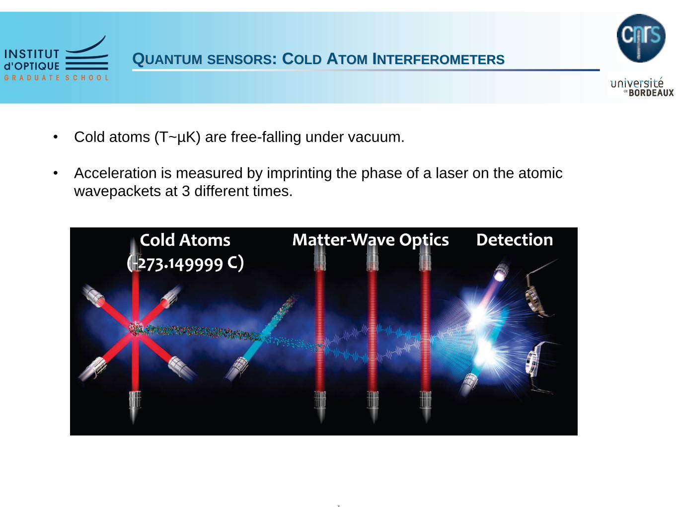
• Cold atoms (T~µK) are free-falling under vacuum.
• Acceleration is measured by imprinting the phase of a laser on the atomic
wavepackets at 3 different times.
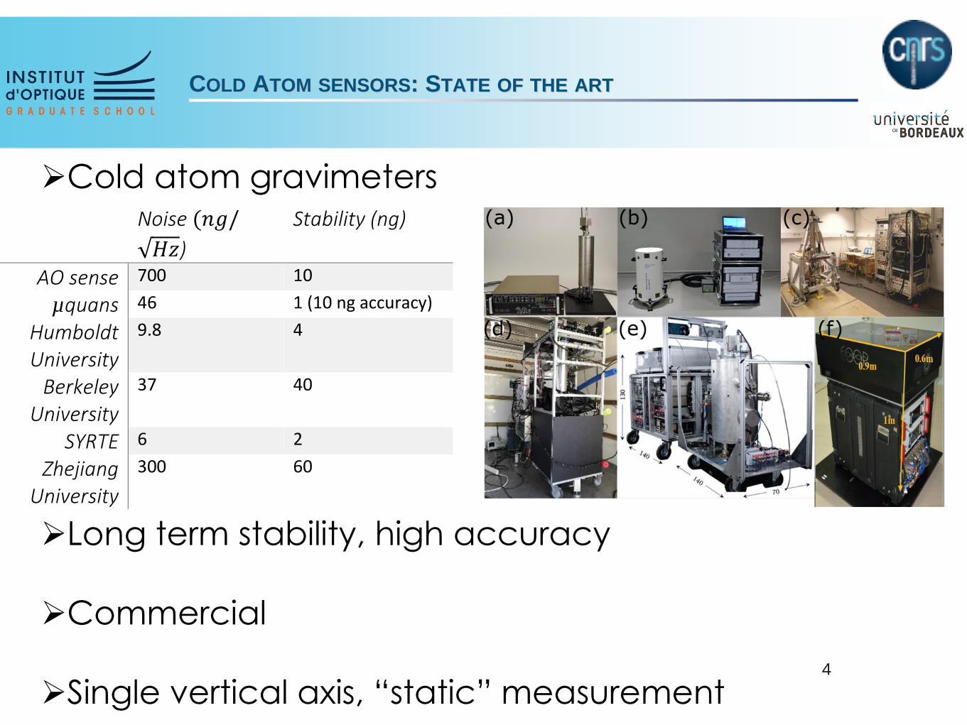
COLD ATOM SENSORS: STATE OF THE ART
4
Noise (𝑛𝑔/
𝐻𝑧)
Stability (ng)
AO sense 700 10
µquans 46 1 (10 ng accuracy)
Humboldt University
9.8 4
Berkeley University
37 40
SYRTE 6 2
Zhejiang University
300 60
➢Cold atom gravimeters
➢Long term stability, high accuracy
➢Commercial
➢Single vertical axis, “static” measurement
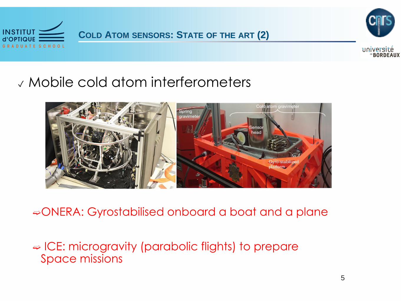
✓ Mobile cold atom interferometers
➫ONERA: Gyrostabilised onboard a boat and a plane
➫ ICE: microgravity (parabolic flights) to prepare Space missions
COLD ATOM SENSORS: STATE OF THE ART (2)
5
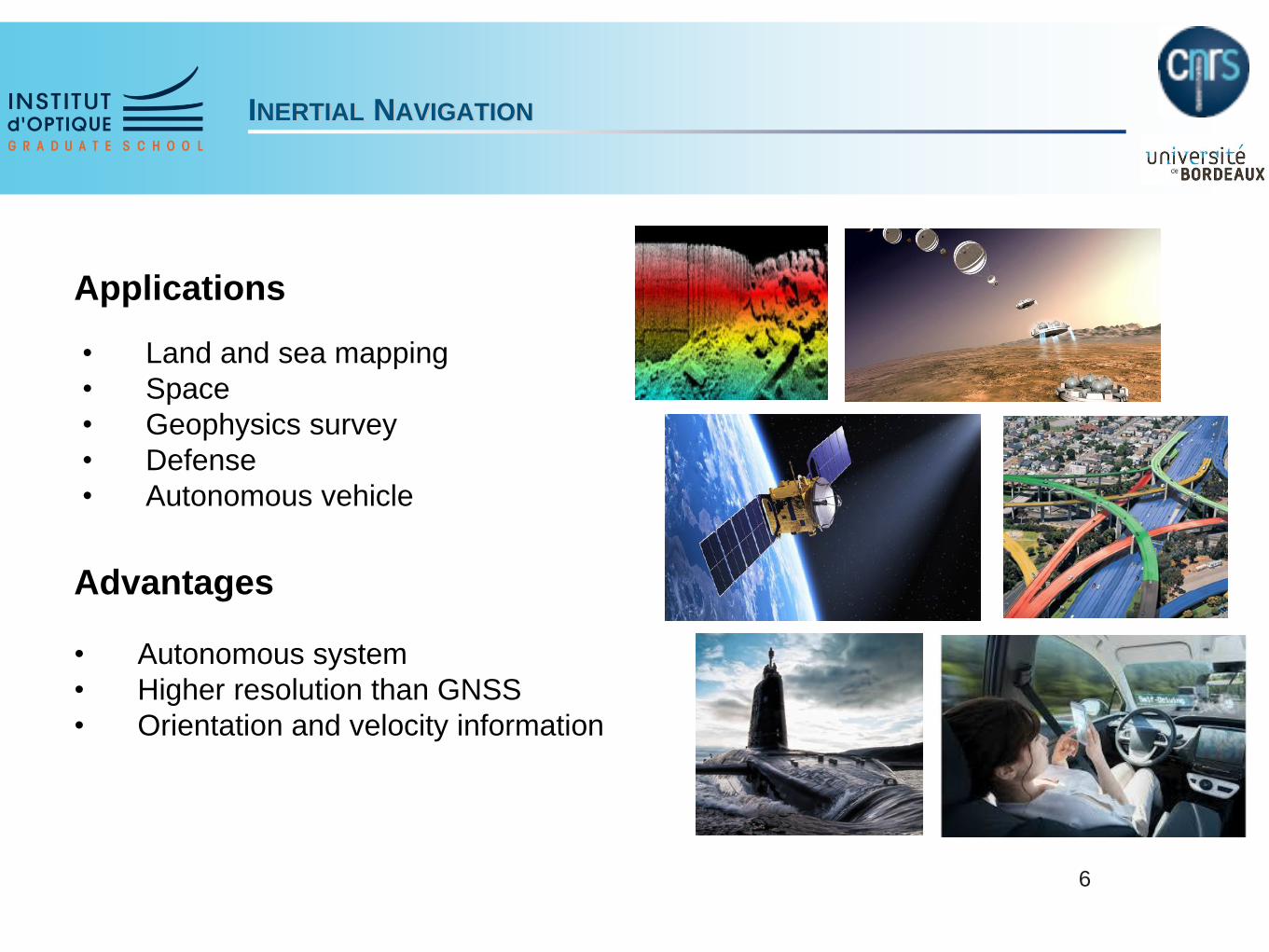
INERTIAL NAVIGATION
6
• Land and sea mapping
• Space
• Geophysics survey
• Defense
• Autonomous vehicle
Applications
Advantages
• Autonomous system
• Higher resolution than GNSS
• Orientation and velocity information
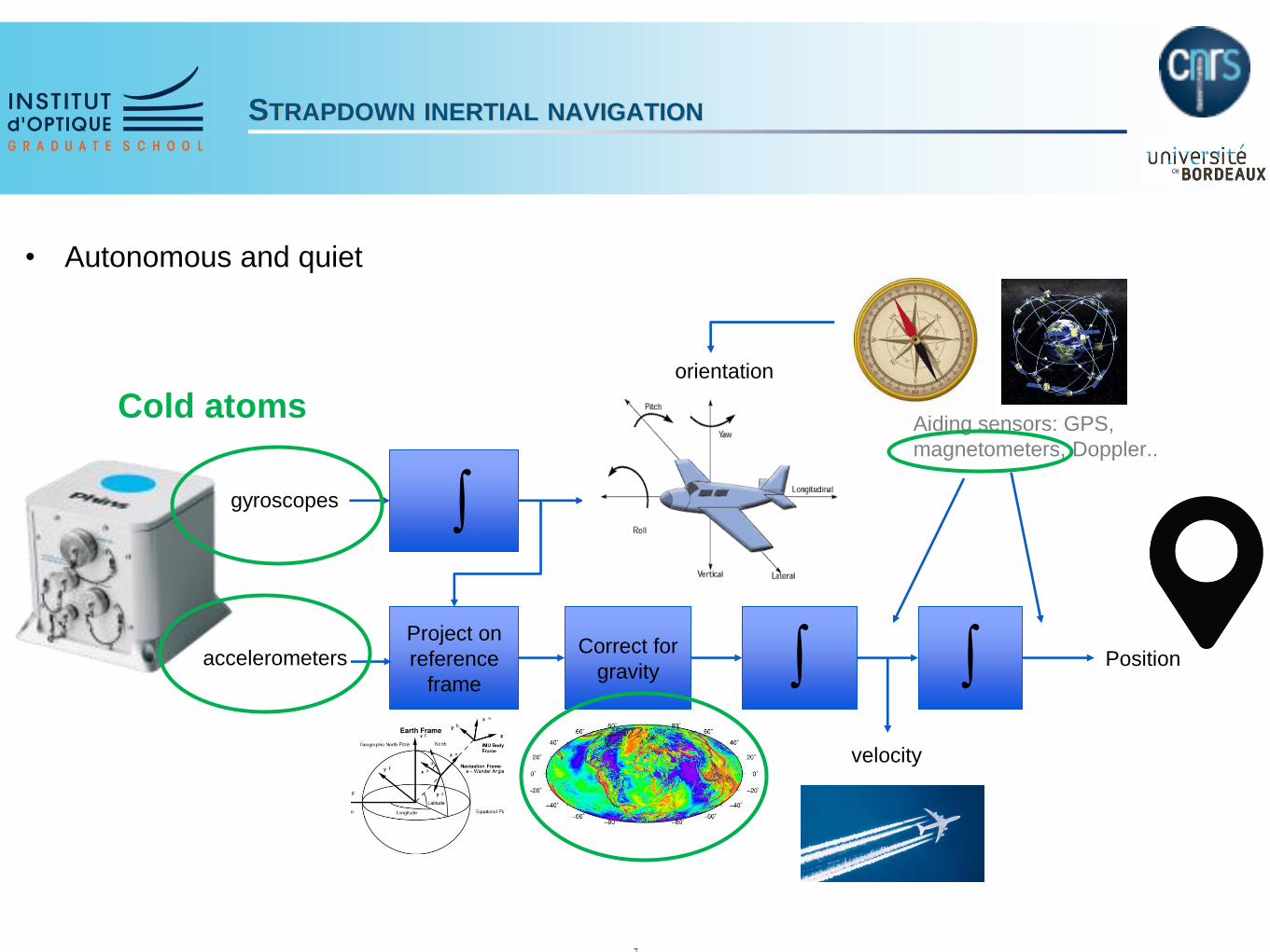
STRAPDOWN INERTIAL NAVIGATION
7
accelerometers
∫
Project on
reference
frame
Correct for
gravity ∫ ∫
gyroscopes
orientation
velocity
Position
Aiding sensors: GPS,
magnetometers, Doppler..
• Autonomous and quiet
Cold atoms
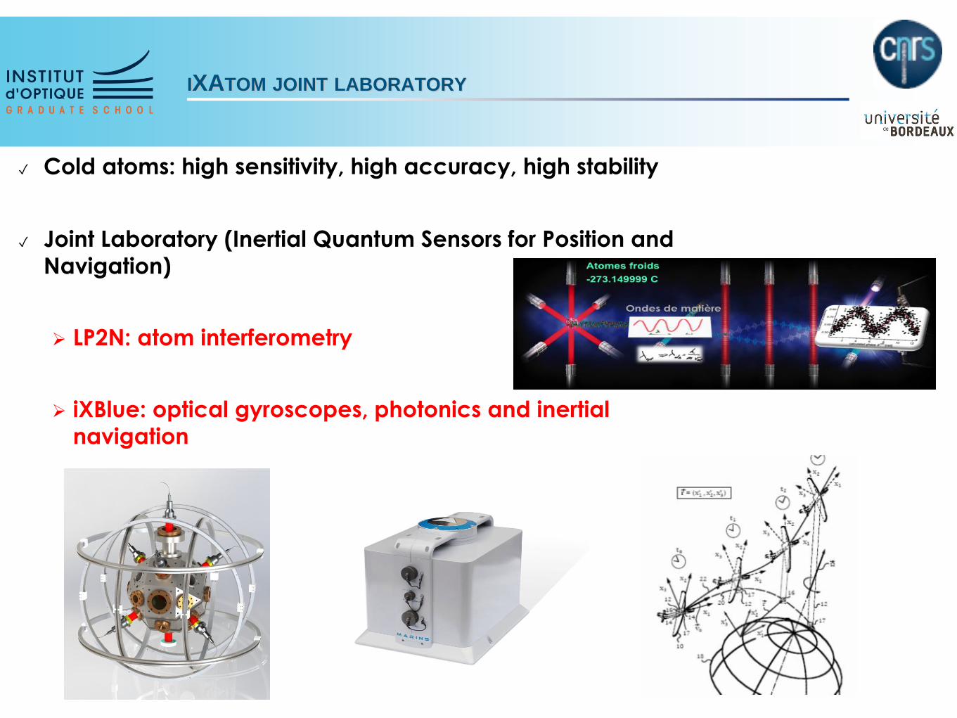
✓ Cold atoms: high sensitivity, high accuracy, high stability
✓ Joint Laboratory (Inertial Quantum Sensors for Position and
Navigation)
➢ LP2N: atom interferometry
➢ iXBlue: optical gyroscopes, photonics and inertial
navigation
IXATOM JOINT LABORATORY
8
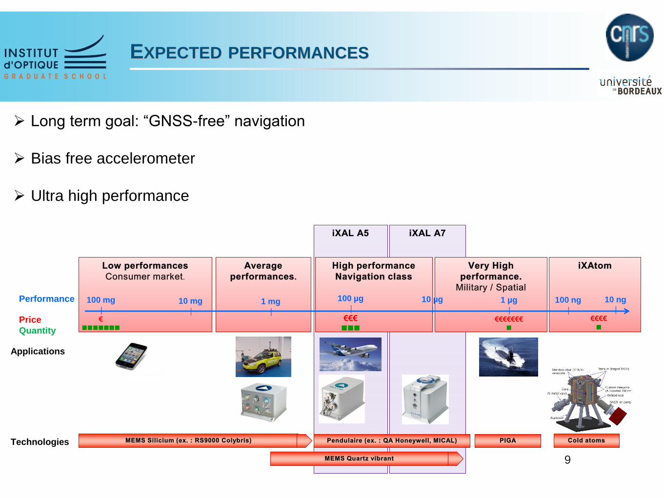
EXPECTED PERFORMANCES
Performance
Price
Quantity
1 µg
€€€€€€€
◼
100 µg
€€€
◼◼◼
10 mg
100 mg
€
◼◼◼◼◼◼◼
1 mg
10 µg
Applications
Technologies
100 ng
€€€€
◼
10 ng
➢ Long term goal: “GNSS-free” navigation
➢ Bias free accelerometer
➢ Ultra high performance
9
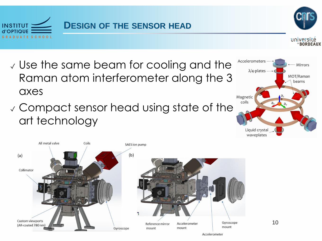
✓ Use the same beam for cooling and the
Raman atom interferometer along the 3
axes
✓ Compact sensor head using state of the
art technology
DESIGN OF THE SENSOR HEAD
10
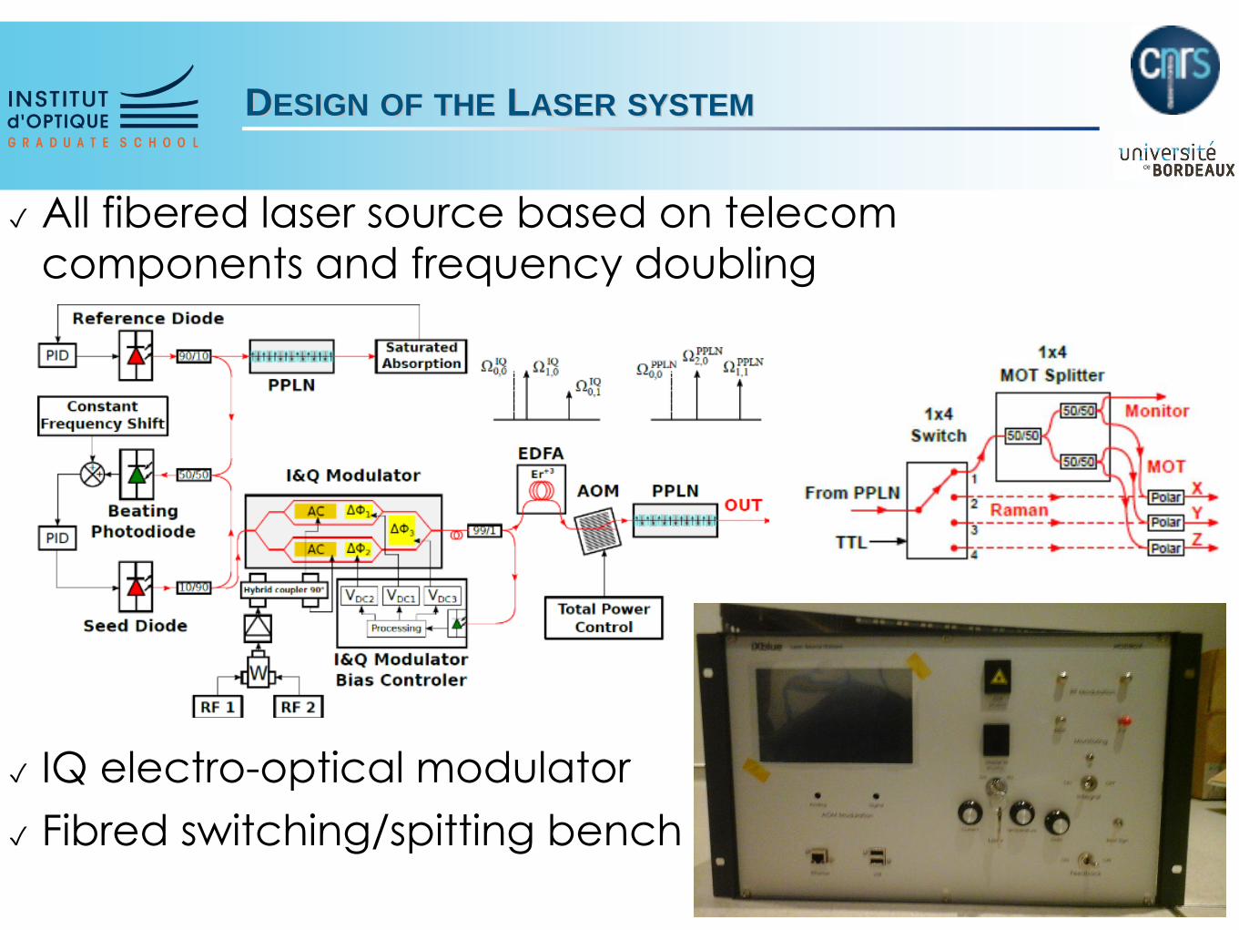
✓ All fibered laser source based on telecom
components and frequency doubling
✓ IQ electro-optical modulator
✓ Fibred switching/spitting bench
DESIGN OF THE LASER SYSTEM
11
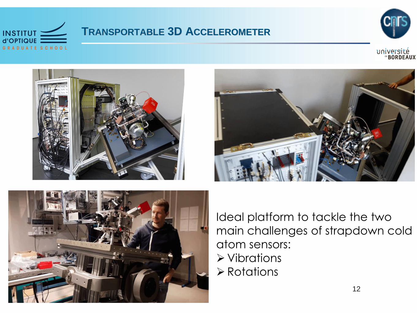
TRANSPORTABLE 3D ACCELEROMETER
12
Ideal platform to tackle the two
main challenges of strapdown cold
atom sensors:
➢Vibrations
➢Rotations
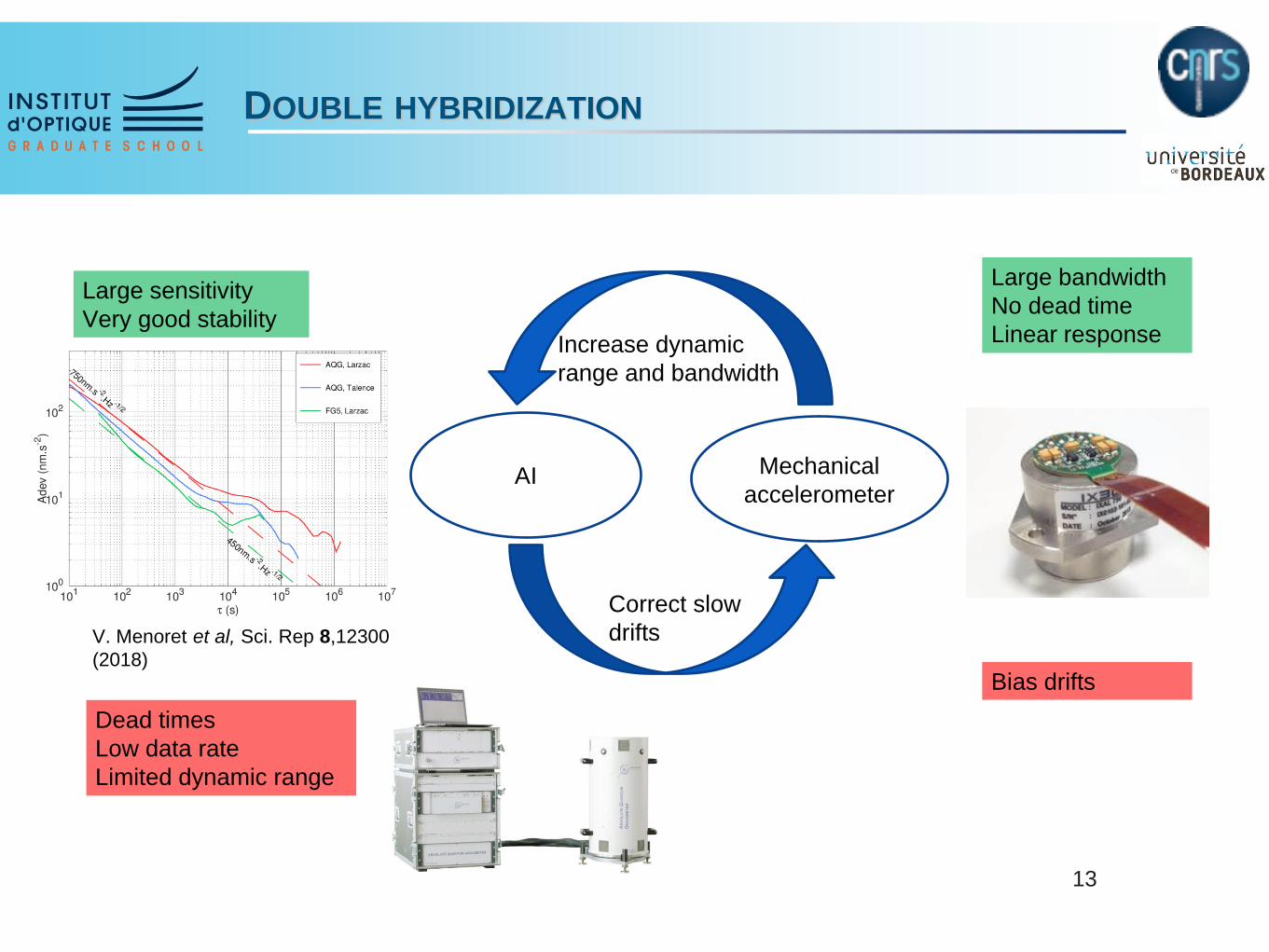
DOUBLE HYBRIDIZATION
AI Mechanical
accelerometer
Correct slow
drifts
Increase dynamic
range and bandwidth
V. Menoret et al, Sci. Rep 8,12300
(2018)
Large bandwidth
No dead time
Linear response
Bias drifts
Large sensitivity
Very good stability
Dead times
Low data rate
Limited dynamic range
13
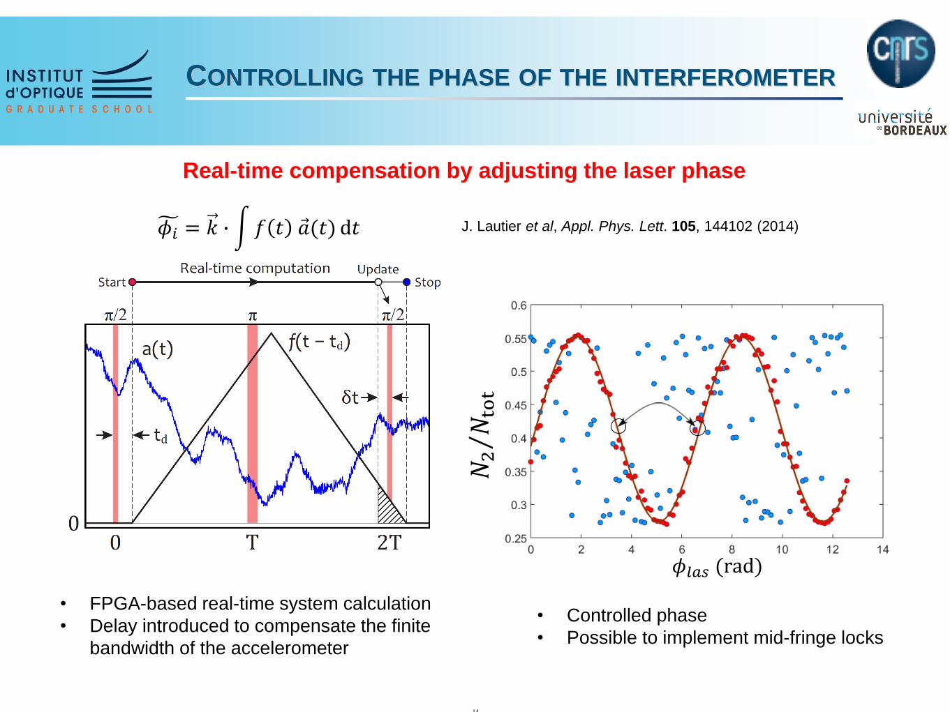
CONTROLLING THE PHASE OF THE INTERFEROMETER
14
෪𝜙𝑖 = 𝑘 ∙ න𝑓 𝑡 Ԧ𝑎(𝑡) d𝑡
• FPGA-based real-time system calculation
• Delay introduced to compensate the finite
bandwidth of the accelerometer
J. Lautier et al, Appl. Phys. Lett. 105, 144102 (2014)
• Controlled phase
• Possible to implement mid-fringe locks
Τ𝑁2𝑁tot
𝜙𝑙𝑎𝑠 (rad)
Real-time compensation by adjusting the laser phase
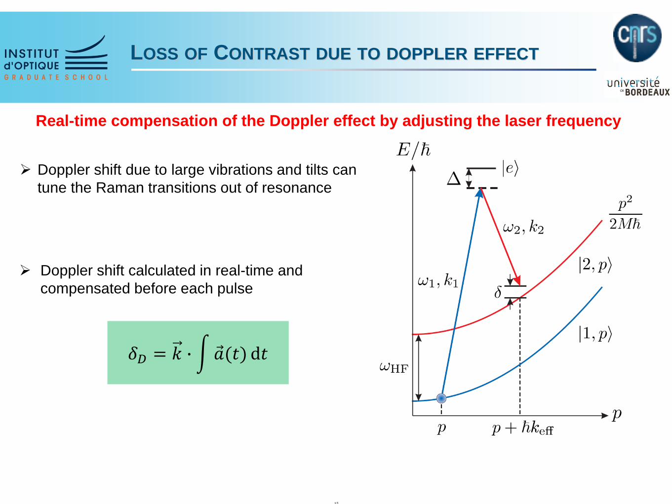
LOSS OF CONTRAST DUE TO DOPPLER EFFECT
15
➢ Doppler shift due to large vibrations and tilts can
tune the Raman transitions out of resonance
𝛿𝐷 = 𝑘 ∙ න Ԧ𝑎(𝑡) d𝑡
➢ Doppler shift calculated in real-time and
compensated before each pulse
Real-time compensation of the Doppler effect by adjusting the laser frequency
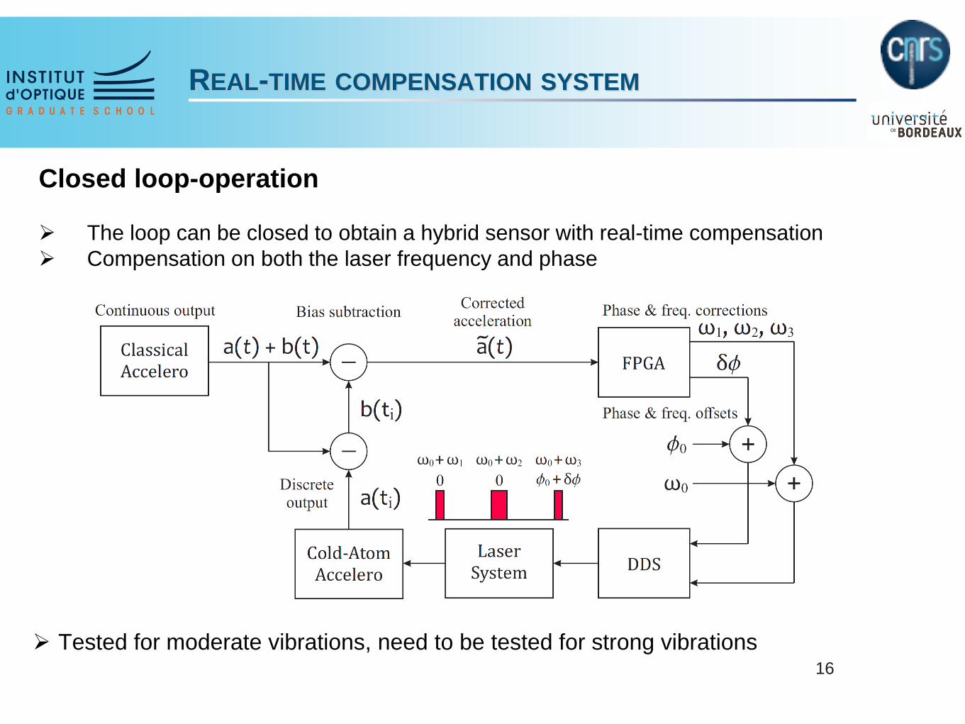
REAL-TIME COMPENSATION SYSTEM
Closed loop-operation
➢ The loop can be closed to obtain a hybrid sensor with real-time compensation
➢ Compensation on both the laser frequency and phase
16
➢ Tested for moderate vibrations, need to be tested for strong vibrations
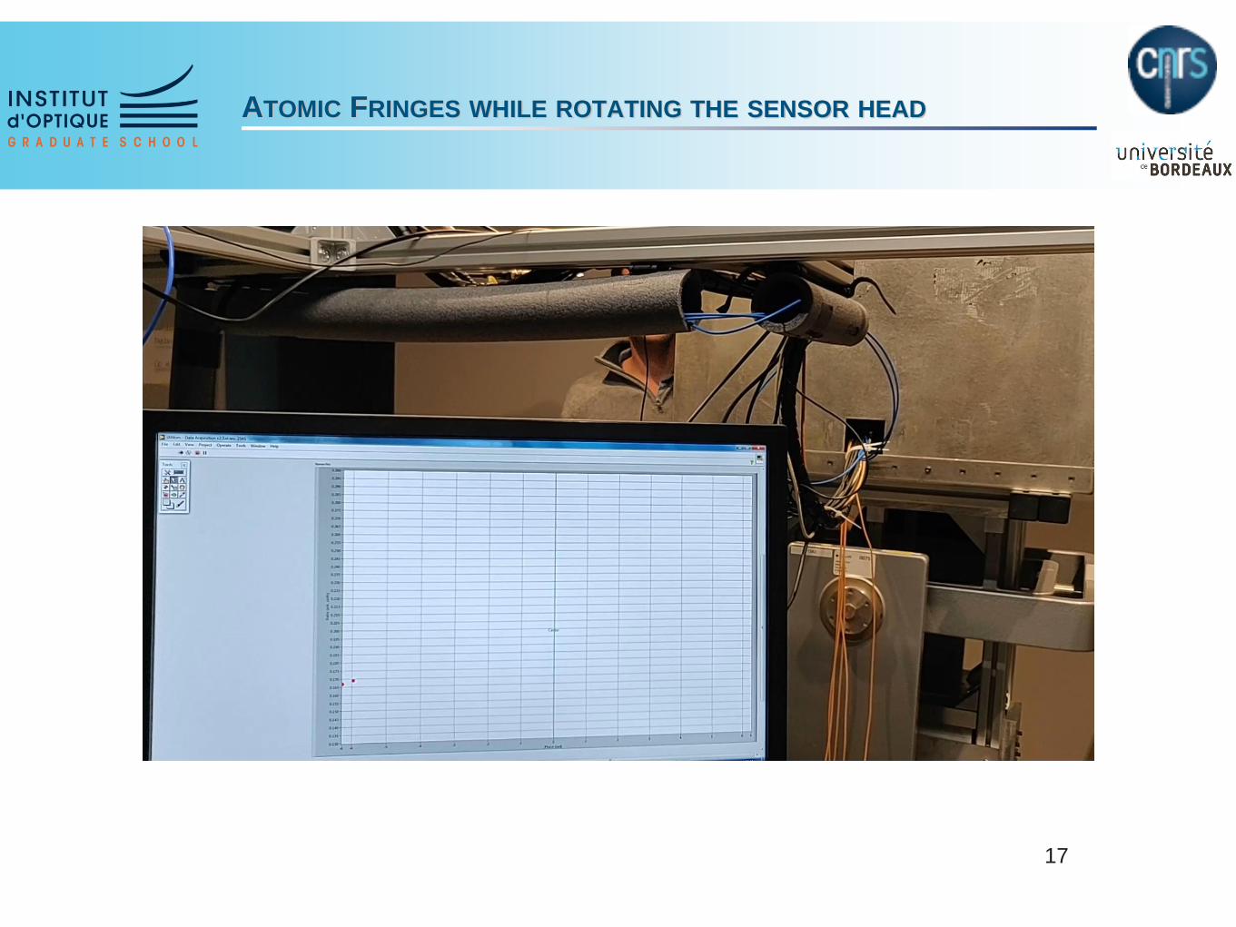
ATOMIC FRINGES WHILE ROTATING THE SENSOR HEAD
17
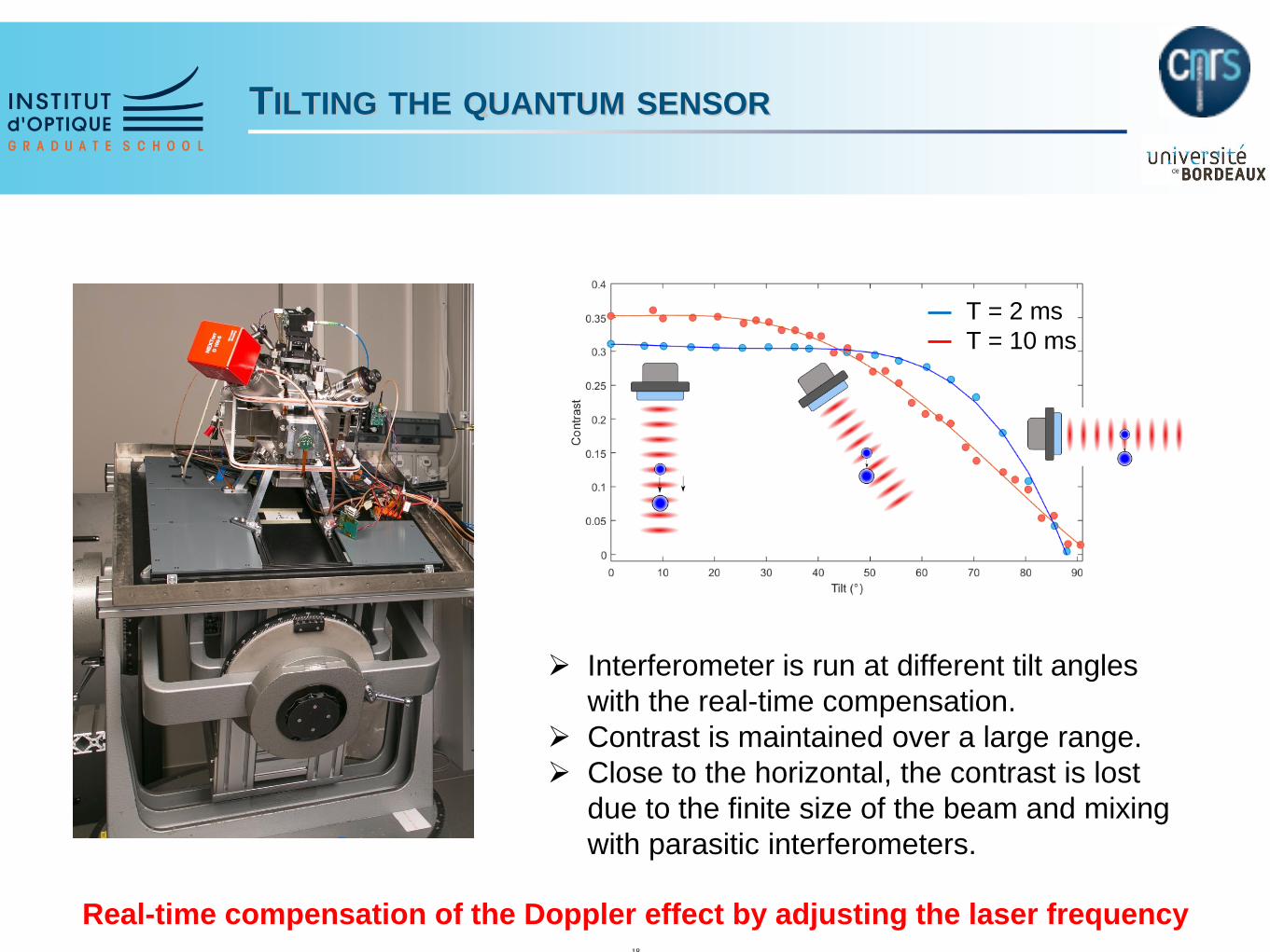
TILTING THE QUANTUM SENSOR
18
Real-time compensation of the Doppler effect by adjusting the laser frequency
T = 2 ms
T = 10 ms
➢ Interferometer is run at different tilt angles
with the real-time compensation.
➢ Contrast is maintained over a large range.
➢ Close to the horizontal, the contrast is lost
due to the finite size of the beam and mixing
with parasitic interferometers.
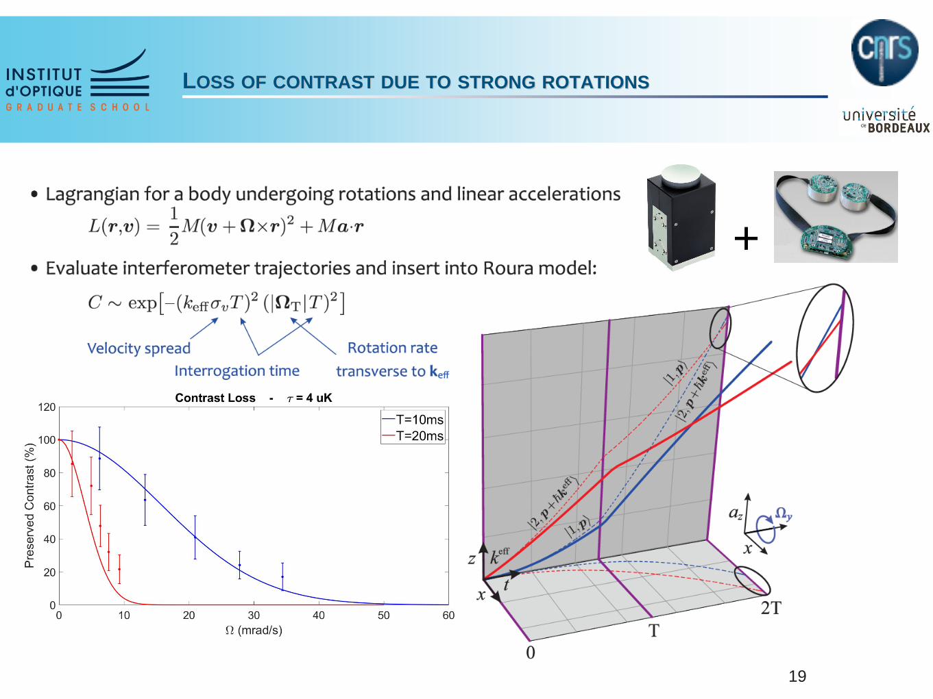
LOSS OF CONTRAST DUE TO STRONG ROTATIONS
19
+
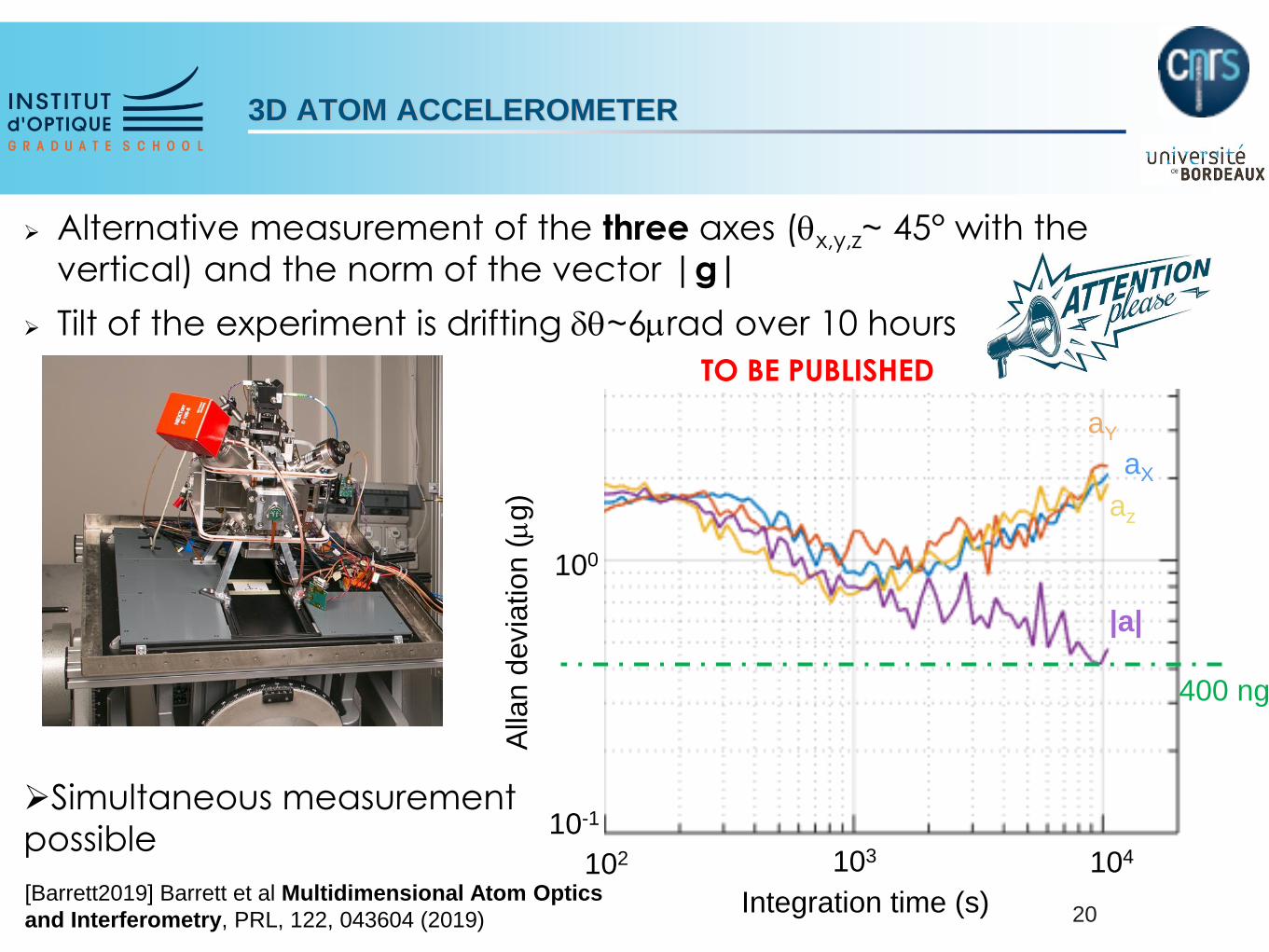
➢ Alternative measurement of the three axes (qx,y,z~ 45° with the vertical) and the norm of the vector |g|
➢ Tilt of the experiment is drifting dq~6mrad over 10 hours
3D ATOM ACCELEROMETER
TO BE PUBLISHED
20
102 103 104
100
10-1
Integration time (s)
Alla
n d
evia
tion (m
g)
aX
aY
az
|a|
➢Simultaneous measurement
possible
[Barrett2019] Barrett et al Multidimensional Atom Optics
and Interferometry, PRL, 122, 043604 (2019)
400 ng
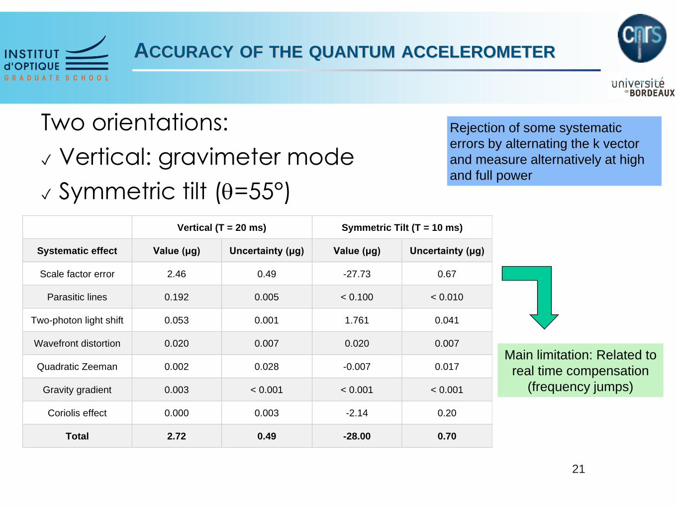
Two orientations:
✓ Vertical: gravimeter mode
✓ Symmetric tilt (q=55°)
ACCURACY OF THE QUANTUM ACCELEROMETER
21
Vertical (T = 20 ms) Symmetric Tilt (T = 10 ms)
Systematic effect Value (μg) Uncertainty (μg) Value (μg) Uncertainty (μg)
Scale factor error 2.46 0.49 -27.73 0.67
Parasitic lines 0.192 0.005 < 0.100 < 0.010
Two-photon light shift 0.053 0.001 1.761 0.041
Wavefront distortion 0.020 0.007 0.020 0.007
Quadratic Zeeman 0.002 0.028 -0.007 0.017
Gravity gradient 0.003 < 0.001 < 0.001 < 0.001
Coriolis effect 0.000 0.003 -2.14 0.20
Total 2.72 0.49 -28.00 0.70
Main limitation: Related to
real time compensation
(frequency jumps)
Rejection of some systematic
errors by alternating the k vector
and measure alternatively at high
and full power
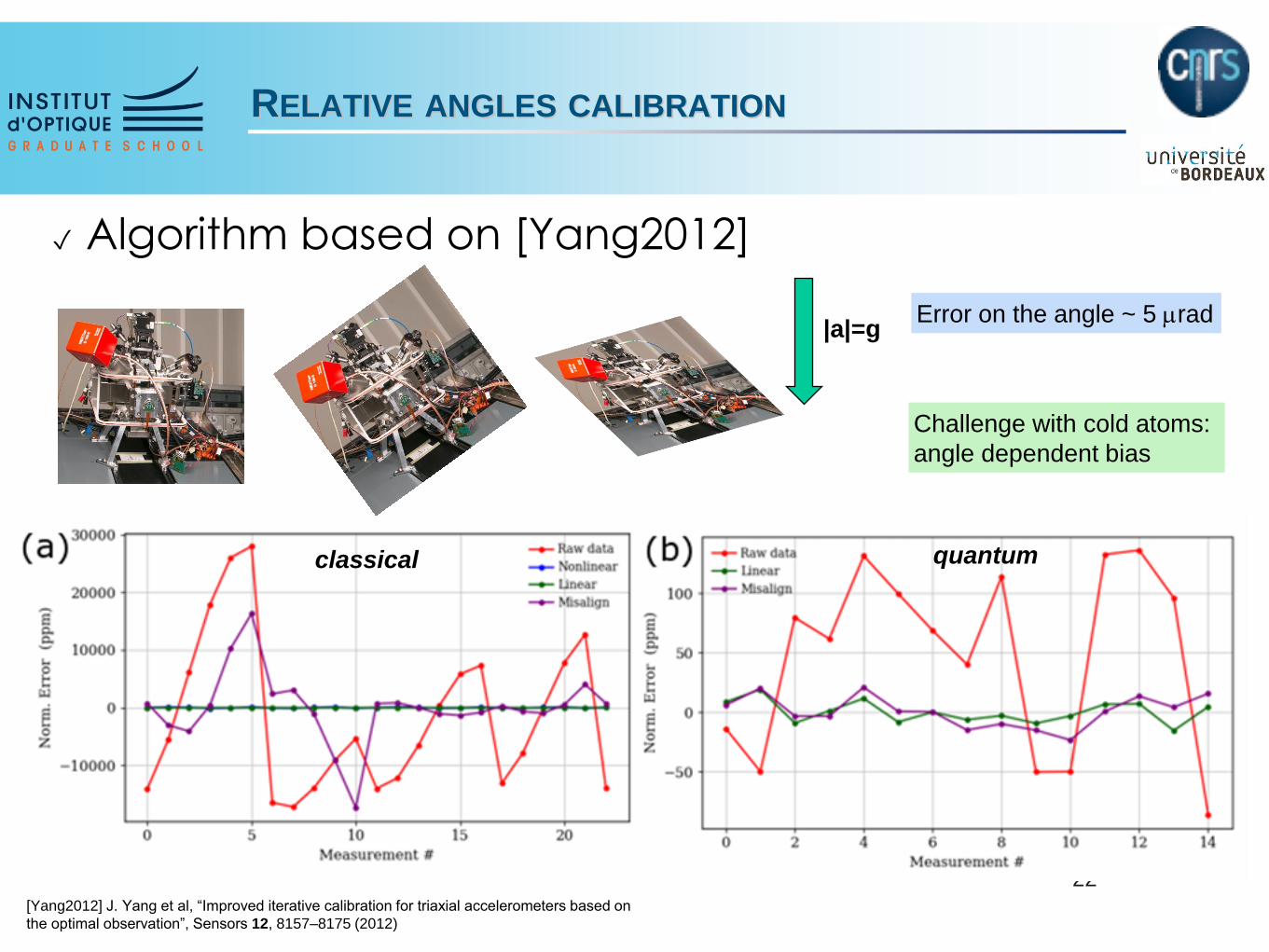
✓ Algorithm based on [Yang2012]
RELATIVE ANGLES CALIBRATION
22[Yang2012] J. Yang et al, “Improved iterative calibration for triaxial accelerometers based on
the optimal observation”, Sensors 12, 8157–8175 (2012)
Error on the angle ~ 5 mrad|a|=g
Challenge with cold atoms:
angle dependent bias
classical quantum
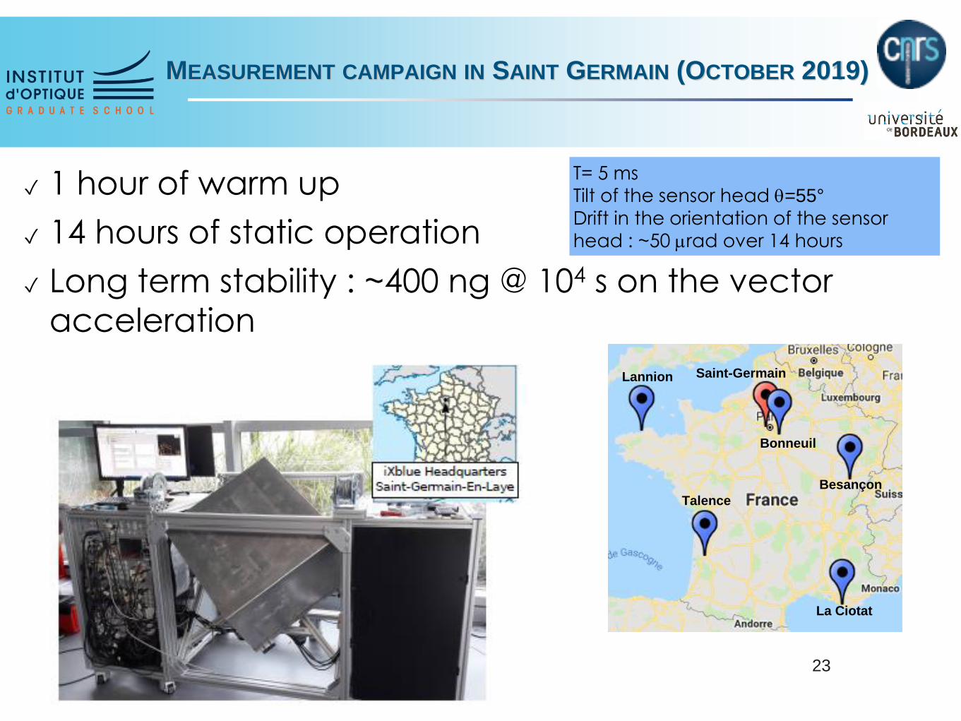
✓ 1 hour of warm up
✓ 14 hours of static operation
✓ Long term stability : ~400 ng @ 104 s on the vector
acceleration
MEASUREMENT CAMPAIGN IN SAINT GERMAIN (OCTOBER 2019)
23
T= 5 msTilt of the sensor head q=55°
Drift in the orientation of the sensor
head : ~50 mrad over 14 hours
Saint-Germain
Bonneuil
Lannion
Talence
La Ciotat
Besançon
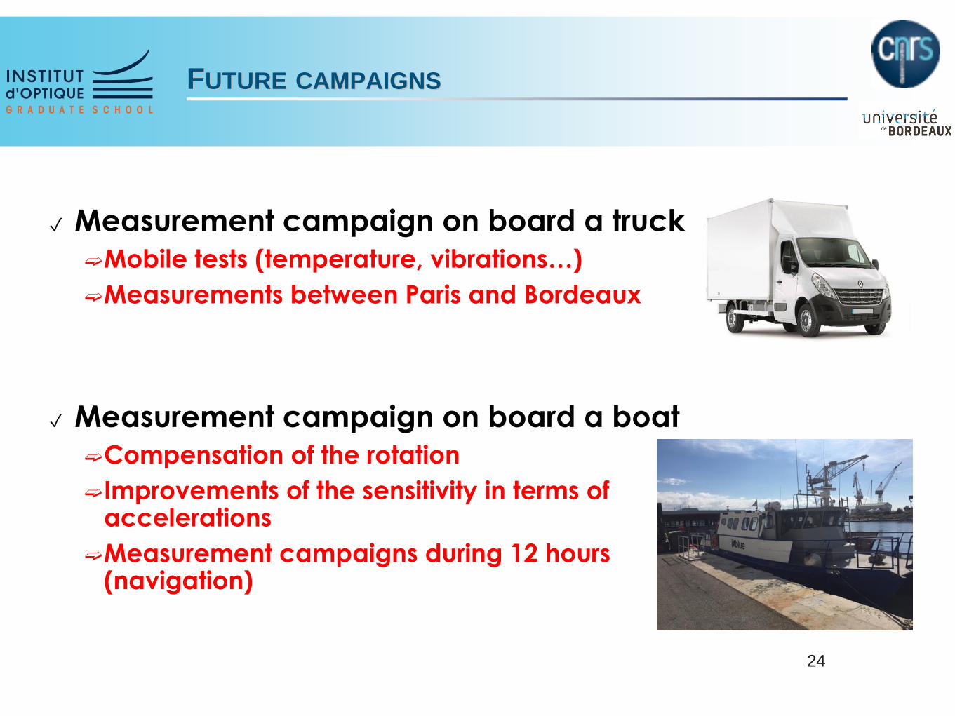
✓ Measurement campaign on board a truck
➫Mobile tests (temperature, vibrations…)
➫Measurements between Paris and Bordeaux
✓ Measurement campaign on board a boat
➫Compensation of the rotation
➫Improvements of the sensitivity in terms of accelerations
➫Measurement campaigns during 12 hours (navigation)
FUTURE CAMPAIGNS
24
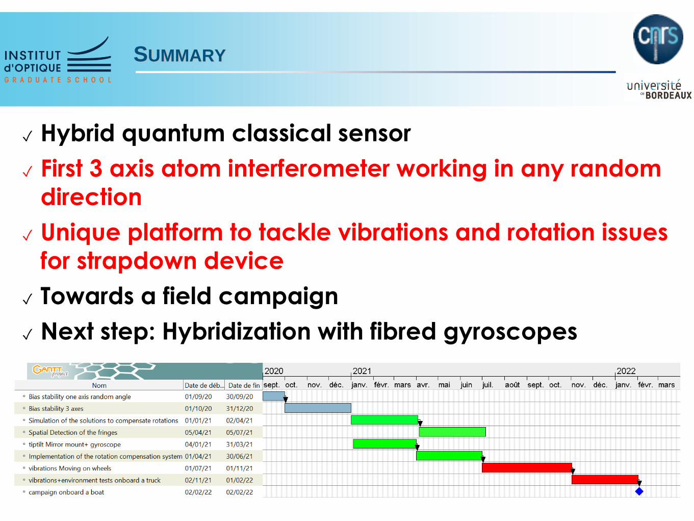
✓ Hybrid quantum classical sensor
✓ First 3 axis atom interferometer working in any random
direction
✓ Unique platform to tackle vibrations and rotation issues
for strapdown device
✓ Towards a field campaign
✓ Next step: Hybridization with fibred gyroscopes
SUMMARY
25

GRAVITY MAPPING WITH A BIASLESS ACCELEROMETER
26
-GNSS signal provides direct position information with a position
(white) noise 𝜎𝑧
- Initial gravity map EGM2008 characterized by an error standard
deviation 𝜎𝑚,𝑖 and a correlation length 𝐿𝑐𝑜𝑟𝑟.
𝑔 = ሷ𝑥𝐺𝑁𝑆𝑆 − 𝑎𝑎𝑐𝑐
𝑣 = 2𝑚/𝑠 𝜎𝑛 = 2 𝜇𝑔/ 𝐻𝑧 𝜎𝑚,𝑖 = 5 𝜇𝑔
𝐿𝑐𝑜𝑟𝑟 = 10 𝑘𝑚 𝜎𝑧 = 1𝑚𝑚/ 𝐻𝑧
➢Perfect accelerometer: 370 ng with a correlation length of 100 m
Performances of our hybrid accelerometer:
Long term stability: 200 ng
Bias uncertainty: 700 ng (vertical axis 500 ng)
Goal : 500 ng (calibration improvement)
gain
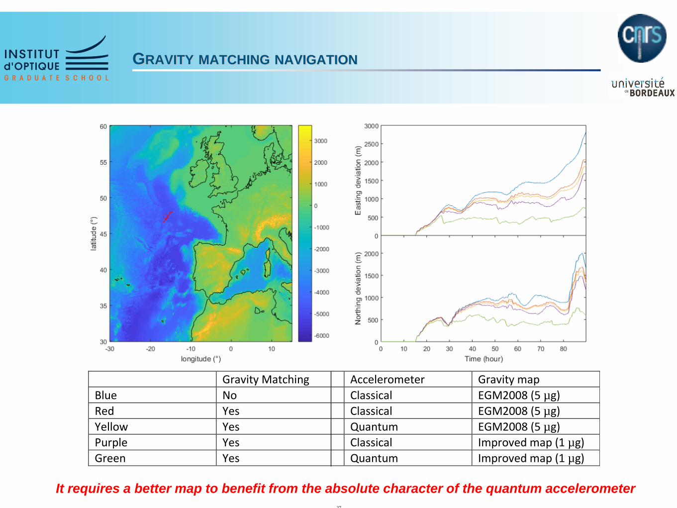
GRAVITY MATCHING NAVIGATION
27
It requires a better map to benefit from the absolute character of the quantum accelerometer
Gravity Matching Accelerometer Gravity map
Blue No Classical EGM2008 (5 µg)
Red Yes Classical EGM2008 (5 µg)
Yellow Yes Quantum EGM2008 (5 µg)
Purple Yes Classical Improved map (1 µg)
Green Yes Quantum Improved map (1 µg)
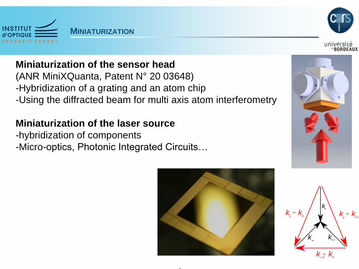
MINIATURIZATION
28
Miniaturization of the sensor head
(ANR MiniXQuanta, Patent N° 20 03648)
-Hybridization of a grating and an atom chip
-Using the diffracted beam for multi axis atom interferometry
Miniaturization of the laser source
-hybridization of components
-Micro-optics, Photonic Integrated Circuits…
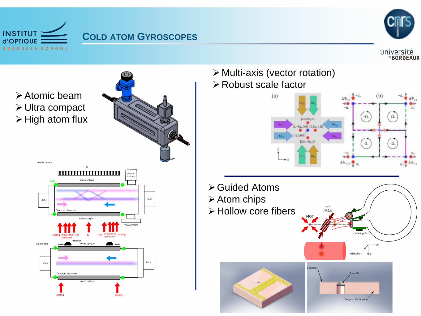
COLD ATOM GYROSCOPES
29
➢Multi-axis (vector rotation)
➢Robust scale factor➢Atomic beam
➢Ultra compact
➢High atom flux
➢Guided Atoms
➢Atom chips
➢Hollow core fibers
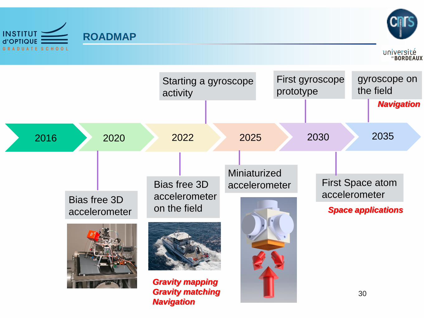
ROADMAP
30
First Space atom
accelerometer
20222016
Miniaturized
accelerometer
2025 2030
Bias free 3D
accelerometer
20352020
Bias free 3D
accelerometer
on the field
Starting a gyroscope
activity
First gyroscope
prototype
gyroscope on
the field
Gravity mapping
Gravity matching
Navigation
Navigation
Space applications
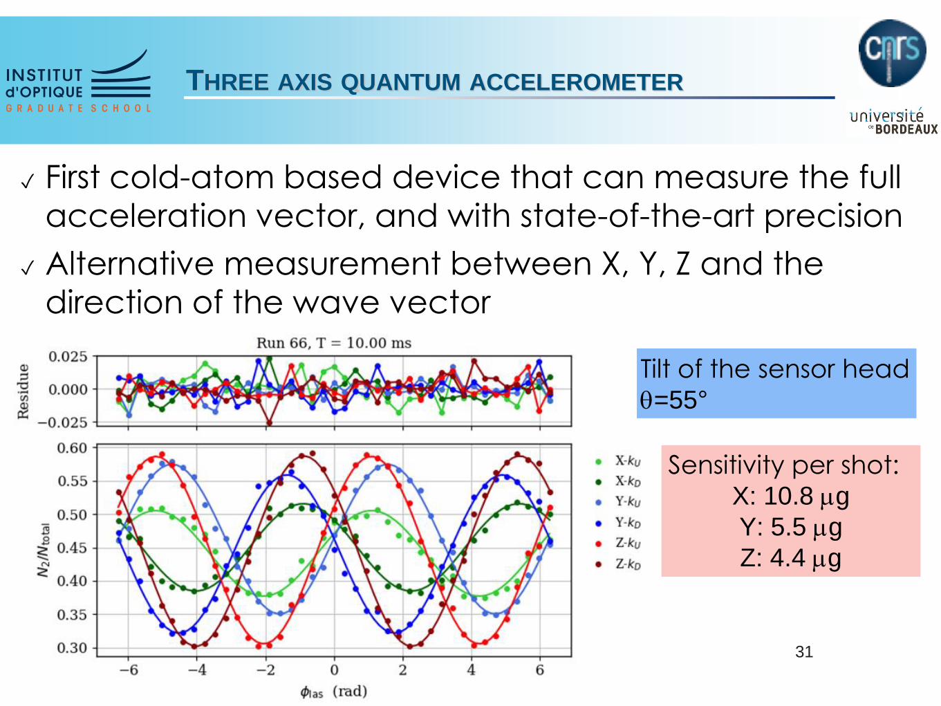
✓ First cold-atom based device that can measure the full
acceleration vector, and with state-of-the-art precision
✓ Alternative measurement between X, Y, Z and the
direction of the wave vector
THREE AXIS QUANTUM ACCELEROMETER
31
Tilt of the sensor headq=55°
Sensitivity per shot: X: 10.8 mg
Y: 5.5 mg
Z: 4.4 mg
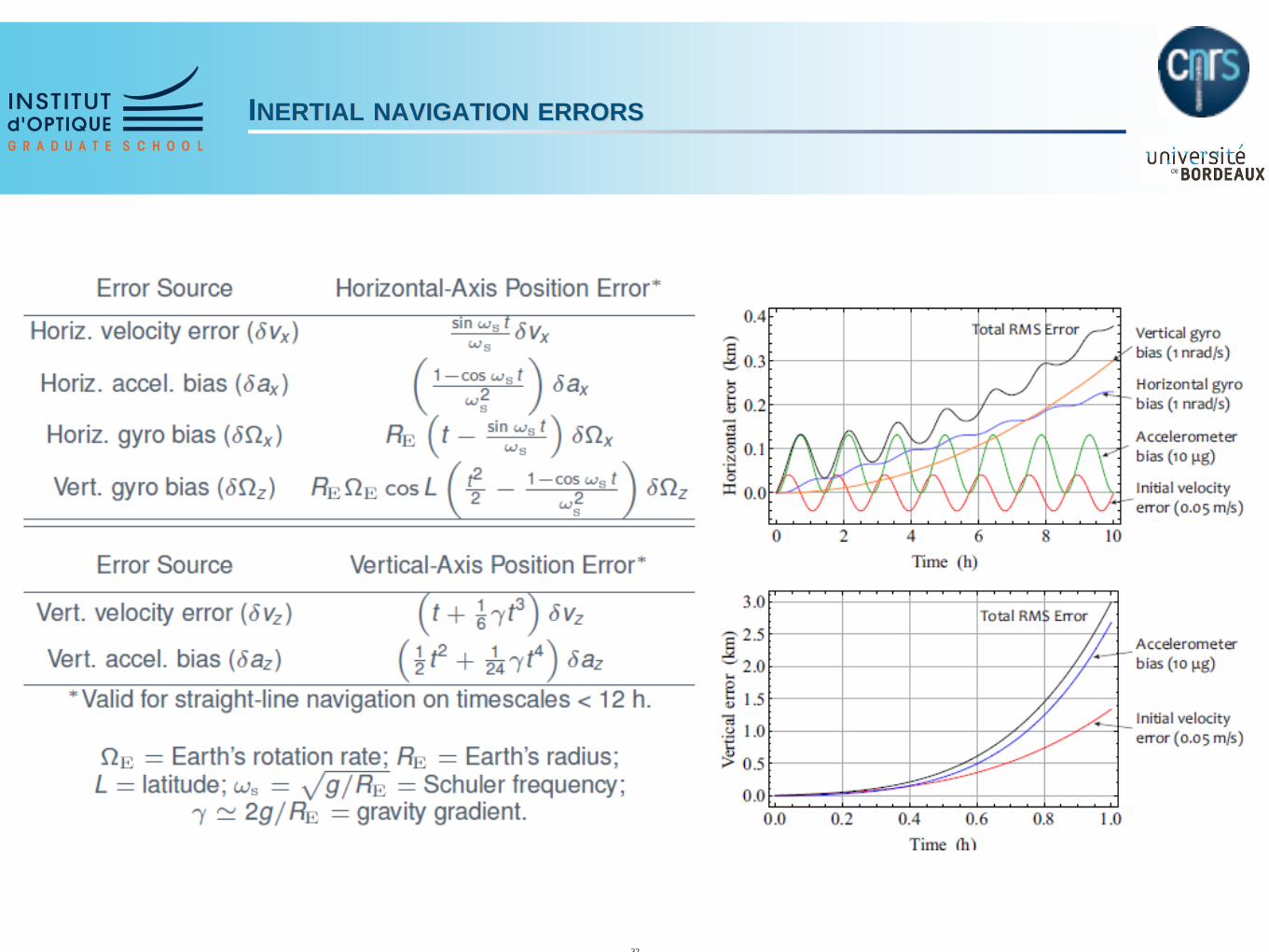
INERTIAL NAVIGATION ERRORS
32
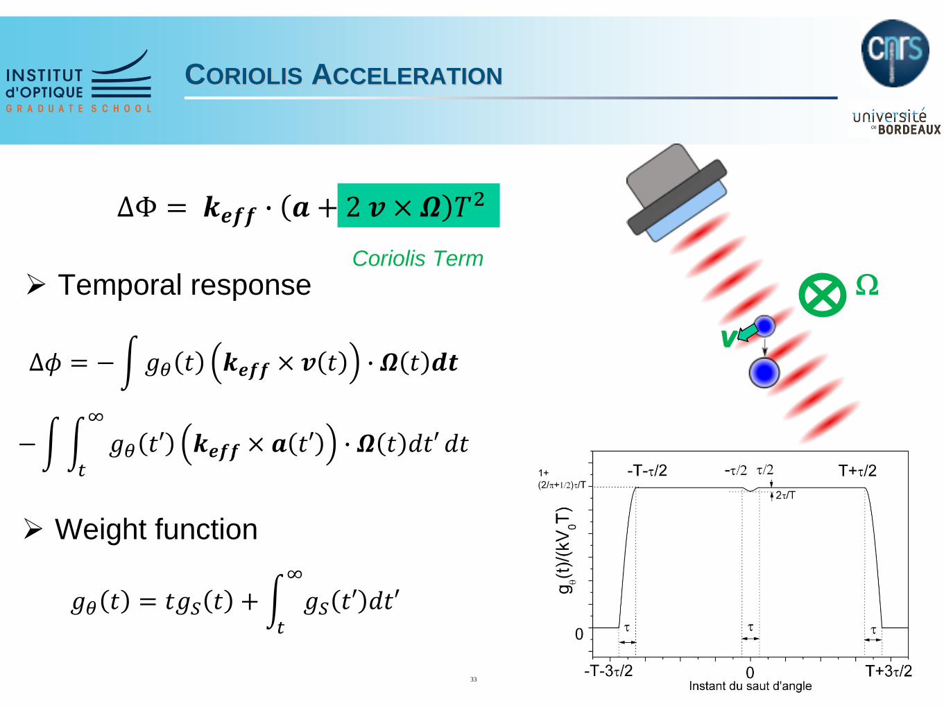
CORIOLIS ACCELERATION
ΔΦ = 𝒌𝒆𝒇𝒇 ∙ 𝒂 + 2 𝒗 × 𝜴 𝑇2
Coriolis Term
v
W➢ Temporal response
➢ Weight function
Δ𝜙 = −න𝑔𝜃 𝑡 𝒌𝒆𝒇𝒇 × 𝒗 𝑡 ∙ 𝜴 𝑡 𝒅𝒕
−නන𝑡
∞
𝑔𝜃 𝑡′ 𝒌𝒆𝒇𝒇 × 𝒂 𝑡′ ∙ 𝜴 𝑡 𝑑𝑡′ 𝑑𝑡
𝑔𝜃 𝑡 = 𝑡𝑔𝑆 𝑡 + න𝑡
∞
𝑔𝑆 𝑡′ 𝑑𝑡′
33
v
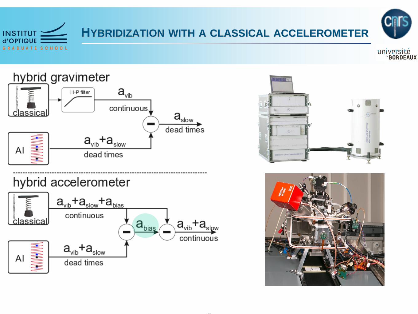
HYBRIDIZATION WITH A CLASSICAL ACCELEROMETER
34