QCVN 81: 2014/BGTVT NATIONAL TECHNICAL ...
585
THE SOCIALIST REPUBLIC OF VIETNAM QCVN 81: 2014/BGTVT NATIONAL TECHNICAL REGULATION ON CLASSIFICATION AND CONSTRUCTIONS OF PLEASURE YACHT HANOI - 2017
-
Upload
khangminh22 -
Category
Documents
-
view
1 -
download
0
Transcript of QCVN 81: 2014/BGTVT NATIONAL TECHNICAL ...

THE SOCIALIST REPUBLIC OF VIETNAM
QCVN 81: 2014/BGTVT
NATIONAL TECHNICAL REGULATION ON
CLASSIFICATION AND CONSTRUCTIONS OF PLEASURE YACHT
HANOI - 2017

QCVN 81: 2014/BGTVT
3
TABLE OF CONTENTS
I GENERAL ...........................................................................................................................14
1.1 Application and Scope ................................................................................................14
1.2 References, Definitions and Explanations and ship‟s principal datas .........................15
1.3 Loading Conditions .....................................................................................................36
1.4 Owner‟s Manual .........................................................................................................37
1.5 Hydrometeorology ......................................................................................................38
II TECHNICAL REGULATIONS ............................................................................................41
PART 1 GENERAL REQUIREMENT ON CLASS SURVEYS ..................................................41
CHAPTER 1 GENERAL ........................................................................................................41
1.1 General .......................................................................................................................41
CHAPTER 2 CLASSIFICATION SURVEYS .........................................................................43
2.1 Classification Survey during Construction ..................................................................43
2.2 Classification Survey of Ships not Built Under Survey................................................50
2.3 Alterations ..................................................................................................................51
CHAPTER 3 PERIODICAL SURVEYS AND OCCASIONAL SURVEYS..............................52
3.1 General .......................................................................................................................52
3.2 Periodical Surveys ......................................................................................................52
3.3 Occasional Survey ......................................................................................................53
3.4 Extent of examination .................................................................................................53
PART 2 HULL .......................................................................................................................56
CHAPTER 1 GENERAL ........................................................................................................56
1.1 Application ..................................................................................................................56
1.2 General Requirements ...............................................................................................56
1.3 Definitions ...................................................................................................................56
CHAPTER 2 STEEL HULL ...................................................................................................59
2.1 General .......................................................................................................................59
2.2 Shell Plating ...............................................................................................................87
2.3 Single Bottom .............................................................................................................90
2.4 Double Bottom ............................................................................................................93
2.5 Side Framing ...........................................................................................................107
2.6 Decks And Platforms ...............................................................................................112
2.7 Bulkheads and Propeller Shaft Tunnel .....................................................................120

QCVN 81: 2014/BGTVT
4
2.8 Fore and Aft Ends .................................................................................................... 125
2.9 Pillars and Panting Beams ....................................................................................... 134
2.10 Stems, Stern Frames, Keels, Rudder Horns And Shaft Struts, Fixed Nozzles Of Propellers ......................................................................................................................... 137
2.11 Seating Of Machinery And Boilers ............................................................................ 144
2.12 Superstructures, Deckhouses And Quarter Decks ................................................... 147
2.13 Machinery Casings ................................................................................................... 157
2.14 Bulwark .................................................................................................................... 157
CHAPTER 3 ALUMINIUM ALLOY HULL ........................................................................... 160
3.1 General .................................................................................................................... 160
3.2 General Provisions On Scantling Of Hull Structural Members ................................. 160
3.3 Special Requirements .............................................................................................. 160
CHAPTER 4 HULL OF GLASS-REINFORCED PLASTIC ................................................ 162
4.1 General .................................................................................................................... 162
4.2 General Provisions on Scantling Of Hull Structural Members .................................. 168
PART 3 EQUIPMENT, ARRANGEMENTS AND OUTFIT .................................................... 196
CHAPTER 1 GENERAL ...................................................................................................... 196
1.1 Application ................................................................................................................ 196
1.2 Definitions and Explanations .................................................................................... 196
1.3 Scope of Survey ....................................................................................................... 199
1.4 Materials and Welding .............................................................................................. 201
1.5 Inertial Loads ............................................................................................................ 202
1.6 Special Strong Structures ......................................................................................... 202
CHAPTER 2 STEERING GEAR .......................................................................................... 203
2.1 General .................................................................................................................... 203
2.2 Initial Design Data .................................................................................................... 204
2.3 Rudder Blade Design ............................................................................................... 210
2.4 Rudder Stock............................................................................................................ 211
2.5 Transom Rudders ..................................................................................................... 213
2.6 Couplings of Rudder Stock with Rudder Blade ........................................................ 214
2.7 Rudder Bearings ...................................................................................................... 215
2.8 Rudder Skeg and Heel ............................................................................................. 216
2.9 Rudder Tiller and Quadrant ...................................................................................... 216
2.10 Steering Gear ........................................................................................................... 217
2.11 Rudder Trunk ........................................................................................................... 220

QCVN 81: 2014/BGTVT
5
CHAPTER 3 ANCHOR ARRANGEMENT ...........................................................................222
3.1 General .....................................................................................................................222
3.2 Characteristics of Anchor Outfit ................................................................................222
3.3 Anchors ....................................................................................................................223
3.4 Ropes and Chain Cables ..........................................................................................223
3.5 Chain Locker ............................................................................................................226
3.6 Arrangement of Anchor Appliances Onboard ...........................................................226
3.7 Anchor Machinery.....................................................................................................227
CHAPTER 4 MOORING AND TOWING ARRANGEMENTS ..............................................229
4.1 General .....................................................................................................................229
4.2 Mooring Appliances ..................................................................................................229
4.3 Location of Mooring Arrangement Onboard .............................................................230
4.4 Towing Arrangement ................................................................................................231
4.5 Mooring and Towing Cables .....................................................................................232
CHAPTER 5 SPARS AND SAILING RIGGING ..................................................................234
5.1 General .....................................................................................................................234
5.2 Permissible Loads ....................................................................................................237
5.3 Rigging Dimensions ..................................................................................................241
5.4 Spars Calculations ....................................................................................................249
5.5 Spar and Rigging Material ........................................................................................256
5.6 Mounting and Operation of Rigging ..........................................................................256
5.7 Sails ..........................................................................................................................257
CHAPTER 6 SIGNAL MASTS ............................................................................................259
6.1 General .....................................................................................................................259
6.2 Stayed Masts ............................................................................................................259
6.3 Unstayed Masts ........................................................................................................260
6.4 Masts Of Special Construction .................................................................................261
CHAPTER 7 RAILING AT OPEN DECKS ..........................................................................262
7.1 General .....................................................................................................................262
7.2 Guard Rails ..............................................................................................................263
7.3 Storm safety rails ......................................................................................................265
7.4 Astenings For Safety Belts .......................................................................................266
7.5 Bulwark .....................................................................................................................266
7.6 Rails of Sailing Craft .................................................................................................266

QCVN 81: 2014/BGTVT
6
CHAPTER 8 MAIN ESCAPE AND EMERGENCY EXITS .................................................. 269
8.1 General .................................................................................................................... 269
8.2 Escape routes on Craft 15 m in length and under .................................................... 270
8.3 Escape routes on craft above 15 m in length ........................................................... 270
CHAPTER 9 HATCHES, DOORS, SIDE SCUTTLES, WINDOWS, COVERS AND MANHOLES ........................................................................................................................... 272
9.1 Definitions and Explanations .................................................................................... 272
9.2 General .................................................................................................................... 274
9.3 Weathertightness ..................................................................................................... 277
9.4 External Doors .......................................................................................................... 278
9.5 Side Scuttles ............................................................................................................ 279
9.6 Deadlights ................................................................................................................ 283
9.7 Companion Hatches, Skylights And Flush Deck Scuttles ......................................... 283
9.8 Requirements to Materials ....................................................................................... 284
9.9 Manholes .................................................................................................................. 288
CHAPTER 10 COCKPITS ................................................................................................... 289
10.1 Definitions and Explanations ............................................................................... 289
10.2 General .................................................................................................................... 292
10.3 Typical Structures And Main Characteristics ............................................................ 293
10.4 Minimum Quick-Draining Cockpit Bottom Height above the Waterline ..................... 296
10.5 Sill Height and Openings in Cockpits ....................................................................... 297
10.6 Watertightness Requirements .................................................................................. 298
10.7 Drainage of Quick-Draining Cockpits ....................................................................... 299
10.8 Draining Time ........................................................................................................... 299
10.9 Number Of Drains .................................................................................................... 300
10.10 Drain Dimensions ................................................................................................ 300
10.11 Centreboard Casings and Other Types of Drain ................................................. 301
10.12 Drain Piping ..................................................................................................... 301
10.13 Drain Fittings ....................................................................................................... 302
10.14 Permanently Open Ventilation Openings ............................................................ 302
CHAPTER 11 SIGNAL MEANS .......................................................................................... 303
11.1 General .................................................................................................................... 303
11.2 Supply of Craft with Signal Means ............................................................................ 303
11.3 Pyrotechnic Signal Means Supply Standards ........................................................... 303
CHAPTER 12 PROVISION OF SEATS, CABINS AND SPARE PARTS ............................ 305

QCVN 81: 2014/BGTVT
7
12.1 Provision of seats and cabins ...................................................................................305
12.2 Spare Parts For Craft‟s Arrangement .......................................................................305
PART 4 STABILITY, RESERVE OF BUOYANCY AND FREEBOARD ..............................306
CHAPTER 1 GENERAL ......................................................................................................306
1.1 Application ................................................................................................................306
1.2 Definitions and Explanations ....................................................................................306
1.3 General Technical Requirements .............................................................................310
1.4 Inclining Test and Lightweight Check .......................................................................315
1.5 Deviations From The Rules ......................................................................................320
CHAPTER 2 STABILITY .....................................................................................................321
2.1 Basic Stability Criteria ...............................................................................................321
2.2 Calculation Of External Action Parameters ............................................................323
2.3 Maximum Allowable Heeling Moment .......................................................................332
2.4 Righting Lever Curve ................................................................................................333
2.5 Metacentric Height....................................................................................................335
2.6 Requirements for Downflooding Angles ...................................................................336
2.7 Additional Requirements for Stability ........................................................................338
CHAPTER 3 RESERVE OF BUOYANCY ...........................................................................350
3.1 General .....................................................................................................................350
3.2 Subdivision ...............................................................................................................351
CHAPTER 4 REQUIREMENTS FOR FLOTATION ELEMENTS ........................................353
4.1 Requirements ...........................................................................................................353
CHAPTER 5 PROTECTION AGAINST FLOODING ...........................................................354
5.1 General .....................................................................................................................354
5.2 Hull Openings ...........................................................................................................354
CHAPTER 6 FREEBOARD AND LOADLINES ..................................................................356
6.1 General .....................................................................................................................356
6.2 Deck Line and Loadline ............................................................................................356
6.3 Assignment of Minimum Freeboard ..........................................................................357
6.4 Tabular Freeboard and Downflooding Height ...........................................................360
6.5 Draught Scales .........................................................................................................364
PART 5 MACHINERY INSTALLATIONS ............................................................................365
CHAPTER 1 GENERAL ......................................................................................................365

QCVN 81: 2014/BGTVT
8
1.1 Application ................................................................................................................ 365
1.2 Definitions and Explanations .................................................................................... 365
CHAPTER 2 MACHINERY INSTALLATIONS .................................................................... 368
2.1 Application ................................................................................................................ 368
2.2 Scope of Technical Supervision ............................................................................... 368
2.3 Power of the Main Engines ...................................................................................... 369
2.4 Control Devices and Stations. Means of Communication ......................................... 371
2.5 Machinery Spaces .................................................................................................... 375
2.6 Arrangement of Machinery and Equipment .............................................................. 377
2.7 Arrangement of Fuel Oil Tanks ................................................................................. 378
2.8 Insulation of Heated Surfaces .................................................................................. 379
2.9 Shafting .................................................................................................................... 379
2.10 Propellers ................................................................................................................. 386
2.11 Torsional Vibration ................................................................................................... 388
2.12 Active Means Of Craft‟s Steering ............................................................................. 389
2.13 Materials and Welding .............................................................................................. 389
CHAPTER 3 MACHINERY .................................................................................................. 391
3.1 Application, Scope of technical supervision ............................................................. 391
3.2 Internal Combustion Engines ................................................................................... 391
CHAPTER 4 SYSTEMS AND PIPING ................................................................................ 395
4.1 Application ................................................................................................................ 395
4.2 Metal Piping.............................................................................................................. 398
4.3 Plastic Piping ............................................................................................................ 401
4.4 Fittings ...................................................................................................................... 405
4.5 Piping Laying ............................................................................................................ 407
4.6 Bilge-pumping System. Ballast system .................................................................... 409
4.7 Air, Overflow and Sounding Pipes ............................................................................ 414
4.8 Exhaust Gas System ................................................................................................ 417
4.9 Ventilation System .................................................................................................... 418
4.10 Fuel Oil System ........................................................................................................ 421
4.11 Lubricating Oil System ............................................................................................. 427
4.12 Cooling Systems Of Internal Combustion Engines .................................................. 428
4.13 Compressed Air System ........................................................................................... 431
4.14 Liquefied Gas Systems ............................................................................................ 432
4.15 Air Heating Installations and Space Heating Appliances .......................................... 436

QCVN 81: 2014/BGTVT
9
PART 6 AUTOMATION .......................................................................................................438
CHAPTER 1 GENERAL ......................................................................................................438
1.1 Application and Basic Requirements ........................................................................438
1.2 Definitions and Explanations ....................................................................................438
1.3 Scope Of Technical Supervision ..............................................................................439
1.4 Technical Documentation .........................................................................................439
CHAPTER 2 DESIGN OF AUTOMATION EQUIPMENT ....................................................441
2.1 Automated Main Machinery ......................................................................................441
2.2 Automated Electric Power Plants .............................................................................442
2.3 Automated Boiler Plants ...........................................................................................444
2.4 Automated Bilge Plants of Machinery Spaces ..........................................................445
2.5 Automated Compressor Plants .................................................................................445
2.6 Automated Pumping Units ........................................................................................445
2.7 Equipment Arrangement in Wheelhouse ..................................................................446
2.8 Equipment Arrangement In Machinery Spaces ........................................................446
2.9 Alarm, Protection and Indication Systems of Machinery Installation ........................446
PART 7 ELECTRICAL EQUIPMENT ..................................................................................448
CHAPTER 1 GENERAL ......................................................................................................448
1.1 General .....................................................................................................................448
1.2 Testing ......................................................................................................................448
CHAPTER 2 ELECTRICAL EQUIPMENT AND SYSTEM DESIGN ...................................450
2.1 General .....................................................................................................................450
2.2 Lightning Protection ..................................................................................................453
2.3 System design - General ..........................................................................................457
2.4 System design- protection ........................................................................................460
2.5 Electrical equipment and cable - General .................................................................463
2.6 Switchboards, section boards and distribution boards..............................................464
2.7 Controlgears for motors ............................................................................................468
2.8 Cables ......................................................................................................................469
2.9 Explosion-protected electrical equipment .................................................................472
2.10 Tests after installation on board ...............................................................................472
CHAPTER 3 DESIGN OF INSTALLATIONS ......................................................................474
3.1 General .....................................................................................................................474
3.2 Main source of electrical power ................................................................................474

QCVN 81: 2014/BGTVT
10
3.3 Accumulator Batteries .............................................................................................. 475
3.4 Emergency Electrical Installations ............................................................................ 476
3.5 Power Supply From External Source Of Electrical Power ........................................ 479
3.6 Alternative Sources Of Electrical Power ................................................................... 480
3.7 Lighting ..................................................................................................................... 480
3.8 Navigation Lights ...................................................................................................... 481
3.9 Signaling and Internal Communication ..................................................................... 481
CHAPTER 4 ADDITIONAL REQUIREMENTS FOR ELECTRIC PROPULSION PLANTS 483
4.1 General .................................................................................................................... 483
PART 8 RADIO AND NAVIGATIONAL EQUIPMENT ........................................................ 484
CHAPTER 1 GENERAL ...................................................................................................... 484
CHAPTER 2 RADIO EQUIPMENT ..................................................................................... 485
2.1 Functional Requirements ......................................................................................... 485
2.2 Structure Of Craft Radio Equipment ......................................................................... 485
2.3 Sources of Electrical Power ..................................................................................... 486
CHAPTER 3 NAVIGATIONAL EQUIPMENT ...................................................................... 487
3.1 General .................................................................................................................... 487
3.2 Magnetic Compass ................................................................................................... 487
3.3 Radio-navigation System Receiver .......................................................................... 488
PART 9 LIFE-SAVING APPLIANCES ................................................................................ 489
CHAPTER 1 GENERAL ...................................................................................................... 489
1.1 Application ................................................................................................................ 489
1.2 Definitions And Explanations .................................................................................... 489
CHAPTER 2 LIFE-SAVING EQUIPMENT .......................................................................... 491
2.1 General .................................................................................................................... 491
2.2 General Technical Requirements For Equipment Of Craft with Life-saving appliances 491
2.3 Requirements For Life-Saving Appliances ............................................................... 494
2.4 Stowage Of Life-Saving Appliances On Board Craft ................................................ 495
PART 10 FIRE PROTECTION ............................................................................................ 498
CHAPTER 1 GENERAL ...................................................................................................... 498
1.1 Application ................................................................................................................ 498
1.2 Definitions and Explanations .................................................................................... 498

QCVN 81: 2014/BGTVT
11
1.3 Scope Of Technical Supervision ..............................................................................500
1.4 Technical Documentation .........................................................................................501
CHAPTER 2 STRUCTURAL FIRE PROTECTION .............................................................502
2.1 General .....................................................................................................................502
2.2 Requirements for Layout ..........................................................................................502
2.3 Requirement for Materials and Design of Fire Protection .........................................502
2.4 Protection Of Cooking And Heating Appliances .......................................................505
2.5 Protection Of Machinery Spaces And Fuel Tanks ....................................................507
2.6 Saunas .....................................................................................................................508
2.7 Local Furnace Heating (Furnaces/Fireplaces) ..........................................................508
CHAPTER 3 FIRE-EXTINGUISHING EQUIPMENT AND OUTFIT .....................................510
3.1 General .....................................................................................................................510
3.2 Classification Of Fires According to ISO 3941:1977 .................................................510
3.3 Arrangement Of Equipment ......................................................................................510
3.4 Equipment of Galley Space ......................................................................................510
3.5 Equipment of Machinery Space ................................................................................510
3.6 Other Enclosed Spaces ............................................................................................512
3.7 Open Deck ...............................................................................................................512
CHAPTER 4 PORTABLE FIRE EXTINGUISHERS ............................................................513
4.1 Application ................................................................................................................513
4.2 General .....................................................................................................................513
4.3 Type, Capacity And Number Of Portable Fire Extinguishers ....................................513
CHAPTER 5 FIRE EXTINGUISHING SYSTEMS ................................................................515
5.1 General .....................................................................................................................515
5.2 Installation ................................................................................................................515
5.3 Carbon Dioxide Smothering System .........................................................................516
5.4 Aerosol Fire Extinguishing System ...........................................................................518
5.5 Water Fire Main System ...........................................................................................520
CHAPTER 6 OPERATION ..................................................................................................524
CHAPTER 7 DESIGN AMOUNT OF EXTINGUISHING MEDIUM ......................................525
7.1 General .....................................................................................................................525
7.2 Design Amount Of Carbon Dioxide Of A Fixed Fire Smothering System .................525
7.3 Design Amount Of Aerosol Generating Agent Of Aerosol Fire Extinguishing System .....525
CHAPTER 8 DISPLAYED INFORMATION .........................................................................527

QCVN 81: 2014/BGTVT
12
CHAPTER 9 TESTS OF OPEN-FLAME DEVICES............................................................. 529
CHAPTER 10 OWNER’S MANUAL .................................................................................... 530
10.1 Fire-Fighting Equipment ........................................................................................... 530
10.2 General .................................................................................................................... 530
PART 11 MATERIALS ........................................................................................................ 532
CHAPTER 1 GENERAL ...................................................................................................... 532
1.1 Application ................................................................................................................ 532
PART 12 MEANS FOR THE PREVENTION OF POLLUTION FROM CRAFT ................... 534
CHAPTER 1 GENERAL ...................................................................................................... 534
1.1 Application ................................................................................................................ 534
1.2 Definitions and Explanations .................................................................................... 534
1.3 Technical Documentation ......................................................................................... 535
CHAPTER 2 CRAFT’S CONSTRUCTION, EQUIPMENT AND ARRANGEMENTS FOR THE PREVENTION OF POLLUTION BY OIL ................................................................................ 536
2.1 General .................................................................................................................... 536
2.2 Definitions and Explanations .................................................................................... 536
2.3 Collection And Storage Of Oily Wastes .................................................................... 537
2.4 Collecting, Piping And Discharge Arrangements For Oily Wastes ........................... 539
CHAPTER 3 MEANS FOR THE PREVENTION OF POLLUTION BY SEWAGE ............... 542
3.1 General .................................................................................................................... 542
3.2 Application ................................................................................................................ 542
3.3 Definitions and Explanations .................................................................................... 542
3.4 Scope Of Technical Supervision .............................................................................. 543
3.5 Sewage Systems ...................................................................................................... 544
3.6 Requirements for Holding Tanks .............................................................................. 548
3.7 Owner‟s manual ....................................................................................................... 549
3.8 Typical Installations For Toilet Retention Systems ................................................... 550
3.9 Sewage Treatment Plants ........................................................................................ 551
3.10 Sewage Comminution and Disinfection Systems ..................................................... 551
CHAPTER 4 REQUIREMENTS FOR CRAFT’S EQUIPMENT AND ARRANGEMENTS FOR PREVENTION OF POLLUTION BY GARBAGE ................................................................... 552
4.1 General .................................................................................................................... 552
4.2 Incinerators .............................................................................................................. 552
4.3 Garbage Receptacles ............................................................................................... 552
QCVN 81: 2014/BGTVT
13
PART 13 ADDITIONAL REQUIREMENTS .........................................................................554
CHAPTER 1 ADDITIONAL REQUIREMENTS FOR CRAFTS CARRYING MORE THAN 12 PASSENGERS .......................................................................................................................554
1.1 General .....................................................................................................................554
1.2 Technical Requirements ...........................................................................................554
CHAPTER 2 ADDITIONAL REQUIREMENTS FOR CRAFTS HAVING HULL’S LENGTH GREATER THAN 24 M AND UP TO 85 M .............................................................................555
2.1 General .....................................................................................................................555
2.2 Definitions .................................................................................................................555
2.3 Technical Requirements ...........................................................................................555
III REGULATIONS ON MANAGEMENT .............................................................................561
1.1 General .....................................................................................................................561
1.2 Class Characters and Notations ...............................................................................561
1.3 Survey request .........................................................................................................564
1.4 Certificates ...............................................................................................................564
1.5 Documentation management ...................................................................................565
IV RESPONSIBILITIES OF ORGANIZATIONS, INDIVIDUALS .........................................566
1.1 Responsibilities of ship owners and operators, design centers, yard of manufacturing, converting, renovating and repairing ships.......................................................................566
1.2 Responsibilities of Vietnam Register ........................................................................566
1.3 Responsibilities of the Ministry of Transport .............................................................566
V IMPLEMENTATION .........................................................................................................568
Appendix A RECOMMENDED TYPES OF GLASS-REINFORCED PLASTICS ................569
Appendix B PHYSICAL AND MECHANICAL PROPERTIES OF GLASS-REINFORCED PLASTICS ..............................................................................................................................571
Appendix C CALCULATION OF CRAFT’S HULL MEMBER SCANTLINGS ....................577
Appendix D ADDITIONAL MATERIALS FOR STABILITY CALCULATIONS ...................580
Appendix E CERTIFICATE OF TECHNICAL SAFETY AND ENVIRONMENT PROTECTION ................................................................................................................................................585

QCVN 81: 2014/BGTVT
14
NATIONAL TECHNICAL REGULATION ON CLASSIFICATION AND CONSTRUCTIONS OF PLEASURE YACHT
I GENERAL
1.1 Application and Scope
1.1.1 Application
1 This Regulation (hereinafter referred to as the Regulation) apply to the Classification and
Constructions of Pleasure Yacht as well as crafts having purpose of recreation on non-
commercial basis and navigated within an area under the jurisdiction of Vietnam
(hereinafter referred to as the Ship or the Craft).
2 This Regulation shall apply to:
(1) Ships from 2.5 m up to 24 m hull length determined in 1.2.3-2 with passenger capacity
not more than 12, as well as their components thereof;
(2) Ships with hull intended for movement in displacement, transitional and/or planning
modes with a speed less than 14 m/s regardless of the power output of the main
engines;
(3) Non-self-propelled and berth-connected ship, including craft, fitted out with machinery
and equipment of total prime propulsion movers power output 100 kW and upwards;
(4) Materials and products intended for installation on board the above ships.
3 This Regulation may be applied to ships which are not under the application of 1.1.1-2(1)
and (2) above provided that these ships comply with requirements in Part 13 Section II of
this Regulation and/or Part 2 Section II QCVN 54: 2013/BGTVT.
4 The requirements of the present Part shall not apply to:
- boats intended for sports purposes and ships of war, racing boats, including training
boats;
- canoes, kayaks, gondolas, pedalos and other types of rowing boats;
- water skis, water sled, “banana” and similar types of towed craft;
- boards for surfing and wind surfing, including powered ones;
- inflatable and framed cloth boats;
- personal watercraft;
- ramwing craft;
- submersibles;
- antique historical craft and replicas thereof;

QCVN 81: 2014/BGTVT
15
- experimental craft, as well as small craft used as ship‟s equipment (life and rescue
boats, rafts) carried on board craft which are not pleasure craft.
1.1.2 Scope
This Regulation shall apply to organizations and individuals involving activities relating to
ships falling under the application as specified in 1.1.1 above, including Vietnam Register
(hereinafter referred to as "VR"); ship owners; designers, building yards, renovating and
repairing yards and operators of those ships.
1.2 References, Definitions and Explanations and ship’s principal datas
1.2.1 References
1 TCVN 3903-1984: Rules for construction of wooden ships – Technical requirements,
promulgated in accordance with Decision No. 162/QĐ dated 22/5/1984.
2 QCVN 21: 2010/BGTVT: National technical regulation - Rules for the Classification and
Construction of sea-going steel ships promulgated in accordance with Circular
No.12/2010/TT-BGTVT dated 21 April 2010 of the Ministry of Transportation.
3 QCVN 23: 2010/BGTVT: National technical regulation–Rules for Cargo handling
appliances of ships promulgated in accordance with Circular No. 11/2010/TT-BGTVT
dated 20 April 2010 ofthe Ministry of transportation.
4 Circular No. 032/2011/TT-BGTVT: Circular additional amendments to some articles of the
regulation on register of ships at sea on Vietnam 19/04/2011 attached to decision No
51/2005/QĐ-BGTVT dated 12 October 2005 of the Ministry of Transportation.
5 QCVN 42: 2012/BGTVT: National Technical Regulation on Safety Equipment,
promulgated in accordance with Circular No. 28/2012/TT-BGTVT dated 30/7/2012 of the
Ministry of Transport.
6 QCVN 51: 2012/BGTVT: National technical regulation on classification and construction of
inland waterway ships of Steel reinforced cement, promulgated in accordance with Circular
No. 54/2012/TT-BGTVT dated 26/12/2012 of the Ministry of Transport.
7 QCVN 56: 2013/BGTVT: National Technical Regulation on the Survey and Construction of
Ships of Fibreglass Reinforced Plastics promulgated in accordance with Circular No.
06/2013/TT-BGTVT dated 02/5/2013 of the Ministry of Transport.
8 QCVN 54: 2013/BGTVT: National Technical Regulation on High Speed Craft, promulgated
in accordance with Circular No. 11/2013/TT-BGTVT dated 22/5/2013 of the Ministry of
Transport.
9 Circular No. 15/2013/TT-BGTVT: Circular stipulating forms of certificates and survey
booklet issued to sea-going and inland water way ships dated 26/7/2013 signed by the
Minister of Transport.
10 A753(18): Guidelines For The Application Of Plastic Pipes On Ships adopted on
04/11/1993 by International Maritime Organization.

QCVN 81: 2014/BGTVT
16
11 A.653(16): Recommendation on Improved Fire Test Procedures for Surface Flammability
of Bulkhead, Ceiling and Deck Finish Materials adopted on 19/10/1989 by International
Maritime Organization.
12 A.952(23): Graphical Symbols for Shipboard Fire Control Plans adopted on 05/12/2003 by
International Maritime Organization.
13 FPT Code: International Code For Application Of Fire Test Procedures of International
Maritime Organization.
14 MSC.1/Circ.1228: Revised Guidance to the Master for Avoiding Dangerous Situations in
Adverse Weather and Sea Conditions adopted by Maritime Safety Committee at its eighty-
second session on 11/01/2007.
15 ISO 13929:2001 Small craft - Steering gear - Geared link systems.
16 ISO 8847:1987 Small craft - Steering gear - Cable and pulley systems.
17 EN 28848: 1993 Small craft - Remote steering system.
18 EN 29775: 1993 Small craft - Remote steering system for single outboard motor of 15 kW
to 40 kW power.
19 ISO 11812:2001 Small craft - Watertight cockpits and quick-draining cockpits.
20 ISO 15084:2003 Small craft - Anchoring, mooring and towing - Strong points.
21 ISO 12217-1:2002 Small craft - Stability and buoyancy assessment and categorization -
Part 1: Non-sailing boats of hull length greater than or equal to 6 m.
22 ISO 12217-2:2002 Small craft - Stability and buoyancy assessment and categorization -
Part 2: Sailing boats of hull length greater than or equal to 6 m.
23 ISO 8665 Small craft - Marine propulsion engines and systems - Power measurements
and declaration.
24 ISO 11592:2001 Small craft less than 8 m length of hull. Determination of maximum
propulsion power rating.
25 ISO 7840:2004 Small craft - Fire-resistant fuel hoses.
26 ISO 8469:2004 Small craft - Non-fireresistant fuel hoses.
27 ISO 21487:2006 Small craft - Permanently installed petrol and diesel fuel tanks.
28 ISO 13297 Small craft - Electrical systems. Alternating current installations.
29 ISO 10133 Small craft - Electrical systems - Extra-low-voltage D.C. installations.
30 ISO 9650-1:2005 Small craft - Inflatable liferafts - Part 1: Type I.
31 ISO 9650-2:2005 Small craft - Inflatable liferafts - Part 2: Type II.
32 ISO 9650-3:2005 Small craft - Inflatable liferafts - Part 3: Materials.
33 ISO 4589-3:1996 Plastic - Determination of buring behavior by oxgen index - Part 3:
Elevated - temperature test.

QCVN 81: 2014/BGTVT
17
34 ISO 3941:1977 Classification of fires.
35 ISO 1069 Magnetic compass and binnacles for sea navigation.
1.2.2 Definitions and Explanations
1 General Definitions and Explanations
(1) “Banana”•boat and similar craft are a non-self-propelled inflatable craft which are
towed by a motor craft and are intended for water sports and entertainment trips of
short duration with passengers sitting on well-appointed places on the top of the
inflatable craft body.
(2) Undecked craft is a craft which within 2/3 of its length from the forward end is a
decked craft, and/or which has cockpits with the general volume factor KC ≥ 1 and/or
does not comply with the requirements of Chapter 10 Part 3 Section II.
(3) Pedalo is a craft propelled by a human being who drives a propeller/propellers or a
paddle wheel/wheels and intended to carry one or more persons who occupy special
seats on the craft body.
(4) Wave height is a characteristic of sea considered in the present Regulation with
definitions and symbols:
- Highest wave: hmax;
- Significant wave: Hs;
- Waves with 1 per cent probability of over-topping: h1%;
- Waves with 3 per cent probability of over-topping: h3%;
- Waves with 5 per cent probability of over-topping: h5%;
- To evaluate comparability of these values, the following relationship may be
applied: h3%=1.33Hs= 1.08h5%=0.87h1%= 0.66hmax.
(5) Significant wave height(hs) is the mean height of the highest one-third wave spectrum,
observed over a continuous long period (within quasi-stationary sea).
(6) Wave height with 1 percent probability of over-topping (h1%) is a design height of
irregular waves which, being assumed, implies that over a continuous long period of
observation, 1 per cent of the actual waves may have a height exceeding the design
height.
(7) Wave height with 3 percent probability of over-topping (h3%) is a design height of
irregular waves which, being assumed, implies that over a continuous long period of
observation 5 per cent of the actual waves may have a height exceeding the design
height.
(8) Wave height with 5 percent probability of over-topping (h5%) is a design height of
irregular waves which, being assumed, implies that during a continuous long period of
observation of 5 per cent of actual waves may have a height exceeding the design

QCVN 81: 2014/BGTVT
18
height.
(9) Planning craft is a boat moving at ascertain speed and supported mainly by
hydrodynamic forces. The planning mode corresponds to the boat speed at which the
displacement- Froude number is:
3
vFr 1.5
g V
Where:
v : boat speed (m/s);
g : gravitational acceleration, m/s2;
V : displacement volume at a certain waterline, m3; For a transitional mode
0.5 Fr 1.5
.
(10) Sheltered acquatorium is a section of the costal aquatorium sheltered from waves and
winds in a natural way or sheltered from waves by a hydraulic structure.
(11) Catamaran is a craft consisting of two main loadbearing hulls connected by a bridge-
deck nacelle.
(12) Launch is a motor craft with a hull length from 6.0 m up to 15.0 m inclusive, except for
boats carrying sailing rig.
(13) International voyage is a voyage between ports of different countries.
(14) Place of refuge is an area in sheltered water.
(15) Open craft is either a craft the hatch covers of which are not satisfactorily strong, rigid
or watertight, or a craft the hatches of which may have no covers.
(16) Decked craft is a craft in which the horizontal projection of an area bounded by the
side line consists of a watertight deck and/or superstructure and which has quick-
draining cockpits complying with the requirements of Chapter 10 Part 3 Section II and
Chapter 2 to 4 Part 4 Section II, and/or watertight cockpits complying with the
requirements of Chapter 10 Part 3 Section II, with a total volume less than LH × BH × FM
/40, and all hatch covers of which are satisfactorily strong, rigid and watertight
complying with the requirements of Chapter 9 Part 3 Section II.
(17) Passenger is any person on board pleasure craft, other than the Master and the
members of the crew, or a child under one year of age.
(18) Passenger capacity is the maximum amount of passengers that a particular craft is
certified to carry.
(19) Personal water craft is a pleasure craft less than 4 m with an internal combustion
engine having a water jet pump as its primary source of propulsion and designed to
move on the water surface in transitional or planning mode and to be operated by a
person or persons sitting, standing or kneeled on, rather than inside the hull. Among

QCVN 81: 2014/BGTVT
19
such craft are water bikes, water scooters and similar craft.
(20) Water bower is a self-propelled or non-self-propelled boat including a berth-connected
boat intended for recreation and lodging purposes.
(21) Pleasure craft is any craft of any type of navigation used on non-commercial basis and
intended solely for recreation.
(22) Distance to the place of refuge is the maximum permissible distance in nautical miles
(or kilometers) which is measured along the shortest, navigationally safe path from
any point on the route selected for sailing to the nearest accessible port or place of
refuge.
(23) Motor craft is a craft propelled by a propulsion internal combustion engine (engines)
with a power output not less than that determined according to Formula in 1.1.2-1(2)
Part 1 Section II.
(24) Motor-sailing craft is a motor craft with a sail area not less than that determined
according to Formula in 1.1.2-1(1) Part 1 Section II.
(25) Sailing craft is a craft with sail area not less than that determined according to Formula
in 1.1.2-1(1) Part 1 Section II.
(26) Sailing-motor craft is a sailing craft with a propulsion internal combustion engine
(engines) having power output less than that determined according to Formula in
1.1.2-1(2) Part 1 Section II.
(27) Craft with auxiliary hydrofoil/hydrofoils is a craft designed in such a way that in the
course of moving, a considerable part of its mass is supported by hydrodynamic
forces which are produced on the hydrofoil/hydrofoils.
(28) Tourist craft is a pleasure craft the structure and seaworthiness of which enable the
craft to make planned multi-day tours.
(29) Trimaran is a craft the middle hull of which connected by a bridge structure with two
sidehulls.
(30) Dinghy (boat) is a general term used for rowing and motor small craft being part of
equipment and installed on board craft for various purposes.
(31) Yacht is a pleasure decked self-propelled craft, other than rowing craft, intended for
water trips with persons lodged on board and having enclosed spaces used to
accommodate all the persons the craft is certified to carry.
(32) Motor yacht is a yacht with a propulsion internal combustion engine (engines) having
power output not less than that determined according to Formula in 1.1.2-1(2) Part 1
Section II.
(33) Motor-sailing yacht is a motor yacht with a sail area not less than that determined
according to Formula in 1.1.2-1(1) Part 1 Section II.
(34) Sailing yacht is a yacht with sail area not less than that determined according to

QCVN 81: 2014/BGTVT
20
Formula in 1.1.2-1(1) Part 1 Section II.
(35) Sailing-motor yacht is a sailing yacht with a propulsion internal combustion engine
(engines) having power output less than that determined according to Formula in
1.1.2-1(2) Part 1 Section II.
(36) Design category is the description of wind and wave conditions based on which the
compliance of a craft is assessed.
(37) Wind scale is the scale of wind in accordance with Beaufort wind force scale.
(38) Design category A – ocean navigation without any restrictions (typical are wave
heights of 10.0 m with 3 per cent probability of over-topping and wind force 10).
(39) Design category A1 – navigation in offshore areas in the seas with a wave height of
8.5 m with 3 per cent probability of over-topping and wind force more than 8, with the
craft proceeding not more than 200 miles from the place of refuge and with an
allowable distance between the places of refuge not more than 400 miles.
(40) Design category A2 – navigation in offshore areas in the seas with a wave height of
7.0 m with 3 per cent probability of over-topping and wind force more than 8, with the
craft proceeding not more than 100 miles from the place of refuge and with an
allowable distance between the places of refuge not more than 200 miles.
(41) Design category B – navigation in offshore areas in the seas with a wave height of 5.5
m with 3 per cent probability of over-topping and wind force not more than 8, with the
craft proceeding not more than 50 miles from the place of refuge and with an
allowable distance between the places of refuge not more than 100 miles.
(42) Design category C – inshore navigation under favorable weather conditions in the
seas with a wave height of 3.0 m with 3 per cent probability of over-topping and wind
force not more than 6, with the craft proceeding not more than 20 miles from the place
of refuge, within the sea coast, where an emergency assistance may be rendered to
the craft.
(43) Design category C1 – inshore navigation under favorable weather conditions in the
seas with a wave height of 2.0 m with 3 per cent probability of overtopping and wind
force not more than 6, with the craft proceeding 5 miles from the shoreline and 15
miles from the place of refuge, within the sea coast, where an emergency assistance
may be rendered to the craft.
(44) Design category C2 – inshore navigation under favorable weather conditions in the
seas with a wave height of 1.2 m with 5 per cent probability of over-topping and wind
force not more than 6, with the craft proceeding 3 miles from the shoreline and 6 miles
from the place of refuge, within the inland waterways of zone 1 or the sea coast,
where an emergency assistance may be rendered to the craft.
(45) Design category C3 – inshore navigation under favorable weather conditions in the
seas with a wave height of 0.6 m with 5 per cent probability of over-topping and wind
force not more than 6, with the craft proceeding up to 1 km from the shoreline for

QCVN 81: 2014/BGTVT
21
motor, sailing and towed craft.
(46) Design category D – sheltered navigation under favorable weather conditions in the
seas with a wave height of 0.3 m with 5 per cent probability of over-topping and wind
force not more than 4, with the craft proceeding up to 200 miles from the shoreline,
where an emergency assistance may be rendered to the craft.
(47) Non-commercial means when the craft is in any operations, the following conditions
are ensured:
(a) in the case of a craft wholly owned by an individual or individuals, used only for
the sport or pleasure of the owner or the immediate family or friends of the owner;
or
(b) in the case of a craft owned by a body corporate, used only for sport or pleasure
and on which the persons on board are employees or officers of the body
corporate, or their immediate family or friends; and
(c) on a voyage or excursion which is one for which the owner does not receive
money for or in connection with operating the craft or carrying any person, other
than as a contribution to the direct expenses of the operation of the craft incurred
during the voyage or excursion; or
(d) any craft wholly owned by or on behalf of a members' club formed for the purpose
of sport or pleasure which, at the time it is being used, is used only for the sport or
pleasure of members of that club or their immediate family, and for the use of
which any charges levied are paid into club funds and applied for the general use
of the club.
2 Definition of principal data
(1) Principal data of ships is given in Table 1.1.
(2) Craft dimensions shall be measured parallel to the reference waterline and craft
centerline as the distance between two vertical planes, perpendicular to the centerline
of the craft. Measurements shall be established with the craft‟s position without heel
and trim.
Reference waterline is fullload water line at which the craft is ready for service. Sheer
line at side is the line of intersection between the deck and the hull or upper edge of
the hull in case of undeck craft (excluding the bulwark).

QCVN 81: 2014/BGTVT
22
Table 1.1 Principal data
Symbol Designation Unit
AS Projected sail area m2
BH (В) Beam of the hull m
Bmax Maximum beam m
BWL Beam at waterline m
BT Transom beam m
Dmax Maximum depth m
DLWL/2 (D) Midship depth m
F Freeboard m
FA Freeboard, aft m
FF Freeboard, forward m
FM Freeboard, midship m
Ha Air draught m
LH Length of the hull m
Lmax Maximum length m
LWL Waterline length m
mG Gross shipping mass kg,t
mLDC(Δmax) Loaded displacement kg
mLCC (Δmin) Light craft mass kg,t
mN Net shipping mass kg,t
mp Performance test mass kg,t
mT Mass of craft when towed on trailer kg,t
mMTL (DW) Maximum load (Deadweight) kg,t
T (d) Draught m
TC (dc) Design draught m
Tmax (dmax) Maximum draught m
Tmin (dmin) Minimum draught m
VD Displacement volume m3
V Volume of the craft m3
VH Volume of the hull m3
VS Volume of the superstructure m3
WL Waterline
WLref Reference waterline
β Deadrise angle deg.
1.2.3 Determination of main particulars

QCVN 81: 2014/BGTVT
23
1 Maximum length, Lmax
The maximum length includes all structural and integral parts of the craft, such as stem,
stern, bulwark and other units attached to the craft‟s hull.
Where appropriate, this length includes parts which are normally fixed, such as fixed
spars, bowsprits, pulpits, rubbing strakes, permanent fenders, hinged rudders, outboard
motor brackets, outdrives, waterjets and any other units, e.g. diving and/or boarding
platforms.
Outdrives, waterjets and all movable parts shall be measured in their normal operating
condition to their maximum lengthwise extension when the craft is underway.
This length excludes outboard motors and any other type of equipment which can be
detached without the use of tools (see Fig. 1.1, 1.2 and 1.3).

QCVN 81: 2014/BGTVT
24
Fig. 1.1 Determination of Lmax and LH for monohull motor craft

QCVN 81: 2014/BGTVT
25
Fig. 1.2 Determination of Lmax and LH for mono hull sailing craft

QCVN 81: 2014/BGTVT
26
Fig. 1.3 Determination of Lmax, LH, Bmax and BH for multihull craft
2 Length of the hull, LH
The length of the hull includes all structural and integral parts of the craft, such as wooden,
plastic or metal stems or sterns, bulwarks and hull/deck joints.
This length excludes removable parts that can be detached in a non-destructive manner
and without affecting the structural integrity of the craft‟s hull, e.g. spars, bowsprits,
bulwarks, pulpits, stemhead fittings, rudders, outdrives, outboard motors and their
mounting brackets and plates, diving platforms, boarding platforms, rubbing strakes and
permanent fenders.

QCVN 81: 2014/BGTVT
27
This length does not exclude detachable parts of the hull, which act as hydrostatic or
dynamic support when the craft is at rest or underway.
With multihull craft, the length of each hull shall be measured individually. The length of
the hull of such craft shall be taken as the longest of the individual measurements (see
Fig. 1.1 and 1.2 for monohull measurements and Fig. 1.3 for multihull measurements).
3 Waterline length, LWL
The waterline length shall be measured in accordance with 1.2.2-2(2) for a waterline
corresponding to the fully loaded ready-for-use condition of the craft at rest.
4 Maximum beam Bmax
The maximum beam shall be measured in accordance with 1.2.2-2(2) between planes
passing through the outermost parts of the craft.
The maximum beam includes all structural or integral parts of the craft, such as extensions
of the hull, hull/deck joints, bulwark, rubbing strakes, permanent fenders, liferails and also
other parts extending beyond the craft‟s side.
5 Beam of the hull, BH
The beam of the hull shall be measured in accordance with 1.2.2-2(2) between the
outermost permanently fixed parts of the hull.
The beam of the hull includes all structural or integral parts of the craft, such as extensions
of the hull, hull/deck joints and bulwarks.
The beam of the hull excludes removable parts that can be detached in a non-destructive
manner and without affecting the integrity of the craft, e.g. rubbing strakes, fenders,
guardrails and stanchions extending beyond the craft‟s side, and other similar equipment.
The beam of the hull does not exclude detachable parts of the hull, which act as
hydrostatic or dynamic support when the craft is at rest or underway.
For multihulls, the beam of the hull shall be established accordingly for each individual hull
(see Fig. 1.4 for monohull measurements and Fig. 1.3 for multihull measurements).
6 Beam at waterline, BWL
The beam at waterline shall be measured in accordance with 1.2.2-2(2) as the maximum
distance between the intersection of the hull surface and the flotation plane for a specific
loading condition.
For multihulls, the beam at waterline shall be established for each hull individually.
7 Maximum depth, Dmax
The maximum depth shall be measured as the vertical distance between the sheerline at
half-length of the waterline, LWL, and the lowest point of the keel.

QCVN 81: 2014/BGTVT
28
It is well to bear in mind, that with a traditional longkeeled craft or craft with a designed
trim, the slope of the keel may result in increased draught aft, which is not at half-length of
the waterline or length of the hull.
8 Midship depth, DLWL/2
The midship depth shall be measured at half-length of the waterline as the distance
between the sheerline and the lowest point of the keel at the same position.
9 Freeboard, F
The freeboard shall be measured as the distance between the sheerline at the defined
lengthwise location and the flotation plane in any specified loading condition.
10 Freeboard, aft, FA
The aft freeboard shall be measured in accordance with 1.2.3-9 at the aftermost point of
the sheerline.
11 Freeboard, midship, FM
The midship freeboard shall be measured in accordance with 1.2.3-9 at half-length of the
hull.
12 Freeboard, forward, FF
The forward freeboard shall be measured in accordance with 1.2.3-9 at the most forward
point of the sheerline/ deck at the side.
13 Draught, T (or d)
The draught shall be measured as the vertical distance between the waterline in the fully
loaded ready-for-use condition and a specific point of the underwater body (see Fig. 1.4).
14 Maximum draught, Tmax (or dmax)
The maximum draught shall be measured to the lowest point of the underwater body or
appendage, including centerboards in their lowest position.
15 Minimum draught, Tmim (or dmin)
The minimum draught shall be measured to the lowest point of the craft or non-retractable
appendage, whichever is lower. All movable underwater parts shall be in their uppermost
possible position.
16 Design draught, TC (or dc)
Design draught shall be measured between the intersections of the hull with the centerline
of the craft at the lowest point of the canoe body. In cases where the keel form cannot be
easily separated from that of the hull, the design draught shall be determined by the
intersection of the least steep tangent to the hull surface with the centerline plane.
17 Headroom

QCVN 81: 2014/BGTVT
29
The headroom shall be measured as the vertical distance between the top of the
cabin/compartment floor and the underside of the deck beam or deck head (whichever is
lower) at the designated position.
Fig. 1.4 Determination of Bmax, BH (or B), D and T (or d)
Notes:
1- Tangent to middle frame under hogging condition.
The upper position of Dmax depends on the inclination between the hull/deck intersection and the actual
deck. Where α ≥ 45°, the lower position applies. Otherwise, the upper position applies.
T (d) - d shall be used to determine draught in other parts of the present Regulation.
18 Air draught, Ha
The air draught shall be measured as the vertical distance between the floatation plane in
the light craft condition and the highest point of the craft‟s structure or mast.
19 Deadrise angle, β
The deadrise angle is the angle of the bottom from the horizontal measured athwartship, at
a specific position, in degrees (see Fig. 1.5).

QCVN 81: 2014/BGTVT
30
Fig. 1.5 Determination of deadrise (1: height; 2: width;
Calculation of deadrise angle: arctg(1/2))
20 Projected sail area, AS
The projected sail area of a craft, m2, is calculated as a sum of the projected profile areas
of all sails that may be simultaneously set when sailing to windward which are attached to
booms, gaffs, sprits or other spars, plus the foretriangle areas to the outermost forestays
permanently attached during operation of the craft to that mast for which suitable sails are
carried, without overlaps, luffs and leeches, taken as straight lines.
21 Volume of the craft, V
Volume of the craft, in m3, is the sum of VH (volume of the hull) and VS (volume of the
superstructure).
22 Volume of the hull, VH
Volume of the hull is the volume measured beneath the ship‟s sheer.
23 Volume of the superstructure, VS
The volume of the superstructure, m3, shall be the sum of the volumes for each part of the
superstructure above the sheerline/deck at the side. Any space that is open at no more
than one side shall be incorporated in the calculation. “Open” in this sense means that no
more than 10 per cent of the area may be covered. Volumes of less than 0.05 m3 shall be
omitted.
24 Net shipping mass, mN
The net shipping mass shall include all permanent and loose equipment delivered with the
craft by the manufacturer, but no shipping materials.
1 1
1 1
2 2
2
2
QCVN 81: 2014/BGTVT
31
25 Gross shipping mass, mG
The gross shipping mass is the net shipping mass plus shipping materials such as cradles,
support, fastening material and covers.
26 Light craft mass, mLCC (or Δmin)
(1) Items of equipment included in mLCC:
(a) all the structural parts, including the ballast keel and/or centerboard/ dagger
board(s) and rudder(s);
(b) ballast comprised of removable ballast (whether solid or liquid) when supplied
and/or intended by the manufacturer to be carried when the craft is underway;
(c) internal structure and outfitting including bulkheads and partitions, insulation,
linings, built-in furniture, flotation material, windows, hatches and doors,
upholstery material;
(d) engine and fuel oil/lubricating oil system.
(i) Permanently installed engine and fuel oil/lubricating oil systems.
The permanently installed engine and fuel oil/lubricating oil systems are
comprised of inboard engine(s), including all supplies and controls as needed
for their operation, and permanently installed fuel oil/lubricating oil systems,
including tanks.
(ii) Outboard engines.
- mass of the heaviest engine(s), as recommended by the craft
manufacturer;
- related equipment;
- mass of any permanently installed fuel oil/lubricating oil system;
- mass of engine controls and steering system.
(e) Internal equipment, including:
- all items of equipment permanently attached to the craft, e.g. tanks
(independent tanks and canisters), sewage and domestic water
system/systems;
- water transfer and storage equipment;
- bilge pumping system(s);
- cooking and heating devices;
- cooling equipment, ventilation system(s);
- electrical installation and equipment including batteries;
- fixed navigational and electronic equipment;

QCVN 81: 2014/BGTVT
32
- fire-fighting equipment;
- mattresses, curtains.
(f) external equipment includes:
- all permanently attached standard or specified deck fittings and equipment, e.g.
guardrails, pulpits and pushpits, bowsprits and their attachments, bathing
platforms, boarding ladders, steering equipment, winches, sprayhood(s), boat
awning(s), cockpit tables, gratings, signal masts; anchors, anchor warps and
chains;
- loose external equipment, e.g. fenders, warps, painters;
- For craft with sailing rig(s), the mass of the external equipment includes
additionally: mast(s), boom(s), spinnaker poles and other pole(s), standing and
running rigging, working and storm sails where supplied as standard, standard
supplies.
(2) Items of equipment and other items not included in mLCC:
- loose internal equipment, e.g. cutlery, crockery, kitchen utensils, linen;
- loose electronic and navigational equipment (e.g. charts);
- tools, spare parts;
- life-saving and safety equipment, including personal one;
- provisions and other stores when intended to be carried;
- bilge water;
- waste water;
- potable water;
- fuel oil and lubricating oil;
- personal equipment;
- liferaft;
- dinghy;
- crew and passengers;
- cargo when intended to be carried.
27 Performance test mass
The performance test mass of a craft shall include all permanently attached standard items
of equipment. Further, the craft shall be fitted with all items of loose equipment needed for
safe operation of the craft, e.g.:
- warps;
- anchors/chains/ropes;
- working sails;

QCVN 81: 2014/BGTVT
33
- engine(s);
- batteries.
In addition, the masses of the following shall be included:
- number of persons needed for the safe operation of the craft;
- fuel at least 25 per cent but no more than 50 per cent of the tank capacity of
permanently installed fuel tanks, or one portable tank per engine, which shall be at least
50 per cent full at the beginning of each test trial
- personal safety equipment for all people on board.
The performance test mass shall exclude the following masses if not required to perform
the test:
- fresh water;
- waste water;
- provisions and other stores;
- loose internal equipment, e.g. cutlery, crockery, kitchen utensils, spare parts, etc.
28 Mass of the craft when towed on a trailer, mT
(1) General
The mass of the craft when towed on a trailer shall only be established for craft
advertised as trailerable to allow the owner/user to identify the mass of additional
equipment that may be carried without exceeding the trailer capacity.
The mass shall include items of equipment as listed under (2), plus fastenings to
secure the craft on the trailer. The mass of the trailer shall be stated separately, even
in case where the craft and trailer are constructed/sold by the manufacturer/dealer.
The manufacturer/dealer shall provide a list of parts, components and equipment that
are included in the mass, as defined above, and shall state the total sum in kilograms
(kg). This may be in the format of the Owner‟s Manual or itemized descriptions (for
items included).
Any items of equipment normally supplied by the manufacturer/dealer not intended to
be placed in the craft or on the trailer shall be listed separately.
(2) Structure, items of equipment, etc., included in mT:
(a) structure
- The structure is made up of all structural parts, including ballast keel and/or
centerboard/daggerboard(s) and rudder(s);
- If loose ballast or parts of the ballast keel are not to be stowed on the trailer,
these parts shall be specifically declared and listed under non-included
equipment.

QCVN 81: 2014/BGTVT
34
(b) internal structure and accommodation
The internal structure and accommodation are made of bulkheads and
partitions, insulation, lining, built-in furniture, flotation material, windows,
hatches and doors, and upholstery material.
(c) internal equipment, including:
- all items of equipment permanently attached to the craft, e.g. sewage and
domestic waste water system(s);
- water transfer and storage equipment;
- bilge pumping system(s);
- cooking and heating devices;
- cooling equipment, ventilation system(s);
- electrical installation and equipment, including batteries;
- fixed navigational and electronic equipment;
- Fire-fighting equipment;
- mattresses, curtains.
(d) external equipment includes:
- all permanently attached deck fittings, e.g. guardrails, pulpits and pushpits,
bowsprits and their attachments, bathing platforms, boarding ladders, steering
equipment, winches, sprayhood(s), boat awning(s), cockpit tables, gratings;
signal masts; anchor(s), anchor warps and chains;
- loose external equipment, e.g. fenders, warps, painters;
- For craft with sailing rig, this also includes: mast(s), boom(s), spinnaker and
other pole(s), standing and running rigging, standard working and storm sails,
standard stores.
(e) engine and fuel oil/lubricating oil system.
(i) Permanently installed engine and fuel oil/lubricating oil systems.
The permanently installed engine and fuel oil/lubricating oil systems are
comprised of inboard engine(s) including all supplies and controls as needed
for their operation, and permanently installed fuel oil/lubricating oil systems
including tanks.
(ii) Outboard engines.
- mass of the heaviest engine(s), as recommended by the craft
manufacturer;
- mass of related equipment;
- mass of any installed fuel oil/lubricating boil system;

QCVN 81: 2014/BGTVT
35
- mass of engine controls and steering system.
(f) tanks, tank contents
- contents of permanently installed fuel oil/lubricating oil tanks;
- portable tanks and their contents;
- contents of fresh water tanks;
- the mass of the liquids shall be calculated or measured up to the full usable
tank volume.
(3) Items of equipment not included in mT:
- loose internal equipment, e.g. cutlery, crockery, kitchen utensils, linen;
- loose electronic and navigational equipment, e.g. charts, etc;
- tools, spare parts;
- safety and life-saving equipment, including personal one;
- provisions and other stores when intended to be carried;
- bilge water;
- ballast water;
- sewage water;
- cargo when intended to be carried.
(4) Exclusions, inclusions
- The manufacturer/dealer may exclude items of equipment listed in (2) (inclusions)
which shall then be specifically declared in the list of exclusions. These shall not
include structural parts of the craft or permanently attached items of equipment
needed for the safe operation of the craft;
- If intending to include items listed in (3) (exclusions), the manufacturer shall
amend the list of items included by adding these items of equipment.
29 Seating area
Any clear sole space in an open craft or in a cockpit provided that an area measuring 400
mm x 750 mm shall be available for each person so accommodated.
For crafts in design category C and D, the deck area beside the cockpit may be used for
this purpose.
30 Maximum number of persons
The maximum number of persons to be carried when the craft is underway shall not
exceed:
- the number of persons for which the craft has successfully passed the requirements
for freeboard, stability and flotation;

QCVN 81: 2014/BGTVT
36
- the number of persons for which seating space is assigned by the manufacturer with
dimensions as defined in -29 and 12.1 Part 3 Section II.
31 Maximum load (deadweight), mMTL (or DW)
The term “maximum load” shall mean craft‟s deadweight. The maximum load shall not
exceed the total weight added into craft‟s light mass so that the craft has successfully
passed the requirements for freeboard, stability and flotation
The manufacturer shall state in the Owner‟s Manual the maximum recommended number
of persons and maximum load.
The maximum load (deadweight) shall take into account the mass of the following:
(1) the number of persons at 75 kg. Where children are carried as part of the crew, the
maximum number of persons may be exceeded provided that each child‟s mass does
not surpass a limit of 37.5 kg and the total persons mass is not exceeded;
(2) basic equipment of (LH+2.5)2, kg but not less than 10 kg;
(3) stores and cargo (if any), dry provisions, liquids (consumable liquids not covered by
(4),(5)) and miscellaneous equipment not included in the light craft mass or in (2);
(4) consumable liquids (fresh water, fuel, oil) in portable tanks filled to the maximum
capacity;
(5) consumable liquids (fresh water, fuel, oil) in permanently installed tanks filled to the
maximum capacity.
1.3 Loading Conditions
1.3.1 Test condition
For the determination of the maneuvering speed and maximum powering, the craft shall be
equipped with masses according to 1.2.3-27.
1.3.2 Ready-for-use condition
The craft is in ready-for-use condition when it is fully equipped for the intended use with
the following:
- Filled-up fuel oil/lubricating oil tanks;
- Filled-up fresh water tanks;
- water in bait tanks and live wells to their designated limit;
- The masses of the liquids shall be measured or calculated up to the full usable tank
volume;
- The masses of the outboard motors and batteries shall correspond to the highest
power rating with which the craft is intended to be equipped and to operate.
1.3.3 Fully loaded ready-for-use condition
The craft is equipped and loaded according to 1.3.2 but also includes:

QCVN 81: 2014/BGTVT
37
- The mass of the persons (at 75 kg each) the boat is designed to carry, in their normal
seating position in the cockpit;
- The mass of personal equipment and basic equipment of the craft of (LH+2.5)2, kg, but
not less than 10 kg;
- The mass of a liferaft and/or dinghy when intended to be carried;
- The designer/manufacturer shall declare the mass and the related draught of the craft
for this loading position.
1.4 Owner’s Manual
1.4.1 General
ach pleasure craft shall be provided with an Owner‟s Manual which shall contain
necessary information for safe operation of the craft, equipment and systems with the
consideration for the environment.
The information does not need to include servicing information other than the routine
checks intended to be carried out for operating the craft. The Owner‟s Manual shall contain
a checklist of actions to be undertaken before use.
The Owner‟s Manual shall be produced in hard copy in a language acceptable or required
in the country of intended use. It may be multilingual.
The Manual shall contain an index or table of contents referenced with page numbers, if it
is more than four pages long. Information may be presented as words, symbols or
pictograms.
The Owner‟s Manual may be also produced in electronic format provided that the following
conditions are met:
- data protection from editing is ensured;
- the Manual shall be installed in a computer intended for this purpose, connected to the
main and emergency sources of power supply, which is accessible for use at all times
during operation of the craft;
- brightness of the data display on the computer monitor shall not interfere with watch
keeping at night;
- the Manual shall also be stored in a data backup software.
1.4.2 Information to be indicated in the Owner’s Manual
The following data shall be indicated in the Owner‟s Manual:
- dimensions, maximum; dimensions of the hull;
- draught(s);
- air draught;
- tank capacities, including usable tank volume and dead stock;

QCVN 81: 2014/BGTVT
38
- projected sail area;
- performance test mass (motor craft only);
- mass for trailering (if applicable);
- mass in the light craft condition;
- mass in the fully loaded ready-for-use condition;
- maximum load (deadweight);
- Other necessary information is provided also in other Parts of the present Regulation.
1.5 Hydrometeorology
1.5.1 General
Characteristic of the sea is measured by the sea state as given in Table 1.5.1.
1.5.2 Wind-load force measurement
Wind speed is measured on 12-point scale at 10.0 m above the water surface, in
accordance with Beaufort wind force scale, see Table 1.5.2.
The design wind pressure is determined as a sum of the statistic (average) and dynamic
(pulsating) components.
The design wind pressure is determined with reference to the vertical position of the
windage area center with consideration for the wind wave heights which have been
defined in Part 4 Section II of this Regulation.
1 Determination of the wind pressure static component
The static component of the wind load Wst, in Pa, is determined by the formula:
2
st 0W 0.732k v
Where:
k: factor accounting for the change in the wind pressure throughout the height and
assumed to be equal to:
- 0.75 for heights of 5.0 m and less;
- 1.00 for heights of 10.0 m and more.
- The intermediate values are determined by linear interpolation.
0v : wind speed at 10 m above the water surface to be assumed as an average of the
wind speed range specified in Table 1.5.2.
2 Determination of the wind pressure dynamic component
The dynamic component of the wind load Wdm, in Pa, is determined by the formula:
dm stW W

QCVN 81: 2014/BGTVT
39
Where:
: pulsation coefficient of wind pressure assumed to be equal to:
- 0.85 for heights of 5.0 m and less;
- 0.76 for heights of 10.0 m;
- 0.69 for heights of 20.0 m.
: correlation factor of the wind pressure pulsations assumed in accordance with the
data of Table 1.5.2-2.
Table 1.5.1 Sea scale
Sea state
Characteristic of the sea Wave height h3%, m
0 Calm 0
1 Light airs 0 - 0.25
2 Slight 0.25 - 0.75
3 Moderate 0.75 - 1.25
4 Moderate 1.25 - 2.0
5 Very rough 2.0 - 3.5
6 Very rough 3.5 - 6.0
7 Very high 6.0 - 8.5
8 Very high 8.5 - 11.0
9 Phenomenal ≥ 11.0
Table 1.5.2 Wind speed according to Beaufort wind force scale
Scale number
Description Wind speed (average), m/s
0 Calm 0 - 0.2 (0)
1 Light air 0.3 - 1.5 (1.0)
2 Light breeze 1.6 - 3.3 (3.0)
3 Gentle breeze 3.4 - 5.4 (5.0)
4 Moderate breeze 5.5 - 7.9 (7.0)
5 Fresh breeze 8.0 - 10.7 (9.0)
6 Strong breeze 10.8 - 13.8 (12.0)
7 Near gale 13.9 - 17.1 (15.0)
8 Gale 17.2 - 20.7 (19.0)
9 Strong gale 20.8 - 24.4 (23.0)
10 Storm 24.5 - 28.4 (27.0)
11 Violent storm 28.5 - 32.6 (31.0)
12 Hurricane > 32.7

QCVN 81: 2014/BGTVT
40
Table 1.5.2-2 Correlation factor of the wind pressure pulsations
Size of an object perpendicularly to wind
direction, m2
Height of windage area center above waterline, m
2.5 5.0 10.0
0.1 0.95 0.92 0.88
5.0 0.89 0.87 0.84
10 0.85 0.84 0.81
20 0.80 0.78 0.76
40 0.72 0.72 0.70
Note: The intermediate values are determined by linear interpolation.

QCVN 81: 2014/BGTVT
41
II TECHNICAL REGULATIONS
PART 1 GENERAL REQUIREMENT ON CLASS SURVEYS
CHAPTER 1 GENERAL
1.1 General
1.1.1 Principles of surveys
1 The surveys of VR are mainly performed in compliance with the provisions of the VR's
instructions for surveys and also by random inspection carried out to any item in
compliance with the Regulation if deemed appropriate by VR.
2 Surveyors shall be given free access at all times to ships which are classed or being
classed, shipyards and works, to carry out their interventions within the scope of
assignment or maintenance of class.
3 The shipowners, shipyards, designers and manufacturers shall take the necessary
measures for the Surveyors‟ inspections and testing to be carried out safely and as a rule,
the Surveyor shall be constantly accompanied during surveys by personnel of the
applicant to the survey.
4 Any alteration or modification to the materials, machinery, equipment and the structural
design of the ship intended to be taken place during construction, the revised plans and
documents shall be submitted to VR for approval beforehand.
5 VR may deny the surveys if the shipyard or manufacturer systematically violates
requirements of the Regulation or the survey contract signed with VR.
6 In case a defect has been found in the material or product which holds a valid document,
VR may require additional test or appropriate corrections to be made, and if the defect
cannot be remedied, may withdraw this document.
7 The surveys carried out by surveyors do not change or preclude the functioning of the
technical inspection of shipowners, shipyards and the manufacturers.
1.1.2 Categorization
1 Where the propelling forces produced by “engine and sail” or “sail and engine” are
combined, the small pleasure craft shall be considered as a motor-sailing craft or a sailing-
motor craft, respectively, depending on the following:

QCVN 81: 2014/BGTVT
42
(1) a craft designed to use wind for translational movement is considered as a sailing
craft, if the sail area, in m2, is:
2 / 3
SA 1.5 gV
Where:
V: the full-load volume displacement, m3;
g: gravitational acceleration (9.8 m.s-2).
With lesser sailing rig area of the craft the requirements of this Regulation regarding
stability and freeboard of sailing craft do not apply to.
(2) a craft with the rig area not less than that specified in Formula (1) and with a
propulsion plant, respectively, shall be considered as a motor-sailing boat if the rated
power output of the propulsion engines, in kW, is:
1/3
eN 5 gV
With lesser power output of the propulsion plant the craft shall be considered as a
sailing-motor craft.
The motor-sailing and sailing-motor craft shall fully meet the requirements imposed
upon sailing craft as well as the requirements imposed upon the craft with internal
combustion engines on board.
1.1.3 Equivalency
1 Alternative hull construction, equipment, arrangement and scantlings will be accepted by
VR, provided that VR is satisfied that such construction, equipment, arrangement and
scantlings are equivalent to those required in the Regulation.
2 Requirements corresponding to ship‟s type, ship‟s size, inspection and supervision on
material and equipment given in National technical regulation on classification and
construction of sea-goings steel ships and National Technical Regulation on Classification
of Sea-Going High Speed Craft are all considered to be equivalent to those given in this
Regulation.

QCVN 81: 2014/BGTVT
43
CHAPTER 2 CLASSIFICATION SURVEYS
2.1 Classification Survey during Construction
2.1.1 General
In the Classification Survey during construction, the crafts shall be examined in
accordance with Part 2 through Part 13 to ascertain that they meet the relevant
requirements in this Regulation.
2.1.2 Technical Documentation for approval
1 When it is intended to build a ship for classification by VR, the following plans and
documents shall be submitted for the approval by VR before the work is commenced:
(1) Documents of general nature and hull:
(a) general craft‟s specification;
(b) general arrangement plans;
(c) list of associated equipment, outfit and materials subject to the technical
supervision by VR with indication of their technical data, manufacturer and
availability of the approval by VR or other body recognized by VR;
(d) program of mooring trials and sea trials of the constructed craft;
(e) hull members scantlings determination, as well as analysis of the overall and local
strength, if required;
(f) midship section plan with the most typical transverse sections and main framing
assemblies with indication of scantlings of all main hull structural members
including superstructures and deckhouses, their material with indication of
categories and grades, spacing between main structural members, main
particulars of the craft and their ratios;
(g) structural plan with indication of main particulars of the craft and their ratios,
bulkheads, integral tanks, buoyancy tanks, superstructures and deckhouses,
cockpits, with spacing between main structural members;
(h) deck and platform plans;
(i) single and double bottom plan;
(j) shell expansion;
(k) drawings of longitudinal, transverse and transom bulkheads;

QCVN 81: 2014/BGTVT
44
(l) drawings of stem, stern frame and ballast keel including attachment thereof to
hull;
(m) drawings of hull framework connections, interconnection of flexible and elastic
members and their securing to hull;
(n) drawings of multi-hull craft‟s bridge structures;
(o) drawings of seatings of main engines and machinery, drawings of outboard
engine and aerial propeller attachment;
(p) hull welding table containing the following information: name and thickness of
structural components to be joined; shape and symbol of edge preparation; marks
and grades of base metal; method of welding and position of joint in space;
If the information indicated above is stated to the full in the drawings of the craft
hull, then submission of the welding table is not required;
(q) cheme of tightness test of hull structures with table of pressure heads;
(r) description of the technological hull constructing process with indication of
production process details including quality control during construction.
(2) Documentation on arrangements, equipment, outfit and signal means:
(a) arrangement plan of openings in hull, superstructures, deckhouses, with indication
of coaming heights and type of closing appliances (doors, hatches, portholes, sea
openings and bottom and side fittings, etc.);
(b) strength calculation of closing appliance where no technical characteristics of the
appliances are available;
(c) general arrangement plans of rudder and steering gear (with drawings of rudder
and rudder stock), anchor, mooring and centerboard arrangements, spar and
rigging with basic data on the equipment in use;
(d) calculations of rudder and steering gear, anchor, mooring and centerboard
arrangements, spar and rigging, attachment of external and internal ballast;
(e) general arrangement plan of life-saving appliances with indication of basic data on
the appliances in use;
(f) general arrangement plan of signal means with indication of their characteristics;
(g) drawing of guarding;
(h) list of life-saving means and signal means with indication of their technical data.
(3) Documentation on stability, reserve of buoyancy and freeboard:
(a) lines drawing;

QCVN 81: 2014/BGTVT
45
(b) hydrostatic curves;
(c) calculations and curves of arms of form stability (cross-curves) with schemes of
hull volumes taken into account;
(d) calculation materials relating to initial stability and verification of craft‟s stability
according to the Regulation; weight tables for various loading conditions with
indication of distribution of cargoes, fuel oil, fresh water and liquid ballast in tanks,
calculation of buoyancy and initial stability characteristics, windage area, heel
caused by crowding of passengers, corrections for free surface effect of liquid
cargoes, angles of flooding, etc.; deck cargo stowage plan; arrangement plan of
compartments and openings as well as corner points coordinate table for
compartments and tanks. The deck plans of craft shall display the areas specified
for people accommodation and movement, and also the maximum potential
crowding of people at one side for the worst case;
(e) static and dynamic stability curves, stability calculations in accordance with the
requirements of the Regulation, summary table of the results of stability
verification for various loading conditions;
(f) freeboard calculation;
(g) calculation of damage trim and stability (for boats held afloat in damaged
condition);
(h) drawing of load line (if applied);
(i) preliminary Information on Stability.
(4) Documentation on fire protection
(a) fire protection plan with indication of fire-resisting, fire-retarding and non-
combustible divisions, doors, closures, passages, ducts, etc. in these divisions,
dangerous zones, means of escape and emergency exits, positioning of fire
extinguishing equipment;
(b) detailed description of the craft‟s fire protection with indication of used heat
insulating, finishing, construction materials, places where they are installed and
degree of their combustibleness, calculation of the quantity of combustible
materials per 1 m3 volume of typical spaces;
(c) basic diagrams and arrangement of domestic-service liquefied gas installations;
(d) basic diagrams of fire extinguishing systems;
(e) list of fire-fighting outfit with indication of its technical data.
(5) Documentation on machinery installations
(a) general arrangement plans of machinery, boilers and equipment in machinery
spaces with indication of passage-ways and escape routes;

QCVN 81: 2014/BGTVT
46
(b) diagrams and description of remote control for main machinery with information
on equipping the remote control stations with control devices, indication and alarm
devices, means of communication and other arrangements;
(c) general view of shafting representing construction and dimensions of propeller,
intermediate and thrust shafts, their bearings and shaft connections and
couplings, stern-tube and parts of stern-tube arrangement including seals;
information on shafting alignment parameters;
(d) trength calculations of shafting and propeller gearings, data on life cycle of
gearings;
(e) torsional vibration calculations of shafting and propeller gearings in the “engine –
propeller” system for propulsion installations with internal combustion engine of
more than 75 kW. For propulsion installations with turbine and electric drive, as
well as diesel-generators and auxiliary machinery the need for torsional vibration
calculations shall be subject to special consideration by VR in each case;
(f) drawing of propeller (and its strength calculation), aerial propeller or other thruster
(no separate submission is required if submitted complete with main engine or
shaftline), air cushion fan, drawings of CP-propellers with pitch adjusting
mechanisms, their components, strength calculations of propeller blades, data on
their life cycle;
(g) diagrams of remote control of stern drives (outboard engines);
(h) diagrams of main engine systems: fuel oil, lubricating, cooling, exhaust gas with
calculations and characteristics of equipment, piping, materials and fittings;
(i) drawings of attachment and earthing of main engines, diesel generators and
boilers, drawings of installation of machinery;
(j) calculations of power output of main engines, power system of hovercraft and
outboard engines (minimum necessary and maximum allowable);
(k) diagrams of systems: bilge, ventilation, domestic-service liquefied gas, heating
with characteristics of equipment, piping, materials and fittings with indication of
details of attachment of bottom and side fittings with positioning of watertight and
fireproof bulkheads;
(l) calculations of systems;
(m) calculations of fuel and drinking water stores.
(6) Documentation on electrical equipment
(a) schematic diagrams of generation and distribution of electrical power from the
main and emergency sources with indication of consumers;

QCVN 81: 2014/BGTVT
47
(b) schematic diagram of navigation lights;
(c) schematic diagrams of switchboards, control desks and other switchboards of
non-standard design;
(d) schematic diagrams of electric drives of boat's arrangements and machinery;
(e) calculation results of necessary output of boat's electric power plant and/or
capacity of accumulator batteries;
(f) calculation results of cross-sections of cables with indication of their types,
currents and protection;
(g) diagram of protective earthing.
(7) Documentation on automation equipment
(a) circuit and block diagrams of remote automated control and alarm systems.
(8) Documentation on radio and navigation equipment
(a) list of radio and navigation equipment installed on board craft with specification of
Manufacturer, type, reference of approval of this equipment by VR);
(b) connection circuit block-diagram of radio and navigation equipment (all units, power supply, aerials);
(c) arrangement plans (at least in two projections) of all units of radio and navigation equipment and aerials;
(d) calculation of the capacity of reserve of electrical power (accumulators) for supplying the radio installations.
(9) Documentation on equipment for the prevention of pollution from craft:
(a) arrangement plan of equipment and arrangements for prevention of pollution from craft;
(b) calculations of the required capacity of holding tanks for oil-containing bilge water and sewage water, oil residues, as well as the required capacity of garbage receptacles and their general arrangement plan;
(c) diagrams of systems with calculations and characteristics of equipment, pipelines, materials and fittings;
(d) operating instructions for the equipment for prevention of pollution (may be included in the Owner‟s Manual).
2.1.3 Presence of Surveyor
1 The presence of the Surveyor is required at the following stages of the work in relation to
hull and equipment:
(1) When the tests for the materials and the equipment prescribed in Part 11;
(2) When the materials or parts manufactured away from the site are being applied to the
ship concerned;

QCVN 81: 2014/BGTVT
48
(3) When the tests of welding prescribed in Part 6 Section II QCVN 21: 2010/BGTVT;
(4) When designated by VR during shop work or sub-assembly;
(5) When each block is assembled;
(6) When hydrostatic tests, watertight tests and non-destructive tests are carried out;
(7) When the hull is completed;
(8) When performance tests are carried out on closing appliances of openings, remote
control devices, steering gears, anchoring and mooring equipment, emergency towing
arrangements, fire fighting systems, piping, etc.;
(9) When rudder installation, keel line profiling, measurement of principal dimensions,
measurement of hull deflection, etc. are carried out;
(10) When the ships are marked with the load lines;
(11) When stability experiments are carried out;
(12) When sea trials are carried out;
(13) When installation of fire extinguishing systems and their performance tests are carried
out;
(14) When deemed necessary by VR.
2 The presence of the Surveyor is required at the following stages of the work in relation to
machinery and electrical installations:
(1) When the tests of materials of main parts of machinery prescribed in Part 11;
(2) Main parts of machinery and electrical installations:
(a) When the tests stipulated in either Part 3 or Part 4 (according to the kind of
machinery) are carried out;
(b) When the materials are assembled for construction of the parts and the parts are
assembled for installation on board;
(c) When machining of the main parts is finished and, if necessary, at appropriate
stages during machining;
(d) In case of welded construction, before welding is commenced and when it is
completed;
(e) When shop trials are carried out.
(3) When main parts of machinery are installed on board (main engines, auxiliary
engines, shafting system, propeller, etc.);
(4) When performance tests are carried out on remote control devices of closing
appliances, remote control devices for machinery and gears, automatic control
devices, steering gear, mooring equipment, piping, etc.;
QCVN 81: 2014/BGTVT
49
(5) When sea trials are carried out;
(6) When deemed necessary by VR.
3 The presence of the Surveyor is required at the installation of safety equipment and signal
means.
4 The requirements specified in -1, -2 and -3 may be modified having regard to the actual
status of facilities, technical abilities and quality control at the place of manufacture, except
in the case of sea trials.
5 For the tests specified in -1, -2 and -3, the applicant shall prepare test plans for review by
VR prior to testing. Test records and/or measurement records shall be submitted to VR, as
required.
2.1.4 Stability Experiments
1 In the Classification Survey, stability experiments shall be carried out upon completion of
the ship. In addition, a stability information booklet, which shall be prepared on the basis of
the particulars of stability determined by the results of stability experiments and to be
approved by VR, shall be provided on board.
2 In the Classification Survey of ships not built under VR‟ survey, stability experiments may
be dispensed with, provided that sufficient information based on previous stability
experiments is available and neither alteration nor repair affecting the stability has been
made after the previous experiments.
3 The stability experiments of an individual ship may be dispensed with, provided that
reliable stability data is obtained from the stability experiments of a sister ship or other
adequate means and a special approval is given by VR.
2.1.5 Sea Trials
1 In the Classification Survey of all crafts, sea trials specified in following (1) to (8) shall be
carried out in full load condition, in the calmest possible sea and weather condition and in
deep unrestricted water. However, where sea trials cannot be carried out in full load
condition, sea trials may be carried out in an appropriate loaded condition.
(1) Speed test;
(2) Astern test;
(3) Steering test and the change-over test from the main to auxiliary steering gears;
(4) Turning test. The turning test of an individual ship may be dispensed with, provided
that sufficient data is available from the turning test of a sister ship and subject to
special approval by VR;
(5) Confirmation of no abnormality for the operating condition of machinery and behaviour
of the ship during the trials;

QCVN 81: 2014/BGTVT
50
(6) Performance test of windlasses;
(7) Performance test of automatic and remote control systems for main propulsion
machinery, controllable pitch propellers and electric generating sets;
(8) Other tests where deemed necessary by VR.
2 The results of the tests specified in -1 shall be submitted to VR as Sea trial records.
3 In the case of classification Survey of ships not built under VR‟ survey, the above tests
may be dispensed with, provided that sufficient data on the previous tests are available
and no alteration affecting the tests specified in -1 have been made after the previous tests
and VR deems it appropriate.
2.2 Classification Survey of Ships not Built Under Survey
2.2.1 General
1 In the Classification Survey of ships not built under VR‟ survey, the actual scantlings of
main parts of the ship shall be measured in addition to such examination of the ship under
the requirements of Part 2 through Part 13 as required for the Special Survey
corresponding to the ship‟s age in order to ascertain that they meet the relevant
requirements in the Regulation.
2 For ships subject to Classification Survey of ships not built under VR‟ survey, plans
documents necessary for registration to VR shall be submitted according to the relevant
requirements in 2.1.2-1 of this Part.
3 Notwithstanding the requirements in -2, for ships that have been classified or certified in
accordance with Directive EC94/25/EC by members of the International Association of
Classification Societies (IACS) or other recognized societies, the plans and documents to
be submitted to VR for the examinations may be as follows:
(1) Hull:
(a) General Arrangement;
(b) Midship Section;
(c) Construction Profile;
(d) Shell Expansion;
(e) Rudder;
(f) Stern Frame;
(g) Hydrostatic Curves;
(h) Stability calculation sheet or information;
(i) Calculation sheets of tonnage or tonnage calculation data (Where tonnage
assignment is required).

QCVN 81: 2014/BGTVT
51
(2) Machinery and Electrical installation:
(a) Particulars of Machinery;
(b) Machinery Arrangement of Machinery Space;
(c) Boiler and its fittings;
(d) Piping Arrangement in Machinery Space;
(e) Propeller Shaft and Stern Tube Shaft;
(f) Steering Gears;
(g) Diagrams of control, monitoring and alarming systems (for ships applying
unattended machinery space);
(h) Wiring Diagram.
(3) Ship Inspection Records or copies of Survey Reports;
(4) Copies of Classification Certificate, Statutory Certificate and Certificate of Registry;
(5) Other documents which show the ship‟s history and particulars (as far as is available).
4 Notice of the Results of Examination of Plans and Documents
Where examination of the plans and documents specified in -2 above is made by VR, the
results will be notified to the applicant. Where sufficient examination cannot be done on
the submitted plans and documents due to lack of information, VR may require an onboard
inspection.
5 Notwithstanding the requirements in -2, for ships that have been classified or certified in
accordance with Directive EC94/25/EC by members of the International Association of
Classification Societies (IACS) or other recognized societies, the examinations may be
carried out at least as follows:
(1) For ships less than 5 years of age, Survey equivalent to an Annual Survey.
(2) For ships between 5 and 15 years of age, Survey equivalent to an Annual Survey and
inspection of a representative number of tanks, chain lockers, sufficient removal of
interior furnishings for the inspection of technical condition of hull‟s structures.
(3) For ships of 15 years of age and above, Survey equivalent to an Special Survey and
Docking survey.
2.3 Alterations
2.3.1 Examinations of Altered Parts
In case of any modifications regarding ship‟s hull, machinery or equipment which affect or
may affect the ship‟s class, the design documentation of such modifications shall be
submitted for VR‟s approval. The modifications shall be subject to VR‟s examination and in
compliance with relevant requirements specified in 2.1 of this Chapter.

QCVN 81: 2014/BGTVT
52
CHAPTER 3 PERIODICAL SURVEYS AND OCCASIONAL SURVEYS
3.1 General
3.1.1 General
1 All the crafts classed by VR shall be subject to the following periodical surveys and
occasional surveys:
(1) Periodical Surveys;
(2) Annual surveys;
(3) Docking surveys.
3.2 Periodical Surveys
3.2.1 Special Surveys
1 Special survey shall be carried out once every 5 years and within 3 months before the date
of expiry of the Classification Certificate. The Special surveys shall consist of examinations
and performance tests to verify the compliance of hull, machinery, equipment, fire-fighting
equipment, etc. with requirements of this Regulation. The Special surveys shall consist of
docking survey.
2 The examinations of a special survey shall be in accordance with Table 1/3.4.1.
3.2.2 Annual Surveys
1 After initial survey, annual surveys shall be carried out within 3 months prior to the expiry
date of the certificate. If the survey is carried out within this period, the validity of the new
certificate shall be counted based on the expiry date of the old one.
2 At annual surveys, external examination and performance test shall be carried out to
assess the technical condition of the hull, propulsion, electrical equipment, other
equipment onboard the ship and special care shall be made for the change in equipment,
their arrangement and installation.
3 The examinations of an annual survey shall be in accordance with Table 1/3.4.1.
4 Annual Surveys and Special surveys may substitute for the Occasional Surveys where the
survey items of the Occasional Surveys are inspected as a part of the Annual or Special
Surveys.
3.2.3 Docking Surveys

QCVN 81: 2014/BGTVT
53
1 Docking Surveys shall be carried out twice in 5 years, one of which is at the time of special
survey. In all cases, the interval between 2 consecutive docking surveys shall not exceed
36 months.
2 At docking surveys, inspections shall be carried out for the immersed part of the hull,
rudder, propeller, shaft sealing arrangement and sea chest, suction, discharge and
associated fittings, as well as the arrangement for connecting them to the immersed part of
the hull.
3 Docking survey is recommended to be carried out at the time of annual survey. In that
case, in addition to those requirements above, the craft shall comply with the examinations
prescribed for an annual survey in Table 1/3.4.1.
3.3 Occasional Survey
1 Occasional Survey shall be carried out when main parts of hull, machinery or important
equipment or fittings which have been surveyed by VR, have been damaged, or shall be
repaired, altered, or modified, when ship‟s name is changed or in other cases of necessity
at the request of authorized bodies, insurance, ship‟s owner. The examinations and
procedure of an Occasional Survey shall depend on the purpose of the survey and
technical condition of the ship.
2 At the Occasional Survey, relevant regulations and guidance shall be complied with to the
reasonable and applicable extent.
3.4 Extent of examination
3.4.1 General
The extent of general examination to be carried out at initial, special and annual survey
shall be in accordance with Table 1/3.4.1.
3.4.2 Examinations to be carried out
The examinations in Table 1/3.4.1 are prescribed for a regular craft. These may be
modified subjected to VR consideration, depending on type, purpose and complexity or
simplicity of the craft, the age and actual technical condition of the craft.

QCVN 81: 2014/BGTVT
54
Table 1/3.4.1 Examinations to be carried out
Object of the examination Survey
Initial/Special Annual
1. Hull and equipment
Hull structure K, D N
Superstructure and/or navigation bridge K, D N
Cargo hold hatch coamings, hatch covers, doors, scuttles K, D N
Bulkward, handrail K, D N
Cabin K, D N
Engine seating and associated equipment K, D N
Water tank, oil tank K, D, A N
Steering system (rudder, rudder stock, hinge, bearing,
transmission mechanism)
K,D,T, A N,T
Anchoring arrangement (anchor, hawse pipe, chain, winch) K,D,T N,T
Mooring bitt, towing bitt, spar, rigging K N
Fire detecting and fighting system K, T, H N, H
Signal means K,T N,T
Lifesaving appliances K,H N
Radio and communication equipment K,D,T N,T
Navigational equipment H,K,D,T N,T
Pollution prevention equipment K,T N,T
2. Machinery installation
Main, auxiliary engines H,K,D,T N,T
Reduction gear H,K,D,T N,T
Shafting arrangement, bearing, stern tube* K,D,T N,T
Propeller K,D N,T
Coupling K,D,T N,T
Fitting at bottom and side K,D,A N,T
Piping and pumps K,D,A N,T

QCVN 81: 2014/BGTVT
55
Table 1/3.4.1 Examinations to be carried out (to be continued)
Object of the examination Survey
Initial/Special Annual
3. Electrical installation
Sources of power (batteries, generators) K,D,T N,D,T
Switchboards K,D,T N,T
Wiring system K,D,T N,D,T
Important loads K,D,T N,T
Signal and lighting system K,D,T N,T
Instruments for checking, starting and adjusting N,D N
Lightning and earthing conductors N,D N,D
Electrical instruments for measuring and checking H,N,T N,T
Notes:
K: Inspect, open or disassemble for inspection when necessary;
N: External inspection;
D: Measure and determine the wear and tear, gaps, electrical resistance, etc.;
A: Pressure test (hydraulic, pneumatic); watertight test;
T: Performance test;
H: Documentation examination (validity, seal etc.).
* Propeller shaft and stern tube shaft on crafts having main engine output of over 37 kW shall be
inspect with the scheme and extent as specified for propeller shaft and stern tube in Part 1B Section
II QCVN 21: 2010/BGTVT.
QCVN 81: 2014/BGTVT
56
PART 2 HULL
CHAPTER 1 GENERAL
1.1 Application
1.1.1 The requirements of this Part of the Regulation apply to the craft having a length of 2.5
m to 24 m with the welded hull in steel or aluminum alloys, as well as in glass-reinforced
plastic. Other materials shall be subject to VR consideration by proving the equivalence
of the strength of these materials to the said materials.
1.2 General Requirements
1.2.1 All the hull structures regulated by the present Part of the Regulation are subject to VR
survey. For this purpose an access shall be provided for their survey.
The structures regulated by the present Part of the Regulation shall comply with the
approved technical documentation specified in Part 1.
1.3 Definitions
1.3.1 The definitions and explanations relating to the general terminology of the Regulation
are given in Part 1. For the purpose of this Part of the Regulation the following
definitions, designations and explanations have been adopted:
1 Upper deck is the uppermost continuous deck extending the full length of the craft.
2 Moulded depth D is the vertical distance, in m, measured amidships from the top of the
plate keel or from the point where the inner surface of shell plating abuts on the bar keel,
to the top of the upper deck beam at side.
3 Length L is the distance, in m, measured at the level of the summer load waterline from
the forward side of the stem to the after side of the rudder post or to the centre of the
rudder stock (in the absence of the rudder post), or the distance equal to 96 per cent of the
craft‟s length measured at the level of that waterline from the forward side of the stem to
the after side of the after end of the craft, whichever is greater.
However, L need not be greater than 97 per cent of the craft‟s length measured at the level
of the maximum summer waterline.
Where the craft‟s fore or aft end has an unusual form, the length L is subject to special
consideration by VR.
After perpendicular is a vertical line in the craft centre plane which limits the craft length L
at the aft end.

QCVN 81: 2014/BGTVT
57
4 Block coefficient Cb is the block at length L, breadth B and draught d determined by the
formula:
Cb = Moulded displacement (m3)
LBd
5 Maximum summer waterline is the waterline on the level of the centre of the load line ring
for the upright craft without heel and trim.
6 Midship section is the hull section at the middle of the craft‟s length L.
7 Superstructure is a decked structure on the upper deck extended from side to side of the
craft or with the side plating not being inboard of the shell plating more than 4 per cent of
the craft‟s breadth from any craft‟s side.
8 Tight structure means a structure which is impervious to water or other liquids.
9 Lower decks are the decks located below the upper deck. Where the craft has more than
one lower deck, they are called: second deck, third deck, etc. counting from the upper
deck.
10 Forward perpendicular is a vertical running through the craft centre plane at a point of
intersection where the maximum summer waterline and the fore side of the stem intersect.
11 Craft‟s ends are the portions of the craft‟s length beyond the midship region.
12 Draught d is the vertical distance, in m, measured amidships from the top of the plate keel
or from the point where the inner surface of shell plating abuts upon the bar keel, to the
maximum summer waterline.
13 Frames are vertical beams (members) of side framing fitted in the plane of floors or bilge
brackets.
14 Freeboard deck is the deck from which the freeboard is calculated.
15 Superstructure deck is a deck forming the top of a tier of superstructure. Where the
superstructure has several tiers, its decks are called: first tier superstructure deck, second
tier superstructure deck, etc. counting from the upper deck.
16 Bulkhead deck is the deck to which the main transverse watertight bulkheads are carried
where subdivision is provided.
17 Deckhouse top is a deck forming the top of a tier of a deckhouse. Where the deckhouse
has several tiers, its decks are called: first tier deckhouse top, second tier deckhouse top,
etc. counting from the upper deck. If a deckhouse is fitted on a superstructure deck of the
first tier, second tier, etc., the deckhouse top is called accordingly: the top of second tier
deckhouse, third tier deckhouse, etc.
18 Platform is a lower deck extended over portions of the craft‟s length or breadth.
19 Strength deck is the deck forming the upper flange of the hull girder. The quarter deck
outside the transition area may be considered as the strength deck (see 2.12.1-2).

QCVN 81: 2014/BGTVT
58
20 Deckhouse is a decked structure on the upper deck or superstructure deck with its side
plating, if one side at least, being inboard of the shell plating by more than 4 per cent of the
craft‟s breadth.
21 Specified speed v0 is the maximum speed of the craft, in knots, at the maximum summer
waterline in still water at the rated power of the propulsion plant.
g = 9.81 m/s2 gravitational acceleration;
= 1.025 t/m3 density of sea water.
22 Midship region is the part of the craft‟s length equal to 0.4 L (0.2 L forward and aft of
amidships), unless expressly provided otherwise.
23 Moulded breadth B is the greatest moulded breadth of the craft, in m, measured amidships
to the moulded line of the frame.
24 Spacing is the distance between primary members assumed on the basis of the value of
standard spacing a0, in m.

QCVN 81: 2014/BGTVT
59
CHAPTER 2 STEEL HULL
2.1 General
2.1.1 Basic provisions for determining hull structural members
1 The scantlings of hull members are regulated for the craft‟s steel welded hulls with the
ratios of main dimensions within the values given in Table 2/2.1.1-1 and the standard
spacing a0, in m, being determined within the following limits:
For the craft of design categories A and A1: 0.75a0 to 1.25a0;
For the craft of design categories A2 and B: 0.7a0 to 1.25a0;
For the craft of design categories C, C1, C2, C3 and D: 0.65a0 to 1.25a0.
Table 2/2.1.1-1 Ratio of main dimensions
Ratio of craft’s main
dimensions
Design category
A A1 A2 B C and C1 C2, C3 and D
L/D 18 19 20 21 22 23
B/D 2.5 2.5 3.0 3.0 3.0 4.0
0a = 0.002L + 0.48
The scantlings of the members ensuring the strength of the craft‟s hulls of which the
design and main dimensions are not regulated by this Regulation, are subject to special
consideration by VR.
The scantlings of the hull members of planning craft and catamarans shall additionally
meet the requirements of QCVN 54: 2013/BGTVT.
2 The scantlings of hull members in this Part of the Regulation are determined by the
formulae for minimum scantlings depending on either the craft‟s length or the spacing of
the craft‟s hull. The determination of scantlings using the formulae in relation to the
external loadings and geometrical characteristics of hull structures is carried out to verify
the minimum scantlings assumed, and also in cases when the formulae for the minimum
scantlings of hull members are not specified in this Part of the Regulation (In this case,
refer to 2.1.1-3 and 2.1.1-4 in this Part of the Regulation).
3 For the purpose of the present Part of the Regulation, the design characteristics assumed
for the material of steel hull structures are the following:
ReH : upper yield stress of ordinary shipbuilding steel equal to 235 MPa;
σn : design specified yield stress for normal stresses equal to 235 MPa for ordinary
shipbuilding steel;
n : design specified yield stress for shear stresses equal to 0.57σn.

QCVN 81: 2014/BGTVT
60
4 The requirements for the strength of structural members and structures as a whole in
determining their scantlings and strength characteristics are set in the present Regulation
by specifying the normative values of permissible stresses for the design normal p n = k
and shear stresses p n = k (Where kσ and k are factors of permissible normal and shear
stresses, respectively).
The values of kσ and k are given in the relevant Chapters of this Part of the Regulation.
5 The thickness of the craft‟s hull structural members determined according to the
requirements of this Part of the Regulation shall be no less than the minimum thickness
specified for particular structures in the relevant Chapters of this Part of the Regulation.
The minimum thickness of hull members may be reduced for the craft of design categories
A2, B, C, C1, C2, C3 and D, but no more than specified in Table 2/2.1.1-5.
Table 2/2.1.1-5 Permissible reduction of minimum hull member thickness
Hull members Design category
A2 and B C, C1, C2, C3 and D
Primary support members in way of ballast
compartments 15% 30%
Others 10% 20%
In all cases, unless expressly provided otherwise, the hull member thickness shall be no
less than 4 mm.
6 In present Part of the Regulation, the requirements on determining the hull member
scantlings are based on the assumption that during the craft‟s construction and operation
provisions are made for protecting the hull against corrosion in accordance with current
standards and other current normative documents.
In all cases, internal surfaces of the tanks shall have protective epoxy or equivalent
anticorrosive coatings applied according to the manufacturer‟s recommendations approved
by VR. Light colours are most preferable for coatings. When needed, the coatings may be
supplemented with an anodic protection against corrosion.
2.1.2 Corrosion allowance
1 The corrosion allowance s, in mm, is set for the structures of which the planned service
life exceeds 12 years and shall be determined by the formula:
s = u(T - 12)
Where:
u: average annual reduction in thickness of the member, in mm per annum, due to
corrosion wear or tear to be taken considering operational conditions;

QCVN 81: 2014/BGTVT
61
T: planned service life of the structure, in years; if the service life is ignored, it is
assumed equal to 24 years.
Where the service life for structures is planned less than 12 years, it is assumed s = 0.
2 When there are no special requirements for operational conditions and the means of
corrosion prevention of the hull protection for determining the scantlings of the hull
members, the data on the average annual reduction in the member thickness u given in
Table 2/2.1.2-2 shall be used in determining the scantlings of hull members according to
the Regulation.
For the webs separating the different purpose compartments, the value of u is determined
as the average value for adjacent compartments.
The value of u may be reduced 2.5 times for the craft of the restricted area of navigation
intended for operating in fresh water basins only; for the craft intended for operating in
fresh water basins only for a part of time, the value of u shall be determined by linear
interpolation in proportion to that part of time.
When justified and agreed by the shipowner, the reduction of scantlings for single hull
members down to the values approved by VR may be allowed. The hull structure drawings
to be submitted for VR for review shall include the calculated scantlings along with the
reduced ones.
A special entry shall be made in the Classification Certificate for the craft with the hull
members of reduced scantlings allowed by VR (see 1.2.2 Section III).
Table 2/2.1.2-2 Average annual reduction in thickness of structural members
Nos. Structural member u, mm per
annum
1 Plating of decks and platforms
1.1 Upper deck 0.1
1.2 Lower deck 0.11
1.3 Deck in accommodation spaces 0.14
2 Side plating
2.1 Hull side
2.1.1 freeboard 0.1
2.1.2 in way of alternating waterlines 0.17
2.1.3 below alternating waterlines 0.14
3 Bottom plating
3.1 Bottom (no inner bottom):
3.1.1 including bilge 0.14
3.1.2 in way of fuel oil tanks 0.17
3.1.3 in way of ballast tanks 0.2

QCVN 81: 2014/BGTVT
62
Nos. Structural member u, mm per
annum
3.2 Bottom (inner bottom is provided):
3.2.1 including bilge 0.14
3.2.2 in way of fuel oil tanks 0.15
3.2.3 in way of ballast tanks 0.2
4 Inner bottom plating
4.1 Inner bottom:
4.1.1 in way of fuel oil tanks 0.12
4.1.2 in way of ballast tanks 0.15
4.1.3 in way of boiler room 0.3
4.1.4 in way of engine room 0.2
4.2 Margin plate:
4.2.1 margin plate (inclined and horizontal) 0.2
4.2.2 margin plate in boiler room: inclined 0.28
5 Bulkheads between ballast compartments:
5.1 top strake (0.1 D from the upper deck) 0.13
5.2 middle strake 0.15
5.3 bottom strake 0.16
6 Framing of decks and platforms
6.1 Deck longitudinals and beams of decks and platforms bounding:
6.1.1 holds 0.12
6.1.2 fuel oil tanks 0.15
6.1.3 ballast compartments 0.18
6.2 Carlings, deep beams of decks and platforms bounding:
6.2.1 holds 0.12
6.2.2 fuel oil tanks 0.19
6.2.3 ballast compartments 0.21
7 Framing of sides and bulkheads
7.1 Longitudinals, main and web frames, cross ties, vertical webs and
horizontal girders of sides and bulkheads bounding:
7.1.1 holds 0.1
7.1.2 fuel oil tanks 0.18
7.1.3 ballast compartments 0.21
8 Framing of bottom and inner bottom
8.1 Vertical keel, side girders, floors and bottom longitudinals (no inner
bottom):
8.1.1 in dry compartments 0.14

QCVN 81: 2014/BGTVT
63
Nos. Structural member u, mm per
annum
8.1.2 in ballast compartments 0.2
8.1.3 under boilers 0.3
8.2 Vertical keel, side girders, floors, bottom and inner bottom
longitudinals in double bottom compartments:
8.2.1 not intended for flooding 0.14
8.2.2 in fuel oil tanks 0.15
8.2.3 in ballast tanks 0.2
8.2.4 under boilers 0.25
9 Superstructures, deckhouses and bulwark
9.1 Shell plating 0.1
9.2 Framing 0.1
3 The factor , which takes into account the corrosion allowance with regard to the cross-
sectional area of a web and to the section modulus of the members of rolled section, is
determined by the formula:
c1 s
Where:
= 0.07 + 6/W' 0.25c if W' < 200 cm3;
= (0.01+1/W')/0.15c if W' > 200 cm3;
where W' section modulus of the member in question according to 2.1.6-4(2);
for s, refer to 2.1.2-1.
2.1.3 Materials
1 The materials used for hull members regulated by this Section of the Regulation shall
comply with the requirements of Part 7A QCVN 21: 2010/BGTVT.
2 The hull members shall be fabricated of ordinary structural steel with the yield stress
ReH = 235 MPa.
2.1.4 Design loads
1 This Section contains the basic formulae for determining the design weather loads on hull,
the craft accelerations at motions, as well as the loads from fuel oil and liquid ballast.
2 Wave induced loads on the forward portion of the bottom and the flare, as well as
emergency loads are given in the items relating to the relevant structures.
3 Rules for determining the design load value and the load point are specified in the
chapters pertaining to particular structures. Where such provisions are unavailable, the

QCVN 81: 2014/BGTVT
64
load is assumed to be applied to the lower edge of a plate, in the middle of the design
span of the member or at the centre of the area under distributed pressure.
4 The basic parameter of the design load and accelerations the craft‟s hull exposed to
weather is the wave factor cw to be determined, depending on the craft‟s length, by the
formula:
wc = 0.0856L
5 For the craft of restricted area of navigation the wave factor cw shall be multiplied by the
reduction factor r obtained from Table 2/2.1.4-5.
Table 2/2.1.4-5 Reduction factor r
Area of navigation r
A1 1
A2 1.25 - 0.25L·10–2 ≤ 1
B 1.0 - 0.207L·10–2
C and C1 0.86 - 0.18L·10–2
C2, C3 and D 0.75 - 0.18L·10–2
6 Wave loads
(1) The design pressure p, in kPa, on the craft‟s hull exposed to weather is determined by
the formulae:
For the points of application of the loads below the maximum summer waterline:
st wp = p + p
For the points of application of the loads above the maximum summer waterline:
P = pw
Where:
pst : static pressure, in kPa, to be determined by the formula:
pst = 10zi
zi : distance from of application of the loads to the maximum summer waterline, in
m;
pw: refer to 2.1.4-6(2).
(2) The design pressure pw, in kPa, due to the craft‟s hull motion about the wave contour
is determined by the formulae:
for the points of application of the loads below the maximum summer waterline:
w w0p = p w i- 1.5c z /d
for the points of application of the loads above the maximum summer waterline:
w w0 x ip = p - 7.5a z

QCVN 81: 2014/BGTVT
65
Where:
w0 w v xp = 5c a a;
Refer to 2.1.4-4 for cw;
3
v 0a = 0.8 (L/10 +0.4)/ L 1.5 ;
x x 1a = k (1 - 2x /L) 0.267 ;
kx : factor equal to 0.8 and 0.5 for the hull sections forward and aft of the midship
section, respectively;
x1 : distance of the considered section from the nearest fore or after
perpendicular, in m;
Refer to 2.1.4-6(1) for zi;
In any case, the product v xa a shall be assumed no less than 0.6.
Distribution of the load pw around the craft‟s hull section contour is shown in Fig.
2/2.1.4-6(2).
Fig. 2/2.1.4-6(2) Distribution of the load pw
7 Accelerations at motions g
Design acceleration a, in m/s2, at motions in waves is determined by the formula:
2 2 2
c p ra = a a 0.4a
Where:
ac: projection of the craft‟s centre of gravity acceleration on the appropriate direction;

QCVN 81: 2014/BGTVT
66
ap and ar: projections of pitching and rolling accelerations on the appropriate directions
at the point under consideration.
Acceleration projections for the considered member on the vertical (index z),
horizontal-transverse (index y) and horizontal-longitudinal (index x) directions are
determined by the following formulae:
1/3
cx r
1/3
cy r
1/3
cz r
2
px p 0
py
2
pz p 0
rx
2
ry r 0
2
rz r 0
a = 0.1(100L) g ;
a = 0.2(100L) g ;
a = 0.2(100L) g ;
a = (2 /T ) z ;
a = 0;
a = (2 /T ) x ;
a = 0;
a = (2 /T ) z ;
a = (2 /T ) y
Where:
r: given in Table 2/2.1.4-5 (r = 1 for the craft of unrestricted navigation);
Tp and Tr: pitching and rolling periods, respectively, in s, to be determined by the
formulae:
3
p 0
r
T 0.8 L / 1 0.4 L /10 0.4 / L ;
T cB / h
Where:
c: numerical factor determined on the basis of the data for the similar type
craft; as the first approximation;
c = 0.8;
h: metacentric height for the most unfavorable operational conditions for the
fully loaded craft; h 0.07B unless more detailed data are available.
0.164 : design angle of trim, in rad;
- refer to Table 2/2.1.4-7( = 1 for the craft of unrestricted area of navigation);
0.50 : design angle of heel, in rad;
x0: distance of the considered point from the transverse plane passing
through the craft‟s centre of gravity, in m;

QCVN 81: 2014/BGTVT
67
y0 and z0: distance of the considered point from the centreline and the
horizontal plane passing through the craft‟s centre of gravity, respectively, in
m.
The total acceleration in the vertical direction az, in m/s2, at all types of motions can be
determined by the formula:
z aa = 0.21g(1+k )
Where:
a 1k = 1.6(1 - 2.5x /L) 0 in the forward region of the craft;
a 1k = 0.5(1 - 1.33x /L) 0 in the aft region of the craft;
Refer to 2.1.4-6(2) for x1.
Table 2/2.1.4-7 Factor
Area of navigation
A1 1.1 - 0.23L·10–2 ≤ 1
A2 1.0 - 0.25L·10–2
B 0.94 - 0.26L·10–2
C and C1 0.92 - 0.29L·10–2
C2, C3 and D 0.71 - 0.22L·10–2
8 Fuel oil and ballast loads
Design pressure pf, in kPa, on the structures of fully loaded compartments is determined
by the following formulae:
f f z i
f f i
f f i
f f i
f f i v
p = g(1 + a /g)z ;
p = g(z + b );
p = g(z + l );
p = 0.75 g(z + z);
p = gz + p
Where:
f: fuel oil or water ballast density, in t/m3, whichever is appropriate;
az: design acceleration in the vertical direction according to 2.1.4-7;
zi: distance, in m, from the member concerned to the deck level (top of the tank)
measured at the centreline;
and : refer to Formula 2.1.4-7;
z: height, in m, of an air pipe above the deck (top of the tank), but not less than 1.5
m for ballast tanks and fresh water tanks, 2.5 m for fuel oil and lubricating oil

QCVN 81: 2014/BGTVT
68
tanks; no minimum values of Δz are established for small expansion tanks and
lubricating oil tanks of less than 3 m3 capacity;
pv: pressure, in kPa, the safety valve is set for, if fitted, but no less than 15 kPa for
ballast tanks and fresh water tanks, 25 kPa for fuel oil and lubricating oil tanks; no
minimum values of pv are established for small expansion tanks and lubricating oil
tanks of less than 3 m3 capacity;
l and b: length and breadth, in m, of the compartment measured at its mid-height;
where the values of l and/or b change step-wise through the compartment height,
l and/or b are measured at the mid-height of each part of the compartment where
their variations are insignificant; Formulae 2.1.4-8 are used for each measured
value of l and b accordingly, whichever is greater.
2.1.5 General longitudinal and transverse strength
1 The longitudinal strength of the hull for the craft of traditional structural configuration,
including the undecked craft of less than 6 m long having the ratio L/D ≤ 10, is not
regulated by this Regulation. The craft‟s hull of unusual structural configuration, including
the undecked craft of more than 6 m long, shall be verified with regard to their general
longitudinal strength in compliance with the applicable requirements of QCVN 03:
2009/BGTVT and QCVN 21: 2010/BGTVT.
2 Where needed, VR can demand calculating the general transverse strength of the craft‟s
hull according to VR-approved procedure.
2.1.6 Geometrical characteristics of welded structures
1 General
(1) This Section contains the general requirements for plating and framing.
(2) Plate structure means a portion of plating bounded by stiffening members. By plate
structures are meant portions of the deck, platform and inner bottom plating and
portions of the bottom, side, bulkhead plating as well as webs of primary support
members.
(3) In the present Part of the Regulation the term “framing”• includes primary members
and primary support members strengthening the plate structures. Primary support
members also serve as supporting structures for primary members. Primary members
are deck longitudinals, side longitudinals, bulkhead longitudinals, inner bottom plating
and bottom longitudinals, as well as vertical and horizontal stiffeners of bulkheads,
frames, beams, reverse and bottom frames of bracket floors, etc. Primary support
members are deck transverses, deck girders, web frames, side stringers, floors, side
girders, centre girder, vertical webs and horizontal girders of bulkheads, etc.
(4) The scantlings of primary and primary support members are based on the required
section modulus, moment of inertia, web sectional area, thicknesses of web and face
plate, as well as width of the face plate.

QCVN 81: 2014/BGTVT
69
Geometric parameters of the member section, unless stated otherwise, are
determined taking into account the effective flange.
If the member is so arranged that it is not normal to the effective flange, the section
modulus shall be increased in proportion to 1/cos (where is the angle, in degrees,
between the member web and the perpendicular to the effective flange at the section
considered). If < 15°, no increase of section modulus is required.
(5) Rounding off the required scantlings of structural members generally shall be made in
the direction of increase. Plate thickness shall be rounded off to the nearest 0.5 or
integer of millimetres.
2 Symbols
For the purpose of this Chapter, the following symbols have been adopted:
l, length of span of the concerned member determined from 2.1.6-3(1), in m;
p, design pressure at the point of load application, determined in the relevant chapters of
this Section, in kPa;
a, spacing, in m, of concerned primary or primary support members of a longitudinal or
transverse framing system; where this varies, a is a half-sum of distances of adjacent
members from the member concerned;
h, depth of the member web, in cm;
σn, design specified yield stress for normal stresses, in MPa, determined from 2.1.1-3;
n, design specified yield stress for shear stresses, in MPa, determined from 2.1.1-3;
s, corrosion allowance, in mm, determined from 2.1.2-1;
s, plate thickness, in mm;
W, section modulus of a member, in cm3;
I, moment of inertia of a member, in cm4;
B1, width of a compartment, in m, measured at the middle of its length as a distance
between the craft‟s sides at the level of the top edge of a floor.
3 Span and effective flange of member.
(1) The span of a primary and primary support member l is measured along the member
face plate as the distance between span points. Unless provided otherwise, where the
end brackets are fitted, the span points shall be taken at the mid-length section of the
bracket. In this case, the span point position shall be such that the height of the end
bracket in that section does not exceed the web depth of the member considered
(refer to Fig. 2/2.1.6-3(1)).
For curvilinear members the span shall be taken equal to the chord connecting the
span point centres.

QCVN 81: 2014/BGTVT
70
Fig. 2/2.1.6-3(1)
(2) The thickness of the effective flange shall be taken equal to its mean value in the
considered section of the member.
(3) The width of the effective flange af, in m, of primary members shall be determined by
the formulae:
f
f 1 2
a = l/6;
a = 0.5 a + a
Where:
a1 and a2, distance of the considered member from the nearest members of the
same direction located on both sides of the considered member, in m, whichever
is less.
(4) The width of the effective flange cf, in m, of primary support members shall be
determined by the formula:
fc = kc
Where:
c = 0.5(c1 + c2);
c1 and c2, distance of the considered primary support member from the nearest
primary support members of the same direction located on both sides of the
considered member, in m;
k = factor obtained from Table 2/2.1.6-3(4) depending on c, the given span lsp and
the number n of the members supported by considered primary support
member.

QCVN 81: 2014/BGTVT
71
Table 2/2.1.6-3(4) Factor k
Number of
members n
lsp/c
1 2 3 4 5 6 ≥ 7
≥ 6 0.38 0.62 0.79 0.88 0.94 0.98 1
≤ 3 0.21 0.40 0.53 0.64 0.72 0.78 0.80
Note. The factor k for intermediate values of lsp/c and n is determined by
linear interpolation.
For simply supported primary support members, the given span lsp = l and for fixed
primary support members, lsp = 0.6l.
The way in which the framing members shall be supported (simple supporting or
fixing) is determined proceeding from the general engineering principles with regard
for the actual structure (presence of brackets, welding of webs, face plates, etc.) and
is characterized by the presence or absence of bending moment effects in the span
point of the member.
4 Scantlings of structural members.
(1) The section modulus W, in cm3, of primary members of rolled section shall be not less
than:
cW = W'
Where:
W', section modulus of the member considered, in cm3, determined according to
2.1.4-6(2);
c : multiplier taking into account the corrosion allowance determined according to
2.1.2-3;
The section modulus of built-up welded members shall meet the requirements in
2.1.4-6(2). In this case, the thickness of section elements shall be increased by the
value of the corrosion allowance s.
(2) The section modulus of the member considered, in cm3, without corrosion allowance
is determined by the formula:
3Ql10
W' = mk n
Where:
Q pal - transverse load on the member considered, kN;
m, kσ : factors of the bending moment and permissible stresses, respectively,
determined in the relevant chapters of this Part of the Regulation.
(3) The net sectional area (excluding openings) fc, in cm2, of primary and primary support
member webs shall be not less than:

QCVN 81: 2014/BGTVT
72
for members of rolled section:
w wf f '
Where:
maxw
n
10Nf ' ;
k
Nmax and k are maximum value of the shear force and the permissible shear stress
factor, respectively, defined in the relevant chapters of this Part of the Regulation;
, see 2.1.2-3.
for built-up welded members, the web cross-section area required shall be determined
by Formula for wf ' with a subsequent increase in thickness by the value of s
followed.
(4) The thickness s, in mm, of the plates under transverse loads shall be not less than:
n
ps mak s
k
Where:
m, kσ are bending moment and permissible stress factors, as definedin the
relevant chapters of this Part of the Regulation;
a
k 1.2 - 0.5b
, but not more than 1;
a and b, smaller and greater sizes, in m, of the supporting contour sides of a plate
structure.
2.1.7 Welded structures and joints
1 General
(1) Any change in the shape or section of the members of hull welded structures shall be
gradual. All openings shall have rounded corners and smooth edges.
(2) The scantlings of sections and the thickness of plates used for longitudinal members
shall change gradually along the hull length.
(3) Continuity shall be ensured for as many of main longitudinal members as possible,
and a gradual change of their sections is required in way of the ends together with
other arrangements contributing to the reduction of stress concentration.
(4) In tight structures, as well as in the non-tight ones in the areas of intense vibration,
provision shall be made for stiffeners and details which prevent the formation of hard
spots in plating at the edges of the face plates of members and at bracket toes.

QCVN 81: 2014/BGTVT
73
(5) The length of unsupported plating between the end of a longitudinal and the nearest
web normal to direction member shall be as short as possible, however, not more than
4 s or 60 mm, whichever is less (s = plate thickness, in mm).
(6) For the purpose of this Part of the Regulation, the hull structures subject to intense
vibration are those situated in way of machinery and equipment which constitute a
source of vibration.
Considered as regions with high level of vibration in all ships are the regions situated
below the lower platform continuous within the engine room and bounded:
- at aft end, by a section forward of the edge of propeller boss at twice the propeller
diameter, but not less than to the after peak bulkhead;
- in the engine room, by the bulkheads of this space.
The bulkheads forming boundaries of engine room, the after peak bulkhead and the
lower continuous platform in the above regions throughout the length of the ship are
considered to be structures subject to intense vibration.
(7) In way of the ends of bulwark, bilge keels, and other details welded to the hull, as well
as generally of gutterway bars, their height shall decrease on a length of at least 1.5
times the height of these members. The ends of bulwarks shall be tapered. This is
also recommended for the portions of the ends of the gutter bars.
(8) Welded joints, welding consumables and procedures, testing and inspection methods
of welded joints shall comply with requirements of Part 6, Section II, QCVN 21:
2010/BGTVT.
2 Connections of framing members
(1) In general, the framing members shall have butt-welded joints. Overlapping joints may
be allowed on agreement with VR, except in regions with high level of vibration,
primary support member connections and in way of heavy concentrated loads.
(2) Connections of primary members
(a) Unless provided otherwise, the size of brackets c, in cm, measured according to
Fig. 2/2.1.7-2(2)(a) shall be determined by the formula:
Wc 5
s
Where:
W, section modulus of the member attached as required by the Regulation, in
cm3;
s, thickness of the bracket, in mm.
The thickness of bracket is taken equal to that of the member web. Where the
web thickness is more than 7 mm the bracket thickness may be reduced by 1

QCVN 81: 2014/BGTVT
74
mm; where the web thickness is more than 12 mm, the bracket thickness may
be reduced by 2 mm;
Where the bracket connects two members of a different profile, the the
characteristics of the smaller profile shall be used for determining the bracket
size;
The bracket height h (refer to Fig. 2/2.1.7-2(2)(a)) shall be no less than 0.7
times the required size c;
The size of brackets determined as indicated above, refers to the case when
the members to be interconnected are not welded to each other or the
member butts are not welded to the plating. The allowable gap shall not
exceed 40 mm or 25 per cent of size c, whichever is less. Otherwise, c may
be required to be increased.
Fig. 2/2.1.7.2-(2)(a) Sizes of brackets
(b) If the free edge l, in mm, of a bracket (refer to Fig. 2/2.1.7-2(2)(a)), exceeds 45 s
(s = thickness of the bracket, in mm), the bracket shell have a flange (face plate).
The width of the flange shall be not less than 50 mm, the width of the face plate,
not less than 75 mm. The thickness of the face plate shall not be less than that of
the bracket. The width of the flange (face plate) shall meet the requirements of ở
2.1.7-3(1);
(c) The size of brackets dimensions may be reduced:
10 % where the framing members are welded to each other or to the plating;
15 % where the flange or face plate is provided;
25 % where the framing members are welded to each other and the brackets are
provided with a face plate or flange.
QCVN 81: 2014/BGTVT
75
(d) Where there is a gap between the beam butt and the frame in way of side
strengthening of ships being moored at sea, the beam bracket shall be provided
with a face plate or flange.
(3) Primary support members are recommended to be connected by rounded brackets
with smooth change of web depth and face plate size.
(a) The height and width of brackets interconnecting the members, or attaching them
to bulkheads are, unless provided otherwise, to be not less than the members
web depth (or the lesser web depth of the members connected). The bracket
thickness is assumed equal to the lesser of the member web thicknesses. In
member connections no gaps are permissible.
(b) The brackets connecting the members shall have a face plate or flange along the
free edge In places of transition from the face plates of brackets to those of
members, the width and thickness of the face plate along the free edge at
different sizes of the member face plates shall change smoothly The area of face
plate (or flange) of tripping bracket shall be taken not less than 0.8 times the area
of lesser face plate of the members connected.
If the distance in mm between bracket ends exceeds 160s
(s = thickness of bracket, in mm), a stiffener shall be fitted parallel to the line
connecting the bracket ends at the distance a equal to 1/4 of the bracket height or
35 times the bracket thickness (whichever is less).
Brackets shall be additionally stiffened depending on their size and configuration.
(c) The radius of rounding shall not be less than the depth of the smaller members
connected;
(d) The constructions used for the attachment of primary members to their supporting
primary support members shall comply with the standards in force.
3 Primary support members
(1) The depth h and thickness sw of primary support member webs (as well as of built-up
primary members), and also their sectional area are specified in the relevant chapters
of this Part of the Regulation. The width of a face plate b, in mm, for the primary
support member measured from its web shall not be more than:
fpb = 13s
Where:
sfp, thickness of the face plate of a primary support member, in mm;
The face plate thickness shall not generally exceed the triple thickness of the web
plate.
(2) Lightening holes, cut-outs for the passage of primary support members, etc. are
permitted in the webs of primary support members.

QCVN 81: 2014/BGTVT
76
The total depth of openings in the same section shall not exceed 0.6 of the member
depth.
The distance from the edges of all openings in primary support members to those for
the passage of primary members shall not be less than the depth of the latter. The
openings in primary support member webs, excepting the cut-outs for the passage of
primary members, shall be at least half the primary support member depth away from
the toes of the bracket attaching the member. Where it is impracticable to meet that
requirement, compensation shall be provided by local thickening of the web, fitting of
collars, etc.
In all cases, the sectional area of a primary support member (excluding cutouts) shall
be no less than the required in the relevant chapters of this Part of the Regulation.
The requirements for the openings in floors, bottom stringers and the vertical keel are
given in 2.4.2-6.
4 Details of welded structures
(1) The face plates and/or webs of the primary support member shall be snipped at the
member ends depending on the construction used for attachment of members.
(2) The width of flange (face plate) shall not be less than eight knee (bracket)
thicknesses unless expressly provided otherwise in the relevant chapters of this
Part of the Regulation.
(3) The edges of brackets, face plates and webs of the members shall be welded all
around and be free of craters. The above is also applicable to air and drain holes and
to the cutouts for primary support members and welded joints getting through. Where
those openings are carried to the deck or bottom shell plating, their length as
measured along the plating shall comply with the requirements of 2.1.7-5(7).
(4) Welded joints shall be arranged in the least stressed structural sections, as far as
practicable from the abrupt changes of sections, openings and details which were
subject to cold forming.
(5) The butt joints of the face plates of the intersection girders under variable dynamic
loads (e.g. in regions with high level of vibration) shall be made with smooth
transitions by means of diamond plates.
(6) It is recommended that local concentration of welds, crossings of welds at an acute
angle, as well as close locations of parallel butts or fillet welds and butt welds, be
avoided. The distance between parallel welded joints, whatever their direction, shall
not be less than:
200 mm between parallel butt welds;
75 mm between parallel fillet and butt welds;
50 mm between parallel fillet and butt welds on a length not exceeding 2 m.

QCVN 81: 2014/BGTVT
77
The distance between welds may be reduced if agreed by VR. The angle between two
butt welds shall not be less than 60° (refer to Fig. 2/2.1.7-4(6)).
Fig. 2/2.1.7-4(6)
The butts (seams) in assembling joints of the plating shall be located at a distance not
less than 200 mm from the bulkheads, decks, inner bottom plating, primary support
members fitted parallel to the above-mentioned joints.
In assembling joints, the welded butts of built-up members shall be arranged so that
the butts of a member web are not less than 150 mm clear of the butts of this member
face plate.
On agreement with VR, the butts of webs and face plates may be arranged in the
same plane provided that:
- full penetration welding is ensured at the connection of the web to face plate on a
length of at least 100 mm each side of the butt by non-destructive testing of the
welded butt in every third member;
- overlapping of the butt by the primary support members (knees, brackets, etc.,
fitted in line with the web) is ensured on a length not less than the face plate width
each side of the butt.
5 Types and dimensions of fillet welds
(1) The design throat thickness a, in mm, of fillet welds for tee-connections for manual
and semi-automatic welding shall not be less than:
a s
Where:
: weld strength factor according to Table 2/2.1.7-5(1)(a);
: factor according to Table 2/2.1.7-5(1)(b) depending on the ratio of the weld
pitch t, in mm, to the weld length l, in mm (refer to Fig. 2/2.1.7-5(1)(a));
s, lesser thickness of the parts to be joined, in mm.

QCVN 81: 2014/BGTVT
78
Table 2/2.1.7-5(1)(a) Weld strength factor
Nos. Connection of structural members
Weld
strength
factor
1 Double bottom
1.1 Centre girder and duct keel to plate keel 0.35
1.2 Ditto to inner bottom plating 0.25
1.3 Ditto to inner bottom plating in the engine room and in way of thrust bearings 0.35
1.4 Floors to vertical keel and duct keel under engines, boilers, thrust bearings and
within 0.25 L from the fore perpendicular 0.35
1.5 Floors to centre girder and duct keel elsewhere 0.25
1.6 Floors to margin plate and inner bottom plating 0.35
1.7
Watertight floors, portions of side girders or centre girder round the boundaries
of tanks, plating of bilge wells to their bottom plates and to inner bottom, floors
and side girders
0.35
1.8 Floors and side girders to shell plating within 0.25 L from the fore perpendicular 0.25
1.9 Ditto elsewhere 0.2
1.10 Floors and side girders to inner bottom plating under engines, boilers and
thrust bearings 0.25
1.11 Ditto elsewhere 0.15
1.12 Floors to side girders within 0.25 L from the fore perpendicular 0.25
1.13 Ditto elsewhere 0.2
1.14 Margin plate to shell plating 0.35
1.15 Inclined margin plate to inner bottom plating 0.35
1.16 Bracket floors: bottom frames and brackets to shell plating 0.15
1.17 Reverse frames and brackets to inner bottom plating 0.1
1.18 Brackets, frames (refer to 2.4.4-5) to duct keel, plate keel, shell and inner
bottom plating 0.35
1.19
With longitudinal framing, bottom transverses to shell, inner bottom plating,
centre girder and duct keel, margin plate where the floor spacing is less than
2.5 m outside the regions defined in 1.4 and 1.7
0.25
1.20 Ditto, with floors spaced 2.5 m and over apart, in all regions 0.35
1.21 Longitudinals to shell plating within 0.25 L from the fore perpendicular 0.17
1.22 Ditto in elsewhere 0.13
1.23 Longitudinals to inner bottom plating 0.1
1.24 Brackets (refer to 2.4.2-4(2)) to shell plating, margin plate, inner bottom plating
and longitudinals 0.25
2 Single bottom

QCVN 81: 2014/BGTVT
79
Nos. Connection of structural members
Weld
strength
factor
2.1 Centre girder to plate keel 0.35
2.2 Centre girder to face plate 0.25
2.3 Floors to centre girder and longitudinal bulkheads 0.45
2.4 Floors and side girder webs to their face plates and to shell plating under
engines, boilers and thrust bearings, and also in the after peak 0.25
2.5 Floors and side girder webs to shell plating in other areas
Refer to
1.8. 1.9.
1.19 and
1.20
2.6 Ditto, to their face plates elsewhere 0.15
2.7 Side girder webs to floors 0.20
2.8 Bottom longitudinals to shell plating
Refer to
1.21 and
1.22
3 Side framing
3.1
Frames (including web frames) and side stringers to side plating within 0.25 L
from the fore perpendicular, in tanks, engine room, in way of ice strengthening,
and also in way of side strengthening of craft mooring at sea alongside other
craft or offshore units
0.17
3.2 Ditto elsewhere 0.13
3.3 Frames (including web frames) and side stringers to their face plates in regions
specified in 3.1 0.13
3.4 Ditto elsewhere 0.1
3.5 Frames (including web frames) and side stringers to shell plating in the after
peak 0.25
3.6 Ditto to their face plates 0.17
3.7 Side stringers to web frames 0.25
3.8 Side longitudinals to shell plating 0.17
3.9 Ditto to their face plates 0.15
3.10 Bilge brackets to margin plate and face plates of floors outside double bottom 0.351
3.11 Ditto to shell plating 0.25
4 Deck framing and decks
4.1 Deck transverses and girders to deck plating 0.17
4.2 Ditto to their face plates 0.13
4.3 Cantilever beams to deck plating and to their face plates 0.25
4.4 Webs of deck transverses to girder webs and bulkheads 0.25

QCVN 81: 2014/BGTVT
80
Nos. Connection of structural members
Weld
strength
factor
4.5 Beams in way of tanks, fore and after peaks, and hatch end beams to deck
plating 0.15
4.6 Ditto elsewhere 0.1
4.7 Deck longitudinals to deck plating and their face plates 0.1
4.8 Stringer plate of strength deck to shell plating 0.452
4.9 Ditto for other decks and platforms 0.351
4.10 Hatch coamings to deck at hatch corners 0.452
4.11 Ditto elsewhere 0.353
4.12 Face plates of hatch coamings to vertical plates of same 0.25
4.13 Stays, horizontal and vertical stiffeners to vertical plates of hatch coamings 0.2
4.14 Side and end bulkheads of superstructures and deckhouses to deck plating 0.35
4.15 Other bulkheads of superstructures and deckhouses to deck plating 0.25
4.16 Bulwark stays to bulwark plating 0.2
4.17 Bulwark stays to deck and guard rail 0.35
4.18 Pillars to deck and inner bottom, pillar brackets to pillars, decks, inner bottom
and other members 0.35
5 Bulkheads and partitions
5.1 Fore and after peak bulkheads, tank (cargo oil tank) boundaries, bulkheads
(including wash bulkheads) inside after peak around the perimeter 0.35
5.2 Other watertight bulkheads (including wash bulkheads) to bottom shell or inner
bottom plating, shell plating in way of the bilge 0.35
5.3 Ditto to sides and deck 0.25
5.4 Vertical box corrugations of corrugated bulkheads to inner bottom plating or
upper strake of lower stool 0.35
5.5 Shaft tunnel plating all round 0.35
5.6 Vertical and horizontal stiffeners to bulkhead plates under 5.1, and to wash
bulkheads 0.15
5.7 Ditto of other bulkheads 0.1
5.8 Vertical webs and horizontal girders to bulkhead plates according to 5.1, and to
wash bulkheads 0.17
5.9 Ditto to their face plates 0.13
5.10 Vertical webs and horizontal girders to plating of other bulkheads 0.13
5.11 Ditto to their face plates 0.1
5.12 Transverse bulkheads to wash bulkheads 0.351

QCVN 81: 2014/BGTVT
81
Nos. Connection of structural members
Weld
strength
factor
6 Brackets and stiffeners
6.1 Brackets for interconnection of primary support members 0.351
6.2 Stiffeners and tripping brackets (refer to 2.1.7-3(2)) of primary support
members, floors, etc. 0.1
7 Foundations for main engines, boilers and other machinery
7.1 Vertical plates to shell plating, inner bottom and deck plating 0.354
7.2 Top plates (face plates) to longitudinal girders, brackets and knees 0.452
7.3 Brackets and knees of foundations to vertical plates, shell plating, inner bottom
(floor face plates) and deck plating 0.354
7.4 Brackets and knees to their face plates 0.25
1 Double continuous weld required.
2 Full penetration welding required.
3 Fillet welds attaching face plates to member webs shall shall be welded in way of brackets with
weld factor of 0.35. The face plates shall be welded to the brackets by the same weld as the one
used for welding the member in the the span between the brackets.
4 The structures under the girder webs, brackets and knees of foundations shall be welded to the
inner bottom and deck plating by a double continuous fillet weld with the weld strength factor of
0.35.
Table 2/2.1.7-5(1)(b) Factor
Type of fillet weld
Double continuous 1.0
Staggered, chain and scalloped t/l
Single continuous 2.0
Single intermittent 2t/l
The relationship between the leg length of the fillet weld and the height of the
isosceles triangle inscribed in the bead cross-section (refer to Fig. 2/2.1.7-5(1)(b))
shall be assumed as k = 1.4a or a = 0.7k. When automatic welding is used instead of
the proposed manual welding, the weld throat or leg length (whichever is adopted in
calculations) may be reduced, but no more than by 30 per cent for single-run welds.
The above reduction for multirun welds is subject to special consideration by VR.
Where the thickness of the thinner of the items to be joined is less than half the
thickness of the thicker one, the leg length are subject to special consideration by VR.

QCVN 81: 2014/BGTVT
82
The fillet weld throat, a, shall be no less than:
2.5 mm for s ≤ 4 mm;
3.0 mm for 4 < s ≤ 10 mm;
3.5 mm for 10 < s ≤ 15 mm;
0.25s for s > 15 mm.
The dimensions of fillet weld assumed from calculations shall not exceed a ≤ 0.7s (k ≤
s).
(2) Overlapping connections, if allowed (refer to 2.1.7-2(1)), shall be welded all around by
the continuous weld having a weld strength factor of 0.4. The over-lap value shall be
no less than b = 2 s + 25, but not more than 50 mm (s = thickness of the thinner of the
plates to be joined, in mm).
Fig. 2/2.1.7-5(1)(a)
Fig. 2/2.1.7-5(1)(b)
(3) The primary members (beams, deck longitudinals, frames, bulkhead stiffeners, etc.)
shall be connected to their primary support members (deck girders, deck transverses,

QCVN 81: 2014/BGTVT
83
side stringers, horizontal girders, etc.) by the weld having a weld strength factor of
0.35.
In this case, the sectional area f, in cm2, of the welds connecting the primary member
webs to their primary support members shall not be less than the determined by the
formula
n
palf 25
Where:
p, conditional pressure specified in the relevant chapters of this Part of the
Regulation, in kPa;
a, spacing of members, in m;
l, span of members, in m;
σn, see 2.1.1-3.
The weld sectional area f of welds is determined as the sum of the products of the fillet
weld throat by the weld length for each portion of the connection between the member
and its primary support member.
(4) The primary support members cut at the intersection with the other ones shall be in
good alignment. The misalignment shall not exceed half the thickness of the member
cut. Where the continuity of these members is ensured by their direct welding to the
web of the structure, they are cut at, the fillet weld throat shall be determined
depending on the thickness of the cut member or welding with full penetration shall be
used. If the thickness of the thinner of the parts to be joined is less than 0.7 times the
thickness of the the other part, the fillet weld throat shall be calculated considering the
particular loading conditions in way of the intersection.
Where longitudinals are cut at transverse bulkheads, the construction used for their
attachment shall meet the following requirements:
(a) where the brackets are fitted in line on both sides of the bulkhead, the area f1, in
cm2, of the weld connecting the brackets (and butts of longitudinals if welded) to
the transverse bulkhead (refer to Fig. 2/2.1.7-5(4), a) shall be no less than the
determined by the formula:
1 0f = 1.75S
Where:
S0: cross-sectional area of the longitudinal (no effective flange), in cm2.

QCVN 81: 2014/BGTVT
84
(b) if one continuous bracket plate welded in the appropriate slot of the bulkhead
plating is fitted (refer to Fig. 2/2.1.7-5(4), b), the sectional area of the bracket in
the bulkhead plane shall not be less than 1.25S0;
(c) the arm length lbr, in mm, of brackets lengthwise of longitudunals shall not be less
than the determined by the formula:
2
0 1
br
1.75S - S 10l
2a
Where:
S1, in cm2: area of the weld connecting the longitudinal butt to the transverse
bulkhead;
a, assumed design thickness of the fillet weld connecting the bracket to the
longitudinal, in mm.
a) b)
Fig. 2/2.1.7-5(4)
(5) Double continuous welds shall be used in the following regions (refer also to Note 1 to
Table 2/2.1.7-5(1)(a)):
(a) in way of foundations for arrangements, machinery and equipment being the
potential source of vibration: for connecting the primary support members to the
bottom plating and the inner bottom plating, and the deck framing to the deck
plating;
(b) in the after peak;
(c) in way of supports and the ends of members: for connecting the primary support
members to the plating (refer to 2/2.1.7-5(7));
(d) for structures ensuring tightness.
(6) Single continuous welds shall not be used:
(a) within 0.2 L from the fore perpendicular: for connecting the side framing to the
shell plating; and within 0.25 L from the fore perpendicular: for connecting the
bottom framing to the shell plating;
(b) in way of intense vibration (refer to 2.1.7-1(6));

QCVN 81: 2014/BGTVT
85
(c) for welding the side framing in the craft mooring at sea alongside other craft or
offshore units;
(d) for connections wherein the angle between the member web and the plating
differs by more than 10° from a right angle.
(7) The welding length l for all types of intermittent welds (refer to Fig. 2/2.1.7-5(1)(a))
shall not be less than 15 a (for a, refer to 2.1.7-5(1) for a) or 50 mm, whichever is
greater. The spacing of welds (t-l) for chain and scalloped welds, (t – 2 l)/2 for
staggered welds shall not exceed 15 s (s = thickness of the plate or member web,
whichever is less, in mm). In any case, the spacing of weld is or the scallop length
(where scalloped frames are used) shall be within 150 mm.
Intermittent or single continuous welds connecting the primary support members to the
plating shall be substituted in way of the supports and member ends by double
continuous welds with the same throat as that of the intermittent (single continuous)
weld within the rest length of the member. The length of joints welded by double welds
shall not be less than the sum of the bracket arm and web depth if a bracket is fitted,
and shall be twice the web depth if no bracket is fitted. Where the primary support
members pass through supporting structures (deep transverses, deck girders, floors,
etc.) the above reinforcement shall be provided on both sides of the supporting
member. Where single continuous welds are used, back runs at least 50 mm long and
spaced not more than 500 mm apart shall be welded on the reverse side of the web of
the detail to be joined. The welding throat thickness shall be the same as that of the
single continuous weld.
(8) Staggered spot welds and single intermittent welds (refer to Fig. 2/2.1.7-5(1)(a), d and
e) are allowed in the structures of the deckhouses and superstructures of the second
tier and above, on decks inside the first tier superstructure, casings and enclosures
inside the hull, which are not subjected to intense vibration and impact loads, and not
affected by active corrosion, provided that the maximum plate or member web
thickness is not more than 7 mm.
The spot diameter d, in mm, shall be not less than the determined by the formula:
d 1.12 ts
Where:
t: pitch of a spot weld (refer to 2.1.7-5(1)(a));
tmax = 80 mm;
and s: see 2.1.7-5(1).
If d > 12 mm, as determined by the Formula above, the weld pitch shall be
reduced or another type of weld shall be chosen.
(9) Scalloped construction shall not be used:

QCVN 81: 2014/BGTVT
86
(a) for the side framing within 0.2 L from the fore perpendicular and for connecting the
primary support members to the bottom plating within 0.25 L from the fore
perpendicular;
(b) in way of intense vibration (refer to 2.1.7-1(6));
(c) for the side framing in the craft mooring at sea alongside other craft or offshore
units;
(d) for connecting the bottom centre girder to the plate keel;
(e) for the upper deck framing under deckhouses in way of their ends at a distance of
less than 0.25 of the deck-house height from the intersection of the deckhouse
side and end bulkheads.
(10) In scalloped construction (refer to Fig. 2/2.1.7-5(1)(a)), the welding shall be carried
round the ends of lugs. The depth of a scallop in the member web shall not exceed
0.25 of the member depth or 75 mm, whichever is less. The scallops shall be rounded
with a radius of no less than 25 mm. The spacing between the edges of adjacent
scallops l (the lug length) shall not be less than the scallop length. The scallops in
frames, beams, stiffeners and similar structures shall be kept clear of the member
ends, as well as intersections with primary support members (deck and side stringers,
carlings, etc.) by at least twice the member depth, and from the bracket toes, by at
least half the member depth.
(11) Provision shall be made for openings in the framing of tanks (including double bottom
tanks) to ensure the free air flow to air pipes and the overflow of fluid.
The openings in longitudinals are recommended to be of an elliptical shape and their
edge shall be away from the deck plating or bottom plating by no less than 20 mm.
Double welding shall be used on both sides of the cut-out within 50 mm in way of the
cutouts for air and drain holes, for passing framing members and welds.
(12) Where the welding of tee-joints by a fillet weld is impracticable, plug welds (refer to
Fig. 2/ 2.1.7-5(12), a) or tenon welds (refer to Fig. 2/2.1.7-5(12), b) may be used.
The length l and the pitch t shall be specified as for the scalloped frames 2.1.7.5.10.
For plug welding, the slots shall be of a circular or linear shape and the throat shall be
0.5 of the plate thickness.
In this case, the slot ends shall generally be of a semicircular shape. The linear slots
shall be arranged with longer side in the direction of the parts to be joined (refer to Fig.
2/2.1.7-5(12), b).
Complete filling of a slot shall not be permitted.
In regions of intense vibration (refer to 2.1.7-1(6)), the welded joints with complete root
penetration on a permanent backing ring (refer to Fig. 2/2.1.7-5(12), c) is
recommended instead of tenon welds or plug welds.

QCVN 81: 2014/BGTVT
87
The tests of craft‟s hulls shall be carried out in compliance with 2.1.5-1(1) Part 1B,
Section II, QCVN 21: 2010/BGTVT, as appropriate.
Fig. 2/2.1.7-5(12)
2.2 Shell Plating
2.2.1 General
1 This Chapter contains the requirements for the thickness of bottom and side shell plating,
the thickness and width of the sheerstrake, plate keel, gar-board strakes, as well as the
requirements for the minimum structural thickness of these members and for the design of
openings therein. The requirements apply to all the regions along the craft‟s length and
throughout the craft‟s depth unless additional requirements for the shell plating thickness
are stipulated.
2 For the purpose of this Chapter the following symbols have been adopted:
Pst - design static pressure according to 2.1.4-6(1);
pw - design pressure due to the motion of craft‟s hull about the wave contour according to
2.1.4-6(2);
pf - design pressure due to ballast or fuel oil according to 2.1.4-8.
2.2.2 Construction

QCVN 81: 2014/BGTVT
88
1 No openings shall be cut in the upper edge of sheerstrake or in the side shell plating if the
distance between the upper edge of opening and the strength deck is less than half the
opening depth. All other cases shall be specially considered by VR.
Rectangular openings in the side shell plating shall have their corners rounded with the
radius equal to at least 0.1 of the opening depth or width, whichever is less, but no less
than 50 mm.
In all cases when the openings may result in considerable reduction of longitudinal or local
strength of the ship, provision shall be made for reinforcement of such areas.
Reinforcement by means of thickened insert plates is required for openings located within
0.35L from the midship region, the distance from their upper edge to the strength deck
being less than the depth of opening. The minimum width of thickened insert plates, as
measured from the upper or lower edge of opening, shall be equal to 0.25 of the depth or
length of the opening, whichever is less; the total width measured outside the opening
shall be greater than the minimum thickness by at least 0.25 of the depth or length of the
opening, whichever is less. The minimum distance from the end of the thickened insert
plate to the nearest edge of opening, as measured along the length, of the ship shall be
equal to at least 0.35 of the depth or length of opening, whichever is less. The corners of
the thickened insert plate shall be rounded. The thickened insert plate thickness shall be
no less than 1.5s. The thickened insert plate may be fitted around the entire cutout
perimeter.
2.2.3 Loads on shell plating
The external pressure p, in kPa, on the bottom and side shell plating is determined by the
formula:
p = pst + pwp
As the design pressure, the external or internal one may be adopted, whichever is greater.
The pressure pw above the maximum summer water-line shall not be less than pmin, in
kPa, determined by the formula:
pmin = 0.03L + 5
For the craft of the design categories of a restricted area of navigation, the value of pmin
may be reduced by multiplying by the factor υr obtained from Table 2.1.4.5.
2.2.4 Scantlings of plate structures of shell plating
1 The thickness of bottom and side shell plating shall not be less than the determined by
Formula 2.1.6-4(4), taking:
m = 15.8
for bottom shell plating:

QCVN 81: 2014/BGTVT
89
k = 0.6 ở in the midship region of the craft of 12 m long with the transverse framing
system;
k = 0.56 in the midship region of the craft of 24 m long with the transverse framing
system;
If 12 m < L < 24 m, kσ is determined by linear interpolation;
k = 0.6 in the midship region of the craft with the longitudinal framing system;
k = 0.7 at the craft‟s ends within 0.1 L from the fore or after perpendicular;
For the regions between the midship region and the above portions of craft‟s ends, kσ is
determined by linear interpolation;
for side shell plating in way of (0.4 – 0.5) D from the base line:
k = 0.6 in the midship region of the craft;
k = 0.7 at the craft‟s ends within 0.1 L from the fore or after perpendicular;
For the regions between the midship region and the above portions of craft‟s ends, kσ is
determined by linear interpolation;
for the region below 0.4 D from the base line, kσ is determined by linear interpolation
between the values of kσ for the bottom shell plating and side shell plating in way of (0.4 –
0.5) D from the base line;
for the region above 0.5 D from the base line, kσ is determined by linear interpolation
between the values of kσ for the upper deck level and side shell plating in way of (0.4 –
0.5) D from the base line.
2 In any case, the thickness of shell plating smin, in mm, shall be less not than that
determined by the formula
mins = 3.1 + 0.12 L
Where the spacing adopted is less than the standard one (refer to 2.1.1-1), the minimum
thickness of shell plating for the craft of design categories A and A1 may be reduced
proportionally to the ratio of the adopted spacing to the standard one, but no more than by
10 per cent.
3 The thickness of a bilge strake shall be adopted equal to that of the bottom or side shell
plating, whichever is greater.
4 The width of a plate keel bk, in mm, shall not be less than that determined by the formula:
kb 800 5L
The plate keel thickness shall be by 2 mm greater than that of the bottom shell plating.

QCVN 81: 2014/BGTVT
90
5 The width of a sheerstrake bs, in mm, shall be no less than the determined by Formula
2.2.4-4. The sheerstrake thickness amidships shall not be less than that of the adjoining
strakes of side shell or deck plating (stringer plate), whichever is greater. The sheerstrake
thickness at craft‟s ends may be equal to that of the side shell plating in the given region.
6 The shell plates adjoining to the stern frame, as well as the plates to which the arms of
propeller shaft brackets are attached shall have a thickness s, in mm, not less than that
determined by the formula
s = 0.1L + 4.4
The aforesaid thickness shall be ensured after hot bending, if applied.
7 The thickness of garboard strakes directly adjoining the bar keel shall not be less than the
required for the plate keel, and their width, not be less than half the width required for the
plate keel according to 2.2.4-4.
2.2.5 Special requirements
1 The upper edge of sheerstrake shall be smooth, and their corners shall be well rounded in
the transverse direction.
2 Bilge keels shall be attached to the shell plating by means of an intermediate member, i.e.
a flat bar welded to the shell plating with an all-round continuous fillet weld. Connection of
the bilge keel to this member shall be weaker than that of the member to the shell plating.
However, the connection shall be strong enough to keep the bilge keels under the ordinary
operating conditions of the craft. The intermediate member shall be made continuous over
the length of bilge keel. Bilge keels shall terminate in the stiffened area of shell plating and
shall be gradually tapered at ends.
3 In bottom-and-side fittings, the welded branch wall thickness shall not be less than that of
shell plating determined according to 2.2.4-8, or 12 mm, whichever is greater.
2.3 Single Bottom
2.3.1 General
1 This Chapter contains the requirements for the bottom framing of ships having no double
bottom and in way where it is omitted, as well as for the floors, centre girder, bottom
longitudinals and the brackets by which they are connected.
2 For the purpose of this Chapter the following symbols have been adopted:
L1 - length of the compartment concerned (hold, tank, engine room, etc.), in m;
BY - breadth of the compartment concerned, in m;
Bx - breadth of craft in m, in way of considered section at the level of maximum summer
waterline.

QCVN 81: 2014/BGTVT
91
2.3.2 Construction
1 The structure of centre girder shall satisfy the following requirements:
(1) the centre girder shall extend throughout the craft‟s length as far as practicable;
(2) when the bottom is framed longitudinally, the centre girder shall be stiffened on both
sides with flanged brackets fitted between the bottom transverses and between
bottom transverse and transverse bulkhead. The distance between brackets, between
bracket and bottom transverse or between bracket and transverse bulkhead shall not
exceed 1.2 m;
The brackets shall be carried to the face plate of the centre girder if the web of the
latter is stiffened vertically or to the second horizontal stiffener from below if the centre
girder web is stiffened horizontally;
In way of bottom plating, the brackets shall extend to the nearest bottom longitudinal
and shall be welded thereto.
2 When the bottom is framed transversely, floors shall generally be fitted at every frame.
Where the floors are cut at the centre girder, their face plates shall be butt-welded to the
face plate of the centre girder. If the actual section modulus of floors exceeds the value
required by 2.3.4-1(2) less than 1.5 times, the width of their face plates shall be doubled,
where attached to the centre girder face plate, or horizontal brackets of adequate size
shall be fitted.
The floor face plates may be replaced by flanges.
Flanged floors are not permitted in way of engine room, in the after peak.
3 When the bottom is framed longitudinally, brackets shall be fitted in line with the bottom
transverse web on both sides of the centre girder where the girder is higher than the
bottom transverse at the place of their connection. A bracket shall be welded to bottom
transverse face plate and to centre girder web and face plate. The free edge of the bracket
shall be stiffened with a face plate, and the angle of its inclination to bottom transverse
face plate shall not exceed 45°.
Similar requirements apply to the connections of the stringer to bottom transverse where
the stringer is higher than the bottom transverse at the place of connection
4 The spacing of side girders and the distance from the centre girder or ship‟s side to the
side girder shall not exceed 2.2 m.
The side girder plates shall be cut at floors and welded thereto.
The face plates of side girders shall be welded to those of floors

QCVN 81: 2014/BGTVT
92
5 In the engine room, the centre girder may be omitted if the longitudinal girders under
engine seating extend from the fore to the after bulkhead of the engine room and terminate
with brackets beyond the bulkhead according to 2.3.5-1.
6 The webs of centre girder, side girders and floors shall be stiffened in accordance with
2.1.7-3.
7 Connections of bottom longitudinals to transverse bulkheads shall be such that the
effective sectional area of the longitudinals is maintained.
2.3.3 Single bottom loading
1 The static pressure pst in Formula 2.2.3 shall be determined at the maximum summer
draught.
2.3.4 Scantlings of single bottom members
1 The bottom with transverse framing shall satisfy the following requirements:
(1) the depth of floors at the centreline shall not be less than 0.055B1. In any case, B1
shall not be assumed less than 0.6 Bx. Allowable reduction of floor depth shall not be
more than 10 per cent, the required floor section modulus being maintained;
In the engine room, the height of floor web between longitudinal girders under the
seating shall not be less than 0.65 of the required depth at the centreline. In this case,
the reduction of the floor section modulus by more than 10 per cent as compared to
that required by 2.3.4-1(2) is not permitted;
At a distance of 0.37 Bx from the centreline, the depth of floors shall not be less than
50 per cent of the required depth of the centreline floors.
(2) at the centreline, the section modulus of floors shall not be less than determined
according to 2.1.6-4(1) and 2.1.6-4(2). In this case:
m = 13;
kσ = 0.6;
l = B1 but not less than 0.6Bx;
for p, refer to 2.3.3-1, but not less than 35 kPa.
On portions equal to 0.05 Bx from the craft‟s side the floor web sectional area shall not
be less than determined according to 2.1.6-4(3) taking:
Nmax = 0.4pal;
k = 0.6
When determining p and l the above limitations shall be used.
(3) in accordance with 2.3.4-1(2), the section modulus of centre girder shall be at least 1.6
times greater than the section modulus of a floor at the centreline. The depth of centre
girder shall be equal to that of a floor at the place of their connection;

QCVN 81: 2014/BGTVT
93
(4) the section modulus of a side girder shall not be less than the section modulus of a
floor at the centreline in accordance with 2.3.4-1(2). The depth of side girder shall be
equal to that of the floor at the place of their connection.
2 The thickness of single bottom members s, in mm, shall not be less than that determined
by the formula:
Smin = 53 + 0.04L
The value smin for the the vertical keel shall be increased by 1.5 mm, but shall not exceed
the thickness of the plate keel; the thickness of the floor web need not exceed that of the
bottom shell plating.
2.3.5 Special requirements
1 End attachments of bottom members and primary support member web stiffening shall
satisfy the following requirements:
(1) centre girder and side girders shall be attached to transverse bulkheads by brackets.
For size of brackets, refer to 2.1.7-2(3);
(2) the height of brackets may be reduced to half the centre girder depth if the face plate
of centre girder is welded to the transverse bulkhead. In case the centre girder face
plate is widened to at least twice the normal value in way of abutting upon the
transverse bulkhead, the brackets need not be fitted. If the centre girder is not fitted in
the engine room, then at discontinuities beyond bulkheads it shall be terminated in
gradually tapered brackets of a length equal to twice the centre girder depth, but not
less than three spacings.
2 If transverse system of framing is adopted, the holes cut in floors shall have a diameter not
exceeding 0.5 of the floor depth in this location. The distance between the hole edge and
floor face plate shall not be less than 0.25 times the floor depth in this location. The
distance between the edges of adjacent holes shall not be less than the floor depth. Floor
plates provided with holes shall be strengthened with vertical stiffeners.
3 The webs of side girders and floors shall be provided with drain holes.
2.4 Double Bottom
2.4.1 General
This Chapter contains the requirements for double bottom structures including bottom
framing up to the top of bilge rounding, inner bottom plating and framing, centre girder and
duct keel, side girders and half-height girders, margin plate with stiffeners, brackets, knees
and intermediate vertical stiffeners in the double bottom space, sea chests and drain wells.
2.4.2 Construction
1 The centre girder shall extend fore and aft as far as practicable to the stem and sternframe
and shall be attached to them whenever possible. The centre girder shall generally be

QCVN 81: 2014/BGTVT
94
continuous within at least 0.6 L amidships. Where longitudinal framing is adopted in the
double bottom, brackets shall be fitted on both sides of centre girder, which shall be
spaced not more than 1.2 m apart, extended to the nearest longitudinal or ligthened side
girder and welded thereto. The distance between brackets shall not exceed 1.2 m.
2 In lieu of centre girder, a duct keel may be fitted consisting of two plates arranged on both
sides of the centreline. The duct keel shall be wide enough for the access to all its
structures to be ensured. A duct keel of more than 1.9 m in width is subject to special
consideration by VR.
Transverse members with brackets shall be fitted at every frame in way of the bottom and
inner bottom plating between the side plates of the duct keel.
If longitudinal system of framing is adopted, brackets shall be fitted at every frame on both
sides of the duct keel, similar to those used for the centre girder.
Where the duct keel fitted only over a part of the ship‟s length terminates and is
transformed into the centre girder, the duct keel and centre girder plates shall overlap over
a length of at least one frame spacing and shall terminate in brackets with face plates. In
this case, the length of the brackets shall not be less than three spacings if the transition
areas lie within 0.6 L amidships, and not less than two spacings elsewhere.
3 The design of side girders and margin plate shall satisfy the following requirements:
(1) the spacing of side girders and the distance between a side girder and centre girder or
margin plate, as measured at the level of the double bottom plating, shall not exceed
4.2 m for transversely framed double bottom and 5.0 for longitudinally framed double
bottom;
(2) if longitudinal framing is adopted in the double bottom, lightened side girders may be
fitted on bottom and double bottom instead of longitudinals (for panels with large
openings, refer to 2.4.2-7(2) and 2.4.2-7(4));
(3) where there are two tunnels symmetrical with regard to the centreline, their design is
subject to special consideration by VR;
(4) in the engine room, the arrangement of side girders shall be consistent with that of the
engine, boiler and thrust block seatings, so that at least one of the longitudinal girders
under the seating is fitted in line with the side girder. In this case, an additional side
girder shall be provided under the seating in line with the second longitudinal.
Where side girders cannot be arranged under the seatings in line with longitudinal
girders, additional side girders shall be fitted under each longitudinal girder.
Additional side girders may be replaced by half height side girders welded to the inner
bottom plating and floors only, if approved by VR.
(5) inclined margin plate, if fitted, shall extend through-out the double bottom length.
4 The arrangement and design of floors shall meet the following requirements:

QCVN 81: 2014/BGTVT
95
(1) if transverse framing is adopted in the double bottom, plate floors shall be fitted at
every frame:
- in engine and boiler rooms;
- at the fore end within 0.25 L from the fore perpendicular;
- in the craft which may get on the ground being anchored during the falling tide.
The solid floors may be fitted in other regions in five spacings or 3.6 m, whichever is
less. In this cases, open (bracket or lightened) floors shall be fitted between them.
Bracket floors consist of bottom and reverse frames connected with brackets at centre
girder, side girders and margin plate (refer to Fig. 2/2.4.2-4(1)(a));
Lightened floors consist of plate panels having large openings of a smooth shape
between side girders (refer to Fig. 2/2.4.2-4(1)(b)).
Fig. 2/2.4.2-4(1)(a)
Side stringer
Not less than 0.75h Not less than 0.75h
Not less than 0.5h
Not less than 0.5h
Not less than 0.25h
Side stringer
Vertical stringer

QCVN 81: 2014/BGTVT
96
Fig. 2/2.4.2-4(1)(b)
(2) where the double bottom is longitudinally framed, solid floors shall generally be fitted
at a distance not exceeding two spacings:
- in engine and boiler rooms;
- at the fore end within 0.25 L from the fore perpendicular;
- in craft which may happen to be aground due to the ebb tide in ports.
In other regions, plate floors may be fitted five spacings or 3.6 m apart, whichever is
less. Where lightened side girders are fitted in lieu of bottom and double bottom
longitudinals (refer to 2.4.2-3(2)), the above spacing may be increased, but not more
than twice.
When the ship‟s side is framed transversely and double bottom is framed
longitudinally, brackets shall be fitted at every frame between plate floors to stiffen the
margin plate, which shall be carried to the nearest bottom and inner bottom
longitudinals or to the nearest additional side girder, and welded thereto (refer to Fig.
2/2.4.2-4(2));
Under the seating of main engine, plate floors shall be fitted at every frame and
carried to the nearest side girder outside the main engine seating.
Fig. 2/2.4.2-4(2)
(3) Regardless of the requirements in 2.4.2-4(1) and 2.4.2-4(2), the plate floors shall be
fitted:
- under pillars and ends of longitudinal partial bulkheads;
- under bearers and boiler bearer ends;
- under transverse bulkheads and sloping plates of low trapezoidal stools of
corrugated bulkheads;
- under block bearing seatings.
In the above cases, the floors need not be fitted throughout the ship‟s breadth. Partial
floors may be fitted and carried to the side girder nearest to the structure being
stiffened.
Bracket in way of margin plate

QCVN 81: 2014/BGTVT
97
5 Arrangement of stiffeners on centre girder and duct keel, side girders and floors shall
satisfy the following requirements:
(1) stiffeners shall be provided where transverse system of framing is adopted and plate
floors are more than 900 mm in depth. The spacing of stiffeners shall not exceed 1.5
m. The spacing of stiffeners of lightened floors shall not exceed 2.2 m.
If longitudinal system of framing is adopted, the stiffeners on plate floors shall be
fitted in line with bottom and inner bottom longitudinals. The stiffeners shall be
carried to the longitudinals and welded thereto;
The stiffeners shall be fitted under the pillars, at bracket toes of end stiffeners of
longitudinal partial bulkheads, etc;
(2) watertight floors shall be fitted with vertical stiffeners spaced not more than 0.9 m
apart.
6 Holes (manholes) shall satisfy the following requirements:
(1) an adequate number of holes (manholes) shall be provided in the inner bottom plating,
side girders and floors for access to all portions of double bottom. The size of the
holes, including lightening holes, shall satisfy the requirements of standards or other
normative documents recognized by VR;
Air and drain holes, cut-outs for the passage of welded joints, refer to 2.1.7-5(11).
(2) the holes in centre girder, side girders and floors shall have a smooth rounded shape.
The minimum allowable height of the plate adjoining bottom shell plating or inner
bottom plating is indicated in Table 2/2.4.2-6(2). Besides, the minimum height of the
plate in way of the hole shall not be less than 1/8 of the length of the hole. The
plate height indicated in Table 2/2.4.2-6(2) may be reduced if suitable stiffening is
provided. Besides lightened side girder and floor plates shall satisfy the
requirements of 2.4.4-5(4) and, where the plate height h0, in mm, exceeds 25 s (s =
thickness of the web thickness, in mm, of a lightened side girder or floor), the free
edge of the plate shall be stiffened;
Table 2/2.4.2.6.2
Member The least height of panel
(as fraction of member height)
Vertical keel 0.30
Bottom stringers 0.25
Lightened stringers 0.15
Solid floors 0.25
Lightened floors 0.20
(3) the distance between the edges of adjacent openings in centre girder, side girders and
plate floors shall not be less than half the length of the largest opening;

QCVN 81: 2014/BGTVT
98
The distance of the edges of openings in the floors from longitudinal bulkheads, centre
girder, side girders, inclined margin plate and inner edges of hopper side tanks shall
not be less than half the centre girder depth in this region. The distance of the edge of
opening in a lightened floor from the side girder shall not be less than one-quarter of
centre girder depth;
In exceptional cases, deviation from the above requirements is permitted.
(4) one or more consecutive openings may be permitted in a lightened side girder web
between adjacent floors or in a lightened floor web between adjacent side girders. In
the latter case, vertical stiffened shall be fitted between openings. The length of one
opening shall not exceed 1.2 times the accepted depth of centre girder or 0.7 times
the distance between floors (side girders) or between a floor (side girder) and vertical
stiffener, whichever is less (refer to Fig. 2/2.4.2-4(1)(b)). The distance of the edges of
openings in lightened side girders and floors from each other shall not be less than
half the centre girder depth in this region;
(5) normally, openings are not permitted:
- in centre girder over a length of 0.75 L from the fore perpendicular;
- in centre girder and side girders (lightened side gird- ers) under pillars and in
sections adjoining transverse bulkheads (between the bulkhead and extreme floor
for double bottom with transverse framing and on a length equal to the depth of
double bottom with longitudinal framing);
- in floors under pillars and in way of partial longitudinal bulkheads;
- in floors at the toes of brackets transversely supporting main machinery seatings;
- in floors between the side (inner side) and the nearest lightened side girder,
provided the spacing of floors is increased in accordance with 2.4.2-4(2).
In exceptional cases, openings are permitted in the above members provided the
webs in way of the openings are suitably stiffened;
(6) circular lightening openings are permitted for brackets, having a diameter not greater
than 1/3 of the width or height of the bracket, whichever is less.
7 Connections of bottom and inner bottom longitudinals to watertight floors shall be such that
the effective sectional area of these members is maintained.
2.4.3 Double bottom loads
1 The external pressure on double bottom structures is determined by Formula (2.2.3-1).
2 Double bottom loads from inside are determined by the formula for testing:
pp = 7.5 h
Where:
hp : vertical distance, in m, from the inner bottom plating to the top of an air pipe.

QCVN 81: 2014/BGTVT
99
2.4.4 Scantlings of double bottom members
1 The double bottom depth h, in m, at the vertical keel shall be determined by the formula:
L - 40 dh 0.04B 3.5
570 L
but not less than 0.65 m.
2 The centre girder and side girders shall meet the following requirements:
(1) the thickness, in mm, of centre girder shall be not less than the determined by the
formula:
2
k
a
hs s
h
Where:
h : depth of the vertical keel as required in 2.4.4-1, in m;
ha : actual depth of the vertical keel, in m;
∆s, refer to 1.1.5-1;
k 0.03L 8.3 , but not more than 11.2.
In any case, the centre girder thickness shall be 1 mm greater than that of a plate
floor.
(2) the thickness of side girders shall be not less than that of plate floors;
(3) at the ends within 0.1 L from the fore and after perpendiculars, the centre girder web
thickness may be by 10 per cent less than that in the mdship region, but not less than
the minimum thickness as per (2.4.4.9);
The thickness of side plates of the duct keel shall not be less than 0.9 of that required
for the centre girder in this region;
(4) the thickness of the watertight sections of the centre girder and side girders shall not
be less than that determined by Formula (2.1.6-4(4)). In this case:
p - according to Formulae (2.1.4-8(4)) and (2.1.4-8(5)) at the mid-depth of the centre
girder (side girder), whichever is greater (assumed pv = 0 if a safety valve is not fitted);
m = 15.8;
if the centre girder (side girder) is stiffened with vertical brackets or stiffeners
amidships:
kσ = 0.75 if L = 12 m;
kσ = 0.73 if L = 24 m;
for 12 m < L < 24 m, kσ shall be determined by linear interpolation.
if the centre girder (side girder) is stiffened with horizontal stiffeners amidships:

QCVN 81: 2014/BGTVT
100
kσ = 0.75;
at the ends within 0.1 L from the fore or after perpendicular:
kσ = 0.85.
For the regions between the midship region and the above portions of the craft‟s ends,
kσ shall be determined by linear interpolation.
The thickness of the watertight sections of the centre girder and side girders need nolt
be greater than that of adjacent shell plating.
3 Floors shall meet the following requirements:
(1) the thickness of solid floors, in mm, shall not be less than the determined by the
formula:
s ka s
Where:
= 0.12 L - 1.1 but not greater than 6.5 for the transverse framing system;
= 0.023 L + 5.8 for the longitudinal framing system;
1 2k k k - coefficients given respectively in Table 2.4.4.3.1-1 and 2.4.4.3.1-2;
a : spacing, in m, of stiffeners, but no greater than the actual depth of the
double bottom;
∆s, refer to 2.1.2.1.
Table 2.4.4.3.1-1 Coefficient k1
Framing system af/a
1 2 3 4 5
Transverse 1 1.15 1.20 1.25 1.30
Longitudinal - 1.25 1.45 1.65 1.85
Symbols:
af - distance, in m, between plate floors;
a - spacing, in m.
Table 2.4.4.3.1-2 Coefficient k2
Framing system Number of girders per craft’s side
0 1 2 ≥ 3
Transverse 1 0.97 0.93 0.88
Longitudinal 1 0.93 0.86 0.80
(2) the floors shall be strengthened with stiffeners.

QCVN 81: 2014/BGTVT
101
The thickness of plate floors, smin, in mm, between the forepeak bulkhead and 0.25 L
from the forward perpendicular, in the engine room and peaks, and in the holds of the
crafts which may happen to be aground due to ebb-tide shall not be less than:
for the transverse framing system:
mins = 0.035L + 5;
for the longitudinal framing system:
mins = 0.035L + 6
(3) the thickness of watertight floors shall not be less than the determined by Formula
2.1.6-4(4).
In this case:
p - according to Formula 2.1.4.8-5 for the mid-depth of the floor;
m = 15.8;
k 0.85.
In any case, the watertight floors shall not be less than that the required for plate floors
in the craft‟s given region.
4 The inner bottom plating and margin plate shall meet the following requirements:
(1) the thickness of the inner bottom plating, including the margin plate, shall not be less
than determined by Formula 2.1.6-4(4).
In this case:
m = 15.8;
p : maximum design pressure according to 2.4.3-2;
k 0.8 in the midship region for L = 12 m and transverse framing system;
k 0.77 in the midship region for L = 24 m and transverse framing system;
If 12 m < L < 24 m, kσ shall be determined by linear interpolation;
k 0.8 in the midship region for a longitudinal framing system;
k 0.9 at the ends within 0.1 L from the fore or after perpendicular.
For the regions between the midship region and the above portions of the craft‟s ends,
kσ is determined by linear interpolation.
(2) in any case, the thickness of the inner bottom plating smin, in mm, shall not be less
than that determined by the formula:
smin = 3.8 + 0.05L
Where the adopted spacing is less than the standard one (refer to 2.1.1-1), it is
allowed for the craft of design categories A and A1 to reduce the minimum thickness

QCVN 81: 2014/BGTVT
102
of the inner bottom plating proportionally to the ratio of the adopted spacing to the
standard one, but no more than by 10 per cent. In any case, the minimum thickness
shall not be less than 5.5 mm.
In the engine room where no wooden sheathing is provided, smin shall be increased by
2 mm.
5 The primary members of the bottom and inner bottom shall meet the following
requirements:
(1) the section modulus of bottom and inner bottom longitudinals, as well as of the bottom
and reverse frames of bracket floors and duct keel shall not be less than stipulated
under 2.1.6-4(1).
Where:
p : design pressure, in kPa, determined for the bottom longitudinals and the bottom
frames of bracket floors and the duct keel according to 2.4.3-1; and for the inner
bottom longitudinals and the reverse frames of bracket floors and the duct keel
according to 2.4.3-2;
m = 12;
l : design span, in m, of longitudinal, defined as the spacing of floors for bottom and
inner bottom longitudinals, as the distance betwen bracket toes or between a bracket
toe and side girder for the bottom and reverse frames of bracket floors, as the spacing
of webs for duct keel;
for bottom longitudinals:
k 0.45 in the midship region;
k 0.65 at the ends within 0.1 L from the fore or after perpendicular.
For the regions between the midship and the above portions of the craft‟s ends, kσ is
determined by linear interpolation.
for inner bottom longitudinals:
k 0.6 in the midship region;
k 0.75 at the ends within 0.1 L from the fore or after perpendicular;
For the regions between the midship and the above portions of the craft‟s ends, kσ is
determined by linear interpolation;
for bottom frames of bracket floors and the duct keel:
k 0.65;
for reverse frames of bracket floors and the duct keel:

QCVN 81: 2014/BGTVT
103
k 0.75.
(2) where intermediate struts are fitted at a mid-span between the bottom and inner bottom
longitudinals, the section modulus of these longitudinals may be reduced by 35 per cent;
(3) where the ratio of the span of a bottom or inner bottom longitudinal to its depth is less
than 10, the sectional area of the longitudinal web shall not be less than that
determined by Formula 2.1.6-4(3)(a) atNmax = 0.5pal (p and l are design pressure and
design span, respectively, of the longitudinal as per 2.4.4.5.1); k 0.56 for bottom
longitudinals and k 0.75 for inner bottom longitudinals;
(4) at the centre of openings in lightened side girders and floors, the section modulus of
the plate adjoining the shell plating or inner bottom plating shall comply with the
requirements of 2.4.4-5(1for bottom and inner bottom longitudinals and transverses
respectively. In this case, the design span l shall be taken equal to the greatest
opening length minus its rounding-off radius. The plate section shall include the
effective flange of shell plating (inner bottom plating), as described under 2.1.6-3(3)
and 2.1.6-3(4), as well as the flange or horizontal stiffener of the free edge of the
plate, if these are fitted.
6 The stiffeners on the watertight sections of centre girder (duct keel), side girders and floors
shall satisfy the following requirements:
(1) the section modulus of vertical stiffeners on the watertight sections of centre girder
(duct keel), side girders and floors shall not be less than stipulated under 2.1.6-4(1);
Where:
p as determined by Formula 2.1.4-8(5) for the mid-height of the vertical stiffener;
l = span, in m, of stiffener, defined as the spacing of longitudinals to which the stiffener
is welded or as double bottom depth if the stiffener is not in line with bottom or inner
bottom longitudinals;
m = 8 and 10 for stiffeners sniped at ends, and welded to the bottom and inner bottom
primary members, respectively;
k 0.75.
(2) the section modulus of horizontal stiffeners centre girder (duct keel) and side girders
shall not be less than the determined as per 2.1.6-4(1). Where:
p as determined by Formula 2.1.4.8-5 at the level of the longitudinal stiffener in
question;
l, distance, in m, between floors or between floors and brackets (refer to 2.4.2-2);
m = 12;
k 0.5 in the midship region;
k 0.75 at the ends within 0.1 L from the fore or after perpendicular;

QCVN 81: 2014/BGTVT
104
For regions between the midship and the above portions of the craft‟s ends, kσ is
determined by linear interpolation.
7 The intermediate struts between bottom and inner bottom longitudinals, and also between
the bottom and reverse frames of bracket floors shall meet the following requirements:
(1) the sectional area f, in cm2, of intermediate struts shall not be less than the
determined by the formula:
n
5palf 0.1h s
k
Where:
p, design pressure, in kPa, determined as the greatest of the values p or pT
according to 2.4.3-1 or 2.4.3-2, whichever is greater;
l : design span of the longitudinal to be stiffened, in m;
k 0.6;
h - height, in cm, of the strut cross section.
(2) the inertia moment i, in cm4, of intermediate struts shall not be less than that
determined by the formula:
2
ni 0.01fl
Where:
f : sectional area of the intermediate strut as per 2.4.4-7(1);
l, length, in m, of the intermediate strut.
8 The thickness of brackets of centre girder (duct keel) and margin plate, as well as of the
brackets of bracket floors and the brackets connecting bottom and inner bottom
longitudinals to watertight floors, if the longitudinals are cut at the floors, shall not be less
than the thickness of plate floors adopted in this region.
The arm length of the brackets in way of centre girder and margin plate the thickness of
brackets fitted in line with the bracket floor shall not be less than 0.75 of the centre girder
depth. The free edges of brackets shall be provided with flanges or face plates. The side
girder fitted in line with the bracket floor shall be provided with a vertical stiffener whose
profile shall be selected in the same way as that of the reverse frame of the floor.
The arm length of brackets connecting longitudinals on the bottom and inner bottom
plating to watertight floors shall not be less than 2.5 times the bottom longitudinal depth
(refer to Fig. 2/2.4.4-8).

QCVN 81: 2014/BGTVT
105
Fig. 2/2.4.4-8
The scantlings of knees by which bottom and reverse frames of the duct keel are secured
shall be determined in accordance with 2.1.7-2(2).
9 The structural members, including primary members, stiffeners, brackets, etc., inside the
double bottom shall have the thickness smin, in mm, not less than the determined by the
formula:
mins = 0.045L + 3.9.
For the centre girder, smin shall be increased by 1.5 mm.
2.4.5 Special requirements
1 Partial double bottom and stiffening in way of variable double bottom depth shall satisfy
the following requirements:
(1) where the double bottom terminates, gradual transition from longitudinal members of
double bottom to those beyond it shall be ensured.
The inner bottom plating shall be gradually tapered (on a length of at least three frame
spaces) into the face plates of centre girder and side girders of single bottom. In way
of the double bottom boundary, the width of these face plates shall be not less than
half the distance between adjacent side girders;
The margin plate shall extend beyond the double bottom as a bracket with the height
equal to the margin plate width and the length equal to at least three frame spaces,
with a face plate or flange along its free edge.
(2) where the double bottom depth changes in the form of a knuckle, one end of the
knuckle shall be in way of a transverse bulkhead and the other, on the plate floor.
However, both the knuckles may be arranged on plate floors in which case the
structure is subject to special consideration by VR;
(3) where the double bottom depth changes in the form of a step, the latter shall normally
be arranged on a transverse bulkhead;
At the step, the inner bottom plating of the lower section shall extend for a length of
two frame spaces under the step. Forward (or aft) of the end of the extension the
general requirements for partial double bottom shall be complied with.

QCVN 81: 2014/BGTVT
106
If the step is arranged beyond 0.5 L amidships or if the height of the step is less than
660 mm, the double bottom structure in way of the extension is in each case subject
the special consideration by VR.
(4) continuity and reduction of stress concentrations shall be ensured in way of the step
where a variation of the depth of centre girder, side girders, margin plate and inner
bottom longitudinals takes place (if longitudinal system of framing is adopted).
2 Bilge wells, sea chests and ice boxes shall meet the following requirements:
(1) the capacity of bilge (drain) wells is specified in Part 3, Section II, QCVN 21: 2010/BGTVT;
The thickness of the walls and bottom plates of a bilge well shall exceed that of
watertight floors by not less than 2 mm;
(2) the thickness of floors, side girders and inner bottom plating forming the walls of sea
chests and ice boxes shall be by 2 mm greater than the required in 2.4.4-2
to 2.4.4-4;
In any case, the thickness of sea chest and ice box walls shall be no less than the
required in 2.2.4-1 for the shell plating in the region under consideration.
3 When oil fuel tanks are arranged in the double bottom, the manholes in the tank tops
arranged within the engine and boiler rooms for access to the tanks shall be provided with
coamings not less than 0.1 m in height, besides the general provisions for the
arrangement of fuel oil tanks.
4 Where the bed plate of main engine and the thrust block are seated directly on the inner
bottom plating, insert plates having a thickness not less than stipulated under 2.11.3-1
shall be welded to the plating under the supporting parts of bed plate and thrust block. The
size of welded inserts shall be such as to ensure an adequate arrangement of supports
and the attachment of machinery, and shall in any case be not less than that of the
supporting parts of bed plate. Where the engine bed plate and thrust block are fitted on the
inner bottom plating, two girders, or one girder and a half-height girder shall be provided in
way of their arrangement along each welded insert plate. The upper part of the girder
webs shall have the same thickness as the welded insert for at least 0.2 of the girder
depth, or alternatively, the thickness of the webs throughout their depth shall be as
required by 2.11.3 for the vertical plates of seatings.
Between the girders, a horizontal stiffener of the size required in the foregoing for the
upper part of girder webs shall be fitted, account being taken of the holes for the hold-
down bolts of the bed plate.
On agreement with VR, only one side girder may be fitted under the welded insert plate for
small power engines.
5 The plating of the recess under the engine crankcase, as well as the side girders and
floors by which it is confined, shall have a thickness 2 mm greater than that of the inner

QCVN 81: 2014/BGTVT
107
bottom plating in this region. The minimum distance from the recess plating down to the
bottom shell plating shall not be less than 460 mm.
2.5 Side Framing
2.5.1 General
1 The requirements of this Chapter apply to side frames, web frames, side longitudinals,
side stringers.
2.5.2 Construction
1 When the craft‟s side is transversely framed, side stringers may be provided.
Web frames may be fitted if the ship‟s side is framed transversely, and they shall be fitted,
if the craft‟s side is framed longitudinally. They shall be fitted in line with plate floors, as
well as with deep beams, if any.
2 In the engine room, the side framing shall be strengthened by fitting of web frames and side
stringers.
The web frames shall be fitted not more than 5 standard spacings or 3 m apart, whichever
is the greater. The web frames shall be arranged taking into account the location of main
engine, i.e. they shall be fitted at the extremities of the engine at least. In the engine room,
the web frames shall be carried to the nearest continuous platform. Deep beams shall be
fitted in line with web frames.
In the engine room the side stringers shall be arranged so that the vertical distance
between them, and also between the side stringer and the deck or tank top (upper edge of
a floor) does not exceed 2.5 m.
2.5.3 Side loads
1 The design pressure on side structures shall be be determined according to 2.2.3. In way
of tanks, the pressure determined in accordance with 2.1.4-8 shall additionally be taken
into consideration.
2.5.4 Member scantlings of side structures
1 The section modulus of hold frames with the transverse framing shall not be less than the
determined in 2.1.6-4(1).
Where:
p - as per 2.5.3; the value of p for the side shell shall not be less than that determined
by the formula:
pmin = 10z + 0.3L + l
Where:
z : distance, in m, from the frame mid-span to the maximum summer waterline;
QCVN 81: 2014/BGTVT
108
l : span, in m, between adjacent supports as measured according to 2.1.6-3(1); unless
expressly provided otherwise, the frame supports are the bottom, deck or platform,
side stringers;
m = 12 in determining the section modulus of the supporting section of a frame
allowing for a bracket at the section, if any;
m =18 in determining the section modulus in the frame span;
k = 0.65
For the craft of the design categories of a restricted area of navigation the value of pmin
may be reduced by multiplying by the factor υr obtained from Table 2/2.1.4-5.
2 The section modulus of tween deck frames shall not be less than the determined in 2.1.6-
4(1).
Where:
p : design pressure according to 2.5.3;
l : span, in m, between adjacent supports as measured according to 2.1.6.3.1; the
frame supports are decks and platforms;
m = 10;
k = 0.65
The above applies to the case when the lower end ofthe tween deck frame is not stiffened
by a bracket. If the lower end of the frame is stiffened by a bracket of a height not less than
0.1 L and the section modulus of the frame in way of deck is not less than 1.75 of the
section modulus determined above, taking the bracket into consideration, the section
modulus of „tween deck frame may be reduced by 30 per cent.
3 The section modulus of side longitudinals shall not be less than the determined in 2.1.6-
4(1).
Where:
p - according to 2.5.3;
a : spacing of longitudinals, in m;
l : average spacing of web frames or diaphragms, in m;
m = 12;
k = 0.65 within (0.4 – 0.5)D from the base line.
For the region below 0.4 D from the base line, kσ shall be determined by linear
interpolation between the value of kσ for bottom longitudinals according to 2.4.4-5(1) and
the value of kσ in the region (0.4 – 0.5) D from the base line.

QCVN 81: 2014/BGTVT
109
For the region above 0.5 D from the base line, kσ shall be determined by linear
interpolation between the value of kσ for strength deck longitudinals according to 2.6.4-2
and the value of kσ in the region (0.4 – 0.5) D from the base line.
4 The section modulus of side stringers with the transverse side framing shall not be less
than the determined in 2.1.6-4(1).
Where:
kσ is determined in the same way as for side shell longitudinals according to 2.5.4-3;
p as defined in 2.5.3-1;
l : spacing, in m, of web frames, and if these are lacking, between transverse
bulkheads, including end brackets;
a : spacing, in m, of side stringers;
m = 18.
The cross-sectional area, in cm2, of a side stringer web less the cutouts shall not be less
than the determined in 2.1.6-4(3).
Where:
Nmax = npal;
n = 0.5;
k = 0.65
Given the web frames, the scantlings of the side stringer section may be determined by
calculating the side grillage as a framed structure. The design loads shall be adopted
according to 2.5.3-1, permissible stress factors, according to this paragraph.
5 The section modulus of web frames in holds and „tween decks shall not be less than the
determined in 2.1.6-4(1) and 2.1.6-4(2).
Where:
p as defined in 2.5.3-1;
l : distance, in m, between the upper edge of a single bottom floor or the inner bottom
plating and the lower edge of a deep beam;
a : spacing of web frames, in m;
m = 10 for „tween deck frames;
m = 11 for holds;
k = 0.65
The cross-sectional area, in cm2, of a side transverse (web frame), excluding openings,
shall not be less than the determined in 2.1.6-4(3).
Where:
Nmax = npal;

QCVN 81: 2014/BGTVT
110
n = 0.5;
k = 0.65
When the side is transversely framed, the scantlings of web frames may be determined on
the basis of the side grillage calculation in accordance with the requirements of 2.5.4-4. In
this case, the permissible stress factors shall be selected in accordance with the
requirements of this paragraph.
In single-deck craft, the depth of web frame (side transverse) webs may be taken variable
over the craft‟s depth with reducing at the top end and increasing at the bottom end.
Variation of web depth shall not exceed 10 per cent of its mean value.
For stiffening of web frames (side transverses), refer to 2.1.7-3.
6 The side framing in the engine room and tanks shall meet the following requirements:
(1) the scantlings of main frames in the engine room are determined in accordance with
2.5.4-1.
Where:
l : span measured between side stringers or between the lower side stringer and
inner bottom plating (upper edge of floor), or between the upper side stringer and
the lower edge of beam;
The scantlings of longitudinals shall be determined in accordance with 2.5.4-3.
The scantlings of web frames (side transverses) shall be determined in
accordance with 2.5.4-5, taking:
l : span measured from the inner bottom plating (upper edge of a floor) to the lower
edge of a deep beam.
(2) in the engine room, the web frames and side stringers required according to 2.5.2-2
may not be fitted provided the section modulus, in cm3, of the main frame is not less
than the determined by the formula:
1W = 1.8W
Where: W1 : section modulus of the main frame according to 2.5.4-6(1).
(3) in the engine room, the web frames shall have a depth not less than 0.1 of the span
and a web thickness not less than 0.01 of the web depth plus 3.5 mm;
(4) the web depth of a side stringer in the engine room shall be equal to that of a web
frame.
The web thickness of a side stringer may be 1 mm less than that of a web frame. The
side stringer face plate thickness shall be equal to the face plate thickness of a web
frame.
2.5.5 Special requirements

QCVN 81: 2014/BGTVT
111
1 If transverse system of framing is adopted, efficient connection of lower ends of frames to
bottom structures shall be ensured by means of bilge brackets or other structures of
equivalent strength. The bilge brackets shall comply with the following requirements:
(1) the depth of bilge brackets shall not be less than that of the bilge as a whole. The free
edge of a bilge bracket shall be flanged or stiffened with a face plate the dimensions of
which shall be in compliance with 2.1.7-2(2)(b);
The thickness of a bilge bracket is taken equal to that of plate floors in the hull region
under consideration, but it need not exceed the frame web thickness more than 1.5 times.
Holes cut in bilge brackets shall be such that the width of plating outside the hole is
nowhere less than 1/3 of the bracket width.
In any case, the size of bilge brackets shall not be less than that required by 2.1.7-
2(2).
(2) the end attachments of a frame to bilge bracket shall be designed so that at no section
the section modulus is less than required for a frame;
(3) where an inclined margin plate is fitted in the double bottom, the bilge bracket shall be
carried to the inner bottom plating, and its face plate (flange) shall be welded to the
plating;
(4) where a horizontal margin plate is fitted in the dou-ble bottom or transverse system of
framing is adopted in the single bottom, the width of bilge brackets shall be
determined proceeding from the condition that their section moduli at the point of
connection to the inner bottom plating or upper edge of floor shall be at least twice
those of the frame;
The face plate (flange) of a bilge bracket may be welded to either the inner bottom
plating or the face plate (flange) of a floor, or it may be sniped at ends. If the face plate
(flange) is welded, the floor web shall be stiffened with a vertical stiffener or a bracket
at the point of welding, also welded to the inner bottom plating or to the floor face plate
(flange);
The depth of a bilge bracket shall not be less than its width.
(5) if longitudinal system of framing is adopted in the single bottom, the bilge bracket shall
be carried at least to the bottom longitudinal nearest to the side and shall be welded
thereto. The section modulus of the bracket at the section perpendicular to the shell
plating where the bracket width is the greatest shall be at least twice the section
modulus of the frame.
2 In all the spaces, the upper ends of frames shall be carried to the decks (platforms) with
mini mum gaps if they are cut at the decks (platforms). The beams of transversely framed
decks (platforms) shall be carried to the inner edges of frames with minimum gaps.

QCVN 81: 2014/BGTVT
112
The uppermost decks of ships (except for those secured alongside other ships at sea) may
be designed with beams carried to the shell plating with minimum gaps, and frames
carried to the beams.
The brackets by which the upper ends of frames are attached shall be sized in accordance
with the requirements of 2.1.7-2(2). If the deck is framed longitudinally, the bracket shall be
carried at least to the deck longitudinal nearest to the deck and welded to that longitudinal.
3 If the frame is cut at deck, its lower end shall be attached by a bracket complying with the
requirements of 2.1.7-2(2). The bracket may be omitted if the ends of this frame are
welded to the deck plating from above and below, and full penetration is ensured.
4 Side stringers shall be attached to web frames by brackets carried to the web frame face
plate and welded thereto.
2.6 Decks And Platforms
2.6.1 General
This Chapter contains the requirements for the deck and platform structures of the craft
with large single openings having a width of no more than 0.7 times the craft‟s breadth in
way of the opening.
This Chapter includes the requirements for plating, primary members and web framing of
decks and platforms: deck longitudinals, beams, deck transverses, deck girders, hatch-end
beams.
Additional requirements for upper deck areas under the superstructures are given in
2.12.5-1 to 2.12.5-3.
2.6.2 Construction
1 Provision shall be made for the structural continuity of deck girders of the strength deck in
the midship region. If the deck girders are cut at transverse bulkheads, their web plates
shall be welded to the transverse bulkheads and attached thereto by brackets.
The face plates of deck girders shall be connected to the face plates of hatch end beams
by means of diamond plates whose thickness shall be equal to the greater face plate
thickness.
2 The deck girders and deck transverses in way of pillars shall be strengthened by stiffeners
or tripping brackets.
Where deck girders are connected to deck transverses and their web height is different,
the deck girder web shall be strengthened by brackets fitted in line with the deck
transverse. The brackets shall be welded to the face plate of deck transverse, to the web
and face plate of deck girder.
Where deck girders are attached to conventional beams, the web of deck girder shall be
strengthened by vertical stiffeners.

QCVN 81: 2014/BGTVT
113
3 In the case of connection of deck longitudinals to transverse bulkheads, the effective
sectional area of the longitudinals shall be maintained.
2.6.3 Deck loads
1 The design pressure on the weather deck shall not be less than that determined by the
formula:
w minp 0.7p p
Where:
pw : wave load at the deck level according to 2.1.4-6(2);
minp 0.1L 7 at the fore end within 0.2 L from the fore perpendicular;
minp 0.015L 7 amidships and aft of the midship region; for the regions between the
fore end and the midship region pmin shall be determined by linear interpolation;
For the craft of a restricted area of navigation the value of pmin may be reduced by
multiplying by the factor υr obtained from Table 2/2.1.4-5.
2 For the decks and platforms intended for the accommodation of crew, passengers and
equipment, the design pressure shall not be less than 3.5 kPa.
For the platforms in the engine room, the minimum design pressure shall be 18 kPa.
Watertight lower decks and platforms shall additionally be calculated for test loads, in kPa,
determined by the formula:
tp = 7.5 h
Where:
ht : vertical distance from the deck (platform) plating to the top of an air pipe, in m.
2.6.4 Scantlings of deck members
1 Thickness of deck plating
(1) The thickness of the strength deck plating outside the line of hatch openings
considering the deck longitudinals of primary members and web framing shall be
determined taking into account 2.1.5.
(2) The plating thickness for decks and platforms shall not be less that determined by
Formula 2.1.6-4(4).
Where:
m = 15.8;
p as defined in 2.6.3;
for the strength deck amidships with the transverse framing system:
kσ = 0.6 for craft of 12 m long;

QCVN 81: 2014/BGTVT
114
kσ = 0.56 for craft of 24 m long;
When 12 m ≤ L ≤ 24 m, kσ is determined by linear interpolation;
kσ = 0.6 amidships with the longitudinal framing system;
kσ = 0.7 at the craft‟s ends within 0.1 L from the fore and aft perpendicular;
For the regions between the midship region and the above portions of the craft‟s
ends, kσ is determined by linear interpolation;
for the second continuous deck situated above 0.5D from the base line:
kσ = 0.8 amidships for the transversely framed craft of 12 m long;
kσ = 0.78 amidships for the transversely framed craft of 24 m long;
When 12 m ≤ L ≤ 24 m, kσ is determined by linear interpolation;
kσ = 0.8 amidships for the longitudinally framed craft;
kσ = 0.9 at the craft‟s ends within 0.1 L from the fore and aft perpendicular;
For the regions between the midship region and the above portions of the craft‟s
ends, kσ is determined by linear interpolation;
for other lower decks and platforms:
kσ = 0.9.
(3) When the engine room is located aft, the plating thickness and the scantlings of deck
longitudinals at the poop and the after deckhouse shall be maintained abaft their front
within the length of no less than the width of the machinery casing opening.
Where the forward edge of the machinery casing opening is away from the poop front
(after deckhouse) for less than the opening width, the deck in this area may be
additionally strengthened.
(4) If the thickness of the strength deck plating is assumed less than that of the side
plating, the deck stringer plate shall be provided. The width of the upper deck stringer
plate b, in mm, shall not be less than the determined by the formula
b = 5L + 800 1800
and the thickness of the deck stringer plate shall not be less than that of the side
plating.
(5) The thickness of deck plating and platforms smin, in mm, shall not be less than:
for the upper deck between the craft‟s side and the line of large openings amidships:
mins = 4 + 0.05 L;
for the upper deck at the craft‟s ends and inside the line of large openings, and also
for the second deck:
mins = 4 + 0.04 L;

QCVN 81: 2014/BGTVT
115
for the third and other lower decks and platforms:
mins = 5 + 0.01 L.
Where the spacing assumed is less than the standard one (refer to 2.1.1-1) the
minimum thickness of deck plating and platform for the craft of design categories A
and A1 may be reduced proportionally to the ratio of the assumed spacing to the
standard one, but not more than by 10 per cent.
In any case, the minimum thickness shall not be less than 5.5 mm.
2 The section modulus of deck longitudinals shall not be less than the determined according
to 2.1.6-4(1) and 2.1.6-4(2).
Where:
p as defined in 2.6.3;
m = 12;
for the weather deck:
kσ = 0.45 amidships;
kσ = 0.65 at the craft‟s ends within 0.1L from the fore and aft perpendicular;
For the regions between the midship region and the above portions of the craft‟s ends, kσ
is determined by linear interpolation.
for other decks:
kσ = 0.75.
3 The section modulus of beams with the transversely framed deck shall not be less than the
determined according to 2.1.6-4(1).
Where:
p as defined in 2.6.3;
m = 10;
kσ = 0.65.
4 The scantlings of deck web framing members, i.e. deck transverses, deck girders and
hatch-end beams shall be determined by calculating the deck grillage as a framed
structure, excepting the cases specified in 2.6.4-5 to 2.6.4-7. The design loads shall be
specified according to 2.6.3. Given the pillars, the interaction between the deck grillage
and the upper and/or lower structures shall be taken into account depending on the pillars
arrangement.
The permissible stress factors shall be assumed as follows:
for the strength deck in calculating the deck girders:
kσ = 0.65 amidships for the craft of 12 m long;
kσ = 0.61 amidships for the craft of 24 m long;

QCVN 81: 2014/BGTVT
116
When 12 m ≤ L ≤ 24 m, kσ is determined by linear interpolation;
k 0.65 at the craft‟s ends within 0.1L from the fore and aft perpendicular;
For the regions between the midship region and the above portions of the craft‟s ends, kσ
is determined by linear interpolation;
in calculating the deep beams and half-beams, and also the end deep beams:
kσ = 0.65;
in calculating the primary support members for shear stresses:
k = 0.65;
for the primary support members of other decks and platforms:
k k 0.7.
5 The deep half-beams, deep beams and hatch deep beams, which may be handled as the
members with rigid supports, shall have the section modulus not less than the determined
in 2.1.6-4(1) and 2.1.6-4(2), the sectional area of a web, excluding openings, not less than
the determined in 2.1.6-4(3).
Where:
p as defined in 2.6.3;
m = 10;
kσ and k as defined in 2.6.4-4;
maxN = 0.5pal.
6 Deck girders shall meet the following requirements:
(1) deck girders and longitudinal hatch coamings, which may be handled as the members
with rigid supports, shall have the section modulus not less than the determined in
2.1.6-4(1) and 2.1.6-4(2), the sectional area of a web, excluding openings, not less
than the determined in 2.1.6-4(3);
Where:
p as defined in 2.6.3;
kσ and k as defined in 2.6.4-4;
maxN = 0.5pal;
m = 10 for intercostal deck girders;
m =12 for continuous deck girders in calculating the section modulus at a
supporting section taking into account the bracket, if any, included in this section;
m = 18 for continuous deck girders in calculating the section modulus in the span
of a deck girder.

QCVN 81: 2014/BGTVT
117
(2) the deck girder web thickness may be assumed not more than that of the deck plating.
7 If the deck primary support member may be handled separately from others, its section
modulus shall not be less than the determined in 2.1.6-4(1) and 2.1.6-4(2). In this case,
the design loads and the factor kσ are determined in the same way as in 2.6.4.4; m = 10.
The sectional area of such member shall not be less than the determined by the formula
2.1.6-4(3)(a). In this case, the factor kτ is determined in the same way as in 2.6.4-4;
maxN = 0.5pal;
p as defined in 2.6.3.
2.6.5 Special requirements
1 The requirements given below for the design of single openings refer to those of which
dimensions do not exceed the specified in 2.6.1.
The openings are supposed to be arranged in the fore-and-aft direction with their greater
side. Otherwise, the corner design of openings will be subject to special consideration by
VR.
(1) The minimum corner radius r (refer to Fig. 2/2.6.5-1(1)) including the openings of
engine and boiler casings may be assumed equal to 0.15 m.
(2) In the area A (refer to Fig. 2/2.6.5-1(1)), the plate butts of deck plating, the butt joints
of primary and deep longitudinal members, openings, welding the clamps, eyes, etc.
as well as mounting parts to deck plating should be avoided.
In the area C (refer to Fig. 2/2.6.5-1(1)), butts of deck plating and coaming plates, butt
welds of primary and deep longitudinal members, openings welding of shackles,
frames, etc., as well as mounting parts, to deck plating are not permitted.
Where the deck plating terminates at a engine casing and welded thereto, the full
penetration welds shall be used.

QCVN 81: 2014/BGTVT
118
Fig. 2/ 2.6.5-1(1)
(3) If the lost cross-sectional area of deck shall be compensated in way of an isolated
opening, reinforcement shall be applied as shown in Fig. 2/2.6.5-1(3). The value of
factor k shall be selected proceeding from the relationship between the deck plating
thickness s, insert plate thickness S1 and opening width b, but shall not be taken less
than k = 0.35s/C1.
Fig. 2/2.6.5-1(3)
(4) The deck plating thickness between the transverse edges of adjacent successive
openings and engine casings (refer to 2/2.6.5-1(1)) within their width less the
transverse dimensions of a rounding shall not be less than that specified in 2.6.4-1(5).
The thickness smin at the transverse edges of isolated openings is allowed in the area
shown in Fig. 2/2.6.5-1(4).

QCVN 81: 2014/BGTVT
119
Fig. 2/2.6.5-1(4)
2 The thickness s, in mm, of the coamings of ventilators (ventilating tubing, ducts, trunks,
etc.) on the freeboard deck and quarter deck, and also on the open decks of
superstructures located within 0.25 L from the fore perpendicular shall not be less than
that determined by the formula:
cs = 0.01d + 5
Where: dc - internal diameter or length of the greater side of the coaming section, in mm.
In this case, the thickness s shall not be less than 7 mm, but it need not be greater than 10
mm.
In the craft of design categories A2, B, C, C1, C2, C3 and D, the ventilator coaming
thickness s, in mm, shall not be less than that determined by the formula:
cs = 0.01d + 4
or
ds = s + 1
whichever is greater.
Where:
dc : internal diameter or length of the greater side of the coaming section, in mm;
sd : thickness of deck plating, in mm.
The thickness of coamings on the deck of the first tier superstructure located outside 0.25
L from the fore perpendicular may be by 10 per cent less than that required for the
coamings on freeboard deck and raised quarterdeck.
Where the thickness of deck plating is less than 10 mm, a welded insert or doubling plate
shall be fitted in way of the coaming, having a thickness equal to at least 10 mm, length
and breadth not less than twice the diameter or twice the length of the greater side of the
coaming section.

QCVN 81: 2014/BGTVT
120
In case of an efficient connection of the coaming to the deck framing, fitting of welded
insert or doubling plate is not required.
Where the height of a ventilator coaming is greater than 0.9 m and the coaming is not
supported by adjacent hull structures, brackets shall be fitted to attach the coaming to the
deck.
The structure of companionway and skylight coamings shall have strength equivalent to
that of cargo hatches, whereas the thickness of the coamings shall not be taken less than
7 mm, but need not exceed the thickness of deck plating in way of the coaming.
2.7 Bulkheads and Propeller Shaft Tunnel
2.7.1 General provisions and definitions
1 This Chapter contains the requirements for bulkheads and a propeller shaft tunnel.
2 Definitions
For the purpose of this Chapter the following definitions are adopted:
Watertight (emergency) bulkhead is a bulkhead restricting the flow of water through craft‟s
spaces in case of emergency;
Tight bulkhead is a bulkhead proof against water and other liquids;
Partial bulkhead is a bulkhead fitted in a compartment or part thereof to ensure an
additional support to deck structures.
3 Where compliance with subdivision requirements shall be ensured, the number and
disposition of watertight bulkheads (and of partial watertight bulkheads) shall be
determined proceeding from the requirements of Part 9, Section II, QCVN 21:
2010/BGTVT.
All the transverse watertight bulkheads located between fore and after peak bulkheads
shall generally be carried to the freeboard deck.
2.7.2 Construction
1 For the construction of longitudinal tight bulkheads, as well as for the tight bulkheads of log
and depth sounder wells, escape trunks, propeller shaft tunnel, etc., the same
requirements apply as for transverse tight bulkheads.
In bulkheads, watertight steps and recesses are permitted.
Partial bulkheads shall be plain.
2 Plane bulkheads shall be strengthened by vertical or horizontal stiffeners. The vertical and
horizontal stiffeners of plane bulkheads as well as the vertical and horizontal corrugations
of corrugated bulkheads may be supported by horizontal girders or vertical webs
respectively.
QCVN 81: 2014/BGTVT
121
The horizontal girders and vertical webs shall be stiff- ened in accordance with the
requirements of 2.1.7-3.
Partial bulkheads shall be strengthened by vertical webs.
3 The end attachments of bulkhead framing members shall comply with the following
requirements:
(1) the ends of vertical webs and horizontal stiffeners of bulkheads shall generally be
attached by brackets complying with the requirements of 2.1.7-2(2). Bracket
attachments are required for the ends of main framing of forepeak bulkhead below the
freeboard deck;
(2) if transverse system of framing is adopted, the brackets by which the vertical webs of
transverse bulkheads are attached to deck plating and inner bottom plating (bottom
plating) shall be carried to the beam or floor nearest to the bulkhead and welded
thereto;
Where transverse framing system is adopted, the brackets by which the horizontal
stiffeners of bulkheads are attached to the side or other bulkhead shall be carried to
the frame or vertical stiffener nearest to the bulkhead and welded thereto;
(3) when the vertical stiffeners of bulkheads are cut at decks, platforms or horizontal
girders and no brackets are fitted, the stiffener ends shall be welded to deck or
platform plating, to horizontal girder web, or sniped at ends;
(4) the end attachments of vertical webs and horizontal girders shall comply with the
requirements of 2.1.7-2(3);
Where there are no horizontal girders on longitudinal bulkheads and/or side stringers
at the level of the horizontal girder brackets of transverse bulkheads, the brackets
shall be carried to the nearest vertical web on longitudinal bulkhead and/or the nearest
frame and welded thereto;
If the vertical web on a transverse bulkhead is not in line with the centre girder or side
girder, a bracket shall be fitted in the double bottom under the bracket by which the
lower end of the vertical web is attached.
2.7.3 Bulkhead loads
1 The design pressure p, in kPa, on the structures of watertight bulkheads and a propeller
shaft tunnel is determined by the formula:
bp = z
Where:
= 10 for structures of a forepeak bulkhead;
= 7.5 elsewhere;

QCVN 81: 2014/BGTVT
122
zb : as measured at the centreline, from the point of design load application to its
upper level; the upper load level is:
- the bulkhead deck for watertight bulkheads and propeller shaft tunnel;
- the upper edge of forepeak bulkhead for the forepeak bulkhead.
If partial watertight bulkheads are fitted on the bulkhead deck in line with the watertight
bulkheads or in close vicinity to them, zb shall be measured to the upper edge of the
watertight partial bulkheads;
In any case, the design pressure shall not be less than 12 kPa for watertight bulkhead
structures and shall not be less than 16 kPa for forepeak bulkhead structures.
2 The design pressure on the tank bulkheads shall be determined according to 2.1.4-8.
2.7.4 Scantlings of bulkhead members
1 The thickness of bulkhead plating shall not less than the determined by Formula 2.1.6-
4(4).
Where:
p as defined in 2.7.3;
m = 15.8;
kσ = 0.9.
The plates of watertight bulkhead plating may have a thickness less by 1 mm.
The thickness of watertight bulkhead plating and lubricating oil bulkhead plating smin, in
mm, shall not be less than:
mins = 4 + 0.02L
The thickness of bottom plates of bulkheads shall exceed the above value by 1 mm, but
shall not be less than 6 mm.
For tank bulkheads (except lubricating oil tanks), the thickness smin, in mm, of plating, face
plates and webs of framing members shall not be less than:
mins = 5 + 0.015L
min6.0 mm s 7.5 mm
Bulkhead plating may have a thickness not exceeding that of relevant shell plating strakes
and deck plating, where the spans and yield stress values are identical. The same applies
to the thickness relationship of bulkhead bottom plating and inner bottom plating (bottom
plating).
The breadth of top and bottom strakes of bulkheads shall be determined in accordance
with 2.7.5.1;

QCVN 81: 2014/BGTVT
123
Where stern-tubes penetrate through bulkhead plating, the thickness of the latter shall be
doubled.
2 The section modulus of vertical and horizontal stiffeners of bulkheads shall not be less
than stipulated under 2.1.6-4(1) and 2.1.6-4(2).
Where:
p as defined in 2.7.3;
m as defined in Table 2/2.7.4-2;
kσ = 0.75.
Table 2/2.7.4-2
Primary support members m
Single span vertical stiffeners:
both ends sniped 8
upper end sniped, lower end welded to supporting structure 9
both ends welded to supporting structure 10
upper end welded to supporting structure, lower end bracketed 1 14
both ends bracketed 18
Multispan vertical stiffeners:
within span 18
within intermediate supporting section where stiffener is continuous through supporting structure 2 12
Horizontal stiffeners 12
1 Strength at the supporting section considring the presence of the bracket and assuming m = 12 shall additionally be verified. 2 Considering the bracket, if any, at the supporting section.
For tank bulkheads (except lubricating oil tanks), the thickness of member webs and face
plates as well as of their stiffening brackets shall not be less than required by Formula
2.7.4-1(2).
3 Bulkhead vertical webs and horizontal girders shall satisfy the following requirements:
(1) the section modulus and web sectional area, excluding openings, of the vertical webs
of bulkheads whose structure does not include horizontal girders, and of the horizontal
girders of bulkheads whose structure does not include vertical webs, shall not be less
than stipulated under 2.1.6-4(1) to 2.1.6-4(3);
Where:
p as defined in 2.7.3;
kσ = k = 0.75;

QCVN 81: 2014/BGTVT
124
Nmax = npal;
m, n as obtained from Table 2/2.7.4-3(1);
l : span including brackets, in m.
Table 2/2.7.4.-3(1)
Member m n
Vertical web:
in holds 11 0.5
in „tween decks 10 0.5
Horizontal girder:
in tanks 10 0.5
(2) where the bulkhead structure incorporates both vertical webs and horizontal girders,
the scantlings of those members shall be determined on the basis of grillage
calculation using beam models, with design loads as stipulated under 2.7.3 and
permissible stress factors as stipulated under 2.7.4-3(1);
(3) for tank bulkheads (except lubricating oil tanks), the web and face plate thickness of
girders and of their brackets and stiffeners shall not be less than required by Formula
2.7.4-1(2).
4 The scantlings of partial bulkhead members shall comply with the following requirements:
(1) the thickness of partial bulkhead plating shall not be less than that required by
Formula 2.7.4-1(1);
(2) the partial bulkhead stiffeners supporting deck transverses and hatch-end beams shall
meet the requirements for the relevant pillars (refer to 2.9);
In any case, the Euler stresses σe, MPa, in a stiffener determined according to 2.9.4.1
shall not be less than:
e = 200
The moment of inertia and sectional area of the stiffener on the basis of which the
Euler stresses therein are determined shall be calculated with regard for the face plate
of partial bulkhead plating equal in width to half the distance between the stiffeners.
5 The scantlings of shaft tunnel members, its recess included, and those of the tight
bulkheads of log and depth sounder wells, escape trunks, etc. shall comply with the
requirements for the scantlings of watertight bulkhead members.
If the shaft tunnel passes through a compartment intended for the carriage of liquid cargo
or ballast, the scantlings of its members shall comply with the requirements for the
scantlings of the members of tight bulkheads bounding the compartment.

QCVN 81: 2014/BGTVT
125
If the top plating is well curved, the thickness may be reduced by 10 per cent.
Under hatchways the top plating thickness shall be increased by 2 mm.
2.7.5 Special requirements
1 The breadth of the bottom strake of bulkhead, as measured from inner bottom plating, or,
where double bottom is omitted, from the bottom shell, shall be not less than 0.62 m for
craft of 24 m, and not less than 0.4 m for craft of 12 m in length. For intermediate craft
lengths, the breadth of this strake shall be determined by linear interpolation. If the double
bottom extends to the bulkhead on one side only, the bottom strake of bulkhead plating
shall extend for at least 0.3 m above the inner bottom plating.
2.8 Fore and Aft Ends
2.8.1 General provisions and symbols
1 The requirements of this Chapter apply to the forepeak and bulb (if any), bottom within
0.25 L aft of the fore perpendicular, craft‟s side within 0.15 L aft of the fore perpendicular,
structures located aft of the afterpeak bulkhead, as well as to the strengthening structures
of the bottom and side forward exposed to impact pressure.
It is assumed in this Chapter that the tight deck or platform located directly above the
maximum summer waterline forms the upper boundary of the forepeak and afterpeak.
2 For the purpose of this 2.8, the following symbols are adopted:
fd - minimum design draught (at the fore perpendicular), in m;
x - angle, in deg., between the vertical and the straight line connecting the cross points of
the maximum summer waterline and the weather deck with the craft‟s side at the cross
section situated within 0.05 L from the fore perpendicular (refer to Fig. 2/2.8.1-2(1));
x - angle, in deg., between the tangent to the waterline at the vertical mid-distance
between the maximum summer waterline and the weather deck at the fore perpendicular,
and the line parallel to the centreline at the cross section situated 0.05 L from the fore
perpendicular (refer to Fig. 2/2.8.1-2(2)).

QCVN 81: 2014/BGTVT
126
Fig. 2/2.8.1-2(1) Diagram for determining an angle x
Center line
Weather deck
Maximum summer waterline
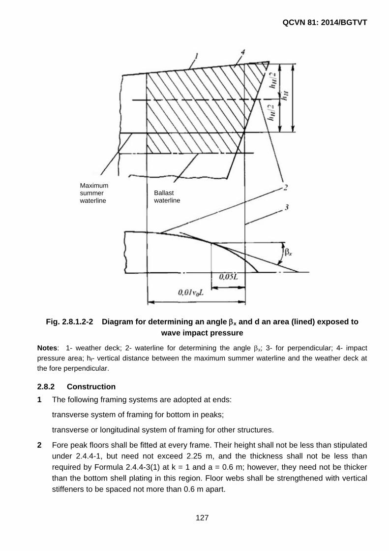
QCVN 81: 2014/BGTVT
127
Fig. 2.8.1.2-2 Diagram for determining an angle x and d an area (lined) exposed to
wave impact pressure
Notes: 1- weather deck; 2- waterline for determining the angle x; 3- for perpendicular; 4- impact
pressure area; hf- vertical distance between the maximum summer waterline and the weather deck at
the fore perpendicular.
2.8.2 Construction
1 The following framing systems are adopted at ends:
transverse system of framing for bottom in peaks;
transverse or longitudinal system of framing for other structures.
2 Fore peak floors shall be fitted at every frame. Their height shall not be less than stipulated
under 2.4.4-1, but need not exceed 2.25 m, and the thickness shall not be less than
required by Formula 2.4.4-3(1) at k = 1 and a = 0.6 m; however, they need not be thicker
than the bottom shell plating in this region. Floor webs shall be strengthened with vertical
stiffeners to be spaced not more than 0.6 m apart.
Maximum summer waterline
Ballast waterline
QCVN 81: 2014/BGTVT
128
Floor face plates shall have a thickness not less than the floor thickness and a breadth
required by 2.1.7-3(1).
At the centreline an intercostal side girder with a face plate shall be fitted as an extension
of centre girder in way of the holds. The height and thickness of girder plates as well as
the thickness and width of girder face plate shall be equal to those of the floors.
Where the webs of the girder cannot be arranged, the floor face plates shall be
interconnected at the centreline by an angle, tee section, etc. the flanges of which have
the same width and thickness as the floor face plates.
3 Where the forepeak side is transversely framed, side stringers shall be provided at least
up to the deck directly above the maximum summer waterline. The vertical spacing of
these stringers shall generally not exceed 2 m.
The side stringers shall be supported with panting beams fitted at alternate frames and
being supported on a longitudinal bulkhead in the centreline where possible.
The free edge of side stringers shall be stiffened by the face plate having a thickness not
less than that of the stringer web and a width according to 2.1.7-3(1). The stringer web
shall be stiffened at every frame with brackets having the side dimensions not less than
half the stringer web height, and where panting beams are fitted, these shall be not less
than the required in 2.1.7-2(2). The thickness of brackets shall not be less than that of the
stringer web.
Instead of panting beams, the side stringers may be supported by web frames spaced not
more than 3 m apart.
Non-tight platforms are recommended instead of side stringers with panting beams or web
frames. In this case, the platforms may be spaced up to 2.5 m apart. The beams of non-
tight platforms shall be fitted at every frame.
Where the forepeak side is longitudinally framed, web frames shall be spaced not more
than 2.4 m apart. Deck transverses shall be fitted in the places where web frames get
through decks and platforms or are attached thereto.
The floors in the plane without web frames shall be connected to the nearest side
longitudinal with brackets.
4 The bow bulb shall be strengthened with platforms spaced no more than 2 m apart. The
plarform beams shall be fitted at every frame.
If the bulb extent forward from the fore perpendicular exceeds 0.03 L, a non-tight bulkhead
strengthened with stiffeners at every frame shall be fitted in the centreline.
If the above extent is less than 0.03 L, the bulb may be strengthened with a girder in the
centreline which shall continue the vertical keel.

QCVN 81: 2014/BGTVT
129
5 The bottom design at the fore end of single-bottom craft outside the forepeak shall meet
the requirements of 2.3.2 and 2.3.4 and additionally of the following one:
(1) if transverse system of framing is adopted, the spacing of side girders, and also a
distance from the centre girder or the craft‟s side to a side girder shall not exceed 1.1
m within 0.25 L from the fore perpendicular.
6 The double bottom design at the fore end outside the forepeak shall meet the
requirements of 2.4.2 and those given below:
Within 0.25 L from the fore perpendicular, the distance between side girders shall not
extens 2.2 m apart. If transverse framing system is adopted, in this region half-height side
girders shall additionally be fitted and welded to the bottom and floors. The distance
between side girders stringers and half-height girders shall not exceed 1.1 m. These half-
height girders shall be extended as far forward as practicable and their free edges shall be
reinforced with flanges or face plates.
If longitudinal system of framing is adopted, the floors shall be strengthened with stiffeners
in line with each half-height side girder and each bottom longitudinal.
7 If transverse framing system is adopted, intercostal side stringers shall be fitted within 0.15
L from the forward perpendicular, outside the fore peak, at the level of the fore peak side
stringers. The depth and thickness of a stringer plate shall be equal to those of the frame.
The intercostal brackets fitted as stringer plates shall be welded to the webs of frames at
both ends and to the shell plating. On the free edge of a stringer, a face plate shall be
fitted with the thickness not less than that of the web and the breadth in accordance with
2.1.7-3(1).
The intercostal side stringer may be of the same profile as the frames.
The stringer face plate (flange) shall not be welded to the face plate of frames.
Intercostal stringers shall be attached to bulkheads with brackets.
Intercostal stringers may have no face plate or flange if the spacing of frames does not
exceed their double depth. In this case, their thickness s, in mm, shall not be less than l/4s
+ ∆s or 0.05h, whichever is greater, where l = length of the free edge of the stringer
between frames, in mm; h = stringer depth, in mm.
In craft with the characteristic 0v / L 1.5 or having a significant bow flare, provision shall
be made for web frames and side stringers which the web frames support. The spacing of
web frames shall not exceed 5 frame spaces.
If longitudinal side framing is used forward outside the forepeak, the spacing of side
transverses shall be no more than 3 m. In the holds, as well as in „tween decks –and
superstructures of the craft having the characteristic 0v / L 1.5 or a significant bow flare,
provision shall be made for a vertical intercostal member between web frames which is

QCVN 81: 2014/BGTVT
130
dimensioned as side longitudinals. The member design shall be similar to that of
intercostal side stringers required at transverse framing. The intercostal member may
terminate at the upper and lower side longitudinals of the hold, tweendeck and
superstructure. Every second side longitudinal shall be connected to side transverses with
brackets brought to the face plate of the frame.
8 Within 0.1 L from the fore perpendicular, the span of the weather deck transverses shall
not exceed 3 m and their deck girder span shall not exceed 3.6 m.
Within 0.2 L from the fore perpendicular, the section modulus of the weather deck
transverse shall not be less than the required for deck girders with the same span and
spacing of members.
9 The structure located aft of the after peak bulkhead shall be sufficiently rigid in the vertical
and horizontal plane. For this purpose, fitting of additional longitudinal bulkheads or
platforms, thickening of deck plating and shell plating, as well as connection of bottom and
upper deck longitudinals with pillars or struts may be required. If the stern overhang is
large or the after peak width exceeds 20 m at any section, fitting of additional longitudinal
non-tight bulkheads is recommended port or star board.
Given the flat part of the bottom, additional strengthening may be required to resist the
loads due to impact pressure.
10 Afterpeak floors shall meet the requirements in 2.8.2-2.
In single-screw craft, the floors shall be extended above the stern-tube, but in any case to
a height of not less than 0.8 m. If this is impracticable, transverse tie plates with face
plates on both edges shall be fitted at every frame above the stern-tube. The thickness of
these tie plates shall not be less than that of the floor. The tie plate of over 1.5 m long shall
have a stiffener at the midspan.
Floors with flanged edges are not allowed.
The opening in floors for the stern-tube shall be reinforced with a face plate along the
edges. The openings in floors below the stern-tube shall be reinforced with face plates or
stiffeners.
11 If transverse framing is adopted in the after peak side, panting beams and side stringers,
beam knees, frame to side stringer attachments, arrangement and structure of web frames
and non-tight platforms shall comply with the requirements of 2.8.2-3. The vertical distance
between side stringers shall not exceed 2.5 m, and the frame span, as measured on the
side plating, shall not exceed 3.5 m.
In twin- and multi-screw craft having a cruiser or transom stern, the distance between
stringers, as measured on the side plating, shall not exceed 2 m. In this case, one of the

QCVN 81: 2014/BGTVT
131
stringers shall be fitted at the top edge of propeller shaft bossing or in line with a shaft
bracket. Where web frames are fitted, their spacing shall not exceed 2.4 m.
If longitudinal side framing is adopted in the afterpeak, the relevant requirements in 2.8.2-3
shall be met.
12 The ends of afterpeak members (including deck, platform and bulkhead framing), and also
the ends of horizontal and, where possible, vertical stiffeners of floors shall be fixed.
The face plates of floors and deck transverses in the afterpeak shall be sniped in way of
their attachment to longitudinal bulkheads. Bulkhead stiffeners shall therewith be attached
to the floor face plates with brackets fitted on both sides of the bulkhead.
The above also applies to deck girder and side girder attachment to transverse bulkheads.
13 The spacing of ordinary and bevel frames may be the same as in the midship region, but
shall not exceed 750 mm. A side girder of the same depth as that of floors shall be fitted at
the centreline. In case of transom stern and/or flat of the bottom, the side girders shall be
spaced not more than 2 m apart.
In full cruiser sterns and where the frame span from the upper edge of floors to the nearest
deck exceeds 2.5 m, additional strengthening shall be provided by means of web frames
and a side stringer.
14 Where peaks are used as tanks, a wash bulkhead at the centreline is recommended.
2.8.3 Loads on structures at craft’s ends
1 The design pressure on the structures at ends is determined using the design loads
specified in 2.2 to 2.7 and the extreme loads specified in 2.8.3-2.
The scantlings of fore end members exposed to impact pressure shall be verified at
extreme loads according to 2.8.3-2 for the craft having the characteristic 0v / L 1.5 or
having a significant bow flare.
2 Under the wave impact on the side at the fore end, the extreme values of the design
hydrodynamic pressure pSL, in kPa, shall be determined by the formula:
2
SL 3 4p = 0.9 C C
Where:
3 xC = 2.2 + 1.5 tg ;
x4 0 x
0.220C = v 0.6 - 1.2 - sin 0.6 L;
L 60
v0 : refer to 1.3.1;
x and x : as defined in 2.8.1-2.

QCVN 81: 2014/BGTVT
132
The impact pressure is applied throughout the depth of the craft‟s side above a ballast
waterline and lengthwise, to the craft‟s side extended afterward till the cross section at
00.01v L from the fore perpendicular and forward till the intersection of the upper deck
with the stem (refer to Fig. 2/2.8.1-2(2)).
2.8.4 Scantlings of structural members at craft’s ends
1 The shell plating thickness, the scantlings of single bottom and double bottom members
and also of side framing under the loads potential in operation, as determined in 2.2, 2.3,
2.4, 2.5, shall meet the requirements in 2.2.4, 2.3.4, 2.4.4 and 2.5.4. In addition, the
following requirements shall be met in determining the scantlings of fore and after peak
members:
(1) the section modulus of frames is determined by Formulae 2.1.6-(4)(1) and 2.1.6-4(2);
Where:
m = 12;
l : spacing of side stringers, as measured along shell plating.
(2) scantlings of panting beams shall be comply with the requirements in 2.9.4-1;
(3) in calculating the section modulus and the cross-section area of web frames, it shall
be assumed:
m = 10;
maxN = 0.5 pal
Where:
p : design pressure, in kPa, according to 2.5.3;
a : spacing of web frames, in m;
l : web frame span, in m, as measured between the top edge of a floor and the
deck (platform) bounding the forepeak (afterpeak) or the non-tight platform, if any,
nearest to the bottom, or between non-tight platforms, the deck and non-tight
platform less the deep beam depth of the relevant deck (platform).
(4) the plating thickness and framing of a non-tight platform shall meet the requirements
in 2.6.4 for platforms at the craft‟s ends. The design load therewith shall not be
assumed less than 3.5 kPa.
The thickness smin, in mm, of non-tight platform plating shall be determined by the
formula, but not less than 5 mm:
mins = 5 + 0.02L

QCVN 81: 2014/BGTVT
133
(5) where the forepeak (afterpeak) is used as a tank, its structural members shall also be
dimensioned according to the requirements imposed on the structural components of
tanks.
2 The side framing members of the fore end ex- posed to extreme loads according to 2.8.3-2
shall be dimensioned in compliance with the requirements in 2.2.4 and 2.5.4 and also with
the following additional requirements:
(1) the shell plating thickness shall be determined by Formula 2.1.6-4(4).
Where:
SLp = 0.5p
Where:
SLp : is determined by Formula 2.8.3-2;
m = 15.8;
k = 0.7
(2) the section modulus of primary members, in cm3, shall not be less than that
determined by the formula:
2 k
n
W = palmk
Where:
p : is determined by Formula 2.8.4-2(1);
k = 0.65;
m = 16, if the members are continuous through the webs of supporting structures;
m = 8, if the members are cut at supports;
m = 28, if the members are reinforced at the supporting sections with brackets on both
sides of the supporting structure; the depth and length of brackets are no less than
1.5 times the member depth;
k - refer to 2.1.2-3.
(3) the cross-section area, in cm2, of a primary member or welds which join intercostal
members and supporting structures shall not be less than that determined by the
formula:
i
n
l - 0.5af 5pa 0.05 h s
k
Where:
p : is determined by Formula 2.8.4-2(1);

QCVN 81: 2014/BGTVT
134
k = 0.65;
ih : length of the member section perimeter, in cm;
∆s : according to 2.1.2-1.
3 The scantlings of frames within the area of stern counter shall not less than those in the
afterpeak unless their span exceeds 2.5 m. With a greater span, the frame scantlings shall
be increased accordingly. The thickness of floors and side girders shall not be less than
the required according to 2.8.4-5.
4 The side stringers in the forepeak and afterpeak shall have the cross-section area of a
web fw, cm2, not less than that determined by the formula:
wf = 12 + 0.45L
The depth of the side stringer web b, in m, shall not be less than that determined by the
formula:
b = 0.24 + 0.005L
The web thickness of the the side stringer, in mm, shall not be less than:
mins = 5 + 0.02L
but not less than 5 mm.
5 The thickness of the bulb shell plating shall not be less than 0.08L + 6.
2.8.5 Special requirements
1 In craft provided with fixed propeller nozzles, transverse bulkheads or primary support
members shall be fitted in way of the nozzle attachment to the hull.
2 Within the curved parts of the hull (deadrise, flare) the framing is recommended to fit at an
angle close to 90° to the shell plating.
3 In multi-screw craft, the structural strength and rigidity in way of attaching the stern-tube,
shaft strut and shaft bossing are subject to special consideration by VR.
2.9 Pillars and Panting Beams
2.9.1 General provisions and symbols
1 This Chapter contains the requirements for the scantlings of pillars fitted in the hull,
superstructures and deckhouses, and for panting beams in peaks.
2 For the purpose of this 2.9, the following symbols are used:
l - length of a pillar (panting beam), in m, measured:
- for the pillar – between the face plate of a deck girder (or a deck transverse if supported
by the pillar) and the deck plating (or inner bottom);

QCVN 81: 2014/BGTVT
135
- or the panting beam – between the inner edges of starboard and port frames or from the
inner edge of the frame to a secure support at the craft‟s centreline.
f - sectional area of the pillar (panting beam), in cm2;
I - the least moment of inertia of the pillar (panting beam), in cm4;
d0 - outer diameter of the pillar, in mm.
2.9.2 Construction
1 The pillar axes in „tween deck spaces shall generally be arranged in the same vertical line
and the pillar ends shall be bracketed.
Where the heel of a tubular pillar has no brackets, the deck (inner bottom) plating under it
shall be reinforced with a doubling or an insert plate.
The web of a framing member to which the head of a pillar is attached shall be
strengthened with brackets to transmit the load to the pillar.
The pillars shall be fitted on plate floors and side girders which shall be strengthened with
vertical brackets. Openings in floors and side girders under the pillars are not permitted.
2 The pillars shall be attached at their heads and heels by brackets or other arrangements
approved by VR, in order to effectively transmit the loads to the hull structures below:
- in tanks, under watertight platforms, deckhouses, ends of superstructures, windlasses,
winches, capstans, etc.;
- at the fore end of the craft having the specified speed 0v 1.5 L or a large bow flare.
2.9.3 Design loads
1 The pillar loads P, in kN, is determined by the formula:
m m m m iP = pl b + pl b
Where:
p : design pressure on the above deck according to 2.6.3, in kPa;
lm : distance measured along carlings between their midpoints, in m;
bm : mean width of the deck area (including the hatchways in the region concerned)
supported by the pillar, in m;
m m ipl b : sum of loads from the pillars fitted above, determined al- lowing for 2.6.3
which may be transferred to the pillar considered, in kN.
2 Loads on the panting beam P, in kN, is determined by the formula:
P = p.a.c
Where:

QCVN 81: 2014/BGTVT
136
st wp p + p - design pressure on the craft‟s side in way of the panting beam to be
determined according to 2.1.4-6(1) and 2.1.4-6(2);
a : spacing of frames on which panting beams are fitted, in m;
c : half-sum of frame spans measured vertically above and be- low the panting beam
considered, in m.
2.9.4 Scantlings of pillars and panting beams
1 The section area of pillars and panting beams f, in cm2, shall not be less than that
determined by the iterative method according to the formula:
cr
10kPf f
Where:
P: according to 2.9.3;
k = 2 : buckling strength margin;
cr : critical stress determined by the formulae:
cr e if e eH0.5R ;
eHcr eH
e
RR 1
4
if
e eH0.5R;
where the Euler stress is determined by the formula:
e 2
206i
fl
;
∆f - wear allowance, in cm2, determined by the formulae:
for tubular pillars: 0f 0.03d s ;
for box-shaped pillars: if 0.1 h s ;
Where:
ih : length of the cross-section perimeter, in cm;
for built-up (H-section, channel, etc.) pillars and panting beams:
if 0.05 h s;
∆s : refer to 2.1.2-1.
2 The wall thickness s, in mm, for tubular pillars shall be assumed not less than that
determined by the formula:

QCVN 81: 2014/BGTVT
137
0ds 3.5
50
The wall thickness s, in mm, for built-up pillars (box-shaped, made of channels or I-beams,
etc.) shall not be less than:
Phs
50
Where:
hP : height of the pillar wall, in mm.
The pillar wall thickness shall generally not be less than 6 mm.
In small craft, if agreed with VR, the wall thickness of pillars may be reduced down to 5
mm, provided the sectional area required is maintained.
2.10 Stems, Stern Frames, Keels, Rudder Horns And Shaft Struts, Fixed Nozzles Of Propellers
2.10.1 General
Requirements are given in this Chapter for the construction and scantlings of the stem,
sternframe (rudder post, propeller post), solepiece of the sternframe, rudder horn of semi-
spade rudders, propeller shaft brackets, bar keel, fixed nozzles of propellers.
2.10.2 Construction
1 It is recommended to use a bar or plate type welded stem. The lower part of the stem shall
be efficiently connected to the bar or plate keel and, whenever possible, to the centre
girder.
The welded stem plates shall be stiffened with transverse brackets. Arrangement of
transverse brackets of the stem shall, as far as possible, be consistent with the hull
framing. Transverse brackets stiffening the stem plate are fitted not more than 1 m apart
below and not more than 1.5 m above the maximum summer waterline. The brackets shall
overlap the joints of the stem with the shell plating and shall be extended and welded to
the nearest frames.
The brackets which cannot be extended to the framing shall have their rear edge made
along a smooth curve.
In case where the radius of curvature of the stem is sufficiently large, it is recommended to
fit a centerline girder with a face plate.
2 The construction of sternframe of a single screw craft shall comply with the following
requirements:

QCVN 81: 2014/BGTVT
138
(1) the sternframe shall have such dimensions as to provide the clearances between
sternframe and propeller, and between propeller and rudder (refer to Fig. 2/2.10.2-
2(1)) not less than specified in Table 2/2.10.2-2(1);
Table 2/2.10.2-2(1)
Dimension a b c d e
Clearance, in mm 0.2RP 0.42RP 0.36RP 0.08RP 200 - 250
RP: radius of a propeller, in mm
Fig. 2/2.10.2-2(1)
(2) the solepiece shall be made with a smooth rise in the aft direction;
(3) the propeller post shall be provided with transverse brackets in the case of welded
sternframe and webs in the case of cast sternframe. The brackets and webs shall be
spaced at least 1 m apart; their arrangement shall be consistent with the hull framing;
(4) the stern frame shall be efficiently attached to the craft‟s hull.
The lower part of the sternframe shall be extended forward from the propeller post and
shall be attached by its brackets (webs) to one floor as a minimum.
The rudder post shall be extended over the stern counter to attach it to the transom
floor.
The thickness of transom floor and additional transom floor shall be increased as
compared to that of the floors in the after peak. In general, the above floors shall be
extended to the nearest deck or platform.
3 The sternframe in twin screw ships shall comply with the requirements for the sternframe
in single screw craft, as specified in 2.10.2-2.
4 The sternframe of triple screw ships shall comply with the requirements for the sternframe
of single screw craft, as specified in 2.10.2-2 and 2.10.4-2.

QCVN 81: 2014/BGTVT
139
5 The rudder horn of a semi-spade rudder shall be securely connected to the corresponding
floors of the afterpeak and its centreline wash bulkhead.
The welded rudder horn shall be provided inside with transverse brackets; its main
supporting structures shall be extended to the nearest deck or platform; the thickness of
the floors to which the rudder horn is connected shall be increased as compared to that of
the floors in the after peak.
6 The struts of two-strut shaft brackets shall form an angle of approximately 90° to each
other. Their axes shall intersect at the axis of the propeller shaft.
The construction of propeller shaft brackets with struts arranged at an angle less than 80°
and greater than 100°, additional strengthening of the hull within the region of shaft
brackets are subject to special consideration by VR.
The propeller shaft brackets shall be so arranged in relation to the craft‟s hull that the
clearance between the blade tip and the craft‟s hull is as large as possible and, but, not
less than 25 per cent of the propeller diameter.
7 The outer and inner plating of propeller nozzle shall be strengthened by stiffeners whose
arrangement and size as well as connection with outer and inner plating of the propeller
nozzle shall be determined according to Part 2B, Section II, QCVN 21: 2010/BGTVT.
In general, the transverse web plates shall be arranged in line with the floors of the after
peak.
In way of attachment of the nozzle to the hull smooth transition from the nozzle to the
craft‟s hull shall be provided. The bottom part of the nozzle shall be connected to the hull.
If the propeller nozzle is attached to the hull by shaft brackets, provision shall be made for
an efficient connection of the brackets with the framing in the aft region of the hull and the
framing inside the nozzle. The construction of shaft brackets shall satisfy the requirements
of 2.10.2.6. Drain plugs of noncorrosive material shall be fitted in the top and bottom parts
of outer plating.
2.10.3 Design loads
Design loads for the structures of the solepiece and rudder horn of semi-spade rudders is
taken from requirements in Part 2B, Section II, QCVN 21: 2010/BGTVT.
2.10.4 Scantlings of stem, sternframe, rudder horn and propeller shaft brackets, bar keel and fixed nozzle of propeller.
1 The stem shall meet the following requirements:
(1) the sectional area f, in cm2, of a bar stem from the keel to the maximum summer
waterline shall not be less than that determined by the formula:
f = 1.3L - 4

QCVN 81: 2014/BGTVT
140
The sectional area of the stem may be reduced for the craft of design categories:
A2 and B - by 10 per cent;
C, C1, C2, C3 and D - by 20 per cent.
The sectional area of the stem above the maximum summer waterline may be
gradually reduced down to 70 per cent of the above-specified area;
(2) the plate thickness s, in mm, of a welded stem shall be determined by the formula :
s = 0.085L + 5.5 but not less than 7 mm.
The stem plate thickness may be reduced for the craft of design categories:
A2 and B - 5%;
C, C1, C2, C3 and D - 10%.
The stem plate thickness above the maximum summer waterline may be gradually
reduced down to that of the shell plates adjoining the stem. The thickness and width of
the stem plates in way of their attachment the plate keel shall not be less than those of
the latter.
When the distance between the brackets strengthening the stem is reduced by 0.5 m,
as compared to that required by 2.10.2-1, the reduction of plate thickness of stem by
20 per cent may be permitted. If the reduction of the distance between the brackets is
less than 0.5 m, the permissible reduction of plate thickness shall be determined by
linear interpolation;
(3) the thickness of brackets strengthening the stem shall not be less than that of shell
plating adjoining the stem.
The thickness of web and face plate of the girder stiffening the stem at the centreline
shall not be less than that of the brackets.
2 The stern frame of single-screw craft shall meet the following requirements:
(1) the length ls and width bs, in mm, of rectangular solid propeller post section from
the keel to the stern counter shall not be less than the determined by the formulae:
ls = 1.30L + 95
bs = 1.60L + 20
The sternpost section scantlings may be reduced for the craft of design categories:
A2 and B - 5%;
C, C1, C2, C3 and D - 10%.

QCVN 81: 2014/BGTVT
141
Above the counter the sectional area of stern-frame may be gradually reduced. And
nowhere its sectional area shall be less than 40 per cent of the required area of the
propeller post, corresponding to the scantlings stated above;
(2) the scantlings of the propeller post cross section of a cast sternframe with the rudder
having top and bottom supports shall be established in accordance with Fig. 2/2.10.4-
2(2) 10.4.2.2 depending on the value s0, in mm, determined by the following formulae:
s0 = 0.1L + 4.4
The thickness of webs shall be at least 50 per cent greater than that of the shell
plating adjoining the stern-frame;
Notes: 1- web; 2- adjoining plate of shell; s1 = 1.5s0; s2 = 2.5s0; s3 = 3.5s0; ls ≥ 1.9L + 135 mm; r - cast radius.
Fig. 2/2.10.4-2(2)
(3) the scantlings of the propeller post cross section of a welded sternframe with the
rudder having top and bottom supports shall be established according to Fig. 2/2.10.4-
2(3), where s0 shall be determined in accordance with 2.10.4-2(2). The thickness of
transverse brackets shall be at least 20 per cent greater than that of the shell plating
adjoining the sternframe
Welded propeller post of other construction may be used, provided that its strength is
equivalent to that of the abovementioned construction.

QCVN 81: 2014/BGTVT
142
(s = 1.6s0; ls ≥ 2.5L + 180 mm; R - bending radius)
Fig. 2/2.10.4-2(3)
(4) the finished thickness of propeller boss shall not be less than 30 per cent of the shaft
diameter;
(5) the section modulus Ws, cm3, of the sole piece of a stern frame about the vertical axis
shall not be less than the determined by the formula:
s 4 sW = 8 p x
The section modulus Wrp, cm3, of the rudder post about the horizontal longitudinal axis
shall not be less than the determined by the formula:
rp 4 rpW = 8(1- ) R l
Where:
= 0.85 if there is a rudder post;
= 1 if there is no rudder post or a bolted rudder post is fixed;
R4 : as determined according to 2.10.3;
xs : distance from the solepiece section concerned to the centre of the rudder, in
m (to be assumed: 0.5ls ≤ xs ≤ ls);
ls : span of the solepiece, measured from the centre of the rudderstock to the
beginning of rounding of the propeller post, in m;
lrp : span of the rudder post measured vertically from the mid-thickness of the
solepiece of a stern frame on the rudder rotation axis to the beginning of
rounding in the upper part of the rudder post, in m.
The section modulus of the solepiece about the horizontal transverse axis shall
not be less than 0.5 Ws where Ws shall be determined by the first Formula in
2.10.4-2(5). The section modulus of the rudder post about the horizontal
Bracket

QCVN 81: 2014/BGTVT
143
transverse axis shall not be less than 0.5 Wrp where Wrp shall be determined
by the second Formula in 2.10.4-2(5).
(6) the scantlings of the sternframe structural members may be determined on the basis
of direct strength calculation taking the permissible stress factor kσ = 0.55 and external
loads according to Part 2B, Section II, QCVN 21: 2010/BGTVT.
3 The scantlings of the sternframe of „twin screw craft shall satisfy requirements for the
scantlings of propeller post in single screw ships as given in 2.10.4-2 with the following
amendments:
(1) the section width of the sternframe of a solid rectangular cross section may be
reduced by 50 per cent as compared with that required by 2.10.4-2(1);
(2) the scantlings of the cast or welded sternframe may be reduced as compared with
those required by 2.10.4-2(2) and 2.10.4-2(3) respectively, so that their section moduli
about the horizontal longitudinal and transverse axes, are reduced by not more than
50 per cent. The thickness of the sternframe wall shall be at least 7 mm.
4 For semi-spade rudders with one gudgeon upon the horn, the section modulus, in cm3, of
the rudder horn about the horizontal longitudinal axis shall not be less than:
4 sW = 12R z
Where:
R4 : as determined according to 2.10.3;
zs : vertical distance from the mid-thickness of the horn gudge onto the section
concerned, in m (to be assumed: 0.5lh ≤ zs ≤ lh);
lh : horn span measured vertically from the mid-thickness of thehorn gudgeon to the
point of intersection of the horn axis with shell plating, in m;
Where the rudder horn is welded of plates, the thickness of the plates, in all cases,
shall be at least 7 mm.
The scantlings of the rudder horn may be determined on the basis of direct strength
calculation taking the permissible stress factor kσ = 0.35 and external loads according
to Part 2B, Section II, QCVN 21: 2010/BGTVT.
5 The sectional area of either strut of two-strut shaft brackets shall be equal to not less than
60 per cent of the propeller shaft section in the bracket plane, the strut thickness – to not
less than 45 per cent, and the boss thickness – to not less than 35 per cent of the propeller
shaft diameter. The length of the boss shall be in accordance with Part 2B, Section II,
QCVN 21: 2010/BGTVT.
The strength of the welded shaft brackets shall not be less than that specified above. The
plate thickness shall not be less than 7 mm.

QCVN 81: 2014/BGTVT
144
The weld area of rivets attaching each strut to the hull shall not be less than 25 per cent of
the propeller shaft sectional area. Where the struts are attached by means of flanges, the
thickness of the latter shall be not less than 25 per cent of the propeller shaft diameter.
6 The height hs and width bs, in mm, of the bar keel cross section shall not be less than:
hs = 1.3L + 100
bs = 0.7L + 8
The bar keel height and width may be reduced for the craft of design categories:
A2 and B - 5%;
C, C1, C2, C3 and D - 10%.
7 The thickness of outer and inner plating of fixed propeller nozzle shall comply with the
requirements of Part 2B, Section II, QCVN 21: 2010/BGTVT, considering the following:
the width of middle belt of inner plating shall be not less than the distance from 0.03D0
forward of the propeller blade tips and 0.07D0 ft of the propeller blade tips, where D0 is the
internal diameter of the propeller nozzle.
the thickness of the forward part of the inner and outer plating shall not be less than
required for side shell plating (refer to 2.2.4-1 for transverse framing system).
The width of attachment shall be at least 0.15D0.
The cross-sectional area of the joint shall be not less than required by 2.10.4-2(5) for the
solepiece. If the sole-piece serves as support of the rudder, the connection of the nozzle to
the solepiece is subject to special consideration by VR.
For twin screw craft when the propeller nozzle is not attached to the hull at its bottom part,
the width of attachment at the top part shall be not less than 0.3D0.
If the propeller nozzle is attached to the hull by shaft brackets, their strength shall comply
with the requirements of 2.10.4-5.
In way of attachment of the nozzle to the hull the thickness of framing members shall not
be less than required by Formula in Part 2B, Section II, QCVN 21: 2010/BGTVT.
2.11 Seating Of Machinery And Boilers
2.11.1 General
1 Requirements are given in this Chapter for the construction and dimensions of the
seatings intended for main machinery and boilers, deck machinery, fishing installations,
cargo handling gear, auxiliary machinery, etc.
2 The requirements laid down in this Chapter are minimum. Requirements concerning
construction and dimensions of structural components of a seating, which are contained in

QCVN 81: 2014/BGTVT
145
the technical documentation of the machinery, unit or device to be installed on the seating
concerned, shall also be complied with.
2.11.2 Construction of seatings
1 The construction of seatings shall satisfy the following requirements:
(1) the seating shall be of substantial construction to ensure efficient attachment of
machinery, gear or device and transmission of forces to the hull framing, which shall
be sufficiently strong. If necessary, the framing may be strengthened;
(2) the seating shall be so constructed that the resonance vibration of the seating as a
whole and of its structural components can be avoided under all specified running
conditions;
(3) where the seating is installed on the continuous longitudinals of the strength deck and
double bottom (bottom), its structural components shall not terminate at unsupported
portions of plating. Attachment of the seating to the upper edge of sheerstrake is
subject to special consideration by VR;
(4) the seating shall be so designed that the plating beneath is accessible for inspection.
Measures shall be taken to prevent water from accumulating under the seating.
In particular cases agreed with VR, a hermetic construction of the seating is permitted,
the inner space of the seating being filled with some chemically neutral material with
good adhesion properties.
2 In general, a seating of main machinery and boilers shall comprise two vertical plates
(girder webs) (for medium-speed and high power engines – four vertical plates (two –
either side of the engine)) and horizontal face plates (top plates) to which the machinery
(boiler) shall be attached directly. The vertical plates shall be strengthened with brackets
(knees) having face plates (flanges) along the free edges.
Where the seating comprises four vertical plates, the top plate is attached to two vertical
plates fitted on one side of the machinery; the outer plates shall have openings to provide
access into the seating. In the case of medium-speed engines, such openings shall not
extend to the top plate. The outer plates may be made sloped.
All the vertical plates shall be fitted in line with the main or additional side girders.
3 Machinery and equipment may be installed on shell plating of the hull, tight bulkheads,
decks and plat-forms (including tank bulkheads and crown), inner bottom and shaft-tunnel
platings on condition they are attached to the framing members and stiffeners, or on
cantilevers connected to framing members or stiffeners.
Attachment of small-sized machinery and equipment directly to the above-mentioned
structure with the help of welded pads is not permitted.
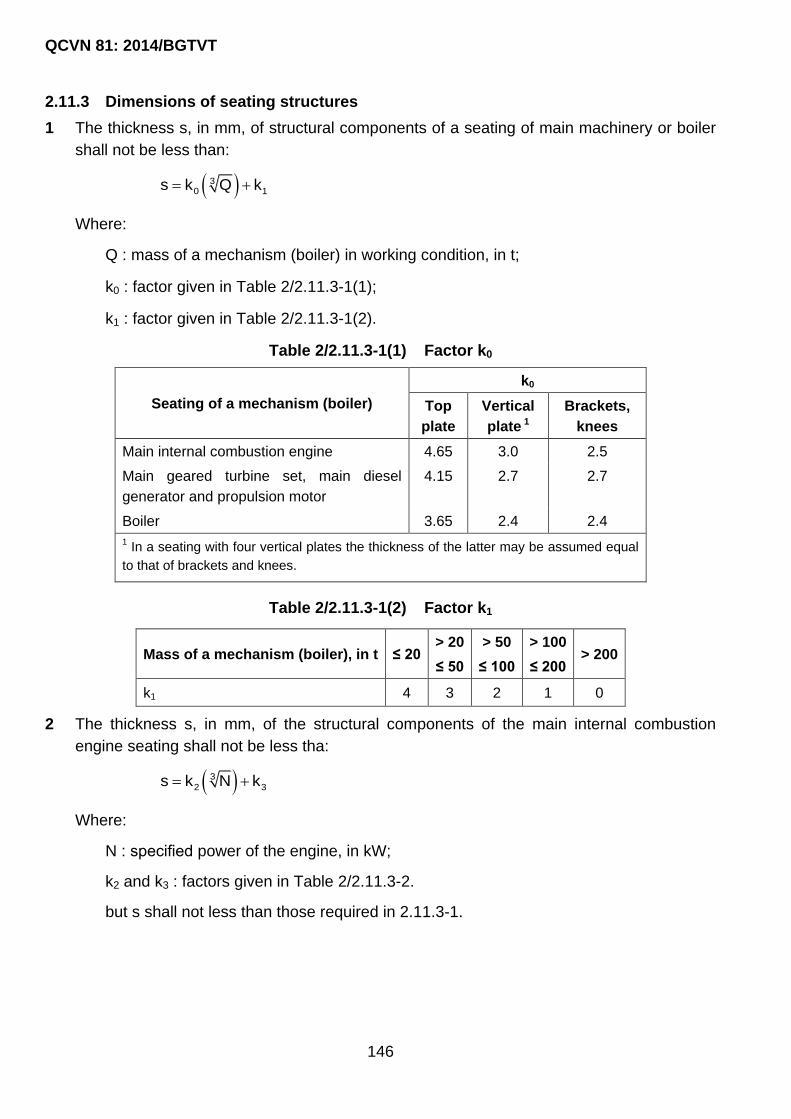
QCVN 81: 2014/BGTVT
146
2.11.3 Dimensions of seating structures
1 The thickness s, in mm, of structural components of a seating of main machinery or boiler
shall not be less than:
30 1s k Q k
Where:
Q : mass of a mechanism (boiler) in working condition, in t;
k0 : factor given in Table 2/2.11.3-1(1);
k1 : factor given in Table 2/2.11.3-1(2).
Table 2/2.11.3-1(1) Factor k0
Seating of a mechanism (boiler)
k0
Top
plate
Vertical
plate 1
Brackets,
knees
Main internal combustion engine 4.65 3.0 2.5
Main geared turbine set, main diesel
generator and propulsion motor
4.15 2.7 2.7
Boiler 3.65 2.4 2.4
1 In a seating with four vertical plates the thickness of the latter may be assumed equal
to that of brackets and knees.
Table 2/2.11.3-1(2) Factor k1
Mass of a mechanism (boiler), in t ≤ 20 > 20
≤ 50
> 50
≤ 100
> 100
≤ 200 > 200
k1 4 3 2 1 0
2 The thickness s, in mm, of the structural components of the main internal combustion
engine seating shall not be less tha:
3
2 3s k N k
Where:
N : specified power of the engine, in kW;
k2 and k3 : factors given in Table 2/2.11.3-2.
but s shall not less than those required in 2.11.3-1.

QCVN 81: 2014/BGTVT
147
Table 2/2.11.3-2 Factor k2 and k3
N, kW
Number of
vertical
plate
Factor Top
plate
Vertical
plate
Brackets,
knees
≤ 1000
2 k2 1.7 1.1 0.9
k3 6 4 3
4 k2 1.4 0.9 0.9
k3 5 3 3
> 1000
2 k2 1.0 1.0 0.7
k3 13 5 5
4 k2 0.8 0.7 0.7
k3 11 5 5
2.12 Superstructures, Deckhouses and Quarter Decks
2.12.1 General provisions, definitions and symbols.
1 Requirements are given in this Chapter for bridges extending from side to side of the ship
as well as to short bridges which do not extend to the sides of the ship, forecastle, poop,
long forecastle and poop extending to ship‟s sides, short deckhouses and quarter decks.
The applicability of the requirements contained in this Chapter to long superstructures not
extending from side to side of the ship as well as to long deckhouses shall be specially
agreed with VR.
2 For the purpose of this 2.12, the following definitions have been adopted:
Quarter deck is the after part of an upper deck stepped up to a portion of a „tween deck
depth.
Ends of superstructures and deck-houses are the ends of the length measured from end
bulkheads having a length, in m, no less than the determined by the formula:
e 2l = 1.5(B /2 + h)
Transition area of quarter deck is an area measured from the forward edge of a break to
the after edge of the upper deck plating and extended below the quarter deck.
3 For the purpose of this 2.12, the following symbols have been adopted:
B2, breadth of a superstructure or deckhouse deck measured at its mid-length excluding
the breadth of large openings, machinery casings, if any, in m;
h - height of the first tier of a superstructure or deck-house, in m;

QCVN 81: 2014/BGTVT
148
l1 - length of a superstructure (deckhouse) measured between the end bulkheads; the
length of a forecastle (poop) measured from the fore (after) perpendicular to the end
bulkhead of the forecastle (poop), in m;
Bx - craft‟s breadth at the upper deck level at the section considered, in m;
b - breadth of a deckhouse, in m.
2.12.2 Construction
1 For the first tier of long bridge outside the end portions, long forecastle (poop) outside the
end portion, the requirements of 2.6 for the upper deck and the requirements of 2.2 and
2.5 for the craft‟s side in way of the upper „tween deck space shall be complied with.
2 For the bottom strake of side plating and longitudinal bulkhead plating of bridges, the
bottom strake of side plating of deckhouses fitted on the strength deck, shall be made of
the steel having the same as the strength deck in this region. The width of the bottom
strake shall not be less than 0.5/L.
3 Whenever practicable, the end bulkheads of superstructures and deckhouses shall be
situated in line with the hull transverse bulkheads or as close to the latter as possible.
Web frames or vertical webs, bulkheads or partial bulkheads shall be fitted in
superstructures and deckhouses in such a way as to be in line with girder webs or
bulkheads of hull structures located below. The vertical webs of end bulkheads shall be
fitted in line with the vertical webs of hull bulkheads.
4 The lower ends of vertical stiffeners of the end bulkheads of the 1st tier superstructures
and deck-houses shall be welded to the deck. The lower ends of side vertical stiffeners of
1st tier houses shall be attached to the deck by brackets.
5 Adequate strengthening shall be provided for the structures of deckhouses and
superstructures where launching and recovery appliances for survival craft and rescue
boats are fitted.
2.12.3 Design loads
1 The design loads on the superstructure sides and on the superstructure and deckhouse
decks shall satisfy the following requirements:
(1) design pressure on superstructure sides is determined according to 2.2.3;
(2) design pressure on the weather areas of superstructure and deckhouse decks is
determined by the formula:
wp = p but no less than pmin
Where:

QCVN 81: 2014/BGTVT
149
pw : wave load at the deck level according to 2.1.4-6(2);
= 0.9 for the forecastle deck, and also for the part of the bridge deck within 0.2 L
from the fore perpendicular;
= 0.8 for the poop deck, and also for the part of the bridge deck within 0.2 L
from the aft perpendicular;
= 0.7 for the bridge and deckhouse decks amidships.
For the bridge and deckhouse deck areas outside the midship and beyond 0.2 L
from the fore and aft perpendicular, the value of α is determined by linear
interpolation.
For the 1st tier superstructure and deckhouse decks pmin, in kPa, is determined by
the following formulae. For the forecastle deck, and also for the part of the
bridge deck within 0.2 L from the fore perpendicular.
minp = 0.1L + 7;
for the poop deck, and also for the bridge deck:
minp = 0.015L + 4
For the decks of the superstructures and deckhouses of the 2nd and other upper
tiers:
minp = 2 kPa
For the craft of design categories of restricted area of navigation the value of pmin
may be reduced by multiplying by the factor υr obtained from Table 2/2.1.4-5.
2 Pressure on the end bulkheads of superstructures and deckhouses as well as on sides of
deckhouses p, in kPa, is determined by the formula:
2 1p = 5.1nc (1.21k - z )
Where:
n - factor obtained from Table 2/2.12.3-2(1);
2 xc = 0.3 + 0.7b/B , in this case c2 ≥ 0.5;
2
1
b
x /L - 0.45k = 1.0 +
C 0.2
if x1/L ≤ 0.45;
2
1
b
x /L - 0.45k = 1.0 + 1.5
C 0.5
if x1/L > 0.45;

QCVN 81: 2014/BGTVT
150
for the deckhouse sides the factor k is assumed to vary length of the bulkhead. For
this purpose the deckhouse is subdivided into equal parts of no more than 0.15L in
length each; in this case the value of x1 is assumed as a distance between the aft
perpendicular and the middle of the part in question;
Cb shall be assumed as not less than 0.6 and nor greater than 0.8; for the aft end
bulkheads forward of amidships it is assumed Cb = 0.8;
z1 vertical distance from the maximum summer waterline to the midpoint of the plate
or stiffener span considered.
Table 2/2.12.3-2(1) Factor n
Bulkhead Structure Factor n
Front Unprotected
1st tier 02 + L /120
2nd tier 01 + L /120
3rd tier 1
00.5 + L /150 Protected
Aft end Aft of amidships 0 10.7 + L /1000 - 0.8x /L
Forward of amidships 0 10.5 + L /1000 - 0.4x /L
Note: L0 = length of craft, in m; x1 = distance from the bulkhead in question to the aft perpendicular,
in m.
1 The formula is also applicable to the deckhouse sides.
The above-stated values of the factor n apply to a craft having the freeboard equal to
the minimum tabular freeboard of Type “B” ships, and the standard height of
superstructures according to Part 11, Section II, QCVN 21: 2010/BGTVT. If the deck,
whereon is situated the superstructure tier in question, is above the standard position
due to the increased freeboard as compared with the tabular one, factor n value
corresponding to the deck position may be determined by linear interpolation between
the values of that factor for the superstructures with the standard and actual position
of the decks under the superstructures. In any case the design pressure shall be no
less than in Table 2/2.12.3-2(2).
For the craft of the design categories of restricted area of navigation the design
pressure may be reduced by multiplying by the factor υr obtained from Table 2/2.1.4-
5.
Table 2/2.12.3-2(2) Design pressure p
Design pressure p, in kPa
for 1st tier unprotected fronts elsewhere
15.6 7.8

QCVN 81: 2014/BGTVT
151
2.12.4 Scantlings of superstructure, deckhouse and quarter deck structures
1 The thickness of the side plating of bridges, a forecastle and poop shall be determined
according to 2.2.4-1 at the design loads according to 2.12.3-1(1). For the bridges,
forecastle and poop, kσ = 0.7.
In any case the side plating thickness smin, in mm, for the bridges, forecastle and poop
shall not be less than:
for the superstructures of a lower tier:
mins = 4.5 + 0.025L
for the superstructures of other tiers:
mins = 4 + 0.02L
For the craft of design categories A and A1, if the spacing assumed is less than the
standard one (refer to 2.1.1-1), the minimum thickness may be reduced in proportion to the
ratio of the assumed spacing to the standard one, but not more than by 10 per cent.
2 The deck plating thickness for bridges, a forecastle and poop, and also for deckhouses
shall be determined according to 2.6.4-1(1) and 2.6.4-1(2) at the design loads according to
2.12.3-1(2). For the bridges, forecastle and poop, and also for the deckhouses, kσ = 0.7.
In any case the deck plating thickness smin, in mm, for the bridges, forecastle and poop,
and also for the deckhouses shall not be less than:
for the open forecastle deck:
mins = 4 + 0.04L
for other decks of superstructures and deckhouses of the lower tier:
mins = 5 + 0.01L
for the superstructure and deckhouse decks of other tiers:
mins = 4 + 0.01L
or the craft of design categories A and A1, if the spacing assumed is less than the
standard one (refer to 2.1.1-1) the minimum thickness may be reduced in proportion to the
ratio of the assumed spacing to the standard one, but no more than by 10 per cent.
For the craft of less than 20 m in length, the minimum thickness may be reduced down to 3
mm subject to agreement with VR.
3 The plate thickness for the end bulkheads of superstructures, for the side and end
bulkheads of deck-houses shall not be less than the determined by Formula 2.1.6-4(1).
Where:
m = 15.8

QCVN 81: 2014/BGTVT
152
kσ = 0.6
Δs = 0
p - as defined in 2.12.3-2.
The thickness of the side plating of deckhouses may be not more than that of
superstructures according to 2.12.4-1, provided they are similarly arranged lengthwise of
the craft and throughout its depth.
The thickness of a bottom plate of end bulkheads for the superstructures (deckhouses) of
the 1st tier shall be increased by 1 mm as compared with the design thickness. The width
of the bottom plate shall be at least 0.5 m.
Where the deckhouse front is of the convex form in plan across the entire width of the
deckhouse, its plating thickness may be reduced by 0.5 mm as compared with the design
value.
4 In any case the plate thickness smin, in mm, for the end bulkheads of superstructures, for
the side and end bulkheads of deckhouses shall not be less than the determined by the
formulae:
for the lower tier:
mins = 5 + 0.01L
for other tiers:
mins = 4 + 0.01L
For the craft of less than 20 m in length the minimum thickness may be reduced down to 3
mm subject to agreement with VR.
5 Framing of the sides, decks and end bulkheads of a forecastle, poop, bridge, quarter deck
and deckhouses shall meet the following requirements:
(1) the side framing of superstructures shall meet the requirements for the side framing in
tweendecks according to 2.5.4-2 to 2.5.4-5 at the design loads in 2.12.3-1(1). For
longitudinals and side stringers of the bridge, forecastle and poop, kσ = 0.65;
(2) the underdeck framing of superstructures and deck-houses shall meet the
requirements in 2.6.4-2 to 2.6.4-7 at the design loads in 2.12.3-1(2). For longitudinals
and carlings of the bridge, forecastle and poop kσ = 0.65;
(3) the section modulus of vertical stiffeners of the end bulkheads of superstructures and
of the side and end bulkheads of deckhouses shall not be less than the determined
according to 2.1.6-4(1).
Where:
kσ = 0.6
ωc = 1

QCVN 81: 2014/BGTVT
153
p - as defined in 2.12.3-2;
m = 12 if the lower end of the stiffener is attached to the deck with a bracket;
m = 10 if the lower end of the stiffener is welded to the deck;
m = 8 if the lower end of the stiffener is sniped.
The section modulus of stiffeners of deckhouse sides need not be greater than that of
frames of superstructures as stated in 2.12.4-5(1 where arranged similarly over craft‟s
length and depth.
6 The member scantlings for bulkheads and par- tial bulkheads inside superstructures and
deckhouses shall meet the requirements in 2.7.4-5 unless otherwise specified.
2.12.5 Special requirements
1 In way of end bulkheads the following requirements shall be met:
(1) where the superstructure end bulkhead is not in line with the transverse bulkhead of
the hull, partial bulkheads or pillars shall be fitted in spaces below the end bulkhead,
or frames and beam knees shall be strengthened;
(2) at the section, where the end bulkheads of superstructures and deckhouses abut on
the undeck longitudinal structures and the sides of deckhouses – on the transverse
underdeck structures fitted below (bulkheads, partial bulkheads, undeck girders, deck
transverses, etc.), the webs of these underdeck structures shall be stiffened with
brackets.
2 The structure in way of the superstructure ends shall meet the following requirements:
(1) in way of the bridge, forecastle and poop ends, the side plating shall be extended
beyond the end bulkhead and gradually curved towards the craft‟s side on the length
d1, in m (refer to Fig. 2/2.12.5-2(1)), determined by the formula:
1 2d 0.1(B /2 + h)

QCVN 81: 2014/BGTVT
154
2 10.5 d = 0.65d 0.75h
Fig. 2/2.12.5-2(1)
On agreement with VR, the value of d1 may be reduced provided the thickness of the
bottom strake of the superstructure side plating, of the sheerstrake and deck stringer
plate in the region shown in Fig. 2/2.12.5-2(1) is increased.
(2) the blunted ends of the projecting side plates of the superstructure shall be machined
flush with the deck;
The curved edge shall be stiffened with a flat bar offset by 50 mm downward from the
edge. The ends of that bar shall be sniped;
Openings in side plating projecting beyond the ends of a superstructure are normally
not permitted. The projecting plates shall be attached to the bulwark by means of
flexible joints.
(3) at the ends of bridge not extending from side to side of ship the attachment of the side
to the deck shall be made as a smooth transition from the side to a short deck girder
strengthening the deck under that side with simultaneous strengthening of the deck
stringer plate within the region shown in Fig. 2/2.12.5-2(1).
3 The structures of the break in way of connecting the upper deck to the quarter deck shall
meet the following requirements:
(1) the upper deck plating need not extend abaft the break;
(2) the upper deck stringer plate shall be extended beyond the upper deck plating for two
frame spaces;
The upper deck stringer plate shall therewith get narrower from its full width to the
depth of the frame to which it shall be welded.

QCVN 81: 2014/BGTVT
155
(3) the stringer plate of quarter deck shall extend forward in the form of a bracket
gradually tapered to ship‟s side on a length of three frame spaces. The quarter deck
stringer plate projecting beyond the break shall be adequately stiffened and its free
edge shall have a face plate or flange;
(4) the sheerstrake of quarter deck shall extend forward of the deck stringer plate
projecting beyond the break bulkhead for at least 1.5 times the height of break and
shall be smoothly tapered into the upper edge of craft‟s side sheerstrake. For other
structural requirements, refer to 2.12.5-2(3);
(5) diaphragm plates spaced not more than 1.5 m apart shall be fitted over the ship‟s
breadth between the over-lapping decks in way of the break. The thickness of
diaphragms shall not be less than the thickness of the break bulkhead plating;
The diaphragm plates shall be strengthened with vertical stiffeners;
Continuous welds shall be used to attach the horizontal edges of diaphragm plates to
the decks, and the vertical edges to break bulkhead on one side, and on the other side
to an extra supporting bulkhead made of continuous plate welded to the decks over
the craft breadth. The plate thickness of that bulkhead shall be not less than the
thickness of break bulkhead plating and may have openings between diaphragms.
(6) where the supporting bulkhead is fitted, the diaphragm plates shall be stiffened with
brackets at their ends (refer to Fig. 2/2.12.5-3(6)).
Notes: 1- supporting bulkhead; 2, 6- brackets; 3- quarter deck; 4- diaphragm; 5- V break
bulkhead; 7- upper deck; 8- stiffener in line with bracket
Fig. 2/2.12.5-3(6)
(7) where the quarter deck adjoins the bridge, the former shall be extended into the bridge
for two frame spaces beyond the break, but no less than the elevation of the bridge
above the quarter deck;
The quarter deck stringer plate shall be extended farther forward for two frame spaces
with the width gradually reduced as required in 2.12.5-3(2);
QCVN 81: 2014/BGTVT
156
Strengthening of the overlapping decks in way of the break shall meet the
requirements in 2.12.5-3(5) and 2.12.5-3(6) depending on the position of the break
length-wise of the craft;
The bridge side plates extended aft of the bridge shall be gradually tapered in a
curve to the sheerstrake within a length of at least 1.5 times the break height
(refer also to 2.12.5-2(1)).
(8) where the break is located within 0.25L from the aft perpendicular, strengthenings
shall meet the following requirements:
the upper deck plating need not extend aft of the break across the craft‟s entire
breadth, but the upper deck stringer, as well as the quarter deck stringer and
sheerstrake shall be extended forward and aft as specified in 2.12.5-3(3) and 2.12.5-
3(4).
4 The use of aluminium alloys for the construction of deckhouses is permitted. Decks of
accommodation and service spaces situated above the machinery and cargo spaces shall
be made of steel.
5 The helideck members and supporting structures shall meet the following requirements:
(1) the helideck members, depending on its location over the ship‟s length and depth,
shall satisfy the requirements for members of weather deck as specified in 2.6 or
superstructure (deckhouse) decks, as specified in 2.12.4-2 and 2.12.4-5(2). In any
case, the design pressure shall not be less than:
pmin = 2 kPa.
(2) helideck members shall satisfy the requirements for the members of decks intended
for the carriage of cargo, as specified in 2.6. The design loads are determined on the
basis of the greatest mass of helicopters and equipment stowed on the helideck
during operation of the ship and the additional pressure of 0.5 kPa from snow cover or
ice;
(3) the helideck members shall satisfy the requirements for deck members of ro-ro ships,
as specified in Part 8B, Section II, QCVN 21: 2010/BGTVT. The design loads under
the helicopter landing conditions are determined on the basis of the following:
Q0 = conditional axle load to be assumed equal to the maximum take-off weight of the
helicopter, in kN;
n0 = conditional number of wheels on the axle;
n = 1 - number of wheels forming a group;
u·v = 0.3·0.3 m2 – size of the tyre print;

QCVN 81: 2014/BGTVT
157
kd = 1.5 – dynamic amplification factor.
(4) where the helideck is not a superstructure or deck house deck, its supporting
structures shall meet the requirements for pillars according to 2.9 and (or) partial
bulkheads according to 2.7.4-4 at the design loads according to 2.12.5-5(1) and
2.12.5-5(3);
(5) where the helicopter deck has the structures protruding beyond the craft‟s side line,
the requirements thereto are subject to special consideration by VR.
2.13 Machinery Casings
2.13.1 General
Openings in decks and platforms over engine rooms shall be protected by strong casings.
The casings may be omitted only in cases where the space on the deck or platform is a
part of the engine room.
2.13.2 Construction
1 Where there are large openings in the deck in way of engine room, additional pillars and
deck transverses shall be fitted for strengthening of the deck in way of machinery casing.
2 Where the opening for machinery casing is arranged in the strength deck, the
requirements of 2.6.5-1 regarding the design of corners and compensation for openings
shall be complied with.
2.13.3 Scantlings of machinery casing structures
1 The part of machinery casing located inside the enclosed spaces („tween deck spaces,
fore castle, poop, bridge, deckhouse) shall comply with the requirements of 2.7.4-5 for
partial bulkheads. The spacing of stiffeners shall not exceed 0.9 m.
The thickness of plating of the part of machinery casing located inside the poop, bridge or
deckhouse may be 0.5 mm less than specified.
2 The part of machinery casing located below the bulkhead deck shall comply with the
requirements of 2.7.2-3, 2.7.4-1 to 2.7.4-3 for watertight bulkheads where it is included in
subdivision calculation as watertight construction.
3 The part of machinery casing located above weather deck shall comply with the
requirements of 2.12 for deckhouses situated in the same region of the ship. In calculating
the design loads by Formula 2.12.3-2, c2 shall be taken equal to 1.
2.14 Bulwark
2.14.1 General

QCVN 81: 2014/BGTVT
158
Bulwarks of strong construction shall be provided in places specified in Part 11, Section II,
QCVN 21: 2010/BGTVT.
2.14.2 Construction
1 The height of the bulwark as measured from the upper edge of the deck plating or from
that of planking, if any, to the upper edge of the rail section shall comply with the
requirements of Part 11, Section II, QCVN 21: 2010/BGTVT.
2 The bulwark openings cut in bulwarks shall be so designed as to ensure a smooth
transition (with a radius not less than 100 mm) from the bulwark plate to the sheerstrake.
Within 0.07L from the fore perpendicular the welding of bulwark plating to the sheerstrake
is necessary.
3 The bulwark shall be supported by stays spaced not more than 1.8 m apart. In the craft
with large flare of sides and in craft with minimum assigned freeboard, stays may be
required to be fitted at very frame within the region considered.
4 The stays shall be fitted in line with deck beams, brackets and other structures and shall
be welded to the rail section, bulwark plate and deck. The attachment of stays to bulwark
shall be ensured on a length not less than half the height of the bulwark.
In welding the stays to the deck, holes sufficient in size to allow free passage of water to
the scuppers shall be provided in the stays. The welded connection of the beam (bracket)
to deck plating under the stay shall not be weaker than the attachment of stay to deck.
Directly under the lower ends of stays no cut-outs in the deck beams and no gaps between
frame ends and deck are permitted.
The dimensions of lightening holes in stays shall not exceed half the stay width in any
section of the stay.
The free edges of stays shall be stiffened with face plates or flanges.
In general, the flanges (face plates) of stays shall not be welded to deck plating and rail
section.
The flanges (face plates) on the outer edge of the stay shall not be welded to horizontal
stiffener (flange) of lower edge of the bulwark in way of continuous cutout.
2.14.3 Loads on bulwarks
The external pressure determined by Formula 2.1.4-6(2) is assumed as the design
pressure p, in kPa, acting on the bulwark. In this case the design pressure shall not be
less than:
pmin = 0.02L + 14 but not less than 15 kPa.
For the craft‟s design categories of an restricted area of navigation the value of pmin may
be reduced by multiplying by the factor υr obtained from Table 2/2.1.4-5.

QCVN 81: 2014/BGTVT
159
2.14.4 Scantlings of bulwark components
1 The thickness s, in mm, of the bulwark plating is determined by the formula:
s = 0.065L + 1.75 but not less than 3 mm.
The thickness of bulwark plating of a superstructure located beyond 1/4 of the craft‟s
length from the fore perpendicular, as well as that of bulwark plating of 2nd tier
deckhouses or superstructures may be reduced by 1 mm.
For 3rd and above tiers of the deckhouses the thickness of the bulwark plating need not
exceed the thickness required for the plating of sides of 3rd tier deckhouse.
2 The section modulus of a bulwark stay adjoining the deck plating shall not be less than the
determined in 2.1.6-4(1).
Where:
p - as defined in 2.14.3;
m = 2
kσ = 0.65
Where the bulwark has cutouts for passage or expansion joints, the section modulus of
stays at the ends of those cutouts or expansion joints shall be increased by 25 per cent.
The width of a stay at its top end shall be equal to that of a rail.

QCVN 81: 2014/BGTVT
160
CHAPTER 3 ALUMINIUM ALLOY HULL
3.1 General
3.1.1 An aluminium alloy hull is subject to all the provisions and requirements applicable to a
steel hull specified in Chapter 2 of this Part of the Regulation.
3.1.2 The scantlings of the structural members of the aliminium alloy hull shall be determined
by recalculating (refer to 3.2.1) the corresponding scantlings of steel hull structures.
3.1.3 The materials used for manufacturing the structural members of the hull regulated by
this Section of the Regulation shall meet the requirements of Part 7A, Section II, QCVN
21: 2010/BGTVT.
3.2 General Provisions On Scantling Of Hull Structural Members
3.2.1 A recalculation shall be made with the use of the formulae specified in Table 2/3.2.1,
ignoring the restrictions on the minimum scantlings of steel structure members.
3.3 Special Requirements
3.3.1 If continuous (fillet and butt) welds are located in the areas of the maximum stresses,
the reduced strength in way of the weld shall be taken into account depending on the
aluminium alloy used and the welding method.
3.3.2 For the aluminium alloy structures specified in Table 2/2.1.7-5(1)(a) and used in joints it
is not allowed:
1 to use intermittent welds (excepting scalloped construction).
2 to use scalloped construction in way of violent vibrations (refer to 2.1.7-1(6)).
The weld throat thickness shall be at least 3 mm, but not more than 0.5 s (for s, refer to
2.1.7-5(1)).
3.3.3 The scantlings of the cross-sections of the stern frame, stem, bar keel and shaft struts
shall be 1.3 times greater than those when steel is used.
3.3.4 The structural components of an aluminium alloy deckhouse are dimensioned by
recalculating according to 3.2.1. The minimum scantlings of structures are assumed the
same as those for a steel deckhouse.
3.3.5 If agreed with VR, bimetallic (steel – aluminium) pressed elements for joining structures
made of steel and aluminium alloys may be used.
3.3.6 The aluminium alloy deckhouse share in the overall longitudinal bending of the hull and
the stresses in the craft‟s hull and the deckhouse shall be determined using the
procedure agreed with VR.

QCVN 81: 2014/BGTVT
161
Table 2/3.2.1
Parameter Requirement
The thickness of plating for the shell, decks (without covering),
bulkhead and inner enclosure plating, and of other details made of
platess
For superstructures:
1 eH p0.2s S R / R
for main hull:
1 eH p0.2s 0.9S R / R
Section modulus of primary support members 1 eH p0.2W = WR / R
Cross-section area of pillars 1 eH p0.2f = f R / R
Moment of inertia of pillars and primary support members 1I = 3I
Notes:
1- p0.2R - proof stress of aliminium alloy, in MPa.
2- S, W, f and I - the values as stipulated by the Regulation, may be adopted without corrosion
allowance.

QCVN 81: 2014/BGTVT
162
CHAPTER 4 HULL OF GLASS-REINFORCED PLASTIC
4.1 General
4.1.1 Application
The requirements of this Section of the Regulation apply to the craft of glass-reinforced
plastic with the main dimension ratios ranged as follows:
craft‟s length to depth ratio: L/D = 6 to 10;
craft‟s breadth to depth: B/D = 2 to 2.5;
craft‟s length to breadth: L/B = 3 to 5.
Where the main dimension ratios are outside the above limits, the design and scantlings of
hull members are subject to special consideration by VR.
The scantlings of the hull structure components of planning craft and catamarans shall
additionally meet the requirements of QCVN 54: 2013/BGTVT.
4.1.2 Definitions and explanations
Single-skin construction is a construction comprising a single-skin laminate stiffened by
primary support members.
Double-skin construction is a construction comprising two single-skin laminates
interconnected by primary support members.
Sandwich construction is a construction comprising two single-skin laminates
interconnected by a core of plastic foam, a honeycomb structure, etc. with the core being
load-carrying and taking up the load together with the laminates.
4.1.3 General
1 The requirements of this Section apply to:
(1) the hulls moulded either as a whole or in two halves (starboard and portside) to be
joined along the keel, stem and sternframe;
(2) the craft with the following connections of hull sections:
shell skin along the centre line;
deck to craft‟s side;
superstructures and deckhouses to deck.
(3) the craft with the shell, deck plating and strength bulkheads of single-skin
construction;

QCVN 81: 2014/BGTVT
163
(4) the craft with superstructure and deckhouse sides of single-skin and sandwich
construction.
2 The scantlings of double-skin and sandwich construction members, as well as the use of
composite structures are subject to special consideration by VR in each case unless
special requirements are given in this Part of the Regulation.
3 The drawings of glass-reinforced plastic structures shall specify the thickness of laminates,
in mm, and also the number of reinforcing material layers and the total mass of
reinforcement, in kg per 1 m2 of the laminate area.
4 The hull moulding technique shall be approved by VR in each case.
5 VR may approve the alternative structural designs which are unlike those given in this Part
provided that it is proved that they are equivalent to requirements in this Part.
4.1.4 Scope of surveys
1 The general provisions on hull are set forth in Part 1.
2 Following the consideration and approval of the craft‟s technical design as a whole, the
following shall be surveyed by VR during the hull construction:
(1) basic materials for moulding hull structures;
(2) condition and microclimate of working shops;
(3) production accessories to be used in moulding hull structures;
(4) moulding of shell plating panels with framing;
(5) moulding of deck assemblies;
(6) moulding of bulkheads;
(7) moulding of tanks;
(8) moulding of superstructures and deckhouses;
(9) moulding of seatings for main machinery, and also for other machinery and
arrangements being subject to VR‟s survey;
(10) moulding of coamings, companions and similar guards for hull openings;
(11) stems, stern frames and shaft struts.
3 Prior to manufacturing the structures listed in 4.1.4-2, the technical documentation on the
hull to the extent specified in Part 1.
4 During construction the hull structures listed in 4.1.4-2 shall be surveyed to verify that the
requirements of QCVN 56: 2013/BGTVT and VR-approved technical documentation is
complied with.
5 The procedure and results of testing the rigidity and strength of completed structures are
subject to special consideration by VR in each case.

QCVN 81: 2014/BGTVT
164
4.1.5 Materials
1 This Part of the Regulation provides for the use of glass-reinforced plastics of the types
listed in Appendix A.
2 In addition to the plastics listed in Appendix A, glass-reinforced plastics with other
combinations of reinforcing materials and binders, as well as with other reinforcement
patterns may be used after submitting the comprehensive information on their mechanical
properties to VR and their approval by the latter.
4.1.6 Primary support members system and spacing
1 This Part of the Regulation provides for the use of the transverse system of framing of the
craft‟s hull. The design and scantlings of hull members are subject to special consideration
by VR if the longitudinal or combined system of framing is used.
2 The standard spacing of transverse framing is given in Table 2/4.1.6-2.
Table 2/4.1.6-2
Length of craft, m Spacing, in mm
≤ 15 350
> 15 400
If the spacing assumed is different from that in Table 2/4.1.6-2, the thickness and
scantlings of primary support members are recalculated according to the requirements in
4.2.2, 4.2.3 and 4.2.5.
3 The spacing in the forepeak shall not be more than:
300 mm, if L ≤ 15 m;
350 mm, if L > 15 m.
4 The spacing of the transverse watertight bulkhead stiffeners is assumed equal to the
spacing of the hull framing.
For the forepeak bulkhead the spacing of stiffeners is assumed equal to the spacing at the
fore end.
The spacing of superstructure or deckhouse stiffeners is assumed equal to that of the
single-skin construction hull.
4.1.7 Matting-in connections and fastenings
1 The connection of longitudinal and transverse framing primary support members is made
by means of matting-in angles (wet angles), which are formed in situ and in which glass
mats are used as reinforcement. By way of exception glass fabric of satin or plain weave
may be used. The use of glass roving cloth is not permitted. The surfaces to be jointed
shall be thoroughly cleaned prior to laying-up the matting-in connections.

QCVN 81: 2014/BGTVT
165
On agreement with VR, the matting-in angles may be moulded by spraying.
2 The thickness of the matting-in angle shall be equal to half the thickness of the stiffener
web in the case of tee-shaped sections and to a full thickness of the stiffener web in the
case of closed box sections. The width of the matting-in angle flange and the diagram of
laying-up the reinforcement shall be in accordance with Fig. 2/4.1.7-2(1) and 2/4.1.7-2(2).
In any case, the width of the matting-in angle flanges shall not be less than 30 mm for
stiffeners and 50 mm for transverse watertight bulkheads.
s1, mm 3 4 5 6 8 10
b1, mm 30 30 40 50 60 70
a) scantlings of matting-in connections;
b) diagram of laying-up layers of glass mats or glass fabric strips.
Fig. 2/4.1.7-2(1)
s1, mm 3 4 5 6 8 10 12 14
b1, mm 30 30 40 50 60 70 90 100
a) scantlings of matting-in connections;
b) diagram of laying-up layers of glass mats or glass fabric strips.
Fig. 2/4.1.7-2(2)
3 The thickness of matting-in angles of bulkheads, platforms, superstructures and
deckhouse sides and ends shall be equal to that of the bulkhead sheathing, platform
planking, superstructure or deckhouse side and end, respectively.

QCVN 81: 2014/BGTVT
166
4 For bolted connections the following conditions shall be met:
(1) bolting shall not be less than three bolt diameters away from the edge of the laminate;
(2) the bolt diameter shall be equal to the thickness of the thickest laminate to be
connected;
(3) bolts shall not be closer spaced than four diameters apart;
(4) parts of the bolted connections shall be protected with anticorrosive coating or made
of corrosion-resistant materials;
(5) washers of not less than 2.5 times the bolt diameter shall be fitted under the bolt head
and nut, the washer thickness being 0.1 times the bolt diameter, but not less than 1.5
mm.
5 Connections made with the use of riveting shall be specially considered by VR.
6 Nonessential or low-stresses connections are permitted to be made by means of matting-
in butts (refer to Fig. 2/4.1.7-6). The contact surfaces shall be thoroughly cleaned prior to
the laying-up of strap layers.
7 Where the hull is moulded in two (starboard and port) halves, they shall be connected
along the centre line with matted-on straps (refer to Fig. 2/4.1.7-7). The straps shall be
moulded with use of the type III or IV glass fabric for any length of the hull. The
thickness s of each strap shall be 0.7 times the thickness sk of the plate keel (refer to
Table 2/4.2.2-1). The full width of the strap shall not be less than 200 mm + 15sk.
ls - width of the matted-on strap (ls = 200+15s1), s1 - thickness of the laminates to be
connected, s2 - thickness of the matted-on strap (s2 = 0.5s1)
Fig. 2/4.1.7-6

QCVN 81: 2014/BGTVT
167
s1,
mm
s2,
mm
Numbers of glass fabric layers
Width of the matted-on strap
1 2 3 4 5 6 7 8 9 10 11 12 13 14
6 3 100 150 150 200 200 250 300
8 4 100 100 150 150 150 200 250 250 300
10 5 100 100 150 150 200 200 250 250 300 300
14 7 100 100 150 150 200 200 250 250 300 300 330 350 400 400
Notes:
The glass fabric warp shall be oriented perpendicularly to the laminate butt;
The gap is 1 – 2 mm;
The strap material is a laminate on the basis of glass fabric of satin or plain weave. Glass
mats are not allowed.
Fig. 2/4.1.7-7
8 The thickness of matted-on straps shall reduce towards the edges down to the
thickness of one layer of glass fabric. The reduced thickness is achieved by gradual
increase in the width of the tapes laid up: the first layer is formed by a tape of 100 mm
wide (50 mm on each side) and the subsequent layers, by tapes (one or two to three at
a time) of 140 mm, 180 mm, etc. wide.
Space to be filled with Glass fibre roving soaked in resin

QCVN 81: 2014/BGTVT
168
9 Deck-to-side connection shall be made by means of inner and outer matting-in angles
(straps) in accordance with to Fig. 2/4.1.7-9. The angles shall be moulded of the type
III or IV glass fabric. The width of both flanges of matting-in angles 2 b shall not be
less than 200 mm + 15ssh (Where ssh - sheerstrake thickness). The matting-in angle
thickness shall be taken equal to 0.7ssh.
The layers in the matting-in angles shall be distributed as specified in 4.1.7-2.
ssh - sheerstrake thickness; sd - deck laminate thickness; s - thickness of a matting – in single
angle; b - half width of flanges of the matting-in single angle.
Note: An additional fabric layer shall be laid onto the outer surface of the deck and side shell
laminate to overlap the matting-in an angle by 100 to 150 mm on each side, the direction of
fabric warp being along the craft‟s hull.
Fig. 2/4.1.7-9
4.2 General Provisions on Scantling of Hull Structural Members
4.2.1 General
1 The thickness of the shell, deck, bulkhead, etc. laminates shall be determined from Fig.
2/4.2.1-1(1), 2/4.2.1-1(2) and 2/4.2.1-1(3) depending on the permissible bending moment
mperm acting on a strip of 1 cm wide which is given in Table 2/4.2.2-1.
The thickness of glass-reinforced plastic laminates with the glass content specified in line
1 of Table B/1 to B/6 of Appendix B shall be determined from Fig. 2/4.2.1-1(1).
Space to be filled with Glass fibre roving soaked in resin

QCVN 81: 2014/BGTVT
169
The thickness of glass-reinforced plastic laminates with the glass content specified in lines
2 and 3 of the above Tables shall be determined from Fig. 2/4.2.1-1(2) and 2/4.2.1-1(3).
The reinforcement schemes specified in lines 1 and 2 of Table B/1, B/2, B/5 and B/6 of
Appendix B are used for moulding sides and bottom shell, decks, divisions, etc. The
reinforcement scheme specified in line 3 of Table B/3 and B/6 and in line 2 of Table B/1 is
used for primary support members which shall be moulded and squeezed in special
devices during manufacture.
2 The present Regulation provide for hull primary support members to be made of closed
box sections of glass reinforced plastics, type I2, and of T-shaped sections with a face
plate of glass-reinforced plastics, type III3, and the web of glass-reinforced plastics, type I2.
3 The scantlings of primary support members shall be determined from Fig. 2/4.2.1-3(1),
2/4.2.1-3(2) and 2/4.2.1-3(3) depending on their section modulus of stiffeners with the
associated face plate.
The scantlings of stiffeners of closed box section are determined from Fig. 2/4.2.1-3(1).
The scantlings of T-shaped stiffeners are determined from Fig. 2/4.2.1-3(2) and 2/4.2.1-
3(3), Fig. 2/4.2.1-3(3) being the scaled-up original of Fig. 2/4.2.1-3(2).
The scantlings of bottom stiffeners (centre girder and side girders) shall be determined in
accordance with 4.2.3-5.
The recommended structural types of closed-box and T-shaped sections are shown in Fig.
2/4.2.1-3(4) and 2/4.2.1-3(5).
4 The scantlings of primary support members are permitted to be determined according to
Appendix C.
5 The width of the associated plate is taken to be 1/6 of the stiffener span, provided that the
panel is of glass- reinforced plastics, types I, V, VI, VII and VIII, or 1/10 of the stiffener
span, provided that the panel is of glass-reinforced plastics, type II, but it shall not be more
than the distance between adjacent parallel stiffeners.
4.2.2 Side and bottom shell
1 The thickness of the side and bottom shell shall be determined from Fig. 4.2.1.1-1 and
4.2.1.1-2 depending on the permissible bending moment given in Table 4.2.2.1.
2 The minimum side and bottom shell thickness shall not be less than:
(1) 4 mm for the craft‟s sides and 5 mm for the bottom for the single-skin construction with
any type of reinforcement;
(2) 3 mm for the craft‟s side and 4 mm for the bottom for the double-skin or sandwich
construction.
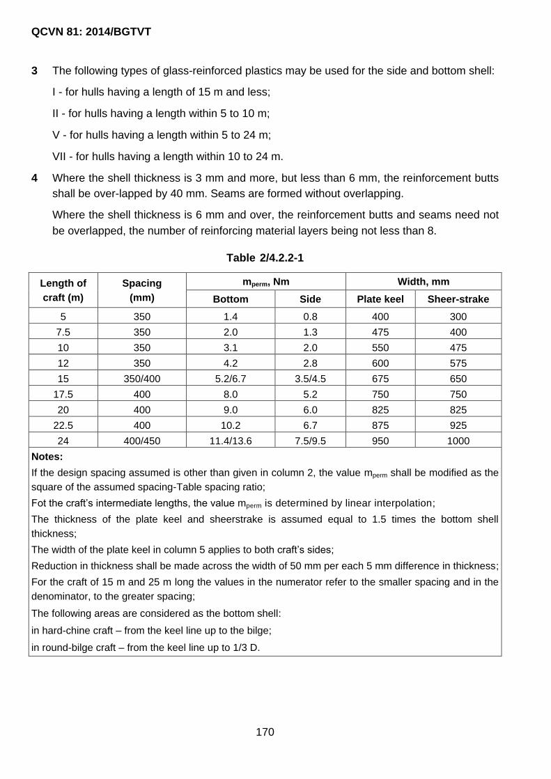
QCVN 81: 2014/BGTVT
170
3 The following types of glass-reinforced plastics may be used for the side and bottom shell:
I - for hulls having a length of 15 m and less;
II - for hulls having a length within 5 to 10 m;
V - for hulls having a length within 5 to 24 m;
VII - for hulls having a length within 10 to 24 m.
4 Where the shell thickness is 3 mm and more, but less than 6 mm, the reinforcement butts
shall be over-lapped by 40 mm. Seams are formed without overlapping.
Where the shell thickness is 6 mm and over, the reinforcement butts and seams need not
be overlapped, the number of reinforcing material layers being not less than 8.
Table 2/4.2.2-1
Length of
craft (m)
Spacing
(mm)
mperm, Nm Width, mm
Bottom Side Plate keel Sheer-strake
5 350 1.4 0.8 400 300
7.5 350 2.0 1.3 475 400
10 350 3.1 2.0 550 475
12 350 4.2 2.8 600 575
15 350/400 5.2/6.7 3.5/4.5 675 650
17.5 400 8.0 5.2 750 750
20 400 9.0 6.0 825 825
22.5 400 10.2 6.7 875 925
24 400/450 11.4/13.6 7.5/9.5 950 1000
Notes:
If the design spacing assumed is other than given in column 2, the value mperm shall be modified as the
square of the assumed spacing-Table spacing ratio;
Fot the craft‟s intermediate lengths, the value mperm is determined by linear interpolation;
The thickness of the plate keel and sheerstrake is assumed equal to 1.5 times the bottom shell
thickness;
The width of the plate keel in column 5 applies to both craft‟s sides;
Reduction in thickness shall be made across the width of 50 mm per each 5 mm difference in thickness;
For the craft of 15 m and 25 m long the values in the numerator refer to the smaller spacing and in the
denominator, to the greater spacing;
The following areas are considered as the bottom shell:
in hard-chine craft – from the keel line up to the bilge;
in round-bilge craft – from the keel line up to 1/3 D.

QCVN 81: 2014/BGTVT
171
Fig. 2/4.2.1-1(1)
Fig. 2/4.2.1-1(2)

QCVN 81: 2014/BGTVT
172
Fig. 2/4.2.1-1(3)

QCVN 81: 2014/BGTVT
173
Note: Stiffener with associated plate of glass plastic type I2
Fig. 2/4.2.1-3(1)

QCVN 81: 2014/BGTVT
174
b s1 s2
(1/1.5 … 1/1.3)h (1/10 … 1/20)h (2 … 3)s1
F = bs2
Note:
1. Face plate of glass plastic type III3, the associated plate of glass plastic type VII2, with EVII –
0.7 ЕIII (where E is the modulus of elasticity).
2. Web of glass plastic type I2.
Fig. 2/4.2.1-3(2)

QCVN 81: 2014/BGTVT
175
Fig. 2/4.2.1-3(3)

QCVN 81: 2014/BGTVT
176
a: premoulded stiffener;
b: stiffiner moulded in situ with a foamed plastic core;
c: ditto, with the face plate reinforced;
d: stiffiner moulded in situ over a former of sheet aluminium.
Notes:
1. Reinforcement in face on the basis of glass fabric or glass rovings;
2. These sketches do not regulate a ratio of dimensions for longitudinal primary support
members.
Fig. 2/4.2.1-3(4)

QCVN 81: 2014/BGTVT
177
b s1 s2
(1/1.5 … 1/3.0)h (1/10 … 1/20)h (2 … 3)s1
Note: The warp of glass fabric in a face plate shall be directed along the stiffener.
Fig. 2/4.2.1-3(5)
5 The butts and seams of the reinforcing material in each adjacent layer shall be
spaced at least 100 mm apart.
The butts and seams may coincide at one section in no less than six layers.
6 Woven rovings in layers of the diagonal layup shall not have butts.
7 The thickness and width of the plate keel and sheerstrake are determined according to
Table 2/4.2.2-1 (see Note 3).
8 The thickness of the stern laminates (transom included) shall not be less than that of the
bottom laminates.
9 The thickness of the shell and sheerstrake laminates in way of the fore peak shall be taken
equal to that of the midship portion.
10 The plate keel and sheerstrake shall be moulded by addition of reinforcing material layers,
which shall be uniformly distributed between the shell basic layers and alternate with the
latter.
The change in thickness shall be made in accordance with Table 2/4.2.2-1 (see Note 5).
4.2.3 Bottom framing
1 Floors shall be fitted at each frame.
2 Floors of increased section modulus shall befitted at all web frames. The depth of floors of
increased section modulus shall be taken equal to that of the centre girder and side
girders, whichever is greater.

QCVN 81: 2014/BGTVT
178
3 The scantlings of floors are taken in accordance with 4.2.1-2 depending on the section
modulus given in Table 2/4.2.3-3.
Table 2/4.2.3-3
Length
of craft
(m)
Design
load
(kPa)
Section modulus of closed-box section, in cm3, for 400 mm
spacing and with the span, in m
0.50 0.75 1.00 1.50 2.00 2.50
5.0 20.0 15 25 50 100 - -
7.5 30.0 20 40 70 150 260 -
10.0 40.0 30 50 90 200 350 -
12.0 25.0 15 30 60 130 220 350
15.0 30.0 20 40 70 150 270 420
17.5 35.0 25 50 80 180 310 490
20.0 38.0 30 60 90 200 350 560
22.5 43.0 35 70 100 230 400 630
25.0 47.0 - 80 110 250 440 690
27.5 51.0 - - 120 280 490 760
30.0 55.0 - - - 300 530 830
Notes:
1. The section modulus in the Table refers to the spacing of 400 mm and varies with
the ratio of “spacing, mm/400” for other spacings;
2. Where a T-section is used, the section modulus may be reduced by a factor of three;
3. The span is measured between the floor ends where the keel is omitted; from the
keel to the floor end where the keel is fitted and the side girder is omitted; from the keel
to the side girder or from the side girder to the floor end, whichever is greater;
4. For the craft of 5 to 10 m in length, the design load is assumed considering the
potential water impact against the bottom when the craft is dropped into water;
5. For the craft over 10 m in length, the design load is equal to the craft‟s maximum
depth at L/D = 6 + 0.5 m;
6. Where the design load considerably differs from that given in the Table, the section
modulus may be reduced proportionally with the ratio: actual design load/tabular design
load.
4 The minimum thickness of floors shall be 2 mm in the case of closed-box sections and 4
mm in the case of T-shaped sections.
5 Where the half-breadth measured along the top edge of the floor is in excess of 0.75 m, a
centre girder is required to be fitted. Where this value is in excess of 2.5 m, the fitting of

QCVN 81: 2014/BGTVT
179
one side girder on each side is required in addition to the centre girder. The scantlings of
the centre girder and side girders are given in Table 2/4.2.3-5.
Table 2/4.2.3-5
Length
of craft
(m)
Spacing,
mm
Centre girder Side stringer
depth,
mm
thicknes
s, mm
Section of face
plate, mm2
depth,
mm
thicknes
s, mm
Section of face
plate, mm2
5.0 350 150 8 60 × 12 - - -
7.5 350 180 9 70 × 14 - - -
10.0 350 210 10 80 × 15 - - -
12.0 350 240 11 90 × 15 - - -
15.0 350 270 12 100 × 15 200 10 80 × 15
17.5 400 300 13 110 × 16 225 11 90 × 15
20.0 400 330 14 120 × 18 250 12 100 × 15
22.5 400 370 15 130 × 20 275 13 110 × 16
25.0 400 410 16 140 × 22 300 14 110 × 16
27.5 450 440 17 150 × 24 325 15 120 × 18
30.0 450 470 18 160 × 26 350 16 130 × 20
Notes:
1. The scantlings shown in the Table are given for a T-shaped section with the face plate of glass-
reinforced plastic type III3 and the web of glass-reinforced plastic, types I2, V2, VII2;
2. Where closed-box sections of glass-reinforced plastic, type I2, are used, the section moduli shall
be increased by the factor of three;
3. The scantlings of longitudinal primary support members refer to the compartments having a length
of 30 per cent of the craft‟s length for the craft between 5 m and 20 m long, and of 20 per cent for the
craft between 20 m and 24 m long. In the case of compartments of greater lengths the scantlings of
the longitudinal primary support members shall be considered specially;
4. Where the actual spacing differs from that shown in the Table, the scantlings of the centre girder
and side girders shall not be modified;
5. For the craft‟s intermediate length the section modulus is determined by linear interpolation.
6 The intersection of the side girders with floor shall be effected in accordance with Fig. 2/4.2.3-
6(1) and Fig. 2/4.2.3-6(2) without cutting the floors. The intersection of side girders with
floors of increased section modulus shall be made by means of an edge cross-lap joint
(refer to Fig. 2/4.2.4-6).
7 The depths of non-continuous longitudinals shall be reduced to the floor depth within at
least three spacings at each longitudinal end.

QCVN 81: 2014/BGTVT
180
8 In floors and side girders water courses shall be provided. The recommended structural
design of a water course is shown in Fig. 2/4.2.3-8.
9 The connection of the bottom framing to the side framing may be effected by means of
matting-in or matting-on connections.
4.2.4 Side framing
1 The scantlings of frames shall be taken in accordance with 4.2.1-2 depending on the
section modulus given in Table 2/4.2.4-1.
2 The distance between adjacent bulkheads and web frames shall not exceed 6 spacings.
Note: The primary support member shall be formed first and not be cut at a deep member.
Fig. 2/4.2.3-6(1)
Note: The primary support member shall be formed first and not be cut at a deep member.
Fig. 2/4.2.3-6(2)

QCVN 81: 2014/BGTVT
181
Table 2/4.2.4-1
Span, m
Section modulus, cm3
Closed-box section, with spacing, mm T-shaped section, with spacing, mm
350 400 450 350 400 450
1.0 47 54 61 12 18 20
1.2 76 87 98 29 29 33
1.4 107 128 138 35 41 46
1.6 147 159 180 47 53 59
1.8 200 228 256 70 76 85
2.0 290 330 370 93 110 123
2.2 369 420 470 123 140 157
2.4 500 570 640 150 189 210
Note:
Where a side stringer is fitted, the section modulus of the frame shall be taken equal to 1.5 times the
section modulus determined from the Table for a span measured from the deck to the side stringer or
from the side stringer to the floor, whichever is greater.
Notes: 1. The hole is cut at 1/4 of the spacing distance from the intersection with a floor;
2. The edge of the hole shall be covered with resin.
Fig. 2/4.2.3-8
3 The section modulus of a web frame shall not be less than 5 times the frame section
modulus.
4 Where the frame span is in excess of 2.4 m, a side stringer shall be fitted.
5 The section modulus of a side stringer shall be equal to that of a web frame.

QCVN 81: 2014/BGTVT
182
6 The intersection of a web frame and a side stringer shall be effected by means of an edge
cross lap joint only (refer to Fig. 2/4.2.4-6).
7 The intersection of a side stringer and a frame shall be made as shown in Fig. 2/4.2.3-6(1)
and Fig. 2/4.2.3-6(2) without cutting the frame.
4.2.5 Decks
1 The upper deck laminate thickness shall be determined from Fig. 2/4.2.1-1(1) and Fig.
2/4.2.1-1(2) depending on the permissible bending moment value given in Table 2/4.2.5-1.
Table 2/4.2.5-1 Permissible bending moment
Length of craft, m Spacing, mm mperm, Nm Width of deck stringer,
mm
5 350 0.8 300
7.5 350 1.3 400
10 350 2.0 475
12 350 2.8 575
15 350/400 3.5/4.5 650
17.5 400 5.2 750
20 400 6.0 825
22.5 400 6.7 925
24 400/450 7.5/9.5 1000
Note:
1. If the spacing differs from the Table value, mperm shall be modified as the square of the assumed
spacing-Table spacing ratio;
2. The thickness of a deck stringer is assumed equal to the sheer- strake thickness (refer to Table
2/4.2.2-1;
3. For the craft‟s intermediate lengths, the value mperm is determined by linear interpolation.

QCVN 81: 2014/BGTVT
183
Notes:
1. Primary support members are joined with the use of an edge cross-lap;
2. The length of the outer strap shall not be more than three widths of the flange of a
longitudinal primary support member. A 20 mm overlap in adjacent layers shall be
provided. The strap thickness shall be equal to that of the flange of transverse primary
support member.
Fig. 2/4.2.4-6
2 The minimum deck laminate thickness shall be 4 mm.
3 The thickness and width of a deck stringer are determined according to Table 2/4.2.5-1.
4 The deck is permitted to be constructed of glass-reinforced plastics of the following types:
I - for hulls of not more than 15 m long;
VI - for hulls from 5 m to 30 m long;
VIII - for hulls from 10 m to 30 m long.
The deck laminate of the craft between 5 m and 10 m in length may be constructed of the
type II glass-reinforced plastic.
5 The reinforcing material shall be laid up in compliance with the requirements of 4.2.2-4.
6 Provisions shall be made for thickening like straps of at least 3 mm thick in the areas
exposed to intense wear unless the deck therein has a special protective coating.
7 Beams shall be dimensioned according to the requirements of 4.2.1-2 depending on the
section modulus given in Table 2/4.2.5-7.

QCVN 81: 2014/BGTVT
184
Table 2/4.2.5-7
Span of
beam, m
Section modulus, cm3
Closed-box section, with spacing,
mm T-section, with spacing, mm
350 400 450 350 400 450
1.0 16 18 20 - - -
1.2 24 27 30 - - -
1.4 33 38 43 - - -
1.6 43 49 55 15 17 19
1.8 52 59 66 18 20 22
2.0 65 74 83 23 25 27
2.2 80 90 100 26 30 34
2.4 98 110 124 32 37 42
Note:
The design span of the beam is measured between the ends of the beam brackets,
from the bracket end to the deck girder or between the deck girders, whichever is
greater.
8 A deep beam having the section modulus equal to at least five times that of the main beam
shall be fitted in the plane of every web frame.
9 Carlings shall be dimensioned according to the requirements of 4.2.1-2 depending on the
section modulus given in Table 2/4.2.5-9.
Table 2/4.2.5-9
Span of carling, m Section modulus, cm3, at the width of the deck supported, m
1.00 1.25 1.50 1.75 2.00
1.8 95 120 140 165 190
2.0 120 150 180 210 240
2.2 140 175 210 250 280
2.4 170 210 250 300 340
2.6 200 250 300 350 400
2.8 230 290 345 400 460
Notes:
1. The section moduli are given for a T-shaped section. Where closed-box section is used, the Table
section modulus shall be increased by the factor of three;
2. Deck girder span is the greatest of the deck girder spans measured between two supports
(centres of pillars, bulkheads, end hatch beams).
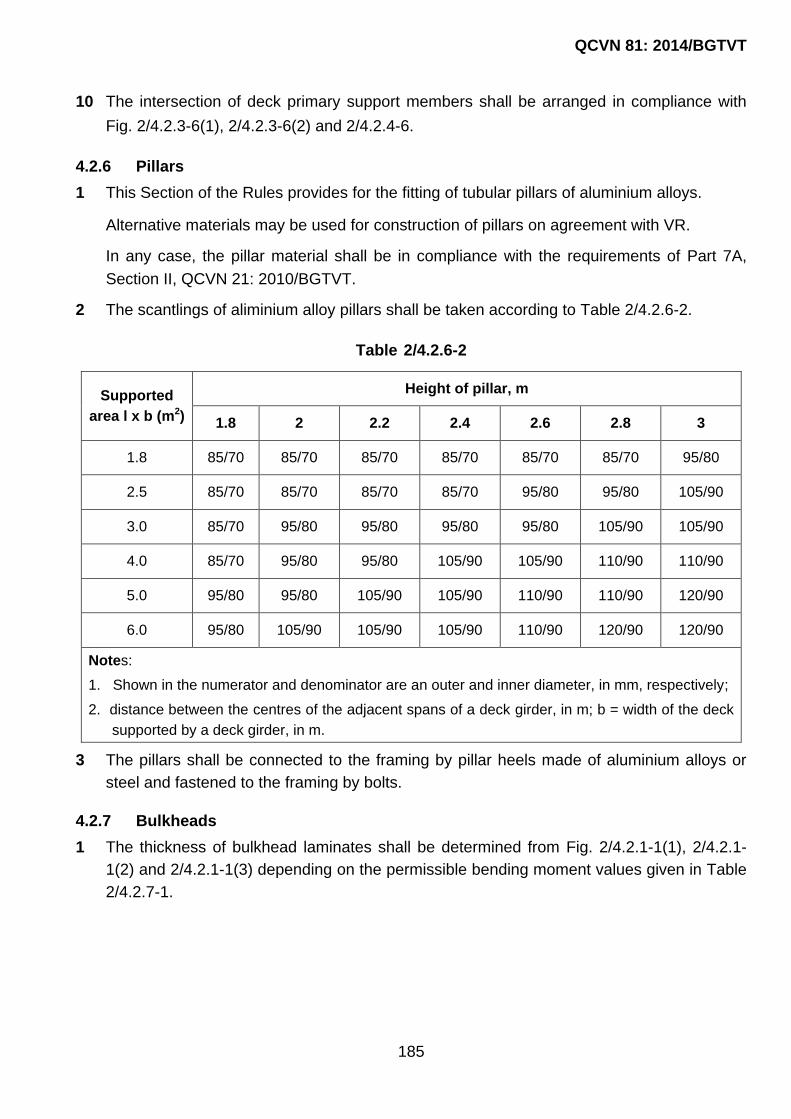
QCVN 81: 2014/BGTVT
185
10 The intersection of deck primary support members shall be arranged in compliance with
Fig. 2/4.2.3-6(1), 2/4.2.3-6(2) and 2/4.2.4-6.
4.2.6 Pillars
1 This Section of the Rules provides for the fitting of tubular pillars of aluminium alloys.
Alternative materials may be used for construction of pillars on agreement with VR.
In any case, the pillar material shall be in compliance with the requirements of Part 7A,
Section II, QCVN 21: 2010/BGTVT.
2 The scantlings of aliminium alloy pillars shall be taken according to Table 2/4.2.6-2.
Table 2/4.2.6-2
Supported
area l x b (m2)
Height of pillar, m
1.8 2 2.2 2.4 2.6 2.8 3
1.8 85/70 85/70 85/70 85/70 85/70 85/70 95/80
2.5 85/70 85/70 85/70 85/70 95/80 95/80 105/90
3.0 85/70 95/80 95/80 95/80 95/80 105/90 105/90
4.0 85/70 95/80 95/80 105/90 105/90 110/90 110/90
5.0 95/80 95/80 105/90 105/90 110/90 110/90 120/90
6.0 95/80 105/90 105/90 105/90 110/90 120/90 120/90
Notes:
1. Shown in the numerator and denominator are an outer and inner diameter, in mm, respectively;
2. distance between the centres of the adjacent spans of a deck girder, in m; b = width of the deck
supported by a deck girder, in m.
3 The pillars shall be connected to the framing by pillar heels made of aluminium alloys or
steel and fastened to the framing by bolts.
4.2.7 Bulkheads
1 The thickness of bulkhead laminates shall be determined from Fig. 2/4.2.1-1(1), 2/4.2.1-
1(2) and 2/4.2.1-1(3) depending on the permissible bending moment values given in Table
2/4.2.7-1.

QCVN 81: 2014/BGTVT
186
Table 2/4.2.7-1
Overall height of
bulkhead, m
mperm, Nm, with spacing, mm
300 350 400 450
1.25 0.9 - - -
1.50 1.1 1.5 - -
1.75 1.3 1.8 2.3 -
2.00 1.5 2.0 2.7 3.4
2.25 1.7 2.3 3.0 3.8
2.50 1.9 2.6 3.3 4.2
2.75 2.1 2.8 3.7 4.6
3.00 2.2 3.1 4.0 5.1
3.25 2.4 3.3 4.3 5.5
3.50 2.6 3.6 4.7 5.9
3.75 2.8 3.8 5.0 6.3
4.00 3.0 4.1 5.3 6.8
4.25 3.2 4.3 5.7 7.2
4.50 - 4.6 6.0 7.6
4.75 - - 6.3 8.0
5.00 - - - 8.4
Notes:
1. mperm refers to the bottom strake of the bulkhead panels;
2. The bulkhead thickness may be reduced throughout the height with the thickness at the upper
deck not less than half the bottom strake thickness;
3. Each strake shall be 0.7 m ... 1.0 m wide;
4. mperm for the bulkhead of an intermediate height is determined by linear interpolation.
2 The minimum plate thickness of watertight bulkhead laminates shall be 4 mm.
3 Bulkhead panels may be manufactured of type I2, V2 or VII3 glass-reinforced plastics.
4 The scantlings of bulkhead stiffeners are taken according to 4.2.1-2 depending on the
section modulus given in Table 2/4.2.7-4.

QCVN 81: 2014/BGTVT
187
Table 2/4.2.7-4
Span of
stiffener,
in m
Section modulus of bulkhead stiffener, in cm3
Stiffener span from deck to bottom or
horizontal girder at spacing, in mm
Stiffener span
from horizontal girder
to bottom at spacing, in mm
300 350 400 450 300 350 400 450
1.25 15 18 20 23 24 29 33 37
1.50 25 29 33 37 30 35 40 45
1.75 40 47 54 60 50 59 67 76
2.00 55 64 73 92 80 92 105 105
2.25 80 93 105 105 95 110 125 140
2.50 95 110 125 140 130 150 170 190
2.75 130 150 170 90 170 200 225 260
3.00 160 187 210 240 225 260 300 335
Notes:
1. The section moduli refer to T-section stiffeners;
2. For shaped section stiffeners with a face plate reinforced with glass mats the tabular section
modulus shall be increased by a factor of three.
5 The maximum span of a stiffener shall be within 3 m. Where the bulkhead height exceeds
3 m, a horizontal girder with a section modulus of not less than 5 times the section
modulus of the stiffener shall be fitted.
6 Where a horizontal girder is provided, a stiffener of the same section modulus as the
horizontal girder shall be fitted at the centre line.
7 The design of openings in bulkheads shall meet the requirements of 4.2.10.
8 The longitudinals shall not be cut at bulkheads. The slots in the bulkheads for the
longitudinals shall be 3 to 4 mm higher and wider than the longitudinals proper and after
the installation of bulkheads shall be filled with glass rovings and covered with not less
than 3 layers of glass fabric.
9 The horizontal girders of bulkheads shall be fitted in one plane with side stringers and
interconnected therewith by brackets of an arm length equal to the web depth of the side
stringer.
10 The bulkhead stiffeners supported by longitudinal framing members shall be connected
thereto by means of straps and mattings-in.
11 The bulkhead stiffeners receiving support from the bottom or deck shall be interconnected
with the nearest transverse member by means of short longitudinals, which depth shall be

QCVN 81: 2014/BGTVT
188
equal to the stiffener depth. The connection of these short longitudinals to stiffeners shall
be effected in accordance with 4.2.7-9.
4.2.8 Tanks
1 The thickness of the laminates of the structures bounding tanks is determined from Fig.
2/4.2.1-1(1), 4.2.1-1(2) and 2/4.2.1-1(3) depending on the permissible bending moment
mperm given in Table 2/4.2.7-1. In this case a distance up to the top of an air pipe is
assumed in lieu of the overall height of the bulkhead given in Table 2/4.2.7-1 (refer also to
4.2.7-2).
2 Primary support members shall be dimensioned according to Table 2/4.2.8-2.
Table 2/4.2.8-2
Head of water, m
Section modulus of closed-box section, cm3,
with a 400 mm spacing and a span, in m
0.50 0.75 1.00 1.25
2.00 10 25 50 70
2.50 15 30 60 85
3.00 20 40 70 100
3.50 25 45 80 120
4.00 30 50 90 140
4.50 35 55 100 160
5.00 40 65 110 175
Notes:
1. In the Table scantlings for a closed-box section are given. Material used is glass-reinforced plastic on
the basis of glass mats (type I2). Where T-shaped section with a flange of glass-reinforced plastic,
type III3, is used, the section modulus may be reduced by the factor of three;
2. The section moduli in the Table refer to a spacing of 400 mm. For other spacings the section
modulus varies proportionally to a ratio of spacing, mm/400;
3. The design head of water is measured from the midlength of a stiffener or from a crown to the top of
an air pipe;
4. The stiffener span is measured from the bottom to the crown of a tank. The beam span is measured
between the sides or between the side and swash bulkhead.
3 The thickness of a margin plate in way of double bottom tanks shall be equal to that of
shell laminates in this area.
4 The sides and tops of tanks may be constructed of type I2, II2 or V2 glass-reinforced
plastics.

QCVN 81: 2014/BGTVT
189
The recommended design of a manhole fitted in the crown of tank is shown in Fig. 2/4.2.8-
6.
a- minimum distance from the edge to the bolts, a ≥ 3d (Where, d = bolt diameter); h- height
to suit bolt or nut fitting; a1 ≥ 1.5 mm.
Note: Bolts shall be spaced not more than 4 d apart.
Fig. 2/4.2.8-6
5 Fuel oil tanks of glass-reinforced plastic shall be provided with VR-approved earthing
arrangements for discharging static electricity.
6 The construction of tank manholes and covers shall ensure the watertightness of the
tanks.
7 Primary support members inside tanks shall be provided with water courses and air holes.
4.2.9 Superstructures and deckhouses
1 The outer shell of supestructures extended as the craft‟s side plating shall be integral to
the latter. The thickness of the superstructure laminate shall be equal to that of the hull
sides. The thickness reduction from the sheerstrake to the superstructure side shall be
according to Table 2/4.2.2-1.
2 The sides of superstructures not extending to the hull sides and deckhouses may be of
single-skin or sandwich construction. The material to be used for superstructure and
deckhouse sides is glass-reinforced plastic on the basis of glass mats or woven rovings
(type I2 or II2). The primary support members shall be of glass reinforced plastic, type I2.
3 The double-skin construction of superstructures and deckhouses is subject to special
consideration by VR.
4 The thickness of a foam plastic core in sandwich construction shall be within 30 to 50 mm.
The average density of foam plastic for superstructure sides shall not be less than 100
kg/m3 and not more than 200 kg/m3.
5 The laminate thickness for the end bulkheads of superstructures, as well as for all outer
ends and sides of deckhouses shall be taken according to Table 2/4.2.9-5(1) for single-
skin construction and Table 2/4.2.9-5(2) for sandwich construction.

QCVN 81: 2014/BGTVT
190
Table 2/4.2.9-5(1) Single-skin construction ends and sides of superstructures and
deckhouses, spacing 400 mm
Length of craft, in m Plate thickness, in mm
5 4
10 6
15 8
20 10
24 10
Notes:
1. For other spacings the thickness varies proportionally to a ratio of spacing, mm/400, but it shall not
be less than 4 mm.
2. The material used is glass-reinforced plastic on the basis of glass mat (type I2);
For intermediate craft length the thickness is determined by linear interpolation.
Table 2/4.2.9-5(2) Ends and sides of superstructures and deckhouses of sandwich
construction with core thickness of 30 to 50 mm, spacing 800 mm
Length of craft, in m Laminate thickness, in mm
outer inner
5 3 2.5
10 4 3
15 7 3.5
20 8 4
24 8 4
Note: For other spacings the thickness of the outer laminate varies proportionally to a ratio of
spacing, mm/800, but it shall not be less than 3 mm.
6 The stiffeners of the superstructure and deckhouse ends and sides shall be dimensioned
according to Table 2/4.2.9-6(1) for single-skin construction and Table 2/4.2.9-6(2) for
sandwich construction.

QCVN 81: 2014/BGTVT
191
Table 2/4.2.9-6(1) Stiffeners of single-skin construction superstructures and
deckhouses, spacing 400 mm
Span of
stiffener, in m
Section modulus of closed-box
section, in cm3
Span of
stiffener, in m
Section modulus of closed-box
section, in cm3
1.0 18 1.8 53
1.2 25 2.0 74
1.4 38 2.2 90
1.6 49 2.4 105
Notes:
1. For other spacings the section modulus varies proportionally to a ratio of spacing, mm/400;
2. For the intermediate value of a stiffener span the section modulus is determined by linear
interpolation.
Table 2/4.2.9-6(1) Stiffeners of sandwich construction superstructures and
deckhouses, spacing 800 mm
Span of
stiffener, in m
Section modulus of closed-box
section, in cm3
Span of
stiffener, in m
Section modulus of closed-box
section, in cm3
1.0 37 1.8 120
1.2 52 2.0 150
1.4 75 2.2 180
1.6 98 2.4 215
Notes:
1. For other spacings the section modulus varies proportionally to a ratio of spacing, mm/800;
2. The spacing of superstructure side stiffeners shall be adjusted with that of superstructure deck
beams;
3. For the intermediate value of a stiffener span the section modulus is determined by linear
interpolation.
7 The deck laminate thickness and the scantlings of the deck framing of superstructures and
deckhouses are taken in accordance with the requirements of 4.2.5 and 4.2.6.
4.2.10 Openings in structures
1 Round openings cut in the shell, deck and watertight bulkheads with a diameter less than
150 mm are permitted not to be reinforced.
2 Round openings cut in the shell with a diameter of 150 mm and over shall be reinforced
with glass fabric of satin weave or woven rovings in accordance with Fig. 4.2.10-2.
The reinforcements of openings having other shapes are subject to special consideration
by VR.

QCVN 81: 2014/BGTVT
192
3 Round openings cut in decks with a diameter of 150 mm and over as well as rectangular
openings of any diameter shall be reinforced with glass fabric of satin weave or woven
rovings.
The recommended reinforcement of openings is shown in Fig. 2/4.2.10-3(1) and 2/4.2.10-
3(2).
4 Lightening holes are not permitted in the webs of primary support members.
Notes:
1. Reinforcing shall be made only with glass fabric whose warp is oriented along the hull;
2. The thickness of the strap shall be equal to that of the structure. If the position of the
openings is specified beforehand, the strap is moulded into the basic layers of the laminate,
otherwise it shall be matted onto the inner face of the laminate between the frames, within
one spacing as shown in the Figure;
3. Openings are not permitted to be positioned closer than d/2 to the frame.
Fig. 2/4.2.10-2

QCVN 81: 2014/BGTVT
193
Notes:
1. Reinforcing shall be made only with glass fabric, which warp is oriented along the hull;
2. The thickness of the strap shall be equal to that of the structure. The strap is matted into the
basic layers of the laminate of the position of the openings is known beforehand or moulded
onto the upper surface of the deck.
Fig. 2/4.2.10-3(1)
5 Openings cut in the primary support member webs for the passage of cables, pipes, etc.
having a diameter of more than 1/3 of the web depth shall be reinforced with straps.
6 Dimensions of openings and the structure of closures in the outer shell and watertight
bulkheads of craft, which subdivision is regulated by the requirements in Part 9, Section II,
QCVN 21: 2010/BGTVT are subject to special consideration by VR in each case.
Notes:
1. Reinforcing shall be made only with glass fabric of which a warp is parallel to the craft‟s
centre line;
2. The fabric layers forming the strap shall be laid between the reinforcement layers of the
deck laminate;
3. The total thickness of reinforcing fabric layers shall be equal to that of the deck laminate
thickness.

QCVN 81: 2014/BGTVT
194
Fig. 2/4.2.10-3(2)
4.2.11 Bulwark
1 The bulwark thickness shall be equal to half the thickness of the side laminate, but not less
than 4 mm.
2 The bulwark stays shall be fitted at alternate beams.
3 In craft over 15 m in length the bulwark laminate shall not be integral to the side laminate
and its sectional area shall be ignored in determining the craft‟s hull section modulus.
4 The structure of bulwarks in craft, which can moor at sea, shall be specially considered by
VR.
4.2.12 Engine seatings
1 Side stringers shall be used as the bearers of main engine seatings, wherever possible.
Where this is impracticable, additional bottom longitudinals with the web as thickness
equal to that shall be fitted.
2 The engine seating girders shall extend forward and aft beyond the machinery space
bulkheads for at least three spacings and be tapered at the end of the third spacing to floor
depth.
3 The seating girders shall be reliably connected with transverse brackets fitted at every
frame.
4 Seatings are permitted to be built of steel and aluminium alloys on special agreement with
VR.
5 The fastening of the engine bed flanges may be made by metal flats moulded into the
flanges of the girders by fitting of metal angle sections bolted to the girder top edge or by
other means approved by VR.
4.2.13 Stems, stern frames, propeller shaft brackets and bilge keels
1 Stems may be moulded of glass-reinforced plastic or may be of composite structure with
the use of metal.
2 For the reinforcing of the stem laminate glass fabrics, woven rovings and glass-fibre
bundless (rovings) are used. The use of glass mats is not permitted.
3 Metal parts of the stem may be of aluminium alloys or of steel reliably protected by
corrosion-resistant coating. As a rule, they shall be moulded into the stem.
4 The section of glass-reinforced stem shall be shaped as a rectangle with the width b and
length l, mm, determined by the formulae:
b = 1.5L + 30;
l = 2.5b.
Where:

QCVN 81: 2014/BGTVT
195
L : craft‟s length, m.
The thickness of the stem laminate reinforced with type II, III or IV glass fabric shall be 1.5
times the sheer-strake thickness. The space inside the stem shall be filled with plastic
reinforced with glass-fibre bundles, which shall be directed along the stem.
5 In case of a composite stem the width b1 of the alluminium alloy core, length l1 and total
width b2 of the stem are determined by the formulae:
b1 = 0.4L + 10
b2 = b1 + 2s
l1 = 2.5 b2
Where:
L : craft‟s length, m;
s : thickness of the stem laminate determined according to 4.2.13-4.
6 The width of a steel core may be equal to 3/4 of the aluminium one (refer to 4.2.13-5). The
core length is determined according to 4.2.13-5.
7 The sternframe (if any) may be metal or composite (glass-reinforced plastic with metal
core). The sternframe scantlings and structure are subject to special consideration by VR
in each case.
8 The shaft brackets shall be as required in Part 2B, Section II, QCVN 21: 2010/BGTVT. The
strut arms shall be attached to the hull with bolts. Straps of glass-reinforced plastic having
a thickness equal to twice the shell thickness and fitted on the reverse side in way of
bracket attachment as well as stiffening for primary support members, which shall be
agreed with VR, shall be provided in this area.
9 Bilge keels, if fitted, shall be of glass reinforced plastic of type II. The attachment of bilge
keels to the hull shall be effected by means of matting-in double angles (without using
bolts), which shall be fitted on both sides of the keel laminate. The thickness of the
matting-in double angles shall be equal to that of the keel laminate. The structural design
of bilge keels shall be such that no damage would be caused to the shell in case of bilge
keel loss.
4.2.14 Casings of engine and boiler rooms, hatch and fan coamings
1 The structure and scantlings of engine and boiler room casings, hatch and fan coamings
are subject to special consideration by VR.

QCVN 81: 2014/BGTVT
196
PART 3 EQUIPMENT, ARRANGEMENTS AND OUTFIT
CHAPTER 1 GENERAL
1.1 Application
1.1.1 The requirements of the present Part of the Regulation apply to craft equipment,
arrangements and outfit t used on small pleasure craft.
1.1.2 The cargo handling gear specified in 1.3.1-6 shall comply with the requirements of QCVN
23: 2010/BGTVT.
1.2 Definitions and Explanations
1.2.1 The following definitions and explanations are used in the present part of the
Regulation.
1 Bitt is a bollard placed on the craft deck to fix the tow lines, mooring ropes or anchor
cables.
2 Windlass is the anchor mechanism with the horizontal axis of rotation of the driving shaft
intended for anchoring and weighing as well as for hauling in anchor cables.
3 Oar is a device for rowing which has a blade to create thrust. There may be a single-blade
or double blade oars and single-bank oars.
4 Auxiliary steering gear is the equipment other than any part of the main steering gear
necessary to steer the craft in the event of failure of the main steering gear, but not
including the tiller, quadrant or components serving the same purpose.
5 Retractable steering propeller (RSP) is the azimuthing thruster which design enables to lift
propeller inside the craft hull in non-operating condition.
6 Main steering gear is the machinery, rudder actuators, steering gear power units, if any,
ancillary equipment and the means of applying torque to the rudder stock (e.g. tiller or
quadrant) necessary for effecting movement of the rudder for the purpose of steering the
craft under normal service conditions.
Main steering gear may be power-operated or hand-operated one.
7 Cargo handling gear is an arrangement necessary for moving various cargoes by craft
means.
8 Propulsion steering system (PSS) is the propulsion and steering element of a craft. Oars,
sail, rudder, azimuthing thrusters, vane propellers, thrusters and outboard motors.
9 Hull fittings are the auxiliary items placed on the craft deck serving for passage and fixing
of towing, mooring and anchor lines, as well as different rigging. Hull fittings are bitts,
blocks, bollards, deck organizers, eyebolts, rollers, cleats, lever stoppers, rigging shackles,
etc.
QCVN 81: 2014/BGTVT
197
10 Closing arrangement is an arrangement intended for closing openings in hull or in craft
superstructure: shell doors, cargo hatch covers, doors, companion hatches and
skylights, windows etc.
11 Canhook or aquisition is any part of craft which may be seized by hand to reduce risk of
falling over-board even if this is not its main function.
12 Fairlead is a plate of special form put on the bulwark gunwale and intended for directing
the mooring line to the bollard or the warping drum. It may have either simple design or be
fitted with the rollers.
13 Vertical-axis propeller is the propeller with the vertical axis of rotation consisting of the
vertical blades fixed on the vertical drum.
14 Guard Rails is a barrier on open deck consisting of posts and ropes or tubes extended
between them.
15 Pulpit is a rigid frame railing.
16 Sailing rig is a set of arrangements, spars and rigging, which provide the craft motion using
the wind energy.
17 Azimuth thruster is an open or ducted propeller fitted on a arrangement rotating 360
degrees around the vertical axis. Azimuth thrusters of great power may be used as the
main propulsion and steering unit.
18 Thruster is an arrangement providing transverse or longitudinal thrust and used for
improvement of the craft steerability at low speed.
19 Railing is a tube rail.
20 Rudder and steering gear is an arrangement intended for craft steering and keeping it on
its course.
21 Rudder is one or several bearing surfaces (wings or plates) which angle in respect to the
craft centerline plane (deflection angle) may be changed by craftmaster.
22 Balanced rudder is the rudder, which part is located before the axis of the rudder stock to
reduce the spindle torque.
23 Unbalanced rudder is the rudder which rudder stock axis coincides with the leading edge
of rudder or passes in close vicinity to it.
24 Streamlined rudder is the rudder with the symmetrical aviation profile in the transverse
section.
25 Plate rudder is the rudder of the easiest design which transverse section is the flat plate.
26 Suspended rudder is the rudder which is fixed to the rudder stock only in the upper part.

QCVN 81: 2014/BGTVT
198
27 Semi-spade rudder is the rudder which upper part is fixed to the rudder stock, in the
middle part it has one or several attachments to horn/rudder post or stern-tube and it has
no support in the lower part (rudder heel).
28 Simple rudder is the rudder which is fixed to the rudder stock in the upper part and it is
supported in the lower part.
29 Transom rudder is the rudder placed on the craft transom.
30 Power actuating system of the steering gear is the hydraulic or mechanical equipment
provided for supplying power to turn the rudder stock or steering nozzle and comprising a
steering gear power unit or units, together with the associated pipes and fittings, and
rudder deflection servo or steering nozzle. The power actuating systems may share
common mechanical nodes, such as tiller, quadrant, rudder stock or nodes serving the
same purpose.
31 Steering gear power unit:
- in the case of electrical steering gear it is an electrical motor and its associated electrical
equipment;
- in the case of electrohydraulical steering gear it is an electrical motor and its associated
electrical equipment and connected pump;
- in the case of hand-operated hydraulic steering gear it is a hand-operated gear and
connected pump.
32 Steering gear control system is the power-driven device used together with the main
steering gear to transmit commands from the navigating bridge to steering gear power
units. The steering gear control systems comprise detectors, receivers, hydraulic control
pumps and their associated motors, motor controllers, piping and cables.
33 Active means of craft‟s steering (AMSS) are the special propulsion and steering units and
any combination of them or with main propulsion devices capable to create thrust or
traction force both at a fixed angle to the centre line plane of the craft and at the variable
angle either under all running conditions or part thereof including slow speed and zero
speed. The active means of craft‟s steering comprise fixed and retractable steerable
propellers, water jets, thrusters, outboard electric motors and other devices of similar
purpose.
34 Safety harness (lifebelt) is a set of belts connected against each other which man puts on
together with safety line with snap shackles on both ends, one of them is attached to the
safety belt and the other to the element rigidly fixed on a craft (on deck, deckhouse,
superstructure etc.) and intended for assuring safety during crew work on deck under the
hard storm conditions.
35 Craft arrangements is a set of the craft equipment and service mechanisms intended to
assure the required operating and navigational properties of craft.

QCVN 81: 2014/BGTVT
199
36 Lanyard is a rope strainer used on crafts instead of the stretching screw to assure rail rope
or lashing tension.
37 Cleat is an item of special (generally, twin-horn) form intended for fastening of the steel
mooring ropes and running rigging.
38 Mooring and towing arrangement is the arrangement intended to provide safe moorage of
a craft by berth or any other floating structure (craft, moorings, floating landing stage) as
well towing assistance to any other similar craft or her own towing by another craft.
39 Mooring pipe is an item with the oval hole fitted in the craft bulwark or on deck and
intended for directing the mooring rope to the bollard or bitt.
40 Centreboard, bilgeboard is a wing casted outboard of the crafts to reduce their drift.
41 Mooring windlass is a mooring mechanism with the vertical axis of rotation of the driving shaft
intended for hauling in a rope to draw a craft nearer to berth.
42 Vertical shaft windlass is an anchor mechanism with the vertical axis of rotation of the
driving shaft intended for anchoring and weighing as well as for hauling in anchor cables.
43 Anchor gear is an arrangement serving for the safe anchorage of a craft at sea, on road
stead and other places far from shore by means of securing to the ground by an anchor
and anchor cable (cable or rope).
44 Cable pipes are the special castings fitted on deck and onboard to direct the anchor cable.
1.3 Scope of Survey
1.3.1 The following parts of craft arrangements are liable to survey by VR during
manufacture
1 Steering gear
(1) rudder stocks;
(2) rudder blade;
(3) rudder axles;
(4) pintles of rudders and steering nozzles;
(5) bushes of pintles;
(6) fastening of the rudder stocks, rudder stock with rudder blade steering nozzles and
also of rudder axle with sternframe (muff couplings, keys, bolts, nuts etc.);
(7) parts of the system of rudder stops;
(8) rudder stock bearings;
(9) rudder trunk;
(10) details hand-operated rope steering gear;
QCVN 81: 2014/BGTVT
200
(11) details and nodes of hand-operated shaft steering gear;
(12) details and nodes of hand-operated remote steering gear.
2 Anchor arrangement
(1) anchors;
(2) chain cables or ropes;
(3) anchor stoppers;
(4) devices for securing and releasing the inboard end of chain or rope;
(5) anchor deck organizers.
3 Mooring arrangement
(1) mooring ropes;
(2) mooring bollards, belaying cleats, fairleads, deck organizers, rollers and stoppers.
4 Towing arrangement
(1) tow lines;
(2) towing bollards, bitts, fairleads, deck organizers and stoppers.
5 Spars and rigging
(1) standing and running spars;
(2) standing and running rigging;
(3) sails;
(4) cable plates, parrals, bollards, belaying cleats, fairleads, rollers and stoppers;
(5) signal masts.
6 Cargo-handling gear
In compliance with QCVN 23: 2010/BGTVT
(1) craft cargo derricks, cranes and hoists with the carrying capacity of 1 t and more;
(2) craft electric traction elevators which are intended for lifting and lowering of people
and/or cargoes in a cage moved by the ropes at a speed of not more than 0.1 m/s;
(3) craft elevating platforms which are lifted and lowered at a speed of not more than 0.1
m/s.
7 Closing appliances
(1) all closing appliances located on the craft outer hull surfaces, superstructures and
deckhouses;
(2) all closing appliances located inside craft in the watertight structures.
8 Equipment of craft spaces

QCVN 81: 2014/BGTVT
201
(1) stairways and vertical ladders;
(2) guard rails, bulwark and gangways.
1.3.2 Survey of products by VR is limited to review of the technical documentation
Products listed in 1.3.1-1(5), 1.3.1-1(8), 1.3.1-1(9), 1.3.1-1(10), 1.3.1-2(5), 1.3.1-3(2),
1.3.1-4(2), 1.3.1-5(3), 1.3.1-5(4), 1.3.1-8.
1.3.3 Documents to be submitted to VR
For items specified in 1.3.1 the following documents shall be submitted to VR:
(1) assembly drawing;
(2) gears and arrangements calculations;
(3) drawings of nodes and details if they are manufactured according to standards or
technical conditions which are not agreed with VR.
1.3.4 Materials subjected to VR survey during manufacture
Products listed in 1.3.1-1(1), 1.3.1-1(4), 1.3.1-3, 1.3.1-4, 1.3.2-6, 1.3.1-7 are subjected to
VR survey during manufacture.
1.3.5 Surveys under construction
The following arrangements, equipment and outfit are subject to VR survey when the craft
is under construction:
(1) rudder and steering gear;
(2) anchor arrangement;
(3) mooring arrangement;
(4) towing arrangement;
(5) rigging;
(6) cargo-handling gear;
(7) signal masts;
(8) closing appliances;
(9) emergency outfit.
1.4 Materials and Welding
Materials for manufacture of the arrangements, equipment and outfit unless otherwise is
not explicitly specified in the Regulation shall comply with the requirements listed in the
documentation of the design approved by VR.
QCVN 81: 2014/BGTVT
202
Welding of structural elements of craft‟s arrangements, equipment and outfit shall be
performed in accordance with the requirements of Part 6 Section II of QCVN 21:
2010/BGTVT.
1.5 Inertial Loads
Inertia loads arising during craft movement at seaways shall be considered in calculation
of craft‟s arrangements. The value of inertia loads is determined by an acceleration arising
at craft‟s motions in waves.
Acceleration at motions in waves is calculated according to 2.1.4-7 Part II. The necessity
for evaluation of acceleration at motions in waves is a matter of the special consideration
by VR in each case.
1.6 Special Strong Structures
1.6.1 Anchor, mooring and towing arrangements
Anchor, mooring and towing arrangements shall have strong design to withstand forces
acting in ropes and cables. Meanwhile, the structures of strong design of anchor and
mooring arrangements may be used in the towing arrangement.
Tensile strength of ropes/cables used in these arrangements shall not exceed 80 per cent
ultimate load of the corresponding strong design structure.
1 At all craft − one strong design structure in the fore end for anchor and towing
arrangements.
2 On craft which length is LH > 6 m - at least one strong design structure for mooring
arrangement in the aft.
3 On craft which length is LH > 12 m - at least one additional structure in addition to those
specified in -1 or 2, strong design structure for the mooring arrangement in the fore end
and in the aft
4 On craft which length is LH > 18 - at least one additional structure in addition to those
specified in -3, strong design structure for the portside and starboard mooring
arrangement.
1.6.2 Requirements of ISO 15084: 2003 shall be considered in the design of strong structures
in respect of assignment of dimensions, strengthenings, corrosion resistance and
marking.

QCVN 81: 2014/BGTVT
203
CHAPTER 2 STEERING GEAR
2.1 General
2.1.1 Each craft shall have a reliable steering gear, enabling its maneuverability and course-
keeping qualities under design operating conditions. Such arrangements may be:
steering gear, vane propeller, azimuth thruster, outboard motor (motors) and other
arrangements approved by VR.
Birth connected craft may not have the steering gear.
Considering the area of navigation and operating conditions the non-self-propelled craft
may not be fitted with the steering gear or only stabilizer may be installed upon agreement
with VR. Design category, area of navigation and operating conditions of the non-self-
propelled craft which allow absence of the steering gear or installation of stabilizers only is
a matter of the special consideration by VR in each case.
2.1.2 Position of helmsman shall provide proper vision around the craft. If there is not a
proper view from the emergency control station then there shall be a voice contact with
a member of the crew who has such view.
2.1.3 The craft is steered by deflection of the rudder blade (blades), steering oar, rotation of
the waterjet nozzle, change of the thrust vector of outboard motor and sterndrive or by
other methods. Rudder blade may be rotated by tiller or by steering gear. The steering
tiller or other mechanical arrangement shall be provided for the emergency operation
(except for craft of design categories C, C1, C2, C3 and D).
2.1.4 The deflection angle of rudder blade (or direction of thrust vector) shall be visible to the
helmsman personally or by means of the indicator.
2.1.5 The steering gear shall be designed so that to enable easy access for control and
maintenance of some elements. There should be no equipment and outfit located close
to the steering gear that may interfere operation of this arrangement. Steering gear
should be designed so that the rudder blade doesn‟t impinge the hull plating preventing
damage to any element of the steering gear.
2.1.6 Requirements of the present section cover the steering gear that have rudders listed in
Fig. 3/2.1.6. It is recommended to apply requirements set forth in QCVN 21:
2010/BGTVT to nozzled steering gears and rudders which design differ from those.
Unusual steering gears: rudder with rotor, flap-type rudder, multi-blade rudders like
Enkel rudders etc., as well as the azimuth thruster, vane propellers etc., in each case
are a matter of the special consideration by VR.

QCVN 81: 2014/BGTVT
204
Considering the purpose, special features of a craft and intended regimes of its
operation it may be allowed upon approval by VR that the regulated steerability of a
craft at slow speed is provided by simultaneous action of the means listed in 2.1.1 and
active means of craft‟s steering (AMSS).
Fig. 3/2.1.6 Types of rudders
2.1.7 In any case the rudder shall have at least two supports, meanwhile, depending on type
of the steering gear, the rudder heel pintle may be one of the supports (lower). It is not
allowed to use the power system as a support (steering gear actuator) unless it is not
intended for the said purpose. Number of rudder pintles which serve as a support for its
blade is not regulated by VR.
2.1.8 The specific pressure shall not exceed values given in Table 3/2.1.8 when the specific
pressure of rudder pintles and rudder stock bearings is checked.
Table 3/2.1.8 Permissible pressure for rudder pintles and rudder stock bearings
Frictional couple’s material
Specific pressure p, in MPa, if lubricated
by
water oil
Stainless steel or bronze against lignum vitae 2.4 -
Stainless steel or bronze against textolite or synthetic
materials
Upon special agreement with VR -
Stainless steel against bronze or vice versa 6.9 -
Steel against the white metal - 4.4
2.2 Initial Design Data
2.2.1 The initial design data specified in this Chapter are valid only for the choice of scantlings
of ordinary rudders and nozzle rudders with rigidly fixed stabilizers and cannot be used
for determination of steering gear output characteristics. Methods of determination of
these characteristics are not regulated by VR, and the relevant calculations are not
subject to approval by VR. The steering gear is checked by VR during sea trials of the
ship to make sure that the steering gear output characteristics comply with the
requirements of 2.9.2, 2.9.3 and 2.9.7.
2.2.2 Rudder force and rudder torque

QCVN 81: 2014/BGTVT
205
1 The rudder blade force F (N), acting on the rudder blade at headway movement shall be
calculated by the formula:
2
1 2 0 0F K K V A
Where:
1K : is the coefficient calculated according to Table 3/2.2.2-1(1);
: is the relative elongation of the rudder blade 2
0b / A ;
b: is the mean height of the submerged part of the rudder blade, m;
0A : effective square of rudder together with horn (skeg), in m2;
0A A for structures shown on Fig. 3/2.2.1-1 and 3/2.2.4-4;
0 stA A A for structures shown in Fig. 3/2.2.4-2, 3/2.2.4-3 and 3/2.2.4-5;
A: square of rudder blade, in m2, (for transom rudder − only square of the submerged
part of it);
stA : square horn (skeg) of rudder, in m2;
2K : coefficient taken according to Table 3/2.2.2-1(2), Where is the water
displacement, in t, at draught to the design waterline;
0V : design craft velocity, in knots, depending on the type of craft according to 2.2.2-2.
Table 3/2.2.2-1(1) 1K coefficients for rudders of different elongation
0.5 1.0 1.5 2.0 2.5 3.0 3.5 4.0
1K 61 93 113 126 135 140 141 141
Table 3/2.2.2-1(2) 2K coefficient for craft of various types
Type of craft 2K
Motor craft 1.2
Non-self-propelled crafts 1.1
Sailing craft, sailing-motor craft and motor-sailing craft:
3
wlL / 6
3
wlL / 6
1.6
3
wl0.11 0.25L /
2 Design craft speed, 0V (knots), whichever is greater:

QCVN 81: 2014/BGTVT
206
0 wlV 2.7 L or 0 maxV V
Where: maxV is actual maximum speed of craft, in knots.
2.2.3 Bending moments acting upon the rudder blade
1 Balanced three pintle rudder
The maximum value of the bending moment M1, in Nm, acting upon the rudder blade shall
be calculated by the formula:
1M 0.125F b
Fig. 3/2.2.3-1 Load, bending moments and transverse forces in the balanced rudder with rudder heel
The maximum value of the bending moment of the rudder stock, in Nm, on the centre
pintle shall be calculated by the formula:
2M 0.14F b
Where:
F: design hydrodynamic load, in N, according to 2.2.2-1, N;
b: mean height of the submerged part of the rudder, in m.
2 Balanced suspended rudder
The value of the bending moment M1, in Nm, in the arbitrary horizontal section of the
rudder blade shall be calculated by the formula:
1 b 1M (F A h ) / A
Where:

QCVN 81: 2014/BGTVT
207
F: design hydrodynamic load, in N, according to 2.2.2-1, N;
Ab: square, in m2, of the part of rudder blade below the section in question;
h1: vertical distance, in m, from the centre of gravity of the cut area Ab to the section in
question;
A: square of the rudder blade, in m2, according to 2.2.2-1.
The value of the bending moment in the rudder stock, M2, in Nm, in the area of the lower
bearing shall be calculated by the formula:
2 2M F h
Where:
F: design hydrodynamic load, in N, according to 2.2.2-1, N;
h2: vertical distance, in m, from the centre of gravity of the square of rudder blade to
the centre of the lower bearing.
Fig. 3/2.2.3- Load, bending moments and shear forces of the balanced suspended rudder
3 Balanced semi-spade rudder
The maximum value of the bending moment on the rudder blade M1, in Nm, shall be
calculated by the formula:
1 b 2M (F A h ) / A
Where:
F: design hydrodynamic load, in N, according to 2.2.2-1, N;
Ab: square, in m2, of the part of rudder blade below the section in question;

QCVN 81: 2014/BGTVT
208
h2: vertical distance, in m, from the centre of gravity square Аb to the section in
question;
A: square, in m2, of the rudder blade according to 2.2.2-1.
The value of the bending moment in rudder stock M2, in Nm, in the area of the lower
bearing:
2M F h /17
Where:
F: design hydrodynamic load, in N, according to 2.2.2-1;
h: mean height of the submerged part of the rudder, in m.
Fig. 3/2.2.3-3 Load, bending moments and shear forces of the balanced semi-spade rudder
4 Simple unbalanced multipintle rudder
The height of the rudder stock up to the upper rudder bearing is exposed to twisting only in
the simple rudders supported by pintles. Above the upper bearing the rudder stock is
exposed to the bending moment (in excess of the spindle torque) caused by the force
applied to the tiller or quadrant to turn rudder.
This bending moment is calculated by the formula, Nm
b k rM F r h / L
Where:
F: design hydrodynamic load, in N, according to 2.2.2-1;
cr x f , see 2.2.4;
kh : distance from the upper support bearing to the axis of tiller or quadrant, in m;

QCVN 81: 2014/BGTVT
209
rL : radius of the quadrant or length of tiller arm, in m.
2.2.4 Torque
Torque caused by the hydrodynamic load on the rudder blade Mc, in Nm, is calculated by
the formula:
cM F r
Where:
F: design hydrodynamic load, in N, according to 2.2.2-1, N;
r: radius of the action force, in m;
cr x - f , if a rotation axis is on the rudder blade;
cr x f , if a rotation axis is before the rudder blade;
cr x , for rudders with the rudder heel and horn (skeg) of large square ( 1 stA / A 2 );
cx : horizontal distance between the point where the resultant hydrodynamic force is
applied and the leading edge of the blade ( or stabilizer) in accordance with the
value shown in Fig. 3/2.2.4-1 to 3/2.2.4-5;
f: horizontal distance between the rotation axis and the leading edge of the blade (or
horn), measured at the height of point where the resultant hydrodynamic force is
applied according to Fig. 3/2.2.4-1 to 3/2.2.4-5.
Fig. 3/2.2.4-1 Rudder with heel without
skeg
Fig. 3/2.2.4-2 Rudder with heel and
narrow skeg
xc = 0.3C
rmin = 0.1C
xc = 0.25C
rmin = 0.1C
xc = 0.25C
rmin = 0.1C
xc = 0.3C
rmin = 0.1C

QCVN 81: 2014/BGTVT
210
Fig. 3/2.2.4-3 Rudder with heel and large
skeg
Fig. 3/2.2.4-4 Balanced suspended
rudder
Fig. 3/2.2.4-5 Balanced semi-spade rudder
2.3 Rudder Blade Design
2.3.1 Materials
Rudder blade can be made of metal, laminate, solid wood or plywood.
The metal blade plating thickness shall not be less than the minimum thickness of hull
plating specified in Part 2. The distance between the stiffeners of such rudder shall not
exceed frame spacing of craft calculated on the basis of the load to the bottom in the area
of the aft end and approved thickness of rudder blade plating.
2.3.2 In an arbitrary section of the rudder blade the combined stresses caused by
bending and twisting com , in MPa, calculated by following Formula shall not exceed
0.3 times the upper yield stress of the rudder blade material:
2 2
com 3
Where:
: normal bending stresses, in MPa;
: tangential stress caused by twisting, in MPa.
If the rudder blade is made of several different materials, the condition for the reduced
stress shall be checked for each of them.
2.3.3 The metal plating of the rudder blade shall be welded to stiffeners by the fillet weld, it is
allowed to apply plug welds.
2.3.4 Rudder blade shall be made of the solid laminate manufactured in two enantiomorphous
forms and glued provided:
A = A1 + A2
xc = C(0.2h1/b = 0.3)
rmin = C(0.1-0.05 - h1/b)

QCVN 81: 2014/BGTVT
211
- the blade is glued following the technology approved by VR;
- manufactured blade is checked for bending by the load equal to 1.5 M1.
If these conditions are not complied with then it is necessary to fix the halves of blade
by laminate strip on the lower, leading and upper edges.
2.3.5 The inner cavity of the volumetric rudder blade shall be properly packed. It is
recommended to fill the blade cavity with the material which doesn‟t imbibe water. The
volumetric blade made of the metal or laminate which is not filled in shall be subjected
to density tests by 2.5 m of water head. This requirement doesn‟t apply to rudder blades
made of stainless steels.
2.4 Rudder Stock
2.4.1 Rudder stock shall pass through hull by means of the strong pipe and appropriate
sealing glands shall be used to prevent penetration of outer water inside craft hull. It is
allowed to use pipes made of synthetic materials provided the following conditions are
complied with:
- rudder stock bearings are immovably fixed on hull;
- the pipe reaches minimum 0.75 height of freeboard in the aft end;
- guaranteed water tightness of all equipment under any operating conditions.
2.4.2 Except special cases, the rudder stock and other main parts of the steering gear shall
made of steels with the yield strength at least 235 MPa. Rudder stock shall be firmly
connected to the rudder blade. There should be no points with a weak strength in the
connection of the blade and rudder stock.
2.4.3 Solid Rudder Stock
Diameters of the solid metal rudder stock (see Fig. 3/2.4.3), in mm, shall not be less than
those calculated by the following formula:
s3
t1
m e
Md 33
R R
2 2
2 s3t2
m e
0.75M Md 33
R R
for supported and semi-spade rudders:
t3 t1 t2d (d d ) / 2
for suspended rudders:
t3 t1 t2d 1.15(d d ) / 2
for supported and semi-spade rudders:

QCVN 81: 2014/BGTVT
212
t4 t2d 0.6d
for rudder stocks passing through the whole height of rudder blade:
t5 t3d d
Fig. 3/2.4.3 Rudder stock
2.4.4 Rudder stocks of pipes
It is allowed to make rudder stocks of pipes.
Diameter of such pipe and thickness of its walls should be so that their strength at twisting
or simultaneous exposure to twisting and bending of the hollow rudder stock is the same
as for the solid rudder stock.
If material of the same strength is used, the diameter of the hollow rudder stock (pipe)
shall be taken so that to observe the following dependence:
4 4
out in3
c
out
d - dd
d

QCVN 81: 2014/BGTVT
213
Where:
cd : diameter of the solid rudder stock, in mm;
outd : outer rudder stock diameter made of pipe, in mm;
ind : inner rudder stock diameter made of pipe, in mm.
It is not recommended to use pipes with wall thickness less than out0.1d
2.4.5 Measures shall be taken to prevent rudder stock loosing (displacement) from bearings.
2.5 Transom Rudders
2.5.1 Design of the permanent (stationary) transom rudder shall comply with the requirements
from 2.3.1 to 2.3.5.
2.5.2 If the rudder blade is detachable, then it is necessary to take measures to prevent its
spontaneous lifting during motion. Meanwhile, the design of the both blade and the yoke
shall comply with the requirements from 2.3.1 to 2.3.5.
2.5.3 Diameters of steel pintles, in mm, used to hang up the transom rudder are shown in Fig.
3/2.5.3 and they shall not be less than:
Fig. 3/2.5.3 Transom rudder
s1d 0.2 F(t /a)
s2d 0.2 F(1- t /a)
s3d 0.2 F(1 t /a)
Where:

QCVN 81: 2014/BGTVT
214
s1d : diameter of upper pintle, mm;
s2d : diameter of lower pintle, if F force is applied between pintles, mm;
s3d : diameter of lower pintle, if F force is applied below this pintle, mm;
F : design hydrodynamic load according to 2.2.2-1, in N;
t : vertical distance between the lower pintle and the point where the F force is
applied, in mm;
a : vertical distance between the pintles, in mm.
However, pintle diameters shall not be less than 14 mm for structural steel and 12 mm
for stainless steel.
2.5.4 The rudder hanging on the pintles shall be fitted with arrangements preventing its
spontaneous lifting and falling out.
2.5.5 Design of ironworks for hanging rudder on the aft end shall correspond with the loads
acting in the places of fixing the ironworks.
Thickness of flat ironworks which are used for holding rudder pintles shall be at least
0.2 diameter of the said pintles.
2.6 Couplings of Rudder Stock with Rudder Blade
2.6.1 Some structural elements of the rudder stock connection with the rudder blade shall be
made in accordance with the loads specified in 2.2.2 and 2.2.3.
2.6.2 If flange connections are used the diameter of bolts ds, in mm, connecting flanges
should be at least those calculated by the formula
3
t et3
s
s es
d Rd 0.62
n r R
Where:
td : diameter of rudder stock calculated according to 2.4.3, mm;
n : number of bolts which shall not be less than: 4 for craft which length is less
than 12 m and not be less than 6 for craft which length is 12 - 24 m;
r : mean distance from the bolt axis to the middle of pintles, mm;
etR : yield strength of the rudder stock material, MPa;
esR : yield strength of the bolt material, MPa.
2.6.3 All bolts shall be stud bolts except cases when keys are fitted, then only two stud bolts
are enough. Nuts shall be of normal size. Bolts and nuts shall be firmly fixed. At least
two bolts shall be located in front of the rotation axis of the rudder stock.

QCVN 81: 2014/BGTVT
215
2.6.4 The distance between the bolt axis and flange edge shall be at least the diameter of
bolt.
2.6.5 Yield strength of steel the bolt is made of shall not be less than 235 MPa.
2.6.6 Flange connection shall be made of the same casting as the rudder stock. It is allowed
to weld flange to the rudder stock, which end is set to diameter by 10 per cent
exceeding the design one, the height of setting shall not be less than the flange
thickness. On craft which length is less than 12 m if stainless steel is used and the
rudder stock diameter is by 10 per cent more than the design one it is allowed to weld
the flange without setting of the rudder stock end. Method of connection shall be agreed
with VR.
2.6.7 Flange thickness shall not be less than the design diameter of the bolt specified for n =
6.
2.6.8 Flange connections shall be fitted with the key but if the bolt diameter is 10 per cent
greater than the required one then a key may not be used.
2.6.9 If cone connections are used, then the conical part of the rudder stock shall comply with
the dependence:
1 21/12 (d - d ) / l 1/ 8 and 1l 1.5d
Where:
1d : rudder stock diameter in the largest cone section, mm;
2d : rudder stock diameter in the least cone section, mm;
l : length of cone, mm.
2.6.10 The conical connection shall be fitted with relevant key.
2.6.11 The size of nut shall not be less than the following ones:
- inner thread diameter 3 1d 0.65d ;
- height of nut n 3h 0.6d ;
- outer thread diameter, n 2d 1.2d or n 3d 1.5d whichever is greater.
The nut shall be firmly fixed to prevent unscrewing.
2.6.12 Other types of rudder stock couplings are the matter of the special consideration by VR.
2.7 Rudder Bearings
2.7.1 In respect of bearings of rudder stock and pintles accepting transverse load the
requirement 2.1.8 shall be complied with.
Rudder bearing square An, in mm2, (height multiplied by diameter) shall not be less than:
n aA R / P
Where:

QCVN 81: 2014/BGTVT
216
R : design value of the reaction force caused by load calculated according to
2.2.2-1, in N;
aP : permissible pressure, in MPa, depending on the material of bearing;
aP 2.5 for soft synthetic material (teflon);
aP 5.0 for solid synthetic material (polyamides);
aP 7.0 for steel and bronze.
2.7.2 Height of bearings shall not be less than the rudder stock diameter in the place of
installation of bearing, however, it shall not be more than 1.2 diameter of rudder stock
for bearing made of metal or two diameters for the bearing made of synthetic material.
2.7.3 If a bearing bushing is made of steel it shall be made of the stainless steel. If a stainless
steel is used for the rudder stock bearing also made of stainless steel it is necessary to
provide measures against grinding.
2.7.4 Bearing linings (bushings) of bearings shall be firmly fixed in the bearing box in order
to avoid accidental displacement.
In order to accept the weight of rudder and stock one of the bearings shall be a thrust
bearing able to carry axial load equal at least the weight of rudder and rudder stock.
Measures shall be taken against the upward axial displacement of the rudder stock by the
value more than that allowed by the steering gear design. Rigidity of hull structures
carrying bearings of rudder stock and pintles (support), shall be checked for action of
forces listed in 2.2.3 in respect of the specific case. Elastic displacement of support under
this load shall not exceed single-sided clearance of bearing.
2.8 Rudder Skeg and Heel
2.8.1 Design of the rudder support in the form of skeg or rudder heel shall be rigid and strong.
Stresses originating in any section due to design transverse reaction in the bearing of
rudder heel shall not exceed 0.25Rm (ultimate tensile strength).
If the support doesn‟t comply with this condition then the design of rudder and its rudder
stock shall comply with the requirements for rudders without lower support.
2.9 Rudder Tiller and Quadrant
2.9.1 Dimensions of tiller or rudder quadrant arm (arms) shall be determined in relation to the
design spindle torque and used material.
Modulus of resistance W1, in mm3, tiller or rudder quadrant arm (arms) in the place of
connection with the boss shall not be less than:
1 s mW 1000M / (k R )
Modulus of resistance, in mm3, in the end of tiller shall not be less than:

QCVN 81: 2014/BGTVT
217
2 s mW 180M / (k R )
Where:
sM : design spindle torque, in Nm, according to 2.2.4;
mR : rupture strength of the applied material, MPa;
k : coefficient depending on the material;
k = 0.40 for metals;
k = 0.15 for laminated wood;
k = 0.09 for solid wood.
2.9.2 If the lifting tiller is used, its fastening to rudder stock (or transom rudder) shall be able
to withstand the design load at tiller lifted at 20° angle.
2.9.3 Dimensions of the emergency tiller shall be calculated for the moment equal to 0.7
design one.
2.9.4 Length of the emergency tiller shall be so that to ensure safe steering by rudder by not
more than two men personally or by means of tackles.
2.9.5 If there is tetrahedral lobe on the rudder stock for fixing the emergency tiller, the side of
the square shall be at least t10.7d and its height at least t10.8d .
2.9.6 The outer diameter of the quadrant or tiller boss shall not be less than 1.8 diameter of
rudder stock in the point of its forcing on, and its height − not less than that diameter.
Bosses consisting of several parts shall be connected by at least four bolts, two on each
side of the rudder stock.
Total square of the section of these bolts, in mm2, shall not be less than:
sA M / f
Where:
f : distance from the bolt axis to the axis of the rudder stock, mm.
2.9.7 Design of the steering gear quadrant with the mechanical drive shall comply with the
requirements in 2.9.1
2.10 Steering Gear
2.10.1 Each craft shall have two steering gears - main and auxiliary unless expressly provided
otherwise.
Mechanical steering gear shall be capable of:
- putting the rudder from one board to the other at least 35 deg., for the outboard
motor this angle shall be at least 30 deg.;
- limit maximum deviations of the rudder by means of stoppers;

QCVN 81: 2014/BGTVT
218
- safe perception of loads caused by the design spindle torque due to action of the
pressure force by all elements of the gear;
- tangential force on the steering-wheel ring not more than 200 N;
- information on the rudder blade position relative to the centre line plane by means
of the relevant indicator on the wheelman‟s position;
- use of the emergency tiller or other emergency steering gear complying with the
requirements in 2.9.3.
2.10.2 The main steering gear shall be capable of putting the fully submerged rudder at a
maximum operational ahead speed of the craft and under the same conditions from 35°
on one side to 30° on the other side within 30 s.
2.10.3 The auxiliary steering gear shall be independent from the main steering gear and shall
be capable of putting the rudder from 20° on one side to 20° on the other side in not
more than 60 s at half of the maximum operational ahead speed at least:
- for craft of design categories A, A1, A2, B, C and C1: 5 knots;
- for craft of design categories C2, C3 and D: half full speed.
It is allowed that the main and auxiliary gears have some common parts (for instance,
tiller, quadrant, gear box, cylinder block etc.) provided the respective scantlings of these
parts are increased sufficiently.
2.10.4 The main steering gear may be hand-operated provided it meets the requirement of
2.10.2 at steering force not more than 120 N and the number of steering wheels of not
more than 25 per one deflection of the rudder. If the said condition is not complied with,
the main steering gear shall be operated by power.
Tiller may be used as a main steering gear if the requirement 2.10.2 is complied with at a
tiller steering force not more than 160 N per each working man; meanwhile, there is no
need to install the auxiliary steering gear.
2.10.5 Where the main steering gear consists of two equal power units, there is no need to
install the auxiliary steering gear.
2.10.6 The auxiliary steering gear can be hand-operated, if the requirement 2.10.3 is complied
with at a tiller steering force not more than 160 N per each working man and the number
of turns of the wheel is not more than 25 per one full helm deflection.
Steering tackles or tiller can be used as the auxiliary steering gear if the requirement
2.10.3 is complied with at the force in the runner of steering tackle or tiller not more than
160 N per each working man.
In all other cases the auxiliary steering gear shall be power driven.
2.10.7 Steering gear shall have the stopper for the rudder rotation which permits its turn either
board to the following angle:
o o o o o( 1 ) ( 1.5 )
QCVN 81: 2014/BGTVT
219
Where:
o : maximum angle of putting the rudder to which the end switches of the
steering gear are adjusted is usually taken as not more than 35 degree.
All details of the stopper including those that are simultaneously used as the details of the
steering gear shall be designed to withstand forces corresponding to the ultimate reverse
torque on the rudder stock Мult, in kN·cm, calculated by the formulae:
3
ultM 2.7d
Meanwhile, stress in these details shall not exceed 0.95 yield strength of their material.
2.10.8 Hand-operated shaft steering gear in respect of design, scope of bench tests and
documentation shall comply with the requirements of ISO 13929: 2001.
2.10.9 Hand-operated rope steering gear in respect of design, scope of bench tests and
documentation shall comply with the requirements of ISO 8847: 1987.
2.10.10 On craft with outboard motor the remote hand steering gear in general case in respect
of design, scope of bench tests and documentation shall comply with the requirements
of EN 28848: 1993 or EN 29775: 1993 at power of the outboard motor from 15 to 40
kW.
2.10.11 Hand-operated rope steering gear the tensile strength of rope steering rods, in N, shall
not be less than that calculated by the formula:
s sR 9.5M /r
Where:
sM : design spindle torque, in Nm, according to 2.2.4;
sr : quadrant radius, in m.
Ropes of steering rods shall be made of stainless steel.
Lanyards and connection elements shall be chosen corresponding to the strength of rods.
Diameter of leading blocks shall not be less than sixteen diameters of rope.
2.10.12 On craft with the remotely controlled outboard motor, the motor shall be fitted with the
relevant lever on tiller for connection with the steering gear. If there are two engines
both engines shall be connected between each other.
Meanwhile, the requirements of 2.10.1 shall be complied with in respect of the angles of
deflection the helm and presence of stoppers (mechanical stops).
2.10.13 One pair of boat oars with rowlocks at Lwl < 6 m shall be provided as an emergency
means of movement and steering on craft with the outboard motor.
2.10.14 In all other respects the steering gears shall comply with the applicable requirements
of Part 3 and Part 4 QCVN 21: 2010/BGTVT.

QCVN 81: 2014/BGTVT
220
2.11 Rudder Trunk
2.11.1 The rudder trunk design shall assure strength which would ensure resistance to forces
emerging in the steering gear. The rudder trunk shall be strengthened in the longitudinal
and transverse directions and be connected to the longitudinal and transverse framing.
The minimal wall thickness of the trunk made of metal materials shall be calculated by the
formula:
wl S 0.9 L k
Where:
Lwl : craft length by design waterline, in m;
k : coefficient considering type of material;
k = 1 for usual carbon steel.
for steels with other characteristics:
eH mk 635 /(R R )
Where:
eHR : yield strength of steel, N/mm2;
mR : steel ultimate tensile strength, N/mm2.
For sea water resistant aluminium alloys:
p0.2 mk 635 /(R R )
Where:
p0,2R : 0.2% yield strength of aluminium alloy, N/mm2;
mR : aluminium alloy ultimate tensile strength, N/mm2.
2.11.2 Strength of the rudder trunk on craft made of glass fiber plastic shall be equal to the
strength of the bottom plating.
The rudder trunk shall pass through the craft hull till the crossing with the deck or be fitted
with the seal higher than the actual waterline.
At height of 200 mm from the actual waterline hoses or sleeves like hoses made of
material agreed with VR may be used for extension of the rudder pipe.
2.11.3 On craft of design categories A, A1, A2, B and C, which upper end of the rudder trunk is
not connected with the cockpit bottom or main deck and located in the inner underdeck
space the seal shall be fitted in the upper end of the rudder trunk to prevent penetration
of the outer water inside craft hull through the rudder trunk. Specific types of designs of
these seals depend on the purpose of craft, dimensions etc and it is a matter of the
special consideration by VR. However, without regard of the design of these seals, all of

QCVN 81: 2014/BGTVT
221
them shall be made so that they are accessible for inspection and maintenance by the
crew at any time.

QCVN 81: 2014/BGTVT
222
CHAPTER 3 ANCHOR ARRANGEMENT
3.1 General
3.1.1 Each craft except of design category D shall be provided with the anchor arrangement
ensuring capability of the long mooring of a craft far from shore exposed to current and
at maximum wind and waves permissible for sailing of this craft as well as fast and safe
release and hoisting of the anchors at all possible situations.
Craft of design category D may have no anchor arrangements.
3.1.2 The following elements shall be a part of the anchor arrangement:
- anchor (one or several);
- anchor cables and/or ropes;
- anchor release and hoisting mechanisms (if necessary);
- arrangements for stowage of anchors onboard (if necessary);
- arrangements for stowage and release of inboard end of chain cables and/or
ropes (if necessary).
3.2 Characteristics of Anchor Outfit
3.2.1 Supply of anchors, cables and ropes shall comply with Table 3/3.2.1-1 and 3/3.2.1-2 on
the basis of outfit characteristics:
c 1N 0.6L B D A
Where:
L : design craft length, in m, equal to half sum of craft length LH and length at
design waterline;
B : maximum craft breadth, in m, measured by the outer edges of framing from
one side to another without regard of the outwhales;
D1 : conditional depth, in m, equal to depth of craft D plus 1/6 keel height
measured at transverse direction amidships at design waterline;
A : 0.5 of the volume of superstructures, in m3, meanwhile superstructures and
deckhouses which width is less than B/4 may be disregarded.
3.2.2 In case of a light craft which displacement is less than that specified in column 2, Table
3/3.2.1-1 and 3/3.2.1-2, anchor appliances may be chosen on the basis of the mean
value between the water displacement and characteristics of the anchor appliances. In
this case the weight of the anchors shall be defined by means of the interpolation and
diameter of chain links and length of cables and ropes shall be rounded upward to the
nearest greatest value.

QCVN 81: 2014/BGTVT
223
For craft of design categories C2, C3 and D the anchor appliances are chosen on the
basis of Nc corrected by the adjustment coefficient equal to 0.75.
3.2.3 For craft with water displacement less than 1.5 t the anchor appliances are chosen on
the basis of the water displacement.
3.2.4 For berth connected craft the anchor appliances are chosen according to Table 3/3.2.1-
2 on the basis of characteristics 3.2.1.
3.2.5 For anchors fitted with anchor cables it is a mandatory requirement to fit the cable to
anchor by means of piece of cable of relevant diameter which length is not less than
one anchor length of chain specified in 3.4.1-5.
3.3 Anchors
3.3.1 The weights of anchors listed in Table 3/3.2.1-1 and 3/3.2.1-2 refer to anchors of the
high holding power.
Anchors shall be manufactured in compliance with Part 7B QCVN 21: 2010/BGTVT.
Anchors of the following types are permitted to be used on craft:
- Hall;
- Gruson;
- Admiralty anchor.
3.3.2 If two anchors are fitted, the mass of each anchor separately may differ by 7 per cent
from the figure given in Table 3/3.2.1-1 and 3/3.2.1-2, meanwhile the total mass of
these two anchors shall not be less than the mass required.
3.3.3 Materials for anchors shall comply with the requirements of Part 7A QCVN 21:
2010/BGTVT. Anchors which mass is more than 75 kg and their chain cables shall be
tested in the presence of VR representative. Anchors which mass is less than 75 kg and
anchors intended for craft of design categories C1, C2, C3 and D may pass relevant
tests at the manufacturer facilities without presence of VR representative.
3.3.4 The sail monohull and multihull craft of design categories A, A1, A2, B and С shall be
fitted with the floating anchor with diameter of bell mouth between 10 per cent and 15
per cent of craft length LH.
The floating anchor shall be fitted with the anchor cable made of plain-laid nylon rope
which length is equal to 10LH and diameter equivalent to the tow line for this craft.
A weight of 20 kg shall be fitted onboard for embedding the floating anchor.
3.4 Ropes and Chain Cables
3.4.1 Anchor cables /ropes and chain cables
1 The tow line may be used as an anchor cable on crafts with water displacement 1.5 t and
less.

QCVN 81: 2014/BGTVT
224
2 Chain cables may have short links or links with studs. They shall be made of mild steel or
special steel in accordance with the requirements of Part 7A Section II QCVN 21:
2010/BGTVT.
3 It is allowed to use chain cables with short links which diameter is defined for the chain
cables with studs.
4 Anchor cables shall be 1.5 longer that the length specified for the chain cable in Table
3/3.2.1-1 and Table 3/3.2.1-2 and be spliced into a thimble at one end.
Table 3/3.2.1-1 Anchors, chain cables/cables and towing ropes of sail boats, motor sailers
Outfit characteristic
Nc,m3
Water displacement
, t
Weight of anchors, kg
Chain cable or cable Towing rope
Anchor 1
(1) Anchor
2
Length of chain,
m(2)
Diameter, in mm Length,
m Diameter,
mm(4)
Chain(3)
Cable(4)
1 2 3 4 5 6 7 8 9
≤ 10 ≤ 0.15 2.5 - - - 8 5LH 12
≤ 10 0.20 3.0 - - - 8 12
≤ 10 0.30 3.5 - - - 8 12
≤ 10 0.40 4.5 - - - 8 12
≤ 10 0.50 5.0 - - - 10 12
≤ 10 0.60 5.5 - - - 10 14
≤ 10 0.75 6.5 - - - 10 14
≤ 10 1.00 7.5 - - - 10 14
≤ 10 1.50 8.7 - - - 10 14
≤ 10 2.00 10.5 9.0 22.5 6.0 12 16
15 3.00 12.0 10.0 24.0 6.0 12 18
20 4.00 13.0 10.5 25.0 6.0 12 18
25 5.00 13.5 11.0 26.0 7.0 14 18
30 6.00 15.0 13.0 27.0 7.0 14 18
40 8.00 17.0 15.0 29.0 8.0 16 20
55 12.00 21.0 18.0 32.5 8.0 18 22
70 17.00 25.0 21.0 36.0 9.0 24
4.75LH
22
90 23.00 29.0 25.0 40.0 10.0 26 22
110 29.00 34.5 29.0 43.0 10.0 28 24
130 36.00 40.0 34.0 47.0 11.0 -
4.5LH
24
155 44.00 46.5 40.0 52.5 13.0 - 24
180 52.00 53.0 45.0 57.0 13.0 - 24
210 57.00 62.0 53.0 62.0 13.0 - 26
245 72.00 73.5 62.0 68.0 14.0 -
4.25LH
26
280 84.00 84.0 71.0 74.0 16.0 - 26
300 100.00 95.0 81.0 78.0 16.0 - 26 (1)
For craft of design categories C2, C3 and D it is allowed to use anchors without a stock with a weight at
least 1.33 of the figure specified in the Table.

QCVN 81: 2014/BGTVT
225
(2) It is applied individually to each anchor.
(3) Chain cable diameter.
(4) Nominal diameter of three-stranded rope twisted nylon cable according to Table 3/4.5.1.
Table 3/3.2.1-2 Anchors, chain cables/cables and towing ropes of motor craft, oar-
propelled and non-self-propelled craft
Outfit
characteristic
Nc, m3
Water
displacement
, t
Weight of anchors,
in kg Chain cable or cable Towing rope
Anchor
1(1) Anchor 2
Length
of chain,
m(2)
Diameter, mm Length,
m
Diameter,
mm(4)
Chain (3)
Cable (4)
1 2 3 4 5 6 7 8 9
≤ 10 ≤ 0.15 2.5 8 5LH 12
≤ 10 0.20 3.0 8 12
≤ 10 0.30 3.5 8 12
≤ 10 0.40 4.5 8 12
≤ 10 0.50 5.0 10 12
≤ 10 0.60 5.5 10 14
≤ 10 0.75 6.5 10 14
≤ 10 1.00 7.5 10 14
≤ 10 1.50 8.7 10 14
≤ 10 2.00 9.0 20.0 6.0 12 16
15 3.00 10.0 22.0 6.0 12 18
20 4.00 11.0 23.0 6.0 12 18
25 5.00 12.0 24.0 6.0 12 18
30 6.00 13.0 25.0 7.0 14 18
40 8.00 14.0 12.0 26.0 7.0 14 20
55 12.00 18.0 15.0 29.0 8.0 16 22
70 17.00 25.0 21.0 32.5 8.0 18
4.75LH
22
90 23.00 29.0 25.0 36.0 9.0 24 22
110 29.00 34.5 29.0 38.5 10.0 26 24
130 36.00 34.5 29.0 42.0 10.0 28
4.5LH
24
155 44.00 40.0 34.0 47.0 11.0 - 24
180 52.00 46.0 39.0 51.0 13.0 - 24
210 57.00 52.5 44.0 55.5 13.0 - 26
245 72.00 61.0 52.0 61.0 13.0 -
4.25LH
26
280 84.00 70.5 60.0 66.5 14.0 - 26
300 100.00 79.5 67.5 70.0 16.0 - 26
(1) For craft of design categories C2, C3 and D it is allowed to use anchors without a stock with a weight at
least 1.33 of the figure specified in the Table.
(2) It is applied individually to each anchor.
(3) Chain cable diameter.
(4) Nominal diameter of three-stranded rope twisted nylon cable according to Table 3/4.5.1.

QCVN 81: 2014/BGTVT
226
Table 3/3.4.1-5 Anchor length of chain
Nominal diameter of chain cable of anchor
length of chain, in mm
Anchor length of chain, in m
6 - 8 6.0
9 - 16 12.5
5 Anchor length of chain shall be inserted between the anchor cable and anchor which
diameter is given in column 6, Table 3/3.2.1-1 and Table 3/3.2.1-2 and length according to
Table 3/3.4.1-5.
Chain cables and anchor length of chain shall be fitted with enforced links on the ends. A
swivel shall be fitted between an anchor and chain cable.
6 The inboard end of chain cable shall be connected to craft hull so that in case of danger it
can be released at any time from the easily accessible and safe place for the crew.
Inboard end of chain cable shall be at least by 15 per cent (but not greater than 30 per
cent) stronger than the nominal breaking strength.
7 In order to serve for anchors with a mass from 30 to 50 kg it is recommended to use
anchor winches. On sail boats the sheet winches may be used for release and hoisting
such anchors.
8 Anchor machinery shall be used for serving anchors with a mass greater than 50 kg on a
mandatory basis. It is recommended to use capstans or windlasses, winches and similar
mechanisms as an anchor machinery.
9 Anchor machinery shall comply with the requirements of 3.7. If anchors weighing more
than 50 kg shall operate together with ropes/cables, then the anchor winch shall be fitted
with the rope drum enabling fast release of the inboard end of chain cable at all possible
situations. Safety of its operation shall be confirmed in practice.
10 At all craft where it is allowed to use the tow line as an anchor cable there shall be details
connecting tow cable with the anchor length of chain.
3.5 Chain Locker
3.5.1 Cable lockers shall be provided for stowage of each chain.
When one chain locker is designed for two chains it shall be provided with an internal
division so that separate stowage of each chain is ensured. Transverse dimensions and
height of the chain locker shall ensure direct and unimpeded lead of chain through the
deck organizer even when the chain is absolutely heaved.
3.5.2 On craft with chain locker measures shall be taken to prevent flood of the adjacent
compartments when the chain locker is submerged through the deck organizer.
3.6 Arrangement of Anchor Appliances Onboard

QCVN 81: 2014/BGTVT
227
3.6.1 The actual number and mass of anchors, hull shape in the area of regular location of
the anchor appliances, arrangement of details of the anchor appliances as well as
arrangement of the forward forepeak bulkhead, transom board and afterpeak bulkhead
shall be considered during arrangement of anchor appliances onboard.
3.6.2 Mutual arrangement of deck organizers, anchors, chain cables and locker shall allow
laying of the whole length of chain cable with minimum crew‟s labour input.
3.6.3 Regular place for anchors are bow and/or stern part of craft.
3.6.4 Without regard of type, the main requirement for place of stowage is safe stowage of
anchors at any heel and trim corresponding to her design category.
3.6.5 Anchor deck organizers shall comply with the following requirements:
- internal diameter of hawse hole if it is a round one or the least diameter if it is an
oval one or close to an oval shall be at least 10 diameters of chain cable or four
diameters of the anchor cable and deck organizer wall thickness shall be not less
than 0.5 chain cable diameter;
- if stoppers are used onboard to fix the chain cable then its bending in the place of
passage through the stopper and deck organizer shall be minimal.
3.6.6 Securing of anchors onboard shall assure their safe storage in the place of stowage at
any significant heels and trims of craft.
3.6.7 For craft of design categories A, A1, A2 and B safe storage of anchors and chain (in
stowed for sea position) shall be ensured at maximum permissible angles of heel.
Securing and stowage of the chain cable in the locker shall ensure that after return of a
craft to the normal operating position the anchor cable is not to be tangled and it is in a
condition ready for release if it is necessary to drop an anchor.
3.6.8 Stoppers, holding an anchor and chain cable shall be placed so that stopping and
release of anchors is performed safely and rather easily.
3.7 Anchor Machinery
3.7.1 Scope of application
The requirements of the present chapter apply to the anchor machinery (windlasses,
capstans and winches) which are installed on a craft in accordance with the requirements
in 3.4.1-9.
3.7.2 Type of drive
1 Hand-operated drive is permissible as the main (primary) one.
Hand drive levers shall be fitted with protection against the counter rotation.
2 For power driven windlasses it is recommended to provide emergency drive independent
from the main drive. If an emergency drive is a hand-operated one it shall be designed so
that switching of a power driven drive will not cause any danger.

QCVN 81: 2014/BGTVT
228
3.7.3 Overload protection
If a drive of anchor machinery may originate a moment exceeding 0.5 of the trial load of
chain cable then there should be protection against exceeding the said load which is fitted
between the drive and machinery.
3.7.4 Disengaging clutches
Anchor machinery shall have a disengaging clutch between a sprocket and drive shaft.
3.7.5 Breaks
Anchor machinery shall be fitted with breaks which guarantee safe stopping and holding of
anchors and chain when a sprocket is disengaged from shaft. Besides, in case of non-self-
braking machinery there shall be arrangements preventing full paying out of chain if the
drive fails to operate with the engaged sprocket.
3.7.6 Chain-wheels
Chain wheels of anchor machinery shall have at least five cams. For sprockets with the
horizontal axis the angle of contact with chain shall be at least 115°, for sprockets with the
vertical axis this angle shall be at least 150°.
3.7.7 Power and strength dimensions
1 Anchor machinery shall be capable of lifting triple mass of an anchor with a mean speed of
3 m/min. In case of hand-operated windlass the force applied to a handle shall not exceed
15 kg at a radius approximately 35 cm and rotational speed 30 rpm.
2 The drive shall be able to withstand a short term overload during detachment of an anchor
from soil.
3 Strength dimensions of drive elements shall assigned in accordance with the usual design
practice of craft machinery based upon requirements of Part 3 Section II QCVN 21:
2010/BGTVT.
QCVN 81: 2014/BGTVT
229
CHAPTER 4 MOORING AND TOWING ARRANGEMENTS
4.1 General
4.1.1 Each craft shall be equipped with the mooring arrangement providing reliable and safe
mooring operations.
The mooring arrangement shall be designed simultaneously with design of anchor and
towing arrangements of a craft.
4.1.2 The mooring arrangement shall consist of the following main machinery and equipment
(considering water displacement and size of craft):
- machinery for craft mooring;
- mooring cables;
- details and equipment serving for fixing and guiding mooring cables (bollards,
fairleads, rollers, belaying cleats, mooring deck organizers, etc.);
- auxiliary equipment and arrangements usually used for craft mooring (mooring
cable stoppers, reels, fenders, outwales, etc.).
- Only one mooring cable shall be fixed on the mooring bollard or cleat at any
mooring scenario. It is not allowed to lead more than one mooring cable through
the mooring deck organizer or mooring fairlead;
- At least 16 m one throwing line shall be provided on each craft.
4.2 Mooring Appliances
4.2.1 Each craft shall be completed with mooring cables of the following quantity:
- 1 for craft, which length is HL 6 m;
- 2 for craft, which length is HL 6 m.
Cable nominal diameter shall comply with Table 3/4.2.1.
The length of mooring cables shall be:
- 1.5LH if a craft is completed with one cable;
- at least 1.5LH and 1.0LH respectively, if a craft is completed with two cables.
4.2.2 Mooring bollards, bitts and belaying cleats shall be made of metal (carbon construction
steel, stainless steel, brass, bronze, aluminium).
Cast bollards and bitts, as well as side mooring deck organizers can be made of cast iron.
On crafts with a length LH up to 6 m inclusive the mooring cleats can be made of wood
bound by metal fastened to foundation or on wooden craft - directly to deck.

QCVN 81: 2014/BGTVT
230
4.2.3 The outer diameter of mooring bollard or bitt shall be at least 5 diameters of the mooring
synthetic cable and height sufficient for four turns of cable laid upon each other. For
safe fixing of mooring ends on bitts and bollards the spreaders with the diameter not
less than 1.2 diameter of the mooring cable shall be fitted.
4.2.4 Bollards, bitts, belaying cleats, fairleads, mooring deck organizers and their foundations
shall be chosen so that if force equal to breaking load of the mooring cable or tow line
as well as anchor cable or chain is applied to them the stresses in them would not
exceed 0.75 of their material‟s yield strength.
4.2.5 It is recommended to use capstans and winches with various mechanical drives (hand-
operated drive, electrical or hydraulic drives) as a mooring machinery.
Table 3/4.2.1 Cable nominal diameter
Craft water displacement, in t
Nominal diameter of three-
stranded twisted
polyamide cable, d2, in
mm
≤ 0.2 10
0.6 12
1.0 14
2.0 14
6.0 16
12.5 18
25.0 20
50.0 22
75 24
100 and more 26
Recommendations on choice of a cable, see Table 3/4.5.1.
4.3 Location of Mooring Arrangement Onboard
4.3.1 General arrangement of mooring machinery and appliances depends on craft
dimensions. Mutual location of mooring machinery and appliances shall ensure safe
and convenient working conditions to handle mooring cables.
4.3.2 To ensure safe mooring of a craft to berthing structures the mooring machinery and
appliances shall be located in the bow and aft ends of craft.
4.3.3 When mooring machinery with drives or bollards and capstans without drives are fitted
there shall be provided a capability to pay out (haul) mooring cables to any side without

QCVN 81: 2014/BGTVT
231
slipping of these cables from drums, gipsy heads, mooring bollards, cleats and rollers
during operation.
4.3.4 In order to assure uniformity of laying the mooring cables on drums of capstans and
winches, the distance from the drum axis of mooring machinery to the arrangement
changing direction of the cable (deck organizer, mooring fairlead, roller), shall be at
least 7 lengths of drum.
4.3.5 Distance from the roller axis to the axis of warping drum (gipsy head) of mooring
machinery shall be at least 50 diameters of the mooring cable.
4.3.6 he angle of vertical slope of the cable from the mooring fairlead to belaying cleats or
bollards shall be not more than 15°.
4.3.7 If a mooring bollard or mooring belaying cleats are located forward from the midship
section its relevant deck organizer shall be located forward from the mooring bollard or
belaying cleats. If mooring bollard or mooring belaying cleats is located behind the
midship section and its relevant deck organizer shall be located further astern from
mooring bollard or belaying cleats.
4.3.8 Distance from the mooring fairlead or mooring deck organizer to relevant mooring
bollards or belaying cleat shall be not less than 40 diameters of the mooring cable.
4.4 Towing Arrangement
4.4.1 General
1 Each craft shall be provided with the safe towage by another craft at wind and waves
typical for the design category of this craft.
2 On motor craft and motor-sailing craft it is recommended to provide towing assistance to
another craft of the same or less dimensions than this craft with regular arrangements to
use her own engine of the propulsion plant.
3 The number and nomenclature of equipment and machinery of towing arrangement as well
as their location on craft shall be chosen by designer in accordance with the structural
features of hull and type of this craft as well as specific features of deck equipment.
4.4.2 Requirements for towing arrangement
Craft towing arrangement shall consist of:
- tow line of sufficient length and diameter in accordance with Table 3/3.2.1-1 and Table
3/3.2.1-2;
- equipment for securing and guiding tow lines;
- Designing of towing arrangement and developing methods of craft towage shall be
integrated with designing of anchor and mooring arrangements.

QCVN 81: 2014/BGTVT
232
4.4.3 Tow line
1 In a craft designed to provide also towage assistance to other craft it is recommended for
motor craft and motor- sailing to check breaking strength of tow line by the engine design
thrust. Breaking strength of tow line Fp, in kN, shall be at least:
pF K F
Where:
F = 0.25Ne is design thrust, kN;
K: safety margin for tow line;
5 K 7 for synthetic lines;
K > 2 for steel ropes;
Ne: effective power of the craft propulsion plant, in kW.
2 The length of tow line Ltl considering 4.4.3-1, shall not be less than that defined by the
following dependence:
tl HL (6.3 6.5)L
Meanwhile the length of the craft tow line calculated according to this dependence
shall be not less than the following value depending on the craft design category.
120 m for craft of design category A;
100 m for craft of design category A1 and A2;
70 m for craft of design category B;
40 m for craft of design category C, C1, C2, C3 and D.
3 Tow line may have an eyesplice on one end and on the other end relevant whipping or
other measures preventing detwisting shall be applied.
4 Tow line may be used as a hawse for slewing anchor.
4.5 Mooring and Towing Cables
4.5.1 Mooring and towing cables may be produced from the fibre or synthetic fibre. Tensile
strength of cable in general shall correspond to the values set forth in Table 3/4.5.1.
Steel ropes manufactured according to standards agreed with VR may be used.
4.5.2 Diameter of the mooring or tow cable shall not be less than 10 mm.
4.5.3 High quality materials complying with the relevant applicable standards shall be used for
production of mooring and towing cables.

QCVN 81: 2014/BGTVT
233
4.5.4 In relation to the type and where necessary, cables made of synthetic fibre may contain
coating protecting from the UV radiation.
4.5.5 Any treatment preventing putrefaction of cable and enabling water-resistant qualities
shall not impair other characteristics, reduce strength or significantly increase mass.
Table 3/4.5.1 Characteristics of cables made of synthetic fibres
1. Characteristics and trademarks
Letter identification Polyamide Polyether Polypropylene
Density, kg/dm3 1.14 1.38 0.19
Breaking elongation, % 35 - 50 20 - 40 20 - 40
Melting point, oC 225 - 250 260 163 - 174
Light stability good very good good at UV-
stabilization
2 Mechanical properties of three stranded twisted cables
Polyamide(1)
Polyether(1)
Polypropylene(1)
Nominal
diameter, mm
Minimal tensile
strength (2)
, kN
Nominal
diameter, mm
Minimal tensile
strength (2)
, kN
Nominal
diameter, mm
Minimal tensile
strength (2)
, kN
6 7.35 6 5.80 6 5.90
8 13.20 8 10.50 8 10.40
10 20.40 10 16.80 10 15.30
12 29.40 12 24.00 12 21.70
14 40.20 14 33.70 14 29.90
16 52.00 16 43.40 16 37.00
18 65.70 18 54.80 18 47.20
20 81.40 20 68.20 20 56.90
22 98.00 22 82.00 22 68.20
24 118.00 24 98.50 24 79.70
26 137.00 26 115.50 26 92.20
(1) Complying with the requirements in Part 7B Section II QCVN 21: 2010/BGTVT and manufactured according
to standards approved by VR. (2)
It is necessary to consider that the minimal tensile strength is reducing in the following cases:
- splicing (about 10 %);
- action of solar radiation;
- internal heating during operation;
- external heating due to friction (deck organizers, gipsy head of capstan);
- If there are kinks it is necessary to take into account the reduction of strength by 50%;
- Wetting reduces the towing capacity of the polyamide ropes by 10 - 15%.

QCVN 81: 2014/BGTVT
234
CHAPTER 5 SPARS AND SAILING RIGGING
5.1 General
5.1.1 Scope of application
1 The requirements of the present Chapter refer to rig of sailing craft, saling-motor craft and
motor-sailing craft.
2 The requirements of the present Chapter are applicable provided the craft operation
complies with the good seamanship which implies that the number and area of lifted sails
do not exceed the values set by the design of craft for the design wind force.
3 The requirements of the present section are applicable to crafts with the Bermuda rig
which is most extensively used on the pleasure craft. Application of the requirements of
the present part to the craft with the square or gaff rig or rig of another type is a matter of
the special consideration by VR unless otherwise is not specified.
5.1.2 Definitions and explanations.
1 The following definitions and explanations are used in this Chapter of the Regulation:
(1) Wind on the bow is the course of the sail boat relative to the wind direction at which its
longitudinal centre-plane makes an angle less than 90° to the line of wind taking from
the craft bow;
(2) Bowsprit is the horizontal or sloped spars, fixed on the craft bow and prostrating in
front of stem;
(3) Shrouds are the ropes of the standing rigging which attach the masts and topmasts to craft
sides;
(4) Lower shrouds (lowers) are shrouds holding the mast column (from deck to the lowest
node);
(5) Hounds are metal plates on the outer side of craft, with the set of which the lower
rigging srew of shrouds and back stays is fastened;
(6) Gaff is the inclined spars, one end of which (“heel”) is resting on the mast and it
serves for setting the four-cornered trysail and topsail;
(7) Sail boom is the horizontal spars permanently fixed in the low part of the mast and
serving for fixing the lower boltrope of trysail;
(8) Permissible load is the conditional load which will not cause the structural damage;
(9) Jib is the forward triangle sail set above bowsprit;
(10) Mast column is the lower part of mast from saucer to the lowest node (cross piece,
spreader etc.);
(11) Safety factor is a fraction at division of the breaking load by the permissible load;

QCVN 81: 2014/BGTVT
235
(12) Incomplete forward triangle (small rig) is the type of rigging when the point of fixing
the forestay is at 0.75 - 0.9 height of mast.
2 Main types of pleasure craft
(1) Yawl I is the type of the two mast rigging with the main mast and after mast if the after
mast is located behind the of the rudder stock head;
(2) Ketch is the type of the two mast rigging with the main mast and after mast if the after
mast is located in front of the rudder stock head;
(3) Sloop is the type of the single mast rigging with the main mast and staysail.
3 Sailing rig
(1) The height of the forward triangle I is the distance from point of stay fixing to the mast
to the point of intersection of the line of the forward edge of mast with deck or
deckhouse or extension, if necessary;
(2) Base of the forward triangle J is the distance from the point of fixing the stay to the line
of intersection of the line of forward edge of mast with deck or deckhouse or
extension, if necessary;
(3) Length of the lower leech of main sail Е is the distance along the sail boom from the
front to aft end;
(4) Mainsail hoist P is the distance along the mast from the upper edge of sail boom
close to mast or lowest point of the main sail to the upper point of main sail;
(5) Sail area is the compound of sails intended for sailing at a conditional wind force and
compliance with the requirements in respect of craft stability and loads applied to the
elements of sails. In respect of wind force the permissible square of sails is usually
divided into the main, reduced and storm one;
(6) Main sail area is the compound of sails intended for sailing by the wind at wind
force 4 - 6 except sailing at the light weather;
(7) Reduced sail area is the compound of sails intended for sailing by the wind at wind
force 6 - 7;
(8) Storm sail area is the compound of sails which are hoisted to sail by the wind at wind
force 8 and more;
(9) Mast span is the part of mast between two consecutive nodes;
(10) Mast hole is a hole in deck specially fitted for passage of a mast;
(11) Breaking load is the conditional load which causes damage to the structure in the
form of rupture, bending, shear, loss of form, etc.;
(12) Spars is a set of appliances serving for hoisting and holding sails etc (masts,
topmasts, cross trees, gaffs, sail booms, bowsprit, booms boomkins, etc.);
(13) Staysail is a triangle sail which is hoisted on the forward boltrope on a stay;
(14) Topmast is spars, which extend the main part of mast;

QCVN 81: 2014/BGTVT
236
(15) Rigging is the general name for all rigging serving for proper holding the spars and for
hoisting, lowering and rotating some of the rigs as well as for setting and hauling in of
some sails;
(16) Running rigging is not rigidly fixed and the hauling end has an unrestricted motion;
(17) Standing rigging holds the spars in proper position;
(18) Type of sailing rig is special features of spars‟ design and forms of sails, as well as
rigging which determine the type of sails as shown in Fig. 3/5.1.2-3(2);
(19) Topsail is the triangle sail set above the gaff;
(20) Trysail is the triangle and square sail which one boltrope is set along the mast;
(21) Mast node is the place where the standing rigging is fixed to the mast;
(22) Quarter backstays are standing rigging which supports the topmast sidewise and
extend till the chain plates;
(23) Stay is the standing rigging which serves for fixing masts in the direction of craft ends
and holding sails (stay-sails and jibs).
Fig. 3/5.1.2-3(1) Sail dimensions

QCVN 81: 2014/BGTVT
237
Fig. 3/5.1.2-3(2) Type of sailing rig
5.2 Permissible Loads
5.2.1 Wind pressure to the underwater hull
Permissible load to craft rigging shall be calculated on the basis of the mean wind force p,
in kN/m2, calculated for the acceptable square of sails, for at least three main options:
main, reduced and storm one according to Formulae 5.2.1-1 and 5.2.1-2.
1 Monohull craft
Wind pressure on the monohull craft, kN/m2
p maxk D lp
S Z
Where:
pk : coefficient, which considers the square of sails;
1.00 for the main square of sails;
0.95 for the reduced square of sails;
0.80 for storm square of sails;
S : square of projection of sails, spars and craft hull to the design waterline at an
outlined square of sails, m2;
Z : vertical distance from the centre of buoyancy to the geometrical centre of the
square of sails S, in m;
D : craft displacement, kN;
maxl : largest value of the lever of the righting moment within the limits of the angle of
slope up to 60°, in m.
For the purpose of the calculation one shall take such state of loading a craft at which the
product of maxD l is the largest one. For craft which length is less than 15 m it is sufficient
Square sails Gaff Bermuda

QCVN 81: 2014/BGTVT
238
to take D as the design water displacement and the largest value of the righting moment
within the limits of the heel 90° for lmax.
n
i ii 1
S Z S Z
Where:
Si : square i-th element;
Zi : vertical distance from the centre of buoyancy to the centre of square of element Si;
n : number of elements by which the square S is divided.
If full stability characteristics are known, an approximation can be used:
max rm 30D l k M
Where:
rm 30k M according to 5.2.4;
or take an approximate value of maxl ;
max 0l 0.750h for sail boats with external ballast;
max 0l 0.675h for other sail boats;
max 0l 0.629h for motor sailers.
Where h0 is initial transverse metacentric height, in m.
2 Multihull craft
Wind pressure applied to multihull craft, in kN/m2
m(M M)p
S Z
Where:
mM : maximum righting moment, in kNm, which shall be taken the largest one from
the two maximum righting moments:
- for craft with minimum stores and minimum crew;
- for craft with full stores and maximum number of people onboard.
M : possible increment of the maximum righting moment due to use of
arrangements changing craft stability during motion, in kNm.
5.2.2 Inertia loads due to craft oscillating motions

QCVN 81: 2014/BGTVT
239
For monohull craft it is necessary to take into consideration the inertia forces Qi, in kN,
which are perpendicular to the mast, during operation with trim or during navigation at
motion:
- for the main square of sails:
j iQ 0.85G
- for reduced and storm square of sails:
j i2
WL
2.11z 0.68yQ ( 0.66)G
L
Where:
z, y : vertical and horizontal distances from the craft‟s centre of mass to the centre of
mass of rigging elements, in m;
: period of transverse rolling, s, is taken less than 10 sec;
iG : weight of rigging elements, in kN.
5.2.3 Compression force due to action of shrouds
In order to define the dimension of masts it is necessary to calculate the maximum
compression force Pst, in kN, originating due to action of shrouds. The force Pst, is
calculated for as a minimum three variants of square of sails according to the formula:
i i
st
PhP
b
Where:
iP : sloping force originating due to wind pressure and masses acting on the i-th
node calculated by Formula 5.3.2-2;
ih : vertical distance between the deck and the i-th node, in m;
b : horizontal distance from the mast axis to shroud cleats, in m.
5.2.4 Load applied to main mast with typical rigging
Loads to rigging and spars of typical single mast craft or yawls and ketches with the
Bermuda sails which is calculated at a permissible load squeezing the main mast due to
action of shrouds in relation to force Рsh, calculated according to Formulae 5.2.4-1 and
5.2.4-2.
1 For monohull craft, force Pst, in kN, is determined by the formula:
st rm 30 1P (k M ) / b
Where:

QCVN 81: 2014/BGTVT
240
rmk : coefficient of the righting moment;
1.50 for craft with external ballast and at WLL 7 m;
1.40 for craft with external ballast and at WLL 7 m;
1.35 for craft without external ballast;
1.20 for craft without ballast;
b1 : horizontal distance from the main mast axis to the shroud cleats, in m;
M30 : righting moment at a heel of 30°, in kNm.
For craft with external ballast M30 it is calculated with the rigging but without stores and
crew and for other craft M30 the greatest of two moments shall be taken: the moment for
the outfitted craft without stores and crew M'30 or the moment for the outfitted craft with
stores and crew M''30.
If the value ''
30M is unknown, it is allowed to take:
'' ' ' ''
30 30M M D / D
Where:
'D : water displacement of an outfitted craft without stores and crew;
''D : water displacement of an outfitted craft with stores and crew.
For craft with the external ballast and compromise design craft the value of M30 may
be taken following an approximate formula:
30 0M 0.44h D
Where: D and h0 are water displacement and metacentric height at relevant
loading.
2 For multihull craft, force Pst in kN, is determined by the formula:
st m 1P (M M) / b
Where:
Mm : maximum righting moment according to 5.2.1-2;
M : possible increment of the righting moment according to 5.2.1-2;
b1 : horizontal distance from the gross mast of the main mast to the shroud cleats, in
m.
5.2.5 Load on after mast with the typical rigging
The force Pst, squeezing the after mast of the typical Bermuda yawls and ketches due to
action of the shrouds is calculated by the formulae:

QCVN 81: 2014/BGTVT
241
for monohull craft:
st p np 30 2P k (k M / b )
for multihull craft:
st p m 2P k (M M) / b
Where:
pk : 0.222(0.226), if the height of the after mast does not exceed 0.58 height of the
main mast;
pk : 0.226(0.271 if the height of the after mast does not exceed 0.68 height of the
main mast;
pk : 0.313(0.376), if the height of the after mast does not exceed 0.75 height of the
main mast.
Values in brackets are applied to the masts, which have an additional load imposed by
the preventer stay.
For the after mast with a height more than 0.75 height of the main mast the load shall
be calculated in accordance with 5.2.3.
knp : coefficient of the righting moment according to 5.2.4-1;
M30 : righting moment at a slope of 30°, in kNm;
Mm : maximum righting moment according to 5.2.1-2;
M : possible increment of the righting moment according to 5.2.1-2;
b2 : horizontal distance from the after mast to the shroud cleats of the after mast, in
m.
5.2.6 Other loads
If steps are fitted to climb on the mast, each step shall withstand a load of at least 200 kg.
5.3 Rigging Dimensions
5.3.1 General
1 Projection of angle β between the shrouds and the mast (see Table 3/5.3.3-1(1)) on the
plane perpendicular to the centreline plane shall not be less than 10°. Use of the rigging
with angles β < 10° is subject to special consideration by VR.
2 For the craft with designed displacement less than 1200 kg, the rig without check stays
and backstay may be used. In this case, the projection of angle α between the lower
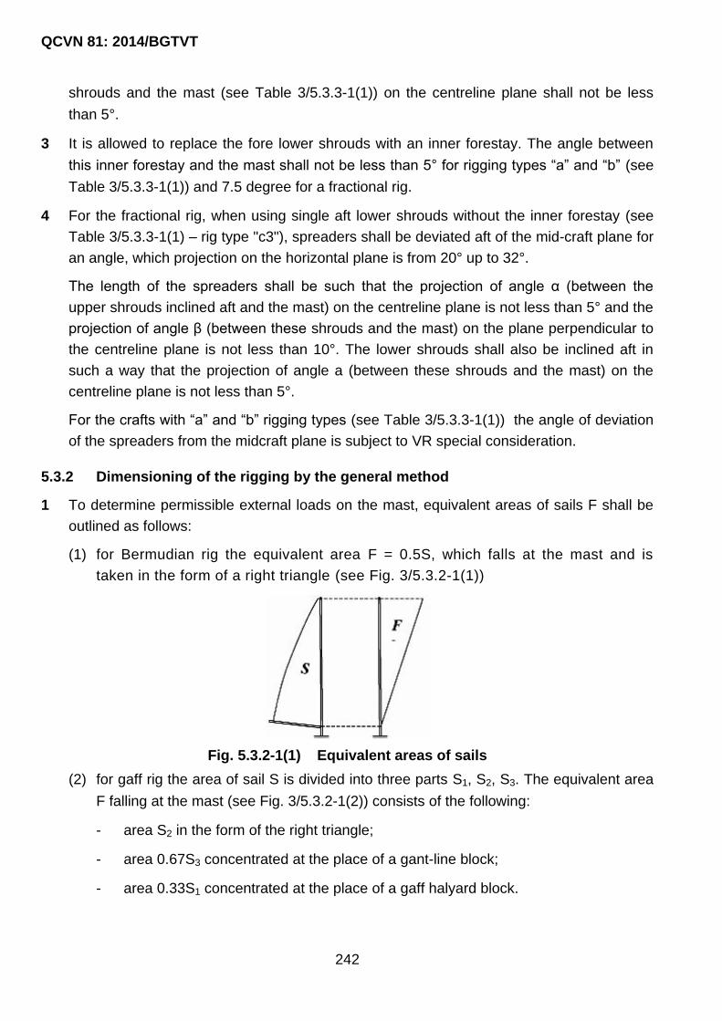
QCVN 81: 2014/BGTVT
242
shrouds and the mast (see Table 3/5.3.3-1(1)) on the centreline plane shall not be less
than 5°.
3 It is allowed to replace the fore lower shrouds with an inner forestay. The angle between
this inner forestay and the mast shall not be less than 5° for rigging types “a” and “b” (see
Table 3/5.3.3-1(1)) and 7.5 degree for a fractional rig.
4 For the fractional rig, when using single aft lower shrouds without the inner forestay (see
Table 3/5.3.3-1(1) – rig type "c3"), spreaders shall be deviated aft of the mid-craft plane for
an angle, which projection on the horizontal plane is from 20° up to 32°.
The length of the spreaders shall be such that the projection of angle α (between the
upper shrouds inclined aft and the mast) on the centreline plane is not less than 5° and the
projection of angle β (between these shrouds and the mast) on the plane perpendicular to
the centreline plane is not less than 10°. The lower shrouds shall also be inclined aft in
such a way that the projection of angle a (between these shrouds and the mast) on the
centreline plane is not less than 5°.
For the crafts with “a” and “b” rigging types (see Table 3/5.3.3-1(1)) the angle of deviation
of the spreaders from the midcraft plane is subject to VR special consideration.
5.3.2 Dimensioning of the rigging by the general method
1 To determine permissible external loads on the mast, equivalent areas of sails F shall be
outlined as follows:
(1) for Bermudian rig the equivalent area F = 0.5S, which falls at the mast and is
taken in the form of a right triangle (see Fig. 3/5.3.2-1(1))
Fig. 5.3.2-1(1) Equivalent areas of sails
(2) for gaff rig the area of sail S is divided into three parts S1, S2, S3. The equivalent area
F falling at the mast (see Fig. 3/5.3.2-1(2)) consists of the following:
- area S2 in the form of the right triangle;
- area 0.67S3 concentrated at the place of a gant-line block;
- area 0.33S1 concentrated at the place of a gaff halyard block.

QCVN 81: 2014/BGTVT
243
Fig. 3/5.3.2-1(2) Equivalent areas of sails
(3) for a jib, equivalent area F falling at the mast is concentrated at the stay fixing point
and is determined by the formula:
S bF
a b
Where: a and b are distances from the fittings up to the sail area centre (see Fig.
3/5.3.2-1(3)).
Fig. 3/5.3.2-1(3) Equivalent areas of sails
(4) for a square sail, equivalent area of sail F is concentrated at the place of hanging the
yard (see Fig. 3/5.3.2-1(4)) and F = 0.675S.
Fig. 3/5.3.2-1(4) Equivalent areas of sails
2 Permissible external load on the mast is determined by action of force Pi, in kN, applied at
the points of action, i.e. in the mast knots. The force shall be determined for, at least, three
variants of the sail area by the formulae:

QCVN 81: 2014/BGTVT
244
for monohulls:
i i iP F p Q
for multihulls:
i iP F p
Where:
Fi : equivalent area of the sails, in m2, which falls at the node and is determined
according to 5.3.2-1;
p : average wind pressure for this variant of the rig, which is determined according to
5.2.1;
Qi : inertial force determined in 5.2.2 and equivalent to і-th node.
3 Force Ni occurring in the shrouds under load Рi shall be determined for, at least, three
variants of the sail area (main, reduced and storm) by the methods generally recognized in
the mechanics. It is also allowed to determine loads on the shrouds by a graphic method
or by calculations equivalent to drawing of Cremona diagram using simplifications (for
example, the rigging of a lee side is not taken into account and the mast knots are
considered to be hinges).
4 Dimensions of each shroud shall be determined by such variant of the sail area, at which it
will be acted upon by the maximum force Ni.
Breaking load Ri, in kN, is determined by the formula:
Ri = knNi
Where:
kn : safety factor:
kn = 3 for the lower shrouds;
kn = 2.5 for other shrouds.
Ni : force, in kN, occurring in the shroud under action of the permissible load, which is
determined according to 5.3.2-3.
5 Breaking load for the stays Rst, in kN, shall be determined according to the wind pressure
influence on the relevant jib by the formula:
st maxR 8.125(S p)
Where:
S : area of the jib lifted on this stay, m2;
p : average wind pressure according to 5.2.1.

QCVN 81: 2014/BGTVT
245
It is necessary to take the greatest of possible values S.p determined for different
permissible variants of the sail area.
However, force Rst cannot be less than that determined depending on the breaking force of
the strongest shroud R:
st wR k R
Where:
kw : stay strength factor;
kw =1.00 for the lowest stay and inner forestay;
kw = 0.75 for a topmast stay and quarter backstay.
6 Breaking load Ra, in kN, for the backstay, check stay, quarter backstay and topmast
shrouds shall be determined by the formula:
a a r st st aR k k R (sin / sin )
Where:
ka : backstay coefficient:
ka = 1.0 for the checkstay, quarter backstay and topmast shrouds;
ka = 1.15 for the backstay;
ka = 1.20 for the backstay, if using a boom for the jib;
ka = 1.25 for the backstay, if using a trysail with the foot length more than 1.3J
(see Fig. 3/5.1.2-3(1)).
kr : load distribution factor:
kr = 1.00 for one backstay, as well as for check stays;
kr = 0.58 for double backstays;
kr = 0.38 for quarter backstay and topmast shrouds.
Rst : breaking force of the relevant stay determined according to 5.3.2-5;
st : angle between the stay and the mast;
a : angle between the mast and: the backstay or check stay or quarter backstay or
topmast shroud.
7 If using a tensioner inducing stress Nn in the rope, the breaking force of this rope Rst shall
not be less than determined by the formula:
Rst = 2.6Nn

QCVN 81: 2014/BGTVT
246
8 For lugsails and gaff sails, it is necessary to check that forces occurring in the backstays,
check stays, quarter backstay and topmast shrouds under the wind pressure at the
heading:
p = 0.250 kN/m2 for the main sail area;
p = 0.572 kN/m2 for the reduced sail area;
do not exceed 0.5 times of the breaking force of the used ropes.
5.3.3 Rigging of some typical single-masters
1 If the rigging of a single-master is typical and complies with Table 3/5.3.3-1(1) and Table
3/5.3.3-1(2) fulfilling the condition:
I J1.6
P E
Breaking forces R in the shrouds, stays and backstays may be determined by the formula:
stR k P
Where:
k : coefficient from Table 3/5.3.3-1(2);
Pst : force compressing the mast under the action of the shrouds according to 5.2.4.
2 If the lower shrouds are located in the mast plane (shroud stay; rigging types “а3” and
“b3”), the back-stays shall be installed to ensure enough tension of the post stay.
3 If angle β between the shrouds and the mast in the projection on the plane perpendicular
to the craft centreline plane exceeds 10°, it is allowed to take coefficients k' determined by
the formula below instead of the relevant coefficients k specified in Table 3/5.3.3-1(2) to
determine breaking loads for the shroud:
ok ' k(sin10 / sin )
If angle α between the inner forestay and the mast exceeds 5° for the masthead rig or 7.5°
- for the fractional rig, it is allowed to take coefficient k'' determined by the formula below
instead of coefficient k specified in Table 3/5.3.3-1(2).
ok '' k(sin5 / sin ) for rig "a" and "b";
ok '' k(sin7,5 / sin ) for fractional rig.
4 If tension of the backstay is over the breaking load of the forestay Rfst, in kN, it is
necessary to take the greatest of the two values, determined according to 5.3.3-1 and by
the formula:
fst ast fst nR 2.25(sin / sin )N

QCVN 81: 2014/BGTVT
247
Where:
ast : angle between the backstay and the mast;
fst : angle between the forestay and the mast;
Nn : backstay stress under tension, in kN.
5.3.4 Rigging of typical yawls and ketches
1 Calculations for the mainmast rigging of Bermudian yawls and ketches may be made in
the same way as for the single-master according to 5.3.3.
2 If the rigging of the mizzenmast is standard and corresponds to the specified in Fig.
3/5.3.4-2, breaking loads R in the rigging may be determined by Formula 5.3.3-1 taking
relevant values of the coefficients from Table 3/5.3.4-2 and the value of force Pst for it may
be determined according to 5.2.5.
5.3.5 Bowsprit rigging
1 If a bowsprit is under forces equal to 0.625 times of the stay breaking loads in the craft
centreline plane, the force in the ropes or chains of whisker stays shall not exceed 0.9
times of their breaking forces and if using rods - the limit of plasticity shall not be
exceeded.
2 Transverse load on the bowsprit shall be 0.165 times of the relevant stay breaking load.
Internal forces occurred in waterbackstays under this load shall not exceed 0.9 times of
the breaking loads of the accepted rope or chain and if using rods – the limit of plasticity
shall not be exceeded.
5.3.6 Rigging screw and fitting
Breaking force of the required rigging screw and fittings Rо, in kN, shall be determined by
the formula depending on the breaking load of the relevant rope:
0 0R k R
Where:
0k : coefficient of the rigging screw and fittings:
0k 1.2 for the shroud rigging screw;
0k 1.35 for the stay rigging screw;
0k 1.35 for the shroud foot points;
0k 1.50 for the stays;
0k 1.10 for the fittings on the masts.
R : design breaking force of the relevant rope, in kN.

QCVN 81: 2014/BGTVT
248
Table 3/5.3.3-1(1) Rigging types
Where:
ast: afterstay, bst: backstay, st: stay, pst: post stay.
Table 3/5.3.3-1(2) Values of coefficients k for the mainmast rigging
Rigging
type
Shroud 1
single
Inner
forestay
pst
Shroud 1
double Shroud 2 Shroud 3 Shroud 4 Stay st
Type a 1.4 1.3 1.3 1.15 - - 1.2
Type b 1.3 1.25 1.25 1.5 0.8 1.15 1.2
Type c 1.4 0.8 1.3 1.2 - - 1.1
Table 3/5.3.4-2 Values of the coefficients for the mizzenmast rigging
Shroud 1 single Shroud 1 double Shroud 2 Shroud 3 Stay st
1.26 0.66 0.60 0.95 1.20

QCVN 81: 2014/BGTVT
249
Fig. 3/5.3.4-2 Standard rigging of Bermudian yawls and ketches
5.4 Spars Calculations
5.4.1 Masts
1 For the craft with a standard rigging complying with 5.3.1-1, the moments of cross
sectional area inertia of mast unsupported spans if bending athwart-craft Ix, in cm4 as well
as the moment of cross sectional area inertia of the mast unsupported spans if bending in
the craft centreline plane Iy, in cm4, shall not be less than determined by the formulae:
2
1x stI k m P l
2
2y stI k m P h
Where:
k1 : unsupported span coefficient specified in Table 3/5.4.1-1;
k2 : stay coefficient determined by Fig. 3/5.4.1-1(1) or 3/5.4.4-1(2);
k3 : coefficient of mast fastening;
k3 = 1.0 for the masts extended through a deck;
k3 = 1.22 for the masts installed on a deck;
m : coefficient taking into account material characteristics:
m = 0.034 for steel;
m = 0.100 for aluminium alloy;
m = 0.725 for timber (pine, spruce);
m = 7060/E, for other materials, where E is Young‟s modulus, MPa.
l : length of the unsupported span considered, in m;
h : vertical distance from the deck or mast bottom, if the mast is supported by the
deck, to the fixing point of the lowest stay, which carriers sails, in m;

QCVN 81: 2014/BGTVT
250
Pst : force compressing the mast under action of the shrouds, determined according to
5.2.3, 5.2.4 or 5.2.5. when determining the moments of inertia for the upper
unsupported spans of the mast, force Pst shall be reduced by the value:
0.14 of the breaking force of the double lower shrouds;
0.23 of the breaking force of the single lower shroud;
0.20 of the breaking force of other shrouds, which are below the unsupported
span considered and do not load it; shrouds of the freeboard shall also be
considered.
Table 3/5.4.1-1 Values of unsupported span coefficients
Rigging type Mast column Other unsupported spans
Without spreaders 2.5k3 -
One cross-tree (pair of
spreaders)
2.5(2.4)k3 3.5(3.6)
Two cross-tree and more 2.7k3 3.8
Values in the brackets refer to the rigging of “c” type.
When using stays and backstays of a higher strength, which take forces caused by
tensioner action, force Pst shall be increased determining an increment stP to force Pst by
the formula:
st 1 1 2 1P 0.208 P sin( )/ sin
Where:
1P : taken increase of the rope breaking force caused by the action of the tensioner
fixed on it, kN;
1 : angle between shroud 1 and the mast;
2 : angle between shroud 2 and the mast.
When using the single (side) lower shrouds and inner forestay, the greater of the two
coefficients k2 shall be taken for calculations.

QCVN 81: 2014/BGTVT
251
Fig. 3/5.4.1-1(1) Stay coefficient k2 for rigging types a1, a2, c1 and c2
Fig. 3/5.4.1-1(2) Stay coefficient k2 for rigging types b1 and b2
Notes: In Fig. 3/5.4.1-1(1) and 3/5.4.1-1(2) - 1: single (side) lower shrouds,
2: double (side) lower shrouds, 3: mast post stays.
2 In case of the single lower shrouds located in the mast plane
(o0 ),if the inner forestay and check stays are available, the stay coefficient
k2 = 1.65 for the rigging type a3 or k2 = 1.85 for the rigging type b3 shall be taken for
calculating the moments of inertia Iy.
If the single lower shrouds are used without the mast post stays and back stays (types
"a4", "b4" or "c4"), the stay coefficient k2 = 2.25 shall be taken for calculating the
moments of inertia Iy. The stay coefficient k2 = 1.25 shall be taken for the rigging type
"a3".
For the rigging with a great number of the spreaders (cross-trees), coefficient k2 shall be
taken the same as for the rigging type "b".
3 For craft with non-typical standing rigging, the following models shall be taken for mast
calculations.

QCVN 81: 2014/BGTVT
252
if bending athwart-craft − a girder elastically fixed at one end and simply supported at the
other end, with a rigid support at the lower shroud fixing point, see Fig. 3/5.4.1-3(1).
Fig. 3/5.4.1-3(1)
if bending in the craft centreline plane - a girder elastically fixed at one end and simply
supported at the other end, with an additional elastic support at the lower shroud fixing
point, see Fig. 3/5.4.1-3(2).
Fig. 3/5.4.1-3(2)
Elastic fixing in a mast hole section is taken into account by the mast housing influence
(Fig. 3/5.4.1-3(1)(a) and Fig. 3/5.4.1-3(2)(a)). For the mast, which stands on the deck, a
simple support shall be used instead of the elastic fixing in the mast hole section (Fig.
3/5.4.1-3(1)(b) and Fig. 3/5.4.1-3(2)(b)).

QCVN 81: 2014/BGTVT
253
For calculations, a value of critical force Pcr, in kN, determined by the formula shall be
taken:
Pcr = 1.6(Pst + 0.385Pc)
not less than:
2.96Pst for the masts loaded with the stay, which carries a sail;
2.32Pst for the remaining masts.
Where:
Pst : force, in kN, compressing the mast under action of the shrouds determined
according to 5.2.3, 5.2.4 or 5.2.5;
Pc : sum of components of the stay and backstay breaking forces, in kN, directed
along the mast axis.
4 For the masts with constant cross section retaining at least up to 0.7 times of their height,
which moment of cross section inertia near the masthead is not less than 0.6 times of the
moment of cross section inertia of the part with constant cross section, it is allowed not to
calculate the moments of inertia Іх of the unsupported spans located above the post, if
their length does not exceed the post length.
5 For the masts with variable cross section or with more taper than specified in 5.1.4-4, each
unsupported span shall be divided into two or three equal parts and the moments of inertia
Іх and Іy, shall be calculated on the basis of their average values I, in cm4, determined by
the formulae:
I = 1/6(I1 + 4I2 + I3) if the unsupported span is divided into two parts;
I = 1/8(I1 + 3I2 + 3I3 + I4) if the unsupported span is divided into three parts.
Where:
I1, I2, I3, I4 : values of the moments of inertia Ix or Iy at the points of unsupported span
division without taking account of local forces and stresses.
The moment of inertia of the weakest section shall not be less than 0.3 times of the
moment of inertia of the strongest section.
6 When using the fractional rig, it shall be checked that the mast bending strength factors Wx
and Wy in cm3, at the intersection of the stay or shroud fixing point are not less than
determined by the formulae:
x 30 x
y y st
W (1000 / ) M (z /P)
W (1000 / ) R z sin
Where:
: permissible stresses for the mast material, when bending, MPa;

QCVN 81: 2014/BGTVT
254
30M : righting moment according to 5.2.4;
xz : distance, in m, from the masthead to the shroud fixing point, see Fig. 3/5.4.1-6;
P : mainsail hoist, in m, according to 5.3.3-1, m;
R : breaking force for the stay, in kN, according to 5.3.3-1;
yz : distance, m, from the masthead to the stay fixing point;
st : angle between the mast and the stay.
Bending strength factors on the masthead shall not be less than 0.2 times of the relevant
factor at the stay or shroud fixing point. If a stay/jackstay providing equal strength of the
mast is used, calculation according to Formula 5.4.1-6 is not required.
7 Criterion of the previous choice of the mast cross sectional area is:
- reaching the minimum mass, i.e. the use, as a rule, of hollow-built wooden masts and
tubular masts of light metal alloys;
- reaching the most possible rigidity of the mast in the direction of the stay action, which
is determined by the moments of inertia of its cross sectional area relative to the craft
centreline plane;
- walls of the hollow-built wooden masts shall not be thinner than 18 per cent of the
relevant cross section size. It is recommended to take the wall thickness equal to 20
per cent of the relevant cross section size.
5.4.2 Spreaders
1 The moment of inertia of the spreader cross sectional area Icr, in cm4, related to the x and
y axes shall not be less than calculated by the formula:
2 cr m cr crI m R l
Where:
mm : material coefficient:
mm = 0.06 for steel;
mm = 0.18 for aluminium alloys;
mm = 1.00 for timber (ash, oak);
mm = 12700/E for other materials, where E is Young‟s modulus, in MPa.
Rcr : force compressing the spreader, in kN;
lcr : spreader length, in m.
2 Spreader stability and compression strength and strength of the spreader fittings shall be
tested under load equal to 1.25Rcr.

QCVN 81: 2014/BGTVT
255
3 Fitting structure shall ensure fixing of the shroud and the spreader shall not move along
the shroud.
5.4.3 Booms
1 For sail booms with a mast edge, the cross section bending moduli, in cm3, related to
horizontal Wy and vertical Wz axes shall not be less than determined by the formulae:
y g st gW m P l
z yW 0.66W
Where:
mg : coefficient taking into material characteristics:
mg = 0.125 for carbon steel;
mg = 0.250 for aluminium alloys with ultimate tensile strength Rm = 200 MPa;
mg = 0.610 for timber (pine);
mg = 50/Rm for other materials Rm, in MPa.
Pst : force, in N, compressing the mast under the action of the shrouds
determined according to 5.2.3, 5.2.4 and 5.2.5;
lg : boom length, in m.
2 When designing the booms, the way of fastening and reefing the sails shall be taken into
account. When designing a boom fitting, its effective fastening to the mast and fastening of
a sheet and topping lift to it shall be considered. Fitting of a front boom end shall meet the
conditions of the hinge, i.e. rotation of the boom about three axes shall be possible.
5.4.4 Gaffs
Choice of the gaffs is subject to VR special consideration.
5.4.5 Bowsprits
1 If an angle between the bob stay and the bow sprit axis is 14° and more, bowsprit
compression stresses under load equal to 0.625 times of the stay breaking force shall not
be more than:
- 0.68 times of the ultimate compression strength − for wooden bowsprits;
- 0.9 times of the yield point − for metal bowsprits.
2 If an angle between the bob stay and the bow-sprit axis is less than 14°, bowsprit bending
and compression stresses shall be determined under load equal to 0.625 times of the stay
breaking force. The sum of the stresses shall not exceed:
- 0.85 times of the ultimate compression strength − for wooden bowsprits;

QCVN 81: 2014/BGTVT
256
- 1.00 yield point − for metal bowsprits.
5.5 Spar and Rigging Material
5.5.1 The materials of spars, rigging, bindings and rigging fittings shall meet the requirements
of Part 11. The spar and rigging products shall be manufactured in compliance with the
technical normative documents recognized by VR.
5.5.2 In manufacture of standing rigging use shall be made of stainless steel wire ropes
without fiber. The standing rigging wires shall have zinc coating in compliance with
the recognized standards.
In case of need rod steel and pudding chains may be used.
5.5.3 In running rigging use shall be made of a vegetable and synthetic fiber. For craft not
fitted with rigging winches it is recommended to use synthetic ropes with a wrapped
multistrand twisted core.
Steel wire ropes will be permitted in the running rigging in case that provision was made
for the relevant winches.
5.6 Mounting and Operation of Rigging
5.6.1 A mast passing through the deck shall be properly fixed in the mast hole. The following
fixation is recommended:
- wedging − for wooden masts;
- using rubber gaskets around the mast − for thin-walled metal masts;
- In rigging of type "a3" or "b3", bow-to-stern movement shall be possible and
athwartships movement shall be limited;
- he heel of a keel-stepped mast shall be securely fastened to the mast step or
adjoining structure.
5.6.2 It is recommended to tension the rigging so as to:
- preclude mast deflection in a direction perpendicular to the craft centreplane, at
the same time, relevant mast deflections from the straight line in the craft
centreplane are permitted;
- ensure that the windward shrouds are not sagging at the heel of 35° that
corresponds to the initial tension equal to 0.16 - 0.18 of the breaking strength for
the wire rope used (rigging shrouds of type “a3” or “b3” shall be eased well);
- ensure that the shroud sagging does not exceed 0.04 of their length under the
conditions of craft sailing by the wind, loads from the sails acting on the stays.
5.6.3 It is recommended to use hinges on all ties, as well as on both ends of forestays.
5.6.4 Rigging fittings shall be of appropriate construction precluding occasional ease of
tension.

QCVN 81: 2014/BGTVT
257
5.6.5 Wooden masts with electric wires therein shall be protected against possible ingress
and accumulation of water inside the mast.
5.6.6 The mast of a sailing craft or sailing motor craft shall have at least two halyards capable
of maintaining the sail.
5.7 Sails
5.7.1 Selection of sails
1 Each craft shall have a set of sails ensuring its operation in the prescribed navigating
conditions.
2 Each craft shall have a mandatory set of storm sails satisfying the requirements of Table
3/5.7.1-2.
Table 3/5.7.1-2 Mandatory set of storm sails
Type of sails
Design category of boat
A, A1,
A2 B C C1 C2 C3 D
Trysail + + - - - -
Storm staysail + + - - - - -
Reduced staysail + + + + - -
Mainsail reefing + + + + + - -
3 For craft having a length of the hull of up to 12 m of design categories C, C1 or C2 a
patent reef and staysail furling device may substitute for a reduced staysail and mainsail
reefing.
4 Alternatively to 5.7.1-3, for craft of design categories С, C1 or C2, a trysail may be
provided for instead of a mainsail reefing.
5 For craft fitted with an effective wing mast trysail is not required.
5.7.2 Dimensions and construction of sails
1 Trysail
The trysail area shall not be greater than 0.175 P E
The trysail shall be capable of being sheeted independently of the boom. The storm trysail
shall have neither headboard nor battens.
2 Storm staysail
The storm staysail area shall be not greater than 0.05I2, with the luff maximum length
0.65I; Where I is the height of the foretriangle. The storm staysail shall be capable of being
set independently of the luff-groove device.

QCVN 81: 2014/BGTVT
258
3 Reduced staysail
The reduced staysail area shall not be greater than 0.135I2, Where I is the height the
foretriangle.
4 Possibility of mainsail reefing
It should be possible to reduce the mainsail area by reefing. Moreover, the length of the
reefed mainsail luff shall be not greater than 0.6P in the most reefed condition.
5.7.3 Sails material
1 The present requirements to cloth used in fabrication of sails apply to the craft with
deadweight of 150 tons and less.
Special synthetic cloth may be used instead of sail-cloth subject to availability of the
relevant manufacturer‟s certificate confirming its intended purpose.
The heavy-weather staysail shall not contain aromatic polyamides, carbon fibers and
similar fibers.
It is recommended that every storm sail should either be of highly visible colored material
or should have a highly visible colored patch of red, orange or yellow added on each side.
2 In manufacture of sails, the cloth types shall be manufactured in accordance with
standards recognized by VR.
QCVN 81: 2014/BGTVT
259
CHAPTER 6 SIGNAL MASTS
6.1 General
6.1.1 The requirements given in the present Chapter refer only to the signal masts, i.e. the
masts which are intended for carrying the signal means: navigation lights, signal
shapes, aerials, etc. Where the masts or their parts carry derrick booms or other cargo
handling gear in addition to the signal means, such masts or their parts shall comply
with the requirements of QCVN 23: 2010/BGTVT.
The requirements of 6.2 to 6.4 do not apply to berth-connected ships. The signal masts of
berth-connected ships shall be designed to carry signal means.
6.1.2 Arrangement, height and provision of signal means on the signal masts shall comply
with the requirements of relevant regulations.
6.1.3 If the signal masts are collapsible, special machinery shall be installed for their
operation or provision shall be made for appropriate connection with other deck
machinery. The drive of the machinery may be hand-operated provided the machinery
is self-braking and the load on the handle is not more than 160 N at any moment of
jackknifing or hoisting the mast.
6.2 Stayed Masts
6.2.1 The outside diameter d and the plate thickness t, in mm, at the heel of the masts made
of steel having the upper yield stress from 215 up to 255 MPa and stayed by two
shrouds on each side of the ship, shall not be less than:
22d l
0.2 3t l
Where:
l : mast length, in m, from the heel to the shroud eyeplates.
The diameter of the mast may be gradually decreased upwards to a value of 0.75 d at the
shroud eyeplates, while the thickness of the mast plates is maintained constant throughout
the length l.
The mast length from the shroud eyeplates to the top shall not exceed 1/3 l.
The mast shall be stayed by the shrouds as follows:
1 Horizontal distance a, in m, from the deck (or bulwark) stay eyeplate to the transverse
plane through the mast stay eyeplate shall not be less than:
a = 1.15h
Where:

QCVN 81: 2014/BGTVT
260
h: vertical distance, in m, from the mast stay eyeplate to the deck (or bulwark) stay
eyeplate.
2 Horizontal distance b, in m, from the deck (or bulwark) stay eyeplate to the longitudinal
plane through the mast stay eyeplate shall not be less than:
b = 0.3h
3 The value а shall not exceed the value b.
6.2.2 The actual breaking strength F of the ropes, in kN, used for the mast shrouds as
specified in 6.2.1, shall not be less than:
20.49( 10 25)F l l
In other respects, the ropes for shroud shall comply with the requirements of Part 7A,
Section II, QCVN 21: 2010/BGTVT.
The loose gear of shrouds (shackles, turnbuckles, etc.) shall be such that their safe
working load is not less than 0.25 times the actual breaking strength of the ropes referred
to above.
6.2.3 Where the mast is made by the following ways, the calculation shall be made in
accordance with 6.4:
- the mast is made of high tensile steel, light alloys, glass-reinforced plastics or
wood (the wood shall be of the 1st grade);
- the mast is stayed in a way other than that specified in 6.2.1;
- in addition to a yard arm, lights and signal shapes, the mast is fitted with other
equipment having considerable weight, such as radar reflectors with platforms for
their servicing, “crow‟s nests”, etc.,
6.3 Unstayed Masts
6.3.1 The outside diameter d and the plate thickness t, in mm, at the heel of masts made of
steel having the upper yield stress from 215 to 255 MPa shall not be less than:
42
2 2
51.5 103 (0.674 13)(1 1 ) 10
(0.674 13)d l l a
l l a
70
dt
Where:
l : length of the mast from heel to top, in m;
a: elevation of the mast heel above centre of gravity of the ship, m.
The outside diameter of the mast may be gradually decreased upwards to a value 0.5 d at
the distance 0.75 l from the heel.

QCVN 81: 2014/BGTVT
261
In no case the thickness of the mast plate shall be less than 4 mm.
The mast heel shall be rigidly fixed in all directions.
6.3.2 Where the mast is made by the following ways, the calculation shall be made in
accordance with 6.4:
- the mast is made of high tensile steel, light alloys, glass-reinforced plastics or
wood (the wood shall be of the 1st grade);
- in addition to a yard arm, lights and signal shapes, the mast is fitted with other
equipment having considerable weight, such as radar reflectors with platforms for
their servicing, “crow‟s nests”, etc.
6.4 Masts Of Special Construction
6.4.1 In the cases specified in 6.2.3 and 6.3.2, as well as where bipod, tripod and other
similar masts are installed, detailed strength calculations of these masts shall be carried
out. These calculations shall be submitted to VR for consideration.
6.4.2 The calculations shall be performed on the assumption that each part of the mast is
affected by a horizontal force Fi, in kN:
23
i i i i i2
4F m ( z r sin ) m g sin p A cos 10
T
Where:
mi : mass of each part, in kg;
zi : elevation of the centre of gravity of each part above that of the ship, in m;
Ai : projected lateral area of each part, m2;
T : rolling or pitching period, s;
: amplitude of roll or pitch, rad;
r : wave half-height, m;
g : gravitational acceleration, 9.81 m/s2;
p : specific wind pressure, Pa, taken according to a ship category.
The calculations shall be carried out both for rolling and pitching of the ship; and θ, in
rad, being taken as corresponding to an angle 40° corner at roll and of 5° corner - at
pitch.
6.4.3 Under the loads specified in 6.4.2, the parts of the mast shall comply with the
requirements of 5.4.1.

QCVN 81: 2014/BGTVT
262
CHAPTER 7 RAILING AT OPEN DECKS
7.1 General
7.1.1 Exposed spaces of decks where people may stay shall be protected along the perimeter
by bulwark or guard rail, rope or tube rail of sufficient strength with a height of at least
900 mm above the deck and a distance between the rails not exceeding 300 mm,
unless provided other-wise in 7.1.3 and 7.1.4. Distance between the lower rail of pulpit
and craft structure (deck) shall not exceed 360 mm. On board of all craft with
intermediate rails, the height of the lowest rail above the working deck shall not exceed
230 mm.
Adjacent surfaces shall also be safe for people moving in all prescribed situations.
Intervals between the guard rail bars shall not exceed 2.2 m.
When the entire guard line is interrupted by side or aft passages, these passages shall be
fitted with safe closures.
7.1.2 On board craft, where accommodation of children is provided by the design, the guard
rail shall be fitted with a net with mesh diagonal size not exceeding 100 mm.
7.1.3 Berth-connected craft shall have guard rail of at least 1100 mm height, therewith a
distance between intermediate rails shall not exceed 250 mm and a distance between
the deck and the lowest intermediate rail shall not exceed 230 mm.
7.1.4 On sailing craft it is allowed to install railing of a height not less than indicated in Table
3/7.1.4 when the rail of 900 mm height interferes with rigging operations.
Table 3/7.1.4
Design
categories
Height of guard
rail, in mm Remarks
A 600 For craft with HL 8.0 m [1], [2], [3], [4]
A1, A2, B 600 For craft with HL 8.0 m [1], [2], [3], [4]
450 For craft with HL 8.0 m [1], [3]
C 450 [3]
C1, C2,
C3, D
450 For decked craft (see types A, B and C in 1.2 Part 4) [3]
C2, C3, D [5] For decked craft with HL 6.0 m
[1] At each craft side a passage of sufficient width with antiskid surface and an extension to meet the
requirements of 7.1.8 shall be available.
[2] At each craft side the rails running to cockpit shall meet the requirements of 7.3 and 7.4.
[3] Bow pulpit is recommended.
[4] Stern pulpit is recommended. When stern pulpit is not provided, guard rail shall be installed from

QCVN 81: 2014/BGTVT
263
the bow pulpit to the stern edge of the cockpit and around the cockpit back.
[5] Guard rail is not required when other safety precautions complying the craft type, such as
handrails and canhooks at deckhouses.
7.1.5 On the craft with a cockpit open to stern the appropriate safety guard rails shall be
installed so as to avoid vertical openings exceeding 500 mm.
7.1.6 On a sailing craft with a stay the continuous or netted bow rail shall be installed in front
of and around the stay at least at the same height as the adjacent railing.
Netted guardrail with mesh diagonal size above 250 mm shall not be installed.
To access a bowsprit or perform mooring operations an opening in the front part of railing
is allowed. In this case safety rails capable to closing this opening and installed as per
7.1.5 shall be be provided.
7.1.7 Ladders to internal craft spaces, companion hatchways and catwalks shall be fitted
with handrails.
7.1.8 On craft of A, A1, A2 and B design categories in places of guard rail a deck extension
shall be provided by the board of at least 25 mm in height to prevent sliding of a foot
overboard.
7.1.9 Rails and rail stanchions on all craft shall be securely fastened.
7.1.10 Rails shall be made of multicore stainless steel rope of a diameter not less than
specified in the Table 3/7.1.10
Table 3/7.1.10
Craft hull length, m Minimum rope diameter, in mm
HL 8.0 3.0
H8 L 13.0 4.0
HL 13.0 5.0
7.2 Guard Rails
7.2.1 Rails and rail stanchions shall be securely fastened at craft deck. When rope rails are
used, rope end restraint shall be strong, safe and make use of traditional patterns based
on eye-splice and dead eye pleaching or using special steel snaps to be fit on the rope
with dead eye installed in the eye-splice.
7.2.2 For rail tension it is recommended to use special pulling turnbuckles made of stainless
steel.
Rope turnbuckle from synthetic rope is permitted on all craft for rail tensioning, provided
their overlap area does not exceed 1000 mm. All ropes, components and fastening points,
as well as lanyards, shall form a continuous guard rail system, bursting strength of which
at every point is at least equal to those of rope required for rails.

QCVN 81: 2014/BGTVT
264
7.2.3 All fixing arrangements and components being a part of rope guard rail shall have
bursting strength 1.2 higher the strength of rail rope.
7.2.4 Rails shall be permanently supported by rail stanchions and shall not pass from outside
the rail stanchions.
7.2.5 Rail stanchions and rails in rails fixing points shall be fitted with relevant arrangements
or openings to ensure secure fastening of the rail.
7.2.6 Overall height of the rail or pulpit in the bow and stern of the sailing craft shall not be
less than specified in Table 3/7.2.6.
Table 3/7.2.6 Rail height at the craft’s ends
Length of craft, m Design categories
Minimum height, in mm
With a single-row rail With a double-row rail
(1)
HL 8.0 A, A1, A2 Not applicable 610/305
B 560/280
C, C1 460 560/280
HL 8.0 A Not applicable 610/305
A1, A2
B
C, C1
(1) Height till the axis of the intermediate rail is fraction separated.
7.2.7 Axes of rail stanchion bases shall not be spaced inward the side edge of work deck
apart 5 per cent of the maximum hull width or 150 mm, whatever is greater. Bases of
rail stanchions shall not be located outside the work deck.
The rail stanchions are strength tested during manufacture. During bench tests in the
direction perpendicular to the axis the stanchions shall withstand load of 560 N without
destruction.
During the installation aboard the craft, the deviation of rail stanchion axis shall not exceed
10° from vertical in any point over 50 mm above the deck, when test load of 280 N is
applied to the rail stanchion in horizontal direction perpendicularly to the rail.
7.2.8 Base of stanchion or rail shall consist of a bush or socket for the stanchion or the rail,
but shall not include the base plate by means of which it is connected with deck or hull.
7.2.9 Bases of rail stanchions and pulpit shall have modulus of resistance at the base, in cm3,
not less than:

QCVN 81: 2014/BGTVT
265
0.2W = (300a - 250)h/
Where:
a : interval between the stanchions, in m;
h : stanchion height, in m;
0,2 : yield point of material, in MPa.
Bases of rail stanchions and pulpit shall be fixed by through bolts or welded.
Inserted stanchions shall be fixed at the base.
7.2.10 When the craft is equipped by a bowsprit, the pulpit in way of bowsprit may only be
fitted with rigid medium rail, however, in this case an arrangement shall be provided for
installation of the upper rail to ensure the pulpit integrity on the level in stormy weather
conditions.
7.2.11 When terminating the cable ends, the following shall be provided:
- insulation of rope yarns and wire strands in place of contact with the component part
(dowel pin) it rubs against. This is ensured by a deadeye;
- at least minimum rope bending radius allowable for particular diameter and material.
7.3 Storm safety rails
7.3.1 In the outfit of sailing craft A, A1, A2 and B design categories storm safety rails shall be
provided, as well as the appropriate places and attachments for their installation.
Storm safety rails are intended for movable fixing of crew and craft passengers‟ individual
safety belts.
7.3.2 Storm safety rails are installed on craft‟s deck at each side in way of waterways or near
the bulwarks from the inner side of rail stanchions.
1 Each storm safety rail shall be fitted with an individual fastener in bow (in stay area) and
stern (in way of stern rail stanchions above cockpit) parts of the craft.
2 In ways of exits from internal spaces to deck the storm safety rail shall be arranged so that
a person has a possibility to clip to it before appearing on deck. A person shall be fastened
to storm safety rail even during transverse movements on deck in ways of craft ends, as
well in the middle part of the craft, when it is necessary to operate the rigging.
3 For storm safety rail the use shall be made of stainless steel rope of at least 8 mm in
diameter and yield point of at least 220 MPa, or a synthetic one of equal strength.
4 Length of storm safety rail shall be selected in compliance with particular craft size and
equipment installed but no less than those required for normal movement of people,
fastened by safety lanyards to storm rails, on craft deck.

QCVN 81: 2014/BGTVT
266
5 When the craft is fitted with a bow guard with an open head, storm safety rails shall be
installed frontward to protect people working outside the pulpit guard, for instance at bow
sprit.
7.4 Astenings For Safety Belts
7.4.1 Effective means for fastening safety belt lanyards shall be provided on the open deck,
including storm rails on the sides and ends of deckhouses.
7.4.2 Fastening points of safety belts shall be arranged regarding the probable necessity of
work on and above the deck. In general, the following fastening points shall be
provided:
- at exits to the deck;
- on cockpit sides.
7.4.3 When it is not otherwise specified, the rails (fixed or movable) shall be located on both
sides of the craft to ensure moving of crew members along the upper deck in
unfavorable weather conditions.
7.5 Bulwark
7.5.1 On craft of A, A1, A2 and В design categories all around the main deck the bulwark of at
least 900 mm from deck shall be installed. On craft of design categories С, С1 and С2
the bulwark may be installed only in the bow part of the craft. On sailing craft of В, С, С1
and С2 design categories the bulwark may be omitted.
7.5.2 When, by any reason, a lesser height of the bulwark is assumed, the cap rail of the
bulwark shall be fitted by guard rail to ensure the required height. Bulwark shall be
equipped with a continuous cap rail except the areas where mooring and towing
arrangements are located.
7.5.3 When water is accumulated at bulwark on open decks, the effective measures shall be
provided for drainage (freeing ports and scuppers). Total area of freeing ports and
scupper at one side shall ensure effective drainage of the bulk of water from the deck at
zero list during maximum 15 s.
7.5.4 Bulwark, regardless the place of installation at main deck shall not be spaced at the
value of 5 per cent of the maximum craft‟s hull width from sheerstrake or 150 mm,
whatever is the greater.
7.5.5 Bulwark strength shall meet the requirements of Part 2, Section II of this Regulation.
7.6 Rails of Sailing Craft
7.6.1 General

QCVN 81: 2014/BGTVT
267
For multihull craft, any deviations of deck guardrail height, guardrail intervals, guardrail
fixing are subject to special consideration of VR.
7.6.2 Permanent railing
1 Permanent bow railing (onward forestay) and stern railing (unless the rails are installed as
an equal alternative to stern railing) shall be provided on single-hull craft of A, A1, A2, В, С
and С1 design categories.
Fort craft up to 8.5 m in length, bow rail may be situated to the stern from forestay,
provided that upper forward strap of the rail is within 405 mm from the forestay.
2 Main hull of trimaran, regardless the design category, shall be fitted with bow railing. On
each side this railing shall be connected with upper and lower rails surrounding the main
hull and supporting by stanchions. Rails may be discontinued where the nets or transverse
wings are located outside the main hull.
3 Catamaran, regardless the design category, shall be fitted with bow and/or stern railing
which ends the rails.
4 Onboard all craft the height of upper handrails of rails above the working deck shall not be
lower than upper rails, the height of which shall be basically the same as the height of the
upper rail at the front part of cockpit.
7.6.3 Rails
1 It is allowed not to fix rails to bow railing when they are fixed to or passing through
sufficiently braced stanchions installed inside bow railing and overlapped by bow railing so
that clearance between the upper rail and bow rail does not exceed 150 mm.
For craft with hull length of 5.5 m and less, guard rail and stern railing are recommended,
however, bow railing is mandatory.
2 On all craft the rails shall be fitted with permanent supporting arrangements and shall not
pass through the outer side of rail stanchions.
3 On all craft the rails shall be sufficiently tensioned. When a deflecting force 50 N is applied
to a rail between the stanchions, the rail shall not be deflected for more than 50 mm.
7.6.4 Supporting backstays and ends on monohull craft
Provided that closed guard rail are supported by stanchions and railing, the bases of which
are located within working deck, rail ends and supporting backstays may be secured on
the hull to the aft from working deck.
7.6.5 Nets-trampolines, rails, stanchions and railings of all multihull craft
1 Nets-trampolines shall be made of firmly interlaced watertight cloth or woven nets with a
mesh not exceeding 50.8 mm. Their fixing points on the yacht structure shall be located so
as to avoid wear. Connections between trampolines or nets or craft shall prevent sticking
of a man foot in them.
QCVN 81: 2014/BGTVT
268
2 Net-trampoline shall be firmly secured at longitudinal and transverse lines at regular
intervals and tightly sewed to boltrope. Lines which are used for net tensioning shall be
tensioned separately or no more than four fixing points may be connected to one
connecting line.
3 Nettrampoline shall withstand total weight of the crew both in normal conditions of
navigation and in case of craft capsizing.
4 Trimaran with two transverse beams shall be equipped with a net covering the space
between the main hull and each auxiliary side/float hulls.
On trimaran the net in the bow part of each side is fixed in the fixing point of bow railing of
main hull and a middle part of a bow transverse beam. In the aft part from each side it is
recommended to fix the net in the vicinity of cockpit or control station, whichever is located
farther to aft and a crossing point of the aft transverse beam and auxiliary float hull.
5 When net extends into the railing base, additional rail shall be provided from the top of the
railing till the middle of bow transverse beam or to the outside of it.
6 Aboard trimarans fitted with one transverse beam between the main hull and each side
hull/float hull the net shall be located at least between two straight lines going from
crossing point of transverse beam with the float hull, one up to stern end of bow rail of the
main hull in the bow part of the yacht, the other one up to right-most stern part of cockpit or
control station (depending on what is located farther to stern) in the stern part of the yacht.
7 Aboard trimarans, where the control station is fitted on the float hull, even in case it is used
not often (for example, as an emergency control station) regardless the availability of
cockpit, such float hulls shall be equipped with rails running till the control station and
protecting it through 3 m radius arc and with a center in the control station. When
measuring a distance between rails, the dimensions shall be taken with the rails tensioned.
8 Total net surface of catamarans shall be terminated:
- on each side − by hulls;
- in the longitudinal direction − by a section going through the stay base and a section
going through the back-most point of boom when the boom is in the center plane.
Catamaran with a central cabin not touching water surface may meet the requirements for
the trimaran.
9 Each catamaran hull shall be equipped with rails running from bow to transom.
Catamarans not fitted with bow or stern transverse beam shall be equipped with
transverse rails on net ends fore and aft. These rails shall be connected to bow and aft
handrails or stanchions. Strapping, bond or robe of at least 6 mm in diameter in a form of
zigzag shall connect rails and net.

QCVN 81: 2014/BGTVT
269
CHAPTER 8 MAIN ESCAPE AND EMERGENCY EXITS
8.1 General
8.1.1 Each hull of the craft with living accommodation shall be provided with, at least, two
exits: main and emergency irrespectively of the craft design category.
Each hull of a multihull of A, A1, A2, В, С, С1 and С2 design categories having living
accommodation, shall be provided with a hatch for entrance into the hull and exit from
it in the case of capsize.
Each living accommodation, which is used either for sleeping/resting or is exposed to
the increased risk of fire, shall be provided with two exits: main and emergency.
Only in exceptional cases, one main exit leading to an open air may be allowed, when
installation of a second exit negatively influences the general safety of the ship. The
length of such accommodation shall not exceed 8 m.
8.1.2 Exits shall be permanently accessible and their closing appliances – be permanently
operational to be opened from the inside and outside without using a special instrument.
8.1.3 The exit located in an upper part of the accommodation shall be equipped with a ladder,
steps or other permanently fixed footholds with the distance between the upper foothold
and the centre of an opening not above 1.2 m.
8.1.4 All exits other than the main shall be appropriately marked and labeled “Exit” or
“Emergency Exit”.
8.1.5 When the only exit from the accommodation specified in 8.1.1 is provided, effective
smoke detectors and an appropriate system warning of fire, which may cut off a way to
the only exit from the accommodation for people being there, shall be obligatory
installed on the ship.
8.1.6 All monohull sailing craft of 8.5 m in length and above shall be provided with, at least,
two exits (main and emergency) from the craft hull irrespectively of the craft design
category. One exit shall be located before the fore mast, except for the case, when
structural features do not allow to install it.
8.1.7 Each escape hatch shall be capable of being opened both from the outside and inside.
8.1.8 In case of craft capsize, an escape and rescue hatch shall not be under water.
8.1.9 Hatches shall have the following minimum clear characteristics:
- circular shape – minimum clear diameter of 450 mm;
- any other shape – minimum dimension of 380 mm and minimum area 0.18 m2 of
coaming clearance and hatch coaming clearance shall have such configuration as to
allow for a 380 mm diameter circle to be inscribed. Some examples are shown in Fig.

QCVN 81: 2014/BGTVT
270
3/8.1.9.
Fig. 3/8.1.9 Shape of escape
8.1.10 Structure of closing appliances
1 Escape hatch covers shall be capable of being easily opened from the inside and outside,
when closed but not battened down.
2 Hinge or hinges of a cover of the escape hatch, which is opened from the inside, shall be
such as to prevent tearing out of the hatch cover by a wave slap, when the hatch is partly
or completely open.
3 When movable shields or storm boards are used to close a vertical opening, they shall be
installed and fixed in such a way as to exclude their displacement at any list (heel) or trim
of the ship.
8.2 Escape routes on Craft 15 m in length and under
8.2.1 The distance to the nearest exit to the open air shall not exceed 5.0 m. Where the exit
route passes beside an engine space, the distance to the nearest exit shall not exceed
4.0 m.
The distance shall be measured in the horizontal plane as the shortest distance between
the centre of the exit and the farthest point where a person can stand at the midpoint of the
height (minimum height 1.6 m).
8.2.2 Where only one escape route is provided, this shall not pass directly over a cooker or
heating appliance.
8.2.3 Where living or sleeping accommodation is separated from the nearest exit by a
partition with a door or in other similar way and leads directly past a cooker or engine
space, an alternative exit shall be provided.
8.3 Escape routes on craft above 15 m in length
8.3.1 General requirements
1 Where there are two escape routes only one may pass through, over and beside an
engine space.

QCVN 81: 2014/BGTVT
271
2 Where the distance between a cooking or open- flame heating-appliance burner and the
nearest side of an escape route is less than 750 mm, a second escape route shall be
provided.
3 In an enclosed galley, the second escape route is not required where its dead end beyond
the cooker is less than 2.0 m.
4 No escape route shall pass directly over a cooking or open-flame heating appliance.
8.3.2 Open-accommodation arrangement
Where living or sleeping accommodation is not separated from the nearest exit, i.e. people
can move around without passing through any door, excluding toilet or shower
compartment doors, the following shall apply:
1 The distance to the nearest exit shall not exceed LH/3, m.
2 the distance shall be measured in the horizontal plane as the shortest distance between
the nearest part of the exit and the farthest point where a person can stand at the midpoint
of the height (minimum height 1.6 m).
8.3.3 Enclosed accommodation arrangement
Where living or sleeping accommodation is separated from the nearest main exit by
bulkheads and doors, escape routes and exits from accommodation areas shall be
arranged to meet the following conditions.
1 Each accommodation section shall have more than one escape route leading finally to the
open air, unless it is a single cabin or compartment intended to accommodate no more
than four persons and the exit leads directly to the open air without passing through or
over engine spaces or over cooking appliances.
2 For individual cabins intended to accommodate no more than four persons, and not
containing cooking or open-flame heating devices, escape routes may form shared escape
ways for up to 2.0 m, measured to a two-way escape route from the door or entrance.
3 Shower and toilet compartments are regarded as part of the compartment or passageway
that gives access to their doors and therefore do not require alternative escape routes.
4 With multilevel arrangements, the exits shall lead to a different accommodation section or
compartment, as far as practicable.

QCVN 81: 2014/BGTVT
272
CHAPTER 9 HATCHES, DOORS, SIDE SCUTTLES, WINDOWS, COVERS AND MANHOLES
9.1 Definitions and Explanations
9.1.1 For the purpose of the present Chapter, the following definitions and explanations have
been adopted:
1 Watertightness is the capacity of an appliance or a device to prevent ingress of water
inside the craft.
2 Entry door is a door or another closing appliance closing the passage to crew spaces.
3 Side scuttle of non-opening type is a side scuttle provided with a fixed glass of non-
opening type.
4 Closing appliance is a device used to cover openings in hull or superstructure,
including windows, side scuttles, deadlights, hatch covers, doors, sliding appliances,
emergency hatches.
5 Escape hatch is an appliance intended to provide an exit and designated means of saving
life in the event of accident or inversion.
6 Window is a glazed appliance. The term “portlight” is generally used for a small window.
7 Flush deck scuttle is a side scuttle of non-opening type installed on the exposed deck
plating to ensure access of light into the space.
8 Deck hatch is a device fitted on decks and inclined sides of superstructures and
deckhouses.
9 Appliance location area is one of the outer hull areas as stated below and shown in Fig.
3/9.1.1.
10 Area I is a part of hull sides situated below the waterline, including inner sides of multihulls
and transom.
11 Area II (IIa or IIb) are exposed parts of the deck, as well as the sides of superstructures
and deckhouses of the first tier situated forward of 0.25 of the craft‟s length L from the
forward perpendicular;
Hull side situated above the waterline, including the inner sides of multihulls and transom;
Exposed parts of the deck, superstructures and deck-houses of the first tier, cockpit soles,
as well as outer sides of the superstructure and deckhouse of the first tier at an inclination
of less than 25° to the horizon in a longitudinal direction, and at an inclination of less than
25° to the horizon in the transversal direction respectively for multihulls and motor sailers.
12 Area III are the outer sides of superstructures and deckhouses of the first tier not
belonging to area II.

QCVN 81: 2014/BGTVT
273
13 Area IV are the decks and outer sides of superstructures and deckhouses of the second
tier and upper. Parts of area III protected from the direct impact of waves. Cockpit sides,
rear faces of superstructures and deckhouses of all tiers.
14 Sliding appliance is an appliance that can slide in a rabbet or a frame.
15 Framed plate sliding appliance is a plate mechanically connected to a frame that slides in
a rabbet.
16 Frameless plate sliding appliance is a plate without frame that slides in a rabbet or a
frame.
17 Pivoted sidescuttle is a side scuttle with an opening glass ensuring access of air to
spaces.
18 Degree of watertightness is the capacity of an appliance or fitting to resist ingress of water
according to the following conditions of exposure to water:
degree 1 – tightness is ensured under the water head in the submerged condition;
Structural components or closing appliances of hull openings shall be deemed watertight if
they are so fitted as to prevent any ingress of liquid inside the craft when they are
subjected to the specified pressure for the unlimited time;
degree 2 – tightness under the effect of waves (temporary submersion, actions of waves
and other possible effects) is ensured.
Structural components or closing appliances in the underwater hull shall be deemed
watertight if they are so fitted as to prevent any ingress of water inside the craft when they
are subjected to a pressure corresponding to a head of water of 10 m for one minute, or a
jet of water at a pressure of at least 100 kPa for 10 min applied over the entire surface and
structural components or closing appliances from a distance of not more than 1.5 m.
degree 3 – weathertightness is ensured.
Structural components or closing appliances of the underwater hull shall be deemed
watertight if they are so fitted as to prevent any ingress of water inside the craft when they
are subjected to a jet of water at a pressure of at least 100 kPa applied over the entire
surface and structural components or closing appliances from a distance of not more than
3.0 m.
degree 4 – spray tightness is ensured.
A closing appliance shall be deemed sprayproof, if under the effect of divergent jet of
water at a pressure of at least 100 kPa applied over the entire surface and closing
appliances from a distance of not more than 3.0 m, it allows only a small quantity of water
to enter the craft.
19 Deadlight is a secondary watertight closure fitted to a window, a hatch or a door, and
which may be fitted outside and inside the plate.

QCVN 81: 2014/BGTVT
274
9.2 General
9.2.1 Watertightness
1 To avoid flooding, all appliances shall be manufactured and fixed to meet the minimum
degree of water-tightness when closed.
2 The degree of watertightness of the manufactured appliance shall be tested by the
appliance manufacturer before installation on the craft.
3 The degree of watertightness of any appliance installed on the outside surface of the craft
shall be checked in compliance with the requirements of 9.2.2-1.
4 The degree of watertightness of any closing appliance installed on a non-outside surface
of the craft should be tested for a chalky imprint on the seal.
9.2.2 Minimum degree of watertightness
1 The required minimum degree of watertightness of a closing appliance depends on the
area of its location onboard and area of navigation. The required minimum degree of
watertightness is shown in Table 3/9.2.2-1.
2 The required degree of watertightness of any appliance, after installation on the craft, shall
meet the requirements of 9.2.2-1.
If the shipyard tests closing appliances and component parts before installation on the
craft, the method required in 9.10 shall be used.
9.2.3 Additional requirements related to water-tightness
1 Sliding appliances shall not be used in Area I.
2 Hatches fitted on the decks of trimaran outrigger hulls shall not be sliding appliances.
Table 3/9.2.2-1 Minimum degree of watertightness
Type of craft
Appliance
location
area
Type of
Appliance
Design category
A, A1, A2, B C, C1 C2, C3 D
All craft I Any 1 1 1 1
II Any 2 2 3 4
Sliding
companionway
hatch
3 4
III Any 2
Sailing
monohulls
IV Any 3 3
Motor craft Any 4

QCVN 81: 2014/BGTVT
275
All multihulls
Fig. 3/9.1.1 Typical appliance location areas on pleasure craft Areas are schematically shown as hatched spots
9.2.4 General requirements to openings and their closing appliances in hull, upper
deck, superstructures and deckhouses
Motor craft
Sailing monohulls
Motor craft
Sailing monohulls
Sailing multihulls
Sailing multihulls
a) Area I
b) Area II (IIa and IIb)
Motor craft
Sailing monohulls
Motor craft
Sailing monohulls
Sailing multihulls Sailing multihulls
c) Area III d) Area IV

QCVN 81: 2014/BGTVT
276
During installation of appliances requirements specified in Table 3/9.2.4-1 and 3/9.2.4-2.
Table 3/9.2.4-1 General requirements for closing appliances
Appliance Design category
A, A1, A2, B C, C1, C2, C3
Deck hatch covers [1], [3] [2], [3]
Cockpit covers [1] [2], [3]
Sliding covers [2], [3], [9] [2], [3]
Access to cabin [2], [5] [2], [4]
Ventilation ducts for
accommodation spaces
[2], [7] [2], [3]
Ventilation ducts for engine room [2], [3], [6], [7] [2], [3], [6]
All pipes [2], [3], [6] [2], [3], [6]
Keel box [1] [2], [8]
Chain locker pipe [2] [2]
[1] Closing appliance ensuring watertightness degree 2;
[2] Sprayproof closing appliance;
[3]
For craft using no sails for propulsion:
- all closing appliances (openings) submerged to the water at an inclination of 0 to 50°, as
appropriate, shall be weathertight so as to ensure stability limit of up to 50°;
- craft with the stability limit less than 50° shall not be exempted from this requirement.
For craft which may use sails for propulsion:
- all closing appliances (openings) submerged to the water at an inclination of 0 to 90°, as
appropriate, shall be weathertight so as to ensure stability limit of up to 90°;
- craft with the stability limit less than 90° shall not be exempted from this requirement.
[4] The coaming shall be at least 50 mm high. Removable coamings on craft of design category C2
shall meet requirement [5];
[5] The coamings of doors to underdeck spaces shall have a height not less than the values
specified in Table 3/9.2.4-2;
[6] May be located only above the main deck in enclosed spaces so as to ensure engine operability
as long as possible, even in foul weather;
[7] Possibility should be provided to arrange weathertight closure (i.e. tarpaulin cover) in the event of
a stormy weather;
[8] Safety distance from the effective waterline to the lowest point, where watertightness is not
ensured, shall be at least 100 mm. The parts of keel box above this level may be sprayproof;
[9] May be located on superstructure or deckhouse deck only. Hatches with sliding covers in the

QCVN 81: 2014/BGTVT
277
bow of the craft shall have coaming height of at least 150 mm above the superstructure or
deckhouse deck.
Table 3/9.2.4-2
Location Height of coamings, in mm
Motor craft Sailing craft
In lateral and rear sides
accessible from the main deck
150 150
In lateral and rear sides
accessible from the cockpit
380 from the cockpit sole 460 from the cockpit sole
Anywhere, if this access leads
directly to underdeck spaces
460 460
Note. Removable coamings of doorways shall allow fitting the doors in places of installation
9.2.5 Additional requirements to appliances located in Area II
1 The lower edge of any opening appliance shall be placed above the waterline at a distance
not less than that specified in 6.4.2 through 6.4.5 Part 4, Section II.
The smallest unsupported dimension of appliance shall not exceed 300 mm.
The above requirements do not apply to escape hatches of sailing craft.
2 All opening appliances shall open inwards, with the exception of deck covers and escape
hatches of sailing craft.
3 On craft of design categories A, A1, A2, B, С or C1 no part of the plate framing shall
extend outside the local vertical tangent to the hull, deck, rubbing strake, fixed fender, or of
a built-in fairing which is an integral part of the hull.
9.3 Weathertightness
9.3.1 General requirements to hatch covers
Hatches leading to inside spaces of the craft shall be fitted with sprayproof covers. The
hatch covers may pivot on hinges, sliders or rollers, though, in any case they shall be
permanently secured to the craft and provided with essential locking devices, which
maintain them in a closed position at potential heel and trim in the prescribed areas of
navigation. The hatches with pivoted covers located forward of the foremast shall have
hinges fitted only on the fore edge of the hatch.
9.3.2 Hatches open on the way
Generally, when at sea, all access hatches shall be closed. Though, the hatch, which can
be open at sea for a long time, shall meet the following requirements:

QCVN 81: 2014/BGTVT
278
1 have minimum possible dimensions (area of vertical opening shall not exceed 0.4 m2 in
the plan).
2 be located on CL, or as close to CL as possible.
3 e installed on craft of design categories A, A1, A2, B, С or C1 so as to be opened at a
height of at least 300 mm above the upper deck adjacent to the opening side.
9.3.3 Rabbet depth
The depth of the rabbet shall be sufficient to prevent any disengagement of the plate. For
unframed plates made of plastics or materials with similar modulus of elasticity, this depth
shall be at least 12 mm.
9.3.4 Stops
The sliding appliance shall be fitted with stops at each end of its stroke to prevent any
disengagement of the sliding part of the frame.
9.3.5 Locking system (locking devices)
Any appliance shall have a locking device which maintains it in a closed position, operable
at least from inside.
On doors, this system shall be operable from both sides.
In craft of design categories A, A1, A2, B, С or C1, if the companionway door is used
together with a companionway hatch, the locking device need only be efficient when both
the door and the hatch are closed together. In this case, if the companionway door is
made with wash-boards, the locking device may only act between the upper panel of the
washboard and the hatch.
9.4 External Doors
9.4.1 All external doors may be installed only above the freeboard deck or cockpit sole.
Watertightness of the external doors shall be 2, 3 or 4 according to the place of their
installation.
9.4.2 Bow doors
Arrangement of bow doors shall be permitted only if the water, which occasionally passed
through them, shall in no case penetrate inside the spaces below the freeboard.
9.4.3 Side and stern doors
1 The coamings of side and stern doors on craft of design categories A, A1 and A2 shall be
at least 300 mm high. For craft of design categories B, С or C1 this height may be reduced
to 230 mm.

QCVN 81: 2014/BGTVT
279
2 On craft of design categories С2 or C3 the coamings of hatchways, companionways and
access openings to superstructures and deckhouses shall be not less than 150 mm.
3 On craft of design category D the coamings of hatchways, companionways and access
openings to superstructures and deckhouses shall be not less than 50 mm.
4 The doors shall be hinged inside.
To ensure opening, closing or securing of doors having watertightness degree 2 or 3
provision shall be made for quick-acting appliances, which may be operated from both
sides.
All external doors shall open outwards; installation of the doors opening inside the
superstructure or deckhouse is subject to special consideration by VR in each particular
case.
5 The number of securing devices on each edge of the door having watertightness degree 2
or 3 shall be not less than two; a securing device shall be provided in the vicinity of each
door corner. The distance between securing devices shall not exceed 1.5 m.
9.4.4 External doors having watertightness degree 2 or 3 shall be made of metal.
External doors having watertightness degree 4 may be made of wood or other non-metal
materials.
9.4.5 The freeboard superstructure doors or deckhouse doors opening the direct access to engine room or underdeck spaces shall be watertight, and the height of their coamings shall be not less than 460 mm above the deck.
9.4.6 Doors made with removable sections: wash-boards
Doors made with removable sections, usually called “washboards” may be installed on
craft of design categories С1, C2, C3 or D, and shall be:
- fitted with a device to keep them in position, when in use, and to be at least operable
from inside;
- stored inside the craft in the vicinity of the door opening;
- easily reached without use of tools;
- removable sections of washboards, when not in use, shall have places of permanent
storage and securing.
9.5 Side Scuttles
9.5.1 The number of side scuttles in the shell plating below the freeboard deck shall be
reduced to a minimum consistent with the structure and operational conditions of the
craft, to exclude their damage during possible mooring alongside other craft.
No side scuttles shall be permitted in shell plating in way of engine room.

QCVN 81: 2014/BGTVT
280
9.5.2 Side scuttles in the shell plating below the freeboard deck shall be of non-opening type
and round-shaped.
Side scuttles in the engine room skylight shall be of non-opening type.
If it was permitted to install pivoted side scuttles in the above area, the requirements of
6.4.2 and 6.4.3 shall be met, as well as the requirements of 2.6 Part 4, Section II of this
Regulation.
9.5.3 Side scuttles may be round or rectangular. In any case the side scuttles shall have
dimensions relevant to the design category and ensure watertightness.
9.5.4 On craft of design categories A, A1 or A2 side scuttles shall be located so as to prevent
their lower edges from being below the line parallel to the freeboard deck and having its
lowest point at a distance of 500 mm above the summer load line.
For craft of design categories B or С this distance may be reduced to 300 mm, while for
craft of design categories С1, C2, C3 or D − to 150 mm.
9.5.5 The side scuttles in shell plating below the free-board deck and in fore sides of enclosed
superstructures and deckhouses of the 1st tier, and also in fore sides of enclosed
superstructures and deckhouses of the 2nd tier situated forward of 0.25 of the craft
length LH from the forward perpendicular shall be:
- of a heavy type and fitted with efficient deadlights hinged inside − on craft of design
categories A, A1 or A2;
- of normal type and fitted with efficient deadlights hinged inside − on craft of design
categories B, C or С1;
- of light type and fitted with no deadlights − on craft of design categories C2, C3 or D,
though they shall be water-tight and of non-opening type, i.e. non-pivoted.
The windows of superstructures, deckhouses and companionways of craft of design
categories С1, C2, C3 or D located below the freeboard deck, may only be weather-
tight and pivoted.
9.5.6 The side scuttles in enclosed superstructures and deckhouses of the 1st tier, except
those specified in 9.5.5, shall be:
- of normal type and fitted with efficient deadlights hinged inside − on craft of design
categories A, A1 or A2;
- of light type and fitted with efficient deadlights hinged inside − on craft of design
categories B, C or С1.
9.5.7 Side scuttles in enclosed superstructures and deckhouses of the 2nd tier, except those
specified in 9.5.5, shall be as required in 9.5.6, provided these side scuttles give direct
access to an open stairway leading to spaces situated below.

QCVN 81: 2014/BGTVT
281
In cabins and similar spaces of enclosed superstructures and deckhouses of the 2nd tier it
is allowed that instead of side scuttles specified in 9.5.6 the side scuttles or windows could
be fitted without deadlights.
9.5.8 The side scuttles and windows of superstructures, deckhouses and companionways on
craft of design categories С1, C2, C3 or D located below the freeboard deck may only
be weathertight and pivoted, though the glass should be safe with the thickness of at
least 6 mm.
9.5.9 The side scuttles installed on the craft hull below the upper deck shall be watertight, and
their strength shall be not less than that of the hull structure in places of their
installation.
9.5.10 It is not permitted to install side scuttles in the main hull of multihulls below the upper
deck, if the strength of glass or the means of its attachment to the frame is not
equivalent to that required for structural components on which they are fitted.
9.5.11 On craft of design categories A, A1, A2, B, C or С1 provision shall be made for caps
(amounting to 50 per cent of the number of craft windows of each size), which may be
securely attached to the window place in case of glass fracture.
9.5.12 Glass of side scuttles and windows
1 Glass, generally, shall be made of tempered or annealed safety glass (“ESG”). It is
permitted to use laminated glass (“MSG”), plates of acrylic and polycarbonate or other
equivalent material.
On craft of design categories A, A1, A2, B, C or С1 plastic window glasses shall be made
of material resistant to ultraviolet rays (UV).
2 Window glasses of silicate (“ESG”, “МSG”) shall have metal frames tightened to the craft
hull. The glass bearing area as against the frame shall be at least 6.0 mm wide.
3 Windows of acrylic or polycarbonate plates shall be attached by means of frames. They
also may be attached directly to the shell plating or outer side, provided that bolt fixture will
be capable to withstand the emerging stresses and ensures long-term watertightness. The
width of the glass bearing area shall be 3 per cent of the shortest side of the glass, but not
less than 20 mm.
Other structural solutions ensuring equal safety are permitted. The strength shall be
confirmed by tests and/or calculation.
4 Sections with rubbers may be used only on craft of design categories C2, C3 or D, if the
shortest side of the window does not exceed 300 mm and circle radius is at least 50 mm.
5 Thicknesses of the window glass shall be determined by the formula:

QCVN 81: 2014/BGTVT
282
bF Ft n
y
Where:
F : surface area of the glass, in m2;
Fb : freeboard, m;
y : height of the window center, in m, above the surface of effective waterline
corresponding to Fb;
n : coefficient adopted in compliance with Table 3/9.5.12-5(1).
Table 3/9.5.12-5(1) Values of coefficient n
Type of glass and
its location Material
n
tmin, mm Design categories
A, A1, A2 and
B
C, C1, C2, C3 and
D
Windows in hull and
in fore sides of
superstructures
Annealed safety glass
(ESG)
12.0 1.0 6
Polycarbonate PC 15.6 14.0 5
Acrylic laminated glass
MSG
18.0 16.0 5
Windows in rear
sides or in recesses
of superstructure
sides
Annealed safety glass
(ESG)
9.6 8.6 4
Polycarbonate PC 12.5 11.0 5
Acrylic laminated glass
MSG
14.4 13.0 5
Depending on the area of location onboard the minimum glass thickness shall not be less
than that given in Table 3/9.5.12-5(2).
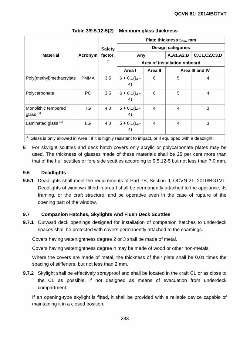
QCVN 81: 2014/BGTVT
283
Table 3/9.5.12-5(2) Minimum glass thickness
Material Acronym
Safety
factor,
Plate thickness tmin, mm
Design categories
Any A,A1,A2,B C,C1,C2,C3,D
Area of installation onboard
Area I Area II Area III and IV
Poly(methyl)methacrylate PMMA 3.5 6 + 0.1(LH-
4)
6 5 4
Polycarbonate PC 3.5 6 + 0.1(LH-
4)
6 5 4
Monolithic tempered
glass (1)
TG 4.0 5 + 0.1(LH-
4)
4 4 3
Laminated glass (1) LG 4.0 5 + 0.1(LH-
4)
4 4 3
(1) Glass is only allowed in Area I if it is highly resistant to impact, or if equipped with a deadlight.
6 For skylight scuttles and deck hatch covers only acrylic or polycarbonate plates may be
used. The thickness of glasses made of these materials shall be 25 per cent more than
that of the hull scuttles or fore side scuttles according to 9.5.12-5 but not less than 7.0 mm.
9.6 Deadlights
9.6.1 Deadlights shall meet the requirements of Part 7B, Section II, QCVN 21: 2010/BGTVT.
Deadlights of windows fitted in area I shall be permanently attached to the appliance, its
framing, or the craft structure, and be operative even in the case of rupture of the
opening part of the window.
9.7 Companion Hatches, Skylights And Flush Deck Scuttles
9.7.1 Outward deck openings designed for installation of companion hatches to underdeck
spaces shall be protected with covers permanently attached to the coamings.
Covers having watertightness degree 2 or 3 shall be made of metal.
Covers having watertightness degree 4 may be made of wood or other non-metals.
Where the covers are made of metal, the thickness of their plate shall be 0.01 times the
spacing of stiffeners, but not less than 2 mm.
9.7.2 Skylight shall be effectively sprayproof and shall be located in the craft CL or as close to
the CL as possible, if not designed as means of evacuation from underdeck
compartment.
If an opening-type skylight is fitted, it shall be provided with a reliable device capable of
maintaining it in a closed position.

QCVN 81: 2014/BGTVT
284
The skylight serving as means of evacuation shall be capable of being opened from any
side (from the deck and from the space).
If the strength of glass or of its attachment to the frame is not equivalent to that required
for the structural components, to which they are attached, provision shall be made for a
removable cap, which may be securely attached to this place in case of the glass rupture.
The glass thickness shall be equal to that required in 9.5.12 with due consideration of
loads from the deck cargo.
9.7.3 Flush deck scuttles shall be of non-opening type. Flush deck scuttles fitted in Areas I
and II shall be provided with deadlights hinged or attached by other method (for
example, by means of a chain) and capable of being easily and efficiently closed and
secured.
9.7.4 The largest dimension of the flush deck scuttles shall not be over 200 mm, with the
glass being at least 15 mm thick. Moreover, the glass shall be tempered. The flush deck
scuttles shall be attached to the metal deck plating by means of frames.
9.7.5 The strength of glass or of its attachment to the frame shall be equal to that of structural
component in which it is fitted.
9.7.6 When secured, the deadlights of the flush deck scuttles shall be weathertight. The
tightness shall be ensured by a rubber or other suitable gasket.
For the same purpose, along their contour the glasses of the flush deck scuttles shall be
provided with a gasket made of rubber or other suitable material.
9.8 Requirements to Materials
9.8.1 Plate materials
1 General requirements
Appliance plates shall be made of a transparent glaz- ing material, such as
poly(methyl)methacrylate (PMMA), polycarbonate (PC), tempered glass, chemically
reinforced glass or laminated glass, refer to Table 3/9.8.3-1(1) a non-transparent plate
material, such as plywood (PW), glass-fiber reinforced thermosetting plastic (GRP),
aluminum alloy, steel, etc.; or any other material of strength and stiffness equivalent to
those cited above.
2 Mechanical properties of materials are given in Table 3/9.8.3-1(2).
9.8.2 Acrylic sheet materials
Poly(methyl)methacrylate (PMMA) made with a technique other than the casting
procedure shall have mechanical properties and resistance to ageing at least equal to
those of cast PMMA.
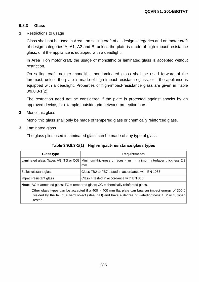
QCVN 81: 2014/BGTVT
285
9.8.3 Glass
1 Restrictions to usage
Glass shall not be used in Area I on sailing craft of all design categories and on motor craft
of design categories A, A1, A2 and B, unless the plate is made of high-impact-resistance
glass, or if the appliance is equipped with a deadlight.
In Area II on motor craft, the usage of monolithic or laminated glass is accepted without
restriction.
On sailing craft, neither monolithic nor laminated glass shall be used forward of the
foremast, unless the plate is made of high-impact-resistance glass, or if the appliance is
equipped with a deadlight. Properties of high-impact-resistance glass are given in Table
3/9.8.3-1(2).
The restriction need not be considered if the plate is protected against shocks by an
approved device, for example, outside grid network, protection bars.
2 Monolithic glass
Monolithic glass shall only be made of tempered glass or chemically reinforced glass.
3 Laminated glass
The glass plies used in laminated glass can be made of any type of glass.
Table 3/9.8.3-1(1) High-impact-resistance glass types
Glass type Requirements
Laminated glass (faces AG, TG or CG) Minimum thickness of faces 4 mm, minimum interlayer thickness 2.3
mm
Bullet-resistant glass Class FB2 to FB7 tested in accordance with EN 1063
Impact-resistant glass Class 4 tested in accordance with EN 356
Note: AG = annealed glass; TG = tempered glass; CG = chemically reinforced glass.
Other glass types can be accepted if a 400 × 400 mm flat plate can bear an impact energy of 300 J
yielded by the fall of a hard object (steel ball) and have a degree of watertightness 1, 2 or 3, when
tested.

QCVN 81: 2014/BGTVT
286
Table 3/9.8.3-1(2) Average mechanical properties of typical materials
Material Abbreviation Ultimate flexural strength,
MPa
Modulus of elasticity E,
MPa
Polymethylacrylate PMMA 110 3000
Polycarbonate PC 90 2400
Tempered glass TG 200 72600
Chemically reinforced
glass
CG 300 (1) 72600
Annealed glass AG 40 72600
(1) This value corresponds to a case depth (chemical reinforcement depth) of 30m
9.8.4 Specific requirements
1 Type of end connection
The Rules do not prescribe any specific types of end connection, though, it is suggested to
use type connections of ISO 12216:2002, namely:
(1) simply supported plates are the plates fastened without glue or gasket to the frame
rabbet or to the craft face by elastomer joint;
(2) flexibly connected plates are the plates fastened to the frame rabbet on elastomer or
fastened to the edge of side opening by elastomer joint like a car windscreen;
(3) semi-fixed plates are the plates fastened directly to the craft side or a frame
exclusively by means of glue, glue and bolts (screws) or by means of glue, bolts and a
counter frame. This type of end connection can be achieved by one of the following
means:
- connected with a counter-frame. The edge fixity is achieved by pinching the plate
at its periphery between the craft shell or a frame and a counter frame. The
counter frame shall be mechanically fastened and/or glued to the structure of the
craft;
- connected by gluing. The edge fixity is achieved by gluing the plate at its
periphery to the craft shell, to the structure of the craft or to a frame. This gluing
can either be in a rabbet or a face, edge gluing or any combination of these gluing
methods;
- connected by direct fastening. The edge fixity is achieved by fastening the plate
inside its periphery to the shell, the structure of the craft or to a frame by correctly
spaced and sized mechanical fasteners. These fasteners may be bolts, rivets,
self-tapping screws or any adequate mechanical fasteners.
2 Location on the craft

QCVN 81: 2014/BGTVT
287
(1) Simply supported plates
Simply supported plates shall not be used in Area I and II on craft of design categories
A, A1, A2, B or C.
On craft of other design categories and in other Areas, simply supported plates may
be used provided that all the following requirements are met:
- the material used is PMMA or PC;
- the plate thickness is equal to 1.3 times the one required by 9.5.12-5;
- the fixing devices of the plate (hinged bolts, fixing knob, etc.) are not spaced more
than 250 mm.
The above restrictions of use need not be considered if the appliance is equipped with
a deadlight.
(2) Flexibly connected plates
Flexibly connected plates may only be used on motor craft of design categories С1,
C2 or C3 in Areas III and IV.
(3) Semi-fixed plates
Semi-fixed plates made of materials other than glass may be used in craft of all design
categories and in all location areas provided that the requirements of 9.8.3 are met.
Semi-fixed plates made of glass may be used on sailing craft of any design category
and on motor craft of design categories A, A1, A2, B or C provided that high-impact-
resistant glass is used or if the appliance is equipped with a deadlight. Besides, metal
to glass contact shall be avoided.
3 Fastening requirements
(1) Fastening of plates and frames
Plates and frames can be fastened by mechanical means, glue or elastomer joints
(rubber resin). All types of fastening shall ensure watertightness of the plate or frame,
and resistance to loads due to normal operating pressure.
Every part of the mechanical elements connecting appliances to the rest of the craft
shall be capable of withstanding the test loads specified by VR in each case. This
requirement shall be verified for inwards opening appliances, where hinges, locks, or
any other part of the link chain between the plate and the support shall be checked by
calculation or testing.
(2) Fastening of semi-fixed plates
Mechanical fasteners shall not induce stress concentration due to deflection or
temperature changes. For instance, bolts in sharp angle counter-bores and
countersunk screw heads in conical bores shall not be used.

QCVN 81: 2014/BGTVT
288
(3) Fastening of glued plates
Glued joints shall be resistant to (or protected against) sunlight (UV, heat etc.) and all
environmental effects and cleaning chemicals normally encountered in the
manufacture and use of the craft.
Glued joint shall fulfill the requirements of one of the following items:
- the inside pressure test according to ISO 12216:2002 (D3.2);
- the separation test according to ISO 12216:2002 (D3.3);
- the manufacturer‟s gluing procedure and conditions are followed and the bond
strength checked by calculation to meet test pressure according to ISO
12216:2002 (D3.2.2);
- the above requirements shall be verified after any change in material or gluing
procedure.
9.9 Manholes
9.9.1 Covers of manholes shall be made of metal. The thickness of the covers shall
correspond to that of the plating on which they are fitted.
9.9.2 The covers of manholes shall be efficiently attached to the coaming or doubling ring by
means of bolts or pins with nuts.
9.9.3 When secured, the covers shall be tight both for water and liquid stores for which the
tanks or compartments are intended under the inner pressure corresponding to the test
pressure of the tank or compartment under consideration.

QCVN 81: 2014/BGTVT
289
CHAPTER 10 COCKPITS
10.1 Definitions and Explanations
10.1.1 For the purpose of this Chapter, the following definitions and explanations have been adopted:
1 Quick-draining cockpit is a cockpit or recess having its characteristics and drainage rate in
accordance with all the requirements of this Section for a craft of particular class.
2 Cockpit top is the upper deck or outer side upper edge in way of cockpit over which the
cockpit may be flooded from the side.
3 Watertight cockpit is a cockpit which satisfies the requirements of the present Section in
respect of water-tightness and sill height, but not in respect of the drain.
4 Cockpit bottom height, HB is the height of the cockpit bottom above the water line, the craft
being upright and fully loaded.
5 Sill height, hS is the height of sill, either the top of a fixed sill, or of the mobile part, when
closed, of a semi-fixed sill.
6 Cockpit water-retention height, h C is the height of water contained in the cockpit
measured between the cockpit bottom and the point of overflow out-board, the craft being
upright and fully loaded.
This term corresponds to the lowest point where the overflow area, expressed in square
metres, exceeds H max0.005L B and is usually the lowest point of the cockpit coaming.
For assessing hC every closing appliance, including the companionway door(s) is assumed
to be closed.
7 Companionway door is a door or closing appliance intended to close a companionway
opening.
8 Cockpit bottom is the lowest surface of the cockpit where water collects before being
drained. A cockpit bottom may have one or more levels.
Devices raising the standing level(s) from the rigid part of the cockpit, e.g. grating, stands,
bridge decks are not considered as part of the cockpit bottom.
9 Drain is an outlet of the cockpit enabling any water contained to be discharged outboard
by gravity. A drain can be:
- a pipe discharging overboard above or below the waterline;
- a part of the cockpit allowing direct discharge overboard;
QCVN 81: 2014/BGTVT
290
- scuppers and freeing port, etc.
10 Washboards are the closing appliance for companionway opening made of several mobile
boards that, when closed, are stacked one on top of each other.
11 Closing appliance is a device used to cover an opening in the cockpit, hull or
superstructure, for instance, a hatch cover, window, door, engine cover, washboards, etc.
12 Cockpit is an open device built in the deck, which is intended to accommodate the crew
and all the means of craft control.
For the purpose of the present Section, this is any area that may retain water, however
briefly, due to rain, waves, craft heeling, etc.
This means that:
- a cockpit may be located amidcrafts or in the after part of the craft;
- in some cases, the cockpit structure may include nearly all the craft;
- a cockpit may open aft to the sea;
- bulwarks may create a cockpit or recess.
12 Sill is a structure serving as a border around an opening in a deck, platform, bulkhead,
enclosure, etc.
13 Cockpit sill is a barrier, above which water in the cockpit may enter companionway
openings and downflood the craft.
14 Cockpit volume coefficient, KC is the ratio between the cockpit volume and the reserve
buoyancy, as determined from the formula:
CC
H max M
VK
L B F
15 Minimum cockpit bottom height, HBmin is the minimum value of HB required by VR.
16 Minimum sill height, hSmin, is the minimum value of sill height required by the Regulation.
17 Bridge deck is the area above the cockpit bottom, onto which people normally step before
entering the accommodation.
18 Cockpit volume, VC is the volume, in cubic metres, of water that can be instantaneously
contained in the cockpit before discharge, which is the volume below hC.
19 Cockpit sole is essentially horizontal surface(s) of the cockpit on which people normally
stand.
20 Semi-fixed sill is any closing appliance movable, but permanently attached to the craft,
which when in place, constitutes a sill higher than the fixed sill, for instance, sliding or
hinged doors, hatches, sliding sills, but excluding wash-boards. A lanyard is not regarded
as a permanent attachment.

QCVN 81: 2014/BGTVT
291
21 Companionway opening is an opening (hatchway or doorway) giving way to
accommodation. There may be several companionway openings.
22 Fixed sill is a sill being a fixed, integral and permanent part of the cockpit or hull.
23 Recess is a local cavity, groove or indentation generally in a bulkhead of the hull. In some
craft with the engine located aft, it may be an afterpeak bulkhead enclosure provided for
the engine, while the forward section of such an enclosure may be lifted to deck level.
24 Self-draining cockpit is a cockpit from which water may be drained overboard in some of
the craft conditions without precise drainage rates or heights of cockpit bottom or sills.
25 Degree of water tightness is ability of a closing appliance, fitting or surface to resist the
ingress of water. The degree of water tightness is summarized as follows:
- degree 1, Degree of tightness providing protection against effects of continuous
immersion in water;
- degree 2, Degree of tightness providing protection against effects of temporary
immersion in water;
- degree 3, Degree of tightness providing protection against splashing water;
- degree 4, Degree of tightness providing protection against water drops falling at an
angle of up to 15° from the vertical.
10.1.2 For the purpose of this Chapter, the following symbols are given in Table 3/10.1.2.
Table 3/10.1.2 Symbol used in this Chapter
Symbol Unit Meaning
d mm Drain diameter in millimetres
D m Drain diameter in metres
hC m Cockpit water retention height
HB m Cockpit bottom height above the waterline
HBmin m Minimum cockpit bottom height above the waterline
hs m Sill height
hSmin m Required minimum sill height
kc - Cockpit volume coefficient
tmax min Maximum allowable draining time
VC m3 Cockpit volume
Note. Heights measured above the cockpit bottom have symbols beginning with h,
whereas heights measured above the waterline have symbols beginning with H.

QCVN 81: 2014/BGTVT
292
10.1.3 For the purpose of this Section, the following arithmetic symbols have been adopted for
the drawings:
1: waterline;
2: cockpit bottom;
3: overflow point;
4: cockpit top;
5: seats;
6: drain;
7: access companionway;
8: top of fixed part;
9: top of mobile part;
10: bridge deck;
11: sole or grating;
12: grating flowing section;
13: companionway closed by washboards.
10.2 General
10.2.1 The cockpit shall be an integral part of the craft hull to ensure strength
The cockpit shall be watertight, i.e. all the openings therein lying below the overflow point
shall be provided with watertight closing appliances except for those mentioned under
10.4.2-2. In open transom cockpits, the lower edge of the access companionway sill shall
not be located below the cockpit top.
10.2.2 Craft condition
The requirements of the present Chapter shall meet the craft loading conditions
corresponding to full displacement with the craft upright in smooth water.
10.2.3 Watertight cockpits and recesses
1 Watertight cockpits and recesses shall:
- have sills in accordance with the requirements of 10.5.1;
- show a degree of watertightness in accordance with 10.6.
2 When assessing craft stability and reserve of buoyancy in accordance with the
requirements of Part 4, water-tight and self-draining cockpits/lockers shall be considered
full of water.
10.2.4 Quick-draining cockpits and lockers
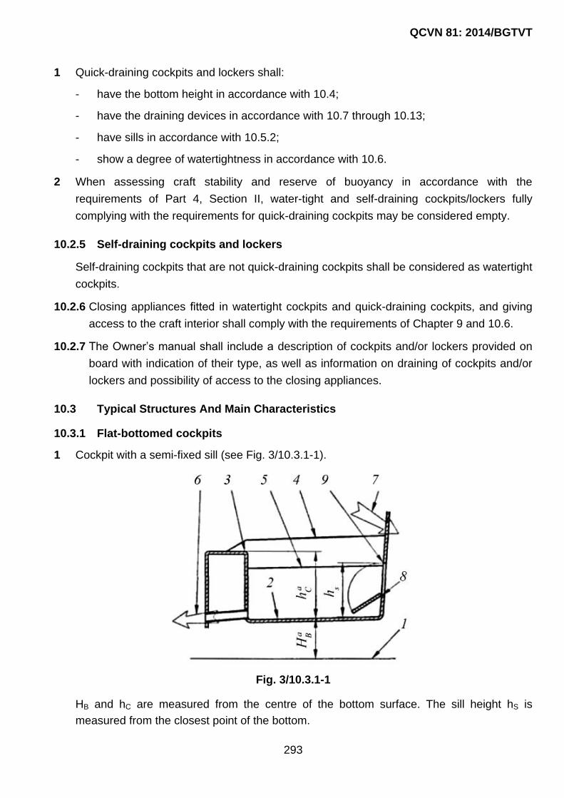
QCVN 81: 2014/BGTVT
293
1 Quick-draining cockpits and lockers shall:
- have the bottom height in accordance with 10.4;
- have the draining devices in accordance with 10.7 through 10.13;
- have sills in accordance with 10.5.2;
- show a degree of watertightness in accordance with 10.6.
2 When assessing craft stability and reserve of buoyancy in accordance with the
requirements of Part 4, Section II, water-tight and self-draining cockpits/lockers fully
complying with the requirements for quick-draining cockpits may be considered empty.
10.2.5 Self-draining cockpits and lockers
Self-draining cockpits that are not quick-draining cockpits shall be considered as watertight
cockpits.
10.2.6 Closing appliances fitted in watertight cockpits and quick-draining cockpits, and giving
access to the craft interior shall comply with the requirements of Chapter 9 and 10.6.
10.2.7 The Owner‟s manual shall include a description of cockpits and/or lockers provided on
board with indication of their type, as well as information on draining of cockpits and/or
lockers and possibility of access to the closing appliances.
10.3 Typical Structures And Main Characteristics
10.3.1 Flat-bottomed cockpits
1 Cockpit with a semi-fixed sill (see Fig. 3/10.3.1-1).
Fig. 3/10.3.1-1
HB and hC are measured from the centre of the bottom surface. The sill height hS is
measured from the closest point of the bottom.

QCVN 81: 2014/BGTVT
294
2 Cockpit with open transom and semi-fixed sill (see Fig. 3/10.3.1-2).
Fig. 3/10.3.1-2
If there is no cockpit water retention (hC = 0), drainage may be omitted, but the
requirements for the minimal sill height (hS) shall be complied with.
3 Cockpit with an opening in the transom (see Fig. 3/10.3.1-3).
Fig. 3/10.3.1-3
An additional drain on the port side may be required.
4 Cockpit having a transom door with a bottom gap (see Fig. 3/10.3.1-4).
Fig. 3/10.3.1-4
The door shall be considered closed. The gap between the door and its lower sill is
considered to be a drain freeing port. Its dimensions may be sufficient for draining time
requirements. However, 90 per cent of cockpit shall drain at 10° heel, which may require
an additional drain on the port side.
5 Cockpit with a bridge deck, grating and wash-boards above the sill (see Fig. 3/10.3.1-5).

QCVN 81: 2014/BGTVT
295
A raised sole, such as a grating, does not alter the sill requirements above the cockpit
bottom. The grating shall in no way impair the efficiency of the draining and shall have a
total flow section at least 3 times the drain section.
Fig. 3/10.3.1-5
10.3.2 Multilevel cockpits
Multilevel cockpits shall comply with the general requirements and the requirements for
flat-bottomed cockpits, with due regard for the following (see Fig. 3/10.3.2).
Fig. 3/10.3.2
1 The cockpit bottom height, HB above the waterline shall be measured upwards from the
waterline assigned in accordance with 10.2.2 to the centre of the lowest bottom level. In so
doing, it is permitted to use the exceptions mentioned in 10.4.2.
phẳng
Đáy

QCVN 81: 2014/BGTVT
296
2 Cockpit water-retention height, hC shall be measured between the point of overflow
overboard and the point at which the height HB is measured.
3 The cockpit volume is defined as a sum of volumes above each bottom level of the
cockpit, which are determined by multiplying the plan area of the level in question by the
retention height corresponding to that level. In so doing, the craft condition shall be in
accordance with the requirements of 10.2.1.
4 The companionway sill height, hS, is determined as the distance between the
companionway lower edge and the nearest point on the symbolic plane of a single-level
bottom. The symbolic plane of a single-level bottom shall be parallel to the horizontal plane
of the waterline complying with the requirements of 10.2.1 and to correspond to the
horizontal position for which conditional exclusions and additions of volumes above/below
all the bottom levels would be balanced. The adopted height, hS, of companionway sills
shall be in accordance with the requirements of 10.5.
5 The minimum sill height hSmin required by 10.5 shall be invariably ensured for the bottom
level nearest to the opening as well as for other levels. Elevations above the highest
bottom level such as the bridge deck mentioned under 10.3.1-5 may be included in the
required sill height.
6 For multilevel cockpits, the draining time stipulated under 10.8 shall be established
proceeding from the total volume determined in accordance with 10.3.2-3. The draining
time for particular levels shall not exceed that required by 10.8.
7 When making the drain cross-sectional area analysis at particular levels, as stipulated by
10.3.2-8, an allowance for the overflow from volumes lying above higher levels of bottom
shall be made even where a separate drainage is provided for these. In the assumption of
a uniform fall of water level, it is recommended that, for calculation purposes, the volume
of water lying above higher levels shall be supposed to flow over to lower levels from a
point lying in the mass centre of the volume in overflow.
8 In the bottom of a multilevel cockpit, provision shall be made for drainage on levels from
which water cannot flow over to lower levels or overboard.
10.4 Minimum Quick-Draining Cockpit Bottom Height above the Waterline
10.4.1 The minimum quick-draining cockpit bottom height, HBmin, above the waterline shall not
be less than stipulated in Table 3/10.4.1.

QCVN 81: 2014/BGTVT
297
Table 3/10.4.1 Minimum bottom height
Design category Height HBmin, m
A, A1, A2 0.15
B 0.1
C, C1, C2, C3 0.075
D 0.05
Note. Greater heights than these minimum values may be required to
fulfill the maximum acceptable draining time according to 10.8.
10.4.2 Exceptions
1 Surfaces up to a total 10 per cent of the horizontal projection of the cockpit bottom may lie
lower than required by 10.4.1. Among these surfaces, those containing water after the
cockpit has drained will be considered full of water when assessing the fully loaded
condition.
2 Lockers placed in the cockpit bottom and walls, which are intended for the storage of life
rafts, ice, fish, baits, etc. are not regarded as part of the cockpit and are not required to
comply with the requirements of 10.2.4, unless their closing appliances fulfill all the
requirements of 10.6, provided they are watertight towards the interior of the craft.
In this case, they shall be considered full of water when assessing the fully loaded
condition.
If the requirements of 10.2.4 and 10.6 are fulfilled, these lockers need not be considered
full of water, but only filled with the maximum loading corresponding to the fully loaded
condition.
10.5 Sill Height and Openings in Cockpits
10.5.1 Watertight cockpits
In watertight cockpits, the sill height for openings shall exceed the cockpit water retention
height hC by 0.05 m at least, as determined for craft conditions in accordance with 10.2.1
and 10.3.
Watertight cockpits of a height less than the cockpit water retention height hC shall have no
openings to the craft interior except those mentioned under 10.4.2-2.
10.5.2 Quick-draining cockpits
In quick-draining cockpits, the sill height hS for openings above the cockpit bottom shall not
be less than the height hSmin stated in Table 3/10.5.2.
For openings in quick-draining cockpits below the water retention height hC, closing
appliances according to the requirements of 10.6.2 shall be provided.

QCVN 81: 2014/BGTVT
298
Table 3/10.5.2 Minimum sill height, hSmin
Design category
Minimum sill height hSmin, m
Sailing mono-hulls Sailing multihulls and non-
sailing craft
A, A1, A2 0.3 0.2
B 0.25 0.15
C, C1 0.2 0.125
C2 0.15 0.1
C3 0.1 0.075
D 0.05 0.05
Note. In order to ensure the required stability and subdivision of a particular craft as per Part 4,
Section II a sill height exceeding the stated value may be necessary.
When measuring the sill height, all closing appliances shall be considered closed with the
exception of companionway door(s), and the semi-fixed parts of the companionway sill –
secured in a position providing for a maximum sill height.
The sill height shall be measured vertically from the cockpit bottom to the lowest point on
the sill edge that allows ingress of water.
If the cockpit bottom is not horizontal, the sill height shall be measured to the closest point
of the cockpit bottom.
The parameter hSmin shall also be used when considering multilevel cockpits.
10.6 Watertightness Requirements
10.6.1 Watertightness of cockpits
All surfaces of watertight and quick-draining cockpits up to the water retention height hC
including the surfaces of spaces mentioned under 10.4.2-2 shall comply with the
requirements for watertightness degree 1.
10.6.2 Watertightness of closing appliances
The watertightness degrees of the closing appliances fitted on the surfaces of quick-
draining cockpits except those mentioned under 10.4.2-2 shall comply with the
requirements of Table 3/10.6.2.
Closing appliances located in the bottom, horizontal areas and sides of quick-draining
cockpits up to the height hSmin shall be fitted with seals and sills at least 12 mm high and
tested for watertightness in accordance with the requirements of Chapter 9.

QCVN 81: 2014/BGTVT
299
Table 3/10.6.2 Watertightness of closing appliances
Location of closing appliance in cockpit Degree of
watertighness
Bottom and horizontal areas 2
Sides up to hSmin 2
Sides between hSmin and 2hSmin 3
Sides above 2hSmin 4
Note. In order to ensure the required stability and subdivision of a particular craft as per Part 4,
Section II, a watertightness exceeding the stated value may be necessary.
Semi-fixed sills and washboards shall have a device maintaining them in place, when in
use, which shall at least be operable from inside.
Semi-fixed sills and washboards shall meet the requirements of Chapter 9.
Semi-fixed sills shall only be detachable with the use of tools.
Where a closing appliance includes washboards as components, a 100 per cent reserve of
these shall be carried which shall be stowed in the vicinity of the closing appliance,
capable of being reached quickly and safely without the use of tools.
10.7 Drainage of Quick-Draining Cockpits
10.7.1 Draining shall be carried out only by gravity.
10.7.2 When the craft is upright, at least 98 per cent of the cockpit volume shall drain,
excluding any recess in accordance with 10.4.2.
10.7.3 The requirements of 10.5.1 and 10.5.2 shall be fulfilled when the craft is heeled to both
port and starboard, with due regard for the following:
1 on sailing monohulls, drainage shall be provided for at least 90 per cent the cockpit volume
VC at the lesser heel angle of 30 or when the deck at side begins to touch the water.
2 on non-sailing craft and multihulls, drainage shall be provided for at least 90 per cent of the
cockpit volume VC at 10° heel.
10.8 Draining Time
10.8.1 The draining time is the time needed to drain the cockpit from the full height of water,
hC, down to a remainder of 0.1 m above cockpit bottom.
Draining time requirements are established proceeding from the craft‟s navigation area
and with due regard for the cockpit volume coefficient, kC the ratio between the cockpit
volume and the reserve buoyancy of the craft, to be determined in accordance with 10.1. A
large cockpit volume relative to the craft‟s reserve buoyancy shall require a
correspondingly small draining time.

QCVN 81: 2014/BGTVT
300
The draining time shall not exceed that stated in Table 3/10.8.1.
Table 3/10.8.1 Maximum acceptable draining time, tmax
Design category tmax, min.
A, A1, A2 0.3/kC but not greater than 5
B 0.4/kC but not greater than 5
C 0.5/kC but not greater than 5
C1 0.6/kC but not greater than 5
C2 0.7/kC but not greater than 5
C3 0.8/kC but not greater than 5
D 0.9/kC but not greater than 5
The draining time shall be measured or calculated with every appliance in the cockpit
closed.
If the draining section, expressed in square metres, is greater than or equal to 0.05 VC,
draining time assessment is not required.
The cockpit volume, VC, shall be measured from the cockpit bottom up to the top of hC,
with the eventual exception of 10.4.2, assuming that all closing appliances and drains are
closed.
Practically secured draining time shall be measured during the trials of the prototype craft
which shall have a displacement close to fullload displacement and a trim in accordance
with the design. The cockpit shall be filled with water up to hC, and the draining time to
empty the cockpit between hC to 0.1 m of water remaining in the cockpit is measured. This
latter height shall be measured above the centre of the bottom surface of the cockpit. It
may be useful to indicate the point located 0.1 m above the centre of the cockpit bottom
with a tape mark.
10.9 Number Of Drains
10.9.1 Each quick-draining cockpit shall have at least two drains, one port and one starboard,
unless one opening enables drainage when the craft is heeled to both port and
starboard, as required in 10.7.
10.10 Drain Dimensions
10.10.1 Internal dimensions of the drain
The internal dimensions of the drain shall ensure the draining time of the cockpit, as
required by 10.8. The internal dimensions of the drain shall be determined in
accordance with 10.10.3 at the craft design stage.

QCVN 81: 2014/BGTVT
301
The minimal internal diameter of drains with a circular cross section shall be 25 mm.
Drains with other cross-sectional shapes shall have a cross-sectional area of at least 500
mm2 and a minimum dimension of 20 mm.
The possibility of inadvertent closure of drains by loose equipment, rigging, etc. shall be
ruled out.
10.10.2 Protective grids
If the drains are equipped with protective grids or other devices preventing loose objects
from falling into the draining system, one shall be aware that a grid of small holes is prone
to be clogged.
The minimum passage dimension inside any part of these devices shall have a section of
125 mm2 (or a diameter of 12 mm) at least, and a total entry cross section of 1.5 times the
cross section of the drain at least. If the above conditions are not met, the head losses
from the protective grid shall be considered.
10.10.3 Determination of drain cross section
For craft design purposes, the internal cross-sectional area of openings that is necessary
to drain the cockpit within the time required by 10.8 shall be determined by calculation
which shall consider all the head losses in the drain system including inlet losses and
outlet losses. With the drain outlet below the waterline, the head shall be measured
upwards of the waterline of floatation determined with due regard for the requirements of
10.2.1.
The required cross section may be calculated by meth- ods described in Annexes B, C, D
and E of ISO 11812: 2001.
10.11 Centreboard Casings and Other Types of Drain
Centreboard casings and other types of aperture may be used as drains if they are
designed for this purpose.
10.12 Drain Piping
10.12.1 The scantlings and design of drains shall take into account all the loads to which they
may be subjected during craft operation.
Drain piping shall be protected against damage from loose objects stowed in the craft and
against being kicked and stepped on.
Drain piping shall not trap water and shall only be used for cockpit drainage. This
requirement does not apply to drains fitted in centerboard housing or outboard wells and
trunks.
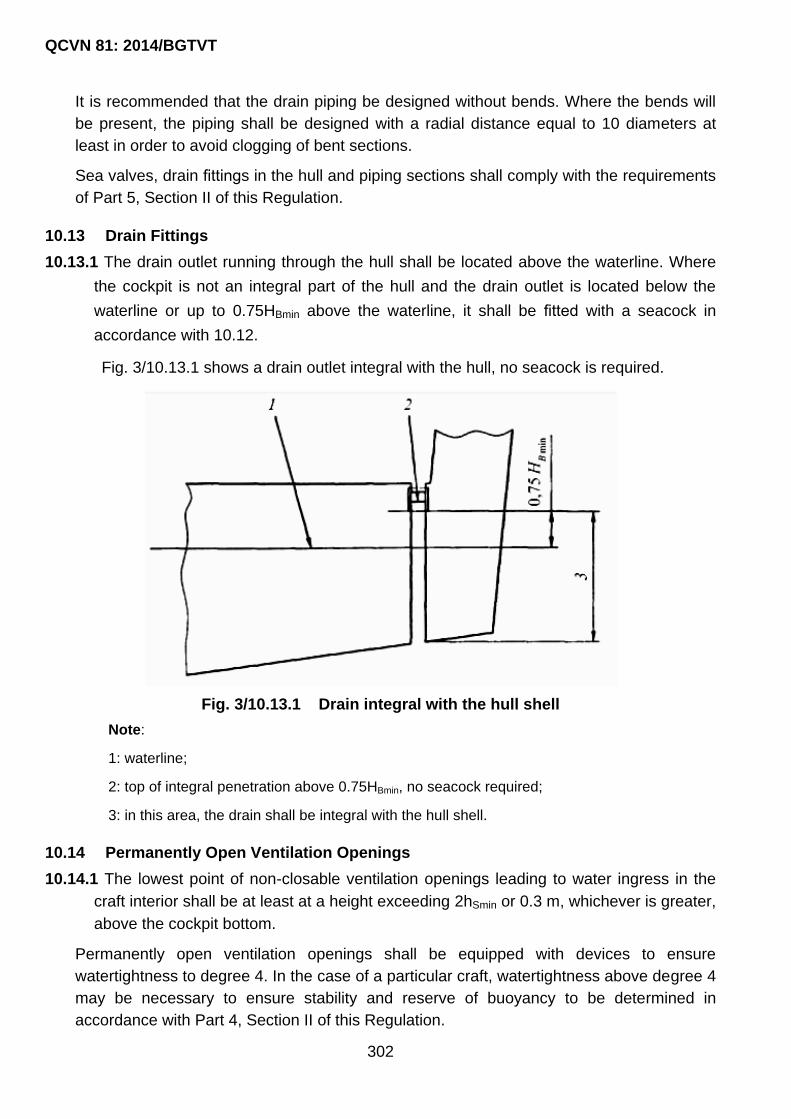
QCVN 81: 2014/BGTVT
302
It is recommended that the drain piping be designed without bends. Where the bends will
be present, the piping shall be designed with a radial distance equal to 10 diameters at
least in order to avoid clogging of bent sections.
Sea valves, drain fittings in the hull and piping sections shall comply with the requirements
of Part 5, Section II of this Regulation.
10.13 Drain Fittings
10.13.1 The drain outlet running through the hull shall be located above the waterline. Where
the cockpit is not an integral part of the hull and the drain outlet is located below the
waterline or up to 0.75HBmin above the waterline, it shall be fitted with a seacock in
accordance with 10.12.
Fig. 3/10.13.1 shows a drain outlet integral with the hull, no seacock is required.
Fig. 3/10.13.1 Drain integral with the hull shell
Note:
1: waterline;
2: top of integral penetration above 0.75HBmin, no seacock required;
3: in this area, the drain shall be integral with the hull shell.
10.14 Permanently Open Ventilation Openings
10.14.1 The lowest point of non-closable ventilation openings leading to water ingress in the
craft interior shall be at least at a height exceeding 2hSmin or 0.3 m, whichever is greater,
above the cockpit bottom.
Permanently open ventilation openings shall be equipped with devices to ensure
watertightness to degree 4. In the case of a particular craft, watertightness above degree 4
may be necessary to ensure stability and reserve of buoyancy to be determined in
accordance with Part 4, Section II of this Regulation.

QCVN 81: 2014/BGTVT
303
CHAPTER 11 SIGNAL MEANS
11.1 General
11.1.1 In addition to requirements in this Chapter, signal means and their arrangement shall
comply with requirements in Chapter 3 QCVN 42: 2012/BGTVT.
11.1.2 For crafts operating in the water of river, lake, gulf…, the signal means of which shall
comply with Part 10 QCVN 72: 2013/BGTVT and Law for Inland waterway
transportation.
11.2 Supply of Craft with Signal Means
11.2.1 Craft shall be provided with electric navigation lights. Craft having no own sources of
electric power may be provided with lights using other sources of white light of the type
approved by VR.
11.2.2 When electric navigation lights are used they shall be capable of being changed over to
the emergency source of power.
11.2.3 Sound signals used on craft shall be reliable in operation and shall produce the required
sound intensity and duration as well as clear sounding of each blast.
11.2.4 Each craft of Categories А, А1, А2 and В, С, С1 shall be provided with the following
spare parts and materials for lights:
1 one light filter for each colour light unless the light is provided with a colour lens.
2 one electric lamp for each electric light.
3 fuel for spare oil lights in such a quantity that provides burning for the whole set of lights
within a period of:
- 32 hours – for craft of Categories А, А1, А2 and В;
- 16 hours – for other Categories of craft.
4 one wick for each oil light.
5 for lights other than electric ones, the set of spare parts shall be determined by VR,
separately in each case.
6 six lamp glasses if all oil lights have glasses of the same size, otherwise each light shall be
provided with two glasses.
11.3 Pyrotechnic Signal Means Supply Standards
11.3.1 The supply of craft with pyrotechnic signal means shall be checked in accordance with
the standards specified in Table 3/11.3.1.

QCVN 81: 2014/BGTVT
304
Table 3/11.3.1 Standards of craft’s supply with pyrotechnic signal means
Design
category
Quantity
Rocket
parachute
flare (1)
Shell or
sound
signal
rocket (1)
Hand flare,
red
Hand flare,
white (2)
One-star
rocket,
green (2)
One-star
rocket, red (2)
A, A1, A2, B (3) 6 (4) 6 6 (4) 6 6 6
C 2 - 3 3 - -
C1 3 - 3 3 - -
C2 3 - 3 3 - -
C3 (4) - - - - - -
(1) Craft engaged in international voyages shall be provided with 12 rocket parachute flares. Hand
flares are also recommended.
(2) Recommended.
(3) Craft of design categories A, A1, A2 and B are additionally supplied with two buoyant smoke
floats. Besides, craft of design category A are additionally supplied with six rocket parachute flares.
(4) Craft navigating in inland waterways may be provided with rocket parachute flares (3) and red
hand flares (3).

QCVN 81: 2014/BGTVT
305
CHAPTER 12 PROVISION OF SEATS, CABINS AND SPARE PARTS
12.1 Provision of seats and cabins
12.1.1 Every crafts of design categories A, A1, A2, B, C shall be provided with cabins.
12.1.2 Each person on craft of design categories A, A1, A2 shall be provided with one berth
and one seat in the cabin. The minimum size of a berth shall be 1900 x 500 mm.
12.1.3 Each person on craft of design categories B, C, C1, C2, C3 and D shall be provided
with one seat having a minimum size of 400 x 750 mm.
12.2 Spare Parts For Craft’s Arrangement
12.2.1 Every craft shall be provided with spare parts required for reliable operation of craft‟s
arrangements. The list of spare parts is given in Table 3/12.2.1.
Table 3/12.2.1 Spare parts for craft’s arrangements
Nos. Items Design category
A, A1, A2 and B C C1
1 Anchor arrangement
1.1 Spare end shackle + - -
1.2 Spare connecting shackle + - -
2 Rudder and steering gear
2.1 Spare rudder stock bearing bush + + -
2.2 Spare rudder pintle bearing
bush
+ + -
2.3 Emergency tiller + + +
2.4 A set of steering tackle (1) + + +
(1) For craft with steering gear fed from a power source. In this case item 2.3 is not required.
QCVN 81: 2014/BGTVT
306
PART 4 STABILITY, RESERVE OF BUOYANCY AND FREEBOARD
CHAPTER 1 GENERAL
1.1 Application
1.1.1 The requirements of this Part of the Regulation apply to craft being subject to VR technical supervision in compliance with the requirements of Section I.
1.1.2 The requirements of this Part of the Regulation apply to craft in service to the extent which is expedient and feasible. However they are mandatory for craft under construction, and also for craft under conversion or major repair if their stability or freeboard depth are affected.
1.1.3 VR may allow the deviations from the requirements of this Part of the Regulation provided the equivalents in craft‟s design are ensured or special restrictions on navigation conditions are specified. The deviations, equivalents and specified restrictions shall be entered in an Owner‟s Manual.
1.2 Definitions and Explanations
1.2.1 The definitions and explanations relating to the general terminology are given in Part 1
and Part 2. In addition, the following definitions and explanations are adopted in this
Part of the Regulation:
1 Loaded displacement, ∆max (mLDC) is the mass of a craft in the loaded condition which
includes the light craft mass ∆min (mLCC) and the maximum total load DW (mMTL) being
defined in.2.3-26 and -31 Part 1.
2 Air space is an air-tight space of hull structure.
3 Righting moment MR is a moment produced by gravity and buoyancy forces at the given
heeling angle.
4 Load waterline (LWL) is the waterline of a craft when upright at a loaded displacement and
design trim.
5 Actual sail area A'S is an actual profile projected area of the specific combination of sails of
a sailing craft.
6 Liquid cargo is all liquids on board including craft‟s liquid stores, ballast, etc.
7 Craft‟s liquid stores are domestic waste waters and drinking water, fuel oil, lubricating oil in
permanently fitted tanks.
8 Reserve of buoyancy is the watertight volume of a craft‟s hull above a load waterline
including the volumes of watertight superstructures and deckhouses.
9 Design category of craft means operational conditions permitted for a craft in compliance
with 1.2.2-1, Section I.
10 Well is any volume open to the sky that may retain water.

QCVN 81: 2014/BGTVT
307
11 Initial metacentric height, h0 is the elevation of a metacentre above a craft‟s centre of
gravity with no craft‟s heel.
12 Corrected initial metacentric height, h is an initial metacentric height, h0 corrected for the
effect of free surfaces.
13 Minimum operating load is the sum of the following amounts:
(1) mass representing the minimum crew, positioned on the centreline near the highest
main control station, which is assumed equal to:
75 kg if LH ≤ 8 m;
150 kg if 8 m < LH ≤ 16 m;
225 kg if 16 m < LH ≤ 24 m.
(2) life-saving appliances with a mass of not less than (LH – 2.5)2, in kg;
(3) non-consumable stores and equipment normally carried on the craft;
(4) water ballast in tanks to be filled whenever the craft is afloat;
(5) a liferaft (if any) fitted in the stowage provided;
(6) not more than 10 per cent of the total amount of the stores of fuel oil, fresh water and
provisions.
14 Minimum operating displacement, mMOC is a craft‟s mass comprising the light craft mass
and the minimum service load.
15 Midship section of craft is the transverse section of the craft‟s hull in the middle of
waterline length LWL.
16 Heeling moments are the assumed design values of moments statically and dynamically
applied to a craft which correspond to a design model of their action on the craft.
17 Maximum permissible moments are the design values of moments being maximum
permissible on condition that the craft‟s stability parameters required at its static and
dynamic inclinations are ensured.
18 Freeboard, F is a distance measured vertically amidships between the deck line and
waterline plane at the maximum draught. For undecked craft, the freeboard is assumed as
a distance measured from the maximum draught plane till the upper edge of permanent
side plating.
19 Superstructure is an enclosed secure and weathertight structure on the freeboard deck
extended from side to side of the craft or having the sides at a distance of not more than 4
per cent of a breadth BH inboard from the craft‟s side.
20 Inflated bag is a bag made of flexible material which is always to be inflated when the craft
is being used.
21 Capsize is an event when a craft reaches any heel angle from which it is unable to recover
to equilibrium near the upright without intervention.

QCVN 81: 2014/BGTVT
308
22 Capsizing moment is an assumed design minimum dynamically-applied heeling moment
resulting in a capsize of craft.
23 Displacement volume of craft, VD is a volume of displacement of the craft to the
appropriate loading condition.
24 Basic stability criterion is the ratio of the maximum permissible moment to the heeling
moment due to wind or wind and waves.
25 Main sails are sails, which may be set under favorable navigational conditions.
26 Openings considered as open are openings in the upper deck or hull sides, as well as in
decks, sides and bulkheads of superstructures and deckhouses of which closing
appliances do not comply with the requirements of Part 3 as to their weathertightness,
strength and dependability. Small openings like sea openings of craft‟s systems and
pipelines which actually have no effect on stability in craft‟s dynamic heeling are not
considered as open.
27 Freeboard deck is a continuous deck from which a freeboard is calculated.
28 Righting lever, l (static stability arm) is an arm of gravity and buoyancy couple at craft‟s
heeling.
29 Windage area, ALV is the projected lateral area of the above-water portion (hull,
superstructures, deck-houses and spars, including awnings and dodgers) of a craft with no
sails on the centre line plane with the craft in the upright position.
30 Correction for free surfaces is a correction to the initial value of a metacentric height
allowing for a decrease in the craft‟s stability due to the effect of free surfaces of liquid
cargoes.
31 Trim of craft is the attitude of a craft in water featured by midship draught d, heel and trim
. Unless otherwise specified, all dimensions and definitions relate to the craft‟s trim in
calm water at the design displacement and design trim in the upright position.
32 Crew limit, CL is the maximum number of crew (with a mass of 75 kg each) which does not
exceed the number of seats provided for accommodation.
33 Maximum permissible angle of heel is an angle of heel which is not to be exceeded under
the Regulation.
34 Design trim is the longitudinal attitude of a craft when upright with crew, stores and
equipment in the positions designated by a designer or builder.
35 Downflooding height is a vertical distance measured between the deepest permitted
draught plane and the lowest point of an opening considered as open or having
watertightness degree 2, 3 or 4.
36 Calculation wind speed, vW is a wind speed used for calculating stability and buoyancy of
pleasure craft.
37 Loaded displacement condition is the light craft condition with the maximum total load
added at the design trim and the distribution of crew.

QCVN 81: 2014/BGTVT
309
38 Watertightness degree of closing appliance is the ability of the appliance or surface to
provide protection against ingress of water.
(1) Degree 1: Degree of tightness providing protection against effects of continuous
immersion in water;
(2) Degree 2: Degree of tightness providing protection against effects of temporary
immersion in water or getting awash;
(3) Degree 3: Degree of tightness providing protection against splashing water;
(4) Degree 4: Degree of tightness providing protection against water drops falling at an
angle of up to 15° from the vertical.
39 Light craft is a craft which is fully ready for use as defined in 1.2.3-26 Section I.
40 Type of craft: for the purpose of this Part of the Regulation, craft are subdivided into five
types arbitrarily designated as A, B, C, D and E.
41 Type A is fully decked craft. The fully decked craft means a craft in which the horizontal
projection of the sheerline area comprises any combination of:
(1) watertight deck and superstructure; and/or
(2) quick-draining well or cockpit complying with the requirements of Chapter 10 Part 3
and Chapter 2 through 5 of this Part; and/or
(3) watertight wells or cockpits complying with the requirements of Chapter 10 Part 3 with
a combined volume of less than H H ML ·B ·F
40;
(4) provided that all craft‟s closing appliances have the adequate strength, stiffness and
watertightness degree complying with the requirements of Chapter 9 Part 3; as well as
(5) for craft of design category A and A1 – plan area of all wells shall be less than
0.2LHBH, at that plan area of all recesses forward of LH/2 shall be less than 0.1LHBH;
(6) for craft of design category A2 and B – plan area of all wells shall be less than
0.3LHBH, at that plan area of all wells forward of LH/2 shall be less than 0.15LHBH.
42 Type B is pontoons and similar craft. These craft shall have a continuous deck with small
openings for access to compartments and the openings shall have steel or equivalent
watertight closing appliances provided with gaskets. With any one compartment damaged,
the water-tight deck of such craft shall remain above the water surface around the entire
periphery.
43 Type C is open craft. The open craft are craft of types A and B having hatch covers of the
inadequate strength, stiffness or watertightness degree, or hatches without closing
appliances.
44 Type D is partially decked craft. These are deemed as the craft of which over two thirds of
the craft‟s length (including one third of the length from the bow) may be considered as
type A or B, and which have cockpits meeting the requirements of Chapter 10 Part 3.

QCVN 81: 2014/BGTVT
310
45 Type E is undecked craft. These are deemed as the craft of which less than two thirds of
the craft‟s length may be considered as type A or B, and/or which have cockpits with a
total coefficient by volume KC 1, and/or the cockpits not meeting the requirements of
Chapter 10 Part 3.
46 Angle of vanishing stability, v is an angle of heel, in deg., other than zero at which the
righting moment is equal to zero; determined assuming that there is no offset load.
47 Downflooding angle, D is an angle of heel at which the craft‟s interior spaces are flooded
by water through openings considered as open, or over board or coamings.
48 Centre of lateral resistance (CLR) is the geometric center of the projection of the craft‟s
underwater hull onto the centerline including appendages.
49 Windage centre (WC) is the geometric centre of a corresponding windage area.
50 Beam between hull centres, BCB is a transverse distance between the centres of
buoyancy of the sidehulls.
51 Flotation element is independent tanks, inflated bags and low density materials providing
the necessary reserve of buoyancy to the craft in case of its hull damages.
1.3 General Technical Requirements
1.3.1 All calculations shall be made by the methods generally accepted in naval architecture.
When using a computer, the methods of computation and programme shall be
approved by VR.
1.3.2 The lines plan shall be made to a scale of at least 1:20; in so doing, the largest ordinate
shall be not less than 100 mm. Where computerized design is not used in calculating
form-stability arms, the width of the projection “body plan” used for measuring ordinates
for calculations shall be not less than 300 mm. Where the lines plan is constructed as
the computerized mathematical model of the hull, and buoyancy and stability
calculations are also computer-aided with the automatic transformation of the hull shape
to a calculation program, the requirement on dimensioning the projection “body plan”
may be ignored.
1.3.3 Calculation of cross-curves of stability
1 The calculation of cross-curves of stability shall be carried out to the waterline which is
parallel to the design waterline. If the craft is shaped and arranged so that the effect of trim
associated with inclinations essentially affects righting moment values, the calculations of
cross-curves of stability shall be carried out with due regard for the trim.
In calculating the cross-curves of stability, the superstructures located above the freeboard
deck are ignored.
2 The diagram of stability shall include the small-scaled layout chart of a hold coaming, as
well as of a companionway to an engine room, a deckhouse, and the designations of
downflooding angles referred to an open hole.

QCVN 81: 2014/BGTVT
311
3 The calculation of cross-curves of stability shall be supplemented with a curve of
downflooding angles for the lowest open hole at the craft‟s side, on deck and in
superstructure.
1.3.4 Calculation of liquid cargo effect
1 Tanks for each kind of liquid cargo and ballast, which may simultaneously have free
surfaces in craft‟s operation, shall supplement the tanks considered in computing the free
surfaces effect of craft‟s liquid stores on stability at large angles of inclination. To allow for
the free surface effect, one design combination of single tanks or their combinations for
each kind of liquid cargo shall be drawn up. Considering the number of tank combinations
for the individual kinds of liquid cargo or for single tanks likely to occur in operation, only
those producing the greatest total heeling moment M30 due to liquid overflow at the craft‟s
heel of 30° should be selected.
In all cases, the correction shall be computed with the tank filled by 50 per cent of its
capacity.
The tanks complying with the following condition below can be ignored:
30 t t b 1l b C 0.01
Where:
at, bt, t : overall dimensions (along base planes): width, depth and volume of tank;
: density;
Cb : block coefficient of tank;
1 displacement at the most unfavorable loading condi- tion in magnitude of h and l;
l30 : non-dimensional factor according to Table 4/1.3.4-1.
Table 4/1.3.4-1 Factor l30
bt/at l30 bt/at l30
20 0.111 1 0.049
10 0.113 0.5 0.024
5 0.114 0.2 0.010
2 0.094 0.1 0.005
2 The tanks included in the design combination for considering the free surface effect on
initial stability shall be selected in compliance with the instructions of 1.3.4-1 with the
difference that proceeding from initial stability the tanks shall be selected in the maximum
value of mh which is equal to the product of the intrinsic moment of inertia of free surface
for a craft in the upright position by the density of liquid cargo.
The correction to a metacentric height in the specific loading condition of a craft is
calculated for the tanks, which have free surfaces of liquids, for the craft when upright

QCVN 81: 2014/BGTVT
312
without trim; at that the correction is assumed as the greatest within the tank capacity
specified by recommendations on the craft operation.
The tanks complying with the following condition below can be ignored:
h t t b minm 0.0834 b C b / a 0.01
Where:
mh : correction to stability coefficient to allow for liquid cargo effect;
min : displacement corresponding to the craft‟s minimum loading condition regulated
by the Regulation.
The residues of liquids which are usual in emptied tanks are ignored in calculations.
The tank filled to more than 98 per cent of its capacity is considered as completely filled.
1.3.5 Calculation of windage area
1 The windage area shall include the projections of the following items on the centre line
plane: all continuous walls and surfaces of the hull, supestructures and deckhouses; rig,
ventilators, boats, deck machinery, all awnings which may be set in stormy weather, as
well as the projections of side surfaces of the deck cargoes specified.
Where projections of various elements are superimposed one upon the other, the
summation for continuous elements does not apply. The projection of discontinued
surfaces superimposed onto the projections of continuous elements is not included in the
windage area.
The windage area of sailing craft is determined for each sail combination of the set of sails
specified, including reefing. The windage area variants for the sailing craft are used in
assessing stability with the corresponding values of wind strength or velocity according to
the set of sails specified for use taking into account the provisions of 5.7.1 Part 3.
2 The windage of discontinued surfaces of rails, rigging and various small items is
recommended to take into account by increasing the total windage area of continuous
surfaces, which is determined for the minimum draught, by 5 per cent and the static
moment of this area by 10 per cent.
The above approximate methods to allow for the windage of discontinued surfaces and
small items are not mandatory. Where needed, those parts of windage may be determined
by detailed calculations. In this case, in calculating the windage of discontinued surfaces
like the craft‟s rig, rails, frames of the lattice type, etc., the overall areas taken into account
shall be multiplied by the filling factors assumed equal to:
0.6 for netted rails;
0.2 for not netted rails;
0.5 for structures of lattice type;

QCVN 81: 2014/BGTVT
313
0.6 for rigging.
The area of the projections of a hull above waterline, as well as of superstructures and
deckhouses of the traditional (other than streamlined) type shall be taken into account with
a flow coefficient equal to 1.0. The areas of the projections of superstructures and
deckhouses of the streamlined type may be assumed with the flow coefficient of at least
0.6 if confirmed by corresponding experimental and design data.
The areas of the projections of detached and streamlined elements (masts, smoke
funnels, ventilators, etc.) of the craft should be assumed with the flow coefficient of 0.6.
3 The position of the centre of windage area is determined by a method generally applied for
determining the coordinates of the centre of gravity for a plane figure.
1.3.6 A righting lever curve shall be plotted up to an angle of 80° with a spacing of 10°.
Where righting is ensured by crew‟s strength, the righting lever curve of the craft shall be
plotted up to an angle of 180° with a spacing of 10°.
The craft‟s righting lever curve shall be plotted, as a minimum, up to a downflooding angle
D or an angle of vanishing stability, V, whichever is greater.
Righting lever curves shall be plotted allowing for the potential effect of free surfaces of
liquids.
1.3.7 Loading condition
1 Unless otherwise specified, the craft‟s stability shall be checked for the following loading
conditions:
craft in fully loaded condition at loaded draught;
craft with minimum service load;
craft with minimum service load without crew.
2 If the loading conditions anticipated in normal service of a craft as regards stability are less
favorable than those listed in 13.7.1 or 2.7, stability shall also be checked for these
conditions.
3 The mass of solid ballast on board craft shall be included in the light-craft condition.
1.3.8 Curves of stability computed considering the correction for the effect of free surfaces of liquid cargoes according to 1.3.4, including the free surfaces of the accumulated oily mixtures shall be plotted for all the loading conditions under consideration.
1.3.9 Requirements for Information on Stability
1 To provide adequate stability of craft in service, the Information on Stability approved by
VR and containing the data below shall be issued to the craft:

QCVN 81: 2014/BGTVT
314
(1) craft‟s main characteristics and data resulting the trim and stability calculations,
including damaged condition, and also the tests for type design loading conditions
specified.
The summary tables of the results of calculating the displacement, the position of
centre of gravity, initial stability and trim, as well as the summary tables of the results
of stability checking for compliance with the requirements of this Part shall be drawn
up;
(2) data on inclining test;
(3) operational, navigational and other restrictions pertinent for craft‟s safety to prevent
downflooding and capsizing;
(4) instructions, diagrams, tables and other data to pro- vide a possibility to assess craft‟s
stability in service under the actual loading;
(5) instructions on mandatory arrangements when forced to tow another craft to render
assistance;
(6) recommendations on arrangements to improve stability.
2 It shall be noted in the Information that craft‟s stability essentially depends on the way of
craft‟s operation.
The Information on Stability shall contain an entry: “Compliance with the requirements of
this Information does not relieve the Master, and in his absence, the person in charge of
craft‟s safety from responsibility for stability and the necessary reserve of buoyancy of the
craft during operation”.
3 In developing instructions for the owner/master, the recommendations on selecting the
craft‟s moving direction and speed relative to sea allowing for potential capsizing due to
broaching or getting into (main and parametric) resonance conditions of rolling shall be
included.
The Information on Stability for any craft shall include the following entries:
“Under way in following sea with a wave height of 3 per cent probability above 2.0 m
(corresponding approximately to sea state IV as per 1.5.1 Section I), at a craft‟s speed
over ... m/s, the craft can capsize.
While running beam to the sea at the sea state close to the one limiting the craft‟s
navigation, the craft can capsize.”
The maximum permissible speed of the craft in a following sea, in m/s, is determined by
the formula:
s HV 0.7 L
The guidance to the Master may include the sections from the IMO document
MSC/1/Circ.1228:

QCVN 81: 2014/BGTVT
315
cautions;
dangerous phenomena;
operational guidance on avoiding dangerous situations, including useful, in the
developer‟s view, information.
The recommendations shall not be overburdened with well-known provisions of good
marine practice.
4 The Information on Stability shall be compiled relying on the calculations carried out in
compliance with this Regulation.
The Information on Stability for the lead (first) craft in series shall be confirmed by an
inclining test of this craft.
The Information on Stability for series-built craft shall be confirmed by the inclining
test/lightweight check carried out in compliance with 1.4 of this Part of the Regulation.
The Information on Stability compiled for the first craft of one series may be used for the
following craft of this series if the inclining test/lightweight check results for the craft
compared meet the following conditions:
(1) difference in the light craft displacement is within 2 per cent and in the height of the
centre of gravity is within 5 per cent, but comprises not more than 4 cm;
(2) difference in the abscissa of the centre of gravity is within 1 per cent of the length
between perpendiculars of the craft;
(3) requirements of this Part of the Regulation are met in the worst, with regard to
stability, loading conditions recalculated on the basis of the craft‟s inclining test.
5 The Information on Stability for the craft of design categories A, A1, A2 and B shall contain
particulars on damage stability and buoyancy compiled on the basis of calculations.
6 If a capsized craft has a possibility to regain its upright position by crew, the
Information on Stability shall include the corresponding recommendations on righting
the craft on the basis of calculations which are confirmed by experiments in craft‟s
testing.
7 The Information on Stability shall be approved by VR.
8 The Information on Stability may be inserted as a separate section in the Owner‟s Manual
of a craft approved by VR. If the Information on Stability is issued as a separate document,
the Owner‟s Manual shall include entry on the mandatory fulfillment of the Information on
Stability requirements.
1.4 Inclining Test and Lightweight Check
1.4.1 To be inclined are:
1 series-built craft as per 1.4.2.
2 every craft of non-series construction.

QCVN 81: 2014/BGTVT
316
3 every craft after reconstruction.
4 craft after major repair, conversion or modernization as per 1.4.3.
5 craft after installation of permanent solid ballast as per 1.4.4.
6 craft in service at time intervals within 10 years, if necessary, as per 1.4.5.
7 craft of which stability is unknown or shall be verified.
8 craft in initial survey for the assignment of class according to this Regulation requirements.
1.4.2 Of the series of craft under construction at each shipyard, to be inclined are:
1 the first craft, then every fifth craft (i.e. sixth, eleventh, etc.).The rest series-built craft shall
be subject to the lightweight check as per 1.4.14.
Depending on the seasonal conditions at craft‟s delivery and subject to special agreement
with VR, the inclining test of the craft may be reserved for the next craft in the series.
Beginning from the twelfth craft in the series, VR may require to incline the lesser number
of craft if it is demonstrated to the satisfaction of VR that in the process of constructing the
craft of the series the stability of their mass and the position of the centre of gravity is
ensured within the limits specified in 1.4.4-2(2).
2 a series-built craft wherein structural modifications, as compared with the first craft of the
series, according to the calculation result in:
(1) the change of the light craft displacement by more than 2 per cent; or
(2) the increase of the height of the light-craft centre of gravity simultaneously exceeding
4 cm and the value determined by the formulae, whichever is less:
g 1 0 maxz 0.1 / l
g 1 0z 0.05 / h
Where:
0 : light-craft displacement;
1 : = craft‟s displacement under the most unfavorable loading con dition with
regard to a value of h or lmax;
lmax : maximum lever of the righting lever curve at the worst, with regard to its
value, design loading condition;
h : corrected initial metacentric height under the most unfavorable design loading
condition as regards its value;
or
(3) violation of the requirements of this Part of the Regulation for design loading
conditions with:

QCVN 81: 2014/BGTVT
317
zg = 1.2 zg2 – 0.2 zg1
Where:
zg1 (zg2) : design light-craft vertical centre of gravity prior to (after) structural
changes;
zg : assumed light craft vertical centre of gravity.
Such craft shall be considered the first craft of a new series regarding stability, and the
inclining test procedure for the following craft shall meet the requirements of 1.4.2-1.
1.4.3 After reconstruction, major repair, conversion or modernization, to be inclined is the
craft wherein structural modifications, as shown by calculation, result in:
1 change of load (total mass of loads removed or added) by more than 6 per cent of the
light-craft displacement; or
2 change in the light-craft displacement by more than 2 per cent; or
3 increase in the the light-craft vertical centre of gravity by more than the value computed as per
1.4.2-2(2); or
4 violation of the requirements of this Part of the Regulation for design loading conditions as
specified in 1.4.2-2(3).
If no inclining test is required according to the calculation results, the lightweight
check shall be carried out in compliance with 1.5.14.
Irrespective of the calculations submitted, VR in compliance with 1.4.1-7 the inclining test
of the craft to be performed, proceeding from the craft‟s technical condition.
1.4.4 After installation of the permanent solid ballast every craft shall be inclined.
The inclining test of the ship may be omitted if VR is satisfied that when installing the
ballast, efficient control is effected to ensure the design values of mass and centre of
gravity position, or these values can be properly confirmed by calculation.
1.4.5 In order to determine a need to incline the craft in accordance with 1.4.1-6, the lightweight check shall periodically be carried out (experimental determination of the light craft displacement and the longitudinal centre of gravity). The lightweight check shall be performed at intervals not exceeding five years.
If a change in the light-ship displacement by more than 2 per cent or in longitudinal centre
of gravity by more than 1 per cent of the ship‟s length as compared to the approved
Information on Stability is found out as a result of the lightweight check then the craft shall
be inclined.
1.4.6 Where the inclining test results for the craft built show that the light-ship vertical centre of gravity exceeds design value to the extent that involves the violation of the requirements of the present Part, calculations with explanation of the reasons of such differences shall be attached to the Inclining Test Report.

QCVN 81: 2014/BGTVT
318
On examining the documents submitted, or in case of their absence, VR may demand the
performance of the repeated (check) inclining test of the craft. In this case, both the
Inclining Test Records shall be submitted to VR for consideration.
1.4.7 Except for the craft engaged on international voyages, VR may, as a shipowner‟s wish, dispense a newly-built craft from the inclining test provided that the 20 per cent increase of the light craft centre of gravity, as compared with the design value, does not violate the requirements of this Part of the Regulation.
1.4.8 Craft‟s loading during the inclining test shall be as far as practicable close to the light-craft displacement. The mass of missing loads shall be not more than 2 per cent of the light-ship displacement, and the mass of surplus loads less inclining ballast and ballast according to 1.4.9 – 4 per cent.
1.4.9 The metacentric height of the craft in the process of the inclining test shall be at least 0.20 m.
For this purpose necessary ballast may be taken. When water ballast is taken, the tanks
shall be carefully pressed up.
1.4.10 To determine the angles of heel during the inclining test, at least two pendulums of at least 2 m and over long, or at least two VR-approved devices shall be fit- ted, or a special VR-approved arrangement for use in the inclining test shall be applied.
1.4.11 If the inclining test is accurately carried out, the value of a metacentric height obtained may be used in calculations with no deduction for a probable error of the test.
The inclining test results are acceptable if:
1 for each measurement the following condition is fulfilled:
2
i k
i k
h - hh - h 2
n - 1
Where:
hi : metacentric height obtained in a single measurement;
hk = hi/n : metacentric height obtained in inclining the craft;
n : number of measurements.
The measurements, which do not meet the above condition, are ignored in processing the
test results with the corresponding correction of the total number n and the repeated
calculation of the metacentric height hk.
No more than one measurement may be ignored (greater number of measurements may
be excluded only if justified and agreed with VR);
2 Probable error of the test
2
i k
n
h - ht
n n - 1

QCVN 81: 2014/BGTVT
319
2
i k
n k
h - ht 0.02 1 h
n n - 1
if hk 2 m;
2
i k
n k
h - ht 0.01 4 h
n n - 1
if hk > 2 m.
Factor tn is taken from the following Table:
Table 4/1.4.11-2 Factor tn
n 8 9 10 11 12 13 14 15 16
tαn 5.4 5.0 4.8 4.6 4.5 4.3 4.2 4.1 4.0
3 considering the values of h and lmax and the worst loading conditions corresponding
thereto, the following condition is met:
2
i k
n 0 1
h - ht /
n n - 1
Where:
ε = 0.05h or 0.10 lmax whichever is less, but at least 4 cm.
4 total number of satisfactory measurements is not less than 8.
1.4.12 Where the requirements of 1.4.11 are not met, it is allowed, if agreed with VR, to use for
calculations the value of the metacentric height obtained in the inclining test less the
probable error of the test computed according to 1.4.11-.2.
1.4.13 The inclining test shall be witnessed by VR‟s Surveyor.
Other methods of experimental determining the light craft weight and the position of its
centre of gravity may also be used, provided that it will be demonstrated to the
satisfaction of VR that the accuracy of the inclining test results meets the present
requirements.
1.4.14 The lightweight check of a craft shall be witnessed by the surveyor to VR. The
lightweight check is carried out for determining:
1 a need to conduct the inclining test in compliance with 1.4.5.
2 the possibility of applying the values of the light craft displacement and the coordinates of
its centre of gravity in stability documents which were obtained:
(1) in the inclining test of the previous series-built craft – for series-built craft constructed
at the same shipyard, by the same drawings and not being subject to the inclining test
in compliance with 1.4.2-1;
(2) by calculation – for any series-built craft with certain distinctions in the light craft
displacement from the previously inclined craft, which do not exceed the values

QCVN 81: 2014/BGTVT
320
specified in 1.4.2-2, or for the craft in service subjected to modifications and for which
the light craft displacement changes may be calculated and do not exceed the values
specified in 1.4.3.
In each of the above cases, no corrections of the stability documents are needed if the
light craft data resulting the lightweight check differ from those in the stability information
by not more than 2 per cent for the light craft displacement and by not more than 1 per
cent of the craft‟s length between perpendiculars for the longitudinal position of the light
craft‟s centre of gravity. Otherwise, the craft shall be subject to the inclining test with the
follow-up correction of the stability documents.
3 The parameters of the craft in a light condition not subjected to the inclining test in
compliance with 1.4.7.
1.5 Deviations From The Rules
1.5.1 If doubts arise with regard to stability of any craft when the requirements of the present
Part are formally complied with, VR may require checking of the craft‟s stability against
additional criteria.
In case where the requirements set forth in the present Part are considered to be too
severe, VR may permit, on a well-grounded statement of design and service bodies,
appropriate departures from these requirements for the craft concerned.
1.5.2 When a ship navigating in a particular area does not comply with the requirements of
the present Part, VR may, in each particular case, either restrict the craft‟s area of
navigation or place other limitations depending upon the craft‟s stability characteristics,
service conditions and purpose the craft is intended for.

QCVN 81: 2014/BGTVT
321
CHAPTER 2 STABILITY
2.1 Basic Stability Criteria
2.1.1 The requirements on meeting the basic stability criteria apply to all the displacement craft.
2.1.2 Craft‟s stability is assumed to be adequate if the craft meets the criteria, specified according to its design category and type, in the worst, with regard to stability, loading condition, while navigating within the specified navigational area and following to the place of refuge.
2.1.3 The craft‟s stability is assessed for the following basic criteria:
Weather criterion considering breaking waves is used to assess the craft‟s stability under
breaking wave conditions. The criterion applies to monohull craft of design categories A,
A1, A2, B and C. A weather criterion below applies to multihulls of those design
categories.
Weather criterion is used to assess the craft‟s stability for navigating in the specified
service area. The criterion applies to assessing the stability of all the craft of categories C1
and C2.
Weather criterion on a following wave top is used to assess the monohull craft‟s stability
for design categories A, A1, A2 and B.
Wind stiffness criterion is used to assess the craft‟s stability for design categories C3 and
D.
Stability criteria specified in 2.1.8 and 2.1.9 to fit craft‟s specific design categories.
2.1.4 Weather criterion
The weather criterion is defined by the moment ratio:
K = Mper/Mw ≥ 1.0
Where:
Mper : maximum permissible moment, in kNm, determined according to 2.3.2
considering craft‟s motions in the seas according to 2.2.2;
Mw : heeling moment, in kNm, due to the wind pressure determined according to 2.2.1.
2.1.5 Weather criterion considering breaking waves
The weather criterion considering breaking waves is defined by the moment ratio:
d
per wK = M /M 1.0
Where:

QCVN 81: 2014/BGTVT
322
Mper : maximum permissible moment, in kNm, specified in 2.1.4 considering craft‟s
motions in the seas according to 2.2.2; however, the design amplitude of rolling for the
design category C craft may be determined only according to 2.2.2-2;
d
wM : dynamic heeling moment, in kNm;
d
w w vM = M + M
Mw : heeling moment, in kNm, due to the wind pressure determined according to 2.2.1;
Mv : heeling moment, in kNm, due to an impact of breaking waves determined
according to 2.2.3.
Where this criteria is impracticable to meet, the parameters of a righting lever curve
are subject to special consideration by VR with due regard for the opportunities of
righting the craft from a bottom up position as specified in a design.
2.1.6 Weather criterion on a following wave top
The criterion defines the adequacy of craft‟s initial stability allowing for the effective
waterline area lost:
h + ∆l10 > 0
Where:
h : initial metacentric height, in m;
∆l10 : increase of the static stability arm, in m, determined according to 2.2.4.
2.1.7 Wind stiffness criterion
The wind resistance criterion is defined by the moment ratio:
per w wK = M / M K
Where:
Mper : maximum permissible moment, in kNm, determined according to 2.3.3;
Mw : heeling moment, in kNm, due to the wind pressure determined according to 2.2.1;
Kw : wind stiffness criterion assumed equal to:
1.0 for craft type A or B;
1.15 for craft type C or D;
1.50 for craft type E.
2.1.8 Stability in turning
1 The stability of a motor craft, which power output of the propulsion engines meets the
requirement in 1.1.2-1(2) Part 1, shall be verified for the effect of a heeling moment acting
on the craft during the turning at the worst, regarding stability, loading condition.
An angle of stable heel in turn shall not exceed:

QCVN 81: 2014/BGTVT
323
12° or 80% of the value of a downflooding angle; or
the angle at which the freeboard deck immerses; or
the angle at which the bilge emerges at its middle; or
15° considering the joint action of the simulated heel- ing moment due to the crowding
of passengers to one side defined in 2.5 of this Part of the Regulation, and the heeling
moment in steady turning;
whichever is less.
2 The heeling moment acting on the craft during turning, MR, in kNm, is computed by the
procedure agreed with VR or is determined by the formula
2
R g
dM = c v z - /L
2
Where:
L and d: craft‟s length and draught up to the effective waterline, respectively, in m;
∆ : displacement at the draught up to the effective water line, t;
zg : elevation of craft‟s centre of gravity above the base line, m;
v : full speed in calm water on straight course, in m/s;
c : factor determined by maneuverability tests of a prototype craft, but at least 0.2.
2.1.9 Additional criteria
Depending on the craft‟s purpose, its structural details and operational conditions, the
additional requirements set forth in 2.7 shall be met.
2.2 Calculation Of External Action Parameters
2.2.1 The heeling moment Mw, in kNm, due to wind pressure on the above-water portion of a craft is determined by the formula:
-3
w LV WC 1 2 A WM = A (z + a a d ) p ·10
Where:
ALV craft‟s windage area, in m2, to be assumed equal to ALV = 0.55LHBH for the craft of
design categories A, A1, A2 and B if ALV < 0.55LHBH;
pw design wind pressure, in Pa, determined by the formula for all types of craft:
pw = WST + WD
Where:
WST and WD static and dynamic components of wind loading, respectively, to be
determined according to 1.5.2, Section I;

QCVN 81: 2014/BGTVT
324
In calculating the static and dynamic components of wind loading, the wind
pressure is assumed at the the height equal to the sum of the height of a
windage centre above waterline and half the wave height with 3 per cent
probability of exceeding a certain level, h3%, in accordance with the craft‟s
operational area;
zWC : elevation of the windage centre above the water- line plane, in m;
dA : draught determined as the doubled distance from a design waterline to the parallel
thereto neutral axis of inertia of the area of the craft‟s centre plane underwater part
(ACL), allowed for hull keels excepting centreboards/leeboards and appendages. It is
allowed to assume dA equal to a midlength draught for the craft with a simply-shaped
underwater area;
a1 : factor allowing for the effect of water resistance- to-craft‟s lateral drift forces on a
heeling arm assumed according to Table 4/2.2.1-1 depending on the ratio BH/dA;
a2 : factor allowing for the effect of inertia forces on a heeling arm z to be determined
according to Table 4/2.2.1-2 depending on the ratio zg/BH (zg is elevation of a centre of
mass above the craft‟s base plane, in m).
Table 4/2.2.1-1
BH/dA < 2.5 3.0 4.0 5.0 6.0 7.0 8.0 9.0 > 10.0
a1 0.40 0.41 0.46 0.60 0.81 1.00 1.20 1.28 1.30
Table 4/2.2.1-2
zg/BH ≤ 0.15 0.20 0.25 0.30 0.35 0.40 ≥ 0.45
a2 0.66 0.58 0.46 0.34 0.22 0.10 0
2.2.2 Design roll amplitude θr, in deg., is assumed for monohulls as the greatest of the values defined by the requirements in 2.2.2-1 to 2.2.2-3 correspondingly to the craft‟s type and the characteristics of the navigational area in question, or by other procedures recognized by VR for small pleasure craft.
For the craft with waterline length above 24 m, on agreement with VR, design roll
amplitude may be determined according to 2.1.5, Part 10, Section II, QCVN 21:
2010/BGTVT.
The design roll amplitude for catamarans is determined in compliance with 2.2.2-3 and
2.7.5. Roll calculations for other multihulls are subject to special consideration by VR.
The design roll amplitude for sailing craft carrying the sails of a total area over 25 per
cent of the standard one is defined by the requirements in 2.2.2-3.
1 The design roll amplitude of 3 per cent probability, θ3%, in rad, is determined by the
formula:

QCVN 81: 2014/BGTVT
325
3% 2.64 D
(1) The dispersion of heeling angles D , in rad2, is determined by the formula:
2 12 2x 440 1 V 0 1 V
1 1 1
D J +h - 3h h - 3hD -
6h 6h 3 h
Where:
h0 : initial metacentric height, in m;
V : static heeling angle, rad;
V = MW/g∆h0
MW : heeling moment, in kNm, due to the design wind pressure determined
according 2.2.1;
∆ : craft‟s weight displacement at the loading condition in question, in tons;
1D : dispersion of angular velocities of rolling, in rad/s2, determined by Formula
2.2.2-1(2);
Jx : moment of inertia of craft‟s masses about the central longitudinal axis going
through the craft‟s centre of gravity, in kg.m.s2;
44 : moment of inertia of added water mass about the central longitudinal axis
going through the craft‟s centre of gravity, in kg.m.s2;
h1 : coefficient computed by the formula:
3 2
1 0 mh = 4h / 27l
lm : maximum righting lever, in m.
(2) The dispersion of angular velocities of rolling 1D , in rad/s2, is determined by the formula:
2 / 3
1 1 2G GD
W
Where:
G1 : dimensionless factor of disturbing wave moment intensity to be determined
by Formula 2.2.2-1(3);
G2 : dimensionless factor of disturbing wind moment intensity to be determined by
Formula 2.2.2-1(4);
W : roll damping coefficient defined in 2.2.2-1(6).
(3) The dimensionless factor of disturbing wave moment intensity G1 is determined by the
following formula:

QCVN 81: 2014/BGTVT
326
-4 3 2 24
3%1 2
44 x
hG = 0.00195 exp -0.456 /
1 / J
Where:
: reduction factor defined in 2.2.2-1(5);
h3% : wave height with 3 % probability of exceeding level, in m, to be determined
depending on the navigational area;
2 / : mean wave frequency, in 1/s;
: mean wave period in question, in s, determined b Fig. D/1 and Table D/2 in
Appendix D.
(4) The dimensionless factor of disturbing wind moment intensity is determined by the
formula:
2
w2 2 5/3 6
x 44
0.3133MG
J + 10
Where:
Mw : heeling moment due to design wind pressure, in kNm, determined according
to 2.2.1.
(5) The reduction factor is determined by the formula:
2
kexp -a
Where:
ak : parameter to be determined, depending on the vertical prismatic coefficient of
the hull CB, breadth BH, draught dH, transverse metacentric radius r, initial
metacentric height h, by the formula
2
k B H H H 0a = 0.068 C B d C r/h
: craft‟s natural frequency of rolling, in s-1, computed as follows:
For monohulls:
0 x 44h / J +
for catamarans:
h/ i
Where i is determined by Formula 2.7.4-3(2).
(6) The roll damping coefficient W is determined by the following formulae:

QCVN 81: 2014/BGTVT
327
(a) for craft with a smooth-lined hull:
28S aW = g/ h x '
Where:
' : coefficient to be determined by the nomographic charts in Fig. D/3.5 of
Appendix D.
(b) for craft with a smooth-lined hull fitted with center or bilge keels:
3
k k
K S 4
H H
715 S lW = W
L B
Where:
Sk : area of a bilge or center keel, in m2;
lk : distance between the craft‟s centre of gravity and the centre of keel area,
in m;
: sum of design values computed for each keel if more than one is fitted, in
m5.
(c) for craft with hard-chine hull:
4
H HHC
X 44
kL BW =
J +
or by the approximate formula:
HHC
B H
0.09BW =
C d
Where:
k = 0.003 : dimension factor, in t.m-4s2;
CB : craft‟s block coefficient;
dH : craft‟s draught, in m.
(7) The craft‟s mass moment of inertia JX, in t.m.s2, about the longitudinal axis going
through the craft‟s centre of gravity is determined by the craft‟s mass load if the latter
is divided into the large number of small items. If the craft‟s detailed mass load is
unavailable, the moment may be determined by one of the following empirical
formulae:
Pavlenko‟s formula:
2 2
X H HJ = B D16g
Shimanskii‟s formula:

QCVN 81: 2014/BGTVT
328
2 2 2
X H WA B HJ = B C /11.4C Dg
Dwire‟s formula:
2 2
X H gJ = B 4z12g
or by assessing:
2
X XXJ = g
Where:
XX : radius of inertia of the mass about the central longitudinal axis going through
the craft‟s centre of gravity which varies within the range 0.35 XX/BH
0.45 for craft of various types; in this case, the greater values correspond to
hard-chine craft;
CWA : waterplane area coefficient;
CB : craft‟s block coefficient.
(8) The moment of inertia of added water mass, 44, in t.m.s2, about the central
longitudinal axis going through the craft‟s centre of gravity is determined by the
formula:
44 B X 00.314 / C J '
Where:
CB : craft‟s block coefficient;
‟0 : quantity to be determined by the nomographic charts in Fig. D/3.1, D/3.2 and
D/3.3 of Appendix D.
2 Calculation of amplitude of motions for non-sailing craft.
(1) The amplitude of motions, in deg., for a round-bilge craft having no bilge keels and bar
keel is determined by the formula:
1r 1 2X X Y
Where:
X1, X2 : dimensionless coefficients;
Y : multiplier, in deg.;
The multiplier Y is taken from Table 4/2.2.2-2(1)(a) depending on the craft‟s
design category and the ratio 0 Hh / B .

QCVN 81: 2014/BGTVT
329
Table 4/2.2.2-2(1)(a) Values of factor Y
Design category 0 Hh / B
≤ 0.04 0.05 0.06 0.07 0.08 0.09 0.1 0.11 0.12 ≥ 0.13
A, A1 and A2 24.0 25.0 27.0 29.0 30.7 32.0 33.4 34.4 35.3 36.0
B, C, C1, C2 and
C3 16.0 17.0 19.7 22.8 25.4 27.6 29.2 30.5 31.4 32.0
Factor X1 is taken from Table 4/2.2.2-2(1)(b) depending on the ratio H HB / h .
Table 4/2.2.2-2(1)(b) Values of factor X1
BH /dH X1 BH /dH X1
≤ 2.4 1.0 3.0 0.90
2.5 0.98 3.1 0.88
2.6 0.96 3.2 0.86
2.7 0.95 3.3 0.84
2.8 0.93 3.4 0.82
2.9 0.91 ≥ 3.5 0.80
Factor X2 is taken from Table 4/2.2.2-2(1)(c) depending on the craft‟s block coefficient
CB.
Table 4/2.2.2-2(1)(c) Values of factor X2
CB ≥ 0.45 0.5 0.55 0.6 0.65 ≥ 0.7
X2 0.75 0.82 0.89 0.95 0.97 1.0
(2) Where the craft is fitted with bilge keels or a bar keel, or both, the amplitude of
motions, in deg, is determined by the formula:
2r 1rk
Where:
Factor k is taken from Table 4/2.2.2-2(2) depending on the ratio Ak/(LB) wherein
Ak is the total overall area of bilge keels, or the area of the side projection of
the bar keel, or the sum of those areas, in m2.
Table 4/2.2.2-2(2) Values of factor k
Ak/(LB). % 0 1.0 1.5 2.0 2.5 3.0 3.5 ≥ 4
k 1.00 0.98 0.95 0.88 0.79 0.74 0.72 0.70
(3) The amplitude of motions for a hard-chine craft shall be assumed equal to 70 per cent
of the amplitude computed by Formula 2.2.2-2(1);

QCVN 81: 2014/BGTVT
330
(4) The amplitude of motions for the craft fitted with stabilizers shall be determined without
their functioning;
(5) The design values of the amplitude of motions should be rounded off to the whole
degrees.
3 The design amplitude of rolling shall be assumed not less than the values given below:
(1) The design roll amplitude 3%, in deg., for the sailing and non-sailing craft of design
categories A, A1, A2, B, C, C1 and C2 shall be assumed not less than the one
determined by the formula:
3% Wk
Where:
W : design angle of waveslope – refer to Table 4/2.2.2-3(1);
r 0 0k f , : coefficient allowing for the probability of the resonance of
oscillations, while running beam to sea, is taken from Table 4/2.2.2-3(1);
2 / : mean wave frequency, s-1;
: craft‟s natural frequency of rolling, in, s-1, computed by Formula (2.2.2-1(5)
depending on craft‟s category;
: mean period of wave in question, in s, to be determined by the diagram in Fig.
D/1, Appendix D.
In calculations of the conditions when sails of the total area over 25 per cent of the
maximum one are carried, the resonance condition for sailing craft is
ignored and the amplitude of motions is assumed equal to the angle of
waveslope W.
Table 4/2.2.2-3(1) Values for coefficient k
Design
category
W, in
deg.
Frequency ratio: 0 0/ / 2
≤ 0.5 0.75 0.87 1.0 1.25 1.5 2.0 ≥ 2.5
A, A1 or A2 25
1.0 1.4 1.8 2.0 1.8 1.5 1.2 1.1 B 20
C, C1 and C2 15
(2) The assumed roll angle for non-sailing craft of 6.0 m long and over according to ISO
12217-1:2002 shall be assumed at least:
for design categories A, A1 or A2:
3% D25 20 / V

QCVN 81: 2014/BGTVT
331
for design category B:
3% D20 20 / V
Where: VD is craft‟s volume displacement, in m3.
2.2.3 The dynamic heeling moment due to breaking wave impact, in kNm, features the kinetic
energy acquired by the craft after the wave impact and is determined by the formula:
2
v br cv 1 2 A br 3
v
X 44
1.3 A p z a a d tM 10
J
Where:
Av : maximum area, m2, of the projection onto the centre plane of the profile area of
the craft‟s hull, superstructures and deckhouses impacted by the breaking part of the
wave throughout a height hbr and along a length Lbr given in Table D/2 of Appendix D;
pbr : design pressure, in kPa, of the largest breaking wave given in Table D/2,
Appendix D;
tbr : action time, in s, of the largest breaking wave given in Table D/2, Appendix D;
zbr : elevation of the centre of area Av above the effective water- line plane, in m;
dA : mean draught, in m, as the doubled distance from a design waterline to the
parallel thereto neutral axis of inertia of the area of the craft‟s centre plane underwater
part (ACL), allowed for hull keels excepting centreboards/leeboards and appendages.
It is allowed to assume dA equal to a midlength draught for the craft with a simply-
shaped underwater area;
a1 and a2 : coefficients – refer to T T Table 2.2.1-1 and 2.2.1-2;
JX and 44 : mass moments of inertia, in t.m.s2, see 2.2.2-1(7) and 2.2.2-1(8).
2.2.4 The increase of a static stability arm l10, in m, is determined by the formula:
14
10 H m mm 1
l B A f - 0.01
Where:
1 H H 2 H H 3 H H 4A L / B - 4.82; A B / d - 2.67; A D / d - 1.30; A = - 0.70;
2 2 2 2
5 6 7 1 8 2 9 3 10 5A - 0.692; A = Fr - 0.28; A = A ; A = A ; A = A ; A = A ;
2
11 6 12 2 3 13 2 4 14 1 6A = A ; A = A A ; A = A A ; A = A A ;
1 2 3 4 5f = -0.0020; f = -0.0035; f = 0.0170; f = 0.0040; f = 0.0192;

QCVN 81: 2014/BGTVT
332
6f = 0.0260 if Fr < 0.28 and
6f = -0.0274 if Fr > 0.28;
f7 = 0.0005 and is taken into account only at H HL / B 4.82 ;
8 9 10 11 12f -0.00080; f = 0.010; f = -0.0040; f = 0.0183; f = -0.0050;
13 14f -0.0244; f = -0.0044;
CP vertical prismatic coefficient;
CL lateral area coefficient.
If the calculated value l10 > 0 then l10 shall be assumed equal to 0.
For design wave length which differs from the craft length and is within the range /L
= 0.5-2.5, the obtained values l10 are multiplied by the parameter F(/L) determined
by the formula:
2F / L 1 / L - 1 0.87 - 1.2 / L - 1 0.21 / L - 1
A wave length is determined by the following formulae:
21.56 for relative depth of waters H/ > 0.5;
21.56 th 2 H/ for relative depth of waters H/ ≤ 0.5.
Froude number Fr is determined with consideration of the speed limit when the craft is
underway according to 1.3.9-3.
2.3 Maximum Allowable Heeling Moment
2.3.1 The maximum allowable heeling moment Mper is determined from a righting lever curve
with use of one of the stated methods depending on the criterion used for assessing the
craft‟s stability.
As the maximum permissible angle of heel θf due to the heeling moment, the least among
the listed below is assumed:
for sailing craft: a downflooding angle θD and an angle of vanishing stability θV;
for non-sailing craft: a downflooding angle θ, an angle of vanishing stability θV and 50°.
2.3.2 In order to assess the weather criterion and the weather criterion considering breaking
waves, Mper is determined from the righting lever curve allowing for the maximum
permissible angle of heel θf and the roll amplitude r.
The maximum allowable heeling moment Mper is determined by plotting (see Fig. 4/2.3.1)
reasoning from the equality of areas (S2 = S1) on the righting lever curve.

QCVN 81: 2014/BGTVT
333
Fig. 4/2.3.1 Determination of maximum permissible moment Mper
The moment Mper, alue, in kNm, corresponds to the craft‟s displacement Δ, in kN,
multiplied by the righting lever lg, in m, being a segment OM on the righting lever curve.
2.3.3 In order to assess the wind stiffness criterion, the maximum permissible heeling moment Mper, in kNm, is determined from the righting lever curve allowing for the maximum permissible angle of heel θf:
per maxM l
Where:
lmax : maximum righting lever, in m, measured either at the maximum of the
righting lever curve or at the angle θf, whichever is less.
2.4 Righting Lever Curve
2.4.1 The righting lever curve of monohulls shall meet the following requirements:
1 The maximum righting lever lmax shall not be less than 0.25 m at a heeling angle of m ≥
30°.
The angle corresponding to the maximum of the righting lever curve may be reduced down
to 25° provided that the maximum righting lever shall be increased 0.01 m for each degree
of decreased angle.
Given two maxima of the righting lever curve due to the effect of superstructures or
deckhouses, the first one from the upright position shall correspond to the heel of at least
25°.
The positive static stability (an angle of vanishing stability) shall terminate at an angle of no
less than 60° for the craft of design categories A, A1, A2 and B.
The area under the righting lever curve shall not be less than 0.055 m·rad up to the
heeling angle of 30° and at least 0.09 m·rad up to the heeling angle of 40°. The area
between the heeling angles of 30° and 40° shall not be less than 0.03 m·rad.
2 The craft shall meet the requirements listed in this Chapter allowing for corrections for the
free surface effect according to 1.3.4 when plotting righting lever curves.

QCVN 81: 2014/BGTVT
334
3 If there are openings considered to be open, through which water can penetrate inside the
hull, the stability curves are considered effective up to the angle of flooding. The craft,
which do not meet the requirements of this Chapter for an angle of vanishing stability due
to the curve terminating at a downflooding angle, may be allowed to operate as the craft of
design categories C, C1 or C2 depending on the wind pressure the craft withstands being
verified for the weather criterion. Nevertheless, it is essential therewith that a conditional
angle of vanishing stability, determined under the assumption that the closing appliances
of openings associated with downflooding are weathertight, not be less than the one
required in this Chapter.
4 The craft having a ratio B/D > 2 are allowed to operate at the reduced angle of vanishing
stability and at the angle corresponding to the maximum righting lever as compared with
those required in 2.4.1:
(1) For the angle of vanishing stability: by a value V determined by the formula:
o
v B D K 40 / - 2 - 1
depending on the ratio B/D and the stability criterion K required by 2.1.4 or 2.1.5, or
2.1.7.
If B/D > 5 and K > 1.5, to be assumed are B/D = 2.5 and K = 1.5.
The value of V shall be rounded off to the nearest integer.
(2) for the angle corresponding to the maximum righting lever: by a value equal to half the
decrease of the angle of vanishing stability.
5 The angle of vanishing stability for the craft considered as sailing craft shall be not less
than:
(1) for the craft of design categories A, A1 and A2 having a displacement max > 3000 kg: θV
= (130 – 0.002 Δmax), in deg., but at least 100°;
(2) for the craft of design category B having a displacement max > 1500 kg:
θV = (130 – 0.005 Δmax), in deg., but at least 95°;
(3) for the craft of design categories C, C1 or C2 irrespective of a displacement: θV 90°;
(4) for the craft of design categories C3 or D irrespective of a displacement: θV 75°;
(5) where the hull structure includes flotation elements of the total volume of not less than
max/850, in m3, the angle of vanishing stability may be:
θV 95° for the craft of design categories A, A1 and A2;
θV 75° for the craft of design category C, C1 and C2.
6 The following requirements shall be met for the craft considered as non-sailing craft:
(1) maximum righting moment M30, kNm, at a heeling angle m 30° shall be:
M30 25 for the craft of design categories A, A1 and A2;

QCVN 81: 2014/BGTVT
335
M30 7 for the craft of design category B.
In this case, the righting lever at the heeling angle of 30° shall be 0.2 m for all the craft.
(2) maximum righting moment M30, kNm, at a heeling angle m 30° shall be:
M30 750/m for the craft of design categories A, A1 and A2;
M30 210/m for the craft of design category B.
2.5 Metacentric Height
2.5.1 The corrected initial transverse metacentric height h of all craft at all the loading conditions, excepting the “light craft”, shall not be less than 0.5 m.
The initial transverse metacentric height h of the motor craft having a length LH 6 m at
the loading condition corresponding to the minimum operational load, but with no crew on
board, shall be not less than 0.5 m.
2.5.2 The initial transverse metacentric height h of fully-loaded non-sailing craft at the worst, regarding stability, crew accommodation shall be not less than a value of h(R) to be determined by the formula:
C(R)
0(R)
Mh
gsin
Where:
MC : heeling moment due to the people displacement to the side, kNm;
0(R) : permissible heeling angle of the craft at the people displace- ment to one side,
in deg., to be determined according to 2.5.2-2;
: craft‟s mass in the corresponding loading condition, in t;
g : gravitational acceleration, 9.81 m/s2.
1 Heeling moment MC, in kNm, is determined according to the design scheme of people
crowding to one side which corresponds to the most hazardous potential accommodation
under the normal conditions of the craft‟s operation.
Crowding of people to one side is assumed in the areas which are free from any
equipment and arrangements considering the restricted admittance of passengers to one
or another part of a deck.
The areas under consideration shall include the areas of cockpits and decks whereon may
be accommodated people, while the craft is underway, including the areas whereon
people may stand, sit, walk or lie.
The areas under consideration shall also include the areas used in steering the craft, for
access to compartments, for recreation and setting sails.
The areas under consideration do not comprise: wind-screens, a wheelhouse roof unless
the presence of people is provided thereon, deck sections inclined over 15° to the horizon
and deck sections of under 100 mm wide.

QCVN 81: 2014/BGTVT
336
It is acceptable for the craft of a length LH ≤ 4.8 m to ignore standing people in calculations
if such situation is not specified under the craft‟s operational conditions.
In calculating the heeling moment, the density of people accommodation is assumed:
in the craft engaged on voyages extended over 24 hours: 4 persons per 1 m2 of free
area;
in the craft engaged on voyages extended under 24 hours: 6 persons per 1 m2 of free
deck area.
The areas of passageways on open decks located near the bulwark or guard rail are
assumed with a factor of 0.75 at a width of 0.7 m to 1.0 m and with a factor of 0.5 at a
width of 0.7 m and less.
The areas of passageways between settees (benches, armchairs), where passengers may
crowd in addition to those occupying their seats, are assumed with a factor of 0.5.
The mass of a person is assumed equal to 75 kg and a centre of gravity for a standing
person is assumed at a height of 1.1 m above the deck, for a sitting one, at a height of 0.3
m above the seat.
2 For the craft having a length of 24 m and less, the permissible heeling angle (0)R of the
craft, in deg, with the potential and actual displacement of people to one side at the most
unfavorable loading condition is determined by the formula:
3
H
0(R)
24 - L10
600
For the craft with length above 24 m, 0(R) 10 .
2.6 Requirements for Downflooding Angles
2.6.1 The heeling angle for the craft of a length LH ≥ 6 m, which results in craft‟s flooding
overside, across the coaming or through sea openings with their total area over 2
H50L , in
mm2, shall not be less than the values given in Table 4/2.6.1.

QCVN 81: 2014/BGTVT
337
Table 4/2.6.1 Requirements for downflooding angles of craft having LH ≥ 6 m
Design category Downflooding angle D
(determined as the greatest of values)
Non-sailing craft (refer to 2.6.2)
A, A1 and A2 o
0 25
40° B o
0 15
C, C1, C2 and C3 o
0 5
D 0 -
Sailing craft (refer to 2.6.3)
A, A1, A2 and B 40° -
C, C1, C2 and C3 35° -
D 30° -
Note: 0 0(R) , being determined as per 2.5.2-2.
2.6.2 Alternatively, the freeboard criterion for an inclined position with the people
displacement as per 2.5 may be used instead of the downflooding angle criterion for the
non-sailing craft of a length LH ≥ 6 m. The freeboard in the inclined position being
determined as a vertical distance from the water surface to the lower edge of the craft‟s
side, coaming/openings across/through which water may penetrate the craft shall be not
less than the values given in Table 4/2.6.4.
Table 4/2.6.4 Minimum freeboard of inclined craft
Design
category
LH ≥ 6 m LH < 6 m
Craft of all
types
Craft of type C and E
Craft of
type A, B
and D
Craft of which
buoyancy ensured
with flotation
elements only
Other
craft
C, C1, C2
and C3 H0.11 L , m 150 mm - 100 mm
D H0.07 L , m 10 mm 250 mm 10 mm
2.6.3 The requirements of Table 4/2.6.1 are not mandatory for the sailing craft of design
categories C, C1, C2, C3 or D of which buoyancy is ensured with flotation elements only
or which may be righted from a capsized position by the actions of the crew.
2.6.4 For the sailing craft of a length HL 6 m , to be normalized is the freeboard in the
inclined position with the people displacement as per 2.6 instead of the down-flooding
angle. The freeboard values of the inclined craft shall be not less than those in Table
4/2.6.4.

QCVN 81: 2014/BGTVT
338
2.6.5 The termination of a righting lever curve at the downflooding angle as per 2.4.3 with
heeling angles below 40° is not allowed.
2.7 Additional Requirements for Stability
2.7.1 Pleasure craft
1 The stability of pleasure craft shall meet the requirements of 2.1.
The stability for compliance with the requirements of 2.7.1-3 and 2.7.1-4 shall also be
verified for the loading conditions specified in 2.7.1-2(1) and 2.7.1-2(2).
2 The stability of pleasure craft for the criteria given in 2.1.4 to 2.1.7 shall be verified at the
craft‟s following loading conditions:
(1) fully loaded – with full load, crew, luggage and full stores;
(2) minimal operational loading.
VR may also demand verifying the craft‟s stability at the partial number of passengers
if such loading condition is supposedly less favorable than the above listed.
Verifying the craft‟s stability for basic criteria, all passengers are assumed to be at
their standard places, the load is stowed in compliance with the normal operational
conditions of the given craft and the crew is at their work stations in steering the craft.
3 The stability of pleasure craft for the loading conditions specified in 2.7.1-2(1) and 2.7.1-
2(2) shall be verified in case of the joint action of heeling moments due to wind pressure
onto a weather side and the maximum potential crowding of people at a lee-side.
The heeling angle of the craft at the feasible displacement of people to one side is
determined for the accommodation of standing people assuming 6 persons per 1 m2 of
open deck with a mass of one person equal to 75 kg.
4 The stability of pleasure craft for the loading conditions specified in 2.7.1-2(1) and 2.7.1-
2(2) shall be verified in case of the joint action of the maximum potential crowding of
people at one side and the heeling moment being determined according to 2.7.1-5 which
arises in the evolutionary period of turning.
5 In verifying stability for compliance with the requirements of 2.7.1-3 and 2.7.1-4, the
permissible heeling angle of craft 0(R) , in deg, at the feasible displacement of people to
one side at the most unfavorable loading condition of the craft shall not exceed that
specified in 2.5.2-2.
2.7.2 Water bowers
1 In verifying the water bower‟s stability at the crowding of passengers to one side according
to 2.7.1-3, the bower‟s deck shall not immerse. Where a heeling angle is limited with a
downflooding angle, the permissible angle of heel shall be assumed equal to not greater
than 0.8 the downflooding angle. In all cases, the heeling angle due to the crowding of
passengers shall not exceed 12°.

QCVN 81: 2014/BGTVT
339
2 The righting lever lM at the angle of the θM maximum shall be not less than 6/θM and 0.2 m.
3 Verifying the berth-connected craft‟s stability, it is recommended to also consider actual
wind loads for the berth areas specified which shall be assumed relying on the data of
local hydrometeorological stations.
2.7.3 Multihull craft
1 In verifying the multihull craft‟s stability at the crowding of passengers to one side under
conditions of 2.7.1-3 to 2.7.1-4, the deck of any craft‟s hull shall not immerse. In this case,
the bilge of any catamaran‟s hull shall not come out of water, and as for a trimaran, only
one hull may rise off the water.
The righting lever lM at the angle of the M maximum shall be not less than 6/M and at least
0.25 m.
2.7.4 Catamarans
1 These requirements apply to the catamarans of design categories C, C1, C2 and C3
provided that the catamaran‟s maximum permissible angle of heel at a co-extensive
inclination does not exceed the angle when the waterline plane touches the bilge of the
hull, which comes out of water, at the midlength section.
2 A heeling lever, in m, for catamarans at the dynamic wind action on the craft is determined
by the formula:
wz z - 0.5d
Where:
wz : elevation of the windage centre above the craft‟s base plane, m;
d : mean draught at the effective waterline, in m.
3 The design roll amplitude, in deg, for the corresponding class catamarans shall be
assumed according to Table 4/2.7.4-3 depending on the values of qB and V/2L (B, L and V
are breadth, length and displacement volume of the catamaran, respectively), a multiplier
q, s-2, therewith, should be determined by the formula:
m gq z - z / i
Where:
mz : ordinate of a transverse metacentre, in m;
gz : ordinate of the catamaran‟s centre of gravity, in m;
i : relative moment of inertia of mass including for the added mass of liquid, m.s2;
22 2 2
g k gi z 5.79B / z c 0.61 1 / 3g
Where:

QCVN 81: 2014/BGTVT
340
kc C / 2B : relative horizontal clearance of the catamaran‟s hulls;
C : distance between the inner sides of hulls at the mid- section at the level of the
effective waterline, in m;
kB : breadth of the catamaran‟s hull at the midsection at the level of the effective
waterline, in m;
g : gravitational acceleration, m/s2;
A value of zm shall be determined according to 2.7.4-4.
Table 4/2.7.4-3 Design roll amplitude of catamaran
Design
category
qB,
ms-2
Design roll amplitude m, in deg, at values of V/2L, m2
< 1.0 2.0 3.0 4.0 5.0 6.0 7.0 8.0 9.0 > 10
C
and C1
< 10 11.3 9.9 8.3 6.8 6.0 5.7 5.5 5.3 5.2 5.1
20 12.0 10.5 8.9 7.4 6.6 6.2 6.0 5.9 5.7 5.6
30 13.2 11.9 10.3 8.7 7.8 7.5 7.3 7.1 7.0 6.
40 14.8 13.9 12.3 10.6 9.6 9.3 9.1 9.0 8.8 8.7
> 50 16.5 15.5 13.9 12.2 11.3 10.8 10.6 10.5 10.3 10.2
C2
and C3
< 10 6.6 5.7 4.5 3.7 3.1 2.7 2.5 2.4 2.3 2.2
20 7.5 6.5 5.3 4.3 3.6 3.2 2.9 2.7 2.6 2.5
30 8.9 8.2 6.8 5.7 4.8 4.2 3.7 3.5 3.4 3.3
40 10.7 10.0 8.6 7.2 6.1 5.3 4.7 4.4 4.2 4.1
> 50 12.4 11.1 9.6 8.1 6.9 5.9 5.3 5.0 4.8 4.7
4 The ordinate of the catamaran‟s transverse metacentre is determined by the formula:
2 2
m kz = B b /11.4 c 0.5 / b /
Where:
: effective waterline area coefficient for the catamaran‟s hull;
b : ratio of the hull breadth Bk to the draught d of the catamaran;
: block coefficient of the catamaran‟s hulls.
5 The dynamic heeling moment, in kNm, applied to the catamaran in the evolutionary period
of turning is determined by the formula:
2
R 0 gM 0.03v z - 0.5d / L
Where:
2
0v : catamaran‟s speed before the turning assumed equal to the full speed on a
straight course, in m/s;
: catamaran‟s weight at the draught at the effective waterline, in ton;

QCVN 81: 2014/BGTVT
341
gz : elevation of the catamaran‟s centre of gravity above the base plan, in m;
L and d are catamaran‟s length and mean draught at the effective waterline,
respectively, in m.
2.7.5 Dynamically supported craft
These requirements apply to powered planning and semi-planning craft moving in the Fr >
1 mode.
1 The stability of dynamically supported craft is determined by an experiment-calculated
approach.
Calculations, the results of testing the similar prototype craft or such their combination,
which is reasonable for the specific craft, may be used to prove that the requirements
providing for the performance of experimental investigations are met. Such evidence shall
be agreed with VR.
2 Specified craft in a displacement mode shall meet the general requirements of 2.1 for the
powered craft for the corresponding purpose.
3 The stability of dynamically supported craft shall be checked under all loading conditions
specified in 1.3.7-1 and 2.7.1-2 in two modes:
(1) in displacement mode;
(2) under operational conditions.
Stability characteristics shall finally be refined for the displacement mode according to an
inclining test, and under the operational conditions, relying on the data of full-scale trials at
the most unfavorable operational conditions being carried out in the course of the craft‟s
acceptance trials. The test programmme, report, as well as the Information on Stability
compiled on the basis of calculations and experiments are subject to special consideration
by VR.
Note: The experimental verification of stability in the full-size craft is allowed to carry out only
for the worst, regarding stability, loading condition which shall be revealed according to the
results of calculations or model tests.
The values of the maximum permissible angles of heel shall be refined with the use of the
experimental heeling angle dependence of a heeling moment, craft‟s speed and an angle of
rudder.
4 The Information on Stability shall contain the recommendations on reducing speed in
turning and in the seas.
2.7.6 Fast displacement craft
1 The stability of fast displacement craft (0.5 ≤ Fr ≤ 1.5) shall be verified in testing the type
craft.

QCVN 81: 2014/BGTVT
342
The verification of stability shall be carried out in turning in calm water with the sequential
stepwise increase of an angle of rudder, including giving full rudder opposite to the crowd
of passengers and with the sequential stepwise increase of the engines speed up to the
greatest one.
2 In testing the pleasure craft, the specially taken in and secured solid ballast shall be used
to ensure the corresponding displacement, position of centre of gravity and initial heeling
angle due to passengers crowding to one side.
3 In testing, it should be entered in a report:
displacement;
forward and aft draught;
engine speed and craft‟s corresponding speed;
depth of water area;
weather conditions;
initial heeling angles;
heeling angles for each test mode;
angles of rudder;
level of water surface at the craft‟s side in heeling.
4 The heeling angles obtained in testing shall be compared with the corresponding
permissible angles of heel considering the additional requirements for the various types of
craft.
5 The pertinent restrictions on the combination of the main engine speed and the angles of
rudder obtained in tests should be entered in the Information on Stability.
6 The test programme, the report, as well as the Information on Stability of the craft
compiled on the basis of calculations and tests shall be approved by VR.
2.7.7 Sailing craft
1 General requirements for stability
The stability of sailing craft shall be determined for all the options of the sails carried, as
specified according to 5.7, Part 3 of this Regulation, and shall meet the requirements of
2.1.
2 Wind stiffness of sailing craft of design categories C3 and D.
The wind stiffness test of the craft is carried out according to the method given in ISO
12217-2:2002 for the craft of a length LH ≥ 6 m.
(1) The test is carried out with the craft in the light condition with the added weight of 75
kg placed at the centreline within reach of the helm. Sails shall be stowed ready for
hoisting. Centreboards and sliding keels shall be raised unless they can be purposely
fixed in the lowered position while underway.

QCVN 81: 2014/BGTVT
343
(2) The calculated wind velocity vC needed to produce a heeling angle θT = 45° is
determined by the formula:
T H
C 1,3
S CE LP T
13M 390Bv
A ' h h cos
Where:
SA ' : the actual profile projected area of the standard sail plan, m2;
CEh : height of the geometrical centre of A‟S above the waterline, m;
LPh : height of the waterline above the geometrical centre of lateral profile area
of the immersed hull and keel/centerboard and rudder, when upright, in
m;
In calculations, if a downflooding angle D < 45° it is assumed T D .
(3) The craft is considered fully complying with the wind resistance criterion if the
calculated value of vC is not less than vC(R) given in Table 4/2.7.9-2.
(4) If the calculated wind velocity is less than required according to Table 4/2.7.9-2, the
craft may be permitted to operate on condition that the requirements on reducing the
sail area SA ' will be entered in the Information on Stability.
Table 4/2.7.9-2 Required wind velocity vC(R), m/s
Design category C3 D
Craft other than those below 13 8
Craft of which buoyancy is ensured with flotation elements only 11 6
3 Stability of sailing multihull craft
(1) The stability of the sailing multihull craft is verified according to the method given in
ISO 12217-2:2002.
(a) If the multihull craft‟s length H CBL 5B , the craft shall meet the requirements for
monohulls;
(b) The size factor F of the multihull craft having length HL 6 m is determined by the
formula:
MOC H HF 1.75m L B
(c) To provide protection against being inverted by breaking waves, the multihull size
factor shall exceed the required values given in Table 4/2.7.9-3(1)(c);

QCVN 81: 2014/BGTVT
344
Table 4/2.7.9-3(1)(c) Required multihull size factor for craft having LH ≥ 6 m
Design category by ISO
12217
Required multihull size factor
L/B < 2.2 2.2 ≤ L/B ≤ 3.2 L/B > 3.2
A 293600/(L/B) 40000
2313600/(6-L/B)
B 272600/(L/B) 15000
2117600/(6-L/B)
C Not applicable
Note:
For catamarans: H CBL/B = L /B ;
for trimarans, H CBL/B = 2L /B .
(d) Alternatively, where the capsized craft may be returned to the upright position by
the actions of the crew, the requirements in 2.7.9.3.1.2 and 2.7.9.3.1.3 do not
apply;
(e) The recommendations on carrying sails, the data on hazardous heeling angles
and the ways to be used to recover the capsized multihull shall be provided in the
Information on Stability.
(f) Where inhabited spaces are available inside the hulls, catamarans shall be
provided with hatches for access into the hulls and for coming out in case of
capsizing. The requirements cover the craft constructed in 2001 and later on.
The hatch of a capsized catamaran shall raise above the water surface.
4 Stability index
(1) The verification of the sailing craft for the stability index is carried out according to the
method given in ISO 12217-2:2002.
(a) The stability index STIX shall be not less than the values given in Table 4/2.7.9-
4(1)(a) depending on the navigational area.
Table 4/2.7.9-4(1)(a) Requirements for index STIX
Design category by ISO 12217 A B C D
STIX 32 23 14 5
The index STIX is used for the overall assessment of dependability of the sailing
monohull craft having a length of LH ≥ 6 m.
If factors FDS, FIR, FKR, etc., which make up the index STIX and are obtained by
calculations, fall outside of the permissible limits, their values shall be taken equal
to the top and bottom limits of the given factor respectively.
The index is determined by the formula:
0.5
BSSTIX = (7 + 2.25 L ) (FDS × FIR × FKR × FDL × FBD × FWM × FDF) +

QCVN 81: 2014/BGTVT
345
Where:
= 5 if the craft has flotation elements and also has l90 > 0° when the craft is
fully flooded with water. Otherwise, = 0 is assumed.
(b) The dynamic stability factor FDS with the limiting values of 0.5 ≤ FDS ≤ 1.5 is
determined by the formula:
GZ
H
AFDS
15.81 L
Where:
AGZ : positive area under the righting lever curve, in m·deg.
(c) The inversion recovery factor FIR with the limiting values of 0.4 ≤ FIR ≤ 1.5 is
determined by the formula:
VFIR
125 - m /1600 if m < 40000 kg;
VFIR100
if ≥ 40000 kg.
where m = mass of the craft in the appropriate loading condition, in kg.
(d) The knockdown recovery factor FKR with the limiting values of 0.5 ≤ FKR ≤ 1.5 is
determined by the formula:
RFKR = 0.875 + 0.0833 Fif FR ≥ 1.5;
RFKR = 0.5 + 0.333 F if FR < 1.5;
FKR = 0.5 if θV < 90°.
Where:
90
S CE
l mFR =
2A' h;
90l : righting lever at θ = 90°, in m.
(e) The displacement-length factor FDL with the limiting values of 0.75 ≤ FDL ≤ 1.25
is determined by the formula:
3
L BS BSFDL = 0.6 15mF / L 333 - 8L
Where:
BS WL HL = (2 L + L ) / 3, in m;

QCVN 81: 2014/BGTVT
346
0.2
L BSF = (L / 11) .
(f) The beam-displacement factor FBD with the limiting values of 0.75 ≤ FBD ≤ 1.25
is determined by the formula:
3
WL H BFBD = 13.31B / B - F if BF > 2.20 ;
WL HFBD = 1.118 B / B if BF = 1.45...2.20 ;
2
WL B HFBD = B F / 1,682B if BF < 1.45 .
Where: 3B HF = 3.3B 0.03m
(g) The wind moment factor FWM with the limiting values of 0.5 ≤ FWM ≤ 1.0 is
determined by the formula:
FWM = 1 if o
D 90 ;
AWFWM = v / 17 if
o
D 90 .
Where:
AWv : wind velocity, in m/s:
D
AW 1.3
S CE LP D
13mlv
A h h cos
lD : righting lever at = D, m;
hLP : height of the waterline above the centre of lateral resistance with
centreboards, keels and rudders in the lowered position, in m.
(h) The downflooding factor FDF with the limiting values of 0.5 ≤ FDF ≤ 1.25 is
determined by the formula:
DFDF = / 90
2.7.8 Verification of stability of craft with reserve of buoyancy provided by flotation
elements
1 When the reserve of buoyancy is verified, the loading condition of the non-sailing craft
shall include at least 25 per cent of stores and outfit being part of the full load. This loading
shall be assumed at the level of the accommodation deck (or cockpit) on the centreline
amid-ships.
2 The reserve of buoyancy of sailing craft is verified in the full load condition.
3 Where the craft‟s reserve of buoyancy is provided by air space, the number of air
chambers open to atmosphere during testing shall be assumed according to Table
4/2.7.10-3.

QCVN 81: 2014/BGTVT
347
Table 4/2.7.10-3 Number of air chambers to be opened
Total number of air spaces Number to be opened
< 4 Single largest
4 ... 8 Two largest
> 8 Three largest
4 After complete flooding the craft with water, it shall remain afloat with an additional load
(refer to Table 4/2.7.10-4) applied to the inner surface of the craft‟s bottom or to the
location where people is usually accommodated.
Table 4/2.7.10-4 Loading for verification of reserve of buoyancy
Design category A, A1, A2 and B C, C1, C2 and
C3 D
Loading, kg 4 mMTL / 3 60 + 15 n 50 + 10 n
Note:
mMTL maximum loading (deadweight) of craft;
n number of people allowed on board.
5 The craft shall remain afloat with the requirements in 2.7.10-3 met having the heel and trim
within 12° and, therewith, at least 2/3 of its sheerline (or gunwale) above water.
6 The positive buoyancy for the craft of a length HL < 4.8 m fitted with buoyancy blocks
under the conditions of 2.7.10-3 shall be ensured with an additional load of 75 kg on the
craft‟s bottom.
7 The monohull sailing craft shall be fitted with the flotation elements of the total volume
equal to at least the displacement volume of the fully loaded craft.
8 Where the reserve of buoyancy of the multi-hull sailing craft is provided with flotation
elements, their total volume shall be at least 120 per cent of the displacement volume of
the fully loaded craft.
9 The fully flooded craft shall not capsize at the heeling loading of 6 n (n = number of people
allowed on board), in kg, applied to its hull side, but not less than 15 kg.
The points to apply the heeling loading shall be assumed at the hull side alternately at a
distance of LH/3 from the bow and stern. Where the forward and aft boundaries of a
cockpit are closer to the middle, the points of applying the heeling loading shall correspond
to those boundaries.
10 The flooded craft stability shall be verified by alternate applying all the loading to the
forward and aft points on the starboard and port sides. In this case, the craft‟s heel shall
not exceed 45°.
(1) The craft flooded with water, fully outfitted and loaded to simulate the weight of
engines, batteries, etc. and with the permanent equipment according to Fig. 4/2.7.10-

QCVN 81: 2014/BGTVT
348
10(1)(a) and 4/2.7.10-10(1)(b) shall be tested by applying the heeling loading PH, in
kg, determined by the formula:
HP = (10 + 5 N) 25
Where:
N : total number of people allowed for accommodation on board.
(2) The points to apply the heeling loading shall be assumed at the hull side alternately at
a distance of LH / 3 from the bow and stern. Where the forward and aft boundaries of a
cockpit are closer to the middle, the points of applying the heeling loading shall
correspond to those boundaries.
The stability of the craft flooded with water should be verified by alternate applying all
the loading to the forward and aft points on the starboard and port sides. In this case,
the craft‟s heel shall not exceed 45°.
Fig. 4/2.7.10-10(1)(a) Mass of outboard petrol engine against power

QCVN 81: 2014/BGTVT
349
Fig. 4/2.7.10-10(1)(b) Total mass of anchor, anchor rope, mooring equipment, oars, fire
extinguisher, etc. against the craft’s full length. The mass, in kg, should be rounded up
to the nearest whole number divisible by 5
(3) The masses (of cargoes) which simulate the weight of the engine and equipment shall
be located, as far as practicable, at the regular places thereof.
(4) Flotation elements shall be located so that the powered craft has positive stability at
an inclination of 60° as well.
(5) The sailing craft shall not invert and after being knocked down shall remain afloat with
its masthead (no sails) touching the water surface.

QCVN 81: 2014/BGTVT
350
CHAPTER 3 RESERVE OF BUOYANCY
3.1 General
3.1.1 The reserve of buoyancy of small pleasure craft shall be provided depending on the
craft‟s class.
1 The reserve of buoyancy for the craft of design categories A, A1, A2 and B shall be such
that with any one watertight compartment flooded the craft‟s defined margin line does not
immerse and the requirements in 3.1.3-1 are met.
2 The reserve of buoyancy for the craft of design categories C, C1, C2, C3 and D shall
provide positive buoyancy when any one compartment is flooded, and compliance with the
requirements of 3.1.3-2.
3 If agreed with VR, the craft of design category D may dispense with the reserve of
buoyancy where the craft is provided with personal life-saving appliances for every person
on board.
4 The craft‟s reserve of buoyancy shall be specified in the Owner‟s Manual and the
Information on Stability.
3.1.2 The damaged craft‟s reserve of buoyancy may be provided by one of the following
ways:
1 dividing the hull in watertight compartments.
2 fitting flotation elements in the craft‟s hull, supestructures and deckhouses including soft
elements filled with foamed polymers or air at an excessive (above atmospheric) pressure
of 10 kPa.
3 applying soft flotation elements inflated at the craft‟s damage and securely fitted inside or
outside the craft‟s hull.
4 any combination of the above ways.
The material and structure of the flotation elements used, including their anchoring to the
craft, and systems for filling soft elements shall be approved by VR.
3.1.3 The damaged craft‟s stability shall meet the following requirements:
1 in the final stage of flooding, a transverse metacentric height for the craft of design
categories A, A1, A2 and B in the upright position shall not be less than 0.05 m in all
loading conditions.
2 in the final stage of flooding for the craft of design categories C, C1, C2, C3 and D, the
damage stability of the craft, which meets the requirements for the reserve of buoyancy,
shall comply with the requirements in 2.7.10.
3.1.4 The margin line for the type A, B and D craft is the waterline at which:
the freeboard deck does not immerse;

QCVN 81: 2014/BGTVT
351
a distance from the lower edge of openings, which have no closing appliances of at least
the tightness Degree 2, to the damage waterline is not less than the value of the freeboard
assigned to the craft.
The type C and E craft qualify as the craft which shall meet only the requirements for the
level of the reserve of buoyancy.
3.1.5 The requirements for the righting lever curve of the damaged craft are subject to special
consideration by VR in each case.
3.2 Subdivision
3.2.1 The structural arrangements associated with subdivision shall meet the requirements for
the structures strength and tightness set forth in Part 2, Part 3 and Part 5.
3.2.2 Only those compartments are considered water-tight (as implied in 3.1.2-1), which have
a length equal to at least 10 per cent of the craft‟s length, but not less than 2 m,
excepting the forepeak and afterpeak.
3.2.3 Where the length of the compartment adjacent to the collision bulkhead is less than 10
per cent of the craft‟s length or less than 2 m, the forepeak and this compartment in
calculating the damage trim and stability are considered as being simultaneously
flooded, but their total length shall not be less than specified in 3.2.2.
3.2.4 All transverse subdivision bulkheads shall be watertight and be brought to the upper
deck or bulkhead deck. In addition, crew‟s accommodations and passenger spaces
shall be separated with watertight bulkheads from the engine room and cargo holds.
Given the engine room in the craft, it shall be separated from other spaces with watertight
bulkheads.
3.2.5 The transverse bulkhead may have a step (recess) provided that all parts of the latter
are at a distance of more than 1/5 of the craft‟s breadth from the outer shell, but at least
0.5 m. If this requirement is not met, the compartment length is determined as a
distance till the nearest recess of this bulkhead.
Pipelines with open holes and vent ducts shall be laid so that other spaces or reservoirs
are safe from flooding in case of leakage. In this regard, the safety is assumed to be
provided if the pipelines or vent ducts are at a distance of more than 1/5 of the craft‟s
breadth from the craft‟s side plating, but at least 0.5 m; this distance therewith shall be
measured normally to the craft‟s centerplane at the level of the maximum draught. Where
this provision is not applicable, the pipelines crossing several compartments and having
open holes therein shall have the closing appliances remotely-controlled from the location
above the upper deck or bulkhead deck; this rule also covers the case when those
pipelines are laid at a height of less than 0.2 m above the craft‟s bottom shell.
Cables shall be laid so that the watertightness of structures subdividing the craft remains
intact.

QCVN 81: 2014/BGTVT
352
3.2.6 Watertight windows may be fitted in side plating below the margin line provided they
cannot be opened and are sufficiently strong.
3.2.7 The permeability of compartments shall be generally assumed equal to 95 per cent. If
ascertained by calculations that the average permeability of some compartment is less
than 95 per cent, this lesser value may be assumed as the design one. However, under
no conditions the permeability may be assumed less than the following values:
Spaces intended for crew and passengers - 95%;
engine spaces - 85%;
storerooms and baggage rooms - 75%;
double bottom, fuel oil and other tanks (whichever results in more heavy consequences) -
0% - 95%.
3.2.8 The ships of a length LH ≥ 4.0 m shall have a watertight forward collision bulkhead
within 10 per cent to 15 per cent of LH from the the forward point of the length LWL, but
not father than 1.5 m, as well as an aft watertight bulkhead which isolates either the
compartment or cockpit for an outboard or inboard engine.
3.2.9 Transverse watertight bulkheads subdividing the craft, but the engine room bulkheads,
may have hatches of tightness degree 1 for passage between compartments which
may, due to their design and location, be used in any craft‟s condition including when
inverted.
Inspection arrangements of tightness degree 1 and classed as fire-retarding (class “B”) or
other structures of the same strength, which allow beforehand to make sure in safe
opening the hatch, shall be fitted at the top and bottom parts of the above hatch coaming
or on the hatch.
Every hatch shall be provided with an automatic alarm indicating its opened position
(untight fit to the coaming) with the corresponding visual and acknowledged audible
signals at the craft‟s conning position.
Where such equipment is fitted on board, the Owner‟s Manual and the Information on
Stability shall contain explicit instructions on its use including a necessity to keep them
permanently closed at sea, particularly with deteriorating weather conditions, during craft‟s
movement in narrow waters or areas of heavy traffic, and with similar hazards.
The bulkheads (on both sides) in way of the above hatches shall have the relevant
instructions on their use.
3.2.10 The hulls of the multihull sailing craft of a length LH ≥ 6.0 m shall have transverse
bulkheads (or buoyancy blocks) located so that the craft remains afloat and retains
positive stability when at least half the length of one hull is flooded.
3.2.11 Where the multihull craft‟s hull of a length LH ≥ 6.0 m has no inhabited, service or cargo spaces, the length of its compartment shall be within 4 m.

QCVN 81: 2014/BGTVT
353
CHAPTER 4 REQUIREMENTS FOR FLOTATION ELEMENTS
4.1 Requirements
4.1.1 Flotation elements shall meet the requirements in Table 4/4.1.1.
4.1.2 The airtightness of integrated air tanks and air containers is checked by pressure in compliance with Table 4/4.1.2.
Table 4/4.1.1 Requirements for flotation elements
Requirements Integrated air
space
Air
container Inflated bag
Low
density
material
Airtightness RT RT R -
Mechanical robustness or protection R R R R
Draining facility R R - -
Resistance to or protection from sunlight - R R R
Fitted with an inflation point - - R -
Temperature resistant -40 °C to +60 °C - - - R
Water absorption max. 8 % by volume - - - R
Securely fastened - R R R
Encapsulated or resistant to liquids - - R R
Label: “Do not puncture air
space/container/bag” R R R -
Symbols:
R - checked by means of examination during craft‟s survey by VR;
RT - checked by means of testing during craft‟s special survey by VR.
Table 4/4.1.2 Pressure for checking tightness
Initial overpressure 12.5 kPa (1.25 m water head)
Maximum pressure drop in 30 s 0.75 kPa (75 mm water head)
Maximum pressure drop in 60 min 7.5 kPa (750 mm water head)
4.1.3 The water absorption of low density material used for flotation elements shall not exceed 8 per cent of their volume after complete immersing and holding under this condition for 8 days.

QCVN 81: 2014/BGTVT
354
CHAPTER 5 PROTECTION AGAINST FLOODING
5.1 General
5.1.1 The monohull craft of design categories A, A1, A2, B and C shall have the structure of the type A, B or D craft. The cockpits of those craft, if provided, shall be quick-draining. This requirement is not applicable to the inflated hull craft.
5.1.2 The multihull sailing craft of any category shall have the structure of the type A, B or D craft for all the hulls. This requirement may be ignored for the craft of design category D.
5.1.3 High-speed powered craft shall have deck forward within one third of the hull length. Alternatively, a spray shield or an awning may be fitted to effectively protect the cockpit against splashing and whipping.
5.1.4 Where the cockpit is quick-draining, the requirement in 5.3 may be omitted for the craft of design categories C3 and D.
5.2 Hull Openings
5.2.1 All the openings leading into the craft‟s hull or enclosed superstructures shall be fitted
with weathertight closing appliances in compliance with the requirements for tightness
set forth in Chapter 9, Part 3 and 4.7 to 4.9 Part 5.
5.2.2 No openings shall be fitted in the hull less than 0.2 m above a load waterline, excepting
the openings being emergency escape hatches or the elements of systems provided
with special closing appliances.
5.2.3 The openings being opened inwards the craft (outboard motor wells, etc.) shall be
considered as the openings of potential flooding.
5.2.4 The requirements of this Chapter do not apply to the hull openings which are:
1 the holes leading into the watertight wells of a total volume less than H H ML B F / 40 or the
quick-draining wells and cockpits.
2 pipes drains from watertight wells which if filled would not lead to downflooding or
capsizing if the craft is upright.
3 the openings to be opened in the homeport only.
4 the opening holes in the craft‟s sides corresponding to watertightness degree 2 which shall
be permanently closed at sea while underway.
5 the engine exhausts or other openings connected to craft‟s systems only.
6 the openings in the sides of the outboard motor well (see Fig. 4/5.2.4-6) which are of:
watertightness degree 2 and are located at a height of 0.1 m above the design waterline;
watertightness degree 3 and are located at a height of 0.2 m above the load waterline and
also above the top of the transom in way of the engine mounting, provided that well drain
holes are fitted;

QCVN 81: 2014/BGTVT
355
watertightness degree 4 and are located at a height of 0.2 m above the load waterline and
also above the top of the transom in way of the engine mounting, provided that well drain
holes are fitted. In this case, the length of the interior into which water may be admitted
shall not exceed LH / 6 with the height of the coaming isolating this space equal to at least
0.2 m above the design waterline (see Fig. 4/5.2.4-6).
5.2.5 Appropriate warning entries “SAFETY PRECAUTION” regarding closing the openings specified in 5.2.4-3 and 5.2.4-4.
1 - waterline at 100 % loading (design waterline);
2 - opening of watertightness degree 3;
3 - drain of outboard engine well;
4 - opening of watertightness degree 4;
5 - non-quick-draining space.
Fig. 4/5.2.4-6 Openings in outboard engine wells
4
< (L /6)H
> 0.2 m
5
> 0.2 m1
3
2
> 0
> 0
.2 m

QCVN 81: 2014/BGTVT
356
CHAPTER 6 FREEBOARD AND LOADLINES
6.1 General
6.1.1 The present Section is framed on the understanding that the nature and stowage of the
cargo, ballast, stores, etc. are such as to provide adequate stability of the craft and to
avoid excessive structural stresses.
The freeboard and the downflooding height according to the requirements of this Section
are specified assuming that the sailing of the craft of design categories C, C1, C2, C3 and
D will be suspended with weather conditions causing a risk to exceed the limiting wave
height representative for the area of the craft‟s navigation, and making the craft underway
head for a place of refuge as soon as possible.
6.1.2 VR shall be satisfied that the craft‟s structural strength is adequate for the draught
corresponding to the freeboard assigned and the navigational area.
The craft constructed and maintained in compliance with the requirements of VR‟s Rules
or Rules of another recognized classification society is considered as having sufficient
strength for the corresponding freeboard.
6.1.3 The value of freeboard is entered in the craft‟s Seaworthiness Certificate.
6.1.4 VR assigns the freeboard to the craft with structural features, which make the
application of this Section requirements inexpedient and impracticable, in such a way
that the safety conditions are equivalent to those prescribed in this Part.
6.2 Deck Line and Loadline
6.2.1 The deck line is a horizontal line of 200 mm in length and 20 mm in breadth. The line
shall be marked amidships on each side of the craft, and its upper edge shall normally
pass through the point where the continuation outwards of the upper surface of the
freeboard deck intersects the outer surface of the side shell.
Where it is impossible or inconvenient to mark the deck line by the above method, the one
may be marked at another level provided the freeboard value is correspondingly corrected.
The deck line is not marked if the loadline is not.
6.2.2 Loadline
1 The loadline mark shall consist of a ring of 200 mm in outside diameter and 20 mm wide
separated by a vertical line of 20 mm wide and intersected by a horizontal line of 300 mm
in length and 20 mm in breadth in such a way that the upper edge of that line passes
through the ring centre.

QCVN 81: 2014/BGTVT
357
The ring centre shall be placed amidships at a distance equal to the freeboard assigned
for the given navigational area, measured vertically below the upper edge of the deck line
(see Fig. 4/6.2.2-1).
Fig. 4/6.2.2-1 Freeboard mark
2 The load line may be omitted on all the craft of less than 10 m long.
3 The loadline shall be marked on both sides of the craft.
4 The letters shall be of a normal script of 75 mm high.
5 The loadline mark and letters shall be painted white on a dark background and black on a
light back-ground. They may be welded to or marked by another approved way which
ensures their durability.
6.3 Assignment of Minimum Freeboard
6.3.1 Conditions of freeboard assignment
1 The craft‟s design and arrangements shall prevent the flooding of holds or restrict its
consequences under normal navigational conditions in the area of craft‟s operation.
To the extent that it is practicable and necessary, the craft shall have watertight bulkheads
which ensure effective subdivision, as well as appropriate systems for draining
compartments.
2 The design of superstructures and coamings on the freeboard deck shall meet the
requirements of Part 2.
V R
Deck line
200
20
Fre
eb
oard
300
200
20
20

QCVN 81: 2014/BGTVT
358
3 The coaming height for closures located in any part of the craft shall correspond to the one
specified in Chapter 9, Part 3.
4 The doors of enclosed superstructures and the covers of companion hatchways in a space
inside the hull shall meet the requirements of Chapter 9, Part 3.
5 The design of scuttles, windows and skylights shall meet the requirements of Chapter 9,
Part 3.
6 The freeboard shall be not less than the required in 6.4.3.
7 The minimum freeboard for the type C craft shall be assigned not less than the tabular one
specified in 6.4.1; in this case, the downflooding height determined in 6.4.2 and 6.4.3 shall
not be reduced.
8 The minimum freeboard for the type E craft shall be assigned not less than the
downflooding height determined in 6.4.2 and 6.4.3.
9 The minimum freeboard for the type A, B and D craft may be established not less than the
tabular one taking into account the set forth in 6.3.2 and 6.3.3; in this case, the
downflooding height determined according to 6.4.2 and 6.4.3 shall not be reduced.
6.3.2 Freeboard of craft of design categories A, A1, A2 and B
1 The freeboard assigned to the craft meeting the requirements of this Regulation shall be
not less than the tabular one given in Table 6.4.1.
2 The tabular freeboard shall be increased by the value of the corrections specified in
6.3.2.3 to 6.3.2.5.
3 Correction for depth
If the design depth D exceeds LWL / 15, the tabular freeboard shall be increased by the
value, in mm:
WL WLD - L /15 L / 0.48
If D is less than LWL/15, the tabular freeboard is not reduced.
4 Correction for coaming height
The craft‟s tabular freeboard may be increased where the height of even one coamings of
the deck openings leading to the spaces which are considered as independent
compartments in verifying floodability is less than the required by this Regulation.
The increase of the tabular freeboard height shall be:
H Af h - h
Where:

QCVN 81: 2014/BGTVT
359
H Ah - h : the greatest difference of the required and the actual coaming heights.
5 Correction for angle of deck edge immersion
An angle of deck edge immersion is the angle measured in the craft‟s midsection between
a waterline and a straight line connecting the point of intersection of the waterline with the
centre line and the point at the craft‟s side at the level of the moulded depth.
Irrespective of the requirements in 6.3.2-1, 6.3.2-3 and 6.3.2-4, the freeboard of pleasure
craft shall be such that the angle of deck edge immersion is at least 12° for the craft of
under 15 m in length and at least 6° for the craft of 24 m in length. Intermediate values
shall be determined by linear interpolation.
6 Minimum bow height of freeboard
(1) The minimum bow height of freeboard defined as the vertical distance at the forward
perpendicular between the waterline corresponding to the freeboard assigned at the
maximum designed trim at the bow, and the top of the exposed deck at the craft‟s
side, shall not be less than, in mm:
WL56L 1- 0.002L
(2) The extension of sheer or a superstructure attributed to the bow height of freeboard
and specified in 6.3.2.6.1 shall meet the requirements of 6.3.2-6(5) or 6.3.2-6(6);
(3) Irrespective of the requirement in 6.3.2-6(1), the minimum “protected freeboard” being
measured similarly to the bow height of freeboard according to 6.3.2-6(1), but to the
top of the bulwark rail or visor shall not be less than 0.1LWL;
(4) Where the required bow height of the “protected freeboard” as required is obtained by
provision of a bulwark or visor, the latter shall extend from the stem to the point
located at a distance of not less than 0.1LWL aft of the forward perpendicular;
(5) The extension of sheer attributed to the minimum bow height of freeboard and
specified in 6.3.2-6(1) shall not be less than 0.15LWL from the forward perpendicular.
In this case, every point of the real sheer shall be situated not lower than the parabolic
curve having its origin at 0.15LWL abaft the forward perpendicular to the straight line
which is drawn through the point of the real sheer at the craft‟s middle of the length
and passes through the point at the fore perpendicular which corresponds to the
minimum freeboard forward;
(6) The extension of a superstructure attributed to the bow height freeboard and specified
in 6.3.2-6(1) shall not be less than 0.07LWL aft from the forward perpendicular. The
superstructure shall be enclosed.

QCVN 81: 2014/BGTVT
360
7 Minimum stern height of freeboard
(1) Minimum stern height of freeboard which is determined similarly to 6.3.2-6(1), but at
the after perpendicular at the maximum designed trim by the stern shall be not less
than half the bow height of freeboard as specified in 6.3.2-6(1);
(2) Where the stern height of freeboard specified in 6.3.2-7(1) is attributed to sheer or a
superstructure, the extension thereof shall be not less than half that required in 6.3.2-
6(5) and 6.3.2-6(6), respectively.
6.3.3 Freeboard of craft of design categories C, C1, C2 and C3
1 The freeboard assigned to the craft meeting the requirements of this Regulation and
having no watertight superstructures shall be not less than the tabular one given in Table
4/6.4.1.
2 The bow height of the freeboard for the craft of design categories C and C1 dealing with
the A, B or D types shall be at least 500 mm and the stern height of the freeboard, not less
than the minimum freeboard amidships.
The bow and stern height of the freeboard for the craft of design categories C and C1
dealing with the C or E types shall be determined in compliance with the set forth in 6.3.2-
6 and 6.3.2-7.
3 No increase of the freeboard forward and aft is required for the craft of design categories
C2, C3 and D dealing with the A, B or D types.
The bow height of the freeboard within a length of LH /3 for the craft of design categories
C2, C3 and D dealing with the C or E types shall be increased according to Fig. 4/6.3.3-3.
Fig. 4/6.3.3-3 Increased freeboard as required (1- waterline; 2- minimum freeboard)
4 The freeboard for the craft of design categories C2, C3 and D, which meet the
requirements in 3.3, may be locally reduced by 20 per cent in way of the outboard motor
installation.
6.4 Tabular Freeboard and Downflooding Height
LH
1 LH/3
+15%2

QCVN 81: 2014/BGTVT
361
6.4.1 The tabular freeboard F0 is determined by Table 4/6.4.1 depending on the craft‟s design category and type.
Table 4/6.4.1 Tabular freeboard
Craft’s
characteristics
Tabular freeboard F0, mm
Design category
Type Length
LH, m A A1 A2 B C C1 C2 C3 D
A
24 500 400
300 250 200 150 100 20 - 375
15 - 340
10 -
B
24 500 400 400 400
235 180 160 120 100 20 - 375 375 375
15 - 340 340
10 -
C Any No operation 1000 600 300 100
D Any No operation 400 300 250 200 100
E Any No operation 1900 1000 500 400
Note: Quantities of F0 for intermediate values of LH are determined by linear
interpolation.
6.4.2 The downflooding height is determined by Table 4/6.4.2 and 4/6.4.3 depending on the craft‟s design category and type, as well as on the location of closing appliances on the craft‟s hull and superstructures in ways specified in 9.1, Part 3.
Table 4/6.4.2 Downflooding height
Сraft’stype
Downflooding height, mm
Design category
A A1 A2 B C C1 C2 C3 D
C No operation 1200 1000 500 250
D No operation 800 700 600 300 200
6.4.3 The downflooding height determined according to 6.4.2 shall be increased up to the values given in Table 4/6.4.3 and specified in ISO 12217-1:2002, ISO 12217-2:2002

QCVN 81: 2014/BGTVT
362
and ISO 12217-3:2002 depending on the craft‟s constructive type, length and design category.
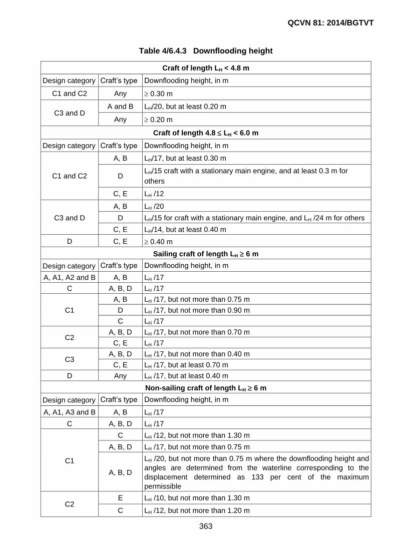
QCVN 81: 2014/BGTVT
363
Table 4/6.4.3 Downflooding height
Craft of length LH < 4.8 m
Design category Craft‟s type Downflooding height, in m
C1 and C2 Any 0.30 m
C3 and D A and B LH/20, but at least 0.20 m
Any 0.20 m
Craft of length 4.8 LH < 6.0 m
Design category Craft‟s type Downflooding height, in m
C1 and C2
A, B LH/17, but at least 0.30 m
D LH/15 craft with a stationary main engine, and at least 0.3 m for
others
C, E LH /12
C3 and D
A, B LH /20
D LH/15 for craft with a stationary main engine, and LH /24 m for others
C, E LH/14, but at least 0.40 m
D C, E 0.40 m
Sailing craft of length LH 6 m
Design category Craft‟s type Downflooding height, in m
A, A1, A2 and B A, B LH /17
C A, B, D LH /17
C1
A, B LH /17, but not more than 0.75 m
D LH /17, but not more than 0.90 m
C LH /17
C2 A, B, D LH /17, but not more than 0.70 m
C, E LH /17
C3 A, B, D LH /17, but not more than 0.40 m
C, E LH /17, but at least 0.70 m
D Any LH /17, but at least 0.40 m
Non-sailing craft of length LH 6 m
Design category Craft‟s type Downflooding height, in m
A, A1, A3 and B A, B LH /17
C A, B, D LH /17
C1
C LH /12, but not more than 1.30 m
A, B, D LH /17, but not more than 0.75 m
A, B, D
LH /20, but not more than 0.75 m where the downflooding height and
angles are determined from the waterline corresponding to the
displacement determined as 133 per cent of the maximum
permissible
C2 E LH /10, but not more than 1.30 m
C LH /12, but not more than 1.20 m

QCVN 81: 2014/BGTVT
364
A, B, D LH /17, but not more than 0.75 m
A, B, D
LH /20, but not more than 0.75 m where the downflooding height and
angles are determined from the waterline corresponding to the
displacement determined as 133 per cent of the maximum
permissible
C3
E LH /20, but not more than 0.75 m
C LH /20, but not more than 0.60 m
A, B, D LH /20, but not more than 0.40 m
A, B, D
LH /24, but not more than 0.4 m where the downflooding height and
angles are determined from the waterline corresponding to the
displacement determined as 133 per cent of the maximum
permissible
D
Any LH /20, but not more than 0.40 m
A, B, D
LH /24, but not more than 0.4 m where the downflooding height and
angles are determined from the waterline corresponding to the
displacement determined as 133 per cent of the maximum
permissible
6.4.4 Sea openings for the craft of design categories C, C1, C2, C3 and D are allowed within the aft quarter of the hull length LH with their total area of not more than 50LH
2, mm2, and the height above the load waterline of at least 75 per cent of the required in 6.4.3.
6.4.5 The downflooding height of sailing craft for open centreboard, drop keel and dagger-board casings shall be not less than half the minimum required in 6.4.3.
6.5 Draught Scales
6.5.1 Draught scales shall be graduated in at least decimetres. The scale shall be marked with a clearly visible paint by means of the alternate stripes of different colours and shall present the range from the minimum to maximum draught potential in the craft‟s operation.
The draught scales shall be marked in the craft of over 6.0 m long
The draught scales in the craft of over 15.0 m long shall be marked in the craft‟s forward
and aft ends.
The draught scales in the craft of over 12.0 m long shall be welded on or marked by
another VR-approved way ensuring their durability.

QCVN 81: 2014/BGTVT
365
PART 5 MACHINERY INSTALLATIONS
CHAPTER 1 GENERAL
1.1 Application
1.1.1 The requirements of this Part of the Regulation apply to machinery installations,
machinery, propellers, systems and piping used in the small pleasure craft.
1.1.2 Application of the requirements of this Part is defined in relevant sections: “Machinery
Installations”, “Machinery” and “Systems and Piping”.
1.2 Definitions and Explanations
1.2.1 Definitions and explanations relating to general terminology of the Regulation are given
in Section I of the Regulation.
For the purpose of this Part of the Regulation, the following definitions and explanations
have been adopted:
1 Fittings mean stop, regulating and other devices intended for distribution control and
regulation of consumption and other parameters of the conveyed medium by means of
entire or partial closing of flow section.
2 Auxiliary machinery means machinery necessary for operation of main machinery, supply
of the craft with electric power and other kinds of energy, as well as functioning of the
systems and arrangements subject to supervision of VR.
3 Auxiliary active means of the craft‟s steering means a propulsion and steering unit
ensuring propulsion and steering of a craft at low speed or steering of a craft at zero speed
when the craft is equipped with main means of propulsion and steering, and is used either
in combination with the latter or when the main means of propulsion and steering are
inoperative.
4 Exit means an opening in bulkhead or deck provided with closing means and intended for
the passage of persons.
5 Means of escape means an escape route leading from the lowest part of the machinery
space floor plates to the exit from that space.
6 Main engines mean the machinery intended for driving propellers.
7 Main machinery means machinery being part of the propulsion plant.
8 Main active means of the craft„s steering means a propulsion and steering unit being part of
the propulsion plant.

QCVN 81: 2014/BGTVT
366
9 Outboard engines mean main engines installed on the transom of the craft.
10 Remote control means changing of the speed and direction of rotation as well as starting
and stopping of the machinery from a remote position.
11 Engine room means a machinery space intended for the main engines, and in case of craft
with electric propulsion plants, the main generators.
12 Machinery spaces mean spaces containing main machinery, shafting, boilers, internal
combustion engines, electric generators and other major electrical machinery, ventilation
and air – conditioning installations, steering engines and similar spaces.
13 Local control station means a control station fitted with controls, indicators, means of
communication (if necessary) intended for control, located in proximity to, or directly on,
the engine.
14 Torsional vibration stresses mean stresses resulting from the alternating torque, which is
superimposed on the mean torque.
15 Equipment means all types of filters, heat exchangers, tanks and other arrangements
ensuring normal operation of the machinery installation.
16 Pipeline fire resistance means the ability of pipeline to maintain strength and functional
properties within the set period of time at flame exposure.
17 Plastic materials mean thermoplastic (thermo-plasts) and thermosetting (thermosets)
materials with or without reinforcement, such as polyvinylchloride (PVC) and fiber
reinforced plastic (FRP).
18 Propulsion plant means the totality of machinery and arrangements intended for
generating, converting and transmitting power ensuring propulsion of the craft at all
specified rates of speed and comprising propellers, shafting, main gearing and main
engines.
19 Rated power means the maximum continuous (not time-limited) power adopted in
calculations under the Regulation and stated in documents issued by VR.
20 Rated speed means the speed corresponding to the rated power.
21 System means a combination of pipelines, machinery, apparatus, devices, appliances and
reservoirs intended for performance of certain functions providing craft‟s operation.
22 Inboard engines mean main engines installed permanently in the engine room or in a
special compartment or in a specially allocated space on deck.
23 Active means of the craft‟s steering (AMCS) mean special propulsion and steering units
and any combination of them or with the main propulsion devices, capable of producing
thrust or traction force both at a fixed angle to the center line plane of the craft and at a
variable angle, either under all running conditions or part thereof, including low and zero
speed.

QCVN 81: 2014/BGTVT
367
The active means of the craft‟s steering comprise steerable propellers including tiltable
and retractable units, active rudders, vertical-axis propellers, waterjets, propellers in
transverse channels (transverse thrust units), separate steering nozzles and other devices
of similar purpose, special propulsion and steering units and outboard engines of the craft
and any combination of them or with the main propulsion devices, capable of producing
thrust or traction force both at a fixed angle to the center line plane of the craft and at a
variable angle, either under all running conditions or part thereof, including low and zero
speed.
24 Pipeline means a combination of pipes, fittings, formed components, pipe joints, any
internal and external linings, insulation coatings, fastening elements and components for
protection of pipes intended for conveying of liquid, gaseous and compound media, as well
as for transmission of pressure and sound waves.
25 Pipelines formed components mean bends, T-pieces, bulkhead and deck penetrations and
other elements of pipelines, intended for pipeline branching, changing of conveying
medium direction and ensuring of hull structure tightness.
26 Navigating bridge means a space or part thereof, open area or an area enclosed by
detachable structures, from which navigation and control of the craft is normally exercised
and where controls of the main steering gear (steering gear control system), remote
controls of the main and auxiliary engines, CP-propellers, main and auxiliary active means
of the craft‟s steering, instruments, alarm devices and means of communication are
located.

QCVN 81: 2014/BGTVT
368
CHAPTER 2 MACHINERY INSTALLATIONS
2.1 Application
2.1.1 The requirements of this Section of the Regulation apply to craft machinery installations
subdivided in accordance with 2.1.2, equipment of machinery spaces, shafting lines,
propellers and spare parts of motor, motor-sailing, sailing-motor and self-propelled craft,
as well as non-self-propelled and berth-connected craft fitted up with machinery and
systems as specified in 1.2.2-1 Section I.
2.1.2 The machinery installations of the craft are subdivided:
1 by the main engines location:
in enclosed machinery space;
in exposed machinery area (cockpit, machinery compartment);
on craft‟s transom;
on weather deck or in a pod (with aerial propeller).
2 by the type of fuel oil used by the main engines:
diesel engines with flash point of fuel not lower than 55 °C. Use of diesel oil with flash point
below 55 °C is subject to special consideration by VR in each case;
carburetor (petrol) engines.
2.1.3 For craft intended for operation in offshore and sheltered areas of navigation (design
categories C, C1, C2, C3 and D, see 1.2.2-1 Section I), the internal combustion engines
which are serially manufactured for automobile industry and have the Manufacturer‟s
certificate may be used as main engines.
2.1.4 For craft intended for operation in offshore areas of navigation (design categories C, C1,
C2 and C3, see 1.2.2-1 Section I), updating of such an engine and testing of it shall be
carried out under VR‟s technical supervision, in accordance with the technical
documentation and test program being part of the craft‟s design documentation.
2.1.5 For craft intended for operation in sheltered areas of navigation (design category D, see
1.2.2-1 Section I), use of the main engines and propulsion systems (reduction gear –
shafting line – propeller) manufactured without VR technical supervision, if their power
output does not exceed 25 kW is subject to special consideration by VR.
2.2 Scope of Technical Supervision

QCVN 81: 2014/BGTVT
369
2.2.1 Subject to VR technical supervision, including the approval of technical documentation
according to 2.1.2-1(5) Part 1 are the following components and items:
1 Shafting as assembled, including propeller shafts, shaft bearings, thrust blocks and stern-
tube bearings, stern-tube seals as assembled.
2 propellers, including vertical-axis propellers and water-jets, aerial propellers, steerable
propellers, outboard engines, transverse thrusters, pitch control units and control systems
of propellers.
2.2.2 Subject to VR technical supervision is the assembling of the machinery space
equipment and testing of the following components of the machinery installation:
1 main machinery.
2 heat exchangers and pressure vessels.
3 auxiliary machinery listed in 3.1.1-3 to 3.1.1-13.
4 control, monitoring and alarm systems of the machinery installation.
5 shafting and propellers.
6 active means of the craft‟s steering.
2.2.3 After assembling of machinery, equipment, systems and piping arrangements on board
the craft, the machinery installation shall be tested according to the program approved
by VR.
At that the test conditions and power measurements of the engine forming part of the
propulsion plant requested by the manufacturer may be specified taking into consideration
of ISO 8665.
2.3 Power of the Main Engines
2.3.1 The power of the main engines providing running of a small pleasure craft shall ensure:
1 Speed in calm water not less than:
for craft of design categories A, A1, A2, B, C, C1 and C2 - 6 (knots) (abt. 11 km/h);
for craft of design categories C3 and D là 6 (knots), but not less than the speed ensuring
fulfillment of the requirements set out in 2.2.2-2 Part 3.
2 Capability of running astern to maintain necessary maneuvering of the craft under all normal
service conditions.
3 With the potential speed increase over 14.0 m/s, the craft shall additionally meet the
requirements of QCVN 54: 2013/BGTVT. And in this case craft with hull length equal to
and less than 8 m shall be tested in accordance with the requirements of ISO 11592-2001.
2.3.2 Installation of the main engines having total power output in excess of the requirements
of 2.3.3 to 2.3.5 is subject to special consideration by VR in each case.
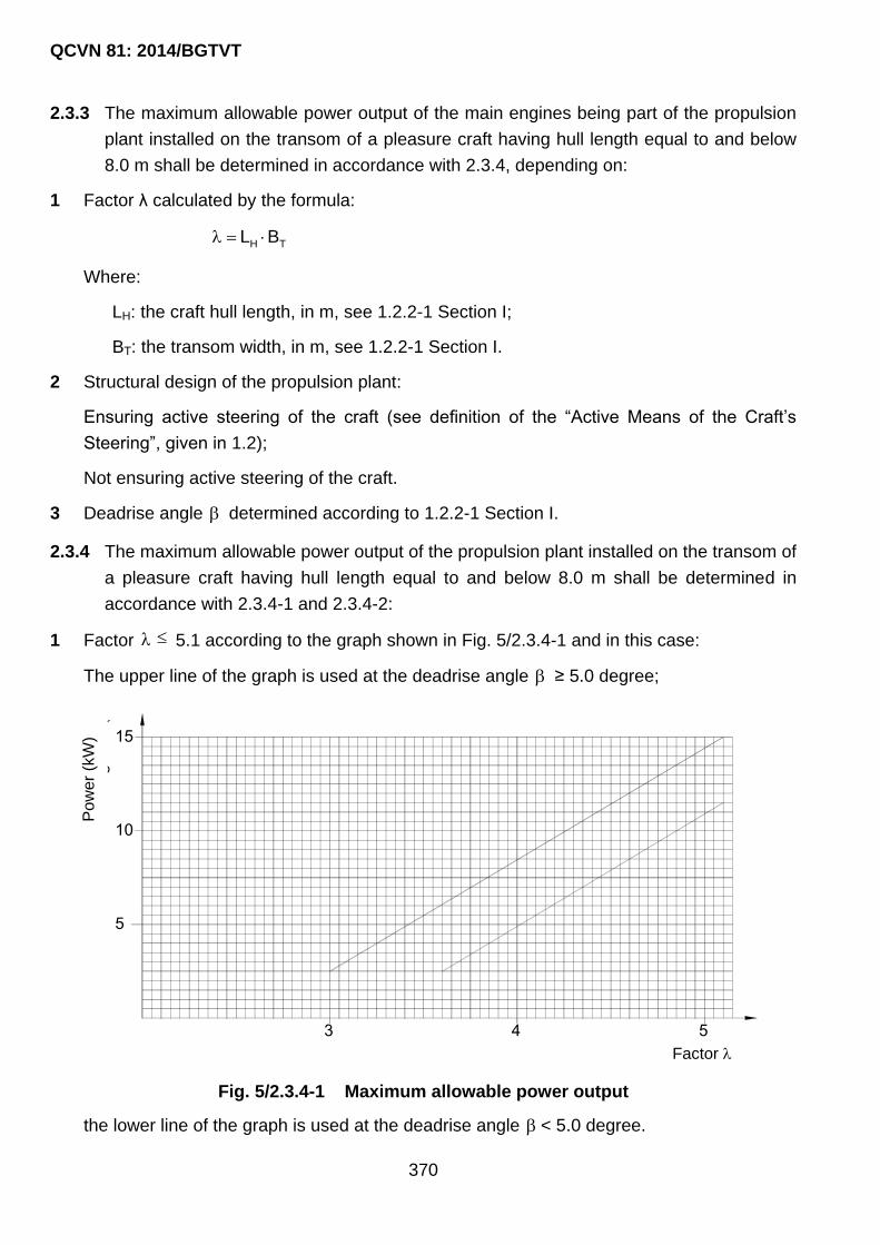
QCVN 81: 2014/BGTVT
370
2.3.3 The maximum allowable power output of the main engines being part of the propulsion
plant installed on the transom of a pleasure craft having hull length equal to and below
8.0 m shall be determined in accordance with 2.3.4, depending on:
1 Factor λ calculated by the formula:
H TL B
Where:
LH: the craft hull length, in m, see 1.2.2-1 Section I;
BT: the transom width, in m, see 1.2.2-1 Section I.
2 Structural design of the propulsion plant:
Ensuring active steering of the craft (see definition of the “Active Means of the Craft‟s
Steering”, given in 1.2);
Not ensuring active steering of the craft.
3 Deadrise angle determined according to 1.2.2-1 Section I.
2.3.4 The maximum allowable power output of the propulsion plant installed on the transom of
a pleasure craft having hull length equal to and below 8.0 m shall be determined in
accordance with 2.3.4-1 and 2.3.4-2:
1 Factor 5.1 according to the graph shown in Fig. 5/2.3.4-1 and in this case:
The upper line of the graph is used at the deadrise angle ≥ 5.0 degree;
Fig. 5/2.3.4-1 Maximum allowable power output
the lower line of the graph is used at the deadrise angle < 5.0 degree.
3 4 5
5
10
15
C«
ng
su
Êt
(kW
)
HÖ sè Factor
Pow
er
(kW
)

QCVN 81: 2014/BGTVT
371
2 Using the formulae given below at factor > 5.1 for a propulsion plant, in kW, ensuring
active steering of the craft, regardless of the value of the deadrise angle:
eN 16 - 67
For a propulsion plant, in kW, not ensuring active steering of the craft, at the deadrise
angle ≥ 5.0 degree:
eN 6.4 - 19
for a propulsion plant, in kW, not ensuring active steering of the craft, at the deadrise angle
< 5.0 degree:
eN 4.2 - 11
2.3.5 It is advisable to determine the maximum allowable power of the outboard engines of
craft having the overall length of the hull equal to and below 5.5 m, depending on the
coefficient K, from a combined graph Fig. 5/2.3.5, having regard to the following:
1 For motor boats with remote control and transom height more than 510 mm at K ≥ 52, by
graph N1.
2 For motor boats with transom height less than 510 mm, by graph N2.
3 For all motor boat with rounded chine, by graph N3.
4 For motor boats mentioned in 2.3.5-1 and 2.3.5-2 at K < 52, by graph N4.
5 The maximum allowable power output of the outboard engines in all cases shall not be
less than 100 kW.
Coefficient K is determined from the combined graph, Fig. 5/2.3.5, depending on the
transom width or hull length, or by the formula:
K 10.6
Where is determined by formula in 2.3.3-1.
2.4 Control Devices and Stations. Means of Communication
2.4.1 Main and auxiliary machinery essential for the propulsion, control and safety of the craft
shall be provided with effective means for their operation and control.
2.4.2 Main engines of craft of design categories A, A1, A2, B and C shall be fitted with
pneumatic or electric starting system.
The electrically-started engines shall be fitted with attached generators and provided with
a device for automatic recharging the starting accumulator batteries.

QCVN 81: 2014/BGTVT
372
Fig. 5/2.3.5 The maximum allowable power output of the outboard engines of craft
with the overall hull length equal to and below 5.5 m.
2.4.3 Main engines of craft of design categories C1, C2, C3 and D may be fitted both with
electrical starting system and with a device for manual starting by means of a starting
handle or a starter cord.
2.4.4 In case where in addition to electric starting, manual drive of the engine is also
provided, such manual drive shall be automatically disengaged when the electric drive
is actuated, and an interlocking system shall be provided to preclude simultaneous
operation of the two drives.
The starting handle of the manual drive and starter cord shall be made so that the safety of
starting is provided.
The starter cord shall be provided with a device which ensures self-disconnection of the
cord from the engine.
The starting handle shall be provided with a device which precludes translational travel in
the direction opposite to the applied force necessary for engine starting.
2.4.5 Starting and reversing arrangements shall be so designed and placed that each engine
can be started or reversed by one operator. The force applied to one handle in this case
shall not exceed 160 N.
The proper working direction of control handles and handwheels shall be clearly indicated
by arrows and relevant inscriptions.
The setting of maneuvering handles of the main machinery from, or to the right of, the
operator, or turning the handwheel clockwise, at control stations on the navigating bridge,
shall correspond to the ahead speed direction of the craft.
Control arrangements shall be so designed as to eliminate the possibility of spontaneous
changing the positions prescribed.

QCVN 81: 2014/BGTVT
373
The outboard engines shall be provided with a device which excludes starting of the
engine in engagement with the propeller, except when:
static thrust provided by the engine does not exceed 500 N;
engine is fitted with a limiter which provides a thrust up to 500 N at the time of starting.
2.4.6 The duration of reversing (a period of time from the reversing of a steering control to the
beginning of the propeller operation with a thrust opposite in direction) shall not exceed:
1 For internal combustion engines of power output 55 kW and above:
25 s at full speed;
15 s at low speed.
2 for internal combustion engines of power output less than 55 kW:
10 s at full speed;
5 s at low speed.
2.4.7 The inboard main engines and outboard engines of power output more than 15 kW, as
a rule, shall be provided with remote control or remote automated control system.
The remote automated control system shall meet the requirements of Part 6.
The main engines of power output less than 25 kW to be installed in exposed machinery
spaces or on transom (see 2.1.2-1) of craft of design categories C2, C3 may be devoid of
the remote control or remote automated control system.
2.4.8 The main machinery remote automated control system operable from the navigating
bridge, shall be designed so as to provide an alarm in the event of failure. As far as
practicable, the prescribed propeller speed and thrust direction shall remain unchanged
until control is transferred to a local station. Among other factors, the loss of power
supply (electric, pneumatic or hydraulic power) shall not substantially affect the power of
main engines or change the direction of propeller rotation.
In case of remote control with the use of mechanical linkage, activation of the alarm to
warn of the remote control failure need not be provided.
2.4.9 The bridge control stations of main machinery and propellers, with any type of remote
control, shall be equipped with:
1 Controls for the operation of main engines and propellers. For installations comprising CP-
propellers, vertical-axis and similar type propellers, the navigating bridge may be equipped
with means for remote control of propellers only.
2 Indicators of:
propeller shaft rotation speed and direction if a fixed pitch propeller is installed;
propeller shaft speed and blade position if a controllable pitch propeller is installed;
main engine speed if a disengaging clutch is provided.

QCVN 81: 2014/BGTVT
374
3 Indicating means to show that the main engines and remote control systems are ready for
operation.
4 Indicating means to show from which station the control is exercised.
5 Means of communication in accordance with 2.4.17.
6 Main machinery emergency stop device, independent of the control system. If disengaging
clutches are provided for disconnection of main machinery from propellers, it is permissible
that emergency disengagement of these clutches only is effected from the navigating
bridge.
7 Device to override the automatic protection covering full range of parameters, except those
parameters which being exceeded, may result in serious damage, complete failure or
explosion.
8 Indication for the override operation, alarm for activation of protection devices and the
emergency stop.
9 Alarm for low starting air pressure, set at the level permitting three starting attempts of
main engines duly prepared for operation.
10 Alarm for minimum oil pressure in pitch control system, overload alarm where the main
engines operates with a CP-propeller.
2.4.10 Control stations on the navigating bridge, where outboard engines and main engines
permanently installed in exposed machinery spaces are remotely controlled with the use
of mechanical linkage, shall be equipped with:
1 Controls for the operation of main engines and propellers.
2 Indicators of:
propeller shaft or main engine speed;
propeller shaft speed and blade positions if CP-propeller is installed.
3 Indicating means to show that the main engines and remote control systems are ready for
operation (recommendational).
4 Main engine emergency stop device. If disengaging clutches are provided for
disconnection of main engines from propellers, it is permissible that emergency
disengagement of these clutches only is effected.
2.4.11 The emergency stop devices of main engines and the overrides of protection
arrangements shall be so constructed as to preclude inadvertent operation thereof.
2.4.12 With a remote control system in use, provision shall also be made for local control of
main engines and propellers.
Where, however, mechanical linkage is fitted for remote control, the local controls may be
dispensed with.

QCVN 81: 2014/BGTVT
375
The local control station of main engines shall be equipped with instruments as specified in
3.2.3.
2.4.13 Remote control of main engines and propellers shall be performed only from one control
station. The transfer of control between the navigating bridge and engine room shall be
possible only from the engine room.
2.4.14 Main engines shall be remotely controlled from the wheelhouse by means of a single
control element per propeller with all operating modes automatically executed,
including, if appropriate, the means preventing overloading and continuous running of
the main engines within the restricted rotation speed ranges. In installations with CP-
propellers, systems with two control elements may be used.
2.4.15 The sequence of the main engine operation modes assigned from the navigating bridge,
including reversal from the full ahead speed in case of emergency, shall be
automatically controlled with the time intervals admissible for main engines. The modes
assigned shall be indicated at the local control stations of the main engines.
2.4.16 All the indicating instruments, with the exception of liquid-filled thermometers, shall be
checked by competent bodies recognized by VR.
Tachometers accuracy shall be within ±2.5%. With restricted speed ranges, the
accuracy shall not be below ±2%, and the ranges shall be marked with bright color on
the scales of tachometers or in another way.
2.4.17 Means of communication
1 For craft of design categories A, A1, A2 and B, where local control station of main
machinery is available, at least two independent means shall be provided for
communicating orders from the navigating bridge to the position in the machinery space or
in the control station, from which the speed and direction of thrust of the propellers are
normally controlled.
One of these means shall provide visible indication of orders and responses both in the
machinery space and on the navigating bridge and which is fitted with a sound signal
clearly audible in any part of the machinery space while the machinery is at work, and
distinct in tone from all other signals in that machinery space.
2 For craft of design categories C, C1, C2 and C3, where local control station of main
machinery is available, a means shall be provided for communicating orders from the
navigating bridge to the position in the machinery space or in the control station, from
which the speed and direction of thrust of propellers are normally controlled, and which
shall provide visible indication of orders and responses both in the machinery space and
on the navigating bridge and shall be fitted with a sound signal clearly audible in any part
of the machinery space while the machinery is at work, and distinct in tone from all other
signals in that machinery space.
2.5 Machinery Spaces
2.5.1 Enclosed machinery spaces

QCVN 81: 2014/BGTVT
376
1 A watertight bulkhead meeting the requirements of 2.2.2 and 2.3 Part 10 shall isolate the
machinery space from all other adjacent compartments.
2 The main and auxiliary machinery shall be so arranged in the machinery space as to
provide free passageways from their control stations and servicing flats to the escape
routes from these spaces. The width of passageways shall not be less than 500 mm over
the whole length.
3 The width of ladders serving as escape routes and the width of exit doors shall not be less
than 500 mm.
4 Escape routes from machinery spaces shall lead to such places which provide ready
access to the exposed deck.
Workshops, spaces for fuel oil units, boilers, oil equipment testing, etc., enclosed within
machinery spaces may have exits into these spaces.
The engine control room and the main switchboard space enclosed within the engine
room shall have their own independent escape routes, in addition to entrances to the
engine room.
In case of small engine room (not more than 30 m2), or where exits from these spaces are
located close (not farther than 5 m) to the engine room exit, an independent escape route
from the engine control room may be omitted on agreement with VR.
If two adjacent machinery spaces communicate through doors and each of them has only
one escape route through the casing, these escape routes shall be located on opposite
sides.
The second escape route is not required:
(1) from machinery spaces of not more than 25 m2 in area if the available escape route
does not lead to the adjacent machinery or accommodation space;
(2) from auxiliary spaces enclosed within the machinery space provided with two escape
routes;
(3) from enclosed engine control rooms where main switchboards are located;
(4) from spaces which contain no oil-fired machinery.
5 All the doors as well as the covers of companionways and skylights which may serve as
means of escape from machinery spaces, shall be capable of being opened and closed
both from inside and outside. The covers of companionways and skylights shall bear clear
inscription prohibiting stowage of any load on them.
6 Ventilation of enclosed machinery spaces shall comply with the requirements of 4.9.
7 Moving parts of machinery and equipment shall be guarded.
8 Detachable plating (floor ceiling) in machinery spaces shall be made of ribbed metal.
Plates shall be reliably installed on special frames or on the hull framing and provided with
securing devices to prevent them from displacement out from their standard positions in
case of heavy heel and trim of the craft and have non-slip surface. All the moving parts of

QCVN 81: 2014/BGTVT
377
machinery and drives which may constitute a threat to the attending personnel shall be
protected by handrails and guards.
2.5.2 Exposed machinery spaces (cockpits, motor compartments)
1 In craft the hull of which is made of non-combustible materials, the boundary structures of
the machinery space where internal combustion engine is permanently installed shall be
protected by non-combustible heat-insulating material and sheet steel.
2 Floors installed in front of, or behind, the engine shall be watertight and form a collecting
tray. The upper edge of the watertight floors enclosing the machinery space (engine) shall
be by 150 mm above the floor plating level of the engine room abutting thereon from the
outside.
Trays shall be installed under the fuel oil tanks, canisters, filters, fittings and all other units
of fuel oil system in which fuel oil leakage is likely to occur.
3 When arranged in one compartment the fuel oil tanks and canisters shall be located at a
distance of not less than 800 mm from the engine and exhaust piping.
4 Detachable flooring shall be suitably installed, secured and have non-slip surface.
2.6 Arrangement of Machinery and Equipment
2.6.1 Main engines, auxiliary machinery, equipment, pipes and fittings shall be so arranged
as to provide easy access for servicing and damage repair; the requirements stated in
2.5.1-1 shall also be met.
2.6.2 Main engines and machinery with horizontal arrangement of the shaft shall be installed
parallel to the center line of the craft.
Such machinery may be installed in any other direction about the center line provided that
the construction of machinery provides for operation under the conditions stated in 1.3,
Part 3 Section II QCVN 21: 2010/BGTVT.
2.6.3 The machinery and equipment constituting the machinery installation shall be installed
on strong and rigid seatings and securely attached thereto. The construction of seatings
shall comply with the requirements set out in Part 2.
2.6.4 The main engines, their gears, thrust bearings of shafts shall in part be secured to
seatings with fitted bolts. The bolts may be omitted, if appropriate stops are provided.
2.6.5 The bolts securing the main engines and auxiliary machinery and shaft bearings to their
seatings, end nuts of shafts as well as bolts connecting the length of shafting shall be
fitted with appropriate lockers against spontaneous loosening.
2.6.6 Where the machinery shall be mounted on shock absorbers, the design of the latter
shall be approved by VR.
Shock adsorbing fasteners of the machinery and equipment shall:
QCVN 81: 2014/BGTVT
378
- maintain vibration-proof properties when the shock-absorbed machinery and
equipment operate in the environmental conditions stated in 1.3 Part 3 Section II,
QCVN 21: 2010/BGTVT;
- be resistant to the corrosive media and temperatures;
- be equipped with a yielding grounding jumper of sufficient length to prevent radio
reception interference and comply with the safety engineering requirements;
- eliminate the interference with operation of other equipment, devices and systems.
2.6.7 Installation of the equipment on pads made of polymeric material is subject to special
consideration by VR in each case.
2.6.8 Installation of the outboard engines on the transom of the craft shall ensure a secure
attachment and provide for an additional cable for attaching the engine to the transom
or to any robust hull structure.
2.6.9 Mounting of inboard engines and installation of carburetor (petrol) engines
1 The inboard carburetor (petrol) engines as well as outboard engines shall not be used in
craft of design categories A, A1, A2 and B.
2 The inboard carburetor (petrol) engines as well as outboard engines may be used in craft
of design categories C1, C2, C3 and D, having the product of the craft length by its
breadth which does not exceed 20, provided that the following requirements for the
inboard engines are complied with:
(1) In craft of open type and in exposed machinery spaces (motor compartments), the
inboard engines shall be protected by casings manufactured of noncombustible
materials;
(2) The detachable engine casings shall be provided with vent pipes of not less than 80
mm in diameter. One such pipe shall stop short of the craft hull bottom by 700 mm and
the other pipe shall come from opening in the highest part of the casing cover;
The upper ends of vent pipes shall be fitted with ventilator heads with flame arresters;
(3) Suction pipes of the carburetors shall be led outside the detachable casings and
elevate above those by at least 500 mm. The ends of the suction pipes shall be fitted
with ventilator heads with flame arresters;
(4) Where engines are installed in enclosed machinery spaces the inlets of the carburetor
suction pipes shall be located at a height of not less than 300 mm above the cylinder
covers and fitted with flame arresting screens. Where suction pipes at the carburetor
air inlet are not provided, flame arresters shall be fitted.
2.7 Arrangement of Fuel Oil Tanks
2.7.1 Arrangement of fuel oil tanks shall meet the requirements of 4.10.2.
2.7.2 Fuel oil tanks shall not be located above ladders, internal combustion engines,
machinery and equipment with surface temperature under insulation over 220 °C,

QCVN 81: 2014/BGTVT
379
exhaust pipes, smoke uptakes, electrical equipment and main machinery control
stations and, as far as practicable, shall be arranged far apart therefrom. The fuel oil
tanks shall be located at not less than 800 mm from the engine and exhaust unless a
metal bulkhead is provided in between.
2.8 Insulation of Heated Surfaces
2.8.1 All parts of machinery, equipment and piping which may be heated to a temperature
over 60 °C and constitute a threat to the attending personnel shall be provided with
means that prevent or restrict thermal radiation.
2.8.2 Surfaces of machinery, equipment and piping with temperatures above 220 °C shall be
insulated. Measures shall be taken to prevent destruction of insulation from vibration
and mechanical damages.
2.8.3 Insulating materials and surface of insulation shall comply with the requirements of
2.3.7, 2.3.8 and 2.5.2 Part 10.
2.9 Shafting
2.9.1 General
1 The minimum shaft diameters without allowance for subsequent turning on lathe during
service life shall be determined by the formulae given in this Section. It is assumed that
torsional vibrations comply with the requirement of 2.11.
2 In craft with no obstruction for the propeller shaft to slip out of the stern-tube, means shall
be provided which, in the event of the propeller shaft breaking, will prevent its slipping out
of the stern-tube gland; or measures shall be taken to preclude flooding of the engine
room, should the propeller shaft is lost.
3 Shafts are recommended to be manufactured from steel with tensile strength of 400 to 800
MPa.
The use of other materials is subject to special consideration by VR in each case.
In all cases, the tensile strength in Formula (2.9.2-1) shall be taken to be not more than
800 MPa for intermediate and thrust shafts and not more than 600 MPa for the propeller
shaft.
4 It is advisable to install propeller shafts having one thrust bearing which takes up the
ahead and astern loads and two line shaft bearings which take up weight loads of the shaft
itself and bending loads due to possible deformations of the craft hull in heavy sea.
Any constructions and units (reduction gears, cardan and flexible shafts, etc.), if justified,
may be used in shafting.
It is advisable to use such construction of the reduction gear which would make it possible
to house the ahead and astern thrust bearings and the forward line shaft bearing of
propeller shaft in the reduction gear case. The aft line shaft bearing of propeller shaft is

QCVN 81: 2014/BGTVT
380
recommended to be installed either on a pedestal on the craft hull or immediately ahead of
the propeller shaft exit from the hull in way of sternpost or counter timber.
2.9.2 Construction and diameters of shafts
1 Intermediate shaft
The diameter of the intermediate shaft (dint), or the diameter of the propeller shaft in case
of a common shaft from the engine to the propeller, in cm, shall not be less than that
determined by the following formula:
3int 677.7 (1 ) / ( . ) alld N k n
Where:
N : rated power transmitted by intermediate shaft (kW);
n : rated speed of intermediate shaft (min-1);
all : allowable tangential stress in shaft cross-section (MPa);
K : Factor depending on the installation of the engine:
k = q(a-1) for installations with internal combustion engines
q = 1.4Jp/(J + 1.4Jp), or if there are no data on the mass moments of inertia, the
value q may be specified, respectively:
q = 0.5 for installations with two-stroke engines;
q = 0.4 for installations with four-stroke engines.
Jp : mass moment of inertia of propeller shaft with propeller without considering the
added water mass, (kg.m2);
J = JENG + JM: mass moment of inertia of propulsion plant without reduction gear,
(kg.m2);
J = (JENG + JM)(nENG/n)2: mass moment of inertia of propulsion plant with reduction
gear (kg.m2);
JENG : moment of inertia of all gyrating and reciprocating masses of propulsion plant
(kg.m2);
JFW : mass moment of inertia of flywheel (kg.m2);
nENG: rated speed of engine shaft, in min–1;
a: factor defined as a ratio of maximum indicated torque as based on the aggregate of
measurements made throughout the engine to the mean indicated torque. Value of
the factor shall be determined from cumulative diagram of tangential forces
constructed for the whole engine or from Table 5/2.9.2-1 which holds true only at

QCVN 81: 2014/BGTVT
381
equal crank angles.
Table 5/2.9.2-1 Factor a
Number of cylinders
Type of internal combustion engine Number of
cylinders
Type of internal combustion engine
Four stroke
Two stroke Four
stroke Two stroke
1 14.0 8.0 7 2.20 1.30
2 6.40 3.8 8 2.00 1.20
3 4.50 2.6 9 1.85 1.15
4 2.80 2.2 10 1.60 1.15
5 2.40 1.8 11 1.50 1.10
6 2.15 1.5 12 1.40 1.05
The diameter of intermediate shaft shall be taken to be not less than 25 mm.
2 The design diameter of the propeller shaft, dp, in cm, shall be not less than that determined
by the following formula:
p intd k d
Where:
k: factor assumed as follows proceeding from the shaft design features:
for the portion of propeller shaft between the propeller shaft base cone or the aft face of
the propeller shaft flange and the forward edge of the aftermost shaft bearing
(subject to a minimum of 2.5.dint);
1.22, where the propeller is keyless fitted onto the propeller shaft taper or is attached to
an integral propeller shaft flange;
1.26, where the propeller is keyed onto the propeller shaft taper;
for the portion of propeller shaft between the forward edge of the aftermost shaft bearing
and the forward edge of the forward stern-tube seal k = 1.15 for all types of design.
On the portion of propeller shaft forward of the forward edge of the forward stern-tube seal,
the diameter of the propeller shaft may be tapered to the actual diameter of the
intermediate shaft.
Where surface hardening is used, the diameters of propeller shafts may be reduced on
agreement with VR.
Portions of the propeller shaft which are in contact with water, in case where the shaft has
no continuous liner or is not effectively protected by some other method, shall have the
outer diameter which exceeds by 5 per cent the diameter determined by Formula (2.9.2-2).
3 The diameter of thrust shaft in external sliding bearing on a length equal to thrust shaft
diameter on either side of the thrust collar and, where roller thrust bearings are used, on a

QCVN 81: 2014/BGTVT
382
length within the housing of thrust bearing, shall not be less than 1.05 times the
intermediate shaft diameter determined by Formula (2.9.2-1).
Beyond the said lengths, the diameter of the thrust shaft may be tapered to that of the
intermediate shaft.
4 Propeller shafts shall be effectively protected against corrosion.
For shafts made of corrosion-resistant steel, no protective coating is required, subject to
the condition that the surfaces which are in contact with sea water are polished.
For craft of design categories A, A1, A2, B, C and C1, the propeller shaft made of carbon
or low-alloyed steel, shall have a liner made of such alloys which poses sufficient corrosion
resistance in sea water.
For craft of design categories C2, C3 and D, liners are recommended to be used.
The thickness of the liner shall not be less than 5 mm.
In case of non-continuous liners, the portion of the shaft between the liners shall be
protected against the action of sea water by a method approved by VR.
The liners shall be shrunk on the shaft in such a way as to provide tight interference
between mating surfaces. The use of pins or other parts for securing the liners to the shaft
is not permitted.
5 If the shaft has a central hole, its bore shall not exceed 0.4 of the design diameter of the
shaft.
If considered necessary, the bore of the central hole may be increased to the value
obtained from the formula:
dc ≤ (da4 – 0.97.d3.da)/4
Where:
dc: bore of central hole;
da: actual shaft diameter;
d: design diameter of the shaft without the central hole.
6 The diameter of a shaft having a longitudinal slot shall be increased by at least 0.2 of the
design diameter of the shaft.
The bossed portion of the shaft shall be of such length as to extend beyond the slot, either
side, for 0.25 of the design diameter of the shaft.
Transition from one diameter to another shall be smooth. The ends of the slot shall be
rounded to a radius of half the width of the slot and the edges – to a radius of at least 0.35
times the width; the surface of the slot shall have a smooth finish.
7 Where the shaft has a radial or transverse hole, the shaft diameter shall be increased over
a length of at least seven bores of the hole. The hole shall be located at mid-length of the
bossed portion of the shaft and its bore shall not exceed 0.3 of the shaft design diameter.

QCVN 81: 2014/BGTVT
383
In all cases, irrespective of the hole bore, the shaft diameter shall be increased by not less
than 0.1 times the design diameter. The edges of the hole shall be rounded to a radius not
less than 0.35 times its bore and the inner surface shall have a smooth finish.
8 The diameter of a shaft having a keyway shall be increased by at least 0.1 times its design
diameter. After a length of not less than 0.2 of the design diameter from the ends of the
keyway, no increase of the shaft diameter is required.
If the keyway is made on the outboard end of the propeller shaft, the diameter need not be
increased.
Fillet radii in the transverse section of the bottom of the keyway shall not be less than
0.0125 of the shaft diameter, but at least 1 mm.
9 On the cone base side, the keyways in shaft cones shall be ski-shaped, while in propeller
shaft cones they shall be spoon-shaped in addition.
For the outboard end of a propeller shaft having the diameter in excess of 100 mm, the
distance between the cone base and the spoon-shaped keyway end shall be at least:
0.2 of the design shaft diameter – with the ratio of the keyway depth to the shaft
diameter less than 0.1;
0.5 of the required shaft diameter – with the ratio of the keyway depth to the shaft
diameter more than 0.1.
In coupling shaft cones, the ski-shaped keyway end shall not extend beyond the cone
base.
For shafts of less than 100 mm in diameter, the spoon-shaped keyway ends may be
dispensed with.
Where the key is secured by screws in the keyway, the first screw shall be positioned at
least 1/3 of the shaft cone length from the shaft cone base. The bore depth shall not
exceed the screw diameter. The bore edges shall be rounded off. Where the shaft has
blind axial bores, the bore edges and end shall also be rounded off. The fillet radius shall
not be less than specified in 2.9.2-8.
10 Where keys are used to fit the propeller on the propeller shaft cone, the latter shall have a
taper not in excess of 1:12, and in case of keyless fitting – according to 2.9.2-11.
11 In case of keyless fitted propellers and shaft couplings, the taper of the shaft cone shall not
exceed 1:15.
A keyless assembly shall generally be constructed without an intermediate sleeve between
the propeller boss and shaft.
12 When fitting the keyless shrunk assembly, the axial pull-up of the propeller boss or
coupling in relation to the shaft, as soon as the contact between mating surfaces is
obtained after eliminating the clearance, shall be determined by formulae given in 7.3 Part
3 Section II QCVN 21: 2010/BGTVT.
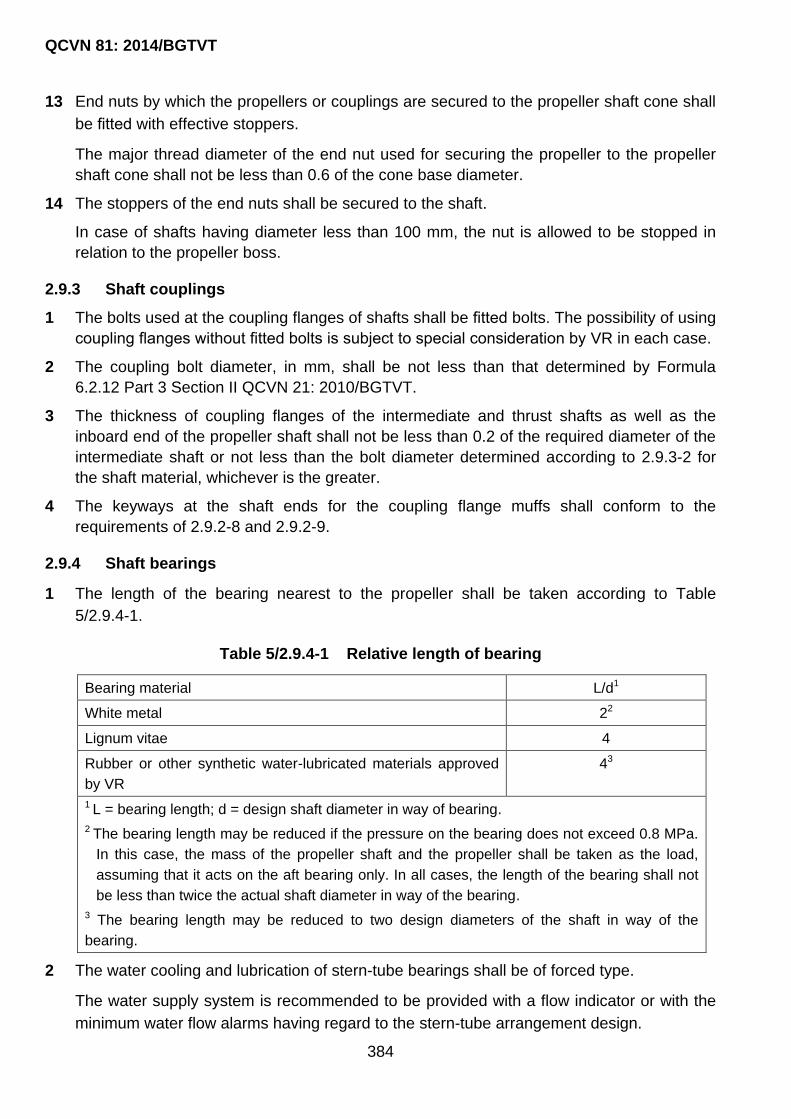
QCVN 81: 2014/BGTVT
384
13 End nuts by which the propellers or couplings are secured to the propeller shaft cone shall
be fitted with effective stoppers.
The major thread diameter of the end nut used for securing the propeller to the propeller
shaft cone shall not be less than 0.6 of the cone base diameter.
14 The stoppers of the end nuts shall be secured to the shaft.
In case of shafts having diameter less than 100 mm, the nut is allowed to be stopped in
relation to the propeller boss.
2.9.3 Shaft couplings
1 The bolts used at the coupling flanges of shafts shall be fitted bolts. The possibility of using
coupling flanges without fitted bolts is subject to special consideration by VR in each case.
2 The coupling bolt diameter, in mm, shall be not less than that determined by Formula
6.2.12 Part 3 Section II QCVN 21: 2010/BGTVT.
3 The thickness of coupling flanges of the intermediate and thrust shafts as well as the
inboard end of the propeller shaft shall not be less than 0.2 of the required diameter of the
intermediate shaft or not less than the bolt diameter determined according to 2.9.3-2 for
the shaft material, whichever is the greater.
4 The keyways at the shaft ends for the coupling flange muffs shall conform to the
requirements of 2.9.2-8 and 2.9.2-9.
2.9.4 Shaft bearings
1 The length of the bearing nearest to the propeller shall be taken according to Table
5/2.9.4-1.
Table 5/2.9.4-1 Relative length of bearing
Bearing material L/d1
White metal 22
Lignum vitae 4
Rubber or other synthetic water-lubricated materials approved
by VR
43
1 L = bearing length; d = design shaft diameter in way of bearing.
2 The bearing length may be reduced if the pressure on the bearing does not exceed 0.8 MPa.
In this case, the mass of the propeller shaft and the propeller shall be taken as the load,
assuming that it acts on the aft bearing only. In all cases, the length of the bearing shall not
be less than twice the actual shaft diameter in way of the bearing.
3 The bearing length may be reduced to two design diameters of the shaft in way of the
bearing.
2 The water cooling and lubrication of stern-tube bearings shall be of forced type.
The water supply system is recommended to be provided with a flow indicator or with the
minimum water flow alarms having regard to the stern-tube arrangement design.

QCVN 81: 2014/BGTVT
385
The shut-off valve controlling the supply of water to stern-tube bearings shall be fitted on
the stern-tube or on the afterpeak bulkhead.
3 If the stern-tube bearings are oil-lubricated, the propeller shaft seals of a type approved by
VR shall be used.
The lubricating oil gravity tanks shall be located above the margin line and fitted with oil
level indicators.
Forced lubricating oil cooling and oil or bearing liner temperature monitoring are
recommended to be implemented having regard to the stern-tube arrangement design.
4 The distance between the centers of adjacent shaft bearings, where there are no
concentrated masses in the span, shall meet the following condition:
0.55 d l d
Where:
l: distance between the centers of adjacent bearings, in m;
d: shaft diameters between bearings, in m;
: factor taken equal to:
14 for n 500 (rpm);
300/ n for n ≥ 500 (rpm).
n: rated shaft speed, in rpm.
5 It is recommended to seek the minimum number of shafting supports and the maximum
possible length of span between them.
The maximum allowable length of the spans between the shaft supports (bearings)
determined according to 2.9.4-4, shall be checked by the bending vibration calculation.
2.9.5 The shafting shall comprise the appropriate braking devices. Such devices may be a
brake, a stopper preventing rotation of the shaft in the event the main engine goes out
of action.
For shafting of less than 60 mm in diameter such devices are recommended to be used.
2.9.6 Cardan shafts
1 Shafting is allowed to comprise cardan shafts to be used as intermediate shafts, subject to
condition that appropriate strength calculations of the shafts and articulated joints are
submitted to VR.
2 In craft of design categories A, A1, A2 and B, the use of cardan shafts is subject to special
consideration by VR.
2.9.7 Hydraulic tests
1 Propeller shaft liners and stern-tubes shall be hydraulically tested by a pressure of 0.2
MPa upon completion of machining.

QCVN 81: 2014/BGTVT
386
2 After assembling, the stern-tube seals, where stern-tube bearing are oil-lubricated, shall be
tested for tightness by a pressure head up to the working level of liquid in gravity tanks. In
general, the test shall be carried out while the propeller shaft is turning.
2.10 Propellers
2.10.1 The requirements of this Chapter apply to metal fixed-pitch propellers, both solid and
detachable-blade propellers, as well as to controllable-pitch propellers.
Design of propellers or blades made of non-metal materials is subject to special
consideration by VR in each case.
2.10.2 Blade thickness
1 Propeller blade thickness, in mm, in two sections being controlled shall not to be less than
that determined by the following formula:
3
3.2
(0.312 /
p
p
A NS
nB ZMH D
Where:
Sp: maximum thickness of expanded blade in the coaxial cylindrical section which is
measured normally away from the driving surface (leading edge) or the standard blade
section chord, for the blade section being measured, which is the nearest section to
the boss, i.e. at the radius:
0.2R - for solid propellers where the propeller boss radius is smaller than 0.2R;
0.25R - for detachable-blade propellers;
0.35R - for CPP;
0.6R - for all propellers irrespective of the propeller boss diameter.
A: coefficient to be determined from Table 5/2.10.2-1 or the radius to be calculated
and also depending on the blade rake angle; if the blade rake angle differs from the
values listed in the Table, the coefficient A shall be taken as for the nearest greater
value of the angle;
N: rated power of main engine, in kW;
n: rated propeller speed, in min–1;
Z: number of blades;
Bp: expanded blade width at the design radius, in m;
D: propeller diameter, m;
R: propeller radius (m);
H/D: pitch ratio at the radius 0.7 R;
M = 0.6Rm(s) + 180 (MPa), but not more than:

QCVN 81: 2014/BGTVT
387
610 MPa for copper alloys;
570 MPa for steel;
Rm(s): tensile strength of blade material, in MPa.
Table 5/2.10.2-1 Factor A
Blade
radius
Blade rake angle measured on the blade driving surface, in deg.
0 2 4 6 8 10 12 14 16
0.20R 390 391 393 395 397 400 403 407 411
0.25R 378 379 381 383 385 388 391 394 398
0.30R 367 368 369 371 373 376 379 383 378
0.35R 355 356 357 359 361 364 367 370 374
0.60R 236 237 238 240 241 243 245 247 249
2 The blade tip thickness shall not be less than 0.0035D. The intermediate blade
thicknesses shall be so selected that the lines connecting the maximum thicknesses points
of sections, from the root section through the intermediate one up to the tip section, are
fair.
In sound cases, the blade thickness calculated according to 2.10.2 and 2.10.3 may be
reduced, provided detailed strength calculations are submitted to VR.
2.10.3 Propeller boss and blade fastening parts
1 Fillet radii of the transition from the root of a blade to the boss shall not be less than 0.04 D
on the suction side and shall not be less than 0.03 D on the pressure side (D is the
propeller diameter). If the blade has no rake, the fillet radius on both sides shall be at least
0.03 D.
Smooth transition from the blade to the boss using a variable radius may be allowed.
2 Empty spaces between the propeller boss and the shaft cone, as well as inside the
propeller cap shall be filled with non-corrosive mass.
3 The diameter of the bolts (studs), by which the blades are secured to the propeller boss or
the minor diameter of the thread of such bolts (studs), whichever is less, shall not be less
than that determined by the following formula:
mb
mbls
dR
bRksd
Where:
k = 0.33 in case of 3 studs in blade flange at the driving surface;
k = 0.30 in case of 4 studs in blade flange at the driving surface;
k = 0.28 in case of 5 studs in blade flange at the driving surface;
s: maximum actual thickness of the blade at the design root section (refer to 6.2.1)
(mm);

QCVN 81: 2014/BGTVT
388
b: width of expanded cylindrical section of the blade at the design root section, in mm;
Rmbl: tensile strength of blade material (MPa);
Rmb: tensile strength of bolt/stud material (MPa);
d: diameter of bolt pitch circle; with other arrangement of bolts, d = 0.85l, where l = the
distance between the most distant studs (m).
2.10.4 Propeller balancing
The completely finished propeller shall be statically balanced.
2.10.5 Controllable pitch, adjustable pitch, foldable blade propellers
1 The hydraulic power system of the CPP, the overload protection system of the main
engines, the lubrication system of the CPP shall meet the requirements of 13.10 Part 3
Section II QCVN 21: 2010/BGTVT.
2 Construction of the adjustable pitch propellers and the foldable blade propellers is subject
to special consideration by VR in each case.
2.10.6 Other propulsors
Construction of other propulsors such as water-jets, paddle wheels, aerial propellers is
subject to special consideration by VR in each case.
2.11 Torsional Vibration
2.11.1 The requirements of this Chapter apply to machinery installations with the main engines
having a power output of 37 kW and over.
2.11.2 For the machinery installations with the main engines having a power output from 37 up
to 75 kW, the torsional vibration calculations shall include:
1 Specifications of the basic installation components.
2 Natural frequency calculation results for all modes of vibration having resonances within
the rated shaft speed range from 0.2 to 1.2.
3 Results of determination of the design stresses in critical sections of shafts caused by the
existing resonances. If the resonance zone of the basic order is situated in the proximity to
the range from 0.85 to 1.05 of the working shaft speeds (idle running, rated speed on
ahead or astern run) or natural frequencies of hull structures, stresses due to non-
resonance forced vibration caused by the resonance frequencies of basic order shall be
calculated for these ranges.
The permissible stresses due to resonance, near-resonance and non-resonance forced
vibration under conditions of continuous running shall not exceed those defined in 2.11.3.
2.11.3 For the machinery installations with the main engines having a power output of 75 kW
and over, the requirements set out in Chapter 8 Part 3 Section II QCVN 21:
2010/BGTVT shall be complied with in so much as they are applicable, depending on
the installation type. Where the technical opportunity of making torsional vibration
measurement on board (e.g. in installations with water-jets, outboard engines, steerable

QCVN 81: 2014/BGTVT
389
propellers, etc.) is unavailable or impracticable, absence of dangerous torsional
vibration over the entire working speed range in all specified operating modes of the
installation shall be supported by a calculation.
2.12 Active Means Of Craft’s Steering
2.12.1 General
1 The requirements of the present Section apply to AMCS as defined in 2.1.
The requirements for steering nozzles and steering system of active rudders are given in
Part 3.
2 Where AMCS is intended for the main propulsion and steering of the motor craft of design
categories A, A1, A2 and B, a minimum of two AMCS shall be provided.
In this case, provision shall be made for control stations equipped with the necessary
devices and, if required, means of communication, as specified in 2.4.
3 A single AMCS may be installed for the main propulsion and steering of the motor craft of
design categories C, C1, C2, C3 and D, as well as the sailing-motor and motor-sailing
craft.
4 The requirements for installation of AMCS machinery and equipment are given in 2.2.
5 For the main AMCS, size and materials of shafts, couplings, coupling bolts, propulsors,
gearings, as well as electrical equipment shall meet the requirements of the relevant Parts
and Sections of the present Regulation. Moreover, the applicable requirements of the
relevant Sections of the present Regulation which relate to the rudder and steering gear
shall be met as well.
When the Regulation contain no requirements for particular components of AMCS, the
possibility of using them is subject to special consideration by VR in each case.
6 Calculations of the AMCS gearing shall be made following the procedure outlined in
Chapter 5, Part 3, Section II, QCVN 21: 2010/BGTVT in so much as they are applicable
and sufficient, unless otherwise specified in this Regulation.
7 Spaces containing AMCS machinery shall be equipped with appropriate ventilating, fire
extinguishing, drainage, heating and lighting arrangements.
2.12.2 The requirements for construction, alarm devices, hydraulic tests shall be fulfilled
consistently with those set out in Part 3, Section II, QCVN 21: 2010/BGTVT, in so much
as they are applicable and sufficient, unless specified otherwise in this Regulation.
2.13 Materials and Welding
2.13.1 Materials intended for the manufacture of parts of the shafts and propellers shall comply
with the requirements given in 6.2 and 7.2, Part 3, Section II, QCVN 21: 2010/BGTVT,
in so much as they are applicable and sufficient, unless specified otherwise in this
Regulation.

QCVN 81: 2014/BGTVT
390
2.13.2 Welding procedures and non-destructive testing of welded joints shall comply with the
requirements of Chapter 11, Part 3, Section II, QCVN 21: 2010/BGTVT in so much as
they are applicable and sufficient, unless specified otherwise in this Regulation.

QCVN 81: 2014/BGTVT
391
CHAPTER 3 MACHINERY
3.1 Application, Scope of technical supervision
3.1.1 The requirements of this Section apply to the following engines and machinery:
1 Main internal combustion engines.
2 Internal combustion engines driving electric generators or auxiliary machinery, units in
assembly.
3 Gears and coupling.
4 Pumps included into systems covered by the requirements of Chapter 4 of this Part and
Part 10, except for manually operated pumps.
5 Power driven air compressors.
6 Centrifugal separators for fuel oil and lubricating oil.
7 Turbochargers of internal combustion engines.
8 Fans included into systems covered the requirements by Chapter 4 of this Part.
9 Steering gear.
10 Anchor machinery.
11 Mooring machinery.
12 Hydraulic drives.
3.1.2 Subject to VR technical supervision during manufacture are engines and machinery
listed in 3.1.1.
The scope of technical supervision, hydraulic tests, operation tests, general technical
requirements, materials and welding shall comply with the requirements of Part 3, Section
II, QCVN 21: 2010/BGTVT in so much as applicable and sufficient unless expressly
specified otherwise in this Regulation.
3.2 Internal Combustion Engines
3.2.1 General.
1 The requirements of the present Chapter apply to all internal combustion engines of power
output 37 kW and above.
Application of these requirements to the internal combustion engines of power output less
than 37 kW is subject to special consideration by VR in each case.
2 The engines shall be capable of working with an overload exceeding the rated power by at
least 10 per cent for not less than one hour.

QCVN 81: 2014/BGTVT
392
3 The engines intended to be used as main engines shall also comply with the requirements
of 2.3.
4 Irregularity of speed of a.c. diesel generating sets intended for parallel operation shall be
such that the amplitude of angle oscillations of the generator shaft does not exceed 3.5°/P,
where P is the number of pairs of generator poles.
5 The diesel generating sets intended to be used as emergency units shall be provided with
self-contained fuel supply, cooling and lubrication systems.
6 Engines intended to drive emergency generators which may also be used as electrical
power sources for non-emergency consumers shall be equipped with fuel oil and
lubricating oil filters, as well as with instruments, alarm and protective devices as required
for the prime movers of the main sources of electrical power when in unattended
operation. Along with that, their fuel oil service tanks shall be fitted with an alarm for low
fuel oil level which corresponds to the capacity of the fuel oil daily service tank of the
emergency diesel generator.
Moreover, such engines shall have design and maintenance system ensuring their
constant availability for use as emergency units when the craft is at sea.
7 The rated power output of the engines shall be determined under environmental conditions
cited in 1.3, Part 3, Section II, QCVN 21: 2010/BGTVT.
8 Fuel oil and lubricating oil pipes, fittings, flanged connections, filters shall be screened or
otherwise protected so that in case of their failure petroleum products falling onto hot
surfaces is prevented.
3.2.2 Engine frame, crankshaft, scavenging and supercharging, fuel oil system, lubrication,
starting arrangements, exhaust arrangements, control, protection and regulation,
torsional vibration damper, antivibrator.
1 Engine frame, crankshaft, scavenging and supercharging, fuel oil system, lubrication,
starting arrangements, exhaust arrangements, control, protection and regulation, torsional
vibration damper, antivibrator shall comply with the requirements of Chapter 2, Part 3,
Section II, QCVN 21: 2010/BGTVT in so much as applicable and sufficient unless
expressly specified otherwise in this Regulation.
3.2.3 Instruments and alarm devices
1 Main and auxiliary engines shall be fitted with instruments for measuring:
(1) lubricating oil pressure at engine inlet;
(2) freshwater pressure (or flow) in the engine cooling system;
(3) starting air pressure at main starting valve or starting device inlet (where compressed
air starting system is provided);

QCVN 81: 2014/BGTVT
393
(4) exhaust gas temperature in exhaust gas pipe;
(5) lubricating oil temperature at engine inlet;
(6) freshwater (coolant) temperature at engine outlet and inlet.
The engines with a compensating tank installed on the engine, only the freshwater
(cooling water) temperature at engine outlet is allowed to be measured;
(7) temperature of cylinder multiple head of the directly air cooled engines.
Note: Proceeding from the structural features of the engines, changes may be introduced to
the list of measuring instruments on agreement with VR.
2 Each driving engine with a power output exceeding 37 kW shall be fitted with audible and
visual warning alarm device actuating signals when the lubricating oil pressure in the
circulating lubrication system drops below the permissible level.
3 Local control stations of main engines shall be equipped with instruments for measuring:
(1) lubricating oil pressure at engine and reduction gear inlet;
(2) freshwater (coolant) pressure (or flow) in the engine cooling system;
(3) starting air pressure at main starting air valve or starting device inlet (where
compressed air starting system is provided);
(4) current strength and voltage in the starter battery charging circuit ( where electrical
starting system is provided);
(5) crankshaft speed, and where disengaging clutches are fitted, with an instrument for
measuring propeller shaft speed as well;
(6) temperature of cylinder multiple head of the directly air cooled engines.
Note: Proceeding from the structural features of the engines, changes may be introduced to
the list of measuring instruments on agreement with VR.
4 Local control stations of main reversible engines or main engines with reverse-reduction
gear, in addition to the instruments listed in 3.2.3-3 shall be equipped with:
propeller shaft rotation indicators;
devices for emergency stop of the engine or disen-gaging of the clutches, operating
irrespective of remote control.
Note: Outboard engines (attached to transom) are fitted with measuring instruments with
consideration for their structural features and the Manufacturer‟s recommendations.
5 Local control stations of auxiliary engines shall be equipped with instruments for
measuring:
(1) lubricating oil pressure at engine and reduction gear inlet;
(2) freshwater (coolant) pressure (or flow) in the engine cooling system);

QCVN 81: 2014/BGTVT
394
(3) current strength and voltage in the started battery charging circuit (where electrical
starting system is provided) – recommendational;
(4) crankshaft speed.
3.2.4 Marking
1 The marking shall contain the following information:
- trade mark or trade name of the engine Manufacturer;
- type of engine, its group (family), if any;
- power and speed.
2 The marking shall be in indelible paint. When a label or a nameplate is used, their
attachment shall remain reliable throughout the standard service life of the engine and
preclude their detachment without damaging them.
3 The marking shall be made on those parts of the engine, the removal of which renders
operation of the engine impossible.
4 The marking shall be so located that it can be clearly visible to a person of a medium
height, after the engine is mounted with all components necessary for its operation.
3.3 Gears, Disengaging Couplings
3.3.1 Gears, disengaging couplings of engines and machinery listed in 3.1.1 shall comply with
the requirements of Chapter 5, Part 3, Section II, QCVN 21: 2010/BGTVT in so much as
applicable and sufficient unless expressly provided otherwise below.
3.4 Auxiliary Machinery
3.4.1 Power driven air compressors, fans and turbo-chargers, power driven centrifugal
separators shall comply with the requirements of Chapter 12 and 13, Part 3, Section II,
QCVN 21: 2010/BGTVT in so much as applicable and sufficient unless expressly
provided otherwise below.
3.5 Deck Machinery
3.5.1 Steering gear, anchor and mooring machinery shall comply with the requirements of
Chapter 15 and Chapter 16, Part 3, Section II, QCVN 21: 2010/BGTVT in so much as
applicable and sufficient unless expressly provided otherwise below.
3.6 Hydraulic Drives
3.6.1 Hydraulic drives of machinery listed in 3.1.1 shall comply with the requirements of 13.10
Part 3, Section II, QCVN 21: 2010/BGTVT in so much as applicable and sufficient
unless expressly provided otherwise below.

QCVN 81: 2014/BGTVT
395
CHAPTER 4 SYSTEMS AND PIPING
4.1 Application
4.1.1 The requirements of this Part apply to the following systems and piping used in craft:
1 bilge pumping and drain.
2 ballast.
3 fuel oil.
4 lubricating oil.
5 water cooling.
6 compressed air.
7 air, overflow, sounding.
8 exhaust gas.
9 ventilation.
10 hydraulic drives.
11 domestic liquefied gas.
Pumping and piping of berth-connected craft shall comply with the requirements of the
present Part of the Regulation, in so much as applicable and sufficient unless provided
otherwise below.
4.1.2 Fuel oil used in craft shall comply with the requirements of 2.1.2-1.
4.1.3 Machinery and other components of the systems indicated in 4.1.1 shall remain
operative under environmental conditions specified in 1.3 Part 3, Section II, QCVN 21:
2010/BGTVT.
4.1.4 For the purpose of determining test categories, types of joints, thermal treatment,
welding procedures, pipes are subdivided into three classes as indicated in Table
5/4.1.4.

QCVN 81: 2014/BGTVT
396
Table 5/4.1.4 Piping categorizing
Media conveyed Class I Class II Class III
Inflammable media heated above flash point or having
flash point below 60 °C, liquefied gases
Without
special
safeguards
With
special
safeguards 1
-
Fuel oil, lubricating oil, hydraulic oil with flash point of
60 °C and above 2
P > 1.6 or t
> 150
P ≤ 1.6 and
t ≤ 150
P ≤ 0.7 and
t ≤ 60
Other media 2,3,4 P > 4.0 or t
> 300
P ≤ 4.0 and
t ≤ 300
P ≤ 1.6 and
t ≤ 200
1 Safeguards for reducing leakage possibility and limiting its consequences through proper pipe
installation, use of special ducts, protective casings, screening, etc. are subject to special
consideration by VR in each case.
2 p: design pressure, in MPa; t = design temperature, (°C) - See 4.2.
3 Including water, air, gases, non-flammable hydraulic fluids.
4 For open-ended pipes (drain, overflow, vent, air and steam lines from safety valves) irrespective of
the temperature, Class III pipes may be used.
4.1.5 Fittings of pipes of all Classes as well as air pipe covers, flexible joints, expansion joints,
mechanical joints, insulating joints may be delivered to pleasure craft with a copy of the
Type Approval Certificate of VR.
In case where the type approval of VR is unavailable, the above equipment for use on a
particular craft may be accepted by the Surveyor to VR after verification of the
Manufacturer‟s certificates, verification of the conformity of used materials with the
Regulation requirements and test performance.
4.1.6 Protection and insulation of piping
1 Steel pipes of sea water, as well as air, sounding and overflow pipes of water tanks and
tanks for alternate carriage of water ballast and fuel oil shall be protected against corrosion
by a method approved by VR.
Galvanic coating, zinc coating applied by a hot method, plastic coating and also paint
coating applied on external surfaces may be used as such protection.
Upon completion of all welding work during manufacture of pipe sections, the damaged
portions of coating shall be restored or protected by other method approved by VR.
Application of galvanic coating does not supersede the measures for protection of pipes
against contact and electrochemical corrosion.
2 Where bottom and side fittings of non-ferrous metal alloys are used, provision shall be
made for protection of the craft‟s shell plating and all components coming into contact with
those fittings, against contact corrosion. Cathodic protection of welded suction and
discharge branch pipes with fittings against contact corrosion shall be made with the use

QCVN 81: 2014/BGTVT
397
of standard ring end or ring inter-flange protectors to be mounted on the branch pipe
flanges. The use of electric insulating joints of the mating components made in accordance
with the approved standards is allowed; in this case, bottom and side fittings shall be
insulated on both sides with the obligatory measuring of the joint insulation resistance
upon completion of installation.
3 Where steel pipes of sea water systems are connected to fittings, pump casings,
machinery units and heat exchangers of non-ferrous metal alloys, provision shall be made
for protection against contact corrosion.
4 Flow velocity for pipe portions incorporating formed components, throttle diaphragms, as
well as through-hull and seacock distance pieces shall not exceed the values specified in
Table 5/4.1.6-4.
Table 5/4.1.6-4 Allowable Flow velocity
Pipe material Permissible flow velocity
(m/s)
Steel, including galvanized steel 2.5
Copper-nickel and aluminum-brass
alloys
2.0
5 Protection against excessive pressure
(1) Pipelines in which pressure in excess of the design pressure is likely to arise, shall be
fitted with safety devices so that the pressure would not exceed the design pressure
for the pipes.
The liquied diversion from relief valves of pumps transferring flammable liquids shall
be effected into the suction side of the pump or to the suction pipeline. This
requirement does not apply to centrifugal pumps.
(2) Where provision is made for a reducing valve on the pipeline, a pressure gauge and a
safety valve shall be installed after the reducing valve. An arrangement for by-passing
the reducing valve is allowed for use.
6 Insulation of piping
Insulation of piping shall comply with the requirements of 2.8.
4.1.7 Flexible joints (hoses)
1 The type and design of flexible joints used in the systems listed in 4.1.1 shall be approved
by VR. The material of flexible joints shall be selected with regard to the used media to be
conveyed, pressures, temperatures and environmental conditions. The bursting pressure
of the flexible joints (except ventilation systems) shall be at least 4 times higher than the
design pressure.
2 In the pipelines conveying fuel oil, lubricating oil and other flammable liquids, as well as in
pipelines connected with the drives of watertight doors or with the openings in shell plating

QCVN 81: 2014/BGTVT
398
only fire-resistant flexible joints made as fabricated inserts with end connections (flanges
or nipples) are allowed for use. No clamping arrangements are allowed. Where such
flexible joints are installed in machinery spaces, provision shall be made for their
disconnection in the event of failure. Disconnecting valves shall be located in readily
accessible places, in the immediate vicinity of flexible joints so that any flexible joint can be
replaced without having to stop other machinery.
3 A joint is considered fire-resistant if, being connected to a pipeline in which water is
circulating at a temperature not lower than 80 °C, at the maximum pressure, it withstand
heating by fire during 30 min at a temperature of 800 °C and retains its integrity during and
after a proof pressure test. As an alternative to this test, are the above-mentioned fire tests
with circulating water pressure equal to 0.5 MPa with subsequent hydraulic test for double
design pressure.
4 Where a flexible joint is made of steel or other equivalent material complying with VR
requirements for fire-resistance, fire test is not required.
5 In pipelines listed in 4.1.6-2 with bore not more than 10 mm and design pressure of the
medium to be conveyed p ≤ 0.34 MPa, as well as in case of bore in excess of 10 mm and
the design pressure of the medium to be conveyed p ≤ 0.25 MPa, fire-resistant flexible
joints with fire-resistant fuel hoses complying with ISO 7840: 2004 may be used.
6 Non-fire-resistant fuel hoses complying with ISO 8469: 2004 with bore up to and including
63 mm and design pressure of medium to be conveyed p ≤ 0.25 MPa, may be used for
taking over and delivery of oily liquids.
4.1.8 Welding and non-destructive testing of welds
Welding and non-destructive testing of welds in pipes shall be carried out in compliance
with the requirements of 11.6, Part 3, Section II, QCVN 21: 2010/BGTVT and Part 6,
Section II, QCVN 21: 2010/BGTVT.
4.1.9 Machinery, equipment and control devices
1 Fans, pumps, compressors and their electric drives used in systems covered by the
present Part of the Regulation shall comply with the requirements of Chapter 3 of this Part
and Part 7.
2 Control and monitoring devices of piping systems shall comply with the requirements of
Part 6.
3 Heat exchangers and pressure vessels used in the systems shall comply with the
requirements of Chapter 10, Part 3, Section II, QCVN 21: 2010/BGTVT.
4.2 Metal Piping
4.2.1 Materials used for pipes and fittings, as well as the methods of testing the materials
shall comply with the requirements of Part 7A, Section II, QCVN 21: 2010/BGTVT.

QCVN 81: 2014/BGTVT
399
The fuel oil pipes shall be manufactured of steel or other material meeting VR
requirements as to its strength and fire-resistance.
These requirements apply also to lubricating oil pipes in machinery spaces and to pipes
conveying other flammable oil products including hydraulic and thermal liquids, if they are
located in spaces containing sources of ignition.
4.2.2 In general, pipes and fittings of carbon steel and carbon-manganese steel shall be used
for media with temperature not exceeding 400 °C and those of low-alloy steel with
temperature not exceeding 500 °C.
These steels may be admitted for temperatures higher than above mentioned, if their
mechanical properties and ultimate long-term strength comply with the effective standards
and are guaranteed by the steel Maker as suitable for the high temperature service.
Pipes and fittings for media with temperature above 500 °C shall be manufactured of alloy
steel. This requirement does not cover exhaust gas pipes.
4.2.3 Copper and copper alloy pipes shall be seamless pipes or of other type approved by
VR.
Copper pipes for Classes I and II shall be seamless.
Pipes and fittings of copper and copper alloys shall generally be used for media having
temperature not exceeding 200 °C, and those for copper-nickel alloys, for media with
temperature not over 300 °C. Bronze fittings may be admitted for media having
temperatures up to 200 °C.
4.2.4 Use of spheroidal or nodular graphite cast iron or aluminium alloys for pipes listed in
4.1.1 is subject to special consideration by VR in each case.
4.2.5 Pipe wall thickness
1 The wall thickness of metal pipes (except cast iron and aluminium alloy pipes) operating
under the internal pressure shall not be less than that specified in Table 5/4.2.5-1.
The wall thickness of bilge, air, overflow and sounding pipes passing through fuel oil and
ballast tanks is subject to special consideration by VR in each case.
The data given in Table 5/4.2.5-1 do not apply to exhaust gas pipes.

QCVN 81: 2014/BGTVT
400
Table 5/4.2.5-1 Minimum pipe wall thickness
External
diameter
(mm)
Minimum pipe wall thickness, mm
Steel pipes
Copper Copper
alloys
Pipes of
systems
other
than stated
in columns 3
and 4
Venting,
overflow,
sounding
pipes of built-
in tanks
Sea water pipes (bilge
pumping, ballast, cooling
water, fire-extinguishing
systems)
6.0 - - - 1.0 0.8
10.2 1.6 - - 1.0 0.8
12.0 1.6 - - 1.2 1.0
14.0 1.6 - - 1.2 1.0
16.0 1.8 - - 1.2 1.0
22.0 2.0 - 3.2 1.2 1.0
25.0 2.0 - 3.2 1.5 1.0
26.9 2.0 - 3.2 1.5 1.0
30.0 2.0 - 3.2 1.5 1.0
32.0 2.0 - 3.2 1.5 1.2
38.0 2.0 4.5 3.6 1.5 1.2
42.4 2.0 4.5 3.6 1.5 1.2
45.0 2.0 4.5 3.6 1.5 1.2
48.3 2.3 4.5 3.6 1.5 1.5
54.0 2.3 4.5 4.0 2.0 1.5
57.0 2.3 4.5 4.0 2.0 1.5
63.5 2.3 4.5 4.0 2.0 1.5
70.0 2.6 4.5 4.0 2.0 1.5
76.0 2.6 4.5 4.5 2.0 1.5
82.5 2.6 4.5 4.5 2.0 1.5
89.0 2.6 4.5 4.5 2.5 2.0
101.0 2.9 4.5 4.5 2.5 2.0
Notes:
1. For pipes with thicknesses and diameters indicated in the Table, the nearest values
specified in national or international standards may be accepted on agreement with VR.
2. The tabulated values require no allowance for negative manufacturing tolerance and
reduction in thickness due to bending.

QCVN 81: 2014/BGTVT
401
3. The tabulated values do not cover the stainless steel pipes the minimum thicknesses of
which are subject to special consideration by VR.
4. For the diameters greater than those stated in the Table, the minimum thicknesses are
subject to special consideration by VR in each case.
5. If pipes are effectively protected, then, at the discretion of VR, the wall thicknesses of
pipes stated in columns 3 and 4 may be reduced by an amount of not more than 1 mm.
6. For sounding pipes, the thicknesses stated in column 3 apply to the parts which are
outside the tanks for which these pipes are intended.
7. For threaded pipes, the wall thickness shown is the minimum thickness at the bottom of
the thread.
2 The wall thicknesses of pipes made of spheroidal graphite cast iron, aluminium alloys,
titanium alloys and corrosion-resistant alloys are subject to special consideration by VR in
each case.
3 For the carbon dioxide smothering system, the wall thickness of pipes on a length from
cylinders to release valves shall not be less than 4.0 mm and from release valves to
discharge nozzles the thickness shall not be less than 3.0 mm.
4.2.6 Radii of pipe bends. Heat treatment after bending
1 Radii of pipe bends and heat treatment after bending shall comply with the requirements of
13.2 Part 3, Section II, QCVN 21: 2010/BGTVT in so much as applicable and sufficient
unless expressly provided otherwise below.
4.2.7 Pipe joints
1 Use of welded, flanged, threaded and mechanical joints, made in accordance with the
standards approved by VR may be allowed.
2 The welded, flanged, threaded and mechanical joints shall comply with the requirements of
13.2 Part 3, Section II, QCVN 21: 2010/BGTVT in so much as applicable and sufficient
unless expressly provided otherwise below.
4.3 Plastic Piping
4.3.1 Scope of application. General requirements
1 The present requirements apply to all pipes made of plastics.
The requirements do not apply to flexible non-metal joints, rubber hoses, as well as to
mechanical joints used in systems with metal pipes.
2 General requirements for plastic pipes and formed components are stated in standards
and procedure recognized by VR.
4.3.2 Requirements for piping depending on their purpose

QCVN 81: 2014/BGTVT
402
1 Fire-resistance
(1) Pipes and formed components, integrity of which has significant influence on safety of
a craft, shall meet the requirements of fire-resistance.
(2) Depending on pipeline ability to maintain integrity during fire tests according to the
procedure stated in Annexes 1 and 2 to IMO Resolution A.753(18), three levels of fire-
resistance are specified:
L1: for pipelines withstanding fire test in dry condition during 1 hour;
L2: for pipelines withstanding fire test in dry condition during 30 min;
L3: for pipelines withstanding fire test in filled condition during 30 min.
The scope of application of plastic pipelines depending on fire-resistance level,
location and media conveyed is given in Table 5/4.3.2-1(2).
Table 5/4.3.2-1(2) Application of plastic pipelines
Nos. Medium to
be conveyed Piping systems
Location
A G H I J K
1 Flammable
liquids with
flash point >
60 °C
Fuel oil
Lubricating oil
Hydraulic
+
+
+
0
-
0
0
-
0
0
0
0
L1
L1
L1
L1
L1
L1
2 Sea water Drainage
Drain pipes of internal spaces
Sanitary drains (internal)
Drainage from weather decks
Fire main systems
Ballast
Essential cooling systems
Non-essential cooling systems
L1
L11
0
02
L1
L3
L3
0
0
0
0
0
-
0
-
0
0
0
0
0
0
0
0
0
0
0
0
0
0
0
0
0
-
0
0
02
+
L2
-
0
L1
0
0
0
L1
L2
L2
0
3 Fresh water Essential cooling systems
Non-essential cooling systems
L3
0
0
0
0
0
0
0
0
0
0
0
4 Other media Air, sounding and overflow pipes: water
tanks and dry compartments 0 0 0 0 0 0
Flammable liquids, Tflash > 60 °C + 0 0 0 +
Pneumatic control systems L13 0 0 0 L13 L13
Air pipes for domestic services 0 0 0 0 0 0
Low pressure steam, water heating L2 0 0 0 0 0
Symbols:
A: machinery spaces;
QCVN 81: 2014/BGTVT
403
G: fuel oil tanks and trunks;
H: ballast tanks and trunks;
I: offerdams, dry compartments, etc.;
J: accommodation, service spaces and control stations;
K: weather decks;
O: fire test is not required;
„„ – ‟‟: not applicable;
„„ + ‟‟: only metal materials with fusion point above 925 °C; 1: For drainage pipes serving only the particular space, “0” may be used instead of “L1”; 2: Scupper holes of weather decks shall be “+”, if they are not provided with the appropriate blanking
means; 3: When control functions are not foreseen, “0” may be used instead of “L1”.
2 Flame spreading, fire-retardant coatings
(1) All pipes, with the exception of pipes located on exposed decks, in cofferdams, etc.,
shall have the characteristic of slow flame-spread on the surface, not exceeding the
average values fixed in IMO Resolution A.653(16) and determined according to the
procedure given in Annex 3 to the Resolution, considering the changes arising from
curved surface of pipes or specified by other standards approved by VR.
(2) When fire-retardant coatings are applied to provide the required level of fire-
resistance, they shall comply with the requirements of Part 11.
Fire-retardant coatings shall be used according to the approved recommendations of
the Manufacturer.
(3) Fire-retardant coatings in junctions shall be applied after conducting of hydraulic tests
of the system in compliance with the pipe Manufacturer‟s recommendations, according
to the procedure approved by VR in each case.
4.3.3 Installation requirements
1 Installation work shall be performed in accordance with the Manufacturer‟s
recommendations.
2 Distances between supports shall not exceed the values recommended by the
Manufacturer.
In selecting supports and distances between them, pipe sizes, mechanical and physical
properties of pipe material, mass of pipes and liquid contained therein, working
temperature, influence of heat expansion, loads due to external forces, axial forces,
hydraulic impacts, vibration, which may occur in the system, shall be taken into
consideration. Allowance shall be made for possible simultaneous effect of the above
mentioned loads.

QCVN 81: 2014/BGTVT
404
The load from pipe weight shall be equally distributed over the entire load-bearing face of
the support. Measures shall be taken to minimize pipe wear at junctions of the pipes with
the supports.
3 Components of the system having significant mass shall be fitted with separate supports.
In pipe laying, allowance shall be made for periodically involved concentrated loads.
When necessary, pipes shall be protected from mechanical damage.
4 Where plastic pipelines pass through watertight and fire-resistant decks and bulkheads,
the requirements of 4.5.1-1 and 4.5.1-5 shall be met.
5 When assembling plastic pipelines, account shall be taken of the compensation tolerance
for relative displacement between piping and steel structures with regard to difference in
heat expansion ratios and craft‟s hull deformation.
When calculating heat expansions, the working temperature of the system and the
temperature at which assembling is carried out, shall be taken into consideration.
6 When laying pipes, allowance shall be made for periodically involved concentrated loads, if
their action is possible. As a minimum, the force caused by one person of 100 kg in mass
at the middle of span of any pipe with outer diameter over 100 mm shall be taken into
consideration.
7 In systems for transferring liquids, such as diesel oil and petrol, pipes of electrically
conductive material shall be used.
Regardless of the liquids transferred, the plastic pipes passing through dangerous zones
shall be electrically conductive.
Resistance in any point of the piping system as relative to the earth shall not exceed 106
Ohm. Pipes and formed components having electrically conductive layers shall preferably
be of equal conductivity.
Such pipes shall be sufficiently protected from damage by electric discharge caused by
difference in electrical conductivity of layers.
After installation earth connection shall be checked. Earthing wires shall be accessible for
examination.
8 Pipelines may be connected with the use of glued, welded, flanged or other joints.
Strength of joints shall not be less than strength of a pipeline where they are mounted.
9 The method of pipe connection (junction) shall be developed and approved prior to
installation.
10 Surveys and tests stated in this Section shall precede the approval of the method.
11 To be reflected in the method of joint connection are: the applied materials, used tools and
accessories, the requirements for preparation of joints, temperature conditions, the
requirements for dimensions and tolerances, as well as the acceptance criteria upon
completion of work and tests.

QCVN 81: 2014/BGTVT
405
12 For the inspection of pipe joint quality, it is necessary, in accordance with the accepted
procedure to prepare test assemblies which shall include at least one pipe joint with a pipe
and a pipe with a formed component.
The test assembly shall comprise a pipe with the maximum diameter.
13 Following joint setting, a test connection shall be subjected to a hydraulic test by a
pressure 2.5 times higher than the design pressure, during 1 hour. Leakage and breaks of
joint are not allowed.
14 After installation on board, essential piping system shall be hydraulically tested by a
pressure at least 1.5 times higher than the design pressure.
Non-essential piping system, after installation on board, may be tested for tightness with
the working pressure.
4.4 Fittings
4.4.1 Construction, marking, arrangement and installation of fittings
1 Construction of valves shall comply with the requirements of 12.3 Part 3, Section II, QCVN
21: 2010/BGTVT.
2 Marking of fittings
(1) Shut-off fittings shall be provided with conspicuous nameplates fixed in place and
bearing clear inscriptions to show the purpose of fittings.
(2) Remote-controlled valves at control stations shall have attached identification plates
showing their purpose, as well as position indicators “open” and “closed”.
Where the remote control is used only to close the valve, the indicators need not be
fitted.
3 Arrangement and installation of fittings
(1) Fittings arranged on watertight bulkheads shall be secured to welded pads by studs,
or alternatively the fittings may be welded to bulkhead pieces.
The stud holes in welded pads shall not be through holes.
(2) Measuring instruments of fuel oil and lubricating oil systems shall be provided with
valves or cocks to cut the instruments off from piping.
Thermometer sensors shall be encased in compact sleeves.
(3) Sight glasses in fuel oil and lubricating oil pipes shall be heat-resistant.
4.4.2 Filters
1 Filters shall be provided with a device to indicate that there is no pressure therein before
they are opened.
The tubes of such devices shall be carried to trays so that spillages are not sprayed
around.

QCVN 81: 2014/BGTVT
406
2 Filters forming part of systems with combustible working medium shall be located as far
away as practicable from potential sources of ignition.
4.4.3 Sea chests and ice boxes. Bottom and side fittings. Openings in shell plating
1 Sea chests and ice boxes
(1) On craft with special ice strengthening meeting the requirements of the Regulation
and with a mark “Ice” added to the class notation, which allows operation in cake ice,
one of the sea chests shall function as an ice box.
(2) Sea inlet valves shall be secured directly to sea chests.
(3) The sea inlet valves may be attached to welded pads or fitted on distance pieces
directly welded to the hull bottom shell plating.
The distance piece shall have welded flange joint. The wall thickness of a distance
piece shall not be less than the thickness of the bottom plate, but in no case it shall
be less than 6 mm.
(4) All the openings in shell plating for sea chests, welded inlet connections and inlet
distance pieces shall be fitted with gratings. Instead of gratings, holes or slots in the
shell plating are allowed. The net area through the gratings or slots shall not be less
than 2.5 times the area of the valve connected to the sea inlet.
The diameter of holes or the width of slots in gratings or shell plating shall be about 20
mm.
The sea chest gratings are recommended to be cleared by compressed air. The
pressure of compressed air in the clearing system shall not exceed 0.3 MPa. Clearing
pipes shall be provided with non-return shut-off valves.
(5) Provision shall be made for the access into sea chests via detachable gratings or
manholes of the side sea chests and ice boxes, if the manhole is located above the
deepest load line.
2 Openings in shell plating. Bottom and side fittings.
(1) The location of sea inlet and discharge openings in shell plating shall be such as to
prevent:
(a) sewage, domestic waste water and other wastes being sucked by sea water
pumps;
(b) sewage, domestic and discharge water penetrating into the craft‟s spaces through
side scuttles, as well as any discharge of water into lifeboats and liferafts when
lowered.
Where it is impracticable to comply with the requirements of 4.4.3-2(1), discharge
openings shall be fitted with appropriate arrangements to prevent water
penetration into the craft‟s spaces, lifeboats and liferafts.

QCVN 81: 2014/BGTVT
407
(2) The overboard discharges from the enclosed spaces below the freeboard deck may
be provided only with one locally controlled non-return shut-off valve.
(3) The scuppers and overboard discharge pipes from open decks and spaces, led
outboard at less than 600 mm above the deepest waterline, shall be fitted with non-
return valves (dampers) at the outer shell.
No valves may be provided if the wall thickness of these pipes installed below the
freeboard deck is not less than the thickness of the shell plating, but in no case it shall
be less than 5 mm.
(4) In machinery spaces, all the sea inlets and discharges of systems and piping in
connection with operation of the main and auxiliary machinery shall be provided with
readily accessible shut-off valves or sluice valves, locally controlled. The controls shall
be fitted with an indicator to show whether the valve is open or closed.
(5) The controls of bottom and inlet fittings shall be located in readily accessible places
and shall be fitted with a device to indicate whether the valve is open or closed.
(6) In machinery spaces, the controls of the bottom inlet and side outlet fittings of the sea
water system that lie located below the waterline, and the control gear of the ejector
drainage system shall be so arranged that there is enough time to access and activate
them from a position above the level of water incoming to the space.
It is recommended that the controls of the bottom and side fittings of the sea water
system, which lie below the waterline, be located above the freeboard deck.
(7) Bottom and side fittings shall be attached to welded pads.
Fittings may be also installed on welded distance pieces with welded flange joints.
The wall thickness of a distance piece shall not be less than the minimum thickness of
shell plating in the ends of the craft.
Stud holes in welded pads shall not penetrate the shell plating.
(8) Flange gaskets of bottom and side fittings shall not be manufactured of materials
easily deteriorating in case of fire.
(9) Spindles and closing parts of bottom and side fittings shall be manufactured of
corrosion-resistant materials.
4.5 Piping Laying
4.5.1 Piping laying through watertight and fire-resistant structures
1 The number of pipelines passing through the watertight bulkheads shall be kept to a
minimum.
The collision bulkhead shall not be pierced below the bulkhead deck by more than one
pipeline for dealing with the contents of the forepeak.

QCVN 81: 2014/BGTVT
408
Each pipe passing through the collision bulkhead shall be fitted with a screw-down valve
installed directly on the collision bulkhead inside the forepeak, operable from a readily
accessible position on the bulkhead deck.
The shut-off valve may be omitted on the pipelines passing through the collision bulkhead
above the bulkhead deck or freeboard deck.
2 Where pipelines pass through watertight bulkheads, decks and other watertight structures,
the appropriate sockets, welded pads and other details to ensure the integrity of the
structure concerned shall be used.
The holes for studs shall not penetrate watertight structures and shall be kept within the
welded pads.
Gaskets made of materials readily deteriorated in the event of fire, shall not be used.
3 Where pipelines pass through fire-resistant divisions, the requirements of Part 10 shall be
met.
4 Where plastic pipes pass through watertight bulkheads and decks forming boundaries of
watertight compartments, valves capable of being operated from a position above the
bulkhead deck shall be fitted.
The valves shall be of steel or another material equivalent to steel in fire resistance.
5 Where plastic pipes pass through a division of the main vertical fire zone, provision shall
be made for steel bulkhead sockets of appropriate length and valves that may be closed
from either side of the bulkhead. The valves shall be of steel or another material equivalent
to steel in fire resistance.
4.5.2 Piping laying in spaces and tanks
1 Fresh water pipelines shall not be laid through fuel oil and lubricating oil tanks, nor shall
fuel oil and lubricating oil pipes pass through fresh water tanks, unless the pipes are laid in
oiltight ducts.
Sea water and lubricating oil piping, as well as air, sounding and overflow pipes may pass
through fuel oil tanks if these pipes are of seamless type and have no detachable joints
inside the tanks.
2 Pipes passing through chain lockers and other spaces, in which they are subject to
mechanical damage, shall be adequately protected.
3 Pipes conveying fuel oil shall not be laid through the accommodation and service spaces
as well as under the lining, with the exception of fuel filling pipes which are allowed to be
laid through sanitary spaces, provided the pipes used have no detachable joints.
4 The pipes of all the systems and the ventilation ducts shall, where necessary, be fitted with
arrangements for blow-down of the working medium or draining of liquid.

QCVN 81: 2014/BGTVT
409
5 Pressure pipes are not allowed to be laid above and behind the main switchboards as well
as the control panels of essential machinery and equipment.
Such pipes may be carried at a distance not less than 500 mm from the fronts and sides of
these switchboards and control panels, provided that at a distance within 1000 mm from
switchboards and control panels no detachable joints are used, or the flanged joints have
protective casings.
6 On twin-hulled craft, the pipes connecting identical systems of both hulls, when routed
along the common upper deck, shall be provided with compensators, where necessary,
and protected against damage.
Damage to these pipes shall not involve failure of the systems connected by them.
4.6 Bilge-pumping System. Ballast system
4.6.1 Pumps
1 Each self-propelled craft with main engines having total power output of 220 kW and
above, installed in a separate hull compartment, shall be provided with at least two power
driven bilge pumps one of which shall be a stationary pump connected to the bilge-
pumping system.
Sanitary or general service pumps of sufficient capacity may be used as bilge pumps. One
of the bilge pumps may be a main engine driven pump or a water ejector.
If fire pumps are used as bilge pumps, the requirement of 6.3 Part 10 shall be met.
2 Each self-propelled craft with main engines having total power output of less than 220 kW,
installed in a separate hull compartment, shall be provided with at least two bilge-pumping
arrangements; one of these arrangements may be stationary power driven pump or an
ejector, while the other arrangement may be a manual pump with a capacity of each pump
not less than that specified in Table 5/4.6.1-2. The use of a portable power pump instead
of the stationary one is subject to special consideration by VR.
On craft having no water fire fighting system, one manual bilge pump may be installed. In
this case, compartments may be drained using flexible hose.
Table 5/4.6.1-2
Hull length, LH’
(m)
Total bilge pump
capacity (m3/h)
Piping diameters, in mm
Main bilge lines Bilge suctions
L<7 3 25
7 ≤ L < 12 5 32
12 ≤ L < 15 5 32
15 ≤ L < 24 6 40 32

QCVN 81: 2014/BGTVT
410
3 On self-propelled craft with engines installed in exposed locations (in cockpit or on
transom), pump capacities and internal diameters of the bilge pipes shall not be less than
those specified in Table 5/4.6.1-2.
Also, depending on the craft size, the following requirements shall be met:
if the hull length is less than or equal to 7 m, at least one manual bilge pump which may be
a portable pump shall be installed. On agreement with VR, a non-sinking bailer may be
used;
if the hull length is of 7 to 12 m, use shall be made of at least one stationary manual pump
operable from the cockpit, with all access ladders and hatches closed;
It is advisable to have on board a secondary pump, permanently installed or portable, of
the same capacity;
if the hull length is greater than or equal to 10 m, the craft shall be provided with two
pumps one of which shall be a power driven pump.
In this case, one pump shall be operable from the cockpit, with all access ladders and
hatches closed.
4 Non-self-propelled craft and berth-connected craft provided with power sources or
supplied with power from shore shall be equipped with drainage arrangements as self-
propelled craft with main engines of power output less than 220 kW, installed in a separate
hull compartment or with engines installed in exposed location (in cockpit or on transom).
5 For non-self-propelled manned craft having no power-driven machinery, it is sufficient to
install one or several manual pumps with a total capacity not less than that specified in
Table 5/4.6.1-5.
Table 5/4.6.1-5
0.8L.B.D1 (m3) Total pump capacity, (m3/h)
≤ 50 4
> 50 6
1 Definitions of L, B, D (length, breadth and depth), in m, are
given in Part 2. D is measured in each particular case up to the
freeboard deck level.
6 On multi-hulled craft (catamarans, trimarans), each hull shall be provided with an
independent bilge-pumping system complying with the relevant requirements of this
Chapter.
7 Centrifugal bilge pumps shall be of self-priming type, or alternatively the system shall be
provided with a vacuum arrangement.
8 Each bilge pump required in 4.6.1-1 shall have a capacity Q, in m3/h, not less than that
determined from the formula
Q = 5.65.10-3.d3

QCVN 81: 2014/BGTVT
411
Where:
d: inner diameter of the main line determined in accordance with 4.6.2-1.
One of the bilge pumps may be replaced by two pumps with a total capacity not less than
that specified above.
9 Cockpits may be drained by gravity in accordance with the requirements of Chapter 10,
Part 3.
4.6.2 Piping diameters
1 The internal diameter d1, in mm, of the main bilge line and that of bilge suctions directly
connected to the pump, except specified in 4.6.2-2, shall be determined by the following
formula:
d1 = 1.5 L(B+D) + 25
Where: L, B, D, see 4.6.1-5.
2 The internal diameter d0, (mm), of the branch bilge suctions connected to the main bilge
line and that of the manual pump suction shall be determined by the formula:
d0 = 2.0 l(B+D) + 25
Where:
l: length of the compartment to be drained, as measured at its bottom (m);
B, D, see 4.6.1-5. In case of multi-hulled craft, B is assumed to be the breadth of one hull.
3 The internal diameter of the main bilge line and bilge suctions determined from formulae
4.6.2-1 and 4.6.2-2 shall not be less than 40 mm. On craft of less than 10 m in length, this
value of the internal diameter may be reduced to 20 mm. The internal diameter of the main
bilge line and bilge suctions directly connected to the pump shall not, in any case, be less
than the bilge pump suction diameter.
4 The cross-sectional area of the pipe connecting the distribution chest with the bilge main
shall not be less than the total cross-sectional area of two largest branch bilge suctions
connected to the chest, but it need not be greater than the sectional area of the bilge main.
5 The diameter of the emergency bilge suction in the engine room shall not be less than that
of the pump suction.
4.6.3 Piping laying
1 The bilge lines and their branch suctions shall be so arranged as to enable any watertight
compartment to be drained by any one of the pumps required in 4.6.1-1, 4.6.1-2, 4.6.1-4
and 4.6.1-8.
2 The system shall be arranged so as to prevent the possibility of sea water penetrating
inside the craft, or water from one watertight compartment into another, in the event of

QCVN 81: 2014/BGTVT
412
pipe breaking or any other pipe damage in any other compartment because of collision or
grounding. For this purpose, the suction valves of the drainage pipes open ends,
connected directly to the chests, shall be of non-return type. In case where only one
common piping system for all pumps is available, provision shall be made for control of the
required valves serving the suctions from positions above the main deck. Other equivalent
arrangements are also allowed.
3 The arrangement of the bilge pipes shall be such as to make it possible to drain the engine
rooms through the suctions directly connected to the pump, the other compartments being
simultaneously drained by other pumps.
4 The arrangement of the bilge pipes shall be such as to enable one of the pumps running in
case when the rest of pumps are inoperative or are used for other purposes.
5 In general, the bilge pipes shall be laid outside the double bottom space. Where the pipe is
laid within the double bottom space, the bilge suctions in each watertight compartment
shall be fitted with non-return valves.
6 The arrangement and number of the bilge suctions shall be determined in each case
depending on the shape and size of the compartment.
The bilge suctions in each compartment shall be arranged in such a manner as to ensure
most complete drainage of the compartment with the craft been heeled 5 either way.
7 Lengthwise, bilge suctions shall be arranged in the following manner:
on craft operating in upright position – near the aft bulkheads of forward compartments
and near the forward bulkheads of aft compartment;
on craft constantly operating with a trim by stern – near the aft bulkheads of compartments.
8 Peaks and steering engine rooms may be drained by their own manual pumps or water
ejectors as well as through drain pipes laid into the engine room or the adjacent
compartment.
Drain pipes shall have readily accessible self-closing valves or gate valves fitted on the
bulkheads on the adjacent compartment side, provided that the gate valves are controlled
from the deck, and shall be not less than 39 mm in diameter.
9 Drainage of chain lockers may be carried out by means of manual pumps, water ejectors
or by removing water through drain openings into the forepeak.
4.6.4 Drainage of enclosed machinery spaces
1 The arrangement and number of bilge suctions in the engine and boiler rooms shall
comply with 4.6.3-1 through 4.6.3-7. One of the bilge suctions shall be connected directly
to an independent bilge pump.

QCVN 81: 2014/BGTVT
413
2 Suctions for bilge drainage of machinery spaces shall be fitted with mud boxes or strum
boxes, provided they are accessible for cleaning. Pipes between mud boxes and bilges
shall be as straight as practicable. The lower ends of these pipes need not be fitted with
strum boxes.
3 In all self-propelled craft of design categories A, A1, A2 or B with main engines having total
power output of 220 kW and over, provision shall be made for an emergency bilge
drainage of machinery spaces, in addition to bilge suctions required by 4.6.3.1. For this
purpose, the largest available sea water power pump shall be fitted with direct suction pipe
at the drainage level and also fitted with a non-return stop valve. The diameter of this
direct suction shall be equal to that of the pump suction branch.
The capacity of this pump shall exceed that required in 4.6.1-8 by an amount satisfactory
to VR.
The spindles of the non-return stop valves fitted to the suction branches shall extend
above the engine room floor plates to a sufficient height and shall bear a notice “For
emergency use only”.
Use of fire pumps for emergency drainage of machinery spaces shall be in compliance
with 6.3, Part 10.
For sailing-motor and motor-sailing craft, this requirement is of recommendatory character.
4 No strum boxes and strainers shall be fitted on the suction for emergency drainage.
5 In craft having an electric propulsion plant, the arrangement shall be such that the bilge
wells under the propulsion motors are properly drained and automatic alarms are fitted to
give warning at excess of permissible level in the wells.
4.6.5 Ballast system
1 The ballast system shall be served by at least one pump. The capacity of the ballast pump
shall be such as to ensure the speed of water not less than 2 m/s, with the suction pipe
diameter taken from Formula (4.6.5-4) for the largest ballast tank.
Each hull of twin-hulled craft shall be provided with an independent ballast system, as
appropriate.
2 General service pumps of sufficient capacity, as well as bilge, fire or standby cooling
pumps may be used as ballast pumps.
The pumps used for pumping out ballast water from the double-bottom tanks shall be of
self-priming type.
Fire pumps may be permitted subject to compliance with 6.3 Part 10.
3 Ballast tanks shall not, generally, be intended for the carriage of fuel oil.
Possible relaxations from this requirement shall be specially considered by VR in each
particular case.

QCVN 81: 2014/BGTVT
414
The standby pump shall not be used for ballasting, nor shall the ballast pump be used as a
standby cooling pump or fire pump.
4 The internal diameter, dB, (mm), of ballast pipe suctions for separate tanks shall be
determined by the following formula:
DB = 16 3 v
Where: v: ballast tank capacity (m3).
The diameter may be adopted by the nearest standard size.
The diameter of the ballast main line shall not be less than the maximum diameter of the
suction determined by Formula (4.6.5-4).
5 The arrangement of the suctions shall be such as to ensure pumping of water from any
ballast tank, whether the craft is upright or heeled to 5°.
4.7 Air, Overflow and Sounding Pipes
4.7.1 Air and overflow pipes, overflow tanks.
1 Each tank intended for the storage of liquid and each cofferdam to be filled, as well as the
sea chests and ice boxes shall have air pipes meeting the requirements of this Chapter.
Air pipes of ice boxes and sea chests shall have shut- off valves fitted directly on them.
Air pipes of double bottom tanks and tanks adjoining the shell plating, as well as air pipes
of sea chests and ice boxes, shall be carried to above the bulkhead deck (main deck).
2 The air pipes of tanks shall be fitted at the highest parts of the tanks and, as a rule, at a
place that is at maximum distance from the filling pipe. The number and arrangement of
the pipes shall be selected depending on the shape and size of the tank, and shall also
preclude the formation of air pockets.
If air pipes of fuel oil tanks are used as overflow (air/overflow) pipes, the requirements of
4.7.1-8 shall be complied with.
The air pipes of tanks carrying liquids of different kinds are not permitted to be laid into a
common line.
3 The height of the air pipes measured from the deck to the level to which liquid may have
access from below shall not be less than:
in craft of design categories A and A1: 760 mm - for pipes on the freeboard deck, and 450
mm – for pipes on the decks arranged above;
in craft of design categories A2 and B: 600 mm - for pipes on the freeboard decks, and
380 mm – for pipes on the decks arranged above;
in craft of design categories C and C1: 450 mm - for pipes on the freeboard deck, and 300
mm – for pipes on the decks arranged above;
in craft of design categories C2 and C3: 250 mm.

QCVN 81: 2014/BGTVT
415
The air pipes shall be located in places where there is no possibility of their damage.
4 The upper end of each air pipe shall be made as a bend, with its opening faced
downwards, or shall have another construction agreed upon with VR.
Outlets of air pipes situated on the open deck are recommended to have permanently
attached automatically operating covers preventing the sea water from penetrating into the
tanks, but allowing a free access to air and liquid.
The air pipes of independent lubricating oil tanks not fitted with heating arrangements, may
terminate in spaces where the tanks are installed, if precautions are taken that will
preclude spillage of oil onto electrical equipment or heated surfaces in case the tank is
overflowing.
5 The total cross-sectional area of air pipes in tank filled by gravity shall not be less than the
total cross-sectional area of the filling pipe of that tank.
The total cross-sectional area of air pipes in tank filled by the craft‟s pumps or shore
pumps shall not be less than 1.25 times the cross-sectional area of the filling pipe of that
tank.
The cross-sectional area of a common air pipe from several tanks shall be at least 1.25
times the cross-sectional area of the common filling pipeline of these tanks.
6 The air pipes of fuel oil and lubricating oil tanks in way of accommodation spaces shall not
have detachable connections.
7 Nameplates shall be attached to the upper ends of all air pipes.
8 Fuel oil tanks filled by pumps shall be provided with overflow pipes directing fuel oil to an
overflow tank or storage tank the capacity of which shall not be less than that of the
overflow tank as stipulated in 4.7.1-15.
The cross-sectional area of an air pipe of a tank fitted with overflow pipe shall not be less
than 1/3 of the cross-sectional area of the filling pipe.
Where the air pipes from several tanks fitted with overflow pipes are combined into a
common pipe, the sectional area of the common air pipe shall not be less than 1/3 of the
sectional area of the common filling pipe of these tanks.
Where air pipes are simultaneously used as overflow pipes, they shall not be connected to
the air pipes of overflow tanks.
9 The inner overflow pipe diameter shall be at least 40 mm under all conditions.
The arrangement of air pipes shall preclude the formation of hydraulic seals in the pipes.
10 Where the overflow pipes from several integrated tanks located in different watertight
compartments are laid to a common header or pipe, this header or pipe shall be located
above the deepest waterline.
11 The overflow pipes of fuel oil and lubricating oil daily and settling tanks shall be laid to
tanks located below the tanks mentioned above.

QCVN 81: 2014/BGTVT
416
12 Overflow pipes shall be extended to the bottom of the overflow tanks with a minimum
clearance. The flow area of the clearance shall not be less than the sectional area of the
overflow pipe.
13 Minimum overflow pipe bore shall be 50 mm.
14 A sight glass shall be fitted on vertical sections of the overflow pipes, or an alarm device
shall be provided to give warning when the predetermined level is reached in the overflow
tank.
Sight glasses on the fuel oil and lubricating oil pipes shall be heat-resistant.
15 The capacity of an overflow tank shall be not less than the maximum permissible
throughput of the fueling system within 10 min.
The overflow tank shall be provided with visual and audible alarms actuated whenever the
tank filling reaches 75 per cent.
16 The air pipes from crankcases of internal combustion engines shall comply with the
requirements of 3.2.2.
4.7.2 Sounding arrangements
1 Each tank intended for the storage of liquid, cofferdams and void spaces with bilge
connections, as well as bilges and bilge wells in spaces which are not readily accessible at
all times, shall be provided with sounding pipes for level measurement, generally extended
to the exposed decks. Other sounding arrangements of design approved by VR may be
used in tanks.
Sounding pipes shall be as straight as practicable and shall not interfere with taking
soundings with a sounding rod.
Sounding pipes of independent tanks are not required to be carried to the exposed deck.
Upper ends of the sounding pipes of fuel oil and lubricating oil tanks shall not be laid to the
spaces which may present a risk of ignition of leakages from sounding pipes. The
sounding pipes of the fuel tanks must not be laid to accommodation and service spaces.
Other oil- level gauges may be permitted provided they are protected by casings of steel or
another fire-resistant material.
Level indicators in the fuel oil and lubricating oil tanks shall comply with the requirements
of 4.10.2-3(8).
2 The sounding pipes of fuel oil and lubricating oil tanks are allowed to be laid to positions
above the machinery space floor plates, provided that such pipes are fitted with self-
closing valves and their height is at least 0.5 m above the floor level. Self-closing test
cocks shall be fitted below the above-mentioned self-closing valves. The said pipes shall
not be used as air pipes.
3 Provision shall be made under the open ends of sounding pipes for welded-on striking
plates or other strengthening to protect the bottom plating from damage by sounding rod.

QCVN 81: 2014/BGTVT
417
In case of slotted sounding pipes with closed ends, adequately strong closing plugs shall
be provided.
4 The internal diameter of sounding pipes shall not be less than 25 mm.
Nameplates shall be attached to the upper ends of sounding pipes.
5 The ends of sounding pipes carried to the exposed deck shall be fitted with tight plugs.
Plugs and threaded portions of deck sockets shall be of bronze or brass. The use of other
material is subject to special consideration by VR in each case.
The use of closing means of other types is subject to special consideration by VR in each
case.
Self-closing fittings of sounding pipes of the double bottom fuel oil tanks shall be corrosion-
resistant and shall not initiate sparks.
If the sounding pipes project above the open deck, they shall be located at such positions
where they cannot be damaged, otherwise they shall have appropriate guards.
4.8 Exhaust Gas System
4.8.1 Exhaust gas piping
1 The exhaust gas pipes shall, as a rule, be laid to the open deck.
2 Where the exhaust gas pipes are laid through the side plating or transom in the vicinity of
the waterline or below it, provision shall be made for arrangements precluding the
possibility of sea water entering the engine.
Inside the machinery space a loop shall be arranged with its upper part located above the
deepest waterline.
3 The exhaust gas pipes shall be laid at a distance not less than 450 mm from the fuel oil
tanks.
4 Each main engine shall have an individual exhaust gas pipe. Where required, departures
may be allowed, subject to special consideration by VR.
The exhaust gas pipes of auxiliary engines may be connected to a common exhaust gas
pipeline provided that the common exhaust gas pipeline is fitted with reliable devices
precluding gases of the common line entering the pipes of the engines not actually in work
as well as damage of any of the engines when started.
In craft intended for operation in offshore areas of navigation, the exhaust gas pipes of the
main and auxiliary engines may be permitted to be connected to a common exhaust line
provided that the foregoing precautions are taken.
5 The gas exhaust pipes of the internal combustion engines shall be generally made of
steel.
The exhaust gas pipelines of the engines with “wet” exhaust or when the exhaust gases
are cooled by the engine cooling water, may be completely or partly manufactured of
plastic pipes or flexible hose.

QCVN 81: 2014/BGTVT
418
6 The exhaust gas pipes of the internal combustion engines shall be thermally insulated by
means of suitable insulating material or double walls. The temperature of the insulation
surface shall not exceed 60 °C.
The material used for thermal insulation shall be non-combustible. In machinery space, the
surface of the insulating material shall be oil- and oily vapor impermeable.
The exhaust gas pipes with “wet” exhaust or double walls cooled by water may not be
insulated if the temperature of the pipe surface does not exceed 60 °C.
7 The exhaust gas pipes of engines shall be fitted with thermal compensators.
8 Exhaust gas pipes passing through accommodation spaces or the wheelhouse shall be
enclosed by a protective casing inside these spaces. The interspace between the exhaust
gas pipes and protective casing shall communicate with the open atmosphere.
4.8.2 Silencers, spark arresters and heat exchangers
1 The exhaust gas pipes shall be generally fitted with silencers and, whenever necessary,
with spark arresters.
2 The silencers and spark arresters shall be so arranged as to permit cleaning or draining of
tar and condensate from the nearest pipeline portion, and shall be provided with
appropriate hand holes or drain cocks and plugs.
3 Where waste heat-exchanging apparatus are installed, arrangements shall be provided to
prevent possible ingress of water into the engine due to leakages in the heat exchangers
or damage thereof.
4.9 Ventilation System
4.9.1 Ventilation ducts and ventilation heads. Air inlets
1 Ventilation ducts shall not be laid through watertight bulkheads below the bulkhead deck
(main deck).
2 Where trunkways and vertical ducts of ventilation system pass through watertight decks,
they shall be watertight and equivalent in strength to adjacent hull structures within a
single watertight compartment below the bulkhead deck.
3 Where ventilation ducts pass through the main fire-retarding bulkheads, they shall be fitted
with steel fire dampers installed generally on the bulkheads. The fire dampers shall be
capable of being locally closed from both sides of the bulkhead.
Places where dampers and their driving gear are installed shall be readily accessible and
painted red. Indicators shall be provided to show whether the damper is open or closed.
Where the damper is not installed on the bulkhead, the duct between the bulkhead and the
damper shall have insulation corresponding to the degree of fire integrity of the bulkhead.
4 Ventilation ducts leading to machinery and other spaces fitted with fire smothering facilities
shall have closing arrangements to preclude movement of gas. The inlets and outlets of
the ventilation systems of these spaces shall be provided with tight covers or closing

QCVN 81: 2014/BGTVT
419
arrangements and, where they are arranged in the said spaces, also with actuators for
closing them from positions outside the spaces fitted with fire smothering facilities.
5 In places of possible sweating, the ventilation ducts shall be properly insulated. Drain
plugs shall be provided for portions of ducts where water is likely to accumulate.
6 Ventilation heads of supply ducts and air inlets of ventilation system shall be so located
that the risk of drawing in air contaminated by gas, oil vapors, etc. is minimized and
admission of sea water into the ventilation ducts is precluded.
On ice-strengthened craft, the ventilation ducts shall be protected against penetration of
snow.
It is recommended to arrange air intakes on both sides of the craft and to provide them
with heating arrangements.
7 Provision shall be made for closing all the main air inlets and outlets of ventilation systems
of spaces in accordance with 4.9.1-9.
8 Ventilators to spaces below the freeboard deck shall be fitted with strong coamings.
Construction of the coamings shall meet the requirements of Part 2.
Thickness of the metal coaming shall not be less than the thickness of the deck in way of
the coaming.
9 The requirements for the closing arrangements of the air inlets and outlets and for the
height of their coamings shall be consistent with 9.2.2 and 9.2.4, Part 3.
10 Galley ventilation systems shall be separated from ventilation systems serving other
spaces.
Exhaust ducts from galley ranges shall be made of steel where they pass through
accommodation spaces or spaces containing combustible materials. Each exhaust duct
shall be fitted with a readily removable grease trap and with a fire damper located in the
lower end of the duct.
4.9.2 Ventilation of machinery spaces
1 Ventilation of machinery spaces shall be such that under all service conditions including
heavy weather a supply of air is maintained which is sufficient for operation of machinery
at full load as well as for the safety and comfort of the attending personnel.
The ventilation shall ensure removal of gases heavier than air from the lower zones of
those spaces, from below floor plates, from where fuel system equipment and daily tanks
are installed.
Provision shall be made for disabling of the artificial ventilation from a readily accessible
position outside the machinery space.
2 Enclosed machinery spaces in which carburetor (petrol) engines are installed, shall, in
addition to the natural supply ventilation, be fitted with a forced exhaust ventilation
ensuring at least 10 air changes per hour, proceeding from the volume of empty spaces.
QCVN 81: 2014/BGTVT
420
The forced exhaust ventilation shall be served by a fan of intrinsically safe design. The
electric motor shall be of safe type or located outside the exhausted air flow.
The natural ventilation ducts shall have the cross-sectional area:
F = 40V (cm2), but not less than 45 cm2.
Where: V: volume of empty space, (m3).
3 Enclosed spaces where carburetor (petrol) engines and petrol tanks or canisters with fuel
are installed, shall be provided with a natural supply-exhaust ventilation with separate
supply and exhaust ducts.
The ducts shall have cross-sectional area not less than that determined from Formula
4.9.2-2.
4 Spaces for portable canisters with petrol shall be provided with a natural supply-exhaust
ventilation ensuring removal of air from the upper zone of the ventilated space.
The inlet air shall be supplied into the lower part of the ventilated space.
The cross-sectional area of the ventilation ducts shall be at least 20 cm2.
The discharges of the exhaust ducts shall be carried to places where issuing gases do not
present a fire hazard.
4.9.3 Ventilation of accumulator battery rooms and boxes
1 The accumulator battery rooms and boxes shall be provided with an independent
ventilation system capable of removing air from the upper part of the ventilated spaces.
The exhaust ducts shall be gastight.
2 The inlet air shall be supplied into the lower part of the ventilated space.
3 The outlets of ventilation ducts shall be so constructed as to preclude penetration of sea
water, atmospheric precipitation and solids.
No flame arresting fittings shall be installed.
The discharges of the exhaust ducts shall be carried to places where issuing gases do not
present a fire hazard.
4 The boxes of accumulator batteries having a charging capacity not over 0.2 kW may be
ventilated through the openings in the lower and upper parts of the box to ensure removal
of gases.
5 The rate of air flow, Q, (m3/s), for the ventilation of an accumulator battery room or box
shall not be less than that determined by the formula:
Q = 3.06.I.n.10-5
Where:

QCVN 81: 2014/BGTVT
421
I: maximum charging current during gas emission, but not less than 0.25 of the
maximum current of the charging device, in A;
n: number of battery cells.
6 The cross-sectional area, F, in m2, of the duct, in case of natural ventilation of accumulator
battery rooms and boxes, shall not be less than that determined by the formula:
F = 1.4Q, but not less than 0.004 m2.
Where:
Q: rate of air flow determined by Formula (4.9.3-5).
7 Natural ventilation of the spaces may be used in the following cases:
(1) required amount of air calculated by Formula (4.9.3-5) is less than 2.36.10-2 (m3/s);
(2) angle of the duct deflection from the vertical is 45°;
(3) number of bends of the duct does not exceed two;
(4) length of the duct does not exceed 5 m;
(5) operation of the ventilation system does not depend on the direction of the wind;
(6) cross-sectional area of the duct is taken not less than that determined by Formula
(4.9.3-6).
Where the rate of air flow determined by Formula (4.9.3-5) is 2.36.10-2 (m3/s) and over, the
accumulator battery room shall be provided with forced exhaust ventilation.
The internal surfaces of exhaust ducts and fans shall be protected against the action of the
electrolyte.
The motors of fans shall not be located in way of gas exhaust.
The construction of fans shall comply with the requirements of Chapter 3.
4.10 Fuel Oil System
4.10.1 Pumps, Piping laying
1 A power driven fuel oil transfer pump and a standby pump which may be a manual pump
shall be provided for fuel oil transfer.
Any suitable pump, including the fuel oil separator pump may be used as a standby pump.
On craft intended for operation in offshore areas of navigation, one pump may be installed.
On craft with daily consumption of fuel oil less than 1000 kg, a manual pump is allowed.
2 Where fuel oil tanks are regularly used also for water ballast, provision shall be made for
reliable arrangements disconnecting the ballast system from these tanks when carrying
fuel oil and also the fuel oil system when containing water ballast.

QCVN 81: 2014/BGTVT
422
3 The fuel oil transfer pumps and separator pumps, besides local control, shall be
provided with stopping means operable from always accessible positions outside the
spaces where the pumps are installed.
Shut-off valves shall be fitted on the pressure side and suction side of fuel oil pumps.
4 Laying of diesel oil piping
(1) The diesel oil pipes, their fittings and joints shall comply with the requirements of
4.2.1, 4.2.2, 4.2.3, 4.2.5.
The fuel oil pipes shall be properly secured and protected against mechanical
damage.
(2) The fuel oil pipelines shall have no communication with other piping systems, shall not
be laid above the internal combustion engines, exhaust gas pipes, electrical
switchboards and control panels.
In exceptional cases, it is allowed to lay fuel oil pipes above the said equipment,
provided that in these positions the pipes have no detachable joints.
(3) Such pipes may be carried at a distance not less than 500 mm from the fronts and
sides of the switchboards and control panels, provided that at a distance of 1000 mm
from switchboards and control panels no detachable joints are used or the joints have
protective casings, and trays are installed in appropriate positions to prevent the
spillage of fuel oil on the equipment or sources of ignition.
(4) The fuel oil suction pipes from tanks of more than 50 l in capacity, as well as the pipes
intended to equalize the level of fuel in tanks, where such tanks are located outside
the double bottom, shall be provided with shut-off valves fitted directly on the tanks.
These valves shall be capable of being closed from always accessible positions
located outside the space containing the tanks.
(5) For draining water from daily service and settling tanks, these tanks shall be fitted with
self-closing valves and pipes connected to drain tanks.
The drain pipes shall be fitted with heat-resistant sight glasses. Where trays are
available, open funnels may be used instead of sight glasses.
(6) Tanks, pumps, filters and other equipment shall be fitted with drip trays where there is
a possibility of fuel oil leakage.
Drain pipes from the drip trays shall be laid into the fuel oil drain tanks.
The internal diameter of the drain pipes shall be at least 25 mm.
Drainage of fuel oil into the bilges is not permitted.
On craft intended for operation in offshore areas of navigation, drip trays may be fitted
with plugs or local drain pipes with a shut-off devices enabling the fuel oil leaks to be
collected in portable tanks.
QCVN 81: 2014/BGTVT
423
(7) The drain tanks shall be fitted with an alarm sensor to give warning when the tank is
filled to 80 per cent of its volume.
If the drain pipes from drip trays or tanks fitted in different watertight compartments are
laid into common drain rank, structural precautions shall be made to prevent water
from one flooded compartment to enter the other compartment via the open ends of
drains.
5 Petrol piping
(1) Compliance with the requirements of 4.10.1-4(1) and 4.10.1-4(2) is mandatory.
(2) The fuel oil pipeline shall be accessible for inspection over its entire length. Number of
detachable joints shall be kept to a minimum. Pipe joints shall have no gaskets.
(3) For draining water from daily service and settling tanks, these tanks shall be fitted with
self-closing valves and pipes connected to drain tanks.
Drain pipes shall be fitted with heat-resistant sight glasses.
Where drain tanks are unavailable, water from the daily service tanks shall be drained
into a portable tank fitted with flame-arresting screen.
In this case, the self-closing valve shall be fitted with a dome nut on the draining end.
4.10.2 Arrangement of fuel oil tanks
1 Arrangement of fuel oil tanks intended for fuel oil with a flash point not lower than 55 °C
(diesel oil).
(1) In general, the fuel oil tanks shall be integral with the hull and, as far as practicable,
located outside the machinery spaces.
Where the fuel oil tanks, other than the double bottom tanks, are arranged adjacent to,
or within, the machinery space, their surfaces in the machinery space shall be as
small as possible and shall preferably have a common boundary with the double
bottom tanks.
Where the fuel oil tanks are arranged within the machinery space, they shall not
contain fuel oil with a flash point below 60 °C.
The fuel oil tanks shall not have common walls with the fresh water storage tanks.
(2) The fuel oil tanks and independent fuel oil tanks shall be placed on oil-tight drip trays.
2 Arrangement of fuel oil tanks intended for fuel oil with a flash point below 43 °C.
(1) Fuel oil shall be stored only in independent tanks located in a separate compartment
isolated from the machinery space and accommodation compartments by a gas-tight
bulkhead and provided with independent natural ventilation which ensures removal of
fuel vapors from any point of the compartment.
(2) Each tank and compartments in which the tank is located shall be fitted with an air
pipe laid to the exposed place on the deck.
Air pipes of the compartment and tanks shall be separated.

QCVN 81: 2014/BGTVT
424
Outlets of the air pipes shall be fitted with permanently attached heads with double
flame-arresting screens and a float. The height of air heads shall meet the
requirements of 4.7.1-3.
(3) The fuel oil tanks located in exposed machinery spaces (compartments), in
superstructures as well as in other exposed places shall be protected against the
action of sunrays.
(4) The fuel oil tanks shall be earthed by connection to engine seating or earth plate.
(5) Enclosed compartment in which independent petrol storage tanks are installed shall
be provided with carbon dioxide or aerosol fire extinguishing system.
(6) Fuel oil tanks delivered complete with outboard engines shall be appropriately secured
to avoid displacement thereof and damage to fuel oil pipe or flexible fuel oil hose.
3 Fuel oil tanks
(1) Fuel oil tanks shall be made of carbon steel, corrosion resistant steel or aluminium
alloys.
Copper-base alloy fittings shall not be installed on aluminium fuel oil tanks.
(2) The wall thickness of the fuel oil tanks shall not be less than that given in Table
5/4.10.2-3(2)
Materials used for manufacture of the fuel oil tanks shall comply with the requirements
of Part 11.
Use of other materials is subject to consideration by VR in each case.
Table 5/4.10.2-3(2) Minimum wall thickness of fuel oil tanks
Tank
capacity,
(dm3)
Minimum wall thickness (mm)
Carbon steel Corrosion-
resistant steel
Aluminium alloy
< 100 21 1 2
100 - 200 3 1.5 3
200 - 500 4 2 4
500 - 1000 5 3 5
1 For externally galvanizes tanks 1.5 mm may be allowed.
(3) Fastenings of the fuel oil tanks made of aluminium alloys shall be manufactured of
aluminium alloys or corrosion-resistant steel.
(4) The inner surfaces of the fuel oil tanks shall not be painted or galvanized. The outer
surface of the fuel oil tanks shall be efficiently protected against corrosion.

QCVN 81: 2014/BGTVT
425
The fuel oil tanks shall be designed and installed so that no exterior surface will trap
water.
(5) The fuel oil tanks shall be so designed as to withstand s test pressure not less than
0.02 MPa. Whenever necessary, tanks shall be reinforced or have internal bulkheads.
(6) Wherever possible, all fittings and openings shall be on top of petrol tanks.
Nevertheless, where fittings are installed on the sides, welded pads shall be used for
direct mounting of the fittings on the tank side.
(7) The fuel oil tanks shall have manholes for inspection of the interiors:
150 mm in diameter – for tanks from 50 up to 500 dm3 in capacity;
350 · 450 mm – for tanks over 500 dm3 in capacity.
(8) Each fuel oil tank shall be provided with a means to determine fuel level or quantity.
(a) Diesel oil tanks may be fitted with sounding pipes or column-type sight gauges.
The column-type sight gauges shall have transparent, unbreakable inserts made
of artificial material or glasses retaining their properties under effect of fuel.
self-closing shut-off valve shall be installed between the level indicator and the
lower part of the tank.
The use of other level gauges is subject to consideration by VR in each case.
(b) The petrol tanks shall be provided with a level detector with an indicator installed
in the conning station.
The detector shall be of an intrinsically safe design.
(9) Diesel oil and petrol tanks complying with the requirements of ISO 21487:2006 may
be used.
4 The fuel oil tanks shall not be immediately adjacent to accommodation spaces. The air
interspace between the fuel oil tank and accommodation space shall be effectively
ventilated.
The fuel oil tanks located in machinery space (see 1.2.1 Part 10) shall be made of steel or
equivalent material.
The fuel oil tanks shall not be located in front of the collision bulkhead.
4.10.3 Filling of fuel oil storage tanks and portable canisters
1 The bunkering of the craft shall be carried out through a permanent pipeline provided with
fittings necessary for filling of all the basic fuel oil storage tanks.
On multi-hulled craft, the suction pipes shall ensure the filling of fuel oil tanks of any of the
hulls as well as transfer of fuel oil from the tanks of one hull into the tanks of the other.
The end of the filling pipe shall be carried to the tank bottom with a clearance not less than
1/4 of the internal diameter of the pipe.

QCVN 81: 2014/BGTVT
426
2 The bunkering point shall be protected by coamings preventing spillage of fuel oil due to
leakage from the filling pipe.
The suction pipe shall have a reliable closing arrangements. Where deck sockets are used
as fuelling arrangements, they shall have a plug made of copper-base alloys.
3 The filling pipes of tanks located above the double bottom, as well as filling pipes of the
double bottom tanks shall be connected to the tanks near the top.
Where this is impracticable, the filling pipes shall be fitted with non-return valves installed
directly on the tanks.
When the filling pipe is used as a suction pipe, the non-return valve shall be replaced by a
remote-controlled shut-off valve operable from an accessible position outside the space in
which the tank is located.
4 The petrol suction pipe shall ensure electrical conductance from the suction socket up to
the tanks being filled.
5 The petrol suction pipe shall be fitted with a readily accessible water separator, in the
absence of which fuelling shall be performed through a funnel with a water separating
gauze (with mesh of 0.5 x 0.5).
6 For filling of fuel oil tanks located in exposed machinery spaces (compartments) provision
shall be made for a branch pipe led to the open deck level, provided with a barrier to
prevent penetration of fuel oil into the hull. The branch pipe shall be fitted with a closing
arrangement made of a metal which preclude spark formation, or of non-combustible
material resistant to the action of fuel and which does not absorb it.
7 Portable fuel oil tanks which are delivered complete with outboard engines shall be filled
outside the craft.
4.10.4 Fuel oil supply to internal combustion engines
1 The equipment of fuel oil system shall be capable of supplying fuel oil duly prepared and
cleaned to an extent required for the given engine.
2 The system of fuel oil supply to engines installed in machinery spaces or compartments
shall be permanently installed.
The daily service tanks are recommended to be fitted with a quick-closing valve remotely
operable from a readily accessible position outside the space in which the tank is installed.
3 The system of fuel oil supply to engines (outboard engines) installed on the craft transom
may consist of flexible connections (hoses) meeting the requirements of 4.1.6.2.
4 The fuel oil filters fitted in the fuel oil supply lines shall be such that any filter can be
cleaned without interrupting the operation of the engine.
5 Fuel oil supply to carburetor (petrol) internal combustion engines.
QCVN 81: 2014/BGTVT
427
(1) Compliance with the requirements of 4.10.1-5, 4.10.4-1, 4.10.4-2, 4.10.4-3, 4.10.4-4 is
mandatory.
(2) The pipeline and fittings shall be located on the engine side opposite to the exhaust
manifold.
(3) The pipeline from the daily service fuel oil tank (or daily service canister which is
delivered complete with the outboard engines) to the engine shall be fitted with quick-
closing valve remotely operable from an accessible position outside the space/area
where the tank or canister is installed.
The valve shall be installed directly on the wall of the tank or the daily service canister.
4.11 Lubricating Oil System
4.11.1 Lubricating oil pumps of internal combustion engines, gears and couplings
1 For an installation with one main engine on motor craft of design categories A, A1, A2 and
B, provision shall be made for not less than two circulating lubrication pumps, main and
standby, of the same capacity. One of these pumps may be driven by the main engine.
The standby pump may be dispensed with, if the craft has a spare pump, provided that it is
accessible for mounting under operating conditions.
In sailing-motor and motor-sailing craft the standby pump may not be installed.
2 Where two and more main engines are installed in craft of design categories A, A1, A2 and
B, each of them shall have its own lubricating oil pump, with provision for one standby
pump driven independently and having a capacity sufficient to ensure operation of each
engine.
The standby pump may be dispensed with, if the craft has a spare pump, provided it is
accessible for mounting under operating conditions.
In sailing-motor and motor-sailing craft the standby pump may not be installed.
3 Lubricating oil pumps of main gearing, if they are independent of the main engine
lubrication system, shall comply with the requirements of 4.11.11 and 4.11.12 for the main
engines.
4.11.2 Lubricating oil supply to engines and gears
1 The pipes of the lubricating oil system shall not communicate with other piping systems.
2 The circulating lubrication system shall provide for cleaning of oil and along with that,
provision shall be made for cleaning of lubricating oil filters without having to stop the
engine and the following filters shall be fitted:
(1) magnetic filter generally on the suction side of the pump of the gears;

QCVN 81: 2014/BGTVT
428
(2) one coarse filter (strainer) on the suction pipe of the pump; two parallel filters or one
switch-over duplex filter or one self-cleaning filter on the pressure pipe of the main
engine pump.
The capacity of each filter shall exceed by 10% the maximum capacity of the pump.
3 The lubricating oil system shall be fitted with a pressure gauge indicating pressure of the
oil after the filter and before it enters the engine.
A pressure gauge indicating the pressure of oil after the oil cooler or after the filter before it
enters the inboard engine shall be placed at the control station.
As regards collection of the lubricating oil leakage in a drain tank, the requirements of
4.10.1.4.7 may be applied.
4.11.3 Lubricating oil tanks
1 The lubricating oil tanks shall be separated from the fresh water tanks.
2 In craft of design categories A, A1, A2 and B, provision shall be made for a spare tank with
a capacity sufficient for filling the system with oil to the working condition.
The tank shall be situated outside the double bottom.
In sailing-motor and motor-sailing craft the spare tank may be dispensed with.
3 The suction pipes from the tanks shall be fitted with shut-off valves installed directly on the
tanks.
4 For the lubricating oil tanks situated in machinery spaces, the requirements of 4.10.1-4(6)
and 2.7.2 shall be met.
4.12 Cooling Systems Of Internal Combustion Engines
4.12.1 Pumps
1 The water cooling system of main engines in craft of design categories A, A1, A2 and B
shall comply with the following requirements:
(1) Sea water cooling system of one main engine shall include two pumps, one of which
shall be a standby pump. The capacity of the standby pump shall not be less than that
of the main pump. At least, one pump shall be driven independently.
The standby pump may not be installed if the craft has a spare pump, provided it is
accessible for mounting under operating conditions.
A fresh water cooling system of the main engine shall also comply with the same
requirements.
One common independently driven standby pump may be used for both fresh and sea
water cooling; the capacity of this pump shall not be less than that of the main pumps;
precautions shall be taken to prevent mixing of fresh and sea water.
In sailing-motor and motor-sailing craft the standby pump may be dispensed with.
QCVN 81: 2014/BGTVT
429
(2) One independently driven standby pump ensuring the operation of each engine
running at maximum load shall be installed in sea water cooling system of two and
more main engines, each served by a separate cooling water pump.
No standby pump may be provided where a spare pump is available, which is
accessible for mounting under operating conditions.
A fresh water cooling system shall also comply with the same requirements.
It is permitted to install one common independently driven standby pump for fresh and
sea water, the capacity of which shall be such as to ensure fresh or sea water cooling
of any engine; precautions shall be taken to prevent mixing of fresh and sea water.
In sailing-motor and motor-sailing craft the standby pump may be dispensed with.
(3) It is allowed to cool several engines by one independently driven pump. In this case,
the capacity of the pump shall be sufficient for simultaneous cooling of all engines
when running at maximum load. One standby pump, the capacity of which shall not be
less than that of the main pump cooling simultaneously all engines, shall be provided.
The cooling pipe shall be fitted with a water control valve at inlet to each engine.
(4) In installations with an automation mark in the class notation provision shall be made
for separate fresh water and sea water standby pumps, the capacity of which shall not
be less than that of the main pumps.
2 The water cooling system of main engines in craft of design categories C, C1 and C2 shall
comply with the following requirements:
(1) Sea water cooling system of one main engine shall be provided generally with one
pumps driven by the main engine; however, provision in this case shall be made for
direct sea water cooling of the main engine or for a spare pump available on board,
which is accessible for mounting under operating conditions;
(2) In a sea water cooling system of two and more engines, each served by a separate
cooling pump driven by the main engine, the standby sea water cooling is not
compulsory.
3 The bilge or other general purpose pumps operated only for clean water may be used as
standby cooling pumps.
The use of fire pumps for this purpose is permitted if the requirements contained in Part 10
are complied with.
4.12.2 Piping laying
1 The water cooling system of the main engines in craft of design categories A, A1, A2 and
B shall be supplied from at least two sea chests: bottom and side or bottom and ice box
arranged in engine room and interconnected.
2 The water cooling system of the main engines in craft of design categories C and C1 may
be supplied from one sea chest: bottom, side or ice box.

QCVN 81: 2014/BGTVT
430
3 The water cooling system of the main engines in craft of design categories C2 and D be
provided only with bottom sea inlet fittings complying with the requirements of 4.4.3-1.
4 The water cooling system of the main engines installed on transom is allowed to be
separately supplied with sea water.
The water cooling system of the auxiliary engines is allowed to be separately supplied with
sea water only from bottom sea inlets which shall comply with the requirements of 4.4.3-1.
5 Filters shall be fitted on suction lines of sea water cooling system serving the main and
auxiliary engines. Filters shall be provided with a device making it possible to be sure,
before the filters are opened, that there is no pressure. Means shall be provided to enable
the filters to be cleaned without having to stop the cooling pumps.
4.12.3 Cooling of internal combustion engines
1 In the fresh water cooling system of the engine, provision shall be made for an expansion
tank where the level of water is higher than the maximum level of water in the engine. The
expansion tank shall be connected to the suction pipes of the pumps and may be common
for the cooling system of several engines.
The tank shall be provided with a device for monitoring the water level.
In the cooling system of engines, the arrangement of the sea water discharge pipes shall
be such that the highest cooled spaces of engines, water and oil coolers are always filled
with water and formation of stagnant pockets is excluded.
2 In the cooling system of the internal combustion engines, the cooling fresh water may be
cooled in water coolers cooled by sea water, by air flow or in the keel cooling systems.
3 The cooling system shall be fitted with thermometers and cooling water temperature
control device.
It is recommended that suitable alarms shall be provided to warn of the limit value of the
cooling water temperature.
4.12.4 Keel cooling systems of inboard internal combustion engines
1 For craft of design categories A, A1 and A2 equipped with one main engine, not less than
two sea water coolers, one of which is standby, shall be provided.
For craft equipped with two or more main engines, one standby cooler shall be provided to
keep each engine running.
2 Each cooler shall be provided with air discharge arrangement.
Arrangements for drainage of cooling medium from the coolers shall be provided.
4.12.5 Air cooling system
1 The main internal combustion engines with a direct air cooling system in sailing-motor and
motor-sailing craft as well as craft intended for operation in offshore area of navigation
shall be provided with an engine driven cooling air blower.

QCVN 81: 2014/BGTVT
431
The craft shall be provided with a spare cooling air blower and its drive elements which will
make it possible to mount the blower on board under operating conditions.
For auxiliary engines, this requirement is not compulsory.
Use of main engines with a direct air cooling system in craft of design categories A, A1,
A2, B and C is subject to special consideration by VR in each case.
2 In case of internal combustion engines with direct air cooling or with air cooling of the fresh
water heat exchanger, released air shall not cause an inadmissible heating of the
machinery space atmosphere.
In general, special ducts shall be provided to lead the exhaust air out to the exposed part
of the deck.
4.13 Compressed Air System
4.13.1 Number of air receivers, compressors, amount of starting air and piping laying
1 Where a craft is provided with main or auxiliary internal combustion engines started by
compressed air or by compressed gas from gas bleeding arrangements of the engines, the
requirements for the number of starting air receivers, compressors and amount of starting
air with consideration for all consumers, piping laying shall comply with those set out in
13.13 Part 3, Section II, QCVN 21: 2010/BGTVT, in so much as applicable and sufficient
unless specified otherwise below.
2 Air receivers shall be equipped with a device for complete moisture removal.
The air receivers shall meet the requirements given in Chapter 10, Part 3, QCVN 21:
2010/BGTVT, in so much as applicable and sufficient unless specified otherwise below.
4.13.2 Compressed air pipes of pneumatic devices, craft’s service consumers, control
and automation systems in craft where the engines are not started by
compressed air
1 Where a tyfon is provided on board, the capacity of a special air receiver for the tyfon shall
be determined so that the tyfon will be able to work continuously for 2 min, with hourly
performance of compressor being not less than required to provide continuous operation
of tyfon during 8 min.
If air from the air receiver is consumed also for other purposes, the capacity of the air
receiver shall be increased as compared with that designed for tyfon only, with provision
for automatic replenishment or signaling means which shall operate as soon as the
amount of air in the air receiver is such as required for tyfon only.
2 Where a tyfon is provided on board, it is allowed to install one independently driven
compressor with a capacity not less than required to operate the tyfon as specified in
4.13.2-1.

QCVN 81: 2014/BGTVT
432
Where a tyfon is not provided on board, the compressor may be attached to the engine or
manually driven, provided that air receiver can be filled by shore means.
3 The air receivers shall meet the requirements of 4.13.1-2.
4.14 Liquefied Gas Systems
4.14.1 General
1 The requirements of this Chapter apply to fixed liquefied gas installations designed to
operate at a pressure of 500 mm water g. and consisting generally of one gas cylinder with
a gas mass not more than 11 kg, one or several pressure regulators, distribution network
and, maximum, two appliances consuming gas simultaneously. More complicated systems
are subject to special consideration by VR.
2 Installations of approved type, complying with the requirements of this Part of the
Regulation and manufactured in accordance with the regulations of a competent body
shall be used on board craft. Installations which are not fixed installations may be used
only when they meet special requirements prescribed by a competent body.
3 Only fuel hydrocarbon liquefied gas termed “propane, butane, propylene, butylene”
complying with the requirements of current national standards are allowed to be used on
board the craft. Installations working on gas shall in every particular be suitable for use of
“propane”.
4 It is allowed to use on board the craft liquefied gas installations for domestic purposes
only: cooking, and in water- and air heaters consuming not more than 1.5 kg of liquefied
gas per hour. Use of liquefied gas for other purposes is subject to special consideration by
VR.
5 Components of the liquefied gas installations shall not be located in machinery spaces.
6 Components of the liquefied gas installations shall not be located within cargo spaces.
7 Gas-consuming appliances separated by the cargo area or integral tank shall not be
served by the installation.
8 Openings in deck located at least 3 m from the doors or other closing arrangements of
spaces or areas where components of the domestic liquefied gas installations are located
shall have coamings of at least 150 mm in height.
9 All the equipment of the domestic liquefied gas installations arranged on board craft,
including gas supply lines, shall be reliably secured.
10 A warning inscription: “Gas cylinder. Open the valve while the gas cylinder is being used.
Close the valve before the flame dies out” shall be displayed near the gas cylinder.
4.14.2 Liquefied gas cylinders

QCVN 81: 2014/BGTVT
433
Only cylinders complying with the national standards and having filling mass up to 11 kg,
are permitted to be installed on board craft.
In special cases, VR may allow to install cylinders with greater filling mass.
4.14.3 Gas-consuming appliances and spaces for their installation
1 All gas-consuming appliances installed in craft shall be approved by a competent body.
2 The gas-consuming appliances shall be provided with devices effectively preventing gas
leakage in the event of the burner and starter flame-jet failure. For the water- and air
heaters such device shall have pilot flame.
Upon agreement with VR, such device may be dispensed with for appliances installed in
spaces above the upper deck and operated only in the presence of attending personnel.
3 The water- and air-heaters shall be fitted with flues designed so as to provide outgoing of
the products of combustion outside the craft.
4 The gas-consuming equipment may be arranged in the wheelhouse only when there are
no ducts which would make penetration of gas into the interiors of the craft possible.
5 Spaces in which the gas-consuming appliances are installed shall be equipped in
accordance with requirements set out in 2.4 and also shall comply with the following
requirements:
(1) they shall be arranged not lower than the upper deck level and have natural ventilation
ensuring effective removal of the products of combustion and the air exchange and
having no shut-off arrangements on ventilation ducts and air gratings.
Installations with cylinders having capacity not more than 3 kg of liquefied gas may be
located below the deck in accommodation spaces, provided that the gas appliance is
mounted directly on the cylinder or is connected with the cylinder by a flexible gas
supply line of no more than 1.5 m in length, and the cylinder is arranged so as to
provide free and fast access to the valve which cuts off supply of gas;
(2) they shall have an access to exposed deck and a pivoted side scuttle (window).
Pivoted side scuttle (window) may not be provided in galley if the pivoted side scuttle
or door opening directly onto the exposed deck are located in an adjacent uninhabited
space or corridor.
(3) where a space, even if partially, is located below the upper deck, it shall be provided
with forced ventilation and a hood shall be fitted above the gas range.
(4) in the lower part of the heater space, provision shall be made for an air grating with
cross-sectional area not less than 0.02 m2 for each heater.
(5) bulkheads and decks shall be tight; sills of the door openings shall be not less than
150 mm high. Installation of ladders and lifts from these spaces to underlaying spaces
is not permitted.

QCVN 81: 2014/BGTVT
434
(6) height of the space shall be not less than 2.2 m. Where an exhaust hood which
extends beyond the overall dimensions of the range is fitted, the height of the spaces
may be reduced to 1.9 m.
(7) a powder or carbon dioxide fire extinguisher shall be installed near the entrance to the
space of gas-consuming appliances.
(8) a warning label shall be affixed in a conspicuous position which shall provide
instructions for operation and maintenance and safety precautions.
6 The distance from the gas appliances to the bulkheads shall not be less than 75 mm.
4.14.4 Distribution station
1 The distribution station shall be situated on the open deck in a special locker or in a
gastight enclosure of the superstructure with a door which shall be opened from the
outside, from the exposed deck.
(1) Whenever necessary, structural measures shall be taken to preclude elevation of the
temperature of the cylinders located at the station above 40 °C.
(2) Artificial illumination shall not be provided; in exceptional cases, the station shall be
illuminated by approved electric safety-type lamps, in this case the switch shall be
fitted on the outside of the station.
(3) Gas leakage shall not present a risk of its penetration into the inner spaces of the craft
or its contact with the potential sources of ignition.
(4) A clearly visible inscription “DANGER. GAS” and a cryptogram (symbol) warning of
explosion hazard and prohibiting use of open flame shall be displayed on the outside
of the station or on the door.
(5) The distribution station shall be adequately ventilated via the openings in its upper and
lower parts.
(6) The special locker of the distribution station shall be manufactured of non-combustible
material and shall not be located near the bulwark.
2 Depending on the number of the cylinders installed, the distribution station shall comply
with the following requirements:
(1) Where one cylinder connected to the network is installed; in this case, in order to
connect a pressure-reducing valve placed on the cylinder head to the liquefied gas
pipeline, a rubberized fabric hose with metal clamps to ensure tightness and security
of coupling may be used. One spare cylinder may be installed at the station.
(2) Where two cylinders connected to the network are installed, one of which is used as a
daily service cylinder and the other is used as a standby cylinder, the both cylinders
shall be connected to the distribution network manifold in accordance to 4.14.4-2(1).
In this case, a shut-off valve or cock shall be fitted between each cylinder and
manifold, and the station shall be provided with a notice prohibiting simultaneous
use of both cylinders. One spare cylinder may be installed at the station.

QCVN 81: 2014/BGTVT
435
(3) The cylinders installed on board the craft shall bear brands of competent authorities,
as well as information on the date of hydraulic tests by proof pressure and on the kind
of gas contained.
(4) The liquefied gas cylinders shall be installed vertically, with their valves faced
upwards, in special housings made of material precluding spark formation and shall be
secured to the station structures by means of quick-detaching joints.
(5) The distribution station shall not contain equipment which is not associated therewith.
(6) Spare and empty cylinders shall be stored in locker or in an enclosed space meeting
the requirements of 4.14.4.
4.14.5 Liquefied gas piping and fittings
1 Liquefied gas piping shall consist of seamless steel or copper pipes with inside diameter
not less than 6 mm.
2 The wall thickness of pipes shall comply with the requirements of columns 2 or 5 of Table
5/4.2.5-1.
3 The pipe joints shall be welded. Threaded or flanged joints shall be allowed only at
connections of instruments, gas-consuming appliances and fittings.
4 Inside the distribution station, a shut-off valve or cock operable from a position outside the
space shall be installed on the pipeline, near its way out from the station. If such
arrangement is impracticable, a second shut-off valve or cock shall be installed outside the
station where the pipeline leaves the station.
5 The pipelines from the distribution station to gas consumers shall be laid on the open deck
and protected against mechanical damage.
The liquefied gas pipelines shall not pass through accommodation, service and machinery
spaces.
6 Where several gas consumers are available on board the craft, each branch line from the
common pipeline to the consumer shall be fitted with shut-off fittings.
7 Pressure-reducing valves fitted in the system shall be designed to provide a pressure of
gas delivered to the consuming appliances not higher than 0.005 MPa.
Where a double-stage pressure-reducing valves are used, the intermediate pressure shall
be not higher than 0.25 MPa.
The pressure-reducing valve or the first stage of pressure reduction which is a constituent
of the double-stage pressure-reducing valves shall be fitted at the distribution station. The
valve shall be fitted on the pipeline section between the cylinder and shut-off valve and
attached to the station bulkheads or manifold.
8 The pipeline shut-off valves shall be fitted in readily accessible positions.

QCVN 81: 2014/BGTVT
436
The shut-off valve shall be provided with an limiting device which allows it to rotate through
90° and with an indicator of “open” and “closed” positions.
9 All the fittings shall be made of bronze, brass or another corrosion-resistant material.
4.14.6 Testing of the liquefied gas installation
1 The liquefied gas pipes from the cylinders to the pressure-reducing valves shall be tested
as follows:
in shop: by hydraulic pressure of 2.5 Mpa;
on board: by air pressure of 1.7 MPa.
The liquefied gas pipes from the pressure-reducing valves to gas consumers, after
installation on board the craft, shall be tested for tightness by air with an excessive
pressure of 0.02 MPa.
2 The whole liquefied gas installation, once mounted on board the craft, shall be tested for
tightness while the system is subjected to a normal working pressure. The test shall be
carried out with the use of soap solution; no gas seepage shall be observed.
3 The normal operation of the gas-consuming appliances, including the arrangement used to
cut off gas supply to the consuming appliance shall be checked.
4.15 Air Heating Installations and Space Heating Appliances
4.15.1 Air heating installations
1 The air heating installation is an installation intended to heat air, wherein the air is heated
while passing through the combustion chamber of the air heater.
2 Air heaters shall not be located in accommodation and service spaces.
The spaces containing air heaters shall be considered as machinery spaces of Category
A; the air to be heated shall be taken in from outside of the machinery spaces. Air intakes
of the air heaters located on exposed areas of the deck shall be protected from penetration
of spray and precipitation.
3 Heat exchangers of the air heater combustion chambers shall be tight and tested by a
pressure not lower than 0.1 MPa.
4 Ventilation ducts for hot air and pipes for carrying off the combustion products shall be
made of steel or of a material equal to steel in fire resistance. No shut-off fittings shall be
installed on pipes for carrying off the combustion products.
5 Combustion air shall be supplied by an independent air blower. Before the burner of the air
heater is alight, the furnace chamber shall be pre-ventilated with the use of the air blower
during at least 5 s.
6 Pipes for air supply to the air heaters shall comply with the requirements of 4.10. The
possibility of fuel oil coming into contact with the hot air and outgoing gas pipes shall be
precluded.

QCVN 81: 2014/BGTVT
437
7 Fuel oil supply to the air heater shall be cut off automatically in case of:
- burner flame-jet cut-off;
- loss or low head of combustion air;
- temperature of the air heated exceeding the predetermined limit.
Upon operation of protective devices, the air heater shall be capable of being actuated
only locally.
8 Provision shall be made for fuel oil supply, hot air blowers and combustion air supply
cutting off from two positions, one of which shall be located outside the machinery space.
4.15.2 Space heating appliances
1 All space heating appliances shall be so designed and arranged that they cannot cause
ignition of equipment, as well as clothes and baggage of people present in the space.
2 The space heating appliances shall be located at a distance at least 50 mm from the craft
sides or from the bulkheads. If the sides or bulkheads are lined with wood, veneer or with
another combustible material, the areas where the space hating appliances are located
shall be protected by thermal insulation of non-combustible material.
With no thermal insulation, the heating appliances shall be located at least 150 mm away
from the wooden, veneer or another combustible lining.

QCVN 81: 2014/BGTVT
438
PART 6 AUTOMATION
CHAPTER 1 GENERAL
1.1 Application and Basic Requirements
1.1.1 The requirements of this Part of the Regulation apply to automated and remotely
controlled machinery installations of the craft for which an automation mark AUT to be
added to the classification notation is assigned (see 1.2 Section III).
1.1.2 The requirements of this Part shall be complied with where the machinery installation of
a craft is adapted to operation without permanent attendance of personnel in machinery
spaces.
The requirements of this Part do not cover craft with locally controlled outboard engines.
1.1.3 For craft with electrical propulsion plants, the level of automation to grant the
automation mark in the class notation is subject to special consideration by VR.
1.1.4 The mechanical, electrical and electronic equipment, as well as components of the
automation systems and machinery themselves shall meet the requirements of relevant
Parts of this Regulation.
1.1.5 The requirements of this Part cover the automation equipment according to 1.3.2, as
well as the cases when a craft, as a whole, is not assigned the mark AUT in the class
notation.
1.2 Definitions and Explanations
1.2.1 For the purpose of this Part of the Regulation, the following definitions and explanations
have been adopted:
1 Automated machinery plant means a plant fitted up with automated control of main and
auxiliary machinery and their associated systems, remote monitoring, alarm and indication
facilities.
2 Remote automated control system means a control system whereby a desired operating
mode of a machinery can be set up from a remote control station with one move of control
(e.g. handle) followed by automatic execution of all intermediate operations.
3 Remote control system means a control system which, when being used for executing
intermediate operations, needs an Operator‟s action to manipulate controls located at the
remote control station.
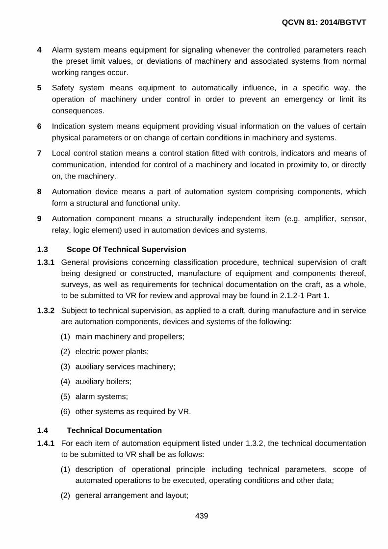
QCVN 81: 2014/BGTVT
439
4 Alarm system means equipment for signaling whenever the controlled parameters reach
the preset limit values, or deviations of machinery and associated systems from normal
working ranges occur.
5 Safety system means equipment to automatically influence, in a specific way, the
operation of machinery under control in order to prevent an emergency or limit its
consequences.
6 Indication system means equipment providing visual information on the values of certain
physical parameters or on change of certain conditions in machinery and systems.
7 Local control station means a control station fitted with controls, indicators and means of
communication, intended for control of a machinery and located in proximity to, or directly
on, the machinery.
8 Automation device means a part of automation system comprising components, which
form a structural and functional unity.
9 Automation component means a structurally independent item (e.g. amplifier, sensor,
relay, logic element) used in automation devices and systems.
1.3 Scope Of Technical Supervision
1.3.1 General provisions concerning classification procedure, technical supervision of craft
being designed or constructed, manufacture of equipment and components thereof,
surveys, as well as requirements for technical documentation on the craft, as a whole,
to be submitted to VR for review and approval may be found in 2.1.2-1 Part 1.
1.3.2 Subject to technical supervision, as applied to a craft, during manufacture and in service
are automation components, devices and systems of the following:
(1) main machinery and propellers;
(2) electric power plants;
(3) auxiliary services machinery;
(4) auxiliary boilers;
(5) alarm systems;
(6) other systems as required by VR.
1.4 Technical Documentation
1.4.1 For each item of automation equipment listed under 1.3.2, the technical documentation
to be submitted to VR shall be as follows:
(1) description of operational principle including technical parameters, scope of
automated operations to be executed, operating conditions and other data;
(2) general arrangement and layout;

QCVN 81: 2014/BGTVT
440
(3) schematic circuit and functional diagrams;
(4) specification with indication of the materials used and accessories, where all used
components and devices with their technical characteristics are shown;
(5) list of monitored parameters for the alarm and safety systems;
(6) test program;
(7) list of spare parts.
1.4.2 The technical documentation pertinent to automation, incorporated into the technical design documentation, shall be submitted to VR for review prior to craft construction, in the scope stipulated in Part 1.

QCVN 81: 2014/BGTVT
441
CHAPTER 2 DESIGN OF AUTOMATION EQUIPMENT
2.1 Automated Main Machinery
2.1.1 Automated main machinery shall be provided with:
(1) devices for remote automated control from the wheelhouse;
(2) visual alarm to indicate the availability of the main machinery for service;
(3) alarms to indicate malfunction in the control system and the limiting values of
monitored parameters;
(4) automatic safety devices activated when the monitored parameters fall beyond the
limits of the allowed parameters being of potential menace of accident, as well as
an alarm system to give warning signal at operation of safety devices;
(5) a device to transfer control of the main machinery from automatic to manual mode
from a local control station regardless of the position of handle at the remote control
station.
2.1.2 Hydraulic and pneumatic control systems shall be supplied from two sources. The
second source shall be connected automatically upon pressure loss with application of
an alarm signal.
2.1.3 Electric and electronic control systems shall be supplied from both the main and
emergency power sources. Power circuits for control systems shall be independent of
the power circuits for safety and alarm systems.
2.1.4 In installations with two or more engines driving one shaft, the safety system shall
provide for automatic shut-down of the faulty engine so that the rest keep the craft
running and maneuvering.
Protection system of main engines, except for over-speed protection, shall be
disconnectable, with the signal of disconnection being activated in the wheelhouse and at
the control stations of machinery space.
2.1.5 A device, independent of the control and alarm systems, shall be provided for
emergency shut-down of the main engine.
2.1.6 Failure of remote control system of the main machinery shall not cause an increase in
the craft speed, change in the propeller thrust direction, or inadvertent starting of the
main machinery, and also immediate stop of the engine from the remote control station
shall be made possible.

QCVN 81: 2014/BGTVT
442
2.1.7 If malfunctions occur in power system for the control systems, changeover from one
power supply source to another shall be effected manually from the control station, or
automatically depending on the system functionality.
2.1.8 In craft with main machinery having power of 220 kW and less, with attached auxiliaries,
the composition of the monitoring, alarm and protection means may be reduced.
2.1.9 For engines with power of 220 kW and less, use of the remote control systems may be
allowed.
2.1.10 For auxiliary machinery, which are required to operate under definite service conditions
only, provision may be made for control from the wheelhouse with application of alarm
signal and indication of starting thereof, if needed.
2.1.11 Pressure and temperature in essential systems of the machinery installation shall be
controlled automatically.
2.2 Automated Electric Power Plants
2.2.1 The automated electric power plants shall be provided with the control devices ensuring
remote starting of generator sets with automatic or remote synchronization, taking over
and load sharing.
2.2.2 In ships where electrical power is normally supplied by one generator, in case of its
failure and de-energization of the main switchboard, provision shall be made for the
following:
(1) automatic starting of stand-by diesel generator and its connection to busbars of the
main switchboard within 30 s;
(2) automatic connection, in the necessary sequence, of essential devices ensuring
propulsion, without any overloading of the electric power plant.
2.2.3 Indicators shall be provided at the electric power plant control stations to warn that the
generator sets are ready to start immediately (automatically).
2.2.4 Where the generator driven by the propulsion plant (shaft generator) and diesel
generator are not intended to operate in parallel, the system of connections shall be so
interlocked as to prevent their possible switching-on for parallel operation.
2.2.5 Monitored parameters of the automatic electric power plants (except emergency),
measuring points, limiting values of parameters and types of automatic protection and
parameter indication are given in Table 6/2.9.7.

QCVN 81: 2014/BGTVT
443
Table 6/2.9.7
Nos. Monitored parameter
Measuring point
Alarm for limiting
values of parameters
Automatic protection
Indication of parameters in wheelhouse
Comments
1 Main internal combustion engines
1.1 Lubricating oil pressure
At engine inlet Min. Engine
shut-down Continuous or
on call –
1.2 Lubricating oil temperature
At engine inlet Max. – Continuous or
on call –
1.3 Lubricating oil pressure drop
Filter Max. – Continuous or
on call –
1.4 Coolant pressure or flow
At engine outlet Min. Slow-down Continuous or
on call –
1.5 Coolant temperature
At engine outlet Max. Slow-down Continuous or
on call –
1.6 Coolant level Expansion tank Min. – – For
independent tank
1.7 Cooling sea water pressure or flow
Sea water cooling system
Min. – Continuous or
on call –
1.8 Exhaust gas temperature
Main pipe Max. – – –
1.9 Starting air pressure
Before starting valve
Min. – – –
1.10 Control air pressure
Engine control system
Min. – – –
1.11 Fuel oil level Daily service
tank Min. – – –
1.12 Fuel oil leakage From high-
pressure piping Presence of
fuel oil
–
–
–
1.13 Engine speed – Max. Engine
shut-down Continuous or
on call –
1.14
Power supply to remote automated control, alarm and safety systems
At inlet of systems
Failure of power supply
– – –
1.15 Oil pressure in CP-propeller hydraulic system
At filter outlet Min. – Continuous or
on call –
1.16 CP-propeller hydraulic oil level
Header tank Min. – – –
2 Reduction gear
2.1 Lubricating oil pressure
At reduction gear inlet
Min. Engine
shut-down – –
2.2 Lubricating oil temperature
In reduction gear
Max. – – –
3 Internal combustion engines for driving generators

QCVN 81: 2014/BGTVT
444
Nos. Monitored parameter
Measuring point
Alarm for limiting
values of parameters
Automatic protection
Indication of parameters in wheelhouse
Comments
3.1 Lubricating oil pressure
At engine inlet Min. Engine
shut-down – –
3.2 Coolant pressure or flow
At engine inlet Min. – – –
3.3 Coolant temperature
At engine outlet Max. – – –
3.4 Engine speed Limiting governor
Max. Engine
shut-down – –
4 Electric installation
4.1 Voltage Main
switchboard
Min.,
Max. – – –
4.2 Insulation resistance
Main switchboard
Min. – – –
5 Starting compressors
5.1 Air temperature At compressor
outlet Max.
Compressor shut-down
– –
6 Tanks
6.1 Leakage fuel oil level
Leakage fuel oil tank
Max. – – –
6.2 Fuel oil level Daily service
tanks Min. – – –
6.3 Domestic waste and sewage water level
Tanks Max. – – –
7 Bilge plants
7.1 Emergency water level
Bilge wells Max. – –
Alarm signalis
activatedin wheelhouse
8 Miscellaneous
8.1 Safety system of boiler plant
Failure Failure Boiler shut-
down – –
8.2 Alarm system Failure Failure – – –
8.3 Protection system Failure Failure – – –
2.3 Automated Boiler Plants
2.3.1 The requirements of the present Chapter cover boiler plants with oil-burning
installations.
2.3.2 Steam boilers shall be provided with automatic feed water and steam pressure
governors.

QCVN 81: 2014/BGTVT
445
2.3.3 Provision shall be made for a remote shut-down of the boiler plants from the control
station where continuous watch is kept.
2.3.4 As far, as the oil-burning installations are concerned, the oil supply to the burners shall
be cut off automatically in the following cases:
(1) absence of flame for not more than 5 s from the moment the oil supply begins;
(2) egradation of parameters of air intended for fuel oil atomization;
(3) insufficient pre-ventilation of the burner furnace.
2.3.5 Starting of boiler plants from cold condition and after being shut down by protection
system shall be possible from the local control station only.
2.3.6 Automation system of exhaust gas water heating boilers operating under pressure shall
provide for automatic changeover of the device which regulates direction of exhaust gas
flow through the boiler or directly into the atmosphere, depending on temperature in the
boiler.
2.4 Automated Bilge Plants of Machinery Spaces
2.4.1 Depending on the water level in wells, the automated bilge plants shall put automatically
the relevant bilge pumps in operation. Alarm to indicate pump operation shall be
provided.
If, after the bilge pumps have been started, the water level in the bilge wells goes on rising
or does not fall, an alarm shall be activated.
2.4.2 A separate sensor shall be provided to signal of the highest possible level, which would
be independent of the sensors provided to control the bilge pumps.
2.5 Automated Compressor Plants
2.5.1 Starting air receivers, tyfon, as well as the amount of air to feed automation systems
shall be replenished automatically.
For automated compressors, provision shall be also made for starting and stopping thereof
from the wheelhouse.
2.5.2 Compressed air system shall be fitted up with automatic drainage devices.
2.5.3 Air compressors shall be automatically started when the pressure in air receivers
drops by not more than 30 per cent of the nominal pressure, and shut down when
the pressure reaches 97 to 103 per cent of the nominal one.
2.6 Automated Pumping Units
2.6.1 Automated pump control system shall ensure automatic starting of standby pumps and
changeover, as necessary, in systems, in case of pump failure or upon reaching the
highest permissible deviations of parameters in essential circulation systems. Along with
that, the alarm system shall actuate signal to warn of faulty pump and of standby pump
starting.
2.6.2 The starting circuit of pumps having equal output shall make it possible to use each of
them as the main one.

QCVN 81: 2014/BGTVT
446
2.7 Equipment Arrangement in Wheelhouse
2.7.1 Facilities shall be provided to effect remote control of main and auxiliary machinery and
propellers.
2.7.2 Provision shall be made for independent emergency stop of main engine from the
wheelhouse.
2.7.3 Alarm system shall be provided to warn of troubles to machinery and plants in
machinery space. Provision shall be made for indicating means to show speed and
direction of propeller rotation, as well as the pitch of CPP.
2.7.4 Provision shall be made for indicating means to show engagement/disengagement
position of the coupling of the main machinery.
2.7.5 In the wheelhouse, provision shall be made for the following separate alarms:
“Water in machinery space”•, “Fire in machinery space”•, “Alarm system failure”.
2.7.6 Control, indication and alarm devices in the wheelhouse shall be located on desks
adapted for manipulation by one person.
The visual indicators shall be arranged in such a way as to prevent dazzling of the
personnel and to be clearly seen in day-time.
Provision shall be made for dimming of the indicating system lamps.
2.7.7 In boats with open machinery space, open navigating bridge, with main machinery of
total power less than 220 kW and outboard engines, the scope and list of the
automation system facilities may be reduced, subject to agreement with VR.
2.8 Equipment Arrangement In Machinery Spaces
2.8.1 Local control station of the main machinery shall be provided.
2.8.2 Provision shall be made for a panel for alarms and indicators of parameters, arranged in
the vicinity of the control station of the main machinery.
2.8.3 The controls of auxiliarities shall be installed in close proximity to the local control
station of the main machinery.
2.8.4 For the main engines with power less than 220 kW, with mechanical remote control
system, the local control stations and alarm panels may be dispensed with.
2.9 Alarm, Protection and Indication Systems of Machinery Installation
2.9.1 The alarm system of the machinery installation shall give visual and audible signals if
operating parameters fall beyond the allowable limits. In this case, the alarm signal shall
not be activated when allowable deviations of the operating parameters are caused by
maneuvering. Alarm shall be activated in the engine room and in wheel-house.
2.9.2 Irrespective of the extent of automation and the monitoring order used for the
machinery, the alarm system shall give visual and audible warning signals at:
(1) monitored parameters reaching predetermined limit values;

QCVN 81: 2014/BGTVT
447
(2) operation of protection devices;
(3) power failure of particular automation systems;
(4) starting of emergency power sources.
The visual signals shall be given as flashing lights. After being accepted (acknowledged)
the flashing light shall change to steady light. Canceling of a visual signal shall be only
possible after the fault has been cleared.
2.9.3 In the crew‟s accommodation and service spaces, the engineer‟s alarm shall be
activated for the call of the engineers to machinery space, which is activated manually,
or automatically where an alarm system has not been acknowledged.
2.9.4 For machinery installations with main engines having power less than 220 kW, outboard
engines and mechanical remote control system the range of alarm signals may be
reduced, subject to agreement with VR.
2.9.5 The protection systems of automated machinery shall be provided for those parameters
only the deviations of which can lead to serious damage, complete failure of the
machinery.
2.9.6 The indication system shall be so designed that the readings are displayed in units
normally used for parameters, i.e. without recalculation.
2.9.7 Monitored parameters of machinery and systems, measuring points, limiting values of
parameters and types of automatic protection and parameter indication shall be found in
Table 2.9.7.
2.9.8 The Owner‟s Manual shall contain information on limiting values of parameters and
types of protection and parameter indication.

QCVN 81: 2014/BGTVT
448
PART 7 ELECTRICAL EQUIPMENT
CHAPTER 1 GENERAL
1.1 General
1.1.1 Application
The requirements in this Part apply to the electrical equipment and wirings for pleasure
yachts (hereinafter referred to as the "electrical equipment").
1.1.2 Equivalency
Electrical installations which do not fully comply with the requirements of this Part may be
accepted, provided that there are justifiable reasons and that the electrical installations are
deemed by VR to be equivalent to those specified in this Part.
1.1.3 Terminology
The terminologies used in this Part are defined in Chapter 1 and in 1.1.5 Part 4 Section II
of QCVN 21: 2010/BGTVT. In addition, for the purpose of this Part, the followings have
been adopted:
(1) Wind-powered generator is a generator driven by the non-reversible machinery using
a wind power and supplying one or several accumulator batteries in flotage.
(2) Solar battery is a special assembly of crystals, which converts luminous energy to
electrical power and supplies one or several accumulator batteries in flotage.
(3) Lightning protection zone is the area, within the limits of which the craft‟s space is
substantially immune to direct strokes of lightning.
1.1.4 Technical documentation
Technical documentation specified in 2.1.2-1(6) Chapter 2, Part 1 Section II shall be
submitted for approval.
1.1.5 Ambient Conditions
The ambient conditions shall be in compliance with 1.1.7 Part 4 Section II of QCVN 21:
2010/BGTVT.
1.2 Testing
1.2.1 Shop Tests
1 Electrical equipment specified below shall be tested in accordance with the respective
requirements in this Part at the manufacturer's works or at other works having the
adequate apparatus for testing and inspections.
(1) Rotating machines for propulsion and their control equipment;

QCVN 81: 2014/BGTVT
449
(2) Ship service generators having output of 50 kVA and above;
(3) Switchboards having input power of 50 kVA and above;
(4) Electrical motors having power of 5 kW or greater for essential auxiliary machinery
servicing the operation of main propulsion system and ship‟s safety, including their
control gears;
(5) Transformers rated at 30 kVA or more for single phase and at 50 kVA or more for
three-phase;
(6) Power semi-conductor rectifiers of not less than 50 kW and their accessories used for
supplying power to electrical equipment specified in (1) to (4);
(7) Other electrical equipment as deemed necessary by VR.
2 For the electrical equipment manufactured by mass production, test procedures suited to
their production methods, despite of the requirements in -1, may be applied subject to the
approval of VR.
3 All cables for power, lighting and internal communications shall be subjected to type tests
for each type of products.
4 Electrical equipment and cables having a certificate considered acceptable to VR may be
exempted partially or wholly from the tests and inspections.
1.2.2 Trials
After the electrical equipment and cables have been installed on board the ship, they shall
be tested and inspected in accordance with the requirements in 2.10.
1.2.3 Additional tests and inspections
VR may require, when it deems necessary, other tests and inspections than those
specified in this Part.

QCVN 81: 2014/BGTVT
450
CHAPTER 2 ELECTRICAL EQUIPMENT AND SYSTEM DESIGN
2.1 General
2.1.1 Application
This Chapter specifies the requirements for electrical equipment and cables and system
design relating to electricity.
2.1.2 Voltage and frequency
1 System voltage is not to exceed:
(1) 1,000 V for generators, power equipment, and heating and cooking equipment
connected to fixed wiring;
(2) 250 V for lighting, heaters in cabins and public rooms, equipment other than those
specified in (1);
(3) If higher voltage is used, requirements in 2.17 Part 4 Section II of QCVN 21:
2010/BGTVT shall be complied with.
2 A frequency of 60 Hz or 50 Hz is recognized as a standard for all alternating current
systems.
3 Electrical equipment supplied from the main and emergency switchboards shall be designed
and manufactured that it is capable of operating satisfactorily under the normally occurring
voltage and frequency fluctuations. Unless otherwise specified, electrical equipment shall
operate satisfactorily under the fluctuations in voltage and frequency as given in Table 7/2.1.
Any special system, e.g. electronic circuits, whose function cannot operate satisfactorily within
the limits given in the Table shall be supplied by suitable means, i.e. through some stabilized
supply. Table 7/2.1 shall not apply to equipment of electrical system which utilizes battery
accumulators.
4 In cases where a.c. generators are driven at rated speeds, giving rated voltages and rated
symmetrical loads, the Total Harmonic Distortion (THD) of distribution systems connected
such generators is not to exceed values of 5%. However, for cases that specified in (1) and
(2) as below, the Total Harmonic Distortion (THD) may exceed values of 5%.
(1) In supply systems connected with semiconductor converters where the safe operation
of other electric devices connected to such supply systems is maintained by the
adoption of suitable methods for decreasing harmonic content effects and Total
Harmonic Distortion (THD) values do not exceed 8%.
(2) In electric propulsion ships, where the supply systems connected with propulsion
semiconductor converters are closed circuits independent from other internal supply
systems, and Total Harmonic Distortion (THD) values do not exceed 10%.

QCVN 81: 2014/BGTVT
451
Table 7/2.1 Voltage and frequency fluctuations
Type of fluctuation Fluctuation
Permanent Transient
Voltage +6%; - 10% ±20% (within 1.5 sec.)
Frequency ±5% ±10% (within 5 sec.)
Notes: Numerical values excluding time in the Table mean percentage for the rated values.
2.1.3 Construction, materials, installations
1 Electric machinery parts subject to mechanical strength shall be of defect-free sound
material. Their proper fits and clearances shall be consistent with the best marine practice
and experience.
2 All electrical equipment shall be so constructed and installed as not to cause injury when
handled and touched in the normal manner.
3 Insulating materials and insulated windings shall be resistant to moisture, sea air and oil
vapour.
4 Bolts, nuts, pins, screws, terminals, studs, springs and such other small parts shall be
made of corrosion resistant material or to be suitably protected against corrosion.
5 All nuts and screws used in connection with current-carrying parts and working parts shall
be effectively locked.
6 Electrical equipment shall be accessibly placed in well-ventilated and adequately lighted
spaces where it is not exposed to risk of mechanical injury or damage arising from water,
steam or oil. The degree of protection of electrical equipment shall comply with the
installation location as specified in Table 7/2.2.
7 No electrical installation shall be installed in spaces where explosive gases are liable to
accumulate or in compartments assigned principally to accumulator batteries, in paint
lockers, in acetylene stores or in similar spaces unless the following requirements (1) to (4)
are satisfied:
(1) Electrical equipment essential for operational purposes;
(2) Electrical equipment of a type which will not ignite the mixtures concerned;
(3) Electrical equipment appropriate to the spaces concerned;
(4) Electrical equipment which is appropriately certified for safe usage in dusts vapours or
gases likely to be encountered.
8 Electrical equipment and cables shall be placed at such a safe distance from the magnetic
compasses or shall be so screened that the interfering external magnetic field is controlled
to negligible extent even when circuits are switched on and off.
9 Electrical appliances shall not be attached directly to the walls of fuel tanks. The distance
from these appliances to the walls of tanks shall be not less than 75 mm.

QCVN 81: 2014/BGTVT
452
Table 7/2 .2 Application of degree of protection
Nos. Area of installation Conditions in area of
installation Degree of protection
1 Dangerous areas and spaces
In which explosive mixtures of vapours, gases and dust with air are likely to occur
Ex
2 Ac Accommodation and general use spaces, as well as corridors having no direct exit to exposed deck
Dry IP20
3 Spaces having direct exit to exposed deck, machinery spaces
With increased humidity IP23
4 Galleys, showers, lavatories, toilets, accumulator rooms and lockers, ventilating trunks leading to exposed deck, etc.
Water splash IP44
5 Exposed decks Water flooding IP56
Notes:
Where the enclosure of equipment does not guarantee the necessary protection, alternative methods of protection or alternative arrangement of equipment shall be applied to ensure the degree of protection stipulated by the Table.
2.1.4 Earthing
1 Non-current-carrying exposed metal parts of electrical equipment which are not intended
to be live but which are liable under fault conditions to become live shall be effectively
earthed except the following:
(1) They are supplied at a voltage not exceeding 50 V D.C. or 50 V A.C. root mean
square between conductors. However, auto-transformers are not to be used for the
purpose of achieving this voltage;
(2) They are supplied at a voltage not exceeding 250 V by safety isolating transformers
supplying only one consuming device;
(3) They are constructed in accordance with the principle of double isolation.
2 Additional safety means shall be provided for portable electrical apparatus for use in
confined or exceptionally damp spaces where particular risks due to conductivity may
exist.
3 Where earthing connections are necessary, the earthing conductors shall be of copper or
other approved materials, and shall be properly protected against damage, and, where
necessary, erosion. Nominal cross-sectional areas of all copper earthing conductors shall
be given in Table 7/2.3.

QCVN 81: 2014/BGTVT
453
Table 7/2.3 Sizes of Earthing Conductors
Cross-sectional areas of current-carrying conductors, (mm2)
Minimum cross-sectional areas of copper earthing conductors, (mm2)
fixed flexible
0.5 to 4 4 2.5
4 to 16 1/2 cross-sectional area of current-carrying conductors,
(mm2)
16 to 35 16 16
35 to 120 1/2 cross-sectional area of current-carrying conductors,
(mm2)
> 120 70
4 In case where aluminum superstructures are secured to the steel hull of the craft including
insulation to prevent galvanic corrosion between these materials, a separate bonding
connection shall be provided between the superstructure and the hull which shall be made
in such a manner that galvanic corrosion is avoided and points of connection may be
readily inspected.
5 For ships whose main structure is made of nonmetallic materials the following additional
requirements in (1) to (5) are also to be met:
(1) All metal parts of the craft shall be earthed to the sea water, in so far as possible in
consideration of galvanic corrosion between dissimilar metals. The earthing of isolated
components inside the structure is not generally necessary, except in fuel tanks;
(2) Each pressure refueling point shall be provided with a means of earthing the fuelling
equipment to the ship;
(3) Metallic pipes capable of generating electrostatic discharges, due to the flow of liquids
and gases shall be bonded so as to be electrically continuous throughout their length
and shall be adequately earthed;
(4) Secondary conductors provided for the equalization of static discharges, bonding of
equipment, etc. shall have a minimum cross section of 5 mm2 in copper or equivalent
surge carrying capacity in aluminum;
(5) The electrical resistance between bonded objects and the basic structure is not to
exceed 0.05. The bonding path shall have sufficient cross-sectional area to carry the
maximum current likely to be imposed on it without excessive voltage drop.
2.2 Lightning Protection
2.2.1 General
1 Craft of design categories A, A1, A2, B, C or C1 shall be provided with lightning-protection
system with protected zones covering all the equipment that requires lightning protection.
It is recommended that the lightning-protection systems be provided also in craft of design
categories C2 and C3.

QCVN 81: 2014/BGTVT
454
In craft, where the consequential effects of lightning strokes may cause a fire or explosion,
lightning earthing devices shall be provided to preclude consequential sparking.
2 The lightning – protection system shall consist of an air terminal, down conductor and
earth bond. No special lightning-protection device need be fitted on metal masts if
provision is made for reliable electrical connection of the mast to the metal craft‟s hull or to
earthing point.
2.2.2 Air termination network
1 In metal craft, the craft‟s vertical structures: masts, derrick posts, superstructures, etc. may
be used as air terminations if provision is made for reliable electrical connection of those
structures to the metal craft‟s hull.
Additional air terminations shall be used only when the craft‟s structural members do not
provide for reliable lightning protection.
2 If electrical equipment is installed on the top of a metal mast, provision shall be made for
an air terminal effectively earthed.
3 On each mast or top mast made of non-conducting material, an effectively earthed
lightning-protection device shall be provided.
4 The air termination shall be made of a rod having a cross-sectional area not less than 12
mm2. The rod may be of copper, copper alloys or steel protected against corrosion.
Aluminium air terminations shall be used for aluminium masts.
5 The air termination shall be fitted to the mast in such a manner that it projects at least 300
mm above the top of the mast or above any device fitted on its top.
6 A lightning-protective mast shall be of a height to provide the desired zone of protection in
accordance with 2.2.2-6(1), 2.2.2-6(2), 2.2.2-6(3) respectively.
(1) For a mast height not exceeding 15 m above the water, the base radius shall be
approximately equal to the mast height h (see Fig. 7/2.1 (1) and 7/2.1(2)).
(2) For mast heights over 15 m, the zone of protection is based on the striking distance of
the lightning stroke.
Since the lightning stroke may strike any earthed object within the striking distance of
the point from which final breakdown to earth occurs, the zone of protection is defined
by a circular arc (see Fig. 7/2.2).
(3) The protection zone afforded by any configuration of masts or other elevated,
conductive and earthed objects can be determined graphically. Increasing the height
of a mast above the striking distance will not increase the protection zone.
The radius of the arc is the striking distance (30 m). The arc passes through the top of
the mast and is tangent to the water. If more than one mast is used, the zone of
protection is defined by arcs to all masts.

QCVN 81: 2014/BGTVT
455
Fig. 7/2.1(1) Sailing craft with a mast not exceeding 15 m above water
Fig. 7/2.1(2) Non-sailing craft with a mast not exceeding 15 m above water
Protective zone of lightning-protective mast
Protection zone with an antenna installed on lightning-protective mast

QCVN 81: 2014/BGTVT
456
Fig. 7/2.2 Craft with mast(s) in excess of 15 m above water
2.2.3 Down conductor
1 The down conductor shall be made of a rod, strip or multiwire cable having a cross-
sectional area not less than 100 mm2.
2 Down conductors shall run on the outer side of masts and superstructures with a minimum
number of bends, which shall be gradual and have as large radius as possible.
3 Down conductors shall not run through dangerous spaces and zones.
4 In craft with non-metal hull, the down conductor of the lightning-protection system shall be
laid separately throughout its length (including connection to the earth termination
network), without connecting to the busbars of the protective and operation earthing
circuits.
2.2.4 Earth termination network
1 In composite craft, the metal stem or other metal structures immersed in water under any
navigation conditions may be used as the craft‟s earth.
2 Means shall be provided on board the craft to allow for connecting the lightning-protection
system or craft‟s steel hull to the shore-based earth network while the craft is in a dock or
on a slipway.
3 In craft with non-conducting hull, means shall be provided to allow for connecting the
lightning-protection system to the shore-based earth network while the craft is in a dock or
on a slipway.
4 Multihull craft shall provide a lightning earth for each hull.
2.2.5 Connections in lightning-protection system
1 Connections between the air terminations, down conductor and earth termination network
shall be welded or bolted with clamps.
Protection zone inside area outlined by dashed lines
Mast in excess of 15 m above water
R - 30m
R - 30m
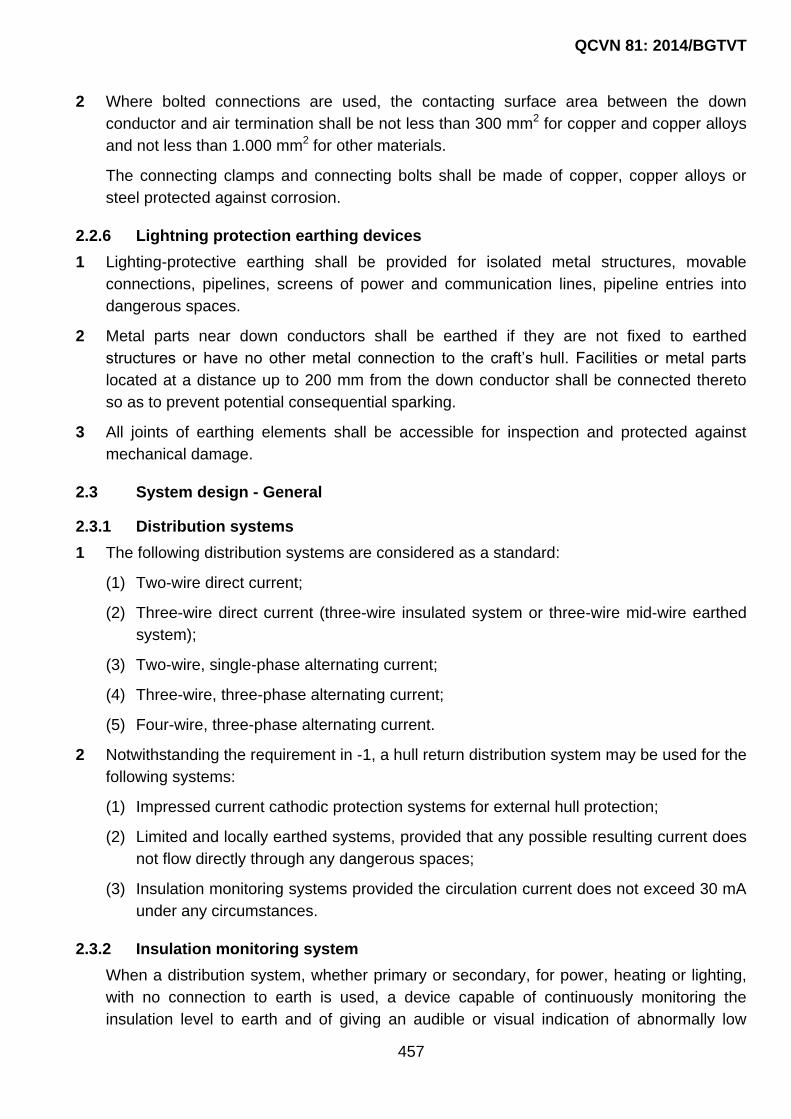
QCVN 81: 2014/BGTVT
457
2 Where bolted connections are used, the contacting surface area between the down
conductor and air termination shall be not less than 300 mm2 for copper and copper alloys
and not less than 1.000 mm2 for other materials.
The connecting clamps and connecting bolts shall be made of copper, copper alloys or
steel protected against corrosion.
2.2.6 Lightning protection earthing devices
1 Lighting-protective earthing shall be provided for isolated metal structures, movable
connections, pipelines, screens of power and communication lines, pipeline entries into
dangerous spaces.
2 Metal parts near down conductors shall be earthed if they are not fixed to earthed
structures or have no other metal connection to the craft‟s hull. Facilities or metal parts
located at a distance up to 200 mm from the down conductor shall be connected thereto
so as to prevent potential consequential sparking.
3 All joints of earthing elements shall be accessible for inspection and protected against
mechanical damage.
2.3 System design - General
2.3.1 Distribution systems
1 The following distribution systems are considered as a standard:
(1) Two-wire direct current;
(2) Three-wire direct current (three-wire insulated system or three-wire mid-wire earthed
system);
(3) Two-wire, single-phase alternating current;
(4) Three-wire, three-phase alternating current;
(5) Four-wire, three-phase alternating current.
2 Notwithstanding the requirement in -1, a hull return distribution system may be used for the
following systems:
(1) Impressed current cathodic protection systems for external hull protection;
(2) Limited and locally earthed systems, provided that any possible resulting current does
not flow directly through any dangerous spaces;
(3) Insulation monitoring systems provided the circulation current does not exceed 30 mA
under any circumstances.
2.3.2 Insulation monitoring system
When a distribution system, whether primary or secondary, for power, heating or lighting,
with no connection to earth is used, a device capable of continuously monitoring the
insulation level to earth and of giving an audible or visual indication of abnormally low

QCVN 81: 2014/BGTVT
458
insulation values shall be provided. For ships of small gross tonnage, earth indicating
systems may be used in lieu of insulation monitoring system.
2.3.3 Unbalance of loads
1 Unbalance of loads between an outer conductor and the middle wire at the switchboards,
section boards and distribution boards is not to exceed 15% of the full load current as far
as possible.
2 Unbalance of loads on each phase at the switchboards, section boards and distribution
boards is not to exceed 15% of the full load current as far as possible.
2.3.4 Diversity factor
1 Circuits supplying two or more final-subcircuits shall be rated in accordance with the total
connected load subject, where justifiable, to the application of a diversity factor.
2 The diversity factor specified in -1 may be applied to the calculation of the cross sectional
area of conductors and ratings of switchgears (including circuit breakers and switches) and
fuses.
2.3.5 Feeder circuits
1 Motors for essential services requiring dual arrangement shall be supplied by individual
circuits without the use of common feeders, protective devices and controlgears.
2 Auxiliaries in the machinery spaces, cargo gears and ventilating fans shall be
independently supplied from switchboards or distribution boards.
3 Ventilating fans for the cargo holds and those for the accommodation spaces are not to be
supplied from the common feeder circuits.
4 Lighting circuits and motor circuits shall be arranged to be supplied independently from the
switchboards.
5 A final sub-circuit of rating exceeding 15 A is not to supply more than one appliance.
2.3.6 Motor circuits
A separate final sub-circuit shall be provided, as a rule, for every motor for essential
service and for every motor of rating at 1 kW or more.
2.3.7 Lighting circuits
1 Lighting circuits shall be supplied by final sub-circuits separate from those for heating and
power except cabin fans and electrical appliances for domestic use.
2 The number of lighting points supplied by a final sub-circuit of rating 15 A or less is not to
exceed:
- 10 for the circuits up to 50 V;
- 14 for the circuits from 51 V up to 130 V;
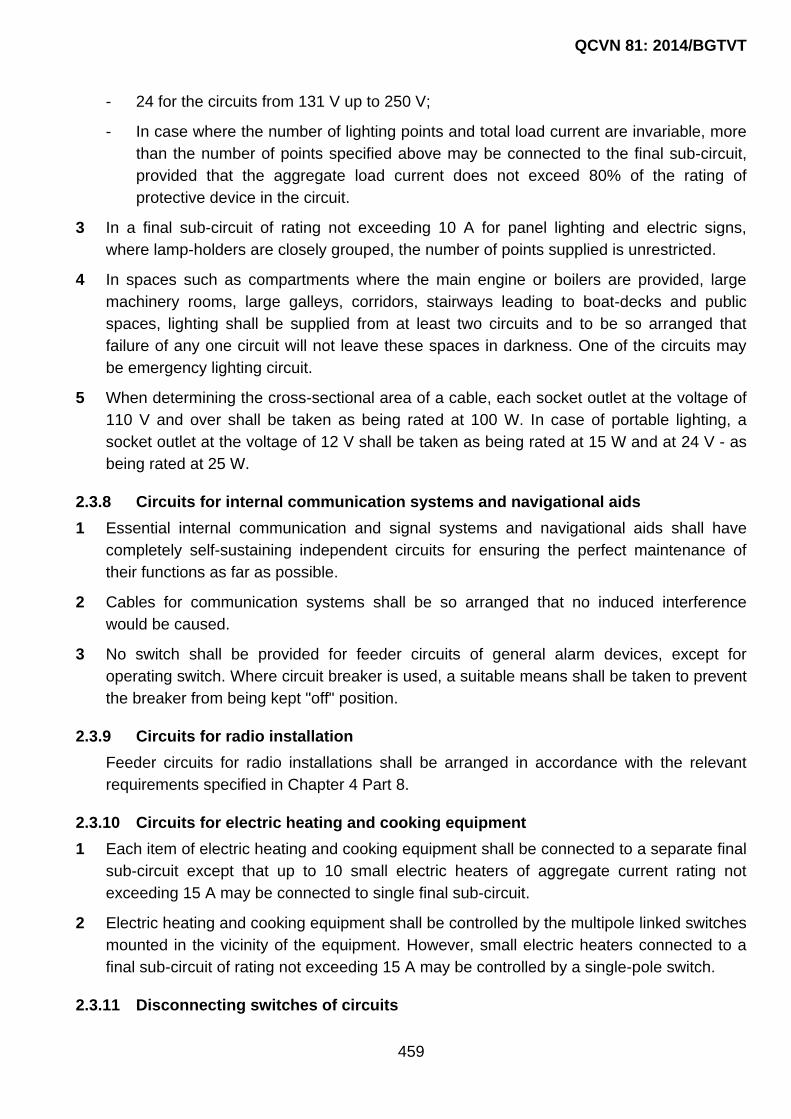
QCVN 81: 2014/BGTVT
459
- 24 for the circuits from 131 V up to 250 V;
- In case where the number of lighting points and total load current are invariable, more
than the number of points specified above may be connected to the final sub-circuit,
provided that the aggregate load current does not exceed 80% of the rating of
protective device in the circuit.
3 In a final sub-circuit of rating not exceeding 10 A for panel lighting and electric signs,
where lamp-holders are closely grouped, the number of points supplied is unrestricted.
4 In spaces such as compartments where the main engine or boilers are provided, large
machinery rooms, large galleys, corridors, stairways leading to boat-decks and public
spaces, lighting shall be supplied from at least two circuits and to be so arranged that
failure of any one circuit will not leave these spaces in darkness. One of the circuits may
be emergency lighting circuit.
5 When determining the cross-sectional area of a cable, each socket outlet at the voltage of
110 V and over shall be taken as being rated at 100 W. In case of portable lighting, a
socket outlet at the voltage of 12 V shall be taken as being rated at 15 W and at 24 V - as
being rated at 25 W.
2.3.8 Circuits for internal communication systems and navigational aids
1 Essential internal communication and signal systems and navigational aids shall have
completely self-sustaining independent circuits for ensuring the perfect maintenance of
their functions as far as possible.
2 Cables for communication systems shall be so arranged that no induced interference
would be caused.
3 No switch shall be provided for feeder circuits of general alarm devices, except for
operating switch. Where circuit breaker is used, a suitable means shall be taken to prevent
the breaker from being kept "off" position.
2.3.9 Circuits for radio installation
Feeder circuits for radio installations shall be arranged in accordance with the relevant
requirements specified in Chapter 4 Part 8.
2.3.10 Circuits for electric heating and cooking equipment
1 Each item of electric heating and cooking equipment shall be connected to a separate final
sub-circuit except that up to 10 small electric heaters of aggregate current rating not
exceeding 15 A may be connected to single final sub-circuit.
2 Electric heating and cooking equipment shall be controlled by the multipole linked switches
mounted in the vicinity of the equipment. However, small electric heaters connected to a
final sub-circuit of rating not exceeding 15 A may be controlled by a single-pole switch.
2.3.11 Disconnecting switches of circuits

QCVN 81: 2014/BGTVT
460
1 Power circuits and lighting circuits terminating in the cargo holds or coal bunkers shall be
provided with the multipole linked switches situated outside these spaces. Provision shall
be made for locking in the "off" position of the switches or switch boxes for these lighting
circuits.
2 Feeder circuits for the electrical equipment installed in hazardous areas shall be provided
with multipole linked isolation switches in a non-hazardous area. In addition, the isolation
switches shall be clearly labelled to identify the electrical equipment to be connected with.
2.4 System design- protection
2.4.1 General
Electrical installations of ships shall be protected against accidental overcurrents including
short-circuit. The protective devices shall be capable of continuously serving other circuits
as far as possible by breaking a fault circuit and eliminating damage to the system and
hazard of fire.
2.4.2 Protection against overload
1 The overcurrent trip characteristics of circuit-breakers and the fusing characteristics of
fuses shall be chosen suitably taking into consideration the thermal capacity of electrical
equipment and cables to be protected thereby. Fuses above 200 A are not to be used for
overload protection.
2 The ratings or appropriate setting of the overload protection device for each circuit shall be
permanently indicated at the location of the protection device, and the current-carrying
capacity of each circuit shall be indicated.
3 The overload relays of circuit-breakers for generators and overload protections, except
moulded-case circuit breakers, shall be capable of adjusting their current setting and time-
delay characteristics.
2.4.3 Protection against short-circuit
1 The breaking capacity of every protective device shall be not less than the maximum value
of the short circuit current which can flow at the point of installation at the instant of
constant separation.
2 The making capacity of every circuit-breaker or switch intended to be capable of being
closed, if necessary, on short-circuit, is not to be less than the maximum value of the
short-circuit current at the point of installation. On alternating current this maximum value
corresponds to the peak value allowing for maximum asymmetry.
3 In case where the rated breaking capacity and/or rated making capacity of short-circuit
protection are(is) not in compliance with the requirements in -1 and -2, fuses or circuit-
breakers having the breaking capacity not less than the prospective short-circuit current
shall be provided at the power source side of the foregoing short-circuit protection. Circuit-
breakers for the generator are not to be used for this purpose. The circuit-breakers

QCVN 81: 2014/BGTVT
461
connected to the load side are not to be excessively damaged and shall be capable of
further service in the following cases:
(1) When the short-circuit current is broken by the back-up circuit-breaker or fuse.
(2) When the circuit-breaker connected to the load side is closed on the short-circuit
current while the back-up circuit-breaker or fuse breaks the current.
2.4.4 Protection of circuits
1 Each pole and phase of all insulated circuits except neutral and equalizer circuits shall be
provided with short-circuit protection.
2 All circuits liable to be overloaded shall be provided with overload protection as indicated
below:
(1) Two-wire D.C. or single-phase A.C. system: at least one line or phase;
(2) Three-wire D.C. system: both outer lines;
(3) Three-phase, three-wire system: at least two phases;
(4) Three-phase, four-wire system: each phase.
3 A fuse, a non-linked switch or a non-linked circuit-breaker is not to be inserted in an
earthed conductor and a neutral line.
2.4.5 Protection of generators
1 Generators shall be protected against short-circuit and overcurrent by a multipole circuit-
breaker arranged to open simultaneously all insulated poles, or in the case of generators
less than 20 kW not arranged to run in parallel, may be protected by a multipole-linked
switch with fuse or a circuit-breaker in each insulated pole. The overload protection shall
be suitable to the thermal capacity of generators.
2 For D.C. generators arranged to operate in parallel, in addition to the requirement in -1, an
instantaneous reverse-current protection, operating at a fixed value of reverse-current
within the limits of 2% to 15% of the rated current of the generator, shall be provided. This
requirement, however, does not apply to the reverse-current generated from load side, e.g.
cargo winch motors, etc.
3 For A.C. generators arranged to operate in parallel, in addition to the requirement in -1, a
reverse-power protection, with time delay, selected and set within the limits of 2% to 15%
of the full load to a value fixed in accordance with the characteristics of the prime mover,
shall be provided.
2.4.6 Load shedding
To protect the main generators against overload, means shall be provided to disconnect
non-essential loads automatically. In this case, the means may be consisted of two or
more stage tripping.

QCVN 81: 2014/BGTVT
462
2.4.7 Protection of feeder circuits
1 Supply circuits to section boards, distribution boards, grouped starters and the similar shall
be protected against overload and short-circuit by multi-pole circuit-breakers or fuses. In
case where the fuses are used, a switch shall be provided at the power source side of the
fuses.
2 Each insulated pole of the final sub-circuits shall be protected against short-circuit and
overload by a circuit-breaker or fuse. In case where fuses are used, a switch shall be
provided at the power source side of the fuses. And for the protection of supply circuits of
the steering gears, the requirements in 15.2.7 Part 3 Section II of QCVN 21: 2010/BGTVT
shall apply.
3 Circuits which supply motors fitted with overload protection may be provided with short-
circuit protection only.
4 In case where fuses are used to protect three-phase A.C. motor circuits, consideration
shall be given to protection against single phasing.
5 In case where condensers for phase advance are used, overvoltage protective devices
shall be installed as required.
2.4.8 Protection of power and lighting transformers
1 The primary circuits of power and lighting transformers shall be protected against short-
circuit and overcurrent by multipole circuit-breakers or fuses.
2 When transformers are arranged to operate in parallel, a means of isolation shall be
provided on the secondary circuits.
2.4.9 Protection of electric motors
1 Motors of rating exceeding 0.5 kW and all motors for essential services, except the motors
for steering gears, shall be protected individually against overload. The overload protection
for motors for the steering gears shall comply with the requirements in 15.2.7 Part 3
Section II of QCVN 21: 2010/BGTVT.
2 The protective devices shall have delay characteristics to enable the motor to start.
3 For motors for intermittent services, the current setting and the delay shall be chosen in
relation to the load factor of the motor.
2.4.10 Protection of lighting
Lighting circuits shall be protected against short-circuit and overload.
2.4.11 Protection of meters, pilot lamps and control circuits
1 Protection shall be provided for voltmeters, voltage coils of measuring instruments, earth
indicating devices and pilot lamps together with their connecting leads by means of fuses
fitted to each insulating pole. A pilot lamp installed as an integral part of another item of

QCVN 81: 2014/BGTVT
463
equipment need not be individually protected, provided that any damage of pilot lamp
circuit does not cause failures on the supply to essential equipment.
2 Insulated wires for control and instrument circuits directly led from busbars and generator
mains shall be protected by fuses at the nearest location to the connecting points.
Insulated wires between the fuses and the connecting points are not to be bunched
together with the wires for other circuits.
3 Fuses in circuits such as those of automatic voltage regulators where loss of voltage might
have serious consequences may be omitted. If omitted, a proper means shall be provided
to prevent risk of fire in the unprotected part of the installation.
2.4.12 Protection of batteries
Accumulator batteries other than engine starting batteries shall be protected against
overload and short-circuit with devices placed as near as practicable to the batteries.
Emergency batteries supplying essential services may have short-circuit protection only.
2.5 Electrical equipment and cable - General
2.5.1 Rotating machines
Rotating machines shall be in compliance with requirements in 2.4 Part 4 Section II of
QCVN 21: 2010/BGTVT.
2.5.2 Transformers for power and lighting
Transformers for power and lighting shall be in compliance with requirements in 2.10 Part
4 Section II QCVN 21: 2010/BGTVT.
2.5.3 Circuit-breakers
Circuit-breakers shall be in compliance with requirements in 2.6.1 Part 4 Section II of
QCVN 21: 2010/BGTVT.
2.5.4 Fuses
Fuses shall be in compliance with requirements in 2.6.2 Part 4 Section II of QCVN 21:
2010/BGTVT.
2.5.5 Electromagnetic contactors
Electromagnetic contactors shall be in compliance with requirements in 2.6.3 Part 4
Section II of QCVN 21: 2010/BGTVT.
2.5.6 Semiconductor Converters for Power
Semiconductor converters for power shall be in compliance with requirements in 2.12 Part
4 Section II of QCVN 21: 2010/BGTVT.
2.5.7 Lighting fittings and Wiring accessories

QCVN 81: 2014/BGTVT
464
Lighting fittings and Wiring accessories shall be in compliance with relevant requirements
in 2.13 and 2.14 Part 4 Section II of QCVN 21: 2010/BGTVT.
2.5.8 Heating and cooking equipment
Heating and cooking equipment shall be in compliance with requirements in 4.4.1 Part 5
Section II of QCVN 21: 2010/BGTVT.
2.6 Switchboards, section boards and distribution boards
2.6.1 Location
Switchboards shall be installed in dry places away from the vicinity of steam, water and oil
pipes as possible.
2.6.2 Safety precautions to operators
1 Switchboards shall be so arranged as to give easy access to each component without
danger to personnel.
2 The sides and the rear and, where necessary, the front of switchboards shall be suitably
guarded.
3 For voltage between poles, or to earth, exceeding 50 V D.C. or 50 V A.C. root mean
square switchboards shall be of dead front type.
4 Insulated handrails shall be provided on the front and the rear faces of switchboards, and
where necessary, insulated mats or gratings shall be provided on the floor of passageway.
5 Sufficient space for operation shall be provided in front of switchboards. Where necessary,
space at the rear of switchboards is provided to permit operation and maintenance of
disconnecting switches, switches, fuses and other parts, the passageway shall be more
than 0.5 m in width.
6 Section boards and distribution boards shall have suitable protective enclosures
depending on their location. If they are installed in such a location that they are readily
accessible for persons other than those responsible operators, proper protection shall be
arranged so that safety can be ensured in normal operation.
2.6.3 Construction and materials
1 Busbars, circuit-breakers and other electrical appliances of main switchboards shall be so
arranged that essential electrical equipment required to be installed in duplicate will not
become unserviceable simultaneously by a single fault.
2 Where the main source of electrical power is necessary for propulsion of the ship, the main
switchboards shall comply with the following requirements or to be of the performance
equivalent thereto.
(1) A generator switchboard shall be provided for each generator, and the switchboards adjoining each other shall be partitioned by the walls of steel or flame-retardant material.

QCVN 81: 2014/BGTVT
465
(2) Main busbars shall be subdivided into at least two parts which shall be normally connected by circuit breakers or other approved means. So far as it is practicable, any connection of generating sets and other duplicated equipment shall be equally divided among such parts.
3 Cable entries of switchboards shall be so constructed that no ingress of water into the
switchboard is permitted along the cables.
4 In case where the supply circuits having different voltages are installed in the same space
of a switchboard, a section board or a distribution board, all appliances shall be so
arranged that the cables of different rated voltages can be laid without coming to contact
with each other within the board. The section boards and distribution boards for
emergency distribution circuits are in principle to be provided independently.
5 The enclosures shall be of robust construction and their materials used shall be
incombustible and non-hygroscopic.
6 Insulating materials shall be durable, flame-retardant and non-hygroscopic.
7 Wiring materials shall conform to the following requirements.
(1) Insulated wires for switchboards shall be those of flame-retardant and non-
hygroscopic having a maximum permissible conductor temperature not less than 75 oC.
(2) Ducts and straps for wiring shall be of flame-retardant materials.
(3) Insulated wires for control and instrument circuits are not to be bunched together with
wires for main circuits and not to be in the same duct. However, if the rated voltages
and maximum permissible temperatures of conductors are the same each other and
no injurious effects are imposed by the main circuits, this requirement may not be
applied.
8 Except where an isolation switch is provided, circuit breakers shall be such that repairing
and replacing can be made without disconnecting them from the busbar connections and
switching off the power source.
2.6.4 Busbars
1 Busbars shall be of copper or of copper-surrounded aluminium alloy.
2 Busbar connections shall be so made as to inhibit corrosion and oxidization.
3 Busbars connections shall be so supported as to withstand the electromagnetic force
resulted from short-circuiting.
4 Temperature rises of busbars, connecting conductors and their connections are not to
exceed 45 oC at an ambient temperature of 45 oC when carrying full load current.
5 Clearance distances between live parts of different polarity or between live parts and
earthed metals are not to be less than the values given in Table 4/2.2.

QCVN 81: 2014/BGTVT
466
Table 4/2.2 Minimum clearance distances for busbars
Rated voltage (V) Air clearance (mm)
250 or less 15
over 250 to 690 inclusive 20
over 690 to 1,000 inclusive 35
2.6.5 Equalizer
1 The current rating of equalizer connections and equalizer switches is not to be less than a
half of the rated full-load current of the generator.
2 The current rating of equalizer busbars is not to be less than a half of the rated full load
current of the largest generator in the group.
2.6.6 Measuring instruments for D.C. generators
Ship's service D.C. generator panels are at least to be provided with the instruments as
given in Table 7/2.3.
Table 7/2.3 Instruments for D.C. generator panels
Operations Instruments Number required
2-wire systems 3-wire systems
Not parallel
Ammeter 1 for each generator (positive pole)
* 2 for each generator (positive and negative poles)
Voltmeter 1 for each generator 1 for each generator (voltage measurement between positive and negative poles or between positive or negative pole and neutral pole)
Parallel
Voltmeter 2 busbars and each generator
2 (voltage measurement between busbars and positive and negative poles of each generator, or between positive poles and neutral poles)
Ammeter 1 for each generator (positive pole)
* 2 for each generator (in the case of compound winding, between equalizers and armatures, and in the case of shunt winding, for positive and negative poles)
Notes:
(1) In cases where neutral line earthed systems are employed, zero centre ammeters for such
earth lines shall be added to those numbers marked with a * in the above table.
(2) One of the voltmeters shall be capable of measuring shore supply voltages.
(3) In cases where control panels are provided for automatic control of generators, the
instruments in the above table may be installed on such control panels. However, in cases
where such control panels are installed outside engine rooms, the minimum number of
instruments required to carry out single or parallel operations of generators shall be mounted
on switchboards.
(4) In case where there are two or more generators which are not operated in parallel, one
ammeter and one voltmeter may be permitted provided that one portable voltmeter and one

QCVN 81: 2014/BGTVT
467
portable ammeter are located on board.
2.6.7 Measuring Instruments for A.C. Generators
Ship's service A.C. generator panels are at least to be provided with the instruments as
given in Table 7/2.4.
2.6.8 Instrument scales
1 The upper limit of the scale of every voltmeter shall be approximately 120% of the normal
voltage of the circuit.
2 The upper limit of the scale of every ammeter shall be approximately 130% of the normal
rating of the circuit.
3 Ammeters for use with D.C. generators and watt-meters for use with A.C. generators
which may operate in parallel shall be capable of indicating reverse current or reverse
power up to 15% respectively.
Table 7/2.4 Instruments for a.c. Generator Panels
Operations Instruments Number required
Not parallel
Ammeter 1 for each generator (current measurement of each phase)
Voltmeter 1 for each generator (measurement of each line voltage)
Wattmeter 1 for each generator (it may be omitted for 50 kVA or less.)
Frequency meter 1 (frequency measurement of each generator)
* Ammeter 1 for the exciting circuit of each generator
Parallel
Ammeter 1 for each generator (current measurement of each phase)
Voltmeter 2 (measurement of busbar voltage and each line voltage of generators)
Wattmeter 1 for each generator
Frequency meter 2 (frequency measurement of each generator and busbar)
Synchroscope and synchronizing lamps
1 set each
In cases where automatic synchroscopes are provided, either one of these may be omitted
*Ammeter 1 for the exciting circuit of each generator
Notes:
(1) In the above table, ammeters marked with a * shall be provided only in those cases where
necessary.
(2) One of the voltmeters shall be capable of measuring shore supply voltages.
(3) In cases where control panels are provided for automatic control of generators, those
instruments given in the above table may be installed on such control panels. However, in
cases where such control panels are installed outside engine rooms, the minimum number of

QCVN 81: 2014/BGTVT
468
instruments required to carry out single or parallel operations of generators shall be mounted
on switchboards.
(4) In case where there are two or more generators which are not operated in parallel, one
ammeter and one voltmeter may be permitted provided that one portable voltmeter and one
portable ammeter are located on board.
2.6.9 Transformers for instruments
The secondary windings of transformers for instruments shall be earthed.
2.7 Controlgears for motors
2.7.1 Controlgears for motors
1 Controlgears for motors shall be durably constructed and provided with efficient means of
starting, stopping, reversing and speed controlling of motors together with essential safety
devices.
2 Controlgears for motors shall be provided with protective enclosures suitable for their
location and to allow safe operation for the personnel.
3 All wearing parts of controlgears shall be readily replaceable and accessible for inspection
and maintenance.
4 Motors above 0.5 kW shall be provided with the controlgears complying with the
requirements in -1, -2 and -3 above and in the following (1) to (3):
(1) Means shall be provided to prevent undesired restarting after stoppage due to low
voltage or complete loss of voltage. This requirement does not apply to motors
continuous availability of which is essential to the safety of the ship and to motors with
automatic operation.
(2) Primary means of isolation shall be provided so that all voltages may be cut off from
the motor, except where a means of isolation (that provided at the switchboard, the
section board, the distribution board, etc.) is adjacent to the motor.
(3) Means for automatic disconnection of the power supply shall be provided in the event
of excess current due to mechanical overloading of the motor. This requirement does
not apply to the motors for steering gears.
5 In case where the primary means of isolation is remote from the motor, either of the
following means or the equivalent shall be provided:
(1) An additional means of isolation fitted adjacent to the motor shall be provided.
(2) Provision is made for locking the primary means of isolation in the "off" position.
6 When fuses are used to protect three-phase A.C. motor circuits, consideration shall be
given to protect against single phasing.
7 Running indicators and overload alarms for motors for steering gears shall comply with the
requirements in 15.2.7 Part 3 Section II of QCVN 21: 2010/BGTVT.

QCVN 81: 2014/BGTVT
469
2.7.2 Additional requirements for electric drive of pumps and fans
1 The electric motors of fuel oil and lubricating oil transfer pumps and separators as well as
of organic coolant circulation pumps shall be provided with remote disconnecting switches
located outside the space wherein these pumps are installed and outside the machinery
casings, but in close vicinity of the exits from these spaces.
2 Disconnecting switches of the electric drives specified in -1 shall be located in conspicuous
positions covered with glass and provided with explanatory inscriptions.
3 The electric motors of emergency fire pumps shall be provided with remote starting
devices located above the bulkhead deck.
The remote starting devices shall be provided with visual alarm to indicate the “on”•
position of the electric drive.
4 Remote-controlled fire pumps shall be capable of being also controlled locally.
5 The electric motors of oily and sewage water transfer and discharge pumps shall be fitted
with remote cut-off arrangements located in the vicinity of discharge manifolds, provided
no telephone communication is available between the discharge observation position and
discharge control position.
6 Local starting of fire and bilge pumps shall be possible even in the event of failure of their
remote control circuits, including protection equipment.
7 The electric motors of ventilation fans in machinery space shall be provided with at least
two disconnecting switches, one of which shall be located outside the machinery spaces
and their casings, but in close vicinity of the exits from these spaces.
It is recommended that these disconnecting switches be positioned together with similar
switches referred to in -1 above.
8 The electric motors of ventilation fans in galley shall be provided with cut-off devices
located in positions readily accessible from the main deck, but outside the machinery
casings.
Electric motors of exhaust ventilation from galley ranges shall be provided with a
disconnecting switch located inside the galley, regardless of the number of disconnecting
switches.
9 The electric motors for the general craft‟s ventilation shall be provided with a switch for
remote disconnection of the motors being located in the wheelhouse.
10 The electric motors in spaces protected by fire-smothering system shall be provided with a
disconnecting switch operating automatically when fire extinguishing medium discharged
into the space concerned.
2.8 Cables
2.8.1 General

QCVN 81: 2014/BGTVT
470
Cables shall comply with IEC Publication 60092 or equivalent thereto. Installation of cables
shall comply with the requirements in this 2.8.
2.8.2 Installation of cables
1 Cables shall be protected according to the condition in the location of installation. Cables
fitted in spaces where they are likely to suffer from mechanical damages shall be
sufficiently protected such as effectively metal armoured.
2 Cable runs shall be, as far as possible, straight and accessible.
3 The installation of cables across expansion joints in the ship's structure shall be avoided
as far as possible. Where such installation is unavoidable, a loop of cable of length
proportional to the expansion of the joint shall be provided. The internal radius of the loop
shall be at least 12 times the external diameter of the cable.
4 Where a duplicate supply is required, the two cables shall follow different routes which
shall be as far apart as practicable.
5 Cables having insulating materials with different maximum-rated conductor temperatures
are not to be bunched together, or, where such bunching is unavoidable, the cables shall
be operated so that no cable may reach a temperature higher than that permitted for the
lowest temperature-rated cable in the group.
6 Cables having a protective covering which may damage the covering of other cables are
not to be bunched together with those other cables.
7 When installing cables, the minimum inside radius of bend shall be in accordance with the
following:
(1) Armoured rubber insulated and PVC insulated cables: 6 d;
(2) Unarmoured rubber insulated and PVC insulated cables:
- 4d (d 25 mm);
- 6d (d > 25 mm).
(3) Mineral insulated cables: 6 d
Notes: d - overall diameter of the finished cable.
8 Intrinsically safe circuits shall be installed complying with the followings:
(1) The cables for intrinsically safe circuits associated with intrinsically safe type electrical
equipment shall be of exclusive use, being installed separately from cables for general
circuits;
(2) Intrinsically safe circuits associated with different intrinsically safe type electrical
equipment are, as a rule, to be wired individually using different cables. Where it is
necessary to use a multi-core cable in common, a cable which has shields by each
core or each pair of cores shall be used, having such shields earthed effectively.
However, intrinsically safe circuits associated with category 'ia' intrinsically safe type

QCVN 81: 2014/BGTVT
471
electrical equipment are not to be contained in a cable associated with category 'ib'
intrinsically safe type electrical equipment.
9 Metallic coverings of cables shall be effectively earthed at both ends, except that in final
sub-circuits earthing may be at the supply end only. This does not necessarily apply to
instrumentation cables where single point earthing may be desirable for technical reasons.
10 Effective means shall be taken to ensure that all metallic coverings of cables are made
electrically continuous throughout their length.
11 Cables and wires shall be so supported and secured that they may not be injured by
chafing or other mechanical damage.
12 Penetration of bulkheads and decks, which are required to have some degree of strength
and tightness, shall be so carried out by means of cable glands or boxes as to ensure that
the strength and tightness are not impaired.
13 Where cables pass through non-watertight bulkheads or steel structures, the holes shall
be bushed with suitable materials in order to avoid damage to cables. If the thickness of
the steel is sufficient (≥ 6 mm) and there is no risk of damage to cables, adequately
rounded edges may be accepted as the equivalent of bushing.
14 The choice of the materials for glands and bushings shall be such that there is no risk of
corrosion.
15 Penetration through bulkheads and decks, which shall have some degree of fire integrity,
shall be so effected as to ensure that the fire integrity is not impaired.
2.8.3 Terminals, joints and branches of cables
1 Cables shall be joined by terminals. Soldering fluxes containing corrosive substances are
not to be used.
2 Terminals shall have sufficient contacting surface and pressure.
3 The length of soldered parts of copper tube terminals and other terminals is not to be less
than 1.5 times the diameter of conductors.
4 Cables not having a moisture-resistant insulation (e.g. mineral insulation) shall have their
ends effectively sealed against ingress of moisture.
5 Terminals and joints (including branches) of all cables shall be so made as to retain the
original electrical, mechanical, flame-retardant and, where necessary, fire-resisting
properties of the cable.
6 Terminals and conductors shall be of dimensions adequate for the cable rating.
2.8.4 Precaution against fire
All cables for essential services shall be so far as practicable routed clear of machinery
spaces of category “A” and their casings, galleys, laundries and other high fire risk areas.
2.8.5 Cables in hazardous areas

QCVN 81: 2014/BGTVT
472
Where cables which are installed in hazardous areas introduce the risk of fire or explosion
in the event of an electrical fault in such areas, proper protections against such risks shall
be provided.
2.9 Explosion-protected electrical equipment
2.9.1 General
1 Explosion-protected electrical equipment shall be in compliance with requirements in 2.16
Part 4 Section II of QCVN 21: 2010/BGTVT.
2 Explosion-protected electrical equipment shall be issued with certificate deemed
appropriate by VR.
2.10 Tests after installation on board
2.10.1 Insulation resistance test
1 For each circuit of electric propulsion and lighting, insulation resistance between each
conductor and earth and, if applicable, between conductors shall be measured and its
value shall be not less than the value specified in Table 7/2.5.
Table 7/2.5 Minimum insulation resistance
Rated voltage
Un (V)
Minimum test voltage
(V)
Minimum insulation resistance
(MΩ)
Un ≤ 250
250 < Un ≤ 1,000
1,000 < Un ≤ 7,200
7,200 < Un
2 x Un
500
1,000
5,000
1
1
Un/1,000 +1
Un/1,000 + 1
Notes: During the above tests, any or all electric heaters, small appliances and the like which
are connected may be disconnected from any circuits.
2 Insulation resistance of internal communication circuits shall comply with the following
requirements from (1) to (3):
(1) In the case of circuits of 100 V and above, insulation resistance between conductors
and earths as well as between conductors shall be measured, and its value is not to
be less than 1 M;
(2) For circuits below 100 V, the insulation resistance shall be at least 1/3 M;
(3) During the test specified in (1) and (2), any or all appliances connected thereto may be
disconnected.
2.10.2 Performance tests

QCVN 81: 2014/BGTVT
473
1 Each electrical equipment shall be subjected to performance test in normal operating
condition to demonstrate their compliance, no occurrence of vibration or harmful increase
of temperature.
2 The tests specified in -1 above shall include tests relating to generators and switchboards
as follows:
(1) The operation of overspeed trip and other safety devices;
(2) Tests to demonstrate that voltage regulation and parallel operation are satisfactory.

QCVN 81: 2014/BGTVT
474
CHAPTER 3 DESIGN OF INSTALLATIONS
3.1 General
3.1.1 General
This Chapter specifies the requirements for the design of installations of main source of
electrical power, emergency source of electrical power and other electrical installations on
board ships.
3.1.2 Design and construction
1 Electrical installations shall comply with the following:
(1) All electrical auxiliary services necessary for maintaining the ship in normal
operational and habitable conditions and other electrical services as deemed
necessary by VR will be ensured without recourse to the emergency source of
electrical power;
(2) Electrical services essential for safety will be ensured under various emergency
conditions; and
(3) The safety of passengers, crew and ship from electrical hazards will be ensured.
3.2 Main source of electrical power
3.2.1 Craft in which electrical equipment is installed shall be provided with the main source of
electrical power with a capacity sufficient to supply all the electrical equipment on board
the craft under conditions specified 3.2.5.
3.2.2 At least one of the following facilities may be used as a main source of electrical power:
1 generator driven by a propulsion plant engine and generator driven by an individual
internal combustion engine.
2 generator driven by an individual internal combustion engine and one or several
accumulator battery(ies) which is(are) floating on the generator.
3 generator driven by a propulsion plant engine and one or several accumulator battery(ies)
which is(are) floating on the generator.
4 generator driven by the propulsion plant and one or several accumulator battery(ies) which
is(are) floating on the generator.
5 one or several accumulator battery(ies).
For craft of design categories A, A1, A2 and B, the sources of electrical power specified in
3.1.2-1 to 3.1.2-4 may be used as the main sources. In this case, the capacity of a
generator shall be sufficient to supply essential services under running conditions and
simultaneously the generator shall be capable of charging the accumulator batteries.

QCVN 81: 2014/BGTVT
475
3.2.3 In craft where accumulator battery including such a battery which is floating on a
generator is the main source of electrical power, its capacity shall be sufficient to supply
the electrical services required within:
24 hours - for craft of design categories A, A1, A2 or B;
16 hours - for craft of design categories C or C1;
8 hours - for craft of design categories C2 or C3.
without additional recharging from the craft‟s charging facilities.
3.2.4 Where an accumulator battery is simultaneously used for starting the main internal
combustion engines, its capacity shall be sufficient to comply with the requirements of
3.2.5 and 3.3.8.
3.2.5 The number and capacity of the sources of electrical power shall be determined with
regard to the following operating conditions of the craft:
(1) running conditions;
(2) maneuvering;
(3) in case of fire, hole in the craft‟s hull or other conditions affecting the safety of
navigation, with the main source of electrical power in operation;
(4) other operating conditions according to the craft‟s purpose.
3.3 Accumulator Batteries
3.3.1 Accumulator batteries shall be installed above the bilge level in dry locations, readily
accessible, ventilated and not exposed to environmental effects, such as high or low
temperature, water splashing and mechanical damage.
3.3.2 Accumulator batteries shall not be installed in close vicinity to fuel tank or fuel filter.
Any metal component of the fuel oil system within 300 mm above the battery top, as
installed, shall be electrically insulated.
3.3.3 Accumulator batteries having a capacity over 0.2 kW (66 A·h at 24 V and 135 A·h at 12
V) shall be located in special room or in boxes. This requirement does not apply to
unattended accumulator batteries.
3.3.4 Acid and alkaline batteries shall not be located in the same room or box.
The containers and accessories intended for batteries with different electrolytes shall
be placed separately.
3.3.5 The battery rooms and boxes shall be adequately ventilated to prevent generation and
accumulation of explosive gas-air mixtures.
3.3.6 The accumulator batteries shall be so arranged that at craft inclinations up to 45 deg.
electrolyte from vented cells does not leak.

QCVN 81: 2014/BGTVT
476
3.3.7 The starting accumulator battery intended for starting engines having power output not
more than 75 kW may be used for supplying the craft‟s lighting system.
3.3.8 Capacity of the starting battery shall ensure six starts of the engine, considering that
the duration of each start is at least 5 s, and shall meet the recommendations of the
engine manufacturer. If no engine manufacturer‟s requirements are available, the
capacity of the starting battery Q, in A·h, can be determined by the formula:
Q = kPst
Where:
k = battery capacity factor;
k = 70 for voltage of 12 V;
k = 35 for voltage of 24 V;
Pst = rated capacity of starter, in kW.
3.3.9 The procedure of charging of an accumulator battery from the main source shall ensure
charging of the battery during not more than 8 hours.
3.3.10 When selecting capacity of acid batteries intended for a service other than starting
service, their discharging of not more than 50 per cent of the rated capacity shall be
specified. For alkaline batteries, a greater discharging value may be specified in
accordance with the battery manufacturer‟s recommendations.
3.3.11 The starter of the main engine shall be supplied from the starting battery and in an
emergency – from another battery having adequate capacity.
In craft with main engine having power output not more than 40 kW, one starting battery
which supply also the electrical lighting may be used.
3.3.12 The starting battery shall be located as close to the engine as practicable.
3.3.13 The electrical circuits of the starting battery shall not incorporate protection against
over-current.
3.3.14 The accumulator batteries shall not be used for supply of services with a voltage lower
that the total voltage of all the battery cells.
3.3.15 It is recommended to use batteries which do not require attendance.
3.4 Emergency Electrical Installations
3.4.1 In each craft of design categories A, A1, A2, B, C and C1 an autonomous emergency
source of electrical power shall be provided.
The autonomous emergency source of electrical power shall be located above the damage
waterline, as required by the conditions to ensure the reserve of buoyancy in accordance
with Part 4. For craft of design categories C and C1, it is permitted to install the
autonomous emergency source of electrical power in machinery space.

QCVN 81: 2014/BGTVT
477
One or several accumulator battery(ies) which is (are) floating on the wind generator or
solar battery may be used as the independent emergency source of electrical power.
3.4.2 Where an accumulator battery is used as the emergency source of electrical power, its
capacity shall be sufficient to supply the following service during the period of time not
less than 25 per cent of that specified in 3.2.3:
1 emergency lighting of:
stowage places for life-saving appliances, emergency materials, fire-fighting inventory;
stairways, corridors, exits from machinery spaces;
passenger spaces;
machinery space;
wheelhouse;
places for stowing and launching of survival craft;
muster and embarkation stations on deck and over the sides and locations;
places for crew crowding in an emergency;
all control stations (desks) as well as spaces for the main and emergency;
switchboards;
spaces for the emergency source of electrical power;
steering gear compartment;
near fire pump, emergency bilge pump and at the starting positions of their motors.
2 navigation lights.
3 radio communication means if the craft‟s own emergency battery is not available.
4 sound signal means.
5 internal communication, general alarm and fire detection and alarm facilities.
3.4.3 In craft where the power source specified in 3.2.2-2 to 3.2.2-4, on which the
accumulator battery is floating, is the main source of electrical power, the specified
battery may be regarded as the emergency source of electrical power.
3.4.4 In craft where an accumulator battery is used as the emergency source of electrical
power, installation of an emergency source of electrical power is not required, provided
that the capacity of the battery is sufficient to comply with the requirements of 3.4.2.
3.4.5 Where an accumulator battery is the emergency source of electrical power, this battery
and the emergency switchboard shall be installed in separate spaces.
3.4.6 In craft where the source specified in 3.2.2-1 is the main source of electrical power, the
individually driven generator installed on board in accordance with 3.4.1 may be
regarded as the emergency source of electrical power. In this case, provision shall be

QCVN 81: 2014/BGTVT
478
made for testing of the complete installation, mentioned in 3.2.2-1, together with the
automatic starting arrangements of the individual generator prime mover.
3.4.7 An indicator shall be provided in the central control station to show when any
accumulator battery, which serves as an emergency source of electrical power, is being
discharged.
3.4.8 The emergency sources of electrical power shall be provided only with short-circuit
protection. Where a generator driven by an individual internal combustion engine is the
emergency source of electrical power, visual and audible alarms shall be fitted in the
central control station or watch-keeping location to warn of the generator over-current.
3.4.9 The emergency switchboard shall be located as close as practicable to the emergency
source of electrical power.
3.4.10 Where the generator driven by an individual internal combustion engine is the
emergency source of electrical power, the emergency switchboard shall be installed in
the same place as the generator except where such an arrangement would adversely
affect the switchboard operation. All starting arrangements and charging facilities and
starter accumulator batteries of the emergency unit shall also be located in this place.
3.4.11 The emergency generator shall be:
1 driven by an internal combustion engine;
2 automatically started upon failure of electrical sup- ply from the main source of electrical
power and automatically connected to the emergency switchboard. The total time of starting
and load takeover by the generator shall not exceed 45 s;
3 in case the automatic start of the emergency unit stipulated by 3.4.11-2 will not take place
within 45 s, a transitional source of emergency electrical power shall be provided, which
shall start immediately upon de-energization.
3.4.12 Where an accumulator battery is used as the emergency source of electrical power, it
shall:
1 operate without recharging while maintaining the voltage variations across the terminals
within 12 per cent of the rated voltage throughout the discharge period;
2 be automatically connected to the emergency switchboard busbars in the event of failure of
the main source of electrical power.
3.4.13 The capacity of the battery serving as the transitional source of emergency electrical
power shall be sufficient to supply during 30 min, the following services:
1 lighting and essential navigation lights.
2 all internal communication and announcing means required in an emergency.
3 general alarm and fire detection and alarm systems.
4 daylight signalling lamps, sound signal means (whistles, gongs, etc.).

QCVN 81: 2014/BGTVT
479
Services listed under 3.4.13-2, 3.4.13-3 and 3.4.13-4 may not be supplied from the
transitional source if they have their own accumulator batteries by which they are supplied
during the required period of time.
3.4.14 Under normal service conditions the emergency switchboard shall be supplied from the
main switchboard by an interconnector feeder which shall be adequately protected at
the main switchboard against over-current and short circuit.
The emergency switchboard shall be fitted with an automatic breaker which shall open
automatically upon failure of the main source of electrical power.
Where the main switchboard is supplied from the emergency switchboard the automatic
breaker in the emergency switchboard shall be provided, at least, with short-circuit
protection.
3.4.15 Cables feeding emergency services shall be so laid that flooding of emergency
consuming equipment situated below the bulkhead deck does not discontinue the
supply of other consuming equipment located above that deck.
3.4.16 Switchgear of emergency services shall be located above the bulkhead deck.
3.5 Power Supply From External Source Of Electrical Power
3.5.1 Where provision is made for the craft‟s mains to be supplied from an external source of
electrical power, an external supply switchboard shall be installed on board.
3.5.2 At the external supply switchboard the following facilities shall be fitted:
1 terminals for flexible cable connection.
2 switchgear and protective devices for connection and protection of the permanently laid
cable of the main switchboard; where the cable length between the external supply
switchboard and the main switchboard is less than 10 m, no protective devices may be
fitted.
3 a voltmeter or pilot lamps to indicate that voltage from the external source exists across
the terminals.
4 an arrangement or facilities for connecting a device to monitor polarity or phase sequence.
It is recommended to provide a phase switch.
5 a terminal for connecting a neutral wire from the external source, an especially marked
terminal for connecting a protective earthing conductor from shore.
6 a nameplate to indicate distribution system, voltage, type of current and frequency.
7 an arrangement for mechanical fixation of the end of flexible cable connected to the
switchboard and hangers for the cable which shall be placed at the external supply
switchboard or in its vicinity.
3.5.3 The external supply switchboard shall be connected to the main switchboard by means
of a permanently laid cable.

QCVN 81: 2014/BGTVT
480
3.5.4 On craft with electrical installation of low power, it is allowed to install socket outlets
used for power supply from the external source of electrical power. The socket outlet
with a rated current over 16 A shall have a switch interlocked so that the plug cannot be
inserted or withdrawn while the switch is in “ON” position. The socket outlet shall be
protected against mechanical damage and flooding by water. The socket outlet shall be
so designed as to preclude touching current-carrying parts under all conditions which
are likely to be met in service and its spontaneous disconnection.
3.5.5 The Owner‟s Manual shall contain information on precautions to be taken when
connecting/disconnecting power supply from shore. If a craft is powered from a shore
supply, the Manual shall include information regarding the hazard caused when the
craft sails in the vicinity of the shore supply cables and the necessity of using in this
case the relevant notice “SAFETY PRECAUTION”.
3.6 Alternative Sources Of Electrical Power
3.6.1 One of both configurations of alternative sources of electrical power indicated below
may be used for power supply of the craft‟s services:
1 wind-powered generator and one or several accumulator battery(ies) which is(are) floating
on the generator;
2 solar battery and one or several accumulator battery(ies) which is(are) floating on the solar
battery.
3.6.2 Where the alternative sources of electrical power are installed on board in addition to
the requirements of 3.2 and/or 3.4 for their cooperative use, the systems of electrical
power distribution including the wind-powered generator and/or solar battery shall be
approved by VR.
3.7 Lighting
3.7.1 In all craft‟s spaces, places and zones where illumination is essential for the safety of
navigation, control of machinery and gear, habitability and evacuation of passengers
and crew, stationary main lighting fixtures shall be provided, which are supplied from
the main source of electrical power.
The list of spaces, places and zones where the emergency lighting fixtures shall be
fitted in addition to the main ones is given in 3.4.2-1.
3.7.2 Lighting fixtures shall be installed in such a manner as to prevent heating of cables and
adjacent materials up to the temperature exceeding the permissible level and that the
heat released by them cannot initiate ignition of flammable objects and their
components situated in the vicinity of the lighting fixtures.
3.7.3 External-illuminating lighting fixtures shall be so installed as to prevent interference for
navigation and for identification of the navigation lights.
3.7.4 Heat resistant wires shall be provided for internal wiring in lighting fixtures.

QCVN 81: 2014/BGTVT
481
A bolt for earthing shall be provided on the lighting fixture body. A reliable electric
contact shall be ensured between all the metal parts of the lighting fixtures.
3.8 Navigation Lights
3.8.1 The navigation lights switchboard shall be supplied by two feeders:
(1) one feeder from the main switchboard through the emergency switchboard (if any);
(2) the second feeder from the nearest group switchboard, which is not supplied from the
emergency switchboard.
3.8.2 In craft, where the main source of electrical power is an accumulator battery and the
main switchboard is installed in the wheelhouse, the navigation lights may be controlled
directly from the main switchboard.
3.8.3 In craft, where the navigation lights are fed from an accumulator battery floating on a
charging facility under the craft‟s running conditions, the second feeder to supply the
navigation lights switchboard may be dispensed with.
3.8.4 The supply circuits of the navigation lights shall be of two-wire type with a double-pole
switch for each circuit to be installed in the navigation lights switchboard.
3.8.5 Each navigation lights supply circuit shall be provided with a protection in two wires and
with an indicator to show that the navigation light is activated.
The navigation light activation indicator shall be so designed that its failure does not
cause malfunction of the navigation light under its control.
The voltage drop at the switchboard supplying navigation lights including the lights
functioning alarm system shall not exceed 5 per cent at rated voltage up to 30 V and 3
per cent – at rated voltage above 30 V.
3.8.6 Regardless of the navigation light switching indication referred to in 3.8.5, provision
shall be made for an audible and visual alarm operating automatically when any
navigation light fails with the switch in the “ON” position.
The audible alarm shall be supplied from a source or feeder other than that used for
power supply to the navigational lights switchboard, or from an accumulator battery.
In craft, where the possibility exists of controlling the functioning of the navigation lights
directly from the wheelhouse, visual alarm may be dispensed with.
3.8.7 Navigation lanterns other than running lights may be supplied from separate distribution
boxes or from the nearest lighting switchboard.
The temporarily-hoisted lanterns may be supplied from socket outlets of the lighting
circuit.
3.9 Signaling and Internal Communication

QCVN 81: 2014/BGTVT
482
1 Craft where a general alarm signal given by voice cannot be heard in all locations manned
during voyage shall be provided with an electrical general alarm system that ensures good
audibility of signals in all places on board craft.
The internal communication shall, as a minimum, ensure compliance with the
requirements of 2.4.17, Part 5. The remaining spaces shall be fitted with internal
communication on agreement with VR.
2 Sound general alarm devices shall be installed in the following places:
(1) in machinery spaces;
(2) in public spaces, if their floor area is more than 150 m2;
(3) in corridors of accommodation, service and public spaces;
(4) on exposed decks;
(5) in working spaces.
3 The general alarm system shall be supplied from the main and emergency sources of
electrical power.
The general alarm system may take its supply from the craft‟s mains and from a separate
accumulator battery automatically activated in the event of the craft‟s mains voltage loss.
4 In circuits supplying the general alarm system, only the short-circuit protection shall be
provided. Protective devices shall be fitted in both conductors of the feeder and also in
circuits of each sound device. Protection of several sound devices by one common
protective device is permitted if in spaces where they are installed good audibility of other
sound devices with independent protection is assured.
5 The general alarm system shall be activated by means of two-pole self-reset switch
installed in the wheel-house and in a space, if any, intended to keep watch while the craft
is in port.
6 Sound devices, switches and distribution devices of the general alarm system shall be
provided with clearly visible distinctive marking.

QCVN 81: 2014/BGTVT
483
CHAPTER 4 ADDITIONAL REQUIREMENTS FOR ELECTRIC PROPULSION PLANTS
4.1 General
4.1.1 General
Electrical equipment for electric propulsion ships shall be in compliance with requirements
in Chapter 5 Part 4 Section II of QCVN 21: 2010/BGTVT.

QCVN 81: 2014/BGTVT
484
PART 8 RADIO AND NAVIGATIONAL EQUIPMENT
CHAPTER 1 GENERAL
1.1 Requirements of this part of the Regulation apply to radio and navigational equipment of
crafts specified in 1.1 Section I. In respect to everything not specified in this part or
specified partially, radio and navigational equipment is regulated by provisions of Chapter
4 and Chapter 5 Section II QCVN 42: 2012/BGTVT. Provisions contradicting those of this
Regulation shall be subject to special consideration by VR.

QCVN 81: 2014/BGTVT
485
CHAPTER 2 RADIO EQUIPMENT
2.1 Functional Requirements
2.1.1 Installed aboard craft radio equipment shall be capable:
- of transmitting ship-to-shore distress alerts;
- of receiving shore-to-ship distress alerts;
- of transmitting and receiving ship-to-ship distress alerts;
- of transmitting and receiving on-scene communication;
- of transmitting of signals for locating;
- receipt of navigational and meteorological warnings and other urgent information on
safety of life at sea.
2.2 Structure Of Craft Radio Equipment
2.2.1 Depending on sea areas of navigation (GMDSS) and distance from shelter place the
small pleasure craft shall have aboard radio equipment according to the requirements of
Table 8/2.2.1.
Table 8/2.2.1
GMDSS Sea Areas A1, A2 and A3 (1)
A1 and A2 A1
Distance from shelter place (no more
than)
Unrestricted 150 miles 20 miles 3 miles 200 m
VHF radiotelephony station with DSC
encoder
2 1 1 - -
MF radiotelephony station with DSC
encoder (2)
1 1 - - -
INMARSAT ship earth station or MF/HF
radiotelephony installation with DSC
encoder device
1 - - - -
NAVTEX service receiver 1 1 R - -
COSPAS-SARSAT system satellite
EPIRB
1 1 R - -
Radar transponder 1 1 R - -
Two-way VHF radiotelephone apparatus 2 1 1 1 (3)
-
(1) Structure of radio equipment of ships of unrestricted area of navigation constitutes a subject of special
consideration by VR.
(2) Not required, if MF/HF radio station with DSC coding device is installed.
(3) Not required, if fixed VHF radiotelephony station is installed.
Remarks:
R: recommended;

QCVN 81: 2014/BGTVT
486
Structure of fitted aboard craft radio equipment shall ensure fulfillment of all functional requirements listed in
2.1
2.2.2 Master shall possess information on boundaries of operation areas of coast VHF and
MF radio stations en route of expected navigation (Sea Areas A1, A2).
2.2.3 COSPAS-SARSAT system satellite EPIRB shall be free-floating, positioned in easily
accessible place and possess an option of manual initiation.
2.2.4 Arials shall be mounted at maximum practicable height. If the antenna is mounted on a
mast bearing sails, the ship shall be provided with emergency aerial.
2.2.5 Operation instructions for installed aboard radio equipment ensuring radio
communications on distress, urgency or safety shall be posted in locations of the radio
equipment.
2.2.6 Each craft provided with required by this chapter radio equipment and navigating at a
distance of more than 3 miles from shelter places shall carry at least one person
qualified for distress and safety radio communication purposes who shall be a holder of
the relevant certificate.
2.2.7 Each craft provided with required by this chapter radio equipment shall possess
authorization for its operation - a duly issued license.
2.3 Sources of Electrical Power
2.3.1 Each craft shall be provided with at least two sources of electrical power to supply radio
equipment: main and reserve.
2.3.2 During all the time of sea voyage continuous power supply shall be ensured sufficient
for operation of radio installations and charging reserve source of electrical power.
2.3.3 Reserve source of power supply, independent of main source of power, shall be
provided for maintaining radio communications in distress and for the purposes of safety
for at least 1 hour in case of failure of the main source of power supply and, if fitted,
emergency source of electrical power.
2.3.4 Reserve source of electrical power (radio equipment accumulator battery) shall be
positioned as high as practicable with the purpose to exclude its failure in case of
flooding.
2.3.5 If reserve source of electrical power consists of rechargeable accumulator battery,
means of automatic charging devices shall be provided and be capable of recharging
the accumulator battery within 10 hours.

QCVN 81: 2014/BGTVT
487
CHAPTER 3 NAVIGATIONAL EQUIPMENT
3.1 General
3.1.1 Depending on design category and distance from shelter place small pleasure craft
shall be equipped with navigational equipment as per requirements of Table 8/3.1.1.
Table 8/3.1.1
Design category A A1 A2 B C C1 C2 C3 D
Distance of shelter place (not more
than)
Unrestricted 200
miles
100
miles
50
miles
20
miles
15
miles
6
miles
1 km 200 m
Magnetic compass 1 1 1 1 1 1 1 - -
Radionavigation system receiver 1 1 1 1 1 - - - -
Radar 1 1 1 1 R - - - -
Echo sounder 1 1 1 1 R - - - -
Log (1)
1 1 1 1 - - - - -
Equipment of the Automatic
Identification System (AIS)
R R R R - - - - -
Radar reflector (2)
1 1 1 1 1 1 1 - -
Barometer 1 1 1 1
Daylight signal lantern 1 1 1 1 1 1 (1)
log may not be fitted, if radio navigation system receiver ensures continuous and reliable measurement of
passed distance in the area of intended navigation.
(2) not required, if ship‟s effective echoing area is sufficient to enable detection by radar.
Remarks:
R: recommended.
3.1.2 Sailing craft of design categories А, А1, А2 and В at a distance more than 20 miles off
shelter place shall be provided with anemometer and clinometer. Multihull sailing craft
shall be provided with anemometer enabling indication of wind velocity at each steering
position.
3.1.3 Categories А, А1, А2 and В craft at a distance of more than 20 miles off shelter place
shall carry International Signal Code, up-to-date nautical charts and nautical
publications necessary for the intended voyage. It is allowed to use nautical charts and
nautical publications in electronic format.
3.2 Magnetic Compass
3.2.1 Craft shall be provided with effective magnetic compass, or other heading finding
device, and means of correcting heading and bearing (valid deviation table annually
renewed).
3.2.2 Duly corrected magnetic compass or other means shall be independent of main source
of electrical power.

QCVN 81: 2014/BGTVT
488
3.2.3 If the craft‟s hull is metal, means for compensation of magnetic compass deviation shall
be provided by coefficients B, C and D, including heeling error (see Standard ISO
1069).
3.2.4 Magnetic compass and its repeater shall be positioned so as to ensure taking express
readings of the compass card by a Helmsman at craft‟s conning position. For craft
making nighttime voyages a lighting of the compass card shall be provided.
3.2.5 The craft shall be provided with a bearing device for taking bearings over an arc of the
horizon of 360° as far as practicable.
3.3 Radio-navigation System Receiver
3.3.1 Radio-navigation system receiver shall ensure automatic position indication at any time
during expected voyage.
3.3.2 Craft position shall be provided automatically from radio-navigation system receiver to
the craft radio equipment intended for distress alert.
3.3.3 The receiver shall be supplied from emergency (if available) and reserve source of
electrical power.

QCVN 81: 2014/BGTVT
489
PART 9 LIFE-SAVING APPLIANCES
CHAPTER 1 GENERAL
1.1 Application
1.1.1 The requirements of this Part apply to craft constructed after the present Regulation
become effective, whose equipment with life-saving appliances and arrangements is
subject to survey by VR, as well as to the life-saving appliances and arrangements
intended for installation aboard these craft.
1.1.2 For craft constructed before the present Regulation become effective, when life-saving
appliances or arrangements on such craft are replaced or such craft undergo repairs,
alterations or modifications of a major character which involve replacement of, or any
addition to, their life-saving appliances or arrangements, such life-saving appliances or
arrangements, in so far as it is reasonable and practicable, shall comply with the
applicable requirements of the present Part of the Regulation. However, if survival craft
other than an inflatable liferaft is replaced without replacing its launching appliance, or
vice versa, the collective life-saving appliance or launching appliance may be of the
same type as that replaced.
1.1.3 General provisions for the scope and procedure of supervision of the life-saving
appliances or arrangements, their manufacture as well as the requirements for the
technical documentation to be submitted to VR and the instructions for the documents
to be issued by VR to the life-saving appliances or arrangements are set out in Chapter
1 and Chapter 2, Section II, QCVN 42: 2012/BGTVT and Part 1, Section II of this
Regulation.
The inflatable liferafts may be subject to the requirements set out in ISO 9650-1: 2005,
ISO 9650-2: 2005 and ISO 9650-3: 2005.
1.2 Definitions And Explanations
1.2.1 Definitions and explanations relating to the general terminology of the Regulation are
given in 1.2.2-1, Section I. For the purpose of the present Part of the Regulation the
following definitions and explanations apply:
1 Standing beacon is a floating mark manufactured in such a way as to be visible at rough
sea. It is used to mark the man-over-board position. It is usually kept in the accessible
ship‟s aft to be easily and quickly thrown overboard, where necessary.
2 Immersion suit is a protective suit made of waterproof material intended for reducing the
body heat-loss of a person wearing it in cold water.

QCVN 81: 2014/BGTVT
490
3 Survival craft is a craft capable of sustaining the lives of persons in distress from the time
of abandoning the craft.
4 Lightest sea-going condition is the loading condition with the craft on even keel, without
cargo, with 10 per cent stores and fuel remaining with the full number of passengers and
crew and their luggage.
5 Inflatable appliance is an appliance which depends upon non-rigid, gas filled chambers for
buoyancy and which is normally kept uninflated until ready for use.
6 Inflated appliance is an appliance which depends upon non-rigid, gas filled chambers for
buoyancy and which is kept inflated and ready for use at all times.
7 Detection is the determination of the location of survivors and life-saving appliances.
8 Positive stability is the ability of a collective life-saving appliance to return to its original
position after the removal of a heeling moment.
9 Embarkation ladder is the ladder provided at embarkation stations of the collective life-
saving appliances after their launching.
10 Retro-reflective material is a material which reflects in the opposite direction a beam of
light directed on it.
11 Moulded depth h is the vertical distance measured from the top of the plate keel to the top
of the freeboard deck beam at side. In wood and composite craft, this distance is
measured from the lower edge of the keel rabbet. Where the form at the lower part of the
midship section is of a hollow character, or where thick garboards are fitted, the depth is
measured from the point where the line of the flat of the bottom continued inwards cuts the
side of the keel.
In craft having rounded gunwales, the moulded depth shall be measured to the point of
intersection of the moulded lines of the deck and side shell plating, the lines extending as
though the gunwales were of angular design.
If the freeboard deck is stepped in the longitudinal direction and the raised part of the deck
extends over the point at which the moulded depth shall be determined, the moulded deck
shall be measured to a line of reference extending from the lower part of the deck along
the line parallel with the raised part.
12 Thermal protective aid is a bag or suit made of waterproof material with low thermal
conductivity intended for restoring the body core temperature of the person immersed in
cold water.

QCVN 81: 2014/BGTVT
491
CHAPTER 2 LIFE-SAVING EQUIPMENT
2.1 General
2.1.1 The present Part of the Regulation lays down standards for equipment of craft with life-saving appliances as well as technical requirements which the life-saving appliances and their stowage on board craft shall comply with.
2.1.2 The life-saving appliances shall be manufactured with due account of the requirements of the present Regulation in accordance with the current standards and specifications approved by VR as well as with the requirements of ISO 9650-1: 2005, ISO 9650-2: 2005 and ISO 9650-3: 2005.
2.1.3 The materials which are used for manufacturing of life-saving appliances shall be in compliance with the requirements of Part 11 and Part 7A, Section II, QCVN 21: 2010/BGTVT as well as requirements of ISO 9650-1: 2005, ISO 9650-2: 2005 and ISO 9650-3: 2005.
2.1.4 The life-saving appliances shall comply with the following requirements:
1 be manufactured of materials approved by VR.
2 not be damaged in stowage throughout the air temperature range from -30 to +65 °C.
3 operate throughout the seawater temperature from 0 °C (when immersed in seawater -
from -1 °C) to +30 °C.
4 be rot-proof, and not unduly affected by seawater, oil or fungal attack.
5 be resistant to prolonged exposure to sunlight (be resistant to deterioration).
6 be of highly visible colour.
7 be fitted with retro-reflecting material where it will assist in detection.
8 retain positive stability and be capable of satisfactory operation in a seaway.
2.1.5 The period of acceptability of life-saving appliances and items of their equipment which
are subject to deterioration with age shall be determined. Such life-saving appliances
and items of their equipment shall be marked with a means for determining their age or
the date by which they must be replaced.
2.1.6 The life-saving appliances shall be marked indelibly.
2.1.7 Upon agreement with VR, individual craft which, in the course of their voyage, do not
proceed more than 20 miles from the nearest land, may be exempted from some
requirements of the present Part of the Regulation provided that the sheltered nature
and conditions of the voyage are such that the application of such requirements is
unreasonable or unnecessary.
2.2 General Technical Requirements For Equipment Of Craft with Life-saving appliances

QCVN 81: 2014/BGTVT
492
2.2.1 Craft shall be provided with life-saving appliances depending on design category and
service conditions.
2.2.2 Life-saving appliances shall be equipped with radio communication facilities in
accordance with the requirements of Part 8.
2.2.3 Equipment of craft with collective life-saving appliances
1 Craft of design category A shall carry liferafts corresponding to the Type IA as specified in
ISO 9650-1: 2005 of such carrying capacity and in such a number that in the event of any
one liferaft with the greatest capacity being lost or sustaining damage that cannot be
repaired on board, there shall be sufficient capacity of the remaining liferafts to
accommodate the total number of persons on board. Craft of unrestricted area of
navigation which are intended for operation in summer within the winter seasonable zone
or area (mark T0 added to the character of classification) shall carry liferafts complying
with SOLAS Convention.
2 Craft of design category A1 which carry 15 persons and more shall be provided with
liferafts according to 2.2.3-1.
3 Craft of design category A1 which carry less than 15 persons and craft of design category
A2 shall be provided with liferafts according to 2.2.3-1 with aggregate capacity sufficient at
least to accommodate total number of the persons on board.
4 Craft of design category B shall be provided with liferafts corresponding to Type IB as
specified in ISO 9650-1:2005 in number indicated in Table 9/2.2.3-4.
Craft of design categories C, C1, C2 and C3 shall be provided with liferafts corresponding
to Type II as specified in ISO 9650-1:2005 in number indicated in Table 9/2.2.3-4.
Table 9/2.2.3-4
Design category
Number of persons
provided with survival craft, in %
Inflatable rafts
B, C 100
C1 at HL 6 m 100 (1)
C2, C3 and D at HL 6 m 100 (1)
C1, C2 at HL 6 m 100 (1),(2)
C3 at HL 6 m 100 (1), (3)
(1) Use of inflatable appliances not inferior to Type I with a compressed air cylinder for inflation is allowed. (2) Required when used at the water temperature less than 20 °C, refer also to 2.2.4-4. (3) Required when used in cold season, refer also to 2.2.4-4.
5 On all craft, other than craft of design category D with hull length of 6.0 m and less, places
shall be provided for stowage and securing of the survival craft.

QCVN 81: 2014/BGTVT
493
The Owner‟s Manual shall contain information on type, number and locations of the
survival craft.
2.2.4 Equipment of craft with personal life-saving appliances
1 Every craft shall carry lifejackets for the total number of persons on board.
2 On craft intended for the carriage of organized groups of people an extra lifejacket shall be
provided.
3 Child lifejackets shall be provided having regard to the likely number and age of the
children on board, subject to the condition that each child is provided with a lifejacket.
4 Craft not provided with liferafts and which operate at low water temperatures down to 12
°C shall be provided with immersion suits for every person on board. In areas where
prompt aid cannot be anticipated, it is recommended to provide immersion suits when the
water temperature is lower than 20 °C.
5 Craft shall be provided with lifebuoys complying with the standards specified in Table
9/2.2.4-5.
Table 9/2.2.4-5 Lifebuoys
Type or purpose of craft
Length LH, m
Number of lifebuoys (1),(2),(3)
In all
Including
With self-igniting lights
With grabline
Planning craft 24 2 - 1
Non-self-propelled craft
24 2 1 1
Craft of other types and purposes
24 4 1(4) At least one on each deck on each side.
Notes: (1) With reduction in the length of a craft including berth-connected craft, number of the lifebuoys may be reduced: when the length is less than 15 m – down to 2 pcs., when the length is less than 7 m – down to 1pc. (2) On craft of design category D possessing buoyancy in submersed condition, the lifebuoy is not mandatory. (3) On craft not provided with inflatable rafts as well as on craft not provided with lifebuoys on the one lifebuoy for every two persons basis, provision shall be made for the persons in water to hold on to the craft filled with water, both in normal and capsized position. (4) On craft of design categories A, A1, A2, B and C two lifebuoys with self-igniting light shall be provided and one lifebuoy shall be fitted with a standing pole with a flag and a light at the upper part thereof.
6 Berth-connected craft of 24 m and less in length shall carry two lifebuoys on each deck.
When the length of the craft is less than mentioned above, Note 2 to Table 9/2.2.4-5 shall
be taken into account.
7 A life rail of at least 8 mm in diameter shall be mounted around the periphery of the hull of
a water bower, in way of the waterline.

QCVN 81: 2014/BGTVT
494
8 On craft of design categories A, A1, A2, B and C, where the crew has to work on deck
under heavy storm conditions, safety belts shall be provided: one for each crew member.
9 Any craft shall be provided with a first aid outfit.
2.3 Requirements For Life-Saving Appliances
2.3.1 Life-saving appliances used on craft in accordance with the requirements of the
present Regulation shall comply with the requirements of Chapter 2, Section II,
QCVN 42: 2012/BGTVT, unless provided otherwise in the present Regulation.
The inflatable liferafts may be subject to the requirements set out in ISO 9650-1: 2005,
ISO 9650-2: 2005 and ISO 9650-3: 2005.
2.3.2 Requirements for a standing beacon
1 The standing beacon shall be so constructed as to retain stability when its upper part
carries a flag (470 × 360 mm, flag colour – orange) and a light at a height of 2 m above the
water level.
2 During operation of the craft the standing bea- con shall be in ready-for-use (assembled)
condition. If the standing beacon is constructed on telescopic principle and extends
automatically, the process of extension shall proceed within a time interval not more than
20 s.
3 The standing beacon shall be connected to the lifebuoy be means of a buoyant line.
4 The light shall be provided with an independent source of power and be activated as soon
as the life-buoy and standing beacon are dropped into water.
2.3.3 Requirements for safety belt
1 The safety belt shall consist of fabric straps and be arranged so that the safety line (sling)
wraps around the chest at the armpits level. The safety belt shall be adjustable so that it
can be put both on the light clothes and on the warm outer clothes.
2 If the safety belt is made integral with any other item of clothes such as lifejacket, the
whole set shall comply also with the requirements of relevant standards for the combined
clothes.
3 The width of the main strap(s) of the safety belt that carries (carry) the major load, shall not
be less than 38 mm, while the width of supporting straps shall be less than 19 mm.
4 The safety line (sling) shall be designed so that:
(1) it is capable of being manually detached from the safety belt with the use of a snap
hook connected either with the safety belt or with the safety line, or
(2) (only for safety belts manufactured prior to 1 January 1994) the safety line is
permanently connected to the safety belt. The safety line shall not be longer than 2 m,

QCVN 81: 2014/BGTVT
495
the distance from the person to the securing point including any gadgets, shall not be
more than 2 m, the free end of the safety line (sling) shall be fitted with a snap hook.
5 For easy identification and to speed up the process of putting on the safety belt, the
elements which pass over the chest and shoulders are recommended to be of different
colour.
6 Yarn used for fabric articles shall consist of bright, continuous multifiber (nylon) or
polyether threads having similar breaking characteristics. The minimum breaking load of
the fabric straps shall be not less than 10 kN per 25 mm of width.
7 The safety belt shall be:
(1) in the form of a twine made of polyamide fibers (nylon) having a diameter not less than
12 mm and sustaining a breaking load of not less than 20.4 kN; or
(2) in the form of a fabric strap made of bright, well-cohesing solid dense-fiber polyamide
(nylon) sustaining a breaking load not less than 20.4 kN.
8 In any case, one third of the crew members shall be provided with safety lines of 1 m long
or the safety line of 2 m long shall be fitted with a snap hook positioned at the half-length
thereof.
9 The snap hooks shall be self-locked. The opening of the snap hook shall be sufficient to
receive and enclose entirely a metal cylinder of 12 mm in diameter, and the snap hooks
shall withstand a minimum load of 14.7 kN without any destruction or obvious symptoms of
deformations or damages.
10 Metal elements being part of the safety belts shall not affect operation of the compass.
11 Provision shall be made for the use of safety belts for children.
12 Construction of the safety belts and their elements is subject to special consideration by
VR.
2.4 Stowage Of Life-Saving Appliances On Board Craft
2.4.1 The collective life-saving appliances shall be stowed in readily accessible positions where there are no obstacles to muster and embarkation stations. The stowage positions of the collective life-saving appliances shall be safe with regard to potential fire, other vessel allision and also to their damage by wave impacts.
2.4.2 The collective life-saving appliances shall be stowed as far away from the stern counter (in way of vertical portions of the craft side) and the propulsors as practicable.
2.4.3 Liferafts mentioned in 2.2.3 shall be stored, fully equipped, in the manufacturer‟s containers and shall be stowed so that neither the liferaft nor its stowage arrangements will interfere with the operation of any other life-saving appliance.
2.4.4 Liferafts shall be so distributed that the aggregate capacity of all rafts stowed on each side will be sufficient to accommodate 50 % of the total number of persons on board.
2.4.5 Every liferaft shall de stowed with its painter permanently attached to the craft.

QCVN 81: 2014/BGTVT
496
2.4.6 Each liferaft or group of liferafts shall be secured to stowage arrangements by means of hydrostatic release units to ensure that each floats free and inflates automatically.
2.4.7 Liferafts shall be so stowed as to permit manual release of one raft or container at a time from their securing arrangements. The stowage points for the liferafts shall be immediately and readily accessible.
2.4.8 Liferafts shall be so stowed as to be readily transferable from one side of the craft to another or portable from the stowage point to the guard railing in 15 s.
2.4.9 Liferaft may be stowed on the working deck, deckhouse roof or at a special stowage point(s) from which its free floating is ensured and which meets the following requirements:
1 it is watertight or quick-drained except when it is completely located above the deck level.
2 its cover can be opened regardless of the water pressure.
2.4.10 Liferaft(s) stored in flexible package (valise), if its (their) mass exceeds 40 kg, may be stowed below the deck near the exit (ladder).
2.4.11 On multihull craft, liferfafts shall so stowed as to be accessible for use with the craft both in upright and capsized condition.
2.4.12 Lifebuoys shall be evenly distributed on both sides of the craft in conspicuous and
readily accessible positions. Permanent securing of lifebuoys which does not ensure
their free floating when the craft sinks is not allowed.
2.4.13 If the craft‟s outfit includes two lifebuoys with a lifeline or self-igniting lights/standing
beacon, these lifebuoys shall be stowed on the opposite sides of the craft.
2.4.14 Lifebuoy with a sea-anchor or a safety sling (without anchor) with self-igniting
light/standing beacon shall be stowed in a position accessible for immediate use by the
steersman.
2.4.15 Lifejackets shall be stowed in readily accessible positions so as to ensure maximum
ease of their distribution between persons on board and putting on.
2.4.16 Stowage positions shall be provided for life-jackets reserved for crew members on
watch.
2.4.17 If lifejackets are intended for groups of persons, an inscription “Lifejackets” shall be
provided near the places where lifejackets are stowed.
2.4.18 Child lifejackets shall be stowed separately, and an inscription “Lifejackets for Children”
shall be provided at the place where such lifejackets are stowed.
2.4.19 Personal immersion suits and thermal protective aids may be sowed in individual
lockers for each member of crew or each passenger or all together for all persons on
board – at especially allocated, readily accessible places marked “Thermal protective
aids”.
2.4.20 Safety belts shall be stored at places destined for this purpose.

QCVN 81: 2014/BGTVT
497
2.4.21 Dinghy
1 It is recommended that every craft of design category A, A1, A2, B and C shall carry a light
row dinghy with a rigid or inflatable hull.
2 The dinghy shall be clearly marked with the following data: the maximum number of
persons of 75 kg in weight the dinghy is capable to carry safely and the name of craft to
which the dinghy belongs.
3 The inflatable dinghy shall be checked at regular intervals by the owner/operator for
serviceability and be kept in proper condition.
2.4.22 Personal clothes
The owner and the master of a craft must notify in advance all the persons on board the
craft en route of the flowing requirements imposed on the personal clothes:
1 Each crew member shall be provided with clothes suitable for the environmental conditions
and each passenger shall be provided with clothes that ensure thermal insulation at the air
and water temperatures which prevail in the geographic areas of the craft navigation in the
relevant season.
2 On craft intended for navigation in high latitudes, each person on board shall be provided
with an immersion suit of a suitable size in order to reduce the likelihood of prompt
overcooling of the person when in water.
3 For movement on deck, each person on board shall be provided with nonslip footwear.
2.4.23 Life-saving appliances and arrangements plan
1 The life-saving appliances and arrangements plan shall be developed and displayed on
each craft, except for craft in design category D, with a hull length of 6.0 m and less.
2 The life-saving appliances plan may be included into the Owner‟s Manual.
3 The Owner‟s Manual shall contain information for rendering first medical aid, e.g. in case
of hypothermia (overcooling of body), drowning, burns, injuries, shock suffering, etc.

QCVN 81: 2014/BGTVT
498
PART 10 FIRE PROTECTION
CHAPTER 1 GENERAL
1.1 Application
1.1.1 The requirements of the present Part of the Regulation apply to craft referred to in 1.1.1,
Section I within the scope of requirements set forth in the relevant Chapter of this Part.
1.1.2 Fire protection of craft where solid fuel is used is subject to special consideration by VR.
1.2 Definitions and Explanations
1.2.1 For the purpose of this Part of the Regulation, the following definitions and explanations
apply:
1 Automatic fire extinguishing system is fire-extinguishing system automatically activated by
a special device when a preset temperature limit is reached.
2 Petrol is hydrocarbon fuel, or blends thereof, which is liquid at atmospheric pressure and is
used in spark-ignition engines. In this context, kerosene is not regarded as petrol.
3 Exit is any door, hatch or any other aperture which leads to open air either directly or via
other sections of the craft.
4 Diesel fuel is hydrocarbon fuel, or blends thereof, which is liquid at atmospheric pressure
and used in compression ignition engines.
5 Accessible is capable of being reached for inspection, including use of appropriate tools
without the removal of permanent craft structure or any item of equipment.
6 Accessible is capable of being reached for inspection, including use of appropriate tools
without the removal of permanent craft structure or any item of equipment.
7 Escape route is the short-cut from any manned location within the enclosed craft‟s space
to the nearest exit to the exposed deck.
8 Structural fire protection is a complex of passive means of the structural fire protection
intended for:
- prevention of fire;
- containment of flame and smoke spreading throughout the craft;
- creation of conditions for safe evacuation of people from the craft‟s spaces and from
the craft, as well as for effective fire extinction.
9 Steel or other equivalent material is a non-combustible material which by itself or due to
insulation provided, has structural and fire integrity properties equivalent to steel at the end
of applicable fire exposure to the standard fire test (e.g. aluminium alloy with appropriate
insulation).

QCVN 81: 2014/BGTVT
499
10 Machinery areas are compartment or space of exposed type or enclosed by a casing,
which contains an internal combustion engine.
11 Machinery spaces are spaces containing main machinery, shafting, boilers, internal
combustion engines, electric generators and other main electrical machinery, ventilation
and air conditioning installations, steering engines and other similar equipment.
12 Low flame spread is that the surface thus described will adequately restrict the spread of
flame, this being determined in accordance with the provisions of the “International Code
for Application of Fire Test Procedures”.
13 Non-combustible, fire-resisting and fire-retarding divisions are respectively, “A”• or “B”•
class divisions, as defined below. The fire-resisting and fire-retarding divisions shall be
subjected to fire test in accordance with the Fire Test Procedures Code.
14 Non-combustible material is material which neither burns nor gives off flammable vapors in
sufficient quantity to self-ignition when heated to 750 °C. Any other material shall be
regarded as combustible.
15 Fire-retarding or “B”•class divisions are those divisions formed by bulkheads, decks,
ceilings or linings which shall comply with the following criteria:
- they are fully constructed of non-combustible materials, with the exception that
combustible veneers may be permitted (see 2.3.13);
- they are constructed as to be capable of preventing the passage of flame to the end
of 30 min. of the standard fire test;
- they have an insulation value such that the average temperature of the unexposed
side will not rise more than 140 °C above the original temperature, nor will the
temperature at any one point, including any joint, rise more than 225 °C above the
original temperature when either side is exposed to flame, within the time listed
below: class “B-15” - during 15 min, class “B-0” - during 0 min.
16 Fire-resisting or “A” class divisions are those divisions formed by bulkheads or decks
which comply with the following criteria:
- they are constructed of steel or other equivalent material;
- they are suitably stiffened;
- the are capable of preventing the passage of smoke and flame to the end of 60 min.
standard fire test
- they are insulated with approved non-combustible materials such that the average
temperature of the unexposed side will not rise more than 140 °C above the original
temperature, nor will the temperature, at any one point, including any joint, rise
more than 180 °C above the original temperature within the time listed below: class
“A-60”• - during 60 min; class “A-30”•- during 30 min; class “A-15” - during 15 min;
class “A-0” – during 0 min.
17 Hazardous area is location where an increased risk of fire actually exists due to:

QCVN 81: 2014/BGTVT
500
- presence of open flames (stove, heater, permanently installed lamps, etc.);
- presence of heat and/or the possibility of electric sparks near flammable
liquids/vapors (e.g. in machinery space);
- possibility of electric sparks near flammable liquids/vapors (e.g. in fuel spaces with
live electrical equipment);
- electrical equipment (main switchboard, battery banks).
18 Galley space is open or enclosed space to accommodate cooking stove.
19 Fire extinguishing system is a fixed system intended for supply of a fire extinguishing
medium to the protected spaces or directly therein and structurally fixed to the craft‟s hull.
20 Fire-fighting outfit is portable fire fighting equipment. Among these are fire hoses with
connected fittings, fire hose nozzles, portable fire extinguishers, fire blankets, fog
applicators, fire buckets.
21 Standard fire test is test carried out in accordance with the Fire Test Procedures Code.
22 Fuel space is a specially allocated space on board, containing permanently installed fuel
tank or intended for the storage of portable fuel tanks.
23 Fuel area is an exposed or enclosed area where fuel pipelines, fittings, fuel tanks or an
area intended for the storage of portable fuel tank or engine with fuel tank.
24 Fire extinguishing media are media used for extinguishing fire by filling of a protected
space with a medium not sustaining combustion.
25 Open-flame device is any appliance where direct bodily contact with an open flame is
possible.
26 Room-sealed appliance is a unit having a combustion system in which incoming
combustion air and outgoing combustion products pass through sealed duct-work
connected to the enclosed combustion chamber and terminating outside the craft.
1.3 Scope Of Technical Supervision
1.3.1 General provisions for the procedures of classification, supervision during craft
construction, manufacture of materials and products, classification surveys, as well as
the requirements for the technical documentation to be submitted to VR for review and
approval are set out in 2.1.2-1, Part 1.
1.3.2 Subject to VR supervision are:
1 structural fire protection.
2 materials the requirements for which, as regards fire hazardous properties thereof, are set
by this Part.
3 fire extinguishing systems.

QCVN 81: 2014/BGTVT
501
4 fire-fighting outfit within the scope of requirements specified by this Part.
1.4 Technical Documentation
1.4.1 Technical documentation on fire protection of a craft shall be submitted to VR for review
prior to commencement of the craft construction, within the scope given in Part 1.

QCVN 81: 2014/BGTVT
502
CHAPTER 2 STRUCTURAL FIRE PROTECTION
2.1 General
2.1.1 In working out measures to prevent origination and spread of fire, particular attention
shall be given to the following zones and spaces on board the craft:
machinery spaces, places with high air temperature and areas around the engines;
fuel spaces, places where fuel filling holes are fitted and unprotected fuel pipelines;
areas around the open-flame devices;
galleys and liquefied gas systems;
areas above the heated parts of machinery in order to avoid laying of electric cables
under them;
structural fire protection zones with structures adjacent thereto;
main and spare exits from the spaces of the craft.
2.2 Requirements for Layout
2.2.1 Compartments inside the craft that may contain spillage of flammable liquids shall be
accessible for cleaning.
2.2.2 Compartments containing petrol engines or petrol tanks shall be separated from
adjacent compartments. This condition is met if the structure fulfills the following
requirements:
1 the boundaries are continuously sealed.
2 penetrations for cables, piping, etc. are closed by suitable seals.
3 doors, hatches and similar openings for passage or access are secured in the closed
position.
4 the effectiveness of the boundary joints or sealings is demonstrated either by
documentation or by test.
2.2.3 Petrol tanks shall be arranged in compliance with the requirements set out in 4.10.2,
Part 5.
2.2.4 Passages through compartments shall not be obstructed. Minimum width of the
passages shall not be less than 500 mm.
2.3 Requirement for Materials and Design of Fire Protection
2.3.1 The structural fire protection requirements apply to craft of design categories A, A1, A2,
B and C.

QCVN 81: 2014/BGTVT
503
2.3.2 The hulls of the craft of design categories A, A1, A2 and B shall be manufactured of
non-combustible materials.
Where aluminium alloys and/or combustible materials are used for this purpose, the
equivalence of the structural fire protection shall be ensured by an unconditional
fulfillment of the requirements of 2.3.4 and 2.3.12. For timber-based materials, the
temperature indicated in 2.3.12-1 not be higher than 150 C.
2.3.3 The hulls of the craft of design category C may be manufactured of combustible
materials, but the hull structures shall be protected from ignition in all spaces inside the
hull, which may be placed into hazardous areas or are intended for crew or passengers,
or in which control stations are situated, by properly installed non-combustible insulation
and lining so that such structural protection is identical to the B-15 class division.
2.3.4 For the machinery spaces, their casings and spaces intended for the storage of
combustible liquids, the structural protection shall be identical to A-30 class in craft of
design categories A, A1, A2, B and C.
2.3.5 At junctions of the metal core of the A-class division, except for A-0 class divisions, with
metal decks, sides and hull framing, as well as at penetrations of pipes, cables and
ventilation ducts through the metal core of the A-class division, in order to reduce heat
transfer, provision shall be made for insulating the nearby structures with non-
combustible materials on one or both sides from the A-class division over a length not
less than 500 mm. The above-indicated length of insulation may be reduced if the
standard fire tests will prove the possibility of smaller insulation length.
2.3.6 A or B – class bulkheads having core of aluminium alloy or other material which fails in
fire or is a combustible material, shall have insulation installed on both sides of the core,
if they are load-bearing sides and/or ensure floodability of the craft, including enclosures
of the buoyancy boxes. A-class decks having core of aluminium alloy or other material
which fails in fire or is a combustible material shall be insulated on the underside.
2.3.7 If an A-class division divides two adjacent spaces one of which is entirely empty of
combustible medium or this division is the external surface of the hull, superstructures
or deckhouses, such a division may be a A-0 class division, provided it is continuous.
2.3.8 Continuous B-class ceilings and linings with the relevant decks and bulkheads shall fully
or partially comply with the requirements for insulation and fire integrity of divisions, as
required by the respective fire integrity tables.
2.3.9 All B-class bulkheads shall extend from deck to deck and to external plating or to other
boundary surfaces. However, if continuous B-class ceilings and/or linings are installed
on both sides of the bulkhead, the bulkheads may terminate in such continuous ceiling
or lining.
2.3.10 With the exception of baggage rooms and refrigerated stores of service spaces, the
insulation materials shall be non-combustible.

QCVN 81: 2014/BGTVT
504
Vapor barriers and adhesives, as well as insulation of cooling pipes and their fittings may
be combustible, but they shall be kept to a minimum, as far as practicable, while their
exposed surfaces shall be low-flame spread.
2.3.11 In spaces where oily products are or may be present, the insulation shall be
impermeable to oil and its vapors.
2.3.12 If the hull, superstructures and deckhouses are manufactured of aluminium alloys or
non-combustible materials, the following requirements shall be complied with:
1 “A”•or “B”•-class divisions made of above-mentioned materials shall be insulated so, that
the temperature of the structural core of their specimens does not rise more than 200 °C
above the initial temperature at any time during the applicable fire exposure at the
standard fire test.
The duration of the standard fire test of “A”-class divisions may be reduced to 30 min.
2 appropriate measures shall be taken to ensure that the components of columns,
stanchions and other structural members made of the above-mentioned materials, which
are required to support lifeboat and liferaft stowage, launching and embarkation areas,
comply with the temperature rise limitation requirement:
structural core of the “A”•- class divisions - at the end of an hour;
structural members required to support the “B”-class divisions – at the end of half an hour.
3 use of combustible materials for manufacture of structural members, grounds, bulkhead
linings, furniture, etc. in the hull, superstructures and deckhouses made of aluminium
alloys or non-metal materials shall be limited. The ceilings of corridors and spaces shall be
made of non-combustible materials.
2.3.13 The amount of combustible materials used for construction of interior bulkheads,
grounds, linings, finishes, furniture and other equipment of control stations,
accommodation and domestic service spaces (except for saunas and spaces
mentioned in 2.3.10), where the use of such materials is not prohibited by the present
Part, shall not be in excess of 45 kg per 1 m2 of the deck area of each space.
Depending on the type and purpose of the craft, VR may revise the above limiting amount
of such materials.
2.3.14 Stairways and vertical ladders shall be securely fixed and manufactured of steel or
another material equal to steel in fire integrity, including steps.
In craft having two or more decks or spacious superstructures, interior stairways shall be
surrounded by at least fire-retarding divisions with self-closing doors of a class not inferior
than “B-0”•class.
2.3.15 Primary deck coverings, if applied within accommodation and service spaces and
control stations, shall be of approved material which is neither non-flammable nor will
give rise to toxic or explosive hazard at elevated temperatures, this being determined in
accordance with the Fire Test Procedures Code.

QCVN 81: 2014/BGTVT
505
2.3.16 Paints, varnishes and other finishes used on exposed surfaces inside spaces shall not
generate excessive quantity of smoke and toxic vapors, this being determined in
accordance with the Fire Test Procedures Code.
2.3.17 In accommodation and service spaces, it is permissible to fit non-combustible
bulkheads, linings and ceilings with a combustible covering at most 2 mm thick, except
corridors, stairway enclosures as well as control stations where thickness of
combustible covering shall not exceed 1.5 mm.
2.3.18 All waste receptacles shall be constructed of non-combustible materials with no
openings in sides and bottom.
2.4 Protection Of Cooking And Heating Appliances
2.4.1 Materials near cooking or heating appliances
1 Materials and finishes used in the vicinity of open-flame cooking and heating devices
within the ranges defined in Fig. 10/2.4.1-1 shall comply with the following requirements,
taking into account the movement of the burner up to 20° for monohull and sailing craft
and 10° for multihull and motor craft, where gimbaled stoves are fitted:
(1) free-hanging curtains or other fabrics shall not be fitted in Zone 1 and Zone 2;
(2) exposed materials installed in Zone 1 and Zone 2 shall be of glass, ceramics,
aluminium, ferrous metals, or other materials with similar fireproof characteristics;
(3) materials installed in Zone 2 shall be thermally insulated from the supporting substrate
to prevent combustion of the substrate, if the surface temperature exceeds 80 °C.
The thermal insulation may be achieved by an air gap or the use of suitable material.

QCVN 81: 2014/BGTVT
506
Fig. 10/2.4.1-1 Areas of special material requirements
2.4.2 General safety provisions
1 Where flues are installed, they shall be shielded to avoid overheating or damage to
adjacent material or to the structure of the craft.
2 For cooking and heating units using fuel which is liquid at atmospheric pressure, the
following shall apply:
(1) stoves and heating units shall be securely fastened;
(2) open-flame burners shall be fitted with drippan;
(3) where open-flame-type water heaters are installed, adequate ventilation and flue
protection shall be provided;
(4) appliances using petrol shall not be installed;
(5) fuel tanks which are not an integral part of the cooking or heating appliance, as well as
fuel supplying pipes shall comply with the requirements of 4.10.2 Part 5;
(6) fuel tanks which are not an integral part of the cooking or heating appliance shall be
installed outside Zone 2, see Fig. 10/2.4.1-1;
1. Zone1;
2. Zone2;
3. LPG appliances;
4. Liquid fuel appliances;
5. Center of burner.

QCVN 81: 2014/BGTVT
507
(7) a readily accessible shut-off valve shall be installed on the fuel tank. If this is outside
the galley, a second valve shall be fitted in the fuel line in the galley space, outside
Zone 2, in a easily accessible position. This requirement may not apply where the tank
is located lower than the cooker/heater and there is no possibility of back siphoning.
Any valve installed on a tank which is located inside a machinery space shall be
remote controlled from a position outside the machinery space;
(8) filler openings for tanks shall be visibly identified to indicate the type of fuel to be used
in the system.
2.5 Protection Of Machinery Spaces And Fuel Tanks
2.5.1 The machinery and fuel spaces shall be properly ventilated to prevent the build-up of
explosive gases.
2.5.2 Material used for the insulation of machinery spaces shall:
1 be non-combustible and shall present a surface which does not absorb oily products and
their vapors;
2 have an oxygen index (OI) of at least 21 in accordance with ISO 4589-3:1996 at an
ambient temperature of 60 °C.
2.5.3 Electrical equipment installed in spaces containing the followings shall be designed so
as to prevent ignition of the surrounding combustible gases:
- petrol engines and/or petrol tanks;
- petrol lines and/or their fittings;
- liquefied gas cylinders and/or gas lines;
- portable petrol tanks and/or outboard engines with integral petrol tank.
2.5.4 Installation of the fuel systems and the installed fuel tanks shall comply with the
requirements of Part 5.
2.5.5 Fuel tanks
Fuel tanks, pipelines and their fittings shall be protected and separated or protected from
any high temperature source. All the tanks shall be provided with a ventilation system.
The petrol shall be stored in independent tanks which are:
- isolated from the machinery space and other sources of ignition;
- separated from the accommodation spaces.
Diesel fuel shall be stored in independent tanks.
2.5.6 Fuel with a flash point below 55 °C (petrol and diesel fuel)
1 Arrangement of fuel tanks, their materials and equipment shall comply with the
requirements of 4.10.2-2 Part 5.

QCVN 81: 2014/BGTVT
508
2 Enclosed compartment in which fuel tanks ate located shall be provided with carbon
dioxide smothering system or aerosol fire extinguishing system.
2.6 Saunas
2.6.1 Sauna shall be insulated against other spaces by “A-60” class divisions except those
spaces inside the perimeter. The perimeter of the sauna may include changing rooms,
shower/bathrooms and toilets.
2.6.2 Showers or bathrooms with direct access to saunas may be considered as part of them.
In such cases, the door between sauna and the shower/bathroom need not comply with
fire safety requirements.
2.6.3 The traditional wooden lining on the bulkheads and ceiling are permitted in the sauna.
The ceiling above the oven shall be lined with a non-combustible plate with an air gap of
at least 30 mm. The distance from the heating surfaces to combustible materials shall
be at least 500 mm or the combustible materials shall be protected (e.g. non-
combustible plate with an air gap of at least 30 mm).
2.6.4 The traditional wooden benches are permitted to be used in the sauna.
2.6.5 The sauna door shall have no locks and open outwards by pushing.
2.6.6 Electrically heated ovens shall be provided with a timer and meet the requirements of
2.15, Part 4, Section II, QCVN 21: 2010/BGTVT, while cables and wires shall meet the
requirements of 2.9, Part 4, Section II, QCVN 21: 2010/BGTVT.
2.7 Local Furnace Heating (Furnaces/Fireplaces)
2.7.1 The use of local solid fuel-fired furnace heating is allowed on non-self-propelled and
berth-connected craft, except for spaces containing fuel oil tanks and/or compressed
and liquefied gas cylinders or the fuel oil- and/or liquefied gas-fired equipment.
2.7.2 The brick furnaces/fireplaces shall meet the following requirements:
1 thickness of the outer brick walls of the combustion chambers shall be not less than 250
mm.
2 thickness of the outer brick walls of the flues shall be not less than 120 mm.
3 thickness of the brickwork of the crown shall be not less than 250 mm.
4 the furnace bottom shall be separated from the combustible deck plating by a brickwork of
not less than 250 mm thick.
5 combustion chamber shall be separated from a combustible deck plating by a brickwork of
not less than 350 mm thick.
6 the brick wall shall have a local thickening of 500 mm at penetrations of the flues through
the craft structures.
7 brick furnaces shall have metal encasements.

QCVN 81: 2014/BGTVT
509
2.7.3 Metal heating furnaces without brick lining or water jacket shall not be installed in the
craft‟s spaces.
2.7.4 Heating furnaces shall be placed at a distance of not less than 500 mm from
constructions of combustible material. Where such constructions have heat insulation of
non-combustible material, the distance shall be at least 250 mm.
In case, where parts of construction abutting on the furnaces are entirely made of non-
combustible materials, the minimum distance is not regulated.
2.7.5 The distance from the furnace door to a bulkhead of combustible material shall be at
least 1.25 m. Where the bulkhead is made of a non-combustible material or is insulated
on surface with steel sheets of 5 mm thick, the distance may be reduced to 1 m.
2.7.6 The distance from the open combustion chamber of the fireplace to a bulkhead of
combustible material shall be not less than 2.5 m. Where the bulkhead is made of a
non-combustible material or is insulated on surface with steel sheets of 5 mm thick, the
distance may be reduced to 2 m.
2.7.7 In front of furnace door and ash hole and the open combustion chamber of the fireplace,
provision shall be made for steel plates placed on the floor or for a surface of non-
combustible material extending for at least 500 mm from the front wall of the
furnace/fireplace.
2.7.8 The furnaces/fireplaces shall be arranged so that, even in case of their overheating, no
combustion danger arises for any equipment and outfit. They shall not be installed close
to hold bulkheads.
2.7.9 The chimneys of the furnaces/fireplaces shall be so arranged that they rise by 0.5 m
above the highest superstructure.
The penetrations of the chimneys through the bulkheads and decks shall be so insulated
that the temperature in the point of their contact does not exceed 60 °C.
The distance from the chimney or flue to combustible construction shall be at least 350
mm.
Chimneys shall be made of steel with casings forming a ventilation space or they shall be
insulated by a heat-insulating material.
The chimneys shall be securely fixed and fitted with spark traps.

QCVN 81: 2014/BGTVT
510
CHAPTER 3 FIRE-EXTINGUISHING EQUIPMENT AND OUTFIT
3.1 General
3.1.1 Provisions shall be made for the craft to be equipped with fire-fighting equipment,
according to the craft size and installed engines, and to the presence of open-flame
heating devices.
3.2 Classification Of Fires According to ISO 3941:1977
3.2.1 Class A: fires involving solid materials, usually of organic nature, in which combustion
normally takes place with the formation of glowing embers.
Class B: fires involving liquids or liquefiable solids;
Class C: fires involving gases;
Class D: fires involving metals.
3.3 Arrangement Of Equipment
3.3.1 The craft spaces shall be equipped with either:
portable fire extinguishers in accordance with the requirements of Chapter 4; or
fixed fire extinguishing systems in accordance with the requirements of Chapter 5 plus
portable fire extinguishers in accordance with the requirements of Chapter 4.
3.4 Equipment of Galley Space
3.4.1 The galley shall be provided by one or more portable fire extinguishers and a fire
blanket in accordance with the requirements of Chapter 4, or by a water mist system.
3.5 Equipment of Machinery Space
3.5.1 Protection of machinery space and fuel tanks
The protection of machinery space and fuel tanks shall be achieved according to the
requirements of Table 10/3.5.1.

QCVN 81: 2014/BGTVT
511
Table 10/3.5.1 Protection of machinery spaces and fuel tanks
T
y
p
e
Type of craft
and position of engine
Type and
rating of
engine
Protection achieved by
Cra
ft w
ith
out
mach
inery
sp
ace
Open craft with inboard
engine(s) or part thereof
above cockpit sole and
nearly vertical casing
Petrol engine
of less than 120
kW rating
Fixed fire- fighting system complying with the
requirements of Chapter 5 or portable fire
extinguisher sized and suited to flood the machinery
space through a fire port in the engine casing Diesel engine
Open craft with transom-mounted petrol
outboard motor(s) and portable fuel tank
stowage in the open atmosphere
According to provisions given in 4.3.7.
No special requirements for a single outboard engine
< 25 kW.
Open craft with transom-mounted petrol
outboard motor(s), and more than one
portable fuel tank per engine, stowed in
open atmosphere Fixed fire-fighting system to protect fuel space
complying with the requirements of Chapter 5, or
portable fire extinguisher sized and suited to flood
the fuel space or to cover totally the tank space.
All
cra
ft
Petrol tanks are installed in enclosed space
Cra
ft w
ith
machin
ery
space
Engine below cockpit
level or inside craft
Petrol engine Fixed fire-fighting system complying with the
requirements of Chapter 5.
Diesel
engine/engines
of less than or
equal to 120 kW
combined
rating.
Fixed fire-fighting system complying with the
requirements of Chapter 5, or portable fire
extinguisher of a type and size suitable to flood the
machinery space through a fire port in the engine
casing.
Diesel
engine/engines
of more than
120 kW
combined rating
Fixed fire-fighting system complying with the
requirements of Chapter 5.
3.5.2 Extinguishing medium and capacity
he fire extinguisher shall be suitable for extinguish- ing a machinery room fire.
The extinguishing capacity of the portable extinguisher shall be sufficient for the volume of
the engine room.
A discharge opening shall be provided so that the extinguishing medium can be
discharged into the machinery space without opening the primary entrance or access
hatch.

QCVN 81: 2014/BGTVT
512
3.5.3 Fire port
The fire port shall be:
- identified;
- sized to accept the discharge nozzle of the appropriate fire extinguisher;
- open or openable to provide ready access for discharge of the medium into the
machinery space;
- located so that the required size of extinguisher can be operated in a position that will
allow complete discharge of the extinguishing medium.
3.6 Other Enclosed Spaces
3.6.1 Other enclosed spaces shall be adapted to supply of extinguishing medium, except
where they are designed for the storage of fuel or other flammable goods when they
shall be protected as specified in 3.5.1 for spaces containing main and auxiliary engines
with a total combined capacity of less than or equal to 120 kW.
3.7 Open Deck
3.7.1 The protection of the open deck area on craft of 15 m and less in length as well as on all
craft without power plant may be achieved by fire buckets.
3.7.2 The protection of the open deck area on craft of more than 15 m in length shall be
achieved by a water hose system complying with the requirements of Chapter 6 and by
fire buckets.
3.7.3 The type, number and stowage of buckets mentioned in 3.7.1 and 3.7.2 shall be taken
according to 10.1.1.4.

QCVN 81: 2014/BGTVT
513
CHAPTER 4 PORTABLE FIRE EXTINGUISHERS
4.1 Application
4.1.1 This Chapter specifies the requirements for type, size, number, location and storage of
portable fire extinguishers on board. This Chapter is not intended to regulate the
technical requirements for the extinguishers themselves, which are subject to national
regulations.
4.2 General
4.2.1 Any portable fire extinguisher shall be readily accessible and available for use.
4.2.2 If the portable fire extinguisher is located where it is exposed to splashed or sprayed
water, the extinguisher nozzle and triggering device shall be shielded, unless the
extinguisher is certified or listed for marine service.
4.2.3 The extinguisher may be stowed in a special locker or other protected or enclosed
space. The locker or the opening part of the enclosed-space door shall carry the
appropriate symbol indicating that the locker contains a fire extinguisher.
4.2.4 Portable carbon dioxide extinguishers may only be located in a space where energized
electrical equipment is located (e.g. electric motor space, battery space, switchboard).
4.3 Type, Capacity And Number Of Portable Fire Extinguishers
4.3.1 The craft shall be protected by portable fire extinguishers of type approved by VR in the
manner described in 4.3.2 to 4.3.8.
4.3.2 The number of portable fire extinguishers shall be determined according to the
requirements of 4.3.6 to 4.3.8.
4.3.3 The craft shall carry Class A and B - rated portable fire extinguishers rated not less than
5A/34B.
4.3.4 An individual carbon dioxide extinguisher shall have a maximum capacity of 2 kg. In
each hazardous area (space) there shall be only one carbon dioxide extinguisher.
4.3.5 Where carbon dioxide extinguishers are installed, except for open areas, a notice
warning of precautions to be taken in using the extinguisher shall be affixed in the
immediate vicinity of such an extinguisher or to the extinguisher itself in accordance with
8.4.
4.3.6 Craft fitted with open-flame device shall carry either:
1 one or more portable fire extinguisher(s) with a minimum combined capacity of 8A/68B; or

QCVN 81: 2014/BGTVT
514
2 one fire blanket of a size sufficient to protect the galley cooker and a portable fire
extinguisher with a minimum capacity of 5A/34B.
4.3.7 Craft with an outboard motor of more than 25 kW shall carry one or more portable fire
extinguisher(s) with a minimum combined capacity 8A/68B.
4.3.8 The craft shall be provided with portable fire extinguishers with regard to the
requirements for the location thereof:
1 one portable extinguisher with a minimum capacity of 5A/34B shall be located within 1 m
from the main helm position for craft with length less than 10.0 m;
2 one portable extinguisher with a minimum capacity of 5A/34B shall be located within 2 m
from the main helm position for craft with length of 10.0 m and more;
3 one portable extinguisher with minimum capacity of 8A/68B shall be located within 2 m
from any open-flame device and so situated that it is accessible in the event of fire. For the
galley cookers, two extinguishers or one extinguisher and fire blanket according to 4.3.6 so
located that they are accessible in the event of fire;
4 one portable extinguisher with minimum capacity of 4A/34B or 8A/68B depending on the
power output of installed internal combustion engines, with regard to 4.3.7, shall be
located outside the machinery space but not more than 2.0 m from the fire port mentioned
in 3.5.3;
5 one portable extinguisher with minimum capacity of 4A/34B shall be located within 5 m
from any manned location for craft with length less than 10.0 m;
6 one portable extinguisher with minimum capacity of 4A/34B shall be located within (LH/3),
from any manned location, measured in the horizontal projection, for craft with length of
10.0 m and more;
7 one portable extinguisher with minimum capacity of 5A/34B shall be located within each
20.0 m2 of the protected space area for craft with length of 10.0 m and more. If a protected
section (area or group of cabins not separated into areas) of the craft is protected by an
automatic system, only one portable fire extinguisher with minimum capacity of 5A/34B
shall be carried in that section.

QCVN 81: 2014/BGTVT
515
CHAPTER 5 FIRE EXTINGUISHING SYSTEMS
5.1 General
This Chapter specifies requirements for fire extinguishing systems, manually or
automatically put into operation, capable of extinguishing Class A and B fires.
5.1.1 Manual systems
A fixed fire extinguishing system put into operation manually shall be activated from the
wheel house. If that position is more than 5 m away from the space to be protected, a
means of additional local activation shall be provided near that space.
5.1.2 Automatic systems
A fixed system that is automatically activated shall comply with the requirements of 5.2.
5.1.3 Manual/automatic combined systems
The arrangement of a combined manual/automatic system shall be such that the operator
can manually override the automatic mode. The system shall comply with the
requirements of 5.2.
5.1.4 Gas fire extinguishing systems
The equipment of a fixed gas fire extinguishing system shall be located in a separate
enclosed space and in such a manner that no parts of the system are situated and pass
through crew‟s quarters.
Enclosed space in which such system is located, may have open, closeable and sealed
openings for the following purposes:
- penetration of cables and pipelines;
- access for maintenance of the system equipment.
5.2 Installation
5.2.1 General
The components of a fixed system shall be securely fastened to the craft hull to withstand
motions, shocks and vibrations during normal running conditions specified by the craft
design.
5.2.2 Manual release control systems
The release control shall be visible or its location clearly labeled and the protected space
identified.
The release device shall be readily accessible and operable.
5.2.3 Pipes of fire extinguishing systems.

QCVN 81: 2014/BGTVT
516
1 The pipelines and fittings of the fire extinguishing systems and their fastening parts shall
be manufactured of steel, copper, copper-nickel alloys as well as of bimetals, one of the
layers in which comprises the mentioned material.
2 If non-metal materials are used for manufacture of any system components mentioned in
5.2.3-1, their fire integrity shall not be inferior to that of steel.
3 Brazing used for joining the pipes in the system shall have the melting temperature of the
solder of not less than 600 °C.
4 The number and location of discharge nozzles shall ensure effective extinguishing of fires
within the protected space.
5.2.4 Discharge and control
A visual indication of the discharge of extinguishing medium shall be provided
1 A warning audible alarm shall sound prior to the extinguishing medium being released.
2 If more than one fire extinguishing system is installed in a hazardous space, than each
system shall be capable of individually protecting the space, unless they are
simultaneously discharged.
5.3 Carbon Dioxide Smothering System
5.3.1 The supply of 85 per cent of the rated amount of carbon dioxide shall be ensured as
follows:
(1) within not more than 2 min for machinery spaces and other spaces where fuel oil is
used or other flammable liquids are carried;
(2) within not more that 10 min for spaces where no fuel oil or other flammable liquids are
carried or used.
5.3.2 Carbon dioxide shall be stored in cylinders and tanks of an approved type.
5.3.3 The number of cylinders for storing liquid carbon dioxide shall be determined depending
on the filling ratio (amount of carbon dioxide per 1 liter of cylinder capacity).
5.3.4 The equipment of carbon dioxide smothering station shall meet the requirements of
5.1.4, 5.2.1 and 5.2.2, as well as 5.3.4-1 to 5.3.4-8.
1 The carbon dioxide smothering stations other than those for machinery spaces shall be
arranged in spaces located on open decks or directly below them and having an access
from the open deck. The carbon dioxide smothering stations for machinery spaces may
not have a direct exit to the open deck only in case where provision is made for remote
release of the fire extinguishing medium from the wheel house or other spaces having a
direct exit to the open deck.
2 Cylinders shall be placed vertically in rows on pads which may be made of wood.

QCVN 81: 2014/BGTVT
517
3 The carbon dioxide smothering station shall have arrangements for weighing the cylinders
or measuring the level of the liquid therein.
4 Each cylinder shall be marked with an ordinal number.
5 Doors of the stations shall be properly marked, open outwards and kept permanently
locked. The lock shall have two keys, one of which shall be kept in a closed case with a
glazed wall located near the lock and the other in the wheel house.
6 A schematic plan of the smothering system showing the controls and spaces protected, as
well as instructions for starting and operating the system shall be displayed in a
conspicuous position within the station.
7 The station shall have natural and electric lighting supplied from the craft‟s mains and from
an emergency source.
8 The carbon dioxide smothering stations shall be provided with an independent exhaust
and supply ventilation. Inlets of exhaust ducts shall be located in the lower part of the
station.
5.3.5 Valves of cylinders shall meet the following requirements:
1 they shall have protective devices. Protective diaphragms shall break at a pressure rise in
the cylinder up to (1.3 0.1)P, MPa, where P is design pressure in the cylinder. For valves
with slotted diaphragms, which are fitted in addition to protective diaphragms, the breaking
pressure of the slotted diaphragms shall be at least 1 MPa more than the highest value of
the protective diaphragm breaking pressure. There shall be provided a checking device to
indicate that the protective device has activated.
2 the valve-opening device shall be of a lever type and shall ensure full opening of the valve
by turning the lever to an angle not more than 90°. The device shall permit the valves to be
opened individually or by groups.
3 the cylinder valves shall be fitted with scarfed pipes cut short at 5 to 15 mm from the
cylinder bottom. The inside diameter of the pipes and pipes connecting cylinder valves
with the manifold shall not be less than 10 mm.
5.3.6 Gas from the protective devices of cylinder valves shall be discharged to the
atmosphere beyond the boundaries of the station through a separate pipe provided with
an audible alarm at the outlet.
5.3.7 The pipe connecting the cylinder with the manifold shall be seamless and made of red
copper. The use of special flexible hoses manufactured of approved materials is
allowed.
A non-return valve shall be fitted on the pipe. The valve shall be installed at the manifold
inlet in such a way as to preclude accumulation of water above it. A drainage arrangement
of the manifolds shall provide their complete draining.
5.3.8 The distributing manifold of the carbon dioxide smothering station shall be fitted with a
pressure gauge graduated to a value at least 1 MPa in excess of the hydraulic test

QCVN 81: 2014/BGTVT
518
pressure of the carbon dioxide cylinders. The value of the pressure gauge scale division
shall not exceed 0.5 MPa.
5.3.9 Sealing materials for valves and flexible hoses shall remain usable at low temperatures
down to -30 C.
5.3.10 The total cross-sectional area of collecting manifolds and cross-sectional area of the
distributing manifold shall be not more than the sum of cross-sections of the
simultaneously opening cylinder valves for the largest (by volume) protected space.
5.3.11 The cross-sectional area of distributing pipes for individual protected spaces shall be
not more than the total cross-sectional area of the simultaneously opening cylinder
valves for the space concerned.
5.3.12 Each pipe to individual protected space shall be fitted with individual shut-off devices.
Wall thickness of the pipes shall be determined in accordance with the requirements of
4.2.5-3, Part 5.
5.3.13 The total sectional area of the outlets of the nozzles in the protected space shall not
exceed 85 per cent of the total cross-section of the distributing piping.
5.3.14 Perforated pipes may be used instead of nozzles in silencers, exhaust-gas boilers and
smoke stacks. The total area of pipe perforations shall be by 10 per cent less than the
pipe cross-section.
5.3.15 Release controls of the system at the fire extinction station shall ensure simultaneous
opening of cylinder valves.
5.3.16 Fixed carbon dioxide smothering systems shall be provided with alarm to warn of gas
release in accordance with 5.2.5-3.
5.3.17 Closing of all openings through which air can enter and/or the fire smothering gas can
escape shall be provided in the spaces protected by the carbon dioxide smothering
system. Controls for closing the openings shall be arranged outside the protected
spaces or at places not likely be cut off by the fire in the protected space.
5.3.18 A notice of an established standard bearing the description of the alarm signal and
actions to be taken when the alarm sounds shall be displayed at each entrance to and
exit from the space to which carbon dioxide can be released.
5.3.19 In sound cases, local stations may be allowed for certain protected spaces.
Carbon dioxide cylinders for protection of silencers of internal combustion engines, smoke
stacks and other enclosed spaces may be installed inside the machinery spaces.
5.4 Aerosol Fire Extinguishing System
5.4.1 General

QCVN 81: 2014/BGTVT
519
1 The fire extinguishing aerosol generators used in the aerosol fire extinguishing system
shall be of a type approved by VR.
2 The aerosol fire extinguishing system shall include:
generators of fire extinguishing aerosol;
remote control device;
predischarge alarms;
cables.
3 The following measures shall be taken at system activation:
automatic activation of the emergency alarm systems in the protected space in accordance
with the requirements of 5.2.4-1;
automatic disconnection of ventilation in the protected space.
4 For machinery and other spaces where fuel oil or flammable liquids are used, the
generator‟s operating mode shall not exceed 2 min.
5 Arrangement of generators in the protected space shall ensure even distribution of fire
extinguishing aerosol. If there are stagnant zones formed by the equipment and
boundaries, the fire extinguishing aerosol shall be fed directly to the stagnant zones.
6 When generators are installed, they shall be oriented so that the jets of fire extinguishing
aerosol do not exert thermal effect on escape routes, craft‟s equipment, cables,
emergency lighting, warning alarm system, fuel oil and lubricating oil tanks and pipes.
5.4.2 Fire extinguishing aerosol generators
1 The fire extinguishing aerosol generator shall consist of a casing, which contains an
aerosol generating agent, starting device, electrical connector, devices for securing to the
craft‟s structures. The casing of the generator shall be fitted with an arrangement (nozzle)
for the release of the aerosol.
2 Each type of generator shall be provided with information about the distance (along the
aerosol jet axis) from the exit of the jet out of the generator to the boundary of thermal
zone with a temperature of +70 C.
3 Time from the start-up of the generator until its operating duty shall not exceed 10 s.
The duration of the operation duty shall not be less than 20 s.
4 The casing of the generator, its foundation and details for securing it to the foundation
shall be made of non-combustible materials.
5 The generators shall be fitted with an arrangement for automatic (spontaneous) starting, if
the ambient temperature exceeds 250 C.
5.4.3 The aerosol fire extinguishing remote control device

QCVN 81: 2014/BGTVT
520
1 The remote control device shall comply with the requirements of Chapter 2, Part 7.
2 The remote control device shall enable simultaneous distant starting of all generators in
the protected space.
3 If several spaces are protected by the fire extinguishing system, the remote control device
shall enable individual start-up of the generators in each space.
4 There shall be two sources of power supply - main and auxiliary - for the remote control
device.
5 The remote control device shall ensure automatic monitoring of the running order of
starting circuits (e.g. disconnection, contact-to-frame fault, etc.) and signaling of the fault
on the front panel.
5.4.4 Local stations of the aerosol fire extinguishing
1 In sound cases, local stations with one or two generators and the starting arrangement
located near entrance to the space (without remote control device) may be fitted.
5.4.5 Cabling
1 Cabling shall comply with the requirements of Chapter 8, Part 7.
2 Starting cables shall be shielded and the shield shall be grounded.
5.5 Water Fire Main System
5.5.1 General
1 For fire fighting purpose, along with special fire pumps, sanitary, bilge and other pumps
may be used, the capacity and head of which shall be not less than the design values for
fire pumps.
2 On self-propelled craft having power output 120 kW and over, and non-self propelled craft
provided with their own fixed sources of power output of 120 kW and over shall be
provided with a fixed water fire main system with a power-driven fire pump. Such a pump,
along with its piping and water intake may be located in machinery space.
3 On agreement with VR, the fixed water main system may not be installed on craft with a
crew consisting maximum of 3 members and/or with hull length of 15 m and less.
4 Craft not mentioned in 5.5.1-2 and 5.5.1-3 shall be provided with appropriate fixed
manually operated pumps or motor pumps which together with their piping and water
intakes shall be located outside the machinery space.
5 For berth-connected craft permanently moored to shore, as an alternative means of fire
extinguishing, water to the water fire main system may be delivered by the shore-based
system with a capacity and head not less than the design values for the fire pumps. In this
case, systems shall be connected with due regard for the craft displacements.

QCVN 81: 2014/BGTVT
521
6 The capacity of a fire pump of a fixed water fire main system shall be sufficient to ensure
simultaneous operation of two fire nozzles with the largest nozzle size adopted for the craft
concerned at a pressure at the farthest hydrant being 0.2 MPa.
Other water fire main systems shall be designed as to be capable of delivering at least one
jet of water to any part of the craft, at a pressure at the farthest hydrant being 2 MPa.
7 If other fire extinguishing systems using water supplied by fire pumps are installed on
board the craft (pressure water-spraying system, drenching system, etc.), the capacity of
the pump of the water fire main system shall be sufficient for delivery of water to any part
of the craft and for parallel operation of one of the above systems that requires the largest
quantity of water.
8 Where a power-driven pump is used, the fire main shall be fitted with at least one fire
hydrant which shall be placed on the deck, and with one fire hydrant fitted on the
discharge line in the vicinity of the fire pump (between the pump and shut-off valve).
9 If the manual pumps and power pumps are connected to a common fire main, they shall
be provided with a non-return shut-off valve fitted on discharge side.
5.5.2 Requirements for fire pumps
1 Fire pumps shall have an independent mechanical drive.
VR may allow use of main-engine-driven pumps, provided that the propulsion plant is
designed to provide the fire pump operation when the craft is not under way and
disconnection of the pump when the ship is under way.
On agreement with VR, a V-belt drive from the main engine to the pump may used,
provided that transmission of torque is ensured even when one of the belts is broken.
2 The fire pump may be used for other purposes requiring only short-time consumption of
water (e.g. flushing out of decks, hawse pipes, etc.).
VR may allow the use of the fire pump for other services (bilge pumping, emergency
drainage of motor compartment), provided that the simultaneous operation of them is
ensured and the requirements of this Regulation for the services are met.
3 Pumps and pipes intended for fire fighting purposes may neither be used for pumping of
petroleum products, oil or other flammable liquids nor as ballast pumps for tanks used for
alternate carriage of fuel oil and ballast water.
4 Pumps that are likely to develop in the fire line a pressure exceeding the permissible value
shall be provided with bypass valves to discharge water from the delivery to the suction
pipe.
The fire pump shall be fitted with a pressure gauge installed on the delivery pipe ahead of
the bypass valves.
The by-pass valves shall be set to operate at a pressure exceeding the working pressure
in the fire line by no more than 10 per cent.

QCVN 81: 2014/BGTVT
522
5 The fixed fire pump and its sea valve shall be located below the light-draught waterline.
On agreement with VR, the pump may be installed above the waterline, provided efficient
self-priming means are available.
5.5.3 Piping
1 The diameters of the water fire main and water service pipes shall be such that the water
velocity at any pipe sections is not more than 4 m/s.
2 Where heating of the craft‟s spaces is provided, the water fire main sections passing
through unheated spaces and spaces located on open deck shall be provided with shut-off
fittings for their isolation from the pipes running through heated spaces as well as with
water drainage arrangements.
3 Each fire pump shall be fitted with shut-off valves on suction and discharge pipes. The use
of slide valves on suction pipes is allowed.
Non-return shut-off valves shall be provided on discharge pipes of centrifugal pumps.
4 Pipes of the water fire main system shall be steel seamless pipes.
5 Fittings shall be of steel, bronze, copper or, on agreement with VR, of other materials.
5.5.4 Fire hydrants
1 Each fire hydrant shall be fitted with shut-off valve and a standard quick-acting coupling.
Hydrants fitted on open decks shall also have quick-acting plugs.
2 Fire hydrants shall be so arranged on board the craft as to ensure delivery of at least one
water jet to any part of the craft through standard fire hoses not more than 10 m long.
3 Fire hydrants shall be placed:
- on open decks - in way of exits;
- inside the spaces - in corridors and lobbies, engine and boiler rooms.
Fire hydrants shall be placed at a distance of not more than 1.35 m from decks or
floorings.
4 All fire hydrants shall be painted red and numbered.
5.5.5 Fire hoses and nozzles
1 Fire hoses approved by the competent bodies shall be used on board craft.
2 Fire hoses shall meet the following requirements:
(1) they shall have a length equal, approximately, to 2/3 of the craft length, but not more
than 15 m;
(2) they shall be made of approved materials resistant to wear and destruction by
microorganisms (rotting);
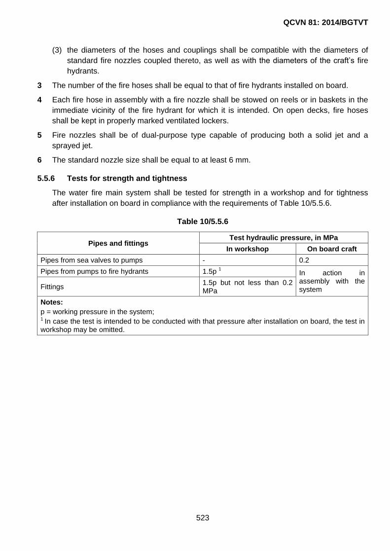
QCVN 81: 2014/BGTVT
523
(3) the diameters of the hoses and couplings shall be compatible with the diameters of
standard fire nozzles coupled thereto, as well as with the diameters of the craft‟s fire
hydrants.
3 The number of the fire hoses shall be equal to that of fire hydrants installed on board.
4 Each fire hose in assembly with a fire nozzle shall be stowed on reels or in baskets in the
immediate vicinity of the fire hydrant for which it is intended. On open decks, fire hoses
shall be kept in properly marked ventilated lockers.
5 Fire nozzles shall be of dual-purpose type capable of producing both a solid jet and a
sprayed jet.
6 The standard nozzle size shall be equal to at least 6 mm.
5.5.6 Tests for strength and tightness
The water fire main system shall be tested for strength in a workshop and for tightness
after installation on board in compliance with the requirements of Table 10/5.5.6.
Table 10/5.5.6
Pipes and fittings Test hydraulic pressure, in MPa
In workshop On board craft
Pipes from sea valves to pumps - 0.2
Pipes from pumps to fire hydrants 1.5p 1 In action in assembly with the system Fittings
1.5p but not less than 0.2 MPa
Notes:
p = working pressure in the system; 1 In case the test is intended to be conducted with that pressure after installation on board, the test in workshop may be omitted.

QCVN 81: 2014/BGTVT
524
CHAPTER 6 OPERATION
6.1 The fixed system shall be capable of operating at environmental temperatures
corresponding to the operating conditions specified by the design.
6.2 Operating instructions shall be provided for each system. If the extinguishing medium is an
asphyxiant, these shall include directions on the necessity and how to ventilate the space
prior to entering for damage assessment and subsequent restarting of the engine, as well
as on how to help people who accidentally sustained asphyxiation in fire extinguishing.

QCVN 81: 2014/BGTVT
525
CHAPTER 7 DESIGN AMOUNT OF EXTINGUISHING MEDIUM
7.1 General
7.1.1 The design amount of the extinguishing medium shall be based on the net volume of
the space with the deduction of the volumes occupied by the equipment. The deducted
items do not include furniture and equipment into which the extinguishing medium can
penetrate.
7.1.2 If the design volume of the space is 10.0 m3 and less the design amount of the
extinguishing medium shall be increased by 10 per cent. When the volume of the space
exceeds 20.0 m3, no reduction is required. The intermediate values are determined by
linear interpolation.
7.2 Design Amount Of Carbon Dioxide Of A Fixed Fire Smothering System
7.2.1 The amount of carbon dioxide, in kg, shall be determined by the following formula:
G = 1.79V
Where:
V - design volume of protected space, in m3;
- factor equal to:
0.3 for machinery spaces, the design volume of which is determined with regard
to the full volume of casings;
0.35 for machinery spaces, the design volume of which is deter- mined without
any regard to the volume of casing from the level at which the horizontal
area of the casings is equal to, or less than, 40 % of the horizontal cross-
sectional area of the machinery space.
For machinery spaces, such value of the factor υ shall be taken which
results in a greater value of G.
7.3 Design Amount Of Aerosol Generating Agent Of Aerosol Fire Extinguishing System
7.3.1 The design mass of the aerosol generating agent, in kg, shall be determined by the
formula:
n1
arj arj a
j 1
G V V P P kq
Where:

QCVN 81: 2014/BGTVT
526
V : design volume of the protected space, in m3;
Varj : volume of the j-th air receiver, in m3, refer to 4.13.1, Part 5;
n : number of air receivers in the protected space;
j : serial number of air receiver;
Parj : working pressure in the j-th air receiver, in MPa;
Pa : atmospheric pressure, in MPa;
q : normative fire extinguishing capacity of aerosol, in kg/m3;
k : safety factor equal to 1.5.
7.3.2 The normative fire extinguishing concentration of aerosol depends on the type of
generator and generally shall not exceed 0.2 kg/m3.
7.3.3 The design number of generators, in pcs, shall be determined by formula:
N = G/m
Where:
G : design mass of aerosol generating agent, in kg;
m : mass of a charge in one generator, in kg.

QCVN 81: 2014/BGTVT
527
CHAPTER 8 DISPLAYED INFORMATION
8.1 Where a space which is regarded as been sealed from adjacent spaces is protected by a
fixed system, the following information shall be displayed near the release device:
Background: Yellow.
8.2 Where a space, which is protected by a fixed system, cannot be regarded as being sealed
from adjacent spaces, the following information shall be displayed near the release device:
Background: Yellow.
8.3 The following information shall be displayed at any entrance to the protected space, if the
extinguishing medium is an asphyxiant:
Background: Yellow or orange.
CAUTION
BEFORE DISCHARGING
SHUT DOWN ENGINES AND
BLOWERS
CHÚ Ý:
TRƯỚC KHI XẢ PHẢI TẮT MÁY AND QUẠT GIÓ
CAUTION
BEFORE DISCHARGING
SHUT DOWN ENGINES AND
BLOWERS
LEAVE ACCOMMODATION
CHÚ Ý:
TRƯỚC KHI XẢ PHẢI TẮT MÁY AND QUẠT GIÓ
HÃY RỜI KHỎI KHU VỰC SINH HOẠT
WARNING
ENGINE COMPARTMENT HAS FIXED EXTINGUISHING SYSTEM.
TO AVOID ASPHYXIATION LEAVE THE AREA BEFORE DISCHARGE.
AFTER DISCHARGE VENTILATE BEFORE ENTERING
CẢNH BÁO:
BUỒNG MÁY CÓ HỆ THỐNG CHỮA CHÁY CỐ ĐỊNH.
ĐỂ TRÁNH NGẠT, HÃY RỜI KHU VỰC NÀY TRƯỚC KHI XẢ.
SAU KHI XẢ, PHẢI THÔNG GIÓ TRƯỚC KHI ANDO.

QCVN 81: 2014/BGTVT
528
8.4 The following information shall be displayed near or on any CO2 portable fire extinguisher:
Background: Yellow or orange
WARNING
THIS EXTINGUISHER USES CO2 AS AN EXTINGUISHING MEDIUM. IT SHALL BE USED ONLY TO FIGHT
ELECTRIC OR GALLEY FIRES.
TO AVOID ASPHYXIATION AFTER DISCHARGE LEAVE THE AREA IMMEDIATELY AND VENTILATE
BEFORE ENTERING.
CẢNH BÁO:
THIẾT BỊ NÀY SỬ DỤNG CO2 LÀM CÔNG CHẤT DẬP CHÁY.
CHỈ ĐƯỢC DÙNG ĐỂ DẬP CÁC ĐÁM CHÁY LIÊN QUAN ĐẾN
ĐIỆN AND TRONG BẾP.
ĐỂ TRÁNH NGẠT, SAU KHI XẢ HÃY RỜI KHỎI KHU VỰC NÀY NGAY LẬP TỨC AND THÔNG
GIÓ TRƯỚC KHI ANDO.
QCVN 81: 2014/BGTVT
529
CHAPTER 9 TESTS OF OPEN-FLAME DEVICES
9.1 Tests are conducted immediately on board at the standard location specified for the
device.
For conducting the test, each of the open-flame burners shall be covered by a metal
plate of diameter 200 mm and a thickness of 3 mm ± 0.2 mm. The flames shall burn
simultaneously in all burners for 10 min, the controls being set to a maximum. At the
end of the burning period, the surface temperature of any material around the open-
flame device shall be measured in order to verify compliance with the requirements of
2.4.

QCVN 81: 2014/BGTVT
530
CHAPTER 10 OWNER’S MANUAL
10.1 Fire-Fighting Equipment
10.1.1 The following instructions and information shall be included in the Owner‟s Manual.
1 Portable fire extinguishers.
The craft, when in service, shall be equipped with portable fire extinguishers of the
following types and extinguishing capacities, in the following number and in the following
locations:
No. 1: extinguishing capacity not less than …………………………….
location…………………………………………………………………………
No. 2: extinguishing capacity not less than …………………………….
location…………………………………………………………………………
No. 3: extinguishing capacity not less than …………………………….
location…………………………………………………………………………
No. n: extinguishing capacity not less than …………………………….
location…………………………………………………………………………
2 Fire blanket
A fire blanket shall be placed in the following location: (Description of position).
3 Servicing of fire-fighting equipment
The craft owner/operator shall:
- have fire-fighting equipment checked at the intervals indicated on the equipment;
- replace portable fire extinguishers, if expired or discharged, by devices of identical
fire-fighting capacity; and
- have fixed systems refilled or replaced when expired or discharged.
4 Fire bucket
The craft shall be provided by at least one fire bucket of a capacity not less than 10.0 l for
every 6.0 m of the craft length or part thereof. The fire buckets shall be provided with a
hemp lanyard attached and stowed in a readily accessible position. The buckets shall be
painted red and bear inscription “FIRE”.
10.2 General
10.2.1 Craft with a hull length up to 15 m shall have Instructions on maintenance and
performance of all fire-fighting equipment and systems which shall be installed on board
craft in an accessible position, complete with related parts and in good order.

QCVN 81: 2014/BGTVT
531
10.2.2 Craft with a hull length of 15 m and over shall have a General Arrangement Booklet.
The content of the Booklet for the operator and crew shall indicate:
- location of control stations;
- location of fire-resisting and fire-retarding divisions;
- spaces equipped with fixed fire-fighting systems with an indication of the location of
fittings ant their control positions;
- location of fire hydrants and nozzles;
- arrangement of fire-fighting equipment;
- ventilation control positions and location of dampers with indication of the group of
protected spaces;
- brief description of the performance of fire-fighting systems and structural features of
fire protection.
10.2.3 As far as practicable, symbols used in the Booklet shall comply with the IMO Resolution
A.952(23) “Graphical Symbols for Use in Fire Plans”.
10.2.4 Information contained in the Booklet shall be in national language, English or French.
10.2.5 Prior to use on board craft, a copy of the Booklet shall be submitted to the VR Surveyor
for review and approval. The approved copy shall be kept on board in an accessible
place.
10.2.6 The Booklets shall be timely updated regarding any amendments and these
amendments shall be duly recorded.
10.2.7 Locations of the appropriate fire-fighting equipment shall be clearly identified.

QCVN 81: 2014/BGTVT
532
PART 11 MATERIALS
CHAPTER 1 GENERAL
1.1 Application
1.1.1 The requirements of this Part of the Regulation apply to materials and products being
subject to VR‟s survey in manufacturing in compliance with the requirements of other
parts of the Regulation.
The requirements relative to selecting and using materials and products are set forth in the
relevant parts of the Regulation.
The requirements for a scope of surveys and tests during initial survey of the manufacture
of materials and products, and also in carrying out VR‟s technical supervision during their
manufacture are set forth in QCVN 64: 2013/BGTVT.
1.1.2 In addition to meeting the requirements of this Part, materials and products shall meet
the requirements of other relevant parts of this Regulation.
1.1.3 The materials used for building pleasure craft shall also meet the requirements of ISO
12215-1: 2000, ISO 12215-2: 2000, ISO 12215-3: 2000.
1.1.4 The materials used for construction of the craft‟s hulls of design categories A, A1, A2 and B shall meet the requirements set forth in Part 7A, Section II, QCVN 21: 2010/BGTVT and in QCVN 56: 2013/BGTVT. The use of other materials is subject to special consideration by VR.
1.1.5 The materials used for construction of reinforced concrete craft shall meet the requirements of QCVN 51: 2012/BGTVT.
1.1.6 The materials which are, as part of a structure or product due to their operational conditions, subject to the requirements not provided in this Part, as well as the materials not regulated by this Part with the chemical composition, mechanical properties and performance not considered by VR for a particular application, shall be specially considered by VR.
The materials produced in compliance with international or national standards or according
to specifications or other technical documentation may be permitted by VR for a specific
application provided VR‟s requirements are met. In this case the standards, specifications
or other technical documentation are recognized by VR by their entering in VR‟s
appropriate document and/or by stamping.
1.1.7 The materials and products below to be surveyed by VR shall be supplied with VR‟s certificates and be produced by the manufacturers holding a Recognition Certificate for Manufacturer:
(1) rolled products of shipbuilding steel;

QCVN 81: 2014/BGTVT
533
(2) rolled steel for Class I and Class II boilers and pressure vessels;
(3) steel pipes for boilers, pressure vessels and Class I and Class II piping;
(4) steel forgings and castings;
(5) iron castings;
(6) castings of non-ferrous and light alloys;
(7) semi-finished products of non-ferrous and light alloys;
(8) chain cables and ropes;
(9) chain steel;
(10) slabs, blooms and billets for rolled products of hull structural and boiler steel if
produced at a manufacturer lacking the rolling.
1.1.8 The materials and products subject to survey by VR, which are listed below may be
supplied with manufacturer‟s certificates provided the works have the quality system
recognized by an authorized body or VR and holds a Type Approval Certificate for the
types of products manufactured:
(1) materials for reinforced plastic structures;
(2) laminated textiles;
(3) retro-reflective materials;
(4) foam plastics;
(5) corrosion-resistant coatings;
(6) plastic fittings and pipes.

QCVN 81: 2014/BGTVT
534
PART 12 MEANS FOR THE PREVENTION OF POLLUTION FROM
CRAFT
CHAPTER 1 GENERAL
1.1 Application
1.1.1 The requirements of the present Part apply to the craft specified in 1.1.1 Section I.
1.2 Definitions and Explanations
1.2.1 Definitions and explanations relating to the general terminology of the Regulation are
given in the 1.2.2, Section I of this Regulation.
For the purpose of this Part of the Regulation the following definitions and explanations
have been adopted:
1 Reception facilities are floating or stationary structures for the reception of all kinds of
pollution substances from ships for subsequent discharge to treatment plants, utilization,
etc.
2 Discharge, in relation to harmful substances or effluents containing such substances, is
any release howsoever caused from a craft into aquatic environment and includes any
escape, disposal, spilling, leaking, pumping, emitting or emptying.
Discharge does not include any intentional disposal of wastes and other matter from craft
into aquatic environment:
- with the aim to secure safety of craft and people on board or the safety of life at sea; or
due to damage of craft or its equipment if all reasonable precautions have been taken
before and after the occurance of the damage for the purpose of preventing or
minimizing the discharge;
- release of harmful substances for the purposes of legitimate scientific research into
pollution abatement or control.
3 Tank is an enclosed space which is formed by permanent structure of a boat and which is
designed for the carriage of liquid in bulk.
4 Number of persons on board is crew, passengers and special personnel, which the craft is
certified to carry.
5 Main machinery is the machinery using fuel oil as the working fluid and being a part of the
craft‟s propulsion plant.
6 Auxiliary machinery is the machinery using fuel oil as the working fluid, necessary for
supply of the craft with electric power and other kinds of power as well as functioning of
the craft‟s systems and arrangements.

QCVN 81: 2014/BGTVT
535
1.3 Technical Documentation
1.3.1 Documentation specified in 2.1.2-1(9)(a) and (b), Part 1 shall be submitted to VR as part
of the documentation relating to all craft designs.
Documentation specified in 2.1.2-1(9)(c) and (d), Part 1 shall be submitted to VR as part of
the documentation relating to designs of craft with design category A, A1, A2, B, C and C1
or intended to carry 10 and more persons on board.

QCVN 81: 2014/BGTVT
536
CHAPTER 2 CRAFT’S CONSTRUCTION, EQUIPMENT AND ARRANGEMENTS FOR THE PREVENTION OF POLLUTION BY OIL
2.1 General
2.1.1 For the purpose of this Part of the Regulation, crafts are subdivided into following
categories:
Category 1 - craft with permanently installed main machinery;
Category 2 - craft fitted with outboard engines only, placed outside the craft‟s hull, used as
the main ones with attached machineries which fully ensure their operability.
Crafts having other equipment which use oil as the working fluid, shall be treated as
Category 2 craft.
2.1.2 Every necessary measure shall be taken to ensure collection, retention on board and
discharge to reception facilities of oily waste generated on board the craft.
Permanently installed internal combustion engines or equipment using fuel oil as the
working fluid, when installed on open deck or outside enclosed compartment of the craft,
shall be housed in a watertight case, container, etc., fitted with arrangements for collection
of leakage fuel oil and lubricating oil from the above-mentioned equipment and means
shall be provided to discharge the same to special tanks/containers.
Drip trays shall be installed under the fittings of the fuel oil and lubricating oil tanks.
Oily waste from the drip trays shall be discharged to special tanks/containers.
2.1.3 Construction of the systems, arrangement of piping and hydraulic tests of the fittings
and piping shall comply with the requirements of Part 3, Section II, QCVN 21:
2010/BGTVT.
Electrical systems shall comply with the requirements of Part 4, Section II, QCVN 21:
2010/BGTVT.
2.2 Definitions and Explanations
2.2.1 For the purpose of this Part of the Regulation the following definitions and explanations
have been adopted:.
1 Parts per million (ppm) are parts of oil per million parts of water by volume.
2 Oily bilge water is mixture of water with any oil content resulting from operation of a craft.
3 Oily waste is oil residues (sludge) and oily bilge water.
4 Oil is petroleum in any form including crude oil, fuel oil, lubricating oil, oil residues, oil
refuse and refined products.
QCVN 81: 2014/BGTVT
537
5 Oil fuel is any oil used as fuel in connection with main and auxiliary machinery of the craft
in which such oil is carried.
6 Oil sludge is part of oil, which due to its consistence is not liable to conventional pumping
or processing and requires special methods and devices for its disposal from the boat.
7 Oil residues are separated sludge, exhausted lubricating oil, oil from bilge water
separators, leakages of fuel and lubricating oil.
8 Exhausted oil is exhausted lubricating oil, hydraulic oil and other hydrocarbon based liquid
which is not suitable for use in machinery due to deterioration and contamination.
9 Separated sludge is sludge resulting from purification of fuel and lubricating oil.
10 15 ppm bilge separator is any combination of a separator, filter/coalescer, and also a
single unit designed to produce an effluent with oil content not exceeding 15 ppm.
11 Oil-containing bilge water tank is a tank for accumulating oily bilge water.
12 Oil residues holding tank is separated sludge tanks, tanks for collecting fuel and lubricating
oil leakages, tanks for collecting exhausted oil.
13 Sludge tanks are tanks for accumulating separated sludge.
2.3 Collection And Storage Of Oily Wastes
2.3.1 Craft mentioned in 2.1.1 shall be provided with tanks for collecting and storing oily
wastes on board.
1 The Category 1 craft of 15 m and more in length having propulsion plants with stern-tube
arrangements which allow inward water leakages under normal operating conditions shall
be provided with oily bilge water holding tanks for collecting and storing oily bilge waters,
the capacity of which shall be not less than 10 per cent of the maximum amount of the fuel
store on board, and with respect to high-speed craft the capacity shall be not less than 7
per cent of the above amount.
In case of twin- or triple-shaft propulsion plant with stern-tube arrangements the design
amount of oily bilge waters collected shall be increased by 15 or 25 per cent, respectively.
2 The Category 1 craft with propulsion plant without stern-tube arrangement mentioned in
2.3.1-1 shall be provided with holding tanks for collecting oil residues in accordance with
the requirements of 2.3.1-3.
3 In Category 1 craft the main and auxiliary machinery shall be fitted with drip trays or
coamings intended for collecting leakages of fuel and lubricating oil there from and means
shall be provided to discharge the oil residues from these to fixed or portable holding
tanks/containers.
In Category 2 craft, the aforesaid is applied as far as it is reasonable and practicable.
4 Where 15 ppm filtering equipment is unavailable, tanks mentioned in 2.3.1-1 may be used
for collecting oil residues such as leakages of fuel and lubricating oil.
2.3.2 Capacity of the oil-residues holding tanks Vor, in l, shall be not less than 10 l or
calculated by the following formula, whichever is the greater:
QCVN 81: 2014/BGTVT
538
or 0.005V C T
Where:
C : the daily fuel consumption, in l;
T : the duration of voyage between ports where oil residues may be discharged to reception facilities (where the duration of voyage is not known it shall be adopted equal to 3 days).
2.3.3 Where it is necessary to store exhausted oil on board, a particular tank for collecting
exhausted oil shall be provided on board, the capacity of which shall be not less than
150 per cent of the total amount of lubricating and other oils used on board, including
oils from crank-cases of all internal combustion engines and all machinery installed, as
well as oils contained in hydraulic fluid installations.
2.3.4 In case where total amount of oils from crank-cases of all internal combustion engines
and all machinery installed on board together with hydraulic fluid installations is 300 l
and more the tank for collecting exhausted oil shall be of permanently fixed type.
2.3.5 The appropriate procedures/instructions for collection and storage on board of oily
wastes and subsequent discharging them to reception facilities shall be documented
and stated in the Owner‟s Manual.
2.3.6 In craft of less than 15 m in length, the oily bilge waters are allowed to be accumulated
in bilges of machinery spaces/compartments with subsequent discharge to reception
facilities.
This accumulated oily bilge waters shall be accounted for in the stability calculations with
due regard for the free surface thereof.
2.3.7 Any craft shall be fitted with 15 ppm bilge separator when necessary endurance cannot
be achieved due to insufficient capacity of the holding tanks/machinery bilges for
collecting oily bilge water.
With the availability of the bilge separator the craft shall be fitted with an oil residues
holding tank.
2.3.8 Where a permanently fixed oil residues holding tank is available, the system for
discharging oil residues to reception facilities shall be provided with a special pump
meeting the requirements of 2.3.15.
2.3.9 The tanks for collection and storage of oil residues shall be manufactured of metal.
2.3.10 The construction of the permanently fixed tanks shall meet the requirements of Part 2.
The walls of portable containers shall be not less than 1.0 mm thick for steel and 1.5 mm
for aluminum and its alloys.
The portable tanks/containers manufactured of non-metallic materials are subject to
special consideration by VR.

QCVN 81: 2014/BGTVT
539
2.3.11 The inner surfaces of the bottom and vertical walls of the permanently fixed container
for collecting oil residues, except for the built-in oil residues holding tanks, shall be
smooth (external framing). In this case, the bottom shall be inclined towards the inlet.
2.3.12 The fixed holding tanks shall be provided with:
(1) a manhole for inspection and cleaning;
(2) a venting pipe with flame arrester;
(3) visual and audible alarm operating in the wheel house or central control station
what are applicable, in case of 80 per cent filling of the tank;
(4) equipment for heating if the tank is located in a place where negative temperature
is possible during the craft‟s operation;
(5) a level gauge.
2.3.13 Instead of a fixed holding tank the installation of a portable holding tank (tanks) is allowed provided that its capacity not more than 25 l. The portable holding containers for collecting oily residues shall be of leaktight construction with a design volume of filling being 85 per cent of the total capacity.
2.3.14 The pump shall be a self-priming displacement with suitable means for protection against dry running and shall have characteristics allowing transfer of oil residues generated on board. The pump shall be suitable for transfer of high-viscosity oil residues, if these are available.
The discharge side of the pump shall be connected only to the transfer line intended for
discharge to reception facilities or to incineration equipment, as appropriate.
2.3.15 The calculation of the capacity of oil-containing bilge water holding tanks and oil residues holding tanks with regard to the intended area of navigation and service conditions of the craft shall be submitted to VR.
2.4 Collecting, Piping And Discharge Arrangements For Oily Wastes
2.4.1 Every craft referred to in 2.3.1-1 shall be provided with arrangement for collecting machinery bilge waters into holding tanks used for collecting oily bilge water.
The arrangement for collecting bilge waters shall consist of permanently installed pump,
piping and fittings designed specially for this purpose.
2.4.2 Every craft, for the purpose of discharging oily bilge waters and oil residues from the permanently fixed holding tanks and machinery bilges to reception facilities, shall be provided with a pipeline fitted with standard discharge connection (see Fig. 12/2.4.2-2) or deck fitting similar to that shown in Fig. 12/2.4.2-1, fitted with threaded plug with a gasket to ensure watertightness of the connection. In this case, the boat shall be provided with an appropriate adapter for connection to reception facilities fitted with standard discharge connection with flanges (see Fig. 12/2.4.2-2). The inner diameter of the pipeline shall be not less than 30 mm.
The flange shall be of steel or other equivalent material having a flat face. The flange
together with a gasket of oil-proof material shall be designed for a working pressure of 0.6

QCVN 81: 2014/BGTVT
540
MPa. The flange is connected by six bolts of suitable length and of 20 mm in diameter
each.
The pipeline may be located in a place convenient for connection of hoses to provide
discharge of oily wastes at both sides of the boat, and shall have distinguishing
nameplates.
The arrangement for discharging oily wastes to reception facilities shall be provided with
pumping-out means. In case, when this is unreasonable and impracticable from
constructional considerations, oily wastes shall be discharged by the arrangements of the
reception facilities.
2.4.3 Starting and stopping of the pumping-out means discharging oily wastes to reception facilities shall be effected manually. Provision shall be made for sealing end fittings of the pipeline for discharging oily wastes to reception facilities.
Fig. 12/2.4.2-1 Deck fitting in accordance with I ISO 8099-2000
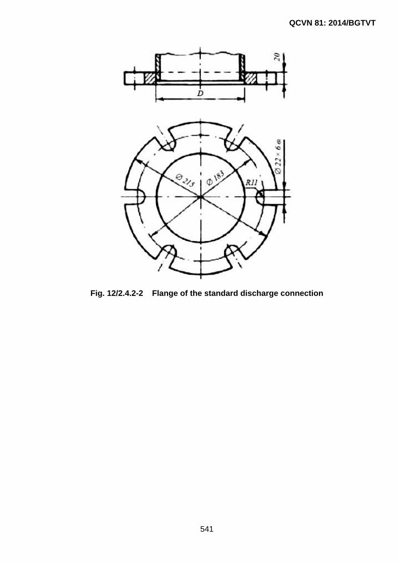
QCVN 81: 2014/BGTVT
541
Fig. 12/2.4.2-2 Flange of the standard discharge connection

QCVN 81: 2014/BGTVT
542
CHAPTER 3 MEANS FOR THE PREVENTION OF POLLUTION BY SEWAGE
3.1 General
3.1.1 Where sewage is mixed with wastes or other contaminated waters to which other provisions of this Part apply, in addition to the requirements of this Chapter, the requirements of other chapters shall be complied with.
3.1.2 Craft which operate with crew members and/or passengers on board, except craft specified in 3.1.3, shall be provided with:
- a holding tank for collecting sewage waters and domestic waste waters (if
applicable);
- pipelines for collecting sewage into holding tank (tanks) and a piping system with
standard discharge connections shown in Fig. 12/3.5.7-2 for discharging sewage
to reception facilities.
3.1.3 Upon agreement with VR, craft intended for independent navigation with duration of not more than 8 hours and with not more than 6 persons on board, except craft specified in 3.2.2, in lieu of equipment specified in 3.1.2, may be provided with, as a minimum, a standard portable biotoilet located in a separate space.
3.1.4 In addition to the equipment referred to in 3.1.2, craft may be provided with a sewage waters and domestic waste waters treatment plant or with a system for comminution and disinfection of sewage waters and domestic waste waters, complying with the requirements of 3.9 and 3.10.
3.1.5 Design of the system, arrangement of the pipelines and hydraulic tests of the fittings and pipelines for collecting and discharging sewage waters and domestic waters shall meet the requirements of Part 5 of this Regulation.
The electrical systems shall meet the requirements of Part 7 of this Regulation.
3.2 Application
3.2.1 The requirements of this Chapter cover the craft‟s equipment and arrangements intended for the prevention of pollution by sewage.
3.2.2 The requirements of this Section of the Regulation for small pleasure craft with hull length of 6 m or less (launch and dinghy (boat)) apply as far as it is reasonable and practicable depending on the service conditions of the craft and number of persons on board.
3.3 Definitions and Explanations
3.3.1 For the purpose of this Section, the flowing definitions and explanations have been adopted:
1 Holding tank is a tank used for the collection and storage of untreated sewage, activated
sludge and pulp from the sewage treatment plant.
2 Sewage is:

QCVN 81: 2014/BGTVT
543
(1) drainage and other wastes from any form of toilets and urinals;
(2) drainage from laboratories and medical premises (dispensaries, etc.) via wash basins,
wash tubs and scuppers located in such spaces;
(3) drainage from spaces containing living animals; or
(4) other waste waters when mixed with the drainages defined above.
3 Sewage treatment plant is a plant in which sewage and, if appropriate, sanitary and
domestic waste waters are treated and disinfected.
4 Sewage comminution and disinfection system is a plant in which sewage is disinfected and
the solid particles contained therein are comminuted.
5 Domestic waste waters are: drainage from wash basins, showers and wash tubs; drainage
from sinks and equipment of galleys.
3.4 Scope Of Technical Supervision
3.4.1 Subject to technical supervision of VR during manufacture are:
1 Sewage treatment plants including their associated piping, pumps, electrical equipment,
metering devices, disinfection devices, control, regulation and monitoring devices.
2 Sewage comminution and disinfection systems.
3 Holding tanks including their associated equipment, control, regulation and monitoring
devices.
3.4.2 Subject to technical supervision of VR during installation on board are:
(1) sewage treatment plants;
(2) sewage comminution and disinfection systems;
(3) holding tanks;
(4) equipment and piping system for discharge of sewage.
3.4.3 In addition to the documentation specified in 2.1.2-1(9), Section I, the following
documentation on equipment and arrangements shall be submitted to VR for review:
1 Drawings of container for collecting sewage.
2 Diagram of piping system for discharging sewage to reception facilities.
3 Documentation on sewage treatment plant:
(1) technical description and operating principle;
(2) general view drawings;
(3) calculation of the plant capacity;
(4) diagram of the plant‟s piping system with indication of supporting mechanisms;
principal electric diagram;
(5) diagrams of control, regulation, monitoring, alarm and protection;

QCVN 81: 2014/BGTVT
544
(6) test program for the plant.
4 Drawings and diagrams of sewage comminution and disinfection systems.
3.5 Sewage Systems
3.5.1 General
The system shall be capable of reliable performance at environment temperatures from 0
up to + 45 °C and sustain in dried condition the environment temperatures from -25 up to
+45 °C.
Design of the systems, arrangement of piping and hydraulic test of the fittings and piping
of sewage collection and discharge systems shall meet the requirements of Part 5.
The electrical systems shall meet the requirements of Part 7.
3.5.2 Materials
The systems shall be manufactured of materials resistant to the effect of the following:
- sewage;
- fresh and sea water;
- disinfectants, deodorants and antifreeze solutions recommended by the system
Manufacturer;
- household cleaning agents recommended by the system Manufacturer;
- chemical compounds in solid, liquid or gaseous form likely to be generated by the
operation of the system.
3.5.3 Construction and installation of sewage collecting systems
1 The system shall be capable of reliable operation when the craft is heeled at least 20° to
either side and trimmed 10° by bow or stern.
2 The equipment of toilets shall be fitted with devices preventing the penetration of odor from
untreated sewage into the craft‟s spaces.
3 When the holding tank is filled to 90 per cent, sewage shall not seep:
- outside the craft under conditions of heel up to 30° either way with respect to a single-
hull sailing craft or to 20° with respect to another craft;
- inward the craft with the maximum expected heel and trim, that is 45°, with respect to
a single-hull sailing craft and 30° with respect to a motor craft or a multi-hull sailing
craft.
4 Pipelines or deck fittings for discharge shall be located in places convenient for connection
to reception facilities.

QCVN 81: 2014/BGTVT
545
5 The holding tank shall be provided with visual indication operating in case of 80 per cent
filling of the tank.
6 The holding tank of more than 40 l in capacity shall be provided with a suitable access
hole fitted with watertight cover for flushing, cleaning and maintenance.
7 Holding tanks shall not have common bulkheads with drinking/washing water tanks.
8 Flexible connections and pipelines shall be reliably secured in position to prevent their
damage by abrasion or vibration.
9 Holding tanks and pipe connections shall be accessible for examination and maintenance.
3.5.4 Venting systems for fixed holding tanks.
The venting system for fixed holding tanks shall provide for venting of gases within the
system to the exterior of the craft at heel angles up to 20° at 90 per cent of tank capacity.
1 Fixed holding tanks of less than 400 l capacity
The minimum inner diameter of the vent pipe shall be 19 mm or not less than 16 mm if the
tank is fitted with an automatic (vacuum operated) or manual relief valve with a minimum
total sectional area of 1100 mm2.
2 Fixed holding tanks of 400 l capacity and greater
The minimum inner diameter of a vent pipe shall be 38 mm, or, if multiple vent pipes
are used, their inner diameter shall be at least 19 mm; and the combined cross-
sectional flow area shall be at least equivalent to that of a single vent pulp with an area
of 1100 mm2.
If a manual relief valve is fitted, an appropriate sign/inscription displayed in the vicinity of
the discharge manifolds shall show the need for opening of the valve prior to beginning of
discharge.
3 Inner diameter of fittings
The inner diameter of fittings used to connect the vent pipeline shall not be less than 75
per cent of the inner diameter of the discharge pipeline.
4 Operability of the venting system
The design and construction of the venting system shall ensure its operability under the
environmental conditions specified in 3.5.1 and 3.5.3-1. The venting pipeline shall be
capable of resisting, without damage, a negative pressure of 50 kPa.
5 Flow area
The minimum flow area and equivalent flow resistance of any filters installed in the venting
system shall not be less than the smallest cross-section area in either the venting pipe or
its fittings.
3.5.5 Pipelines and/or flexible joints (hoses)

QCVN 81: 2014/BGTVT
546
Pipeline or flexible joints (hoses) between the toilet and holding tank as well as between
the tank and pump-out deck fitting/discharge pipeline shall be as short as practicable and
its inner surface shall:
- be smooth, without convolutions to permit free flow of sewage;
- have an inner diameter in conformity with the toilet Manufacturer‟s recommendations;
- or have an inner diameter of 38 mm if no recommendations are provided.
3.5.6 Overboard discharge of sewage in the areas, where discharge is allowed
Systems capable of direct overboard discharge of sewage/ domestic waste waters (if
appropriate) to the areas, where discharge is allowed, shall be fitted with a valve located
immediately adjacent to shell plating.
Provision shall be made for sealing the valve in the closed position.
Starting and stopping of the discharge shall be effected manually.
Every valve used for direct overboard discharge shall satisfy the requirements of Part 5.
3.5.7 Sewage discharge to reception facilities
1 Every craft having fixed holding tanks for discharge of sewage and domestic waste waters
(if appropriate) to reception facilities shall be provided with a pipeline fitted with
international standard discharge connections with flanges (see Fig. 12/3.5.7-1(2)) or with a
pump-out deck fitting similar to that shown in Fig. 12/3.5.7-1(1), fitted with a threaded plug
with a gasket to ensure watertightness of the connection.
To enable connection to the reception facilities fitted with the standard discharge
connection with flanges (Fig. 12/3.5.7-1(2)), the craft shall be provided with an appropriate
adapter.
The flange is intended for pipes with an inner diameter of up to 100 mm and shall be
manufactured of steel or other equivalent material with a flat machined face. The flange
together with a suitable gasket shall be designed for a working pressure of 0.6 MPa. For
craft with a moulded depth of 5.0 m or less, the inner diameter of the discharge connection
may be 38 mm. Coupling is effected by means of four 18 mm diameter bolts of requisite
length.
2 The discharge system shall be provided with pump-out means. If this is unreasonable and
impracticable from the constructional considerations, the holding tanks shall be emptied by
the discharge arrangements of the reception facilities (see Fig. 12/3.8.1 and 12/3.8.2).
The discharge manifolds may be located in one place convenient for connection of hoses
to provide discharge at both sides of the craft, and shall have distinguishing name-plates.
3 The pump-out deck fittings for discharge pipe shall be marked by at least the symbol in
Fig. 12/3.5.7-3, the symbol shall be placed visibly on, or in the vicinity of, the fitting.

QCVN 81: 2014/BGTVT
547
Fig. 12/3.5.7-1(1) Pump-out deck fitting according to ISO 8099-2000
Fig. 12/3.5.7-1(2) Flange of the standard discharge connection

QCVN 81: 2014/BGTVT
548
Fig. 12/3.5.7-3
3.6 Requirements for Holding Tanks
3.6.1 Holding tanks for collecting sewage may be built-in or independent, including portable
tanks.
3.6.2 Requirements for fixed holding tanks
1 The construction of the tank shall provide removal of at least 90 per cent of its contents
through the pump-out deck fitting/discharge pipeline. Fixed tanks shall have bottom
inclined towards the outlet.
2 The fixed tanks shall be provided with arrangements for flushing with water and for
disinfection.
3 The fixed built-in tanks shall be separated by cofferdams from the tanks used for drinking
and washing water, as well as from accommodation and service spaces. The independent
and portable tanks shall be located in a separate space/compartment or in machinery
space fitted with efficient exhaust ventilation.
4 The construction of the tanks including covers of openings/manholes shall provide gas-
and water-tightness.
5 The tank shall be subjected to leakage test by excess pressure of 25 kPa during 5 min.
3.6.3 Requirements for portable holding tanks
1 Portable holding tanks shall be of capacity less than 20 l and shall not be connected to any
craft‟s fittings arranged on the shell plating.
2 The inner diameter of venting pipeline for portable holding tanks, if used, shall be not less
than 16 mm and shall have a quick disconnect from the tank-vent opening. All openings of
the tank shall be fitted with closing devices which ensure water- and gas-tightness, also
during transportation thereof.
3 Handles or recesses for carrying the tank shall be provided on the tank in a location that
will allow safe transport and emptying of the tank.

QCVN 81: 2014/BGTVT
549
4 The tank shall have an instruction for its safe disconnection, transport and emptying of its
contents.
5 The tank shall be securely attached to hull structures.
3.6.4 Capacity of the holding tanks
Total capacity of the sewage holding tank/tanks shall be determined having regard to the
intended area of navigation, service conditions of the craft and number of persons on
board. The calculation of the total capacity shall be submitted to VR for review.
The volume of the holding tanks V shall be calculated by the following formula:
V f K N T
Where:
K : design value of accumulated amount of sewage and domestic waste waters (if
appropriate), l/per person per day, according to the norms established by the Flag
Administration;
N : maximum admissible number of persons on board;
T : period between emptyings of the onboard tanks to reception facilities, in days;
f : 0.3 - factor accounting for the possibility of craft operating in the area, where
discharge of untreated sewage is allowed. In case where such possibility does
not exist, f = 1.
3.6.5 Identification
Prefabricated holding tanks/containers shall be legibly marked with the following
information:
- name or trade mark of the Manufacturer;
- name and/or model number;
- tank capacity, in l.
3.7 Owner’s manual
3.7.1 Documentation on the system operation and maintenance shall be included into the Owner‟s Manual incorporating a sewage system drawing and shall include the following information:
1 description of the system operation and maintenance thereof.
2 method of control of the three-way valve:
- sealing;
- avoidance of inadvertent discharge.
3 capacity of the holding tank, in l.
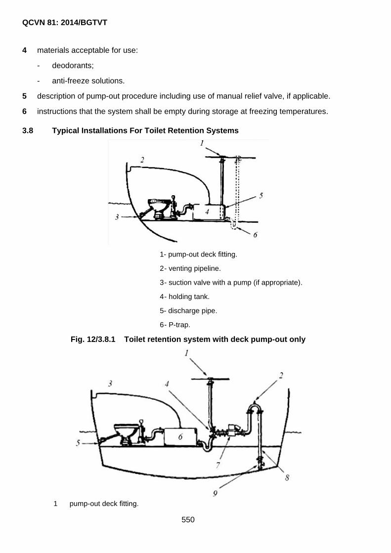
QCVN 81: 2014/BGTVT
550
4 materials acceptable for use:
- deodorants;
- anti-freeze solutions.
5 description of pump-out procedure including use of manual relief valve, if applicable.
6 instructions that the system shall be empty during storage at freezing temperatures.
3.8 Typical Installations For Toilet Retention Systems
1- pump-out deck fitting.
2 - venting pipeline.
3 - suction valve with a pump (if appropriate).
4 - holding tank.
5- discharge pipe.
6 - P-trap.
Fig. 12/3.8.1 Toilet retention system with deck pump-out only
1 pump-out deck fitting.

QCVN 81: 2014/BGTVT
551
2 siphon break may be necessary if system is below the waterline).
3 venting pipeline.
4 Y-valve.
5 suction valve with a pump (if appropriate).
6 holding tank.
7 macerator pump.
8 overboard discharge pipeline.
9 overboard discharge valve.
Fig. 12/3.8.2 Toilet retention system with deck pump-out and overboard discharge capability
3.9 Sewage Treatment Plants
3.9.1 The rated capacity of the sewage treatment plant, in liters per day, shall be not less than the daily accumulated amount of sewage and domestic waste waters (if appropriate) determined according to the requirements of 3.6.4.
3.9.2 The sewage treatment plant, all its associated pumps and other accessories, piping and fittings which arein contact with sewage shall be reliably protected from its attack.
3.9.3 The sewage treatment plants shall ensure a level of treatment in accordance with the current international and national standards. The required level of treatment shall be achieved only through purification and disinfection of sewage.
3.9.4 The sewage treatment plants shall be tested by a test pressure equal to 1.5 the pressure of water column measured from the tank bottom to the lower sanitary fixture having no shut-off valve on the discharge pipeline, but not less than 25 kPa.
Pipelines shall be tested by a hydraulic test pressure ptest = 1.5 p (where p = working
pressure).
3.9.5 The sewage treatment plants shall be tested at the Manufacturer or on board the craft according to the program approved by VR.
3.9.6 The sewage treatment plants may be located in machinery spaces or in separate spaces with forced exhaust ventilation.
3.9.7 Provision shall be made for washing and disinfection of the sewage treatment plant, associated machinery and piping, to carry out work in connection with the inspection and repair of the plant.
3.10 Sewage Comminution and Disinfection Systems
3.10.1 The sewage comminution and disinfection systems shall meet the requirements of 3.9.
3.10.2 The sewage comminution and disinfection systems shall provide for comminution of solid particles contained in sewage to a size not exceeding 25 mm.

QCVN 81: 2014/BGTVT
552
CHAPTER 4 REQUIREMENTS FOR CRAFT’S EQUIPMENT AND ARRANGEMENTS FOR PREVENTION OF POLLUTION BY
GARBAGE
4.1 General
4.1.1 Every craft with a crew on board shall be provided with arrangements for collection and
storage of garbage and food wastes generated during operation of the craft.
4.1.2 Garbage processing devices, incinerators and their systems shall comply with the
requirements of Part 5 and Part 7, and equipment for control, regulation and monitoring
shall comply with the requirements of Part 6.
4.2 Incinerators
4.2.1 The incinerator installed on board the craft on or after 1 January 2000 shall comply with
the requirements of Resolution MEPC.76(40) and be approved by VR on behalf of the
Administration.
4.2.2 Incinerator installed in existing craft, the date of contract for delivery of which is before 1
January 2000, may have type approval in accordance with the requirements of
Resolution MEPC.59(33) or other normative documents.
4.2.3 Where fuel oil and oil residues leakages are likely to occur, trays shall be fitted which
shall be effectively drained. The leaked fuel oil and oil residues collected in trays shall
be trapped to the oil leakage collecting pipeline.
4.2.4 Special receptacles shall be provided for collecting ash from incinerators after
garbage incineration.
4.2.5 The incinerators may be installed in machinery or separate spaces.
4.2.6 The fuel oil system supply to the oil burners shall be so designed that it can shut down
from two positionsone of which must be outside the space in which the incinerator is
installed.
4.3 Garbage Receptacles
4.3.1 Garbage receptacles shall be removable.
4.3.2 The calculation of the total capacity of the garbage receptacles having regard to the
intended area of navigation, service conditions of the craft and number of persons on
board shall be submitted to VR.
The capacity of the receptacles for collecting garbage and food wastes Vg shall be
calculated by the following formula:
g gV G N T

QCVN 81: 2014/BGTVT
553
Where:
Gg : daily accumulated amount of garbage in accordance with the service condition of the boat per one person, in m3:
- dry garbage: 0.002;
- solid food wastes: 0.004k;
- plastics: 0.000015k.
Where:
k = 5.0 for boats engaged on voyages of 8 hours and more in duration;
k = 1.0 for boats engaged on voyages of less than 8 hours in duration.
N : maximum allowable number of persons on board;
T : time intervals between emptying of garbage containers at collection points, in days.
The total capacity of receptacles for collecting garbage and food wastes for craft
engaged on voyages of 16 hours or more in duration shall make up not less than two
day standard for accumulation.
4.3.3 The garbage receptacles shall be clearly marked to identify the category of garbage to be collected (plastics, food wastes, other garbage) and differ in colour.
4.3.4 The garbage receptacles shall have inner surfaces which allow easy cleaning.
4.3.5 The garbage receptacles shall be provided with covers ensuring tight closure, installed in well- ventilated places and have fixtures for reliable securing on board the craft.
4.3.6 Separate receptacles with fastened covers (cans, barrels, buckets) may be used for collecting garbage inside the spaces.
4.3.7 In boats with hull length of less than 10 m garbage and food wastes may be collected in separate dense polyethylene bags with subsequent unloading to reception facilities.
4.3.8 Garbage from the garbage receptacles may only be disposed to reception facilities or delivered to the craft‟s incinerator, if appropriate (if no restrictions are imposed by the Administrations), as well as to the sea areas where disposal is allowed (depending on the garbage category).

QCVN 81: 2014/BGTVT
554
PART 13 ADDITIONAL REQUIREMENTS
CHAPTER 1 ADDITIONAL REQUIREMENTS FOR CRAFTS CARRYING MORE THAN 12 PASSENGERS
1.1 General
1.1.1 The requirements of this Part apply to crafts specified in 1.1.1-3 Section I, carrying more
than 12 passengers and having hull‟s length not more than 24 m.
1.1.2 The crafts shall comply with requirements in this Regulation except otherwise specified
in 1.2 below.
1.2 Technical Requirements
1.2.1 Radio and navigational equipment
Radio and navigational equipment shall comply with requirements in Chapter 4 and
Chapter 5 Section II QCVN 42: 2012/BGTVT as for passenger ships not engaged in
international voyages.
1.2.2 Life-saving appliances
Life-saving appliances shall be in accordance with Chapter 2 Section II QCVN 42:
2012/BGTVT as for passenger ships not engaged in international voyages.

QCVN 81: 2014/BGTVT
555
CHAPTER 2 ADDITIONAL REQUIREMENTS FOR CRAFTS HAVING HULL’S LENGTH GREATER THAN 24 M AND UP TO 85 M
2.1 General
2.1.1 The requirements of this Chapter shall apply to crafts specified in 1.1.1-3 Section I,
having hull‟s length greater than 24 metres and up to 85 metres.
2.1.2 The crafts shall comply with relevant requirements in QCVN 21: 2010/BGTVT and in
relevant regulations as for ships not engaged in international voyages, except those
given in 2.2 and 2.3 below. For crafts carrying more than 12 passengers, the
requirements in following 2.2 and 2.3 shall be applied as for passenger ships.
2.2 Definitions
2.2.1 The definitions and explanations relating to general terms of this Regulation are given in
1.2 Part 1A Section II QCVN 21: 2010/BGTVT. For the purpose of this Regulation, the
terms relating to pleasure yachts are specified in 1.2.2-1 Section I of this Regulation.
2.3 Technical Requirements
2.3.1 General requirements on technical supervision, classification and periodical survey.
1 General requirements on technical supervision, classification and periodical survey are
given in Part 1 of this Regulation.
2.3.2 Hull and outfitting
1 The requirements for steel hull shall be complied with as specified in Part 2 of this
Regulation with correction factor for the hull length deemed appropriate by VR in each
case or based on requirements in Part 2B Section II QCVN 21: 2010/BGTVT.
Requirements for equipment made of steel shall be based on Part 2B Section II QCVN 21:
2010/BGTVT.
Requirements for hull and equipment made of Fibreglass Reinforced Plastics shall be
based on QCVN 56: 2013/BGTVT.
Requirements for signal means of ships shall be based on Chapter 3 Section II QCVN 42:
2012/BGTVT.
2 Requirements for hull and equipment made of alluminum alloy shall be based on Part 2
and Part 3 of this Regulation with correction factor for the hull length deemed appropriate
by VR in each case.
3 Hatches and doors

QCVN 81: 2014/BGTVT
556
(1) Weathertight hatches and doors shall be fitted for all openings providing the access
from outside on:
(a) Bulkhead and superstructure decks;
(b) Superstructures and deckhouses.
(2) Hatches and doors shall be of permanent type and shall be openable from either side
if they are fitted in the accommodation area;
(3) The strength of hatches and doors shall be equivalent to the structures where they are
fitted on;
(4) Hatches, doors and windows constituted by glass of large size may be accepted if
they are fitted on aft bulkhead of superstructures and deckhouses;
(5) The sill of hatches and doors fitted forward and side leading to spaces under bulkhead
deck shall be at least 380 mm;
(6) For hatches and doors which do not directly lead to spaces under bulkhead deck and
are not necessary for ship‟s operation at sea, the sills of those are not required;
(7) Doors on bulkheads of superstructures shall be normally hinged outside;
(8) The weathertightness standard of hatches and doors leading to small spaces above
the bulkhead deck, the flood of which does not affect the ship‟s stability, may be
reduced based on their sizes, location and the openness of the spaces.
4 Freeing ports, ventilation openings
(1) Ventilation openings and air inlets
(a) The lower edge of ventilation openings and air inlets above the waterline shall
have a height Hv as specified in Table 13/2.3.2-4;
Table 13/2.3.2-4 Height of ventilation openings and air inlets
Area of navigation Height Hv (m)
Unrestricted 0.05L: at least 2.30 m
Restricted I 0.04L: at least 2.00 m
Restricted II 0.035L: at least 1.70 m
Restricted III 0.035L: at least 1.50 m
(b) For openings which are not necessary for ship‟s operation, the height Hv may be
reduced. In this case, a permanent means of closing shall be fitted;
(c) Ventilators the coamings of which extend to more than one metre above the deck
or which are fitted to decks above the datum need not be fitted with closing
arrangements unless they face forward;

QCVN 81: 2014/BGTVT
557
(d) Except as provided in the above mentioned (3), ventilator openings shall be
provided with efficient weathertight closing appliances;
(e) Ventilator openings shall face aft or athwartships wherever practicable.
(2) Freeing ports
(a) Where bulwarks on weather decks form wells, ample provision shall be made for
rapidly freeing the decks of water and for draining them. The minimum freeing port
area A, m2, on each side of the craft for each well on the weather deck of the main
hull(s) shall be:
Where the length of bulwark (l) in the well is 20 m or less:
A 0.7 0.035l
Where l exceeds 20 m:
A 0.07l
l : in no case shall be greater than 0.7L .
(b) If the bulwark is more than 1.2 m in average height, the required area shall be
increased by 0.004 m2 per metre of length of well for each 0.1 m difference in
height. If the bulwark is less than 0.9 m in average height, the required area shall
be decreased by 0.004 m2 per metre of length of well for each 0.1 m difference in
height.
(c) Such freeing ports shall be located within the height of 0.6 m above the deck and
the lower edge shall be within 0.02 m above the deck.
(d) If the bulwark is more than 1.2 m in average height, the required area shall be
increased by 0.004 m2 per metre of length of well for each 0.1 m difference in
height. If the bulwark is less than 0.9 m in average height, the required area shall
be decreased by 0.004 m2 per metre of length of well for each 0.1 m difference in
height.
(e) Craft having superstructures which are open in front or both ends, shall comply
with the provisions of (a).
(f) In craft having superstructures which are open at the aft end, the minimum freeing
port area shall be:
A = 0.3b (m2)
Where: b is the breadth of the craft at the exposed deck (m).
5 Windows
(1) Windows are generally to be of toughened safety glass. Except for front windows in
the wheel house other materials may be found acceptable based on consideration of
strength, impact resistance and ageing properties.

QCVN 81: 2014/BGTVT
558
(2) Window glass with baked-in heating elements bolted mechanical fastenings or other
strength reducing arrangements, shall be specially considered with regard to
thickness.
(3) Window glass are in general to be firmly mounted in stiff fames with due respect to
impacts. In superstructures and deckhouses other type of mounting, gluing etc. shall
be documented to the satisfaction of the surveyor. In the aft ends of superstructures
and deckhouses large windows may be accepted.
(4) The thickness of toughened safety glass panes above the bulkhead deck is in general
not to be less than:
gy
bt K P
350 ,(mm)
Where:
b: small dimension of window openings, (mm);
K: factor, taken from the following formula, depending on the aspect ratio of
the window:
K = 1.0414 - 0.7375/Λ - 0.0244Λ or 0.75, whichever is less, where Λ is the
aspect ratio of the window (large/small dimension);
P: lateral pressure (kPa).
(5) The thickness of glasses in the hull sides shall be according to 19.5 Part 2B and
Chapter 8 Part 7B, Section II, QCVN 21: 2010/BGTVT.
(6) The number of deadlights in relation to number of windows depending on the service
restriction notation, shall be as given in Table 13/2.3.2-5(6).
Table 13/2.3.2-5(6) Number of Deadlights
Location Area of navigation
Non restricted Restricted I Restricted II Restricted III
Below main deck 100% 1 each type 0% 0%
(7) Deadlights shall be interchangeable port and starboard.
(8) Deadlights shall be stowed in such a way as to provide quick mounting. Deadlights for
which there is 100 % requirement, shall provide protection for intact windows. Other
deadlights shall provide temporary replacement of damaged windows and may be
mounted internally or externally over window openings.
6 Protective handrail

QCVN 81: 2014/BGTVT
559
The height of protective handrail shall be at least 1.0 metre from the deck. For ships
having length of 48 metres of less, the height shall be at least 600 mm from the deck.
2.3.3 Stability, Reserve of Buoyancy And Freeboard
1 Intact stability of a sailing craft shall be in accordance with Part 4 of this Regulation as
required for sailing crafts.
2 Reserve Of Buoyancy
(1) For craft having length less than 48 metres, Chapter 3 Part 4 of this Regulation shall
be applied;
(2) For craft having length of 48 metres and up to 85 metres, requirements in Chapter 3
Part 9 Section II QCVN 21: 2010/BGTVT shall be applied assuming one compartment
is flooded.
3 Loadlines of the craft shall comply with Part 11 Section II QCVN 21: 2010/BGTVT except
those defined in 1.3.2-3 to -6.
2.3.4 Machinery installation and piping arrangement
1 Machinery installation and piping arrangement shall be in accordance with Part 3 Section II
QCVN 21: 2010/BGTVT.
2 The capacity Q of each bilge pump shall be not less than required by the following formula:
3.75(1 /36)Q L (m3/h)
L : length of craft on design waterline (m).
3 Where main bilge pipe is not provided in the bilge pumping system, with the exception of
the space in front of the public space and crew space, at least one fixed submersible pump
shall be fitted for each space. In addition for bilge pumping of each space at least one
portable pump shall be provided, supplied from emergency supply if electric for use. The
capacity Qn of each submersible pump shall be not less than required by the following
formula or 8.0 m3/h, whichever is the greater.
/ ( - 1)nQ Q N (m3/h)
Where:
N : number of submersible pumps;
Q : capacity as defined in 1.1.
4 Manual pumps, if fitted, shall be located on the bulkhead deck or upward.
2.3.5 Electrical equipment
Electrical equipment shall comply with Part 4 Section II QCVN 21: 2010/BGTVT.

QCVN 81: 2014/BGTVT
560
2.3.6 Radio and navigational equipment
Radio and navigational equipment shall comply with Chapter 4 and Chapter 5 Section II
QCVN 42: 2012/BGTVT.
2.3.7 Lifesaving appliances
Lifesaving appliances shall comply with Chapter 2 Section II QCVN 42: 2012/BGTVT.
2.3.8 Fire prevention and extinguishing
Fire prevention and extinguishing shall be in accordance with Part 10 of this Regulation
except for detecting and alarm system, the relevant requirements of QCVN 21:
2010/BGTVT shall be applied.
2.3.9 Materials
Requirements for materials and products shall be in accordance with Part 11 of this
Regulation.
2.3.10 Pollution prevention equipment
Pollution prevention equipment shall comply with Part 12 of this Regulation.
2.3.11 Provision of seats and cabins
Seats and cabins shall be provided in accordance with 12.1 Part 3 Section II.

QCVN 81: 2014/BGTVT
561
III REGULATIONS ON MANAGEMENT
1.1 General
1.1.1 Upon the compliance of crafts with requirements in this Regulation, VR will assign the
class to crafts with class notations as specified in 1.2 of this Section.
1.1.2 The Certificate shall be valid for a period not exceeding 12 months but shall not exceed the due date of Special survey.
1.1.3 When the compliance with requirements of this Regulation is made, the ship will be issued a Certificate Of Technical Safety And Environment Protection in a form specified in Appendix E.
1.2 Class Characters and Notations
1.2.1 Classification Characters
1 Classification Characters: VR, or VR, or VR
Where:
VR: Symbol of Vietnam Register carrying out the survey in accordance with
requirements of this Regulation;
: Showing that the design of the craft was approved by VR and the construction
of the craft was carried out under supervision of VR;
: Showing that the construction was carried out under supervision of a
Classification Society authorized or/and recognized by VR.
: Construction without supervision of VR or under supervision of a
ClassificationSociety not recognized by VR.
2 Class notation of Hull: H
The ship‟s hull will be assigned with the following notations:
VRH : The hull is designed and approved by VR in accordance with requirements of
this Regulation and is surveyed during construction in compliance with
approved design documentation;
VRH : The hull is designed, approved, surveyed during construction by a
classification society authorized and/or recognized by VR and afterward it is
subject to classification surveys of VR in compliance with requirements of this
Regulation;
VRH : The hull is not designed, approved, surveyed during construction by any
classification society (or the society is not recognized by VR) but afterward it is
()
()
()

QCVN 81: 2014/BGTVT
562
subject to classification surveys of VR in compliance with requirements of this
Regulation.
3 Class notation of Machinery: M
Machinery installation of self-propelled crafts will be assigned with the following notations :
VRM : The machinery installation is designed and approved by VR in accordance with
requirements of this Regulation and is surveyed during manufacturing and
installing in compliance with approved design documentation;
VRM : The machinery installation is designed, approved, surveyed during
manufacturing by a classification society authorized and/or recognized by VR
and afterward it is subject to classification surveys of VR in compliance with
requirements of this Regulation;
VRM : The machinery installation is not designed, approved, surveyed during
manufacturing by any classification society (or the society is not recognized by
VR) but afterward it is subject to classification surveys of VR in compliance
with requirements of this Regulation.
4 Notation for design categories and areas of service
Notation for design categories (A or A1, or A2, or B, or C, or C1, or C2, or C3, or D) shall
be affixed to the hull notation.
For a yacht, the notations A, A1 and A2 shall be subjected to VR consideration on a case
by case basis.
In all cases, the notation A shall be assigned only for crafts having length greater than 24
m.
For crafts falling outside the application of 1.1.1-2(1) and (2) Section I, design category
notations shall be replaced be the notations for restricted area of navigation specified in
2.1.2-4(1)(a) Part 1A Section II QCVN 21: 2010/BGTVT.
5 Distinguishing notation for seasonal navigation restriction
(1) Depending on whether the craft has or has no appropriate hull strength, stability and
reserve of buoyancy, specially designed equipment, insulation and heating of spaces
as well as suitable emergency and salvage outfit, the distinguishing notation for
seasonal navigation restriction shall be introduced in the hull notation specified in
1.2.1-4.
Seasonal periods for appropriate zones and areas are defined in Part 11 Section II of
QCVN 21: 2010/BGTVT.
The distinguishing mark for seasonal restrictions is denoted by letter T accompanied
by an appropriate figure 0. 1, 2 or 3, namely:
()

QCVN 81: 2014/BGTVT
563
T0: for craft built, equipped and outfitted for navigation in summer in the winter
seasonal zone or area; navigation in zones denoted T1 and T2 is also possible;
T1: or craft built, equipped and outfitted to be capable of year-round navigating in
summer zone; navigation in zone denoted T2 is also possible;
T2: for craft built, equipped and outfitted for navigation in summer period in the
summer zone;
T3: for craft built, equipped and outfitted for year-round navigation in tropical zone and
tropical seasonal area; navigation in zone denoted T2 is also possible.
(2) The possibility of assigning a particular distinguishing notation for seasonal navigation
restriction shall be subject to special consideration by VR in each case.
6 Distinguishing notation for day time navigation restriction
For of design categories C2, C3 and D, restrictions on navigation only in the daylight may
be allowed. In such case, mark O is added to the hull notation specified in 1.2.1-5.
7 Distinguishing automation notation
Distinguishing automation notation shall be added to the class notation if the craft complies
with Part 6 Section II. In this case, the notation “AUT” shall be added to the notation for
machinery installation.
8 Descriptive notation in the class notation
(1) For all crafts, the main descriptive notation is added to the character of classification in
1.2.1-5 to -6, as follows:
"Pleasure craft" - in the general case;
"Pleasure yacht" - only for yachts.
(2) Craft complying with a definite scope of requirements of this Regulation taking account
of their structural features or purpose are assigned, whenever necessary, one or
several additional descriptive notations, as stated below:
(a) Determination of propelling forces:
"Sailing";
"Sailing-motor";
"Motor- sailing";
"Tow";
"Berth-connected".
(b) Structural particulars of a craft:
"Catamaran", "Trimaran", "Proa";
"Hydroplane".

QCVN 81: 2014/BGTVT
564
(c) Details of the craft purpose:
"Tourist";
"Water bower ";
"Water house".
1.2.2 Additional characteristics
When complying with definite requirements of this Regulation stipulated by the structural
features or operational characteristics of the craft the fulfillment of which is not reflected by
distinguishing notations and descriptive notation in the class notation, the confirmation of
compliance of the craft with such requirements shall be added to the class notation.
1.3 Survey request
1.3.1 Survey request letter
1 Classification survey
Classification survey shall be carried out by VR after receiving the survey request letter
from shipowner or ship builder.
2 Class maintenance survey
Class maintenance survey shall be carried out by VR after receiving survey request letter
from shipowner, ship's master or representative of shipowner.
1.4 Certificates
1.4.1 Certificate withdrawal
1 VR may withdraw the certificate and notify ship‟s owner when:
(1) Owner requests;
(2) The ship can no longer be used because it was scrapped, sank, etc.;
(3) The Surveyors report that the ship has not complied with survey requirements
specified in Part 1 Section II of the Regulation and VR accepts the report;
(4) The ship is not subjected to the survey defined in Part 1 Section II of the Regulation;
(5) Survey fees are not paid.
2 In the cases of -1(4) or -1(5) above, VR will notify the invalidation of the certificate.
1.4.2 Reissue the withdrawn certificate
The owner of a ship may apply for the reissuance of the withdrawn certificate according to
a procedure as for the application for special survey.
1.4.3 Invalidation of the Certificate
1 The validity of a Certificate shall cease to be valid in the following cases:

QCVN 81: 2014/BGTVT
565
(1) Ship‟s certificate is withdrawn as defined in 1.4.1-1 above;
(2) If after an accident, VR has not been notified of and the ship has not been subjected
to Occasional Survey by the surveyors at port where the accident took place or at the
first port of call if the accident took place at sea;
(3) If alterations have taken place in the construction and/or if any change has been made
in the equipment without VR's approval or without notification to VR;
(4) When repair of supervised items of a ship has been performed without the agreement
and/or supervision by VR;
(5) When a ship navigates with a draught exceeding that assigned by VR for specific
conditions as well as in case of operation of a ship in conditions which do not comply
with the requirements for assigned class of a ship or the restrictions specified by VR;
(6) If the prescribed specific requirements which during previous survey were conditions
for assignment or confirmation of the class have not been fulfilled within the specified
period;
(7) The owner does not follow relevant regulations on technical condition maintenance
surveys.
1.5 Documentation management
1.5.1 Storage, Reissue and return of certificates
1 The master of a ship shall keep a Certificate on board the ship and present the same to
VR upon request.
2 The owner or master of a ship shall request the VR without delay to reissue a Certificate
when the same:
(1) Certificate is lost or soiled;
(2) The particulars described in the same are changed.
3 The owner or master of a ship shall return the old Certificate to VR immediately if the
Certificate has been issued after completion of special survey or reissued under -2, except
when the Certificate was lost.
4 The owner or master of a ship shall return the old Certificate to VR immediately when the
Certificate has been withdrawn under the provisions of 1.4.1-1 above.
5 The owner or master of a ship shall, when a lost Certificate is found after reissuing the
same under -2 above, return the found certificate to VR immediately.
1.5.2 Storage of Survey record
All documents issued by VR for ships including test/inspection report (ground to issue
related certificates), certificates, material and product certificate shall be kept and
maintained on board and ready to present to surveyor as requested.
QCVN 81: 2014/BGTVT
566
IV RESPONSIBILITIES OF ORGANIZATIONS, INDIVIDUALS
1.1 Responsibilities of ship owners and operators, design centers, yard of manufacturing, converting, renovating and repairing ships
1.1.1 Ship owners and Operators
To implement all relevant requirements of this Regulation in manufacturing, converting,
renovating, operating the pleasure yachts in order to ascertain and maintain good
technical condition of the ships.
1.1.2 Design centers
1 To design ships in compliance with requirements of the Regulation.
2 To submit all required design documentation in accordance with requirements in the
Regulation.
1.1.3 Yards of manufacturing, converting, renovating and repairing ships
1 To be capable in terms of warehouse, manufacturing shop, building facilities etc. and
competent manpower to meet requirement for new manufacture, conversions, renovations
and repairs of the ships.
2 To comply with standards of quality, safety while manufacturing, converting, renovating
and repairing the ships and to comply with approved design.
3 To be subjected to VR‟s supervision on the technical quality and safety of the ships.
1.2 Responsibilities of Vietnam Register
1.2.1 Design approval, technical supervision
To assign surveyors having competence and of sufficient standard to carry out the
technical supervision during manufacture, conversions, renovations, repairs and operation
of the ships in accordance with technical requirements specified in this Regulation.
1.2.2 To give instructions for implementation/application
To give instructions for the application of requirements of this Regulation to ship owners
and operators, yards of manufacture, conversions, renovations and repair of the ships,
inspection offices of Vietnam Register throughout the country.
1.2.3 To amend and supplement the Regulation
Based on the fact, Vietnam Register shall have responsibility to petition the Ministry of
Transport to amend the Regulation on a yearly basis.
1.3 Responsibilities of the Ministry of Transport

QCVN 81: 2014/BGTVT
567
The Ministry of Transport (Science and Technology department) is responsible for
verifying on the regular or random basis the implementation of this Regulation by relating
organizations.

QCVN 81: 2014/BGTVT
568
V IMPLEMENTATION
1.1 It is the responsibility of Vietnam Register to organize the survey system, technical
supervision, classification and technical registration of pleasure yachts. It shall also include
organizing the printing, dissemination and instructions for the application of this Regulation
for organizations and individuals falling within the scope of this Regulation.
1.2 In case of inconsistency between the requirements in this Regulation and those in other
rules, standards or technical regulations relating to pleasure yachts, the requirements of
this Regulation shall prevail over those of others.
1.3 In case the documents referred to in this Regulation are amended, supplemented or
replaced, the latter shall prevail over the former.
1.4 This Regulation and its amendment shall apply to crafts of which early stages of the new
building or date of major conversions are on or after effective date of this Regulation.

QCVN 81: 2014/BGTVT
569
Appendix A RECOMMENDED TYPES OF GLASS-REINFORCED PLASTICS
1 The following eight types of glass-reinforced plastics are recommended for use in craft and
lifeboat structures:
Type I: plastic reinforced with glass mats, which may be coated on the outer face or on
both faces with one or two layers of glass net or glass fabric to impart better surface
smoothness to it (designation X);
Type II: plastic reinforced with woven rovings of plain weave and parallel orientation, i.e.
all layers are laid with their warp in one direction (designation P);
Type III: plastic reinforced with glass fabric of satin weave with parallel orientation
(designation T);
Type IV: plastic reinforced with glass fabric or glass net of plain weave with parallel
orientation (designation T or C);
Type V: plastic reinforced both with glass mats and woven rovings of parallel orientation,
each amounting to 50 per cent in thickness, the layers of mats and woven rovings being
alternately laid through the entire thickness of the laminate;
Type VI: plastic with the same reinforcement thickness ratio as for type V, but with mats
concentrated in the middle and woven rovings laid on the outer and inner faces and
amounting to 1/4 of the thickness on each side;
Type VII: plastic with parallel and diagonal reinforcement of woven rovings at angles + 45°
and – 45°, which layers, laid parallel to the warp, shall amount to half the laminate
thickness, while the diagonal parts plied at + 45° and –45° to the layers of parallel
orientation shall amount to 1/4 of the laminate thickness each, the layers of parallel
reinforcement being alternately laid throughout the entire thickness;
Type VIII: layers arranged diagonally shall occupy the middle portion of the laminate
thickness while those of parallel reinforcement shall form the outer and inner faces of the
laminate (packet arrangement).
Glass-reinforced plastics, types II, V, VI, VII and VIII shall be overlaid on both faces with
one or two layers of glass fabric or glass net.

QCVN 81: 2014/BGTVT
570
2 The schemes of reinforcement for the above plastics types are shown in Fig. A/1.
Reinforcing material:
X- glass mat;
P- woven rovings (plain weave), parallel orientation of layers: woven rovings, plied at + 45° or –
45°;
T or C- glass fabric or glass net, parallel orientation of layers.
Types of glass-reinforced plastics (shown in per cent is the fraction of thickness falling on the
layers of the given reinforcement):
Type X P T or C
I 100%
II
100%
III and IV
100%
V and VI 50% 50%
VII and VIII
0° - 50%
+45° - 25%
-45° - 25%
Fig. A/1 Schemes of reinforcement

QCVN 81: 2014/BGTVT
571
Appendix B PHYSICAL AND MECHANICAL PROPERTIES OF GLASS-REINFORCED PLASTICS
Physical and mechanical properties of glass reinforced plastics depending on the
reinforcement schemes included in Appendix A shall be in accordance with the values stated in
Table B/1 to B/6.
For each type of plastic depending on the fibre glass content in per cent by mass the tables
contain respective values of physical and mechanical properties.
The values of physical and mechanical properties such as glass content by volume, average
density, shear modulus, Poisson‟s ratio and shear strength in the laminate plane are
determined only during approval tests of a particular type of plastic.
Table B/1 Physical and mechanical properties of glass-reinforced plastics with glass
mats as reinforcement and a polyester binder (type I). Tested in dry condition at 20 °C
Nos. Type
Glass
content, % Average
density,
kg/m3
Young’s
modulus,
MPa
Shear
modulus in
laminate
plane, MPa
Poisson
ratio
Tensile
strength,
MPa
Compression
strength,
MPa
Shear
strength
in
laminate
plane,
MPa
by
mass
by
volume
1 I1 25 15 1.45 0.60 × 10⁴ 0.22 × 10
4 0.35 80.0 110.0 40.0
2 I2 30 18 1.50 0.70 × 10⁴ 0.26 × 10
4 0.35 90.0 120.0 50.0
Note:
1. The glass content by volume and the average density of glass-reinforced plastic refer to the average density
of glass equal to 2550 to 2600 kg/m3 and to the average density of binder as cured of 1200 to 1250 kg/m
3;
2. Young‟s modulus refers to tension-and-compression;
3. For a thickness of 4 mm and less the tensile strength is reduced by 20 per cent against the Table value.

QCVN 81: 2014/BGTVT
572
Table B/2 Physical and mechanical properties of glass-reinforced plastics with woven
roving of parallel orientation and a polyester binder (type II). Tested in dry condition at
20 °C
Nos. Type
Glass content,
% Average
density,
kg/m3
Young’s
modulus,
MPa
Shear
modulus
in
laminate
plane,
MPa
Poisson
ratio
Tensile
strength,
MPa
Compression
strength,
MPa
Shear
strength
in
laminate
plane,
MPa
by
mass
by
volume
1 II1 45 28 1600
1.30 ×
104
1.30 ×
104
0.21 × 10⁴
0.21 × 10⁴
0.12
0.12
170.0
170.0
105.0
105.0 60.0
2 II2 50 32 1640
1.50 ×
104
1.50 ×
104
0.25 × 10⁴
0.25 × 10⁴
0.12
0.12
200.0
200.0
110.0
110.0 70.0
3 II3 55 37 1700
1.70 ×
104
1.70 ×
104
0.29 × 10⁴
0.29 × 10⁴
0.12
0.12
230.0
230.0
115.0
115.0 80.0
Note:
1. The glass content by volume and the average density of glass-reinforced plastic refer to the average density
of glass equal to 2550 to 2600 kg/m3 and to the average density of binder as cured of 1200 to 1250 kg/m
3;
2. Young‟s modulus refers to tension-and-compression;
3. Shown in the numerator are the values for the warp direction, in the denominator – for the weft direction;
4. For woven rovings the ratio of breaking strength in the warp and weft direction is 1:1.

QCVN 81: 2014/BGTVT
573
Table B/3 Physical and mechanical properties of glass-reinforced plastics with glass
fabric of satin weave and parallel orientation, and a polyester binder (type III). Tested in
dry condition at 20 °C
Nos. Type
Glass
content, % Average
density,
kg/m3
Young’s
modulus,
MPa
Shear
modulus
in laminate
plane, MPa
Poisson
ratio
Tensile
strength,
MPa
Compression
strength,
MPa
Shear
strength
in
laminate
plane,
MPa
by
mass
by
volume
1 III1 45 28 1600 1.70 × 10
4
1.10 × 10⁴
0.28 × 10⁴
0.15
0.10
270.0
170.0
200.0
150.0 80.0
2 III2 49 31 1640 1.80 × 10
4
1.20 × 10⁴
0.10 × 10⁴
0.15
0.10
290.0
180.0
210.0
160.0 85.0
3 III3 52 34 1670 1.90 × 10
4
1.30 × 10⁴
0.32 × 10⁴
0.15
0.10
300.0
190.0
220.0
170.0 90.0
Note:
1. The glass content by volume and the average density of glass-reinforced plastic refer to the average density
of glass equal to 2550 kg/m3 to 2600 kg/m
3 and to the average density of binder as cured of 1200 to 1250
kg/m3;
2. The modulus of elongation refers to tension-and-compression;
3. Shown in the numerator are the values for the warp direction, in the denominator – for the weft direction;
4. Glass fabric features the ratio of breaking strength in the warp and weft direction equal to 2:1.

QCVN 81: 2014/BGTVT
574
Table B/4 Physical and mechanical properties of glass-reinforced plastics with glass
net or glass fabric of plain weave and parallel orientation, and a polyester binder (type
IV). Tested in dry condition at 20 °C
Nos. Type
Glass
content, % Average
density,
kg/m3
Young’s
modulus,
MPa
Shear
modulus
in laminate
plane, MPa
Poisson
ratio
Tensile
strength,
MPa
Compression
strength,
MPa
Shear
strength
in
laminate
plane,
MPa
by
mass
by
volume
1 IV1 45 28 1600 1.30 × 10
4
1.30 × 10⁴
0.28 × 10⁴
0.13
0.13
220.0
220.0
160.0
160.0 80.0
2 IV2 49 31 1640 1.40 × 10
4
1.40 × 10⁴
0.30 × 10⁴
0.13
0.13
230.0
230.0
170.0
170.0 85.0
3 IV3 52 34 1670 1.50 × 10
4
1.50 × 10⁴
0.32 × 10⁴
0.13
0.13
240.0
240.0
180.0
180.0 90.0
Note:
1. The glass content by volume and the average density of glass-reinforced plastic refer to the average density
of glass equal to 2550 to 2600 kg/m3 and to the average density of binder as cured of 1200 to 1250 kg/m
3;
2. Young‟s modulus refers to tension–and-compression;
3. Shown in the numerator are the values for the warp direction, in the denominator – for the weft direction;
4. For the glass fabric the ratio of the breaking strength in the warp and weft direction is 1:1.

QCVN 81: 2014/BGTVT
575
Table B/5 Physical and mechanical properties of glass-reinforced plastics of
composite reinforcement with 1/2 of the thickness by glass matsand 1/2 of the thickness
by roving glass fabric of parallel orientation on the basis of a polyester binder (types V
and VI). Tested in dry condition at 20 °C
Nos. Type
Content by mass,
% Average
density,
kg/m3
Young’s
modulus,
MPa
Shear
modulus
in
laminate
plane,
MPa
Poisson
ratio
Tensile
strength,
MPa
Compression
strength,
MPa
Shear
strength
in
laminate
plane,
MPa
glass
mat
roving
glass
fabric
glass
1 V1
VI1 25 50 37.5 1550
1.05 ×
104
1.05 ×
104
0.24 ×
104
0.21
0.21
135.0
135.0
77.0
77.0 55.0
2 V2
VI2 30 55 42.5 1600
1.20 ×
104
1.20 ×
104
0.28 ×
104
0.21
0.21
160.0
160.0
80.0
80.0 65.0
Note:
1. The average density of glass-reinforced plastic refers to the average density of glass equal to 2550 to 2600
kg/m3;
2. Young‟s modulus refers to tension-and-compression;
3. Shown in the numerator are the values for the warp direction, in the denominator – for the weft direction.

QCVN 81: 2014/BGTVT
576
Table B/6 Physical and mechanical properties of glass-reinforced plastics with
parallel-and-diagonal reinforcement by roving glass fabric, of which 1/2 the layers is of
parallel orientation and in 1/4 of the layers, of diagonal orientation at angles of + 45° and
–45°, and a polyester binder (types VII and VIII). Tested in dry condition at 20 °C
Nos. Type
Glass
content,
%
Average
density,
kg/m3
Young’s
modulus,
MPa
Shear
modulus in
laminate
plane, MPa
Poisson
ratio
Tensile
strength,
MPa
Compression
strength,
MPa
Shear
strength
in
laminate
plane,
MPa
1 VII1
VIII1 45 1600
1.10 × 10⁴
1.10 × 10⁴
0.37 × 10⁴
0.30
0.30
140.0
140.0
80.0
80.0 56.0
2 VII2
VIII2 50 1650
1.30 × 10⁴
1.30 × 10⁴
0.45 × 10⁴
0.30
0.30
170.0
170.0
95.0
95.0 68.0
3 VII3
VIII3 55 1700
1.50 × 10⁴
1.50 × 10⁴
0.52 × 10⁴
0.30
0.30
200.0
200.0
110.0
110.0 79.0
Note:
1. The average density of glass-reinforced plastic refers to the average density of glass equal to 2550 to 2600
kg/m3 and to the average density of binder as cured of 1.20 to 1.25 g/cm
3;
2. Young‟s modulus refers to tension-and-compression;
3. Shown in the numerator are the values for the warp direction, in the denominator – for the weft direction;
4. For the glass fabric the ratio of the breaking strength in the warp and weft direction is 1:1.

QCVN 81: 2014/BGTVT
577
Appendix C CALCULATION OF CRAFT’S HULL MEMBER SCANTLINGS
1 In addition to the table method of the hull scantlings determination as given in this Part of
the Regulation, this may be done by a calculation method approved by VR.
2 The basic data for recalculating separate hull members and for calculating the hull strength
(longitudinal and local) are given in Table C/1, C/2 and C/3.
Table C/1 Maximum bending moment
Craft’s length 1, m Maximum bending moment at longitudinal bending, kNm
5 - 10 1.66 ΔL
15 - 24 ΔL
ΔL is full-load displacement;
1 Bending moment for craft from 10 m to 15 m in length is determined by linear interpolation.
Table C/2 Design load
Type of load Design formula or value,
kPa
Local load on bottom and side shell hp = 10 (h1 + Δ)
Local load on the upper deck in way of:
- forward of the forepeak bulkhead 15
- elsewhere 5
Ditto, for craft of design categories C2, C3 and D:
- forward of the forepeak bulkhead 10
- elsewhere 4
Note:
1. h1 distance from the member under consideration to the upper deck; Δ = 0.5 m for any region
excepting the forepeak; Δ = 1.5 m for the region forward of the forepeak bulkhead;
2. The load for the craft of an intermediate length is determined by linear interpolation.

QCVN 81: 2014/BGTVT
578
Table C/3 Permissible stress
Type of load Permissible stress
Stresses due to general and local bending
at instantaneous load:
- for type I glass-reinforced plastics σ = 0.25 Rm
= 0.25 m
- for type II to VIII glass-reinforced plastics σ = 0.30 Rm
= 0.30 m
at permanent load for all types of glass-reinforced plastics
- at shear in the laminate plane for all types of glass-reinforced plastics σ = 0.10 Rm
= 0.10 m
- at shear in matting-in connections and at interlaminar shear = 0.30 m
= 0.60 m
Stresses at the matting-in connections subject to pull
- at instantaneous load σ = 2 MPa
- at permanent load σ = 1 MPa
Note:
σ is permissible normal stress;
is permissible shear stress;
Rm and m are tensile strength and shear strength respectively obtained on dry specimens at t = 20 °C
(see Appendix B).
3 Permissible stresses is taken as a part of design tensile, compression or shear strength.
For permissible stress in the case of alternating tension-and-compression and bending,
either tensile or compressive stresses shall be taken, whichever are less.
4 Design values for Young‟s modulus and the shear modulus are assumed equal to:
Ed = 0.6E and Gd = 0.6G
Where: E and G are Young‟s modulus and the shear modulus determined for dry material
at 20 °C (see Appendix B).
5 For hull structural members the factor of safety against buckling shall be taken not lower
than that given in Table C/4.
Table C/4 Safety factor
Structural member to be calculated Safety factor
Centre girder, side and deck girders 3
Plate keel, sheerstrake and deck stringer 1.5
6 Permissible deflection values calculated with due regard for shear are assumed equal to:

QCVN 81: 2014/BGTVT
579
1/400 of length for the hull as a whole;
1/50 of spacing for the shell;
1/100 of a span for primary support members.
7 For the shell and upper deck the reduction coefficient may be used. The moment of inertia
with consideration of the reduction coefficient shall then not be less than 95 per cent of the
moment of inertia calculated in the first approximation without regard to the reduction
coefficient.

QCVN 81: 2014/BGTVT
580
Appendix D ADDITIONAL MATERIALS FOR STABILITY CALCULATIONS
1 Parameters Of Irregular Waves
Fig. D/1 Parameters of irregular waves
2 Characteristics of Wave Impact For Developing Waves Of Various Intensity

QCVN 81: 2014/BGTVT
581
Table D/2 Characteristics of Wave Impact
Characteristic Unit Sea state, number
2 3 4 5 6 7 8
Basic parameters of design wind waves spectrum
Wave height, h3% m 0.52 1.25 2.0 3.5 6.0 8.5 11.0
Mean period of developing
waves, s 2.0 3.1 4.0 5.2 6.8 8.1 9.2
Variance of wave ordinates, D m2 0.001 0.056 0.143 0.438 1.29 2.58 4.33
Characteristics of the greatest breaking wave
Length, Lbr m 3.1 7.5 12.0 21.1 35.6 50.7 95.0
Velocity, Vbr m/s 2.2 3.4 4.2 5.6 7.3 8.7 9.9
Height, hbr m 0.24 0.6 0.9 1.6 2.8 3.9 5.1
Period, br s 1.1 1.6 2.1 2.8 3.6 4.3 4.9
Action time, tbr s 0.27 0.4 0.5 0.7 0.9 1.1 1.2
Pressure, pbr kPa 2.4 5.8 9.2 16.0 27.5 39.0 50.0
The characteristics of the largest plunger breaking wave in the seas of a given intensity
are determined using the following parameters:
wave height with 3 % probability of exceeding level, in m:
3%h 2.11h
maximum wave height, in m:
max 1% 3%h h 1.15h
height of the breaking part of the wave, in m:
br maxh 0.4h
length of the breaking part of the wave, in m:
2
brL 0.5L g / 4
periodicity of wave impact, in s:
br 0.53
breaking velocity, in m/s:
brv 1.08
action time, in s:
br brt = 0.25
pressure in the breaking base, in kPa:
br brp = gh

QCVN 81: 2014/BGTVT
582
3 Graphical Charts for Calculating The Moment Of Inertia Of Added Water Masses
And The Damping Coefficient
Fig. D/3.1 Graphical chart for
determining the equivalent moment
of inertia of added water masses '0
Fig. D/3.2 Graphical chart for determining the
equivalent moment of inertia of added water
masses '0 for craft with the large ratio LH/BH
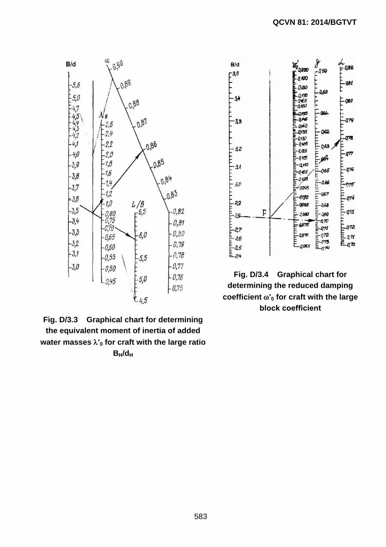
QCVN 81: 2014/BGTVT
583
Fig. D/3.3 Graphical chart for determining
the equivalent moment of inertia of added
water masses '0 for craft with the large ratio
BH/dH
Fig. D/3.4 Graphical chart for
determining the reduced damping
coefficient '0 for craft with the large
block coefficient

QCVN 81: 2014/BGTVT
584
Fig. D/3.5 Graphical chart for determining the reduced damping coefficient '0 for craft
with the small block coefficient

585
Appendix E CERTIFICATE OF TECHNICAL
SAFETY AND ENVIRONMENT PROTECTION
(Issued in compliance with requirements of
National Technical Regulation QCVN 81: 2014/BGTVT)
MINISTRY OF TRANSPORT THE SOCIALIST REPUBLIC OF VIETNAM
VIETNAM REGISTER Independence –Freedom – Happiness
Ref. No.:…………………
CERTIFICATE OF TECHNICAL SAFETY AND
ENVIRONMENT PROTECTION
Ship’s name:........................................Registration number: ...............................
VR number: ................................................Place of survey:.......................
Ship’s owner: ……............ ................................................................................
Address: .........................................................................................................
Year of build/conversion:......................................................................................
Main particulars: Lwl x Bwl x Dwl x d ..... ......................................... m;
Lmax x Bmax: ........................ …...m; Gross tonnage :..............................;
Passenger capacity.............(person(s)) Number of Crews............(person(s))
Upon the satisfactory completion of the carried-out survey, it is to certify that
this ship and its equipment are in compliance with relevant requirements of
National Technical Regulation on Classification and Construction of Pleasure
Yacht QCVN 81: 2014/BGTVT with the following permanent restrictions and
other characteristics:
Hull class notation …………….………………………………....
Machinery class notation …………….………………………………....
Other characteristics: ………………………………………………….……
The validity of this certificate shall be until: day……month……year……
Issued at ..................., day …. month …. year.............
VIETNAM REGISTER
DT-01
1

586
HULL AND EQUIPMENT
Hull material:………..Superstructure/deckhouse material: .....................
Shell thickness: Bottom ...................... mm Side ............................ mm
Number of watertight bulkheads: ............................................................
Mass of anchors: No1 anchor ................ (kg) No2 anchor ...........(kg)
Length of chain: No1 anchor ................. (m) No2 anchor ........... (m)
Type of main steering gear: ....................................................................
Type of aux. steering gear: ......................................................................
Mooring equipment: ................................................................................
Mooring line:Type .................. Quantity ........... Length ...... (m)
Mooring bitt: Type ................. Quantity ........... Material ..........
Height of main mast.................................................................................
MAIN ENGINE
Quantity, type: .........................................................................................
Year and place of manufacture: ...............................................................
Total Output: ......................................................................... (kW)
Revolution: ...................................................................... (rpm)
Type of redution gear: ............................................................ …..
AUX. ENGINE
Quantity, type ..........................................................................................
Year and place of manufacture ................................................................
Output……………..(/kW) Revolution .......................................... (rpm)
Purpose:
2
1
ELECTRICAL INSTALLATION
Quantity of generators .............. Total output .................... (kVA/kW)
Quatity and total capacity of batteries ......................................... (Ah)
LIFE-SAVING APPLIANCES
Liferaft: Quantity and capacity................................................ persons
Raft-type lifesaving appliances: Quantity and capacity .......... persons
Lifebuoy .................. pieces Lifejacket ........ pieces
FIRE-FIGHTING EQUIPMENT
Fire pump: Quantity ................................ Capacity ...................... m3/h
Foam extinguisher:.......................................... pieces, CO2 extinguisher pieces
Hose Bucket Sand
Shovel Bạt Axe
Other equipment ........................................................................................................
SIGNAL MEANS AND SIGNAL SHAPE
Tyfon ................................................................... Klaxon .........................................................
Navigation light White Green Red
Search light Towing light Anchor light
Signal shapes Ball Cone Basket
Quantity of pyrotechnic signal means ..............................................................................................
..........................................................................................................................................................
RADIO EQUIPMENT
MF/HF radio installation
VHF radio installation using DSC
Two-way VHF radiotelephone apparatus
NAVIGATIONAL EQUIPMENT
Magnetic compass GPS Chart manipulation set
Stopwatch Prismatic binocular Hand lead
Inclinometer Navigational charts of operating area
Other equipment ........................................................................................................
3