Pyroclastic flow dynamics and hazard in a caldera setting: Application to Phlegrean Fields (Italy
17
Pyroclastic flow dynamics and hazard in a caldera setting: Application to Phlegrean Fields (Italy) Micol Todesco Istituto Nazionale di Geofisica e Vulcanologia, Via D. Creti, 12, I-40128 Bologna, Italy ([email protected]) Augusto Neri, Tomaso Esposti Ongaro, and Paolo Papale Istituto Nazionale di Geofisica e Vulcanologia, Via della Faggiola, 32, I-56126 Pisa, Italy ([email protected]; [email protected]; [email protected]) Mauro Rosi Dipartimento Scienze della Terra, Universita ` di Pisa, Via S. Maria, 53, I-56126 Pisa, Italy ([email protected]) Istituto Nazionale di Geofisica e Vulcanologia, Via della Faggiola, 32, I-56126 Pisa, Italy [1] Numerical simulation of pyroclastic density currents has developed significantly in recent years and is increasingly applied to volcanological research. Results from physical modeling are commonly taken into account in volcanic hazard assessment and in the definition of hazard mitigation strategies. In this work, we modeled pyroclastic density currents in the Phlegrean Fields caldera, where flows propagating along the flat ground could be confined by the old crater rims that separate downtown Naples from the caldera. The different eruptive scenarios (mass eruption rates, magma compositions, and water contents) were based on available knowledge of this volcanic system, and appropriate vent conditions were calculated for each scenario. Simulations were performed along different topographic profiles to evaluate the effects of topographic barriers on flow propagation. Simulations highlighted interesting features associated with the presence of obstacles such as the development of backflows. Complex interaction between outward moving fronts and backflows can affect flow propagation; if backflows reach the vent, they can even interfere with fountain dynamics and induce a more collapsing behavior. Results show that in the case of large events (10 8 kg/s), obstacles affect flow propagation by reducing flow velocity and hence dynamic pressure in distal regions, but they cannot stop the advancement of flows. Deadly conditions (in terms of temperature and ash concentration) characterize the entire region invaded by pyroclastic flows. In the case of small events (2.5 10 7 kg/s), flows are confined by distal topographic barriers which provide valuable protection to the region beyond. Components: 9369 words, 10 figures, 4 tables, 2 animations. Keywords: Phlegrean Fields; multiphase flow; pyroclastic flows; dynamic pressure; volcanic hazard; caldera. Index Terms: 8414 Volcanology: Eruption mechanisms and flow emplacement; 8428 Volcanology: Explosive volcanism; 8488 Volcanology: Volcanic hazards and risks. Received 22 March 2006; Revised 19 July 2006; Accepted 28 July 2006; Published 7 November 2006. Todesco, M., A. Neri, T. Esposti Ongaro, P. Papale, and M. Rosi (2006), Pyroclastic flow dynamics and hazard in a caldera setting: Application to Phlegrean Fields (Italy), Geochem. Geophys. Geosyst., 7, Q11003, doi:10.1029/2006GC001314. G 3 G 3 Geochemistry Geophysics Geosystems Published by AGU and the Geochemical Society AN ELECTRONIC JOURNAL OF THE EARTH SCIENCES Geochemistry Geophysics Geosystems Article Volume 7, Number 11 7 November 2006 Q11003, doi:10.1029/2006GC001314 ISSN: 1525-2027 Click Here for Full Articl e Copyright 2006 by the American Geophysical Union 1 of 17
Transcript of Pyroclastic flow dynamics and hazard in a caldera setting: Application to Phlegrean Fields (Italy

Pyroclastic flow dynamics and hazard in a caldera setting:Application to Phlegrean Fields (Italy)
Micol TodescoIstituto Nazionale di Geofisica e Vulcanologia, Via D. Creti, 12, I-40128 Bologna, Italy ([email protected])
Augusto Neri, Tomaso Esposti Ongaro, and Paolo PapaleIstituto Nazionale di Geofisica e Vulcanologia, Via della Faggiola, 32, I-56126 Pisa, Italy([email protected]; [email protected]; [email protected])
Mauro RosiDipartimento Scienze della Terra, Universita di Pisa, Via S. Maria, 53, I-56126 Pisa, Italy ([email protected])
Istituto Nazionale di Geofisica e Vulcanologia, Via della Faggiola, 32, I-56126 Pisa, Italy
[1] Numerical simulation of pyroclastic density currents has developed significantly in recent years and isincreasingly applied to volcanological research. Results from physical modeling are commonly taken intoaccount in volcanic hazard assessment and in the definition of hazard mitigation strategies. In this work,we modeled pyroclastic density currents in the Phlegrean Fields caldera, where flows propagating alongthe flat ground could be confined by the old crater rims that separate downtown Naples from the caldera.The different eruptive scenarios (mass eruption rates, magma compositions, and water contents) werebased on available knowledge of this volcanic system, and appropriate vent conditions were calculated foreach scenario. Simulations were performed along different topographic profiles to evaluate the effects oftopographic barriers on flow propagation. Simulations highlighted interesting features associated with thepresence of obstacles such as the development of backflows. Complex interaction between outwardmoving fronts and backflows can affect flow propagation; if backflows reach the vent, they can eveninterfere with fountain dynamics and induce a more collapsing behavior. Results show that in the case oflarge events (�108 kg/s), obstacles affect flow propagation by reducing flow velocity and hence dynamicpressure in distal regions, but they cannot stop the advancement of flows. Deadly conditions (in terms oftemperature and ash concentration) characterize the entire region invaded by pyroclastic flows. In the caseof small events (2.5 � 107 kg/s), flows are confined by distal topographic barriers which provide valuableprotection to the region beyond.
Components: 9369 words, 10 figures, 4 tables, 2 animations.
Keywords: Phlegrean Fields; multiphase flow; pyroclastic flows; dynamic pressure; volcanic hazard; caldera.
Index Terms: 8414 Volcanology: Eruption mechanisms and flow emplacement; 8428 Volcanology: Explosive volcanism;
8488 Volcanology: Volcanic hazards and risks.
Received 22 March 2006; Revised 19 July 2006; Accepted 28 July 2006; Published 7 November 2006.
Todesco, M., A. Neri, T. Esposti Ongaro, P. Papale, and M. Rosi (2006), Pyroclastic flow dynamics and hazard in a caldera
setting: Application to Phlegrean Fields (Italy), Geochem. Geophys. Geosyst., 7, Q11003, doi:10.1029/2006GC001314.
G3G3GeochemistryGeophysics
Geosystems
Published by AGU and the Geochemical Society
AN ELECTRONIC JOURNAL OF THE EARTH SCIENCES
GeochemistryGeophysics
Geosystems
Article
Volume 7, Number 11
7 November 2006
Q11003, doi:10.1029/2006GC001314
ISSN: 1525-2027
ClickHere
for
FullArticle
Copyright 2006 by the American Geophysical Union 1 of 17
1. Introduction
[2] The Phlegrean Fields is an active and denselypopulated volcanic caldera in the urban area ofNaples (Figure 1). The caldera formed through theseveral eruptive events and collapses of differentstyles and magnitudes which have occurred sincethe big caldera-forming Campanian Ignimbriteeruption 39 ka ago. The volcanic history of thecaldera has been reconstructed in great detail [Rosiand Sbrana, 1987; Orsi et al., 2004, and referencestherein] and mostly comprises explosive eventswith emplacement of pyroclastic flows, base surgesand fallout deposits [Orsi et al., 1996; Di Vito etal., 1999; Dellino et al., 2004a; Isaia et al., 2004].Hundreds of long periods (years) of intense activityalternated with a few ka periods of eruptive quies-cence. About 3.5 ka of quiescence preceded the1538 AD Monte Nuovo event which led to theformation of a tuff cone in the western part ofthe caldera [Di Vito et al., 1987; D’Oriano et al.,2005; Piochi et al., 2005]. Since then, extensivefumarolic activity, seismicity, and remarkable epi-sodes of ground deformation [Barberi et al.,1984a] have provided evidence of activity in thecaldera, such that the possibility of eruptions in thefuture cannot be excluded. Given the large numberof people presently living within the area, even asmall eruption could produce enormous economicconsequences, and the volcanic risk for the regionis one of the highest in the world. The first attemptsto assess volcanic hazard in the Phlegrean region[Barberi et al., 1984b; Rosi and Santacroce, 1984]were prompted by two bradyseismic crises (in1969 and 1982), when the ground rose a fewmeters in just a few years in possible prelude toan eruption. More recently, several authors haveaddressed the problem of hazard assessment at thePhlegrean Fields; they have tried to define thelocation, nature and magnitude of the expectedevent, and identify areas potentially at risk [Lireret al., 2001; Alberico et al., 2002; Dellino et al.,2004b; Orsi et al., 2004; Rossano et al., 2004].Different authors have approached the problemfrom different perspectives, but there is generalconsensus on some points: the vent will most likelyopen within the eastern sector of the caldera(roughly the Agnano plain); activity is expectedto be explosive and characterized by pyroclasticdensity currents (hereafter named pyroclasticflows, in a general sense). The propagation ofpyroclastic density currents is therefore one ofthe issues to be addressed in a comprehensiveevaluation of volcanic hazard at the Phlegrean
Fields caldera. The dynamics is expected to becomplex due to the peculiar topography of the area,which is characterized by a flat ground surfacedotted with large and small crater rims, tuff ringsand tuff cones. A key issue is whether or notpyroclastic flows could surmount the hills flankingthe eastern and northern sides of the caldera anddirectly threaten the city of Naples.
[3] The assessment of pyroclastic flow hazardinvolves the identification of areas which are likelyto be invaded by pyroclastic flows. In case of aneruption, total devastation is generally assumed tooccur in those areas, and complete evacuationappears to be the only possible mitigation measure.Areas at risk have been traditionally identifiedusing maps of past pyroclastic flow deposits,assuming that similar events could occur in thefuture. Lirer et al. [2001], on the basis of thedistribution of products during the last 10 ka,suggested that pyroclastic flows and surges wouldmost likely remain confined within the calderawall. Orsi et al. [2004], on the other hand, sug-gested that flows might spill over the northern rimof the caldera during large events. An attempt toquantify the impact of pyroclastic flows at thePhlegrean Fields was carried out by Dellino et al.[2004b]. On the basis of sediment mechanics, andassuming low particle concentrations and quasi-steady, incompressible behavior, these authors es-timated local flow densities and shear velocitiesfrom structural and textural features of the deposits.Alberico et al. [2002] based their estimate ofmaximum possible run-out on the energy-coneapproach [Sheridan and Malin, 1983]: theystressed the role of topography in confining flowpropagation within the caldera walls, except duringlarge events (VEI 5-6). Rossano et al. [2004] cameto similar conclusions by computing gravity-drivenflow paths on the real topography of the caldera asa function of vent coordinates and of flow rheol-ogies. Although these approaches provide a statis-tical description of the hazard associated withpyroclastic flows, the application of a 1-D descrip-tion of the flow to 3-D topography is, in principle,incorrect and introduces uncertainty in the resultsthat cannot be quantified a priori.
2. Aim of the Work
[4] A step forward in the definition of pyroclasticflow impact is based on 2-D and 3-D physicalmodeling of pyroclastic flow propagation, whichhas never been applied to the Phlegrean Fields.Models based on the Navier-Stokes equations
GeochemistryGeophysicsGeosystems G3G3
todesco et al.: pyroclastic flow dynamics 10.1029/2006GC001314
2 of 17

allow the description of relevant flow variables andthe quantification of their effects on the involvedregion. Pyroclastic flows are generally consideredvery dilute, compressible mixtures of gas and fineparticles, for which thermal and mechanical equi-librium can be assumed. Under this assumption,the mixture can be considered a single-phase fluidcharacterized by bulk properties which depend onparticle concentrations [Cordoba, 2005; Ishimine,2005; Suzuki et al., 2005]. A more complex ap-proach includes the full description of the multi-phase nature of the flow in which particles ofdifferent sizes and properties are thermally andmechanically decoupled from the gas phase[Valentine and Wohletz, 1989; Dobran et al.,1993; Neri and Dobran , 1994; Neri andMacedonio, 1996; Neri et al., 2003; Dartevelle,2004; Dartevelle et al., 2004] and which takesinto account water phase changes [Herzog et al.,1998; Oberhuber et al., 1998]. In particular, inthe present work, the multiparticle PDAC2D model[Neri et al., 2003] was adopted to investigatethe generation and propagation dynamics ofpyroclastic flows. Comparison of model resultswith well-studied pyroclastic flow deposits,detailed observation of recent eruptions, and gas-solid laboratory experiments provided a robustsemi-quantitative validation of this model, whichwas shown to be fully consistent with availableestimates of flow temperature and velocity, andcould appropriately reproduce observed maximumrunout, fountain height, and eruptive style [Neri
and Gidaspow, 2000; Neri et al., 2002; Clarke etal., 2002; Di Muro et al., 2004]. Moreover, severalapplications of this model allowed identification ofimportant characteristics of pyroclastic flows thatare crucial for hazard assessment [Dobran et al.,1994; Baxter et al., 1998; Todesco et al., 2002;Esposti Ongaro et al., 2002]. In this work weaddress the dynamics of pyroclastic flow propaga-tion in a typical caldera setting, with crater rimsand caldera walls rising above an otherwise ratherhorizontal topography. On the basis of volcanolog-ical studies, a number of 2-D eruptive scenarioswere selected. Following a well-established prac-tice [Dobran et al., 1994; Neri et al., 1998;Todesco et al., 2002; Esposti Ongaro et al.,2002], flow conditions at the vent were computedby modeling magma ascent along the volcanicconduit for specific magma compositions, reservoirconditions, and eruption intensities. The dispersalof the eruptive mixture into the atmosphere wasthen simulated to describe the generation andpropagation of pyroclastic density currents. Forthe first time simulations considered three particletypes with different physical properties and dimen-sions representing ash, pumice and crystals, orlithic material found in Phlegrean Fields products.Simulations were performed considering differenttopographic profiles representative of the southeasternsector of the caldera and accounting for different ventpositions with respect to the Agnano rim and Posilliporidge (see Figure 1). This allowed us to investigate theinteraction between a multiphase flow and a simple
Figure 1. The Phlegrean Fields caldera, with the locations of the Agnano Plain, the Posillipo ridge, and the studyarea. Stars indicate vent locations for topographic profiles AP and P.
GeochemistryGeophysicsGeosystems G3G3
todesco et al.: pyroclastic flow dynamics 10.1029/2006GC001314todesco et al.: pyroclastic flow dynamics 10.1029/2006GC001314
3 of 17

topography characterized by the presence of one ortwo obstacles at different distances.
[5] Results revealed interesting aspects of flowtransport and interaction with the obstacles, andsuggest that Posillipo does not represent an effec-tive topographic barrier in the case of large-scaleevents. Hazard flow variables computed by themodel were used to estimate the hazard associatedwith flow propagation along different topographicprofiles. In the following sections, we provide ashort description of the applied models and somedetails on the volcanic system and hypothesizederuption scenarios. Selected simulation results arethen described and discussed in the conclusions.
3. Modeling Tools andHazard Variables
[6] The adopted PDAC2D gas-pyroclasts atmo-spheric dispersal model [Neri et al., 2003]describes the transient, axisymmetric, multiphaseflow dynamics of a mixture of N solid particulatephases in a continuous gas phase with M chemicalcomponents. In the present simulations, watervapor is the only volatile component assumed inthe eruptive mixture, whereas three particle classesare used to represent ash, pumice and lithics. Mass,momentum, and energy balance equations aresolved for each phase, including the drag betweengas and each particulate phase and among solidparticles. Heat exchange between gas and solids isalso explicitly computed. Model formulation andsolution techniques are fully discussed in severalpapers published in the international literature[Dobran et al., 1993; Neri and Dobran, 1994; Neriand Macedonio, 1996; Clarke et al., 2002; Todescoet al., 2002; Neri et al., 2003]. In order to providethe atmospheric dispersal model with realisticboundary conditions at the vent, magma ascentalong the volcanic conduit was simulated on thebasis of current knowledge of the volcanic system(see next section). In particular, the conduit flowmodel [Papale, 2001] describes an isothermal, one-dimensional, steady flow for a non-equilibrium,two-phase (gas/liquid + crystals) ascending mix-ture. Magma density and rheological properties areexpressed as a function of liquid composition,water concentration, crystal content and tempera-ture. Details on the model formulation and solutiontechniques are reported in the above-cited refer-ence. We here only recall that the conduit flowmodel calculates vent diameter and flow conditionsfor a given mass eruption rate, which are then usedas steady boundary conditions at the vent for
modeling pyroclastic dispersal. Boundary condi-tions for the pyroclastic dispersal model also in-clude a no-slip boundary at ground level with nomass outflow and a symmetry axis along the left-hand side of the domain. Note that, although theaxisymmetric constraint may lead to underestima-tion of the turbulent entrainment of atmospheric airinto the eruptive column, thereby shifting thetransition between Plinian and collapsing style[Suzuki et al., 2005], 2-D simulations still representa useful trade-off between accuracy and computa-tional efficiency in parametric studies on multi-phase flows. Moreover, we focus here on thosescenarios characterized by a collapsing regime, inwhich buoyancy effects are less important. Thereported simulations were performed on a 2-Dcomputational domain, with cylindrical symmetry,to better capture the geometry of the sector high-lighted in Figure 1. The computational domainextends 6 km in the radial direction and 5 km inthe vertical one. Test cases performed on largerdomains (up to 10 � 26 km) confirmed the overalldynamics highlighted by the smaller one. Spatialdiscretization ranges from 6.5 to 70 m (radially)and from 10 to 100 m (vertically). Such a gridspacing was chosen on the basis of previousexperience and following well-known criteria tooptimize numerical accuracy. Although a crudesimplification of the real three-dimensional topog-raphy, the adoption of the simpler, 2-D geometryrepresents a reasonable first approach to the com-prehension of the flow dynamics, and a first steptoward the quantification of volcanic hazard thatwill work as a sound base for future 3-D simula-tions. Performed simulations provide the spatialand temporal distributions of certain flow variablesessential for hazard assessment, such as flowtemperature and the concentration of ash in theair. The critical temperature for human survival inthe open has been identified as 200�C, whereas thethreshold concentration of inhalable particles(<100 mm) is 0.1 kg/m3 [Baxter, 1990; Baxter etal., 1998, 2005; Esposti Ongaro et al., 2002].Another important flow variable is the dynamicpressure of the flow [Valentine and Wohletz, 1989;Valentine, 1998; Esposti Ongaro et al., 2002;Baxter et al., 2005]. Following a common ap-proach in wind-engineering [Cook, 1985; NuovoColombo, 1990] based on flow density and veloc-ity, the impact of a pyroclastic flow on urban areascan be estimated in terms of its kinetic energy perunit volume [Valentine and Wohletz, 1989;Valentine, 1998; Esposti Ongaro et al., 2002].For a given building type with known character-istics, it is possible to evaluate ranges of dynamic
GeochemistryGeophysicsGeosystems G3G3
todesco et al.: pyroclastic flow dynamics 10.1029/2006GC001314
4 of 17

pressures corresponding to different degrees ofdamage. A damage scale for pyroclastic densitycurrents based on data from nuclear weapons testswas first defined by Valentine [1998]. Lowervalues (Table 1) derive from more recent directobservations of damage caused by pyroclasticsurges [Baxter et al., 2005]. According to thisnew scale, dynamic pressures of 1–6 kPa arecapable of generating minor to moderate damage(implosion of windows and the inflow of hot ashwhich may in turn ignite fires). Values of the orderof 10 kPa may lead to heavy damage up to partialdevastation, whereas values in excess of 25 kPacause total devastation with serious damage toeven strong earthquake-proof buildings.
[7] Note that the model applied in this study doesresolve neither the details of flow interaction withthe real ground surface nor the large gradients inflow density and velocity close to the ground dueto the 10-m grid resolution. As described in greaterdetail by Todesco et al. [2002], our simulationsonly describe the flow above the so-called ‘‘aero-dynamic ground plane,’’ and local effects associ-ated with landforms or with the presence ofobstacles are only approximated in terms of aver-age terrain roughness [Mason, 1994]. According tothis approach, flow variables calculated 5–10 mabove the aerodynamic ground plane are extrapo-lated to estimate average flow dynamics within theinterfacial layer [Cook, 1985]. In actual fact, thereexists an interfacial layer in which the groundsurface morphology strongly interact with a strat-ified flow. As a consequence the dynamic pressureestimates provided in the following should beregarded as first-order values for computing theflow impact and for comparing the effects ofdifferent eruptive scenarios.
4. Investigated Volcanic Scenarios
[8] The definition of a scenario entails the charac-terization of the volcanic event to be simulated
(magnitude of eruption, magma temperature andproperties, depth of magma reservoir, etc.) and, inthis case, also the identification of the vent location.
[9] To define the volcanic event, we referred to theAgnano-Monte Spina (AMS) eruption (the largestevent recorded in the last 5 ka) and considered themaximum expected event for this volcanic system[Orsi et al., 2004]. Deposits from this event havebeen carefully studied [Rosi et al., 1983; Rosi andSantacroce, 1984; Rosi and Sbrana, 1987; de Vitaet al., 1999; Dellino et al., 2001, 2004a; Papale,2004], so that most of the information required toconstrain the system is available. The AMS erup-tion took place 4.1 ka ago and emplaced about1.2 km3 of tephra (DRE), leading to the formationof a caldera 3 km in diameter. On the basis of thethickness of deposits, the vent was likely locatedwithin the Agnano plain. Petrological data suggestthat two isotopically and chemically different mag-mas (alkali-trachytic and trachytic in composition)fed the eruption and interacted with each otherduring its last stages. The stratigraphic sequenceand textural data suggest that the eruption followeda complex evolution, with alternating magmaticand phreatomagmatic phases sometimes occurringsimultaneously. The sequence, characterized byshort pauses in eruptive activity, has been dividedinto 6 members (named A through E [de Vita et al.,1999]) with highly variable lithological features[Dellino et al., 2001]. Eruptive activity emplacedfallout products both inside and outside the Phle-grean Fields caldera. Pyroclastic flows and surgesformed due to partial column collapse or as aconsequence of phreatomagmatic explosions in-volving the geothermal system [de Vita et al.,1999; Dellino et al., 2001].
[10] In this work we focus on the magmatic phasesof the eruption (B1 and D1) which generatedPlinian columns. The estimated heights of thesecolumns, based on the dispersal characteristics ofthe largest clasts in the deposits, range from 20–23 km (B1) to 22–27 km (D1), depending on theadopted method of calculation. These values cor-respond to mass flow rates of 2.5 � 107–1 �108 kg/s for eruptive phase B1, and of 4 � 107–1.8 � 108 kg/s for D1. Pyroclastic flows weregenerated by partial collapses of the eruptivecolumn, as flow deposits interbedded in falloutproducts testify. The composition of the two erup-tive phases is reported in Table 2. Pre-eruptivetemperature and pressure estimates were based onmineralogical assemblages, volatile contents, pet-rological constraints and considerations deriving
Table 1. Building Damage Scale for Pyroclastic FlowImpacta
Level Pressure, kPa Damage
0 <1 none1 1–3 light2 2–6 moderate3 4–10 heavy4 8–25 partial devastation5 >25 total devastation
aAfter Baxter et al. [2005].
GeochemistryGeophysicsGeosystems G3G3
todesco et al.: pyroclastic flow dynamics 10.1029/2006GC001314
5 of 17
from modeling of multicomponent liquid-gas equi-libria. Accordingly, magma temperatures of about830�C (1100�K) and 900�C (1170�K) were con-sidered for units B1 and D1, respectively, and avolcanic conduit of 4 km was inferred [Papale,2004]. Given the uncertainties associated with thedefinition of the initial water content dissolved inthe magma and the importance of this parameter indefining the eruptive style, two different values (4and 3 wt%) were considered.
[11] To define the grain-size and density of solidparticles, a required input for models, standard andnovel sedimentological analyses were carried outon samples from the two considered eruptive units.Samples are representative of deposits from pyro-clastic flows of limited spatial extent generated bythe collapse of the volcanic column and foundbetween B1 and D1 fallout products. Grain-sizeand component analysis allowed the identificationof three main types of pyroclasts with differentproperties: pumice, ash and loose solid material(lithics and crystals) (Table 3). The ash content inthe eruptive mixture was obtained by adding theash content found in the pyroclastic flow depositand the amount of ash elutriated during pyroclasticflow emplacement, taking into consideration theelutriation factor proposed by Walker [1981]. Farfrom being an accurate representation of particledistribution at the vent or in the flow deposits, thisanalysis provided a first-order approximation ofmain grain-size populations to be considered in ourmodels. In the described simulations, each particletype was represented by spherical particles ofuniform size corresponding to the particle diameter(Table 3) having the same volume/surface ratio asthe original distribution [Kunii and Levenspiel,1995].
[12] Last, to complete the eruptive scenario, thevent location had to be identified. As mentionedearlier, the vent could probably open in the Agnanoplain [Orsi et al., 2004]. To deal with its uncertainlocation, we performed simulations consideringdifferent topographic profiles corresponding tothe southeastern sector of the Agnano Plain(Figure 1). The first topographic profile (ProfileAP) assumes a vent located in the middle of the
Agnano plain and therefore involves two obstacles:the rim of the Agnano caldera (110 m high, 950 mfrom the vent) and the Posillipo ridge (160 m high,3400 m from the vent). The second profile (ProfileP) represents the same sector, but with a ventopening on the Agnano crater rim. The only obsta-cle along this second profile is therefore the Pos-illipo ridge (160 m, 2500 m from the vent). A third,flat topography was then considered for comparison(Profile F). Simulations performed with the pyro-clastic density current model are listed in Table 4.
5. Simulation Results
5.1. Large Events: Overall Dynamics(Simulation B1-AP-L)
[13] The first simulation (B1-AP-L) describes theevolution of a large-scale event during which theeruptive phase B1, with an initial water content of4 wt%, is discharged along profile AP, character-ized by two topographic obstacles. The evolutionof this simulation is represented in Figures 2a and2b, where gas temperatures and velocities areshown at different times. As the simulation begins,the eruptive mixture injected into the atmosphereforms an eruptive column above the vent. Localinstabilities develop in the fountain, as a result ofthe competing effects of vertical momentum in thegas thrust region, buoyancy, enhanced by air en-trainment, and gravity. As a result, two radiallyspreading, suspended flows develop both at the topof the column (�1800 m) and at lower elevations(�500 m). After 72 s, the lower suspended flowcollapses and hits the ground right on top of
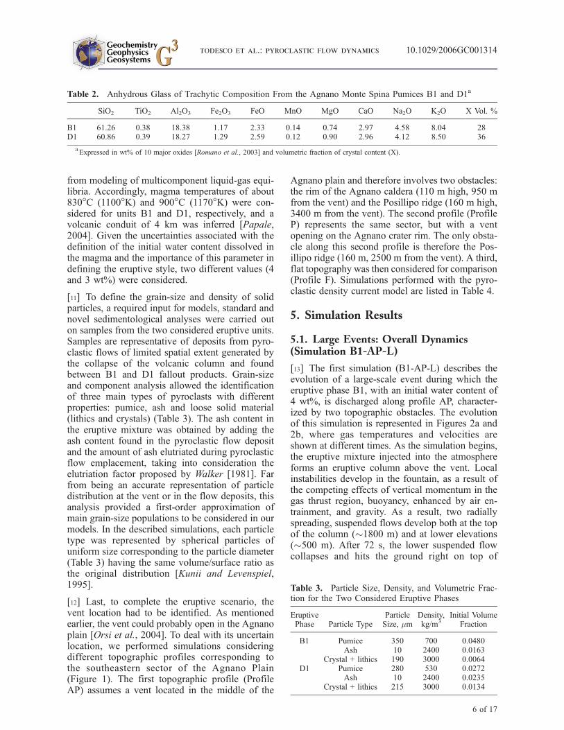
Table 2. Anhydrous Glass of Trachytic Composition From the Agnano Monte Spina Pumices B1 and D1a
SiO2 TiO2 Al2O3 Fe2O3 FeO MnO MgO CaO Na2O K2O X Vol. %
B1 61.26 0.38 18.38 1.17 2.33 0.14 0.74 2.97 4.58 8.04 28D1 60.86 0.39 18.27 1.29 2.59 0.12 0.90 2.96 4.12 8.50 36
aExpressed in wt% of 10 major oxides [Romano et al., 2003] and volumetric fraction of crystal content (X).
Table 3. Particle Size, Density, and Volumetric Frac-tion for the Two Considered Eruptive Phases
EruptivePhase Particle Type
ParticleSize, mm
Density,kg/m3
Initial VolumeFraction
B1 Pumice 350 700 0.0480Ash 10 2400 0.0163
Crystal + lithics 190 3000 0.0064D1 Pumice 280 530 0.0272
Ash 10 2400 0.0235Crystal + lithics 215 3000 0.0134
GeochemistryGeophysicsGeosystems G3G3
todesco et al.: pyroclastic flow dynamics 10.1029/2006GC001314
6 of 17

Agnano. A portion of the eruptive mixture flowsback toward the vent, while the rest forms apyroclastic flow that propagates outward. Thesubsequent evolution is highly unsteady: the col-umn collapse height changes through time, and thepoint where the collapsing material hits the groundalso shifts from the top of the Agnano rim to moreproximal locations. As a consequence, feeding ofthe pyroclastic flow is rather discontinuous, witheruptive material sometimes mostly driven towardthe fountain where it favors a more collapsing
behavior, and other times substantially contributingto flow advancement.
[14] After 136 s, the flow has reached the distalhill, and temperatures in the region between thetwo obstacles are as high as 600�C (Figures 2a and2b). The presence of the distal obstacle reduces theflow velocity without stopping it completely. Fur-ther column collapses significantly thicken theflow and facilitate its advancement beyond thePosillipo ridge. As the flow moves uphill deceler-
Table 4. Eruptive Phase, Vent Conditions, and Topographic Profile for the Simulations of Pyroclastic FlowPropagationa
Simulations Phase M, kg/s H2O, wt% T, �K D, m V, m/s eg P, MPa O
B1-AP-L B1 1 � 108 4 1100 107 127 0.9293 1.152 APB1-AP-S B1 2.5 � 107 3 1100 75 110 0.9595 0.51 APD1-AP D1 1.8 � 108 4 1170(1100) 133 121 0.9359 1.357 APD1-P D1 1.8 � 108 4 1170 133 121 0.9359 1.357 PD1-F D1 1.8 � 108 4 1170 133 121 0.9359 1.357 -
aM, eruption intensity; H2O, water content; T, temperature of eruptive mixture; D, conduit diameter; V, mixture velocity; eg, gas volumetric
fraction; P, pressure; O, topographic obstacles (A, Agnano; P, Posillipo).
Figure 2a. Simulation B1-AP-L. Gas temperature (colors) and velocity field (vectors) after 72 and 136 s ofsimulation. Maximum gas velocity (longest arrows) changes slightly in different plots, ranging from 296 to 308 m/s.Topographic profile with two obstacles, representing the Agnano crater rim and Posillipo. The entire evolution of thetemperature field is shown in Animation 1 provided as dynamic content.
GeochemistryGeophysicsGeosystems G3G3
todesco et al.: pyroclastic flow dynamics 10.1029/2006GC001314
7 of 17

ating, hot gases segregate upwards dragging aportion of solid particles to form a small phoenixcloud (360 s). A thin pyroclastic flow head cansurmount the obstacle and propagate downslope,covering a distance of 6 km in about 300 s.Continuous feeding of the pyroclastic flowincreases temperatures considerably, so that thosebetween the two hills are as high as 700�C. Lowervalues still well above the critical threshold arefound beyond the distal hill (5 km), where the thinflow may attain temperatures of 450�C. At thislocation, short-term temperature attenuation mayoccur as a consequence of discontinuous feeding ofthe flow beyond the obstacle, and due to the strongvent-ward winds which favor air entrainment andcooling. Nevertheless, at the end of the simulation(600 s), high temperatures (450–650�C) are ob-served along most of the computational domain.
[15] Even if the distal hill does not stop flowpropagation, not all the eruptive material cansurmount the obstacle: a fraction accumulates atthe base of the hill and forms a particle-rich,ground-hugging layer which, under favorable con-ditions, may propagate backward toward the ventand interact with new flow fronts (Figure 3).Outward moving pyroclastic flows can either stopthe propagation of the backflow or incorporate the
backflow, dragging particles back toward the hill,or they can flow over the particle-rich layer withoutstopping its backward motion. Prevailing flowdirections at different times and locations dependon the relative size, velocity and density of theforward- and backward-moving flow fronts. Theobstacle also affects the distribution of differentsolid particles. Figure 3 illustrates velocity fieldsand volumetric fractions of pumice, ash, and lithicsafter 300 s of simulation. Different solid particlestend to accumulate along the ground and in front ofthe obstacle, but because of their different proper-ties, their relative proportion at ground levelchanges with time and location. Heavier lithicsare preferentially concentrated in the particle-richlayer that forms in front of the obstacle, whereaslighter pumice and ash particles easily enter phoe-nix clouds when they form.
[16] Results from numerical simulations can alsobe analyzed in terms of hazard flow variables. Asmentioned in the previous section, a first-orderestimate of the impact of pyroclastic flows onbuildings is given by the dynamic pressure of theflow. The time-wise evolution of dynamic pressurefor this simulation (Figure 4a) reflects the complexdynamics of the eruption, characterized by discon-tinuous feeding of the flow with peak values
Figure 2b. Simulation B1-AP-L. Gas temperature (colors) and velocity field (vectors) after 360 and 600 s ofsimulation. Maximum gas velocity (longest arrows) changes slightly in different plots, ranging from 296 to 308 m/s.Topographic profile with two obstacles, representing the Agnano crater rim and Posillipo. The entire evolution of thetemperature field is shown in Animation 1 provided as dynamic content.
GeochemistryGeophysicsGeosystems G3G3
todesco et al.: pyroclastic flow dynamics 10.1029/2006GC001314
8 of 17

generated by periodic column collapses. At adistance of 2500 m from the vent, the first flowfront is associated with a dynamic pressure ofabout 1 kPa. Further column collapses generatemore energetic flows, and after 320 s the dynamicpressure at this location reaches a maximum valueof 3.6 kPa. These values are associated with highhorizontal flow velocities at this location (up to30 m/s, Figure 4b). Note that the last peak (1.4 kPa,after 476 s) is generated by the passage of abackflow propagating from the base of the Pos-illipo hill toward Agnano, with a negative (i.e.,directed toward the vent) horizontal velocity of9 m/s (Figure 4b). Its arrival at this location ismarked by a significant increase in the density ofthe mixture (Figure 4c), which determines anincrease in the dynamic pressure.
[17] The flow velocity is much lower 3300 m fromthe vent due to the presence of the obstacle. Afteran initial peak of about 10 m/s when the first flowfront reaches this location, the horizontal flowvelocity then becomes nearly negligible. Continu-ous changes in flow direction are recorded as newflow fronts arrive and backflows are generated, butabsolute values are commonly close to zero. As aconsequence, dynamic pressure never exceeds
0.5 kPa at this location, despite the large incrementin mixture density (up to 43 kg/m3) associated withparticle sedimentation at the base of the obstacle. Asignificant drop in density occurs at the end of thesimulation, when backflows remove material fromthis location.
[18] The first flow front that passes over the hillreaches the third location (5000 m from the vent)after 228 s of simulation. At this time, the flowvelocity there is close to 20 m/s thanks to thefavorable slope, but it is associated with a very lowmixture density (4 kg/m3). The resulting dynamicpressure (0.6 kPa) is higher than along the vent-ward slope of the ridge, but it still below thethreshold associated with light damage (Table 1).Afterwards, discontinuous feeding and ventwardwinds determine lower flow velocities, such thatdynamic pressures remain below 0.35 kPa.
[19] Gas temperature represents another importanthazard variable (Figure 4d). In areas invaded bypyroclastic flows this value is commonly above thecritical threshold for human survival, but temper-ature effects on buildings, and on the people insideshelters, vary considerably in relation to the lengthof exposure to extreme heat. Figure 4d shows howthe arrival of a flow causes an immediate increase
Figure 3. Simulation B1-AP-L. Detail of the volumetric particle fraction (log scale) of pumice, ash, and lithics atthe base of Posillipo after 300 s of simulation. The velocity field is also shown (longest arrows represent themaximum particle velocity, here about 60 m/s).
GeochemistryGeophysicsGeosystems G3G3
todesco et al.: pyroclastic flow dynamics 10.1029/2006GC001314
9 of 17

in temperature to extreme values which are main-tained throughout the simulation. Up to 3300 mfrom the vent temperatures can reach 600�C.Beyond the hill, temperatures are only slightlylower (400–500�C) and remain rather constant,with only minor fluctuations associated with dis-continuous flow feeding and air entrainment.
[20] The third hazard variable associated withpyroclastic flow propagation is the concentrationof inhalable particles (<100 mm). In the simulationspresented here, the only inhalable particle type isash. The critical ash concentration roughly corre-sponds to a volumetric fraction of 4 � 10�5. Thisvalue is generally exceeded by one order of mag-nitude everywhere in this simulation (not shown),even though at distal locations large oscillationsmay temporarily drive ash fractions below thisthreshold limit.
5.2. Small Events: Overall Dynamics(Simulation B1-AP-S)
[21] A few simulations were performed consider-ing a smaller mass eruption rate (2.5 � 107 kg/s).Initial water contents of 4 and 3 wt% were consid-ered, and simulations were performed along thethree topographic profiles presented above. In allcases, flows are characterized by shorter runoutsand are not capable of overriding the Posilliporidge.
[22] We here only describe the simulation per-formed along the AP profile with an initial watercontent of 3 wt%. Figure 5 shows the temperaturedistribution and velocity fields at three differentmoments during the simulation. As in the case ofthe larger event, an eruptive column develops andcollapses shortly thereafter. In this case, however,the eruptive material hits the ground closer to thevent, in front of the Agnano rim (60 s). As the flowpropagates radially, the rim represents a first andvery close obstacle which does not stop but hindersflow advancement. The low water content favorsthe collapsing behavior, thereby ensuring a contin-uous feeding of the flow, which contributes to itspropagation. As the first obstacle is overcome, afraction of the eruptive mixture slides back towardthe vent, forming a small and proximal backflow.A thin flow propagates outward, and small phoenixclouds are generated as the flow velocity declineswith distance from the vent. After about 300 s, thePosillipo ridge is finally reached. The flow, how-ever, does not have enough energy to climb theslope, and a thin backflow forms at the base of theobstacle. The overall dynamics lead to the devel-
Figure 4. Simulation B1-AP-L. Time-wise distribu-tion of hazard flow variables at ground level and atdifferent distances from the vent: between the hills(2500 m); at the base of Posillipo (3300 m); and beyondPosillipo (5000 m). (a) Dynamic pressure (kPa); (b) flowvelocity (m/s); (c) density of the eruptivemixture (kg/m3);and (d) gas temperature (�C). Details of flow propagationbetween the obstacles, and associated dynamic pressurechanges, are shown in Animation 2 provided as dynamiccontent.
GeochemistryGeophysicsGeosystems G3G3
todesco et al.: pyroclastic flow dynamics 10.1029/2006GC001314
10 of 17

opment of winds which blow toward the vent anddrag the phoenix cloud toward the fountain (650 s).The simulation runs for 1000 s, but the flow isnever capable of surmounting the distal obstacle.Conditions between the two hills remain deadlydue to high temperatures (400–700�C) and ashcontents above the critical threshold; lower flowvelocities produce a dynamic pressure of �1 kPa.
5.3. Large Events: Role of Topography(Simulations D1-AP, D1-P, D1-F)
[23] Other simulations were performed consideringthe D1 eruptive unit. This unit is characterized by amass eruption rate of 1.8 � 108 kg/s, a slightlyhigher eruption temperature (�900�C), and a lowerparticle fraction containing less pumice than erup-tive unit B1. A simulation with an eruptive mixturetemperature of �830�C was also performed toallow comparison with simulation B1-AP-L. Theevolution along profile AP is qualitatively similarto the one described for eruptive phase B1: subse-quent column collapses feed pyroclastic flows thatpropagate outward, finally overriding the Posilliporidge. Phoenix clouds form as the flow decelerates,and backflows are generated down the ridge slope.In this case, the larger mass flow rate at the vent
generates a wider eruptive column and a thickerpyroclastic flow that propagates somewhat fasterthan in simulation B1-AP-L. Backward motion isrestricted by the nearby Posillipo ridge, as thecontinuous generation of new and fast flow frontshinders the propagation of backflows toward themore proximal locations. Figure 6 compares dy-namic pressures at ground level, 2500 m from the
Figure 5. Simulation B1-AP-S. Gas temperature (colors) and velocity field (vectors) after 60, 300, and 650 s ofsimulation. Maximum flow velocity ranges from 214 m/s (60 s) to 196 m/s (300 and 650 s). Topographic profile withtwo obstacles representing the Agnano crater rim and Posillipo.
Figure 6. Temporal evolution of dynamic pressure(kPa) in simulations B1-AP-L and D1-AP (both runwith an eruptive mixture temperature of 830�C).Reported values refer to ground level and to a distanceof 2500 m from the vent.
GeochemistryGeophysicsGeosystems G3G3
todesco et al.: pyroclastic flow dynamics 10.1029/2006GC001314
11 of 17

vent, for simulations D1-AP and B1-AP-L, both at830�K. In both cases, peak values correspond tothe arrival of new flow fronts generated by columncollapses. The larger mass flow rate in simulationD1-AP generates faster flows (up to 55 m/s) withrespect to simulation B1-AP-L and therefore higherdynamic pressures (up to 11.7 kPa). A largernumber of column collapses (and associated pyro-clastic flow arrivals) also characterize the largerD1-AP event.
[24] Simulations performed with a higher initialtemperature (900�C) were run along three differenttopographic profiles: one with two obstacles, as inthe previous case (profile AP); one with the Pos-illipo ridge only (profile P), and a third, flat profilefor comparison (profile F). The impact of obstaclesis strictly in relation to their distance from the vent.Distal obstacles generally hinder flow propagationby reducing flow velocity and inducing particlesedimentation. Closer obstacles may interfere withthe column dynamics: if the eruptive mixture hitsthe ground along the Agnano inner slope or closerto the vent the crater rim will act as a barrier,driving most of the eruptive material toward thevent, where it will interfere with the discharge ofnew material and induce a more collapsing behav-
ior. In contrast, if the collapse occurs beyond thetop of the rim, outward propagation will be en-hanced by the rim slope.
[25] The initial evolution is similar in the threesimulations: an eruptive column forms and reachesa height of about 2300 m, where it begins to spreadout, forming a suspended flow 500 m above thesurface. After 70 s this flow collapses, hitting theground 1–1.5 km from the vent. This correspondsto the position of the Agnano hill along the APprofile: the slope accelerates the outward, downhillpropagation of the flow. As a result, the pyroclasticflow that forms along this profile is initially thefastest. Figure 7a illustrates flow propagation alongthe three different profiles after 140 s of simulation.At this time, the distal obstacle has been reachedand overcome, causing a deceleration of the flowalong both profiles AP and P. The most advancedpyroclastic flow head is now the one propagatingalong the flat topography. However, the flow alongAP maintains the advantage gained down the slopeof the proximal hill, and it is still ahead of the flowalong profile P. Sedimentation is favored in front ofthe distal obstacle, where small backflows form,but their full development is prevented by thecontinuous arrival of new flow fronts discharged
Figure 7a. Gas temperature (colors) and velocity field (vectors) after 140 s along three different topographic profiles:with two obstacles (simulation D1-AP), with one obstacle (D1-P), and flat (D1-F). Maximum gas velocity ranges from307 m/s (D1-AP) to 309 m/s (D1-F).
GeochemistryGeophysicsGeosystems G3G3
todesco et al.: pyroclastic flow dynamics 10.1029/2006GC001314
12 of 17
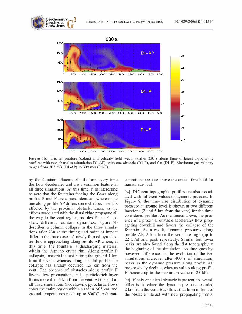
by the fountain. Phoenix clouds form every timethe flow decelerates and are a common feature inall three simulations. At this time, it is interestingto note that the fountains feeding the flows alongprofile P and F are almost identical, whereas theone along profile AP differs somewhat because it isaffected by the proximal obstacle. Later, as theeffects associated with the distal ridge propagate allthe way to the vent region, profiles P and F alsoshow different fountain dynamics. Figure 7bdescribes a column collapse in the three simula-tions after 230 s: the timing and point of impactdiffer in the three cases. A newly formed pyroclas-tic flow is approaching along profile AP where, atthis time, the fountain is discharging materialwithin the Agnano crater rim. Along profile Pcollapsing material is just hitting the ground 1 kmfrom the vent, whereas along the flat profile thecollapse has already occurred 1.5 km from thevent. The absence of obstacles along profile Ffavors flow propagation, and a particle-rich layerforms more than 3 km from the vent. At the end ofall three simulations (not shown), pyroclastic flowscover the entire region within a radius of 5 km, andground temperatures reach up to 800�C. Ash con-
centrations are also above the critical threshold forhuman survival.
[26] Different topographic profiles are also associ-ated with different values of dynamic pressure. InFigure 8, the time-wise distribution of dynamicpressure at ground level is shown at two differentlocations (2 and 5 km from the vent) for the threeconsidered profiles. As mentioned above, the pres-ence of a proximal obstacle accelerates flow prop-agating downhill and favors the collapse of thefountain. As a result, dynamic pressures alongprofile AP, 2 km from the vent, are high (up to22 kPa) and peak repeatedly. Similar but lowerpeaks are also found along the flat topography atthe beginning of the simulation. As time goes by,however, differences in the evolution of the twosimulations increase: after 400 s of simulation,peaks in the dynamic pressure along profile APprogressively decline, whereas values along profileF increase up to the maximum value of 25 kPa.
[27] If only one distal obstacle is present, its overalleffect is to reduce the dynamic pressure recorded2 km from the vent. Backflows that form in front ofthe obstacle interact with new propagating fronts,
Figure 7b. Gas temperature (colors) and velocity field (vectors) after 230 s along three different topographicprofiles: with two obstacles (simulation D1-AP), with one obstacle (D1-P), and flat (D1-F). Maximum gas velocityranges from 307 m/s (D1-AP) to 309 m/s (D1-F).
GeochemistryGeophysicsGeosystems G3G3
todesco et al.: pyroclastic flow dynamics 10.1029/2006GC001314
13 of 17

reducing their velocity well before the obstacle.With respect to the flat topography, dynamic pres-sures (up to 13 kPa, 406 s) are therefore lower atthis location.
[28] At a distal location (5 km), the shelteringeffect of obstacles is more evident: dynamic pres-
sures do not exceed 1.5 kPa along profile AP and3 kPa along profile P. Note that dynamic pressuresfor these two profiles do not differ much at thislocation, suggesting that the proximal obstacle onlyplays a minor role. Attenuation of the flow impactis also observed along the flat profile due to thedistance from the vent: the maximum dynamicpressure at this location (11 kPa) is less than halfthat observed at 2 km.
6. Conclusions
[29] In this work we addressed the problem ofpyroclastic flow propagation in a typical calderasetting, where crater rims may hinder flow ad-vancement. In particular, our application focusedon the southeastern sector of the Phlegrean Fieldscaldera, where the Posillipo ridge could possiblyprotect the town of Naples. Simulations are basedon the definition of the volcanic system that fed theAgnano-Monte Spina eruption, which was takenhere as a reference case history. Magma ascentalong the volcanic conduit was simulated in orderto calculate appropriate conditions at the vent.Dispersion of the eruptive mixture into the atmo-sphere was simulated on a 2-D, axisymmetricdomain for set vent conditions. Modeling resultsdescribe the development of a collapsing volcaniccolumn and the generation and propagation ofpyroclastic density currents. Different magma com-positions, water contents, mass eruption rates, andtopographic profiles, all consistent with data on theAMS eruption, were considered in the differentscenarios. Performed simulations reveal some in-teresting features of pyroclastic flow propagationalong a flat ground surface with one or twoconcentric crater rims.
[30] In agreement with previous results [Todesco etal., 2002], simulations suggest that eruption inten-sity is the main parameter controlling the propaga-tion of pyroclastic flows. In the present application,large events (�108 kg/s) generate pyroclastic flowswhich are thicker and faster, and which overruntopographic obstacles more easily, covering largerdistances. In contrast, flows generated by smallscale events (2.5 � 107 kg/s) are fully confinedby the distal ridge, even when considering lowinitial water contents (3 wt%) which favor columncollapse.
[31] In addition, simulations showed how the pres-ence of obstacles affects flow propagation in sev-eral ways. Obstacles directly modify the flowvelocity, which decreases on the ventward slope
Figure 8. Temporal evolution of dynamic pressure(kPa) at ground level along different topographicprofiles: (a) simulations D1-AP and D1-F, 2000 m fromthe vent; (b) simulations D1-P and D1-F, 2000 m fromthe vent; and (c) simulations D1-AP, D1-P, and D1-F,5000 m from the vent, beyond the obstacles. Maximumgas velocity ranges from 304 m/s (D1-AP) to 312 m/s(D1-F).
GeochemistryGeophysicsGeosystems G3G3
todesco et al.: pyroclastic flow dynamics 10.1029/2006GC001314
14 of 17

of the hill and increases again whenever the flowcan surmount the obstacle and propagate outward,downhill. Every time the flow decelerates, hotgases and light particles decouple from the flowand rise to form phoenix clouds, thereby contrib-uting to flow deceleration.
[32] As the flow propagates uphill, a portion ofmaterial segregates at the base of the flow andeventually slides back downward, generating back-flows that propagate toward the vent. These back-flows, already identified in the field [Fisher, 1990;Ort et al., 2003], represent another importantfeature (along with obstacles) affecting the outwardpropagation of flows. Interaction between newflow fronts and backflows certainly generates com-plex and interesting depositional features. Al-though the interpretation of modeling results inthis respect is beyond the scope of the presentpaper, if properly investigated these features couldprovide elements for interpreting eruptive sequen-ces in the field.
[33] If the obstacle is close to the vent, as is theAgnano crater rim in our simulations, backflowsmay enter the vent region and interfere with thefountain dynamics. As a result, the presence of aproximal obstacle, instead of providing some kindof protection to the surrounding regions, promotescollapse events and more continuous feeding ofpyroclastic flows. The resulting dynamic pressureis therefore higher and characterized by a largernumber of peaks. On the other hand, the presenceof two concentric crater rims reduces dynamicpressures in the distal region down to valuescorresponding to only light damage according tothe scale of Baxter et al. [2005]; it may alsoprevent flow propagation in the case of smalleruptions. The presence of obstacles does not inany way attenuate temperatures or the distributionof particle fractions, which in the case of largeevents reach and maintain values well above sur-vival thresholds, even beyond the hills.
[34] Our results suggest that in the case of largeevents distal obstacles as high as the Posillipo hilldo not protect the area beyond. This finding is notnew in the literature, but it is for the first time basedon quantitative results from a realistic description ofthe involved physical processes. As the model doesnot account for the real 3-D topography, our calcu-lation of dynamic pressure at different locationsonly represents a first order estimate of the impactassociated with a given scenario; it should beconsidered a starting point for detailed pyroclasticflow hazard assessment in the area. The 3-D version
of the model has already been developed and isbeing tested on the Vesuvius [Cavazzoni et al.,2005; Esposti Ongaro et al., 2006; T. EspostiOngaro et al., A parallel multiphase flow code forthe 3D simulation of explosive volcanic eruptions,submitted to Parallel Computing, 2006]. The ap-plication of 3-D models which account for the realcaldera topography will therefore be possible in thenear future. The physical model, however, does notallow full hazard assessment, as it does not provideany information on the actual probability associatedwith the simulated phenomenon. Numerical mod-eling represents an important contribution to hazardassessment, which requires the availability andintegration of multidisciplinary data.
Acknowledgments
[35] This work was carried out within the framework of GNV
Project 17 (2001–2003 Framework Program) and of the V3-
Campi Flegrei Project funded by the Italian Department of
Civil Protection. The authors wish to thank George Bergantz
and an anonymous reviewer for their comments on the
manuscript.
References
Alberico, I., L. Lirer, P. Petrosino, and R. Scandone (2002), Amethodology for the evaluation of long-term volcanic riskfrom pyroclastic flows in Campi Flegrei (Italy), J. Volcanol.Geotherm. Res., 116, 63–78.
Barberi, F., G. Corrado, F. Innocenti, and G. Luongo (1984a),Phlegrean Fields 1982–1984: Brief chronicle of a volcanoemergency in a densely populated area, Bull. Volcanol., 41,1–22.
Barberi, F., F. Innocenti, G. Luongo, M. Rosi, R. Santacroce,and R. Scandone (1984b), Il rischio vulcanico nei CampiFlegrei, CNR-GNV report, Gruppo Naz. per la Vulcanol.,Cons. Naz. delle Ric., Rome.
Baxter, P. J. (1990), Medical effects of volcanic eruptions: I,Main causes of death and injury, Bull. Volcanol., 52, 532–544.
Baxter, P. J., A. Neri, and M. Todesco (1998), Physical mod-eling and human survival in pyroclastic flows, Nat. Hazards,17, 163–176.
Baxter, P. J., R. Boyle, P. Cole, A. Neri, R. Spence, andG. Zuccaro (2005), The impact of pyroclastic surges onbuildings at the eruption of the Soufriere Hills volcano,Montserrat, Bull. Volcanol., 67, 292–313.
Cavazzoni, C., T. Esposti Ongaro, G. Erbacci, A. Neri, andG. Macedonio (2005), High performance computing simula-tions of pyroclastic flows, Comput. Phys. Comm., 169, 454–456.
Clarke, A., B. Voight, A. Neri, and G. Macedonio (2002),Transient dynamics of vulcanian explosions and column col-lapse, Nature, 415, 897–901.
Cook, N. J. (1985), The Designer’s Guide to Wind Loading ofBuilding Structures, Butterworths, London.
Cordoba, G. (2005), A numerical model for the dynamics ofpyroclastic flows at Galeras Volcano, Colombia, J. Volcanol.Geotherm. Res., 139, 59–71.
GeochemistryGeophysicsGeosystems G3G3
todesco et al.: pyroclastic flow dynamics 10.1029/2006GC001314
15 of 17

Dartevelle, S. (2004), Numerical modeling of geophysicalgranular flows: 1. A comprehensive approach to granularrheologies and geophysical multiphase flows, Geochem.Geophys. Geosyst., 5, Q08003, doi:10.1029/2003GC000636.
Dartevelle, S., W. I. Rose, J. Stix, K. Kelfoun, and J. W.Vallance (2004), Numerical modeling of geophysical granu-lar flows: 2. Computer simulations of plinian clouds andpyroclastic flows and surges, Geochem. Geophys. Geosyst.,5, Q08004, doi:10.1029/2003GC000637.
Dellino, P., R. Isaia, L. La Volpe, and G. Orsi (2001), Statis-tical analysis of textural data from complex pyroclastic se-quences: implications for fragmentation processes of theAgnano-Monte Spina Tephra (4.1 ka), Phlegrean Fields,southern Italy, Bull. Volcanol., 63, 433–461.
Dellino, P., R. Isaia, L. La Volpe, and G. Orsi (2004a), Inter-action between particles transported by fallout and surge inthe deposits of the Agnano-Monte Spina eruption (CampiFlegrei, Southern Italy), J. Volcanol. Geotherm. Res., 133,193–210.
Dellino, P., R. Isaia, and M. Veneruso (2004b), Turbulentboundary layer shear flows as an approximation of basesurges at Campi Flegrei (Southern Italy), J. Volcanol.Geotherm. Res., 133, 211–228.
de Vita, S., et al. (1999), The Agnano-Monte Spina eruption(4.1 ka) in the resurgent, nested Campi Flegrei caldera(Italy), J. Volcanol. Geotherm. Res., 91, 269–301.
Di Muro, A., A. Neri, and M. Rosi (2004), Contemporaneousconvective and collapsing eruptive dynamics: The transi-tional regime of explosive eruptions, Geophys. Res. Lett.,31, L10607, doi:10.1029/2004GL019709.
Di Vito, M. A., L. Lirer, G. Mastrolorenzo, and G. Rolandi(1987), The Monte Nuovo eruption (Campi Flegrei, Italy),Bull. Volcanol., 49, 608–615.
Di Vito, M. A., R. Isaia, G. Orsi, J. Southon, S. de Vita,M. D’Antonio, L. Pappalardo, and M. Piochi (1999), Volca-nic and deformational history of the Campi Flegrei caldera inthe past 12 ka, J. Volcanol. Geotherm. Res., 91, 221–246.
Dobran, F., A. Neri, and G. Macedonio (1993), Numericalsimulations of collapsing volcanic columns, J. Geophys.Res., 98, 4231–4259.
Dobran, F., A. Neri, and M. Todesco (1994), Assessing pyr-oclastic flow hazard at Vesuvius, Nature, 367, 551–554.
D’Oriano, C., E. Poggianti, A. Bertagnini, R. Cioni, P. Landi,M. Polacci, and M. Rosi (2005), Changes in eruptive styleduring the A. D. 1538 Monte Nuovo eruption (PhlegreanFields, Italy): The role of syn-eruptive crystallization, Bull.Volcanol., 67, 601–621.
Esposti Ongaro, T., A. Neri, M. Todesco, and G. Macedonio(2002), Pyroclastic flow hazard at Vesuvius from numericalmodelling. II. Analysis of local flow variables, Bull. Volca-nol., 64, 178–191.
Esposti Ongaro, T., A. Neri, C. Cavazzoni, G. Erbacci,A. Clarke, and B. Voight (2006), A new high-performance3D multiphase flow code for the simulation of collapsingcolumns and volcanic blasts, paper presented at Cities onVolcanoes 4, IAVCEI, Quito, Ecuador, 23–27 Jan.
Fisher, R. V. (1990), Transport and deposition of pyroclasticsurge across an area of high relief: The May 1980 eruption ofMount St Helens, Washington, Geol. Soc. Am. Bull., 102,1038–1054.
Herzog, M., H. F. Graf, C. Textor, and J. M. Oberhuber (1998),The effects of phase change of water on the development ofvolcanic plumes, J. Volcanol. Geotherm. Res., 87, 55–74.
Isaia, R., M. D’Antonio, F. Dell’Erba, M. Di Vito, and G. Orsi(2004), The Astroni volcano: The only example of closelyspaced eruptions in the same vent area during the recent
history of the Campi Flegrei caldera (Italy), J. Volcanol.Geotherm. Res., 133, 171–192.
Ishimine, Y. (2005), Numerical study of pyroclastic surges,J. Volcanol. Geotherm. Res., 139, 33–57.
Kunii, D., and O. Levenspiel (1995), Fluidization Engineer-ing, Elsevier, New York.
Lirer, L., P. Petrosino, and I. Alberico (2001), Hazard assess-ment at volcanic fields: The Campi Flegrei case history,J. Volcanol. Geotherm. Res., 112, 53–74.
Mason, P. J. (1994), Large-eddy simulation: a critical review ofthe technique, Q. J. R. Meteorol. Soc., 120, 1–26.
Neri, A., and F. Dobran (1994), Influence of eruption para-meters on the thermofluid dynamics of collapsing volcaniccolumns, J. Geophys. Res., 99, 11,833–11,857.
Neri, A., and D. Gidaspow (2000), Riser hydrodynamics: Si-mulation using kinetic theory, AIChE J., 46, 52–67.
Neri, A., and G. Macedonio (1996), Numerical simulation ofcollapsing volcanic columns with particles of two sizes,J. Geophys. Res., 101, 8153–8174.
Neri, A., P. Papale, and G. Macedonio (1998), The role ofmagma composition and water content in explosive erup-tions: II. Pyroclastic dispersion dynamics, J. Volcanol.Geotherm. Res., 87, 95–115.
Neri, A., P. Papale, D. Del Seppia, and R. Santacroce (2002),Couplet conduit and atmospheric dispersion dynamics dur-ing the Plinian phase of the AD 79 Vesuvius eruption,J. Volcanol. Geotherm., Res., 120, 141–160.
Neri, A., T. Esposti Ongaro, G. Macedonio, and D. Gidaspow(2003), Multiparticle simulation of collapsing volcanic col-umns and pyroclastic flow, J. Geophys. Res., 108(B4), 2202,doi:10.1029/2001JB000508.
Nuovo Colombo (1990), Carichi nelle costruzioni, manualedell’ingegnere, Hoepli, Milan, Italy.
Oberhuber, J. M., M. Herzog, H. F. Graf, and K. Schwanke(1998), Volcanic plume simulation on a large scale, J. Vol-canol. Geotherm. Res., 87, 29–53.
Orsi, G., S. de Vita, and M. Di Vito (1996), The restless,resurgent Campi Flegrei nested caldera (Italy): Constraintson its evolution and configuration, J. Volcanol. Geotherm.Res., 74, 179–214.
Orsi, G., M. Di Vito, and R. Isaia (2004), Volcanic hazardassessment at the restless Campi Flegrei caldera, Bull. Vol-canol., 66, 514–530.
Ort, M. H., G. Orsi, L. Pappalardo, and R. V. Fisher (2003),Anisotropy of magnetic susceptibility studies of depositionalprocesses in the Campanian Ignimbrite, Italy, Bull. Volcanol.,65, 55–72.
Papale, P. (2001), Dynamics of magma flow in volcanic con-duits with variable fragmentation efficiency and nonequilib-rium pumice degassing, J. Geophys. Res., 106, 11,043–11,065.
Papale, P. (2004), Simulation of eruptive scenarios at Phle-grean Fields based on field, laboratory and numerical studiesand implication for volcanic hazard, Final Report of theINGV 2001–2003 Frame Program, Ist. Naz. di Geofis. eVulcanol., Bologna, Italy.
Piochi, M., G. Mastrolorenzo, and L. Pappalardo (2005),Magma ascent and eruptive processes from textural andcompositional features of Monte Nuovo pyroclastic pro-ducts, Campi Flegrei, Italy, Bull. Volcanol., 67, 663–678.
Romano, C., D. Giordano, P. Papale, V. Mincione, D. B.Dingwell, and M. Rosi (2003), The dry and hydrous viscos-ities of silicate melts from Vesuvius and Phlegrean Fields,Chem. Geol., 202, 23–38.
Rosi, M., and R. Santacroce (1984), Volcanic hazardassessment in the Phlegraean Fields: A contribution based
GeochemistryGeophysicsGeosystems G3G3
todesco et al.: pyroclastic flow dynamics 10.1029/2006GC001314
16 of 17

on stratigraphic and historical data, Bull. Volcanol., 47,359–370.
Rosi, M., and A. Sbrana (Eds.) (1987), The Phlegrean Fields,‘‘La Ricerca Scientifica,’’ vol. 114, Cons. Naz. delle Ric.,Rome.
Rosi, M., A. Sbrana, and C. Principe (1983), The Phle-graean Fields: Structural evolution, volcanic history anderuptive mechanisms, J. Volcanol. Geotherm. Res., 17,273–288.
Rossano, S., G. Mastrolorenzo, and G. De Natale (2004),Numerical simulation of pyroclastic density currents onCampi Flegrei topography: A tool for statistical hazard esti-mation, J. Volcanol. Geotherm. Res., 132, 1–14.
Sheridan, M. F., and M. C. Malin (1983), Application of com-puter assisted mapping to volcanic hazard evaluation ofsurge eruptions: Vulcano, Lipari and Vesuvius, J. Volcanol.Geotherm. Res., 17, 187–202.
Suzuki, Y. J., T. Koyaguchi, M. Ogawa, and I. Hachisu (2005),A numerical study of turbulent mixing in eruption cloudsusing a three-dimensional fluid dynamics model, J. Geophys.Res., 110, B08201, doi:10.1029/2004JB003460.
Todesco, M., A. Neri, T. Esposti Ongaro, P. Papale,G. Macedonio, R. Santacroce, and A. Longo (2002), Pyro-clastic flow hazard at Vesuvius from numerical modelling.I. Large scale dynamics, Bull. Volcanol., 64, 155–177.
Valentine, G. A. (1998), Damage to structures by pyroclasticflows and surges, inferred from nuclear weapons effects,J. Volcanol. Geotherm. Res., 87, 117–140.
Valentine, G. A., and K. H. Wohletz (1989), Numerical modelsof Plinian eruption columns and pyroclastic flows, J. Geo-phys. Res., 94, 1867–1887.
Walker, J. P. L. (1981), The Waimihia and Hatepe Pliniandeposits from the rhyolitic Taupo volcanic centre, N. Z. F.,Geol. Geophys., 24, 305–324.
GeochemistryGeophysicsGeosystems G3G3
todesco et al.: pyroclastic flow dynamics 10.1029/2006GC001314
17 of 17