
1202-15 for Website.pdf - Colorado Department of Agriculture
Upload
khangminh22Category
view
6download
0
● Norms and standards; ● Analysis – methods
comparison and developments;
● Country reports updates/review of state-of-the-art;
● Fuels and chemicals from pyrolysis.
For the coming triennium the new Priority Topics include: ● Review of bio-oil
applications; ● Bio-oil standardization; ● Round Robin for analytical
method development; ● Technoeconomic
assessment of thermochemical liquefaction technologies.
In this issue of the newsletter There are several articles from the participants describing the latest developments in fast pyrolysis, including work in
Inside this issue
Members 2
Articles 3-32
Events 33-35
Publications 36
Contact the Editor 37
The IEA Bioenergy Task 34 for Pyrolysis has finished its work in the triennium, from 2010 to 2012. Current participants in the Task are Canada, Finland, Germany, Netherlands and the UK with leadership provided by the US. This newsletter is produced by the Task to stimulate the interaction of researchers with commercial entities in the field of biomass pyrolysis. Aims & Objectives The overall objective of Task 34 is to improve the rate of implementation and success of fast pyrolysis for fuels and chemicals by contributing to the resolution of critical technical areas and disseminating relevant information particularly to industry and policy makers. The scope of the Task will be to monitor, review and contribute to the resolution of issues that will permit more successful and more rapid implementation of pyrolysis technology, including identification of opportunities to provide a substantial contribution to bioenergy. The following have been the Priority Topics for Task 34 for the past three years:
IEA Bioenergy Agreement Task 34 Newsletter — PyNe 32 Page 1
Continued on page 2 Published by Aston University Bioenergy Research Group
ISSN 2040-2759
Welcome to Task 34 By Doug Elliott, Task 34 Leader
December 2012
IEA Bioenergy
Task 34 Pyrolysis
PyNe 32
Welcome to Task 34 By Doug Elliott, Task 34 Leader
December 2012

Welcome...continued
Members of IEA Bioenergy Task 34 2010-2012
Finland on the standards development within CEN and product registration within REACH; in the Netherlands on the developments in applications for bio-oil, including gasification and roofing material; from the UK a contribution on Miscanthus fast pyrolysis; and from the US we have contributions from RTI describing its hydropyrolysis developments, from Mississippi State University and from UOP describing the progress at the Integrated Biorefinery. There is also an updated calendar of events of interest to the biomass pyrolysis community. An extension of the Round Robin on bio-oil viscosity and accelerated aging continued in
USA Doug Elliott
Battelle PNNL 902 Battelle Boulevard
P.O. Box 999 Richland
Washington, 99352 USA
T: +1 509 375 2248 F: +1 509 372 4732
IEA Bioenergy Agreement Task 34 Newsletter — PyNe 32 Page 2
three of the participant laboratories. The report of the results of those tests is now available as a journal article in Energy & Fuels, electronically available “ASAP” and soon to be published. Results of the IEA Round Robin on Viscosity and Aging of Fast Pyrolysis Bio-oils: Long-Term Tests and Repeatability, Douglas C. Elliott, Anja Oasmaa, Dietrich Meier, Fernando Preto, and Anthony V. Bridgwater. dx.doi.org/10.1021/ef301607v. In the past, you may have seen the short introductory articles from the national team leaders from each of the participating countries summarizing the particular biomass pyrolysis efforts in
their countries. These have been moved to direct links on our webpage—please use the tab for Developments for Country Report Updates. Similarly, in the past we have included an overview of the latest Task meeting including information on the developments within each of the Priority Topics. These summaries will now be found on the website by using the Events tab and linking to Task 34 Meetings. We hope you find the website (www.pyne.co.uk) useful. Doug Elliott Battelle PNNL P.O. Box 999, Richland Washington 99352, USA Tel: +1 509 375 2248
GERMANY Dietrich Meier Johann Heinrich von Thünen-Institut (vTI) Institute of Wood Technology and Wood Biology (HTB), Leuschnerstr. 91, D-21031 Hamburg, GERMANY T: +49 40 73 962517 F: +49 40 73 962599 E: [email protected]
CANADA Fernando Preto Bioenergy Systems, CanmetENERGY, Natural Resources Canada, 1 Haanel Drive, Ottawa, CANADA K1A 1M1 T: +1 613 996 5589 E: [email protected]
FINLAND Anja Oasmaa VTT Technical Research Centre of Finland, Liquid Biofuels Biologinkuja 3-5, P.O. Box 1000, Espoo, FIN-02044 VTT, FINLAND T: +358 20 722 5594 F: +358 20 722 7048 E: [email protected]
UK Tony Bridgwater Aston University Bioenergy Research Group School of Engineering and Applied Science, Birmingham B4 7ET, UK T: +44 121 204 3381 F: +44 121 204 3680 E: [email protected]
Doug Elliott Task 34 Leader
NETHERLANDS Bert van de Beld BTG Biomass Technology Group bv, Josink Esweg 34, 7545 PN, NETHERLANDS T: +31 53 486 1186 F: +31 53 486 1180 E: [email protected]

Levoglucosan is the major anhydrosugar component of bio-oil produced by fast pyrolysis. Previous research has shown that levoglucosan yield can be greatly increased if a mild acid pretreatment is applied to demineralize the feedstock prior to pyrolysis. The interest in levoglucosan production is that it provides a route to production of
MSU invents and files a patent on a method to increase anhydrosugar yields from lignocellulosic biomass
IEA Bioenergy Agreement Task 34 Newsletter — PyNe 32 Page 3
Update from Philip Steele of Mississippi State University, USA
monomeric sugars, primarily glucose, which can be utilized to produce biochemically derived fuels (ethanol, butanol, etc). Yield of levoglucosan from lignocellusice biomass without acid pretreatment is about 3% of dry biomass weight; with pretreatment it is approximately 12%. Mississippi State University (MSU) has filed a patent on a method to produce levoglucosan at 16.5% yield in bio-oil. The method depends mainly on prevention of levoglucosan decomposition in the vapor phase and during condensation. The anhydrosugars can be utilized to produce hydrogen or hydrolyzed to glucose to be used to grow ethanol or other microbial fuel producers. The following describes a method to produce glucose and grow ethanol microbes from the levoglucosan produced by the new MSU method.
Figure 1: Stages of inhibitor removal showing the raw aqueous fraction bio-oil in the leftmost bottle; the centre bottle shows the aqueous fraction after being filtered through activated charcoal; the rightmost bottle shows the hydrolyzed filtered bio-oil containing high glucose content.
The aqueous fraction of bio-oil was produced by the water fractionation method by addition of 1:1 water to the bio-oil produced with levoglucosan increased to 16.5%. Inhibitors were removed by filtration through activated carbon. The filtered aqueous fraction was then acid hydrolyzed to convert the anhydrosugars to glucose. Following inhibitor removal and acid hydrolysis of the high sugars, aqueous fraction glucose was produced. Hydrolyzate was successfully filtered to remove inhibitors such that ethanol microbes were not hindered. Saccharomyces cerevisiae fermented the hydrolyzed aqueous fraction to ethanol. This research is based upon work performed through the Sustainable Energy Research Center at Mississippi State University and is supported by the Department of Energy under Award Number DE-FG3606GO86025. Contact Philip Steele Mississippi State University Box 9820, Mississippi State, Mississippi 39762-9820 USA T: +1 662 325 8083 E: [email protected] www.msstate.edu

Pressurized entrained flow gasification of pyrolysis oil
IEA Bioenergy Agreement Task 34 Newsletter — PyNe 32 Page 4
Figure 1: Pyrolysis oil pump skid at the ETC site during the gasification trial.
Within the framework of the SUPRABIO project, ETC (Sweden) and BTG (Netherlands) have carried out successful experiments with entrained flow gasification of pyrolysis oil. Several tons of pyrolysis oil were made from pine wood in the pilot plant at BTG in Enschede, the Netherlands, and shipped along with a dedicated fuel pump skid to Sweden. Using the pump skid, the pyrolysis oil was then gasified in the pressurised entrained flow biomass gasifier (PEBG) at the ETC research facilities in Piteå, Sweden. The pyrolysis oil pump skid was specifically designed to comply with the requirements of the PEBG. Important aspects were the realisation of a steady continuous flow of the acidic, pyrolysis oil into a pressurized environment. The data acquisition of the pump skid was fitted with dedicated
Evert Leijenhorst (above) of BTG in the Netherlands and Olov Öhrman (below) of the Energy Technology Centre (ETC) in Sweden outline a joint project
Continued on page 5
algorithms to allow fine tuning of both viscosity and feed flow. In Figure 1, a picture of the pump skid is presented and the pilot gasification plant is shown in Figure 2. The PEBG is described in detail in reference [1]. The PEBG pilot plant, built by Infjärdens Värme AB (IVAB, Sweden), was designed for high process temperatures (1200-1500°C) and with a thermal throughput of a maximum of 1 MWth and pressures up to 10 bar (g). The dimension of the PEBG gasifier was 0.52m (inner diameter) with a length of 1.67m with a conical shaped outlet. The reactor ceramics, mainly Al2O3 (63 wt%) and SiO2 (31wt%), were slowly heated up (below 100°C/h in order to avoid thermal stress) to 1000°C by an electrical heater.

Pressurized entrained flow gasification of pyrolysis oil...continued
IEA Bioenergy Agreement Task 34 Newsletter — PyNe 32 Page 5
Pyrolysis oil was fed to the gasifier using an internal atomization nozzle (SU22, Spraying Systems Co.). Oil and atomization gas (nitrogen) entered the reactor on a central mounted spray burner lance, which in turn was surrounded by a cooling water jacket. The oxygen was supplied by jets surrounding the fuel inlet. The produced synthesis gas was cooled in a water quench along with some
residual solids. The system pressure was controlled by a regulating valve on the syngas outlet pipe after the quench. Approximately seven hours of pyrolysis oil gasification was carried out in the PEBG plant at a fuel feeding rate of 60 kg/hr, 3 bar absolute pressure and oxygen enrichment conditions (70 wt% oxygen) with an equivalence ratio of between 0.45 and 0.50.
The temperature (as measured by thermocouples in the reactor) increased up to about 1300°C during the gasification test. Hydrogen, carbon monoxide and carbon dioxide were the main gas components with H2/CO ratios quite stable during the gasification test (0.70). At the end of the test, the hydrogen concentration was 27.4%, the CO concentration was 39.3% and the CO2 concentration was 31.8%. At the end, the methane concentration was below 1.5% and the ethylene and acetylene were both below 0.15%, where acetylene had a slightly higher concentration than ethylene. It will be important to further characterize the gas with respect to trace elements since the catalysts used for conversion of synthesis gas are very sensitive to certain elements such as H2S, COS, halides, alkali metals and metal carbonyls [2-4]. Reducing the amount of N2 added to the gasifier and increasing the pressure is also very important for downstream catalytic conversion and should also be carried out in future work. Calculation of cold gas efficiency and carbon conversion require accurate syngas mass flow measurements. However, this was not achieved and the syngas flow was estimated based on helium trace experiments. The carbon conversion was estimated to 84.8 ±4.9%. A higher conversion is desired for commercial application and the range observed here could
Figure 2: The pressurized entrained flow gasifier (PEBG).
Continued on page 6

Pressurized entrained flow gasification of pyrolysis oil...continued
IEA Bioenergy Agreement Task 34 Newsletter — PyNe 32 Page 6
be explained by the fact that all of the carbon in the fuel was not converted to gas and thereby ends up in the slag and/or the quench water. Also, the operating conditions were not optimized in this gasification trial; this will be carried out in future work. For comparison, in 2002 pilot gasification tests of bio-oil in an entrained flow concept was carried out at the UET site in Freiberg [5]. Interestingly, it was found that as much as 10 wt-% of the bio-oil used ended up as soot, which reduces the carbon conversion significantly from 100%. In laboratory scale entrained flow gasification tests of wood powder [6], it was observed that up to 40g soot was formed per kg fuel, i.e. 4 wt%. Future work should focus on longer testing (days) and finding optimum operating conditions from an investigation of the effect of parameter changes such as variation in oxygen equivalence ratio, fuel load and pressure. In 2013, ETC’s gasification train will be expanded to include a newly developed synthesis reactor. Once the full gasification train is operational, a second test campaign will be conducted, demonstrating at a single site the whole chain from pyrolysis oil feedstock to synthetic biomass-based end-products
like methanol, Fischer-Tropsch diesel or Dimethylether (DME). This work was carried out as part of the European project SUPRABIO (Sustainable products from economic processing of biomass in highly integrated biorefineries), which is financially supported by the 7th Framework Programme of the European Commission (Grant number 241640). This work was also supported by the County Administrative Board of Norrbotten, Sweden. References [1] F. Weiland, H. Hedman, M.
Marklund, H. Wiinikka, O. Öhrman, R. Gebart, Pilot plant oxygen blown entrained-flow gasification of wood powder, submitted to Energy and Fuels.
[2] M.V. Twigg, M. Spencer, Deactivation of supported copper metal catalysts for hydrogenation reactions, Applied catalysis 212 (2001) 161-174.
[3] R. Quinn, T. Dahl, B.Toseland, An evaluation of synthesis gas contaminants as methanol synthesis catalyst poisons, Applied catalysis 272 (2004) 61-68.
[4] J.R. Rostrup-Nielsen, P.E. Hojlund-Nielsen, Catalyst deactivation in synthesis gas production and important synthesis, New York: Marcel Dekker (1985).
[5] Handbook Biomass Gasification. Ed. by H.A.M. Knoef. BTG Biomass Technology Group. 2nd Edition. ISBN 9081006819 (2012).
[6] K. Qin, W. Lin, P.A. Jensen, A.D. Jensen, High-temperature entrained flow gasification of biomass, Fuel 93 (2012) 589-600.
Contact
Evert Leijenhorst BTG Biomass Technology Group BV P.O. Box 835 7500 AV Enschede The Netherlands T: +31 53 486 11 86 E: [email protected] www.btgworld.com
Olov Öhrman Energy Technology Centre in Piteå Industrigatan 1 94138 Piteå Sweden T: +46 911 232391 E: [email protected] www.etcpitea.se/eng/
For further information about the SUPRABIO project visit: www.suprabio.eu

Introduction For a couple of years we have been working in the area of combustion of bio-oil both in a flame tunnel and in a gas turbine (GT). In May 2012, we completed a short project ‘Combustion of bio-oil in a GT’. The bio-oil has been conditioned and burned in the commercial gas turbine T 216. The required tests were carried out in the machinery laboratory at the Faculty of Mechanical Engineering and Marine Technology at Rostock. The gas turbine The experimental work was performed with a small commercial gas turbine type T 216 with a rated electric power output of 75 kW. It has a single shaft, single stage radial turbine and a single stage radial flow compressor with a pressure ratio of approximately 2.5. The turbine
Bio-oil application in a small gas turbine
IEA Bioenergy Agreement Task 34 Newsletter — PyNe 32 Page 7
Continued on page 8
Rolf Strenziok describes the challenging conditioning and short combustion tests of bio-oil in a small gas turbine at the University of Rostock, Germany
Table 1: The bio-oil used in the tests.
shaft speed ranges from 30,000 to 50,000 revolutions min-1. With a two stage reduction gear the turbine is coupled to a synchronous generator. The combustion chamber of the gas turbine was fitted with two fuel nozzles, a main nozzle for diesel fuel and an (ignition) nozzle for bio-oil. The supply of bio-oil to the nozzle was by a separately driven, external fuel pump. The flow through the nozzle can be switched between diesel and bio-oil. The proportion of fuel mass flow of the main nozzle and ignition nozzle was as shown in Table 2. The bio-oil from pyrolysis may contain solid residues and is highly viscous. Filtering and pre-heating are necessary
Crude bio-oil characteristics (excerpt)
Sample 1
Sample2
Sample3
Density kg/m3 20oC 1159.8 1160.5 1161.7 Viscosity mm2/s 50oC 17.16 16.24 19.69 CCR % (m/m) 14.9 14.9 15.5 Water content % (m/m) 22.19 22.30 21.74 pH—value 3.97 4.01 3.99 Ethanol-insol. residues % (m/m) 2.60 2.37 3.08
Figure 1: Gas turbine T 216 (left photo); Pel. = 74 kW, rear view (middle photo); Bio-oil nozzle 80°C, 4 USG/hour (right photo).

before injection. The gas turbine was started with diesel oil. Then followed a changeover from diesel oil to bio-oil. Due to the lower heating value of the bio-oil, it was only possible to operate the gas turbine in part load in the dual-fuel mode. Results The tests have shown that it is possible to burn bio-oil as an alternative fuel in a gas turbine together with diesel fuel in dual-fuel mode in two separate nozzles. The short tests were completed successfully. For further projects some changes in the fuel system should be made: achieving a high injection pressure; low viscosity by
Bio-oil application in a small gas turbine ...continued
IEA Bioenergy Agreement Task 34 Newsletter — PyNe 32 Page 8
preheating; heat tracing; filtering of the bio- oil etc. Conclusions In comparison with diesel engines, the use of alternative fuels in a gas turbine is advantageous. Currently we are interested in continuing and improving the gas turbine tests with a good bio-oil quality. We are looking for partners producing bio-oil of high quality. From my point of view, we should pay more attention to producing electricity with bio-oil. There is still a lot to be done in research. Only bio-oil of good quality can successfully be utilized for
power generation in a gas turbine. An improvement in oil quality by upgrading is strongly recommended. There is also a need to adjust the combustor and fuel supply system for the specific characteristics of biofuel in order to achieve optimum results. This is a task for further R&D work. Long-term tests are needed to obtain information about wear and fouling in the combustor and in the turbine. Likewise, there are no results regarding the emissions. Acknowledgement This work was conducted as part of the Project ‘BioWaste to liquid’ (grant No. 03KB010). A joint research project of the DBFZ (Deutsches Biomasseforschungszentrum GmbH) and the KIT (Karlsruhe Institute of Technology) which was funded by the German Federal Ministry for the Environment, Nature Conservation and Nuclear Safety (BMU) within the program ‘Promoting Projects to Optimize Biomass Energy Use’ within the framework of the German Climate Initiative. For additional information on the project contact Michael Kröger (project coordination) at [email protected] Contact Rolf Strenziok University of Rostock 18051 Rostock Germany T: +49 381 498 0 E: [email protected] www.uni-rostock.de/en/
Figure 2: Operation with Diesel Fuel (DF) alone (Test 1), and operation with Diesel Fuel (DF) and bio-oil (Test 2).
Test 1: Diesel operation
Test 2: Diesel + bio-oil operation
Fuel consumption [kg/h] 48.4 45.8+10.6 Electric power [kW] 25 26.4
Table 2: The proportion of fuel mass flow of the main nozzle and ignition nozzle.

The UOP Integrated BioRefinery (IBR) project
IEA Bioenergy Agreement Task 34 Newsletter — PyNe 32 Page 9
Figure 1: The Rapid Thermal Processing (RTP) unit at the Envergent Integrated BioRefinery (IBR) site, Kapolei, Hawaii.
and engine manufacturers are also team members to demonstrate fungibility of the fuels within the refinery, determine fuel properties and accelerate qualification and acceptance as liquid transportation fuels. The site chosen for the IBR project is adjacent to the Tesoro Refinery at Kapolei on the Island of Oahu, in the State of Hawaii. The choice of this location was based upon the ability of the project’s refining partner, Tesoro, to provide both land and hydrogen at this site. The RTP technology has been used commercially since 1989 and is currently in use in several units in North America. The production of pyrolysis oils is envisioned taking place near areas of biomass production in order to transport a higher energy density product to the refinery where upgrading to
An overview from Steve Lupton of UOP in the USA
Continued on page 10
In 2010, Honeywell’s UOP LLC was awarded a grant under the U.S. Department of Energy’s Integrated BioRefinery (IBR) programme to demonstrate the conversion of lignocellulosic biomass to fungible transportation fuels using a combination of UOP’s hydroconversion technology and the Rapid Thermal Processing (RTP) technology of Envergent Technologies LLC, a joint venture between Honeywell’s UOP and Ensyn Corporation. This project leverages these two commercially proven core technologies into an integrated platform. UOP will conduct a pilot scale operation of a fully integrated process to convert high impact biomass to fuels including gasoline, diesel and jet range hydrocarbon. Feedstock producers will provide feed and information for detailed lifecycle assessment and growth potential. The feeds will be converted to fuels via integrated pyrolysis and hydro-conversion. Refiners
fuels will take place. The basis for upgrading pyrolysis oil to hydrocarbon fuels is hydroconversion technology. As is well known, pyrolysis oil contains a significant amount of highly oxygenated organic compounds along with a large amount of water. In order to convert these organic compounds to true hydrocarbon fuels, oxygen must be removed from the molecules. Hydroconversion utilizes hydrogen in the presence to a suitable catalyst at elevated temperatures and pressures to remove oxygen from these organic compounds in the form of water (hydrodeoxygenation), or as carbon dioxide (decarboxylation), or carbon monoxide (decarbonylation). A diverse family of deoxygenated hydrocarbon compounds is produced from

The UOP Integrated BioRefinery (IBR) project...continued
IEA Bioenergy Agreement Task 34 Newsletter — PyNe 32 Page 10
the hydroconversion of pyrolysis oil including light hydrocarbon gases and liquid products that boil in the gasoline, jet and diesel range. The IBR pilot will operate at a scale of about 1 metric ton of bone dry biomass per day, which will produce approximately 2.2 barrels per day of upgraded hydrocarbon product. The pilot will have fractionation capability to produce gasoline, jet and diesel range products which will be evaluated as blend stock for mixing with petroleum derived fuel products to demonstrate fungability with the existing fuels infrastructure. A schematic of the UOP IBR process is shown in Figure 2. The hydroconversion of pyrolysis oil is complicated by the metallic impurities present in the raw oil. UOP has developed a proprietary process for the removal of solids, such as finely dispersed char particles and metals from the pyrolysis oil prior to upgrading. The removal of metals is essential to prevent poisoning of the hydrotreating catalysts. Thus the upgrading process is composed of two parts; Upgrader 1 (UG1) is the
solids and metals removal system, whereas Upgrader 2 (UG2) is the catalytic deoxygenation system. To evaluate the efficacy of this technology to produce hydrocarbon fuels from a variety of biomass feedstocks, Ensyn has produced pyrolysis oil at bench scale from a variety of lignocellulosic waste streams, such as forestry slash, cane bagasse, corn stover, switch grass and even algae for evaluation as possible IBR feedstocks. One lignocellulosic feedstock that was converted as part of this study was guinea grass. Guinea grass is an exotic species present in the Hawaiian Islands and represents a favorable local feedstock with high potential GHG savings. UOP successfully demonstrated the conversion of these raw pyrolysis oils to a hydrocarbon product in bench scale hydroconversion studies. The first phase of the project is complete. The RTP unit and UG1 were delivered and installed at the Kapolei site late in 2011 and early 2012. This summer start-up and shakedown testing, followed by continuous operation, were accomplished. This phase is
now complete and the hydroconversion unit is expected to be delivered in late 2013. The integrated system will operate in 2014 to demonstrate integrated operations to convert a diverse array of lignocellulsoic biomass feeds to hydrocarbon fuels. Acknowledgement This material is based upon work supported by the Department of Energy, Energy Efficiency & Renewable Energy, Biomass Programme, under Award Number DE-EE0002879, Recovery Act - Pilot Scale Biorefinery: Sustainable Transport Fuels From Biomass And Algal Residue Via Integrated Pyrolysis And Catalytic Upgrading. Neither the United States Government nor any agency thereof, nor any of their employees, makes any warranty, express or implied, or assumes any legal liability or responsibility for the accuracy, completeness, or usefulness of any information, apparatus, product, or process disclosed, or represents that its use would not infringe privately owned rights. Reference herein to any specific commercial product, process, or service by trade name, trademark, manufacturer, or otherwise does not necessarily constitute or imply its endorsement, recommendation, or favouring by the United States Government or any agency thereof. The views and opinions of authors expressed herein do not necessarily state or reflect those of the United States Government or any agency thereof. Contact Steve Lupton UOP 50.E. Algonquin Rd Des Plaines, IL, 60016 USA T: +1 847 391 3224 E: [email protected]
www.uop.com
Figure 2: IBR scope block flow diagram.

Bituminous waterproofing systems are designed to protect residential and commercial buildings against the influences of the weather. Bitumen is a mixed substance made up of organic liquids that are highly sticky and viscous. The unique properties of the bitumen such as sustainable water resistance, excellent adhesion and easy handling are the main reasons for the large market share. Disadvantageously, bitumen is derived from fossil oils and the availability of sustainable alternatives is limited. Recently an innovative non-bituminous vegetal roofing membrane was developed by Derbigum, containing ‘green’ materials, making this ‘Derbipure’ the first vegetal roofing membrane in the world. A small fraction of these green materials can also be replaced by a fraction extracted from pyrolysis oils, providing a cheap and green alternative for fossil bitumen as well as
‘BIOtumen’: Roofing membranes from pyrolysis oil
IEA Bioenergy Agreement Task 34 Newsletter — PyNe 32 Page 11
Continued on page 12
News from Hans Heeres of BTG Biomass Technology Group in the Netherlands regarding the development of the first vegetal roofing membrane in the world
Figure 1: Schematic representation of the fractionation of pyrolysis oil.
for the sustainable green materials in the Derbipure. The production and use of the thus produced ‘BIOtumen’ has been demonstrated by a consortium of partners, comprising BTG Biomass Technology Group, the Belgium based company Derbigum, Orineo/BBA Biobased Applications, the local roofing company Weijers Platte Daken and the housing cooperative Talis. Apparently, only a fraction of the pyrolysis oil, the lignitic fraction, is suitable as a raw material for the BIOtumen. For the specific purpose, a large batch of around 1000kg fast pyrolysis oil was produced in BTG’s pilot plant. The precursor pyrolytic lignin was subsequently obtained in a pilot setup by extraction using a special separator (see Figure 1). Yields for the lignitic precursor are around 25 to 30 wt% of the pyrolysis oil. The pyrolytic lignin is then further treated to make it suitable for processing into

roofing materials. In this way a few hundred kilos of modified pyrolytic lignin (BIOtumen) was produced, shipped to the production facility of Derbigum and processed into approximately 1200m2 of roofing membranes (see Figure 2). Starting from Derbipure, having a white top coating, a fully ‘green’ roofing material was obtained. The white colour reflects the sun’s rays, which can result in a temperature reduction of 5°C or even more underneath flat roofs during summertime. The roofing material produced was subsequently placed on a residential complex in Nijmegen in the Netherlands (NL), as well as on a private house in Enschede (NL). In total 900m2 of test roof was fitted with this material (see Figure 3). By-products from the BIOtumen production are pyrolytic carbohydrates and low molecular weight (acidic) organics. The carbohydrates contain large amounts of levoglucosan, cellobiosan and other sugar-like molecules that can easily be concentrated to obtain a thick ‘syrup’ phase. It comprises up to 50 wt% of the (dry) original pyrolysis oil, and
‘BIOtumen’: Roofing membranes from pyrolysis oil...continued
IEA Bioenergy Agreement Task 34 Newsletter — PyNe 32 Page 12
has a high potential to be used as a raw material in the production of chemicals such as levulinic acid, polyols and ethanol. Organic acids can be produced by, amongst others, extraction and distillation. The use of BIOtumen in roofing materials is not fully developed yet. Scaling up is required to ensure a consistent quality, and the amount of BIOtumen used in the roofing material will have to be gradually increased. With the planned construction of a pyrolysis plant in Hengelo (NL), which is likely to be operational in 2014, pyrolysis oils will be produced on an industrial scale (20,000 t/y),
allowing the production of BIOtumen based roofing materials to be commercially feasible. Contact Hans Heeres BTG Biomass Technology Group BV P.O. Box 835 7500 AV Enschede The Netherlands T: +31 534 861186 E: [email protected] www.btgworld.com
Figure 2: From pyrolytic lignin to roofing material.
Figure 3: Fitting of 900m2 of test roof.

The impact of Miscanthus harvest time on bio-oil quality and storage
IEA Bioenergy Agreement Task 34 Newsletter — PyNe 32 Page 13
University, with the collaboration of an agronomist from Aberystwyth University in the UK, investigated the impact of senescence and harvest time of Miscanthus on the quality of fast pyrolysis derived bio-oil. They also investigated the impact of utilising biomass of different senescence stages on nitrogen remobilisation. The crop (Miscanthus x giganteus) was harvested in June 2009 (early harvest), September 2009 (late summer harvest) and February 2010 (conventional harvest). Figure 1 shows Miscanthus leaves at the different senescence stages. Bio-oil was produced using a 1 kg/h fast pyrolysis reactor to obtain a comparable quantity of bio-oil with existing industrial reactors. The experiments were carried out at an average reaction temperature of 525°C. Bio-oil quality was defined by its stability measured by a viscosity index, a water content index and analysis of phase separation.
The aims of this research were to study: ● The impact of Miscanthus x
giganteus biomass harvested at different senescence stages on fast pyrolysis bio-oil quality;
● The impact of utilising biomass of different senescence stages on nitrogen remobilisation (i.e. would optimising bio-oil production impact the sustainability of biomass production);
● The impact of different harvest times on bio-oil quality.
Miscanthus is a perennial grass capable of producing large biomass yields with low agricultural inputs. Typically Miscanthus is harvested after the winter, when the crop has fully senesced, for combustion in a dedicated biomass facility or for co-firing with coal. For alternative conversion technologies, such as pyrolysis, it may be possible to utilise the crop in summer or autumn to maximise harvestable yields. Researchers at Aston
Daniel Nowakowski of Aston University, UK summarises the findings of research into the impact of different harvest times on bio-oil quality
“Miscanthus is a perennial grass capable of producing large biomass yields with low agricultural input.”
Figure 1: Miscanthus leaves at the different senescence stages.
Continued on page 14

The impact of Miscanthus harvest time on bio-oil quality and storage
IEA Bioenergy Agreement Task 34 Newsletter — PyNe 32 Page 14
Each fast pyrolysis bio-oil was placed in storage for 24 hours at 80oC to simulate one year in storage at room temperature. The viscosity index showed that the early summer harvest bio-oil was the least stable (viscosity index 1.77), the other three harvests were of comparable stability. The conventional harvest and commercial pellets had a stable water content index of 1.00. No major differences were observed in the chemical composition of bio-oils obtained from Miscanthus harvested in September and February analysed by gas chromatography with mass spectrometric detector (GC-MS), except for a small number of low molecular weight components generated during the accelerated storage at 80oC. The viscosity index seemed to be a more reliable predictor of bio-oil stability and all four bio-oil viscosities increased over the storage experiment, which was to be
expected due to polymerisation resulting in increasing the average molecular weight. Sustainable production of bio-oil from Miscanthus biomass should be optimised so that minimal energy input is required for biomass growth, for example from fertiliser requirements while achieving optimal bio-oil quantity and quality in terms of stability. It has been shown that the harvest window for Miscanthus can be extended while maintaining similar bio-oil qualities to that produced from the conventional timed harvest (harvested on 1st February 2010). To maintain sustainable crop production, nutrient remobilisation has to be taken into account if the harvest window can be extended. Nitrogen fixation from bacteria could replenish some soil nitrogen, but nitrogen concentrations in the harvested crop should be kept
to a minimum to reduce the potential need for fertiliser application. Figure 2 provides a summary of the results considering the impact of the Miscanthus harvest times on bio-oil storage, heating values and nitrogen accumulation in the crop. Further research could be conducted to identify more accurately the time (exact week) of harvest, between 1st September and 1st February (highlighted in grey), and the precise relationship with developmental senescence, when the level of nutrients in the above ground biomass reaches a level that does not compromise the sustainability of Miscanthus production. The paper which shows details of the research highlighted in this article can be found at http://www.sciencedirect.com/science/article/pii/S0960852412017610 Reference Mos, M., Banks, S.W., Nowakowski, D.J., Robson, P.R.H., Bridgwater, A.V., Donnison, I.S.; Impact of Miscanthus x giganteus senescence times on fast pyrolysis bio-oil quality, Bioresource Technology (2012), doi: http://dx.doi.org/10.1016/j.biortech.2012.11.069 Contact Daniel Nowakowski Aston University Bioenergy Research Group Birmingham B4 7ET UK T: +44 121 204 3417 E:[email protected] www.aston-berg.co.uk
Figure 2: A summary of the results considering the impact of the Miscanthus harvest times on bio-oil storage, heating values and nitrogen accumulation in the crop.

Standardisation of fast pyrolysis bio-oil under CEN
IEA Bioenergy Agreement Task 34 Newsletter — PyNe 32 Page 15
A new fuel, fast pyrolysis bio-oil, is coming onto the market. The bio-oil is produced by fast pyrolysis, where biomass is heated rapidly under an inert atmosphere at around 500°C and thereby converted into liquid bio-oil. Fast pyrolysis bio-oils can be a substitute for fuel oil or diesel in many stationary applications including boilers, furnaces, engines and turbines for electricity generation. A range of chemicals including food flavourings, specialities, resins, agro-chemicals, fertilisers, and emissions control agents can also be extracted or derived from pyrolysis bio-oils. Specifications for fast pyrolysis bio-oil have been established by ASTM and similar organisations since the 1980’s. In 2002, the standardisation of these bio-oils was included in the work programme of CEN/BT/WG 149 ‘Liquid and Gaseous Alternative fuels’. However, during that time there were no demonstration plans for fuel oil production. The main result of the work was an overview of priorities in standardisation of liquid and gaseous alternative fuels and fast pyrolysis bio-oils were not prioritised. After its final report was issued in 2004, the results
of WG 149 were forwarded to CEN/TC 19 ‘Gaseous and liquid fuels, lubricants and related products of petroleum, synthetic and biological origin’. That TC established a working group that entertained a feasibility study defining time frames of promising alternative liquid and gaseous fuels for transport and stationary applications. In 2007 and 2009 standardisation of fast pyrolysis bio-oil was seen by this working group as a longer term need. Pyrolysis plants entering the market When looking at the market situation in 2012, fast pyrolysis bio-oil will be available as large volumes in the near future. Several consortia in Europe and in North America have plans for commercialisation of bio-oil production. Market assessments for integrated pyrolysis plants (i.e. fast pyrolysis connected to boilers in forest industries) have been carried out both for the European Union (EU) and North America. Initial economically viable applications are replacing heavy and light fuel oil in heating. Use of bio-oil to replace heavy fuel oil has
Virpi Nummisalo from Finland summarises the latest developments regarding fast pyrolysis bio-oil standards
Table 1: Properties of fast pyrolysis bio-oils.
Property Grade G Grade D Gross heat of combustion, MJ/kg, min 15 15
Pour point, °C, max -9 -9
pH Report Report
Density at 20°C, kg/dm3 1.1-1.3 1.1-1.3 Kinematic viscosity at 40°C, mm2/s, max 125 125
Water content, % mass, max 30 30 Pyrolysis solids content, % mass, max 2.5 0.25
Ash content, % mass, max 0.25 0.15 Sulfur content, % mass, max 0.05 0.05
Flash point, °C, min 45 45
Continued on page 16

Standardisation of fast pyrolysis bio-oil under CEN...continued
IEA Bioenergy Agreement Task 34 Newsletter — PyNe 32 Page 16
already been proven and the next step is to replace light fuel oil. Other applications include gas turbines, diesel engines, and eventually transportation fuels through upgrading and co-production at a mineral oil refinery. ASTM burner fuel standard In 2007 a fast pyrolysis bio-oil standard initiative for ASTM within the D02 Petroleum Products and Lubricants committee was initiated, and in 2010 the first set of burner fuel standard, ASTM D7544, and in 2012 the second grade was approved (see Table 1). As can be seen in the table, pyrolysis bio-oils are chemically different from conventional liquid fuels. These highly polar bio-oils have a heating value of less than half of that of mineral oil, contain significant levels of dissolved water, higher density and viscosity, low pH, and poorer storage stability. Information on suitable quality classes and specifications would promote the acceptance of fast pyrolysis bio-oils and encourage their market introduction as a fuel. Therefore standards are needed to facilitate the European market penetration of fast pyrolysis bio-oils either for power and/or heat applications or as a transport fuel after upgrading. Mandate to CEN for standards on fast pyrolysis bio-oils produced from biomass feedstocks In 2012 a mandate to CEN was given to develop standards on pyrolysis bio-oils produced from biomass feedstocks to be used in various energy applications or
intermediate products for subsequent processing. In order to achieve the ambitious targets of the Renewable Energy and Fuel Quality Directives it is necessary to maximise the production and use of fast pyrolysis bio-oils. Especially, since these can be used in numerous applications in all the three energy markets, heat, power and transportation fuels. Owing to the current low exploitation of pyrolysis bio-oils in the EU, their desired accelerated deployment necessitates the development and adoption of standards in order to ensure the high quality of fuels used in the EU market. Given the very large unexploited potential of feedstock materials for pyrolysis bio-oils production, their increased production and use will also facilitate the energy security of the EU and contribute significantly to meeting the Kyoto objectives. This has led to the EU requesting CEN to develop quality specifications for fast pyrolysis bio-oil: ● Replacing heavy fuel oil in
boilers; ● Replacing light fuel oil in
boilers; ● Replacing fuel oil in internal
combustion engines (excluding vehicle engines);
● Suitable for gasification feedstock for production of syngas and synthetic biofuels;
● Suitable for mineral oil refinery co-processing.
Initiation of CEN standardisation work A planning meeting was held in Brussels on 2nd February 2012. A meeting with SFS
(Finnish Standardisation Institute) was held on 29th February where the secretariat was forwarded to the Finnish Petroleum Federation. Since then, the mandate has been passed through several formal steps including consultation of CEN/TC 19 and the EU Member States. Final approval by CEN is expected December 7th 2012. The work will be undertaken in one or more so-called working groups. The convenor is foreseen to come from Fortum Power and Heat. It is foreseen that CEN/TC 19 will establish all necessary work plans and groups at its plenary meeting on 30th May 2013 in Helsinki. After that, the standards' drafting work can effectively begin. The elaboration of the standards should be undertaken in co-operation with the broadest possible range of interest groups, including international and European associations. Experts from outside Europe, with experience of producing, using, transporting and testing the product are invited to join. CEN has special rules for their participation. An active participation is required. See:http://www.cen.eu/CEN/Pages/faq.aspx Contact Virpi Nummisalo Finnish Petroleum Federation Unioninkatu 22 00130 Helsinki Finland T: +358 40 516 5874 E: [email protected] www.oil.fi/en/finnish-petroleum-federation

In October 2012, Ensyn Corporation announced a joint venture with Brazil’s Fibria Celulose, S.A. (NYSE: FBR), the world’s leading market pulp producer. The 50/50 joint venture intends to roll out multiple projects in Brazil using Ensyn’s RTP™ (Rapid Thermal Processing) technology to convert cellulosic, non-food biomass feedstocks to Renewable Fuel Oil™ (RFO). RFO is a liquid petroleum replacement that can be used for heating, power generation via diesel engines, and upgrading to transportation fuels. The Fibria joint venture represents another step in Ensyn’s mission to develop a worldwide business producing renewable liquid fuels. As part of this transaction Felda invested $20 million in Ensyn, acquiring ownership of approximately 6% of Ensyn. Ensyn’s commercial production of liquids from biomass feedstocks using its RTP technology was initiated in 1989. Since then, Ensyn has produced over 125 million litres of liquids. Initial production was used for food chemicals and for heating purposes. Ensyn is now applying the same RTP technology in the roll-out of its renewable fuels business. This roll-out is based primarily on 400 bone-dry metric tonne/day (BDMT/D) RTP facilities producing approximately 80 million litres
Ensyn in joint venture with Brazil’s Fibria Celulose
IEA Bioenergy Agreement Task 34 Newsletter — PyNe 32 Page 17 Continued on page 18
Update from Stefan Müller regarding Ensyn Corporation’s joint ventures with various partners around the world
of RFO per year. This represents a slight scale-up from Ensyn’s largest commercial facility located in Renfrew, Ontario, which has a nominal processing capacity of 75 BDMT/D, but routinely operates at rates in excess of this, up to a maximum of approximately 100 BDMT/D. The renewable fuels business plan underway accelerated in 2005 following Ensyn’s sale of the RTP rights for petroleum applications to Ivanhoe Energy Inc (NASD: IVAN, TSX: IE) at an enterprise value of $100 million. The Fibria announcement follows a number of other key strategic alliances Ensyn has established in recent years in preparation for the development of a global renewable fuels business. Notable among these is a strategic alliance Ensyn has established with UOP, a Honeywell company. This alliance operates primarily through a joint venture named Envergent Technologies LLC. Under this alliance Envergent and UOP are providing licensing, engineering, design and supply of Ensyn’s RTP
“The 50/50 joint venture intends to roll out multiple projects in Brazil using Ensyn’s RTP™ technology to convert cellulosic, non-food biomass feedstocks to Renewable Fuel OilTM (RFO).”

Title..continued
IEA Bioenergy Agreement Task 34 Newsletter — PyNe 32 Page 18
technology to projects on a world-wide basis, with performance guarantees, and are also developing upgrading technologies to convert Ensyn’s RFO to transportation fuels. Ensyn has also established a number of key alliances with feedstock owners, developers and potential offtake customers, including leading oil refining companies. This includes the establishment of a major initiative in Malaysia and Indonesia, where Ensyn is a partner in an initiative to produce liquid fuels from palm residues in conjunction with Felda Palm Industries Sdn Bhd. There is also a leading initiative underway in Finland, with Green Fuel Nordic Oy (GFN) developing three 400 BDMT/D facilities. This was covered in the July 2012 edition of this newsletter (issue 31).
Ensyn is a private U.S. company with its engineering centre located in Ottawa, Ontario. Its shareholders include Credit Suisse, Fibria Celulose S.A., Chevron Technology Ventures LLC, Impax Asset Management Group PLC and Felda Palm Industries Sdn Bhd. Contact Stefan Müller Ensyn Technologies Inc. 2 Gurdwara Road Suite 210 Ottawa Ontario K2E 1A2 Canada T: +1 604 945 6673 E: [email protected] www.ensyn.com
“Ensyn has also established a major initiative in Malaysia and Indonesia to produce liquid fuels from palm residues.”
Ensyn in joint venture with Brazil’s Fibria Celulose...continued
“See also UOP article on pages xxxxxxxxxxxx.”
Figure 1: Ensyn’s RTP™ unit.

Fast pyrolysis development at UDT, Chile
IEA Bioenergy Agreement Task 34 Newsletter — PyNe 32 Page 19
A new approach of three interconnected fluidized bed reactors for fast pyrolysis and by-product combustion has been demonstrated. Development of chemical process technology has a modest record in Chile, mainly taking place in the exceedingly important mining and metallurgical industry. In 2008, adding his vast experience in this area, Professor Igor Wilkomirsky joined Unidad de Desarrollo Tecnológico (UDT), the unit of technology development of Universidad de Concepción, to start the development of a fast pyrolysis system, inspired by a SO2 cleaning system he designed and scaled-up. A pilot plant with capacity of 15 kg/h biomass was built and successfully went into operation in 2011, providing proof-of-concept of the process shown in Figure 1 below. Specific to the process is the arrangement of three fluidized bed reactors, one on
top of the other, that allows the fluidized heat carrier (sand) to overflow and descend by gravity from the pyrolysis gas combustor at the top, to the pyrolysis reactor at the centre, and to the char combustor at the bottom. Between each reactor, a special valve discharges solids downwards and avoids the counter current flow of gases. The heart of the plant, the pyrolysis reactor, is partially enclosed by the char combustor for indirect heating [1]. The pyrolysis reactor is a hybrid between a circulating and bubbling fluidized bed reactor combining some advantages of both, i.e. a higher throughput, better scale-up and char removal because of the circulating sand, and a lower gas flow and higher solid density. The pyrolysis system is also well suited for mixing the heat carrier with a catalyst and
Niels Müller (above) & Alex Berg (below) outline a new approach which has been demonstrated at UDT in Chile
Continued on page 20
Figure 1: Basic flow sheet of the integrated fast pyrolysis plant.

Fast pyrolysis development at UDT, Chile ...continued
IEA Bioenergy Agreement Task 34 Newsletter — PyNe 32 Page 20
regenerating the catalyst in the char combustor. After passing a cyclone and hot gas filter for separating entrained char, volatile products of pyrolysis and aerosols are cooled in a novel condenser by direct contact with cold pyrolysis gases and cold mineral or bio-oil. The oil covers the conical shaped and refrigerated walls of the
condenser to avoid fouling [2]. A final electrostatic precipitator and filter separates entrained bio-oil from non-condensable gases, which are partially recycled to fluidize the bed of the pyrolysis reactor and to feed the biomass, and are finally burnt in the pyrolysis gas combustor.
The pyrolysis system, after start-up with external heat and burning char in the char combustor, was operated 4-5 hours per run at 520°C, feeding 10 kg/h pinus radiata sawdust (9% water) with particle size less than 2mm. The recirculation rate of sand was about the same as the biomass feed rate. Typical liquid yield was around 60 wt% (bio-oil/dry biomass) and water content was 26-30 wt%. The bio-oil yield was somewhat lower than expected. This may be due to hot filter plugging and some air leakage through valves and reactor seals, as well as incomplete liquid recovery due to an undersized
electrostatic precipitator. The bio-oil condenser performed satisfactorily without fouling, but operation with cold pyrolysis gases increased the formation of aerosols. Currently, UDT is carrying out several projects in the area of fast pyrolysis, with emphasis on catalytic pyrolysis of lignin, fractionation and upgrading of bio-oil, and conversion for chemical applications. References [1] I. Wilkomirsky; Equipment and a
method for generating biofuel based on rapid pyrolysis of biomass, U.S. Patent Appl. Publ. 2011/0219680.
[2] I. Wilkomirsky; Fast cooling equipment for organic or inorganic vapors, U.S. Patent Appl. Publ. 2012/0006051.
Contact Niels Müller and Alex Berg Unidad de Desarrollo Tecnológico Universidad de Concepción Casilla 4051 Correo 3 Concepción Chile T: +56 41 266 18 10 E: [email protected] E: [email protected] www.udt.cl
Figure 2: Fast pyrolysis pilot plant at UDT, Chile.

A variety of pyrolysis technologies are being investigated for producing liquid intermediates from biomass that can be upgraded into hydrocarbon fuels. Traditional biomass flash pyrolysis processes have demonstrated a roughly 70% liquid product yield; however, this pyrolysis oil product has limited use without significant stabilization and upgrading. Unfortunately, the physical and chemical properties of fast biomass pyrolysis oils make them unsuitable for integrating into existing petroleum refineries. Adverse properties of conventional pyrolysis oil include: ● Thermal instability and high
fouling tendency; ● Corrosiveness due to high
organic acid content (pH 2.2 to 2.4, typically);
● Immiscibility with refinery feedstocks due to high water and oxygenates content;
● Metals (K, Na and Ca) and nitrogen content, which fouls or deactivates refinery catalysts.
The utilization of catalysts to improve the physical and chemical properties of bio-oils is currently an active area of research, development, and demonstration (RD&D). Catalysts can be used downstream of the pyrolysis reactor to upgrade the pyrolysis vapors, or they can be added in direct contact with the biomass in the primary pyrolysis reactor in a catalytic fast pyrolysis (CFP) process. RTI International is developing a catalytic pyrolysis process to produce biomass-derived hydrocarbon fuels. From a
Biomass pyrolysis technology development at RTI International
IEA Bioenergy Agreement Task 34 Newsletter — PyNe 32 Page 21
Continued on page 22
Update from David Dayton regarding RTI International’s activities, including the development of a catalytic pyrolysis process to produce biomass-derived hydrocarbon fuels
technology perspective, this advanced biofuels process produces liquid transportation fuels that can leverage capital expenditures in the existing petroleum distribution infrastructure. The focus of our development effort is to overcome technical challenges to develop an advanced biofuels technology that can produce cost-competitive gasoline, diesel and jet fuel. Maximizing biofuel yield while minimizing the hydrogen demand improves the economic competitiveness of the process. Biomass is inherently oxygen-rich and hydrogen-deficient compared to petroleum crude. The role of the catalyst in our single-step process is to control the chemistry during biomass pyrolysis to produce a bio-crude that has lower oxygen content, and is more thermally stable than conventional biomass fast pyrolysis oil. The assumption is that bio-crude with lower oxygen content will be more stable because the more reactive oxygen functional groups that lead to re-polymerization will be removed. Oxygen removal during catalytic fast pyrolysis can occur by dehydration (loss of H2O), decarboxylation (loss of CO2), and decarbonylation (loss of CO). Dehydration of the cellulose and hemicellulose biomass fractions produces a lot of water, referred to as water of pyrolysis. Catalytic cracking tends to produce gas phase products and carbonaceous solids (char and coke). Loss of CO2 is the preferred route for
“The utilization of catalysts to improve the physical and chemical properties of bio-oils is currently an active area of RD&D.”

deoxygenation because more oxygen is removed per carbon atom lost. Deoxygenation by CO and CO2 removal (decarboxylation and decarbonylation), plus any carbon losses in the form of coke formation on the catalyst lead to lower hydrocarbon liquid yields and lower energy recovery in the bio-crude intermediate. One of the keys to the commercial success of this technology is to produce a hydrocarbon-rich intermediate that can be upgraded using traditional hydroprocessing technology to leverage existing petroleum refining infrastructure. Catalytic biomass pyrolysis has the potential to eliminate the need for a mild hydrotreating step or pretreatment to stabilize the liquid intermediate and, therefore, significantly reduce the overall process complexity and capital costs. In an optimized integrated process, the catalytic fast pyrolysis step and the hydroprocessing step need to be carefully balanced to produce a bio-crude intermediate with enough
Biomass pyrolysis technology development at RTI International ...continued
IEA Bioenergy Agreement Task 34 Newsletter — PyNe 32 Page 22
deoxygenation to allow efficient hydroprocessing, but resulting in a finished product with higher overall energy recovery than hydroprocessing conventional biomass fast pyrolysis oil. We are developing a novel single-step catalytic biomass pyrolysis process with high energy conversion efficiency to produce stable bio-crude with low oxygen content (<20%). A promising catalyst has developed that has proven to have excellent potential for bio-crude production. RTI International has demonstrated the catalytic fast pyrolysis process in a 1 inch-diameter fluidized bed reactor with this catalyst to prove the concept. A comparison of the material balances and elemental bio-crude compositions for non-catalytic and catalytic biomass pyrolysis is presented in Table 1. Catalyst properties are optimized to minimize gas and coke production and improve catalytic deoxygenation and bio-crude yields. A robust, integrated process has been
designed based on these laboratory results to achieve the short residence times and high heat transfer rates for maximum liquid bio-crude yields while optimizing process integration to maintain catalyst activity by continuous regeneration. A nominal 1-TPD (100 lb/hr biomass feed rate) catalytic biomass pyrolysis system (shown in Figure 1) is being fabricated based on RTI International’s laboratory results. The catalytic biomass pyrolysis reactor is a continuously circulating single-loop transport reactor design that is flexible enough to allow sensitivity studies around temperature, residence time, biomass feed rate, and catalyst-to-biomass ratio (i.e. catalyst circulation rate) for process optimization.
Continued on page 23
Figure 1: A 3D model of RTI International’s 1-TPD catalytic biomass pyrolysis unit.
Non-catalytic Catalytic
Solids (wt%) 14.3 19.8
Gas (wt%) 11.6 23.9
Liquids (wt%) 67.8 53.5
Bio-crude Composition (wt%) C 56.6 72.8
H 5.8 7.2
O 37.7 19.9
Table 1: Material balances and bio-crude compositions for non-catalytic and catalytic biomass pyrolysis.

This reactor system is also easily scalable for future technology development. The material balance and product compositions for bio-crude production provide the basis for the design. Pyrolysis temperatures are expected to be 350–600°C and the system will be operated at ambient pressure. Biomass will be delivered with less than 15% moisture at a 5 mm maximum particle size. The water cooled feed screw injects biomass into the bottom of the mixing zone where it contacts the hot, regenerated catalyst. Nitrogen is added as fluidization gas to maintain a well fluidized bed in this section. Biomass interacts and mixes with hot catalyst and undergoes pyrolysis at the bottom of the mixing zone. Bed temperature is maintained by controlling the temperature and circulation rate of the regenerated catalyst. Pyrolysis product gases and vapors flow upwards in the mixing zone and continue to interact with the catalyst to produce the final product stream. The combination of the biomass pyrolysis product and the fluidization gas leaving the mixing zone entrains the solids mixture (catalyst, char, ash and unconverted biomass) through the riser section at a rate where secondary reactions should be minimized. The entrained char and catalyst are separated from the product vapors and gases in the first cyclone, maintained at a temperature equal to or
IEA Bioenergy Agreement Task 34 Newsletter — PyNe 32 Page 23
lower than the mixing zone/riser reactor but high enough to prevent condensation. The product vapor stream is condensed in a quench system. Water is atomized and mixed with the pyrolysis vapors to condense the bio-crude product and this liquid/vapor mixture is cooled to ambient temperature or lower in a direct-contact heat exchanger. A gas/liquid separator will disengage the permanent gas products from the liquid products. Permanent gases will be sent to a thermal oxidizer. The liquid products will be sent to a storage tank. Coke deposited catalyst, char and ash captured in the primary cyclone are transferred to the regenerator through a loop seal that separates the oxidizing regeneration from the inert pyrolysis process. The catalyst is regenerated and char is oxidized to provide heat for the process. Hot regenerated catalyst leaves the regenerator bottom and is transferred back to the mixing zone. This 1-TPD bench-scale unit will be commissioned in early 2013, and bio-crude samples from woody biomass and corn stover will be produced and upgraded by summer 2013. RTI International is working with Haldor Topsøe to upgrade the bio-crude to produce infrastructure compatible biofuels. The long-term operation of this unit will provide technical data to validate and refine our techno-economic model. Yield and system performance data will
also be used to support additional scale-up and demonstration in our continued efforts to commercialize this technology. Acknowledgement This work has been supported by the U.S. Department of Energy’s Advanced Research Projects Agency – Energy (ARPA-E) and the Office of Biomass Programs. Contact David Dayton Center for Energy Technology RTI International 3040 Cornwallis Road Research Triangle Park, NC 27709-2194 USA T: +1 919 541 7202 E: [email protected] www.rti.org/energy
“RTI International is working with Haldor Topsøe to upgrade the bio-crude to produce infrastructure compatible biofuels.”
Biomass pyrolysis technology development at RTI International ...continued

Introduction Interest in bioliquids, as fuels derived from biomass, has grown recently due to a number of reasons, but mainly for their positive effect in reducing carbon emissions. The main advantages of bioliquids when compared to raw (solid) biomass are their higher energy density and their availability on demand, thus making them easier to store and transport. Fast pyrolysis liquid or bio-oil has been used in a variety of engine configurations with limited success due to the poor combustibility and adverse effects on engine components. It requires a pilot fuel and/or an additive for successful engine combustion and there are issues with materials and liquid properties. It is immiscible with all conventional hydrocarbon fuels.
Blends of biodiesel, alcohols and pyrolysis oil
IEA Bioenergy Agreement Task 34 Newsletter — PyNe 32 Page 24
Continued on page 25
Overview from Alejandro Alcala of Aston University, UK
Figure 1: Three phase chart for bio-oil, biodiesel and 1-butanol blends.
Biodiesel, a product of the esterification of vegetable oil with an alcohol, is widely used as a renewable liquid fuel, usually as an additive to diesel at up to 20%. There are, however, limits to its use in conventional engines due to poor low temperature performance and variability in quality. Biodiesel is also seen as an alternative transportation fuel. The composition of blends of diesel and biodiesel are defined by the ‘B’ prefix, where B100 is 100% biodiesel, and thus B5 refers to a blend of 5%vol. biodiesel and 95%vol. conventional petro diesel. The latter is currently widely used in the European transportation market. Blends of bio-oil and biodiesel were evaluated at Aston
“The main advantages of bioliquids when compared to raw (solid) biomass are their higher energy density and availability on demand, thus making them easier to store and transport.”

University and its properties tested, aiming at overcoming the disadvantages of using either fuel by itself. A blend could allow for mixtures to be created with improved properties to enable matching of the blend to the requirements of the application, such as a desired viscosity or a target minimum heating value. The main objective was to assess their macroscopic visual homogeneity using different alcohols as co-solvents. A 100% renewable liquid fuel could take advantage of a range of incentives available for renewable power. The macroscopic results were used to build a three phase diagram depicting the blend stability and identifying regions of miscibility and non-miscibility. The role of the various bio-derived alcohols as co-solvent in the blend is ideally low, thus the alcohol content should be minimised in order to achieve the optimum result, however; in reality this should not
Blends of biodiesel, alcohols and pyrolysis oil...continued
IEA Bioenergy Agreement Task 34 Newsletter — PyNe 32 Page 25
Table 1: Accelerated stability test results.
compromise the homogeneity of the blend. The blend long term stability was assessed adapting an accelerated test following the procedure established by Oasmaa et al (2011). The blend pH was also measured to document the variation with a range of bio-oil proportions. Sample preparation and proposed test The bio-oil was weighted in the container first, followed by the biodiesel. The alcohol was then added and the container was sealed and lightly shaken. All samples were prepared at room temperature. The blend sample size was fixed at 0.02kg and prepared in clear glass containers. The blends were labelled according to their weight proportions, e.g. sample 10 (30, 30, 40) 1-butanol is sample number ten made out of 30%wt bio-oil, 30%wt biodiesel and 40%wt 1-butanol. A photograph was taken 48 hours after the blend was prepared to document its appearance.
An adapted accelerated long term stability test was completed on selected samples. The procedure involved measuring viscosity and/or water content before and after the sample was subjected to a 24 hour continuous heating at 80°C. This is believed to mimic the stability over 12 months when stored at ambient conditions. The sample weight is also recorded in order to make sure no evaporation took place during the test. In addition, pH was measured for all homogeneous samples. A variation in pH is expected, however, the extent of the change cannot be calculated by the equations of average weight distribution. Results Different alcohols were tested; 1-butanol, however, showed the best performance as it is required in lower concentrations to prepare homogeneous blends. The resulting chart for 1-butanol is shown in Figure 1, in which it can be seen that a blend containing less than 30% 1-butanol is likely to be phase separated. Blends prepared with 1-butanol can tolerate a maximum of 60%wt bio-oil. In Table 1 the results for the accelerated stability test for selected blends is shown. The weight loss is less than 0.1% for these samples; in addition, the variations in both water content and viscosity are negligible. Therefore, the stability of the blends can be described as remarkably good, especially when compared to fast pyrolysis oils. The blend is
Test Value before test
Value after test
Variation
10 (30,30,40) 1-butanol
Weight (g) 250.65 250.52 -0.05%
Water content (%wt) 7.38 7.64 0.03
Viscosity (cP) 4.98 4.88 -0.02
60 (45,18,37) 1-butanol Weight (g) 255.68 255.65 -0.01%
Water content (%wt) 11.02 11.86 0.08
Viscosity (cP) 6.97 6.81 -0.02
Continued on page 26

expected to remain unaltered for up to one year while in storage. As expected, the measured pH values for the one phase blends showed an intermediate value between the biodiesel and the bio-oil. The increase in pH relative to the bio-oil pH is not significant
Blends of biodiesel, alcohols and pyrolysis oil...continued
IEA Bioenergy Agreement Task 34 Newsletter — PyNe 32 Page 26
and depends on the amount of bio-oil present in the mixture. Conclusions The experiments showed that it is possible to prepare homogenous blends of bio-oil and biodiesel in the presence of an alcohol. Furthermore, the miscibility of blends of bio-oil and biodiesel depends on the type and amount of alcohol employed. In the particular case of 1-butanol, a blend containing less than 30%wt 1-butanol is likely to be phase separated. Blends prepared with 1-butanol can tolerate a maximum of 60%wt bio-oil. The adapted accelerated stability test showed negligible changes in water content and viscosity for the selected blends. It is therefore expected that these blends will remain stable and homogeneous after one year in storage. In relation to the pH, its increase in the blend relative
to the original bio-oil pH value is not significant and depends on the amount of bio-oil present in the mixture. It still represents a challenge to be solved due to the implication on handling materials. Blends of bio-oil and biodiesel can overcome some of the disadvantages of using either fuel by itself. Improved properties will enable the matching of the blend to the application requirements thus creating synergies and allowing for wider fields of application. Acknowledgement This work was partially supported by the European Commission through the Bioliquids-CHP project, (http://www.bioliquids-chp.eu/). We are grateful for the assistance of Surila Darbar of Aston University Bioenergy Research Group, Javier Celaya (formerly of Aston University Bioenergy Research Group), and to BTG for supplying the bio-oil. Contact Tony Bridgwater Aston University Bioenergy Research Group Aston Triangle Birmingham B4 7ET UK T: +44 121 204 3381 E: [email protected] www.aston-berg.co.uk
“The experiments showed that it is possible to prepare homogenous blends of bio-oil and biodiesel in the presence of an alcohol.”
Figure 2: Homogeneous and non-homogeneous blends.

REACH registration of fast pyrolysis bio-oil
IEA Bioenergy Agreement Task 34 Newsletter — PyNe 32 Page 27
REACH registration In the EU, REACH (Registration, Evaluation and Authorisation of Chemicals), the new EU chemicals regulation, requires that chemical substances on their own, in preparations, and those which are intentionally released from articles have to be registered to the European Chemicals Agency (ECHA). Any activities related to REACH have to be carried out in full compliance with the EU competition law requirements. Registration requirement concerns companies who manufacture or import one tonne or more of a chemical substance per year. The purpose of the pre-registration is to group all companies who produce or import the same substance under a Substance Information Exchange Forum (SIEF). The deadline for registration depends on the tonnage band and the hazardous properties of the substances. Companies who failed to meet the pre-registration deadline have to submit a full registration dossier before they can start to manufacture or import a substance. However, companies who start manufacturing or importing one tonne or more of a chemical substance per year after 2008 may benefit from late pre-registration provisions. The next step after pre-registration is to check if the pre-registered substances can be regarded as the same. If members of one pre-SIEF agree that their substance is not the same, they may split and seek to form/join another
SIEF. The discussion in a pre-SIEF is usually led by the SIEF Formation Facilitator (SFF). The SFF can be anyone of the pre-registrants, and his/her duty is to contact the other pre-SIEF participants with a view to forming the SIEF. The SIEF (or pre-SIEF) members will choose a Lead Registrant and make an agreement on how the costs and work will be shared. Usually the cooperation at this stage is organised to a form of a consortium. The Lead Registrant’s role is to submit the common part of the registration dossier (Joint Submission) to ECHA when all tests needed for registration have been performed and chemical safety assessment has been compiled. After that, each registrant needs to submit his/her own dossier referring to the Joint Submission together with his/her company-specific information. The registration is completed when the registration fee has been received by the agency. Substances which are subject to product and process orientated research and development (PPORD) can be exempted from the registration requirement for a five year period upon a PPORD notification submitted to ECHA by the company. Pre-registration of EC entry No. 302-678-6, wood hydropyrolyzed and fast pyrolysis REACH registration initiative by Fortum Power and Heat Several companies have made a pre-registration of their
Sara Kärki of Fortum Power & Heat in Finland summarises the procedures relating to REACH registration, a new EU chemicals regulation
Continued on page 28
“Companies who failed to meet the pre-registration deadline have to submit a full registration dossier before they can start to manufacture or import a substance.”

REACH registration of fast pyrolysis bio-oil …continued
IEA Bioenergy Agreement Task 34 Newsletter — PyNe 32 Page 28
substance with the EC entry No. 302-678-6, wood hydropyrolyzed. The pre-registrants of this EC entry consist of both companies that intend to register fast pyrolysis bio-oil/liquid and companies that intend to register slow pyrolysis liquids. This is the reason why, the pre-SIEF group of wood hydropyrolyzed has recently received two registration initiatives: one suggesting an umbrella approach covering registration of several substances at the same time, and the second one covering only the registration of fast pyrolysis bio-oil with full registration (1000 tons production per annum). The first initiative was made by REACheck and the latter by a group of companies active in the field of fast pyrolysis. As a result of the latter initiative and the communications sent by Fortum to the pre-SIEF members a formal pre-SIEF meeting was organized on November 30, 2012 at Fortum, Espoo, Finland.
Conclusions of the formal pre-SIEF meeting In the formal pre-SIEF meeting of this EC entry, held at Fortum on November 30, 2012, the participants discussed the substance identification and sameness. During the meeting, the participants reached a consensus on the following tentative identification for fast pyrolysis bio-oil: ● Substance name: Fast
pyrolysis bio-oil; ● Definition: Liquid
condensate recovered by thermal treatment of biomass, like wood, at short hot vapour residence time (typically less than about 10 seconds) typically at between 450-600°C at near atmospheric pressure or below, in the absence of oxygen;
● Additional information: Because of the UVCB (substance of Unknown or Variable composition, Complex reaction products or Biological materials) status of the Substance, its main identifiers are source and the process
used. Analytical data of the Substance will be generated during the Joint Registration Dossier preparation.
This substance identification is based on the CAS definition (CAS RN 1207435-39-9), which was proposed by IEA Bioenergy Task 34 on March 1, 2010. In this meeting the participants also unanimously nominated Fortum Power and Heat Oy as the Lead Registrant of the substance ‘Fast pyrolysis bio-oil’ as defined above. As Fortum has been an active member of the pre-SIEF group, it has prepared a consortium agreement proposal and a cost estimate for the registration of fast pyrolysis bio-oil amongst other preparatory studies in collaboration with Linnunmaa Ltd and VTT. The agreement proposal has been sent out to the participants of the meeting held on November 30, along
Figure 1: REACH registration of fast pyrolysis bio-oil.
Continued on page 29
Target timeline
● November—December
2012
● Studies, tests and assessments January—April 2013
● Dossier preparation Dossier submission in May 2013
Agreeing on the substance identification and organising the cooperation in a form of a consortium
Performing the necessary studies and chemical safety assessment
Submitting the registration dossiers by individual registrants
Compiling the REACH registration dossier and submitting it to ECHA by the Lead Registrant

REACH registration of fast pyrolysis bio-oil …continued
IEA Bioenergy Agreement Task 34 Newsletter — PyNe 32 Page 29
with the cost estimate. Both documents are available for any interested parties upon request. The possibility of receiving the consortium agreement proposal upon request was also communicated to the pre-SIEF members on December 4, 2012. Any other interested parties are invited to contact the following for more information: Sara Kärki/Fortum [email protected] or Joonas Alaranta/Linnunmaa [email protected] Fast pyrolysis bio-oil REACH registration and tasks of the consortium The target for the fast pyrolysis bio-oil REACH initiative is to make the REACH registration for fast pyrolysis bio-oil, and to submit a joint registration dossier covering
annual volumes of more than 1000 tons to ECHA by the end of May 2013. Other tasks will be to: ● Agree on the exact
substance identity; ● Commission the necessary
studies, tests and assessments;
● Take care of other practical work related to preparation of the joint registration dossier.
Establishing a consortium of companies registering the same substance, is one way to agree on how to organise the cooperation and how to share the costs of the registration. The consortium will be bound to a competition law compliance policy. In addition to the tasks performed by the consortium, individual registrants have their own obligations in the registration process. Each registrant/member of the consortium has to perform substance identity analyses according to the methods agreed by the consortium, participate in the consortium work and share the existing data that they may have and to fulfil the legal entity specific REACH registrations requirements. Next steps The proposed next steps and timeline of the registration process are illustrated in Figure 1 and consist of four steps: 1. The organization of the
cooperation in the form of a consortium and agreeing on the substance identification;
2. Performance of necessary studies, tests and safety assessments;
3. Preparation and submission of the joint REACH registration dossier to ECHA by the Lead Registrant;
4. Submission of the registration dossiers by individual registrants.
The target of getting the joint registration done by the end of May 2013 is ambitious, but is possible however because of the fluent administration of a presumably small consortium, and a lot of relevant publicly available study data. Fortum has also already commissioned a data gap analysis, a REACH study plan and a cost estimate of the joint registration which will be needed for the next steps towards registration. However, in order to achieve the target, the establishment of the consortium as soon as possible is highly important. Acknowledgement The data sharing of the EU BIOTOX NNE5/744/2001, IEA Bioenergy Task 34 work, and VTT’s long term research work on pyrolysis are highly acknowledged. Contact Sara Kärki Fortum Power and Heat Oy POB 100, FI- 00048 FORTUM Finland T: +358 10 4511 E: [email protected] www.fortum.com
“Establishing a consortium of companies registering the same substance, is one way to agree on how to organise the cooperation and how to share the costs of the registration.”
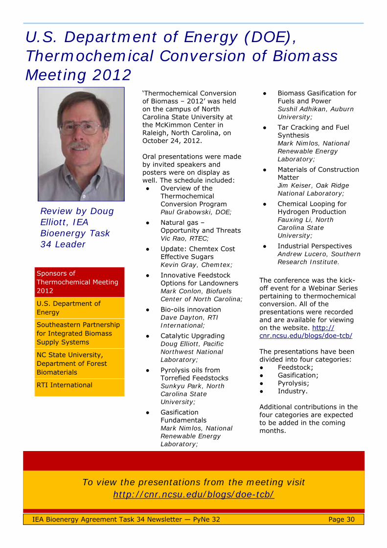
U.S. Department of Energy (DOE), Thermochemical Conversion of Biomass Meeting 2012
IEA Bioenergy Agreement Task 34 Newsletter — PyNe 32 Page 30
‘Thermochemical Conversion of Biomass – 2012’ was held on the campus of North Carolina State University at the McKimmon Center in Raleigh, North Carolina, on October 24, 2012. Oral presentations were made by invited speakers and posters were on display as well. The schedule included: ● Overview of the
Thermochemical Conversion Program Paul Grabowski, DOE;
● Natural gas – Opportunity and Threats Vic Rao, RTEC;
● Update: Chemtex Cost Effective Sugars Kevin Gray, Chemtex;
● Innovative Feedstock Options for Landowners Mark Conlon, Biofuels Center of North Carolina;
● Bio-oils innovation Dave Dayton, RTI International;
● Catalytic Upgrading Doug Elliott, Pacific Northwest National Laboratory;
● Pyrolysis oils from Torrefied Feedstocks Sunkyu Park, North Carolina State University;
● Gasification Fundamentals Mark Nimlos, National Renewable Energy Laboratory;
● Biomass Gasification for Fuels and Power Sushil Adhikan, Auburn University;
● Tar Cracking and Fuel Synthesis Mark Nimlos, National Renewable Energy Laboratory;
● Materials of Construction Matter Jim Keiser, Oak Ridge National Laboratory;
● Chemical Looping for Hydrogen Production Fauxing Li, North Carolina State University;
● Industrial Perspectives Andrew Lucero, Southern Research Institute.
The conference was the kick-off event for a Webinar Series pertaining to thermochemical conversion. All of the presentations were recorded and are available for viewing on the website. http://cnr.ncsu.edu/blogs/doe-tcb/ The presentations have been divided into four categories: ● Feedstock; ● Gasification; ● Pyrolysis; ● Industry. Additional contributions in the four categories are expected to be added in the coming months.
Sponsors of Thermochemical Meeting 2012
U.S. Department of Energy
Southeastern Partnership for Integrated Biomass Supply Systems
NC State University, Department of Forest Biomaterials
RTI International
Review by Doug Elliott, IEA Bioenergy Task 34 Leader
To view the presentations from the meeting visit http://cnr.ncsu.edu/blogs/doe-tcb/

IEA Bioenergy Agreement Task 34 Newsletter — PyNe 32 Page 31
Pyrolysis research opportunities
Are you interested in: ● Biofuels? ● Thermal biomass
conversion? ● Using the facilities of
leading European laboratories?
BRISK opens up a wide variety of research infrastructures via Transnational Access, allowing researchers outside and inside the project to conduct experiments. Infrastructure available to all in Europe and qualifying countries The BRISK network will encourage and facilitate cooperative research in the project partners’ laboratories as follows:
● Researchers can apply to go to any of the project partners located outside their home country to utilize the thermal biomass conversion facilities;
● The project will pay for facility access costs along with a grant for travel and subsistence for those researchers based in an eligible country.
Applications for access If you are interested in applying for access, or require further information please visit the BRISK website. www.briskeu.com
Figure 1: Expertise and facilities available through the BRISK initiative.
BRISK: Biofuels Research Infrastructure for Sharing Knowledge
Two useful databases
IEA Bioenergy Agreement Task 34 Newsletter — PyNe 32 Page 32
New biomass & waste database: ‘Phyllis2’ The Energy research Centre of the Netherlands (ECN) has merged its biomass database ‘Phyllis’ with the BIODAT database. This work has been completed as part of its contribution to Work Package 5 of the BRISK project (Biofuels Research Infrastructure for Sharing Knowledge). This new database known as ‘Phyllis2’ is available at www.ecn.nl/phyllis2/. Here you will be able to find information on the composition of biomass and waste, including analysis data of individual biomass or waste
materials, or average values for a group of materials. It enables users to find answers to questions such as: What is the average
sulphur content of wood? What is the ash content of
willow? What is the average
calorific value of chicken manure?
Development of Phyllis2 was co-funded by the EU 7th Framework Programme through the BRISK project. For further details contact [email protected]
Visit www.ecn.nl/phyllis2/
Phyllis2 contains data on:
Algae Char Fossil fuel Grass/plant Husk/shell/pit Manure Non-organic residue Organic residue/product RDF and MSW Sludge Straw (stalk/cob/ear) Torrefied material Treated wood Untreated wood Other types of biomass
‘BioprocDB’ = Biomass processing Database The German Biomass Research Centre (DBFZ) has built up a data bank on pyrolysis processes and products known as ‘BioprocDB’. It was developed as a part of the joint project ‘BioWaste to liquid: Utilisation of biogenic residues and wastes in thermochemical systems for the provision of fuels’ and was funded by Germany's Climate Initiative. As part of this project a literature review was undertaken with the focus on the pyrolysis of different input
materials. In total, 150 papers have been reviewed and all available data has been put into the database containing several hundreds of columns. DBFZ has also added the data from the pyrolysis experiments of the above mentioned joint project into the database. BioprocDB enables you to: ● Find process data on
pyrolysis experiments described in publications of peer reviewed journals and projects;
● Get analysis data of the input materials;
● Generate a small diagram on a chosen parameter;
● Export the data you have filtered as a csv file.
DBFZ would welcome additional publications and test results to cite in their database. For further information email [email protected] Visit http://bioprocdb.dbfz.de/about

Worldwide Events
JANUARY 2013 21st-22nd Fuels of the Future Berlin, Germany 23rd-24th Global Biofuels Forum Milan, Italy 27th-30th Bioenergy, Environment and Sustainable Technologies - BEST2013 Tiruvannamalai, India 29th-31st BIOGAS Annual Conference and Trade Fair Leipzig, Germany
FEBRUARY 2013 27th-28th Energy from Waste London, UK 27th February-1st March World Sustainable Energy Days 2013 Wels, Austria
MARCH 2013 12th-14th World Biofuels Markets Rotterdam, Netherlands
IEA Bioenergy Agreement Task 34 Newsletter — PyNe 32 Page 33
13th-14th Bio-based Chemicals Rotterdam, Netherlands 19th-21st Green Polymer Chemistry 2013 Cologne, Germany 20th-24th Salon Bois Energie 2013 Nantes, France
APRIL 2013 8th-10th International Biomass Conference & Expo Minneapolis, USA 10th-11th European Biomass to Power Krakow, Poland 16th-18th Sustainability Live Birmingham, UK 17th-18th Argus European Biomass Trading London, UK 24th-25th European Algae Biomass Vienna, Austria
25th-27th The 3rd Annual Congress of Bioenergy Nanjing, China 25th-27th RENEXPO® Central Europe Budapest, Hungary
MAY 2013 16th-17th World Biomass Power Markets Amsterdam, Netherlands
JUNE 2013 3rd-7th 21st European Biomass Conference and Exhibition Copenhagen, Denmark 5th-7th RRB-9 Renewable Resources & Biorefineries Antwerp, Belgium 9th-14th BioEnergy IV: Innovations in Biomass Conversion for Heat, Power, Fuels and Chemicals Otranto, Italy 17th-19th AEBIOM Bioenergy Conference Brussels, Belgium
JULY 2013 3rd-5th Bioenergy China Beijing, China
SEPTEMBER 2013 3rd-6th tcbiomass2013 Chicago, USA

IEA Bioenergy Agreement Task 34 Newsletter — PyNe 32 Page 34
http://www.engconfintl.org/13aa.html
Engineering Conferences International
BioEnergy IV: Innovations in Biomass Conversion
for Heat, Power, Fuels and Chemicals An ECI Conference Series
June 9-14, 2013
Basiliani Resort, Otranto, Italy
This conference will address the scientific and technological challenges for biomass conversion into heat and power, fuel and chemicals. It will: ● Highlight the current progress in bioenergy and biomass
conversion research and development; ● Identify industrial successes and good practices; ● Discuss the most promising future directions; ● Assess the means to overcome the current constraints for
commercialization of biochemical and thermochemical technologies and downstream refining.
Gas Technology Institute (GTI) is pleased to announce tcbiomass2013, the International Conference on Thermochemical Biomass Conversion Science.
Mark your calendars for Chicago from 3-6 September 2013 and plan to connect with many of the world’s leading researchers, scientists and engineers. The three-day scientific forum will cover the gamut—from fundamental and applied research, to applications and technology lessons learned. Be at the centre of dramatic change to discuss, learn and assess the progress and promise of this exciting area of bioenergy.
Submit an abstract A broad array of papers will be selected for presentation and posters will be selected for display at dedicated sessions during the conference. Researchers, scientists, engineers, technicians and others can take advantage of the opportunity to share emerging technology and process insights. Abstracts will be accepted on the following topics: ● Gasification; ● Pyrolysis; ● Upgrading; ● Pre-treatment.
For further information visit http://www.gastechnology.org or email [email protected]

For over 30 years, the European Biomass Conference and Exhibition (EU BC&E) has combined a very renowned international Scientific Conference with an industry exhibition. The EU BC&E is held at different venues throughout Europe and ranks on top of the world's leading events in the biomass sector. It provides a high-level scientific programme and parallel events which attract participants from wide ranging backgrounds: Researchers, engineers, technologists, standards organisations, financing institutions and others. Such a global exchange platform of current knowledge in turn attracts industrial exhibitors, making the conference events a significant tool for technology transfer and innovation. This event is supported by European and international organizations such as the European Commission, UNESCO - United Nations Educational, Scientific and Cultural Organization, Natural Sciences Sector, WCRE - the World
Council for Renewable Energy, EUBIA - the European Biomass Industry Association, and other organisations. The Technical Programme is coordinated by the European Commission, Joint Research Centre - JRC. Conference subjects will include:
Biomass resources; R&D on biomass conversion technologies for
heating, electricity and chemicals; R&D on processes for solid, liquid and
gaseous fuels from biomass; Industrial demonstration and business
concepts; Biomass policies, markets and sustainability.
For further information contact: T: +39 055 5002280 extension 221 E: [email protected]
www.conference-biomass.com
IEA Bioenergy Agreement Task 34 Newsletter — PyNe 32 Page 35
The International Biomass Conference & Expo unites current and future producers of biomass-derived power, fuels and chemicals with waste generators, energy crop growers, municipal leaders, utility executives, technology providers, equipment manufacturers, project developers, investors and policy makers. The event fosters public and private partnerships that help bioenergy producers and large-scale waste generators identify and assess available production resources, as well as viable technology solutions for improving operational efficiencies and reducing industrial greenhouse gas emissions. Volatile energy costs, mounting climate change concerns and the anticipation of federal carbon
cap-and-trade policies are compelling waste generators to think differently – much differently – about waste liabilities and, in some cases, the rising value of already valuable process side streams. Program Tracks Track 1: Pellets & Densified Biomass Track 2: Industrial & Commercial Thermal Energy Track 3: Biomass Power Track 4: Biogas & Landfill Gas Track 5: Advanced Biofuels & Biobased Chemicals Registration, Sponsor, Exhibitor Questions T: +1 866 746 8385 E: [email protected] Program/Speaker Questions T: +1 866 746 8385 E: [email protected]
www.biomassconference.com
April 8-10, 2013 Minneapolis Convention Center Minneapolis, MN

Biomass and Bioenergy: Special Issue, Volume 38 Overcoming Barriers to Bioenergy: Outcomes of the Bioenergy Network of Excellence 2003-2009 Edited by A.V. Bridgwater Publisher: Elsevier Publication Date: March 2012
Biofuels - Alternative Feedstocks and Conversion Processes Edited by: Ashok Pandey, Christian Larroche, Steven Ricke, Claude-Gilles Dussap and Edgard Gnansounou Publisher: Elsevier Publication Date: July 2011
The Pellet Handbook - the Production and Thermal Utilization of Biomass Pellets Authors: Ingwald Obernberger and Gerold Thek Publisher: Earthscan Publication Date: September 2010 Proceedings of the Bioten Conference on Biomass, Bioenergy and Biofuels 2010; Bioten Edited by: A.V. Bridgwater Publisher: CPL Press Publication Date: October 2011
Biomass Gasification and Pyrolysis - Practical Design and Theory Author: Prabir Basu Publisher: Academic Press Publication Date: June 2010 Thermochemical Processing of Biomass: Conversion into Fuels, Chemicals and Power Edited by Robert C Brown Publisher: Wiley Publication Date: March 2011
Biomass Pyrolysis - A guide to UK capabilities Edited by A.V. Bridgwater and I.I. Watkinson Publisher: Aston University Publication Date: May 2011 To download a free copy of this guide visit www.pyne.co.uk/?_id=120
Biofuels: Ethical Issues Publisher: Nuffield Council on Bioethics Publication Date: April 2011 To download a free copy of this guide visit: www.nuffieldbioethics.org/biofuels-0
Bioliquids-CHP Power Generation from Biomass Main Project Results 2011 To download this brochure click on the ‘Bioliquids-CHP’ link above.
Beginners Guide to Pellet Production Publisher: PelHeat Click on the above link to download this and other free guides from PelHeat. BRISK NEWS Published November 2012 The newsletter of the BRISK Consortium (Biofuels Research Infrastructure for Sharing Knowledge) To download this free newsletter visit the Publications section at www.briskeu.com Handbook Biomass Gasification Second Edition Edited by: H.A.F. Knoef Publisher: BTG Biomass Technology Group BV Publication Date: September 2012
To visit the website of each of these publications click on the relevant title to open the hyperlink.
Publications
IEA Bioenergy Agreement Task 34 Newsletter — PyNe 32 Page 36

If you require further information about the PyNe newsletter, or you would like to contribute to future editions, please contact the Editor: Irene Watkinson Bioenergy Research Group Aston University Birmingham B4 7ET, UK T: +44 121 204 3430 E: [email protected] Past editions of PyNe newsletters are available on the website.
Further Information
Disclaimer: The PyNe newsletter is edited and produced by the Bioenergy Research Group, Aston University, UK on behalf of IEA Bioenergy Task 34 Pyrolysis. Any opinions or material contained within are those of the contributors and do not necessarily reflect any views or policies of the International Energy Agency, Aston University or any other organization.
www.pyne.co.uk
IEA Bioenergy Agreement Task 34 Newsletter — PyNe 32 Page 37
Welcome to Task 34 By Doug Elliott, Task 34 Leader
December 2012
IEA Bioenergy
Task 34 Pyrolysis
PyNe 32
Copyright © 2022 FDOKUMEN