provor-i & do-i float– 33-16-030_uti
66
PROVOR-I & DO-I FLOAT – 33-16-030_UTI USER MANUAL Z.I de KERANDRE - RUE GUTENBERG 56700 HENNEBONT - FRANCE Telephone: +33 (0)2 97 36 10 12 Fax: +33 (0)2 97 36 55 17 Web : http://www.nke.fr - E-mail : [email protected] USER MANUAL © nke: This document is the property of nke instrumentation and contains proprietary and confidential information. The document is loaned on the express condition that neither the document itself nor the information contained therein shall be disclosed without the express consent of nke instrumentation and that the information shall not be used by the recipient without prior written acceptance by nke Instrumentation. Furthermore, the document shall be returned immediately to nke instrumentation upon request. DOC du 19 / 04 / 17 rev.3
-
Upload
khangminh22 -
Category
Documents
-
view
1 -
download
0
Transcript of provor-i & do-i float– 33-16-030_uti
PROVOR-I & DO-I FLOAT – 33-16-030_UTI
USER MANUAL
Z.I de KERANDRE - RUE GUTENBERG
56700 HENNEBONT - FRANCE
Telephone: +33 (0)2 97 36 10 12 Fax: +33 (0)2 97 36 55 17
Web : http://www.nke.fr - E-mail : [email protected]
USER MANUAL
© nke: This document is the property of nke instrumentation and contains proprietary and confidential information. The document is loaned on the express condition that neither the document itself nor the information contained therein shall be disclosed without the express consent of nke instrumentation and that the information shall not be used by the recipient without prior written acceptance by nke Instrumentation. Furthermore, the document shall be returned immediately to nke instrumentation upon request.
DOC du 19 / 04 / 17 rev.3
PROVOR-DO-I FLOAT
USER MANUAL
2
1 INTRODUCTION ............................................................................................................................................................... 4
2 OPERATING INSTRUCTIONS ........................................................................................................................................ 5
2.1 HANDLING PRECAUTIONS .............................................................................................................................................. 5 2.2 ACCEPTANCE TESTS ...................................................................................................................................................... 5
2.2.1 Inventory ................................................................................................................................................................... 5 2.2.2 Physical Inspection ................................................................................................................................................... 5
2.3 DEFAULT PARAMETERS ................................................................................................................................................. 5 2.3.1 ARGO Identification ................................................................................................................................................. 5 2.3.2 Decoding .................................................................................................................................................................. 5
2.4 LAUNCHING ................................................................................................................................................................... 6 2.4.1 Test the Float and arm the mission .......................................................................................................................... 6 2.4.2 Remove protective plugs and magnet ....................................................................................................................... 6 2.4.3 Deployment checklist ................................................................................................................................................ 7 2.4.4 Launch the Float ...................................................................................................................................................... 8
2.5 CHECKS PRIOR TO DEPLOYMENT .................................................................................................................................... 9 2.5.1 Necessary Equipment ............................................................................................................................................... 9 2.5.2 Connecting the PC .................................................................................................................................................... 9 2.5.3 Example of Bluetooth dongle tested by NKE .......................................................................................................... 11 2.5.4 How to Send Commands ......................................................................................................................................... 12 2.5.5 How to Read and change Parameter Values .......................................................................................................... 12 2.5.6 How to Check and change the Time ....................................................................................................................... 14 2.5.7 Configuration Check .............................................................................................................................................. 14 2.5.8 Functional Tests ..................................................................................................................................................... 15
3 GENERAL DESCRIPTION OF PROVOR-DO-I FLOAT............................................................................................ 18
3.1 PROVOR-DO-I .......................................................................................................................................................... 18 3.1.1 Electronics .............................................................................................................................................................. 18 3.1.2 Embedded software ................................................................................................................................................ 18 3.1.3 Mechanical interface with oxygen sensor............................................................................................................... 18
3.2 MAGNET POSITIONS ..................................................................................................................................................... 18 3.3 DENSITY CONTROL SYSTEM ........................................................................................................................................ 20 3.4 SENSORS ...................................................................................................................................................................... 20 3.5 IRIDIUM/GPS MODEM ............................................................................................................................................ 20 3.6 CPU BOARD ................................................................................................................................................................ 20 3.7 BATTERY ..................................................................................................................................................................... 20 3.8 MMI LINK .................................................................................................................................................................... 20 3.9 FIRMWARE EVOLUTION IN 2016 ................................................................................................................................... 20
4 THE LIFE OF AN PROVOR-DO-I FLOAT .................................................................................................................. 22
4.1 THE MISSION - OVERVIEW ........................................................................................................................................... 22 4.2 DESCENT ..................................................................................................................................................................... 24 4.3 GROUNDING................................................................................................................................................................. 24 4.4 SUBMERGED DRIFT ...................................................................................................................................................... 24 4.5 ASCENT ....................................................................................................................................................................... 25
4.5.1 Ice detection ........................................................................................................................................................... 25 4.6 “NEAR SURFACE” AND “IN AIR” MEASUREMENT ......................................................................................................... 29 4.7 TRANSMISSION ............................................................................................................................................................ 29
5 PROVOR-DO-I PARAMETERS ..................................................................................................................................... 30
5.1 MISSION PARAMETERS ................................................................................................................................................ 31 5.2 ICE DETECTION COMMANDS ......................................................................................................................................... 34 5.3 USER COMMANDS ....................................................................................................................................................... 35
6 IRIDIUM SBD FORMATS .............................................................................................................................................. 38
6.1 OVERVIEW ................................................................................................................................................................... 38 6.2 TECHNICAL PACKET 1 (TYPE =0).................................................................................................................................. 40 6.3 TECHNICAL PACKET 2 (TYPE = 4) ................................................................................................................................. 42
PROVOR-DO-I FLOAT
USER MANUAL
3
6.3.1 General information ............................................................................................................................................... 44 6.3.2 Buoyancy reduction ................................................................................................................................................ 44 6.3.3 Descent to parking depth ........................................................................................................................................ 44 6.3.4 Drift at parking depth ............................................................................................................................................. 44 6.3.5 Drift at profile depth ............................................................................................................................................... 44 6.3.6 Ascent ..................................................................................................................................................................... 44 6.3.7 Data information .................................................................................................................................................... 45 6.3.8 Subsurface point ..................................................................................................................................................... 45 6.3.9 Grounding .............................................................................................................................................................. 45 6.3.10 Emergency ascent .............................................................................................................................................. 45 6.3.11 Various Data ...................................................................................................................................................... 45 6.3.12 End Of Life information ..................................................................................................................................... 46
6.4 DESCENT PROFILE CTD PACKET (TYPE = 1) ................................................................................................................ 47 6.5 SUBMERGED DRIFT CTD PACKET (TYPE = 2) ............................................................................................................... 48 6.6 ASCENT PROFILE CTD PACKET (TYPE = 3) ................................................................................................................... 48 6.7 NEAR SURFACE PACKET (TYPE = 13) ........................................................................................................................... 48 6.8 IN AIR PACKET (TYPE = 14).......................................................................................................................................... 48 6.9 DESCENT PROFILE CTDO PACKET (TYPE = 8) ............................................................................................................. 49 6.10 SUBMERGED DRIFT CTDO PACKET (TYPE = 9) ............................................................................................................ 50 6.11 ASCENT PROFILE CTDO PACKET (TYPE = 10) .............................................................................................................. 50 6.12 NEAR SURFACE PACKET (TYPE = 11) ........................................................................................................................... 50 6.13 IN AIR PACKET (TYPE = 12).......................................................................................................................................... 50 6.14 CTD(O) DATA TREATMENT DETAILS .......................................................................................................................... 51
6.14.1 Zone & slice thickness ........................................................................................................................................ 51 6.14.2 Decimation ......................................................................................................................................................... 52 6.14.3 Averaging ........................................................................................................................................................... 53
6.15 PARAMETERS DATA PACKET (TYPE = 5) ...................................................................................................................... 54 6.16 HYDRAULIC PACKET (TYPE = 6) ................................................................................................................................... 56 6.17 FLOAT PARAMETER N°2 PACKET (TYPE = 7) ................................................................................................................. 56 6.18 LIFE EXPIRY MESSAGE ................................................................................................................................................ 57
6.18.1 Phase description ............................................................................................................................................... 58 6.18.2 Sending a SBD message (telecommand) to the 9602 Iridium modem ................................................................ 59 6.18.3 Telecommand SBD File creation ....................................................................................................................... 60
7 SPECIFICATIONS ........................................................................................................................................................... 61
8 PROVOR-DO-I OPERATING PRINCIPLE .................................................................................................................. 62
9 LITHIUM BATTERY ....................................................................................................................................................... 63
10 GLOSSARY ....................................................................................................................................................................... 64
11 ANNEX A: DETERMINATION OF CYCLE TIMINGS .............................................................................................. 65
11.1 FLOAT CLOCK OFFSET DETERMINATION ....................................................................................................................... 65 11.2 CYCLE TIMINGS DETERMINATION ................................................................................................................................. 65
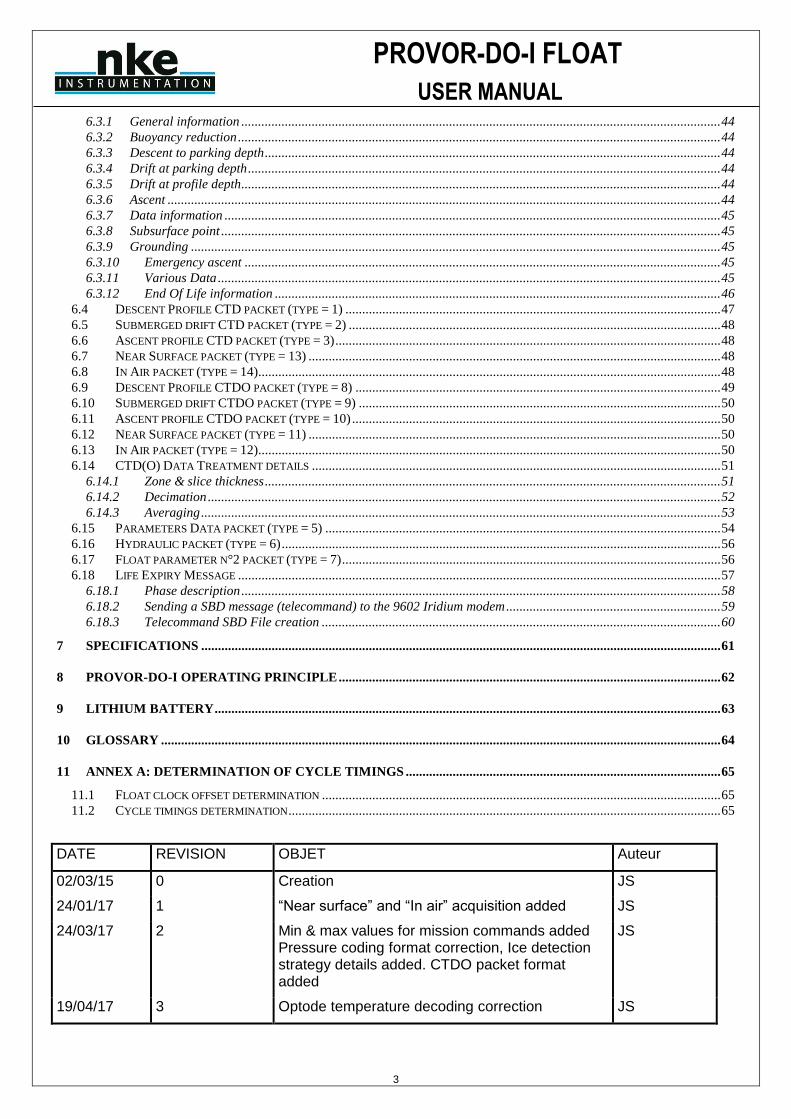
DATE REVISION OBJET Auteur
02/03/15 0 Creation JS
24/01/17 1 “Near surface” and “In air” acquisition added JS
24/03/17 2 Min & max values for mission commands added Pressure coding format correction, Ice detection strategy details added. CTDO packet format added
JS
19/04/17 3 Optode temperature decoding correction JS
PROVOR-DO-I FLOAT
USER MANUAL
4
1 INTRODUCTION
PROVOR-DO-I is a subsurface profiling float developed jointly by IFREMER and MARTEC Group. Since
January 1st, 2009 nke has integrated profiling floats activity and is now in charge of PROVOR-DO-I
manufacturing and development in industrial partnership with IFREMER.
PROVOR-DO-I is the Iridium version of PROVOR-DO float (that uses ARGOS satellite system for data
transmission), from which it takes up most of the essential sub-assemblies.
The PROVOR-DO-I float described in this manual is designed for the ARGO Program. This international
program will be a major component of the Global Ocean Observing System (GOOS). An array of 3,000 free-
drifting profiling floats is planned for deployment in 2004. These floats will measure the temperature and salinity
of the upper 2,000 meters of the ocean, allowing continuous monitoring of the ocean's climate.
All Argo measurements will be relayed and made publicly available within hours after collection. The data will
provide a quantitative description of the evolving state of the upper ocean and the patterns of ocean climate
variability, including heat and freshwater storage and transport. It is expected that ARGO data will be used for
initialization of ocean and coupled forecast models, and for dynamic model testing. A primary focus of Argo is
seasonal to decadal climate variability and predictability.
After launch, PROVOR-DO-I 's mission consists of a repeating cycle of descent, submerged drift, ascent and
data transmission. During these cycles, PROVOR-DO-I dynamically controls its buoyancy with a hydraulic
system. This hydraulic system adjusts the density of the float causing it to descend, ascend or hover at a
constant depth in the ocean. The user selects the depth at which the system drifts between descent and ascent
profiles. PROVOR-DO-I continually samples the pressure at this drift depth and maintains that depth within
approximately 30m.
After the submerged drift portion of a cycle, the float proceeds to the depth at which the ascending profile is to
begin. The ascent profile starting depth (typically the ARGO-selected depth of 2,000m) is not necessarily the
same as the drift depth.
During its mission, PROVOR-DO-I collects measurements of four parameters - salinity, temperature and depth
(CTD) - and saves them in its memory. These measurements can be made during the float descent (descent
profile), during the submerged drift period (Lagrangian operation) and during the ascent (ascent profile).
After each ascent, PROVOR-DO-I transmits its saved data to the satellites of the IRIDIUM system. The volume
of data is reduced using a compression algorithm in order to reduce the time needed for transmission. The
IRIDIUM system calculates the float's position during its stay on the sea surface.
In 2016, nke developed new firmware evolutions for “In air” measurement, and added Ice detection function.
This manual describes the PROVOR-DO-I float, how to use it and safety precautions to be observed during
handling.
Please read this manual carefully to ensure that PROVOR-DO-I functions as intended.
Overview of the present manual’s contents:
• Chapter 2 contains the instructions necessary for the personnel in charge of the deployment
• Chapter 3 describes the components of PROVOR-DO-I ; it is intended for those who want a more in-depth understanding of PROVOR-DO-I
• Chapter 4 describes the mission of PROVOR-DO-I
• Chapter 5 describes the various parameters
• Chapter 6 describes the various IRIDIUM messages
• Chapter 7 presents the technical specifications
• Chapter 8 provides explanations about the operation of PROVOR-DO-I
• Chapter 9 specifies the elements of the constraints limited to the transport of Lithium batteries.
PROVOR-DO-I FLOAT
USER MANUAL
5
2 OPERATING INSTRUCTIONS
The following instructions tell you how to handle, configure, test and launch the PROVOR-DO-I float. Please
read these instructions carefully and follow them closely to ensure your PROVOR-DO-I float functions as
intended.
2.1 Handling Precautions
PROVOR-DO-I is designed to withstand submersion at great depths for long periods of time (up to five years).
This remarkable specification in oceanographic instrumentation is possible thanks to the protection of the
casing by an anti-corrosion coating. This coating is sensitive to impact. Damage to the coating can accelerate
the corrosion process.
NOTE: Take precautions to preserve the anti-corrosion coating during handling. Remove the float
from its packing only when absolutely necessary.
NOTE: Regulations state that PROVOR-DO-I must not be switched on during transport.
2.2 Acceptance Tests
Immediately upon receipt of the PROVOR-DO-I float, you should test it to confirm that it is complete, correctly
configured and has not been damaged in shipment. If your PROVOR-DO-I float fails any of the following tests,
you should contact nke instrumentation.
2.2.1 Inventory The following items should be supplied with your PROVOR-DO-I float:
• The present user manual
• A test sheet
• Quickstart & Deployment checklist
NOTE: Disassembly of the float voids the warranty.
Check that all of the above items are present. If any are missing, contact nke-instrumentation.
2.2.2 Physical Inspection Upon the opening of the transport casing, visually inspect the float's general condition: Inspect the transport
container for dents, damage, signs of impact or other signs that the float has been mishandled during shipping.
Inspect the CTD sensor, antenna, hull, housing around the lower bladder for dents or any other signs of damage
NOTE: Ensure the magnet is in place against the hull (on ON/OFF position), meaning that float is
switched OFF.
2.3 Default Parameters
Notwithstanding special instructions given to NKE during the PROVOR-DO-I preparation stage, the following set
of parameters is applied: section 5 PROVOR-DO-I PARAMeterS.
If these parameters are not appropriate, the user can change them himself by following the instructions.
2.3.1 ARGO Identification The user is responsible for contacting the AIC in order to obtain the WMO number which will identify the PROVOR-DO-I ’s mission
2.3.2 Decoding The CORIOLIS project team (IFREMER) is able to assist the teams that use PROVOR-DO-I for data processing.
Nke can provide light PC software for manual data decoding. Contact nke-instrumentation.
PROVOR-DO-I FLOAT
USER MANUAL
6
2.4 Launching
Following is what you should do to launch the PROVOR-DO-I float.
2.4.1 Test the Float and arm the mission Before you take PROVOR-DO-I on deck for deployment, we recommend that you repeat all of the tests described
in section 2.5.8 “Display Sensor Data”. This will ensure that the float is functioning and configured correctly and
maximize the probability of success of your experiment.
IMPORTANT: Before launching the float, you must arm the mission by issuing the !AR command:
!AR
PROVOR-DO-I will execute auto-test (see section 2.5.8 page 15 for description) and respond :
<AR ON>
Put the magnet on the float (ON/OFF position).
NOTE: Once the mission is armed, the next time you will attempt to communicate with the float upon
magnet removal, you need to establish Bluetooth connection (see section 2.5.2 page 9) and
press "ENTER" within 30 seconds in order to get the prompt ].
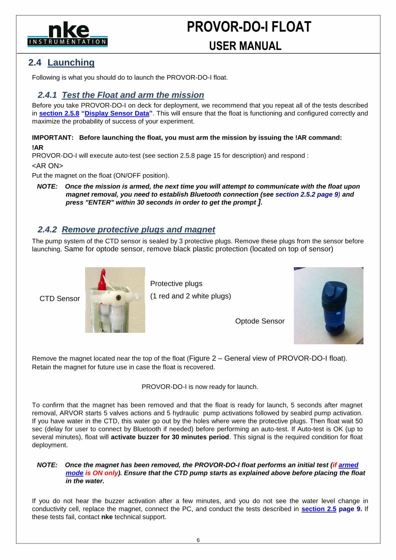
2.4.2 Remove protective plugs and magnet
The pump system of the CTD sensor is sealed by 3 protective plugs. Remove these plugs from the sensor before
launching. Same for optode sensor, remove black plastic protection (located on top of sensor)
Remove the magnet located near the top of the float (Figure 2 – General view of PROVOR-DO-I float).
Retain the magnet for future use in case the float is recovered.
PROVOR-DO-I is now ready for launch.
To confirm that the magnet has been removed and that the float is ready for launch, 5 seconds after magnet
removal, ARVOR starts 5 valves actions and 5 hydraulic pump activations followed by seabird pump activation.
If you have water in the CTD, this water go out by the holes where were the protective plugs. Then float wait 50
sec (delay for user to connect by Bluetooth if needed) before performing an auto-test. If Auto-test is OK (up to
several minutes), float will activate buzzer for 30 minutes period. This signal is the required condition for float
deployment.
NOTE: Once the magnet has been removed, the PROVOR-DO-I float performs an initial test (if armed
mode is ON only). Ensure that the CTD pump starts as explained above before placing the float
in the water.
If you do not hear the buzzer activation after a few minutes, and you do not see the water level change in
conductivity cell, replace the magnet, connect the PC, and conduct the tests described in section 2.5 page 9. If
these tests fail, contact nke technical support.
Protective plugs
(1 red and 2 white plugs) CTD Sensor
Optode Sensor
PROVOR-DO-I FLOAT
USER MANUAL
7
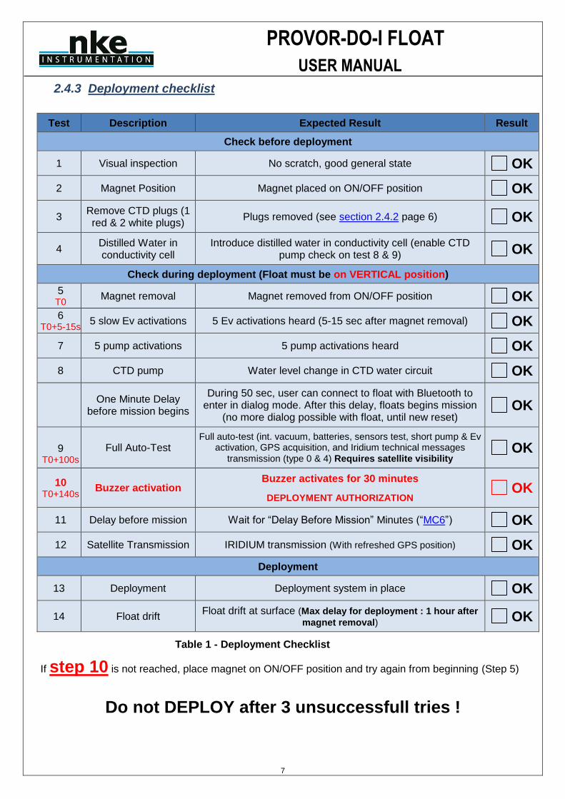
2.4.3 Deployment checklist
Test Description Expected Result Result
Check before deployment
1 Visual inspection No scratch, good general state OK
2 Magnet Position Magnet placed on ON/OFF position OK
3 Remove CTD plugs (1 red & 2 white plugs)
Plugs removed (see section 2.4.2 page 6) OK
4 Distilled Water in conductivity cell
Introduce distilled water in conductivity cell (enable CTD pump check on test 8 & 9) OK
Check during deployment (Float must be on VERTICAL position)
5 T0
Magnet removal Magnet removed from ON/OFF position OK
6 T0+5-15s
5 slow Ev activations 5 Ev activations heard (5-15 sec after magnet removal) OK
7 5 pump activations 5 pump activations heard OK
8 CTD pump Water level change in CTD water circuit OK
One Minute Delay
before mission begins
During 50 sec, user can connect to float with Bluetooth to enter in dialog mode. After this delay, floats begins mission
(no more dialog possible with float, until new reset) OK
9
T0+100s Full Auto-Test
Full auto-test (int. vacuum, batteries, sensors test, short pump & Ev activation, GPS acquisition, and Iridium technical messages
transmission (type 0 & 4) Requires satellite visibility OK
10 T0+140s
Buzzer activation Buzzer activates for 30 minutes
DEPLOYMENT AUTHORIZATION OK
11 Delay before mission Wait for “Delay Before Mission” Minutes (“MC6”) OK
12 Satellite Transmission IRIDIUM transmission (With refreshed GPS position) OK
Deployment
13 Deployment Deployment system in place OK
14 Float drift Float drift at surface (Max delay for deployment : 1 hour after
magnet removal) OK
Table 1 - Deployment Checklist
If step 10 is not reached, place magnet on ON/OFF position and try again from beginning (Step 5)
Do not DEPLOY after 3 unsuccessfull tries !
PROVOR-DO-I FLOAT
USER MANUAL
8
2.4.4 Launch the Float
NOTE: Keep the float in its protective packaging for as long as possible to guard against any nicks and
scratches that could occur during handling. Handle the float carefully, using soft, non-abrasive
materials only. Do not lay the float on the deployment vessel's unprotected deck. Use
cardboard or cloth to protect it.
2.4.4.1 By hand
PROVOR-DO-I can be launched by hand from the deck from a height of 2 meters maximum.
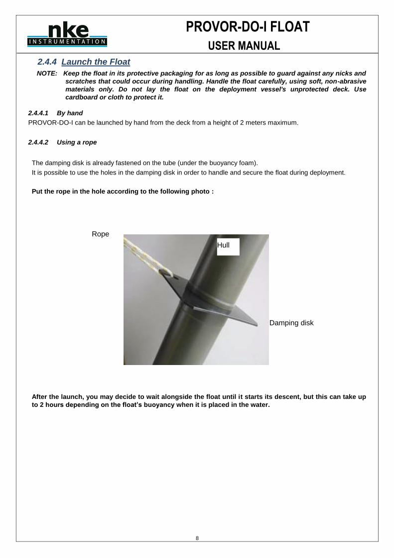
2.4.4.2 Using a rope
The damping disk is already fastened on the tube (under the buoyancy foam).
It is possible to use the holes in the damping disk in order to handle and secure the float during deployment.
Put the rope in the hole according to the following photo :
After the launch, you may decide to wait alongside the float until it starts its descent, but this can take up
to 2 hours depending on the float’s buoyancy when it is placed in the water.
Rope
Hull
Damping disk
PROVOR-DO-I FLOAT
USER MANUAL
9
2.5 Checks prior to deployment
This chapter deals with test to perform in laboratory, before float is put in its wooden box. These tests can be performed on ship only by experienced users.
2.5.1 Necessary Equipment
The equipment required to check that PROVOR-DO-I is functioning correctly and to prepare it for the mission
are:
(1) A PC. The most convenient way of communicating with PROVOR-DO-I is with a PC in terminal emulation mode.
Among other advantages, this allows storage of configuration parameters and commands. You can use
any standard desktop or laptop computer. The PC must be equipped with a serial port (usually called
COM1 or COM2).
(2) VT52 or VT100 terminal emulation software.
The Hyper Terminal emulation software can be used.
(3) A Bluetooth Dongle with drivers installed on the PC (BELKIN class 2 model is recommended).
2.5.2 Connecting the PC
Make sure you check the following points before attempting a connection:
✓ Bluetooth key connected to the PC with the drivers installed
✓ Magnet present at the Bluetooth’s power supply ILS (see Figure 2 – General view of PROVOR-DO-I float
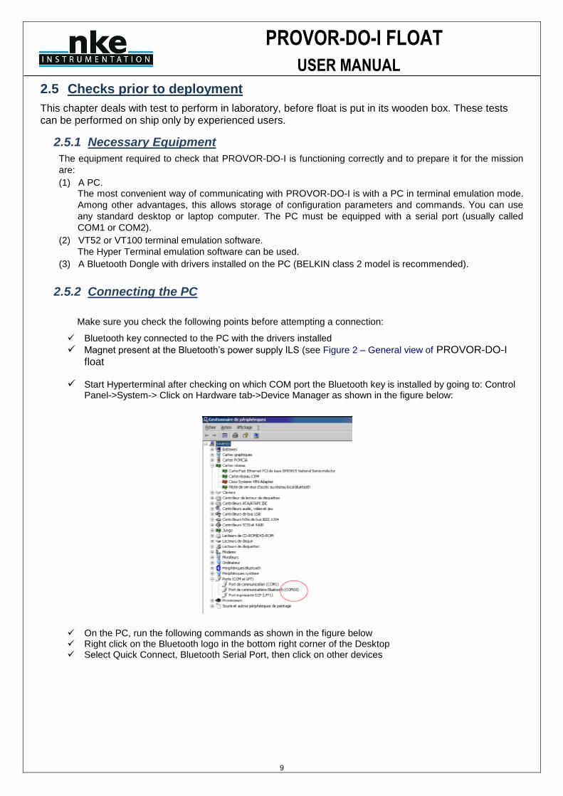
✓ Start Hyperterminal after checking on which COM port the Bluetooth key is installed by going to: Control Panel->System-> Click on Hardware tab->Device Manager as shown in the figure below:
✓ On the PC, run the following commands as shown in the figure below ✓ Right click on the Bluetooth logo in the bottom right corner of the Desktop ✓ Select Quick Connect, Bluetooth Serial Port, then click on other devices

PROVOR-DO-I FLOAT
USER MANUAL
10
A window appears as shown in the figure below:
✓ Click on Refresh
✓ Check that the Bluetooth number is present on the traceability label (see Figure 2 – General view of PROVOR-DO-I float
✓ ) ✓ There are two ways of establishing the connection: ✓ Either select the number shown and press Connect ✓ Or come back to the previous step and instead of selecting “other devices”, select the number shown ✓ When the connection is made, a dialog box appears as shown in the figure above:
PROVOR-DO-I FLOAT
USER MANUAL
11
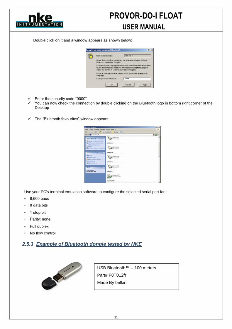
Double click on it and a window appears as shown below:
✓ Enter the security code “0000” ✓ You can now check the connection by double clicking on the Bluetooth logo in bottom right corner of the
Desktop
✓ The “Bluetooth favourites” window appears:
Use your PC's terminal emulation software to configure the selected serial port for:
• 9,600 baud
• 8 data bits
• 1 stop bit
• Parity: none
• Full duplex
• No flow control
2.5.3 Example of Bluetooth dongle tested by NKE
USB Bluetooth™ – 100 meters
Part# F8T012fr
Made By belkin
PROVOR-DO-I FLOAT
USER MANUAL
12
2.5.4 How to Send Commands
You must communicate with PROVOR-DO-I to verify or change its configuration parameters, to read data from the
float, or to test the float's functions. You perform these verifications/changes by sending commands, and by
observing the float's response to those commands. Compose commands by typing characters on the keyboard of
your PC, and send them to PROVOR-DO-I by pressing the Enter key. In the following descriptions of commands we will use the general syntax:
• Keystrokes entered by the user are written in bold.
• Replies received from the float are in normal font.
• Commands entered by the user end with the Enter key. Complete description and list of user command can be read using the command ?HE and is also given in Section “USER COMMANDS” page 31
The software version can be viewed using the ?VL command
PROVOR-DO-I will respond:
<VL 5900Yxx (where Y indicates major software revision and x indicates minor software revision)
<VC IRIDIUM>
<HY PROVOR>
<Firmware make ID : z>
The float’s serial number can be viewed using the ?NS command
PROVOR-DO-I will respond:
<NS 00001> (identification 1)
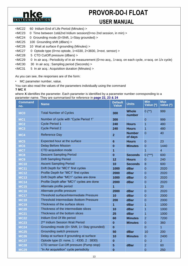
2.5.5 How to Read and change Parameter Values Read the values of “mission parameters” by sending the MC command. Do this by typing the characters ?MC in
response to PROVOR-DO-I's ‘]’ prompt character then confirm the command by pressing the Enter key. It should
look like this:
?MC
PROVOR-DO-I will respond:
<MC0 300 Total cycle nb >
<MC1 300 Nb cycles with Cycle period 1 >
<MC2 240 Cycle period 1 (Hours) >
<MC3 240 Cycle period 2 (Hours) >
<MC4 2 Reference day >
<MC5 6 Hour at surface >
<MC6 0 Delay before mission (Minutes) >
<MC7 1 CTD sampling mode (1=Std, 2=Eco, 3=Mixed, 4=Spot sampling) >
<MC8 0 Descent CTD sampling period (Seconds) >
<MC9 12 Drift CTD sampling period (Hours) >
<MC10 10 Ascent CTD sampling period (Seconds) >
<MC11 1000 Drift pressure 1 (dBars) >
<MC12 2000 Profile pressure 1 (dBars) >
<MC13 1000 Drift pressure 2 (dBars) >
<MC14 2000 Profile pressure 2 (dBars) >
<MC15 1 Alternate cycle number (1=not used, x=1/x alternated profile) >
<MC16 2000 Alternate profile pressure (dBars) >
<MC17 10 Threshold Zone 1/2 (dBars) >
<MC18 200 Threshold Zone 2/3 (dBars) >
<MC19 1 Slice thickness in zone 1-Surface (dBars) >
<MC20 10 Slice thickness in zone 2-Intermediate (dBars) >
<MC21 25 Slice thickness in zone 3-Deep (dBars) >
PROVOR-DO-I FLOAT
USER MANUAL
13
<MC22 60 Iridium End of Life Period (Minutes) >
<MC23 0 Time between 1st&2nd Iridium session(0=no 2nd session, in min) >
<MC24 0 Grounding mode (0=Shift, 1=Stay grounded) >
<MC25 100 Grounding shift (dBars) >
<MC26 10 Wait at surface if grounding (Minutes) >
<MC27 0 Optode type (0=no optode, 1=4330, 2=3830, 3=ext. sensor) >
<MC28 5 CTD CutOff pressure (dBars) >
<MC29 0 In air acq.: Periodicity of in air measurement (0=no acq., 1=acq. on each cycle, x=acq. on 1/x cycle)
<MC30 30 In air acq.: Sampling period (Seconds) >
<MC31 5 In air acq.: Acquisition duration (Minutes) >
As you can see, the responses are of the form:
• MC parameter number, value.
You can also read the values of the parameters individually using the command
? MC X
where X identifies the parameter. Each parameter is identified by a parameter number corresponding to a
parameter name. They are summarised for reference in page 22, 23 & 24
Command
no. Name
Default Value
Units Min Value (*)
Max value (*)
MC0 Total Number of Cycles 300 Whole
number
0 (**) 999
MC1 Number of cycle with “Cycle Period 1” 300 0 999
MC2 Cycle Period 1 240 Hours 1 480
MC3 Cycle Period 2 240 Hours 1 480
MC4 Reference Day 2 Number
of days
0 40
MC5 Expected hour at the surface 6 Hours 0 23
MC6 Delay Before Mission 0 Minutes 0 1440
MC7 CTD acquisition mode 1 1 4
MC8 Descent Sampling Period 0 Seconds 0 (***) 600
MC9 Drift Sampling Period 12 Hours 0 240
MC10 Ascent Sampling Period 10 Seconds 8 600
MC11 Drift Depth for “MC1” first cycles 1000 dBar 0 2020
MC12 Profile Depth for “MC1” first cycles 2000 dBar 0 2020
MC13 Drift Depth after “MC1” cycles are done 1000 dBar 0 2020
MC14 Profile Depth after “MC1” cycles are done 2000 dBar 0 2020
MC15 Alternate profile period 1 1 20
MC16 Alternate profile pressure 2000 dBar 0 2020
MC17 Threshold surface/Intermediate Pressure 10 dBar 0 2000
MC18 Threshold Intermediate /bottom Pressure 200 dBar 0 2000
MC19 Thickness of the surface slices 1 dBar 1 1000
MC20 Thickness of the intermediate slices 10 dBar 1 1000
MC21 Thickness of the bottom slices 25 dBar 1 1000
MC22 Iridium End Of life period 60 Minutes 2 7200
MC23 2nd Iridium Session Wait Period 0 Minutes 0 360
MC24 Grounding mode (0= Shift, 1= Stay grounded) 0 0 1
MC25 Grounding switch pressure 50 dBar 10 200
MC26 Delay at surface if grounding at surface 10 Minutes 0 2400
MC27 Optode type (0: none, 1 : 4330, 2 : 3830) 0 0 2
MC28 CTD sensor Cut-Off pressure (Pump stop) 5 dBar 2 60
MC29 “In Air acquisition” cycle periodicity 0 0 250
PROVOR-DO-I FLOAT
USER MANUAL
14
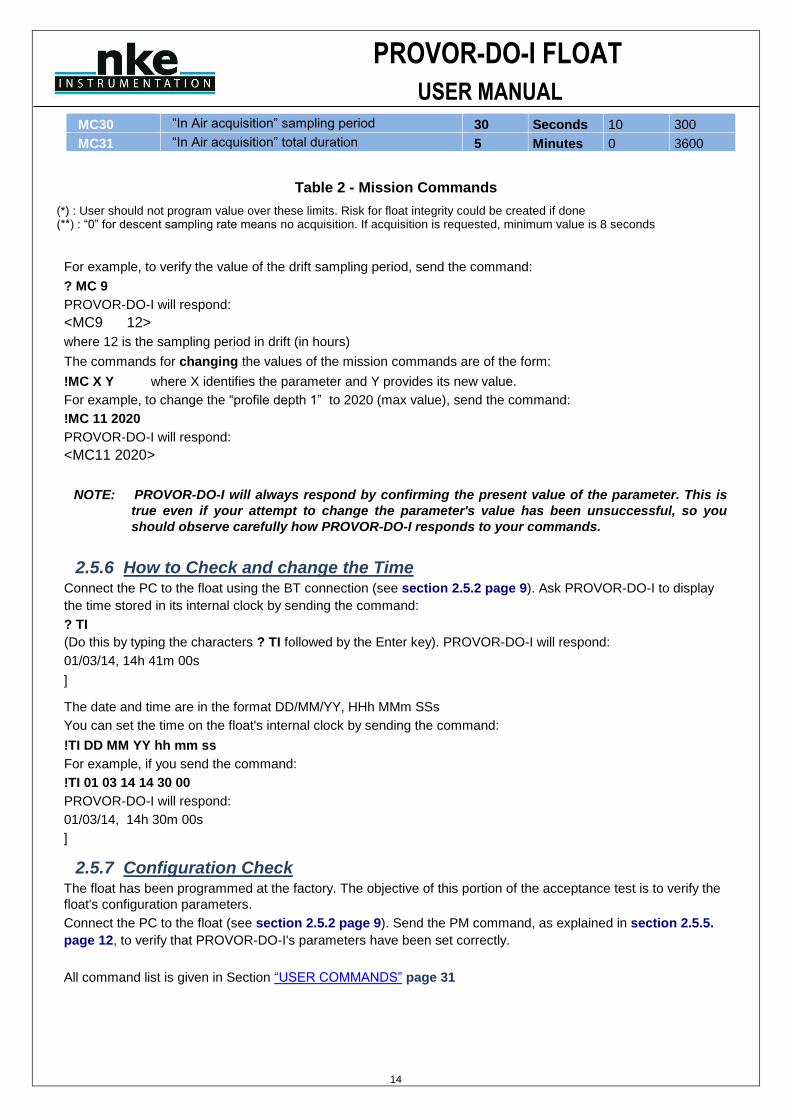
MC30 “In Air acquisition” sampling period 30 Seconds 10 300
MC31 “In Air acquisition” total duration 5 Minutes 0 3600
Table 2 - Mission Commands
(*) : User should not program value over these limits. Risk for float integrity could be created if done (**) : “0” for descent sampling rate means no acquisition. If acquisition is requested, minimum value is 8 seconds
For example, to verify the value of the drift sampling period, send the command:
? MC 9
PROVOR-DO-I will respond:
<MC9 12>
where 12 is the sampling period in drift (in hours)
The commands for changing the values of the mission commands are of the form:
!MC X Y where X identifies the parameter and Y provides its new value.
For example, to change the “profile depth 1” to 2020 (max value), send the command:
!MC 11 2020
PROVOR-DO-I will respond:
<MC11 2020>
NOTE: PROVOR-DO-I will always respond by confirming the present value of the parameter. This is
true even if your attempt to change the parameter's value has been unsuccessful, so you
should observe carefully how PROVOR-DO-I responds to your commands.
2.5.6 How to Check and change the Time Connect the PC to the float using the BT connection (see section 2.5.2 page 9). Ask PROVOR-DO-I to display
the time stored in its internal clock by sending the command:
? TI
(Do this by typing the characters ? TI followed by the Enter key). PROVOR-DO-I will respond:
01/03/14, 14h 41m 00s
]
The date and time are in the format DD/MM/YY, HHh MMm SSs
You can set the time on the float's internal clock by sending the command:
!TI DD MM YY hh mm ss
For example, if you send the command:
!TI 01 03 14 14 30 00
PROVOR-DO-I will respond:
01/03/14, 14h 30m 00s
]
2.5.7 Configuration Check The float has been programmed at the factory. The objective of this portion of the acceptance test is to verify the
float's configuration parameters.
Connect the PC to the float (see section 2.5.2 page 9). Send the PM command, as explained in section 2.5.5.
page 12, to verify that PROVOR-DO-I's parameters have been set correctly.
All command list is given in Section “USER COMMANDS” page 31
PROVOR-DO-I FLOAT
USER MANUAL
15
2.5.8 Functional Tests
Connect the PC to the float (see section 2.5.2).
NOTE: The hydraulic components will function correctly only if the float is in a vertical position with
the antenna up.
Orient the float vertically, and support it to prevent it from falling over during the performance of the functional
tests.
PROVOR-DO-I has several commands that allow you to test its various functions.
2.5.8.1 Auto-test
Before sending float auto-test, place the float on vertical position.
Float can realize 2 kind of auto-tests. The “standard one” and the “full auto-test”. These auto-test are used by float to check all internal components.
Standard auto-test can be done by sending command :
!C 0
Float will respond :
CPU : OK
INT. VACUUM: OK (600mbars)
BATTERY : OK (10.7V)
HYDR. PUMP : OK (Voltage dropdown:0.4V)
HYDR. VALVE: OK (Voltage dropdown:0.6V)
CTD MODE : OK
FP MODE : OK
OPTODE : (No Optode, type = 0)
IRIDIUM/GPS: OK
FLASH : OK (calc:5CD4 read:5CD4) (Checksum values depends on firmware version)
During auto-test, float will activate hydraulic pump to fill in external bladder. Once external bladder is full, you will indication <RV ON>. Float will test “internal vacuum”, CTD sensor, Oxygen sensor, Dialog with Iridium modem, parameters integrity and firmware integrity (checksum).
Full auto-test is identical to standard auto-test, with addition of GPS position acquisition with good fix, SBD message transmission and buzzer activation once test is finished and successful. So float needs satellite visibility (both GPS and Iridium constellation).
Full auto-test can be done by sending command !C 1
2.5.8.2 Display of technological parameters
2 commands are used (?VB and !RV) : Send the command ?VB to display :
• Internal vacuum (V)
This vacuum is drawn on the float as one of the final steps of assembly. It should be between 600 and 800 mbar absolute. 700 mbar (@20°C) is recommended.
• Battery voltage (B)
Normal values for a new battery are 10.8 volts (see test sheets for limits).
PROVOR-DO-I will respond:
<B:109 V:700 (A=2.000 B=-200.000)> meaning 10.9V for battery voltage and 700 mBar as internal vacuum
A & B coefficients are specific to float and vary from one to another.
PROVOR-DO-I FLOAT
USER MANUAL
16
A & B coefficients value can be checked on document FIT provided with
float
Then, send the command !RV
PROVOR will respond with :
<RV ON> if lower bladder is full
If lower bladder is not full, hydraulic pump will activate until oil has been transferred and lower bladder is full. By this way, initial buoyancy will be maximal at deployment
2.5.8.3 Display Sensor Data
This command is used to display:
• External pressure (P)
• Temperature (T)
• Salinity (S)
Send the command:
?S
PROVOR-DO-I will respond:
<S: 10cBars 24561mdc 12mPSU>
As this sensor is in open air, only the temperature data should be regarded as accurate.
2.5.8.4 Test of Oxygen sensor
This command is used to perform an acquisition on the oxygen sensor.
Send the command :
?D
Provor will respond with : <O2 : C1Ph : 56.850 ° C2Ph : 45.128 ° Temp : 17.128 °C >
2.5.8.5 Test Hydraulic Pump
To activate the pump for one second, send the command :
!P 100
Listen for the pump running for one second (unit: centiseconds).
2.5.8.6 Test Hydraulic Valve
To activate the valve for one second, send the command:
!E 100
Listen for the actuation of the valve (unit: centiseconds).
2.5.8.7 Test GPS subsystem
To test the GPS, send the command: ?GP Float will acquire GPS position and update float’s internal clock with GPS date and hour. Float will respond : MESSAGE > Old Time:13aa12mm 09jj 14hh42mn31ss New Time:13aa 12mm 09jj 14hh42mn32ss Float answer can take a few minutes depending on GPS satellite visibility.
2.5.8.8 Test Iridium Subsystem
To test the Iridium transmitter, send the command:
!SE
The float will reprogram time with GPS, receive Iridium SBD telecommand files and then send a technical SBD
message. Put the magnet back in place to stop the transmission.
This command will cause PROVOR-DO-I to transmit several messages. They are technical messages, the
PROVOR-DO-I FLOAT
USER MANUAL
17
format of which is described in section 6 page 38. Use your email address to check transmission was OK. The
message content is not meaningful, this is a test of the transmission only.
2.5.8.9 Check armed mode
To check if armed mode is ON or OFF, send the command :
?AR
Float will respond :
<AR ON> if armed mode is ON or <AR OFF> if armed mode is OFF.
Armed mode set “ON” means that float is ready for deployment. Armed mode set to OFF means that float
enters in “user-dialog mode” each time float is powered ON.
Before deployment, armed mode must absolutely be set to ON !
If armed mode is ON, next time float is powered ON, after a delay of 50 seconds, float begin a new mission and
it won’t be possible to send command to float anymore. During the 50s delay, user can enter in “dialog mode”
by connecting on bluetooth and type on “ENTER” character until float send prompt character ( “]” ).
Armed mode is set in factory on request. This information (AR state) can also be verify by reading FIT file
delivered with float.
You have now completed the functional tests. Ensure the magnet is in place on the ON/OFF position (see Figure 1 - Magnet positions).
Tip : To ensure that float is powered OFF, place magnet on ON/OFF before 5th slow valve activation. In that
case, if click stopped before 5th activation, you are sure that magnet in on right position and float power is OFF.

PROVOR-DO-I FLOAT
USER MANUAL
18
3 GENERAL DESCRIPTION OF PROVOR-DO-I FLOAT
3.1 PROVOR-DO-I
The main developments of PROVOR-DO-I compared to the PROVOR CTS-3 float are mainly:
✓ Embedded software, ✓ Electronics, ✓ Float casing, frame ✓ MMI link
3.1.1 Electronics
A new CPU board has been developed to take in account the obsolescence of components of the CTS-3
profiler.
3.1.2 Embedded software
The CPU board is equipped with a new embedded software taking in account supplementary inputs and
possibilities required by the PROVOR-DO-I float.
3.1.3 Mechanical interface with oxygen sensor The oxygen sensor is mounted on top end-cap.
3.2 Magnet Positions
Figure 1 - Magnet positions
BLUETOOTH Magnet Position (Bluetooth Module Power ON if magnet installed). Do not install at deployment, for Programmation and dialog with float only
ON/OFF Magnet Position (Float is Powered ON if magnet removed)
PROVOR-DO-I FLOAT
USER MANUAL
19
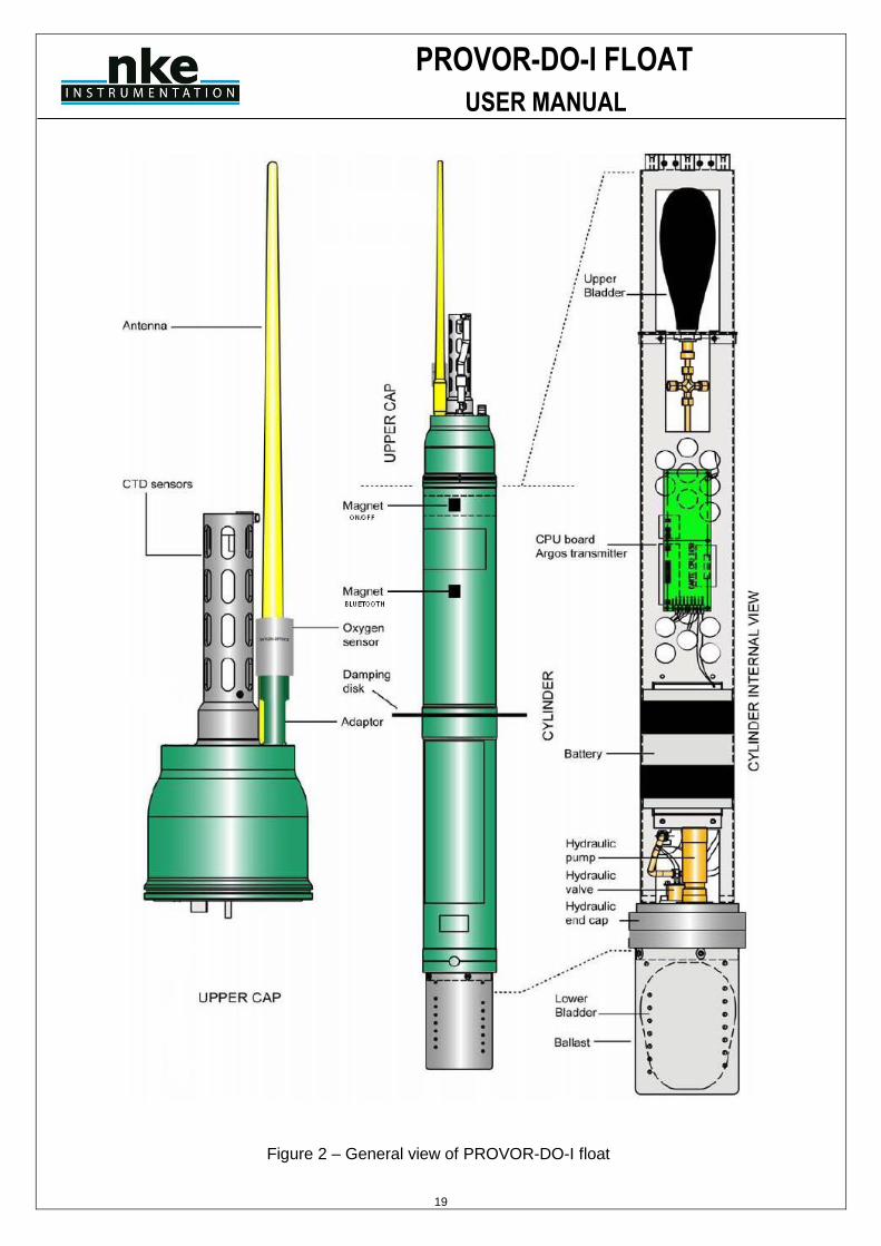
Figure 2 – General view of PROVOR-DO-I float
PROVOR-DO-I FLOAT
USER MANUAL
20
3.3 Density Control System
Descent and ascent depend upon buoyancy. PROVOR-DO-I is balanced when its density is equal to that of the
level of surrounding water. The float has a fixed mass. A precision hydraulic system is used to adjust its volume.
This system inflates or deflates an external bladder by exchanging oil with an internal reservoir. This exchange is
performed by a hydraulic system comprising a high-pressure pump and a solenoid valve.
The interested reader is referred to a more detailed description of the operation of PROVOR-DO-I's density control
system in section 8 page 62.
3.4 Sensors
PROVOR-DO-I is equipped with precision instruments for measuring :
- pressure, temperature and salinity with the SEABIRD SBE41CP CTD sensor. Specifications of the sensor are
provided in section 7 page 61.
- Dissolved Oxygen with the Oxygen Optode AANDERAA 3830 or 4330 sensor
3.5 IRIDIUM/GPS MODEM
While the float is at the surface, the Iridium Modem sends stored data to the satellites of the Iridium system (see
sections 6. Page 38). The transmitter has a unique IMEI ID assigned by Iridium. This ID identifies the individual
float. The antenna is mounted on the top end of the PROVOR-DO-I float and must be above the sea surface in
order for transmissions to reach the satellites.
3.6 CPU Board
This board contains a micro-controller (or CPU) that controls PROVOR-DO-I. Its functions include maintenance of
the calendar and internal clock, supervision of the depth cycling process, data processing and activation and
control of the hydraulics. This board allows communication with the outside world for the purpose of testing and
programming.
3.7 Battery
A battery of lithium thionyl chloride cells supplies the energy required to operate PROVOR-DO-I .Depending
requested number of cycles, several kind of battery packs can be installed in float
3.8 MMI link
The User link is made via Bluetooth (radiofrequency link)
3.9 Firmware evolution in 2015
PROVOR-DO-I firmware has been modified in 2015 with several objectives. Main objectives were :
- Better resistance to deployment conditions (Auto-test improvement, ...)
- Deployment procedure simplification (with use of Buzzer)
- Increase technical return from float (Creation of 2nd technical message)
- Sampling capability increasing (from 308 CTD points per cycle -> 2015 CTD points per cycle)
- User interface simplification*

PROVOR-DO-I FLOAT
USER MANUAL
21
3.10 Firmware evolution in 2016 (firmware 5900A03 & higher)
- “Near surface” and “In air” measurement phases were added at the end of ascent phase. This is specifically
useful for float with optional dissolved oxygen sensor, for saturation control in order to compensate potential
sensor drift
- Ice detection possibility (option), based on Ice Sensing algorithm (ISA for Antarctic area)
- Because of Ice detection capability, SBD messages are now stored in float’s memory, for transmission on a
following cycle, as soon as satellite transmission becomes possible

PROVOR-DO-I FLOAT
USER MANUAL
22
4 THE LIFE OF AN PROVOR-DO-I FLOAT
The life of an PROVOR-DO-I float is divided into 4 phases: Storage/Transport, Deployment, Mission, & Life
Expiry.
(1) Storage/Transport
During this phase, the float, packed in its transport case, awaits deployment. The electronic components
are dormant, and float's buoyancy control functions are completely shut down. This is the appropriate
status for both transport and storage.
(2) Deployment
The float is removed from its protective packaging, configured, tested and launched at sea.
(3) Mission The mission begins with the launching of the float. During the Mission, PROVOR-DO-I conducts a pre-
programmed number of cycles of descent, submerged drift, ascent and data transmission. During these
cycles it collects CTD data, computes data, and transmits it to the IRIDIUM satellite system.
(4) Life Expiry Life Expiry begins automatically upon completion of the pre-programmed number of cycles. During Life
Expiry, the float, drifting on the sea surface, periodically transmits messages until the battery is depleted.
Reception of these messages makes it possible to locate the float, to follow its movements and, if desired,
to recover it. PROVOR-DO-I floats are designed to be expendable, so recovery is not part of its normal life
cycle, but is possible with Iridium telecommand.
If the battery is depleted before completion of the pre-programmed number of cycles, PROVOR-DO-I will
probably remain submerged and cannot be located nor recovered.
4.1 The Mission - Overview
We call "Mission" the period between the moment when the float is launched at the experiment zone and the
moment when the data transmission relating to the final depth cycle is completed.
During the Mission, PROVOR-DO-I conducts ascent and descent profiles, separated by periods of IRIDIUM
transmitting and drifting at a predetermined depth. PROVOR-DO-I can collect data during the descent,
submerged drift, or ascent portions of the cycle, and transmits the collected data during the surface drift period
at the end of each cycle. One cycle is shown in the figure below.
Figure 3 Schematic representation of a PROVOR-DO-I's depth-cycle during the Mission
PROVOR-DO-I FLOAT
USER MANUAL
23
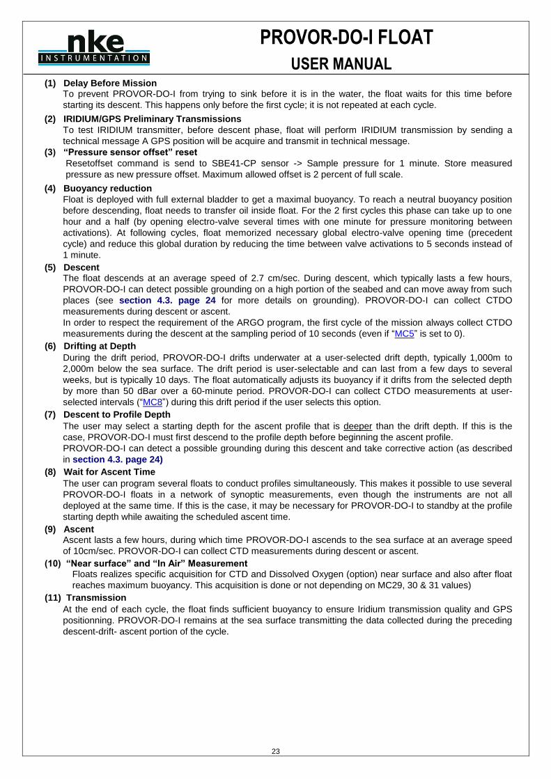
(1) Delay Before Mission To prevent PROVOR-DO-I from trying to sink before it is in the water, the float waits for this time before
starting its descent. This happens only before the first cycle; it is not repeated at each cycle.
(2) IRIDIUM/GPS Preliminary Transmissions
To test IRIDIUM transmitter, before descent phase, float will perform IRIDIUM transmission by sending a
technical message A GPS position will be acquire and transmit in technical message.
(3) “Pressure sensor offset” reset
Resetoffset command is send to SBE41-CP sensor -> Sample pressure for 1 minute. Store measured
pressure as new pressure offset. Maximum allowed offset is 2 percent of full scale.
(4) Buoyancy reduction
Float is deployed with full external bladder to get a maximal buoyancy. To reach a neutral buoyancy position
before descending, float needs to transfer oil inside float. For the 2 first cycles this phase can take up to one
hour and a half (by opening electro-valve several times with one minute for pressure monitoring between
activations). At following cycles, float memorized necessary global electro-valve opening time (precedent
cycle) and reduce this global duration by reducing the time between valve activations to 5 seconds instead of
1 minute.
(5) Descent The float descends at an average speed of 2.7 cm/sec. During descent, which typically lasts a few hours,
PROVOR-DO-I can detect possible grounding on a high portion of the seabed and can move away from such
places (see section 4.3. page 24 for more details on grounding). PROVOR-DO-I can collect CTDO
measurements during descent or ascent. In order to respect the requirement of the ARGO program, the first cycle of the mission always collect CTDO
measurements during the descent at the sampling period of 10 seconds (even if “MC5” is set to 0).
(6) Drifting at Depth
During the drift period, PROVOR-DO-I drifts underwater at a user-selected drift depth, typically 1,000m to
2,000m below the sea surface. The drift period is user-selectable and can last from a few days to several
weeks, but is typically 10 days. The float automatically adjusts its buoyancy if it drifts from the selected depth
by more than 50 dBar over a 60-minute period. PROVOR-DO-I can collect CTDO measurements at user-
selected intervals (“MC8”) during this drift period if the user selects this option.
(7) Descent to Profile Depth
The user may select a starting depth for the ascent profile that is deeper than the drift depth. If this is the
case, PROVOR-DO-I must first descend to the profile depth before beginning the ascent profile. PROVOR-DO-I can detect a possible grounding during this descent and take corrective action (as described
in section 4.3. page 24)
(8) Wait for Ascent Time
The user can program several floats to conduct profiles simultaneously. This makes it possible to use several
PROVOR-DO-I floats in a network of synoptic measurements, even though the instruments are not all
deployed at the same time. If this is the case, it may be necessary for PROVOR-DO-I to standby at the profile
starting depth while awaiting the scheduled ascent time.
(9) Ascent Ascent lasts a few hours, during which time PROVOR-DO-I ascends to the sea surface at an average speed
of 10cm/sec. PROVOR-DO-I can collect CTD measurements during descent or ascent.
(10) “Near surface” and “In Air” Measurement Floats realizes specific acquisition for CTD and Dissolved Oxygen (option) near surface and also after float
reaches maximum buoyancy. This acquisition is done or not depending on MC29, 30 & 31 values)
(11) Transmission
At the end of each cycle, the float finds sufficient buoyancy to ensure Iridium transmission quality and GPS
positionning. PROVOR-DO-I remains at the sea surface transmitting the data collected during the preceding
descent-drift- ascent portion of the cycle.
PROVOR-DO-I FLOAT
USER MANUAL
24
4.2 Descent
While the float is still at the sea surface PROVOR-DO-I measures and records its pressure sensor offset. This
offset is used to correct all pressure measurements. The offset is transmitted in a technical message (see section
6. Page 38) for a description of technical messages format). Descent takes the float from the sea surface to the
drift depth. Initially, in order to avoid possible collisions with ships, PROVOR-DO-I's objective is to lose buoyancy in
the shortest possible time. It does this by opening the solenoid valve for a time period that is initially long, but
decreases as the float approaches its target depth.
If the user chooses, PROVOR-DO-I will collect CTDO measurements during descent and/or during ascent. The
interval between CTD measurements is user-programmable.
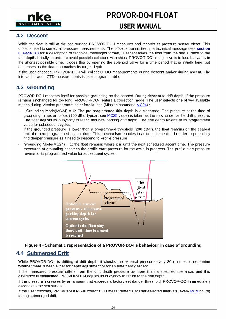
4.3 Grounding
PROVOR-DO-I monitors itself for possible grounding on the seabed. During descent to drift depth, if the pressure
remains unchanged for too long, PROVOR-DO-I enters a correction mode. The user selects one of two available
modes during Mission programming before launch (Mission command MC24) :
• Grounding Mode(MC24) = 0: The pre-programmed drift depth is disregarded. The pressure at the time of
grounding minus an offset (100 dBar typical, see MC25 value) is taken as the new value for the drift pressure.
The float adjusts its buoyancy to reach this new parking drift depth. The drift depth reverts to its programmed
value for subsequent cycles. If the grounded pressure is lower than a programmed threshold (200 dBar), the float remains on the seabed
until the next programmed ascent time. This mechanism enables float to continue drift in order to potentially
find deeper pressure as it need to descend to Profile pressure
• Grounding Mode(MC24) = 1: the float remains where it is until the next scheduled ascent time. The pressure
measured at grounding becomes the profile start pressure for the cycle in progress. The profile start pressure
reverts to its programmed value for subsequent cycles.
Figure 4 - Schematic representation of a PROVOR-DO-I's behaviour in case of grounding
4.4 Submerged Drift
While PROVOR-DO-I is drifting at drift depth, it checks the external pressure every 30 minutes to determine
whether there is need either for depth adjustment or for an emergency ascent.
If the measured pressure differs from the drift depth pressure by more than a specified tolerance, and this
difference is maintained, PROVOR-DO-I adjusts its buoyancy to return to the drift depth.
If the pressure increases by an amount that exceeds a factory-set danger threshold, PROVOR-DO-I immediately
ascends to the sea surface.
If the user chooses, PROVOR-DO-I will collect CTD measurements at user-selected intervals (every MC9 hours)
during submerged drift.
PROVOR-DO-I FLOAT
USER MANUAL
25
4.5 Ascent
If the chosen ascent profile starting pressure (MC12,or resp. MC14) is higher than the drift pressure (MC13, or
resp. MC15), the float must first descend to reach the profile starting pressure.
If grounding is detected while PROVOR-DO-I is descending to the profile starting pressure, the present pressure is
substituted for the profile starting pressure. This substitution is only for the cycle in progress; the profile starting
pressure reverts to its pre-programmed value for subsequent cycles.
Once the profile starting pressure has been reached, the float waits for the programmed time to begin the ascent.
If this time is reached before the float has arrived at the profile starting pressure, the ascent starts immediately.
PROVOR-DO-I ascends by repeated use of the pump. When the pressure change between two successive
measurements is less than 10 dBar, the pump is activated for a pre-set time period. In this way, the pump
performs minimum work at high pressure, which ensures minimum electrical energy consumption. The average
speed of ascent is approximately 10cm/sec. For a 2,000m profile, the ascent would therefore last 6 hours.
When the pressure drops below 10 dBar (signifying completion of ascent), PROVOR-DO-I waits 10 minutes and
then activates the pump in order to empty the reservoir and achieve maximum buoyancy. If the user chooses,
PROVOR-DO-I will collect CTDO measurements during descent and/or ascent. CTDO measurements begin at the
profile start time and stop 10 minutes after the float rises above the 10 dBar isobar in its approach to the sea
surface. The interval between CTDO measurements is user-programmable. For example, during a profile
beginning at 2,000 m with a 10 sec sampling period, 2,200 CTDO measurements (raw data) will be collected.
These samples will be then “treated” before transmission” (see 6.14 CTD(O) Data Treatment details).
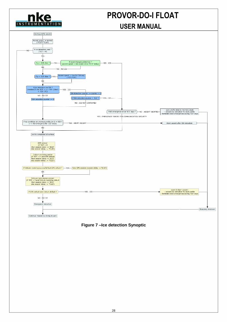
4.5.1 Ice detection (with firmware 5900A03 and higher) At the end of ascent, if Ice detection option is activated, float will start ice detection in order to stop ascent and avoid hit ice with risk to remain blocked under ice.
To detect Ice, float uses 3 mecanisms :
o ISA method (Ice Sensing Algorithm)
o Satellite visibility
o Pressure evolution
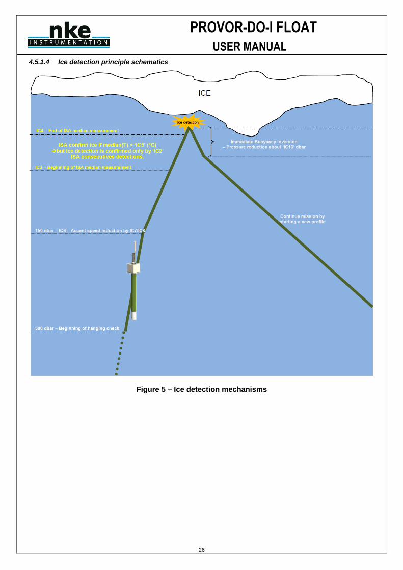
If ice is detected, float stop ascent and abort “In air “ measurement and satellite transmission. In that case, SBD packets are created and stored into float internal memory for transmission next time float will really reach surface.
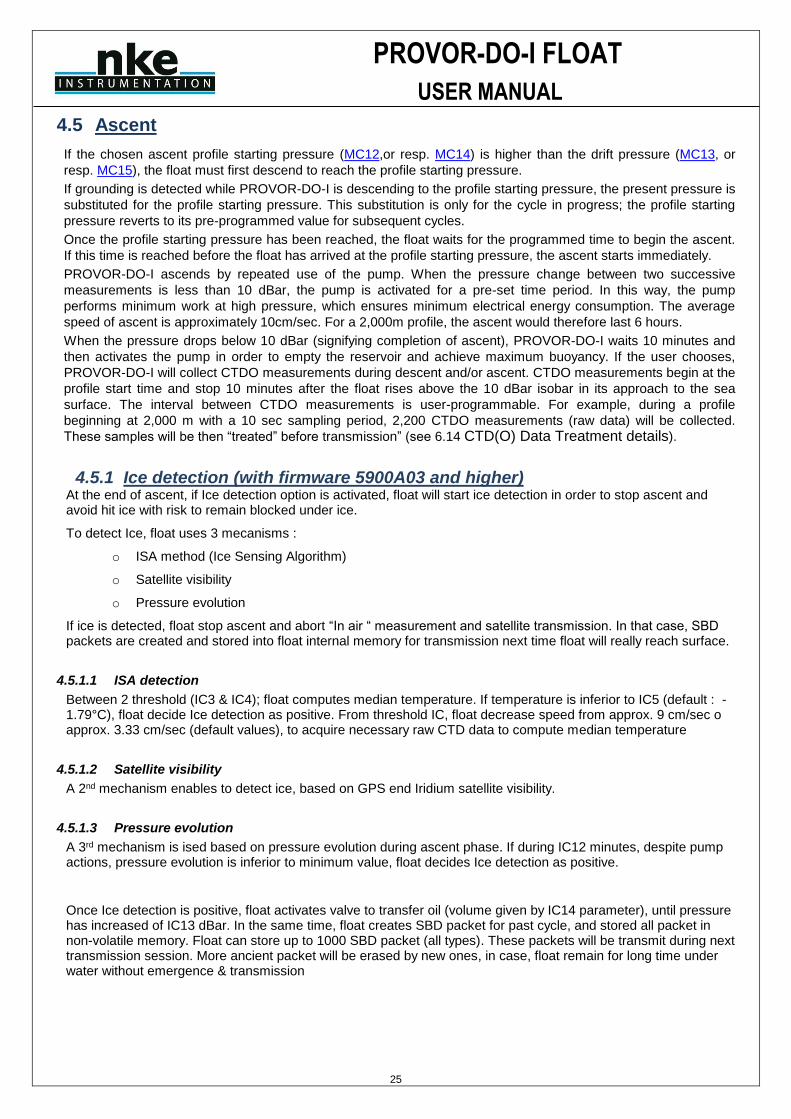
4.5.1.1 ISA detection
Between 2 threshold (IC3 & IC4); float computes median temperature. If temperature is inferior to IC5 (default : -1.79°C), float decide Ice detection as positive. From threshold IC, float decrease speed from approx. 9 cm/sec o approx. 3.33 cm/sec (default values), to acquire necessary raw CTD data to compute median temperature
4.5.1.2 Satellite visibility
A 2nd mechanism enables to detect ice, based on GPS end Iridium satellite visibility.
4.5.1.3 Pressure evolution
A 3rd mechanism is ised based on pressure evolution during ascent phase. If during IC12 minutes, despite pump actions, pressure evolution is inferior to minimum value, float decides Ice detection as positive.
Once Ice detection is positive, float activates valve to transfer oil (volume given by IC14 parameter), until pressure has increased of IC13 dBar. In the same time, float creates SBD packet for past cycle, and stored all packet in non-volatile memory. Float can store up to 1000 SBD packet (all types). These packets will be transmit during next transmission session. More ancient packet will be erased by new ones, in case, float remain for long time under water without emergence & transmission
PROVOR-DO-I FLOAT
USER MANUAL
26
4.5.1.4 Ice detection principle schematics
Figure 5 – Ice detection mechanisms
PROVOR-DO-I FLOAT
USER MANUAL
27
Figure 6 – Transmission after Ice detection principle
PROVOR-DO-I FLOAT
USER MANUAL
28
Figure 7 –Ice detection Synoptic
PROVOR-DO-I FLOAT
USER MANUAL
29
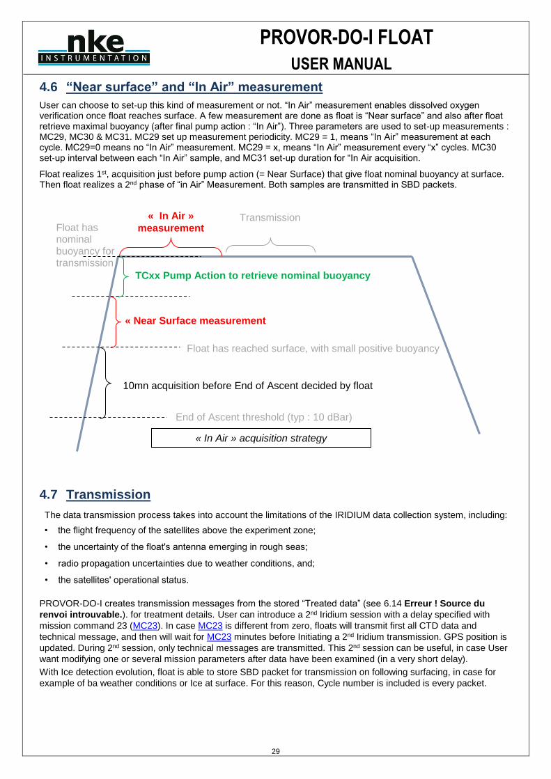
4.6 “Near surface” and “In Air” measurement
User can choose to set-up this kind of measurement or not. “In Air” measurement enables dissolved oxygen verification once float reaches surface. A few measurement are done as float is “Near surface” and also after float retrieve maximal buoyancy (after final pump action : “In Air”). Three parameters are used to set-up measurements : MC29, MC30 & MC31. MC29 set up measurement periodicity. MC29 = 1, means “In Air” measurement at each cycle. MC29=0 means no “In Air” measurement. MC29 = x, means “In Air” measurement every “x” cycles. MC30 set-up interval between each “In Air” sample, and MC31 set-up duration for “In Air acquisition.
Float realizes 1st, acquisition just before pump action (= Near Surface) that give float nominal buoyancy at surface. Then float realizes a 2nd phase of “in Air” Measurement. Both samples are transmitted in SBD packets.
4.7 Transmission
The data transmission process takes into account the limitations of the IRIDIUM data collection system, including:
• the flight frequency of the satellites above the experiment zone;
• the uncertainty of the float's antenna emerging in rough seas;
• radio propagation uncertainties due to weather conditions, and;
• the satellites' operational status.
PROVOR-DO-I creates transmission messages from the stored “Treated data” (see 6.14 Erreur ! Source du
renvoi introuvable.). for treatment details. User can introduce a 2nd Iridium session with a delay specified with
mission command 23 (MC23). In case MC23 is different from zero, floats will transmit first all CTD data and
technical message, and then will wait for MC23 minutes before Initiating a 2nd Iridium transmission. GPS position is
updated. During 2nd session, only technical messages are transmitted. This 2nd session can be useful, in case User
want modifying one or several mission parameters after data have been examined (in a very short delay).
With Ice detection evolution, float is able to store SBD packet for transmission on following surfacing, in case for
example of ba weather conditions or Ice at surface. For this reason, Cycle number is included is every packet.
End of Ascent threshold (typ : 10 dBar)
10mn acquisition before End of Ascent decided by float
« Near Surface measurement
TCxx Pump Action to retrieve nominal buoyancy
« In Air »
measurement Transmission
« In Air » acquisition strategy
Float has reached surface, with small positive buoyancy
Float has nominal buoyancy for transmission
PROVOR-DO-I FLOAT
USER MANUAL
30
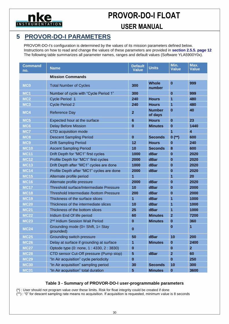
5 PROVOR-DO-I PARAMETERS
PROVOR-DO-I's configuration is determined by the values of its mission parameters defined below.
Instructions on how to read and change the values of these parameters are provided in section 2.5.5. page 12
The following table summarizes all parameter names, ranges and default values (Software YLA5900Y0x).
Command
no. Name
Default Value
Units Min. Value
Max. Value
Mission Commands
MC0 Total Number of Cycles 300 Whole
number
0 999
MC1 Number of cycle with “Cycle Period 1” 300 0 999
MC2 Cycle Period 1 240 Hours 1 480
MC3 Cycle Period 2 240 Hours 1 480
MC4 Reference Day 2 Number
of days
0 40
MC5 Expected hour at the surface 6 Hours 0 23
MC6 Delay Before Mission 0 Minutes 0 1440
MC7 CTD acquisition mode 1 4
MC8 Descent Sampling Period 0 Seconds 0 (**) 600
MC9 Drift Sampling Period 12 Hours 0 240
MC10 Ascent Sampling Period 10 Seconds 8 600
MC11 Drift Depth for “MC1” first cycles 1000 dBar 0 2020
MC12 Profile Depth for “MC1” first cycles 2000 dBar 0 2020
MC13 Drift Depth after “MC1” cycles are done 1000 dBar 0 2020
MC14 Profile Depth after “MC1” cycles are done 2000 dBar 0 2020
MC15 Alternate profile period 1 1 20
MC16 Alternate profile pressure 2000 dBar 0 2020
MC17 Threshold surface/Intermediate Pressure 10 dBar 0 2000
MC18 Threshold Intermediate /bottom Pressure 200 dBar 0 2000
MC19 Thickness of the surface slices 1 dBar 1 1000
MC20 Thickness of the intermediate slices 10 dBar 1 1000
MC21 Thickness of the bottom slices 25 dBar 1 1000
MC22 Iridium End Of life period 60 Minutes 2 7200
MC23 2nd Iridium Session Wait Period 0 Minutes 0 360
MC24 Grounding mode (0= Shift, 1= Stay
grounded) 0
0 1
MC25 Grounding switch pressure 50 dBar 10 200
MC26 Delay at surface if grounding at surface 1 Minutes 0 2400
MC27 Optode type (0: none, 1 : 4330, 2 : 3830) 0 0 2
MC28 CTD sensor Cut-Off pressure (Pump stop) 5 dBar 2 60
MC29 “In Air acquisition” cycle periodicity 0 0 250
MC30 “In Air acquisition” sampling period 30 Seconds 10 300
MC31 “In Air acquisition” total duration 5 Minutes 0 3600
Table 3 - Summary of PROVOR-DO-I user-programmable parameters
(*) : User should not program value over these limits. Risk for float integrity could be created if done (**) : “0” for descent sampling rate means no acquisition. If acquisition is requested, minimum value is 8 seconds
PROVOR-DO-I FLOAT
USER MANUAL
31
5.1 Mission Parameters
MC(0) Total Number of Cycles This is the total number of cycles of descent, submerged drift, ascent and transmission that PROVOR-DO-I will perform. The mission ends and PROVOR-DO-I enters Life Expiry mode when this number of cycles has been completed. The capacity of PROVOR-DO-I 's batteries is sufficient for at least 300 cycles (depending on Battery type). If you wish to recover PROVOR-DO-I at the end of the mission, you must set the number of cycles at less than 300 to ensure there is sufficient battery capacity remaining to allow PROVOR-DO-I to return to the sea surface and enter Life Expiry. Under favourable conditions, the battery capacity may exceed 300 cycles. If you do not plan to recover the PROVOR-DO-I float, you may choose to set the number of cycles to 300 to ensure that PROVOR-DO-I completes the maximum number of cycles possible.
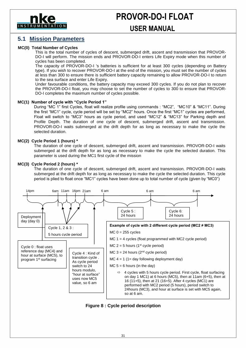
MC(1) Number of cycle with “Cycle Period 1” During “MC 1” first Cycles, float will realize profile using commands : “MC2”, “MC10” & “MC11”. During
the first “MC1” cycle, cycle period will be set by “MC2” hours. Once the first “MC1” cycles are performed,
Float will switch to “MC3” hours as cycle period, and used “MC12” & “MC13” for Parking depth and
Profile Depth. The duration of one cycle of descent, submerged drift, ascent and transmission.
PROVOR-DO-I waits submerged at the drift depth for as long as necessary to make the cycle the
selected duration. MC(2) Cycle Period 1 (hours) *
The duration of one cycle of descent, submerged drift, ascent and transmission. PROVOR-DO-I waits
submerged at the drift depth for as long as necessary to make the cycle the selected duration. This
parameter is used during the MC1 first cycle of the mission MC(3) Cycle Period 2 (hours) *
The duration of one cycle of descent, submerged drift, ascent and transmission. PROVOR-DO-I waits
submerged at the drift depth for as long as necessary to make the cycle the selected duration. This cycle
period is plied to float once “MC1” cycles have been done up to total number of cycle (given by “MC0”)
Figure 8 : Cycle period description
Deployment day (day 0)
Example of cycle with 2 different cycle period (MC2 ≠ MC3)
MC 0 = 255 cycles
MC 1 = 4 cycles (float programmed with MC2 cycle period)
MC 2 = 5 hours (1st cycle period)
MC 3 = 24 hours (2nd cycle period)
MC 4 = 1 (1= day following deployment day)
MC 5 = 6 hours (in the day)
4 cycles with 5 hours cycle period. First cycle, float surfacing on day 1 MC1) at 6 hours (MC5), then at 11am (6+5), then at 16 (11+5), then at 21 (16+5). After 4 cycles (MC1) are performed with MC2 period (5 hours), period switch to 24hours (MC3), and hour at surface is set with MC5 again, so at 6 am.
6 am 6 am 6am 11am 16pm 21am
Cycle 6: 24 hours
Cycle 5 : 24 hours
Cycle 1, 2 & 3 :
5 hours cycle period
Cycle 0 : float uses reference day (MC4) and hour at surface (MC5), to program 1st surfacing
6 am 14pm
Cycle 4 : Kind of transition cycle . As cycle period switch to 24 hours modulo, “hour at surface” uses now MC5 value, so 6 am
PROVOR-DO-I FLOAT
USER MANUAL
32
MC(4) Reference Day (number of days) The float’s internal clock day number is set to zero when the mission starts. When this float day number equals the reference day “MC4”, the float performs its first profile. Thus, as this parameter defines a particular day on which the first profile is to be made, it allows you to configure a group of floats so that they all conduct their first profile at the same time. When setting the reference day, it is recommended to allow enough time between the deployment and reach of profiling depth. Using a reference day of at least 2 will ensure the first profile to be completed. If reference day is set to 0 or 1, float will probably not have enough time to reach Profile pressure target. In that case, float will shorten descent in order to stay in compliance with hour at surface. It means also that CTD acquisition during 1st descent could not occurs, as float will enter earlier than expected in descent to profile (CTD acquisition is only during descent to parking depth).
MC(5) Estimated Time on Surface (hours)
Estimated time float must reach surface.
MC(6) Delay Before Mission (minutes) To prevent PROVOR-DO-I from trying to sink while still on deck, the float waits for this time before commanding the buoyancy engine to start the descent. After disconnection of the PC, followed by removal of the magnet, PROVOR-DO-I will wait for this delay before beginning the descent. The delay is measured after the first start of the pump which confirms the removal of the magnet (see section 2.4.1) and before the start of the descent.
MC(7) CTD sensor acquisition mode 1 = Continuous pump mode (recommended), CTD pump will be active during complete profile 2 = ECO Mode (Measurement is taken in the middle of the theoretical slice). 3 = Mix-mode (ECO mode in Deep zone, Continuous pump mode in intermediate & shallow zone) 4 = Spot-sampling mode (pump is active for 20s approx, then sample is acquired)
With mode, 2, 3 and 4, slice thickness must be parametered to stay inferior to 5 dBar.
For thin slice thickness (< 5 dBar), continuous mode is needed
MC(8) Descent Sampling Period (seconds)
The time interval between successive CTD measurements during descent. If this parameter is set to 0 seconds, no profile will be carried out during the descent phase. Nevertheless, due to the ARGO requirements, the first descent profile of the mission is automatically done even if the parameter was equal to 0. Minimum value is 8 seconds.
MC(9) Drift Sampling Period (hours) The time interval between successive CTD measurements during PROVOR-DO-I 's stay at the drift
depth.
MC(10) Ascent Sampling Period (seconds)
The time interval between successive CTD measurements during ascent. Minimum value is
8 seconds.
MC(11) Drift Depth used during “MC1” first cycle (dbar) ** The depth at which PROVOR-DO-I drifts after completion of a descent while awaiting the time scheduled for the beginning of the next ascent.
MC(12) Profile Depth used during “MC1” first cycle (dbar) ** Depth at which profiling begins if in an ascending profile. If PROVOR-DO-I is drifting at some shallower depth, it will first descend to the profile depth before starting the ascent profile.
MC(13) Drift Depth used with cycle period MC2 (dbar) ** The depth at which PROVOR-DO-I drifts after completion of a descent while awaiting the time scheduled for the beginning of the next ascent.
PROVOR-DO-I FLOAT
USER MANUAL
33
MC(14) Profile Depth used with cycle period MC2 (dbar) ** Depth at which profiling begins if in an ascending profile. If PROVOR-DO-I is drifting at some shallower depth, it will first descend to the profile depth before starting the ascent profile.
MC(15) Alternate profile period
Period for float to make profile with “MC16” dBar as profile pressure instead of “MC12” or “MC14” dBar.
If MC15 = 1, float do not realize alternate profiles
If MC15 = 2, float wil perform on profile with “MC12” (or “MC14”) dBar as profile pressure and one profile
at “MC16” dBar
If MC 15 = n, floats will perform (n-1) profiles with “MC12” (or “MC14”) dBar as profile pressure and 1
profile with “MC16” dBar as profile pressure.
MC(16) Alternate profile pressure (dBar)
Pressure used as profile pressure for alternated profiles
MC(17) Threshold surface/Intermediate Pressure (dbar) **
The isobar that divides surface depths from intermediate depths for the purpose of data reduction.
MC(18) Threshold Intermediate / Bottom Pressure (dbar) **
The isobar that divides Intermediate depths from shallow depths for the purpose of data reduction.
MC(19) Thickness of the surface slices (dbar) **
Thickness of the slices for shallow depths (algorithm of data reduction).
MC(20) Thickness of the intermediate slices (dbar) **
Thickness of the slices for shallow depths (algorithm of data reduction).
MC(21) Thickness of the bottom slices (dbar) **
Thickness of the slices for deep depths (algorithm of data reduction).
MC(22) End of life period (hours)
Transmission period (in hours) once float is in “end of life mode” (all programmed cycles have
been reached. Float send Technical SBD message.
MC(23) 2nd Iridium Session Wait Period (min)
At beginning of cycle, if this parameter is different of zero, 2 SBD sessions will occur. This
enable to check if a change on mission or technical parameter has been correctly treated by
float and if new parameters are effective for next cycle. After the 1st transmission, float will
wait for MC20 minutes before proceeding to 2nd transmission.
MC(24) Grounding mode
MC21 = 0 means shift, MC21 = 1, means float stay grounded.
MC(25) Grounding switch pressure
In case of grounding during descent to parking depth, float will reduce target pressure from MC22 dBars.
MC(26) Delay in case of grounding at surface (minutes)
Transmission period (in hours) once float is in “end of life mode” (all programmed cycles have
been reached. Float send Technical SBD message.
MC(27) Optode Type
Set Optode type mounted on float, 0 : 3830, 1 : 4330.
* Cycle period can be setted to inferior value than 24H. In that case, float will wait hour at surface for 1st cycle, and then will realize cycles every cycle period.
Example : cycle period is 8H, and hour at surface is 14h (MC5) on day 1 (given by MC4). After deployment, at 1st cycle, float will be at surface at “MC5” hour, on day “MC4”. Then, float will cycle every 8 hours.
In our example, float is deployed on 20/12/2013. Float will be at surface at 14:00 pm on 21/12/2013 for 1st cycle, then, at surface on 21/12/2013 at 22:00 pm, then , on 22/12/2013 at 6:00 am, ...
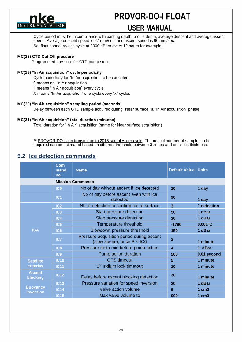
PROVOR-DO-I FLOAT
USER MANUAL
34
Cycle period must be in compliance with parking depth, profile depth, average descent and average ascent speed. Average descent speed is 27 mm/sec, and ascent speed is 90 mm/sec.
So, float cannot realize cycle at 2000 dBars every 12 hours for example.
MC(28) CTD Cut-Off pressure
Programmed pressure for CTD pump stop.
MC(29) “In Air acquisition” cycle periodicity
Cycle periodicity for “In Air acquisition to be executed.
0 means no “In Air acquisition
1 means “In Air acquisition” every cycle
X means “In Air acquisition” one cycle every “x” cycles
MC(30) “In Air acquisition” sampling period (seconds)
Delay between each CTD sample acquired during “Near surface “& “In Air acquisition” phase
MC(31) “In Air acquisition” total duration (minutes)
Total duration for “In Air” acquisition (same for Near surface acquisition)
** PROVOR-DO-I can transmit up to 2015 samples per cycle. Theoretical number of samples to be acquired can be estimated based on different threshold between 3 zones and on slices thickness.
5.2 Ice detection commands
Com
mand
no.
Name Default Value Units
Mission Commands
IC0 Nb of day without ascent if Ice detected 10 1 day
IC1
Nb of day before ascent even with ice detected
90 1 day
ISA
IC2 Nb of detection to confirm Ice at surface 3 1 detection
IC3 Start pressure detection 50 1 dBar
IC4 Stop pressure detection 20 1 dBar
IC5 Temperature threshold -1790 0.001°C
IC6 Slowdown pressure threshold 150 1 dBar
IC7 Pressure acquisition period during ascent
(slow speed), once P < IC6 2
1 minute
IC8 Pressure delta min before pump action 4 1 dBar
IC9 Pump action duration 500 0.01 second
Satellite
criterias
IC10 GPS timeout 5 1 minute
IC11 1st Iridium lock timetout 10 1 minute
Ascent
blocking IC12 Delay before ascent blocking detection 30
1 minute
Buoyancy
inversion
IC13 Pressure variation for speed inversion 20 1 dBar
IC14 Valve action volume 9 1 cm3
IC15 Max valve volume to 900 1 cm3
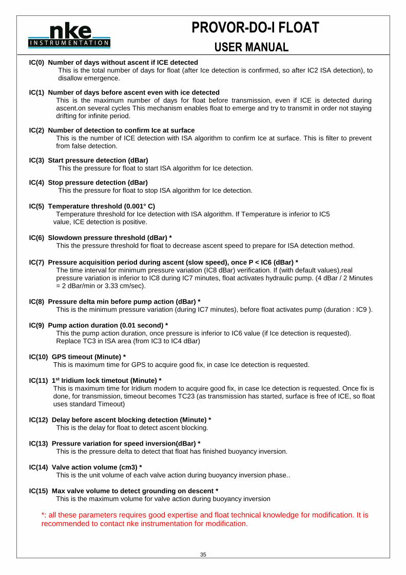
PROVOR-DO-I FLOAT
USER MANUAL
35
IC(0) Number of days without ascent if ICE detected This is the total number of days for float (after Ice detection is confirmed, so after IC2 ISA detection), to disallow emergence.
IC(1) Number of days before ascent even with ice detected This is the maximum number of days for float before transmission, even if ICE is detected during ascent.on several cycles This mechanism enables float to emerge and try to transmit in order not staying drifting for infinite period.
IC(2) Number of detection to confirm Ice at surface This is the number of ICE detection with ISA algorithm to confirm Ice at surface. This is filter to prevent from false detection.
IC(3) Start pressure detection (dBar) This the pressure for float to start ISA algorithm for Ice detection.
IC(4) Stop pressure detection (dBar) This the pressure for float to stop ISA algorithm for Ice detection.
IC(5) Temperature threshold (0.001° C) Temperature threshold for Ice detection with ISA algorithm. If Temperature is inferior to IC5
value, ICE detection is positive.
IC(6) Slowdown pressure threshold (dBar) * This the pressure threshold for float to decrease ascent speed to prepare for ISA detection method.
IC(7) Pressure acquisition period during ascent (slow speed), once P < IC6 (dBar) *
The time interval for minimum pressure variation (IC8 dBar) verification. If (with default values),real pressure variation is inferior to IC8 during IC7 minutes, float activates hydraulic pump. (4 dBar / 2 Minutes = 2 dBar/min or 3.33 cm/sec).
IC(8) Pressure delta min before pump action (dBar) * This is the minimum pressure variation (during IC7 minutes), before float activates pump (duration : IC9 ).
IC(9) Pump action duration (0.01 second) * This the pump action duration, once pressure is inferior to IC6 value (if Ice detection is requested). Replace TC3 in ISA area (from IC3 to IC4 dBar)
IC(10) GPS timeout (Minute) * This is maximum time for GPS to acquire good fix, in case Ice detection is requested.
IC(11) 1st Iridium lock timetout (Minute) * This is maximum time for Iridium modem to acquire good fix, in case Ice detection is requested. Once fix is done, for transmission, timeout becomes TC23 (as transmission has started, surface is free of ICE, so float uses standard Timeout)
IC(12) Delay before ascent blocking detection (Minute) * This is the delay for float to detect ascent blocking.
IC(13) Pressure variation for speed inversion(dBar) * This is the pressure delta to detect that float has finished buoyancy inversion.
IC(14) Valve action volume (cm3) * This is the unit volume of each valve action during buoyancy inversion phase..
IC(15) Max valve volume to detect grounding on descent * This is the maximum volume for valve action during buoyancy inversion
*: all these parameters requires good expertise and float technical knowledge for modification. It is recommended to contact nke instrumentation for modification.

PROVOR-DO-I FLOAT
USER MANUAL
36
5.3 User Commands
These commands are used to dialog with float during preparation phase, to make test (sensor, GPS, Iridium,…) or to program float parameters for coming mission. These commands requires Bluetooth connection to float.
User commands can be request to float with command :
?HE
Float will answer will available command list
Command Rôle
!AR x *** Arm float (x=1) or deactivate arm mode (x=0)
MUST BE ON FOR DEPLOYMENT
?AR Request “armed mode” state
!C x Float complete auto-test. X = 0 or 1. Is X=1, a complete auto-test is done. If x=0,
buzzer won’t be activated
?CK Firmware checksum check
!CU Program SBE41 Cut-Off Pressure value according to technical command
?D Optode sensor acquisition Optode sensor acquisition
?DH Read all hydraulic data (pump and electrovalve activations) acquired during last
mission (cf chap 6.13.1Phase description to check kind of acquired data)
?DT Read all Treated Data acquired during last mission (cf chap 6.13.1Phase
description to check kind of acquired data)
?DB Read all Raw Data acquired during last mission (cf chap 6.13.1Phase description
to check kind of acquired data)
!E x Activate electrovalve for x cs (ctrl-c to stop)
?FP Fast Pressure request (Pressure measurement only)
?HE Help command. Float will screen all available user commands
!IC x y Set value y for “Ice command” x
?IC Screen all Ice commands
?IC x Screen Ice command x
!K x Command to activate or deactivate read/Write access for technical parameters. X
value is communicated to users upon request to nke
!MC x y Set value y for “mission command” x
?MC Screen all mission commands
?MC x Screen mission command x
?NS Request float’s serial number
!P x** Activate pump for x cs (ctrl-c to stop)
!PB Request Battery Voltage with hydraulic pump active
?RE Read the 5 last reset date and time
?RO SBE Pressure sensor last resetoffset value(deciBars)
!RO SBE Pressure sensor resetoffset operation (take one minute)
!RP Parameters are transferred from EEPROM memory to RAM memory
?S CTD sensor acquisition
!SE Initiate GPS acquisition and IRIDIUM transmission session (requires satellite

PROVOR-DO-I FLOAT
USER MANUAL
37
visibility
?SP Read all Data (Treated & Raw CTD data, hydraulic data)
!SH x Activate (x=1) or de-activate (x=0) Show mode
(MUST BE OFF FOR DEPLOYMENT)
?SH Request show mode state
!TB x Activate buzzer for x seconds. To stop buzzer before ‘x’ seconds, send command
!TB 0
?TI Request float’s internal date and time
!TR SBE41 transparent dialog mode
!TC x y * Set value y for “technical parameter” x
?TC * Screen all technical commands
?TC x * Screen technical command x
!TI dd mm yy hh mn ss Set date and time to dd/mm/yy hh:mn:ss
!V Float measure Internal vaccum and refresh value every 5 seconds
?VB Request internal vacuum and battery voltage (in decivolt and millibar)
?VL Request software version
Table 4 - User command list
* : protected command (need !K x to unlock) ** : Float is delivered with hydraulic pump priming (fill in with oil). Pump must not be activated for long period as external bladder is already full
*** : As Armed Mode command is sent to float, float performs auto-test, and fill in external bladder, by activate hydraulic pump. Floats can pump up to several minutes depending on external bladder initial state.
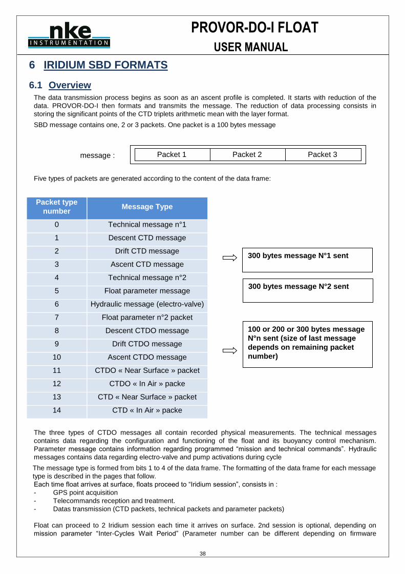
PROVOR-DO-I FLOAT
USER MANUAL
38
6 IRIDIUM SBD FORMATS
6.1 Overview
The data transmission process begins as soon as an ascent profile is completed. It starts with reduction of the
data. PROVOR-DO-I then formats and transmits the message. The reduction of data processing consists in
storing the significant points of the CTD triplets arithmetic mean with the layer format.
SBD message contains one, 2 or 3 packets. One packet is a 100 bytes message
Five types of packets are generated according to the content of the data frame:
Packet type
number Message Type
0 Technical message n°1
1 Descent CTD message
2 Drift CTD message
3 Ascent CTD message
4 Technical message n°2
5 Float parameter message
6 Hydraulic message (electro-valve)
7 Float parameter n°2 packet
8 Descent CTDO message
9 Drift CTDO message
10 Ascent CTDO message
11 CTDO « Near Surface » packet
12 CTDO « In Air » packe
13 CTD « Near Surface » packet
14 CTD « In Air » packe
The three types of CTDO messages all contain recorded physical measurements. The technical messages
contains data regarding the configuration and functioning of the float and its buoyancy control mechanism.
Parameter message contains information regarding programmed “mission and technical commands”. Hydraulic
messages contains data regarding electro-valve and pump activations during cycle
The message type is formed from bits 1 to 4 of the data frame. The formatting of the data frame for each message
type is described in the pages that follow.
Each time float arrives at surface, floats proceed to “Iridium session”, consists in :
- GPS point acquisition
- Telecommands reception and treatment.
- Datas transmission (CTD packets, technical packets and parameter packets)
Float can proceed to 2 Iridium session each time it arrives on surface. 2nd session is optional, depending on
mission parameter “Inter-Cycles Wait Period” (Parameter number can be different depending on firmware
Packet 1 message : Packet 2 Packet 3
300 bytes message N°1 sent
300 bytes message N°2 sent
100 or 200 or 300 bytes message
N°n sent (size of last message
depends on remaining packet
number)

PROVOR-DO-I FLOAT
USER MANUAL
39
revision) value. This parameter specifies delay between end of 1st iridium session and beginning of 2nd iridium
session. By default this parameter is set to zero, meaning that float will only proceed to one Iridium session.
If this parameters is set to a different value than zero, a 2nd session will be done in a delay specified by “Inter-
Cycles Wait Period” parameter.
During 2nd session, only technical and parameters packets will be send.
The 2nd session enable to modify float parameters before beginning of following cycle and after datas analysis
(datas received during 1st session).
Telecommands can be send before float arrives at surface, or before 2nd session only. It seems that
telecommands must be sent maximum 24H before floats arrives on surface. If telecommand is send before this
delay (48H before float surfacing), it could be erased from Iridium queue and not be delivered as expected.
One telecommand must be send for each parameter that need to be modify -> One telecommand = One
parameter to modify. See chapter 6.18.2 page 59 for details about Iridium telecommands.
If the float has been deployed within the framework of the Argo project (http://www.argo.ucsd.edu/), the decoded data are available in one of the 4 NetCDF files (META, PROF, TRAJ, TECH) used by the Argo data management to store and diffuse the information (see http://www.argodatamgt.org/Documentation for details).
Behaviour with ICE detection : In case float has stored packets because of ICE detection, during transmission; float transmit first last cycle, then, all previous cycles will be transmitted starting with most ancient cycle data.
Ex : float could not transmit on cycle 52 to 58 because of Ice, and transmission restart at cycle 59 : float will transmit cycle 59 data, then data from cycle 52, 53, up to 58
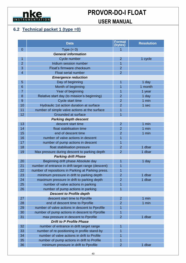
PROVOR-DO-I FLOAT
USER MANUAL
40
6.2 Technical packet 1 (type =0)
Data Format (bytes) Resolution
0 Type (= 0) 1
General information
1 Cycle number 2 1 cycle
2 Iridium session number 1
3 Float’s firmware checksum 2
4 Float serial number 2
Emergence reduction
5 Day of beginning 1 1 day
6 Month of beginning 1 1 month
7 Year of beginning 1 1 year
8 Relative start day (to mission’s beginning) 2 1 day
9 Cycle start time 2 1 min
10 Hydraulic 1st action duration at surface 2 1 sec
11 number of simple valve actions at the surface 1
12 Grounded at surface 1
Parking depth descent
13 descent start time 2 1 min
14 float stabilisation time 2 1 min
15 end of descent time 2 1 min
16 number of valve actions in descent 1
17 number of pump actions in descent 1
18 float stabilisation pressure 2 1 dbar
19 Max pressure during descent to parking depth 2 1 dbar
Parking drift Phase
20 Beginning drift phase Absolute day 1 1 day
21 number of entrance in drift target range (descent) 1
22 number of repositions in Parking at Parking press. 1
23 minimum pressure in drift to parking depth 2 1 dbar
24 maximum pressure in drift to parking depth 2 1 dbar
25 number of valve actions in parking 1
26 number of pump actions in parking 1
Descent to Profile depth
27 descent start time to Pprofile 2 1 min
28 end of descent time to Pprofile 2 1 min
29 number of valve actions in descent to Pprofile 1
30 number of pump actions in descent to Pprofile 1
31 max pressure in descent to Pprofile 2 1 dbar
Drift to P Profile Phase
32 number of entrance in drift target range 1
33 number of re-positioning in profile stand-by 1
34 number of valve actions in drift to Profile 1
35 number of pump actions in drift to Profile 1
36 minimum pressure in drift to Pprofile 2 1 dbar

PROVOR-DO-I FLOAT
USER MANUAL
41
37 maximum pressure in drift to Pprofile 2 1 dbar
Ascent Phase
38 Ascent start time 2 1 min
39 time at end of ascent (hh+mm+ss) 2 1 min
40 number of pump actions in ascent 1
General information
41 Float's time (hh+mm+ss) 3 1h, 1min, 1sec (1 byte each)
42 Float’s date (dd+mm+yy) 3 1day, 1month, 1year, 1byte each
43 pressure sensor offset (two’s complement coded) 1 1 cbar
44 internal pressure 1 5 mbars
45 batteries voltage drop at Pmax, pump ON (with regard to Unom = 15.0 V) (in dV) 1 0.1 V
46 RTC state indicator ( normal = 0, failure = 1) 1
47 Coherence problem counter 1
48 oxygen sensor Status (0 = OK, 1 = problem, 2 = none) 1
GPS Data
49 GPS latitude in degrees 1 1 degree
50 GPS latitude in minutes 1 1 minute
51 GPS latitude in minutes fractions (4th) 2 1 minute fraction (4th)
52 GPS latitude orientation (0= North, 1 = South) 1
53 GPS longitude in degrees 1 1 degree
54 GPS longitude in minutes 1 1 minute
55 GPS longitude in minutes fractions (4th) 2 1 minute fraction (4th)
56 GPS longitude orientation (0= East, 1 = West) 1
57 GPS valid fix (1 = valid, 0 = not valid) 1
58 GPS session duration 2 1 sec
59 GPS retries 1
60 Pump duration (buoyancy retrieve for GPS acquisition) 2 1 sec
61 Antenna status (0=DontKnow 1=Ok 2=Short 3=Open) 1
End Of Life information
62 End Of Life detection flag 1
63 End Of life Start hour 3 1h, 1min, 1sec (1 byte each)
64 End Of life Start Date 3 1day, 1month, 1year, 1byte each
65 Not used (filled by zeros) 3
Total 100
Table 5 - Technical message
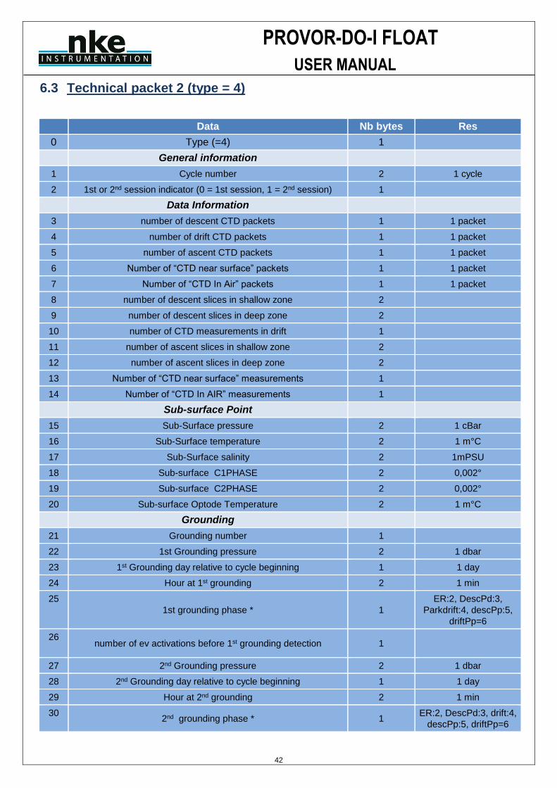
PROVOR-DO-I FLOAT
USER MANUAL
42
6.3 Technical packet 2 (type = 4)
Data Nb bytes Res
0 Type (=4) 1
General information
1 Cycle number 2 1 cycle
2 1st or 2nd session indicator (0 = 1st session, 1 = 2nd session) 1
Data Information
3 number of descent CTD packets 1 1 packet
4 number of drift CTD packets 1 1 packet
5 number of ascent CTD packets 1 1 packet
6 Number of “CTD near surface” packets 1 1 packet
7 Number of “CTD In Air” packets 1 1 packet
8 number of descent slices in shallow zone 2
9 number of descent slices in deep zone 2
10 number of CTD measurements in drift 1
11 number of ascent slices in shallow zone 2
12 number of ascent slices in deep zone 2
13 Number of “CTD near surface” measurements 1
14 Number of “CTD In AIR” measurements 1
Sub-surface Point
15 Sub-Surface pressure 2 1 cBar
16 Sub-Surface temperature 2 1 m°C
17 Sub-Surface salinity 2 1mPSU
18 Sub-surface C1PHASE 2 0,002°
19 Sub-surface C2PHASE 2 0,002°
20 Sub-surface Optode Temperature 2 1 m°C
Grounding
21 Grounding number 1
22 1st Grounding pressure 2 1 dbar
23 1st Grounding day relative to cycle beginning 1 1 day
24 Hour at 1st grounding 2 1 min
25
1st grounding phase * 1
ER:2, DescPd:3,
Parkdrift:4, descPp:5,
driftPp=6
26 number of ev activations before 1st grounding detection 1
27 2nd Grounding pressure 2 1 dbar
28 2nd Grounding day relative to cycle beginning 1 1 day
29 Hour at 2nd grounding 2 1 min
30 2nd grounding phase * 1
ER:2, DescPd:3, drift:4,
descPp:5, driftPp=6
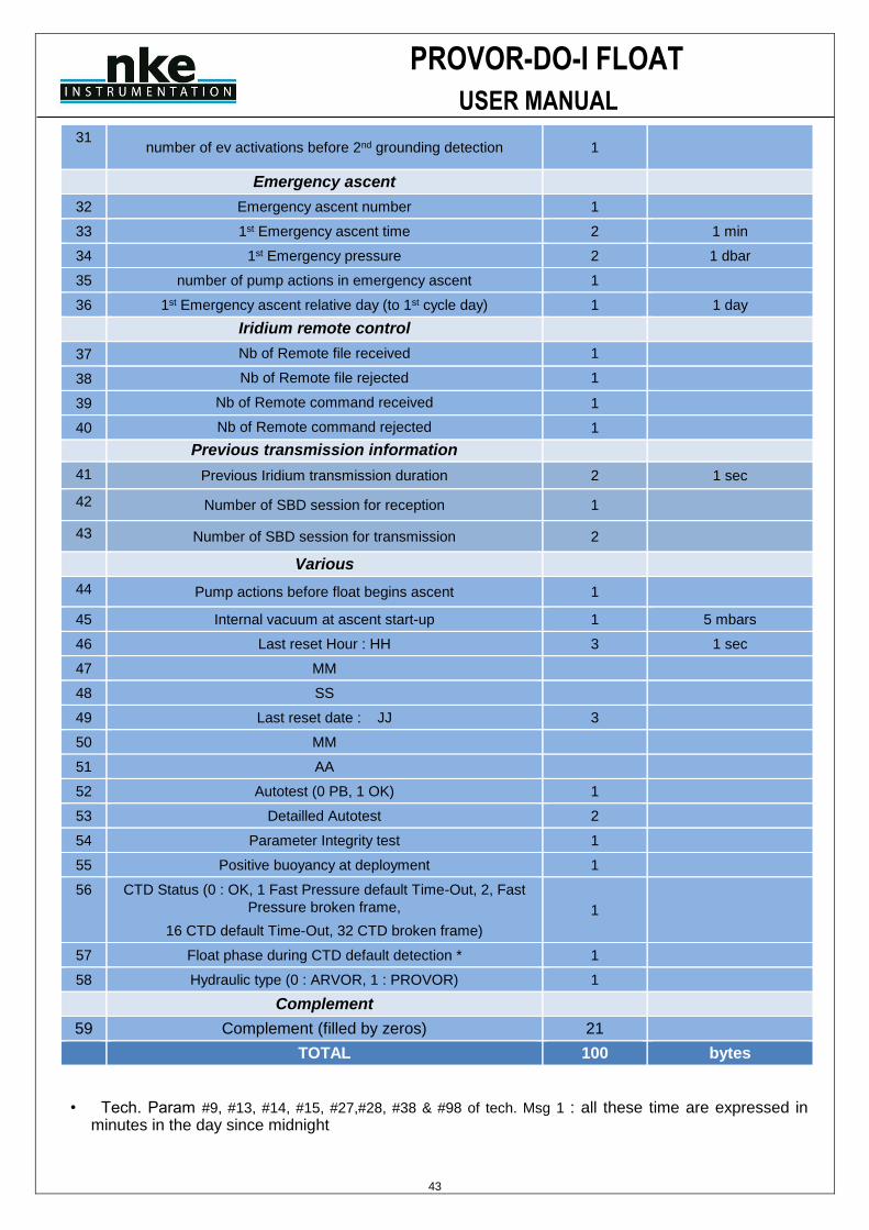
PROVOR-DO-I FLOAT
USER MANUAL
43
31 number of ev activations before 2nd grounding detection 1
Emergency ascent
32 Emergency ascent number 1
33 1st Emergency ascent time 2 1 min
34 1st Emergency pressure 2 1 dbar
35 number of pump actions in emergency ascent 1
36 1st Emergency ascent relative day (to 1st cycle day) 1 1 day
Iridium remote control
37 Nb of Remote file received 1
38 Nb of Remote file rejected 1
39 Nb of Remote command received 1
40 Nb of Remote command rejected 1
Previous transmission information
41 Previous Iridium transmission duration 2 1 sec
42 Number of SBD session for reception 1
43 Number of SBD session for transmission 2
Various
44 Pump actions before float begins ascent 1
45 Internal vacuum at ascent start-up 1 5 mbars
46 Last reset Hour : HH 3 1 sec
47 MM
48 SS
49 Last reset date : JJ 3
50 MM
51 AA
52 Autotest (0 PB, 1 OK) 1
53 Detailled Autotest 2
54 Parameter Integrity test 1
55 Positive buoyancy at deployment 1
56 CTD Status (0 : OK, 1 Fast Pressure default Time-Out, 2, Fast
Pressure broken frame,
16 CTD default Time-Out, 32 CTD broken frame)
1
57 Float phase during CTD default detection * 1
58 Hydraulic type (0 : ARVOR, 1 : PROVOR) 1
Complement
59 Complement (filled by zeros) 21
TOTAL 100 bytes
• Tech. Param #9, #13, #14, #15, #27,#28, #38 & #98 of tech. Msg 1 : all these time are expressed in minutes in the day since midnight
PROVOR-DO-I FLOAT
USER MANUAL
44
6.3.1 General information
• Tech. Param #1 of tech. Msg 1 : The prelude phase and the first deep cycle are numbered 0.
• Tech. Param #41 of tech. Msg 1 : Floats’ time is expressed with 3 bytes : Hour (1 byte) + Minute (1 byte) + seconds (1 byte).
• Tech. Param #43 of tech. Msg 1 : Pressure sensor offset is measured at the surface. Least significant bit = 1 cbar (two’s complement coded). Range: -32 cbar to +31 cbar
• Tech. Param #45 of tech. Msg 2 : Internal pressure is measured at the end of the ascent and before the mission start. Least significant bit = 5 mbar.
6.3.2 Buoyancy reduction
• Tech. Param #11 of tech. Msg 1 : Number of solenoid valve actions at the surface until the crossing of the 8 dbar threshold is an integer from 1 to 255 (modulo 256).
6.3.3 Descent to parking depth
• Tech. Param #5, #6 & #7 of tech. Msg #1 : Calendar day, month & year for buoyancy reduction start.
• Tech. Param #10 of tech. Msg 1 : Hydraulic valve action duration before float switch to simple valve actions
• Tech. Param #11 of tech. Msg 1 : Number of solenoid valve actions at the surface until the crossing of the 8 dBar threshold is an integer from 1 to 127 (modulo 128).
• Tech. Param #13 of tech. Msg 1: Descent start time is expressed in minutes since midnight.
• Tech. Param #14 of tech. Msg 1 : Float first stabilisation time after the crossing of the 8 dbar threshold.
• Tech. Param #16 of tech. Msg 1 : Number of solenoid valve actions carried out to reach the target pressure after crossing the 8 dbar threshold.
• Tech. Param #18 of tech. Msg 1 : Float first stabilisation pressure after crossing the 8 dbar threshold is coded in 8 bits with least significant bit = 1 bar.
6.3.4 Drift at parking depth
• Tech. Param #23 & #24 of tech. Msg 1 : Minimum and maximum pressure collected during the hydraulics measurements at parking depth, expressed in bar.
6.3.5 Drift at profile depth
• Tech. Param #36 & #37 of tech. Msg 1 : Minimum and maximum pressure collected during the hydraulics measurements at profile depth, expressed in bar.
6.3.6 Ascent
• Tech. Param #39 of tech. Msg 1 : Time at the end of the pump action after surfacing, just before the transmission starts.
Ascent end time (crossing of the 1 bar threshold) occurs approximately [10 minutes + duration of the last pump action of the buoyancy acquisition phase (TC4)] before transmission start time.
• Tech. Param #40 of tech. Msg : Number of pump actions in ascent (from the profile pressure until the crossing of the 1 bar threshold).
PROVOR-DO-I FLOAT
USER MANUAL
45
6.3.7 Data information
• Tech. Param #8 of tech. Msg 2 : Includes the sum of the data sampled in the shallow and the intermediate zones (descent profile).
• Tech. Param #9 of tech. Msg 2 : Includes the sum of the data sampled in the deep zone (descent profile).
• Tech. Param #11 of tech. Msg 2 : Includes the sum of the data sampled in the shallow and the intermediate zones (ascent profile).
• Tech. Param #12 of tech. Msg 2 : Includes the sum of the data sampled in the deep zone (ascent profile).
6.3.8 Subsurface point
The sub-surface point is the last ‘raw’ CTD measurement sampled before the switch off of the CTD pump.
• Tech. Param #15 of tech. Msg 2: Pressure of the sub-surface point, coded in two’s complement (in cbar).
To decode the transmitted (Pssp) value: Pressure (dbar) = [two’s-complement of a 16 bits value (Pssp)] / 10.
• Tech. Param #16 of tech. Msg 2 : Temperature of the sub-surface point, coded in two’s complement (in m°C).
To decode the transmitted (Tssp) value: Temperature (°C) = [two’s-complement of a 16 bits value (Tssp)] / 1000.
• Tech. Param #17 of tech. Msg 2 : Salinity of the sub-surface point coded in m°PSU.
To decode the transmitted (Sssp) value: Salinity (PSU) = Sssp / 1000.
6.3.9 Grounding
• Tech. Param #23 of tech. Msg 2 : Number of days elapsed since the mission start day (modulo 256).
6.3.10 Emergency ascent
• Tech. Param #36 of tech. Msg 2 : Number of days elapsed since the mission start day (modulo 256).
6.3.11 Various Data
• Tech. Param #44 of tech. Msg 2 : Number of pump actions before float lift-up from Profile Pressure.
• Tech. Param #45 of tech. Msg 2 : Internal pressure is measured at the end of the ascent and before the Mission start. Measurements are given in 5 mbar steps starting from 700 mbar.
• Tech. Param #46, #47 & #48 of tech. Msg 2 : Hour, +minute+ seconds for float mission start, is expressed with 3 bytes : Hour (1 byte) + Minute (1 byte) + seconds (1 byte)
• Tech. Param #49, #50 & #51 of tech. Msg #2 : Calendar day, month & year for float mission start (1 byte each)
• Tech. Param #60 of tech. Msg 1 : Additional electro-valve activation during GPS acquisition, in case of unsufficient buoyancy, is expressed with 2 bytes in seconds
• Tech. Param #58 of tech. Msg 1 : Timing before GPS position is considered as valid. Expressed in seconds
• Tech. Param #59 of tech. Msg 1 : GPS retries is not used
PROVOR-DO-I FLOAT
USER MANUAL
46
• Tech. Param #52 of tech. Msg 2 : Autotest flag. “0” means that initial auto-test at float’s deployment was not OK. “1” means that everything was OK.
• Tech. Param #53 of tech. Msg 2 : Detailled autotest. Give information about sub-assemblies tested during auto-test
• Tech. Param #55 of tech. Msg 2 : Positive buoyancy at deployment : 0, means float stay at surface at deployment. “” means that was heavy at deployment and begin to sink immediately
• Tech. Param #56 & #57 of tech. Msg 2 : give information about CTD sensor status, and float phase for default detection
6.3.12 End Of Life information
• Tech. Param #62 of tech. Msg 1 : End Of Life Detection flag, indicate if float has entered in End Of Life mode
• Tech. Param #63 of tech. Msg 1 : Hour, +minute+ seconds for float End Of Life start (1 byte each)
• Tech. Param #64 of tech. Msg 1 : Day, Month, Year for float End Of Life start (1 byte each)
• : see chap 6.18.1 Phase description to check kind of acquired data
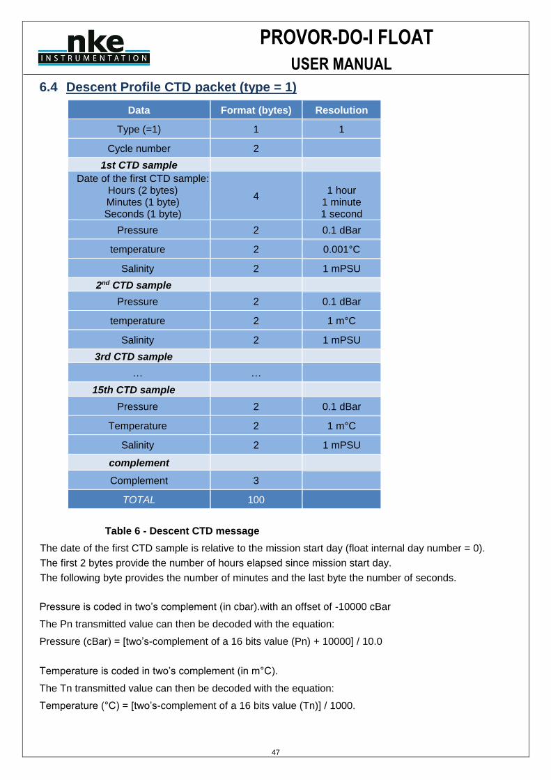
PROVOR-DO-I FLOAT
USER MANUAL
47
6.4 Descent Profile CTD packet (type = 1)
Data Format (bytes) Resolution
Type (=1) 1 1
Cycle number 2
1st CTD sample
Date of the first CTD sample: Hours (2 bytes) Minutes (1 byte) Seconds (1 byte)
4
1 hour
1 minute 1 second
Pressure 2 0.1 dBar
temperature 2 0.001°C
Salinity 2 1 mPSU
2nd CTD sample
Pressure 2 0.1 dBar
temperature 2 1 m°C
Salinity 2 1 mPSU
3rd CTD sample
… …
15th CTD sample
Pressure 2 0.1 dBar
Temperature 2 1 m°C
Salinity 2 1 mPSU
complement
Complement 3
TOTAL 100
Table 6 - Descent CTD message
The date of the first CTD sample is relative to the mission start day (float internal day number = 0).
The first 2 bytes provide the number of hours elapsed since mission start day.
The following byte provides the number of minutes and the last byte the number of seconds.
Pressure is coded in two’s complement (in cbar).with an offset of -10000 cBar
The Pn transmitted value can then be decoded with the equation:
Pressure (cBar) = [two’s-complement of a 16 bits value (Pn) + 10000] / 10.0
Temperature is coded in two’s complement (in m°C).
The Tn transmitted value can then be decoded with the equation:
Temperature (°C) = [two’s-complement of a 16 bits value (Tn)] / 1000.
PROVOR-DO-I FLOAT
USER MANUAL
48
Salinity is coded in mPSU.
The Sn transmitted value can then be decoded with the equation:
Salinity (PSU) = Sn / 1000
6.5 Submerged drift CTD packet (type = 2)
Identical to descent profile CTD message with type 2
6.6 Ascent profile CTD packet (type = 3)
Identical to descent profile CTD message with type 3
6.7 Near Surface packet (type = 13)
Identical to descent profile CTD message with type 13
Float will transmit MC31 * 60 / MC30 measure for “Near surface” acquisition with a limit of 3 packets.
6.8 In Air packet (type = 14)
Identical to descent profile CTD message with type 14
Float will transmit MC31 * 60 / MC30 measure for “In Air” acquisition with a limit of 3 packets.
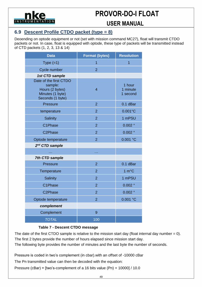
PROVOR-DO-I FLOAT
USER MANUAL
49
6.9 Descent Profile CTDO packet (type = 8)
Deoending on optode equipment or not (set with mission command MC27), float will transmit CTDO packets or not. In case, float is equipped with optode, these type of packets will be transmitted instead of CTD packets (1, 2, 3, 13 & 14)
Data Format (bytes) Resolution
Type (=1) 1 1
Cycle number 2
1st CTD sample
Date of the first CTDO sample:
Hours (2 bytes) Minutes (1 byte) Seconds (1 byte)
4 1 hour
1 minute 1 second
Pressure 2 0.1 dBar
temperature 2 0.001°C
Salinity 2 1 mPSU
C1Phase 2 0.002 °
C2Phase 2 0.002 °
Optode temperature 2 0.001 °C
2nd CTD sample
… …
7th CTD sample
Pressure 2 0.1 dBar
Temperature 2 1 m°C
Salinity 2 1 mPSU
C1Phase 2 0.002 °
C2Phase 2 0.002 °
Optode temperature 2 0.001 °C
complement
Complement 9
TOTAL 100
Table 7 - Descent CTDO message
The date of the first CTDO sample is relative to the mission start day (float internal day number = 0).
The first 2 bytes provide the number of hours elapsed since mission start day.
The following byte provides the number of minutes and the last byte the number of seconds.
Pressure is coded in two’s complement (in cbar).with an offset of -10000 cBar
The Pn transmitted value can then be decoded with the equation:
Pressure (cBar) = [two’s-complement of a 16 bits value (Pn) + 10000] / 10.0
PROVOR-DO-I FLOAT
USER MANUAL
50
Temperature is coded in two’s complement (in m°C).
The Tn transmitted value can then be decoded with the equation:
Temperature (°C) = [two’s-complement of a 16 bits value (Tn)] / 1000.
Salinity is coded in mPSU.
The Sn transmitted value can then be decoded with the equation:
Salinity (PSU) = Sn / 1000
C1 and C2 phases are coded with a 0.002° resolution and an offset of 40°.
The CPn transmitted value can then be decoded with the equation:
C1/C2Phase (angular degree) = [(CPn - 20 000) x 2] / 1000.
Optode temperature is coded in m°C with an offset of 5 000 m°C. The OTn transmitted value can then be decoded with the equation: Optode temperature (°C) = (OTn - 5 000) / 1000.
6.10 Submerged drift CTDO packet (type = 9)
Identical to descent profile CTD message with type 9
6.11 Ascent profile CTDO packet (type = 10)
Identical to descent profile CTD message with type 10
6.12 Near Surface packet (type = 11)
Identical to descent profile CTD message with type 11
Float will transmit MC31 * 60 / MC30 measure for “Near surface” acquisition with a limit of 3 packets.
6.13 In Air packet (type = 12)
Identical to descent profile CTD message with type 12
Float will transmit MC31 * 60 / MC30 measure for “In Air” acquisition with a limit of 3 packets.
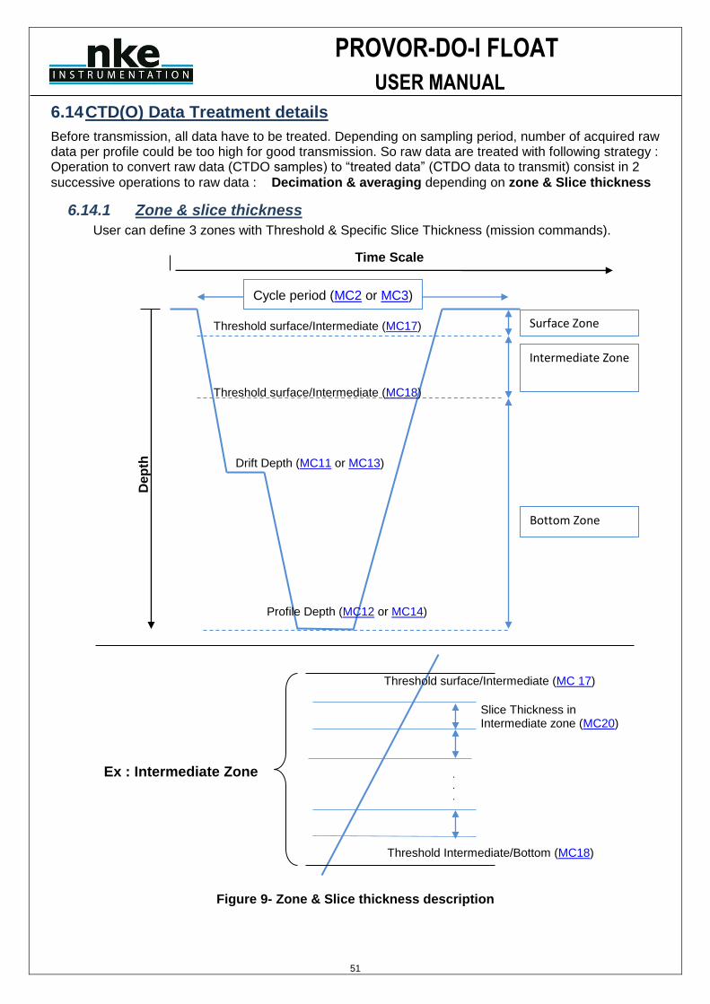
PROVOR-DO-I FLOAT
USER MANUAL
51
6.14 CTD(O) Data Treatment details
Before transmission, all data have to be treated. Depending on sampling period, number of acquired raw data per profile could be too high for good transmission. So raw data are treated with following strategy : Operation to convert raw data (CTDO samples) to “treated data” (CTDO data to transmit) consist in 2
successive operations to raw data : Decimation & averaging depending on zone & Slice thickness
6.14.1 Zone & slice thickness
User can define 3 zones with Threshold & Specific Slice Thickness (mission commands).
Figure 9- Zone & Slice thickness description
Time Scale
De
pth
Cycle period (MC2 or MC3)
Surface Zone
Intermediate Zone
Bottom Zone
Threshold surface/Intermediate (MC18)
Threshold surface/Intermediate (MC17)
Drift Depth (MC11 or MC13)
Profile Depth (MC12 or MC14)
Slice Thickness in Intermediate zone (MC20)
.
.
.
Ex : Intermediate Zone
Threshold surface/Intermediate (MC 17)
Threshold Intermediate/Bottom (MC18)

PROVOR-DO-I FLOAT
USER MANUAL
52
Figure 10 - Treatment description
6.14.2 Decimation
All raw data included in one theoretical CTD slice (defined with mission command depending on zone threshold and slice thickness in each zone) are filtered before proceed to averaging operation. Filter condition is that CTD samples must have 0.5 deciBar pressure variation (in the appropriate direction) with last kept CTD sample to be preserved.
Example : 5 dBar slice thickness in bottom zone (defined with “MC18”) from 20 to 15 dBar.
CTD sample
rank
CTD sample Pressure
(raw data) in theoretical
slice
CTD sample
temperature
CTD sample salinity
Last previous
kept sample
pressure
Pressure difference with
previous sample
Keep after decimation
0 19.9 dBar 17.312 33900 - - Yes (1st
sample in slice)
1 19.3 dBar 17.314 33901 19.9 19.9–19.3 = 0.6 Yes
2 18.9 dBar 17.317 33903 19.3 19.3–18.9 = 0.4 No
3 18.6 dBar 17.319 33904 19.3 19.3–18.6 = 0.7 Yes
4 18.1 dBar 17.320 33905 18.6 18.6–18.1 = 0.5 Yes
5 17.5 dBar 17.320 33906 18.1 18.1–17.5 = 0.6 Yes
6 17.1 dBar 17.322 33907 17.5 17.5–17.1 = 0.4 No
7 16.5 dBar 17.329 33909 17.5 17.5–16.5 = 1.0 Yes
8 16.1 dBar 17.338 33910 16.5 16.5–16.1 = 0.4 No
9 15.6 dBar 17.351 33910 16.5 16.5–15.6 = 0.9 Yes
10 15.1 dBar 17.361 33913 15.6 15.6–15.1 = 0.5 Yes
Table 8 - Decimation example
Ex : Theoretical
Slice thickness
in Intermediate
zone (MC20
dBars) CTD samples (Raw data) acquired every “MC10” seconds during ascent
One Treated
data per slice (Data will be transmitted)
TREATMENT
Decimation
+
Averaging
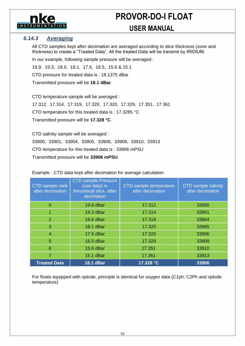
PROVOR-DO-I FLOAT
USER MANUAL
53
6.14.3 Averaging
All CTD samples kept after decimation are averaged according to slice thickness (zone and thickness) to create a “Treated Data”. All the treated Data will be transmit by IRIDIUM.
In our example, following sample pressure will be averaged :
19.9, 19.3, 18.6, 18.1, 17.5, 16.5, 15.6 & 15.1
CTD pressure for treated data is : 18.1375 dBar
Transmitted pressure will be 18.1 dBar.
CTD temperature sample will be averaged :
17.312, 17.314, 17.319, 17.320, 17.320, 17.329, 17.351, 17.361
CTD temperature for this treated data is : 17.3285 °C
Transmitted pressure will be 17.328 °C.
CTD salinity sample will be averaged :
33900, 33901, 33904, 33905, 33906, 33909, 33910, 33913
CTD temperature for this treated data is : 33906 mPSU
Transmitted pressure will be 33906 mPSU.
Example : CTD data kept after decimation for average calculation
CTD sample rank after decimation
CTD sample Pressure (raw data) in
theoretical slice, after decimation
CTD sample temperature after decimation
CTD sample salinity after decimation
0 19.9 dBar 17.312 33900
1 19.3 dBar 17.314 33901
2 18.6 dBar 17.319 33904
3 18.1 dBar 17.320 33905
4 17.5 dBar 17.320 33906
5 16.5 dBar 17.329 33909
6 15.6 dBar 17.351 33910
7 15.1 dBar 17.361 33913
Treated Data 18.1 dBar 17.328 °C 33906
For floats equipped with optode, principle is identical for oxygen data (C1ph, C2Ph and optode temperature)

PROVOR-DO-I FLOAT
USER MANUAL
54
6.15 Parameters Data packet (type = 5)
This message contains float‘s mission and technical parameters
Data Format (bytes) Resolution
Type (=5) 1
General informations
Cycle number 2 1 cycle
Iridium session number 1
Float's time (hh+mm+ss, 1 byte each) 3 hh+mm+ss
Float's date (dd+mm+yy, 1 byte each) 3 dd+mm+yy
Float serial number 2
Mission parameters – Next Cycle
Total Nb of cycles (MC 0) 2 1 cycle
Nb of cycles with cycle period 1 (MC 1) 2 1 cycle
Cycle period 1 (MC 2) 2 Hours
Cycle period 2 (MC 3) 2 Hours
Reference day (MC 4) 1 Day
Expected time at the surface (MC 5) 1 Hour
Delay before mission (MC6) 1 Minutes
CTD sensor acquisition mode (MC 7) 1
Descent sampling period (MC 8) 1 Seconds
Drift sampling period (MC 9) 1 Hours
Ascent sampling period (MC 10) 1 Seconds
Drift depth used during « MC1 » first cycle (MC 11) 2 dBar
Profile depth used during « MC1 » first cycle (MC 12) 2 dBar
Drift depth used with cycle period « MC2 » (MC 13) 2 dBar
Profile depth used with cycle period « MC2 » (MC 14) 2 dBar
T_profil_alten (MC 15) 1
P_profil_alterne (MC 16) 2 dBar
Threshold Surface/Intermediate Pressure (MC 17) 2 dBar
Threshold Intermediate/Bottom Pressure (MC18) 2 dBar
Surface Slice Thickness (MC 19) 1 dBar
Intermediate Slice Thickness (MC 20) 1 dBar
Bottom Slice Thickness (MC 21) 1 dBar
Iridum End of Life transmission period (MC 22) 2 Minutes
2nd Iridium Session Wait Period (MC23) 2 Minutes
Grounding mode (MC24) 1
Grounding switch pressure (MC25) 1 dBar
Delay after grounding at surface (MC26) 1 Minutes
Optode type (MC27) 1
CTD Sensor Cut-Off Pressure (MC 28) 1 dBar
“In Air acquisition” cycle periodicity (MC29) 1 Minutes
“In Air acquisition” sampling period (MC30) 2 Seconds
“In Air acquisition” total duration (MC31) 2 Minutes
Technical Parameter – Next Cycle
Max eV activation on Surface (TC 0) 2 10 cs
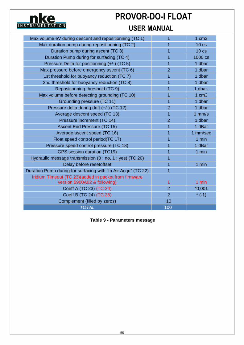
PROVOR-DO-I FLOAT
USER MANUAL
55
Max volume eV during descent and repositionning (TC 1) 1 1 cm3
Max duration pump during repositionning (TC 2) 1 10 cs
Duration pump during ascent (TC 3) 1 10 cs
Duration Pump during for surfacing (TC 4) 1 1000 cs
Pressure Delta for positionning (+/-) (TC 5) 1 1 dbar
Max pressure before emergency ascent (TC 6) 2 1 dbar
1st threshold for buoyancy reduction (TC 7) 1 1 dbar
2nd threshold for buoyancy reduction (TC 8) 1 1 dbar
Repositionning threshold (TC 9) 1 1 dbar-
Max volume before detecting grounding (TC 10) 1 1 cm3
Grounding pressure (TC 11) 1 1 dbar
Pressure delta during drift (+/-) (TC 12) 2 1 dbar
Average descent speed (TC 13) 1 1 mm/s
Pressure increment (TC 14) 2 1 dbar
Ascent End Pressure (TC 15) 1 1 dBar
Average ascent speed (TC 16) 1 1 mm/sec
Float speed control period(TC 17) 1 1 min
Pressure speed control pressure (TC 18) 1 1 dBar
GPS session duration (TC19) 1 1 min
Hydraulic message transmission (0 : no, 1 ; yes) (TC 20) 1
Delay before resetoffset 1 1 min
Duration Pump during for surfacing with “In Air Acqu” (TC 22) 1
Iridium Timeout (TC 23)(added in packet from firmware version 5900A02 & following) 1 1 min
Coeff A (TC 23) (TC 24) 2 *0,001
Coeff B (TC 24) (TC 25) 2 * (-1)
Complement (filled by zeros) 10
TOTAL 100
Table 9 - Parameters message
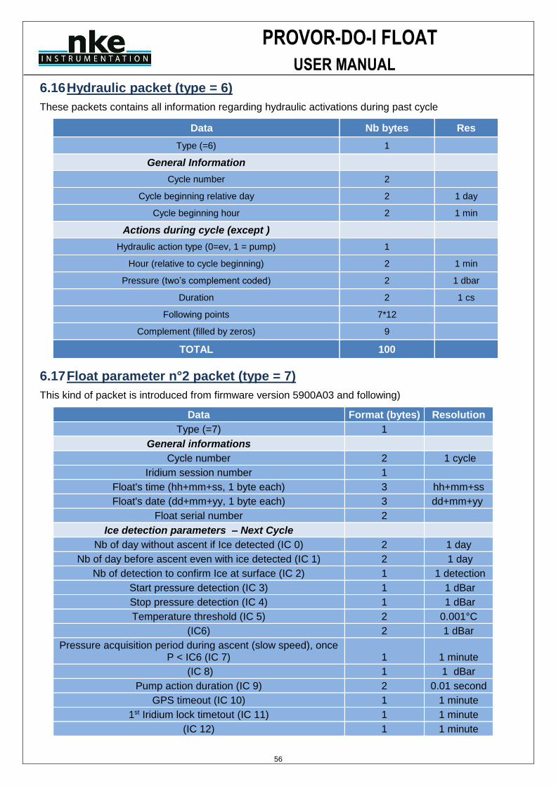
PROVOR-DO-I FLOAT
USER MANUAL
56
6.16 Hydraulic packet (type = 6)
These packets contains all information regarding hydraulic activations during past cycle
Data Nb bytes Res
Type (=6) 1
General Information
Cycle number 2
Cycle beginning relative day 2 1 day
Cycle beginning hour 2 1 min
Actions during cycle (except )
Hydraulic action type (0=ev, 1 = pump) 1
Hour (relative to cycle beginning) 2 1 min
Pressure (two’s complement coded) 2 1 dbar
Duration 2 1 cs
Following points 7*12
Complement (filled by zeros) 9
TOTAL 100
6.17 Float parameter n°2 packet (type = 7)
This kind of packet is introduced from firmware version 5900A03 and following)
Data Format (bytes) Resolution
Type (=7) 1
General informations
Cycle number 2 1 cycle
Iridium session number 1
Float's time (hh+mm+ss, 1 byte each) 3 hh+mm+ss
Float's date (dd+mm+yy, 1 byte each) 3 dd+mm+yy
Float serial number 2
Ice detection parameters – Next Cycle
Nb of day without ascent if Ice detected (IC 0) 2 1 day
Nb of day before ascent even with ice detected (IC 1) 2 1 day
Nb of detection to confirm Ice at surface (IC 2) 1 1 detection
Start pressure detection (IC 3) 1 1 dBar
Stop pressure detection (IC 4) 1 1 dBar
Temperature threshold (IC 5) 2 0.001°C
(IC6) 2 1 dBar
Pressure acquisition period during ascent (slow speed), once P < IC6 (IC 7) 1 1 minute
(IC 8) 1 1 dBar
Pump action duration (IC 9) 2 0.01 second
GPS timeout (IC 10) 1 1 minute
1st Iridium lock timetout (IC 11) 1 1 minute
(IC 12) 1 1 minute
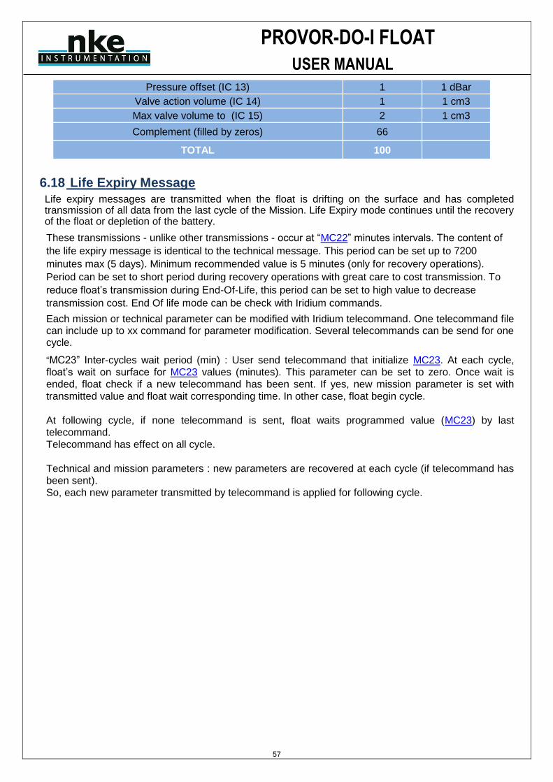
PROVOR-DO-I FLOAT
USER MANUAL
57
Pressure offset (IC 13) 1 1 dBar
Valve action volume (IC 14) 1 1 cm3
Max valve volume to (IC 15) 2 1 cm3
Complement (filled by zeros) 66
TOTAL 100
6.18 Life Expiry Message
Life expiry messages are transmitted when the float is drifting on the surface and has completed transmission of all data from the last cycle of the Mission. Life Expiry mode continues until the recovery of the float or depletion of the battery.
These transmissions - unlike other transmissions - occur at “MC22” minutes intervals. The content of
the life expiry message is identical to the technical message. This period can be set up to 7200
minutes max (5 days). Minimum recommended value is 5 minutes (only for recovery operations).
Period can be set to short period during recovery operations with great care to cost transmission. To
reduce float’s transmission during End-Of-Life, this period can be set to high value to decrease
transmission cost. End Of life mode can be check with Iridium commands.
Each mission or technical parameter can be modified with Iridium telecommand. One telecommand file can include up to xx command for parameter modification. Several telecommands can be send for one cycle.
“MC23” Inter-cycles wait period (min) : User send telecommand that initialize MC23. At each cycle,
float’s wait on surface for MC23 values (minutes). This parameter can be set to zero. Once wait is
ended, float check if a new telecommand has been sent. If yes, new mission parameter is set with
transmitted value and float wait corresponding time. In other case, float begin cycle.
At following cycle, if none telecommand is sent, float waits programmed value (MC23) by last
telecommand.
Telecommand has effect on all cycle.
Technical and mission parameters : new parameters are recovered at each cycle (if telecommand has
been sent).
So, each new parameter transmitted by telecommand is applied for following cycle.
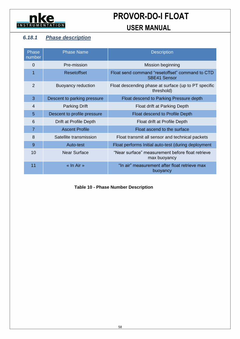
PROVOR-DO-I FLOAT
USER MANUAL
58
6.18.1 Phase description
Phase number
Phase Name Description
0 Pre-mission Mission beginning
1 Resetoffset Float send command “resetoffset” command to CTD SBE41 Sensor
2 Buoyancy reduction Float descending phase at surface (up to PT specific threshold)
3 Descent to parking pressure Float descend to Parking Pressure depth
4 Parking Drift Float drift at Parking Depth
5 Descent to profile pressure Float descend to Profile Depth
6 Drift at Profile Depth Float drift at Profile Depth
7 Ascent Profile Float ascend to the surface
8 Satellite transmission Float transmit all sensor and technical packets
9 Auto-test Float performs Initial auto-test (during deployment
10 Near Surface “Near surface” measurement before float retrieve max buoyancy
11 « In Air » “In air” measurement after float retrieve max buoyancy
Table 10 - Phase Number Description

PROVOR-DO-I FLOAT
USER MANUAL
59
6.18.2 Sending a SBD message (telecommand) to the 9602 Iridium modem
Messages can be sent to the 9602 Iridium modem via SBD from almost any e-mail program (Outlook, Outlook Express, etc.).
1. In order to send e-mail messages to a 9602, the e-mail program must use the standard Multipurpose Internet Mail Extensions (MIME) Base64 encoding as defined in RFC 2045. The following instructions describe how to set this up for Microsoft Outlook Express:
a. Select ―Tools/Options‖
b. Click the ―Send‖ Tab
c. Under ―Mail Sending Format‖, click ―HTML Settings…‖
d. Click MIME
e. Select ―Base 64‖ for Encode text using
f. Click OK
g. Under ―Mail Sending Format‖, click ―Plain Text Settings…‖
h. Repeat steps d – f
2. Send all e-mail messages to [email protected]
3. Place the IMEI number of the 9602 in the subject line. Be careful to indicate the right IMEI number.
4. The message should be carried in an attachment, which must have a ―.sbd‖ extension
In a delay of a few minutes, user can check that iridium system send confirmation that message is queued (email coming from [email protected] with subject : “SBD Mobile Terminated Message Queued for Unit : xxxxxxxxxxxxxxx (here xx replace IMEI number)
Mail from iridium will indicate :
“The following mobile-terminated message was queued for delivery: IMEI: 30003401340xxxx Time: Thu Apr 29 12:00:13 2010 Attachment Filename: PM0_330.sbd Attachment Size: 9 The MTMSN is 2, and the message is number 1 in the queue.“
At this step, message is queued and ready to be treated by float at next float surfacing.
PROVOR-DO-I FLOAT
USER MANUAL
60
6.18.3 Telecommand SBD File creation
For example, to modify mission parameter 0 from 300 to 330, user need :
1- to create an empty text file (with notepad or wordpad for example)
2- to type same command as command send to float with hyperterminal. In our example, user need to type in file : !MC 0 330 followed by carriage return. PC file format (or windows) with CR/LF and ANSI coding must be used, not UNIX or MAC file Format. (UTF-8 coding format). To check if file is properly created, you can check file size (right click on file properties). File size must be equal to all character included in file + 2 (because of non visible character CR/LF).
Example : !MC 0 330 -> 9 characters. So file size must be 11 bytes (9+2)
3- save file as “MC0_330” (This is only an example, any file name can be chose by user, in a limit of 16 characters)
4- close file
5- change file extension from “.txt” to “.sbd”. File name will be “MC0_330.sbd” (Be careful file name is not “MC0_330.sbd.txt” in case file extension do not appears depending on windows configuration).
Once file is created, User must send email to Iridium system, with attached file.
PROVOR-DO-I FLOAT
USER MANUAL
61
7 SPECIFICATIONS
• Storage
Temperature range................................................................................................. -20°C to +50°C
Storage time before expiry ...........................................................................................up to 1 year
• Operational
Temperature range.................................................................................................... 0°C to +40°C
Pressure at drift depth ....................................................................................... 40 bar to 200 bar
Depth maintenance accuracy .............................................................. ± 3 bar typical (adjustable)
Survival at sea ...........................................................................................................up to 5 years
Maximum number of cycles.................up to 310 cycles (Depending on Battery pack configuration)
• Mechanical
Length
with antenna ..............................................................................................................#220 cm
Diameter
casing ............................................................................................................................17 cm
damping disk ................................................................................................................ 35 cm
Weight.............................................................................................................................35kg
Material......................................................................................... anodized aluminum casing
• Sensors
Salinity
range........................ .......................................................................................... 10 to 42 PSU
initial accuracy ..................................................................................................... ± 0.005 PSU
resolution................................................................................................................. 0.001 PSU
Temperature
range... .............................................................................................................. -3°C to +32°C
initial accuracy ..........................................................................................................± 0.002°C
resolution.......................................................................................................................0.001°C
Pressure
range... ....................................................................................................... 0 bar to 2500 dBar
initial accuracy ......................................................................................................... ± 2.4 dBar*
resolution......................................................................................................................0.1 dBar
Offset adjusted when surfacing Oxygen (C1Phase, C2Phase & temperature)
Range (C1Phase, C2Phase)............................................................................ -40.000° to 90.000°
initial accuracy ...................................................................................................................... 0.001°
Range (Temperature)......................................................................................... -5.000° to 60.000°
initial accuracy ...................................................................................................................... 0.001°
(*) offset has to be adjusted at each surfacing
PROVOR-DO-I FLOAT
USER MANUAL
62
8 PROVOR-DO-I OPERATING PRINCIPLE
Movement of the float through its profile is accomplished by a pump and valve system. The pump transfers oil from the inner reservoir to the outer bladder. Oil moves back to the reservoir when the valve is opened- -driven by the difference between the float's internal and external pressures. The float's speed of ascent oscillates. This oscillation is due to the way in which the float's controller regulates its speed. The controller, using depth measurements from the float's pressure sensor, calculates the change in depth over a set period of time. With this information, the controller determines the float's speed. When ascending, if the calculated speed is lower than desired, the pump is activated for about 10 seconds, pumping oil into the outer bladder. This produces an increase in buoyancy, which increases the speed of ascent. As the float rises to shallower depths, its buoyancy decreases, causing the ascent speed to also decrease. When the calculated speed is too low, the pump is activated again. This cycle repeats until the float reaches the surface. The same regulating method is used to control the float's descent speed, by opening the valve and allowing oil to flow from the external bladder to the internal reservoir.
Why does PROVOR-DO-I's speed decrease as it ascends? The buoyancy of a float is determined principally by its mass and its volume, but another factor, hull compressibility, also plays an important role. As PROVOR-DO-I ascends, the decrease in water density reduces the float's buoyancy. At the same time, the decrease in water pressure causes PROVOR-DO-I's hull to expand, which increases the float's buoyancy. The two effects tend to counteract each other. Because PROVOR-DO-I 's compressibility is actually less than that of sea water, the decrease in buoyancy due to decreasing water density is greater than the increase in buoyancy due to hull expansion. This causes PROVOR-DO-I 's speed of ascent to decrease as it rises in the water column. Conversely, as the float descends, the increasing water density increases the buoyancy more than the decreasing buoyancy from hull compression. This causes PROVOR-DO-I 's speed of descent to slow as it goes deeper. To reduce the probability of contact with ships, PROVOR-DO-I 's target speed during the initial stage of descent is high at shallow depths. This minimizes the time during which the float is at risk of damage. To slow the float's descent, its controller is programmed with a series of depths at which the descent speed is halved until it reaches the target depth.

PROVOR-DO-I FLOAT
USER MANUAL
63
9 LITHIUM BATTERY
All batteries, both lithium and other with chemical elements, contain large quantities of stored energy. This is, of course, what makes them useful, but it also makes them potentially hazardous.
If correctly handled, neither alkaline nor lithium batteries present any risk to humans or the environment. Improper handling of these batteries presents potential risks to humans, but does not present an environmental risk.
The energy stored in a battery cell is stored in chemical form. Most batteries contain corrosive chemicals. These chemicals can be released if the cells are mishandled. Mishandling includes:
• short-circuiting the cells; • (re)charging the cells; • puncturing the cell enclosure with a sharp object; • exposing the cell to high temperatures.
WARNING: BOTH ALKALINE AND LITHIUM BATTERIES MAY EXPLODE, PYROLIZE OR VENT
IF MIS-HANDLED. DO NOT DISASSEMBLE, PUNCTURE, CRUSH, SHORT-
CIRCUIT, (RE)CHARGE OR INCINERATE THE CELLS. DO NOT EXPOSE CELLS
TO HIGH TEMPERATURES.
The lithium thionyl chloride cells used in PROVOR-DO-I floats incorporate sealed steel containers, warning labels and venting systems to guard against accidental release of their contents.
WARNING: IF A BATTERY SPILLS ITS CONTENTS DUE TO MISHANDLING, THE RELEASED
CHEMICALS AND THEIR REACTION PRODUCTS INCLUDE CAUSTIC AND
ACIDIC MATERIALS, SUCH AS HYDROCHLORIC ACID (HCL) IN THE CASE OF
LITHIUM THIONYL CHLORIDE BATTERIES, AND POTASSIUM HYDROXIDE
(KOH) IN THE CASE OF ALKALINE BATTERIES. THESE CHEMICALS CAN
CAUSE EYE AND NOSE IRRITATION AND BURNS TO EXPOSED FLESH.
The hazard presented by these chemicals is comparable to that presented by common domestic cleaning materials like bleach, muriatic acid or oven cleaner.
Inevitably, the battery contents will eventually be released into the environment, regardless of whether the cells are deliberately dismantled or simply disintegrate due to the forces of nature. Because of their highly reactive nature, battery materials disintegrate rapidly when released into the environment. They pose no long-term environmental threat. There are no heavy metals or chronic toxins in PROVOR-DO-I 's lithium cells. Indeed, a recommended safe disposal method for thionyl chloride lithium cells is to crush them and dilute them in sufficient quantities of water.
Discharged batteries pose a greatly reduced threat, as the process of discharging them consumes the corrosive chemicals contained in them.
In summary, PROVOR-DO-I 's lithium battery poses no significant or long-term environmental threats. Any threats that they do present, are short-term threats to the safety of persons mishandling the cells. These safety threats are similar to those of other common household-use materials. These threats are reduced when the cells are discharged - and exist only if the cells are mishandled in extreme ways. These threats are the same as those presented by the alkaline cells widely used by consumers.
PROVOR-DO-I FLOAT
USER MANUAL
64
10 GLOSSARY
BT Bluetooth
COM1, COM2. Serial communication ports.
CPU Central Processing Unit. In the context of PROVOR-DO-I , this term denotes the board that ensures the running and control of the system.
CTDO Celerity (for salinity), Temperature, Depth and Oxygen
dBar. 1/10 bar = 1 decibar Unit of pressure used for PROVOR-DO-I . It roughly corresponds to a depth of 1m.
IFREMER Institut Français pour la Recherche et l'Exploitation de la MER (French Institute for the Research and the Exploitation of the Sea).
Mission The portion of PROVOR-DO-I ’s life that consists of a number of repeating cycles of descent, submerged drift, ascent and data transmission.
PC Personal Computer; IBM-PC compatible.
RS232
Widely recognized standard for the implementation of a serial data communication link.
TBD To Be Defined. This information is not available yet.
Quartet
Set of four measurements (Salinity, Temperature, Depth and dissolved oxygen) all taken at the same time.
Two's-complement
A system for representation of negative numbers in binary notation. The decimal equivalent of a two's- complement binary number is computed in the same way as for an unsigned number, except that the weight of the most significant bit is -2n-1 instead of +2n-1. VT52, VT100 Video Terminal, type 52 or 100 Computer terminals developed by Digital Equipment Corporation (DEC). They are considered standard in the field.
PROVOR-DO-I FLOAT
USER MANUAL
65
11 ANNEX A: DETERMINATION OF CYCLE TIMINGS
11.1 Float clock offset determination
Over time, the float's clock may drift. Clock drift can be defined as the drift of the clock in hours/ minutes/ seconds per year. To correct for this, we must apply a clock offset where clock offset is defined as a measurement, done at a given time, of the offset of the clock due to clock drift. Thus a clock offset should be estimated for each cycle and used to correct cycle timings provided by the float.
Float clock offset is defined as: Float clock offset = Float time - UTC time.
As ARVOR-I sets its Real Time Clock (RTC) before each transmission phase, the clock offset, which is the drift of
the RTC for the cycle duration only, can be neglected. Float clock offset = 0.
11.2 Cycle timings determination
The hours and minutes of the cycle timings are obtained from technical message information.
The associated day can be obtained by the following algorithms.
The day of Transmission Start Time (TST) is determined using the time of the first received Iridium message (FMT):
1. Convert FMT in Float Time (FMTFT = FMT + FloatClockOffset),
2. Convert the hours and minutes of FMTFT in Technical Message time (in minutes after truncation) to obtain FMTFTTM,
3. Compare the resulting FMTFTTM with TST to determine the day of TST (remembering that FMTFTTM ≥ TST).
The day of Ascend End Time (AET) is determined using TST.
The day of Ascent Start Time (AST) is determined using AET and the assumption that: AET-AST < 24 h.
The day of Deep Park Start Time (DPST) is determined using AST and the assumption that: AST- DPST < 24 h.
The day of Park End Time (PET) is determined using DPST and the assumption that: DPST - PET < 24 h.
The day of Cycle Start Time (CST) is determined using a Reference Date (RD) which can be:
• For cycle #1 (first deep cycle): the day of the first descent (determined from float startup date + PM4),
• For a given cycle #N (N > 1):
o If cycle #N-1 exists: RD is the time of the last received Iridium message (LMT) of the cycle #N-1,
o Otherwise, RD is computed from LMT: RD = LMT – CycleDuration (PM1).
The obtained RD is then used to determine the day of CST:
1. Convert RD in float time (RDFT = RD + FloatClockOffset),
2. Convert the hours and minutes of RDFT in Technical Message time (in minutes after truncation) to obtain RDFTTM,
3. Compare the resulting RDFTTM with CST to determine the day of CST (remembering that RDFTTM ≤ CST).
The day of Descent Start Time (DST) is determined using CST.
The day part of First Stabilization Time (FST) is determined using DST and the assumption that: FST-DST < 24 h.
The day part of Park Start Time (PST) is determined using FST and the assumption that: FST- PST < 24 h.

PROVOR-DO-I FLOAT
USER MANUAL
66
Fabriqué par / Manufactured by
Nke-instrumentation
Z.I de KERANDRE - RUE GUTENBERG
56700 HENNEBONT - FRANCE Telephone: +33 (0)2 97 36 10 12 Fax: +33 (0)2 97 36 55 17
Web : http://www.nke-instrumentation.fr
E-mail : [email protected]