Prototype development of low-cost, augmented reality trainer ...
84
Calhoun: The NPS Institutional Archive Theses and Dissertations Thesis and Dissertation Collection 2008-09 Prototype development of low-cost, augmented reality trainer for crew service weapons Conger, Nathan W. Monterey, California. Naval Postgraduate School http://hdl.handle.net/10945/3933
-
Upload
khangminh22 -
Category
Documents
-
view
3 -
download
0
Transcript of Prototype development of low-cost, augmented reality trainer ...
Calhoun: The NPS Institutional Archive
Theses and Dissertations Thesis and Dissertation Collection
2008-09
Prototype development of low-cost, augmented
reality trainer for crew service weapons
Conger, Nathan W.
Monterey, California. Naval Postgraduate School
http://hdl.handle.net/10945/3933
NAVAL
POSTGRADUATE SCHOOL
MONTEREY, CALIFORNIA
THESIS
This thesis was done at the MOVES Institute
Approved for public release; distribution is unlimited
PROTOTYPE DEVELOPMENT OF LOW-COST, AUGMENTED REALITY TRAINER FOR CREW SERVICE WEAPONS
by
Nathan Conger
September 2008
Thesis Co-Advisors: Mathias Kolsch Joseph Sullivan

THIS PAGE INTENTIONALLY LEFT BLANK

i
NSN 7540-01-280-5500 Standard Form 298 (Rev. 2-89) Prescribed by ANSI Std. 239-18
REPORT DOCUMENTATION PAGE Form Approved OMB No. 0704-0188Public reporting burden for this collection of information is estimated to average 1 hour per response, including the time for reviewing instruction, searching existing data sources, gathering and maintaining the data needed, and completing and reviewing the collection of information. Send comments regarding this burden estimate or any other aspect of this collection of information, including suggestions for reducing this burden, to Washington headquarters Services, Directorate for Information Operations and Reports, 1215 Jefferson Davis Highway, Suite 1204, Arlington, VA 22202-4302, and to the Office of Management and Budget, Paperwork Reduction Project (0704-0188) Washington DC 20503. 1. AGENCY USE ONLY (Leave blank)
2. REPORT DATE September 2008
3. REPORT TYPE AND DATES COVERED Master’s Thesis
4. THESIS TITLE Prototype Development of Low-Cost, Augmented Reality Trainer for Crew Service Weapons 6. AUTHOR(S) Nathan Conger
5. FUNDING NUMBERS
7. PERFORMING ORGANIZATION NAME(S) AND ADDRESS(ES) Naval Postgraduate School Monterey, CA 93943-5000
8. PERFORMING ORGANIZATION REPORT NUMBER
9. SPONSORING /MONITORING AGENCY NAME(S) AND ADDRESS(ES)
N/A
10. SPONSORING/MONITORING AGENCY REPORT NUMBER
11. SUPPLEMENTARY NOTES The views expressed in this thesis are those of the author and do not reflect the official policy or position of the Department of Defense or the U.S. Government. 12a. DISTRIBUTION / AVAILABILITY STATEMENT Approved for public release; distribution is unlimited
12b. DISTRIBUTION CODE
13. ABSTRACT (maximum 200 words) A significant emerging threat to coalition forces in littoral regions is from
small craft such as jet skis, fast patrol boats, and speedboats. These craft, when armed, are categorized as Fast Inshore Attack Craft (FIAC), and their arsenal can contain an array of weapons to include suicide bombs, crew-served weapons, anti-tank or ship missiles, and torpedoes. While these craft often have crude weapon technologies, they use an asymmetric tactic of large numbers of small, cheap, poorly armed and armored units to overwhelm coalition defenses.
Training on crew-served weapons on coalition ships has not advanced to meet this new threat. The current training methods do not satisfactorily train the following skills: Rules of engagement (ROE), marksmanship against highly maneuverable targets, threat prioritization, target designation, field of fire coordination, coordinated arms effects, or watch station to CIC communications.
The creation of a prototype Augmented Reality Virtual At Sea Trainer (AR-VAST) shows that emerging augmented reality technologies can overcome limitations of traditional training methods. A fully developed AR-VAST system would be a deployable technology solution that uses in-place weapon systems as trainers in real-world environments with simulated enemy targets. While the AR-VAST architecture can be expanded to allow for training and coordination with multiple weapon operators, phone talkers, and bridge teams for maximum training effectiveness, the current prototype addresses the primary issue of identification and marksmanship.
15. NUMBER OF PAGES
83
14. SUBJECT TERMS Augmented Reality, Swarm Tactics, .50 Cal Trainer
16. PRICE CODE
17. SECURITY CLASSIFICATION OF REPORT
Unclassified
18. SECURITY CLASSIFICATION OF THIS PAGE
Unclassified
19. SECURITY CLASSIFICATION OF ABSTRACT
Unclassified
20. LIMITATION OF ABSTRACT
UU

ii
THIS PAGE INTENTIONALLY LEFT BLANK

iii
Approved for public release; distribution is unlimited
PROTOTYPE DEVELOPMENT OF LOW-COST, AUGMENTED REALITY TRAINER FOR CREW SERVICE WEAPONS
Nathan W. Conger Lieutenant United States Navy B.A. Texas A&M University, 1998
M.S. University of Texas at Dallas, 2001
Submitted in partial fulfillment of the requirements for the degree of
MASTER OF SCIENCE IN MODELING VIRTUAL ENVIRONMENTS AND SIMULATIONS (MOVES)
from the
NAVAL POSTGRADUATE SCHOOL September 2008
Author: Nathan W. Conger
Approved by: Mathias Kölsch Thesis Co-Advisor
Joseph Sullivan Thesis Co-Advisor
Mathias Kölsch, Ph.D. Chair, MOVES Academic Committee

iv
THIS PAGE INTENTIONALLY LEFT BLANK
v
ABSTRACT
A significant emerging threat to coalition forces in
littoral regions is from small craft such as jet skis, fast
patrol boats, and speedboats. These craft, when armed, are
categorized as Fast Inshore Attack Craft (FIAC), and their
arsenal can contain an array of weapons to include suicide
bombs, crew-served weapons, anti-tank or ship missiles, and
torpedoes. While these craft often have crude weapon
technologies, they use an asymmetric tactic of large numbers
of small, cheap, poorly armed and armored units to overwhelm
coalition defenses.
Training on crew-served weapons on coalition ships has
not advanced to meet this new threat. The current training
methods do not satisfactorily train the following skills:
Rules of engagement (ROE), marksmanship against highly
maneuverable targets, threat prioritization, target
designation, field of fire coordination, coordinated arms
effects, or watch station to CIC communications.
The creation of a prototype Augmented Reality Virtual
At Sea Trainer (AR-VAST) shows that emerging augmented
reality technologies can overcome limitations of traditional
training methods. A fully developed AR-VAST system would be
a deployable technology solution that uses in-place weapon
systems as trainers in real-world environments with
simulated enemy targets. While the AR-VAST architecture can
be expanded to allow for training and coordination with
multiple weapon operators, phone talkers, and bridge teams
for maximum training effectiveness, the current prototype
addresses the primary issue of identification and
marksmanship.

vi
THIS PAGE INTENTIONALLY LEFT BLANK
vii
TABLE OF CONTENTS
I. INTRODUCTION ............................................1 A. SMALL BOAT ATTACKS .................................1 B. MOTIVATION .........................................1 C. THE THREAT .........................................4 D. WEAPON QUALIFICATION ...............................5 E. PROPOSED SOLUTION TO TRAINING GAP ..................6 F. WHY AUGMENTED REALITY ..............................7 G. CHAPTER SUMMARY ....................................8
II. RELATED WORK ............................................9 A. CURRENT QUALIFICATION AND TRAINING METHODS .........9
1. Weapon Qualification / Killer Tomato ..........9 2. Robo-Ski .....................................12
B. EXAMINATION OF THE THREAT .........................13 1. Hughes Salvo Model ...........................13 2. MANA Study of Small Boat Attacks .............17 3. SMALL BOAT AND SWARM DEFENSE: A GAP STUDY ....17 4. Threat Summary ...............................17
C. AUGMENTED REALITY TECHNOLOGIES ....................18 1. Display types ................................18 2. Tracking .....................................19 3. Blending Virtual and Real Worlds .............20
D. GAME ENGINES ......................................21 E. CHAPTER SUMMARY ...................................23
III. SYSTEM DEVELOPMENT .....................................25 A. DISPLAY DECISION ..................................26
1. Monitor ......................................27 2. Head Mounted Display .........................28
B. TRACKING DECISION .................................29 1. Intersense InertiaCube2 ......................29 2. Feature Tracking .............................30 3. Combined Solution ............................31 4. Prototype Tracking Decision ..................32
C. RENDERING .........................................32 1. Capturing Video ..............................33 2. Creating Video Texture .......................33 3. Combining Video and Game Engine ..............33
D. ANIMATION .........................................34 1. Small Boat Animation .........................34 2. Wake and Bow-wave Creation and Animation .....35 3. Weapon and Camera Animation ..................39 4. Firing the Weapon ............................40
viii
E. ENEMY TARGET BEHAVIOR .............................42 1. Human in the Loop ............................42
a. Dual Use Trainer ........................42 2. Artificial Intelligence ......................43
IV. AR-VAST EVALUATION AND FUTURE DEVELOPMENT SPIRALS ......45 A. SYSTEM ENGINEERING AND ANALYSIS ...................45
1. Conceptual System Design .....................46 B. SYSTEM IMPROVEMENTS ...............................49
1. Number of Targets ............................49 2. Rendering ....................................49
a. Weather and Lighting ....................50 b. Sea State ...............................50 c. Lines of Demarcation ....................51
3. Display ......................................51 4. Tracking .....................................51 5. Ballistics ...................................52 6. Real and Simulation Interaction ..............53 7. Realistic Artificial Intelligence ............54
a. Cognitive Agent AI ......................55 b. JSAF AI .................................60
8. Force Feedback ...............................60 V. SUMMARY ................................................61
A. WHAT IS NEXT? .....................................61 B. DESIGN RECOMMENDATIONS ............................61 C. SUMMARY ...........................................63
LIST OF REFERENCES ..........................................65 INITIAL DISTRIBUTION LIST ...................................67

ix
LIST OF FIGURES
Figure 1. Damage to USS Cole from FIAC attack..............3 Figure 2. Deployed ‘Killer Tomato’.........................4 Figure 3. AR-VAST Concept..................................7 Figure 4. The Hughes Salvo Model..........................15 Figure 5. Hughes Salvo Model Results......................15 Figure 6. Hughes Example Results..........................16 Figure 7. Intersense InteriaCube2.........................30 Figure 8. Wake Effect in the Particle Editor..............36 Figure 9. Bow Wave Effect in Particle Editor..............37 Figure 10. Example of a Particle System Wake from the
Front...........................................37 Figure 11. Example of a Particle System Wake from the Side.38 Figure 12. Sample Ocean Scene Image........................38 Figure 13. Sample Real Wake Used as Wake Model.............39 Figure 14. Simulated Wake Applied Using Photoshop..........39 Figure 15. General Four Frame Ticket with linear
transitions.....................................58 Figure 16. Four Frame Ticket transition to Three Frame
Ticket..........................................58 Figure 17. Connectors for agent communication and
coordination....................................59

x
THIS PAGE INTENTIONALLY LEFT BLANK

xi
LIST OF TABLES
Table 1. FIAC classes (Galligan, Galdorisi, & Marland, 2005)............................................2
Table 2. Summary Table – Category II Heavy Machine Gun Performance valuation...........................11
Table 3. Aspects of the Hughes Salvo Model...............14 Table 4. Hughes Salvo Model Assumptions..................14 Table 5. Common Commercial Game Engines..................22 Table 6. Initial Prototype Milestones....................25 Table 7. ADDITIONAL FUNCTIONALITY........................26 Table 8. Agent Initialization............................56

xii
THIS PAGE INTENTIONALLY LEFT BLANK
xiii
ACKNOWLEDGMENTS
The following were instrumental throughout my time at
the Naval Postgraduate School. First, I would like to thank
God for all the wonderful blessings in my life (the good and
the bad). My wife, Linda, and my daughter, Emma, you have
sacrificed daddy for countless hours and weekends when I was
required to study. At times, it was overwhelming and seemed
as if it would never end. I love you very much. It has been
great working with my classmates and partners for the past
two years — Robert (Fatty) Betts and Ron Hemmelgarn — I will
miss you greatly. I would like to thank the professors from
the MOVES Institute for their support and guidance,
especially John Hiles, Bill Becker and Michael McCauley, as
well as the Delta3D development team. Finally, thanks to my
thesis advisors, Commander Joseph Sullivan and Dr. Mathias
Kolsch, who worked many hours guiding me in the completion
of my thesis. Thanks to you all. It has been an exciting
journey.

xiv
THIS PAGE INTENTIONALLY LEFT BLANK
1
I. INTRODUCTION
A. SMALL BOAT ATTACKS
A significant emerging threat to coalition forces in
littoral regions is from small craft such as jet skis, fast
patrol boats, and speedboats. These craft, when armed, are
categorized as Fast Inshore Attack Craft (FIAC), and their
arsenal can contain an array of weapons to include suicide
bombs, crew-served weapons, anti-tank or ship missiles, and
torpedoes. While these craft often have crude weapon
technologies, they use an asymmetric tactic of large numbers
of small, cheap, poorly armed and armored units to overwhelm
coalition defenses.
B. MOTIVATION
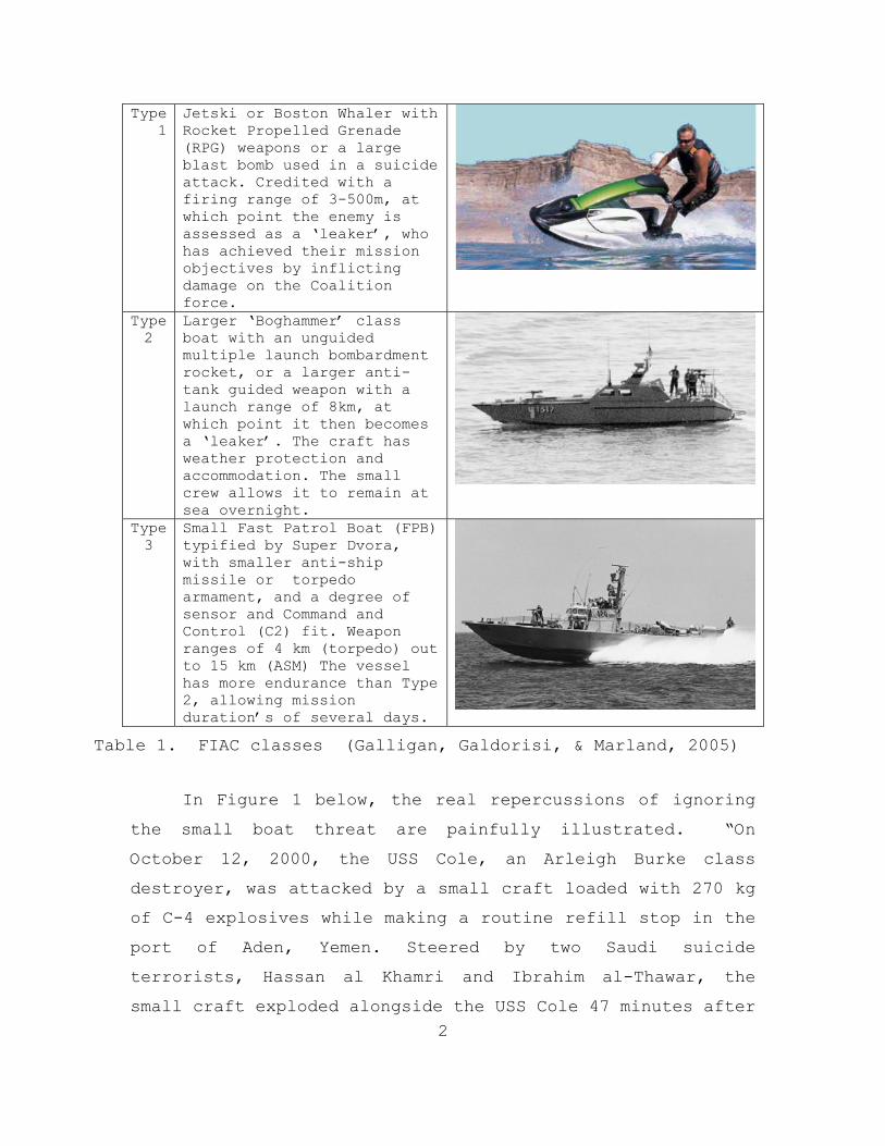
This thesis addresses two underlying problems. The
first is the inherent danger to the U.S. Navy and Coalition
ships from the FIAC threat, the types of FIAC are listed
below in Table 1. These craft, with an arsenal which can
contain an array of weapons to include suicide bombs, crew-
served weapons, anti-tank or ship missiles, and torpedoes
pose a considerable threat. While these craft often have
crude weapon technologies, they use an asymmetric tactic of
large numbers of small, cheap, poorly armed and armored
units to overwhelm coalition defenses. The corollary issue
is the training gap which exists for dealing with this
threat.
2
Type 1
Jetski or Boston Whaler with Rocket Propelled Grenade (RPG) weapons or a large blast bomb used in a suicide attack. Credited with a firing range of 3-500m, at which point the enemy is assessed as a ‘leaker’, who has achieved their mission objectives by inflicting damage on the Coalition force.
Type 2
Larger ‘Boghammer’ class boat with an unguided multiple launch bombardment rocket, or a larger anti-tank guided weapon with a launch range of 8km, at which point it then becomes a ‘leaker’. The craft has weather protection and accommodation. The small crew allows it to remain at sea overnight.
Type 3
Small Fast Patrol Boat (FPB) typified by Super Dvora, with smaller anti-ship missile or torpedo armament, and a degree of sensor and Command and Control (C2) fit. Weapon ranges of 4 km (torpedo) out to 15 km (ASM) The vessel has more endurance than Type 2, allowing mission duration’s of several days.
Table 1. FIAC classes (Galligan, Galdorisi, & Marland, 2005)
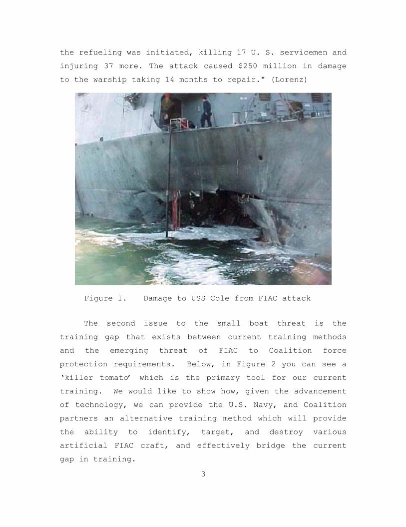
In Figure 1 below, the real repercussions of ignoring
the small boat threat are painfully illustrated. “On
October 12, 2000, the USS Cole, an Arleigh Burke class
destroyer, was attacked by a small craft loaded with 270 kg
of C-4 explosives while making a routine refill stop in the
port of Aden, Yemen. Steered by two Saudi suicide
terrorists, Hassan al Khamri and Ibrahim al-Thawar, the
small craft exploded alongside the USS Cole 47 minutes after
3
the refueling was initiated, killing 17 U. S. servicemen and
injuring 37 more. The attack caused $250 million in damage
to the warship taking 14 months to repair." (Lorenz)
Figure 1. Damage to USS Cole from FIAC attack
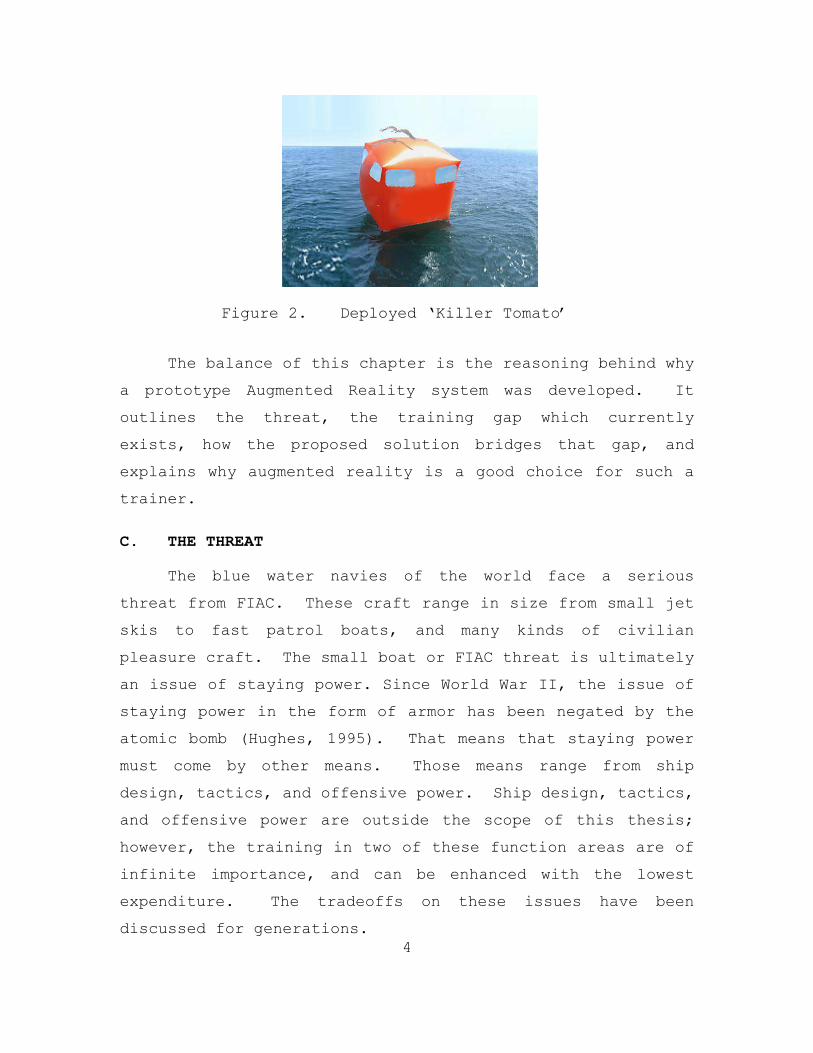
The second issue to the small boat threat is the
training gap that exists between current training methods
and the emerging threat of FIAC to Coalition force
protection requirements. Below, in Figure 2 you can see a
‘killer tomato’ which is the primary tool for our current
training. We would like to show how, given the advancement
of technology, we can provide the U.S. Navy, and Coalition
partners an alternative training method which will provide
the ability to identify, target, and destroy various
artificial FIAC craft, and effectively bridge the current
gap in training.
4
Figure 2. Deployed ‘Killer Tomato’
The balance of this chapter is the reasoning behind why
a prototype Augmented Reality system was developed. It
outlines the threat, the training gap which currently
exists, how the proposed solution bridges that gap, and
explains why augmented reality is a good choice for such a
trainer.
C. THE THREAT
The blue water navies of the world face a serious
threat from FIAC. These craft range in size from small jet
skis to fast patrol boats, and many kinds of civilian
pleasure craft. The small boat or FIAC threat is ultimately
an issue of staying power. Since World War II, the issue of
staying power in the form of armor has been negated by the
atomic bomb (Hughes, 1995). That means that staying power
must come by other means. Those means range from ship
design, tactics, and offensive power. Ship design, tactics,
and offensive power are outside the scope of this thesis;
however, the training in two of these function areas are of
infinite importance, and can be enhanced with the lowest
expenditure. The tradeoffs on these issues have been
discussed for generations.
5
You cannot have everything. If you attempt it, you will lose everything... On a given tonnage ...there cannot be the highest speed, and the heaviest battery, and the thickest armor, and the longest coal endurance (Mahan [28, p.44]).
“The problem now, as it was when Mahan wrote at the
turn of the century, is to decide the proper mix of
attributes in a modern warship” (Hughes, 1995). This is a
problem faced by our enemys as well as coalition forces.
Due to financial constraints on different countries, the
solutions to this problem manifest themselves in different
ways.
A country can, or will, pay only so much for its war fleet. That amount of money means so much aggregat tonnage. How shall that tonnage be allotted? And especially, how shall the total tonnage invested in armored ships be divided? Will you have a very few big ships, or more numerous medium ships? (Mahan [27. P. 37]).
The United States Navy has answered this problem with a
large number of large ships, in comparison with the rest of
the worlds navies. Many our enemies cannot afford the
amount of aggregat tonnage which the United States is
willing to pay, and therefore their solution is Fast Inshore
Attack Craft. The consequences of these decisions are
evaluated in Section B in Chapter II.
D. WEAPON QUALIFICATION
There are currently no qualification requirements for
Rules of engagement (ROE), marksmanship against moving
targets, threat prioritization, target designation, field of
fire coordination, coordinated arms effects, watch-station
to CIC communications, or coordination with bridge
6
maneuvering orders. Live fire exercises can approximate the
bridge to weapon crew communications, but weapon
effectiveness and marksmanship cannot be measured.
Additionally, the cost involved with live fire exercises,
and the limitations on the locations where these exercises
are permitted do not allow crews to be trained in locations
or with scenarios they are likely to face. Current
qualification and training methods will be explored and
evaluated in Chapter II.
E. PROPOSED SOLUTION TO TRAINING GAP
Trying to overcome all these limitations of current
training systems, we devised a technological solution that
addresses most of them. We will now briefly introduce AR-
VAST: the Augmented-Reality Virtual at Sea Trainer.
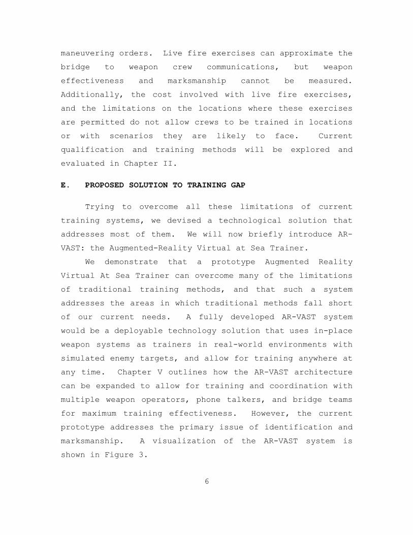
We demonstrate that a prototype Augmented Reality
Virtual At Sea Trainer can overcome many of the limitations
of traditional training methods, and that such a system
addresses the areas in which traditional methods fall short
of our current needs. A fully developed AR-VAST system
would be a deployable technology solution that uses in-place
weapon systems as trainers in real-world environments with
simulated enemy targets, and allow for training anywhere at
any time. Chapter V outlines how the AR-VAST architecture
can be expanded to allow for training and coordination with
multiple weapon operators, phone talkers, and bridge teams
for maximum training effectiveness. However, the current
prototype addresses the primary issue of identification and
marksmanship. A visualization of the AR-VAST system is
shown in Figure 3.
7
Figure 3. AR-VAST Concept
F. WHY AUGMENTED REALITY
Different technologies were investigated for this
training need. It was decided to use augmented reality for
a technological solution because it has the benefits of
virtual reality without its limitations of cost, limited
training environments and Virtual Reality Sickness. AR
retains most of the important aspects of live fire exercises
since it incorporates the real environment. It does so at a
lower cost and with less danger involved, and with fewer
restrictions for training locations than with live fire
exercises. As a deployable trainer, it also has a distinct
advantage over a static trainer, where the crews come to the
trainer rather than the trainers coming to the crew.
Finally, a robo-ski solution was investigated, but it
suffers from the same limitations as live fire exercises

8
with the added cost of potential loss of the robo-ski during
training. We will address these issues in detail in Chapter
II.
G. CHAPTER SUMMARY
The current training methods do not adequately address
the emerging threats, and we have proposed a technological
solution for this training gap. In the following chapter,
we cover the background investigation which led to the
conclusion there is a gap, the related work, and the
technologies’ current state of the art.
9
II. RELATED WORK
This chapter addresses the technology and procedures
currently in use for training gunners, the methods for
evaluating threats and damage, augmented reality technology,
which we propose to use to improve VAST training, and
rendering systems.
A. CURRENT QUALIFICATION AND TRAINING METHODS
As stated in Chapter I, it is our hypothesis that there
is a gap in the qualification and training requirements now
employed. This section will first examine and evaluate the
current weapon qualification, and then the current training
methods.
1. Weapon Qualification / Killer Tomato
The current training on heavy machine guns in the U.S.
Navy does not address either the identification of targets,
or the ability to destroy moving targets. The following is
the description for the qualification for use of a .50 cal
in the Navy’s OPNAVINST 3591.1E:
Course of fire is a six-phase, 100 round performance evaluation, fired on a 400-meter range (afloat or ashore) using an 8’ x 8’ size area target. Most military machine gun ranges ashore usually provide adequate area targets that can be used (i.e., old tanks, trucks, etc). For ranges at sea a ‘killer tomato” or something of equivalent size placed at 400 to 500 yards will suffice. Any non-fired rounds due to weapon malfunctions shall be fired as an alibi. The machine gun will be fired from a mounted (free-gun) position with no T&E mechanism used. Each shooter will set Headspace and verify Timing
10
before firing the performance evaluation. After the shooter has completed five phases of fire, the barrel shall be changed and Headspace and Timing set/verified again, which represents the sixth phase of the course of fire.
The first phase is to zero the weapon, or establish
hold. The qualification on phase one is:
With a 20 round belt of ammunition, on command, the shooter will LOAD, MAKE READY, and FIRE on the designated target in order to zero the weapon or establish a proper hold. The shooter must UNLOAD, SHOW CLEAR at the completion of fire.
The qualification is scored by the following criteria:
Verify Headspace and Timing, Place Weapon in Condition 4,
Zero or Establish Hold, and Unload Show Clear. All of these
objectives are graded on a pass or fail basis.
Phase two is the engagement of a single target. The
grading criteria for this phase are: Place weapon in
Condition 3, Effectively Engage Target (15 Seconds), Unload
Show Clear. The qualification on phase two is:
With a 20 round belt of ammunition, on command, the shooter will MAKE READY and FIRE on the designated target utilizing multiple 3 to 5 round bursts while maintaining a consistent cone of fire and beaten zone to effectively engage the target. The shooter must UNLOAD, SHOW CLEAR at the completion of fire.
Phase three is functionally the same as phase two, but
starting in weapon condition four instead of condition
three. Phases four and five are both intended to qualify
the individual on the reloading of the weapon, and phase six
11
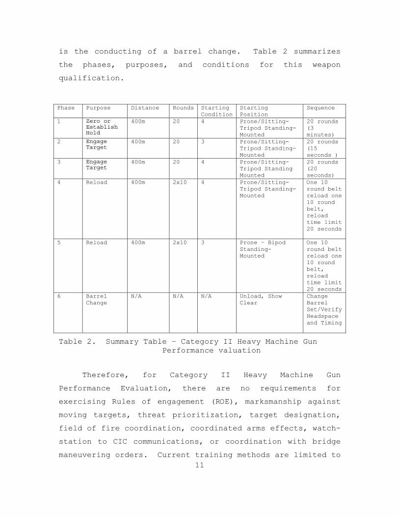
is the conducting of a barrel change. Table 2 summarizes
the phases, purposes, and conditions for this weapon
qualification.
Phase Purpose Distance Rounds Starting Condition
Starting Position
Sequence
1 Zero or Establish Hold
400m 20 4 Prone/Sitting-Tripod Standing-Mounted
20 rounds (3 minutes)
2 Engage Target
400m 20 3 Prone/Sitting-Tripod Standing-Mounted
20 rounds (15 seconds )
3 Engage Target
400m 20 4 Prone/Sitting-Tripod Standing Mounted
20 rounds (20 seconds)
4 Reload 400m 2x10 4 Prone/Sitting-Tripod Standing-Mounted
One 10 round belt reload one 10 round belt, reload time limit 20 seconds
5 Reload 400m 2x10 3 Prone – Bipod Standing- Mounted
One 10 round belt reload one 10 round belt, reload time limit 20 seconds
6 Barrel Change
N/A N/A N/A Unload, Show Clear
Change Barrel Set/Verify Headspace and Timing
Table 2. Summary Table – Category II Heavy Machine Gun Performance valuation
Therefore, for Category II Heavy Machine Gun
Performance Evaluation, there are no requirements for
exercising Rules of engagement (ROE), marksmanship against
moving targets, threat prioritization, target designation,
field of fire coordination, coordinated arms effects, watch-
station to CIC communications, or coordination with bridge
maneuvering orders. Current training methods are limited to
12
familiarizing the trainees with loading, firing, and
clearing the weapon and static marksmanship training from a
static platform. This highlights a gap in the training
requirements and subsequently a gap in current training
systems where a new training system could be employed.
2. Robo-Ski
A much more innovative solution is the Robo-Ski type
trainer. There are currently three types of this trainer to
include: the Robo-Ski, a remote controlled jet-ski, the
Robo-raider, a remote control combat rubber raiding craft
powered by a diesel outboard with autopilot GPS, and the
Seafox, a 16-foot rigid hull inflatable boat (RHIB) powered
by a JP-5 propulsion system.
The advantage of this training method over the killer
tomato is that this target system can move through the water
exactly the same way a real enemy would move. The primary
disadvantage is that the craft cannot be targeted and fired
upon directly. This system utilizes a tow rope to drag the
actual target through the water. The issue is that in order
to protect the Robo-Ski a long tow rope is used, the target
does not behave correctly. A shorter rope can be used to
avoid this unwanted behavior, but that puts the Robo-Ski in
danger of stray rounds, or inexperienced trainees. A
consequential issue is the cost of replacement if the Robo-
Ski is damaged or destroyed during the fire exercise. The
third disadvantage is that identification of the target
(what is the target?) is trivial, and this does not exercise
threat prioritization or target designation. Also, as with
all live fire exercises, locations are limited. Lastly, the
13
cost increases dramatically as more Robo-skis are used to
simulate small boat swarm attacks.
B. EXAMINATION OF THE THREAT
This section is an examination of several studies and
models used to illustrate the dangers of small boat attacks,
and justification of development of new technologies to help
counter this threat.
1. Hughes Salvo Model
This section describes a method of evaluating the
dangers of small boat attacks, and a realistic example of
the employment of this model.
Hughes proposed an extension to Lancaster’s equations,
which specifies the casualties a firing force would inflict
over a period of time, relative to those inflicted by the
opposing force, to show the tactical consequenses of a ship
that had the offensive power to destroy one or more similar
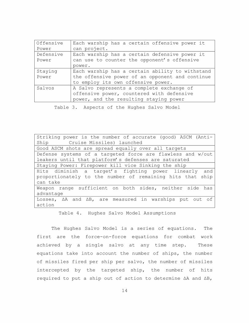
ships with a single ‘salvo’. Below are the Aspects of the
Hughes Salvo Model, and its assumptions. For the purpose of
illustration of the dangers of small boat attacks we will go
through an example problem with the Hughes Salvo Model.
First, we will explain the model’s aspects and assumptions
in Tables 3 an 4 respectively.
14
Offensive Power
Each warship has a certain offensive power it can project.
Defensive Power
Each warship has a certain defensive power it can use to counter the opponent’s offensive power.
Staying Power
Each warship has a certain ability to withstand the offensive power of an opponent and continue to employ its own offensive power.
Salvos A Salvo represents a complete exchange of offensive power, countered with defensive power, and the resulting staying power
Table 3. Aspects of the Hughes Salvo Model
Striking power is the number of accurate (good) ASCM (Anti-Ship Cruise Missiles) launched Good ASCM shots are spread equally over all targets Defense systems of a targeted force are flawless and w/out leakers until that platform’s defenses are saturated Staying Power: Firepower kill vice Sinking the ship Hits diminish a target’s fighting power linearly and proportionately to the number of remaining hits that ship can take Weapon range sufficient on both sides, neither side has advantage Losses, ΔA and ΔB, are measured in warships put out of action
Table 4. Hughes Salvo Model Assumptions
The Hughes Salvo Model is a series of equations. The
first are the force-on-force equations for combat work
achieved by a single salvo at any time step. These
equations take into account the number of ships, the number
of missiles fired per ship per salvo, the number of missiles
intercepted by the targeted ship, the number of hits
required to put a ship out of action to determine ΔA and ΔB,
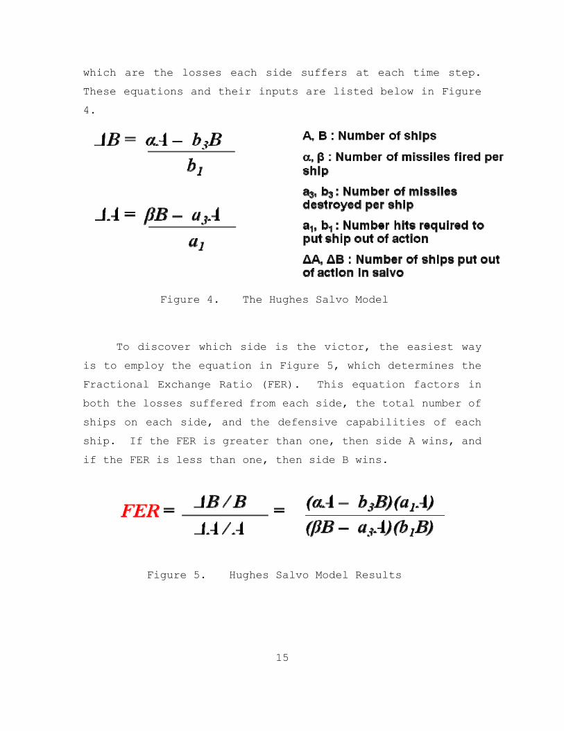
15
which are the losses each side suffers at each time step.
These equations and their inputs are listed below in Figure
4.
Figure 4. The Hughes Salvo Model
To discover which side is the victor, the easiest way
is to employ the equation in Figure 5, which determines the
Fractional Exchange Ratio (FER). This equation factors in
both the losses suffered from each side, the total number of
ships on each side, and the defensive capabilities of each
ship. If the FER is greater than one, then side A wins, and
if the FER is less than one, then side B wins.
Figure 5. Hughes Salvo Model Results
16
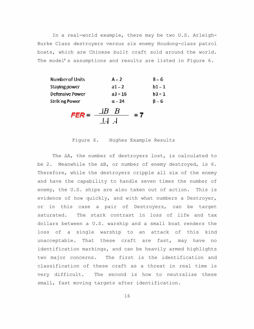
In a real-world example, there may be two U.S. Arleigh-
Burke Class destroyers versus six enemy Houdong-class patrol
boats, which are Chinese built craft sold around the world.
The model’s assumptions and results are listed in Figure 6.
Figure 6. Hughes Example Results
The ΔA, the number of destroyers lost, is calculated to
be 2. Meanwhile the ΔB, or number of enemy destroyed, is 6.
Therefore, while the destroyers cripple all six of the enemy
and have the capability to handle seven times the number of
enemy, the U.S. ships are also taken out of action. This is
evidence of how quickly, and with what numbers a Destroyer,
or in this case a pair of Destroyers, can be target
saturated. The stark contrast in loss of life and tax
dollars between a U.S. warship and a small boat renders the
loss of a single warship to an attack of this kind
unacceptable. That these craft are fast, may have no
identification markings, and can be heavily armed highlights
two major concerns. The first is the identification and
classification of these craft as a threat in real time is
very difficult. The second is how to neutralize these
small, fast moving targets after identification.

17
2. MANA Study of Small Boat Attacks
Galligan et al. (Galligan, Galdorisi, & Marland, 2005)
did a study with MANA (Map Aware Non-uniform Automata) which
is an agent-based model developed by the Operations Analysis
group at Defense Technology Agency in New Zealand, and
concluded that an a type I FIAC attack would have a 3 to
100% chance of a leaker, an enemy reaching their effective
weapon range, depending upon the size of the swarm attack.
They further concluded that for type II and III that the
survivability of the blue force depends entirely upon the
range of red forces weapons.
3. SMALL BOAT AND SWARM DEFENSE: A GAP STUDY
LT Andre Tiwari, of the U.S. Navy, is currently
conducting a current capabilities gap study which attempts
to determine if a gap in capability exists in the surface
force to defend itself against small threat craft by using
the Anti-Terrorism / Force Protection (AT/FP) Tool initially
developed by Lieutenant James Harney and significantly
enhanced by Lieutenant Patrick Sullivan.
4. Threat Summary
We have illustrated three examples of studies and
models which highlight the threat of small boat tactics. To
help mitigate this threat we would propose additional
training in the area of Small Caliber Action Teams. To this
end we are recommending the technological solution AR-VAST
which can answer many of the gaps in current training
methods.

18
C. AUGMENTED REALITY TECHNOLOGIES
Augmented reality is already in use in various ways we
see every day. It was used to great effect during NBC’s
television broadcasts of the 2008 Summer Olympics, as the
flags of the athletes’ countries were superimposed on their
swimming or running lanes, and as seen as the yellow line on
National Football League television broadcasts.
A perfect example of AR for the war-fighter would be
the Heads-Up-Display (HUD) in the cockpit of airplanes.
This is an example of how aircraft data like altitude and
attitude can be displayed in the pilots view frustum,
limiting the need for the pilot to look at the actual
instruments.
This section examines the state of the current
technologies for use with an augmented reality system in
general, and for AR-VAST specifically.
1. Display types
The first major design decision for AR-VAST is what
display type to use. There are many display type options
for Augmented Reality systems. These displays range from
various Head-Attached displays such as retinal displays,
head-mounted displays, and head mounted projectors; and Hand
held displays such as cell phones to Playstation Portables;
to spatial optical see-through devices such as video
monitors, and stationary projectors. (Bimber & Raskar, 2005)
Not all of these display types would be suitable for use in
an application such as AR-VAST. First, the currently
available retinal displays are only monochrome. This
display type is good for informational purposes, but poor
19
for realistic graphical displays. Second, hand held
displays are too small and impractical for an application
such as AR-VAST. Third, projection displays (Bimber &
Raskar, 2005) would be bulky, and not usable in all lighting
conditions, specifically when it is sunny. They also
require projection on a suitable surface, which the ocean
does not provide.
The two most suitable display types, therefore, would
be a COTS flat paneled monitor, and a Head Mounted Display
(HMD). Each mode of display has advantages over the other,
and each has limitations from which the other technology may
not suffer.
2. Tracking
Tracking requirements for an augmented reality system
will necessarily depend upon the display type. For example,
in the AR-VAST system, if a monitor is used, the only
tracking requirement will be to track the weapon’s movement
to translate real world movement into movement in the
simulated environment. However, if the display is a Head-
mounted system, then in addition to the weapon, the head
will have to be tracked. There are also different types of
tracking technologies, some of which may be more or less
suitable for this application.
Another issue to influence which tracking technology to
use is drift. Drift is an undesired change in output over a
period of time that is unrelated to input. Inertial
trackers are particularly susceptible to problems with drift
due to the nature of their accelerometer sensors.

20
While in prototype, drift is less of a problem because
all objects are internal to the system itself. However,
later development will include objects which are outside the
simulated world. An interaction between the real world and
the simulated world will be achieved by placing “artificial”
transparent objects in front of any real objects. This will
allow for users to have the impression that they are in fact
interacting with “real” objects. However, if there is
considerable drift injected into the system by the tracking
mechanism, the transparent objects will become detached from
their real world counterparts, and the illusion will be
lost.
The three options for tracking in an AR-VAST prototype
would therefore be inertial tracking, feature or optical
tracking, and some hybrid combining both solutions. Other
options exist, but would not be suitable to this
environment. First, magnetic tracking would be infeasible
on a ship with degaussing, a method for eliminating unwanted
magnetic fields. Second, ultrasonic tracking could
interfere with ship systems. Lastly, external optical
tracking for example with retro-reflective markers and
infrared vision would necessitate external infrastructure in
the form of a camera, and bright daylight performance is
questionable. The source-less, self-contained inertia
tracking is not subject to any of these disadvantages.
3. Blending Virtual and Real Worlds
One of the first AR applications which used the real
world environment for first person shooting was ARQuake,
developed at the University of South Australia. In this
application, the physical world is modeled as a Quake 3D
21
graphical model. This mapped model of the physical world is
not rendered, but “the augmented reality information is
rendered in special context with the physical world.”
(Thomas, et al., 2000) A GPS unit and head tracking are
used to sync the real world with the modeled real world
within the application. For AR-VAST we would like to
advance this technology to divorce the system from needing a
GPS device and needing to have the environment modeled
before runtime.
D. GAME ENGINES
A game engine is a middle-ware software development
tool kit that simplifies game and simulation design for
rapid development. It frequently consists of the following
components: rendering 2D and 3D graphics, physics, collision
detection, sound, scripting, AI, networking, memory
management, and scene graphs. A game engine provides a
flexible and reusable software platform which provides all
the core game functionality needed, right out of the box, to
develop a game application while reducing costs,
complexities, and time-to-market.
AR-VAST needs a game engine to provide the components
needed to give the user a rich visual environment; endow AR-
VAST with the necessary functionality for the physics of
rigid body motion, ballistics, and particle systems;
calculate collision detection; and give scalability with
regards networking and confederation with other simulations.
There are many commercially available game engines
available for use, but there is a vast degree of separation
on price and functionality. There are also several open
22
source game engines available that have issues on customer
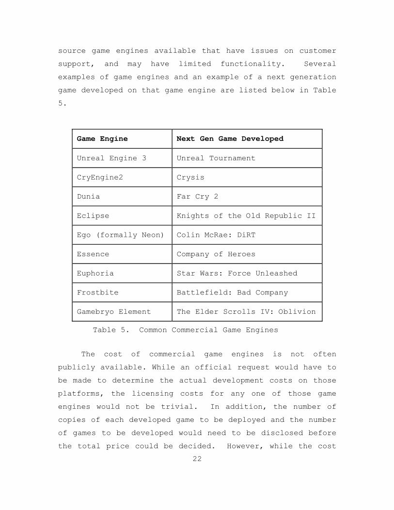
support, and may have limited functionality. Several
examples of game engines and an example of a next generation
game developed on that game engine are listed below in Table
5.
Game Engine Next Gen Game Developed
Unreal Engine 3 Unreal Tournament
CryEngine2 Crysis
Dunia Far Cry 2
Eclipse Knights of the Old Republic II
Ego (formally Neon) Colin McRae: DiRT
Essence Company of Heroes
Euphoria Star Wars: Force Unleashed
Frostbite Battlefield: Bad Company
Gamebryo Element The Elder Scrolls IV: Oblivion
Table 5. Common Commercial Game Engines
The cost of commercial game engines is not often
publicly available. While an official request would have to
be made to determine the actual development costs on those
platforms, the licensing costs for any one of those game
engines would not be trivial. In addition, the number of
copies of each developed game to be deployed and the number
of games to be developed would need to be disclosed before
the total price could be decided. However, while the cost
23
is high, customer service can be expected, and explicitly
added to the contract.
To avoid the costs involved with commercial game
engines, an open source game engine can be used. There are
at least two engines which fit into this category:
NeoEngine and Delta3D. NeoEngine has the advantage that is
available for Windows, Linux, and MacOS X. This means that
software can be developed on any of the three top computer
platforms. Delta3D can develop games on both Windows and
Linux platforms. Between the NeoEngine and Delta3D game
engines Delta3D is the more accessible to NPS students as it
was developed at NPS, the development team is co-located
with the MOVES department, and is taught as part of the
curriculum.
E. CHAPTER SUMMARY
This chapter has examined the current training methods,
the current state of Augmented Reality technology, and
evaluation of the FIAC threat. The following chapter will
examine the design decisions which were made in the
development of the AR-VAST prototype with justification for
the technologies used in the prototype.

24
THIS PAGE INTENTIONALLY LEFT BLANK
25
III. SYSTEM DEVELOPMENT
This chapter explains the design choices and
implementation of AR-VAST from concept to working prototype
and beyond. The initial prototype specifications were kept
intentionally simple. This would allow for the construction
of a framework upon which to build successive iterations
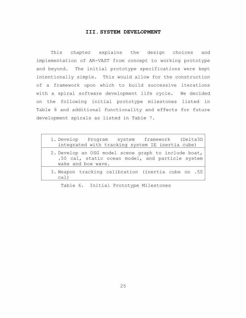
with a spiral software development life cycle. We decided
on the following initial prototype milestones listed in
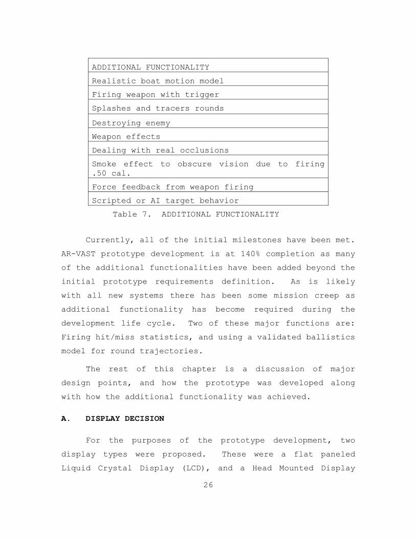
Table 6 and additional functionality and effects for future
development spirals as listed in Table 7.
1. Develop Program system framework (Delta3D integrated with tracking system IE inertia cube)
2. Develop an OSG model scene graph to include boat, .50 cal, static ocean model, and particle system wake and bow wave.
3. Weapon tracking calibration (inertia cube on .50 cal)
Table 6. Initial Prototype Milestones
26
ADDITIONAL FUNCTIONALITY
Realistic boat motion model
Firing weapon with trigger
Splashes and tracers rounds
Destroying enemy
Weapon effects
Dealing with real occlusions
Smoke effect to obscure vision due to firing .50 cal.
Force feedback from weapon firing
Scripted or AI target behavior
Table 7. ADDITIONAL FUNCTIONALITY
Currently, all of the initial milestones have been met.
AR-VAST prototype development is at 140% completion as many
of the additional functionalities have been added beyond the
initial prototype requirements definition. As is likely
with all new systems there has been some mission creep as
additional functionality has become required during the
development life cycle. Two of these major functions are:
Firing hit/miss statistics, and using a validated ballistics
model for round trajectories.
The rest of this chapter is a discussion of major
design points, and how the prototype was developed along
with how the additional functionality was achieved.
A. DISPLAY DECISION
For the purposes of the prototype development, two
display types were proposed. These were a flat paneled
Liquid Crystal Display (LCD), and a Head Mounted Display

27
(HMD). Below is a rationalization of the pros and cons of
both choices, and the conclusion that we came to regarding
the design choice.
1. Monitor
A traditional flat panel monitor has several advantages
over an HMD display. The first advantage is cost.
Lightweight flat panel monitors are becoming a commodity, as
the technology is much more mature than HMD technologies.
The second advantage is Field of View (FOV), where people
have a 180° FOV most HMDs have less than 150° FOV.
Additionally, a monitor can be moved closer or further away
to change the FOV and resolution of monitors is much greater
than the typical HMD’s 10-20 pixels/°. Resolutions of
1900x1200 pixels are commonplace. The third advantage is
that users would not suffer what is commonly referred to as
Virtual Reality Sickness (VR Sickness). This phenomenon is
caused by a conflict of signals between the eyes and the
inner ear due to lag introduced by image rendering.
(Johnson, 2005) With a monitor, VR sickness is less of an
issue since the user can see the real world as well as the
virtual world. The last advantage is that the design of
the tracking functionality is a degree of difficulty easier
as only the weapon needs to be tracked rather than the
weapon and the user.
This solution also has disadvantages. The primary
disadvantage being that a monitor is less immersive than an
HMD. On the other hand, it is the lack of immersion that
allows users not to suffer VR sickness. To make the monitor
solution as immersive as possible and thus less likely to be
rejected by users would be careful calibration between the
28
user, the camera and the weapon. The camera should as
closely as possible match the point of view of the user, and
should be adjustable in both the depth and height
diminutions. This requires that the camera be mounted on an
adjustable frame or gimbal. The lighting between the real
world and the virtual world may differ, as well as lighting
conditions will change the visibility of the LCD screen.
FOV is also problematic with an LCD screen, but may be
overcome with how the LCD is mounted, possibly also with
more than one LCD monitor. Additionally, the monitor should
be adjustable as well to maximize the field of view to cover
as much of the users view as possible. This would require a
two degree of freedom of motion of the monitor in the depth
and height.
2. Head Mounted Display
The primary advantage of the HMD would be that it is
more immersive than a monitor. However, HMDs can cause
Simulator Sickness more often than a monitor. (Johnson,
2005) This effect would be compounded if any image
manipulation were to be used to create photo realistic
wakes.
The disadvantages of an HMD would be cost, higher
requirements on tracking accuracy, the discomfort of wearing
an HMD, putting it on and calibrating it, Field Of View
limitations, resolution limitations, jitter, brightness
issues, and video- vs. optical see-through problems. Video
see-through has limited resolution and field of view.
Typical current technology is limited to 150° FOV and 10-20
pixels/°. Optical see-through was not viewed as an option
because lighting conditions that are required for optimum
29
viewing do not exist in the operating environment that AR-
VAST would be expected to be used. Also, registration
remains a high hurdle to clear for optical see-through
displays since the real-world optical path has no latency at
all, while no latency rendered imagery has yet to be
achieved.
B. TRACKING DECISION
AR-VAST had three proposed tracking solutions. These
were the InertiaCube2 (inertial tracking), feature tracking
and a hybrid of both inertial and feature tracking. Below
is an explanation of all three tracking technologies and
discussion of their benefits and limitations. Last, is the
conclusion on which tracking choice to be used in the AR-
VAST prototype.
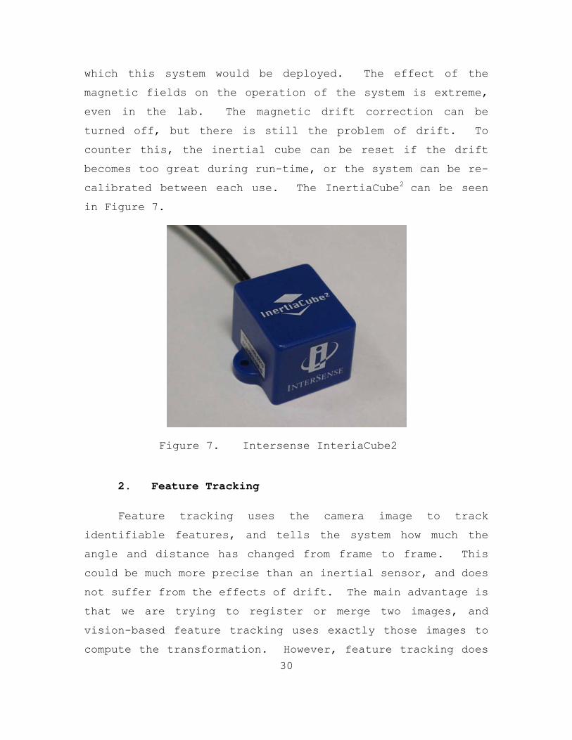
1. Intersense InertiaCube2
“The InertiaCube2 integrates nine discrete miniature
sensing elements utilizing advanced Kalman filtering
algorithms to produce a full 360° orientation tracking
sensor.” Not only does this tracker have 360° orientation,
it also has a full three degrees of freedom in heading,
pitch, and roll. However, this tracking system, while good
in laboratory settings and initial development, has
limitations which could make it in-appropriate for fielded
use on ships. The major problem with using this tracking
technology is that it uses magnetic correction for drift
which is a byproduct of inertial tracking. However, this
magnetic correction introduces more error because of the
magnetic fields produced by the weapon and any ship onto
30
which this system would be deployed. The effect of the
magnetic fields on the operation of the system is extreme,
even in the lab. The magnetic drift correction can be
turned off, but there is still the problem of drift. To
counter this, the inertial cube can be reset if the drift
becomes too great during run-time, or the system can be re-
calibrated between each use. The InertiaCube2 can be seen
in Figure 7.
Figure 7. Intersense InteriaCube2
2. Feature Tracking
Feature tracking uses the camera image to track
identifiable features, and tells the system how much the
angle and distance has changed from frame to frame. This
could be much more precise than an inertial sensor, and does
not suffer from the effects of drift. The main advantage is
that we are trying to register or merge two images, and
vision-based feature tracking uses exactly those images to
compute the transformation. However, feature tracking does
31
have a potentially serious drawback in this particular
environment. Finding identifiable features to track could
be a difficult problem when faced with an open ocean
environment. There are different methods of feature
tracking which could be used to achieve the necessary
tracking, but the question of how this system will be
deployed and used will have to be answered before the
correct feature tracking method can be chosen. The short-
term solution for this particular problem would be to have
an option in a graphical user interface to tell the system
what operating environment the system is being used in
currently, and apply the correct feature tracking method
based upon that input.
Additionally, if the future development includes a
video see-through HMD and all tracking is done with feature
tracking, then the decision must be made for the placement
of the camera, and how to track both the head movement and
the movement of the weapon. Ideally, the gun camera would
have the same field of vision that the user would have
without wearing the HMD. Tracking the weapon would then be
done at the same time as the environment tracking using a
similar process.
3. Combined Solution
Inertial tracking has drift issues, and feature
tracking has potential problems with feature identification.
Perhaps the best solution would be to blend feature tracking
with inertial tracking. This would eliminate the complexity
of tracking both the gun and the head with feature tracking,
and inertial tracking’s issue with drift. In effect, it is
complementing one’s weakness with the other’s strength.
32
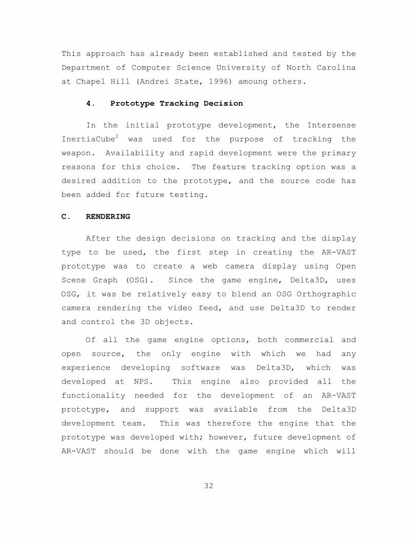
This approach has already been established and tested by the
Department of Computer Science University of North Carolina
at Chapel Hill (Andrei State, 1996) amoung others.
4. Prototype Tracking Decision
In the initial prototype development, the Intersense
InertiaCube2 was used for the purpose of tracking the
weapon. Availability and rapid development were the primary
reasons for this choice. The feature tracking option was a
desired addition to the prototype, and the source code has
been added for future testing.
C. RENDERING
After the design decisions on tracking and the display
type to be used, the first step in creating the AR-VAST
prototype was to create a web camera display using Open
Scene Graph (OSG). Since the game engine, Delta3D, uses
OSG, it was be relatively easy to blend an OSG Orthographic
camera rendering the video feed, and use Delta3D to render
and control the 3D objects.
Of all the game engine options, both commercial and
open source, the only engine with which we had any
experience developing software was Delta3D, which was
developed at NPS. This engine also provided all the
functionality needed for the development of an AR-VAST
prototype, and support was available from the Delta3D
development team. This was therefore the engine that the
prototype was developed with; however, future development of
AR-VAST should be done with the game engine which will
33
provide the best solution within budget. This may mean
using a different game engine for final production.
1. Capturing Video
In order to capture the video, the Open Computer Vision
(Open CV) API was used. An additional function had to be
written to translate the image from OpenCV format to OSG
format. The virtual OSG camera had to be set-up to render
the captured image. This was done with an OSG scenegraph
node called “Heads Up Display” (HUD) that takes as input the
captured camera image and displays it as a texture on an
orthographic projection in front of the OSG camera. This
implementation allowed any OSG object file to be loaded in
front of the HUD’s projection of the captured image.
2. Creating Video Texture
The next step was creating a video texture instead of a
single image. This was accomplished by creating a buffer in
which each captured frame would be stored until a new frame
was captured from the camera. The current frame would be
used until notification of a new frame was received, and the
new frame would be retrieved. Thus, a rapid exchange of
still images was used to display streaming video.
3. Combining Video and Game Engine
The difficulty in rendering both the video HUD and the
Delta objects was that the HUD was an OSG camera, and every
Delta3D Application already has a default OSG camera.
The solution was to nest the cameras so that they
render at the same time. This solved the problem where only

34
one of the two, the Delta3D or HUD, cameras could be seen at
one time, and made it possible to have video see-through AR
with augmented objects created and controlled by Delta3D.
D. ANIMATION
Once the HUD and the Delta objects were both being
rendered, creating appropriate objects such as small boats,
various other ocean vessels, and boat wakes was the next
step. Delta3D provides vehicles from the sourceforge web
site (Sorce Forge, 2006). Several vessels were chosen from
the downloadable files, and were made ready for the AR-VAST
application.
1. Small Boat Animation
A cigarette boat was chosen to be the prototype 3D
model for a target. We modified an existing model for use
in the simulation so that the center of rotation is in the
stern of the boat. That simplifies animating the turns such
that the boat is pivoting by its stern as a real small boat
moves.
Animating the small boat was accomplished by setting
the boat’s transform during the pre-frame function with
changing x and y variables. The amount of change depended
on the heading of the boat. Using a unit length of 1 unit
of change, the amount of x or y translation was determined
by the following equations:
y = - (sin (( PI*(heading-90))/180.0));
x = - (cos ((PI*(heading-90))/180.0));

35
The subtraction of 90 degrees is necessary to properly
align the mathematical coordinate system with Delta3D’s
coordinate system.
Once the x and y components are calculated, those
lengths are multiplied by the current speed variable.
Currently, speed and heading are adjusted during runtime
with keystrokes.
To make the simulation more realistic, the turn radius
and roll are dependent upon speed. Both maximum rates of
turn and roll change based upon the ratio of current speed
to maximum speed. Also, the pitch increases during
acceleration, and decreases during deceleration.
2. Wake and Bow-wave Creation and Animation
Creation of a wake and bow-wave are vital to AR-VAST.
Often these two visual clues are the only way to mark
relative motion and speed of a craft through the water.
There are different ways to meet this goal. The first and
easiest way is to make a particle system, which emits
particles to simulate the creation of a wake. The advantage
of this method is that the faster the boat moves through the
water, the longer the wake becomes. Therefore, the wake’s
appearance is directly linked to the speed of the boat,
which is a good approximation of real boat wakes. The
drawback is that the particles do not interact with the
background image, and do not cause after effects such as
ripples.
These effects were created with Delta3D’s particle
editor (pictured below in Figure 8). By experimentation
with different particle systems developed in the editor and
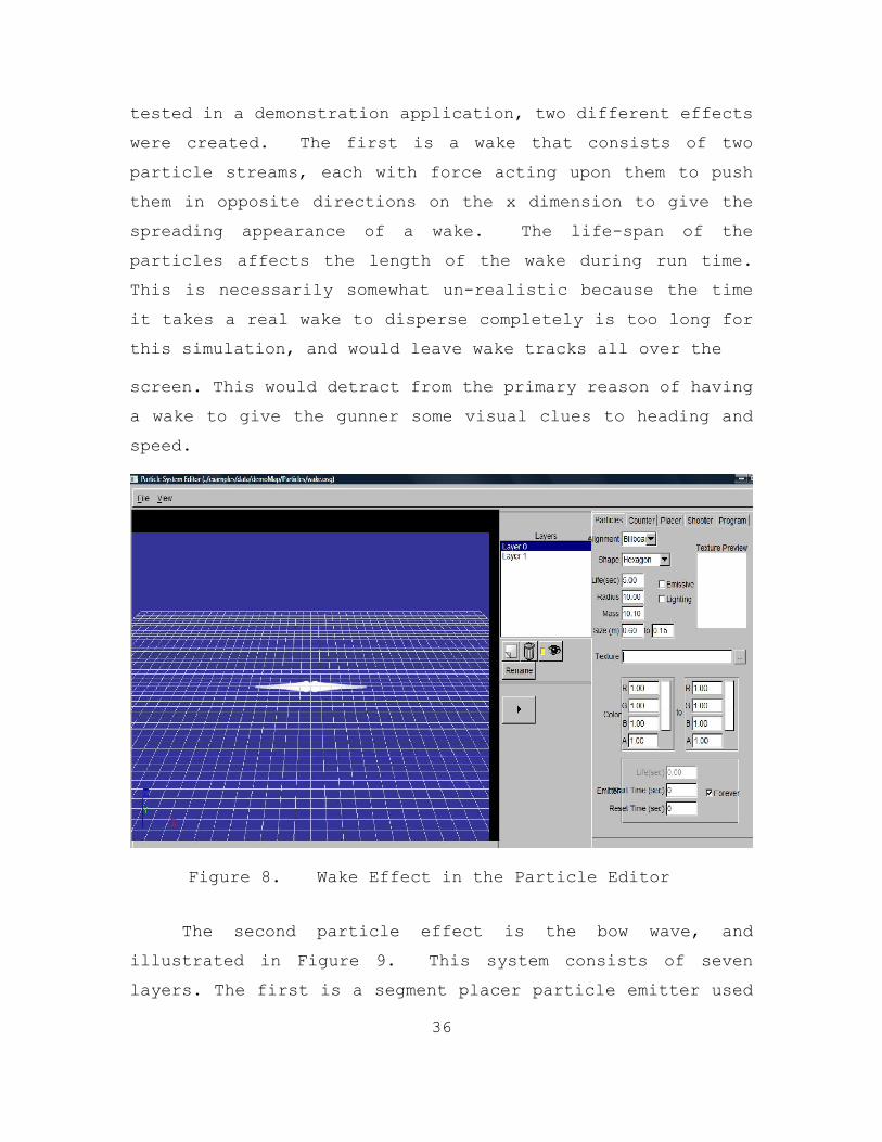
36
tested in a demonstration application, two different effects
were created. The first is a wake that consists of two
particle streams, each with force acting upon them to push
them in opposite directions on the x dimension to give the
spreading appearance of a wake. The life-span of the
particles affects the length of the wake during run time.
This is necessarily somewhat un-realistic because the time
it takes a real wake to disperse completely is too long for
this simulation, and would leave wake tracks all over the
screen. This would detract from the primary reason of having
a wake to give the gunner some visual clues to heading and
speed.
Figure 8. Wake Effect in the Particle Editor
The second particle effect is the bow wave, and
illustrated in Figure 9. This system consists of seven
layers. The first is a segment placer particle emitter used
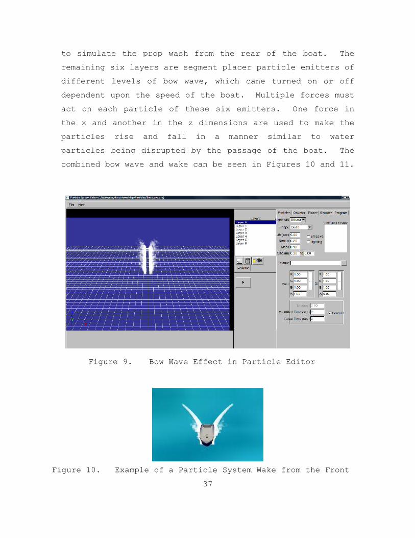
37
to simulate the prop wash from the rear of the boat. The
remaining six layers are segment placer particle emitters of
different levels of bow wave, which cane turned on or off
dependent upon the speed of the boat. Multiple forces must
act on each particle of these six emitters. One force in
the x and another in the z dimensions are used to make the
particles rise and fall in a manner similar to water
particles being disrupted by the passage of the boat. The
combined bow wave and wake can be seen in Figures 10 and 11.
Figure 9. Bow Wave Effect in Particle Editor
Figure 10. Example of a Particle System Wake from the Front

38
Figure 11. Example of a Particle System Wake from the Side
The second method is wake creation through image
manipulation. This involves taking an image from the
camera, before it was displayed to the user, and changing it
during run time. As an example, Figure 12 shows a
representative example of an image from what a deployed
system could expect to see before any effects have been
added. Figure 13 is a real wake formed by a speedboat.
Using the real wake as a model, Figure 14 shows how
Photoshop could be used to apply a simulated wake to the
original image of Figure 12.
Figure 12. Sample Ocean Scene Image

39
Figure 13. Sample Real Wake Used as Wake Model
Figure 14. Simulated Wake Applied Using Photoshop
Between a particle emitter solution, and an image
manipulation method of wake and bow wave creation, the
particle system was chosen because it was a known technology
which was easier to implement for a prototype.
3. Weapon and Camera Animation
Weapon and camera animation are tied directly to the
tracking mechanisms. They are also dependent upon the
40
display type being used. For the prototype, a flat screen
monitor was used and only one tracking source was needed,
the InertiaCube2. This means the camera and the weapon
animations needed to be slaved to the InertiaCube2. To
achieve this, the camera was added to the weapon as a child,
and then translated in object space to an approximate sight
picture from which a typical user might view the weapon in
real life. The weapon and camera’s rotation was changed
before rendering (during the pre-frame) with an update from
the InteriaCube2. However, the InteriaCube2’s rotation
matrix needed to be transformed o match Delta3D’s xyz
coordinate space.
4. Firing the Weapon
Instead of relying upon OSG to detect object collisions
based upon collision geometry or a physics engine, a Delta3D
proximity trigger is used to detect collisions between the
small boat and other objects. The Proximity Trigger class
contains a Trigger that it fires whenever a Transformable
enters its bounding shape. All Delta3D Proximity Triggers
have default collision geometry of a sphere set with a
radius of 5 units; therefore, this was changed to
appropriate collision geometry and size of the small boat.
The proximity sensor was then filtered to collide with the
appropriate objects by setting the collision collide bits
for every category with which the trigger should collide. A
Proximity Trigger is fired only once per touch of a
Transformable.
A side effect of adding children, such as the wake and
bow wave, to the small boat is that the bounding box for the
small boat expands to encompass the small boat and all of
41
its children. This requires that an empty root node be
created as the boat parent, and the boat object as well as
any additional objects such as wake and bow wave be added to
the root. This allows for the creation of the boat’s
proximity trigger with the correct dimensions. This trigger
is then added to the small boat as a child, and translated
in object space to cover the entire small boat’s dimensions.
Each time the weapon fires, a bullet object is created
and added to a bullet queue. The bullet’s collision
category bits are changed to match to collide with the
boat’s proximity trigger, and its collision box dimensions
are changed to have a width of .05m, height of .05m, and a
length of 1000.0m. The objective with this approach is two-
fold. First, this lays the groundwork for using a ballistic
model for the bullet trajectories, as the necessary parts
are already established, and just need to be modified for
addition of more bullets and movement of the rounds through
the simulation space along a ballistic trajectory. The
second is that an arbitrary number of individual proximity
triggers can be created to trigger different effects. For
example, one trigger could be applied to the hull of the
small boat which when hit changes the boat’s handling
dynamics or make the boat sink lower in the water, while
another trigger can be attached to the engines which would
affect the speed of the boat, and could start to smoke when
hit. Other methods of collision detection do not allow for
this level detail with the effects. For tradition collision
detection methods, the boat would have to be split into its
component parts to allow for the same level of detail, but
this could increase the complexity of the animation process.
42
E. ENEMY TARGET BEHAVIOR
There are several options for enemy behavior models.
These options may be constrained by the number of targets to
be controlled. The two options discussed here are: a human in
the loop option, where a person drives a target in the
environment, and different methods for an artificial
intelligence option.
1. Human in the Loop
With a human in the loop system, the easiest solution is
to have only one enemy target. This limits the complexity of
the system and the number of people needed to operate at full
capacity. The prototype was built to this specification for
these reasons. This oversimplifies the task of marksmanship
and target acquisition, however, and does not address most of
the other target training objects.
It is possible to scale this system to have multiple
input devices and multiple windows such that a different
person operates a separate target up to an arbitrary number of
targets. This would be an interesting solution for several
reasons.
a. Dual Use Trainer
An interesting aspect of a human in the loop multi-
user solution would be that it could be as a dual use trainer
to train small boat drivers. Experiments could be conducted
for effectiveness with different levels of coordination or
communication between the small boat drivers on one side and
multiple gunners on the other, as well as different numbers of
enemy targets and gunners to find optimal attack vectors and
defensive strategies with real subjects.

43
However, this approach would be best suited to a
lab environment. As this is designed to be a deployable
trainer, a more compact and less user intensive route should
be taken for the deployable version. However, this could be
an intermediate step towards an artificial intelligence
solution by finding the behaviors that are most successful,
and trying to automate those behaviors. Also, the necessary
target-to-gunner ratio needed to either defeat an attack, or
to overwhelm the defenders could be explored.
2. Artificial Intelligence
The current AI module for the AR-VAST prototype an A*
search algorithm, included in the Delta3D game-engine, for
waypoint planning. It is implemented with a waypoint map
where the small craft moves from point to point with an A*
search algorithm with the destination as one of many points
on the Destroyer from which the gunner is firing. For this
AI solution, a reset function has been written so that the
starting position of the small craft is randomized to make
sure that each run is unique.
This approach gives the small boat some intelligence,
but does not allow the small boat to behave in any way that
is not predictable. In Chapter IV, we will discuss two
options for intelligent AI. The first is an agent-based
approach which, if implemented, will simulate both enemy and
neutral virtual vessels as well as allows behavior switching
to allow for deception. The second is using an existing
JSAF AI module.

44
THIS PAGE INTENTIONALLY LEFT BLANK

45
IV. AR-VAST EVALUATION AND FUTURE DEVELOPMENT SPIRALS
Goal of this chapter is to make a system recommendation
and to provide a detailed plan for implementing a packaged
AR-VAST product.
The evaluation and design plan for AR-VAST is
delineated into two categories. The first category and the
most important at this stage of AR-VAST evolution is making
design decisions based on a system engineering approach.
The second category is possible improvements to the
functional areas of AR-VAST.
A. SYSTEM ENGINEERING AND ANALYSIS
In the following, we describe our approach for putting
forth a systems engineering approach to the next development
spirals for AR-VAST. This approach has its roots in
standard engineering and planning practices which we applied
to the specific system at hand. We validated our approach
with a recognized expert at this task and experienced system
developer.1 Guaranteeing system success is impractical for
larger systems and spiral development by definition means
periodic re-evaluation. Hence, the recommendations stated
below should be re-evaluated frequently. However, we hope
that our three-pronged approach of following established
practices, validation with experts, and benefiting from our
personal exposure to the problem will mitigate many risk
factors and help future system development.
1 Dr. Mike McCauley, personal communication, August 2008.

46
AR-VAST needs to be developed in a “technologically-
based process encompassing an extension of engineering
through all phases of the system life cycle; i.e., design
and development, production or construction, utilization and
support, and phase-out and disposal.” (Blanchard &
Fabrycky, 2006)
The prototype has proved that current technology can
achieve a certain level of visual fidelity in an augmented
reality simulation, but thus far the human system has been
largely ignored. For AV-VAST to go beyond prototype, the
prototype and the assumptions made during its development
need to be put aside. For this system to be viable, a
system engineering approach which takes into account the
whole system life-cycle, and not just development life-
cycle, must be used.
There are many different system engineering approaches
for system design. Here, we strive for a generic outline of
the path that AR-VAST should take to make sure that all
areas of system design are addressed, and design decisions
are made intelligently up-front rather than when any changes
have much higher financial and time costs.
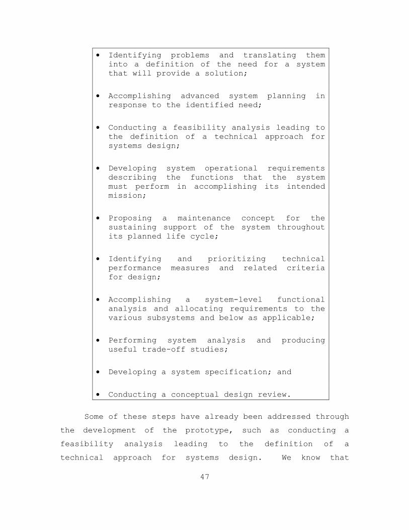
1. Conceptual System Design
The first step is to conduct a conceptual design, which
is an early and high-level activity where many design
choices are made, potential problems are addressed, and the
time-line established. According to Blanchard and Fabrycky
(Blanchard & Fabrycky, 2006) the following are the steps
which need to be taken or considered:
47
• Identifying problems and translating them into a definition of the need for a system that will provide a solution;
• Accomplishing advanced system planning in response to the identified need;
• Conducting a feasibility analysis leading to the definition of a technical approach for systems design;
• Developing system operational requirements describing the functions that the system must perform in accomplishing its intended mission;
• Proposing a maintenance concept for the sustaining support of the system throughout its planned life cycle;
• Identifying and prioritizing technical performance measures and related criteria for design;
• Accomplishing a system-level functional analysis and allocating requirements to the various subsystems and below as applicable;
• Performing system analysis and producing useful trade-off studies;
• Developing a system specification; and
• Conducting a conceptual design review.
Some of these steps have already been addressed through
the development of the prototype, such as conducting a
feasibility analysis leading to the definition of a
technical approach for systems design. We know that
48
Augmented Reality technology can work, but is AR the right
solution for the training need? The most important question
that has yet to be answered is: How do we fill the training
gap?
Next, a human factors study should be conducted to
ensure that technology is the right solution for the
training need. For this, a top down functional analysis
needs to be done, and a training requirements document needs
to be developed so that the technology trains a user in all
the desired functional areas, as well as defining areas
where the graphical display is most needed. For example,
how does the typical gunner hit the targets? Does one use
the optical sight, tracers or the splashes as the rounds
strike the water to “walk” the rounds onto the target, or
use some other method? All of these questions need to be
answered before a fully fleshed out version of AR-VAST can
be created.
A task analysis needs to be done on all the functions
which will be required of the trainer such as: loading,
firing, target selection, and successful shooting of targets
with the .50 cal, or unintentional damage to neutral
targets. Therefore, the next step is finalizing the system
requirements and what functions AR-VAST will have. This
will involve speaking to real weapon crews, and doing
functional analysis of each function that will be required.
Without this, AR-VAST is simply a toy video game product
with no training value.

49
B. SYSTEM IMPROVEMENTS
1. Number of Targets
The ability to first add more targets in the
simulation, and second to allow that the user or system
administrator to control this variable is vital to the
future development of this system.
The recommended solution is to create a queue of boats
rather than a single entity. The number allowed in the
queue should be decided by the training administrator before
the simulation begins within the user interface. Creating a
user interface, which utilizes a slider or some other input
which allows the system administrator to know the maximum
number of boats allowed by the system, as defined in the
architecture would also be beneficial.
The ability to add more small boats also adds
challenges to the application. First, a “Factory” design
pattern should be used to create boat objects and
encapsulate all the information that a small boat needs to
have such as the maximum speed, pitch, and roll
coefficients. A control will also need to be implemented
which will iterate through the process to animate each
vessel in the boat queue in turn.
2. Rendering
There are many variables that may need to be controlled
manually or automatically before or during runtime to adjust
the rendered view as needed to account for many real world
conditions that will arise during normal operation of the
AR-VAST system.

50
a. Weather and Lighting
The first of these variables is weather. Delta3D
is capable of displaying different weather conditions. Fog
is a good example of a weather condition which might be
present with deployed systems. If there is no fog control
on the user interface, then the real world view will show
fog, but the augmented virtual objects will be completely
un-obstructed by the fog. This will ruin the illusion of
reality, and provide both negative training and a false
sense of security by being able to fire at the attacking
boats which should be obscured by the fog. This would also
apply to nighttime operations. So, either a control for
both lighting and weather must be implemented so that a user
can adjust them to match the environment, or some type of
automated function needs be created such that the system
calibrates to the current weather and lighting conditions
during runtime.
b. Sea State
Consideration must be given to different sea
states under which the system might be called upon to
operate. Under higher sea states, the movement of the small
craft on the ocean will be un-realistic without any type of
sinusoidal motion. The difficulty is matching the sea sate,
the location of the waves, and the rendering of the
simulation. The alternative would be to ignore the problem
and to make training restrictions to certain sea states.
The limitation of training in lower sea states would still
benefit users with an HMD. The gunner, gun and AR-VAST

51
display themselves naturally experiences the sea state and
resulting motions, this does not have to be simulated.
c. Lines of Demarcation
A further rendering improvement that should be
considered for addition are lines of demarcation. This
would allow any gunner to know precisely when any craft came
within specific ranges to their ship. This would be a
similar technology to the National Football League’s yellow
first down line. Several line recommendations would be a
ring for .50 cal’s effective range, and a ring for each of
the ROE’s ranges.
3. Display
Based upon the outcome of the training requirements
documentation, the display type will have to be tested in
operational environments. The LCD monitor mounted on the
.50 cal may not be the appropriate technology solution if it
is decided that the force feedback is a necessary
requirement for proper training. The violent motion of the
firing of the weapon may destroy the monitor. This motion
may also shake the user so violently that the HMD is
unusable, either due to the users’ inability to focus on the
display as it moves, or by shaking the HMD from the users.
In either event, any display solution would need to be
hardened for the shaking involved, and the harsh operating
environments.
4. Tracking
The final decisions about tracking will be based on the
final decision about the display type, and testing and

52
evaluation studies. These studies need to show that the
chosen tracking system can track with sufficient precision
and accuracy and speed such that it enables apparently
seamless mixing of real and virtual environments. The goal
is that trainees and experienced gunners alike accept the
system with no issues with the tracking system. A cost
benefit analysis will also be required for each potential
tracking option. The bottom line is that if a monitor is
used as the display device, then all that is needed is a
single three degree of freedom tracking system for the
weapon. If however, the HMD is the display device, then a
three degree of freedom tracker for the weapon, and a six
degree of freedom for the head would be required.
5. Ballistics
For AR-VAST not to provide negative training, a
realistic ballistics model needs to be applied to the rounds
fired from the weapon. Without this, the firing projectile
flight path is a straight line, and the rounds could pass
through any object to still hit the target. The round’s
model is already in place, and what needs to be applied is
the physics behind a round traveling through space.
A number of different solutions are available to
provide this functionality. The first would be the Open
Dynamic Engine, an open source physics engine which is
provided with Delta3D. The second option would be to use an
existing Semi-Autonomous-Force (SAF) ballistics model using
HLA to link the SAF to AR-VAST. The third option would be
to buy a proprietary physics engine such as Havoc Physics,
and use that in place of ODE. Each option would have
53
advantages and disadvantages, and their own implementation
issues, discussed here briefly.
ODE is an open source physics engine, and has limited
support and may not have all the functionality or fidelity
that may be required. SAF has registration issues, which is
where an object in SAF space does not match exactly to the
same objects location in Delta3D space. This would cause
the weapon rounds to be inaccurate. A proprietary physics
engine would have problems being integrated into Delta3D,
and may be too costly to implement.
6. Real and Simulation Interaction
Augmented Reality, while having distinct advantages
over Virtual Reality, has unique challenges which must be
addressed before the technology can be fully realized. The
largest and most important advantage but also challenge is
the ability to interact with the real objects in the
environment.
The AR-VAST prototype made inroads into merging real
and virtual environments, but there are many more aspects
that could be fused, or fused better. For example, while we
implemented video scenery backdrop, gun pointing tracking,
and boat physics on an approximated ocean surface, aspects
such as ammo interaction with the ocean surface and
appropriate virtual weather simulation were outside the
scope of this prototype. If these challenges can be
overcome, then this product would far surpass any trainer or
system is this area.
A first step towards a solution would be for the camera
to pan across the environment during runtime, and to
54
recognize solid objects such as piers. The system would
drop corresponding, virtual geometry over those objects so
that simulated objects could collide with them, The virtual
geometry would not be rendered (transparent color) and only
used for collision detection, creating the appearance as if
the simulated objects interacted with the real world.
Admittedly, this is not a trivial undertaking. Work has been
done with creating virtual objects from real objects
already, and it is one more step to manipulate those objects
within the AR-VAST simulation. (Brahim Nini, 2005) Some of
the major complications are with recognizing real-world
objects and their 3D structure, putting the
transparent shapes in to the simulation at the right depth,
and registering those shapes to their real world
counterparts.
7. Realistic Artificial Intelligence
An AR system such as AR-VAST, which could be used in
any geographical location around the world, has interesting
and challenging problems for artificial intelligence for the
behaviors of the attacking craft. A primary problem is the
mismatch between the real geography and the virtual
environment. For many typical AI procedures even as simple
as path scripting, a priori knowledge of the game
environment (its geometry) is needed. Canned behaviors
would not be suitable for a system where the environment is
not known until runtime. Additionally, areas of cover may
or may not exist, and their existence depends upon the
ability to incorporate real space objects into game-space.
Secondly, real FIAC attacks need to be studied to identify
common, unsuccessful, and successful behavior models.

55
a. Cognitive Agent AI
In an ocean environment where there are
potentially no real areas of cover for an enemy to hide
behind, a tactical A* search, or a path scripting method
will not necessarily be the best method for AI. In this
instance, where target identification is being trained
concurrently with marksmanship, it is not just the location
of a Non-Player Characters (NPC) that needs to be modeled or
scripted, but the many higher-level behaviors which are
employed by our enemies that need to be portrayed by the
NPC. For the most lifelike solution for AI in AR-VAST, the
small craft need to be aware of their environment, and be
able to adapt to the current situation to exploit
opportunities. This will require a cognitive approach where
the agents’ behavior is scripted, and that behavior can be
switched based on environmental conditions. This approach
has already been pioneered by Kok Tan and John Hiles in
Kok’s thesis: A Multi-Agent System for Tracking the Intent
of Surface Contacts in Ports and Waterways. (Tan, 2005)
This AI behavior is achieved using the Connector-
based Multi-agent Simulation Library (CMAS) developed by
John Hiles and his students at the Naval Postgraduate
School. The CMAS library has been used in projects such as
the US Army game “Soldiers” and Project IAGO (Integrated
Asymmetric Goal Assessment). The CMAS utilizes two types of
tickets. Tickets are “a mechanism for encoding procedural
instructions for agents as well as to provide an internal
data organizing system. The first are data tickets, which
are used to organize and ascertain the completion of
hierarchical tasks. The second are Procedural tickets,
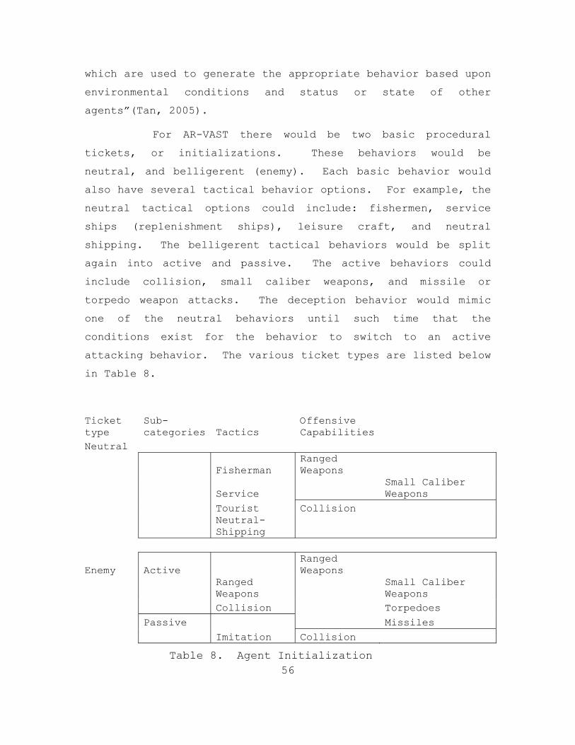
56
which are used to generate the appropriate behavior based upon
environmental conditions and status or state of other
agents”(Tan, 2005).
For AR-VAST there would be two basic procedural
tickets, or initializations. These behaviors would be
neutral, and belligerent (enemy). Each basic behavior would
also have several tactical behavior options. For example, the
neutral tactical options could include: fishermen, service
ships (replenishment ships), leisure craft, and neutral
shipping. The belligerent tactical behaviors would be split
again into active and passive. The active behaviors could
include collision, small caliber weapons, and missile or
torpedo weapon attacks. The deception behavior would mimic
one of the neutral behaviors until such time that the
conditions exist for the behavior to switch to an active
attacking behavior. The various ticket types are listed below
in Table 8.
Ticket type
Sub-categories Tactics
Offensive Capabilities
Neutral
Fisherman Ranged Weapons
Service Small Caliber Weapons
Tourist Collision
Neutral-Shipping
Enemy Active Ranged Weapons
Ranged Weapons
Small Caliber Weapons
Collision Torpedoes Passive Missiles Imitation Collision
Table 8. Agent Initialization
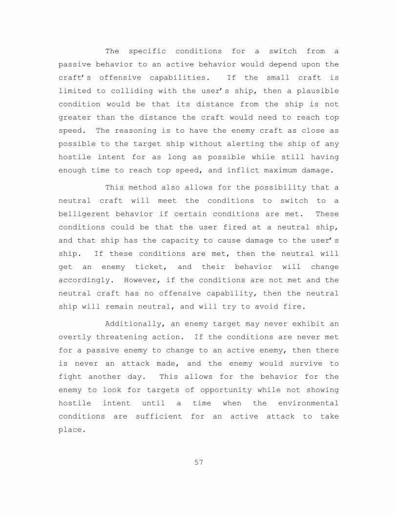
57
The specific conditions for a switch from a
passive behavior to an active behavior would depend upon the
craft’s offensive capabilities. If the small craft is
limited to colliding with the user’s ship, then a plausible
condition would be that its distance from the ship is not
greater than the distance the craft would need to reach top
speed. The reasoning is to have the enemy craft as close as
possible to the target ship without alerting the ship of any
hostile intent for as long as possible while still having
enough time to reach top speed, and inflict maximum damage.
This method also allows for the possibility that a
neutral craft will meet the conditions to switch to a
belligerent behavior if certain conditions are met. These
conditions could be that the user fired at a neutral ship,
and that ship has the capacity to cause damage to the user’s
ship. If these conditions are met, then the neutral will
get an enemy ticket, and their behavior will change
accordingly. However, if the conditions are not met and the
neutral craft has no offensive capability, then the neutral
ship will remain neutral, and will try to avoid fire.
Additionally, an enemy target may never exhibit an
overtly threatening action. If the conditions are never met
for a passive enemy to change to an active enemy, then there
is never an attack made, and the enemy would survive to
fight another day. This allows for the behavior for the
enemy to look for targets of opportunity while not showing
hostile intent until a time when the environmental
conditions are sufficient for an active attack to take
place.

58
Each ticket or frame will be comprised of blocks.
Each block will have three parts: conditions, behavior, and
transitions. The conditions are the mechanisms to allow
ticket transitions. They will be dependent upon the agents’
capabilities assigned at the agents’ initialization. Figure
15 illustrates a typical transition from frame to frame in a
four frame procedural ticket in which the agent acts in a
liner manner to reach its goal. Figure 16 illustrates how
an agent can switch from one ticket to another when the
environmental conditions exist for the agent to reach a
higher priority goal.
Condition Condition Condition Condition Behavior Behavior Behavior Behavior GOAL Transition Transition Transition Transition
Figure 15. General Four Frame Ticket with linear transitions
Condition Condition Condition Condition Behavior Behavior Behavior Behavior GOAL Transition Transition Transition Transition Condition Condition Condition Behavior Behavior Behavior GOAL Transition Transition Transition
Figure 16. Four Frame Ticket transition to Three Frame Ticket
The last piece is communication between agents to
allow for coordinated attacks. The communications is also
achieved using the CMAS Library. The basic elements of
agent communication are connectors. These connectors are
like an outlet and a plug, either of which can be extended
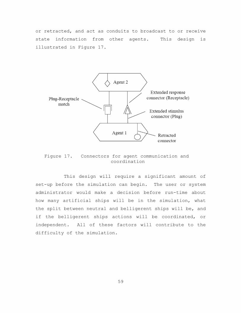
59
or retracted, and act as conduits to broadcast to or receive
state information from other agents. This design is
illustrated in Figure 17.
Figure 17. Connectors for agent communication and
coordination
This design will require a significant amount of
set-up before the simulation can begin. The user or system
administrator would make a decision before run-time about
how many artificial ships will be in the simulation, what
the split between neutral and belligerent ships will be, and
if the belligerent ships actions will be coordinated, or
independent. All of these factors will contribute to the
difficulty of the simulation.
60
b. JSAF AI
Another option for intelligent AI which could
provide intelligent behavior with potentially less coding
would be to utilize the JSAF module. Since Delta3D is
capable of passing information with HLA this implementation
is feasible.
8. Force Feedback
Some system of force feedback needs to be developed.
There are three possible ways to accomplish this task. The
first would be using real ammunition, the second would be to
use blank rounds, and the last alternative would be to use a
compressed gas such as CO2.
The first two methods are virtually the same, except
live ammunition would again limit where training could take
place, but would exercise the re-loading of the weapon.
Blanks also exercise this, but enable a ship’s crew to
exercise in any environment. Both of these methods would
incur additional costs as ammunition was expended.
The other option would be to use CO2 similar to the
ISMT trainer which the U.S. Marines currently use. For the
ISMT, the weapons have been modified to use compressed CO2
to simulate the firing of the weapon. This option would
have a large start-up cost to retro-fit the fleet’s weapons
to accept CO2, but the operational costs would likely be
cheaper to refill the CO2 tanks than to purchase either live
ammunition or blank rounds.

61
V. SUMMARY
A. WHAT IS NEXT?
The next step is to begin the Conceptual System Design
Process as prescribed in Chapter IV. It is important to
follow a system design process so that all aspects of the
design process are considered, and no part is forgotten or
marginalized.
B. DESIGN RECOMMENDATIONS
Summarizing the analysis and evaluation from Chapter
IV, there are seven functional areas that need improvement:
number of targets, rendering, display type, tracking,
ballistics, real and simulation interaction, and artificial
intelligence. The recommendations for improvement are made
now without knowledge of the results of the functional
analysis and problem definition.
The number of targets must be variable, and include
both enemy and neutral vessels. This is required if target
selection is a function AR-VAST is supposed to train.
Otherwise, it is only necessary to incorporate multiple
targets to try to overwhelm the user’s ability to destroy
all targets before they reach their weapons’ effective
range.
The incorporation of real weather and lighting
conditions must be accomplished. Without this, the virtual
targets will be rendered in daylight with perfect visibility
despite the real weather and lighting conditions. These

62
processes either can be automated (preferred but more
difficult), or manually controlled before the simulation
begins.
Experimentation with different display types must be
done in both laboratory and real world environments to
determine what display will provide the best solution.
Finalization of the display type is necessary before
the finalization of the tracking system can be accomplished.
However, a good candidate solution is that a combination of
visual tracking and inertial tracking, and the
implementation of this blend must be worked on in
anticipation of the display type selection.
Real ballistics must be implemented. Of the options
available, using ODE, the physics engine within Delta3D is
the logical choice. Incorporating ODE with the prototype
will be less problematic and less expensive than either
using SAF ballistics, or using a third party proprietary
physics engine. Once AR-VAST has ODE physics implemented in
the firing of the weapon, test and evaluation of the physics
will be required to ascertain if the physical model will
achieve the training requirements.
If possible, the improved blending of real and virtual
objects needs to be accomplished. This will provide a much
richer and fulfilling training environment. If this is not
possible, restrictions on where training can take place must
be established. However, that would defeat one of the
primary goals of AR-VAST, which is the ability to train
anywhere.

63
Finally, an Artificial Intelligence system must be
created specifically to the unique needs of AR-VAST. These
are: a training environment where the number of objects and
areas of cover are unknown beforehand; targets include both
enemy and neutral vessels; targets include both real and
artificial objects; target behavior can change dynamically;
and enemy targets may act in unison or individualistically.
This will require an AI system where the targets, or agents,
are aware of their environment and the actions of the other
agents.
C. SUMMARY
The primary focus of this thesis was to show a gap in
training methods, and to propose a technical solution to
this perceived training need. The secondary focus was to
develop a prototype of the proposed solution to prove that
Augmented Reality is a viable technology that is mature
enough to provide the elements required of a fully
functional training system that bridges the gap between the
need and current deficiencies.
In addition to prototype development / proof-of-concept
demonstrator we developed in this thesis a roadmap for
further work upon the AR-VAST system. Implementing the
roadmap will allow AR-VAST to be fully developed into a
deployable system that will enhance the security and
operational readiness of U.S. and Coalition forces.

64
THIS PAGE INTENTIONALLY LEFT BLANK
65
LIST OF REFERENCES
Andrei State, G. H. (1996). Superior augmented reality registration by integrating landmark tracking and magnetic tracking. International Conference on Computer Graphics and Interactive Techniques (pp. 429 - 438). New York, NY, USA: ACM.
Bimber, O., & Raskar, R. (2005). Spatial Aumented Reality Merging Real and Virtual Worlds. Wellesley, Massachusetts: A K Peters.
Blanchard, B. S., & Fabrycky, W. J. (2006). Systems Engineering and Analysis (Fourth Edition). Upper Saddle River, New Jersey: Pearson Prentice Hall.
Brahim Nini, M. B. (2005). Real Time Virtualized Real Object Manipulation in an Augmented Reality Environment. In Brain, Vision, and Artificial Intelligence (pp. 477-486). Springer Berlin / Heidelberg.
Chae, C., & Ko, K. (2008). Introduction of Physics Simulation in Augmented Reality. International Symposium on Ubiquitous Virtual Reality (pp. 37-40). Gwangju, South Korea: Conference Publishing Services.
Galligan, D., Galdorisi, G., & Marland, P. (2005). Net Centric Maritime Warfare – Countering a ‘Swarm’ of Fast Inshore Attack Craft. 10th International Command and Control Research and Technology Symposium The Future of C2. Virginia Beach, VA.
Hess, R., Braun, K., Coumans, E., Dale, R., Helgevold, T., Lister, C., et al. (2007). The Essential Blender. Amersterdam: Ton Roosendal Blender Foundation.
Hughes, W. J. (1995). A salvo model of warships in missile combat used to evaluate their staying power. Naval Research Logistics, 2667-289.
Johnson, D. M. (2005). Introduction to and Review of Simulator Sickness. Arlington, VA: U.S. Army Research Institute.

66
Krasner, S. D. (2004). New Institutions For Collapsed and Failing States. International Security , 86-120.
Parent, R. (2008). Techniques, Computer Animation Algorithms and Techniques (2nd Edition ed.). Burlington, MA: Morgan KaufmannPublishers.
Peters, R. (1994). The New Warrior Class. Parameters , 16-26.
Reality Rift Studios. (n.d.). Retrieved August 31, 2008, from http://www.realityrift.com/technology/neoengine/
Sorce Forge. (2006, October 06). Retrieved July 24, 2008, from Sorce Forge: https://sourceforge.net/project/showfiles.php?group_id=113203&package_id=143034
Tan, K. S. (2005). A Multi-Agent System for Tracking the Intent Of Surface. Master’s thesis, Monterey, CA: Naval Postgraduate School.
Thomas, B., Close, B., Donoghue, J., Squires, J., De Bondi, P., Morris, M., et al. (2000). ARQuake: An Outdoor/Indoor Augmented Reality First Person Application. 4th International Symposium on Wearable Computers. Atlanta, GA: IEEE.
67
INITIAL DISTRIBUTION LIST
1. Defense Technical Information Center Ft. Belvoir, Virginia
2. Dudley Knox Library
Naval Postgraduate School Monterey, California
3. Mathias Kolsch
Naval Postgraduate School Monterey, California
4. CDR Joseph Sullivan
Naval Postgraduate School Monterey, California
5. CAPT Wayne Hughes Jr.
Naval Postgraduate School Monterey, California
6. John Hiles
Naval Postgraduate School Monterey, California
7. Michael McCauley
Naval Postgraduate School Monterey, California
8. CAPT Jeffrey E. Kline, USN
Naval Postgraduate School Monterey, California
11. R. Mitchell Brown, III
U.S. Naval War College Monterey, California
12. Mike McMaster
Naval Postgraduate School Monterey, California