Helios Prototype Vehicle Mishap
31
Helios Prototype Vehicle Mishap: Technical Findings, Recommendations, and Lessons Learned http://www.nasa.gov/pdf/64317main_helios.pdf Presented by John Del Frate Aerospace Control and Guidance Systems Committee Meeting No. 100
-
Upload
khangminh22 -
Category
Documents
-
view
0 -
download
0
Transcript of Helios Prototype Vehicle Mishap

Helios Prototype Vehicle Mishap: Technical Findings, Recommendations,
and Lessons Learnedhttp://www.nasa.gov/pdf/64317main_helios.pdf
Presented
by
John Del Frate
Aerospace Control and Guidance Systems Committee Meeting No. 100

Outline
• Background
• Description of Mishap
• Observations Concerning the Mishap and Analysis Results
• Proximate and Root Causes
• Technical Recommendations and Lessons Learned
• Summary

Chairperson: Thomas E. Noll, NASA Langley Research Center
Members: John M. Brown, National Oceanic and Atmospheric Admin
Marla E. Perez-Davis, NASA Glenn Research Center
Stephen D. Ishmael, NASA Dryden Flight Research Center
Geary C. Tiffany, NASA Ames Research Center
Ex-Officio: Matthew Gaier, NASA Headquarters
Advisers: Bart Henwood, NASA Dryden Flight Research Center
John Madura, NASA Kennedy Space Center
Ted Wierzbanowski, AeroVironment, Inc.
MIB Members and Advisors
Background

Pathfinder
Pathfinder Plus
Centurion
Helios Prototype HP01 (High-Altitude Configuration)
Helios Prototype HP03 (Long-Endurance Configuration)
Evolution from the Pathfinder to the Helios
1981 - 1997
1998 - 2002
1998
1999 - 2001
2003
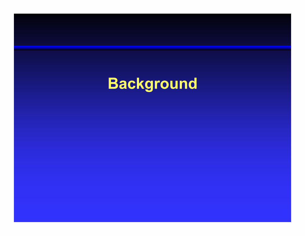
Helios Prototype HP01 and HP03
• 1996: ERAST plans to build two flying vehicles- “Centurion” - high-altitude solar powered mission- “Helios” - long-endurance fuel cell/solar powered mission
• 1998: Development of Regenerative Fuel Cell System (RFCS) begins
• 1999: Under the constraint of a reduced budget, NASA and AV agree to build one airframe to demonstrate both ERAST missions
• “Centurion” is modified and renamed “Helios Prototype”
• 2001: NASA and AV agree to use consumable hydrogen-air Primary Fuel Cell System (PFCS) because of RFCS operational difficulties and schedules
• “Helios Prototype HP01” is modified for the PFCS and becomes the “Helios Prototype HP03”
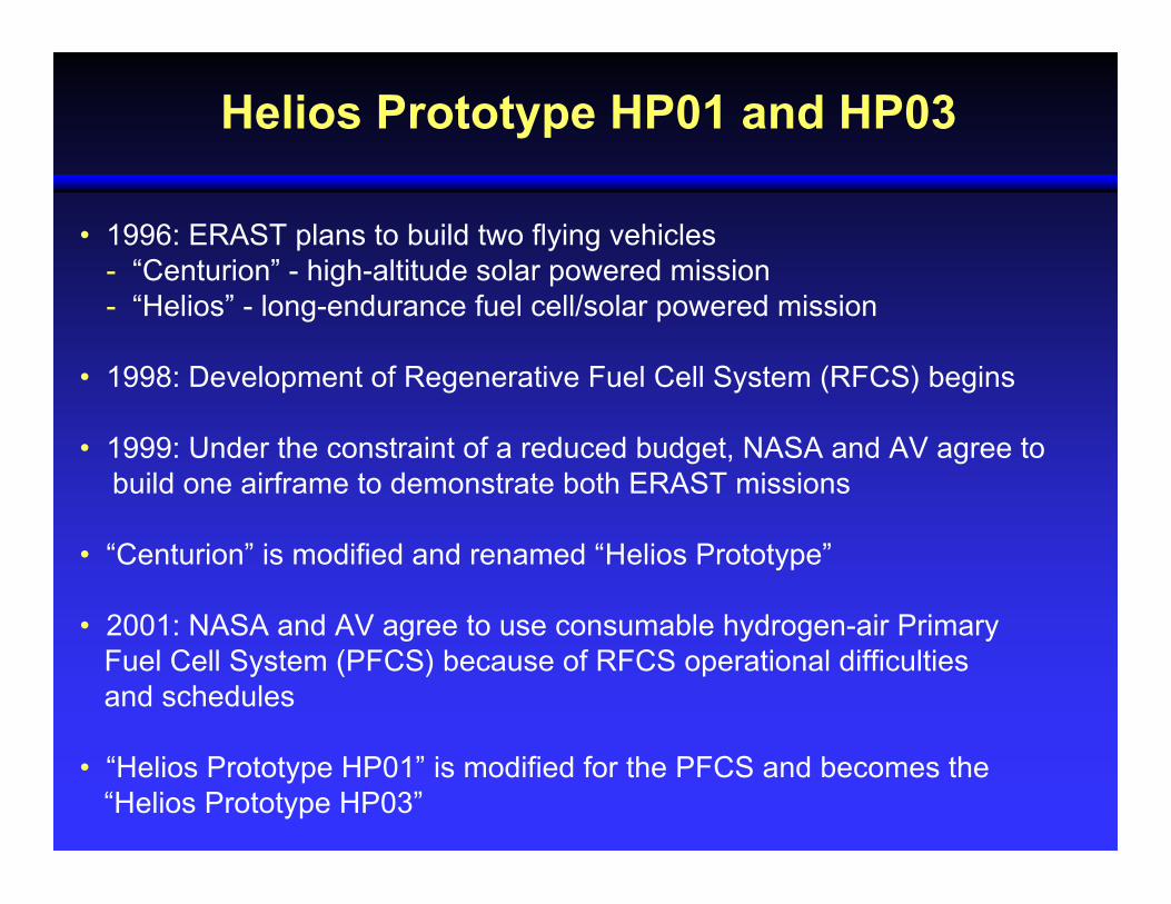
On August 13, 2001 “Helios Prototype HP01”
reaches an altitude of 96,863 feet,
a world record for sustained horizontal flight by a winged aircraft
Helios Prototype HP01High-Altitude Configuration
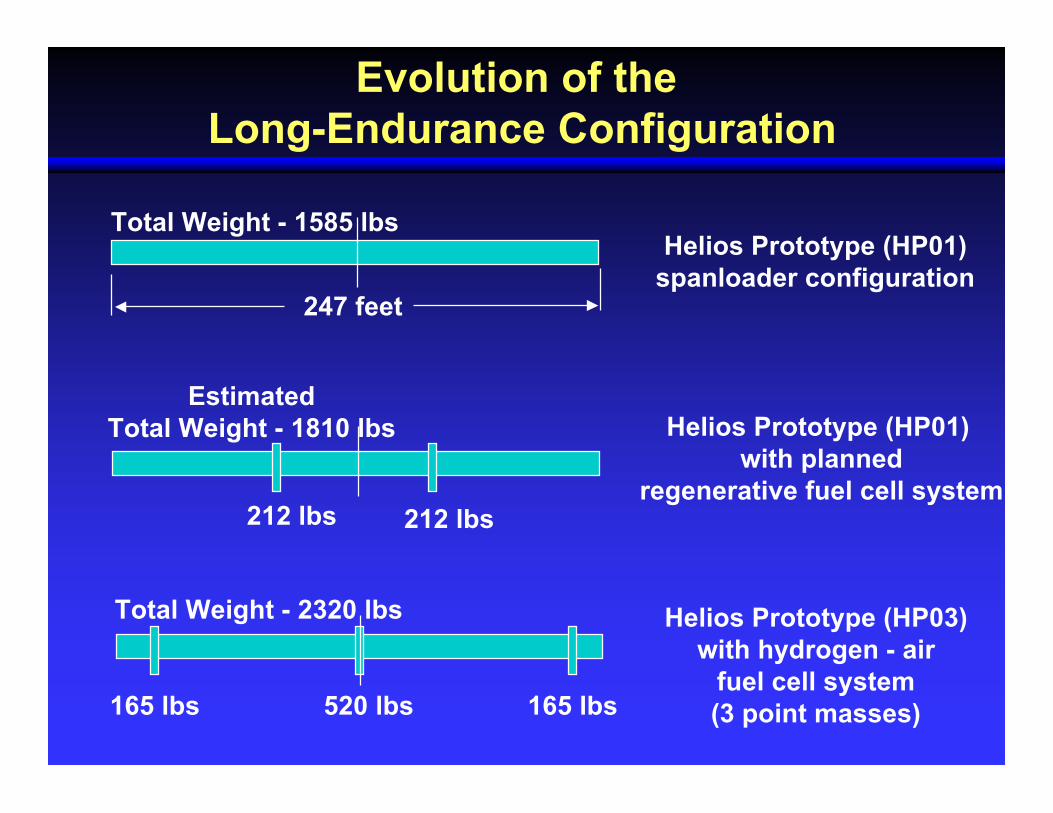
Evolution of the Long-Endurance Configuration
Helios Prototype (HP01) with planned
regenerative fuel cell system
Helios Prototype (HP03)with hydrogen - air
fuel cell system(3 point masses)
Helios Prototype (HP01)spanloader configuration
Total Weight - 1585 lbs
247 feet
212 lbs 212 lbs
Estimated Total Weight - 1810 lbs
520 lbs165 lbs 165 lbs
Total Weight - 2320 lbs
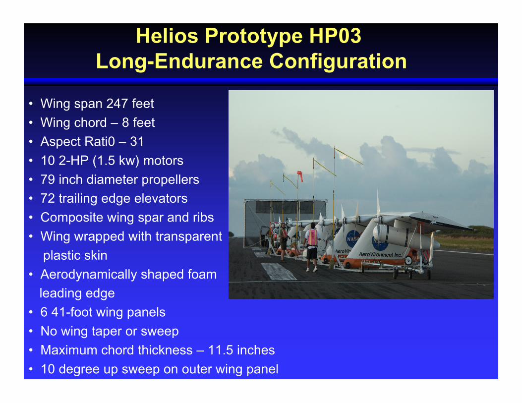
Helios Prototype HP03 Long-Endurance Configuration
• Wing span 247 feet
• Wing chord – 8 feet
• Aspect Rati0 – 31
• 10 2-HP (1.5 kw) motors
• 79 inch diameter propellers
• 72 trailing edge elevators
• Composite wing spar and ribs
• Wing wrapped with transparent
plastic skin
• Aerodynamically shaped foam
leading edge
• 6 41-foot wing panels
• No wing taper or sweep
• Maximum chord thickness – 11.5 inches
• 10 degree up sweep on outer wing panel
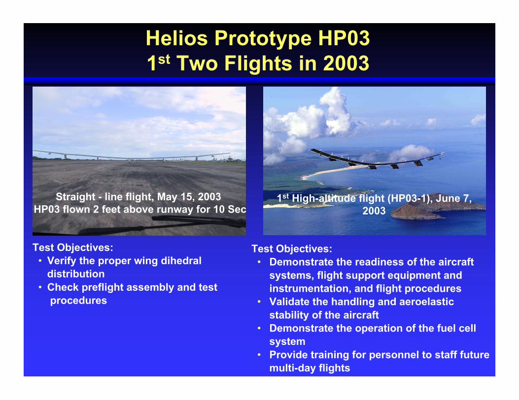
Helios Prototype HP031st Two Flights in 2003
Straight - line flight, May 15, 2003 HP03 flown 2 feet above runway for 10 Sec
1st High-altitude flight (HP03-1), June 7,2003
Test Objectives: • Verify the proper wing dihedral distribution • Check preflight assembly and test procedures
Test Objectives:• Demonstrate the readiness of the aircraft
systems, flight support equipment andinstrumentation, and flight procedures
• Validate the handling and aeroelasticstability of the aircraft
• Demonstrate the operation of the fuel cellsystem
• Provide training for personnel to staff futuremulti-day flights
Description of Mishap

Turbulence Shear Line Observations
Northern wind shear line
Southern windshear line
Helicopter observed wind
shear lines
HP03-2 flight pathwith wind speed
and direction

HP03-2 on take-off
HP03-2 with normal wing dihedral HP03-2 with persistent high wing dihedral
Photos Taken of HP03-2June 26, 2003

Description of Mishap
• On June 26, 2003 at approximately 10:35am at an altitude of about 2,800 feet, HP03-2 encountered turbulence associated with wind shear lines around the island of Kauai
• Turbulence initiated a persistent high wing dihedral causing an unstable pitch oscillation
• Airspeed excursions were around ± 2 ft/sec; main wing spar strain gauge reading 103% of limit load
• Following pilot procedures to reduce dihedral, wing dihedral decreased slightly, but then grew to over 30 feet
• Large airspeed fluctuations of about ± 10 ft/sec now observed, an indication the aircraft was experiencing large pitching motions
• Airspeed excursions began to double every cycle

Description of Mishap (Cont’d)
• Vehicle became oriented at extreme attitudes relative to the air stream (wing dihedral of about 40 feet with the airspeed nearing 90 ft/sec)
• High dynamic loads broke the right wing leading edge foam secondary structure near the hydrogen fuel tanks • Solar cells and the wing skin began to rip off the upper surface of the wing resulting in loss of lift
• Vehicle entered a more severe attitude resulting in additional secondary structural failure
• Aircraft continued to come apart as it fell to the Pacific Ocean
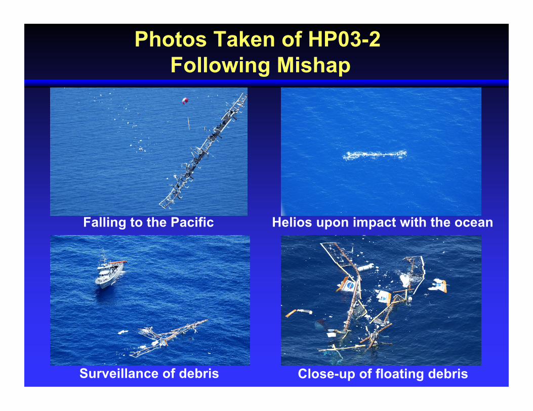
Photos Taken of HP03-2 Following Mishap
Falling to the Pacific Helios upon impact with the ocean
Surveillance of debris Close-up of floating debris
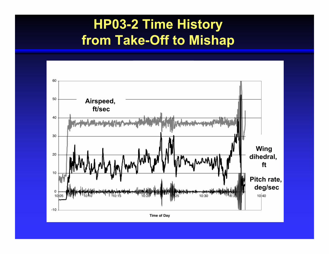
HP03-2 Time History from Take-Off to Mishap
Airspeed, ft/sec
Wingdihedral,
ft
Pitch rate, deg/sec
Observations Concerning Mishap and Analysis Results

Surprises to Crew
• Strength of dihedral response to mild turbulence
• High persistent dihedral
• Wing not robust to returning to low dihedral
• Rapid divergence of pitch instability
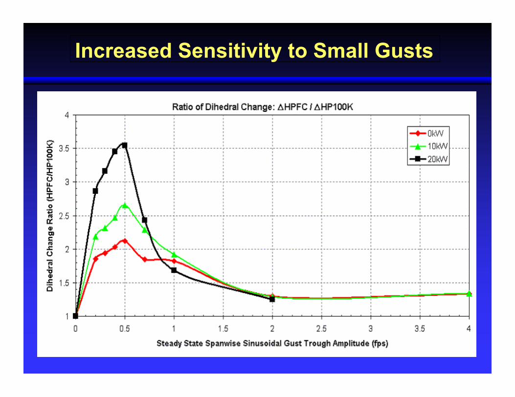
Increased Sensitivity to Small Gusts

Variation of Spanwise Lift Distribution with Gust Velocity
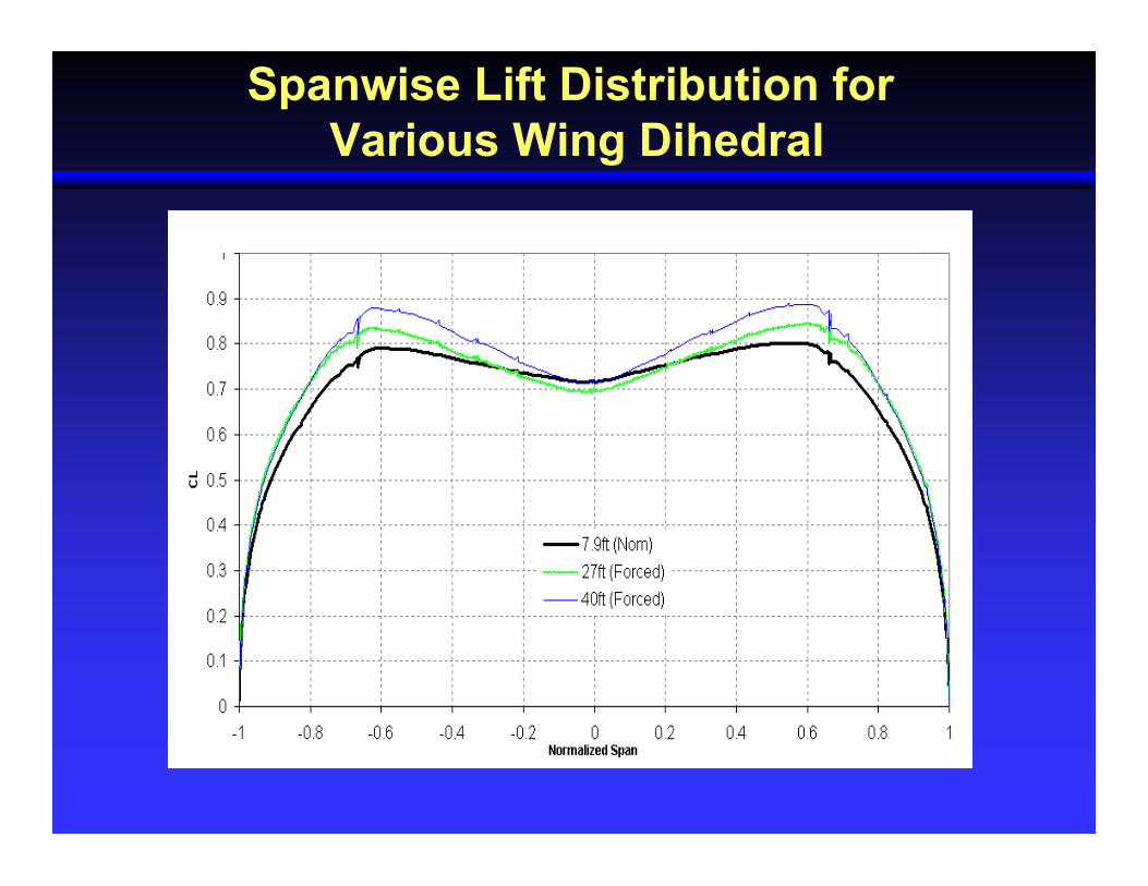
Spanwise Lift Distribution for Various Wing Dihedral

Proximate and Root Causes
Proximate Cause
Proximate Cause DefinitionThe event that occurred, including any condition that existed immediatelybefore the undesired outcome, that directly resulted in its occurrenceand, if eliminated or modified, would have prevented the undesiredOutcome.
The proximate cause for the loss of the HP03-2 was the high dynamic
pressure reached by the aircraft during the last cycle of the unstable
pitch oscillation leading to failure of the vehicle’s secondary structure.

Root Causes
1) Lack of adequate analysis methods led to an inaccurate risk assessment of the effects of the configuration changes
2) Configuration changes to the aircraft, altered the aircraft from a spanloader to a highly point-loaded mass distribution on the same structure
significantly reducing design robustness and margins of safety
Root Cause DefinitionOne of multiple factors (events, conditions, or organizational factors) thatcontributed to or created the proximate cause and subsequent undesiredoutcome and, if eliminated, or modified, would have prevented theundesired outcome.

Technical Recommendationsand Lessons Learned

Technical Recommendations
• Develop more advanced, multidisciplinary (structures, aeroelastic, aerodynamics, atmospheric, materials, propulsion, controls, etc) “time-domain” analysis methods appropriate to highly flexible, “morphing” vehicles
• Develop ground-test procedures and techniques appropriate to this class of vehicle to validate new analysis methods and predictions
• Develop multidisciplinary (structures, aerodynamic, controls, etc) models, which can describe the nonlinear dynamic behavior of aircraft modifications
• Provide for more incremental flight-testing when large configuration changes significantly deviate from the initial design concept
• Implement mitigations or hardware systems for returning a vehicle back into a safe flight envelope
Technical Recommendations (Cont’d)
• Develop a method to measure wing dihedral in real-time
• Develop manual and/or automatic techniques to control wing dihedral in flight
• Develop capability to perform simulations of the vehicle’s response to disturbances
• Apply advanced atmospheric models that better predict conditions hazardous to this class of vehicle
Lessons Learned
• Including large point masses on this type of airframe should not be attempted without optimizing the design of the primary load carrying structure
• Measurement of wing dihedral in real-time is necessary with visual displays
• Procedure to control wing dihedral in flight is necessary
• Time domain design and analysis tools for examining the effects of disturbances on the behavior of highly flexible vehicles are a necessity
• Model fidelity/validation and time domain simulation, can significantly reduce technical risk where the complexity and nonlinear interaction is significant
• Using numerical simulation models, useful meteorological information can be obtained that highlights the regional weather peculiarities
• Design and analysis tools applicable to large, lightweight flexible wing aircraft require better space-time domain models of atmospheric disturbances
Summary
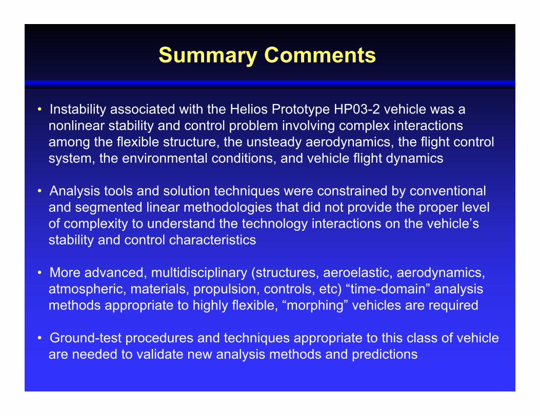
Summary Comments
• Instability associated with the Helios Prototype HP03-2 vehicle was a nonlinear stability and control problem involving complex interactions among the flexible structure, the unsteady aerodynamics, the flight control system, the environmental conditions, and vehicle flight dynamics
• Analysis tools and solution techniques were constrained by conventional and segmented linear methodologies that did not provide the proper level of complexity to understand the technology interactions on the vehicle’s stability and control characteristics
• More advanced, multidisciplinary (structures, aeroelastic, aerodynamics, atmospheric, materials, propulsion, controls, etc) “time-domain” analysis methods appropriate to highly flexible, “morphing” vehicles are required
• Ground-test procedures and techniques appropriate to this class of vehicle are needed to validate new analysis methods and predictions


![nokia morph phone]s prototype - 123seminarsonly.com](https://static.fdokumen.com/doc/165x107/63322002ba79697da5101deb/nokia-morph-phones-prototype-123seminarsonlycom.jpg)