Property Risk Consulting Guidelines - AXA XL
32
Property Risk Consulting Guidelines A Publication of AXA XL Risk Consulting PRC.17.19.0 100 Constitution Plaza, Hartford, Connecticut 06103 Copyright 2020, AXA XL Risk Consulting Global Asset Protection Services, LLC, AXA Matrix Risk Consultants S.A. and their affiliates (“AXA XL Risk Consulting”) provide loss prevention and risk assessment reports and other risk consulting services, as requested. In this respect, our property loss prevention publications, services, and surveys do not address life safety or third party liability issues. This document shall not be construed as indicating the existence or availability under any policy of coverage for any particular type of loss or damage. The provision of any service does not imply that every possible hazard has been identified at a facility or that no other hazards exist. AXA XL Risk Consulting does not assume, and shall have no liability for the control, correction, continuation or modification of any existing conditions or operations. We specifically disclaim any warranty or representation that compliance with any advice or recommendation in any document or other communication will make a facility or operation safe or healthful, or put it in compliance with any standard, code, law, rule or regulation. Save where expressly agreed in writing, AXA XL Risk Consulting and its related and affiliated companies disclaim all liability for loss or damage suffered by any party arising out of or in connection with our services, including indirect or consequential loss or damage, howsoever arising. Any party who chooses to rely in any way on the contents of this document does so at their own risk. AXA, the AXA and XL logos are trademarks of AXA SA or its affiliates © 2020 AXA SA or its affiliates. VEHICLE MANUFACTURING INTRODUCTION This industry abstract describes loss control in the automobile vehicle manufacturing industry. The major headings identified below introduce informational topics mostly by plants, shops, departments or special areas or functions. Except for this Introduction, each topic is presented in three parts, Process, Loss Exposures and Loss Prevention and Control. The major headings, and the pages on which they begin, are as follows: • Vehicle Manufacturing - General .............................................. Page 2 • Stamping Operations .............................................................. Page 12 • Body Fabrication ..................................................................... Page 13 • Spray Finishing Operations .................................................... Page 14 • Powertrain Manufacturing and Assembly ............................... Page 24 • Trim and Final Assembly ........................................................ Page 27 • Computers and Electronics .................................................... Page 31 • Yard and Utility Areas ............................................................. Page 32 Management programs like those described in AXA XL Risk Consulting’s OVERVIEW are extremely important at automobile manufacturing facilities. These facilities typically contain a high level of automation and have high property and time element values. Each loss exposure described in this guide requires most, if not all, of the 14 OVERVIEW programs. For many OVERVIEW programs, such as fire protection impairment controls, fire protection equipment inspections, proper housekeeping, smoking regulations, loss prevention inspections and the control of hot work, the application to loss control is obvious. Only selected OVERVIEW programs requiring special emphasis are discussed in this guide. NFPA standards and guidelines provide a minimum consensus level of fire protection. They cannot be adequate for all situations or to control losses to the degree expected of a highly protected risk. Many of AXA XL Risk Consulting’s guidelines apply to long-lived production equipment and unchanging occupancies. Some might be broad-based and might not consider the unique features applicable to automobile manufacturing plants. They might not attempt to provide reasonable continuing protection as materials, equipment and hazards change each model year. By design, protection specified for the vehicle manufacturing industry may exceed recommendations required by other AXA XL Risk Consulting and NFPA standards and guidelines. Providing a higher level of protection adds a degree of flexibility for unspecified future changes in materials, manufacturing and other occupancy hazards. Once installed, these higher levels of protection do not
-
Upload
khangminh22 -
Category
Documents
-
view
0 -
download
0
Transcript of Property Risk Consulting Guidelines - AXA XL

Property Risk Consulting Guidelines
A Publication of AXA XL Risk Consulting PRC.17.19.0
100 Constitution Plaza, Hartford, Connecticut 06103 Copyright 2020, AXA XL Risk Consulting
Global Asset Protection Services, LLC, AXA Matrix Risk Consultants S.A. and their affiliates (“AXA XL Risk Consulting”) provide loss prevention and risk assessment reports and other risk consulting services, as requested. In this respect, our property loss prevention publications, services, and surveys do not address life safety or third party liability issues. This document shall not be construed as indicating the existence or availability under any policy of coverage for any particular type of loss or damage. The provision of any service does not imply that every possible hazard has been identified at a facility or that no other hazards exist. AXA XL Risk Consulting does not assume, and shall have no liability for the control, correction, continuation or modification of any existing conditions or operations. We specifically disclaim any warranty or representation that compliance with any advice or recommendation in any document or other communication will make a facility or operation safe or healthful, or put it in compliance with any standard, code, law, rule or regulation. Save where expressly agreed in writing, AXA XL Risk Consulting and its related and affiliated companies disclaim all liability for loss or damage suffered by any party arising out of or in connection with our services, including indirect or consequential loss or damage, howsoever arising. Any party who chooses to rely in any way on the contents of this document does so at their own risk.
AXA, the AXA and XL logos are trademarks of AXA SA or its affiliates © 2020 AXA SA or its affiliates.
VEHICLE MANUFACTURING
INTRODUCTION This industry abstract describes loss control in the automobile vehicle manufacturing industry. The major headings identified below introduce informational topics mostly by plants, shops, departments or special areas or functions. Except for this Introduction, each topic is presented in three parts, Process, Loss Exposures and Loss Prevention and Control. The major headings, and the pages on which they begin, are as follows:
• Vehicle Manufacturing - General .............................................. Page 2 • Stamping Operations .............................................................. Page 12 • Body Fabrication ..................................................................... Page 13 • Spray Finishing Operations .................................................... Page 14 • Powertrain Manufacturing and Assembly ............................... Page 24 • Trim and Final Assembly ........................................................ Page 27 • Computers and Electronics .................................................... Page 31 • Yard and Utility Areas ............................................................. Page 32 Management programs like those described in AXA XL Risk Consulting’s OVERVIEW are extremely important at automobile manufacturing facilities. These facilities typically contain a high level of automation and have high property and time element values. Each loss exposure described in this guide requires most, if not all, of the 14 OVERVIEW programs.
For many OVERVIEW programs, such as fire protection impairment controls, fire protection equipment inspections, proper housekeeping, smoking regulations, loss prevention inspections and the control of hot work, the application to loss control is obvious. Only selected OVERVIEW programs requiring special emphasis are discussed in this guide.
NFPA standards and guidelines provide a minimum consensus level of fire protection. They cannot be adequate for all situations or to control losses to the degree expected of a highly protected risk. Many of AXA XL Risk Consulting’s guidelines apply to long-lived production equipment and unchanging occupancies. Some might be broad-based and might not consider the unique features applicable to automobile manufacturing plants. They might not attempt to provide reasonable continuing protection as materials, equipment and hazards change each model year.
By design, protection specified for the vehicle manufacturing industry may exceed recommendations required by other AXA XL Risk Consulting and NFPA standards and guidelines. Providing a higher level of protection adds a degree of flexibility for unspecified future changes in materials, manufacturing and other occupancy hazards. Once installed, these higher levels of protection do not
PRC.17.19.0
Property Risk Consulting Guidelines 2 A Publication of AXA XL Risk Consulting
eliminate the need to discuss with appropriate authorities all proposed changes in materials and processes that affect the level of protection provided.
This guideline is not intended to address every hazard. Transformers, cooling towers, boilers, incinerators, propane systems and other equipment having widespread use in all industries and which are described in numerous other references are not addressed herein unless changing occupancies, emphasis or special considerations unique to the automotive industry cause a need for increased protection or discussion.
POSITION VEHICLE MANUFACTURING - GENERAL Process Vehicle manufacturing plants range from “knock down” (CKD) assembly plants, that are generally located outside of North America, to fully integrated manufacturing complexes. Knock down assembly plants receive finished and pre-assembled parts in wood crates for manual body fabrication body paint operations and final assembly. Automated operations are limited. Few components, if any, are made on the premises. Finished vehicle output is typically 5 to 15 units per hour.
An integrated vehicle manufacturing facility is more sophisticated than a CKD assembly plant. In the integrated facility, many components are manufactured on site. Assembly takes place along a highly efficient assembly line. These plants typically produce 50 to 60 vehicles per hour. Annually, 150,000 to 240,000 units are produced by a single-line plant depending on the number and length of shifts and the number of work days per week. Annual production rates are usually based on 250 work days per year.
Integrated manufacturing facilities consist of various plants, shops or departments, each serving special functions. These are typically the Stamping Operations, Body Fabrication, Spray Painting Operations, Powertrain Assembly and Trim and Final Assembly. Some facilities may not have a stamping operation or powertrain assembly on site. The facility may receive stampings, engines and transmissions from remote facilities that also supply other facilities.
From casting and stamping to final assembly, many of the machines used for processing and product transfer have hydraulic control systems. Hydraulic controls for the designated plants, departments or functions are described in detail in their respective sections.
Many automobile components are manufactured at off-site locations, as production requirements are unique and mandate specialization beyond that available at the facility. These locations could be the property of a vehicle manufacturer or independent contract suppliers. These sub-assemblies or parts are shipped to the manufacturing facility for assembly into vehicles. Products typically include seats; trim parts; audio equipment; wiring harnesses; lamps; seat belts; supplemental inflatable restraints, also known as air bags; electronic control modules; tires and wheels; windows; air conditioners; exhaust systems; radiators; and fluids, including brake fluids, oil and gasoline. See Figure 1.
Loss Exposure In contrast to CKD facilities, operations in an integrated vehicle manufacturing facility are highly automated. Specialized production equipment includes processor-controlled stamping presses, robotic welding machines, automatic stationary and robotic painting equipment and robotic assembly equipment. Manufacturing is controlled by computer systems that schedule production and monitor various functions in the facility.

PRC.17.19.0
Property Risk Consulting Guidelines 3 A Publication of AXA XL Risk Consulting
Figure 1. Operations Involved In Vehicle Manufacturing.
Machine hazards can be moderate to severe. Although robotic equipment is readily available, most used in automobile manufacturing is customized for its application. All computerized manufacturing equipment depends upon software that is application-specific and often evolutionary in nature. Programmable logic controllers (PLCs) drive much of this equipment. They are further described under Computers and Electronics.
Stamping plants, foundries, forge and plastics molding operations can contain highly specialized machines with long replacement times. These include heavy presses, transfer presses, machining centers, automated casting and molding machines, and extruders. Dies, molds and patterns used with these machines can also present severe business interruption exposures, as long lead times may be needed for replacement. To reduce the time needed to resume production following damage
Steel
StampingPlant
Electronics Powertrain
BodyShop
PaintShop
Trim and FinalAssembly
Rubber Worker Plastics
Glass
Metal Worker
Tires, Rubber Trim
Unibody
Painted Unibody
Finished Vehicle
Fluids
RadiosWiring Harnesses
LightsControls
WindshieldsBacklights, Side Windows
FuelLubricantsBrake Fluid
Windshield WasherFluid
SuspensionsExhaust System
RadiatorsBrake Systems
Front and Rear FasciaSeats
Interior TrimExterior TrimHeater/AC
EnginesTransmissions
Axles

PRC.17.19.0
Property Risk Consulting Guidelines 4 A Publication of AXA XL Risk Consulting
of any component, spares can be fabricated. However, spares are not usually fashioned for components having limited susceptibility to loss and high fabrication costs.
Hydraulic systems have a history of incidents where component ruptures lead to ensuing fires. Even minor leakage from hydraulic systems using less flammable water base fluids has been known to significantly contribute to major fire losses. Proper system design, preventive maintenance and good housekeeping can limit such losses.
Off-site supplier locations have the potential to cause production interruptions. Using alternate suppliers, adding parts warehousing and increasing the supplier’s capacity and reliability are methods of limiting such exposures. See additional comments on this issue in the discussion of “just in time” assembly associated with the Trim and Final Assembly section.
The property hazards that exist at off-site supplier locations either do not carry over into the automobile manufacturing process, or they become less severe when they are transferred. For example, an air bag module, which is part of the supplemental restraint system, contains an inflator in which, during deployment, an oxidizer and fuel are mixed to generate the volume of gas needed to fill the air bag. Manufacturing hazards can consist of hazardous dust accumulations and large quantities of toxic, flammable, solid propellants, usually in the form of pellets. These hazards do not exist in the vehicle manufacturing facility. Only the hazards associated with storing a limited number of finished modules are delivered to the vehicle manufacturing facility. These hazards are described under the Trim and Final Assembly section.
Although many machines serve multiple functions, some components require the use of specific machinery. An analysis of process reliability may reveal the need for redundant machines or for a special parts inventory to back up machine components with long replacement or repair times.
Automated high speed manufacturing equipment is exposed to constant technological change. Production machinery parts and accessories rapidly become obsolete. Each model change requires production line changes and re-tooling, and causes changes in production rates. Management must constantly update information about production machinery parts availability and ensure that spares are obtained for critical parts while they can be obtained at a reasonable cost and in a reasonable time frame. Market pressures demand that processes, materials and hazards be at the cutting edge of technology. Accordingly, protection and safeguards must be state-of-the-art to compete effectively in such a market.
Loss Prevention And Control Loss Control Management Programs Implement a comprehensive written loss prevention and control program. Use AXA XL Risk Consulting’s OVERVIEW as a guide in designing and evaluating components of the program. Pay particular attention to the following areas:
Housekeeping Establish housekeeping programs as described in OVERVIEW. Provide oil mist collectors where needed to meet these housekeeping objectives, e.g., in the powertrain plant if oil accumulates on either equipment or building structures. Control housekeeping for special occupancy conditions as follows:
• Maintain pits and basements free of oil residue. • Locate drip pans beneath all hydraulic oil pumps and valve manifolds, drain and clean these
pans regularly, and clean oil residue from hydraulic equipment. • Control combustible exposures by:
o Limiting quantities of cardboard boxes, wood forms and paper in areas of the plant where there are oil piping systems.
o Prohibiting storage beneath platforms, decks or other structures that form obstructions to sprinkler discharges.

PRC.17.19.0
Property Risk Consulting Guidelines 5 A Publication of AXA XL Risk Consulting
o Prohibiting combustible storage in areas exposed to sparks. o Maintaining safe distances between hydraulic equipment and storage of tools, spare
parts and critical equipment. o Controlling paint residues. o Establishing written procedures for safe cleaning and removal of spray guns, pots, masks
and rags. o Keeping combustible materials, equipment and fluid containment piping away from
molten materials. • Immediately repair or replace leaking pump seals and fittings. • Schedule the regular cleaning of oil accumulations near scrap conveyors in the stamping
plant. • Maintain roof areas free of combustible residues. Regularly inspect and clean exhaust ducts,
vent pipe terminations and ventilators. Pay particular attention to possible travel paths of released contaminants affected by prevailing winds and drafts.
• Promptly remove parts that have dropped from assembly line conveyors into wire mesh conveyor guards.
• Equip, operate and maintain air systems to prevent the accumulation of oil and combustible residues.
Pre-Emergency Planning Establish written procedures for the organization, ongoing support and continued training of emergency response teams to provide effective response to various types of emergencies including fire, explosion, severe weather, flood and power outage. The procedures should identify the teams responsible for firefighting, engineering response, public relations, restoration of protection, resumption of production and salvage. Assign an emergency coordinator to provide overall control over these operations. Assign key personnel the responsibility of communicating and coordinating their actions, particularly as they concern other emergency response teams, including civil authorities such as fire and police departments.
As part of this emergency response plan, organize and train a fire brigade. Assign this brigade responsibilities of ensuring fire protection equipment is functional, extending fire protection capabilities to fight incipient stage fires, and supplementing the capabilities of fixed fire protection equipment. The brigade should assist in evacuating personnel not involved in incident control; coordinating activities with the public fire department; and assisting in salvage, clean-up and restoration of protection. If the public fire department can be expected to encounter delays in getting necessary firefighting equipment to the site, the in-plant fire brigade should also have the equipment and training necessary to fight structural fires.
Preventive Maintenance Implement a preventive maintenance program as described in PRC.1.3.0, PRC.1.3.0.1, and PRC.1.3.0.2. Develop the electrical preventive maintenance program based on recommendations in PRC.5.4.5, PRC.5.9.1, and other appropriate guidelines, including NFPA 70B.
Install rigid, fixed, paint distribution piping systems. Where plastic tubing must be used, as inside a paint spray booth, use only tubing manufactured specifically for such use. Such tubing should be examined weekly. As tubing ages, ultra-violet exposures, mechanical stress from clamps and motion, chemical effects of solvents and paints, and thermal factors can deteriorate tubing so it no longer meets designed physical characteristics. Annual replacement of tubing can preclude losses caused by such deterioration.
Incorporate nondestructive testing (NDT) into preventive maintenance programs where the hazard identification and evaluation program indicates a need. NDT is important to loss control, particularly if highly stressed mechanical components can create a dangerous condition when they break down. NDT includes dye penetrant testing, wear-particle analysis, vibration monitoring and analysis, infrared

PRC.17.19.0
Property Risk Consulting Guidelines 6 A Publication of AXA XL Risk Consulting
imaging, alignment and electrical tests. NDT is performed on a periodic basis; testing schedules usually depend on the type of equipment being tested.
As part of an effective maintenance program, obtain necessary spare parts and store them in a safe manner. Spares are usually obtained to restore critical systems and major production as quickly as possible following any incident. Spares are also needed for short lived and disposable components. Storage of large, complex or sensitive spare components can require special techniques to assure functionality when needed.
Fire Protection and Security Surveillance Because of the large values at integrated vehicle manufacturing facilities, surveillance is crucial. Both bi-hourly recorded watchman tours and complete central station or proprietary alarm and supervisory devices are recommended. As part of the surveillance system, provide the following:
• Waterflow alarm for each sprinkler system. In addition, provide a distinct waterflow alarm for each spray booth, paint mix and paint storage room, and similar special hazards
• Heat, smoke or flame detectors along with listed devices to activate special extinguishing systems, such as deluge, preaction and gaseous protective systems
• Manual fire alarms • Devices to detect high and low dry pipe valve air pressure • Explosive vapor and combustible gas detectors, arranged to alarm at 20% of the lower
explosive limit (LEL), and to initiate automatic process shut down and emergency exhaust at 40% LEL
• Fire pump house alarms as follows: o Pump running o Diesel pump trouble o Diesel pump controller not on automatic o Diesel engine overspeed shut-down o Electric pump power available or power loss o Electric pump power phase reversal o Suction tank low level o Suction tank low temperature o Low pump house temperature o Pump failure to start o Excessive fluid flow rates o Loss of ac power to battery chargers
• Gate valve supervisory devices. Gate valve supervision is not required if valves are sealed and are inspected during weekly inspections. Monthly inspections may be performed if valves are electronically supervised or locked open with hard shank locks. However, all valves outside of the plant’s security zone (fenced area) must be electronically supervised or protected in accordance with PRC.12.0.2 and NFPA 25.
Cut-Offs Provide fire resistance rated cutoffs to separate occupancies containing high storage hazards or high concentrations of combustibles or values. Generally, paints, plastics and high rack storage areas are cut off from adjacent areas. Depending on the occupancy and the distance between buildings, detached buildings may be considered separate fire areas. Where separate buildings cannot be provided, install fire walls or fire barriers to separate occupancies. Specific recommendations involving the Paint Shop, Trim and Final Assembly, and Computers and Electronics areas appear later in this guideline. PRC.2.2.1 and PRC.2.2.2 contain additional guidance.

PRC.17.19.0
Property Risk Consulting Guidelines 7 A Publication of AXA XL Risk Consulting
Hydraulic Equipment Use “less flammable” or other low hazard hydraulic fluids. Unless a noncombustible fluid like water is used, hydraulic systems require special fire loss control measures. Follow the manufacturer’s recommendations and recommendations in PRC.9.2.4. The following additional recommendations should be incorporated to help minimize fire and overpressure losses involving hydraulic fluids:
• Provide an interlock to disconnect the electric power supply upon the detection of unsafe conditions. Shutting down hydraulic pumps and associated equipment can minimize a loss if a hydraulic system ruptures or is exposed to fire. Utilize a fire alarm panel listed for release device service. One of the following conditions should initiate a power disconnect: o Low hydraulic system pressure o Low reservoir fluid level o Through the use of a sprinkler waterflow switch, or rate-of-rise and fixed temperature
heat detectors, rated at least 50°F (30°C) above the highest anticipated operating environment temperature. above the hydraulic systems.
• Provide excess oil flow system interlocks. • Design and protect hydraulic system vessels in accordance with Section VIII of the ASME
Boiler And Pressure Vessel Code and good engineering practice. Additionally, design piping systems in accordance with ANSI/ASME B31.3.
• Test and maintain overpressure protection such as relief valves and automatic pump bypasses.
• Provide at least two well marked remote emergency shutdown (ESD) stations for each hydraulic system. Locate the ESD stations to be easily accessible to employees evacuating the area of the equipment, but far enough away to avoid direct exposure to a hydraulic system fire.
• Protect hydraulic piping, pumps and reservoirs against physical damage from falling stock, vehicular traffic and other moving objects.
• Use only rigid steel, steel reinforced rubber hoses, and flexible metallic piping and fittings appropriately rated to withstand the high pressures of the hydraulic system. Non-armored type rubber hoses should be rated for five times the maximum operating pressure.
• If a water base fluid or synthetic fluid is used, establish a program of fluid testing to assure proper fluid characteristics are maintained. Perform these tests twice per year or more frequently as recommended by the manufacturer. For water base fluids, test and record the % water content. For all hydraulic fluids, maintain a log identifying the date and quantity of all fluid additions.
Electrical Equipment Periodically review electrical installations to assure compliance with local jurisdictional requirements and to assure quality system performance. In the U.S., comply with NFPA 70 or more restrictive local regulations. Also, comply with electrical guidelines in other NFPA publications including NFPA 30, NFPA 30A, and NFPA 33. Information useful to evaluating and improving electrical system performance includes standards and guidelines published by the Institute of Electrical and Electronics Engineers. In particular, evaluate equipment and systems that:
• Have high value • Serve a critical function as defined by OVERVIEW • Are located in hazardous (classified) locations as defined by NFPA 70 • Are in a harsh or severe environment • Affect power quality. See PRC.5.7.1.3
Follow the general AXA XL Risk Consulting guidance concerning high energy electrical equipment provided in PRC.5.0.3. Additionally:

PRC.17.19.0
Property Risk Consulting Guidelines 8 A Publication of AXA XL Risk Consulting
• Limit the number of cabinets in any group. Long rows of inter-connected cabinets containing PLCs are a major concern, as values are concentrated and numerous machines become susceptible to a single loss.
• Maintain inter-panel side walls of PLC cabinets. Inter-panel side walls provide some measure of separation between units. Air sampling smoke detectors with input orifices strategically located in the cabinets can greatly improve loss control. If side wall separating panels are missing, additional detection and protection may be necessary, depending on the importance attributed to the loss of the grouping of the panels.
• Keep PLC machine drive cabinet doors closed. Open doors allow dust, oil mist and other contaminants from the environment to enter. Open doors also allow debris to accumulate inside the units. In extremely adverse environments, provide a positive pressure clean air or inert gas supply to the cabinet. The positive air or gas pressure should prevent contamination from the environment and should cool interior components to help maintain normal service life.
• Prohibit foam plastic insulation within PLC cabinets.
Heat and Smoke Venting Installation of heat and smoke venting will no longer be routinely recommended for manufacturing and warehouse occupancies.
Consider the following items when installing heat and smoke venting:
• Consider power venting for occupancies that are highly susceptible to smoke damage. • Install draft curtains to separate sprinklers with different response factors, ESFR sprinkler
systems from standard response sprinklers and at major changes of roof elevations. • Where building codes require automatic heat and smoke vents, AXA XL Risk Consulting will
not oppose their installation because the testing showed that the vents did not have a detrimental effect on sprinkler operation. Where installed, arrange the heat and smoke vents for manual operation. If automatic operation is required, minimum vent operating temperature is to be 360°F (182°C) using standard response links, when ESFR sprinklers are installed. With other sprinkler types, the vent operating temperature is to be a minimum of one rating higher than the ceiling sprinklers using standard response links.
• Where building codes require draft curtains, AXA XL Risk Consulting will not oppose their installation. Where installed, locate the curtains over aisles.
• In certain high hazard manufacturing occupancies such as heat treat and engine hot test operations, install venting and deep draft curtains. Install draft curtains and closely spaced sprinklers around conveyor or other large floor openings. Draft curtains may also be required at points where there are substantial changes in roof elevations.
In areas where vents or draft curtains are required, the following conditions should be met:
• Space the vents or monitors so that the distance between sides of adjacent units does not exceed 80 ft (24.4 m).
• The minimum effective vent to floor area ratio should be 1 to 50. • Locate roof vents at or near the center of small rooms or draft curtained areas less than three
bays. In larger areas, locate the vents symmetrically, in regular patterns and spacing. In areas where existing heat & smoke vents are installed, inspect the vents annually to ensure their functionality.
See PRC.2.1.4 and NFPA 204 for additional information on heat and smoke venting and draft curtains for sprinklered and unsprinklered buildings.
Automatic Sprinklers NFPA 13 and PRC.12.1.1.0 provide basic guidance for sprinkler system designs. Protect special storage occupancies in accordance with NFPA 13, and NFPA 30 and PRC.12.1.1.0, PRC.10.1.1,

PRC.17.19.0
Property Risk Consulting Guidelines 9 A Publication of AXA XL Risk Consulting
PRC.10.2.3 and PRC.10.2.6. Use this guideline to add to protection requirements as appropriate for the features specific to the vehicle manufacturing. This guideline is not intended to reduce any requirements of NFPA or other AXA XL Risk Consulting guidelines. When evaluating protection, apply the most restrictive requirement for existing conditions.
• Provide automatic sprinkler protection throughout the facility. • Extend automatic sprinklers below obstructions to provide the same floor coverage and
density that would be provided if there were no obstructions. Ceiling sprinklers do not provide effective fire protection if obstructions block the distribution of water spray. Examples of obstructions are: car bodies, or other vertical hanging parts being conveyed on overhead conveyors; gratings; mezzanines; platforms; building structural members; press support structures; ducts; oil drip pans; pipe racks; cable trays and other groupings of distribution system components. Generally, NFPA 13 does not require the extension of sprinklers below a solid obstruction less than 48 in. (120 cm) wide. However, extend sprinkler protection below such an obstruction if it forms a solid deck and creates an unprotected area over combustible storage or over a flammable or combustible liquids hazard.
• If wide wire mesh conveyor screen guards are used to catch materials when they drop from conveyors in automotive assembly areas, then the designated use of any floor area below these guards should be limited to moving traffic. Prohibit all storage from these areas. If usage cannot be restricted, extend sprinkler protection below the conveyor screen guards. See below.
• Automatic sprinkler protection is required below conveyor screen guarding with combustible storage below, but this depends on the type, commodity and height of storage below. Also, sprinkler density requirements can vary if the conveyor above the screen guarding is carrying vertical or horizontal vehicle parts. Vertical hanging parts include hanging hoods, doors, etc. and horizontal parts include entire vehicle body, etc. Sprinkler densities required below the screen guarding can vary from a 0.30 to 0.60 gpm/ft² (12.21 to 24.42 L/min/m²) density. Details are needed for each application.
• Provide sprinkler protection for all pits and basements containing combustible fluids, combustible storage, hydraulic fluids or other combustible content. Secure piping and supports to avoid exposure from the vibration of nearby equipment. Ceiling sprinkler protection alone cannot effectively protect pits because of obstructions and high clearances. Directional water spray nozzles or standard sprinklers with heat collectors can be used. If these cannot be installed to provide effective protection, sidewall sprinklers along the perimeters of pits may be acceptable if all other factors are favorable and if the sidewall sprinklers are listed for Ordinary Hazard Occupancies.
• Locate standard automatic sprinkler protection directly over and under scrap conveyors, oil reservoirs and similar equipment hazards. Secure piping and supports to avoid exposure from the vibration of nearby equipment.
• Calculate hydraulically designed sprinkler systems to include a simultaneous hose stream demand of 500 gpm (1900 L/min) for manufacturing and 750 gpm (2800 L/min) for storage areas and other high hazard occupancies. Unusual arrangements may require different demands.
Hose Connections Provide 1 in. (25 mm) hose connections in accordance with NFPA 13 supplied with 100 ft (30 m) of 1-!/2 in. (38 mm) fire hose and an adjustable spray nozzle for manual firefighting. Place these connections in the following areas:
• Roof Areas: above paint shops, ovens and building areas containing moderate to severe hazards if these areas are difficult to reach by means of ground travel; and near roof mounted cooling towers, dust collectors, and transformers. Make arrangements to prevent fire

PRC.17.19.0
Property Risk Consulting Guidelines 10 A Publication of AXA XL Risk Consulting
protection system water from freezing. Note: An alternative is to provide a well-equipped roof hose pack available at the nearest roof stair well which has access to the appropriate roof area.
• Stamping operations: at 100 ft (30 m) intervals on the main floor and basements; and at each entrance to basements.
• Body fabrication: at 100 ft (30 m) intervals. • Spray painting operations: at 100 ft (30 m) intervals and at each entrance to paint mix and
paint storage rooms. • Trim and final assembly operations: arranged so any storage area can be reached by at least
two hose streams. • Power and boiler houses: arranged so any area can be reached by at least two hose streams. • Powertrain plant:
o Storage areas arranged so storage can be reached by at least two hose streams. o Casting area where hydraulic fluids are used, arranged so that any area to which fluid
can spray or flow can be reached by at least one hose stream. o Machining and assembly areas at 100 ft (30 m) intervals.
Fire Protection Water Supply Because of the high values associated with vehicle manufacturing, provide two fire protection water supplies each capable of meeting the total water demand. Water supplies and fire protection underground should be arranged as follows:
• Install a looped fire service main using 12 in. (300 mm) or larger piping. Provide hydrants every 250 – 300 ft (75 – 90 m) along the loop. Utilize proper sectional control valving. Refer to PRC.14.5.0.1 and NFPA 24 for additional guidance.
• Provide two separate water supplies for the fire protection system. Locate the supplies on opposite ends of the fire protection loop. Both should consist of one 3500 gpm (13250 L/min), two 3000 gpm (11,000 L/min), or two 2000 – 2500 gpm (7600 – 9500 L/min) diesel engine driven fire pumps taking suction from a 500,000 gal (1900 m³) reservoir. Reservoir size may be reduced to 400,000 gal (1500 m³) if a suitable city water supply and automatic fill is provided.
NOTE: This recommendation is based on a demand of approximately 4000 gpm (15,100 L/min). The demand results from a typical maximum ceiling sprinkler requirement of 0.60 gpm/ft² (24.4 L/min/m²) over the most hydraulically remote 4000 ft² (370 m²) plus 500 gpm (1900 L/min) for in-rack sprinklers plus 750 gpm (2800 L/min) hose. A higher density, area of application or hose stream requirement can create a greater demand. One vehicle manufacturer routinely increases design areas to 5000 ft² (460 m²) to increase the water demands and provide added flexibility in facility design. Another manufacturer requires higher design densities at the ceiling. Appropriate adjustments would be made in those situations.
• Alternately, the following recommendations may provide an acceptable water supply for small facilities such as CKD operations, manufacturing operations and other standalone support operations of less than 300,000 ft² (27,870 m²) and service parts operations of less than 500,000 ft² (46,451 m²). Provide a one source water supply and associated pumping capacity to satisfy the largest hydraulic sprinkler demand with at least 500 gpm (1900 L/min) simultaneous hose stream demand for a minimum of one hour. A city water supply may suffice either alone or in combination with an appropriate sized booster pump. If a reservoir is installed, provide an automatic fill. The fill rate should be such that the reservoir can be filled within an eight hour period. If city water is unavailable or cannot provide the specified rate, increase reservoir size accordingly.
• Yard mains should be sized as per the sprinkler and hose stream hydraulic demand with yard hydrants spaced to provide adequate coverage.

PRC.17.19.0
Property Risk Consulting Guidelines 11 A Publication of AXA XL Risk Consulting
• Sprinkler design parameters for these types of operations should be in accordance with the provisions of the National Fire Protection Association standards based on the occupancy classifications contained herein.
STAMPING OPERATIONS Process A blanking press receives coils or sheet steel and cuts it into flat sheets on a shear. Cut sheets are then transferred to other presses for stamping, either to single stand stamping presses or multiple stand transfer presses.
Each stand of a transfer press acts as an individual stamping press. The incoming cut steel sheet is automatically placed on the first stand for the initial press or “hit.” The sheet is then automatically transferred to the second stand for the second hit. This activity continues as the sheet is gradually transformed into a body part such as a hood, fender, roof, rear deck lid, floor pan or a one-piece side wall of an auto body.
Production capacities have increased significantly with the development of tri-axis transfer presses. Modern presses can be reset within minutes to allow quick production changes. These presses are large and can handle even the largest sheet metal part. A press enclosure can be 20 ft (6 m) wide, by 20 ft (6 m) high and 60 ft (18 m) or longer.
Several different transfer lines stamp the various body parts. These lines are usually interchangeable and capable of stamping any of the major parts by changing the dies for each press within a line.
Loss Exposure The most common form of stamping utilizes very small quantities of die-release coatings. These coatings bond to the die, which minimizes oil buildup.
Hazard identification and evaluation programs should examine fire and mechanical breakdown exposures, including over pressurization and rupture of hydraulic and lubricating oil systems. Bottlenecks should also be examined. Major parts for large presses require long lead times. Specialized valves and pumps may also require an inventory of spares. Off site backup copies of programs for computer-controlled machines protect the continuity of operations.
Also, building height could be a factor in loss exposure and loss control. Buildings with a ceiling or roof height of 40 – 60 ft (12 – 18 m) are not unusual.
Housekeeping programs should monitor and correct oil leakage problems. Combustible hydraulic fluid under high pressure presents a severe fire hazard to a press. Use of a less flammable fluid reduces but does not eliminate this hazard. A lubricating oil system might also involve pumping at a high pressure, and can also be a severe fire hazard.
Lubricating and hydraulic oil pumps and reservoirs are either located on the tops of presses or in pits or basements beneath the presses. The systems are normally arranged to avoid direct exposures to important equipment. Some reservoirs hold hundreds of gallons of fluids. Hydraulic pressures can be as high as 3000 psi (207 bar). Lubricating and hydraulic oils are sometimes electrically heated to improve system performance. However, the process of heating increases fire loss exposures.
Transfer presses and other large equipment are susceptible to mechanical losses. Nondestructive tests of presses, including the heads and press columns, can detect effects of stress before fractures or breaks occur. Because the presses and their supporting structures are so massive, significant fire damage to the main structure of a press is not usually anticipated. However, constructions forming enclosures that house hydraulic and lubricating oil systems can require special protection to limit damage. Further, even a small fire can severely damage pumps, piping, electric controls, motors, wiring and press alignment and cause a significant press outage.
Most hydraulic and large mechanical presses contain pressure vessels that must be protected against overpressure; these vessels serve as shock absorbers in mechanical presses and

PRC.17.19.0
Property Risk Consulting Guidelines 12 A Publication of AXA XL Risk Consulting
accumulators in hydraulic systems. The vessels may require jurisdictional certification. Most contain safety valves that require inspections and testing.
Poor housekeeping in press pits or basements presents a major loss exposure. Leaking equipment results in pools or coatings of combustible liquids. Residues on floors, equipment and structures have led to large losses from fires initiated by arcs in electrical equipment in the area.
Loss Prevention And Control Comply with the general loss prevention and control items listed earlier in this guideline.
Provide hydraulically designed automatic sprinkler protection for the stamping plant in accordance with NFPA 13 and PRC.12.1.1.0 except, based on the use of dry stamping and less flammable fluids, use densities and areas of application as follows:
• For the ceiling over the press operating level, provide a minimum of 0.20 gpm/ft² (8.1 L/min/m²) over the most hydraulically remote 2000 ft² (186 m²) using 165°F (74°C) sprinklers.
• For all pits, basements and enclosures containing hydraulic or lubricating equipment, provide 0.30 gpm/ft² (12.2 L/min/m²) over the most hydraulically remote 3000 ft² (279 m²) using 286°F (141°C) sprinklers with sprinklers located at a maximum spacing of 100 ft² (9.3 m²) per sprinkler.
NOTE: Deluge foam-water and closed head foam-water protection systems may be used. See PRC.12.3.1.1.
Provide electrical interlocks to shut down the transfer press upon the following events:
• Excessive and low oil pressure caused by malfunction of a hydraulic or lubricating oil system. • High and low oil temperature caused by malfunction of a hydraulic or lubricating oil heating
systems. • Out of tolerance shaft position, motor speed or loading.
BODY FABRICATION Process Body fabrication is a highly automated process. The most common machines are the welding machines that spot weld metal stampings to form a unibody chassis assembly or a “body on frame” vehicle, e.g., a truck. Automated transfer machines load the stampings onto welding jigs and move partly assembled bodies to other welding stations. Hydraulic equipment can include hydraulic clamps to hold the body being welded.
Less automated manufacturing facilities use manually operated welding equipment. These facilities include knock down assembly plants.
Loss Exposure Modern plants have robotic welding and transfer equipment. Much of the equipment is built “in place.” The equipment is operated electrically, pneumatically or hydraulically. Hydraulically-operated transfer equipment is very common. The hydraulic fluid capacity usually does not exceed 30 gal (110 L) per unit.
Sparking is common to all welding operations. Automated welding equipment provides constant ignition sources that cannot be eliminated. The hot work and housekeeping programs are critical to prevent welding until hydraulic fluid leaks are repaired and unnecessary combustibles are removed.
Maintenance programs assure the hydraulic systems are secure and reliable, and that they can contain system pressures. Maintenance programs can also establish the reliability of computer and tape drive equipment.

PRC.17.19.0
Property Risk Consulting Guidelines 13 A Publication of AXA XL Risk Consulting
The electric power supply is also a loss control concern. Spare transformers may be needed to minimize loss potentials if electrical breakdown were to occur in one unit. Also, plant power quality can be affected by dc welding supplies.
Loss Prevention And Control Comply with the general loss prevention and control items listed earlier in this guideline.
Design ceiling sprinklers to no less than 0.20 gpm/ft² (8.1 L/min/m²) over the most hydraulically remote 2000 ft² (186 m²) using 165°F (74°C) sprinklers.
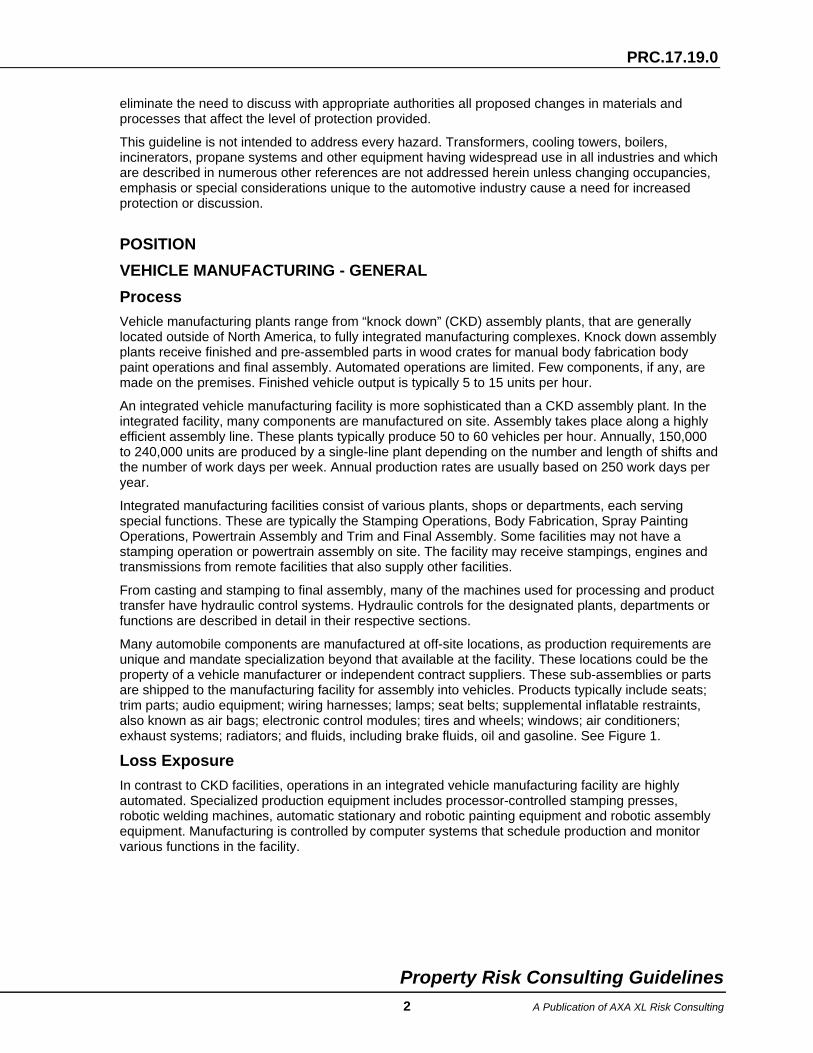
SPRAY FINISHING OPERATIONS Process The welded unit from the body shop is suspended from an overhead conveyor that carries it to the spray finishing operations. The body goes through various processes in the applications of coatings The coating applications performed are; chemical wash and treatment, corrosion prevention, primer coating application and a two coat paint finish. Drying occurs at each stage. Refer to Figure 2.

PRC.17.19.0
Property Risk Consulting Guidelines 14 A Publication of AXA XL Risk Consulting
Figure 2. Vehicle Painting Process.
Exhaust air from the ovens, which can include solvent vapors, is adsorbed via carbon bed systems, incinerated or exhausted to the atmosphere.
Paints and thinners are received in totes or drums directly from the manufacturer and are stored in a paint storage room. They are then moved to a paint mix room, also called a paint kitchen, where they are dispensed into mix tanks. The paint is continuously agitated and pumped from the mix tanks through insulated stainless steel piping to the wall of the paint spray booths. The paint piping system consists of supply, return and recirculation piping. The paint is continually recirculated to prevent solidification. Supply paint temperatures are controlled by hot water heat exchangers. The mix and storage rooms are either detached or cut off from the main paint shop building.
Final Assembly
Electrostatic Dip Coat
Oven
Manual Sanding
Prime Coat
Oven
Base Coat (color)
Flash Tunnel
Clear Coat
Repair Booths
PaintStorage
PaintMix
Oven
Phosphate Booth (cleaning)VehicleBody

PRC.17.19.0
Property Risk Consulting Guidelines 15 A Publication of AXA XL Risk Consulting
Various coating methods can be used. Electrostatic painting (EP) is common. With EP, the paint can be a powder coating, solvent base paint spray, or water borne paint. In general, paint is electrically charged, and the body being painted is electrically grounded by its contact with and bonding to the grounded conveyor structure. Thus, the paint is attracted to the body. This attraction reduces overspray, promotes adherence of the coating, and provides uniform and complete coverage.
Powder coating applies a layer of dry organic powder to the body. Heat from an oven or infrared electric heater melts the powder into a continuous coating. Spray paint is typically applied by the EP method; however, air atomization is sometimes used. Electrostatic Deposition (ED) is the application of the EP process to a dip tank.
Air atomization and EP can be combined. A nozzle (bell) at the end of a rotary atomizer spray gun spins at about 20,000 rpm – 40,000 rpm. This bell is electrically charged to impart a charge onto the paint, which is fed into the center of the bell. The centrifugal force of the spinning bell forces the paint out toward the edge of the bell. As the electrostatically charged paint is expelled from the bell, shaping air directs the spray. As the paint nears the body, the electrical attraction takes over. To clean the bell between color changes, the electrostatic charge is turned off and thinner (purge solvent) is sprayed through the nozzle.
When custom, prototype or specialty colors are needed to paint a vehicle, paint is pumped from a small pressure pot system located in a satellite paint mix operation adjacent to the booth. Limitations and design requirements for this mixing area are identified in NFPA 33.
The painting and coating areas require a clean environment. They must be free of dust and other contaminants to apply a quality coat to the vehicles.
Coating Applications The first stage of the coating process is to clean and treat the body in a phosphate wash booth. This booth contains several stages where high pressure water and chemicals are sprayed on to the body and where the body is dipped in cleansing tanks. The phosphate promotes a strong adhesion between the bare metal and the next coating application (Electrostatic Deposition). The body is then dried in an oven. After the phosphate process, joints in the body construction are manually or automatically sealed with a highly viscous compound.
The overhead conveyor then conveys the body to an Electrostatic Deposition (ED) dip tank where bodies are submerged in a mixture of corrosion resistant solids and 90% water. The coverage is uniform and complete since the electrically charged materials are uniformly attracted to the body which is at ground potential. The coated body is dried in an oven at an operating temperature in the range of 250°F – 350°F (120°C – 175°C). The ED coat provides rust protection for the body.
Next, a primer coat is applied to the body in the primer booth. This prime coat can be applied by paint spraying or by powder coating. The prime coat minimizes chipping of the ED coat, and promotes greater adhesion between the ED coat and color coats. The primed body passes through a flash-off zone where initial solvents are released and then a curing oven where the coat is cured at a temperature of 250°F – 350°F (120°C – 175°C).
After the prime coat, a two coat paint finish is common. It consists of a base coat of color paint covered with either a clear coat sealer or a second color coat. The color coat can be applied by paint spraying or by powder coating the body. Between the base coat and the clear coat of paint the body travels through a flash-off zone in which most of the solvents are evaporated from the body. Proper flash-off is required to obtain a surface that is free of defects. When water borne paints are used, the flash-off zone is usually heated. The base coat is not fully cured (not all solvents are evaporated) when the clear coat is applied; the two coats combine to produce a lustrous shine on the body. After the clear coat or the second color coat is applied, the body is conveyed through a flash-off zone and an oven. Paint is cured in the oven at temperatures ranging from 250°F – 350°F (120°C – 175°C). The body is then inspected for defects. After inspection, bodies are conveyed to the trim and final assembly area or they are sent to reprocessing booths for repair.
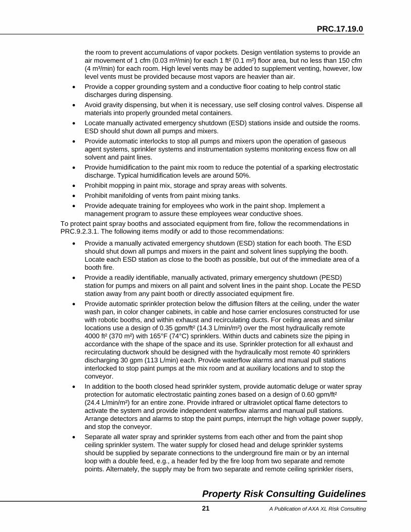
The typical vehicle paint booth is a down draft, water wash type booth. Refer to Figure 3. Newer designs for booths include dry powder filtration or electronic precipitation. These newer systems

PRC.17.19.0
Property Risk Consulting Guidelines 16 A Publication of AXA XL Risk Consulting
require individual engineering review with respect to the level of fire protection necessary to protect the process, especially in the exhaust systems. The coating booths are usually 100 to 200 ft long, (30 to 60 m) and are divided into zones. Individual zones may consist of manual painting zones, automatic (robotic or reciprocating) zones, and flash-off tunnels. Manual zones are typically located at the ends of the booths, while automatic zones are in the middle of the booth. Reciprocating action is confined to a linear motion along either the X or Y axis. Robotic action is three-dimensional through computer controlled paths.
Figure 3. Vehicle Paint Spray Operation.
As reciprocating and robotic painting (see Figure 4) require movement of a spray gun, the paint and thinner lines must be flexible. Maintenance, the potential for clogging, service life and operating considerations require the paint and thinner lines be flexible plastic from the inside of the wall of the booth to the spray guns. Because they are plastic, normal wear and especially the use of metallic paints can cause erosion and pinhole leaks in the plastic tubing. Plastic paint and thinner lines can be quickly involved in a major fire situation. Thus, response time is critical, and optical detectors are normally used to actuate deluge or water spray systems protecting the automatic zones in each booth.
SCRUBBERTANK
*PENDANTHD
WET PIPE100 ft /hd
EXHAUSTTUNNEL
SPRINKLERED TUNNEL FOLLOWS TO END OFBOOTH PROCESS TO FAN FARM THEN TO CONC STACK
PAINT SYSTEM
DIFFUSION
PAINTVALVE BOX
ROBOTICGUN
CLEANERBOX
CLEAN RM
PAINT LINECHASE
AIREXHAUST
WATERRECIRCULATION
SYSTEM
FLOOD SHEET
WATER &AIR FLOW
BAFFELS &SCREENS
CIRCULATINGPAINT SYSTEMCIRCULATING
SPRINKLEREDDUCTWORK
10'
FILTEROPEN AND
CLOSED HEADSPLACED CLOSELY
IN LINE TOONE ANOTHER
CE
ILIN
G
CE
ILIN
GH
AN
GER
HA
NG
ER
14’

PRC.17.19.0
Property Risk Consulting Guidelines 17 A Publication of AXA XL Risk Consulting
Figure 4. Electrostatic Painting Operation.
Air for a paint booth is typically supplied from an Air Supply House (ASH) on the roof or in a penthouse. In the ASH the air is filtered and conditioned for temperature and humidity. Supply fans convey the conditioned air through sheet metal ducts into a plenum at the top of the booth. The airflow continues down through diffusion filters that form the “ceiling” of the booth, across the vehicle painting area, through open steel grating on the “floor” of the booth, across the water wash pan below the grating, through scrubber or eliminator baffles below the water wash pan, and into the exhaust or recirculation ducts. Air fans, located near the spray booth or in the penthouse, convey exhaust air through sheet metal ducts or concrete tunnels to the atmosphere, incinerators, electrostatic precipitators or other vapor recovery systems. Exhaust air is commonly 80% recirculated and mixed with fresh air and supplied back to the air supply house.
The water wash drains to a sludge removal tank. This mixture is chemically treated to separate paint sludge from the water. The sludge can be dried on site by evaporating it in an oven. Either the wet sludge or the inorganic solids remaining after drying are hauled away as waste.
Ovens Curing ovens (see Figure 5) are directly or indirectly heated by various fuels or sources including natural gas, propane, oil, electricity, steam and hot water, ED, prime coat and top coat ovens are divided into multiple zones.
Typically, in the first zone, radiated heat dries the outer layer of the paint and provides a “skin.” If heated air were forced directly on the vehicle, the finish could be damaged by the velocity of the air or by the introduction of dust particles into the paint. The radiant heat is provided by infrared electrical heaters or by a blackwall radiant design. The blackwall radiant design passes heated air through a chamber along both sides of the oven. Due to the high temperatures required to radiate in this chamber, the air is typically recirculated. Extreme care in the design and maintenance of this type of oven is critical to preventing property damage and business interruption losses.
The remaining zones of the oven are typically convection zones, where air is passed directly over the vehicle to cure the coating.

PRC.17.19.0
Property Risk Consulting Guidelines 18 A Publication of AXA XL Risk Consulting
Figure 5. Vehicle Drying Oven.
Loss Exposure The coatings or paints used may be solvent base, water borne or powder. The use of water borne paints and powder coatings has become more common as governments restrict the amount of volatile organic compounds (VOCs) that can be released to the atmosphere.
Enamels, urethanes and lacquers are common solvent base coatings. Solvents and thinners such as toluol and methyl ethyl ketone (MEK) used with automotive paint operations typically are light and evaporate quickly. Flash points are generally in the 0°F − 40°F (minus 18°C − 4°C) range.
Water borne paint can also be flammable, or combustible containing water miscible flammable liquids. Fire tests of water borne paints have shown a wide variety of burning characteristics. Some burn readily; others do not. Water borne paints containing flammable materials are rated for flammability as: 1) Non-burning; 2) Non-sustained burning; or 3) Sustained burning. The burning characteristics depend on the type of spray system, the spray concentration, the droplet size and the source of ignition. Specific details of the water borne paint are needed to determine fire suppression requirements. Currently, all available clear coat water borne paints readily burn.
Purge Solvents are used for cleaning rigid and flexible paint lines used in the robotic paint spray equipment. Purge solvents can be either a flammable or a combustible liquid. Purge solvents used in the primer and the clear coat booths have a flash point <100°F (<37°C). and purge solvents used for water borne paints have a flash point generally around 140 – 200°F (60 – 93°C). Purge solvent is normally stored in a large holding tank (up to 6000 gal (22,700 L)) in the main paint storage room and is piped to the spray booth paint area via solid rigid tubing. The spent purge solvent generally is discharged into a container located near grade level or inside the paint booth area that is piped to a reservoir for holding. The spent purge solvent is then discarded as hazardous waste. Combustible purge solvents used in the water-borne base coat paint booths may be discharged directly into the spray booth water wash system. The process for handling and disposal of the spent purge solvent may vary at different locations. Dispensing and transfer of purge solvents into containers located outside of paint mix rooms or paint spray booths should be protected in accordance with NFPA 33. Discrepancies should be reported to the Principal Consultant for review.

PRC.17.19.0
Property Risk Consulting Guidelines 19 A Publication of AXA XL Risk Consulting
Dry paint used in powder coating is combustible. Generally, an explosion potential exists in dust collection systems. Collected powders in prime spray operations are recirculated. See NFPA 33 for further guidance.
All paint residues are considered combustible when dry.
Changes in operations, construction, materials and equipment can affect loss prevention and fixed protection requirements. Loss control management programs, particularly loss prevention inspection, hazardous materials, new construction, housekeeping and hazard identification and evaluation, help to monitor these changes.
Where paints or solvents are used, paint mixing, transfer, dispensing and application hazards require control over ignition sources including grounding and bonding to prevent static charge accumulations. Electrical equipment must be suitable for the hazardous (classified) areas. Ventilation and explosion relief are important loss control considerations.
Combustible residues can accumulate in paint spray booths, air handling systems, ovens and associated exhaust ducts. Numerous fires and explosions have occurred in paint spray booths, exhaust and recirculation air ducts, air supply unit filters, ovens, carbon adsorption vapor recovery systems, scrubbers, incinerators, and paint mix, storage and distribution systems. Sludge residues in water wash booths have also ignited and contributed to the spread of fires.
Any paint transfer or application system may contain pressure vessels requiring jurisdictional attention. Safety and relief valves on vessels handling paints and paint components require special maintenance attention for two reasons: paints tend to clog overpressure protective devices; and valve discharges may consist of atomized flammable materials.
Large important fans associated with the painting facility are included in a vibration monitoring program. Fans handling dirty air are particularly susceptible to imbalance.
The use of unsuitable plastic tubing to supply paint to discharge nozzles is a serious fire exposure. Tubing manufactured with a proprietary plastic resin and specifically manufactured for paint line use is less susceptible to such failures.
Human error, inadequate welding and cutting procedures, Improper solvent cleaning procedures and improper paint shop design are typical causes of losses. Another cause is the electrical discharge from high voltage electrostatic painting that ignites atomized paint. Discharges can occur when a paint spray gun comes too close to a grounded object, such as the body on a conveyor line. Discharges also occur when a grounding system becomes ineffective. An ineffective ground allows a static charge to build on the body. When the potential is great enough, a discharge sparks back to the paint nozzle and ignites the paint.
Housekeeping programs are very important. Paint build-up between the body and the conveyor and between the conveyor and the ground system can also cause ineffective grounding.
Loss Prevention And Control Comply with the general loss prevention and control items listed earlier in this guideline.
Separate the paint mix and paint storage rooms from the paint shop by no less than a free standing, parapeted, 4 hr fire resistance rated, explosion resistant masonry fire wall.
Separate the paint mix room from the paint storage room by no less than a 2 hr fire resistance rated masonry fire barrier wall.
Protect all openings into the paint shop and between the mix and storage rooms with automatic closing 3 hr fire resistance rated fire doors. Provide appropriate drainage to preclude the travel of combustible liquids through doorways.
Separate the sludge room from adjacent areas by no less than a 2 hr rated masonry fire partition wall.
Install electrical equipment listed for use in Class I, Group D, Division 1 (Zone 1, Group IIA) locations in paint mix and paint storage rooms. Electrical equipment rated for Division 2 (Zone 2) locations may

PRC.17.19.0
Property Risk Consulting Guidelines 20 A Publication of AXA XL Risk Consulting
be acceptable if flammable liquids are not mixed or dispensed in the paint storage room, and they are stored only in closed containers. If electrically powered industrial trucks are used, the trucks must be listed for the hazardous (Classified) location. EX rated trucks may be used in paint mixing areas, and trucks rated EE may be used in paint storage areas.
Provide Class I, Group D, Division 1 (Zone 1, Group IIA) or intrinsically safe electrical equipment in enclosed paint spray booths. Outside of the booth within 3 ft (1 m) of any booth door opening, provide electrical equipment suitable for use in Class I, Group D, Division 2 (Zone 2, Group IIA) occupancies. NFPA 33 provides additional guidance.
Protect flammable and combustible liquids hazards in accordance with NFPA 30 and NFPA 33. Route paint and solvent piping to minimize involvement from exposure fires, Protect piping from mechanical damage.
Provide complete automatic sprinkler protection for the paint operations, including the clean room areas between spray booths. Limit each sprinkler system to a maximum area of coverage of 40,000 ft² (3700 m²) in accordance with NFPA 13 and PRC.12.1.1.0. Sprinkler systems should be designed as follows:
• At the ceiling and under any obstructions including under paint distribution piping and metal grate platforms - Designed for 0.30 gpm/ft² (12.2 L/min/m²) over the most hydraulically remote 3000 ft² (279 m²) using 165°F (74°C) sprinklers.
• Penthouses - Designed for 0.30 gpm/ft² (8.2 L/min/m²) over the most hydraulically remote 3000 ft² (279 m²) using 165°F (74°C) sprinklers.
Protect satellite paint mix operations in accordance with NFPA 33.
Protect main paint mix rooms and paint storage rooms as follows:
• Provide automatic sprinklers at the ceiling and under obstructions, including paint distribution piping and metal grated platforms, using 0.60 gpm/ft² (24.4 L/min/m²) over the most hydraulically remote 3000 ft² (279 m²) with 165°F (74°C) sprinklers. Provide individual riser laterals, each having an alarm check valve, shutoff valve and waterflow indicator.
• Provide explosion relief following NFPA 68 guidance for the paint mix room and the paint storage room.
• Currently, some auto manufacturers are choosing not to provide carbon dioxide (CO2) protection in paint mix and storage rooms due to current concerns with life safety, and proposed legislation involving greenhouse gases. Sprinkler protection as outlined above is considered sufficient protection.
• If total flooding clean agent protection, or water mist protection is installed, the system can be arranged with selector valves to each room. Design protection to actuate by means of a supervised heat or optical detection system and by manual means. If door openings between paint mix and storage rooms are normally open, the areas should be protected as a single hazard. Refer to the appropriate NFPA standard for the type of protection selected. If a CO2 system is utilized, the design concentration depends on the solvent being used and should be between 34% and 40%; refer to NFPA 12 and PRC.13.3.1 for CO2 system design and installation criteria and for occupancy precautions. The use of an AFFF extinguishing system can be an acceptable alternative to a gaseous extinguishing system.
• Provide drainage in accordance with PRC.8.1.0. Lack of adequate drainage, is less critical if a gaseous agent is the primary extinguishing agent and the sprinkler system protection is backup control. If gaseous agent protection is provided and adequate drainage cannot be installed, design the room to allow fluid containment through trapped trenches, drains and sumps. Containment should be designed to hold a minimum of two times the volume of the largest vessel or tank and 10 minutes of sprinkler discharge.
• Provide mechanical ventilation in accordance with NFPA 30. Locate exhaust and intake openings within 12 in. (30 cm) of the floor and position them to provide air movement across
PRC.17.19.0
Property Risk Consulting Guidelines 21 A Publication of AXA XL Risk Consulting
the room to prevent accumulations of vapor pockets. Design ventilation systems to provide an air movement of 1 cfm (0.03 m³/min) for each 1 ft² (0.1 m²) floor area, but no less than 150 cfm (4 m³/min) for each room. High level vents may be added to supplement venting, however, low level vents must be provided because most vapors are heavier than air.
• Provide a copper grounding system and a conductive floor coating to help control static discharges during dispensing.
• Avoid gravity dispensing, but when it is necessary, use self closing control valves. Dispense all materials into properly grounded metal containers.
• Locate manually activated emergency shutdown (ESD) stations inside and outside the rooms. ESD should shut down all pumps and mixers.
• Provide automatic interlocks to stop all pumps and mixers upon the operation of gaseous agent systems, sprinkler systems and instrumentation systems monitoring excess flow on all solvent and paint lines.
• Provide humidification to the paint mix room to reduce the potential of a sparking electrostatic discharge. Typical humidification levels are around 50%.
• Prohibit mopping in paint mix, storage and spray areas with solvents. • Prohibit manifolding of vents from paint mixing tanks. • Provide adequate training for employees who work in the paint shop. Implement a
management program to assure these employees wear conductive shoes. To protect paint spray booths and associated equipment from fire, follow the recommendations in PRC.9.2.3.1. The following items modify or add to those recommendations:
• Provide a manually activated emergency shutdown (ESD) station for each booth. The ESD should shut down all pumps and mixers in the paint and solvent lines supplying the booth. Locate each ESD station as close to the booth as possible, but out of the immediate area of a booth fire.
• Provide a readily identifiable, manually activated, primary emergency shutdown (PESD) station for pumps and mixers on all paint and solvent lines in the paint shop. Locate the PESD station away from any paint booth or directly associated equipment fire.
• Provide automatic sprinkler protection below the diffusion filters at the ceiling, under the water wash pan, in color changer cabinets, in cable and hose carrier enclosures constructed for use with robotic booths, and within exhaust and recirculating ducts. For ceiling areas and similar locations use a design of 0.35 gpm/ft² (14.3 L/min/m²) over the most hydraulically remote 4000 ft² (370 m²) with 165°F (74°C) sprinklers. Within ducts and cabinets size the piping in accordance with the shape of the space and its use. Sprinkler protection for all exhaust and recirculating ductwork should be designed with the hydraulically most remote 40 sprinklers discharging 30 gpm (113 L/min) each. Provide waterflow alarms and manual pull stations interlocked to stop paint pumps at the mix room and at auxiliary locations and to stop the conveyor.
• In addition to the booth closed head sprinkler system, provide automatic deluge or water spray protection for automatic electrostatic painting zones based on a design of 0.60 gpm/ft² (24.4 L/min/m²) for an entire zone. Provide infrared or ultraviolet optical flame detectors to activate the system and provide independent waterflow alarms and manual pull stations. Arrange detectors and alarms to stop the paint pumps, interrupt the high voltage power supply, and stop the conveyor.
• Separate all water spray and sprinkler systems from each other and from the paint shop ceiling sprinkler system. The water supply for closed head and deluge sprinkler systems should be supplied by separate connections to the underground fire main or by an internal loop with a double feed, e.g., a header fed by the fire loop from two separate and remote points. Alternately, the supply may be from two separate and remote ceiling sprinkler risers,

PRC.17.19.0
Property Risk Consulting Guidelines 22 A Publication of AXA XL Risk Consulting
e.g., overhead ceiling sprinklers over the hazard are not supplied by either of these interconnected systems.
• Provide approved, automatic gaseous agent or water spray protection within paint equipment enclosures in electrostatic painting zones. Interlock this system with paint pumping and conveyor power supplies as described earlier.
• Design mechanical ventilation systems to prevent flammable vapor accumulations in excess of 25% of the LEL. Operate fans continuously during fire alarm conditions, and whenever paint distribution piping is pressurized and paint or thinner can leak into the spray booth. Include this air flow when designing protection systems.
• Use only UL listed Class 1 or Class 2 air supply filters at the ceiling of paint spray booths. • Maintain proper housekeeping to prevent residue buildup throughout the spray booth including
the booth flood sheet, plenum and exhaust system. • Protect all other paint booth features in accordance with NFPA 33.
Protect paint bake ovens, exhaust and recirculation air ducts used to cure metal-body and plastic body parts, as follows:
• Design, inspect and maintain paint bake ovens in accordance with NFPA 86. • Install automatic sprinkler protection throughout ovens drying combustible parts and
associated exhaust and recirculation ductwork. Design automatic sprinkler protection for 0.35 gpm/ft² (14.3 L/min/m²) over the most hydraulically remote 4000 ft² (370 m²). Sprinkler systems may be wet pipe, dry pipe or preaction. Wet pipe systems should be located outside the oven with only sprinkler heads protruding into the oven. Dry pendant sprinklers may be suitable in limited situations to prevent wet piping being installed in heated oven spaces. However, piping for dry pipe and preaction systems may be located inside the oven.
• Clean paint residue from ovens and associated exhaust ducts at regular intervals.
Protect the sludge room as follows:
• Install automatic sprinkler protection to provide 0.30 gpm/ft² (12.2 L/min/m²) over the most hydraulically remote 4000 ft² (370 m²) using 165°F (74°C) sprinklers.
• Install continuous mechanical ventilation. Locate exhaust and intake openings within 12 in. (30 cm) of the floor and position them to provide air movement across the room to prevent accumulations of vapor pockets. Design ventilation systems to provide an air movement of 1 cfm (0.03 m³/min) for each 1 ft² (0.1 m²) floor area, but provide no less than 150 cfm (4 m³/min) for the room. High level vents may be added to supplement venting, however, low level vents are recommended because these vapors are normally heavier than air.
Protect pollution control equipment in accordance with appropriate AXA XL Risk Consulting guidelines. See PRC.9.6.2.2 for the protection of activated carbon solvent recovery systems.
POWERTRAIN MANUFACTURING AND ASSEMBLY Process A powertrain operation may contain a casting plant where engine blocks, exhaust manifolds and other parts are cast out of aluminum or iron. The casting process uses one or more melt furnaces and several gas fired or electric holding furnaces. The holding furnaces supply melted iron or aluminum to the mold line or die cast machines. Much of this equipment is hydraulically operated.
Following the casting operation, engine parts, transaxle and transmission assemblies are machined and assembled. Machining involves various highly automated milling, honing and boring equipment. Large quantities of water based and mineral oil coolants and lubricants are used. Hazards include aluminum dusts and flammable and combustible liquids.

PRC.17.19.0
Property Risk Consulting Guidelines 23 A Publication of AXA XL Risk Consulting
Assembling the engine and transaxle or transmission is mainly performed by hand with some automation. Assembly line storage is usually not a concern because of low quantities of materials. However, off-line storage of metal and plastic parts in plastic containers may be significant and extensive.
Some assembled engines are placed on an engine test stand for a short duration “hot test.” Engines are fueled by natural gas or other fuels. Operators measure all critical parameters and make adjustments as necessary. This test is not a high stress test, and typically lasts only 30 – 60 sec per engine. Mechanical engine failures are infrequent.
Samples of assembled engines or engines under design considerations are subjected to durability (destructive) testing performed in specially constructed dynamometer test cells. Engine failures are more likely to occur during this long term, high stress test. Typically these operations are conducted in separate facilities, and may support many powertrain locations.
Loss Exposure The inherent dangers of hydraulic equipment; gas fired and electric furnaces; metal casting and machining; combustible metals control; combustible cooling and lubricating fluids; parts storage; and engine testing and fuel hazards are well known. Many have already been described.
Die cast machines, mold machines and machining operations in powertrain facilities represent critical loss exposures. State or local regulations sometimes require approved pollution control systems before molten metal operations are allowed. Methods to lower time element loss exposures include maintaining supplies of finished units, spare parts and raw materials, and providing for alternate means of production.
A hazard identification and evaluation program must include provisions for molten materials handling to limit potential damage to facilities and processes. Areas exposed to molten metal flow from a leak or breakout must be clean and should be free of hydraulic hoses, electrical wiring, cables and anything else that will burn or create an unsafe condition. Housekeeping programs and operating procedures must assure that pits used to contain molten metal spills are kept clean and dry.
Loss Prevention And Control Comply with the general loss prevention and control items listed earlier in this guideline.
To protect casting areas:
• Install combustion controls on all fuel-fired melting and holding furnaces in accordance with NFPA 86 and PRC.4.0.1.
• Provide automatic sprinkler protection to provide 0.30 gpm/ft² (12.2 L/min/m²) over the most hydraulically remote 3000 ft² (278 m²) using 165°F (74°C) sprinklers. Design this protection in accordance with NFPA 13 and PRC.12.1.1.0. Coverage should extend to the entire casting plant except over areas containing exposed molten metals.
• Because areas containing exposed molten metal should not be sprinklered, all hydraulic equipment should use listed “less flammable” hydraulic fluid and the areas should be kept free of combustibles.
• Locate electrical control and signal cable, hydraulic and pneumatic control equipment, fuel lines and building and machinery structural members away from direct exposure to molten metal spills or breakouts; or provide appropriate shielding, such as a 2 in. (50 mm) concrete insulation barrier.
Protect machining areas as follows:
• Provide automatic sprinkler protection designed for 0.30 gpm/ft² (12.2 L/min/m²) over the most hydraulically remote 4000 ft² (370 m²) using 165°F (74°C) sprinklers.
• Provide oil mist collectors to prevent oily residue from accumulating on building structures.

PRC.17.19.0
Property Risk Consulting Guidelines 24 A Publication of AXA XL Risk Consulting
• Depending on the type of oil coolants (water soluble or mineral oil) contained in the machining operations, provide automatic sprinkler protection for all oil mist collection systems. If water soluble oils are used, sprinkler protection should be provided in all mist collection units, but may not be required in the associated ductwork, depending upon duct size and support of multiple machining systems. If mineral/petroleum oils are used, provide sprinkler protection in all mist collection units and associated ductwork 100 in² (64,516 mm²), or larger, in area. These sprinkler systems should be designed to provide 30 gpm (113 L/min) for the 20 hydraulically most remote sprinklers.
NOTE: Some auto manufacturers have agreed to NOT protect ‘small’, individual mist collectors if they are rated <2500 cfm (71 m³/min), service only a single machine, and use water soluble coolants and Class 1 (UL 900) filters.
• Machining enclosures that are 100 ft², or larger, may not require automatic sprinkler protection if the operation, is continuously bathed using water soluble oils as the coolant. Machining enclosures that contain mineral/petroleum oil coolants, require sprinkler protection if the enclosure is larger than 50 ft² (4.6 m²).
• Use water based coolants wherever possible. If combustible mineral oil coolant is used, provide adequate protection for all coolant sluices, reservoirs and filter tanks. As an alternative, automatic double-shot CO2 protection is preferred for this type of hazard. Interlocks should shut down the coolant supply automatically when the CO2 protection discharges, but manual control should also be available. This manual control should be readily accessible, yet remote from the anticipated fire.
Comply with NFPA 484 for the machining and finishing of aluminum parts and associated handling of dust.
For material handling and storage areas, install sprinkler protection designed to provide a minimum density of 0.40 gpm/ft² (16.4 L/min/m²) over any including the most remote 4000 ft² (372 m²) area of application. This design density is considered adequate to protect typical storage patterns including exposed, non-expanded dunnage not to exceed 15 ft (4.6 m) in height. Storage of other Class A plastic materials require additional safeguards and protection. Refer to NFPA 13 for further details.
Engine durability dynamometer test cells are exposed to severe duty while testing. Special construction and protection is required for these cells:
• Locate dynamometer test cells along an outside wall. Design interior walls separating test cells from each other, and walls separating cells from the remainder of the engine test area, to have 3 hr fire resistance rating and to be blast-resistant. Design outside walls to allow explosion relief in accordance with NFPA 68.
NOTE: If the test cells are to have a ceiling separate from the roof of the main building, the ceiling should also be blast-resistant and have a minimum 2 hr fire resistance rating. If the ceiling is continuous with the roof of the building, it may be used for explosion relief. Precautions must be taken to prevent snow and ice accumulations obstructing the explosion relief.
• Provide sprinkler protection for each test cell at a minimum density of 0.60 gpm/ft² (24.4 L/min/m²) over the entire cell. The temperature rating of the sprinkler should be 50°F (28°C) higher than the expected ambient temperature within the cell.
• Provide water mist, automatic total flooding CO2, or other approved clean agent protection for each engine test cell that uses gasoline or other flammable liquids or gases for fuel. Also, provide the protection system with a fully connected reserve supply of agent. See NFPA 750 for additional information on water mist protection.
• Provide mechanical ventilation of at least 1 cfm (0.03 m³/min) of mechanical venting for each 1 ft² (0.1 m²) of floor area, with no less than 150 cfm (4 m³/min) for any cell. Locate exhaust and intake openings within 12 in. (30 cm) of the floor and position them to provide air

PRC.17.19.0
Property Risk Consulting Guidelines 25 A Publication of AXA XL Risk Consulting
movement across the cell to prevent accumulations of vapor pockets. For test cells using natural gas or hydrogen to fuel engines, provide additional high level vents.
• Provide Class I, Group D, Division 1 (Zone 1) electrical equipment in trenches, pits and fuel cabinets. Provide Class I, Group D, Division 2 (Zone 2) electrical equipment in within 18 in. (46 cm) of the floor. Non-classified electrical equipment may be acceptable for the remainder of the area. NFPA 497 provides guidance for area classifications.
• Provide floor drains or trapped trenches to carry firefighting water and spilled fluids away from a fire. Terminate these drains at a safe location.
• Protect all doorways with automatic closing 3 hr. fire resistance rated fire doors and curbs, ramps or grated trenches.
• Provide fusible link-operated valves and excess flow switches on incoming fuel lines. • Design automatic interlocks to stop all fuel supply upon sprinkler, water mist, or gaseous agent
discharge. • Provide flammable vapor and CO detectors in each cell, interlocked to sound an alarm and
interrupt the fuel supply. As it is not practical to provide continuously active low level ventilation or drainage for environmental test cells that expose the test operations to extreme heat or cold, these detectors should also activate ventilation.
Depending on its size and arrangement, provide the following for the engine hot test area:
• Sprinkler protection throughout to provide 0.30 gpm (12 L/min/m²) over the most hydraulically remote 3000 ft² (280 m²), or over the entire area, whichever is smaller.
NOTE: The temperature rating of the sprinkler heads should be 50°F (30°C) higher than the expected ambient temperature.
• Fusible link-operated valves and excess flow switches on all incoming fuel lines. • Provide vapor detection to alarm at 20% of the LEL and shut down at 40% of the UEL. • Low level ventilation and flammable vapor detectors in pits and basements associated with hot
test stands. • Provide interlocks to shut down testing equipment and the fuel supply upon failure of low level
ventilation. • Automatic interlocks to stop all fuel feed upon sprinkler or other extinguishing system
discharge.
Provide listed gas detectors above natural gas or hydrogen fueled engine test stands to detect gas leakage and shut down operations as outlined above.
TRIM & FINAL ASSEMBLY Process The painted body is conveyed from the paint shop into trim and final assembly. Seats and other interior sub-assemblies, air bags, suspensions, drive train, glass and wheels and tires are installed on assembly lines. Multiple assembly lines may exist in large plants. There may be final paint repair booths for minor paint defects.
Automation on the assembly line can vary from facility to facility. But even in the most highly automated operation, much of the activity in the final trim and assembly phase is manual.
Parts needed for assembly are unpacked, scheduled and sometimes temporarily stored off-line. Storage is in solid piles or racks in designated, limited, material storage and handling areas. As needed, parts are sent to the assembly line.
Under ideal production arrangements, raw material storage is limited and regularly turns over as a result of the “just in time” (J-I-T) concept. Essentially, J-I-T means parts are received and taken

PRC.17.19.0
Property Risk Consulting Guidelines 26 A Publication of AXA XL Risk Consulting
directly to the assembly line, just in time for assembly or in-process storage; parts suppliers ship parts to the assembly plant only as required for assembly or in-process storage. Generally, in-process storage is continuously supplied by fork lift trucks or other means, some of which are automated. Various storage arrangements, including detached or remote warehousing to supply the assembly process, and other methods of control and protection are too numerous to identify in this section. They require individual analysis.
On the assembly line, fluids are added to the vehicle. Coolants, brake fluid, diesel fuel and gasoline are dispensed within the building. Anywhere from 3 − 10 gal (10 − 40 L) of fuel is added to each vehicle. The fuel supply lines often travel long distances from the tank farm to the fill area. Automatic shut-off valves, actuated upon loss of line pressure, can help limit loss potential in the event of a liquid line rupture.
Typically, fueling is performed manually by inserting the fuel nozzle into the filler opening, and removing it after the fuel has been dispensed. The fuel is metered and dispensing automatically stops once the programmed fuel volume is reached.
Chassis roll testing, emissions testing and adjustments are normally performed at the end of the assembly line. The completed vehicle is started, operated at various speeds, inspected for leaks and adjustments made as needed. The roll test equipment involves high pressure hydraulic systems located in a pit. This pit area should have sprinkler protection designed to provide 0.30 gpm/ft² (12.2 L/m/m²) over the entire pit area.
After completed vehicles are tested, they are sent to the yard and subsequently shipped to dealerships by a transport company.
Loss Exposure Loss prevention inspection, hazardous materials, hazard identification and evaluation and new construction programs are necessary to monitor the adequacy of protection as products and equipment continually change. Alternative power sources and technologically advanced electronics and components continue to evolve and present new hazards.
Carpets, seats and other plastic interior trim present ever increasing combustible loading. The best form of loss control is to limit the quantity of such materials, and to design adequate protection for materials that cannot be eliminated.
Fires in the trim and final assembly areas can result in lengthy production downtimes and large losses to production and profits. Thus, the combustibility of the building’s contents, particularly the concentration and continuity of combustibles, must be carefully controlled to limit those losses.
The commodity classification of stored air bag modules is Group A plastic. However, the modules are classified as explosives by the U.S. Department of Transportation. Supplemental inflatable restraints are highly theft attractive, and as a result, these units are usually stored in secured areas.
While fire rated walls may be constructed to cut off some automotive parts storage, other storage will be on or near the assembly line. Such storage must be limited and well protected to limit the fire, heat, smoke and water damage exposures.
As previously stated, an increasing use of plastics in body and component parts results in higher loss exposures in vehicle manufacturing facilities. Most assembly facilities receive exposed plastic parts in plastic dunnage or containers. Plastic components can readily contribute to the spread of fire and smoke and its attendant acidic vapors and soot. Smoke can damage the sophisticated automated machinery and vehicles with which it comes into contact.
Loss exposures from flammable liquids, adhesives residues and vapors should also be reviewed. Further, the trim and final assembly building contains additional flammable and combustible exposures in fluid fill and chassis roll test areas.
Although the J-I-T process can lessen property damage potentials, it can increase process interruption time. The reliability and capabilities of J-I-T suppliers must be controlled. A continuous supply of raw materials may require utilizing multiple sources for each item, and signing contracts

PRC.17.19.0
Property Risk Consulting Guidelines 27 A Publication of AXA XL Risk Consulting
with other suppliers who can make backup supplies available whenever needed. Evaluating loss control issues for any vehicle manufacturer includes evaluating loss control management at suppliers’ manufacturing and storage facilities.
Loss Prevention And Control Comply with the general loss prevention and control items listed earlier in this guideline.
Provide sprinkler protection throughout assembly operations designed to provide a density of 0.40 gpm/ft² (16.4 Lpm/m²) over the most hydraulically remote 4000 ft² (370 m²). This density is considered adequate to protect typical storage not exceeding 15 ft (4.6 m) in height, arranged in piles not exceeding 1000 ft² (93 m²) with 8 ft (2.4 m) minimum aisles.
For material storage and handling areas, provide sprinkler protection designed to discharge 0.60 gpm/ft² (24.4 L/min/m²) over the most hydraulically remote 4000 ft² (370 m²) using 165°F (74°C) sprinkler heads. Use of this design does not preclude the need to examine the storage arrangement for other protection needs. For instance, in-rack sprinkler systems, pile size and height limitations and specific aisle requirements may all be necessary for effective loss control. Evaluate each storage arrangement using appropriate guidelines, including PRC.10.1.1, PRC.10.2.6 and PRC.12.1.1.0. Further, refer to NFPA 13 for additional guidance. Where any plastic material is stored, review the type of plastic, its arrangement and other details necessary to categorize the proper commodity classification.
Provide automatic sprinkler protection over chassis roll test enclosures and associated pits and exhaust ducts designed to provide 0.25 gpm/ft² (10 L/min/m²) over the most hydraulically remote 3000 ft² (280 m²), or over the entire area, whichever is smaller.
Provide a cut-off room for significant storage of tires, seat cushions or assembled seats to isolate this storage from assembly and manufacturing areas. The cutoff should be a free standing, 4 hr rated, parapeted fire wall.
Fuel (gasoline and diesel) and windshield washer solvent are supplied from the remote fuel farm and are piped into the plant to the dispensing area via overhead rigid steel piping. The following safety precautions should be considered and installed within the fuel dispensing location:
• Fuel may be chilled/refrigerated at the fuel-fill area to limit flammable vapors • Provide automatic closing (electrically and fusible link operated) valves for all fuel and
windshield solvent piping lines at the entry point of the building and at the dispensing location. • Provide spill containment and/or a special drainage system for dispensing areas. Provide an
accessible collection point for clean-up, recovery, or maintenance by qualified personnel. • Provide a fuel/water separator for the recovery of flammable fluids for all pit installations that
have an automatic water wash system. Provide Class I, Group D, Division 1 (Zone 1) electrical equipment in fueling areas and all areas where fuel vapors can travel. NFPA 30A and NFPA 497 provide further guidance for developing an area classification system.
Install a noncombustible vapor-tight barrier along the traffic aisles on either side of the classified area to limit the extent of the electrical classification boundary for above grade areas. The installation of this barrier will eliminate the need for rated electrical equipment in the aisle where fork lift traffic is common. Extend the barrier 15 ft (4.57 m) beyond the low-level mechanical ventilation. Install self-sealing exit doors in the barrier walls as required. Properly bond and ground all dispensing and processing equipment.
Provide continuous mechanical low-level ventilation at a minimum rate of 1 cfm/ft² (0.3 m³/min/m²) for the dispensing and metering areas and for 10 ft (3.0 m) beyond the immediate dispensing area. Interlocks including exhaust air flow should be provided to verify air movement and should shut down fluid fill operations upon actuation.

PRC.17.19.0
Property Risk Consulting Guidelines 28 A Publication of AXA XL Risk Consulting
Provide automatic sprinkler protection over, and for 20 ft (6.1 m) beyond, the classified fuel dispensing area on a designed density of 0.60 gpm/ft² (24.5 L/min/m²). Include protection under any overhead obstructions such as ductwork, mezzanines, stairways, piping assemblies.
Provide automatic sprinkler protection, hydraulically calculated to deliver a density of 0.30 gpm/ft² (12.2 L/min/m²) for all pits and trenches that meet either of the following conditions:
• Pits greater than 3 ft (0.9 m) deep. • Where drip pans are provided in pits or trenches and the area beneath the pans are part of the
exhaust system. Provide flammable gas detectors in adjacent pit areas where the potential for vapor accumulation exists.
Install manual emergency stop buttons located at the dispensing station.
Arrange all automatic and manual dispensing equipment to automatically shut off after the delivery of the preset quantity of fluid.
Provide at least one flammable gas detector upstream and downstream of each fluid-fill area pit barrier opening and in accordance with the manufacturer's specifications for the application. The detectors must initiate a trouble signal locally and to the proprietary alarm console at 20% of Lower Flammable Limit (LFL). The detectors must initiate an alarm signal locally to the proprietary alarm console and initiate an emergency shutdown at 40% of the Upper Flammable Limit (UFL).
Protect auxiliary booths used for application of combustible wax or other final coating applications as described for booths located in the Spray Finishing Operations.
COMPUTERS AND ELECTRONICS Process A main frame computer is usually located in a designated location of the facility, and is connected to a data network using numerous satellite computers throughout the complex. Typical computer functions include payroll, order scheduling, inventory, and production control.
Computers are essential to the manufacturing philosophy. The system tracks inventory and production schedules. Computers may also be located in specially designed conveyor control rooms in various departments, e.g., paint and body shops. Computers regulate the operation of conveyors, and thus control the rate of production. Numerous stations can be used to input system data.
Programmable logic controllers (PLCs) operate much of the production machinery in a modern automobile manufacturing complex. They are typically located in production machinery control cabinets. PLCs can be reprogrammed on site, but once set, they provide continuous on-line supervision and program logic.
Loss Exposure Computer equipment is expensive and can greatly aid the production rates. However, computer equipment can be easily damaged by fire and smoke contamination and electric power surges, resulting in significant interruption. A computer’s power supply and environment must be conditioned to prevent hardware damage.
Electronic control module storage can lead to high values in small areas. Where such storage exists near assembly lines, manufacturing hazards expose these values to loss.
As with any computer, defective software, erroneous input and poor programming can cause PLC output errors. PLCs have a limited life span that can be reduced by inadequate ventilation, overheating and contamination. Refer to the electrical equipment Loss Prevention and Control items discussed with Vehicle Manufacturing - General.

PRC.17.19.0
Property Risk Consulting Guidelines 29 A Publication of AXA XL Risk Consulting
In the vehicle manufacturing industry, computer software can also constitute a loss exposure. Adequate procedures for updating and maintaining off site backup programs and data for all main and satellite computers will limit these exposures.
Loss Prevention And Control Follow the basic AXA XL Risk Consulting guidelines in PRC.17.10 and PRC.17.10.1. Protect computer rooms and control rooms in automobile manufacturing facilities with automatic sprinklers and smoke detectors. Smoke detection is required at the ceiling and below the subfloor (if provided) area. Provide total flooding gaseous protection for the under floor areas of process control computer rooms. Separate computer rooms from other areas by partition walls that have been fire resistance rated for 1 hr.
YARD AND UTILITY AREAS Process Large yard areas normally surround vehicle manufacturing facilities. The yard area may contain utility substations, tank farms, tanker truck loading and unloading, cooling towers and storage, and parking for employees’ vehicles. Completed production vehicles are driven to transfer stations in the yard where they are loaded onto common carriers. Outdoor storage may also include combustible dunnage in portable racks and plastic containers.
Generically, “utilities” includes indoor and outdoor portions of utility distribution systems from each supply to its point of use. The major utility areas of a manufacturing facility include utility buildings, utility and service equipment rooms, yard substations and other areas containing major mechanical and electrical equipment. Utility and service equipment rooms can be located in all areas of the plant.
Utility buildings usually contain boilers, air compressors, emergency diesel powered generators and process water facilities. Compressed air systems can be extensive, and they often contain many receivers and extensive piping and valves. Other gases and liquefied products may be used, including oxygen, nitrogen, welding gases, liquefied propane and carbon dioxide.
Natural gas and electrical power are normally received from public utilities at substations located in the yard. There are many possible arrangements.
Large vehicle manufacturing complexes may generate or co-generate electricity. Power generation and related processes are discussed in PRC.17.12.
Overhead trestles are often used to support natural gas lines, domestic and process water piping and electric cables between the utility building and various other buildings. Cooling towers can be located in the yard, but are also located on building roofs.
Tank farms in vehicle manufacturing plants are not very large compared to those in oil refineries or chemical plants. The largest tank is usually no more than 20,000 gal (75 m³). Fluids generally stored in bulk tanks are thinner, gasoline, diesel fuel, motor oil, power steering fluid, brake fluid, anti-freeze (ethylene glycol), fuel oil, LP gas and various compressed or liquefied gases.
Loss Exposure Yard storage is exposed to the environment. Completed automobiles awaiting shipping can be easily damaged by hail or windstorm.
For utility occupancies, loss exposure concerns vary greatly, and include electrical breakdown, mechanical breakdown, fire, lightning, overpressure, off-premises power, equipment reliability, harmonics, power factor, electrical coordination, and short circuit analyses. Loss potential is usually high. The unique considerations of power generation and distribution are described in PRC.5.7.1.1, PRC.5.7.1.2, PRC.17.12 and PRC.17.12.1.
Compressed air systems, especially in older facilities, can cause oil and carbonaceous deposits to accumulate and eventually produce an explosion hazard. See PRC.3.1.1 for more information.

PRC.17.19.0
Property Risk Consulting Guidelines 30 A Publication of AXA XL Risk Consulting
Gases other than air all represent some degree of exposure. Oxygen and welding gases present a fire exposure. Gases are received by pipeline or from bulk tanks or portable service tanks. Some vessels require jurisdictional attention. Liquefied product vessels and piping systems are designed to minimize exposure to brittle fracture.
Cooling towers used for welding operations can be vital to operations. Other cooling towers used only to provide comfort will not become a threat to production if damaged.
In many emergency situations vehicle manufacturing facilities utilize rented service equipment as part of restoration projects. This is discussed in PRC.1.7.1.
In the past, most tanks were located underground where they posed little or no fire hazard. More recently, environmental considerations have made it much more expensive to install a properly arranged buried tank. Some states forbid buried tanks altogether except for certain specific occupancies. For these reasons, aboveground tank farms are becoming common in the vehicle industry. Thinners, paints, gasoline, oils and other fluids are usually flammable or combustible, and a hazard identification and evaluation program is needed to examine fire prevention and protection needs.
Vents, vacuum breakers and relief devices can be clogged by paints and other materials. Underground tanks and vessels are often protected by corrosion protection systems. Maintenance and loss prevention inspection programs ensure these protection systems’ ability to perform.
With respect to repairing and constructing atmospheric tanks brittle fracture hazards can be introduced by welding, as occurs when the tank is relocated or repaired. The fracture resistance of materials will not be lowered if proper welding procedures are followed.
Placement of and topography around tank truck loading and unloading stations are important considerations for spill control and exposures. These stations can present severe fire loss exposure potentials.
Loss Prevention And Control Comply with the general loss prevention and control items listed earlier in this guideline.
Provide automatic sprinkler protection designed to discharge 0.20 gpm/ft² (8.2 L/min/m²) for the most hydraulically remote 3000 ft² (280 m²) for typical utility buildings.
Keep switchgear buildings free of extraneous combustibles and arrange fire detection systems to sound an alarm at a constantly attended location.
Provide enclosed trestles with adequate ventilation and sprinkler protection. Fixed fire protection is not normally installed for open trestles, however trestles should not be routed over tank farms, yard storage or other exposing hazards.
Maintain 50 – 100 ft (15 – 30 m) clearance between outdoor combustible storage and major buildings and structures. Keep outdoor storage racks that do not contain combustible plastic or rubber dunnage a minimum of 50 ft. (7.5m) from the building to allow fire department access to all parts of the building. Storage racks containing combustible material should be located at least 50 ft (15 m), preferably 100 ft (30 m) from buildings and important structures.
Provide automatic sprinkler protection in accordance with NFPA 214 for combustible cooling towers required for production.
Follow the guidance in PRC.3.1.1 to control compressed air system hazards.
If electrical breakdown of high energy electrical equipment, and its consequent loss, can cause a safety hazard or major property damage, protect this equipment in accordance with PRC.5.0.3.
Protect major electric power generation facilities as described in PRC.17.12 and PRC.17.12.1.
Limit outdoor storage of completed vehicles to limit loss exposures from weather related events.

PRC.17.19.0
Property Risk Consulting Guidelines 31 A Publication of AXA XL Risk Consulting
Keep tank truck loading and unloading stations handling flammable liquids remote from all valuable and important structures by maintaining a clearance of no less than 50 ft (15 m). Provide these stations with the following:
• Static bonding and grounding. • Class I, Group D, Division 1 (Zone 1) electrical equipment. • Adequate drainage sloped away from trucks, tank farms and structures. Consider spill
containment using curbs and trapped sumps. • Interlocks to prevent the overfilling of storage tanks. • Continuous supervision by personnel while they load and unload materials. • Fixed pipe automatic foam-water deluge designed for 0.25 gpm/ft² (10.2 L/min/m²) over tank
surfaces at stations detached less than 100 ft (30 m), but more than 50 ft (15 m) from valuable or important structures. Design the foam concentrate supply to provide a foam-water solution for a duration of no less than 20 min. Also, refer to PRC.9.2.1.1 and PRC.12.3.1.1.
• At least two fire hydrants within 100 ft (30 m) of each station. Monitor nozzles or foam monitors are desirable and should be considered.
Arrange and protect tank farms containing flammable and combustible liquids to comply with design and protection features in NFPA 30 guidelines, and as follows:
• For tanks containing Class I liquids- o Arrange tanks containing Class I (Zone 1) flammable liquids in their own diked area,
separated from tanks containing Class II (Zone 2) and III combustible liquids. o Locate tanks of Class I flammable liquids, containing 50,000 gal (189,274 L), or more, at
least 100 ft (30 m) from all valuable or important structures. If 100 ft (30 m) separation is not possible, keep tanks 50 ft (15 m) away and provide them with fixed pipe automatic AFFF/water deluge protection. The deluge system should be designed to provide 0.25 gpm/ft² (10.2 L/min/m²) over the surface areas of the tank. Design the foam supply to provide a foam-water solution for a duration of no less than 20 min. See PRC.12.3.1.1.
NOTE: Oxygenated gasoline is polar and requires an alcohol-resistant foam, or a foam specifically listed for use with oxygenated gasoline.
o Locate tanks containing Class I flammable liquids, containing 1000 – 50,000 gal (3785 – 189,271 L), a minimum of 50 ft (15 m) from all valuable or important structures; 250 – 1000 gal (946 – 3785L), a minimum of 15 ft (4.6 m); and tanks containing 250 gallons (946 L), or less, a minimum of 5 ft (1.5 m) from any valuable or important structures.
o Use vertical tanks, and avoid horizontal tanks, wherever possible. o Mount tanks on concrete pads. If horizontal tanks are used, place them on concrete
saddles having no less than a 4 hr fire resistance rating. o Extend the deluge or automatic sprinkler systems to protect the transfer pumps. Design
the system to provide a discharge of 0.5 gpm/ft² (20 L/min/m²) over the protected areas. o Provide a remote emergency shutdown (ESD) station for each area containing transfer
pumps. Locate the ESD stations to be easily accessible to employees near the equipment, but far enough away to avoid a direct exposure to an escape of fluid and ensuing fire.
• For tanks containing Class II and III liquids- o Locate tanks containing 100,000 gal (378,541 L), or more, of Class II and III combustible
liquids, at least 100 ft (30 m) from all valuable or important structures. o Locate tanks containing 5000 – 100,000 gal (18927 - 378,541 L), of Class II and III
combustible liquids at least 50 ft (15 m), from all valuable or important structures; tanks containing 1000 – 5000 gal (3785 -18927 L), a minimum of 50 ft. (15 m); and tanks

PRC.17.19.0
Property Risk Consulting Guidelines 32 A Publication of AXA XL Risk Consulting
containing less than 1000 gallons (3785 L), a minimum of 5 ft (1.5 m) from all valuable or important structures.
• For all tanks containing flammable and combustible liquids- o Provide tanks containing flammable and combustible liquids with adequate diking
designed to contain at least 150% of the largest tank. o Locate at least two fire hydrants within 100 ft (30 m) of each diked area. o Install, inspect and maintain vents and overpressure protection in accordance with
PRC.7.0.5.2. o Install and repair tanks and vessels in accordance with recognized codes for design,
welding and inspection.