project report title
33
1
-
Upload
independent -
Category
Documents
-
view
0 -
download
0
Transcript of project report title

1

Contents
Contents i
List of Tables iii
List of Figures v
1 INTRODUCTION 11.1 INTRODUCTION . . . . . . . . . . . . . . . . . . . . . . . . . . . . . . . . 1
1.1.1 Face Detection and Recognition . . . . . . . . . . . . . . . . . . . . . 21.1.2 Raspberry Pi Development Board . . . . . . . . . . . . . . . . . . . . 3
2 Literature Review 5
3 System Overview 63.1 flow chart . . . . . . . . . . . . . . . . . . . . . . . . . . . . . . . . . . . . . 63.2 Face Detection . . . . . . . . . . . . . . . . . . . . . . . . . . . . . . . . . . 6
3.2.1 Methodology- Viola-Jones algorithm . . . . . . . . . . . . . . . . . . 63.2.2 FACE DETECTION DESIGN AND ANALYSIS . . . . . . . . . . . . 9
3.3 Face Recognition using Principal Component Analysis . . . . . . . . . . . . . 103.3.1 Eigen faces for Recognition . . . . . . . . . . . . . . . . . . . . . . . 103.3.2 Calculation of Eigen faces and Weights . . . . . . . . . . . . . . . . 11
4 System hardware-software design 154.1 Block Diagram . . . . . . . . . . . . . . . . . . . . . . . . . . . . . . . . . . 154.2 RASPBERRY PI BOARD . . . . . . . . . . . . . . . . . . . . . . . . . . . . 154.3 MEMORY . . . . . . . . . . . . . . . . . . . . . . . . . . . . . . . . . . . . 154.4 CAMERA INTERFACE . . . . . . . . . . . . . . . . . . . . . . . . . . . . . 164.5 RASPBERRY PI PLATFORM . . . . . . . . . . . . . . . . . . . . . . . . . . 164.6 WIRELESS NETWORK ZIGBEE . . . . . . . . . . . . . . . . . . . . . . . . 184.7 GSM . . . . . . . . . . . . . . . . . . . . . . . . . . . . . . . . . . . . . . . 22
5 Advantages and applications 235.1 Advantages . . . . . . . . . . . . . . . . . . . . . . . . . . . . . . . . . . . . 235.2 Applications . . . . . . . . . . . . . . . . . . . . . . . . . . . . . . . . . . . . 23
6 Future Work 25
7 Conclusion 26
i

List of Tables
ii

Contents
iii

List of Figures
1.1 shravani . . . . . . . . . . . . . . . . . . . . . . . . . . . . . . . . . . . . . . 3
3.1 shravani . . . . . . . . . . . . . . . . . . . . . . . . . . . . . . . . . . . . . . 73.2 shravani . . . . . . . . . . . . . . . . . . . . . . . . . . . . . . . . . . . . . . 123.3 shravani . . . . . . . . . . . . . . . . . . . . . . . . . . . . . . . . . . . . . . 133.4 shravani . . . . . . . . . . . . . . . . . . . . . . . . . . . . . . . . . . . . . . 143.5 shravani . . . . . . . . . . . . . . . . . . . . . . . . . . . . . . . . . . . . . . 143.6 shravani . . . . . . . . . . . . . . . . . . . . . . . . . . . . . . . . . . . . . . 143.7 shravani . . . . . . . . . . . . . . . . . . . . . . . . . . . . . . . . . . . . . . 143.8 shravani . . . . . . . . . . . . . . . . . . . . . . . . . . . . . . . . . . . . . . 143.9 shravani . . . . . . . . . . . . . . . . . . . . . . . . . . . . . . . . . . . . . . 14
4.1 shravani . . . . . . . . . . . . . . . . . . . . . . . . . . . . . . . . . . . . . . 154.2 shravani . . . . . . . . . . . . . . . . . . . . . . . . . . . . . . . . . . . . . . 154.3 shravani . . . . . . . . . . . . . . . . . . . . . . . . . . . . . . . . . . . . . . 154.4 shravani . . . . . . . . . . . . . . . . . . . . . . . . . . . . . . . . . . . . . . 164.5 shravani . . . . . . . . . . . . . . . . . . . . . . . . . . . . . . . . . . . . . . 17
iv

Contents
v

Abstract
The requirement for reliable personal identication in computerized access control has re-sulted in an in- creased interest in biometrics. Biometrics being investigated include ngerprints, speech , signature dynamics , and face recognition. The face is the identity of a person. Themethods to exploit this physical feature have seen a great change since the advent of image pro-cessing techniques. The attendance is taken in every schools, colleges and library. Traditionalapproach for attendance is professor calls student name & record attendance. It takes some timeto record attendance. Suppose duration of class of one subject is about 50 minutes & to recordattendance takes 5 to 10 minutes. For each lecture this is wastage of time. To avoid these losses,we are about use automatic process which is based on image processing. In this novel approach,we are using face detection & face recognition system. This face detection differentiates facesfrom non-faces and is therefore essential for accurate attendance. The other strategy involvesface recognition for marking the students attendance. The Raspberry pi module is used for facedetection & recognition. The camera will be connected to the Raspberry pi module. The studentdatabase is collected. The database includes name of the students, there images & roll number.This raspberry pi module will be installed at the front side of class in such a way that we cancapture entire class. Thus with the help of this system, time will be saved. With the help of thissystem, it is so convenient to record attendance. We can take attendance on any time. An imagecapture system with embedded computing can extract information from images without needfor an external processing unit, and interface devices used to make results available to otherdevices. The choosing of an Embedded platform is very unique and easy to implement. Thepaper proposed an image capturing technique in an embedded system based on Raspberry Piboard. Considering the requirements of image capturing and recognition algorithm, RaspberryPi processing module and its peripherals, implementing based on this platform, finally actual-ized Embedded Image Capturing using Raspberry Pi system (EICSRS). The proposed systemis fast enough to run the image capturing, recognition algorithm, and the data stream can flowsmoothly between the camera and the Raspberry Pi board.

Chapter 1
INTRODUCTION
1.1 INTRODUCTIONOrganizations of all sizes use attendance systems to record when student or employees startand stop work, and the department where the work is performed. Some organizations also keepdetailed records of attendance issues such as who comes in late. An attendance system pro-vides many benefits to organizations. There was a time when the attendance of the students andemployees was marked on registers. However, those who have been a part of the classes whenattendance registers were used know how easy it was to abuse such a method of attendanceand mark bogus attendances for each other. Of course, technology had to play its role in thisfield just as well as it has done in other fields. The attendance monitoring system was createdand it changed the way attendances were marked. The attendance monitoring system has madethe lives of teachers and employers easier by making attendance marking procedure . When itcomes to schools and universities, the attendance monitoring system is a great help for parentsand teachers both. Parents are never uninformed of the dependability of their children in theclass if the university is using an attendance monitoring system. The registers could easily beexploited by students and if information was mailed to the parents, there were high chances thatmails could be made to disappear before parents even saw them. With the monitoring system inplace, the information can easily be printed or a soft copy can be sent directly to parents in theirpersonal email accounts. The system started with two basic processes - Manual processes andAutomatic processes. Manual processes are eliminated as the staff needed to maintain them.It is often difficult to comply with regulation, but an automated attendance system is valuablefor ensuring compliance with regulations regarding proof of attendance. Traditional ways forpersonal identification depend on external things such as keys, passwords, etc. But such thingsmay be lost or forgotten. One possible way to solve these problems is through biometrics, forevery person has his special biometric features definitely. Biometrics identification has gainedincreasing attention from the whole world [1]. Biometrics features that can be used for identi-fication include fingerprints, palm prints, handwriting, vein pattern, facial characteristics, face,and some other methods such as voice pattern, etc [2]. Compared with other biometric meth-ods, the face recognition has the following advantages: The face image acquisition requires nophysical contact, so face identification system is non-invasiveness Since the face is created in anearly random morphogenetic process during the gestation, it has little probability to find twopeople in the world whose face textures are identical. So face recognition is the most accu-rate method and has the lowest false recognition rate. The face recognition has more stabilitythan other biometric identification methods because the face has much more features than otherbiometrics and it wont change in peoples life. With the advantages of non- invasiveness, unique-
1

ness, stability and low false recognition rate, face recognition has been researched widely andhas a broad usage, such as security, attendance, etc. Most of the recognition systems are basedon PC. However, the portability of PC is limited by its weight, size and the high power con-sumption. Thus results in that the using of face recognition is confined in few fields, and itis inconvenient to use. The way to get rid of the limit of PC is using embedded system. Thedesigned EICSRS platform acquires the images and stores them into the real time database ,which in turn later used for comparing the faces of the users to provide access to them or todeny the access to a place or to operate a device. Recent technological advances are enabling anew generation of smart cameras that represent a quantum leap in sophistication. While today’sdigital cameras capture images, smart cameras capture high-level descriptions of the scene andanalyze what they see. These devices could support a wide variety of applications includinghuman and animal detection, surveillance, motion analysis, and facial identification.
1.1.1 Face Detection and RecognitionFacial recognition or face recognition as it is often referred to as, analyses characteristics ofa person’s face image input through a camera. It measures overall facial structure, distancesbetween eyes, nose, mouth, and jaw edges. These measurements are retained in a databaseand used as a comparison when a user stands before the camera. One of the strongest positiveaspects of facial recognition is that it is non-intrusive. Verification or identification can be ac-complished from two feet away or more, without requiring the user to wait for long periods oftime or do anything more than look at the camera. Traditionally students attendance is takenmanually by using attendance sheet, given by the faculty member in class. The Current at-tendance marking methods are monotonous & time consuming. Manually recorded attendancecan be easily manipulated. Moreover, it is very difficult to verify one by one student in a largeclassroom environment with distributed branches whether the authenticated students are actu-ally responding or not. Hence the paper is proposed to tackle all these issues [1]. The proposedsystem consists of a high resolution digital camera to monitor the classroom or office room.It is embedded on a micro-controller based motor system which enables it to rotate in left &right directions. The data or images obtained by the camera are sent to a computer programmedsystem for further analysis. The obtained images are then compared with a set of referenceimages of each of the employees or students & mark the corresponding attendance. The systemalso provides for continuous monitoring of the classroom by an operator if needed. The cameramodule can be a wireless or wired system. Traditional ways for personal identification dependon external things such as keys, passwords, etc. But such things may be lost or forgotten. Onepossible way to solve these problems is through biometrics, for every person has his specialbiometric features definitely. Biometrics identification has gained increasing attention from thewhole world [1]. Biometrics features that can be used for identification include fingerprints,palm prints, handwriting, vein pattern, facial characteristics, face, and some other methods suchas voice pattern, etc [2]. Compared with other biometric methods, the face recognition has thefollowing advantages: The face image acquisition requires no physical contact, so face identi-fication system is non-invasiveness Since the face is created in a nearly random morphogeneticprocess during the gestation, it has little probability to find two people in the world whose facetextures are identical. So face recognition is the most accurate method and has the lowest falserecognition rate. The face recognition has more stability than other biometric identificationmethods because the face has much more features than other biometrics and it wont changein peoples life. With the advantages of non- invasiveness, uniqueness, stability and low falserecognition rate, face recognition has been researched widely and has a broad usage, such as
2

security, attendance, etc.
1.1.2 Raspberry Pi Development BoardAn image capture system with embedded computing can extract information from images with-out need for an external processing unit, and interface devices used to make results available toother devices. The choosing of an Embedded platform is very unique and easy to implement.The paper proposed an image capturing technique in an embedded system based on RaspberryPi board. Considering the requirements of image capturing and recognition algorithm, Rasp-berry Pi processing module and its peripherals, implementing based on this platform, finallyactualized Embedded Image Capturing using Raspberry Pi system (EICSRS). Experimentalresults show that the designed system is fast enough to run the image capturing, recognitionalgorithm, and the data stream can flow smoothly between the camera and the Raspberry Piboard. Most of the recognition systems are based on PC. However, the portability of PC islimited by its weight, size and the high power consumption. Thus results in that the using offace recognition is confined in few fields, and it is inconvenient to use. The way to get rid of thelimit of PC is using embedded system.
Figure 1.1: shravani
The designed EICSRS platform acquires the images and stores them into the real timedatabase , which in turn later used for comparing the faces of the users to provide access tothem or to deny the access to a place or to operate a device. Recent technological advancesare enabling a new generation of smart cameras that represent a quantum leap in sophistication.While today’s digital cameras capture images, smart cameras capture high-level descriptions ofthe scene and analyze what they see. These devices could support a wide variety of applications
3
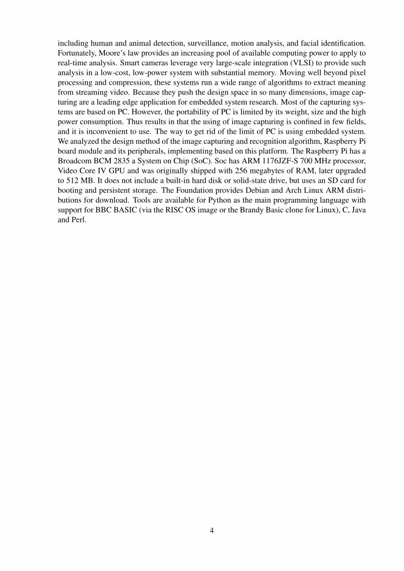
including human and animal detection, surveillance, motion analysis, and facial identification.Fortunately, Moore’s law provides an increasing pool of available computing power to apply toreal-time analysis. Smart cameras leverage very large-scale integration (VLSI) to provide suchanalysis in a low-cost, low-power system with substantial memory. Moving well beyond pixelprocessing and compression, these systems run a wide range of algorithms to extract meaningfrom streaming video. Because they push the design space in so many dimensions, image cap-turing are a leading edge application for embedded system research. Most of the capturing sys-tems are based on PC. However, the portability of PC is limited by its weight, size and the highpower consumption. Thus results in that the using of image capturing is confined in few fields,and it is inconvenient to use. The way to get rid of the limit of PC is using embedded system.We analyzed the design method of the image capturing and recognition algorithm, Raspberry Piboard module and its peripherals, implementing based on this platform. The Raspberry Pi has aBroadcom BCM 2835 a System on Chip (SoC). Soc has ARM 1176JZF-S 700 MHz processor,Video Core IV GPU and was originally shipped with 256 megabytes of RAM, later upgradedto 512 MB. It does not include a built-in hard disk or solid-state drive, but uses an SD card forbooting and persistent storage. The Foundation provides Debian and Arch Linux ARM distri-butions for download. Tools are available for Python as the main programming language withsupport for BBC BASIC (via the RISC OS image or the Brandy Basic clone for Linux), C, Javaand Perl.
4

Chapter 2
Literature Review
Robust and real-time face detection place a vital role in many of the application scenarios likeaccess control, surveillance scenarios, gaming, human-computer interaction, etc. Viola andJones devised an algorithm, called Haar Classifiers, to rapidly detect any object, includinghuman faces, using Haar classifier cascades that are based on Haar Like features. Haar-likefeatures and not pixels. Different types of methods are available for detecting the face andrecognition: Principal Component Analysis (PCA), Linear Discriminate Analysis (LDA), Sup-port Vector Machines (SVM) Independent Component Analysis (ICA), Local Binary Pattern(LBP), and more recently Sparse Representation (SR) based methods. A recent survey on facerecognition algorithms can be found in. Different algorithm are existing for performing andanalysis of face detection with each of its own weakness and strengths related to use of fleshtones, some use contours, and other are even more complex involving templates, neural net-works, or filters few of these algorithm are computationally expensive. There has been littlework in the literature during the last years about real-time face detection at HDTV resolutions.Face detection algorithm using Haar-like features was described by Viola and Jones [14] andnow it and a range of its modifications are widely spread in many applications. One of thesemodifications [15] was implemented in OpenCV library [16]. The OpenCV implementationcompiled with OpenMP option provides only 4.5 frames per second on 4-core CPU. Its tooslow to process HD stream in real time. As a solution to this problem a parallel modificationof OpenCV algorithm for GPU has been developed. Some parallel versions of face detectionalgorithm using Haar-like features [17, 18, 19]. The algorithm introduced by Hefenbrock [16]was the first realization of a face detection algorithm using GPU we could find. It showed aneffect of using GPU versus CPU. But the algorithm could not process a stream with resolution640x480 in real time. The next parallel implementation is found in Obukhovs algorithm [20].Its a single realization that uses GPU and can work with OpenCV classifiers without modifica-tion that is why modern versions of OpenCV library include it (test result of the algorithm ispresented. in corresponding section of the paper). The main problem of the algorithm is tex-ture memory usage for classifier storing because texture memory is not as effective for generaloperation as cached global memory on modern GPU. Section III presents to the face detectionmechanism that uses Haar Classiers based on Haar-like features. Section II refers to relatedworks. Section IV presents the face detection design and analysis with Cascade Haar Classifiertracking mechanism based on a Haar-Like features approach. Section V presents the Systemoverview obtained by implementing the Haar Classifier on System on Chip (Raspberry Pi). Fur-ther section real time data results are presented where it can be seen that faces are detected inimages from High Definition video streaming from Image Sensor. Section VI provides resultand Section VII concludes this article.
5

Chapter 3
System Overview
3.1 flow chart
3.2 Face Detection
3.2.1 Methodology- Viola-Jones algorithmThere are three major blocks in Viola-Jones algorithm; Integral Images, Ada-Boost Algorithmand Attentional cascade. The integral image computes a value at each pixel for example (x,y)that is the sum of the pixel values above to the left of (x,y). This is quickly computed in onepass through the image. Viola jones algorithm uses Haar like features. This is nothing but scalarproduct between the image & some haar like structures. Feature is selected through adaboost.Ada-Boost provides an effective learning algorithm and strong bounds on generalization perfor-mance. The overall form of the detection process is that of a degenerate decision tree, what wecall a cascade. A positive result from the first classifier triggers the evaluation of a second clas-sifier which has also been adjusted to achieve very high detection rates. A positive result fromthe second classifier triggers a third classifier, and so on. A negative outcome at any point leadsto the immediate rejection of the sub- window. The cascade training process involves two typesof tradeoffs. In most cases classifiers with more features will achieve higher detection rates andlower false positive rates. At the same time classifiers with more features require more time tocompute. In principle one can use following stages.
• The number of classifier stages
• The number of features in each stage, and
• The threshold of each stage
These are traded off in order to minimize the expected number of evaluated features. Unfor-tunately finding this optimum is a tremendously difficult problem. In practice a very simpleframework is used to produce an effective classifier which is highly efficient. Each stage in theThe face detection algorithm proposed by Viola and Jones is used as the basis of our design. Theface detection algorithm looks for specific Haar features of a human face. When one of thesefeatures is found, the algorithm allows the face candidate to pass to the next stage of detection.A face candidate is a rectangular section of the original image called a sub-window. Generallythese sub-windows have a fixed size (typically 2424 pixels). This sub-window is often scaled inorder to obtain a variety of different size faces. The algorithm scans the entire image with this
6

Figure 3.1: shravani
window and denotes each respective section a face candidate [6]. The algorithm uses an integralimage in order to process Haar features of a face candidate in constant time. It uses a cascadeof stages which is used to eliminate non-face candidates quickly. Each stage consists of manydifferent Haar features. Each feature is classified by a Haar feature classifier. The Haar featureclassifiers generate an output which can then be provided to the stage comparator. The stagecomparator sums the outputs of the Haar feature classifiers and compares this value with a stage
7

threshold to determine if the stage should be passed. If all stages are passed the face candidateis concluded to be a face. These terms will be discussed in more detail in the following sections.
• Integral Image The integral image is defined as the summation of the pixel values of theoriginal image. The value at any location (x, y) of the integral image is the sum of theimages pixels above and to the left of location (x, y). Figure 1 illustrates the integralimage generation. The simple rectangular features of an image are calculated using anintermediate representation of an image, called the integral image [1]. The integral imageis an array containing the sums of the pixels intensity values located directly to the leftof a pixel and directly above the pixel at location ,) (xy inclusive. So if ,) (xyA is theoriginal image and , is the integral image then the integral image is computed as shownin equation 1 and illustrated in Figure 2.
(1) The features rotated by forty-five degrees, like the line feature shown in Figure 1(b),require another intermediate representation called the rotated integral image or rotatedsum auxiliary image[1]. The rotated integral image is calculated by finding the sum ofthe pixels intensity values that are located at a forty five degree angle to the left and abovefor the x value and below for the y value. So if , is the original image and , is the rotatedintegral image then the integral image is computed as shown in equation 2 an illustratedin Figure 2 and Figure 3.
Figure 3. (a) Edge Features (b) Line Features (c) Center Surround Features It only takestwo passes to compute both integral image arrays, one for each array. Using the appropri-ate integral image and taking the difference between six to eight array elements formingtwo or three connected rectangles, a feature of any scale can be computed. Thus calculat-ing a feature is extremely fast and efficient. It also means calculating features of varioussizes requires the same effort as a feature of only two or three pixels. The detection ofvarious sizes of the same object requires the same amount of effort and time as objects ofsimilar sizes since scaling requires no additional effort.
• Haar Features Haar features are composed of either two or three rectangles. Face candi-dates are scanned and searched for Haar features of the current stage. The weight and sizeof each feature and the features themselves are generated using a machine learning algo-rithm from AdaBoost. The weights are constants generated by the learning algorithm.There are a variety of forms of features as seen below in Figure 4. Each Haar feature hasa value that is calculated by taking the area of each rectangle, multiplying each by theirrespective weights, and then summing the results. The area of each rectangle is easilyfound using the integral image. The coordinate of the any corner of a rectangle can beused to get the sum of all the pixels above and to the left of that location using the integralimage. By using each corner of a rectangle, the area can be computed quickly as denotedby Figure 5. Since L is subtracted off twice it must be added back on to get the correctarea of the rectangle. The area of the rectangle R, denoted as the rectangle integral, canbe computed as follows using the locations of the integral image:
• Haar Feature Classifier A Haar feature classifier uses the rectangle integral to calculatethe value of a feature. The Haar feature classifier multiplies the weight of each rectangleby its area and the results are added together. Several Haar feature classifiers composea stage. A stage comparator sums all the Haar feature classifier results in a stage andcompares this summation with a stage threshold. The threshold is also a constant obtainedfrom the AdaBoost algorithm. Each stage does not have a set number of Haar features.Depending on the parameters of the training data individual stages can have a varying
8

number of Haar features as shown in the Figure 6. For example, Viola and Jones data setused 2 features in the first stage and 10 in the second. All together they used a total of 38stages and 6060 features. Our data set is based on the OpenCV data set which used 22stages and 2135 features in total.
Figure 6. Calculating the area of rectangular
• Cascade
The Viola and Jones face detection algorithm eliminates face candidates quickly using acascade of stages. The cascade eliminates candidates by making stricter requirements ineach stage with later stages being much more difficult for a candidate to pass. Candidatesexit the cascade if they pass all stages or fail any stage. A face is detected if a candidatepasses all stages. This process is shown in Figure 7.
3.2.2 FACE DETECTION DESIGN AND ANALYSIS
This section will describe about the Face detection with itself which has several modulesthat are working together as one to make the system runs smoothly. The phase consists ofcapture image; Detect faces in the image, feature extraction, template comparison, dec-laration of matching template. The acquisition of face images can be done by acquiringthe real time image from the OVA5647 CMOS Image Sensor interfaced with Raspberrypi High speed processor with GPU Processing. Furthermore the acquisition can also bedone through real time remote monitoring either with IP or Wifi. The function of the facedetection module is clarify whether the face is available during real time monitoring ordetection of not. The face detection is done by scanning up an image for different scalesand looking for some simple patterns as mentioned in the above section III. When thesystem detects the face, it will produce and sub-image that is scaled such that the face ap-pears in the center and presented at a uniform size. OpenCV already provide algorithm tolocate faces in still image and videos-Algorithm mentioned in section III. Haar classifieralgorithm scans the image and creates a bounding box as returns for each detected face.The feature extraction in face detection is done by localizing of the characteristics of facecomponents (i.e., eyes, mouth, nose etc) in an image. In other terms the feature extractionis a step in face recognition where the system locates certain points on the faces such ascorner and center of the eyes, tip of the nose, mouth etc. It analyzes spatial geometry ofdifferential feature of a face. Result of this analyzing is a set of template generated foreach face .The template consists of a reduced set of data which represent the real timeface detected in bounded box. The template comparison is done with the template storedin the database. Two phases are there in this phase Identification and verification. Thesetwo term identification to detect the face in real time video and verification applicationfor face recognition which scope out of this paper. The final phase of face detection is todeclare the highest matching score resulted in the previous step. The configuration willdetermine how the application should behave based on the desired security and opera-tional consideration. The face detection methodology is shown in the Figure 8. Figure 8.Flowchart of face detection system A. Face detection System is capable of detecting thefaces from the captured image for the purpose of prototype. From the above Section, facedetection determines where in an image a face is located and it is done by scanning thedifferent image scales and extracting the exact patterns to detect the face. The Prototypeis to built with Haar-Like Feature function from OpenCV. Haar classifier detection is used
9
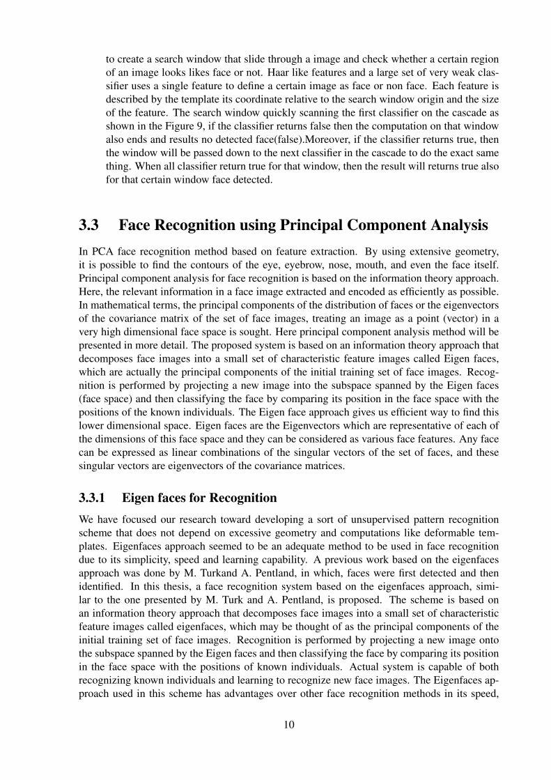
to create a search window that slide through a image and check whether a certain regionof an image looks likes face or not. Haar like features and a large set of very weak clas-sifier uses a single feature to define a certain image as face or non face. Each feature isdescribed by the template its coordinate relative to the search window origin and the sizeof the feature. The search window quickly scanning the first classifier on the cascade asshown in the Figure 9, if the classifier returns false then the computation on that windowalso ends and results no detected face(false).Moreover, if the classifier returns true, thenthe window will be passed down to the next classifier in the cascade to do the exact samething. When all classifier return true for that window, then the result will returns true alsofor that certain window face detected.
3.3 Face Recognition using Principal Component AnalysisIn PCA face recognition method based on feature extraction. By using extensive geometry,it is possible to find the contours of the eye, eyebrow, nose, mouth, and even the face itself.Principal component analysis for face recognition is based on the information theory approach.Here, the relevant information in a face image extracted and encoded as efficiently as possible.In mathematical terms, the principal components of the distribution of faces or the eigenvectorsof the covariance matrix of the set of face images, treating an image as a point (vector) in avery high dimensional face space is sought. Here principal component analysis method will bepresented in more detail. The proposed system is based on an information theory approach thatdecomposes face images into a small set of characteristic feature images called Eigen faces,which are actually the principal components of the initial training set of face images. Recog-nition is performed by projecting a new image into the subspace spanned by the Eigen faces(face space) and then classifying the face by comparing its position in the face space with thepositions of the known individuals. The Eigen face approach gives us efficient way to find thislower dimensional space. Eigen faces are the Eigenvectors which are representative of each ofthe dimensions of this face space and they can be considered as various face features. Any facecan be expressed as linear combinations of the singular vectors of the set of faces, and thesesingular vectors are eigenvectors of the covariance matrices.
3.3.1 Eigen faces for RecognitionWe have focused our research toward developing a sort of unsupervised pattern recognitionscheme that does not depend on excessive geometry and computations like deformable tem-plates. Eigenfaces approach seemed to be an adequate method to be used in face recognitiondue to its simplicity, speed and learning capability. A previous work based on the eigenfacesapproach was done by M. Turkand A. Pentland, in which, faces were first detected and thenidentified. In this thesis, a face recognition system based on the eigenfaces approach, simi-lar to the one presented by M. Turk and A. Pentland, is proposed. The scheme is based onan information theory approach that decomposes face images into a small set of characteristicfeature images called eigenfaces, which may be thought of as the principal components of theinitial training set of face images. Recognition is performed by projecting a new image ontothe subspace spanned by the Eigen faces and then classifying the face by comparing its positionin the face space with the positions of known individuals. Actual system is capable of bothrecognizing known individuals and learning to recognize new face images. The Eigenfaces ap-proach used in this scheme has advantages over other face recognition methods in its speed,
10
simplicity, learning capability and robustness to small changes in the face image. FACE-PRO,the actual face recognition software based on the Eigen faces approach was developed in Cprogramming language on a personal computer. Although no optimizations were performed formatrix operations, during the tests on a Intel 80486 based personal computer, it was remark-able that the system could build a training set that had 14 members with 7 eigen faces overa 58 member demo face library by updating all the feature vectors of the library members inaround one minute. Once the training set has been built, recognitions were done near real timeover this demo face library in less than one second. Much of the previous work on automatedface recognition has ignored the issue of just what aspects of the face stimulus are importantfor face recognition. This suggests the use of an information theory approach of coding anddecoding of Face images, emphasizing the significant local and global features. Such featuresmay or may not be directly related to our intuitive notion of face features such as the eyes, nose,lips, and hair. In the language of information theory, the relevant information in a face imageis extracted, encoded as efficiently as possible, and then compared with a database of modelsencoded similarly. A simple approach to extracting the information contained in an image ofa face is to somehow capture the variation in a collection of face images, independent of anyjudgment of features, and use this information to encode and compare individual face images.In mathematical terms, the principal components of the distribution of faces, or the eigenvectorsof the covariance matrix of the set of face images, treating an image as point (or vector) in avery high dimensional space is sought. The eigenvectors are ordered, each one accounting fora different amount of the variation among the face images.
3.3.2 Calculation of Eigen faces and WeightsLet a face image I(x,y) be a two-dimensional N x N array of 8-bit intensity values. An imagemay also be considered as a vector of dimension N2 , so that a typical image of size 256 x 256becomes a vector of dimension 65,536, or equivalently a point in 65,536-dimensional space.An ensemble of images, then, maps to a collection of points in this huge space. Images of faces,being similar in overall configuration, will not be randomly distributed in this huge image spaceand thus can be described by a relatively low dimensional subspace. The main idea of theprincipal component analysis (or Karhunen-Loeve expansion) is to find the vectors that bestaccount for the distribution of face images within the entire image space. These vectors definethe subspace of face images, which we call ”face space”. Each vector is of length N2 , describesan N x N image, and is a linear combination of the original face images. Because these vectorsare the eigenvectors of the covariance matrix corresponding to the original face images, andbecause they are face-like in appearance, we refer to them as ”eigenfaces”. Some examples ofeigenfaces are shown in Figure 5.2.
An N x N matrix A is said to have an eigenvector X, In linear algebra, the eigenvectors of alinear operator are non-zero vectors which, when operated on by the operator, result in a scalarmultiple of them. The scalar is then called the eigenvalue An N x N matrix A is said to havean eigenvector X, In linear algebra, the eigenvectors of a linear operator are non-zero vectorswhich, when operated on by the operator, result in a scalar multiple of them. The scalar is thencalled the eigenvalue associated with the eigenvector(X). Eigen vector is a vector that is scaledby a linear transformation. It is a property of a matrix. When a matrix acts on it, only the vectormagnitude is changed not the direction AX X
11

Figure 3.2: shravani
12

Figure 3.3: shravani
13

Figure 3.4: shravani
Figure 3.5: shravani
Figure 3.6: shravani
Figure 3.7: shravani
Figure 3.8: shravani
Figure 3.9: shravani
14

Chapter 4
System hardware-software design
The whole system is composed by following parts: an image capturing camera, Raspberry Piboard to run image recognition programs on it. DVI compatible monitors also connected withthis system during initial stages to preview the captured images and give the user indication.
Figure 4.1: shravani
4.1 Block Diagram
Figure 4.2: shravani
4.2 RASPBERRY PI BOARDThis board is the central module of the whole embedded image capturing and processing systemas given in figure 2. Its main parts include: main processing chip, memory, power supply HDMIOut, Ethernet port, USB ports and abundant global interfaces. 2.1.1 MAIN PROCESSINGCHIP The main signal processing chip used in our system is a Broadcom 700MHz Chip inwhich CPU core is a 32 bit ARM1176JZF-S RISC processor designed by Advanced RISCMachines, Ltd. It has very rich peripheral. This main processing chip connects a camera anddisplay units.
Figure 4.3: shravani
4.3 MEMORYThe design does not include a built in hard disk or solid state drive, instead relying on anSD card for booting and long term storage. This board is intended to run Linux kernel basedoperating systems. This Raspberry Pi module has a Samsung class 4 micro SD card preloaded
15

with the official Raspberry Pi NOOBS (New Out of Box Software) package, and a beautifullyscreen printed Micro SD card adaptor 2.1.3 INTERFACES Plenty of interfaces are containedon the Raspberry Pi board, including 2 USB ports through which a Keyboard and mouse canbe connected, a HDMI out for connecting HD TVs and monitors with HDMI input or HDMIto DVI lead for monitors with DVI input. Other peripherals like A standard RCA compositevideo lead to connect to analogue display if HDMI output is not used. Ethernet port is used fornetworking even though it is optional, although it makes updating and getting new software forRaspberry Pi board much easier. An Audio lead is also provided for getting the stereo audio ifHDMI is not used, otherwise HDMI will get digital audio with it.
4.4 CAMERA INTERFACEThe camera module used in this project is RPI NOIR CAMERA BOARD i.e. Raspberry Pi NoIR camera board as shown in the Figure 3. The camera plugs directly into the CSI connector onthe Raspberry Pi. It’s able to deliver clear 5MP resolution image, or 1080p HD video recordingat 30fps. The module attaches to Raspberry Pi, by way of a 15 pin Ribbon Cable, to the dedi-cated 15 pin MIPI Camera Serial Interface (CSI), which was designed especially for interfacingto cameras. The CSI bus is capable of extremely high data rates, and it exclusively carries pixeldata to the BCM2835 processor. This camera board which has no infrared filter making it per-fect for taking infrared photographs or photographing objects in low light (twilight) conditions.Other features of this camera board are Automatic image control functions ,Programmable con-trols for frame rate 32 bytes of embedded one time programmable (OTP) memory and Digitalvideo port (DVP) parallel output interface Excellent
Figure 4.4: shravani
4.5 RASPBERRY PI PLATFORM• Overview– The Raspberry Pi is a credit-card-sized single-board development platform
envisaged and developed in the UK by the Raspberry Pi Foundation. The Raspberry Pi ismanufactured through licensed manufacturing deals with Element 14/Premier Farnell andRS Components. Both of these companies sell the Raspberry Pi online. The Raspberry Pihas a Broadcom BCM2835 system on a chip (SoC), which includes an ARM1176JZF-S700 MHz processor (The firmware includes a number of ”Turbo” modes so that the usercan attempt overclocking, up to 1 GHz, without affecting the warranty), VideoCore IVGPU, and was originally shipped with 256 megabytes of RAM, later upgraded to 512MB.It does not include a built-in hard disk or solid-state drive, but uses an SD card for bootingand long-term storage.
• Software Architecture– The Raspberry Pi uses Linux kernel-based operating systems.Raspbian, a Debian-based free operating system optimized for the Raspberry Pi hard-ware, is the current recommended system, released in July 2012. The GPU hardwareis accessed via a firmware image which is loaded into the GPU at boot time from theSD- card. The firmware image is known as the binary blob, while the associated ARMcoded Linux drivers were initially closed source. This part of the driver code was laterreleased, however much of the actual driver work is done using the closed source GPU
16

code. Application software uses calls to closed source run-time libraries (Open Max,Open GL ES or open VG) which in turn calls an open source driver inside the Linuxkernel, which then calls the closed source Videocore IV GPU driver code. The API ofthe kernel driver is specific for these closed libraries. Video applications use OpenMAX,3D applications use OpenGL ES and 2D applications use OpenVG which both in turnuse EGL. OpenMAX and EGL use the open source kernel driver in turn. On 19 February2012, the Raspberry Pi Foundation released its first proof of concept SD card image thatcould be loaded onto an SD card to produce a preliminary operating system. The imagewas based upon Debian 6.0 (Squeeze), with the LXDE desktop and the Midori browser,plus various programming tools. The image also runs on QEMU allowing the RaspberryPi to be emulated on various other platforms.
Figure 4.5: shravani
• Software Design–
– MATLAB The software code for the Principal Component analysis was modeledinitially in MATLAB. Once tested and debugged, the code was rewritten in Python.The next two sub sections deal with the software development using MATLABand its subsequent porting to the Python IDE. MATLAB, which stands for MA-Trix LABoratory, is a state-of-the-art mathematical software package, which is usedextensively in both academia and industry. It is an interactive program for numericalcomputation and data visualization, which along with its programming capabilitiesprovides a very useful tool for almost all areas of science and engineering. Un-like other mathematical packages, such as MAPLE or MATHEMATICA, MATLABcannot perform symbolic manipulations without the use of additional Toolboxes. Itremains however, one of the leading software packages for numerical computation.Guessing from its name, MATLAB deals mainly with matrices. A scalar is a 1-by-1 matrix and a row vector of length say 5, is a 1-by-5 matrix. We will elaboratemore on these and other features of MATLAB in the sections that follow. One ofthe many advantages of MATLAB is the natural notation used. It looks a lot likethe notation that you encounter in a linear algebra course. This makes the use ofthe program especially easy and it is what makes MATLAB a natural choice fornumerical computations.
– Python Implementation The code for both face detection and recognition was writ-ten in python 2.7. Graphical User Interfaces [GUI] are created for both applications.Several Libraries are used along with python to incorporate specific tasks. The soft-ware implementation in python involves face detection, initially, which detects theface region and returns an image comprising of only the detected region. This ishelpful for the subsequent recognition process since less amount of pre-processingis required. C. Development The USB webcam sends a video stream of imageframes received by the RPi through the USB interface. Once received, the pythonGUIs implement the face recognition and detection algorithms. The SD card holdsthe necessary software to implement these algorithms. It also holds the database ofEigenfaces. Once authenticated, the access grant message is displayed on screen.At each stage of implementation, from the system initialization to the validation,status messages are displayed on a 16x2 character LCD. The RPi, through its GPIO
17

pins is connected through a two-wire I2C interface to the PIC16F877A microcon-troller. The microcontroller receives the status signals from RPi through I2C andappropriately drives the LCD, displaying the correct status message.
4.6 WIRELESS NETWORK ZIGBEEZigBee ZigBee is a specification for a suite of high level communication protocols using small,
low-power digital radios based on an IEEE 802 standard for personal area networks. Zig-Bee devices are often used in mesh network form to transmit data over longer distances,passing data through intermediate devices to reach more distant ones. This allows Zig-Bee networks to be formed ad-hoc, with no centralized control or high-power transmit-ter/receiver able to reach all of the devices. Any Zigbee device can be tasked with runningthe network. ZigBee is targeted at applications that require a low data rate, long batterylife, and secure networking. ZigBee has a defined rate of 250 kbit/s, best suited for peri-odic or intermittent data or a single signal transmission from a sensor or input device. Ap-plications include wireless light switches, electrical meters with in-home-displays, trafficmanagement systems, and other consumer and industrial equipment that requires short-range wireless transfer of data at relatively low rates. The technology defined by theZigBee specification is intended to be simpler and less expensive than other WPANs,such as Bluetooth.
Zigbee technology ZigBee is a low-cost, low-power, wireless mesh network standard. The low cost allowsthe technology to be widely deployed in wireless control and monitoring applications.Low power-usage allows longer life with smaller batteries. Mesh networking provideshigh reliability and more extensive range. ZigBee chip vendors typically sell integratedradios and microcontrollers with between 60 KB and 256 KB flash memory. ZigBee op-erates in the industrial, scientific and medical (ISM) radio bands; 868 MHz in Europe,915 MHz in the USA and Australia, and 2.4 GHz in most jurisdictions worldwide. Datatransmission rates vary from 20 to 900 kilobits/second. The ZigBee network layer na-tively supports both star and tree typical networks, and generic mesh networks. Everynetwork must have one coordinator device, tasked with its creation, the control of its pa-rameters and basic maintenance. Within star networks, the coordinator must be the centralnode. Both trees and meshes allows the use of ZigBee routers to extend communicationat the network level.
ZigBee protocol stack ZigBee builds upon the physical layer and medium access control defined in IEEE stan-dard 802.15.4 (2003 version) for low-rate WPANs. The specification goes on to completethe standard by adding four main components: network layer, application layer, ZigBeedevice objects (ZDOs) and manufacturer-defined application objects which allow for cus-tomization and favor total integration. Besides adding two high-level network layers tothe underlying structure, the most significant improvement is the introduction of ZDOs.These are responsible for a number of tasks, which include keeping of device roles, man-agement of requests to join a network, device discovery and security. ZigBee is notintended to support powerline networking but to interface with it at least for smart me-tering and smart appliance purposes. Because ZigBee nodes can go from sleep to activemode in 30 ms or less, the latency can be low and devices can be responsive, particularlycompared to Bluetooth wake-up delays, which are typically around three seconds. [2]Because ZigBee nodes can sleep most of the time, average power consumption can be
18

low, resulting in long battery life.
Trademark and alliance The ZigBee Alliance is a group of companies that maintain and publish the ZigBee stan-dard.[3] The term ZigBee is a registered trademark of this group, not a single technicalstandard. The Alliance publishes application profiles that allow multiple OEM vendorsto create interoperable products. The relationship between IEEE 802.15.4 and ZigBee[4]is similar to that between IEEE 802.11 and the Wi-Fi Alliance.
Application profiles The current list of application profiles either published, or in the works are:
– Released specifications
∗ ZigBee Home Automation∗ ZigBee Smart Energy 1.0∗ ZigBee Telecommunication Services∗ ZigBee Health Care∗ ZigBee RF4CE - Remote Control
– Specifications under development
∗ ZigBee Smart Energy 2.0∗ ZigBee Building Automation∗ ZigBee Retail Services∗ ZigBee Light Link
The ZigBee Smart Energy V2.0 specifications define an IP-based protocol to monitor,control, inform and automate the delivery and use of energy and water. It is an enhance-ment of the ZigBee Smart Energy version 1 specifications,[8] adding services for plug-inelectric vehicle (PEV) charging, installation, configuration and firmware download, pre-pay services, user information and messaging, load control, demand response and com-mon information and application profile interfaces for wired and wireless networks. It isbeing developed by partners including:
– HomeGrid Forum responsible for marketing and certifying ITU-T G.hn technologyand products
– HomePlugPowerline Alliance
– International Society of Automotive Engineers SAE International
– IPSO Alliance
– SunSpec Alliance
– Wi-Fi Alliance
In 2009 the RF4CE (Radio Frequency for Consumer Electronics) Consortium and Zig-Bee Alliance agreed to jointly deliver a standard for radio frequency remote controls.ZigBee RF4CE is designed for a wide range of consumer electronics products, such asTVs and set-top boxes. It promises many advantages over existing remote control so-lutions, including richer communication and increased reliability, enhanced features andflexibility, interoperability, and no line-of-sight barrier.[9] The ZigBee RF4CE specifica-tion lifts off some networking weight and does not support all the mesh features, which istraded for smaller memory configurations for lower cost devices, such as remote controlof consumer electronics.
19

Uses ZigBee protocols are intended for embedded applications requiring low data rates andlow power consumption. The resulting network will use very small amounts of powerindividual devices must have a battery life of at least two years to pass ZigBee certifica-tion.[10] Typical application areas include:[11]
– Home Entertainment and Control Home automation, smart lighting, advanced tem-perature control, safety and security, movies and music
– Wireless sensor networks Starting with individual sensors like Telosb/Tmote andIris from Memsic
– Industrial control
– Embedded sensing
– Medical data collection
– Smoke and intruder warning
– Building automation
Device types Zigbee devices are of three types:
ZigBee coordinator (ZC) : The most capable device, the coordinator forms the root of the network tree andmight bridge to other networks. There is exactly one ZigBee coordinator in eachnetwork since it is the device that started the network originally. It stores informationabout the network, including acting as the Trust Center & repository for securitykeys.[12][13]
ZigBee Router (ZR) : As well as running an application function, a router can act as an intermediaterouter, passing on data from other devices.
ZigBee End Device (ZED) : Contains just enough functionality to talk to the parent node (either the coordinatoror a router); it cannot relay data from other devices. This relationship allows thenode to be asleep a significant amount of the time thereby giving long battery life.A ZED requires the least amount of memory, and therefore can be less expensive tomanufacture than a ZR or ZC.
Protocols The protocols build on recent algorithmic research (Ad-hoc On-demand Distance Vector,neuRFon) to automatically construct a low-speed ad-hoc network of nodes. In most largenetwork instances, the network will be a cluster of clusters. It can also form a mesh or asingle cluster. The current ZigBee protocols support beacon and non-beacon enabled net-works. In non-beacon-enabled networks, an unslottedCSMA/CA channel access mech-anism is used. In this type of network, ZigBee Routers typically have their receiverscontinuously active, requiring a more robust power supply. However, this allows forheterogeneous networks in which some devices receive continuously, while others onlytransmit when an external stimulus is detected. The typical example of a heterogeneousnetwork is a wireless light switch: The ZigBee node at the lamp may receive constantly,since it is connected to the mains supply, while a battery-powered light switch wouldremain asleep until the switch is thrown. The switch then wakes up, sends a commandto the lamp, receives an acknowledgment, and returns to sleep. In such a network thelamp node will be at least a ZigBee Router, if not the ZigBee Coordinator; the switchnode is typically a ZigBee End Device. In beacon-enabled networks, the special networknodes called ZigBee Routers transmit periodic beacons to confirm their presence to othernetwork nodes. Nodes may sleep between beacons, thus lowering their duty cycle and
20

extending their battery life. Beacon intervals depend on data rate; they may range from15.36 milliseconds to 251.65824 seconds at 250 kbit/s, from 24 milliseconds to 393.216seconds at 40 kbit/s and from 48 milliseconds to 786.432 seconds at 20 kbit/s. However,low duty cycle operation with long beacon intervals requires precise timing, which canconflict with the need for low product cost. In general, the ZigBee protocols minimizethe time the radio is on, so as to reduce power use. In beaconing networks, nodes onlyneed to be active while a beacon is being transmitted. In non-beacon-enabled networks,power consumption is decidedly asymmetrical: some devices are always active, whileothers spend most of their time sleeping. Except for the Smart Energy Profile 2.0, ZigBeedevices are required to conform to the IEEE 802.15.4-2003 Low-Rate Wireless PersonalArea Network (LR-WPAN) standard. The standard specifies the lower protocol layers-the (physical layer) (PHY), and the (media access control) portion of the (data link layer(DLL)). The basic channel access mode is ”carrier sense, multiple access/collision avoid-ance” (CSMA/CA). That is, the nodes talk in the same way that people converse; theybriefly check to see that no one is talking before they start, with three notable exceptions.Beacons are sent on a fixed timing schedule, and do not use CSMA. Message acknowl-edgments also do not use CSMA. Finally, devices in Beacon Oriented networks that havelow latency real-time requirements may also use Guaranteed Time Slots (GTS), which bydefinition do not use CSMA.
Communication and device discovery In order for applications to communicate, their comprising devices must use a commonapplication protocol (types of messages, formats and so on); these sets of conventions aregrouped in profiles.Furthermore, binding is decided upon by matching input and outputcluster identifiers, unique within the context of a given profile and associated to an in-coming or outgoing data flow in a device. Binding tables contain source and destinationpairs. Depending on the available information, device discovery may follow differentmethods. When the network address is known, the IEEE address can be requested usingunicast communication. When it is not, petitions are broadcast (the IEEE address be-ing part of the response payload). End devices will simply respond with the requestedaddress, while a network coordinator or a router will also send the addresses of all thedevices associated with it. This extended discovery protocol permits external devicesto find out about devices in a network and the services that they offer, which endpointscan report when queried by the discovering device (which has previously obtained theiraddresses). Matching services can also be used. The use of cluster identifiers enforcesthe binding of complementary entities by means of the binding tables, which are main-tained by ZigBee coordinators, as the table must be always available within a networkand coordinators are most likely to have a permanent power supply. Backups, managedby higher-level layers, may be needed by some applications. Binding requires an estab-lished communication link; after it exists, whether to add a new node to the network isdecided, according to the application and security policies. Communication can happenright after the association. Direct addressing uses both radio address and endpoint identi-fier, whereas indirect addressing uses every relevant field (address, endpoint, cluster andattribute) and requires that they be sent to the network coordinator, which maintains as-sociations and translates requests for communication. Indirect addressing is particularlyuseful to keep some devices very simple and minimize their need for storage. Besidesthese two methods, broadcast to all endpoints in a device is available, and group address-ing is used to communicate with groups of endpoints belonging to a set of devices. Theoperating frequency of Zigbee in India is 868 MHZ and 902-928 MHZ. The operatingrange is roughly 50 metres.
21

4.7 GSMA GSM modem is a wireless modem that works with a GSM wireless network. A wirelessmodem behaves like a dial-up modem. The main difference between them is that a dial-upmodem sends and receives data through a fixed telephone line while a wireless modem sendsand receives data through radio waves. A GSM modem can be an external device or a PC Card /PCMCIA Card. Typically, an external GSM modem is connected to a computer through a serialcable or a USB cable. Like a GSM mobile phone, a GSM modem requires a SIM card from awireless carrier in order to operate.computers use at commands to control modems. both GSMmodems and dial-up modems support a common set of standard at commands. GSM modemssupport an extended set of at commands. Reading, writing and deleting sms messages. Sendingsms messages. Monitoring the signal strength. Monitoring the charging status and charge levelof the battery. Reading, writing and searching phone book entries.
22

Chapter 5
Advantages and applications
5.1 Advantages• An image capture system with embedded computing can extract information from images
without need for an external processing unit, and interface devices used to make resultsavailable to other devices. The choosing of an Embedded platform is very unique andeasy to implement
• the designed system is fast enough to run the image capturing, recognition algorithm, andthe data stream can flow smoothly between the camera and the Raspberry Pi board
• embedded image capturing system with Raspberry Pi system is smaller, lighter and withlower power consumption, so it is more convenient than the PC-based face recognitionsystem.
• Because of the open source code, it is freer to do software development on Linux. Exper-imental results show that its an effective method of using Raspberry Pi board to actualizeembedded image capturing system.
• Face detection and recognition system is more cheap, simple, accurate and non intrusiveprocess as compare to other biometrics.
5.2 Applications• Camera technology will begin to enter new applications, for example, in the security and
access control markets, in the automotive industry, for collision avoidance, and even oneday for the toy industry.
• Even our automobiles may soon be outfitted with miniature eyes. Built into a cruisecontrol system, for instance, such a camera would suddenly alert the driver if it noted arapidly decelerating vehicle.
• The cameras could also take the place of the rear view and side-view mirrors, therebyeliminating dangerous blind spots and - in the event of an accident recording the secondsprior to a collision.
• Another example would be with intelligent lifts. An office block, with many lifts andfloors, may see a lot of people travelling up and down between floors, particularly at
23

high traffic times such as early morning or end of the working day. At the moment,lifts are called by somebody pressing a button and putting in a request for the lift tostop at a particular floor. Connected with smart camera technology, lifts could be routedon demand, working intelligently, stopping only when there was a pre-set number ofpassengers waiting at a floor and missing out a floor if too many people were waiting tomeet the maximum capacity of the lift.
• This will be helping hand to the police. In this system, we will use GSM module. Supposeif culprit is detected, then detected signal can be transmitted using GSM module to thecentral control room of police station. With the help of ISDN number of GSM, culpritsurviving area will be recognized
24

Chapter 6
Future Work
The current recognition system has been designed for frontal views of face images. A neuralnetwork architecture (may be together with a feature based approach) can be implemented inwhich the orientation of the face is first determined, and then the most suitable recognitionmethod is selected, Also the current recognition system acquires face images only from facefiles located on magnetic mediums. Camera and scanner support should be implemented forgreater flexibility. With the advancement the real time face detection in remote monitoringis help for building much efficient application. Moreover such technology can be useful intracking the lost object under dynamic environment. Further enhancement of this work canbe extended with stereo depth analysis of face detection using two image sensor interfacedwith High speed Processor. Experimentation with the other face recognition algorithms suchas ICA, Markov models, 3D Modelling etc is one such avenue. The frame rate and the pixelsize can be increased to improve the performance. The algorithm may be optimized to reducethe recognition timing. On the hardware side, instead of using the Raspberry Pi itself, theProcessor of the SOC may individually be used to reduce the system cost. This may involve atransition to C coding for the processor but is effective in reducing costs nonetheless. A touchscreen LCD may be interfaced with the Pi to enhance User Interface capabilities. Since thecurrent project involves a remote desktop access to the RPi, several such systems may be linkedthrough network clouds.
25

Chapter 7
Conclusion
We come to know that there are wide range of methods such as biometric, RFID based etc.which are time consuming and non-efficient. So to overcome this above system is the betterand reliable solution from every perceptive of time and security. Thus we have achieved todevelop a reliable and efficient attendance system to implement an image processing algorithmto detect faces in classroom and to recognize the faces accurately to mark the attendance. Facedetection and tracking is being challenging for many researchers with real time Image sensor.With the advancement the real time face detection in remote monitoring is help for buildingmuch efficient application. Moreover such technology can be useful in tracking the lost objectunder dynamic environment. Raspberry Pi system. This system is smaller, lighter and withlower power consumption, so it is more convenient than the PC-based face recognition system.Because of the open source code, it is free to do software development on Linux.
26