Project Manual For: The Bonneville Renovation - Idaho Falls, ID
571
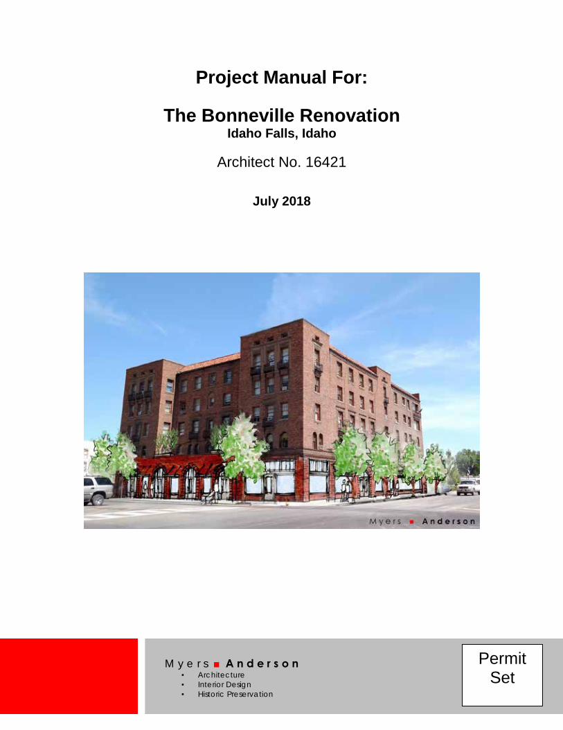
M y e r s ■ A n d e r s o n ▪ Architecture ▪ Interior Design ▪ Historic Preservation Permit Set Project Manual For: The Bonneville Renovation Idaho Falls, Idaho Architect No. 16421 July 2018
-
Upload
khangminh22 -
Category
Documents
-
view
1 -
download
0
Transcript of Project Manual For: The Bonneville Renovation - Idaho Falls, ID
M y e r s ■ A n d e r s o n ▪ Architecture ▪ Interior Design ▪ Historic Preservation
Permit Set
Project Manual For:
The Bonneville Renovation Idaho Falls, Idaho
Architect No. 16421
July 2018

PROJECT MANUAL FOR
The Bonneville Renovation Idaho Falls, ID
Architects No. 16421
July 2018
OWNER The Housing Company
P.O. Box 6943 Boise, ID 83707-0943
CONSTRUCTION MANAGER
Bateman-Hall, Inc. P.O. Box 1464
Idaho Falls, ID 83403 (208) 523-2681
ARCHITECT Myers Anderson Architects
122 South Main Street, Suite 1 Pocatello, ID 83204
(208) 232-3741 [email protected]
MECHANICAL Engineered Systems Associates
1355 East Center Street Pocatello, ID 83201
(208) 233-0501
ELECTRICAL Bradley Engineering
645 W 25th Street Idaho Falls, ID 83402-4569
STRUCTURAL Frost Structural
1020 Lincoln Road Idaho Falls, ID 83401
(208) 277-8404
CIVIL HLE, Inc.
101 S Park Avenue Idaho Falls, ID 83402
(208) 524-0212

The Bonneville Renovation, Idaho Falls, ID TOC-1
TABLE OF CONTENTS Title Page Table of Contents BIDDING REQUIREMENTS Invitation to Bid Instructions to Bidders (AIA Doc A701, 1997 Edition) Supplementary Instructions to Bidders BID FORMS AND CONTRACTS Bid Form General Requirements for All Bid Packages Bid Packages Agreement Between Owner and Contractor, by Reference (AIA Doc A121/CMc, 2003 Edition) Subcontract Agreement-Sample General Conditions, by Reference Supplemental Conditions Conditional Lien Release Form TECHNICAL SPECIFICATIONS Division 01 General Requirements 01 10 00 Summary 01 20 00 Price and Payment Procedures 01 30 00 Administrative Requirements 01 33 00 Submittal Procedures 01 40 00 Quality Requirements 01 50 00 Temporary Facilities and Controls 01 60 00 Product Requirements 01 70 00 Execution and Closeout Requirements Copyright Release Agreement Substitution Request Request for Interpretation Division 02 Existing Conditions 02 41 19 Selective Structure Demolition Division 03 Concrete 03 01 00 Maintenance of Concrete 03 30 00 Cast-in-Place Concrete 03 35 00 Concrete Finishing 03 39 00 Concrete Curing Division 04 Masonry 04 01 00 Maintenance of Masonry 04 05 03 Masonry Mortaring and Grouting 04 20 00 Brick Masonry Unit 04 22 00 Concrete Masonry Unit 04 72 00 Cast Stone Masonry Division 05 Metals 05 12 00 Structural Steel Framing 05 21 00 Steel Joist Framing 05 31 00 Steel Decking 05 40 00 Cold-Formed Metal Framing 05 50 00 Metal Fabrications 05 51 00 Metal Stairs 05 52 00 Metal Railings
Division 06 Wood, Plastic, Composites 06 10 00 Rough Carpentry 06 16 00 Sheathing 06 20 00 Finish Carpentry Division 07 Thermal and Moisture Protection 07 21 13 Board Insulation 07 21 16 Blanket Insulation 07 21 26 Blown Insulation 07 53 05 Elastomeric Membrane Roofing -
Mechanically Attached 07 84 00 Firestopping 07 90 00 Joint Protection Division 08 Openings 08 12 14 Standard Steel Frames 08 13 14 Standard Steel Doors 08 14 16 Flush Wood Doors 08 14 33 Stile and Rail Wood Doors 08 41 13 Aluminum-Framed Entrances and
Storefronts 08 52 00 Wood Windows 08 71 00 Door Hardware 08 80 00 Glazing Division 09 Finishes 09 21 16 Gypsum Board Assemblies 09 22 16 Non-Structural Metal Stud Framing 09 23 00 Gypsum Plastering 09 30 00 Tiling 09 65 00 Resilient Flooring 09 68 13 Tile Carpeting 09 68 16 Sheet Carpeting 09 90 00 Painting and Coating Division 10 Specialties 10 14 00 Signage 10 28 00 Toilet, Bath, Laundry Accessories, and
Residential Appliances 10 44 00 Fire Protection Specialties 10 55 13 Central Mail Delivery Boxes

The Bonneville Renovation, Idaho Falls, ID TOC-2
Division 12 Furnishings 12 21 13 Horizontal Louver Blinds 12 35 30 Residential Casework Division 14 Conveying Equipment 14 21 23 Electric Traction Passenger Elevators MECHANICAL SECTIONS Division 21 00 00 Fire Suppression 21 05 00 Common Requirements for Fire
Suppression 21 05 48 Vibration & Seismic Controls for Fire
Suppression & Equipment 21 05 53 Identification for Fire Suppression Piping
and Equipment 21 12 00 Fire Suppression Standpipes 21 13 00 Wet Pipe Fire Suppression Sprinklers 21 14 00 Dry Pipe Fire Suppression Sprinklers Division 22 00 00 Plumbing 22 05 01 Common Pluming Requirements 22 05 02 Demolition and Repair 22 05 03 Pipe, Pipe Fittings, Pipe Hangers &
Valves 22 05 53 Identification for Plumbing Pipes and
Equipment 22 07 03 Mechanical Insulation and Fire Stopping 22 07 05 Underground Piping Insulation 22 07 10 Potable Water Pipe Insulation 22 07 11 Handicapped Fixtures Insulation 22 02 20 Rain Drain Insulation 22 10 07 Press Type Pipe Fittings 22 11 14 Natural Gas Systems 22 11 16 Domestic Water Piping Systems
(Copper) 22 11 16 Domestic Water Piping Systems (Pex) 22 11 18 Backflow Preventer Valve 22 13 13 Soil, Waste & Vent Piping Systems 22 14 00 Storm Drainage Piping 22 26 00 Condensate Drain Piping 22 34 20 Gas Fired Storage Type Water Heaters 22 34 25 Flues for Water Heaters 22 36 00 Water Softeners 22 40 01 Plumbing Fixtures 22 47 03 Handicap Drinking Water Cooling
System Division 23 00 00 Heating, Ventilating and Air Conditioning (HVAC) 23 05 01 Common HVAC Requirements 23 05 02 Demolition and Repair 23 05 53 Identification for HVAC Piping and
Equipment 23 05 93 Testing, Adjusting and Balancing 23 07 12 Mechanical Insulation and Fire Stopping 23 07 16 Ductwork Insulation 23 07 17 Round Supply Duct Insulation 23 07 18 Duct Lining 23 07 20 Refrigerant Piping Insulation
23 08 00 Fire Stopping 23 21 15 Hot Water Heating System 23 21 16 Hot Water Heating System Specialties 23 21 18 Backflow Preventer Valve 23 21 23 Circulating Pumps and Accessories 23 21 25 Cleaning and Flushing Steam and
Water Circulating Systems 23 23 00 Refrigerant Piping Systems 23 23 10 Refrigerant Specialties 23 31 14 Low-Pressure Steel Ductwork 23 33 46 Flex Duct 23 34 00 Exhaust Fans 23 37 13 Air Outlets & Inlets 23 52 30 Gas Boiler 23 54 17 High Efficiency Natural Gas Furnace 23 55 40 Electric Radiant Wall Heaters 23 62 13 Air Cooled Condensing Unit 23 65 14 Cooling Towers 23 81 29 VRF System 23 81 30 VRF System – Multi V Indoor Units ELECTRICAL SECTIONS Division 26 00 00 Electrical 26 05 00 Common Work Results for Electrical 26 05 03 Equipment Wiring Connections 26 05 19 Low-Voltage Electrical Power
Conductors 26 05 26 Grounding and Bonding 26 05 33 Raceways and Boxes for Electrical
Systems 26 05 53 Identification for Electrical Systems 26 24 16 Switchboards and Panelboards 26 27 26 Wiring Devices 26 28 19 Enclosed Switches 26 28 26 Emergency Transfer Switches 26 32 13 Natural Gas Engine Generators 26 51 00 Interior Lighting 26 52 00 Emergency Lighting 26 56 00 Exterior Lighting Division 27 Communications 27 05 33 Conduits and Backboxes for
Communications Systems Division 32 Exterior Improvements 32 13 13 Concrete Paving 32 31 13 Chain Link Fences and Gates DRAWINGS General G100 Cover Sheet & Index of Drawings &
Symbols G101 Code Review & Legend Civil C.1 Demo Plan C.2 Site Plan

The Bonneville Renovation, Idaho Falls, ID TOC-3
Demo D100 Basement Level Demo Plan D101 Main Level Demo Plan D102 2nd Level Demo Plan D103 3rd Level Demo Plan D104 4th Level Demo Plan D105 5th Level Demo Plan D106 Upper Roof Demo Plan D200 East Elevation Demo Plan D201 South Elevation Demo Plan D202 West Elevation Demo Plan D203 North Elevation Demo Plan DP100 Basement Level Demo Photos DP101 Main Level Demo Photos DP102 Main Level Demo Photos DP103 Main & 2nd Level Demo Photos DP104 2nd Level & Lower Roof Demo Photos DP105 3rd Level, 4th Level & 5th Level Demo
Photos DP200 East Elevation Demo Photos DP201 South Elevation Demo Photos DP202 West Elevation Demo Photos DP203 North Elevation Demo Photos Architectural A001 Basement Level Plan A002 Enlarged Basement Level Plan A100 Main Level Plan A101 2nd Level Floor Plan A102 2nd Level Enlarged Details A103 2nd Level Enlarged Details A104 3rd Level Floor Plan A105 3rd Level Enlarged Details A106 3rd Level Enlarged Details A107 4th Level Floor Plan A108 4th Level Enlarged Details A109 4th Level Enlarged Details A110 5th Level Floor Plan A111 5th Level Enlarged Details A112 5th Level Enlarged Details A113 Roof Plan & Details A114 Roof Details A200 Elevations A201 Elevations A202 Elevations A203 Building Section A204 Building Section A205 Building Section A206 Building Section A207 Wall Sections A300 Window Schedule & Details A301 Window Schedule & Details A400 Enlarged Stair Plans & Sections A401 Enlarged Stair Plans & Sections A402 Enlarged Stair Plans & Sections A500 Interior Elevations A501-A Basement & 1st Level Floor Finish Plan A501-B 2nd & 3rd Level Floor Finish Plan A501-C 4th & 5th Level Floor Finish Plan
A502 Interior Elevations & Details A503 Interior Elevations & Details A600 Basement & 1st Level Reflected Ceiling
Plan A601 2nd & 3rd Levels Reflected Ceiling Plans A602 4th & 5th Levels Reflected Ceiling Plans Structural S1.0 General Structural Notes S1.1 General Structural Notes S1.2 Typical Details S1.3 Typical Details S1.4 Typical Details S2.0 Foundation Plan S2.1 1st Floor Framing Plan S2.2 2nd Floor & Low Roof Framing Plan S2.3 3rd Floor Framing Plan S2.4 4th Floor Framing Plan S2.5 5th Floor Framing Plan S2.6 Roof Framing Plan S3.0 Foundation Details S3.1 Foundation Details S4.0 Floor Framing Details S4.1 Floor Framing Details S4.2 Floor Framing Details Mechanical M100 Basement Mechanical Floor Plan M101 1st Floor Mech. Plan M102 2nd Floor Mech. Plan M103 3rd Floor Mech. Plan M104 4th Floor Mech. Plan M105 5th Floor Mech. Plan Plumbing P000 Foundation Level Plumbing Plan P100 Basement Level Plumbing Plan P101 1st Floor Plumbing Plan P102 2nd Floor Plumbing Plan P103 3rd Floor Plumbing Plan P104 4th Floor Plumbing Plan P105 5th Floor Plumbing Plan Electrical E000 Electrical Title Sheet E100 Electrical Site Plan E101 Site Electrical Details E200 Lighting Basement & First Floors E201 Lighting 2nd & 3rd Floors E202 Lighting 4th & 5th Floors E203 Fixture Schedule E300 Power Basement & 1st Floors E301 Power 2nd & 3rd Floors E302 Power 4th & 5th Floors E400 Mechanical Power Basement & 1st Floor E401 Mechanical Power 2nd & 3rd Floors E402 Mechanical Power 4th & 5th Floors E403 Mechanical Power Roof E500 Special Systems Basement & 1st Floors E501 Special Systems 2nd & 3rd Floors

The Bonneville Renovation, Idaho Falls, ID TOC-4
E502 Special Systems 4th & 5th Floors E503 Electrical Service Elevation E600 Electrical Service Elevation E601 Tenant Service Riser E602 Basement Panel Schedules E603 1st Floor Panel Schedules E604 2nd Floor Panel Schedules E605 3rd Floor Panel Schedules E606 4th Floor Panel Schedules E607 5th Floor Panel Schedules E608 Commercial Space Panel Schedule E700 Electrical Details E701 Electrical Details E702 Exterior Electrical Details FA100 Fire Alarm Basement & 1st Floors FA101 Fire Alarm 2nd & 3rd Floors FA102 Fire Alarm 4th & 5th Floors FA103 Fire Alarm Riser

Bidding Requirements

The Bonneville Renovation, Idaho Falls, ID 00 11 16 - 1
SECTION 00 11 16
INVITATION TO BID Project: The Bonneville Renovation Owner: The Housing Company P.O. Box 6943 Boise, Idaho 83707-0943
Architect: Myers Anderson Architects 122 South Main Street, Suite 1 Pocatello, Idaho 83204 Date: April 2018
Sealed Proposal will be received by The Housing Company for The Bonneville Renovation, Idaho Falls, Idaho. The Construction Manager will receive bids on behalf of the Owner at Bateman-Hall, Inc., 1405 Foote Drive, Idaho Falls, ID 83402 until 2:00 PM local time on (date), at which time and place the Bids will be publicly opened and read aloud. Bids not received by the indicated time will not be opened.
Project Description: The Project consists of renovation of the historic 4,800 sf hotel building to accommodate new affordable housing. The project will include selective demolition and complete new reconfiguration of interior spaces. Commercial “vanilla shell” on the main level, apartments on the upper four levels and laundry and storage in the basement level. The building will receive all new finishes, mechanical, electrical and plumbing systems, a new elevator and stair towers. The exterior of the building will be cleaned and restored. New entrances, windows and new roofing will be installed.
Owner requires the Project to be completed in two hundred sixty (260) calendar days from the date of Notice to Proceed.
Bidding Documents for a Stipulated Price contract may be obtained from the office of the Architect upon receipt of a refundable deposit, by cash or check, in the amount of $200.00 for one set. Documents can be obtained only by General Contract and Mechanical and Electrical Subcontract Bidders. Others may view the Bid Documents at the following locations. Dodge Data & Analytics 4300 Beltway Place, Suite 180 Arlington, TX 76018-5253
ARC Document Solutions 2700 W. Idaho Street Boise, ID 83702
Associated General Contractors 1649 W. Shoreline Dr. Suite 100 Boise, ID 83702
All bidders are expected to familiarize themselves with the requirements of Chapter 40, Title 31, of the Idaho Code, as amended, concerning bidding, and bidder's security. Bidders will be required to provide bidder's security in the amount of 5% of the total bid including alternates according to the requirements in AIA Document A701 - Instructions to Bidders, 1997 edition. Bidder's security is required to be in one of the following forms:
1. Cash 2. Cashier's Check, made payable to Owner. 3. Bidder's Bond executed by a qualified surety company, made payable to Owner.
Bidders are required to provide a 100% Performance Bond, and a 100% Payment Bond.

The Bonneville Renovation, Idaho Falls, ID 00 11 16 - 2
Any bid is required to be submitted under the condition of irrevocability for a period of 30 days after submission. Refer to other Bidding requirements described in AIA Document A701 - Instructions to Bidders, 1997 edition.
Submit your Bid on the Bid Form provided.
Your Bid will be required to be submitted under a condition of irrevocability for a period of 30 days after submission.
A pre-bid meeting will be held for all Bidders at the project site, 410 Constitution Way, Idaho Falls, ID 83402 at 2:00 PM local time on (date). Bidders are encouraged to attend.
The Owner reserves the right to accept or reject any or all bids in the best interest of the Owner.
This Project is subject to the provisions of Sections 44-1001 and 44-1002, Idaho Code, dealing with labor preference.
A Public Works Contractors License for the State of Idaho is required to bid on this work. If any person requires special assistance or accommodation to participate in this bid opening, please call to make the necessary arrangements prior to the bid opening.
PUBLISHING DATES:
BID OPENING:


SUPPLEMENTARY INSTRUCTIONS TO BIDDERS SIB-1
SUPPLEMENTARY INSTRUCTIONS TO BIDDERS The following supplements modify, change, delete from or add to the Instructions to Bidders, AIA Document A701, 1997. Where any Article of the Instructions to Bidders is modified or any Paragraph, Subparagraph or Clause thereof is modified or deleted by the Supplementary Instructions to Bidders, the unaltered provisions of that Article, Paragraph, Subparagraph or Clause shall remain in effect. ARTICLE 3 BIDDING DOCUMENTS 3.1 COPIES Add to Article 3.1 the following: 31.5 The Owner and Architect may make electronic (digital) copies of complete sets of the Bidding documents available on the above terms for the purpose of obtaining bids on the work. The Bidder assumes all responsibility for the use of electronic (digital) bidding documents in preparing their bids. ARTICLE 4; BIDDING PROCEDURE 4.1 PREPARATION OF BIDS In Article 4, paragraph 4.1.1, submit one copy of Bid Proposal. Add to Article 4, the following: 4.3 SUBMISSION OF BIDS 4.3.1.1 The mailing envelope containing the bid shall be addressed as follows:
The Housing Company Attention: Blake Jumper
P.O. Box 6943 Boise, ID 8707-0943
4.3.1.2 All bids shall be in a sealed envelope addressed to The Housing Company. The following shall be written on the exterior of the envelope “The Bonneville Renovation”. 4.3.1.3 Bidders submitting a “Bid” on this work will be required to figure and furnish everything as called for by these specifications and the requirements of the “Bid” sheet. 4.3.1.5 Sealed “BIDS” will be received on or before the time and date set forth under “INVITATION TO BID”. ARTICLE 5; CONSIDERATION OF BIDS Add to Article 5, the following: 5.2 REJECTION OF BIDS
5.2.1 The owner reserves the right to accept or reject any part or all bids. 5.4 PUBLIC WORKS CONTRACTORS LICENSE 5.4.1 Contractor shall have a current license as a public works contractor in the State of Idaho in order to submit a bid on this Project 5.5 EMPLOYMENT PRACTICES

SUPPLEMENTARY INSTRUCTIONS TO BIDDERS SIB-2
5.5.1 Bids shall be based on the provisions of Section 44-1001 and 44-1002 of the Idaho Code dealing with labor preference. ARTICLE 6; POST-BID INFORMATION Add to Article 6, the following: 6.1 CONTRACTOR’S QUALIFICATION STATEMENT 6.1.1 Upon request of the owner, a bidder whose bid is under consideration for award of the contract shall submit, promptly, satisfactory evidence of his financial resources, his experiences, and the organization and equipment he has available for performance of the contract. ARTICLE 7; PERFORMANCE BOND AND PAYMENT Add to Article 7, the following: 7.1 BOND REQUIREMENTS 7.1.1.1 Performance Bond and Labor and Material Payment Bond are required for this project in the amount of 100% of the Contract Amount, and by a surety company authorized to do business in Idaho. Bonds shall be on 2010 ISPWC 00610 and 00615. END OF SUPPLEMENTARY INSTRUCTIONS TO BIDDERS

Bid Forms and Contracts

The Bonneville Renovation, Idaho Falls, ID Contractor Bid Proposal Form - 1
Provided by CMaR

The Bonneville Renovation, Idaho Falls, ID General Requirements - 1
Provided by CMaR

The Bonneville Renovation, Idaho Falls, ID Bid Packages - 1
Provided by CMaR

The Bonneville Renovation, Idaho Falls, ID Owner/CMaR Agreement - 1
Provided by CMaR

The Bonneville Renovation, Idaho Falls, ID Subcontract Agreement - 1
Provided by CMaR

The Bonneville Development, Idaho Falls, ID General Conditions - 1
GENERAL CONDITIONS AIA Document A200, General Conditions of the Contract for Construction, 2017 Edition, is hereby included by reference and shall be a part of the Contract Documents. Copies of AIA Document A200 are available for review at the offices of the Construction Manager and Architect. Copies of the document may be purchased from the American Institute of Architects or its local distributor.

SUPPLEMENTARY CONDITIONS SC-1
SUPPLEMENTARY CONDITIONS The following supplements modify the "General Conditions of the Contract for Construction", AIA Document A201, 2017. Where a portion of the General Conditions is modified or deleted by these Supplementary Conditions, the unaltered portions of the General Conditions shall remain in effect. ARTICLE 2 OWNER 2.1 General In subparagraph 2.1.1, delete the second sentence and substitute the following:
“The Housing Company may delegate in writing a representative or representatives who shall have only such express authority as indicated in the written document.
Add to 2.1.1 the following: 2.1.1.1 Blake Jumper shall be the sole representative of The Housing Company and here and after shall be designated as the Owner. Wherever in these specifications and contract the term "Owner" shall mean The Housing Company as represented by Blake Jumper. 2.1.1.2 The Owner will assign a Representative to represent the Owner. The Representative's duties, responsibilities, and limitations of authority are set forth in accordance with Owner guidelines, which are available to the Contractor. Delete subparagraph 2.1.2 2.3 Information and Services Required of the Owner Delete subparagraph 2.3.1 Delete subparagraph 2.3.4 and substitute the following: 2.3.4 The Owner may furnish to the Architect for inclusion with the Contract Documents surveys describing physical characteristics and utility locations for the site of the project. Delete subparagraph 2.3.6 and substitute the following: 2.3.6 The Contractor will be furnished free of charge two (2) copies of Drawings and Project Manuals. Additional sets will be furnished at the cost of reproduction, postage, and handling. ARTICLE 3 CONTRACTOR 3.5 Warranty Add to 3.5 the following 3.5.3 The Contractor shall provide a written workmanship and materials warranty for one year from the date of Substantial Competition. 3.6 Taxes Add to 3.6 the following: 3.6.2 The Contractor, in consideration of securing the business of erecting or constructing public works in this State, recognizing that the business in which he is engaged is of a transitory character, and that in the

SUPPLEMENTARY CONDITIONS SC-2
pursuit thereof, his property used therein may be without the state when taxes, excises, or license fees to which he is liable become payable, agrees: 1. To pay promptly when due all taxes, (other than on real property), excises and license fees due to the
state, its sub-divisions, and municipal and quasi-municipal corporations therein, accrued or accruing during the term of this contract, whether or not the same shall be payable at the end of such term;
2. That if the said taxes, excises, and license fees are not payable at the end of said term, but liability for
the payment thereof exists even though the same constitute liens upon his property, to secure the same to the satisfaction of the respective officers charged with the collection thereof; and
3. That, in the event of his default in the payment or securing of such taxes, excises, and license fees, to consent that the department, officer, board, or taxing unit entering into this contract may withhold from any payment due him hereunder the estimated amount of such accrued and accruing taxes, excises, and license fees for the benefit of all taxing units to which said contractor is liable.
3.6.4 Within ten days of receipt of forms from Owner, Contractor shall complete and return to Owner forms as required by tax collector, showing dates, names, addresses, contracting parties, including all subcontractors, and all other relevant information, which may be required. 3.7 Permits, Fees and Notices In subparagraph 3.7.1 delete “the building permit and as well as other permits” and substitute “all”. Add to 3.7.1 the following: 3.7.1.1 The Contractor shall pay for all permits required by the City of Idaho Falls. The Contractor shall obtain and pay for all licenses and permits and shall pay all fees and charges for connections to outside services and for the use of municipal or private property for storage of materials, parking, utility services, temporary obstructions, enclosures, opening and patching of streets, etc., off of the property of the State arising from the construction and completion of the Work. The Contractor is not responsible for and will not be required to pay impact fees, sewer capacity fees, and similar forms of taxes imposed by local taxing bodies. 3.9 Superintendent Delete subparagraph 3.9.1 and substitute the following: 3.9.1 The Contractor shall employ a competent superintendent and necessary assistants who shall be in attendance at the Project site during the progress of the Work. The superintendent shall be satisfactory to the Architect, and shall not be changed except with the consent of the Architect, unless the superintendent proves to be unsatisfactory to the Contractor and ceases to be in his employ. Under this circumstance, the new superintendent shall also be satisfactory to the Architect. The superintendent shall represent the Contractor and all communications given to the superintendent shall be as binding as if given to the Contractor. Important communications will be confirmed in writing. 3.10 Contractor’s Construction and Submittal Schedules Add to 3.10.3 the following: 3.10.3.1 If the work is not on schedule, as determined by the Architect, and the Owner and the Architect do not believe the Contractor’s proposed action to bring the work on schedule is adequate, then the Contractor shall be deemed in default under this Contract, and the progress of the work shall be deemed unsatisfactory. In such event, the Owner, at its discretion, may require the Contractor to work such additional time over regular hours, including Saturdays, Sundays, and holidays, without additional cost to the Owner to bring the work on schedule.

SUPPLEMENTARY CONDITIONS SC-3
3.12 Shop Drawings, Product Data and Samples In paragraph 3.12.10.1, in the second line, delete “the Owner and”. In the ninth and eleventh lines change “Owner and Architect have” to “Architect has”. Also delete the last sentence. ARTICLE 7 CHANGES IN THE WORK 7.2 Change Orders Add to 7.2 the following: 7.2.2 Any Change Order prepared, including but not limited to those arising by reason of the parties’ mutual agreement or by mediation, shall constitute a final and full settlement of all matters relating to or affected by the change in the work, including, but not limited to, all direct, indirect and consequential costs associated with such change and any and all adjustments to the Contract Sum and Contract Time. In the event a Change Order increases the Contract Sum, the Contractor shall include the work covered by such Change Order in the Application for Payment as if such work were originally part of the Project and Contract Documents. 7.2.3 By the execution of a Change Order, the Contractor agrees and acknowledges that he has had sufficient time and opportunity to examine the change in work which is the subject of the Change Order and that he has undertaken all reasonable efforts to discover and disclose any concealed or unknown conditions which may to any extent affect the Contractor’s ability to perform in accordance with the Change Order. Aside from those matters specifically set forth in the Change Order, the Owner shall not be obligated to make any adjustments to either the Contract Sum or Contract Time by reason of any conditions affecting the change in work addressed by the Change Order, which could have reasonably been discovered or disclosed by the Contractor’s examination. 7.3 Construction Change Directives After subparagraph 7.3.1, add the following: 7.3.1.1 A Construction Change Directive, within limitations, may also be used to incorporate minor changes in the work agreed to by the Architect’s representative, the Owner’s Representative, and the Contractor’s Superintendent. The limits of, representative’s authority with regard to Construction Change Directives shall be documented in writing by the Architect, Owner, and Contractor. Add to subparagraph 7.3.6 the following: In the second line after the word "Architect" insert the following words: "in writing within forty-eight hours ".... The balance of the subparagraph remains unchanged. In subparagraph 7.3.7, in the last sentence, delete “recorded as a” and substitute “incorporated into a future”. In subparagraph 7.3.9, delete the last two sentences. ARTICLE 8 TIME 8.1 Definitions Add to subparagraph 8.1.1 the following:
SUPPLEMENTARY CONDITIONS SC-4
8.1.1.1 The Contractor shall substantially complete the work as defined by paragraph 9.8.1 within the time indicated on the Bid Form after the date indicated to proceed in the Notice to Proceed as defined by Paragraph 8.1.2. In subparagraph 8.1.2, delete the word "Agreement" and substitute the words "Notice to Proceed". 8.3 Delays and Extensions of Time Delete subparagraph 8.3.3 and substitute the following: 8.3.3 Notwithstanding any term, condition or provision to the contrary in this Contract, the remedies available to the Contractor for adjustments of Contract Time and Contract Sum by reason of delay shall be those set forth in subparagraph 15.1.6.3 of these Supplementary Conditions. 8.3.4 If the Contractor submits a progress report or schedule indicating, or otherwise expressing an intention to achieve completion of the Work prior to any completion date required by the Contract Documents or expiration of the Contract Time, no liability of the Owner to the Contractor for any failure of the Contractor to so complete the Work shall be created or implied. ARTICLE 9 PAYMENTS AND COMPLETION 9.3 Applications for Payment In subparagraph 9.3.1, in the first sentence, delete the words "At least ten days" and substitute the following: “On or before the date of the monthly progress meeting, but not less than thirty days” Delete subparagraph 9.3.1.1. Add to 9.3.1. The following: 9.3.1.3 The form of Application for Payment shall be AIA Form G702 and G703 Application and Certificate for Payment. Submit two originals. Add to 9.3.2 the following: Off site-storage will not be approved at locations more than 10 miles from the project site or outside the State. Any materials stored off site and paid for by the Owner shall be physically marked as being the property of the Owner. 9.4 Certificates for Payment Add to 9.4 the following: 9.4.3 The Architects decision to withhold a Certificate for Payment shall not be considered a breach of the contract by the Owner. 9.6 Progress Payments Add to 9.6.1 the following: 9.6.1.1 Until conditions set forth in paragraph 9.10 are met, the Owner shall pay ninety-five percent (95%) of the amount due the Contractor on account of progress payments. If the Architect determines that the Contractor has made or is making satisfactory progress on any uncompleted portions of the work, the Owner may, at its discretion, release a portion of the retainage to the Contractor prior to the actual completion of the conditions set forth in Paragraph 9.10.

SUPPLEMENTARY CONDITIONS SC-5
9.6.1.2 Progress Payments shall fall due twenty-one (21) days after the Architects Certificate for Payment is received by the Owner. Add to 9.6.2 the following: 9.6.2.1 The Contractor shall not withhold from a subcontractor or supplier more than the percentage withheld from a payment certificate for the subcontractor or suppliers portion of the work. Delete subparagraph 9.6.7 9.7 Failure of Payment Delete paragraph 9.7 9.10 Final Completion and Final Payment In subparagraph 9.10.1, in the sixth line and after the words Contract Documents, delete the balance of the sentence. Add to 9.10.1 the following: 9.10.1.1 The final retainage shall become due and payable to the Contractor in not more than thirty (30) days after issuance of the final Certificate for Payment by the Architect, provided that the conditions of subparagraph 9.10.2 are fully satisfied. Add to Article 9 the following: 9.11 Liquidated Damages and Early Completion Incentive 9.11.1 The Owner will suffer financial loss in an amount that is difficult to quantify if the Project is not Substantially Complete on the date set forth in the Contract Documents. The Contractor (and his Surety) shall be liable for and shall pay to the Owner the sums hereinafter stipulated as fixed, agreed and liquidated damages, and not as a penalty, for each calendar day of delay until the Work is substantially completed: Three Hundred Dollars and No Cents ($300.00) ARTICLE 10 PROTECTION OF PERSONS AND PROPERTY 10.2 Safety of Persons and Property Add to 10.2.4 the following: 10.2.4.1 When use or storage of explosives or other hazardous materials or equipment or unusual methods are necessary, the Contractor shall give the Owner reasonable advance written notice. 10.3 Hazardous Materials and Substances Add to 10.3.1 the following: 10.3.1.1 Reference to asbestos or polychlorinated biphenyl (PCB) in this Article does not negate the appropriate abatement of asbestos and PCB containing materials as specifically required by the Contract Documents. In subparagraph 10.3.2 after “notice”, insert the following:

SUPPLEMENTARY CONDITIONS SC-6
“and if the hazardous materials or substances were not reasonably susceptible of being disclosed as indicated in Supplementary Condition subparagraph 15.1.7 or required to be abated by the Contract Documents,”
In subparagraph 10.3.2 after the first sentence, delete the rest of the subparagraph. Delete subparagraph 10.3.3. Delete paragraph 10.3.6 10.4 Emergencies In subparagraph 10.4 delete the last sentence. ARTICLE 11 INSURANCE AND BONDS 11.1 Contractor's Insurance and Bonds Add to 11.1.1 the following: 11.1.1.1 The insurance required by Subparagraph 11.1.1 shall be written for not less than the following limits: 1. Workers' Compensation: (a) State: Statutory (b) Employer's Liability: $100,000 per Accident $500,000 Disease, Policy Limit $100,000 Disease, Each Employee 2. Comprehensive or commercial general liability including premises operation; owners and contractors protective liability, products and completed operations liability, personal injury liability (including employee acts), broad form property damage liability and blanket contractual liability:
(a) For any claim for bodily injury, property damage or due to a contractual liability, limits of not
less than $1 million per occurrence. (b) For products and completed operations coverage, coverage is to be maintained for a period
of two (2) years following final payment. (c) For the hazards of explosion, collapse, and underground, commonly referred to as XCU,
coverage shall be required if the exposures exist. This coverage may be provided by the subcontractor if the Owner and prime contractor are named as additional insureds.
(d) For personal injury liability, limits of not less than $1,000,000 per occurrence. 3. Business auto liability (including owned, non-owned, and hired vehicles) in an amount of not less than $1 million combined single limit. 4. If the General Liability coverages are provided by a Commercial Liability policy, the: (a) General Aggregate shall be not less than $2,000,000. (b) Fire legal liability shall be provided in an amount not less than $50,000 per occurrence.

SUPPLEMENTARY CONDITIONS SC-7
5. Umbrella Excess Liability:
An umbrella policy may be used in combination with other policies to provide a minimum coverage of $1,000,000.
11.1.1.2 The Owner shall be named as an additional insured on the insurance required in 11.1.1.1 items 2, 3, and 5 above and the insurance shall contain the severability of interest clause as follows:
“The insurance afforded herein applies separately to each insured against whom claim is made or suit is brought, except with respect to the limits of the company’s ‘liability’.”
11.1.1.3 The Contractor shall require all subcontractors of any tier to provide Commercial General Liability Insurance with liability limits of not less than $1,000,000 for bodily injury and property damage, and Business Automobile Liability Insurance for all owned, non-owned, and hired vehicles with liability limits of not less than $1,000,000.
11.2 Owner’s Liability Insurance Delete subparagraph 11.2.1 and substitute the following: 11.2.1 The Contractor will maintain an insurance program of property insurance supplemented by an insurance policy sufficient to cover the total insurable value of this project. This insurance program covers the interests of the Owner. Delete subparagraphs 11.2.2 and 11.2.3 and substitute the following: 11.2.1.1 The Contractor insurance program is intended to cover the interests of the Owner and does not cover the interests of the Contractor, Subcontractors, and Sub-subcontractors in the Work or material suppliers or others associated with the Project. 11.2.1.2 The Contractor shall maintain insurance as deemed necessary by the Contractor to protect the interests of himself, his subcontractors and the sub-subcontractors in the work, including property, materials, equipment, and tools. Materials incorporated into the Work and materials suitably stored at the site will be considered covered by the Owner's insurance program at 12:00 noon, on the date an application for payment for such materials is initialed by the Owner and Architect. 11.2.1.3 The Contractor shall provide insurance coverage for portions of the Work stored off the site after written approval of the Owner at the value established in the approval, and also for portions of the Work in transit and all materials stored at the site and incorporated into the Work until covered by the Owner's insurance program as described in Subparagraph 11.2.1.2. In subparagraph 11.3.1 in the fourth line, after the word "damages", add the words "to the work". In subparagraph 11.4 delete the last sentence. Add to Article 11 the following: 11.6 Indemnity 11.6.1 The Contractor shall indemnify, defend and save harmless the Owner, the Architect, and the
Architect’s Consultants from and against all claims, damages, costs legal fees, expenses, actions and suits whatsoever including injury or death of others or any employee of the Contractor, subcontractors, or the sub-subcontractors, agents or employees, caused by failure to comply fully with any term or condition of the Contract, or caused by damage to or loss of use of property, directly or indirectly by the carrying out of the work, or caused by any matter or thing done, permitted or

SUPPLEMENTARY CONDITIONS SC-8
omitted to be done by the contractor, his agents, subcontractors or employees and occasioned by the negligence of the Contractor, his agents, subcontractors or employees.
ARTICLE 12 UNCOVERING AND CORRECTION OF WORK 12.2 Correction of Work In subparagraph 12.2.2.1 delete the second sentence. ARTICLE 13 MISCELLANEOUS PROVISIONS 13.1 Governing Law Add to 13.1 the following: 13.1.2 Each Contractor and his subcontractors and sub-subcontractors shall comply with all Idaho Statutes with specific reference to Public Works Contractor's State License Law, Title 54, Chapter 19, Idaho Code, as amended. 13.1.3 Pursuant to Sections 44-1001 and 44-1002, Idaho Code, it is provided that each Contractor "must employ ninety-five percent (95%) bona fide Idaho residents as employees, except where under such contracts fifty or less persons are employed, the Contractor may employ ten percent (10%) non-residents, provided, however, in all cases employers must give preference to the employment of bona fide residents in the performance of said work, and no contract shall be let to any person, firm, association or corporation refusing to execute an agreement with the above-mentioned provisions in it; provided that in contracts involving the expenditure of Federal Aid Funds this act shall not be enforced in such a manner as to conflict with or be contrary to the federal statutes prescribing a labor preference to honorable discharged soldiers, sailors, or marines, prohibiting as unlawful any other preference or discrimination among citizens of the United States." 13.2 Successors and Assigns In subparagraph 13.2.1, in the second sentence, delete “Except as provided in Subparagraph 13.2.2,”. Delete subparagraph 13.2.2. 13.5 Interest. Delete subparagraph 13.5.1 and substitute the following: 13.6.1 Payments due and unpaid under the Contract Documents (21 days from date received by the Owner) shall bear no interest until 30 days past due, thereafter they shall bear interest at the rate of 8% per annum until the date of the check as posted by the Owner. Add to Article 13 the following: 13.8 Equal Opportunity 13.8.1 The Contractor shall maintain policies of employment as follows: 13.8.1.1 The Contractor and the Contractor's Subcontractors shall not discriminate against any employee or applicant for employment because of race, religion, color, sex, age or national origin. The Contractor shall take affirmative action to insure that applicants are employed, and that employees are treated during employment without regard to their race, religion, color, sex, age or national origin. Such action shall include, but not be limited to, the following: employment, upgrading, demotion, or transfer; recruitment or recruitment advertising; layoff or termination; rates of pay or other forms of compensation; and selection for

SUPPLEMENTARY CONDITIONS SC-9
training including apprenticeship. The Contractor agrees to post in conspicuous places, available to employees and applicants for employment, notices setting forth the policies of non-discrimination. 13.8.1.2 The Contractor and the Contractor's Subcontractors shall, in all solicitation or advertisements for employees placed by them or on their behalf, state that all qualified applicants will receive consideration for employment without regard to race, religion, color, sex, age or national origin. ARTICLE 14 TERMINATION OR SUSPENSION OF THE CONTRACT 14.1 Termination by the Contractor In subparagraph 14.1.1, in the first sentence, delete the number "30" and substitute the number "60". Delete subparagraphs 14.1.1.3 and 14.1.1.4. Delete subparagraph 14.1.2. In subparagraph 14.1.3 delete “or 14.1.2”. Delete subparagraph 14.1.4. 14.2 Termination by the Owner for Cause In subparagraph 14.2.2.3, delete the last sentence. 14.4 Termination by the Owner for Convenience Delete subparagraph 14.4.3 and substitute the following: 14.4.3 In the case of such termination for the Owner convenience, the Contractor shall be entitled to receive payment from the Owner on the same basis provided in Subparagraph 14.1.3, as modified. ARTICLE 15 CLAIMS AND DISPUTES 15.1 Claims Delete subparagraph 15.1.3 and substitute the following: 15.1.3 Notice of Claims. A Claim by either party must be made by written notice to the Architect within ten (10) days from the date of the occurrence of the event or discovery of the condition-giving rise to the Claim or within ten (10) days from the date that the Claimant knew or should have known of the event or condition. Unless the Claim is made within the aforementioned time requirements, it shall be deemed to be waived. The written notice of Claim shall include a factual statement of the basis for the Claim, pertinent dates, contract provisions offered in support of the Claim, additional materials offered in support of the Claim and the nature of the resolution sought by the Claimant. The Architect will not consider, and the Owner shall not be responsible or liable for, any Claims from subcontractors, suppliers, manufacturers, or other persons or entities not a party to this Contract. Once a Claim is made, the Claimant shall cooperate with the Architect and the party against whom the Claim is made in order to mitigate the alleged or potential damages, delay, or other adverse consequences arising out of the condition. Add to 15.1.6 the following: 15.1.6.3 The Contractor shall not be entitled to an adjustment in Contract Time or in Contract Sum for any delay or failure of performance to the extent such delay or failure was caused by the Contractor or anyone

SUPPLEMENTARY CONDITIONS SC-10
for whose acts the Contractor is responsible. The Contractor shall be entitled to an equitable adjustment in Contract Time, and may be entitled to an equitable adjustment in Contract Sum, if the cost or time of Contractor’s performance is delayed or changed due to the fault of the Owner. To the extent any delay or failure of performance was concurrently caused by the Owner and Contractor, the Contractor shall be entitled to an adjustment in the Contract Time for that portion of the delay or failure of performance that was concurrently caused, but shall not be entitled to an adjustment in Contract Sum. In the event that the Contractor is entitled to an adjustment in Contract Sum, the Owner will pay only for the following verifiable costs directly associated with the time extension or delay: 1) the actual labor costs, fringe benefits, employment taxes and insurance related to the Project Superintendent; 2) the cost associated with the fair rental value of the Project Superintendent’s vehicle directly related to the time extension; 3) the direct costs attributable to the extension for the field office facility, including telephone lines, utilities, power, lights, water, and sewer (toilets). Mark-up on these costs will not be allowed. The Contractor shall make all reasonable efforts to prevent and mitigate the effects of any delay regardless of cause. 15.1.6.4 All Claims for costs related to Claims for additional time shall be pursuant to Paragraph 15.1. The Contractor shall not be entitled to make a Claim for adjustment in the Contract Sum based upon the matter of adverse weather conditions or force majeure. Add subparagraph 15.1.8 Claims for Concealed or Unknown Conditions: 15.1.8 Claims for Concealed or Unknown Conditions 15.1.8.1 If conditions are encountered at the site which are subsurface or are otherwise concealed or unknown physical conditions which differ materially from those indicated in the Contract Documents or which were not reasonably susceptible of being disclosed by the Contractor’s examination of the site in accordance with Subparagraph 4.3.4.1 of these Supplementary Conditions, then notice by the observing party shall promptly be given to the Architect and the other party before the conditions are disturbed and in no event later than ten (10) days after first observance of the conditions. The Architect will promptly investigate such conditions and, if they differ materially from the Contract Documents or if they were not reasonably susceptible of being disclosed by the Contractor’s examination of the site, will recommend an equitable adjustment in the Contract Sum or Contract Time, or both, if the conditions cause an increase or decrease in the Contractor’s cost of, or time required for, performance of any part of the Contract. If the Architect determines that the conditions at the site do not warrant an adjustment in the Contract terms, the Architect shall so notify the Owner and Contractor in writing, stating the reasons. If the Owner and the Contractor cannot agree on an equitable adjustment to the Contract terms or otherwise disagree with the determination of the Architect, the matter shall be subject to further proceedings in accordance with Paragraph 4.4. 15.1.8.2 The Contractor agrees and acknowledges that he has had sufficient time and opportunity to examine the Contract Documents and the site of the work in order to undertake any necessary actions to determine the character of the subsurface materials and site conditions to be encountered. No adjustment in the Contract Time or Contract Sum shall be permitted in connection with a subsurface, concealed, or unknown site condition which does not differ in any material respect from those conditions disclosed or which reasonably should have been disclosed or identified by the Contractor’s examination of the Contract Documents and the site of the work. 15.2 Initial Decision In subparagraph 15.2.1, in the first sentence, delete “excluding those where the condition giving rise to the Claim is first discovered after expiration of the period for correction of the Work set forth in Section 12.2.2 or arising under paragraphs 10.3, 10.4, 10.5, 11.3.9 and 11.3.10”. In the second sentence after “Initial Decision Maker”, delete the rest of the sentence. In subparagraph 15.2.2 delete actions (3), (4), and (5) and substitute the following:

SUPPLEMENTARY CONDITIONS SC-11
(3) recommend approval of all or part of the Claim, or (4) attempt to facilitate the resolution of the Claim through informal negotiations.
Delete subparagraph 15.2.8. 15.3 Mediation In subparagraph 15.3.2, delete the last two sentences. 15.4 Arbitration Delete entirely all subparagraphs in 15.4 and substitute the following: 15.4.1 The Contractor and the Owner shall not be obligated to resolve any Claim or dispute related to this Contract by arbitration. Upon agreement of the parties and following the exhaustion of mediation, any Claim related to this Contract may be submitted to arbitration, either binding or non-binding, upon mutually agreeable terms and conditions. In the absence of such agreement, any reference in this Contract to arbitration is deemed void and has no force or effect. END OF SUPPLEMENTARY CONDITIONS

The Bonneville Renovation, Idaho Falls, ID Lien Release - 1
Provided by CMaR

Technical Specifications
The Bonneville Renovation, Idaho Falls, ID 01 10 00 - 1
DIVISION 1 GENERAL REQUIREMENTS
SECTION 01 10 00
SUMMARY
PART 1 GENERAL
1.1 SECTION INCLUDES
A. Contract description.
B. Contractor's use of site and premises.
C. Future Work.
D. Work sequence.
E. Construction Manager occupancy.
F. Specification Conventions.
1.2 CONTRACT DESCRIPTION
A. The project consists of renovation of the historic 4,800 sf hotel building to accommodate new affordable housing. The project will include selective demolition and complete new reconfiguration of interior spaces. Commercial “vanilla shell” on the main level, apartments on the upper four levels and laundry and storage in the basement level. The building will receive all new finishes, mechanical, electrical and plumbing systems, a new elevator and stair towers. The exterior of the building will be cleaned and restored. New entrances, windows and new roofing will be installed.
The work included in these bid packages includes all work indicated on the drawings. The work of these bid packages shall be complete and coordinated with the Construction Manager and other bid packages.
B. Perform Work of this Contract under fixed cost contract with Construction Manager in accordance with Conditions of Contract.
1.3 CONTRACTOR'S USE OF SITE AND PREMISES
A. Limit use of site and premises to allow: 1. Construction Manager occupancy. 2. Architect and Owner observation.
B. Construction Operations: Limited to areas noted on Drawings. 1.4 FUTURE WORK
A. Project is designed for future work in the main level tenant areas. Work will be consistent with intent of finished project development.
1.5 WORK SEQUENCE
A. Construct Work in stages to accommodate Construction Manager occupancy requirements for continued work.
The Bonneville Renovation, Idaho Falls, ID 01 10 00 - 2
1.6 CONSTRUCTION MANAGER OCCUPANCY
A. The Construction Manager will occupy the premises during the entire period of construction.
B. Cooperate with Construction Manager to minimize conflict, and to facilitate ongoing operations.
C. Schedule the Work to accommodate other Contract work.
1.7 SPECIFICATION CONVENTIONS
A. These specifications are written in imperative mood and streamlined form. This imperative language is directed to the Contractor, unless specifically noted otherwise. The words “shall be” are included by inference where a colon (:) is used within sentences or phrases.
B. Should there be a conflict within the Contract Documents, request clarification from the Architects before proceeding. 1. Specification shall take precedence over schedules and drawings. 2. Schedule shall take precedence over drawings. 3. Notes shall take precedence over drawing graphics. 4. Larger scale drawings shall take precedence over smaller scale drawings.
PART 2 PRODUCTS - Not Used.
PART 3 EXECUTION - Not Used. END OF SECTION

The Bonneville Renovation, Idaho Falls, ID 01 20 00 - 1
SECTION 01 20 00
PRICE AND PAYMENT PROCEDURES
PART 1 GENERAL
1.1 SECTION INCLUDES
A. Schedule of values.
B. Applications for payment.
C. Change procedures.
D. Alternates
1.2 SCHEDULE OF VALUES
A. Submit typed schedule on AIA Form G702 – Application and Certificate for Payment and Form G703 - Continuation Sheet. Contractor’s standard form or electronic medial printout will be considered.
B. Submit Schedule of Values in duplicate within 15 days after date of Construction Manager-Contractor Agreement.
C. Format: Utilize Table of Contents of this Project Manual. Identify each line item with number and title of major specification Section. Identify site mobilization, bonds and insurance, and project closeout.
D. Include within each line item, direct proportional amount of Contractor's overhead and profit.
E. Revise schedule to list approved Change Orders, with each Application For Payment.
1.3 APPLICATIONS FOR PAYMENT
A. Submit one copy of each AIA Form G702 – Application and Certificate for Payment and Form G703 - Continuation Sheet.
B. Content and Format: Utilize Schedule of Values for listing items in Application for Payment.
C. Submit updated construction schedule with each Application for Payment.
D. Payment Period: Submit at intervals stipulated in the Contract.
E. Submit with transmittal letter as specified for Submittals in Section 01 33 00 - Submittal Procedures.
1.4 CHANGE PROCEDURES
A. The Architect will advise of minor changes in the Work not involving adjustment to Contract Sum/Price or Contract Time by issuing supplemental instructions on AIA Form G710.

The Bonneville Renovation, Idaho Falls, ID 01 20 00 - 2
B. The Architect/Engineer may issue a Proposal Request, which includes a detailed description of a proposed change with supplementary or revised Drawings and specifications, a change in Contract Time for executing the change. Contractor will prepare and submit a proposal within seven (7) days.
C. Contractor may propose changes by submitting a request for change to Architect, describing proposed change and its full effect on the Work. Include a statement describing reason for the change, and effect on Contract Sum and Contract Time with full documentation and a statement describing effect on Work by separate or other Contractors. Document requested substitutions in accordance with Section 01 60 00 - Product Requirements.
D. Stipulated Sum/Price Change Order: Based on Proposal Request and Contractor's fixed price quotation or Contractor's request for Change Order as acceptable to the Owner.
E. Construction Change Directive: Architect may issue directive, on AIA Form G713 Construction Change Directive signed by Owner, instructing Contractor to proceed with change in the Work, for subsequent inclusion in a Change Order. Document will describe changes in the Work, and designate method of determining any change in Contract Sum/Price or Contract Time. Promptly execute change.
F. Document each quotation for change in cost or time with sufficient data to allow evaluation of quotation.
G. Change Order Forms: in the conditions of the contract. AIA Document G701.
H. Execution of Change Orders: Architect will issue Change Orders for signatures of parties as provided.
I. Correlation of Contractor Submittals: 1. Promptly revise Schedule of Values and Application for Payment forms to record
each authorized Change Order as separate line item and adjust Contract Sum. 2. Promptly revise progress schedules to reflect change in Contract Time, revise
sub-schedules to adjust times for other items of work affected by the change, and resubmit.
1.5 ALTERNATES
A. Definitions 1. Alternate: An amount proposed by bidders and stated on Bid Form work defined
in the Bidding Requirements that may be added to the Base Bid amount if Owner decides to accept a corresponding alternate to be completed. a. The cost of each alternate is an addition to the Contract Sum to
incorporate alternate into the Work. No other adjustments are made to the Contract Sum.
b. The cost of alternate shall include all contractor costs, profit and overhead.
B. Procedures 1. Modify or adjust affected adjacent work as necessary to completely integrate the
work of the alternate into Project. a. Include as part of each alternate, miscellaneous devises, accessory
objects, and similar items incidental to or required for a complete installation whether or not indicated as part of alternate.
2. Execute accepted alternates under the same conditions as other work of the Contract.

The Bonneville Renovation, Idaho Falls, ID 01 20 00 - 3
3. Schedule: A Schedule of Alternates is included at the end of the Section.
C. Alternates quoted on Bid Forms will be reviewed and accepted or rejected at Owner’s option. Accepted Alternates will be identified in Owner-Contractor Agreement.
D. Schedule of Alternates: 1. Alternate No. 1:
a. Base Bid: b. Alternate Item:
PART 2 PRODUCTS - Not Used.
PART 3 EXECUTION - Not Used.
END OF SECTION

The Bonneville Renovation, Idaho Falls, ID 01 30 00 - 1
SECTION 01 30 00
ADMINISTRATIVE REQUIREMENTS
PART 1 GENERAL
1.1 SECTION INCLUDES
A. Coordination and project conditions.
B. Preconstruction meeting.
C. Progress meetings.
D. Cutting and patching.
E. Special procedures.
1.2 COORDINATION AND PROJECT CONDITIONS
A. Construction Manager will provide a full time Superintendent, on site throughout the course of the project to facilitate the coordination of the work. Approval by the Architect is required for change of the Superintendent during the course of the work. Project Superintendent shall have five (5) years minimum experience as a Project Superintendent. Construction Manager shall provide experience verification to the Architect prior to start of work.
B. Coordinate scheduling, submittals, and Work of various sections of Project Manual to ensure efficient and orderly sequence of installation of interdependent construction elements, with provisions for accommodating items installed later.
C. Verify utility requirements and characteristics of operating equipment are compatible with building utilities. Coordinate work of various sections having interdependent responsibilities for installing, connecting to, and placing in service, operating equipment.
D. Coordinate space requirements, supports, and installation of mechanical and electrical Work indicated diagrammatically on Drawings. Follow routing shown for pipes, ducts, and conduit, as closely as practicable; place runs parallel with lines of building. Utilize spaces efficiently to maximize accessibility for other installations, for maintenance, and for repairs.
E. In finished areas except as otherwise indicated, conceal pipes, ducts, and wiring within construction. Coordinate locations of fixtures and outlets with finish elements.
F. Coordinate completion and clean up of Work of separate sections in preparation for Substantial Completion.
G. After Owner occupancy of premises, coordinate access to site for correction of defective Work and Work not in accordance with Contract Documents, to minimize disruption of Owner's activities.
1.3 PRECONSTRUCTION MEETING
A. Construction Manager will schedule meeting after Notice of Intent to Award.

The Bonneville Renovation, Idaho Falls, ID 01 30 00 - 2
B. Attendance Required: Owner, Architect, Contractor, and Sub Contractor.
C. Agenda: 1. Execution of Owner-Contractor Agreement. 2. Submission of executed bonds and insurance certificates. 3. Distribution of Contract Documents. 4. Submission of list of Subcontractors, list of products, schedule of values, and
progress schedule. 5. Designation of personnel representing parties in Contract, and
Architect/Engineer. 6. Procedures and processing of field decisions, submittals, substitutions,
applications for payments, proposal request, Change Orders, and Contract closeout procedures.
7. Scheduling. 8. Use of premises by Owner and Contractor. 9. Construction facilities and control provided by the Owner. 10. Temporary utilities provided by the Owner. 11. Architect will record and distribute minutes for the preconstruction meeting.
D. Record minutes and distribute copies within five days after meeting to participants, with copies to Architect/Engineer, Owner, and those affected by decisions made.
1.4 PROGRESS MEETINGS
A. Schedule and administer meetings throughout progress of the Work at minimum monthly intervals.
B. Architect/Engineer will make arrangements for meetings, prepare agenda with copies for participants, and preside at meetings.
C. Attendance Required: Job superintendent, major subcontractors and suppliers, Owner, Architect/Engineer, as appropriate to agenda topics for each meeting.
D. Agenda: 1. Review minutes of previous meetings. 2. Review of Work progress. 3. Field observations, problems, and decisions. 4. Identification of problems impeding planned progress. 5. Review of submittals schedule and status of submittals. 6. Review of off-site fabrication and delivery schedules. 7. Maintenance of progress schedule. 8. Corrective measures to regain projected schedules. 9. Planned progress during succeeding work period. 10. Coordination of projected progress. 11. Maintenance of quality and work standards. 12. Effect of proposed changes on progress schedule and coordination. 13. Other business relating to Work.
E. Construction Manager shall record minutes and distribute copies within seven (7) days after meeting to participants, with copies to Owner, and those affected by decisions made.
The Bonneville Renovation, Idaho Falls, ID 01 30 00 - 3
PART 2 PRODUCTS - Not Used.
PART 3 EXECUTION
3.1 CUTTING AND PATCHING
A. Employ skilled and experienced installer to perform cutting and patching.
B. Submit written request in advance of cutting or altering elements affecting: 1. Structural integrity of element. 2. Integrity of weather-exposed or moisture-resistant elements. 3. Efficiency, maintenance, or safety of element. 4. Visual qualities of sight exposed elements. 5. Work of Owner or separate contractor.
C. Execute cutting, fitting, and patching to complete Work, and to: 1. Fit the several parts together, to integrate with other Work. 2. Uncover Work to install or correct ill-timed Work. 3. Remove and replace defective and non-conforming Work. 4. Remove samples of installed Work for testing. 5. Provide openings in elements of Work for penetrations of mechanical and
electrical Work.
D. Execute work by methods to avoid damage to other Work, and to provide proper surfaces to receive patching and finishing.
E. Cut masonry and concrete materials using masonry saw or core drill.
F. Restore Work with new products in accordance with requirements of Contract Documents.
G. Seal all penetrations through exterior surface (walls and roofs) watertight.
H. Fit Work tight to pipes, sleeves, ducts, conduit, and other penetrations through surfaces.
I. Maintain integrity of wall, ceiling, or floor construction; completely seal voids.
J. At penetrations of fire rated walls, partitions, ceiling, or floor construction, completely seal voids with fire rated material in accordance with Section 07 84 00, to full thickness of penetrated element.
K. Refinish surfaces to match adjacent finishes. For continuous surfaces, refinish to nearest intersection; for assembly, refinish entire unit.
L. Identify hazardous substances or conditions exposed during the Work to Architect/Engineer for decision or remedy. Asbestos Abatement work was completed under separate contract by others.
1.2 SPECIAL PROCEDURES
A. Materials: As specified in product sections; match existing with new products and salvaged products for patching and extending work.
B. Employ skilled and experienced installer to perform alteration work.
The Bonneville Renovation, Idaho Falls, ID 01 30 00 - 4
C. Cut, move, or remove items as necessary for access to alterations and renovation Work. Replace and restore at completion.
D. Remove unsuitable material not marked for salvage, including rotted wood, corroded metals, and deteriorated masonry and concrete. Replace materials as specified for finished Work.
E. Remove debris and abandoned items from area and from concealed spaces.
F. Prepare surface and remove surface finishes to permit installation of new work and finishes.
G. Close openings in exterior surfaces to protect existing work from weather and extremes of temperature and humidity.
H. Remove, cut, and patch Work in manner to minimize damage and to permit restoring products and finishes to original or specified condition.
I. Refinish existing visible surfaces to remain in renovated rooms and spaces, to specified condition for each material, with neat transition to adjacent finishes.
J. Where new Work abuts or aligns with existing, provide smooth and even transition. Patch Work to match existing adjacent Work in texture and appearance.
K. When finished surfaces are cut so that smooth transition with new Work is not possible, terminate existing surface along straight line at natural line of division and submit recommendation to Architect/Engineer for review.
L. Where change of plane of 1/4 inch or more occurs, submit recommendation for providing smooth transition; to Architect/Engineer for review.
M. Trim existing doors to clear new floor finish. Refinish trim specified condition.
N. Patch or replace portions of existing surfaces, which are damaged, lifted, discolored, or showing other imperfections.
O. Finish surfaces as specified in individual product sections.
END OF SECTION

The Bonneville Renovation, Idaho Falls, ID 01 33 00 - 1
SECTION 01 33 00
SUBMITTAL PROCEDURES
PART 1 GENERAL
1.1 SECTION INCLUDES
A. Submittal procedures.
B. Construction progress schedules.
C. Product data.
D. Shop drawings.
E. Samples.
F. Design data.
G. Test reports.
H. Certificates.
I. Manufacturer's instructions.
1.2 SUBMITTAL PROCEDURES
A. Transmit each submittal with Architect/Engineer accepted form.
B. Sequentially number transmittal forms. Mark revised submittals with original number and sequential alphabetic suffix.
C. Identify Project, Contractor, subcontractor and supplier; pertinent drawing and detail number, and specification section number, appropriate to submittal.
D. Apply Contractor's stamp, signed or initialed certifying that review, approval, verification of products required, field dimensions, adjacent construction Work, and coordination of information is in accordance with requirements of the Work and Contract Documents. 1. Submittal without the Contractor stamp, signed or initialed certifying review shall
be returned to Contractor without review by Architect/Engineer. 2. Architect/Engineer will review submittals twice; all additional reviews shall be
paid for by the Contract or at an established fee.
E. Schedule submittals to expedite Project, and deliver to architect at business address. Coordinate submission of related items.
F. Identify variations from Contract Documents and product or system limitations, which may be detrimental to successful performance of completed Work.
G. Allow space on submittals for Contractor and Architect/Engineer review stamps.
H. When revised for resubmission, identify changes made since previous submission.

The Bonneville Renovation, Idaho Falls, ID 01 33 00 - 2
I. Distribute copies of reviewed submittals as appropriate. Instruct parties to promptly report inability to comply with requirements.
J. Submittals not requested will not be recognized or processed.
1.3 CONSTRUCTION PROGRESS SCHEDULES
A. Submit initial schedules within 15 days after date of Owner-Contractor Agreement for Architect’s review. Revise and resubmit as required.
B. Submit revised Progress Schedules with each Application for Payment.
C. Distribute copies of reviewed schedules to Project site file, subcontractors, suppliers, and other concerned parties.
D. Instruct recipients to promptly report, in writing, problems anticipated by projections indicated in schedules.
E. Submit computer generated horizontal bar chart with separate line for each section of Work, identifying first workday of each week.
F. Indicate estimated percentage of completion for each item of Work at each submission.
G. Submit separate schedule of submittal dates for shop drawings, product data, samples, and dates, reviewed submittals will be required from Architect/Engineer. Indicate decision dates for selection of finishes.
H. Revisions To Schedules: 1. Indicate progress of each activity to date of submittal, and projected completion
date of each activity. 2. Identify activities modified since previous submittal, major changes in scope, and
other identifiable changes. 3. Prepare narrative report to define problem areas, anticipated delays, and impact
on Schedule. Report corrective action taken, or proposed, and its effect including effect of changes on schedules of separate contractors.
1.4 PRODUCT DATA
A. Product Data: Submit to Architect/Engineer for review for limited purpose of checking for conformance with information given and design concept expressed in Contract Documents.
B. Submit number of copies Contractor requires, plus two copies Architect/Engineer will retain.
C. Mark each copy to identify applicable products, models, options, and other data. Supplement manufacturers' standard data to provide information specific to this Project.
D. Indicate product utility and electrical characteristics, utility connection requirements, and location of utility outlets for service for functional equipment and appliances
E. After review, produce copies and distribute in accordance with SUBMITTAL PROCEDURES article and for record documents described in Section 01 70 00 - Execution and Closeout Requirements.

The Bonneville Renovation, Idaho Falls, ID 01 33 00 - 3
1.5. SHOP DRAWINGS
A. Shop Drawings: Submit to Architect/Engineer for review for limited purpose of checking for conformance with information given and design concept expressed in Contract Documents.
B. Indicate special utility and electrical characteristics, utility connection requirements, and location of utility outlets for service for functional equipment and appliances.
C. When required by individual specification sections, provide shop drawings signed and sealed by professional engineer responsible for designing components shown on shop drawings.
1. Include signed and sealed calculations to support design. 2. Submit drawings and calculations in form suitable for submission to
and approval by authorities having jurisdiction. 3. Make revisions and provide additional information when required by
authorities having jurisdiction.
C. Submit number of opaque reproductions Contractor requires, plus two copies Architect/Engineer will retain.
D. After review, produce copies and distribute in accordance with SUBMITTAL PROCEDURES article and for record documents described in Section 01 70 00 - Execution and Closeout Requirements.
1.6. SAMPLES
A. Samples: Submit to Architect for review for limited purpose of checking for conformance with information given and design concept expressed in Contract Documents.
B. Samples for Selection as Specified in Product Sections: 1. Submit to Architect/Engineer for aesthetic, color, or finish selection. 2. Submit samples of finishes from full range of manufacturers' standard colors,
textures, and patterns for Architect selection.
C. Submit samples to illustrate functional and aesthetic characteristics of Products, with integral parts and attachment devices. Coordinate sample submittals for interfacing work.
D. Include identification on each sample, with full Project information.
E. Submit number of samples specified in individual specification sections; Architect/Engineer will retain one sample.
F. Reviewed samples, which may be used in the Work, are indicated in individual specification sections.
G. Samples will not be used for testing purposes unless specifically stated in specification section.
H. After review, produce duplicates and distribute in accordance with SUBMITTAL PROCEDURES article and for record documents purposes described in Section 01 70 00 - Execution and Closeout Requirements.

The Bonneville Renovation, Idaho Falls, ID 01 33 00 - 4
1.7 DESIGN DATA
A. Submit for information for limited purpose of assessing conformance with information given and design concept expressed in Contract Documents.
1.8 TEST REPORTS
A. Submit test reports for information for limited purpose of assessing conformance with information given and design concept expressed in Contract Documents.
1.9 CERTIFICATES
A. When specified in individual specification sections, submit certification by manufacturer, installation/application subcontractor, or Contractor to Architect/Engineer, in quantities specified for Product Data.
B. Indicate material or product conforms to or exceeds specified requirements. Submit supporting reference data, affidavits, and certifications as appropriate.
C. Certificates may be recent or previous test results on material or Product, but must be acceptable to Architect.
1.10 MANUFACTURER'S INSTRUCTIONS
A. Submit printed instructions for delivery, storage, assembly, installation, start-up, adjusting, and finishing, to Architect for delivery to Owner in quantities specified for Product Data.
B. Indicate special procedures, perimeter conditions requiring special attention, and special environmental criteria required for application or installation.
PART 2 PRODUCTS - Not Used.
PART 3 EXECUTION - Not Used.
END OF SECTION

The Bonneville Renovation, Idaho Falls, ID 01 40 00 - 1
SECTION 01 40 00
QUALITY REQUIREMENTS
PART 1 GENERAL
1.1 SECTION INCLUDES
A. Quality control and control of installation.
B. Tolerances
C. References
1.2 QUALITY CONTROL AND CONTROL OF INSTALLATION
A. Monitor quality control over suppliers, manufacturers, products, services, site conditions, and workmanship, to produce Work of specified quality.
B. Comply with manufacturers' instructions, including each step in sequence.
C. When manufacturers' instructions conflict with Contract Documents, request clarification from Architect/Engineer before proceeding.
D. Comply with specified standards as minimum quality for the Work except where more stringent tolerances, codes, or specified requirements indicate higher standards or more precise workmanship.
E. Perform Work by persons qualified to produce required and specified quality.
F. Verify field measurements are as indicated on Shop Drawings or as instructed by manufacturer.
G. Secure products in place with positive anchorage devices designed and sized to withstand stresses, vibration, physical distortion, or disfigurement.
1.3 TOLERANCES
A. Monitor fabrication and installation tolerance control of products to produce acceptable Work. Do not permit tolerances to accumulate.
B. Comply with manufacturers' tolerances. When manufacturers' tolerances conflict with Contract Documents, request clarification from Architect/Engineer before proceeding.
C. Adjust products to appropriate dimensions; position before securing products in place.
1.4 REFERENCES
A. For products or workmanship specified by association, trade, or other consensus standards, comply with requirements of standard, except when more rigid requirements are specified or are required by applicable codes.
B. Conform to reference standard by date of issue current on date of Contract Documents.

The Bonneville Renovation, Idaho Falls, ID 01 40 00 - 2
C. Obtain copies of standards where required by product specification sections.
D. When specified reference standards conflict with Contract Documents, request clarification from Architect/Engineer before proceeding.
E. Neither contractual relationships, duties, nor responsibilities of parties in Contract nor those of Architect/Engineer shall be altered from Contract Documents by mention or inference otherwise in reference documents.
PART 2 PRODUCTS - Not Used.
PART 3 EXECUTION
3.1 EXAMINATION
A. Verify existing site conditions and substrate surfaces are acceptable for subsequent Work. Beginning new Work means acceptance of existing conditions.
B. Verify existing substrate is capable of structural support or attachment of new Work being applied or attached.
C. Examine and verify specific conditions described in individual specification sections.
D. Verify utility services are available, of correct characteristics, and in correct locations.
3.2 PREPARATION
A. Clean substrate surfaces prior to applying next material or substance.
B. Seal cracks or openings of substrate prior to applying next material or substance. Apply manufacturer required or recommended substrate primer, sealer, or conditioner prior to applying new material or substance in contact or bond.
END OF SECTION

The Bonneville Renovation, Idaho Falls, ID 01 50 00 - 1
SECTION 01 50 00
TEMPORARY FACILITIES AND CONTROLS
PART 1 GENERAL
1.1 SECTION INCLUDES
A. Temporary Utilities: 1. Temporary electricity. 2. Temporary lighting for construction purposes. 3. Temporary heating. 4. Temporary cooling. 5. Temporary ventilation. 6. Telephone service. 7. Digital Communication. 8. Temporary water service. 9. Temporary sanitary facilities.
B. Construction Facilities: 1. Field offices and sheds. 2. Vehicular access. 3. Parking. 4. Progress cleaning and waste removal. 5. Traffic regulation. 6. Project identification 7. Fire prevention facilities.
B. Temporary Controls: 1. Barriers. 2. Security. 3. Water control. 4. Dust control. 5. Erosion and sediment control – At site of staging area. 6. Noise control. 7. Pest control. 8. Pollution control. 9. Rodent control.
C. Removal of utilities, facilities, and controls.
1.2 TEMPORARY ELECTRICITY
A. Owner has provided temporary electric feeder from electrical service.
A. Complement existing power service capacity and characteristics as required for construction operations.
B. Provide power outlets, with branch wiring and distribution boxes located as required for construction operations. Provide flexible power cords as required for portable construction tools and equipment.
C. Provide main service disconnect and over-current protection at convenient location.

The Bonneville Renovation, Idaho Falls, ID 01 50 00 - 2
D. Permanent convenience receptacles may not be utilized during construction.
E. Provide distribution equipment, wiring, and outlets to provide single phase branch circuits for power and lighting. 1. Provide 20 ampere duplex outlets, single phase circuits for power tools. 2. Provide 20 ampere, single phase branch circuits for lighting.
1.3 TEMPORARY LIGHTING FOR CONSTRUCTION PURPOSES
A. Provide and maintain lighting for construction operations to achieve minimum lighting level of 2 watts/sq ft.
B. Provide and maintain lighting to exterior staging and storage areas after dark for security purposes.
C. Provide branch wiring from power source to distribution boxes with lighting conductors, pigtails, and lamps for specified lighting levels.
D. Maintain lighting and provide routine repairs.
E. Permanent building lighting may be utilized during construction.
1.4 TEMPORARY HEATING
A. Provide and pay for heating devices and heat as needed to maintain specified conditions for construction operations.
B. Enclose building prior to activating temporary heat in accordance with Enclosures article in this section.
C. Prior to operation of permanent equipment for temporary heating purposes, verify installation is approved for operation, equipment is lubricated and filters are in place. Provide and pay for operation, maintenance, and regular replacement of filters and worn or consumed parts.
D. Maintain minimum ambient temperature of 50 degrees F in areas where construction is in progress, unless indicated otherwise in product sections.
1.5 TEMPORARY COOLING
A. Provide and pay for cooling devices and cooling as needed to maintain specified conditions for construction operations.
B. Enclose building prior to activating temporary cooling in accordance with Enclosures article in this section.
C. Prior to operation of permanent equipment for temporary cooling purposes, verify installation is approved for operation, equipment is lubricated and filters are in place. Provide and pay for operation, maintenance, and regular replacement of filters and worn or consumed parts.
D. Maintain a maximum ambient temperature of 80 degrees F in areas where construction is in progress, unless otherwise indicated in the specifications.

The Bonneville Renovation, Idaho Falls, ID 01 50 00 - 3
1.6 TEMPORARY VENTILATION
A. Ventilate enclosed areas to achieve curing of materials, to dissipate humidity, and to prevent accumulation of dust, fumes, vapors, or gases.
1.7 TELEPHONE SERVICE
A. Construction Manager will maintain and pay for telephone service to field office at time of project mobilization.
1.8 DIGITAL COMMUNICATION
A. Construction Manager will maintain and pay for digital communication service via computer/printer and/or facsimile service to field office at time of project mobilization.
1.9 TEMPORARY WATER SERVICE
A. Owner will pay cost of temporary water. Exercise measures to conserve energy. Utilize Owner’s existing water system, extend and supplement with temporary devices as needed to maintain specified conditions for construction operations.
B. Extend branch piping with outlets located so water is available by hoses with threaded connections. Provide temporary pipe insulation to prevent freezing, as necessary.
1.10 TEMPORARY SANITARY FACILITIES
A. Construction Manager will provide and maintain required facilities and enclosures. Existing facility use is not permitted. Provide facilities at time of project mobilization.
1.11 FIELD OFFICES AND SHEDS
A. Contractor may use existing facility.
B. Provide space for Project meetings, with table and chairs to accommodate 6 persons.
C. Storage Areas and Sheds: Size to storage requirements for products of individual Sections, allowing for access and orderly provision for maintenance and for inspection of products to requirements of Section 01 60 00 – Product Requirements.
D. Removal: At completion of Work, remove all temporary office facilities.
1.12 VEHICULAR ACCESS
A. Construct temporary access from public thoroughfares to serve construction area, of width and load bearing capacity to accommodate unimpeded traffic for construction purposes.
B. Extend and relocate vehicular access as Work progress requires, provide detours as
necessary for unimpeded traffic flow.
C. Location approved by Architect, Owner, and City.
D. Provide unimpeded access for emergency vehicles.
E. Provide and maintain access to fire hydrants free of obstruction.

The Bonneville Renovation, Idaho Falls, ID 01 50 00 - 4
F. Provide means of removing mud from vehicle wheels before entering streets.
G. Provide a detailed vehicular and pedestrian access and control plan. 1.13 PARKING
A. Provide temporary parking area to accommodate construction personnel. B. Locate as approved by Architect and Owner.
C. Use of designated existing on-site streets and driveways used for construction traffic is
not permitted. Tracked vehicles not allowed on paved areas.
D. Do not allow heavy vehicles or construction equipment in public parking areas.
E. Permanent Pavements and Parking Facilities: 1. Prior to Substantial Completion, bases for permanent roads and parking areas
may be used for construction traffic. 2. Avoid traffic loading beyond paving design capacity. Tracked vehicles not
allowed.
F. Maintenance: 1. Maintain traffic and parking areas in sound condition free of excavated material,
construction equipment, products, mud, snow or ice. 2. Maintain existing and permanent paved areas used for construction; promptly
repair breaks, potholes, low areas, standing water, and other deficiencies, to maintain paving and drainage in original or specified condition.
G. Removal, Repair:
1. Remove temporary materials and construction before Substantial Completion. 2. Repair existing facilities damaged by use, to original condition.
H. Mud from Site Vehicles: Provide means for removing mud from vehicle wheels before
entering street.
1.14 PROGRESS CLEANING AND WASTE REMOVAL
A. Maintain areas free of waste materials, debris, and rubbish. Maintain site in clean and orderly condition.
B. Remove debris and rubbish from pipe chases, plenums, attics, crawl spaces, and other closed or remote spaces, prior to enclosing spaces.
C. Broom and vacuum clean interior areas prior to start of surface finishing, and continue cleaning to eliminate dust.
D. Collect and remove waste materials, debris, and rubbish from site weekly and dispose off-site.
E. Open free-fall chutes are not permitted. Terminate closed chutes into appropriate containers with lids.
1.15 PROJECT IDENTIFICATION
A. Project Identification Sign: 1. One painted sign 32 sq ft area.

The Bonneville Renovation, Idaho Falls, ID 01 50 00 - 5
2. Content: a. Project title, and name of Owner as indicated on Contract Documents. b. Names and titles of authorities. c. Names and titles of Architect/Engineer and Consultants. d. Name of Construction Manager, Prime Contractor and major
subcontractors. 3. Graphic Design, Colors, Style of Lettering: Designated by Architect.
B. Apply sign to building area at public right of way to be identified by Architect.
C. Finishes, painting: Adequate to withstand weathering, fading, and chipping for duration
of construction.
D. Sign Materials: 1. Structure and framing: new metal, structurally adequate. 2. Sign Surfaces: Exterior grade metal faced signboard. 3. Rough hardware: Galvanized. 4. Lettering: Exterior quality vinyl, colors as selected.
E. Installation: 1. Install project identification sign within 5 days after date fixed by Notice to
Proceed. 2. Erect at location of high public visibility adjacent to main entrance to site. 3. Install sign surface plumb and level, with butt joints. Anchor securely.
F. Maintenance: Maintain sing and supports clean, repair deterioration and damage.
G. Removal: Remove signs, framing, supports, and foundation at completion of project and restore area.
1.16 FIRE PREVENTION FACILITIES
A. Prohibit smoking within building under construction and demolition. Designate areas where smoking is permitted. Provide approved ashtrays in designated smoking areas.
B. Establish fire watch for cutting and welding and other hazardous operations capable of starting fires. Maintain fire watch before, during, and after hazardous operations until threat of fire does not exist.
C. Portable Fire Extinguishers: NFPA 10; 10 pound capacity, 4A-60B: C UL rating. 1. Provide one fire extinguisher at each stair on each floor of buildings under
construction and demolition. 2. Provide minimum one fire extinguisher in every construction trailer and storage
shed. 3. Provide minimum one fire extinguisher on roof during roofing operations using
heat producing equipment.
1.17 BARRIERS
A. Provide barriers to prevent unauthorized entry to construction areas to allow for Owner’s use of site and to protect existing facilities and adjacent properties from damage from construction operations and demolition.
B. Provide barricades and covered walkways required by authorities having jurisdiction for public rights-of-way and for public access to existing building.

The Bonneville Renovation, Idaho Falls, ID 01 50 00 - 6
C. Protect non-owned vehicular traffic, stored materials, site, and structures from damage.
1.18 SECURITY
A. Security Program: 1. Protect work and existing premises from theft, vandalism and unauthorized entry. 2. Initiate program at project mobilization. 3. Maintain program throughout construction period until Owner occupancy. Owner
acceptance precludes need for Contractor security.
B. Entry Control: 1. Restrict entrance of persons and vehicles into project site and existing facilities. 2. Allow entrance only to authorized persons.
1.19 WATER CONTROL
A. Protect building from excessive water penetration. Provide reasonable means for weather protection.
1.20 DUST CONTROL
A. Execute Work by methods to minimize raising dust from construction operations.
B. Provide positive means to prevent air-borne dust from dispersing into atmosphere.
1.21 EROSION AND SEDIMENT CONTROL – AT SITE OF STAGING AREA
A. Plan and execute construction by methods to control surface drainage from cuts and fills, from borrow and waste disposal areas. Prevent erosion and sedimentation.
B. Minimize surface area of bare soil exposed at one time.
C. Provide temporary measures including berms, dikes, and drains and other devices to prevent water flow.
D. Construct fill and waste areas by selective placement to avoid erosive surface silts or clays.
E. Periodically inspect earthwork to detect evidence or erosion and sedimentation; promptly apply corrective measures.
1.22 NOISE CONTROL
A. Provide methods, means, and facilities to minimize noise from and noise produced by construction operations.
1.23 PEST CONTROL
A. Provide methods, means, and facilities to prevent pests and insects from entering facility.
1.24 POLLUTION CONTROL
A. Provide methods, means, and facilities to prevent contamination of soil, water, and atmosphere from discharge of noxious, toxic substances, and pollutants produced by construction operations.

The Bonneville Renovation, Idaho Falls, ID 01 50 00 - 7
B. Comply with pollution and environmental control requirements of authorities having jurisdiction.
1.25 RODENT CONTROL
A. Provide methods, means, and facilities to prevent rodents from accessing or invading premises.
1.26 REMOVAL OF UTILITIES, FACILITIES, AND CONTROLS
A. Remove temporary utilities, equipment, facilities and materials, prior to Substantial Completion inspection.
B. Clean and repair damage caused by installation or use of temporary work.
C. Restore existing and permanent facilities used during construction to original condition. Restore permanent facilities used during construction to specified condition.
PART 2 PRODUCTS - Not Used.
PART 3 EXECUTION - Not Used.
END OF SECTION

The Bonneville Renovation, Idaho Falls, ID 01 60 00 - 1
SECTION 01 60 00
PRODUCT REQUIREMENTS
PART 1 GENERAL
1.1 SECTION INCLUDES
A. Products.
B. Product delivery requirements.
B. Product storage and handling requirements.
C. Product options.
D. Product substitution procedures.
1.2 PRODUCTS
A. Furnish products of qualified manufacturers suitable for intended use. Furnish products of each type by single manufacturer unless specified otherwise.
B. Do not use materials and equipment removed from existing premises, except as specifically permitted by Contract Documents.
C. Furnish interchangeable components from same manufacturer for components being replaced.
1.3 PRODUCT DELIVERY REQUIREMENTS
A. Transport and handle products in accordance with manufacturer's instructions.
B. Promptly inspect shipments to ensure products comply with requirements, quantities are correct, and products are undamaged.
C. Provide equipment and personnel to handle products by methods to prevent soiling, disfigurement, or damage.
1.4 PRODUCT STORAGE AND HANDLING REQUIREMENTS
A. Store and protect products in accordance with manufacturers' instructions.
B. Store with seals and labels intact and legible.
C. Store sensitive products in weather tight, climate controlled, enclosures in an environment favorable to product.
D. For exterior storage of fabricated products, place on sloped supports above ground.
E. Provide off-site storage and protection when site does not permit on-site storage or protection.

The Bonneville Renovation, Idaho Falls, ID 01 60 00 - 2
F. Cover products subject to deterioration with impervious sheet covering. Provide ventilation to prevent condensation and degradation of products.
G. Store loose granular materials on solid flat surfaces in well-drained area. Prevent mixing with foreign matter.
H. Provide equipment and personnel to store products by methods to prevent soiling, disfigurement, or damage.
I. Arrange storage of products to permit access for inspection. Periodically inspect to verify products are undamaged and are maintained in acceptable condition.
1.5 PRODUCT OPTIONS
A. Products Specified by Reference Standards or by Description Only: Any product meeting those standards or description.
B. Products Specified by Naming One or More Manufacturers: Products of one of manufacturers named and meeting specifications, no options or substitutions allowed.
C. Products Specified by Naming One or More Manufacturers with Provision for Substitutions: Submit request for substitution for any manufacturer not named in accordance with the following article.
1.6 PRODUCT SUBSTITUTION PROCEDURES
A. Instructions to Bidders specify time restrictions for submitting requests for Substitutions during bidding period to requirements specified in this section.
B. Substitutions may be considered when a product becomes unavailable through no fault of Contractor.
A. Document each request with complete data substantiating compliance of proposed Substitution with Contract Documents.
B. A request constitutes a representation that Bidder:
1. Has investigated proposed product and determined that it meets or exceeds quality level of specified product.
2. Will provide same warranty for Substitution as for specified product.
3. Will coordinate installation and make changes to other Work which may be required for the Work to be complete with no additional cost to Owner.
4. Waives claims for additional costs or time extension which may subsequently become apparent.
5. Will reimburse Owner and Architect for review or redesign services associated with re-approval by authorities having jurisdiction.
C. Substitutions will not be considered when they are indicated or implied on Shop Drawing
or Product Data submittals, without separate written request, or when acceptance will require revision to Contract Documents.

The Bonneville Renovation, Idaho Falls, ID 01 60 00 - 3
D. Substitution Submittal Procedure: 1. Submit three copies of request for Substitution for consideration. Limit each
request to one proposed Substitution. 2. Submit Shop Drawings, Product Data, and certified test results attesting to
proposed product equivalence. Burden of proof is on proposer. 3. Architect will notify Contractor in writing of decision to accept or reject request.
PART 2 PRODUCTS - Not Used.
PART 3 EXECUTION - Not Used.
END OF SECTION

The Bonneville Renovation, Idaho Falls, ID 01 70 00 - 1
SECTION 01 70 00
EXECUTION AND CLOSEOUT REQUIREMENTS
PART 1 GENERAL
1.1 SECTION INCLUDES
A. Closeout procedures.
B Final cleaning.
C. Starting of Systems.
B. Demonstration and Instructions.
E. Testing, adjusting and balancing.
F. Protecting installed construction.
G. Project record documents.
H. Operation and maintenance data.
I. Manual for materials and finishes.
J. Manual for equipment and systems.
K. Spare parts and maintenance products.
L. Product warranties and product bonds.
1.2 CLOSEOUT PROCEDURES
A. Submit written certification that Contract Documents have been reviewed, Work has been inspected, and that Work is complete in accordance with Contract Documents and ready for Architect/Engineer's review.
B. Provide submittals to Architect required by authorities having jurisdiction.
C. Submit final Application for Payment identifying total adjusted Contract Sum, previous payments, and sum remaining due.
1.3 FINAL CLEANING
A. Execute final cleaning prior to final project assessment.
B. Clean interior and exterior glass, surfaces exposed to view; remove temporary labels, stains and foreign substances, polish transparent and glossy surfaces. Vacuum carpeted and soft surfaces.
C. Clean equipment and fixtures to sanitary condition with cleaning materials appropriate to surface and material being cleaned.

The Bonneville Renovation, Idaho Falls, ID 01 70 00 - 2
D. Replace filters of operating equipment.
E. Clean debris from roofs, gutters, downspouts and drainage systems.
F. Clean site; sweep paved areas, rake clean landscaped surfaces.
G. Remove waste and surplus materials, rubbish, and construction facilities from site.
1.4 STARTING OF SYSTEMS
A. Coordinate schedule for start-up of various equipment and systems.
B. Notify Architect/Engineer and Owner seven days prior to start-up of each item.
C. Verify each piece of equipment or system has been checked for proper lubrication, drive rotation, belt tension, control sequence, and for conditions, which may cause damage.
D. Verify tests, meter readings, and specified electrical characteristics agree with those required by equipment or system manufacturer.
E. Verify wiring and support components for equipment are complete and tested.
F. Execute start-up under supervision of applicable manufacturer’s representative and Contractor’s personnel in accordance with manufacturer’s instructions.
G. When specified in individual specification Sections, require manufacturer to provide authorized representative to be present at site to inspect, check, and approve equipment or system installation prior to start-up, and to supervise placing equipment or system in operation.
H. Submit a written report in accordance with Section 01 33 00 – Submittal procedures that equipment or system has been property installed and is functioning correctly.
1.5 DEMONSTRATION AND INSTRUCTIONS
A. Demonstrate operation and maintenance products to Owner’s personnel two weeks prior to date of Substantial Completion.
B. For equipment or systems requiring seasonal operation, perform demonstration for other seasons within six months.
C. Utilize operation and maintenance manuals as basis for instruction. Review contents of maintenance and shutdown of each item of equipment at agreed time at equipment location.
D. Demonstrate start-up, operation, control, adjustment, trouble-shooting, servicing, maintenance, and shut-down of each item of equipment at agreed time at equipment location.
E. Prepare and insert additional data in operations and maintenance manuals when need for additional data becomes apparent during instruction.
F. Required instruction time for each item of equipment and system is specified in individual sections.
1.6 TESTING, ADJUSTING, AND BALANCING

The Bonneville Renovation, Idaho Falls, ID 01 70 00 - 3
A. Contractor shall employ services of independent firm to perform testing, adjusting, and balancing. Contractor shall pay for services.
B. Reports will be submitted by independent firm to Architect indicating observations and results of tests and indicating compliance or non-compliance with requirements of Contract Documents.
1.7 PROTECTING INSTALLED CONSTRUCTION
A. Protect installed Work and provide special protection where specified in individual specification sections.
B. Provide temporary and removable protection for installed products. Control activity in immediate work area to prevent damage.
C. Provide protective coverings at walls, projections, jambs, sills, and soffits of openings.
D. Protect finished floors, stairs, and others surfaces from traffic, dirt, wear, damage or movement of heavy objects, by protecting with durable sheet materials.
E. Prohibit traffic or storage upon waterproofed or roofed surfaces. When traffic or activity is necessary, obtain recommendations for protection from waterproofing or rooming material manufacturer.
F. Prohibit traffic from landscaped areas.
1.8 PROJECT RECORD DOCUMENTS
A. Maintain on site one set of the following record documents; record actual revisions to the Work: 1. Drawings. 2. Specifications. 3. Addenda. 4. Change Orders and other modifications to the Contract. 5. Reviewed Shop Drawings, Product Data, and Samples. 6. Manufacturer's instruction for assembly, installation, and adjusting.
B. Ensure entries are complete and accurate, enabling future reference by Owner.
C. Store record documents separate from documents used for construction.
D. Record information concurrent with construction progress, not less than weekly.
E. Specifications: Legibly mark and record at each product section description of actual products installed, including the following: 1. Manufacturer's name and product model and number. 2. Product substitutions or alternates utilized. 3. Changes made by Addenda and modifications.
F. Record Drawings and Shop Drawings: Legibly mark each item to record actual construction including: 1. Measured horizontal and vertical locations of underground utilities and
appurtenances, referenced to permanent surface improvements. 2. Measured locations of internal utilities and appurtenances concealed in
construction, referenced to visible and accessible features of the Work. 3. Field changes of dimension and detail.

The Bonneville Renovation, Idaho Falls, ID 01 70 00 - 4
4. Details not on original Contract drawings.
G. Submit documents to Architect/Engineer with claim for final Application for Payment.
1.9 OPERATION AND MAINTENANCE DATA
A. Submit data bound in 8-1/2 x 11 inch (A4) text pages, three D side ring binders with durable plastic covers.
B. Prepare binder cover with printed title "OPERATION AND MAINTENANCE INSTRUCTIONS", title of project, and subject matter of binder when multiple binders are required.
C. Internally subdivide binder contents with permanent page dividers, logically organized as described below; with tab titling clearly printed under reinforced laminated plastic tabs.
D. Drawings: Provide with reinforced punched binder tab. Bind in with text; fold larger drawings to size of text pages.
E. Contents: Prepare Table of Contents for each volume, with each product or system description identified, typed on white paper, in three parts as follows: 1. Part 1: Directory, listing names, addresses, and telephone numbers of
Architect/Engineer, Contractor, Subcontractors, and major equipment suppliers. 2. Part 2: Operation and maintenance instructions, arranged by system and
subdivided by specification section. For each category, identify names, addresses, and telephone numbers of Subcontractors and suppliers. Identify the following: a. Significant design criteria. b. List of equipment. c. Parts list for each component. d. Operating instructions. e. Maintenance instructions for equipment and systems. f. Maintenance instructions for special finishes, including recommended
cleaning methods and materials, and special precautions identifying detrimental agents.
3. Part 3: Project documents and certificates, including the following: a. Shop drawings and product data. b. Air and water balance reports. c. Certificates. d. Originals of warranties and bonds.
1.10 MANUAL FOR MATERIALS AND FINISHES
A. Submit two copies of preliminary draft or proposed formats and outlines of contents before start of Work. Architect/Engineer will review draft and return one copy with comments.
B. For equipment, or component parts of equipment put into service during construction
and operated by Owner, submit documents within ten days after acceptance.
C. Submit one copy of completed volumes 15 days prior to final inspection. Draft copy be reviewed and returned after final inspection with Architect/Engineer comments. Revise content of document sets as required prior to final submission.
D. Submit one set of revised final volumes in final form within 10 days after inspection.

The Bonneville Renovation, Idaho Falls, ID 01 70 00 - 5
E. Building Products, Applied Materials, and Finishes: Include product data, with catalog number, size, composition and color and texture designations. Include information for re-ordering custom manufactured products.
F. Instruction for Care and Maintenance: Include manufacturer’s recommendations for
cleaning agents and methods, precautions against detrimental agents and methods, and recommended schedule for cleaning and maintenance.
G. Moisture Protection and Weather Exposed Products: Include product data listing
applicable reference standards, chemical composition and details of installation. Include recommendations for inspections, maintenance and repair.
H. Additional Requirements: As specified in individual product specification sections.
I. Include listing in Table of Contents for design data, with tabbed fly sheet and space for
insertion of data. 1.11 MANUAL FOR EQUIPMENT AND SYSTEMS
A. Submit two copies of preliminary draft or proposed formats and outlines of contents before start of work. Architect/Engineer will review draft and return one copy with comments.
B. For equipment, or component parts of equipment put into service during construction
and operated by Owner, submit documents within ten days after acceptance.
C. Submit one copy of completed volumes 15 days prior to final inspection. Draft copy be reviewed and returned after final inspection with Architect/Engineer comments. Revise content of document sets as required prior to final submission.
D. Submit two sets of revised final volumes in final form within 10 days after final
inspection.
E. Each Item of Equipment and Each System: Include description of unit or system, and component parts. Identify function, normal operating characteristics, and limiting conditions. Include performance curves, with engineering data and tests, and complete nomenclature and model number of replaceable parts.
F. Panelboard Circuit Directories: Provide electrical service characteristics, controls, and communications; typed, by label machine.
G. Include color coded wiring diagrams as installed.
H. Operating Procedures: Include start-up, break-in, and routine normal operating instructions and sequences. Include regulation, control, stopping, shut-down, and emergency instructions. Include summer, winter, and special operating instructions.
I. Maintenance Requirements: Include routine procedures and guide for preventative maintenance and trouble shooting; disassembly, repair, and reassembly instructions; and alignment, adjusting, balancing, and checking instructions.
J. Include servicing and lubrication schedule, and list of lubricants required.
K. Include manufacturer's printed operation and maintenance instructions.
L. Include sequence of operation by controls manufacturer.

The Bonneville Renovation, Idaho Falls, ID 01 70 00 - 6
M. Include original manufacturer's parts list, illustrations, assembly drawings, and diagrams required for maintenance.
N. Include control diagrams by controls manufacturer as installed.
O. Include Contractor's coordination drawings, with color coded piping diagrams as installed.
P. Include charts of valve tag numbers, with location and function of each valve, keyed to flow and control diagrams.
Q. Include list of original manufacturer's spare parts, current prices, and recommended quantities to be maintained in storage.
R. Include test and balancing reports as specified in Section 01 40 00 - Quality Requirements
S. Additional Requirements: As specified in individual product specification sections.
T. Include listing in Table of Contents for design data, with tabbed dividers and space for insertion of data.
1.12 SPARE PARTS AND MAINTENANCE PRODUCTS
A. Furnish spare parts, maintenance, and extra products in quantities specified in individual specification sections.
B. Deliver to Project site and place in location as directed by Owner obtain receipt prior to final payment.
1.13 PRODUCT WARRANTIES AND PRODUCT BONDS
A. Obtain warranties and bonds executed in duplicate by responsible subcontractors, suppliers, and manufacturers, within ten days after completion of applicable item of work.
B. Execute and assemble transferable warranty documents and bonds from subcontractors, suppliers, and manufacturers.
C. Verify documents are in proper form, contain full information, and are notarized.
D. Co-execute submittals when required.
E. Include Table of Contents and assemble in three D side ring binder with durable plastic cover.
F. Submit prior to final Application for Payment.
G. Time Of Submittals: 1. For equipment or component parts of equipment put into service during
construction with Owner's permission, submit documents within ten days after acceptance.
2. Make other submittals within ten days after Date of Substantial Completion, prior to final Application for Payment.

The Bonneville Renovation, Idaho Falls, ID 01 70 00 - 7
3. For items of Work for which acceptance is delayed beyond Date of Substantial Completion, submit within ten days after acceptance, listing date of acceptance as beginning of warranty or bond period.
PART 2 PRODUCTS - Not Used.
PART 3 EXECUTION - Not Used.
END OF SECTION

Idaho Office 122 South Main Street, Suite 1 Pocatello, Idaho 83204 P 208.232.3741 F 208.232.3782
www.myers-anderson.com
M y e r s ■ A n d e r s o n § Architecture § Interior Design § Historic Preservation
Copyright Release Agreement Project: The Bonneville Renovation, Idaho Falls, ID Myers Anderson Architects Project Number: 16421 In response to the Contractor’s (Sub-Contractor’s) request to obtain electronic copies of portions of the copyrighted documents produced by Myers Anderson Architects, PLLC for the above referenced project, Myers Anderson Architects, PLLC agrees to provide such electronic reproductions with the following conditions: Contractor (Sub-Contractor) to initial each condition in the space provided. ________ 1. These electronically reproduced document copies are only for the use of this Contractor (Sub-Contractor); and only as an aid in the production of this Contractor’s (Sub-Contractor’s) portion of the Work. ________ 2. All title blocks and other references to Myers Anderson Architects, PLLC, the Architect of Record, the Consultant(s), and the Owner shall be removed. ________ 3. This Contractor (Sub-Contractor) shall remove all notes, text, and detail cuts from the electronic file prior to use. _________ 4. This Contractor (Sub-Contractor) agrees to the following indemnity clause: In consideration of the Contractor’s (Sub-Contractor’s) use of Architect’s copyrighted electronic file documents, the Contractor (Sub-Contractor) agrees that it shall make no claim against Myers Anderson Architects, PLLC and shall further hold harmless, indemnify, and defend Myer Anderson Architects, PLLC from and against any and all claims, costs and expenses resulting from the Contractor’s (Sub-Contractor’s) use of Architect’s copyrighted electronic file documents contained therein. Contractor (Sub-contractor) Company: ___________________________________________________ Officer & Title (Printed): ___________________________________________________ Officer & Title (Signed): ___________________________________________________ Date: ______________________________________________ _______________________________ Myers Anderson Architects, PLLC Representative & Title (Printed): ____________________________________________________ Representative & Title (Signed): ____________________________________________________ Date: _______________________________________________

REQUEST FOR INTERPRETATION R.F.I. No: Date: Regarding: From:
To: Project Name: Contract For: Project No:
Specification Section Paragraph Drawing No Detail Request: Signed by: ___________________________________ Date: __________________ Response: Signed by: ___________________________________ Date: __________________ Date Rec'd: Date Ret’d: Attachments
Copies: □Architect □Contractor □Consultant □Owner □ Others

SUBSTITUTION REQUEST (During the Bidding Phase)
Project:
To:
Re:
Substitution Request Number:
From:
Date:
A/E Project Number:
Contract For:
Specification Title: Description:
Section: Page: Article/Paragraph: Proposed Substitution:
Manufacturer: Address: Phone:
Trade Name: Model No.: Attached data includes product description, specifications, drawings, photographs, and performance and test data adequate for evaluation of the request; applicable portions of the data are clearly identified. Attached data also includes a description of changes to the Contract Documents that the proposed substitution will require for its proper installation. The Undersigned certifies:
• Proposed substitution has been fully investigated and determined to be equal or superior in all respects to specified product. • Same warranty will be furnished for proposed substitution as for specified product. • Same maintenance service and source of replacement parts, as applicable, is available. • Proposed substitution will have no adverse effect on other trades and will not affect or delay progress schedule. • Proposed substitution does not affect dimensions and functional clearances. • Payment will be made for changes to building design, including A/E design, detailing, and construction costs caused by the
substitution. Submitted by:
Signed by:
Firm:
Address:
Telephone: A/E’s REVIEW AND ACTION
□Substitution approved - Make submittals in accordance with Specification Section 01 33 00.
□Substitution approved as noted - Make submittals in accordance with Specification Section 01 33 00.
□Substitution rejected - Use specified materials.
□Substitution Request received too late - Use specified materials.
Signed by: Date:
Supporting Data Attached □ Drawings □Product Data □ Samples □ Tests □Reports □
Page 1 of 1

The Bonneville Renovation, Idaho Falls, ID 02 41 19 - 1
DIVISION 02 EXISTING CONDITIONS SECTION 02 41 19
SELECTIVE STRUCTURE DEMOLITION
PART 1 GENERAL
1.1 SUMMARY
A. Section Includes: 1. Demolishing designated building equipment and fixtures. 2. Demolishing designated construction. 3. Cutting and alterations for completion of the Work. 4. Removing designated items for reuse and Owner’s retention. 5. Protecting items designated to remain. 6. Removing demolished materials.
1.2 SUBMITTALS
A. Section 01 33 00 - Submittal Procedures: Requirements for submittals.
B. Demolition Schedule: Indicate overall schedule and interruptions required for utility and building services.
B. Shop Drawings: 1. Indicate demolition and removal sequence. 2. Indicate location and construction of temporary work.
1.3 CLOSEOUT SUBMITTALS
A. Section 01 70 00 - Execution and Closeout Requirements: Requirements for submittals.
B. Project Record Documents: Accurately record actual locations of capped utilities, concealed utilities discovered during demolition.
1.4 QUALITY ASSURANCE
A. Conform to applicable code for demolition work, dust control, products requiring electrical disconnection and re-connection.
B. Conform to applicable code for procedures when hazardous or contaminated materials are discovered.
C. Obtain required permits from authorities having jurisdiction.
1.5 SEQUENCING
A. Section 01 10 00 - Summary: Requirements for sequencing.
B. Owner will conduct salvage operations before demolition begins to remove materials Owner chooses to retain.

The Bonneville Renovation, Idaho Falls, ID 02 41 19 - 2
1.6 SCHEDULING
A. Section 01 30 00 - Administrative Requirements 01 32 16 - Construction Progress Schedule: Requirements for scheduling.
B. Schedule Work to coincide with new construction.
C. Cooperate with Owner in scheduling noisy operations and waste removal that may impact Owners operation in adjoining spaces.
D. Coordinate utility and building service interruptions with Owner. 1. Do not disable or disrupt building fire or life safety systems without three days
prior written notice to Owner. 2. Schedule tie-ins to existing systems to minimize disruption. 3. Coordinate Work to ensure fire sprinklers, fire alarms, smoke detectors,
emergency lighting, exit signs and other life safety systems remain in full operation in occupied areas.
1.7 PROJECT CONDITIONS
A. Conduct demolition to minimize interference with adjacent building areas.
B. Cease operations immediately if structure appears to be in danger and notify Architect/Engineer. Do not resume operations until directed.
PART 2 PRODUCTS - Not Used.
PART 3 EXECUTION
3.1 PREPARATION
A. Notify affected utility companies before starting work and comply with their requirements.
B. Mark location and termination of utilities.
C. Erect, and maintain temporary barriers and security devices, including warning signs and lights, and similar measures, for protection of the public, Owner, and existing improvements indicated to remain.
D. Layout cuts in post tensioned concrete elements to avoid cutting concrete within 12 inches of any stressing tendon. Notify Architect/Engineer three days in advance of cutting post-tensioned concrete.
E. Erect and maintain weatherproof closures for exterior openings.
F. Erect and maintain temporary partitions to prevent spread of dust, odors, and noise to permit continued Owner occupancy.
G. Prevent movement of structure; provide temporary bracing and shoring required to ensure safety of existing structure.
H. Provide appropriate temporary signage including signage for exit or building egress.
I. Do not close or obstruct building egress path.

The Bonneville Renovation, Idaho Falls, ID 02 41 19 - 3
J. Do not disable or disrupt building fire or life safety systems without 3 days prior written notice to Owner.
K. Review items, materials or conditions that have historic integrity and are to be reclaimed, reused or salvaged.
3.2 SALVAGE REQUIREMENTS
A. Coordinate with Owner to identify building components and equipment required to be removed and delivered to Owner.
B. Tag components and equipment Owner designates for salvage.
C. Protect designated salvage items from demolition operations until items can be removed.
D. Carefully remove building components and equipment indicated to be salvaged.
E. Disassemble as required to permit removal from building.
F. Package small and loose parts to avoid loss.
G. Mark equipment and packaged parts to permit identification and consolidation of components of each salvaged item.
H. Prepare assembly instructions consistent with disassembled parts. Package assembly instructions in protective envelope and securely attach to each disassembled salvaged item.
I. Deliver salvaged items to Owner. Obtain signed receipt from Owner.
3.3 DEMOLITION
A. The project is an historic rehabilitation project. Take care in demolition to protect any known or unknown historic elements which may be important. Request clarification and identification by Architect upon finding such materials or conditions.
B. Conduct demolition to minimize interference with adjacent building areas.
C. Maintain protected egress from and access to adjacent existing buildings at all times.
D. Cease operations immediately when structure appears to be in danger and notify Architect/Engineer.
E. Disconnect and remove designated utilities within demolition areas.
F. Cap and identify abandoned utilities at termination points when utility is not completely removed. Annotate Record Drawings indicating location and type of service for capped utilities remaining after demolition.
G. Demolish in orderly and careful manner. Protect existing improvements, supporting structural members.
H. Carefully remove building components indicated to be reused. 1. Disassemble components as required to permit removal. 2. Package small and loose parts to avoid loss. 3. Mark components and packaged parts to permit reinstallation.

The Bonneville Renovation, Idaho Falls, ID 02 41 19 - 4
4. Store components, protected from construction operations, until reinstalled.
I. Remove demolished materials from site except where specifically noted otherwise. Do not burn or bury materials on site.
J. Remove materials as Work progresses. Upon completion of Work, leave areas in clean condition.
K. Remove temporary Work.
END OF DIVISION

The Bonneville Renovation, Idaho Falls, ID 03 01 00 - 1
DIVISION 03 CONCRETE SECTION 03 01 00
MAINTENANCE OF CONCRETE
PART 1 GENERAL
1.1 SUMMARY
A. Section Includes: 1. Concrete surface repair. 2. Concrete crack repair.
1.2 REFERENCES
A. ASTM International: 1. ASTM A82 - Standard Specification for Steel Wire, Plain, for Concrete
Reinforcement. 2. ASTM A615/A615M - Standard Specification for Deformed and Plain Billet-Steel
Bars for Concrete Reinforcement. 3. ASTM C33 - Standard Specification for Concrete Aggregates. 4. ASTM C150 - Standard Specification for Portland Cement. 5. ASTM C260 - Standard Specification for Air-Entraining Admixtures for Concrete. 6. ASTM C404 - Standard Specification for Aggregates for Masonry Grout.
1.3 SUBMITTALS
A. Section 01 33 00 - Submittal Procedures: Submittal procedures.
B. Product Data: Submit product standards, physical and chemical characteristics, technical specifications, limitations, maintenance instructions, and general recommendations regarding each material.
C. Manufacturer’s Instructions: Submit mixing instructions.
D. Manufacturer's Certificate: Certify Products meet or exceed specified requirements.
1.4 QUALIFICATIONS
A. Manufacturer: Company specializing in manufacturing products specified in this section with minimum three years experience.
B. Applicator: Company specializing in concrete repair with minimum 3 years experience and approved by manufacturer.
1.5 MOCK-UP
A. Section 01 40 00 - Quality Requirements: Requirements for mockup.
B. Construct mockup panel 10 feet long by 10 feet wide, illustrating patching method, color and texture of repair surface.
C. Prepare one mockup of each type of patching procedure.

The Bonneville Renovation, Idaho Falls, ID 03 01 00 - 2
D. Locate where directed by Architect.
E. Incorporate accepted mockup as part of Work.
1.6 DELIVERY, STORAGE, AND HANDLING
A. Section 01 60 00 - Product Requirements: Product storage and handling requirements.
B. Comply with instructions for storage, shelf life limitations, and handling.
PART 2 PRODUCTS
2.1 CEMENTITIOUS MORTAR MATERIALS
A. Manufacturers: 1. The Euclid Chemical Company. 2. L & M Construction Chemicals Inc. 3. Sika Corporation. 4. Substitutions: Section 01 60 00 - Product Requirements.
B. Portland Cement: ASTM C150, Type M, color to match existing.
C. Sand: ASTM C33; uniformly graded, clean.
D. Water: Clean and potable.
E. Air Entrainment Admixture: ASTM C260.
F. Calcium Chloride: Not permitted.
G. Bonding Agent: Polyvinyl acetate emulsion, dispersed in water while mixing, non-coagulant in mix, water resistant when cured.
H. Cleaning Agent: Commercial muriatic acid.
2.2 MIXING CEMENTITIOUS MORTAR
A. Mix cementitious mortar to consistency required for purpose intended.
B. Include bonding agent as additive to mix.
PART 3 EXECUTION
3.1 EXAMINATION
A. Section 01 30 00 - Administrative Requirements: Coordination and project conditions.
B. Verify surfaces are ready to receive work.
C. Beginning of installation means acceptance of existing surfaces.
3.2 PREPARATION
A. Clean concrete surfaces of dirt, laitance, corrosion, or other contamination; wire brush using acid; rinse surface and allow to dry.

The Bonneville Renovation, Idaho Falls, ID 03 01 00 - 3
B. Flush out cracks and voids with muriatic acid to remove laitance and dirt. Chemically neutralize by rinsing with water.
3.3 REPAIR WORK
A. Repair spalling. Fill voids flush with surface. Apply surface finish.
3.4 APPLICATION - CEMENTITIOUS MORTAR
A. Apply coating of bonding agent to damp concrete surfaces. Provide full surface coverage.
B. Apply cementitious mortar by steel trowel. Tamp into place filling voids at spalled areas. Work mix into damaged areas.
C. Damp cure cementitious mortar for four days.
3.5 FIELD QUALITY CONTROL
A. Section 01 40 00 - Quality Requirements: Testing, inspection and analysis requirements.
3.6 SCHEDULE
A. Concrete wall, floor and surface areas exposed to public areas and areas used by tenants.
B. Areas of concrete walls, floor or columns requiring repair for structural integrity.
C. Repair of floor areas in new remodeled areas to be occupied.
END OF SECTION

The Bonneville Renovation, Idaho Falls, ID 03 30 00 - 1
SECTION 03 30 00 CAST-IN-PLACE CONCRETE
PART 1 - GENERAL
1.1 RELATED DOCUMENTS
A. Drawings and general provisions of the Contract, including General and Supplementary Conditions and Division 1 Specification Sections, apply to this Section.
1.2 SUMMARY
A. This Section specifies cast-in place concrete, including formwork, reinforcement, concrete materials, mixture design, placement procedures, and finishes, for the following:
1. Footings and Foundation walls. 2. Slabs-on-grade.
B. Related Sections include the following:
1. Division 7 Section “Under-Slab Vapor Retarders”.
1.3 DEFINITIONS
A. Cementitious Materials: Portland cement and Type-F Fly Ash.
1.4 SUBMITTALS
A. Product Data: For each type of product indicated.
B. Design Mixtures: For each concrete mixture. Submit alternate design mixtures when characteristics of materials, Project conditions, weather, test results, or other circumstances warrant adjustments.
1. Indicate amounts of mixing water to be withheld for later addition at Project site. 2. Provide 30 consecutive 28-day compressive strength histories compliant with
ACI 318 requirements. 3. Provide results of drying shrinkage testing for the interior slab on grade mix
design.
C. Formwork Shop Drawings for Exterior Exposed Concrete Walls: Show formwork construction, including form-facing joints, construction and contraction joints, form joint-sealant details, form tie locations and patterns, inserts and embedments, cutouts, cleanout panels, and other items that visually affect cast-in-place architectural concrete.

The Bonneville Renovation, Idaho Falls, ID 03 30 00-2
D. Steel Reinforcement Shop Drawings: Placing drawings that detail fabrication, bending, and placement. Include bar sizes, lengths, material, grade, bar schedules, stirrup spacing, bent bar diagrams, bar arrangement, splices and laps, mechanical connections, tie spacing, hoop spacing, and supports for concrete reinforcement.
E. Welding certificates.
F. Qualification Data: For Installer manufacturer testing agency.
G. Material Test Reports: For the following, from a qualified testing agency, indicating compliance with requirements:
1. Aggregates. Include service record data indicating absence of deleterious expansion of concrete due to alkali aggregate reactivity.
H. Material Certificates: For each of the following, signed by manufacturers:
1. Cementitious materials. 2. Admixtures. 3. Form materials and form-release agents. 4. Steel reinforcement and accessories. 5. Fiber reinforcement. 6. Curing compounds. 7. Floor and slab treatments. 8. Bonding agents. 9. Adhesives. 10. Semirigid joint filler. 11. Joint-filler strips. 12. Repair materials.
I. Floor surface flatness and levelness measurements to determine compliance with specified tolerances.
J. Field quality-control test and inspection reports.
K. Construction Joint Layout: Indicate proposed construction joints required to construct the structure.
1. Location of construction joints is subject to approval of the Architect.
1.5 QUALITY ASSURANCE
A. Installer Qualifications: A qualified installer who employs on Project personnel qualified as ACI-certified Flatwork Technician and Finisher and a supervisor who is an ACI-certified Concrete Flatwork Technician.
B. Manufacturer Qualifications: A firm experienced in manufacturing ready-mixed concrete products and that complies with ASTM C 94/C 94M requirements for production facilities and equipment.

The Bonneville Renovation, Idaho Falls, ID 03 30 00 - 3
1. Manufacturer certified according to NRMCA's "Certification of Ready Mixed Concrete Production Facilities."
C. Testing Agency Qualifications: An independent agency, acceptable to authorities having jurisdiction, qualified according to ASTM C 1077 and ASTM E 329 for testing indicated, as documented according to ASTM E 548.
1. Personnel conducting field tests shall be qualified as ACI Concrete Field Testing Technician, Grade 1, according to ACI CP-01 or an equivalent certification program.
2. Personnel performing laboratory tests shall be ACI-certified Concrete Strength Testing Technician and Concrete Laboratory Testing Technician - Grade I. Testing Agency laboratory supervisor shall be an ACI-certified Concrete Laboratory Testing Technician - Grade II.
D. Source Limitations: Obtain each type or class of cementitious material of the same brand from the same manufacturer's plant, obtain aggregate from one source, and obtain admixtures through one source from a single manufacturer.
E. Welding: Qualify procedures and personnel according to AWS D1.4, "Structural Welding Code--Reinforcing Steel."
F. ACI Publications: Comply with the following unless modified by requirements in the Contract Documents:
1. ACI 301, "Specification for Structural Concrete," Sections 1 through 5. 2. ACI 117, "Specifications for Tolerances for Concrete Construction and Materials."
G. Concrete Testing Service: Engage a qualified independent testing agency to perform material evaluation tests and to design concrete mixtures.
1.6 DELIVERY, STORAGE, AND HANDLING
A. Steel Reinforcement: Deliver, store, and handle steel reinforcement to prevent bending and damage.
PART 2 - PRODUCTS
2.1 MANUFACTURERS
A. In other Part 2 articles where titles below introduce lists, the following requirements apply to product selection:
1. Available Products: Subject to compliance with requirements, products that may be incorporated into the Work include, but are not limited to, products specified.
2. Available Manufacturers: Subject to compliance with requirements, manufacturers offering products that may be incorporated into the Work include, but are not limited to, manufacturers specified.

The Bonneville Renovation, Idaho Falls, ID 03 30 00-4
2.2 FORM-FACING MATERIALS
A. Smooth-Formed Finished Concrete: Form-facing panels that will provide continuous, true, and smooth concrete surfaces. Furnish in largest practicable sizes to minimize number of joints.
1. Plywood, metal, or other approved panel materials.
B. Rough-Formed Finished Concrete: Plywood, lumber, metal, or another approved material. Provide lumber dressed on at least two edges and one side for tight fit.
C. Chamfer Strips: Wood, metal, PVC, or rubber strips, 3/4 by 3/4 inch, minimum.
D. Form-Release Agent: Commercially formulated form-release agent that will not bond with, stain, or adversely affect concrete surfaces and will not impair subsequent treatments of concrete surfaces.
1. Formulate form-release agent with rust inhibitor for steel form-facing materials.
E. Form Ties: Factory-fabricated, removable or snap-off metal or glass-fiber-reinforced plastic form ties designed to resist lateral pressure of fresh concrete on forms and to prevent spalling of concrete on removal.
1. Furnish units that will leave no corrodible metal closer than 1 inch to the plane of exposed concrete surface.
2.3 STEEL REINFORCEMENT
A. Reinforcing Bars: ASTM A 615/A 615M, Grade 60, deformed.
B. Low-Alloy-Steel Reinforcing Bars: ASTM A 706/A 706M, deformed.
C. Plain-Steel Welded Wire Reinforcement: ASTM A 185, plain, fabricated from as-drawn steel wire into flat sheets.
2.4 REINFORCEMENT ACCESSORIES
A. Joint Dowel Bars: ASTM A 615/A 615M, Grade 60, plain-steel bars, cut bars true to length with ends square and free of burrs.
B. Bar Supports: Bolsters, chairs, spacers, and other devices for spacing, supporting, and fastening reinforcing bars and welded wire reinforcement in place. Manufacture bar supports from steel wire, plastic, or precast concrete according to CRSI's "Manual of Standard Practice," of greater compressive strength than concrete and as follows:
1. For concrete surfaces exposed to view where legs of wire bar supports contact forms, use CRSI Class 1 plastic-protected steel wire or CRSI Class 2 stainless-steel bar supports.

The Bonneville Renovation, Idaho Falls, ID 03 30 00 - 5
2.5 CONCRETE MATERIALS
A. Cementitious Material: Use the following cementitious materials, of the same type, brand, and source, throughout Project:
1. Portland Cement: ASTM C 150, Type II L.A. or Type-V.
2. Fly Ash: ASTM C618 Type-F.
B. Normal-Weight Aggregates: ASTM C 33, Class 3S coarse aggregate or better, graded. Provide aggregates from a single source with documented service record data of at least 10 years' satisfactory service in similar applications and service conditions using similar aggregates and cementitious materials.
1. Maximum Coarse-Aggregate Size: 1” 2. Fine Aggregate: Free of materials with deleterious reactivity to alkali in cement.
C. Water: ASTM C 94/C 94M and potable.
2.6 ADMIXTURES
A. Air-Entraining Admixture: ASTM C 260.
B. Chemical Admixtures: Provide admixtures certified by manufacturer to be compatible with other admixtures and that will not contribute water-soluble chloride ions exceeding those permitted in hardened concrete. Do not use calcium chloride or admixtures containing calcium chloride.
1. Water-Reducing Admixture: ASTM C 494/C 494M, Type A. 2. Retarding Admixture: ASTM C 494/C 494M, Type B. 3. Water-Reducing and Retarding Admixture: ASTM C 494/C 494M, Type D. 4. High-Range, Water-Reducing Admixture: ASTM C 494/C 494M, Type F. 5. High-Range, Water-Reducing and Retarding Admixture: ASTM C 494/C 494M,
Type G. 6. Plasticizing and Retarding Admixture: ASTM C 1017/C 1017M, Type II.
a. Sika Corporation; Sika Fiber.
2.7 FLOOR AND SLAB TREATMENTS
A. Floor Sealer: “Day-Chem Sure Hard” (J-17) by Dayton Superior or approved equal. Product shall be compatible with previous product used for curing.
2.8 CURING MATERIALS
A. Evaporation Retarder: Waterborne, monomolecular film forming, manufactured for application to fresh concrete.
1. Available Products:

The Bonneville Renovation, Idaho Falls, ID 03 30 00-6
a. Axim Concrete Technologies; Cimfilm. b. Burke by Edoco; BurkeFilm. c. ChemMasters; Spray-Film. d. Conspec Marketing & Manufacturing Co., Inc., a Dayton Superior
Company; Aquafilm. e. Dayton Superior Corporation; Sure Film. f. Euclid Chemical Company (The); Eucobar. g. Kaufman Products, Inc.; Vapor Aid. h. Lambert Corporation; Lambco Skin. i. L&M Construction Chemicals, Inc.; E-Con. j. MBT Protection and Repair, Div. of ChemRex; Confilm. k. Meadows, W. R., Inc.; Sealtight Evapre. l. Metalcrete Industries; Waterhold. m. Nox-Crete Products Group, Kinsman Corporation; Monofilm. n. Sika Corporation, Inc.; SikaFilm. o. Symons Corporation, a Dayton Superior Company; Finishing Aid. p. Unitex; Pro-Film. q. US Mix Products Company; US Spec Monofilm ER. r. Vexcon Chemicals, Inc.; Certi-Vex EnvioAssist.
B. Curing Compound: (ACI 301 5.3.6.4.e) For floors scheduled to receive floor finishes, use only product that conforms to ASTM C1315. For floors that are to be exposed to view and will not receive floor finishes, use product that conforms to ASTM C309, Type I-D, Class B, 18% solids content minimum, and has test data from an independent laboratory indicating a maximum moisture loss of 0.030 grams per sq. cm. when applied at a coverage rate of 300 sq. ft. per gallon (2 coats minimum). Manufacturers certification required.
2.9 RELATED MATERIALS
A. Expansion- and Isolation-Joint-Filler Strips: ASTM D 1751, asphalt-saturated cellulosic fiber or ASTM D 1752, cork or self-expanding cork.
B. Semirigid Joint Filler: Two-component, semirigid, 100 percent solids, epoxy resin with a Type A shore durometer hardness of 80 aromatic polyurea with a Type A shore durometer hardness range of 90 to 95 per ASTM D 2240.
1. Epoxy Bonding Adhesive: ASTM C 881, two-component epoxy resin, capable of humid curing and bonding to damp surfaces, of class suitable for application temperature and of grade to suit requirements, and as follows: Types IV and V, load bearing, for bonding hardened or freshly mixed concrete to hardened concrete.
C. Under-Slab Vapor Retarder: See Section 07 26 00 Under-Slab Vapor Retarder.

The Bonneville Renovation, Idaho Falls, ID 03 30 00 - 7
2.10 REPAIR MATERIALS
A. Repair Underlayment: Cement-based, polymer-modified, self-leveling product that can be applied in thicknesses from 1/8 inch and that can be feathered at edges to match adjacent floor elevations.
1. Cement Binder: ASTM C 150, portland cement or hydraulic or blended hydraulic cement as defined in ASTM C 219.
2. Primer: Product of underlayment manufacturer recommended for substrate, conditions, and application.
3. Aggregate: Well-graded, washed gravel, 1/8 to 1/4 inch or coarse sand as recommended by underlayment manufacturer.
4. Compressive Strength: Not less than 4100 psi at 28 days when tested according to ASTM C 109/C 109M.
B. Repair Overlayment: Cement-based, polymer-modified, self-leveling product that can be applied in thicknesses from 1/8 inch and that can be feathered at edges to match adjacent floor elevations.
1. Cement Binder: ASTM C 150, portland cement or hydraulic or blended hydraulic cement as defined in ASTM C 219.
2. Primer: Product of topping manufacturer recommended for substrate, conditions, and application.
3. Aggregate: Well-graded, washed gravel, 1/8 to 1/4 inch or coarse sand as recommended by topping manufacturer.
4. Compressive Strength: Not less than 5000 psi at 28 days when tested according to ASTM C 109/C 109M.
2.11 CONCRETE MIXTURES, GENERAL
A. Prepare design mixtures for each type and strength of concrete, proportioned on the basis of laboratory trial mixture or field test data, or both, according to ACI 301.
1. Use a qualified independent testing agency for preparing and reporting proposed mixture designs based on laboratory trial mixtures.
B. Cementitious Materials: Portland Cement and Type-F Fly Ash only.
C. Limit water-soluble, chloride-ion content in hardened concrete to 0.06 percent by weight of cement.
D. Admixtures: Use admixtures according to manufacturer's written instructions.
1. Use water-reducing high-range water-reducing or plasticizing admixture in concrete, as required, for placement and workability.
2. Use water-reducing and retarding admixture when required by high temperatures, low humidity, or other adverse placement conditions.
3. Use water-reducing admixture in pumped concrete, concrete for heavy-use industrial slabs and parking structure slabs, concrete required to be watertight, and concrete with a water-cementitious materials ratio below 0.50.

The Bonneville Renovation, Idaho Falls, ID 03 30 00-8
4. Use corrosion-inhibiting admixture in concrete mixtures where indicated.
2.12 CONCRETE MIXTURES FOR BUILDING ELEMENTS
A. See the General Structural Notes for concrete mixture requirements.
2.13 FABRICATING REINFORCEMENT
A. Fabricate steel reinforcement according to CRSI's "Manual of Standard Practice."
2.14 CONCRETE MIXING
A. Ready-Mixed Concrete: Measure, batch, mix, and deliver concrete according to ASTM C 94/C 94M and ASTM C 1116, and furnish batch ticket information.
1. When air temperature is between 85 and 90 deg F, reduce mixing and delivery time from 1-1/2 hours to 75 minutes; when air temperature is above 90 deg F, reduce mixing and delivery time to 60 minutes.
PART 3 - EXECUTION
3.1 FORMWORK
A. Design, erect, shore, brace, and maintain formwork, according to ACI 301, to support vertical, lateral, static, and dynamic loads, and construction loads that might be applied, until structure can support such loads.
B. Construct formwork so concrete members and structures are of size, shape, alignment, elevation, and position indicated, within tolerance limits of ACI 117.
C. Limit concrete surface irregularities, designated by ACI 347R as abrupt or gradual, as follows: 1. Class B, 1/4 inch for rough-formed finished surfaces.
D. Construct forms tight enough to prevent loss of concrete mortar.
E. Fabricate forms for easy removal without hammering or prying against concrete surfaces. Provide crush or wrecking plates where stripping may damage cast concrete surfaces. Provide top forms for inclined surfaces steeper than 1.5 horizontal to 1 vertical.
1. Install keyways, reglets, recesses, and the like, for easy removal. 2. Do not use rust-stained steel form-facing material.
F. Set edge forms, bulkheads, and intermediate screed strips for slabs to achieve required elevations and slopes in finished concrete surfaces. Provide and secure units to support screed strips; use strike-off templates or compacting-type screeds.

The Bonneville Renovation, Idaho Falls, ID 03 30 00 - 9
G. Provide temporary openings for cleanouts and inspection ports where interior area of formwork is inaccessible. Close openings with panels tightly fitted to forms and securely braced to prevent loss of concrete mortar. Locate temporary openings in forms at inconspicuous locations.
H. Chamfer exterior corners and edges of permanently exposed concrete.
I. Form openings, chases, offsets, sinkages, keyways, reglets, blocking, screeds, and bulkheads required in the Work. Determine sizes and locations from trades providing such items.
J. Clean forms and adjacent surfaces to receive concrete. Remove chips, wood, sawdust, dirt, and other debris just before placing concrete.
K. Retighten forms and bracing before placing concrete, as required, to prevent mortar leaks and maintain proper alignment.
L. Coat contact surfaces of forms with form-release agent, according to manufacturer's written instructions, before placing reinforcement.
3.2 EMBEDDED ITEMS
A. Place and secure anchorage devices and other embedded items required for adjoining work that is attached to or supported by cast-in-place concrete. Use setting drawings, templates, diagrams, instructions, and directions furnished with items to be embedded.
1. Install anchor rods, accurately located, to elevations required and complying with tolerances in Section 7.5 of AISC's "Code of Standard Practice for Steel Buildings and Bridges."
3.3 REMOVING AND REUSING FORMS
A. General: Formwork for sides of beams, walls, columns, and similar parts of the Work that does not support weight of concrete may be removed after cumulatively curing at not less than 50 deg F for 24 hours after placing concrete, if concrete is hard enough to not be damaged by form-removal operations and curing and protection operations are maintained.
1. Leave formwork for beam soffits, joists, slabs, and other structural elements that supports weight of concrete in place until concrete has achieved100 percent of its 28-day design compressive strength.
2. Remove forms only if shores have been arranged to permit removal of forms without loosening or disturbing shores.
B. Clean and repair surfaces of forms to be reused in the Work. Split, frayed, delaminated, or otherwise damaged form-facing material will not be acceptable for exposed surfaces. Apply new form-release agent.

The Bonneville Renovation, Idaho Falls, ID 03 30 00-10
C. When forms are reused, clean surfaces, remove fins and laitance, and tighten to close joints. Align and secure joints to avoid offsets. Do not use patched forms for exposed concrete surfaces unless approved by Architect.
3.4 SHORING AND RESHORING INSTALLATION
A. Comply with ACI 318 and ACI 301 for design, installation, and removal of shoring and reshoring.
1. Do not remove shoring or reshoring until measurement of slab tolerances is complete.
B. In multistory construction, extend shoring or reshoring over a sufficient number of stories to distribute loads in such a manner that no floor or member will be excessively loaded or will induce tensile stress in concrete members without sufficient steel reinforcement.
C. Plan sequence of removal of shores and reshore to avoid damage to concrete. Locate and provide adequate reshoring to support construction without excessive stress or deflection.
3.5 VAPOR- RETARDER INSTALLATION
A. Vapor Retarder Placement:
1. Underslab surfaces shall be fine graded smooth, level surface prior to installation of slab on grade edge and construction forms. Compact and level subbase material to the following tolerances +0 in., –3/4 in. Install vapor retarder in accordance with the manufacturer’s instructions and ASTM E 1643-98: Unroll vapor retarder with the longest dimension parallel with the direction of the pour. Lap vapor retarder over foundation elements and seal to foundation walls. Overlap joints 6 inches and seal with manufacturer’s tape. Seal all penetrations (including pipes) with manufacturer’s pipe boot. No penetration of the vapor retarder is allowed except for reinforcing steel and permanent utilities. Repair damaged areas by cutting patches of vapor retarder, overlapping damaged area 6 inches and taping all four sides with tape.
3.6 STEEL REINFORCEMENT
A. General: Comply with CRSI's "Manual of Standard Practice" for placing reinforcement.
B. Clean reinforcement of loose rust and mill scale, earth, ice, and other foreign materials that would reduce bond to concrete.
C. Accurately position, support, and secure reinforcement against displacement. Locate and support reinforcement with bar supports to maintain minimum concrete cover. Do not tack weld crossing reinforcing bars.
D. Set wire ties with ends directed into concrete, not toward exposed concrete surfaces.

The Bonneville Renovation, Idaho Falls, ID 03 30 00 - 11
E. Install welded wire reinforcement in longest practicable lengths on bar supports spaced to minimize sagging. Lap edges and ends of adjoining sheets at least one mesh spacing. Offset laps of adjoining sheet widths to prevent continuous laps in either direction. Lace overlaps with wire.
3.7 JOINTS
A. General: Construct joints true to line with faces perpendicular to surface plane of concrete.
B. Construction Joints: Install so strength and appearance of concrete are not impaired, at locations indicated or as approved by Architect.
1. Place joints perpendicular to main reinforcement. Continue reinforcement across construction joints, unless otherwise indicated. Do not continue reinforcement through sides of strip placements of floors and slabs.
2. Form keyed joints as indicated. Embed keys at least 1-1/2 inches into concrete. 3. Locate joints for beams, slabs, joists, and girders in the middle third of spans.
Offset joints in girders a minimum distance of twice the beam width from a beam-girder intersection.
4. Locate horizontal joints in walls and columns at underside of floors, slabs, beams, and girders and at the top of footings or floor slabs.
5. Space vertical joints in walls as indicated. Locate joints beside piers integral with walls, near corners, and in concealed locations where possible.
6. Use a bonding agent at locations where fresh concrete is placed against hardened or partially hardened concrete surfaces.
7. Use epoxy-bonding adhesive at locations where fresh concrete is placed against hardened or partially hardened concrete surfaces.
C. Contraction Joints in Slabs-on-Grade: Form weakened-plane contraction joints, sectioning concrete into areas as indicated. Construct contraction joints for a depth equal to at least one-fourth of concrete thickness as follows: 1. Sawed Joints: Form contraction joints with power saws equipped with
shatterproof abrasive or diamond-rimmed blades. Cut 1/8-inch- wide joints into concrete when cutting action will not tear, abrade, or otherwise damage surface and before concrete develops random contraction cracks.
D. Isolation Joints in Slabs-on-Grade: After removing formwork, install joint-filler strips at slab junctions with vertical surfaces, such as column pedestals, foundation walls, grade beams, and other locations, as indicated. 1. Terminate full-width joint-filler strips not less than 1/2 inch or more than 1 inch
below finished concrete surface where joint sealants, specified in Division 7 Section "Joint Sealants," are indicated.
2. Install joint-filler strips in lengths as long as practicable. Where more than one length is required, lace or clip sections together.
E. Doweled Joints: Install dowel bars and support assemblies at joints where indicated. Lubricate or asphalt coat one-half of dowel length to prevent concrete bonding to one side of joint.

The Bonneville Renovation, Idaho Falls, ID 03 30 00-12
3.8 CONCRETE PLACEMENT
A. Before placing concrete, verify that installation of formwork, reinforcement, and embedded items is complete and that required inspections have been performed.
B. Before test sampling and placing concrete, water may be added at Project site, subject to limitations of ACI 301.
1. Do not add water to concrete after adding high-range water-reducing admixtures to mixture.
C. Deposit concrete continuously in one layer or in horizontal layers of such thickness that no new concrete will be placed on concrete that has hardened enough to cause seams or planes of weakness. If a section cannot be placed continuously, provide construction joints as indicated. Deposit concrete to avoid segregation.
1. Deposit concrete in horizontal layers of depth to not exceed formwork design pressures and in a manner to avoid inclined construction joints.
2. Consolidate placed concrete with mechanical vibrating equipment according to ACI 301.
3. Do not use vibrators to transport concrete inside forms. Insert and withdraw vibrators vertically at uniformly spaced locations to rapidly penetrate placed layer and at least 6 inches into preceding layer. Do not insert vibrators into lower layers of concrete that have begun to lose plasticity. At each insertion, limit duration of vibration to time necessary to consolidate concrete and complete embedment of reinforcement and other embedded items without causing mixture constituents to segregate.
D. Deposit and consolidate concrete for floors and slabs in a continuous operation, within limits of construction joints, until placement of a panel or section is complete.
1. Consolidate concrete during placement operations so concrete is thoroughly worked around reinforcement and other embedded items and into corners.
2. Maintain reinforcement in position on chairs during concrete placement. 3. Screed slab surfaces with a straightedge and strike off to correct elevations. 4. Slope surfaces uniformly to drains where required. 5. Begin initial floating using bull floats or darbies to form a uniform and open-
textured surface plane, before excess bleedwater appears on the surface. Do not further disturb slab surfaces before starting finishing operations.
E. Cold-Weather Placement: Comply with ACI 306.1 and as follows. Protect concrete work from physical damage or reduced strength that could be caused by frost, freezing actions, or low temperatures.
1. When average high and low temperature is expected to fall below 40 deg F for three successive days, maintain delivered concrete mixture temperature within the temperature range required by ACI 301.
2. Do not use frozen materials or materials containing ice or snow. Do not place concrete on frozen subgrade or on subgrade containing frozen materials.

The Bonneville Renovation, Idaho Falls, ID 03 30 00 - 13
3. Do not use calcium chloride, salt, or other materials containing antifreeze agents or chemical accelerators unless otherwise specified and approved in mixture designs.
F. Hot-Weather Placement: Comply with ACI 301 and as follows:
1. Maintain concrete temperature below 90 deg F at time of placement. Chilled mixing water or chopped ice may be used to control temperature, provided water equivalent of ice is calculated to total amount of mixing water. Using liquid nitrogen to cool concrete is Contractor's option.
2. Fog-spray forms, steel reinforcement, and subgrade just before placing concrete. Keep subgrade uniformly moist without standing water, soft spots, or dry areas.
3.9 FINISHING FORMED SURFACES
A. Rough-Formed Finish: As-cast concrete texture imparted by form-facing material with tie holes and defects repaired and patched. Remove fins and other projections that exceed specified limits on formed-surface irregularities.
1. Apply to concrete surfaces not exposed to public view.
B. Smooth-Formed Finish: As-cast concrete texture imparted by form-facing material, arranged in an orderly and symmetrical manner with a minimum of seams. Repair and patch tie holes and defects. Remove fins and other projections that exceed specified limits on formed-surface irregularities.
1. Apply to concrete surfaces exposed to public view, to receive a rubbed finish, to be covered with a coating or covering material applied directly to concrete.
C. Rubbed Finish: Apply the following to smooth-formed finished as-cast concrete where indicated:
1. Smooth-Rubbed Finish: Not later than one day after form removal, moisten concrete surfaces and rub with carborundum brick or another abrasive until producing a uniform color and texture. Do not apply cement grout other than that created by the rubbing process.
2. Grout-Cleaned Finish: Wet concrete surfaces and apply grout of a consistency of thick paint to coat surfaces and fill small holes. Mix one part portland cement to one and one-half parts fine sand with a 1:1 mixture of bonding admixture and water. Add white portland cement in amounts determined by trial patches so color of dry grout will match adjacent surfaces. Scrub grout into voids and remove excess grout. When grout whitens, rub surface with clean burlap and keep surface damp by fog spray for at least 36 hours.
3. Cork-Floated Finish: Wet concrete surfaces and apply a stiff grout. Mix one part portland cement and one part fine sand with a 1:1 mixture of bonding agent and water. Add white portland cement in amounts determined by trial patches so color of dry grout will match adjacent surfaces. Compress grout into voids by grinding surface. In a swirling motion, finish surface with a cork float.
The Bonneville Renovation, Idaho Falls, ID 03 30 00-14
D. Related Unformed Surfaces: At tops of walls, horizontal offsets, and similar unformed surfaces adjacent to formed surfaces, strike off smooth and finish with a texture matching adjacent formed surfaces. Continue final surface treatment of formed surfaces uniformly across adjacent unformed surfaces, unless otherwise indicated.
3.10 FINISHING FLOORS AND SLABS
A. General: Comply with ACI 302.1R recommendations for screeding, restraightening, and finishing operations for concrete surfaces. Do not wet concrete surfaces.
B. Scratch Finish: While still plastic, texture concrete surface that has been screeded and bull-floated or darbied. Use stiff brushes, brooms, or rakes to produce a profile amplitude of 1/4 inch in 1 direction.
1. Apply scratch finish to surfaces indicated and to receive concrete floor toppings to receive mortar setting beds for bonded cementitious floor finishes.
C. Float Finish: Consolidate surface with power-driven floats or by hand floating if area is small or inaccessible to power driven floats. Restraighten, cut down high spots, and fill low spots. Repeat float passes and restraightening until surface is left with a uniform, smooth, granular texture.
1. Apply float finish to surfaces indicated to receive trowel finish and to be covered with fluid-applied or sheet waterproofing, built-up or membrane roofing, or sand-bed terrazzo.
D. Trowel Finish: After applying float finish, apply first troweling and consolidate concrete by hand or power-driven trowel. Continue troweling passes and restraighten until surface is free of trowel marks and uniform in texture and appearance. Grind smooth any surface defects that would telegraph through applied coatings or floor coverings.
1. Apply a trowel finish to surfaces indicated exposed to view or to be covered with resilient flooring, carpet, ceramic or quarry tile set over a cleavage membrane, paint, or another thin-film-finish coating system.
2. Finish and measure surface so gap at any point between concrete surface and an unleveled, freestanding, 10-foot- long straightedge resting on 2 high spots and placed anywhere on the surface does not exceed 1/4 inch
E. Trowel and Fine-Broom Finish: Apply a first trowel finish to surfaces indicated where ceramic or quarry tile is to be installed by either thickset or thin-set method. While concrete is still plastic, slightly scarify surface with a fine broom.
1. Comply with flatness and levelness tolerances for trowel finished floor surfaces.
F. Broom Finish: Apply a broom finish to exterior concrete platforms, steps, and ramps, and elsewhere as indicated.

The Bonneville Renovation, Idaho Falls, ID 03 30 00 - 15
1. Immediately after float finishing, slightly roughen trafficked surface by brooming with fiber-bristle broom perpendicular to main traffic route. Coordinate required final finish with Architect before application.
3.11 MISCELLANEOUS CONCRETE ITEMS
A. Filling In: Fill in holes and openings left in concrete structures, unless otherwise indicated, after work of other trades is in place. Mix, place, and cure concrete, as specified, to blend with in-place construction. Provide other miscellaneous concrete filling indicated or required to complete the Work.
B. Curbs: Provide monolithic finish to interior curbs by stripping forms while concrete is still green and by steel-troweling surfaces to a hard, dense finish with corners, intersections, and terminations slightly rounded.
C. Equipment Bases and Foundations: Provide machine and equipment bases and foundations as shown on Drawings and for all pumps, boilers, tanks, fans, transformers, floor mounted electrical equipment, etc. Set anchor bolts for machines and equipment at correct elevations, complying with diagrams or templates from manufacturer furnishing machines and equipment. Finish all bases in a workmanlike manner with trowelled finish. The bases shall be located and sizes determined by the contractor furnishing the equipment.
D. Splash Blocks: Install precast concrete splash blocks under all downspouts or roof drain leaders emptying onto unpaved areas.
E. Anchors: Install anchors furnished under section 05500 in accordance with Shop Drawings for structural or miscellaneous steel.
3.12 CONCRETE PROTECTING AND CURING
A. General: Protect freshly placed concrete from premature drying and excessive cold or hot temperatures. Comply with ACI 306.1 for cold-weather protection and ACI 301 for hot-weather protection during curing.
B. Evaporation Retarder: Apply evaporation retarder to unformed concrete surfaces if hot, dry, or windy conditions cause moisture loss approaching 0.2 lb/sq. ft. x h before and during finishing operations. Apply according to manufacturer's written instructions after placing, screeding, and bull floating or darbying concrete, but before float finishing.
C. Formed Surfaces: Cure formed concrete surfaces, including underside of beams, supported slabs, and other similar surfaces. If forms remain during curing period, moist cure after loosening forms. If removing forms before end of curing period, continue curing for the remainder of the curing period.
D. Unformed Surfaces: Begin curing immediately after finishing concrete. Cure unformed surfaces, including floors and slabs, concrete floor toppings, and other surfaces.

The Bonneville Renovation, Idaho Falls, ID 03 30 00-16
E. Cure concrete according to ACI 308.1, by one or a combination of the following methods:
1. Moisture Curing: Keep surfaces continuously moist for not less than seven days with the following materials:
a. Water. b. Continuous water-fog spray. c. Absorptive cover, water saturated, and kept continuously wet. Cover
concrete surfaces and edges with 12-inch lap over adjacent absorptive covers.
2. Moisture-Retaining-Cover Curing: Cover concrete surfaces with moisture-retaining cover for curing concrete, placed in widest practicable width, with sides and ends lapped at least 12 inches, and sealed by waterproof tape or adhesive. Cure for not less than seven days. Immediately repair any holes or tears during curing period using cover material and waterproof tape.
a. Moisture cure or use moisture-retaining covers to cure concrete surfaces to receive floor coverings.
b. Moisture cure or use moisture-retaining covers to cure concrete surfaces to receive penetrating liquid floor treatments.
c. Cure concrete surfaces to receive floor coverings with either a moisture-retaining cover or a curing compound that the manufacturer certifies will not interfere with bonding of floor covering used on Project..
3. Curing Compound: Apply uniformly in continuous operation by power spray or roller according to manufacturer's written instructions. Recoat areas subjected to heavy rainfall within three hours after initial application. Maintain continuity of coating and repair damage during curing period.
a. After curing period has elapsed, remove curing compound without damaging concrete surfaces by method recommended by curing compound manufacturer unless manufacturer certifies curing compound will not interfere with bonding of floor covering used on Project.
4. Curing and Sealing Compound: Apply uniformly to floors and slabs indicated in a continuous operation by power spray or roller according to manufacturer's written instructions. Recoat areas subjected to heavy rainfall within three hours after initial application. Repeat process 24 hours later and apply a second coat. Maintain continuity of coating and repair damage during curing period.
3.13 FLOOR SEALER
A. Apply specified sealing compound to all slabs on grade not scheduled to receive further finish (Re: Room Finish Schedule), following completion of ten day moisture cure, in accordance with manufacturer’s recommendations. Apply specified sealing compound to other areas as indicated on the drawings.

The Bonneville Renovation, Idaho Falls, ID 03 30 00 - 17
3.14 JOINT FILLING
A. Prepare, clean, and install joint filler according to manufacturer's written instructions.
1. Defer joint filling until concrete has aged at least one six month(s). Do not fill joints until construction traffic has permanently ceased.
B. Remove dirt, debris, saw cuttings, curing compounds, and sealers from joints; leave contact faces of joint clean and dry.
C. Install semirigid joint filler full depth in saw-cut joints and at least 2 inches deep in formed joints. Overfill joint and trim joint filler flush with top of joint after hardening.
3.15 CONCRETE SURFACE REPAIRS
A. Defective Concrete: Repair and patch defective areas when approved by Architect. Remove and replace concrete that cannot be repaired and patched to Architect's approval.
B. Patching Mortar: Mix dry-pack patching mortar, consisting of one part portland cement to two and one-half parts fine aggregate passing a No. 16 sieve, using only enough water for handling and placing.
C. Repairing Formed Surfaces: Surface defects include color and texture irregularities, cracks, spalls, air bubbles, honeycombs, rock pockets, fins and other projections on the surface, and stains and other discolorations that cannot be removed by cleaning.
1. Immediately after form removal, cut out honeycombs, rock pockets, and voids more than 1/2 inch in any dimension in solid concrete, but not less than 1 inch in depth. Make edges of cuts perpendicular to concrete surface. Clean, dampen with water, and brush-coat holes and voids with bonding agent. Fill and compact with patching mortar before bonding agent has dried. Fill form-tie voids with patching mortar or cone plugs secured in place with bonding agent.
2. Repair defects on surfaces exposed to view by blending white portland cement and standard portland cement so that, when dry, patching mortar will match surrounding color. Patch a test area at inconspicuous locations to verify mixture and color match before proceeding with patching. Compact mortar in place and strike off slightly higher than surrounding surface.
3. Repair defects on concealed formed surfaces that affect concrete's durability and structural performance as determined by Architect.
D. Repairing Unformed Surfaces: Test unformed surfaces, such as floors and slabs, for finish and verify surface tolerances specified for each surface. Correct low and high areas. Test surfaces sloped to drain for trueness of slope and smoothness; use a sloped template.
1. Repair finished surfaces containing defects. Surface defects include spalls, popouts, honeycombs, rock pockets, crazing and cracks in excess of 0.01 inch wide or that penetrate to reinforcement or completely through unreinforced sections regardless of width, and other objectionable conditions.

The Bonneville Renovation, Idaho Falls, ID 03 30 00-18
2. After concrete has cured at least 14 days, correct high areas by grinding. 3. Correct localized low areas during or immediately after completing surface
finishing operations by cutting out low areas and replacing with patching mortar. Finish repaired areas to blend into adjacent concrete.
4. Correct other low areas scheduled to receive floor coverings with a repair underlayment. Prepare, mix, and apply repair underlayment and primer according to manufacturer's written instructions to produce a smooth, uniform, plane, and level surface. Feather edges to match adjacent floor elevations.
5. Correct other low areas scheduled to remain exposed with a repair topping. Cut out low areas to ensure a minimum repair topping depth of 1/4 inch to match adjacent floor elevations. Prepare, mix, and apply repair topping and primer according to manufacturer's written instructions to produce a smooth, uniform, plane, and level surface.
6. Repair defective areas, except random cracks and single holes 1 inch or less in diameter, by cutting out and replacing with fresh concrete. Remove defective areas with clean, square cuts and expose steel reinforcement with at least a 3/4-inch clearance all around. Dampen concrete surfaces in contact with patching concrete and apply bonding agent. Mix patching concrete of same materials and mixture as original concrete except without coarse aggregate. Place, compact, and finish to blend with adjacent finished concrete. Cure in same manner as adjacent concrete.
7. Repair random cracks and single holes 1 inch or less in diameter with patching mortar. Groove top of cracks and cut out holes to sound concrete and clean off dust, dirt, and loose particles. Dampen cleaned concrete surfaces and apply bonding agent. Place patching mortar before bonding agent has dried. Compact patching mortar and finish to match adjacent concrete. Keep patched area continuously moist for at least 72 hours.
E. Perform structural repairs of concrete, subject to Architect's approval, using epoxy adhesive and patching mortar.
F. Repair materials and installation not specified above may be used, subject to Architect's approval.
3.16 FIELD QUALITY CONTROL
A. Testing and Inspecting: Owner will engage a qualified testing and inspecting agency to perform field tests and inspections and prepare test reports.
B. Inspections:
1. Steel reinforcement placement. 2. Steel reinforcement welding. 3. Headed bolts and studs. 4. Verification of use of required design mixture. 5. Concrete placement, including conveying and depositing. 6. Curing procedures and maintenance of curing temperature. 7. Verification of concrete strength before removal of shores and forms from beams
and slabs.

The Bonneville Renovation, Idaho Falls, ID 03 30 00 - 19
C. Concrete Tests: Testing of composite samples of fresh concrete obtained according to ASTM C 172 shall be performed according to the following requirements: 1. Testing Frequency: Obtain one composite sample for each day's pour plus one
set for each additional 150 cu. yd. or fraction thereof, but not less than one set for each 5000 square feet of surface area for walls or slabs.
2. Slump: ASTM C 143/C 143M; one test at point of placement for each composite sample, but not less than one test for each day's pour of each concrete mixture. Perform additional tests when concrete consistency appears to change.
3. Air Content: ASTM C 231, pressure method, for normal-weight concrete; ASTM C 173/C 173M, volumetric method, for structural lightweight concrete; one test for each composite sample, but not less than one test for each day's pour of each concrete mixture.
4. Concrete Temperature: ASTM C 1064/C 1064M; one test hourly when air temperature is 40 deg F and below and when 80 deg F and above, and one test for each composite sample.
5. Unit Weight: ASTM C 567, fresh unit weight of structural lightweight concrete; one test for each composite sample, but not less than one test for each day's pour of each concrete mixture.
6. Compression Test Specimens: ASTM C 31/C 31M.
a. Cast and laboratory cure two sets of two standard cylinder specimens for each composite sample.
7. Compressive-Strength Tests: ASTM C 39/C 39M; test one set of two laboratory-cured specimens at 7 days and one set of two specimens at 28 days.
a. Test one set of two field-cured specimens at 7 days and one set of two specimens at 28 days.
b. A compressive-strength test shall be the average compressive strength from a set of two specimens obtained from same composite sample and tested at age indicated.
8. Strength of each concrete mixture will be satisfactory if every average of any three consecutive compressive-strength tests equals or exceeds specified compressive strength and no compressive-strength test value falls below specified compressive strength by more than 500 psi.
9. Test results shall be reported in writing to Architect, concrete manufacturer, and Contractor within 48 hours of testing. Reports of compressive-strength tests shall contain Project identification name and number, date of concrete placement, name of concrete testing and inspecting agency, location of concrete batch in Work, design compressive strength at 28 days, concrete mixture proportions and materials, compressive breaking strength, and type of break for both 7- and 28-day tests.
10. Nondestructive Testing: Impact hammer, sonoscope, or other nondestructive device may be permitted by Architect but will not be used as sole basis for approval or rejection of concrete.
11. Additional Tests: Testing and inspecting agency shall make additional tests of concrete when test results indicate that slump, air entrainment, compressive strengths, or other requirements have not been met, as directed by Architect. Testing and inspecting agency may conduct tests to determine adequacy of

The Bonneville Renovation, Idaho Falls, ID 03 30 00-20
concrete by cored cylinders complying with ASTM C 42/C 42M or by other methods as directed by Architect.
12. Additional testing and inspecting, at Contractor's expense, will be performed to determine compliance of replaced or additional work with specified requirements.
13. Correct deficiencies in the Work that test reports and inspections indicate dos not comply with the Contract Documents.
D. Measure floor and slab flatness and levelness according to ASTM E 1155 within 48 hours of finishing.
END OF SECTION 03 30 00

The Bonneville Renovation, Idaho Falls, ID 03 35 00 - 1
SECTION 03 35 00
CONCRETE FINISHING
PART 1 GENERAL
1.1 SUMMARY
A. Section Includes: 1. Finishing concrete floors. 2. Floor surface treatment. 3. Wall surfaces.
1.2 REFERENCES
A. American Concrete Institute: 1. ACI 301 - Specifications for Structural Concrete. 2. ACI 302.1 - Guide for Concrete Floor and Slab Construction.
B. ASTM International: 1. ASTM E1155 - Standard Test Method for Determining Floor Flatness and of
Levelness Using the F-number System.
1.3 SUBMITTALS
A. Section 01 33 00 - Submittal Procedures: Submittal procedures.
B. Product Data: Submit data on concrete hardener, sealer, curing compounds, compatibilities, and limitations.
1.4 CLOSEOUT SUBMITTALS
A. Section 01 70 00 - Execution and Closeout Requirements.
B. Operation and Maintenance Data: Submit data on maintenance renewal of applied coatings.
1.5 QUALITY ASSURANCE
A. Perform Work in accordance with ACI 301 and ACI 302.1.
B. Perform Work in accordance with industry standard.
1.6 QUALIFICATIONS
A. Manufacturer: Company specializing in manufacturing Products specified in this section with minimum three years experience.
B. Applicator: Company specializing in performing work of this section with minimum 3 years experience.
1.7 MOCK-UP
A. Section 01 40 00 - Quality Requirements.

The Bonneville Renovation, Idaho Falls, ID 03 35 00 - 2
B. Construct mock-up area under conditions similar to those which will exist during actual placing, 10 feet long by 10 feet wide, with specified finishes, and coatings applied.
C. Locate where directed by Architect.
B. Incorporate accepted mockup as part of Work.
1.8 DELIVERY, STORAGE, AND HANDLING
A. Section 01 60 00 - Product Requirements.
B. Deliver materials in manufacturer's packaging including application instructions.
1.9 ENVIRONMENTAL REQUIREMENTS
A. Section 01 60 00 - Product Requirements.
B. Temporary Lighting: Minimum 200 W light source, placed 8 feet above floor surface, for each 425 sq ft of floor being finished.
C. Temporary Heat: Ambient temperature of 50 degrees F ( 10 degrees C) minimum.
D. Ventilation: Sufficient to prevent injurious gases from temporary heat or other sources affecting concrete.
1.10 COORDINATION
A. Section 01 30 00 - Administrative Requirements.
B. Coordinate the Work with concrete floor placement and concrete floor curing.
PART 2 PRODUCTS
2.1 MANUFACTURERS
A. Manufacturers: 1. Davis Colors. 2. Dayton Superior Corp. 3. Euclid Chemical Co. 4. L & M Construction Chemicals. 5. Master Builders Inc. 6. Nox-Crete Chemicals. 7. Scofield: L M Scofield Co. 8. Sika Corp. 9. Substitutions: Section 01 60 00 - Product Requirements.
PART 3 EXECUTION
1.1 EXAMINATION
A. Section 01 30 00 - Administrative Requirements.
B. Verify concrete surfaces are acceptable to receive the Work of this section.

The Bonneville Renovation, Idaho Falls, ID 03 35 00 - 3
1.2 FLOOR FINISHING
A. Finish concrete floor surfaces in accordance with ACI 301 and ACI 302.1.
B. Wood float surfaces receiving ceramic tile with full bed setting system.
C. Steel trowel surfaces receiving carpeting, resilient flooring, seamless flooring, and thin set ceramic tile.
D. Steel trowel surfaces which are scheduled to be exposed.
E. In areas with floor drains, maintain design floor elevation at walls; slope surfaces uniformly to drains at 1/8 inch per foot nominal or as indicated on Drawings.
1.3 FLOOR SURFACE TREATMENT
A. Apply sealer on all concrete floor surfaces to be exposed.
1.4 UNFINISHED CONCRETE SURFACES
A. Wall surfaces may be left unfinished if integrity of formed wall is sufficient with no honeycomb, bulge or significant irregularities. Stone wall when forms are removed to eliminate rough areas or areas where forms joined leaving ridges. If wall is not in condition to be left exposed provide new finish per Section 03 01 00 Maintenance of Concrete.
1.5 TOLERANCES
A. Section 01 40 00 - Quality Requirements.
B. Maximum Variation of Surface Flatness for Exposed Concrete Floors: 1/8 inch in 10 ft.
C. Maximum Variation of Surface Flatness Under Seamless Resilient Flooring: 1/8 inch in 10 ft.
D. Maximum Variation of Surface Flatness Under Carpeting: 1/8 inch in 10 ft.
1.6 SCHEDULES
A. See drawings and schedule.
END OF SECTION

The Bonneville Renovation, Idaho Falls, ID 03 39 00 - 1
SECTION 03 39 00
CONCRETE CURING
PART 1 GENERAL
1.1 SUMMARY
A. Section includes initial and final curing of horizontal and vertical concrete surfaces.
1.2 REFERENCES
A. American Concrete Institute: 1. ACI 301 - Specifications for Structural Concrete. 2. ACI 302.1 - Guide for Concrete Floor and Slab Construction. 3. ACI 308.1 - Standard Specification for Curing Concrete. 4. ACI 318 - Building Code Requirements for Structural Concrete.
B. ASTM International: 1. ASTM C171 - Standard Specification for Sheet Materials for Curing Concrete. 2. ASTM C309 - Standard Specification for Liquid Membrane-Forming Compounds
for Curing Concrete. 3. ASTM C1315 - Standard Specification for Liquid Membrane-Forming
Compounds Having Special Properties for Curing and Sealing Concrete. 4. ASTM D2103 - Standard Specification for Polyethylene Film and Sheeting.
1.3 SUBMITTALS
A. Section 01 33 00 - Submittal Procedures.
B. Product Data: Submit data on curing compounds, compatibilities, and limitations.
1.4 QUALITY ASSURANCE
A. Perform Work in accordance with ACI 301, ACI 302.1, ACI 318.
B. Perform Work in accordance with industry standard.
1.5 DELIVERY, STORAGE, AND HANDLING
A. Section 01 60 00 - Product Requirements.
B. Deliver curing materials in manufacturer's packaging including application instructions.
PART 2 PRODUCTS
2.1 MATERIALS
A. ASTM C1315 Type and Class are as follows:
-Type I – Clear or translucent.
-Type II – White Pigmented.

The Bonneville Renovation, Idaho Falls, ID 03 39 00 - 2
B. Membrane Curing Compound: ASTM C1315 Type I, Class A.
C. Polyethylene Film Type E: ASTM C171, ASTM D2103, 6 mil thick, 0.15 mm thick, clear.
PART 3 EXECUTION
1.1 EXAMINATION
A. Section 01 30 00 - Administrative Requirements.
B. Verify substrate surfaces are ready to be cured.
1.2 INSTALLATION - HORIZONTAL SURFACES
A. Cure concrete in accordance with ACI 308.1.
B. Membrane Curing Compound: Apply curing compound in two coats with second coat applied at right angles to first.
1.3 INSTALLATION - VERTICAL SURFACES
A. Cure concrete in accordance with ACI 308.1.
B. Membrane Curing Compound: Apply compound in two coats with second coat applied at right angles to first.
1.4 PROTECTION OF FINISHED WORK
A. Section 01 70 00 - Execution and Closeout Requirements.
B. Do not permit traffic over unprotected floor surface.
END OF DIVISION

The Bonneville Renovation, Idaho Falls, ID 04 01 00 - 1
DIVISION 04 MASONRY SECTION 04 01 00
MAINTENANCE OF MASONRY
PART 1 GENERAL
1.1 SUMMARY
A. Section includes water and chemical cleaning of exterior and interior surfaces; replacement of brick units; repointing mortar joints; and repair of damaged masonry, (brick, tile shingles, terra cotta and cast concrete window sills, trim and clay tile shingles).
1.2 REFERENCES
A. American Concrete Institute: 1. ACI 530 - Building Code Requirements for Masonry Structures. 2. ACI 530.1 - Specifications for Masonry Structures.
1.3 SUBMITTALS
A. Section 01 33 00 - Submittal Procedures: Submittal procedures.
B. Product Data: Submit data on cleaning solutions and procedures.
C. Samples: Submit four samples of matching face brick.
D. Manufacturer's Installation Instructions: Submit installation procedures for products selected for use and manufacturer's installation instructions.
1.4 QUALITY ASSURANCE
A. Perform Work in accordance with ACI 530 and ACI 530.1 requirements.
B. Work shall be done in accordance with Nation Park Service Preservation Briefs 1, 2, 6, 7, 15, 30 and 42 relative to cast stone, concrete and clay tile roofs.
1.5 QUALIFICATIONS
A. Manufacturer: Company specializing in manufacturing products specified in this section with minimum three years documented experience.
B. Installer: Company specializing in performing Work of this section with minimum three years documented experience.
1.6 MOCKUP
A. Section 01 40 00 - Quality Requirements: Mockup requirements.
B. Restore and repoint a masonry (brick) wall, 8 feet long by 6 feet high, including mortar.
C. Restore and repoint a ten foot square foot area of the east wall and west wall, including mortar.

The Bonneville Renovation, Idaho Falls, ID 04 01 00 - 2
D. Clean a wall panel and clay tile roof of an approximate 10 x 10 ft area to determine preferred cleaning methods and cleaning products. Include masonry, concrete and clay tile materials.
E. Repeat, using same or different cleaning methods up to three different panels, until acceptable.
F. Locate where directed by Architect.
G. Acceptable panel illustrating results of restoration and cleaning will become standard for work of this section.
1.7 PRE-INSTALLATION MEETINGS
A. Section 01 30 00 - Administrative Requirements: Pre-installation meeting.
B. Convene minimum one week prior to commencing work of this section.
1.8 DELIVERY, STORAGE, AND HANDLING
A. Section 01 60 00 - Product Requirements: Product storage and handling requirements.
B. Deliver masonry neatly stacked and tied on pallets. Store clear of ground with adequate waterproof covering.
C. Store acid solution and restoration cleaner materials in manufacturer's packaging.
D. Store mortar ingredients in manufacturer's packaging, or when delivered loose, with adequate weatherproof covering.
1.9 ENVIRONMENTAL REQUIREMENTS
A. Section 01 60 00 - Product Requirements.
B. Cold Weather Requirements: In accordance with ACI 530.1 when ambient temperature or temperature of masonry units is less than 40 degrees F.
C. Hot Weather Requirements: In accordance with ACI 530.1 when ambient temperature is greater than 100 degrees F or ambient temperature is greater than 90 degrees F with wind velocity greater than 8 mph.
1.10 SEQUENCING
A. Section 01 10 00 - Summary: Work sequence.
B. Perform repointing after cleaning masonry surfaces.
1.11 SCHEDULING
A. Section 01 30 00 - Administrative Requirements: Coordination and project conditions.
B. Perform cleaning to exterior masonry between hours of 7 AM to 11 PM.

The Bonneville Renovation, Idaho Falls, ID 04 01 00 - 3
PART 2 PRODUCTS
2.1 MASONRY RESTORATION AND CLEANING
A. Manufacturers: 1. Diedrich Chemicals Restoration Technology. 2. ProSoCo Inc. 3. STO Concrete Restoration. 4. Sure Klean Inc. 5. Cathedral Stone. 6. Substitutions: Section 01 60 00 - Product Requirements Not Permitted.
2.2 COMPONENTS
A. Acid Solution: Clean, stain free, commercial hydrochloric (muriatic) acid, mixed one part to 15 parts of potable water.
B. Mortar and Grout Materials: Conform to requirements of Section 04 05 03. Match existing mortar and grout color and composition.
C. Brick: Match existing.
D. Brick Cleaner: Sure Klean Restoration Cleaner.
E. Paint Remover: Sure Klean Heavy Duty sprayable paint stripper.
F. Masonry Sealant: Weather Seal H40.
PART 3 EXECUTION
3.1 EXAMINATION
A. Section 01 30 00 - Administrative Requirements: Coordination and project conditions.
B. Verify surfaces to be cleaned and restored are ready for work of this section.
3.2 PREPARATION
A. Protect elements surrounding work of this section from damage or disfiguration.
B. Immediately remove stains, efflorescence, or other excess resulting from work of this section.
C. Protect roof membrane and flashings from damage. Lay 6 ml clear plastic and 1/2 inch plywood on roof surfaces over full extent of work area and traffic route.
D. Provide dams to divert flowing water to exterior or to roof drains.
E. Carefully remove and store fixtures, fittings, finishing hardware, accessories to be retained.
F. Mask areas, landscaping, materials, and surfaces not receiving work of this section to protect from damage.
G. Construct dust proof partitions to close off occupied areas.

The Bonneville Renovation, Idaho Falls, ID 04 01 00 - 4
3.3 INSTALLATION – (MASONRY, BRICK)
A. Rebuilding: 1. Cut out damaged and deteriorated masonry with care in manner to prevent
damage to adjacent remaining materials. 2. Support structure in advance of cutting out units to maintain stability of remaining
materials. 3. Cut away loose or unsound adjoining masonry and mortar to provide firm and
solid bearing for new work. 4. Build in new or reclaimed masonry units following procedures for new work
specified in Section 04 05 03. 5. Mortar Mix: Colored and proportioned to match existing work. 6. Ensure anchors, ties, reinforcing and flashings are correctly located and built in. 7. Install built in masonry work to match and align with existing, with joints and
coursing true and level, faces plumb and in line. Build in openings, accessories and fittings.
B. Repointing: 1. Cut out loose or disintegrated mortar in joints to minimum 1/2 inch depth or until
sound mortar is reached. 2. Utilize hand tools and power tools only after test cuts determine no damage to
masonry units results. 3. Do not damage masonry units. 4. When cutting is complete, remove dust and loose material by brushing or with
water jet. 5. Premoisten joint and apply mortar specified in Section 04 05 03. Pack tightly in
maximum 1/4 inch layers. Form smooth, compact joint to match existing. 6. Moist cure for 72 hours.
C. Cleaning Existing Masonry: 1. Brick cleaner: Sure Klean Restoration Cleaner. 2. Start with 8 to 1 water dilution to start cleaning and increase strength
incrementally until optimal effectiveness is reached. 3. Use High Pressure (500 + psi) hot or cold water for rinsing. 4. Pre-wet brick before applying chemicals. Condition described as saturated,
surface dry. 5. Heavily soiled areas may be brushed as necessary with care after applying
restoration cleaner and before rinsing. 6. Allow 3 to 6 minutes dwell time between application of restoration cleaner and
rinsing.
D. Cleaning New Masonry: 1. Verify mortar is fully set and cured. 2. Clean surfaces and remove large particles with wood scrapers, brass or nylon
wire brushes. 3. Scrub walls with cleaning solution using stiff brush. Thoroughly rinse and wash
off cleaning solution, dirt and mortar crumbs using clean, pressurized water. 4. Protect area below cleaning operation and keep masonry soaked with water and
flushed free of cleaner and dissolved mortar continuously for duration of cleaning.
5. Before solution dries, rinse and remove cleaning solution and dissolved mortar, using clean, pressurized water.
E. Restoration Cleaning: 1. Clean surfaces and remove large particles with wood scrapers or non-ferrous
wire brush.

The Bonneville Renovation, Idaho Falls, ID 04 01 00 - 5
2. Spray masonry with restoration cleaner, mixed into solution identical to solution required for sample area.
3. Provide second application when required by preliminary test of sample area. 4. Allow sufficient time for solution to remain on masonry and agitate with soft fiber
brush or sponge. 5. Rinse from bottom up with potable water applied at 400 psi and at rate of 4
gal/min.
F. Aging: 1. Dust new masonry work to match, as close as possible, adjacent original work. 2. After each application, dust off surplus and wash down with low pressure hose.
Allow surface to dry before proceeding with succeeding applications. 3. Continue process until acceptance.
3.4 INSTALLATION – (MASONRY, TERRA COTTA)
A. Restoration Cleaning: 1. Clean surfaces and remove large particles with wood scrapers or non-ferrous
wire brush. 2. Brush coat terra cotta type masonry with restoration cleaner, mixed into solution
identical to solution required for sample area. 3. Allow sufficient time for solution to remain on masonry and agitate with soft fiber
brush or sponge. 4. Rinse from bottom up with potable water applied at 400 psi and at rate of 4
gal/min. 5. Repeat when required to match approved test sample area.
B. Repointing: 1. Pointing mortar shall be: Jahn M110 Pointing Mortar. 2. Mortar color shall match existing, Architects approval after five days curing time. 3. Mix mortar with clean, potable water. 4. Remove existing mortar one and one fourth inch (1-1/4”) depth. 5. Remove unsound material below 1-1/4” depth to full depth of masonry unit,
remove dust and debris. 6. Dampen joints. 7. Mix mortar with water; amounts adjusted for local weather conditions. 8. Apply Jahn M110 in number of lifts necessary to ensure full depth compaction
and flush with masonry face, let set for final tooling. 9. Tool joints when mortar has “set” but before it has hardened. 10. Clean up by brushing across the joint, wipe residue from masonry face with clean
water and sponge. 11. Match profile of existing joints. 12. Keep damp for 72 hours.
C. Terra Cotta Rebuilding:
1. Patching mortar shall be Jahn M100. 2. Mortar shall be custom mixed for compatibility with existing terra cotta. Submit
and pay for representative samples from each of two buildings for manufacturer’s analysis and formulation.
3. Do not use additives or bonding agents. 4. Remove all loose mortar and masonry prior to installation of the repair mortar.
“Sound” masonry with a hammer to verify its integrity. If necessary, cut away an additional 1/2" of the substrate to ensure the surface to be repaired is solid and stable. Remove any sealant residue.

The Bonneville Renovation, Idaho Falls, ID 04 01 00 - 6
5. Cut the edges of the repair area to provide a minimum depth of 1/4". The edges of repair should be square cut. Do not allow any feathered edges in the repair area.
6. Clean all dust from surface and pores of the substrate, using clean water and a scrub brush.
7. For very dry or porous surfaces, pre-wet the substrate ahead of time to prevent the substrate from drawing moisture out of the repair too quickly. Re-wet the surface immediately before applying the repair material.
8. Add water to dry ingredients and mix well. Adjust amount of water according to the weather and the porosity of the substrate.
9. Apply the mortar mix using a trowel in a series lifts with no waiting period or scratch coat necessary between layers, up to a total maximum thickness of 3”. For repairs thicker than 3’’, apply mortar in two layers, allowing the first layer to cure for a while before applying the second layer. If applied in layers, scrape off any cement skin that has formed and continue application. Dampen the surface before applying the next layer. Work mortar firmly into the surface of the masonry, including the corners, and under and around all mechanical anchors.
10. Build up repair material so that it is slightly above the adjacent masonry surface. Allow mortar 15 to 30 minutes to set slightly (wait time will vary with temperature and humidity-longer in cool weather), then scrape off excess material using a straight edge (a plasterer’s miter rod is good for this). Do not press down or “float” the repair. Where repairs occur at panel edges or corners, form mortar to match the profile of the surrounding masonry. In all cases, finish repair so that it is as indistinguishable as possible from the adjacent masonry.
11. Obtain a smooth finish to match existing terra cotta, finished repair can be trowelled or “floated” to leave a smooth surface.
12. Clean any mortar residues from area surrounding the repair by sponging as many times as necessary with clean water. This should be done before repair material sets.
13. Lightly mist the repair with water to wet the entire surface of the finished repair approximately 30 minutes to 1 hour after completion on hot sunny days, and approximately 2 hours or longer, on cool or cloudy days. Time will vary with temperature and humidity. Mist several times a day on the three days following the repair installation. Should access to the repairs be impossible for a period of time, plastic may be used to cover them temporarily. The application of plastic, however, does not remove the need for normal curing techniques. Never cover repairs with plastic immediately after finishing – the water in the repair will be trapped on the surface, causing it to lighten.
14. Remove uncured mortar from the perimeter of the repair before it dries using clean water and a rubber sponge. Repeat several times with clean water to prevent a halo effect (staining of adjacent masonry). Cured mortar may only be removed chemically or mechanically.
D. Crack Repair: 1. Use Jahn M30 Micro Injection Adhesive for hairline cracks up to 3/16” in width. 2. Use Jahn M40 Crack and Void Injection Grout for cracks 3/16” to 3/8” in width. 3. Do not use additives. 4. Discard all grout that has hardened or exceeded it pot life. 5. Prepare transverse cracks by drilling a series of injection ports in the center of
the cracks. 6. Prepare lateral cracks (delaminating layers) or Voids with a series of drilled
injection ports on the face of the substrate. 7. Wash interior of crack with clean water immediately before injecting grout. 8. Treatment of Transverse Cracks: Inject grout into lowest port and continue until it
flows freely from this port and other ports at the same level. Seal ports using

The Bonneville Renovation, Idaho Falls, ID 04 01 00 - 7
non-staining clay, sealant, or caulk and proceed in identical fashion until the crack is filled. Clean up overflow immediately.
9. Treatment of Lateral Cracks (Delaminating layers) or Voids: Inject grout into lower left port and proceed until it flows freely from this port and other ports at the same level. Where necessary, inset threaded stainless steel dowels after some grout has been injected, agitate or tap several times to remove any voids or air pockets, and inject the remainder of the grout until port is full and grout flows freely from other ports at the same level. Seal ports using non-staining clay, sealant, or caulk. Inject grout into lower right port and proceed in identical fashion. The order of injection is lower left, lower right, upper left, then upper right. Clean up overflow immediately.
10. Remove plugs after 24 to 48 hours and repair the ports and the crack surface, if not previously performed, using an appropriate Jahn Mortar to match color and type of existing masonry.
11. Remove uncured mortar from substrate before it dies using clean water and a rubber sponge. Cured mortar may only be removed chemically or mechanically.
12. Remove uncured mortar from tools and equipment with ware as soon as possible. Cured material may only be removed chemically or mechanically.
3.5 CLEANING
A. Section 01 70 00 - Execution and Closeout Requirements: Final cleaning.
B. As work proceeds and on completion, remove excess mortar, smears, droppings.
C. Clean surrounding surfaces.
3.6 SCHEDULES
A. Exterior brick walls, all sides; exterior concrete, cast stone and clay tile roofing.
END OF SECTION

The Bonneville Renovation, Idaho Falls, ID 04 05 03 - 1
SECTION 04 05 03
MASONRY MORTARING AND GROUTING
PART 1 GENERAL
1.1 SUMMARY
A. Section includes mortar and grout for masonry.
1.2 REFERENCES
A. American Concrete Institute: 1. ACI 530 - Building Code Requirements for Masonry Structures. 2. ACI 530.1 - Specifications for Masonry Structures.
B. ASTM International: 1. ASTM C5 - Standard Specification for Quicklime for Structural Purposes. 2. ASTM C91 - Standard Specification for Masonry Cement. 3. ASTM C94/C94M - Standard Specification for Ready-Mixed Concrete. 4. ASTM C144 - Standard Specification for Aggregate for Masonry Mortar. 5. ASTM C150 - Standard Specification for Portland Cement. 6. ASTM C199 - Standard Test Method for Pier Test for Refractory Mortars. 7. ASTM C270 - Standard Specification for Mortar for Unit Masonry. 8. ASTM C387 - Standard Specification for Packaged, Dry, Combined Materials for
Mortar and Concrete. 9. ASTM C404 - Standard Specification for Aggregates for Masonry Grout. 10. ASTM C476 - Standard Specification for Grout for Masonry. 11. ASTM C595 - Standard Specification for Blended Hydraulic Cements. 12. ASTM C780 - Standard Test Method for Preconstruction and Construction
Evaluation of Mortars for Plain and Reinforced Unit Masonry. 13. ASTM C1019 - Standard Test Method for Sampling and Testing Grout. 14. ASTM C1142 - Standard Specification for Extended Life Mortar for Unit Masonry. 15. ASTM C1314 - Standard Test Method for Constructing and Testing Masonry
Prisms Used to Determine Compliance with Specified Compressive Strength of Masonry.
16. ASTM C1329 - Standard Specification for Mortar Cement. 17. ASTM C1357 - Standard Test Method for Evaluating Masonry Bond Strength.
1.3 SUBMITTALS
A. Section 01 33 00 - Submittal Procedures: Submittal requirements.
B. Samples: Submit samples of mortar, illustrating mortar color and color range.
C. Design Data: Submit design mix when Property specification of ASTM C270 is to be used, required environmental conditions, and admixture limitations.
D. Submit manufacturer’s product data for cement and lime to verify compliance with the requirements of this section.
E. Submit manufacturer’s product data for cementitious patching and injection grout training for applicators.

The Bonneville Renovation, Idaho Falls, ID 04 05 03 - 2
F. Manufacturer's Certificate: Certify products meet or exceed specified requirements.
1.4 QUALITY ASSURANCE
A. Perform Work in accordance with ACI 530 and ACI 530.1.
G. Maintain one copy of each document on site.
H. Do not change source or manufacturers of mortar supplies during the course of the Work.
I. Contractor shall select and assign a single individual employee to mix material for repointing to assure consistency throughout repointing process; post the proportions for each mortar mix in the mortar mixing area to help avoid improper proportioning.
J. Contractor shall provide a mortar analysis for determination/confirmation of proper mortar match.
1.5 ENVIRONMENTAL REQUIREMENTS
A. Section 01 60 00 - Product Requirements.
B. Cold Weather Requirements: In accordance with ACI 530.1 when ambient temperature or temperature of masonry units is less than 40 degrees F.
C. Hot Weather Requirements: In accordance with ACI 530.1 when ambient temperature is greater than 100 degrees F or ambient temperature is greater than 90 degrees F with wind velocity greater than 8 mph.
1.6 DELIVERY, STORAGE, AND HANDLING
A. Deliver, store, protect, and handle products to site under provisions of Section 01 60 00.
B. Portland cement and hydrated lime shall be stored above ground on pallets and covered with tarpaulins or plastic to prevent damage by moisture.
C. Cover sand with tarpaulins or plastic to prevent damage by moisture.
D. Products shall be delivered to the site in manufacturer’s standard packaging. Indicate product name, shelf life, mixing instructions, and precautions. Damaged packaging shall be examined immediately upon receipt, and damaged products shall be removed from site and replaced with new products. Store pre-mixed propriety products according to manufacturer’s instructions.
PART 2 PRODUCTS
2.1 MORTAR MATERIALS
A. White or gray Portland cement shall be in compliance with ASTM C 150, Type I or II, except Type III, may used in cold weather construction. Cement color shall be as required for color to match existing mortar. Verify use of Type III Portland cement with Architect prior to use.
B. Hydrated lime shall comply with ASTM C 207, Type S.

The Bonneville Renovation, Idaho Falls, ID 04 05 03 - 3
C. Sand shall be free of silt, loam, soluble salts and organic matter, and shall meet the requirements of ASTM C 144. Match the color and texture of the original or existing mortar sand to achieve color match to the original/existing mortar as indicated on Drawings.
1. Brick masonry on the north, south, east, and west elevations interior and exterior. Match the color and texture of the original mortar joints and the profile of the original joints.
D. Water shall be potable, free from injurious amounts of oil, soluble salts, alkali, acids, organic impurities, and other deleterious materials.
E. No admixtures are permitted. No coloring pigments are permitted.
2.2 MORTAR MIXES
A. Mortar shall develop average compressive strength in 28 days in accordance with ASTM C 270.
B. Mortar mixes shall be in accordance with ASTM C 270. Basic proportions shall be as listed below:
1. Mortar for setting new brick; repointing brick: a. 1 part by volume Portland cement. b. 1 part by volume hydrated lime. c. 6 parts by volume sand.
2. Mortar for filling mortar joints below 1-1/4” minimum of repointing: a. 1 part by volume Portland cement. b. 1 part by volume hydrated lime. c. 6 parts by volume sand.
2.3 OTHER CEMENTITIOUS MATERIALS
A. Cementitious grout for setting of stainless steel pins in masonry shall be bill mixed material, :M80 Anchor-Setting Mortar: by Jahn and distributed by Cathedral Stone Products, Inc., Jessup, Marryland 20794 (800) 684-0901.
B. Clay for closing crack surfaces during injection grouting shall be inert and non-staining.
C. Injection equipment shall be as recommended by grout manufacturer for applications
indicated.
PART 3 EXECUTION
1.1 MIXING PROCEDURES
A. In cold weather, heat the water and sand sufficiently to maintain the temperature of the mortar at time of use to above 50 degrees F (10 degrees C).
B. Measure materials by volume or equivalent weight. Do not measure by shovel.
C. Mix ingredients in clean mechanical batch mixer 3 to 5 minutes.
D. Let grouting mortar setting mortar sit 20 minutes prior to use to allow for initial shrinkage.
E. Repointing mortar shall be pre-hydrated to reduce shrinkage. Cement, lime and sand shall be thoroughly mixed. Add only enough water to produce a damp, unworkable mix, which will retain its form when pressed into a ball. Mortar shall stand in this condition for

The Bonneville Renovation, Idaho Falls, ID 04 05 03 - 4
1 to 1-1/2 hours. Add remainder to water to pre-hydrated mix to provide a workable mortar consistency.
F. Use consistent mixing procedures.
G. Pre-wet containers before filling with fresh mortar.
H. Mix mortar to keep pace with construction.
I. Mix.
1.2 INSTALLATION
A. Place mortar within 1 hour of initial mixing at temperature of 80 degrees F, and above, and within 1-1/2 hours below 80 degrees F.
B. Do not retemper mortar or use any mortar that has begun to set.
C. Install cementitious crack injection and patching mortars in accordance with manufacturer’s instructions.
END OF SECTION

The Bonneville Renovation, Idaho Falls, ID 04 20 00 - 1
SECTION 04 20 00
BRICK MASONRY UNIT
PART 1 GENERAL
1.1 SUMMARY
A. Section includes brick units.
1.2 SUBMITTALS
A. Section 01 33 00 - Submittal Procedures: Submittal requirements.
B. Submit data for brick units and fabricated wire reinforcement, wall ties, anchors and other accessories.
C. Samples: Submit four samples of each type of brick unit to illustrate color, texture, extremes of color range, and closeness of match to existing.
D. Manufacturer's Certificate: Certify products meet or exceed specified requirements.
1.3 QUALITY ASSURANCE
A. Perform Work in accordance with ACI 530 Building Code Requirements for Masonry Structures and ACI 530.1 Specification for Masonry Structures.
1.4 QUALIFICATIONS
A. Installer: Company specializing in performing Work of this section with minimum three years documented experience.
1.5 PRE-INSTALLATION MEETINGS
A. Section 01 30 00 - Administrative Requirements: Pre-installation meeting.
B. Convene minimum one week prior to commencing work of this section.
1.6 DELIVERY, STORAGE, AND HANDLING
A. Section 01 60 00 - Product Requirements: Product storage and handling requirements.
B. Accept new brick units on site. Inspect for damage.
1.7 ENVIRONMENTAL REQUIREMENTS
A. Section 01 60 00 - Product Requirements.
B. Cold Weather Requirements: In accordance with ACI 530.1 when ambient temperature or temperature of masonry units is less than 40 degrees F.
C. Hot Weather Requirements: In accordance with ACI 530.1 when ambient temperature is greater than 100 degrees F or ambient temperature is greater than 90 degrees F with wind velocity greater than 8 mph.
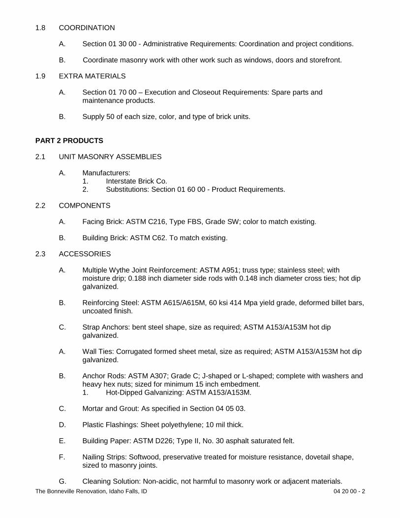
The Bonneville Renovation, Idaho Falls, ID 04 20 00 - 2
1.8 COORDINATION
A. Section 01 30 00 - Administrative Requirements: Coordination and project conditions.
B. Coordinate masonry work with other work such as windows, doors and storefront.
1.9 EXTRA MATERIALS
A. Section 01 70 00 – Execution and Closeout Requirements: Spare parts and maintenance products.
B. Supply 50 of each size, color, and type of brick units.
PART 2 PRODUCTS
2.1 UNIT MASONRY ASSEMBLIES
A. Manufacturers: 1. Interstate Brick Co. 2. Substitutions: Section 01 60 00 - Product Requirements.
2.2 COMPONENTS
A. Facing Brick: ASTM C216, Type FBS, Grade SW; color to match existing.
B. Building Brick: ASTM C62. To match existing.
2.3 ACCESSORIES
A. Multiple Wythe Joint Reinforcement: ASTM A951; truss type; stainless steel; with moisture drip; 0.188 inch diameter side rods with 0.148 inch diameter cross ties; hot dip galvanized.
B. Reinforcing Steel: ASTM A615/A615M, 60 ksi 414 Mpa yield grade, deformed billet bars, uncoated finish.
C. Strap Anchors: bent steel shape, size as required; ASTM A153/A153M hot dip galvanized.
A. Wall Ties: Corrugated formed sheet metal, size as required; ASTM A153/A153M hot dip galvanized.
B. Anchor Rods: ASTM A307; Grade C; J-shaped or L-shaped; complete with washers and heavy hex nuts; sized for minimum 15 inch embedment. 1. Hot-Dipped Galvanizing: ASTM A153/A153M.
C. Mortar and Grout: As specified in Section 04 05 03.
D. Plastic Flashings: Sheet polyethylene; 10 mil thick.
E. Building Paper: ASTM D226; Type II, No. 30 asphalt saturated felt.
F. Nailing Strips: Softwood, preservative treated for moisture resistance, dovetail shape, sized to masonry joints.
G. Cleaning Solution: Non-acidic, not harmful to masonry work or adjacent materials.

The Bonneville Renovation, Idaho Falls, ID 04 20 00 - 3
2.4 SOURCE QUALITY CONTROL
A. Section 01 40 00 – Quality Requirements: Testing, inspection and analysis requirements.
B. Test brick efflorescence in accordance with ASTM C67. Brick rated greater than “slightly effloresced” is not acceptable.
PART 3 EXECUTION
3.1 EXAMINATION
A. Section 01 30 00 - Administrative Requirements: coordination and project conditions.
B. Verify field conditions are acceptable and are ready to receive work.
C. Verify items provided by other sections of work are properly sized and located.
D. Verify built-in items are in proper location, and ready for roughing into masonry work.
3.2 PREPARATION
A. Direct and coordinate placement of metal anchors supplied to other sections.
B. Furnish temporary bracing during installation of masonry work. Maintain in place until building structure provides permanent support.
1.2 INSTALLATION
A. Establish lines, levels, and coursing indicated. Protect from displacement.
B. Maintain masonry courses to uniform dimension. Form bed and head joints of uniform thickness.
C. Coursing of Brick Units: To match existing.
D. Placing and Bonding: 1. Lay solid masonry units in full bed of mortar, with full head joints. 2. Lay hollow masonry units with face shell bedding on head and bed joints. 3. Buttering corners of joints or excessive furrowing of mortar joints are not
permitted. 4. Remove excess mortar as work progresses. 5. Interlock intersections and external corners. 6. Do not shift or tap masonry units after mortar has achieved initial set. Where
adjustment is required, remove mortar and replace. 7. Perform job site cutting of masonry units with proper tools to assure straight,
clean, unchipped edges. Prevent broken masonry unit corners or edges. 8. Isolate masonry from vertical structural framing members with movement joint. 9. Isolate top of masonry from horizontal structural framing members and slabs or
decks with compressible joint filler.
E. Reinforcement and Anchorages - Multiple Wythe Unit Masonry: 1. Install horizontal joint reinforcement 16 inches oc. 1. Place masonry joint reinforcement in first horizontal joints above and below
openings. Extend minimum 16 inches each side of opening.

The Bonneville Renovation, Idaho Falls, ID 04 20 00 - 4
2. Place joint reinforcement continuous in first joint below top of walls. 3. Lap joint reinforcement ends minimum 6 inches. 4. Support and secure reinforcing bars from displacement. Maintain position within
1/2 inch of dimensioned position. 5. Embed anchors embedded in concrete attached to structural steel members.
Embed anchorages in every sixth brick joint. 6. Reinforce joint corners and intersections with strap anchors 16 inches oc.
F. Masonry Flashings: 1. Extend flashings horizontally through outer wythe above ledge or shelf angles
and lintels, under parapet caps, at bottom of walls and turn down on outside face to form drip.
2. Turn flashing up minimum 8 inches and bed into mortar joint of masonry. 3. Lap end joints minimum 6 inches and seal watertight. 4. Turn flashing, fold, and seal at corners, bends, and interruptions.
G. Lintels: 1. Install loose steel lintels over openings. 2. Install reinforced masonry lintels over openings where steel lintels are not
scheduled or indicated. 3. Openings Up To 42 inches Wide: Place two, No. 4 M12 reinforcing bars 1 inch
from bottom web. 4. Openings From 42 inches Up To 78 inches Wide: Place two, No. 5 M16
reinforcing bars 1 inch from bottom web. 5. Openings Over 78 inches: Reinforce openings as indicated on Drawings. 6. Do not splice reinforcing bars. 7. Support and secure reinforcing bars from displacement. 8. Place and consolidate grout fill without displacing reinforcing. 9. Allow masonry lintels to attain specified strength before removing temporary
supports. 10. Maintain minimum 3 inch bearing on each side of opening.
H. Built-In Work: 1. As work progresses, install built-in door and window frames, anchor bolts, plates,
and other items to be built-in the work and furnished by other sections. 2. Install built-in items plumb and level. 3. Bed anchors of door and window frames in adjacent mortar joints. Fill frame
voids solid with grout or mortar. 4. Do not build in materials subject to deterioration.
I. Cutting and Fitting: 1. Cut and fit for chases, pipes, conduit and sleeves. Coordinate with other sections
of work to provide correct size, shape, and location. 2. Obtain Architect’s approval prior to cutting or fitting masonry work not indicated
or where appearance or strength of masonry work may be impaired.
J. Parging: 1. Dampen masonry walls prior to parging. 2. Scarify each parging coat to ensure full bond to subsequent coat. 3. Parge masonry walls in two uniform coats of mortar to total thickness of 3/4 inch. 4. Steel trowel surface smooth and flat with maximum surface variation of 1/8 inch
per foot. 5. Strike top edge of parging at 45 degrees.

The Bonneville Renovation, Idaho Falls, ID 04 20 00 - 5
1.3 ERECTION TOLERANCES
A. Section 01 40 00 - Quality Requirements: Tolerances.
B. Maximum Variation from Alignment of Columns: Pilasters: 1/4 inch.
C. Maximum Variation from Unit to Adjacent Unit: 1/16 inch.
D. Maximum Variation from Plane of Wall: 1/4 inch in 10 ft and 1/2 inch in 20 ft or more.
E. Maximum Variation from Plumb: 1/4 inch per story non-cumulative; 1/2 inch in two stories or more.
F. Maximum Variation from Level Coursing: 1/8 inch in 3 ft and 1/4 inch in 10 ft; 1/2 inch in 30 ft.
G. Maximum Variation of Joint Thickness: 1/8 inch in 3 ft.
H. Maximum Variation from Cross Sectional Thickness of Walls: 1/4 inch.
I. Maximum Variation for Steel Reinforcement: 1. Install reinforcement within the tolerances specified in ACI 530.1 for foundation
walls. 2. Plus or minus 1/2 inch when distance from centerline of steel to opposite face of
masonry is 8 inches or less. 3. Plus or minus 1 inch when distance is between 8 and 24 inches. 4. Plus or minus 1-1/4 inch when distance is greater than 24 inches. 5. Plus or minus 2 inches from location along face of wall.
1.4 FIELD QUALITY CONTROL
A. Section 01 40 00 - Quality Requirements 01 70 00 - Execution and Closeout Requirements: Field inspecting, testing, adjusting, and balancing.
B. Brick Units: Test each type in accordance with ASTM C67, 5 random units for each 50,000 units installed.
1.5 CLEANING
A. Section 01 70 00 - Execution and Closeout Requirements: Final cleaning.
B. Remove excess mortar and mortar smears as work progresses.
C. Replace defective mortar. Match adjacent work.
D. Clean soiled surfaces with cleaning solution.
E. Use non-metallic tools in cleaning operations.
1.6 PROTECTION OF FINISHED WORK
A. Section 01 70 00 - Execution and Closeout Requirements: Requirements for protecting finished Work.
B. Protect exposed external corners subject to damage.
C. Protect base of walls from mud and mortar splatter.

The Bonneville Renovation, Idaho Falls, ID 04 20 00 - 6
D. Protect masonry and other items built into masonry walls from mortar droppings and staining caused by mortar.
E. Protect tops of masonry work with waterproof coverings secured in place without damaging masonry. Provide coverings where masonry is exposed to weather when work is not in progress.
F. Protect adjacent properties from damage.
END OF SECTION
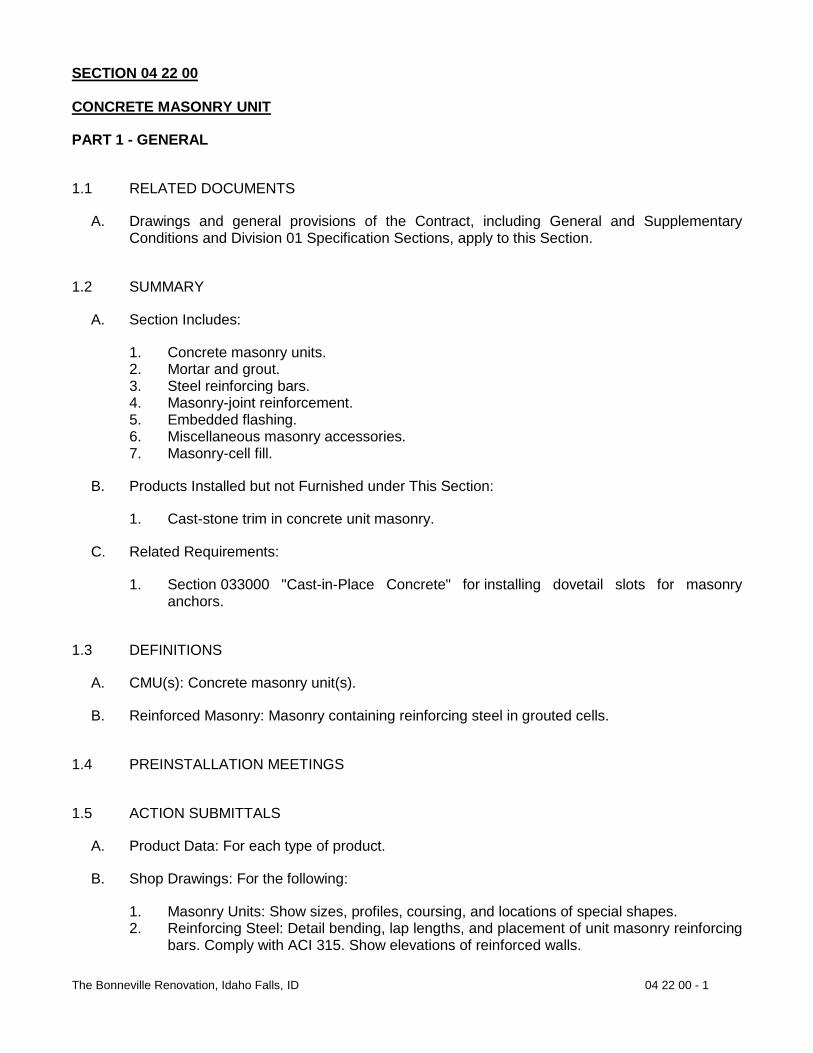
The Bonneville Renovation, Idaho Falls, ID 04 22 00 - 1
SECTION 04 22 00 CONCRETE MASONRY UNIT
PART 1 - GENERAL
1.1 RELATED DOCUMENTS
A. Drawings and general provisions of the Contract, including General and Supplementary Conditions and Division 01 Specification Sections, apply to this Section.
1.2 SUMMARY
A. Section Includes:
1. Concrete masonry units. 2. Mortar and grout. 3. Steel reinforcing bars. 4. Masonry-joint reinforcement. 5. Embedded flashing. 6. Miscellaneous masonry accessories. 7. Masonry-cell fill.
B. Products Installed but not Furnished under This Section:
1. Cast-stone trim in concrete unit masonry.
C. Related Requirements:
1. Section 033000 "Cast-in-Place Concrete" for installing dovetail slots for masonry anchors.
1.3 DEFINITIONS
A. CMU(s): Concrete masonry unit(s).
B. Reinforced Masonry: Masonry containing reinforcing steel in grouted cells.
1.4 PREINSTALLATION MEETINGS
1.5 ACTION SUBMITTALS
A. Product Data: For each type of product.
B. Shop Drawings: For the following:
1. Masonry Units: Show sizes, profiles, coursing, and locations of special shapes. 2. Reinforcing Steel: Detail bending, lap lengths, and placement of unit masonry reinforcing
bars. Comply with ACI 315. Show elevations of reinforced walls.

The Bonneville Renovation, Idaho Falls, ID 04 22 00 - 2
1.6 INFORMATIONAL SUBMITTALS
A. Qualification Data: For testing agency.
B. Material Certificates: For each type and size of the following:
1. Masonry units. a. For masonry units used in structural masonry, include data and calculations
establishing average net-area compressive strength of units.
2. Integral water repellant used in CMUs. 3. Cementitious materials. Include name of manufacturer, brand name, and type. 4. Mortar admixtures. 5. Preblended, dry mortar mixes. Include description of type and proportions of ingredients. 6. Grout mixes. Include description of type and proportions of ingredients. 7. Reinforcing bars. 8. Joint reinforcement. 9. Anchors, ties, and metal accessories.
C. Mix Designs: For each type of mortar and grout. Include description of type and proportions of ingredients.
1. Include test reports for mortar mixes required to comply with property specification. Test according to ASTM C 109/C 109M for compressive strength, ASTM C 1506 for water retention, and ASTM C 91/C 91M for air content.
2. Include test reports, according to ASTM C 1019, for grout mixes required to comply with compressive strength requirement.
D. Cold-Weather and Hot-Weather Procedures: Detailed description of methods, materials, and equipment to be used to comply with requirements.
1.7 QUALITY ASSURANCE
A. Testing Agency Qualifications: Qualified according to ASTM C 1093 for testing indicated.
1.8 DELIVERY, STORAGE, AND HANDLING
A. Store masonry units on elevated platforms in a dry location. If units are not stored in an enclosed location, cover tops and sides of stacks with waterproof sheeting, securely tied. If units become wet, do not install until they are dry.
B. Store cementitious materials on elevated platforms, under cover, and in a dry location. Do not use cementitious materials that have become damp.
C. Store aggregates where grading and other required characteristics can be maintained and contamination avoided.
D. Deliver preblended, dry mortar mix in moisture-resistant containers. Store preblended, dry mortar mix in delivery containers on elevated platforms in a dry location or in covered weatherproof dispensing silos.
E. Store masonry accessories, including metal items, to prevent corrosion and accumulation of dirt and oil.

The Bonneville Renovation, Idaho Falls, ID 04 22 00 - 3
1.9 FIELD CONDITIONS
A. Protection of Masonry: During construction, cover tops of walls, projections, and sills with waterproof sheeting at end of each day's work. Cover partially completed masonry when construction is not in progress.
1. Extend cover a minimum of 24 inches (600 mm) down both sides of walls, and hold cover securely in place.
B. Do not apply uniform floor or roof loads for at least 12 hours and concentrated loads for at least three days after building masonry walls or columns.
C. Stain Prevention: Prevent grout, mortar, and soil from staining the face of masonry to be left exposed or painted. Immediately remove grout, mortar, and soil that come in contact with such masonry.
1. Protect base of walls from rain-splashed mud and from mortar splatter by spreading coverings on ground and over wall surface.
2. Protect sills, ledges, and projections from mortar droppings. 3. Protect surfaces of window and door frames, as well as similar products with painted
and integral finishes, from mortar droppings. 4. Turn scaffold boards near the wall on edge at the end of each day to prevent rain from
splashing mortar and dirt onto completed masonry.
D. Cold-Weather Requirements: Do not use frozen materials or materials mixed or coated with ice or frost. Do not build on frozen substrates. Remove and replace unit masonry damaged by frost or by freezing conditions. Comply with cold-weather construction requirements contained in TMS 602/ACI 530.1/ASCE 6.
1. Cold-Weather Cleaning: Use liquid cleaning methods only when air temperature is 40 deg F (4 deg C) and higher and will remain so until masonry has dried, but not less than seven days after completing cleaning.
E. Hot-Weather Requirements: Comply with hot-weather construction requirements contained in TMS 602/ACI 530.1/ASCE 6.
PART 2 - PRODUCTS
2.1 MANUFACTURERS
A. Source Limitations for Masonry Units: Obtain exposed masonry units of a uniform texture and color, or a uniform blend within the ranges accepted for these characteristics, from single source from single manufacturer for each product required.
B. Source Limitations for Mortar Materials: Obtain mortar ingredients of a uniform quality, including color for exposed masonry, from single manufacturer for each cementitious component and from single source or producer for each aggregate.
2.2 PERFORMANCE REQUIREMENTS
A. Provide structural unit masonry that develops indicated net-area compressive strengths at 28 days.

The Bonneville Renovation, Idaho Falls, ID 04 22 00 - 4
1. Determine net-area compressive strength of masonry from average net-area compressive strengths of masonry units and mortar types (unit-strength method) according to TMS 602/ACI 530.1/ASCE 6.
2.3 UNIT MASONRY, GENERAL
A. Masonry Standard: Comply with TMS 602/ACI 530.1/ASCE 6 except as modified by requirements in the Contract Documents.
B. Defective Units: Referenced masonry unit standards may allow a certain percentage of units to contain chips, cracks, or other defects exceeding limits stated. Do not use units where such defects are exposed in the completed Work and will be within 20 feet (6 m) vertically and horizontally of a walking surface.
C. Fire-Resistance Ratings: Comply with requirements for fire-resistance-rated assembly designs indicated.
1. Where fire-resistance-rated construction is indicated, units shall be listed and labeled by a qualified testing agency acceptable to authorities having jurisdiction.
2.4 CONCRETE MASONRY UNITS
A. Shapes: Provide shapes indicated and as follows, with exposed surfaces matching exposed faces of adjacent units unless otherwise indicated.
1. Provide special shapes for lintels, corners, jambs, sashes, movement joints, headers, bonding, and other special conditions.
2. Provide square-edged units for outside corners unless otherwise indicated.
B. CMUs: ASTM C 90.
1. Unit Compressive Strength: Provide units with minimum average net-area compressive strength of 2000 psi (19.3 MPa).
2. Density Classification: Normal weight. 3. Size (Actual Dimensions): 7-5/8 inches (92 mm) wide by 7-5/8 inches (92 mm) high by
15-5/8 inches (194 mm) long.
2.5 CONCRETE AND MASONRY LINTELS
A. General: Provide one of the following:
B. Concrete Lintels: ASTM C 1623, matching CMUs in color, texture, and density classification; and with reinforcing bars indicated. Provide lintels with net-area compressive strength not less than that of CMUs.
C. Concrete Lintels: Precast or formed-in-place concrete lintels complying with requirements in Section 033000 "Cast-in-Place Concrete," and with reinforcing bars indicated.
D. Masonry Lintels: Prefabricated or built-in-place masonry lintels made from bond beam CMUs matching adjacent CMUs in color, texture, and density classification, with reinforcing bars placed as indicated and filled with coarse grout. Cure precast lintels before handling and installing. Temporarily support built-in-place lintels until cured.

The Bonneville Renovation, Idaho Falls, ID 04 22 00 - 5
2.6 MORTAR AND GROUT MATERIALS
A. Portland Cement: ASTM C 150/C 150M, Type I or II, except Type III may be used for cold-weather construction. Provide natural color or white cement as required to produce mortar color indicated.
1. Alkali content shall not be more than 0.1 percent when tested according to ASTM C 114.
B. Hydrated Lime: ASTM C 207, Type S.
C. Portland Cement-Lime Mix: Packaged blend of portland cement and hydrated lime containing no other ingredients.
D. Masonry Cement: ASTM C 91/C 91M.
E. Mortar Cement: ASTM C 1329/C 1329M.
1. Formulate blend as required to produce color indicated or, if not indicated, as selected from manufacturer's standard colors.
F. Aggregate for Mortar: ASTM C 144.
1. For mortar that is exposed to view, use washed aggregate consisting of natural sand or crushed stone.
2. For joints less than 1/4 inch (6 mm) thick, use aggregate graded with 100 percent passing the No. 16 (1.18-mm) sieve.
3. Colored-Mortar Aggregates: Natural sand or crushed stone of color necessary to produce required mortar color.
G. Aggregate for Grout: ASTM C 404.
H. Cold-Weather Admixture: Nonchloride, noncorrosive, accelerating admixture complying with ASTM C 494/C 494M, Type C, and recommended by manufacturer for use in masonry mortar of composition indicated.
I. Water-Repellent Admixture: Liquid water-repellent mortar admixture intended for use with CMUs containing integral water repellent from same manufacturer.
J. Water: Potable.
2.7 REINFORCEMENT
A. Uncoated Steel Reinforcing Bars: ASTM A 615/A 615M or ASTM A 996/A 996M, Grade 60 (Grade 420).
B. Reinforcing Bar Positioners: Wire units designed to fit into mortar bed joints spanning masonry unit cells and to hold reinforcing bars in center of cells. Units are formed from 0.148-inch (3.77-mm) steel wire, hot-dip galvanized after fabrication. Provide units designed for number of bars indicated.
C. Masonry-Joint Reinforcement, General: Ladder type complying with ASTM A 951/A 951M.
1. Interior Walls: Hot-dip galvanized carbon steel. 2. Exterior Walls: Hot-dip galvanized carbon.

The Bonneville Renovation, Idaho Falls, ID 04 22 00 - 6
3. Wire Size for Side Rods: 0.148-inch (3.77-mm) diameter. 4. Wire Size for Cross Rods: 0.148-inch (3.77-mm) diameter. 5. Spacing of Cross Rods: Not more than 16 inches (407 mm) o.c. 6. Provide in lengths of not less than 10 feet (3 m), with prefabricated corner and tee units.
2.8 TIES AND ANCHORS
A. General: Ties and anchors shall extend at least 1-1/2 inches (38 mm) into masonry but with at least a 5/8-inch (16-mm) cover on outside face.
B. Materials: Provide ties and anchors specified in this article that are made from materials that comply with the following unless otherwise indicated:
1. Mill-Galvanized, Carbon-Steel Wire: ASTM A 82/A 82M, with ASTM A 641/A 641M, Class 1 coating.
2. Hot-Dip Galvanized, Carbon-Steel Wire: ASTM A 82/A 82M, with ASTM A 153/A 153M, Class B-2 coating.
3. Steel Plates, Shapes, and Bars: ASTM A 36/A 36M.
C. Adjustable Anchors for Connecting to Structural Steel Framing: Provide anchors that allow vertical or horizontal adjustment but resist tension and compression forces perpendicular to plane of wall.
2.9 EMBEDDED FLASHING MATERIALS
A. Metal Flashing: Provide metal flashing complying with SMACNA's "Architectural Sheet Metal Manual" Section 076200 "Sheet Metal Flashing and Trim" and as follows:
1. Stainless Steel: ASTM A 240/A 240M or ASTM A 666, Type 304, 0.016 inch (0.40 mm) thick.
2. Copper: ASTM B 370, Temper H00, cold-rolled copper sheet, 16-oz./sq. ft. (4.9-kg/sq. m) weight or 0.0216 inch (0.55 mm) thick or ASTM B 370, Temper H01, high-yield copper sheet, 12-oz./sq. ft. (3.7-kg/sq. m) weight or 0.0162 inch (0.41 mm) thick.
3. Fabricate continuous flashings in sections 96 inches (2400 mm) long minimum, but not exceeding 12 feet (3.7 m). Provide splice plates at joints of formed, smooth metal flashing.
4. Fabricate through-wall metal flashing embedded in masonry from stainless steel copper, with ribs at 3-inch (76-mm) intervals along length of flashing to provide an integral mortar bond.
5. Fabricate through-wall flashing with snaplock receiver on exterior face where indicated to receive counterflashing.
6. Fabricate through-wall flashing with drip edge where unless otherwise indicated. Fabricate by extending flashing 1/2 inch (13 mm) out from wall, with outer edge bent down 30 degrees and hemmed.
7. Fabricate through-wall flashing with sealant stop where unless otherwise indicated. Fabricate by bending metal back on itself 3/4 inch (19 mm) at exterior face of wall and down into joint 1/4 inch (6 mm) to form a stop for retaining sealant backer rod.
8. Fabricate metal drip edges and sealant stops for ribbed metal flashing from plain metal flashing of same metal as ribbed flashing and extending at least 3 inches (76 mm) into wall with hemmed inner edge to receive ribbed flashing and form a hooked seam. Form hem on upper surface of metal so that completed seam sheds water.

The Bonneville Renovation, Idaho Falls, ID 04 22 00 - 7
9. Fabricate metal drip edges from stainless steel. Extend at least 3 inches (76 mm) into wall and 1/2 inch (13 mm) out from wall, with outer edge bent down 30 degrees and hemmed.
10. Fabricate metal sealant stops from stainless steel. Extend at least 3 inches (76 mm) into wall and out to exterior face of wall. At exterior face of wall, bend metal back on itself for 3/4 inch (19 mm) and down into joint 1/4 inch (6 mm) to form a stop for retaining sealant backer rod.
11. Fabricate metal expansion-joint strips from stainless steel copper to shapes indicated. 12. Solder metal items at corners.
B. Flexible Flashing: Use one of the following unless otherwise indicated:
1. Copper-Laminated Flashing: 5-oz./sq. ft. (1.5-kg/sq. m) 7-oz./sq. ft. (2-kg/sq. m) copper sheet bonded between two layers of glass-fiber cloth. Use only where flashing is fully concealed in masonry.
2. Asphalt-Coated Copper Flashing: 5-oz./sq. ft. (1.5-kg/sq. m) 7-oz./sq. ft. (2-kg/sq. m) copper sheet coated with flexible asphalt. Use only where flashing is fully concealed in masonry.
3. Rubberized-Asphalt Flashing: Composite flashing product consisting of a pliable, adhesive rubberized-asphalt compound, bonded to a high-density, cross-laminated polyethylene film to produce an overall thickness of not less than 0.030 inch (0.76 mm) 0.040 inch (1.02 mm). a. Accessories: Provide preformed corners, end dams, other special shapes, and
seaming materials produced by flashing manufacturer.
4. Butyl Rubber Flashing: Composite, self-adhesive, flashing product consisting of a pliable, butyl rubber compound, bonded to a high-density polyethylene film, aluminum foil, or spunbonded polyolefin to produce an overall thickness of not less than 0.030 inch (0.76 mm) 0.040 inch (1.02 mm). a. Accessories: Provide preformed corners, end dams, other special shapes, and
seaming materials produced by flashing manufacturer.
5. Elastomeric Thermoplastic Flashing: Composite flashing product consisting of a polyester-reinforced ethylene interpolymer alloy. a. Monolithic Sheet: Elastomeric thermoplastic flashing, 0.040 inch (1.02 mm) thick. b. Self-Adhesive Sheet: Elastomeric thermoplastic flashing, 0.025 inch (0.64 mm)
thick, with a 0.015-inch- (0.38-mm-) thick coating of adhesive. c. Self-Adhesive Sheet with Drip Edge: Elastomeric thermoplastic flashing, 0.025
inch (0.64 mm) thick, with a 0.015-inch- (0.38-mm-) thick coating of rubberized-asphalt adhesive. Where flashing extends to face of masonry, rubberized-asphalt coating is held back approximately 1-1/2 inches (38 mm) from edge.
1) Color: Gray White Tan/buff Black.
d. Accessories: Provide preformed corners, end dams, other special shapes, and seaming materials produced by flashing manufacturer.
6. EPDM Flashing: Sheet flashing product made from ethylene-propylene-diene terpolymer, complying with ASTM D 4637/D 4637M, 0.040 inch (1.02 mm) thick.
C. Application: Unless otherwise indicated, use the following:

The Bonneville Renovation, Idaho Falls, ID 04 22 00 - 8
1. Where flashing is indicated to receive counterflashing, use metal flashing. 2. Where flashing is indicated to be turned down at or beyond the wall face, use metal
flashing. 3. Where flashing is partly exposed and is indicated to terminate at the wall face, use metal
flashing with a drip edge with a sealant stop or flexible flashing with a metal drip edge or elastomeric thermoplastic flashing with a drip edge or flexible flashing with a metal sealant stop.
4. Where flashing is fully concealed, use metal flashing or flexible flashing.
D. Single-Wythe CMU Flashing System: System of CMU cell flashing pans and interlocking CMU web covers made from UV-resistant, high-density polyethylene. Cell flashing pans have integral weep spouts designed to be built into mortar bed joints and that extend into the cell to prevent clogging with mortar.
E. Solder and Sealants for Sheet Metal Flashings: As specified in Section 076200 "Sheet Metal Flashing and Trim."
1. Solder for Stainless Steel: ASTM B 32, Grade Sn60 Grade Sn96, with acid flux of type recommended by stainless-steel sheet manufacturer.
2. Solder for Copper: ASTM B 32, Grade Sn50 with maximum lead content of 0.2 percent. 3. Elastomeric Sealant: ASTM C 920, chemically curing urethane polysulfide silicone
sealant; of type, grade, class, and use classifications required to seal joints in sheet metal flashing and remain watertight.
F. Adhesives, Primers, and Seam Tapes for Flashings: Flashing manufacturer's standard products or products recommended by flashing manufacturer for bonding flashing sheets to each other and to substrates.
2.10 MASONRY-CELL FILL
A. Loose-Fill Insulation: Perlite complying with ASTM C 549, Type II (surface treated for water repellency and limited moisture absorption) or Type IV (surface treated for water repellency and to limit dust generation).
B. Lightweight-Aggregate Fill: ASTM C 331/C 331M.
2.11 MORTAR AND GROUT MIXES
A. General: Do not use admixtures, including pigments, air-entraining agents, accelerators, retarders, water-repellent agents, antifreeze compounds, or other admixtures unless otherwise indicated.
1. Do not use calcium chloride in mortar or grout. 2. Use portland cement-lime masonry cement or mortar cement mortar unless otherwise
indicated. 3. For exterior masonry, use portland cement-lime masonry cement or mortar cement
mortar. 4. For reinforced masonry, use portland cement-lime masonry cement or mortar cement
mortar.

The Bonneville Renovation, Idaho Falls, ID 04 22 00 - 9
5. Add cold-weather admixture (if used) at same rate for all mortar that will be exposed to view, regardless of weather conditions, to ensure that mortar color is consistent.
B. Preblended, Dry Mortar Mix: Furnish dry mortar ingredients in form of a preblended mix. Measure quantities by weight to ensure accurate proportions, and thoroughly blend ingredients before delivering to Project site.
C. Mortar for Unit Masonry: Comply with ASTM C 270, Proportion Property Specification. Provide the following types of mortar for applications stated unless another type is indicated or needed to provide required compressive strength of masonry.
1. For masonry below grade or in contact with earth, use Type M or Type S. 2. For reinforced masonry, use Type S. 3. For exterior, above-grade, load-bearing and nonload-bearing walls and parapet walls; for
interior load-bearing walls; for interior nonload-bearing partitions; and for other applications where another type is not indicated, use Type N.
4. For interior nonload-bearing partitions, Type O may be used instead of Type N.
D. Grout for Unit Masonry: Comply with ASTM C 476.
1. Use grout of type indicated or, if not otherwise indicated, of type (fine or coarse) that will comply with TMS 602/ACI 530.1/ASCE 6 for dimensions of grout spaces and pour height.
2. Proportion grout in accordance with ASTM C 476, Table 1 or paragraph 4.2.2 for specified 28-day compressive strength indicated, but not less than 2500 psi (14 MPa).
3. Provide grout with a slump of 8 to 11 inches (200 to 280 mm) as measured according to ASTM C 143/C 143M.
PART 3 - EXECUTION
3.1 EXAMINATION
A. Examine conditions, with Installer present, for compliance with requirements for installation tolerances and other conditions affecting performance of the Work.
1. For the record, prepare written report, endorsed by Installer, listing conditions detrimental to performance of the Work.
2. Verify that foundations are within tolerances specified. 3. Verify that reinforcing dowels are properly placed. 4. Verify that substrates are free of substances that would impair mortar bond.
B. Before installation, examine rough-in and built-in construction for piping systems to verify actual locations of piping.
C. Proceed with installation only after unsatisfactory conditions have been corrected.
3.2 INSTALLATION, GENERAL
A. Build chases and recesses to accommodate items specified in this and other Sections.
B. Leave openings for equipment to be installed before completing masonry. After installing equipment, complete masonry to match construction immediately adjacent to opening.

The Bonneville Renovation, Idaho Falls, ID 04 22 00 - 10
C. Use full-size units without cutting if possible. If cutting is required to provide a continuous pattern or to fit adjoining construction, cut units with motor-driven saws; provide clean, sharp, unchipped edges. Allow units to dry before laying unless wetting of units is specified. Install cut units with cut surfaces and, where possible, cut edges concealed.
3.3 TOLERANCES
A. Dimensions and Locations of Elements:
1. For dimensions in cross section or elevation, do not vary by more than plus 1/2 inch (12 mm) or minus 1/4 inch (6 mm).
2. For location of elements in plan, do not vary from that indicated by more than plus or minus 1/2 inch (12 mm).
3. For location of elements in elevation, do not vary from that indicated by more than plus or minus 1/4 inch (6 mm) in a story height or 1/2 inch (12 mm) total.
B. Lines and Levels:
1. For bed joints and top surfaces of bearing walls, do not vary from level by more than 1/4 inch in 10 feet (6 mm in 3 m), or 1/2-inch (12-mm) maximum.
2. For conspicuous horizontal lines, such as lintels, sills, parapets, and reveals, do not vary from level by more than 1/8 inch in 10 feet (3 mm in 3 m), 1/4 inch in 20 feet (6 mm in 6 m), or 1/2-inch (12-mm) maximum.
3. For vertical lines and surfaces do not vary from plumb by more than 1/4 inch in 10 feet (6 mm in 3 m), 3/8 inch in 20 feet (9 mm in 6 m), or 1/2-inch (12-mm) maximum.
4. For conspicuous vertical lines, such as external corners, door jambs, reveals, and expansion and control joints, do not vary from plumb by more than 1/8 inch in 10 feet (3 mm in 3 m), 1/4 inch in 20 feet (6 mm in 6 m), or 1/2-inch (12-mm) maximum.
5. For lines and surfaces, do not vary from straight by more than 1/4 inch in 10 feet (6 mm in 3 m), 3/8 inch in 20 feet (9 mm in 6 m), or 1/2-inch (12-mm) maximum.
6. For vertical alignment of exposed head joints, do not vary from plumb by more than 1/4 inch in 10 feet (6 mm in 3 m), or 1/2-inch (12-mm) maximum.
7. For faces of adjacent exposed masonry units, do not vary from flush alignment by more than 1/16 inch (1.5 mm).
C. Joints:
1. For bed joints, do not vary from thickness indicated by more than plus or minus 1/8 inch (3 mm), with a maximum thickness limited to 1/2 inch (12 mm).
2. For exposed bed joints, do not vary from bed-joint thickness of adjacent courses by more than 1/8 inch (3 mm).
3. For head and collar joints, do not vary from thickness indicated by more than plus 3/8 inch (9 mm) or minus 1/4 inch (6 mm).
4. For exposed head joints, do not vary from thickness indicated by more than plus or minus 1/8 inch (3 mm).
3.4 LAYING MASONRY WALLS
A. Lay out walls in advance for accurate spacing of surface bond patterns with uniform joint thicknesses and for accurate location of openings, movement-type joints, returns, and offsets. Avoid using less-than-half-size units, particularly at corners, jambs, and, where possible, at other locations.

The Bonneville Renovation, Idaho Falls, ID 04 22 00 - 11
B. Bond Pattern for Exposed Masonry: Unless otherwise indicated, lay exposed masonry in running bond; do not use units with less-than-nominal 4-inch (100-mm) horizontal face dimensions at corners or jambs.
C. Lay concealed masonry with all units in a wythe in running bond or bonded by lapping not less than 4 inches (100 mm). Bond and interlock each course of each wythe at corners. Do not use units with less-than-nominal 4-inch (100-mm) horizontal face dimensions at corners or jambs.
D. Stopping and Resuming Work: Stop work by stepping back units in each course from those in course below; do not tooth. When resuming work, clean masonry surfaces that are to receive mortar, remove loose masonry units and mortar, and wet brick if required before laying fresh masonry.
E. Built-in Work: As construction progresses, build in items specified in this and other Sections. Fill in solidly with masonry around built-in items.
1. Install compressible filler in joint between top of partition and underside of structure above.
2. At fire-rated partitions, treat joint between top of partition and underside of structure above to comply with Section 078443 "Joint Firestopping."
3.5 MORTAR BEDDING AND JOINTING
A. Lay hollow CMUs as follows:
1. Bed face shells in mortar and make head joints of depth equal to bed joints. 2. Bed webs in mortar in all courses of piers, columns, and pilasters. 3. Bed webs in mortar in grouted masonry, including starting course on footings. 4. Fully bed entire units, including areas under cells, at starting course on footings where
cells are not grouted.
B. Lay solid CMUs with completely filled bed and head joints; butter ends with sufficient mortar to fill head joints and shove into place. Do not deeply furrow bed joints or slush head joints.
C. Set cast-stone trim units in full bed of mortar with full vertical joints. Fill dowel, anchor, and similar holes.
1. Clean soiled surfaces with fiber brush and soap powder and rinse thoroughly with clear water.
2. Wet joint surfaces thoroughly before applying mortar. 3. Rake out mortar joints for pointing with sealant.
D. Rake out mortar joints at pre-faced CMUs to a uniform depth of 1/4 inch (6 mm) and point with epoxy mortar to comply with epoxy-mortar manufacturer's written instructions.
E. Tool exposed joints slightly concave when thumbprint hard, using a jointer larger than joint thickness unless otherwise indicated.
F. Cut joints flush for masonry walls to receive plaster or other direct-applied finishes (other than paint) unless otherwise indicated.
G. Cut joints flush where indicated to receive waterproofing unless otherwise indicated.

The Bonneville Renovation, Idaho Falls, ID 04 22 00 - 12
3.6 MASONRY-CELL FILL
A. Pour loose-fill insulation lightweight-aggregate fill into cavities to fill void spaces. Maintain inspection ports to show presence of fill at extremities of each pour area. Close the ports after filling has been confirmed. Limit the fall of fill to one story high, but not more than 20 feet (6 m).
B. Install molded-polystyrene insulation units into masonry unit cells before laying units.
3.7 MASONRY-JOINT REINFORCEMENT
A. General: Install entire length of longitudinal side rods in mortar with a minimum cover of 5/8 inch (16 mm) on exterior side of walls, 1/2 inch (13 mm) elsewhere. Lap reinforcement a minimum of 6 inches (150 mm).
B. Interrupt joint reinforcement at control and expansion joints unless otherwise indicated.
C. Provide continuity at corners by using prefabricated L-shaped units.
3.8 CONTROL AND EXPANSION JOINTS
A. General: Install control- and expansion-joint materials in unit masonry as masonry progresses. Do not allow materials to span control and expansion joints without provision to allow for in-plane wall or partition movement.
B. Form control joints in concrete masonry using one of the following methods:
1. Fit bond-breaker strips into hollow contour in ends of CMUs on one side of control joint. Fill resultant core with grout, and rake out joints in exposed faces for application of sealant.
2. Install preformed control-joint gaskets designed to fit standard sash block. 3. Install interlocking units designed for control joints. Install bond-breaker strips at joint.
Keep head joints free and clear of mortar, or rake out joint for application of sealant. 4. Install temporary foam-plastic filler in head joints, and remove filler when unit masonry is
complete for application of sealant.
3.9 LINTELS
A. Provide concrete or masonry lintels where shown and where openings of more than 12 inches (305 mm) for brick-size units and 24 inches (610 mm) for block-size units are shown without structural steel or other supporting lintels.
3.10 FLASHING
A. General: Install embedded flashing at ledges and other obstructions to downward flow of water in wall where indicated.
B. Install flashing as follows unless otherwise indicated:
1. Prepare masonry surfaces so they are smooth and free from projections that could puncture flashing. Where flashing is within mortar joint, place through-wall flashing on sloping bed of mortar and cover with mortar. Before covering with mortar, seal

The Bonneville Renovation, Idaho Falls, ID 04 22 00 - 13
penetrations in flashing with adhesive, sealant, or tape as recommended by flashing manufacturer.
2. At lintels, extend flashing a minimum of 6 inches (150 mm) into masonry at each end. At heads and sills, extend flashing 6 inches (150 mm) at ends and turn up not less than 2 inches (50 mm) to form end dams.
3. Interlock end joints of ribbed sheet metal flashing by overlapping ribs not less than 1-1/2 inches (38 mm) or as recommended by flashing manufacturer, and seal lap with elastomeric sealant complying with requirements in Section 079200 "Joint Sealants" for application indicated.
4. Install metal drip edges and sealant stops with ribbed sheet metal flashing by interlocking hemmed edges to form hooked seam. Seal seam with elastomeric sealant complying with requirements in Section 079200 "Joint Sealants" for application indicated.
5. Install metal drip edges beneath flexible flashing at exterior face of wall. Stop flexible flashing 1/2 inch (13 mm) back from outside face of wall, and adhere flexible flashing to top of metal drip edge.
6. Install metal flashing termination beneath flexible flashing at exterior face of wall. Stop flexible flashing 1/2 inch (13 mm) back from outside face of wall, and adhere flexible flashing to top of metal flashing termination.
7. Cut flexible flashing off flush with face of wall after masonry wall construction is completed.
C. Install single-wythe CMU flashing system in bed joints of CMU walls where indicated to comply with manufacturer's written instructions. Install CMU cell pans with upturned edges located below face shells and webs of CMUs above and with weep spouts aligned with face of wall. Install CMU web covers so that they cover upturned edges of CMU cell pans at CMU webs and extend from face shell to face shell.
D. Install reglets and nailers for flashing and other related construction where they are shown to be built into masonry.
3.11 FIELD QUALITY CONTROL
A. Testing and Inspecting: Owner will engage special inspectors to perform tests and inspections and prepare reports. Allow inspectors access to scaffolding and work areas as needed to perform tests and inspections. Retesting of materials that fail to comply with specified requirements shall be done at Contractor's expense.
3.12 REPAIRING, POINTING, AND CLEANING
A. Remove and replace masonry units that are loose, chipped, broken, stained, or otherwise damaged or that do not match adjoining units. Install new units to match adjoining units; install in fresh mortar, pointed to eliminate evidence of replacement.
B. Pointing: During the tooling of joints, enlarge voids and holes, except weep holes, and completely fill with mortar. Point up joints, including corners, openings, and adjacent construction, to provide a neat, uniform appearance. Prepare joints for sealant application, where indicated.
C. In-Progress Cleaning: Clean unit masonry as work progresses by dry brushing to remove mortar fins and smears before tooling joints.

The Bonneville Renovation, Idaho Falls, ID 04 22 00 - 14
D. Final Cleaning: After mortar is thoroughly set and cured, clean exposed masonry as follows:
1. Remove large mortar particles by hand with wooden paddles and nonmetallic scrape hoes or chisels.
2. Wet wall surfaces with water before applying cleaners; remove cleaners promptly by rinsing surfaces thoroughly with clear water.
3. Clean concrete masonry by applicable cleaning methods indicated in NCMA TEK 8-4A.
3.13 MASONRY WASTE DISPOSAL
A. Salvageable Materials: Unless otherwise indicated, excess masonry materials are Contractor's property. At completion of unit masonry work, remove from Project site.
B. Waste Disposal as Fill Material: Dispose of clean masonry waste, including excess or soil-contaminated sand, waste mortar, and broken masonry units, by crushing and mixing with fill material as fill is placed.
1. Crush masonry waste to less than 4 inches (100 mm) in each dimension. 2. Mix masonry waste with at least two parts of specified fill material for each part of
masonry waste. Fill material is specified in Section 312000 "Earth Moving." 3. Do not dispose of masonry waste as fill within 18 inches (450 mm) of finished grade.
C. Masonry Waste Recycling: Return broken CMUs not used as fill to manufacturer for recycling.
D. Excess Masonry Waste: Remove excess clean masonry waste that cannot be used as fill, as described above or recycled, and other masonry waste, and legally dispose of off Owner's property.
END OF SECTION

The Bonneville Renovation, Idaho Falls, ID 04 72 00 - 1
SECTION 04 72 00
CAST STONE MASONRY
PART 1 GENERAL
1.1 SUMMARY
A. Section Includes: 1. Cast stone sills and copings. 2. Anchors and supports. 3. Accessories.
1.2 REFERENCES
A. American Concrete Institute: 1. ACI 530 - Building Code Requirements for Masonry Structures. 2. ACI 530.1 - Specifications for Masonry Structures.
1.3 SUBMITTALS
A. Section 01 33 00 - Submittal Procedures: Requirements for submittals.
B. Shop Drawings: 1. Indicate cast stone layout, profiles, cross-sections, reinforcement, exposed faces,
joint arrangement, anchoring methods, anchors.
C. Product Data: Submit data for cast stone units, wall ties, anchors, and other accessories.
D. Samples: 1. Submit two of each cast stone item illustrating profiles, finish, texture and color
range. 2. Submit two of each anchor and illustrating material, configuration, and finish.
1.4 QUALITY ASSURANCE
A. Perform Work in accordance with ACI 530 Building Code Requirements for Masonry Structures and ACI 530.1 Specification for Masonry Structures.
B. Perform Work in accordance with Cast Stone Institute Technical Manual.
1.5 DELIVERY, STORAGE, AND HANDLING
A. Section 01 60 00 - Product Requirements: Requirements for transporting, handling, storing, and protecting products.
B. Accept cast stone on site in manufacturer’s protective packaging. Inspect for damage.
C. Store cast stone on site covered and elevated above grade. Protect cast stone from damage, soiling, and staining.
D. Provide ventilation to prevent condensation from forming on cast stone.

The Bonneville Renovation, Idaho Falls, ID 04 72 00 - 2
1.6 ENVIRONMENTAL REQUIREMENTS
A. Section 01 60 00 - Product Requirements: Environmental conditions affecting products on site.
B. Cold Weather Requirements: In accordance with ACI 530.1 when ambient temperature or temperature of masonry units is less than 40 degrees F.
C. Hot Weather Requirements: In accordance with ACI 530.1 when ambient temperature is greater than 100 degrees F or ambient temperature is greater than 90 degrees F with wind velocity greater than 8 mph.
1.7 FIELD MEASUREMENTS
A. Verify field measurements prior to fabrication.
1.8 COORDINATION
A. Section 01 30 00 - Administrative Requirements: Requirements for coordination.
B. Coordinate cast stone work with masonry work.
1.9 EXTRA MATERIALS
A. Section 01 70 00 - Execution and Closeout Requirements: Requirements for extra materials.
PART 2 PRODUCTS
2.1 CAST STONE
A. Manufacturers: 1. Behner Concrete. 2. Amcor 3. Substitutions: Section 01 60 00 - Product Requirements Not Permitted.
B. Product Description: ASTM C1364, architectural cast stone units fabricated by wet casting methods, with fine grained texture, simulating natural cut stone.
C. Color and Finish: To match existing.
2.2 COMPONENTS
A. Portland Cement: ASTM C150, Type III - High Early Strength; grey color.
B. Coarse Aggregates: ASTM C33, except grading requirements; granite, quartz or limestone.
C. Fine Aggregates: ASTM C33, except grading requirements; manufactured or natural sand.
D. Colors: ASTM C979; inorganic iron oxide pigments.
E. Admixtures: ASTM C494/C494M.
F. Fly Ash: ASTM C618.

The Bonneville Renovation, Idaho Falls, ID 04 72 00 - 3
G. Water: Potable.
2.3 ACCESSORIES
A. Wall Ties: Formed steel wire.
B. Mortar: As specified in Section 04 05 03.
C. Plastic Flashings: Sheet polyethylene; 10 mil thick.
D. Cleaning Solution: Acidic detergent type, not harmful to cast stone or adjacent materials.
2.4 MIXES
A. Concrete Mix: 1. Compressive Strength: ASTM C1194; minimum 6,500 psi at 28 days.
2.5 FABRICATION
A. Size: As indicated on Drawings and to match existing.
B. Use rigid molds, constructed to maintain cast stone units uniform in shape, size, and finish.
C. Form units to length required for joint layout indicated on Drawings. Field cutting to length is not permitted.
D. Reinforce units in accordance with ASTM C1364 for safe handling and as indicated on Drawings to resist structural loads. 1. Use galvanized finished reinforcing when concrete cover over reinforcing is less
than 1-1/2 inches thick, including end conditions.
E. Embed anchors and other cast-in items.
F. Form external corners to square joint profile.
G. Slope exposed top surfaces of horizontal sill, coping and surfaces for natural wash.
H. Form drip slot in bottom surface of exterior units projecting more than 1/2 inch beyond face of wall window frame. Size slot not less than 3/8 inch wide and 1/4 inch deep; full width of projection.
I. Curing: Cure units to develop concrete quality, and to minimize appearance blemishes including non-uniformity, staining, or surface cracking.
J. Acid etch exposed-to-view surfaces to remove cement film and achieve uniform appearance.
PART 3 EXECUTION
1.1 EXAMINATION
A. Section 01 30 00 - Administrative Requirements: Verification of existing conditions before starting work.
B. Verify field conditions are acceptable and are ready to receive work.

The Bonneville Renovation, Idaho Falls, ID 04 72 00 - 4
C. Verify items provided by other sections of work are properly sized and located.
1.2 PREPARATION
A. Coordinate installation of anchors furnished to other sections.
B. Provide for erection procedures and induced loads during erection. Furnish temporary bracing during installation. Maintain temporary bracing in place until final support is provided.
1.3 INSTALLATION
A. Establish lines, levels, and coursing indicated. Protect from displacement.
B. Maintain cast stone courses to uniform dimension. Form bed and head joints of uniform thickness.
C. Placing and Bonding: 1. Install anchors to support and position cast stone. 2. Drench cast stone units with clear running water, just prior to setting. 3. Lay cast stone units in full bed of mortar, with full head joints. 4. Leave head and top joints in units with exposed top surfaces open to receive
sealant. 5. Leave joints under relieving shelf angles open to receive sealant. 6. Fill dowel holes and anchor slots with mortar. 7. Do not shift or tap cast stone units after mortar has achieved initial set. Where
adjustment is required, remove mortar and replace. 8. Rake mortar joints 3/4 inches deep for pointing. Sponge face of each stone to
remove excess mortar. 9. Tuck point mortar joints. Pack mortar tightly into joint. Tool joint surface to shape
specified. 10. Site cutting of cast stone units is not permitted.
1.4 ERECTION TOLERANCES
A. Section 01 40 00 - Quality Requirements: Tolerances.
B. Maximum Variation of Joint Thickness: Plus 1/16 inch; minus 1/8 inch.
C. Maximum Offset from Adjacent Unit: 1/8 inch.
D. Maximum Variation from Plane of Wall: 1/4 inch in 10 ft and 1/2 inch in 20 ft or more.
E. Maximum Variation from Plumb: 1/4 inch in each story non-cumulative; 1/2 inch in two stories or more.
F. Maximum Variation from Level Coursing: 1/8 inch in 3 ft and 1/4 inch in 10 ft; 1/2 inch in 30 ft.
1.5 CLEANING
A. Section 01 70 00 - Execution and Closeout Requirements: Requirements for cleaning.
B. Remove excess mortar as work progresses.
C. Replace defective mortar. Match adjacent work.

The Bonneville Renovation, Idaho Falls, ID 04 72 00 - 5
D. Wet cast stone. Clean soiled surfaces with cleaning solution.
E. Use non-metallic tools in cleaning operations.
1.6 PROTECTION OF FINISHED WORK
A. Section 01 70 00 - Execution and Closeout Requirements: Requirements for protecting finished Work.
B. Protect cast stone from contact with mortar, soil, and other materials capable of staining or discoloring cast stone.
END OF DIVISION

The Bonneville Renovation, Idaho Falls, ID 05 12 00 - 1
DIVISION 05 METALS
SECTION 05 12 00
STRUCTURAL STEEL FRAMING
PART 1 - GENERAL
1.1 RELATED DOCUMENTS
A. Drawings and general provisions of the Contract, including General and Supplementary Conditions and Division 01 Specification Sections, apply to this Section.
1.2 SUMMARY
A. Section Includes:
1. Structural steel. 2. Prefabricated building columns. 3. Field-installed shear connectors. 4. Grout.
B. Related Requirements:
1. Section 051213 "Architecturally Exposed Structural Steel Framing" for additional requirements for architecturally exposed structural steel.
2. Section 053100 "Steel Decking" for field installation of shear connectors through deck.
1.3 DEFINITIONS
A. Structural Steel: Elements of the structural frame indicated on Drawings and as described in AISC 303, "Code of Standard Practice for Steel Buildings and Bridges."
B. Seismic-Load-Resisting System: Elements of structural-steel frame designated as "SLRS" or along grid lines designated as "SLRS" on Drawings, including columns, beams, and braces and their connections.
C. Heavy Sections: Rolled and built-up sections as follows:
1. Shapes included in ASTM A 6/A 6M with flanges thicker than 1-1/2 inches (38 mm). 2. Welded built-up members with plates thicker than 2 inches (50 mm). 3. Column base plates thicker than 2 inches (50 mm).
D. Protected Zone: Structural members or portions of structural members indicated as "Protected Zone" on Drawings. Connections of structural and nonstructural elements to protected zones are limited.
E. Demand Critical Welds: Those welds, the failure of which would result in significant degradation of the strength and stiffness of the Seismic-Load-Resisting System and which are indicated as "Demand Critical" or "Seismic Critical" on Drawings.

The Bonneville Renovation, Idaho Falls, ID 05 12 00 - 2
1.4 COORDINATION
A. Coordinate installation of anchorage items to be embedded in or attached to other construction without delaying the Work. Provide setting diagrams, sheet metal templates, instructions, and directions for installation.
1.5 ACTION SUBMITTALS
A. Product Data: For each type of product.
B. Shop Drawings: Show fabrication of structural-steel components.
1. Include details of cuts, connections, splices, camber, holes, and other pertinent data. 2. Include embedment Drawings. 3. Indicate welds by standard AWS symbols, distinguishing between shop and field welds,
and show size, length, and type of each weld. Show backing bars that are to be removed and supplemental fillet welds where backing bars are to remain.
4. Indicate type, size, and length of bolts, distinguishing between shop and field bolts. Identify pretensioned and slip-critical, high-strength bolted connections.
5. Identify members and connections of the Seismic-Load-Resisting System. 6. Indicate locations and dimensions of protected zones. 7. Identify demand critical welds.
C. Welding Procedure Specifications (WPSs) and Procedure Qualification Records (PQRs): Provide according to AWS D1.1/D1.1M, "Structural Welding Code - Steel," for each welded joint whether prequalified or qualified by testing, including the following:
1. Power source (constant current or constant voltage). 2. Electrode manufacturer and trade name, for demand critical welds.
D. Delegated-Design Submittal: For structural-steel connections indicated to comply with design loads, include analysis data signed and sealed by the qualified professional engineer responsible for their preparation.
1.6 INFORMATIONAL SUBMITTALS
A. Qualification Data: For Installer fabricator
B. Welding certificates.
C. Mill test reports for structural steel, including chemical and physical properties.
D. Product Test Reports: For the following:
1. Bolts, nuts, and washers including mechanical properties and chemical analysis. 2. Direct-tension indicators. 3. Tension-control, high-strength, bolt-nut-washer assemblies. 4. Shear stud connectors. 5. Shop primers. 6. Nonshrink grout.
E. Survey of existing conditions.

The Bonneville Renovation, Idaho Falls, ID 05 12 00 - 3
F. Source quality-control reports.
G. Field quality-control and special inspection reports.
1.7 QUALITY ASSURANCE
A. Fabricator Qualifications: A qualified fabricator that participates in the AISC Quality Certification Program and is designated an AISC-Certified Plant, Category STD, or is accredited by the IAS Fabricator Inspection Program for Structural Steel (AC 172).
B. Installer Qualifications: A qualified installer who participates in the AISC Quality Certification Program and is designated an AISC-Certified Erector, Category ACSE Category CSE.
C. Shop-Painting Applicators: Qualified according to AISC's Sophisticated Paint Endorsement P1 Endorsement P2 Endorsement P3 or to SSPC-QP 3, "Standard Procedure for Evaluating Qualifications of Shop Painting Applicators."
D. Welding Qualifications: Qualify procedures and personnel according to AWS D1.1/D1.1M, "Structural Welding Code - Steel."
1. Welders and welding operators performing work on bottom-flange, demand-critical welds shall pass the supplemental welder qualification testing, as required by AWS D1.8/D1.8M. FCAW-S and FCAW-G shall be considered separate processes for welding personnel qualification.
E. Comply with applicable provisions of the following specifications and documents:
1. AISC 303. 2. AISC 341 and AISC 341s1. 3. AISC 360. 4. RCSC's "Specification for Structural Joints Using ASTM A 325 or A 490 Bolts."
1.8 DELIVERY, STORAGE, AND HANDLING
A. Store materials to permit easy access for inspection and identification. Keep steel members off ground and spaced by using pallets, dunnage, or other supports and spacers. Protect steel members and packaged materials from corrosion and deterioration.
1. Do not store materials on structure in a manner that might cause distortion, damage, or overload to members or supporting structures. Repair or replace damaged materials or structures as directed.
B. Store fasteners in a protected place in sealed containers with manufacturer's labels intact. 1. Clean and relubricate bolts and nuts that become dry or rusty before use. 2. Comply with manufacturers' written recommendations for cleaning and lubricating
ASTM F 1852 fasteners and for retesting fasteners after lubrication.

The Bonneville Renovation, Idaho Falls, ID 05 12 00 - 4
PART 2 - PRODUCTS
2.1 PERFORMANCE REQUIREMENTS
A. Connections: Provide details of simple shear connections required by the Contract Documents to be selected or completed by structural-steel fabricator, including comprehensive engineering analysis by a qualified professional engineer, to withstand loads indicated and comply with other information and restrictions indicated.
1. Select and complete connections using schematic details indicated and AISC 360 <Insert source>.
2. Use Load and Resistance Factor Design; data are given at factored-load level
B. Construction: Shear wall system.
2.2 STRUCTURAL-STEEL MATERIALS
A. W-Shapes: ASTM A 992/A 992M Grade 50 (345).
B. Channels, Angles,-Shapes: ASTM A 36/A 36M.
C. Plate and Bar: ASTM A 36/A 36M.
D. Corrosion-Resisting Structural-Steel Shapes, Plates, and Bars: ASTM A 588/A 588M, Grade 50 (345).
E. Welding Electrodes: Comply with AWS requirements.
2.3 BOLTS, CONNECTORS, AND ANCHORS
A. High-Strength Bolts, Nuts, and Washers: ASTM A 325 (ASTM A 325M), Type 1, heavy-hex steel structural bolts; ASTM A 563, Grade C, (ASTM A 563M, Class 8S) heavy-hex carbon-steel nuts; and ASTM F 436 (ASTM F 436M), Type 1, hardened carbon-steel washers; all with plain finish.
1. Direct-Tension Indicators: ASTM F 959, Type 325 (ASTM F 959M, Type 8.8), compressible-washer type with plain finish.
B. Headed Anchor Rods: ASTM F 1554, Grade 55, weldable ASTM A 449, straight.
1. Nuts: ASTM A 563 (ASTM A 563M) heavy-hex carbon steel. 2. Plate Washers: ASTM A 36/A 36M carbon steel. 3. Washers: ASTM F 436 (ASTM F 436M), Type 1, hardened carbon steel. 4. Finish: Plain.
2.4 GROUT
A. Nonmetallic, Shrinkage-Resistant Grout: ASTM C 1107/C 1107M, factory-packaged, nonmetallic aggregate grout, noncorrosive and nonstaining, mixed with water to consistency suitable for application and a 30-minute working time.
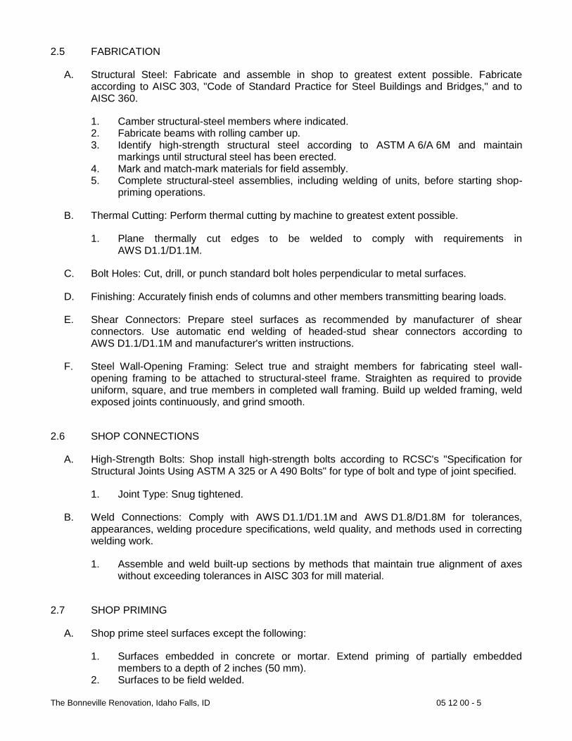
The Bonneville Renovation, Idaho Falls, ID 05 12 00 - 5
2.5 FABRICATION
A. Structural Steel: Fabricate and assemble in shop to greatest extent possible. Fabricate according to AISC 303, "Code of Standard Practice for Steel Buildings and Bridges," and to AISC 360.
1. Camber structural-steel members where indicated. 2. Fabricate beams with rolling camber up. 3. Identify high-strength structural steel according to ASTM A 6/A 6M and maintain
markings until structural steel has been erected. 4. Mark and match-mark materials for field assembly. 5. Complete structural-steel assemblies, including welding of units, before starting shop-
priming operations.
B. Thermal Cutting: Perform thermal cutting by machine to greatest extent possible.
1. Plane thermally cut edges to be welded to comply with requirements in AWS D1.1/D1.1M.
C. Bolt Holes: Cut, drill, or punch standard bolt holes perpendicular to metal surfaces.
D. Finishing: Accurately finish ends of columns and other members transmitting bearing loads.
E. Shear Connectors: Prepare steel surfaces as recommended by manufacturer of shear connectors. Use automatic end welding of headed-stud shear connectors according to AWS D1.1/D1.1M and manufacturer's written instructions.
F. Steel Wall-Opening Framing: Select true and straight members for fabricating steel wall-opening framing to be attached to structural-steel frame. Straighten as required to provide uniform, square, and true members in completed wall framing. Build up welded framing, weld exposed joints continuously, and grind smooth.
2.6 SHOP CONNECTIONS
A. High-Strength Bolts: Shop install high-strength bolts according to RCSC's "Specification for Structural Joints Using ASTM A 325 or A 490 Bolts" for type of bolt and type of joint specified.
1. Joint Type: Snug tightened.
B. Weld Connections: Comply with AWS D1.1/D1.1M and AWS D1.8/D1.8M for tolerances, appearances, welding procedure specifications, weld quality, and methods used in correcting welding work.
1. Assemble and weld built-up sections by methods that maintain true alignment of axes without exceeding tolerances in AISC 303 for mill material.
2.7 SHOP PRIMING
A. Shop prime steel surfaces except the following:
1. Surfaces embedded in concrete or mortar. Extend priming of partially embedded members to a depth of 2 inches (50 mm).
2. Surfaces to be field welded.

The Bonneville Renovation, Idaho Falls, ID 05 12 00 - 6
3. Surfaces of high-strength bolted, slip-critical connections. 4. Surfaces to receive sprayed fire-resistive materials (applied fireproofing). 5. Galvanized surfaces. 6. Surfaces enclosed in interior construction.
B. Surface Preparation: Clean surfaces to be painted. Remove loose rust and mill scale and spatter, slag, or flux deposits. Prepare surfaces according to the following specifications and standards:
1. SSPC-SP 2, "Hand Tool Cleaning."
C. Priming: Immediately after surface preparation, apply primer according to manufacturer's written instructions and at rate recommended by SSPC to provide a minimum dry film thickness of 1.5 mils (0.038 mm). Use priming methods that result in full coverage of joints, corners, edges, and exposed surfaces.
1. Stripe paint corners, crevices, bolts, welds, and sharp edges. 2. Apply two coats of shop paint to surfaces that are inaccessible after assembly or
erection. Change color of second coat to distinguish it from first.
D. Painting: Prepare steel and apply a one-coat, nonasphaltic primer complying with SSPC-PS Guide 7.00, "Painting System Guide 7.00: Guide for Selecting One-Coat Shop Painting Systems," to provide a dry film thickness of not less than 1.5 mils (0.038 mm).
2.8 SOURCE QUALITY CONTROL
A. Welded Connections: Visually inspect shop-welded connections according to AWS D1.1/D1.1M and the following inspection procedures, at testing agency's option:
1. Liquid Penetrant Inspection: ASTM E 165. 2. Magnetic Particle Inspection: ASTM E 709; performed on root pass and on finished
weld. Cracks or zones of incomplete fusion or penetration are not accepted. 3. Ultrasonic Inspection: ASTM E 164. 4. Radiographic Inspection: ASTM E 94.
B. In addition to visual inspection, test and inspect shop-welded shear connectors according to requirements in AWS D1.1/D1.1M for stud welding and as follows: 1. Conduct tests according to requirements in AWS D1.1/D1.1M on additional shear
connectors if weld fracture occurs on shear connectors already tested.
C. Prepare test and inspection reports.
PART 3 - EXECUTION
3.1 EXAMINATION
A. Verify, with certified steel erector present, elevations of concrete- and masonry-bearing surfaces and locations of anchor rods, bearing plates, and other embedments for compliance with requirements.

The Bonneville Renovation, Idaho Falls, ID 05 12 00 - 7
1. Prepare a certified survey of existing conditions. Include bearing surfaces, anchor rods, bearing plates, and other embedments showing dimensions, locations, angles, and elevations.
B. Proceed with installation only after unsatisfactory conditions have been corrected.
3.2 PREPARATION
A. Provide temporary shores, guys, braces, and other supports during erection to keep structural steel secure, plumb, and in alignment against temporary construction loads and loads equal in intensity to design loads. Remove temporary supports when permanent structural steel, connections, and bracing are in place unless otherwise indicated.
3.3 ERECTION
A. Set structural steel accurately in locations and to elevations indicated and according to AISC 303 and AISC 360.
B. Baseplates Bearing Plates and Leveling Plates: Clean concrete- and masonry-bearing surfaces of bond-reducing materials, and roughen surfaces prior to setting plates. Clean bottom surface of plates.
1. Set plates for structural members on wedges, shims, or setting nuts as required. 2. Weld plate washers to top of baseplate. 3. Snug-tighten anchor rods after supported members have been positioned and plumbed.
Do not remove wedges or shims but, if protruding, cut off flush with edge of plate before packing with grout.
4. Promptly pack grout solidly between bearing surfaces and plates so no voids remain. Neatly finish exposed surfaces; protect grout and allow to cure. Comply with manufacturer's written installation instructions for shrinkage-resistant grouts.
C. Maintain erection tolerances of structural steel within AISC 303, "Code of Standard Practice for Steel Buildings and Bridges."
D. Align and adjust various members that form part of complete frame or structure before permanently fastening. Before assembly, clean bearing surfaces and other surfaces that are in permanent contact with members. Perform necessary adjustments to compensate for discrepancies in elevations and alignment.
1. Level and plumb individual members of structure. 2. Make allowances for difference between temperature at time of erection and mean
temperature when structure is completed and in service.
E. Splice members only where indicated.
F. Do not use thermal cutting during erection unless approved by Architect. Finish thermally cut sections within smoothness limits in AWS D1.1/D1.1M.
G. Do not enlarge unfair holes in members by burning or using drift pins. Ream holes that must be enlarged to admit bolts.

The Bonneville Renovation, Idaho Falls, ID 05 12 00 - 8
H. Shear Connectors: Prepare steel surfaces as recommended by manufacturer of shear connectors. Use automatic end welding of headed-stud shear connectors according to AWS D1.1/D1.1M and manufacturer's written instructions.
3.4 FIELD CONNECTIONS
A. High-Strength Bolts: Install high-strength bolts according to RCSC's "Specification for Structural Joints Using ASTM A 325 or A 490 Bolts" for type of bolt and type of joint specified.
1. Joint Type: Snug tightened.
B. Weld Connections: Comply with AWS D1.1/D1.1M and AWS D1.8/D1.8M for tolerances, appearances, welding procedure specifications, weld quality, and methods used in correcting welding work.
1. Comply with AISC 303 and AISC 360 for bearing, alignment, adequacy of temporary connections, and removal of paint on surfaces adjacent to field welds.
2. Remove backing bars or runoff tabs where indicated, back gouge, and grind steel smooth.
3. Assemble and weld built-up sections by methods that maintain true alignment of axes without exceeding tolerances in AISC 303, "Code of Standard Practice for Steel Buildings and Bridges," for mill material.
3.5 PREFABRICATED BUILDING COLUMNS
A. Install prefabricated building columns to comply with AISC 360, manufacturer's written recommendations, and requirements of testing and inspecting agency that apply to the fire-resistance rating indicated.
3.6 FIELD QUALITY CONTROL
A. Special Inspections: Owner will engage a qualified special inspector to perform the following special inspections:
1. Verify structural-steel materials and inspect steel frame joint details. 2. Verify weld materials and inspect welds. 3. Verify connection materials and inspect high-strength bolted connections.
B. Testing Agency: Owner will engage a qualified testing agency to perform tests and inspections.
C. Bolted Connections: Inspect bolted connections according to RCSC's "Specification for Structural Joints Using ASTM A 325 or A 490 Bolts."
D. Welded Connections: Visually inspect field welds according to AWS D1.1/D1.1M.
1. In addition to visual inspection, test and inspect field welds according to AWS D1.1/D1.1M and the following inspection procedures, at testing agency's option:
a. Liquid Penetrant Inspection: ASTM E 165.

The Bonneville Renovation, Idaho Falls, ID 05 12 00 - 9
b. Magnetic Particle Inspection: ASTM E 709; performed on root pass and on finished weld. Cracks or zones of incomplete fusion or penetration are not accepted.
c. Ultrasonic Inspection: ASTM E 164. d. Radiographic Inspection: ASTM E 94.
END OF SECTION

The Bonneville Renovation, Idaho Falls, ID 05 21 00 - 1
SECTION 05 21 00 STEEL JOIST FRAMING
PART 1 - GENERAL
1.1 RELATED DOCUMENTS
A. Drawings and general provisions of the Contract, including General and Supplementary Conditions and Division 01 Specification Sections, apply to this Section.
1.2 SUMMARY
A. Section Includes:
1. K-series steel joists. 2. KCS-type K-series steel joists. 3. K-series steel joist substitutes. 4. LH- and DLH-series long-span steel joists. 5. Joist girders. 6. Joist accessories.
B. Related Requirements:
1. Section 033000 "Cast-in-Place Concrete" for installing bearing plates in concrete. 2. Section 042000 "Unit Masonry" for installing bearing plates in unit masonry. 3. Section 051200 "Structural Steel Framing" for field-welded shear connectors.
1.3 DEFINITIONS
A. SJI's "Specifications": Steel Joist Institute's "Standard Specifications, Load Tables and Weight Tables for Steel Joists and Joist Girders."
B. Special Joists: Steel joists or joist girders requiring modification by manufacturer to support nonuniform, unequal, or special loading conditions that invalidate load tables in SJI's "Specifications."
1.4 ACTION SUBMITTALS
A. Product Data: For each type of joist, accessory, and product.
B. Shop Drawings:
1. Include layout, designation, number, type, location, and spacing of joists. 2. Include joining and anchorage details; bracing, bridging, and joist accessories; splice
and connection locations and details; and attachments to other construction. 3. Indicate locations and details of bearing plates to be embedded in other construction.
1.5 INFORMATIONAL SUBMITTALS
A. Qualification Data: For manufacturer.
B. Welding certificates.

The Bonneville Renovation, Idaho Falls, ID 05 21 00 - 2
C. Manufacturer certificates.
D. Mill Certificates: For each type of bolt.
E. Comprehensive engineering analysis of special joists signed and sealed by the qualified professional engineer responsible for its preparation.
F. Field quality-control reports.
1.6 QUALITY ASSURANCE
A. Manufacturer Qualifications: A manufacturer certified by SJI to manufacture joists complying with applicable standard specifications and load tables in SJI's "Specifications”.
1. Manufacturer's responsibilities include providing professional engineering services for designing special joists to comply with performance requirements.
B. Welding Qualifications: Qualify field-welding procedures and personnel according to AWS D1.1/D1.1M, "Structural Welding Code - Steel."
1.7 DELIVERY, STORAGE, AND HANDLING
A. Deliver, store, and handle joists as recommended in SJI's "Specifications”. Protect joists from corrosion, deformation, and other damage during delivery, storage, and handling.
1.8 SEQUENCING
A. Deliver steel bearing plates to be built into masonry construction.
PART 2 - PRODUCTS
2.1 PERFORMANCE REQUIREMENTS
A. Structural Performance: Provide special joists and connections capable of withstanding design loads indicated.
1. Use LRFD; data are given at factored-load level. 2. Design special joists to withstand design loads with live-load deflections no greater than
the following: a. Roof Joists: Vertical deflection of [1/360] [1/240] of the span.
2.2 K-SERIES STEEL JOISTS
A. Manufacture steel joists of type indicated according to "Standard Specification for Open Web Steel Joists, K-Series" in SJI's "Specifications," with steel-angle top- and bottom-chord members, underslung ends, and parallel top chord.
1. Joist Type: K-series steel joists.
B. Steel Joist Substitutes: Manufacture according to "Standard Specifications for Open Web Steel Joists, K-Series" in SJI's "Specifications," with steel-angle or -channel members.

The Bonneville Renovation, Idaho Falls, ID 05 21 00 - 3
C. Provide holes in chord members for connecting and securing other construction to joists.
D. Top-Chord Extensions: Extend top chords of joists with SJI's Type S top-chord extensions where indicated, complying with SJI's "Specifications."
E. Extended Ends: Extend bearing ends of joists with SJI's Type R extended ends where indicated, complying with SJI's "Specifications."
F. Camber joists according to SJI's "Specifications.”
G. Equip bearing ends of joists with manufacturer's standard beveled ends or sloped shoes if joist slope exceeds 1/4 inch per 12 inches (1:48).
2.3 LONG-SPAN STEEL JOISTS
A. Manufacture steel joists according to "Standard Specification for Longspan Steel Joists, LH-Series and Deep Longspan Steel Joists, DLH-Series" in SJI's "Specifications," with steel-angle top- and bottom-chord members; of joist type and end and top-chord arrangements as indicated.
B. Provide holes in chord members for connecting and securing other construction to joists.
C. Camber long-span steel joists according to SJI's "Specifications."
D. Equip bearing ends of joists with manufacturer's standard beveled ends or sloped shoes if joist slope exceeds 1/4 inch per 12 inches (1:48).
2.4 JOIST GIRDERS
A. Manufacture joist girders according to "Standard Specification for Joist Girders" in SJI's "Specifications," with steel-angle top- and bottom-chord members; with end and top-chord arrangements as indicated.
B. Provide holes in chord members for connecting and securing other construction to joist girders.
C. Camber joist girders according to SJI's "Specifications.
D. Equip bearing ends of joists with manufacturer's standard beveled ends or sloped shoes if joist slope exceeds 1/4 inch per 12 inches (1:48).
2.5 PRIMERS
A. Primer: SSPC-Paint 15, or manufacturer's standard shop primer complying with performance requirements in SSPC-Paint 15.
B. Primer: Provide shop primer that complies with Section 099113 "Exterior Painting" and Section 099123 "Interior Painting”.

The Bonneville Renovation, Idaho Falls, ID 05 21 00 - 4
2.6 JOIST ACCESSORIES
A. Bridging: Provide bridging anchors and number of rows of horizontal or diagonal bridging of material, size, and type required by SJI's "Specifications” for type of joist, chord size, spacing, and span. Furnish additional erection bridging if required for stability.
B. Bridging: Schematically indicated. Detail and fabricate according to SJI's "Specifications”. Furnish additional erection bridging if required for stability.
C. Bridging: Fabricate as indicated and according to SJI's "Specifications”. Furnish additional erection bridging if required for stability.
D. Fabricate steel bearing plates from ASTM A 36/A 36M steel with integral anchorages of sizes and thicknesses indicated. Shop prime paint.
E. Steel bearing plates with integral anchorages are specified in Section 055000 "Metal Fabrications."
F. Furnish ceiling extensions, either extended bottom-chord elements or a separate extension unit of enough strength to support ceiling construction. Extend ends to within 1/2 inch (13 mm) of finished wall surface unless otherwise indicated.
1. Finish: Plain, uncoated.
G. High-Strength Bolts, Nuts, and Washers: ASTM A 325 (ASTM A 325M), Type 1, heavy hex steel structural bolts; ASTM A 563 (ASTM A 563M) heavy hex carbon-steel nuts; and ASTM F 436 (ASTM F 436M) hardened carbon-steel washers.
1. Finish: Plain.
H. Welding Electrodes: Comply with AWS standards.
I. Furnish miscellaneous accessories including splice plates and bolts required by joist manufacturer to complete joist assembly.
2.7 CLEANING AND SHOP PAINTING
A. Clean and remove loose scale, heavy rust, and other foreign materials from fabricated joists and accessories by hand-tool cleaning, SSPC-SP 2 or power-tool cleaning, SSPC-SP 3.
B. Apply one coat of shop primer to joists and joist accessories to be primed to provide a continuous, dry paint film not less than 1 mil (0.025 mm) thick.
C. Shop priming of joists and joist accessories is specified in Section 099113 "Exterior Painting" and Section 099123 "Interior Painting"
PART 3 - EXECUTION
3.1 EXAMINATION
A. Examine supporting substrates, embedded bearing plates, and abutting structural framing for compliance with requirements for installation tolerances and other conditions affecting performance of the Work.

The Bonneville Renovation, Idaho Falls, ID 05 21 00 - 5
B. Proceed with installation only after unsatisfactory conditions have been corrected.
3.2 INSTALLATION
A. Do not install joists until supporting construction is in place and secured.
B. Install joists and accessories plumb, square, and true to line; securely fasten to supporting construction according to SJI's "Specifications”, joist manufacturer's written instructions, and requirements in this Section.
1. Before installation, splice joists delivered to Project site in more than one piece. 2. Space, adjust, and align joists accurately in location before permanently fastening. 3. Install temporary bracing and erection bridging, connections, and anchors to ensure that
joists are stabilized during construction. 4. Delay rigidly connecting bottom-chord extensions to columns or supports until dead
loads are applied.
C. Field weld joists to supporting steel bearing plates and framework. Coordinate welding sequence and procedure with placement of joists. Comply with AWS requirements and procedures for welding, appearance and quality of welds, and methods used in correcting welding work.
D. Bolt joists to supporting steel framework using carbon-steel bolts.
E. Bolt joists to supporting steel framework using high-strength structural bolts. Comply with RCSC's "Specification for Structural Joints Using ASTM A 325 or ASTM A 490 Bolts" for high-strength structural bolt installation and tightening requirements.
F. Install and connect bridging concurrently with joist erection, before construction loads are applied. Anchor ends of bridging lines at top and bottom chords if terminating at walls or beams.
3.3 FIELD QUALITY CONTROL
A. Testing Agency: Engage a qualified testing agency to perform tests and inspections.
B. Visually inspect field welds according to AWS D1.1/D1.1M.
1. In addition to visual inspection, test field welds according to AWS D1.1/D1.1M and the following procedures, at testing agency's option:
a. Liquid Penetrant Inspection: ASTM E 165/E 165M. b. Magnetic Particle Inspection: ASTM E 709. c. Ultrasonic Testing: ASTM E 164. d. Radiographic Testing: ASTM E 94.
C. Visually inspect bolted connections.
D. Prepare test and inspection reports.
3.4 PROTECTION
A. Repair damaged galvanized coatings on galvanized items with galvanized repair paint according to ASTM A 780/A 780M and manufacturer's written instructions.

The Bonneville Renovation, Idaho Falls, ID 05 21 00 - 6
B. Touchup Painting: After installation, promptly clean, prepare, and prime or reprime field connections, rust spots, and abraded surfaces of prime-painted joists, bearing plates and accessories.
1. Clean and prepare surfaces by hand-tool cleaning according to SSPC-SP 2 or power-tool cleaning according to SSPC-SP 3.
2. Apply a compatible primer of same type as primer used on adjacent surfaces.
C. Touchup Painting: Cleaning and touchup painting are specified in Section 099113 "Exterior Painting" and Section 099123 "Interior Painting."
END OF SECTION

The Bonneville Renovation, Idaho Falls, ID 05 31 00 - 1
SECTION 05 31 00 STEEL DECKING
PART 1 - GENERAL
1.1 RELATED DOCUMENTS
A. Drawings and general provisions of the Contract, including General and Supplementary Conditions and Division 01 Specification Sections, apply to this Section.
1.2 SUMMARY
A. Section Includes:
1. Roof deck.
B. Related Requirements:
1. Section 033000 "Cast-in-Place Concrete" for normal-weight and lightweight structural concrete fill over steel deck.
2. Section 051200 "Structural Steel Framing" for shop- and field-welded shear connectors.
1.3 ACTION SUBMITTALS
A. Product Data: For each type of deck, accessory, and product indicated.
B. Shop Drawings:
1. Include layout and types of deck panels, anchorage details, reinforcing channels, pans, cut deck openings, special jointing, accessories, and attachments to other construction.
1.4 INFORMATIONAL SUBMITTALS
A. Welding certificates.
B. Product Certificates: For each type of steel deck.
C. Product Test Reports: For tests performed by a qualified testing agency, indicating that each of the following complies with requirements:
1. Power-actuated mechanical fasteners.
D. Evaluation Reports: For steel deck, from ICC-ES.
E. Field quality-control reports.
1.5 QUALITY ASSURANCE
A. Welding Qualifications: Qualify procedures and personnel according to AWS D1.3/D1.3M, "Structural Welding Code - Sheet Steel."
B. FM Global Listing: Provide steel roof deck evaluated by FM Global and listed in its "Approval Guide, Building Materials" for Class 1 fire rating and Class 1-90 windstorm ratings.

The Bonneville Renovation, Idaho Falls, ID 05 31 00 - 2
1.6 DELIVERY, STORAGE, AND HANDLING
A. Protect steel deck from corrosion, deformation, and other damage during delivery, storage, and handling.
B. Stack steel deck on platforms or pallets and slope to provide drainage. Protect with a waterproof covering and ventilate to avoid condensation.
PART 2 - PRODUCTS
2.1 PERFORMANCE REQUIREMENTS
A. AISI Specifications: Comply with calculated structural characteristics of steel deck according to AISI's "North American Specification for the Design of Cold-Formed Steel Structural Members."
2.2 ROOF DECK
A. Roof Deck: Fabricate panels, without top-flange stiffening grooves, to comply with "SDI Specifications and Commentary for Steel Roof Deck," in SDI Publication No. 31, and with the following: 1. Prime-Painted Steel Sheet: ASTM A 1008/A 1008M, Structural Steel (SS), Grade 33
(230) minimum, shop primed with manufacturer's standard baked-on, rust-inhibitive primer. a. Color: Gray top surface with white underside.
2. Deck Profile: As indicated Type NR, narrow rib Type IR, intermediate rib Type WR, wide rib Type 3DR, deep rib Long span.
3. Profile Depth: 1-1/2 inches (38 mm). 4. Span Condition: Triple span or more. 5. Side Laps: Overlapped or interlocking seam at Contractor's option.
2.3 ACCESSORIES
A. General: Provide manufacturer's standard accessory materials for deck that comply with requirements indicated.
B. Mechanical Fasteners: Corrosion-resistant, low-velocity, power-actuated or pneumatically driven carbon-steel fasteners; or self-drilling, self-threading screws.
C. Side-Lap Fasteners: Corrosion-resistant, hexagonal washer head; self-drilling, carbon-steel screws, No. 10 (4.8-mm) minimum diameter.
D. Flexible Closure Strips: Vulcanized, closed-cell, synthetic rubber.
E. Column Closures, End Closures, Z-Closures, and Cover Plates: Steel sheet, of same material, finish, and thickness as deck unless otherwise indicated.
F. Repair Paint: Manufacturer's standard rust-inhibitive primer of same color as primer.

The Bonneville Renovation, Idaho Falls, ID 05 31 00 - 3
PART 3 - EXECUTION
3.1 EXAMINATION
A. Examine supporting frame and field conditions for compliance with requirements for installation tolerances and other conditions affecting performance of the Work.
B. Proceed with installation only after unsatisfactory conditions have been corrected.
3.2 INSTALLATION, GENERAL
A. Install deck panels and accessories according to applicable specifications and commentary in SDI Publication No. 31, manufacturer's written instructions, and requirements in this Section.
B. Install temporary shoring before placing deck panels if required to meet deflection limitations.
C. Locate deck bundles to prevent overloading of supporting members.
D. Place deck panels on supporting frame and adjust to final position with ends accurately aligned and bearing on supporting frame before being permanently fastened. Do not stretch or contract side-lap interlocks.
E. Provide additional reinforcement and closure pieces at openings as required for strength, continuity of deck, and support of other work.
F. Comply with AWS requirements and procedures for manual shielded metal arc welding, appearance and quality of welds, and methods used for correcting welding work.
G. Mechanical fasteners may be used in lieu of welding to fasten deck. Locate mechanical fasteners and install according to deck manufacturer's written instructions.
3.3 ROOF-DECK INSTALLATION
A. Fasten roof-deck panels to steel supporting members by arc spot (puddle) welds of the surface diameter indicated or arc seam welds with an equal perimeter that is not less than 1-1/2 inches (38 mm) long, and as follows:
1. Weld Diameter: 5/8 inch (16 mm), nominal. 2. Weld Spacing: Weld edge and interior ribs of deck units with a minimum of two welds
per deck unit at each support. Space welds 12 inches (305 mm) apart in the field of roof and 12 inches (305 mm) apart in roof corners and perimeter.
3. Mechanically fasten with self-drilling, No. 10 (4.8-mm-) diameter or larger, carbon-steel screws.
4. Fasten with a minimum of 1-1/2-inch- (38-mm-) long welds.
B. End Bearing: Install deck ends over supporting frame with a minimum end bearing of 1-1/2 inches (38 mm), with end joints as follows:
1. End Joints: Lapped 2 inches (51 mm) minimum Butted Lapped 2 inches (51 mm) minimum or butted at Contractor's option.
C. Flexible Closure Strips: Install flexible closure strips over partitions, walls, and where indicated. Install with adhesive according to manufacturer's written instructions to ensure complete closure.

The Bonneville Renovation, Idaho Falls, ID 05 31 00 - 4
3.4 FIELD QUALITY CONTROL
A. Testing Agency: Owner will engage a qualified testing agency to perform tests and inspections.
B. Field welds will be subject to inspection.
C. Prepare test and inspection reports.
END OF SECTION

The Bonneville Renovation, Idaho Falls, ID 05 40 00 - 1
SECTION 05 40 00 COLD-FORMED METAL FRAMING
PART 1 - GENERAL
1.1 RELATED DOCUMENTS
A. Drawings and general provisions of the Contract, including General and Supplementary Conditions and Division 01 Specification Sections, apply to this Section.
1.2 SUMMARY
A. Section Includes:
1. Load-bearing wall framing.
B. Related Requirements:
1. Section 055000 "Metal Fabrications" for miscellaneous steel shapes, masonry shelf angles, and connections used with cold-formed metal framing.
1.3 PREINSTALLATION MEETINGS
A. Preinstallation Conference: Conduct conference at Project site.
1.4 ACTION SUBMITTALS
A. Product Data: For each type of product.
B. Shop Drawings:
1. Include layout, spacings, sizes, thicknesses, and types of cold-formed steel framing; fabrication; and fastening and anchorage details, including mechanical fasteners.
2. Indicate reinforcing channels, opening framing, supplemental framing, strapping, bracing, bridging, splices, accessories, connection details, and attachment to adjoining work.
C. Delegated-Design Submittal: For cold-formed steel framing.
1.5 INFORMATIONAL SUBMITTALS
A. Qualification Data: For testing agency.
B. Welding certificates.
C. Product Certificates: For each type of code-compliance certification for studs and tracks.
D. Product Test Reports: For each listed product, for tests performed by manufacturer and witnessed by a qualified testing agency.

The Bonneville Renovation, Idaho Falls, ID 05 40 00 - 2
1. Steel sheet. 2. Miscellaneous structural clips and accessories.
1.6 QUALITY ASSURANCE
A. Testing Agency Qualifications: Qualified according to ASTM E 329 for testing indicated.
B. Product Tests: Mill certificates or data from a qualified independent testing agency[, or in-house testing with calibrated test equipment,] indicating steel sheet complies with requirements, including base-metal thickness, yield strength, tensile strength, total elongation, chemical requirements, and metallic-coating thickness.
C. Code-Compliance Certification of Studs and Tracks: Provide documentation that framing members are certified according to the product-certification program of the Certified Steel Stud Association the Steel Framing Industry Association or the Steel Stud Manufacturers Association.
D. Welding Qualifications: Qualify procedures and personnel according to the following:
1. AWS D1.1/D1.1M, "Structural Welding Code - Steel." 2. AWS D1.3/D1.3M, "Structural Welding Code - Sheet Steel."
E. Comply with AISI S230 "Standard for Cold-Formed Steel Framing - Prescriptive Method for One and Two Family Dwellings."
PART 2 - PRODUCTS
2.1 PERFORMANCE REQUIREMENTS
A. Structural Performance: Provide cold-formed steel framing capable of withstanding design loads within limits and under conditions indicated.
1. Design Loads: As indicated on Drawings. 2. Deflection Limits: Design framing systems to withstand design loads without deflections
greater than the following:
a. Exterior Load-Bearing Wall Framing: Horizontal deflection of 1/600 of the wall height.
3. Design exterior non-load-bearing wall framing to accommodate horizontal deflection without regard for contribution of sheathing materials.
B. Cold-Formed Steel Framing Standards: Unless more stringent requirements are indicated, framing shall comply with AISI S100, AISI S200, and the following: 1. Wall Studs: AISI S211. 2. Lateral Design: AISI S213.
C. Fire-Resistance Ratings: Comply with ASTM E 119; testing by a qualified testing agency. Identify products with appropriate markings of applicable testing agency.
1. Indicate design designations from UL's "Fire Resistance Directory" or from the listings of another qualified testing agency acceptable to authorities having jurisdiction.
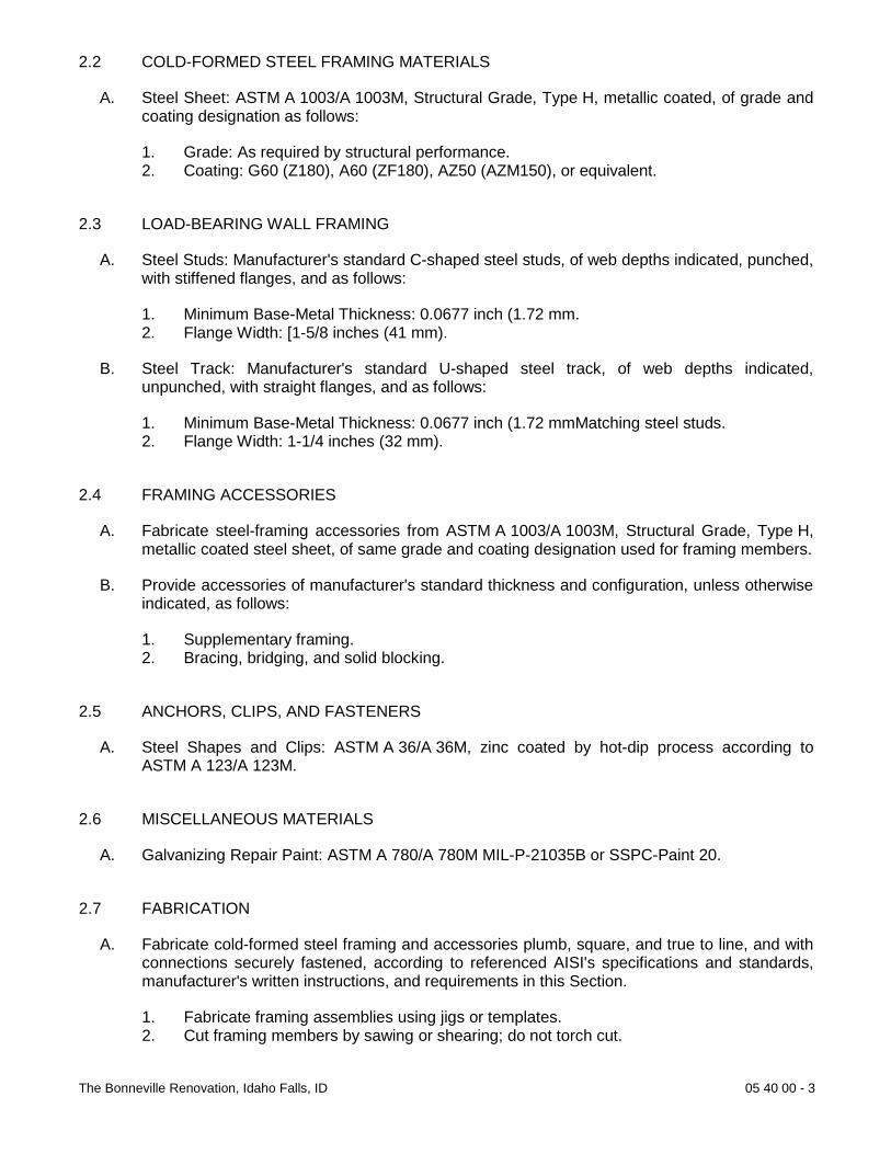
The Bonneville Renovation, Idaho Falls, ID 05 40 00 - 3
2.2 COLD-FORMED STEEL FRAMING MATERIALS
A. Steel Sheet: ASTM A 1003/A 1003M, Structural Grade, Type H, metallic coated, of grade and coating designation as follows:
1. Grade: As required by structural performance. 2. Coating: G60 (Z180), A60 (ZF180), AZ50 (AZM150), or equivalent.
2.3 LOAD-BEARING WALL FRAMING
A. Steel Studs: Manufacturer's standard C-shaped steel studs, of web depths indicated, punched, with stiffened flanges, and as follows:
1. Minimum Base-Metal Thickness: 0.0677 inch (1.72 mm. 2. Flange Width: [1-5/8 inches (41 mm).
B. Steel Track: Manufacturer's standard U-shaped steel track, of web depths indicated, unpunched, with straight flanges, and as follows:
1. Minimum Base-Metal Thickness: 0.0677 inch (1.72 mmMatching steel studs. 2. Flange Width: 1-1/4 inches (32 mm).
2.4 FRAMING ACCESSORIES
A. Fabricate steel-framing accessories from ASTM A 1003/A 1003M, Structural Grade, Type H, metallic coated steel sheet, of same grade and coating designation used for framing members.
B. Provide accessories of manufacturer's standard thickness and configuration, unless otherwise indicated, as follows:
1. Supplementary framing. 2. Bracing, bridging, and solid blocking.
2.5 ANCHORS, CLIPS, AND FASTENERS
A. Steel Shapes and Clips: ASTM A 36/A 36M, zinc coated by hot-dip process according to ASTM A 123/A 123M.
2.6 MISCELLANEOUS MATERIALS
A. Galvanizing Repair Paint: ASTM A 780/A 780M MIL-P-21035B or SSPC-Paint 20.
2.7 FABRICATION
A. Fabricate cold-formed steel framing and accessories plumb, square, and true to line, and with connections securely fastened, according to referenced AISI's specifications and standards, manufacturer's written instructions, and requirements in this Section.
1. Fabricate framing assemblies using jigs or templates. 2. Cut framing members by sawing or shearing; do not torch cut.
The Bonneville Renovation, Idaho Falls, ID 05 40 00 - 4
3. Fasten cold-formed steel framing members by welding, screw fastening, clinch fastening, pneumatic pin fastening, or riveting as standard with fabricator. Wire tying of framing members is not permitted.
a. Comply with AWS D1.3/D1.3M requirements and procedures for welding, appearance and quality of welds, and methods used in correcting welding work.
b. Locate mechanical fasteners and install according to Shop Drawings, with screws penetrating joined members by no fewer than three exposed screw threads.
4. Fasten other materials to cold-formed steel framing by welding, bolting, pneumatic pin fastening, or screw fastening, according to Shop Drawings.
B. Reinforce, stiffen, and brace framing assemblies to withstand handling, delivery, and erection stresses. Lift fabricated assemblies by means that prevent damage or permanent distortion.
C. Tolerances: Fabricate assemblies level, plumb, and true to line to a maximum allowable variation of 1/8 inch in 10 feet (1:960) and as follows:
1. Spacing: Space individual framing members no more than plus or minus 1/8 inch (3 mm) from plan location. Cumulative error shall not exceed minimum fastening requirements of sheathing or other finishing materials.
2. Squareness: Fabricate each cold-formed steel framing assembly to a maximum out-of-square tolerance of 1/8 inch (3 mm).
PART 3 - EXECUTION
3.1 EXAMINATION
A. Examine substrates, areas, conditions, and abutting structural framing for compliance with requirements for installation tolerances and other conditions affecting performance of the Work.
B. Proceed with installation only after unsatisfactory conditions have been corrected.
3.2 PREPARATION
A. Before sprayed fire-resistive materials are applied, attach continuous angles, supplementary framing, or tracks to structural members indicated to receive sprayed fire-resistive materials.
B. After applying sprayed fire-resistive materials, remove only as much of these materials as needed to complete installation of cold-formed framing without reducing thickness of fire-resistive materials below that required to obtain fire-resistance ratings indicated. Protect remaining fire-resistive materials from damage.
C. Install load-bearing shims or grout between the underside of load-bearing wall bottom track and the top of foundation wall or slab at locations with a gap larger than 1/4 inch (6 mm) to ensure a uniform bearing surface on supporting concrete or masonry construction.
D. Install sealer gaskets at the underside of wall bottom track or rim track and at the top of foundation wall or slab at stud or joist locations.

The Bonneville Renovation, Idaho Falls, ID 05 40 00 - 5
3.3 INSTALLATION, GENERAL
A. Cold-formed steel framing may be shop or field fabricated for installation, or it may be field assembled.
B. Install cold-formed steel framing according to AISI S200, AISI S202, and manufacturer's written instructions unless more stringent requirements are indicated.
C. Install shop- or field-fabricated, cold-formed framing and securely anchor to supporting structure.
1. Screw, bolt, or weld wall panels at horizontal and vertical junctures to produce flush, even, true-to-line joints with maximum variation in plane and true position between fabricated panels not exceeding 1/16 inch (1.6 mm).
D. Install cold-formed steel framing and accessories plumb, square, and true to line, and with connections securely fastened.
1. Cut framing members by sawing or shearing; do not torch cut. 2. Fasten cold-formed steel framing members by welding, screw fastening, clinch
fastening, or riveting. Wire tying of framing members is not permitted.
a. Comply with AWS D1.3/D1.3M requirements and procedures for welding, appearance and quality of welds, and methods used in correcting welding work.
b. Locate mechanical fasteners, install according to Shop Drawings, and comply with requirements for spacing, edge distances, and screw penetration.
E. Install framing members in one-piece lengths unless splice connections are indicated for track or tension members.
F. Install temporary bracing and supports to secure framing and support loads equal to those for which structure was designed. Maintain braces and supports in place, undisturbed, until entire integrated supporting structure has been completed and permanent connections to framing are secured.
G. Do not bridge building expansion joints with cold-formed steel framing. Independently frame both sides of joints.
H. Fasten hole-reinforcing plate over web penetrations that exceed size of manufacturer's approved or standard punched openings.
3.4 LOAD-BEARING WALL INSTALLATION
A. Install continuous top and bottom tracks sized to match studs. Align tracks accurately and securely anchor at corners and ends, and at spacings as follows:
1. Anchor Spacing: As shown on Shop Drawings>.
B. Squarely seat studs against top and bottom tracks, with gap not exceeding 1/8 inch (3 mm) between the end of wall-framing member and the web of track. Fasten both flanges of studs to top and bottom tracks. Space studs as follows:
1. Stud Spacing: As indicated on Drawings.

The Bonneville Renovation, Idaho Falls, ID 05 40 00 - 6
C. Set studs plumb, except as needed for diagonal bracing or required for nonplumb walls or warped surfaces and similar configurations.
D. Align studs vertically where floor framing interrupts wall-framing continuity. Where studs cannot be aligned, continuously reinforce track to transfer loads.
E. Align floor and roof framing over studs according to AISI S200, Section C1. Where framing cannot be aligned, continuously reinforce track to transfer loads.
F. Anchor studs abutting structural columns or walls, including masonry walls, to supporting structure.
G. Install headers over wall openings wider than stud spacing. Locate headers above openings. Fabricate headers of compound shapes indicated or required to transfer load to supporting studs, complete with clip-angle connectors, web stiffeners, or gusset plates.
1. Frame wall openings with not less than a double stud at each jamb of frame. Fasten jamb members together to uniformly distribute loads.
2. Install tracks and jack studs above and below wall openings. Anchor tracks to jamb studs with clip angles or by welding, and space jack studs same as full-height wall studs.
H. Install supplementary framing, blocking, and bracing in stud framing indicated to support fixtures, equipment, services, casework, heavy trim, furnishings, and similar work requiring attachment to framing.
1. If type of supplementary support is not indicated, comply with stud manufacturer's written recommendations and industry standards in each case, considering weight or load resulting from item supported.
I. Install horizontal bridging in stud system, spaced vertically 48 inches (1220 mm). Fasten at each stud intersection.
1. Channel Bridging: Cold-rolled steel channel, welded or mechanically fastened to webs of punched studs with a minimum of two screws into each flange of the clip angle for framing members up to 6 inches (150 mm) deep.
2. Strap Bridging: Combination of flat, taut, steel sheet straps of width and thickness indicated and stud-track solid blocking of width and thickness to match studs. Fasten flat straps to stud flanges, and secure solid blocking to stud webs or flanges.
3. Bar Bridging: Proprietary bridging bars installed according to manufacturer's written instructions.
J. Install steel sheet diagonal bracing straps to both stud flanges; terminate at and fasten to reinforced top and bottom tracks. Fasten clip-angle connectors to multiple studs at ends of bracing and anchor to structure.
K. Install miscellaneous framing and connections, including supplementary framing, web stiffeners, clip angles, continuous angles, anchors, and fasteners, to provide a complete and stable wall-framing system.
3.5 ERECTION TOLERANCES
A. Install cold-formed steel framing level, plumb, and true to line to a maximum allowable tolerance variation of 1/8 inch in 10 feet (1:960) and as follows:

The Bonneville Renovation, Idaho Falls, ID 05 40 00 - 7
1. Space individual framing members no more than plus or minus 1/8 inch (3 mm) from plan location. Cumulative error shall not exceed minimum fastening requirements of sheathing or other finishing materials.
3.6 FIELD QUALITY CONTROL
A. Testing: Owner will engage a qualified independent testing and inspecting agency to perform field tests and inspections and prepare test reports.
B. Field and shop welds will be subject to testing and inspecting.
C. Testing agency will report test results promptly and in writing to Contractor and Architect.
D. Cold-formed steel framing will be considered defective if it does not pass tests and inspections.
E. Additional testing and inspecting, at Contractor's expense, will be performed to determine compliance of replaced or additional work with specified requirements.
3.7 REPAIRS AND PROTECTION
A. Galvanizing Repairs: Prepare and repair damaged galvanized coatings on fabricated and installed cold-formed steel framing with galvanized repair paint according to ASTM A 780/A 780M and manufacturer's written instructions.
B. Provide final protection and maintain conditions, in a manner acceptable to manufacturer and Installer, that ensure that cold-formed steel framing is without damage or deterioration at time of Substantial Completion.
END OF SECTION

The Bonneville Renovation, Idaho Falls, ID 05 50 00 - 1
SECTION 05 50 00
METAL FABRICATIONS PART 1 - GENERAL 1.1 RELATED DOCUMENTS
A. Drawings and general provisions of the Contract, including General and Supplementary
Conditions and Division 1 Specification Sections, apply to this Section. 1.2 SUMMARY
A. This Section includes the following:
1. Loose bearing and leveling plates.
2. Shelf angles. 3. Steel framing and supports for countertops.
4. Steel framing and supports for mechanical and electrical equipment. 5. Steel framing and supports for applications where framing and supports are not
specified in other Sections. 6. Miscellaneous metal trim. 7. Steel bollards.
1.3 SUBMITTALS
A. Product Data: For the following:
1. Paint products. 2. Grout.
B. Shop Drawings: Detail fabrication and erection of each metal fabrication indicated. Include
plans, elevations, sections, and details of metal fabrications and their connections. Show anchorage and accessory items. 1. Provide templates for anchors and bolts specified for installation under other Sections.
C. Mill Certificates: Signed by manufacturers of stainless-steel sheet certifying that products
furnished comply with requirements. D. Welding Certificates: Copies of certificates for welding procedures and personnel. E. Qualification Data: For firms and persons specified in "Quality Assurance" Article to
demonstrate their capabilities and experience. Include lists of completed projects with project names and addresses, names and addresses of architects and owners, and other information specified.
1.4 QUALITY ASSURANCE
A. Fabricator Qualifications: A firm experienced in producing metal fabrications similar to those
indicated for this Project and with a record of successful in-service performance, as well as sufficient production capacity to produce required units.
B. Welding: Qualify procedures and personnel according to the following:

The Bonneville Renovation, Idaho Falls, ID 05 50 00 - 2
1. AWS D1.1, "Structural Welding Code--Steel." 2. AWS D1.2, "Structural Welding Code--Aluminum." 3. AWS D1.3, "Structural Welding Code--Sheet Steel." 4. Certify that each welder has satisfactorily passed AWS qualification tests for welding
processes involved and, if pertinent, has undergone recertification. 1.5 PROJECT CONDITIONS
A. Field Measurements: Where metal fabrications are indicated to fit walls and other
construction, verify dimensions by field measurements before fabrication and indicate measurements on Shop Drawings. Coordinate fabrication schedule with construction progress to avoid delaying the Work. 1. Established Dimensions: Where field measurements cannot be made without delaying
the Work, establish dimensions and proceed with fabricating metal fabrications without field measurements. Coordinate construction to ensure that actual dimensions correspond to established dimensions. Allow for trimming and fitting.
1.6 COORDINATION
A. Coordinate installation of anchorages for metal fabrications. Furnish setting drawings,
templates, and directions for installing anchorages, including sleeves, concrete inserts, anchor bolts, and items with integral anchors, that are to be embedded in concrete or masonry. Deliver such items to Project site in time for installation.
PART 2 - PRODUCTS 2.1 METALS, GENERAL
A. Metal Surfaces, General: For metal fabrications exposed to view in the completed Work,
provide materials with smooth, flat surfaces without blemishes. Do not use materials with exposed pitting, seam marks, roller marks, rolled trade names, or roughness.
2.2 FERROUS METALS
A. Recycled Content of Steel Products: Provide products with average recycled content of steel products so postconsumer recycled content plus one-half of preconsumer recycled content is not less than 25 percent.
B. Steel Plates, Shapes, and Bars: ASTM A 36. C. Stainless-Steel Sheet, Strip, Plate, and Flat Bars: ASTM A 666, Type 304. D. Stainless-Steel Bars and Shapes: ASTM A 276, Type 304. E. Steel Tubing: Cold-formed steel tubing complying with ASTM A 500. F. Steel Pipe: ASTM A 53, standard weight (Schedule 40), unless another weight is indicated or
required by structural loads.

The Bonneville Renovation, Idaho Falls, ID 05 50 00 - 3
G. Slotted Channel Framing: Cold-formed metal channels with flange edges returned toward web and with 9/16-inch-wide slotted holes in webs at 2-inches o.c. 1. Width of Channels: 1-5/8-inches. 2. Depth of Channels: As indicated. 3. Metal and Thickness: Uncoated steel complying with ASTM A 570, Grade 33; 0.0966-
inch-minimum thickness. 4. Finish: Rust-inhibitive, baked-on, acrylic enamel.
H. Malleable-Iron Castings: ASTM A 47, Grade 32510. I. Gray-Iron Castings: ASTM A 48, Class 30, unless another class is indicated or required by
structural loads. J. Cast-in-Place Anchors in Concrete: Anchors of type indicated below, fabricated from
corrosion-resistant materials capable of sustaining, without failure, the load imposed within a safety factor of 4, as determined by testing per ASTM E 488, conducted by a qualified independent testing agency. 1. Threaded or wedge type; galvanized ferrous castings, either ASTM A 47 malleable iron
or ASTM A 27 cast steel. Provide bolts, washers, and shims as needed, hot-dip galvanized per ASTM A 153.
K. Welding Rods and Bare Electrodes: Select according to AWS specifications for metal alloy
welded.
L. Copper Alloys: Plate: ASTM B 36/B 36M, alloy UNS No. C28000 (muntz metal, 60 percent copper). Sand Castings: ASTM B 584, alloy UNS No. C83600 (No. 1 manganese bronze)
2.3 PAINT
A. Shop Primer for Ferrous Metal: Fast-curing, lead- and chromate-free, universal modified-
alkyd primer complying with performance requirements in FS TT-P-664; selected for good resistance to normal atmospheric corrosion, compatibility with finish paint systems indicated, and capability to provide a sound foundation for field-applied topcoats despite prolonged exposure.
B. Galvanizing Repair Paint: High-zinc-dust-content paint for regalvanizing welds in steel,
complying with SSPC-Paint 20.
2.4 FASTENERS
A. General: Provide Type 304 or 316 stainless-steel fasteners for exterior use and zinc-plated
fasteners with coating complying with ASTM B 633, Class Fe/Zn 5, where built into exterior walls. Select fasteners for type, grade, and class required.
B. Bolts and Nuts: Regular hexagon-head bolts, ASTM A 307, Grade A; with hex nuts,
ASTM A 563 and, where indicated, flat washers. C. Anchor Bolts: ASTM F 1554, Grade 36. D. Machine Screws: ASME B18.6.3.

The Bonneville Renovation, Idaho Falls, ID 05 50 00 - 4
E. Lag Bolts: ASME B18.2.1. F. Wood Screws: Flat head, carbon steel, ASME B18.6.1. G. Plain Washers: Round, carbon steel, ASME B18.22.1. H. Lock Washers: Helical, spring type, carbon steel, ASME B18.21.1. I. Expansion Anchors: Anchor bolt and sleeve assembly of material indicated below with
capability to sustain, without failure, a load equal to six times the load imposed when installed in unit masonry and equal to four times the load imposed when installed in concrete, as determined by testing per ASTM E 488, conducted by a qualified independent testing agency. 1. Material: Alloy Group 1 or 2 stainless-steel bolts complying with ASTM F 593 and nuts
complying with ASTM F 594. J. Toggle Bolts: FS FF-B-588, tumble-wing type, class and style as needed.
2.5 GROUT
A. Non-shrink, Non-metallic Grout: Factory-packaged, non-staining, non-corrosive, non-gaseous
grout complying with ASTM C 1107. Provide grout specifically recommended by manufacturer for interior and exterior applications.
2.6 FABRICATION, GENERAL
A. Shop Assembly: Preassemble items in shop to greatest extent possible to minimize field
splicing and assembly. Disassemble units only as necessary for shipping and handling limitations. Use connections that maintain structural value of joined pieces. Clearly mark units for reassembly and coordinated installation.
B. Shear and punch metals cleanly and accurately. Remove burrs. C. Ease exposed edges to a radius of approximately 1/32-inch, unless otherwise indicated. Form
bent-metal corners to smallest radius possible without causing grain separation or otherwise impairing work.
D. Weld corners and seams continuously to comply with the following:
1. Use materials and methods that minimize distortion and develop strength and corrosion
resistance of base metals. 2. Obtain fusion without undercut or overlap. 3. Remove welding flux immediately. 4. At exposed connections, finish exposed welds and surfaces smooth and blended so no
roughness shows after finishing and contour of welded surface matches that of adjacent surface.
E. Provide for anchorage of type indicated; coordinate with supporting structure. Fabricate and
space-anchoring devices to secure metal fabrications rigidly in place and to support indicated loads.
F. Cut, reinforce, drill, and tap metal fabrications as indicated to receive finish hardware, screws,
and similar items.

The Bonneville Renovation, Idaho Falls, ID 05 50 00 - 5
G. Fabricate joints that will be exposed to weather in a manner to exclude water, or provide weep holes where water may accumulate.
H. Allow for thermal movement resulting from the following maximum change (range) in ambient
and surface temperatures by preventing buckling, opening up of joints, overstressing of components, failure of connections, and other detrimental effects. Base engineering calculation on surface temperatures of materials due to both solar heat gain and nighttime-sky heat loss. 1. Temperature Change (Range): 120 deg F, ambient; 180 deg F, material surfaces.
I. Form exposed work true to line and level with accurate angles and surfaces and straight sharp
edges. J. Remove sharp or rough areas on exposed traffic surfaces. K. Form exposed connections with hairline joints; flush and smooth, using concealed fasteners
where possible. Use exposed fasteners of type indicated or, if not indicated, Phillips flat-head (countersunk) screws or bolts. Locate joints where least conspicuous.
2.7 LOOSE BEARING AND LEVELING PLATES
A. Provide loose bearing and leveling plates for steel items bearing on masonry or concrete
construction. Drill plates to receive anchor bolts and for grouting. 2.8 STEEL BOLLARDS
A. Fabricate from Schedule 40 steel pipe.
1. Concrete filled. 2. Paint finish.
2.9 ELEVATOR SILL ANGLES AND HOIST DIVIDER BEAMS
A. Sill Angles: Steel sections as indicated on Drawings for support of elevator sills, prime paint, one coat.
B. Hoist and Divider Beams: Steel wide flange sections, shape and size required to support
applied loads with maximum deflection of 1/240 of the span; prim paint, one coat. 2.10 LADDERS
A. Ladder: ANSI A14.3, Steel welded construction: 1. Finish: Prime paint, one coat. 2. Refer to Drawings for configuration.
B. Pre-fabricated Folding Ladder, ANSI A14.3 1. Manufactured by ALAGO Folding Wall Ladders, Model 485-80. 2. Provide extended handrails, with non-marking rubber feet for secure floor contact. 3. Aluminum ladder fabricated from 6061-T6 alluminum alloy. Minimum 24” wide, 3” deep
treads,and 1-1/4” round serrated tubing handrails with cast aluminum fittings.
The Bonneville Renovation, Idaho Falls, ID 05 50 00 - 6
2.11 MISCELLANEOUS FRAMING AND SUPPORTS A. General: Provide steel framing and supports indicated and as necessary to complete the
Work. This includes but is not limited to steel framing supports for countertops and other interior and exterior shapes.
B. Fabricate units from structural-steel shapes, plates, and bars of welded construction, unless
otherwise indicated. Fabricate to sizes, shapes, and profiles indicated and as necessary to receive adjacent construction retained by framing and supports. Cut, drill, and tap units to receive hardware, hangers, and similar items. 1. Fabricate units from slotted channel framing where indicated. 2. Where units are indicated to be cast into concrete or built into masonry, equip with
integrally welded steel strap anchors 1-1/4-inches-wide by ¼-inch-thick by 8 inches-long at 24-inches o.c., unless otherwise indicated.
3. Furnish inserts if units must be installed after concrete is placed. C. Galvanize miscellaneous framing and supports at all exterior locations and where indicated.
2.12 MISCELLANEOUS STEEL TRIM
A. Unless otherwise indicated, fabricate units from structural-steel shapes, plates, and bars of
profiles shown with continuously welded joints, and smooth exposed edges. Miter corners and use concealed field splices where possible.
B. Provide cutouts, fittings, and anchorages as needed to coordinate assembly and installation
with other work. Provide anchors, welded to trim, for embedding in concrete or masonry construction, spaced not more than 6-inches from each end, 6 inches from corners, and 24-inches o.c., unless otherwise indicated.
2.13 FINISHES, GENERAL
A. Comply with NAAMM's "Metal Finishes Manual for Architectural and Metal Products" for
recommendations for applying and designating finishes. B. Finish metal fabrications after assembly.
2.14 STEEL AND IRON FINISHES
A. All metal to be shop primed. B. Preparation for Shop Priming: Prepare uncoated ferrous-metal surfaces to comply with
minimum requirements indicated below for SSPC surface-preparation specifications and environmental exposure conditions of installed metal fabrications: 1. Exteriors (SSPC Zone 1B): SSPC-SP 6/NACE No. 3, "Commercial Blast Cleaning." 2. Interiors (SSPC Zone 1A): SSPC-SP 3, "Power Tool Cleaning."
C. Apply shop primer to uncoated surfaces of metal fabrications, except those with galvanized
finishes and those to be embedded in concrete, sprayed-on fireproofing, or masonry, unless otherwise indicated. Comply with SSPC-PA 1, "Paint Application Specification No. 1, for shop painting.

The Bonneville Renovation, Idaho Falls, ID 05 50 00 - 7
1. Stripe paint corners, crevices, bolts, welds, and sharp edges.
PART 3 - EXECUTION 3.1 INSTALLATION, GENERAL
A. Fastening to In-Place Construction: Provide anchorage devices and fasteners where
necessary for securing metal fabrications to in-place construction. Include threaded fasteners for concrete and masonry inserts, toggle bolts, through-bolts, lag bolts, wood screws, and other connectors.
B. Cutting, Fitting, and Placement: Perform cutting, drilling, and fitting required for installing
metal fabrications. Set metal fabrications accurately in location, alignment, and elevation; with edges and surfaces level, plumb, true, and free of rack; and measured from established lines and levels.
C. Provide temporary bracing or anchors in formwork for items that are to be built into concrete,
masonry, or similar construction. D. Fit exposed connections accurately together to form hairline joints. Weld connections that are
not to be left as exposed joints but cannot be shop welded because of shipping size limitations. Do not weld, cut, or abrade surfaces of exterior units that have been hot-dip galvanized after fabrication and are for bolted or screwed field connections.
E. Field Welding: Comply with the following requirements:
1. Use materials and methods that minimize distortion and develop strength and corrosion
resistance of base metals. 2. Obtain fusion without undercut or overlap. 3. Remove welding flux immediately. 4. At exposed connections, finish exposed welds and surfaces smooth and blended so no
roughness shows after finishing and contour of welded surface matches that of adjacent surface.
F. Corrosion Protection: Coat concealed surfaces of aluminum that will come into contact with
grout, concrete, masonry, wood, or dissimilar metals with a heavy coat of bituminous paint. 3.2 SETTING BEARING AND LEVELING PLATES
A. Clean concrete and masonry bearing surfaces of bond-reducing materials, and roughen to
improve bond to surfaces. Clean bottom surface of plates. B. Set bearing and leveling plates on wedges, shims, or leveling nuts. After bearing members
have been positioned and plumbed, tighten anchor bolts. Do not remove wedges or shims but, if protruding, cut off flush with edge of bearing plate before packing with grout. 1. Use non-shrink grout, non-metallic, in all locations. 2. Pack grout solidly between bearing surfaces and plates to ensure that no voids remain.
3.3 INSTALLING MISCELLANEOUS FRAMING AND SUPPORTS

The Bonneville Renovation, Idaho Falls, ID 05 50 00 - 8
A. General: Install framing and supports to comply with requirements of items being supported,
including manufacturers written instructions and requirements indicated on Shop Drawings, if any.
3.4 ADJUSTING AND CLEANING
A. Touchup Painting: Immediately after erection, clean field welds, bolted connections, and
abraded areas of shop paint, and paint exposed areas with the same material as used for shop painting to comply with SSPC-PA 1 for touching up shop-painted surfaces. 1. Apply by brush or spray to provide a minimum 2.0-mil dry film thickness.
B. Galvanized Surfaces: Clean field welds, bolted connections, and abraded areas and repair
galvanizing to comply with ASTM A 780. END OF SECTION

The Bonneville Renovation, Idaho Falls, ID 05 51 00 - 1
SECTION 05 51 00
METAL STAIRS
PART 1 GENERAL
1.1 SUMMARY
A. Section includes steel stair frame of structural sections, with closed risers; concrete filled steel pan stair treads and landings; and handrailing.
1.2 REFERENCES
A. American National Standards Institute: 1. ANSI A117.1 - Accessible and Usable Buildings and Facilities.
B. ASTM International: 1. ASTM A36/A36M - Standard Specification for Carbon Structural Steel. 2. ASTM A53/A53M - Standard Specification for Pipe, Steel, Black and Hot-Dipped,
Zinc-Coated, Welded and Seamless. 3. ASTM A307 - Standard Specification for Carbon Steel Bolts and Studs, 60 000
PSI Tensile Strength. 4. ASTM A501. - Standard Specification for Hot-Formed Welded and Seamless
Carbon Steel Structural Tubing. 5. ASTM A563 - Standard Specification for Carbon and Alloy Steel Nuts. 6. ASTM E935 - Standard Test Methods for Performance of Permanent Metal
Railing Systems and Rails for Buildings. 7. ASTM E985 - Standard Specification for Permanent Metal Railing Systems and
Rails for Buildings.
C. American Welding Society: 1. AWS A2.4 - Standard Symbols for Welding, Brazing, and Nondestructive
Examination. 2. AWS D1.1 - Structural Welding Code - Steel.
D. National Association of Architectural Metal Manufacturers: 1. NAAMM AMP 510 - Metal Stairs Manual. 2. NAAMM MBG 531 - Metal Bar Grating Manual.
B. National Ornamental & Miscellaneous Metals Association: 1. NOMMA Guideline 1 - Joint Finishes.
C. SSPC: The Society for Protective Coatings: 1. SSPC - Steel Structures Painting Manual. 2. SSPC Paint 20 - Zinc-Rich Primers (Type I - Inorganic and Type II - Organic).
1.3 DESIGN REQUIREMENTS
A. Fabricate stair assembly to support uniform live load of 100 lb/sq ft and concentrated load of 300 lb/sq ft with deflection of stringer or landing framing not to exceed 1/240 of span. Test in accordance with ASTM E935.

The Bonneville Renovation, Idaho Falls, ID 05 51 00 - 2
B. Railing assembly, wall rails, and attachments to resist lateral force of 75 lbs at any point without damage or permanent set. Test in accordance with ASTM E935.
C. Fabricate stair assembly to NAAMM AMP 510, Class Commercial.
1.4 SUBMITTALS
A. Section 01 33 00 - Submittal Procedures: Submittal requirements.
B. Shop Drawings: Indicate profiles, sizes, connection attachments, reinforcing, anchorage, size and type of fasteners, and accessories.
C. Shop Drawings: Indicate welded connections using standard AWS A2.4 welding symbols. Indicate net weld lengths.
D. Welders Certificates: Certify welders employed on the Work, verifying AWS qualification within previous 12 months.
1.5 QUALITY ASSURANCE
A. Perform Work in accordance with ASTM E985 - Permanent Metal Railing Systems and Rails for Buildings.
B. Finish joints in accordance with NOMMA Guideline 1.
1.6 A. Verify filed measurements prior to fabrication.
PART 2 PRODUCTS
2.1 COMPONENTS
A. Steel Sections: ASTM A36.
B. Steel Plate: ASTM A36.
C. Hollow Structural Sections: ASTM A500, Grade B.
D. Steel Pipe: ASTM A53/A53M, Grade B, Schedule 40.
E. Sheet Steel: ASTM A653/A653M, galvanized.
F. Bolts: ASTM A307; Grade A or B. 1. Finish: Mechanically galvanized.
G. Nuts: ASTM A563 heavy hex type. 1. Finish: Mechanically galvanized.
H. Washers: ASTM F436; Type 1. 1. Finish: Mechanically galvanized.
I. Exposed Mechanical Fastenings: Flush countersunk screws or bolts; consistent with design of stair structure.
J. Welding Materials: AWS D1.1; type required for materials being welded.
K. Shop and Touch-Up Primer: SSPC Paint 15, Type 1, red oxide.

The Bonneville Renovation, Idaho Falls, ID 05 51 00 - 3
L. Touch-Up Primer for Galvanized Surfaces: Type II Organic zinc rich.
M. Tread and Landing Concrete Reinforcement: Mesh type as detailed, unfinished.
N. Stair Treads: Concrete in metal pan, non-slip surface.
O. Concrete: Type specified in Section 03 30 00.
2.2 FABRICATION
A. Fit and shop assemble components in largest practical sections, for delivery to site.
B. Fabricate components with joints tightly fitted and secured.
C. Continuously seal joined pieces by continuous welds.
D. Grind exposed joints flush and smooth with adjacent finish surface. Make exposed joints butt tight, flush, and hairline. Ease exposed edges to small uniform radius.
E. Exposed Welded Joints: NOMMA Guideline 1 Joint Finish.
F. Exposed Mechanical Fastenings: Flush countersunk screws or bolts; unobtrusively located; consistent with design of component, except where specifically noted otherwise.
G. Supply components required for anchorage of fabrications. Fabricate anchors and related components of same material and finish as fabrication, except where specifically noted otherwise.
H. Accurately form components required for anchorage of stairs and landings and railings to each other and to building structure.
2.3 FABRICATION – PAN STAIRS AND LANDINGS
A. Fabricate stairs and landings with closed risers and treads of metal pan construction, ready to receive concrete.
B. Form treads and risers with minimum gage sheet steel stock as detailed in structural drawings.
C. Secure reinforced tread pans to stringers with clip angles; welded or bolted in place.
D. Form stringers with rolled steel channels or rectangular hollow sections, 10 inches 250 mm deep. Weld facia plates to channels using 14 gage 1.8 mm thick steel sheet across channel toes.
E. Form landings with minimum gage sheet stock as detailed on structural drawings. Reinforce underside with angles to attain design load requirements.
F. Form balusters with 1-1/2 inch diameter steel sections, welded or bolted to stringers.
2.4 SHOP FINISHING
A. Prepare surfaces to be primed in accordance with SSPC.
B. Clean surfaces of rust, scale, grease, and foreign matter prior to finishing.
C. Do not prime surfaces in direct contact with concrete or where field welding is required.

The Bonneville Renovation, Idaho Falls, ID 05 51 00 - 4
D. Prime paint items with two coats.
E. Galvanizing: ASTM A123/A123M; minimum 1.25 oz/sq ft coating thickness; galvanize after fabrication.
F. Galvanizing for Fasteners, Connectors, and Anchors: 1. Mechanical Galvanizing: ASTM B695; Class 50 minimum.
PART 3 EXECUTION
1.1 EXAMINATION
A. Section 01 30 00 - Administrative Requirements: Coordination and project conditions.
B. Verify field conditions are acceptable and are ready to receive work.
C. Verify concealed blocking and reinforcement is installed and correctly located to receive wall mounted handrails.
1.2 PREPARATION
A. Clean and strip primed steel items to bare metal where site welding is required.
B. Supply items required to be cast into concrete and/or embedded in masonry with setting templates.
1.3 INSTALLATION
A. Install components plumb and level, accurately fitted, free from distortion or defects.
B. Install anchors, plates angles hangers and struts required for connecting stairs to structure.
C. Allow for erection loads. Install sufficient temporary bracing to maintain framing safe, plumb, and in alignment.
D. Field weld components indicated on Drawings. Perform field welding in accordance with AWS D1.1.
E. Field bolt and weld to match shop bolting and welding. Conceal bolts and screws whenever possible. Where not concealed, use flush countersunk fastenings.
F. Mechanically fasten joints butted tight, flush, and hairline. Grind welds smooth and flush.
G. Obtain approval of Architect/Engineer prior to site cutting or creating adjustments not scheduled.
H. After erection, prime welds, abrasions, and surfaces not shop primed, except surfaces to be in contact with concrete.
1.4 ERECTION TOLERANCES
A. Section 01 40 00 - Quality Requirements: Tolerances.
B. Maximum Variation from Plumb: ¼ inch per story, non-cumulative.

The Bonneville Renovation, Idaho Falls, ID 05 51 00 - 5
C. Maximum Offset from Alignment: ¼ inch.
END OF DIVISION

The Bonneville Renovation, Idaho Falls, ID 05 52 00 - 1
SECTION 05 52 00
METAL RAILINGS
PART 1 GENERAL
1.1 SUMMARY
A. Section includes steel railings, balusters, and fittings; and handrails.
1.2 REFERENCES
A. ASTM International: 1. ASTM A53/A53M - Standard Specification for Pipe, Steel, Black and Hot-Dipped,
Zinc-Coated, Welded and Seamless. 2. ASTM A123/A123M - Standard Specification for Zinc (Hot-Dip Galvanized)
Coatings on Iron and Steel Products. 3. ASTM A500 - Standard Specification for Cold-Formed Welded and Seamless
Carbon Steel Structural Tubing in Rounds and Shapes. 4. ASTM A501 - Standard Specification for Hot-Formed Welded and Seamless
Carbon Steel Structural Tubing. 5. ASTM E935 - Standard Test Methods for Performance of Permanent Metal
Railing Systems and Rails for Buildings.
B. National Ornamental & Miscellaneous Metals Association: 1. NOMMA Guideline 1 - Joint Finishes.
C. SSPC: The Society for Protective Coatings: 1. SSPC - Steel Structures Painting Manual. 2. SSPC Paint 20 – Zinc Rich Primers (Type I – Inorganic and Type II – Organic).
1.3 DESIGN REQUIREMENTS
A. Design handrail, guardrail, and attachments to resist forces as required by applicable code. Apply loads non-simultaneously to produce maximum stresses. 1. Guard Top Rail and Handrail Concentrated Load: 200 pounds applied at any
point in any direction. 2. Guard Top Rail Uniform Load: 50 plf applied in any direction. 3. Intermediate Rails, Panels, and Baluster Concentrated Load: 50 pounds applied
to 1 sf area.
1.4 SUBMITTALS
A. Section 01 33 00 - Submittal Procedures: Submittal requirements.
B. Shop Drawings: Indicate profiles, sizes, connection attachments, anchorage, size and type of fasteners, and accessories.
1.5 QUALITY ASSURANCE
A. Finish joints in accordance with NOMMA Guideline 1.
1.6 FIELD MEASUREMENTS
A. Verify field measurements prior to fabrication.

The Bonneville Renovation, Idaho Falls, ID 05 52 00 - 2
PART 2 PRODUCTS
2.1 STEEL RAILING SYSTEM COMPONENTS
A. Pipe: ASTM A53/A53M, Grade B, Schedule 40.
B. Rails and Posts: 1 ½ inch diameter steel pipe joints.
C. Posts: 1 ½ inch diameter steel pipe joints.
D. Fittings: Elbows, T-shapes, wall brackets, escutcheons; cast machined steel.
E. Mounting: Refer to drawings.
F. Exposed Fasteners: Flush countersunk screws or bolts; consistent with design of railing.
G. Splice Connectors: Steel concealed spigots.
H. Shop and Touch-Up Primer: SSPC Paint 15, Type 1, red oxide.
2.2 FABRICATION
A. Fit and shop assemble components in largest practical sizes for delivery to site.
B. Fabricate components with joints tightly fitted and secured. Furnish spigots and sleeves to accommodate site assembly and installation.
C. Exposed Mechanical Fastenings: Flush countersunk screws or bolts; unobtrusively located; consistent with design of component, except where specifically noted otherwise.
D. Supply components required for anchorage of fabrications. Fabricate anchors and related components of same material and finish as fabrication, except where specifically noted otherwise.
E. Exterior Components: Continuously seal joined pieces by continuous welds. Drill condensate drainage holes at bottom of members at locations not encouraging water intrusion.
F. Interior Components: Continuously seal joined pieces by continuous welds.
G. Grind exposed joints flush and smooth with adjacent finish surface. Make exposed joints butt tight, flush, and hairline. Ease exposed edges to small uniform radius.
H. Exposed Welded Joints: NOMMA Guideline 1 Joint Finish.
I. Accurately form components to suit stairs and landings, to each other and to building structure.
J. Accommodate for expansion and contraction of members and building movement without damage to connections or members.
PART 3 EXECUTION
1.1 EXAMINATION
A. Section 01 30 00 - Administrative Requirements: Coordination and project conditions.

The Bonneville Renovation, Idaho Falls, ID 05 52 00 - 3
B. Verify field conditions are acceptable and are ready to receive work.
C. Verify concealed blocking and reinforcement is installed and correctly located to receive wall mounted handrails.
1.2 PREPARATION
A. Clean and strip primed steel items to bare metal where site welding is required.
B. Supply items required to be cast into concrete and/or embedded in masonry and placed in partitions with setting templates, to appropriate sections.
1.3 INSTALLATION
A. Install components plumb and level, accurately fitted, free from distortion or defects.
B. Anchor railings to structure with anchors.
C. Field weld anchors as indicated on Drawings. Touch-up welds with primer. Grind welds smooth.
D. Conceal bolts and screws whenever possible. Where not concealed, use flush countersunk fastenings.
E. Assemble with spigots and sleeves to accommodate tight joints and secure installation.
1.4 ERECTION TOLERANCES
A. Section 01 40 00 - Quality Requirements: Tolerances.
B. Maximum Variation from Plumb: ¼ inch per story, non-cumulative.
C. Maximum Offset from Alignment: ¼ inch.
D. Maximum Out-of-Position: ¼ inch.
END OF DIVISION

The Bonneville Renovation, Idaho Falls, ID 06 10 00 - 1
DIVISION 06 WOOD, PLASTICS, AND COMPOSITES SECTION 06 10 00
ROUGH CARPENTRY
PART 1 GENERAL
1.1 SUMMARY
A. Section includes structural floor, wall, and roof framing; built-up structural beams and columns; floor, wall, and roof sheathing; sill gaskets and flashings; preservative treatment of wood; miscellaneous framing and sheathing; telephone and electrical panel back boards; and concealed wood blocking for support of toilet and bath accessories wall cabinets and wood trim.
1.2 REFERENCES
A. American National Standards Institute: 1. ANSI A135.4 - Basic Hardboard. 2. ANSI A208.1 - Mat-Formed Wood Particleboard.
B. American Wood-Preservers’ Association: 1. AWPA C1 - All Timber Products - Preservative Treatment by Pressure Process. 2. AWPA C20 - Structural Lumber - Fire-Retardant Treatment by Pressure
Processes.
C. ASTM International: 1. ASTM E84 - Test Method for Surface Burning Characteristics of Building
Materials. 2. ASTM E84 - Standard Test Method for Surface Burning Characteristics of
Building Materials. 3. ASTM E119 - Standard Test Methods for Fire Tests of Building Construction and
Materials.
D. National Fire Protection Association: 1. NFPA 255 - Standard Method of Test of Surface Burning Characteristics of
Building Materials.
E. National Institute of Standards and Technology: 1. NIST PS 20 - American Softwood Lumber Standard.
F. National Lumber Grades Authority: 1. NLGA - Standard Grading Rules for Canadian Lumber.
G. The Redwood Inspection Service: 1. RIS - Standard Specifications for Grades of California Redwood Lumber.
H. Southern Pine Inspection Bureau: 1. SPIB - Standard Grading Rules for Southern Pine Lumber.
I. Underwriters Laboratories Inc.: 1. UL 723 - Tests for Surface Burning Characteristics of Building Materials.

The Bonneville Renovation, Idaho Falls, ID 06 10 00 - 2
J. West Coast Lumber Inspection Bureau: 1. WCLIB - Standard Grading Rules for West Coast Lumber.
K. Western Wood Products Association: 1. WWPA G-5 - Western Lumber Grading Rules.
1.3 SUBMITTALS
A. Section 01 33 00 - Submittal Procedures: Submittal procedures.
B. Product Data: Submit technical data on insulated sheathing, wood preservative materials, and application instructions.
1.4 QUALITY ASSURANCE
A. Perform Work in accordance with the following: 1. Lumber Grading Agency: Certified by NIST PS 20.
B. In lieu of grade stamping exposed to view lumber and wood structural panels, submit manufacturer's certificate certifying Products meet or exceed specified requirements.
C. Surface Burning Characteristics: 1. Fire Retardant Treated Materials: Maximum 25/450 flame spread/smoke
developed index when tested in accordance with ASTM E84, NFPA 255 and UL 723.
1.5 DELIVERY, STORAGE, AND HANDLING
A. Section 01 60 00 - Product Requirements: Product storage and handling requirements.
B. Protect trusses from warping or other distortion by stacking in vertical position, braced to resist movement.
PART 2 PRODUCTS
2.1 LUMBER MATERIALS
A. Lumber Grading Rules: WWPA.
B. Saw Lumber: No. 2 and better Douglas Fir-Larch.
2.2 SHEATHING MATERIALS
A. Wall and Roof Sheathing: APA Rated Sheathing; Refer to Structural Drawings.
B. Floor Sheathing: APA Rated Sturd-I-Floor, Exposure-1 NER 108; Refer to Structural Drawings.
C. Telephone and Electrical Panel Boards: Plywood or Oriented Strand Board.
2.3 FIREBLOCKING AND DRAFTSTOPPING
A. Fireblocking: Solid lumber, structural wood panel, or particleboard. 1. Solid lumber nominal 2 inches thick.

The Bonneville Renovation, Idaho Falls, ID 06 10 00 - 3
2.4 ACCESSORIES
A. Fasteners and Anchors: 1. Fasteners: Hot dipped galvanized steel for high humidity and treated wood
locations, unfinished steel elsewhere. 2. Drywall Screws: Bugle head, hardened steel, power driven type, length to
achieve full penetration of sheathing substrate. 3. Anchors: Expansion shield and lag bolt type for anchorage to solid masonry or
concrete. Bolt or ballistic fastener for anchorages to steel.
B. Structural Framing Connectors: Hot dipped galvanized steel, sized to suit framing conditions.
C. Sill Gasket on Top of Foundation Wall: ½ inch thick, plate width closed cell polyethylene or glass fiber strip.
D. Subfloor Glue: EWA AFG-01, waterproof of water or solvent base, air cure type, cartridge dispensed.
E. Building Paper: High Density Polyethylene Fiber; Spun bonded Olefin.
2.5 FACTORY WOOD TREATMENT
A. Wood Preservative (Pressure Treatment): AWPA Treatment C1 using water borne preservative with 0.25 percent retainage.
PART 3 EXECUTION
3.1 FRAMING
A. Set structural members level and plumb, in correct position.
B. Make provisions for erection loads, and for sufficient temporary bracing to maintain structure safe, plumb, and in alignment until completion of erection and installation of permanent bracing.
C. Place horizontal members, crown side up.
D. Construct framing and curb members full length without splices.
E. Double members at openings over 12 inches wide. Space short studs over and under opening to stud spacing.
F. Construct double joist headers at floor and ceiling openings and under wall stud partitions parallel to floor joists. Frame rigidly into joists.
G. Bridge joists and framing span as detailed. Fit solid blocking or bridging at ends of members.
H. Place sill gasket directly on cementitious foundation. Puncture gasket clean and fit tight to protruding foundation anchor bolts.
I. Coordinate installation of wood decking, prefabricated wood trusses.
J. Curb roof openings. Form corners by alternating lapping side members.

The Bonneville Renovation, Idaho Falls, ID 06 10 00 - 4
K. Coordinate curb installation with installation of decking and support of deck openings, roofing vapor retardant.
3.2 SHEATHING
A. Secure roof sheathing with longer edge (strength axis) perpendicular to framing members and with ends staggered and sheet ends over bearing.
B. Use sheathing clips between sheets between roof framing members. Install solid edge blocking between sheets as shown on Structural Drawings.
C. Secure wall sheathing with long dimension parallel or perpendicular to wall studs, with ends over firm bearing and staggered.
D. Place building paper horizontally over wall sheathing; weather lap edges and ends.
E. Secure subfloor sheathing with longer edge perpendicular to floor framing and with end joints staggered and sheet ends over bearing. Attach with subfloor glue and drywall screws.
F. Install plywood to simple span.
G. Place building paper between floor underlayment and subflooring.
H. Install telephone and electrical panel back boards with sheathing material where required. Size back boards 12 inches beyond size of electrical panel.
3.3 FIREBLOCKING AND DRAFTSTOPPING
A. Install fireblocking to cut off concealed draft openings. 1. Concealed Framed Wall and Furred Spaces: Install fireblocking vertically at floor
and ceiling levels and horizontally at maximum 10 feet on center. 2. Connections Between Horizontal and Vertical Spaces: Install fireblocking
between vertical walls and partitions and the following: a. Horizontal floor and roof framing. b. Soffits, dropped ceilings, cove ceilings and other horizontal concealed
spaces. 3. Stairs: Install fireblocking between stair stringers at top and bottom of each run. 4. Exterior Combustible Architectural Trim: Install fireblocking at maximum 20 feet
on center.
3.4 TOLERANCES
A. Section 01 40 00 - Quality Requirements: Tolerances.
B. Framing Members: ¼ inch from indicated position, maximum.
C. Surface Flatness of Floor: ¼ inch in 10 feet maximum, and ½ inch in 30 feet maximum.
END OF SECTION

The Bonneville Renovation, Idaho Falls, ID 06 16 00 - 1
SECTION 06 16 00 SHEATHING
PART 1 - GENERAL
1.1 RELATED DOCUMENTS
A. Drawings and general provisions of the Contract, including General and Supplementary Conditions and Division 1 Specification Sections, apply to this Section.
1.2 SUMMARY
A. This Section includes the following: 1. Wall sheathing. 2. Roof sheathing. 3. Subflooring. 4. Underlayment. 5. Building paper. 6. Building wrap. 7. Sheathing joint-and-penetration treatment. 8. Flexible flashing at openings in sheathing. 9. Plywood Backing Panels.
B. Related Sections include the following: 1. Division 6 "Rough Carpentry" for wood framing. 2. Division 6 “Finish Carpentry”.
1.3 SUBMITTALS
A. Product Data: For each type of process and factory-fabricated product. Indicate component materials and dimensions and include construction and application details. 1. Include data for wood-preservative treatment from chemical treatment manufacturer and
certification by treating plant that treated plywood complies with requirements. Indicate type of preservative used and net amount of preservative retained.
2. Include data for fire-retardant treatment from chemical treatment manufacturer and certification by treating plant that treated plywood complies with requirements. Include physical properties of treated materials.
3. For fire-retardant treatments specified to be High-Temperature (HT) type, include physical properties of treated plywood both before and after exposure to elevated temperatures, based on testing by a qualified independent testing agency according to ASTM D 5516.
4. For products receiving a waterborne treatment, include statement that moisture content of treated materials was reduced to levels specified before shipment to Project site.
5. Include copies of warranties from chemical treatment manufacturers for each type of treatment.
6. For building wrap, include data on air-/moisture-infiltration protection based on testing according to referenced standards.
B. Research/Evaluation Reports: For the following, showing compliance with building code in effect for Project: 1. Preservative-treated plywood. 2. Fire-retardant-treated plywood. 3. Building wrap.

The Bonneville Renovation, Idaho Falls, ID 06 16 00 - 2
1.4 QUALITY ASSURANCE
A. Fire-Test-Response Characteristics: For assemblies with fire-resistance ratings, provide materials and construction identical to those of assemblies tested for fire resistance per ASTM E 119 by a testing and inspecting agency acceptable to authorities having jurisdiction. 1. Fire-Resistance Ratings: Indicated by design designations from UL's "Fire Resistance
Directory".
1.5 DELIVERY, STORAGE, AND HANDLING
A. Stack plywood and other panels flat with spacers between each bundle to provide air circulation. Provide for air circulation around stacks and under coverings.
PART 2 - PRODUCTS
2.1 WOOD PANEL PRODUCTS, GENERAL
A. Plywood: DOC PS 1.
B. Oriented Strand Board: DOC PS 2.
C. Thickness: As needed to comply with requirements specified, but not less than thickness indicated.
D. Factory mark panels to indicate compliance with applicable standard.
2.2 PRESERVATIVE-TREATED PLYWOOD
A. Preservative Treatment by Pressure Process: AWPA C9. 1. Preservative Chemicals: Acceptable to authorities having jurisdiction and containing no
arsenic or chromium.
B. Mark plywood with appropriate classification marking of an inspection agency acceptable to authorities having jurisdiction.
C. Application: Treat items indicated on Drawings and plywood in contact with masonry or concrete or used with roofing, flashing, vapor barriers, and waterproofing.
2.3 FIRE-RETARDANT-TREATED PLYWOOD
A. General: Comply with performance requirements in AWPA C27. 1. Use treatment that does not promote corrosion of metal fasteners. 2. Use Exterior type for exterior locations and where indicated. 3. Use Interior Type A, High Temperature (HT) for roof sheathing and where indicated. 4. Use Interior Type A, unless otherwise indicated.
B. Kiln-dry material after treatment to a maximum moisture content of 15 percent. Do not use material that is warped or does not comply with requirements for untreated material.
C. Identify fire-retardant-treated plywood with appropriate classification marking of UL, U.S. Testing, Timber Products Inspection, or another testing and inspecting agency acceptable to authorities having jurisdiction.
D. Application: Treat plywood indicated on Drawings, and the following: 1. Roof sheathing within 48 inches (1220 mm) of fire walls. 2. Subflooring and underlayment for raised platforms.

The Bonneville Renovation, Idaho Falls, ID 06 16 00 - 3
3. Plywood Backing Panels (For electrical or telephone equipment).
2.4 WALL SHEATHING
A. Plywood Wall Sheathing: Exposure 1 sheathing. 1. Span Rating: As indicated in General Structural Notes. 2. Nominal Thickness: As indicated on Drawings and General Structural Notes.
B. Oriented-Strand-Board Wall Sheathing: Exposure 1 sheathing. 1. Span Rating: As indicated on General Structural Notes. 2. Nominal Thickness: As indicated on Drawings and General Structural Notes.
2.5 ROOF SHEATHING
A. Plywood Roof Sheathing: Exposure 1 sheathing. 1. Span Rating: As indicated on General Structural Notes. 2. Nominal Thickness: As indicated on Drawings and General Structural Notes.
B. Oriented-Strand-Board Roof Sheathing: Exposure 1, sheathing. 1. Span Rating: As indicated on General Structural Notes. 2. Nominal Thickness: As indicated on Drawings and General Structural Notes. 3.
2.6 SUBFLOORING AND UNDERLAYMENT
A. Plywood Subflooring: Exposure 1 single-floor panels or sheathing. 1. Span Rating: 48/24. 2. Nominal Thickness: Not less than 23/32 inch (18.3 mm) or as indicated on Drawings.
B. Oriented-Strand-Board Subflooring: Exposure 1, Structural I sheathing. 1. Span Rating: 48/24. 2. Nominal Thickness: Not less than 23/32 inch (18.3 mm).
2.7 PLYWOOD BACKING PANELS
A. For mounting electrical or telephone equipment, provide fire-retardant treated plywood panels with grade designation, APA C-D PLUGGED INT with exterior glue, in thickness indicated, or, if not otherwise indicated, not less than ½-inch.
2.8 FASTENERS
A. General: Provide fasteners of size and type indicated that comply with requirements specified in this Article for material and manufacture. 1. For roof and wall sheathing, provide fasteners with hot-dip zinc coating complying with
ASTM A 153/A 153M of Type 304 stainless steel.
B. Nails, Brads, and Staples: ASTM F 1667.
C. Power-Driven Fasteners: NES NER-272.
D. Wood Screws: ASME B18.6.1.
2.9 WEATHER-RESISTANT SHEATHING PAPER
A. Building Paper: UBC Standard 14-1, Grade D (water-vapor-permeable, kraft building paper), except that water resistance shall be not less than 1 hour and water-vapor transmission shall be not less than 75 g/sq. m x 24 h.

The Bonneville Renovation, Idaho Falls, ID 06 16 00 - 4
2.10 MISCELLANEOUS MATERIALS
A. Adhesives for Field Gluing Panels to Framing: Formulation complying with APA AFG-01 ASTM D 3498 that is approved for use with type of construction panel indicated by manufacturers of both adhesives and panels. 1. Use adhesives that have a VOC content of 70 g/L or less when calculated according to
40 CFR 59, Subpart D (EPA Method 24).
B. Flexible Flashing: Composite, self-adhesive, flashing product consisting of a pliable, rubberized-asphalt compound, bonded to a high-density, cross-laminated polyethylene film to produce an overall thickness of not less than 0.025 inch (0.6 mm). 1. Products: Subject to compliance with requirements, provide one of the following:
a. Carlisle Coatings & Waterproofing; CCW-705-TWF Thru-Wall Flashing. b. Grace Construction Products, a unit of W. R. Grace & Co. - Conn.; Vycor Plus
Self-Adhered Flashing. c. MFM Building Products Corp.; Window Wrap. d. Polyguard Products, Inc.; Polyguard 300.
C. Primer for Flexible Flashing: Product recommended by manufacturer of flexible flashing for substrate.
PART 3 - EXECUTION
3.1 INSTALLATION, GENERAL
A. Do not use materials with defects that impair quality of sheathing or pieces that are too small to use with minimum number of joints or optimum joint arrangement.
B. Cut panels at penetrations, edges, and other obstructions of work; fit tightly against abutting construction, unless otherwise indicated.
C. Securely attach to substrate by fastening as indicated, complying with the following: 1. NES NER-272 for power-driven fasteners. 2. Table 2304.9.1, "Fastening Schedule," in ICC's "International Building Code."
D. Use common wire nails, unless otherwise indicated. Select fasteners of size that will not fully penetrate members where opposite side will be exposed to view or will receive finish materials. Make tight connections. Install fasteners without splitting wood.
E. Coordinate wall and roof sheathing installation with flashing and joint-sealant installation so these materials are installed in sequence and manner that prevent exterior moisture from passing through completed assembly.
F. Do not bridge building expansion joints; cut and space edges of panels to match spacing of structural support elements.
G. Coordinate sheathing installation with installation of materials installed over sheathing so sheathing is not exposed to precipitation or left exposed at end of the workday when rain is forecast.
3.2 WOOD STRUCTURAL PANEL INSTALLATION
A. General: Comply with applicable recommendations in APA Form No. E30K, "APA Design/Construction Guide: Residential & Commercial," for types of structural-use panels and applications indicated.

The Bonneville Renovation, Idaho Falls, ID 06 16 00 - 5
1. Comply with "Code Plus" installation provisions in guide referenced in paragraph above.
B. Fastening Methods: Fasten panels as indicated below: 1. Subflooring:
a. Glue and nail to wood framing. b. Screw to cold-formed metal framing. c. Space panels 1/8 inch (3 mm) apart at edges and ends.
2. Wall and Roof Sheathing: a. Nail to wood framing. Apply a continuous bead of glue to framing members at
edges of wall sheathing panels. b. Screw to cold-formed metal framing. c. Space panels 1/8 inch (3 mm) apart at edges and ends.
3. Underlayment: a. Nail or staple to subflooring. b. Space panels 1/32 inch (0.8 mm) apart at edges and ends. c. Fill and sand edge joints of underlayment receiving resilient flooring right before
installing flooring.
3.3 WEATHER-RESISTANT SHEATHING-PAPER INSTALLATION
A. General: Cover sheathing with weather-resistant sheathing paper as follows: 1. Cut back barrier 1/2 inch (13 mm) on each side of the break in supporting members at
expansion- or control-joint locations. 2. Apply barrier to cover vertical flashing with a minimum 4-inch (100-mm) overlap, unless
otherwise indicated.
B. Building Paper: Apply horizontally with a 2-inch (50-mm) overlap and a 6-inch (150-mm) end lap; fasten to sheathing with galvanized staples or roofing nails. 1.
3.4 FLEXIBLE FLASHING INSTALLATION
A. Apply flexible flashing where indicated to comply with manufacturers written instructions. 1. Prime substrates as recommended by flashing manufacturer. 2. Lap seams and junctures with other materials at least 4 inches (100 mm), except that at
flashing flanges of other construction, laps need not exceed flange width. 3. Lap flashing over weather-resistant building paper at bottom and sides of openings. 4. Lap weather-resistant building paper over flashing at heads of openings. 5. After flashing has been applied, roll surfaces with a hard rubber or metal roller to ensure
that flashing is completely adhered to substrates. END OF SECTION

The Bonneville Renovation, Idaho Falls, ID 06 20 00 - 1
SECTION 06 20 00
FINISH CARPENTRY
PART 1 GENERAL
1.1 SUMMARY
A. Section includes finish carpentry items; wood door frames, glazed frames; wood casings and moldings; and hardware and attachment accessories.
1.2 REFERENCES
A. American National Standards Institute: 1. ANSI A135.4 - Basic Hardboard. 2. ANSI A156.9 - Cabinet Hardware. 3. ANSI A208.1 - Mat-Formed Wood Particleboard.
B. Related Sections:
1. Section 12 35 30 – Residential Casework
B. APA-The Engineered Wood Association: 1. APA/EWA PS 1 - Voluntary Product Standard for Construction and Industrial
Plywood.
C. ASTM International: 1. ASTM E84 - Standard Test Method for Surface Burning Characteristics of
Building Materials.
B. Architectural Woodwork Institute: 1. AWI - Quality Standards Illustrated.
C. American Wood-Preservers’ Association: 1. AWPA C1 - All Timber Products - Preservative Treatment by Pressure Process.
D. Federal Specification Unit: 1. FS A-A-1936 - Adhesive, Contact, Neoprene Rubber.
E. Hardwood Plywood and Veneer Association: 1. HPVA HP-1 - American National Standard for Hardwood and Decorative
Plywood.
F. National Institute of Standards and Technology: 1. NIST PS 20 - American Softwood Lumber Standard.
G. National Electrical Manufacturers Association: 1. NEMA LD 3 - High Pressure Decorative Laminates.
H. National Fire Protection Association: 1. NFPA 255 - Standard Method of Test of Surface Burning Characteristics of
Building Materials. 2. NFPA 286 - Standard Methods of Fire Tests for Evaluating Contribution of Wall
and Ceiling Interior Finish to Room Fire Growth.

The Bonneville Renovation, Idaho Falls, ID 06 20 00 - 2
I. Underwriters Laboratories Inc.: 1. UL 723 - Tests for Surface Burning Characteristics of Building Materials.
J. Window and Door Manufacturers Association: 1. WDMA I.S.4 - Water-Repellent Treatment for Millwork.
K. Woodwork Institute: 1. WI - Manual of Millwork.
1.3 SUBMITTALS
A. Section 01 33 00 - Submittal Procedures: Submittal procedures.
B. Shop Drawings: Indicate materials, component profiles, fastening methods, jointing details and accessories.
C. Product Data: 1. Submit data on fire retardant treatment materials and application instructions. 2. Submit data on attachment hardware and finish hardware.
D. Samples: 1. Submit sample of finish plywood, 8 x 10 inch in size illustrating wood grain and
specified finish. 2. Submit sample of wood trim 10 inch long. 3. Submit samples of laminates, prefinished paneling, synthetic surfacing, hardware
items and shop finishes.
1.4 QUALITY ASSURANCE
A. Perform work in accordance with AWI (Architectural Woodwork Institute) Architectural Woodwork Quality Standards Illustrated, Custom Grade. WI (Woodwork Institute) Manual of Millwork, Custom Grade.
B. Surface Burning Characteristics: Maximum 25/450 flame spread/smoke developed index when tested in accordance with ASTM E84, NFPA 255 and UL 723.
1.5 QUALIFICATIONS
A. Fabricator: Company specializing in fabricating Products specified in this section with minimum three years experience.
1.6 DELIVERY, STORAGE, AND HANDLING
A. Section 01 60 00 - Product Requirements: Product storage and handling requirements.
B. Protect work from moisture damage.
1.7 FIELD MEASUREMENTS
A. Verify field measurements prior to fabrication.
1.8 SEQUENCING
A. Section 01 10 00 - Summary: Work sequence.
B. Sequence work to ensure utility connections are achieved in orderly and expeditious manner.

The Bonneville Renovation, Idaho Falls, ID 06 20 00 - 3
1.9 COORDINATION
A. Section 01 30 00 - Administrative Requirements: Coordination and project conditions.
B. Coordinate work with plumbing rough-in, electrical rough-in, installation of associated and adjacent components.
PART 2 PRODUCTS
2.1 FINISH CARPENTRY
A. Manufacturers: 1. Diamond Master Brand Cabinets
a. Model: Wittenburg b. Finish: Natural Maple c. See construction drawings for configuration.
2.2 COMPONENTS
A. Softwood Lumber: NIST PS 20. AWI Grade WI Custom Grade; maximum moisture content of 6-8 percent; and the following: 1. Species of Wood: Douglas Fir – Larch or Pine. 2. Cut or Slicing of Wood: To Match Existing.
B. Softwood Plywood: APA/EWA PS 1 Grade X-B softwood plywood. Lumber core; type of glue recommended for application; and the following: 1. Species of Veneer: Fir.
C. High Pressure Decorative Laminate: NEMA LD 3, GP50 for horizontal surfaces, GP28 for vertical surfaces, CL20 for cabinet liner surfaces, BK20 for undecorated backing sheets, through color, pattern, and surface texture as selected.
D. Interior Wood Siding. 1 x 6 Douglas Fir – Larch or Pine, to match existing, Diagonal siding, softwood for fabricated wood doors (Barn Doors). 1. Douglas Fir-Larch or Pine, Grade B or better.
E. Hardboard: Pressed wood fiber with resin binder, tempered grade, ¼ inch thick, smooth one side.
F. Sheet Metal Components: Stainless steel, Type 304 with #4 satin and #8 polished finish; 16 gage thick.
G. Synthetic Surfacing: Synthetic marble of proprietary resins, with integral color and design, stain resistant to domestic chemicals and cleaners.
H. Wall paneling: To match existing species and finish.
2.3 ACCESSORIES
A. Adhesive for High Pressure Decorative Laminates: FS A-A-1936 contact adhesive. Type recommended by laminate manufacturer to suit application.
B. Fasteners: Of size and type to suit application; finish in concealed locations and finish in exposed locations.
C. Concealed Joint Fasteners: Threaded steel.

The Bonneville Renovation, Idaho Falls, ID 06 20 00 - 4
D. Lumber for Shimming, Blocking, and Softwood lumber of Pine species.
E. Veneer Edge Band: Standard wood veneer edge band matching face veneer.
F. Plastic Edge Trim: Extruded flat shaped; smooth finish; self-locking serrated tongue; of width to match component thickness; color as selected.
G. Primer: Alkyd primer sealer type.
H. Wood Filler: Solvent or Oil base, tinted to match surface finish color.
I. Wood Treatment: 1. Wood Preservative by Pressure Treatment (PT Type): AWPA Treatment C1
using water borne preservative with 0.25lbs/cu ft retention. 2.4 HARDWARE
A. Cabinet Drawer Pull. 1. Brand: Amerock Model: BP4477-G10
B. Cabinet Knobs 1. Brand: Amerock Model: BP4476-G10.
C. Cabinet Catches – Supplied by Cabinet Manufacturer.
D. Cabinet Adjustable Shelf Supports, 32 mm System. – Supplied by Cabinet Manufacturer.
E. Cabinet Adjustable Shelf Standards and Supports – Supplied by Cabinet Manufacturer.
F. Cabinet Hinges – Supplied by Cabinet Manufacturer.
G. Guide.
1. Full extension – Supplied by Cabinet Maker.
2.4 FABRICATION
A. Shop assemble work for delivery to site, permitting passage through building openings.
B. Fit exposed sheet material edges with plastic edging. Use one piece for full length only.
C. Cap exposed high pressure decorative laminate finish edges with material of same finish and pattern.
D. Shop prepare and identify components for grain matching during site erection.
E. When necessary to cut and fit on site, fabricate materials with ample allowance for cutting. Furnish trim for scribing and site cutting.
F. Apply high pressure decorative laminate finish in full-uninterrupted sheets consistent with manufactured sizes. Fit corners and joints hairline; secure with concealed fasteners. Locate counter butt joints minimum 2 feet from sink cutouts.
G. Apply laminate backing sheet to reverse face of high pressure decorative laminate finished surfaces.

The Bonneville Renovation, Idaho Falls, ID 06 20 00 - 5
2.5 SHOP FINISHING
A. Sand work smooth and set exposed nails and screws.
B. Apply wood filler in exposed nail and screw indentations.
C. On items to receive transparent finishes, use wood filler matching surrounding surfaces and of types recommended for applied finishes.
D. Stain, seal, and varnish exposed to view surfaces.
E. Seal internal surfaces and semi-concealed surfaces.
F. Seal surfaces in contact with cementitious materials.
PART 3 EXECUTION
1.1 EXAMINATION
A. Section 01 30 00 - Administrative Requirements: Coordination and project conditions.
B. Verify adequacy of backing and support framing.
C. Verify mechanical, electrical, and building items affecting work of this section are placed and ready to receive this work.
1.2 INSTALLATION
A. Install work in accordance with AWI Custom quality standard.
B. Set and secure materials and components in place, plumb and level.
C. Carefully scribe work abutting other components, with maximum gaps of 1/32 inch Do not use additional overlay trim to conceal larger gaps.
D. Install components trim with nails, screws or bolts with blind fasteners as appropriate. Apply wall adhesive by gun application.
E. Install hardware in accordance with Manufacturer’s instructions.
F. Preparation for Site Finishing: 1. Set exposed fasteners. Apply wood filler in exposed fastener indentations. Sand
work smooth. 2. Before installation, prime paint surfaces of items or assemblies to be in contact
with cementitious materials.
1.3 ERECTION TOLERANCES
A. Section 01 40 00 - Quality Requirements: Tolerances.
B. Maximum Variation from Indicated Position: 1/16 inch.
C. Maximum Offset from Alignment with Abutting Materials: 1/32 inch.
END OF DIVISION

The Bonneville Renovation, Idaho Falls, ID 07 21 13 - 1
DIVISION 7 THERMAL AND MOISTURE PROTECTION SECTION 07 21 13
BOARD INSULATION
PART 1 GENERAL
1.1 SUMMARY
A. Section includes rigid board insulation at perimeter walls where indicated.
1.2 REFERENCES
A. ASTM International: 1. ASTM C578 - Standard Specification for Rigid, Cellular Polystyrene Thermal
Insulation. 2. ASTM D2842 - Standard Test Method for Water Absorption of Rigid Cellular
Plastics. 3. ASTM E84 - Standard Test Method for Surface Burning Characteristics of
Building Materials.
B. Underwriters Laboratories Inc.: 1. UL 723 - Tests for Surface Burning Characteristics of Building Materials.
1.3 SUBMITTALS
A. Section 01 33 00 - Submittal Procedures: Submittal procedures.
B. Product Data: Submit data on product characteristics, performance criteria, limitations and adhesives.
1.4 QUALITY ASSURANCE
A. Insulation Installed in Concealed Locations Surface Burning Characteristics: 1. Foam Plastic Insulation: Maximum 75/450 flame spread/smoke developed index
when tested in accordance with ASTM E84.
1.5 ENVIRONMENTAL REQUIREMENTS
A. Section 01 60 00 - Product Requirements.
B. Do not install adhesives when temperature or weather conditions are detrimental to successful installation.
PART 2 PRODUCTS
2.1 BOARD INSULATION
A. Manufacturers: 1. DiversiFoam Products - Extruded-Polystyrene Insulation. 2. Dow Chemical - Extruded-Polystyrene Insulation. 3. Tenneco Foam Products - Extruded-Polystyrene Insulation. 4. UC Industries/Owens Corning - Extruded-Polystyrene Insulation. 5. Substitutions: Section 01 60 00 - Product Requirements.

The Bonneville Renovation, Idaho Falls, ID 07 21 13 - 2
2.2 COMPONENTS
A. Extruded Polystyrene Insulation: ASTM C578; extruded cellular type, conforming to the following: 1. Board Size: 2 x 8 or 4 x 8 feet. 2. Board Thickness: 2 inches. 3. Thermal Resistance: R of 5.0. 4. Water Absorption: In accordance with ASTM D2842 0.3 percent by volume
maximum. 5. Compressive Strength: Minimum 35 psi. 6. Board Edges: Square edges. 7. Vapor Barrier: 6 mil polyethylene sheeting (under slab).
2.3 ACCESSORIES
A. Adhesive Type recommended by insulation manufacturer for application.
PART 3 EXECUTION
3.1 EXAMINATION
A. Section 01 30 00 - Administrative Requirements: Coordination and project conditions.
B. Verify substrate, adjacent materials, and insulation boards are dry and ready to receive insulation and adhesive.
C. Verify substrate surface is flat, free of honeycomb, fins, irregularities, materials or substances affecting adhesive bond.
3.2 INSTALLATION - FOUNDATION PERIMETER
A. Apply adhesive in three continuous beads per board length to full bed 1/8 inch thick.
B. Install boards on foundation wall perimeter, vertically. 1. Place boards in method to maximize contact bedding. 2. Stagger end joints. 3. Butt edges and ends tight to adjacent board and to protrusions.
C. Extend boards over control or expansion joints, unbonded to foundation.
D. Cut and fit insulation tight to protrusions or interruptions to insulation plane.
3.3 PROTECTION OF INSTALLED CONSTRUCTION
A. Section 01 70 00 - Execution and Closeout Requirements: Protecting installed construction.
B. Do not permit damage to insulation prior to covering.
END OF SECTION
The Bonneville Renovation, Idaho Falls, ID 07 21 16 - 1
SECTION 07 21 16
BLANKET INSULATION
PART 1 GENERAL
1.1 SUMMARY
A. Section includes batt insulation in roof, floor and wall construction.
1.2 REFERENCES
A. ASTM International: 1. ASTM C665 - Standard Specification for Mineral-Fiber Blanket Thermal
Insulation for Light Frame Construction and Manufactured Housing. 2. ASTM E84 - Standard Test Method for Surface Burning Characteristics of
Building Materials. 3. ASTM E96 - Standard Test Methods for Water Vapor Transmission of Materials.
B. National Fire Protection Association: 1. NFPA 255 - Standard Method of Test of Surface Burning Characteristics of
Building Materials.
B. Underwriters Laboratories Inc.: 1. UL 723 - Tests for Surface Burning Characteristics of Building Materials.
1.3 SYSTEM DESCRIPTION
A. Materials of This Section: Provide continuity of thermal barrier at building enclosure elements.
1.4 PERFORMANCE REQUIREMENTS
A. Vapor Retarder Permeance: Maximum 1 perm when tested in accordance with ASTM E96, Procedure A.
1.5 SUBMITTALS
A. Section 01 33 00 - Submittal Procedures: Submittal procedures.
B. Product Data: Submit data on product characteristics, performance criteria, and limitations.
PART 2 PRODUCTS
2.1 BATT INSULATION
A. Manufacturers: 1. CertainTeed Insulation. 2. Johns Manville. 3. Knauf Fiber Glass. 4. Owens Corning Fiberglas. 5. Substitutions: Section 01 60 00 - Product Requirements.

The Bonneville Renovation, Idaho Falls, ID 07 21 16 - 2
2.2 COMPONENTS
A. Batt Insulation: ASTM C665; preformed glass fiber roll; conforming to the following: 1. Roof: Between rafters.
a. Thermal Resistance: R-38 b. Thickness: 12”. c. Roll Size: 24 inch. (Confirm to proper fit.) d. Facing: Faced on one side with asphalt treated Kraft paper.
2. Floor: a. Thermal Resistance: R-19 b. Thickness: 6” c. Roll Size: To fit. d. Facing: Faced on one side with asphalt treated Kraft paper.
3. Wall: Exterior and Designated Interior Walls a. Thermal Resistance: R-11 b. Thickness: 4” nominal c. Roll Size: 16 inch. d. Facing: Faced on one side with asphalt treated Kraft paper.
4. Wall: Sound Batt. a. Thermal Resistance: R-9 b. Thickness: 2” c. Roll Size: To fit. d. Facing: None.
B. Staples: Steel wire; type and size to suit application.
C. Tape: Polyethylene self-adhering type, 2 inch wide.
PART 3 EXECUTION
3.1 EXAMINATION
A. Section 01 30 00 - Administrative Requirements: Coordination and project conditions.
B. Verify substrate, adjacent materials, and insulation are dry and ready to receive insulation.
3.2 INSTALLATION
A. Install in exterior walls and roof spaces without gaps or voids. Do not compress insulation.
B. Trim insulation neatly to fit spaces. Insulate miscellaneous gaps and voids.
C. Fit insulation tight in spaces and tight to exterior side of mechanical and electrical services within plane of insulation.
D. Install with factory applied vapor retarder membrane facing warm side of building spaces. Lap ends and side flanges of membrane over framing members.
E. Staple flanges in place at maximum 6 inches.
F. Tape seal butt ends, lapped flanges, and tears or cuts in membrane.

The Bonneville Renovation, Idaho Falls, ID 07 21 16 - 3
G. Extend vapor retarder tight to full perimeter of adjacent window and doorframes and other items interrupting plane of membrane. Tape seal in place.
END OF SECTION

The Bonneville Renovation, Idaho Falls, ID 07 21 26 - 1
SECTION 07 21 26
BLOWN INSULATION
PART 1 GENERAL
1.1 SUMMARY
A. Section includes: attic loose insulation pneumatically placed in areas unable to be insulated with Batt Insulation in roof rafters or by board insulation at walls above ceiling.
1.2 REFERENCES
A. ASTM International: 1. ASTM C739 - Standard Specification for Cellulosic Fiber (Wood-Base) Loose-Fill
Thermal Insulation. 2. ASTM C764 - Standard Specification for Mineral Fiber Loose-Fill Thermal
Insulation. 3. ASTM E84 - Test Method for Surface Burning Characteristics of Building
Materials. 4. ASTM E970 - Standard Test Method for Critical Radiant Flux of Exposed Attic
Floor Insulation Using a Radiant Heat Energy Source.
B. Consumer Product Safety Commission: 1. CPSC 16 CFR 1209 - Interim Safety Standard for Cellulose Insulation. 2. CPSC 16 CFR 1404 - Cellulose Insulation.
C. National Fire Protection Association: 1. NFPA 255 - Test of Surface Burning Characteristics of Building Materials.
D. Underwriters Laboratories, Inc.: 1. UL 723 - Tests for Surface Burning Characteristics of Building Materials.
1.3 SYSTEM DESCRIPTION
A. Materials of This Section: Provide continuity of thermal barrier at building enclosure elements, in conjunction with Section 07 21 13, 07 21 16.
1.4 SUBMITTALS
A. Section 01 33 00 - Submittal Procedures: Submittal procedures.
B. Product Data: Submit data on product characteristics, performance criteria and limitations.
C. Manufacturer's Installation Instructions: Submit procedure for preparation and installation.
1.5 QUALITY ASSURANCE
A. Furnish and label cellulose loose fill insulation in accordance with CPSC 16 CFR 1209 and CPSC 16 CFR 1404.
B. Insulation Installed in Concealed Locations Surface Burning Characteristics:

The Bonneville Renovation, Idaho Falls, ID 07 21 26 - 2
1. Cellulose Loose Fill Insulation: Maximum 450 smoke developed index when tested in accordance with ASTM E84, NFPA 255, UL 723, ULC S102.2.
2. Other Loose Fill Insulation: Maximum 25/450 flame spread/smoke developed index when tested in accordance with ASTM E84, NFPA 255, UL 723, ULC S102.2.
C. Insulation Installed in Exposed Locations Surface Burning Characteristics: 1. Cellulose Loose Fill Insulation: Maximum 450 smoke developed index when
tested in accordance with ASTM E84, NFPA 255, UL 723, ULC S102.2. 2. Other Loose Fill Insulation: Maximum 25/450 flame spread/smoke developed
index when tested in accordance with ASTM E84, NFPA 255, UL 723,ULC S102.2.
D. Apply label from agency approved by authority having jurisdiction to identify each package of cellulose loose fill insulation.
1.6 COORDINATION
A. Section 01 30 00 - Administrative Requirements: Coordination and project conditions.
B. Coordinate the Work with Section 07 21 13, 07 21 16 or placement of insulation materials.
PART 2 PRODUCTS
2.1 BLOWN INSULATION
A. Manufacturers: 1. John Mansville. 2. Certain Teed Insulation. 3. Owens Corning. 4. Substitutions: Section 01 60 00 - Product Requirements.
2.2 COMPONENTS
A. Fiber Fill Insulation: ASTM C764, glass fiber type, bulk for pneumatic placement, R-38.
B. Ventilation Baffles: Formed plastic.
PART 3 EXECUTION
3.1 EXAMINATION
A. Section 01 30 00 - Administrative Requirements: Coordination and project conditions.
B. Verify substrate, adjacent materials, and insulation are dry and ready to receive insulation.
C. Verify light fixtures have thermal cut-out device to restrict over-heating in soffit or ceiling spaces.
D. Verify spaces are unobstructed to allow placement of insulation.

The Bonneville Renovation, Idaho Falls, ID 07 21 26 - 3
3.2 INSTALLATION
A. Place insulation pneumatically, tight in joist and rafter spaces.
B. Place insulation against baffles. Do not impede natural attic ventilation to soffit.
C. Place against and behind mechanical and electrical services within plane of insulation.
D. Completely fill intended spaces. Leave no gaps or voids.
3.3 CLEANING
A. Section 01 70 00 - Execution and Closeout Requirements: Final cleaning.
B. Remove loose insulation residue.
3.4 SCHEDULES
A. Existing Attic: Pneumatically placed into joist spaces to achieve R-value of 38.
END OF SECTION

The Bonneville Renovation, Idaho Falls, ID 07 53 05 - 1
SECTION 07 53 05
ELASTOMERIC MEMBRANE ROOFING - MECHANICALLY ATTACHED
PART 1 GENERAL
1.1 SUMMARY
A. Section includes new plywood sheathing over existing wood board sheathing/roof deck; insulation; and mechanically attached membrane roofing, base flashings, roofing membrane expansion joints, cant strips, and counterflashings.
1.2 REFERENCES
A. ASTM International: 1. ASTM C1289 - Standard Specification for Faced Rigid Cellular Polyisocyanurate
Thermal Insulation Board. 2. ASTM D4637 - Standard Specification for EPDM Sheet Used in Single-Ply Roof
Membrane. 3. FM Global: 4. FM 4470 - Approval Standard for Class 1 Roof Coverings.
B. National Roofing Contractors Association: 1. NRCA - The NRCA Roofing and Waterproofing Manual.
C. Underwriters Laboratories Inc.: 1. UL 790 - Tests for Fire Resistance of Roof Covering Materials. 2. UL - Fire Resistance Directory.
1.3 SYSTEM DESCRIPTION
A. Elastomeric Sheet Membrane Conventional Roofing System: One ply membrane system, mechanically attached membrane, and white reinforced 45 mil. thick uncured TPO, with sheathing and insulation.
1.4 PERFORMANCE REQUIREMENTS
A. Conform to applicable code for roof assembly fire hazard requirements.
B. UL 790: Class B Fire Hazard Classification.
B. FM 4470: Roof Assembly Classification, of Class 1 Construction.
1.5 SUBMITTALS
A. Section 01 33 00 - Submittal Procedures: Submittal procedures.
B. Shop Drawings: Indicate setting plan for tapered insulation, joint and termination detail conditions, and conditions of interface with other materials. Indicate membrane layout and seam locations.
C. Product Data: Submit characteristics on membrane materials, fasteners, seaming materials, flashing materials, and insulation.

The Bonneville Renovation, Idaho Falls, ID 07 53 05 - 2
C. Samples: Submit two 12" x 12" inch in size illustrating insulation, Dens Deck and roofing material.
D. Manufacturer's Installation Instructions: Submit special precautions required for seaming membrane.
E. Manufacturer's Certificate: Certify Products meet or exceed specified requirements.
1.6 QUALITY ASSURANCE
A. Perform Work in accordance with NRCA Roofing and Waterproofing Manual.
1.7 QUALIFICATIONS
A. Manufacturer: Company specializing in manufacturing products specified in this section with minimum ten years experience.
B. Applicator: Company specializing in performing Work of this section with minimum five years experience and approved by manufacturer.
1.8 PRE-INSTALLATION MEETINGS
A. Section 01 30 00 - Administrative Requirements: Pre-installation meetings.
B. Convene minimum one week prior to commencing Work of this section.
C. Review preparation and installation procedures and coordinating and scheduling required with related work.
1.9 DELIVERY, STORAGE, AND HANDLING
A. Section 01 60 00 - Product Requirements: Requirements for transporting, handling, storing, and protecting products.
B. Deliver products in manufacturer’s original containers, dry, undamaged, with seals and labels intact.
C. Store products in weather protected environment, clear of ground and moisture.
D. Store products in weather protected environment, clear of ground and moisture.
1.10 ENVIRONMENTAL REQUIREMENTS
A. Section 01 60 00 - Product Requirements: Environmental conditions affecting products on site.
B. Do not apply roofing membrane during inclement weather or with ambient temperatures below 45 degrees F without proper weather protection.
C. Do not apply roofing membrane to damp or frozen deck surface or when precipitation is expected or occurring.
D. Do not expose materials vulnerable to water or sun damage in quantities greater than can be weatherproofed during same day.

The Bonneville Renovation, Idaho Falls, ID 07 53 05 - 3
1.11 COORDINATION
A. Section 01 30 00 - Administrative Requirements: Coordination and project conditions.
B. Coordinate Work with installation of associated roof penetrations and metal flashings, as Work of this section proceeds.
1.12 WARRANTY
A. Section 01 70 00 - Execution Requirements: Requirements for warranties.
B. Furnish 15-year manufacturer's warranty including coverage of materials and installation resulting from failure to resist penetration of moisture.
C. The warranty shall be from the Manufacturer of the membranes, not the Marketer.
D. Roofing contractor shall provide a 2-year workmanship warranty.
PART 2 PRODUCTS
2.1 SINGLE PLY ROOFING - MECHANICALLY ATTACHED
A. Manufacturers: 1. J.P.S. Elastomerics Corporation (E.P.) Roof Systems Division 9 Sullivan Rd Holyoke, Massachusetts 01040-2800 Tech. Dept.: 1-800-621-7663 Michael Thornton David Bredemeier (303) 657-9919 Tracy Booth 1-801-565-9829 2. Versigo 3485 Fortuna Drive Akron, Ohio (zip) Phone: 1-800-992-7663 Fax: 1-330-644-2440 Dan Barker-(801) 393-0940 3. Firestone (Ultra-Ply) 925 Congressional Blvd. Carmel, Indiana 46032-5607 Phone: 1-800-428-4442 Fax: 1-317-575-7100 Bob Berg & Associates 1-801-487-4312 4. Carlisle Syntec, Inc. (Sure Weld) P.O. Box 7000 Carlisle, Pennsylvania 17013-0925 Tech. Dept.: 1-800-479-0925 Patrick D. McGrady, Director Tech./Warrant Fax: 717-245-7159 5. GAF (Everguard)
The Bonneville Renovation, Idaho Falls, ID 07 53 05 - 4
1361 Alps Rd. Wayne, New Jersey 07470 Phone: 973-628-3000 Fax: 973-628-4954 6. Gen Flex Roofing Systems 1722 Indian Wood Circle Ste A Maumee Ohio 43537 Jon Apgar - 1-800-443-4272 7. Johns Manville P.O. box 5108 Denver Colorado 80217-5108 1-800-654-3103
2.2 COMPONENTS
A. Elastomeric Sheet Material: Membrane shall be 45 mil. Overall thickness, uncured white TPO membrane reinforced. There shall be more than 15 mils of Hypalon membrane between the scrim and the weathering surface of the roof. The Hypalon sheet physical properties must be actual tested properties of the sheet, not typical or hypothetical values. In order to minimize seams on the roof, the minimum width of the membrane shall be 6 feet. The membrane shall have the following physical properties.
PHYSICAL PROPERTY SPECIFICATION TEST METHOD RESULTS 1. Weight, 45 mil, minimum
width 6-foot min. 0.29 lbs/sq ft. 2. Breaking Strength ASTM 751 225 lbs.
minimum Grab method 3. Tear Strength ASTM D751 90 lbs.
Minimum tongue tear 4. Low Temperature Bend ASTM D 2136 -40 deg. F Pass
1/8" mandrel 5. Store A Hardness ASTM D 2240 80 +/-5 6. Heat Aging ASTM D 573 Maintains 100% of 7 days @ original 200 deg. F. breaking retention of tensile strength 7. Volatility ASTM D751 300 psi Volatile loss Method A 8. Hydrostatic Resistance ASTM D 1149 3000 psi minimum Method A 9. Ozone Resistance* ASTM D 1149 no effect 3 p pm @ 30% strain @ 104 deg. F (40 deg C): 72 hrs & 2500 hrs. 10. Emmaqua Concentrated ASTM E 838 no effect Natural-Sunlight surface cracking 3 million langely or stiffening 11. Dimensional Stability ASTM E 1203 0.1% 12. Puncture Resistance FTM 191B 200 lbs. 13. 108 deg. Peel Method 2031 strength min * Test performed on non-reinforced material only.

The Bonneville Renovation, Idaho Falls, ID 07 53 05 - 5
B. Mechanically attached System: Provide membrane manufacturer's standard system of plate sand fasteners for attachment of the membrane to substrate at sheet perimeter and at intermediate locations to meet requirement for FM I-90 wind uplift as per July 1993 requirements.
C. Seaming Materials: As recommended by membrane manufacturer.
D. Flexible Flashings: Same material as membrane.
2.2 ACCESSORIES
A. Fiber Cant and Tapered Edge Strips: Asphalt impregnated wood fiberboard or Prelate board, preformed to configuration as detailed.
B. Sheathing Fasteners: Appropriate for purpose intended and approved by Factory Mutual and system manufacturer; length required for thickness of material with metal washers.
C. Sheathing Joint Tape: Paper type.
D. Sealants: As recommended by membrane manufacturer.
PART 3 EXECUTION
3.1 EXAMINATION
A. Section 01 30 00 - Administrative Requirements: Coordination and project conditions.
B. Verify surfaces and site conditions are ready to receive work.
C. Verify deck is supported and secure.
D. Verify deck is clean and smooth, free of depressions, waves, or projections, properly sloped to drains and valleys, and suitable for installation of roof system.
E. Verify deck surfaces are dry and free of snow or ice.
F. Confirm dry deck by moisture meter with moisture content acceptable to roofing manufacturer.
3.2 PREPARATION
A. Wood Deck: 1. Verify flatness and tight joints of wood decking. 2. Seal joints of decking with tape. 3. Fill knotholes with latex filler.
3.3 INSTALLATION
A. Membrane Application: 1. Apply membrane and mechanical attachment devices. 2. Install mechanical fasteners as recommended by manufacturer. 3. Roll out membrane, free from wrinkles or tears. Place sheet into place without
stretching. 4. Overlap edges and ends and seal by heat welding. Seal permanently waterproof. 5. Extend membrane up cant strips minimum of per manufacturer's
recommendations.

The Bonneville Renovation, Idaho Falls, ID 07 53 05 - 6
6. Seal membrane around roof penetrations.
B. Flashings and Accessories: 1. Apply flexible flashings to seal membrane to vertical elements. 2. Fabricate roofing control and expansion joints to isolate roof into areas as per
manufacturers recommendation. Make joints watertight. 3. Coordinate installation of roof drains and related flashings. 4. Seal flashings and flanges of items penetrating membrane. 5. Install walkway pads. Space pad joints to permit drainage.
3.4 CLEANING
A. Section 0170 00 - Execution Requirements: Final cleaning.
B. In areas where finished surfaces are soiled by Work of this section, consult manufacturer of surfaces for cleaning advice and conform to their instructions.
C. Repair or replace defaced or disfigured finishes caused by Work of this section.
3.5 PROTECTION OF INSTALLED CONSTRUCTION
A. Section 0170 00 - Execution Requirements: Protecting installed construction.
B. Protect building surfaces against damage from roofing work.
C. Where traffic must continue over finished roof membrane, protect surfaces.
END OF SECTION

The Bonneville Renovation, Idaho Falls, ID 07 84 00 - 1
SECTION 07 84 00
FIRESTOPPING
PART 1 GENERAL
1.1 SUMMARY
A. Section includes firestopping materials and accessories.
1.2 REFERENCES
A. ASTM International: 1. ASTM E84 - Standard Test Method for Surface Burning Characteristics of
Building Materials. 2. ASTM E119 - Standard Test Methods for Fire Tests of Building Construction and
Materials. 3. ASTM E814 - Standard Test Method for Fire Tests of Through-Penetration Fire
Stops. 4. ASTM E1966 - Standard Test Method for Fire-Resistive Joint Systems.
B. Intertek Testing Services (Warnock Hersey Listed): 1. WH - Certification Listings.
C. National Fire Protection Association: 1. NFPA 255 - Standard Method of Test of Surface Burning Characteristics of
Building Materials.
D. Underwriters Laboratories Inc.: 1. UL 263 - Fire Tests of Building Construction and Materials. 2. UL 723 - Tests for Surface Burning Characteristics of Building Materials. 3. UL 1479 - Fire Tests of Through-Penetration Firestops. 4. UL 2079 - Tests for Fire Resistance of Building Joint Systems. 5. UL - Fire Resistance Directory.
1.3 DEFINITIONS
A. Firestopping: Sealing or stuffing material or assembly placed in spaces between and penetrations through building materials to arrest movement of fire, smoke, heat, and hot gases through fire rated construction.
1.4 PERFORMANCE REQUIREMENTS
A. Conform to applicable code FM, UL and WH for fire resistance ratings and surface burning characteristics.
1.5 SUBMITTALS
A. Section 01 33 00 - Submittal Procedures: Submittal procedures.
B. Product Data: Submit data on product characteristics, performance and limitation criteria.

The Bonneville Renovation, Idaho Falls, ID 07 84 00 - 2
C. Schedule: Submit schedule of opening locations and sizes, penetrating items, and required listed design numbers to seal openings to maintain fire resistance rating of adjacent assembly.
D. Manufacturer's Installation Instructions: Submit preparation and installation instructions.
1.6 QUALITY ASSURANCE
A. Through Penetration Firestopping of Fire Rated Assemblies: UL 1479 or ASTM E814 with 0.10 inch water gage minimum positive pressure differential to achieve fire F-Ratings and temperature T-Ratings as indicated on Drawings, but not less than 1-hour. 1. Wall Penetrations: Fire F-Ratings as indicated on Drawings, but not less than 1-
hour. 2. Floor [and Roof] Penetrations: Fire F-Ratings and temperature T-Ratings as
indicated on Drawings, but not less than 1-hour. a. Floor Penetrations Within Wall Cavities: T-Rating is not required.
B. Through Penetration Firestopping of Non-Fire Rated Floor [and Roof] Assemblies: Materials to resist free passage of flame and products of combustion. 1. Noncombustible Penetrating Items: Noncombustible materials for penetrating
items connecting maximum of three stories. 2. Penetrating Items: Materials approved by authorities having jurisdiction for
penetrating items connecting maximum of two stories.
C. Fire Resistant Joints in Fire Rated Floor, Roof, and Wall Assemblies: [ASTM E1966 or] UL 2079 to achieve fire resistant rating as indicated on Drawings for assembly in which joint is installed.
D. Surface Burning Characteristics: Maximum 25/450 flame spread/smoke developed index when tested in accordance with ASTM E84, NFPA 255, UL 723.
1.7 QUALIFICATIONS
A. Manufacturer: Company specializing in manufacturing products specified in this section with minimum three years experience.
B. Applicator: Company specializing in performing Work of this section with minimum three years experience.
1.8 ENVIRONMENTAL REQUIREMENTS
A. Section 01 60 00 - Product Requirements.
B. Do not apply materials when temperature of substrate material and ambient air is below 60 degrees F.
C. Maintain this minimum temperature before, during, and for minimum 3 days after installation of materials.
PART 2 PRODUCTS
2.1 FIRESTOPPING
A. Manufacturers: 1. A/D Fire Protection Systems, Inc.

The Bonneville Renovation, Idaho Falls, ID 07 84 00 - 3
2. Dow Corning Corp. 3. Fire Trak Corp. 4. Hilti Corp. 5. 3M fire Protection Products. 6. Nelson Firestop Products. 7. United States Gypsum Co. 8. Substitutions: Section 01 60 00 - Product Requirements.
B. Product Description: Different types of products by multiple manufacturers are acceptable as required to meet specified system description and performance requirements; provide only one type for each similar application. 1. Silicone Firestopping Elastomeric Firestopping: Single component silicone
elastomeric compound and compatible silicone sealant. 2. Foam Firestopping Compounds: Single component foam compound. 3. Formulated Firestopping Compound of Incombustible Fibers: Formulated
compound mixed with incombustible non-asbestos fibers. 4. Fiber Stuffing and Sealant Firestopping: Composite of ceramic fiber stuffing
insulation with silicone elastomer for smoke stopping. 5. Intumescent Firestopping: Intumescent putty compound which expands on
exposure to surface heat gain.
C. Color: As selected from manufacturer’s full range of colors.
2.2 ACCESSORIES
A. Primer: Type recommended by firestopping manufacturer for specific substrate surfaces and suitable for required fire ratings.
B. Dam Material: Permanent: 1. Mineral fiberboard.
C. Installation Accessories: Provide clips, collars, fasteners, temporary stops or dams, and other devices required to position and retain materials in place.
PART 3 EXECUTION
3.1 EXAMINATION
A. Section 01 30 00 - Administrative Requirements: Coordination and project conditions.
B. Verify openings are ready to receive firestopping.
3.2 PREPARATION
A. Clean substrate surfaces of dirt, dust, grease, oil, loose material, or other matter affecting bond of firestopping material.
B. Remove incompatible materials affecting bond.
C. Install backing materials to arrest liquid material leakage.
3.3 APPLICATION
A. Install material at fire rated construction perimeters and openings containing penetrating sleeves, piping, ductwork, conduit and other items, requiring firestopping.

The Bonneville Renovation, Idaho Falls, ID 07 84 00 - 4
B. Apply primer where recommended by manufacturer for type of firestopping material and substrate involved, and as required for compliance with required fire ratings.
C. Apply firestopping material in sufficient thickness to achieve required fire and smoke rating, to uniform density and texture.
D. Place foamed material in layers to ensure homogenous density, filling cavities and spaces. Place sealant to completely seal junctions with adjacent dissimilar materials.
3.4 FIELD QUALITY CONTROL
A. Section 01 40 00 - Quality Requirements 01 70 00 - Execution and Closeout Requirements: Field inspecting, testing, adjusting, and balancing.
B. Inspect installed firestopping for compliance with specifications and submitted schedule.
3.5 CLEANING
A. Section 01 70 00 - Execution and Closeout Requirements: Final cleaning.
B. Clean adjacent surfaces of firestopping materials.
3.6 PROTECTION OF INSTALLED CONSTRUCTION
A. Section 01 70 00 - Execution and Closeout Requirements: Protecting installed construction.
B. Protect adjacent surfaces from damage by material installation.
3.7 SCHEDULES Main floor fire walls 1 hour Stair tower walls 2 hours Room to room partitions, metallic pipe and conduit 3/4 hour Room to room partitions, non-metallic pipe and conduit 3/4 hour Floors, metallic pipe and conduit 1 hour
END OF SECTION

The Bonneville Renovation, Idaho Falls, ID 07 90 00 - 1
SECTION 07 90 00
JOINT PROTECTION
PART 1 GENERAL
1.1 SUMMARY
A. Section includes sealants and joint backing, precompressed foam sealers, hollow gaskets, and accessories.
1.2 REFERENCES
A. ASTM International: 1. ASTM C834 - Standard Specification for Latex Sealants. 1. ASTM C919 - Standard Practice for Use of Sealants in Acoustical Applications. 2. ASTM C920 - Standard Specification for Elastomeric Joint Sealants. 3. ASTM C1193 - Standard Guide for Use of Joint Sealants. 4. ASTM D1056 - Standard Specification for Flexible Cellular Materials-Sponge or
Expanded Rubber. 5. ASTM D1667 - Standard Specification for Flexible Cellular Materials-Vinyl
Chloride Polymers and Copolymers (Closed-Cell Foam). 6. ASTM D2628 - Standard Specification for Preformed Polychloroprene
Elastomeric Joint Seals for Concrete Pavements.
1.3 SUBMITTALS
A. Section 01 33 00 - Submittal Procedures: Submittal procedures.
B. Products Data: Submit data indicating sealant chemical characteristics, performance criteria, substrate preparation, limitations, and color availability.
C. Manufacturer's Installation Instructions: Submit special procedures, surface preparation.
1.4 QUALIFICATIONS
A. Manufacturer: Company specializing in manufacturing products specified in this section with minimum three years experience.
B. Applicator: Company specializing in performing Work of this section with minimum three years experience.
1.5 ENVIRONMENTAL REQUIREMENTS
A. Section 01 60 00 - Product Requirements.
B. Maintain temperature and humidity recommended by sealant manufacturer during and after installation.
1.6 COORDINATION
A. Section 01 30 00 - Administrative Requirements: Coordination and project conditions.
B. Coordinate Work with sections referencing this section.

The Bonneville Renovation, Idaho Falls, ID 07 90 00 - 2
PART 2 PRODUCTS
2.1 JOINT SEALERS
A. Products Description: 1. Acrylic Emulsion Latex: ASTM C834, single component, non-staining, non-
bleeding, non-sagging. a. Color: Colors as selected. b. Movement Capability: 2 to 5 percent. c. Service Temperature Range: 2 to 160 degrees F. d. Shore A Hardness Range: 15 to 40.
2. Non-sag Polyurethane Sealant: ASTM C920, Grade NS, Class 25, Uses NT, M; single component, chemical curing, non-staining, non-bleeding, non-sagging type. a. Color: Colors as selected. b. Movement Capability: Plus and minus 25 percent. c. Service Temperature Range: -40 to 180 degrees F. d. Shore A Hardness Range: 20 to 35.
2.2 ACCESSORIES
A. Primer: Non-staining type, recommended by sealant manufacturer to suit application.
B. Joint Cleaner: Non-corrosive and non-staining type, recommended by sealant manufacturer; compatible with joint forming materials.
C. Joint Backing: Round foam rod compatible with sealant; ASTM D1056, sponge or expanded rubber; oversized 30 to 50 percent larger than joint width.
D. Bond Breaker: Pressure sensitive tape recommended by sealant manufacturer to suit application.
PART 3 EXECUTION
3.1 EXAMINATION
A. Section 01 30 00 - Administrative Requirements: Coordination and project conditions.
B. Verify substrate surfaces and joint openings are ready to receive work.
C. Verify joint backing and release tapes are compatible with sealant.
3.2 PREPARATION
A. Remove loose materials and foreign matter impairing adhesion of sealant.
B. Clean and prime joints.
C. Perform preparation in accordance with ASTM C1193.
D. Protect elements surrounding Work of this section from damage or disfiguration.
3.3 INSTALLATION
A. Perform installation in accordance with ASTM C1193.

The Bonneville Renovation, Idaho Falls, ID 07 90 00 - 3
B. Measure joint dimensions and size joint backers to achieve width-to-depth ratio, neck dimension, and surface bond area as recommended by manufacturer.
C. Install bond breaker where joint backing is not used.
D. Install sealant free of air pockets, foreign embedded matter, ridges, and sags.
E. Apply sealant within recommended application temperature ranges. Consult manufacturer when sealant cannot be applied within these temperature ranges.
F. Tool joints concave.
3.4 CLEANING
A. Section 01 70 00 - Execution and Closeout Requirements: Final cleaning.
B. Clean adjacent soiled surfaces.
3.5 PROTECTION OF INSTALLED CONSTRUCTION
A. Section 01 70 00 - Execution and Closeout Requirements: Protecting installed construction.
B. Protect sealants until cured.
END OF DIVISION

The Bonneville Renovation, Idaho Falls, ID 08 12 14 - 1
DIVISION 08 OPENINGS SECTION 08 12 14
STANDARD STEEL FRAMES
PART 1 GENERAL
1.1 SUMMARY
A. Section includes fire rated, non-rated, thermally insulated steel frames. 1. Provide frames for interior doors and exterior glazed lights, per the door
schedule.
1.2 REFERENCES
A. American National Standards Institute: 1. ANSI A250.8 - Recommended Specifications for Standard Steel Doors and
Frames.
B. ASTM International: 1. ASTM A653/A653M - Standard Specification for Steel Sheet, Zinc-Coated
(Galvanized) or Zinc-Iron Alloy-Coated (Galvannealed) by the Hot-Dip Process.
C. National Fire Protection Association: 1. NFPA 80 - Standard for Fire Doors, Fire Windows. 2. NFPA 252 - Standard Methods of Fire Tests of Door Assemblies.
D. Underwriters Laboratories Inc.: 1. UL 10B - Fire Tests of Door Assemblies. 2. UL 10C - Positive Pressure Fire Tests of Door Assemblies. 3. UL 1784 - Air Leakage Tests of Door Assemblies.
E. Uniform Building Code: 1. UBC Standard 7-2 - Fire Tests of Door Assemblies.
1.3 SUBMITTALS
A. Section 01 33 00 - Submittal Procedures: Submittal procedures.
B. Shop Drawings: Indicate frame elevations, reinforcement, anchor types and spacing, location of cut-outs for hardware, and finish.
C. Product Data: Submit frame configuration and finishes.
D. Manufacturer's Installation Instructions: Submit special installation instructions.
1.4 QUALITY ASSURANCE
A. Conform to requirements of ANSI A250.8.
B. Fire Rated Frame Construction: Conform to NFPA 252.

The Bonneville Renovation, Idaho Falls, ID 08 12 14 - 2
C. Fire Rated Frame Construction: Conform to UBC Standard 7-2.
D. Installed Fire Rated Frame Assembly: Conform to NFPA 80 for fire rated class same as fire door.
E. Attach label from agency approved by authority having jurisdiction to identify each fire rated door frame.
1.5 QUALIFICATIONS
A. Manufacturer: Company specializing in manufacturing products specified in this section with minimum three years experience.
1.6 DELIVERY, STORAGE, AND HANDLING
A. Section 01 60 00 - Product Requirements: Product storage and handling requirements.
B. Accept frames on site in manufacturer's packaging. Inspect for damage.
C. Break seal on-site to permit ventilation.
1.7 COORDINATION
A. Section 01 30 00 - Administrative Requirements: Coordination and project conditions.
B. Coordinate Work with frame opening construction, door, and hardware installation.
C. Sequence installation to accommodate required door hardware electric wire connections.
PART 2 PRODUCTS
2.1 STANDARD STEEL FRAMES
A. Manufacturers: 1. Amweld Building Products, Inc. 2. Ceco Door Products. 3. Kewanee Corp. 4. Republic Builders Products. 5. Steelcraft. 6. Substitutions: Section 01 60 00 - Product Requirements.
B. Product Description: Standard shop fabricated steel frames, fire rated and non-rated types. 1. Frames: To suit ANSI A250.8 Grade and Model of door specified in Section
08 13 14. 16 Gage thick material, base metal thickness.
2.2 ACCESSORIES
A. Removable Stops: Rolled steel shape, mitered corners; prepared for countersink style tamper proof screws.
B. Bituminous Coating: Non-asbestos fibered asphalt emulsion.

The Bonneville Renovation, Idaho Falls, ID 08 12 14 - 3
C. Primer: ANSI A250.10 rust inhibitive type.
D. Silencers: Specified in Section 08 71 00. Resilient rubber fitted into drilled hole.
E. Weatherstripping: Specified in Section 08 71 00. Resilient rubber set in steel retainer.
2.3 FABRICATION
A. Fabricate frames as welded unit for gypsum board slip on type, except for exterior.
B. Transom Bars for Glazed Lights: Fixed type, of same profiles as jamb and head.
C. Fabricate frames with hardware reinforcement plates welded in place.
D. Reinforce frames wider than 48 inches with roll formed steel channels fitted tightly into frame head, flush with top.
E. Prepare frames for silencers. Provide three single silencers for single doors on strike side. Provide two single silencers on frame head.
F. Configure exterior frames with special profile to receive recessed weatherstripping.
G. Attach fire rated label to each fire rated frame.
2.4 SHOP FINISHING
A. Steel Sheet: Galvanized to ASTM A653/A653M A60.
B. Primer: Baked.
PART 3 EXECUTION
3.1 EXAMINATION
A. Section 01 30 00 - Administrative Requirements: Coordination and project conditions.
B. Verify opening sizes and tolerances are acceptable.
3.2 INSTALLATION
A. Install frames in accordance with ANSI A250.8.
B. Coordinate with gypsum board wall construction for anchor placement.
C. Coordinate installation of glass and glazing specified in Section 08 80 00.
D. Coordinate installation of frames with installation of hardware specified in Section 08 71 00 and doors in Section 08 13 14, 08 14 16, and 08 14 33.
E. Install roll formed steel reinforcement channels between two abutting frames. Anchor to structure and floor.
3.3 ERECTION TOLERANCES
A. Section 01 40 00 - Quality Requirements: Tolerances.

The Bonneville Renovation, Idaho Falls, ID 08 12 14 - 4
B. Maximum Diagonal Distortion: 1/16 inch measured with straight edges, crossed cornerto corner.
END OF SECTION

The Bonneville Renovation, Idaho Falls, ID 08 13 14 - 1
SECTION 08 13 14
STANDARD STEEL DOORS
PART 1 GENERAL
1.1 SUMMARY
A. Section includes non-rated, fire rated, thermally insulated, and acoustic steel doors and panels and door louvers.
1.2 REFERENCES
A. American National Standards Institute: 1. ANSI A250.8 - Recommended Specifications for Standard Steel Doors and
Frames.
B. ASTM International: 1. ASTM A653/A653M - Standard Specification for Steel Sheet, Zinc-Coated
(Galvanized) or Zinc-Iron Alloy-Coated (Galvannealed) by the Hot-Dip Process. 2. ASTM C1363 - Standard Test Method for the Thermal Performance of Building
Assemblies by Means of a Hot Box Apparatus. 3. ASTM E84 - Standard Test Method for Surface Burning Characteristics of
Building Materials. 4. ASTM E413 - Standard Classification for Rating Sound Insulation.
B. Hollow Metal Manufacturers Association: 1. HMMA 810 - Hollow Metal Doors.
C. National Fire Protection Association: 1. NFPA 80 - Standard for Fire Doors, Fire Windows. 2. NFPA 252 - Standard Methods of Fire Tests of Door Assemblies. 3. NFPA 255 - Standard Method of Test of Surface Burning Characteristics of
Building Materials.
D. Steel Door Institute: 1. SDI 108 - Recommended Selection and Usage Guide for Standard Steel Doors.
E. Underwriters Laboratories Inc.: 1. UL 10B - Fire Tests of Door Assemblies. 2. UL 10C - Positive Pressure Fire Tests of Door Assemblies. 3. UL 723 - Tests for Surface Burning Characteristics of Building Materials. 4. UL 1784 - Air Leakage Tests of Door Assemblies.
F. Uniform Building Code: 1. UBC Standard 7-2 - Fire Tests of Door Assemblies.
1.3 SUBMITTALS
A. Section 01 33 00 - Submittal Procedures: Requirements for submittals.

The Bonneville Renovation, Idaho Falls, ID 08 13 14 - 2
B. Shop Drawings: Indicate door elevations, internal reinforcement, closure method, and cut-outs for glazing, louvers, finishes.
C. Product Data: Submit door configurations, location of cut-outs for hardware reinforcement.
1.4 QUALITY ASSURANCE
A. Perform Work in accordance with ANSI A250.8.
B. Fire Rated Door Construction: Conform to NFPA 252.
C. Fire Rated Door Construction: Conform to UBC Standard 7-2.
D. Installed Fire Rated Door Assembly: Conform to NFPA 80 for fire rated class as indicated on Drawings.
E. Attach label from agency approved by authority having jurisdiction to identify each fire rated door.
F. Surface Burning Characteristics: 1. Foam Insulation: Maximum 75/450 flame spread/smoke developed index when
tested in accordance with ASTM E84, NFPA 255, UL 723.
G. Apply label from agency approved by authority having jurisdiction to identify each foam plastic insulation board.
1.5 QUALIFICATIONS
A. Manufacturer: Company specializing in manufacturing Products specified in this section with minimum three years experience.
B. Installer: Company specializing in performing work of this section with minimum five years experience.
1.6 DELIVERY, STORAGE, AND HANDLING
A. Section 01 60 00 - Product Requirements: Requirements for transporting, handling, storing, and protecting products.
B. Protect doors with resilient packaging.
C. Accept doors on site in manufacturer's packaging. Inspect for damage.
D. Break seal on site to permit ventilation.
1.7 COORDINATION
A. Section 01 30 00 - Administrative Requirements: Requirements for coordination.
B. Coordinate Work with door opening construction, door frame, and door hardware installation.
C. Coordinate installation to accommodate door hardware electric wire connections.
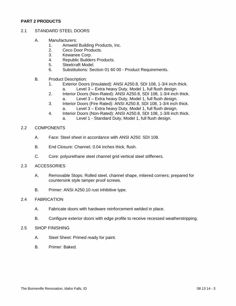
The Bonneville Renovation, Idaho Falls, ID 08 13 14 - 3
PART 2 PRODUCTS
2.1 STANDARD STEEL DOORS
A. Manufacturers: 1. Amweld Building Products, Inc. 2. Ceco Door Products. 3. Kewanee Corp. 4. Republic Builders Products. 5. Steelcraft Model. 6. Substitutions: Section 01 60 00 - Product Requirements.
B. Product Description: 1. Exterior Doors (Insulated): ANSI A250.8, SDI 108, 1-3/4 inch thick.
a. Level 3 – Extra heavy Duty, Model 1, full flush design. 2. Interior Doors (Non-Rated): ANSI A250.8, SDI 108, 1-3/4 inch thick.
a. Level 3 – Extra heavy Duty, Model 1, full flush design. 3. Interior Doors (Fire Rated): ANSI A250.8, SDI 108, 1-3/4 inch thick.
a. Level 3 – Extra heavy Duty, Model 1, full flush design. 4. Interior Doors (Non-Rated): ANSI A250.8, SDI 108, 1-3/8 inch thick.
a. Level 1 - Standard Duty, Model 1, full flush design.
2.2 COMPONENTS
A. Face: Steel sheet in accordance with ANSI A250. SDI 108.
B. End Closure: Channel, 0.04 inches thick, flush.
C. Core: polyurethane steel channel grid vertical steel stiffeners.
2.3 ACCESSORIES
A. Removable Stops: Rolled steel, channel shape, mitered corners; prepared for countersink style tamper proof screws.
B. Primer: ANSI A250.10 rust inhibitive type.
2.4 FABRICATION
A. Fabricate doors with hardware reinforcement welded in place.
B. Configure exterior doors with edge profile to receive recessed weatherstripping.
2.5 SHOP FINISHING
A. Steel Sheet: Primed ready for paint.
B. Primer: Baked.

The Bonneville Renovation, Idaho Falls, ID 08 13 14 - 4
PART 3 EXECUTION
1.1 EXAMINATION
A. Section 01 30 00 - Administrative Requirements: Verification of existing conditions before starting work.
B. Verify opening sizes and tolerances are acceptable.
1.2 INSTALLATION
A. Install doors in accordance with ANSI A250.8.
B. Install door louvers, plumb and level.
C. Coordinate installation of glass and glazing specified in Section 08 80 00.
D. Coordinate installation of doors with installation of frames specified in Section 08 12 14 and hardware specified in Section 08 71 00.
E. Touch-up damaged shop finishes.
1.3 ERECTION TOLERANCES
A. Section 01 40 00 - Quality Requirements: Tolerances.
B. Maximum Diagonal Distortion: 1/16 inch measured with straight edge, corner to corner.
1.4 ADJUSTING
A. Section 01 70 00 - Execution and Closeout Requirements: Requirements for adjusting.
B. Adjust door for smooth and balanced door movement.
1.5 SCHEDULE
A. Refer to Door and Frame Schedule on drawings.
END OF SECTION

The Bonneville Renovation, Idaho Falls, ID 08 14 16 - 1
SECTION 08 14 16
FLUSH WOOD DOORS
PART 1 GENERAL
1.1 SUMMARY
A. Section includes flush wood doors; flush and flush glazed configuration; fire rated and non-rated.
1.2 REFERENCES
A. Architectural Woodwork Institute: 1. AWI - Quality Standards Illustrated.
B. Hardwood Plywood and Veneer Association: 1. HPVA HP-1 - American National Standard for Hardwood and Decorative
Plywood.
C. National Fire Protection Association: 1. NFPA 80 - Standard for Fire Doors, Fire Windows. 2. NFPA 252 - Standard Methods of Fire Tests of Door Assemblies.
D. Underwriters Laboratories Inc.: 1. UL 10B - Fire Tests of Door Assemblies.
E. Uniform Building Code: 1. UBC Standard 7-2 - Fire Tests of Door Assemblies.
1.3 SUBMITTALS
A. Section 01 33 00 - Submittal Procedures: Submittal procedures.
B. Shop Drawings: Illustrate door opening criteria, elevations, sizes, types, swings, undercuts required, special beveling, special blocking for hardware, factory machining criteria, factory finishing criteria, identify cutouts for glazing.
C. Product Data: Submit information on door core materials and construction, and on veneer species, type and characteristics.
D. Samples: 1. Submit two samples of door veneer, 6 x 6 inch in size illustrating wood grain and
finish.
E. Manufacturer's Installation Instructions: Submit special installation instructions.
1.4 QUALITY ASSURANCE
A. Perform Work in accordance with AWI Quality Standard Section 1300, Custom Grade.
B. Finish doors in accordance with AWI Quality Standard Section 1500, grades identified in section.

The Bonneville Renovation, Idaho Falls, ID 08 14 16 - 2
C. Fire Rated Door Construction: Conform to NFPA 252.
D. Fire Rated Door Construction: Conform to one of the following: 1. NFPA 252; with neutral pressure level at 40 inches maximum above sill at 5
minutes into test. 2. UL 10B.
E. Installed Fire Rated Door Assembly: Conform to NFPA 80 for fire rated class as indicated on Drawings.
1.5 QUALIFICATIONS
A. Manufacturer: Company specializing in manufacturing products specified in this section with minimum three years experience.
1.6 DELIVERY, STORAGE, AND HANDLING
A. Section 01 60 00 - Product Requirements: Product storage and handling requirements.
B. Accept doors on site in manufacturer's packaging. Inspect for damage.
C. Protect doors with resilient packaging sealed with heat shrunk plastic. Do not store in damp or wet areas; or in areas where sunlight might bleach veneer. Seal top and bottom edges when stored more than one week. 1. Break seal on site to permit ventilation.
1.7 COORDINATION
A. Section 01 30 00 - Administrative Requirements: Coordination and project conditions.
B. Coordinate Work with door opening construction, door frame and door hardware installation.
1.8 WARRANTY
A. Section 01 70 00 - Execution and Closeout Requirements: Product warranties and product bonds.
B. Include coverage for de-lamination of veneer, warping beyond specified installation tolerances, defective materials, and telegraphing core construction.
C. Furnish manufacturer’s “Life of Installation” warranty for interior doors.
PART 2 PRODUCTS
2.1 FLUSH WOOD DOORS
A. Manufacturers: 1. Jeld Wen 2. Eggers Industries. 3. Marshfield Door systems. 4. Oshkosh Doors. 5. Substitutions: Section 01 60 00 - Product Requirements.

The Bonneville Renovation, Idaho Falls, ID 08 14 16 - 3
B. Product Description: Solid core flush wood doors; wood veneer facing material; fire ratedand non-rated types; flush glazed design; without louvers; paint grade wood doors.1. Flush Interior Doors: 1-3/4 inches thick; solid core, fire rated as indicated on
Drawings.
2.2 COMPONENTS
A. Solid Core, Non-Rated: AWI Section 1300, Type SCL Structural Composite Lumber.
B. Solid Core, Fire Rated: AWI Section 1300, Type indicated on Door Schedule.
C. Interior Veneer Facing: AWI Custom quality wood.1. Wood: Paint grade.
D. Facing Adhesive: Type II - water resistant.
2.3 FABRICATION
A. Fabricate doors in accordance with AWI Quality Standards requirements.
B. Sound Rating for Single Door Leaf and Frame Assembly: ASTM E413, minimum STC35.
C. Furnish lock blocks at lock edge and top of door for closer for hardware reinforcement.
D. Vertical Exposed Edge of Stiles: Of same species as veneer facing, paint grade.
E. Fit door edge trim to edge of stiles after applying veneer facing.
F. Bond edge banding to cores.
G. Factory machine doors for finish hardware in accordance with hardware requirementsand dimensions. Do not machine for surface hardware. Furnish solid blocking forthrough bolted hardware.
H. Factory fit doors for frame opening dimensions identified on shop drawings.
I. Cut and configure exterior door edge to receive recessed weather stripping devices.
J. Provide edge clearances in accordance with AWI 1300.
2.4 SHOP FINISHING
A. Finish work in accordance with AWI - Section 1500 Factory Finishing; Custom Quality;Paint grade.
B. Factory finish doors in accordance with approved sample.
C. Seal door top edge with clear sealer to match door facing.
PART 3 EXECUTION
3.1 EXAMINATION
A. Section 01 30 00 - Administrative Requirements: Coordination and project conditions.

The Bonneville Renovation, Idaho Falls, ID 08 14 16 - 4
B. Verify opening sizes and tolerances are acceptable.
C. Do not install doors in frame openings that are not plumb or are out-of-tolerance for sizeor alignment.
3.2 INSTALLATION
A. Install doors in accordance with AWI Quality Standards requirements.
B. Trim non-rated door width by cutting equally on both jamb edges.
C. Trim door height by cutting bottom edges to maximum of 3/4 inch.1. Trim fire door height at bottom edge only, in accordance with fire rating
requirements.
D. Machine cut doors for hardware installation.
E. Coordinate installation of glass and glazing specified in Section 08 80 00.
3.3 INSTALLATION TOLERANCES
A. Section 01 40 00 - Quality Requirements: Tolerances.
B. Conform to AWI requirements for fit and clearance tolerances.
C. Conform to AWI Section 1300 requirements for maximum diagonal distortion.
D. Maximum Diagonal Distortion (Warp): 1/8 inch measured with straight edge or tautstring, corner to corner, over imaginary 36 x 84 inches surface area.
E. Maximum Vertical Distortion (Bow): 1/8 inch measured with straight edge or taut string,top to bottom, over imaginary 36 x 84 inches surface area.
F. Maximum Width Distortion (Cup): 1/8 inch measured with straight edge or taut string,edge to edge, over imaginary 36 x 84 inches surface area.
3.4 ADJUSTING
A. Section 01 70 00 - Execution and Closeout Requirements: Testing, adjusting, andbalancing.
B. Adjust door for smooth and balanced door movement.
C. Adjust closer for full closure.
3.5 SCHEDULE
A. Refer to Door Schedule.
END OF SECTION

The Bonneville Renovation, Idaho Falls, ID 08 14 33 - 1
SECTION 08 14 33
STILE AND RAIL WOOD DOORS
PART 1 GENERAL
1.1 SUMMARY
A. Section includes wood doors, stile and rail design and transom panels; flat panel configurations; non-rated and fire rated.
1.2 REFERENCES
A. Architectural Woodwork Institute: 1. AWI - Quality Standards Illustrated.
B. Hardwood Plywood and Veneer Association: 1. HPVA HP-1 - American National Standard for Hardwood and Decorative
Plywood.
C. National Fire Protection Association: 1. NFPA 80 - Standard for Fire Doors, Fire Windows. 2. NFPA 252 - Standard Methods of Fire Tests of Door Assemblies.
B. Underwriters Laboratories Inc.: 1. UL 10B - Fire Tests of Door Assemblies. 2. UL 10C - Positive Pressure Fire Tests of Door Assemblies. 3. UL 1784 - Air Leakage Tests of Door Assemblies.
C. Uniform Building Code: 1. UBC Standard 7-2 - Fire Tests of Door Assemblies.
1.3 SUBMITTALS
A. Section 01 33 00 - Submittal Procedures: Submittal procedures.
B. Shop Drawings: Illustrate door opening criteria, elevations, sizes, types, swings, undercuts required, special beveling, and special blocking for hardware.
1.4 QUALITY ASSURANCE
A. Perform Work in accordance with AWI Quality Standard Section 1400, Custom Grade.
B. Finish doors in accordance with AWI Quality Standard Section 1500, grades identified in schedule.
C. Fire Rated Door Construction: Conform to NFPA 252.
D. Fire Rated Door Construction: Conform to UBC Standard 7-2.
E. Installed Fire Rated Door Assembly: Conform to NFPA 80 for fire rated class as indicated on Drawings.

The Bonneville Renovation, Idaho Falls, ID 08 14 33 - 2
F. Attach label from agency approved by authority having jurisdiction to identify each fire rated door.
1.5 QUALIFICATIONS
A. Manufacturer: Company specializing in manufacturing products specified in this section with minimum three years experience.
1.6 DELIVERY, STORAGE, AND HANDLING
A. Section 01 60 00 - Product Requirements: Product storage and handling requirements.
B. Package, deliver and store doors in accordance with AWI Section 1400; in manufacturer's packaging; inspect for damage.
C. Protect doors with resilient packaging. Do not store in damp or wet areas; or in areas where sunlight might bleach veneer. Seal top and bottom edges with tinted sealer when stored more than one week. 1. Break seal on site to permit ventilation.
1.7 COORDINATION
A. Section 01 30 00 - Administrative Requirements: Coordination and project conditions.
B. Coordinate Work with door opening construction, door frame and door hardware installation.
1.8 WARRANTY
A. Section 01 70 00 - Execution and Closeout Requirements: Product warranties and product bonds.
PART 2 PRODUCTS
2.1 STILE AND RAIL WOOD DOORS
A. Manufacturers: 1. Eggers Industries. 2. The Maiman Co. 3. Mohawk Flush Doors, Inc. 4. Pinecrest Inc. 5. Jeld-Wen 6. OshKosh 7. Substitutions: Section 01 60 00 - Product Requirements.
B. Product Description: Stile and rail wood doors, non-rated and fire rated type; flat wood panel design; factory pre-fit; shop finished. 1. Exterior Doors: 1-3/4 inches thick; veneer and lumber stile and rail construction;
mortised and tenoned joints. 2. Interior Doors: 1-3/4 thick; veneer and lumber stile and rail construction; mortised
and tenoned joints. 3. Transom Panels: To match door, fire rated where over fire rated doors.

The Bonneville Renovation, Idaho Falls, ID 08 14 33 - 3
2.2 COMPONENTS
A. Veneer Faced Core, Non-Rated: AWI Section 1400, Type MDF Medium Density Fiberboard.
B. Veneer Faced Core, Fire Rated: AWI Section 1400, manufacturer’s standard for rating indicated; Category A for positive pressure fire test.
C. Exterior Housing Unit Door, Veneer Facing: AWI Custom quality wood, for transparent finish. 1. Wood: Paint Grade.
D. Interior Housing Unit Door, Veneer Facing: AWI Custom quality wood, for transparent finish.
1. Wood: Prefinished Maple.
E. Adhesive: Type I - waterproof.
2.3 ACCESSORIES
A. Molding: Wood, of same species and finish as door facing, shape as indicated on Drawings, mitered corners; prepared for countersink style tamper proof screws.
B. Glazing Stops: Wood, of same species as door facing. Wood with metal clips for rated doors, mitered corners; prepared for countersink style tamper proof screws.
2.4 FABRICATION
A. Fabricate doors in accordance with AWI Quality Standards requirements.
B. Fit door edge trim to edge of stiles after applying veneer facing.
C. Bond edge banding to cores.
D. Factory machine doors for finish hardware in accordance with hardware requirements and dimensions. Do not machine for surface hardware.
2.5 SHOP FINISHING
A. Factory finish doors in accordance with approved sample. Architect provided sample.
PART 3 EXECUTION
1.1 EXAMINATION
A. Section 01 30 00 - Administrative Requirements: Coordination and project conditions.
B. Verify opening sizes and tolerances are acceptable.
C. Do not install doors in frame openings that are not plumb or are out of tolerance for size or alignment.
1.2 INSTALLATION
A. Install doors in accordance with AWI Quality Standards requirements.

The Bonneville Renovation, Idaho Falls, ID 08 14 33 - 4
B. Trim non-rated door width by cutting equally on both jamb edges.
C. Trim door height by cutting bottom edges to maximum of 3/4 inch.1. Trim fire door height at bottom edge only, in accordance with fire rating
requirements.
D. Machine cut for hardware installation.
E. Coordinate installation of doors with installation of frames and hardware.
F. Coordinate installation of glass and glazing.
1.3 INSTALLATION TOLERANCES
A. Section 01 40 00 - Quality Requirements: Tolerances.
B. Conform to AWI requirements for fit, clearance, and joinery tolerances.
C. Maximum Diagonal Distortion (Warp): 1/8 inch measured with straight edge or tautstring, corner to corner, over imaginary 36 x 84 inch surface area.
D. Maximum Vertical Distortion (Bow): 1/8 inch measured with straight edge or taut string,top to bottom, over imaginary 36 x 84 inch surface area.
E. Maximum Width Distortion (Cup):1/8 inch measured with straight edge or taut string,edge to edge, over imaginary 36 x 84 inch surface area.
1.4 ADJUSTING
A. Section 01 70 00 - Execution and Closeout Requirements: Testing, adjusting andbalancing.
B. Adjust door for smooth and balanced door movement.
C. Adjust closer for full closure.
1.5 SCHEDULE
A. Refer to Door and Frame Schedule on drawings.
END OF SECTION

The Bonneville Renovation, Idaho Falls, ID 08 41 13 - 1
SECTION 08 41 13
ALUMINUM ENTRANCES AND STOREFRONTS
PART 1 GENERAL 1.1 SUMMARY
A. Section includes aluminum-framed storefront including aluminum doors and frames including door hardware and perimeter sealant.
1.2 REFERENCES
A. Aluminum Association: 1. AA ADM 1 - Aluminum Design Manual.
B. American Architectural Manufacturers Association: 1. AAMA 501 - Methods of Test for Exterior Walls. 2. AAMA 611 - Voluntary Specification for Anodized Architectural Aluminum. 3. AAMA 1503 - Voluntary Test Method for Thermal Transmittance and
Condensation Resistance of Windows, Doors and Glazed Wall Sections. 4. AAMA CW-10 - Care and Handling of Architectural Aluminum from Shop to Site. 5. AAMA SFM-1 - Aluminum Store Front and Entrance Manual.
C. ASTM International: 1. ASTM B209 - Standard Specification for Aluminum and Aluminum-Alloy Sheet
and Plate. 2. ASTM B221 - Standard Specification for Aluminum and Aluminum-Alloy Extruded
Bars, Rods, Wire, Profiles, and Tubes. 3. ASTM E283 - Standard Test Method for Determining the Rate of Air Leakage
Through Exterior Windows, Curtain Walls, and Doors Under Specified Pressure Differences Across the Specimen.
4. ASTM E330 - Standard Test Method for Structural Performance of Exterior Windows, Curtain Walls, and Doors By Uniform Static Air Pressure Difference.
5. ASTM E331 - Standard Test Method for Water Penetration of Exterior Windows, Curtain Walls, and Doors By Uniform Static Air Pressure Difference.
D. National Fenestration Rating Council Incorporated: 1. NFRC 100 - Procedures for Determining Fenestration Product U-Factors.
1.3 SYSTEM DESCRIPTION
A. Aluminum entrances and storefront system includes tubular aluminum sections with supplementary internal support framing, shop fabricated, factory pre-finished, vision glass, glass infill, related flashings, anchorage and attachment devices.
1.4 PERFORMANCE REQUIREMENTS
A. Limit mullion deflection to 1/200, or flexure limit of glass; with full recovery of glazing materials, whichever is less.
B. System to accommodate, without damage to components or deterioration of seals,
movement within system, movement between system and peripheral construction, dynamic loading and release of loads, deflection of structural support framing.
1.5 SUBMITTALS

The Bonneville Renovation, Idaho Falls, ID 08 41 13 - 2
A. Submit under provisions of Section 01 33 00 B. Shop Drawings: Indicate system dimensions, framed opening requirements and
tolerances, affected related Work and expansion and contraction joint location and details.
C. Product Data: Provide component dimensions, describe components within assembly,
anchorage and fasteners, glass and infill, door hardware, and internal drainage details.
D. Manufacturer's Certificate: Certify that Products meet or exceed specified requirements. 1.6 QUALITY ASSURANCE
A. Perform Work in accordance with AAMA SFM-1 and AAMA - Metal Curtain Wall, Window, Store Front and Entrance - Guide Specifications Manual.
B. Conform to requirements of ANSI A117.1.
1.7 QUALIFICATIONS
A. Manufacturer and Installer: Company specializing in manufacturing aluminum glazing systems with minimum five years experience.
1.8 DELIVERY, STORAGE, AND HANDLING
A. Deliver, store, protect and handle products to site under provisions of Section 01 60 00.
B. Protect pre-finished aluminum surfaces with wrapping or strippable coating. Do not use adhesive papers or sprayed coatings which bond when exposed to sunlight or weather.
1.9 ENVIRONMENTAL REQUIREMENTS
A. Do not install sealants when ambient temperature is less than 40 degrees F during and 48 hours after installation.
1.10 FIELD MEASUREMENTS
A. Verify that field measurements are as indicated on Drawings. 1.11 COORDINATION
A. Coordinate Work with other trades. 1.12 WARRANTY
A. Provide three year warranty under provisions of Section 01 70 00.
B. Warranty: Include coverage for complete system for failure to meet specified requirements.
PART 2 PRODUCTS 2.1 MANUFACTURERS
A. Types: 1. Storefront System 451T (Entrance door wall) 2. Doors: 350 Tuffline.
B. Substitutions: Under provisions of Section 01 60 00. 2.2 MATERIALS
A. Extruded Aluminum: ANSI/ASTM B221; 6063 TS alloy, GS-10A75 temper.

The Bonneville Renovation, Idaho Falls, ID 08 41 13 - 3
B. Sheet Aluminum: ANSI/ASTM B209.
C. Steel Sections: ANSI/ASTM A36; shaped to suit mullion sections.
D. Fasteners: Stainless or Galvanized steel, standard with door manufacturer.
E. Shop and Touch-Up Primer for Steel Components: SSPC 15, Type 1, red oxide.
F. Touch-Up Primer for Galvanized Steel Surfaces: SSPS 20, zinc rich type.
2.3 COMPONENTS
A. Frame: 1-3/4" inches x 4-1/2 inches nominal dimension; applied glazing stops. B. Doors: 1-3/4" inches thick, 3-3/8 inches wide top rail, 3-3/8 inches wide vertical stiles, 16
inches wide bottom rail; square glazing stops. C. Flashings: 1/64" gage aluminum, finish to match mullion sections where exposed.
2.4 GLASS AND GLAZING MATERIALS
A. Glass and Glazing Materials: As specified in Section 08 80 00 of Types described below: 1. Glass in exterior doors and lights: Insulating, Low E.
2.5 SEALANT MATERIALS
A. Sealant and Backing Materials: As recommended by system manufacturer. 2.6 HARDWARE
A. Hinges: McKinney (2 pair ball bearings butt hinges).
B. Push/Pulls: Brushed Aluminum, Baldwin, Quality.
C. Cylinder Locks: Schlage (to match existing keying).
D. Exit Devices: Von Dupin 99.
E. Closers: LCN 4041 Series.
F. Gasket: Pemko.
G. Substitutions: Under provisions of Section 01 60 00. 2.7 KEYING
A. Touch Pad at entries to building, elevator, laundry room and exercise room. B. Door Locks: Master keyed-apartments with dead bolt. C. Keying shall be accomplished by manufacturer certified lock smith.
D. Provide cylinder core and keys.
2.8 FABRICATION
A. Fabricate components with minimum clearances and shim spacing around perimeter of assembly, yet enabling installation and dynamic movement of perimeter seal.
B. Accurately fit and secure joints and corners. Make joints flush, hairline, and weatherproof. C. Prepare components to receive anchor devices. Fabricate anchors.

The Bonneville Renovation, Idaho Falls, ID 08 41 13 - 4
D. Arrange fasteners and attachments to conceal from view. E. Prepare components with internal reinforcement for door hardware and door operator hinge
hardware. F. Reinforce framing members for imposed loads.
2.9 FINISH
A. East Façade; Powder coated frame: Color as selected from full range of manufacturer’s
colors. B. West façade; clear anodized.
PART 3 EXECUTION 3.1 EXAMINATION
A. Verify site-opening conditions.
B. Verify dimensions, tolerances, and method of attachment with other work.
C. Verify wall openings and adjoining air and vapor seal materials are ready to receive work of this Section.
3.2 INSTALLATION
A. Install wall system in accordance with manufacturer's instructions and AAMA - Metal Curtain Wall, Window, Store Front and Entrance - Guide Specifications Manual.
B. Attach to structure to permit sufficient adjustment to accommodate construction tolerances
and other irregularities. C. Provide alignment attachments and shims to permanently fasten system to building
structure. D. Align assembly plumb and level, free of warp or twist. Maintain assembly dimensional
tolerances, aligning with adjacent work. E. Provide thermal isolation where components penetrate or disrupt building insulation. F. Install flashings. G. Pack fibrous insulation in shim spaces at perimeter of assembly to maintain continuity of
thermal barrier. H. Set thresholds in bed of mastic and secure. I. Install hardware using templates provided. J. Install glass in accordance with manufacturer's recommendations. K. Install perimeter sealant as per system manufacturer's recommendations.
3.3 TOLERANCES
A. Maximum Variation from Plumb: 0.06 inches every 3 ft non-cumulative or 1/16 inches per 10 feet, whichever is less.
B. Maximum Misalignment of Two Adjoining Members Abutting in Plane: 1/32 inch.
3.4 ADJUSTING
A. Adjust work under provisions of Section 01 70 00.

The Bonneville Renovation, Idaho Falls, ID 08 41 13 - 5
B. Adjust operating hardware for smooth operation.
3.5 CLEANING
A. Clean work under provisions of 01 70 00.
B. Remove protective material from pre-finished aluminum surfaces.
C. Wash down surfaces with a solution of mild detergent in warm water, applied with soft, cleanwiping cloths. Take care to remove dirt from corners. Wipe surfaces clean.
D. Remove excess sealant by method acceptable to sealant manufacturer.
3.6 PROTECTION OF FINISHED WORK
A. Protect finished Work under provisions of Section 01 50 00.
B. Protect finished Work from damage.
END OF SECTION

The Bonneville Renovation, Idaho Falls, ID 08 52 00 - 1
SECTION 08 52 00
WOOD WINDOWS
PART 1 GENERAL
1.1 SUMMARY
A. Section includes factory fabricated clad wood windows with an operating sash factory glazed, operating hardware and insect screens.
1.2 REFERENCES
A. American Architectural Manufacturers Association: 1. AAMA 101 - Voluntary Performance Specification for Windows, Skylights and
Glass Doors. 2. AAMA 1503 - Voluntary Test Method for Thermal Transmittance and
Condensation Resistance of Windows, Doors and Glazed Wall Sections.
B. American Society of Civil Engineers: 1. ASCE 7 - Minimum Design Loads for Buildings and Other Structures.
A. ASTM International: 1. ASTM D3656 - Standard Specification for Insect Screening and Louver Cloth
Woven from Vinyl-Coated Glass Yarns. 2. ASTM E84 - Standard Test Method for Surface Burning Characteristics of
Building Materials. 3. ASTM E283 - Standard Test Method for Determining the Rate of Air Leakage
Through Exterior Windows, Curtain Walls, and Doors Under Specified Pressure Differences Across the Specimen.
4. ASTM E330 - Standard Test Method for Structural Performance of Exterior Windows, Curtain Walls, and Doors by Uniform Static Air Pressure Difference.
5. ASTM E331 - Standard Test Method for Water Penetration of Exterior Windows, Curtain Walls, and Doors by Uniform Static Air Pressure Difference.
6. ASTM F588 - Standard Test Methods for Resistance of Window Assemblies to Forced Entry Excluding Glazing.
B. Glass Association of North America: 1. GANA - FGMA Sealant Manual.
C. National Fenestration Rating Council Incorporated: 1. NFRC 100 - Procedures for Determining Fenestration Product U-Factors.
D. National Fire Protection Association: 1. NFPA 255 - Standard Method of Test of Surface Burning Characteristics of
Building Materials.
E. Underwriters Laboratories Inc.: 1. UL 723 - Tests for Surface Burning Characteristics of Building Materials.

The Bonneville Renovation, Idaho Falls, ID 08 52 00 - 2
1.3 SYSTEM DESCRIPTION
A. Wood Windows: Wood clad sections, factory fabricated, vision glass, related flashings, anchorage and attachment devices.
B. Configuration: double hung sash.
1.4 PERFORMANCE REQUIREMENTS
A. Primary Performance Requirements: AAMA 101 Designation R15 Residential or better.
B. Member Deflection: Limit member deflection to flexure limit of glass 1/200 with full recovery of glazing materials.
C. Lintel Deflection: Accommodate deflection of lintel without damage to components, deterioration of seals, or movement between window and perimeter framing.
D. Air and Vapor Seal: Maintain continuous air barrier and vapor retarder throughout assembly, primarily in line with inside pane of glass and heel bead of glazing compound.
E. System Internal Drainage: Drain water entering joints, condensation occurring in glazing channel, and moisture occurring within system to exterior by weep drainage network.
F. Thermal Movement: Design sections to permit thermal expansion and contraction of components to match perimeter opening construction.
G. Air Infiltration: Limit air infiltration through assembly to 0.33 cfm/sq ft of wall area, measured at reference differential pressure across assembly of 1.57 psf as measured in accordance with ASTM E283.
H. Water Leakage: None, when measured in accordance with ASTM E331 with test pressure difference as defined by AAMA 101.
1.5 SUBMITTALS
A. Section 01 33 00 - Submittal Procedures: Submittal requirements.
B. Shop Drawings: Indicate opening dimensions, framed opening tolerances, affected related work; and installation requirements.
C. Product Data: Submit component dimensions, anchorage and fasteners, glass, internal drainage details and for window hardware and accessories.
D. Manufacturer's Installation Instructions: Submit special procedures and perimeter conditions requiring special attention.
1.6 QUALITY ASSURANCE
A. Perform Work in accordance with the following: 1. Clad Wood Windows: Fabricate and label window assemblies in accordance with
AAMA 101 for types of windows required. 2. Insulated Glass: Fabricate insulated glass units in accordance with GANA.
B. Surface Burning Characteristics:

The Bonneville Renovation, Idaho Falls, ID 08 52 00 - 3
1. Foam Insulation: Maximum 75/450 flame spread/smoke developed index when tested in accordance with ASTM E84 NFPA 255 UL 723.
C. Apply label from agency approved by authority having jurisdiction to identify each foam plastic insulation board.
1.7 QUALIFICATIONS
A. Manufacturer: Company specializing in manufacturing commercial wood windows with minimum three years experience.
B. Installer: Company specializing in performing residential commercial installation of wood windows with minimum five years experience.
1.8 PRE-INSTALLATION MEETINGS
A. Section 01 30 00 - Administrative Requirements: Preinstallation meetings.
B. Convene minimum one week before starting Work of this section.
1.9 DELIVERY, STORAGE, AND HANDLING
A. Section 01 60 00 - Product Requirements: Product storage and handling requirements.
B. Protect factory finished surfaces with wrapping. Do not use adhesive papers or sprayed coatings that bond when exposed to sunlight or weather.
1.10 ENVIRONMENTAL REQUIREMENTS
A. Section 01 60 00 - Product Requirements.
B. Do not install sealants when ambient temperature is less than 40 degrees F.
C. Maintain this minimum temperature during and after installation of sealants.
1.11 WARRANTY
A. Section 01 70 00 - Execution and Closeout Requirements: Product warranties and product bonds.
B. Furnish five year manufacturer warranty for insulated glass units from seal failure, interpane dusting or misting, and replacement of same.
C. Warranty: 1. Include coverage for degradation of color finish. 2. Include coverage for delamination or separation of finish cladding from window
member.
PART 2 PRODUCTS
2.1 WOOD WINDOWS
A. Manufacturers: 1. Andersen Windows.

The Bonneville Renovation, Idaho Falls, ID 08 52 00 - 4
2. Classic Windows Inc. 3. Duratherm Window Corp. 4. Loewen Windows. 5. Marvin Windows & Doors. 6. Pella Corp. 7. Milgard Windows. 8. Substitutions: Section 01 60 00 - Product Requirements.
B. Product Description: High quality residential wood windows, site finished, metal clad finished, operable sash, glass and glazing, operating hardware, and insect screen.
2.2 COMPONENTS
A. Wood: Clear Pine species, clear preservative treated, of type suitable for transparent interior finish.
B. Aluminum or Ultrex Cladding (Exterior Surface): Formed material factory fit to profile or exterior exposed surface; factory finished.
C. Unit Frame and Intermediate Mullions: Construction: Wood with mortise and tenon joint construction. Frame and mullions shall match existing windows in general size, profile, and configuration.
D. Fixed and Sliding Frame Construction: Wood with mortise and tenon joint construction.
E. Insulating Glass: Sealed double pane units; conform with requirements in Section 08 80 00. 1. Outer Pane: Clear Low E tempered float glass. 2. Inner Pane: Clear tempered float glass. 3. Pane Thickness: Minimum 1/8 thick. Determined by size or wind and suction
loads. 4. Minimum Total Unit Thickness: 5/8 inch. 5. Glazing: Manufacturer’s standard conforming with requirements specified in
Section 08 80 00.
F. Glass Stops: Solid wood to match windows, sloped for wash.
G. Sills: Sloped for positive wash; fit under sash to project 1/2 inch beyond wall face; one piece full width of opening.
H. Window Hardware: 1. Sash lock: Lever handle with cam lock. 2. Double Hung Sash: Metal and nylon spiral friction slide cylinder, each sash, each
jamb. 3. Pulls: Manufacturer’s standard.
I. Insect Screen Frame: aluminum frame of rectangular sections; fit with adjustable hardware; nominal size similar to operable glazed unit.
J. Insect Screens: ASTM D3656, Class 2, 18 by 14 mesh, charcoal color.
K. Operable Sash Weatherstripping: Nylon pile or Resilient PVC; permanently resilient, profiled to effect weather seal.

The Bonneville Renovation, Idaho Falls, ID 08 52 00 - 5
2.3 ACCESSORIES
A. Anchors: Corrosion resistant steel.
2.4 FABRICATION
A. Fabricate framing and sash members with mortise and tenon joints. Glue joints.
B. Ensure joints and connections are flush, hairline, and weather-tight.
C. Finger joints not permitted in units intended for transparent finish.
A. Form sills and stools in one piece. Slope sills for wash.
B. Furnish weather stop flange for perimeter of unit.
C. Fabricate components with minimum clearances and shim spacing around perimeter of assembly, yet allowing installation and dynamic movement of perimeter seal.
D. Arrange fasteners to be concealed from view.
E. Permit internal drainage weep holes and channels to migrate moisture to exterior. Provide internal drainage of glazing spaces to exterior through weep holes.
F. Assemble insect screen frame, miter and reinforced frame corners. Fit mesh taut into frame and secure. Fit frame with four spring loaded steel pin retainers.
G. Double weatherstrip operable units.
H. Factory install glass in window units in accordance with manufacturer’s standard method conforming with GANA and to achieve performance criteria specified.
2.5 SHOP FINISHING
A. Exterior Surfaces: Color anodized aluminum cladding to color as selected.
B. Interior Surfaces: Wood shop finished with transparent materials as specified in Section 09 90 00.
C. Screens: Match window frame color.
D. Exposed Hardware: Baked enamel color as selected.
PART 3 EXECUTION
1.1 EXAMINATION
A. Section 01 30 00 - Administrative Requirements: Coordination and project conditions.
B. Verify wall openings and adjoining air and vapor seal materials are ready to receive work of this section, and opening dimensions and clearances are as indicated on shop drawings.

The Bonneville Renovation, Idaho Falls, ID 08 52 00 - 6
1.2 INSTALLATION
A. Attach window frame and shims to perimeter opening to accommodate construction tolerances and other irregularities.
B. Align window plumb and level, free of warp or twist. Maintain dimensional tolerances and alignment with adjacent work.
C. Install sills.
D. Provide thermal isolation where components penetrate or disrupt building insulation. Pack fibrous insulation in shim spaces at perimeter of assembly to maintain continuity of thermal barrier.
E. Coordinate attachment and seal of perimeter air and vapor retarder materials.
F. Install operating hardware.
1.3 ERECTION TOLERANCES
A. Section 01 40 00 - Quality Requirements: Tolerances.
B. Maximum Variation from Level and from Plumb: 1/16 inches every 3 ft non-cumulative or 1/8 inches per 10 ft, whichever is less.
1.4 ADJUSTING
A. Section 01 70 00 - Execution and Closeout Requirements: Requirements for starting and adjusting.
B. Adjust hardware for smooth operation and secure weathertight closure.
1.5 CLEANING
A. Section 01 70 00 - Execution and Closeout Requirements: Final cleaning.
B. Remove protective material from factory finished surfaces.
C. Remove labels and visible markings.
D. Wash surfaces by method recommended and acceptable to sealant and window manufacturer; rinse and wipe surfaces clean.
1.6 SCHEDULES
A. Primary: south and east facades – wood clad window such as Integrity by Marvin.
B. Secondary: north and west facades – Ultrex windows to match existing profile and window configuration.
2.3
END OF SECTION

The Bonneville Renovation, Idaho Falls, ID 08 71 00 - 1
SECTION 08 71 00
DOOR HARDWARE
PART 1 GENERAL
1.1 SUMMARY
A. Section includes hardware for metal, aluminum, and wood doors. 1. Provide all door hardware, door gaskets, including weatherstripping and seals,
and thresholds at exterior doors.
1.2 REFERENCES
A. Builders Hardware Manufacturers Association: 1. BHMA Directory of Certified Products.
1.3 SUBMITTALS
A. Section 01 33 00 - Submittal Procedures: Submittal procedures.
B. Shop Drawings: 1. Indicate locations and mounting heights of each type of hardware, schedules,
catalog cuts. 2. Submit manufacturer's parts lists, and templates.
C. Manufacturer's Installation Instructions: Submit special procedures, and perimeter conditions requiring special attention.
1.4 CLOSEOUT SUBMITTALS
A. Section 01 70 00 - Execution and Closeout Requirements: Closeout procedures.
B. Project Record Documents: Record actual locations of installed cylinders and their master key code.
C. Operation and Maintenance Data: Submit data on operating hardware, lubrication requirements, and inspection procedures related to preventative maintenance.
D. Keys: Deliver with identifying tags to Owner by security shipment direct from hardware supplier.
1.5 QUALITY ASSURANCE
A. Perform Work in accordance with the following requirements: 1. ANSI A156 series. 2. NFPA 80. 3. UL 305.
B. Furnish hardware marked and listed in BHMA Directory of Certified Products.

The Bonneville Renovation, Idaho Falls, ID 08 71 00 - 2
1.6 QUALIFICATIONS
A. Manufacturer: Company specializing in manufacturing products specified in this section with minimum three years documented experience.
B. Hardware Supplier: Company specializing in supplying commercial door hardware with minimum three years experience.
B. Hardware Supplier Personnel: Employ qualified person to assist in work of this section.
1.7 DELIVERY, STORAGE, AND HANDLING
A. Section 01 60 00 - Product Requirements: Product storage and handling requirements.
B. Package hardware items individually with necessary fasteners, instructions, and installation templates, when necessary; label and identify each package with door opening code to match hardware schedule.
1.8 COORDINATION
A. Section 01 30 00 - Administrative Requirements: Coordination and project conditions.
B. Coordinate Work with other directly affected sections involving manufacture or fabrication of internal reinforcement for door hardware and recessed items. 1. Provide templates or actual hardware as required to ensure proper preparation of
doors and frames.
1.9 WARRANTY
A. Section 01 70 00 - Execution and Closeout Requirements: Product warranties and product bonds.
B. Furnish five-year manufacturer warranty for locksets and door closers.
1.10 MAINTENANCE MATERIALS
A. Section 01 70 00 - Execution and Closeout Requirements: Maintenance materials.
B. Furnish special wrenches and tools applicable for each different and for each special hardware component.
C. Furnish maintenance tools and accessories supplied by hardware component manufacturer.
PART 2 PRODUCTS
2.1 DOOR HARDWARE
A. Hinge Manufacturers: 1. McKenney. 2. Hager. 3. Stanley. 4. Substitutions: Section 01 60 00 - Product Requirements.
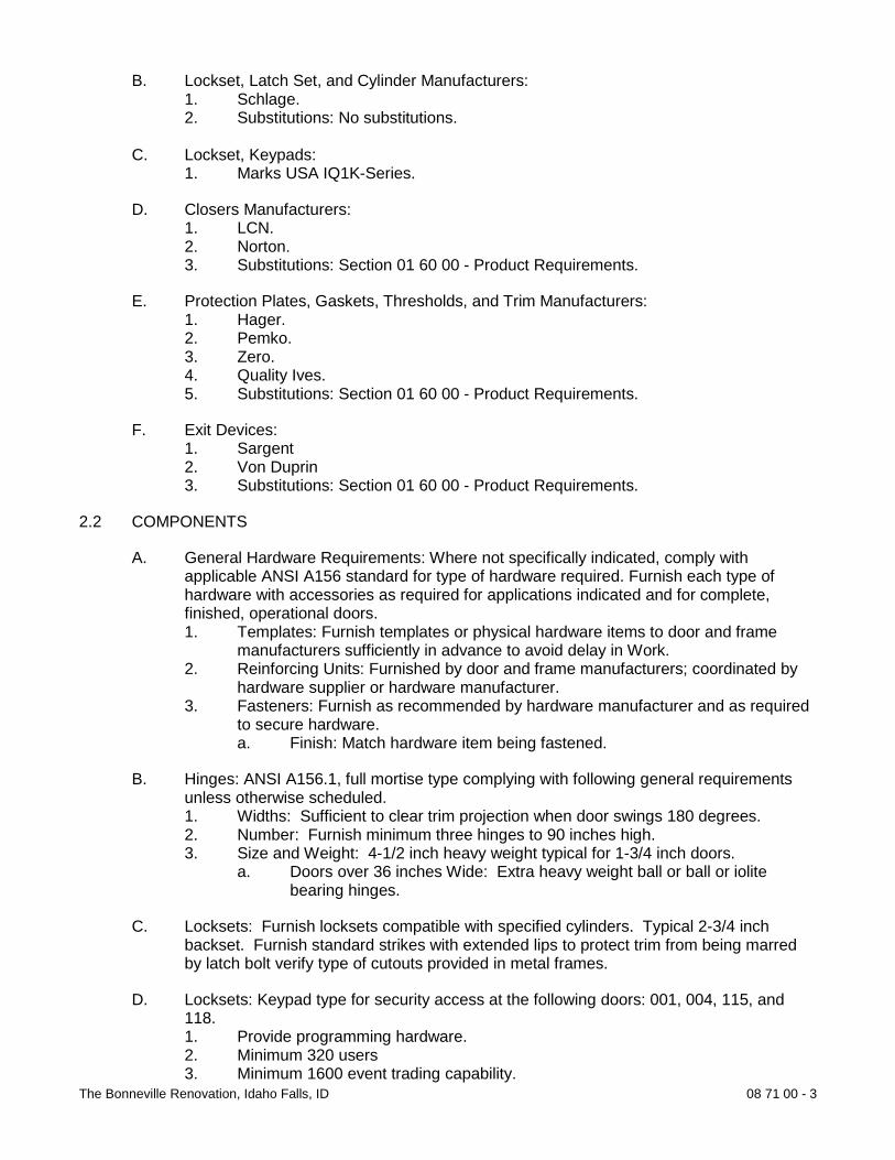
The Bonneville Renovation, Idaho Falls, ID 08 71 00 - 3
B. Lockset, Latch Set, and Cylinder Manufacturers: 1. Schlage. 2. Substitutions: No substitutions.
C. Lockset, Keypads: 1. Marks USA IQ1K-Series.
D. Closers Manufacturers: 1. LCN. 2. Norton. 3. Substitutions: Section 01 60 00 - Product Requirements.
E. Protection Plates, Gaskets, Thresholds, and Trim Manufacturers: 1. Hager. 2. Pemko. 3. Zero. 4. Quality Ives. 5. Substitutions: Section 01 60 00 - Product Requirements.
F. Exit Devices: 1. Sargent 2. Von Duprin 3. Substitutions: Section 01 60 00 - Product Requirements.
2.2 COMPONENTS
A. General Hardware Requirements: Where not specifically indicated, comply with applicable ANSI A156 standard for type of hardware required. Furnish each type of hardware with accessories as required for applications indicated and for complete, finished, operational doors. 1. Templates: Furnish templates or physical hardware items to door and frame
manufacturers sufficiently in advance to avoid delay in Work. 2. Reinforcing Units: Furnished by door and frame manufacturers; coordinated by
hardware supplier or hardware manufacturer. 3. Fasteners: Furnish as recommended by hardware manufacturer and as required
to secure hardware. a. Finish: Match hardware item being fastened.
B. Hinges: ANSI A156.1, full mortise type complying with following general requirements unless otherwise scheduled. 1. Widths: Sufficient to clear trim projection when door swings 180 degrees. 2. Number: Furnish minimum three hinges to 90 inches high. 3. Size and Weight: 4-1/2 inch heavy weight typical for 1-3/4 inch doors.
a. Doors over 36 inches Wide: Extra heavy weight ball or ball or iolite bearing hinges.
C. Locksets: Furnish locksets compatible with specified cylinders. Typical 2-3/4 inch backset. Furnish standard strikes with extended lips to protect trim from being marred by latch bolt verify type of cutouts provided in metal frames.
D. Locksets: Keypad type for security access at the following doors: 001, 004, 115, and 118. 1. Provide programming hardware. 2. Minimum 320 users 3. Minimum 1600 event trading capability.

The Bonneville Renovation, Idaho Falls, ID 08 71 00 - 4
E. Closers: ANSI A156.4 modern type with cover, surface mounted, closers; full rack and pinion type with steel spring and non-freezing hydraulic fluid; closers required for fire rated doors unless otherwise indicated. 1. Adjustability: Furnish controls for regulating closing, latching, speeds, and back
checking. 2. Arms: Type to suit individual condition; parallel-arm closers at reverse bevel
doors and where doors swing full 180 degrees. 3. Location: Mount closers on room side of interior doors typical; mount on pull side
of other doors. 4. Operating Pressure: Maximum operating pressure as follows.
a. Interior Doors: Maximum 5 pounds.
F. Exit Devices: ANSI A156.3, Grade 1, rim type, cross bar, unless otherwise indicated. Furnish standard strikes with extended lips to protect rim from being marred by latch bolt, verify type of cutouts provided in metal frames. 1. Types: Suitable for doors requiring exit devices.
G. Cylinders: ANSI A156.5, Grade 1, match existing keying Schlage Keyway Type “F”. 1. Keying: Keyed as directed by Owner. Master keyed. 2. Include construction keying. 3. Keys: Nickel silver. Stamp keys with “DO NOT DUPLICATE”. 4. Supply keys in the following minimum quantities:
a. 5 master keys. b. 5 construction keys. c. 2 change keys for each lock and cylinder.
2.3 ACCESSORIES
A. Lock Trim: Furnish levers with rose or escutcheon plate as indicated on Schedule. 1. Do not permit through bolts on solid wood core doors.
2.4 FINISHING
A. Door Hardware Finishes: ANSI A156.18; furnish following finishes. 1. Hinges:
a. BHMA 630 and 626, satin finish. 2. Typical Exterior Exposed and High Use Interior Door Hardware:
a. BHMA 626, satin chromium plated brass or bronze. 3. Typical Interior Door Hardware:
a. BHMA 626, satin chromium plated brass or bronze. 4. Typical Interior Toilet Room Door Hardware:
a. BHMA 626 satin chromium plated brass or bronze. 5. Closers: Finish appearance to match door hardware on same face of door. 6. Thresholds
a. BHMA 628, satin aluminum, clear anodized. 7. Other Items: Furnish manufacturer’s standard finishes to match similar hardware
types on same door, and maintain acceptable finish considering anticipated use and BHMA category of finish.
PART 3 EXECUTION
3.1 EXAMINATION
A. Section 01 30 00 - Administrative Requirements: Coordination and project conditions.

The Bonneville Renovation, Idaho Falls, ID 08 71 00 - 5
B. Verify doors and frames are ready to receive door hardware and dimensions are as indicated on shop drawings.
3.2 INSTALLATION
A. Coordinate mounting heights with door and frame manufacturers. Use templates provided by hardware item manufacturer.
B. Mounting Heights from Finished Floor to Center Line of Hardware Item: Comply with manufacturer recommendations and applicable codes where not otherwise indicated. 1. Locksets: 38 inch. 2. Push/Pulls: 42 inch. 3. Dead Locks: 48 inch. 4. Cross Bar Type Exit Devices: 38 inch. 5. Top Hinge: Jamb manufacturer’s standard, but not greater than 10 inches from
head of frame to center line of hinge. 6. Bottom Hinge: Jamb manufacturer’s standard, but not greater than 12-1/2 inches
from floor to center line of hinge. 7. Intermediate Hinges: Equally spaced between top and bottom hinges and from
each other. 8. Hinge Mortise on Door Leaf: 1/4 inch to 5/16 inch from stop side of
door.
3.3 FIELD QUALITY CONTROL
A. Section 01 40 00 - Quality Requirements: Field inspecting, testing, adjusting, and balancing.
B. Architectural Hardware Consultant inspect installation and certify hardware and installation has been furnished and installed in accordance with manufacturer's instructions and as specified.
3.4 ADJUSTING
A. Section 01 70 00 - Execution and Closeout Requirements: Testing, adjusting, and balancing.
B. Adjust hardware for smooth operation.
3.5 PROTECTION OF INSTALLED CONSTRUCTION
A. Section 01 70 00 - Execution and Closeout Requirements: Protecting installed construction.
C. Do not permit adjacent work to damage hardware or hardware finish.
2.3
END OF SECTION

The Bonneville Renovation, Idaho Falls, ID 08 80 00 - 1
SECTION 08 80 00
GLAZING
PART 1 GENERAL
1.1 SUMMARY
A. Section includes glass glazing for metal frames, doors, and windows.
1.2 REFERENCES
A. American National Standards Institute: 1. ANSI Z97.1 - Safety Glazing Materials Used in Buildings Safety.
B. ASTM International: 1. ASTM C864 - Standard Specification for Dense Elastomeric Compression Seal
Gaskets, Setting Blocks, and Spacers. 2. ASTM C920 - Standard Specification for Elastomeric Joint Sealants. 3. ASTM C1036 - Standard Specification for Flat Glass. 4. ASTM C1193 - Standard Guide for Use of Joint Sealants. 5. ASTM E90 - Standard Test Method for Laboratory Measurement of Airborne
Sound Transmission Loss of Building Partitions and Elements. 6. ASTM E119 - Standard Test Methods for Fire Tests of Building Construction and
Materials. 7. ASTM E330 - Standard Test Method for Structural Performance of Exterior
Windows, Curtain Walls, and Doors by Uniform Static Air Pressure Difference. 8. ASTM E546 - Standard Test Method for Frost Point of Sealed Insulating Glass
Units. 9. ASTM E576 - Standard Test Method for Frost Point of Sealed Insulating Glass
Units in the Vertical Position. 10. ASTM E773 - Standard Test Methods for Seal Durability of Sealed Insulating
Glass Units. 11. ASTM E774 - Standard Specification for Sealed Insulating Glass Units. 12. ASTM E1425 - Standard Practice for Determining the Acoustical Performance of
Exterior Windows and Doors.
C. Consumer Products Safety Commission: 1. CPSC 16 CFR 1201 - Safety Standard for Architectural Glazing.
D. Glass Association of North America: 1. GANA - FGMA Sealant Manual. 2. GANA - Glazing Manual. 3. GANA - Laminated Glass Design Guide.
1.3 PERFORMANCE REQUIREMENTS
A. Provide glass and glazing materials for continuity of building enclosure vapor retarder and air barrier: 1. In conjunction with materials described in Section 07 27 00 and 07 90 00. 2. To utilize inner pane of multiple pane sealed units for continuity of air barrier and
vapor retarder seal.

The Bonneville Renovation, Idaho Falls, ID 08 80 00 - 2
3. To maintain continuous air barrier and vapor retarder throughout glazed assembly from glass pane to heel bead of glazing sealant.
B. Structural Design: Design in accordance with applicable code for most critical combination of wind, snow, and dead loads.
C. Wind Loads: Design and size glass to withstand positive and negative wind loads acting normal to plane of wall, including increased loads at building corners. 1. Design Wind Load: As calculated in accordance with applicable code.
D. Wind-Borne Debris Loads: Design and size glass located less than 60 feet above grade to withstand the following loads: 1. Glass Within 30 feet of Grade: ASTM 1996; large missile impact test.
E. Seismic Loads: Design and size components to withstand seismic loads and sway displacement as calculated in accordance with applicable code.
F. Exterior Glass Deflection: Maximum of 1/175 of glass edge length or 3/4 inch, which ever is less with full recovery of glazing materials.
D. Interior Glass Deflection: Maximum thickness of glass differential deflection for two adjacent unsupported edges when 50 plf force is applied to one panel at any point up to 42 inches above finished floor.
1.4 SUBMITTALS
A. Section 01 33 00 - Submittal Procedures: Submittal procedures.
B. Shop Drawings 1. Indicate sizes, layout, thicknesses, and loading conditions for glass.
C. Product Data: 1. Glass: Provide structural, physical and environmental characteristics, size
limitations, special handling or installation requirements. 2. Glazing Sealants, Compounds and Accessories: Provide chemical, functional,
and environmental characteristics, limitations, special application requirement. Identity available colors where exposed.
E. Design Data: Submit design calculations for glass resisting wind loads.
F. Manufacturer's Certificate: Certify sealed insulated glass, meets or exceeds specified requirements.
G. Installer's Certificate: Certify glass furnished without identification label is installed in accordance with Construction Documents and applicable code.
1.5 QUALITY ASSURANCE
A. Perform Work in accordance with GANA Glazing Manual, GANA Sealant Manual, GANA Laminated Glass Design Guide for glazing installation methods.
1.6 QUALIFICATIONS
A. Installer: Company specializing in performing Work of this section with minimum three years experience.

The Bonneville Renovation, Idaho Falls, ID 08 80 00 - 3
1.7 ENVIRONMENTAL REQUIREMENTS
A. Section 01 60 00 - Product Requirements.
B. Do not install glazing when ambient temperature is less than 50 degrees F.
C. Maintain minimum ambient temperature before, during and 24 hours after installation of glazing compounds.
1.8 WARRANTY
A. Section 01 70 00 - Execution and Closeout Requirements: Product warranties and product bonds.
B. Furnish ten year warranty to include coverage for sealed glass units from seal failure, interpane dusting or misting, and replacement of same.
PART 2 PRODUCTS
2.1 GLAZING
A. Manufacturers: 1. Libbey-Owens-Ford, Inc. 2. PPG Industries. 3. Substitutions: Section 01 60 00 - Product Requirements. Not Permitted.
2.2 COMPONENTS
A. Flat Glass: Minimum 1/4 inch unless otherwise indicated. 1. Clear Float Glass (Type FG-CF): ASTM C1036, Type 1 transparent flat, Class 1
clear, Quality q3 glazing select.
B. Safety Glass: Conform to CPSC 16 CFR 1201 Category II, total thickness 1/4 inch unless otherwise indicated. 1. Clear Tempered Glass (Type SG-CT): ASTM C1048, Kind FT Fully tempered,
Condition A, uncoated, Type 1 transparent flat, Class 1 clear, Quality q3 glazing select; with horizontal tempering.
C. Insulated Glass Units (Type IG): Total unit thickness 1 inch 1. Double Pane Insulated Glass Units (Type IG-DP-1): ASTM E774 Class A and
E773; with glass elastomer, glass to mastic, or silicone sealant edge seal; purge interpane space with dry hermetic air. a. Type: Sungate 100 (3) manufactured by PPG Industries. b. Outer Pane: Glass Type: Atlantica. c. Inner Pane: Clear float, with Low E (Sputtered) coating on third surface
(3). 2. Double Pane Insulated Glass Units (Type 1G-DP-2): Kind FT Fully Tempered
ASTM E774 Class A and E773; with glass elastomer, glass to mastic, silicone sealant, edge seal; purge interpane space with dry hermetic air. a. Sungate 100 (3) manufactured by PPG Industries. b. Outer Pane: Glass Type: Atlantica. c. Inner Pane: With Low E (spotless) Coating on third surface (3).
A. Insulated Glass Units (Type 1G): Total unit thickness 1/2 inch.

The Bonneville Renovation, Idaho Falls, ID 08 80 00 - 4
1. Double Pane Insulated Glass Units (Type IG-DP-3): ASTM E774 Class A and E773; with glass elastomer, glass to mastic, or silicone sealant edge seal; purge interpane space with dry hermetic air. a. Type: Sungate 100 (3) manufactured by PPG Industries. b. Outer Pane: Glass Type: Atlantica. c. Inner Pane: Clear float, with Low E (Sputtered) coating on third surface
(3).
B. Insulated Glass Units (Type 1G): Total unit thickness 1 inch. 1. Double Pane Insulated Glass Units (Type IG-DP-4): ASTM E774 Class A and
E773; with glass elastomer, glass to mastic, or silicone sealant edge seal; purge interpane space with dry hermetic air. a. Type: Sungate (3) manufactured by PPG Industries. b. Outer Pane: Glass Type: Atlantica-Obscure c. Inner Pane and Middle: Clear float, with Low E (Sputtered) coating on
third surface (3).
C. Insulated Glass Units (Type 1G): Total unit thickness 3/4 inch. 1. Triple Pane Insulated Glass Units (Type IG-DP-5: ASTM E774 Class A and
E773; with glass elastomer, glass to mastic or silicone sealant edge seal; purge interpane space with dry hermetic air. a. Type: Sungate (3) manufactured by PPG Industries. b. Outer Pane: Glass Type: Colored and textured to match existing. c. Inner Pane and Middle: Clear float, with Low E (Sputtered) coating on
third surface (3).
G. Fire Resistive Glass (Type FRG): Glazing materials to be types approved for use with specified materials in fire rated applications as indicated on Drawings. Minimum 1/4 inch (6mm) thick unless otherwise indicated. 1. Wired Clear Glass (Type FRG-CW): ASTM C1036, Type II wired flat, Class 1
polished both sides, Quality q8 glazing; Mesh m1 diagonal m2 square of woven stainless steel wire, manufacturer’s standard grid size; conforming to ANSI Z91.7.
2. Wired Clear Glass (Type FRG-PW): ASTM C1036, Type II patterned wired flat, Class 1 clear, Form 2 patterned and wired. Finish fl patterned one side f2 patterned both sides; Mesh m1 diagonal m2 square of woven stainless steel wire, manufacturer’s standard grid size; conforming to ANSI Z91.7.
2.3 ACCESSORIES
A. Elastomeric Glazing Sealants: Materials compatible with adjacent materials including glass, insulating glass seals, and glazing channels.
B. Glazing Compounds: As recommended by manufacturer.
C. Glazing Accessories: As recommended by manufacturer.
PART 3 EXECUTION
1.1 EXAMINATION
B. Section 01 30 00 - Administrative Requirements: Coordination and project conditions.
A. Verify openings for glazing are correctly sized and within acceptable tolerance.

The Bonneville Renovation, Idaho Falls, ID 08 80 00 - 5
B. Verify surfaces of glazing channels or recesses are clean, free of obstructions impeding moisture movement, weeps are clear, and ready to receive glazing.
1.1 PREPARATION
A. Clean contact surfaces with solvent and wipe dry.
B. Seal porous glazing channels or recesses with substrate compatible primer or sealer.
C. Prime surfaces scheduled to receive sealant.
1.2 INSTALLATION
A. Perform installation in accordance with GANA Glazing Manual. 1. Glazing Sealants: Comply with ASTM C1193.
B. Interior Dry Method (Tape and Tape) Installation: 1. Cut glazing tape to length and set against permanent stops, projecting 1/16 inch
above sight line. 2. Place setting blocks at 1/4 points with edge block no more than 6 inches from
corners. 3. Rest glazing on setting blocks and push against tape for full contact at perimeter
of pane or unit. 4. Place glazing tape on free perimeter of glazing in same manner described above. 5. Install removable stop without displacement of tape. Exert pressure on tape for
full continuous contact. 6. Knife trim protruding tape.
1.3 FIELD QUALITY CONTROL
A. Section 01 40 00 - Quality Requirements, 01 70 00 - Execution and Closeout Requirements: Field inspecting, testing, adjusting, and balancing.
B. Monitor quality of glazing.
1.4 CLEANING
A. Section 01 70 00 - Execution and Closeout Requirements: Final cleaning.
B. Remove glazing materials from finish surfaces.
C. Remove labels after Work is complete.
D. Clean glass and adjacent surfaces.
1.5 PROTECTION OF INSTALLED CONSTRUCTION
A. Section 01 70 00 - Execution and Closeout Requirements: Protecting installed construction.
B. After installation, mark pane with an 'X' by using removable plastic tape or paste. Do not mark heat absorbing or reflective glass units.
2.3
END OF DIVISION

The Bonneville Renovation, Idaho Falls, ID 09 21 16 - 1
DIVISION 09 FINISHES SECTION 09 21 16
GYPSUM BOARD ASSEMBLIES
PART 1 GENERAL
1.1 SUMMARY
A. Section includes gypsum board and joint treatment; cementitious backer board; acoustic insulation; and textured finish.
1.2 REFERENCES
A. ASTM International: 1. ASTM C36 - Standard Specification for Gypsum Wallboard. 2. ASTM C442 - Standard Specification for Gypsum Backing Board and Coreboard. 3. ASTM C475 - Standard Specification for Joint Compound and Joint Tape for
Finishing Gypsum Board. 4. ASTM C557 - Standard Specification for Adhesives for Fastening Gypsum
Wallboard to Wood Framing. 5. ASTM C630/C630M - Standard Specification for Water-Resistant Gypsum
Backing Board. 6. ASTM C665 - Standard Specification for Mineral-Fiber Blanket Thermal
Insulation for Light Frame Construction and Manufactured Housing. 7. ASTM C840 - Standard Specification for Application and Finishing of Gypsum
Board. 8. ASTM C1002 - Standard Specification for Steel Drill Screws for the Application of
Gypsum Panel Products or Metal Plaster Bases.
B. Gypsum Association: 1. GA 214 - Recommended Levels of Gypsum Board Finish. 2. GA 216 - Application and Finishing of Gypsum Board.
C. Intertek Testing Services (Warnock Hersey Listed): 1. WH - Certification Listings.
D. National Fire Protection Association: 1. NFPA 255 - Standard Method of Test of Surface Burning Characteristics of
Building Materials.
E. Underwriters Laboratories Inc.: 1. UL - Fire Resistance Directory. 2. UL 723 - Tests for Surface Burning Characteristics of Building Materials.
1.3 SUBMITTALS
A. Section 01 33 00 - Submittal Procedures: Submittal procedures.
B. Product Data: Submit data on gypsum board and joint tape.

The Bonneville Renovation, Idaho Falls, ID 09 21 16 - 2
1.4 QUALITY ASSURANCE
A. Perform Work in accordance with ASTM C840, GA-214, GA-216.
1.5 QUALIFICATIONS
A. Manufacturer: Company specializing in manufacturing products specified in this section with minimum three years experience.
B. Installer: Company specializing in performing Work of this section with minimum three years experience.
PART 2 PRODUCTS
2.1 GYPSUM BOARD ASSEMBLIES
A. Manufacturers: 1. Celotex Building Products. 2. G-P Gypsum Corp. 3. National Gypsum Co. 4. United States Gypsum Co. 5. Substitutions: Section 01 60 00 - Product Requirements.
2.2 COMPONENTS
A. Gypsum Board Materials: 1. Fire Rated Gypsum Board: ASTM C36; fire resistive type, UL or WH rated; 5/8
inch thick, maximum available length in place; ends square cut, tapered and beveled edges.
2. Moisture Resistant Gypsum Board: ASTM C630/C630M; 5/8 inch thick, maximum available length in place; ends square cut, tapered and beveled edges.
3. Cementitious Backing Board: High density, glass fiber reinforced, 1/2 inch thick; 2 inch wide, coated glass fiber tape for joints and corners.
2.3 ACCESSORIES
A. Acoustic Insulation: ASTM C665; preformed glass fiber, friction fit type, unfaced, full thickness of the wall.
B. Acoustic Sealant: Non-hardening, non-skinning, for use in conjunction with gypsum board.
C. Corner Beads: Metal, square.
D. Edge Trim: GA-216; Type bead.
E. Joint Materials: ASTM C475; reinforcing tape, joint compound, adhesive, and water.
F. Textured Finish Materials: Latex based texturing material.
G. Fasteners: ASTM C1002.

The Bonneville Renovation, Idaho Falls, ID 09 21 16 - 3
PART 3 EXECUTION
3.1 EXAMINATION
A. Section 01 30 00 - Administrative Requirements: Coordination and project conditions.
B. Verify site conditions are ready to receive work and opening dimensions are as indicated on shop drawings.
3.2 INSTALLATION
A. Gypsum Board Installation: 1. Install gypsum board in accordance with GA-216. 2. Erect single layer fire rated gypsum board with edges and ends occurring over
firm bearing. 3. Use screws when fastening gypsum board to wood furring or framing. 4. Treat cut edges and holes in moisture resistant gypsum board with sealant. 5. Place control joints consistent with lines of building spaces. 6. Place corner beads at external corners. Use longest practical length. Place edge
trim where gypsum board abuts dissimilar materials. 7. Install cementitious backing board over wood studs.
B. Joint Treatment: 1. Tape, fill, and sand exposed joints, edges, and corners to produce smooth
surface ready to receive finishes. 2. Feather coats on to adjoining surfaces so that camber is maximum 1/32 inch. 3. Taping, filling, and sanding is not required at surfaces behind adhesive applied
ceramic tile. 4. Fill and finish joints and corners of cementitious backing board.
C. Texture Finish: Roller apply finish texture coating.
3.3 ERECTION TOLERANCES
A. Section 01 40 00 - Quality Requirements: Tolerances.
B. Maximum Variation of Finished Gypsum Board Surface from Flat Surface: 1/8 inch in 10 feet.
END OF SECTION

The Bonneville Renovation, Idaho Falls, ID 09 22 16 - 1
SECTION 09 22 16
NON-STRUCTURAL METAL FRAMING
PART 1 GENERAL
1.1 SUMMARY
A. Section includes metal stud framing and accessories at interior locations.
1.2 REFERENCES
A. ASTM International: 1. ASTM A653/A653M - Standard Specification for Steel Sheet, Zinc-Coated
(Galvanized) or Zinc-Iron Alloy-Coated (Galvannealed) by the Hot-Dip Process. 2. ASTM C645 - Standard Specification for Nonstructural Steel Framing Members. 3. ASTM C754 - Standard Specification for Installation of Steel Framing Members
to Receive Screw-Attached Gypsum Panel Products. 4. ASTM C1002 - Standard Specification for Steel Drill Screws for the Application of
Gypsum Panel Products or Metal Plaster Bases.
B. National Association of Architectural Metal Manufacturers: 1. NAAMM ML/SFA 540 - Lightweight Steel Framing Systems Manual.
1.3 SYSTEM DESCRIPTION
A. Interior Walls: Metal stud framing system with batt type acoustic insulation and interior gypsum board.
B. Maximum Allowable Deflection: 1:360 span.
B. Wall System: 1. Design to provide for movement of components without damage, failure of joint
seals, undue stress on fasteners, or other detrimental effects when subject to seasonal or cyclic day/night temperature ranges.
2. Design system to accommodate construction tolerances, deflection of building structural members, and clearances of intended openings.
1.4 PERFORMANCE REQUIREMENTS
A. Select stud thickness to resist minimum 5 psf uniform load and maximum 1/360 deflection.
1.5 SUBMITTALS
A. Section 01 33 00 - Submittal Procedures: Submittal procedures.
B. Product Data: Submit data describing standard framing member materials and finish, product criteria, load charts, limitations.
1.6 QUALITY ASSURANCE
A. Perform Work in accordance with ASTM C754 and NAAMM ML/SFA 540.

The Bonneville Renovation, Idaho Falls, ID 09 22 16 - 2
C. Form, fabricate, install, and connect components in accordance with NAAMM ML/SFA 540.
D. Furnish framing materials in accordance with SSMA - Product Technical Information.
1.7 QUALIFICATIONS
A. Manufacturer: Company specializing in manufacturing products specified in this section with minimum three years documented experience. 1. Framing Manufacturer: Current member of Steel Stud Manufacturers
Association.
E. Installer: Company specializing in performing Work of this section with minimum three years experience.
1.8 COORDINATION
A. Section 01 30 00 - Administrative Requirements: Coordination and project conditions.
B. Coordinate placement of components within stud framing system specified in other Sections.
PART 2 PRODUCTS
2.1 METAL FRAMING SYSTEM
A. Manufacturers: 1. Clark Steel Framing Systems 2. Dietrich Industries, Inc. 3. Harrison Manufacturing Co. 4. Marino/Ware 5. Unimast Incorporated 6. Substitutions: Section 01 60 00 - Product Requirements.
2.2 COMPONENTS
A. Framing System Components: ASTM C645.
B. Studs: ASTM A653/A653M, non-load bearing rolled steel, channel shaped, punched for utility access, as follows: 1. Depth: as shown on drawings. 2. Thickness: 22 gauge.
C. Tracks and Headers: Same material and thickness as studs, bent leg retainer notched to receive studs.
D. Fasteners: ASTM C1002; Type S, GA-216; length to suit application.
E. Sheet Metal Backing: 0.03mm galvanized steel for reinforcement of walls.
F. Anchorage Devices: Power actuated.
G. Furring and Bracing Members: Of same material as studs. Thickness to suit purpose.
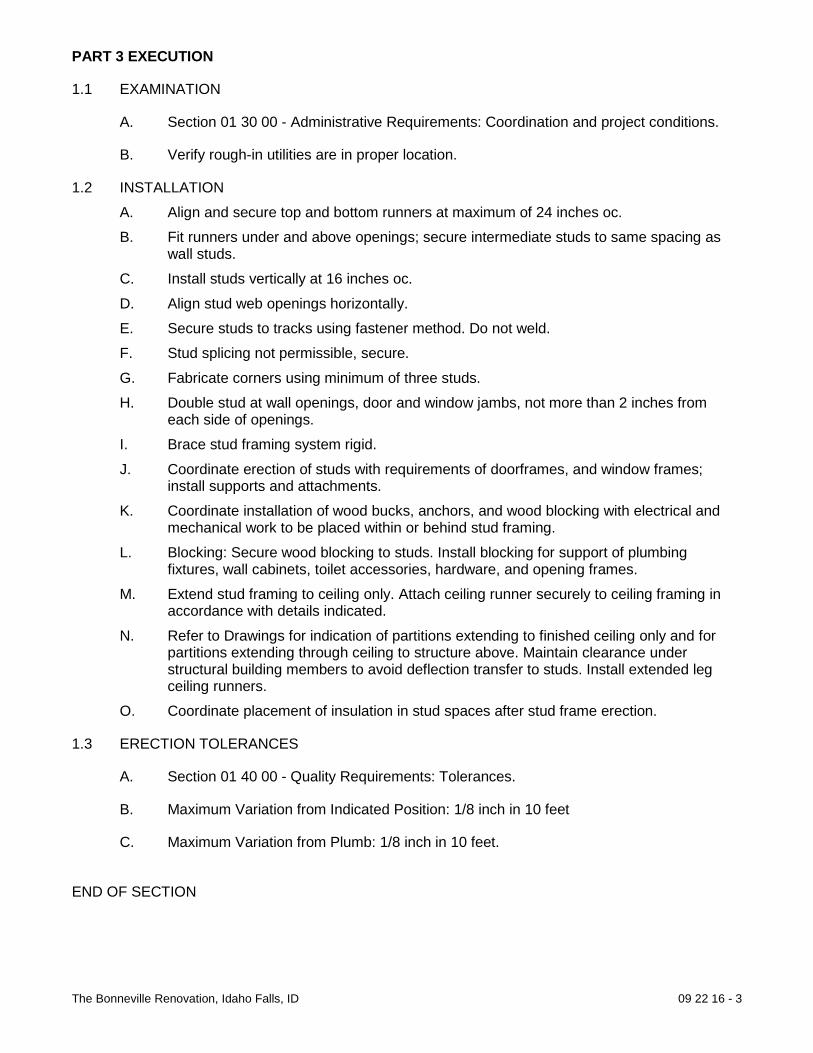
The Bonneville Renovation, Idaho Falls, ID 09 22 16 - 3
PART 3 EXECUTION
1.1 EXAMINATION
A. Section 01 30 00 - Administrative Requirements: Coordination and project conditions.
B. Verify rough-in utilities are in proper location.
1.2 INSTALLATION A. Align and secure top and bottom runners at maximum of 24 inches oc. B. Fit runners under and above openings; secure intermediate studs to same spacing as
wall studs. C. Install studs vertically at 16 inches oc. D. Align stud web openings horizontally. E. Secure studs to tracks using fastener method. Do not weld. F. Stud splicing not permissible, secure. G. Fabricate corners using minimum of three studs. H. Double stud at wall openings, door and window jambs, not more than 2 inches from
each side of openings. I. Brace stud framing system rigid. J. Coordinate erection of studs with requirements of doorframes, and window frames;
install supports and attachments. K. Coordinate installation of wood bucks, anchors, and wood blocking with electrical and
mechanical work to be placed within or behind stud framing. L. Blocking: Secure wood blocking to studs. Install blocking for support of plumbing
fixtures, wall cabinets, toilet accessories, hardware, and opening frames. M. Extend stud framing to ceiling only. Attach ceiling runner securely to ceiling framing in
accordance with details indicated. N. Refer to Drawings for indication of partitions extending to finished ceiling only and for
partitions extending through ceiling to structure above. Maintain clearance under structural building members to avoid deflection transfer to studs. Install extended leg ceiling runners.
O. Coordinate placement of insulation in stud spaces after stud frame erection.
1.3 ERECTION TOLERANCES
A. Section 01 40 00 - Quality Requirements: Tolerances.
B. Maximum Variation from Indicated Position: 1/8 inch in 10 feet
C. Maximum Variation from Plumb: 1/8 inch in 10 feet.
END OF SECTION

The Bonneville Renovation, Idaho Falls, ID 09 23 00 - 1
SECTION 09 23 00
GYPSUM PLASTERING
PART 1 GENERAL
1.1 SUMMARY
A. Section includes gypsum plaster with metal or wood furring and lath for patching of existing plaster walls; plaster base for gypsum veneer plaster.
1.2 REFERENCES
A. ASTM International: 1. ASTM C28/C28M - Standard Specification for Gypsum Plasters. 2. ASTM C35 - Standard Specification for Inorganic Aggregates for Use in Gypsum
Plaster. 3. ASTM C37/C37M - Standard Specification for Gypsum Lath. 4. ASTM C61/C61M - Standard Specification for Gypsum Keene’s Cement. 5. ASTM C206 - Standard Specification for Finishing Hydrated Lime. 6. ASTM C631 - Standard Specification for Bonding Compounds for Interior
Gypsum Plastering. 7. ASTM C665 - Standard Specification for Mineral-Fiber Blanket Thermal
Insulation for Light Frame Construction and Manufactured Housing. 8. ASTM C842 - Standard Specification for Application of Interior Gypsum Plaster. 9. ASTM C847 - Standard Specification for Metal Lath. 10. ASTM C897 - Standard Specification for Aggregate for Job-Mixed Portland
Cement-Based Plasters. 11. ASTM C954 - Standard Specification for Steel Drill Screws for the Application of
Gypsum Panel Products or Metal Plaster Bases to Steel Studs from 0.033 in. (0.84 mm) to 0.112 in. (2.84 mm) in Thickness.
12. ASTM C1002 - Standard Specification for Steel Drill Screws for the Application of Gypsum Panel Products or Metal Plaster Bases.
13. ASTM C1396/C1396M - Standard Specification for Gypsum Board. 14. ASTM E90 - Standard Test Method for Laboratory Measurement of Airborne
Sound Transmission Loss of Building Partitions and Elements. 15. ASTM E119 - Standard Test Methods for Fire Tests of Building Construction and
Materials.
B. Gypsum Association: 1. GA 216 - Application and Finishing of Gypsum Board. 2. GA 600 - Fire Resistance Design Manual Sound Control.
B. Underwriters Laboratories Inc.: 1. UL - Fire Resistance Directory.
C. Intertek Testing Services (Warnock Hersey Listed): 1. WH - Certification Listings.
1.3 SUBMITTALS
A. Section 01 33 00 - Submittal Procedures: Submittal procedures.

The Bonneville Renovation, Idaho Falls, ID 09 23 00 - 2
B. Product Data: Submit data on plaster materials, characteristics, and limitations of products specified.
1.4 QUALITY ASSURANCE
A. Perform Work in accordance with ASTM C841.
B. Fire Rated Wall and Ceiling Construction: Rating as indicated on Drawings. 1. Tested Rating: Determined in accordance with ASTM E119.
1.5 QUALIFICATIONS
A. Manufacturer: Company specializing in manufacturing products specified in this section with minimum three years experience.
B. Installer: Company specializing in performing Work of this section with minimum three years experience.
1.6 PRE-INSTALLATION MEETINGS
A. Section 01 30 00 - Administrative Requirements: Preinstallation meetings.
B. Convene minimum one week prior to commencing Work of this section.
1.7 ENVIRONMENTAL REQUIREMENTS
A. Section 01 60 00 - Product Requirements.
B. Do not apply plaster when substrate or ambient air temperature is less than 50 degrees F nor more than 80 degrees F.
C. Maintain minimum ambient temperature of 50 degrees F during and after installation of plaster.
PART 2 PRODUCTS
2.1 GYPSUM PLASTER
A. Manufacturers: 1. National Gypsum Co. 2. Premix-Marbletie Manufacturing Co. 3. United States Gypsum Co. 4. Substitutions: Section 01 60 00 - Product Requirements.
2.2 COMPONENTS
A. Plaster Base Materials: 1. Plaster: ASTM C28/C28M; gypsum bonding type. 2. Plaster Aggregate: ASTM C35 ASTM C897; sand. 3. Water: Clean, fresh, potable and free of mineral or organic matter capable of
affecting plaster. 4. Bonding Agent: ASTM C631; type recommended for bonding plaster to surfaces.
B. Finishing Plaster: 1. Sand Float Type: ASTM C28/C28M and ASTM C35 ASTM C897; prepared
mixture of gypsum plaster and sand.

The Bonneville Renovation, Idaho Falls, ID 09 23 00 - 3
2. Water: Clean, fresh, potable and free of mineral and organic matter capable of affecting plaster.
C. Metal Lath: 1. Metal Lath: ASTM C847; mesh stamped sheet; of weight to suit application.
2.3 ACCESSORIES
A. Anchorage: Nails, staples, or other approved metal supports, of type and size to suit application, to rigidly secure lath and associated metal accessories in place.
2.4 MIXES
A. Mix and proportion plaster in accordance with ASTM C842.
PART 3 EXECUTION
1.1 EXAMINATION
A. Section 01 30 00 - Administrative Requirements: Coordination and project conditions.
B. Masonry: Verify joints are cut flush and surface is ready to receive work of this section. Verify no bituminous or water repellent coatings exist on masonry surface.
C. Concrete: Verify surfaces are flat, honeycomb is filled flush, and surface is ready to receive work of this section. Verify no bituminous, water repellent, or form release agents exist on concrete surface that are detrimental to plaster or plaster bond.
D. Metal Lath and Accessories: Verify lath is flat, secured to substrate, and joint and surface perimeter accessories are in place.
E. Mechanical and Electrical: Verify services within walls have been tested and approved.
1.2 PREPARATION
A. Dampen masonry surfaces to reduce excessive suction.
B. Clean concrete surfaces of foreign matter. Thoroughly dampen surfaces before using acid solutions, solvent, or detergents to perform cleaning. Wash surface with clean water.
C. Roughen smooth concrete surfaces and smooth faced masonry.
D. Apply bonding agent.
1.3 INSTALLATION
A. Apply metal lath taut, with long dimension perpendicular to supports.
B. Lap ends minimum 1 inch. Secure end laps with tie wire where they occur between supports.
C. Lap sides of diamond mesh lath minimum 1-1/2 inches. Nest outside ribs of rib lath together.
D. Attach metal lath to wood supports using nails at maximum 12 inches on center.

The Bonneville Renovation, Idaho Falls, ID 09 23 00 - 4
E. Attach metal lath to metal supports using tie wire at maximum 6 inches on center.
F. Plastering: 1. Apply gypsum plaster in accordance with ASTM C842. 2. Apply finish coat to minimum 1/8 inch thickness. 3. Work finish coat to match existing wall texture. 4. Perform work in panels to nearest natural break blend into wall to be non-visible.
1.4 ERECTION TOLERANCES
A. Section 01 40 00 - Quality Requirements: Tolerances.
B. Maximum Variation from Flat Surface: 1/8inch in 10 feet.
1.5 SCHEDULES
A. Plaster patching of existing walls where indicated on plans. END OF SECTION

The Bonneville Renovation, Idaho Falls, ID 09 30 00 - 1
SECTION 09 30 00
TILING
PART 1 GENERAL
1.1 SUMMARY
A. Section includes ceramic tile for floor and wall applications; application method; cementitious backer board as tile substrate; thresholds at door openings; and ceramic accessories.
1.2 REFERENCES
A. American National Standards Institute: 1. ANSI A108.1 - Installation of Ceramic Tile, A collection. 2. ANSI A108.10 - Specifications for Installation of Grout in Tilework. 3. ANSI A108.5 - Specifications for Ceramic Tile Installed with Dry-Set Portland
Cement Mortar or Latex-Portland Cement Mortar. 4. ANSI A108.9 - Specifications for Ceramic Tile Installed with Modified Epoxy
Emulsion Mortar/Grout. 5. ANSI A118.1 - Standard Specification for Dry-Set Portland Cement Mortar. 6. ANSI A118.6 - Ceramic Tile Grouts. 7. ANSI A136.1 - Organic Adhesives for Installation of Ceramic Tile. 8. ANSI A137.1 - Ceramic Tile.
B. Tile Council of America: 1. TCA - Handbook for Ceramic Tile Installation.
1.3 SUBMITTALS
A. Section 01 33 00 - Submittal Procedures: Submittal procedures.
B. Shop Drawings: Indicate tile layout, patterns, color arrangement, perimeter conditions, junctions with dissimilar materials, control and expansion joints, thresholds, ceramic accessories, and setting details.
C. Product Data: Submit instructions for using grouts and adhesives.
D. Samples: Submit tile and grout samples.
E. Manufacturer's Certificate: Certify Products meet or exceed specified requirements.
1.4 CLOSEOUT SUBMITTALS
A. Section 01 70 00 - Execution and Closeout Requirements: Closeout procedures.
B. Operation and Maintenance Data: Submit recommended cleaning methods, cleaning materials, stain removal methods, and polishes and waxes.
1.5 QUALITY ASSURANCE
A. Perform Work in accordance with TCA Handbook and ANSI A108 Series/A118 Series.

The Bonneville Renovation, Idaho Falls, ID 09 30 00 - 2
1.6 QUALIFICATIONS
A. Manufacturer: Company specializing in manufacturing products specified in this section with minimum three years documented experience.
B. Installer: Company specializing in performing Work of this section with minimum three years experience.
1.7 DELIVERY, STORAGE, AND HANDLING
A. Section 01 60 00 - Product Requirements: Product storage and handling requirements.
B. Protect adhesives and grouts from freezing or overheating.
1.8 ENVIRONMENTAL REQUIREMENTS
A. Section 01 60 00 - Product Requirements.
B. Do not install adhesives and grouts in unventilated environment.
C. Maintain ambient and substrate temperature of 50 degrees F during installation of mortar materials.
PART 2 PRODUCTS
2.1 TILE
A. Wall Tile Manufacturers: 1. Dal-Tile International.
B. Floor Tile Manufacturers: 1. Dal-Tile International
2.2 COMPONENTS
A. Ceramic Wall Tile (Public Restrooms): ANSI A137.1, conforming to the following: 1. Moisture Absorption: 0.5 to 3.0 percent. 2. See schedule on drawings.
B. Ceramic Floor Tile (Public Restrooms): ANSI A137.1, conforming to the following: 1. Moisture Absorption: 0.5 to 3.0 percent. 2. See schedule on drawings.
C. Base (Public Restrooms): 2. See schedule on drawings.
D. Ceramic Trim (Public Restrooms): 1. See schedule on drawings.
E. Floor Tile (Apartments-Kitchen and Bathrooms): 1. See schedule on drawings.
2.3 ACCESSORIES
A. Adhesive Materials: 1. Organic Adhesive: ANSI A136.1, thin-set bond type.

The Bonneville Renovation, Idaho Falls, ID 09 30 00 - 3
2. Tile Setting Adhesive: Elastomeric, waterproof, liquid applied.
B. Mortar Materials: 1. Mortar Bed Materials: Portland cement, sand, latex additive, and water. 2. Mortar Bond Coat Materials:
a. Dry-Set Portland Cement type: ANSI A118.1. b. Latex-Portland Cement type: ANSI A118.4. c. Epoxy: ANSI A118.3. d. Furan: ANSI A118.5.
C. Grout Materials: 1. Standard Grout: Grout as recommended by Manufacturer for each tile as
specified in ANSI A118.6.
D. Cementitious Backer Board: ANSI A118.9; High density, cementitious, glass fiber reinforced, 1/2 inch thick; 2 inch wide coated glass fiber tape for joints and corners.
E. Thresholds: Marble color as selected by Architect from Manufacturer’s full range of colors, size by full width of wall or frame opening, beveled both sides, radiused edges from bevel to vertical face.
F. Tile underlayment: Polyethylene membrane with grid structure, anchoring fleece on underside (Schluter-Ditra).
PART 3 EXECUTION
1.1 EXAMINATION
A. Section 01 30 00 - Administrative Requirements: Coordination and project conditions.
B. Verify surfaces are ready to receive work.
1.2 PREPARATION
A. Protect surrounding work from damage.
B. Vacuum clean surfaces and damp clean.
C. Seal substrate surface cracks with filler. Level existing substrate surfaces to acceptable flatness tolerances.
D. Cementitious backer board installed in Section 09 21 16.
E. Prepare substrate surfaces for adhesive installation.
1.3 INSTALLATION
A. Install tile, thresholds and grout in accordance with applicable requirements of ANSI A108.1 through A108.10, and TCA Handbook recommendations.
B. Lay tile to pattern indicated. Do not interrupt tile pattern through openings.
C. Place thresholds at locations indicated.
D. Cut and fit tile to penetrations through tile, leaving sealant joint space. Form corners and bases neatly. Align floor, base and wall joints.

The Bonneville Renovation, Idaho Falls, ID 09 30 00 - 4
E. Place tile with joints uniform in width, subject to variance in tolerance allowed in tile size. Make joints watertight, without voids, cracks, excess mortar, or excess grout. 1. Ceramic Tile: 1/8 inch.
F. Form internal angles square and external angles bullnosed.
G. Install ceramic accessories rigidly in prepared openings.
H. Sound tile after setting. Replace hollow sounding units.
I. Keep expansion or control joints free of adhesive or grout. Apply sealant to joints.
J. Allow tile to set for a minimum of 48 hours prior to grouting.
K. Grout tile joints. Use standard grout unless otherwise indicated.
L. Apply sealant to junction of tile and dissimilar materials and junction of dissimilar planes.
M. Installation - Floors - Thin-Set Methods: 1. Over interior concrete substrates, install in accordance with TCA Handbook
Method F113, dry-set or latex-portland cement bond coat, with standard grout. 2. Install polyethylene membrane over concrete slab per manufacturer instructions.
N. Installation – Floors – Cement Mortar bed. 1. Over interior wood substrates, install in accordance with TCA Handbook Method
F141-03, Dry-set or latex-portland cement bond coat, with standard grout. 2. Install cleavage membrane over wood subfloor per manufacturer’s instruction. 3. Over Interior wood substrates, install in accordance with TCA Handbook Method
F148-03. Dry-set or latex-portland cement bond coat with standard grout. 4. Install uncoupling system per manufacturer’s instructions.
O. Installation - Wall – Over Cement Board
1. Over cementitious backerboard, install in accordance with TCA W223, organic adhesive.
O. Installation - Wall Tile: 1. Over interior concrete and masonry install in accordance with TCA Handbook
Method W202, thin-set with dry-set or latex-portland cement bond coat.
Q. Seal all grout after curing period as recommended by grout manufacturer.
R. Seal all tile prior to installation of grout as recommended by tile manufacturers.
1.4 CLEANING
A. Section 01 70 00 - Execution and Closeout Requirements: Final cleaning.
B. Clean tile and grout surfaces.
END OF SECTION

The Bonneville Renovation, Idaho Falls, ID 09 65 00 - 1
SECTION 09 65 00
RESILIENT FLOORING
PART 1 - GENERAL
1.1 SUMMARY
A. Section includes: 1. Resilient tile flooring 2. Resilient LV plank 3. Resilient base
1.2 REFERENCES
A. ASTM International: 1. ASTM F1066 - Standard Specification for Vinyl Composition Floor Tile 2. ASTM F1303 - Standard Specification for Sheet Vinyl Floor Covering with Backing 3. ASTM F1700 - Standard Specification for Solid Vinyl Floor Tile 4. ASTM F1861 - Standard Specification for Resilient Wall Base
B. Federal Specification Unit: 1. FS L-F-475 - Floor Covering Vinyl, Surface (Tile and Roll), with Backing 2. FS RR-T-650 - Treads, Metallic and Nonmetallic, Skid Resistant
C. National Fire Protection Association: 1. NFPA 253 - Standard Method of Test for Critical Radiant Flux for Floor Covering
Systems Using a Radiant Heat Energy Source
1.3 SUBMITTALS
A. Section 01 33 00 - Submittal Procedures: Submittal procedures B. Shop Drawings: Indicate seaming plan, custom patterns and inlay designs C. Product Data: Submit data describing physical and performance characteristics; including
sizes, patterns and colors available; and installation instructions D. Samples:
1. Submit manufacturer's complete set of color samples for initial selection 2. Submit two samples illustrating color and pattern for each resilient flooring product
specified
1.4 CLOSEOUT SUBMITTALS
A. Section 01 70 00 - Execution and Closeout Requirements: Closeout procedures B. Operation and Maintenance Data: Submit maintenance procedures, recommended
maintenance materials, and suggested schedule for cleaning, stripping, and re-waxing
1.5 QUALIFICATIONS
A. Manufacturer: Company specializing in manufacturing products specified in this section with minimum three years documented experience
B. Installer: Company specializing in performing Work of this section with minimum three years documented experience

The Bonneville Renovation, Idaho Falls, ID 09 65 00 - 2
1.6 DELIVERY, STORAGE, AND HANDLING
A. Section 01 60 00 - Product Requirements: Product storage and handling requirements B. Protect roll materials from damage by storing on end
1.7 ENVIRONMENTAL REQUIREMENTS
A. Section 01 60 00 - Product Requirements B. Maintain temperature in storage area between 55 degrees F and 90 degrees F C. Store materials for not less than 48 hours prior to installation in area of installation at
temperature of 70 degrees F to achieve temperature stability 1. Thereafter, maintain conditions above 55 degrees F
1.8 EXTRA MATERIALS
A. Section 01 70 00 - Execution and Closeout Requirements: Spare parts and maintenance products
B. Furnish: 1. Flooring: 25 sq ft of each type and color specified 2. Base: 25 lineal feet of each type and color specified
PART 2 - PRODUCTS
2.1 TILE FLOORING
A. Manufacturers: 1. Armstrong World Industries, Inc 2. Mannington Mills, Inc 3. Substitutions: Section 01 60 00 - Product Requirements
B. Luxury Vinyl Plank: ASTM F1066: 1. Size: 6 x 36 inch 2. Thickness: 0.096 inches 3. Edge: Beveled 4. Style: See schedule on drawings. 5. Manufacturer: Mannington Commercial
C. Vinyl Composition Tile: ASTM F1066: 1. Size: 12 x 12 inch 2. Thickness: 0.125 inches 3. Style: See schedule on drawings. 4. Manufacturer: Armstrong
2.2 RESILIENT BASE
A. Manufacturers: 1. Armstrong World Industries, Inc 2. Burke Mercer Flooring Products 3. Flexco, Corporation 4. Johnsonite 5. Substitutions: Section 01 60 00 - Product Requirements
B. Base: ASTM F1861 Rubber; straight and coved style:

The Bonneville Renovation, Idaho Falls, ID 09 65 00 - 3
1. Height: 4 inch 2. Thickness: 0.125 inch thick 3. Finish: Satin, Matte, or Gloss 4. Length: Roll 5. Accessories: Pre-molded external corners
C. Base: ASTM F1861 Rubber; contoured style: 1. Height: 5.25 inch 2. Thickness: 1/4 inch thick 3. Finish: Satin, Matte, or Gloss 4. Length: 8 foot 5. Accessories: Pre-molded external corners 6. Profile: See schedule on drawings 7. Color: See schedule on drawings
2.3 ACCESSORIES
A. Subfloor Filler: Type recommended by adhesive material manufacturer B. Primers and Adhesives: Waterproof; types recommended by flooring manufacturer C. Moldings and Edge Strips: Rubber or Vinyl. D. Filler for Coved Base: Plastic or E. Sealer and Wax: Types recommended by flooring manufacturer
PART 3 - EXECUTION
3.1 EXAMINATION
A. Section 01 30 00 - Administrative Requirements: Verification of existing conditions before starting work
B. Verify concrete floors are dry to maximum moisture content as recommended by manufacturer, and exhibit negative alkalinity, carbonization, and dusting
C. Verify floor and lower wall surfaces are free of substances capable of impairing adhesion of new adhesive and finish materials
3.2 PREPARATION
A. Remove sub-floor ridges and bumps B. Fill minor low spots, cracks, joints, holes, and other defects with sub-floor filler to achieve
smooth, flat, hard surface C. Prohibit traffic until filler is cured D. Clean substrate E. Apply primer as required to prevent "bleed-thru" or interference with adhesion by
substances that cannot be removed.
3.3 INSTALLATION - TILE FLOORING
A. Mix tile from container to ensure shade variations are consistent when tile is placed B. Lay flooring with joints and seams parallel to building lines to produce symmetrical tile
pattern

The Bonneville Renovation, Idaho Falls, ID 09 65 00 - 4
C. Install tile to monolith pattern 1. Allow minimum 1/2 full size tile width at room or area perimeter
D. Scribe flooring to walls, columns, cabinets, floor outlets, and other appurtenances to produce tight joints
E. Where floor finishes are different on opposite sides of door, terminate flooring under centerline of door
F. Install edge strips at unprotected or exposed edges, where flooring terminates, and where indicated
3.4 INSTALLATION - BASE
A. Fit joints tightly and make vertical. Maintain minimum dimension of 18 inches between joints
B. Miter internal corners. At external corners, use pre-molded units. At exposed ends, use pre-molded units
C. Install base on solid backing 1. Bond tightly to wall and floor surfaces
D. Scribe and fit to door frames and other interruptions
3.5 CLEANING
A. Section 01 70 00 - Execution and Closeout Requirements: Final cleaning B. Remove excess adhesive from floor, base, and wall surfaces without damage C. Clean, seal, and maintain resilient flooring products
3.6 PROTECTION OF INSTALLED CONSTRUCTION
A. Section 01 70 00 - Execution and Closeout Requirements: Protecting installed construction
B. Prohibit traffic on resilient flooring for 48 hours after installation
3.7 SCHEDULE
A. Refer to Room Finish Schedule and Floor Finishes Plan
END OF SECTION

The Bonneville Renovation, Idaho Falls, ID 09 68 13 –1
SECTION 09 68 13
TILE CARPETING
PART 1 - GENERAL
1.1 SUMMARY
A. Section Includes: 1. Carpet tile, fully adhered. 2. Accessories
B. Related Requirements: 1. Section 03 30 00 - Cast-In-Place Concrete. 2. Section 09 65 00 – Resilient Flooring: Base finish.
1.2 REFERENCE STANDARDS
A. ASTM International: 1. ASTM D2859 - Standard Specification for Ignition Characteristics of Finished Textile
Floor Covering Materials B. Carpet and Rug Institute:
1. CRI Carpet Installation Standard - Standard for Installation of Commercial Carpet 2. CRI Green Label Plus Testing Program 3. CRI Model Specifications for Commercial Carpets
C. Consumer Products Safety Commission: 1. CPSC 16 CFR 1630 - Standard for the Surface Flammability of Carpets and Rugs
D. National Fire Protection Association: 1. NFPA 253 - Standard Method of Test for Critical Radiant Flux for Floor Covering
Systems Using a Radiant Heat Energy Source
1.3 SUBMITTALS
A. Section 01 33 00 - Submittal Procedures: Requirements for submittals B. Product Data: Submit data on specified products, describing physical and performance
characteristics; sizes, patterns, colors available, and method of installation C. Samples:
1. Submit two carpet tiles illustrating color and pattern design for each carpet color selected.
1.4 CLOSEOUT SUBMITTALS
A. Section 01 70 00 - Execution and Closeout Requirements: Requirements for submittals B. Operation and Maintenance Data: Submit maintenance procedures, recommended
maintenance materials, and suggested schedule for cleaning
1.5 MAINTENANCE MATERIAL SUBMITTALS
A. Section 01 70 00 - Execution and Closeout Requirements: Requirements for maintenance materials
B. Extra Stock Materials: 1. Furnish 10 tiles of carpet tiles of each color and pattern selected.

The Bonneville Renovation, Idaho Falls, ID 09 68 13 –2
1.6 QUALITY ASSURANCE
A. Surface Burning Characteristics: 1. Floor Finishes: Comply with one of the following:
a. Class I, minimum 0.45 watts/sq cm when tested in accordance with NFPA 253 b. CPSC 16 CFR 1630 and ASTM D 2859
B. Texture Appearance Retention Rating: Rating classifications as determined by CRI Model Specifications for Commercial Carpets 1. Greater than or equal to 3.5 TARR for Severe Traffic Level Classification
1.7 QUALIFICATIONS
A. Manufacturer: Company specializing in manufacturing products specified in this section with minimum five years documented experience
B. Installer: Company specializing in performing work of this section with minimum three years documented experience approved by manufacturer
1.8 AMBIENT CONDITIONS
A. Section 01 50 00 - Temporary Facilities and Controls: Ambient conditions control facilities for product storage and installation
B. Store materials in area of installation for 48 hours prior to installation
PART 2 - PRODUCTS
2.1 CARPET TILE
A. Manufacturers: 1. J & J Flooring Group 2. Substitutions: Section 01 60 00 - Product Requirements
2.2 COMPONENTS
A. Carpet Tile: manufactured in one color dye lot 1. Product Specifications:
a. Backing: Polyester Felt Cushion b. Wear Layer: Solution Dyed Polyester c. Style: See schedule on drawings. d. Color: See schedule on drawings. e. Size: See schedule on drawings.
2.3 ACCESSORIES
A. Sub-Floor Filler: Type recommended by flooring material manufacturer B. Moldings and Edge Strips: Rubber or Vinyl, color as selected C. Contact Adhesive: Recommended by carpet manufacturer
PART 3 - EXECUTION
3.1 EXAMINATION
A. Section 01 70 00 - Execution and Closeout Requirements: Requirements for installation examination

The Bonneville Renovation, Idaho Falls, ID 09 68 13 –3
B. Verify floor surfaces are smooth and flat within tolerances specified in Section 03 30 00 and are ready to receive work
3.2 PREPARATION
A. Section 01 70 00 - Execution and Closeout Requirements: Requirements for installation preparation
B. Remove sub-floor ridges and bumps. 1. Fill minor or local low spots, cracks, joints, holes, and other defects with sub-floor filler
C. Apply, trowel, and float filler to achieve smooth, flat, hard surface 1. Prohibit traffic until filler is cured
D. Clean substrate
3.3 INSTALLATION
A. Install carpet tile in accordance with CRI Carpet Installation Standard B. Do not mix carpet from different cartons unless from same dye lot C. Cut carpet tile clean. Fit carpet tight to intersection with vertical surfaces without gaps D. Install carpet tile in the following patterns:
1. Carpet Tile (CRPT): See floor finish plan E. Locate change of color or pattern between rooms under door centerline F. Fully adhere carpet tile to substrate G. Trim carpet tile neatly at walls and around interruptions H. Complete installation of edge strips, concealing exposed edges
3.4 CLEANING
A. Section 01 70 00 - Execution and Closeout Requirements: Requirements for cleaning B. Remove excess adhesive from floor, base, and wall surfaces without damage C. Clean and vacuum carpet surfaces
END OF SECTION

The Bonneville Renovation, Idaho Falls, ID 09 68 16 - 1
SECTION 09 68 16
SHEET CARPETING
PART 1 GENERAL
1.1 SUMMARY
A. Section includes carpet stretched with pad; carpet and accessories.
1.2 REFERENCES
A. Carpet and Rug Institute: 1. CRI 104 - Standard for Installation of Commercial Carpet.
B. Consumer Products Safety Commission: 1. CPSC 16 CFR 1630 - Standard for the Surface Flammability of Carpets and
Rugs.
C. National Fire Protection Association: 1. NFPA 253 - Standard Method of Test for Critical Radiant Flux for Floor Covering
Systems Using a Radiant Heat Energy Source.
1.3 SUBMITTALS
A. Section 01 33 00 - Submittal Procedures: Submittal procedures.
B. Product Data: Submit data on specified products, describing physical and performance characteristics; sizes, patterns, colors available, and method of installation.
C. Samples: 1. Submit two samples 6 x 6 inch in size illustrating color and pattern.
D. Manufacturer's Installation Instructions: Submit special procedures and perimeter conditions requiring special attention.
1.4 CLOSEOUT SUBMITTALS
A. Section 01 70 00 - Execution and Closeout Requirements: Closeout procedures.
B. Operation and Maintenance Data: Submit maintenance procedures, recommended maintenance materials, and suggested schedule for cleaning.
1.5 QUALIFICATIONS
A. Manufacturer: Company specializing in manufacturing products specified in this section with minimum three years documented experience.
B. Installer: Company specializing in performing work of this section with minimum three years experience.
1.6 ENVIRONMENTAL REQUIREMENTS
A. Section 01 60 00 - Product Requirements.

The Bonneville Renovation, Idaho Falls, ID 09 68 16 - 2
B. Store materials in area of installation for 48 hours prior to installation.
C. Maintain minimum 70 degrees F ambient temperature 3 days prior to, during and 24 hours after installation.
D. Ventilate installation area during installation and for 3 days after installation.
1.7 EXTRA MATERIALS
A. Section 01 70 00 - Execution and Closeout Requirements: Spare parts and maintenance products.
PART 2 PRODUCTS
2.1 CARPET
A. Manufacturers: 1. Mohawk Commercial Carpet.
2.2 COMPONENTS
A. Carpet Type: Tufted, nylon polypropylene broad loom conforming to the following criteria: 1. Style: Marche’ #MC020 2. Color: Bronze 832 3. Dye Method: Piece dyed. 4. Roll Width: 12 ft. 5. Construction: Tufted 6. Max. Electrostatic Charge: 3.5 kV. 7. Finish pyle thickness: .257 inch. 8. Gage: 1/8 inch. 9. Stitches: 14.0 10. Density Factor: 5,323 oz/yds. 11. Primary Backing Material: Woven Polypropylene. 12. Secondary Backing Material: Woven Polypropylene. 13. Total Weight: 38 oz/sq yd
2.3 ACCESSORIES
A. Sub-Floor Filler: Type recommended by flooring material manufacturer.
B. Pad: Type recommended by installer.
C. Base: Wood. New to match existing profile.
D. Seam Adhesive: Recommended by manufacturer.
PART 3 EXECUTION
1.1 EXAMINATION
A. Section 01 30 00 - Administrative Requirements: Coordination and project conditions.
B. Verify floor surfaces are smooth and flat within tolerances recommended by manufacturer and are ready to receive work.

The Bonneville Renovation, Idaho Falls, ID 09 68 16 - 3
1.2 PREPARATION
A. Remove sub-floor ridges and bumps. Fill minor or local low spots, cracks, joints, holes, and other defects with sub-floor filler.
B. Apply, trowel, and float filler to achieve smooth, flat, hard surface. Prohibit traffic until filler is cured.
C. Vacuum clean substrate.
1.3 INSTALLATION
A. Install carpet in accordance with manufacturer’s recommendations stretched with pad.
B. Verify carpet match before cutting to ensure minimal variation between dye lots.
C. Lay out carpet and locate seams in accordance with CRI 104 section 7.2: 1. Locate seams in area of least traffic, out of areas of pivoting traffic, and parallel
to main traffic. 2. Do not locate seams perpendicular through door openings. 3. Align run of pile in same direction as anticipated traffic and in same direction on
adjacent pieces. 4. Provide monolithic color, pattern, and texture match within each contiguous area.
D. Install carpet tight and flat on subfloor, well fastened at edges, with uniform appearance.
E. Double cut carpet seams, with accurate pattern match. Make cuts straight, true, and unfrayed. Apply seam adhesive to cut edges of woven carpet immediately.
F. Trim carpet neatly at walls and around interruptions.
1.4 CLEANING
A. Section 01 70 00 - Execution and Closeout Requirements: Final cleaning.
B. Clean and vacuum carpet surfaces.
1.5 PROTECTION OF INSTALLED CONSTRUCTION
A. Section 01 70 00 - Execution and Closeout Requirements: Protecting installed construction.
B. Do not permit traffic over unprotected floor surface.
C. Cover carpeting in traffic areas with protective non-staining building paper. Do not use plastic sheeting.
END OF SECTION

The Bonneville Renovation, Idaho Falls, ID 09 90 00 - 1
SECTION 09 90 00
PAINTING AND COATING
PART 1 GENERAL
1.1 SUMMARY
A. Section includes surface preparation and field application of paints, stains, varnishes, and other coatings.
1.2 REFERENCES
A. ASTM International: 1. ASTM D16 - Standard Terminology Relating to Paint, Varnish, Lacquer, and
Related Products.
B. Painting and Decorating Contractors of America: 1. PDCA - Architectural Painting Specification Manual.
C. SSPC: The Society for Protective Coatings: 1. SSPC - Steel Structures Painting Manual.
1.3 DEFINITIONS
A. Conform to ASTM D16 for interpretation of terms used in this section.
1.4 SUBMITTALS
A. Section 01 33 00 - Submittal Procedures: Submittal procedures.
B. Product Data: Submit data on finishing products.
C. Manufacturer's Installation Instructions: Submit special surface preparation procedures, substrate conditions requiring special attention.
1.5 QUALIFICATIONS
A. Manufacturer: Company specializing in manufacturing products specified in this section with minimum three years experience.
B. Applicator: Company specializing in performing work of this section with minimum three years experience.
1.6 DELIVERY, STORAGE, AND HANDLING
A. Section 01 60 00 - Product Requirements: Product storage and handling requirements.
B. Deliver products to site in sealed and labeled containers; inspect to verify acceptability.
C. Container Label: Include manufacturer's name, type of paint, brand name, lot number, brand code, coverage, surface preparation, drying time, cleanup requirements, color designation, and instructions for mixing and reducing.

The Bonneville Renovation, Idaho Falls, ID 09 90 00 - 2
D. Paint Materials: Store at minimum ambient temperature of 45 degrees F and maximum of 90 degrees F, in ventilated area, and as required by manufacturer's instructions.
1.7 ENVIRONMENTAL REQUIREMENTS
A. Section 01 60 00 - Product Requirements.
B. Do not apply materials when surface and ambient temperatures are outside temperature ranges required by paint product manufacturer.
C. Do not apply exterior coatings during rain or snow when relative humidity is outside humidity ranges, or moisture content of surfaces exceed those required by paint product manufacturer.
D. Minimum Application Temperatures for Latex Paints: 45 degrees F for interiors; 50 degrees F for exterior; unless required otherwise by manufacturer's instructions.
E. Minimum Application Temperature for Varnish and Finishes: 65 degrees F for interior or exterior, unless required otherwise by manufacturer's instructions.
F. Provide lighting level of 80 ft candle measured mid-height at substrate surface.
1.8 EXTRA MATERIALS
A. Section 01 70 00 - Execution and Closeout Requirements: Spare parts and maintenance products.
B. Supply 1 gallons of each color, type, and surface texture; store where directed.
B. Label each container with color, type, texture, room locations, and in addition to manufacturer's label.
PART 2 PRODUCTS
2.1 PAINTS AND COATINGS
A. Manufacturers: Paint Transparent Finishes Stain Primer Sealers Block Filler Field Catalyzed Coatings. 1. Benjamin Moore Paint Co. 2. Sherwin Williams Paint Co.
2.2 COMPONENTS
A. Coatings: Ready mixed, except field-catalyzed coatings. Prepare coatings: 1. To soft paste consistency, capable of being readily and uniformly dispersed to
homogeneous coating. 2. For good flow and brushing properties. 3. Capable of drying or curing free of streaks or sags.
B. Accessory Materials: Linseed oil, shellac, turpentine, paint thinners and other materials not specifically indicated but required to achieve finishes specified; commercial quality.
C. Patching Materials: Latex filler.
D. Fastener Head Cover Materials: Latex filler.

The Bonneville Renovation, Idaho Falls, ID 09 90 00 - 3
PART 3 EXECUTION
1.1 EXAMINATION
A. Section 01 30 00 - Administrative Requirements: Coordination and project conditions.
B. Verify surfaces and substrate conditions are ready to receive Work as instructed by product manufacturer.
C. Examine surfaces scheduled to be finished prior to commencement of work. Report conditions capable of affecting proper application.
D. Test shop applied primer for compatibility with subsequent cover materials.
E. Measure moisture content of surfaces using electronic moisture meter. Do not apply finishes unless moisture content of surface is below the following maximums: 1. Plaster and Gypsum Wallboard: 12 percent. 2. Masonry, Concrete, and Concrete Unit Masonry: 12 percent. 3. Interior Wood: 15 percent. 4. Exterior Wood: 15 percent. 5. Concrete Floors: 8 percent.
1.2 PREPARATION
A. Surface Appurtenances: Remove electrical plates, hardware, light fixture trim, escutcheons, and fittings prior to preparing surfaces or finishing.
B. Surfaces: Correct defects and clean surfaces capable of affecting work of this section. Remove or repair existing coatings exhibiting surface defects.
C. Marks: Seal with shellac those which may bleed through surface finishes.
D. Impervious Surfaces: Remove mildew by scrubbing with solution of tri-sodium phosphate and bleach. Rinse with clean water and allow surface to dry.
E. Aluminum Surfaces Scheduled for Paint Finish: Remove surface contamination by steam or high pressure water. Remove oxidation with acid etch and solvent washing. Apply etching primer immediately following cleaning.
F. Gypsum Board Surfaces: Fill minor defects with filler compound. Spot prime defects after repair.
G. Galvanized Surfaces: Remove surface contamination and oils and wash with solvent. Apply coat of etching primer.
H. Concrete and Unit Masonry Surfaces Scheduled to Receive Paint Finish: Remove dirt, loose mortar, scale, salt or alkali powder, and other foreign matter. Remove oil and grease with solution of tri-sodium phosphate; rinse well and allow to dry. Remove stains caused by weathering of corroding metals with solution of sodium metasilicate after thoroughly wetting with water. Allow to dry.
I. Uncoated Steel and Iron Surfaces: Remove grease, mill scale, weld splatter, dirt, and rust. Where heavy coatings of scale are evident, remove by hand or power tool wire brushing or sandblasting; clean by washing with solvent. Apply treatment of phosphoric acid solution, ensuring weld joints, bolts, and nuts are similarly cleaned. Spot prime paint after repairs.

The Bonneville Renovation, Idaho Falls, ID 09 90 00 - 4
J. Shop Primed Steel Surfaces: Sand and scrape to remove loose primer and rust. Featheredges to make touch-up patches inconspicuous. Clean surfaces with solvent. Prime bare steel surfaces. Prime metal items including shop primed items.
K. Interior Wood Items Scheduled to Receive Paint Finish: Wipe off dust and grit prior to priming. Seal knots, pitch streaks, and sappy sections with sealer. Fill nail holes and cracks after primer has dried; sand between coats.
L. Interior Wood Items Scheduled to Receive Transparent Finish: Wipe off dust and grit prior to sealing, seal knots, pitch streaks, and sappy sections with sealer. Fill nail holes and cracks after sealer has dried; sand lightly between coats.
M. Exterior Wood Scheduled to Receive Paint Finish: Remove dust, grit, and foreign matter. Seal knots, pitch streaks, and sappy sections. Fill nail holes with tinted exterior paintable caulking compound after prime coat has been applied.
N. Exterior Wood Scheduled to Receive Transparent Finish: Remove dust, grit, and foreign matter; seal knots, pitch streaks, and sappy sections with sealer. Fill nail holes with tinted exterior caulking compound after sealer has been applied.
O. Glue-Laminated Beams: Prior to finishing, wash surfaces with solvent, remove grease and dirt.
P. Wood Doors Scheduled for Painting: Seal wood door top and bottom edge surfaces with clear sealer, tinted primer.
Q. Metal Doors Scheduled for Painting: Prime metal door top and bottom edge surfaces.
1.3 EXISTING WORK
A. Extend existing paint and coatings installations using materials and methods compatible with existing installations and as specified.
1.4 APPLICATION
A. Do not apply finishes to surfaces that are not dry. Allow applied coats to dry before next coat is applied.
B. Apply each coat to uniform appearance. Apply each coat of paint slightly darker than preceding coat unless specified otherwise.
C. Sand wood and metal surfaces lightly between coats to achieve required finish.
D. Vacuum clean surfaces of loose particles. Use tack cloth to remove dust and particles just prior to applying next coat.
E. Where clear finishes are required, tint fillers to match wood. Work fillers into grain before set. Wipe excess from surface.
F. Prime concealed surfaces of interior and exterior woodwork with primer paint.
G. Prime concealed surfaces of interior wood surfaces scheduled to receive stain or varnish finish with gloss varnish reduced 25 percent with thinner.
H. Finishing Mechanical and Electrical Equipment: 1. Paint shop primed equipment.

The Bonneville Renovation, Idaho Falls, ID 09 90 00 - 5
2. Remove unfinished louvers, grilles, covers, and access panels on mechanical and electrical components and paint separately.
3. Prime and paint insulated and exposed pipes, conduit, boxes, insulated and exposed ducts, hangers, brackets, collars and supports except where items are shop finished.
4. Paint exposed conduit and electrical equipment occurring in finished areas. 5. Paint both sides and edges of plywood backboards for electrical and telephone
equipment before installing equipment. 6. Reinstall electrical cover plates, hardware, light fixture trim, escutcheons, and
fittings removed prior to finishing.
1.5 FIELD QUALITY CONTROL
A. Section 01 40 00 - Quality Requirements.
1.6 CLEANING
A. Section 01 70 00 - Execution and Closeout Requirements: Final cleaning.
B. Collect waste material, which may constitute fire hazard, place in closed metal containers, and remove daily from site.
1.7 SCHEDULE - SHOP PRIMED ITEMS FOR SITE FINISHING
A. Metal Fabrications (Section 05 50 00): elevator pit ladders.
B. Metal Stairs (Section 05 51 00): Exposed surfaces of stringers, exposed vertical risers.
1.8 SCHEDULE - EXTERIOR SURFACES
A. Wood - Painted (Opaque): 1. One coat of alkyd primer sealer. 2. Two coats of alkyd enamel, gloss or semi-gloss.
B. Wood - Transparent: 1. Two coats of stain.
C. Glue-Laminated Wood and Wood Timber Members: 1. One coat of stain. 2. Two coats of varnish, gloss or semi-gloss.
D. Concrete, Concrete Block: 1. One coat of block primer. 2. Two coats of alkyd semi-gloss.
E. Steel - Unprimed: 1. One coat of alkyd primer. 2. Two coats of alkyd enamel, gloss or semi-gloss.
F. Steel - Shop Primed: 1. Touch-up with zinc rich primer. 2. Two coats of alkyd enamel, gloss or semi-gloss.
G. Steel - Galvanized: 1. One coat galvanize primer. 2. Two coats of alkyd enamel, gloss or semi-gloss.

The Bonneville Renovation, Idaho Falls, ID 09 90 00 - 6
1.9 SCHEDULE - INTERIOR SURFACES
A. Wood - Painted: 1. One coat of alkyd prime sealer. 2. Two coats of alkyd enamel Satin.
B. Wood - Transparent: 1. Filler coat (for open grained wood only). 2. One coat of stain. 3. Two coats of varnish, Satin.
C. Glue-Laminated Wood, Wood Timber Members: 1. One coat of sealer. 2. Two coats of varnish, Satin.
D. Concrete, Concrete Block: 1. One coat of block filler. 2. Two coats of alkyd, flat or semi-gloss
E. Steel - Unprimed: 1. One coat of alkyd primer. 2. Two coats of alkyd enamel, semi-gloss.
F. Steel - Primed: 1. Touch-up with alkyd primer. 2. Two coats of alkyd enamel, semi-gloss.
G. Steel - Galvanized: 1. One coat galvanize primer. 2. Two coats of alkyd enamel, semi-gloss.
H. Gypsum Board and Plaster Walls: 1. One coat of latex primer sealer. 2. Two coats or 100% latex acrylic enamel, satin, low order and low voc.
I. Gypsum Board or Plaster Ceilings:
1. One coat of latex primer sealer. 2. Two coats or 100% latex acrylic enamel, satin, low order and low voc.
END OF DIVISION

The Bonneville Renovation, Idaho Falls, ID 10 14 00 - 1
DIVISION 10 SPECIALTIES SECTION 10 14 00
SIGNAGE
PART 1 GENERAL
1.1 SUMMARY
A. Section includes interior signs.
1.2 SUBMITTALS
A. Section 01 33 00 - Submittal Procedures: Submittal procedures.
B. Shop Drawings: Indicate sign styles, lettering font, foreground and background colors, locations, overall dimensions of each sign.
C. Manufacturer's Installation Instructions: Submit installation template and attachment devices.
1.3 QUALIFICATIONS
A. Manufacturer: Company specializing in manufacturing Products specified in this section with minimum three years experience.
1.4 DELIVERY, STORAGE, AND HANDLING
A. Section 01 60 00 - Product Requirements: Product storage and handling requirements.
B. Package signs, labeled in name groups.
C. Store adhesive attachment tape at ambient room temperatures.
1.5 ENVIRONMENTAL REQUIREMENTS
A. Section 01 60 00 - Product Requirements: Environmental conditions affecting products on site.
B. Do not install signs when ambient temperature is lower than recommended by manufacturer.
C. Maintain this minimum temperature during and after installation of signs.
PART 2 PRODUCTS
2.1 COMPONENTS
A. Engraved Signs: Laminated colored plastic; lettering engraved through face to expose core color: 1. Face Color: Color as selected. 2. Core Color: As selected. 3. Total Thickness: 1/8 inch.

The Bonneville Renovation, Idaho Falls, ID 10 14 00 - 2
4. Height: Refer to drawings. 5. Edges: Radiused. 6. Character Font: Helvetica.
B. Graphic Style: Handicapped type.
2.2 ACCESSORIES
A. Tape Adhesive: Double sided tape, permanent adhesive.
PART 3 EXECUTION
3.1 INSTALLATION
A. Install signs after surfaces are finished, in locations as directed by Architect/Engineer.
B. Locate sign on wall surface, level.
END OF SECTION

The Bonneville Renovation, Idaho Falls, ID 10 28 00 - 1
SECTION 10 28 00
TOILET, BATH, LAUNDRY ACCESSORIES AND RESIDENTIAL APPLIANCES
PART 1 GENERAL
1.1 SUMMARY
A. Section includes public toilet accessories; and utility room accessories.
1.2 REFERENCES
A. ASTM International: 1. ASTM A123/A123M - Standard Specification for Zinc (Hot-Dip Galvanized)
Coatings on Iron and Steel Products. 2. ASTM A153/A153M - Standard Specification for Zinc Coating (Hot-Dip) on Iron
and Steel Hardware. 3. ASTM A269 - Standard Specification for Seamless and Welded Austenitic
Stainless Steel Tubing for General Service. 4. ASTM A653/A653M - Standard Specification for Steel Sheet, Zinc-Coated
(Galvanized) or Zinc-Iron Alloy-Coated (Galvannealed) by the Hot-Dip Process. 5. ASTM A666 - Standard Specification for Austenitic Stainless Steel Sheet, Strip,
Plate, and Flat Bar. 6. ASTM B456 - Standard Specification for Electrodeposited Coatings of Copper
Plus Nickel Plus Chromium and Nickel Plus Chromium. 7. ASTM C1036 - Standard Specification for Flat Glass.
1.3 SUBMITTALS
A. Section 01 33 00 - Submittal Procedures: Submittal procedures.
B. Product Data: Submit data on accessories describing size, finish, details of function, attachment methods.
C. Manufacturer's Installation Instructions: Submit special procedures, conditions requiring special attention.
1.5 COORDINATION
A. Section 01 30 00 - Administrative Requirements: Coordination and project conditions.
B. Coordinate the Work with placement of internal wall reinforcement and reinforcement of toilet partitions to receive anchor attachments.
PART 2 PRODUCTS
2.1 TOILET AND BATH ACCESSORIES
A. Manufacturers: 1. Bobrick Washroom Accessories. 2. Bradley Corp. 3. Substitutions: Section 01 60 00 - Product Requirements.

The Bonneville Renovation, Idaho Falls, ID 10 28 00 - 2
2.2 COMPONENTS
A. Accessories - General: Shop assembled, free of dents and scratches and packaged complete with anchors and fittings, steel anchor plates, adapters, and anchor components for installation. 1. Grind welded joints smooth. 2. Fabricate units made of metal sheet of seamless sheets, with flat surfaces.
B. Keys: Furnish two keys for each accessory to Owner.
C. Stainless Steel Sheet: ASTM A666, Type 304.
D. Stainless Steel Tubing: ASTM A269, stainless steel.
E. Galvanized Sheet Steel: ASTM A653, G90 zinc coating.
F. Mirror Glass: Float glass, Type I, Class 1, Quality q2 (ASTM C 1036), with silvering, copper coating, and suitable protective organic coating to copper backing in accordance with FS A-A-3002.
G. Adhesive: Two-component epoxy type, waterproof.
H. Fasteners, Screws, and Bolts: Hot dip galvanized, tamper-proof.
I. Expansion Shields: Fiber, lead, or rubber as recommended by accessory manufacturer for component and substrate.
2.3 TOILET ROOM ACCESSORIES
A. Toilet Paper Dispenser (Public Restrooms, Basement Restroom): Roll-in-reserve type, designed to allow automatic activation of reserve roll when needed, surface-mounted stainless steel unit with pivot hinge tumbler lock.
B. Paper Towel Dispenser (Basement Restroom): Roll paper type, stainless steel, surface-mounted, tumbler lock. 1. Capacity: Standard-Core roll, 8” wide up to 800 feet.
C. Waste Receptacle (Basement Restroom): Stainless steel, freestanding style. 1. Liner: Removable galvanized steel with wire handle receptacle. 2. Minimum capacity: 21 gallons.
D. Diaper Changing Station (Basement Restroom): Wall-mounted, non-porous polyethylene, pneumatic cylinder operated door for slow opening and closing, continuous foam core, stainless steel hinge.
E. Soap Dispenser (Basement Restroom): Liquid soap dispenser, wall-mounted, surface, for with stainless steel cover and horizontal stainless steel tank and working parts; push type soap valve, check valve, and window gage refill indicator, tumbler lock. 1. Minimum Capacity: 32 ounces.
F. Mirrors (Basement Restroom): Stainless steel framed, 6 mm thick float glass mirror. 1. Size: As indicated on Drawings. 2. Frame: 0.05inch channel shapes, with mitered and welded and ground corners,
and tamperproof hanging system; bright polished finish. 3. Backing: Full-mirror sized, minimum 0.03inch galvanized steel sheet and non-
absorptive filler material.

The Bonneville Renovation, Idaho Falls, ID 10 28 00 - 3
G. Mirrors (Public Restrooms): Custom frame (wood-painted) 1. Size: As indicated on Drawings. 2. Frame: Painted wood. 3. Backing: Full-mirror sized, minimum 0.03inch galvanized steel sheet and non-
absorptive filler material.
H. Grab Bars (Public Restrooms): Stainless steel, 18 Gauge 1- 1/4 inches outside diameter, minimum 18 gauge wall thickness, nonslip grasping surface finish, concealed flange mounting; 1-1/2 inches clearance between wall and inside of grab bar. 1. Length and configuration: As indicated on Drawings schedule.
I. Apartment Bathroom Accessory Schedule: Accessory Brand Model Number Description Finish Mirror Pottery Barn Metropolitan Large 30" x 36" White Toilet Paper Moen DN6808BN Sage paper holder Brushed Nickel 18" Towel Bar Moen DN6818BN Sage 18" Towel Bar Brushed Nickel 24" Towel Bar Moen DN6824BN Sage 24" Towel Bar Brushed Nickel Robe Hook Moen DN6803BN Single robe hook Brushed Nickel Shower Curtain Rod
Moen 2-102-5x66F-BN Moen 5' Curved Shower Curtain Rod
Brushed Nickel
J. Apartment Appliance Schedule: Appliance Brand Model Number Description Refrigerator Whirlpool ETIMHKXMQ 21 cft. Top mount refrigerator - white Range Whirlpool RF262LXSQ 30" Self-cleaning Ceran Range - white Range Hood Broan BRQT230WW 30" Over range hood. Ducted. Dishwasher Whirlpool DU930PWSQ Energy Star Rated DW with standard tub Microwave Sharp R230LW .8 cft microwave - white Substitutions: Section 01 60 00 – Product Requirements.
2.6 UTILITY ROOM ACCESSORIES
A. Combination Utility Shelf/Mop and Broom Holder: 0.05 inch thick stainless steel, Type 304, with 1/2 inch returned edges, 0.06 inch steel wall brackets. 1. Drying rod: Stainless steel, 1/4 inch diameter. 2. Hooks: 3, 0.06 inch stainless steel rag hooks at shelf front. 3. Mop/broom holders: 4 spring-loaded rubber cam holders at shelf front. 4. Length: Manufacturer's standard length for number of holders/hooks.
2.7 FACTORY FINISHING
A. Stainless Steel: No. 4 satin brushed, unless otherwise noted.
PART 3 EXECUTION
1.1 EXAMINATION
A. Section 01 30 00 - Administrative Requirements: Coordination and project conditions.
B. Verify exact location of accessories for installation.
C. Verify field measurements are as indicated on product data.

The Bonneville Renovation, Idaho Falls, ID 10 28 00 - 4
1.2 PREPARATION
A. Deliver inserts and rough-in frames to site for timely installation.
B. Provide templates and rough-in measurements as required.
1.3 INSTALLATION
A. Install plumb and level, securely and rigidly anchored to substrate. Mounting Heights and Locations: As indicated on Drawings.
END OF SECTION

The Bonneville Renovation, Idaho Falls, ID 10 44 00 - 1
SECTION 10 44 00
FIRE PROTECTION SPECIALTIES
PART 1 GENERAL
1.1 SUMMARY
A. Section includes fire extinguishers; fire extinguisher cabinets; and brackets for wall mounting.
1.2 REFERENCES
A. National Fire Protection Association: 1. NFPA 10 - Standard for Portable Fire Extinguishers.
B. Underwriters Laboratories Inc.: 1. UL - Fire Protection Equipment Directory.
1.3 PERFORMANCE REQUIREMENTS
A. Conform to NFPA 10.
B. Provide extinguishers classified and labeled by Underwriters Laboratories Inc. for purpose specified and indicated.
C. Provide fire extinguisher cabinets classified and labeled by Underwriters Laboratories Inc. for purpose specified and indicated.
1.4 SUBMITTALS
A. Section 01 33 00 - Submittal Procedures: Submittal procedures.
B. Shop Drawings: Indicate cabinet physical dimensions, rough-in measurements for recessed cabinets, location, and fire ratings.
C. Product Data: Submit extinguisher operational features, color and finish, anchorage details.
D. Manufacturer's Installation Instructions: Submit special criteria and wall opening coordination requirements.
1.5 CLOSEOUT SUBMITTALS
A. Section 01 70 00 - Execution and Closeout Requirements: Closeout procedures.
B. Operation and Maintenance Data: Submit test, refill or recharge schedules and re-certification requirements.
1.6 ENVIRONMENTAL REQUIREMENTS
A. Section 01 60 00 - Product Requirements: Environmental conditions affecting products on site.

The Bonneville Renovation, Idaho Falls, ID 10 44 00 - 2
B. Do not install extinguishers when ambient temperatureS are capable of freezing extinguisher ingredients.
PART 2 PRODUCTS
2.1 FIRE EXTINGUISHERS
A. Manufacturers: 1. Larsen’s Manufacturing Co. 2. Potter Roemer. 3. Substitutions: Not Permitted.
B. Dry Chemical Type: Cast steel tank, with pressure gage; Class A, B, C, Size 10
2.2 FIRE EXTINGUISHER CABINETS
A. Metal: Formed Sheet Steel, Galvanized.
B. Configuration: Semi-recessed type, sized to accommodate accessories.
C. Trim Type: Returned to wall surface, with 2-1/2 inch projection.
D. Door: 0.016 inch thick, reinforced for flatness and rigidity; lock with break glass access.
E. Door Glazing: Glass, clear, 1/8 inch thick tempered.
F. Cabinet Mounting Hardware: Appropriate to cabinet.
G. Form cabinet enclosure with right angle inside corners and seams. Form perimeter trim and door stiles.
H. Pre-drill for anchors.
I. Hinge doors for 180 degree opening with continuous piano hinge. Furnish roller type catch.
J. Weld, fill, and grind components smooth.
K. Glaze doors with resilient channel gasket glazing.
L. Finishing Cabinet Exterior Trim and Door: Baked enamel, color as selected.
M. Finishing Cabinet Interior: White enamel.
2.3 ACCESSORIES
A. Extinguisher Brackets: Formed steel, chromed finish.
PART 3 EXECUTION
1.1 EXAMINATION
A. Section 01 30 00 - Administrative Requirements: Coordination and project conditions.
B. Verify rough openings for cabinet are correctly sized and located.

The Bonneville Renovation, Idaho Falls, ID 10 44 00 - 3
1.2 INSTALLATION
A. Install cabinets plumb and level in wall openings, maximum 48 inches finished floor to top of extinguisher handle.
B. Install wall brackets, 48 inches from finished floor to top of extinguisher handle.
C. Secure rigidly in place.
D. Place extinguishers in cabinets on wall brackets. END OF SECTION

The Bonneville Renovation, Idaho Falls, ID 10 55 13 - 1
SECTION 10 55 13
CENTRAL MAIL DELIVERY BOXES
PART 1 GENERAL
1.1 SUMMARY
A. Section includes multiple mail boxes with hinged and locked doors.
1.2 SUBMITTALS
A. Section 01 33 00 - Submittal Procedures: Submittal procedures.
B. Shop Drawings: Indicate locations, construction and anchorage details, dimensions, rough-in openings sizes, number and arrangement of box sizes.
C. Product Data: Submit data for components.
D. Manufacturer's Installation Instructions: Submit special procedures, perimeter conditions requiring special attention.
1.3 QUALITY ASSURANCE
A. Conform to U.S. Postal Service requirements.
1.4 QUALIFICATIONS
A. Manufacturer: Company specializing in manufacturing products specified in this section with minimum three years experience.
1.5 FIELD MEASUREMENTS
A. Verify field measurements are as indicated on shop drawings.
PART 2 PRODUCTS
2.1 MAIL BOXES
A. Manufacturers: 1. Salsbury Industries: Horizontal mailboxes standard and horizontal mailboxes
custom. 2. Substitutions: Section 01 60 00 - Product Requirements.
2.2 COMPONENTS
A. Front Loading Panel Frame: Aluminum with standard finish, continuous hinged jamb, prepared for Post Office lock cylinder.
B. Box Door: Aluminum with standard finish, continuous hinged jamb, custom engraved placecards.
E. Box Construction: Aluminum.

The Bonneville Renovation, Idaho Falls, ID 10 55 13 - 2
F. Box Sizes: Configured as follows: Box Size Height (inches) Width (inches) Depth (inches) Size A 5-1/4” 6-1/2” 16-1/2” Size B 5-1/4” 13” 16-1/2”
Size PL2 10-3/4” 13” 16-1/2” Size PL3 16-1/4” 13” 16-1/2”
G. Postal Box Locks: Five pin tumbler lock cylinder, two keys per box, cylinders master keyed to group with two master keys.
H. "Out-going Mail" Lock Box: Face plate to match front loading panel frame box of galvanized steel construction, 5-1/4 x 13 x 16-1/2 inch size, lockable with cylinder provided by Post Office.
PART 3 EXECUTION
1.1 EXAMINATION
A. Section 01 30 00 - Administrative Requirements: Coordination and project conditions.
B. Verify prepared openings are ready to receive work.
1.2 INSTALLATION
A. Install in accordance with U.S. Postal Service regulations.
B. Install and secure boxes in position, neatly, and accurately stacked.
C. Install doors and adjust to operate smoothly.
1.3 ADJUSTING
A. Section 01 70 00 - Execution and Closeout Requirements: Testing, adjusting, and balancing.
B. Adjust individual mailboxes for proper operation.
1.4 SCHEDULES
A. Provide box sizes to the following schedule and arranged to Drawing elevation indicated: 1. Unit 1.
a. A size: 24 boxes 2. Unit 2
a. A size: 2 boxes b. B size: 1 box c. PL2: 3 boxes d. PL3: 1 box e. B size with out going slot: 1 box.
END OF DIVISION

The Bonneville Renovation, Idaho Falls, ID 12 21 13 - 1
DIVISION 12 FURNISHINGS SECTION 12 21 13
HORIZONTAL LOUVER BLINDS
PART 1 GENERAL
1.1 SUMMARY
A. Section includes horizontal metal slat louver blinds and operating hardware.
1.2 SUBMITTALS
A. Section 01 33 00 - Submittal Procedures: Submittal requirements.
B. Shop Drawings: Indicate opening sizes, tolerances required, method of attachment, clearances, and operation.
C. Product Data: Submit data indicating physical and dimensional characteristics, operating features.
D. Samples: Submit two samples, 6 inch long illustrating slat materials and finish, color.
E. Manufacturer's Installation Instructions: Submit special procedures, perimeter conditions requiring special attention.
1.3 QUALIFICATIONS
A. Manufacturer: Company specializing in manufacturing products specified in this section with minimum three years documented experience.
1.4 FIELD MEASUREMENTS
A. Verify field measurements prior to fabrication.
1.5 COORDINATION
A. Section 01 30 00 - Administrative Requirements: Coordination and project conditions.
B. Coordinate the Work with window installation and placement of concealed blocking to support blinds.
1.6 EXTRA MATERIALS
A. Section 01 70 00 - Execution and Closeout Requirements: Spare parts and maintenance products.
B. Supply five additional slats
PART 2 PRODUCTS
2.1 HORIZONTAL LOUVER BLINDS
A. Manufacturers:
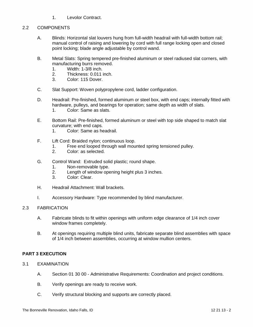
The Bonneville Renovation, Idaho Falls, ID 12 21 13 - 2
1. Levolor Contract.
2.2 COMPONENTS
A. Blinds: Horizontal slat louvers hung from full-width headrail with full-width bottom rail; manual control of raising and lowering by cord with full range locking open and closed point locking; blade angle adjustable by control wand.
B. Metal Slats: Spring tempered pre-finished aluminum or steel radiused slat corners, with manufacturing burrs removed. 1. Width: 1-3/8 inch. 2. Thickness: 0.011 inch. 3. Color: 115 Dover.
C. Slat Support: Woven polypropylene cord, ladder configuration.
D. Headrail: Pre-finished, formed aluminum or steel box, with end caps; internally fitted with hardware, pulleys, and bearings for operation; same depth as width of slats. 1. Color: Same as slats.
E. Bottom Rail: Pre-finished, formed aluminum or steel with top side shaped to match slat curvature; with end caps. 1. Color: Same as headrail.
F. Lift Cord: Braided nylon; continuous loop. 1. Free end looped through wall mounted spring tensioned pulley. 2. Color: as selected.
G. Control Wand: Extruded solid plastic; round shape. 1. Non-removable type. 2. Length of window opening height plus 3 inches. 3. Color: Clear.
H. Headrail Attachment: Wall brackets.
I. Accessory Hardware: Type recommended by blind manufacturer.
2.3 FABRICATION
A. Fabricate blinds to fit within openings with uniform edge clearance of 1/4 inch cover window frames completely.
B. At openings requiring multiple blind units, fabricate separate blind assemblies with space of 1/4 inch between assemblies, occurring at window mullion centers.
PART 3 EXECUTION
3.1 EXAMINATION
A. Section 01 30 00 - Administrative Requirements: Coordination and project conditions.
B. Verify openings are ready to receive work.
C. Verify structural blocking and supports are correctly placed.

The Bonneville Renovation, Idaho Falls, ID 12 21 13 - 3
3.2 EXISTING WORK
A. Remove abandoned window treatments and patch surfaces.
3.3 INSTALLATION
A. Install blinds.
B. Secure in place with flush countersunk fasteners.
C. Place intermediate head supports at equal spacing of opening.
3.4 ERECTION TOLERANCES
A. Section 01 40 00 - Quality Requirements: Tolerances.
B. Maximum Variation of Gap at Window Opening Perimeter: 1/4 inch.
C. Maximum Offset from Level: 1/8 inch.
3.5 ADJUSTING
A. Section 01 70 00 - Execution and Closeout Requirements: Testing, adjusting, and balancing.
B. Adjust blinds for smooth operation.
3.6 CLEANING
A. Section 01 70 00 - Execution and Closeout Requirements: Final cleaning.
B. Clean blind surfaces just prior to occupancy.
END OF SECTION

The Bonneville Renovation, Idaho Falls, ID 12 35 30 - 1
SECTION 12 35 30
RESIDENTIAL CASEWORK
PART 1 GENERAL
1.1 SUMMARY
A. Section includes cabinets and counter tops; vanity cabinets and counter tops; and casework hardware.
B. Related Sections: 1. Section 06 10 00 - Rough Carpentry: Grounds and support framing. 2. Section 06 20 00 - Finish Carpentry: Related trim not specified in this section.
B. Allowances: Include under provisions of Section 01 20 00 - Price and Payment Procedures: Allowances. Allowance includes [purchase and delivery of residential casework. Installation is included in this section and is part of Contract Sum/Price purchase, delivery, and installation of residential casework.
1.2 REFERENCES
A. American National Standards Institute: 1. ANSI A156.9 - Cabinet Hardware. 2. ANSI A161.1 - Performance and Construction Standard for Kitchen and Vanity
Cabinets.
B. Kitchen Cabinet Manufacturers Association: 1. KCMA - Directory of Certified Cabinet Manufacturers.
1.3 SUBMITTALS
A. Section 01 33 00 - Submittal Procedures: Submittal requirements.
B. Shop Drawings: Indicate casework locations, large scale plans, elevations, rough-in and anchor placement dimensions and tolerances, clearances required.
C. Product Data: Submit component dimensions, configurations, construction details, joint details, fastening methods, accessory listings, hardware location and schedule of finish.
D. Samples: Submit two samples, minimum size 8 x 10 inches of each color of finish and two samples of each type of hardware.
1.4 QUALITY ASSURANCE
A. Perform Work in accordance with ANSI A161.1
B. Maintain one copy of each document on site.
1.5 QUALIFICATIONS
A. Manufacturer: Company specializing in manufacturing products specified in this section with minimum three years documented experience.

The Bonneville Renovation, Idaho Falls, ID 12 35 30 - 2
1.6 MOCKUP
A. Section 01 40 00 - Quality Requirements: Mockup requirements.
B. Construct full size mockup including base unit, upper cabinet, counter top, hardware and accessories.
C. Locate where directed by Architect.
D. Incorporate accepted mockup as part of Work.
PART 2 PRODUCTS
2.1 RESIDENTIAL CASEWORK
A. Manufacturers: 1. Diamond Cabinets. Model Whittenburg. 2. Substitutions: Section 01 60 00 - Product Requirements Not Permitted.
2.2 COMPONENTS
A. Cabinet Construction: Softwood lumber framing and particle board.
B. Counter Top: Self edged plastic laminate over particle board, square internal intersection to 6” back splash with solid surface nosing.
C. Side Splash: Plastic laminate over particle board, square internal intersections to back splash and top surface.
D. Door and Drawer Fronts: Solid wood and Wood veneer over particle board per manufacturer’s standard.
E. Bolts, Nuts, Washers and Screws: Of size and type to suit application.
F. Concealed Joint Fasteners: Threaded steel.
2.3 HARDWARE COMPONENTS
A. Shelf Standards and Rests: Manufacturer’s standard.
B. Shelf Brackets: Manufacturer’s standard.
C. Drawer Pulls: Amerock BP4477-G10
D. Door Pulls: Amerak BP4476-G10.
E. Catches: Manufacturer’s standard.
F. Drawer Slides: Manufacturer’s standard.
G. Hinges: Manufacturer’s standard.
H. Door Bumpers: Resilient plastic with adhesive back; clear color; diameter 5/16” x 3/64”.
I. Shelf Supports: Manufacturer’s standard.

The Bonneville Renovation, Idaho Falls, ID 12 35 30 - 3
2.4 FABRICATION
A. Shop assemble casework for delivery to site in units easily handled and to permit passage through building openings.
B. Fabricate corners and joints without gaps or inaccessible spaces or areas where dirt or moisture could accumulate.
C. Fabricate each unit rigid, not dependent on adjacent units for rigidity.
D. Apply laminate backing sheet to reverse side of plastic laminate finished surfaces.
E. Form edges smooth. Form material for counter tops, facing, and shelves from continuous sheets.
F. Provide cutouts for plumbing fixtures. Prime paint contact surfaces of cut edges.
G. When necessary to cut and fit on site, furnish materials with ample allowance for cutting. Furnish trim for scribing and site cutting.
2.5 SHOP FINISHING
A. Exposed to View Surfaces: Manufacturer’s standard.
B. Counter Top Nosing: Solid surface with 1/4” bull nose edge. Color as selected.
C. Interior Surfaces: Manufacturer’s standard.
PART 3 EXECUTION
1.1 EXAMINATION
A. Section 01 30 00 - Administrative Requirements: Coordination and project conditions.
B. Verify adequacy of support framing.
1.2 INSTALLATION
A. Install casework, components and accessories.
B. Use anchoring devices to suit conditions and substrate materials encountered.
C. Set casework items plumb and square, securely anchored to building structure.
D. Carefully scribe casework abutting other components, with maximum gaps of 1/32 inch. Use filler strips; not additional overlay trim for this purpose.
E. Close ends of units, back splashes, shelves and bases.
1.3 ADJUSTING
A. Section 01 70 00 - Execution and Closeout Requirements: Testing, adjusting, and balancing.

The Bonneville Renovation, Idaho Falls, ID 12 35 30 - 4
B. Adjust doors, drawers, hardware, fixtures, and other moving or operating parts to function smoothly.
1.4 CLEANING
A. Section 01 70 00 - Execution and Closeout Requirements: Final cleaning.
B. Clean casework, counters, shelves, and hardware.
1.5 PROTECTION OF INSTALLED CONSTRUCTION
A. Section 01 70 00 - Execution and Closeout Requirements: Protecting installed construction.
B. Do not permit finished casework to be exposed to continued construction activity.
1.6 SCHEDULES
A. Kitchen: Casework post formed counter tops, natural maple finish. See construction drawings for configuration.
B. Bathrooms: Casework laminate counter tops with 4” back splashes, natural maple finish. See construction drawings for configuration.
END OF DIVISION

The Bonneville Renovation, Idaho Falls, ID 14 21 23 - 1
DIVISION 14 CONVEYING EQUIPMENT SECTION 14 21 23 ELECTRIC TRACTION PASSENGER ELEVATORS
PART 1 GENERAL
1.1 SUMMARY
A. Section includes 1. Electric traction passenger elevator.
B. Related Sections 1. Section 03 30 01 - Minor Concrete Work: Grouting door frames and sills. 2. Section 05 12 00 - Structural Steel Framing: Support steel, divider beams, and
hoist beams. 3. Section 05 50 00 - Metal Fabrications: Pit ladders 4. Section 08 17 13 Intergrated door System: Hoistway Doors 5. Section 09 21 16 - Gypsum Board Assemblies: Furred walls. 6. Section 09 22 16 – Non Structural Metal Framing: Furred walls 7. Section 09 90 00 - Paints and Coatings (Painting and Coating): Field painting of
elevator entrances over primer.
1.2 REFERENCES
A. Americans with Disabilities Act 1. Americans with Disabilities Act Accessibility Guidelines.
B. American Society of Mechanical Engineers: 1. ASME A17.1 - Safety Code for Elevators and Escalators. 2. ASME A17.2.1 - Inspector's Manual for Electric Elevators.
C. ASTM International: 1. ASTM A36/A36M - Standard Specification for Carbon Structural Steel. 2. ASTM A653/A653M - Standard Specification for Steel Sheet, Zinc-Coated
(Galvanized) or Zinc-Iron Alloy-Coated (Galvannealed) by the Hot-Dip Process. 3. ASTM A666 - Standard Specification for Austenitic Stainless Steel Sheet, Strip,
Plate, and Flat Bar. 4. ASTM A1008/A1008M - Standard Specification for Steel, Sheet, Cold-Rolled,
Carbon, Structural, High-Strength Low-Alloy and High-Strength Low-Alloy with Improved Formability.
5. ASTM B221 - Standard Specification for Aluminum and Aluminum-Alloy Extruded Bars, Rods, Wire, Profiles, and Tubes.
6. ASTM E84 - Standard Test Method for Surface Burning Characteristics of Building Materials.
D. American Welding Society: 1. AWS D1.1 - Structural Welding Code - Steel.
E. Copper Development Association Inc.: 1. CDA 113/5 - Standards Handbook 2. Alloy Data.
F. National Electrical Manufacturers Association:

The Bonneville Renovation, Idaho Falls, ID 14 21 23 - 2
1. NEMA LD 3 - High Pressure Decorative Laminates. 2. NEMA MG 1 - Motors and Generators.
G. National Fire Protection Association: 1. NFPA 72 - National Fire Alarm Code. 2. NFPA 80 - Standard for Fire Doors, Fire Windows. 3. NFPA 252 - Standard Methods of Fire Tests of Door Assemblies.
H. SSPC: The Society for Protective Coatings: 1. SSPC - Steel Structures Painting Manual.
I. Underwriters Laboratories Inc.: 1. UL 10B - Fire Tests of Door Assemblies.
1.3 DESIGN REQUIREMENTS
A. Arrange elevator components in control closet or machinery space so equipment can be removed for repairs or replaced with minimal disturbance to other equipment and components.
B. Where permitted by code, provide all elevator equipment including controls, drives, transformers, and rescue features within the elevator hoistway.
1.4 SUBMITTALS
A. Section 01 33 00 - Submittal Procedures: Submittal requirements. 1. Descriptive brochures and detail drawings of car and hall fixtures, cab ceilings,
and product features. 2. Power Information: Horsepower, starting current, running current, machine and
control heat release, and electrical requirements.
B. Shop Drawings: Indicate the following information: 1. Section view, floor heights, location of pit equipment, location and means for
disconnect. 2. Driving machine, controller, power conversion unit selector, governor and other
component locations. 3. Car, counterweight, sheaves, machine and sheave beams, guide rails, buffers,
ropes, and other components in hoistway. 4. Rail bracket spacing; maximum loads imposed on guide rails requiring load
transfer to building structural framing. 5. Individual weight of principal components; load reaction at points of support. 6. Loads on hoisting beams and location of trolley beams. 7. Clearances and over travel of car and counterweight. 8. Locations in hoistway and machine room of traveling cables and connections for
car light and telephone. 9. Location and sizes of access doors, doors, and frames. 10. Expected heat dissipation of elevator equipment in machine room. 11. Applicable seismic design data. 12. Interface with building security system. 13. Electrical characteristics and connection requirements.
C. Show arrangement of equipment in machine room so rotating elements, sheaves, and other equipment can be removed for repairs or replaced without disturbing other components. Arrange equipment for clear passage through access door.
D. Product Data: Submit data on the following items:

The Bonneville Renovation, Idaho Falls, ID 14 21 23 - 3
1. Signal and operating fixtures, operating panels, indicators. 2. Cab design, dimensions, layout, and components. 3. Cab and hoistway door and frame details. 4. Electrical characteristics and connection requirements.
E. Samples: Submit manufacturer/installer's samples of standard colors and finishes of finish materials.
F. Operation and Maintenance Manual: Submit manufacturer/installer's operation and maintenance manual; including operation, maintenance, adjustment, and cleaning instructions; trouble shooting guide; renewal parts catalogs; and electrical wiring diagrams.
G. Warranty: Submit manufacturer/installer's standard warranty.
1.5 CLOSEOUT SUBMITTALS
A. Section 01 70 00 - Execution and Closeout Requirements: Closeout procedures.
B. Operation and Maintenance Data: 1. Include parts catalog with complete list of equipment replacement parts; identify
each entry with equipment description and identifying code. 2. Include technical information for servicing operating equipment. 3. Include legible schematic wiring diagrams of installed electrical equipment and
changes made in the Work. List symbols corresponding to identity or markings on machine room and hoistway apparatus.
4. Include one copy of master schematic and one copy of lubrication
1.6 QUALITY ASSURANCE
A. Perform Work in accordance with ASME A17.1, AWS D1.1, AISC S335, and as supplemented in this section.
B. Fire Rated Door Construction: Conform to one of the following: 1. NFPA 252. 2. UL 10B.
C. Attach label from agency approved by authority having jurisdiction to identify each fire rated door.
D. Installed Fire Rated Door Assembly: Conform to NFPA 80 for fire rated class as indicated on Drawings.
E. Surface Burning Characteristics: Maximum 25/450flame spread/smoke developed index when tested in accordance with ASTM E84.
F. Regulatory Requirements: 1. Elevator design, clearances, construction, workmanship, materials, and
installation, unless specified otherwise, shall be in accordance with ANSI/ASME A17.1, handicap accessibility, Americans with Disabilities Act, and other codes having legal jurisdiction.
2. ANSI/ASME A17.1 shall govern, except where codes having legal jurisdiction include more rigid requirements or conflict with ANSI/ASME A17.1.
3. Where product is in variance to the published ANSI/ASME A17.1 model code, provide a 3rd party AECO certification demonstrating equivalent function, safety, and performance.

The Bonneville Renovation, Idaho Falls, ID 14 21 23 - 4
1.7 QUALIFICATIONS
A. Manufacturer: Company specializing in manufacturing products specified in this section with minimum ten years documented experience.
B. Installer: Employees and supervisor on payroll of elevator equipment manufacturer.
1.8 PRE-INSTALLATION MEETINGS
A. Section 01 30 00 - Administrative Requirements: Pre-installation meeting.
B. Convene minimum one week prior to commencing work of this section.
C. Require attendance of parties directly affecting work of this section, including Contractor, Architect, and elevator manufacturer/installer.
D. Review examination, installation, field quality control, adjusting, cleaning, protection, and coordination with other work.
1.9 FIELD MEASUREMENTS
A. Verify field measurements prior to fabrication.
1.10 SCHEDULING
A. Section 01 30 00 - Administrative Requirements: Coordination and project conditions.
B. Remove and install one elevator at a time. The owner requires one elevator either existing or new to be operational for the public to use at all times
C. Temporary Use of Elevator:
D. Owner will negotiate with manufacturer/installer for temporary use of elevator, if required.
E. Temporary use of elevator shall be in accordance with terms and conditions of manufacturer/installer's temporary acceptance form.
1.11 DELIVERY, STORAGE, AND HANDLING
A. Delivery: Deliver materials to site in manufacturer/installer's original, unopened containers and packaging, with labels clearly identifying product name and manufacturer/installer.
B. Storage: Store materials in clean, dry area indoors in accordance with manufacturer/installer's instructions.
C. Handling: Protect materials during handling and installation to prevent damage.
1.12 WARRANTY
A. Section 01 70 00 - Execution and Closeout Requirements: Product warranties and product bonds.
B. Furnish one year manufacturer warranty for elevator equipment and devices.
The Bonneville Renovation, Idaho Falls, ID 14 21 23 - 5
1.13 MAINTENANCE SERVICE
A. Section 01 33 00 - Submittal Procedures: Requirements for Elevator maintenance service shall be performed by elevator manufacturer/installer.
B. Elevators shall receive regular maintenance on each unit for period of 12 months after completion of work specified herein or acceptance thereof by beneficial use, whichever is earlier.
C. Trained employees shall make periodic examinations and perform work including necessary adjusting, greasing, oiling, and replacing parts to keep elevators in operation, except parts that require replacement because of accidents, vandalism, misuse, or negligence by parties other than manufacturer/installer.
D. Manufacturer/installer shall perform all Work, except emergency minor adjustment call-back service, during regular working hours. Manufacturer/installer shall provide emergency minor adjustment call-back service, during regular working hours.
E. Should Owner request that examinations, cleaning, lubrication, adjustments, repairs, replacements, or emergency minor adjustment call-back service, unless specified herein, be performed on other than manufacturer/installer's regular working hours of regular working days, manufacturer/installer shall absorb straight-time labor charges and Owner will compensate manufacturer/installer for overtime premium, travel time, and expense at normal billing rates.
F. Elevator Control System: 1. Include built-in remote diagnostic module to relay constant status of elevators
and control system to a 24-hour, 7-days-a-week, central-monitoring facility. 2. Remote Monitoring Device: Transmit information on current status of elevators,
including malfunctions, system errors, and shutdown.
PART 2 PRODUCTS
2.1 ELECTRIC TRACTION PASSENGER ELEVATOR
A. Manufacturers 1. Kone 2. Otis Elevator Co. 3. Schindler Elevator Corp. Model: 3300 MRL 4. ThyssenKrupp Elevator. 5. Substitutions: Section 01 60 00 - Product Requirements.
2.2 COMPONENTS
A. Electric Traction Passenger Elevators: Basis of design is the Schindler 3300 Gearless Traction Elevator.
B. Elevator Equipment Summary: 1. Application: Machine Room Less 2. Counterweight Location: Side 3. Machine Location: Top of the hoistway mounted on car and
counterweight guide rails 4. Control Space Location: Top landing entrance frame or entrance frame at
one floor below the top landing 5. Service: General Purpose Passenger

The Bonneville Renovation, Idaho Falls, ID 14 21 23 - 6
6. Quantity of Units: 2 7. Capacity: 2100 lbs 8. Speed: 150 fpm 9. Travel: 78 feet 2 inches 10. Landings: 8 11. Front Openings: 8 12. Operation: Microprocessor Single Car Automatic Operation 13. Clear Inside Dimensions: 5'-9'' W x 4'-5'' D 14. Cab Height: 7'-9'' 15. Guide Rails: 15 lb. per foot 16. Entrance Type and Width: Two Speed Side Opening Doors 3'-0'' 17. Entrance height: 7'-0” 18. Power Supply: 208 Volts 3 Phase 60 Hz
C. Performance 1. Car Speed: -10% to +5% of contract speed under any loading condition or
direction of travel. 2. Car Capacity: Safely lower, stop and hold up to 125% of rated load per code.
D. Ride Quality: 1. Vertical Vibration (maximum): 25 mg 2. Horizontal Vibration (maximum): 15 mg 3. Vertical Jerk (maximum): 2 ft/sec3 4. Acceleration (maximum): 1.6 ft/sec2 5. In Car Noise: 53-60 dB(A) 6. Stopping Accuracy: ±5mm 7. Starts per hour (maximum): 180
E. Elevator Operation 1. Simplex Collective Operation: Using a microprocessor based controller,
operation shall be automatic by means of the car and hall buttons. When all calls have been answered, the car shall park at the last landing served.
2. Group Automatic Operation with Demand-Based Dispatching: Provide reprogrammable group automatic system that assigns cars to hall calls based on a dispatching algorithm designed to minimize passenger waiting time.
F. Operating Features - Standard 1. Door Light Curtain Protection 2. Static AC Drive 3. Phase Monitor Relay 4. Cab Overload with Indicator 5. Load-weighing 6. Central Alarm 7. Remote Monitoring 8. Firefighter's Operation 9. Automatic Evacuation 10. When the main line power is lost for longer than 5 seconds the emergency
battery power supply provides power automatically to the elevator controller. If the car is at a floor when the power fails, it remains at that floor, opens its doors, and shuts down. If the car is between floors, it is raised or lowered to the first available landing, opens its doors, and shuts down.
11. Independent Service
G. Operating Features - Optional

The Bonneville Renovation, Idaho Falls, ID 14 21 23 - 7
2.3 EQUIPMENT: CONTROL COMPONENTS AND CONTROL SPACE
A. Controller: Provide microprocessor based control system to perform all of the functions of safe elevator operation, as well as perform car and group operational control. 1. All high voltage (110v or above) contact points inside the inspection and test
panel shall be protected from accidental contact in a situation where the access panels are open.
2. The controller shall be distributed throughout the elevator system located in the overhead, cab and inspection and test panel. The inverter will be mounted in the overhead adjacent to the hoist machine and an inspection and test panel will be located in the door jamb at the top floor or one floor below the top floor. No elevator equipment mechanical rooms or closets are required.
3. Provide multi-bus control architecture to reduce cabling, material and waste.
B. Drive: Provide a Variable Voltage Variable Frequency AC Closed Loop drive system. Provide stable start without high peak current, quickly reaching a low energy consumption level.
C. Inspection and Test Panel: Integrated control equipment, main inspection and test panel in door frame at top level served.
2.4 EQUIPMENT: HOISTWAY COMPONENTS
A. Machine: 1. Gearless asynchronous AC motor with integral drive sheave, service and
emergency brakes. 2. Design machine to enable direct power transfer, thereby avoiding loss of power. 3. Design machine to be compact, lightweight and durable to optimize material
usage and save space. 4. Mount to structural support channels on top of guide rail system as applicable in
hoistway overhead.
B. Governor: 1. Tension type over-speed governor with remote manual reset. 2. Mount to structural support channels as applicable in hoistway overhead.
C. Buffers, Car and Counterweight: Compression spring type buffers to meet code.
D. Hoistway Operating Devices: 1. Emergency Stop switch in the pit. 2. Terminal stopping switches. 3. Emergency stop switch on the machine.
E. Positioning System: System consisting of proximity sensors and door zone vanes.
F. Guide Rails and Attachments: Provide Tee-section steel rails with brackets and fasteners. Side counterweight arrangements shall have a dual purpose bracket that combines both counterweight guide rails, and one of the car guide rails to building fastening.
G. Suspension System: Non circular Elastomeric coated suspension media with high tensile grade steel cords.
H. Governor rope: Steel wire rope with 6 mm diameter.

The Bonneville Renovation, Idaho Falls, ID 14 21 23 - 8
2.5 EQUIPMENT: HOISTWAY ENTRANCES
A. Hoistway Doors and Frames: 1. UL rated with required fire rating. 2. Doors: Rigid flush panel construction with reinforcement ribs. 3. Frames: Securely fasten at corners to form unit frame. Frames shall be bolted.
B. Finish: 1. Exposed Areas of Corridor Frames: Selected from Manufacturer standard colors 2. Doors: Selected from Manufacturer standard colors
C. Sills: Aluminum on all floors.
D. Entrance Markings and Jamb Plates: Provide standard entrance jamb tactile markings on both jambs, at all floors. Plate Mounting: Refer to manufacturer drawings.
2.6 EQUIPMENT: CAR COMPONENTS
A. Car Frame and Safety: Provide car frame with adequate bracing to support the platform and car enclosure. The safety shall be integral to the car frame and shall be flexible guide clamp type.
B. Platform: Provide platform of steel construction with plywood subfloor and aluminum threshold.
C. Car Guides: Provide sliding guide shoes mounted to top and bottom of both car and counterweight frame. Arrange each guide shoe assembly to maintain constant contact on the rail surfaces. Provide retainers in areas with Seismic design requirements.
D. Provide central guiding system to reduce mechanical friction and energy consumption.
E. Steel Cab: 1. Fire rating: Provide Class B fire rating for cab, or Class A fire rating where
required by local Code. 2. Design cab to comply with LEED Indoor Environmental Quality requirements
through use of Low-Emitting Materials on walls, ceiling and subflooring. 3. Car wall finish: The cab walls shall be steel, baked enamel finish selected from
manufacturer's standard colors. 4. Base and frieze: Aluminum. 5. Car front finish: Brushed stainless steel. 6. Car door finish: Brushed stainless steel. 7. Ceiling: Canopy ceiling, finished in painted silver metallic with compact
fluorescent lighting. Provide lighting consisting of four compact fluorescent energy saving lights located in two semi-oval lateral cutouts located on the center-sides of the cab ceiling, Lexan lens cover.
8. Handrail: 1 3/8'' round and curved painted aluminum. Locate on rear wall. 9. Flooring: By others. 10. Ventilation: Provide one-speed fan in canopy. 11. Emergency Car Lighting: Provide an emergency power unit employing a 12 volt
sealed rechargeable battery and static circuits to illuminate the elevator car and provide current to the alarm bell in the event of building power failure.
12. Emergency Siren: Provide siren mounted on top of the car that is activated when the Alarm button in the car operating panel is engaged.
13. Emergency Exit Switch: Provide an electrical contact to open the safety circuit when the emergency car top exit is opened. When the exit door is opened, the top exit switch shall signal the control and the car will be unable to move.

The Bonneville Renovation, Idaho Falls, ID 14 21 23 - 9
14. Emergency Exit Lock: Provide an emergency exit lock where required by local code.
15. Emergency Exit Guard: Provide emergency exit guard on top of car when required for hoistway wall to platform clearance exceeds 12” or for multiple cars in hoistway.
2.7 DOOR OPERATOR AND REOPENING DEVICES
A. Door Operator: Provide a closed loop VVVF high performance door operator with frequency controlled drive for fast and reliable operation to open and close the car and hoistway doors simultaneously.
B. In case of interruption or failure of electric power, the doors can be readily opened by hand from within the car, in accordance with applicable code. Provide emergency devices and keys for opening doors from the landing as required by local code.
C. Doors shall open automatically when the car has arrived at or is leveling at the respective landings. Doors shall close after a predetermined time interval or immediately upon pressing of a car button. Provide door open button in the car operating panel. Momentary pressing of this button shall reopen the doors and reset the time interval.
D. Provide door hangers and tracks for each car and hoistway door. Contour tracks to match the hanger sheaves. Design hangers for power operation with provisions for vertical and lateral adjustment. Hanger sheaves shall have polyurethane tires and pre-lubricated sealed for life bearings.
E. Electronic Door Safety Device: Equip car doors with concealed transmitter and receiver infrared beam devices to detect presence of object in process of passing through hoistway entrance and car doorway (light curtain device). 1. Use multi-beam scanning without moving parts to detect obstructions in door
opening. 2. Detector Device: Prevent doors from closing, or if they have already started
closing, cause doors to reopen and remain open while object is within detection zone.
3. Horizontal Beams: Minimum of 33 infra red beams to fill doorway from ground level to a height of 6 feet.
2.8 EQUIPMENT: SIGNAL DEVICES AND FIXTURES
A. Car Operating Panel: Provide a car operating panel with all push buttons, key switches and message indicators for elevator operation. 1. Full height car operating panel shall be surface-mounted on front return. 2. Comply with handicap requirements. 3. Push Buttons: Mechanical, illuminating using long-lasting LEDs for each floor
served. 4. Emergency Buttons: Provide in accordance with code. Emergency alarm button,
door open and door close buttons.
B. Features of the Car Operating Panel Shall Include: 1. Audible chime to signal that the car is either stopping at or passing a floor served
by the elevator. 2. Raised markings and Braille provided to the left hand side of each push button. 3. Car Lantern: Provide LED illuminated car lantern with direction arrows to comply
with local code when hall lanterns are not provided. 4. Door open and close push buttons.

The Bonneville Renovation, Idaho Falls, ID 14 21 23 - 10
5. Firefighter's hat and Phase 2 Key-switch 6. Inspection key-switch. 7. Key-switch for optional Independent Service Operation 8. Illuminated alarm button with raised marking. 9. Elevator Data Plate marked with elevator capacity and car number. 10. Help Button: Activation of help button will initiate two-way communication
between car and a location inside the building, switching over to alternate location if call is unanswered, where personnel are available to take the appropriate action. Visual indicators are provided for call initiation and call acknowledgement.
C. Hall Fixtures: Provide hall fixtures with necessary push buttons and key switches for elevator operation. 1. Push buttons: Metallic tactile push buttons, up button and down button at
intermediate floors, single button at each terminal floor. 2. Illumination: Illuminating using long-lasting low power LEDs.
D. Hall Lanterns and Position Indicators. 1. LED illuminated direction arrows with audible and visible call acknowledgement.
E. Hoistway access switches: Provide key-switch at top and/or bottom floor in entrance jamb as required by local code.
F. Firefighter's Phase 1 Service: Key switch in brushed stainless steel cover plate.
G. Fixture Cover Plates: For push buttons, hall lanterns and position indicators, resistant white back-printed glass, no screws required for mounting. Provide stainless steel cover plates for Firefighters Phase I switch and hoistway access switches, with tamper resistant screws in same finish.
H. Mounting: Mount hall fixtures in entrance frames.
PART 3 EXECUTION
3.1 EXAMINATION
A. Section 01 30 00 - Administrative Requirements: Verification of existing conditions before starting work.
B. Examine hoistways, hoistway openings, and pits before starting elevator installation. C. Verify walls are plumb where openings occur and ready for entrance sill installation.
Traditional sill angle or concrete sill support shall not be required. D. Verify hoistway is clear and plumb, with variations not to exceed -0 to +1 inch at any
point. Verify projections greater than 4” must be beveled not less than 75 degrees from horizontal. No negative tolerance is permitted for minimum hoistway dimensions.
E. Verify minimum 2-hour fire-resistance rating of hatch walls. F. Notify Architect in writing of dimensional discrepancies or other conditions detrimental to
proper installation or performance of elevators. G. Do not proceed with elevator installation until unsatisfactory conditions have been
corrected in a manner acceptable to manufacturer/installer.

The Bonneville Renovation, Idaho Falls, ID 14 21 23 - 11
3.2 INSTALLATION
A. Install elevators in accordance with manufacturer/installer's instructions and ANSI/ASME A17.1.
B. Set entrances in vertical alignment with car openings, and aligned with plumb hoistway lines.
3.3 FIELD QUALITY CONTROL
A. Section 01 40 00 - Quality Requirements 01 70 00 - Execution and Closeout Requirements: Field inspecting, testing, adjusting, and balancing.
B. Perform tests of elevator as required by ANSI/ASME A17.1 and governing codes.
3.4 ADJUSTING
A. Section 01 70 00 - Execution and Closeout Requirements: Requirements for starting and adjusting.
B. Adjust elevators for proper operation in accordance with manufacturer/installer's instructions.
C. Adjust elevators for smooth acceleration and deceleration of car so not to cause passenger discomfort.
D. Adjust doors to prevent opening of doors at landing on corridor side, unless car is at rest at that landing, or is in leveling zone and stopping at that landing.
E. Adjust automatic floor leveling feature at each floor to within 1/4 inch of landing. F. Repair minor damages to finish in accordance with manufacturer/installer's instructions
and as approved by Architect. G. Remove and replace damaged components that cannot be successfully repaired as
determined by Architect.
3.5 CLEANING
A. Section 01 70 00 - Execution and Closeout Requirements: Requirements for cleaning. B. Clean elevators promptly after installation in accordance with manufacturer/installer's
instructions. C. Do not use harsh cleaning materials or methods that could damage finish.
3.6 PROTECTION
A. Section 01 70 00 - Execution and Closeout Requirements: Requirements for protecting finished Work.
B. Protect installed elevators from damage during construction in accordance with the negotiated temporary use agreement between Owner and manufacturer's installer.
END OF DIVISION

Mechanical Specifications

The Bonneville Renovation, Idaho Falls, ID 21 00 00 - 1
DIVISION 21: FIRE SUPPRESSION 21 05 00 COMMON REQUIREMENTS FOR FIRE SUPPRESSION 21 05 48 VIBRATION & SEISMIC CONTROLS FOR FIRE SUPPRESSION & EQUIPMENT 21 05 53 IDENTIFICATION FOR FIRE SUPPRESSION PIPING AND EQUIPMENT 21 12 00 FIRE-SUPPRESSION STANDPIPES 21 13 00 WET PIPE FIRE SUPPRESSION SPRINKLERS 21 14 00 DRY PIPE FIRE SUPPRESSION SPRINKLERS TABLE OF CONTENTS

The Bonneville Renovation, Idaho Falls, ID 21 05 00 - 1
SECTION 21 05 00
COMMON REQUIREMENTS FOR FIRE SUPPRESSION
PART 1 - GENERAL
1.1 SECTION INCLUDES
A. Pipe, fittings, valves, and connections for sprinkler systems.
1.2 SUMMARY
A. Furnish and install an automatic fire sprinkler protection system as described in Contract Documents. 1. System shall be installed beginning with connection to the new building service
main located as shown and work shall include but not necessarily be limited to the following areas: a. Entire Existing Building.
2. Provide double check valve on fire sprinkler service lines. 3. Furnish and install post indicator valves on all fire line services. 4. It is mandatory that a site visit be made to inspect existing conditions before
submitting bid.
1.3 RELATED REQUIREMENTS
A. Section 09 9123 - Painting: Preparation and painting of fire protection piping systems.
1.4 REFERENCE STANDARDS
A. ASTM A 795/A 795M - Standard Specification for Black and Hot-Dipped Zinc-Coated (Galvanized) Welded and Seamless Steel Pipe for Fire Protection Use; 2008.
B. AWS D1.1/D1.1M - Structural Welding Code - Steel; 2010.
C. NFPA 13 - Standard for the Installation of Sprinkler Systems; National Fire Protection Association; 2010.
D. UL (FPED) - Fire Protection Equipment Directory; Underwriters Laboratories Inc.; current edition.
E. UL 262 - Gate Valves for Fire-Protection Service; Underwriters Laboratories Inc.; Current Edition, Including All Revisions.
F. UL 312 - Check Valves for Fire-Protection Service; Underwriters Laboratories Inc.; Current Edition, Including All Revisions.
1.5 APPLICABLE CODES AND ORDINANCES
A. The following form a part of this specification:

The Bonneville Renovation, Idaho Falls, ID 21 05 00 - 2
1. National Fire Protection Association Pamphlets: Standards of the National Fire Protection Association for the Installation of Sprinkler and Fire Protection Equipment. a. Pamphlet No. 13, 13D, 13R, 14, and applicable standards. b. Pamphlet No. 231, 231C and applicable standards. c. And as approved over this geographical area
2. International Building Code 3. International Fire Code 4. Underwriter's Laboratories, Inc. Publications: List of Inspected Fire Protection
Equipment and Materials. 5. Applicable state and local codes and ordinances pertaining to fire protection
systems and equipment. 6. Requirements of State Fire Marshal. 7. Requirements of Local Fire Marshal. 8. Safety Code for Elevators and Escalators. 9. Life Safety Code.
B. Work in Idaho must be done by an Idaho licensed sprinkler contractor and plans submitted to and approved by the office of the Idaho State Fire Marshal.
C. The contractor shall notify the Idaho State Fire Marshall and the Local Fire Department to witness the test of the fire sprinkler system.
1.6 VERIFICATIONS AND REQUIREMENTS
A. Fire Sprinkler Contractor shall verify adequacy of the water service to the building.
B. Fire Sprinkler Contractor shall also check with the Local City Fire Marshal, the State Fire Marshal and the Fire Rating Bureau to determine requirements for the following: 1. Fire department connections 2. Test connections 3. Exterior and interior piping 4. Spacing of heads 5. Rating of building
1.7 FEES AND PERMITS
A. Fees or permits required to furnish and install the fire protection system shall be included as part of this Section of the Contract Documents.
1.8 PIPE SIZING
A. Fire Sprinkler Contractor shall be required to size all piping for this project using the Hydraulic Calculation Method in accordance with requirements of National Fire Protection Association Pamphlet No. 13 for Hydraulically Designed Sprinkler Systems
1.9 SUBMITTALS
A. See General Section – for submittal procedures.

The Bonneville Renovation, Idaho Falls, ID 21 05 00 - 3
B. Product Data: Provide manufacturers catalogue information. Indicate valve data and ratings.
C. Shop Drawings: Indicate pipe materials used, jointing methods, supports, floor and wall penetration seals. Indicate installation, layout, weights, mounting and support details, and piping connections. 1. Fire Sprinkler Contractor shall submit complete layouts to underwriters having
jurisdiction and the State Fire Marshal for approval prior to submission to Architect. a. Particular attention shall be paid in layout to coordination of sprinkler piping
and structural system of beams and mechanical ductwork. Notations shall be made on shop drawings where pipes are required to pass thru beams.
b. Wall sprinkler shall be used in ramp areas where headroom is at a minimum and shall be arranged so as not to conflict with egress and door swings.
c. Careful coordination shall be given to avoid changing ceiling lighting systems as shown on drawings.
d. Sprinklers must be spaced equally with lights and ceiling diffusers. e. No fabrication of piping shall be done until piping drawings are accepted by
the Architect, the Mechanical Engineer and State Fire Marshal. 2. The Fire Protection Sprinkler Contractor shall submit drawings that have been
prepared and overseen by a NICET Certified Engineering Technician in fire protection with a minimum, Level 3 rating, or by a Professional Engineer in fire protection. This person shall be employed and be a staff member of the Fire Protection Contractor and shall be required to certify that the drawings are in accordance with the specifications and all regulatory requirements. All drawings shall be signed by the CET or stamped and signed by the Professional Engineer.
3. All area with exposed structure, piping shall neatly follow and be held tight to the line of the deck. When approved by the Architect, piping may follow the line of the exposed structure.
D. Project Record Documents: Record actual locations of components and tag numbering.
E. Operation and Maintenance Data: Include installation instructions and spare parts lists.
1.10 QUALITY ASSURANCE
A. Manufacturer Qualifications: Company specializing in manufacturing the Products specified in this section with minimum three years documented experience.
B. Installer: The sub-contractor for the fire protection system shall be duly licensed by the state, county and city in which the project is being constructed. The fire sprinkler contractor must be engaged in the installation of the types of automatic fire sprinkler system required for this project and be fully familiar with all local conditions, specified codes and requirements. Prior to installation, submit data for approval showing that the Fire Sprinkler Contractor has successfully installed Automatic Fire Sprinkler Systems of the type and design as specified herein.
C. Designer: The designer for the fire sprinkler system shall be a staff employee of the “Installer” and shall be either a licensed Fire Protection Engineer in the State of Idaho,

The Bonneville Renovation, Idaho Falls, ID 21 05 00 - 4
or a Certified Engineering Technician in Fire Protection, Level III (NICET Level III). Registration or certification shall be active during the entire contract period. The designer shall certify that the drawings and installation are in accordance with the intent of the plans and specifications. The designer shall make a complete and final inspection of the installation, including operating all alarms, control valves, checking all piping, seismic bracing, hangers, etc. After checking all components of the system, the designer shall provide a letter stating the installation is complete, operational and in accordance with approved plans and specifications. If changes have been made in the installation since the plans were approved, the designer shall correct the shop drawings and provide as-built drawings to the Owner with the letter.
D. Valves: Bear UL label or marking. Provide manufacturer's name and pressure rating marked on valve body.
E. Products Requiring Electrical Connection: Listed and classified as suitable for the purpose specified and indicated.
F. Final Inspection: The Sprinkler Contractor CET or PE responsible for overseeing this project shall make a complete and final inspection of the installation, checking out all alarms, valves, piping, seismic bracing, hangers, etc., conduct a final main drain test on the system, and provide documentation of this final inspection
1.11 DELIVERY, STORAGE, AND HANDLING
A. Deliver and store valves in shipping containers, with labeling in place.
B. Provide temporary protective coating on cast iron and steel valves.
C. Provide temporary end caps and closures on piping and fittings. Maintain in place until installation.
PART 2 - PRODUCTS
2.1 FIRE PROTECTION SYSTEMS
A. Sprinkler Systems: Conform work to NFPA 13.
B. Welding Materials and Procedures: Conform to ASME Code.
2.2 BURIED PIPING
A. Steel Pipe: ASTM A 53/A 53M Schedule 40 or ASTM A 795 Standard Weight, black , with AWWA C105 polyethylene jacket, or double layer, half-lapped polyethylene tape. 1. Steel Fittings: ASME B16.9, wrought steel or buttwelded; with double layer, half-
lapped polyethylene tape. 2. Cast Iron Fittings: ASME B16.1, flanges and flanged fittings. 3. Joints: Welded in accordance with AWS D1.1. 4. Casing: Closed glass cell insulation.

The Bonneville Renovation, Idaho Falls, ID 21 05 00 - 5
2.3 ABOVE GROUND PIPING
A. Steel Pipe: ASTM A 795 Schedule 10 or ASTM A 53 Schedule 40, black. 1. Steel Fittings: ASME B16.9, wrought steel or buttwelded. 2. Cast Iron Fittings: ASME B16.1, flanges and flanged fittings, ASME B16.4 and
threaded fittings. 3. Malleable Iron Fittings: ASME B16.3 and threaded fittings. 4. Mechanical Grooved Couplings: Malleable iron housing clamps to engage and
lock, "C" shaped elastomeric sealing gasket, steel bolts, nuts, and washers; galvanized for galvanized pipe.
2.4 PIPE HANGERS AND SUPPORTS
A. Hangers for Pipe Sizes 1/2 to 1-1/2 inch (15 to 40 mm): Malleable iron, adjustable swivel, split ring.
B. Hangers for Pipe Sizes 2 inches (50 mm) and Over: Carbon steel, adjustable, clevis.
C. Multiple or Trapeze Hangers: Steel channels with welded spacers and hanger rods.
D. Wall Support for Pipe Sizes to 3 inches (80 mm): Cast iron hook.
E. Wall Support for Pipe Sizes 4 inches (100 mm) and Over: Welded steel bracket and wrought steel clamp.
F. Vertical Support: Steel riser clamp.
G. Floor Support: Cast iron adjustable pipe saddle, lock nut, nipple, floor flange, and concrete pier or steel support.
H. Copper Pipe Support: Carbon steel ring, adjustable, copper plated.
2.5 GATE VALVES
A. A. Up to and including 2 inches (50 mm): 1. Manufacturers:
a. Nibco ; Product Model F-637-31 Flanged Ends. b. Mueler; Product Model A-2073-6 Flanged Ends.
2. Bronze body, bronze trim, rising stem, handwheel, solid wedge or disc, threaded ends.
B. Over 2 inches (50 mm): 1. Manufacturers:
a. Nibco ; Product Model F-637-31 Flanged Ends. b. Mueler; Product Model A-2073-6 Flanged Ends.
2. Iron body, bronze trim, rising stem pre-grooved for mounting tamper switch, handwheel, OS&Y, solid rubber covered bronze or cast iron wedge, flanged ends.
C. Over 4 inches (100 mm): 1. Manufacturers:

The Bonneville Renovation, Idaho Falls, ID 21 05 00 - 6
a. Nibco ; Product Model F-637-31 Flanged Ends. b. Mueler; Product Model A-2073-6 Flanged Ends.
2. Iron body, bronze trim, non-rising stem with bolted bonnet, solid bronze wedge, flanged ends, iron body indicator post assembly.
2.6 GLOBE OR ANGLE VALVES
A. Up to and including 2 inches (50 mm): 1. Bronze body, bronze trim, rising stem and handwheel, inside screw, renewable
rubber disc, threaded ends, with backseating capacity repackable under pressure.
B. Over 2 inches (50 mm): 1. Iron body, bronze trim, rising stem, handwheel, OS&Y, plug-type disc, flanged
ends, renewable seat and disc.
2.7 BALL VALVES
A. Up to and including 2 inches (50 mm): 1. Manufacturers:
a. Milwaukee Model BBSC with threaded ends b. Nibco Model T-505 with threaded ends c. Nibco Model G-505 with grooved ends
2. Bronze two piece body, brass, chrome plated bronze, or stainless steel ball, teflon seats and stuffing box ring, lever handle and balancing stops, threaded ends with union.
B. Over 2 inches (50 mm): 1. Manufacturers:
a. Milwaukee Model BBSC with threaded ends b. Nibco Model T-505 with threaded ends c. Nibco Model G-505 with grooved ends
2. Cast steel body, chrome plated steel ball, teflon seat and stuffing box seals, lever handle or gear drive handwheel for sizes 10 inches (250 mm) and over, flanged.
2.8 BUTTERFLY VALVES
A. Bronze Body: 1. Manufacturers:
a. Mueller: 1) Model B-3250-00 Wafer type with valve tamper switch 2) Model B-3250-52 Grooved ends type with valve tamper switch
b. Nibco: 1) Model WD3510-4 Wafer type with valve tamper switch 2) Model GD1765-4 Grooved type with valve tamper switch
c. Norris Model NW285AC-2K Wafer type with optional tamper switch d. Pratt Model IBV
2. Stainless steel disc, resilient replaceable seat, threaded or grooved ends, extended neck, handwheel and gear drive and integral indicating device , and built-in tamper proof switch rated 10 amp at 115 volt AC.

The Bonneville Renovation, Idaho Falls, ID 21 05 00 - 7
B. Cast or Ductile Iron Body 1. Manufacturers:
a. Mueller: 1) Model B-3250-00 Wafer type with valve tamper switch 2) Model B-3250-52 Grooved ends type with valve tamper switch
b. Nibco: 1) Model WD3510-4 Wafer type with valve tamper switch 2) Model GD1765-4 Grooved type with valve tamper switch
c. Norris Model NW285AC-2K Wafer type with optional tamper switch d. Pratt Model IBV
2. Cast or ductile iron, chrome or nickel plated ductile iron or aluminum bronze disc, resilient replaceable EPDM seat, wafer, lug, or grooved ends, extended neck, handwheel and gear drive and integral indicating device , and internal tamper switch rated 10 amp at 115 volt AC.
2.9 CHECK VALVES
A. Up to and including 2 inches (50 mm): 1. Manufacturers:
a. Nibco Model KT-403-W b. Walworth Figure 412
2. Bronze body and swing disc, rubber seat, threaded ends.
B. Over 2 inches (50 mm): 1. Manufacturers:
a. Nibco Model F-938-31 b. Walworth Fig. 883F c. Mueller Model A-2120-6
2. Iron body, bronze trim, swing check with rubber disc, renewable disc and seat, flanged ends with automatic ball check.
C. 4 inches (100 mm) and Over: 1. Iron body, bronze disc, stainless steel spring, resilient seal, threaded, wafer, or
flanged ends.
2.10 DRAIN VALVES
A. Compression Stop: 1. Bronze with hose thread nipple and cap.
B. Ball Valve: 1. Manufacturers:
a. Milwaukee Model BBSC with threaded ends b. Nibco Model T-505 with threaded ends c. Nibco Model G-505 with grooved ends
2. Brass with cap and chain, 3/4 inch (20 mm) hose thread.
2.11 POST INDICATOR VALVES
A. Furnish and install at each fire service entrance a “Post Indicator Valve” with alarm switch equal to Kennedy.

The Bonneville Renovation, Idaho Falls, ID 21 05 00 - 8
PART 3 - EXECUTION
3.1 FIRE SPRINKLER CONTRACTOR
A. It is the responsibility of the Fire Sprinkler Contractor to inspect the job site prior to fabricating materials. The Fire Sprinkler Contractor shall coordinate the design with all plans and other contractors so that construction can be done without problems. The Fire Sprinkler Contractor shall call for a meeting with all trades to coordinate and sequence installation with the progress of other mechanical and structural systems, and work out spaces for all of the work. By doing so, the project will proceed at the General Contractor’s completion schedule.
3.2 PREPARATION
A. Ream pipe and tube ends. Remove burrs. Bevel plain end ferrous pipe.
B. Remove scale and foreign material, from inside and outside, before assembly.
C. Prepare piping connections to equipment with flanges or unions.
3.3 INSTALLATION
A. Install sprinkler system and service main piping, hangers, and supports in accordance with NFPA 13.
B. Route piping in orderly manner, plumb and parallel to building structure. Maintain gradient.
C. Install piping to conserve building space, to not interfere with use of space and other work.
D. Areas Subject to Freezing Temperatures: 1. Branches serving these areas may contain a cold weather valve and anti-freeze
loop or dry heads.
E. Group piping whenever practical at common elevations.
F. Sleeve pipes passing through partitions, walls, and floors.
G. Install piping to allow for expansion and contraction without stressing pipe, joints, or connected equipment.
H. Pipe Hangers and Supports: 1. Install hangers to provide minimum 1/2 inch space between finished covering
and adjacent work. 2. Place hangers within 12 inches of each horizontal elbow. 3. Use hangers with 1-1/2 inch minimum vertical adjustment. Design hangers for
pipe movement without disengagement of supported pipe. 4. Support vertical piping at every other floor. Support riser piping independently of
connected horizontal piping.

The Bonneville Renovation, Idaho Falls, ID 21 05 00 - 9
5. Where several pipes can be installed in parallel and at same elevation, provide multiple or trapeze hangers.
6. Provide copper plated hangers and supports for copper piping. 7. Prime coat exposed steel hangers and supports. Refer to Painting Section.
Hangers and supports located in crawl spaces, pipe shafts, and suspended ceiling spaces are not considered exposed.
I. Slope piping and arrange systems to drain at low points. Use eccentric reducers to maintain bottom of pipe level.
J. Prepare pipe, fittings, supports, and accessories for finish painting. Where pipe support members are welded to structural building framing, scrape, brush clean, and apply one coat of zinc rich primer to welding. Refer to General Painting Section.
K. Do not penetrate building structural members unless indicated and approved in writing by the Structural Engineer.
L. Provide sleeves when penetrating footings, floors, and walls. Seal pipe and sleeve penetrations to achieve fire resistance equivalent to fire separation required.
M. When installing more than one piping system material, ensure system components are compatible and joined to ensure the integrity of the system. Provide necessary joining fittings. Ensure flanges, union, and couplings for servicing are consistently provided.
N. Die cut threaded joints with full cut standard taper pipe threads with red lead and linseed oil or other non-toxic joint compound applied to male threads only.
O. Install valves with stems upright or horizontal, not inverted. Remove protective coatings prior to installation.
P. Provide gate valves for shut-off or isolating service.
Q. Provide drain valves at main shut-off valves, low points of piping and apparatus.
R. Work shall be executed and inspected in accord with laws, ordinances, rules and regulations of local authorities having jurisdiction over such work. Should any change in the drawings or specifications be required to conform to these ordinances, Fire Sprinkler Contractor shall notify the Architect-Engineer at time of submitting his bid. After entering into the contract, Fire Sprinkler Contractor shall be held to complete all necessary work to meet local requirements without expense to Owner.
S. Sprinkler system shall be installed such that spacing of sprinkler heads in relation to ceiling shall not exceed that permitted for type of ceiling construction involved.
T. General Contractor is required under contract stipulations to leave chases and openings in walls, floors, ceilings, partitions and beams, etc., provided Fire Sprinkler Contractor shall furnish to General Contractor full information as to locations, dimensions, etc., of such chases and openings including the provision and proper setting of all sleeves and other equipment in advance of construction of work so as to cause no delay in work.

The Bonneville Renovation, Idaho Falls, ID 21 05 00 - 10
U. Should any cutting of walls, floors, ceilings, partitions, etc., be required for proper installation of the work or apparatus of Fire Sprinkler Contractor due to his failure in giving the General Contractor proper information at time required, such cutting shall be done at his own expense and in a manner acceptable to Architect-Engineer. All drilling and patching for anchor bolts, hangers, and other supports shall be subject to approval of Architect-Engineer.
V. Siamese connections and watermains to sprinkler room shall be provided by Fire Sprinkler Contractor and connections to sprinkler system shall be by Fire Sprinkler Contractor.
W. Conduits and wiring for alarm contacts, power wiring from starter to motor, and starter shall be provided and wired complete by Electrical Contractor for testing by Fire Sprinkler Contractor. Control wiring from starter to control and safety devices shall be provided and wired by Fire Sprinkler Contractor.
3.4 FIELD TESTING
A. All portions of the system shall be hydrostatically tested.
B. Flushing of underground piping shall be done in accord with National Fire Protection Association.
C. On completion of the work, system shall be tested by full flow. 1. Each control valve for each sprinkler system shall be tested by use of an
inspector's test valve or the application of heat to sprinkler head most remote from the valve.
2. All alarms and other devices shall be tested. 3. All appliances and equipment for testing shall be furnished by Fire Sprinkler
Contractor. 4. Expenses, except for water and electricity used in connection with the tests, shall
be defrayed by Fire Sprinkler Contractor. 5. On completion of tests by Fire Sprinkler Contractor, any defects detected shall be
corrected by Fire Sprinkler Contractor at his own expense and additional tests made until systems are proved satisfactory.
6. Fire Sprinkler Contractor shall submit to Architect-Engineer a certificate covering materials and tests, similar to that specified by National Fire Protection Association, with a request for formal inspection at least five working days prior to date of inspection. The State and Local Fire Marshalls shall also be notified to witness this test. At such inspection any or all of required tests shall be repeated as directed by the Architect-Engineer.
END OF SECTION

The Bonneville Renovation, Idaho Falls, ID 21 05 48 - 1
SECTION 21 05 48
VIBRATION &SEISMIC CONTROLS FOR FIRE SUPPRESSION PIPING AND EQUIPMENT
PART 1 - GENERAL
1.1 SECTION INCLUDES
A. Vibration isolators.
B. Seismic restraints.
1.2 SUBMITTALS
A. See General Section – for submittal procedures.
B. Product Data: Provide schedule of vibration isolator type with location and load on each.
C. Shop Drawings: Indicate seismic control measures.
D. Manufacturer's Instructions: Indicate installation instructions with special procedures and setting dimensions.
PART 2 - PRODUCTS
2.1 MANUFACTURERS
A. Isolation Technology, Inc: www.isolationtech.com.
B. Kinetics Noise Control, Inc: www.kineticsnoise.com.
C. Mason Industries: www.mason-ind.com.
2.2 VIBRATION ISOLATORS
A. Spring Hanger: 1. Springs: Minimum horizontal stiffness equal to 75 percent vertical stiffness, with
working deflection between 0.3 and 0.6 of maximum deflection. Color code springs for load carrying capacity.
2. Housings: Incorporate neoprene isolation pad meeting requirements for neoprene pad isolators.
3. Misalignment: Capable of 20 degree hanger rod misalignment.
B. Neoprene Pad Isolators: 1. Rubber or neoprene waffle pads.
a. Hardness: 30 durometer. b. Thickness: Minimum 1/2 inch. c. Maximum Loading: 50 psi. d. Rib Height: Maximum 0.7 times width.
2. Configuration: Single layer.

The Bonneville Renovation, Idaho Falls, ID 21 05 48 - 2
3. Configuration: 1/2 inch thick waffle pads bonded each side of 1/4 inch thick steel plate.
C. Rubber Mount or Hanger: Molded rubber designed for 0.4 inch deflection with threaded insert.
D. Seismic Fittings and Braces: 1. Earthquake bracing is required and shall conform to the minimum requirements
of NFPA-13 and the State Fire Marshall requirements. 2. Calculate and show on the submittal drawings the type of earthquake bracing to
be used and its UL listing or FM approval.
PART 3 - EXECUTION
3.1 INSTALLATION
A. Install in accordance with manufacturer's instructions.
3.2 FIELD QUALITY CONTROL
A. Inspect isolated equipment after installation and submit report. END OF SECTION

The Bonneville Renovation, Idaho Falls, ID 21 05 53 - 1
SECTION 21 05 53
IDENTIFICATION FOR FIRE SUPPRESSION PIPING AND EQUIPMENT
PART 1 - GENERAL
1.1 SECTION INCLUDES
A. Nameplates.
B. Tags.
C. Stencils.
D. Pipe Markers.
1.2 RELATED REQUIREMENTS
A. General Painting Section - Painting: Identification painting.
1.3 REFERENCE STANDARDS
A. ASME A13.1 - Scheme for the Identification of Piping Systems; The American Society of Mechanical Engineers; 2007.
1.4 SUBMITTALS
A. See General Section – for submittal procedures.
B. List: Submit list of wording, symbols, letter size, and color coding for mechanical identification.
C. Chart and Schedule: Submit valve chart and schedule, including valve tag number, location, function, and valve manufacturer's name and model number.
D. Product Data: Provide manufacturers catalog literature for each product required.
E. Manufacturer's Installation Instructions: Indicate special procedures, and installation.
F. Project Record Documents: Record actual locations of tagged valves.
PART 2 - PRODUCTS
2.1 IDENTIFICATION APPLICATIONS
A. Automatic Controls: Tags.
B. Control Panels: Nameplates.
C. Instrumentation: Tags.

The Bonneville Renovation, Idaho Falls, ID 21 05 53 - 2
D. Major Control Components: Nameplates.
E. Piping: Tags.
F. Relays: Tags.
G. Small-sized Equipment: Tags.
H. Valves: Namplates and ceiling tacks where above lay-in ceilings.
2.2 NAMEPLATES
A. Manufacturers: 1. Kolbi Pipe Marker Co.: www.kolbipipemarkers.com. 2. Seton Identification Products: www.seton.com.
B. Description: Laminated three-layer plastic with engraved letters. 1. Letter Color: White. 2. Letter Height: 1/4 inch (6 mm). 3. Background Color: Black. 4. Thickness: 1/8 inch (3 mm). 5. Plastic: Conform to ASTM D 709.
2.3 TAGS
A. Manufacturers: 1. Advanced Graphic Engraving: www.advancedgraphicengraving.com. 2. Brady Corporation: www.bradycorp.com. 3. Kolbi Pipe Marker Co.: www.kolbipipemarkers.com. 4. Seton Identification Products: www.seton.com.
B. Plastic Tags: Laminated three-layer plastic with engraved black letters on light contrasting background color. Tag size minimum 1-1/2 inch diameter.
C. Metal Tags: Brass with stamped letters; tag size minimum 1-1/2 inch diameter with smooth edges.
D. Valve Tag Chart: Typewritten letter size list in anodized aluminum frame.
2.4 STENCILS
A. Manufacturers: 1. Brady Corporation: www.bradycorp.com. 2. Kolbi Pipe Marker Co.: www.kolbipipemarkers.com. 3. Seton Identification Products: www.seton.com.
B. Stencils: With clean cut symbols and letters of following size: 1. 3/4 to 1-1/4 inch Outside Diameter of Insulation or Pipe: 8 inch long color field,
1/2 inch high letters. 2. 1-1/2 to 2 inch Outside Diameter of Insulation or Pipe: 8 inch long color field, 3/4
inch high letters.

The Bonneville Renovation, Idaho Falls, ID 21 05 53 - 3
3. 2-1/2 to 6 inch Outside Diameter of Insulation or Pipe: 12 inch long color field, 1-1/4 inch high letters.
4. 8 to 10 inch Outside Diameter of Insulation or Pipe: 24 inch long color field, 2-1/2 inch high letters.
5. Over 10 inch Outside Diameter of Insulation or Pipe: 32 inch long color field, 3-1/2 inch high letters.
6. Equipment: 2-1/2 inch high letters.
C. Stencil Paint: As specified in Painting Section, semi-gloss enamel, colors conforming to ASME A13.1.
2.5 PIPE MARKERS
A. Manufacturers: 1. Brady Corporation: www.bradycorp.com. 2. Kolbi Pipe Marker Co.: www.kolbipipemarkers.com. 3. MIFAB, Inc.: www.mifab.com. 4. Seton Identification Products: www.seton.com.
B. Color: Conform to ASME A13.1.
C. Plastic Pipe Markers: Factory fabricated, flexible, semi- rigid plastic, preformed to fit around pipe or pipe covering; minimum information indicating flow direction arrow and identification of fluid being conveyed.
D. Plastic Tape Pipe Markers: Flexible, vinyl film tape with pressure sensitive adhesive backing and printed markings.
E. Underground Plastic Pipe Markers: Bright colored continuously printed plastic ribbon tape, minimum 6 inches wide by 4 mil thick, manufactured for direct burial service.
F. Color code as follows: 1. Fire Quenching Fluids: Red with white letters.
PART 3 - EXECUTION
3.1 PREPARATION
A. Degrease and clean surfaces to receive adhesive for identification materials.
B. Prepare surfaces in accordance with Painting Section - Painting for stencil painting.
3.2 INSTALLATION
A. Install nameplates with corrosive-resistant mechanical fasteners, or adhesive. Apply with sufficient adhesive to ensure permanent adhesion and seal with clear lacquer.
B. Install tags with corrosion resistant chain.
C. Apply stencil painting in accordance with Painting Section.

The Bonneville Renovation, Idaho Falls, ID 21 05 53 - 4
D. Install plastic pipe markers completely around pipe in accordance with manufacturer's instructions.
E. Install plastic tape pipe markers complete around pipe in accordance with manufacturer's instructions.
F. Install underground plastic pipe markers 6 to 8 inches below finished grade, directly above buried pipe.
G. Locate ceiling tacks to locate valves above T-bar type panel ceilings. Locate in corner of panel closest to equipment.
END OF SECTION

The Bonneville Renovation, Idaho Falls, ID 21 12 00 - 1
SECTION 21 12 00
FIRE-SUPPRESSION STANDPIPES
PART 1 - GENERAL
1.1 SECTION INCLUDES
A. Dry standpipe system.
B. Fire department connection.
C. Fire extinguishers where shown.
1.2 RELATED REQUIREMENTS
A. Section 10 4400 - Fire Protection Specialties.
B. Section 21 0500 - Common Work Results for Fire Suppression: Fire protection piping.
C. Section 21 0553 - Identification for Fire Suppression Piping and Equipment.
1.3 REFERENCE STANDARDS
A. FM P7825 - Approval Guide; Factory Mutual Research Corporation; current edition.
B. ITS (DIR) - Directory of Listed Products; Intertek Testing Services NA, Inc.; current edition.
C. NFPA 14 - Standard for the Installation of Standpipe Systems; National Fire Protection Association; 2010.
D. UL (FPED) - Fire Protection Equipment Directory; Underwriters Laboratories Inc.; current edition.
1.4 SUBMITTALS
A. See General Section - Administrative Requirements, for submittal procedures.
B. Product Data: Provide manufacturer's catalog sheet for equipment indicating rough-in size, finish, and accessories.
C. Shop Drawings: Indicate supports, components, accessories, and sizes. 1. Submit shop drawings and product data to Owner's insurance underwriter for
approval. 2. Submit proof of approval to Architect.
D. Project Record Documents: Record actual locations of components.
E. Operation Data: Include manufacturer's data.

The Bonneville Renovation, Idaho Falls, ID 21 12 00 - 2
F. Maintenance Data: Include servicing requirements.
G. Certificates: Provide certificate of compliance from authority having jurisdiction indicating approval of field acceptance tests.
1.5 QUALITY ASSURANCE
A. Perform Work in accordance with NFPA 14. Maintain one copy on site.
B. Installer Qualifications: Company specializing in performing the work of this section with minimum 5 years experience approved by manufacturer.
1.6 DELIVERY, STORAGE, AND HANDLING
A. Deliver and store products in shipping packaging until installation.
PART 2 - PRODUCTS
2.1 FIRE DEPARTMENT CONNECTION A. Type: Flush mounted wall type with brass finish. B. Outlets: Two way with thread size to suit fire department hardware; threaded dust cap
and chain of matching material and finish. C. Drain: 3/4 inch automatic drip, outside. D. Label: "Standpipe - Fire Department Connection".
2.2 FIRE EXTINGUISHERS
A. General: Comply with NFPA 10; UL, FM, and ITS (Warnock Hersey) listed.
B. Water Type: Copper container with positive displacement pump and discharge hose. 1. 2-1/2 gallon capacity with 2A rating. 2. 5 gallon capacity with 4A rating.
C. Carbon Dioxide Type: Insulated handle, hose and horn discharge assembly, self-closing lever or squeeze grip operated, insulated handle. 1. 5 pound capacity with 5BC rating. 2. 10 pound capacity with 10BC rating. 3. 15 pound capacity with 10BC rating. 4. 20 pound capacity with 10BC rating.
D. Multi-Purpose Dry Chemical Type: Cartridge operated with hose and shut-off nozzle or integral shut-off nozzle. 1. 2-1/2 pound capacity with 1A:10BC rating. 2. 5 pound capacity with 2A:10BC rating. 3. 6 pound capacity with 3A:40BC rating. 4. 10 pound capacity with 4A:60BC rating. 5. 20 pound capacity with 20A:120BC rating.

The Bonneville Renovation, Idaho Falls, ID 21 12 00 - 3
PART 3 - EXECUTION
3.1 INSTALLATION A. Install in accordance with manufacturer's instructions. B. Install in accordance with NFPA 14. C. Locate and secure cabinets plumb and level. Establish top of cabinet (inside
horizontal) surface 66 inches above finished floor. D. Provide two way fire department outlet connection on roof. E. Flush entire system of foreign matter.
3.2 FIELD QUALITY CONTROL A. Perform field inspection and testing in accordance with Section 01 4000. B. Test entire system in accordance with NFPA 14. C. Test shall be witnessed by Fire Marshal.
END OF SECTION

The Bonneville Renovation, Idaho Falls, ID 21 13 00 - 1
SECTION 21 13 00
WET PIPE FIRE SUPPRESSION SPRINKLERS
PART 1 - GENERAL
1.1 SECTION INCLUDES
A. Wet-pipe sprinkler system.
B. System design, installation, and certification.
C. Fire department connections.
1.2 RELATED REQUIREMENTS
A. Section 21 0500 - Common Requirements for Fire Suppression: Pipe, fittings, and valves.
B. Section 21 0548 - Vibration and Seismic Controls for Fire Suppression Piping and Equipment.
C. Section 21 0553 - Identification for Fire Suppression Piping and Equipment.
D. Section 26 0519 – Line Voltage Electrical Power Conductors and Cables: Electrical characteristics and wiring connections.
E. Section 26 6411 – Automatic Fire Alarm and Detection System.
1.3 REFERENCE STANDARDS
A. UL (FPED) - Fire Protection Equipment Directory; Underwriters Laboratories Inc.; current edition.
1.4 SUBMITTALS
A. See Section 01 3300 – for submittal procedures.
B. Product Data: Provide data on sprinklers, valves, and specialties, including manufacturers catalog information. Submit performance ratings, rough-in details, weights, support requirements, and piping connections.
C. Shop Drawings: 1. Submit preliminary layout of finished ceiling areas indicating only sprinkler
locations coordinated with ceiling installation. 2. Indicate hydraulic calculations, detailed pipe layout, hangers and supports,
sprinklers, components and accessories. Indicate system controls. 3. Submit shop drawings to authority having jurisdiction for approval. Submit proof
of approval to Architect.
D. Project Record Documents: Record actual locations of sprinklers and deviations of piping from drawings. Indicate drain and test locations.

The Bonneville Renovation, Idaho Falls, ID 21 13 00 - 2
E. Manufacturer's Certificate: Certify that system has been tested and meets or exceeds specified requirements and code requirements.
F. Operation and Maintenance Data: Include components of system, servicing requirements, record drawings, inspection data, replacement part numbers and availability, and location and numbers of service depot.
G. Maintenance Materials: Furnish the following for Owner's use in maintenance of project. 1. See Section 01 6000 - Product Requirements, for additional provisions. 2. Extra Sprinklers: Type and size matching those installed, in quantity required by
referenced NFPA design and installation standard. 3. Sprinkler Wrenches: For each sprinkler type.
1.5 QUALITY ASSURANCE
A. Maintain one copy of referenced design and installation standard on site.
B. Conform to UL requirements.
C. Designer Qualifications: Design system under direct supervision of a Professional Engineer experienced in design of this type of work and licensed in the State of Idaho.
D. Manufacturer Qualifications: Company specializing in manufacturing the Products specified in this section with minimum three years documented experience.
E. Equipment and Components: Provide products that bear UL label or marking.
F. Products Requiring Electrical Connection: Listed and classified by Underwriters Laboratories Inc., as suitable for the purpose specified and indicated.
1.6 DELIVERY, STORAGE, AND HANDLING
A. Store products in shipping containers and maintain in place until installation. Provide temporary inlet and outlet caps. Maintain caps in place until installation.
PART 2 - PRODUCTS
2.1 MANUFACTURERS
A. Sprinklers, Valves, and Equipment: 1. Tyco Fire Suppression & Building Products: www.tyco-fire.com. 2. Viking Corporation: www.vikinggroupinc.com. 3. Reliable: www.reliablehvac.com 4. Central: www.aecinfo.com 5. Substitutions: See Section 01 6000 - Product Requirements.
2.2 SPRINKLER SYSTEM
A. Sprinkler System: Provide coverage for entire building.
B. Occupancy: Comply with NFPA 13 for hazard classification..
C. Water Supply: Determine volume and pressure from water flow test data.
The Bonneville Renovation, Idaho Falls, ID 21 13 00 - 3
1. Revise design with test data available prior to submittals.
D. Provide fire department connections where indicated.
E. Storage Cabinet for Spare Sprinklers and Tools: Steel, located adjacent to alarm valve.
2.3 SPRINKLERS
A. Suspended Ceiling Type: Semi-recessed pendant type with matching screw on escutcheon plate. 1. Finish: Enamel, color white. 2. Escutcheon Plate Finish: White. 3. Fusible Link: Fusible solder link type temperature rated for specific area hazard.
B. Concealed Ceiling Type: Fully recessed with surface cap. 1. Finish: Enamel, color white. 2. Surface Cap Finish: White. 3. Fusible Link: Fusible solder link type, temperated rated for specific area hazard.
C. Exposed Area Type: Pendant upright type with guard. 1. Finish: Brass. 2. Fusible Link: Fusible solder link type temperature rated for specific area hazard.
D. Sidewall Type: Semi-recessed horizontal sidewall type with matching screw on escutcheon plate. 1. Finish: Brass. 2. Escutcheon Plate Finish: Brass. 3. Fusible Link: Fusible solder link type temperature rated for specific area hazard.
E. Dry Sprinklers: Standard pendant type with matching screw on escutcheon plate. 1. Finish: Brass. 2. Escutcheon Plate Finish: Brass. 3. Fusible Link: Fusible solder link type temperature rated for specific area hazard.
F. Furnish and install special sprinkler heads on each side of all windows or doors with windows in the two hour fire rated walls as required by I.B.C. 715. 1. White enamel finish. 2. Liquid filled bulb link. 3. White escutcheon plates.
G. Guards: Finish to match sprinkler finish.
H. Spray Nozzles: Brass with solid cone discharge, 30 degrees of arc with blow-off dust cap.
2.4 SPRINKLER HEADS
A. Sprinkler head orifice sizes shall be in accordance with National Fire Protection Association.
B. Any change in spacing must be in straight rows with lights and walls.

The Bonneville Renovation, Idaho Falls, ID 21 13 00 - 4
C. Sprinkler heads shall be automatic and conventional (spray) type approved by a nationally recognized testing laboratory.
D. Each head shall have an orifice of nominal 1/2" diameter.
E. Sprinkler heads shall be pendant type where installed above a hung ceiling.
2.5 PROTECTIVE GUARDS
A. Heavy wire protective guard shall be provided for sprinkler heads located in heavy use areas where damage may result including, but not limited to:
B. Gyms, Wrestling rooms
C. Locker rooms
D. Multi-purpose rooms
E. Shops
F. Equipment rooms
2.6 PIPING SPECIALTIES
A. Dry Pipe Sprinkler Alarm Valve: Check type valve with divided seat ring, rubber faced clapper to automatically actuate water motor alarm and electric alarm, with pressure retard chamber and variable pressure trim ; with test and drain valve.
B. Electric Alarm: 24 volt D.C. electrically operated chrome plated gong with pressure alarm switch.
C. Water Flow Switch: Vane type switch for mounting horizontal or vertical, with two contacts; rated 10 amp at 125 volt AC and 2.5 amp at 24 volt DC.
D. Fire Department Connections: 1. Type: Flush mounted wall type with brass finish. 2. Outlets: Two way with thread size to suit fire department hardware; threaded
dust cap and chain of matching material and finish. 3. Drain: 3/4 inch (19 mm) automatic drip, outside. 4. Label: "Sprinkler - Fire Department Connection".
E. Post indicator valves. a. UL / ULC / FM Approved. b. Adjustable type. c. Cast iron body. d. Category Four Approved Products:
1) Nibco: Model NIP1A Vertical Post. 2) Mueller: Model A-20806 Adjustable vertical indicator post.

The Bonneville Renovation, Idaho Falls, ID 21 13 00 - 5
PART 3 - EXECUTION
3.1 INSPECTION
A. It is the responsibility of the Fire Sprinkler Contractor to inspect the job site prior to fabricating materials. The Fire Sprinkler Contractor shall coordinate the design with all plans and other contractors so that construction can be done without problems. The Fire Sprinkler Contractor shall call for a meeting with all trades to coordinate and sequence installation with the progress of other mechanical and structural systems, and work out spaces for all of the work. By doing so, the project will proceed at the General Contractor’s completion schedule.
3.2 INSTALLATION
A. Install in accordance with referenced NFPA design and installation standard.
B. Install equipment in accordance with manufacturer's instructions.
C. Work to begin inside building, at base of flange to underground fire protection water main.
D. Install system in compliance with methods detailed in NFPA-13, including seismic requirements for Area 3.
E. Offset as needed for other trades. Avoid conflict in areas of tight construction. Do not obstruct access to air control boxes, access doors, lights or other ceiling mounted equipment.
F. Submit piping and equipment data sheets for review by the Architect prior to the start of the installation.
G. Install piping straight and true to bear evenly on hangers and supports. Keep the interior and ends of new piping thoroughly cleaned of foreign matter by closing pipe openings with caps or plugs during installation. Cover and protect components of the system against dirt, chemical or mechanical injury.
H. Piping shall only be installed in areas where temperatures will not drop below 40°F. If piping must be installed in areas where temperature is not maintained above 40°F, the piping must be fitted with an antifreeze loop and filled with an antifreeze solution per the requirements of NFPA-13.
I. Fire sprinklers shall be centered in ceiling tile in one direction and a minimum of 4-inches from acoustical ceiling (“T”) grid. Provide piping offsets or flexible offsets as required that meet the code. Install fire sprinkler head guards on fire sprinklers lower than 7-feet above finished floor and as identified in 2.05.
J. Fire sprinkler piping that is exposed shall be approved and coordinated with the Architect, prior to any pipe fabrication and/or installation of fire sprinkler piping. Care shall be used in locating exposed fire sprinkler piping.
K. Install inspectors test valve at an accessible height, without the use of a ladder, or having to remove ceiling tiles. Location to be approved by the Architect.

The Bonneville Renovation, Idaho Falls, ID 21 13 00 - 6
L. Provide concrete splash blocks for drains, test valve discharge, etc. Concrete splash blocks shall be pre-fabricated, 2-1/2inches thick.
M. Install special sprinkler heads on each side of windows or doors with windows in the two hour rated fire walls as required by I.B.C. 715.
N. Provide white painted escutcheons around exposed piping, where piping passes through walls or ceilings in a finished area.
O. Field Changes: Do not make field changes for piping layout or sizing without prior approval, after the approval of the fire sprinkler drawings.
P. Provide approved double check valve assembly at sprinkler system water source connection.
Q. Locate fire department connection with sufficient clearance from walls, obstructions, or adjacent siamese connectors to allow full swing of fire department wrench handle.
R. Locate outside alarm gong on building wall as indicated.
S. Apply masking tape or paper cover to ensure concealed sprinklers, cover plates, and sprinkler escutcheons do not receive field paint finish. Remove after painting. Replace painted sprinklers.
T. Flush entire piping system of foreign matter.
U. Hydrostatically test entire system.
V. Require test be witnessed by Fire Marshal.
W. Conduct an inspection and operational test at the end of the one year warrantee period in accordance with NFPA-25. Provide a written report to the Owner at the completion of the inspection.
3.3 INTERFACE WITH OTHER PRODUCTS
A. Ensure required devices are installed and connected as required to fire alarm system.
B. Work with Fire Alarm Contractor to insure system alarms properly when activated.
C. Work with Electrical Contractor to insure that all control devices are properly wired with electrical power and connected to power and alarm systems.
3.4 ACCEPTANCE
A. Acceptance of installation is subject to final inspection and approval by: 1. Idaho State Fire Marshal's Office. 2. Local Fire Department. 3. Architect or his Representative
END OF SECTION

The Bonneville Renovation, Idaho Falls, ID 21 14 00 - 1
SECTION 21 14 00
DRY PIPE FIRE SUPPRESSION SPRINKLERS
PART 1 - GENERAL
1.1 SECTION INCLUDES
A. Dry-pipe sprinkler system.
B. System design, installation, and certification.
C. Fire department connections.
1.2 RELATED REQUIREMENTS
A. Section 21 0500 - Common Requirements for Fire Suppression: Pipe, fittings, and valves.
B. Section 21 0548 - Vibration and Seismic Controls for Fire Suppression Piping and Equipment.
C. Section 21 0553 - Identification for Fire Suppression Piping and Equipment.
D. Section 26 0519 – Line Voltage Electrical Power Conductors and Cables: Electrical characteristics and wiring connections.
E. Section 26 6411 – Automatic Fire Alarm and Detection System.
1.3 REFERENCE STANDARDS
A. UL (FPED) - Fire Protection Equipment Directory; Underwriters Laboratories Inc.; current edition.
1.4 SUBMITTALS
A. See Section 01 3300 – for submittal procedures.
B. Product Data: Provide data on sprinklers, valves, and specialties, including manufacturers catalog information. Submit performance ratings, rough-in details, weights, support requirements, and piping connections.
C. Shop Drawings: 1. Submit preliminary layout of finished ceiling areas indicating only sprinkler
locations coordinated with ceiling installation. 2. Indicate hydraulic calculations, detailed pipe layout, hangers and supports,
sprinklers, components and accessories. Indicate system controls. 3. Submit shop drawings to authority having jurisdiction for approval. Submit proof
of approval to Architect.

The Bonneville Renovation, Idaho Falls, ID 21 14 00 - 2
D. Project Record Documents: Record actual locations of sprinklers and deviations of piping from drawings. Indicate drain and test locations.
E. Manufacturer's Certificate: Certify that system has been tested and meets or exceeds specified requirements and code requirements.
F. Operation and Maintenance Data: Include components of system, servicing requirements, record drawings, inspection data, replacement part numbers and availability, and location and numbers of service depot.
G. Maintenance Materials: Furnish the following for Owner's use in maintenance of project. 1. See Section 01 6000 - Product Requirements, for additional provisions. 2. Extra Sprinklers: Type and size matching those installed, in quantity required by
referenced NFPA design and installation standard. 3. Sprinkler Wrenches: For each sprinkler type.
1.5 QUALITY ASSURANCE
A. Maintain one copy of referenced design and installation standard on site.
B. Conform to UL requirements.
C. Designer Qualifications: Design system under direct supervision of a Professional Engineer experienced in design of this type of work and licensed in the State of Idaho.
D. Manufacturer Qualifications: Company specializing in manufacturing the Products specified in this section with minimum three years documented experience.
E. Equipment and Components: Provide products that bear UL label or marking.
F. Products Requiring Electrical Connection: Listed and classified by Underwriters Laboratories Inc., as suitable for the purpose specified and indicated.
1.6 DELIVERY, STORAGE, AND HANDLING
A. Store products in shipping containers and maintain in place until installation. Provide temporary inlet and outlet caps. Maintain caps in place until installation.
PART 2 - PRODUCTS
2.1 MANUFACTURERS
A. Sprinklers, Valves, and Equipment: 1. Tyco Fire Suppression & Building Products: www.tyco-fire.com. 2. Viking Corporation: www.vikinggroupinc.com. 3. Reliable: www.reliablehvac.com 4. Central: www.aecinfo.com 5. Substitutions: See Section 01 6000 - Product Requirements.

The Bonneville Renovation, Idaho Falls, ID 21 14 00 - 3
2.2 SPRINKLER SYSTEM
A. Sprinkler System: Provide coverage for entire building.
B. Occupancy: Comply with NFPA 13 for hazard classification..
C. Water Supply: Determine volume and pressure from water flow test data. 1. Revise design with test data available prior to submittals.
D. Provide fire department connections where indicated.
E. Storage Cabinet for Spare Sprinklers and Tools: Steel, located adjacent to alarm valve.
2.3 SPRINKLERS
A. Suspended Ceiling Type: Semi-recessed pendant type with matching screw on escutcheon plate. 1. Finish: Enamel, color white. 2. Escutcheon Plate Finish: White. 3. Fusible Link: Fusible solder link type temperature rated for specific area hazard.
B. Concealed Ceiling Type: Fully recessed with surface cap. 1. Finish: Enamel, color white. 2. Surface Cap Finish: White. 3. Fusible Link: Fusible solder link type, temperated rated for specific area hazard.
C. Exposed Area Type: Pendant upright type with guard. 1. Finish: Brass. 2. Fusible Link: Fusible solder link type temperature rated for specific area hazard.
D. Sidewall Type: Semi-recessed horizontal sidewall type with matching screw on escutcheon plate. 1. Finish: Brass. 2. Escutcheon Plate Finish: Brass. 3. Fusible Link: Fusible solder link type temperature rated for specific area hazard.
E. Dry Sprinklers: Standard pendant type with matching screw on escutcheon plate. 1. Finish: Brass. 2. Escutcheon Plate Finish: Brass. 3. Fusible Link: Fusible solder link type temperature rated for specific area hazard.
F. Furnish and install special sprinkler heads on each side of all windows or doors with windows in the two hour fire rated walls as required by I.B.C. 715. 1. White enamel finish. 2. Liquid filled bulb link. 3. White escutcheon plates.
G. Guards: Finish to match sprinkler finish.

The Bonneville Renovation, Idaho Falls, ID 21 14 00 - 4
H. Spray Nozzles: Brass with solid cone discharge, 30 degrees of arc with blow-off dust cap.
2.4 SPRINKLER HEADS
A. Sprinkler head orifice sizes shall be in accordance with National Fire Protection Association.
B. Any change in spacing must be in straight rows with lights and walls.
C. Sprinkler heads shall be automatic and conventional (spray) type approved by a nationally recognized testing laboratory.
D. Each head shall have an orifice of nominal 1/2" diameter.
E. Sprinkler heads shall be pendant type where installed above a hung ceiling.
F. Any sprinkler heads in non-conditioned areas or exterior areas shall be protected with antifreeze loop or freeze proof sprinkler heads as required.
2.5 PROTECTIVE GUARDS
A. Heavy wire protective guard shall be provided for sprinkler heads located in heavy use areas where damage may result including, but not limited to:
B. Gyms, Wrestling rooms
C. Locker rooms
D. Multi-purpose rooms
E. Shops
F. Equipment rooms
2.6 PIPING SPECIALTIES
A. Wet Pipe Sprinkler Alarm Valve: Check type valve with divided seat ring, rubber faced clapper to automatically actuate water motor alarm and electric alarm, with pressure retard chamber and variable pressure trim ; with test and drain valve.
B. Electric Alarm: 24 volt D.C. electrically operated chrome plated gong with pressure alarm switch.
C. Water Flow Switch: Vane type switch for mounting horizontal or vertical, with two contacts; rated 10 amp at 125 volt AC and 2.5 amp at 24 volt DC.
D. Fire Department Connections: 1. Type: Flush mounted wall type with brass finish. 2. Outlets: Two way with thread size to suit fire department hardware; threaded
dust cap and chain of matching material and finish. 3. Drain: 3/4 inch (19 mm) automatic drip, outside.

The Bonneville Renovation, Idaho Falls, ID 21 14 00 - 5
4. Label: "Sprinkler - Fire Department Connection".
E. Post indicator valves. a. UL / ULC / FM Approved. b. Adjustable type. c. Cast iron body. d. Category Four Approved Products:
1) Nibco: Model NIP1A Vertical Post. 2) Mueller: Model A-20806 Adjustable vertical indicator post.
F. Air Maintenance Device 1. Maximum inlet air pressure 125 psi. 2. Minimum outlet air pressure 65 psi. 3. Approved Manufacturers:
a. Reliable Model B-1 b. Viking Model D-2 c. Star Model B
G. Accelerator: 1. Install with pressure gauge 2. Approved Manufacturers:
a. Reliable Model B-1 b. Viking Model D-1 c. Star Model A
2.7 AIR COMPRESSOR
A. Air compressor: 1. Tank-mounted, 17 gallon tank rated at 165 psi working pressure. Restrict speed
of compressor to between 700 and 900 RPM. 2. Set tank-mounted air compressor on neoprene isolation pads located at each
corner and sized 4" x 4" x 3/4" high. 3. Wire air compressor to circuit breaker. 4. Furnish with air intake filter and silencer. 5. Overload protected 1750 RPM motor. 6. Industrial grade with totally enclosed steel belt guard. 7. Auto control group mounted and pre-wired. Auto group includes pressure switch,
check valve, manifold, safety valve, and mounting. 8. Approved Manufacturers:
a. General Air Products Model LT620100. b. Jenny Products Model K1S-17WMS. c. Equal as approved by Architect prior to bidding.
PART 3 - EXECUTION
3.1 INSPECTION
A. It is the responsibility of the Fire Sprinkler Contractor to inspect the job site prior to fabricating materials. The Fire Sprinkler Contractor shall coordinate the design with all plans and other contractors so that construction can be done without problems. The Fire Sprinkler Contractor shall call for a meeting with all trades to coordinate and

The Bonneville Renovation, Idaho Falls, ID 21 14 00 - 6
sequence installation with the progress of other mechanical and structural systems, and work out spaces for all of the work. By doing so, the project will proceed at the General Contractor’s completion schedule.
3.2 INSTALLATION
A. Install in accordance with referenced NFPA design and installation standard.
B. Install equipment in accordance with manufacturer's instructions.
C. Work to begin inside building, at base of flange to underground fire protection water main.
D. Install system in compliance with methods detailed in NFPA-13, including seismic requirements for Area 3.
E. Offset as needed for other trades. Avoid conflict in areas of tight construction. Do not obstruct access to air control boxes, access doors, lights or other ceiling mounted equipment.
F. Submit piping and equipment data sheets for review by the Architect prior to the start of the installation.
G. Install piping straight and true to bear evenly on hangers and supports. Keep the interior and ends of new piping thoroughly cleaned of foreign matter by closing pipe openings with caps or plugs during installation. Cover and protect components of the system against dirt, chemical or mechanical injury.
H. Fire sprinklers shall be centered in ceiling tile in one direction and a minimum of 4-inches from acoustical ceiling (“T”) grid. Provide piping offsets or flexible offsets as required that meet the code. Install fire sprinkler head guards on fire sprinklers lower than 7-feet above finished floor and as identified in 2.05.
I. Fire sprinkler piping that is exposed shall be approved and coordinated with the Architect, prior to any pipe fabrication and/or installation of fire sprinkler piping. Care shall be used in locating exposed fire sprinkler piping.
J. Install inspectors test valve at an accessible height, without the use of a ladder, or having to remove ceiling tiles. Location to be approved by the Architect.
K. Provide concrete splash blocks for drains, test valve discharge, etc. Concrete splash blocks shall be pre-fabricated, 2-1/2inches thick.
L. Install special sprinkler heads on each side of windows or doors with windows in the two hour rated fire walls as required by I.B.C. 715.
M. Provide white painted escutcheons around exposed piping, where piping passes through walls or ceilings in a finished area.
N. Field Changes: Do not make field changes for piping layout or sizing without prior approval, after the approval of the fire sprinkler drawings.

The Bonneville Renovation, Idaho Falls, ID 21 14 00 - 7
O. Provide approved double check valve assembly at sprinkler system water source connection.
P. Locate fire department connection with sufficient clearance from walls, obstructions, or adjacent siamese connectors to allow full swing of fire department wrench handle.
Q. Locate outside alarm gong on building wall as indicated.
R. Apply masking tape or paper cover to ensure concealed sprinklers, cover plates, and sprinkler escutcheons do not receive field paint finish. Remove after painting. Replace painted sprinklers.
S. Flush entire piping system of foreign matter.
T. Pressure test entire system as required by code.
U. Require test be witnessed by Fire Marshal.
V. Conduct an inspection and operational test at the end of the one year warrantee period in accordance with NFPA-25. Provide a written report to the Owner at the completion of the inspection.
W. Install piping system so it will not fail due to freezing temperatures. X. Do not use dropped, damaged, or used sprinkler heads. Y. Pendants:
1. Do not use regular pendants. 2. Install dry pendants with tees and not elbows. Do not adjust length with pipe
nipples and couplings. 3. Individually measure and order each dry pendant based on measured distance
from ceiling to face of branch line tee. 4. Dry-Pendant Concealed Sprinkler:
a. Use flat cover plate to conceal sprinkler head. Cover not to exceed 3/16 inch from ceiling.
Z. Minimum slope required by code and inspected by Local Fire Marshall to insure complete drainage of dry piping.
3.3 FIELD QUALITY CONTROL
A. Field Tests: 1. Water Flow Test:
a. Test to determine static and residual pressures and corresponding flow rate at point of connection to utility water main.
b. Adjust water flow test data for seasonal fluctuations and future growth as recommended by Water Utility and AHJ.
c. At point of connection to utility water main, combine inside and outside hose stream allowances.
2. Pneumatically test dry system by establishing 40 psi air pressure and measuring drop as required by 'Contractor's Material And Testing certificate for Above Ground Piping' NFPA-13, Figure 24.1 (2010) Edition) Drop shall not exceed 1 - 1/2 psi (6.90 - 3.45 kPA) in 24 hours

The Bonneville Renovation, Idaho Falls, ID 21 14 00 - 8
3. Check slope of piping and certify that piping is sloped as required by Contract Documents and will not trap water in system. Report unsatisfactory conditions to Architect.
4. Tests shall be witnessed by Architect and representative of local jurisdiction over fire prevention.
3.4 INTERFACE WITH OTHER PRODUCTS
A. Ensure required devices are installed and connected as required to fire alarm system.
B. Work with Fire Alarm Contractor to insure system alarms properly when activated.
C. Work with Electrical Contractor to insure that all control devices are properly wired with electrical power and connected to power and alarm systems.
3.5 ACCEPTANCE
A. Acceptance of installation is subject to final inspection and approval by: 1. Idaho State Fire Marshal's Office. 2. Local Fire Department. 3. Architect or his Representative
END OF SECTION END OF DIVISION

The Bonneville Renovation, Idaho Falls, ID 22 00 00 - 1
DIVISION 22: PLUMBING
22 00 00 PLUMBING
22 05 01 COMMON PLUMBING REQUIREMENTS 22 05 02 DEMOLITION AND REPAIR 22 05 03 PIPE, PIPE FITTINGS, PIPE HANGERS & VALVES 22 05 53 IDENTIFICATION FOR PLUMBING PIPES AND EQUIPMENT 22 07 03 MECHANICAL INSULATION AND FIRE STOPPING 22 07 05 UNDERGROUND PIPING INSULATION 22 07 10 POTABLE WATER PIPE INSULATION 22 07 11 HANDICAPPED FIXTURES INSULATION 22 07 20 RAIN DRAIN INSULATION 22 08 00 FIRE STOPPING
22 10 00 PLUMBING PIPING AND VALVES
22 10 07 PRESS TYPE PIPE FITTINGS 22 11 14 NATURAL GAS SYSTEMS 22 11 16 DOMESTIC WATER PIPING SYSTEMS (COPPER) 22 11 16 DOMESTIC WATER PIPING SYSTEMS (PEX) 22 11 18 BACKFLOW PREVENTER VALVE 22 13 13 SOIL, WASTE, & VENT PIPING SYSTEMS 22 14 00 STORM DRAINAGE PIPING 22 26 00 CONDENSATE DRAIN PIPING
22 30 00 PLUMBING EQUIPMENT
22 34 20 GAS FIRED STORAGE TYPE WATER HEATERS 22 34 25 FLUES FOR WATER HEATERS 22 36 00 WATER SOFTENERS
22 40 00 PLUMBING FIXTURES
22 40 01 PLUMBING FIXTURES 22 47 03 HANDICAP DRINKING WATER COOLING SYSTEM
END TABLE OF CONTENTS

The Bonneville Renovation, Idaho Falls, ID 22 05 01 - 1
SECTION 22 05 01
COMMON PLUMBING REQUIREMENTS
PART 1 - GENERAL
1.1 RELATED DOCUMENTS
A. Drawings and General Provisions of Contract, including General and Supplementary Conditions and other Division 1 Specification Sections, apply to this Section.
1.2 SUMMARY
A. Furnish labor, materials, and equipment necessary for completion of work as described in Contract Documents.
B. It is the intent of these specifications that the systems specified herein are to be complete and operational before being turned over to the owner. During the bidding process, the contractor is to ask questions or call to the engineer’s attention any items that are not shown or may be required to make the system complete and operational. Once the project is bid and the contractor has accepted the contract, it is his responsibility to furnish and install all equipment and parts necessary to provide a complete and operational system without additional cost to the owner.
C. Furnish and install fire stopping materials to seal penetrations through fire rated structures and draft stops.
1.3 SUBMITTALS
A. Substitutions: By specific designation and description, standards are established for specialties and equipment. Other makes of specialties and equipment of equal quality will be considered provided such proposed substitutions are submitted to the Architect for his approval, complete with specification data showing how it meets the specifications, at least 5 working days prior to bid opening. A list of approved substitutions will be published as an addendum, but does not relieve Contractor from meeting all requirements of the specifications. 1. Submit a single copy of Manufacturer's catalog data including Manufacturer's
complete specification for each proposed substitution. 2. The Architect or Engineer is to be the sole judge as to the quality of any material
offered as an equal.
B. Product Data, Shop Drawings: Within 30 days after award of contract, submit 10 sets of Manufacturer's catalog data for each manufactured item. 1. Literature shall include enough information to show complete compliance with
Contract Document requirements. 2. Mark literature to indicate specific item with applicable data underlined. 3. Information shall include but not be limited to capacities, ratings, type of material
used, guarantee, and such dimensions as are necessary to check space requirements.
4. When accepted, submittal shall be an addition to Contract Documents and shall be in equal force. No variation shall be permitted.
5. Even though the submittals have been accepted by the Engineer, it does not relieve the contractor from meeting all of the requirements of the plans and specifications and providing a complete and operational system.

The Bonneville Renovation, Idaho Falls, ID 22 05 01 - 2
C. Drawings of Record: One complete set of blue line mechanical drawings shall be provided for the purpose of showing a complete picture of the work as actually installed. 1. These drawings shall serve as work progress report sheets. Contractor shall
make notations neat and legible therein daily as the work proceeds. 2. The drawings shall be kept at the job at a location designated by the Mechanical
Engineer. 3. At completion of the project these "as-built" drawings shall be signed by the
Contractor, dated, and returned to the Architect.
D. Operating Instructions and Service Manual: The Mechanical Contractor shall prepare 2 copies of an Operation and Maintenance Manual for all mechanical systems and equipment used in this project. Manuals shall be bound in hard-backed binders and the front cover and spine of each binder shall indicate the name and location of the project. Use plastic tab indexes for all sections. Provide a section for each different type of equipment item. The following items shall be included in the manual, together with any other pertinent data. This list is not complete and is to be used as a guide. 1. Provide a master index at the beginning of the manual showing all items
included. 2. The first section of the manual shall contain:
a. Names, addresses, and telephone numbers of Architect, Mechanical Engineer, Electrical Engineer, General Contractor, Plumbing Contractor, Sheet Metal Contractor, and Temperature Control Contractor.
b. List of Suppliers which shall include a complete list of each piece of equipment used with the name, address, and telephone number of vendor.
c. General Description of Systems including – 1) Location of all major equipment 2) Description of the various mechanical systems 3) Description of operation and control of the mechanical systems 4) Suggested maintenance schedule
d. Copy of contractor's written warranty 3. Provide a copy of approved submittal literature for each piece of equipment. 4. Provide maintenance and operation literature published by the manufacturer for
each piece of equipment which includes: oiling, lubrication and greasing data; belt sizes, types and lengths; wiring diagrams; step-by-step procedure to follow in putting each piece of mechanical equipment in operation.
5. Include parts numbers of all replaceable items. 6. Provide control diagram and operation sequence, along with labeling of control
piping and instruments to match diagram. 7. Include a valve chart indicating valve locations. 8. Include air balance and/or water balance reports.
1.4 QUALITY ASSURANCE
A. Requirements of Regulatory Agencies: 1. Perform work in accordance with applicable provisions of local and state
Plumbing Code, Gas Ordinances, and adoptions thereof. Provide materials and labor necessary to comply with rules, regulations, and ordinances.
2. In case of differences between building codes, state laws, local ordinances, utility company regulations, and Contract Documents, the most stringent shall govern. Promptly notify Architect in writing of such differences.
B. Applicable Specifications: Referenced specifications, standards, and publications shall be of the issues in effect on date of Advertisement for Bid.

The Bonneville Renovation, Idaho Falls, ID 22 05 01 - 3
1. "Heating, Ventilating and Air Conditioning Guide" published by the American Society of Heating and Air Conditioning Engineers.
2. "Engineering Standards" published by the Heating, Piping, and Air Conditioning Contractors National Association.
3. "2015 International Building Code", "2015 International Mechanical Code", and "2015 International Fire Code" as published by the International Conference of Building Officials.
4. “2015 Idaho Plumbing Code” as published by the International Association of Plumbing and Mechanical Officials.
5. "National Electrical Code" as published by the National Fire Protection Association.
6. "2015 International Energy Conservation Code ".
1.5 INSPECTIONS AND PERMITS
A. Pay for permits, fees, or charges for inspection or other services. Local and state codes and ordinances must be properly executed without expense to Owner and are considered as minimum requirements. Local and state codes and ordinances do not relieve the Contractor from work shown that exceeds minimum requirements.
1.6 ADDITIONAL WORK:
A. Design is based on equipment as described in the drawing equipment schedule. Any change in foundation bases, electrical wiring, conduit connections, piping, controls and openings required by alternate equipment submitted and approved shall be paid for by this division. All work shall be in accordance with the requirements of the applicable sections.
PART 2 - NOT USED
PART 3 - EXECUTION
3.1 EXAMINATION
A. Site Inspection: 1. Examine premises and understand the conditions which may affect performance
of work of this Division before submitting proposals for this work. 2. No subsequent allowance for time or money will be considered for any
consequence related to failure to examine site conditions.
B. Drawings: 1. Plumbing drawings show general arrangement of piping, equipment, etc, and do
not attempt to show complete details of building construction which affect installation. This Contractor shall refer to architectural, structural, mechanical, and electrical drawings for additional building detail which affect installation of his work. a. Follow plumbing drawings as closely as actual building construction and
work of other trades will permit. b. No extra payments will be allowed where piping and/or ductwork must be
offset to avoid other work or where minor changes are necessary to facilitate installation.
c. Everything shown on the plumbing drawings shall be the responsibility of Plumbing Contractor unless specifically noted otherwise.
2. Consider architectural and structural drawings part of this work insofar as these drawings furnish information relating to design and construction of building. These drawings take precedence over mechanical drawings.

The Bonneville Renovation, Idaho Falls, ID 22 05 01 - 4
3. Because of small scale plumbing drawings, it is not possible to indicate all offsets, fittings, and accessories which may be required. Investigate structural and finish conditions affecting this work and arrange work accordingly, providing such fittings, valves, and accessories required to meet conditions. Do not scale drawings for locations of equipment or piping. Refer to large scale dimensioned drawings for exact locations.
C. Insure that items to be furnished fit space available. Make necessary field measurements to ascertain space requirements including those for connections and furnish and install equipment of size and shape so final installation shall suit true intent and meaning of Contract Documents. 1. If approval is received to use other than specified items, responsibility for
specified capacities and insuring that items to be furnished will fit space available lies with this Division.
2. If non-specified equipment is used and it will not fit job site conditions, this Contractor assumes responsibility for replacement with items named in Contract Documents.
3.2 PREPARATION
A. Cut carefully to minimize necessity for repairs to existing work. Do not cut beams, columns, or trusses. 1. Patch and repair walls, floors, ceilings, and roofs with materials of same quality
and appearance as adjacent surfaces unless otherwise shown. Surface finishes shall exactly match existing finishes of same materials.
2. Each Section of this Division shall bear expense of cutting, patching, repairing, and replacing of work of other Sections required because of its fault, error, tardiness, or because of damage done by it.
3. Cutting, patching, repairing, and replacing pavements, sidewalks, roads, and curbs to permit installation of work of this Division is responsibility of Section installing work.
3.3 INSTALLATION
A. Arrange pipes, ducts, and equipment to permit ready access to valves, unions, traps, starters, motors, control components, and to clear openings of doors and access panels.
3.4 STORAGE AND PROTECTION OF MATERIALS:
A. Provide storage space for storage of materials and assume complete responsibility for losses due to any cause whatsoever. Storage shall not interfere with traffic conditions in any public thoroughfare.
B. Protect completed work, work underway, and materials against loss or damage.
C. Close pipe openings with caps or plugs during installation. Cover fixtures and equipment and protect against dirt, or injury caused by water, chemical, or mechanical accident.
3.5 EXCAVATION AND BACKFILL
A. Perform necessary excavation of whatever substance encountered for proper laying of all pipes and underground ducts. 1. Excavated materials not required for fill shall be removed from site as directed by
Engineer.

The Bonneville Renovation, Idaho Falls, ID 22 05 01 - 5
2. Excavation shall be carried low enough to allow a minimum coverage over underground piping of 5'-0" or to be below local frost level.
3. Excess excavation below required level shall be backfilled at Contractor's expense with earth, sand, or gravel as directed by Engineer. Tamp ground thoroughly.
4. Ground adjacent to all excavations shall be graded to prevent water running into excavated areas.
B. Backfill pipe trenches and allow for settlement. 1. Backfill shall be mechanically compacted to same density as surrounding
undisturbed earth. 2. Cinders shall not be used in backfilling where steel or iron pipe is used. 3. No backfilling shall be done until installation has been approved by the Engineer.
3.6 COOPERATION
A. Cooperate with other crafts in coordination of work. Promptly respond when notified that construction is ready for installation of work under Division 22. Contractor will be held responsible for any delays which might be caused by his negligence or failure to cooperate with the other Contractors or crafts.
3.7 SUPERVISION
A. Provide a competent superintendent in charge of the work at all times. Anyone found incompetent shall be removed at once and replaced by someone satisfactory, when requested by the Architect.
3.8 INSTALLATION CHECK:
A. An experienced, competent, and authorized representative of the manufacturer or supplier of each item of equipment indicated in the equipment schedule shall visit the project to inspect, check, adjust if necessary, and approve the equipment installation. In each case, the equipment supplier's representative shall be present when the equipment is placed in operation. The equipment supplier's representative shall revisit the project as often as necessary until all trouble is corrected and the equipment installation and operation is satisfactory to the Engineer.
B. Each equipment supplier's representative shall furnish to the Owner, through the Engineer, a written report certifying the following: 1. Equipment has been properly installed and lubricated. 2. Equipment is in accurate alignment. 3. Equipment is free from any undue stress imposed by connecting piping or anchor
bolts. 4. Equipment has been operated under full load conditions. 5. Equipment operated satisfactorily.
C. All costs for this installation check shall be included in the prices quoted by equipment suppliers.
3.9 CLEANING EQUIPMENT AND PREMISES
A. Properly lubricate equipment before Owner's acceptance.
B. Clean exposed piping, equipment, and fixtures. Repair damaged finishes and leave everything in working order.

The Bonneville Renovation, Idaho Falls, ID 22 05 01 - 6
C. Remove stickers from fixtures and adjust flush valves.
D. Trap elements shall be removed during cleaning and flushing period. Replace trap elements and adjust after cleaning and flushing period.
3.10 TESTS
A. No piping work, fixtures, or equipment shall be concealed or covered until they have been inspected and approved by the inspector. Notify inspector when the work is ready for inspection.
B. All work shall be completely installed, tested as required by Contract Documents and the city and county ordinances and shall be leak-tight before the inspection is requested.
C. Tests shall be repeated to the satisfaction of those making the inspections.
D. Water piping shall be flushed out, tested at 100 psi and left under pressure of supply main or a minimum of 40 psi for the balance of the construction period.
3.11 WARRANTEE
A. Contractor shall guarantee work under Division 22 to be free from inherent defects for a period of one year from acceptance. 1. Contractor shall repair, revise or replace any and all such leaks, failure or
inoperativeness due to defective work, materials, or parts free of charge for a period of one year from final acceptance, provided such defect is not due to carelessness in operation or maintenance.
B. In addition to warrantee specified in General Conditions and plumbing systems are to be free from noise in operation that may develop from failure to construct system in accordance with Contract Documents.
3.12 SYSTEM START-UP, OWNER'S INSTRUCTIONS
A. Owner's Instructions 1. Instruct building maintenance personnel and Owner Representative in operation
and maintenance of mechanical systems utilizing Operation & Maintenance Manual when so doing.
2. Minimum instruction periods shall be as follows – a. Plumbing - Four hours.
3. Instruction periods shall occur after Substantial Completion inspection when systems are properly working and before final payment is made.
4. None of these instructional periods shall overlap another. END OF SECTION

The Bonneville Renovation, Idaho Falls, ID 22 05 02 - 1
SECTION 22 05 02
DEMOLITION AND REPAIR
PART 1 - GENERAL
1.1 RELATED DOCUMENTS
A. Drawings, General Provisions of Contract, including General and Supplementary Conditions and Section 22 0501 apply to this Section.
1.2 SUMMARY
A. Under this section remove obsolete piping and mechanical equipment and relocate, reconnect or replace existing piping affected by demolition or new construction. Remove concealed piping abandoned due to demolition or new construction, or cap piping flush with existing surfaces.
1.3 DRAWINGS AND EXISTING CONDITIONS
A. All relocations, reconnections and removals are not necessarily indicated on the drawings. As such, the Contractor shall make adequate allowance in his proposal for this work as no extra charges will be allowed for these items.
PART 2 - NOT USED
PART 3 - EXECUTION
3.1 TEMPORARY CONNECTIONS
A. Where existing piping must remain in service to supply occupied areas during construction, provide temporary piping, connections, and equipment to maintain service to such areas. All shall be performed in a neat and safe manner to prevent injury to the building or its occupants.
3.2 EXISTING TO BE ABANDONED
A. All Required drilling, cutting, block-outs and demolition work required for the removal and/or installation of the mechanical system is the responsibility of this Contractor.
B. No joists, beams, girders, trusses or columns shall be cut by any Contractor without written permission from the Architect.
C. The patching, repair, and finishing to existing or new surfaces is the responsibility of this Contractor, unless specifically called for under sections of specifications covering these materials.
D. Disconnect all equipment that is to be removed or relocated. Relocate any existing equipment that obstructs new construction.
3.3 EXISTING TO REMAIN IN USE
A. Where affected by demolition or new construction, relocate, replace, extend, or repair piping and equipment to allow continued use of same. Use methods and materials as specified for new construction.

The Bonneville Renovation, Idaho Falls, ID 22 05 02 - 2
3.4 MATERIALS AND EQUIPMENT REMOVED
A. All obsolete materials, piping, and equipment shall become the property of the Contractor and be removed from the site promptly.
END OF SECTION

The Bonneville Renovation, Idaho Falls, ID 22 05 03 - 1
SECTION 22 05 03
PIPE, PIPE FITTINGS, PIPE HANGERS & VALVES
PART 1 - GENERAL
1.1 RELATED DOCUMENTS
A. Drawings, General Provisions of Contract, including General and Supplementary Conditions and Section 22 05 01 apply to this Section.
1.2 SUMMARY
A. General piping and valve materials and installation procedures for all piping systems.
1.3 QUALITY ASSURANCE
A. Manufacture: 1. Use domestic made valves, pipe and pipe fittings.
B. General: Support components shall conform to Manufacturer's Standardization Society Specification SP-58.
PART 2 - PRODUCTS
2.1 VALVES
A. Ball Valves: 1. 2" and smaller for domestic water service:
a. Milwaukee BA-100, bronze, screwed, 600# WOG ball valve with Teflon seats b. Victaulic S/722.
B. Use ball valves or butterfly valves everywhere unless noted otherwise.
C. Approved Manufacturers: 1. Crane 2. Nibco 3. Hammond 4. Stockham 5. Milwaukee 6. Victaulic
2.2 PIPE
A. Exposed waste, vent and water piping connections to fixtures shall be chrome plated.
B. Condensate Drain Piping: Type "M" copper with sweat fittings or Schedule 40 PVC pipe and fittings.
C. Cooling Tower Piping and Tower Sump Piping: Schedule 40 PVC pipe and fittings. 4" and larger to be flanged fittings or Victaulic grooved with PVC pipe.
2.3 PIPE HANGERS
A. Adjustable, malleable iron clevis type of a diameter adequate to support pipe size.

The Bonneville Renovation, Idaho Falls, ID 22 05 03 - 2
B. Approved Manufacturers: 1. B-Line Systems Fig. B3100 2. Grinnell No. 260 3. Kin-Line 455 4. Superstrut CL-710
2.4 INSULATING COUPLINGS
A. Suitable for at least 175 PSIG WP at 250 deg F.
B. Approved Manufacturers: 1. Central Plastics Co 2. Victaulic Co 3. Watts Regulator Co
2.5 EXPANSION JOINTS
A. Install at all building expansion joints and as shown on the drawings, flexible, or nipple/flexible coupling combinations for added expansion/deflection. Submit Manufacturer’s data.
B. Approved Manufacturers 1. Victaulic Style 155, 150 2. Grinnell - Gruv-Lok 3. Garlock Garlflex 8100 4. Vibration Mountings & Controls, Inc.
2.6 SLEEVES
A. Sleeves shall be standard weight galvanized iron pipe, Schedule 40 PVC, or 14 gauge galvanized sheet metal two sizes larger than pipe or insulation.
B. Steel or heavy steel metal of the telescoping type of a size to accommodate pipe and covering wherever it passes through floors, walls, or ceilings.
2.7 INTERMEDIATE ATTACHMENTS
A. Continuous threaded rod may be used wherever possible.
B. No chain, wire, or perforated strap shall be used.
2.8 FLOOR AND CEILING PLATES
A. Brass chrome plated
2.9 APPROVED MANUFACTURERS - Grinnell and Fee/Mason
A. Concrete Inserts: Grinnell Fig. 282
B. Pipe Hanger Flange: Grinnell Fig. 163
C. Vertical Pipe: Grinnell Fig. 261 or equal.
D. Cast Iron Pipe: Grinnell Fig. 260 clevis hanger or equal
E. Pipe Attachments for steel pipe with 1" or less of insulation:

The Bonneville Renovation, Idaho Falls, ID 22 05 03 - 3
1. Grinnell Fig. 108 ring 2. Grinnell Fig. 114 turnbuckle adjuster 3. Or equal
PART 3 - EXECUTION
3.1 INSTALLATION
A. Furnish and install complete system of piping, valved as indicated or as necessary to completely control entire apparatus. Pipe drawings are diagrammatic and indicate general location and connections. Piping may have to be offset, lowered, or raised as required or directed at site. This does not relieve this Contractor from responsibility for proper erection of systems of piping in every respect.
B. Properly support piping and make adequate provisions for expansion, contraction, slope, and anchorage.
1. Cut piping accurately for fabrication to measurements established at site and work into place without springing or forcing.
2. Do not use pipe hooks, chains, or perforated metal for pipe support. 3. Remove burr and cutting slag from pipes. 4. Make changes in direction with proper fittings. 5. Insulate hangers for copper pipe from piping by means of at least two layers of
Scotch 33 plastic tape. 6. Support piping at 8 feet on center maximum for pipe 1-1/4 inches or larger and 6
feet on center maximum for pipe one inch or less. Provide support at each elbow. Install additional support as required.
7. Suspend piping from roof trusses or clamp to vertical walls using Unistrut and clamps (except underground pipe). Laying of piping on any building member is not allowed.
C. Arrange piping to not interfere with removal of other equipment, ducts, or devices, or block access to doors, windows, or access openings. Provide accessible, ground joint unions in piping at connections to equipment.
D. Make connections of dissimilar metals with insulating couplings.
E. Provide sleeves around pipes passing through floors, walls, partitions, or structural members.
1. Seal sleeves with plastic or other acceptable material. 2. Do not place sleeves around soil, waste, vent, or roof drain lines passing through
concrete floors on grade.
F. Cap or plug open ends of pipes and equipment to keep dirt and other foreign materials out of system. Do not use plugs of rags, wool, cotton waste, or similar materials.
G. Install piping systems so they may be easily drained.
H. Grade soil and waste lines within building perimeter 1/4 inch fall per ft in direction of flow.
I. Insulate water piping buried within building perimeter. 1. Do not use reducing bushings, street elbows, or close nipples. 2. Bury water piping 6 inches minimum below bottom of slab and encase in 2
inches minimum of sand. 3. Do not install piping in shear walls.

The Bonneville Renovation, Idaho Falls, ID 22 05 03 - 4
3.2 HORIZONTAL PIPING INSTALLATION
A. Locate hangers, supports, and anchors near or at changes in piping direction and concentrated loads.
B. Provide for vertical adjustment to maintain pitch required for proper drainage.
C. Allow for expansion and contraction of the piping.
3.3 PIPE SLEEVES AND INSERTS
A. Set sleeves before concrete is poured or floors finished.
B. Inserts for units should be placed in the concrete or masonry during construction to avoid cutting of finished work. When and if cutting becomes necessary, it must be done in accordance with the cutting and patching specifications.
3.4 FLOOR AND CEILING PLATES
A. Install on all pipes passing through floors, partitions, and ceilings.
3.5 UNIONS AND CONNECTIONS
A. Install malleable ground joint unions in hot and cold water piping throughout the system so that any portion can be taken down for repairs or inspections without injury to same or covering.
B. Running threads or long screws will not be permitted in jointing any pipe.
C. Provide dielectric waterways Style #47 between ferrous and non-ferrous metals.
3.6 FIRE STOPPING
A. Fire stop all penetrations of fire walls, fire barriers, fire petitions, and other fire rated walls and ceilings and floors as per IBC Section 711. See Specification 22 0800.
END OF SECTION

The Bonneville Renovation, Idaho Falls, ID 22 05 53 - 1
SECTION 22 05 53
IDENTIFICATION FOR PLUMBING PIPES AND EQUIPMENT
PART 1 - GENERAL
1.1 SUMMARY
A. Includes But Not Limited To: 1. Furnish and install identification of plumbing piping and equipment as described
in Contract Documents.
PART 2 - PRODUCTS
2.1 MATERIALS
A. Paint: 1. One Coat Primer:
a. 6-2 Quick Drying Latex Primer Sealer over fabric covers. b. 6-205 Metal Primer under dark color paint. c. 6-6 Metal Primer under light color paint.
2. Finish Coats: Two coats 53 Line Acrylic Enamel. 3. Performance Standard: Paints specified are from Pittsburgh Paint & Glass
(PPG), Pittsburgh, PA www.pittsburghpaints.com or PPG Canada Inc, Mississauga, ON (800) 263-4350 or (905) 238-6441.
4. Type Two Acceptable Products. See Section 01 6200. a. Paint of equal wuality from following Manufacturers may be submitted for
Architect’s approval before use. Maintain specified colors, shades, and contrasts.
1) Benjamin Moore, Montvale, NJ www.benjaminmoore.com or Toronto, ON (800) 304-0304 or (416) 766-1176.
2) ICI Dulux, Cleveland, OH or ICI Paints Canada Inc, Concord, ON www.dulux.com.
3) Sherwin Williams, Cleveland, OH www.sherwin-williams.com.
2.2 VALVE IDENTIFICATION
A. Make a list of and tag all valves installed in this work. 1. Valve tags shall be of brass, not less than 1"x2" size, hung with brass chains. 2. Tag shall indicate plumbing or heating service.
PART 3 - EXECUTION
3.1 SCHEDULES
A. Pipe Identification Schedule: 1. Apply stenciled symbols as follows:
Pipe Use Abbreviation
Domestic Cold Water CH Domestic Hot Water HW
END OF SECTION

The Bonneville Renovation, Idaho Falls, ID 22 07 03 - 1
SECTION 22 07 03
MECHANICAL INSULATION AND FIRE STOPPING
PART 1 - GENERAL
1.1 RELATED DOCUMENTS
A. Drawings, General Provisions of Contract, including General and Supplementary Conditions and Section 22 05 01 apply to this Section.
1.2 SUMMARY
A. Furnish and install mechanical insulation and fire stopping as described in Contract Documents including but not limited to the following: 1. Cold Water and Rain Drain Piping Insulation 2. Hot Water Piping Insulation (Domestic) 3. Fire Stopping
1.3 QUALITY ASSURANCE
A. Insulation shall have composite (insulation, jacket or facing and adhesive used to adhere facing or jacket to insulation) fire and smoke hazard ratings as tested by Procedure ASTM E-84, NFPA 255 and UL 723 not exceeding: Flame Spread of 25 and Smoke Developed of 50.
B. Insulation Contractor shall certify in writing, prior to installation, that all products to be used will meet the above criteria.
C. Accessories, such as adhesives, mastics, cements, and tapes, for fittings shall have the same component ratings as listed above.
D. Products, or their shipping cartons, shall bear a label indicating that flame and smoke ratings do not exceed above requirements.
E. Any treatment of jacket or facings to impart flame and smoke safety shall be permanent.
F. The use of water-soluble treatments is prohibited. END OF SECTION

The Bonneville Renovation, Idaho Falls, ID 22 07 05 - 1
SECTION 22 07 05
UNDERGROUND PIPING INSULATION
PART 1 - GENERAL
1.1 RELATED DOCUMENTS
A. Drawings, General Provisions of Contract, including General and Supplementary Conditions and Section 22 05 01 apply to this Section.
1.2 SUMMARY
A. Furnish and install insulation on underground hot and cold water pipes within confines of building as described in Contract Documents.
PART 2 - PRODUCTS
2.1 MATERIAL
A. Insulation: 1. 1/2 inch thick Armaflex Standard Pipe Insulation 2. Equal by Rubatex 3. Equal by Imcolock
B. Joint Sealant: 1. Armstrong 520
PART 3 - EXECUTION
3.1 INSTALLATION
A. Slip underground pipe insulation onto pipe and seal butt joints.
B. Where slip-on technique is not possible, slit insulation, apply to pipe, and seal seams and joints.
END OF SECTION

The Bonneville Renovation, Idaho Falls, ID 22 07 10 - 1
SECTION 22 07 10
POTABLE WATER PIPE INSULATION
PART 1 - GENERAL
1.1 RELATED DOCUMENTS
A. Drawings, General Provisions of Contract, including General and Supplementary Conditions and Section 22 05 01 apply to this Section.
1.2 SUMMARY
A. Furnish and install insulation on above ground hot and cold water lines, fittings, valves, pump bodies, flanges, and accessories as described in Contract Documents.
PART 2 - PRODUCTS
2.1 INSULATION
A. One inch thick snap-on glass fiber pipe insulation.
B. Heavy density pipe insulation with factory vapor jacket equal to Fiberglass ASJ may be used.
C. Approved Manufacturers: 1. CTM 2. Manville 3. Owens-Corning 4. Knauf
2.2 PVC FITTING, VALVE, & ACCESSORY COVERS
A. Approved Manufacturers: 1. Knauf 2. Zeston
PART 3 - EXECUTION
3.1 APPLICATION A. Piping:
1. Apply insulation to clean, dry piping with joints tightly butted. 2. Adhere "factory applied vapor barrier jacket lap" smoothly and securely at
longitudinal laps with a white vapor barrier adhesive. 3. Adhere 3 inch wide self-sealing butt joint strips over end joints.
B. Fittings, Valves, & Accessories: 1. Insulate with same type and thickness of insulation as pipe, with ends of
insulation tucked snugly into throat of fitting and edges adjacent to pipe insulation tufted and tucked in.
2. Cover insulation with one piece fitting cover secured by stapling or taping ends to adjacent pipe covering.
C. Pipe Hangers: 1. Do not allow pipes to come in contact with hangers.

The Bonneville Renovation, Idaho Falls, ID 22 07 10 - 2
2. Provide 16 ga x 6 inch long galvanized shields at each pipe hanger to protect pipe insulation from crushing by clevis hanger.
END OF SECTION

The Bonneville Renovation, Idaho Falls, ID 22 07 11 - 1
SECTION 22 07 11
HANDICAPPED FIXTURES INSULATION
PART 1 - GENERAL
1.1 RELATED DOCUMENTS
A. Drawings, General Provisions of Contract, including General and Supplementary Conditions and other Division-1 Specification Sections, and Section 22 05 00 apply to this Section.
1.2 SUMMARY
A. Furnish and install handicapped fixtures insulation as described in Contract Documents.
1.3 QUALITY ASSURANCE
A. Insulating device must comply with UBC-85 and federal accessibility standards.
B. Cover must meet federal standards for protection from burns and abrasions.
PART 2 - PRODUCTS
2.1 MANUFACTURED UNITS
A. Insulating device shall be molded fire resistant foam, to encapsulate hot water piping, stop, and P-trap. 1. Approved Manufacturers:
a. TCI Products' Skal+Gard SG-100B
B. Safety cover with recloseable sealing strips which allow for removal and replacement for line maintenance may be used on drain and supply lines under lavatories. 1. Approved Manufacturers:
a. Handy-Shield b. Plumberex
C. Color shall be white.
PART 3 - EXECUTION
3.1 INSTALLATION
A. Install tamper-proof locking strap to discourage pilferage. END OF SECTION

The Bonneville Renovation, Idaho Falls, ID 22 07 20 - 1
SECTION 22 07 20
RAIN DRAIN INSULATION
PART 1 - GENERAL
1.1 RELATED DOCUMENTS
A. Drawings, General Provisions of Contract, including General and Supplementary Conditions and Section 22 05 01 apply to this Section.
1.2 SUMMARY
A. Furnish and install rain drain insulation as described in Contract Documents.
PART 2 - PRODUCTS
2.1 MANUFACTURED UNITS
A. 1/2 inch thick pre-formed fibrous glass pipe covering with a vapor barrier jacket or 1/2" thick rubber insulator.
B. End joint strips and overlap seams shall be adhered with a vapor barrier mastic and stapled with outward clinch staples on 4-inch centers. Staples and seams shall be sealed with a second coat of vapor barrier adhesive.
PART 3 - EXECUTION
3.1 INSTALLATION
A. Insulate rain drain lines, overflow lines, and drain bodies.
B. Seal off vapor barrier to pipe at all fittings, hangers, and every 20 feet on straight runs. END OF SECTION

The Bonneville Renovation, Idaho Falls, ID 22 08 00 - 1
SECTION 22 08 00
FIRE STOPPING
PART 1 - GENERAL
1.1 RELATED DOCUMENTS
A. Drawings, General Provisions of Contract, including General and Supplementary Conditions and Section 22 05 01 apply to this Section.
1.2 SUMMARY
A. Furnish and install fire stopping as described in Contract Documents.
1.3 QUALITY ASSURANCE
A. Fire stopping material shall meet ASTM E814, E84 and be UL listed.
PART 2 - PRODUCTS
2.1 MANUFACTURED UNITS
A. Material shall be flexible, long lasting, intumescent acrylic seal to accommodate vibration and building movement.
B. Caulk simple penetrations with gaps of 1/4" or less with: 1. Dow Corning Fire Stop Sealant 2. Pensil 300
C. Caulk multiple penetrations and/or penetrations with gaps in excess of 1/4" with: 1. Dow Corning Fire Stop Foam 2. Pensil 200 3. IPC flame safe FS-1900 4. Tremco “Tremstop 1A”
PART 3 - EXECUTION
3.1 INSTALLATION
A. Follow manufacturer's installation instructions explicitly.
B. Seal penetrations of ductwork, piping, and other mechanical equipment through one-hour and two-hour rated partitions as shown on Architectural and Mechanical Drawings.
C. Install fire stopping material on clean surfaces to assure adherence. END OF SECTION

The Bonneville Renovation, Idaho Falls, ID 22 10 07 - 1
SECTION 22 10 07
PRESS TYPE PIPE FITTINGS
PART 1 - GENERAL
1.1 RELATED DOCUMENTS
A. Drawings, General Provisions of Contract, including General and Supplementary Conditions and other Division 1 Specification Sections, and Section 22 05 01 apply to this Section.
1.2 SUMMARY
A. Copper Tubing and Fitting System for Hot and Cold Water Distribution Systems, Sprinkler and Standpipe Systems and Hydronic Piping Systems
1.3 DEFINITIONS
A. ASME: American Society of Mechanical Engineers
B. ASTM: American Society for Testing and Materials
C. EPDM: Ethylene-propylene-diene-monomer
D. IAPMO: International Association of Plumbing & Mechanical Officials
E. ICC: International Code Council
F. MSS: Manufacturers Standardization Society
G. AWWA: American Water Works Association
H. NSF: National Sanitation Foundation
I. UL: Underwriters Laboratory
J. NFPA: National Fire Protection Association
1.4 REFERENCES
A. ASME A13.1: Scheme for the Identification of Piping Systems
B. ASME B1.20.1: Pipe Threads, General Purpose (inch)
C. ASME B16.18: Cast Copper Alloy Solder Joint Pressure Fittings
D. ASME B16.22: Wrought Copper and Copper Alloy Solder-Joint Pressure Fittings
E. ASME B16.26: Cast Copper Alloy Fittings for Flared Copper Tube
F. ASME B31.9: Building Services Piping
G. ASTM B75: Standard Specification for Seamless Copper Tube

The Bonneville Renovation, Idaho Falls, ID 22 10 07 - 2
H. ASTM B88: Standard Specification for Seamless Copper Water Tube
I. ASTM B813: Standard Specification for Liquid and Paste Fluxes for Soldering Applications of Copper and Copper Alloy Tube
J. ASTM B828: Standard Practice for Making Capillary Joints by Soldering of Copper and Copper Alloy Tube and Fittings
K. AWWA C651: Standard for Disinfecting Water Mains
L. IAPMO: Uniform Mechanical Code
M. IAPMO: Uniform Plumbing Code
N. ICC: International Plumbing Code
O. ICC: International Mechanical Code
P. MSS-SP-58 Pipe Hangers and Supports Materials, Design and Manufacturer
Q. MSS-SP-69 Pipe Hangers and Supports Selection and Application
R. NFPA 13 Standard for the Installation of Sprinkler Systems
S. NFPA 13D Standard for the Installation of Sprinkler Systems in One/Two Family Dwellings and Mobile Homes
T. NFPA 13R Standard for the Installation of Sprinkler Systems for Residential Occupancies up to and including Four Stories in Height
U. NFPA 14 Standard for the Installation of Standpipe and Hose Systems
V. NSF 61 Drinking Water System Components – Health Effects
1.5 QUALITY ASSURANCE
A. Installer shall be a qualified installer, licensed within the jurisdiction, and familiar with the installation of ProPress copper press joint systems.
B. ProPress copper press fittings shall be installed using the proper tool, actuator, jaws and rings as instructed by the press fitting manufacturer.
C. The installation of copper tubing for hot and cold water distribution systems shall conform to the requirements of the ICC International Plumbing Code or IAPMO Uniform Plumbing Code.
D. The installation of copper tubing in sprinkler or standpipe systems shall conform to NFPA 13, 13D, 13R and 14.
E. The installation of copper tubing in Hydronic systems shall conform to the requirements of the ICC International Mechanical Code or the IAPMO Uniform Mechanical Code.
F. ASME Compliance: ASME B31.9 for building services piping valves.

The Bonneville Renovation, Idaho Falls, ID 22 10 07 - 3
1.6 DELIVERY, STORAGE AND HANDLING
A. Copper tubing shall be shipped to the job site on truck or in such a manner to protect the tubing. The tubing and fittings shall not be roughly handled during shipment. Tubing and fittings shall be unloaded with reasonable care.
B. Protect the stored product from moisture and dirt. Elevate above grade. When stored inside, do not exceed the structural capacity of the floor.
C. Protect fittings and piping specialties from moisture and dirt.
1.7 PROJECT CONDITIONS
A. Verify length of tubing required by field measurements.
1.8 WARRANTY
A. The tubing and fittings manufacturer shall warrant that the tubing and fittings are free from defects and conform to the designated standard. The warranty shall only be applicable to tubing and fittings installed in accordance with the manufacturer’s installation instructions.
B. The manufacturer of the fittings shall not be responsible for the improper use, handling or installation of the product.
PART 2 - PRODUCTS
2.1 MANUFACTURES
A. Press Fittings: Viega, Victaulic.
2.2 MATERIAL
A. Tubing Standard: Copper tubing shall conform to ASTM B 75 or ASTM B88.
B. Fitting Standard: Copper fittings shall conform to ASME B16.18, ASME B16.22 or ASME B16.26.
C. Press Fitting: Copper and copper alloy press fittings shall conform to material requirements of ASME B16.18 or ASME B16.22 and performance criteria of IAPMO PS 117. Sealing elements for press fittings shall be EPDM. Sealing elements shall be factory installed or an alternative supplied by fitting manufacturer.
D. Threaded Fittings: Pipe Threads shall conform to ASME B1.20.1.
E. Hanger Standard: Hangers and supports shall conform to MSS-SP-58.
2.3 SOURCE QUALITY CONTROL
A. All fittings in contact with drinking water shall be listed by a third party agency to NSF 61.
B. All fittings used in Fuel Gas Applications shall be listed by a third party agency as being acceptable for fuel gas piping systems.

The Bonneville Renovation, Idaho Falls, ID 22 10 07 - 4
PART 3 - EXECUTION
3.1 EXAMINATION
A. The installing contractor shall examine the copper tubing and fittings for defects, sand holes or cracks. There shall be no defects of the tubing or fittings. Any damaged tubing or fittings shall be rejected.
B. The installing contractor shall insure that sealing elements are properly in place and free from damage. For Sizes 2-1/2” to 4”, installer should insure that the stainless steel grip ring is in place.
3.2 PREPARATION
A. Copper tubing shall be cut with a wheeled tubing cutter or approved copper tubing cutting tool. The tubing shall be cut square to permit proper joining with the fittings.
B. Remove scale, slag, dirt and debris from inside and outside of tubing and fittings before assembly. The tubing end shall be wiped clean and dry. The burrs on the tubing shall be reamed with a deburring or reaming tool.
3.3 INSTALLATION GENERAL LOCATIONS
A. Plans indicate general location and arrangement of piping systems. Identified locations and arrangements are used to size tubing and calculate friction loss, expansion, pump sizing and other design considerations. Install piping as indicated, except where deviations to layout are approved on coordination drawings.
3.4 INSTALLATION
A. Pressure Rating: Install components having a pressure rating equal to or greater than the system operating pressure.
B. Install piping free of sags, bends and kinks.
C. Change in Direction: Install fittings for changes in direction and branch connections. Where approved, changes in direction may also be made by bending of Types K and L tube.
D. Solder Joints: Solder joints shall be made in accordance with ASTM B 828. The temperature of the joint during soldering shall not be raised above the maximum temperature limitation of the flux.
E. Threaded Joints: Threaded joints shall have pipe joint compound or teflon tape applied to the male threads only. Tighten joint with a wrench and backup wrench as required.
F. Flared Joints: Flared copper tube joints shall be made by the appropriate use of cast copper alloy fittings. Flared ends of copper tube shall be of the 45-degree flare type and shall only be made with a flaring tool designed specifically for that purpose.
G. Press connections: Copper and copper alloy press connections shall be made in accordance with the manufacturer’s installation instructions. The tubing shall be fully inserted into the fitting and the tubing marked at the shoulder of the fitting. The fitting alignment shall be checked against the mark on the tubing to assure the tubing is fully engaged (inserted) in the fitting. The joints shall be pressed using the tool(s) approved by the manufacturer.

The Bonneville Renovation, Idaho Falls, ID 22 10 07 - 5
H. Pipe Protection: Provide protection against abrasion where copper tubing is in contact with other building members by wrapping with an approved tape, pipe insulation or otherwise suitable method of isolation.
I. Penetration Protection: Provide allowance for thermal expansion and contraction of copper tubing passing through a wall, floor, ceiling or partition by wrapping with an approved tape or pipe insulation or by installing through an appropriately sized sleeve. Penetrations for fire resistant rated assemblies shall maintain the rating of the assembly.
J. Backfill Material: Backfill material shall not include any ashes, cinders, refuse, stones, boulders or other materials which can damage or break the tubing or promote corrosive action in any trench or excavation in which tubing is installed.
K. Horizontal Support: Install hangers for horizontal piping in accordance with MSS-SP-69 or the following maximum spacing and minimum rod sizes.
L. Vertical Support: Vertical copper tubing shall be supported at each floor.
M. Galvanic Corrosion: Hangers and supports shall be either copper or vinyl coated to prevent galvanic corrosion between the tubing and the supporting member.
N. Seismic Restraint: In seismic areas, copper tubing shall be installed to withstand all seismic forces.
O. Piping Identification: Copper tubing systems shall be identified in accordance with the requirements of ASME A13.1.
3.5 FIELD QUALITY CONTROL
A. Water Testing: The copper tubing system shall be water tested for joint tightness. The piping system shall be filled with water. The system shall be pressurized to the maximum pressure and length of time required by the code or standard. The system shall have no leaks at the rated pressure.
B. Air Testing: The copper tubing system shall be air tested for joint tightness. The piping system shall be pressurized with air to the maximum pressure of the system or to the code or standard required minimum for the required length of time. The system shall have no leaks at the rated pressure.
3.6 CLEANING (potable water systems)
A. Disinfection: The copper hot and cold water distribution system shall be disinfected prior to being placed in service. The system shall be disinfected in accordance with AWWA C651 or the following requirements: 1. The piping system shall be flushed with potable water until discolored water does
not appear at any of the outlets. 2. The system shall be filled with a water chlorine solution containing at least 50
parts per million of chlorine. The system shall be valved off and allowed to stand for 24 hours or the system shall be filled with a water chlorine solution containing at least 200 parts per million of chlorine. The system shall be valved off and allowed to stand for 3 hours.
3. Following the standing time, the system shall be flushed with water until the chlorine is purged from the system.
END OF SECTION

The Bonneville Renovation, Idaho Falls, ID 22 11 14 - 1
SECTION 22 11 14
NATURAL GAS SYSTEMS
PART 1 - GENERAL
1.1 RELATED DOCUMENTS
A. Drawings, General Provisions of Contract, including General and Supplementary Conditions and other Division 1 Specification Sections, and Section 22 0501 apply to this Section.
1.2 SUMMARY
A. Furnish and install gas piping and fittings within building including connection to meter.
1.3 QUALITY ASSURANCE
A. Qualifications: 1. Welders shall be certified and bear evidence of certification 30 days prior to
commencing work on project. If there is doubt as to proficiency of welder, Owner's Representative may require welder to take another test. This shall be done at no cost to Owner. Certification shall be by Pittsburgh Testing Laboratories or other approved authority.
PART 2 - PRODUCTS
2.1 PIPE
A. Meet requirements of ASTM A 53-89a, "Specification for Pipe, Steel, Black & Hot-Dipped Zinc-Coated Welded & Seamless".
B. Carbon steel, butt welded, Schedule 40 black steel pipe.
2.2 FITTINGS
A. Black Pipe: 1. Welded forged steel fittings meeting requirements of ASTM A 234-89a,
"Specification for Piping Fittings of Wrought Carbon Steel and Alloy Steel for Moderate and Elevated Temperatures", or standard weight malleable iron screwed.
2.3 GAS PRESSURE REGULATOR
A. Self- operated, spring loaded regulator with large diaphragm area.
B. Internal registration and relief.
C. Tamper-resistant adjustment with corrosion resistance for indoor or outdoor use.
D. Install with manual shut off cock.
E. Emerson Y600AR or approved equal.

The Bonneville Renovation, Idaho Falls, ID 22 11 14 - 2
2.4 VALVES
A. 125 psi bronze body ball valve, UL listed
B. Approved Manufacturers & Models: 1. ConBraCo - "Apollo" series 80-100 2. Jenkins - FIG-30-A 3. Jomar - Model T-204 4. McDonald - 3410 5. PGL Corp - "Red Cap" gas ball valve 6. Watts - Model B-6000-UL
2.5 PRESSURE REDUCING REGULATORS
A. Corrosion Resistant Brass Body.
B. 1/2” to 4” Threaded NPT
C. 2” and Above Flanged.
D. Max Inlet Pressure 10 psi.
E. Max Outlet Pressure 0.5 psi.
F. Temperature Capabilities - ~20 to 180° F.
G. Approved Manufactures and Models. 1. Emerson Process Management. 2. Maxitrol 3UP33 3. Or approved equal.
PART 3 - EXECUTION 3.1 INSTALLATION
A. Pipe installed underground, through air plenums, in walls, and pipes 2-1/2 inches and larger shall have welded fittings and joints. Other pipe may have screwed or welded fittings.
B. Wrap and lay underground pipe in accordance with local gas utility company regulations and specifications.
C. Install gas cocks on lines serving boilers, furnaces, duct heaters, and water heaters adjacent to boiler, furnace, or heater on outside of boiler, furnace, or heater cabinet and easily accessible.
D. Do not use flexible pipe connections to boilers, furnaces, duct heaters, or hot water heaters.
E. Install dirt leg with pipe cap, 6 inches long minimum, on each vertical gas drop to heating equipment.
F. Use fittings for changes of direction in pipe and for branch runouts.
G. Paint exterior exposed gas piping with gray paint to match gas meter.
END OF SECTION

The Bonneville Renovation, Idaho Falls, ID 22 11 16 - 1
SECTION 22 11 16
POTABLE WATER PIPING SYSTEMS (COPPER)
PART 1 - GENERAL
1.1 RELATED DOCUMENTS
A. Drawings, General Provisions of Contract, including General and Supplementary Conditions and Section 22 05 01 apply to this Section.
1.2 SUMMARY
A. Furnish and install potable water piping complete with necessary valves, connections, and accessories inside building and connect with outside utility lines 5 feet from building perimeter.
B. Perform excavating and backfilling required by work of this Section.
1.3 SUBMITTALS
A. Quality Control: 1. Submit written report of sterilization test to Architect.
PART 2 - PRODUCTS
2.1 PIPE
A. Type K copper for piping underground or beneath concrete slab. 3/4 inch minimum under slabs.
B. Type L hard drawn copper for above ground applications.
2.2 FITTINGS
A. Wrought copper.
2.3 CONNECTIONS:
A. Sweat copper type with 95/5 or 96/4 Tin-Antimony solder. Victaulic copper connection system with “FS” flush-seal gasket and zero-flex couplings.
B. Joints under slabs, if allowed by local codes, shall be brazed.
2.4 BALL VALVES
A. Use ball valves exclusively unless otherwise specified. Ball valves shall be by single manufacturer from approved list below. Valves shall be for 150 PSI SWP.
B. Approved Manufacturers: 1. Nibco-Scott T595 or S595 or equal by 2. ConBraCo (Apollo) 3. Crane 4. Hammond 5. Jenkins
The Bonneville Renovation, Idaho Falls, ID 22 11 16 - 2
6. Ohio Brass 7. Stockham 8. Walworth 9. Watts 10. Victaulic
2.5 STOP & WASTE VALVES
A. Approved Manufacturers: 1. Mark II Oriseal stop & waste valve H15134 by Mueller 2. Buffalo screw type curb box H-10350 complete with lid and H-10349 enlarged
base by Mueller.
2.6 COMBINATION PRESSURE REDUCING VALVE/STRAINER
A. Integral stainless steel strainer, or separate 'Y' strainer installed upstream of pressure reducing valve.
B. Built-in thermal expansion bypass check valve.
C. Approved Manufacturers: 1. Watts U5B or equal by 2. Cash Valve 3. Clayton Valve 4. Spencer 5. Thrush 6. Wilkins
2.7 DOMESTIC WATER PRESSURE REGULATOR
A. Bronze body
B. Bronze trim
C. Heat resistant seat and diaphragm
D. Built-in monel strainer with separate cleanout plug
E. Stainless steel body seat
F. Screwed ends.
G. Install with manual shutoff valve on each side and 3/4" bypass line with gate valve.
H. Provide 0-200 psi pressure gauge on each side.
I. Approved Manufacturers: 1. Cash-Acme Type E 2. or approved equal
PART 3 - EXECUTION
3.1 INSTALLATION
A. Install piping under slabs without joints where possible.

The Bonneville Renovation, Idaho Falls, ID 22 11 16 - 3
B. Locate cold water lines a minimum of 6 inches from hot water line.
C. Run main water pipe and branches to all fixtures.
D. Size piping as shown.
E. Run piping direct and concealed from view, unless otherwise shown.
F. Grade horizontal runs to allow for drainage.
G. Provide sufficient drains to draw water from entire domestic water system and sections thereof where cutoffs are shown.
H. Furnish and install complete hot and/or cold water to all fixtures as shown on drawings.
I. Run lines parallel to each other and parallel with the lines of the building.
J. Cut pipes accurately to required measurements and work into place without springing or forcing.
K. Provide for expansion and contraction of piping.
L. Paint exposed threads on underground piping one coat asphaltum varnish.
3.2 FIELD QUALITY CONTROL
A. Before pipes are covered, test systems in presence of Architect at 100 psi hydrostatic pressure for two hours and show no leaks.
B. Sterilize potable water system with solution containing 250 parts per million minimum of available chlorine. Introduce chlorinating materials into system in manner approved by Architect. Allow sterilization solution to remain for 24 hours and open and close valves and faucets several times during that time.
C. After sterilization, flush solution from system with clean water until residual chlorine content is less than 0.2 parts per million.
D. Water system will not be accepted until negative bacteriological test is made on water taken from system. Repeat dosing as necessary until such negative test is accomplished.
END OF SECTION

The Bonneville Renovation, Idaho Falls, ID 22 11 16 - 1
SECTION 22 11 16
POTABLE WATER PIPING SYSTEMS (PEX)
PART 1 - GENERAL
1.1 SUMMARY
A. Section includes ASTM F877 cross-linked polyethylene (PEX) tubing hot and cold water distribution systems, ASTM F876 cross-linked polyethylene (PEX) tube, ASTM F1807 fittings and ASTM F2159 fittings
1.2 REFERENCES
A. ASTM International 1. ASTM E84 Standard Test Method for Surface Burning Characteristics of Building
Materials. 2. ASTM F876 Standard Specification for Cross-linked Polyethylene (PEX) Tubing. 3. ASTM F877 Standard Specification for Cross-linked Polyethylene (PEX) Plastic
Hot and Cold Water Distribution Systems 4. ASTM F1807 Standard Specification for Metal Insert Fittings Utilizing a Copper
Crimp Ring for SDR9 Cross-linked Polyethylene (PEX) Tubing 5. ASTM F2159 Standard Specification for Plastic Insert Fittings Utilizing a Copper
Crimp Ring for SDR9 Cross-linked Polyethylene (PEX) Tubing
B. National Sanitation Foundation (NSF) 1. Standard 14 Plastics Piping System Components and Related Materials 2. Standard 61 Drinking Water System Components – Health Effects
C. International Code Council (ICC) 1. International Mechanical Code 2. International Plumbing Code
D. International Association of Plumbing Officials (IAPMO) 1. Uniform Plumbing Code 2. Uniform Mechanical Code
E. Plastic Pipe Institute (PPI) 1. Technical Report TR-3 Policies and Procedures for Developing Recommended
Hydrostatic Design Stresses for Thermoplastic Pipe Materials. 2. Technical Report TR-4 Recommended Hydrostatic Strengths and Design
Stresses for Thermoplastic Piping and Fitting Compounds
1.3 SYSTEM DESCRIPTION
A. A. Design Requirements 1. Standard Grade hydrostatic pressure ratings from the Plastic Pipe Institute in
accordance with TR-3 and listed in TR-4. The following three standard-grade hydrostatic ratings are required; a. 200 degrees F at 80 psi b. 180 degrees F at 100 psi c. 73 degrees F at 160 psi

The Bonneville Renovation, Idaho Falls, ID 22 11 16 - 2
2. Tubing tested in general accordance with ASTM E84 for a flame spread/smoke developed index of 25/50 or less for the following PEX tube sizes encased with ½ inch fiberglass insulation; a. 1 ¼ inch b. 1 ½ inch c. 2 inch
3. Tubing tested in general accordance with ASTM E84 for a flame spread/smoke developed index of 25/50 or less for the following PEX tube sizes; a. 3/8 inch b. ½ inch c. 5/8 inch d. ¾ inch e. 1 inch
B. Performance Requirements 1. To provide a PEX tubing hot and cold potable water distribution system, which is
manufactured, fabricated and installed to comply with regulatory agencies and to maintain performance criteria stated by the PEX tubing manufacturer without defects, damage or failure a. Comply with NSF Standard 14 b. Comply with NSF Standard 61 c. Show compliance with ASTM F877
1.4 SUBMITTALS
A. General 1. Upon request, submit listed submittals in accordance with Conditions of the
Contract and Division 1 Submittal Procedures Section
B. Product Data 1. Upon request, submit manufacturer’s product submittal data and installation
instructions 2. Upon request, submit manufacturer’s Professional Installation Limited Warranty
C. Shop Drawings 1. Upon request, provide installation drawings indicating tubing layout, manifold
locations, plumbing fixtures supported and schedules with details required for installation of the system
D. Samples 1. Upon request, submit selection and verification samples of piping
E. Listing Certifications 1. Upon request, submit manufacturers third party listings
1.5 QUALITY ASSURANCE
A. Installer Qualifications 1. Utilize an installer having demonstrated experience on projects of similar size
and complexity and possesses the skills and knowledge to install a PEX potable water distribution system
2. Installer will utilize skilled workers holding a trade qualification license or equivalent or apprentices under the supervision of a licensed tradesperson
B. Pre-installation Meetings

The Bonneville Renovation, Idaho Falls, ID 22 11 16 - 3
1. Verify project timeline requirements 2. Manufacturer’s installation instruction 3. Manufacturer’s warranty requirements
1.6 DELIVERY, STORAGE AND HANDLING
A. General 1. Comply with Division 1 Product Requirement Section
B. Delivery 1. Deliver materials in manufacture’s original, unopened, undamaged containers
with identification labels intact until ready for installation
C. Storage and Protection 1. Store materials protected from exposure to harmful environmental conditions and
at temperature and humidity conditions recommended by the manufacturer 2. Store PEX tubing indoors, in cartons or under cover to avoid dirt or foreign
material from entering the tubing 3. Do not expose PEX tubing to direct sunlight for more than six months. If
construction delays are encountered, cover the tubing that is exposed to direct sunlight
1.7 WARRANTY
A. Project Warranty 1. Refer to Conditions of the Contract for project warranty provisions
B. Manufacturer’s Warranty 1. Shall cover the repair or replacement of properly installed tubing and fittings
proven defective as well as incidental damages 2. Warranty period for PEX tubing and subsequent system shall be 25 year non-
prorated warranty against failure due to defect in material or workmanship, beginning with the date of installation
3. It is the installer’s responsibility to avoid mixing fittings manufactured by others as it will reduce the owner’s warranty
PART 2 - PRODUCTS
2.1 PRODUCT MANUFACTURERS A. Zurn B. Uponor C. Vanguard D. Rehau E. Viega
2.2 MATERIALS
A. Tubing 1. Cross-linked polyethylene (PEX). 2. Non-barrier type.
a. Shall have a pressure and temperature rating of 160 PSI at 73°F, 100 PSI at 180°F and 80 PSI at 200°F.

The Bonneville Renovation, Idaho Falls, ID 22 11 16 - 4
b. Tubing shall have a minimum of 6 months UV protection. 3. Manufactured in accordance with ASTM F876 and ASTM F877 and tested for
compliance by an independent third-party agency.
B. Fittings 1. Manufactured in accordance with ASTM F1807 or ASTM F2159 and/or comply
with ASTM F877 system standard as identified on the fitting
C. Manifold 1. Preassembled Manifold 2. Copper Manifold System 3. Multi Port Fittings 4. Copper Manifold Header
D. Valves 1. Shall be of the metal type, meeting the requirements of ASTM F877, identified as
such with the appropriate mark on the product
PART 3 - EXECUTION
3.1 MANUFACTURER’S INSTRUCTIONS
A. A. Comply with manufacture’s product data, including product technical bulletins, technical memo’s, installation instructions and design drawings.
3.2 EXAMINATION
A. Site Verification of Conditions 1. Verify that site conditions are acceptable for the installation of the PEX potable
water system 2. Do not proceed with installations of the PEX potable water system until
unacceptable conditions are corrected
3.3 INSTALLATION
A. Install PEX tubing in accordance with tubing manufacturer’s recommendations and as indicated in the PEX Plumbing Installation Guide
B. Do not install PEX tubing within 6 inches of gas appliance vents or within 12 inches of any recessed light fixtures
C. Do not solder within 18 inches of PEX tubing in the same waterline. Make sweat connections prior to making PEX connections
D. Ensure no glues, solvents, sealants or chemicals come in contact with the tubing without prior permission from the tubing manufacturer
E. Do not expose PEX tubing to direct sunlight for more than 6 months
F. Use grommets or sleeves at the penetration for PEX tubing passing through metal studs
G. Use a PEX manufacturer recommended fire stop sealant manufacturer
H. Protect PEX tubing with sleeves where abrasion may occur

The Bonneville Renovation, Idaho Falls, ID 22 11 16 - 5
I. Use nail plates where PEX tubing penetrates wall stud or joists and has the potential for being struck with a screw or nail
J. Allow slack of approximately 1/8 inch per foot of tube length to compensate for expansion and contraction
K. Minimum horizontal supports are to be installed not less than 32 inches between hangers in accordance with model plumbing codes.
L. Pressurize PEX tubing in accordance with applicable codes or in the absence of applicable codes, test pressure shall be at least equal to normal system working pressure, but not less than 40 PSI water or air and not greater than 225 PSI water, 125 PSI air
3.4 FIELD QUALITY CONTROL
A. Site Tests 1. To ensure system integrity, pressure test the system before covering tubing in
concrete and after other trades have worked in the vicinity of the tubing 2. Repair and replace any product that has been damaged according to
manufacturer’s recommendation
3.5 PROTECTION
A. Protect installed work from damage due to subsequent construction activity on the site END OF SECTION

The Bonneville Renovation, Idaho Falls, ID 22 11 18 - 1
SECTION 22 11 18
BACKFLOW PREVENTER VALVE
PART 1 - GENERAL
1.1 RELATED DOCUMENTS
A. Drawings, General Provisions of Contract, including General and Supplementary Conditions and Section 22 05 01 apply to this Section.
1.2 SUMMARY
A. Furnish and install a backflow preventer valve as described in Contract Documents.
PART 2 - PRODUCTS
2.1 MANUFACTURED UNITS
A. Designed to provide separation of radiant hot water heating system water from domestic cold water supply in accordance with Code. 1. Rated flow at 30 psi pressure drop rated for 175 psi inlet pressure and 140 deg.
F maximum operating temperature. 2. Brass body construction with 3/4 inch NPT connections.
B. Approved Manufacturers: 1. Beeco 12 2. Watts 900 3. Equal by Febco 4. Equal by Conbraco
PART 3 - EXECUTION
3.1 INSTALLATION
A. Furnish and install a drain cup and pipe the waste line to the nearest floor drain or floor sink.
END OF SECTION

The Bonneville Renovation, Idaho Falls, ID 22 13 13 - 1
SECTION 22 13 13
SOIL, WASTE, & VENT PIPING SYSTEMS
PART 1 - GENERAL
1.1 RELATED DOCUMENTS
A. Drawings, General Provisions of Contract, including General and Supplementary Conditions and Section 22 05 01 apply to this Section.
1.2 SUMMARY
A. Furnish and install soil, waste, and vent piping systems within building and connect with outside utility lines 5 feet out from building where applicable.
B. Perform excavation and backfill required by work of this Section.
PART 2 - PRODUCTS
2.1 BURIED LINES
A. Service weight, single-hub type cast iron soil pipe and fittings meeting requirements of ASTM A 74-87, "Specification for Cast Iron Soil Pipe & Fittings". 1. Joint Material:
a. Rubber gaskets meeting requirements of ASTM C 564-88, "Specification for Rubber Gaskets for Cast Iron Soil Pipe and Fittings".
b. No hub stainless steel clamps with neoprene gasket.
B. ABS-DWV or PVC-DWV plastic waste pipe and fittings as permitted by state and local plumbing code.
2.2 ABOVE GRADE PIPING & VENT LINES
A. Same as specified for buried lines except no-hub pipe may be used.
B. Vent lines 2-1/2 inches or smaller may be Schedule 40 galvanized steel.
C. Joint Material: 1. Bell & Spigot Pipe - rubber gaskets meeting requirements of ASTM C 564-88,
"Specification for Rubber Gaskets for Cast Iron Soil Pipe and Fittings". 2. No-Hub Pipe - Neoprene gaskets with stainless steel cinch bands. 3. Galvanized Pipe - Screwed Durham tarred drainage fittings, or Victaulic. 4. ABS-DWV solvent weld fittings
2.3 TRAP PRIMERS
A. Components: 1. Drains And Drain Accessories:
a. Floor Drain FD-1: 1) Approved types with deep seal trap and chrome plated strainer. 2) Provide trap primer connection and trap primer equal to Sioux Chief
695-01.

The Bonneville Renovation, Idaho Falls, ID 22 13 13 - 2
3) Category Four Approved Products. See Section 01 6200 for definitions of Categories: a) Josam: 30000-50-Z-5A. b) J. R. Smith: 2010-A. c) Sioux Chief: 832. d) Wade: 1100. e) Watts: FD-200-A. f) Zurn: Z-415.
PART 3 - EXECUTION
3.1 INSTALLATION
A. Do not caulk threaded work.
B. Slope horizontal pipe at 1/4 in/ft.
C. Cleanouts: 1. Provide and set full size cleanouts at foot of each riser, and ends of branches
from toilets, at points where a change of direction occurs, on exposed and accessible traps, at points where required to remove rust accumulation or other obstructions and as shown on plans. Set screw cap in cleanout with graphite paste. Cleanouts in walls shall be flush and covered with a chrome plated cleanout cover screwed into the cleanout plug. Cleanouts in floors shall be flush using Zurn, Josam, or Wade floor level cleanout fittings. Location of all cleanouts subject to approval of inspector.
D. Each fixture and appliance discharging water into sanitary sewer or building sewer lines shall have seal trap in connection with complete venting system so gasses pass freely to atmosphere with no pressure or syphon condition on water seal.
E. Vent entire waste system to atmosphere. Discharge 14 inches above roof. Join lines together in fewest practicable number before projecting above roof. Set back vent lines so they will not pierce roof near edge or valley.
F. Use torque wrench to obtain proper tension in cinch bands when using hubless cast iron pipe. Butt ends of pipe against centering flange of coupling.
G. Flash pipes passing through roof with 16 oz sheet copper flashing fitted snugly around pipes and calk between flashing and pipe with flexible waterproof compound. Flashing base shall be at least 24 inches square. 1. Flashing may be 4 lb per sq ft lead flashing fitted around pipes and turned down
into pipe 1/2 inch with turned edge hammered against pipe wall.
3.2 FIELD QUALITY CONTROL
A. Before piping is covered, conduct tests for leaks and defective work. Notify Architect prior to testing. Correct leaks and defective work. Fill waste and vent system to roof level with water, 10 feet minimum, and show no leaks for two hours.
END OF SECTION

The Bonneville Renovation, Idaho Falls, ID 22 14 00 - 1
SECTION 22 14 00
STORM DRAINAGE PIPING
PART 1 - GENERAL
1.1 RELATED DOCUMENTS
A. Drawings, General Provisions of Contract, including General and Supplementary Conditions and Section 22 05 01 apply to this Section.
1.2 SUMMARY
A. This Section includes storm-drainage piping inside the building and to locations indicated.
B. Related Sections include the following: 1. Division 22 Section "Plumbing Specialties" for storm drainage piping system
specialties.
1.3 PERFORMANCE REQUIREMENTS 1. Provide components and installation capable of producing piping systems with
the following minimum working-pressure ratings, unless otherwise indicated: 2. Storm Drainage Piping: 10-foot head of water.
1.4 SUBMITTALS 1. Product Data: For pipe, tube, fittings, and couplings. 2. Field Test Reports: Indicate and interpret test results for compliance with
performance requirements.
1.5 QUALITY ASSURANCE 1. Piping materials shall bear label, stamp, or other markings of specified testing
agency.
PART 2 - PRODUCTS
2.1 PIPING MATERIALS 1. Refer to Part 3 "Piping Applications" Article for applications of pipe, tube, fitting,
and joining materials. 2. Flexible Transition Couplings for Underground Nonpressure Piping:
ASTM C 1173 with elastomeric sleeve. Include ends of same sizes as piping to be joined and include corrosion-resistant metal band on each end.
3. Transition Couplings for Underground Pressure Piping: AWWA C219 metal, sleeve-type coupling or other manufactured fitting same size as, with pressure rating at least equal to and ends compatible with, piping to be joined.
2.2 CAST-IRON SOIL PIPING 1. Hub-and-Spigot Pipe and Fittings: ASTM A 74.
a. Gaskets: ASTM C 564, rubber. 2. Hubless Pipe and Fittings: ASTM A 888 or CISPI 301.
a. Couplings: ASTM C 1277 assembly of metal housing, corrosion-resistant fasteners, and ASTM C 564 rubber sleeve with integral center pipe stop.
b. Heavy-Duty, Type 304, Stainless-Steel Couplings: ASTM A 666, Type 304, stainless-steel shield; stainless-steel bands; and sleeve.

The Bonneville Renovation, Idaho Falls, ID 22 14 00 - 2
1) NPS 1-1/2 to NPS 4: 3-inch- wide shield with 4 bands. 2) NPS 5 to NPS 10: 4-inch- wide shield with 6 bands.
PART 3 - EXECUTION
3.1 PIPING APPLICATIONS
A. Transition and special fittings with pressure ratings at least equal to piping pressure ratings may be used in applications below, unless otherwise indicated.
3.2 PIPING INSTALLATION
A. Install cleanouts at grade and extend to where building storm drains connect to building storm sewers.
B. Install cleanout fitting with closure plug inside the building in storm drainage force-main piping.
C. Install cast-iron sleeve with water stop and mechanical sleeve seal at each service pipe penetration through foundation wall. Select number of interlocking rubber links required to make installation watertight.
D. Install wall penetration system at each service pipe penetration through foundation wall. Make installation watertight.
E. Install cast-iron soil piping according to CISPI's "Cast Iron Soil Pipe and Fittings Handbook," Chapter IV, "Installation of Cast Iron Soil Pipe and Fittings."
F. Make changes in direction for storm piping using appropriate branches, bends, and long-sweep bends. Do not change direction of flow more than 90 degrees. Use proper size of standard increasers and reducers if pipes of different sizes are connected. Reducing size of drainage piping in direction of flow is prohibited.
G. Lay buried building drain piping beginning at low point of each system. Install true to grades and alignment indicated, with unbroken continuity of invert. Place hub ends of piping upstream. Install required gaskets according to manufacturer's written instructions for use of lubricants, cements, and other installation requirements. Maintain swab in piping and pull past each joint as completed.
H. Install storm drainage piping at the following minimum slopes, unless otherwise indicated: 1. Building Storm Drain: 1 percent downward in direction of flow for piping. 2. Horizontal Storm-Drainage Piping: 2 percent downward in direction of flow.
3.3 JOINT CONSTRUCTION
A. Cast-Iron, Soil-Piping Joints: Make joints according to CISPI's "Cast Iron Soil Pipe and Fittings Handbook," Chapter IV, "Installation of Cast Iron Soil Pipe and Fittings." 1. Gasketed Joints: Make with rubber gasket matching class of pipe and fittings. 2. Hubless Joints: Make with rubber gasket and sleeve or clamp.
3.4 HANGER AND SUPPORT INSTALLATION
A. "Hangers and Supports" install the following: 1. Vertical Piping: MSS Type 8 or Type 42, clamps.

The Bonneville Renovation, Idaho Falls, ID 22 14 00 - 3
2. Individual, Straight, Horizontal Piping Runs: According to the following: a. 100 Feet and Less: MSS Type 1, adjustable, steel clevis hangers. b. Longer Than 100 Feet: MSS Type 43, adjustable roller hangers. c. Longer Than 100 Feet, if Indicated: MSS Type 49, spring cushion rolls.
3. Multiple, Straight, Horizontal Piping Runs 100 Feet or Longer: MSS Type 44, pipe rolls. Support pipe rolls on trapeze.
4. Base of Vertical Piping: MSS Type 52, spring hangers.
B. Install hangers for cast-iron soil piping with the following maximum horizontal spacing and minimum rod diameters: 1. 60 inches with 3/4-inch rod.
C. Install supports for vertical cast-iron soil piping every 15 feet. 3.5 CONNECTIONS
A. Drawings indicate general arrangement of piping, fittings, and specialties.
B. Connect interior storm drainage piping to exterior storm drainage piping. Use transition fitting to join dissimilar piping materials.
C. Connect storm drainage piping to roof drains and storm drainage specialties. 3.6 FIELD QUALITY CONTROL
A. During installation, notify authorities having jurisdiction at least 24 hours before inspection must be made. Perform tests specified below in presence of authorities having jurisdiction. 1. Roughing-in Inspection: Arrange for inspection of piping before concealing or
closing-in after roughing-in. 2. Final Inspection: Arrange for final inspection by authorities having jurisdiction to
observe tests specified below and to ensure compliance with requirements. B. Reinspection: If authorities having jurisdiction find that piping will not pass test or
inspection, make required corrections and arrange for reinspection. C. Test storm drainage piping according to procedures of authorities having jurisdiction or,
in absence of published procedures, as follows: 1. Test for leaks and defects in new piping and parts of existing piping that have
been altered, extended, or repaired. If testing is performed in segments, submit separate report for each test, complete with diagram of portion of piping tested.
2. Leave uncovered and unconcealed new, altered, extended, or replaced storm drainage piping until it has been tested and approved. Expose work that was covered or concealed before it was tested.
3. Test Procedure: Test storm drainage piping on completion of roughing-in. Close openings in piping system and fill with water to point of overflow, but not less than 10-foot head of water. From 15 minutes before inspection starts to completion of inspection, water level must not drop. Inspect joints for leaks.
4. Repair leaks and defects with new materials and retest piping, or portion thereof, until satisfactory results are obtained.
5. Prepare reports for tests and required corrective action.
3.7 CLEANING A. Clean interior of piping. Remove dirt and debris as work progresses. B. Protect drains during remainder of construction period to avoid clogging with dirt and
debris and to prevent damage from traffic and construction work.

The Bonneville Renovation, Idaho Falls, ID 22 14 00 - 4
C. Place plugs in ends of uncompleted piping at end of day and when work stops. END OF SECTION

The Bonneville Renovation, Idaho Falls, ID 22 26 00 - 1
SECTION 22 26 00
CONDENSATE DRAIN PIPING
PART 1 - GENERAL 1.1 SUMMARY
A. Includes But Not Limited To: 1. Furnish and install condensate drain piping as described in Contract Documents.
B. Related Requirements: 1. Section 23 0501: Common HVAC Requirements.
1.2 REFERENCES
A. Reference Standards: 1. ASTM International:
a. ASTM B 88-03, 'Standard Specification for Seamless Copper Water Tube.'
PART 2 - PRODUCTS
2.1 SYSTEMS
A. Materials: 1. Condensate Drains:
a. Schedule 40 PVC for condensate drains from furnace combustion chambers and furnace cooling coils, and auxiliary drain pans.
B. Manufactured Units 1. Condensate Pump
a. Rated at 225 gph at 15 feet total head. Complete with one gallon polystyrene tank with pump and automatic float control. 1/5 hp, 120 V, one phase, 60 Hertz.
b. Condensate piping shall be Type M copper or Schedule 40 PVC. c. Approved Manufacturers -
1) No. CU551UL by Beckett Pumps, (888) 232-5388 2) No. VCL45S by Little Giant Pump Co, Oklahoma City, OK (405) 947-
2511
PART 3 - EXECUTION
3.1 INSTALLATION
A. Condensate Drains: 1. Support piping and protect from damage. 2. Do not combine PVC condensate drain piping from furnace combustion chamber
with copper condensate drain piping from cooling coil. 3. Do not combine auxiliary drain pan piping with furnace / Cooling Coil Condensate
drain piping. END OF SECTION

The Bonneville Renovation, Idaho Falls, ID 22 34 20 - 1
SECTION 22 34 20
GAS FIRED STORAGE TYPE WATER HEATERS
PART 1 - GENERAL
1.1 RELATED DOCUMENTS
A. Drawings, General Provisions of Contract, including General and Supplementary Conditions and Section 22 0501 apply to this Section.
1.2 SUMMARY
A. Furnish and install water heater as described in Contract Documents.
PART 2 - PRODUCTS
2.1 MANUFACTURED UNITS
A. Glass lined storage tank, pressure tested and rated for 150 psi wp complete with thermostat, high limit control, gas valve, gas pressure regulator, 100% safety shut-off, and draft diverter. AGA approved.
B. 92 to 100 Gallon: 1. With hand hole cleanout and non-prorated three year tank warranty. 2. Approved Manufacturers:
a. Paragon b. PVI
2.2 ACCESSORIES
A. Anchoring Components: 1. One inch by 18 ga galvanized steel straps. 2. No. 10 by 2-1/2 inch screws.
B. Thermal Expansion Absorbers: 1. Bladder type for use with potable water systems. 2. Acceptable Products:
a. Therm-X-Trol ST-12 by Amtrol. b. Equal as approved by Architect before bidding. See Section 01600.
C. Mixing Valve: 1. Solid brass construction and CSA B125 certified. 2. Includes integral check valves and inlet screen. Features advanced paraffin-
based actuation technology. 3. Flow of 5.7 GPM with maximum 10 psi (69 kPA) pressure drop. Perform to
minimum flow of 0.5 GPM (1.89 LPM) in accordance with ASSE 1016 and 1070. 4. Set for 110 deg F (43 deg C) Service. 5. Class One Quality Standard: Powers LM495. See Section 01 6200. 6. Acceptable Manufacturers: Leonard, Powers, Sloan, Symmons, and Watts.

The Bonneville Renovation, Idaho Falls, ID 22 34 20 - 2
PART 3 - EXECUTION
3.1 INSTALLATION
A. Water heaters shall each have temperature-pressure relief valve sized to match heat input and set to relieve at 120 psi.
B. Install temperature-pressure relief valve on hot water heater and pipe discharge to directly above funnel of floor drain.
3.2 WATER TEMPERATURE
A. Contractor shall be responsible to verify and/or change temperature settings on water heaters supplied on this project to meet requirements of Life Safety and Health Department Codes. Any setting above 120 deg. F. shall require warning labels placed on outside of water heaters in conspicuous places indicating water temperature setting and fact that any temperature above 120 deg. F. may be a hazard.
END OF SECTION

The Bonneville Renovation, Idaho Falls, ID 22 34 25 - 1
SECTION 22 34 25
FLUES FOR WATER HEATERS
PART 1 - GENERAL
1.1 SUMMARY
A. Includes But Not Limited To: 1. Furnish and install heating equipment exhaust piping and combustion air intake
piping as described in Contract Documents.
B. Related Sections: 1. Sections Under 09 9000 Heading: Painting. 2. Section 22 0501: Common HVAC Requirements.
1.2 REFERENCES
A. American Society For Testing And Materials: 1. ASTM D 1785-03, 'Standard Specification for Poly(Vinyl Chloride)(PVC) Plastic
Pipe, Schedules 40, 80, and 120.' 2. ASTM D 2564-02, 'Standard Specification for Solvent Cements for Poly(Vinyl
Chloride)(PVC) Plastic Piping Systems.' 3. ASTM D 2661-02, 'Standard Specification for Acrylonitrile-Butadiene-Styrene
(ABS) Plastic Drain, Waste, and Vent Pipe and Fittings.' 4. ASTM D 2665-02, 'Standard Specification for Poly(Vinyl Chloride)(PVC) Plastic
Drain, Waste, and Vent Pipe and Fittings.'
PART 2 - PRODUCTS
2.1 MATERIALS
A. Air Piping: Schedule 40 pipe and fittings meeting requirements of ASTM D 1785, ASTM D 2661, or ASTM D 2665.
B. Piping Primer And Cement: Meet requirements of ASTM D 2564.
C. Flexible Foamed Pipe Insulation: 1. Thickness:
a. 1/2 inch 13 mm for 2 through 3 inch 50 through 75 mm outside diameter pipe.
b. 1/2 inch 13 mm sheet for fittings as recommended by Manufacturer. 2. Category Four Approved Products. See Section 01 6200 for definitions of
Categories. a. Tubolit by Armaflex. b. ImcoLock or Therma-Cel by Nomaco K-Flex.
D. Insulation Joint Sealer: 1. Category Four Approved Products. See Section 01 6200 for definitions of
Categories. a. 520 by Armaflex. b. R-320 by Nomaco K-Flex.

The Bonneville Renovation, Idaho Falls, ID 22 34 25 - 2
2.2 MANUFACTURERS
A. Contact Information: 1. Armaflex by Armacell, Mebane, NC www.armaflex.com. 2. Nomaco K-Flex, Youngsville, NC www.nomacokflex.com.
PART 3 - EXECUTION
3.1 INSTALLATION
A. Installation For Condensing Water Heaters: 1. Run individual vent and individual combustion intake piping from each water
heater to roof termination as recommended by Water Heater Manufacturer. Concentric roof termination kit may be used if approved by and provided by Water Heater Manufacturer. Slope lines downward toward water heater.
2. Slope combustion chamber exhaust drain downward to floor drain.
B. Support: 1. Support concentric roof termination kit at ceiling or roof line with 20 ga sheet
metal straps as detailed on Drawings. 2. Support horizontal sections of pipe in accordance with requirements of Section
23 0501. Anchor securely to structure, not allowing pipe to sway.
C. Insulation: 1. General:
a. Install insulation in snug contact with pipe and in accordance with Manufacturer's recommendations.
b. Slip insulation on piping before piping sections and fittings are assembled keeping slitting of insulation to a minimum.
c. Joints: 1) Place 'slit' joint seams of insulation exposed outside building on bottom
of pipe. 2) Stagger joints on layered insulation. 3) Seal joints in insulation.
d. Paint exterior exposed insulation with two coats of finish recommended by Insulation Manufacturer, color selected by Architect.
2. Install specified insulation on PVC air piping serving mechanical equipment as follows a. Combustion air PVC piping in truss space and in attic. b. Combustion vent PVC piping in attic, in truss space, and above roof. c. Insulate fittings with sheet insulation and as recommended by Manufacturer.
END OF SECTION

The Bonneville Renovation, Idaho Falls, ID 22 36 00 - 1
SECTION 22 36 00
WATER SOFTENER
PART 1 - GENERAL
1.1 RELATED DOCUMENTS
A. Drawings, General Provisions of Contract, including General and Supplementary Conditions and Section 22 05 01 apply to this Section.
1.2 SUMMARY
A. The purpose of the water softening system will be to reduce the hardness to less than 0.8 mg/L. The system will be a Culligan Hi-Flo 55 duplex water softener model HV-363, or approved equal, designed to handle a peak flow rate of 185.0 gal/min at a pressure loss not exceeding 23 psi. The system will have a softening capacity of not less than 300.0 kilo-grains per regeneration when a salt dosage of 10 lbs/cu. ft. per tank is used.
1.3 SUBMITTALS
A. Before fixtures are ordered, the Contractor shall submit a complete list of plumbing fixtures, giving the catalog number, cut and make, for approval. Fixtures shall not be ordered until this list is approved.
PART 2 - PRODUCTS
2.1 RESIN TANK
A. Each softener resin tank will be 30.0 inches in diameter. The sideshell height will be 54.0 inches, sufficient to allow adequate freeboard above the resin bed for proper expansion of the resin during backwashing. Each tank will be designed for:
100 psi, AMCE construction.
B. The tank will be supported by steel legs that permit skid mounting and comply with seismic loading requirements for Zone 4.
C. The tank will be internally lined with a phenolic epoxy to a 4-6 mil thickness and then baked at 450 xF. The exterior will be sand blasted, painted with a rust-inhibiting primer, and then finished with a gloss epoxy top coat.
D. The tank will be equipped with an opening in the top head for mineral filling and periodic inspection.
2.2 DISTRIBUTOR SYSTEM
A. The softener tank will have a stainless steel upper distributor which will disperse water laterally to avoid channeling within the resin bed. The lower distributor will be of all-plastic construction in a hub-radial design. It will incorporate fine slot distributors to avoid possible passing of resin to service in the event of plumbing system upset. No slots will face upward to minimize the opportunity of channeling. One layer of gravel will be provided to aid in the even collection of water and make efficient use of the softening capacity of the resin.

The Bonneville Renovation, Idaho Falls, ID 22 36 00 - 2
2.3 SOFTENING MEDIA
A. Each softener tank will be provided with 15.0 cu.ft. of high quality non-phenolic Cullex Hi-V resin having a minimum exchange capacity of 24,000 grains/cu.ft. When regenerated with 15 pounds of salt. The media shall be solid, of the proper particle size (16 by 30 mesh, U.S. standard screen) and will contain no agglomerates, shells, plates or other shapes that might interfere with the normal function of the water softener. The resins will be manufactured to comply with the food additive regulation, 21 CFR 173.25 as set forth by the US FDA.
2.4 BRINE SYSTEM
A. A combination salt storage and brine tank, measuring 30 inches in diameter by 48 inches tall, with cover, will be provided. The tank will be molded of corrosion-proof, high-density polyethylene.
B. The brine tank will be equipped with an elevated salt plate for brine collection, and a chamber to house a brine valve assembly. The brine valve will automatically open to admit brine to the resin tank during education and close automatically to prevent introduction of air into the resin tank. During refill, the brine valve will regulate the flow of treated water into the brine tank, working with the timed refill feature of the control valve; together these components will admit the correct volume of water to the brine tank in accordance with the salt dosage settings on the control valve. The brine valve will include a float-operated safety shut-off valve, as a back-up to the time refill valve on the control, to prevent brine tank overflow.
2.5 AUTOMATIC CONTROLS
A. The automatic control will be of top mount design and all-brass construction. It will utilize a bolt-down flange connection to permit proper positioning between the valve and conditioner tank openings. It will have provision for either left-hand or right-hand raw water plumbing to simplify installation while maintaining a forward-facing timer for easy servicing. Service connections of the control will be 3.0 inch pipe size. The control will be a Culligan fully automatic multi-port control valve operated by a rotary pilot that hydraulically or pneumatically activates cartridge style diaphragm valves to accomplish regeneration. The multi-port valve will incorporate self-adjusting flow regulators to control the rate of flow and prevent resin loss during backwash, brine-rinse, and brine tank refill positions, regardless of pressure fluctuations between 30 and 100 psig. The control will open and close slowly to prevent noise and hydraulic shock. It will have provisions for bypass of hard water during the regeneration cycle or elimination of the bypass, depending upon the requirements. The electrical control mechanism will be enclosed in a gasketed, moisture-resistant case. The enclosure will conform to Nema 3 enclosure standards. The unit will have provisions for individual adjustment of backwash and rinse cycle, and provisions for manually regenerating by means of inlet hydraulic pressure even without the use of electric power. Regeneration will be controlled by a seven-day calendar clock that permits regeneration at any time of the day or night, any or every day of the week.
B. A Culligan Digital Demand System will be installed in the outlet (service) pipe of the unit. It will include turbine meter(s) and a solid state control device to permit regeneration on a metered volume basis. The system will include:
C. One turbine to allow two tanks to regenerate on an alternating basis.

The Bonneville Renovation, Idaho Falls, ID 22 36 00 - 3
PART 3 - EXECUTION
3.1 INSTRUCTIONS
A. Complete instructions for the installation, operation, and maintenance of the equipment will be provided in booklet form. All component parts will be easily identified, in exploded views, by individual part numbers.
3.2 SERVICE
A. Start-up and subsequent service such as maintenance, repair, and salt delivery will be available as desired from a local authorized independently operated dealer or licensee.
3.3 PRODUCT INTEGRITY
A. All major components such as tanks, distributors, controls, front piping assemblies and regenerant systems will all be designed and assembled by a single source for optimum compatibility. The Culligan System referred to above carries a written limited warranty on workmanship and materials. Refer to the warranty itself for all information on warranty rights relating to this system. Independently operated Culligan dealerships throughout the country have replacement parts and factory authorized service available. Factory authorized service will be available through your local Culligan dealer so that the equipment can be maintained and serviced as needed.
END OF SECTION

The Bonneville Renovation, Idaho Falls, ID 22 40 01 - 1
SECTION 22 40 01
PLUMBING FIXTURES
PART 1 - GENERAL
1.1 RELATED DOCUMENTS
A. Drawings, General Provisions of Contract, including General and Supplementary Conditions and Section 22 0501 apply to this Section.
1.2 SUMMARY
A. Furnish and install plumbing fixtures as described in Contract Documents.
B. Before fixtures are ordered, the Contractor shall submit a complete list of plumbing fixtures, giving the catalog number, cut and make, for approval. Fixtures shall not be ordered until this list is approved.
PART 2 - PRODUCTS
2.1 GENERAL
A. Interior exposed pipe, valves, and fixture trim shall be chrome plated.
B. Do not use flexible water piping.
C. Flow Control Fittings: 1. Vandal proof type and fit faucet spout of fixture used. Flow shall be controlled as
required by local codes.
D. Furnish and install the necessary plumbing fixtures in quantity as shown on plans. Provide all necessary valves, chrome plated 17 gauge or cast "P" traps, stops with risers, fittings, and accessories to make the job complete with the fixtures specified on the drawings. Exposed stops to be equal to Brasscraft with compression inlet, chrome plated nipples, cross handles, ¼ turn ball valves and flexible risers.
E. Fixtures shall be PROFLO, Kohler, Crane, Briggs, Eljer, American Standard, or an approved equal. Specialties shall be Zurn, Josam, MiFab, J. R. Smith, Wade, or Watts.
F. Toilet seat manufacturers shall be Beneke, Church, Olsonite, or Bemis.
G. Carrier and wall hydrant manufacturers shall be Smith, Zurn, Wade, Josam, or Watts.
H. Stainless steel sink manufacturers shall be Elkay or Just.
I. Drinking fountain manufacturers shall be Elkay, Halsey Taylor, Haws, Cordley, Sunroc, or Oasis.
J. Pressure balance mixing valves shall be Powers, Lawler, Leonard, or Symmons.
K. Thermostatic mixing valves shall be Powers.

The Bonneville Renovation, Idaho Falls, ID 22 40 01 - 2
PART 3 - EXECUTION
3.1 INSTALLATION
A. Install fixtures including traps and accessories with accessible stop or control valve in each hot and cold water branch supply line.
B. Mounting – Refer to Architectural Elevations: 1. Urinals:
a. Standard - 20 inches from floor to bottom lip. b. Handicap - 17 inches from floor to bottom lip.
C. Make fixture floor connections with approved brand of cast iron floor flange, soldered or calked securely to waste pipe.
D. Make joints between fixtures and floor flanges tight with approved fixture setting compound or gaskets.
E. Caulk between fixtures and wall and floor with white butyl rubber non-absorbent caulking compound. Point edges.
F. Cleanouts: Provide and set full size cleanouts at foot of each riser, and ends of branches from toilets, at points where a change of direction occurs, on exposed and accessible traps, at points where required to remove rust accumulation or other obstructions and as shown on plans. Set screw cap in cleanout with graphite paste. Location of all cleanouts subject to approval of inspector.
G. Traps: Install "P" traps in branch lines from floor drains or where required. Traps installed in connection with threaded pipe shall be recess drainage pattern. Traps installed in connection with cast iron pipe shall be of the same quality and grade as the pipe. Traps installed in connection with fixtures shall have a seal of not less than 2" nor more than 4". Exposed traps shall be chrome plated cast brass or chrome plated 17 gauge tubular type. Provide trap primers as required by Code.
3.2 FIXTURE INSTALLATION
A. Provide stop valves and 18" minimum air chambers on all water connections to fixtures. Furnish and install wall carriers for wall mounted fixtures, wood backing, where necessary, to be installed by General Contractor at the direction of this Contractor. Provide exact locations, including proper mounting heights, obtained from details on drawings and from manufacturer's specifications. Provide hudee rims for countertop installations.
B. Interior exposed pipe, valves, and fixtures trim shall be chrome plated.
C. Complete installation of each fixture including trap and accessories with accessible stop or control valve in each hot and cold water branch supply line. Make fixture floor connections with approved brand of cast iron floor flange, soldered or caulked securely to waste pipe. Make joint between fixture and floor flange tight with approved fixture setting compound or gaskets.
D. Polish chrome finish at completion of project.
E. Caulk between fixtures and wall and floor with white butyl rubber non-absorbent caulking compound. Paint all edges.

The Bonneville Renovation, Idaho Falls, ID 22 40 01 - 3
F. Install fixtures and fittings as per local codes and manufacturer's instructions. END OF SECTION

The Bonneville Renovation, Idaho Falls, ID 22 47 03 - 1
SECTION 22 47 03
HANDICAP DRINKING WATER COOLING SYSTEM
PART 1 - GENERAL
1.1 RELATED DOCUMENTS
A. Drawings, General Provisions of Contract, including General and Supplementary Conditions and Section 22 05 01 apply to this Section.
1.2 SUMMARY
A. Furnish and install handicap drinking water cooling system as described in Contract Documents.
PART 2 - PRODUCTS
2.1 HANDICAPPED FOUNTAIN
A. Vandal proof operating bar on front and both sides. 7-1/2 GPH of 50 deg F water with 90 deg F room temperature, 1/5 horsepower compressor motor, 120 V, 60 Hz, single phase. One piece stainless steel back splash and basin. Flexi-guard or chrome plated brass bubbler.
B. Approved Manufacturers: 1. Sunroc 2. Halsey Taylor 3. Haws 4. Elkay 5. Oasis
2.2 HYDRATION STATION.
A. Touchless sensor activated, 1.5 GPM Quick Fill, with automatic 20 second shut-off timer. 120V, 60 HZ single phase.
B. Visual user interface display includes: 1. Innovative Green Ticker counting number of bottles saved from waste. 2. Filter moniter indicating when replacement is needed.
C. Water Sentry Plus Filler: 1. 3000 Gallon Capacity. 2. Quick ¼ turn for easy installation. 3. Polypropylene pre-filter mesh prevents coarse sediment from entering filter. 4. Made with activated carbon and patented ATS lead-removal media. 5. Final filter mesh prevents loose carbon from entering water. 6. ANSI/NSF Standard 42 and 53.
D. Approved Manufacturers: 1. Sunroc 2. Halsey Taylor 3. Haws 4. Elkay

The Bonneville Renovation, Idaho Falls, ID 22 47 03 - 2
5. Oasis
PART 3 - EXECUTION
3.1 INSTALLATION
A. Anchor bottom of fountain to wall.
B. Top surface to be 32 inches above floor unless required otherwise by local code.
C. Install 3/8 inch IPS union connection and Chicago No. 376 stop to building supply line.
D. Install 1-1/4 inch IPS slip cast brass "P" trap. Install trap so it is concealed.
END OF SECTION
END OF DIVISION

The Bonneville Renovation, Idaho Falls, ID 23 00 00 - 1
DIVISION 23: HEATING, VENTILATING, AND AIR-CONDITIONING 23 00 00 HEATING, VENTILATING, AND AIR-CONDITIONING 23 05 01 COMMON HVAC REQUIREMENTS 23 05 02 DEMOLITION AND REPAIR 23 05 53 IDENTIFICATION FOR HVAC PIPING AND EQUIPMENT 23 05 93 TESTING, ADJUSTING, AND BALANCING 23 07 12 MECHANICAL INSULATION AND FIRE STOPPING 23 07 16 DUCTWORK INSULATION 23 07 17 ROUND SUPPLY DUCT INSULATION 23 07 18 DUCT LINING 23 07 20 REFRIGERANT PIPING INSULATION 23 08 00 FIRE STOPPING 23 20 00 HVAC PIPING AND PUMPS 23 21 15 HOT WATER HEATING SYSTEM 23 21 16 HOT WATER HEATING SYSTEM SPECIALTIES 23 21 18 BACKFLOW PREVENTER VALVE 23 21 23 CIRCULATING PUMPS AND ACCESSORIES 23 21 25 CLEANING AND FLUSHING STEAM AND WATER CIRCULATING SYSTEMS 23 23 00 REFRIGERANT PIPING SYSTEMS 23 23 10 REFRIGERANT SPECIALTIES
23 30 00 HVAC AIR DISTRIBUTION
23 31 14 LOW-PRESSURE STEEL DUCTWORK 23 33 46 FLEX DUCT 23 34 00 EXHAUST FANS 23 37 13 AIR OUTLETS & INLETS
23 50 00 CENTRAL HEATING EQUIPMENT
23 52 30 GAS BOILER 23 54 17 HIGH EFFICIENCY NATURAL GAS FURNACE 23 55 40 ELECTRIC RADIANT WALL HEATERS
23 60 00 CENTRAL COOLING EQUIPMENT
23 62 13 AIR COOLED CONDENSING UNIT 23 65 14 COOLING TOWERS 23 81 29 VRF SYSTEM – OUTDOOR UNITS 23 81 30 VRF SYSTEM – INDOOR UNITS END TABLE OF CONTENTS

The Bonneville Renovation, Idaho Falls, ID 23 05 01 - 1
SECTION 23 05 01
COMMON HVAC REQUIREMENTS
PART 1 - GENERAL
1.1 RELATED DOCUMENTS
A. Drawings and General Provisions of Contract, including General and Supplementary Conditions and other Division 1 Specification Sections, apply to this Section.
1.2 SUMMARY
A. Furnish labor, materials, and equipment necessary for completion of work as described in Contract Documents.
B. It is the intent of these specifications that the systems specified herein are to be complete and operational before being turned over to the owner. During the bidding process, the contractor is to ask questions or call to the engineer’s attention any items that are not shown or may be required to make the system complete and operational. Once the project is bid and the contractor has accepted the contract, it is his responsibility to furnish and install all equipment and parts necessary to provide a complete and operational system without additional cost to the owner.
C. Furnish and install fire stopping materials to seal penetrations through fire rated structures and draft stops.
D. Includes But Not Limited To: 1. General procedures and requirements for HVAC.
E. Related Sections: 1. Section 23 0593: Testing, Adjusting, and Balancing for HVAC.
1.3 SUBMITTALS
A. Substitutions: By specific designation and description, standards are established for specialties and equipment. Other makes of specialties and equipment of equal quality will be considered provided such proposed substitutions are submitted to the Architect for his approval, complete with specification data showing how it meets the specifications, at least 5 working days prior to bid opening. A list of approved substitutions will be published as an addendum. 1. Submit a single copy of Manufacturer's catalog data including Manufacturer's
complete specification for each proposed substitution. 2. The Architect or Engineer is to be the sole judge as to the quality of any material
offered as an equal.
B. Product Data, Shop Drawings: Within 30 days after award of contract, submit 10 sets of Manufacturer's catalog data for each manufactured item. 1. Literature shall include enough information to show complete compliance with
Contract Document requirements. 2. Mark literature to indicate specific item with applicable data underlined. 3. Information shall include but not be limited to capacities, ratings, type of material
used, guarantee, and such dimensions as are necessary to check space requirements.

The Bonneville Renovation, Idaho Falls, ID 23 05 01 - 2
4. When accepted, submittal shall be an addition to Contract Documents and shall be in equal force. No variation shall be permitted.
5. Even though the submittals have been accepted by the Engineer, it does not relieve the contractor from meeting all of the requirements of the plans and specifications and providing a complete and operational system.
C. Drawings of Record: One complete sets of blue line mechanical drawings shall be provided for the purpose of showing a complete picture of the work as actually installed. 1. These drawings shall serve as work progress report sheets. Contractor shall
make notations neat and legible therein daily as the work proceeds. 2. The drawings shall be kept at the job at a location designated by the Mechanical
Engineer. 3. At completion of the project these "as-built" drawings shall be signed by the
Contractor, dated, and returned to the Architect.
D. Operating Instructions and Service Manual: The Mechanical Contractor shall prepare 2 copies of an Operation and Maintenance Manual for all mechanical systems and equipment used in this project. Manuals shall be bound in hard-backed binders and the front cover and spine of each binder shall indicate the name and location of the project. Use plastic tab indexes for all sections. Provide a section for each different type of equipment item. The following items shall be included in the manual, together with any other pertinent data. This list is not complete and is to be used as a guide. 1. Provide a master index at the beginning of the manual showing all items
included. 2. The first section of the manual shall contain:
a. Names, addresses, and telephone numbers of Architect, Mechanical Engineer, Electrical Engineer, General Contractor, Plumbing Contractor, Sheet Metal Contractor, and Temperature Control Contractor.
b. List of Suppliers which shall include a complete list of each piece of equipment used with the name, address, and telephone number of vendor.
c. General Description of Systems including – 1) Location of all major equipment 2) Description of the various mechanical systems 3) Description of operation and control of the mechanical systems 4) Suggested maintenance schedule
d. Copy of contractor's written warranty 3. Provide a copy of approved submittal literature for each piece of equipment. 4. Provide maintenance and operation literature published by the manufacturer for
each piece of equipment which includes: oiling, lubrication and greasing data; belt sizes, types and lengths; wiring diagrams; step-by-step procedure to follow in putting each piece of mechanical equipment in operation.
5. Include parts numbers of all replaceable items. 6. Provide control diagram and operation sequence, along with labeling of control
piping and instruments to match diagram. 7. Include a valve chart indicating valve locations.
E. Include air balance and/or water balance reports.
1.4 SUBMITTALS FOR COMMON HVAC REQUIREMENTS
A. Samples: Sealer and gauze proposed for sealing ductwork.
B. Quality Assurance / Control:

The Bonneville Renovation, Idaho Falls, ID 23 05 01 - 3
1. Manufacturer’s installation manuals providing detailed instructions on assembly, joint sealing, and system pressure testing for leaks.
2. Specification data on sealer and gauze proposed for sealing ductwork.
C. Quality Assurance 1. Requirements: Construction details not specifically called out in Contract
Documents shall conform to applicable requirements of SMACNA HVAC Duct Construction Standards.
2. Pre-Installation Conference: Schedule conference immediately before installation of ductwork.
1.5 QUALITY ASSURANCE
A. Requirements of Regulatory Agencies: 1. Perform work in accordance with applicable provisions of local and state
Plumbing Code, Gas Ordinances, and adoptions thereof. Provide materials and labor necessary to comply with rules, regulations, and ordinances.
2. In case of differences between building codes, state laws, local ordinances, utility company regulations, and Contract Documents, the most stringent shall govern. Promptly notify Architect in writing of such differences.
B. Applicable Specifications: Referenced specifications, standards, and publications shall be of the issues in effect on date of Advertisement for Bid. 1. "Heating, Ventilating and Air Conditioning Guide" published by the American
Society of Heating and Air Conditioning Engineers. 2. "Engineering Standards" published by the Heating, Piping, and Air Conditioning
Contractors National Association. 3. "2015 International Building Code", "2015 International Mechanical Code", “2015
International Plumbing Code” and "2015 International Fire Code" as published by the International Conference of Building Officials.
4. "National Electrical Code" as published by the National Fire Protection Association.
5. "2015 International Energy Conservation Code ".
C. Identification: Motor and equipment name plates as well as applicable UL and AGA labels shall be in place when Project is turned over to Owner.
1.6 INSPECTIONS AND PERMITS
A. Pay for permits, fees, or charges for inspection or other services. Local and state codes and ordinances must be properly executed without expense to Owner and are considered as minimum requirements. Local and state codes and ordinances do not relieve the Contractor from work shown that exceeds minimum requirements.
1.7 ADDITIONAL WORK:
A. Design is based on equipment as described in the drawing equipment schedule. Any change in foundation bases, electrical wiring, conduit connections, piping, controls and openings required by alternate equipment submitted and approved shall be paid for by this division. All work shall be in accordance with the requirements of the applicable sections.
PART 2 - PRODUCTS FOR COMMON HVAC REQUIREMENTS
A. Finishes, Where Applicable: Colors as selected by Architect.

The Bonneville Renovation, Idaho Falls, ID 23 05 01 - 4
B. Duct Hangers: 1. One inch 25 mm by 18 ga 1.27 mm galvanized steel straps or steel rods as
shown on Drawings, and spaced not more than 96 inches 2 400 mm apart. Do not use wire hangers.
2. Attaching screws at trusses shall be 2 inch 50 mm No. 10 round head wood screws. Nails not allowed.
PART 3 - EXECUTION
3.1 EXAMINATION
A. Site Inspection: 1. Examine premises and understand the conditions which may affect performance
of work of this Division before submitting proposals for this work. 2. No subsequent allowance for time or money will be considered for any
consequence related to failure to examine site conditions.
B. Drawings: 1. Mechanical drawings show general arrangement of piping, ductwork, equipment,
etc, and do not attempt to show complete details of building construction which affect installation. This Contractor shall refer to architectural, structural, and electrical drawings for additional building detail which affect installation of his work. a. Follow mechanical drawings as closely as actual building construction and
work of other trades will permit. b. No extra payments will be allowed where piping and/or ductwork must be
offset to avoid other work or where minor changes are necessary to facilitate installation.
c. Everything shown on the mechanical drawings shall be the responsibility of Mechanical Contractor unless specifically noted otherwise.
2. Consider architectural and structural drawings part of this work insofar as these drawings furnish information relating to design and construction of building. These drawings take precedence over mechanical drawings.
3. Because of small scale of mechanical drawings, it is not possible to indicate all offsets, fittings, and accessories which may be required. Investigate structural and finish conditions affecting this work and arrange work accordingly, providing such fittings, valves, and accessories required to meet conditions. Do not scale drawings for locations of equipment or piping. Refer to large scale dimensioned drawings for exact locations.
C. Insure that items to be furnished fit space available. Make necessary field measurements to ascertain space requirements including those for connections and furnish and install equipment of size and shape so final installation shall suit true intent and meaning of Contract Documents. 1. If approval is received to use other than specified items, responsibility for
specified capacities and insuring that items to be furnished will fit space available lies with this Division.
2. If non-specified equipment is used and it will not fit job site conditions, this Contractor assumes responsibility for replacement with items named in Contract Documents.
3.2 PREPARATION
A. Cut carefully to minimize necessity for repairs to existing work. Do not cut beams, columns, or trusses.

The Bonneville Renovation, Idaho Falls, ID 23 05 01 - 5
1. Patch and repair walls, floors, ceilings, and roofs with materials of same quality and appearance as adjacent surfaces unless otherwise shown. Surface finishes shall exactly match existing finishes of same materials.
2. Each Section of this Division shall bear expense of cutting, patching, repairing, and replacing of work of other Sections required because of its fault, error, tardiness, or because of damage done by it.
3. Cutting, patching, repairing, and replacing pavements, sidewalks, roads, and curbs to permit installation of work of this Division is responsibility of Section installing work.
3.3 INSTALLATION
A. Arrange pipes, ducts, and equipment to permit ready access to valves, unions, traps, starters, motors, control components, and to clear openings of doors and access panels.
3.4 STORAGE AND PROTECTION OF MATERIALS:
A. Provide storage space for storage of materials and assume complete responsibility for losses due to any cause whatsoever. Storage shall not interfere with traffic conditions in any public thoroughfare.
B. Protect completed work, work underway, and materials against loss or damage.
C. Close pipe openings with caps or plugs during installation. Cover fixtures and equipment and protect against dirt, or injury caused by water, chemical, or mechanical accident.
3.5 EXCAVATION AND BACKFILL
A. Perform necessary excavation of whatever substance encountered for proper laying of all pipes and underground ducts. 1. Excavated materials not required for fill shall be removed from site as directed by
Engineer. 2. Excavation shall be carried low enough to allow a minimum coverage over
underground piping of 5'-0" or to be below local frost level. 3. Excess excavation below required level shall be backfilled at Contractor's
expense with earth, sand, or gravel as directed by Engineer. Tamp ground thoroughly.
4. Ground adjacent to all excavations shall be graded to prevent water running into excavated areas.
B. Backfill pipe trenches and allow for settlement. 1. Backfill shall be mechanically compacted to same density as surrounding
undisturbed earth. 2. Cinders shall not be used in backfilling where steel or iron pipe is used. 3. No backfilling shall be done until installation has been approved by the Engineer.
3.6 COOPERATION
A. Cooperate with other crafts in coordination of work. Promptly respond when notified that construction is ready for installation of work under Division 23000. Contractor will be held responsible for any delays which might be caused by his negligence or failure to cooperate with the other Contractors or crafts.

The Bonneville Renovation, Idaho Falls, ID 23 05 01 - 6
3.7 SUPERVISION
A. Provide a competent superintendent in charge of the work at all times. Anyone found incompetent shall be removed at once and replaced by someone satisfactory, when requested by the Architect.
3.8 INSTALLATION CHECK:
A. An experienced, competent, and authorized representative of the manufacturer or supplier of each item of equipment indicated in the equipment schedule shall visit the project to inspect, check, adjust if necessary, and approve the equipment installation. In each case, the equipment supplier's representative shall be present when the equipment is placed in operation. The equipment supplier's representative shall revisit the project as often as necessary until all trouble is corrected and the equipment installation and operation is satisfactory to the Engineer.
B. Each equipment supplier's representative shall furnish to the Owner, through the Engineer, a written report certifying the following: 1. Equipment has been properly installed and lubricated. 2. Equipment is in accurate alignment. 3. Equipment is free from any undue stress imposed by connecting piping or anchor
bolts. 4. Equipment has been operated under full load conditions. 5. Equipment operated satisfactorily.
C. All costs for this installation check shall be included in the prices quoted by equipment suppliers.
3.9 CLEANING EQUIPMENT AND PREMISES
A. Properly lubricate equipment before Owner's acceptance.
B. Clean exposed piping, ductwork, equipment, and fixtures. Repair damaged finishes and leave everything in working order.
C. Remove stickers from fixtures and adjust flush valves.
D. At date of Substantial Completion, air filters shall be new, clean, and approved by Owner's representative.
E. Trap elements shall be removed during cleaning and flushing period. Replace trap elements and adjust after cleaning and flushing period.
3.10 TESTS
A. No piping work, fixtures, or equipment shall be concealed or covered until they have been inspected and approved by the inspector. Notify inspector when the work is ready for inspection.
B. All work shall be completely installed, tested as required by Contract Documents and the city and county ordinances and shall be leak-tight before the inspection is requested.
C. Tests shall be repeated to the satisfaction of those making the inspections.
D. Water piping shall be flushed out, tested at 100 psi and left under pressure of supply
The Bonneville Renovation, Idaho Falls, ID 23 05 01 - 7
main or a minimum of 40 psi for the balance of the construction period.
3.11 WARRANTEE
A. Contractor shall guarantee work under Division 23 to be free from inherent defects for a period of one year from acceptance. 1. Contractor shall repair, revise or replace any and all such leaks, failure or
inoperativeness due to defective work, materials, or parts free of charge for a period of one year from final acceptance, provided such defect is not due to carelessness in operation or maintenance.
2. In addition, the Contractor shall furnish all refrigeration emergency repairs, emergency service and all refrigerant required due to defective workmanship, materials, or parts for a period of one year from final acceptance at no cost to the Owner, provided such repairs, service and refrigerant are not caused by lack of proper operation and maintenance.
B. In addition to warrantee specified in General Conditions, heating, cooling, and plumbing systems are to be free from noise in operation that may develop from failure to construct system in accordance with Contract Documents.
3.12 SYSTEM START-UP, OWNER'S INSTRUCTIONS
A. Off-Season Start-up 1. If Substantial Completion inspection occurs during heating season, schedule
spring start-up of cooling systems. If inspection occurs during cooling season, schedule autumn start-up for heating systems.
2. Notify Owner 7 days minimum before scheduled start-up. 3. Time will be allowed to completely service, test, check, and off-season start
systems. During allowed time, train Owner's representatives in operation and maintenance of system.
4. At end of off-season start-up, furnish Owner with letter confirming that above work has been satisfactorily completed.
B. Owner's Instructions 1. Instruct building maintenance personnel and Owner Representative in operation
and maintenance of mechanical systems utilizing Operation & Maintenance Manual when so doing.
2. Minimum instruction periods shall be as follows – a. Mechanical - Four hours. b. Temperature Control - Four hours. c. Refrigeration - Two hours.
3. Instruction periods shall occur after Substantial Completion inspection when systems are properly working and before final payment is made.
4. None of these instructional periods shall overlap another.
3.13 PROTECTION
A. Do not run heat pump, air handling units, fan coil units, or other pieces of equipment used for moving supply air without proper air filters installed properly in system.
B. The mechanical systems are not designed to be used for temporary construction heat. If any equipment is to be started prior to testing and substantial completion, such equipment will be returned to new condition with full one year warranties, from date of substantial completion after any construction use. This includes, but is not necessarily limited to: Equipment, filters, ductwork, fixtures, etc.

The Bonneville Renovation, Idaho Falls, ID 23 05 01 - 8
3.14 COMMON HVAC REQUIREMENTS:
A. INSTALLATION 1. During installation, protect open ends of ducts by covering with plastic sheet tied
in place to prevent entrance of debris and dirt. 2. Make necessary allowances and provisions in installation of sheet metal ducts for
structural conditions of building. Revisions in layout and configuration may be allowed, with prior written approval of Architect. Maintain required airflows in suggesting revisions.
3. Hangers And Supports: a. Install pair of hangers close to each transverse joint and elsewhere as
required by spacing indicated in table on Drawings. b. Install upper ends of hanger securely to floor or roof construction above by
method shown on Drawings. c. Attach strap hangers to ducts with cadmium-plated screws. Use of pop
rivets or other means will not be accepted. d. Where hangers are secured to forms before concrete slabs are poured, cut
off flush all nails, strap ends, and other projections after forms are removed. e. Secure vertical ducts passing through floors by extending bracing angles to
rest firmly on floors without loose blocking or shimming. Support vertical ducts, which do not pass through floors, by using bands bolted to walls, columns, etc. Size, spacing, and method of attachment to vertical ducts shall be same as specified for hanger bands on horizontal ducts.
B. CLEANING 1. Clean interior of duct systems before final completion.
END OF SECTION

The Bonneville Renovation, Idaho Falls, ID 23 05 02 - 1
SECTION 23 05 02
DEMOLITION AND REPAIR
PART 1 - GENERAL
1.1 RELATED DOCUMENTS
A. Drawings, General Provisions of Contract, including General and Supplementary Conditions and Section 23 0501 apply to this Section.
1.2 SUMMARY
A. Under this section remove obsolete piping and mechanical equipment and relocate, reconnect or replace existing piping affected by demolition or new construction. Remove concealed piping abandoned due to demolition or new construction, or cap piping flush with existing surfaces.
1.3 DRAWINGS AND EXISTING CONDITIONS
A. All relocations, reconnections and removals are not necessarily indicated on the drawings. As such, the Contractor shall make adequate allowance in his proposal for this work as no extra charges will be allowed for these items.
PART 2 - NOT USED
PART 3 - EXECUTION
3.1 TEMPORARY CONNECTIONS
A. Where existing piping must remain in service to supply occupied areas during construction, provide temporary piping, connections, and equipment to maintain service to such areas. All shall be performed in a neat and safe manner to prevent injury to the building or its occupants.
3.2 EXISTING TO BE ABANDONED
A. All required drilling, cutting, block-outs and demolition work required for the removal and/or installation of the mechanical system is the responsibility of this Contractor.
B. No joists, beams, girders, trusses or columns shall be cut by any Contractor without written permission from the Architect.
C. The patching, repair, and finishing to existing or new surfaces is the responsibility of this Contractor, unless specifically called for under sections of specifications covering these materials.
D. Disconnect all equipment that is to be removed or relocated. Relocate any existing equipment that obstructs new construction.
3.3 EXISTING TO REMAIN IN USE
A. Where affected by demolition or new construction, relocate, replace, extend, or repair piping and equipment to allow continued use of same. Use methods and materials as specified for new construction.

The Bonneville Renovation, Idaho Falls, ID 23 05 02 - 2
3.4 MATERIALS AND EQUIPMENT REMOVED
A. All obsolete materials, piping, and equipment shall become the property of the Contractor and be removed from the site promptly.
END OF SECTION

The Bonneville Renovation, Idaho Falls, ID 23 05 53 - 1
SECTION 23 05 53
IDENTIFICATION FOR HVAC PIPING AND EQUIPMENT
PART 1 - GENERAL
1.1 RELATED DOCUMENTS
A. Drawings, General Provisions of Contract, including General and Supplementary Conditions and Section 23 0501 apply to this Section.
1.2 SUMMARY
A. Furnish and install identification of equipment and piping as described in Contract Documents.
B. Mechanical Contractor shall touch-up equipment where factory paint has been damaged. Repaint entire item where more than 20 percent of the surface is involved.
C. Primary painting of walls, ceilings, ductwork, piping and plenums is covered in the general painting section of these Contract Documents.
PART 2 - PRODUCTS
2.1 PAINT
A. Benjamin Moore Impervo or equivalent by Paint Manufacturer approved in Section 09 900.
B. Use appropriate primer.
2.2 LABELS
A. Black Formica with white reveal on engraving.
2.3 CODED BANDS
A. Using colored bands and arrows to indicate supply and return, with colored reflective tape, color code all piping installed in this contract at not more than 20-foot intervals, at equipment, at walls, etc., in accordance with ANSI Standards.
B. Approved Manufacturers: 1. Seton 2. Craftmark
2.4 PIPE IDENTIFICATION
A. In addition to the colored bands, stencil with black paint in 1/2 inch high letters a symbol and directional arrow for all fluids handled or use Seaton coded and colored pipe markers and arrows to meet ANSI Standards.
2.5 EQUIPMENT IDENTIFICATION
A. Provide an engraved plastic plate for each piece of equipment stating the name of the item, symbol number, area served, and capacity. Label all control components with

The Bonneville Renovation, Idaho Falls, ID 23 05 53 - 2
plastic embossed mechanically attached labels. Sample: 1. Supply Fan SF-1 - North Classrooms 2. 10,000 CFM @ 2.5"
2.6 VALVE IDENTIFICATION
A. Make a list of and tag all valves installed in this work. 1. Valve tags shall be of brass, not less than 1"x2" size, hung with brass chains. 2. Tag shall indicate plumbing or heating service.
PART 3 - EXECUTION
3.1 APPLICATION
A. Engraved Plates: 1. Identify thermostats and control panels in mechanical rooms, furnaces, boilers
and hot water heating specialties, duct furnaces, air handling units, electric duct heaters, and condensing units with following data engraved and fastened to equipment with screws – a. Equipment mark noted on Drawings (i.e., SF-1) b. Area served (i.e., North Classrooms) c. Capacity (10,000 CFM @ 2.5)
B. Stenciling: 1. Locate identifying legends and directional arrows at following points on each
piping system – a. Adjacent to each item of equipment and special fitting. b. At point of entry and exit where piping goes through wall. c. On each riser and junction. d. Every 50 feet on long continuous lines.
2. Heat Pump, Cooling Tower, Gas, & Valve Identification – a. Identify specific pipe contents by stenciling pipe with written legend and
placing of arrows to indicate direction of flow.
C. Painting: 1. Background Color - Provide by continuous painting of piping.
Symbol Name Color HPS Heat Pump Supply Green HPR Heat Pump Return Green NG Natural Gas Yellow CTS Cooling Tower Supply Blue CTR Cooling Tower Return Blue
2. Identification stenciling and flow arrows shall be following colors for proper
contrast:
Arrows & ID Stenciling Color Shade of Pipe White Black
Red, Grays, & black Yellows, Oranges, Greens, & White
END OF SECTION

The Bonneville Renovation, Idaho Falls, ID 23 05 93 - 1
SECTION 23 05 93
TESTING, ADJUSTING, AND BALANCING
PART 1 - GENERAL
1.1 RELATED DOCUMENTS
A. Division 23 0501 - Common HVAC Requirements and Basic Mechanical Materials and Methods Sections apply to work of this section.
1.2 SUMMARY SCOPE
A. This Section includes TAB to produce design objectives for the following: 1. Air Systems.
a. Furnaces. b. Exhaust Fans.
2. Hydronic Piping Systems. a. Primary - Secondary Systems b. Cooling Tower c. Pumps
1.3 SUBMITTALS
A. Agency Data: 1. Submit proof that the proposed testing, adjusting, and balancing agency meets
the qualifications specified below. The firm or individuals performing the work herein specified may not be the installing firm.
B. Engineer and Technicians Data: 1. Submit proof that the Test and Balance Engineer assigned to supervise the
procedures, and the technicians proposed to perform the procedures meet the qualifications specified below.
C. Procedures and Agenda: Submit a synopsis of the testing, adjusting, and balancing procedures and agenda proposed to be used for this project.
D. Sample Forms: Submit sample forms, if other than those standard forms prepared by the AABC or NEBB are proposed.
E. Certified Reports: Submit testing, adjusting, and balancing reports bearing the seal and signature of the Test and Balance Engineer. The reports shall be certified proof that the systems have been tested, adjusted, and balanced in accordance with the referenced standards; are an accurate representation of how the systems have been installed; are a true representation of how the systems are operating at the completion of the testing, adjusting, and balancing procedures; and are an accurate record of all final quantities measured, to establish normal operating values of the systems. Follow the procedures and format specified below. 1. Draft Reports: Upon completion of testing, adjusting, and balancing procedures,
prepare draft reports on the approved forms. Draft reports may be hand written, but must be complete, factual, accurate, and legible. Organize and format draft reports in the same manner specified for the final reports. Submit 2 complete sets of draft reports. Only 1 complete set of draft reports will be returned.

The Bonneville Renovation, Idaho Falls, ID 23 05 93 - 2
2. Final Report: Upon verification and approval of draft reports, prepare final reports, type written, and organized and formatted as specified below. Submit 4 complete sets of final reports.
3. Report Format: Report forms shall be those standard forms prepared by the referenced standard for each respective item and system to be tested, adjusted, and balanced. Bind report forms complete with schematic systems diagrams and other data. Divide the contents of the binder into the below listed divisions, separated by divider tabs: a. General Information and Summary b. Air Systems c. Temperature Control System Verification.
F. Report Contents: Provide the following minimum information, forms, and data: 1. General information and Summary: Inside cover sheet to identify testing,
adjusting, balancing agency, Contractor, Owner, Engineer, and Project. Include addresses and contact names and telephone numbers. Also include a certification sheet containing the seal and name, address, telephone number, and signature of the Certified Test and Balance Engineer. Include in this division a listing of the instrumentation used for the procedures along with the instrument calibration sheet.
2. The remainder of the report shall contain the appropriate forms containing as a minimum, the information indicated on the standard report forms prepared by the AABC or NEBB, for each respective item and system. Prepare a schematic diagram for each item of equipment and system to accompany each respective report form. The report shall contain the following information, and all other data resulting from the testing, adjusting, and balancing work: a. All nameplate and specification data for all air handling equipment and
motors. b. Actual metered running amperage for each phase of each motor on all
pumps and air handling equipment. c. Actual metered voltage at air handling equipment (phase-to-phase for all
phases). d. Fan RPM for each piece of air handling equipment. e. Total actual CFM being handled by each piece of air handling equipment. f. Actual CFM of systems by rooms.
3. Certify that all smoke and fire dampers operate properly and can be reset under actual system operating conditions.
G. Calibration Reports: 1. Submit proof that all required instrumentation has been calibrated to tolerances
specified in the referenced standards, within a period of six months prior to starting the project.
1.4 CERTIFICATION
A. Agency Qualifications: 1. Employ the services of a certified testing, adjusting, and balancing agency
meeting the qualifications specified below, to be the single source of responsibility to test, adjust, and balance the building mechanical systems identified above, to produce the design objectives. Services shall include checking installations for conformity to design, measurement, and establishment of the fluid quantities of the mechanical systems as required to meet design specifications, recording and reporting the results, and operation of all systems to demonstrate satisfactory performance to the owner.

The Bonneville Renovation, Idaho Falls, ID 23 05 93 - 3
2. The testing, adjusting, and balancing agency certified by National Environmental Balancing Bureau (NEBB) or Associated Air Balance Council (AABC) in those testing and balancing disciplines required for this project, and having at least one person certified by NEBB or AABC as a Test and Balance supervisor, and a registered professional mechanical engineer, licensed in the state where the work will be performed.
B. Codes and Standard: 1. NEBB: “Procedural Standards for Testing, Adjusting, and Balancing of
Environmental Systems.” 2. AABC: “National Standards for Total System Balance.” 3. ASHRAE: ASHRAE Handbook, 1984 Systems Volume, Chapter 37, Testing,
Adjusting, and Balancing.
1.5 PROJECT CONDITIONS
A. Systems Operation: Systems shall be fully operation and clean prior to beginning procedures.
1.6 SEQUENCING AND SCHEDULING
A. Test, adjust, and balance the air systems before hydronic, steam, and refrigerant systems within +10% to -5% of contract requirements.
B. The report shall be approved by the Engineer. Test and balance shall be performed prior to substantial completion.
PART 2 - NOT USED
PART 3 - EXECUTION
3.1 PRELIMINARY PROCEDURES FOR AIR SYSTEM BALANCING
A. Before operating the system, perform these steps. 1. Obtain design drawings and specifications and become thoroughly acquainted
with the design intent. 2. Obtain copies of approved shop drawings of all air handling equipment, outlets
(supply, return, and exhaust) and temperature control diagrams. 3. Compare design to installed equipment and field installations. 4. Walk the system from the system air handling equipment to terminal units to
determine variations of installation from design. 5. Check filters for cleanliness and to determine if they are the type specified. 6. Check dampers (both volume and fire) for correct and locked position. Check
automatic operating and safety controls and devices to determine that they are properly connected, functioning, and at proper operating setpoint.
7. Prepare report test sheets for both fans and outlets. Obtain manufacturer’s outlet factors and recommended procedures for testing. Prepare a summation of required outlet volumes to permit a cross-check with required fan volumes.
8. Determine best locations in main and branch ductwork for most accurate duct traverses.
9. Place outlet dampers in the full open position. 10. Prepare schematic diagrams of system “As-Built” ductwork and piping layouts to
facilitate reporting. 11. Lubricate all motors and bearings. 12. Check fan belt tension.

The Bonneville Renovation, Idaho Falls, ID 23 05 93 - 4
13. Check fan rotation.
3.2 PROCEDURES FOR HYDRONIC SYSTEMS
A. Measure water flow at pumps. Use the following procedures, except for positive-displacement pumps: 1. Verify impeller size by operating the pump with the discharge valve closed. Read
pressure differential across the pump. Convert pressure to head and correct for differences in gage heights. Note the point on manufacturer's pump curve at zero flow and verify that the pump has the intended impeller size.
2. Check system resistance. With all valves open, read pressure differential across the pump and mark pump manufacturer's head-capacity curve. Adjust pump discharge valve until indicated water flow is achieved.
3. Verify pump-motor brake horsepower. Calculate the intended brake horsepower for the system based on pump manufacturer's performance data. Compare calculated brake horsepower with nameplate data on the pump motor. Report conditions where actual amperage exceeds motor nameplate amperage.
4. Report flow rates that are not within plus or minus 5 percent of design.
B. Set calibrated balancing valves, if installed, at calculated presettings.
C. Measure flow at all stations and adjust, where necessary, to obtain first balance. 1. System components that have Cv rating or an accurately cataloged flow-
pressure-drop relationship may be used as a flow-indicating device.
D. Measure flow at main balancing station and set main balancing device to achieve flow that is 5 percent greater than indicated flow.
E. Adjust balancing stations to within specified tolerances of indicated flow rate as follows: 1. Determine the balancing station with the highest percentage over indicated flow. 2. Adjust each station in turn, beginning with the station with the highest percentage
over indicated flow and proceeding to the station with the lowest percentage over indicated flow.
3. Record settings and mark balancing devices.
F. Measure pump flow rate and make final measurements of pump amperage, voltage, rpm, pump heads, and systems' pressures and temperatures including outdoor-air temperature.
G. Measure the differential-pressure control valve settings existing at the conclusions of balancing.
3.3 MEASUREMENTS
A. Provide all required instrumentation to obtain proper measurements, calibrated to the tolerances specified in the referenced standards. Instruments shall be properly maintained and protected against damage.
B. Provide instruments meeting the specifications of the referenced standards.
C. Use only those instruments which have the maximum field measuring accuracy and are best suited to the function being measured.
D. Apply instrument as recommended by the manufacturer.

The Bonneville Renovation, Idaho Falls, ID 23 05 93 - 5
E. Use instruments with minimum scale and maximum subdivisions and with scale ranges proper for the value being measured.
F. When averaging values, take a sufficient quantity of readings which will result in a repeatability error of less than 5%. When measuring a single point, repeat readings until 2 consecutive identical values are obtained.
G. Take all readings with the eye at the level of the indicated value to prevent parallax.
H. Use pulsation dampeners where necessary to eliminate error involved in estimating average of rapidly fluctuation readings.
I. Take measurements in the system where best suited to the task.
3.4 PERFORMING TESTING, ADJUSTING, AND BALANCING
A. Perform testing and balancing procedures on each system identified, in accordance with the detailed procedures outlined in the referenced standards. Balancing of the air systems and hydronic systems shall be achieved by adjusting the automatic controls, balancing valves, dampers, air terminal devices, and the fan/motor drives within each system.
B. Cut insulation, ductwork, and piping for installation of test probes to the minimum extent necessary to allow adequate performance of procedures.
C. Patch insulation, ductwork, and housings, using materials identical to those removed.
D. Seal ducts and piping, and test for and repair leaks.
E. Seal insulation to re-establish integrity of the vapor barrier.
F. Adjust timing relays of environmental equipment motor reduced voltage starters to the optimum time period for the motor to come up to the maximum reduced voltage speed and then transition to the full voltage speed to prevent damage to motor, and to limit starting current spike to the lowest possible and practical.
G. Mark equipment settings, including damper control positions, valve indicators, fan speed control levers, and similar controls and devices, to show final settings. Mark with paint or other suitable, permanent identification materials.
H. Retest, adjust, and balance systems subsequent to significant system modifications, and resubmit test results.
3.5 RECORD AND REPORT DATA
A. Record all data obtained during testing, adjusting, and balancing in accordance with, and on the forms recommended by the referenced standards, and as approved on the sample report forms.
B. Prepare report of recommendations for correcting unsatisfactory mechanical performances when system cannot be successfully balanced.
C. Report shall be certified and stamped by a registered professional mechanical engineer employed by the agency and licensed in the state where the work will be performed.

The Bonneville Renovation, Idaho Falls, ID 23 05 93 - 6
D. Engineer is to provide a floor plan and test and balance contractor to include the plan in test and balance report and identify actual cfm on drawing or number the diffusers to match report.
3.6 DEMONSTRATION
A. If requested, testing, adjusting, and balancing agency shall conduct any or all of the field tests in the presence of the engineer.
B. Agency shall include a maximum of one (1) call back to the project within the one year warranty period to make additional adjustments if requested by the engineer.
END OF SECTION

The Bonneville Renovation, Idaho Falls, ID 23 07 12 - 1
SECTION 23 07 12
MECHANICAL INSULATION AND FIRE STOPPING
PART 1 - GENERAL
1.1 RELATED DOCUMENTS
A. Drawings, General Provisions of Contract, including General and Supplementary Conditions and Section 23 0501 apply to this Section.
1.2 SUMMARY
A. Furnish and install mechanical insulation and fire stopping as described in Contract Documents including but not limited to the following: 1. Ductwork Insulation 2. Heating Piping Insulation 3. Boilers, Tanks, Headers, and Breechings 4. Refrigerant Piping 5. Fire Stopping
1.3 QUALITY ASSURANCE
A. Insulation shall have composite (insulation, jacket or facing and adhesive used to adhere facing or jacket to insulation) fire and smoke hazard ratings as tested by Procedure ASTM E-84, NFPA 255 and UL 723 not exceeding: Flame Spread of 25 and Smoke Developed of 50.
B. Insulation Contractor shall certify in writing, prior to installation, that all products to be used will meet the above criteria.
C. Accessories, such as adhesives, mastics, cements, and tapes, for fittings shall have the same component ratings as listed above.
D. Products, or their shipping cartons, shall bear a label indicating that flame and smoke ratings do not exceed above requirements.
E. Any treatment of jacket or facings to impart flame and smoke safety shall be permanent.
F. The use of water-soluble treatments is prohibited. END OF SECTION

The Bonneville Renovation, Idaho Falls, ID 23 07 16 - 1
SECTION 23 07 16
DUCTWORK INSULATION
PART 1 - GENERAL
1.1 RELATED DOCUMENTS
A. Drawings, General Provisions of Contract, including General and Supplementary Conditions and other Division 1 Specification Sections, and Section 23 0501 apply to this Section.
1.2 SUMMARY
A. Furnish and install insulation on air ducts outside building insulation envelope as described in Contract Documents.
B. Furnish and install insulation on fresh air ducts and combustion air ducts within building insulation envelope as described in Contract Documents.
C. Furnish and install insulation on other air ducts where indicated on Drawings.
PART 2 - PRODUCTS
2.1 INSULATION
A. 1-1/2 inch thick fiberglass with aluminum foil scrim kraft facing and have a density of one lb/cu ft.
B. Approved Manufacturers: 1. Manville Microlite FSK 2. CSG Type IV standard duct insulation 3. Owens-Corning FRK 4. Knauf (Duct Wrap FSK)
PART 3 - EXECUTION
3.1 INSTALLATION
A. Install duct wrap in accordance with Manufacturer's recommendations.
B. Do not compress insulation except in areas of structural interference.
C. Completely seal joints. END OF SECTION

The Bonneville Renovation, Idaho Falls, ID 23 07 17 - 1
SECTION 23 07 17
ROUND SUPPLY DUCT INSULATION
PART 1 - GENERAL
1.1 RELATED DOCUMENTS
A. Drawings, General Provisions of Contract, including General and Supplementary Conditions and Section 23 0501 apply to this Section.
1.2 SUMMARY
A. Furnish and install round supply duct insulation as described in Contract Documents.
1.3 QUALITY ASSURANCE
A. Insulation shall be UL rated with FSK (foil-skrim-kraft) facing.
PART 2 - PRODUCTS
2.1 MANUFACTURED UNITS
A. Fiberglass blanket insulation
B. Approved Manufacturers: 1. Johns-Manville R-4 Microlite (R-4 does not include the vapor barrier material). 2. Owens-Corning faced duct wrap insulation FRK-25 ED-150 3. Certainteed Standard Duct Wrap.
PART 3 - EXECUTION
3.1 INSTALLATION
A. Insulate round air supply ducts.
B. Facing shall overlap 2" at joints and shall be secured with outward clinch staples on 4" centers.
C. Ducts over 30" in width shall have spot application of adhesive, weld pins or metal screws and caps on not more than 18" centers applied to underside.
D. 3" wide vapor barrier paper shall be applied over seams and sealed with vapor barrier adhesive.
E. Insulate attenuators.
F. Insulate high and low pressure flex ducts. END OF SECTION

The Bonneville Renovation, Idaho Falls, ID 23 07 18 - 1
SECTION 23 07 18
DUCT LINING
PART 1 - GENERAL
1.1 RELATED DOCUMENTS
A. Drawings, General Provisions of Contract, including General and Supplementary Conditions and other Division 1 Specification Sections, and Section 23 0501 apply to this Section.
1.2 SUMMARY
A. Furnish and install acoustic lining in following above ground metal ductwork as described in Contract Documents unless detailed otherwise: 1. Outside air 2. Supply air 3. Return air 4. Mixed air 5. Transfer air 6. Relief air 7. Elbows, fittings, and diffuser drops greater than 12 inches in length.
1.3 SYSTEM DESCRIPTION
A. Duct dimensions shown on Drawings are for free area inside insulation. Allowance must be made for insulation, where applicable.
1.4 RATINGS:
A. Material shall have maximum air friction correction factor of 1.10 at 1000 FPM velocity and have a minimum sound absorption coefficient NRC of .60.
PART 2 - PRODUCTS
2.1 DUCT LINER
A. One inch thick, 1-1/2 lb density fiberglass, factory edge coated.
B. Duct lining materials are to meet the requirements of UL 181 for mold, humidity, and erosion resistance.
C. Approved Manufacturers: 1. Certainteed Ultralite 150 Certa Edge Coat 2. Knauf - Type M 3. Manville - Lina-Coustic 4. Owen Corning Fiberglas - Aeroflex
2.2 ADHESIVE
A. Water Base Type: 1. Cain - Hydrotak 2. Duro Dyne - WSA 3. Kingco - 10-568

The Bonneville Renovation, Idaho Falls, ID 23 07 18 - 2
4. Miracle - PF-101 5. Mon-Eco - 22-67 6. Techno Adhesive - 133
B. Solvent Base (non-flammable) Type: 1. Cain - Safetak 2. Duro Dyne - FPG 3. Kingco - 15-137 4. Miracle - PF-91 5. Mon-Eco - 22-24 6. Techno Adhesive - 'Non-Flam' 106
C. Solvent Base (flammable) Type: 1. Cain - HV200 2. Duro Dyne - MPG 3. Kingco - 15-146 4. Miracle - PF-96 5. Mon-Eco - 22-22 6. Techno Adhesive - 'Flammable' 106
2.3 FASTENERS
A. Adhesively secured fasteners not allowed.
B. Approved Manufacturers: 1. AGM Industries Inc - "DynaPoint" Series DD-9 pin 2. Cain 3. Duro Dyne 4. Omark dished head "Insul-Pins" 5. Grip nails may be used if each nail is installed by "Grip Nail Air Hammer" or by
"Automatic Fastener Equipment" in accordance with Manufacturer's recommendations.
PART 3 - EXECUTION
3.1 INSTALLATION
A. Install mat finish surface on air stream side. Secure insulation to cleaned sheet metal duct with continuous 100% coat of adhesive and with 3/4 inch long mechanical fasteners 12 inches on center maximum unless detailed otherwise on Drawings. Pin all duct liner.
B. Accurately cut liner and thoroughly coat ends with adhesive. Butt joints tightly. Top and bottom sections of insulation shall overlap sides. If liner is all one piece, folded corners shall be tight against metal. Ends shall butt tightly together.
C. In casings and plenums further contain insulation with wire mesh.
3.2 FIELD QUALITY CONTROL
A. If insulation is installed without longitudinal and end joints butted together, installation will be rejected and work removed and replaced with work that conforms to this Specification.
B. Insulation shall be installed in accordance with Duct Liner Application Standard SMACNA Manual 15.

The Bonneville Renovation, Idaho Falls, ID 23 07 18 - 3
3.3 ADJUSTING, CLEANING
A. Keep duct liner clean and free from dust. At completion of project, vacuum duct liner if it is dirty or dusty.
END OF SECTION

The Bonneville Renovation, Idaho Falls, ID 23 07 20 - 1
SECTION 23 07 20
REFRIGERANT PIPING INSULATION
PART 1 - GENERAL
1.1 RELATED DOCUMENTS
A. Drawings, General Provisions of Contract, including General and Supplementary Conditions and Section 23 0501 apply to this Section.
1.2 SUMMARY
A. Furnish and install insulation on above ground refrigerant suction piping and fittings, including thermal bulb, from thermal expansion valve as described in Contract Documents.
1.3 QUALITY ASSURANCE
A. Insulation shall have flame-spread rating of 25 or less and a smoke density rating of 50 or less as tested by ASTM E-84 method.
B. Ratings: 1. Upper rating of =210 deg. F. 2. Lower rating of -110 deg. F. 3. UV stabilized for ten year life. 4. Thermal conductivity of 0.24. 5. Water vapor transmission of .03 perms per inch. 6. Material to be polyolefin food grade.
PART 2 - PRODUCTS
2.1 FLEXIBLE FOAMED PIPE INSULATION
A. Thickness: 1. 1/2 inch for one inch outside diameter and smaller pipe. 2. 3/4 inch for 1-1/8 through 2 inch outside diameter pipe. 3. One inch for 2-1/8 inches outside diameter and larger pipe (two layers of 1/2
inch). 4. One inch sheet for fittings as recommended by Manufacturer.
B. Approved Manufacturers: 1. Armaflex 2. Halstead "Insul-tube" 3. Rubatex 4. Therma-Cel
2.2 JOINT SEALER
A. Approved Manufacturers: 1. Armaflex 520 2. BFG Construction Adhesive #105 3. Therma-Cel 950.

The Bonneville Renovation, Idaho Falls, ID 23 07 20 - 2
2.3 MANUFACTURED UNITS
A. Nominal 3/4" wall thickness
B. Approved Manufacturers: 1. ImcoLock Pipe Insulation 2. or approved equal
PART 3 - EXECUTION
3.1 INSTALLATION
A. Install insulation in snug contact with pipe and in accordance with Manufacturer's recommendations.
B. Insulation shall be slipped onto pipe prior to connection or applied after pipe is installed, at contractor's option.
C. Close butt joints and miter joints. 1. Approved Manufacturers:
a. IMCOA's Fuse-Seal joining system b. or factory approved contact adhesive
D. Insulation shall be installed according to manufacturer's recommended procedures.
E. Exterior exposed Insulation shall be finished with two coats of factory approved finish. Color shall be selected by the Owner's representative.
F. Stagger joints on layered insulation.
G. Slip insulation on tubing before tubing sections and fittings are assembled keeping slitting of insulation to a minimum.
H. Seal joints in insulation.
I. Insulate flexible pipe connectors.
J. Insulate thermal expansion valves with insulating tape.
K. Insulation exposed outside building shall have "slit" joint seams placed on bottom of pipe.
L. Insulate fittings with sheet insulation and as recommended by Manufacturer.
END OF SECTION

The Bonneville Renovation, Idaho Falls, ID 23 08 00 - 1
SECTION 23 08 00
FIRE STOPPING
PART 1 - GENERAL
1.1 RELATED DOCUMENTS
A. Drawings, General Provisions of Contract, including General and Supplementary Conditions and Section 23 0501 apply to this Section.
1.2 SUMMARY
A. Furnish and install fire stopping as described in Contract Documents.
1.3 QUALITY ASSURANCE
A. Fire stopping material shall meet ASTM E814, E84 and be UL listed.
PART 2 - PRODUCTS
2.1 MANUFACTURED UNITS
A. Material shall be flexible, long lasting, intumescent acrylic seal to accommodate vibration and building movement.
B. Caulk simple penetrations with gaps of 1/4" or less with: 1. Dow Corning Fire Stop Sealant 2. Pensil 300
C. Caulk multiple penetrations and/or penetrations with gaps in excess of 1/4" with: 1. Dow Corning Fire Stop Foam 2. Pensil 200 3. IPC flame safe FS-1900 4. Tremco “Tremstop 1A”
PART 3 - EXECUTION
3.1 INSTALLATION
A. Follow manufacturer's installation instructions explicitly.
B. Seal penetrations of ductwork, piping, and other mechanical equipment through one-hour and two-hour rated partitions as shown on Architectural and Mechanical Drawings.
C. Install fire stopping material on clean surfaces to assure adherence. END OF SECTION

The Bonneville Renovation, Idaho Falls, ID 23 21 15 - 1
SECTION 23 21 15
HOT WATER HEATING SYSTEM
PART 1 - GENERAL
1.1 RELATED DOCUMENTS
A. Drawings, General Provisions of Contract, including General and Supplementary Conditions and Section 23 0501 apply to this Section.
1.2 SUMMARY
A. Furnish and install system of supply and return piping, boiler water make-up lines, and boiler drain lines as described in Contract Documents.
PART 2 - NOT USED
PART 3 - EXECUTION
3.1 INSTALLATION
A. Ends of all pipe shall be reamed out before being made up into fittings.
B. Use graphite and oil applied to male threads only in making up all pipe joint fittings.
C. Install unions on downstream side of shut-off valves and specialty valves and meters. Also install unions on both ends of radiation piping where piping goes from floor level into steel pipe troughs in floor slab.
D. Use teflon tape for lubricating threads on all threaded connections.
3.2 PIPING GRADE
A. Heating supply and return lines are to be graded up 1 inch to 40 feet, in the direction of flow with the high and low points in every case being in the boiler room to permit drainage.
B. Provide an automatic air eliminator at the high of each circuit and on the heating coils.
C. If it is necessary to change the grade of a flow main due to an obstruction, the high point shall be vented with an automatic air vent.
D. All runouts shall be taken off the top of the main and at least three elbow joints used on the spring piece to provide for expansion and contraction.
3.3 CLEANING SYSTEM
A. Thoroughly clean all equipment, piping and all other material controlled under this contract free from rust, scale, and other dirt before any painting or covering is done or the system is put into operation.
B. The heating system shall be thoroughly cleaned by operating at 10 psi for at least 6 hours.

The Bonneville Renovation, Idaho Falls, ID 23 21 15 - 2
1. At end of run, the boiler is to be filled to the top with water and any film of oil or grease is to be washed over the top.
2. Drain the boiler completely and refill to proper level with fresh water. 3. Repeat this process three (3) times. 4. Use 1 pound tri-sodium phosphate for every 100 gallons of water during cleaning
operation.
3.4 FIELD QUALITY CONTROL
A. Piping systems shall be subjected to the following tests and no piping shall be covered or concealed until it has been so tested, inspected, and approved by the Architect and any local inspector having jurisdiction. 1. Heating piping shall be hydrostatically tested at 50 psi in excess of maximum
working pressures, 100 psi minimum. 2. Without connecting equipment items rated below 100 psi, pressure test system at
100 psi for two hours. Correct leaks and defective work and repeat test until no leaks appear.
3. When so directed by Architect or Engineer, the Contractor shall conduct an operating test on any piece of equipment to demonstrate its capacity and/or operating characteristics.
END OF SECTION

The Bonneville Renovation, Idaho Falls, ID 23 21 16 - 1
SECTION 23 21 16
HOT WATER HEATING SYSTEM SPECIALTIES
PART 1 - GENERAL
1.1 RELATED DOCUMENTS
A. Drawings, General Provisions of Contract, including General and Supplementary Conditions and Section 23 0501 apply to this Section.
1.2 SUMMARY
A. Furnish and install hot water heating specialties as described in Contract Documents.
PART 2 - PRODUCTS
2.1 MANUAL AIR VALVES
A. On each coil or piece of equipment wherever an air pocket can form.
B. On each high point of piping or as shown on plans.
C. Approved Manufacturers: 1. Hoffman #500 or equal complete with #550 air chamber.
2.2 AUTOMATIC AIR ELIMINATORS
A. Furnish and install at the high point of each zone piping, or wherever an air pocket can form because of obstructions in the piping, a 3/4" float operated automatic air eliminator, Hoffman #79.
2.3 BALANCING FITTINGS
A. Automatic flow regulator kits complete with ball valve and strainer with capacity shown. Provide P/T test valves. 1. Approved Manufacturers:
a. Griswold b. Auto flow
B. Manual balance valves with capacity shown. Provide with PT gage taps. 1. Approved Manufacturers:
a. Bell & Gossett circuit setters b. Armstrong
2.4 COMPRESSION TANKS
A. Welded steel compression tanks of sizes shown, ASME Code for 30 lb. W.P., made of steel plate.
B. Provide a water column with water gauge and gauge cocks on ends of tanks.
C. Tanks to be furnished with three 3/4 inch I.P.S. female thread connections, one at either end and one in the middle.

The Bonneville Renovation, Idaho Falls, ID 23 21 16 - 2
D. Approved Manufacturers 1. B&G
2.5 AIR SEPARATORS
A. Furnish and install as shown on plans, air separator with tangential nozzles. The air separator shall be fitted with an NPT vent connection to facilitate installation of piping to connect a compression tank.
B. An NPT tapping shall be provided on the bottom of the air separator to facilitate blowdown.
C. The air separator shall also be equipped with a steel system strainer with a free area of not less than four times the cross sectional area of the connecting piping.
D. Air separators shall be fabricated steel with flanged connections, designed and constricted for 165 psig @ 375̊F, and in accordance with Section VIII Division I of ASME Boiler & Pressure Vessel Code.
E. Approved Manufacturers 1. B&G Rollairtrol 2. Armstrong VAS
2.6 PRESSURE GAUGES
A. Cases shall be black enameled cast aluminum with back flange for surface or line mounting.
B. Gauges shall be of the repairable type with sturdy brass movements and phosphor bronze tubes.
C. Range shall be selected so that normal operating pressure shall be approximately at the center of the dial.
D. 3-1/2 inch figure bourdon tube type pressure gauge.
E. Install on inlet of each pressure gauge a No. 38, 1/4 inch consolidated brass "T" handle gauge cock.
F. Approved Manufacturers: 1. U. S. Gauge 2. Trerice
2.7 BOILER FITTINGS & COMPRESSION TANK FITTINGS
A. Boiler fittings as detailed on plans. 1. Approved Manufacturers:
a. Bell & Gossett Airtrol
B. Compression Tank Fittings: 1. Install according to detail and manufacturer's instructions. 2. Fitted for diameter tanks shown. 3. Tank fittings to be connected with 1 inch black pipes pitched up to tanks. 4. Compression tanks fitted with 3/4 inch drain piped to floor of boiler room to permit
draining of tanks. 5. Approved Manufacturers:

The Bonneville Renovation, Idaho Falls, ID 23 21 16 - 3
a. Bell & Gossett ATFL Airtrol
2.8 SELF-FILLING VALVES
A. 3/4 inch reducing valves (self-filling)
B. Brass body and bronze interior
C. Install on water service to boiler.
D. Approved Manufacturers: 1. Bell & Gossett No. 12 2. Or equal
2.9 BOILER RELIEF VALVE
A. ASME Code relief valve.
B. Approved Manufacturers: 1. Bell & Gossett 2. Or Equal
2.10 THERMOMETERS AND ACCESSORIES
A. Red reading, mercury, separable socket, 7 inch cast, adjustable with 3 1/2 inch stem.
B. Range: Heating 30 degrees to 240 degrees F.
C. Provide other accessories as shown.
D. Approved Manufacturers: 1. Weiss 2. Trerice 3. Palmer
PART 3 - EXECUTION
3.1 INSTALLATION
A. Install pressure gauges on each side of each pump and elsewhere as shown on plans.
B. Install "T" handle gauge cock on the inlet of each pressure gauge. END OF SECTION

The Bonneville Renovation, Idaho Falls, ID 23 21 18 - 1
SECTION 23 21 18
BACKFLOW PREVENTER VALVE
PART 1 - GENERAL
1.1 RELATED DOCUMENTS
A. Drawings, General Provisions of Contract, including General and Supplementary Conditions and Section 23 0501 apply to this Section.
1.2 SUMMARY
A. Furnish and install a backflow preventer valve as described in Contract Documents.
PART 2 - PRODUCTS
2.1 MANUFACTURED UNITS
A. Designed to provide separation of radiant hot water heating system water from domestic cold water supply in accordance with Code. 1. Rated flow at 30 psi pressure drop rated for 175 psi inlet pressure and 140 deg.
F maximum operating temperature. 2. Brass body construction with 3/4 inch NPT connections.
B. Approved Manufacturers: 1. Beeco 12 2. Watts 900 3. Equal by Febco 4. Equal by Conbraco
PART 3 - EXECUTION
3.1 INSTALLATION
A. Furnish and install a drain cup and pipe the waste line to the nearest floor drain or floor sink.
END OF SECTION

The Bonneville Renovation, Idaho Falls, ID 23 21 23 - 1
SECTION 23 21 23
CIRCULATING PUMPS AND ACCESSORIES
PART 1 - GENERAL
1.1 RELATED DOCUMENTS
A. Drawings, General Provisions of Contract, including General and Supplementary Conditions and Section 22 0501 apply to this Section.
1.2 SUMMARY
A. Furnish and install circulating water pumps and accessories as described in the Contract Documents.
PART 2 - PRODUCTS
2.1 BASE MOUNTED PUMPS
A. Packless flexible coupled, end suction vertically split case design to facilitate servicing all internal components without disturbing pump, volute or motor. The pump volute shall be supplied with plugged vent, drain, and gage tappings. The pump casing shall be of Class 30 cast iron, suitable for 175 PSI working pressure.
B. The pump and motor shall be mounted or a common base plate of heavy structural steel design and securely welded cross members and open grouting area. Securely bolted to isolation base as specified and to the 6-inch high concrete base. Weight of piping shall not be supported on pumps. The pump shall be factory tested before shipment.
C. The motor shall beet NEMA specifications and shall be the size, voltage and enclosure called for on the plans. Pump and motor shall be factory aligned, and shall be realigned by the Contractor after installation prior to start up.
D. 1750 rpm with bronze impeller, wearing rings, stainless steel shaft, and ceramic seal. The pump bearings shall be the regreasable camlock ball bearing type with provision for purging or flushing through the bearing surface, and capable of being inspected by removing the bearing cover. The shaft shall be of 18-8 stainless steel on standard mechanical seal models.
E. Internally-flushed seals shall be mechanical type with ceramic seal and carbon ring, suitable for continuous operation at 225 deg. F. The seals shall be capable of being serviced without disconnecting the pump from piping.
F. Impeller shall be of the enclosed end-suction type in bronze construction and shall be dynamically balanced for quiet operation. Impeller shall be shaved to provide exact operating point specified on drawings. Motor size shall be as shown on drawing but if an alternate pump is supplied that could operate in the overload range, a large motor shall be furnished. Motor shall not operate overloaded. Any additional electrical cost for oversized motor shall be borne by pump manufacturer’s representative.
G. A flexible, Center Drop-out spacer type coupler, capable of absorbing torsional vibration, shall be employed between the pump and motor. Coupler shall be shielded

The Bonneville Renovation, Idaho Falls, ID 23 21 23 - 2
by a Coupler Guard securely fastened to the base.
H. Approved Manufacturers: 1. TACO 2. Bell & Gossett 3. Armstrong 4. Grundfos
2.2 PUMP SUCTION DIFFUSERS:
A. Match system pipe size and pump inlet size shall be furnished and installed where shown on drawings.
B. Angle type body with inlet vanes and combination diffuser-strainer-orifice cylinder.
C. Approved Manufacturers: 1. TACO 2. Bell & Gossett 3. Armstrong 4. Or approved equal
2.3 TRIPLE DUTY VALVES
A. Place on each pump discharge. Valve serves as a non-slam check valve with spring loaded disk check, calibrated adjustable and lockable balance valve and full shutoff valve with memory stop. Valve shall be back-seated so as to allow repacking under full line pressure.
B. Cast iron body
C. Bronze disk and seat with stainless steel stems and springs.
D. Teflon packing
E. Maximum valve working pressure of 175 psig and a maximum operating temperature of 300 deg. F.
F. Approved Manufacturers: 1. TACO 2. Bell & Gossett 3. Armstrong
2.4 EXPANSION JOINT PUMP CONNECTORS
A. Precision machine molded neoprene and nylon construction internal reinforced by means of steel wire.
B. Cadmium steel floating flanges tapped to mate with 150# ASA companion flanges.
C. Capable of operating at a temperature of 20 deg. F. thru 220 deg. F. and at a pressure ranging from 10" HG vacuum thru 150 psi working pressure.
D. Capable of 15 deg. angular deflection.
E. Twin quiet-sphere design with control rods.

The Bonneville Renovation, Idaho Falls, ID 23 21 23 - 3
F. Approved Manufacturers: 1. Vibration Mountings & Controls, Inc. 2. Metraflex
2.5 IN-LINE CIRCULATORS
A. Bronze fitted with ceramic seal, spring coupling, and 1750-rpm, drip-proof motor with overload protection.
B. Substantially supported in piping with a full size leg to floor.
C. Approved Manufacturers: 1. TACO 2. Bell & Gossett 3. Armstrong 4. Grundfos
PART 3 - EXECUTION
3.1 INSTALLATION
A. Install equipment in accordance with manufacturers instructions.
B. Align pump and motor shafts in accordance with manufacturers requirements before starting equipment. Provide report in the M&O manual regarding pump alignment.
C. Remove start-up filter screen on suction diffuser after system has been cleaned and flushed. Leave main filter screen in place.
END OF SECTION

The Bonneville Renovation, Idaho Falls, ID 23 21 25 - 1
SECTION 23 21 25
CLEANING AND FLUSHING WATER CIRCULATING SYSTEMS
PART 1 - GENERAL
1.1 RELATED DOCUMENTS
A. Drawings, General Provisions of Contract, including General and Supplementary Conditions and Section 23 0501 apply to this Section.
1.2 SUMMARY
A. Furnish labor and materials to thoroughly clean water circulating systems as described in Contract Documents.
B. Mechanical contractor shall procure the services of an independent treatment contractor as described in this specification.
1.3 QUALITY ASSURANCE
A. System Additives: This Contractor shall not add any water treatment chemicals or "stop-leak" compounds to the system.
PART 2 - EXECUTION
2.1 FIELD QUALITY ASSURANCE
A. Water circulating systems for project shall be thoroughly cleaned before placing in operation to rid system of dirt, piping compound, mill scale, oil, and other materials foreign to water being circulated.
B. During construction extreme care shall be exercised to prevent dirt and other foreign matter from entering pipe or other parts of system. Pipe stored on project shall have open ends capped and equipment shall have openings fully protected. Before erection, each piece of pipe, fittings, or valve shall be visually examined and dirt removed.
C. Side Stream Filtration and Flushing Valves 1. The Mechanical Contractor shall install a bag style side stream filter in the main
mechanical room. This filter shall be furnished with 12 clean polyester bags with a filtration rating of 5 micron. The filter shall be sized to provide a pressure drop equal to the pressure drop of the parallel component with 80% flow through the primary component and 20% through the filter. Minimum filter size shall be 18” high and 6” in diameter. If this minimum size allows excessive flow through the side stream filter a balance valve shall be installed to insure sufficient flow through the primary central plant component.
2. Ball valves of full line size shall be installed at the end of each primary run. The valves shall have a nipple and cap installed.
D. Hydronic Heat Pump Closed Loop Cleaning 1. Prior to any introduction of fluids to the closed loop system the Mechanical
Contractor shall close isolation valves at each heat pump and open the bypass valve to prevent flow through the strainer, flow control device and heat pump

The Bonneville Renovation, Idaho Falls, ID 23 21 25 - 2
during the initial flushing and subsequent cleaning. The side stream filter bag shall be removed during the initial flushing process.
2. The Mechanical Contractor shall fill each hydronic system with clean fresh water prior to cleaning and thoroughly leak check system piping. A cleaning and passivating agent supplied by the Chemical Treatment Contractor shall be added to the system at the direction of the Treatment Contractor during the leak check process to minimize initial corrosion. If the system is filled multiple times during the leak check and repair process the Mechanical Contractor shall coordinate with the Treatment Contractor to maintain this initial protection. The Treatment Contractor is responsible for providing chemical for up to two refills of the system. If additional chemical is required due to multiple refillings the Mechanical Contractor shall be responsible for the additional time and chemical.
3. Following leak check the closed system shall be flushed by the Mechanical Contractor until the leaving water runs clear. All primary runs shall be flushed at their ends to obtain maximum sweep of debris from the system. The inlet screens on the circulating pumps must be kept clear during this initial cleaning process and inspected following cleaning. When flushing is complete the system is to be left full.
4. Prior to flushing the Mechanical Contractor shall coordinate with Treatment Contractor so that the Treatment Contractor can be available immediately following flush and final refill to add cleaning chemical within 4 hours to prevent initial corrosion.
5. Following initial flushing the Chemical Treatment Contractor shall refill all systems with cleaning and passivating agents raising the PH to a minimum of 10, circulate and flush until thoroughly clean. All primary piping runs shall be flushed at the ends during this cleaning process. When boiler operation is available the loop temperature should be raised to 110 to 120° to accelerate cleaning. Cleaning with availability of boiler operation should be anticipated to last 7 to 10 days or longer depending on initial loop conditions. If boiler operation is unavailable loop cleaning duration should be expected to double. The Chemical Treatment Contractor shall verify and adjust cleaning chemistry, and inspect side stream filter bags at a minimum of every two days, exception for weekends. Filter bags shall be changed as required during this cleaning process. Cleaning shall continue until these bags no longer show signs of debris.
6. Following cleaning process the Treatment Contractor shall close the bypass valves at each heat pump and open isolation valves for normal operation and check for leaks of local piping connections. Any leaks found shall be referred to the Mechanical Contractor for repair. The bypass valve handle shall be removed and tied to the valve. The system shall then be charged with final operating chemical to control long term corrosion and a clean bag filter shall be installed in the system.
7. The Treatment Contractor shall provide final inspection report for inclusion in the Operation and Maintenance Manual. Additionally the Treatment Contractor shall take loop samples approximately 12 months following completion, add or adjust chemical as required and provide a post construction report to the owner prior to warranty closeout. Chemical required is the responsibility of the Treatment Contractor.
E. Fluid Cooler Chemical Treatment Station 1. A chemical treatment station shall be provided by the Treatment Contractor in a
24” x 24” locked cabinet. Station shall include LMI DC4000-1-1 conductivity meter with sensor and A-17-1-1351S chemical pump, or approved equal. The chemical station shall be located inside the mechanical room. Mechanical Contractor shall provide ¾” PVC piping from the discharge of the spray pump of

The Bonneville Renovation, Idaho Falls, ID 23 21 25 - 3
the fluid cooler to the station enclosure with T’s for installation of the conductivity sensor and for chemical injection. This contractor shall also provide return piping back to the fluid cooler sump at the opposite end from the spray pump pickup. The Treatment Contractor shall install the conductivity sensor and injection fitting in the T’s provided and set up initial treatment.
2. Under the scope of this specification the Treatment Contractor shall monitor the tower sump and adjust feed and bleed to maintain proper control of scale and corrosion for a period of one year. At a minimum tower treatment shall be check monthly from May until October. The Treatment Contractor shall provide all chemical required during the first year of operation
END OF SECTION

The Bonneville Renovation, Idaho Falls, ID 23 23 00 - 1
SECTION 23 23 00
REFRIGERANT PIPING SYSTEMS
PART 1 - GENERAL
1.1 RELATED DOCUMENTS
A. Drawings, General Provisions of Contract, including General and Supplementary Conditions and Section 23 0501 apply to this Section.
1.2 SUMMARY
A. Furnish and install piping for refrigeration systems as described in Contract Documents.
1.3 QUALITY ASSURANCE
A. Qualifications: 1. Refrigerant piping shall be installed by a refrigeration contractor licensed by
State.
PART 2 - PRODUCTS
2.1 REFRIGERANT PIPING
A. Meet requirements of ASTM B 280-88, "Specification for Seamless Copper Tube for Air Conditioning & Refrigeration Field Service", hard drawn straight lengths.
B. Do not use pre-charged refrigerant lines.
2.2 REFRIGERANT FITTINGS
A. Wrought copper with long radius elbows.
B. Approved Manufacturers: 1. Mueller Streamline 2. Nibco Inc 3. Grinnell 4. Elkhart Products Corp
2.3 SUCTION LINE TRAPS
A. Manufactured standard one-piece traps.
2.4 CONNECTION MATERIAL
A. Brazing Rods: 1. Copper to Copper Connections: 2. AWS Classification BCuP-4 Copper Phosphorus (6% silver). 3. AWS Classification BCuP-5 Copper Phosphorus (15% silver). 4. Copper to Brass or Copper to Steel Connections: 5. AWS Classification BAg-5 Silver (45% silver). 6. Do not use rods containing Cadmium.

The Bonneville Renovation, Idaho Falls, ID 23 23 00 - 2
2.5 FLUX
A. Approved Manufacturers: 1. "Stay-Silv white brazing flux" by J W Harris Co 2. High quality silver solder flux by Handy & Harmon
PART 3 - EXECUTION
3.1 INSTALLATION
A. Do not install refrigerant piping underground or in tunnels.
B. Slope suction lines down toward compressor one inch/10 feet. Locate traps at vertical rises against flow in suction lines.
C. Refrigeration system connections shall be copper-to-copper, copper-to-brass, or copper-to-steel type properly cleaned and brazed with specified rods. Use flux only where necessary. 1. No soft solder (tin, lead, antimony) connections will be allowed in system.
D. Braze valve, sight glass, and flexible connections.
E. Circulate dry nitrogen through tubes being brazed to eliminate formation of copper oxide during brazing operation.
3.2 FIELD QUALITY CONTROL
A. Make evacuation and leak tests in presence of Architect's Engineer after completing refrigeration piping systems. Positive pressure test will not suffice for procedure outlined below. 1. Draw vacuum on each entire system with vacuum pump to 200 microns using
vacuum gauge calibrated in microns. Do not use cooling compressor to evacuate system nor operate it while system is under high vacuum. Isolate compressor from system piping using shut-off valves prior to pulling vacuum.
2. Break vacuum with freon to be used and re-establish vacuum test. Vacuum shall hold for 24 hours at 200 microns without compressor running.
3. Conduct tests at 70 deg F ambient temperature minimum. 4. Do not run systems until above tests have been made and systems started up as
specified. Inform Owner's Representative of status of systems at time of final inspection and schedule start-up and testing if prevented by outdoor conditions before this time.
5. After testing, fully charge system with refrigerant and conduct test with Halide Leak Detector.
END OF SECTION

The Bonneville Renovation, Idaho Falls, ID 23 23 10 - 1
SECTION 23 23 10
REFRIGERANT SPECIALTIES
PART 1 - GENERAL
1.1 RELATED DOCUMENTS
A. Drawings, General Provisions of Contract, including General and Supplementary Conditions and Section 23 0501 apply to this Section.
1.2 SUMMARY
A. Furnish and install refrigeration specialties as described in Contract Documents except for expansion valves on 2 through 5 ton condensing units.
PART 2 - PRODUCTS
2.1 EXPANSION VALVES
A. For pressure type distributors, externally equalized with stainless steel diaphragm, and same refrigerant in thermostatic elements as in system.
B. Size valves to provide full rated capacity of cooling coil served. Coordinate selection with evaporator coil and condensing unit.
C. Approved Manufacturers: 1. Alco 2. Henry 3. Mueller 4. Parker 5. Singer 6. Sporlan
2.2 FILTER-DRIER
A. On lines 3/4 inch outside diameter and larger, filter-drier shall be replaceable core type with Schraeder type valve.
B. On lines smaller than 3/4 inch outside diameter, filter-drier shall be sealed type using flared copper fittings.
C. Size shall be full line size.
D. Approved Manufacturers: 1. Alco 2. Mueller 3. Parker 4. Sporlan 5. Virginia
2.3 SIGHT GLASS
A. Combination moisture and liquid indicator with protection cap.

The Bonneville Renovation, Idaho Falls, ID 23 23 10 - 2
B. Sight glass shall be full line size.
C. Sight glass connections shall be solid copper or brass, no copper-coated steel sight glasses allowed.
D. Approved Manufacturers: 1. Alco 2. Mueller 3. Parker 4. Superior 5. Virginia
2.4 MANUAL REFRIGERANT SHUT-OFF VALVE
A. Ball valves designed for refrigeration service and full line size.
B. Valve shall have cap seals.
C. Valves with hand wheels are not acceptable.
D. Provide service valve on each liquid and suction line at compressor.
E. If service valves come as integral part of condensing unit, additional service valves shall not be required.
F. Approved Manufacturers: 1. ConBraCo (Apollo) 2. Henry 3. Mueller 4. Superior 5. Virginia
2.5 FLEXIBLE CONNECTORS
A. Provide in each liquid line and suction line at both condensing unit and evaporator on systems larger than five tons.
B. Anchor pipe near each flexible connector.
C. Connectors shall be for refrigerant service with bronze seamless corrugated hose and bronze braiding.
D. Approved Manufacturers: 1. Anaconda "Vibration Eliminators" by Anamet 2. Vibration Absorber Model VAF by Packless Industries 3. Vibration Absorbers by Superior Valve Co 4. Style "BF" Spring-flex freon connectors by Vibration Mountings
PART 3 - EXECUTION
3.1 INSTALLATION
A. Install valves and specialties in accessible locations. Install refrigeration distributors and suction outlet at same end of coil.
END OF SECTION
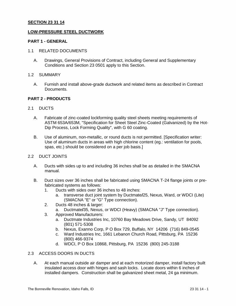
The Bonneville Renovation, Idaho Falls, ID 23 31 14 - 1
SECTION 23 31 14
LOW-PRESSURE STEEL DUCTWORK
PART 1 - GENERAL
1.1 RELATED DOCUMENTS
A. Drawings, General Provisions of Contract, including General and Supplementary Conditions and Section 23 0501 apply to this Section.
1.2 SUMMARY
A. Furnish and install above-grade ductwork and related items as described in Contract Documents.
PART 2 - PRODUCTS
2.1 DUCTS
A. Fabricate of zinc-coated lockforming quality steel sheets meeting requirements of ASTM 653A/653M, "Specification for Sheet Steel Zinc-Coated (Galvanized) by the Hot-Dip Process, Lock Forming Quality", with G 60 coating.
B. Use of aluminum, non-metallic, or round ducts is not permitted. [Specification writer: Use of aluminum ducts in areas with high chlorine content (eg.: ventilation for pools, spas, etc.) should be considered on a per job basis.]
2.2 DUCT JOINTS
A. Ducts with sides up to and including 36 inches shall be as detailed in the SMACNA manual.
B. Duct sizes over 36 inches shall be fabricated using SMACNA T-24 flange joints or pre-fabricated systems as follows: 1. Ducts with sides over 36 inches to 48 inches:
a. transverse duct joint system by Ductmate/25, Nexus, Ward, or WDCI (Lite) (SMACNA "E" or "G" Type connection).
2. Ducts 48 inches & larger: a. Ductmate/35, Nexus, or WDCI (Heavy) (SMACNA "J" Type connection).
3. Approved Manufacturers: a. Ductmate Industries Inc, 10760 Bay Meadows Drive, Sandy, UT 84092
(801) 571-5308 b. Nexus, Exanno Corp, P O Box 729, Buffalo, NY 14206 (716) 849-0545 c. Ward Industries Inc, 1661 Lebanon Church Road, Pittsburg, PA 15236
(800) 466-9374 d. WDCI, P O Box 10868, Pittsburg, PA 15236 (800) 245-3188
2.3 ACCESS DOORS IN DUCTS
A. At each manual outside air damper and at each motorized damper, install factory built insulated access door with hinges and sash locks. Locate doors within 6 inches of installed dampers. Construction shall be galvanized sheet metal, 24 ga minimum.

The Bonneville Renovation, Idaho Falls, ID 23 31 14 - 2
B. Fire and smoke damper access doors shall have a minimum clear opening of 12" x 12" or as specified on Drawings to easily service fire or smoke damper. Doors shall be within 6 inches of fire and smoke dampers and in Mechanical Room if possible.
C. Identify each door with 1/2" high letters reading “smoke damper” or “fire damper”.
D. Approved Manufacturers: 1. AirBalance - Fire/Seal #FSA 100 2. Air Control Products - HAD-10 3. Cesco-Advanced Air - HAD-10 4. Elgen - Model 85 A 5. Kees Inc - ADH-D. 6. Louvers & Dampers - #SMD-G-F 7. Nailor-Hart Industries Inc - Series 0831 8. National Controlled Air Inc - Model AD-FL-1
2.4 FLEXIBLE EQUIPMENT CONNECTIONS
A. 30 oz closely woven UL approved glass fabric, double coated with neoprene.
B. Fire retardant, waterproof, air-tight, resistant to acids and grease, and withstand constant temperatures of 250 deg F.
C. Approved Manufacturers: 1. Cain - N-100 2. Duro Dyne - MFN 3. Elgen - ZLN 4. Ventfabrics - Ventglas
2.5 CONCEALED CEILING DAMPER REGULATORS
A. Approved Manufacturers: 1. Cain 2. Duro Dyne 3. Metco Inc 4. Vent-Lock - #666 5. Young - #303
2.6 VOLUME DAMPERS
A. In Main Ducts: 1. 16 gauge galvanized steel, opposed blade type with 3/8 inch pins and end
bearings. Blades shall have 1/8 inch clearance all around. 2. Damper shall operate within acoustical duct liner. 3. Provide channel spacer equal to thickness of duct liner. 4. Approved Manufacturers:
a. Air Balance - Model AC-2 b. Air Control Products - CD-OB c. American Warming - VC-2-AA d. Greenheck - VCD-1100 e. NCA, Safe Air f. Vent Products - 5100
B. In Sheet Metal Branch Ducts:

The Bonneville Renovation, Idaho Falls, ID 23 31 14 - 3
1. Extruded aluminum, opposed blade type. When in open position, shall not extend beyond damper frame.
2. Maximum blade length 12 inches. 3. Damper Regulator shall be concealed type with operation from bottom or with 90
deg miter gear assembly from side. 4. Approved Manufacturers:
a. Air Control Products - TCD-OB b. Air Guide - OB c. Arrow - OBDAF-207 d. CESCO - CDA e. Reliable Metals - OBD-RO f. Tuttle & Bailey - A7RDDM g. Safe Air h. Young - 820-AC
C. Dampers above removable ceiling and in Mechanical Rooms shall have locking quadrant on bottom or side of duct. Otherwise, provide concealed ceiling damper regulator and cover plate.
2.7 MOTORIZED OUTSIDE AIR DAMPERS
A. Damper Blades: 1. 18 gauge galvanized steel or equivalent aluminum with replaceable rubber blade
edges, 9 inches wide maximum. 2. End seals shall be flexible metal compression type. 3. Opposed blade type.
B. Make provision for damper actuators and actuator linkages to be mounted external of air flow.
C. Approved Manufacturers & Models: 1. Air Balance - AC-2 2. American Warming - VC-2-AAVA 3. Arrow - OBDAF-207 4. Greenheck - VCD-2100 5. Honeywell - D641 6. Johnson - D1300 7. Louvers & Dampers - TSD400 8. Ruskin - CD36 or CD60 9. Safe Air - 610 10. Vent Products - 5800
2.8 BACKDRAFT DAMPER
A. Backdraft blades shall be nonmetallic and shall be neoprene coated fiberglass.
B. Stop shall be galvanized steel screen or expanded metal, 1/2 inch mesh.
C. Frame shall be galvanized steel or extruded aluminum alloy.
D. Approved Models & Manufacturers: 1. Air Control Products - FBD 2. American Warming - BD-15 3. CESCO - FBD 101 4. Ruskin - NMS2

The Bonneville Renovation, Idaho Falls, ID 23 31 14 - 4
5. Safe Air
2.9 DUCT HANGERS
A. 1" x 18 gauge galvanized steel straps or steel rods as shown on Drawings, and spaced not more than 8 feet apart. Do not use wire hangers.
B. Attaching screws at trusses shall be 1-1/2 inch No. 10 round head wood screws. Nails not allowed.
2.10 DUCT SEALER
A. Cain - Duct Butter or Butter Tak
B. Design Polymerics - DP 1010
C. DSC - Stretch Coat
D. Duro Dyne - S2
E. Hardcast - #601 Iron-Grip or Peel-N-Seal Tape 1. Kingco - 15-325 2. Mon-Eco - 44-41 3. Trans-Continental Equipment Co - Multipurpose Duct Sealant 4. United - Sheet Metal duct-sealer
PART 3 - EXECUTION
3.1 INSTALLATION
A. Ducts: 1. Straight and smooth on inside with joints neatly finished unless otherwise
directed. 2. Duct panels through 48 inch dimension having acoustic duct liner need not be
crossbroken or beaded. 3. Crossbreak unlined ducts and duct panels larger than 48 inch or bead 12 inches
on center. 4. Securely anchor ducts to building structure with specified duct hangers attached
with screws. Do not hang more than one duct from a duct hanger. 5. Brace and install ducts so they shall be free of vibration under all conditions of
operation. 6. Ducts shall not bear on top of structural members. 7. Make duct take-offs to branches, registers, grilles, and diffusers as detailed on
Drawings. 8. Ducts shall be large enough to accommodate inside acoustic duct liner.
Dimensions shown on Drawings are net clear inside dimensions after duct liner has been installed.
9. Properly flash where ducts protrude above roof. 10. Install internal ends of slip joints in direction of flow. Make joints air tight using
specified duct sealer. 11. Cover horizontal and longitudinal joints on exterior ducts with two layers of
Hardcast tape installed with Hardcast HC-20 adhesive according to Manufacturer's recommendations.
12. Paint ductwork visible through registers, grilles, and diffusers flat black.

The Bonneville Renovation, Idaho Falls, ID 23 31 14 - 5
B. Install flexible inlet and outlet duct connections to each furnace, fan, fan coil unit, and air handling unit.
C. Install concealed ceiling damper regulators. 1. Paint cover plates to match ceiling tile. 2. Damper regulators will not be required for dampers located directly above
removable ceilings or in Mechanical Rooms.
D. Provide each take-off with an adjustable volume damper to balance that branch. 1. Anchor dampers securely to duct. 2. Install dampers in main ducts within insulation. 3. Dampers in branch ducts shall fit against sheet metal walls, bottom and top of
duct, and be securely fastened. Cut duct liner to allow damper to fit against sheet metal.
4. Where concealed ceiling damper regulators are installed, provide a cover plate.
E. Install grilles, registers, and diffusers. Level floor registers and anchor securely into floor.
F. Air Turns: 1. Permanently installed, consisting of single thickness curved metal blades with
one inch straight trailing edge to permit air to make abrupt turn without appreciable turbulence, in 90 degree elbows of above ground supply and return ductwork.
2. 4-1/2 inch wide minimum vane rail. Do not use junior vane rails. 3. Double thickness vanes not acceptable. 4. Quiet and free from vibration when system is in operation. See SMACNA Manual
G. Install motorized dampers
END OF SECTION

The Bonneville Renovation, Idaho Falls, ID 23 33 46 - 1
SECTION 23 33 46
FLEX DUCT
PART 1 - GENERAL
1.1 RELATED DOCUMENTS
A. Drawings, General Provisions of Contract, including General and Supplementary Conditions and Section 23 0501 apply to this Section.
1.2 SUMMARY
A. Furnish and install supply air branch duct runouts to diffusers as described in Contract Documents.
PART 2 - PRODUCTS
2.1 DUCTS
A. Formable, flexible, circular duct which shall retain its cross-section, shape, rigidity, and shall not restrict air flow after bending.
B. Nominal 1-1/2 inches thick, 3/4 lb/cu ft density fiberglass insulation with air-tight, polyehtylene or polyester core, sheathed in seamless vapor barrier jacket factory installed over flexible assembly.
C. Assembly, including insulation and vapor barrier, shall meet Class I requirement of NFPA 90A and be UL 181 rated, with flame spread of 25 or less and smoke developed rating of 50 or under.
D. Length of flexible ductwork shall not exceed 8'-0".
2.2 APPROVED MANUFACTURERS
A. ANCO-FLEX - 4625
B. Flex-Aire - PF/UPC #090
C. Hart & Cooley - F114
D. Thermaflex - G-KM
PART 3 - EXECUTION
3.1 INSTALLATION
A. Install duct in fully extended condition free of sags and kinks.
B. Make duct connections by coating exterior of duct collar for 3 inches with duct sealer and securing duct in place over sheet metal collar with 1/2 inch wide metal cinch bands and sheet metal screws.
END OF SECTION

The Bonneville Renovation, Idaho Falls, ID 23 34 00 - 1
SECTION 23 34 00
EXHAUST FANS
PART 1 - GENERAL
1.1 RELATED DOCUMENTS
A. Drawings, General Provisions of Contract, including General and Supplementary Conditions and Section 23 0501 apply to this Section.
1.2 SUMMARY
A. Furnish and install exhaust fans as described in Contract Documents.
1.3 QUALITY ASSURANCES
A. Requirements of Regulatory Agencies: 1. Bear AMCA seal and UL label.
PART 2 - PRODUCTS
2.1 CEILING MOUNTED EXHAUST FANS
A. Acoustically insulated housings.
B. Sound level rating of 4.6 sones maximum for fan RPM and CFM listed on Drawings.
C. Include chatterproof integral back-draft damper with no metal to metal contact.
D. True centrifugal wheels.
E. Entire fan, motor, and wheel assembly shall be easily removable without disturbing housing.
F. Suitably ground motors and mount on rubber-in shear vibration isolators.
G. Provide wall or roof cap, as required.
H. Approved Manufacturers: 1. Cook-Gemini 2. Greenheck Sp 3. Pace 4. Penn Zephyr
2.2 ROOF MOUNTED EXHAUST FANS
A. Direct drive or have adjustable pitch V-belt as noted on Drawings.
B. Wheels shall be backward curved and housing shall be removable or hinged aluminum.
C. Isolate motor with vibration dampeners.
D. Provide quiet type back-draft dampers.

The Bonneville Renovation, Idaho Falls, ID 23 34 00 - 2
E. Insulated, pre-fabricated metal roof curb shall be for flat or sloped roof as shown on Drawings.
F. Approved Manufacturers: 1. Fans:
a. Penn b. Centri-Master c. Cook d. Greenheck G, GB
2. Standard curbs: a. Penn b. Cook c. Greenheck
3. Sound attenuating curbs: a. Penn b. Greenheck
PART 3 - EXECUTION
3.1 INSTALLATION
A. Anchor fan units securely to structure or curb. END OF SECTION

The Bonneville Renovation, Idaho Falls, ID 23 37 13 - 1
SECTION 23 37 13
AIR OUTLETS & INLETS
PART 1 - GENERAL
1.1 RELATED DOCUMENTS
A. Drawings, General Provisions of Contract, including General and Supplementary Conditions and Section 23 0501 apply to this Section.
1.2 SUMMARY
A. Furnish and install wall supply registers, transfer grilles, return air grilles, soffit grilles, ceiling diffusers, louvers connected to ductwork, and registers as described in Contract Documents.
PART 2 - PRODUCTS
2.1 GRILLES & REGISTERS
A. Approved Manufacturers: 1. Price 2. Anemostat 3. Krueger 4. Titus 5. Tuttle & Bailey
2.2 SPIN-IN FITTINGS
A. Low pressure round take-offs to diffusers shall be made with spin-in fittings. They shall incorporate a manual balancing damper. The damper shall be spring loaded and a positive locking wing nut shall secure the damper position.
B. Approved Manufacturers: 1. Sheet metal fittings: Genflex DB-1DEL, Hercules
2.3 ROOF MOUNTED INLETS AND OUTLETS
A. FABRICATION 1. Penthouse type of extruded aluminum complete with roof curb to fit slope of roof
and ½ inch mesh 16 gauge aluminum bird screen.
B. APPROVED MANUFACTURERS & MODELS 1. Tiered Type:
a. Model TRE extruded aluminum ventilator by Loren Cook Company, Springfield Missouri
2. Louvered Penthouse a. Penn “Penhouse” b. Model WRH by Greenheck Fan Corporation, Schofield, WI c. Model MPH by Jenn-Air Industries Inc., Indianapolis, IN

The Bonneville Renovation, Idaho Falls, ID 23 37 13 - 2
PART 3 - EXECUTION
3.1 INSTALLATION
A. Anchor securely into openings.
B. Install with screws to match color and finish of grilles and registers.
C. Touch-up any scratched finish surfaces.
D. Install in accordance with manufacturer's instructions.
E. Check location of outlets and inlets and make necessary adjustments in position to conform with architectural features, symmetry, and lighting arrangement.
F. Install diffusers to ductwork with air tight connection.
G. Provide balancing dampers on duct take-off to diffusers, and grilles and registers, despite whether dampers are specified as part of the diffuser, or grille and register assembly.
H. Paint ductwork visible behind air outlets and inlets matte black. Refer to Section 09 9000.
END OF SECTION

The Bonneville Renovation, Idaho Falls, ID 23 52 30 - 1
SECTION 23 52 30
GAS BOILER
PART 1 - GENERAL
1.1 SUMMARY
A. Furnish and install complete with flues the gas fired boilers described in the contract documents.
PART 2 - PRODUCTS
2.1 The Boiler shall bear the ASME “H” stamp for 160 psi working pressure and shall be National Board listed. There shall be no banding material, bolts, gaskets or "O" rings in the header configuration. The 316L stainless steel combustion chamber shall be designed to drain condensation to the bottom of the heat exchanger assembly. A built-in trap shall allow condensation to drain from the heat exchanger assembly. The complete heat exchanger assembly shall carry a ten (10) year limited warranty.
2.2 The Boiler shall be certified and listed by C.S.A. International under the latest edition of the harmonized ANSI Z21.13 test standard for the U.S. and Canada. The BOILER shall comply with the energy efficiency requirements of the latest edition of the ASHRAE 90.1 Standard and the minimum efficiency requirements of the latest edition of the BTS2000 Standard. The BOILER shall operate at a minimum of 93% thermal efficiency at full fire on 399,999 and 500,000 Btu/hr models and at a minimum 94% thermal efficiency at full fire on 600,000, 700,000 and 800,000 Btu/hr models. All models shall operate up to 98% thermal efficiency with return water temperatures at 100°F or below. The BOILER shall be certified for indoor installation. The BOILER’s Thermal Efficiency shall be verified through third party testing by the Hydronics Institute Division of AHRI and listed in the AHRI Certification Directory.
2.3 The Boiler shall be constructed with a heavy gauge steel jacket assembly, primed and pre-painted on both sides. The combustion chamber shall be sealed and completely enclosed, independent of the outer jacket assembly, so that integrity of the outer jacket does not affect a proper seal. A burner/flame observation port shall be provided. The burner shall be a premix design and constructed of high temperature stainless steel with a woven metal fiber outer covering to provide modulating firing rates. The BOILER shall be supplied with a gas valve designed with negative pressure regulation and be equipped with a variable speed blower system, to precisely control the fuel/air mixture to provide modulating boiler firing rates for maximum efficiency. The BOILER shall operate in a safe condition at a derated output with gas supply pressures as low as 4 inches of water column. The BOILER shall be equipped with leveling legs.
2.4 The Boiler shall utilize a 24 VAC control circuit and components. The control system shall have an electronic display for boiler set-up, boiler status, and boiler diagnostics. All components shall be easily accessed and serviceable from the front and top of the jacket. The BOILER shall be equipped with; a temperature/pressure gauge, high limit temperature control certified to UL353, ASME certified pressure relief valve, outlet water temperature sensor, return water temperature sensor, a UL 353 certified flue temperature sensor, outdoor air sensor, low water flow protection and built-in adjustable freeze protection.
2.5 The Boiler shall feature the “Smart System” control with a Multi-Colored Graphic LCD display with Navigation Dial and Soft Keys for, password security, three loop

The Bonneville Renovation, Idaho Falls, ID 23 52 30 - 2
temperature setpoints with individual outdoor air reset curves, pump delay with adjustable freeze protection, pump exercise, domestic hot water prioritization with DHW modulation limiting and USB PC port connection. The BOILER shall be capable of controlling a variable speed boiler pump to keep a constant Delta T at all modulation rates. The BOILER shall have the capability to accept a 0-10 VDC input connection for BMS control of modulation or setpoint, enable disable of the boiler, variable system pump signal and a 0-10VDC output of boiler modulation rate. The Boiler shall have a built-in “Cascade” with sequencing options for “lead lag” or “efficiency optimized” modulation logic, with both capable of rotation while maintaining modulation of up to eight boilers without utilization of an external controller. Supply voltage shall be 120 volt / 60 hertz / single phase.
2.6 The Boiler shall be equipped with two terminal strips for electrical connection. A low voltage connection board with 42 data points for safety and operating controls, i.e., Auxiliary Relay, Auxiliary Proving Switch, Alarm Contacts, Runtime Contacts, Manual Reset Low Water Cutoff, Flow Switch, High and Low Gas Pressure Switches, Tank Thermostat, Three Wall Thermostat/Zone Controls, System Supply Sensor, Outdoor Sensor, Building Management System Signal, Modbus Control Contacts and Cascade Control Circuit. A high voltage terminal strip shall be provided for supply voltage. The high voltage terminal strip plus integral relays are provided for independent pump control of the System pump, the Boiler pump and the Domestic Hot Water pump.
2.7 BOILER
A. The Boiler shall have an independent laboratory rating for Oxides of Nitrogen (NOx) of 20 ppm or less corrected to 3% O2. The manufacturer shall verify proper operation of the burner, all controls and the heat exchanger by connection to water and venting for a factory fire test prior to shipping.
B. The Boiler shall operate at altitudes up to 4,500 feet above sea level without additional parts or adjustments.
C. The Boiler shall be started up, adjusted and checked out by a manufacturer’s authorized service agency. A start-up report shall be submitted to the owner and the contractor for inclusion in the O&M Manuals.
2.8 MANUFACTURERS
A. Lochinvar XL
B. Laars – Neotherm
C. AERCO Benchmark
2.9 BUFFER TANK
A. Furnish and install in the system where shown a “Buffer Tank” or “Low Loss Header” as required by the boiler system design and recommended by the boiler manufacturer.
B. The Unit shall have flanged connections to match the heating pipe connections and shall include a high capacity air vent at the top and a ball valve drain at the bottom piped to the floor drain.
C. Units shall be rated for 250 gpm primary system flow and 60 gpm Boiler flow.
D. Manufacturers:

The Bonneville Renovation, Idaho Falls, ID 23 52 30 - 3
1. Lochinvar “Buffer Tank”
2. Spirovent “Quad”
END OF SECTION

The Bonneville Renovation, Idaho Falls, ID 23 54 17 - 1
SECTION 23 5417
HIGH EFFICIENCY NATURAL GAS FURNACE
PART 1 - GENERAL
1.1 RELATED DOCUMENTS
A. Drawings, General Provisions of Contract, including General and Supplementary Conditions and other Division 1 Specification Sections, and Section 23 0501 apply to this Section.
1.2 SUMMARY
A. Furnish and install gas fired condensing high efficiency furnace as described in Contract Documents.
PART 2 - PRODUCTS
2.1 MANUFACTURED UNITS
A. Fabrication: 1. Furnaces shall be factory assembled units certified by AGA complete with blower
section, furnace section, condensing coil, steel casing, piped, and wired. 2. Blower section shall consist of cabinet, blower, and motor. 3. Cabinet shall be of 22 gauge minimum cold rolled steel and have finish coat of
baked-on enamel. 4. Blower shall be Class 1, full DIDW, statically and dynamically balanced. 5. Filters shall be one inch thick pleated throw-away type as furnished by furnace
manufacturer. 6. Provide furnace with accessory side mounted filter box frame and factory
available bottom closure. 7. Automatic controls:
a. 100% cut-off safety pilot b. Manual gas shut-off valve c. 0perating automatic gas valve d. Solid state type fan and thermal limit controls e. 24 volt transformer f. Electronic ignition system g. Pressure switch safety for induced draft fan
B. Units: 1. Blower shall be driven by motor with adjustable pitch V-belt drive or by a multi-
speed direct driven motor. 2. Furnace section shall be enclosed in 22 gauge minimum enameled steel casing
lined with foil covered insulation. 3. Heat exchanger shall be ceramic or glass coated, stainless steel, or 18 gauge
aluminized steel with 20 year minimum limited warranty. 4. Units shall be rated at 93% minimum AFUE (Annual Fuel Utilization Efficiency)
calculated in accordance with DOE test procedures. 5. 2" or 3" intake and exhaust lines to outside with factory furnished combination
flue/intake assembly for roof or sidewall.
C. Provide with Web enabled 7 day programmable thermostat equal to Honeywell

The Bonneville Renovation, Idaho Falls, ID 23 54 17 - 2
Prestige.
D. Approved Manufacturers: 1. Lennox 2. Carrier 3. Bryant 4. Trane
PART 3 - EXECUTION
3.1 FIELD QUALITY CONTROL
A. Quality Assurance: Furnace manufacturer's representative shall start up and check out furnace equipment as follows: 1. Verify proper gas orifice sizing for altitude. 2. Clock gas meter for rated input. 3. Verify and set gas pressure at furnace. 4. Check and measure temperature rise. 5. Check safety controls for proper operation.
END OF SECTION

The Bonneville Renovation, Idaho Falls, ID 23 55 40 - 1
SECTION 23 55 40
ELECTRIC RADIANT WALL HEATERS
PART 1 - GENERAL
1.1 RELATED DOCUMENTS
A. Drawings, General Provisions of Contract, including General and Supplementary Conditions and other Division 1 Specification Sections, and Section 23 0501 apply to this Section.
1.2 SUMMARY
A. Furnish and install wall heaters as described in Contract Documents.
1.3 QUALITY ASSURANCE
A. Units shall be UL listed and comply with NEC.
PART 2 - PRODUCTS
2.1 MANUFACTURED UNITS
A. Fan type for recess mounting in wall.
B. 20 gauge minimum sheet metal casing.
C. Heating element shall be encased in steel finned casting and protected by thermal switch.
D. Fan motor shall be heavy duty enclosed and permanently lubricated.
E. Fan shall be precision balanced and fan-motor assembly mounted to be vibration free.
F. Units shall be controlled automatically by integral thermostat when heater is in "ON" position.
G. Heater shall have built-in fan delay.
H. Finish - Baked-on enamel.
I. Approved Manufacturers: 1. Q' Mark 2. Berko 3. Thermador 4. Markel
END OF SECTION

The Bonneville Renovation, Idaho Falls, ID 23 62 13 - 1
SECTION 23 62 13
AIR-COOLED CONDENSING UNITS
PART 1 - GENERAL
1.1 RELATED DOCUMENTS
A. Drawings, General Provisions of Contract, including General and Supplementary Conditions and other Division 1 Specification Sections, and Section 23 0501 apply to this Section.
1.2 SUMMARY
A. Furnish and install condensing units as described in Contract Documents.
1.3 WARRANTY
A. Five-year warranty on compressors. 1. Warranty time frame shall be five years from date of "start-up". "Start-up" date
shall be recorded on warranty certificate for each unit.
PART 2 - PRODUCTS
2.1 TWO TON THROUGH FIVE TON UNITS
A. Condenser coil shall have aluminum plate fins mechanically bonded to seamless copper tubes. 1. Provide coil guard for unit.
B. Fans shall be direct driven propeller upflow type. 1. Fan motor shall be single or two speed, thermostatically controlled, permanently
lubricated, and designed with permanent protection and ball bearings. 2. Motors shall be resiliently mounted. 3. Each fan shall have a safety guard.
C. Units shall be operable down to 0 deg F outdoor temperature.
D. Compressor shall be of hermetic design with the following features. Each condenser unit shall have only one compressor. 1. Externally mounted brass service valves with charging connections. 2. Crankcase heater. 3. Resilient rubber mounts. 4. Compressor motor overload protection. 5. Single speed
E. Controls: 1. Factory wired and located in separate enclosure. 2. Safety devices shall consist of high and low pressure cutout and condenser fan
motor overload devices. 3. Unit shall have anti-cycle timers to prevent units from starting up again for five
minutes after any power interruption.
F. Casing:

The Bonneville Renovation, Idaho Falls, ID 23 62 13 - 2
1. Fully weatherproof for outdoor installation. Finish shall be weather resistant. 2. Openings shall be provided for power and refrigerant connections. 3. Panels shall be removable for servicing.
G. Expansion Valves: 1. Stainless steel diaphragm and same refrigerant in thermostatic elements as in
system. Externally or internally equalized as required by evaporator/condensing system.
2. Size valves to provide full rated capacity of cooling coil served. 3. Furnished by evaporator coil/condensing unit supplier and coordinated to provide
bleed holes for system pressure equalization, if required.
H. Condensing units shall use R-410A refrigerant. Only one liquid line, one suction line, and one power connection shall be made to each compressor. Provide charging valves.
I. SEER rating as defined by ARI shall be not less than 13.0.
J. Set each unit on neoprene isolation pads located at each corner and sized 4" x 4" x 3/4" high minimum.
K. Approved Manufacturers: 1. Bryant 2. Carrier 3. Lennox 4. Trane
PART 3 - EXECUTION
3.1 INSTALLATION
A. Set condensing units as detailed on the drawings.
3.2 FIELD QUALITY CONTROL
A. Manufacturer's Field Service:
B. Condensing units shall be started up, checked out, and adjusted by Condensing Unit Manufacturer's authorized factory trained service mechanic.
C. Mechanic shall use check-out sheet provided by Manufacturer, complete and sign all items on sheet, and submit to Architect.
END OF SECTION

The Bonneville Renovation, Idaho Falls, ID 23 65 14 - 1
SECTION 23 65 14 COOLING TOWER PART 1 - GENERAL 1.1 SECTION INCLUDES
A. Furnish an induced draft, counter-flow, factory-assembled cooling tower, manufactured by REYMSA Cooling Towers, Inc., and equal in all respects to REYMSA RT-505103-B cooling tower model. The cooling tower consists of one (01) basin section, one (01) body section and one(01) fan ducts.
1.2 THERMAL PERFORMANCE A. The cooling tower has the capacity to cool 277 U.S. GPM of water, from 95 Deg. F to
85 Deg. F, at a design entering air wet-bulb temperature of 65 Deg. F B. Thermal performance is certified by the Cooling Technology Institute (CTI) in
accordance with CTI Certification Standard STD-201. In addition, the manufacturer guarantees that the cooling tower meet the specified performance conditions when installed according to plans and per the guidelines established in the cooling tower manufacturer’s Installation, Operation & Maintenance (IOM) Manual.
1.3 CONSTRUCTION A. The cooling tower are designed and constructed to withstand wind pressure of no
less than 30 pounds-force per square foot (psf) on external surfaces. The top of the cooling tower’s body is designed and constructed to withstand a live load of no less than 40 pounds-force per square foot (psf) in addition to the concentrated loads of the fan or other equipment mounted thereon.
1.4 BASIN SECTION A. The Cooling Tower has one(01) seamless piece basin section, water-tight and leak-
proof, constructed of high-performance resins with corrosion-resistant Fiberglass Reinforced Polyester (FRP) with Ultraviolet (UV) resistant. The Fiberglass Reinforced Polyester (FRP) walls must have a thickness no less than 1/4 inch; also to ensure the structural strength, the framing structural members, the basin’s structure, walls and bottom must be specially reinforced. A high grade Isophthalic Polyester Resin with UV inhibitor is only be used for the manufacturing process. No side fasteners will be allowed in the sidewalls of the basin. There are no metal supports or structure in direct contact with water
Following water connections are furnished:
Hot Water Inlet (in): 6 Water make-up (in): 1 Cold Water Outlet (in): 10
Drain (in): 1 1/2
Overflow (in): 1 1/2 Purge (in): 3/4 B. Fittings of 3 inch and smaller are NPT, and fittings larger than 3 inch use ANSI
flange. For remote sump application a standard make-up water mechanical float valve, a make up water connection, a drain connection, an overflow connection are NOT provided.
1.5 BODY SECTION A. The Cooling Tower has one(01) seamless piece body section, water-tight and leak-
proof, constructed of high-performance resins with corrosion-resistant Fiberglass Reinforced Polyester (FRP) with Ultraviolet (UV) resistant. The Fiberglass

The Bonneville Renovation, Idaho Falls, ID 23 65 14 - 2
Reinforced Polyester (FRP) walls must have a thickness no less than 1/4 inch; also to ensure the structural strength, the framing structural members, the body’s structure, and the top cover, must be specially reinforced. A high grade Isophthalic Polyester Resin with UV inhibitor is only be used for the manufacturing process.
1.6 FAN DUCT A. The Cooling Tower has one (01) fan duct, constructed of high-performance
corrosion-resistant Fiberglass Reinforced Polyester (FRP) with Ultraviolet (UV) resistant resins. Fiberglass Reinforced Polyester (FRP) material has a thickness no less than1/4 inch; the fan duct are specially reinforced to ensure its structural strength. The fan Duct contains a direct-drive fan, a motor mounted on an FRP structure, and a corrosion-resistant safety screen mesh (also known as fan guard).
PART 2.0 - MECHANICAL EQUIPMENT 2.1 LOW SOUND FAN
A. The cooling tower has one(01) fan. Fan is direct-drive, with axial, propeller type, adjustable-pitch fan blades. Fan blades are manufactured of spark and corrosion resistant Fiberglass Reinforced Polyamide (PAG), and are suitable for operation on a temperature range of -50 Deg. F (-45 Deg. C) to 250 Deg. F (120 Deg. C). Fan hubs are manufactured of a pressure die cast aluminum alloy.
2.2 FAN MOTORS A. The cooling tower has one(01) fan motor, rated at 7.5 HP and 700 RPM. B. The fan motor is single speed, Totally Enclosed Air Over (TEAO), and are suitable
for 230/460 Volts, 3 phases, 60Hz, continuous operation, 1.15 service factor on sine wave, NEMA Premium efficiency, severe duty – IEEE841, marine duty – meets IEEE45 IP56, and inverter rated. Fan motor’s construction is 100% cast iron and has Class F Insulation System. The fan motor meets NEMA MG1 – 1.26.6, has a Division 2 CSA certification nameplate for hazardous locations, Class I Groups A, B, C and D, and is Underwriters Laboratories (UL) Recognized CSA Certified.
2.3 FILL MEDIA MODULES A. Fill media modules are fabricated from rigid, corrugated UV protected Polyvinyl
Chloride (PVC) sheets that are conducive to cooling water. Polyvinyl Chloride (PVC) corrugated sheets form a cross-corrugated pattern with an angle of 60 degrees from the horizontal between adjacent sheets, to provide a continuous and horizontal redistribution of air and water. Fill media modules provide no less than 69 ft2/ft3 of surface area and a void-to-volume ratio of 95%. The manufacturing material, Polyvinyl Chloride (PVC), are resistant to rot, fungi, bacteria and organic/inorganic acids and alkalis as commonly found in cooling towers; and meet CTI STD-136. Fill media modules’ flame spread rating is less than 20 according to ASTM E84; and regarding flammability, fill media is self-extinguishing in less than 5 seconds according to ASTM D635.
2.4 DRIFT ELIMINATORS A. Drift eliminators are fabricated from rigid, corrugated UV protected Polyvinyl Chloride
(PVC) sheets and is furnished in lightweight, easily removable sections with 2 changes in air direction to remove entrained water particles from the leaving airstream. Drift losses not exceed 0.0005% of the design circulating flow. The manufacturing material, Polyvinyl Chloride (PVC), are resistant to rot, fungi, bacteria and organic/inorganic acids and alkalis as commonly found in cooling towers, and meet CTI STD-136. Drift eliminators’ flame spread rating is less than 25 according to ASTM E84, and regarding flammability, drift eliminators are self-extinguishing.
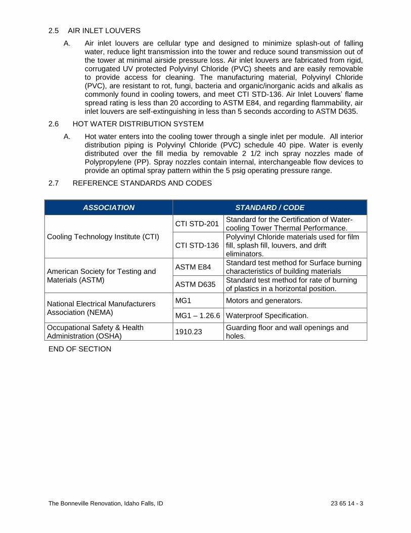
The Bonneville Renovation, Idaho Falls, ID 23 65 14 - 3
2.5 AIR INLET LOUVERS A. Air inlet louvers are cellular type and designed to minimize splash-out of falling
water, reduce light transmission into the tower and reduce sound transmission out of the tower at minimal airside pressure loss. Air inlet louvers are fabricated from rigid, corrugated UV protected Polyvinyl Chloride (PVC) sheets and are easily removable to provide access for cleaning. The manufacturing material, Polyvinyl Chloride (PVC), are resistant to rot, fungi, bacteria and organic/inorganic acids and alkalis as commonly found in cooling towers, and meet CTI STD-136. Air Inlet Louvers’ flame spread rating is less than 20 according to ASTM E84, and regarding flammability, air inlet louvers are self-extinguishing in less than 5 seconds according to ASTM D635.
2.6 HOT WATER DISTRIBUTION SYSTEM A. Hot water enters into the cooling tower through a single inlet per module. All interior
distribution piping is Polyvinyl Chloride (PVC) schedule 40 pipe. Water is evenly distributed over the fill media by removable 2 1/2 inch spray nozzles made of Polypropylene (PP). Spray nozzles contain internal, interchangeable flow devices to provide an optimal spray pattern within the 5 psig operating pressure range.
2.7 REFERENCE STANDARDS AND CODES
ASSOCIATION STANDARD / CODE
Cooling Technology Institute (CTI)
CTI STD-201 Standard for the Certification of Water-cooling Tower Thermal Performance.
CTI STD-136 Polyvinyl Chloride materials used for film fill, splash fill, louvers, and drift eliminators.
American Society for Testing and Materials (ASTM)
ASTM E84 Standard test method for Surface burning characteristics of building materials
ASTM D635 Standard test method for rate of burning of plastics in a horizontal position.
National Electrical Manufacturers Association (NEMA)
MG1 Motors and generators.
MG1 – 1.26.6 Waterproof Specification. Occupational Safety & Health Administration (OSHA) 1910.23 Guarding floor and wall openings and
holes.
END OF SECTION

The Bonneville Renovation, Idaho Falls, ID 23 81 29 - 1
SECTION 23 81 29
VRF SYSTEM – OUTDOOR UNITS VARIABLE REFRIGERANT FLOW (6 TO 48 TONS NOMINAL) PART 1 - PRODUCT DESCRIPTION
1.1 RELATED DOCUMENTS
A. Variable Refrigerant Flow (VRF) HVAC system shall be a variable capacity, direct expansion (DX) heat recovery or heat pump engineered system. The water source unit shall consist of one or more cabinet(s) connected through common refrigerant piping, with built-in refrigerant to water heat exchanger for integration with field provided boiler/cooling tower and/or geothermal heat sink systems. Each water source system shall have (1) inverter compressor. Each system shall be connected to multiple indoor units (ducted, non-ducted or combination thereof) refrigerant piping and integrated system controls. Each indoor unit shall be capable of providing individual zone control. Additionally the heat recovery system shall be capable of simultaneous heating and cooling individual zone(s).
1.1 SIMULTANEOUS COOLING AND HEATING VRF SYSTEM
A. LG Multi V Water IV VRF (Heat Recovery System)
B. LG Multi V Water IV heat recovery system shall be a 3-pipe, water source heat pump system consisting of one to three water source unit(s) connected to Heat Recovery (HRU) unit(s) and multiple indoor units. Multi-port heat recovery units shall allow simultaneous heating and cooling of individual zone(s).
C. The heat recovery system shall be capable of operating with<208/230V>or<460V>, 60Hz, 3 phase power.
PART 2 - STANDARDS / CERTIFICATIONS
A. LG Multi V Water IV VRF (variable refrigerant flow) heat pump and heat recovery systems shall have published performance ratings certified by AHRI (Air-Conditioning, Heating, and Refrigeration Institute) and listed in the AHRI Standard 1230 certified product directory.
B. LG Multi V Water IV VRF heat pump and heat recovery system components shall be
manufactured in production facilities maintaining the following ISO certifications: a) ISO 9001 Quality Management System b) ISO 14001 Environmental Management System
C. LG Multi V Water IV VRF heat pump and heat recovery system components shall
comply with Underwriters Laboratories (UL) 1995 Heating and Cooling Equipment Standard for Safety and bear the Electrical Testing Laboratories (ETL) label.

The Bonneville Renovation, Idaho Falls, ID 23 81 29 - 2
D. LG Multi V Water IV VRF heat pump and heat recovery system field provided power wiring shall be installed according to National Electrical Code (NEC) and all applicable state and local building codes.
PART 3 - WARRANTY
A. Please refer to LG web site www.lg-hvac.com for applicable warranty.
PART 4 - LG MULTI V Water IV VRF(HEAT RECOVERY/HEAT PUMP SYSTEM)
A. Water source Unit shall be capable of the following operating ambient range. 1. Heat Recovery System
a. Cooling and simultaneous mode 1. Entering water range temperature: 23°F to 113°F
b. Heating mode 1. Entering water range temperature: 23°F to 113°F
2. Heat Pump System
a. Cooling mode 1. Entering water range temperature: 23°F to 113°F
b. Heating mode 2. Entering water range temperature: 23°F to 113°F
3. Geothermal operating range: 23°F (Heating only)
B. General
1. The air-conditioning system shall use R410A refrigerant. 2. Each system shall have one, two or three water source units. 3. Dual and triple frame configurations shall be field piped together using manufacturer’s designed and supplied Y-branch kit and field provided interconnecting pipe to form a common refrigerant circuit. 4. Refrigerant circuit configuration for Heat Recovery System
a. The refrigerant circuit shall be constructed using field provided copper pipe together with manufacturer supplied Heat Recovery unit(s) connected to Y- branches or Headers fittings connected to multiple (ducted, non-ducted or combination thereof) indoor units to effectively and efficiently distribute refrigerant between system components.
b. Each refrigerant pipe, y-branch, header kit and refrigerant specialties shall be individually insulated with no air gaps. All joints shall be glued and sealed.
5. Refrigerant circuit for Heat Pump System a. The refrigerant circuit shall be constructed using field provided copper
pipe together with manufacturer connected to Y- branches or Headers fittings connected to multiple (ducted, non-ducted or combination thereof) indoor units to effectively and efficiently distribute refrigerant between system components.
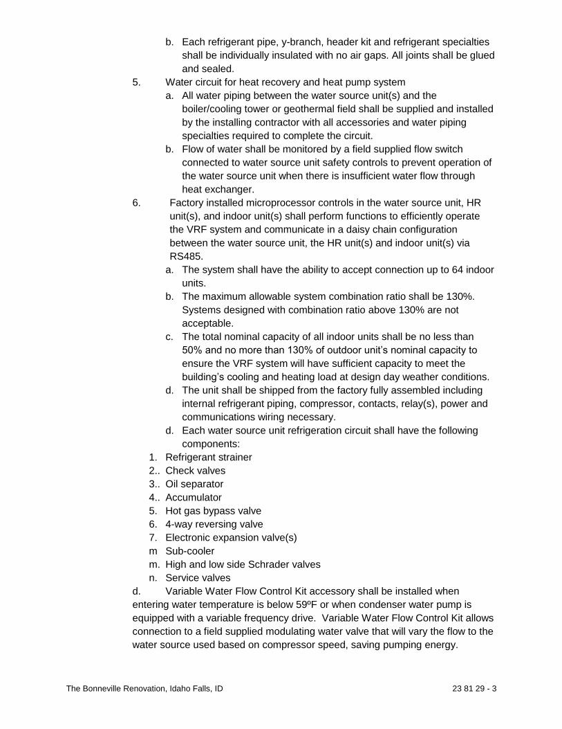
The Bonneville Renovation, Idaho Falls, ID 23 81 29 - 3
b. Each refrigerant pipe, y-branch, header kit and refrigerant specialties shall be individually insulated with no air gaps. All joints shall be glued and sealed.
5. Water circuit for heat recovery and heat pump system a. All water piping between the water source unit(s) and the
boiler/cooling tower or geothermal field shall be supplied and installed by the installing contractor with all accessories and water piping specialties required to complete the circuit.
b. Flow of water shall be monitored by a field supplied flow switch connected to water source unit safety controls to prevent operation of the water source unit when there is insufficient water flow through heat exchanger.
6. Factory installed microprocessor controls in the water source unit, HR unit(s), and indoor unit(s) shall perform functions to efficiently operate the VRF system and communicate in a daisy chain configuration between the water source unit, the HR unit(s) and indoor unit(s) via RS485.
a. The system shall have the ability to accept connection up to 64 indoor units.
b. The maximum allowable system combination ratio shall be 130%. Systems designed with combination ratio above 130% are not acceptable.
c. The total nominal capacity of all indoor units shall be no less than 50% and no more than 130% of outdoor unit’s nominal capacity to
ensure the VRF system will have sufficient capacity to meet the building’s cooling and heating load at design day weather conditions.
d. The unit shall be shipped from the factory fully assembled including internal refrigerant piping, compressor, contacts, relay(s), power and communications wiring necessary.
d. Each water source unit refrigeration circuit shall have the following components:
1. Refrigerant strainer 2.. Check valves 3.. Oil separator 4.. Accumulator 5. Hot gas bypass valve 6. 4-way reversing valve 7. Electronic expansion valve(s) m Sub-cooler m. High and low side Schrader valves n. Service valves
d. Variable Water Flow Control Kit accessory shall be installed when entering water temperature is below 59ºF or when condenser water pump is equipped with a variable frequency drive. Variable Water Flow Control Kit allows connection to a field supplied modulating water valve that will vary the flow to the water source used based on compressor speed, saving pumping energy.

The Bonneville Renovation, Idaho Falls, ID 23 81 29 - 4
C. Piping Capabilities 1. The system shall be capable of operating at an elevation difference of up to 164 feet above or below the lowest or highest indoor unit respectively. 2. The system shall be capable of operating with up to 1640 equivalent length feet of interconnecting liquid line refrigerant pipe in the network. 3. The system shall be capable of operating with up to 656 actual feet or 738 equivalent length feet of liquid line refrigerant pipe spanning between the outdoor unit and farthest indoor unit. 4. The elevation difference between two indoor units shall not exceed 131 feet for heat pump.
D. Oil Management 1. The system shall have Hi-POR (High Pressure Oil Return) to ensure a consistent film of oil on all moving compressor parts at low speed. Oil is returned to compressor through a separate oil injection pipe. 2. The system shall be provided with a centrifugal oil separator designed to extract oil from the oil/refrigerant gas stream leaving the compressor and return the extracted oil to the compressor oil sump. 3. The system shall have an oil level sensor in the compressor to provide direct oil level sensing. 4. The system shall only initiate an oil return cycle if the oil level is too low.
E. Cabinet
1. Water source unit cabinet shall be made of 20 gauge galvanized steel with a powder coated baked enamel finish. 2. Water source unit cabinet shall be tested in accordance with ASTM B-117 salt spray test procedure for a minimum of 1000 hours. 3. All pipe connections, maintenance, and service access shall be from front side of the unit only. Unit designs that require service access or pipe connections through either side, top or back panels will not be acceptable. 4. Optionally, the cabinet shall be designed to also accept field provided refrigerant piping through the bottom of the unit. 5. A smaller service access panel, not larger than 4”x 8” shall be provided in the front panel to access the following with removing the front service panel:
a. Service tool connection b. DIP switches c. Error code
6. Water connections shall be from the front of the water source unit.
F. Condenser 1. The water source unit shall be provided with a stainless steel plate type heat exchanger. 2. The heat exchanger shall remove/add heat between refrigerant and water. 3. The heat exchanger shall be protected with a field supplied (50Mesh or finer) strainer.

The Bonneville Renovation, Idaho Falls, ID 23 81 29 - 5
4. Field provided closed loop water tower or dry cooler to extract excessive heat from the water loop. If an open cell tower or a geothermal field is used, provide a field supplied and installed intermediate heat exchanger 5. The system shall be provided with a field provided flow switch. 6. The unit shall have a factory installed water temperature safety switch to monitor excessive increase or decrease of inlet water temperature.
G. Compressor(s)
1. 208-230V Water Source Unit a. Each 6, 8, 10, and 12 ton cabinet(s) shall be equipped with one
hermetically sealed, High Side Shell (HSS), inverter driven, scroll compressor.
b. Low Side Shell compressor(s) are not acceptable. 2. Each inverter driven, digitally scroll compressor shall be capable of
operating in a frequency range from 20 Hz to 140 Hz with control in 1 Hz increments.
3. The compressor shall be provided with a full charge of Polyvinyl Ether (PVE) oil from the factory.
4. The compressor bearing(s) shall be Teflon™ coated. 5. The compressor(s) shall be mounted on rubber isolation grommets. 6. The compressor(s) shall be wrapped with heat resistant, sound
attenuating blanket. 7. Inverter compressor(s) safeties shall include a minimum of:
a. High Pressure switch b. Over-current /under current protection c. Phase failure d. Phase reversal
H. Sound Levels 1. Each cabinet shall be rated with a sound level not to exceed 62 dB(A)
when tested in an anechoic chamber under ISO3745 standard.
I. Sensors 1. Each unit cabinet shall be equipped with
a. Suction temperature thermistor b. Discharge temperature thermistor c. High Pressure switch d. High Pressure sensor e. Low Pressure sensor f. Water source temperature sensor g. Heat exchanger temperature sensor
PART 5 - HEAT RECOVERY UNIT (HRU) (HEAT RECOVERY SYSTEMS ONLY)
A. General 1. HR unit shall be designed and manufactured by the same manufacturer
of VRF indoor units and water source units.

The Bonneville Renovation, Idaho Falls, ID 23 81 29 - 6
2. HR unit casing shall be made with galvanized steel.
3. HR unit shall require 208-230V/1-phase/60Hz power supply.
4. HR Unit shall be an intermediate refrigerant control device between the
water source unit and the indoor units to control the systems
simultaneous cooling and heating operation.
5. HR unit shall be engineered to work with a have a three pipe VRF
system comprising of
a. High Pressure Vapor Pipe
b. Low Pressure Vapor Pipe
c. Liquid Pipe
6. HR unit shall be designed to be piped in series with the use of Y-branch
or header fittings.
7. HR unit shall have 2, 3 or 4 ports.
8. Each port shall be capable of operating in cooling or heating
independently regardless of the operating mode of any other port on the
HR unit or in the system.
9. Each port shall be capable of connecting from 2, 3 or 4 indoor units to a
maximum nominal capacity of 54MBh.
10. Maximum nominal capacity per HR unit shall not exceed 191MBh.
a) HR unit shall be internally piped, wired, assembled and run tested at
the factory.
b) HR unit shall be designed for installation in a conditioned
environment.
c) HR unit shall have a liquid bypass valve.
d) HR unit shall have (2) two-position solenoid valves per port.
e) HR unit shall have a balancing valve to control the pressure between
the high pressure and low pressure pipe during mode switching.
f) HR unit shall have an electronic expansion valve for subcooling.
g) HR unit shall not require a condensate drain.
h) HR unit shall be internally insulated.
i) All field refrigerant lines between water source unit and HR unit and
from HR unit to indoor unit shall be field insulated.
j) The HR unit shall not exceed a net weight of 53 lbs.
k) The system shall be designed to accommodate 16 HR units
connected to Heat Recovery units piped in single series string.

The Bonneville Renovation, Idaho Falls, ID 23 81 29 - 7
l) A single series pipe string of 1 to 16 HR units shall be capable of
serving indoor units with a total nominal capacity of 192 MBH
B. Piping Capabilities 1. The acceptable piping length between HR unit(s) and indoor unit(s) shall be
131 equivalent length feet. 2. The acceptable elevation difference between each HR unit and each indoor
unit and between (2) HR units shall not exceed 131 feet.
C. Controls 1. HR unit(s) shall have factory installed unit mounted control boards and
integral microprocessor to communicate with other devices in the VRF system.
2. HR unit shall be connected to the water source unit and indoor unit in a control circuit with 24VDC using a 2-conductor shielded cable for RS485 daisy chain communication.
3. The VRF manufacturer shall provide published documentation that specifically allows the installation of field provided isolation valves on all pipes connected to the Heat Recovery unit to allow the servicing of HR units refrigerant circuit or the replacement of HR unit without evacuating the balance of the piping system.
END OF SECTION

The Bonneville Renovation, Idaho Falls, ID 23 81 30 - 1
SECTION 23 81 30 VFR SYSTEM - INDOOR UNITS Part 1 – PRODUCT DESCRIPTION
A. LG Multi V indoor units, with nominal cooling capacity ranges from 5,300 Btu/h to 96,000 Btu/h (model dependent) designed specifically for use with LG Multi V, LG Multi V Mini, and LG Multi V S air source units or LG Multi V Water, LG Multi V Water Mini water source units, shall be factory assembled, wired, piped and run tested.
B. All LG indoor units shall be available as ducted, ductless or a combination of both, and shall be complete with factory mounted controls, fans, coils, electronic expansion valves (EEVs), condensate drain pans, condensate drain lift pumps (selected models) filter racks, return air temperature sensors, refrigerant pipe temperature sensors and wiring terminal blocks. The units shall have multiple-speed constant-flow fan assemblies with direct drive digitally commutated BLDC motors.
C. All LG Multi V indoor units shall be capable of real-time response and communication from smart load control and/or flexible capacity control commands and re-set as required super-heat, sub-cooling, sensible heat ratio, total coil capacity and fan control when requested by main processor Indoor units shall provide capacity verses implied load status information.
D. All LG Multi V indoor units shall be factory equipped with a single set of configurable dry contacts for use with integration of other controls, control of remote devices or to be controlled by other devices. LG Multi V indoor units shall be capable of being controlled by, but not limited to, all LG zone controllers, LG wireless zone controllers and all commonly available automatic or manual thermostats equipped with (or without) Wi-Fi capabilities (thermostat dry contact option required).
E. All indoor unit coils shall pressure tested with dry nitrogen to a minimum of 500 psi in the field, coils and indoor units containing coils not rated for 500 psi or more shall not be permitted.
F. The entirety of this indoor unit specification and unit options define the minimum acceptable VRF indoor unit requirements for this project. All indoor units provided shall include all features and capabilities.
Part 2 – STANDARDS/CERTIFICATIONS 2.1 LG Multi V VRF indoor unit components shall be manufactured in production facilities
maintaining the following ISO certifications: A. ISO 9001 Quality Management System
B. ISO14001 Environmental Management System 2.2 All wiring shall be in accordance with the National Electric Code (NEC) and Canadian
Electrical Code (CEC). 2.3 LG Multi V VRF indoor unit components shall comply with Underwriters Laboratories
(UL) 1995 Heating and Cooling Equipment Standard for Safety and bear the Intertek Electrical Testing Laboratories (ETL) mark.
2.4 Design Basis
A. The indoor VRF fan coil equipment basis of design is LG Electronics. All bidders shall furnish the minimum system standards as defined by the base bid model numbers, model families or as otherwise specified herein. In any event the contractor shall be responsible for all specified items and intents of this document without further compensation.

The Bonneville Renovation, Idaho Falls, ID 23 81 30 - 2
Part 3 – LIMITED WARRANTY
3.1 Please refer to LG website http://www.lg-vrf.com/technical-
literature.aspx?pagesize=25&resourcesType=Warranty%20Information for applicable limited warranty.
Part 4 –PRODUCTS: LG MULTI V INDOOR UNITS:
A. Wall Mounted – Standard (ARNU ***SBL4, SCL4, SVA4 4.1 Wall Mounted – Standard (SBL4, SCL4, SVA4)
A. General: 1. Unit shall be manufactured by LG. 2. Unit shall be designed to be installed for indoor application. 3. Unit shall be attached to an installation plate/bracket that secures unit
to the wall. 4. The depth of the unit shall not exceed 10 inches.
B. Casing/Panel
1. Unit case shall be manufactured using Acrylonitrile Butadiene Styrene (ABS) polymeric resin and has a pearl white finish designed for mounting on a vertical surface and include an installation mounting template, guild and separate hanging bracket.
C. Cabinet Assembly:
1. Unit shall have one supply air outlet and one return air inlet with a manual or motorized sweeping guide vane that automatically changes the direction of airflow from side-to-side and up-and-down.
2. Unit shall be equipped with factory installed temperature thermistors for: a. Return air b. Refrigerant entering coil c. Refrigerant leaving coil
3. Unit shall have a factory assembled, piped and wired electronic expansion valve (EEV) for refrigerant control.
4. Unit shall have a built-in control panel to communicate with other indoor units and to the outdoor unit.
5. Unit shall have the following functions as standard: a. Self-diagnostic function b. Auto addressing c. Auto restart function d. Auto changeover function (Heat Recovery system only) e. Auto operation function f. Auto clean function g. Child lock function h. Forced operation i. Dual thermistor control j. Sleep mode k. Dual set point control l. Filter life timer m. Power consumption data n. External on/off control input
6. Unit shall be capable of refrigerant piping in four different directions.

The Bonneville Renovation, Idaho Falls, ID 23 81 30 - 3
7. Unit shall be capable of drain piping in two different directions.
D. Fan Assembly: 1. The unit shall have a single, direct driven crossflow tangential Sirocco
fan made of high strength ABS BSN-7530 polymeric resin. 2. The fan impeller shall be statically and dynamically balanced. 3. The fan motor is Brushless Digitally commutated (BLDC) with
permanently lubricated and sealed ball bearings. 4. The fan motor shall include thermal, overcurrent and low RPM
protection. 5. The fan/motor assembly shall be mounted on vibration attenuating
rubber grommets. 6. The fan speed shall be controlled using microprocessor based direct
digitally controlled algorithm that provides a minimum of three pre-programed fan speeds in the heating mode and fan only mode and four speeds in the cooling mode. The fan speed algorithm provides a field selectable fixed speed.
7. In cooling mode, the indoor fan shall have the following settings: Low, Med, High, Power Cool, and Auto.
8. In heating mode, the indoor fan shall have the following settings: Low, Med, High, and Auto.
9. Unit shall have factory installed motorized louver to provide flow of air in up and down direction for uniform airflow.
10. Unit shall have factory installed motorized guide vane to control the direction of flow of air from side to side.
E. Filter Assembly: 1. The return air inlet shall have a factory supplied removable, washable
filter 2. The filter access shall be from the front of the unit without the need of
tools. F. Coil Assembly:
1. Unit shall have a factory built coil comprised of aluminum fins mechanically bonded on copper tubing.
2. The copper tubing shall have inner grooves to expand the refrigerant contact surface for high efficiency heat exchanger operation.
3. Unit shall have a minimum two row coil, 18 fins per inch. 4. Unit shall have a factory supplied condensate drain pan below the coil
constructed of EPS (expandable polystyrene resin). 5. Unit shall be designed for gravity drain. 6. Unit shall have a 5/8” inside diameter factory insulated drain hose to
handle condensate. 7. Unit shall have provision of 45° flare refrigerant pipe connections. 8. The coil shall be factory pressure tested at a minimum of 551 psig. 9. All refrigerant piping from outdoor unit to indoor unit shall be field
insulated. Each pipe should be insulated separately. Thickness and heat transfer characteristics shall be determined by the design engineer and shall meet all code requirements.
G. Microprocessor Control:
1. The unit shall have a factory installed microprocessor controller capable of performing functions necessary to operate the system with or without the use of a wall mounted zone controller. The unit shall have a factory mounted return air thermistor for use as a space

The Bonneville Renovation, Idaho Falls, ID 23 81 30 - 4
temperature control device. All operating parameters except scheduling shall be stored in non-volatile memory resident on the microprocessor. The microprocessor shall provide the following functions, self-diagnostics, auto re-start after a power failure and a test run mode.
2. The unit shall be able to communicate with other indoor units and the outdoor unit using a field supplied minimum of 18 AWG, two core stranded, twisted, and shielded communication cable (RS-485).
3. The unit controls shall operate the indoor unit using one of the five operating modes: a. Auto changeover (Heat Recovery System only) b. Heating c. Cooling d. Dry e. Fan only
4. The unit shall be able to operate in either cooling or heating mode for testing and/or commissioning.
5. The unit shall have adjustable, multi-step cooling and heating mode thermal on/off temperature range settings.
6. The system shall include a product check function to access and display indoor unit type and capacity from a wired programmable thermostat controller.
7 Unit shall have a field settable method to choose auto fan speed change operation based on mode of operation, on/off fan operation based on mode of operation, or continuous minimum set fan speed operation.
H. Electrical: 1. The unit electrical power shall be 208-230/1/60 (V/Ph./Hz). 2. The unit shall be capable of operating within voltage limits of +/- 10%
of the rated voltage.
I. Controls: 1. Unit shall use controls provided by the manufacturer to perform all
functions necessary to operate the system effectively and efficiently and communicate with the outdoor unit over an RS485 daisy chain.
END OF SECTION END OF DIVISION

Electrical Specifications

The Bonneville Renovation, Idaho Falls, ID 26 05 00 - 1
DIVISION 26 ELECTRICAL
SECTION 26 05 00
COMMON WORK RESULTS FOR ELECTRICAL
GENERAL
SUMMARY
A. Section Includes: 1. Supporting Devices for Electrical Components 2. Electricity-Metering Components 3. Concrete Equipment Bases 4. Electrical Demolition 5. Cutting and Patching For Electrical Construction 6. Touchup Painting
REFERENCES
A. ASTM International (ASTM) Publications: 1. A53 "Standard Specification for Pipe, Steel, Black and Hot-Dipped, Zinc-Coated, Welded
and Seamless"
B. American Welding Society (AWS) Publications: 1. D1.1 "Structural Welding Code - Steel"
C. National Fire Protection Association (NFPA) Publications: 1. 70 "National Electric Code"
D. National Electrical Manufacturers Association (NEMA) Publications: 1. 250 “Enclosures for Electrical Equipment (1000 Volts Maximum)”
SUBMITTALS
A. General: Submit the following in accordance with Conditions of Contract and Division 01 Specification Sections: 1. Product Data:
For electricity-metering equipment. For each electrical identification product indicated.
2. Shop Drawings: Do not purchase equipment before completion of shop drawing review. Dimensioned plans and sections or elevation layouts of electricity-metering
equipment. Engineer will not review shop drawings before the contractor has reviewed the shop
drawings. The contractor shall stamp all drawings with a statement that he has reviewed all shop drawings and that they conform to the intent of the drawings and specifications.
Dimensioned plans and sections or elevation layouts of electricity-metering equipment.
3. Field Test Reports: Indicate and interpret test results for compliance with performance requirements.

The Bonneville Renovation, Idaho Falls, ID 26 05 00 - 2
PRIOR APPROVAL
A. General: 1. Catalog and manufacturer's numbers are for the purpose of establishing standards of
quality and types of materials to be used. Products of other manufacturers may be used if equal in quality and design in the opinion of the Engineer and are specifically approved by the Engineer, in writing, 10 days prior to close of bidding.
2. Any conflict arising from the use of substituted equipment shall be the responsibility of the supplier of that equipment. The contractor and his supplier shall bear all costs required to make equipment comply with the intent of the plans and specifications.
QUALITY ASSURANCE
A. Electrical Components, Devices, and Accessories: Listed and labeled as defined in NFPA 70, Article 100, by a testing agency acceptable to authorities having jurisdiction, and marked for intended use.
B. Comply with NFPA 70.
C. All work to be in accordance with latest requirements of the N.E.C. and all other applicable codes and regulations of authorities having jurisdiction over the work.
COORDINATION
A. A pre-installation meeting shall be held with the General Contractor and affected subcontracts prior to all work, in all areas of the project.
B. Coordinate chases, slots, inserts, sleeves, and openings with general construction work and arrange in building structure during progress of construction to facilitate the electrical installations that follow. 1. Set inserts and sleeves in poured-in-place concrete, masonry work, and other structural
components as they are constructed.
C. Sequence, coordinate, and integrate installing electrical materials and equipment for efficient flow of the Work. Coordinate installing large equipment requiring positioning before closing in the building.
D. Coordinate electrical service connections to components furnished by utility companies. 1. Coordinate installation and connection of exterior underground and overhead utilities and
services, including provision for electricity-metering components. 2. Comply with requirements of authorities having jurisdiction and of utility company
providing electrical power and other services. 3. Schedule utility interruptions in accordance with Division 01 of the specifications.
E. Coordinate location of access panels and doors for electrical items that are concealed by finished surfaces. Access doors and panels as specified.
F. Coordinate all work with Division 21, 22, & 23. Electrical Contractor shall provide all wiring and final connection to all line voltage thermostats. Thermostat provided and installed by Division 23.
G. All electrical drawings are to be read in conjunction with the project specifications and all other related contract drawings.
H. The contractor shall examine the site and observe the conditions under which the work will be done or other circumstances which will affect the contemplated work. No allowance will be

The Bonneville Renovation, Idaho Falls, ID 26 05 00 - 3
made subsequently in the connection for any error or negligence on the contractor’s part.
I. The contractor shall verify exact location, size and extent of all existing utilities, obstructions and/or other conditions which may affect the proposed work under the project. The contractor shall take every precaution to prevent damage to existing work and shall repair any damage as a result of this work.
J. The contractor shall verify all door swings in the field and mount switches on knob side of doors or as approved by the engineer.
K. The contractor shall carefully examine all contract drawings/specifications and be responsible for the proper fittings of materials and equipment at each location as indicated without substantial alteration. The drawings are generally diagrammatic and because of the small scale of the drawings, it is not possible to indicate all offsets, fittings and accessories which may be required. Furnishing such fittings that are required to meet such conditions shall be furnished and installed at no cost.
PRODUCTS
SUPPORTING DEVICES
A. Material: Cold-formed steel, with corrosion-resistant coating acceptable to authorities having jurisdiction.
B. Metal Items for Use Outdoors or in Damp Locations: Hot-dip galvanized steel.
C. Slotted-Steel Channel Supports: Flange edges turned toward web, and 9/16-inch diameter slotted holes at a maximum of 2 inches o.c., in webs. 1. Channel Thickness: Selected to suit structural loading. 2. Fittings and Accessories: Products of the same manufacturer as channel supports.
D. Raceway and Cable Supports: Manufactured clevis hangers, riser clamps, straps, threaded C-clamps with retainers, ceiling trapeze hangers, wall brackets, and spring-steel clamps or click-type hangers.
E. Pipe Sleeves: ASTM A53, Type E, Grade A, Schedule 40, galvanized steel, plain ends.
F. Cable Supports for Vertical Conduit: Factory-fabricated assembly consisting of threaded body and insulating wedging plug for nonarmored electrical cables in riser conduits. Plugs have number and size of conductor gripping holes as required to suit individual risers. Body constructed of malleable-iron casting with hot-dip galvanized finish.
G. Expansion Anchors: Carbon-steel wedge or sleeve type.
H. Toggle Bolts: All-steel springhead type.
EQUIPMENT FOR UTILITY COMPANY'S ELECTRICITY METERING
A. Meter Sockets: Comply with requirements of electrical power utility company.
CONCRETE BASES
A. Concrete Forms and Reinforcement Materials: As specified in Section 03 30 00 - "Cast-in-Place Concrete."

The Bonneville Renovation, Idaho Falls, ID 26 05 00 - 4
TOUCHUP PAINT
A. For Equipment: Equipment manufacturer's paint selected to match installed equipment finish.
B. Galvanized Surfaces: Zinc-rich paint recommended by item manufacturer.
EXECUTION
ELECTRICAL EQUIPMENT INSTALLATION
A. Headroom Maintenance: If mounting heights or other location criteria are not indicated, arrange and install components and equipment to provide the maximum possible headroom.
B. Materials and Components: Install level, plumb, and parallel and perpendicular to other building systems and components, unless otherwise indicated.
C. Equipment: Install to facilitate service, maintenance, and repair or replacement of components. Connect for ease of disconnecting, with minimum interference with other installations.
D. Right of Way: Give to raceways and piping systems installed at a required slope.
E. Coordinate work with other trades and install conduit and boxes to clear embedded ducts, openings, etc. and all structural features.
F. Unless otherwise noted, mounting heights, as shown, are from finished floor to top of panelboard and to centerline of other equipment. Coordinate all mounting heights with contract drawings, local code requirements, and all A.D.A. requirements. 1. Toggle (snap) switch: 4’-0”. 2. Enclosed circuit breaker: 5’-0” 3. Disconnect (safety) switch: 5’-0”. 4. Motor starter: 5’-0”. 5. Panelboard: 6’-6”.
ELECTRICAL SUPPORTING DEVICE APPLICATION
A. Damp Locations, Pool Equipment Rooms, Storage Rooms and Outdoors: Hot-dip galvanized materials or nonmetallic, U-channel system components.
B. Dry Locations: Steel materials.
C. Support Clamps for PVC Raceways: Click-type clamp system.
D. Selection of Supports: Comply with manufacturer's written instructions.
E. Strength of Supports: Adequate to carry present and future loads, times a safety factor of at least four; minimum of 200-lb design load.
SUPPORT INSTALLATION
A. Install support devices to securely and permanently fasten and support electrical components.
B. Install individual and multiple raceway hangers and riser clamps to support raceways. Provide U-bolts, clamps, attachments, and other hardware necessary for hanger assemblies and for securing hanger rods and conduits.

The Bonneville Renovation, Idaho Falls, ID 26 05 00 - 5
C. Support parallel runs of horizontal raceways together on trapeze- or bracket-type hangers.
D. Size supports for multiple raceway installations so capacity can be increased by a 25 percent minimum in the future.
E. Support individual horizontal raceways with separate, malleable-iron pipe hangers or clamps.
F. Install 1/4-inch- diameter or larger threaded steel hanger rods, unless otherwise indicated.
G. Spring-steel fasteners specifically designed for supporting single conduits or tubing may be used instead of malleable-iron hangers for 1-1/2-inch and smaller raceways serving lighting and receptacle branch circuits above suspended ceilings and for fastening raceways to slotted channel and angle supports.
H. Arrange supports in vertical runs so the weight of raceways and enclosed conductors is carried entirely by raceway supports, with no weight load on raceway terminals.
I. Simultaneously install vertical conductor supports with conductors.
J. Separately support cast boxes that are threaded to raceways and used for fixture support. Support sheet-metal boxes directly from the building structure or by bar hangers. If bar hangers are used, attach bar to raceways on opposite sides of the box and support the raceway with an approved fastener not more than 24 inches from the box.
K. Install metal channel racks for mounting cabinets, panelboards, disconnect switches, control enclosures, pull and junction boxes, transformers, and other devices unless components are mounted directly to structural elements of adequate strength.
L. Install sleeves for cable and raceway penetrations of concrete slabs and walls unless core-drilled holes are used. Install sleeves for cable and raceway penetrations of masonry and fire-rated gypsum walls and of all other fire-rated floor and wall assemblies. Install sleeves during erection of concrete and masonry walls.
M. Securely fasten electrical items and their supports to the building structure, unless otherwise indicated. Perform fastening according to the following unless other fastening methods are indicated: 1. Wood: Fasten with wood screws or screw-type nails. 2. Masonry: Toggle bolts on hollow masonry units and expansion bolts on solid masonry
units. 3. New Concrete: Concrete inserts with machine screws and bolts. 4. Existing Concrete: Expansion bolts. 5. Steel: Welded threaded studs or spring-tension clamps on steel.
Field Welding: Comply with AWS D1.1. 6. Welding to steel structure may be used only for threaded studs, not for conduits, pipe
straps, or other items. 7. Light Steel: Sheet-metal screws. 8. Fasteners: Select so the load applied to each fastener does not exceed 25 percent of its
proof-test load.
UTILITY COMPANY ELECTRICITY-METERING EQUIPMENT
A. Install equipment according to utility company's written requirements. Provide grounding and empty conduits as required by utility company.

The Bonneville Renovation, Idaho Falls, ID 26 05 00 - 6
FIRESTOPPING
A. Apply firestopping to cable and raceway penetrations of fire-rated floor and wall assemblies to achieve fire-resistance rating of the assembly. Firestopping materials and installation requirements are specified in Section 07 84 00 - “Firestopping."
CONCRETE BASES
A. Construct concrete bases of dimensions indicated, but not less than 4 inches larger, in both directions, than supported unit. Follow supported equipment manufacturer's anchorage recommendations and setting templates for anchor-bolt and tie locations, unless otherwise indicated. Use 3000-psi 28-day compressive-strength concrete and reinforcement as specified in Section 03 30 00 - "Cast-in-Place Concrete."
CUTTING AND PATCHING
A. Cut, channel, chase, and drill floors, walls, partitions, ceilings, and other surfaces required to permit electrical installations. Perform cutting by skilled mechanics of trades involved.
B. Repair and refinish disturbed finish materials and other surfaces to match adjacent undisturbed surfaces. Install new fireproofing where existing firestopping has been disturbed. Repair and refinish materials and other surfaces by skilled mechanics of trades involved.
FIELD QUALITY CONTROL
A. Inspect installed components for damage and faulty work, including the following: 1. Supporting devices for electrical components. 2. Electricity-metering components. 3. Concrete bases. 4. Electrical demolition. 5. Cutting and patching for electrical construction. 6. Touchup painting.
REFINISHING AND TOUCHUP PAINTING
A. Refinish and touch up paint. Paint materials and application requirements are specified in Section 09 90 00 - "Painting and Coating."
CLEANING AND PROTECTION
A. On completion of installation, including outlets, fittings, and devices, inspect exposed finish. Remove burrs, dirt, paint spots, and construction debris.
B. Protect equipment and installations and maintain conditions to ensure that coatings, finishes, and cabinets are without damage or deterioration at time of Substantial Completion.
END OF SECTION

The Bonneville Renovation, Idaho Falls, ID 26 05 03 - 1
SECTION 26 05 03
EQUIPMENT WIRING CONNECTIONS
GENERAL
SUMMARY
A. Section includes electrical connections to equipment.
B. Related Sections: 1. Section 26 05 19 - Low-Voltage Electrical Power Conductors and Cables. 2. Section 26 05 33 - Raceway and Boxes for Electrical Systems.
REFERENCES
A. National Electrical Manufacturers Association: 1. NEMA WD 1 - General Requirements for Wiring Devices. 2. NEMA WD 6 - Wiring Devices-Dimensional Requirements.
SUBMITTALS
A. Section 01 33 00 - Submittal Procedures: Submittal procedures.
B. Product Data: Submit wiring device manufacturer’s catalog information showing dimensions, configurations, and construction.
C. Manufacturer's installation instructions.
PRIOR APPROVAL
A. General: 1. Catalog and manufacturer's numbers are for the purpose of establishing
standards of quality and types of materials to be used. Products of other manufacturers may be used if equal in quality and design in the opinion of the Engineer and are specifically approved by the Engineer, in writing, 10 days prior to close of bidding.
2. Any conflict arising from the use of substituted equipment shall be the responsibility of the supplier of that equipment. The contractor and his supplier shall bear all costs required to make equipment comply with the intent of the plans and specifications.
CLOSEOUT SUBMITTALS
A. Section 01 70 00 - Execution and Closeout Requirements: Submittal procedures.
B. Project Record Documents: Record actual locations, sizes, and configurations of equipment connections.
COORDINATION
A. Section 01 30 00 - Administrative Requirements: Coordination and project conditions.
B. Obtain and review shop drawings, product data, manufacturer’s wiring diagrams, and manufacturer's instructions for equipment furnished under other sections.

The Bonneville Renovation, Idaho Falls, ID 26 05 03 - 2
C. Determine connection locations and requirements.
D. Sequence rough-in of electrical connections to coordinate with installation of equipment.
E. Sequence electrical connections to coordinate with start-up of equipment.
PRODUCTS
CORD AND PLUGS
A. Furnish and install equipment as required to make all connections to building and mechanical equipment.
EXECUTION
EXAMINATION
A. Section 01 30 00 - Administrative Requirements: Coordination and project conditions.
B. Verify equipment is ready for electrical connection, for wiring, and to be energized.
INSTALLATION
A. Make electrical connections.
B. Make conduit connections to equipment using flexible conduit. Use liquidtight flexible conduit with watertight connectors in damp or wet locations.
C. Connect heat producing equipment using wire and cable with insulation suitable for temperatures encountered.
D. Install receptacle outlet to accommodate connection with attachment plug.
E. Install cord and cap for field-supplied attachment plug.
F. Install suitable strain-relief clamps and fittings for cord connections at outlet boxes and equipment connection boxes.
G. Install disconnect switches, controllers, control stations, and control devices to complete equipment wiring requirements.
H. Install terminal block jumpers to complete equipment wiring requirements.
I. Install interconnecting conduit and wiring between devices and equipment to complete equipment wiring requirements.
J. Coolers and Freezers: Cut and seal conduit openings in freezer and cooler walls, floor, and ceilings.
ADJUSTING
A. Section 01 70 00 - Execution and Closeout Requirements: Testing, adjusting, and balancing.
B. Cooperate with utilization equipment installers and field service personnel during checkout and starting of equipment to allow testing and balancing and other startup

The Bonneville Renovation, Idaho Falls, ID 26 05 03 - 3
operations. Provide personnel to operate electrical system and checkout wiring connection components and configurations.
END OF SECTION

The Bonneville Renovation, Idaho Falls, ID 26 05 19 - 1
SECTION 26 05 19
LOW-VOLTAGE ELECTRICAL POWER CONDUCTORS AND CABLES
GENERAL
SUMMARY
A. Section Includes: 1. Building wires and cables and associated connectors, splices, and terminations
for wiring systems rated 600 V and less.
REFERENCES
A. National Electrical Manufacturer’s Association (NEMA) Publications: 1. WC 26 “Binational Wire and Cable Packaging Standard” 2. WC 70 “Nonshielded Power Cables Rated 2000 Volts or less for the Distribution
of Electrical Energy”
B. National Fire Protection Association (NFPA) Publications: 1. 70 "National Electric Code"
C. Underwriter's Laboratories, Inc. (UL) Publications: 1. 486A “Standard For Wire Connectors and Soldering Lugs for Use with Copper
Conductors” 2. 486B “Standard for Wire Connectors for Use With Aluminum Conductors”
SUBMITTALS
A. General: Submit the following in accordance with Conditions of Contract and Division 01 Specification Sections: 1. Field Test Reports: Indicate and interpret test results for compliance with
performance requirements.
PRIOR APPROVAL
A. General: 1. Catalog and manufacturer's numbers are for the purpose of establishing
standards of quality and types of materials to be used. Products of other manufacturers may be used if equal in quality and design in the opinion of the Engineer and are specifically approved by the Engineer, in writing, 10 days prior to close of bidding.
2. Any conflict arising from the use of substituted equipment shall be the responsibility of the supplier of that equipment. The contractor and his supplier shall bear all costs required to make equipment comply with the intent of the plans and specifications.
QUALITY ASSURANCE
A. Listing and Labeling: Provide wires and cables specified in this Section that are listed and labeled. 1. The Terms "Listed" and "Labeled": As defined in NFPA 70, Article 100. 2. Listing and Labeling Agency Qualifications: A "Nationally Recognized Testing
Laboratory" as defined in OSHA Regulation 1910.7.

The Bonneville Renovation, Idaho Falls, ID 26 05 19 - 2
B. Comply with NFPA 70.
DELIVERY, STORAGE, AND HANDLING
A. Deliver wires and cables according to NEMA WC 26.
COORDINATION
A. Coordinate layout and installation of cables with other installations.
B. Revise locations and elevations from those indicated, as required to suit field conditions and as approved by Owner's Representative.
PRODUCTS
BUILDING WIRES AND CABLES
A. Approved Manufacturers: 1. American Insulated Wire Corp.; Leviton Manufacturing Co. (800-366-2492) 2. Carol Cable Co., Inc. (401-728-7000) 3. Southwire Company (800-444-1700) 4. Alcan Cable Division of Alcan Aluminum Corporation (770-392-2368)
B. UL-listed building wires and cables with conductor material, insulation type, cable construction, and rating as specified in Part 3 "Wire and Insulation Applications" Article.
C. Rubber Insulation Material: Comply with NEMA WC 70.
D. Thermoplastic Insulation Material: Comply with NEMA WC 70.
E. Cross-Linked Polyethylene Insulation Material: Comply with NEMA WC 70.
F. Ethylene Propylene Rubber Insulation Material: Comply with NEMA WC 70.
G. Conductor Material: Copper 1. Feeders 100 ampere or greater may be aluminum "Alcan Stabiloy #8000", or
approved substitution by listed manufacturers. Upsize conduit and wire as required.
2. All aluminum conductors shall include Burndy Hyplug connectors at each end of cable.
H. Stranding: Solid conductor for No. 10 AWG and smaller; stranded conductor for larger than No. 10 AWG.
CONNECTORS AND SPLICES
A. Approved Manufacturers: 1. AMP Incorporated (800-522-6752) 2. General Signal; O-Z/Gedney Unit (203-584-0571) 3. Square D Co.; a Division of Groupe Schneider (888-778-2733) 4. Alcan Cable Division of Alcan Aluminum Corporation (770-392-2368)
B. UL-listed, factory-fabricated wiring connectors of size, ampacity rating, material, type, and class for application and service indicated. Comply with Project's installation requirements and as specified in Part 3 "Wire and Insulation Applications" Article.

The Bonneville Renovation, Idaho Falls, ID 26 05 19 - 3
EXECUTION
EXAMINATION
A. Examine raceways and building finishes to receive wires and cables for compliance with requirements for installation tolerances and other conditions affecting performance of wires and cables. Do not proceed with installation until unsatisfactory conditions have been corrected.
WIRE AND INSULATION APPLICATIONS
A. Service Entrance: Type RHW or THWN, in raceway
B. Horizontal Feeders: Type THHN/THWN, in raceway
C. Vertical Feeders: Type THHN/THWW in raceway
D. Horizontal Branch Circuits: Type THHN/THWN, in raceway
E. Vertical Branch Circuits: Type THNN/THWW in raceway
INSTALLATION
A. Install wires and cables as indicated, according to manufacturer's written instructions and NECA's "Standard of Installation."
B. Pull Conductors: Use manufacturer-approved pulling compound or lubricant where necessary; compound used must not deteriorate conductor or insulation. Do not exceed manufacturer's recommended maximum pulling tensions and sidewall pressure values.
C. Use pulling means, including fish tape, cable, rope, and basket-weave wire/cable grips, that will not damage cables or raceway.
D. Install exposed cables, parallel and perpendicular to surfaces of exposed structural members, and follow surface contours where possible.
E. Support cables according to Section 26 05 00 - "Common Work Results for Electrical."
F. Seal around cables penetrating fire-rated elements according to Section 07 84 00 "Firestopping."
G. Identify wires and cables according to Section 26 05 53 "Identification for Electrical Systems."
CONNECTIONS
A. Conductor Splices: Keep to minimum.
B. Install splices and tapes that possess equivalent or better mechanical strength and insulation ratings than conductors being spliced.
C. Use splice and tap connectors compatible with conductor material.
D. Use oxide inhibitor in each splice and tap connector for aluminum conductors.
E. Wiring at Outlets: Install conductor at each outlet, with at least 12 inches of slack.

The Bonneville Renovation, Idaho Falls, ID 26 05 19 - 4
F. Connect outlets and components to wiring and to ground as indicated and instructed by manufacturer.
G. Tighten electrical connectors and terminals according to manufacturer's published torque-tightening values. If manufacturer's torque values are not indicated, use those specified in UL 486A and UL 486B.
FIELD QUALITY CONTROL
A. Testing: On installation of wires and cables and before electrical circuitry has been energized, demonstrate product capability and compliance with requirements. 1. Perform meggar and continuity tests on all conductors.
B. Correct malfunctioning conductors and cables at Project site, where possible, and retest to demonstrate compliance; otherwise, remove and replace with new units and retest.
END OF SECTION

The Bonneville Renovation, Idaho Falls, ID 26 05 26 - 1
SECTION 26 05 26
GROUNDING AND BONDING FOR ELECTRICAL SYSTEMS
GENERAL
SUMMARY
A. Section Includes: 1. Grounding of Electrical Systems and Equipment.
Grounding requirements specified in this Section may be supplemented by special requirements of systems described in other Sections.
REFERENCES
A. ASTM International (ASTM) Publications: 1. B3 “Standard Specification for Soft or Annealed Copper Wire” 2. B8 “Standard Specification for Concentric-Lay-Stranded Copper Conductors,
Hard, Medium-Hard, or Soft” 3. B33 “Standard Specification for Tinned Soft or Annealed Copper Wire for
Electrical Purposes”
B. Institute of Electrical and Electronics Engineers, Inc. (IEEE) Publications: 1. C2 “ASC C2 Eighth Interim Collection of the National Electrical Safety Code ®” 2. 81 “Instrumentation and Measurement” 3. 837 “Substations”
C. National Fire Protection Association (NFPA) Publications: 1. 70 "National Electric Code" 2. 780 “Standard for the Installation of Lightning Protection Systems”
D. Underwriter's Laboratories, Inc. (UL) Publications: 1. 96 “Standard for Safety for Lightning Protection Components” 2. 467 “Grounding and Bonding Equipment” 3. 486A “Standard For Wire Connectors and Soldering Lugs for Use with Copper
Conductors”
SUBMITTALS
A. General: Submit the following in accordance with Conditions of Contract and Division 01 Specification Sections: 1. Product Data: For the following:
Ground rods.
PRIOR APPROVAL
A. General: 1. Catalog and manufacturer's numbers are for the purpose of establishing
standards of quality and types of materials to be used. Products of other manufacturers may be used if equal in quality and design in the opinion of the Engineer and are specifically approved by the Engineer, in writing, 10 days prior to close of bidding.
2. Any conflict arising from the use of substituted equipment shall be the responsibility of the supplier of that equipment. The contractor and his supplier shall bear all costs required to make equipment comply with the intent of the

The Bonneville Renovation, Idaho Falls, ID 26 05 26 - 2
plans and specifications.
QUALITY ASSURANCE
A. Electrical Components, Devices, and Accessories: Listed and labeled as defined in NFPA 70, Article 100, by a testing agency acceptable to authorities having jurisdiction, and marked for intended use. 1. Comply with UL 467.
B. Comply with NFPA 70; for overhead-line construction and medium-voltage underground construction, comply with IEEE C2.
C. Comply with NFPA 780 and UL 96 when interconnecting with lightning protection system.
PRODUCTS
MANUFACTURERS
A. Approved Manufacturers: 1. Grounding Conductors, Cables, Connectors, and Rods:
Chance/Hubbell (573-682-5521) Copperweld Corp. (931-433-7177) Thomas & Betts, Electrical (800-816-7809)
GROUNDING CONDUCTORS
A. For insulated conductors, comply with Section 26 05 19 - "Low-Voltage Electrical Power Conductors and Cables."
B. Material: Copper.
C. Equipment Grounding Conductors: Insulated with green-colored insulation.
D. Isolated Ground Conductors: Insulated with green-colored insulation with yellow stripe. On feeders with isolated ground, use colored tape, alternating bands of green and yellow tape to provide a minimum of three bands of green and two bands of yellow.
E. Grounding Electrode Conductors: Stranded cable.
F. Underground Conductors: Bare, tinned, stranded, unless otherwise indicated.
G. Bare Copper Conductors: Comply with the following: 1. Solid Conductors: ASTM B3. 2. Assembly of Stranded Conductors: ASTM B8. 3. Tinned Conductors: ASTM B33.
H. Copper Bonding Conductors: As follows: 1. Bonding Cable: 28 kcmil, 14 strands of No. 17 AWG copper conductor, 1/4 inch
in diameter. 2. Bonding Conductor: No. 4 or No. 6 AWG, stranded copper conductor. 3. Bonding Jumper: Bare copper tape, braided bare copper conductors, terminated
with copper ferrules; 1-5/8 inches wide and 1/16 inch thick. 4. Tinned Bonding Jumper: Tinned-copper tape, braided copper conductors,
terminated with copper ferrules; 1-5/8 inches wide and 1/16 inch thick.

The Bonneville Renovation, Idaho Falls, ID 26 05 26 - 3
I. Grounding Bus: Bare, annealed copper bars of rectangular cross section, with insulators.
J. Equipment Ground Conductor (Green) shall be included with all circuit conductors where shown. In addition, provide a neutral conductor where applicable.
CONNECTOR PRODUCTS
A. Comply with IEEE 837 and UL 467; listed for use for specific types, sizes, and combinations of conductors and connected items.
B. Bolted Connectors: Bolted-pressure-type connectors, or compression type.
C. Welded Connectors: Exothermic-welded type, in kit form, and selected per manufacturer's written instructions.
GROUNDING ELECTRODES
A. Ground Rods: copper-clad steel. 1. Size: 120” long by 3/4” in diameter.
EXECUTION
APPLICATION
A. Use only copper conductors for both insulated and bare grounding conductors in direct contact with earth, concrete, masonry, crushed stone, and similar materials.
B. In raceways, use insulated equipment grounding conductors.
C. Exothermic-Welded Connections: Use for connections to structural steel and for underground connections, except those at test wells.
D. Equipment Grounding Conductor Terminations: Use bolted pressure clamps.
E. Grounding Bus: Install in electrical and telephone equipment rooms, in rooms housing service equipment, and elsewhere as indicated. 1. Use insulated spacer; space 1 inch from wall and support from wall 6 inches
above finished floor, unless otherwise indicated. 2. At doors, route the bus up to the top of the door frame, across the top of the
doorway, and down to the specified height above the floor.
EQUIPMENT GROUNDING CONDUCTORS
A. Comply with NFPA 70, Article 250, for types, sizes, and quantities of equipment grounding conductors, unless specific types, larger sizes, or more conductors than required by NFPA 70 are indicated.
B. Install equipment grounding conductors in all feeders and circuits.
C. Computer Outlet Circuits: Install insulated equipment grounding conductor in branch-circuit runs from computer-area power panels or power-distribution units.
D. Isolated Grounding Receptacle Circuits: Install an insulated equipment grounding conductor connected to the receptacle grounding terminal. Isolate grounding conductor from raceway and from panelboard grounding terminals. Terminate at equipment

The Bonneville Renovation, Idaho Falls, ID 26 05 26 - 4
grounding conductor terminal of the applicable derived system or service, unless otherwise indicated.
E. Isolated Equipment Enclosure Circuits: For designated equipment supplied by a branch circuit or feeder, isolate equipment enclosure from supply raceway with a nonmetallic raceway fitting listed for the purpose. Install fitting where raceway enters enclosure, and install a separate equipment grounding conductor. Isolate equipment grounding conductor from raceway and from panelboard grounding terminals. Terminate at equipment grounding conductor terminal of the applicable derived system or service, unless otherwise indicated.
F. Nonmetallic Raceways: Install an equipment grounding conductor in nonmetallic raceways unless they are designated for telephone or data cables.
G. Air-Duct Equipment Circuits: Install an equipment grounding conductor to duct-mounted electrical devices operating at 120 V and more, including air cleaners and heaters. Bond conductor to each unit and to air duct.
H. Signal and Communication Systems: For telephone, alarm, voice and data, and other communication systems, provide No. 4 AWG minimum insulated grounding conductor in raceway from grounding electrode system to each service location, terminal cabinet, wiring closet, and central equipment location. 1. Service and Central Equipment Locations and Wiring Closets: Terminate
grounding conductor on a 1/4-by-2-by-12-inch grounding bus. 2. Terminal Cabinets: Terminate grounding conductor on cabinet grounding
terminal.
INSTALLATION
A. Ground Rods: Install at least three rods spaced at least one-rod length from each other and located at least the same distance from other grounding electrodes. 1. Drive ground rods until tops are 2 inches below finished floor or final grade,
unless otherwise indicated. 2. Interconnect ground rods with grounding electrode conductors. Use exothermic
welds, except at test wells and as otherwise indicated. Make connections without exposing steel or damaging copper coating.
B. Grounding Conductors: Route along shortest and straightest paths possible, unless otherwise indicated. Avoid obstructing access or placing conductors where they may be subjected to strain, impact, or damage.
C. Bonding Straps and Jumpers: Install so vibration by equipment mounted on vibration isolation hangers and supports is not transmitted to rigidly mounted equipment. Use exothermic-welded connectors for outdoor locations, unless a disconnect-type connection is required; then, use a bolted clamp. Bond straps directly to the basic structure taking care not to penetrate any adjacent parts. Install straps only in locations accessible for maintenance.
D. Metal Water Service Pipe: Provide insulated copper grounding conductors, in conduit, from building's main service equipment, or grounding bus, to main metal water service entrances to building. Connect grounding conductors to main metal water service pipes by grounding clamp connectors. Where a dielectric main water fitting is installed, connect grounding conductor to street side of fitting. Bond metal grounding conductor conduit or sleeve to conductor at each end.

The Bonneville Renovation, Idaho Falls, ID 26 05 26 - 5
E. Water Meter Piping: Use braided-type bonding jumpers to electrically bypass water meters. Connect to pipe with grounding clamp connectors.
F. Bond each aboveground portion of gas piping system upstream from equipment shutoff valve.
G. UFER ground: Install UFER ground system as shown on the drawings.
CONNECTIONS
A. General: Make connections so galvanic action or electrolysis possibility is minimized. Select connectors, connection hardware, conductors, and connection methods so metals in direct contact will be galvanically compatible. 1. Use electroplated or hot-tin-coated materials to ensure high conductivity and to
make contact points closer to order of galvanic series. 2. Make connections with clean, bare metal at points of contact. 3. Coat and seal connections having dissimilar metals with inert material to prevent
future penetration of moisture to contact surfaces.
B. Exothermic-Welded Connections: Comply with manufacturer's written instructions. Welds that are puffed up or that show convex surfaces indicating improper cleaning are not acceptable.
C. Equipment Grounding Conductor Terminations: For No. 8 AWG and larger, use pressure-type grounding lugs. No. 10 AWG and smaller grounding conductors may be terminated with winged pressure-type connectors.
D. Noncontact Metal Raceway Terminations: If metallic raceways terminate at metal housings without mechanical and electrical connection to housing, terminate each conduit with a grounding bushing. Connect grounding bushings with a bare grounding conductor to grounding bus or terminal in housing. Bond electrically noncontinuous conduits at entrances and exits with grounding bushings and bare grounding conductors, unless otherwise indicated.
E. Tighten screws and bolts for grounding and bonding connectors and terminals according to manufacturer's published torque-tightening values. If manufacturer's torque values are not indicated, use those specified in UL 486A.
F. Compression-Type Connections: Use hydraulic compression tools to provide correct circumferential pressure for compression connectors. Use tools and dies recommended by connector manufacturer. Provide embossing die code or other standard method to make a visible indication that a connector has been adequately compressed on grounding conductor.
G. Moisture Protection: If insulated grounding conductors are connected to ground rods or grounding buses, insulate entire area of connection and seal against moisture penetration of insulation and cable.
TRANSFORMER GROUNDING
A. Install ground rods at transformer in accordance with National Electric Code.
FIELD QUALITY CONTROL
A. Testing: Perform the following field quality-control testing: 1. After installing grounding system but before permanent electrical circuitry has

The Bonneville Renovation, Idaho Falls, ID 26 05 26 - 6
been energized, test for compliance with requirements. 2. Test completed grounding system at each location where a maximum ground-
resistance level is specified, at service disconnect enclosure grounding terminal, and at ground test wells. Measure ground resistance not less than two full days after the last trace of precipitation, and without the soil being moistened by any means other than natural drainage or seepage and without chemical treatment or other artificial means of reducing natural ground resistance. Perform tests, by the fall-of-potential method according to IEEE 81.
3. Provide drawings locating each ground rod and ground rod assembly and other grounding electrodes, identify each by letter in alphabetical order, and key to the record of tests and observations. Include the number of rods driven and their depth at each location and include observations of weather and other phenomena that may affect test results. Describe measures taken to improve test results.
Equipment Rated 500 kVA and less: 10 ohms. Equipment Rated 500 to 1000 kVA: 5 ohms.
4. Excessive Ground Resistance: If resistance to ground exceeds specified values, notify Owner representative promptly and include recommendations to reduce ground resistance such as a chemical ground system or others that are available and approved by the Consulting Engineer.
GRADING AND PLANTING
A. Restore surface features, including vegetation, at areas disturbed by Work of this Section. Reestablish original grades, unless otherwise indicated. If sod has been removed, replace it as soon as possible after backfilling is completed. Restore areas disturbed by trenching, storing of dirt, cable laying, and other activities to their original condition. Include application of topsoil, fertilizer, lime, seed, sod, sprig, and mulch. Restore disturbed paving as indicated.
END OF SECTION

The Bonneville Renovation, Idaho Falls, ID 26 05 33 - 1
SECTION 26 05 33
RACEWAYS AND BOXES FOR ELECTRICAL SYSTEMS
GENERAL
SUMMARY
A. Section Includes: 1. Raceways include the following:
RMC PVC, schedule 40 or 80 EMT FMC LFMC
LFNC RNC Wireways
Surface raceways MC cable for branch circuit wiring
2. Boxes, enclosures, and cabinets include the following: Device boxes Floor boxes Outlet boxes Pull and junction boxes Cabinets and hinged-cover enclosures
REFERENCES
A. National Electrical Contractors Association (NECA) Publications: 1. 111 “Standard for Installing Nonmetallic Raceways (RNC, ENT, LFNC) (ANSI)”
B. National Electrical Manufacturer’s Association (NEMA) Publications: 1. 250 “Enclosures for Electrical Equipment (1000 Volts Maximum)” 2. ANSI/NEMA FB 1 “Fittings, Cast Metal Boxes, and Conduit Bodies for Conduit,
Electrical Metallic Tubing, and Cable” 3. ANSI/NEMA OS 1 “Sheet-Steel Outlet Boxes, Device Boxes, Covers, and Box
Supports” 4. RN 1 “Polyvinyl Chloride (PVC) Externally Coated Galvanized Rigid Steel
Conduit and Intermediate Metal Conduit” 5. TC 2 “Electrical Polyvinyl Chloride (PVC) Tubing and Conduit” 6. TC 3 “Polyvinyl Chloride (PVC) Fittings for Use with Rigid PVC Conduit and
Tubing”
C. National Fire Protection Association (NFPA) Publications: 1. 70 "National Electric Code"
D. Underwriter's Laboratories, Inc. (UL) Publications: 1. 1660 “Liquid-Tight Flexible Nonmetallic Conduit”
DEFINITIONS
A. EMT: Electrical metallic tubing.
B. FMC: Flexible metal conduit.

The Bonneville Renovation, Idaho Falls, ID 26 05 33 - 2
C. IMC: Intermediate metal conduit.
D. LFMC: Liquidtight flexible metal conduit.
E. LFNC: Liquidtight flexible nonmetallic conduit.
F. RMC: Rigid metal conduit.
G. RNC: Rigid nonmetallic conduit.
SUBMITTALS
A. General: Submit the following in accordance with Conditions of Contract and Division 01 Specification Sections: 1. Product Data: For surface raceways, wireways and fittings, floor boxes, hinged-
cover enclosures, and cabinets.
PRIOR APPROVAL
A. General: 1. Catalog and manufacturer's numbers are for the purpose of establishing
standards of quality and types of materials to be used. Products of other manufacturers may be used if equal in quality and design in the opinion of the Engineer and are specifically approved by the Engineer, in writing, 10 days prior to close of bidding.
2. Any conflict arising from the use of substituted equipment shall be the responsibility of the supplier of that equipment. The contractor and his supplier shall bear all costs required to make equipment comply with the intent of the plans and specifications.
QUALITY ASSURANCE
A. Listing and Labeling: Provide raceways and boxes specified in this Section that are listed and labeled. 1. The Terms "Listed" and "Labeled": As defined in NFPA 70, Article 100. 2. Listing and Labeling Agency Qualifications: A "Nationally Recognized Testing
Laboratory" as defined in OSHA Regulation 1910.7.
B. Comply with NECA's "Standard for Installing Nonmetallic Raceways (RNC, ENT, LFNC) (ANSI).”
C. Comply with NFPA 70.
COORDINATION
A. Coordinate layout and installation of raceways and boxes with other construction elements to ensure adequate headroom, working clearance, and access.
PRODUCTS
MANUFACTURERS
A. Approved Manufacturers: 1. Metal Conduit and Tubing:
Anixter Brothers, Inc. (800-323-8166) Carol Cable Co., Inc. (401-728-7000)

The Bonneville Renovation, Idaho Falls, ID 26 05 33 - 3
Wheatland Tube Co. (800-257-8128) 2. Flexible Conduit:
Carol Cable Co., Inc. (401-728-7000) Electri-Flex Co. (800-323-6174)
3. Nonmetallic Conduit and Tubing: Hubbell, Inc.; Raco, Inc. (800-722-6437) Lamson & Sessions; Carlon Electrical Products (800-322-7566) Thomas & Betts Corp. (800-816-7809)
4. Conduit Bodies and Fittings: Emerson Electric Co.; Appleton Electric Co. (800-727-5102) Hubbell, Inc.; Killark Electric Manufacturing Co. (314-531-0460) Lamson & Sessions; Carlon Electrical Products (800-322-7566)
5. Metal Wireways: Hoffman Engineering Co. (203-425-8900) Keystone/Rees, Inc. (219-495-9811) Square D Co.; a Division of Groupe Schneider (888-778-2733)
6. Nonmetallic Wireways: Hoffman Engineering Co. (203-425-8900) Lamson & Sessions; Carlon Electrical Products (800-322-7566)
7. Surface Metal Raceways: Airey-Thompson Co., Inc.; A-T Power Systems (800-421-6196) Butler Manufacturing Co.; Walker Division (304-485-1611) Wiremold Co. (The); Electrical Sales Division (800-621-0049)
8. Surface Nonmetallic Raceways: Hubbell, Inc.; Wiring Device Division (203-882-4900) Panduit Corp. (800-777-3300) Wiremold Co. (The); Electrical Sales Division (800-621-0049)
9. Boxes, Enclosures, and Cabinets: Hoffman Engineering Co.; Federal-Hoffman, Inc. (203-425-8900) Hubbell Inc.; Killark Electric Manufacturing Co. (314-531-0460) Thomas & Betts Corp. (800-816-7809)
10. MC cable: Afc Cable Systems (508) 998-1131 Southwire (801) 486-4778 Encore Wire Corp (972) 562-9473
METAL CONDUIT AND TUBING
A. Rigid Steel Conduit: ANSI C80.1.
B. Plastic-Coated Steel Conduit and Fittings: NEMA RN 1.
C. EMT and Fittings: ANSI C80.3. 1. Fittings: Set-screw or compression type.
D. FMC: Zinc-coated steel.
E. LFMC: Flexible steel conduit with PVC jacket.
F. Fittings: NEMA FB 1; compatible with conduit/tubing materials.
NONMETALLIC CONDUIT AND TUBING
A. RNC: NEMA TC 2, Schedule 40 or 80 PVC.

The Bonneville Renovation, Idaho Falls, ID 26 05 33 - 4
B. RNC Fittings: NEMA TC 3; match to conduit or conduit/tubing type and material.
C. LFNC: UL 1660.
METAL WIREWAYS
A. Material: Sheet metal sized and shaped as indicated.
B. Fittings and Accessories: Include couplings, offsets, elbows, expansion joints, adapters, hold-down straps, end caps, and other fittings to match and mate with wireways as required for complete system.
C. Select features, unless otherwise indicated, as required to complete wiring system and to comply with NFPA 70.
D. Wireway Covers: As indicated
E. Finish: Manufacturer's standard enamel finish.
NONMETALLIC WIREWAYS
A. Description: PVC plastic, extruded and fabricated to size and shape indicated, with snap-on cover and mechanically coupled connections using plastic fasteners.
B. Fittings and Accessories: Include couplings, offsets, elbows, expansion joints, adapters, hold-down straps, end caps, and other fittings to match and mate with wireways as required for complete system.
C. Select features, unless otherwise indicated, as required to complete wiring system and to comply with NFPA 70.
SURFACE RACEWAYS
A. Surface Metal Raceways: Galvanized steel with snap-on covers. Finish with manufacturer's standard prime coating.
B. Surface Nonmetallic Raceways: 2-piece construction, manufactured of rigid PVC compound with matte texture and manufacturer's standard color.
C. Types, sizes, and channels as indicated and required for each application, with fittings that match and mate with raceways.
OUTLET AND DEVICE BOXES
A. Sheet Metal Boxes: NEMA OS 1.
FLOOR BOXES
A. Floor Boxes: Cast metal, fully adjustable, rectangular.
PULL AND JUNCTION BOXES
A. Small Sheet Metal Boxes: NEMA OS 1.
B. Cast-Metal Boxes: NEMA FB 1, cast aluminum with gasketed cover.

The Bonneville Renovation, Idaho Falls, ID 26 05 33 - 5
ENCLOSURES AND CABINETS
A. Hinged-Cover Enclosures: NEMA 250, Type 1, with continuous hinge cover and flush latch. 1. Metal Enclosures: Steel, finished inside and out with manufacturer's standard
enamel. 2. Nonmetallic Enclosures: Plastic, finished inside with radio-frequency-resistant
paint.
B. Cabinets: NEMA 250, Type 1, galvanized steel box with removable interior panel and removable front, finished inside and out with manufacturer's standard enamel. Hinged door in front cover with flush latch and concealed hinge. Key latch to match panelboards. Include metal barriers to separate wiring of different systems and voltage, and include accessory feet where required for freestanding equipment.
EXECUTION
EXAMINATION
A. Examine surfaces to receive raceways, boxes, enclosures, and cabinets for compliance with installation tolerances and other conditions affecting performance of raceway installation. Do not proceed with installation until unsatisfactory conditions have been corrected.
WIRING METHODS
A. Outdoors: Use the following wiring methods: 1. Exposed: Rigid steel. 2. Concealed: Rigid steel. 3. Underground, Single Run: RNC. 4. Underground, Grouped: RNC. 5. Connection to Vibrating Equipment (Including Transformers and Hydraulic,
Pneumatic, Electric Solenoid, or Motor-Driven Equipment): LFMC. 6. Boxes and Enclosures: NEMA 250, Type 3R or Type 4.
B. Indoors: Use the following wiring methods: 1. Exposed on ceilings and wall in Mechanical Equipment Rooms galvanized rigid
steel conduit. 2. Concealed in spaces above hung ceiling and wall: Electrical Metallic Tubing
(EMT). 3. Connection to Vibrating Equipment (Including Transformers and Hydraulic,
Pneumatic, Electric Solenoid, or Motor-Driven Equipment): FMC; except in wet or damp locations, use LFMC.
4. Damp or Wet Locations: Rigid steel conduit. 5. Boxes and Enclosures: NEMA 250, Type 1, except as follows:
Damp or Wet Locations: NEMA 250, Type 4, stainless steel.
C. Underground or concrete encased: 1. Schedule 40 PVC.
INSTALLATION
A. Install raceways, boxes, enclosures, and cabinets as indicated, according to manufacturer's written instructions.

The Bonneville Renovation, Idaho Falls, ID 26 05 33 - 6
B. Minimum Raceway Size: 3/4-inch trade size (DN21).
C. Conceal conduit and EMT, unless otherwise indicated, within finished walls, ceilings, and floors.
D. Keep raceways at least 6 inches away from parallel runs of flues and steam or hot-water pipes. Install horizontal raceway runs above water and steam piping.
E. Install raceways level and square and at proper elevations. Provide adequate headroom.
F. Complete raceway installation before starting conductor installation.
G. Support raceways as specified in Section 26 05 00 - "Common Work Results for Electrical."
H. Use temporary closures to prevent foreign matter from entering raceways.
I. Protect stub-ups from damage where conduits rise through floor slabs. Arrange so curved portion of bends is not visible above the finished slab.
J. Make bends and offsets so ID is not reduced. Keep legs of bends in the same plane and straight legs of offsets parallel, unless otherwise indicated.
K. Use raceway fittings compatible with raceways and suitable for use and location. For intermediate steel conduit, use threaded rigid steel conduit fittings, unless otherwise indicated.
L. Run concealed raceways, with a minimum of bends, in the shortest practical distance considering the type of building construction and obstructions, unless otherwise indicated.
M. Raceways Embedded in Slabs: Install in middle third of slab thickness where practical, and leave at least 1-inch concrete cover. 1. Secure raceways to reinforcing rods to prevent sagging or shifting during
concrete placement. 2. Space raceways laterally to prevent voids in concrete. 3. Run conduit larger than 1-inch trade size (DN27) parallel to or at right angles to
main reinforcement. Where at right angles to reinforcement, place conduit close to slab support.
4. Transition from nonmetallic tubing to Schedule 80 nonmetallic conduit or rigid steel conduit, before rising above floor.
N. Install exposed raceways parallel to or at right angles to nearby surfaces or structural members, and follow the surface contours as much as practical. 1. Run parallel or banked raceways together, on common supports where practical. 2. Make bends in parallel or banked runs from same centerline to make bends
parallel. Use factory elbows only where elbows can be installed parallel; otherwise, provide field bends for parallel raceways.
O. Join raceways with fittings designed and approved for the purpose and make joints tight. 1. Make raceway terminations tight. Use bonding bushings or wedges at
connections subject to vibration. Use bonding jumpers where joints cannot be made tight.
2. Use insulating bushings to protect conductors.

The Bonneville Renovation, Idaho Falls, ID 26 05 33 - 7
P. Tighten set screws of threadless fittings with suitable tools.
Q. Terminations: Where raceways are terminated with locknuts and bushings, align raceways to enter squarely and install locknuts with dished part against the box. Where terminations are not secure with one locknut, use two locknuts: one inside and one outside the box.
R. Where raceways are terminated with threaded hubs, screw raceways or fittings tightly into the hub so the end bears against the wire protection shoulder. Where chase nipples are used, align raceways so the coupling is square to the box and tighten the chase nipple so no threads are exposed.
S. Install pull wires in empty raceways. Use No. 14 AWG zinc-coated steel or monofilament plastic line with not less than 200-lb tensile strength. Leave at least 12 inches (300 mm) of slack at each end of the pull wire.
T. Telephone and Signal System Raceways, 2-Inch Trade Size (DN53) and Smaller: In addition to the above requirements, install raceways in maximum lengths of 150 feet and with a maximum of two 90-degree bends or equivalent. Separate lengths with pull or junction boxes where necessary to comply with these requirements.
U. Install raceway sealing fittings according to manufacturer's written instructions. Locate fittings at suitable, approved, and accessible locations and fill them with UL-listed sealing compound. For concealed raceways, install each fitting in a flush steel box with a blank cover plate having a finish similar to that of adjacent plates or surfaces. Install raceway sealing fittings at the following points: 1. Where conduits pass from warm to cold locations, such as the boundaries of
refrigerated spaces. 2. Where otherwise required by NFPA 70.
V. Stub-up Connections: Extend conduits through concrete floor for connection to freestanding equipment. Install with an adjustable top or coupling threaded inside for plugs set flush with the finished floor. Extend conductors to equipment with rigid steel conduit; FMC may be used 6 inches above the floor. Install screwdriver-operated, threaded flush plugs flush with floor for future equipment connections.
W. Flexible Connections: Use maximum of 6 feet of flexible conduit for recessed and semirecessed lighting fixtures; for equipment subject to vibration, noise transmission, or movement; and for all motors. Use liquidtight flexible conduit in wet or damp locations. Install separate ground conductor across flexible connections.
X. Do not install aluminum conduits embedded in or in contact with concrete.
Y. PVC Externally Coated, Rigid Steel Conduits: Use only fittings approved for use with that material. Patch all nicks and scrapes in PVC coating after installing conduits.
Z. Surface Raceways: Install a separate, green, ground conductor in raceways from junction box supplying the raceways to receptacle or fixture ground terminals. 1. Select each surface raceway outlet box, to which a lighting fixture is attached, of
sufficient diameter to provide a seat for the fixture canopy. 2. Where a surface raceway is used to supply a fluorescent lighting fixture having
central-stem suspension with a backplate and a canopy (with or without extension ring), no separate outlet box is required.
3. Provide surface metal raceway outlet box, and the backplate and canopy, at the feed-in location of each fluorescent lighting fixture having end-stem suspension.

The Bonneville Renovation, Idaho Falls, ID 26 05 33 - 8
4. Where a surface metal raceway extension is made from an existing outlet box on which a lighting fixture is installed, no additional surface-mounted outlet box is required. Provide a backplate slightly smaller than the fixture canopy.
AA. Set floor boxes level and adjust to finished floor surface.
BB. Install hinged-cover enclosures and cabinets plumb. Support at each corner.
CC. Size all conduits supplying motors and associated control equipment to include equipment grounding conductor sized per NFPA 70 whether or not shown on the drawings or specified.
DD. Unless otherwise noted, terminate all conduits stubbing up inside rooms or roof as follows: 1. Conduits for AC power: Stub up 6” above finished floor and provide concrete sill
to protect stub-ups. 2. On PVC conduit for AC power and control cable, provide PVC to galvanized steel
rigid conduit adaptor. 3. Plug or cap all conduits during construction or until permanent conductors are
installed. Taped ends will not be allowed.
EE. In exposed conduit runs longer than 300 feet, expansion fittings shall be installed. Where embedded conduit crosses a structural expansion joint, expansion and deflection fitting shall be installed.
FF. MC Cable Installation: 1. MC cable may be installed for branch circuit wiring for switches, lights and
receptacles from the point of the home run. All home runs shall be in conduit. Support all MC cable per NEC.
PROTECTION
A. Provide final protection and maintain conditions, in a manner acceptable to manufacturer and Installer, that ensure coatings, finishes, and cabinets are without damage or deterioration at the time of Substantial Completion. 1. Repair damage to galvanized finishes with zinc-rich paint recommended by
manufacturer. 2. Repair damage to PVC or paint finishes with matching touchup coating
recommended by manufacturer.
CLEANING
A. On completion of installation, including outlet fittings and devices, inspect exposed finish. Remove burrs, dirt, and construction debris and repair damaged finish, including chips, scratches, and abrasions.
END OF SECTION

The Bonneville Renovation, Idaho Falls, ID 26 05 53 - 1
SECTION 26 05 53
IDENTIFICATION FOR ELECTRICAL SYSTEMS
GENERAL
SUMMARY
A. Section Includes: 1. Electrical identification materials and devices required to comply with ANSI C2,
NFPA 70, OSHA standards, and authorities having jurisdiction.
REFERENCES
A. American National Standards Institute (ANSI) Publications:
B. National Fire Protection Association (NFPA) Publications: 1. 70 "National Electric Code"
SUBMITTALS
A. General: Submit the following in accordance with Conditions of Contract and Division 01 Specification Sections: 1. Product Data: For each electrical identification product indicated.
PRIOR APPROVAL
A. General: 1. Catalog and manufacturer's numbers are for the purpose of establishing
standards of quality and types of materials to be used. Products of other manufacturers may be used if equal in quality and design in the opinion of the Engineer and are specifically approved by the Engineer, in writing, 10 days prior to close of bidding.
2. Any conflict arising from the use of substituted equipment shall be the responsibility of the supplier of that equipment. The contractor and his supplier shall bear all costs required to make equipment comply with the intent of the plans and specifications.
QUALITY ASSURANCE
A. Comply with ANSI C2.
B. Comply with NFPA 70.
C. Comply with ANSI A13.1 and NFPA 70 for color-coding.
PRODUCTS
MANUFACTURERS
A. Approved Manufacturers: 1. Brady USA, Inc. (800-541-1686) 2. Panduit corp. (800-777-3300) 3. Seton Identification Products (800-571-2596)

The Bonneville Renovation, Idaho Falls, ID 26 05 53 - 2
RACEWAY AND CABLE LABELS
A. Comply with ANSI A13.1, Table 3, for minimum size of letters for legend and for minimum length of color field for each raceway and cable size. 1. Color: Black letters on orange field. 2. Legend: Indicates voltage.
B. Pretensioned, Wraparound Plastic Sleeves: Flexible, preprinted, color-coded, acrylic band sized to suit the diameter of the line it identifies and arranged to stay in place by pretensioned gripping action when placed in position.
C. Colored Adhesive Tape: Self-adhesive vinyl tape not less than 3 mils thick by 1 to 2 inches wide.
D. Underground-Line Warning Tape: Permanent, bright-colored, continuous-printed, vinyl tape. 1. Not less than 6 inches wide by 4 mils thick. 2. Compounded for permanent direct-burial service. 3. Embedded continuous metallic strip or core. 4. Printed legend indicating type of underground line.
E. Tape Markers: Vinyl or vinyl-cloth, self-adhesive, wraparound type with preprinted numbers and letters.
F. Aluminum, Wraparound Marker Bands: Bands cut from 0.014-inch thick aluminum sheet, with stamped or embossed legend, and fitted with slots or ears for permanently securing around wire or cable jacket or around groups of conductors.
G. Plasticized Card-Stock Tags: Vinyl cloth with preprinted and field-printed legends. Orange background, unless otherwise indicated, with eyelet for fastener.
H. Aluminum-Faced, Card-Stock Tags: Weather-resistant, 18-point minimum card stock faced on both sides with embossable aluminum sheet, 0.002 inch thick, laminated with moisture-resistant acrylic adhesive, punched for fasteners, and preprinted with legends to suit each application.
NAMEPLATES AND SIGNS
A. Safety Signs: Comply with 29 CFR, Chapter XVII, Part 1910.145.
B. Engraved Plastic Nameplates and Signs: Engraving stock, melamine plastic laminate, minimum 1/16 inch thick for signs up to 20 sq. in. and 1/8 inch thick for larger sizes. 1. Engraved legend with black letters on white face. 2. Punched or drilled for mechanical fasteners.
C. Baked-Enamel Signs for Interior Use: Preprinted aluminum signs, punched or drilled for fasteners, with colors, legend, and size required for the application. 1/4-inch grommets in corners for mounting.
D. Exterior, Metal-Backed, Butyrate Signs: Weather-resistant, nonfading, preprinted, cellulose-acetate butyrate signs with 0.0396-inch galvanized-steel backing; and with colors, legend, and size required for the application. 1/4-inch grommets in corners for mounting.
E. Fasteners for Nameplates and Signs: Self-tapping, stainless-steel screws or No. 10/32, stainless-steel machine screws with nuts and flat and lock washers.

The Bonneville Renovation, Idaho Falls, ID 26 05 53 - 3
MISCELLANEOUS IDENTIFICATION PRODUCTS
A. Cable Ties: Fungus-inert, self-extinguishing, one-piece, self-locking, Type 6/6 nylon cable ties. 1. Minimum Width: 3/16 inch. 2. Tensile Strength: 50 lb minimum. 3. Temperature Range: Minus 40 to plus 185 deg F. 4. Color: According to color-coding.
EXECUTION
INSTALLATION
A. Identification Materials and Devices: Install at locations for most convenient viewing without interference with operation and maintenance of equipment.
B. Lettering, Colors, and Graphics: Coordinate names, abbreviations, colors, and other designations with corresponding designations in the Contract Documents or with those required by codes and standards. Use consistent designations throughout Project.
C. Sequence of Work: If identification is applied to surfaces that require finish, install identification after completing finish work.
D. Self-Adhesive Identification Products: Clean surfaces before applying.
E. Caution Labels for Indoor Boxes and Enclosures for Power and Lighting: Install pressure-sensitive, self-adhesive labels identifying system voltage with black letters on orange background. Install on exterior of door or cover.
F. Circuit Identification Labels on Boxes: Install labels externally. 1. Exposed Boxes: Pressure-sensitive, self-adhesive plastic label on cover. 2. Concealed Boxes: Plasticized card-stock tags. 3. Labeling Legend: Permanent, waterproof listing of panel and circuit number or
equivalent.
G. Paths of Underground Electrical Lines: During trench backfilling, for exterior underground power, control, signal, and communication lines, install continuous underground plastic line marker located directly above line at 6 to 8 inches below finished grade. Where width of multiple lines installed in a common trench or concrete envelope does not exceed 16 inches overall, use a single line marker. Install line marker for underground wiring, both direct-buried cables and cables in raceway.
H. Secondary Service, Feeder, and Branch-Circuit Conductors: Color-code throughout the secondary electrical system. 1. Wire color code:
Color-code for 208/120V system shall be as follows: 1) Phase A: Black 2) Phase B: Red 3) Phase C: Blue 4) Neutral: White 5) Ground: Green
2. Factory apply color the entire length of conductors, except the following field-applied, color-coding methods may be used instead of factory-coded wire for sizes larger than No. 10 AWG:
Colored, pressure-sensitive plastic tape in half-lapped turns for a distance

The Bonneville Renovation, Idaho Falls, ID 26 05 53 - 4
of 6 inches from terminal points and in boxes where splices or taps are made. Apply last two turns of tape with no tension to prevent possible unwinding. Use 1-inch wide tape in colors specified. Adjust tape bands to avoid obscuring cable identification markings.
Colored cable ties applied in groups of three ties of specified color to each wire at each terminal or splice point starting 3 inches from the terminal and spaced 3 inches apart. Apply with a special tool or pliers, tighten to a snug fit, and cut off excess length.
I. Power-Circuit Identification: Metal tags or aluminum, wraparound marker bands for cables, feeders, and power circuits in vaults, pull and junction boxes, manholes, and switchboard rooms. 1. Legend: 1/4-inch steel letter and number stamping or embossing with legend
corresponding to indicated circuit designations. 2. Tag Fasteners: Nylon cable ties. 3. Band Fasteners: Integral ears.
J. Apply identification to conductors as follows: 1. Conductors to Be Extended in the Future: Indicate source and circuit numbers. 2. Multiple Power or Lighting Circuits in the Same Enclosure: Identify each
conductor with source, voltage, circuit number, and phase. Use color-coding to identify circuits' voltage and phase.
3. Multiple Control and Communication Circuits in the Same Enclosure: Identify each conductor by its system and circuit designation. Use a consistent system of tags, color-coding, or cable marking tape.
K. Apply warning, caution, and instruction signs as follows: 1. Warnings, Cautions, and Instructions: Install to ensure safe operation and
maintenance of electrical systems and of items to which they connect. Install engraved plastic-laminated instruction signs with approved legend where instructions are needed for system or equipment operation. Install metal-backed butyrate signs for outdoor items.
2. Emergency Operation: Install engraved laminated signs with white legend on red background with minimum 3/8-inch high lettering for emergency instructions on power transfer, load shedding, and other emergency operations.
L. Equipment Identification Labels: Engraved plastic laminate. Install on each unit of equipment, including central or master unit of each system. This includes power, lighting, communication, signal, and alarm systems, unless units are specified with their own self-explanatory identification. Unless otherwise indicated, provide a single line of text with 1/2-inch high lettering on 1-1/2-inch high label; where two lines of text are required, use labels 2 inches high. Use white lettering on black field. Apply labels for each unit of the following categories of equipment using mechanical fasteners: 1. Panelboards, electrical cabinets, and enclosures. 2. Access doors and panels for concealed electrical items. 3. Electrical switchgear and switchboards. 4. Emergency system boxes and enclosures. 5. Disconnect switches. 6. Enclosed circuit breakers. 7. Motor starters. 8. Dimmers. 9. Control devices. 10. Telephone switching equipment. 11. Label inside of all switch plates and cover plates with panel and circuit numbers. 12. Label all disconnect switches with circuit number and equipment server inside

The Bonneville Renovation, Idaho Falls, ID 26 05 53 - 5
disconnect switch as well as outside of switch.
END OF SECTION

The Bonneville Renovation, Idaho Falls, ID 26 24 16 - 1
SECTION 26 24 16
SWITCHBOARDS AND PANELBOARDS
GENERAL
SUMMARY
Section Includes: 1. Service And Distribution Switchboards Rated 600 V And Less. 2. Panelboards, Overcurrent Protective Devices, And Associated Auxiliary
Equipment Rated 600 V And Less For The Following Types: Lighting and Appliance Branch-Circuit Panelboards. Distribution Panelboards.
REFERENCES
American National Standards Institute (ANSI) Publications:
Institute of Electrical and Electronics Engineers, Inc. (IEEE) Publications: 1. C57.13 “IEEE Standard Requirements for Instrument Transformers”
National Electrical Manufacturer’s Association (NEMA) Standards Publications: 1. 250 “Enclosures for Electrical Equipment (1000 Volts Maximum)” 2. AB 1 “Molded-Case Circuit Breakers, Molded Case Switches, and Circuit-
Breaker Enclosures” 3. EI 21.1, “Instrument Transformers for Revenue Metering (110 kV BIL and less)” 4. FU 1 “Low Voltage Cartridge Fuses” 5. PB 1 “Panelboards” 6. PB 1.1 “General Instructions for Proper Installation, Operation, and Maintenance
of Panelboards Rated 600 Volts or Less” 7. PB 2 “Deadfront Distribution Switchboards” 8. PB 2.1 “General Instructions for Proper Handling, Installation, Operation, and
Maintenance of Deadfront Distribution Switchboards Rated 600 Volts or Less”
National Fire Protection Association (NFPA) Publications: 1. 70 "National Electric Code"
Underwriter's Laboratories, Inc. (UL) Publications: 1. 486A “Standard For Wire Connectors and Soldering Lugs for Use With Copper
Conductors” 2. 486B “Standard for Wire Connectors for Use With Aluminum Conductors”
DEFINITIONS
EMI: Electromagnetic interference.
GFCI: Ground-fault circuit interrupter.
RFI: Radio-frequency interference.
RMS: Root mean square.
SPDT: Single pole, double throw.

The Bonneville Renovation, Idaho Falls, ID 26 24 16 - 2
TVSS: Transient voltage surge suppressor.
SUBMITTALS
General: Submit the following in accordance with Conditions of Contract and Division 01 Specification Sections: 1. Product Data:
For each type of switchboard, panelboard, overcurrent protective device, TVSS device, ground-fault protector, accessory, and component indicated. Include dimensions and manufacturers' technical data on features, performance, electrical characteristics, ratings, and finishes.
2. Shop Drawings: For each switchboard, panelboard and related equipment. Dimensioned plans, elevations, sections, and details, including required
clearances and service space around equipment. Show tabulations of installed devices, equipment features, and ratings. Include the following: 1) Enclosure types and details for types other than NEMA 250,
Type 1. 2) Bus configuration, current, and voltage ratings. 3) Short-circuit current rating of switchboards and overcurrent
protective devices. 4) Descriptive documentation of optional barriers specified for
electrical insulation and isolation. 5) Utility company's metering provisions with indication of approval
by utility company. 6) UL listing for series rating of installed devices. 7) Features, characteristics, ratings, and factory settings of individual
overcurrent protective devices and auxiliary components. Wiring Diagrams: Diagram power, signal, and control wiring and
differentiate between manufacturer-installed and field-installed wiring. 3. Qualification Data: Submit data for testing agencies indicating that they comply
with qualifications specified in "Quality Assurance" Article. 4. Field Test Reports: Submit written test reports and include the following:
Test procedures used. Test results that comply with requirements. Results of failed tests and corrective action taken to achieve test results
that comply with requirements. 5. Manufacturer's field service report. 6. Maintenance Data: For switchboards and components to include in maintenance
manuals specified in Division 01. In addition to requirements specified in Division 01 Section "Contract Closeout," include the following:
Routine maintenance requirements for switchboards and all installed components.
Manufacturer's written instructions for testing and adjusting overcurrent protective devices.
7. Panelboard Schedules: For installation in panelboards. Submit final versions after load balancing.
8. Maintenance Data: For panelboards and components to include in maintenance manuals specified in Division 01. In addition to requirements specified in Division 01 Section "Contract Closeout," include the following:
Manufacturer's written instructions for testing and adjusting overcurrent protective devices.

The Bonneville Renovation, Idaho Falls, ID 26 24 16 - 3
PRIOR APPROVAL
General: 1. Catalog and manufacturer's numbers are for the purpose of establishing
standards of quality and types of materials to be used. Products of other manufacturers may be used if equal in quality and design in the opinion of the Engineer and are specifically approved by the Engineer, in writing, 10 days prior to close of bidding.
2. Any conflict arising from the use of substituted equipment shall be the responsibility of the supplier of that equipment. The contractor and his supplier shall bear all costs required to make equipment comply with the intent of the plans and specifications.
QUALITY ASSURANCE
Testing shall be accomplished by electrical contractor.
Electrical Components, Devices, and Accessories: Listed and labeled as defined in NFPA 70, Article 100, by a testing agency acceptable to authorities having jurisdiction, and marked for intended use.
Comply with NEMA PB 2 for switchboards.
Comply with NEMA PB1 for panelboards.
Comply with NFPA 70.
Product Selection for Restricted Space: Drawings indicate maximum dimensions for switchboards, including clearances between switchboards, and adjacent surfaces and other items. Comply with indicated maximum dimensions.
DELIVERY, STORAGE, AND HANDLING
Deliver in sections of lengths that can be moved past obstructions in delivery path.
Store indoors in clean dry space with uniform temperature to prevent condensation. Protect from exposure to dirt, fumes, water, corrosive substances, and physical damage.
Handle switchboards according to NEMA PB 2.1.
PROJECT CONDITIONS
Installation Pathway: Remove and replace access fencing, doors, lift-out panels, and structures to provide pathway for moving switchboards into place.
Existing Utilities: Do not interrupt utilities serving facilities occupied by Owner or others unless permitted under the following conditions and then only after arranging to provide temporary utility services according to requirements indicated: 1. Notify Owner's Representative not less than seven days in advance of proposed
utility interruptions. Identify extent and duration of utility interruptions. 2. Indicate method of providing temporary utilities. 3. Proceed with utility interruptions only after receiving Owner’s representative
written authorizations.
Environmental Limitations: Rate equipment for continuous operation under the following, unless otherwise indicated:

The Bonneville Renovation, Idaho Falls, ID 26 24 16 - 4
1. Ambient Temperature: Not exceeding 104 deg F. 2. Altitude: Not exceeding 6600 feet.
COORDINATION
Coordinate layout and installation of switchboards, panelboards, and components with other construction, including conduit, piping, equipment, and adjacent surfaces. Maintain required workspace clearances and required clearances for equipment access doors and panels.
Coordinate size and location of concrete bases. Cast anchor-bolt inserts into bases. Concrete, reinforcement, and formwork requirements are specified in Section 03 30 00 "Cast-in-Place Concrete."
PRODUCT
SWITCHBOARDS
Approved Manufacturers: 1. Eaton Corp.; Cutler-Hamer Products (800-498-2678) 2. General Electric Co.; Electrical Distribution & Control Div. (888-437-3765) 3. Siemens Energy & Automation, Inc. (800-964-4114) 4. Square D Co.; a Division of Groupe Schneider (888-778-2733)
Manufactured Units: 1. Front-Connected, Front-Accessible Switchboard Fixed, individually mounted
main device, panel-mounted branches, and sections rear aligned. 2. Nominal System Voltage: 208/120 V wye. 3. Main-Bus Continuous: 800 A.
Fabrication and Features: 1. Enclosure: Steel: NEMA 250, Type 1. 2. Enclosure Finish for Indoor Units: Factory-applied finish in manufacturer's
standard gray finish over a rust-inhibiting primer on treated metal surface. 3. Barriers: Between adjacent switchboard sections. 4. Bus Transition and Incoming Pull Sections: Matched and aligned with basic
switchboard. 5. Hinged Front Panels: Allow access to circuit-breaker, metering, accessory, and
blank compartments. 6. Buses and Connections: Three phase, four wire, unless otherwise indicated.
Include the following features: Phase- and Neutral-Bus Material: Hard-drawn copper of 98 percent
conductivity or tin-plated, high-strength, electrical-grade aluminum alloy. 1) If bus is aluminum, use copper or tin-plated aluminum for circuit-
breaker line connections. 2) If bus is copper, use copper for feeder circuit-breaker line
connections. Ground Bus: 1/4-by-2-inch minimum size, drawn-temper copper of 98
percent conductivity, equipped with pressure connectors for feeder and branch-circuit ground conductors. For busway feeders, extend insulated equipment grounding cable to busway ground connection and support cable at intervals in vertical run.
Contact Surfaces of Buses: Silver plated. Main Phase Buses, Neutral Buses, and Equipment Ground Buses:
Uniform capacity for entire length of switchboard's main and distribution

The Bonneville Renovation, Idaho Falls, ID 26 24 16 - 5
sections. Provide for future extensions from both ends. Isolation Barrier Access Provisions: Permit checking of bus-bolt
tightness. Neutral Buses: 100 percent of the ampacity of the phase buses, unless
otherwise indicated, equipped with pressure connectors for outgoing circuit neutral cables. Bus extensions for busway feeder neutral bus is braced.
7. Future Devices: Equip compartments with mounting brackets, supports, bus connections, and appurtenances at full rating of circuit-breaker compartment.
Panelboards
All panelboards shall have hinged door covers.
Approved Manufacturers: 1. Eaton Corp.; Cutler-Hammer Products (800-498-2678) 2. General Electric Co.; Electrical Distribution & Control Div. (888-437-3765) 3. Siemens Energy & Automation, Inc. (800-864-4114) 4. Square D Co.; a Division of Groupe Schneider (888-778-2733)
Panelboard Short-Circuit Rating: 1. Fully rated to interrupt symmetrical short-circuit current available at terminals.
Lighting And Appliance Branch-Circuit Panelboards: 1. Branch Overcurrent Protective Devices: Plug-in circuit breakers, replaceable
without disturbing adjacent units. 2. Doors: Front mounted with concealed hinges; secured with flush latch with
tumbler lock; keyed alike with hinged dead front cover.
Fabrication And Features: 1. Enclosures: Flush- and/or surface-mounted cabinets as indicated on drawings.
NEMA PB 1, Type 1, to meet environmental conditions at installed location. Outdoor Locations: NEMA 250, Type 3R. Other Wet or Damp Indoor Locations: NEMA 250, Type 4.
2. Front: Secured to box with concealed trim clamps. For surface-mounted fronts, match box dimensions; for flush-mounted fronts, overlap box.
3. Hinged Dead Front Cover: Entire front trim hinged to box and with standard door within hinged trim cover.
4. Finish: Manufacturer's standard enamel finish over corrosion-resistant treatment or primer coat.
5. Directory Card: With transparent protective cover, mounted inside metal frame, inside panelboard door.
6. Bus: Hard-drawn copper, 98 percent conductivity or tin-plated aluminum. 7. Main and Neutral Lugs: Mechanical type suitable for use with conductor
material. 8. Equipment Ground Bus: Adequate for feeder and branch-circuit equipment
ground conductors; bonded to box. 9. Future Devices: Mounting brackets, bus connections, and necessary
appurtenances required for future installation of devices. 10. Isolated Equipment Ground Bus: Adequate for branch-circuit equipment ground
conductors; insulated from box. 11. Extra-Capacity Neutral Bus: Neutral bus rated 200 percent of phase bus and UL
listed as suitable for nonlinear loads. 12. Gutter Barrier: Arrange to isolate individual panel sections. 13. Feed-through Lugs: Mechanical type suitable for use with conductor material.

The Bonneville Renovation, Idaho Falls, ID 26 24 16 - 6
Locate at opposite end of bus from incoming lugs or main device.
OVERCURRENT PROTECTIVE DEVICES - SWITCHBOARD AND PANELBOARDS
Approved Manufacturers: 1. Eaton Corp.; Cutler-Hammer Products (800-498-2678) 2. General Electric Co.; Electrical Distribution & Control Div. (888-437-3765) 3. Siemens Energy & Automation, Inc. (800-864-4114) 4. Square D Co.; a Division of Groupe Schneider (888-778-2733)
Molded-Case Circuit Breaker: NEMA AB 1, with interrupting capacity to meet available fault currents. 1. Thermal-Magnetic Circuit Breakers: Inverse time-current element for low-level
overloads, and instantaneous magnetic trip element for short circuits. Adjustable magnetic trip setting for circuit-breaker frame sizes 250 A and larger.
2. Adjustable Instantaneous-Trip Circuit Breakers: Magnetic trip element with front-mounted, field-adjustable trip setting.
3. Electronic Trip Unit Circuit Breakers: RMS sensing; field-replaceable rating plug; with the following field-adjustable settings:
Instantaneous trip. Long- and short-time pickup levels. Long- and short-time time adjustments.
4. GFCI Circuit Breakers: Single- and two-pole configurations with 5-mA trip sensitivity.
IDENTIFICATION
Presentation Media: Painted graphics in color contrasting with equipment factory-finished background to represent bus and components, complete with lettered designations.
EXECUTION
PROTECTION
Temporary Heating: Apply temporary heat to maintain temperature according to manufacturer's written instructions.
EXAMINATION
Examine elements and surfaces to receive switchboards for compliance with installation tolerances and other conditions affecting performance. 1. Proceed with installation only after unsatisfactory conditions have been
corrected.
INSTALLATION
Install switchboards and accessories according to NEMA PB 2.1.
Install panelboards and accessories according to NEMA PB 1.1
Support switchboards on concrete bases, 4-inch nominal thickness.
Temporary Lifting Provisions: Remove temporary lifting eyes, channels, and brackets and temporary blocking of moving parts from switchboard units and components.

The Bonneville Renovation, Idaho Falls, ID 26 24 16 - 7
Operating Instructions: Frame and mount the printed basic operating instructions for switchboards, including control and key interlocking sequences and emergency procedures. Fabricate frame of finished wood or metal and cover instructions with clear acrylic plastic. Mount on front of switchboards.
Mounting of Panelboards: Plumb and rigid without distortion of box. Mount recessed panelboards with fronts uniformly flush with wall finish.
Circuit Directory: Create a directory to indicate installed circuit loads after balancing panelboard loads. Obtain approval before installing. Use a computer or typewriter to create directory and encapsulate in plastic, handwritten directories are not acceptable.
Install filler plates in unused spaces. 1. Provision for Future Circuits at Flush Panelboards: Stub four 1-inch (27-GRC)
empty conduits from panelboard into accessible ceiling space or space designated to be ceiling space in the future. Stub four 1-inch (27-GRC) empty conduits into raised floor space or below slab not on grade.
Wiring in Panelboard Gutters: Arrange conductors into groups and bundle and wrap with wire ties after completing load balancing.
IDENTIFICATION
Identify field-installed conductors, interconnecting wiring, and components; provide warning signs as specified in Section 26 05 53 "Identification for Electrical Systems."
Switchboard Nameplates: Label each switchboard compartment with engraved metal or laminated-plastic nameplate mounted with corrosion-resistant screws.
Panelboard Nameplates: Label each panelboard with engraved metal or laminated-plastic nameplate mounted with corrosion-resistant screws.
CONNECTIONS
Install equipment grounding connections for switchboards with ground continuity to main electrical ground bus.
Tighten electrical connectors and terminals according to manufacturer's published torque-tightening values. If manufacturer's torque values are not indicated, use those specified in UL 486A and UL 486B.
FIELD QUALITY CONTROL
Prepare for acceptance tests as follows: 1. Test insulation resistance for each switchboard bus, component, connecting
supply, feeder, and control circuit. 2. Test continuity of each circuit.
Testing: After installing switchboards and after electrical circuitry has been energized, demonstrate product capability and compliance with requirements. 1. Correct malfunctioning units on-site, where possible, and retest to demonstrate
compliance; otherwise, replace and new units and retest.
ADJUSTING
Set field-adjustable switches and circuit-breaker trip ranges.

The Bonneville Renovation, Idaho Falls, ID 26 24 16 - 8
CLEANING
On completion of installation, inspect interior and exterior of switchboards. Remove paint splatters and other spots. Vacuum dirt and debris; do not use compressed air to assist in cleaning. Repair exposed surfaces to match original finish.
END OF SECTION

The Bonneville Renovation, Idaho Falls, ID 26 27 26 - 1
SECTION 26 27 26
WIRING DEVICES
GENERAL
SUMMARY
A. Section Includes: 1. Receptacles, Connectors, Switches, and Finish Plates.
B. Related Sections: 1. Section 26 05 53 - Identification for Electrical Systems.
DEFINITIONS
A. GFCI: Ground-fault circuit interrupter.
PRIOR APPROVAL
A. General: 1. Catalog and manufacturer's numbers are for the purpose of establishing
standards of quality and types of materials to be used. Products of other manufacturers may be used if equal in quality and design in the opinion of the Engineer and are specifically approved by the Engineer, in writing, 10 days prior to close of bidding.
2. Any conflict arising from the use of substituted equipment shall be the responsibility of the supplier of that equipment. The contractor and his supplier shall bear all costs required to make equipment comply with the intent of the plans and specifications.
SUBMITTALS
A. General: Submit the following in accordance with Conditions of Contract and Division 01 Specification Sections: 1. Prior approval
Catalog and manufacturer's numbers are for the purpose of establishing standards of quality and types of materials to be used. Products of other manufacturers may be used if equal in quality and design in the opinion of the Engineer and are specifically approved by the Engineer, in writing, 10 days prior to close of bidding.
Any conflict arising from the use of substituted equipment shall be the responsibility of the supplier of that equipment. The contractor and his supplier shall bear all costs required to make equipment comply with the intent of the plans and specifications.
2. Product Data: For each electrical product indicated. 3. Shop Drawings:
Product Data: Submit manufacturer's catalog information showing dimensions, colors, and configurations.
Do not purchase equipment before completion of shop drawing review. Engineer will not review shop drawings before the contractor has
reviewed the shop drawings. The contractor shall stamp all drawings with a statement that he has reviewed all shop drawings and that they conform to the intent of the drawings and specifications.

The Bonneville Renovation, Idaho Falls, ID 26 27 26 - 2
4. Field Test Reports: Indicate and interpret test results for compliance with performance requirements.
B. Submit “Letter of Conformance” in accordance with Section 01 33 00 indicating specified items selected for use in Project with the following supporting data: 1. Maintenance Data: For materials and products to include in maintenance
manuals specified in Division 01.
QUALITY ASSURANCE
A. Electrical Components, Devices, and Accessories: Listed and labeled as defined in NFPA 70, Article 100, by a testing agency acceptable to authorities having jurisdiction.
B. Comply with NEMA WD 1. 1. Comply with NFPA 70 "National Electric Code"
COORDINATION
A. Receptacles for Owner-Furnished Equipment: Match plug configurations. 1. Cord and Plug Sets: Match equipment requirements.
EXTRA MATERIALS
A. Furnish extra materials described that match products installed and that are packaged with protective covering for storage and identified with labels describing contents. Deliver extra materials to Owner.
PRODUCTS
RECEPTACLES
A. Straight Blade and Locking Type Receptacles: General duty grade, NEMA 5-20R duplex type.
B. GFCI Receptacles: Feed-through type, with integral NEMA WD 6, Configuration 5-20R duplex receptacle arranged to protect connected downstream receptacles on same circuit. Design units for installation in a 2-3/4-inch- deep outlet box without an adapter.
C. Isolated-Ground Receptacles: Equipment grounding contacts connected only to the green grounding screw terminal of the device with inherent electrical isolation from mounting strap. 1. Devices: Listed and labeled as isolated-ground receptacles. 2. Isolation Method: Integral to receptacle construction and not dependent on
removable parts.
D. Approved Manufacturers: 1. For receptacles:
15A
Receptacles
20A
Receptacles
15A GFCI
Receptacles
Cooper Wiring Devices Hubbell Leviton Pass & Seymour
5262 5262 5262 5262
5362 5362 5362 5362
GF15A/XGF15A GF5262
6598 1597-I

The Bonneville Renovation, Idaho Falls, ID 26 27 26 - 3
2. Approved manufacturers for tamper resistant, weather resistant GFCI receptacles:
15A GFCI Tamper/Weather
Resistant
20A GFCI Tamper/Weather
Resistant
Cooper Wiring Devices Hubbell Leviton Pass & Seymour
TWRVGF15W GFTR15W W7599-TW
1597TRWRW
TWRVG20W GFTR20W W7899-TW
2097TRWRW
E. In Use Weatherproof Covers - 1. Approved Manufacturer -
TayMac MX3200 Extra Heavy Duty Intermatic WP3110MXD, WP1030MXD, WP1010MXD, WP1010HMXD Engineer approved equal
Toggle Switches
A. Snap Switches: General-duty, quiet type.
B. Combination Switch and Receptacle: Both devices in a single gang unit with plaster ears and removable tab connector that permit separate or common feed connection. 1. Switch: 20 A, 120/277-VAC. 2. Receptacle: NEMA WD 6, Configuration 5-15R.
C. Approved Manufacturers for Switches -
15A Switches
20A
Switches
15A Three-Way Switches
1. 2. 3. 4.
Cooper Wiring Devices Hubbell Leviton Pass & Seymour
1201 HBL1201
1201 15AC-1
1221 HBL1221
1202 20AC-1
1203 HBL1203
1203 15AC-3
D. Where more than one switch occurs at the same location, they shall be ganged under one plate. Where space does not permit horizontal ganging, interchangeable type switches may be used, only with approval of the Owner’s Representative.
E. Approved Manufacturers for occupancy sensors: 1. Sensor Switch CMR PDT 10 (line voltage) ceiling 2. Sensor Switch WSD PDT (line voltage - wall) 3. Sensor Switch WSD PDT 2 (line voltage two pole – wall) 4. Engineering approved equal
F. Dimmer Switches: Modular, full-wave, solid-state units with integral, quiet on/off switches and audible and electromagnetic noise filters. 1. Control: Continuously adjustable slide. Single-pole or three-way switch to suit
connections. 2. Incandescent Lamp Dimmers: Modular, 120 V, 60 Hz with continuously
adjustable slide; single pole with soft tap or other quiet switch; electromagnetic filter to eliminate noise, RF, and TV interference; and 5-inch wire connecting leads.
3. Fluorescent Lamp Dimmers: Modular; compatible with dimmer ballasts; trim potentiometer to adjust low-end dimming; dimmer-ballast combination capable of

The Bonneville Renovation, Idaho Falls, ID 26 27 26 - 4
consistent dimming to a maximum of 1 percent of full brightness, with filters to reduce audible noise, RF and TV interference.
WALL PLATES
A. Single and combination types match corresponding wiring devices. 1. Plate-Securing Screws: Metal with head color to match plate finish. 2. Provide plates for all devices and outlets with opening configuration suitable for
devices to be covered. 3. Plates shall be smooth urea plastic secured in place with screws finished to
match the plates. Back of the house areas, such as equipment spaces, shall have steel plates. Stainless steel plates shall be used in kitchens. In use rated weatherproof plates shall be used where exposed to the weather.
4. Color: White Color of devices shall match cover plates Floor service fittings
B. Type: Modular, flush-type, dual-service units suitable for wiring method used.
C. Compartmentation: Barrier separates power and signal compartments.
D. Housing Material: Die-cast aluminum, satin finished.
E. Power Receptacle: NEMA WD 6, Configuration 5-20R, gray finish, unless otherwise indicated.
F. Signal Outlet: Blank cover with bushed cable opening, unless otherwise indicated.
POKE-THROUGH ASSEMBLIES
A. Description: Factory-fabricated and -wired assembly of below-floor junction box unit with multi-channeled, through-floor raceway/firestop unit and detachable matching floor service-outlet assembly. 1. Size: Selected to fit nominal 3-inch cored holes in floor and matched to floor
thickness. 2. Fire Rating: Unit is listed and labeled for fire rating of floor-ceiling assembly. 3. Closure Plug: Arranged to close unused 3-inch cored openings and reestablish
fire rating of floor. 4. Wiring: Three No. 12 AWG power and ground conductors; one 75-ohm coaxial
telephone/data cable; and one four-pair, 75-ohm telephone/data cable.
MULTIOUTLET ASSEMBLIES
A. Components of Assemblies: Products from a single manufacturer designed for use as a complete, matching assembly of raceways and receptacles.
B. Raceway Material: Metal, with manufacturer's standard finish.
C. Wire: No. 12 AWG.
EXECUTION
INSTALLATION
A. Install devices and assemblies plumb and secure.

The Bonneville Renovation, Idaho Falls, ID 26 27 26 - 5
B. Protect devices and assemblies during painting. Install wall plates when painting is complete.
C. Install wall dimmers to achieve indicated rating after derating for ganging as instructed by manufacturer.
D. Do not share neutral conductor on load side of dimmers.
E. Arrangement of Devices: Unless otherwise indicated, mount flush, with long dimension vertical, and grounding terminal of receptacles on top. Group adjacent switches under single, multi-gang wall plates.
F. Adjust locations at which floor service outlets and telephone/power service poles are installed to suit arrangement of partitions and furnishings.
IDENTIFICATION
A. Comply with Section 26 05 53 "Identification for Electrical Systems." 1. Switches: Where three or more switches are ganged, and elsewhere as
indicated, identify each switch with approved legend engraved on wall plate. 2. Receptacles: Identify panelboard and circuit number from which served. Use
machine-printed, pressure-sensitive, abrasion-resistant label tape on face of plate and durable wire markers or tags within outlet boxes.
CONNECTIONS
A. Connect wiring device grounding terminal to branch-circuit equipment grounding conductor.
B. Isolated-Ground Receptacles: Connect to isolated-ground conductor routed to designated isolated equipment ground terminal of electrical system.
C. Tighten electrical connectors and terminals according to manufacturer’s published torque-tightening values. If manufacturers torque values are not indicated, use those specified in UL 486A and UL 486B.
FIELD QUALITY CONTROL
A. Test wiring devices for proper polarity and ground continuity. Operate each device at least six times.
B. Check TVSS receptacle indicating lights for normal indication.
C. Test GFCI operation with both local and remote fault simulations according to manufacturer's written instructions.
D. Replace damaged or defective components.
CLEANING
A. Internally clean devices, device outlet boxes, and enclosures. Replace stained or improperly painted wall plates or devices.
END OF SECTION

The Bonneville Renovation, Idaho Falls, ID 26 28 19 - 1
SECTION 26 28 19
ENCLOSED SWITCHES
GENERAL
SUMMARY
A. Section includes fusible and nonfusible switches.
B. Related Sections: 1. Fuses – as shown on the drawings.
REFERENCES
A. National Electrical Manufacturers Association: 1. NEMA FU 1 - Low Voltage Cartridge Fuses. 2. NEMA KS 1 - Enclosed and Miscellaneous Distribution Equipment Switches (600
Volts Maximum).
B. International Electrical Testing Association: 1. NETA ATS - Acceptance Testing Specifications for Electrical Power Distribution
Equipment and Systems.
SUBMITTALS
A. Section 01 33 00 - Submittal Procedures: Submittal procedures.
B. Product Data: Submit switch ratings and enclosure dimensions.
PRIOR APPROVAL
A. General: 1. Catalog and manufacturer's numbers are for the purpose of establishing
standards of quality and types of materials to be used. Products of other manufacturers may be used if equal in quality and design in the opinion of the Engineer and are specifically approved by the Engineer, in writing, 10 days prior to close of bidding.
2. Any conflict arising from the use of substituted equipment shall be the responsibility of the supplier of that equipment. The contractor and his supplier shall bear all costs required to make equipment comply with the intent of the plans and specifications.
CLOSEOUT SUBMITTALS
A. Section 01 70 00 - Execution and Closeout Requirements: Closeout procedures.
B. Project Record Documents: Record actual locations of enclosed switches and ratings of installed fuses.
QUALIFICATIONS
A. Manufacturer: Company specializing in manufacturing products specified in this section with minimum three years documented experience.

The Bonneville Renovation, Idaho Falls, ID 26 28 19 - 2
PRODUCTS
FUSIBLE SWITCH ASSEMBLIES
A. Manufacturers: 1. Square D Class 3110 2. Cutler-Hammer 3. General Electric
B. Product Description: NEMA KS 1, Type HD enclosed load interrupter knife switch. Handle lockable in OFF position.
C. Fuse clips: Designed to accommodate NEMA FU 1, Class R fuses.
D. Enclosure: NEMA KS 1, to meet conditions. Fabricate enclosure from steel finished with manufacturer's standard gray. 1. Interior Dry Locations: Type 1. 2. Exterior Locations: Type 3R.
E. Furnish switches with entirely copper current carrying parts.
NONFUSIBLE SWITCH ASSEMBLIES
A. Manufacturers: 1. Square D Class 3110 2. Cutler-Hammer 3. General Electric
B. Product Description: NEMA KS 1, Type HD enclosed load interrupter knife switch. Handle lockable in OFF position.
C. Enclosure: NEMA KS 1, to meet conditions. Fabricate enclosure from steel finished with manufacturer's standard gray. 1. Interior Dry Locations: Type 1. 2. Exterior Locations: Type 3R.
SWITCH RATINGS
A. Switch Rating: Horsepower rated for AC or DC as indicated on Drawings.
B. Short Circuit Current Rating: UL listed for 200,000 rms symmetrical amperes when used with or protected by Class R or Class J fuses.
EXECUTION
EXISTING WORK
A. Disconnect and remove abandoned enclosed switches.
B. Maintain access to existing enclosed switches and other installations remaining active and requiring access. Modify installation or provide access panel.
C. Clean and repair existing enclosed switches to remain or to be reinstalled.

The Bonneville Renovation, Idaho Falls, ID 26 28 19 - 3
INSTALLATION
A. Install enclosed switches plumb. Provide supports.
B. Height: 5 feet to operating handle.
C. Install fuses for fusible disconnect switches. See drawings.
D. Install engraved plastic nameplates in accordance with Section 26 05 53.
E. Apply adhesive tag on inside door of each fused switch indicating NEMA fuse class and size installed.
FIELD QUALITY CONTROL
A. Section 01 40 00 - Quality Requirements and 01 70 00 - Execution and Closeout Requirements: Field inspecting, testing, adjusting, and balancing.
B. Inspect and test in accordance disconnect switches for operation.
END OF SECTION

The Bonneville Renovation, Idaho Falls, ID 26 28 26 - 1
SECTION 26 28 26
EMERGENCY/STANDBY POWER SYSTEMS TRANSFER SWITCHES
GENERAL
SCOPE
A. Provide complete factory assembled power transfer equipment with electronic controls designed for designed for fully automatic operation and including: surge voltage isolation, voltage sensors on all phases of the normal source and one phase of the emergency source, positive mechanical and electrical interlocking, and mechanically held contacts for both sources.
B. The generator set manufacturer shall warrant transfer switches to provide a single source of responsibility for all the products provided. Technicians specifically trained to support the product and employed by the generator set supplier shall service the transfer switches.
CODES AND STANDARDS
A. The automatic transfer switch shall conform to the requirements of the following codes and standards: 1. UL1008. The transfer switch shall be UL listed and labeled. 2. CSA C22.2, No. 14 – M91 Industrial Control Equipment. 3. CSA 282, Emergency Electrical Power Supply for Buildings 4. IEEE Standard C62.41 and C62.45. 5. NFPA70 – National Electrical Code. Equipment shall be suitable for use in
systems in compliance to Article 700, 701, and 702. 6. NFPA99 – Essential Electrical Systems for Health Care Facilities 7. NFPA110 – Emergency and Standby Power Systems. The transfer switch shall
meet all requirements for Level 1 systems. 8. IEEE446 – Recommended Practice for Emergency and Standby Power Systems
for Commercial and Industrial Applications. 9. NEMA ICS10-1993 – AC Automatic Transfer Switches.
B. The transfer switch manufacturer shall be certified to ISO 9001 International Quality Standard and shall have third party certification verifying quality assurance in design/development, production, installation, and service, in accordance with ISO 9001.
ACCEPTABLE MANUFACTURERS
A. Only approved bidders shall supply equipment provided under this contract. Equipment specifications for this project are based on transfer switches manufactured by Cummins Onan. Transfer switches by ASCO, Generac, and Kohler are approved as part of approved generator packages. Equipment by other suppliers that meets the requirement of this specification is acceptable, if approved not less than 2 weeks before scheduled bid date. Proposals must include a line by line compliance statement based on this specification.
PRODUCTS
POWER TRANSFER SWITCH
A. Ratings:
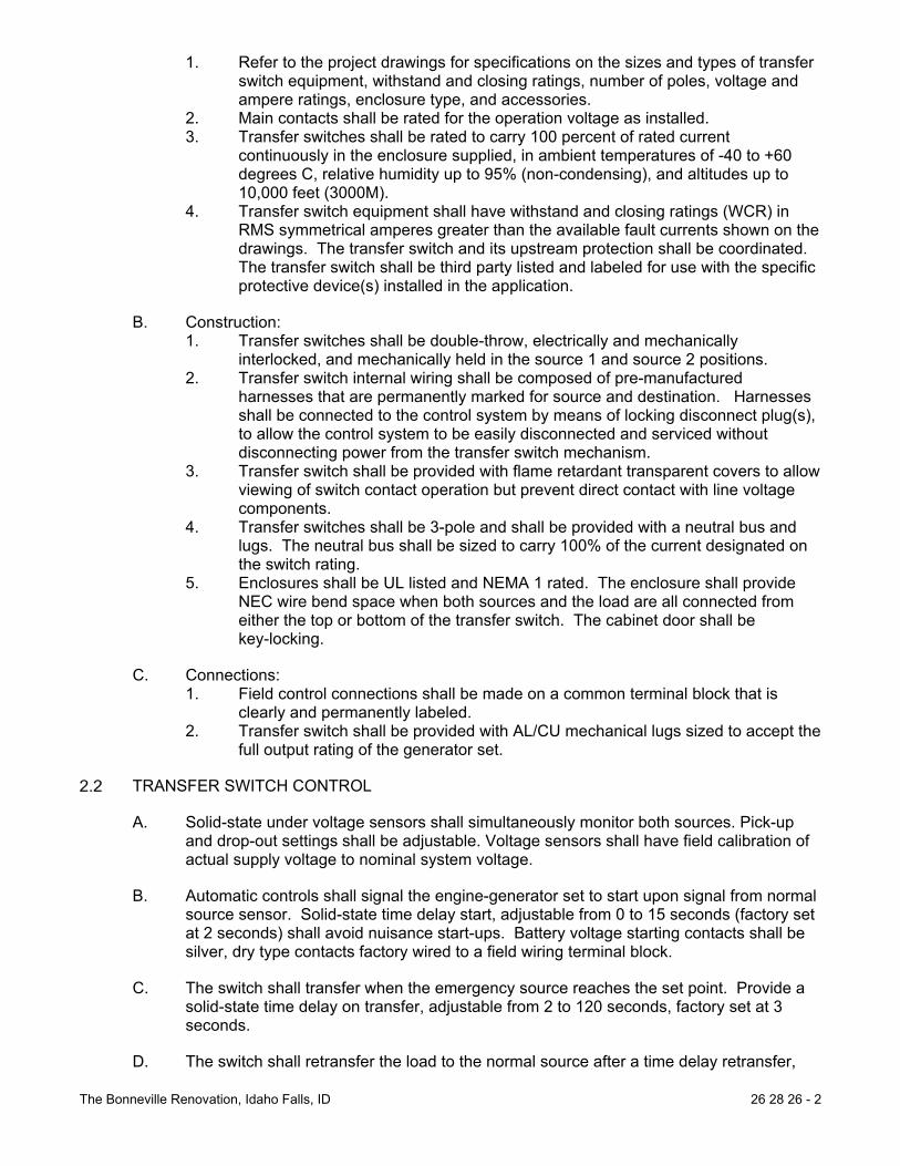
The Bonneville Renovation, Idaho Falls, ID 26 28 26 - 2
1. Refer to the project drawings for specifications on the sizes and types of transfer switch equipment, withstand and closing ratings, number of poles, voltage and ampere ratings, enclosure type, and accessories.
2. Main contacts shall be rated for the operation voltage as installed. 3. Transfer switches shall be rated to carry 100 percent of rated current
continuously in the enclosure supplied, in ambient temperatures of -40 to +60 degrees C, relative humidity up to 95% (non-condensing), and altitudes up to 10,000 feet (3000M).
4. Transfer switch equipment shall have withstand and closing ratings (WCR) in RMS symmetrical amperes greater than the available fault currents shown on the drawings. The transfer switch and its upstream protection shall be coordinated. The transfer switch shall be third party listed and labeled for use with the specific protective device(s) installed in the application.
B. Construction: 1. Transfer switches shall be double-throw, electrically and mechanically
interlocked, and mechanically held in the source 1 and source 2 positions. 2. Transfer switch internal wiring shall be composed of pre-manufactured
harnesses that are permanently marked for source and destination. Harnesses shall be connected to the control system by means of locking disconnect plug(s), to allow the control system to be easily disconnected and serviced without disconnecting power from the transfer switch mechanism.
3. Transfer switch shall be provided with flame retardant transparent covers to allow viewing of switch contact operation but prevent direct contact with line voltage components.
4. Transfer switches shall be 3-pole and shall be provided with a neutral bus and lugs. The neutral bus shall be sized to carry 100% of the current designated on the switch rating.
5. Enclosures shall be UL listed and NEMA 1 rated. The enclosure shall provide NEC wire bend space when both sources and the load are all connected from either the top or bottom of the transfer switch. The cabinet door shall be key-locking.
C. Connections: 1. Field control connections shall be made on a common terminal block that is
clearly and permanently labeled. 2. Transfer switch shall be provided with AL/CU mechanical lugs sized to accept the
full output rating of the generator set.
TRANSFER SWITCH CONTROL
A. Solid-state under voltage sensors shall simultaneously monitor both sources. Pick-up and drop-out settings shall be adjustable. Voltage sensors shall have field calibration of actual supply voltage to nominal system voltage.
B. Automatic controls shall signal the engine-generator set to start upon signal from normal source sensor. Solid-state time delay start, adjustable from 0 to 15 seconds (factory set at 2 seconds) shall avoid nuisance start-ups. Battery voltage starting contacts shall be silver, dry type contacts factory wired to a field wiring terminal block.
C. The switch shall transfer when the emergency source reaches the set point. Provide a solid-state time delay on transfer, adjustable from 2 to 120 seconds, factory set at 3 seconds.
D. The switch shall retransfer the load to the normal source after a time delay retransfer,

The Bonneville Renovation, Idaho Falls, ID 26 28 26 - 3
adjustable from 6 seconds to 30 minutes, factory set at 5 minutes. Retransfer time delay shall be immediately bypassed if the emergency power source fails.
E. Controls shall signal the engine-generator set to stop after a time delay, adjustable from 2 seconds to 10 minutes, and factory set at 5 minutes, beginning on return to the normal source.
F. The control system shall include field adjustable provisions to control the speed of transfer of the transfer switch.
G. Power for transfer operation shall be from the source to which the load is being transferred.
H. The control shall include latching diagnostic indicators to pinpoint the last successful step in the sequence of control functions, and to indicate the present status of the control functions in real time, as follows:
Normal Available Start (Gen Set) Emergency Available
Transfer Timing Transfer Complete Retransfer Timing
Retransfer Complete Timing for Stop
I. The transfer switch shall be provided with a battery charger for the generator set starting batteries. The battery charger shall be a float type charger rated 10 amps. The battery charger shall include an ammeter for display of charging current and shall have fused AC inputs and DC outputs. The charger shall also include fault indications for high and low dc voltage, and supply power failed, and dry contacts for external indication of these fault conditions. Supply power failed indication shall be displayed on the ATS control panel.
J. Provide solid state exerciser clock to set the day, time, and duration of generator set exercise/test period. Provide a with/without load selector switch for the exercise period.
FRONT PANEL DEVICES:
A. Provide control switches mounted on cabinet front for: 1. Test - Simulates normal power loss to control for testing of generator set.
Controls shall provide for a test with or without load transfer. 2. Retransfer - Momentary position to override retransfer time delay and cause
immediate return to normal source, if available. 3. Provide LED-type switch position and source available indicator lamps on the
front of the transfer switch cabinet. 4. Provide manual override switch to bypass the control system and transfer load
from source to source when control is disabled.
CONTROL INTERFACE
A. The transfer switch will provide an isolated relay contact for starting of a generator set. The relay shall be normally held open, and close to start the generator set. Output contacts shall be form C, for compatibility with any generator set.
B. Provide one set Form C auxiliary contacts on both sides, operated by transfer switch position, rated 10 amps 250 VAC.
C. The transfer switch shall provide relay contacts to indicate the following conditions:

The Bonneville Renovation, Idaho Falls, ID 26 28 26 - 4
source 1 available, load connected to source 1, source 2 available, source 2 connected to load.
ENCLOSURE
A. Enclosures shall be UL listed. The cabinet door shall be key-locking.
B. Transfer switch equipment shall be provided in a NEMA 1 or better enclosure.
C. Enclosures shall be the NEMA type specified. The cabinet shall provide code-required wire bend space at point of entry as shown on the drawings. Manual operating handles and all control switches (other than key-operated switches) shall be accessible to authorized personnel only by opening the key-locking cabinet door. Transfer switches with manual operating handles and/or non key-operated control switches located on outside of cabinet do not meet this specification and are not acceptable.
D. All transfer switches installed outside shall have a heater element installed with a thermostat control.
OPERATION
OPEN TRANSITION SEQUENCE OF OPERATION
A. Transfer switch normally connects an energized utility power source (source 1) to loads and a generator set (source 2) to the loads when normal source fails. The normal position of the transfer switch is source 1 (connected to the utility), and no start signal is supplied to the genset.
B. Generator Set Exercise (Test) With Load Mode. The control system shall be configurable to test the generator set under load. In this mode, the transfer switch shall control the generator set in the following sequence: 1. Transfer switch shall initiate the exercise sequence at a time indicated in the
exercise timer program, or when manually initiated by the operator. 2. When the control systems senses the generator set at rated voltage and
frequency, it shall operate to connect the loads to the generator set by opening the normal source contacts, and closing the alternate source contacts a predetermined time period later. The timing sequence for the contact operation shall be programmable in the controller.
3. The generator set shall operate connected to the load for the duration of the exercise period. If the generator set fails during this period, the transfer switch shall automatically reconnect the generator set to the normal service.
4. On completion of the exercise period, the transfer switch shall operate to connect the loads to the normal source by opening the alternate source contacts, and closing the normal source contacts a predetermined time period later. The timing sequence for the contact operation shall be programmable in the controller.
5. The transfer switch shall operate the generator set unloaded for a cool down period, and then remove the start signal from the generator set. If the normal power fails at any time when the generator set is running, the transfer switch shall immediately connect the system loads to the generator set.
C. Generator Set Exercise (Test) Without Load Mode. The control system shall be configurable to test the generator set without transfer switch load connected. In this mode, the transfer switch shall control the generator set in the following sequence:

The Bonneville Renovation, Idaho Falls, ID 26 28 26 - 5
1. Transfer switch shall initiate the exercise sequence at a time indicated in the exercise timer program, or when manually initiated by the operator.
2. When the control systems senses the generator set at rated voltage and frequency, it shall operate the generator set unloaded for the duration of the exercise period.
3. At the completion of the exercise period, the transfer switch shall remove the start signal from the generator set. If the normal power fails at any time when the generator set is running, the transfer switch shall immediately connect the system loads to the generator set.
OTHER REQUIREMENTS
A. Factory Testing: 1. The transfer switch supplier shall perform a complete operational test on the
transfer switch prior to shipping from the factory. A certified test report shall be available on request. Test process shall include calibration of voltage sensors.
B. Service and Support: 1. The manufacturer of the transfer switch shall maintain service parts inventory at
a central location which is accessible to the service location 24 hours per day, 365 days per year.
2. The transfer switch shall be serviced by a local service organization that is trained and factory certified in both generator set and transfer switch service. The supplier shall maintain an inventory of critical replacement parts at the local service organization, and in service vehicles. The service organization shall be on call 24 hours per day, 365 days per year.
3. The manufacturer shall maintain model and serial number records of each transfer switch provided for at least 20 years.
END OF SECTION

The Bonneville Renovation, Idaho Falls, ID 26 32 13 - 1
SECTION 26 32 13
ENGINE GENERATORS
GENERAL
SCOPE
A. Provide complete factory assembled generator set equipment with digital (microprocessor-based) electronic controls.
B. Provide factory test, startup by a supplier authorized by the manufacturer, and on-site testing of the system.
C. The generator set manufacturer shall warrant all equipment provided under this section, whether or not is manufactured by the generator set manufacturer, so that there is one source for warranty and product service. Technicians specifically trained and certified by the manufacturer to support the product and employed by the generator set supplier shall service the generator sets.
CODES AND STANDARDS
A. The generator set installation and on-site testing shall conform to the requirements of the following codes and standards, as applicable. The generator set shall include necessary features to meet the requirements of these standards. 1. CSA 282, 1989 Emergency Electrical Power Supply for Buildings 2. IEEE446 – Recommended Practice for Emergency and Standby Power Systems
for Commercial and Industrial Applications 3. NFPA37 – Standard For The Installation And Use Of Stationary Combustion
Engines And Gas Turbines 4. NFPA70 – National Electrical Code. Equipment shall be suitable for use in
systems in compliance to Article 700, 701, and 702. 5. NFPA99 – Essential Electrical Systems for Health Care Facilities 6. NFPA110 – Emergency and Standby Power Systems. The generator set shall
meet all requirements for Level 1 systems. Level 1 prototype tests required by this standard shall have been performed on a complete and functional unit, component level type tests will not substitute for this requirement.
7. 40 CFR 89 Certified EPA non-road CT Tier 3. 8. IBC 2014 – Roof Mounted Generators
B. The generator set and supplied accessories shall meet the requirements of the following standards: 1. NEMA MG1-1998 part 32. Alternator shall comply with the requirements of this
standard. 2. UL1236 – Battery Chargers 3. UL2200. The generator set shall be listed to UL2200 or submit to an independent
third party certification process to verify compliance as installed.
C. The control system for the generator set shall comply with the following requirements. 1. CSA C22.2, No. 14 – M91 Industrial Control Equipment. 2. EN50082-2, Electromagnetic Compatibility – Generic Immunity Requirements,
Part 2: Industrial. 3. EN55011, Limits and Methods of Measurement of Radio Interference
Characteristics of Industrial, Scientific and Medical Equipment. 4. FCC Part 15, Subpart B.

The Bonneville Renovation, Idaho Falls, ID 26 32 13 - 2
5. IEC8528 part 4. Control Systems for Generator Sets 6. IEC Std 801.2, 801.3, and 801.5 for susceptibility, conducted, and radiated
electromagnetic emissions. 7. UL508. The entire control system of the generator set shall be UL508 listed and
labeled. 8. UL1236 –Battery Chargers.
D. The generator set manufacturer shall be certified to ISO 9001 International Quality Standard and shall have third party certification verifying quality assurance in design/development, production, installation, and service, in accordance with ISO 9001.
ACCEPTABLE MANUFACTURERS
A. Only approved bidders shall supply equipment provided under this contract. Equipment specifications for this project are based on microprocessor-based generator sets manufactured by Cummins Power Generation.
B. This specification is based on a Cummins Model GGPB natural gas generator. Generators that meet this specification supplied by Generac, Kohler, or Cat are approved as “or equal” units.
PRODUCTS
GENERATOR SET
A. Ratings 1. The generator set shall operate at 1800 rpm at a voltage of: 208/120 Volts AC,
three phase, four-wire, 60 hertz. 2. The generator set shall be rated at 60 kW, at 0.8 lagging PF, full load rating,
based on site conditions of: Altitude 4,800 ft., ambient temperatures up to 85 degrees F.
3. The generator set rating shall be based on emergency/standby service. 4. Generator shall be roof mounted and meet the requirements of IBC 2014.
B. Performance 1. Voltage regulation shall be plus or minus 0.5 percent for any constant load
between no load and rated load for both parallel and non-parallel applications. Random voltage variation with any steady load from no load to full load shall not exceed plus or minus 0.5 percent.
2. Frequency regulation shall be isochronous from steady state no load to steady state rated load. Random frequency variation with any steady load from no load to full load shall not exceed plus or minus 0.25%.
3. The engine-generator set shall be capable of single step load pick up of 100% nameplate kW and power factor, less applicable derating factors, with the engine-generator set at operating temperature.
4. Motor starting capability shall be a minimum as shown below. The generator set shall be capable of sustaining a minimum of 90% of rated no load voltage with the specified kVA load at near zero power factor applied to the generator set.
Motor HP Starter Harmonic Filter Elevator 15 (208V 3ø) VFD No
5. The alternator shall produce a clean AC voltage waveform, with not more than
5% total harmonic distortion at full linear load, when measured from line to neutral, and with not more than 3% in any single harmonic. Telephone influence

The Bonneville Renovation, Idaho Falls, ID 26 32 13 - 3
factor shall be less than 40.
C. Construction 1. The engine-generator set shall be mounted on a heavy-duty steel base to
maintain alignment between components. The base shall incorporate a battery tray with hold-down clamps within the rails.
2. All switches, lamps, and meters in the control system shall be oil-tight and dust-tight, and the enclosure door shall be gasketed. There shall be no exposed points in the control (with the door open) that operate in excess of 50 volts.
3. The engine generator shall be mounted to vibration damping base and structurally sound roof curb.
D. Connections 1. The generator set load connections shall be composed of silver or tin plated
copper bus bars, drilled to accept mechanical or compression terminations of the number and type as shown on the drawings. Sufficient lug space shall be provided for use with cables of the number and size as shown on the drawings.
2. Power connections to auxiliary devices shall be made at the devices, with required protection located at a wall-mounted common distribution panel.
3. Generator set control interfaces to other system components shall be made on a common, permanently labeled terminal block assembly.
ENGINE AND ENGINE EQUIPMENT
A. The engine shall be natural gas fueled, radiator and fan cooled with V8 cylinders. The horsepower rating of the engine at its minimum tolerance level shall be sufficient to drive the alternator and all connected accessories. Engine accessories and features shall include: 1. Complete engine fuel system, including all pressure regulators, strainers, and
control valves. The fuel system shall be plumbed to the generator set skid for ease of site connections to the generator set. For dual fuel systems, changeover from primary to secondary fuel shall be automatic.
2. An electronic governor system shall provide automatic isochronous frequency regulation. The governing system dynamic capabilities shall be controlled as a function of engine coolant temperature to provide fast, stable operation at varying engine operating temperature conditions. The control system shall actively control the fuel rate and excitation as appropriate to the state of the generator set. Fuel rate shall be regulated as a function of starting, accelerating to start disconnect speed, accelerating to rated speed, and operating in various isochronous or parallel states.
3. Skid-mounted radiator and cooling system rated for full load operation in 104 degrees F (40 degrees C) ambient as measured at the generator air inlet, based on 0.5 in H2O external static head. Radiator shall be sized based on a core temperature that is 20F higher than the rated operation temperature, or prototype tested to verify cooling performance of the engine/radiator/fan operation in a controlled environment. Radiator shall be provided with a duct adapter flange. The equipment manufacturer shall fill the cooling system with a 50/50-ethylene glycol/water mixture. Rotating parts shall be guarded against accidental contact.
4. Electric starter(s) capable of three complete cranking cycles without overheating. 5. Positive displacement, mechanical, full pressure, lubrication oil pump. 6. Full flow lubrication oil filters with replaceable spin-on canister elements and
dipstick oil level indicator. 7. Replaceable dry element air cleaner with restriction indicator. 8. Flexible fuel lines. 9. Engine mounted battery charging alternator, 40-ampere minimum, and

The Bonneville Renovation, Idaho Falls, ID 26 32 13 - 4
solid-state voltage regulator. 10. Coolant heater
Engine mounted, thermostatically controlled, coolant heater(s) for each engine. Heater voltage shall be as shown on the project drawings. The coolant heater shall be UL499 listed and labeled.
The coolant heater shall be installed on the engine with high temperature silicone hose connections. Steel tubing shall be used for connections into the engine coolant system wherever the length of pipe run exceeds 12 inches. The coolant heater installation shall be specifically designed to provide proper venting of the system. The coolant heaters shall be installed using quick disconnect couplers to isolate the heater for replacement of the heater element. The quick disconnect/automatic sealing couplers shall allow the heater element to be replaced without draining the engine cooling system or significant coolant loss.
The coolant heater shall be provided with a 24VDC thermostat, installed at the engine thermostat housing. An AC power connection box shall be provided for a single AC power connection to the coolant heater system.
The coolant heater(s) shall be sized as recommended by the engine manufacturer to warm the engine to a minimum of 100F (40C) in a 40F ambient, in compliance with NFPA110 requirements, or the temperature required for starting and load pickup requirements of this specification.
11. Provide vibration isolators, spring/pad type or as recommended by the manufacturer, quantity as recommended by the generator set manufacturer. Isolators shall include seismic restraints if required by site location.
12. Starting and Control Batteries shall be calcium/lead antimony type, 24 volt DC, sized as recommended by the engine manufacturer, complete with battery cables and connectors.
13. Provide critical rated exhaust silencer(s) for each engine of size and type as recommended by the generator set manufacturer and approved by the engine manufacturer. The mufflers shall be critical grade. Exhaust system shall be installed according to the engine manufacturer’s recommendations and applicable codes and standards.
B. The contractor furnishing the generator shall be responsible for the generator exhaust system and all associated equipment.
AC GENERATOR
A. The AC generator shall be; synchronous, four pole, 2/3 pitch, revolving field, drip-proof construction, single prelubricated sealed bearing, air cooled by a direct drive centrifugal blower fan, and directly connected to the engine with flexible drive disc. All insulation system components shall meet NEMA MG1 temperature limits for Class H insulation system. Actual temperature rise measured by resistance method at full load shall not exceed 150 degrees Centigrade.
B. The generator shall be capable of delivering rated output (kVA) at rated frequency and power factor, at any voltage not more than 5 percent above or below rated voltage.
C. A permanent magnet generator (PMG) shall be included to provide a reliable source of excitation power for optimum motor starting and short circuit performance. The PMG and controls shall be capable of sustaining and regulating current supplied to a single phase or three phase fault at approximately 300% of rated current for not more than 10 seconds.
D. The subtransient reactance of the alternator shall not exceed 15 percent, based on the

The Bonneville Renovation, Idaho Falls, ID 26 32 13 - 5
standby rating of the generator set.
E. The alternator shall be capable of operation with reverse kVAR of 0.15 per unit.
GENERATOR SET CONTROL
A. The generator set shall be provided with a microprocessor-based control system that is designed to provide automatic starting, monitoring, and control functions for the generator set. The control system shall also be designed to allow local monitoring and control of the generator set, and remote monitoring and control as described in this specification.
B. The control shall be mounted on the generator set, or may be mounted in a free-standing panel next to the generator set if adequate space and accessibility is available. The control shall be vibration isolated and prototype tested to verify the durability of all components in the system under the vibration conditions encountered.
C. The generator set mounted control shall include the following features and functions: 1. Control Switches
Mode Select Switch. The mode select switch shall initiate the following control modes. When in the RUN or MANUAL position the generator set shall start, and accelerate to rated speed and voltage as directed by the operator. A separate push-button to initiate starting is acceptable. In the OFF position the generator set shall immediately stop, bypassing all time delays. In the AUTO position the generator set shall be ready to accept a signal from a remote device to start and accelerate to rated speed and voltage.
EMERGENCY STOP switch. Switch shall be Red "mushroom-head" push-button. Depressing the emergency stop switch shall cause the generator set to immediately shut down, and be locked out from automatic restarting.
RESET switch. The RESET switch shall be used to clear a fault and allow restarting the generator set after it has shut down for any fault condition.
PANEL LAMP switch. Depressing the panel lamp switch shall cause the entire panel to be lighted with DC control power. The panel lamps shall automatically be switched off 10 minutes after the switch is depressed, or after the switch is depressed a second time.
2. Generator Set AC Output Metering. The generator set shall be provided with a metering set including the following features and functions:
Digital metering set, 1% accuracy, to indicate generator RMS voltage and current, frequency, output current, output KW, KW-hours, and power factor. Generator output voltage shall be available in line-to-line and line-to-neutral voltages, and shall display all three-phase voltages (line to neutral or line to line) simultaneously.
Analog voltmeter, ammeter, frequency meter, power factor meter, and kilowatt (KW) meter. Voltmeter and ammeter shall display all three phases. Meter scales shall be color coded in the following fashion: green shall indicate normal operating condition, amber shall indicate operation in ranges that indicate potential failure, and red shall indicate failure impending. Metering accuracy shall be within 1% at rated output. Both analog and digital metering are required.
The control system shall monitor the total load on the generator set, and maintain data logs of total operating hours at specific load levels ranging from 0 to 110% of rated load, in 10% increments. The control shall

The Bonneville Renovation, Idaho Falls, ID 26 32 13 - 6
display hours of operation at less than 30% load and total hours of operation at more than 90% of rated load.
The control system shall log total number of operating hours, total kWH, and total control on hours, as well as total values since reset.
3. Generator Set Alarm and Status Display. The generator set control shall include LED alarm and status indication
lamps. The lamps shall be high-intensity LED type. The lamp condition shall be clearly apparent under bright room lighting conditions. Functions indicated by the lamps shall include: 1) The control shall include five configurable alarm-indicating lamps.
The lamps shall be field adjustable for any status, warning, or shutdown function monitored by the genset. They shall also be configurable for color, and control action (status, warning, or shutdown).
2) The control shall include green lamps to indicate that the generator set is running at rated frequency and voltage, and that a remote start signal has been received at the generator set. The running signal shall be based on actual sensed voltage and frequency on the output terminals of the generator set.
3) The control shall include a flashing red lamp to indicate that the control is not in automatic state, and red common shutdown lamp.
4) The control shall include an amber common warning indication lamp.
The generator set control shall indicate the existence of the warning and shutdown conditions on the control panel. All conditions indicated below for warning shall be field-configurable for shutdown. Conditions required to be annunciated shall include: 1) Low oil pressure (warning) 2) Low oil pressure (shutdown) 3) Oil pressure sender failure (warning) 4) Low coolant temperature (warning) 5) High coolant temperature (warning) 6) High coolant temperature (shutdown) 7) High oil temperature (warning) 8) Engine temperature sender failure (warning) 9) Low coolant level (warning) 10) Fail to crank (shutdown) 11) Fail to start/overcrank (shutdown) 12) Overspeed (shutdown) 13) Low DC voltage (warning) 14) High DC voltage (warning) 15) Weak battery (warning) 16) Low fuel-daytank (warning) 17) High AC voltage (shutdown) 18) Low AC voltage (shutdown) 19) Under frequency (shutdown) 20) Over current (warning) 21) Over current (shutdown) 22) Short circuit (shutdown) 23) Over load (warning) 24) Emergency stop (shutdown) 25) (4) Configurable conditions
Provisions shall be made for indication of four customer-specified alarm or shutdown conditions. Labeling of the customer-specified alarm or shutdown conditions shall be of the same type and quality as the above-

The Bonneville Renovation, Idaho Falls, ID 26 32 13 - 7
specified conditions. The non-automatic indicating lamp shall be red, and shall flash to indicate that the generator set is not able to automatically respond to a command to start from a remote location.
4. Engine Status Monitoring; The following information shall be available from a digital status panel on
the generator set control: 1) Engine oil pressure (psi or kPA) 2) Engine coolant temperature (degrees F or C) 3) Engine oil temperature (degrees F or C) 4) Engine speed (rpm) 5) Number of hours of operation (hours) 6) Number of start attempts 7) Battery voltage (DC volts)
The control system shall also incorporate a data logging and display provision to allow logging of the last 10 warning or shutdown indications on the generator set, as well as total time of operation at various loads, as a percent of the standby rating of the generator set.
5. Engine Control Functions: The control system provided shall include a cycle cranking system, which
allows for user selected crank time, rest time, and # of cycles. Initial settings shall be for 3 cranking periods of 15 seconds each, with 15-second rest period between cranking periods.
The control system shall include an idle mode control, which allows the engine to run in idle mode in the RUN position only. In this mode, the alternator excitation system shall be disabled.
The control system shall include an engine governor control, which functions to provide steady state frequency regulation as noted elsewhere in this specification. The governor control shall include adjustments for gain, damping, and a ramping function to control engine speed and limit exhaust smoke while the unit is starting.
The control system shall include time delay start (adjustable 0-300 seconds) and time delay stop (adjustable 0-600 seconds) functions.
The control system shall include sender failure monitoring logic for speed sensing, oil pressure, and engine temperature which is capable of discriminating between failed sender or wiring components, and an actual failure conditions.
6. Alternator Control Functions: The generator set shall include a full wave rectified automatic digital
voltage regulation system that is matched and prototype tested by the engine manufacturer with the governing system provided. It shall be immune from misoperation due to load-induced voltage waveform distortion and provide a pulse width modulated output to the alternator exciter. The voltage regulation system shall be equipped with three-phase line to neutral RMS sensing and shall control buildup of AC generator voltage to provide a linear rise and limit overshoot. The system shall include a torque-matching characteristic, which shall reduce output voltage in proportion to frequency below an adjustable frequency threshold. Torque matching characteristic shall be adjustable for roll-off frequency and rate, and be capable of being curve-matched to the engine torque curve with adjustments in the field. The voltage regulator shall include adjustments for gain, damping, and frequency roll-off. Adjustments shall be broad range, and made via digital raise-lower switches, with an alphanumeric LED readout to indicate setting level. Rotary potentiometers for system adjustments are not acceptable.
Controls shall be provided to monitor the output current of the generator

The Bonneville Renovation, Idaho Falls, ID 26 32 13 - 8
set and initiate an alarm (over current warning) when load current exceeds 110% of the rated current of the generator set on any phase for more than 60 seconds. The controls shall shut down and lock out the generator set when output current level approaches the thermal damage point of the alternator (over current shutdown). The protective functions provided shall be in compliance to the requirements of NFPA70 article 445. The protection for this function shall be 3rd party certified to very performance.
Controls shall be provided to individually monitor all three phases of the output current for short circuit conditions. The control/protection system shall monitor the current level and voltage. The controls shall shut down and lock out the generator set when output current level approaches the thermal damage point of the alternator (short circuit shutdown). The protective functions provided shall be in compliance to the requirements of NFPA70 article 445. The protection for this function shall be 3rd party certified to very performance.
Controls shall be provided to monitor the KW load on the generator set, and initiate an alarm condition (over load) when total load on the generator set exceeds the generator set rating for in excess of 5 seconds. Controls shall include a load shed control, to operate a set of dry contacts (for use in shedding customer load devices) when the generator set is overloaded.
An line to neutral sensing AC over/under voltage monitoring system that responds only to true RMS voltage conditions shall be provided. The system shall initiate shutdown of the generator set when alternator output voltage exceeds 110% of the operator-set voltage level for more than 10 seconds, or with no intentional delay when voltage exceeds 130%. Under voltage shutdown shall occur when the output voltage of the alternator is less than 85% for more than 10 seconds.
When required by National Electrical Code or indicated on project drawings, the control System shall include a ground fault monitoring relay. The relay shall be adjustable from 3.8-1200 amps, and include adjustable time delay of 0-10.0 seconds. The relay shall be for indication only, and not trip or shut down the generator set. Note bonding and grounding requirements for the generator set, and provide relay that will function correctly in system as installed.
The generator set control shall include a 120VAC-control heater. 7. Other Control Functions
The generator set shall be provided with a network communication module to allow LonMark compliant communication with the generator set control by remote devices. The control shall communicate all engine and alternator data, and allow starting and stopping of the generator set via the network in both test and emergency modes.
A battery monitoring system shall be provided which initiates alarms when the DC control and starting voltage is less than 25VDC or more than 32 VDC. During engine cranking (starter engaged), the low voltage limit shall be disabled, and DC voltage shall be monitored as load is applied to the battery, to detect impending battery failure or deteriorated battery condition.
8. Control Interfaces for Remote Monitoring: The control system shall provide four programmable output relays. These
relay outputs shall be configurable for any alarm, shutdown, or status condition monitored by the control. The relays shall be configured to indicate: (1) generator set operating at rated voltage and frequency, (2) common warning, (3) common shutdown, (4) load shed command.

The Bonneville Renovation, Idaho Falls, ID 26 32 13 - 9
A fused 10 amp switched 24VDC power supply circuit shall be provided for customer use. DC power shall be available from this circuit whenever the generator set is running.
A fused 10 amp 24VDC power supply circuit shall be provided for customer use. DC power shall be available from this circuit at all times from the engine starting/control batteries.
The control shall be provided with a direct serial communication link for the LonWorks communication network interface as described elsewhere in this specification and shown on the drawings.
OTHER EQUIPMENT TO BE PROVIDED WITH THE GENERATOR SET:
A. The generator set shall be provided with a mounted main line circuit breaker, sized to carry the rated output current of the generator set. The circuit breaker shall incorporate an electronic trip unit that operates to protect the alternator under all overcurrent conditions, or a thermal-magnetic trip with other overcurrent protection devices that positively protect the alternator under overcurrent conditions. The supplier shall submit time overcurrent characteristic curves and thermal damage curve for the alternator, demonstrating the effectiveness of the protection provided.
B. Outdoor Weather-Protective Enclosure 1. The generator set shall be provided with an outdoor enclosure, with the entire
package listed under UL2200. The package shall comply with the requirements of the National Electrical Code for all wiring materials and component spacing. The total assembly of generator set, enclosure, and sub-base fuel tank (when used) shall be designed to be lifted into place using spreader bars. Housing shall provide ample airflow for generator set operation at rated load in an ambient temperature of 100F. The housing shall have hinged access doors as required to maintain easy access for all operating and service functions. All doors shall be lockable, and include retainers to hold the door open during service. Enclosure roof shall be cambered to prevent rainwater accumulation. Openings shall be screened to limit access of rodents into the enclosure. All electrical power and control interconnections shall be made within the perimeter of the enclosure.
2. All sheet metal shall be primed for corrosion protection and finish painted with the manufacturer’s standard color using a two step electrocoating paint process, or equal meeting the performance requirements specified below. All surfaces of all metal parts shall be primed and painted. The painting process shall result in a coating that meets the following requirements:
Primer thickness, 0.5-2.0 mils. Top coat thickness, 0.8-1.2 mils. Gloss, per ASTM D523-89, 80% plus or minus 5%. Gloss retention after
one year shall exceed 50%. Crosshatch adhesion, per ASTM D3359-93, 4B-5B. Impact resistance, per ASTM D2794-93, 120-160 inch-pounds. Salt Spray, per ASTM B117-90, 1000+ hours.
Humidity, per ASTM D2247-92, 1000+ hours. Water Soak, per ASTM D2247-92, 1000+ hours.
3. Painting of hoses, clamps, wiring harnesses, and other non-metallic service parts shall not be acceptable. Fasteners used shall be corrosion resistant, and designed to minimize marring of the painted surface when removed for normal installation or service work.
4. Enclosure shall be constructed of minimum 12 gauge steel for framework and 14 gauge steel for panels. All hardware and hinges shall be stainless steel.
5. A factory-mounted exhaust silencer shall be installed inside the enclosure. The exhaust shall exit the enclosure through a rain collar and terminate with a rain cap. Exhaust connections to the generator set shall be through seamless flexible

The Bonneville Renovation, Idaho Falls, ID 26 32 13 - 10
connections. 6. The enclosure shall include the following maintenance provisions:
Flexible coolant and lubricating oil drain lines, that extend to the exterior of the enclosure, with internal drain valves
External radiator fill provision. 7. The generator set shall be provided with a sound-attenuated housing which
allows the generator set to operate at full rated load in an ambient temperature of up to 100F. The enclosure shall be a Cummins Quiet Site II housing with silencer or equal.
8. The enclosure shall be insulated with non-hydroscopic materials.
OPERATION
SEQUENCE OF OPERATION
A. Generator set shall start on receipt of a start signal from remote equipment. The start signal shall be via hardwired connection to the generator set control and a redundant signal over the required network connection.
B. The generator set shall complete a time delay start period as programmed into the control.
C. The generator set control shall initiate the starting sequence for the generator set. The starting sequence shall include the following functions: 1. The control system shall verify that the engine is rotating when the starter is
signaled to operate. If the engine does not rotate after two attempts, the control system shall shut down and lock out the generator set, and indicate “fail to crank” shutdown.
2. The engine shall fire and accelerate as quickly as practical to start disconnect speed. If the engine does not start, it shall complete a cycle cranking process as described elsewhere in this specification. If the engine has not started by the completion of the cycle cranking sequence, it shall be shut down and locked out, and the control system shall indicate “fail to start”.
3. The engine shall accelerate to rated speed and the alternator to rated voltage. Excitation shall be disabled until the engine has exceeded programmed idle speed, and regulated to prevent over voltage conditions and oscillation as the engine accelerates and the alternator builds to rated voltage.
D. On reaching rated speed and voltage, the generator set shall operate as dictated by the control system in isochronous, synchronize, load share, load demand, or load govern state.
E. When all start signals have been removed from the generator set, it shall complete a time delay stop sequence. The duration of the time delay stop period shall be adjustable by the operator.
F. On completion of the time delay stop period, the generator set control shall switch off the excitation system and shall shut down. 1. Any start signal received after the time stop sequence has begun shall
immediately terminate the stopping sequence and return the generator set to isochronous operation.
OTHER REQUIREMENTS
A. Submittals: Within 10 days after award of contract, provide six sets of the following

The Bonneville Renovation, Idaho Falls, ID 26 32 13 - 11
information for review: 1. Manufacturer’s product literature and performance data, sufficient to verify
compliance to specification requirements. 2. A paragraph by paragraph specification compliance statement, describing the
differences between the specified and the proposed equipment. 3. Manufacturer's certification of prototype testing. 4. Manufacturer's published warranty documents. 5. Shop drawings showing plan and elevation views with certified overall
dimensions, including height of tank generator and muffler assembly. 6. Interconnection wiring diagrams showing all external connections required; with
field wiring terminals marked in a consistent point-to-point manner. 7. Manufacturer's installation instructions.
B. Contractor coordination: 1. The contractor furnishing the generator, generator fuel tank, generator exhaust
system and other generator equipment shall provide, to scale, drawings of the generator and shall coordinate the generator information with the general contractor to verify that the generator can be properly housed in the structure designed. Any discrepancies shall be brought to the attention of the project engineer and a recommended solution shall be provided by the contractor.
FACTORY TESTING.
A. The generator set supplier shall perform a complete operational test on the generator set prior to shipping from the factory. A certified test report shall be provided. Equipment supplied shall be fully tested at the factory for function and performance.
B. Factory testing may be witnessed by the owner and consulting engineer. Costs for travel expenses will be the responsibility of the owner and consulting engineer. Supplier is responsible to provide two weeks’ notice for testing.
C. Generator set factory tests on the equipment shall be performed at rated load and rated power factor. Generator sets that have not been factory tested at rated power factor will not be acceptable. Tests shall include: run at full load, maximum power, voltage regulation, transient and steady-state governing, single step load pickup, and function of safety shutdowns.
INSTALLATION:
A. Equipment shall be installed by the contractor in accordance with final submittals and contract documents. Installation shall comply with applicable state and local codes as required by the authority having jurisdiction. Install equipment in accordance with manufacturer's instructions and instructions included in the listing or labeling of UL listed products.
B. Installation of equipment shall include furnishing and installing all interconnecting wiring between all major equipment provided for the on-site power system. The contractor shall also perform interconnecting wiring between equipment sections (when required), under the supervision of the equipment supplier.
C. Equipment shall be installed on concrete housekeeping pads. Equipment shall be permanently fastened to the pad in accordance with manufacturer’s instructions and seismic requirements of the site.
D. Equipment shall be initially started and operated by representatives of the manufacturer.

The Bonneville Renovation, Idaho Falls, ID 26 32 13 - 12
E. All equipment shall be physically inspected for damage. Scratches and other installation damage shall be repaired prior to final system testing. Equipment shall be thoroughly cleaned to remove all dirt and construction debris prior to final testing of the system.
ON-SITE ACCEPTANCE TEST:
A. The complete installation shall be tested for compliance with the specification following completion of all site work. Testing shall be conducted by representatives of the manufacturer, with required fuel supplied by Contractor. The Engineer shall be notified in advance and shall have the option to witness the tests.
B. Installation acceptance tests to be conducted on-site shall include a "cold start" test, a two hour full load test, and a one-step rated load pickup test in accordance with NFPA 110. Provide a resistive load bank and make temporary connections for full load test, if necessary.
C. Perform a power failure test on the entire installed system. This test shall be conducted by opening the power supply from the utility service, and observing proper operation of the system for at least 2 hours. Coordinate timing and obtain approval for start of test with site personnel.
D. The testing shall include load bank testing.
TRAINING
A. The equipment supplier shall provide training for the facility operating personnel covering operation and maintenance of the equipment provided. The training program shall be not less than 4 hours in duration and the class size shall be limited to 5 persons. Training date shall be coordinated with the facility owner.
SERVICE AND SUPPORT
A. The manufacturer of the generator set shall maintain service parts inventory at a central location which is accessible to the service location 24 hours per day, 365 days per year.
B. The generator set shall be serviced by a local service organization that is trained and factory certified in generator set service. The supplier shall maintain an inventory of critical replacement parts at the local service organization, and in service vehicles. The service organization shall be on call 24 hours per day, 365 days per year.
C. The manufacturer shall maintain model and serial number records of each generator set provided for at least 20 years.
WARRANTY
A. The generator set and associated equipment shall be warranted for a period of not less than 5 years from the date of commissioning against defects in materials and workmanship.
B. The warranty shall be comprehensive. No deductibles shall be allowed for travel time, service hours, repair parts cost, etc.
END OF SECTION

The Bonneville Renovation, Idaho Falls, ID 26 51 00 - 1
SECTION 26 51 00
INTERIOR LIGHTING
GENERAL
SUMMARY
A. Section Includes: 1. Interior Lighting Fixtures 2. Exit Signs 3. Emergency Lighting Units 4. Lamps 5. Accessories
REFERENCES
A. Institute of Electrical and Electronics Engineers, Inc. (IEEE) Publications: 1. C62.41 “Surge Voltages in Low-Voltage AC Power Circuits”
B. National Fire Protection Association (NFPA) Publications: 1. NFPA 70 "National Electric Code" 2. NFPA 101 “Life Safety Code®”
C. Underwriter's Laboratories, Inc. (UL) Publications: 1. 486A “Standard For Wire Connectors and Soldering Lugs for Use with Copper
Conductors” 2. 486B “Standard for Wire Connectors for Use with Aluminum Conductors” 3. 924 “Emergency Lighting and Power Equipment”
PRIOR APPROVAL
A. General: 1. Catalog and manufacturer's numbers are for the purpose of establishing
standards of quality and types of materials to be used. Products of other manufacturers may be used if equal in quality and design in the opinion of the Engineer and are specifically approved by the Engineer, in writing, 10 days prior to close of bidding.
2. Any conflict arising from the use of substituted equipment shall be the responsibility of the supplier of that equipment. The contractor and his supplier shall bear all costs required to make equipment comply with the intent of the plans and specifications.
SUBMITTALS
A. General: Submit the following in accordance with Conditions of Contract and Division 01 Specification Sections: 1. For each type of lighting fixture indicated, arranged in order of fixture designation.
Include data on features, accessories, and the following: Dimensions of fixtures. Certified results of laboratory tests for fixtures and lamps for photometric
performance. Emergency lighting unit battery and charger. Types LED. Photometric data.

The Bonneville Renovation, Idaho Falls, ID 26 51 00 - 2
2. Dimming Driver Compatibility Certificates: Signed by manufacturer of driver certifying that driver are compatible with dimming systems and equipment with which they are used.
3. Field Test Reports: Indicate and interpret test results for compliance with performance requirements.
4. Maintenance Data: For lighting fixtures to include in maintenance manuals specified in Division 01.
QUALITY ASSURANCE
A. Fixtures, Emergency Lighting Units, and Accessories: Listed and labeled as defined in NFPA 70, Article 100, by a testing agency acceptable to authorities having jurisdiction.
B. Comply with NFPA 70.
C. NFPA 101 Compliance: Comply with visibility and luminance requirements for exit signs.
COORDINATION
A. Fixtures, Mounting Hardware, and Trim: Coordinate layout and installation of lighting fixtures with ceiling system and other construction.
EXTRA MATERIALS
A. Deliver extra materials to Owner. Furnish extra materials described in Division 01 Section that match products installed, are packaged with protective covering for storage, and are identified with labels describing contents.
PRODUCTS
FIXTURES AND FIXTURE COMPONENTS, GENERAL
A. Approved Manufacturers: 1. Subject to compliance with requirements, provide the products indicated for each
designation in Lighting Fixture Schedule as shown on drawings. 2. All alternate light fixture packages shall be submitted a minimum of 7 days prior
to bid for approval.
B. Metal Parts: Free from burrs, sharp corners, and edges.
C. Sheet Metal Components: Steel, unless otherwise indicated. Form and support to prevent warping and sagging.
D. Doors, Frames, and Other Internal Access: Smooth operating, free from light leakage under operating conditions, and arranged to permit maintenance without use of tools. Arrange doors, frames, lenses, diffusers, and other pieces to prevent accidental falling during maintenance and when secured in operating position.
E. Reflecting Surfaces: Minimum reflectance as follows, unless otherwise indicated: 1. White Surfaces: 85 percent. 2. Specular Surfaces: 83 percent. 3. Diffusing Specular Surfaces: 75 percent. 4. Laminated Silver Metallized Film: 90 percent.
F. Lenses, Diffusers, Covers, and Globes: 100 percent virgin acrylic plastic or annealed crystal glass, unless otherwise indicated.

The Bonneville Renovation, Idaho Falls, ID 26 51 00 - 3
1. Plastic: High resistance to yellowing and other changes due to aging, exposure to heat, and ultraviolet radiation.
2. Lens Thickness: 0.125 inch minimum, unless greater thickness is indicated.
LED LIGHTING FIXTURES
A. General Requirements: 1. See lighting fixtures schedule for specifications.
EXIT SIGNS
A. General Requirements: Comply with UL 924 and the following: 1. Sign Colors and Lettering Size: Comply with authorities having jurisdiction.
B. Internally Lighted Signs: As follows: 1. Lamps for AC Operation: Light-emitting diodes, 70,000 hours minimum rated
lamp life.
C. Self-Powered Exit Signs (Battery Type): Integral automatic charger in a self-contained power pack. 1. Battery: Sealed, maintenance-free, nickel-cadmium type with special warranty. 2. Charger: Fully automatic, solid-state type with sealed transfer relay. 3. Operation: Relay automatically energizes lamp from unit when circuit voltage
drops to 80 percent of nominal or below. When normal voltage is restored, relay disconnects lamps, and battery is automatically recharged and floated on charger.
EMERGENCY LIGHTING UNITS
A. General Requirements: Self-contained units. Comply with UL 924. Units include the following features: 1. Battery: Sealed, maintenance-free, lead-acid type with minimum 10-year
nominal life and special warranty. 2. Charger: Fully automatic, solid-state type with sealed transfer relay. 3. Operation: Relay automatically turns lamp on when supply circuit voltage drops
to 80 percent of nominal voltage or below. Lamp automatically disconnects from battery when voltage approaches deep-discharge level. When normal voltage is restored, relay disconnects lamps, and battery is automatically recharged and floated on charger.
4. Integral Time-Delay Relay: Arranged to hold unit on for fixed interval after restoring power after an outage. Provides adequate time delay to permit high-intensity-discharge lamps to restrike and develop adequate output.
FIXTURE SUPPORT COMPONENTS
A. Comply with Section 26 05 00 "Basic Electrical Materials and Methods," for channel- and angle-iron supports and nonmetallic channel and angle supports.
B. Single-Stem Hangers: 1/2-inch steel tubing with swivel ball fitting and ceiling canopy. Finish same as fixture.
C. Twin-Stem Hangers: Two, 1/2-inch steel tubes with single canopy arranged to mount a single fixture. Finish same as fixture.
D. Rod Hangers: 3/16-inch- minimum diameter, cadmium-plated, threaded steel rod.

The Bonneville Renovation, Idaho Falls, ID 26 51 00 - 4
E. Hook Hangers: Integrated assembly matched to fixture and line voltage and equipped with threaded attachment, cord, and locking-type plug.
F. Aircraft Cable Support: Use cable, anchorages, and intermediate supports recommended by fixture manufacturer.
FINISHES
A. Fixtures: Manufacturer's standard, unless otherwise indicated. 1. Paint Finish: Applied over corrosion-resistant treatment or primer, free of
defects. 2. Metallic Finish: Corrosion resistant. 3. Colors as indicated in Light Fixture Schedule.
EXECUTION
INSTALLATION
A. Do not locate light fixtures in closet or storage areas within 18 inches of shelves. Do not locate fluorescent fixtures within six inches of shelves.
B. Securely fasten fixtures in place in all areas. Fixtures located in secure areas shall be anchored at four corners.
C. Where recessed lighting fixtures are to be installed, provide openings, plaster rings, etc., of exact dimensions for such fixtures to be inserted in openings. Terminate circuits for recessed fixtures in an extension outlet box near fixture and connect with 1/2 inch flexible conduit in accordance with Contract Documents.
D. Where fluorescent units are shown installed end to end, provide suitable connectors or collars to connect adjoining units to appear as a continuous unit.
E. Each fixture shall be wired with a 72 inch piece of flexible conduit connected to a blank covered junction box located in the accessible ceiling space within 36 inches of the fixture connection point.
F. Do not install fixture lens enclosures or louvers in fixtures until general construction work is complete, including painting.
G. All light fixtures and lamps shall be left clean at the time of substantial completion of the work. It is the responsibility of the electrical contractor for protection and final cleaning of fixtures. If fixtures are dirty at completion of the project, the Contractor shall clean them at no additional cost to the Owner.
Light Fixture Attachment:
A. Light fixtures in ceiling grid shall be mechanically attached to grid per NEC 410-16 (two per fixture unless independently supported). 1. Surface-mounted fixtures shall be attached to grid. 2. Pendant-hung fixtures shall be directly supported from structure with 9-gauge
wire (or approved alternative). 3. Rigid lay-in or can light fixtures:
<10 lbs. - one wire to structure (may be slack). 11 to 56 lbs. - two wires from housing to structure (may be slack). >57 lbs. - supported directly to structure by approved method.

The Bonneville Renovation, Idaho Falls, ID 26 51 00 - 5
CONNECTIONS
A. Ground Equipment: 1. Tighten electrical connectors and terminals according to manufacturer's
published torque-tightening values. If manufacturer's torque values are not indicated, use those specified in UL 486A and UL 486B.
FIELD QUALITY CONTROL
A. Inspect each installed fixture for damage. Replace damaged fixtures and components.
B. Advance Notice: Give dates and times for field tests.
C. Provide instruments to make and record test results.
D. Tests: As follows: 1. Verify normal operation of each fixture after installation. 2. Emergency Lighting: Interrupt electrical supply to demonstrate proper operation. 3. Verify normal transfer to battery source and retransfer to normal. 4. Report results in writing.
E. Malfunctioning Fixtures and Components: Replace or repair, then retest. Repeat procedure until units operate properly.
F. Corrosive Fixtures: Replace during warranty period.
CLEANING AND ADJUSTING
A. Clean fixtures internally and externally after installation. Use methods and materials recommended by manufacturer.
B. Adjust aimable fixtures to provide required light intensities.
END OF SECTION

The Bonneville Renovation, Idaho Falls, ID 26 52 00 - 1
SECTION 26 52 00
EMERGENCY LIGHTING
GENERAL
SUMMARY
A. Section includes emergency lighting units and exit signs.
REFERENCES
A. National Electrical Manufacturers Association:
B. NEMA WD 6 - Wiring Devices-Dimensional Requirements.
SYSTEM DESCRIPTION
A. Emergency lighting to comply with requirements.
SUBMITTALS
A. Section 01 33 00 - Submittal Procedures: Submittal procedures.
B. Product Data: Submit dimensions, ratings, and performance data.
QUALIFICATIONS
A. Manufacturer: Company specializing in manufacturing products specified in this section with minimum three years’ experience.
MAINTENANCE MATERIALS
A. Section 01 70 00 - Execution and Closeout Requirements: Spare parts and maintenance products.
PRODUCTS
EMERGENCY LIGHTING UNITS
A. As shown on the drawings.
B. All alternate emergency light fixtures shall be submitted a minimum of 10 days prior to bid for approval.
EXIT SIGNS
A. As shown on the drawings.
B. All alternate exit light fixtures shall be submitted a minimum of 10 days prior to bid for approval.
FLUORESCENT LAMP EMERGENCY POWER SUPPLY
A. As shown on the drawings.

The Bonneville Renovation, Idaho Falls, ID 26 52 00 - 2
B. All alternate fluorescent lamp emergency power supply submittals shall be submitted a minimum of 10 days prior to bid for approval.
EXECUTION
INSTALLATION
A. Install suspended exit signs using pendants supported from swivel hangers. Install pendant length required to suspend sign at indicated height.
B. Install surface-mounted exit signs plumb and adjust to align with building lines and with each other. Secure to prevent movement.
C. Install accessories furnished with each emergency lighting unit.
D. Connect emergency lighting units and exit signs to branch circuit outlets provided in Section 26 05 33 as indicated on Drawings.
E. Make wiring connections to branch circuit using building wire with insulation suitable for temperature conditions within unit.
F. Install specified lamps in each emergency lighting unit and exit sign.
G. Ground and bond emergency lighting units and exit signs in accordance with Section 26 05 26.
FIELD QUALITY CONTROL
A. Section 01 40 00 - Quality Requirements, 01 70 00 - Execution and Closeout Requirements: Field inspecting, testing, adjusting, and balancing.
B. Operate each unit after installation and connection. Inspect for proper connection and operation.
ADJUSTING
A. Section 01 70 00 - Execution and Closeout Requirements: Testing, adjusting, and balancing.
B. Position exit sign directional arrows as indicated on Drawings.
PROTECTION OF FINISHED WORK
A. Section 01 70 00 - Execution and Closeout Requirements: Protecting finished work.
B. Relamp emergency lighting units and exit signs having failed lamps at Substantial Completion.
END OF SECTION

The Bonneville Renovation, Idaho Falls, ID 26 56 00 - 1
SECTION 26 56 00
EXTERIOR LIGHTING
GENERAL
SUMMARY
A. Section Includes: 1. Exterior Lighting Units with Luminaires 2. Drivers 3. Accessories
DEFINITIONS
A. Lighting Unit: A luminaire or an assembly of luminaires complete with a common support, including mounting and support accessories.
B. Luminaire (Light Fixture): A complete lighting device consisting of LED’s and drivers, when applicable, together with parts designed to distribute light, to position and protect lamps, and to connect lamps to power supply.
SUBMITTALS
A. General: Submit the following in accordance with Conditions of Contract and Division 01 Specification Sections: 1. For each type of lighting fixture indicated, arranged in order of fixture designation.
Include data on features, accessories, and the following: Dimensions of fixtures. Certified results of laboratory tests for fixtures and lamps for photometric
performance. Emergency lighting unit battery and charger. Photometric data.
2. Dimming Ballast Compatibility Certificates: Signed by manufacturer of ballast certifying that ballasts are compatible with dimming systems and equipment with which they are used.
3. Field Test Reports: Indicate and interpret test results for compliance with performance requirements.
4. Maintenance Data: For lighting fixtures to include in maintenance manuals specified in Division 01.
PRIOR APPROVAL
A. General: 1. Catalog and manufacturer's numbers are for the purpose of establishing
standards of quality and types of materials to be used. Products of other manufacturers may be used if equal in quality and design in the opinion of the Engineer and are specifically approved by the Engineer, in writing, 7 days prior to close of bidding.
2. Any conflict arising from the use of substituted equipment shall be the responsibility of the supplier of that equipment. The contractor and his supplier shall bear all costs required to make equipment comply with the intent of the plans and specifications.
The Bonneville Renovation, Idaho Falls, ID 26 56 00 - 2
QUALITY ASSURANCE
A. Luminaires and Accessories: Listed and labeled as defined in NFPA 70, Article 100, for their indicated use, location, and installation conditions by a testing agency acceptable to authorities having jurisdiction
B. Comply with ANSI C2.
C. Comply with NFPA 70.
EXTRA MATERIALS
A. Deliver extra materials to Owner. Furnish extra materials described in Division 01 Section that match products installed, are packaged with protective covering for storage, and are identified with labels describing contents.
PRODUCTS
LUMINAIRES
A. Approved Manufacturers: 1. Subject to compliance with requirements, provide the products indicated for each
designation in Section 26 05 50.16 - Lighting Fixture Schedule. 2. All alternate light fixture packages shall be submitted a minimum of 10 days prior
to bid for approval.
B. Comply with ANSI/IESNA RP-8 for parameters of lateral light distribution patterns indicated for luminaires.
C. Metal Parts: Free from burrs, sharp corners, and edges.
D. Sheet Metal Components: Corrosion-resistant aluminum, unless otherwise indicated. Form and support to prevent warping and sagging.
E. Housings: Rigidly formed, weather- and light-tight enclosures that will not warp, sag, or deform in use. Provide filter/breather for enclosed luminaires.
F. Doors, Frames, and Other Internal Access: Smooth operating, free from light leakage under operating conditions, and arranged to permit relamping without use of tools. Arrange doors, frames, lenses, diffusers, and other pieces to prevent accidental falling during relamping and when secured in operating position. Provide for door removal for cleaning or replacing lens. Arrange to disconnect ballast when door opens.
G. Exposed Hardware Material: Stainless steel.
H. Plastic Parts: High resistance to yellowing and other changes due to aging, exposure to heat, and ultraviolet radiation.
I. Reflecting Surfaces: Minimum reflectance as follows, unless otherwise indicated: 1. White Surfaces: 85 percent. 2. Specular Surfaces: 83 percent. 3. Diffusing Specular Surfaces: 75 percent.
J. Lenses and Refractors: Materials as indicated. Use heat- and aging-resistant, resilient gaskets to seal and cushion lens and refractor in luminaire doors.

The Bonneville Renovation, Idaho Falls, ID 26 56 00 - 3
K. Photoelectric Relays: As follows: 1. Contact Relays: Single throw, arranged to fail in the on position and factory set
to turn light unit on at 1.5 to 3 fc and off at 4.5 to 10 fc with 15-second minimum time delay.
2. Relay Mounting: In luminaire housing.
LED’s
A. Approved Manufacturers: 1. See fixture schedule
EXECUTION
INSTALLATION
A. Luminaire Attachment: Fasten to indicated structural supports.
B. Luminaire Attachment with Adjustable Features or Aiming: Attach luminaires and supports to allow aiming for indicated light distribution.
C. Lamp luminaires with indicated lamps according to manufacturer's written instructions. Replace malfunctioning lamps.
CONNECTIONS
A. Ground equipment. 1. Tighten electrical connectors and terminals according to manufacturer's
published torque-tightening values. If manufacturer's torque values are not indicated, use those specified in UL 486A and UL 486B.
FIELD QUALITY CONTROL
A. Inspect each installed unit for damage. Replace damaged units.
B. Advance Notice: Give dates and times for field tests.
C. Provide instruments to make and record test results.
D. Tests and Observations: Verify normal operation of lighting units after installing luminaires and energizing circuits with normal power source, and as follows: 1. Measure light intensities at night if specific illumination performance is indicated.
Use photometers with calibration referenced to NIST standards. 2. Check intensity and uniformity of illumination. 3. Check excessively noisy ballasts.
E. Prepare a written report of tests, inspections, observations and verifications indicating and interpreting results.
F. Malfunctioning Fixtures and Components: Replace or repair, then retest. Repeat procedure until units operate properly.
CLEANING AND ADJUSTING
A. Clean units after installation. Use methods and materials recommended by manufacturer.

The Bonneville Renovation, Idaho Falls, ID 26 56 00 - 4
B. Adjust amiable luminaires and luminaires with adjustable lamp position to provide required light distributions and intensities.
END OF SECTION

The Bonneville Renovation, Idaho Falls, ID 27 05 33 - 1
SECTION 27 05 33
CONDUITS AND BACKBOXES FOR COMMUNICATIONS SYSTEMS
GENERAL
SUMMARY
A. Section includes conduit and tubing, surface raceways, wire ways, outlet boxes, pull and junction boxes, and hand holes.
REFERENCES
A. American National Standards Institute: 1. ANSI C80.1 - Rigid Steel Conduit, Zinc Coated 2. ANSI C80.3 - Specification for Electrical Metallic Tubing, Zinc Coated
B. National Electrical Manufacturers Association: 1. NEMA 250 - Enclosures for Electrical Equipment (1000 Volts Maximum) 2. NEMA FB 1 - Fittings, Cast Metal Boxes, and Conduit Bodies for Conduit and
Cable Assemblies 3. NEMA OS 1 - Sheet Steel Outlet Boxes, Device Boxes, Covers, and Box
Supports 4. NEMA OS 2 - Nonmetallic Outlet Boxes, Device Boxes, Covers, and Box
Supports
SYSTEM DESCRIPTION
A. Raceway and boxes located as indicated on Drawings, and at other locations required for splices, taps, wire pulling, equipment connections, and compliance with regulatory requirements. Raceway and boxes are shown in approximate locations unless dimensioned. Provide raceway to complete wiring system.
B. Concealed Dry Locations: Provide electrical metallic tubing and nonmetallic conduit. Provide sheet-metal boxes. Provide flush mounting outlet box in finished areas.
C. Exposed Dry Locations: Provide electrical metallic tubing and nonmetallic conduit. Provide sheet-metal boxes. Provide flush mounting outlet box in finished areas.
DESIGN REQUIREMENTS
A. Minimum Raceway Size: 3/4 inch unless otherwise specified.
PRIOR APPROVAL
A. General: 1. Catalog and manufacturer's numbers are for the purpose of establishing
standards of quality and types of materials to be used. Products of other manufacturers may be used if equal in quality and design in the opinion of the Engineer and are specifically approved by the Engineer, in writing, 10 days prior to close of bidding.
2. Any conflict arising from the use of substituted equipment shall be the responsibility of the supplier of that equipment. The contractor and his supplier shall bear all costs required to make equipment comply with the intent of the plans and specifications.

The Bonneville Renovation, Idaho Falls, ID 27 05 33 - 2
SUBMITTALS
A. Section 01 33 00 - Submittal Procedures: Submittal procedures.
B. Product Data: Submit for the following: 1. Electrical metallic tubing 2. Surface raceway 3. Floor boxes
C. Manufacturer's Installation Instructions: Submit application conditions and limitations of use stipulated by Product testing agency specified under Regulatory Requirements. Include instructions for storage, handling, protection, examination, preparation, and installation of Product.
CLOSEOUT SUBMITTALS
A. Section 01 70 00 - Execution and Closeout Requirements: Requirements for submittals.
B. Project Record Documents: 1. Record actual locations and mounting heights of outlet, pull, and junction boxes.
DELIVERY, STORAGE, AND HANDLING
A. Section 01 60 00 - Product Requirements: Product storage and handling requirements.
B. Protect conduit from corrosion and entrance of debris by storing above grade. Provide appropriate covering.
COORDINATION
A. Section 01 30 00 - Administrative Requirements: Coordination and project conditions.
B. Coordinate installation of outlet boxes for equipment connected under Section 26 05 33.
C. Coordinate mounting heights, orientation and locations of outlets mounted above counters, benches, and backsplashes.
PRODUCTS
ELECTRICAL METALLIC TUBING (EMT)
A. Product Description: ANSI C80.3; galvanized tubing.
B. Fittings and Conduit Bodies: NEMA FB 1; steel compression type.
SURFACE METAL RACEWAY
A. Manufacturers: 1. Carlon Electrical Products 2. Hubbell Wiring Devices 3. Thomas & Betts Corp. 4. Walker Systems Inc. 5. The Wiremold Co.
B. Product Description: Sheet metal channel with fitted cover, suitable for use as surface metal raceway.

The Bonneville Renovation, Idaho Falls, ID 27 05 33 - 3
SURFACE NONMETAL RACEWAY
A. Manufacturers: 1. Carlon Electrical Products 2. Hubbell Wiring Devices 3. Thomas & Betts Corp. 4. Walker Systems Inc. 5. The Wiremold Co.
B. Product Description: Fiberglass channel with fitted cover, suitable for use as surface raceway.
C. Finish: white
D. Fittings, Boxes, and Extension Rings: Furnish manufacturer’s standard accessories, finish to match raceway.
OUTLET BOXES
A. Sheet Metal Outlet Boxes: NEMA OS 1, galvanized steel. 1. Luminaire and Equipment Supporting Boxes: Rated for weight of equipment
supported; furnish 1/2 inch male fixture studs where required. 2. Concrete Ceiling Boxes: Concrete type.
B. Wall Plates for Finished Areas: As specified in Section 26 27 26.
EXECUTION
EXAMINATION
A. Section 01 30 00 - Administrative Requirements: Coordination and project conditions.
B. Verify outlet locations and routing and termination locations of raceway prior to rough-in.
EXISTING WORK
A. Remove exposed abandoned raceway. Cut raceway flush with walls and floors, and patch surfaces.
B. Remove concealed abandoned raceway to its source.
C. Disconnect abandoned outlets and remove devices. Remove abandoned outlets when raceway is abandoned and removed. Install blank cover for abandoned outlets not removed.
D. Maintain access to existing boxes and other installations remaining active and requiring access. Modify installation or provide access panel.
E. Extend existing raceway and box installations using materials and methods as specified.
F. Clean and repair existing raceway and boxes to remain or to be reinstalled.
INSTALLATION
A. Install Work in accordance with standards.

The Bonneville Renovation, Idaho Falls, ID 27 05 33 - 4
B. Identify raceway and boxes in accordance with Section 26 05 53.
C. Arrange raceway and boxes to maintain headroom and present neat appearance.
INSTALLATION - RACEWAY
A. Raceway routing is shown in approximate locations unless dimensioned. Route to complete wiring system.
B. Arrange raceway supports to prevent misalignment during wiring installation.
C. Support raceway using coated steel or malleable iron straps, lay-in adjustable hangers, clevis hangers, and split hangers.
D. Do not support raceway with wire or perforated pipe straps. Remove wire used for temporary supports
E. Do not attach raceway to ceiling support wires or other piping systems.
F. Construct wire way supports from steel channel specified in Section 26 05 29.
G. Route exposed raceway parallel and perpendicular to walls.
H. Route raceway installed above accessible ceilings parallel and perpendicular to walls.
I. Maintain clearance between raceway and piping for maintenance purposes.
J. Maintain 12-inch clearance between raceway and surfaces with temperatures exceeding 104 degrees F.
K. Cut conduit square using saw or pipe cutter; de-burr cut ends.
L. Bring conduit to shoulder of fittings; fasten securely.
M. Install no more than equivalent of three 90-degree bends between boxes. Install conduit bodies to make sharp changes in direction, as around beams.
INSTALLATION - BOXES
A. Owner to install all rough-in boxes for data cabling.
INTERFACE WITH OTHER PRODUCTS
A. Install conduit to preserve fire resistance rating of partitions and other elements.
CLEANING
A. Section 01 70 00 - Execution and Closeout Requirements: Final cleaning.
B. Clean interior of boxes to remove dust, debris, and other material.
C. Clean exposed surfaces and restore finish.
END OF SECTION

Site and Infrastructure

The Bonneville Renovation, Idaho Falls, ID 32 13 13 - 1
DIVISION 32 EXTERIOR IMPROVEMENTS
SECTION 32 13 13
CONCRETE PAVING
PART 1 GENERAL
1.1 SUMMARY
A. Section Includes: 1. Concrete sidewalks. 2. Concrete integral curbs and gutters. 3. Aggregate base course.
1.2 REFERENCES
A. American Concrete Institute: 1. ACI 301 - Specifications for Structural Concrete. 2. ACI 304 - Guide for Measuring, Mixing, Transporting, and Placing Concrete.
B. ASTM International: 1. ASTM C33 - Standard Specification for Concrete Aggregates. 2. ASTM C94/C94M - Standard Specification for Ready-Mixed Concrete. 3. ASTM C150 - Standard Specification for Portland Cement. 4. ASTM C260 - Standard Specification for Air-Entraining Admixtures for Concrete. 5. ASTM C309 - Standard Specification for Liquid Membrane-Forming Compounds
for Curing Concrete. 6. ASTM C494/C494M - Standard Specification for Chemical Admixtures for
Concrete. 7. ASTM C1315 - Standard Specification for Liquid Membrane-Forming
Compounds Having Special Properties for Curing and Sealing Concrete. 8. ASTM D1751 - Standard Specification for Preformed Expansion Joint Filler for
Concrete Paving and Structural Construction (Nonextruding and Resilient Bituminous Types).
1.3 SUBMITTALS
A. Section 01 33 00 - Submittal Procedures: Requirements for submittals.
B. Product Data: Submit data on curing compounds.
1.4 QUALITY ASSURANCE
A. Perform Work in accordance with ACI 301.
B. Perform Work in accordance with Municipality of Pocatello standard.
C. Obtain cementitious materials from same source throughout.
1.5 QUALIFICATIONS
A. Manufacturer: Company specializing in manufacturing Products specified in this section with minimum three years experience.

The Bonneville Renovation, Idaho Falls, ID 32 13 13 - 2
B. Installer: Company specializing in performing work of this section with minimum five years experience.
1.6 ENVIRONMENTAL REQUIREMENTS
A. Section 01 60 00 - Product Requirements: Environmental conditions affecting products on site.
B. Do not place concrete when base surface temperature is less than 40 degrees F, or surface is wet or frozen.
PART 2 PRODUCTS
2.1 FORM MATERIALS
A. Wood or Steel form material, profiled to suit conditions.
B. Joint Filler: ASTM D1751 1/2 inch thick.
2.2 REINFORCEMENT
A. Fiber Mesh.
2.3 CONCRETE MATERIALS
A. Cement: ASTM C150 Portland type II, white color.
B. Fine and Coarse Mix Aggregates: ASTM C33.
C. Water: Potable, not detrimental to concrete.
D. Air Entrainment: ASTM C260.
E. Chemical Admixtures: By written approval only.
2.4 ACCESSORIES
A. Curing Compound: ASTM C309, Type 1, Class A.
2.5 CONCRETE MIX - BY PERFORMANCE CRITERIA
A. Mix concrete in accordance with ACI 304. Deliver concrete in accordance with ASTM C94/C94M.
B. Select proportions for normal weight concrete in accordance with ACI 301 Method 3.
C. Provide concrete to the following criteria: 1. Compressive Strength: 2400 psi at 7 days. 2. Compressive Strength: 4000 psi at 28 days. 3. Slump: 2 to 4 inches. 4. Minimum Cement Content: 6.5 bags/cu yd. 5. Maximum Water/Cement Ratio: 0.45. 6. Air Entrained: 6.5 percent, ± 1.5%. 7. Maximum Aggregate Size: 3/4 inch. 8. Fiber Mesh: 1.5 lbs/cy. 9. Fly Ash: Maximum 15% cement.

The Bonneville Renovation, Idaho Falls, ID 32 13 13 - 3
D. Use accelerating admixtures in cold weather only when approved by the Architect in writing. Use of admixtures will not relax cold weather placement requirements.
E. Use calcium chloride only when approved by the Architect in writing.
F. Use set retarding admixtures during hot weather only when approved by the Architect in writing.
2.6 SOURCE QUALITY CONTROL AND TESTS
A. Section 01 40 00 - Quality Requirements: Testing and Inspection Services: Provide mix design for concrete mix.
B. Submit proposed mix design of each class of concrete to appointed firm for review prior to commencement of Work.
C. Tests on cement, aggregates, and mixes will be performed to ensure conformance with specified requirements.
D. Test samples in accordance with ACI 301.
PART 3 EXECUTION
3.1 EXAMINATION
A. Section 01 30 00 - Administrative Requirements: Verification of existing conditions before starting work.
B. Verify compacted subgrade is acceptable and ready to support paving and imposed loads.
C. Verify gradients and elevations of base are correct.
3.2 SUBBASE
A. Prepare subbase in accordance with Municipality of Pocatello standards.
3.3 PREPARATION
A. Moisten base to minimize absorption of water from fresh concrete.
B. Notify Architect a minimum of 24 hours prior to commencement of concreting operations.
3.4 FORMING
A. Place and secure forms to correct location, dimension, profile, and gradient.
B. Assemble formwork to permit easy stripping and dismantling without damaging concrete.
C. Place joint filler vertical in position, in straight lines. Secure to formwork during concrete placement.
3.5 PLACING CONCRETE
A. Place concrete in accordance with ACI 301.

The Bonneville Renovation, Idaho Falls, ID 32 13 13 - 4
B. Place concrete continuously over the full width of the panel and between predetermined construction joints. Do not break or interrupt successive pours such that cold joints occur.
C. Place concrete to pattern indicated.
3.6 JOINTS
A. Place expansion joints at 20 foot intervals. Align curb, gutter, and sidewalk joints.
B. Place joint filler between paving components and building or other appurtenances. Recess top of filler 1/4 inch for sealant placement.
C. Provide scored or sawn joints at 5 feet intervals between sidewalks and curbs.
3.7 FINISHING
A. Sidewalk Paving: Light broom and trowel joint edges. Wood float.
B. Curbs and Gutters: Light broom.
C. Direction of Texturing: Transverse to pavement direction.
D. Inclined Vehicular Ramps: V-jointed perpendicular to slope.
E. Place curing compound on exposed concrete surfaces immediately after finishing.
3.8 JOINT SEALING
A. Separate pavement from vertical surfaces with 1/2 inch thick joint filler.
B. Place joint filler in pavement pattern placement sequence. Set top to required elevations. Secure to resist movement by wet concrete.
C. Extend joint filler from bottom of pavement to within 1/4 inch of finished surface. Install joint material.
3.9 TOLERANCES
A. Section 01 40 00 - Quality Requirements: Tolerances.
B. Maximum Variation of Surface Flatness: 1/4 inch in 10 ft.
C. Maximum Variation from True Position: 1/4 inch.
3.10 FIELD QUALITY CONTROL
A. Section 01 40 00 - Quality Requirements 01 70 00 - Execution and Closeout Requirements: Field inspecting, testing, adjusting, and balancing.
B. Testing firm will take cylinders and perform slump [and air entrainment] tests in accordance with ACI 301.
C. One slump test will be taken for each set of test cylinders taken.
D. Maintain records of placed concrete items. Record date, location of pour, quantity, air temperature, and test samples taken.

The Bonneville Renovation, Idaho Falls, ID 32 13 13 - 5
3.11 PROTECTION
A. Immediately after placement, protect pavement from premature drying, excessive hot or cold temperatures, and mechanical injury.
B. Do not permit pedestrian or vehicular traffic over pavement for 7 days minimum after finishing.
END OF DIVISION

The Bonneville Renovation, Idaho Falls, ID 32 31 13 - 1
SECTION 32 31 13
CHAIN LINK FENCES AND GATES
PART 1 - GENERAL
1.1 SUMMARY
A. Section Includes:
1. Fence framework, fabric, and accessories. 2. Concrete foundation for posts and center drop for gates. 3. Manual gates and related hardware.
1.2 REFERENCES
A. ASTM International:
1. ASTM A121 - Standard Specification for Metallic-Coated Carbon Steel Barbed Wire. 2. ASTM A123/A123M - Standard Specification for Zinc (Hot-Dip Galvanized) Coatings on
Iron and Steel Products. 3. ASTM A153/A153M - Standard Specification for Zinc Coating (Hot-Dip) on Iron and
Steel Hardware. 4. ASTM A392 - Standard Specification for Zinc-Coated Steel Chain-Link Fence Fabric. 5. ASTM A491 - Standard Specification for Aluminum-Coated Steel Chain-Link Fence
Fabric. 6. ASTM A817 - Standard Specification for Metallic-Coated Steel Wire for Chain-Link
Fence Fabric and Marcelled Tension Wire. 7. A1011/A1011M-07 Standard Specification for Steel, Sheet and Strip, Hot-Rolled,
Carbon, Structural, High-Strength Low-Alloy, High-Strength Low-Alloy with Improved Formability, and Ultra-High Strength
8. ASTM B429/B429M - Standard Specification for Aluminum-Alloy Extruded Structural Pipe and Tube.
9. ASTM C94/C94M - Standard Specification for Ready-Mixed Concrete. 10. ASTM F552 - Standard Terminology relating to Chain Link Fencing. 11. ASTM F567 - Standard Practice for Installation of Chain-Link Fence. 12. ASTM F626 - Standard Specification for Fence Fittings. 13. ASTM F668 - Standard Specification for Polyvinyl Chloride (PVC) and Other Organic
Polymer-Coated Steel Chain-Link Fence Fabric. 14. ASTM F900 - Standard Specification for Industrial and Commercial Swing Gates. 15. ASTM F934 - Standard Specification for Standard Colors for Polymer-Coated Chain Link
Fence Materials. 16. ASTM F1043 - Standard Specification for Strength and Protective Coatings on Metal
Industrial Chain Link Fence Framework. 17. ASTM F1083 - Standard Specification for Pipe, Steel, Hot-Dipped Zinc-Coated
(Galvanized) Welded, for Fence Structures. 18. ASTM F1183 - Standard Specification for Aluminum Alloy Chain Link Fence Fabric. 19. ASTM F1184 - Standard Specification for Industrial and Commercial Horizontal Slide
Gates. 20. ASTM F1345 - Standard Specification for Zinc - 5% Aluminum -Mischmetal Alloy-Coated
Steel Chain-Link Fence Fabric.

The Bonneville Renovation, Idaho Falls, ID 32 31 13 - 2
B. Chain Link Fence Manufacturers Institute:
1. CLFMI - Product Manual.
1.3 SYSTEM DESCRIPTION
A. Fence Height: as indicated on Drawings.
B. Line Post Spacing: At intervals not exceeding 10.
C. Fence Post and Rail Strength: Conform to ASTM F1043 Heavy Industrial Fence quality.
1.4 SUBMITTALS
A. Section 01 33 00 - Submittal Procedures: Requirements for submittals.
B. Shop Drawings: Indicate plan layout, spacing of components, post foundation dimensions, hardware anchorage, gates, and schedule of components.
C. Product Data: Submit data on fabric, posts, accessories, fittings and hardware.
D. Manufacturer's Installation Instructions: Submit installation requirements.
1.5 QUALITY ASSURANCE
A. Supply material according to CLFMI - Product Manual.
B. Perform installation according to ASTM F567.
1.6 QUALIFICATIONS
A. Manufacturer: Company specializing in manufacturing Products specified in this section with minimum three years documented experience.
B. Installer: Company specializing in performing work of this section with minimum three years documented experience.
1.7 DELIVERY, STORAGE AND HANDLING
A. Section 01 60 00 - Product Requirements: Requirements for transporting, handling, storing, and protecting products.
B. Deliver fence fabric and accessories in packed cartons or firmly tied rolls.
C. Identify each package with manufacturer's name.
D. Store fence fabric and accessories in secure and dry place.

The Bonneville Renovation, Idaho Falls, ID 32 31 13 - 3
PART 2 - PRODUCTS
2.1 MANUFACTURERS
A. Manufacturers:
1. Pacific Fence and Wire Company. 2. Substitutions: Section 01 60 00 - Product Requirements.
2.2 MATERIALS AND COMPONENTS
A. Materials and Components: Conform to CLFMI Product Manual.
B. Fabric Size: CLFMI Standard Residential service.
C. Intermediate Posts: Type I round.
D. Terminal, Corner, Rail, Brace, and Gate Posts: Type I round.
2.3 COMPONENTS
A. Line Posts: 1.9 inch diameter.
B. Corner and Terminal Posts: 2.38 inch.
C. Gate Posts: 3.5 inch diameter.
D. Top and Brace Rail: 1.66 inch diameter, plain end, sleeve coupled.
E. Gate Frame: 1.66 inch diameter for welded fittings and truss rod fabrication.
F. Fabric: 2 inch diamond mesh interwoven wire, 11 gage thick, top salvage twisted tight, bottom selvage twisted tight.
G. Tension Wire: 6 gage thick steel, single strand, marcelled, spiraled or crimped, aluminum-coated tension wire conforming to ASTM A824.
H. Tension Band: 1 inch thick steel.
I. Tension Strap: 1 inch thick steel.
J. Tie Wire: Aluminum alloy steel wire.
2.4 ACCESSORIES
A. Caps: Cast steel galvanized; sized to post diameter, set screw retainer.
B. Fittings: Sleeves, bands, clips, rail ends, tension bars, fasteners and fittings; galvanized steel.
C. Gate Hardware: Fork latch with gravity drop; two 180 degree gate hinges for each leaf and hardware for padlock keyed to match hardware specified in Section 08 71 00.

The Bonneville Renovation, Idaho Falls, ID 32 31 13 - 4
2.5 GATES
A. General:
1. Gate Types, Opening Widths and Directions of Operation: As indicated on Drawings. 2. Factory assemble gates. 3. Design gates for operation by one person.
B. Swing Gates:
1. Fabricate gates to permit 180 degree swing. 2. Gates Construction: ASTM F900 with welded corners. Use of corner fittings is not
permitted.
2.6 FINISHES
A. Components and Fabric: Galvanized to ASTM A123/A123M for components; ASTM A153/A153M for hardware; ASTM A392 for fabric; 1.8 oz/sq ft coating.
B. Hardware: Galvanized to ASTM A153/A153M, 1.8 oz/sq ft coating.
C. Accessories: Same finish as framing.
PART 3 - EXECUTION
3.1 INSTALLATION
A. Install framework, fabric, accessories and gates according to ASTM F567.
B. Set intermediate, terminal, and gate posts plumb, with base plates anchored in concrete floor 2 inches above concrete slab.
C. Stretch fabric between terminal posts or at intervals of 100 feet maximum, whichever is less.
D. Fasten fabric to top rail, line posts, braces, and bottom tension wire with tie wire at maximum 15 inches on centers.
E. Attach fabric to end, corner, and gate posts with tension bars and tension bar clips.
F. Install bottom tension strap stretched taut between terminal posts.
3.2 ERECTION TOLERANCES
A. Section 014000 - Quality Requirements: Tolerances.
B. Maximum Variation From Plumb: 1/4 inch.
C. Maximum Offset From Indicated Position: 1 inch.
3.3 SCHEDULES
A. Tenant storage cubicles, Basement level.
END OF SECTION