INVITATION TO TENDER RENOVATION WORKS FOR ...
351
1 INVITATION TO TENDER RENOVATION WORKS FOR EQUIPMENT ROOM AT CHANGI AIRPORT TERMINAL 1 TENDER REF NO : CAA000/ANS/2020/T19 CLOSING DATE & TIME : 21 January 2021, 16:00 hours, Singapore Time
-
Upload
khangminh22 -
Category
Documents
-
view
0 -
download
0
Transcript of INVITATION TO TENDER RENOVATION WORKS FOR ...

1
INVITATION TO TENDER
RENOVATION WORKS FOR EQUIPMENT ROOM AT CHANGI AIRPORT TERMINAL 1
TENDER REF NO : CAA000/ANS/2020/T19 CLOSING DATE & TIME : 21 January 2021, 16:00 hours, Singapore Time

2
RENOVATION WORKS FOR EQUIPMENT ROOM AT CHANGI AIRPORT TERMINAL 1
Part No. Content Page
1 Cover Letter 3 – 6
2 Form of Tender 7 – 8
3 Instructions to Tenderers 9 – 19
4 Conditions of Contract 20 – 47
5 Requirements Specifications 48 – 325
6 Evaluation Criteria 326 – 327
7 Information on Tenderer 328 – 335
8 Schedule of Tender 336 – 338
9 Schedule of Manpower Deployment 339 – 340
10 Statement of Compliance 341 – 344
11 Undertaking to Safeguard Official Information Form 345 – 347
12 Specimen Letter of Acceptance of Tender 348 – 351

3
Part 1 Cover Letter

4
CAA000/ANS/2020/T19 24 December 2020 Tel: 6595 6060 Fax: 6545 6516
To all Tenderers
INVITATION TO TENDER FOR RENOVATION WORKS FOR EQUIPMENT ROOM AT CHANGI AIRPORT TERMINAL 1
1 The Civil Aviation Authority of Singapore hereby invites tenders for the above renovation
works for equipment room at Changi Airport Terminal 1. 2 This is an open tender. Building and Construction Authority (BCA) registered contractors
under the Construction workhead CW01 (General Building) or CW02 (Civil Engineering) of tendering limit C3 (S$650,000) or above, and the Mechanical & Electrical workhead ME01 (Air-conditioning, Refrigeration & Ventilation Works) of tendering limit L1 (S$650,000) or above, are invited to tender.
3 The documents included in this Invitation to Tender comprise of this Cover Letter and all documents and forms enclosed.
4 Tenderers must submit their Tender Proposal using the copy of the Invitation to Tender.
5 Tenderers shall submit their Tender Proposals in accordance with the following mode(s) of submission:

5
Information or document(s) in Tender Offer
Mode of Submission
Closing Date and Time
(Singapore Time)
Mandatory Documents
Item Description
1 Form of Tender
2 Schedule of Tender
3 Statement of Compliance
4 Schedule of Manpower Deployment
5 Proposed key personnel resume with supporting documents including working experience, qualifications, past track records, etc., for CAAS’ evaluation based on Clause 2.3 in Part 6 (Evaluation Criteria).
Item 1 to 4 shall be submitted in the exact format as specified in the tender document. All fields in the Mandatory Documents need to be duly completed.
Other Information / Documents
Item Description
6 Contract Price
7 Information on Tenderer
8 Undertaking to Safeguard Official Information
9 Certificate copy of the company of company/business registration certificate
10 WSHC BizSAFE status certificate
11 Organisation structure and composition of the proposed project team(s)
12 Any other document
The Contract Price (item 6) shall be submitted to CAAS using GeBIZ. All documents listed under items 1 to 12 (except item 6) shall be submitted electronically to CAAS as file attachments in GeBIZ.
21 January 2021 16:00 hours,
Singapore time
6 Where Tender Offers are to be submitted using GeBIZ, Tenderers shall submit all documents forming part of their Tender Offers in accordance with the Terms and Conditions for Use Of The Government Electronic Business (GeBIZ). Such documents may be submitted through GeBIZ without any handwritten signature. The Authority shall be entitled to rely on the use or entry of the prescribed Authentication Device (as defined in the Terms and Conditions For Use Of The Government Electronic Business) by the Tenderer or its representative(s) as the authorised signature of the Tenderer, as conclusive evidence of the authenticity of the submitted document and the authority of the originator of the submitted document.
7 The Authority reserves the right to reject Tender Offers not submitted in accordance with the mode(s) of submission specified in these Instructions to Tenderers.

6
8 A compulsory tender briefing teleconference is compulsory, and a web link will be sent out on a per Tenderer basis. Each Tenderer shall appoint a minimum of one representative to attend the teleconference and send the contact details to Mr. Maurice Ang ([email protected]) and Mr. Chen Jiarong ([email protected]). The timeline for tender briefing teleconference is as shown in the table below:
9 A compulsory site showround will be held on 7 January 2021 (Thursday), with 20-min
sessions scheduled between 2.00pm to 5.00pm. The meeting venue will be at Changi Airport Terminal 1 Level 2 (Departure Level) at Row 10. Each Tenderer is only allowed to send a maximum of one representative due to prevalent social distancing measures for site inspection under the escort of CAAS’ officers. Each Tenderer is to await for more site showround meeting details, before proceeding down to the meeting venue. More details will be made known after the 1-hour compulsory tender briefing on 6 January 2021 (Thursday) between 9.30am to 10.30am. Please contact CAAS’ officer, Mr Maurice Ang at 98514620 (hp), and Mr. Chen Jiarong at 98194422 (hp) if you encounter issues.
10 All enquires relating to this Invitation to Tender should be made in writing and directed to
Mr. Chen Jiarong at [email protected] and Mr. Maurice Ang at [email protected] at least seven (7) calendar days before the closing date of tender, failing which CAAS may disregard any such requests.
Yours faithfully
___________________________________ CHEN JIARONG for DIRECTOR-GENERAL CIVIL AVIATION
S/N Activity Date and Time
1 Closing Date for tender briefing teleconference registration
6 January 2021 (Wednesday) 4.00pm
2 CAAS issues weblink details for tender briefing teleconference
6 January 2021 (Wednesday) 6.00pm
3 Tender briefing teleconference 7 January 2021 (Thursday) 9.30am

1
Part 2
Form of Tender

2
FORM OF TENDER
To: DIRECTOR-GENERAL CIVIL AVIATION AUTHORITY OF SINGAPORE SINGAPORE CHANGI AIRPORT P O BOX 1 SINGAPORE 918141
Name(s) of Tenderer(s):1 Address :
TENDER NO: CAA000/ANS/2020/T19 TENDER FOR RENOVATION WORKS FOR EQUIPMENT ROOM AT CHANGI AIRPORT TERMINAL 1 1 We offer and undertake on your acceptance of this Tender Offer to supply goods and services as specified in the Requirements Specifications in accordance with the Instructions to Tenderer in your Invitation to Tender and the terms and conditions as agreed upon between you and us. 2 Our Tender Offer may include qualifications or variations permitted under the Instructions to Tenderers. We may include alternative offer(s) in our Tender Offer. 3 Where required by you, we shall execute a formal agreement in the appropriate form incorporating the terms and conditions as agreed upon between you and us. Until the said formal agreement is executed, this Tender Offer together with your written acceptance, shall constitute a binding agreement between us. 4 OUR OFFER IS VALID FOR the Validity Period as specified in the Invitation to Tender and for any such extension of the period as may be agreed in writing by the Tenderer at the request of the Authority. 5 Our prices for the goods and services to be supplied by us are stated in the price schedule attached to our Tender Offer. 6 We further undertake to give you any further information which you may require. 7 We warrant, represent and declare that we have the power to enter into, perform and deliver, and have taken all necessary action to authorise our entry into, performance and delivery of, the binding agreement upon your written acceptance of our Tender Offer. Authorised Name: _____________________ Designation: _____________________
[No handwritten signature or company stamp is required for documents submitted through GeBIZ
The Government/Statutory Board shall be entitled to rely on the use or entry of the prescribed
Authentication Device (as defined in the Terms and Conditions For Use Of The Government
Electronic Business) by the Tenderer or its representative(s) as the authorised signature of the
Tenderer, as conclusive evidence of the authenticity of the submitted document and the authority of
the originator of the submitted document.]

1
Part 3 INSTRUCTIONS TO TENDERERS

2
INSTRUCTIONS TO TENDERERS
1. DEFINITIONS
1.1 All terms referred to in this Invitation to Tender shall have the meanings ascribed to them in
the Conditions of Contract, unless otherwise defined herein or the context otherwise requires.
2. EVALUATION CRITERIA
2.1 Where this Invitation to Tender specifies evaluation criteria in terms of the financial category and supply category/head required for registration with any Government Registration Authority (“GRA”), namely the Ministry of Finance or the Building and Construction Authority, as the case may be, the evaluation of such criteria will be delegated to the relevant GRA.
2.2 Where a Tenderer's existing registration with a GRA, which is valid up to the closing date of this Invitation to Tender, specifies that the Tenderer has met particular criteria in relation to a particular financial category and supply category/head, the Authority will regard the Tenderer as having met the criteria specified in the registration for the financial category and supply category/head set out in the registration and in the manner set out in the registration.
2.3 Tenderers who are registered with the relevant GRA must declare their registration status in the manner set out in this Invitation to Tender.
2.4 Tenderers who do not hold a valid registration from the relevant GRA specifying that they have met the criteria for this Invitation to Tender are advised to apply for the registration with the relevant GRA at the earliest possible opportunity and must declare their registration status in their Tender Offers. Such Tenderers should apply for registration with the relevant GRA through the Government Electronic Business (GeBIZ) website at http://www.gebiz.gov.sg. If their registration with the relevant GRA is still pending at the time of submission of their Tender Offer, Tenderers should enclose a copy of the receipt for registration fee issued by the GRA(s) with their Tender Offers.
3. ELIGIBILITY
3.1 All persons or entities who are debarred from participating in public sector tenders are not eligible to participate in this Invitation to Tender. Where a Tenderer is debarred after the submission of its Tender Offer, the Tenderer shall not be considered for the award of this Invitation to Tender. If a Tender Offer is submitted without explicitly mentioning that the Tenderer is currently debarred, the Authority shall treat the submission of the Tender Offer as an express continuing declaration by the Tenderer that the Tenderer is in fact eligible to participate in this Invitation to Tender and, if such a declaration is discovered to be false, the Authority will be entitled to, at any time, rescind any contracts entered into pursuant to such a Tender Offer without the Authority being liable therefor in damages or compensation.

3
4. SUBMISSION OF TENDER OFFER
4.1 Tenderers shall submit their Tender Offers in accordance with the following mode of submission:
Information or document(s) in Tender Offer Mode of Submission
Closing Date and Time
(Singapore Time)
Mandatory Documents
Item Description
1 Form of Tender
2 Schedule of Tender
3 Statement of Compliance
4 Schedule of Manpower Deployment
5 Proposed key personnel resume with supporting documents including working experience, qualifications, past track records, etc., for CAAS’ evaluation based on Clause 2.3 in Part 6 (Evaluation Criteria)
Item 1 to 4 shall be submitted in the exact format as specified in the tender document. All fields in the Mandatory Documents need to be duly completed.
Other Information / Documents
Item Description
6 Contract Price
7 Information on Tenderer
8 Undertaking to Safeguard Official Information Form
9 Certificate copy of the company of company/business registration certificate
10 WSHC BizSAFE status certificate
11 Organisation structure and composition of the proposed project team(s)
12 Any other document
The Contract Price (item 6) shall be submitted to CAAS using GeBIZ. All documents listed under items 1 to 12 (except item 6) shall be submitted electronically to CAAS as file attachments in GeBIZ.
21 January 2021 16:00hours,
Singapore time
4.2 Where Tender Offers are to be submitted using GeBIZ, Tenderers shall submit all documents forming part of their Tender Offers in accordance with the Terms and Conditions For Use Of The Government Electronic Business (GeBIZ). Such documents may be submitted through GeBIZ without any handwritten signature. The Authority shall be entitled to rely on the use or entry of the prescribed Authentication Device (as defined in the Terms and Conditions For Use Of The Government Electronic Business) by the Tenderer or its representative(s) as the authorised signature of the Tenderer, as conclusive evidence of the authenticity of the submitted document and the authority of the originator of the submitted document.
4.3 The Authority reserves the right to reject Tender Offers not submitted in accordance with
the mode(s) of submission specified in these Instructions to Tenderers.

4
4.4 The Tender Offer must include:
(a) the Form of Tender fully completed; and
(b) an address where any notice, request, waiver, consent or approval required to be sent to the Tenderer in connection therewith can be directed to.
5 COMPLIANCE WITH INSTRUCTIONS
5.1 Any Tender Offer which is not submitted according to the instructions contained and in the form(s) prescribed in in this Invitation to Tender is liable to be rejected.
5.2 The Tenderer’s Tender Offer may include alternative offer(s).
5.3 The Tenderer’s Tender Offer may include qualifications or variations to any provision of this Invitation to Tender or may be an offer which does not fully comply with the Requirement Specifications.
5.4 Notwithstanding Clause 5.3, the Tenderer cannot vary the clauses in the Conditions of Contract in this Invitation to Tender.
6 TENDERING PERIOD
6.1 This Invitation to Tender shall be closed on the Closing Date and Time. “Closing Date and Time” means the date and time specified in Clause 4.1, or such other date and time as notified by the Authority from time to time through GeBIZ. Tender Offers received after the Closing Date and Time shall be disqualified.
7 VALIDITY PERIOD
7.1 Tender Offers submitted shall remain valid for acceptance for the Validity Period. “Validity Period” means a period of 90 days from the Closing Date and Time, or such longer period as may separately be agreed in writing between the Tenderer and the Authority.
8 WITHDRAWAL OF TENDER OFFER
8.1 No Tender Offer may be withdrawn after the Closing Date and Time. Any Tenderer who attempts to do so may, in addition to any remedy which the Authority may have against it, be liable to be debarred from future public sector tenders.
9 REQUIREMENT SPECIFICATIONS
9.1 The Goods and Services offered under a Tender Offer shall comply with the Requirement Specifications of this Invitation to Tender.

5
10 ACCEPTANCE OF TENDER OFFER
10.1 The Authority shall be under no obligation to accept the lowest priced or any Tender Offer. 10.2 The Authority may accept the whole or any part(s) of the Tender Offer as it may decide,
unless the Tenderer expressly stipulates in its Tender Offer that certain parts of the Tender Offer are to be treated as indivisible. The prices shall be adjusted in accordance with the schedules of prices set out in the Tender Offer.
10.3 The issuance by the Authority of a Letter of Acceptance accepting the Tenderer’s Tender Offer or part of the Tender Offer shall create a binding contract (to the extent accepted by the Authority) between the Authority and such Tenderer. The Conditions of Contract shall apply to such contract.
10.4 The Letter of Acceptance may be issued:
(a) through GeBIZ to the successful Tenderer; or (b) to the successful Tenderer's address as given in its Tender Offer by hand or by
post. Such issuance of the Letter of Acceptance through GeBIZ, by hand or post shall be deemed effective communication of acceptance.
10.5 Notwithstanding the issuance of the Letter of Acceptance, the Authority may at its
discretion require the Tenderer to sign a formal agreement in respect of the Contract and the Tenderer shall do so without unnecessary delay. In the event that the Tender Offer is submitted by a duly authorised agent, the formal agreement is to be executed by his principal.
10.6 The Authority shall have the right to accept the Tender Offers of one or more Tenderers. 11 INTENTIONALLY LEFT BLANK
12 GEBIZ
12.1 Tenderers are put on notice that business transactions with the Authority shall be conducted by the electronic exchange of information using the GeBIZ system or such other mode as the Authority may specify.
12.2 It shall be the Tenderer’s responsibility to check GeBIZ for any addendum, corrigendum or
other documents that may be issued in respect of this Invitation to Tender before the Closing Date and Time.
13 SAMPLES
13.1 Where this Invitation to Tender specifies that samples (e.g. of Goods or packages) shall be submitted as evidence of the type and quality of items offered in the Tender Offer, such samples shall be delivered at the site and by the time stipulated in this Invitation to Tender and should be marked clearly with the tender number, item number and the name of the Tenderer. Where samples are required, failure to provide the required samples at the stipulated time may render the Tender Offer liable to be rejected.

6
13.2 The Tenderer shall indicate, when submitting the samples, whether he wishes the samples
to be returned. If no indication is given, the Authority shall not be obliged to return any samples to the Tenderer. Notwithstanding the above, risk of loss or damage to the samples shall at all times remain with the Tenderer and where the samples are to be subject to destructive testing, such samples will not be returned to the Tenderer.
13.3 All costs, including but not limited to all shipping and transportation duties incurred in
providing and delivering such samples to the Authority shall be borne by the Tenderer. 14 SPECIFICATIONS, PATTERNS, SAMPLES OR DRAWINGS
14.1 Any specifications, patterns, samples or drawings specified in this Invitation to Tender will be available for inspection by the Tenderer at the address specified in this Invitation to Tender during 9.00am to 5.00pm, Monday to Friday, up to 7 days before the Closing Date and Time.
15 DEMONSTRATION OF CLAIMED CAPABILITIES
15.1 At the request of the Authority, the Tenderer shall, at its own expense, prepare and conduct locally, demonstrations or presentations to substantiate the Tenderer’s capabilities as described in its Tender Offer.
15.2 The Authority is entitled to require the Tenderer to make available all necessary information
and equipment to enable the Tenderer to demonstrate the claims in its Tender Offer. 16 LANGUAGE
16.1 The Tender Offer and all supporting data and all documentation to be supplied by the Tenderer shall be written in readily comprehensible English language.
17 EXPORT APPROVAL
17.1 The Tenderer shall indicate clearly whether there is any requirement for the Authority to furnish end-user certificates or statements. The Tenderer shall also indicate clearly in its Tender Offer if there is a need for the Authority to enter into separate agreement(s) with the Tenderer to satisfy export requirements of the Tenderer's or any foreign government.
18 CONFIDENTIALITY
18.1 Except with the consent in writing of the Authority the Tenderer shall not disclose to any person (other than employees, servants and agents on a “need-to-know” basis for the purposes of preparing or submitting a Tender Offer or subsequently clarifications) this Invitation to Tender, or any of its provisions, or any specifications, plans, drawings, patterns, samples or information issued by the Authority.
18.2 The Authority may require an unsuccessful Tenderer to return or destroy any specifications,
plans, drawings, patterns, samples or information issued by the Authority in connection with this Invitation to Tender.

7
19 OWNERSHIP OF TENDER DOCUMENTS
19.1 All documents submitted by the Tenderer in response to this Invitation to Tender shall become the property of the Authority. However, intellectual property in the information contained in the Tender Offer shall remain vested in the Tenderer. This Clause is without prejudice to any provisions to the contrary in any subsequent contract between the Tenderer and the Authority.
20 ALTERATION, ERASURES OR ILLEGIBILITY
20.1 Except for amendments to the entries made by the Tenderer itself which are initialled by the Tenderer, Tender Offers bearing any other alterations or erasures and Tender Offers in which prices are not legibly stated are liable to be rejected.
21 AUTHORITY'S CLARIFICATIONS OF THE TENDERER'S TENDER OFFER
21.1 In the event that the Authority seeks clarification on any aspect of the Tenderer's Tender Offer, the Tenderer shall provide full and comprehensive responses within seven (7) days of notification.
22 TENDER OFFER
22.1 The Tenderer shall satisfy itself before tendering as to the correctness and sufficiency of its Tender Offer for the supply of the Goods and Services, and all matters and things necessary for the proper execution and completion of such supply, including any duties, customs and excise, licences, transport and insurance expenses, regardless of whether such matters or things were specifically set out in this Invitation to Tender.
22.2 The Tenderer shall ensure that its Tender Offer is complete, and that the information in its Tender Offer is clearly visible without further action required by the Authority. In particular, the Tenderer shall ensure that all information in any softcopy or spreadsheet or other document is not hidden in rows or otherwise not visible. Any part of the Tender Offer that is not clearly visible without further action required by the Authority may be excluded from the Tender Offer and may not be considered in the evaluation of such Tender Offer.
22.3 The Tenderer shall be deemed to have been thoroughly acquainted by its own independent
observations and enquiries as to all matters which can in any way influence its Tender Price.
22.4 The Tender Price shall be deemed to have included the delivery of all items and
performance of all works and services to meet the requirements as specified in the Requirement Specifications irrespective of whether such items, works and/or services have been specifically listed or priced in the Tender Offer.
22.5 The Tenderer shall notify the Authority in writing of any ambiguity, discrepancy, conflict, inconsistency or omission in or between any of the documents in this Invitation to Tender and seek clarification about the same from the Authority at least seven (7) days before the Closing Date and Time.

8
22.6 No oral representation shall be:
(a) binding on the Authority; or (b) construed as modifying or varying any of the provisions of this Invitation to Tender.
23 EXPENSE OF TENDERER
23.1 In no case will any expense incurred by the Tenderer in the preparation or submission of its Tender Offer or subsequent clarifications be borne by the Authority.
24 GOODS AND SERVICES TAX
24.1 The Tenderer shall not include in the rates and prices proposed in its Tender Offer, GST chargeable for the supply of goods or services required in this Invitation to Tender. All rates and prices quoted shall be exclusive of GST.
24.2 If the Contractor is a taxable person under the GST Act, the Authority shall reimburse the Contractor for the GST charged on the supply by the Contractor of goods and services provided pursuant to this Invitation to Tender.
25 GST REGISTRATION
25.1 The Tenderer shall declare its GST status in its Tender Offer. The Tenderer shall clearly indicate whether it is, or will be, a taxable person under the GST Act. The Tenderer shall furnish its GST registration number to the Authority, if available.
25.2 A Tenderer who declares itself to be a non-taxable person under the GST Act but which becomes a taxable person at any time thereafter shall forthwith inform the Authority of its change in GST status. The Tenderer shall be entitled to reimbursement from the Authority of any GST charged on the supply of goods or services made by it after its change in GST status.
26 GOVERNING LAW
26.1 All Tender Offers submitted pursuant to this Invitation to Tender and any resultant contracts shall be governed by the laws of the Republic of Singapore.
27 OWNERSHIP STATUS OF TENDERER
27.1 The Tenderer shall provide in its Tender Offer full information on:
(a) the name and address of any person, company or corporation which Controls the Tenderer; and
(b) the number, percentage and class of shares held by such person, company or
corporation.

9
28 SHORTLISTING TENDERERS
28.1 The Authority reserves the right to shortlist Tenderers in accordance with the criteria set forth in this Invitation to Tender and give those so shortlisted the opportunity to submit new or amended Tender Offers on the basis of the Authority's revised requirements, in accordance with a common deadline.
28.2 Tender Offers received based on the firm and updated requirements shall form the basis of
the final tender evaluation. The Tender Offers received in the final round shall be complete and comprehensive and shall over-ride all Tender Offers previously submitted. The final Tender Offer shall not make references to previous Tender Offers. All Tender Offers received in the previous rounds shall be treated as lapsed. Such final Tender Offers shall be submitted as instructed by the Authority.
29 CONSORTIUM
29.1 In this Invitation to Tender, “Consortium” means an unincorporated joint venture through the medium of a consortium or a partnership.
29.2 The following shall apply if a Tender Offer is submitted by a Consortium:
(a) each member of the Consortium shall be a business organisation duly organised, existing and registered under the laws of its country of domicile;
(b) no Consortium shall include a member who has been debarred from public sector
tenders; (c) after the submission of the Tender Offer, any introduction of, or changes to,
Consortium membership must be approved in writing by the Authority. Changes made without the Authority’s written approval may render the Tender Offer liable to be rejected;
(d) the following documents must be submitted with the Tender Offer:
(i) a certified copy of the consortium or partnership agreement, signed by all members of the Consortium, the terms of which shall include the terms set out in Clause 22 (Consortium) of the Conditions of Contract;
(ii) the Tender Offer is to be submitted by a member of the Consortium (“Lead
Member”). Documentary proof must be provided that the Lead Member is authorised by all members of the Consortium to submit and sign the Tender Offer, receive instruction, give any information, accept any contract and act for and on behalf of all the members of the Consortium. The documentary proof can be in the form of:
(A) relevant provision(s) in the certified copy of the consortium or
partnership agreement; or
(B) certified copies of powers of attorney from each member of the Consortium;

10
(e) information must be submitted with respect to:
(i) the legal relationship among the members of the Consortium;
(ii) the role and responsibility of each member of the Consortium; and
(iii) the address of the Consortium to which the Authority may send any notice, request, clarification or correspondence;
(f) if the Authority issues a Letter of Acceptance to a Consortium:
(i) the Letter of Acceptance may be issued through GeBIZ or handed to or posted to the address of the Lead Member of the Consortium given in the Tender Offer;
(ii) the issuance by the Authority of a Letter of Acceptance shall create a
binding contract on all the members of the Consortium;
(iii) each member of the Consortium shall be jointly and severally responsible to the Authority for the due performance of the Contract;
(iv) as and when requested by the Authority, all members of the Consortium
shall be required to sign a formal agreement in the appropriate form with the Authority. Until the said formal agreement is prepared and executed, the Consortium's Tender Offer together with the Authority's Letter of Acceptance, shall constitute a contract binding on all the members of the Consortium; and
(v) in the event that any member of the Consortium withdraws from the
Consortium or is adjudicated a bankrupt by a duly constituted judicial tribunal, or goes into liquidation in accordance with the laws of the country of incorporation, the remaining member(s) of the Consortium shall be obliged to carry out and complete the Contract.
30 CORRIGENDA TO INVITATION TO TENDER
30.1 The Authority reserves the right to amend any terms in, or to issue supplementary terms to this Invitation to Tender at any time prior to the Closing Date and Time.
31 DISCLAIMER AND LIMITATION OF LIABILITY
31.1 This Invitation to Tender may not contain all information which Tenderers may require. Tenderers should therefore make their own inquiries and seek such clarifications they think necessary. The Authority shall not be liable to any Tenderer for any information in this Invitation to Tender which is incomplete or inaccurate.
31.2 The Authority shall not be liable for any loss of profit or indirect or consequential losses
arising from or in connection with the Authority’s failure to comply with its legal obligations in conducting this Invitation to Tender, considering or evaluating any Tender Offer or accepting any Tender Offer. Any liability shall be limited to the costs of preparing and submitting the Tender Offer reasonably incurred by the Tenderer.

11
32 COMPULSORY TENDER BRIEFING AND SITE SHOWROUND
32.1 A compulsory tender briefing teleconference is compulsory, and a web link will be sent out on a per Tenderer basis. Each Tenderer shall appoint a minimum of one representative to attend the teleconference and send the contact details to Mr. Maurice Ang ([email protected]) and Mr. Chen Jiarong ([email protected]). The timeline for tender briefing teleconference is as shown in the table below:
S/N Activity Date and Time
1 Closing Date for tender briefing teleconference registration
6 January 2021 (Wednesday) 4.00pm
2 CAAS issue weblink details for tender briefing teleconference
6 January 2021 (Wednesday) 6.00pm
3 Tender briefing teleconference 7 January 2021 (Thursday) 9.30am
32.2 A compulsory site showround will be held on 7 January 2021 (Thursday), with 20-min
sessions scheduled between 2.00pm to 5.00pm. The meeting venue will be at Changi Airport Terminal 1 Level 2 (Departure Level) at Row 10. Each Tenderer is only allowed to send a maximum of one representative due to prevalent social distancing measures for site inspection under the escort of CAAS’ officers. Each Tenderer is to await for more site showround meeting details, before proceeding down to the meeting venue. More details will be made known after the compulsory tender briefing on 7 January 2021 (Thursday) between 9.30am to 10.30am. Please contact CAAS’ officer, Mr Maurice Ang at 98514620 (hp), and Mr. Chen Jiarong at 98194422 (hp) if you encounter issues.

1
Part 4 CONDITIONS OF CONTRACT

2
CONDITIONS OF CONTRACT (GOODS AND SERVICES)
1. DEFINITIONS
1.1 In these Conditions of Contract, unless the context otherwise requires:
(a) “Authority” (or initial “CAAS”) shall mean the Civil Aviation Authority of Singapore
and shall include any officer authorised by CAAS to act on its behalf.
(b) “Acceptance” means the issue of the Acceptance Certificate;
(c) “BCA” means the Building and Construction Authority, as established under the
Building and Construction Authority Act (Cap. 30A)]
(d) “Contract” means the resulting contract between the Authority and the Contractor
for the provision of the Goods and Services as a result of the Authority’s acceptance
of the Contractor’s Tender Offer which terms and conditions are contained in the
following:
(i) the Covering Letter;
(ii) the Instructions to Tenderers;
(iii) the Contractor's Tender Offer;
(iv) these Conditions of Contract;
(v) the Requirement Specifications;
(vi) the Letter of Acceptance;
(vii) any Purchase Orders issued by the Authority to the Contractor;
(viii) any correspondence exchanged between the Authority and the Contractor
which is agreed to by the Authority in writing as amplifying or modifying the
Invitation to Tender or the Contractor’s Tender Offer; and
(ix) any formal agreement executed between the Parties,
including all schedules and annexes to such documents as relevant. (e) “Contract Period” has the meaning set out in Clause 40.1.
(f) “Contract Price” means the aggregate Tender Price for Goods and Services
required under the Contract.
(g) “Contractor” means a successful Tenderer whose Tender Offer has been accepted
by the Authority.

3
(h) “Control” means, with respect to a person (i) the right to exercise, directly or
indirectly, at least 50 per cent of the voting rights attributable to the shares of the
controlled person or (ii) the possession, directly or indirectly, of the power to direct
or cause the direction of the management or policies of such person.
(i) “Government Furnished Equipment” or “GFE” means the items which the
Authority provides or is required to provide pursuant to the Contract.
(j) “Goods” means all goods proposed in the Contractor’s Tender Offer as being
capable of meeting or exceeding the Requirement Specifications and accepted in
the Letter of Acceptance which the Contractor is required to supply under the
Contract, including technical documentation, parts or units thereof.
(k) “GST” means goods and services tax charged under the GST Act.
(l) “GST Act” means the Goods and Services Tax Act (Cap. 117A).
(m) “IP” means patents, copyright, trademarks, service marks, trade names, domain
names, logos, get-ups, inventions, registered and unregistered design rights,
database rights, industrial design, integrated circuit topography and all other
intellectual property rights.
(n) “Invitation to Tender” means the invitation to participate in the tender for the supply
of Goods and Services and comprises all the tender documents forwarded to the
Tenderer, inclusive of the Covering Letter, Form of Tender, Instructions to
Tenderers, Conditions of Contract, Requirement Specifications, Guidelines for
Tender, Evaluation Criteria and any other documents and forms enclosed.
(o) “Letter of Acceptance” means the letter issued by the Authority accepting the
Contractor’s Tender Offer.
(p) “Losses” means all liabilities, losses, damages, actions, claims, demands, costs
(including legal costs on a full indemnity basis and experts’ and consultants’ fees),
settlement sums and sums paid in satisfaction of court, arbitral or expert award.
(q) “Parties” means the Authority and the Contractor, and “Party” means any one of
them.
(r) “Price Schedule” means the schedule of prices for Goods and Services proposed
in the Contractor’s Tender Offer and accepted in the Letter of Acceptance.
(s) “Purchase Order” means an order issued by the Authority, making reference to the
Contract, to purchase the Goods and/or Services.
(t) “Requirement Specifications” means the specifications set out in Part 5 of the
Invitation to Tender and any amendments or additions to the aforesaid as may be
mutually agreed in writing between the Parties from time to time.
(u) “S$” means the lawful currency of Singapore.

4
(v) “Services” means the services proposed in the Contractor’s Tender Offer as being
capable of meeting or exceeding the Requirement Specifications and accepted in
the Letter of Acceptance which the Contractor is required to provide under the
Contract.
(w) “Subcontractor” means any person, firm or company engaged by the Contractor to
perform any part or parts of the Contractor’s obligations and includes the
Subcontractor’s duly appointed representatives, successors and permitted
assignees and the Subcontractor’s subcontractor.
(x) “Tender Offer” means the offer submitted by the Tenderer to provide Goods and
Services to the Authority in response to the Invitation to Tender, and other
documents submitted by the Tenderer and accepted in writing by the Authority as
modifying such offer submitted by the Tenderer.
(y) “Tender Price” in respect of any of the Goods or Services, means the sum
specified in the Price Schedule (as may be varied in accordance with the Contract)
for the provision of such Goods or Services under the Contract.
(z) “Tenderer” means a person or its permitted assigns and successors offering to
provide the Goods and Services pursuant to the Invitation to Tender, and shall be
deemed to include two or more persons if appropriate.
(aa) “Working Day” means a day which is not a Saturday, Sunday or a public holiday in
Singapore.
1.2 Words importing the singular only shall also include the plural and vice versa where the
context requires.
1.3 The headings are for convenience of reference only and shall not be taken into
consideration for the purpose of interpretation.
1.4 References to a person include any company, limited liability partnership, partnership,
business trust, unincorporated association or government agency (whether or not having
separate legal personality).
1.5 Unless a contrary intention appears, a reference in the Contract to “including” shall not be
construed restrictively but shall mean “including without prejudice to the generality of the
foregoing” and “including but without limitation”.
1.6 Unless otherwise provided, any reference to any legislation shall be deemed a reference to
such legislation as amended or revised from time to time and be deemed to include any
subsidiary legislation made under such legislation.
1.7 In the Contract, “month” means calendar month and “day” means calendar day.
1.8 For the purposes of computing time, unless the contrary intention appears, a period of days
from the happening of an event or the doing of any act or thing shall be deemed to be
exclusive of the day on which the event happens or the act or thing is done.

5
2 CLAUSE REFERENCES
2.1 All references to clauses in these Conditions of Contract or any other document, unless
otherwise expressly stated, are references to clauses numbered in these Conditions of
Contract or the document in which the reference appears respectively.
3 SCOPE OF CONTRACT
3.1 The Contractor shall carry out and complete the supply of all items of Goods and Services
in accordance with the Contract. Unless otherwise stated in the Contract, all Goods shall be
new and unused.
4 DELIVERY AND PERFORMANCE
4.1 The Contractor shall, unless otherwise specified by the Authority prior to delivery or
performance, deliver the Goods and perform the Services at the time(s) and place(s) and in
the manner specified in the Contract. The Contractor shall obtain a receipt therefor from the
Authority. The issue of such receipt shall in no way relieve the Contractor from its
obligations under Clause 5 to replace defective or damaged Goods and re-perform
deficient Services.
5 REMOVAL AND REPLACEMENT
5.1 The Authority may reject any Goods that are found on delivery, or upon installation where
installation is required, to be:
(a) damaged or defective;
(b) incorrect or not in accordance with the Contract; or
(c) not newly manufactured or of unsatisfactory quality or not fit for the ordinary uses
contemplated by the Authority,
(collectively, the “Rejected Goods”), and the Contractor shall:
(i) provide a replacement for the Rejected Goods immediately at the Contractor’s own
expense; and
(ii) collect the Rejected Goods at the Contractor’s own expense within seven (7) days from the date of notification by the Authority and failing which, the Authority shall have the right:
(a) to claim from the Contractor storage charges and other expenses incurred in relation to the Rejected Goods until collection by the Contractor or disposal in accordance with sub-clause (b) below, whichever is earlier; and

6
(b) if the Rejected Goods are not collected after one (1) month from the date of notification by the Authority, to dispose of the Rejected Goods in any way the Authority deems fit and claim all expenses incurred thereby from the Contractor,
and the Authority shall be entitled to claim from the Contractor all costs and damages incurred by the Authority as a result of the Rejected Goods.
5.2 The Authority may reject any Services that are not performed in accordance with the
Contract or with reasonable care, skill and diligence, and if so required by the Authority, the
Contractor shall re-perform such rejected Services at the Contractor’s own expense.
5.3 Where any Goods or Services are rejected by the Authority pursuant to Clause 5.1 or
Clause 5.2 or pursuant to any other provision of law, the Contractor shall be deemed to
have completely failed to:
(a) deliver such Goods or perform such services relating to the delivery or installation of
such Rejected Goods; and
(b) perform such Services, as the case may be.
5.4 Notwithstanding anything to the contrary, the risk of loss, damage or deterioration of Rejected Goods (whether rejected pursuant to this Clause 5 or otherwise) shall be borne by the Contractor at all times and possession shall be deemed to have never passed to the Authority.
6 ACCEPTANCE
6.1 The Contractor shall conduct all tests in accordance with the acceptance test plan and
procedures as set out in the Requirement Specifications and such other tests as may be
determined by the Authority (such tests collectively, the “Acceptance Tests”) to verify and
demonstrate that the Goods and Services (including any replacement and repaired Goods
and any re-performed Services) meet the Requirement Specifications.
6.2 The Contractor shall notify the Authority about the Acceptance Tests at least 1 month[s]
prior to the date scheduled for the Acceptance Tests. The Contractor shall submit the
proposed test plan to the Authority for approval at least 1 month[s] prior to the date
scheduled for the Acceptance Tests.
6.3 The Authority shall have the right to attend and scrutinise the conduct of each Acceptance
Test. If the Contractor has given notice to the Authority in accordance with Clause 6.2, and
the Authority does not appoint any representative to attend the Acceptance Tests prior to
the date scheduled for the Acceptance Tests, the Contractor shall have the right to proceed
with the Acceptance Tests without a representative of the Authority being present.
6.4 The results of the Acceptance Tests shall be properly documented by the Contractor (the
“Acceptance Tests Report”) and submitted to the Authority within five (5) days after the
conduct of the Acceptance Tests.

7
6.5 Upon submission of the Acceptance Tests Report to the Authority, the Authority shall issue
an acceptance test certificate (the “Acceptance Certificate”) if it is satisfied with the results
of the Acceptance Tests.
6.6 The Contractor shall provide all necessary labour, facilities and equipment required and
bear all costs for the performance of the Acceptance Tests.
6.7 Where the Contract allows or provides that the Acceptance Tests are to be conducted at
the Contractor’s premises, the Contractor shall at no cost to the Authority provide
administrative support such as office facilities and local transport to:
(a) the Authority’s representatives attending the Acceptance Tests; and
(b) any Authority’s representatives stationed at the Contractor's premises for purposes
pertaining to the Contract.
6.8 The Authority shall not be under any obligation to accept any Goods which have not
satisfactorily passed the Acceptance Tests. In the event that any deficiencies in the Goods
or Services become evident, the Contractor shall immediately, at the Authority’s option,
replace the Goods or re-perform the Services or perform remedial or corrective action. The
cost of the replacement, re-performance, remedial or corrective action shall be borne by the
Contractor.
7 WARRANTY
7.1 In the Contract, “Warranty Period” in respect of Goods or Services, means the period of
12 months commencing on the date of acceptance of such Goods or Services by the
Authority in accordance with the provisions of the Contract, unless otherwise agreed in
writing by the Parties.
7.2 Where during the Warranty Period, any Goods are found to:
(a) be defective in design, materials or workmanship; or
(b) be not in accordance with the Contract; or
(c) having been installed, operated, stored and maintained in accordance with the
written instructions of the Contractor, fail to function properly or fail to meet any
Requirement Specifications or specifications published by the Contractor as
applicable to the Goods,

8
(the “Defective Goods”),
then unless the Contractor can show that the foregoing is caused solely by improper use or
mishandling by the Authority, the Contractor shall, at its own expense (including
transportation costs), at the option and written notification of the Authority, replace, rectify
or completely repair the Defective Goods and deliver the replaced/repaired Goods to the
Authority within 14 days from the date of receipt by the Contractor of the Defective Goods.
The Warranty Period shall be extended, from the date of original expiry of the Warranty
Period, by a period equivalent to the period commencing on the date of the said notification
to the date of acceptance of the repaired/replaced Goods by the Authority. In the event that
the remaining Warranty Period (after such extension) as at the date of such acceptance is
less than one (1) month, the Warranty Period shall be extended such that the date of expiry
of the Warranty Period falls one (1) month after the date of such acceptance.
7.3 If any Service performed is found during the Warranty Period to be deficient, the Contractor
shall at the written notification of the Authority, complete the re-performance of the same, at
the expense of the Contractor within 14 days from the date of the Authority’s notification.
The Warranty Period for the re-performed Service shall be extended, from the date of original
expiry of the Warranty Period, by a period equivalent to the period commencing on the date
of the said notification to the date of completion of the re-performed Service. In the event that
the Warranty Period (after such extension) remaining at the date of such completion is less
than one month, the Warranty Period shall be extended such that the date of expiry of the
Warranty Period falls one (1) month after the date of such completion of the re-performed
Service.
7.4 The Authority’s rights and remedies under this Clause 7 are independent of and without
prejudice to any other rights and remedies of the Authority.
8 TITLE AND RISK
8.1 The risk of loss or damage to the Goods or any documentation delivered pursuant to the
Contract shall pass upon receipt of the Goods or documentation by the Authority. Title to
the Goods shall pass from the Contractor to the Authority upon acceptance.
8.2 Risk of loss or damage to the Goods shall be borne by the Contractor from the time the
Goods are received by the Contractor for the purpose of modification, replacement, repair
or rectification until the modified, repaired, replaced or rectified Goods are received by the
Authority.
8.3 Title to the GFE and all other property from time to time furnished by the Authority to the
Contractor in relation to the performance of the Contract shall at all times remain with the
Authority.
8.4 Risk of loss or damage to the GFE and all other property at any time furnished by the
Authority to the Contractor shall be borne by the Contractor from the moment the
Contractor takes delivery of the GFE or such other property until such time as the GFE or
such other property is delivered to and received by the Authority.

9
9 CONTRACTOR’S PERSONNEL
9.1 The Contractor shall provide all necessary personnel with adequate skills and required
professional certification (where applicable) for the performance of the Contract. Upon
request by the Authority, the Contractor shall provide evidence of certification and
competency of the personnel assigned.
9.2 If required by the Authority, the Contractor shall provide to the Authority the names and
particulars (in such form as may be required by the Authority) of the personnel provided by
the Contractor to perform the Contract.
9.3 The personnel provided by the Contractor to perform the Contract shall be subject to the
Authority’s approval. Where the Contractor has proposed such personnel in its Tender
Offer, the Authority’s acceptance of the Contractor’s Tender Offer shall not constitute its
approval of such personnel.
9.4 The Authority shall not be obliged to provide any reasons for objecting to any of the
Contractor’s personnel. If the Authority objects by notice in writing to any personnel
provided by the Contractor to perform the Contract, the Contractor shall remove such
person immediately and furnish a suitable and adequate replacement for CAAS’ access
approval for the replacement at no additional expense to the Authority within 3 days.
9.5 The Contractor undertakes not to change its personnel approved under this Clause 9
without the Authority’s consent, whose consent shall not be unreasonably withheld. All new
or replacement personnel shall also be subject to the approval of the Authority. The
Contractor shall not reduce the quality of its personnel if this may adversely affect the
performance of the Contract, including the quality of the Services.
10 PAYMENT
10.1 The Contractor shall invoice the Authority in accordance with Clause 10.4 after receipt by
the Authority of all the Goods and Services.
10.2 Against compliance with Clause 10.1, the Authority shall pay the Contractor within thirty
(30) days from the date of the invoice by Interbank GIRO or such other mode of payment
as the Authority and the Contractor may agree. The Contractor shall provide the Authority
with the relevant bank account details for the purpose of such Interbank GIRO payment
within thirty (30) days after the date of the Letter of Acceptance.
10.3 No payment shall be considered as evidence of the quality of the Goods or Services to
which such payments relate or a waiver of any default on the part of the Contractor in the
performance of its obligations, nor shall it relieve the Contractor from its other obligations
under the Contract.

10
10.4 The Contractor shall submit invoices electronically via the Vendors@Gov portal
(http://www.vendors.gov.sg), together with such other supporting documents as may be
specified by the Authority for the purposes of making payment.
10.5 The Authority shall not be required to pay for expenses or cost of whatever nature other
than those expressly set out in the Contract or otherwise expressly agreed to in writing by
the Authority.
10.6 The Contract Price is exclusive of any GST chargeable on the supply of goods and
services to the Authority by the Contractor under the Contract. If the Contractor is a taxable
person under the GST Act, the Authority shall reimburse the Contractor for any such GST
charged on the supply by the Contractor of goods or services under the Contract.
10.7 Any invoice or other request for payment of monies due to the Contractor under the
Contract shall, if he is a taxable person for the purpose of the GST Act, be in the same form
and contain the same information as if it were a tax invoice for the purposes of the
regulations made under the GST Act.
11 TAXES, FEES AND DUTIES
11.1 The Contractor shall be responsible for all corporate and personal income taxes, customs
fees, duties, fines, levies, assessments and other taxes payable by the Contractor or its
employees in carrying out its obligations under the Contract.
11.2 If the Authority receives a request from the tax authorities or otherwise decides to pay on
behalf of the Contractor or the Contractor's employees, or to withhold payments from the
Contractor in order that the Authority may subsequently so pay, any of the abovementioned
taxes, fees, duties, fines, levies and assessments (“Taxes”), the Contractor hereby agrees
that the Authority may deduct such Taxes from payment due to the Contractor and forward
the balance to the Contractor without any obligation to gross up such payment or pay the
Contractor any amount so withheld.
11.3 For the avoidance of doubt, in the event that withholding taxes are imposed by the tax
authorities on any payments due under the Contract, the Contractor shall bear all such
withholding taxes and the Authority shall deduct such taxes from payment due to the
Contractor and forward the balance to the Contractor without any obligation to gross up
such payment or pay the Contractor any amount so withheld.

11
12 DELAY IN DELIVERY AND PERFORMANCE
12.1 If the Contractor fails to deliver any Goods or complete the performance of any Services by
the date(s) specified in the Contract, the Authority shall have the right (in addition to and
without prejudice to all other rights or remedies available, including the Authority’s right to
terminate the Contract pursuant to Clause 18.1) to do one or more of the following:
(a) cancel all or any such Goods or Services from the Contract without compensation
and obtain them (the “Replacement Goods and Services”) from other sources and
all increased costs thereby incurred shall be borne by the Contractor provided that
the quantity of the Replacement Goods and Services so obtained shall not exceed
the quantity stated in the Contract; or
(b) require the Contractor to pay as liquidated damages, a sum calculated at the rate
of:
(i) (in respect of Goods) Singapore Dollars 200 per day (including Sundays and
public holidays), for every day of delay until such Goods are delivered or
cancelled pursuant to Clause 12.1(a), [subject to a cap of 20% of the
Contract Price]; and
(ii) (in respect of Services) Singapore Dollars 580 for every 60 minutes
exceeded or part thereof (including Sundays and public holidays), for total
air-conditioning failure where the monthly allowable downtime per failure is
60 minutes, for every day of delay until such Services are performed or
cancelled pursuant to Clause 12.1(a), [subject to a cap of 20% of the
Contract Price].
(iii) (in respect of Services) Singapore Dollars 1,100 for every 60 minutes
exceeded or part thereof (including Sundays and public holidays), for total
power supply failure where the monthly allowable downtime per failure is 60
minutes, for every day of delay until such Services are performed or
cancelled pursuant to Clause 12.1(a), [subject to a cap of 20% of the
Contract Price].
12.2 The Authority shall have the right, at its sole discretion, to elect to claim general damages
in common law from the Contractor instead of imposing liquidated damages under this
Clause 12.
13 COMPLIANCE WITH LAW
13.1 The Contractor shall, at its own costs, obtain and maintain all licences, permits,
certifications and regulatory authorisations without any restriction or qualification
whatsoever so as to enable the Contractor to fulfil all its obligations under the Contract.
13.2 The Contractor shall, in performing its obligations under the Contract, comply with all
applicable laws and shall keep the Authority indemnified against all penalties and liabilities
of every kind for the breach of any such laws.

12
14 CARE AND DILIGENCE
14.1 The Contractor shall with due care and diligence carry out its obligations to the Authority
under the Contract.
14.2 The Contractor acknowledges and accepts that the Authority relies on the skill and
judgment of the Contractor and also upon the accuracy of all representations and
statements made and advice given by the Contractor in the delivery of the Goods and
provision of the Services under the Contract.
15 INTENTIONALLY LEFT BLANK
16 INTENTIONALLY LEFT BLANK
17 GIFTS, INDUCEMENTS AND REWARDS
17.1 The Authority shall be entitled to immediately terminate or rescind the Contract and recover
from the Contractor the amount of any loss resulting from such termination or rescission if:
(a) any Contractor Representative has offered or given or agreed to give to any person
any gift or consideration of any kind as an inducement or reward for:
(i) doing or forbearing to do or for having done or forborne to do any act in
relation to the obtaining or performance of the Contract; or
(ii) showing favour to any person in relation to any contract with the Authority; or
(b) any Contractor Representative has engaged in any activity or conduct that has
resulted or will result in a violation of any Anti-Corruption Laws.
17.2 In this Clause 17:
“Anti-Corruption Laws” means:
(a) Chapter IX of the Penal Code (Cap. 224);
(b) the Prevention of Corruption Act (Cap. 241); and
(c) any other applicable law including any foreign law which:
(i) prohibits the conferring of any gift, payment or other benefit on any person or
any officer, employee, agent or adviser of such person; or
(ii) is broadly equivalent to the laws set out in paragraphs (a) or (b) or which has
as its objective the prevention of corruption.

13
“Contractor Representative” means any of the following:
(d) the Contractor;
(e) any person employed by the Contractor; or
(f) any person acting on behalf of the Contractor (whether with or without the
knowledge of the Contractor).
18 TERMINATION
18.1 If the Contractor is in breach of any of its obligations under the Contract and:
(a) the Contractor fails to remedy the breach within fourteen (14) days from a written
notice from the Authority to do so; or
(b) the breach is not capable of being remedied within a reasonable time,
the Authority shall have the right (in addition to and without prejudice to all other rights or remedies available, including the right to claim damages) to terminate the Contract with immediate effect by written notice.
18.2 If any of the following events occur, the Authority shall be entitled to terminate the Contract
with immediate effect by written notice to the Contractor, and the Contractor shall have no
claim for any damages or compensation:
(a) the Contractor becomes insolvent;
(b) where the Contractor is a company, a receiver or liquidator is appointed over any
undertaking or property of the Contractor or an order is made or a resolution is
passed for winding-up or dissolution without winding-up (other than for the purpose
of amalgamation or reconstruction) of the Contractor;
(c) where the Contractor is a partnership, the Contractor is dissolved or has a
bankruptcy order made against it;
(d) where the Contractor is an individual, the Contractor becomes bankrupt or dies;
(e) legal proceedings alleging insolvency are brought against the Contractor;
(f) the Contractor enters into any composition or arrangements with creditors.
18.3 If the Contract is terminated, the following shall apply:
(a) termination shall be without prejudice to any rights and obligations of either Party
which has accrued prior to such termination and any obligation which expressly or
by implication is intended to come into or continue in force on or after such
termination;

14
(b) the Contractor shall forthwith refund to the Authority all amounts paid to the
Contractor under the Contract, less the price of the Goods and Services which have
been accepted by the Authority as at the date of termination;
(c) the Contractor shall immediately deliver property belonging to or provided by the
Authority pursuant to the Contract and all deliverables prepared by the Contractor
for the Contract (including works-in-progress if so requested by the Authority).
Works-in-progress shall be paid on a pro-rated basis at the Authority’s sole
discretion
(d) in the event of a termination pursuant to Clause 18.1 or 18.2, the Authority shall, at
its sole discretion, have the right to engage another person to provide the remaining
Goods and Services to be provided under the Contract, and any additional costs
and expenses incurred shall be paid by the Contractor, and the Contractor shall
give reasonable assistance to the incoming contractors; and
18.4 Nothing in this Clause 18 shall be deemed to prejudice any other rights or remedies
available to the Authority against the Contractor for any breach of the Contractor’s
obligations whether under the Contract or at law or in equity.
19 FORCE MAJEURE
19.1 Neither Party shall be liable for any failure to perform its obligations under the Contract if
the failure results from events which are beyond its reasonable control (“Force Majeure
Event”) provided always that whenever possible the affected Party will resume that
obligation as soon as the factor or event occasioning the failure ceases or abates. For
purposes of the Contract, “Force Majeure Event” shall include acts of God, acts of civil or
military authority, civil disturbance, wars, strikes, fires and other catastrophes.
19.2 If the effect of any Force Majeure Event continues for a period exceeding 30 days, the
Authority may at any time thereafter give notice to the Contractor to terminate the Contract
with immediate effect without being liable to the Contractor in damages or compensation.
19.3 If a Force Majeure Event occurs, the Contractor or the Authority (as the case may be) shall
for the duration of such Force Majeure Event be relieved of any obligation under the
Contract as is affected by the Force Majeure Event except that the provisions of the
Contract shall remain in force with regard to all other obligations under the Contract which
are not affected by the Force Majeure Event.
19.4 Failure of the Contractor’s Subcontractors or suppliers to perform their obligations shall not
be regarded as events beyond the control of the Contractor.

15
20 CORRESPONDENCE
20.1 Subject to Clause 20.2, any notice, request, waiver, consent or approval (“Notice”) shall be
in writing and shall be deemed to have been duly given or made when it is delivered by
hand or by prepaid registered post or fax to the Party as follows:
(a) in the case of the Contractor, the address and fax number set out in the Tender
Offer; and
(b) in the case of the Authority, please refer to the cover letter, where the contact
details of the Authority are stated.
20.2 Any Notice may be made by the Authority to the Contractor by electronic mail or other
electronic means and shall be deemed to have been duly given or made when it is sent to
the Contractor’s electronic mail address set out in the Tender Offer.
20.3 Either Party may change its address, fax number and (in the case of the Contractor)
electronic mail address referred to above by giving the other Party written notice of the
change.
21 LANGUAGE
21.1 All data, documents, descriptions, diagrams, books, catalogues, instructions, markings for
the Goods and correspondence shall be written in readily comprehensible English
language.
21.2 The personnel of the Contractor and any Subcontractor shall be proficient in both written
and spoken English for the purpose of performing the Contractor’s obligations under the
Contract.
22 CONSORTIUM
22.1 As used in the Contract, “Consortium” means an unincorporated joint venture through the
medium of a consortium or a partnership.
Joint and Several Responsibility 22.2 Each member of the Consortium shall be jointly and severally responsible to the Authority
for the due performance of the Contract.
Addition of members to Consortium 22.3 Any introduction of, or changes to, Consortium membership must be approved in writing by
the Authority.
22.4 Should additional member(s) be added to the Consortium at any time with the approval of
the Authority pursuant to Clause 22.33, he or they shall be deemed to be included in the
expression “the Contractor”.

16
Withdrawal from Consortium 22.5 If any member of the Consortium withdraws from the Consortium, goes into liquidation, is
wound up or ceases to exist in accordance with the laws of the country of incorporation:
(a) the Contract shall continue and not be terminated, and
(b) the remaining member(s) of the Consortium shall be obliged to carry out and
complete the Contract.
23 SUB-CONTRACT, TRANSFER AND ASSIGNMENT
23.1 The Contractor shall not, without the prior written consent of the Authority, sub-contract its
obligations, or transfer or assign the benefit of the whole or any part of the Contract.
23.2 The Contractor shall be responsible for the acts, defaults, negligence and omissions of any
Subcontractor, their agents, servants or workmen.
24 DEFAULT INTEREST
24.1 If the Contractor defaults in the payment when due of any sum payable under the Contract
its liability shall be increased to include interest on such sum from the date when such
payment is due until the date of actual payment (after as well as before judgment). The
interest shall be calculated on a daily basis at a rate per annum 5%.
25 REMEDIES
25.1 The rights and remedies of a Party under the Contract are cumulative and are without
prejudice and in addition to any rights or remedies such Party may have at law or in equity.
No exercise by a Party of any one right or remedy under the Contract, or at law or in equity
shall operate so as to hinder or prevent the exercise by it of any other right or remedy
under the Contract, at law or in equity.
25.2 The Authority shall have the right, at its sole discretion, to elect to claim general damages
in common law from the Contractor instead of imposing liquidated damages under the
Contract.
26 VARIATION
26.1 No variation of the Contract shall be of any force unless agreed upon in writing and signed
by the authorised signatories of both Parties.

17
27 WAIVER
27.1 In no event shall any delay, failure or omission on the part of either of the Parties in
enforcing any right, power, privilege, claim or remedy (“Remedy”), which is conferred under
the Contract or at law or in equity, or arises from any breach by the other Party, (a) be
deemed to be or be construed as a waiver or variation thereof, or of any other such
Remedy, in respect of the particular circumstances in question, or (b) operate so as to bar
the enforcement or exercise thereof, or of any other such Remedy in any other instances at
any time or times thereafter.
27.2 No waiver of any breach of the Contract shall be deemed to be a waiver of any other or of
any subsequent breach.
27.3 Any waiver granted under the Contract must be in writing and may be given subject to
conditions. Such waiver under the Contract shall be effective only in the instance and for
the purpose for which it is given.
28 SET-OFF
28.1 Whenever under the Contract any sum of money (including liquidated damages and any
other damages) shall be recoverable from or payable by the Contractor, the same may be
deducted from any sum then due or which at any time thereafter may become due to the
Contractor under the Contract.
29 ENTIRE AND WHOLE AGREEMENT
29.1 The Contract contains the entire and whole agreement between the Parties relating to the
subject matter of the Contract.
30 SEVERABILITY
30.1 In the event any provision in the Contract is determined to be illegal, invalid or
unenforceable, in whole or in part, such provision or part of it shall, to the extent it is illegal,
invalid or unenforceable, be deemed not to form part of the Contract and the legality,
validity and enforceability of the remainder of the Contract shall not be affected.
31 RIGHTS OF THIRD PARTIES
31.1 A person who is not a party to the Contract shall have no right under the Contracts (Rights
of Third Parties) Act to enforce any term of the Contract.

18
32 SURVIVING PROVISIONS
32.1 Any provision of the Contract that expressly or by implication is intended to come into or
continue in force on or after termination or expiry of the Contract, including Clauses 17
(Gifts, Inducements and Rewards), 18.3 and 18.4 (Termination), 20 (Correspondence), 24
(Default Interest), 25 (Remedies), 26 (Variation), 27 (Waiver), 28 (Set-off), 29 (Entire and
Whole Agreement), 30 (Severability), 31 (Rights of Third Parties), 32 (Surviving
Provisions), 33 (Governing Law), 34 (Mediation), 35 (Dispute Resolution) and 36 (Order of
Precedence), shall survive the termination or expiry of the Contract.
33 GOVERNING LAW
33.1 The Contract and Clause 35 shall be deemed to be made in Singapore and shall be
governed by and construed in accordance with the laws of the Republic of Singapore.
33A. ESCALATION OF DISPUTE
33A.1 In the event of any dispute, claim, question or disagreement arising out of or relating to the
Contract or its subject matter or formation (a “Dispute”), no Party shall proceed to
mediation or any form of dispute resolution unless the Parties have referred the Dispute to
a senior officer of each Party (each, an “Officer”) who shall negotiate in good faith with a
view to resolution of such Dispute.
33A.2 If such Dispute is not resolved by agreement between the Officers within 90 days after the
date of referral of the Dispute to the Officers, any Party may proceed to:
(a) if the Dispute is within the jurisdiction of the Small Claims Tribunals, refer the
Dispute to the Small Claims Tribunals; or
(b) give the other Party written notice for mediation as contemplated in Clause 34
(Mediation).
34 MEDIATION
34.1 Notwithstanding anything in the Contract, in the event of any dispute, claim, question or
disagreement arising out of or relating to the Contract (a “Dispute”) and subject to Clause
34.3, no Party shall proceed to any form of dispute resolution unless the Parties have made
reasonable efforts to resolve the same through mediation in accordance with the mediation
procedure of the Singapore Mediation Centre. The Parties shall be deemed to have made
reasonable efforts in accordance with this Clause 34.1 if they have gone through at least
one mediation session at the Singapore Mediation Centre.
34.2 A Party who receives a written notice for mediation from the other Party shall consent and
participate in the mediation process in accordance with Clause 34.
34.3 The mediation session is to commence no later than ninety (90) days from the date of the
written notice of mediation failing which either Party may proceed to dispute resolution.

19
34.4 Clause 34.1 shall not apply to a Dispute referred to the Small Claims Tribunals, provided
that:
(a) the Parties attend a consultation session before a Registrar (where the Parties will
be given an opportunity to resolve the Dispute amicably) after a claim is filed with
the Small Claims Tribunals; and
(b) the proceedings relating to such Dispute are not:
(i) discontinued by the Registrar pursuant to Section 17(3) of the Small Claims
Tribunal Act; or
(ii) transferred out of the Small Claims Tribunals before or pursuant to such
consultation session.
34.5 Failure to comply with Clause 34.1 or 34.2 shall be deemed to be a breach of the Contract.
35 DISPUTE RESOLUTION
35.1 Subject to Clause 34, any Dispute shall be referred to and finally resolved by arbitration in
Singapore in the English language by a sole arbitrator in accordance with the Arbitration
Rules of the Singapore International Arbitration Centre (“SIAC”) for the time being in force
which rules are deemed to be incorporated by reference into this Clause.
35.2 The seat of the arbitration shall be Singapore.
35.3 The arbitrator shall be agreed upon between the Parties, or on failure to agree within thirty
(30) days of a written proposal by one Party to the other Party, to be appointed by the SIAC
acting in accordance with the SIAC Rules.
36 ORDER OF PRECEDENCE
36.1 In the event and to the extent only of any conflict between any provisions of the Contract,
the conflict shall be resolved, subject to Clause 36.2, in accordance with the following order
of precedence:
(a) these Conditions of Contract (as amplified or modified by any correspondence
exchanged between the Authority and the Contractor which has been agreed to by
the Authority in writing as amplifying or modifying these Conditions of Contract);
(b) the Requirement Specifications;
(c) the Letter of Acceptance;
(d) the Purchase Orders, if any
(e) any formal agreement executed between the Parties;

20
(f) the Contractor’s Tender Offer (as amplified or modified by any correspondence
exchanged between the Authority and the Contractor which has been agreed to by
the Authority in writing as amplifying or modifying the Contractor’s Tender Offer).
36.2 Where the Contractor’s Tender Offer (as amplified or modified by any correspondence
exchanged between the Authority and the Contractor which has been agreed to by the
Authority in writing as amplifying or modifying the Contractor’s Tender Offer) contains
provisions which are more favourable to the Authority in relation to the rest of the Contract,
such provisions of the Contractor’s Tender Offer shall prevail. The Authority shall in its
absolute and sole discretion determine whether any provision is more favourable to it in
relation to the Contract.
36.3 For the avoidance of doubt, this Clause shall form an integral part of the Conditions of
Contract referred to in Clause 36.1(a).
37 CONFIDENTIALITY AND SECURITY
37.1 Except with the written consent of the Authority, the Contractor shall:
(a) treat as strictly confidential and not disclose any Confidential Information to any
person other than employees, servants and agents of the Contractor or its
Subcontractors on a need-to-know basis for the purposes of performing the
Contractor’s obligations under the Contract; and
(b) only use the Confidential Information for the sole purpose of performing the
Contractor’s obligations under the Contract and shall not use it for any other
purpose.
37.2 The Contractor shall take all reasonable precautions in dealing with Confidential
Information so as to prevent any unauthorised person from having such access to such
Confidential Information. The Contractor shall procure that all its employees, servants and
agents and those of its Subcontractors and agents to whom Confidential Information is to
be made available observe the obligations contained in this Clause 37 and shall, at the
request of the Authority, procure that each of its employees, servants and agents and those
of its Subcontractors and agents sign an undertaking to safeguard official information in the
form set out in Part 11, if they have not already done so.
37.3 The Contractor shall not publish or release, nor shall it allow or suffer the publication or
release of, any news item, article, publication, advertisement, prepared speech or any other
information or material pertaining to any part of the obligations to be performed under the
Contract in any media without the prior written consent of the Authority.
37.4 For the purposes of this Clause 37, “Confidential Information” means any information
received or obtained as a result of entering into the Contract (or any agreement entered
into pursuant to the Contract), including:

21
(a) information which relates to the Authority;
(b) information which relates to the existence and the provisions of the Contract or any
Purchase Order, or of any agreement entered into pursuant to the Contract; or
(c) any analyses, compilations, notes, studies, memoranda or other documents derived
from, containing or reflecting such information,
but does not include information that is:
(a) or has become public knowledge otherwise than through breach of agreement or
other legal obligation or through the default or negligence of the Contractor, his
employees, servants, agents or Subcontractors;
(b) lawfully in the possession of the Contractor or already known to the Contractor on a
non-confidential basis prior to the Contractor receiving or obtaining such information
as a result of entering into the Contract, as evidenced by written records; or
(c) independently developed by the Contractor.
37.5 The Contractor shall not be liable for disclosure of Confidential Information in the event and
to the extent any Confidential Information is required to be disclosed by the Contractor
pursuant to any applicable law, regulations or directives of any relevant government,
statutory or regulatory body (including stock exchange) or pursuant to any legal process
issued by any court or tribunal of competent jurisdiction in accordance with the provisions
of the Contract, provided the Contractor shall, to the extent practicably possible and
permissible by law or regulations, give the Authority prompt and prior notice of any such
requirement and shall cooperate with the Authority to limit the scope of such disclosure to
the maximum extent legally possible.
37.6 No later than 30 days from the termination or expiry of the Contract, the Contractor shall:
(a) return all Confidential Information received from the Authority for the purpose of the
Contract and all documents and copies thereof produced in the course of
performing its obligations under the Contract;
(b) securely destroy and erase all softcopies of Confidential Information that exist in
hard disk, removable storage media and other storage media or facility whatsoever;
and
(c) upon completion of the obligations under Clauses 37.6(a) and 37.6(b), the
Contractor shall provide a written confirmation that it has complied with Clauses
37.6(a) and 37.6(b).
37.7 The Contractor shall immediately notify the Authority where the Contractor becomes aware
of any breach of this Clause 37 by its employees, servants, agents and Subcontractors and
cooperate with the Authority to limit the extent and impact of such breach.
37.8 This Clause 37 shall survive the termination or expiry of the Contract.

22
38 LOSSES
38.1 The Contractor shall indemnify and keep indemnified the Authority against any and all
Losses sustained, incurred, paid by or suffered by the Authority arising out of or in
connection with any act or omission on the part of the Contractor, Subcontractor or any of
their directors, officers, personnel, employees, servants or agents (the “Contractor
Parties”) unless the Contractor can show that:
(a) it is not due to the Contractor’s breach, failure or delay in the performance of the
Contract; and
(b) it is not due to the negligent, unlawful or wrongful action or omission, fraud, bad
faith, wilful misconduct or breach of any duty of any of the Contractor Parties.
38.2 If any claim is commenced against the Authority that may give rise to a claim against the
Contractor under Clause 38.1, notice thereof shall be given to the Contractor as soon as
practicable.
38.3 Upon receipt of such notice, if required by the Authority, the Contractor shall immediately
take control of the defence and investigation of such claim and shall employ and engage
attorneys reasonably acceptable to the Authority to handle and defend the same, at the
Contractor’s sole cost and expense.
38.4 In the event the Contractor takes control of the defence and investigation of the claim, the
Authority shall co-operate, at the cost of the Contractor, in all reasonable respects with the
Contractor and its attorneys in the investigation, trial and defence of such claim and any
appeal arising therefrom; provided, however, that this will not limit the Authority’s right to
participate, at the Contractor’s cost and expense, through their attorneys or otherwise, in
such investigation, trial and defence of such claim and any appeal arising therefrom. No
settlement of a claim that involves a remedy other than the payment of money by the
Contractor shall be entered into without the consent of the Authority.
38.5 Notwithstanding anything to the contrary in the Contract, the Authority shall, at all times,
have the right to defend the claim in such manner as it may deem appropriate, at the sole
cost and expense of the Contractor. If required by the Authority, the Contractor shall
immediately relinquish control of the defence and investigation of such claim.
38.6 This Clause 38 shall survive the termination or expiry of the Contract.
39 LIMITATION OF LIABILITY
39.1 The aggregate liability of the Contractor to the Authority in respect of all breaches under the
Contract shall not exceed the Contract Price.
39.2 The aggregate liability of the Authority to the Contractor in respect of all breaches under the
Contract shall not exceed the Contract Price.

23
39.3 None of the limitations contained in this Clause 39 shall apply to any claim:
(a) relating to any death or personal injury;
(b) relating to any patent, copyright or other intellectual property right infringement;
(c) which arises or is increased as a consequence of fraud, fraudulent
misrepresentation, wilful misconduct or gross negligence by the Contractor, its
Subcontractors or any of their respective directors, officers, employees or agents;
(d) under Clause 40 (Intellectual Property Indemnification);
(e) under any indemnity provided under the Contract (other than a claim relating to the
Contractor’s breach, failure or delay in the performance of the Contract).
40 INTELLECTUAL PROPERTY INDEMNFICATION
40.1 The Contractor:
(a) represents, warrants and undertakes that all Goods and Services supplied by the
Contractor and all IP used or introduced by the Contractor in the course of
performing its obligations under the Contract do not infringe any rights or interests
of any third party in IP; and
(b) shall give the Authority prompt notice in writing of any claim of infringement of any
such rights or interests made by any third party.
40.2 The Contractor shall indemnify the Authority and its officers against all Losses which the
Authority or its officers may at any time and from time to time incur or suffer by reason of:
(a) any breach of Clause 40.1; or
(b) any claim of infringement or alleged infringement of any IP used or introduced by
the Contractor in the course of performing its obligations under the Contract.
40.3 Without prejudice to the Authority’s right to defend a claim alleging such infringement, the
Contractor shall, if requested by the Authority but at the Contractor’s expense, defend such
claim. The Contractor shall observe the Authority’s directions relating to the defence or
negotiation for settlement of such claim.
40.4 The Authority shall, if requested but at the Contractor’s expense, provide the Contractor
with reasonable assistance in conducting the defence of such claim.
40.5 If any of the Goods or Services supplied by the Contractor or IP used or introduced by the
Contractor in the course of performing its obligations under the Contract is alleged to
infringe the rights or interests of third parties in IP, the Authority may (in addition to and
without prejudice to all other rights or remedies available), at the option of the Authority,
require the Contractor, at the Contractor’s own expense, to:

24
(a) procure for the Authority the right to continue using the same;
(b) replace or modify the same so as to avoid the infringement but still meeting the
obligations of the Contractor under the Contract (in which event the Contractor shall
compensate the Authority for any Losses sustained or incurred by the Authority in
connection with such replacement or modification); or
(c) pay the Authority a sum equivalent to the purchase price of items functionally
equivalent to the infringing items upon the return of the infringing items to the
Contractor.
40.6 All royalties and fees claimable by or payable to any person for or in connection with any IP
used or required to be used in connection with the performance of the Contractor’s
obligations under the Contract shall be deemed to be included in the Contract Price and
shall not be further borne by the Authority.
40.7 This Clause 40 shall survive the termination or expiry of the Contract.
41 COMMENCEMENT AND DURATION OF CONTRACT
41.1 The Contract shall commence on the date of commencement stated in the Letter of
Acceptance or any other formal agreement executed between the Parties, and shall remain
in force for a period of 2 years. (“Contract Period”).
42 INSURANCE
42.1 The Contractor:
(a) shall at all times, at its cost and expense, procure and maintain with reputable
licensed insurers, the insurance coverage set out in Schedule 1;
(b) shall, if required by the Authority, deliver to the Authority evidence that the
Contractor has maintained each of the insurances required to be maintained under
this Clause 42; and
(c) shall, and shall use its best endeavours to procure that the insurer shall, give to the
Authority at least 30 days’ (or such shorter period as may be agreed between the
Contractor and the Authority) prior notice of any cancellation or material change.
42.2 Each of the insurances required to be maintained under this Clause 42 shall:
(a) be taken out in the joint names of the Contractor and the Authority or, be noted, by
endorsement on such insurances (in such form as may be reasonably acceptable to
the Authority), with the interest of the Authority;
(b) name the Authority as loss payee or beneficiary;

25
(c) acknowledge that the Contractor is the sole party liable to pay the premiums in
respect thereof; and
(d) provide that such insurances may not be altered or amended without the prior
consent in writing of the Authority.
43 EXIT MANAGEMENT
43.1 During the Transition Period, the Contractor shall, at its cost and expense, make available to the Authority and any third party succeeding the Contractor appointed by the Authority (“Incoming Contractor”) such documents and records and provide such assistance (including briefings and training) as the Authority or the Incoming Contractor may reasonably require to allow an orderly transition to the Incoming Contractor with minimal disruption.
43.2 In the Contract, “Transition Period” means:
(a) the period of 1 months before the expiry or termination of the Contract; or
(b) where the notice period for termination of the Contract is shorter than the period
referred to in Clause 43.2(a) the period of 1 months commencing from the date of
notice of such termination.
43.3 This Clause 43 shall survive the termination or expiry of the Contract.
44 INSPECTION
44.1 The Contractor shall allow the Authority to conduct investigations, audits or inspections at
any location in which the Contractor is providing or has provided Goods and Services under
the Contract, for the purpose of ensuring proper compliance with the Contract. The costs of
conducting any such investigation, audit or inspection shall be borne by the Contractor.
44.2 The Contractor shall cooperate with and provide all support, information and assistance
necessary to the Authority or the auditor (including access to the Contractor’s financial
records) for the conduct of the investigations, audits or inspections referred to in Clause 0
at no charge to the Authority. The Authority reserves the right to conduct spot-checks on
the Contractor for the purpose of such investigations, audits or inspections.
44.3 All investigations, audits or inspections referred to in Clause 0 shall be in the form of a
government audit, or a third-party audit conducted by a reputable audit firm acceptable to
the Authority.

26
45 TERMINATION FOR CONVENIENCE
45.1 The Authority shall have the right to terminate the Contract for convenience by giving one
month’s written notice to the Contractor without having to assign any reason. Upon receipt
of such written notice, the Contractor shall cease or reduce his work according to the tenor
of the notice, and shall forthwith take reasonable steps to mitigate its losses consequent
thereto. The Authority shall pay to the Contractor the compensation as determined in
accordance with Clauses 45.2 to 45.5 below (“Termination Compensation”). The
Termination Compensation shall be in full and final settlement of all liabilities of the
Authority arising out of any termination of the Contract by the Authority pursuant to this
Clause 45.1.
45.2 Within 14 days after receiving a written notice pursuant to Clause 45.1, the Contractor may,
subject to Clauses 45.3 to 45.5, submit a claim, duly substantiated, to the Authority for
compensation.
45.3 The Contractor shall set out its claim in a report on an itemised basis and the report shall
contain such information that the Authority may reasonably require. The compensation:
(a) shall not exceed the total of the following two components:
(i) the reasonable direct costs which the Contractor has reasonably incurred in
respect of the terminated portions of the Contract;
(ii) any other reasonable costs reasonably incurred by the Contractor in respect
of the terminated portions of the Contract; and
(b) shall, in any event, not be greater than a sum which, in addition to any sums paid or
due or becoming due to the Contractor under the Contract, would together exceed
the price provided under the Contract for the terminated portion of the Contract.
45.4 If the Parties fail to reach an agreement on the compensation sum set out in the
Contractor’s report, the report shall be submitted to an independent public accountant or
valuer for verification of compliance with Clause 45.3, with any doubts as to whether the
costs were reasonably incurred or were reasonable in amount to be resolved in favour of
the Authority. The appointment of such independent public accountant or valuer shall be
subject to the Authority’s approval, and the cost of such appointment shall be borne by the
Authority.
45.5 The Authority shall pay to the Contractor:
(a) the compensation sum in the Contractor’s report, if such sum is mutually agreed
upon between the Parties, within sixty (60) days of such agreement; or
(b) the compensation sum in the report as verified or varied by the independent public
accountant or valuer, if such compensation sum is submitted to an independent
public accountant or valuer, within sixty (60) days of the Authority’s receipt of the
report from the independent public accountant or valuer.

27
46 TERMINATION FOR CHANGE IN CONTROL
43.1 If the Contractor suffers a change in Control, the Authority shall have the right to terminate the Contract by giving one (1) month’s written notice to the Contractor and the Contractor shall have no claim for any damages or compensation.
47 INSPECTION OF GOODS IF REQUIRED BY THE AUTHORITY
47.1 Where inspection of any of the Goods (whether completed or in the course of production) is
required by the Authority, the Contractor shall give the Authority full and free access to
such Goods and all reasonable facilities as and when required for the purpose of
inspection.
48 SAMPLES TESTING
48.1 The Authority shall have the right to require the Contractor to provide samples of the Goods
to be supplied under the Contract for the Authority’s approval and for such further samples
as are required until the Authority is satisfied that the samples submitted are in accordance
with the Requirement Specifications. Upon the approval of the samples by the Authority,
the Contractor shall ensure that the Goods to be supplied under the Contract meet the
standards of the approved samples. If any Goods supplied under the Contract do not meet
or exceed the Requirement Specifications or the standards of the approved sample, the
Authority shall have the right to submit such Goods to expert examination and testing and
all costs in connection therewith shall be borne by the Contractor unless such examination
and test shows that such Goods meet or exceed the Requirement Specifications and the
standards of the approved samples.
49 ADEQUACY OF DESIGN
49.1 The Contractor shall be solely responsible for ensuring the suitability and adequacy of the
design relating to every respect of the Goods and the documentation on the Goods,
including the design relating to the materials used, the performance function, reliability and
construction of the Goods, except that where the Contractor is obliged to make use of a
design provided by the Authority, the Contractor shall not be responsible for such a design
if the Contractor can show that there are defects in the design which the Authority has
failed to rectify even after reasonable notice and proof has been given, in which event, the
Authority shall have the option to either:
(a) accept the disclaimer and continue to require the use of the design; or
(b) withdraw the design and allow the Contractor to use its own design in lieu thereof, in which case the Contractor shall be entitled to such costs and extension of time as may be reasonable having regard to the effort required of the Contractor in providing such a design.

28
SCHEDULE 1 - INSURANCES
1. Public liability insurance against any claims brought for personal injury, death or damage to property of third persons in such amounts and to such extent as may from time to time be usual and prudent for companies carrying on similar businesses.
2. All-risk property insurance against damage to point of work and equipment in the room where works are performed from risks of all nature including, without limitation, terrorism, fire, flood and earthquake, all to the extent available on commercially reasonable terms.
3. Builder’s all-risk insurance in an amount equal to not less than the full insurable amount of the work.

Part 5 REQUIREMENT SPECIFICATIONS

REQUIREMENT SPECIFICATIONS
WORK REQUIREMENTS AND SPECIFICATIONS
(Part I) WORK REQUIREMENTS 1 General 1.1 This is a LUMP SUM contract. The price quoted shall include labour, transportation,
working outside normal working hours, materials, tools and equipment for the effective execution of the work. The tender bid shall include all labour, transportation, supervision, hoisting, staging, scaffolding, equipment, tools and all necessary incidentals and ancillary works to facilitate the installation work including testing and commissioning at site.
1.2 The cost of dismantling, removal and disposal of existing furniture, fixtures and fittings
and the making good of all affected works shall be deemed to be included in the Contract unless otherwise stated.
1.3 The Contractor shall ensure that all precautions and protections are taken during
delivery, to prevent any damage to the furniture and existing building features, e.g. door, wall, etc. Any damages shall be reinstated by the Contractor at his own cost.
1.4 The cost of surface preparation works to receive new installation and finishing shall be
deemed to be included in the Contract unless otherwise stated. 1.5 The proposed materials and furnishings required in this Project shall match the overall
design concept to ensure design cohesiveness while meeting CAAS’ requirements. 1.6 All materials and components used in the work shall be free from any defects that may
impair the strength, function, durability, integrity or appearance of the work. 1.7 All materials and components used in the work shall be in accordance with the
Specification and shall be uniform in type, colour, texture and finish where applicable. 1.8 Substitutions of materials and components shall not be permitted without the approval of
CAAS and the proposal for any substitution shall not be permitted without ample notice given to CAAS.
1.9 Substitutes for materials and components for approval shall be equivalent in quality and
suitable for the work. 1.10 The general description of works covered under this contract is given only for the
guidance of the Contractor. The onus for investigating and ensuring the actual extent and nature of the works comprised in this Contract, prior to the submission of the tender bid, rest solely with the Tenderer. Any doubt as to the actual extent or nature of the works would be clarified with CAAS before submission of the tender bid, as no claim arising out of lack of clarify or availability of information will be entertained. Allowances for all and any contingency on account of this provision should be made in the tender bid.
1.11 The Contractor shall carry out and complete all the works specified herein and
mentioned or otherwise inferred in the drawings and specifications, including works not specifically mentioned, but are necessary for the execution and completion of the works.

1.12 Any and all eventualities arising out of the limitations in this Contract and the extent of the Works must be allowed for in the tender bid. No claim to the contrary will be entertained by CAAS.
1.13 The Contractor shall be responsible for making all arrangement and co-ordination with
all the relevant authorities, specialists, direct contractors and other contractors engaged by CAAS to ensure satisfactory completion of work.
1.14 The Contractor shall be prepared to carry out the works after office hours and on
Saturdays subject to CAAS, CAG and AES approval. Generally, works are to be carried out during office hours from Monday to Sunday from 8.30am to 6.00pm, however, noisy works can only be carried out from 1am to 5am. The Contractor shall prepare the project and working schedule for CAAS’ review and approval.
1.15 The Contractor’s attention is drawn that the necessary application for Work Permit
(“WP”) from CAG (being building owner) and CAAS (being room’s licensee) must be obtained before the commencement of any physical work. The Contractor is required to submit the application 1 month in advance prior to the renovation commencement date. The WP application approval and processing will take up to 10 working days for CAAS, and 1-month for CAG. The estimated timelines assume that the appointed Contractor submits complete and proper documentations, with relevant Professional-Engineers’ endorsements are submitted for the application. The Contractor shall take note to comply to the terms set out by the approving entity for the WP. No works shall commence prior to the attainment of the WP Approval. The Contractor shall also note that if there are hot works, a hot work permit must be obtained from Airport Emergency Service, and hot works to proceed only in compliance with the approved hot work permits’ prevailing conditions, in the presence of a Singapore Aviation Academy-trained fire-patroller and his fire blanket/fire extinguisher. For works that generate dust and to avoid triggering active smoke detectors at the point-of-work,
1.16 The Contractor shall and ensure that all materials supplied, comply with the latest local
Authorities’ Code of Practices for Building Control, Fire Protection, etc. 1.17 The Contractor shall be responsible for the proper supervision and inspection of the
works in accordance with the Building Control Act. The presence of CAAS officer(s) during the works shall not absolve the Contractor of his responsibility of ensuring proper execution and supervision of the works as required under the Building Control Act.
1.18 CAAS will not be responsible for the care, storage or security of any of the Contractor’s
materials, tools and equipment. 1.19 In the course of the work preparation, physical works and the maintenance services
during the Defects Liability Period, the Contractor may need to access the Terminal 1 building rooftop for aircon related work and typically only approval from Changi Airport Group (CAG) is required. There is only a remote likelihood of CAG imposing the need for Armed Police Officer to escort the Contractor or his sub-contractor, which costs about $75 per hour. Should it be required, the Contractor shall be prepared to engage escorting services from the approved security agencies for work implementation, access, site survey, investigations etc. at Contractor’s own cost.
1.20 Upon the completion of works, the Contractor shall inform the relevant parties, i.e.
CAAS’ Maintenance Team and/or Airport Operator of the completion within 5 working days and arrange for a post-renovation site inspection and subsequent handover with the required documentations, certificates, drawings (including as-built drawings) and O&M Manual etc.

2 Project Brief 2.1 To carry out renovation and fit-out works to existing CAAS premise at the Singapore
Changi Airport Terminal 1, Room #041-38. The works to be carried out under this contract comprise of renovation work where details and site photos on all points-of-work are shown here, including dimensions for potential Vendors to quote. All the details are shown in Part 5 (Requirement Specifications), or as specified therein or inferred from the Conditions of Contract.
2.2 Scope of Work
The Contractor shall design the overall office layout at Changi Airport, Terminal 1, Room #041-38, including the following features and works:
a. Preliminaries
• Conduct site surveys and measurements
• Carry out design and planning
• Carry out work permit application and obtain necessary approvals for work to commence
• Site preparation including dust and debris protection to existing equipment within the room, disposal and removal of existing finishes to receive new.
b. Architecture Works
• To replace all existing suspended ceiling boards, including supporting structures to the false ceiling system found defective or unable to receive new ceiling boards
• To supply, deliver and install new: ➢ Ceiling Board ➢ Raised Floorboard ➢ Fire-rated Dry Wall Partition ➢ Fire Rated Door ➢ Metal Cladding ➢ Window Grille ➢ Painting ➢ Door Signage
c. Mechanical & Electrical Works
• To upgrade existing mechanical and electrical features and fittings, including the supply, deliver, install, test and commission of new: ➢ Electrical ➢ Mechanical ➢ Closed-Circuit Television (CCTV) ➢ Access Control System ➢ Integrated Security Management System

3 The Proposal 3.1 All Tenderers shall submit the proposal and full cost of this project. Please refer to Part
2 (Form of Tender) and Part 8 (Schedule of Tender) and fill in the details required. 3.2 All Tenderers shall submit the following mandatory documents together with the
proposal. a. Form of Tender; b. Schedule of Tender; c. Statement of Compliance; d. Schedule of Manpower Deployment; and e. Proposed Key Personnel resume with supporting documents including
working experience, qualifications, past track records,etc. 3.3 All items / samples submitted in the proposal will be considered properties of CAAS and
are non-returnable. 3.4 The Tenderer is required to clearly specify compliance / non-compliance in accordance
to the instructions in the Statement of Compliance. 3.5 CAAS reserves the right to accept or reject portions of the proposal when awarding the
contract to the successful Tenderer. CAAS also reserves the right to exercise in whole or in parts, the items specified under the Work Specifications and / or the Price Schedule. The Tenderer should be responsive in reacting to changes in operational details and in meeting our needs throughout the work period.
3.6 The Tender will close on 21 January 2021 (Thursday) at 1600 Hrs. No submissions
will be entertained after the closing date. Contractors are to submit their bids online via GeBiz. Please direct your queries to Chen Jiarong at [email protected] (email) or Maurice Ang at [email protected] (email).
4 Duration of Works 4.1 The Contractor shall complete the renovation and fit-out works as follows:
Phase 1: Within 3 months upon confirmation of the proposal or possession of site, or 15 May 2021, whichever comes earlier.
Phase 2: Within 1 month, upon issuance of written instruction from CAAS.
5 Test Results and Test Certificates 5.1 The Contractor shall carry out or make arrangement to carry out at his own cost all
instruction for testing of materials or workmanship deemed necessary by CAAS. 5.2 Where tests are required to be carried out on site, they shall be carried out in the
presence of the Contractor and CAAS or their representatives. 5.3 All samples submitted for testing shall be free of charge and all the costs arising from
carrying out the test and subsequent re-testing arising from failure of the earlier test shall be borne by the Contractor
5.4 Approved test certificates from relevant approving authority listed under the Regulatory
Requirements where required for materials specified in the respective section of the Specification may be submitted as evidence in lieu of actual test.

5.5 The Contractor shall allow ample time for test and re-testing where applicable, to be carried out prior to the order of any material and fabrication.
5.6 All test results and approved test certificates shall be submitted to CAAS and its
representative before proceeding with any order of material or fabrication. 5.7 In the event any test on the material or workmanship results in a failure, the material or
work in question shall be removed and reinstated by the Contractor and all costs arising to the removal and reinstatement work shall be borne by the Contractor.
6 Protection, Acceptance and Cleaning 6.1 Protection
a. The Contractor shall protect all work from misuse or damage upon the
completion of each section of the work.
b. Special precaution shall be taken to protect work from damage by tradesmen of other trades.
c. Any work damaged with marks or scratches during the progress of the work shall not be accepted and shall be replaced with new work and all costs arising from the replacement of such damaged work shall be borne by the Contractor.
d. The Contractor shall always not only protect his work but shall also protect all adjacent work and materials where necessary using suitable coverings or other suitable approved methods during the progress of his work.
e. Upon the completion of the whole work and at such time as directed, all materials used in the protection of the work shall be removed and the exposed surfaces of all work checked for smears, scratches, and abrasions.
f. Any damages to exposed finishes shall be repaired and make good and all costs arising from the repair and making good shall be borne by the Contractor.
6.2 Acceptance
a. Acceptance of all works requires the installation to be sound, materials to be free from defects and workmanship to be of an acceptable standard.
b. Defective, broken or damaged work shall be removed and replaced with new
work of the same design and specification at no cost to the CAAS. c. Touching-up of factory finish surfaces may be permitted when prior agreement
from CAAS is obtained. d. Where the touch-up is deemed unsatisfactory, the Contractor shall remove the
damaged work and replace with new work and all costs arising from the removal and replacement shall be borne by the Contractor.
e. All work requiring acceptance shall be made ready for final inspection and
acceptance by CAAS or its representatives.
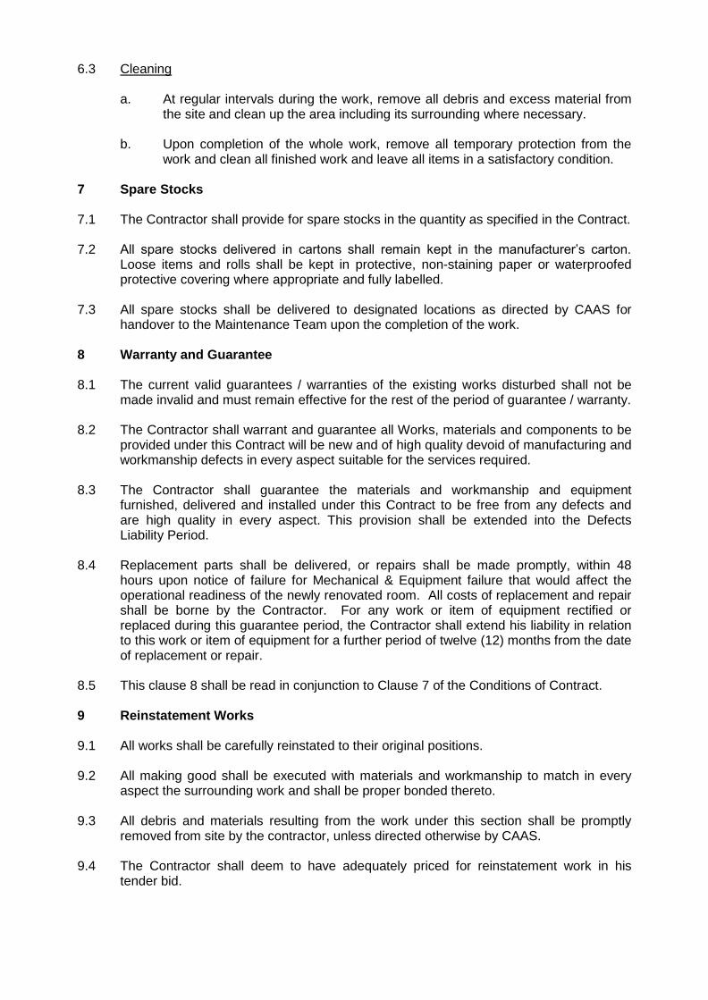
6.3 Cleaning a. At regular intervals during the work, remove all debris and excess material from
the site and clean up the area including its surrounding where necessary. b. Upon completion of the whole work, remove all temporary protection from the
work and clean all finished work and leave all items in a satisfactory condition. 7 Spare Stocks 7.1 The Contractor shall provide for spare stocks in the quantity as specified in the Contract. 7.2 All spare stocks delivered in cartons shall remain kept in the manufacturer’s carton.
Loose items and rolls shall be kept in protective, non-staining paper or waterproofed protective covering where appropriate and fully labelled.
7.3 All spare stocks shall be delivered to designated locations as directed by CAAS for
handover to the Maintenance Team upon the completion of the work. 8 Warranty and Guarantee 8.1 The current valid guarantees / warranties of the existing works disturbed shall not be
made invalid and must remain effective for the rest of the period of guarantee / warranty. 8.2 The Contractor shall warrant and guarantee all Works, materials and components to be
provided under this Contract will be new and of high quality devoid of manufacturing and workmanship defects in every aspect suitable for the services required.
8.3 The Contractor shall guarantee the materials and workmanship and equipment
furnished, delivered and installed under this Contract to be free from any defects and are high quality in every aspect. This provision shall be extended into the Defects Liability Period.
8.4 Replacement parts shall be delivered, or repairs shall be made promptly, within 48
hours upon notice of failure for Mechanical & Equipment failure that would affect the operational readiness of the newly renovated room. All costs of replacement and repair shall be borne by the Contractor. For any work or item of equipment rectified or replaced during this guarantee period, the Contractor shall extend his liability in relation to this work or item of equipment for a further period of twelve (12) months from the date of replacement or repair.
8.5 This clause 8 shall be read in conjunction to Clause 7 of the Conditions of Contract. 9 Reinstatement Works 9.1 All works shall be carefully reinstated to their original positions. 9.2 All making good shall be executed with materials and workmanship to match in every
aspect the surrounding work and shall be proper bonded thereto. 9.3 All debris and materials resulting from the work under this section shall be promptly
removed from site by the contractor, unless directed otherwise by CAAS. 9.4 The Contractor shall deem to have adequately priced for reinstatement work in his
tender bid.

9.5 The reinstatement of the Site upon completion of the Works shall be subject to the satisfaction and approval of CAAS.
9.6 The Contractor shall familiarise himself with the existing site conditions to examine the
site extent, constraints, restrictions, availability of facilities and services, etc., before commencement of the work.
10 Mock-up Samples 10.1 The Contractor shall provide mock-up samples of the proposed materials upon CAAS’s
request. 11 Security Clearance and Requirements 11.1 All project personnel and workers’ access to site shall be subject to clearances and
approval by the relevant authority, whose decision shall be deemed to be final and binding.
11.2 Within one (1) week from the date of Contract award, the Contractor shall submit the
particulars of all personnel he intends to deploy for the works for clearances. The Contractor shall allow at least 2 days for processing of clearance. The particulars of the workers shall include, but not limited to the following:
a. Full name b. NRIC / Passport and Work Permit Nos. c. Nationality d. Date of Birth e. Appointment/Designation on the Project Team f. Company Name
11.3 The Contractor shall ensure that all his workers (including the sub-contractor’s) involved
in executing the works hold valid security clearances to carry out the Works. 12 Sub-Contractors 12.1 Specialised work shall be performed by Sub-Contractors who are specialists in their
respective field of work. 12.2 The term "Specialist" as used in the specification shall mean a firm of established
reputation, which is regularly engaged in, and which maintains a regular work force of workmen skilled in the handling and application of the types of materials for that special scope of work.
12.3 Sub-Contractors seeking approval to carry out this work shall: -
a. Submit evidence of being a bona fide Sub-Contractors specializing in that field of work
b. Submit evidence of having been in the said business continuously, under their present name, for a period of five (5) years.
c. Submit a list of at least five projects of similar work the firm has completed within the past three years, stating the name of the project, location, quantity supplied, project value, name of owner, owner's contact number and the commencement and completion dates of the work.

13 Payment 13.1 Payment will be made to the Contractor upon the satisfactory completion and
acceptance of the required works as set out in Clause 10 of Conditions of Contract. 13.2 All fees quoted herein shall be deemed to be an all-in cost to include administration and
overheads, checking and inspection, drawings, plants, equipment and scaffoldings, warning signs, barricades, walkways and access-way, temporary works, supervision costs, insurance for workers and all other expenses necessary for the execution of these works.
13.3 The fees shall also include all other direct and indirect cost and expenses such as
subsistence allowance, communication allowance, plans and report printing, overtime payment, engaging site staff, profit and any other incidental cost incurred by the Contractor.
13.4 The payment for any item of the work quoted by the Contractor shall be omitted should
that item of work be taken out. CAAS would not entertain any claim of the Consultant for loss of profit or expenditures, etc. due to the omission of works.
14 Attending for Measurements 14.1 The Contractor shall from time to time, when required on reasonable notice by CAAS,
attend the Site to take jointly with CAAS any measurements of their work executed that may be necessary for any valuation for payment. Any such measurement when ascertained and any differences arising thereon shall be recorded in the manner required by CAAS. The Contractor shall without extra charge provide assistance with every appliance and other things necessary for measuring the work. If the Contractor fails to attend when so required, then the measurements made by CAAS or approved by him shall be taken to be correct measurements of the works.
15 Safety and Personal Protection of Workers 15.1 Risk assessment & management shall be done and follow up & necessary actions shall
be carried out to comply with Workplace Safety & Health Act (WSHA). The Contractor is responsible for all the measures and consequences related to safety and personal protection of workers.
16 Quality Requirements 16.1 All materials used in the work shall be approved for use in Singapore and shall comply
with the provisions of the latest version of the standards and code of practice currently in force whether used singly or as part of an approved system.
16.2 It shall be incumbent upon the Contractor to provide proof of acceptance and approval of material by the Local Authorities having jurisdiction.
16.3 In the event of an overlap between the American, British, Australian and Singapore
Standards, the most stringent standards shall apply.

16.4 The Contractor shall refer to the standards and code of practice as specified in the Contract. All reference to standards and code of practice shall refer to the latest version of local and international code of practice and include: -
a. Singapore Standards (SS) b. British Standards (BS) c. Australian Standards (AS) d. American Society for Testing and Materials (ASTM) e. American National Standards Institute (ANSI) f. German Standards Service (DIN) g. European Harmonised Standards (EN) h. American Institute of Steel Construction (AISC). i. American Welding Society (AWS). j. Aluminium Association (AA). k. American Iron and Steel Institute (AISI). l. International Organisation for Standardisation (ISO). m. National (U.S.) Association of Architectural Metal Manufacturers (NAAMM). n. Architectural Aluminium Manufacturers Association (AAMA). o. Federal Specifications (FS). p. Tile Council of America (TCA) q. National Terrazzo and Mosaic Association (NTMA) r. International Electrotechnical Commission (IEC)
16.5 The minimum acceptable standard for materials and components furnished shall be not
less than the Singapore Standards (SS) or the British Standards (BS) for the respective section of the Specification and in the absence of a standard, the Singapore Standard, British Standard, ASTM, UL or appropriate standard or code of practice shall apply.
16.6 Final acceptance of the applicable standard or code of practice shall be decided by
CAAS and shall not relieve the Contractor of the responsibility on the strength, function, durability, integrity or appearance of the work
17 Need to comply to Changi Airport Group (Singapore)’s renovation guidelines 17.1 As the point of works is in Passenger Terminal Building 1, which is owned by Changi
Airport Group (Singapore) [CAG], there is a need for Contractor to comply to CAG renovation guidelines. CAG requirements must be satisfied before work permit is approved. For avoidance of doubt, CAG’s renovation guidelines will take precedence should there be any ambiguity. Please see section E of Part 5 (Requirement Specifications) for the full renovation guidelines from CAG.

(PART II) SPECIFICATIONS OF WORK 1 PRELIMINARIES 1.1 Site Surveys and Measurements
a. The Contractor shall carry out site survey, gather users’ requirements and take site measurements necessary prior to commencement of interior design and space planning works.
b. Verification of site measurements shall be conducted prior to the preparation of
shop drawing and fabrication to ensure proper fit between the works and adjacent work.
c. The Contractor shall take note that measurements provided in the Contract are
for references only. d. The Contractor shall note that arrangements with various CAG contractors are
required to complete the site surveys and measurements. 1.2 Work Permit Application
a. The Contractor is required to coordinate and liaise with the appropriate personnel from the Changi Airport Group (“CAG”) to:
i. Examine the services and existing conditions at site and its surroundings; ii. Obtain all information for tapping of utilities, cable routing and any other
integration works etc.; and iii. complete and submit the Work Permit applications for CAG’s approval.
b. Renovation and fit-out works will not commence until CAG’s Work Permit
approval has been obtained.

2 WORK SPECIFICATIONS FOR CIVIL WORKS 2.1 ARCHITECTURE – CEILING BOARDS 2.2 Scope of Work
a. The Contractor is required to replace all false ceiling board members including all necessary accessories, ironmongery works and materials to ensure the stability and robustness of the suspended ceiling system. The new ceiling members installed shall be compatible with the existing suspended ceiling system,
b. Furnish and install fire-rated calcium silicate board ceiling to the entire room at
Terminal 1 Room #041-38. The estimated ceiling area of the room is about 45m2.
c. Supply and install access panels to the suspended ceilings for access to the
suspended MEP services. 2.3 Materials and Products
a. Manufacturers complying with the specified requirements will be accepted. Other
manufacturers providing similar and equal product (i.e. Cape East, Promat and
its equivalent) will be given equal consideration.
b. Metal Trim Accessories
i. Provide manufacturer's standard trim accessories of types required or
indicated for gypsum plasterboard and fibrous plasterboard work, formed
of galvanized steel, with either knurled and perforated or expanded
flanges for nailing or stapling, and beaded for concealment of flanges in
joint compound. Provide corner beads, L-type edge trim-beads, U-type
edge trim-beads, J-type reveal trim, and one-piece control joint beads
c. Fire-Resistive Calcium silicate board
i. 12mm thick, unless otherwise shown on the drawings, 1200mm wide, in
maximum standard lengths as required.
ii. All calcium silicate boards shall have a maximum moisture movement
from ambient to fully saturated equal to, or less than 0.1%, and an
alkalinity less than pH value 10.
iii. Ready mixed joint compound for taping, topping or texturing in calcium
silicate board construction shall be to Architect’s acceptance.

2.4 Delivery, Storage and Handling a. Deliver materials to project site with manufacturer's labels intact and legible.
b. Handle materials with care to prevent damage. Install no material which
becomes damaged during handling.
c. When storing, stack gypsum board and fibrous plasterboard flat off floor on
pallets or similar platforms providing continuous support for board to prevent
sagging. Stack wallboard so that long lengths are not over short lengths.
d. Protect stored gypsum board and fibrous plasterboard from moisture and
excessive humidity.
e. Store adhesives and laminating compounds in dry area.
2.5 Installation
a. Conduct site assessment and review the coordination and sequencing of work to ensure that everything to be concealed by ceiling board has been accomplished, and that access panels, openings, supplementary framing and blocking and similar provision have been completed.
b. Locate exposed end-butt joints as far from centre of ceilings as possible, and
stagger not less than 300mm alternate courses of board. c. Install ceiling boards in the direction and manner which shall minimize the
number of end-butt joints, and which shall avoid end joints in the central area of each ceiling. Stagger end joints at least 300mm. Back all joints with a framing member.
d. Install exposed ceiling board with face side out. Do not install imperfect,
damaged or damp boards. Butt boards together for a light contact at edges and ends with not more than 1.5mm open space between boards. Do not force into place.
e. Locate edge and end joints over supports. Position boards so that like edges
abut, tapered edges against tapered edges and mill-cut or field-cut ends against mill-cut or field cut ends. Do not place tapered edges against cut edges or ends.
f. Attach ceiling board to framing and blocking as required for additional support at
openings and cutouts. g. Form control joints and expansion joints with space between edges of boards,
prepared to receive trim accessories. h. Space fasteners in ceiling boards in accordance with referenced standards and
manufacturer's recommendations.

i. Protection
a. Protect all ceiling board work from damage and deterioration during remainder of construction period.
b. Replace any damaged gypsum, fibrous-plaster and calcium silicate board
work at no cost to the Employer. 3 ARCHITECTURE - RAISED FLOORBOARD 3.1 Scope of Work
a. The Contractor shall supply, deliver and install new raised floor system to the entire room, including the stripping and preparation of surfaces to receive the new system. The estimated floor area is about 50m2.
b. The Contractor shall propose a raised floor material of suitable height for cable
management and capable of withstanding the loads to be imposed on the floor boards, similar to the design live load of the room. The Contractor shall prepare and submit the PE/QP endorsed calculations and drawings on the approved designed loading of the raised floor board, that is consistent with the design live load limits of the said room floor structure.
c. The access floor boards shall consist of all labour, material, equipment, and
installation. d. The batch of floorboards used shall be of uniform properties for strict consistency
with similar or equivalent specifications as the existing and available for CAAS’ selection prior to their deployment
3.2 Environmental Conditions for Storage and Installation
a. The Contractor must provide a dry accessible area to receive and unload
material with a free path to elevators, hoists, and/or the area receiving the access floor.
b. Prior to and during installation, a secure and dry storage space closed to the
weather must be made available for the access floor materials, with recommended environment at 40° F to 90° F and approximately 35% to 70% relative humidity, 24 hours a day during and after installation.
c. The subfloor surface must be free of moisture, dust, dirt and other debris. Once
installed, the access floor must be maintained in the same manner. 3.3 Design Performance and Certification of Product
a. Provide access flooring board consisting of moveable assemblies composed of modular floor panels supported on pedestals with stringers forming accessible under floor cavities to accommodate electrical, mechanical, communication services, and complying with performance requirements specified and for cable management purposes. Raised Floor panels must be interchangeable with each other except where cut for special conditions.
b. Where applicable load testing shall be performed according to “Recommended
Test Procedures for Access Flooring” as established by the manufacturer of the approved raised floor board.

3.4 Quality
Installer: A company with experience in the installation of access floor systems of comparable size and complexity.
a. Manufacturing tolerance:
i) Nominal panel size ± 4mm or less. ii) Panel flatness ± 5mm or less. iii) Panel squareness ± 4mm or less.
b. Installation Tolerance:
i) Finished installation shall be level within ± 2mm in 3m and ± 3mm for the
entire floor. 4 ARCHITECTURE – DRY WALL PARTITION 4.1 Scope of Work
a. The Contractor shall supply and install a new ¾ height 2-hours fire-rated light-weight drywall fire-proof partition wall together with a top (extending from top of new partition wall, through existing false ceiling system, up till slab soffit) and bottom wire mesh (from bottom of new partition wall down to slab floor) with excellent sound-proof quality and preparation of surfaces to receive the dry wall partition at Terminal 1 Room #041-38.
b. The installation of the drywall with wire mesh consists of Two (2) Phases.
• Phase 1 – Installation of partition wall with wire mesh, complete with supporting structures
• Phase 2 – Remove part of partition wall with wire mesh for extension, complete with supporting structures
c. Phase 1
To install a new ¾ height light-weight drywall fire-proof partition wall with excellent sound -proof quality, of total length 9.1 metres, where there are one (1) right-angled turn along the 9.1-metre length.
d. Phase 2
To remove the existing 4.45 metres of the partition wall together with the top and bottom wire mesh and extend the ¾ height light-weight drywall fire-proof partition wall with excellent sound-proof quality, of total length 6.25 metres, where there are one (1) right-angled turn along the 6.25-metre length.
4.2 Job Conditions a. Vendors are to note that that the top and bottom end of the ¾ partition wall shall
terminate along the height of a wire mesh (above the false ceiling up to the ceiling slab level and to the bottom floor level underneath the raised up floor board), where the termination details shall be in accordance with a Professional-Engineer endorsed design, that assures CAAS that there shall not be any adverse impact to the integrity of the wire mesh (see picture 2). All new partitions shall be painted with odourless paint.

b. Picture 1 (General View)
c. Picture 2 (Alternative View)
d. Picture 3

e. Picture 4
4.3 Material
a. Provision of drywall partition comprising of minimum 9mm thick light-weight fire-proof wall panel/boards or cement board or equivalent pinned to bearers with sound-proofing insulation mineral wool or fibreglass in-fill. The Vendor shall provide the details of the construction of the drywall partition. The finished wall partition shall match to the existing surrounding wall partition. The finished wall partition shall match to the existing surrounding wall partition. The materials colour and texture of finishes shall be selected and approved by CAAS.
b. The proposed drywall partition shall comprise of two 9mm thick light-weight fire-
proof boards fixed to bearers and sound-absorbent material compressed in-between to achieve excellent sound-proofing property. The boards shall be fixed to partition frame that is fixed to the existing floor panels using adhesive compound allowed to set permanently. Demountable partition framing (for full height lining) with an overall thickness of not more than 75mm, comprising of mild steel studs or galvanised iron studs with exposed anodised aluminium framing placed at 600mm centres at both ways, corner and end posts, anodised aluminium ceiling and floor tracks to receive lining and fixed complete with approved vinyl insert, door frames, if any, 100mm high aluminium skirting and other recommended accessories.
4.4 Delivery, Storage and Handling
a. Delivery of dry partition wall shall be made in accordance with installation schedule.
b. Storage of all materials at the Site shall be in clean, dry, and well-ventilated
areas designated by CAAS, kept under lock and key.

5 ARCHITECTURE – FIRE RATED DOOR 5.1 Scope of Work
a. The Contractor is required to remove one existing door (see Picture 5, Door 1) and install two new 2-hour fire-rated 45mm thick flush single leaf door (see Picture 5 and 6 for Door 1 and 2).
b. The proposed fire rated door shall come with an overall size 1200mm x 2100mm
high, with PSB stamp of approval of 1.22mm (18 gauge) thick zinc coated steel sheet pressformed, 1.6mm (16 gauge) thick stiles, top and bottom rails reinforced with 16-gauge channels and infill with fire resisting materials.
c. This work shall include a 2-hour fire-rated metal door frame, 150mm x 50mm x
1.6mm thick press formed to required shape to be affixed to both locations as specified. Both doors are to be swing in an outwards direction. (see Picture 5 for Door 1 and Picture 6 for Door 2). As existing Door 1 is a fire-rated door leading into a FM200-protected equipment room, and the main change to Door 1 is the opening direction of the door (from inwards-opening changed to outwards-opening), the Contractor is to obtain a written endorsement from a Qualified Person, and confirm that the door change meets SCDF’s code requirements.
d. The Works shall include paint touch-up where necessary. The door shall be fitted
with a two separate standalone key system for each individual doors (Door 1 and 2), ‘KABA 20/1519’ (or equivalent) double cylinder with inside thumb turn and outside keyed complete with 5 keys, where the cost of duplicating the keys from KABA (or equivalent) shall be borne by the Vendor. In addition, because both Door 1 and Door 2 will be outwards opening, the Contractor shall mark out clearly on the ground, pathway of both doors’ opening using paint or equivalent markers, complete with signage, to warn other users risk of doors opening towards them to mitigate this risk.
e. All materials/elements, fixtures/fittings, tools and equipment etc. including the
preparation of surfaces which are required for the removal, disposable and installation shall be deemed to be included in the scope of work.
f. Picture 5 (Door 1)

g. Picture 6 (Door 2)
6 ARCHITECTURE – METAL CLADDING 6.1 Scope of Work Work described in this Section shall consist the design and furnishing of all materials
and the performance of all fabrication and installation works in connection with existing carpentry and joinery for the metal cladding replacement works:
a. To affix new metal cladding onto existing partition board located below the
window panel, of total length 7.94 metres. The batch of metal cladding used shall be of uniform properties for strict consistency and available for CAAS’ selection prior to their deployment. Total area is estimated 7.94 metres long by 1.5 metres tall (please see picture 7)
b. Picture 7

6.2 Job Conditions
a. The Contractor is to take site measurements to ascertain exact size
requirements for joinery items fabricated off the site. Indicate exact dimensions
on shop drawings.
b. Do not proceed with the work until unsatisfactory conditions have been corrected
in a manner acceptable to CAAS or its representative.
6.3 Delivery, Storage and Handling
a. Immediately upon delivery to job site, place materials indoors in an enclosed space, adequately protected against exposure or damage from the conditions of weather.
b. All materials and work of this Section shall be protected from damage until final
acceptance of Work. Cover, ventilate, and protect from damage caused by weather, moisture, heat, staining, dirt, abrasions, and other causes which may adversely affect appearance or use, or which may cause deterioration of finish, warpage, distortion, twisting, opening of joints and seams, delamination, loosening, etc., of metal cladding.
7 ARCHITECTURE – WINDOW GRILLE 7.1 Scope of Works
Work described in this Section shall consist the design and furnishing of all materials and the performance of all fabrication and installation works in connection with existing window panels and joinery for the window grille installation works:
a. To affix new window grilles onto existing window panel frame. The batch of
window grilles used shall be of uniform properties for strict consistency and available for CAAS’ selection prior to their deployment. The grilles shall be made of mild steel or equivalent material and the gap in between the grilles shall not allow people to enter. Total area is estimated 7.94 metres long by 0.92 metres tall (please see picture 8)
b. Picture 8

7.2 Job Conditions
a. The Contractor is to take site measurements to ascertain exact size
requirements for joinery items fabricated off the site. Indicate exact dimensions
on shop drawings.
b. Do not proceed with the work until unsatisfactory conditions have been corrected
in a manner acceptable to CAAS or its representative.
7.3 Delivery, Storage and Handling
a. Immediately upon delivery to job site, place materials indoors in an enclosed space, adequately protected against exposure or damage from the conditions of weather.
b. All materials and work of this Section shall be protected from damage until final
acceptance of Work. Cover, ventilate, and protect from damage caused by weather, moisture, heat, staining, dirt, abrasions, and other causes which may adversely affect appearance or use, or which may cause deterioration of finish, warpage, distortion, twisting, opening of joints and seams, delamination, loosening, etc., of window grille.
8 ARCHITECTURE - PAINTING 8.1 Unless otherwise specified, all plastered wall surfaces (estimated total area of 34.64m2 )
shall be painted with one alkaline resistant sealer, one undercoat and two finishing coats of approved emulsion paint inclusive of all necessary preparation of surfaces to remove dust, rust, grease and oil before painting. All painting is to be applied by roller or airless spray.
8.2 The Contractor is reminded to be mindful of the existing M&E fittings (i.e. PA system,
smoke detectors, sprinklers lightings, switches, sockets etc.) within the room and to exercise caution when carrying out painting works. The Contractor shall be liable for all affected damages and shall reinstate them to CAAS satisfaction.
8.3 The Contractor shall conduct pre-work survey upon taking over of the site and take note
of the amount of ceiling boards that are already damaged and deemed unable to be repaired. The Contractor shall then supply and install new ceiling boards of similar type and material in replacement and to match the existing, including all necessary dismantling and refixing of M&E installations.
8.4 The Contractor shall supply and install adequate screens, tarpaulins etc. to protect the
existing surfaces, fixtures, fittings and any other properties prior to carrying out painting works.
8.5 The Contractor shall propose the paint type and colour for CAAS confirmation prior to
work commencement.

8.6 The Contractor shall warrant that all painting works will be executed using good quality materials free from manufacturer or supplier defects and with all due care and professional skill and shall be free from defects for a period of one (1) years from the date of acceptance. The Contractor shall immediately make good all defects appearing in the said coating at his own expense and to the satisfaction of CAAS. If the Contractor shall refuse, neglect or fail to do so for any reason within 14 days after notice in writing to make good any such defect, CAAS shall be entitled to engage others to make good the same and charge the costs thereof to the Contractor.
8.7 All work shall be shop pre-finished unless otherwise stated. No field finishing will be
permitted, except minor re-touching that is necessary after installation to leave work in perfect condition. Field touch-up shall be accomplished using the same finishes as originally applied at the shop.
8.8 All painted finishes shall be free from runs, sags, and other visual defects. All wood shall
be thoroughly hand-smoothed, and hand sanded to remove all traces of machine and tool marks. All coatings shall be spray applied to a smooth finish.
8.9 Requirements for surface preparation shall be in accordance with British Standards for
paint finish. 9 ARCHITECTURE - DOOR SIGNAGE 9.1 The Contractor shall supply, fabricate, deliver and install two (2) nos. acrylic door
signage c/w fixing accessories as shown below:
Door Signage
9.2 The Contractor shall seek CAAS’ approval on the signage artwork, shop drawings prior to
fabrication.

10 WORK SPECIFICATIONS FOR ELECTRICAL WORKS 10.1 ELECTRICAL WORKS 10.2 Scope of Work 10.3 The Contractor shall include the design, supply, delivery, installation, testing and
commissioning of the Mechanical and Electrical system at CAAS premise Room No. #041-38, including all associated works at the points of connection at CAG Switch room as specified.
10.4 The Contractor shall carry out, but not limited, to the following: Electrical Works
a. Design, supply, deliver, installation, testing and commissioning of one (1) number floor standing Main Distribution Boards at Room No. #041-38, Level 4 of Passenger Terminal Building (PTB) 1, complete with sub- with sub-main final circuits and sub-circuits, moulded case circuits breakers, Automatic Transfer Switch, , digital power meter, fuses, control switches, miniature circuit breakers, relays, contactors and etc. Each of the distribution board shall include but not limited to the following items:
i. The metal distribution board shall have separate compartments to house
the main incoming breaker, ATS, digital power meter & indicators, outgoing breakers and the L&P compartment separately.
ii. Two (2) numbers of 63A 4P incoming MCCB c/w protection (ZCT, ELR
and etc), LED indicators (incoming and outgoing for each incoming feed) and digital power meter c/w with CTs and fuses.
iii. One (1) number Automatic Transfer Switch with maintenance bypass
function.
iv. One (1) (1) number of 63A 4P incoming MCCB c/w protection (ZCT, ELR and etc) LED indicators (incoming and outgoing for each incoming feed) and digital power meter c/w with CTs and fuses.
v. General and lighting power sub-panel with at least 32A SP MCB
complete with 100mA RCCB. Outgoing SP MCB complete with RCCB to the lightings and general power points. To include at least 5 spare ways.
vi. Breakers of SP or TPN complete with RCCB for the aircon board –
subject to Aircon design.
vii. Three (3) nos. of 32A TPN MCB (outgoing)
viii. Three (3) nos. of 40A 4P 100mA RCCB (outgoing)
ix. All other necessary labelling, fuses and ancillaries.

b. Supply installation, connection, modification, testing and commissioning of the main incoming supply for both the Main Distribution Boards Normal and Emergency DBs.
i. The main incoming normal source shall be tap from the spare breaker
within DB DB-MB5-2 at CAG T1 Switchroom “B”, located at the same 4th
floor.
ii. The main incoming emergency source shall be tap from DB MDB-EB5 at CAG T1 Switchroom “B”, located at the same 4th floor. As there are no spare breakers available, the contractor shall tap from the busbar of DB MDB-EB5 and install a 63A 4-pole breaker complete with metal compartment above the DB.
c. Supply, installation, testing and commissioning of main distribution power cables
from CAG Switchroom to Main Distribution Board at Room No. #041-38. d. Supply, installation of cable tray/ladder including necessary hanging rods,
brackets to support cables leading from CAG Switchroom to the Main Distribution Board.
e. Design, supply, delivery and installation of LED ceiling light including removal of
existing lighting circuits.
i. To remove the existing ceiling light fitting, existing cablings, switches, etc.
ii. To supply and install new 600 x 600 mm LED panel ceiling lightings to existing available ceiling space. The requirement of the room is to fulfill the SS531: Part 1 :2006 for the Offices usage. Contractor shall consider and design based on the additional partition within the room
iii. At least 4 circuits from each board shall be provided for the lightings.
50% of the lightings shall be taken from the normal and emergency board each.
iv. Lighting switches shall be provided beside the door.
v. Exit lights shall be provided for the exit doors and compliance to fire
escape requirements.
vi. At least 50% of the LED panel ceiling lights shall be provided with batteries packs.
f. To supply and install 10 twin switch sockets outlet complete with RCCB from
each of the sources. The switch socket outlet shall be spread out within the rooms with red rocker for emergency source.
10.5 12 Months Defects Liability Period (DLP)
a) The Defects and Liability Period is 12 months from the date of acceptance of the whole works as certified by the S.O. Upon notice, the contractor shall immediately rectify any material defects or poor workmanship
b) The Contractor is to maintain the whole works against any defects and damages
during the Defects Liability Period and to rectify any damages as and when required by the CAAS.
d) Should the Contractor fail to turn up for the rectification work more than the days
upon the issue of the CAAS written instruction stated within this tender, CAAS may in this case engage other parties to carry out the job on the Contractor’s behalf and demand reimbursement from the Contractor of all costs incurred by CAAS through monies due or to become due to the Contractor.
e) The Contractor shall provide 3-monthly servicing during the DLP and conduct
thermal scanning once before the end of DLP. During DLP, any breakdown shall be attended to within the next working day. All transport and labour costs for the breakdown attendance shall be included in the tender proposal and no additional cost shall be claimed from CAAS.

11 WORK SPECIFICATIONS FOR MECHANICAL WORKS 11.1 MECHANICAL WORKS 11.2 Scope of Works 11.3 The Contractor shall re-configure and modify (if required), inclusive of design, supply,
delivery, installation and testing and commissioning of the existing FM200 system to conform to the new layout.
11.4 Supply, delivery, installation, testing and commissioning of two (2) sets VRF min. 42,000
BTU/Hours Ceiling Suspended Single Split Unit Air-conditioning unit with wired remote control and complete with two (2) numbers Control Panels c/w two (2) numbers of temperature sensors.
i. To supply and install 1 no. of secondary pan tray c/w drainline just below each
air-con units
ii. To supply and install 1 no. of condensate water pump completed with 13A SSO and power tap from Main DB (20A SPM MCB)
11.5 To supply, deliver and install 2 (two) lots of Split-Unit Control Panel complete with FR
cable, trunking / cable tray works and:
i. 8 nos. of LED Indication Lights – 3 no. Incoming (white), 1 no. Run (green), 1 no. Stop (red), 1 no. Trip (orange), 1 no. High Temperature (orange),1 no. FM200 Trip (red) – Run, Stop & Trip lights signal from FCU Interfaced Card.
ii. 1 no. of 32A 4P MCB, 1 no. 40A 4P RCCB 100mA, 1 no. 16A TP MCB for CU, 1
no. 16A DP MCB for FCU, & 1 no. 6A MCB for Control.
iii. 7 Days Digital Timer.
iv. Manual -Auto-Basys-Off Selector-Switch.
v. LED Display Thermometer / Thermostat with 1 decimal point.
vi. LED three phase Digital Ammeter with one decimal point.
vii. High Temp reset push button, Contactors, Relays, wiring, fuses, etc. 11.6 The Contractor shall design/configure the above Control Panel as such that:
i. On ‘Auto’ mode – The FCU turn ‘on’ or ‘off’ either by 7 Days Timer / Thermostat setting (High Temperature)
ii. On ‘Manual’ mode – The FCU operate by ‘On’ & ‘Off’ push button
iii. On ‘Basys’ mode – Operation by Basys (For future connection)
iv. FM200 FM200 – 2nd Alarm – FCU trip and can only be reset with ‘Reset’ push
button v. Power Failure - FCU running shall restart after power restore and setting of FCU
shall remain as per last setting

11.7 The Contractor shall supply, deliver, install and configure one (1) number of room temperature sensors to be integrated with the Automatic SMS System.
11.8 The Contractor shall supply, deliver, install, testing and commission of 3G Automatic
SMS System with minimum 16 points inclusive terminations, etc c/w UPS for a minimum backup of 30 minutes housed in electro-galvanised sheet steel panel and 12 months 3G mobile SIM contract. The Automatic SMS System should have the acknowledgement functionality of up to minimum 3 levels of escalation. The following SMS Points are to be monitored:
i. FCU-1 Run/Stop ii. FCU-1 Trip iii. FCU-1 High Temp iv. FCU-2 Run/Stop v. FCU-2 Trip vi. FCU-2 High Temp vii. Room Temp Reading (Analogue) viii. Air-Con Control Panel Normal Supply Incoming Power Status ix. Air-Con Control Panel Emergency Supply Incoming Power Status x. Air-Con Control Panel Outgoing Supply Power Status xi. L/P DB Normal Supply Incoming Power Status xii. L/P DB Emergency Supply Incoming Power Status xiii. L/P DB Outgoing Supply Power Status xiv. Monitor UPS status for the Automatic SMS System xv. Spare xvi. Spare
11.9 The Contractor shall ensure that these requirements are strictly adhered to when
carrying out the works, unless otherwise instructed 11.10 The requirements in the scope of works shall also be considered together and
complimentary to the technical specification. The requirements in both sections are to be complied with by the Contractor.
11.11 Equipment and material supplied and installed shall be suitable for the application and
the arrangements shown on the drawings. Notwithstanding this, the equipment and material offered shall comply in every respect with all capacities and other performance requirements covered in the tender document and elsewhere in the Specification
11.12 The information provided in the tender documents and drawings are for tender purposes
only. Final assessment of the system head shall be ascertained by the Contractor to suit the actual equipment selected and layout of services.
11.13 All equipment and material offered and accepted for installation shall operate
satisfactorily within the standard ranges of capacities and speed guaranteed by the manufacturers.

11.14 Equipment and material offered for supply and installation shall include the following:
i. All major items and incidental work, equipment accessories and materials may not be specifically mentioned but are required for the proper completion of the installations in accordance with the true intent and meaning of this Specification.
ii. All necessary safety devices for the protection of personnel against injury and
the protection of plant and equipment against damage including relief valve, belt guards, fan inlet and/or discharge guards, safety railing, effective earthing of electrical components, mechanical and electrical interlocks, warning lights and alarms
iii. Readily accessible, dust-proof lubricating facilities on all moving parts and
equipment including provision for cleaning all lubricating lines and bearings and charging same with the correct lubricants after installation but prior to testing and commissioning.
iv. Clearly visible and robust manufacturer’s name-plates permanently fitted to each
and every item of equipment and showing the manufacturer’s name, type and/or model number, serial number, year of manufacture and all essential operating data; such as speed, capacity, voltage, current draw, etc.
11.15 The following abbreviations, where used, will be:
AS - Australian Standard BCA - Building and Construction Authority BS - British Standard CP - Code of Practice FSSD - Fire Safety & Shelter Department (Singapore) ISO - International Standardization Organization NEA - National Environment Agency PUB - Public Utilities Board (Singapore) SO - Superintending Officer SS - Singapore Standard SWG - Standard Wire Gauge (British) UL - Underwriters Laboratories Inc
11.16 Statutory Regulations 11.16.1 In the Republic of Singapore mechanical installations are required to comply with
the statutory regulations indicated below. The Regulations listed represent the principal legal requirements. This list is not exhaustive. Information concerning those regulations may be obtained from the appropriate authority indicated below:
i. Public Utilities Act Public Utilities Board
ii. The Public Utilities Board Director, Water Department, (Water Supply) Regulations, 1977 Public Utilities Board
iii. Workplace Safety and Health Act Ministry of Manpower (MOM)
WSH Council
iv. Building Control Act & Regulations Building and Construction Authority (BCA)

11.17 Singapore Standard
11.17.1 The air-conditioning and mechanical ventilation installation, shall comply with the following Singapore Standards.
i. CP 5: 1997, Wiring of Electrical Equipment of Buildings ii. SS 553:2009 (CP 13: 1999) Air-conditioning and Mechanical Ventilation
in Buildings iii. SS 530:2006 (CP 24: 1999) Energy Efficiency standard for building
services and equipment 11.18 Equipment and Material
11.18.1 All equipment, material and accessories to be installed shall be heavy duty industrial type and products of reputable manufacturer and full performance details shall be as given in the Schedule of Technical Data (Part 11). The equipment shall be suitable for operating on 400 volts, 3-phase, 50 Hz power supply or 230 volts, 1-phase, 50 Hz power supply. All equipment specified herein shall be supplied through authorized local agents with an established local office so as to ensure after sale service and maintenance backup. Equipment not supplied through local agents shall be rejected. Contractors shall submit a list of authorized local agents for the equipment offered by him at the time of tender.
11.18.2 All equipment and material shall be new and unused. All equipment and
material previously installed or used shall be rejected. Equipment and material shall be stored in such a manner as to be in a new condition when installed and to avoid damage from weather and site conditions. Damaged, deformed and cracked equipment or materials shall be rejected. Replacement shall be the responsibility of the contractor at no additional cost to the CAAS.
11.18.3 Equipment and material to be incorporated into the works as called for in
this specification are required to meet the quality/testing requirements of PSB and the relevant BS. However, equivalent materials and equipment meeting other authoritative standards, which ensure and equal or higher quality than the standards mentioned may also be accepted, subject to the approval of SO.
11.18.4 Should the tenderer propose to furnish equipment and material other
than those specified, as permitted by the “or approved equivalent” clause; he shall submit a written request for any such substitution. Such requests shall be accompanied by complete descriptive (manufacturers, brand name, catalogue number, etc. and technical data for all items, of both the specified and the proposed substitute items, and shall include any addition of deduction to contract price.
11.18.5 Where such substitutions after the design or space requirement indicated
on the plans, the Contractor shall include all items of cost in the revised design and construction including the cost of allied trades involved.
11.18.6 Acceptance or rejection of the proposed substitution shall be subjected to
the approval of the SO. 11.18.7 The expenses incurred by any such exercise shall be borne in full by the
Contractor.

11.19 Dimensions
11.19.1 The Contractor shall ensure that the equipment offered can be easily installed in the space provided such that easy accessibility is obtained for subsequent maintenance purposes. The Contractor shall submit details of the proposed equipment layout together with their tenders
11.20 Approval
11.20.1 Approval of the Contractor’s submission does not constitute a complete check but indicate only that the design, general methods of construction and detailing is satisfactory. Approval does not relieve the contractor of his contractual responsibilities and obligations. The Contractor shall be responsible for discrepancies errors or omissions of details on drawings and other documentation supplied by him. He is also responsible for co-ordinating installation and/or construction subject to actual site conditions
12 MECHANICAL & ELECTRICAL – TECHNICAL REQUIREMENTS 12.1 DESIGN RULES AND REGULATIONS
12.1.1 The installation shall comply with the requirements of the local Authorities and current editions of the following Standards, Codes and Regulations:
i. NEPA 2001: Standard on Clean Agent Fire Extinguishing System (Latest
Ed.) ii. Singapore Standard CP5 Code of Practice for Wiring of Electrical
Equipment of Building iii. Singapore Standard CP10 Code of Practice for the Installation and
Servicing of Electrical Fire Alarm System iv. Fire Safety Act v. Workplace Safety and Health (WSH) Act vi. Fire Safety (Building Fire Safety) Regulations vii. All other relevant rules, regulations and Codes of Practices required by
the Authorities 12.1.2 These specifications are intended to be complementary to the stipulated rules
and regulations. 12.1.3 Where differing requirements exist, the most stringent requirements shall take
precedence. 12.1.4 All Electrical and Mechanical installation and works shall comply with the
Technical Specification in Part III’s Section A and B and C of Part 5 (Requirements Specifications) respectively.

13 MECHANICAL & ELECTRICAL – TESTING AND COMMISSION 13.1 GENERAL
13.1.1 The whole works shall be carried out to the entire satisfaction of the S.O.. The completed installation shall be in full operational condition before testing is to be carried out. Tests shall be executed by the Contractor and witnessed by the S.O. and test results shall be recorded in writing, certified by the Contractor.
13.1.2 The S.O. shall be at liberty to order such tests to be carried out to verify the
reliability and performance of the system and check compliance with specifications herein provided. The Contractor shall provide all equipment and things necessary and bear all costs for executing the necessary tests except where specified herein.
13.1.3 All defects and deficiencies in performance, reliability, safety, efficiency,
appearance of finish shall be rectified and resettled by the Contractor to the entire satisfaction of the S.O. before acceptance.
13.1.4 Upon the completion of the work herein called for and the satisfactory fulfilment
of all contractual requirements, the Contractor shall then commission the system installed in the presence of the S.O.. The system shall be in complete and perfect operational condition by then. The Contractor shall, upon commissioning, conduct an instructional briefing to the users concerned on the safe and proper use of the system and necessary evacuation drills in the event of an agent discharged.
13.2 REGULATION AND PERFORMANCE TEST
13.2.1 All balancing, testing and commissioning shall comply with all rules and requirements of the Local Authorities. After completion of each and every section of the works, the contractor shall submit to the SO two (2) copies of the test results with the method of testing stated clearly.
13.2.2 It shall be the contractor’s responsibility to seek approval from the SO for the
method of testing. The contractor shall then give a minimum of seven (7) days’ notice to the SO to verify the test results on site and the contractor is to demonstrate to the SO that the installation is adjusted and regulated correctly to fulfill the function for which it has been designed, eg. Room temperature and relative humidity to be maintained, air quantity to be handled, etc. and the contractor shall adjust, balance and regulate the section concerned as necessary until the required conditions are obtained.
13.2.3 Should the SO find discrepancies between the recorded test results and the
measurements demonstrated to him on site, the contractor shall be required to repeat the tests. Tests shall be repeated to the satisfaction of the SO at no extra cost.
13.2.4 Room temperature and humidity shall be measured by recording instruments
located 1.5m above floor level at points away from the influence of draughts or direct radiation from hot or cold surfaces, whilst air quantities shall be measured by the Velometer or Anemometer. Room temperatures shall be maintained with ±1ºC of the design indoor dry bulb temperature.

13.2.5 No demonstration of room temperature shall be carried out when weather conditions are abnormal as to wind, rain or at times when the external at temperature is changing at a rate exceeding 1ºC per hour.
13.2.6 The duration of the tests will be at the discretion of the SO and all recording
charts shall be submitted to him for approval. 13.3 TEST RECORD
13.3.1 After the completion and acceptance of the testing, the contractor shall submit two copies of the test records to CAAS for retention.
13.4 PIPEWORK
13.4.1 All refrigerant pipework shall be tested to pressure as recommended by the manufacturers using anhydrous carbon dioxide or nitrogen. After charging with refrigerant, the system shall be thorough checked for leaks, using the Halide Torch principle
13.4.2 All pressure tests of pipework shall be to the approval of the SO before any
insulation of pipework may commence 13.5 COILS
13.5.1 All coils and automatic control valves shall be checked for water flow characteristics, pressure drops using the ratings given by the manufacturers. Final assessment shall be done by checking the air volumes and entering/leaving conditions of the air.
13.5.2 Any possibility of partial blocking shall be fully investigated. Should any coil fan
to meet the capacity requirements as guaranteed, the contractor must install all necessary equipment to enable all accurate heat balance to be carried out. If the coils are at fault, they shall be replaced with new coils of the correct capacity. Any cost incurred shall be borne by the contractor. Test readings and a copy of the calculation for such a test shall be submitted to the SO.
13.6 CONTROL EQUIPMENT
13.6.1 The Contractor shall calibrate all thermostats and humidistats, set the modulating range and set points on all automatic valves and dampers as required to ensure that operating directions are correct. The time and control sequence shall also be tested and verified.
13.7 REFRIGERATION EQUIPMENT
13.7.1 Each refrigeration compressor shall be tested in accordance with the manufacturer’s instructions. The pressure control settings shall be adjusted and set. The capacity control mechanisms shall be verified and the lead/training and stage loading operating and sequencing shall be checked and confirmed.
13.7.2 Each water chilling unit shall be checked, tested and recorded under design
conditions; performance tests shall comply with latest appropriate ARI Standards as approved equivalent standard.

13.8 ELECTRICAL COMMISSIONING TESTS
13.8.1 The complete electrical installation shall be tested to EMA requirements both before and after being connected up to the satisfaction of the SO.
13.8.2 The contractor satisfactions shall be represented by a Licensed Electrical
Worker (LEW) during the whole of the period required for the tests. The LEW shall be responsible for all electrical tests at the site
13.8.3 All materials and equipment supplied or erected under this Contract which fails
the tests shall be replaced or rectified at once by the contractor without cost to the owner and the tests shall be repeated.
13.8.4 All tests shall be conducted in the presence of and to the satisfaction of the
SO. The contractor shall supply all necessary instruments, apparatus, required for the tests to the satisfaction of the SO, the cost of so doing shall be included in the Contract.
13.8.5 The contractor shall make accurate records of all tests and shall furnish test
certificate and a schedule of the results in an approved form. Four copies of such schedules and of each test certificate will be required.
13.8.6 Any circuit or section of the installation failing to reach the required standard for
acceptance shall be made good by the contractor without cost to CAAS. 13.8.7 The minimum of site tests to be carried out on each completed section of the
electrical installation shall be as follows:
i. Insulation resistance tests
ii. Continuity tests
iii. Tests to prove correct operation of interlocks, tripping and closing circuits, indications, etc
iv. Vector group, phasing and synchronising tests
v. Operation of all protective gear circuits by primary injection and system
fault tests to check sensitivity and stability
vi. Protective gear timing tests as may be necessary
vii. Test operation of alarm devices
viii. Rotational tests on all motors
ix. Polarity tests to verify that single pole switches are installed in the phase or live conductor of each circuit, and not in the neutral conductor
x. A test to verify the continuity of all conductors in every rig circuit, correct
connections to terminals or all sockets
xi. Insulation resistance tests to earth and between conductors before and after fitting of lamps. The standard of acceptance for electrical insulation tests shall be as recommended in the CP5: Wiring of Electrical Equipment of Buildings

xii. Earth continuity tests for each final sub-circuit and the completed installation to ensure that the impedance of the earth fault loop is such as to permit compliance with the requirements of CP5: Wiring of Electrical Equipment of Buildings
13.9 ELECTRICAL RELIABILITY TESTS
13.9.1 When the commissioning tests have been concluded successfully and the contractor has notified the SO, the installation shall be required to operate within the specified limits of its rating either continuously or intermittently as may be convenient without failure of any kind or for a period of one 20 days before the official handover inspection can be arranged
13.9.2 Should any failure occur due to, or arising from faulty design, materials or
workmanship sufficient to prevent the commercial use of the installation, the reliability test period of 20 days shall be commenced after the contractor has remedied the cause of failure to the satisfaction of the SO
13.9.3 The onus of providing that any failure is due to any other cause shall rest with
the contractor. 13.10 SCHEDULE OF TECHNICAL DATA
13.10.1Tenderers shall submit a schedule of technical data of the proposed new equipment submit any supplementary information which may be considered necessary to convey a complete description of the equipment offered
13.10.2It is understood that the requirements of the specification and drawings
provided are the minimum requirement and standard that will be accepted for the execution of the works
13.10.3Tenderers are reminded that notwithstanding whatever is submitted in his
schedule, all equipment and installation must comply with the requirements of the Specification.
13.10.4Unless written confirmation and approval is obtained from the Engineer to that
effect, the requirements of the Specification shall supersede all other qualification herein.

14 TECHNICAL SPECIFICATIONS FOR SECURITY SYSTEM WORKS CCTV SYSTEM ACCESS CONTROL SYSTEM INTEGRATED SECURITY MANAGEMENT SYSTEM CCTV SYSTEM 14.1 Scope of works
The Contractor shall supply, deliver and install four (4) nos. of CCTV as indicated in drawing (in red), cater extra 5m cable slack when CCTV are relocated to new position (in dotted red). All CCTV cameras shall have UPS for at least 30 mins in the event of a power failure.
14.1.1 Supply, deliver, install, testing and commissioning of security system to be
integrated with existing security system 14.1.2 Indoor Dome IP camera, to be installed with C-channel at top of ceiling with
galvanised drop rod to be secured at false ceiling. Provide additional 3 no. galvanised drop rod when 3 no. of camera will be relocated when wall space shifted during room expansion.(see Section D room layout for clarity)
14.1.3 Supply 8-port PoE Switch and switch shall have Fibre optic port 14.1.4 Supply 20 metre of 3-core non armoured power cable with 20mm BS4568
conduit 14.1.5 Supply and install 100 metre of FO Single Mode 4-core cable, from 041-38 (#04-
32) room to 041-32 (#04-39) 14.1.6 Terminate and test fibre cable (4-core FO cable, total 8 termination points)
14.2 Labelling of Rack The labelling of rack shall be as follows:
i. Height of the rack label 20mm ii. Font Ariel Bold iii. Height of wording 10mm iv. Colour of the rack label Black v. Colour of the wording White vi. Material of the rack label Hard engraved plastic tag or equivalent vii. Rack Label’s dimensions is illustrated below:

14.3 General Hardware Requirement
14.3.1 All Security Systems equipment supplied shall comply with the specifications under this section.
14.3.2 Relevant standards for ACS include BS EN 60839-11-1, UFC 4-021-02 and UL
294. 14.3.3 POE Surge protector for field end devices shall be provided
14.4 IP Fixed Dome Camera
14.4.1 The contractor shall supply and install IP fixed dome cameras to provide
coverage of designated areas 14.4.2 The minimum specifications for the camera shall be as follows:
i. Resolution of HD 1080p: 1920x1080 pixels or its equivalent
ii. Compliance to Open Network Video Interface Forum (ONVIF) standards
iii. Minimum illumination 0.2 Lux (F1.2) in Colour mode, 0.02 Lux (F1.2) in monochrome mode
iv. IP Rating: IP66
ACCESS CONTROL SYSTEM 15 Scope of works
The Contractor shall supply and install one (1) no. new access control system c/w card/pin reader for door access control, cabling and wiring works. The cost for preparing the existing surfaces for the installation shall be included.
15.1 General Hardware Requirement
15.1.1 All Security Systems equipment supplied shall comply with the specification under this section.
15.1.2 Relevant standards for ACS include BS EN 60839-11-1, UFC 4-021-02 and UL
294. 15.1.3 Door controller power source shall be from electrical DB within the room. 15.1.4 Door controller control and network cable shall be laid to #04-39 estimated 80
metres

15.2 Door Access Controller
15.2.1 The minimum specifications of the Door Access Controllers shall include the following:
i. Modular design for future expansion ii. Card holders: 5,000 iii. Event buffers: 200,000 iv. Access schedules: 64 v. User Access Group: 255 vi. Common alarm relay output, common fault relay output vii. Fire alarm input, AC failure input, enclosure tamper input viii. Interface I/O: entry biometric card reader, door contact, exit card reader,
fire alarm, breakglass, EM lock, key bypass ix. Buzzer
15.3 Reader with Facial Recognition and Card and PIN
i. The card reader shall support at least one (1) SSID Security Access Module
ii. The card reader shall support Mifare DESFire EV2 cards. iii. The card reader shall be able to read the SSID Card Serial Number
(Unique Number) embedded in the card. iv. The card reader shall have a display and keypad to display the status of
the card reader in standby mode and to the tapping of CAAS/airport staff pass. The messages to be displayed shall be determined by CAAS during final design review. Keypad shall be for keying in the PIN or other relevant in-built features.
v. Reader shall be IP66 rated or better. In addition, weatherproof enclosure to be provided when mounted at outdoor environment.
vi. Minimum specifications shall include the following:
• Card Holders
• Verification time: < 2 s
• Templates per user: 2
• Event buffers: 30,000
vii. Recognition modes shall be 1:N identification and 1:1 verification with Iris or Facial + Card or PIN.
viii. Reader is able to provide main power failure alert and backup battery low voltage alert.
ix. Reader shall be back-up by batteries for at least 2 hours during power failures.
15.4 Card Reader with Card and PIN
15.4.1 The card reader shall support at least one (1) SSID Security Access Module . 15.4.2 The card reader shall support Mifare DESFire EV2 cards. 15.4.3 The card reader shall have a display and keypad to display the status of the card
reader in standby mode and to the tapping of CAAS/airport staff pass. The messages to be displayed shall be determined by CAAS during final design review. Keypad shall be for keying in the PIN or other relevant in-built features.

15.4.4 Reader shall be IP66 rated or better. In addition, weatherproof enclosure to be provided when mounted at outdoor environment.
15.4.5 Minimum specifications shall include the following:
• Card Holders: 5,000
• Verification time: < 2s
• Event buffers: 30,000 15.4.6 Reader shall allow user authentication via 1. Card and PIN, 2. Card Only; and 3.
PIN only 15.5 Card Reader with Card
15.5.1 The card reader shall support at least one (1) SSID Security Access Module. 15.5.2 The card reader shall support Mifare DESFire EV2 cards. 15.5.3 The card reader shall be able to read SSID Card Serial Number embedded in
the card. 15.5.4 Reader shall be IP66 rated or better.
15.6 Door Monitoring Sensor/Contact 15.6.1 Heavy duty metallic type 15.6.2 Screw in type 15.6.3 Adhesive type not allowed 15.7 The installation of the new door access control system shall include all necessary
labour, cablings and electrical works for the system to be operational, complete with commissioning and testing of equipment.
15.8 The contract shall include 12-month hardware warranty against defects, inclusive of
parts and labour. 15.9 The Contractor shall provide the following as part of the Works:
a. At least two (2) sessions of training at a venue and time stipulated by CAAS b. Three (3) sets (in hardcopy and softcopy) of the User Manual and OEM training
materials INTEGRATED SECURITY MANAGEMENT SYSTEM 16 Scope of Works 16.1 All Security Systems equipment supplied shall be integrated to existing security
management system located at Singapore Air Traffic Control Centre (SATCC). 16.2 There is existing FO network from Changi Airport Terminal 1 to SATCC. 16.3 Contractor shall perform testing and commissioning at SATCC main server to ensure
CCTV and ACS can be remotely controlled and monitored from SATCC. 16.3 Refer to product catalogue (Section D1 of Part III in Part 5 [Requirements
Specifications]) for existing security equipment.

16.4 During 1-year Defective Liability Period, contractor shall provide quarterly maintenance and respond to adhoc fault call within 2 hours and restore the system within 4 hours.
16.5 Contractor shall link CCTV and door controller from 041-38 to network switch at 041-32.
Door controller power source shall come from 041-38 new electrical DB.

(PART III) TECHNICAL SPECIFICATIONS OF WORK SECTION A – ELECTRICAL TECHNICAL SPECIFICATIONS
SECTION A
TECHNICAL REQUIREMENTS FOR ELECTRICAL WORKS AND INSTALLATION
Section A1 Low Voltage Switchboards And Distribution Boards
Section A2 LV Cables (Main And Sub Circuit Distribution) Installation
Section A3 Cable Support System
Section A4 Lighting And Power Installation (Final Sub Circuit)
Section A5 Light Fittings
Section A6 Power Earthing System

SECTION A1 - LOW VOLTAGE SWITCHBOARDS AND DISTRIBUTION BOARDS 1 Scope of Works 1.1 This Specification covers the manufacture, supply, delivery, installation, testing and
commissioning of the low voltage switchboards, distribution boards, control panels and associated cables, auxiliary cables.
1.2 All items of accessories, fittings, sundries, apparatus and labour whether specified in
detail or not, which however, are usual practice or necessary for the satisfactory completion of the installation of the switchboards shall form part of the Scope of Works.
1.3 Any conflict between the requirements of this section and other relevant documents
shall be referred and highlighted to the CAAS for clarification. 1.4 Compliance with the provision of this Specification does not relieve the Contractor of
the responsibility to supply electrical equipment of proper design and suitable for operation as intended.
2 General Requirements 2.1 Work Description
a) The switchboards, distribution boards and control panels shall be built in accordance with IEC 60439 “Factory Built Assemblies for Low Voltage” or BS5486 “Factory-built Assemblies of Switchgear and Control Gear for Voltage up to and including 1000 AC and 1200V DC.
b) All factory- built assemblies shall be capable of withstanding the electrical,
mechanical and thermal stresses of the prospective fault level experience. The prospective fault levels of the various factory-built assemblies shall be as indicated in the Drawings.
c) All factory-built assemblies, as a complete unit shall have a rating equal to or
greater than the integrated equipment rating as indicated in the Drawing.
d) All factory-built assemblies subject to rain or wet conditions shall be weatherproof constructed to IP 65, able to withstand high impact strength of 60 KN/m2 (min), temperature resistant, flame retardant and corrosion resistant.
2.2 Transportation
a) Switchboards and distribution boards are not allowed to be delivered to site until the electrical room or the premises is in a clean and acceptable condition with lockable doors.
b) Switchboards and distribution boards transported to site shall be fully covered
with weatherproof covers and transportation eye bolts shall be provided for handling at site.
c) Switchboards and distribution board, which are poorly packed and result in
signs of corrosion will be rejected. d) All necessary measures to cover and protect the switchboards and
distributions at site shall be provided. Such measures shall include a complete PVC blanket over the whole switchboard or distribution board.

2.3 Standards
a) The LV switchboards and distribution boards shall be designed and constructed in accordance with the latest revision of the following standards:
1 BS 88
Cartridge fuses for voltages up to and including 1000V AC and 1500V DC
2 BS 89, IEC Direct acting electrical indicating analogue electrical measuring instruments and their accessories
3 IEC 60255 Electrical protective relays 4 BS 5486 Part 1 Busbars and busbar connection 5 BS EN13601 Copper for electrical purposes. Rods and bars. 6 BS EN 60898 Circuit-breakers for over current protection for household
and similar installations 7 IEC 60185 Current transformers 8 BS EN 60947-2 Low-voltage switchgear and controlgear, Part 2 circuit-
breakers. 9 BS EN 60947-5-1
Control switches (switching devices, Part 1 including contactor relays, for control and auxiliary circuits, for voltages up to and including 1000V AC and 1200V DC). General requirements.
10 BS EN 60947-3 Air-break switches, air-break disconnectors, and fuse combination units for voltages up to and including 1000V AC and 1200V DC.
11 BS EN 60947-1 Degrees of protection of enclosures of switch Part I great Part I and controlgear for voltages up to and including 1000V AC and 1200V DC
12 BS 5424 Controlgear for voltages up to and including 1000V AC and 1200V DC– Part 1 Contactors.
13 IEC 60439 Low-voltage switchgear and control gear Part 1 assemblies. Part I: Requirement for type tested and partially type tested assemblies.
14 BS 5685, IEC: 60521 Electricity meters – Part I: Class 0.5, 1 and 2 single phase and polyphase, single-rate and multi-rate watt-hour meters.
15 IEC 60255 Electrical relays 16 BS 6004 PVC insulated cables, (non- armoured), for electric power
and lighting 17 BS 6231 PVC insulated cables for switchgear and controlgear
wiring. 18 BS4730, SS: 551 Earthing
b) BS/IEC or other National standards not mentioned above but are applicable to this installation shall also apply.

2.4 Submission
a) A component list and catalogues. b) Detailed construction drawings of all factory-built assemblies shall be
submitted for clearance before construction commences. c) Such drawings shall show the proposed method of construction of the cubicles,
method of supporting equipment and busbars, full details of busbar layout, method of support, electrical control wiring diagrams, equipment weight, colors, surface treatment.
d) The drawings shall also incorporate a full list of proposed materials. The
construction shall not commence until the drawings are approved for construction.
e) Factory and site testing procedures and report formats shall also be included.
3 Products 3.1 General
a) The factory-built assemblies shall be of the totally enclosed, modular cubicle type, which are extensible and suitable for floor or wall mounting as indicated in the drawings.
b) The factory-built assemblies shall be compartmented and utilise sheet steel
plates of thickness as detailed below. The panels shall be vermin proof and constructed to a minimum degree of protection of IP ratings to BS EN 60947-1. The IP ratings indicated below shall be applicable unless otherwise indicated in the drawing.
c) Main and Sub-Switchboards
i) 2mm thick sheet steel ii) Form 2B for Main Board and Emergency Board unless otherwise
specified to IEC 60439 with functional unit separate from the busbar and terminal compartment
iii) Minimum IP 42 and IP 2X after opening of doors & panels (of external
covers) unless otherwise specified. iv) IP65 for location subject to rain wet conditions. v) Switchboard frame shall be of modular design and extensible. vi) The interior of each cubicle shall be dust inert and vermin resistant.
d) Distribution Boards and Control Panels
i) 1.6mm thick sheet steel ii) Form 2 to IEC 60439 with separate compartment for busbar section,
functional unit section and terminal compartment.

iii) Minimum IP 42 and IP 2X after opening of doors and panels (of external covers), unless otherwise specified.
iv) IP65 for location subject to rain, wet conditions.
e) Switchboard frames shall be fabrication of 2.0mm thick electro-galvanised steel. All joints shall be neatly formed and finished flush with the adjacent surfaces by grinding and/or machining. No joints shall be located on a corner and all bare edges shall be lipped.
f) Structural members and bracing, where necessary, shall be welded or bolted
to the frame. 3.2 Doors and Panels
a) Full access shall be provided to service and maintain all equipment inside each cubicle by means of a suitable hinged door that shall open a minimum of 120 degrees. All hinged doors shall have an earth braid connected to the cubicle.
b) Doors and panels shall be constructed of 2 mm electro-galvanised sheet
steel, pressed or rolled so that edges are given a neat round finish and shall reinforced with a suitable frame welded to the inside folded edge of the door. An approved stiffener shall be welded to the inside of each door and/or panel.
c) Doors shall hang on substantially concealed non-corrosive hinges and shall
be fitted with good quality door handles to CAAS’s approval which shall be lockable and operable by the same key (if key is required). The door handles shall be fitted with toggles to operate rods to latch with suitable slots in both the top and bottom of the switchboards. Latching rods shall be guided by brackets. The latching rods and associated brackets shall be cadmium plated.
d) All front, side and top panels shall be constructed in a manner similar to that
specified for doors above. They shall be fitted to the frame from the outside with captive, hand tightened screw. Panels longer than 1.2 metres shall be provided with 3-point locking system
3.3 Baseplate and Insulating Panels
a) The switchboard shall be mounted on 50mm X 50mm C-channel. Wherever insulating panels are required to mount special equipment, they shall be of high quality black bakelite, polished on the front.
b) All edges must be cut straight and square and shall be chamfered on the front
edge with a 3mm chamfer.

3.4 Finishing of Metal Work
a) Panel work of the switchboards shall be finished with electrostatic epoxy
power coating of minimum 50 microns all treat with1800C 12 minute oven backing. All metal work shall be rust inhibited and sprayed with two coats of primer. The painting shall be of best quality oven-bake epoxy power coated, colour to S.O’s selection.
b) After erection on site and after all inspection and tests have been carried out,
the Contractor shall thoroughly clean all painted parts, apply an additional coat of anti-corrosive structural priming paint to any part of the originally painted surfaces that have been scratched or otherwise marked and at least one additional finishing coat, colour as specified in this Clause.
3.5 Busbars and Current Carrying Parts
a) The design of the busbar system shall comply to the latest edition of BS 5486 Part 1. All busbars and current carrying parts shall be designed to carry a
current density of not more than 1.55 A/mm2 and shall be capable of carrying normal current continuously without the temperature rise of any part
exceeding 400C. Their location shall be such as to ensure adequate spacing between conductors and they shall be securely fastened and braced to withstand all stress set up during transportation, erection and normal operation, and under short circuit conditions. The busbars shall not be damaged in any way under a fault of short circuit experience with minimum 45MVA for 3 seconds. Where two or more conductors are used to form a phase, it shall be separated with an air gap sufficient to allow for the ventilation of the individual conductors all round. Busbar supports shall be made of slotted first grade “Bakelite” or glass fibre reinforced polymer able to
withstand minimum operating temperature of 1100C. b) All connections in current carrying parts shall be made by means of bolts with
lock nuts. The use of tapped holes and studs or any other alternative method of connection in current carrying parts shall not be employed without the express approval of the S.O prior to manufacture.
c) Busbars shall be provided with adhesive stickers of appropriate phase to
indicate phases. d) All connections, tapping and clamping shall be made in an approved manner
to ensure minimum contact resistance. All connections in the busbars shall be firmly bolted and clamped with even tension. Before assembly, all busbar joint surfaces shall be filed or finished to remove burrs, dents and oxides and silvered to maintain good continuity at all joints.
e) All intermediate conducting material shall be used when there is a possibility
of electrolytic action when contact of the copper busbars with dissimilar metals are made.
f) An earth bar minimum size comply with CP 5 and SS 551 with minimum
50mm x 6mm to each vertical section of the cubicle units and shall run the full length at the bottom of each switchboard. All metal parts of the switchboards and associated equipment shall be bonded and connected to this earth bar.

g) The neutral busbar shall be the same size of that of the phase bars and shall be provided with an adequate number of terminals including cable lugs, bolts, etc. to suit the installation.
h) For circuits not less than 200A, busbar drops to moulded case circuit breakers
or other apparatus shall be made of circular or rectangular busbar covered with Nylex tubing of appropriate colour and terminated in adequately sized concentric lug, of lug type, cone grip cable sockets or approved equal. Cables may be used for circuits less than 200A to type test configuration.
i) All visible rectangular busbars shall be bare tinned type size 1.55A/mm2 based on current density.
j) All screws, bolts, washers used for the busbars shall be cadmium plated. All
contact parts of the busbars and connections shall be sanded and coated with a thin coat of chemical inert petroleum jelly. All bolts shall be tightened with an even tension. Approved spring washers shall be used at all joints complete with cadmium plated high tensile steel bolts.
k) All busbars and switchgear terminals to which outgoing or incoming cables
are terminated shall be designed for a maximum temperature of 400
C above ambient.
3.6 Insulation
a) The clearances and insulation shall be such as to withstand the standard 3 kV dielectric tests on the switchboard.
b) All insulation used shall be of the best quality and sufficiently strong to
withstand all stresses which may be imposed on it in the ordinary erection and operation of the switchboards.
c) Where insulators are cemented or jointed to metal parts, such jointing shall be
of such a nature that no dangerous stresses are set up in the insulators by the unequal expansion or contraction of the insulation and the metal through the range of temperatures stated in Clauses above.
3.7 Cable or Busduct Entries
a) Provision shall be made within the factory- built assemblies for the proper support and bracing of outgoing and incoming cables or busducts.
b) Weatherproof cable glands and all necessary non-ferrous gland plates, etc.
shall be provided for all cables entering or leaving the switchboards. Cable terminating end boxes shall be mounted at or near the base of the cubicles. Cable supports shall be provided below the termination boxes.
c) Busduct entries to the switchboard shall be liaised with busduct vendor for the
exact position and phasing. d) Detail of cable or busduct in and out of the switchboard shall take into the IP
rating requirement as specified for the switchboard.

3.8 Labels
a) All factory-built assemblies and equipment shall be clearly labelled in accordance with regulations and to indicate its functions by means of engraved labels. Plastic labels are not acceptable. Emergency Main Switch Board shall be “red-on-white” others shall be “black-on-white”
b) Labels shall be attached by means of chrome finished countersunk screws
and nuts. c) Prior to engraving the labels, a label schedule shall be submitted for approval.
Cost for two sets of labels shall be included in the Contract to cater for any amendment to the label as directed by the S.O.
3.9 Spares
a) The switchboards shall incorporate a rack for mounting spares, moulded case circuit breakers and a minimum of 25 percent space capacities shall be provided for future installation of circuit breakers.
b) End covers and pre-drilled holes at main busbars shall be designed for future
extension of the switchboards at both ends. 3.10 Base Supports
a) The base support shall be fabricated from 50mm x 50mm C-channel base sufficiently stiffened to adequately support the switchboard. The base shall be hot dip galvanised after fabrication. The base may be made as part of the switchboard.
3.11 Ventilation
a) All switchboards shall be properly natural ventilated. b) Vents shall be provided with the consideration of IP rating as specified. c) Detailed calculation shall be submitted to verify the total heat from the
switchgear and switchboard and the amount of vents and ventilation fans size.
3.12 Metering, Instruments And Accessories
a) Where indicated in the drawings, facilities shall be provided on switchboards for the authority to carry out their metering. The cubicle for housing PowerGrid meters, fuses, cut-outs and neutral link shall comply with PowerGrid requirements. Where required, the Contractor shall collect and install the meters for PowerGrid.
b) Where indicated, voltmeters and ammeters shall be provided. Indicating instruments shall comply with BS 89, Class Index 2.5. Instruments shall be of the 1st grade moving iron spring-controlled type, with 100 mm diameter dials ((240° scale) and external zero adjustment. They shall be flush-mounted, housed in a pressed steel or plastic case with escutcheon plate. Instrument terminals shall be shrouded.

c) To mount additional auxiliary devices (incl. DIN rails, cable ducts, modular terminals etc.) a mounting plate will be installed in the cubicle, assigned to the circuit breaker. The measuring instruments will be installed in the door.
d) Voltmeters shall be incorporated with selector switches for phase to phase
and phase to neutral indication. e) Ammeters shall be current transformer operated type and shall be
incorporated with selector switches for indication of all phase currents. f) Switches shall be of the rotary wafer type. Rotary control and selector
switches shall be of positive action type, operated by spade type handles, mounted and wired so as to facilitate the maintenance of contacts without the necessity for disconnecting the wiring.
g) All control switches and push buttons shall be fully tropicalised and the double
break contacts shall be strong, silver plated, and with self-cleaning action when operated.
h) Where maximum demand ammeters are specified, they shall be of the
bimetallic type with thermal delay to suppress the short-term current and indicate the average effective value. The response time of the maximum demand ammeter shall be 8 minutes. The maximum pointer controlled by the bimetallic mechanism shall be reset manually by means of an external knob. Where indicated, a maximum demand ammeter of the approved make shall be provided for each phase.
i) Indicator lamps shall be of LED type with the built-in transformer type
providing step-down lamp voltages protected by fuse. 3.13 Selector Switches
a) The switches shall be of the panel mounting type with totally enclosed contacts and stud connection. Ammeter selector switches shall have make before break contacts to ensure that the current transformers are never open circuited.
b) The ammeter selector switch shall be suitable for measuring the current in
each phase independently. c) The voltmeter selector switcher shall be 7-way type. Voltmeter selector
switches shall have break before make contacts.
3.14 Voltage Transformers
Voltage transformers shall have rated output appropriate to its intended usage. The limits of voltage error and phase displacement shall be, in accordance to IEC 60186, of Class 1 for measuring voltage transformers and Class 3P for protective voltage transformers.

3.15 Current Transformers
a) Current transformers necessary for the operation of instruments and meters shall comply with IEC 60185 and be of the ‘straight through’ epoxy-resin type. Measuring current transformer shall be of accuracy class 1 and for metering of accuracy Class 0.5 for energy metering.
b) They shall be adequately rated in V.A. to carry the summation of all V.A.
burdens of connected loads and shall be capable of carrying current of the corresponding circuit breakers and fuses. The output secondary current shall be 5 amperes.
c) They shall be capable of operation, without damage, with open circuited
secondary and full load current flowing in the primary. d) Current transformers shall be adequately supported and installed as to permit
easy access and to be readily replaceable, if necessary, without dismantling of adjacent equipment.
e) All current transformers shall be provided with an identifying label giving type,
ratio, class, output and serial number. f) Current transformers provided f o r p r o t e c t i v e g e a r p u r p o s e s s h a l l
h a v e overcurrent and accuracy limit factors not less than those corresponding to the design short circuit level of the system. The output of each current transformer shall be not less than that specified, and the capacity of the current transformers provided shall be adequate for operation of the associated protective devices and instruments. Where double ratio secondary windings are specified, a label shall be provided at the secondary terminals of the current transformer indicating clearly the connection required for either ratio. These connections and the ratio in use shall be shown on the appropriate schematic and connection diagrams. Protection current transformer shall be of a accuracy Class 5P 10 and the burden in no case shall be less than 15VA.
3.16 Moulded Case Circuit Breakers (MCCB)
a) The MCCB shall comply with IEC 60947-2. The MCCB shall be provided with overcurrent protection by means of thermal and magnetic tripping element.
b) All MCCB tripping mechanism shall be ambient temperature compensated.
MCCB of frame sizes greater than 150 amps shall be equipped with continuously adjustable magnetic pick up setting. MCCBs used for incoming main feeders shall in addition be provided with continuously adjustable rated current settings in the range of 60 to 100% rated current.
c) The MCCBs shall have quick make and quick break mechanism independent
of the operating speed. The tripping mechanism shall be mechanically “trip free” from the handle so that the handle cannot be closed against fault conditions.
d) The MCCB shall be provided with door interlock handles. All handles shall be
large and robust to carry out the switching operation with ease. The handle shall clearly indicate the “ON”, “OFF” and “TRIP” positions. The handle shall be able to be locked in the “ON” or “OFF” positions. When locked in the “ON” position it shall still be possible for the handle to indicate “TRIP” when the MCCB has tripped. An interlock release mechanism shall be provided to enable the door to be opened when the MCCB is locked in the “ON” position.

e) Multi-pole MCCB shall have a common-trip bar so that a fault condition on any one pole of the MCCB will cause all poles to trip simultaneously.
f) The MCCB interrupting capacity shall be not less than that indicated on the
drawings unless alternative scheme using cascading protection or other schemes are utilised.
g) MCCBs of ratings 200A and above shall be of busbar termination type,
adaptable for use with bolts and cable lugs.
h) Automatic change over MCCBs shall be of the motorised type, fully withdrawable, with both mechanical and electrical interlock. The transfer operation shall be controllable by an adjustable time delay of between 0.1 to 30 sec. The actual transfer time of the MCCBs shall not exceed 2 sec. The motor mechanism shall utilise universal motor with electro- magnetic clutch and shall be equipped with full handles to allow manual operation of the MCCB. All automatic change over MCCBs shall have a minimum mechanical life of 10,000 operations.
i) MCCB when used for motor protection shall have characteristics suitable for
the motor starting. Standard range MCCB shall not be substituted for motor protection circuits.
j) All fully withdrawable MCCB shall have interlocks to prevent withdrawal when
the MCCB is “ON”. k) All main moulded case circuit breaker shall be provided with at least 2 pairs
N/O and N/C auxiliary contact. 3.17 Miniature Circuit Breakers (MCB)
a) MCBs shall comply to IEC 60898. They shall be of the current limiting type having a sealed ambient temperature independent thermal magnetic tripping mechanism providing overload and short circuit protection. All MCBs shall be of 35mm D/N symmetrical rail mounted type.
b) The breaking capacity of MCBs shall be at least equal to the prospective fault
level at the point installation, unless back-up by a current limiting upstream breaker of the same make.
c) The MCB operating mechanism shall be mechanically trip free from the
operating handle so as to prevent the contacts from being held closed against short circuit and overload conditions. It shall be of the automatic resetting type.
d) The individual operating mechanism of each pole of a multi-pole MCB shall
be directly linked within the MCB casing and not be the operating handles. e) The operating handle shall be of the toggle type with possibility for mounting
of padlocking facility. f) Each pole shall be provided with bi-metallic thermal element for overload
protection and magnetic element for short circuit protection. g) It shall be possible to fit on site auxiliaries like shunt-trip coil, under-voltage
release, ON/OFF switch or alarm switch.

3.18 Residual Current Circuit Breakers (RCCB)
a) RCCB shall comply to SS97 and shall be of the current operated type.
b) The RCCBs shall be designed to trip within 0.1 second for 30 mA.
c) The RCCBs shall be of 2-pole construction for single phase and 4-pole construction for 3 phases.
d) All RCCBs shall be complete with test buttons. e) All RCCBs shall be batch tested and bear the appropriate PSB label of
approval. f) All RCCBs shall be of high sensibility type as appropriate and as specified in
the drawing. They shall be of surge proof design to prevent nuisance tripping due to transient over voltage.
3.19 Contactors
a) Contactors shall be fully tropicalised and robust design and shall comply with relevant parts of BS EN60470, IEC 60470 or BS 5424 and be rated for the following duties.
b) Contactors for voltages up to and including 1000 volts A.C. and 1200 volts
D.C. (BS EN 60470).
i) Rated duty - Uninterrupted
ii) Mechanical duty - Class I
iii) Making and Breaking - AC4 Category
c) A.C. Contactors for voltage above 1000 volts and up to and including 12000 volts (BS 5424)
i) Rated duty - Uninterrupted (UR)
ii) Mechanical duty - Class 0.3
iii) Making and Breaking - AC4 Category
d) Contactors shall be selected to suit the load such that a minimum electrical life of one million operations is ensured. The mechanical life shall be at least 5 million operations.
e) Contactors shall have at least 15 times making capacity and 10 times
breaking capacity for contactors less than 100 amps and 10 times and 8 times respectively for contactors above 100 amps. The selection of contactors shall be coordinated with the prospective fault levels suitable at that point of installation.
f) Contactors shall generally be suitable for rail mounting and be of modular
design. The coil shall be suitable for +10% and –15% of nominal main voltage. Provision shall be made on the contactors for affixing of termination and contactor identification labels.

g) Contactors shall be provided in sheet steel enclosure of a tropical finish and vermin proof. Adequate ventilation shall be accordance with BS 775 Part I, category IP 42 for indoor service and IP 65 for outdoor service.
h) The contactor shall be located within the enclosure so that upon making or
opening of the contactor under normal or fault conditons, damage will not be caused to other equipment and wiring within the enclosure.
i) An isolating switch shall be provided for each contactor circuit except that if
there is more than one contactor and they are grouped together, one incoming supply isolating switch shall be provided to isolate all contactor circuits. Al mechanical interlocking device between the isolating switch and panel cover shall be provided to prevent access to live parts within the panel when the isolating switch is in the “ON” position.
j) Contactors equipped with both local and remote control shall have
local/remote changeover switches capable of being locked by padlock in the either position.
3.20 Automatic Transfer Switch (Break before make)
a) Furnish and install closed transition transfer switches (CTTS) with number of poles, amperage, and voltage and withstand current ratings as shown on the plans. Each CTTS shall consist of a power transfer switch unit and control modules interconnected to provide complete automatic operation.
b) The CTTS shall transfer the load without interruption (closed transition) by
momentarily connecting both sources of power only when both sources are present and acceptable. The maximum interconnection time is 100 milliseconds. The CTTS shall operate as a conventional break-before-make (open transition) switch when the power source serving the load fails.
c) The closed transition transfer switches and accessories shall conform to the
requirements of IEC Standard 60947-6-1 Class PC Utilization Category A – Standard for Automatic Transfer Switch.
d) The transfer switch unit shall be electrically operated and mechanically held.
The electrical operator shall be a solenoid mechanism, momentarily energized.
e) Upon restoration of normal power supply the ATS will automatically retransfer
to normal source without interrupting the loads. f) Inspection of all contacts shall be possible from the front of the switch without
disassembly of operating linkages and without disconnection of power conductors. A manual operating handle shall be provided for maintenance purposes. The handle shall permit the operator to manually stop the contacts at any point throughout their entire travel to inspect and service the contacts when required.
g) The voltage of each phase of the normal source and frequency shall be
monitored, with pickup adjustable from 85% to 100% of nominal and dropout adjustable from 75% to 98% of pickup setting for open transition operation.
h) Single-phase voltage and frequency sensing of the emergency source shall be provided, with pickup voltage adjustable from 85% to 100% of nominal and

independent frequency sensing with pickup adjustable from 90% to 100% of nominal for open transition operation.
i) A source differential sensor shall be provided for the closed transition operating
mode. The sensor shall enable transfer/re-transfer between live sources in the closed transition mode only when the two sources have a maximum voltage differential of 5%, frequency differential of 0.2 Hz and are within 5 electrical degrees.
j) Closed transition transfer shall be accomplished with no power interruption
and without altering or actively controlling standby generator set. k) A time delay shall be provided to override momentary normal source outages
and delay all transfer and engine starting signals. Adjustable from 0 to 6 seconds.
l) A time delay shall be provided on transfer to emergency, adjustable from 0 to 5 minutes for controlled timing of transfer of loads to emergency. m) A time delay shall be provided on retransfer to normal, adjustable from 0 to 30
minutes. Time delay shall be automatically bypassed if emergency source fails and normal source is acceptable.
n) A time delay shall be provided on shutdown of engine generator for cool
down, adjustable from 0 to 60 minutes. o) A set of DPDT contacts rated 10 Amps, 32 VDC shall be provided for a low-
voltage engine start signal. p) A momentary-type test switch shall be provided to simulate a normal source
failure. q) Auxiliary contacts rated 10 amps, 250 VAC shall be provided consisting of
one contact, closed when the CTTS is connected to the normal source and one contact closed, when the CTTS is connected to the emergency source.
r) Indicating lights shall be provided, one to indicate when the CTTS is
connected to the normal source (green) and one to indicate when the CTTS is connected to the emergency source (red). The indication of availability of each source shall be a true indication as determined by the voltage and frequency settings.
s) Auxiliary contacts shall be provided to indicate actual availability of the normal
and emergency sources, as determined by the voltage sensing pickup and dropout settings for each source.
t) An in phase monitor shall be provided to transfer motor loads, without any
intentional off time and to prevent inrush currents from exceeding normal starting levels. The monitor shall control transfer in the “open-transition” mode.
u) Failure recovery control to assures the CTTS does not remain connected to both sources even if one of the main operators should become disables.
v) Control contact use to shunt trip normal or emergency breakers should both sources remain connected for more than 100msec.
w) The complete CTTS shall be factory tested to ensure proper operation of the
individual components and correct overall sequence of operation and to

ensure that the operating transfer time, voltage, frequency and time delay settings are in compliance with the specification requirements.
x) The manufacturer shall provide a third-party certification from an international
recognized testing institute or laboratory to ensure that the CTTS comply with IEC 60947-6-1, which shall include the lists of Type Tests as mentioned on Table V per IEC 60947-6-1.
y) The CTTS manufacturer shall be certified to ISO 9001 International Quality
Standard and the manufacturer shall have third party certification verifying quality assurance in design/development, production, and installation and servicing in accordance with ISO 9001.
z) To perform testing and commissioning duties on site by the manufacturer or
appointed agent consisting the following:
i) Functional Test.
ii) Sequential Test.
4 Relays 4.1 Control Relays
a) All control and indication relays shall be of the heavy-duty pattern fully tropicalised type.
b) Relays shall be grouped conveniently in dust proof cases with removable
covers given access for adjustment, cleaning, etc., without dismantling the relay.
4.2 Protection Relays
a) Protection relays shall be approved types complying with IEC 60255 or equal and shall have approved characteristics and be flush mounted in dust proof cases. Relay cases shall generally be finished in black enamel.
b) Relays shall be of approved construction and shall be arranged so that
adjustments, testing and replacements can be effected with the minimum of time and labour. Relays of the hand reset type shall be capable of being reset without opening the case.
c) Relay contacts shall make firmly without bounce and the whole of the relay mechanisms shall be as far as possible unaffected by vibration or external magnetic fields.
d) Relays, where appropriate shall be provided with flag indicators of approved
type, phase coloured where applicable. Flag indicators shall be of the hand- reset pattern and shall be capable of being reset without opening the case. Where two or more phase elements are included in one case separate indicator shall be provided for each element.
e) Relays with provision for manual operation from outside the case, other than resetting will not be accepted, and time delay relays shall note be of the dashpot type.

f) Relays shall be provided with clearly inscribed labels describing their application and rating in addition to the general-purpose labels.
g) Approved means shall be provided on the relay panels for the testing of
protective relays and associated circuits. Withdrawable type cases and plug- in type test facilities being preferred.
h) Full discrimination relay curves indicate relay setting shall be co-ordinate by
the Contractor and submit for clearance. The submission shall cover both O/C & E/F protection up to DB level and shall be endorsed by the Installation LEW.
4.3 Overcurrent Protection
a) Overcurrent protection shall be of the current transformers operated direct acting type. Where instantaneous trip is specified, the relay shall incorporate on electronic timer with adjustable time delay setting.
b) Where IDMT characteristic is required the time/current characteristic shall
comply with IEC 60255. IDMT type relay shall consist of an electromagnet with shading rings on the pole pieces driving an induction disc. Current setting shall be of a plug and bridging socket arrangement and time lag setting shall be by setting screw located above the time scale.
c) Overload phase indicator shall be provided to show the phase overload
condition. d) The range of current setting adjustment for phase faults shall be 50% of
200% of rated full load with tapping at 25% intervals and the time setting adjustment shall be 0 to 3 seconds at 10 times the normal operating current. The current/time characteristics of the relays shall be in accordance with the British Standard Curve and shall be provided during the technical submission.
e) Both electromechanical and electronic type protective relays may be
considered. Submission of full technical detail and approval shall be obtained prior to installation.
4.4 Earth Leakage Protection
a) The earth leakage relays shall be of the instantaneous type with adjustable current settings from 5% to 40% in 5% steps.
b) The operating coils and contacts shall be adequately rated to carry the
necessary load. Operating indicator and reset facilities shall be provided. c) The relays shall house in dust proof sheet metal casings, provided with viewing
glass. d) Both electromechanical and electronic type protective relays may be
considered. Submission of full technical detail and approval shall be obtained prior to installation

5 Control Circuit Wiring and Auxiliary 5.1 Control Circuit Wiring
a) All wiring shall be arranged in a regular manner with bends set at 90 degree and securely held in position with suitable clips and where convenient shall be installed in the uprights and/or back-stays insulating bushes being used where necessary.
b) Control wiring of the switchboard shall be carried out in PVC insulated
switchboard cable of size not less than 1.5mm2 and those for current measurement shall be minimum 2.5mm2. All meter wiring shall be of similar colours to those of the respective busbars, etc., to which connections are made. The cable termination shall be made with approved type lugs.
c) No wires/cables shall be tee-off or jointed between terminal points. d) Wiring shall be carried out in such a manner as to make circuits and
connections easily traceable. Cable marking ferrules or similar shall be used at each termination. Terminals shall be designated in an approved manner.
e) All terminals shall be fitted with brass washers and securely fixed with lock
nuts. f) Displacement Insulation push-in type termination for cable up to 2.5mm2,
tunnel type terminals shall be provided for cables up to and below 6mm2. Cables larger than 6mm2 shall be terminated with compression cable lugs or proprietary makes of termination approved by the S.O.
5.2 Anti-condensation Heaters
a) Anti-condensation heaters shall be fitted in each cubicle together with an ON/OFF isolating switch suitable for electrical operation at 230 volts A.C. 50 Hz single phase of sufficient capacity to raise the internal ambient temperature by 50C. The electrical apparatus so protected shall be designed so that the maximum permitted rise in temperature is not exceeded if the heaters are energised while the switchboard is in operation.
b) As a general rule, the heaters shall be placed at the bottom of the cubicle.
5.3 Terminal Boards
a) All terminal boards shall be mounted in accessible positions and, when in enclosed cubicles shall be inclined downwards towards the door. Spacing of adjacent terminal boards shall not be less than 100 mm and the bottom of each board shall not be less than 200 mm above the incoming cable gland plate. Separate studs shall be provided on each terminal strip for the cores of incoming and outgoing cables including all spare cores.
b) Brass bolts and studs shall be of not less than 6 mm diameter size but
stainless steel and bronze down to 4.5 mm diameter may be used provided that the current carrying capacity is adequate. All studs shall be provided with nuts, washers and lock nuts or lock washers. Where pinch type terminations are provided these shall be of approved type. They shall have adequate current carrying capacity and shall be provided with locking devices. Insulated barriers shall be fitted between adjacent terminals.

c) 400/230 volt and higher voltage circuit terminals shall be segregated from other terminals and shall be fitted with non-flammable transparent plastic covers to prevent contact with any live parts. They shall have warning labels with red lettering, mounted thereof in a conspicuous position.
d) All connections shall be made at the front of the terminal boards and no live
metal shall be exposed at the back. 5.4 Fuses and Disconnecting Links
a) All fuse link and disconnecting link assemblies associated with electrical installation, instrument, protection and control circuits shall be of approved type and grouped as far as possible according to their functions. They shall be clearly labeled, both on the panels and the associated wiring diagrams.
b) Fuse link and disconnecting link assemblies associated with tripping circuits
shall preferably be mounted on the outside of control panels and shall be mounted in approved positions. All others shall be mounted internally.
c) Carriers and base for flush links shall be black. Disconnecting link carriers
and bases shall be white. d) All fuse links shall be High Rupturing Capacity (HRC) cartridge type and all
fuse switches and distribution boards and the like shall be suitable for the accommodation of these fuses.
e) Each cartridge shall incorporate a fuse element of appropriate current rating and fusing factor in order that adequate protection and discrimination is provided to the circuit.
f) The high rupturing capacity (HRC) cartridge fuses of rating shown shall
conform to BS 88 Part 2 Class Q1 with minimum breaking capacity of 80 KA. When fuses are used for motor protection they shall have Class R rating. Fuse bases and carriers shall be made of high-grade phenolic moulding.
5.5 Push Button
a) All the push buttons shall be made of non-hygroscopic material, non-swelling and fitted to avoid any possibility of sticking. Unless otherwise specified, they shall be of the non-retaining type. All push buttons shall have minimum IP54 ingress protection rating.
b) The contacts of all push buttons shall be of adequate strength and have a
positive wiping action when in operation. 5.6 Indicating Lamps and Fittings
a) Indicating lamps fitted to the fascias of switch and instrument cubicles or panels shall be adequately ventilated.
b) Lamps shall be easily removed and replaced by manual means not requiring
the use of extractors. c) The bezel of metal or other approved material holding the lamp glass shall be
of an approved finish and be easily removable from the body of the fitting so as to permit access to the lamp and lamp glass.

d) The lamps shall be clear and shall fit into an accepted standard form of lamp holder. The rated lamp voltage shall be 4% in excess of the auxiliary supply voltage, whether A.C. or D.C.
e) The lamp glasses/lens shall be in the standard colours, The colour shall be in
the glass/lens and not an applied coating and the different colored glasses/lens shall be interchangeable.
f) The indicating lamp shall be of LED Type.
5.7 Radio Interference Suppression
a) All Plant and apparatus, including such items as contactors, starters, relays and the like where the normal operation is such that interruption of low frequency or direct current occur, shall be fitted with means of suppressing all interference frequencies caused.
b) The standard of interference suppression shall be in accordance with the current edition of BS EN 55014-1 incorporating all amendments but extended to include the frequency ranges 300 to 360 MHz and 1.000 to 3,400 MHz.
c) Details of the equipment and methods to be used in quantitative assessment
of the level of radio interference shall be as specified in BS CISPR 16-1:1998, CISPR 16-1:1998,BS CISPR 16-2:1996,CISPR 16-2:1996.
d) For guidance in the installation of electrical equipment to meet the foregoing
standards, reference shall be made to BS Code of Practice CP:1006 “General Aspects of Radio Interference Suppression: which deals with interference caused by electrical apparatus and installations.
5.8 Surge Protection Devices
a) Surge Protection devices shall be provided and comply with IEC 61643-11 for the main switchboards, sub-boards and distribution boards to cover whichever cable route from external or to external of the building.
b) All surge protection devices shall be of the pluggable type. All bases shall be
able to accept cartridges of different discharge current ratings: 15 kA 8/20 micro-second, 40 kA 8/20 micro-second and 65 kA 8/20 micro-second.
c) Unless otherwise stated, main and sub-switchboard shall use 65kA
8/20micro-second cartridges. Distribution board shall use 15 kA 8/20 micro- second cartridges.
6 Distribution Boards 6.1 The equipment used and construction details shall be as detailed in earlier sections
of the Specification. 6.2 The distribution board shall be of the totally enclosed, sheet metal type of minimum
thickness 1.6 mm and suitable for wall mounting unless specified. 6.3 The sheet metal box shall be sprayed with one coat of anti-rust primer and two
finishing coats of grey paint. The cover for the box shall have a handle lock complete with keys. Screw on type will not be accepted. The hinges for the covers should as far as possible be concealed. Knock-outs shall be provided for cable entry.

6.4 Phases shall be separated by phase barriers. Circuit breaker shall be mounted on a metal strip of sufficient thickness and tightly fixed. Sufficient length of busbars and metal strip space shall be provided to accommodate future circuit breakers. Sufficient terminal sand clams shall be provided for the neutral bars and earth bars to accommodate neutral wires and earth wires. The distribution board wires shall be clearly labelled for easy identification and prevention of wrong phase connection. Adhesive tape labeling on distribution wires shall not be acceptable.
6.5 All circuits and breaker sizes shall be clearly labeled and mounted on an approved
holder fixed on to the back of cover of the distribution board. 6.6 All distribution boards shall include a main incoming isolator, circuit breaker or
switch-fuse of sufficient rating. 6.7 Distribution boards in mechanical plant room areas and in areas exposed to weather
shall be of a weatherproof type or enclosed in a weatherproof housing with hinged doors of IP65 rating.
6.8 Single line diagram indicating the equipment served shall be laminated and located
adjacent to each distribution board. 6.9 The equipment used and construction details shall be as detailed in earlier sections
of the Specifications. 6.10 Additional space shall be allowed in each distribution board for increasing the
number of circuit ways by at least 10% and suitable blank plates shall be provided for the initial installation.
7 Metering Panel 7.1 The equipment used and construction details shall be as detailed in earlier sections of
the Specification and in compliance with power company’s requirements. 7.2 The switchboard metering compartment shall include for front and back access of
incoming line, with bus and space for 3 current transformers. Removable links on the busbars for isolating and facilitating current transformer installation and removal shall be provided.
7.3 Where the metering panel is to be externally wall mounted as directed by the
Authority, the panel shall be supplied and installed complete with all connections and works required thereof.
7.4 This portion of work shall also include all necessary consultation, liaison and
compliance with the local Authorities in respect to all metering facilities and arrangements. The detail of the metering panel and fixing detail shall be endorsed by the installation LEW for submission.

8 Testing and Commissioning 8.1 All switchboards and distribution boards shall be tested and certified by the
installation LEW that it is safe before supply is energised, and that all the equipment comply with the requirements of the Specification.
8.2 Generally such tests in the factory and repeated at site both to be witness by CAAS or
its representative are as follows: a) Insulation resistance tests; b) Earth continuity tests; c) Dielectric test – 2 kV for 1 minute; d) Check of clearance and creepage distances; e) Tests to prove correct operation of controls, interlocks, tripping and closing
circuits, indications, etc.; f) Phasing tests; g) Operation of all protective gear circuits by primary injection and system fault
tests to check sensitivity and stability; h) Test of accuracy of all measuring instruments; i) Test operation of alarm devices; j) Interfacing test with BMS k) All other tests required by CAAS to verify compliance with the Specification.
8.3 Triplicate sets of all principal test records and test certificates are to be supplied for
all the tests carried out in accordance with the Specification to the CAAS for clearance before dispatch from the switchboard factory.
8.4 All costs, materials, equipment, labour, etc. necessary for the execution of the testing
shall be included in this portion of work. 9 Rejection of Switchboard
If any of the above tests fail to comply with the requirements of this Specification in any respect whatsoever at any stage of manufacture, test, erection or on completion at site, the S.O may reject the item or defective component thereof, whichever is considered necessary, and after adjustment or modification as directed by the S.O the Contractor shall submit that item for further inspection and/or test. In the event of the defective item being of such nature that the requirements of this Specification cannot be fulfilled by adjustment or modification, such item is to be replaced by the Contractor at his own expense, to the entire satisfaction of the CAAS. Delivery of switchboard and distribution board on site without significant cable connection (Say 80%) shall not entitle progress payment certified for material delivery on site

10 Earthing 10.1 Suitable earthing terminals or studs shall be provided on the frame for the connection
of 25 mm x 3 mm copper strip to the main earthing bar in the switchroom. 10.2 A main earthing bar of HDHC copper with cross-sectional area in compliance with CP
5 and SS551 50 mm x 6 mm shall be provided in the switchroom and to which all earthing connections shall be made. This earthing bar shall run along the wall adjacent to the full length of the main switchboard.

SECTION A2 - LOW VOLTAGE (LV) CABLES, MAINS AND SUB MAINS DISTRIBUTION A. Low Voltage (LV) Cables 1 General 1.1 Scope of Works
a) This section specifies the supply and installation of LV power cables. Each type of cables specified shall have been certified either by TUV SUD PSB Product Listing Scheme or by BASEC (British Approvals Service for Cables) that it has been designed and manufactured to the appropriate BS or IEC standard.
b) The indicative routing where indicated and the minimum rated current
carrying capacity of the LV power cables shall be as indicated on the Drawings. The Contractor shall be responsible for checking the exact requirements to suit the local conditions, viz grouping, ambient temperature etc., and for making any necessary modifications to the CAAS’s approval.
c) The current carrying capacities and voltage drop of cables shall be in
accordance with the latest edition of CP5. d) All LV cables for normal power/control circuitries within buildings shall be
copper conductor with XLPE insulated and PVC sheathed, denoted as XLPE/PVC cable or copper conductor with PVC insulated and PVC sheathed, denoted as PVC/PVC cable as specified.
e) All LV cables for emergency power circuitries serving emergency lightings,
Building Management System (BMS), Fire Protection System, Security Systems, emergency communication systems, and sump pump system and fire lifts etc. with back-up from standby generator sets or UPS systems or incoming and outgoing from the Emergency Main Switchboard / Distribution board shall be fire resistant cables as required.
f) Cablings in service ducts, open trenches, direct-laid underground in soil shall
be by means of armoured cables. Non-armoured cables shall be laid in conduits, trunkings or tray/ladder for mechanical protection.

1.2 Standards
a) Complete cabling shall be designed and constructed in accordance with the latest revision of the following standards and the appropriate BS/IEC:
1 BS EN10257-1 Galvanised mild steel wire for armouring cables
2 IEC 60332-3 Test on electric cables under fire conditions
3 BS EN13602 Copper for electrical purposes and insulated cables and flexible cords
4 BS EN61238-1 Performance of mechanical and compression joints in electric cable and wire connectors
5 BS 5467 +A3 Technical Specification for armoured cables with thermosetting insulation for electricity supply
6 BS6469 Technical Specification for XLPE insulation of electric cables
7 BS6004 Technical Specification for PVC insulated cables (non-armoured) for electric power and lighting
8 BS EN 60702 - 2 Technical Specification for termination for mineral insulated cables
9 BS6121 Mechanical cable gland for elastomer and plastic insulated cables
10 BS EN50525, BS6004, BS7919
Technical Specification for insulated cables and flexible cords for use in high temperature zones
11 BS EN 60702 Mineral-insulated cables
12 BS6346 Technical Specification for PVC insulated cables for electricity supply
13 BS6387 Technical Specification for performance requirements for cables required to maintain circuit integrity under fire conditions
14 SEN50267, IE C60754-2
Test methods for gases evolved during combustion of electric cables
15 BS6724 Technical Specification for armoured cables for electricity supply having thermosetting insulation with low emission of smoke and corrosive gases when affected by fire
16 IEC60227 PVC insulation and sheath of electric cables
17 BS7211 Specification for thermosetting insulated cable (non-armoured) for electric power and lighting with low emission of smoke and corrosive gases when affected by fire
b) The design of the cable shall also conform to the requirements of all relevant local codes, as applicable, together with the additional requirements referred to in this Specification and Drawings, whichever is the more stringent.
c) In the adoption of standards and requirements, the Contractor shall take the
following precedence:
ii Local codes of practice; ii) Drawings; v) Specification; iv) International standards and requirements.

1.3 Submission
a) All technical submissions shall be accepted by the CAAS prior to the respective stages of construction.
b) As a minimum requirement, the submission shall include the following:
i) Equipment submission with manufacturer’s data
ii) Sample submission
iii) Shop Drawings of the cable routings showing the co-ordinated routing of cables, arrangement on cable trays, methods of fixing of cable trays and cables, etc. All conduits including concealed conduit routing drawings shall also be included
iv) Cable test reports and TUV SUD PSB Certification
v) Builder’s works requirement
vi) Cable schedule indicate the following data include
• Cable code and type and installation method
• Cable feed from and serve to
• Cable route length and voltage drop
• Cable capacity and
• Upstream protection breaker rating
The cable schedule shall be endorsed by the cable manufacturer.

2 Technical Requirement 2.1 LV Cables
a) PVC Cables
i) PVC cables shall be of 450/750V grade complying with BS 6004 and SS 358, copper core and PVC insulated.
ii) Conductors shall be plain annealed copper conductors complying with
BS EN 60228 iii) PVC cables shall only be used for final power circuits and control
circuits, installed in conduits or trunkings, unless otherwise specified. iv) The insulation shall be PVC type Tl1 complying with IEC60227, and
flame retardant complying with IEC 60332-3
b) PVC/PVC Cable
i) Cable shall be 600/1000V grade complying with IEC 60502, copper core, PVC insulated, and PVC sheathed.
ii) Conductors shall be high conductivity stranded copper conductors
complying with IEC 60228 Specification and Drawings. iii) The insulation shall be PVC type A complying with IEC 60502.
Insulation colours shall be in accordance with current edition of SS CP5: Code of Practice for Electrical Installations.
iv) The core of the cables shall be identified by the appropriate colour as
specified in SS CP5 throughout the whole of the insulation. v) The oversheath of the cables shall be an extruded layer of PVC
complying with the requirements of IEC 60502 type STI compound and shall comply with the requirements of IEC 60332 for flame retardance.
c) PVC/SWA/PVC Cable
i) Cables shall be 600/1000V grade complying with BS 6346, copper core, PVC insulated, extruded PVC bedded, steel wire armoured and PVC sheathed.
ii) Conductors shall be high conductivity stranded copper conductors
complying with IEC 60228, each conductor core shall be of the same cross-sectional area.
iii) The insulation of cores shall be PVC type TI1 complying with IEC
60277.
iv) The bedding shall be an extruded layer of type TM1 compound complying with the requirements of IEC 60277.
v) Each core of the cable shall be identified by the appropriate colour as
specified in BS 6346 throughout the whole of the insulation. vi) Wire armour shall consist of a single layer of galvanized steel wire of
sizes as shown in the appropriate table in BS 6346 and comply with BS EN 10257-1.

vii) The oversheath of the cables shall be an extruded layer of black PVC complying with the requirements of IEC 60277, and shall comply with the requirements of IEC 60332-3 for flame retardant. The PVC material shall contain approved anti-termite additives.
d) XLPE/PVC Cable
i) Cable shall be 600/1000V grade complying with IEC 60502, copper core, cross-linked polyethylene (XLPE) insulated and PVC sheathed.
ii) The cable specification shall be the same as those for PVC/PVC cable
except the material for cable insulation.
iii) The XLPE insulation shall comply with BS 5467+A3 and IEC 6502 e)
XLPE/SWA/PVC Cable
i) Cables shall be 600/1000V grade complying with BS 5467+A3, copper core, cross-linked polyethylene insulated, extruded PVC bedded, steel wire armoured and PVC sheathed.
ii) Conductors shall be single core high conductivity, stranded
conductors complying with BS EN 60228. For multi-core cables, each conductor core shall be of the same cross-sectional area.
iii) The insulation of cores shall be cross-linked polyethylene complying
with relevant BS 5467 +A3. iv) The other specifications on bedding, colouring, armouring and
oversheathing shall be the same as those for PVC/SWA/PVC cable.
f) Fire Resistant (FR) Cable
i) Fire resistant cables shall be provided for essential circuits, especially for fire protection system and lift installation.
ii) The insulating thermal barrier must be able to provide electrical integrity
prior, during and after exposure to fires with intensities of up to
11000C. The FR Cables shall be of Fire resistant, low smoke, non- toxic gas emission with halogen free. It shall be manufactured to IEC 60331, BS 6387 and IEC 60332-3.
iii) Fire resistant, low smoke zero halogen materials shall meet the following requirement:
• IEC 61034 and BS EN 50268-2 – Three Metre Cube Smoke Obscuration Test.
• Limiting Oxygen Index of a least 30, to ASTM D-2863.
• A temperature index (TI) of 2600C to ASTM D-2863.
• An insulation is to be moisture and heat resistant, with
temperature ratings appropriate to the application conditions and
in no case lower than 900C.

• When a sample of cable is subjected to the combustion test for the determination of the amount of halogen acid gases (other than hydrofluoric acid) as set in IEC 60754 – Part 1, and the amount of halogen acid evolved is less than 0.5%, the cable shall be regarded as zero halogen.
iv) Fire Resistant cables in open tray/ladder inside false ceiling and as
required by Fire Code for the location of installation. v) In addition, fire resistant cables shall also comply with the following
requirements:
• IEC 60331: Fire Resisting Characteristics of Electric Cables.
• BS 6387: Fire and Mechanical Tests categories C, W and Z.
g) Fire Retardant (FRT) Cable
i) Fire retardant, low smoke zero halogen materials shall have a similar specification as the FR cable above and shall meet the requirements of items 2.1.f (iii).
ii) In addition, FRT cables shall also comply with the following
requirements:
• IEC 60332 Parts 1 & 3, BS 4066, CEI 20-22, and CEGB specification G D C D 21, tests on single and bunched cables under fire conditions.
• The flame propagating criteria of US IEEE Standard 383, with a minimum test short circuit time of five minutes, in the IEEE Standard 383 test.
• Fire retardant low smoke zero halogen cable shall be used for all cables in open tray/ladder inside false ceiling and as required by Fire Code for the location of installation.
h) Prefabricated Branch Cable
i) Cables of this type shall be 600/1000V grade, copper core, XLPE insulated and PVC sheathed.
ii) The prefabricated cables shall be provided with one prefabricated
cable tee-off per phase at approximately 2.8m intervals or otherwise specified. The length of the tee-off cable shall be less than 1.5m per phase for connection to the electrical equipment. The tee-off cable shall be connected to the main cable with a purpose design connector by compression and the connected part shall be covered with PVC injection molding completely. All cable ends, including the tee-off cables, shall be factory sealed before delivery to site. The conductor size of the main cable and the tee-off cable shall be per specified on the Specification and Drawings. The exact locations and length of the cable tee-off shall be submitted for clearance prior to ordering.
iii) Conductors shall be plain annealed copper conductors complying with
BS EN 60228. iv) The insulation shall be cross-linked polyethylene complying with
relevant BS 6469.

v) The oversheath of the cables shall be extruded layer of black PVC
complying with the requirements of IEC 60227, and shall comply with the requirements of IEC 60332-3 for flame retardant. The PVC material shall contain approved anti-termite additives.
i) Mineral Insulated (MI) Cable
i) Mineral insulted cables shall be of the high conductivity copper conductors heavy duty grade manufactured to BS 6207. Insulation shall consist of pure pressure packed magnesium oxide contained in a solid copper sheath.
ii) All cables shall terminate in approved glands, special core being taken
to prevent ingress of moisture. The work must be undertaken by skilled tradesmen using tools recommended by the manufacturer. Cable ends shall be properly sealed during storage prior to installation.
iii) Mineral Insulated Cable will only be used for special area installation
as specified on the drawings.
j) Flexible Cord
i) Flexible cord shall comply with BS 50525, PVC insulated with flame retardant white circular PVC oversheath at 300/500V grade.
ii) Flexible cord shall be multi-strand copper conductor insulated by vulcanised rubber, PVC, butyl rubber, ethylene propylene rubber (epv), silicon rubber or glass fibre. Cord shall be twin or three core with colour code brown for line, blue for neutral and green/yellow for earth complete with PVC or CSP (chlorosulphorated polythene) shealth.
iii) Cord shall have cross-section area of not less than 0.75 sq. mm and
shall be held firmly by cord grips provided in plugs. iv) Cords shall be used for pendant fixtures, portable lamps, portable
appliances and stationary equipment. Cord shall not be permanently fastened to building surfaces and shall not pass through holes in wall, ceiling, floor, door-way and window.
2.2 Cable Glands and Accessories
a) For Armoured and Non-Armoured Cables
i) All cable glands shall be manufactured and tested to the requirements of BS 6121 and the relevant standard requirements.
ii) All cable glands shall be manufactured from unplated brass complying
with the requirements of the relevant BS or IEC standard requirements.
iii) Cable glands for armoured cables shall be accurately machined and
have water-tights seals between outer sheath and gland, and between inner sheath and thread component, with electric bond for metallic inner sheath. The brass gland nut shall incorporate a cone-grip armour clamp which shall be designed to ensure that each armour wire contributes equally to the conductance of the bonding connection. Cable glands for non-armoured cables shall be accurately machined and have water-tight seals on outer and inner sheath.

iv) Each cable gland shall be supplied with a brass gland locknut, plain
brass slip-on earth tag and flame retardant and termite repellant PVC outer gland shroud. The earth tag shall be flat circular ring type and placed between the gland and the apparatus into which it is screwed to ensure metal to metal contact between equipment/earth tag and gland. The thread engagement shall not be reduced to below the limits as specified in IEC 60079-7 or IEC 60079-1 where appropriate. The PVC shroud shall totally enclose the gland body and form an effective seal down onto the cable’s sheathing overall.
v) The body of cable glands shall be stamped with identification for the
size, type and manufacturer. vi) For cables which are protected by ACBs or MCCBs, an integrally cast
earth lug shall be provided at the entry portion of cable gland for armour clamp. The lug shall be complete with zinc passivated bolt for earthing the armour to the main earth system at the supply end.
vii) All cable glands design shall have the same IP rating as that of the switchboard or equipment to ensure the water proof integrity of the switchboard and equipment enclosure.
b) For Mineral Insulated Cables
i) All cable glands, cable seals, cable clips, cable joints, connectors, etc. specified herein shall be supplied by the same manufacturer of the cables.
ii) Cable glands shall be compression type brass glands for connecting
the cables to equipment and switchgears. The gland shall consist of a gland body, compression ring and backnut to provide a water-tight seal between the cable sheath and gland as well as a good earth continuity.
iii) Cable seals shall be screw-on type seal with brass pots, caps,
insulating sleeving and compound suitable for continuous operation at 105oC. Alternatively, for sealing of large single core cables, heat shrinkable seals using irradiated cross-linked semi-rigid polyolefin seal tubing and conductor sleeving may be used.
iv) Where it is necessary to joint the cables, standard straight through
joints shall be used. Each joint shall consist of an internally screwed brass sleeve, cable seals and glands at both ends with compression connectors or tinned soldering ferrules for each conductor, where appropriate
v) Cables saddles and clips shall be copper with plaster cover, and shall
be secured by means of brass screws. vi) For conductor sizes of 6 sq. mm and above, lug type cone grip cable
sockets shall be used for conductor termination. Crimp type conductor ferrules shall be used for conductor sizes below 6 sq. mm.

B. Mains & Sub-Circuit Distribution Cables
1 General 1.1 Scope of Work
a) Mains and sub-circuit distribution cablings of the LV System shall be as shown on the Drawings and as specified hereinafter.
b) All mains and sub-circuit cables shall be in conduits, trunking, cable trays and
ladders as appropriate. Armoured cables shall be used for all circuits in open ground in trenches or on open trays and ladders. All the mains, sub-mains and final sub-circuits shall include insulated earthing conductor sized in accordance with SS:CP5.
c) All cable runs shall be continuous and without joints unless acceptance has
expressly been granted by the SO Rep/M&E Engineer prior to installation. Only approved connections in accessible junction boxes where joints are specifically approved by the CAAS shall be used for cable jointing. They shall also be run neatly and vertically, horizontally or match the features of the building.
d) The current carrying capacities and voltage drops of cables shall be in
accordance with SS: CP5, with ratings adjusted to suit local conditions. 1.2 Submissions
a) All technical submissions shall be accepted by the CAAS prior to the respective stages of construction. i) Detailed schedule of cables and manufacturer’s data, Manufacturer’s
type test certificates and testing documents shall be submitted for inspection.
ii) Calculations of voltage drop of cables; iii) Calculations of the prospective short circuit current;
iv) Co-ordinated drawings showing all cable routings;
v) Builder’s works requirement;
vi) Detailed control wiring diagram.

2 Technical Requirement 2.1 General
a) Cables shall be delivered on robust cable drums with cable ends treated to form an effective seal. When a cable is cut from a drum, the cable and the end left on the drum shall be immediately sealed in approved manner to prevent the ingress of moisture.
b) Cables shall be installed along the routes as indicated on the Specification
and Drawings and shall be agreed in detail with the CAAS before any work is commenced. There is no cost adjustment to any routing of the cables as required to suit the installation and subject to site co-ordination.
c) All necessary precautions shall be taken to prevent damage to cables during
installation. d) Where cables are installed in situations where works by other trades are still
incomplete, all reasonable precautions shall be taken to protect the cables against damages arising from the execution of such other works.
e) Cable laying shall be carried out by means of normal hand running off the
cable drum. Roller guides shall be used all through and be drawn through by hands. No cable winches shall be employed.
f) Cable entries into buildings shall be hermetically sealed with an appropriate
fire, heat and water-resistant, non-ageing, flexible material. g) Cables shall be adequately protected against all risk of mechanical damage
to which they may be liable in normal conditions of services. h) Cables shall be installed in accordance with CP5. In particular, the internal
radius of every bend in a cable shall be such that as not to cause damage to the cable and not less than the appropriate value stated in CP5.
i) Except for cables laid in ducts, all cables as specified herein shall run on
cable trays/cable ladder, vertically and horizontally, and properly fixed in the prescribed manner. Where cables are laid on cable trays/cable ladder in the horizontal directions, nylon cable ties shall be used. Where cables are installed in the vertical direction, approved clips and saddles shall be used. The spacing of cable fixings shall be in accordance with CP5.
j) Where three-phase power is run in single core cables, the cables shall be
grouped in a trefoil formation and spaced from other cables. The relative position of the single-core cables of the trefoil group shall be changed through 120o at approximately one-third and again at two-thirds point of the entire cable route.
k) Not more than one circuit of single core cables or one multi-core cable shall
be grouped together. The spacing between groups of single core cables or multi-core cables shall not be less than twice the diameter of the largest cable in the adjacent group of cables.
l) Where cables pass through structural elements such as floors and walls, the opening made shall be sealed with approved fire-resistant material of not less than two (2) hours fire rating or not less than the fire rating of the slab/wall to prevent the spread of fire.

m) Where cables pass through expansion joints, the cables shall be formed into a loop which shall be of such size that any movement in the joint shall not stress the cables.
2.2 Final Circuit PVC Cable Installation
a) In general, cables are to be run in zinc coated trunking to SS 249 or Class 4 galvanised steel conduit to BS 4568 or IEC 61386.
b) Except for final circuit wirings in plant rooms, within false ceilings and boxed
up risers, all final circuit wiring shall be in concealed G.l. conduit in concrete slab, wall, column, etc.
c) NO PVC conduit shall be used, unless otherwise specified.
d) Cables in trunking shall be bunched in approved
cable tie.
e) Trunking shall be properly sized to conform to IEE Regulations with minimum space factor of 45%.
f) BS Standard or relevant other Standards, name of the manufacturer, the
voltage grade and the relevant BS number shall be printed on the outer sheathed insulation of the cables.
g) Minimum size of cable shall be 1.5mm2 for lighting, 2.5mm2 for power and for earth continuity subject to a maximum volt drop of 2.5% of the nominal voltage.
h) The cable size shall be selected to ensure that it has adequate current
carrying capacity and that the voltage drop at the apparatus supplied does not exceed the approved limit. Derating of cables shall also be taken into account for adverse conditions.
i) Connection of fixtures shall be by the “loop-in” method.
2.3 Non-Armoured Mains & Sub-Mains Cable Installation
a) In general, the cables shall be installed on cable trays or ladders. They shall be installed to an acceptable way conforming to IEE Regulations to prevent losses in cables and performance of the current carrying capacity.
b) Proper labelling shall be installed at every 6 m interval.
c) Avoiding of overlapping of cable is necessary.
d) A three phase circuit cables shall be installed on the same tray.
e) Cables shall be routed at high level on proprietary make horizontal cable trays or cable ladders (for large cables) and support systems. All vertical runs including cabling to switchboards, etc. shall be secured on approved type cable ladder system. For horizontal runs, cables shall be secured neatly on the cable trays or ladders at close intervals by means of moulded polythene cleats or other approved equivalent whereas claw cleats shall be used for securing vertical cables. Details of cable routes, terminations and support system shall be forwarded to the CAAS for review prior to installation.

2.4 Armoured Cable Installation
a) Armoured cables shall be laid and secured on approved type cable ladder system. The cable ladder shall be supported on support system. For horizontal runs, the cables shall be secured neatly on the ladder at close intervals by means of moulded polythene cleats whereas claw cleats shall be used for securing vertical cables. Details of cable routes, terminations and support system shall be forwarded to the CAAS for review prior to installation.
b) Termination and jointing of armoured cables shall be carried out by accredited
and fully experienced jointers and evidence of this shall be produced to the satisfaction of the CAAS before jointing of cables is being carried out. The standard of the cable jointing shall not be less than that of the Underground Cable Installation specified in the specification.
c) Compression type glands for the termination of armoured cables shall be
included with the terminating boxes supplied under the Contract. Marshalling and other terminating boxes supplied under the Contract, however, are to include the cable terminating glands.
d) The design of compression glands is to be such that the cable is not twisted
when the gland is tightened. They are to provide facilities for the efficient bonding and termination of the armour wires and are to project at least 20mm into the terminating box so that any condensation collected on the inner surfaces of the boxes cannot flow down between the cable cores. Where anti-condensation heaters are not fitted, drain holes are to be provided. It is to be possible to erect and dismantle any cable compression gland without the use of special tools. Termination shall have IP rating the same as that of the switch board or equipment where the cables are connected to.
2.5 Fire Resistant (FR) Cable Installation
a) Fire Resistant cables shall be installed on a separate cable tray without sharing with other sub-main/control cables.
b) Fire Resistant cables shall be installed in accordance with the maker’s
recommendations and instructions. Fire Resistant cables shall be run on proprietary make horizontal/vertical cable trays, horizontal/vertical cable ladders, trunkings or conduits depending on the sizes. For horizontal runs, Fire Resistant cables of larger sizes shall be secured neatly on the cable trays or ladders at close intervals by means of moulded polythene cleats whereas fire resistant claw cleats shall be used for securing vertical runs.
c) All installation accessories shall be of manufacturer’s standard products.
Cable glands shall be of fire rating equal to the cables. The bending radius of the cables measured from the inside of the bend shall be not less than eight times the diameter of the cable or to manufacturer’s recommendation, whichever is more.
d) For emergency final circuit, the FR cables shall be installed in Gl conduit in
concealed slab, wall, etc. unless otherwise approved by the CAAS. e) All circuit tapping from the emergency DB shall be installed with FR cables.

2.6 Earth Continuity Conductor Installation
Each circuit wire shall have its own protective conductor with adequately sized in accordance with CP5 using stranded copper cable with green/yellow PVC installation.
3 Cable Jointing & Termination 3.1 General
a) The Contractor is to be wholly responsible for the sealing and jointing of all cables erected and jointed under this Contract.
b) All cable sealing and jointing are to be in accordance with the best current
practice and of first-class workmanship. Cable glands are to have the necessary contact surfaces or straps to provide a low resistance path under fault conditions.
c) The cost of all jointing materials for the termination of cables into sealing
boxes attached to equipment supplied under other contracts is to be included in the process for jointing into these boxes.
3.2 Straight Joints
Cable joints and splices shall be prohibited unless accepted by the CAAS. If by reasons of the length or nature of the route of the cable, straight joints are deemed to be necessary, the intended method of cable joints to be used shall be submitted for approval to execution. The cost of such straight joints if approved shall be borne by the Contractor. The standard of the joints shall not be less than that of the Underground Cable Installation specified in the specification.
3.3 Tee Joints
a) Tee-off joints as required for tapping of power supply from the main riser cables to individual circuits shall be designed for such purposes. Installation method must be submitted for approval prior to commencement of works. Under all circumstances, the conductors to be jointed shall be secured by means of proprietary made compression type mechanical connectors, enclosed in plastic protective shell and filled with acrylic resin. No strand of a stranded conductor shall be cut away in making the joint.
b) In the case of armoured cables, the earth continuity for the main cable and
tee-off cable shall be maintained. 3.4 Cable Termination
a) Cable shall be terminated using suitably chosen cable glands as specified.
b) A PVC shroud as specified shall be fitted to cover the gland body.
c) In the case of armoured cables, all armour and all faces of armour clamps of connectors making contact with them shall be thoroughly cleaned before termination and the clamps shall be adequately tightened to ensure good electrical contact.

d) Cable conductor terminations shall be by means of heavy duty solderless cable lugs. The lugs shall be of high conductivity copper electro-tinned and applied to the conductor by means of a hydraulic crimping tool unless otherwise specified. Heat shrinkable tapes shall be used for insulating the termination whenever possible.
3.5 Armoured Earthing
a) Metallic sheaths and/or armour of all cables in the same circuit shall be solidly bonded together at both ends of their runs. The bonding shall extend from the earth lug or earth lug attached to the cable glands to the main earth system.
b) The cross-sectional area of the bonding conductor shall be selected in
accordance to SS:CP5. c) The bonding conductor shall be as short and straight as possible.
4 Cable Identification 4.1 Cables shall be provided with identification markers, at each end of the cable, at
entry and exit points of buried ducts, and in such other positions as are necessary to identify and trace the route at any cable. Where cables are not enclosed in ducts and are of multiple runs, markers shall be provided at 10 metre intervals
4.2 Cable identification shall be assembled from elliptical profiled plasticised PVC
markers, carrier strip and nylon ties, the complete assembly shall be suitable for a
maximum service temperature of 70oC. 4.3 Every single core cable and every core of a multicore cable shall be provided with
identification at its termination in the form of tapes, sleeves or discs of appropriate colours.

SECTION A3 – CABLE SUPPORT SYSTEM 1 General
1.1 Scope of works
a) This section describes the supply and installation of cable support system such as conduits, cable trays, cable ladder and trunking system, c/w associated fittings and accessories.
b) All cables run above the suspended false ceiling, concealed in walls,
columns, or on surface shall be supported by conduits, cable tray, trunking or cable ladder system. No free slinging cable is allowed.
c) The cable routes as shown in the drawings, shall be used as a guide only.
Prior to the installation, the cable routes shall be coordinated with other services. Uncoordinated and unaccessible routes after other services are installed, shall be relocated at the expense of the Contractor.
d) All conduits, trunkings, cable trays and cable ladders shall be earthed in
accordance to CP 5 & SS 551. 1.2 Standards
a) The complete wiring facilities system shall be manufactured, supplied, installed and tested in accordance with the latest edition of the Singapore Standards and the appropriate BS/IEC.
b) The complete wiring facilities system shall also conform to the requirements
of all relevant local codes, as applicable, together with the additional requirements referred to in this Specification and Drawings, whichever is the more stringent and acceptable to the CAAS.
c) In the adoption of standards and requirements, the Contractor shall take the
following precedence:
i) Local codes of practice; ii) Drawings; iii) Specification; iv) International standards and requirements
1.3 Submissions
a) All technical submissions shall be accepted by the CAAS prior to the respective stages of construction.
i) Routing of installation ii) Sample with proprietary factory-made accessories, elbows, risers,
reducers, tees, crosses, etc. iii) PSB Certificate.

2 Technical Requirement
2.1 Steel Conduit and Accessories
a) Steel Conduit
i) Conduits shall be of heavy gauge steel conforming to British Standard. They shall be solid drawn or seamed by welding. Both ends of the conduit shall be threaded.
ii) Conduits shall show no appreciable unevenness and their interior and
ends shall be free from burrs, fins and the like which may cause damage to cables. Removal of any rough internal edges shall be made by a reamer rather than any tools that come to hand.
iii) Conduits used for the project shall be galvanised to Class 4 type of
BS 4568-1: 1970 or EN61386-1:2008 and be approved reputable manufacturer. Adequate protection against corrosion shall be applied to both conduit interior and exterior.
iv) Flexible conduits used for equipment that subject to vibration such as
pump, motor, etc. shall be of mild steel complying with EN61386- 1:2008. All flexible conduits shall be PVC covered. For installation within false ceiling, the conduits used shall be Low smoke zero halogen materials covered.
b) Fittings
i) Samples of conduit fittings shall be submitted for approval prior to installation.
ii) Fittings shall be those intended for use with screwed conduits and
shall comply with EN61386-1:2008. However, bends elbows and tees shall not be used.
iii) Boxes and cover plates that are installed outdoors shall have fixing
lugs exterior to the box so that fixing screws do not enter the box interior.
iv) Adaptors used with flexible conduits shall conform to EN61386- 1:2008.
c) Circular Boxes
Circular boxes shall be of malleable cast iron, galvanised and of standard pattern with spout(s). When used for connecting lengths of conduits, circular boxes shall be provided with cover plates of similar make that are complete with brass fixing screws.
d) Rectangular Boxes
Rectangular boxes (adaptable boxes) shall be of mild steel not less than 2.4 mm gauge and galvanised. When used as junction boxes, lids of the same gauge with brass fixing screws shall be used.

e) Boxes for Accessories
Boxes for accessories shall be suitable for surface mounting or recessed mounting according to the requirements. Surface mounted boxes and accessories shall be metal clad type. Recessed boxes and accessories shall be complete with insulated moulded type cover plates.
f) Covers
All covers for boxes, etc shall be made of galvanized steel of 1.2 mm thickness.
2.2 PVC Conduit and Accessories
a) PVC Conduit
i) Conduits shall conform to EN61386-1:2008 and shall be heavy gauge of wall thickness of 1.9 mm rigid tubes which are unscrewed without coupling and with plain ends. All conduits used shall not be less than 25 mm diameter.
ii) PVC conduit mounted outside building will not be accepted. PVC
conduits shall not be used where liable to mechanical damage. iii) PVC conduit shall not be used for the installation unless directed by
the Superintending Officer.
b) PVC Conduit Accessories
i) Accessories used for conduit wiring shall be of an approved type complying to EN61386-1:2008.
ii) All accessories used shall be of standard white or black colour,
identical to conduit used. iii) Plain conduits should be jointed by slip type of couplers with
manufacturer’s standard sealing cement.
iv) All conduit entries to outlet boxes, trunking and switchgear are to be made with adaptors female thread and male bushes screwed.
v) PVC-switch and socket boxes with round knockouts are to be used.
The colours of these boxes and the conduits shall be the same.
vi) Standard PVC circular junction boxes are to be used with conduits for intersection, Tee-junction, angle-junction and terminal. For the drawing-in of cables, standard circular through boxes shall be used.
viii) All jointing of PVC conduits shall be by means of adhesive jointing.
Adequate expansion joints shall be allowed to take up the expansion of PVC conduits.

2.3 Cable Tray
a)
Cable tray shall be of perforated type and constructed a minimum 1.6 mm hot dipped galvanised mild steel for outdoor damp condition, and epoxy coated electro-galvanised mild steel for indoor installation. All cable trays shall be installed in a straight run parallel to walls where possible.
b)
Cable trays shall be supported by electro-galvanised ‘U’ channel with galvanised threaded rod for indoor suspended tray and hot-dipped galvanised for area subject to weather.
c)
All hangers shall be installed at 1 metre intervals and shall be primed and painted to match with the surrounding building finish approved by the S.O.
d)
For cable tray that are exposed to the weather, a hot-dip galvanised covers of 1.5mm gauge steel, flush fixing type with gasket, shall be installed on top of the tray.
e)
Copper earth link bar shall be fixed at every joint of the cable tray run.
2.4 Cable Ladder
a) All cable ladders and accessories installed indoors shall be heavy-duty epoxy coated electro-galvanised mild steel type. All cable ladders installed outdoors shall be heavy-duty hot dipped galvanised hot rolled mild steel to BS 729. Thickness of the mild steel shall not be less than 2 mm.
b) Cable ladder shall have a 150 mm high longitudinal side member for ladders
width of 800 mm or above and 120 mm high longitudinal side member for ladder width less than 800 mm.
c) The rugs shall be at least 50 mm wide, with slots of 25 mm x 10 mm at 25
mm intervals covering the length of the rungs. The rungs shall be space at 300 mm apart along straight lengths of the ladder.
d) All nuts, bolts and washers for clips and brackets shall be zinc plated. Each cable ladder shall be in standard manufacturers length and supplied complete with coupling sets consisting of fishplates, spined bolts, nuts and locking washers.
e) The complete cable ladder installation shall be provided with all necessary
proprietary factory-made elbows, risers, reducers, tees, crosses, drop-outs, etc. and any site fabricated items will not be permitted.
f) Separate flexible earth continuity connectors of at least 16mm2
copper jumpers shall be installed between the ladder sections.
g) All cables ladders shall be supported from the ceiling concrete slab, steel
structures or sidewalls using a frame system, with overhead hangers, support channels, hanger rods or angle brackets, beam clams and ceiling brackets.
h) Fixings and supports shall be installed at regular intervals not exceeding
1000 mm and 150 mm from all bends, tees, inter-sections and risers.

i) When cable ladder is refined to install across structure expansion joints, the ladder shall be in two sections between supports installed on either side of the expansion joint.
j) The ladder sections shall than be jointed with expansion joint fishplates, bolts,
nuts and washers installed in elongated holes permitting a lengthwise movement of 25 mm from the initial fastening position.
k) For cable ladder that are exposed to the weather, a not-dip galvanised covers
of 1.5mm gauge steel, flush fixing type with gasket, shall be installed on top of the ladder.
l) Copper earth link bar shall be fixed at every joint of the cable ladder run.
2.5 Cables Trunking
a) Cable trunking shall be manufactured from 1.6 mm minimum electro- galvanised mild sheet steel to SS 249 Table 1 finished in oven-baked electrostatically coated epoxy power coating with colour to the Superintending Officer’s choice.
b) All trunking shall have removable lids extending over their entire lengths.
Lids shall be fixed at interval not exceeding 1 metre by means of brass steel screws which and protected against corrosion by a finish of zine coating or equivalent to zinc coating.
c) Factory-made bends, joints, elbow, riser, tee, reducer and accessories with
same material shall be provided throughout the installation for trunking. d) Trunking space factor shall be in compliance with CP 5. e) Copper earth link bar shall be fixed at every joint of the cable trunking run.
3 Conduit Installation
The whole conduit system shall be installed to comply fully with IEE Wiring Regulation.
a) Layout
i) The conduit layout and conduit routes shall be submitted for approval. Allowance for adjustments due to site conditions shall be provided with no extra cost.
ii) Conduit routes shall be chosen for easy, straight runs with a minimum
of bends and crossings. Generally they shall follow the structure of building, running at right angles or in parallel to floors and ceilings. Conduits shall be kept within 300 mm of floors and ceilings when running parallel to them.
iii) Outlet boxes for housing accessories shall be used as draw boxes.
The total number of draw boxes shall be kept to a minimum and shall be provided so that conduit runs do not exceed 12 m or have more than two right angle bends.

iv) All conduits shall be kept clear of gas and water pipes. In particular, conduits shall be at least 150 mm away from gas pipes. Where proximity to these pipes is unavoidable, they shall be effectually segregated e.g. using rubber or other insulating material to prevent appreciable voltage differences at possible points of contact. Segregation from extra low voltage circuits and telecommunication circuits shall also apply unless these are wired to the same voltage requirements as lighting and power circuits.
v) Conduits from different distribution boards shall not be connected to
the same junction box. Each run of conduit shall be assembled complete with draw-in-wires.
b) Joints and Terminations
i) Electrical and mechanical continuity shall be maintained throughout all conduit joints and terminations. Conduit threads shall be thoroughly cleaned and the conduits tightly screwed. The conduit system shall be watertight after installation.
ii) Conduits shall be connected using couples or via boxes. With a
coupler, the ends of the conduit shall butted close together and the running coupler is screwed tightly on and tightened by a locknut.
iii) Conduits terminating into boxes provided with spouts shall be
threaded so that there are no exposed threads. For boxes with no spouts, the termination shall be made using a brass bush and a coupler. The conduit is pushed through the knockout or drilled entry and the bush is screwed tightly onto its end. The coupler is screwed to butt firmly against the exterior wall of the box.
iv) Where conduits are not jointed or terminated in boxes, they shall be terminated in a screwed brass bush.
v) In all joints and terminations, conduit threads shall not be exposed.
Where this cannot be avoided as in a running coupler, the exposed threads shall be coated with red lead paint to seal against the ingress of water.
c) Bends
i) Conduits shall only be bent cold with an approved type of bending block or bending machine, without altering the dimensions of their sections.
ii) All conduit bends shall be such as to permit compliance to the
requirements for bends in cables as stated in CP5. iii) Bends shall be made with as large a radius as the position of the
conduit within the building permits. Where the bend is more than 90 degree, circular or rectangular junction boxes are to be used for connecting conduits.

d) Cabling
i) The conduit system must be completely installed and free of obstructions and sharp corners before any cables are drawn in. Conduits shall be thoroughly swabbed to remove moisture and dirt immediately prior to the drawing in of cables.
ii) Cables shall be drawn without crossing each other and shall not be
pulled against the walls of the draw boxes. Slack cables shall left in all draw boxes.
iii) Cables shall be continuous throughout conduit lengths and no joints
are permitted. There shall be no kink in cables, neither any cut, abrasion or chink in the cable insulation.
iv) The same conduit shall carry the lead and return conductors bunched
together. However, the same conduit shall not house cables from different distribution boards.
v) Cables for power and lighting circuits and extra low voltage systems
shall not be drawn into the same conduit. Lighting and power final circuits shall be run in separate conduits except, where an adaptable box is employed as final distribution point, a number of final circuits may be grouped together in larger conduits between the distribution board and the adaptable box provided that all final circuits in one conduit are of the same phase. In the case of three phase circuits, all three phases including neutral, if any, shall be drawn into the same conduit.
vi) Conduits shall not constitute the earth continuity path for the electrical circuit. A separate circuit protective conductor shall be installed within the conduit. The whole conduit system shall be effectively earthed.
vii) Flexible conduits shall also have a separate earthing conductor
installed within the tubing and connected at conduit ends. Flexible conduits in general shall not be used for more than 3m length.
e) Access and Drainage
i) The conduit system shall be rewirable, that is, draw boxes must be accessible for the purpose. Where boxes are concealed, their covers shall be flushed with the finished surface.
ii) The need for accessibility notwithstanding, the conduit system shall be
protected against the ingress of water and impurities. When installed, conduits shall be kept dry and free of debris with approved pipe plugs or caps. Such plugging is especially essential prior to pouring concrete for concealed installation. As for boxes, they shall be covered by steel plates prior to concreting.
iii) When installed outdoor, and in situations liable to condensation of
moisture, conduits shall be arranged to be self draining, so that water may drain to low points which are fitted with a drain plug. Conduits laid under concrete floors shall have watertight floor-traps of approved design for access of these drainage points.

f) Surface conduit Wiring
i) Conduits run on surfaces other than structural steel members shall be secured using galvanised space bar saddles and brass fixing screws. Spacing of saddles shall not exceed 1.2 m for conduit sizes up to and including 25 mm and 1.8 m for sizes 32 mm and above.
ii) Conduits run on structural steel shall be secured using girder clips or
an approved clamp. These conduits and those run in the vicinity of structural steel shall be bonded to the steelwork using an efficient and permanent metallic connection. The conduits shall not in any way be under mechanical stress.
iii) All conduit boxes except loop-in patterns shall be fixed direct to the
building structure in addition to the support provided by the conduits. iv) Conduits terminating into surface boxes shall be secured by a
minimum of 3 saddles at not less than 32 mm, 150 mm and 300 mm respectively from the box.
v) Conduits shall be painted with an approved paint to blend with visual
environment. A zinc rich undercoat shall be provided before painting the final coat.

SECTION A4 - LIGHTING AND POWER INSTALLATION 1 General 1.1 Scope of works
a) The actual positions of all fittings, switches, the wiring details and cable routes shall be co-ordinated with other trades on site and submitted for the approval of the CAAS. All time and cost required to adjust the layout or adjust the completed installation to Superintending Officer’s satisfaction and to suit site co-ordination is included in the contract.
b) During the exact positioning of lighting and power points, due consideration
shall be given to the operational requirements of the installation, the selection of the most accessible routes for wiring and the convenience of switching.
c) No additional cost will be entertained should the final positions be relocated
within the same room or not more than five (5) metres away from the original locations due to any requirement.
d) Each lighting and small power point circuits shall in general be coded with a
prefix to indicate the corresponding distribution board number; details on the circuit way and phase shall be submitted for the acceptance of CAAS.
e) Certain types of electrical equipment or systems involving sudden changes,
or low frequency or of direct electric current such as fluorescent lamps, contactors, etc. shall be fitted with radio and television interference suppression components suitable to meet the levels specified in BS 800 “Limits of Radio Interference”.
1.2 Standards
a) The complete wiring installation shall be designed and constructed in accordance with the latest revision of the following standards and the appropriate BS/IEC/SS:
i) SS CP5 : Electrical Installation ii) SS 145 : 13A Switched Socket Outlet
iii) SS 227 : Lighting Switches
iv) BS 546 : 15A & 30A Switched Socket Outlets
v) BS EN 55014 : Electromagnetic compatibility. Requirements for household appliances, electric tools and similar apparatus
vi) BS 1362 : Specification for general purpose fuse links for
domestic and similar purposes

vii) BS 3535-1: Safety requirements for transformers which may be stationary or portable, single-phase or polyphase.
viii) BS EN 60669-1: Switches for household and similar fixed-
1999+A2:2008: electrical installations ix) BS 4662: Conduit Boxes
x) BS 5424: Contactors
b) The design of the cable shall also conform to the requirements of all relevant local codes, as applicable, together with the additional requirements referred to in this Specification and Drawings, whichever is the more stringent and acceptable to the Superintending Officer.
c) In the adoption of standards and requirements, the Contractor shall take the
following precedence:
i) Local codes of practice; ii) Drawings; iii) Specification; iv) International standards and requirements.
1.3 Submission
a) All technical submissions shall be accepted by the CAAS prior to the respective stages of construction.
b) As a minimum requirement, the submission shall include the following:
i) Equipment catalogues submission with manufacturer’s data; ii) Sample submission include all wiring accessories; iii) Shop Drawings of the lighting and power positions, circuit numbers,
cable routings, switching arrangement, mounting height, etc.The positions and mounting heights shall be co-ordinated with other services. Fixing details of all wiring accessories shall also be included.
iv) Drawings showing the installation details.
v) Labeling system
vi) PSB Certificate
vii) Builder’s works requirement.

2 Technical Requirement 2.1 Light Installation
a) Surface mounted light fitting shall terminate at a BS 4662 junction box having
entries appropriate to the run of conduit and shall be complete with porcelain connector suitable for the size and number of connections to be made at the point and the wiring required to connect the specified fitting. Wiring to the light fittings within the false ceiling spaces shall be by means of heat resistant (butyl or silicon rubber insulated to BS 6500) cables i.e. between the junction box and the lamp holder/terminal blocks, in flexible conduits.
b) At every light fitting an approved type earthing terminal shall be provided for
connection of the circuit protective conductor of the final circuit. c) Ferrous metalwork shall be of minimum thickness of 22 s.w.g. treated against
corrosion by galvanising after welding or be lead primer or other approved process. Metalwork shall be painted with one priming coat, one under-coat and two top coats finished stove-enamelled matt white, unless otherwise specified.
d) Cables used for internal wiring of the lighting fittings shall be of appropriate
type and size and number. Conductor shall be of size not less than 1.5
mm2/1C or the equivalent. The insulation of the cables shall be able to withstand throughout the life of the fitting the maximum temperature to which it will be subject in normal use without deterioration which could affect the safety of the fitting.
e) Cables within the lighting fittings shall be neatly bundled by nylon self locking
cable ties; wiring shall be properly routed and secured away from control gear etc. wherever possible.
f) All cable terminations within the light fittings shall be suitably shrouded to the
approval of the CAAS. g) All lighting fittings shall be self-supporting complete with the appropriate fixing
accessories such as clips, supporting brackets, suspension sets, nuts, washers, screws etc. for the proper installation of the fittings on different types of ceiling panels. Suspension sets shall be of adjustable type designed to carry the weight of the lighting fittings , the suspension sets shall be generally 900mm in length; exact lengths required shall suit site situations.
h) All lamps complete with control gear necessary in operational condition shall be provided together with the lighting fittings as specified.

2.2 Switches
a) Lighting switches, unless otherwise specified, shall be single pole, quick make and slow-break, silent switch action type with solid silver alloy contacts and totally enclosed switch action for flush or surface mounting as required.
b) Lighting switches shall be suitable for indoor or outdoor service according to
location, housed in standardised purpose manufactured galvanised steel boxes completed with conduit knockouts made up into single or multi-gang units employing a grid switch system of fully interchangeable components at standardised fixing centres of matching switches of different types and ratings but of identical dimensions, push buttons, neon indicator lamps, blanking units, grids, steel boxes and plates all capable of integration into standard composite assemblies in any combination as required.
c) Grids shall be adjustable for variation in depth of plaster and for squaring
errors and of the same type for surface or flush mounting. d) Switches in mechanical plantrooms and electrical sub-stations and
switchrooms shall be of the metal clad type approved by the CAAS, mounted in flush or surface conduit boxes as specified elsewhere.
e) Switches located on brick or concrete walls shall be mounted in horizontal
arrangement in plaster depth steel boxes or in galvanised steel boxes using box suspension straps and cover plates. Countersunk screws shall be provided for fixing to the conduit boxes.
f) Switches for external use shall be of weatherproof construction with IP65
rating, unless otherwise specified. g) Samples of all switches, conduit boxes and plaster depth boxes shall be
submitted to the S.O for approval prior to installation. h) Samples shall be rated for 10 Amps, 15 Amps or 20 Amps as determined by
circuit load which for inductive lighting circuit shall be assessed at twice the steady state connected load current, one way or two ways as indicated on the drawings and fixed generally at a height of 1400 mm from floor level and where located in rooms the switch shall, where possible be located on the inside of the room on the handle side of the door as close to the door as is practicable.
i) An earthing terminal, connected to the earth continuity terminal shall be
provided and connected to the circuit protective conductor at every lighting switch positions.
j) Single pole switches shall be connected to break the phase wire of the
supply; the neutral wire shall not be routed through switch boxes. k) Switches which are mounted in the same location shall be of multi-gang type,
of the maximum number of gangs available.
l) All switches used shall be of an approved or prescribed items as required by local Authorities.

m) Circuit from different phase and circuit from emergency power should have separate switch plate.
2.3 Switched Socket Outlets
a) Switched socket outlets shall be to SS 145 single pole 13 Amp 3 rectangular pin switch shuttered outlets, one or two gang for indoor service except otherwise specified and either surface or flush mounting according to location.
b) Switches shall be of the quick-make slow break type with silent, totally
enclosed switch action and solid silver alloy contacts. Switched socket outlets for indoor use shall be housed in suitable galvanised steel boxes to BS 4662 with conduit knockouts. Types and finishes of socket plates shall match those for the lighting switches.
c) Generally switched socket outlets shall be positioned 300 mm above floor
level except in plant rooms, kitchen, etc. where they shall be positioned 1400 mm above floor level or 150 mm above counters or benches whichever is suitable.
d) Switch socket outlet in all mechanical plant rooms, electrical sub-stations and
switch rooms shall be of the metal clad type, with recessed or protected switch dolly, mounted in flush or surface conduit boxes as specified elsewhere.
e) All switched socket outlets used shall be of an approved or prescribed items
as required by the local Authorities.
2.4 Fused Connection Unit
a) All fused connection units shall be double pole switched, rated at 13 Amp unless otherwise specified, with fuse-links to BS 1362.
b) Units shall be of moulded ivory plastic, flush mounted, suitable for housing
into galvanised steel boxes to BS 4662 with conduit knockouts. c) Fused connection units shall be of the same manufacture as 13 Amp socket
outlets and of matching appearance. d) Fused connection units provide supply to gas ignition of home appliance shall
not be located in gas pipe compartment.
2.5 Isolation Switch
a) Isolating switches shall be of the current ratings and number of poles (generally double pole for single phase and 4-pole three phases) as indicated on the Drawings.
b) Isolating switches shall be of the totally enclosed pattern, metal-clad or
polycarbonate with positive quick-make and quick-break action. c) Switches shall be capable of passing and also interrupting their full rated
current safety and without damage.

d) Ferrous materials shall be galvanised, switch handles shall be interlocked to
prevent opening the cover with the switch "ON".
2.6 15 Amp Switched Socket Outlets
15 Amp switched socket outlets shall be 3 pin round type to BS 546 shuttered, of a finished similar to 13 Amp switched socket outlets and flush mounted in galvanised steel conduit boxes to BS 4662 requirements.
2.7 Weatherproof Isolator
Weatherproof enclosure shall be of the high impact, water resistant to IP65. The isolator provided shall complete with lockable device. Isolators shall be double-pole, 4-pole as specified.
2.8 Lighting Control Dimmers
a) Lighting control dimmer shall be the solid state, variable load, thyristor controlled type suitable for controlling fluorescent and or incandescent lighting circuits operating at 230V ± 6% 50Hz single phase AC supply.
b) Dimmer units shall be designed for local or remote control as indicated on the
Drawings. For the latter case, remote control stations shall be provided. The control voltage shall be extra low voltage generated from the dimmer units. The Contractor shall submit the intended control and details of remote control stations for approval.
c) Dimmer units shall be designed to eliminate TV and radio frequency
interference in compliance with BS 800. d) Ventilation of the dimmer units shall be by natural air flow and fan assisted
where necessary. e) The ratings of the dimmer units shall be as shown on the Drawings. f) The dimmers shall be suitable for multi-phases connection and operation.
2.9 Time Switches
a) Time switches shall be self-contained units suitable for mains operation. All units shall have a self-starting synchronous motor with a single-pole fuse in the motor circuit, a 3-way terminal block and a thirty-six (36) hours spring reserve complete with an automatic solar dial.
b) When fitted, the solar dial shall be capable of switching ON at sunset and
OFF at sunrise throughout the year by control of a secondary calendar dial with month and day settings, and the automatic switching time shall be adjustable.
c) Time switches shall be encased in a dust-tight metal casing have a hinged
front cover with a clear perspex window. The casing shall be effectively earthed.

d) A manual bypass switch shall be incorporated with the time switch to facilitate
maintenance of the latter. 2.10 Contactors
Contactors for lighting control, whether locally, remotely or through timer, shall comply with BS 5424: Part 1, utilization category AC-2, Class 3 intermittent duty, and shall have a current rating of not less than that of the outgoing switchgear to which they are connected, and in any case not less than 20A.
2.11 Power Supply for lighting at wet condition
Residual Current Circuit Breakers shall be provided individually for each circuit serving lighting subject to wet condition.

SECTION A5 - LIGHT FITTINGS 1. General Requirement 1.1. This specification sets the general and technical requirements for the complete supply,
delivery, installation, testing and commissioning of luminaires for the complete lighting system. The Contractor shall demonstrate that all the luminaires, it associated components and materials necessary and incidental to the contract are proven in both design and manufacture. On demand, samples of luminaires complete with lamps and all necessary accessories shall be submitted to CAAS for approval.
1.2. Installation of Luminaires and Lighting Points.
1.2.1. Support and installation shall be included in the contract to provide the similar lighting effect as existing.
1.2.2. Light fittings shall be secured with metal threaded studs completed with two lock
nuts and washers using approved metal studs cartridge hammer. The threaded metal studs shall penetrate into the hard concrete to a depth of not less than 32mm.
1.2.3. Each light fitting shall be wired from a light point unless otherwise specified. The
lighting point shall be include in this tender. 1.2.4. The contractor shall ensure that metal parts of all components of the lighting
fixtures shall be in effective electrical contact with the earth terminals. All luminaires shall be complete with metal housing and shall be securely earthed to circuit protective conductor through screws, bolts or positive clips provided by the fitting manufacturer for that purpose.
1.2.5. The sub-cabling terminating to the luminaire shall be of fire resistant cable. The
fire resistant cables linking to the luminarie shall not exceed 1.5m in length. 1.2.6. Recessed fitting shall be supported form the secondary grip system via approved
6mm adjustment steel rods. All fitting shall be adjusted so that there shall be no noticeable ceiling deflection when the fittings are installed. In areas where there are no secondary grid system, the fittings shall be directly secured to the floor stab above metal threaded rods incorporating provision for level adjustments. All the high bay recessed fittings shall be further supported by a chain threaded around nearby structural truss. The lighting control gears shall be remotely mounted on supporting brackers located around the fittings.
1.2.7. Conduit stems, rods and back supports lighting fixture shall be painted with one
coat primer and two coats of semi-glossy grey. 1.3. Climate and Environmental Conditions
1.3.1. The climate of Singapore is tropical with a mean shad temperature of 27.8ºC (82ºF). The normal maximum shad temperature is 31ºC (86.5ºF), on an occasions 35ºC (95ºF) shade temperature is reached. The minimum shade temperature is 23.9ºC (75ºF).
1.3.2. The mean relatively humidity is 80%. The maximum and minimum relative
humidity are 95.8% and 65.1% respectively. The relative humidity is only below 80% for 8 to 10 hours per 24 hour period, and of the remaining 14 to 16 hours ,

at least 8 hours are at 90% to 95%. The maximum gust wind speed recorded in Singapore is 32 metres/sec.
1.3.3. All materials and equipment to be supplied under this contract shall individually
and collectively designed for continuous reliable operation under the following service conditions throughout its service life with no degradation in system performance or system reliability. The recommendation of British Code of Practice CP 1014 shall be observed unless otherwise approved.
a) Ambient temperature : up to 40 C b) Maximum diurnal range : up to 15 C c) Relative humidity : up to 95% d) Dust content : high e) Maximum wind speed : 45 m/s f) Surfaces exposed to direct sunshine often attain temperature of 70 C. g) Corrosive sea coast atmosphere h) Jet exhaust pollution
1.4. Power Supply
1.4.1. The electricity supply system used to operate the luminaires is 400/230 volts, 3-phase, 4-wire, 50 Hz AC system.
2. Intent 2.1. The intent of the Specifications is to ensure that the Contractor will supply, deliver,
install, test and commission the complete lighting system. The operational and technical requirements for the individual components, sub-systems and overall system must be met. Compliance of individual components and sub-system does not constitute compliance with the requirement for overall system reliability and capability.
2.2. Notwithstanding any approval given by CAAS to any proposal relating to the design,
performance and installation of the lighting system, the Contractor will be solely responsible for the adequacy of the complete lighting system within the scope of this Specification.
2.3. In the event of any discrepancy with the Specifications and/or with the Drawings, the
more stringent requirement shall be deemed applicable. The Contractor shall bring such discrepancies to the CAAS’ attention, and the decision on the prevailing requirements shall be final.
3. Standards 3.1. The lighting fixtures, its associated components and the method of construction as
applicable shall conform to the latest relevant British, Singapore or International Electrotechnical Commission Standard (BS, SS and IEC respectively). The following BS are considered relevant and the minimum requirement for the luminaires as specified in this contract.
CP 5 Code of Practice for Electrical Installations IES TM-21-11 Projected Long term Lumen Maintenance of LED light Sources IES LM-79-08 Approved Method: Electirical and photometric measurements of solid-
state lighting products IES LM-80-08 Approved Methods: Lumen maintenance testing of LED light sources

IEC 60598-1 Luminaires – Part 1: General requirements and tests IEC 60598-2 Luminaires – Part 2: General requirements and tests IEC 60838-1 Miscellaneous lamp holders – Part 1: General requirements and tests IEC 60838-2-2 Miscellaneous lamp holders – Part 2-1: Particular requirements –
connections for LED modules IEC 61000-3-2 Electromagnetic compatibility (EMC) Part 3-2: Limits – Limites for
harmonic current emissions (equipment input current < 16A per phase) IEC 61000-3-3 Electromagnetic compatibility (EMC) – Part 3-3: Limits – Limitation of
voltage changes, voltage fluctuations and flicker in public low-voltage supply systems, for equipment with rated current ≤ 16A per phase and not subject to conditional connection
IEC 61347-2-11 Lamp Control Gear – Part 2-11: Particular requirements for
miscellaneous electronic circuits used with luminaires IEC 61347-2-13 Lamp Control Gear – Part 2-13: Particular requirements for DC or AC
supplied electronic control gear for LED modules IEC 61547 Equipment for general lighting purposes – EMC Immunity requirements IEC 62031 Led modules for general lighting – Safety specifications IEC/PAS 62722-1 Luminaire Performance – Part 1 General requirements IEC/PAS 62722-2-1 Luminaire Performance – Part 2-1: Particular requirements for LED
luminaires IEC 62384 DC or AC supplied electronic control gear for LED modules –
Performance requirements IEC 62471 Photobiological safety lamps and lamp systems IEC 62493 Assessment of lighting equipment related to human exposure to
electromagnetic fields CISPR 15 Limits and methods of measurements of radio disturbance characteristics
of electrical lightin and similar equipment SS531 Part 1 Code of Practice for Lighting of work places – Part 1: Indoor CIE 117 Discomfort Glare in Interior Lighting IEC 62262 Degrees of protection provided by enclosures for electrical equipment
against external mechanical impacts (IK code) IES TM-21 Projecting Long Term Lumen Maintenance of LED Light Sources JESD 51-50 Overview of Methodologies BS EN ISO 1461 Zinc Coatings on iron and steel articles. Part 1 : Hot-dip galvanised
coatings.

BS EN 60470 Contactors. Part 1: Contactors for voltages up to and including
1000 volts a.c. and 1200 volts d.c. BS EN 12540 Electroplated coatings of nickel and chromium. BS EN 515 Wrought aluminium and aluminium alloys. BS EN573 BS EN 485 Plate, sheet and strip. BS EN ISO 7599 Anodic oxidation coatings on aluminium. BS EN 2081, Electroplated coatings of cadmium and zinc on iron and steel BS EN ISO 2082 BS 1872 Electroplated coatings of tin. BS EN 61032 Standard test fingers for checking protection against
electric shock and mechanical hazard. BS 3643 ISO metric screw threads. BS 6500 Insulated flexible cords. IEC 60061 Lamp caps and holders together with gauges for
interchangeability and safety. BS EN 60598 Luminaires BS EN 13032 Photometric data for luminaires. IEC 60801 Electromagnetic compatibility for control units 3.2. All materials and components shall comply to the relevant British Standard (BS), IEC or
Singapore Standard (SS). Where a BS, IEC or SS is referred to, it shall be the latest published edition thereof, unless otherwise stated.
3.3. In the event that the requirements of the Drawings and/or Specifications do not reconcile
with the standards, the more stringent requirement shall govern the quality of materials or works.
3.4. Standards of the following organisations are considered acceptable provided that the
corresponding BS, IEC or SS is not available or the Supplier is able to indicate clearly the cross-index of these standards against BS, IEC or SS. All deviations from the BS, IEC or SS must be indicated in the tender document. A copy of the Standard in English Language shall be included with the tender document.
a) ANSI -American National Standard Institute b) ASTM -American Society of Testing and Materials c) IEEE -Institute of Electrical and Electronics Engineers (USA) d) NESC -National Electrical Safety Code (USA) e) NEC -National Electrical Code (USA) f) VDE -Association of Germany Electrical Engineers g) JIS -Japan Industrial Standard

4. Light Fitting Installation 4.1 All luminaires shall be securely hung or mounted as follows: -
a) Surface mounted fittings shall be secured with metal threaded studs complete with washers, two lock nuts or approved equal apparatus. The threaded metal studs shall penetrate into the hard concrete to a depth of not less than 32 mm and shall ensure that it will not hit at the concealed conduit or any other concealed services.
b) For the pendent fittings, the down rods shall be securely fixed to the ceiling with
conduit terminating boxes (and not teak boxes). c) Recessed fittings shall be sit on the suspended ceiling grid work, but shall be
supported to the ceiling slab independently by means of galvanised steel wires tied to metal studs penetrated into the concrete to a depth of not less than 32 mm, as detailed in the relevant Drawings. There shall be no noticeable ceiling deflection when the fittings are installed.
4.2 The above represents the minimum requirements and the Contractor shall take further
precautions if the fittings to be mounted are exceptionally heavy such as high bay fittings. The Contractor shall ensure that all fittings are securely mounted.
4.3 All wiring shall be carried out on the “loop in” principle with terminal points at the socket
end of plug and socket connectors. The connectors shall be polarised and rated at 10 Amperes. The cable from the luminaires shall be terminated at the plug end. Each plug and socket connection shall be three-pin type with the earth pin in the middle. The connector shall be of such construction that the earth connection is first to make and last to break. The plug and socket connector shall be type tested to comply with the relevant clauses of BS 5733: General Requirements for Accessories.
5. Luminaires 5.1. General
5.1.1. The LED luminaire shall be pre-wired and complete with all necessary components to provide a working unit.
5.1.2. The luminaire shall incorporate the following features:
• The luminaire shall be capable of operation at 230Volt AC +/- 10%, 50Hertz. The luminaire shall be corrected to a lagging power factor between 0.95 to 0.99.
• Be resistance to shock and vibration, appropriate to the environment it will be installed in.
• Luminaires manufactured to European standards shall incorporate the CE marking.
• Luminaires manufactured to American standards shall incorporate the FCC certificate of Compliance marking.
• All housings shall be capable of being easily opended and closed without the use of a specialized tool.
• Be designed for ease of individual component replacement including LED engines/modules, drivers, etc.

• The design shall accommodate ease of end-of-life dis-assembly.
• All internal wiring shall be color coded and sized in accordance with the requirements of CP5.
• The luminaire wiring input terminals shall be capable of accepting a looped 1.5mm2 stranded wire (as a minimum size).
• The light produced shall be free-line / spots / flicker. 5.2. Operating Ambient Temperature (Temperature and Humidity)
The luminaire shall be capable of operating in an ambient temperature range of -10oC to 45oC and humidity (RH) greater than 90%.
5.3. Environment Protection Rating
The IP rating of luminaires shall be defined by IEC 660529. The minimum IP rating shall be IP20 or as specified.
5.4. Impact Resistance
The luminaire shall have an impact rating better than IK03. 5.5. Labelling
Luminaires shall have the following information distinctly and durably marked:
• Trademark or mark or origin.
• Nominal Wattage
• Marking requirements in accordance to relevant test standards. 5.6. EMC Requirement
The luminaire shall meet the requirements of;
• IEC 61547
• IEC 61000-3-2
• IEC 61000-3-3
• CISPR
• EN 55015 5.7. Electromagnetic Fields
The Luminaire shall meet the requirements of;
• IEC 62493 5.8. Control Functionality
The luminaire shall be capable of being switched and/or dimmed via occupancy photocell as a standard feature.

5.9. Minimum Luminaire Efficacy
The luminaire system efficacy (including driver losses) shall be greater than 75 lumens/watt (in accordance to IES LM-79 test method).
5.10. Minimum Colour Rendering Index (CRI)
Specific CRI’s against luminaire placement shall be:
Location CRI
Internal Building use ≥ 80
Specific nominated areas ≥ 90
5.11. Photobiological Safety
All luminaires shall meet the Category Risk ‘Exempt’ as defined by IEC 62471. 5.12. Environment Considerations
All luminaires shall meet the RoHS (Restrictions of Hazardous Substances) Directive 2002/95/EC.
5.13. Diffuser Material
Diffuser material shall be high impact acrylic or toughened glass and shall be ultraviolet resistance to avoid yellowing affecting light transmission losses and colour shift.
5.14. Luminaires (With Integrated Emergency Power Pack)
5.14.1. The emergency LED luminaire shall compy with SS263 Part 2 and SS563 Part 1 and 2, and shall be capable if continuous emergency operation for the rated period of minimum 2 hours.
6. Verification Requirements
6.1. Lumen Maintenance (LM)
6.1.1. Compliance shall be defined by either;
• Based on IED TM-21 Method, the calculated lumen maintenance at L70 shall be at least 50,000hrs. Calculation shall be done using IES LM-80 test data, as well as measured LED case temperature under luminaire’s operating temperature of 45oC in accordance to thermal test condition with IEC 60598-1. The total test duration of IES LM-80 shall be at least required life projection of 50,000hrs divided by 6, i.e. 8,333hrs. or
• LED luminaire performance based on a 6,000 hour test, using a pass/fail threshold for lumen maintenance compliance, as established by the Energy Star Manufacturer’s Guide i.e. for a 6,000 hour test, LM >95.8%.
6.2. Period of warranty The luminaire included all the related lighting component shall have a minimum warranty
of 3 years; on a one-to-one exchange due to inherent failure.

6.3. Type testing All necessary test reports of the LED luminaire and mnaufacturer’s in house test
proceudres, warranty and relevant data shall be submitted. 6.4. LED luminaire Evaluation Requirements
The following information shall be included for each luminaire type submitted for
acceptance during the procurement process:
6.4.1. Schedule of Technical Date of each propose luminiare shall be supplied for each luminaire.
6.4.2. Test sheer regime and calculation detailing the proposed life and maintenance
depreciation shall be supplied for each luminaire. 6.4.3. LED luminaire technical information, including any specific installation
requirements that would affect warranty. 6.4.4. LED module/engine technical information, including utilized driver output
wattage(s), control interface description and associated wiring connection schematics.
6.5. LED luminaire Verification Requirements The verification of the Manufacturer/Suppliers claims shall be tested against the
verification and evaluation of the photometric performance and use in-situ operating life expectations, based upon the following criteria. Information shall be submitted for each luminaire type submitted for acceptance during the procurement process:
6.5.1. LM-79 photometric test reports
6.5.2. Expected useful life projection description and associated supporting documentation on how this has been calculated
6.5.3. Expected lument maintenance depreciation projections descriptions and
associated supporting docunmentation on how this has been calculated. The deprecation values shall be learly shown as individual components of LED moduke aging, othe component aging, dirt, etc. and how these are used to calculate the overall maintenance depreciation value.
6.5.4. Expected product reliability of the luminaires based on reliability and testing
procedures of the internal compenents specifically including information of LED modules/engines and associated driver combinations.
7 Exit Signs and Emergency Escape Luminaires 7.1 All exit signs and emergency escape luminaires shall comply fully with the requirements
of SS CP 19 and EN 50172 Requirements for emergency escape lighting systems. 7.2 The exit sign/emergency luminaires shall be LED type with batteries and built-in
automatic charging and changeover system. 7.3 The exit sign shall bear the legend ‘EXIT’ together with directional arrows where
required.

7.4 The normal electricity supply to the exit sign/emergency luminaires shall be continuously monitored by a neon lamp or light emitting diode.
7.5 A cut-off device shall be provided to automatically disconnect the battery from the load
before the battery voltage falls below the minimum value recommended by the battery manufacturer. The cut-off device shall automatically reset upon restoration of normal supply.
7.6 The batteries shall be capable of operating the luminaires for 2 hours, at the end of
which the batteries shall provide not less than 85% of its nominal voltage. After the batteries have been so discharged and following a re-charge period of not more than 24 hours, it should again be capable of supporting an operating duration of 2 hours.
7.7 The circuit wiring shall terminate in the plug and socket connector in the metallic junction
box. For recessed luminaires, the plug and socket connector shall be incorporated within the fitting framework.
7.8 Flexible steel conduit in accordance with IEC 61386 of the diameter of 12.5 mm
minimum shall be used for lead-in cables from the trunking or conduit for lead in cables from the trunking or conduit boxes. In an area subject to dampness, flexible conduit complete with a protective jacket shall be used.
7.9 Internal wirings of the luminaires shall be by means of 1.5mm² glass fibre insulated, heat-
resistant, 230V, 105°C fitting wire or approved equivalent.
7.10 Each fitting shall contain a permanent and legible marking on the inside of the lamp housing where it is clearly visible to anyone changing lamps, stating the type and wattage of lamp recommended.
7.11 Conduit stems, rods and strong backed supports for light fittings shall be painted with
one coat of primer and two coats of exterior synthetic enamel, alkyd resin type, or approved equal, coloured to match the fitting-body.
7.12 All light fittings shall be delivered to the job site pre-wired and completely equipped with
ballasts, lamp holders or sockets, diffusing materials, refractors, reflectors, canopies, brackets, stems, plates and the like (with the exception of lamps), wired, assembled and tested by the fitting manufacturer.
7.13 The Contractor shall be responsible for the replacement and satisfactory repair of any
damage or defective fitting, including paint finish, metal work, lenses, diffusers, etc up to the final acceptance.
7.14 Any deterioration or discoloration of painted or plated finishes or lenses or diffusers,
apparent upon close inspection, within the maintenance period shall be replaced by the Contractor at his own expense.
7.15 Samples of light fittings shall be submitted to the CAAS for approval prior to
installation. 7.16 A brass threaded terminal post, not less than 5 mm diameter and 12.5 mm long,
complete with an approved brass solderless lug shall be securely attached to the metal body of the luminaires as close as possible to the terminal block. The metal portions of all components shall be in effective electrical contact with the earth terminal.
7.17 The exit sign luminaires shall be positioned such that it is clearly visible to persons
approaching the exit or external balcony as appropriate. The average luminance of the legend of the internally illuminated signs shall be between 8 cd/m² and 25 cd/m². The exit sign shall be mounted at a height of 2.0 m to 2.5 m above floor level.

7.18 Each exit sign and emergency escape light unit shall consist of all necessary devices, e.g. changeover contactor, terminal block etc.

SECTION A6 – POWER EARTHING SYSTEM 1 Scope of Works 1.1 This Specification covers the manufacture, supply, delivery, installation, testing and
commissioning of Power Earthing System. 1.2 All items of accessories, fittings, sundries, apparatus and labour whether specified in
detail or not, which however, in the opinion of the CAAS are usual practice or necessary for the satisfactory completion of the installation of the Power Earthing System shall form part of the Scope of Works.
1.3 Any conflict between the requirements of this section and other relevant documents shall
be referred and highlighted to the CAAS for clarification. 1.4 Compliance with the provision of this Specification does not relieve the Contractor of the
responsibility to supply electrical equipment of proper design and suitable for operation as intended.
2 Standards 2.1 All equipment, materials and workmanship shall comply with the appropriate Singapore or
British Standards or an acceptable equivalent international standard as well as all local statutory obligations and regulations.
. 2.2 All aspects of the installation shall be in accordance with the latest requirements of the
Singapore Standards Code of Practice CP 5 – Electrical Installation and SS 551- Earthing and all statutory obligations and regulations.
3 General 3.1 This Section specifies the power earthing installation, which shall form part of the
Works of the Contract. 3.2 The earthing installation shall consist of earth electrodes and earth continuity
conductors, etc., for providing safety earth to the electrical system. 3.3 All electrical equipment and materials of the same type shall be supplied by a single
manufacturer to ensure uniformity of standards and composition. 3.4 All equipment and accessories delivered to site shall be new and shall be clearly
marked to identify different type and materials.
4 Equipment 4.1 The Contractor shall supply, install, test, commission and set to work a complete earthing
network in respect of the electrical installation. 4.2 Power system earth tapes shall be tinned copper tapes with 25 x 3mm cross-section. 4.3 All metal work associated with the installations not forming part of a phase or neutral circuit
shall be bonded together and shall be solidly and effectively earthed.

5 Equi-Potential Bonding 5.1 Equi-potential bonding shall be provided for all exposed metallic parts by the
Contractor. 5.2 This bonding shall include but not be limited to any metallic window frames, doors and door
frames, handrails, curtain rails, sinks, bath tubs, towel rails, brackets and pipes, etc. 5.3 Networks shall be formed from plain annealed copper strip complying with BS EN
60228 - Specification for conductors in insulated cables and cords of cross sectional area
of not less than 180mm2
and shall be provided complete with a green PVC over-sheath complying with BS 6004 In areas where the PVC sheath is not provided, the copper strip shall be tinned over its entire length.
5.4 Joints in the earth bars shall have a resistance not exceeding that of an equivalent length of
conductor, and the Architect may require any joints to be tested to prove compliance with this requirement. No drilling of the earth conductor shall be allowed except for jointing or terminating unless approved by the S.O.
5.5 Joints in, and connections to, the earthing system shall be so effected as to avoid reduction
of the current-carrying capacity of the earth bar. Special precautions shall be taken to ensure that the available contact area is fully utilised in all connections to plant and apparatus.
5.6 The contact faces of earth terminals shall be cleaned before connections are made to the
earthing system. 5.7 Along each sectional joints of cable trays or cable trunking, a copper strip shall be provided
to electrically bond the two joining sections.
6 L.V. Earthing 6.1 The electrical earthing installation shall be installed both vertically and horizontally
along the routes and shall form network bonding all HV and LV switchboards, motor control panels, distribution boards and associated metal work to a common building earth bar.
6.2 A tinned copper terminal bar not smaller than 50mm x 6.4mm cross section shall be
provided by the Contractor as shown in the Contract Drawings. The Contractor shall be responsible for connecting the earth tapes to the terminal bar.
6.3 All switchboards, motor control centres and distribution boards shall be fitted with an
180mm2
tinned copper earth bar over their entire length to which the building main earth network shall be connected.

SECTION B – AIR-CONDITIONING TECHNICAL SPECIFICATIONS
SECTION B
TECHNICAL REQUIREMENTS FOR AIR-CONDITIONING INSTALLATION AND WORKS

1. TO SUPPLY AND INSTALL 2 NOS. 42,000 BTU/HOUR SINGLE (INVERTER) SPLIT VRF
AIR-CONDITIONING UNIT 1.1 General
a) The Contractor shall:
i) Supply, delivery, installation, testing and commissioning of two (2) sets VRF min. 42,000 BTU/Hours Ceiling Suspended Single Split Unit Air-conditioning unit with wired remote controland complete with two (2) numbers Control Panels c/w two (2) numbers of temperature sensors including condensate water pump kit, Interfacing Card, wired digital thermostat controller, power supply wiring from the main electrical source, electrical distribution board completed with main and individual circuit breakers, individual earth leakage breakers, indoor and outdoor unit power isolators, control panel to facilitate operations in auto and manual modes, complete refrigerant pipe works and insulation, complete drain pipe works and all pipeworks shall encase in a heavy duty PVC trunking, etc.
ii) Supply, delivery and install 1 no. of secondary pan tray c/w drainline just
below the air-con units. iii) Supply, deliver and install 1 no. of condensate water pump completed with
13A SSO and power tap from Air-con DB (20A SPM MCB). iv) Supply, deliver and install 2 (two) lots of Split-Unit Control Panel complete with
FR cable, trunking / cable tray works and
1) 8 nos. LED Indication Lights – 3 no. Incoming (white), 1 no. Run (green), 1 no. Stop (red), 1 no. Trip (orange), 1 no. High Temperature (orange),1 no. FM200 Trip (red) – Run, Stop & Trip lights signal from FCU Interfaced Card.
2) 1 no. 32A 4P MCB, 1 no. 40A 4P RCCB 100mA, 1 no. 16A TP MCB for CU, 1 no. 16A DP MCB for FCU, & 1 no.6A MCB for Control
3) 7 days Digital Timer 4) Manual-Auto-Basys-Off Selector Switch 5) LED Display Thermometer / Thermostat with 1 decimal point 6) LED three phase Digital Ammeter with one decimal point 7) High Temp reset push button, Contactors, Relays, wiring, fuses, etc The Contractor shall design / configure the above Control Panel as such that:
• On ‘Auto’ mode – The FCU turn ‘on’ or ‘off’ either by 7 Days Timer / Thermostat setting (High Temperature)
• On ‘Manua’l mode – The FCU operate by ‘On’ & ‘Off’ push button
• On ‘Basys’ mode – Operation by Basys (For future connection)
• FM 200 – 2nd Alarm – FCU trip and can only be reset with ‘Reset’ push button
• Power Failure – FCU running shall restart after power restore and setting of FCU shall remain as per last setting

b) The Contractor shall submit method statements, Risk Assessment Report, installation plan and layout drawings/shop drawing for approval prior to work commencement at site.
c) The Indoor fan coil unit (FCU) with minimum 3-fan speed (High/Medium/Low) shall be
installed completed with Stainless Steel (Grade 316) Bracket. The Indoor fan coil shall come completed with G.I. 24 gauge drain pan.
d) Weatherproof outdoor condensing units Top Throw / Side Throw condensing unit
(CU) shall be installed on the 5th Storey rooftop of terminal building complete with Stainless Steel (Grade 316) Bracket, neoprene pads, stainless steel bolts & nuts, concrete plinth. The loading of the condensing unit is to be endorsed by a Professional Engineer (Civil).
e) Equipment in the room shall be protected and NO damage to the existing equipment
during the installation and materials delivery. Temporary protection shall be arranged. The Contractor will bear the consequences should there be any damage or tripping caused due to the installation.
f) All holes shall be patched back with fire stopping materials of similar grade
immediately. (The equipment room is protected by FM 200 gas suppression system) g) Existing M&E services (such as supply air duct, cable tray, etc.) diversion if required,
are deem inclusive. h) The Contractor shall note that the air-conditioned space is located within equipment
room. The system is operating 24 hours/7 days. All the installation work shall only be carried out during the office hours (from 9am to 4.30pm) on weekdays only
i) The Contractor shall allow in his quotation for any additional expense, contingently
or actually necessary, due to the special nature of the work, the mode of execution, the location and the nature of the site, the restricted access and working area, and other difficulties and constraints all as specified, shown, inferred or anticipated from the drawings, terms and conditions or from any other sources available to the Contractor.
j) The quotation shall include all labour, transportation, supervision, hoisting, staging,
scaffolding, equipment, tools and all necessary incidentals and ancillary works to facilitate the installation work including testing and commissioning at site.
k) The Contractor must provide qualified firewatcher (Approved by Changi Airport
Group’s AES Division) during hot work with appropriate hot work permit and safety measures (fire arrestor, fire extinguisher). Fire alarm/Gas Suppression System isolation shall be carried out with proper procedures whenever it is necessary. Application of Hot Work Permit shall be applied thru’ Online Application at www.changiairport.com and required of minimum of 3 working days for processing.
l) Building and Construction Authority (BCA) air-conditioning system installer’s
supervisor shall be on site throughout the whole installation works. m) All Electrical Works shall be carried out or supervised by LEW and the Single Line
Diagram shall be endorsed and turn-on the service by LEW. n) The Contractor shall use proper safety and personal protective equipment at all
time.

o) Material storage and fabrication works will not be allowed on site and the Contractor
shall maintain good housekeeping at all time. Only installation, testing and commissioning works shall be carried out on site with supervision.
p) The Contractor shall carry out systematic testing & commissioning (T&C) after
installation works. q) The Contractor shall produce and submit Operation & Maintenance Manual (O&M)
complete with as-built drawings, equipment details, circuit diagrams, T&C records, operating procedures, maintenance requirements & procedures to CAAS. Total four sets of O&MM and as-built drawings shall be submitted in the form of both hard and soft copies.
r) The Contractor shall adhere to the rules and regulations as required in the
Workplace, Safety and Health Act (WSHA). The document can be downloaded via eServices and WSHA documents via www.mom.gov.sg.
2 SINGAPORE STANDARDS 2.1 The air-conditioning installation, shall comply with the following Singapore Standards and the
latest version available in the market and shall also be meeting the excellent energy efficiency label from National Environment Agency:
a) CP 5: 1998, Wiring of Electrical Equipment of Buildings b) SS 553:2009, Mechanical Ventilation and Air-conditioning in Buildings c) CP 530: 2006, Energy Efficiency Standard for Building Services and Equipment
3 DIMENSIONS 3.1 The contractor shall ensure that the equipment offered can be easily installed in the space
provided such that easy accessibility is obtained for subsequent maintenance purposes. The contractor shall submit details of the proposed equipment layout to get approval prior to installation.
4 APPROVAL 4.1 Approval of the Contractor's submission does not constitute a complete check but indicate
only that the design, general methods of construction and detailing is satisfactory. Approval does not relieve the contractor of his contractual responsibilities and obligations. The contractor shall be responsible for discrepancies, errors or omissions of details on drawings and other documentation supplied by him. He is also responsible for coordinating installation and/or construction subject to actual site conditions.
4.2 The Contractor is required to apply ‘Application for Carrying out Building / Renovation /
Works’ for Approval before proceeding with the installation works.

5 SAFETY AND PERSONAL PROTECTION OF WORKERS 5.1 Risk assessment & management shall be done and follow up & necessary actions shall be
carried out to comply with Workplace, Safety & Health Act (WSHA). The Contractor is responsible for all the consequences related to safety and personal protection of workers.
6 AIR-CONDITIONING UNIT 6.1 General
The air-conditioning unit shall contain a fan coil unit and an outdoor condensing unit, which shall be factory-assembled and tested with all necessary electrical control pre-wired, ready to be installed and operated. The minimum coefficient of performance (COP) of the equipment shall comply with the Singapore Standard Code of Practice, SS CP 530: 2006.
The air-conditioning units offered shall have minimum of 3 Green Ticks under NEA energy efficiency labelling. Refrigerant used shall be zero ozone depletion type.
6.2 Condensing Unit
The condensing unit shall consist of condenser; compressor(s) and condenser fan(s) enclosed in weatherproof unit and operate in Three Phase 380-415 VAC 50 Hz complete with weather-proof Isolator.
The condenser coil shall be of non-ferrous construction with aluminum plate fins mechanically bonded to seamless copper tubing with all joint brazed.
The compressor shall be of the variable speed hermetic type and mounted on vibration isolators. The compressor shall be of the same manufacture as the unit. The starter for the compressor shall be soft-starter type.
The condenser fan shall be of the propeller type direct-driven by a drip-proof permanently lubricated motor. (Top Throw / Side Throw)
The condenser unit casing shall be constructed of galvanized steel finished with enamel. Panel shall be easily removable to provide access for servicing.
The condensing unit shall have the following protective devices- Discharge & Suction Temp Sensor, Compressor Case Thermostat, High Pressure Switch, Over-Current Sensor, High & Low Pressure Sensor and Over-current Relay,
6.3 Fan-Coil Unit
The fan coil unit shall consist of direct-expansion evaporator coil, high static blower fan and motor(s) enclosed in a waterproof casing and operate in Single Phase 220-240 VAC 50 Hz.
The evaporator coil shall be of the same construction as the condenser coil. The fan coil unit casing shall be of the same construction as the condensing unit casing. Top, bottom and sides shall be fully insulated to prevent sweating and to muffle noise. The blower fan shall be of the centrifugal forward curve type. The evaporator fan shall be capable of delivering the rated quantity of air with minimum 3 speed control.
The contractor shall fabricate drip tray complete with a drainage system incorporated. The contractor shall supply and install condensate pumps for proper drainage of condensate water.

6.4 Controls
The built-in electrical controls shall contain a low voltage control circuit transformer, compressor relay, fan relay and a compressor motor timer circuit. The timer circuit shall prohibit starting of the compressor motor more than once every six minutes. The system shall be protected by high and low-pressure switches and temperature sensitive compressor overload protector.
Control panel shall be designed, supplied and installed to operate air-con units alternatively or simultaneously at manual and auto modes.
6.5 Refrigerants and Condensate Drain Pipe Work
All refrigerant piping shall be made of copper. The suction & cold liquid line shall be insulated with minimum 25mm polyethylene foam or approved equivalent insulation. The copper pipes shall be sized in accordance with the recommendation of the air-conditional equipment manufacturer. A liquid line dryer, sight glass and service valves shall be provided for each circuit.
The condensate drainpipe shall be 25mm diameter heavy duty UPVC type and run to the nearest drain floor trap. The floor trap shall be insulated if it is not already insulated. The condensate drainpipe shall be insulated with 25mm polyethylene foam or approved equivalent insulation.
Outdoor refrigerant pipes in insulation and electrical wiring in conduit shall run in hot dipped galvanized metal trunking. The trunking shall be properly secured to the wall or floor by means of suitable brackets, which are rust-resistant. All trunking subject to ingress of water shall be sealed tight with approved sealing compound.
All condensing units, refrigerant and condensate pipe shall be properly labeled (every 3m). Insulation for refrigerant and condensate pipe shall be class ‘O’.
6.6 Thermostat
Thermostat of approved digital type shall be supplied and installed. The thermostat shall be capable of operating the compressors in variable speed to achieve the required cooling effect. The thermostat shall be of operating range of 15oC-30oC with a differential of 1oC suitably mounted in the appropriate place determined by the SO. A built-in digital thermometer shall be incorporated.
6.7 Supports and Hangers
The fan coil shall be supported with steel hanger rods. Hanger rods brackets shall be of metal and shall have sufficient strength and durability and sufficient resistance to atmospheric corrosion. Hangers shall not be used in direct contact with dissimilar metals and shall be coated with aluminum or bitumastic paint. Lock nuts shall be used for all hangers and supports.

7 Electrical Works 7.1 The contractor shall appoint an EMA Licensed Electrical Worker appropriates to the capacity
and voltage of his proposed electrical installation work. 7.2 The sub-main cables shall be installed in metal trunking and the same colour coding as the
existing system is required. Colour code for electrical cable tray or trunking/conduit shall be grey.
7.3 Trunking/tray/conduit shall be of appropriate cross-section, parallel or perpendicular to the
existing wall or partition and the methods of support shall be in accordance with the latest issue of the Code of Practices.
7.4 Trunking installed shall be offset where crossing of the other M&E services is unavoidable
(i.e. trays, trunkings, diffusers, air-con ducts, etc). 7.5 Trunking shall be individually supported and rigidly secured by suspended downrods or full
saddles where secondary grid could not be used for support. 7.6 All trunkings and through boxes shall be covered up after installation is completed. 7.7 All outgoing cables or final sub-circuits shall be run in metal or GI conduit/trunking,
including above ceiling. PVC trunking/conduit is not allowed regardless of exposed, concealed or embedded (in the wall, floor or partition of any kind) wiring.
7.8 All cables for the DB shall be colour coded & fitted with alphanumeric ferrules at both ends.
Colour sleeves shall be used for different phases, including neutral and cable lugs. 8 12 Months Defects Liability Period (DLP) a) The Defects and Liability Period is 12 months from the date of practical completion and
acceptance of the whole works as certified by the S.O. Upon notice, the contractor shall immediately rectify any material defects or poor workmanship
b) The Contractor is to maintain the whole works against any defects and damages during the
Defects Liability Period and to rectify any damages as and when required by the CAAS. c) Any improper or unsatisfactory performance, arising from whatever cause shall be promptly
rectified within the next working day on receipt of the verbal or written instructions of the CAAS or CAAS Appointed Maintenance Contractor. Replacement parts shall be delivered promptly. All costs of remedial works to the satisfaction of the SO shall be deemed to be included.
d) Should the Contractor fail to turn up for the defects work more than 1 day upon the issue of
the CAAS written instruction, CAAS may in this case engage other parties to carry out the job on the Contractor’s behalf and demand reimbursement from the Contractor of all costs incurred by CAAS through monies due or to become due to the Contractor.
e) The Contractor shall provide 3-monthly servicing during the DLP. During DLP, any
breakdown shall be attended to within the next working day. All transport and labour costs for the breakdown attendance shall be included in the tender proposal and no additional cost shall be claimed from CAAS.

SECTION C – FM200 CLEAN AGENT TECHNICAL SPECIFICATIONS
SECTION C
TECHNICAL REQUIREMENTS FOR FM200 CLEAN AGENT FIRE SUPPRESSION SYSTEM

1. General
1.1. The Contractor shall be responsible for all aspects of the design, supply and installation of
FM200 clean agent Fire Suppression System and its associated works, and testing and
commissioning and thereafter maintenance of the Total Gas Flooding System (TGFS)
during the warranty period.
1.2. The Contractor shall add in additional status monitoring points (Normal, Fault & Alarm) and
the status shall be monitored by CAG FCC, FMC and Automatic SMS System. The
Contractor shall include the cost of engaging / coordinating with CAG in house contractor to
complete the works.
1.3. The Contractor shall be responsible for the interfacing works and application of approvals
which shall include:
1.3.1. Modification of existing AHU panel (to add a LED indication light for ‘FIRE’ c/w reset
button) for the shutting down of air-conditioning system and dampers where
applicable;
1.3.2. Interfacing with CAG FCC, FMC and Automatic SMS System which shall include all
necessary cabling works, additional modules, relays and programming of
addressable fire alarm system;
1.3.3. Modification and updating of affected fire alarm mimic panel at the respective floor
and in CAG FCC & FMC;
1.3.4. Programming and updating of graphic for additional fire alarm supervisory and
monitoring points;
1.3.5. Programming and updating of CAG iBMS graphic and monitoring points;
1.3.6. Seeking of QP endorsement and submission to Fire Safety and Shelter Bureau
(FSSB). All costs shall be borne by the Contractor and deemed inclusive.
1.4. The system components shall be designed to be installed according to pre-test limitations
as approved or listed by a recognised testing laboratory.
1.5. All devices shall be designed for service encountered and shall not be readily rendered in-
operative or susceptible to accidental operation. They shall be located, installed or suitably
protected against mechanical, chemical or other damage, which may render them in-
operative. All devices for activating supplementary equipment shall be considered as
integral parts of the system and shall function with system operation.
1.6. The fire extinguishant shall be a clean agent and comply with the NFPA 2001 Standards
latest edition. The acceptable clean agent shall be HFC-227ea (FM200) for the proposed
System. The design concentration of the agent shall not be greater than the NO Observed
Adverse Effect Level (NOAEL).

1.7. Whether or not specifically provided for, described herein or shown in the Tender Drawings,
all items or parts or installation materials required for the proper operation of the System in
accordance with the specified requirements shall be furnished by the Contractor. The
Tender Drawings and Specifications are intended to outline the Works, define operational
and functional requirements and establish minimum standards of quality. The Contractor
has to establish that the drawings are an accurate reflection of the site.
2. Design Rules and Regulations 2.1 The installation shall comply with the requirements of the local Authorities and current
editions of the following Standards, Codes and Regulations.
a. NFPA 2001: Standard on Clean Agent Fire Extinguishing System (Latest Ed.)
b. Singapore Standard CP5 Code of Practice for Wiring of Electrical Equipment of
Building
c. Singapore Standard CP10 Code of Practice for the Installation and Servicing of
Electrical Fire Alarm System
d. Fire Safety Act
e. Workplace Safety and Health (WSH) Act
f. Fire Safety (Building Fire Safety) Regulations
g. FSSD Code of Practice for Fire Precautions in Buildings (Fire Code)
h. All other relevant rules, regulations and Codes of Practices required by the Authorities.
2.2 This Specification is intended to be complementary to the stipulated rules and regulations.
2.3 Where differing requirements exist, the most stringent requirements shall take precedence.
3. Design Requirements 3.1 The design and installation of the total gas flooding suppression system shall be based on
manual/automatic release total flooding principle of approved/listed systems.
3.2 The Contractor shall ensure that the design of the system be such that a uniform design
concentration of minimum 7% concentration (by volume) and holding time of 10 minutes is
achieved throughout the protected area as indicated in the Specifications drawings by
calculation using an approved listed software program for engineered system. The
contractor shall indicate the design concentration for the agent used in their tender.

3.3 The quantity of the clean gas shall be carefully pre-determined to ensure fastest extinction
of any fire in the protected areas as well as to ensure an adequate margin of safety to cater
for leakage and environmental conditions. The Contractor shall submit the complete
catalogue, technical information, samples and complete with full technical hydraulic
calculations for SO approval before installation. The alarm system shall be linked to the
CAG FCC & FMC System, Automatic SMS System
3.4 All calculation, drawing and mounting details must be endorsed by a qualified Professional
Engineer who is familiar with the system.
4. System of Operation 4.1 The actuation/detection system shall operate on a “Dual Risk/Cross Zone” basis whereby
the 1st stage detection will occur when any detector is activated and the 2nd stage detection
will occur when another detector connected to the other detection circuit of the same zone
group is activated. The actuation mode for each of the rooms tabulated to be protected
shall be the same. However, each of these rooms shall be provided with an independent
zone. Actuation shall be carried out in two stages:
Actuation Stage 1
When a detector of a particular protected zone has been activated, the ‘Alarm’ (red) light shall come on. Simultaneously, the following functions shall be executed:
i. The alarm bell(s) within the protected area shall sound.
ii. The buzzer at the control panel shall sound.
iii. The ‘Evacuate Area’ sign(s) shall be illuminated and flashing.
iv. The red beacon(s) shall flash.
v. Fire signal is transmitted to the respective CAG FCC, FMC & Automatic SMS
System System.
Actuation Stage 2
When another detector of the same protected zone mentioned above has been activated, the second ‘Alarm’ (red) light of that area shall come on. The following functions shall be executed:
i. All the functions executed in Actuation Stage 1 shall continue.
ii. The alarm siren(s) of the protected zone shall sound.
iii. The “Gas Discharged” sign(s) shall be flashing.
iv. All fans, air conditioning units and other ancillary units of the associated protected
area shall be de-energised, and all dampers closed by the activation or deactivation
of auxillary relays (where applicable).

v. After a preset time of 30 – 60 seconds (selectable by DIP switches), the valve
actuator shall be automatically activated to release the agent into the particular
protected area.
vi. At the moment of activation of the actuator, the ‘Gas Discharge’ signs(s) of that
protected area shall be steady.
5. Alarm Warning System 5.1 The alarm warning system shall consist of both audible and visual alarms as follows:
Operations of the Fire Detection System (1st Smoke detector)
Audible alarm (bell) and visual alarm (‘Evacuate Area’, flashing indicator sign) and with beacon (s) the protected area shall be activated. The zone identification light on the control panel shall also light up.
Operations of the Fire Detection System (2nd Smoke detector)
Audible alarm and visual alarm (‘Gas Discharged’ flashing indicator sign) (siren) and with strobe light within the protected area shall be activated.
After preset time delay of 30 – 60 seconds (setting via DIP switches)
Visual alarm (‘Gas Discharged’ flashing indicator sign) outside the protected area at all entrances shall then become steady.
5.2 A positive device such as pressure operated trip switch shall be provided to give indication
on the control panel that the agent has discharged. Low pressure switches shall be
provided to monitor the pressure of the cylinders. Upon activation of any of these switches,
a buzzer within the panel shall sound.
5.3 Warning signs shall also be prominently displayed at all the entrances (inside and outside)
to the area protected by the TGFS.
6. Fire Extinguishing Control Panel 6.1 The Fire Extinguishing Control Panel shall be non-addressable type and shall perform the
task of processing the input signals and thereafter transmit the output signals or initiate
other auxiliary funtions. The panel shall be mounted on the wall outside the protected room
at a prominent location clearly visible from the entrance. Lightning surge protection shall be
provided in the panel.

6.2 The following controls and supervisory circuits shall be provided at the gas control panel:
Zone Isolate Switch Zone isolate switches shall be provided to isolate the detection zones from being activated.
Manual Reset Switch
This shall be provided to reset the system should the system be isolated for maintenance purposes.
Firing Abort Switch
This shall be provided to prevent the actuator from being fired before the expiry of the preset time delay.
Auxiliary Isolate Switch
This shall be provided to isolate the auxiliary functions from being triggered by both the first and second activations.
Remote Release Isolate Switch
This shall be provided to prevent the remote release from activating the actuator. Manual Release Switch
This shall be provided to facilitate the firing of the actuator after the preset time delay. Sounder Silence Switch
An alarm silencing switch shall be provided to silence an alarm. The switch shall not incapacitate the audible alarm from resounding should another fire detection be received.
Buzzer Silence Switch
A buzzer provided at the control panel shall sound continuously upon detecting a fault in the system. The buzzer can be silenced by a fault buzzer silencing switch or when the fault is correct. The silencing of the buzzer shall not de-energise the ‘FAULT’ light and should not prevent the buzzer from resounding when another fault is detected. The ‘FAULT’ light shall be de-energised only when the respective fault has been rectified. The fault buzzer silencing shall be independent of the alarm silencing switch.
Supervisory Circuits
The panel shall be provided with supervisory circuits to monitor the continuity of the wiring connected to the audible alarms, earth fault, line fault, AC supply failure, remote manual release, detection zones, gas gone switch and the firing actuator.

7. Battery Charger and Batteries 7.1 A 24-volt battery charger and batteries shall be provided for the control panel. The unit shall
incorporate the following components:
i. Selector switch
ii. One incoming protection control fuse
iii. Maintenance-free batteries
iv. Mains on (green light)
v. Battery fail (amber light)
7.2 The unit shall be suitable for use on a 230V A.C. 50 Hz single phase supply and is to
automatically maintain the 24 volt batteries at a state approximately to full charge and at
the same time to compensate for the standing load.
7.3 Batteries shall be maintenance free type of lithium type and shall be of sufficient capacity
capable of maintaining the system in normal working condition for at least 24 hours without
recharging and subsequently to operate in the alarm condition for at least one hour.
7.4 The capacity and rating of the battery shall be carefully calculated based on the system,
which the Contractor proposed and submitted to SO for acceptance.
8. System of Wiring 8.1 The Contractor shall engage a Licensed Electrical Worker (LEW) to provide power points to
support the power requirements of each Fire Suppression Systems and mechanical
equipment at all sites. This includes the tapping of supply and providing associated wiring
from an existing distribution board to proposed Fire Suppression Systems and mechanical
equipment. The primary commercial mains supply is 400 / 230 volts ± 10% line-to-line,
50Hz ± 3Hz. All electrical installation works shall meet the requirement of the Singapore
Standard CP 5: Wiring of Electrical Equipment of Buildings and the Electricity Regulations
of the Public Utilities Act.
8.2 All electrical works shall comply with SS CPS and SS CP1O. The system of wiring shall be
fire resistant cables enclosed in GI conduits.
8.3 All wiring inside the control panel shall be coloured coded, neatly binded and tagged for
easy identification and run properly in slotted PVC trunking.
8.4 All terminal blocks/connectors shall be of the type suitable for mounting on DIN rail.
8.5 A circuit diagram shall be laminated and mounted on the internal side of the door
panel indicating clearly the schematics and function of each outgoing terminal.

9. Discharge Nozzle 9.1 Discharge nozzle shall be listed for the uses intended.
9.2 The discharged nozzle shall consist of an orifice and any associated
horn, shield or baffle. It shall be constructed of corrosion resistant metal and shall be of
adequate strength to withstand the working temperature and pressure.
10. Conventional Smoke Detectors
Smoke Detectors
i. The smoke detector must exhibit uniform response behavior to all combustion
products of smoke-forming flaming and smouldering fires. The detection principle
shall employ a multiple light pulse coincidence circuit, and a temperature-sensing
element.
ii. The detector shall be designed to suppress transient interference and other
deceptive phenomena’s without impairing the capability of detecting real fire and
shall conform to EN54-7/9 or the latest version.
iii. The detector shall have a built-in line short circuit isolator which shall be able to
isolate short circuits on the detector line such that any single short circuit in the
detection loop will not impair the operation of the system or detectors.
iv. The detector shall be inserted into or removed from the base by a simple push-twist
mechanism. It shall be possible to remove/exchange detector up to 7 meter above
floor level by operator with special tool.
v. The smoke detector must be immune to external Electro-Magnetic Interference
(EMI) generated by radio equipment. It shall have EMI protection up to 50
Volts/meter electric field strength tested in accordance to EN54-7 and IEC 1000-4-
5.
vi. The alarm indicator of the detector shall be illuminated when an alarm occurs during
emergency operation mode.
vii. The detector shall operate reliably within the following specification:
Operating temperature range
: -25 C to +70 C
Relative humidity
:
Up to 95%
Operating voltage
:
24VDC nominal (16 to 26)
Protection category IEC
:
IP-43
EMI Protection
:
50 V/m

viii. Sensitivity of each smoke detector shall be adjustable.
ix. The smoke detector shall be able to be activated or tested by means of a remote
unit such as using a laser light.
Smoke Detector
i. The smoke detector shall be of optical smoke sensor type.
ii. The detector shall be protected against damage by reverse of polarity or faulty
wiring. The detector shall have a built-in short circuit line isolator which shall be able
to automatically isolate short circuits on the detector line such that any single short
circuit in the detection loop will not impair the operation of the system or detectors.
iii. The LED response indicator of the affected detector shall be illuminated during
emergency mode alarm.
iv. The smoke detector shall be designed to suppress transient interference and other
deceptive phenomena’s without impairing the capability of detecting real fire and
shall conform to EN54-7/9.
v. The smoke detector must be immune to external Electro-Magnetic Interference
(EMI) generated by radio equipment. It shall have EMI protection up to 50
Volts/meter electric field strength tested in accordance to IEC1000-4-5.
vi. The smoke detector shall be able to be activated or tested by means of a remote
unit such as using a laser light.
11. Actuator
11.1 This automatic discharge of clean gas agent from the cylinder will be by electrical means
through a resettable type of solenoid actuator.
12. Agent Storage Containers 12.1 The cylinders shall be designed constructed, tested and marked in accordance with the
latest NFPA Edition 2001 requirements, seamless steel cylinders or equivalent and shall be
painted signal red in accordance with the requirements of BS 381C or in accordance with
the requirements of BS 5255. They shall be supported securely in frames bolted to the wall.
The mounting of the cylinders shall be such that all external parts can be readily inspected
and corrosion will not occur.
12.2 Containers shall be super pressurised with dry nitrogen and have means of a local manual
level for manual discharge of agent.
12.3 Each cylinder shall be fitted with an automatic pressure release device which shall function
when the pressure of the gas within the cylinder exceeds a predetermined value, which
shall be less than the test pressure defined in latest NFPA.

12.4 Each cylinder shall be equipped with a level indicator to measure the clean agent liquid
level in the cylinder. The gross weight of each cylinder shall not exceed 500 kg.
12.5 Cylinders shall be placed on rubber mats and so arranged that any of the cylinders can be
taken out and replaced without interruption to the entire system.
12.6 Cylinders shall be properly supported in a rack such that they shall not impose any loading
on the pipework header or any flexible connection.
12.7 Each container shall be equipped with a suitable discharge valve assembly capable
discharging clean agent liquid at the required flow rate and pressure.
12.8 Containers with top-mounted valves shall be provided with an internal dip tube to ensure
discharge of the liquid clean gas agent.
12.9 A reliable means of indication shall be provided for determining the pressure containers.
The means of indication shall account for variation of container pressure with temperature.
12.10 The Contractor shall be responsible for the complete installation including design and sizing
the piping system, the amount of gas, cylinders required and all other accessories to meet
the NFPA requirements.
12.11 Each container shall have a permanent name-plate specifying the capacity, agent, bare and
gross weight in addition to the super pressurisation level. The last date of charging and
subsequent re-charging shall also be indicated on the name-plate.
13. Breathing Apparatus 13.1 Each room fitted with TGFS shall be equipped with at least one (1) breathing apparatus
stored in a clear cabinet mounted on a wall. 13.2 The breathing apparatus shall comprise of a face mask, demand valve and air supply
cylinder offering a nominal endurance capacity of 30 minutes c/w backplate and harness. 13.3 The Contractor shall be responsible to send all the Breathing Apparatus for servicing on the
11th month of the Warranty Period and reinstate immediately, at no additional cost to CAAS.
14. Material of Pipework 14.1 The material of piping and fittings etc. for the installations of the TGFS must be of non-
combustible heat resisting and must have capacity to maintain its own shape in room
temperature during the outbreak of fire. Pipes used shall be heavy grade galvanized steel
pipes manufacture to ASTM A53 or equivalent standard. Victaulic coupling pipe fittings of
appropriate pressure rating shall be used for 40mm pipe sizes and above. For smaller
pipes, galvanized maellable threaded pipe fittings with minimum working pressure of 620
psi shall be used.
14.2 The Contractor shall be responsible to clean and blow down the entire piping before fixing
on the discharged nozzle or discharged device.

14.3 Piping shall be designed and installed to deliver the required rate of agent at each nozzle.
14.4 All pipes and conduits shall be painted with one coat of primer suitable for galvanized
surface and two coats of red enamel paint.
14.5 All threaded pipes shall be coated with Teflon tape or an appropriate pipe joint compound.
Care must be taken soa as not to allow te compound or sealing tape to enter the pipe,
fitting or valves etc.
14.6 All pipes passing through walls, floor slabs and the like shall be sleeved with steel pipes at
least one size larger than the service pipes. Sleeves shall be packed with an approved fire
proof sealing material/compound.
14.7 All valves used shall be suitable for their intended use, particularly with regard to flow
capacity, operation, temperature and other relevant conditions. Valves shall be protected
against mechanical, chemical or other damage.
15. Painting and Labeling 15.1 General
i. All pipe work, metal work, equipment, valves, etc. supplied and installed shall be
painted to colours approved by the SO and in accordance with the section on
“Painting”.
ii. All items subject to corrosive air or other hazardous condition shall be specially
treated and painted with suitable anti-corrosive paint as recommended by the
manufacturers.
iii. Where necessary main stop valves shall be labeled with white painted words of
minimum 50 mm high letters.
iv. All plants shall be supplied with appropriate labels for the indicating of the purpose
of the various components. “On” and “Off’ position of all switches “service”, “test”
and “isolated” positions of withdrawal circuit breakers, phase markings of motors,
circuit breakers, bus bars, relay and instruction function etc. shall be clearly labeled
in a manner approved by the SO.
v. Labels shall be of an approved material to ensure that the letterings are permanent.
The sizes of labels and letterings on them shall be adequate to ensure clarity and
the lettering shall be of a contrasting colour to the label background colours.
vi. Labels shall be attached by means of machine screws and nuts or machine screws
driven into drilled and tapered holes.
vii. Contractor shall submit a list of symbols to be used for SO approval.
All surfaces of pipework, equipment, etc shall be cleaned and painted.

16. Testing and Commissioning 16.1 The whole work shall be carried out to the entire satisfaction of the SO. The completed
installation shall be in full operational condition before testing is to be carried out. Tests
shall be executed by the Contractor and witnessed by the SO and test results shall be
recorded in writing certified by the Contractor.
16.2 The SO shall be at liberty to order such tests, including and not limited to room integrity
test, to be carried out to verify the reliability and performance of the system and check
compliance with specifications herein provided. The Contractor shall provide all equipment
and things necessary and bear all costs for executing the necessary tests except where
specified herein.
16.3 The performance and reliability of the detection, alarm and actuation systems shall be
tested by simulation of smoke and/or fire conditions. These tests, however, shall exclude
the actual discharged of extinguishing agent. Faults simulation shall be carried out to test
the supervisory system in the indicator or control panel.
16.4 All defects and deficiencies in performance, reliability, safety, efficiency, appearance of
finish shall be rectified and resettled by the Contractor to the entire satisfaction of the SO
before acceptance.
16.5 Upon the completion of the work herein called for and the satisfactory fulfillment of all
contractual requirements, the Contractor shall then commission the system installed in the
presence of the SO. The system shall be in complete and perfect operational condition by
then. The Contractor shall on commissioning conduct an instructional briefing to the users
concerned on the safe and proper use of the system and necessary evacuation drills in the
event of an agent discharged.
17. Certification of Completion 17.1 On completion of the total gas flooding system, it is the Contractor’s responsibility to submit
a Professional Engineer’s Certification on the gas cylinders including manifolds, starters,
panels and wiring indicating compliance to NFPA 2001. The Contractor shall also
undertake to submit his Professional Engineer’s Certificate on supervision in accordance
with Building Control submission requirements.

18. Interface with Fire Control Centre (FCC), FMC amd Automatic SMS System 18.1 The following points are to be monitored and controlled by FCC, FMC and Automatic SMS
System for each of the protected area:
FM200 Control Panel Status
Normal Fault 1st Fire Alarm
Activated 2nd Fire Alarm
Activated
Per Ctrl Panel 1 1 1 1
18.2 The Contractor shall also add in additional status monitoring points (Normal, Fault & 1st &
2nd Alarm) by FCC, FMC and Automatic SMS System.
19. Maintenance Service during Warranty Period 19.1 The Contractor shall be required to provide maintenance service to the installation during
the warranty period.
19.2 The maintenance service shall be carried out and shall be in accordance with the Schedule
of Work and Services for Maintenance. All costs for the maintenance service shall be borne
by the Contractor.
19.3 During the maintenance period, the Contractor shall undertake to replace, free of charge,
all defective parts and materials as and when found following notification of such defects
from CAAS.
19.4 The Contractor shall undertake to refill the clean gas cylinder in the event of a discharge
during the maintenance period within twenty four (24) hours (including Sundays and Public
Holidays) following notification of such a discharge from CAAS. All costs of refilling the
clean gas agent where the discharge is due to a fire or directed by the SO, in writing shall
be chargeable to CAAS according to the rate(s) and requirements elsewhere tendered
herein. Where the discharge of the clean gas agents during the maintenance period is, in
the opinion of the SO is due to the system defects, material defects, poor workmanship or
negligence, omission or default on the part of the Contractor, his agents or servants, then
and in any such cases, all charges for the refilling of the clean gas agents and restoration
of the system to the satisfaction of the SO shall be borne by the Contractor.
19.5 The Contractor shall carry out leak detection test, whenever the system is assembled or
serviced.

20. Schedule of Work and Services for Maintenance 20.1 The work and services for maintenance hereinbefore referred to shall include, but not be
limited to, the following works:
Detection and actuation System
i. Check and clean all detectors for their proper functioning.
ii. Check effectiveness of gas actuation devices including the condition of the gas
initiator; all mechanical linkages, piercing heads and solenoids.
iii. Check and simulate effectiveness of detection and actuation system,
alarm bells, fire brigade link. Check time delay for initiating the discharge of gas.
iv. Check effectiveness of all manual operating devices, lock-off units and manual push
button/or stop-start gas release. Check time delay for discharge of gas.
Agent Supply
i. Check the condition of the gas storage cylinders/spheres including the reserve
cylinders/spheres, if any. Check all mechanical linkages, brackets, supports etc,
ensuring that they are in good working condition.
ii. Check for corrosion or damage on the cylinders and all actuating devices,
mechanical linkages, etc and paint all exposed ferrous surfaces. When doing any
painting, the rust corrosion shall be removed first and then painted with one coat of
painting of approved colour.
iii. Check the weight of the gas content. This shall be done once three monthly, or at
shorter interval if deemed necessary by the SO after a discharge.
Electrical System
i. Check condition of battery and battery charger unit in good operational order. Check
voltage level of battery.
ii. Check all indicator and warning lights for proper functioning by simulation of fault
and fire conditions.
iii. Check emergency lighting, if any.
iv. Check shut-down of electrical power supply for fans, air-conditioning plant and any
other associated equipment during simulated discharge of the gas. Check and
visually inspect condition of all electrical components in the control panel, including
resistors, capacitors, cable and wire connections. Check proper functioning of the
supervisory circuits including fault display indication for fault in the external circuit.
v. Check operation and effectiveness of power supply failure facility by disconnecting
the mains supply from the battery charger. Check the effectiveness and sufficiency
of the battery standby to perform its intended function.

Others
i. Perform such other work and services may be necessary for the proper functioning
and operation of the entire system, including preparation of a report to the SO
stating:
a. Reports of the inspection;
b. Recommendations for work or servicing required on the equipment and
quotation of the cost, if applicable
Procedure
i. The Contractor shall conform to all necessary Regulations and procedure, and in
particular:
a. To inform CAAS, and the SO in writing at least one week before carrying out
the works and servicing. All servicing and testing schedule shall be approved
by the SO.
b. To report to the Duty Officer in charge of the occupancy on arrival at the
address of the location of the protected system for carrying out any work
under this agreement.
ii. To enter in the Fire Protection System Log Book such particulars as the SO may
prescribe including:
a. Any alteration to the equipment/system since the previous inspection;
b. The nature of any repair work to the equipment/system carried out;
c. Whether the equipment/system is effective or in what respects it is not in
such condition and what steps are being taken to correct the same; and
d. The date and time for each and every entry.
e. To sign the above entries in the Fire Protection System Log Book, the same
to be countersigned by the SO.
f. To submit a separate report on the work and services carried for each and
every inspection to the SO. This shall include all findings, observations and
recommendation for the continued proper functioning of the equipment/fire
protection system.
Spare Parts
i. The Contractor shall also include a schedule of spare parts, which he recommends
that CAAS should hold in stock.

SECTION D – CCTV & SECURITY SYSTEM TECHNICAL SPECIFICATIONS
SECTION D
TECHNICAL REQUIREMENTS FOR CCTVS & SECURITY SYSTEM (Refer to next page)

6230
660
1270
1930
470
4450
1500 1800 4640
1150
CAG
Switch
Panel
6380
CAG
Server
Rack
650
Passenger Terminal Building (PTB 1) #041-38:
Proposed additional SYS3 Rack Spaces (1/2)
1050
• Equipment to be housed in Secure Room after renovations
• Secure Room to be expanded after CAG has removed their equipment racks
900
900
800
800
600
390
CCTV come with GI drop rod
GI drop rod (CCTV to be
relocated to new position when
room expanded)
Facial + Card + Pin Entry Reader
Card + Pin Exit Reader

04-3
0A(p
art o
f)
3
04-4
4
04-6
9
04-3
9
04-3
204
-37
(par
t of)


Distribute By:
Globaltech Systems Pte Ltd15 Yishun Industrial Street 1, #02-25 Singapore 768091
Tel: +65 69093066 www.globaltechsys.com.sgV1.170110.0
PS21 Standard
SSID SS529 Standard
Dual SAM Authentication
*Specification are subject to changes without prior notice due to engineering improvement. All brands and product names are trademarks or registered trademarks of their respective holders.
TECHNICALSPECIFICATION
MCU 32 Bits Processor
Frequency 13.56MHz
Card Protocol PS21 & SSID No.
Communication RS485 / Wiegand 92 Bits
Visual Status 3 x Color LED (White, Green, Red)
Sound Status 1 x Buzzer (Multi Tone)
Human Interface 3 x 4 Touch Sense Keypad
Power Input DC 12V
Current Consumption 300mA
Operating Temperature 0° ~ 65° Celsius
Enclosure Material ABS & Metal (IP65)
Dimension (mm) : 125 (L) x 80 (W) x 25 (H)
ORDER INFORMATION
SV-PSSR100WKL High Security Smart Card Reader
SINGAPORE PUBLIC SERVICE
PS21
SINGAPORE PUBLIC SERVICE
SSID


This information carrier contains proprietary information which shall not be used, reproduced or disclosed to 3 rd-parties without prior written authorization by Globalstream and/or its suppliers, as applicable. Data on this sheet may be subject to change without notification. All rights reserved. Globalstream. 19.02.21.
8 Ports PoE Ethernet Switch
802.3af/at, 6KV Lightning Protection The NTB0801E-POE 8 ports Ethernet switch is a security surveillance Ethernet Switch which aims at Ethernet High Definition surveillance and Ethernet project security system. The product fully combines the characteristics of security surveillance, provides fast packet forwarding ability and abundant backplane bandwidth, which ensures clear image and fluent transmission. ESD and surge protection circuit can improve product stability. The product supports one key prevent the viral transmission and Ethernet attack, fully satisfy the Ethernet Video security surveillance system and Ethernet project needs.
▪ 1 * 100Mbps uplink Ethernet port, 8 * 100Mbps downlink Ethernet port, every port supports MDI/MDIX
▪ One key CCTV mode, 1~8 downlink ports can only communicate with uplink ports. Prevent network storm under 3Mbps, Extend downlink ports transmission distance to 250m
▪ Power input: DC48V~57V
▪ Standards: IEEE802.3, IEEE802.3u, IEEE802.3 af/at
▪ PoE use End-Span, the spare cable can be of other use
▪ Protection: Excellent anti-thunder, anti-static and anti-interference ability
▪ Appearance: Delicate design and easy installation, configure the anti-theft lock hole, guard against theft
▪ Plug and Play Operation, No Setting required

This information carrier contains proprietary information which shall not be used, reproduced or disclosed to 3rd-parties without prior written authorization by Globalstream and/or its suppliers, as applicable. Data on this sheet may be subject to change without notification. All rights reserved. Globalstream. 19.02.21.
24 Gigabit PoE Ports Managed Ethernet Switch
The product comes with the following:
▪ NTB0801E-POE (1 pc) ▪ Power Adapter (1 pc) ▪ Accessories (1 pc) ▪ User Manual (1 pc)

This information carrier contains proprietary information which shall not be used, reproduced or disclosed to 3rd-parties without prior written authorization by Globalstream and/or its suppliers, as applicable. Data on this sheet may be subject to change without notification. All rights reserved. Globalstream. 19.02.21.
24 Gigabit PoE Ports Managed Ethernet Switch
Item Description
Power
Power Supply Power Adapter
Voltage Range DC48V ~ 54V
Consumption < 5W
Ethernet
Speed
1~8 ports Default: 10/100Mbps
CCTV: 10Mbps
Uplink: 100Mbps
Transmission Distance
1~8 ports Default: 0~100m
CCTV: 0~250m
Uplink: 0~100m
Network Switch
Ethernet Standards IEEE802.3, IEEE802.3u, IEEE802.3af/at
Exchange Capacity 1.8Gbps
Package Forwarding Rate 1.34Mpps
Packet Buffer 768K
MAC 2K
Status Indicator
Power Light 1 Pc (Red)
Ethernet Port Light 2pc (Yellow & Green) on RF45, yellow
indicates PoE, Green indicates Link/Act
CCTV Mode Light 1pc (Green), Green indicates CCTV
Protection Level
Pulse Group Level 3 Standard: IEC61000-4-4
ESD 6KV/8KV Standard: IEC61000-4-2
Lightning protection 6KV Standard: IEC61000-4-5
Working Environment
Operating Temperature -10℃~55℃
Storage Temperature -40℃~85℃
Humidity 0%-95% (non-condensing)
Mechanical
Dimension (L×W×H) 200mm × 101.8mm × 27mm
Outer shell Galvanized sheet
Color Grey
Weight 500g
Power/Distance 54V Distance 100m 150m 200m 250m
Power 26W 24W 23W 21W
❖ 16 Ports PoE Fast Unmanaged Ethernet Switch– NTB1602E-POE


66 6
6 6 6


CITEL • 2 rue Troyon • 92316 Sèvres Cedex • France • Tel: +33 1 41 23 50 23 • e-mail: [email protected] • www.citel.fr 201907 • CITEL2CP-MJ8-POE-A-en • Document Subject To Modifications Without Notice

SECTION E – Renovation Guidelines from Changi Airport Group (Singapore)
SECTION E (Refer to next page)

Version 5.1
CAG RENOVATION REQUIREMENTS
(Compiled by Facilities Management, Dec 2019)

Version 5.1
Requirements for Alteration and Addition Works to
Premises in Singapore Changi Airport S/no Contents 1. General requirements 1 2. Security Requirements 5 3. Requirements on Building Works 8
4. Specific Airport’s Requirements 4.1 Architectural Works 18
4.2 Specific Requirements for Event Setup 27 4.3 General Requirements for Structural Installation 28 4.4 General Guidelines for Structural Installation 29
5. Specific M&E requirements 5.1 Electrical system 37 5.2 Air-conditioning system 49 5.3 Mechanical ventilation system 54 5.4 Fire protection & detection system 56 5.5 Gas pipes and detection system 61 5.6 General requirements for auto door installation 63 5.7 Public announcement system 64
5.8 Fire safety requirements 66 5.9 Structured cabling system (T3) 79 5.10 Telecommunications & Cabling Infrastructure 85 (Terminal 4) 5.11 Wireless Infrastructure Requirements 85 5.12 Maintenance requirements 87
5.13 CCTV requirements 88

Version 5.1
6. Detailed Requirements for M&E & Structural Plans 89 7. Protection to floor 95 8. Hoarding details (front elevation, plan) 96 9. Typical shop layout plan 97 10. Appendix
a) List of Prohibited Items (Terminal 4) Appendix A b) Blank Appendix B c) Rules on the Blacklisting Of Contractors,
Administrative/Service Charges and Stop Work Orders Appendix C
d) WSH Requirements and In-house Safety Rules Appendix D e) Performance based areas in Terminal buildings Appendix E f) Signage Mounting Method (Terminal 4) Appendix F

1
Version 5.1
1 GENERAL REQUIREMENTS
1.1 Before commencement of any additional/alternation/renovation/event setup works, the applicant should obtain a permit to work from CAG at https://oc.changiarport.com
1.2 The applicant shall appoint a consultant architect/professional engineer to take charge of the renovation works. All works shall comply with prevailing statutory requirements and latest Singapore Standards and Code of Practice.
1.3 The applicant shall only appoint BCA registered contractors of the relevant disciplines for the modification and alteration of the respective Mechanical & Electrical systems.
1.4 The applicant with his consultant architect/professional engineer and contractor
shall comply with the Changi Airport Group (Singapore) Pte Ltd (CAG) requirements on renovation works. This document is to be read in conjunction with Tenancy Design Guidelines and Provision Lists.
1.5 The applicant shall ensure that a site inspection and proper risk assessment are
conducted to verify the condition of the site before actual commencement of any work. The applicant shall keep CAG informed should there be any discrepancies in the site.
1.6 The applicant shall ensure that the work does not encroach into public and
circulation areas. 1.7 The applicant shall ensure that no person shall commence or carry out any
building works except under the full time supervision of an appropriate qualified site supervisor. The particular of such person shall be made known to CAG.
1.8 CAG reserves the right to inspect the applicant’s premise during renovation and
thereafter during the leased period without notice. 1.9 All works carried out on site should be in strict accordance to the approved
drawings. 1.10 After the completion of the renovation works, it shall be the responsibility of the
applicant to maintain the new and existing installation in a proper working condition and keep all drawings updated at all times.
1.11 Hacking of beams, columns and slabs are not allowed. This includes the
drilling of inserts through beams, columns and slabs. 1.12 Transportation of goods/materials is not allowed in the passenger lifts,
escalators and travellators. All materials for renovation should be transported using the Cargo Service Lift and the lift should be protected with suitable covering materials (e.g. polykem board) approved by CAG.

2
Version 5.1
1.13 All renovation debris must be disposed out of the airport by the applicant daily. 1.14 The applicant will appoint a Qualified Person (i.e. consultant) to check if the
intended use for that property / area can be allowed for by URA, and apply for Change-of-Use from the authority if this is required (e.g. from a shop to a restaurant, or from an office to a lounge).
1.15 The applicant is required to forward the Written Permission from URA to CAG
upon approval of the intended change of use before renovation works start. 1.16 If there are any changes to the floor areas, the area information and boundaries
should be indicated clearly in the As-Built drawings. 1.17 Applicant is required to submit to CAG a copy of the risk assessment report
pertaining to the work involved before the commencement of the said work. 1.18 The applicant shall, at its own cost and expense, at all times comply with all laws
and statutes now or hereafter in force including but not limited to the Workplace & Safety Health Act (Cap 354A) and any other orders, rules, regulations and notices thereunder, including but not limited to compliance with the registration or notification requirements under the Workplace Safety and Health (Registration of Factories) Regulations 2008. Without prejudice to the generality of this Clause, the applicant shall, at its own cost and expense, ensure that all its employees and such other persons comply at all times with such procedures and measures and any rules, regulations, notices, orders or directions, which includes this Renovation Requirements, which CAG may make, review and update from time to time relating to the work.
1.19 The applicant shall, at its own cost and expense, itself and shall instruct and
ensure that its employees and all other persons at the site shall take all reasonable steps to safeguard their own safety and the safety of other persons who may be affected by their actions or omissions. The applicant agrees to absolve CAG from liability for and to indemnify and keep indemnified CAG from all and any claims, losses, damages, liabilities, obligations, costs and expenses (including solicitor and client costs) whatsoever arising from any loss, damage or injury caused to CAG or any third party by the applicant, its employees and/or such other persons in this regard.
1.20 The applicant shall, at its own cost and expense, ensure that the site and all
machinery, equipment, plants, articles and substances used for work are safe and without risk to the health of workers and any person within the site. The applicant shall, at its own cost and expense, ensure that risk controls are implemented based on risk assessment conducted prior to commencement of work, in accordance with the Workplace & Safety Health (Risk Management) Regulations. The applicant shall, at its own cost and expense, also develop a site-specific safe work procedure and implement the necessary risk controls and other safety measures to ensure that work is carried out in a safe manner within the site and adjacent locations.

3
Version 5.1
1.21 Terminal 1, 3 and 4 are protected by Engineered Smoke Control (ESC) system.
The Tenant/Contractor is to ensure that the proposed works do not affect the integrity of the ESC system. The tenant/contractor shall obtain a "letter of no objection" from the Fire Safety Engineer (FSE) / Qualified Person (QP) to certify that the proposed works do not affect the Engineered Smoke Control (ESC) system. If any changes to the ESC system are required, submissions to the relevant Authorities and their approval are required before any work can be carried out. The design of the drawings to be submitted to the relevant Authorities shall be carried out by a Qualified Person (QP) engaged by the Tenant/Contractor and submitted to the Landlord's Fire Engineer for endorsement before Authority submissions. All costs related to the modification of the ESC system and submissions to the Authority shall be borne by the tenant.
1.22 The applicant shall, at its own cost and expense, take the necessary measures
to ensure compliance to the Height Limits for Roads in Changi Airport, in association with the work involved:
Applicants have to refer to Height Limit for Roads in Changi Airport
(downloadable in the Work Permit Application module in OneCalendar portal https://oc.changiarport.com) and conduct a safety assessment before bringing vehicle/equipment into airport premises.
Applicants are to issue travel route map to drivers indicating the access routes
into the Airport and the roadways leading to the work location nothing the following requirements: (i) The driver is to take note of landmarks that will guide him/her to the work
location; (ii) Contact details of persons who can provide assistance, in case the driver
is lost within the airport road network; and (iii) Translation to language (s) understood by the driver.
1.23 The applicant shall, at its own cost and expense, ensure compliance with the
WSH requirements and in-house safety rules, and acknowledge these WSH obligations and responsibilities before commencing work. Please refer to Appendix D
IMPORTANT NOTES
1.24 Contractors/applicants (refer to Appendix C for full details)
If the contractor/applicant fails to comply with any of the requirements herein and/or any other instructions given by CAG, the Work permit may, in the sole and absolute discretion of CAG, be withdrawn by CAG. In addition CAG may issue stop work order of 2-5 days, and/or the tenant/ contractor shall, if required by CAG, pay to CAG administrative charge of S$1,000 to S$1,500 for each violation set out in Table A of Appendix C.

4
Version 5.1
In addition, demerit points shall also be issued on contractor/applicant and contractor(s) who accumulate a pre-determined number of demerit points within an 18-month period will be blacklisted. Once a contractor has been blacklisted, no further work-permits will be approved by CAG for them for the time periods stipulated in Appendix C and their details may be published by CAG on any medium CAG deems fit. Before engaging any contractor for any works, tenants shall check with CAG Commercial Officer on the updated list of blacklisted contractors. The contractor shall be solely liable for and indemnify CAG and or the affected agencies and parties for any damage caused by the contractor. For avoidance of doubt, this includes all costs incurred for the reinstatement, replacement and repair work of the property that was damaged.
1.25 CAG Project Officers
a) ALL CAG Officers overseeing projects or tenancy works (“Project Officers”) shall attend CAG Project Officers Briefing in CAG E-Cloud Services
(If you do not have a CLOUD account, pls email: [email protected] or [email protected])
• The Validity of the COA is one year
• CAG Project Officers will be registered as valid Project Officer in the E-Cloud System, each time their contractor attend the Fire Alarm Briefing, the contractor will be asked to select CAG Project Officers Name before the briefing start.
b) Project officers are required to do preliminary checks with Master Planning on Occupancy Loading for the terminals to ensure that the occupant load capacity for the particular storey does not exceed the total number of persons that may occupy such building or part thereof at any one time.
c) Project officers are required to keep Master Planning in the correspondences from project inception to completion.
d) Project officers should use the latest As-built floor layouts for their projects. e) All CAG Project Officers must ensure their contractors send photo evidence
of hot work commencement as well as 30 minutes post hot work standby to duty fire prevention officer at 9639 3843
1.26 Construction works in the airside – refers to works that result in physical changes
(e.g. new fixtures or systems etc.) to infrastructure in the airfield (apron and aircraft manoeuvring area) or baggage handling area. Applicants shall apply for Airside Work Permit (Airfield) or Airside Work Permit (Baggage) for any construction works executed in the airside. All works carried out in the airside shall comply with the latest requirements as stipulated in the AOS (Airport Operational and Safety Requirements).

5
Version 5.1
2. SECURITY REQUIREMENTS 2.1. For all terminals, the applicant shall
2.1.1. Note and acknowledge that the security and protection of the Airport is
conducted in accordance with the Air Navigation (“Aviation Security”) Order
and other applicable laws and regulations of the Republic of Singapore, and
that the Singapore Police Force (“SPF”) is the Appropriate Authority (AA) for
civil aviation security and oversees all matters pertaining to aviation security
at the Airport.
2.1.2. Note and acknowledge that loading/unloading of materials / goods shall be
via designated bays only. The Applicant shall ensure that each batch of
materials / goods delivered is accompanied by valid renovation permits,
invoice and/or delivery order for verification purposes. CAG reserves the right
to restrict the delivery of goods to specific time periods and may be subjected
to change from time-to-time.
2.1.3. Note and acknowledge that CAG Aviation Security Department has been
consulted and/or approvals from appropriate authorities are duly obtained
including and not limited to:
(i) any works that is carried out in the restricted areas (e.g. Arrival or Departure
Transit, Airside, etc.)
(ii) any works that may involve security equipment or infrastructure (e.g., Close
Circuit Television (CCTV), security doors etc)
(iii) any request(s) to access restricted areas through access points that are not
designated staff entrances (e.g. Security Doors)
(iv) any works that involves alteration to the existing security boundaries
segregating different security zones (e.g public and departure transit areas, etc)
2.2. The Applicant shall note and acknowledge that failure to adhere to any security
requirement, permit, circular or directive set out by the AA, any Agent
authorised by the AA or CAG shall constitute a security lapse. This may also

6
Version 5.1
include any non-compliance detected by the AA, authorised Agent or CAG
through audits, surveys and inspections.
2.3. The Applicant shall be liable for and shall make good any loss, damage, costs
or expenses (on a full indemnity basis) incurred by CAG (including for this
purpose any officer, employee or agent of CAG) on account of or arising from
any security lapse by the Applicant, its officers, employees or agents.
2.4. The Applicant shall indemnify and hold CAG harmless against any claim which
may be made by any person against the Landlord on account of or arising from
any security lapse by the Applicant, its officers, employees or agents.
2.5. For Terminal 4, the applicant shall:
2.5.1. Note and acknowledge that all authorised staff and goods entering the Transit
Area of Terminal 4 (“Transit Area”) shall be subjected to security screening and
checks as required by the AA. The security screening of goods and belongings
shall include screening via X-ray machines, explosive trace detectors, physical
search and any other screening methods as deemed necessary by the AA. The
security screening of persons shall include screening via metal detectors,
explosive trace detectors, physical search, and any other screening methods as
deemed necessary by the AA.
2.5.2. To note and acknowledge that the AA maintains a list of Prohibited Items (“PI”)
that are strictly not allowed within the Transit Area or to be carried in the cabin
of a passenger aircraft. The list of currently-prohibited items is attached in
Appendix A. The Tenant/Contractor shall note and acknowledge that the list is
not intended to be all inclusive and may be subjected to amendments as and
when necessary for security purposes.
2.6. Where the renovation is located within the Transit Area, the Tenant/Contractor
must ensure that:
(i) A list of all items/equipment and tools regarded as PIs, including any
replacement thereof, shall be submitted to the AA (through CAG) for registration
and approval prior to any such items/equipment being brought into the Transit

7
Version 5.1
Area for renovation, repair or maintenance works. PIs include but are not limited
to those listed in Appendix A, which may be varied from time to time by the AA.
No implied consent shall be construed from the AA’s failure to approve or the AA’s
delay in granting approval of the PI for renovation, repair or maintenance works,
as long as no specific approval has been given.
(ii) The Applicant shall be held fully accountable for all items/equipment brought
into the Transit Area and any missing or unaccounted items must be reported to
the AA immediately. Approved PIs shall be tagged by the AA and secured within
the premises at all times. The Tenant shall be issued a Permit by the AA on the
handling of PI(s) for compliance. A sample Permit is attached for reference in
Appendix B;
(iii) Auxiliary Police Officers (“APO”) are engaged for contractors performing any
renovation, maintenance or repair works within the Transit Area. The cost of
engaging the APO is to be borne by the Applicant;
(iv) Contractors and workers performing any renovation, maintenance or repair
works, are not allowed to move around the Transit Area and any other restricted
areas without an APO escort;
(v) Only approved items/equipment and tools may be brought into the Transit Area
with the Permit issued by the AA. All approved items/equipment and tools must
be accounted for at all times and must not at any time be left unattended. All
items/equipment and tools must be accounted for by APO escorts upon the entry
of any workers into the Transit Area. If works are to be carried out over a period
of days, all items/equipment and tools must be removed from the Transit Area at
the end of each day’s work; and
(vi) The Tenant and their contractor will be held fully accountable for all PIs they
require and bring into the Transit Area for their renovation, maintenance or repair
works within their Premises in the Transit Area, which shall be subject to periodic
checks and inspections by the AA.

8
Version 5.1
3. REQUIREMENTS ON BUILDING WORKS
3.1 BEFORE COMMENCEMENT OF WORK
Prior to the commencement of work, the applicant shall:
a) Attend the project kick-off meeting arranged by the CAG Project Officer. Representatives from the various CAG divisions e.g. Facilities Management (FM), Engineering & Development Group (E&D) etc. will attend this meeting. Applicants are strongly encouraged to use this session to clear their doubts on the tenanted premises/work areas and work procedures and requirements in the airport.
b) Prepare the relevant drawings and perspective in accordance to the
requirements spelt out in this document. c) Apply for a permit to carry out works at https://oc.changiarport.com.
Applicants are advised to submit the application 2 (two) weeks prior to the commencement of works. A copy of the approved work permit and others CAG Permits [i.e.Isolation, Hotwork, STC permit] shall be printed and displayed behind the hoarding door or at the worksite.
d) Submit copies of the statutory approval from relevant authorities to CAG
for record. In the event that applicants wish to commence work prior to the approval from the statutory authorities, a letter of undertaking signed by a Qualified Person (architect for building work or professional engineer for M&E and Civil/Structural works) will have to be submitted to CAG.
3.1.1 HOARDING
a) The work site shall be hoarded up before actual work can commence on site. All works shall be confined within the hoarded area. The temporary hoarding shall comply with the details laid down in the “Hoarding Details” section.
b) Method statement and detail drawing for the hoarding with Structural Qualified Person’s certification shall be submitted to CAG before erecting the hoarding.
c) For all hoarding works, Tenant/ Applicant is to propose graphic sticker with interesting design & write-up, the design shall be submitted to CAG for approval. The sticker material with approved hoarding design should be ready for installation before erecting the hoarding.
d) All hoarding erected shall finish with approved graphic design without any lapse.
e) All works carried out must be confined to the boundary of the premise or within the hoarding area. The surrounding area and the route used for the transportation of materials must be protected by means of plywood (at least 6mm thick and lay on a 4mm thick underlay) covered with 4mm thick grey

9
Version 5.1
felt carpet. All protection must be laid prior to the commencement of any work. If the protection is not laid in accordance with the specifications, the contractor is not allowed to commence work (see details on page 94 and 95).
3.1.2 Fire Safety Condition for Hoarding Areas
a) All hoarding shall be constructed of non combustible partition (such as gypsum board and metal sheet) of
• minimum 12mm thick.(work periods less than 30 days)
• minimum of 15mm thick (work period more than 30 days)
b) Within the hoarded area(s), 50 kg fire extinguisher(s) in trolley shall be provided near the hoarding exit access door. Each fire extinguisher shall not cover more than 20m.
3.2 COMMENCEMENT OF WORK
3.2.1 The applicant and his contractor shall not commence any site work until they have obtained a Work Permit issued by CAG, if the areas is protected by fire protection and detection systems that will possibly causes a fire alarm activation, the applicant shall only commence work after obtaining an approved AES isolation permit. The workers’ security passes will be withdrawn if they are caught not complying with those requirements.
3.2.2 The applicant may proceed with the installation work only after CAG and other relevant authorities have approved every proposed plan. The applicant shall also take note and comply with the conditions of approval (if any).
3.2.3 The applicant shall inform CAG on the commencement and completion dates of the proposed renovation works.
3.2.4 The applicant and his contractor shall comply with all statutory requirements.
3.2.5 All works that generate heat or sparks, such as cutting, welding, grinding etc shall require prior written approval from Airport Emergency Service (AES), in the form of Hot Work Approval. Applicant shall apply for the approval using the prescribed ‘Hot Work Approval’ application form. Application can be made online via https://oc.changiarport.com. A copy of this form can also be found on page 72. A qualified fire patroller with appropriate fire extinguishers is required to be on standby at the site throughout the hot works. A service charge in accordance with prevailing rates will be levied and the applicants shall provide transportation of AES personnel to and from the site. The applicant must ensure that every Fire Safety precaution is taken during the execution of works at all times and shall be held fully responsibility for any consequences due to failure on his part to comply with the Fire Safety measures during the execution of works.

10
Version 5.1
3.2.6 No flammable object/material, such as thinner, kerosene, oxygen cylinder, is allowed to be stored in Airport. If it is required for the execution of renovation works, it shall be brought to site and removed from the Airport on the same day.
3.2.7 All addition and alteration works, renovations, construction or installation works shall in no way affect the functioning or efficiency of existing fire protection systems and means of escape, on CAG’s property.
3.2.8 Precautions shall be taken by applicant to prevent damage to CAG property in the course of the works. Carpet in public areas affected by the works shall be covered with clean nylon or plastic sheets and protected with plywood and grey felt carpet. Cargo lift shall also be protected with polythene lined plywood. Glass, aluminum panels, tiles, etc. shall be properly protected from welding sparks, corrosive fluid, sharp/abrasive objects, etc. When carrying out renovation works, applicant shall ensure that his contractors do not block or impede any fire protection systems.
3.2.9 To provide secondary filter protection to AHUs and to seal off all air-con grilles during the duration of renovation work.
3.2.10 All electrical equipment used during the installation work shall obtain electricity supply through 30mA ELCB and to be provided by the applicant’s contractors.
3.2.11 Applicant shall not use any existing tray or trunking for their own installation.
3.2.12 Applicant and their contractors shall not tamper with CAG’s and government agency’s services. Action will be taken against the offender for any unauthorized tampering of such facilities.
3.2.13 Applicants and their contractors shall not tamper with or try to gain access to
secured information from ICA and Customs secured trunking/services. Any offender will be penalized/ charged in accordance to Singapore Law, Official Secret Act (Chapter 213) and Computer Misuse Act for any unauthorized access of official secret information.
3.2.14 All tools, equipment and materials used for the renovation works should be stored within the hoarding area.
3.2.15 The applicant and their contractor shall not in any way hold CAG responsible for any loss or damage to any equipment, plant or material brought to site for the execution of renovation works.
3.2.16 For works in the ceiling, the applicant is to ensure that the works are carried out according to time and duration allowed and that the area directly below the work area is properly cordoned off.
3.2.17 The passage shall be kept clear at all times. No debris shall accumulate at the site but must be removed from the Airport daily in approved heavy-duty polythene bags. For works with high volume of debris removal, the applicant

11
Version 5.1
shall provide open top container/ bulk bin of appropriate size and place at designated locations subject to CAG‟s approval.
The requirements below are for strict compliance:
(i) A copy of the work permit shall be pasted on the bulk bin;
(ii) A set of warning signage shall be pasted on the bulk bin (No smoking signage and No common waste disposal signage);
(iii) The uplift of the bulk bin shall not exceed 3.5m high;
(iv) The top of the bulk bin shall be with covered top or proper roll off system;
(v) Combustible fluid and chemicals shall not be disposed into the bulk bin; and
(vi) Carpet and absorbent materials shall be properly discarded and dampened.
3.2.18 The applicant shall notify CAG immediately of any site problem that is likely to affect the proper operation of the services in airport in the course of the works.
3.2.19 All works such as hacking, drilling, demolition, etc. which are likely to cause noise, dust, disturbance, inconvenience, etc. to the airport users shall only be carried out between 0100hrs to 0500hrs. The applicant shall inform CAG of such work at least 3 days in advance. CAG shall stop all works and may revoke the work permit if the applicant fails to comply with the working hours.
3.2.20 The movement of large equipment, appliances and fittings shall only be carried out between 0100hrs to 0500hrs unless otherwise approved. Should the applicant or contractors wish to move any object outside this timing, the object(s) moved must not exceed 1500mm in width and vertically not exceeding the shoulder height of the delivery personnel or 1200mm, whichever is lower. The object(s) must be well-secured and sufficiently manned during conveyance.
3.2.21 New floor traps and pipes installed by the applicant must be clearly indicated on site. All waste pipes are to have unit numbers painted at 5 meter interval. Floor traps installed by the applicant shall be painted in green and number them in sequence (TFT-1, TFT2, etc.) and to indicate them in the as-built drawing. All CAG existing floor traps are to be painted in luminous pink.
3.2.22 All discharge pipes from ice-machine, freezer and chiller must be properly insulated to prevent condensation.
3.2.23 All M & E systems, equipment and plants installed within the premises shall be colour coded as indicated below:

12
Version 5.1
No Type of M & E Services Colour Code
T1, T2 & T3 T4
1 Domestic Water (To label as “DW”)
Aircraft Blue Blue
Marines
2 Industrial Water (To label as “IW”)
Orange -
3 NeWater (To label as “NWP”)
- Purple Dawn
4 Compressed Air White
5 PUB’s Gas Yellow Canary Yellow
6 Fire Installation Signal Red
7 TAS Installation (To label as “TAS”)
Green
8 Public Address / Background Music Installation (To label as “PA/BGM”)
Moss Green
9 Electrical Services Grey Yellow
10 Hot Water System Brown
11 IT Services Green
12 Sanitary Soil Drainage (To label as “SWP”)
Matt Black
13 Kitchen Drainage (To label as “KWP”)
Matt Black
14 Drainage (Others) Matt Black
3.2.24 In the false ceiling, all installation works must be coordinated on site and clearances of 300mm (all round) between the services must be maintained. No fire protection systems are to be impeded or blocked.
3.2.25 Workers shall only be allowed to smoke in approved smoking areas.
3.3 PEST CONTROL MEASURES
(Applicable only to F&B outlets with ceiling boards in the kitchen, food preparation areas and store) 3.3.1 A 2 feet wide wire mesh shall be secured along the perimeter of the kitchen,
food preparation areas and store.

13
Version 5.1
3.3.2 The wire mesh shall be made of rust-free material e.g. aluminum or stainless
steel and secured properly (by brackets or adhesive) without leaving sharp edges exposed.
3.2.3 A sample of the proposed wire mesh shall be submitted to FM for approval prior
to installation. NEA’S PRELIMINARY REQUIREMENTS FOR NEW FOODSHOP / FOODSTALL AT SINGAPORE CHANGI AIRPORT 3.3.4 All the floor traps used within the premises must be of strong metal material, not
easily breakable and must be screwed down (not easily opened by workers or pushed-up by rodents).
3.3.5 Metal is the preferred material to be used for constructing the “false” ceiling for
the whole foodshop/foodstall. If this is not possible and soft ceiling boards are used, then the perimeter of the ceiling’s edges must be covered with a thin one foot broad metal sheet (above the ceiling boards), especially around the kitchen, wash area, store, pantry and office. Strong metal grilles must be used to cover up all openings/gaps for the utility and other pipes that enter the premises from the ceiling area.
3.3.6 The foodshop/foodstall operator should engage a pest control operator (PCO)
to carry out regular & effective rodent/pest control surveillance at the foodshop/foodstall. The PCO besides carrying out monthly pest control visit/treatment, has to submit a on the pest status of the premises. This report will be kept in the foodshop/foodstall and made available to the relevant agencies (e.g. NEA, CAG, etc.) when requested to do so. The PCO’s services should be made available on a 24 hours basis.
3.3.7 All doors within the foodshop/foodstall should be made of rodent-proof material
(especially the lower part of the door up to a height of 30cm). 3.3.8 All foodshop/foodstall applicants are to note that applications for foodshop/stall
licence have to be submitted online via website address: www.enterpriseone.gov.sg
3.3.9 All foodshop/foodstall applicants have to submit a proper location plan indicating
where exactly is the foodshop/stall located, perhaps, by highlighting the shop space and unit number on plan. This is to facilitate NEA officers to locate the new premises, during their initial inspection.
3.4 WASTE MANAGEMENT (Applicable to all tenanted units) 3.4.1 Tenants shall identify the different types of waste generated from their
operations and provide proper receptacles and storage space within the premises for the purpose of segregation and disposal. Glass bottles, metals,

14
Version 5.1
carton boxes and electronic waste, if any, should be separated from general waste. All waste shall be drained of excess liquid before being transferred to the recycling areas and bin centre designated by CAG.
3.4.2 F&B tenants shall cater a tray return point or dish sorting/washing area and fit it with necessary cabinetry, water supply, sanitary outlet and various waste bins to facilitate waste segregation. Where a food waste digester system is provided, tenants will be required to sort their food waste into a designated waste bin and transfer it to the digester system. Tenants are to check with the CAG officer in charge when in doubt about the disposal procedures and sites.
3.4.3 Tenants who generate used cooking oil, toxic waste, hazardous (medical) waste, etc., shall provide proper containment for these waste. They are to make their own arrangement for these waste to be collected by licensed vendors.
3.5 AFTER COMPLETION OF WORK 3.5.1 The applicant shall make good all works disturbed to CAG’s satisfaction at his
own cost. 3.5.2 To arrange for a joint site inspection with CAG upon completion of the renovation
works. All fire protection systems will be checked to ensure that they are not blocked or impeded.
3.5.3 All M & E systems, equipment and plants installed within the tenanted premises
shall be maintained in good condition by the applicant. Any lamp failure shall be replaced with new within 3 working days. There shall not be any increase in the electrical load without prior CAG approval.
3.5.4 The applicant shall submit complete As-Built drawings (Architectural, Structural
and M & E drawings) in compliance with CP83 requirements to CAG within three weeks upon completion of works via https://oc.changiarport.com. Hardcopies and Auto-Cad soft copy (CD-Rom) should also be provided upon request.
3.5.5 The applicant shall submit the name of the company approved by City Gas to maintain the gas supply system and gas leak detection system to CAG before commencing their business operation. The monthly maintenance report shall be forwarded to CAG and the yearly calibration reports to City Gas and CAG for record purposes.
3.5.6 The applicant shall reinstate the leased premise to its original state upon giving up his tenancy, if required by CAG.
3.5.7 There shall be no increase in the electrical load without prior written notice to CAG. Approval shall be at the sole discretion of CAG.
3.5.8 CAG or its appointed maintenance contractor reserves the right to inspect the
applicant’s premise without notice from time to time.

15
Version 5.1
3.5.9 The consequence of illegal modification, extension or renovation of the electrical
installation shall be the cutting off of power supply to the applicant’s premise or other penalties which shall be decided by CAG. CAG shall not be held liable for any loss of business as a result of cutting off the electricity supply.
3.5.10 The electrical contractor shall obtain from CAG the setting of the overload and earth fault trip before the testing and commissioning of their switchboard. AS.I test shall be conducted on site, witnessed by CAG staff or its maintenance representative before the scheduled turn-on date. A copy of all test result shall be submitted to CAG for record. Nevertheless, CAG reserves the right to instruct the applicant to reduce their earth leakage current or overload current setting to a satisfactory level so as not to affect other Airport Users.
3.6 PREPARATION OF PLANS 3.6.1 Where any building works consists of alterations and additions to existing
building in respect of which a certificate of statutory completion or temporary occupation permit has been issued by BCA, an application for approval of such building work is required by BCA.
(i) Where the applicant’s qualified person who prepared the building plans
reasonably suspects that the building works may affect the structural stability or integrity of the building, his submission of plans to BCA must be accompanied by a certificate from another appropriate qualified person.
(ii) Where building works such as repairs, alterations or additions that will affect the existing air-conditioning or mechanical ventilation system or fire protection system of the building, the applicant must engage appropriate qualified person(s) to issue certificates that the systems have been modified in accordance with the prevailing statutory requirements.
3.6.2 The consultant Architect/Professional Engineer engaged by the applicant shall
also request for and obtain a copy of the following relevant information before designing the propose renovation works:
(i) FRS Fire Safety Strategy Report and FSER in Transit for Terminal 3
Changi Airport (which is accepted and approved by FSSD); (ii) FSER for Terminal 1 (which is accepted and approved by FSSD) (iii) FSER for Terminal 4 (which is accepted and approved by FSSD) (iv) FSSD approved drawings (smoke reservoir and engineered smoke control
system, fire alarm system, sprinklers system, fire escape route); and (v) All FSSD approved waivers for the particular fire zone which the leased
premise located in.

16
Version 5.1
Unless otherwise a waiver is applied and obtained from FSSD, the requirements stated in FRS Fire Safety Strategy Report and FSER for Terminal 3, FSER for Terminal 1 and 4 Changi Airport are to be strictly complied with.
3.6.3 An Information Request Form (IRF) has to be completed by the applicant when
requesting for drawings and other information pertaining to the leased premise. 3.6.4 Samples of architectural finishes including colour schemes shall be mounted
and properly labeled on a hardboard and submitted to CAG, for renovation proposal concerning shops, Restaurant, CIP Lounges and other concession areas.
3.6.5 The applicant should submit eight (8) sets each of the following preliminary
drawings drawn on standard metric size sheets of international “A” series (min A3 size) before a meeting is called for detailed discussion:
(i) Architectural layout plan. (ii) Sections and elevations. (iii) Sanitary and water supply system layout plan and schematic diagram. (iv) Layout of power and lighting points and cable tray/trunking. (v) Electrical single line diagram (showing the source tapping of power supply).
They should include the detailed loading requirement in KW for every circuit shown in the single line. The maximum demand of the connected load shall be indicated.
(vi) Layout of fire sprinkler points and hose reels, c/w associated piping and
valves and if applicable, the ceiling with 25% free area (only for Terminal 3).
(vii) Layout of fire alarm callpoints, alarm bells, heat and smoke detectors
(indicator the fire alarm zone). (viii) Layout of aircon diffusers, air return grills, VAV Boxes, thermostat and
aircon ducting. (ix) Layout of kitchen ventilation air grilles, exhaust cooker hoods, kitchen fans
local control panel, gas leak detection system and kitchen ventilation ducting (for F&B kitchen only).
(x) Floor trunking layout. (xi) Layout of mechanical services. (xii) Layout and sizes of gas pipeline.

17
Version 5.1
(xiii) Layout and single line drawing for the gas leak detection system. (xiv) Layout and pipe size of the Hot/Cold Water System. (xv) Layout of the kitchen self-extinguish systems for kitchen cooker hood and
cooling areas.
3.6.6 Applicants of shops, restaurants and CIP Lounges are required to submit a copy of coloured perspective drawings of the proposed works.
3.6.7 Applicants shall submit four (4) sets of the following drawings if proposed
renovation works involves alteration to existing Public Address (PA) system or Flight Information Display System (FIDS):
(i) System layout (ii) Electrical layout and connection for the system
3.6.8 All drawings shall be drawing to a scale of 1:50 with existing and proposed alteration/new addition works clearly shown.
3.6.9 All proposed alteration/new addition works to the existing service services shall
be highlight in color on the plan to be submitted. The following color code to be adopted.
(i) Alteration to existing works - RED (ii) Complete new work - BLACK/BLUE
i.e. No alteration/addition to existing services
(iii) Change of space/room usage - Underline in RED (iv) Deletion Work - YELLOW dotted line
3.6.10 All the above drawings are to be endorsed by the applicant, his consultant
architect/professional engineer and/or PUB licensed plumber/licensed electrical worker who undertake the design and installation work.
3.6.11 The applicants shall note that the drawings provided by CAG do not necessarily reflect the complete as-built condition. These drawings are to be verified on site by the Professional Engineers/Consultant engaged by the applicant.
3.6.12 All information of the M & E systems is given in good faith by CAG and such
information are to be verified on site by the Professional Engineers responsible for the installation work. CAG shall not be held liable for this information supplied.
3.6.13 For Terminal 4 Background Music system, the applicant should submit eight (8) sets each of the preliminary drawings drawn on standard metric size sheets of

18
Version 5.1
international “A” series (min A3 size) for the applicant’s Background Music system (if any) before a meeting is called for detailed discussion.
3.7 Building Information Modeling (BIM) Submission (For Terminal 2 and Terminal
4 only) For any renovation, construction works related to Terminal 2 and Terminal 4, the Contractor is to submit BIM model for both Proposed Works and As-Built Drawings. The BIM model should include architectural, mechanical & electrical systems, facilities system and structural details. The Contractor can submit the BIM model through the Work Request Portal and/or submit a CDs/DVDs/Thumbdrives to the Drawing Management Office (Master Planning). Contractors who are unfamiliar with BIM model should refer to the CAG BIM Guidelines for reference.
3.7.1 The Contractor shall develop and update the BIM model in accordance to:
(i) The latest CAG Fundamental BIM Standard; (ii) The latest BCA BIM guidelines and requirements. Contractors may
reference to BCA website for reference; (iii) Level of Development (400) LOD for As Built Model with field verification
and facility data; (iv) BIM models shall be developed using the latest version of Autodesk Revit
as the BIM Authoring Tool. 3.7.2 Final As-Built BIM Model, facility data and CAD files reflecting as-built conditions
are to be submitted for CAG’s approval prior to project closeout.
3.7.3 Allowance for all and any contingency on account of this provision shall be made and deemed included in the project.
4 SPECIFIC AIRPORT’S REQUIREMENTS 4.1 ARCHITECTURAL WORKS 4.1.1 Signage
a) Tenants must ensure that they carry out a full measured survey of the unit and the Landlord’s shopfront. Tenants must incorporate their design into the as-built survey dimension.
b) The background colour, text, typeface and colour of light for shop signage shall be proposed and submit to CAG for approval.
c) Applicant shall submit 2 copies of coloured Artworks of shop name and
Logo to CAG for approval before commencement of fabrication. d) Applicant to ensure that the lightings behind the cut-outs of the new shop
signs shall be evenly illuminated.

19
Version 5.1
e) All shopfront signages, advertisement panels, display spotlights and
lightings for general area should only use warm light fluorescent tubes or bulbs of 3000 degree K colour temperature.
f) The shop’s signages and unit number shall be installed on shopfront
existing facade panels (or at any other location deem appropriate by the CAG project officer) for maintenance reference.
g) Applicants are to comply with engineering, safety, fire safety, statutory
and client requirements detailed within the technical appendices of this document. Any non-compliance shall be declared to CAG. Any fixing or embedment detail to demise (separation) pier must receive prior written approval from CAG. Tenants are not allowed to alter the bulkhead without prior written approval from CAG.
h) Tenant shall submit structural support of signage to authority where
required.
i) Tenant shall carry out their own PE calculation and provide PE endorsement for mounting of signage to comply with authority requirements.
j) The loading of tenant’s signage should not exceed 15kg/m. Any signage
that exceeds the loading limitation should subject to Tenant’s PE calculations, endorsements and necessary submission to relevant authorities.
k) For T4 tenants, it is recommended to follow the signage installation
methods as attached in Appendix E.
4.1.2 Display showcase, shelves, gondolas etc
a) All new shop shall be provided with some full height showcases or glass panels at the shopfront which shall be lighted up at all times, so that the merchandise on display inside the shop can be seen from outside after business hour. All glass used for showcases, shelves etc shall be tempered glass / safety glass.
b) All glass used for display showcases and windows along the shop (facing
the thoroughfare and passageway) shall be tempered glass and lined with an approved shatterproof lining.
c) 60% of all free standing display units shall not exceed 1.35 m high. The
remaining 40% can be up to a maximum of 1.5 m height. The display furniture must be at least 900mm away from each other and the inter-tenancy shutter. A clear minimum of 600mm border from the leased line is to be maintained for all display shelves, showcases and counters.

20
Version 5.1
Larger clearance may be required if across the counter service is to be provided near the leased boundary line.
d) No display shelves or showcases placed closed to existing glass panels
shall have solid backing exceeding, 1.2m high, unless otherwise approved.
e) For signs with white background, the lux level should not exceed 850
measured from 0.5m away from the light source. f) Display units or furniture that are illuminated/powered are not to be
movable.
4.1.3 Roller Shutter / Sliding Glass Door
a) Perforated Roller Shutter (Terminal 1 and 2 only)
Manual operated perforated roller shutter with 0.8mm thick A7 6mm hole perforated slats with color powder coated finish, complete with side guides, casing with cover, bulk head panel, spring shaft, locks, bottom bar with weather seal and standard accessories.
General Specifications
• Typical Manual Design
• Manual Spring Box Enclosure Size
• Motorised Concealed Guide Rails
• Shutter Curtain * Roll formed 1st grade BHP zincalume steel with perforation holes with folded edge interlocking design curtain slats. RAL color powder coated finishing as standard.
• Bottom Bar * Roll formed BHP Zincalume steel T-shape bottom bar with Nylon Guided Model: SKB-T58 Powder coated finishing.
• Roller grilles * Aluminum type – Fabricated from Natural Anodised flat bar and round tube with 7.5mm diameter solid polished steel shaft reinforcement between each link. Both ends with galvanized washer and lock pin to keep the grilles panel rigid intact.

21
Version 5.1
b) Sliding glass door (Terminal 3 only)

22
Version 5.1
4.1.4 Demountable Partitions, Walls, Ceiling, Carpet, Door etc
a) Demountable partitions shall be aligned with the existing aluminum
mullions and ceiling grids.
b) Demountable partitions shall have an overall thickness of 75mm comprising of galvanised steel studs with concealed framing.
c) The demountable partitions, display showcases, walls cabinets etc shall
not obstruct the existing wall, floor and ceiling fixtures, e.g. thermostats, switches, diffusers, smoke curtains, smoke detectors, floor junction boxes, etc.
d) All interior finishing shall be of non-combustible or fire resistant materials.
Where gypsum boards are used, they must be lined with acceptable wall paper.
e) The ceiling shall be approved by CAG and it should accommodate the
air-con diffusers to be used for the new shop. Ceiling materials used shall be of class ‘I’ fire flame spread rating.
f) All carpets shall be treated with carpets protector and subsequent
periodic treatment.
g) Only approved wide stainless steel trimmer shall be used for carpet finishing lines.
h) All carpet installations shall use grippers and / or approved adhesive that
is non-combustible, non-flammable, odourless and deterioration resistant. The applicant shall submit the test reports for the Surface Spread of Flame Test for Materials Class I for carpets installed upon request.
i) All new doors proposed shall be constructed within the tenanted premises
and shall not encroach on the common area when the door swings outward.
j) A ceiling access panel shall be provided if the proposed works results in
difficulty in access for CAG inspection or maintenance purpose. The minimum size of the ceiling access panel shall be of 600mm x 600mm.
k) Tenants shall allow authorized personnel and with notification from CAG
to access their premises any time for maintenance purposes of the wireless access points sited within their premises. Tenant shall also ensure that access to the wireless access points are not blocked by any fitting outs and access panel shall be catered for wherever necessary. The wireless access points shall not be removed/relocated/blocked at any one time.

23
Version 5.1
l) All installation works in the false ceiling put up by the applicant must be coordinated properly. Clearance of 500mm (all round) between the services must be maintained.
m) Tenant to comply with smoke detector provisions detailed in individual
units’ Tenant Provision Lists. n) All equipment, transformer, fixing methods, cables etc must be concealed
and ventilated. o) Tenants intending to utilize the inter-tenancy walls for the support of
shelving or other attachments must provide additional metal studs or metal structure where necessary.
p) All partitions for the back of house must be full height and incorporated
with durable door to conceal from the public view. q) Tenants are not allowed to remove the fire rated walls provided. Should
the renovations affect the fire rated walls (including running M&E services within walls). Tenants shall engage QP/Fire Engineer to certify that fire rating of wall is met.
r) Prohibited ceiling finishes includes standard tiles/T-bar ceilings or new
ceiling which are suspended from old ceilings/partially demolished ceilings or ceiling that do not allow at least 25% permeability.
4.1.5 Flooring
a) All wet floors especially in kitchens, toilets, sanitary duct rooms, chiller room, mechanical plant rooms, etc, are to be waterproofed. All floor traps and surrounding must be properly sealed to ensure water-tight. The waterproofing system used must be approved by CAG and shall come with a 10 years warranty by the supplier and installer against leakage due to failure of material or poor workmanship. A copy of such report shall be submitted to CAG for record. Watertightness (Ponding test) shall be carried out for at least 48hours on site. Floor finishes can only be installed if the officer-in-charge from FM is satisfied that the waterproofing is performing satisfactorily. Prior to the test, the contractor shall ensure that the space under the test zone is properly protected. In the event that water leaks to the space below and damage any property, be it CAG or those of other tenants, the contractor shall be responsible to make good and compensate for any damages.
b) No drilling of floor for the concealed pipings, conduits or trunkings is
allowed, if unavoidable, only hacking works is allowed with prior written approval for the CAG project officer.

24
Version 5.1
c) Junction boxes shall not be open unless written approval is given by the officer from the Engineering & Development Group (E&D). Existing junction boxes should not be sealed for functional and maintenance reasons. Access for the opening of such junction boxes should be provided. The junction boxes shall be reinstated to its original condition after use and these shall be jointly inspected by the CAG project officer and the contractor.
d) A 3mm stainless steel dividing strip shall be installed between the tenant’s
floor finishes and the CAG floor finishes at the shop boundary. e) Any change in level of the floor surface, the gradient of the slope shall
conform to the table below.
f) Elevated or raised floors must not exceed a height of 50mm from the original floor level.
g) The edges of the ramps have to be clearly demarcated with yellow coloured warning tapes or suitable materials.
Additional requirements for conversion to Duplex Shops (*For Selected Terminal 4 Units only):
h) The Tenant shall engage a Qualified Person (QP) for the design and installation of additional slab and staircase at the Tenant's unit. For the additional staircase, the loading cannot exceed 5 kN/m2, subject to PE calculations, endorsements and necessary submission to relevant authorities.
i) The Tenant shall note that a maximum occupancy load of 40 persons for
the additional storey is applicable.
j) All works related to the lift installation including supply and installation of the lift(s), structural works, electrical cabling, necessary submissions to the Authorities etc. shall be carried out by the Tenant. All works shall comply with SS 550 : 2009.

25
Version 5.1
k) The Tenant shall design the lift size as per the shaft size catered. Lift homing provision, cabling to supervisory panel at the Tenant's security room / lift lobby, handicap compliance, etc. shall be by the Tenant. The power supply can be tapped from the Tenant's Emergency Board and shall be in fire-rated cabling. PA speakers and lift intercom are to link to the T4 Fire Command Centre (FCC).
l) Hydraulic-type lifts are not allowed.
m) The Tenant shall submit all drawings including layout and elevation plans
as well as schematic drawings for the Landlord's review and approval. 4.1.6 Furniture, Fixtures
a) Only approved non-combustible or fire retardant materials shall be used for interior furnishing e.g. wall, door and ceiling and certificates or test reports confirming this have to be submitted to the CAG Airport Emergency Service for their perusal.
b) Applicant shall ensure that all fire protection systems including sprinkler
heads, smoke and heat detectors, dry riser outlets, etc are not blocked or impeded by any decorative ceilings, partitions, paneling, etc. Applicant to ensure all fire rated walls are not to be removed.
c) Applicant shall provide ceiling access panels (minimum size of 600 x
600mm) at strategic locations if the proposed renovation causes difficulty to access the space above ceiling for inspection by maintenance staff.
d) Entrance to concession area shall not be obstructed.
e) Clearance between display shelves, furniture, fittings, inter-tenancy doorway / roller shutter & the shop boundary are to comply with the minimum distance as indicated on Page 98.

26
Version 5.1
Balustrades at Food courts and Restaurants (Terminal 4 only) f) Tenant is to ensure that balustrades and supports for balustrades (both
above and within the screed flooring) are well protected during renovation and reinstatement works. A detail of the balustrade is shown below:
g) To ensure that the Tenanted Premises is safe for passengers and staffs alike, all free-standing structures shall be secured by increasing the weight of the base, reducing the items hanging on the structures to lower the centre of gravity or any other measures that the Tenants may deem suitable.

27
Version 5.1
4.2 SPECIFIC REQUIREMENTS FOR EVENT SETUP
a) A valid work permit is required for the event setup/teardown.
b) For designated event space, applicant (event organizer) shall apply CAG use of event space permit with AES and the permit shall be fully endorsed by CAG project officer and building owner. (refer to Annex)
c) For undesignated event space, applicant (event organizer) shall apply
temporary change of use permit through SCDF beta online system. d) All designated and non designated event space shall adhere to SCDF
Fire Safety Condition for use of event space. e) Each event space covered areas more than 4 meter square shall be
installed with Ball Type Fire Extinguishment Agent as a temporary protection.
f) 50 kg(s) of trolley fire extinguisher shall be provided by applicant (event
organizer) during the event duration at the event space without fire protection system.
g) All installation, dismantling and removal works are to be carried out
between 0100hrs to 0500hrs.
h) Event site/work areas are to be cordoned off, with signs put up during the period of work.
i) Carpet laid shall be of fire retardant materials. It is to be firmly secured to
the flooring (heavy duty double-sided tape) and its edges well finished. j) At stair-steps or areas where there is a height displacement, the edges
shall be demarcated with warning tapes (yellow, min. width 50mm) or other materials approved by CAG.
k) Cables are to be housed in conduit piping. If the cables need to run across
the platform, they must be housed in proper PVC dome-shaped trunking. Trunking laid on the floor must be covered with black and yellow tape to enhance safety.
l) All display stands, exhibition panels, counters and furniture used are to
be in good condition. They should be free of sharp edges and defects. m) Applicant is to be responsible for the maintenance of the event sites
during the period of event. The site is to be kept clean and tidy at all times. It shall not be used to store goods or merchandises.
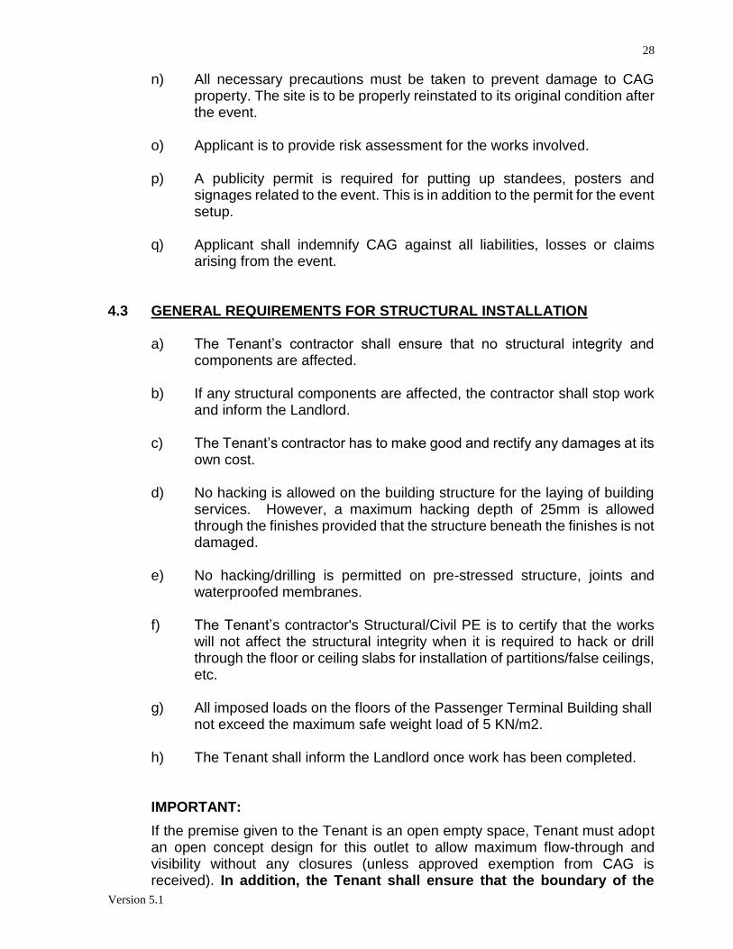
28
Version 5.1
n) All necessary precautions must be taken to prevent damage to CAG property. The site is to be properly reinstated to its original condition after the event.
o) Applicant is to provide risk assessment for the works involved. p) A publicity permit is required for putting up standees, posters and
signages related to the event. This is in addition to the permit for the event setup.
q) Applicant shall indemnify CAG against all liabilities, losses or claims arising from the event.
4.3 GENERAL REQUIREMENTS FOR STRUCTURAL INSTALLATION
a) The Tenant’s contractor shall ensure that no structural integrity and components are affected.
b) If any structural components are affected, the contractor shall stop work and inform the Landlord.
c) The Tenant’s contractor has to make good and rectify any damages at its own cost.
d) No hacking is allowed on the building structure for the laying of building services. However, a maximum hacking depth of 25mm is allowed through the finishes provided that the structure beneath the finishes is not damaged.
e) No hacking/drilling is permitted on pre-stressed structure, joints and waterproofed membranes.
f) The Tenant’s contractor's Structural/Civil PE is to certify that the works will not affect the structural integrity when it is required to hack or drill through the floor or ceiling slabs for installation of partitions/false ceilings, etc.
g) All imposed loads on the floors of the Passenger Terminal Building shall not exceed the maximum safe weight load of 5 KN/m2.
h) The Tenant shall inform the Landlord once work has been completed. IMPORTANT:
If the premise given to the Tenant is an open empty space, Tenant must adopt an open concept design for this outlet to allow maximum flow-through and visibility without any closures (unless approved exemption from CAG is received). In addition, the Tenant shall ensure that the boundary of the

29
Version 5.1
Premises shall not be “built-up”, with for example, back walls/partitions/glass, to preserve the transparency as well as the visibility of the surrounding retail concessions.
4.4 GENERAL GUIDELINES FOR STRUCTURAL INSTALLATION
ITEM GUIDELINES / REQUIREMENTS
1. Knocking down of walls / partitions of adjoining
floor areas
Load bearing walls and partitions cannot be removed unless the loads carried are fully transferred to other parts of the structure without effecting the structural integrity, stability and strength. Such proposal shall be designed by Structural / Civil P.E* & subject to the relevant authorities approval. Any demolition works shall be done in accordance to SS557:2010 Code of Practice for Demolition.
2. Additional Load / Installation
Details of ** Permanent additional loads ( e.g racking systems, safes , weighing machines, additional ducts, services, projectors, etc) proposed to be placed onto the floor area or structural members must be submitted to CAG(S) for approval. Prior to submission , the Successful Tenderer is to ensure that the proposed loads / installation for that floor or structural member does not exceed its design live load+ and this should be verified by the Successful Tenderer’s Structural / Civil P.E’s. *
Sub-note: Steel plate spreaders are to be provided to evenly distribute the load onto the structure where high concentration of point-loads is anticipated. The spreader is to be designed by the Successful Tenderer’s Structural / Civil P.E *, steel plate spreader designs must not impose too much of its self-weight onto the existing structure.
2.1 Change of use Any change of use for the area must be made known to CAG(S) Master Planning, A preapproval are required to be endorsed by CC and CAAS
3. Hacking of floor / coring / Walls/ columns or ceiling
No hacking or coring is allowed on the structural members for the laying of building services. However, a maximum trimming depth of 25mm is allowed through finishes provided the structure beneath the finishes is not damaged. Groove lines should be cut to prevent over spalling of adjacent concrete along the line of trimming. Any trimmed areas are to be patched back using non-shrink grout. Beams and webs of hollow core slabs shall be avoided during coring. Coring on Pre- Stressed beams should be carried out only upon further inspection and certification by a PE. Fibre wrap materials used for slab/beam/column strengthening & waterproofing membrane used for RC flat roof /planter box area shall not be disturbed/affected.

30
Version 5.1
Sub –Note: For any openings at fire rated wall due to their services penetrations , contractors are to seal off with Approved fire materials and endorsed by the professional engineers, All work involved in the Fire Safety Engineering Areas under terminal 1, 3 and 4, a “FSE no objection letter” shall be obtained by the contracted company
4. Erection of partitions / false ceilings
The following should be submitted for approval : a) Specifications of proposed partitions / false ceiling b) Drawings to show the proposed locations of
partitions/false ceiling c) Details of the methods of installation of partitions /
false ceiling d) PE calculations to design to Code of Practice for
Dead and Imposed Loads – BS6399: Part 1 for lateral/impact loads onto partitions
The Successful Tenderer’s Structural / Civil PE is to certify that the work will not affect the structural integrity when it is required to carry out hacking / drilling on structure members. (Supervising PE must made known of areas of Post Tension Beams, Prestressed Planks/Tee-beams and Precast Prestressed Precast Beams (PSPC) under its care)
* Structural / Civil P.E to certify statements / calculations / necessary documents to state that renovations work / other works do not affect the structural integrity. * Carry out pre-con dilapidation survey (Pre-con survey) if renovation works involving hacking/demolition of structure. * Provide instrumentation plan for our approval (demolition/hacking): - Noise Meter - Settlement Markers (Building/Ground) - Vibration Meter * Impact assessment report to be submitted for our record (For hacking/demolition works only) ** Permanent additional loads refer to under hanging as well as top resting loads. + Refer to Annex on Loading Criteria

31
Version 5.1
Annex on Loading Criteria for all PTB
S/N Facilities Designed Live Load ( KN/M²) 1 Typical Floors (Floor uses that are not specified
on plan), Supermarket, Refuse Centre and Service Mezzanine
5 KN/M²
2 Equipment, plant and motor rooms and workshop, AHS/AHU Rooms, Stored Rooms, Arrival & Departure Halls.
To design to *** actual weights of equipment but not less than 7.5 KN/M²
3. Injector Plant Rooms and HT/LT Rooms To design to *** actual weights of equipment but not less than 15 KN/M²
4. Stores, Auditorium and Multi –purpose Hall (Similar to Arrival & Departure Halls)
Min 7.5 KN/M²
5. Telecoms Plant Rooms, Computers Floor Min10 KN/M²
6. Baggage Handling Area (BHA), M&E Fan Rooms, Electrical Load Centre, Baggage Ramp, /Inbound & Outbound Areas, Equipment Parking Areas and TGFS Rooms.
Min10 KN/M² on 1st storey floor for baggage belts, equipment, actual location of BHA etc.
7. Chiller plant rooms, Transformer Room and Generator Room
To design to *** actual weights of equipment but not less than 30 KN/M² for equipment transportation path. 20 KN/M² for actual location
8. Bus Station , Basement Ramp, Basement Roadways, Service/Loading Bays, Vehicular Ramps/underpass, Electrical sub-station, Bus Gates
12.5 KN/M²
9. Landscape Courtyard, Planter area /Landscape area (Excluded Soil)
3 KN/M²
10. Engineering Parking Areas and SATS Elect Tow Tug Recharging Area, Elevated Driveway/Ramps
50 tonnes vehicle with four wheels spaced at 2.74m * 3.6m (HA loading, 45 units of HB loading and footway crowd loading in accordance with BCA Forth Scheme-Loading)
11. Diesel Tank Room, Domestic Water Tank, Sprinkler Tank Rooms, Water tank at 4m
30 KN/ M²
12. Cooling Towers To design to *** actual weights of plants with special consideration for vibration and deflection
13. Concrete roof 1.5 KN/M²
14. Steel roof 0.5 KN/M²
15. Main Roof 0.75 KN/M²
*** If actual weights of materials are not available, weights of materials can to be made with reference to BS 648.

32
Version 5.1
Common Renovation Queries

33
Version 5.1
Annex: Loading Criteria Schedule for Terminal 4
Load Type Description Uniformly Distributed Load
(kN/m²) UNO
Hydraulic Water (unit weight = 10 kN/m3) As Calculated
Dead load
Concrete (unit weight = 24 kN/m3)
As Calculated
Concrete Block (unit weight = 20kN/m3)
Steel (unit weight = 77 kN/m3)
Backfill Refer to geotechnical design information (unit weight to be based on average density)
As Calculated
Superimposed Dead Loads
100mm finishes 2.4
150mm waterproofing 3.6
Plinths As Calculated
Brick wall
100mm thick 3.0 (on elevation)
200mm thick 5.0 (on elevation)
Rockwool
50mm thick 0.04 (on elevation)
100mm thick 0.08 (on elevation)
Ceiling and Services (general) 1.2
Partitions 1.0
Roof Built-up (including secondary purlin)
1.2

34
Version 5.1
Roof Central Skylight 2.1
Roof Lantern Skylight 2.6
Elevated Driveway / Ramp (50 mm premix)
1.2
Planter (soil depth of 1 m) 20.0
PV cells on roof 0.11
Imposed Load
Surcharge at Ground Level
20.0
on and off carriageway
General or Public Area, Arrival & Departure Hall (Subjected to trolley)
5.0
Shop Floor, F&B, Cafes, Restaurants (Subjected to trolley)
5.0
PLB Fixed Gangway 4.0
Offices 2.5
Toilets 2.0

35
Version 5.1
Roof (Steel) (accessible for cleaning & repair only)
0.75
Roof (RC) 1.5
Staircase, Corridor 5.0
Car Parking / Car Park Driveway 2.5
Car Park Ramp 5.0
Fire Engine Access Way 20.0
Imposed Load
M&E Room (In General) 10.0
AHU Room 7.5
MCER Room 12.0
Bin Centre 5.0
Water / Fuel / Storage Tanks or Pits As Calculated
Specific M&E Equipment / Machinery As Calculated
Elevated/Suspended Driveway As Calculated
Storage
2.4 (per 1.0m high)

36
Version 5.1
Baggage Handling System (Floor loading on Level 1)
12.0
Baggage Handling System (Suspended from Level 1 Mezzanine or Level 2)
12.0
(a) floor elements (e.g. beam and slab) 5.0
(b) vertical support elements (e.g. columns, struts and walls)
7.0
(c) X-ray machines 12.0
Baggage Claim Area 5.0
Check-in Island 5.0
Main Galleria Exhibition Display (Suspended from roof)
5.0
Transformer Room / Switch Room / Generator Room
16.0
Concentrated Load
Catwalks 1.0 kN at 1 m centres
Safe Box 20 kN
(903mm (W) x 773mm (D) x 1796mm (H))
The tenant shall verify the loading provision with the loading plan posted on the premises and certified as-built drawings.

37
Version 5.1
5. SPECIFIC M&E REQUIREMENTS 5.1 ELECTRICAL SYSTEM A. Appointment of Licensed Electrical Worker (LEW) (a) The tenant must appoint an EMA Licensed Electrical Worker appropriate to the
capacity and voltage of his proposed electrical installation work. Under The Electricity (Electrical Installations) Regulations 2002 made under the Electricity Act (Cap. 89A), the design and installation may be undertaken by the following categories of licensed electrical workers:
LEW Voltage Capacity of Installation
Grade
Electrician Not exceeding 650V
Not exceeding 45kVA
7
Electrical Technician
Not exceeding 650V
i) Design - Not exceeding 150kVA ii) Install - Not exceeding 500kVA
8
Electrical Engineer
No Limit No Limit 9
(b) The tenant must inform CAG Engineering & Development Group (EDG) of any
change of Licensed Electrical Worker during the course of the modification works. B. Appointment of Electrical Contractor (a) The tenant must appoint BCA-registered electrical contractors to carry out the
electrical installation works.
(b) The tenant must ensure that the LEW and the electrical contractor reads and understands the general requirements for electrical system in the CAG Renovation Requirement.
C. Licensing of Electrical Installation (a) The tenant must appoint an EMA Licensed Electrical Worker to take charge of the
electrical installation, which includes repair, operation and maintenance.
(b) The tenant must renew their electrical license annually with CAG Engineering & Development Group (EDG) at the end of each calendar.

38
Version 5.1
D. Submission of Plans (a) The tenant must submit the following plans duly endorsed by an LEW:
i) Proposed single line diagram, ii) Proposed lighting layout plan with circuit numbers and looping, iii) Proposed power point layout plan with circuit numbers and looping, iv) Proposed fire alarm system layout plan and interfacing details with landlord’s
existing system whereby applicable, v) Proposed public address system layout plan with looping and interfacing details
with landlord’s existing public address system if there is (Terminal 4 only) vi) Proposed meter connection details and elevations with landlord’s existing energy
monitoring system (Terminal 4 only) vii) Lighting power budget calculation
(b) The tenant must submit electrical meter specifications or catalogues of their new
electrical kWh private meters for CAG EDG approval, prior to approval of work permit.
(c) Once proposed drawings have been approved by CAG EDG, no further changes are allowed.
E. Application for the Turn-On of Electrical Supply (a) The tenant must ensure that the following forms are duly signed by an LEW and
submitted to CAG EDG in order to arrange for a turn-on of electrical supply:
i) Form 1 : Application For Renewal Of License To Use Or Operate An Electrical
Installation (2 sets),
ii) Form 13a : Certificate of Compliance (2 sets),
iii) Form 13b : Statement of Turn On (2 sets),
iv) Form 14 : Certificate of Responsibility of Installation after Turn-on (2 sets),
v) Form 16 : Letter of Consent (2 sets),
vi) Form 18 : Electrical Test Report (2 sets),
vii) As-built Single Line Diagrams,
viii) As-built Power Layout plan,
ix) As-Built Lighting Layout Plan.
(b) In the case of incumbent tenants, the tenant is still required to submit the above
mentioned documents. F. General

39
Version 5.1
(a) All installation works carried out must comply with the latest issues of the
Singapore Standard and Code of Practices and must be governed by all relevant regulations on electricity supply.
(b) All M&E services, within and/or adjacent to the tenant’s premises which are
affected by the renovation works must be diverted/relocated by the tenant at his own cost.
(c) Any damages to fire-stop or fire-proof sealant must be reinstated. G. Breach of Regulation (a) Works to the electrical installation are not allowed without an approved work
permit. Should the tenant choose ignore this, CAG has the right to cut off electricity supply to the tenant’s premises; or any other penalties which CAG deem fit.
H. Electrical Meter (a) The tenant must install their own private electrical kWh meters, unless informed
otherwise by CAG EDG.
(b) The meters must be placed within the tenant’s premises at a location which is easily accessible and at a height that can be easily read by CAG’s contractor without a need to use a ladder. Access to the meter panel must be clear and unobstructed at all times.
(c) Both the electrical kWh meters and its current transformers used must be of
accuracy class 0.5 and vandal proof type with MID certification.
(d) If electrical kWh meters are kept within an enclosure or box, it must have a window so that readings can be easily seen.
(e) The tenant is fully responsible for the maintenance and calibration of the electrical
kWh meter. I. Distribution Board (DB) (a) No addition or alteration, temporary or permanent, can be made to an existing
installation unless approved by CAG EDG.
(b) Unless provided, the tenant must install their own distribution boards.
(c) Any openings in the DB must be fitted with grommets or glands to prevent cables from being cut by the sharp edges.

40
Version 5.1
(d) Any equipment or enclosure with a voltage that exceeds 250V must have a “High Voltage” warning label with the maximum voltage clearly visible on it.
(e) Fuses are not allowed to be used for protecting final circuits in the distribution
boards.
(f) All MCBs installed by the tenant must have minimum short-circuit capacity of r.m.s. symmetrical amperes of; i) 6kA for lighting circuits and, ii) 9kA/10kA for power circuits or circuits with shared lighting and power.
(g) All MCBs installed by the tenant that serves downstream distribution boards and/or
motors must have type "3" or "C" curve tripping characteristic.
(h) Lighting and power circuit must have separate residual current protection.
(i) As-built single line diagrams must made available at the Distribution Boards.
(j) The main circuit breaker installed by the tenant must be paired with a residual current protection circuit breaker (RCCB). However for installations exceeding 100A 3-phase, the main circuit breaker must incorporate overcurrent and earth fault protection.
J. Cable Tray, Trunking and Conduit (a) All outgoing cables or final sub-circuits must be laid in metal or GI conduit/trunking.
PVC trunking/conduit is not allowed. Flexible metal conduits not exceeding 2 meters can be used for lighting points.
(b) New sub-main cables from the switchroom to the tenant's premises must be laid
in metal trunking. The colour of the trunking must match the building’s electrical system, which is yellow. It must be embossed at every 3 meters apart with the word “ELECT” and the tenant’s unit number.
(c) All electrical cable trunkings or trays installed within the leased premises must be
labeled by spray paint with the word “ELECT” and tenant’s shop name.
(d) All electrical cable conduits installed must be labeled by spray paint with a yellow band and printed sticker with the word “ELECT” and tenant’s shop name.
(e) All trunking/tray/conduit installed by the tenant must be of appropriate cross-
sectional size. Methods of support must be in accordance with the latest issue of the Code of Practices.
(f) Trunking of not more than 200 x 75mm in size or cable tray not exceeding 300mm
in width may be allowed to sit on the secondary grid. This is subjected to CAG EDG approval.

41
Version 5.1
(g) In cases where there are no secondary grids, trunkings must be individually supported and rigidly secured by suspended down-rods or full saddles.
(h) All trunking/tray/conduit must be at least 200mm clear of air-con ducts, pipes &
mechanical installation. (i) Proper couplings and hexagonal brass bushes must be used at connections points
between conduits and trunkings.
(j) Any wall, floor or ceiling penetrations/hacking done by the tenant, either at the leased premises or CAG electrical closet/plant rooms, must be made good with fire stop.
(k) All trunkings must be properly covered after installation.
(l) Any trunking/tray/conduit laid in areas exposed to public or passengers must not
block any pathway and match adjacent finishes. K. Cables
(a) All cable installation by the tenant must be laid in metal conduits, trunkings or trays. (b) Cable installations are to be sized in accordance to the table below (factors such
as voltage drop, ambient temperature, current-carrying capacity are to be factored in before determining the cable size):
MCCB/ MCB Ratings
Cable Size (Live & Neutral)
Cable Size (Earth)
6A/10A 16A/20A 30A/32A 40A 60A/63A 80A 100A 120A 150A/160A 200A
300A
400A
2.5 mm² 4.0 mm² 10 mm² 16 mm² 25 mm² 35 mm² 50 mm² 70 mm² 95 mm² 120 mm²
150 mm²
185 mm2
2.5 mm² 4.0 mm² 10 mm² 16 mm² 16 mm² 16 mm² 25 mm² 35 mm² 50 mm² 70 mm²
95 mm²
95 mm2
i) The above requirement applies to both single phase and 3 phase system. ii) The tenant must seek CAG EDG’s approval on the size of cable to use for
MCCB ratings not shown in the table above.

42
Version 5.1
(c) Fire rated (FR) cables must be used for services or equipments related to fire
safety such as lifts, pumps, fire alarm system (e.g. detectors, alarm bells, panels, manual call points, etc.), etc.
(d) Cables that are above 35 sqmm shall be of XLPE types which are compliant to the relevant IEXC and SS standards.
(e) All outgoing cables from the tenant’s DB must be colour coded & fitted with alphanumeric ferrules at both ends.
(f) Colour sleeves must be used on cables serving 3-phase electrical supply.
(g) The cable colour code must comply with EMA’s cable colour code:
i) Three Phase Conductor or Live – Brown (L1), Black (L2) and Grey(L3) ii) Single Phase Conductor or Live– Brown iii) Neutral Conductor – Blue iv) Protective Conductor or Earth– Green and Yellow
(h) Extension cords are not allowed as final circuit.
(i) All cable joints must be mechanically and electrically sound and fully insulated.
Cable joints are not allowed within the conduits, trunkings, cable trays, etc.
(j) The termination/connection or joining of cables using a PVC connector is not allowed. Metal clad switches shall be used for the isolation of lighting fixtures or other maintenance purpose, unless due to site constraints where it is necessary to use cable coupler or ceiling rose. The housing/k.o. box to be used to contain the plug and receptacle shall be made of metal casing and cover. The flexible metal conduit protecting the cables in between fitting and metal k.o. box shall be made of metal with pvc coating on the outside.
(k) All cables must be least 200mm clear of piped services such as gas and water and
are not to be located directly below and parallel to these pipes.
(l) All cables laid in the ground must be armoured cables. All armoured cable terminations are to be provided with cable glands and earth tags.
(m)For cable termination works that requires shutdown of sub-mains distribution
panels, it must be carried out between 1am to 6am on weekdays. The tenant is to arrange with CAG EDG for shutdown of electrical supply. The tenant’s LEW must be present during the cable termination works.
(n) If the sub-main cables are installed in the common tray/trunking (e.g. shared by
other tenant's cables), tenant must label with tenant's shop name and unit number at 3 meter intervals.

43
Version 5.1
L. Electrical Fixtures / Luminaries (a) All electrical fixtures, accessories and gears must be supplied by the tenant at his
own cost.
(b) The tenant is responsible for the maintenance of all electrical installation, fixtures, and luminaries within their premises.
(c) All lamps for general lighting, signs, bulkhead, display shelves, and advertisement panels must be warm white colour (i.e. colour temperature of 3000K).
(d) The following are Prohibited lighting application:
- All exposed/ visible fixing devices, wiring, clips, transformers and other mechanisms.
- All non-glare free light sources - Exposed direct ceiling surface mounted track lighting.
(e) The lighting installation’s (including general, accent, display and specialized lighting) maximum lighting power budget (including ballast loss) must be in accordance with SS 530:2006. The lighting power budget must not exceed the following;
Type of Usage Maximum lighting
power budget (Watts / m2)
Offices 15
Shops / Supermarket / Departmental stores (including general, accent and display lighting)
25
Restaurants 15
Lobbies / Atriums / Concourses 10
Stairs 6
Corridors 10
Warehouses / Storage areas 10
(f) All emergency lights (e.g. UFO lights or battery-pack lights) must be able to
operate a minimum of 2 hours in an event of power outage.
(g) Exit light must be of the LED type. All exit lights and emergency lights (e.g. UFO lights or battery-pack lights) must be tapped from the emergency supply.
(h) Lamps that produce a lot of heat and glare, such as Halogen, Metal Halide, etc.
are not allowed to be used for general lighting. (i) Installation of Neon Sign/Lighting, Cold Cathode Lighting and any High Voltage
Discharge Lighting is not allowed. (j) The use of magnetic (conventional) ballast in luminaries is not allowed.

44
Version 5.1
(k) 2A fuse & holder must be installed for all fluorescent light fittings.
(l) All metal parts on the installation such as enclosures, luminaries, cable trunkings, cable trays, water pipes etc. must be bonded to earth.
(m)The tenant must ensure that covers of the shop bulkhead and signs are not
fastened with rivets.
(n) All switch socket outlets must be incorporated with 30mA passive type, residual current protection device.
(o) The tenant must label all light fittings, light switches, equipments and socket
outlets, switchboards and distribution boards, with their assigned circuit numbers as indicated in the single line and layout drawings.
(p) Switch socket outlets and light switches which are connected to emergency supply,
these must be marked distinctively with a red sticker or label. (q) The tenant should provide UPS back-up for computers and POS
(r) All electrical fixtures, DBs and electrical meter panels must be more than 1.5
meters away from the wash basin, water pipe/joint and tap.
(s) No demountable partition, fixed furnishings or wall are allowed to be positioned on top of any of the floor junction boxes. The existing junction boxes must not be sealed for functional and maintenance reasons. The tenant is to ensure that junction boxes are accessible at all times. If not, the tenant must bear all cost for the relocation of the junction boxes subject to CAG approval.
(t) Tenant/contractor must indicate clearly the locations of LED drivers/ballast in the
lighting layout drawings. (u) Tenant/contractor must also ensure that the these drivers/ballast are properly
ventilated with proof of drawings/pictures/photos. M. Emergency Supply (a) 50% of the overall lighting must be connected to the emergency supply.
(b) At least one (1) switch socket outlet at Cashier counter must be circuited from the
emergency supply.
(c) There will be a fortnightly testing of the Generators. During the testing period, there will be a momentarily disruption of power to the emergency supply. The tenant should provide UPS back-up for any critical equipment.
N. Temporary Electrical Supply

45
Version 5.1
(a) The tenant must install a temporary distribution board that includes RCCB with sensitivity of 30mA and 0.1 seconds tripping time. This temporary distribution board must be approved by CAG before commencement of work.
(b) The tenant must install a private electrical kWh.
(c) Proper testing and turn-on procedures must be carried out.
(d) Cables must be clear of building operation or engineering construction work and are not a hazard to persons working on the site.
(e) All joints must be mechanically and electrically sound and fully insulated.
(f) All socket outlets must be industrial type (commando plug).
(g) For single phase socket outlet assembly fed from single phase source, a double
pole MCB and 30mA RCCB must be provided at the incoming. Each socket outlet (max. 6 nos.) must be controlled by a double pole MCB not exceeding 16A current rating.
(h) For single phase socket outlet assembly fed from 3 phase source, a 4 pole MCB
and 30mA RCCB must be provided at the incoming. Each socket outlet (max. 9 nos.) must be controlled by a double pole MCB not exceeding 16A current rating.
(i) For 3 phase socket outlet assembly fed from 3 phase source, a 4 pole MCB and
30mA RCCB must be provided at the incoming. Each socket outlet (max. 3 nos.) must be controlled by a TPN MCB not exceeding 16A current rating.
(j) For mixed 3 phase and single phase socket outlet assembly fed from 3 phase
source, a 4 pole MCB and 30mA RCCB must be provided at the incoming. Each 3 phase socket outlet (max. 2 nos.) and single phase socket outlet (max. 3 nos.) must be controlled by a TPN MCB and a double pole MCB respectively, not exceeding 16A current rating.
(k) All cables that are laid in the ground must be armoured cables.
(l) All temporary electrical installations must comply with the latest code of practice,
CP 88: Part 1: 2001. O. Testing & Commissioning of Electrical Installation (a) The tenant must apply for date of turn on with CAG EDG.
(b) The tenant’s LEW must provide his own tools, ladder and testing equipment. (c) Testing & commissioning of the electrical installation must be carried out by the
tenant's LEW, in the presence of CAG EDG’s staff. Inspection and testing of the

46
Version 5.1
electrical installation must be in accordance with the latest issue of the Code of Practices.
Note: If the above-mentioned test report records are different from the records
taken during the T&C in the presence of CAG personnel, 2 sets of the revised test report, endorsed by LEW, must be submitted within 3 days after the turn-on.
P. Tapping of new power supply from CAG Load Centre/Low Tension Room (a) Any electrical connections to CAG switchboards will be done at the tenant’s own
cost.
(b) The tenant must seek CAG’s approval on the source of the new power supply.
(c) The tenant must submit proposal for the cable tray and/or trunking routing to CAG for approval.
(d) Sub-main cables must be sized adequately to cater for the voltage drop from the Low Tension Room/Load Centre (supply source) to the location of the new distribution board (DB) at the tenant’s premises.
(e) The shutdown of electrical supply to facilitate the connection of the new sub-main
cables is between 0100hrs to 0600hrs (subjected to last flight). The shutdown will be arranged by CAG and supervised by CAG’s maintenance contractors.
(f) The tenant must update both soft and hard copies of the main single line drawing
of the switchboard that is modified. The tenant must provide one (1) laminated hard copy at CAG switchboard on site. The softcopies of single line drawings, power and lighting layout drawings, cable tray/trunking routing and switchboard installation diagram must be submitted to CAG.
(g) The tenant must label the MCCB, RCD, MCB, new distribution board (DB) and
sub-main cables installed by with the tenant with the new circuit number (assigned by CAG) and shop name.
(h) The tenant must make arrangements with CAG to Turn-On the electrical supply at
the Switchroom. The tenant’s LEW must prepare testing forms and documents prior to the electrical supply Turn-On. The tenant’s appointed LEW must attend all such ‘Turn-On’.
(i) For connections made at the Low Tension (LT) switchboards, the tenant must
install Meters that record the Maximum Demand for each phase. (j) The tenant must install digital earth leakage relay (ELR) at their main switchboard
and residual current circuit breaker (RCCB or RCD) at their distribution boards. The tenant must install RCD/MCBs in their distribution boards.

47
Version 5.1
(k) All cables in the switchboard must be secured via cable ties. The colour code of the cables must be clearly indicated. Cable entry to the switchboard must be via cable glands.
(l) Transparent Perspex covers must be installed in the new switchboards and/or
distribution boards. The transparent covers must have handles to allow for proper/easy removal.
(m)The tenant must install new cable trays and/or metal trunkings for the sub-main
cables from the switchrooms to the new distribution board in the tenant’s premises. The tray/trunking must be Yellow in colour.
(n) The cable routing from the switchrooms to the tenant’s DB must be submitted to
CAG for approval. The requirement for cable occupancy inside the trunking must comply with the latest code of practice. The tenant must comply with approved method of support system for all services.
(o) The locking mechanism of the new switchboards must be wing knobs, unless
otherwise instructed by CAG. (p) Additional requirement for Installations in T1 & T2: The tenant must install new
digital kWh meter in new meter panel in CAG meter room. The new kWh meter panel must have a transparent cover in. A MCCB/MCB breaker of appropriate capacity and KA rating must be installed before and after the meter.
(q) The tenant must label the cables and the meter panel with CAG assigned circuit
number and the shop name. The kWh meter installed must be easily accessible in order to record the meter reading.
Q. Working in CAG Electrical Switchrooms (a) The tenant must submit the Switchroom Authorization Form (Appendix 4.10) to
CAG EDG to seek approval to commence work in any switchroom.
(b) All works in the switchrooms can only be carried out during office hours. Approval must be sought from CAG EDG for works after office hours.
(c) The tenant is fully responsible for the security of these premises during the
approved period of works. The tenant must provide full-time manning at the switchroom during the course of works.
(d) The tenant must ensure that the switchroom is cleaned before leaving. R. Inspection during Works (a) CAG have the rights to inspect the tenant's premises without notice.

48
Version 5.1
(b) CAG have the right to cut off electrical supply to the tenant’s premises, or any other penalties CAG deems fit, if any illegal alteration, modification, extension or renovation of the electrical installation is found.
S. Reinstatement (a) The tenant must reinstate the condition of the leased premises to its original state
when his tenancy expires. All equipment that was provided for must be returned and installed as per its original state.
(b) The tenant must dismantle and remove all electrical fixtures, luminaries, cables, etc. installed by them from the leased premises.
T. CAG Obligation (a) CAG is responsible for the availability of electrical supply to the tenant’s premises.
The tenant is responsible for the down-stream electrical supply and equipment within the leased premises, including isolators, distributions boards, electrical kWh meter and final circuit cables.
U. Fire Safety Advisories to Prevent Electrical Fires
(a) Never overload electrical outlets with electrical appliances;
(b) Always switch off appliances when they are not in use;
(c) Check the condition of wires regularly. Frayed wires or cracked cords should be
replaced or repaired immediately;
(d) Do not run/lay wires under carpets or mats and keep wires away from hot
surfaces; and
(e) Use electrical plugs which carry the SAFETY Mark.
(f) All tenants shall engage LEW to conduct check on all electrical appliances within
their leased areas annually. The LEW report shall be submitted to commercial
and EDG for record purpose and provide to AES for investigation when needed.
V. Electrical Meter (for Terminal 4 only) (a) The tenant must install their own private electrical kWh digital meters, unless
informed otherwise by CAG EDG.
(b) The digital meters shall be of make ABB, Schneider, Socomec or approved equivalent. These meters are to be installed at the Metering Panel (MP) rooms provided for this purpose.
(c) The meter shall comply with IEC 62053-22 Class 0.5S for Active Energy vandal
proof type with MID certificate and must be approved by CAG.
(d) The tenant shall be provided with RS-485 cabling and Current Transformer (CT) leads at the Metering Panel room / closet for connection of the Tenant’s Energy Meter. All programming and other works required to integrate the meter to the

49
Version 5.1
centralised Schneider Struxureware EMS shall be borne by the tenant. The tenant shall also provide additional 5 meters of RS-485 cable (of make Datwyler, Belden or equivalent / better) for daisy-chain connection. Proper cable management must be ensured and installation of meters must not cause damage to the existing RS485 daisy chain of the energy monitoring system.
(e) If electrical kWh meters are kept within an enclosure or box, it must have a window so that readings can be easily seen. The tenant is fully responsible for the maintenance and calibration of the electrical kWh meter.
(f) Tenant shall engage the IBMS term contractor for required programming and related works to interface/link the Energy Meter to IBMS which shall be borne by the tenant. (Applicable to T4 only)
W. Cable Termination Method
Termination, connection or joining of cables using PVC connector is not allowed. This requirement applies for all electrical connections including lighted signs, gondolas, display panels or furniture with electrical fixtures. Photos of termination must be attached together with Turn On Forms for verification. (Please refer to ‘DECLARATION OF PROPER TERMINATION ADOPTED FOR ELECTRICAL WORKS’ incorporated with Turn On Forms 1 to 18).
5.2 AIR-CONDITIONING SYSTEM 1. The tenant shall submit 4 sets of plans (minimum A2 size) showing the existing
position of air-conditioning diffuser, air return grilles, VAV boxes, duct sizes, thermostat etc. and the proposed changes. All the drawings are to be endorsed by a Professional Engineer (P.E). No alteration is to be done on the main duct. All additional air-conditioning shall be coloured in the plan.
2. The tenant shall submit detailed heat load calculations and ductwork static
pressure loss for the tenanted area and the calculations are to be endorsed by a PE(M).
3. The renovation work to be carried out must comply with the regulations laid down
in the Code of Practice SS 553 and other requirements by FSSD. 4. The type, make, model and rating of any fitting/equipment used are to be clearly
indicated in the drawings. 5. All new ducts to be installed shall be insulated internally and externally. Flexible
ducts installed must not exceed 2 metres in length. 6. Tenants to note that the installation of excess lighting/computer/ equipment and
erection of full height partitions will affect the space temperature and ventilation. Tenant is to take note that the supply “off-grille” temperature is around 18±1°C. If no modification works is done to the provided air-con supply,

50
Version 5.1
tenant shall submit a letter from a Professional Engineer (Mechanical) to ensure that the stipulated space temperature of 23±0.5°C can be achieved. Failing which the tenant has to install additional air-con units at their own cost and submit proposal drawings for CAG approval.
7. Odour removal devices such as ionizers are to be installed to minimize smell
problem occurring in the surrounding space area if the works involve hot works, painting or works that may emit pungent smell surrounding the work area. Details of existing ionizer installed (Applicable in T4 F&B only) are as such: Kitchen Odour Removal
Electronic Air Cleaner a) For maximum air cleaning efficiency, Kitchen Exhaust must come with
Electronic Air Cleaner. b) The Air Cleaner must be a high efficiency contaminant collector designed
to remove up to 95% of the dust, smoke, liquid aerosol and other pollutants on single pass from the air passing through it.
c) Fine fumes mist and dust particles that entered into the ionizing section are ionized and charged with positive electricity (corona discharge), and subsequently absorbed, caught, cleaned and attached to the negative plate at dust – collecting section of ion chamber.
d) Solid state Two stage electrostatic purification machine is applied in ion chamber. Ionizing section are highly charged with 12,000V and 6000V respectively.
e) Electronic Air Cleaner comes with spiked Ionizer, No ionizing wires to replace, reducing maintenance and replacement cost.
f) Ceramics Insulator is applied to ensure reliable isolation under tough working conditions.
g) Zig-Zag type stainless steel electrode is applied to avoid being enfolded by oil stain and enable equipment to be in the state of high efficiency.
h) Corrosion-resistant aerolite dust-collecting plate is applied to ensure longer service life of equipment.
i) ON/OFF switch and safety switch are configured to realize safer two-fold protection.
Nano Catalytic Filter with Oxidation a) Nano Catalytic Filter is installed after Electronic Air Cleaner for removal
of odorous gases and harmful vapours such as food odours, smoke, hydrocarbon substances and other inorganic compounds.
b) Filter material shall be non-toxic and non-flammable material. c) Provided with filter cell which is non-toxic, moisture resisted, non-
flammable or frame retardant material and with minimum bacterial and fungal growth environment.
d) The filter material used for odour removal shall be able to perform absorption and also chemical oxidation at the same time to achieve self-regeneration.

51
Version 5.1
e) Bed thickness, air velocity, porosity and pore size shall be carefully selected to ensure filter can be operated efficiently throughout its service life.
f) The filter material shall bear nano sized cavity which for adsorption of odorous gases.
g) The filter material shall be able to perform catalytic oxidation which increases the rate of chemical oxidation.
h) Selected with operating condition over a wide range of temperature and humidity.
i) Provide with panels containing absorbent evenly and assembled into a casing effectively sealed.
j) The filter material has to work with an oxidant generation system for chemical oxidation.
k) Use of electricity by the system is a must to generate oxidant. l) The filter is installed in V bank arrangement. One piece of Nano Catalytic
Filter has a dimension of 500mm(W) x500mm (H) x20mm (D) 8. Tenant shall ensure the use of a flexible duct to extract and exhaust the welding
fumes or use a smoke filtration equipment to filter out or neutralize the welding fumes/smell to avoid the smell goes into the air-conditioned space area, during welding works.
9. Tenant shall install new air-conditioning square/round diffusers instead of linear
diffusers (Applicable for shops in T2 Departure Transit Area only). 10. Tenant shall provide and install new DDC VAV boxes with local control
thermostat with the necessary connecting ducts to CAG design and specifications. Tenant is to link the power supply cables for VAV boxes to their own DB and labelled. In addition, tenants are required to provide “Access Panel” near each VAV boxes for maintenance purposes. The air-conditioning distributing system including VAV boxes and local control thermostat which the tenant installed, shall be properly maintained by the tenant themselves and shall not be dismantled upon expiry of tenancy. CAG has the rights to ensure that the VAV boxes and local control thermostat are properly and sufficiently maintained.
11. Tenant shall appropriately design the air-conditioning ductwork and fitting with
low static pressure losses that it will not affect CAG’ centralized air-conditioning performance.
12. Tenant shall conduct their own internal air-con balancing to the approved CMH
values as in the air-conditioning shop drawings and heat load calculations. Prior to the air-balancing work, tenant is to arrange with CAG to set the Air Handling Unit to the maximum speed. The VAV boxes shall be in fully open positions. After then, a joint inspection with CAG to be carried to verify the CMH values before commencement of the concession operation. Appropriate locations of test holes and volume control damper are to be provided to facilitate this works.

52
Version 5.1
13. Thermostats shall be located at an appropriate location where they reflect the correct average temperature. Thermostat located near lighting, heating element, inside another room, etc is all prohibited. Thermostat shall also be located at area that is visible but yet at high level that is beyond a standing person’s reach. Thermostats are to be set at 24 deg C at all times.
14. There shall be no illegal tapping of air-conditioning supply at the main ducts before the VAV boxes or tampering with the approved installed VAV boxes. Any illegal tapping or VAV box tampering will be removed by CAG in-house Contractor and a penalty of 15% above the cost will be charged to the guilty party.
15. For Terminal 3 only, due to the nature of the main terminal building butterfly
roof design in Terminal 3, tenants shall note that the feasibility of having a standalone air-conditioning unit (s) is subjected to the propose equipments technical capabilities, the refrigerant piping distance and the availability of space for mounting the Condensing Units. Tenants shall install stand alone air-con unit(s) at their own costs using VRV refrigerant system or any special air-conditioning system, whichever is applicable and feasible if air-conditioning is required for kitchen area or if the proposed heat loads exceeds the existing cooling capacity provided by CAG. Tenants are advised to strictly adhere to the recommended lighting levels to prevent air-conditioning overload.
16. Tenant is not allowed to tap chilled water supply from the main chiller plant for their air-conditioning units.
17. Tenant is only allowed to tap supplementary CHW supply (subject to CAG approval) equipped with stream energy meter (BTU meter for billing purpose by CAG) connected to IBMS which is provided by CAG. (Applicable to T4 only)
18. The lighting loads in the outlet shall not exceed the specified design lux levels and proposed type of task lightings used shall not exceeding 60 watts per square meter.
19. The tenant shall switch off the air-conditioning system when shop is not in operation to avoid energy wastage.
20. The air-conditioning distribution system, especially in the F&B area, shall be designed and configured as such to minimize smell propagating to the common/landlord space. If necessary, tenant shall install odour removal devices to minimize smell problem occurring in the common/landlord space and a complete mechanical exhaust system comply with local code of practice shall be provided.
21. Tenant shall install new compatible temperature sensor with cabling to the
junction box for the operation of the dedicated AHU (especially restaurant/F&B area) with also necessary connecting ducts as per CAG design and specifications. (Applicable to T4 only)

53
Version 5.1
22. Tenant shall engage the IBMS term contractor for required programming and related works which shall be borne by the tenant. (Applicable to T4 only)
5.2.1 ADDITIONAL REQUIREMENTS FOR TENANT’S OWN AIR-CONDITIONING SPLIT UNIT
1. For split unit air-conditioning system a detailed cross sectional plan showing
the mounting, location of the condensing units for the air-conditioning should be reflected in the drawings.
2. All FCU’s installed shall be securely mounted with steel rods c/w with bolts and
nuts. And the condensing units shall have neoprene pad with a proper aluminum tray and discharge pipe must be provided beneath the condensing unit.
3. All refrigerant pipes and condensate pipes shall be run in trunking and sleeves
when penetrating walls and floors. Tenant shall provide these and make good the affected CAG ceiling area and floor penetration at their own cost. Condensate pipe must be drain to the nearest floor trap with tenant insulating the floor trap if is not insulated. The proposed routing of all refrigerant pipes and condensate pipes and penetrations details shall subjected to CAG approval.
4. The air-conditioning renovation works shall include the electrical single-line
diagram showing the MCB rating, position of switch socket outlet, operating switch, isolator, catalogue etc. for the air-conditioning unit.
5. The tenant is to ensure that the electrical load of the additional air-conditioning
unit will not trip the electrical mains. 6. The location of the condensing unit installed shall seek the approval of FM The
loading of the condensing unit are to be endorsed by a Civil P.E and submitted to Engineering Civil Section for approval.
7. The tenant shall properly label all condensing units, refrigerant and condensate
pipe installed. In addition, tenants are to submit the refrigerant pressure pipe test. Insulation for refrigerant and condensate pipe shall be class ‘O’.
8. The tenant shall submit detailed heat load calculations for the outlet and all
calculations are to be endorsed by a Professional Engineer. 9. The Aircon distribution system, especially in the F&B area, shall be design and
configured as such to minimize smell propagating to the common/landlord space. If necessary, tenant shall install odour removal devices to minimize smell problem occurring in the common/landlord space and a complete mechanical exhaust system with local code of practice shall be provided.
10. All FCU’s installed at the kitchen areas shall be linked to ACMV system that such system shall be cut off automatically if there is any KFSS and Gas Detection System activation.

54
Version 5.1
5.3 MECHANICAL VENTILATION SYSTEM 1. The renovation work to be carried must comply with the regulations laid down in
Code of Practice SS 553 and other requirements by FSSD and NEA. 2. The ACMV works and drawings must be endorsed and supervised by a
Professional Engineer (Mechanical). 3. To show all existing/new ducting in the proposed drawing. 4. The main fresh air duct and exhaust air duct are provided and terminated at the
kitchen wall. 5. Tenant is to provide the fresh air grilles, cooker hoods with grease filters, air
cleaning system, VCDs, fresh and exhaust air distribution ductworks and connect to the provided main fresh air duct and exhaust air duct respectively. They are to maintain them and bear the cost to leaks and breakdowns.
6. All fumes from the cooking range shall be extracted immediately and treated with
an air cleaning system. The air cleaning system shall not cause noise nuisance. The air cleaning system shall capture particulate matters, grease, oil, water vapour and smell causing compounds such that there is:
i. No visible black smoke and fumes (white or otherwise) from the exhaust; ii. No emission of grease or oil from the exhaust as evident by the deposition on the grating or in the surrounding area of the exhaust; iii. No intense/irritating smell of frying, charbroiling, roasting and such other cooking in the vicinity of exhaust. 7. The kitchen exhaust and fresh air fan shall be interlocked to the kitchen gas
detector system. Control wiring shall be installed by the tenant if not provided. Testing shall be conducted on the gas interlocked with the exhaust fan together with CityGas and CAG after all the installations have completed.
8. Tenant is required to provide connect the provided remote control panel for the
Kitchen Fans and gas detector panel to their own DB. 9. Should any modification or relocation works required to the provided control
panels for the kitchen exhaust fans and gas detector panel so to suit the kitchen layout, the tenant shall undertake this works with CAG approval and bear the cost.
10. Tenant shall indicate in drawing on their proposed drawing the design air flow
(in CMH) on their respective exhaust cooker hoods and fresh air grilles. 11. The tenant shall submit detailed calculations of kitchen exhaust and hood sizing
requirements for the tenanted area and the calculations are to be endorsed by a PE(M). Should the tenant exhaust requirement exceed the provided exhaust capacity, tenant shall construct 3 sided wall/ glass partition at the cooking area.

55
Version 5.1
Tenant shall ensure that the design of kitchen exhaust does not permit cooking smell to propagate to other areas.
12. Tenant shall arrange for the kitchen exhaust duct to be chemical cleaned at least
once a year and submit a copy of the servicing report for CAG EDG record purposes.
13. The tenant shall maintain at least once every 6 monthly the kitchen exhaust
and fresh air fans and submit a copy of the servicing report for CAG EDG record purposes. Tenant shall attend and bear the cost of any breakdowns due to poor maintenance fans.
14. The tenant shall maintain, attend and bear the cost of the breakdowns of the
provided dedicated main control panel and electrical switchboard serving the tenant kitchen ventilation system.
15. The tenant shall to switch off the kitchen ventilation system when shop is not in
operation to avoid energy wastage. 16. The exhaust and fresh air distribution ducts material must be of mild steel,
stainless steel or other approved materials as per Code of Practice SS 553. The jointing material used shall be compatible and not creating corrosion to CAG ductworks.
17. All air ducts provided by tenant shall be made of non-combustible materials and
of smooth texture, and easy to clean. Inspection openings shall also be provided in the air ducting.
18. The qualified person shall ensure that the exhaust and ventilation system
compiles with the above requirements and all applicable guidelines stipulated by NEA, FSSD and latest edition of Code of Practice SS 553.
5.3.1 ADDITIONAL REQUIREMENTS FOR SMOKING ROOM IN AIR-
CONDITIONING AREA 1. For smoking area, an independent air-conditioning unit and mechanical
ventilation system (Smoke Exhaust Fan with all distribution ductwork) shall be installed for the room. Fire damper shall be installed to prevent fire spread through the ventilation duct. All existing centralized air-conditioning system will be removed and blanked-off (both supply & return).
2. The smoking area shall be of full height partition and completely enclosed. The
smoke exhaust fan system is designed as such that 100% of the exhaust air shall be extracted from the smoking room area.

56
Version 5.1
5.4 FIRE PROTECTION AND DETECTION SYSTEM 1. All 1st layer fire sprinkler system has been provided in leased premise in
Terminals. Should there be any change to the location / position of fire sprinkler, the tenant shall carry out the alteration works subject to the designed by PE and approve by Fire Safety and Shelter Department (FSSD).
2. The tenant shall appoint BCA registered Fire Protection Contractor to carry out the alteration work of the fire detection / protection system.
3. The tenant shall engage a Professional Engineer (mechanical) for the design, supervision, certification, testing and commissioning of the fire protection installation work.
4. The tenant shall ensure that the fire detection/protection installation carried out by their contactor comply with the requirements stipulated in CP52:2004 and other relevant Code of Practice. The tenant shall also obtain approval of the FSSD and the relevant local authorities having jurisdiction over the installation.
5. The tenant shall forward a copy of the Notice of Approval (NOA) from FSSD for the fire protection addition and alteration works to CAG AES and EDG
6. The tenant shall submit a copy of the FSSD’s Notice of Approval (NOA) and Fire Safety Certificate (FSC) for the fire detection/protection installation work to CAG AES and EDG
7. The tenant shall ensure that all fire detection/protection system drawings to FSSD are endorsed by their Qualified Person / Professional Engineer who undertakes the design and installation work.
8. The fire alarm and detection system shall be connected to the building’s fire zone/s respectively. Upon completion, the PE(M&E) shall submit two copies of the certificate of fitness to CAG.
9. CAG and the AES shall be informed in writing (7 working days notice) of any fire sprinkler A&A works to be carried out.
10. The allowable time for the fire protection system to be isolated or discharged shall be from 0900 hrs to 1700 hrs (Monday to Friday). The tenant shall be responsible for ensuring that the entire sprinkler installation within his premises is charged up and in operation by 1630 hrs.
11. Upon completion of the installation work, the tenant shall be responsible for the proper maintenance of the complete fire sprinkler and alarm system in their premises.

57
Version 5.1
12. The professional engineer (M) responsible for the fire protection installation shall submit in writing if a waiver for any statutory requirements or any building regulations is required.
13. The tenant shall conduct regular servicing and maintenance of the fire protection and/or detection system in their premises.
14. The fire alarm systems are to be wired to the existing zone as designed by CAG. End of line resistors shall be installed where necessary.
15. Tenants must adhere fully to the standards and regulations laid down in the CP52:2004, CP10:2005, Fire Code 2013 and other applicable statutory requirements
16. The tenant’s qualified person (i.e. Professional Engineer (Mechanical)) has to endorse on the drawings as whether the fire protection system has been affected by the renovation.
17. If the Fire Protection System is affected:
a) Tenants must submit the proposed sprinklers additions/alteration works for the premises with the Qualified Person’s endorsement on the drawings to FSSD for approval;
b) Landowners endorsement on the drawings for the above submission is required; and
c) 18. If the Fire Protection System is not affected, drawings must still be
submitted to FSSD for approval with the said status of the Fire Protection System endorsed onto the drawings by the Qualified Person, in addition, a letter of undertaking must be issued by PE to CAG AES and EDG
19. Any proposed sprinklers that to be installed by tenants shall be of Quick Response Type (at Terminal 1, 3 and 4 building).
20. If there are any decorate false ceiling/canopy/display cabinets etc. installation below the existing false ceiling which has sprinkler installed, tenant’s Qualified Person shall ensure and certify that the sprinkler discharge pattern and engineered smoke extraction control is not affected.
21. Tenant shall arrange an inspection upon completion of works and furnish two sets of printed and one sets of soft copy in CD ROM using latest AutoCAD release as-built drawing to CAG.
22. Any isolation, draining and recharging to the affected sprinkler system must be done by our CAG maintenance contractor and is chargeable to the tenant. This works can only be performed provided the tenant has

58
Version 5.1
obtainedWork Permit from Facilities Management and AES online isolation permit, it is to be is supervised by the tenant’s project supervisor and completed during normal office hours.
23. For new pipe work – pressure test report (certification) is required before it can be connected to the existing sprinkler system. Existing sprinkler layout is handed over to the tenants who are required to upgrade or carry out any changes to the pipe size or distribution in accordance to the current code.
24. All sprinkler works have to be carried out by competent workers.
5.4.1 ENGINEERED SMOKE CONTROL SYSTEM 1. Tenant shall note that all the Terminals in Singapore Changi Airport are
protected by Engineered Smoke Control (ESC) System and that any alteration or addition works may affect the integrity of this system.
2. The tenant shall submit the drawings or proposals to CAG for approval. 3. In the event that the proposed works affect the ESC system and changes are
made to the system, the tenant shall submit the necessary documents and those documents that require the Qualified Person’s endorsement, to the relevant Authorities to get their approval. Tenant’s Qualified Person’s shall endorse and certify that the proposed ceiling design have a minimum of 25% of perforation openings and meets the engineering smoke control requirements. The 25% perforation opening shall be evenly distributed in lease area. Where ceiling is perforated, smoke detectors linked to the Fire Alarm and Smoke Exhaust system is to be provided by the Tenant (only applicable to Terminal 3)
4. Any isolation to the affected ESC system must be conducted by CAG in-house maintenance contractor and this cost is chargeable to the tenant. This works can only be performed provided that the tenant has obtained “Permit to Work” from CAG Facilities Management and it is supervised by the tenant’s Professional Engineer/Qualified Person carried out during normal office hours.
5. All contractor project manager must attend to CAG Fire Alarm Isolation Briefing
conducted by CAG EDG
6. ALL AES isolation online submission via https://oc.changiarport.com must be submitted 7 working days in advance.
7. All necessary testing data, joint site inspection, as-built drawings and approval
from the relevant authorities must be submitted to CAG for record purposes.

59
Version 5.1
8. The tenant shall be responsible to provide the 2nd layer of fire alarm smoke detectors for their installed false ceilings (areas protected by ESCS). The above fire smoke detectors shall be linked back to existing fire alarm system (The following particular requirements in this paragraph is applicable for Terminal 3 and 4 only). Renovation contractor is to isolate the fire alarm at his premises before carry out any renovation and cover the smoke detectors with proper cover (plastic bag is not allowed). Tenant shall also clean up the smoke detectors before handing over back to Landlord before being reinstated and reactivated back with the building fire alarm system. Despite what is stated in this document, Tenant must refer to Terminal 3 and 4 Provision Lists for the rest of smoke detectors’ full requirements).
9. The proposed fire alarm detectors shall be designed and installed in accordance with the latest edition of Singapore Standard CP10 and in full compliances with the rules and regulation of the Building Control Division, FSSD and other relevant authorities.
10. The tenant shall submit the proposed fire alarm smoke detector plan clearly indicate the all existing, additional or alteration of the detectors and drawing must be endorsed by their own professional engineer.
11. Tenant must arrange at his own cost to engage their own contractor or the respective Fire Alarm monitoring system for the software programming to be integrated into existing fire alarm system.
12. If there is already existing detector on false ceiling, any alteration, addition or relocation to existing detector also required to submit to CAG with PE endorsement for approval.
13. Additional Requirements for Terminal 4: a) The tenant shall engage FSE or QP to design the smoke detectors layout so as i) not affect the performance-based ESC design of the building and ii) to follow the landlord design to have double-knock detection and link to the building’s fire alarm system. b) For Units with Flame Detectors provided by Landlord: - This brief pertains to the shops covered under performance based
approach to fire safety design which provided with detecting devices such as flame detector, beam detector or smoke detector as part of the FSSD TOP compliance requirement and handed over to the tenant. For the case of Flame detector, it should not re-used by the tenant as per advised by the Building FSE, it has to be removed and update the building fire detection and protection system due to the removal work. The tenant is to safe keep and reinstates back the flame detector(s) upon the end of the lease term.
c) All smoke detecting devices within the unit whether existing or newly added together with other devices such as strobe lights, call points etc forming

60
Version 5.1
part of fire alarm system for the unit, shall be maintained and serviced by the tenant.
5.4.2 Requirement for Isolation of Fire Alarm and Draining of Fire Sprinkler
System
1. Fire alarm isolation and/or draining of fire sprinkler application shall be submitted to https://oc.changiarport.com at least 7 working days before work commence. Notwithstanding this, CAG reserves the right to schedule for the requested isolation works to be carried out together in a zone to safeguard the Terminal buildings fire safety during the mass renovation works.
2. Allowable working time: Mon – Fri, 0830 hrs to 1630 hrs. Isolation / discharging of the protection system is not allowed on Saturday, Sunday and Public Holiday (unless approval given by AES)
3. A joint physical site inspection (JSI) shall be carried out with CAG M&E
Contractor to ensure the requested zone is correct and recorded in “The JSI Form. No approval will be given at all if physical checks on site were not carried out, regardless of how urgent the work may be.
4. A copy of the fire sprinkler drawing / floor plan shall be submitted together in
the online permit application. 5. No hot work is allowed when the building’s fire protection /detection systems
are not in service or vice-versa 6. Tenant’s project officer shall be present during draining and charging of fire
protection system 7. Any fire alarm activation due to the negligence of the worker/s, a Service
Charge will be levied to the tenant or contractor for the fire engine turnout. 8. Tenants shall ensure that the 2nd (exposed) layer fire sprinklers are installed
and charged-up before installing the false ceiling. 9. Tenant’s PE(M) shall ensure that pipe pressure tests is carried out (In
accordance to the Code of Practice) on all newly installed sprinkler pipes before connecting to the building’s fire protection system and a copy of the report / certificate to be forwarded to CAG AES & EDG
10. A physical sprinkler flow test will be conducted on all newly installed sprinkler
pipes and it shall be witness by AES and EDG staff.

61
Version 5.1
5.5 GAS PIPES AND DETECTION SYSTEM Note : a. Please do not to tamper with the existing gas service pipe serving your unit up to the
meter/capped-off within your premise as it may still be “live” with gas. b. Please be informed that any alteration, addition or pipe removal works on the existing internal
installation within your premise by you or your appointed subcontractors would require the relevant party to engage a LGSW for a written approval from City Gas before proceeding with any work on the existing gas installation.
1. The tenant shall appoint a CITY GAS PTE LTD or Licensed Gas Service
Worker for any installation or alteration of gas pipes and detection system.
2. The tenant shall ensure that the gas system installation work carried out by their contractor complies with CITY GAS PTE LTD requirements and the requirements of the relevant authorities having jurisdiction over the installation.
3. A photocopy of the covering letter of application to CITY GAS PTE LTD for alteration works for the gas system shall be forwarded to CAG for record purposes.
4. The tenant shall ensure that all drawings to be submitted to CITY GAS PTE LTD are endorsed by the Professional Engineer or Licensed Gas Service Worker who undertakes the design and installation work. Copies of all such drawings shall be forwarded to CAG.
5. The ‘Certificate of Responsibility For The Gas Installation After Turn-On’ shall be submitted at least two days in advance before turn-on can be effected.
6. A photocopy of the Certificate Form shall be submitted to CAG for record.
7. Gas meter and gas distribution layout in leased premises shall be installed by the tenant subject to the approval by CITY GAS PTE LTD. Gas solenoid valve will be installed at the main gas distribution pipe in the kitchen for the tenant to connect to gas detection system.
8. Any additional gas detector which is a requirement by CITY GAS PTE LTD is to be installed by the tenant. The location of gas detector to be installed shall be subject to the approval of CITY GAS PTE LTD. The gas detection panel will be installed in the kitchen.
9. Interlinking between gas solenoid valve, gas detection system and ventilation system shall be carried out by the tenant. The gas detector panel shall interface with the existing IBMS.
10. The tenant shall arrange with CITY GAS PTE LTD Gas Department for the inspection and testing of the system installation and bear all costs incurred.

62
Version 5.1
11. The tenant shall engage the supplier to calibrate the gas detector system
annually and submit copies of the calibration certificates to CITY GAS PTE LTD and copied to CAG Engineering and Development Group. All costs incurred shall be borne by the tenant.
12. The tenant shall engage CITY GAS PTE LTD or Licensed Gas Service Worker (approved by CAG) for the installation of the fittings/gas detector.
13. The tenant shall inform CAG giving two weeks advance notice for any installation works to be carried out and arrange for CITY GAS PTE LTD inspection.
14. The connection of the new system can only be carried out from 0001hrs to 0500hrs if the existing gas supply is affected by the said works.
15. Any fees for the inspection of the system by CITY GAS PTE LTD’s officers, presence of firemen, CAG’ maintenance contractor etc, shall be borne by the tenant.
16. The colour scheme of the new pipings/conduits shall be the same as the existing ones for the gas system.
17. Upon completion of the installation work, the tenant shall be responsible for the proper maintenance of the complete gas system in their premises.
18. No liquefied petroleum gas (LPG) cylinder is allowed in the Airport.
19. All gas-piping need to be sleeved up to CITY GAS PTE LTD’s requirement.
20. A gas leak detector should be installed for at every 40 sq meter of ceiling space and must be explosion proof.
21. In the event of any leakage at the gas pipe in the tenant’s premises the tenant will have to engage a Licensed Gas Service worker to rectify the faulty immediately.
22. Tenant has to install their own solenoid valve for the gas. This solenoid valve must have an interlinked with the fire suppression and mechanical ventilation system serving the particular area. When either ventilation system fails or fire suppression system activated, the valve shall closed and remain closed until it is manually reset.
23. To submit 4 nos. of ‘As-built’ drawings for the Gas Detection System.
24.
The Gas piping drawing must be approved by City Gas Pte Ltd.
25. The new gas detection system shall be maintained by the tenant and shall not be dismantled by tenant upon expiry of tenancy.

63
Version 5.1
26. Tenant are required to engage a Licensed Gas Service Worker (LGSW) to submit the proposal drawing to the City Gas for approval on any alteration, addition or gas pipe removal work on the existing gas pipe work installation within the building/premises. LGSW MUST NOT proceed with any work on the existing gas installation until a written approval is given by the City Gas.
27. All equipment/fitting used must be of the approved type by City Gas Pte Ltd.
28. Tenants are required to handover solenoid valve by-pass key to CAG Engineering & Master Planning Division for maintenance purposes.
5.5.1 Portable Grease Trap 1. F&B tenant shall install his own portable grease traps that are sized according
to the scale of F&B operations in their premises. The tenant must assess the suitability of the portable grease trap location while complying with all relevant statutory requirements, latest Singapore Standards and/or Code of Practice.
5.5.2 Fire Suppression System (For Kitchen and F&B outlet) 1. Tenants shall install an approved kitchen’s fire suppression system for all
“Open flame” cooking facilities and deep frying activities in their premises. This is in addition to the premises fire protection system. The system shall be linked to the building’s fire alarm system.
2. A copy of the fire suppression system manual and the layout plan shall be
submitted to AES for reference. A copy of the layout plan shall be posted in the kitchen/ preparation area.
3. Tenant’s QP / PE (M) is to ensure that the suppression system is included in
the submission drawings for FSSD approval. 5.6 GENERAL REQUIREMENTS FOR AUTO DOOR INSTALLATION 1. All auto doors installed shall connect to the fire alarm system under that zone. All
costs shall be borne by the tenant.
2. In the case of power failure or fire alarm activation, all auto doors installed shall be activated and opened.
3. Drawings showing the connections between the auto door and the fire alarm system
must be submitted to CAG.
4. The tenant is required to engage the supplier or specialized contractor to maintain the auto doors.

64
Version 5.1
5.7 PUBLIC ANNOUNCEMENT SYSTEM Provided as per existing. If there is no false ceiling, Tenant/project contractor is required to provide speaker baffles for all speakers. If there is already existing false ceiling, Tenant/project contractor must provide speaker perforations for all CAG ceiling speakers above the false ceilings. Any changes or modifications are to be carried out by the Tenant/project contractor. i) For M&E installation work above the ceiling that will not affect the PA speakers: Tenant/project contractor should arrange with CAG PA system maintenance contractor to carry out a pre-test before the renovation work. This is to verify that the building PA system is in working condition. A post-test will be carried out after the Tenant/project contractor has completed renovation work. If the post-test fails, the Tenant/project contractor shall rectify the fault at his own cost to the satisfaction of CAG. ii) For works on or above the ceiling that will affect the PA speakers: Tenant/project contractor should arrange with CAG PA system maintenance contractor to carry out a pre-test before the renovation work. This is to verify that the building PA system is in working condition. A post-test will be carried out after the Tenant/project contractor has completed renovation work. If the post-test fails, the Tenant/project contractor shall rectify the fault at his own cost to the satisfaction of CAG. The Tenant/project contractor shall seek approval from CAG PA Engineer for any changes to the existing PA speakers and speaker zones (i.e. regroup the PA speakers for local music system or convert the public area to office & etc.). The Tenant/project contractor shall also provide additional amplifier integrated to the building PA system at their own cost if the proposed speaker loads exceeded the capacity of existing speaker zone(s). The type/model of any additional amplifier, speaker, and speaker baffle proposed by the Tenant/project contractor must be submitted to CAG for approval and all speaker cables must be Fire Retardant type. The Tenant/project contractor should reinstate all changes made to their original condition to CAG full satisfaction based on the as-built at their own cost when tenant handover the unit back to CAG. If the Tenant wishes to install his own sound system within the unit, he is required to engage CAG' PA system maintenance contractor to provide an overriding switch to cut off his sound system for emergency announcement to be made. The Tenant will not be allowed to play in-house music until he or she has engage the maintenance contractor to install overriding switch. The music level for the in-house music must be kept to below 60dB. For any additional pre-test/post test, tenant/project contractor will have to write an official letter to CAG PA Engineer to state the reasons for the additional test.

65
Version 5.1
iii) For Reinstatement of PA speakers: Tenant/project contractor should arrange with CAG PA system maintenance contractor to carry out a pre-test before the reinstatement work. This is to verify that the building PA system is in working condition. A post-test will be carried out after the Tenant/project contractor has completed reinstatement work. If the post-test fails, the Tenant/project contractor shall rectify the fault at his own cost to the satisfaction of CAG. The tenant must relocate the PA speakers back to their original position based on the As-built. The PA speakers need to be connected back to the original building PA speaker zone if re-grouping/re-zoning had been done by tenant for local PA/music system. The tenant should also remove or relocate the overriding switch for local PA/music system and any own speaker baffle installed if required by CAG. If the tenant’s unit was converted from a public area and requested to be reinstated back, the tenant must also reinstate the PA speakers to their original function/condition based on the As-built. If tenant is required by FM to reinstate the ceiling strips, then tenant shall provide ceiling perforation for ceiling loudspeaker.
iv) Additional Requirements For Terminal 4
a) The landlord’s speakers are meant for general airport announcements and to
meet statutory requirements. The tenant shall not be able to utilise these speakers for
his own purposes.
b) The landlord shall provide a 24V normally closed dry-contact Over-ride Relay
(OR) Switch (where applicable - refer to service drawings for any provisions) for
connection to the tenant’s local sound system.
c) The tenant is responsible for provision of his own sound system (if he requires
it) and speakers, and connection of his system’s control unit to the OR Switch.
d) The OR Switch shall temporarily disable the tenant’s sound system in case the
landlord needs to make higher-priority announcements in the general area (e.g. in
case of fire emergency). The music level for the in-house music must be kept to below
60dB as measured at the tenancy boundary at all times.
e) Tenant’s QP (Qualified Person) shall ensure that every occupant area in the
unit receive sufficient sound level from the EVC speakers as per latest SS546
requirement. All speakers and OR to be accessible for maintenance by a ceiling
access panel size 600 x 600 and floor space to be provided by tenant for an A frame
ladder.
f) Do note that tenant shall only carry out the relocation works if it is deemed really
necessary for their ceiling work. The existing speakers are currently circuited with

66
Version 5.1
nearby tenanted area speakers in a 1 complete EVC line. Any line fault or damage to
the landlord PA system due to the relocation will affect the nearby EVC speakers, and
the tenant has to re-test and commission the line integrity at their own cost. Tenant is
to take good care of the speakers to ensure EVC is remained healthy.
g) As per latest SCDF requirement, with the fact that the renovation works actually
involved new changes, including new partition walls and ceilings in the tenanted
premises, tenant is required to do the PA EVC plans submission together with Fire
Protection Plans and the PA EVC plans are to be endorsed by a Qualified Person.
h) Whether or not there is change to PA system in the tenanted area, tenant is
still required to submit as built drawings for PA with QP endorsement with the new
layout design of the tenanted.
j) All PA EVC speakers whether existing or newly added by tenant, shall be
maintained and serviced by the tenant. The tenant is required to liaise with the building
PA contractor to conduct the speakers’ performance check at least once a year.
5.8 FIRE SAFETY REQUIREMENTS 1 GENERAL 1.1 To comply with all fire safety requirements, safety instructions, permit to work
system and hot work procedures stipulated in the CAG Fire Safety Manual and also the regulations and fire safety practices of the Singapore Civil Defence Force (SCDF). CAG Airport Emergency Service (AES) provides fire safety consultation on airport fire safety, please call 65412535 or write in to [email protected]
1.2 All addition and alteration works, renovations, construction or installation works
shall in no way obstruct or affect the functioning or efficiency of existing fire protection systems such as fire detectors, fire extinguishers, hose reels etc and means of escape on CAG’s property.
1.3 At all times to take all practicable and proper precautions and use all
reasonable means to prevent the occurrence of fire and enhance fire safety and facilitate fire escape at all times.
1.4 To permit CAG AES to perform unannounced checks of the premises at any
time, following which CAG AES may request the parties involved to take additional precautions as may be deemed necessary to enhance fire safety and prevention.
2 CAG FIRE SAFETY MANUAL

67
Version 5.1
2.1 For details on airport fire safety requirements, reference may be made to the latest CAG Fire Safety Manual available online from the CAG website at https://www.changiairport.com/content/cag-corp/en/e-services/documents.html
3 GUIDELINE FOR TERMINAL BUILDINGS WITH PERFORMANCE BASED
FIRE SAFETY DESIGNS (APPLICABLE TO T1, T3 AND T4 ONLY) You may refer to Appendix E for the details on the Performance based areas in the respective Terminals.
Additions & Alteration
works (A/A)
Temporary change of use
(TPCU)
Performance Based Areas
(PB)
Prescriptive Areas
Change in tenancy without
change in class type/use Eg: Retail to retail/F&B to
F&B/Office to Office
Any other works in PB areas
Eg: Retail to F&B/F&B to
office/Circulation space to Event space
Engage Qualified Person(s)
to assess
Affects PB
design?
QP(s) to issue
Letter of Undertaking
Yes
No
Engage Fire Safety
Engineer (FSE) to assess
Affects PB
design?
FSE to issue
Letter of No objection
No Yes
FSE to submit PB
plans to SCDF
Engage Qualified Person(s)
to assess
Submit plan to SCDF

68
Version 5.1
4 PLAN AND DOCUMENT SUBMISSION 4.1 A PDF Soft Copy of the Fire Protection Plans indicating the extent of
renovations/alterations/additions, together with all proposed fire safety measures (to include where applicable; gross floor area, occupancy load calculations, exit capacity calculations, fire extinguishers, exit signs, fire alarm manual call points, fire sprinkler points, hose reels, fire alarm bells, fire alarm/gas panels, heat/smoke/gas detectors, fire alarm system, gas pipe and detection systems, kitchen fire suppression systems etc) duly submitted / endorsed / certified / approved by the Qualified Persons (“QP”) as defined in the Fire Safety Act and the Code of Practice, shall be submitted to the CAG AES within three weeks upon completion of works.
4.2 A PDF Soft Copy of the Fire Safety Certificate (in the case of renovation works)
or Letter of Acknowledgement (in the case of minor addition and alteration works) from the SCDF Fire Safety and Shelter Department (FSSD) shall be submitted to CAG AES prior to premises occupation failing which the premises may not be allowed to be occupied.
4.3 Updated drawings, plans, documents and waivers of the premises shall be kept by the tenant as these may be requested by CAG AES for reference purposes. AES shall have the right of use these documents for official purposes not amounting to infringement of intellectual property rights.
5 FIRE PROTECTION SYSTEM 5.1 All addition and alteration works, renovations, construction or installation works
shall comply with SCDF regulations and the CAG renovation requirements and shall in no way affect the functioning or efficiency of existing fire protection systems and means of fire escape on CAG’s property at all times.
5.2 All fire hose reels, fire extinguishers, kitchen fire suppression systems (for food
outlets and restaurants) and all other fire equipment and fire protection systems in the Premises shall be checked and serviced by trained persons of an approved organization authorized by the relevant authorities. A label certifying that the equipment and/or system has been checked shall be attached to the same.
5.3 All kitchen hood/filter/duct, fire equipment and fire protection systems
maintenance records shall be kept and produced upon the inspection and request of CAG AES.
5.5 Fire rated (FR) cables shall be used for services or equipments related to fire
safety such as lifts, pumps, fire alarm system (e.g. detectors, alarm bells, panels, manual call points, etc.), etc.
Kitchen Fire Suppression System

69
Version 5.1
5.5 In the case of kitchens of food outlets, or any other premises where open-
flames are used and deep-frying is carried out, in addition to the fire sprinkler system protecting the Premises, a kitchen fire suppression system approved by CAG AES shall be installed over all cooking ranges. The system shall be linked to the building’s fire alarm system.
5.6 To ensure that all kitchen fire suppression systems (including link to AES
Changi Fire Station 1 and the Fault Monitoring Centre located at Changi Airport Terminal 3) are checked and serviced.
5.7 A pipe leak test shall be conducted for the kitchen fire suppression system prior
to commissioning and upon CAG’s/AES’ request.
Gas Pipes and Detection Systems 5.8 Interlinking between gas solenoid valve, gas detection system and ventilation
system shall be carried out by the tenant. The gas detector panel shall interface with the existing IBMS.
5.9 This solenoid valve shall be interlinked with the fire suppression and
mechanical ventilation system serving the particular area. When either ventilation system fails or fire suppression system activated, the valve shall close and remain closed until it is manually reset.
5.10 The kitchen exhaust and fresh air fan shall be interlocked to the kitchen gas
detector system. Testing shall be conducted on the gas interlocked with the exhaust fan together with CityGas and CAG after all the installations have completed.
5.11 All gas detection systems (including link to Fault Monitoring Centre located at
Changi Airport Terminal 3) are checked and serviced. 5.12 The layout of the piped gas installation shall be posted in the kitchen and
tenants are required to handover solenoid valve by-pass key to CAG Engineering & Master Planning Division for maintenance purposes.
5.13 No liquefied petroleum gas (LPG) cylinder is allowed in the Airport subject to
the approval of SCDF and AES. Fire Alarm Panels
5.14 To ensure all fire alarm panels (including link to AES Changi Fire Station 1 and
Fault Monitoring Centre located at Changi Airport Terminal 3) are checked and serviced.
Kitchen Exhaust Ducts

70
Version 5.1
5.15 Tenant shall arrange for the kitchen exhaust duct to be chemical cleaned at least once a year and a copy of the servicing report shall be produced to CAG/AES upon request.
5.16 The tenant shall maintain at least once every 6 monthly the kitchen exhaust
and fresh air fans and a copy of the servicing report shall be produced to CAG/AES upon request.
Smoking Room in Air-conditioned Area
5.17 For smoking rooms, an independent air-conditioning unit and mechanical
ventilation system (Smoke Exhaust Fan with all distribution ductwork) shall be installed for the room. Fire damper shall be installed to prevent fire spread through the ventilation duct. All existing centralized air-conditioning system will be removed and blanked-off (both supply & return).
5.18 The smoking room shall be of full height partition and completely enclosed.
The smoke exhaust fan system is designed as such that 100% of the exhaust air shall be extracted from the smoking room area.
Manual Call Points 5.19 Manual call points installed in area exposed to the elements shall be the
waterproof type or approved for outdoor use. 6 FITTINGS AND FURNISHINGS 6.1 Reference shall be made to Table 3.13A of the SCDF Fire Code 2013 on the
use of interior furnishing e.g. wall, door, carpet, ceiling, raised floor for both sprinkler and non-sprinkler protected premises. Certificates or test reports confirming that they meet the specified standards shall be submitted to AES for perusal.
6.2 The tenant shall ensure that all fire protection systems including sprinkler
heads, smoke and heat detectors, dry riser outlets, etc are not blocked or impeded by any decorative ceilings, partitions, paneling, etc.
6.3 Magnetic/Conventional ballasts shall not be used in CAG buildings and only electronic ballasts shall be installed in CAG buildings. The Electronic/Electrical ballast shall be replaced according to factory recommendation (based on user life – hours of usage or to be replaced after X number of years after installation, etc). Records on the electronic ballast installation shall be kept and produced upon request from CAG/AES.

71
Version 5.1
7 ELECTRICAL WORKS
7.1 A Licensed electrical worker (LEW) shall be engaged to operate, maintain and repair all electrical installations in the premises as required under the provisions of the Public Utilities Act and the Public Utilities (License to Use or Operate Electrical or Supply Installations) Regulations. The Work Party shall ensure that the licensed electrical worker keeps records of all the inspections and maintenance work he has conducted which shall be produced upon request by CAG/AES.
7.2 All installation of CCTV consoles and others server box shall maintain at least 500 mm away from the false ceiling or from lowest point of any M&E system.
8 SITE INSPECTION 8.1 At least three (3) days prior to the completion date of any renovation or addition
and alteration works or scheduled opening/re-opening of the premises, a joint site inspection shall be carried out to check that all fire safety requirements are fully complied with.
8.2 If the premise failed to comply with any fire safety requirements and
recommendations, the premises may be or shall remain closed until all fire safety requirements and recommendations are fully met.
9 STORAGE OF FLAMMABLE LIQUIDS/GASES 9.1 No storage of flammable liquids/gases, i.e. diesel/petrol for
vehicle/machinery/plant or other hazardous substances shall be allowed at the premises. Fuel shall only be brought to premises as and when refuelling is necessary. Prior written approval of CAG must be obtained and subject to strict compliance with all conditions set by the relevant authorities. AES reserves the right to remove or cause to be removed prohibited substances found at the premises.
10 HOT WORKS, ISOLATION OF FIRE ALARM SYSTEM AND DRAINING OF
SPRINKLER SYSTEM 10.1 The prior approval of CAG AES Division shall be obtained for all hot works that
generate heat or sparks through submitting a request for approval of hot works. The approval will be granted subject to the condition that all fire safety requirements are met. Prior approval shall also be required when works are being carried out to isolate the fire alarm system and draining of the sprinkler system.
10.2 The “Hot Work Permit” ” shall be applied online via https://oc.changiarport.com .
This shall be done at least 7 working days before the work is expected to

72
Version 5.1
commence. When the work needs to be carried out urgently, CAG AES Division HQ [Tel No.: 6541 2535 (Changi)/6481 3377 (Seletar) during office hours] or Fire Station 1 [Tel: 6541 2526 (Changi)/6481 3377 (Seletar) during non-office hours] shall be notified and approval sought. The “Hot Work Permit” (Attachment A1) can be downloaded from CAG website at https://www.changiairport.com/content/cag-corp/en/e-services/documents.html
10.3 All hot works on site shall be supervised by a person who has attended the "Fire
Patroller Course" conducted by a qualified local training institute. The course fee will be at the prevailing rate set by the institute. A qualified fire patroller equipped with appropriate fire extinguisher must be present at site whenever welding/hot works is in progress. One fire extinguisher of the appropriate type shall be placed on site to cover a protection zone within a radius of 15 metres from each hot work area. The Work Party shall ensure that each and every area where hot works are carried out is supervised by a qualified fire patroller. Each qualified fire patroller is only allowed to provide fire coverage for a work radius of up to 15 metres. The Work Party shall take into account of this requirement in his tender submission.
10.5 No hotwork and activities which generate sparks such as welding, cutting and
grinding shall be permitted within 3m from the safety net as sparks from these work may ignite the net, if unavoidable, these works shall be isolated/ shielded from the safety nets by non-combustible shielding material to prevent sparks from igniting the nets
10.4 The “Isolation of Fire Alarm System/Draining of Sprinkler System” shall be
submitted via https://oc.changiarport.com. This shall be done at least 7 working days before the work is expected to commence. When the work needs to be carried out urgently, CAG AES Division HQ [Tel No.: 6541 2535 (Changi)/6481 3377 (Seletar) during office hours] or [Tel: 6541 2526 (Changi Fire Station 1)/6481 3377 (Seletar) during non-office hours] shall be notified and approval sought. The “Isolation of Fire Alarm System/Draining of Sprinkler System” (Attachment A2) can be downloaded from CAG website at https://www.changiairport.com/content/cag-corp/en/e-services/documents.html. The requested works shall be carried out during normal office hours and where applicable be approved by the Work Party's Qualified Person. Any isolation, draining or recharging to the affected sprinkler system must be carried out by CAG M&E Maintenance Contractor. The Work Party shall engage the CAG TMC for such requests and any fees chargeable by the M&E Maintenance contractor are to be borne by the Work Party. The sprinkler system must be promptly charged up and normalised by 1800 hrs on Mondays to Fridays to reinstate its full function. Isolation of the system on Weekends and Public Holidays is not allowed unless with CAG/CAAS Project Officer’s support and AES approval. A joint physical site check must be carried out with CAG M&E Contractor to ensure that the requested fire alarm zone to be isolated is correct before recording the zone label in Joint Site Inspection Form of the application. Approval will not be given if the joint verification inspection is not carried out. The Work Party supervisor-in-charge is required to be present during the draining and charging of the requested zone. The sprinkler works contractor is required to label the Alarm Control Valve (ACV) number on all the new sprinkler pipes which they have

73
Version 5.1
installed. The applicant shall ensure that all affected parties are duly informed of the application status and the intention to carry out the works beforehand. All sprinkler installation works shall only be carried out by Qualified Persons. The Work Party supervisor-in-charge shall contact [Tel: 6541 2526 (Changi Fire Station 1)/6481 3377 (Seletar) for notification prior to the start and after the completion of the above-mentioned works. The Work Party shall also make arrangements for the M&E Maintenance Contractor to be on site on standby to react promptly to any situation where there is water discharge due to incorrect isolation of the sprinkler system so as to minimise disruption to operations.
10.5 Manual applications of the “Hot Work Permit and “Isolation of Fire Alarm
System/Draining of Sprinkler System” can only be submitted if One Calendar is under maintenance via [email protected].
10.6 Where hot works that could produce fumes are carried out in the vicinity of air-
conditioning return air diffusers/ducts, the Work Party shall take appropriate measures to prevent the burning smell from being propagated into the air-conditioning return air system (e.g. installing temporary ioniser deodorants near the return air system).
11 AES SERVICE CHARGE 11.1 All reasonable measures shall be taken to prevent false activation of the fire
alarm equipment installed and/or used in the premises. If the AES is activated by a false fire alarm that is not due to fault in the equipment but by negligence or vandalism on behalf of any staff or invited guests, a service charge may be levied as per Paragraph 11.3 below.
11.2 To prevent abuse of AES resources, CAG AES Division may levy a service
charge on the Work Party for any of the following services:
a) removal of fuel hazards; b) refuelling/defuelling standby; c) explosives escort; d) hot works standby; e) First Aid Fire Appliances (FAFA) training; f) false fire alarm activation turnout; g) vehicle escort;

74
Version 5.1
11.3 The schedule of rates is as follows:
Service Charge*
i) Fire Vehicle $600 per vehicle per hour or part thereof*
ii) Sea Rescue Craft
$1010 per vessel per hour or part thereof*
iii) Fire Officer $100 per officer per hour or part thereof*
iv) Fire fighter $60 per firefighter per hour or part thereof*
v) EDG $400/ 500 per team per incident*
vi) AvSecurity $400 per team per incident*
vii) DECAM line connection
$750 per line connection*
*excludes prevailing government taxes and the revised rates will be effective from 0000LT, 15 June 2017

75
Version 5.1
ANNEX

76
Version 5.1
07 May 2019

77
Version 5.1
ANNEX

78
Version 5.1

79
Version 5.1
5.9 GENERAL REQUIREMENTS FOR STRUCTURED CABLING (STC) SYSTEM IN TERMINAL 3
a) The provision for xx nos. of voice pair termination block enclosed in
Telecommunication Enclosure (TE) or Consolidation Point (CP) in the vicinity of the tenanted area is sized based on the floor area of the tenanted area.
b) In the event if the xx nos. of voice pairs are insufficient to support the tenant
operational requirements, the tenant is required to write in to CAG requesting for the additional voice pairs for CAG review and approval.
c) The tenant shall need to apply the voice-enabled service such as
TEL/FAX/ADSL/ISDN with the TELCO service provider (e.g. SingTel/Starhub) for the activation and subscription of the service. All costs shall be borne by the tenant.
d) The tenant shall engage their own cabling contractor to provide their voice
cabling and cable support for tapping to CAG STC System, i.e. from TE/CP to the final service outlet in the tenant’s premise. All costs shall be borne by the tenant.
e) All cable supports (above ceiling, embedded in floor or wall) shall be
metallic, e.g. metallic G.I conduit, metal trunking, etc. All cable support interfacing with STC TE/CP enclosures shall be 25mm G.I. conduit. The minimum size of conduit and trunking use shall be 25 mm in diameter and 20mm x 20mm respectively. Any other type or size of cable support not mentioned herein and proposed for use by the tenant is subjected to CAG approval.
f) All cable entries to STC Enclosures (TE/CP) have been provided. Tenant
is not to make any new opening. Tenant is required to replace the TE/CP enclosure if there is any opening made by their appointed contractor. All costs associated with the replacement of the TE/CP shall be borne by the tenant.
g) For TE/CP located in the tenanted premise, the tenant shall ensure that
any interior fixture installed by the tenant shall not obstruct the access to the TE/CP. If ceiling is provided by tenant, the tenant shall provide ceiling access panel (600mm x 600mm) for access to TE/CP.
h) Any proposed installation of M&E works such as the cable support system and cabling by the tenant shall not impede or hinder the existing CAG services installed for access to conduct preventive/corrective maintenance works including allowing laying of cables on existing CAG cable support systems. If found, the tenant is require to remove/divert their services installed at their own costs.

80
Version 5.1
i) The tenant is required to submit the 2 copies of the shop drawing in A3 size showing their proposed voice cabling from CAG STC TE/CP to the final service outlets including method statement of the installation works to CAG for approval.
j) The tenant is required to submit the work request application form to
connect to CAG STC system (for voice-graded system) at least 5 working days in advance to CAG for approval before commencement of work on site. The approved renovation work permit including the drawing mentioned above shall be attached as a complete set of document for CAG approval.
k) To refer to Annex A for additional requirements and rules/regulations.
l) Before the start of the renovation works, CAG appointed STC maintenance contractor will carry out a pre site inspection with tenant. This is to verify that the TE/CP and the cables along cable trays are in good condition before handing over to the tenant.
m) After the completion of the renovation works, CAG appointed STC
maintenance contractor will carry out a post site inspection with tenant. This is to verify that the installation works is found acceptable and the TE/CP and the cables along cable trays are in good condition before handing over to CAG. Any damage(s) to CAG STC TE/CP caused by the Tenant/Tenant’s Contractors in the course of their works, shall be made good at the Tenant’s/Tenant Contractor’s cost.
n) Prior to the patching of the voice-graded/telephone lines, the tenant/their appointed cabling contractor are required to furnish the As-Built drawings to CAG. Failure to do so, CAG will not allow or facilitate the necessary patching works on site. As a result, any delay to the use of the telephone/voice-graded lines, CAG will not be liable and will not entertain any request to patch the lines before the submission of the As-Built drawings.
o) No modifications to the existing STC provisions are allowed except with the explicit prior approval of CAG. Repainting or diversion of these provisions shall only be carried out after seeking approval from CAG. Any material alterations to existing provisions would only be allowed if the tenant commits to reinstating the changes proposed at the end of the tenancy period, failing which CAG shall recover any cost needed to make good the affected cables (whether in physical appearance or in actual performance) from the tenant concerned.
p) During the tenancy period, if there is any add/change/remove of the
telephone/voice-enabled lines to be connected or disconnected to CAG STC system (for voice-graded system), the tenant is also required to submit the work request application form to connect/disconnect to CAG STC system at least 5 working days in advance to CAG for approval before commencement of work on site. The approved renovation work permit

81
Version 5.1
including the updated As-Built drawings shall be attached as a complete set of document for CAG approval.
q) At the end of the tenancy agreement,
(i) The tenant is required to submit the work request application form to disconnect their voice cabling connection from CAG STC system (for voice-graded system) at least 5 working days in advance to CAG for approval prior the handover inspection with CAG. The approved reinstatement work permit including the As-Built drawing shall be attached as a complete set of document for CAG approval.
(ii) The tenant is required to remove all their telephone points, BT box (if
any), voice cabling & cable support, any associated equipment and reinstate back to the original condition for handing over to CAG.
r) These requirements are strictly required for structured cabling system and
do not relieve the tenant of any of his responsibility, nor exempt the tenant from seeking the approval of all relevant authorities, prior to execution of the mentioned works.
s) For matters/queries relating to STC system, please send your queries to the STC team (CAG/Corporate IT and Technology Division) via the respective CAG liaison officer (i.e. CAG officer handling the tenancy agreement for tenant) for clarification.

82
Version 5.1
ANNEX Important Notes:-
1) Any relocation/diversion of CP/TE shall be subjected to CAG/CIT approval. The relocation costs shall be borne by the Applicant.
2) Applicant shall ensure that their Contractor shall have the appropriate tools
and equipment for the Works. 3) For Telecommunications Enclosure (TE), 110-type Punch Down Tool shall be
used. See picture below.
110 Type Punch Down Tool 4) For Consolidation Point (CP), Krone-type LSA Tool shall be used. See picture
below.
Krone-Type LSA Tool
5) In T3, the EIA/TIA T568A Standard is used. See picture for the copper cable (Cat 6 UTP) color code termination.
EIA/TIA T568A
Pin #
Conductor Color Code
1 white/green 2 green 3 white/orange 4 blue 5 white/blue 6 orange 7 white/brown 8 brown
6) Any ports/pairs assigned at the CP/TE are for one point Data/Voice
connection only. Any parallel extensions shall not be allowed to be connected at the CP/TE.

83
Version 5.1
7) For Data/Voice (Telephone) patching at CP, please ensure that all cables are properly bundled by cable tie and no cable slack is allowed in the CP. See example below:
8) For Data/Voice (Telephone) patching at TE, please ensure that all cables are properly bundled by cable tie and no cable slack is allowed in the TE. See example below:
9) Terms & Conditions: i) Any damage(s) to CAG Structured Cabling System caused by the
Applicant/Applicant’s Contractor in the course of their works, shall be made good at the Applicant/Applicant’s Contractor own cost.
ii) Applicant and their appointed Contractor shall ensure that all cables
connected at the TE/CP and Applicant’s own data/voice outlet shall be labeled with CAG approved label type. Please see and comply with CAG proposed labeling format & approved label type. Label for Voice outlet,
Port/Pair Assignment
V1 : CRR-1-6-CP1/1/blue
V2 : CRR-1-6-CP1/1/orange
V3 : CRR-1-6-CP1/1/green
V4 : CRR-1-6-CP1/1/blown
V5 : CRR-1-6-CP1/2/blue
Go thru
eyelet.
Cables entry to TE
from final data/
voice outlets.
This side of TE Box is for
Authorised Access only.
CRR-1-6-CP1/1/blue
##### / L1 / N / Vx
Source Port No.
Room V - voice
X - outlet no.
Black Text over
Red Background
Pair colour
L - Level
B - Basement
N - North
S - South
CRR-1-6-TE1/1
##### / L1 / N / Vx
Source Pair No.

84
Version 5.1
Label for Data outlet, Example:
Label for Cable,
For Voice cable, For Data cable, Example:
Example of
Outlet Label.
Approved
Label
Types
Laser printed,
self adhesive.
CRR-1-6-CP1/1/blue
##### / L1 / N / Vx
Black Text over
White Background CRR-1-6-TE1/1
##### / L1 / N / Vx
CRR-1-6-CP1/1
##### / L1 / N / Dx Black Text over
White Background
CRR-1-6-CP1/1
##### / L1 / N / Dx
Source Port No.
D - data
X - outlet no.
Black Text over
Blue Background
Room
L - Level
B - Basement
N - North
S - South

85
Version 5.1
5.10 TELECOMMUNICATIONS AND CABLING INFRASTRUCTURE (Terminal 4) General Requirements (a) The Tenant to ensure that any service providers activated by them (for the
purposes of implementing any telecommunication services) shall install the
necessary cable installations (including but not limited to cable supports) in
accordance with technical specifications stipulated by the Landlord from time
to time.
(b) The Tenant to remove and decommission, unless otherwise required by the
Landlord, any such cable installations prior to the end of the Term, and to
reinstate the Premises to its original state and condition; and
(c) not remove, relocate, or obstruct the structured cabling consolidation point at
all times. Any damage, obstruction or removal shall be immediately reported
by the Tenant to the Landlord. The Tenant shall bear all charges required for
the repair, reinstatement and/or replacement of any such damaged or missing
structured cabling consolidation point.
5.11 WIRELESS INFRASTRUCUTRE REQUIREMENTS
General Information (1) The Landlord has deployed wireless infrastructure throughout the Airport
(Terminal 1 to Terminal 4) to serve passengers, airport systems such as Point-of-Sale (POS) and other enterprise services.
Access to be granted to Landlord’s contractors (2) The Tenant shall allow the Landlord’s contractors to access the Premises in
order to inspect and maintain the wireless infrastructure. No installation of Tenant’s own equipment without the Landlord’s prior approval (3) The Tenant shall utilize the Landlord’s wireless infrastructure for the provision
of WiFi related services, and shall not (without the prior written approval of the Landlord) install its own equipment to achieve the same.
(4) The Tenant shall remove any unauthorized wireless infrastructure (if present)
at its own cost within five working days of the Landlord’s written notice. In the event the Tenant fails to comply with such notice, the Landlord reserves the right to remove any wireless infrastructure which had been installed without the Landlord’s consent. The Tenant shall indemnify the Landlord for all costs and expenses related to such removal. The Landlord further reserves the right to impose an additional administrative charge of fifteen percent (15%) in respect of such costs and expenses.

86
Version 5.1
Guidelines on the Landlord’s Wireless Infrastructure General Protection (5) The Tenant shall ensure that all equipment (including but not limited to any
wireless access points or associated cabling) pertaining to the Landlord’s wireless infrastructure (“WiFi Equipment”) shall be protected from damage or interference at all times. In particular, the Tenant shall ensure that all WiFi Equipment located within the Premises:-
(i) are not handled by unauthorized personnel; and (ii) are not obstructed, removed or powered off. (6) Any damage or removal caused to WiFi Equipment located within the Premises
shall be immediately reported by the Tenant to the Landlord. The Tenant shall bear all charges required for the repair, reinstatement and/or replacement of any such damaged or missing WiFi Equipment (“Reparation Works”).In such an event, the Landlord reserves the right to hire a third party to conduct such Reparation Works (and for such third party to gain access to the Premises at any time for purposes of conducting such Reparation Works) to recover all associated costs from the Tenant. The Landlord further reserves the right to impose an administrative charge of fifteen percent (15%) of the total amount payable.
(7) As certain building materials may reduce wireless signal strength and hence
adversely affect the Landlord’s WiFi Equipment dependent services, the Tenant shall consult the Landlord on its use and deployment of such materials, prior to the commencement of any building or renovation works.
Location of fixtures/Antenna to be exposed (8) The Tenant shall ensure that any fixtures are located at least 200mm away
from the Landlord’s wireless access point(s) and its antenna. The antenna must be exposed at all times.
No Obstruction to WiFi Equipment (9) The Tenant shall ensure that there is no obstruction to the WiFi Equipment. Access to WiFi Equipment (10) The Tenant shall provide a ceiling access panel should the Landlord’s WiFi
Equipment be concealed by any fittings. The Tenant shall ensure that the minimum dimensions of the ceiling access panel are at least 600mm x 600mm.
(11) The Tenant shall ensure that access to the WiFi Equipment are not blocked. No removal of WiFi Equipment without Landlord’s prior approval

87
Version 5.1
(12) The Tenant shall ensure that no WiFi Equipment is to be removed or relocated
(whether on a temporary or permanent basis), without the prior written approval of the Landlord.
(13) In the event the Landlord grants such approval, the Tenant shall (at its own
cost):-
(i) conduct a joint site survey with the Landlord to determine the placement of such WiFi Equipment (including but not limited to any wireless access points etc); and
(ii) liaise with the Landlord’s appointed WiFi maintenance contractor to
ensure a proper inspection and handover after the removal or relocation of such WiFi Equipment (including but not limited to any wireless access points etc).
(14) If the Tenant fails to comply with the obligations above, the Tenant shall
indemnify the Landlord for all costs and expenses required for any reinstatement of any affected WiFi Equipment, including but not limited to the reinstatement of the Landlord’s wireless access points. The Landlord reserves the right to impose an additional administrative charge of fifteen percent (15%) of the total sum payable, in respect of such reinstatement costs.
Additional Internet Connectivity (15) For areas where it is not covered by the Landlord’s WiFi, the Tenant may
request the Landlord for any additional WiFi internet connectivity. The Landlord reserves the right to impose further fees and charges pursuant to the Tenant’s request.
5.12 MAINTENANCE REQUIREMENTS 1. Tenants must conduct their own regular maintenance checks of the services in
their leased premises.
2. Unless otherwise stated by CAG, the frequency of maintenance checks that
tenants must carry out are listed below:
System Item Frequency
Electrical Renewal of Electrical License
Annually
Electrical kWh Meters Inspection
Annually
Fire Protection
Kitchen Fire Suppression System
6-Monthly
Sprinkler Visual Inspection Annually

88
Version 5.1
Smoke Detector Cleaning Annually
Gas Gas System Inspection 3-Monthly
Gas Annual Report Annually
Air-conditioning
VAV Inspection 3-Monthly
FCU Inspection 3-Monthly
3. Maintenance checks and frequency must be scheduled and carried out in
compliance to the regulations laid down in the relevant codes of practices and
local authorities having jurisdiction over the relevant systems.
4. Tenants must maintain, formulate and safe keep their own checklists and submit
to CAG for review within a month after commencement of operations.
5. Tenants must submit the records of the maintenance checks to CAG as per the
frequency stated in the table above. These records must be acknowledged by the
tenant and their maintenance contractor.
6. For Terminal 4, unless otherwise stated by CAG, the frequency of maintenance
checks that tenants must carry out are listed below:
System Item Frequency
Water Water Meters Inspection 3-monthly
5.13 CCTV SYSTEM REQUIREMENTS General Information
2. The Landlord has deployed CCTV systems throughout the Airport (Terminal 1 to Terminal 4) as part of the measures taken to enhance security for all persons in the Airport.
3. The Tenant shall allow the Landlord’s contractors to access the Premises to inspect and maintain any CCTV infrastructure.
Guidelines on the Landlord’s CCTV Infrastructure
4. Before the commencement of works the applicant shall report sighting of all equipment (including but not limited to any cameras and junction boxes) pertaining to the Landlord’s CCTV infrastructure (“CCTV Equipment”) that are within 20 metres of the future Premises to the CAG Project Officer.
5. The Tenant shall ensure that there is no obstruction to the CCTV Equipment (whether on a temporary or permanent basis).

89
Version 5.1
6. The Tenant shall provide a ceiling access panel should the Landlord’s CCTV Equipment be concealed by any fittings. The Tenant shall ensure that the minimum dimensions of the ceiling access panel are at least 600mm x 600mm.
7. The Tenant shall ensure that access to the CCTV Equipment are not blocked.
8. The Tenant shall ensure that no CCTV Equipment is to be removed or
relocated (whether on a temporary or permanent basis), without the prior written approval of the Landlord.
9. In the event the Landlord grants such approval, the Tenant shall (at its own
cost):-
(i) conduct a joint site survey with the Landlord to determine the placement of such CCTV Equipment and
(ii) liaise with the Landlord’s appointed CCTV maintenance contractor to ensure a proper inspection and handover after the removal or relocation of such CCTV Equipment.
If the Tenant fails to comply with the obligations above, the Tenant shall indemnify the Landlord for all costs and expenses required for any reinstatement of any affected CCTV Equipment. The Landlord reserves the right to impose an additional administrative charge of fifteen percent (15%) of the total sum payable, in respect of such reinstatement costs.
6. DETAILED REQUIREMENTS FOR MECHANICAL, ELECTRICAL &
STRUCTURAL PLANS 6.1 SINGLE LINE DIAGRAM
6.1.1 All protective devices (i.e. circuit breaker/fuse/isolator/ELCB etc.) are to be used as rating and poles. (All MCBs are to be indicated with type and rating).
6.1.2 Electrical kWh meter shall be indicated with rating and multiplying factor. 6.1.3 The rating and number of poles used for the isolator are to be clearly
indicated in the drawings.
6.1.4 Earth Leakage Relay (ELR) and Earth Fault Relay (EFR) are to be indicated with current and time setting range. CAG approved setting shall be indicated in the as-built single drawing.
6.1.5 Distribution Board (DB) (c/w incoming MCB or MCCB and outgoing MCB)
is to be indicated with total load demand in kW.

90
Version 5.1
6.1.6 The size, type and number of all cables (sub-main & final sub-circuit cables) are to be shown,
6.1.7 Every final sub-circuit is to be indicated with phase number (i.e. R, Y &
B) and its installed load in kW. 6.1.8 The character of the protective devices, earthing system, bonding,
circuit and protective conductor impedances, fault levels, installed loads, diversities and maximum demands as appropriate will have to be provided in schedule form.
6.1.9 All electrical drawings submitted must have a title block and bear the
company’s chop and these must be endorsed by the Licensed Electrical Worker (LEW) of the appropriate grade who shall be responsible for all design and electrical installation work done by the tenant.
6.1.10 To indicate on the shop drawings and as-built drawings the proposed
connected load for every power and lighting circuit, distribution board (DB) and main switchboard (MSB) including the approved maximum load on the electrical single line drawing.
6.1.11 To ensure that the connected load does not exceed the supply capacity
of the main distribution board and the approved capacity. Subsequent additional load shall be submitted by licensed electrical
worker (LEW) to CAG and work can only commence after having been approved by the Authority.
6.2 POWER AND LIGHTING PLAN
6.2.1 All existing, additional or obsolete power points and lighting points are to be clearly indicated.
6.2.2 All power and lighting circuits are to be numbered according to the
distribution board outgoing circuit number.
6.2.3 List the type of lamps and their wattages. List the current rating, number of phases, voltage, power factor and KVA rating of all fixed equipment.
6.2.4 Location of distribution board is to be indicated.
6.2.5 All exit lights and emergency lights to be installed are to be indicated
and shall have battery back-up.
6.3 FIRE ALARM SYSTEM LAYOUT PLAN

91
Version 5.1
6.3.1 All existing detectors are to be indicated. 6.3.2 Proposed addition or deletion of detectors shall be stated.
6.3.3 Any detector to be dismantled owning to the change of ceiling board etc.
shall be clearly indicated.
6.3.4 Full or half partition of the room which may affect the effectiveness of the detector shall be stated.
6.3.5 End of line resistor shall be indicated with resistance value.
6.3.6 The type, make, model and rating of the fittings/equipment used are to
be clearly indicated in drawings.
6.3.7 All the drawings are to be endorsed by a professional engineer.
6.3.8 The tenant shall engage their own professional engineer to submit the installation drawings to the FSSD.
6.4 FLOOR TRUNKING PLAN
6.4.1 Proposed relocation or deletion of the existing floor trunking system shall
be indicated in the floor trunking layout plan.
6.4.2 Any new floor trunking to be installed are to be indicated in the floor trunking layout plan.
6.5 FIRE PROTECTION LAYOUT PLAN
6.5.1 The plan submitted shall show the existing portions of all existing detectors/sprinkler hose reels, automatic sprinkler alarm valves etc.
6.5.2 Proposed additions or deletions of the detectors/fittings etc. are to be
stated.
6.5.3 Any detectors/fittings etc. to be dismantled owning to the change of ceiling board etc. shall be clearly indicated.
6.5.4 All false/decorative ceiling, panellings and full or half partition of the
room shall not impede the effectiveness of the fire protection systems. 6.5.5 The type, make, model and rating of the fittings/equipment used are to
be clearly indicated in the drawings.
6.5.6 All the drawings are to be endorsed by a professional engineer.

92
Version 5.1
6.5.7 The tenant shall engage their own professional engineer to submit the
installation drawings to the FSSD. 6.5.8 The sprinklers to be installed for offices, shops, restaurants and public
areas etc shall have temperatures in the range 68oC – 74oC, except those in the kitchen areas where they shall be in the range 110oC – 140oC.
6.6 AIR-CONDITIONING SYSTEM LAYOUT PLAN
6.6.1 The plan submitted shall show the existing positions of air-conditioning ducts/diffuser, air return grilles, circular ducting, VAV boxes, thermostat etc and the proposed changes.
6.6.2 The type, make, model and rating of the fittings/equipment used are to
be clearly indicated in the drawings.
6.6.3 Access opening to false ceiling shall be indicated in the drawings. 6.6.4 Pneumatic lines for aircon control are to be shown in the drawings.
6.7 STRUCTUAL FLOOR PLAN
6.7.1 Unless otherwise stated all additional openings/brick walls/partition or demolished of brick walls/partitions are to be indicated clearly in the drawings and must be approved by the PE (Structural).
6.7.2 For Knocking Down of Walls and Partitions of Adjoining Floor
Areas The load bearing walls and partitions shall be removed unless the loads carried are fully transferred to other parts of the building structure without affecting the structural integrity and stability. Such alteration work shall be designed by a Structural Professional Engineer and submitted to CAG for reviews and comments. The approval of the Building Construction Authority or relevant authorities will have to be obtained.
6.7.3 For Hacking of Floor, Walls, Columns and Ceiling
Please note that hacking of the following is not permitted:
i) The pre-stressed members, joints and waterproofed members. ii) The structural members for the laying of building services.
6.7.4 For Partition and False Ceiling Installation

93
Version 5.1
The applicant’s Structural P.E is to certify that work involving hacking the flooring and structural members for installation of the partition and false ceiling will not affect the structured integrity.
6.7.5 Installing of Additional Loads onto the Floor Areas/Structural
Members
(a) The applicant’s Structural P.E. shall submit the details of permanent additional loads (e.g. racking system, safes, weighing machines, machines, computer equipment, air-con plants etc.) proposed to be placed onto the floor area or structural member to Building Control Division for approval. Prior to submission, the tenant is to ensure that the proposed additional loads for that floor or structural members do not exceed the allowed load of 5.0KN/m2 imposed on the floor. This should be designed and approved by the tenant’s Structural/Civil P.E.
(b) Steel plate spreaders are to be provided where there is a highly
concentrated point load acting on a member so as to evenly distribute the load to the structure. The spreader is to be designed by tenant’s Structural P.E.
6.7.6 All the above drawings are to be endorsed by a Professional Engineer.
These endorsed drawings together with the calculations and the certificate from another appropriate qualified person if required by the Building Contract Act 1989 are to be submitted to CAG for review and comments.
6.8 GAS SYSTEM PLAN 6.8.1 The plan submitted shall show the existing gas detectors.
6.8.2 Proposed addition or deletion of the detectors/ fitting etc is to be stated.
6.8.3 The type, make, model of the detector and gas meter are to be clearly indicated in the drawings. The detector shall be compatible to the existing system in use.
6.8.4 All the drawings shall be endorsed by the Professional Engineer/PUB
licensed gas worker who undertakes the design and installation work.
6.8.5 The tenant shall engage their own professional engineer/licensed plumber to submit the installation drawings to Power Gas for approval.
6.8.6 Electrical drawings of the gas leak detection system shall show the
interfacing to other system e.g. mechanical ventilation system, fire alarm system.

94
Version 5.1
6.8.7 All equipment/fittings used must be of the approved type by PUB. 6.9 HOT AND COLD WATER SYSTEM
6.9.1 The plan submitted shall show both the existing and the proposed hot/cold water supply and return line.
6.9.2 Proposed addition or deletion of water taps/water meters/fittings etc, are
to be stated.
6.9.3 The type, make and model of the water tap/water meter/fitting are to be clearly indicated in the drawings.
6.9.4 All the drawings shall be endorsed by the professional engineer/licensed
plumber who undertakes the design and installation work.
6.9.5 The tenant shall engage his own professional engineer/licensed plumber to submit the installation drawings to PUB and arrange for PUB inspection.
6.9.6 All fittings/materials must be of the approved type by PUB.

95
Version 5.1
7. PROTECTION TO FLOOR

96
Version 5.1
8. HOARDING DETAILS (FRONT ELEVATION, PLAN)
Signage Mounting Details (For Terminal 3 Only)
For all hoarding
works:
Tenant/Applicant is to
propose interesting
design & write-up on
the hoarding. The
design shall be
submitted to CAG for
approval. The sticker
material with
approved hoarding
design should be
ready before erecting
the hoarding.

97
Version 5.1
9. TYPICAL SHOP LAYOUT

Version 5.1
Appendix A Category 1 Firearms, Guns and Weapons
Items
All firearms / Parts of firearms (excluding telescopic sighting devices and sights)
Pellet guns/ Ball bearing guns/Air Pistol / Rifle or parts
Animal Humane Killers
Catapult
Cross bow
Harpoon
Spear Gun
Industrial Bolts and Nail Guns
Cigarette lighters which resemble real firearms
Replica and imitation firearms and all toy guns which resemble real firearms
Signal flare/ signal flare pistols
Starter pistols
Stun Gun or shocking devices e.g. cattle prods, ballistic conducted energy weapons (taser)
Antique Pistol / Gun
Category 2 Pointed/Edged Weapons and Sharp Objects
Items
Axe and hatchets
Bow & Arrow
Darts (including blowpipe darts and playing darts)
Crampons
Wooden /Metal Spear/Spear Heads
Ice axes/picks
Ice skates
Lockable or flick knives with blades of any length
Knives, both real and ceremonial, with blades of any length, made of metal or any other materials strong enough to be used as a potential weapon, including bayonet, decorative kris, decorative samurai knives, dagger, kirpans, diving and hunting knives, kitchen knives. Butter knives are allowed if they are blunt.
Meat cleavers and choppers
Machetes/ Parang
Open razors and cutters/blades (except safety or disposable razors with blades enclosed in cartridge, blades for manicure purposes i.e. blades in nail clippers)
Sabre, sword and swordsticks (with metal blades)
Scalpels
Scissors with blades more than 6 cm (scissors which are less than 6 cm and round ended are allowed)
Ski and walking/hiking poles
Throwing stars/ninja stars
Tradesman’s tools that have potential to be used as a pointed or edged weapon, e.g. drill and drill bits, box cutters, utility knives, all types of saws, screwdrivers,

Version 5.1
Items
crowbars, hammers, pliers, wrenches/spanners, blow torches, bearing scrapper, chisels
Skewer
Corkscrews
Walking stick with dagger
Cutlery Set with sharp edges
Metal Hook
Letter Opener with pointed sharp end
Syringes (Hypodermic needles) (unless documented for medical need)
Category 3 Blunt Objects
Items
Bats including baseball, softball and cricket bats
Cues including billiard, snooker and pool cues
Clubs or batons - rigid or flexible e.g. billy clubs, blackjacks, golf clubs, night sticks and batons (for night stick and batons)
Rods including fishing rods, iron rods
Sticks including Lacrosse sticks , hockey sticks
Paddles including kayak and canoe paddles
Martial arts equipment e.g. clubs, coshes, rice flails, kubatons, kubasaunts, but not including nanchaku and knuckle dusters
Knuckle dusters and nanchaku (num chucks).
Skateboards
Blowpipe (and blowpipe dart)
Category 4 Explosives and Flammable Substances
Items
Aerosol spray paint and aerosol cylinder with unknown contents (However aerosol for personal use or toiletries can be accepted. (for cabin – 100ml is allowed)
Alcoholic beverages exceeding 70% by volume (140% proof)
Ammunition (Live / Blank)
Blasting caps
Detonators and Fuses and any other IED components
Explosives and Explosive devices
Fireworks and flares in any forms and pyrotechnics (including party poppers and toy caps) / Fire crackers
Flammable Liquid Fuel e.g. petrol, gasoline, diesel, lighter fluid (gas lighters), alcohol, ethanol
Gas and gas containers e.g. butane, propane, acetylene, oxygen in large volume.
Grenades of all types
Mines and other explosive military stores
Replica or imitation explosive materials or devices

Version 5.1
Appendix B
Appendix B is intentionally left blank as it has been deleted.

Version 5.1
Appendix C
RULES ON THE BLACKLISTING OF CONTRACTORS, ADMINISTRATIVE/SERVICE
CHARGES AND STOP WORK ORDERS
1. Administrative/Service Charge(s) and/or Stop-Work Order(s) shall be imposed on contractors for violations set out in Table A.
2. In addition to Administrative/Service Charge(s) and/or Stop-Work Order(s), demerit points will be issued to contractors. The number of demerit points to be issued is calculated based on the amount of Administrative/Service Charge and/or number of days issued under Stop-Work Orders (SWO), which is set out in the table below. Each demerit point is valid for a period of 18 months from the date in which the Administrative/Service Charge and/or Stop-Work Order was issued. For avoidance of doubt, a contractor’s total number of demerit points includes all of the demerit points which have accumulated through their works within Changi Airport.
3. Contractors who accumulate 30 or more demerit points within an 18 month period shall be black-listed for 1 year from the date which CAG issues a notice of blacklisting.
4. Contractors who accumulate 40 or more demerit points within an 18 month period shall be black-listed for 2 years from the date which CAG issues a notice of blacklisting.
5. If a contractor wishes to appeal his blacklisting, he shall submit an appeal to the CAG Project Officer within 3 days of the date of notice of blacklisting. CAG has the sole and absolute discretion to decide on whether the contractor’s appeal is to be allowed.
6. During the period where a contractor is blacklisted (“the Blacklisted Contractor”), CAG may at its sole and absolute discretion take the following action(s):
a. reject all work permit applications by Blacklisted Contractor; and b. publish and distribute the names of the Blacklisted Contractor and its directors on
record and the fact that the Blacklisted Contractor has been blacklisted, to any person, on any medium and in any manner that CAG deems fit. This information may include the Blacklisted Contractor’s company registration number, the Blacklisted Contractor’s registered address as well as the respective NRIC numbers and full names of the Directors of those blacklisted companies at the date of notice of blacklisting.
Administrative/Service Charge Stop-Work Order Demerit Points Awarded $1,000 $1,500 No. of Day(s)
0 4
0 6
2 8
3 10
4 12
5 14
2 12
3 14
4 16
5 18
2 14
3 16
4 18
5 20# # For violations which amount to Serious Misconduct (Table A), 30 demerit points will be issued.

Version 5.1
Illustration 1. If Contractor A was issued an Administrative Charge of $1,500 and 3 days SWO on 1 January 2016, the total number of demerit points issued would be 16 demerit points. The effective date of the 16 demerit points would be 1 January 2016. 2. If Contractor A was further issued with an Administrative Charge of $1,000 and 3 days SWO on 1 Jan 2017 for another violation, the total number of demerit points awarded would be 14 demerit points. The effective date of the 14 demerit points would be 1 January 2017.
1 Jan
2016
31 May
2016 1 Jan
2017
31 May
2017
31 Dec
2017
16 demerit points valid for 18 months
14 demerit points valid for 18 months
31 May
2018
C-A has 16 live demerit points C-A has remaining 14 live
demerit points (first 16 demerit
points expired as of 31 May
2017)
C-A has 30 (16+14) live
demerit points which
triggered a 1 year
debarment/blacklist.
1 year debarment / blacklist

Version 5.1
Sample of details that will be published:
List of Contractors with Demerit Points
S/No. Date Name of
Contractor
Name of Director(s) and IC / PP
no.
Demerit points
accumulated by
Contractor
Blacklist Period
Phase 2 (Accumulation of 40 and above)
1 0
Phase 1 (30-39 demerit points)
1 01-Jan-17 ABC Company Tan Ah Kow / S1234567Z
30 1 Jan 17 to 31
Dec 17
Phase 0 (Accumulated < 30)
1 01-Feb-16 EFG Company John Lim / S1000002Y
10 -
2 04-Mar-16 KLM Company Ahmad / S2345678X
6 -

Version 5.1
Table A Either / Both
Demerit Points
Awarded Category of Irregularities
Administrative or Service Charges / Amount
SWO / No. of Days
1 Housekeeping Issue & Operational Impact Issue
a. Illegal or improper dumping. b. General cleanliness outside the
premises being renovated. c. Works encroaching into public &
circulation areas. d. Failure to provide proper lift/floor
protection. e. Water/waste pipes burst/leaking caused
by the works. f. Unauthorised termination of cables or
water piping. g. Illegal tapping of power/water supply. h. Opening ceiling without
permission/permit. i. Work disturbance and complaints by
passengers and airport users. j. Activation of fire alarm without affecting
security doors
$1,000 2 to 5 4 to 18
2 Safety & Security Breach a. Activation of false fire alarm affecting
security operations, including release of security doors.
b. Smoking. c. Improper/unsafe hoarding/structural
works. d. Falling objects that caused
damages/injuries. e. Illegal hot works.
$1,500 2 to 5 6 to 20
3 Failure to Comply with Stop Work Order
a. Work permit will be withdrawn & tenant to re-apply.
b. Contractor will be barred from working in the Airport, i.e. revocation of their Airport Pass.
$1,500 5 6 to 20
4 Serious Misconduct # a. Gross negligence. b. Wilful default. c. Breach of any statutory laws of
Singapore.
$1,500 5 30

Appendix C
Version 5.1
NON-COMPLIANCE OF WORK PERMIT
Housekeeping Issue Safety & Security Breach Operational Impact Issue
A joint inspection is to be conducted to revoke the SWO.
If Tenant/Contractor does not adhere or rectify the problem, CAG will impose Admin Charge and/or
SWO and demerit points with Project Officer's concurrence. Admin
Charge/SWO/Demerit Points Form must be completed.
Verbal Warning/ Via Email Notification
A joint inspection is to be conducted to revoke the SWO.
If Tenant/Contractor does not adhere or rectify the problem, CAG
will impose heavier Admin Charge/SWO and demerit points
with Project Officer's concurrence. Another Admin
Charge/SWO/Demerit Points Form must be completed.
Admin or Service Charge and/or SWO and demerit points will be issued immediately with Project
Officer's concurrence. Admin Charge/SWO/Demerit Points Form
must be completed.
A joint inspection is to be conducted to revoke the SWO.
Admin or Service Charge and/or SWO and demerit points will be issued immediately with Project
Officer's concurrence. Admin Charge/SWO/Demerit Points Form
must be completed.
SERIOUS
A joint inspection is to be conducted to revoke the SWO.
If Tenant/Contractor does not adhere or rectify the problem, CAG will impose Admin Charge and/or
SWO and demerit points with Project Officer's concurrence. Admin Charge/SWO/Demerit Points Form
must be completed.
Verbal Warning/ Via Email Notification
MODERATE

Version 5.1
Appendix D
Workplace, Safety and Health Requirements and In-House Rules
S/N WSH Requirements
1 Workplace Safety and Health Act
The working party shall comply with the Workplace Safety and Health Act and any subsequent
amendments thereto, its regulations and any other subsidiary legislation in force for the time
being (collectively “WSHA”) and shall take so far as is reasonably practicable, such measures
to ensure the safety, health and welfare of any and all persons (including members of public)
at the workplace. They in doing so shall bear all costs and expenses consequent thereon or
incidental thereto.
2 Kick off meeting
All working parties shall meet up with relevant Changi Airport Group (“CAG”) officers (if
applicable) before work commencement so as to be fully aware of the task requirements, as
well as the safety requirements.
3 In-house safety rules and other requirements
The working party shall follow and comply with in-house safety rules and any additional safety
related requirements (by CAG or other authorities) where applicable. Failure to comply may
result in work suspension without compensation.
4 Safety Personnel
The working party shall ensure that its competent safety personnel carry out safety and health
supervision on work activities they are engaged to perform. The safety personnel shall be at
on-site at all times and be in charge of the safety and health of their workers, as well as any
and all persons (including members of public), throughout the duration of its work activities.
5 Training
The working party shall ensure that all their workers are competently trained to conduct work
activities carried out by them, as required under the WSHA, before allowing such persons to
perform any work.
6 Maintenance of equipments, machinery and tools
The working party shall ensure that all machinery, equipment and tools brought to the
workplace are properly maintained and are safe for use.
7 Risk Assessment, Safe Work Procedures and Method Statements
The working party shall be responsible, at its own costs, for carrying out risk assessment for
all work activities which may pose safety and health risks to any person who may be affected
by these work activities. They shall also ensure that all works are carried out in accordance
with safe work procedures and method statements. In this regard, the applicant or working
party shall furnish the said risk assessments to CAG before commencing work, and provide
the said procedures and method statements to CAG upon request.
8 Personal Protective Equipment (PPE)
The working party shall provide its personnel with appropriate and adequate PPE, as well as
train and ensure that the PPE are correctly used while at work.

Version 5.1
In-House Safety Rules
1. Submit approved risk assessments to CAG for both routine and non-routine tasks prior to work
commencement.
2. Obtain all necessary permits (e.g. hot work permit, work at heights permit, lifting permit, and/ or
confined space entry permit) prior to work commencement.
3. Submit copies of Safety Data Sheets (SDS) for all hazardous materials such chemicals being
brought on-site to CAG prior to work commencement, ensure that SDS of chemicals are available
at work area at all times and ensure that only competent persons are permitted to handle chemicals.
4. Ensure PPE are in good condition, wear or use appropriate PPE during work whenever necessary.
5. Provide or ensure sufficient fire extinguishers are available at work areas.
6. Eat, drink, rest and smoke only in designated areas.
7. Obtain prior written approval from CAG before any area is used for storage of work materials or
equipment, and not to store amounts above what is specifically approved by CAG.
8. Perform housekeeping in work areas during and after work, and dispose of waste materials at
designated waste disposal areas and into appropriate receptacles.
9. Ensure that only competent, trained and authorised persons are allowed to operate, repair or alter
any equipment or machinery.
10. Do not enter any area other than assigned work area, unless authorised to do so.
11. Do not throw or allow any objects to fall from height.
12. Do not engage in horseplay while working.
13. Do not obstruct fire exits or evacuation routes, as well as fire-fighting and other emergency
response equipment such as fire hydrants, fire extinguisher and water hose reels.
14. Seek medical attention if not feeling well.
15. Immediately report any unsafe act or unsafe condition observed to your supervisor or management
for corrective action.
16. Immediately report any work related occurrences and emergencies to the CAG project officer(s) in
charge and Airport Emergency Service (AES) Changi (Contact No: 6541 2525), or AES Fire Safety
(Contact No: 6541 2535).

Version 5.1
Appendix E Performance based areas in Terminal buildings
Terminal Performance Based Areas Prescriptive Areas
T1
Performance base smoke control system
❖ Transit Hall – 2nd & 3rd level ❖ Departure Hall – 2nd & 3rd level ❖ Arrival Hall – 1st level ❖ Immigration Hall – High void area
comprising of the 1st, 2nd & 3rd levels
Performance base design for egress
All other emergency escape pathways other than the areas listed below
❖ Basement levels B1 and B2 ❖ Upper levels 4th, 5th and 6th ❖ Finger Pier C & D
Prescriptive base smoke control system
❖ Basement levels B1 and B2 ❖ Upper levels 4th , 5th and 6th ❖ Finger Piers C & D
Prescriptive design for egress
❖ Basement levels B1 and B2 ❖ Upper levels 4th, 5th and 6th ❖ Finger Pier C & D
T3
Performance base smoke control system All air-conditioned areas directly below the iconic T3 ceiling with flip-flop panels
❖ Departure Transit – Level 2 & 3 ❖ Departure Hall – Level 2 Public# ❖ Treetop and Viewing gallery- Level 3
and Level 4
Performance base design for egress
❖ Level 3 – Landside & Airside ❖ Treetop and Viewing gallery- Level 3
and Level 4 #: refer to the Fire safety strategy report by Dr. Morgan
Prescriptive base smoke control system
All other air-conditioned areas other than the areas listed below
❖ Departure Transit – Level 2 & 3 ❖ Departure Hall – Level 2 Public ❖ Treetop and Viewing gallery- Level 3
and Level 4
Performance base design for egress
All other emergency escape pathways other than the areas listed below
❖ Level 3 – Landside & Airside ❖ Treetop and Viewing gallery- Level 3
and Level 4
T4 Main Terminal Building including finger pier and link bridges connecting to MSCPA
Coach stand, MSCPA, MSCPB, Taxi Holding area.
** Important Note
1. The information provided in the above table serves as an indicative reference guide only. 2. Please note as per FSSD’s circular ref CD/FSSD/12/02/03/01 dated 18 Oct 2013 the onus is
on the tenant’s QP for A/A plans involving PB fire safety designs to do their due diligence in referring to the relevant PB documents such as the respective Terminals’ Fire safety reports and OMMs before issuing the letter of undertaking or undertake the certification and will take full responsibility if the A/A works are subsequently found to have affected the original PB designs
3. If the tenant/tenant’s QP is doubtful whether their proposed A/A works affect the PB designs, they are strongly advised to engage/consult the FSE.

Version 5.1
Appendix F

Version 5.1

Version 5.1

Version 5.1

Version 5.1

Version 5.1
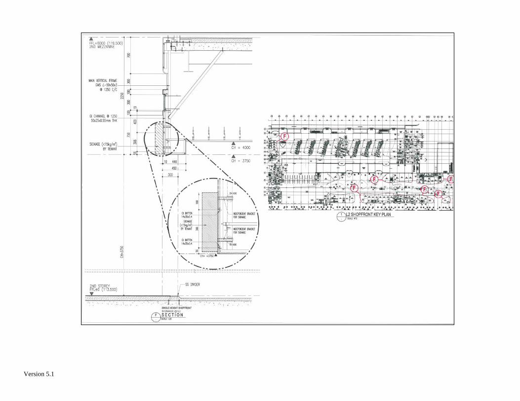
Version 5.1

Version 5.1

Version 5.1

Version 5.1

Version 5.1

Version 5.1

Version 5.1

Version 5.1

Version 5.1

1
Part 6
EVALUATION CRITERIA

2
EVALUATION CRITERIA
1 Critical Criteria: The evaluation criteria specified below are the Critical Criteria. Tender proposals that do not meet any of these criteria shall be rejected and excluded from further evaluation:
1.1 Tenderer1 shall be registered with BCA under the Construction workhead CW01 (General
Building) or CW02 (Civil Engineering) of tendering limit C3 (S$650,000) or above2, and the Mechanical & Electrical workhead ME01 (Air-conditioning, Refrigeration & Ventilation Works) of tendering limit L1 (S$650,000) or above;
1.2 Tenderer3 shall attend the tender briefing and site showround; 1.3 Tenderer4 shall have completed one or more renovation projects of similar scale within the
two years preceding the tender Closing Date; 1.4 Tenderer shall submit all the Mandatory Documents as listed and required in the Cover
Letter by the tender Closing Date and Time. Mandatory Documents are considered submitted only if they are complete and all fields are duly completed;
1.5 Tenderer5 shall have at least attained the “bizSAFE Level 3” status accredited by the
Workplace Safety and Health Council (“WSHC”) under the prevailing bizSAFE programme on the tender Closing Date; and
1.6 Tenderer6 shall not be debarred on or after the closing date of tender.
2 OTHER EVALUATION CRITERIA:
2.1 Competitive Pricing (40%); 2.2. Compliance with tender specifications and requirements (30%); 2.3 Relevant academic qualifications, experiences and performance track records7 of the key
personnel8 in the proposed project team(s) (15%); 2.4 Performance track records in past completed projects of similar job nature and scale within
the past two years preceding the tender closing date. The evaluation will take into consideration past track records (10%); and
2.5 Comprehensive organisation structure and composition of the proposed project team(s).
(5%).
1 Where a tender proposal is submitted by a Consortium, each Consortium member shall have its own valid registration with BCA and one of the Consortium members shall be registered with BCA under the Construction workhead CW01 (General Building) or CW02 (Civil Engineering) of tendering limit C3 (S$650,000) or above, and the Mechanical & Electrical workhead ME01 (Air-conditioning, Refrigeration & Ventilation Works) of tendering limit L1 (S$650,000) or above. 2 Refer to Clause 2 of the Instructions to Tenderer for the requirement on registration with Government Registration Authority (GRA). 3 Where a tender proposal is submitted by a Consortium, at least one of the Consortium members shall attend the tender briefing and site showround. 4 Where a tender proposal is submitted by a Consortium, at least one of the Consortium members shall have completed one or more renovation projects of similar scale within the two years preceding the tender Closing Date. 5 Where a tender proposal is submitted by a Consortium, each member of the Consortium shall have at least attained the “bizSAFE Level 3” status accredited by the Workplace Safety and Health Council (“WSHC”) under the prevailing bizSAFE programme on the tender Closing Date. 6 Where a tender proposal is submitted by a Consortium, all members of the Consortium shall not be debarred on or after the tender Closing Date. 7 Tenderer to submit the resume with supporting documents of the key personnel proposed. 8 Key personnel shall refer to one Project Manager and one Project Engineer. Each defined key personnel shall be different persons.

1
Part 7 INFORMATION ON TENDERER

2
INFORMATION ON TENDERER
1 DEFINITIONS OF THE COMPANIES/FIRM (Please indicate "NA" where not applicable) (a) THE COMPANY/FIRM State name, registered address and telephone number. (b) THE PRINCIPALS
State name and identity card numbers of Principals, Partners and/or Directors.
(c) REGISTRATION OF COMPANY/ FIRM (Photocopy of registration certificate to be enclosed) State registration number and particulars.
(d) TYPE OF COMPANY / FIRM State whether public, private, partnership or sole proprietorship.
(e) NAME AND ADDRESSES OF MAJOR SHAREHOLDERS AND PERCENTAGE OWNED
(f) NUMBER OF STAFF AND ORGANISATION CHART

3
(g) QUALIFICATION AND EXPERIENCE OF QUALIFIED
PERSONNEL UNDER YOUR EMPLOYMENT
2 FINANCIAL CAPACITY (Please attach Balance Sheet and Profit and Loss Statement for the last financial year) (a) BANKERS
(b) CAPITALIZATION OF FIRM AND PRESENT PAID-UP CAPITAL

4
INFORMATION ON TENDERER
DECLARATION OF GOVERNMENT'S EQUITY PARTICIPATION
I hereby certify that as of this date, the equity participation of the Singapore Government and Statutory Boards of the Government either directly or indirectly through a holding or subsidiary company, constitutes _________% of the total share-holder's equity in ______________________________ of ______________________________________ (Name of Company) (Address) Dated this _____________ day of ____________ 20 ______. ______________________ ___________________ ______________________ Signature Name Designation

5
INFORMATION ON TENDERER
PAST COMMITMENTS OF TENDERER
Client
Project Title
Value of Contract
Contract Period
Name, Designation and Contact
No. of Superintending Officer
I/ We certify and declare that all information given under the Information on Tenderer is true and correct. __________________________________ _________________________________ Signature of Contractor Signature of Witness Name :______________________ Name :_____________________ Address :______________________ Address :_____________________ ______________________ _____________________ Date :______________________ Date :_____________________

6
INFORMATION ON TENDERER
PRESENT COMMITMENTS OF TENDERER
Client
Project Title
Value of Contract
Contract Period
Name, Designation and Contact
No. of Superintending Officer
I/ We certify and declare that all information given under the Information on Tenderer is true and correct. __________________________________ _________________________________ Signature of Contractor Signature of Witness Name :______________________ Name :_____________________ Address :______________________ Address :_____________________ ______________________ _____________________ Date :______________________ Date :_____________________

7
INFORMATION ON TENDERER
PAST COMMENDATION / WARNING LETTER(S) ISSUED TO TENDERER
Client
Project Title
Value of Contract
Name, Designation and Contact No. of
Superintending Officer
Description of Commendation /
Warning Letter(s)
I/ We certify and declare that all information given under the Information on Tenderer is true and correct. __________________________________ _________________________________ Signature of Contractor Signature of Witness Name :______________________ Name :_____________________ Address :______________________ Address :_____________________ ______________________ _____________________ Date :______________________ Date :_____________________

8
INFORMATION ON TENDERER
GOODS AND SERVICES TAX REGISTRATION
I / We* certify and declare that I / we* am / are* not a taxable person under the Goods and Services Tax (GST) Act or registered with the Comptroller of GST, and that all information provided under this section on the Information on Tenderer are true and correct. ___________________________________ __________________________________ Signature of Contractor Signature of Witness Name :_______________________ Name :______________________ Address :_______________________ Address :______________________ _______________________ ______________________ _______________________ ______________________ Date :_______________________ Date :______________________ GST Registration No:_____________________________ *To delete where applicable

1
Part 8 SCHEDULE OF TENDER

2
SCHEDULE OF TENDER
Item Description Quantity Unit Price
(S$) Total Price
(S$)
Phase 1, including dust and debris protection of live equipment
P1-1
Civil & Structural and Building Works
P1-1a Erection of ¾ height partition walls on raised floor with PE-endorsed supporting struts, complete with wire-mesh below raised-floor system and extends to slab-soffit, based on Phase 1 layout, including fire-rated door.
1 Job
P1-1b Entire room repainting and to newly-installed partition walls
1 Job
P1-1c Replacement of entire room false ceiling 1 Job
P1-1d Window grilles and replacement of wall cabinet finishes
1 Job
P1-1e Replacement of existing fire-rated door, from original opening inwards to opening outwards
1 Job
P1-2 Mechanical & Electrical Works
P1-2a Air-conditioning system 1 Job
P1-2b Electrical Works 1 Job
P1-2c CCTV 1 Job
P1-2d Room Door Access Systems 1 Job
P1-3 Any Other Cost Items for Phase 1 (Please list accordingly, items that are not specified above but essential for the complete the Works as specified)
1 Lot
Sub-Total (A) of Contract Price for Works in Phase 1 (Sum of P1-1 to P1-3)
Note: Please furnish additional copies if space given above is insufficient.
__________________ ________________________ ________________________ Date Company’s Stamp Name & Signature of Tenderer

3
Table A - Main Items (Cont’d)
Item Description Quantity Unit Price
(S$) Total Price
(S$)
Phase 2, including dust and debris protection of live equipment
P2-1 Civil & Structural and Building Works
P2-1a Erection of ¾ height partition walls on raised floor with PE-endorsed supporting struts, based on Phase 2 layout, including removal of a portion of S/N P1-1a to suit the new Phase 2 layout
1 Job
P2-2 Any Other Cost Items for Phase 2 (Please list accordingly, items that are not specified above but essential for the complete the Works as specified)
1 Lot
Sub-Total (B) of Contract Price for Works in Phase 2 (Sum of P2-1 to P2-2)
Total Contract Price (Sum of Sub-Total A & B) (To be submitted as item 1 in GeBIZ)
Note: Please furnish additional copies if space given above is insufficient.
__________________ ________________________ ________________________ Date Company’s Stamp Name & Signature of Tenderer

1
Part 9 SCHEDULE OF MANPOWER DEPLOYMENT

2
SCHEDULE OF MANPOWER DEPLOYMENT
The Tenderer must indicate the numbers of Project Managers, Project Engineers, Supervisors and Technicians he intends to deploy for the execution of the works. The appointed Contractor shall provide the following manpower deployment of personnel. The contractor shall prepare and plan his personnel to meet the performance requirements of the Contract. The S.O reserves the right to instruct the contractor to provide additional manpower at the contractor’s cost should the manpower offered in the tender, failed to deliver the performance standard required in the contract.
Type Of Manpower Proposed Number
Project Manager
Project Engineer
Supervisors
Workers
Others (If any)
Note: An employee shall be on full-time basis.

1
Part 10 STATEMENT OF COMPLIANCE

2
STATEMENT OF COMPLIANCE
1 GENERAL 1.1 The Tenderer shall submit a paragraph by paragraph statement of compliance for
the following sections of the tender as specified below:
(a) Part 4 Conditions of Contract; and
(b) Part 5 Requirement Specifications
The statements shall be numbered in accordance to the numbering reference adopted in the above-mentioned sections.
1.2 All documents shall be submitted electronically to CAAS as file attachments in GeBIZ. The submission for the Statement of Compliance shall consist of the following:
(a) Clause by clause statement of compliance or non-compliance; (b) All other relevant documents which is requested in the tender or deemed useful in
aiding CAAS in evaluation of the tender shall be also be submitted; and (c) Clauses not entered here shall be assumed to have fully complied with the above-
mentioned sections.
1.3 Any variation from the tender specifications shall be examined in detail and where necessary to this section.
1.4 The Statement of Compliance List shall use only the following:
(a) C for “Full Compliance” – Tenderer is able to comply full with the specified requirements. The Contractor shall then implement, without any reservation, the requirements in these clauses with full compliance to the detailed descriptions provided by CAAS in the Specification and/or subsequent clarifications. CAAS reserve the rights not to entertain any alterative offers to these clauses proposed by the Contractor during the entire Contract Period;
(b) NC for “Non Compliance” – Tenderer is unable to comply fully or partially with
the specified requirements. Full Non-Compliant shall mean that all the requirements specified in the clause(s) are not parts of the tender proposal. For Partially Non- Compliant, the Tenderer shall indicate the area and the reason(s) why it is not complying and to what extent the requirements will be met.
(c) N for “Noted” – “N” shall be used only for paragraphs meant for information to
Tenderer. CAAS will treat all “Noted” and/or “Blank” given for answer to a requirement as Full Compliant “C” without remark for all these Tenderer’s responses to this tender.
1.5 CAAS shall have the rights to resolve any inconsistency or conflict arising between
the technical proposal and the Statement of Compliance in favour of either the technical proposal and the Statement of Compliance.

3
Reference: Conditions of Contract
Paragraph No. Compliance Detailed Description of how compliance is achieved or otherwise
Note: Please furnish additional copies if space given above is insufficient.
* C denotes Full Compliance, NC denotes Non-Compliance, N denotes Noted for information I/We certify and declare that the information given in the statement of compliance is true and correct. Any inconsistency or conflict arising between the technical proposal and the statement of compliance shall be resolved in favour of either the technical proposal or the statement of compliance. Authorized Signature of Tenderer Name Designation Company’s Address Company Stamp Date

4
Reference: Requirement Specifications
Paragraph No. Compliance Detailed Description of how compliance is achieved or otherwise
Note: Please furnish additional copies if space given above is insufficient.
* C denotes Full Compliance, NC denotes Non-Compliance, N denotes Noted for information I/We certify and declare that the information given in the statement of compliance is true and correct. Any inconsistency or conflict arising between the technical proposal and the statement of compliance shall be resolved in favour of either the technical proposal or the statement of compliance. Authorized Signature of Tenderer Name Designation Company’s Address Company Stamp

1
Part 11 UNDERTAKING TO SAFEGUARD OFFICIAL
INFORMATION FORM

2
UNDERTAKING TO SAFEGUARD OFFICIAL INFORMATION FOR COMPANY1
Re: Tender Reference: CAA000/ANS/2020/T19 Our attention has been drawn to the Official Secrets Act (Chapter 213, Revised
Edition 2012) and in particular to Section 5 thereof which relates to the safeguarding of official information. 2 We understand and agree that all official information acquired by us in the course of our work for the Civil Aviation Authority of Singapore (CAAS) is strictly confidential in nature, and is not to be published or communicated by us to any unauthorised person in any form at any time, without the official sanction of the Director-General of Civil Aviation. 3 We agree to adopt appropriate measures to protect the confidentiality of such official information and to ensure that our employees and agents, and sub-contractors and their employees and agents that have access to any part of such official information also duly observe the terms of this Undertaking. 4 We further understand and agree that any breach or neglect of this undertaking may render us liable to prosecution under the Official Secrets Act. 5 We acknowledge that in addition to our obligations under the OSA, we are required to comply with our confidentiality obligations under our contract with CAAS, failing which we may be liable under any civil suit brought against us by CAAS for all losses, damages, costs, charges and expenses incurred by CAAS and/or for all claims against CAAS as a result of such breach. For and on behalf of ___________________________________ Full Name of Company ___________________________________ __________________________________ Signature of duly authorised representative Full name in BLOCKS and NRIC _______________________ _________________________________ Designation Company Stamp _______________________ Date To be filled up by CAAS ______________________ ____________________________ Signature of WITNESS Full name in BLOCKS ______________________ Designation ______________________ CIVIL AVIATION AUTHORITY OF Date SINGAPORE
1 To be signed by the company and other company e.g. sub-contractors who will work on the project

3
UNDERTAKING TO SAFEGUARD OFFICIAL INFORMATION FOR INDIVIDUAL2
Re: Tender Reference: CAA000/ANS/2020/T19
My attention has been drawn to the Official Secrets Act (Chapter 213, Revised Edition
2012) and in particular to Section 5 thereof which relates to the safeguarding of official information. 2 I understand and agree that all official information acquired by me in the course of my work as *an employee / consultant of the company named below (the “Company”) which is performing work or services for the Civil Aviation Authority of Singapore (CAAS) is strictly confidential in nature, and is not to be published or communicated by me to any unauthorised person in any form at any time, without the official sanction of the Director-General of Civil Aviation. 3 I agree to comply with the measures adopted or to be adopted by the Company to protect the confidentiality of the official information 4 I further understand and agree that any breach or neglect of this undertaking may render me liable to prosecution under the Official Secrets Act. *Delete whichever is not applicable ________________________ _____________________________ Signature of Officer Full name in BLOCKS and NRIC ________________________ _____________________________ Designation Name of Company ________________________ Date To be filled up by CAAS ________________________ _____________________________ Signature of WITNESS Full name in BLOCKS ________________________ Designation ________________________ CIVIL AVIATION AUTHORITY OF Date SINGAPORE
2 To be signed by individuals who are the company’s employees, consultants, etc

1
Part 12 SPECIMEN LETTER OF ACCEPTANCE

2
[On CAAS‘ letterhead]
SPECIMEN LETTER OF ACCEPTANCE OF TENDER
Our Ref: [ ● ] [Date] Tel: [ ● ] Fax: [ ● ] To: [Name of Organisation]
[Address] Attn: [Name] [Designation] Dear Sirs LETTER OF ACCEPTANCE OF TENDER FOR RENOVATION WORKS FOR EQUIPMENT ROOM AT CHANGI AIRPORT TERMINAL 1
We refer to the above and your Tender Proposal dated [●].
2. We are pleased to inform you that the Civil Aviation Authority of Singapore (“CAAS”) hereby accepts your Tender Proposal for renovation works for equipment room at Changi Airport Terminal 1 (“Goods”) for a period of [ ● ] year(s) commencing on [date] until [date] (“Contract Term”) at the sum of Singapore Dollars [amount in words] (S$[ ● ]) (“Contract Sum”). 3. Please note CAAS’ acceptance of your Tender Proposal is subject to all the documents in the Invitation to Tender (including but not limited to the Instructions to Tenderers, Conditions of Contract, Form of Tender, Schedule of Tender, Requirement Specifications and Information on Tenderer) and this Letter of Acceptance of Tender. 4. Your Tender Proposal and this Letter of Acceptance of Tender together constitute a binding contract between CAAS and you. The terms of this contract are set out in your Tender Proposal, this Letter of Acceptance of Tender and all documents in the Invitation to Tender (including but not limited to the Conditions of Contract and Requirement Specifications). 5. Pursuant to Clause 10.5 of the Instructions to Tenderers, CAAS may require you to execute a formal agreement. We will notify you as to whether you are required to do so. 6. This Letter of Acceptance of Tender is prepared in duplicate. Please acknowledge receipt of this Letter by returning one of the copies, with the acknowledgement letter at Annex A duly signed and witnessed, no later than [date].

3
7. If you have any enquiries, please contact Mr Chen Jiarong at 65956060 ([email protected]) and Mr Maurice Ang at 65412790 ([email protected]).
Yours faithfully ________________________________ Kevin Shum Director-General for and on behalf of Civil Aviation Authority of Singapore

4
Annex A [On Company’s Letterhead]
SPECIMEN ACKNOWLEDGEMENT OF LETTER OF ACCEPTANCE OF TENDER
Our Ref : Date :
To: Civil Aviation Authority of Singapore Aeronautical Telecommunications & Engineering Singapore Changi Airport
PO Box 1 Singapore 918141
Attn: [name of officer from division] Dear Sir LETTER OF ACCEPTANCE OF TENDER FOR RENOVATION WORKS FOR EQUIPMENT ROOM AT CHANGI AIRPORT TERMINAL 1 We hereby acknowledge receipt of your Letter of Acceptance of Tender Ref: [ ● ] dated [date of LOA] and confirm that no terms, conditions or stipulations additional to those contained in the Invitation to Tender and this Letter of Acceptance of Tender have been imposed by this acknowledgement letter. Signed for and on behalf of the Contractor: __________________________________ ___________________________________ Signature of Authorised Signatory1 Signature of Witness (with Company’s Official Stamp) Name & Designation: Name & Designation: __________________________________ ___________________________________ NRIC/Passport No: NRIC/Passport No: __________________________________ ___________________________________ Address: Address: __________________________________ ___________________________________ __________________________________ ___________________________________ __________________________________ ___________________________________ Date: ____________________________ Date: ______________________ 1 If the tender is submitted by a consortium, the Lead Member’s official stamp and authorised signature must be
provided.