TENDER DOCUMENT
70
January- 2017 TENDER DOCUMENT for Renovation & Up-gradation of Protection Systems of 132kV Sub-Stations in Mizoram under Power System Development Fund (PSDF) Volume-II Broad Scope & Technical Specifications Office of the Superintending Engineer, Mizoram SLDC Circle, P&E Department, Government of Mizoram Mizoram: Aizawl
-
Upload
khangminh22 -
Category
Documents
-
view
2 -
download
0
Transcript of TENDER DOCUMENT

January- 2017
TENDER DOCUMENT for
Renovation & Up-gradation of Protection
Systems
of 132kV Sub-Stations in Mizoram
under
Power System Development Fund (PSDF)
Volume-II
Broad Scope &
Technical Specifications
Office of the Superintending Engineer, Mizoram SLDC Circle,
P&E Department, Government of Mizoram
Mizoram: Aizawl

Tender Document, Volume – II [Broad Scope & Tech. Specifications]
Page 1
VOLUME - II:
BROAD SCOPE OF WORK
&
TECHNICAL SPECIFICATIONS

Tender Document, Volume – II [Broad Scope & Tech. Specifications]
Page 2
INDEX
Sl.No. Content Page
1 110V BATTERY BANK, BATTERY CHARGER & DC
DISTRIBUTION BOARD
3-14
2 48V BATTERY BANK, BATTERY CHARGER & DC
DISTRIBUTION BOARD
15-25
3 250kVA, 33/0.415kV TRANSFORMER 26-33
4 30kVA D.G. SET 34-42
5
BACK-UP OVER CURRENT AND EARTH FAULT
RELAY; DISTANCE PROTECTION RELAY &
LOCAL BREAKER BACK-UP PROTECTION RELAY AND
TOOL KITS
43-54
6 TIME SYNCHRONIZING EQUIPMENT/TIME
SYNCHRONIZER 55-56
7 CONTROL CABLES OF VARIOUS SIZES 57-59
8 NITROGEN INJECTION SYSTEM 60-66

Tender Document, Volume – II [Broad Scope & Tech. Specifications]
Page 3
SCOPE OF WORK AND
TECHNICAL SPECIFICATIONS FOR PLANT & EQUIPMENT
A. 110V BATTERY BANK, CHARGERS AND DC DISTRIBUTION BOARD
1.0 SCOPE
1.1 The scope of work is furnished below:
a) Design, manufacture, testing at manufacturer’s works and supply of 110 Volt
Battery Banks, Chargers and DC Distribution Boards with all fittings and
accessories including supporting rack/mounting structures as applicable.
b) Loading at manufacturer’s works, transportation and delivery at respective
substation sites, including unloading at destination sites.
c) Erection, Testing and Commissioning of Battery Banks, Chargers and DCDB
including dismantling of existing equipment, if necessary.
2.0 SERVICE CONDITIONS
2.1. The plant and materials supplied shall be suitable for operation under the
following climatic and other conditions:
a) Max. Ambient temperature : 50o C
b) Min. Ambient temperature : 4o C
c) Relative humidity : 35% - 98%
d) Average Annual Rainfall : 3,000 mm
e) No of months of active monsoon : 6 (May to October)
f) Seismic zone : V
g) Altitude : Not less than 2,210 M above
sea level
3.0 TYPE TEST REPORTS
3.1. Equipment, which has never been tested for critical performance, shall not be
accepted. In such cases, a promise or agreement by a bidder to have the equipment
tested after award of a contract is not acceptable.
3.2. All Bids must be accompanied by the full Type Test Certificates of equipment offered.
Such type test certificates shall be acceptable only if:-
(a) Tests are conducted in an independent and well known testing
laboratory, or
(b) Tests are conducted in manufacturer’s own laboratory. In this
case (i) the laboratory must have ISO 9000 (or its equivalent)
series certification; and (ii) tests have been witnessed by
technically qualified representatives of earlier clients or
purchaser.

Tender Document, Volume – II [Broad Scope & Tech. Specifications]
Page 4
3.3. Test reports to be acceptable must be related directly to the materials offered. Test
reports for higher class of equipment are acceptable with commitment to perform the type tests free of any charge on the particular equipment(s) after the award of contract.
3.4. Type Test Reports older than five (5) years on the date of tender opening shall not be
accepted.
4.0 GUARANTEED TECHNICAL PARTICULARS
4.1. The Guaranteed Technical Particulars of the various items shall be furnished by the
Bidders in the prescribed format furnished under volume III of this tender document.
The Bidder shall also furnish any other information's as in their opinion is needed to
give full description and details to judge the item(s) offered by them.
4.2. The data furnished in Guaranteed Technical Particulars should be the minimum or
maximum value (as per the requirement of the specification) required. A Bidder may
guarantee a value more stringent than the specification requirement. However, for
testing purpose or from performance point of view, the material shall be considered
performed successfully if it achieves the minimum/maximum value required as per the
technical specification. No preference what so ever shall be given to the bidder
offering better/more stringent values than those required as per specification except
where stated otherwise.
5.0 TECHNICAL SPECIFICATION OF BATTERY BANKS
5.1. Type:
5.1.1. The DC Batteries shall be VRLA (Valve Regulated Lead-Acid) type and shall be Normal
Discharge type. These shall be suitable for a long life under continuous float
operations and occasional discharges.
5.1.2. The Battery and accessories shall conform to IS: 15549/ IEC 60896 and other relevant
IS/IEC standards except to the extent explicitly modified in this specification.
5.2. Ratings:
(i) The Ampere-hour capacity of the battery bank at 27°C at 10 hours discharge
rate shall be 250 Ah.
(ii) The nominal voltage of the battery bank shall be 110 Volts D.C.
(iii) The number of cells in a complete battery bank set shall be 55.
5.3. Capacity Requirements:
5.3.1. When the battery is discharged at 10-hour rate, it shall deliver 80% of C (rated capacity,
corrected at 27o Celsius) before any of the cells in the battery bank reaches 1.85V/cell.
5.3.2. The battery shall be capable of being recharged from the fully exhausted condition
(1.75V/cell) within 10 hrs up to 90% state of charge. All the cells in a battery shall be
designed for continuous float operation at the specified float voltage throughout the
life.
Tender Document, Volume – II [Broad Scope & Tech. Specifications]
Page 5
5.3.3. The capacity (corrected at 27ºCelcius) shall also not be less than C and not more than
120% of C before any cell in the battery bank reaches 1.75V/cell. The battery voltage
shall not be less than the following values, when a fully charged battery is put to
discharge at C/10 rate:
(a) After Six minutes of discharge : 1.98 V/cell
(b) After Six hours of discharge : 1.92V/cell
(c) After 8 hours of discharge : 1.85 V/cell
(d) After 10 hours of discharge : 1.75 V/cell
5.3.4. Loss in capacity during storage at an average ambient temperature of 35º Celcius for
a period of 6 months shall not be more than 60% and the cell/battery shall achieve
85% of its rated capacity within 3 charge/discharge cycles and full rated capacity
within 5 cycles, after the storage period of 6 months. Voltage of each cell in the
battery set shall be within 0.05V of the average voltage throughout the storage
period. Ampere hour efficiency shall be better than 90% and watt hour efficiency shall
be better than 80%.
5.4. Material and constructional requirements:
5.4.1. Container
The container shall be made of acid resistant and fire retardant grade polypropylene
copolymer plastic and shall have chemical and electrochemical compatibility. The
container material shall have an Oxygen Index of at least 28 %. The other
requirement for plastic container shall be as per IS 1146.
5.4.2. Cell Lids
The cell lids shall be made of same plastic material as that of container and
permanently fixed with the container. It shall be capable to withstand internal
pressure without bulging or cracking. Fixing of Pressure Regulation Valve & terminal
posts in the cover shall be such that the seepage of electrolyte, gas escapes and
entry of electro-static spark are prevented.
5.4.3. Plates
The plates shall be of pasted construction and of good workmanship. These shall be
free from cracks, white patches and other imperfections, which may affect the life
and performance of the battery.
5.4.4. Separators
The separators used shall be of glass mat having high acid absorption capability,
resistance to sulphuric acid and good insulating properties. The separator shall meet
the test requirements as given in IEC/IS.
5.4.5. Terminal posts
Positive and negative terminals posts shall have built in lead plated copper or brass
inserts. Terminals of cells shall be clearly and unmistakably identifiable and marking
shall be of permanent nature. Terminal posts shall be suitably sealed at the lid to
prevent leakage of any gas. Any gas escape shall be only through the venting device
provided. The surface of the terminal post extending above the cell cover including

Tender Document, Volume – II [Broad Scope & Tech. Specifications]
Page 6
bolt hole shall be coated with an acid resistant and corrosion retarding material.
5.4.6. Fastners
Nuts and bolts for connecting the cells shall be made of copper, brass or stainless
steel. Copper or brass nuts and bolts shall be effectively lead coated to prevent
corrosion. Stainless steel bolts and nuts shall be passivated to prevent corrosion
with acid.
5.4.7. Electrolyte
The sulphuric and water used for the preparation of electrolyte shall conform to IS
266 and IS 1069 respectively.
5.4.8. Connectors
When it is not possible to bolt the cell terminals directly to assemble the battery, a
separate lead coated copper connectors or flexible copper cable connectors of
suitable cross-section shall be provided to join the cells. The lead plating on copper
connectors shall not be less than 25 micron. The sulphuric and water used for the
preparation of electrolyte shall conform to IS 266 and IS 1069 respectively.
5.4.9. Venting device
Each cell shall be provided with a venting device (pressure regulation valve). The
valve shall be self-re-sealable and flame retardant. The valve unit shall be such that
it cannot be opened without a proper tool. The valve shall be capable to withstand
the internal cell pressure specified by the manufacturer. Each valve regulated
venting device shall be provided with flame arrestor capable of preventing the
ingress of moisture/flame into the cell interior when the valve releases the gas
mixture. The opening and closing pressure shall be within + 1 psi variation and
manufacturer shall declare the closing and opening pressure values
5.5. Battery Racks
5.5.1. B a t t e r i e s shall be installed on MS racks to be supplied by the Contractor to fit in
the battery room. Racks/Trays shall be powder coated with acid proof, anti-
corrosive paint. Rack shall accommodate 55/110 cells. Racks/Tray shall be suitably
treated before painting for protection against fungus growth and other harmful
effects due to tropical environment.
5.5.2. The colour of the supporting racks shall conform to shade 631 of IS: 5.
6.0 BATTERY CHARGING CABLES
6.1. General description
6.1.1. The Battery Chargers as well as their automatic regulators shall be of static type
and shall be compatible with offered VRLA batteries.
6.1.2. The battery charging Cable shall have following two separate Boost-cum Trickle
Charger sections:
(a) Section-1: Float Charger Section

Tender Document, Volume – II [Broad Scope & Tech. Specifications]
Page 7
(b) Section-2: Float-cum-Boost Charger Section
Each section shall have its own rectifier transformer, Rectifier Bridge and other
cable so that each section can operate independent of each other.
6.1.3. The Charger shall regulate the float/boost voltage in case of prescribed temperature
rise of battery as per manufacturer’s recommendation to avoid thermal runaway.
Necessary temperature sensors shall be provided in mid location of battery banks and
shall be wired up to the respective charger for feedback control. The manufacturer
shall demonstrate this feature during testing of each charger.
6.2. Charger ratings:
6.2.1. The charger sections shall have the following ratings:
(A) Section-1: Float Charger Section (FC):
(i) Input Voltage : 415+/- 10% volts three phase, 4 wire, 50 Hz A.C.
(ii) Output Voltage : 110 Volt (Nominal).
(iii) Output Voltage Range : 2.13 to 2.27 Volt per cell (Continuously Settable)
(iv) Total Output DC Current : 50 Amp
(B) Section-1: Float cum Boost Charger Section (FCBC):
(i) Input Voltage : 415+/- 10% volts three phase, 4 wire, 50 Hz A.C.
(ii) Output Voltage : 110 Volt (Nominal)
(iii) Output Voltage Range : 2.13 to 2.50 Volt per cell (Continuously Settable)
(iv) Total Output DC Current : 25 Amp
6.3. Operation and control:
6.3.1. Both the Charger Sections shall be capable for charging the battery and supplying the
load simultaneously. The Float-cum-Booster charger section shall be operated either
in float mode or in boost-cum-standby float charger mode.
6.3.2. Under normal operating condition, with the input AC supply present, the ‘Float
Charger Section' shall supply the DC load and also float the battery by trickle charging
and the ‘Float cum Boost Charger Section’ shall be kept in hot standby mode.
6.3.3. In the event of main AC supply failure, the Sub-station DC load shall be automatically
change over to the battery without any interruption. Similarly, after restoration of AC
supply the normal operating condition shall be restored automatically and without any
interruption.
6.3.4. Under normal operating condition, with the input AC supply present and battery
requires boost charge, the battery shall be automatically change over to ‘Float cum
Boost Charger Section’ automatically. Similarly, after completion of Boost Charging,
the battery shall be automatically to ‘Float Charger Section'. During this Boost
Charging operation, `the float charger section' shall supply the load current only while

Tender Document, Volume – II [Broad Scope & Tech. Specifications]
Page 8
boost charger section of ‘Float cum Boost Charger Section’ shall boost charge the
battery and the load supply shall be disconnected from the battery through a contact
of a contractor. If the ‘Float Charger Section' fails during this period, the battery shall
maintain load through tap cell diode, connected at suitable cell (to limit the DC load
voltage to 110% of the specified Nominal Voltage, even at maximum Boost Charging
voltage), instantaneously without any interruption of the DC load supply. If the
incoming AC supply or the boost charger fails during boost charging, all the cells shall
be connected to the load bus through the contact of the same contactor mentioned
above.
6.3.5. All Battery Chargers shall be provided with facility for both automatic and manual
control of output voltage and current. A selector switch shall be provided for
selecting the mode of output voltage/current control, whether automatic or manual.
When on automatic control mode during Float charging, the Charger output voltage
shall remain within +1% of the set value, for AC input voltage variation of +10%,
frequency variation of +5%, a combined voltage and frequency variation of +10%, and
a DC load variation from zero to full load.
6.3.6. All battery chargers shall have a constant voltage characteristic throughout the range
(from zero to full load) at the floating value of the voltage so as to keep the battery
fully charged but without harmful overcharge.
6.3.7. All chargers shall have load limiters having drooping characteristic, which shall cause,
when the voltage control is in automatic mode, a gradual lowering of the output
voltage when the DC load current exceeds the Load limiter setting of the Charger.
The Load-limiter characteristics shall be such that any sustained overload or short
circuit in DC System shall not damage the Charger, nor shall it cause blowing of any of
the Charger fuses. The Charger shall not trip on overload or external short circuit.
6.3.8. Uniform and step less adjustments of voltage setting (in both manual and automatic
modes) shall be provided on the front of the Charger panel (FC) covering the entire
float charging output range specified. Step less adjustments of the Load limiter
setting shall also be possible from 80% to 100% of the rated output current for
charging mode.
6.3.9. During Boost Charging, the Battery Charger (FCBC in Boost Mode) shall operate on
constant current mode (when automatic regulator is in service). It shall be possible
to adjust the Boost charging current continuously over a range of 50% to 100% of
the rated output current for Boost charging mode.
6.3.10. The Charger output voltage shall automatically go on rising, when it is operating on
Boost mode (FCBC), as the Battery charges up. For limiting the output voltage of
the Charger, a potentiometer shall be provided on the front of the panel, whereby
it shall be possible to set the upper limit of this voltage anywhere in the output
range specified for Boost Charging mode.
6.3.11. The Charger manufacturer may offer an arrangement in which the voltage setting
device for Float charging mode is also used as output voltage limit setting device for
Boost charging mode and the Load-limiter of Float charging mode is used as current
setting device in boost charging mode.

Tender Document, Volume – II [Broad Scope & Tech. Specifications]
Page 9
6.3.12. Su i t a b l e filter circuits shall be provided in all the chargers to limit the ripple
content (Peak to Peak) in the output voltage to 1%, irrespective of the DC load
level, when they are not connected to a Battery.
6.3.13 An indicative logic of operation of FC & FCBC is furnished below:
System
condition
Battery Status
Charger Mode
FC FCBC
Battery
Load
AC Mains available
Battery full
charged
FCBC on AUTO
ON OFF Supplied
by FC Supplied
by FC
AC Mains
Available
Battery requires
boost
FCBC on
AUTO ON ON
Supplied by BC in Boost
mode
Supplied by FC
AC Mains Available
Battery requires boost
FCBC on AUTO
FAIL or OFF
ON Supplied by
FCBC in Float mode
Supplied by FCBC
A C Mains Available
Irrespective of battery
condition
FCBC on Manual
Float ON OFF
Supplied by FC
Supplied by FC
AC Mains
Available
Irrespective of battery
condition
FCBC on
ManualFloat
FAIL or
OFF ON
Supplied by
FCBC in FLOAT mode
Supplied by FCBC
AC Mains Available
Irrespective of battery
condition
FCBC on Manual
Boost ON ON
Boost charged by FCBC
Supplied by FC
AC Mains
Available
Irrespective O of battery
condition
FCBC on
Manual Boost
FAIL or
OFF ON
Supplied by FCBC in
Float mode
Supplied by FCBC
AC Mains Available -----
FCBC on any Boost
OFF OFF On discharge
Battery will supply to
load
6.4. MCCB
All Battery Chargers shall have 2 Nos. MCCBs on the input side to receive cables from
two sources. Mechanical interlock should be provided such that only one shall be
closed at a time. It shall be of P2 duty and suitable for continuous duty. MCCB’s
should have auxiliary contacts for annunciation.
6.5. Rectifier Transformer:
The rectifier transformer shall be continuously rated, dry air cooled (A.N) and of class F insulation type. The rating of the rectifier transformer shall have 10% overload capacity.
6.6. Rectifier assembly:
The rectifier assembly shall be fully/half controlled bridge type and shall be designed
to meet the duty as required by the respective Charger. The rectifier shall be

Tender Document, Volume – II [Broad Scope & Tech. Specifications]
Page 10
provided with heat sink having their own heat dissipation arrangements with
natural air cooling. Necessary surge protection devices and rectifier type fast acting
HRC fuses shall be provided in each arm of the rectifier connection
6.7. Instruments:
One AC voltmeter and one AC ammeter along with selector switches shall be
provided for each charger sections. One DC voltmeter and DC ammeter (with shunt)
shall be provided for all Charger sections. The instruments shall be flush type, dust
proof and moisture resistant. The instruments shall have easily accessible means for
zero adjustment. The instruments shall be of 1.5 accuracy class. In addition to the
above a centre zero voltmeter with selector switch shall also be provided for each
charger sections for testing purpose. All instruments shall be with digital displays.
6.8. Air break switches:
Each circuit breaker shall be equipped with auxiliary switches with sufficient
number of contacts for control, indication and interlocking purposes. Ten normally
open and ten normally closed contacts shall be provided as spares. All contacts
shall be rated for the DC voltage specified in data sheet.
6.9. Fuses:
All fuses shall be HRC Link type. Fuses shall be mounted on fuse carriers which are in
turn mounted on fuse bases. Wherever it is not possible to mount fuses on carriers,
fuses shall be directly mounted on plug-in type base. In such case one insulated fuse
pulling handle shall be supplied for each charger. Fuse rating shall be chosen by the
Bidder depending on the circuit requirement. All fuses in the chargers shall be
monitored. Fuse failure annunciation shall be provided on the failure of any fuse.
6.10. Blocking Diode:
Blocking diode shall be provided in the positive pole of the output circuit of each charger to prevent current flow from the DC Battery into the Charger.
6.11. Annunciation system:
Audio-visual indications through bright LEDs shall be provided in each charger
sections for the following abnormalities:
a) AC power failure
b) Rectifier/chargers fuse blown.
c) Over voltage across the battery when boost charging. d) Abnormal voltage (High/Low)
e) Any other annunciation if required.
Potential free NO Contacts of above abnormal conditions shall also be provided for
common remote indication “CHARGER TROUBLE” in Purchaser’s Control System.
Indication for charger in float mode and boost mode through indication lamps shall
be provided for chargers. A potential free contact for float/boost mode shall be
provided for external interlocks.
6.12. Analogue and Digital Inputs:
Following Analogue and Digital Inputs for Purchaser’s substation
automation/SCADA purposes in the Charger, the analogue inputs shall be
generated by distinct transducers. These inputs shall be wired up to respective

Tender Document, Volume – II [Broad Scope & Tech. Specifications]
Page 11
terminal blocks. The Digital Inputs shall be potential free:
Analogue Inputs
(i) Voltage of Battery
(ii) Current of Battery from Charger
Digital Inputs
(i) Charger Fails
(ii) Charger Float/Boost Mode
6.13. Charger construction:
6.13.1. Each Charger Section (FC & FCBC) shall be housed in two separate chambers.
6.13.2. The Chargers shall be indoor, floor-mounted, self-supporting sheet metal enclosed
cubicle type. The Supplier shall supply all necessary base frames, anchor bolts and
hardware. The Chargers shall be fabricated from 2.0 mm cold rolled sheet steel and
shall have folded type of construction. Removable gland plates for all cables and lugs
for power cables shall be supplied by the Supplier. The lugs for power cables shall be
made of electrolytic copper with tin coat. Power cable sizes shall be advised to the
Supplier at a later date for provision of suitable lugs and drilling of gland plates. The
Charger shall be tropicalized and vermin proof. Ventilation louvers, if provided shall
be backed with screens. All doors and covers shall be fitted with synthetic rubber
gaskets. The chargers shall have hinged double leaf doors provided on front and on
backside for adequate access to the Charger’s internals. All the charger cubicle doors
shall be properly earthed. The degree of protection of Charger enclosure shall be at
least IP-42 as per IS: 13947 Part I. All indicating instruments, control switches and
indicating lamps shall be mounted on the front side of the Charger. Each Charger shall
be furnished completely wired upto power cable lugs and terminal blocks and ready
for external connections. The control wiring shall be carried out with PVC insulated,
1.5 sq.mm stranded copper wires. Control terminals shall be suitable for connecting
two wires, with 2.5 sq.mm stranded copper conductors. All terminals shall be
numbered for ease of connections and identification. Each wire shall bear a ferrule or
tag on each end for identification. At least 20% spare terminals shall be provided for
control circuits. The insulation of all circuits, except the low voltage electronic circuits
shall withstand test voltage of 2 KV AC for one minute. An air clearance of at least ten
(10) mm shall be maintained throughout for such circuits, right up to the terminal
lugs. Whenever this clearance is not available, the live parts shall be insulated or
shrouded.
6.14. Painting:
All sheet steel work shall be pre-treated, in tanks, in accordance with IS:6005.
Degreasing shall be done by alkaline cleaning. Rust and scale shall be removed by
pickling with acid. After pickling, the parts shall be washed in running water. Then
these shall be rinsed in slightly alkaline hot water and dried. The phosphate coating
shall be `Class-C’ as specified in IS: 6005. Welding shall not be done after
Tender Document, Volume – II [Broad Scope & Tech. Specifications]
phosphating. The phosphating surfaces shall be rinsed and passivated prior to
application of stoved lead oxide primer coating. After primer application, two coats
of finishing synthetic enamel paint of shade-692 (smoke grey) of IS:5 shall be
applied, unless required otherwise by the Employer. The inside of the chargers shall
be glossy white. Each coat of finishing synthetic enamel paint shall be properly
staved. The paint thickness shall not be less than fifty (50) microns.
6.15. Tests and inspection:
The battery charger and all the components of the charger shall be routine tested accordingly to their relevant standard. This shall include the following -
(a) Operational check for boost cum float charger.
(b) Input / Output test of the chargers. (c) Voltage Regulation Test (d) Performance test of the charger.
(e) Temperature rise test of the rectifier transformer.
(f) Power frequency H.V. test / Insulation tests.
The Supplier/Manufacturer shall be required to demonstrate to the Purchaser that
the Chargers conform to the specification particularly regarding continuous rating,
ripple free output, voltage regulation and load limiting characteristic, before
despatch as well as after installation at site. At site the following tests shall be
carried out:
i) Insulation resistance test
ii) Checking of proper annunciation system operation.
The Supplier/Manufacturer shall present for inspection, the type and routine test
certificates for the following components whenever required by the Purchaser.
(i) Switches.
(ii) Relays/ MCCBs
(iii) Instruments.
(iv) DC fuses.
(v) SCR.
(vi) Diodes.
(vii) Condensers.
(viii) Potentiometers.
(ix) Semiconductor
(x) Annunciator.
(xi) Control wiring
(xii) Push buttons and contactors.
7.0 DOCUMENT SUBMISSION
The supplier shall submit following documents for approval:
a) Data sheet as per Annexure-I/GTP sheet

Tender Document, Volume – II [Broad Scope & Tech. Specifications]
Page 13
b) GA of cell and layout drawing
c) Discharge Data for 10 Hour, 8 Hour, 3 Hour, 2 Hour, 1 Hour, 15 Minutes and
One Minute indicating capacity factors for end cell voltage of 1.75 V & 1.85 V.
d) Temperature correction factors
e) Installation and commissioning Instructions
f) O & M Manual
8.0 DC DISTRIBUTION BOARD
8.1. General Features:
The D.C. distribution boards shall be indoor, floor mounting of self-supporting, sheet
metal clad, and cubicle type. The panels should be totally enclosed, dust tight and
vermin proof and shall be made of 2.0 mm cold rolled sheet steel. The boards shall
be provided with double leaf hinged doors at the back. All doors and covers shall be
fitted with rubber gaskets. The doors shall be provided with locks and duplicated
covers.
8.2. Bus Bars:
The bus bars shall be of electrolytic copper of ample cross-section. The bus bars shall
be insulated from the structure by means of durable, non-hydroscopic, non-
combustible and non-tracking materials.
8.3. Detail Requirements:
8.3.1. The 110 Volts D.C. distribution boards shall be provided with the following:
i. Mains failure alarm relay. Ii Earth fault alarm relay. iii. 110 Volts D.C. bell to be operated by the mains failure alarm relay. iv. 110 Volts D.C. buzzer to be operated by the earth failure alarm relay.
v. 3 Nos. Double pole air-break circuit breaker/MCCB of 400 amp capacity with thermal overload tripping arrangement to act as follows:
� One for DC Source-1 (incomer 1) � One for DC Source-2 (incomer 2) � One for Bus Section
vi. 0-150 volts D.C. moving coil voltmeter to measure the bus-bar
voltage. The display is to be in digital.
vii. Pilot lamp to indicate D.C. on conditions.
viii. 110 volts, double pole MCBs of following ratings for outgoing feeders. For 110 V DCDB a. 32 Amp, 10 Nos. b. 63 Amp, 4 Nos.
ix. One terminal Board/block for all feeder outlets including cable glands.
8.3.2. Automatic Supply Changeover:
Automatic changeover between Incomer I and Incomer II is to be carried out during
the failure of supply in any of one the incomers. After the restoration of the supply,
system shall be restored to normal condition automatically. The requirement of
changeover under various conditions are as below:

Tender Document, Volume – II [Broad Scope & Tech. Specifications]
Page 14
(a) Under normal conditions i.e. when supply is available in both the incomers,
incomers 1 & 2 of DCDB shall be in closed condition and Bus couplers
breaker shall be in open condition.
(b) In case of failure of either of the sources, the incomer of that source shall trip and Bus coupler shall get closed. On restoration of supply, normal conditions described above are to be established automatically.
8.3.3. Analogue and Digital Inputs
Following Analogue and Digital Inputs for Purchase’s substation
automation/SCADA purposes shall be provided. The analogue inputs shall be
generated by distinct transducers. These inputs shall be wired up to respective
terminal blocks. The Digital Inputs shall be potential free:
Analogue Inputs
(i) Voltage of Bus Section-I
(ii) Voltage of Bus Section-II
(iii) Current from Source-I
(iv) Current from Source-II
Digital Inputs
(i) Incomer-I breaker On/Off
(ii) Incomer-II breaker On/Off
(iii) Bus Section Breaker On/Off (iv) 110 Volt DC earth fault

Tender Document, Volume – II [Broad Scope & Tech. Specifications]
Page 15
B. 48VOLT BATTERY BANK, CHARGERS AND DC DISTRIBUTION BOARD
1.0. SCOPE
1.1. The scope of work is furnished below:
a) Design, manufacture, testing at manufacturer’s works and supply of 48 Volt
Battery Banks, Chargers and DC Distribution Boards with all fittings and
accessories including supporting rack/mounting structures as applicable.
b) Loading at manufacturer’s works, transportation and delivery at respective
substation sites, including unloading at destination sites.
c) Erection, Testing and Commissioning of Battery Banks, Chargers and DCDB
including dismantling of existing equipment, if necessary.
2.0. SERVICE CONDITIONS
2.1. The plant and materials supplied shall be suitable for operation under the
following climatic and other conditions:
a) Max. Ambient temperature : 50o C
b) Min. Ambient temperature : 4o C
c) Relative humidity : 35% - 98%
d) Average Annual Rainfall : 3,000 mm
e) No of months of active monsoon : 6 (May to October)
f) Seismic zone : V
g) Altitude : Not less than 2,210 M above
Sea Level
3.0 TYPE TEST REPORTS
3.1. Equipment, which has never been tested for critical performance, shall not be
accepted. In such cases, a promise or agreement by a bidder to have the equipment
tested after award of a contract is not acceptable.
3.2. All Bids must be accompanied by the full Type Test Certificates of equipment offered.
Such type test certificates shall be acceptable only if:-
a) Tests are conducted in an independent and well known testing
laboratory, or
b) Tests are conducted in manufacturer’s own laboratory. In this
case (i) the laboratory must have ISO 9000 (or its equivalent)
series certification; and (ii) tests have been witnessed by
technically qualified representatives of earlier clients or
purchaser.
3.3. Test reports to be acceptable must be related directly to the materials offered. Test reports for higher class of equipment are acceptable with commitment to perform the type tests free of any charge on the particular equipment(s) after the award of contract.
3.4. Type Test Reports older than five (5) years on the date of tender opening shall not
be accepted.

Tender Document, Volume – II [Broad Scope & Tech. Specifications]
Page 16
4.0 GUARANTEED TECHNICAL PARTICULARS
4.1. The Guaranteed Technical Particulars of the various items shall be furnished by the
Bidders in the prescribed format furnished under vol. III of this tender document. The
Bidder shall also furnish any other information's as in their opinion is needed to give
full description and details to judge the item(s) offered by them.
4.2. The data furnished in Guaranteed Technical Particulars should be the minimum or
maximum value (as per the requirement of the specification) required. A Bidder may
guarantee a value more stringent than the specification requirement. However, for
testing purpose or from performance point of view, the material shall be considered
performed successfully if it achieves the minimum/maximum value required as per the
technical specification. No preference what so ever shall be given to the bidder
offering better/more stringent values than those required as per specification except
where stated otherwise.
5.0 TECHNICAL SPECIFICATION OF BATTERY BANKS
5.1. Type:
5.1.1. The DC Batteries shall be VRLA (Valve Regulated Lead-Acid) type and shall be
Normal Discharge type. These shall be suitable for a long life under continuous
float operations and occasional discharges.
5.1.2. The Battery and accessories shall conform to IS: 15549/ IEC 60896 and other
relevant IS/IEC standards except to the extent explicitly modified in this
specification.
5.2. Ratings:
(i) The Ampere-hour capacity of the battery bank at 27°C at 10 hours
discharge rate shall be 250 Ah.
(ii) The nominal voltage of the battery bank shall be 48 Volts D.C.
(iii) The number of cells in a complete battery bank set shall be 24 plus 2 spares.
5.3. CAPACITY REQUIREMENTS
5.3.1. When the battery is discharged at 10 hour rate, it shall deliver 80% of C (rated
capacity, corrected at 27o Celsius) before any of the cells in the battery bank
reaches 1.85V/cell.
5.3.2. The battery shall be capable of being recharged from the fully exhausted condition
(1.75V/cell) within 10 hrs up to 90% state of charge. All the cells in a battery shall
be designed for continuous float operation at the specified float voltage
throughout the life.
5.3.3. The capacity (corrected at 27ºCelcius) shall also not be less than C and not more
than 120% of C before any cell in the battery bank reaches 1.75V/cell. The battery
voltage shall not be less than the following values, when a fully charged battery is
put to discharge at C/10 rate:

Tender Document, Volume – II [Broad Scope & Tech. Specifications]
Page 17
(a) After Six minutes of discharge : 1.98 V/cell
(b) After Six hours of discharge : 1.92V/cell
(c) After 8 hours of discharge : 1.85 V/cell
(d) After 10 hours of discharge : 1.75 V/cell
5.3.4. Loss in capacity during storage at an average ambient temperature of 35º Celcius
for a period of 6 months shall not be more than 60% and the cell/battery shall
achieve 85% of its rated capacity within 3 charge/discharge cycles and full rated
capacity within 5 cycles, after the storage period of 6 months. Voltage of each cell
in the battery set shall be within 0.05V of the average voltage throughout the
storage period. Ampere hour efficiency shall be better than 90% and watt hour
efficiency shall be better than 80%.
5.4. MATERIAL AND CONSTRUCTIONAL REQUIREMENTS
5.4.1. Container:
The container shall be made of acid resistant and fire retardant grade
polypropylene copolymer plastic and shall have chemical and electrochemical
compatibility. The container material shall have an Oxygen Index of at least 28 %.
The other requirement for plastic container shall be as per IS 1146.
5.4.2. Cell Lids:
The cell lids shall be made of same plastic material as that of container and
permanently fixed with the container. It shall be capable to withstand internal
pressure without bulging or cracking. Fixing of Pressure Regulation Valve &
terminal posts in the cover shall be such that the seepage of electrolyte, gas
escapes and entry of electro-static spark are prevented.
5.4.3. Plates:
The plates shall be of pasted construction and of good workmanship. These shall
be free from cracks, white patches and other imperfections, which may affect the
life and performance of the battery.
5.4.4. Separators:
The separators used shall be of glass mat having high acid absorption capability,
resistance to sulphuric acid and good insulating properties. The separator shall
meet the test requirements as given in IEC/IS.
5.4.5. Terminal posts:
Positive and negative terminals posts shall have built in lead plated copper or
brass inserts. Terminals of cells shall be clearly and unmistakably identifiable and
marking shall be of permanent nature. Terminal posts shall be suitably sealed at
the lid to prevent leakage of any gas. Any gas escape shall be only through the
venting device provided. The surface of the terminal post extending above the
cell cover including bolt hole shall be coated with an acid resistant and corrosion
retarding material.

Tender Document, Volume – II [Broad Scope & Tech. Specifications]
Page 18
5.4.6. Fastners:
Nuts and bolts for connecting the cells shall be made of copper, brass or
stainless steel. Copper or brass nuts and bolts shall be effectively lead coated to
prevent corrosion. Stainless steel bolts and nuts shall be passivated to prevent
corrosion with acid.
5.4.7. Electrolyte:
The sulphuric and water used for the preparation of electrolyte shall conform to IS
266 and IS 1069 respectively.
5.4.8. Connectors:
When it is not possible to bolt the cell terminals directly to assemble the battery,
a separate lead coated copper connectors or flexible copper cable connectors of
suitable cross-section shall be provided to join the cells. The lead plating on
copper connectors shall not be less than 25 micron. The sulphuric and water used
for the preparation of electrolyte shall conform to IS 266 and IS 1069 respectively.
5.4.9. Venting Device:
Each cell shall be provided with a venting device (pressure regulation valve). The
valve shall be self-re-sealable and flame retardant. The valve unit shall be such
that it cannot be opened without a proper tool. The valve shall be capable to
withstand the internal cell pressure specified by the manufacturer. Each valve
regulated venting device shall be provided with flame arrestor capable of
preventing the ingress of moisture/flame into the cell interior when the valve
releases the gas mixture. The opening and closing pressure shall be within + 1 psi
variation and manufacturer shall declare the closing and opening pressure values
5.5. Battery Racks
5.5.1. B a t t e r i e s shall be installed on MS racks to be supplied by the Contractor to fit in
the battery room. Racks/Trays shall be powder coated with acid proof, anti-
corrosive paint. Rack shall accommodate 24 cells. Racks/Tray shall be suitably
treated before painting for protection against fungus growth and other harmful
effects due to tropical environment.
5.5.2. The colour of the supporting racks shall conform to shade 631 of IS: 5.
6.0 BATTERY CHARGING EQUIPMENTS
6.1. General description
6.1.1. The battery charging equipment shall have two separate Boost-cum Trickle Charger
sections. Each section shall have its own rectifier transformer, Rectifier Bridge and
other equipment so that each section can operate independent of each other.
Each section of the Charger shall be housed in two separate chambers, completely
separated and insulated from each other. The Battery Chargers as well as their
automatic regulators shall be of static type and shall be compatible with offered
VRLA batteries.
Tender Document, Volume – II [Broad Scope & Tech. Specifications]
Page 19
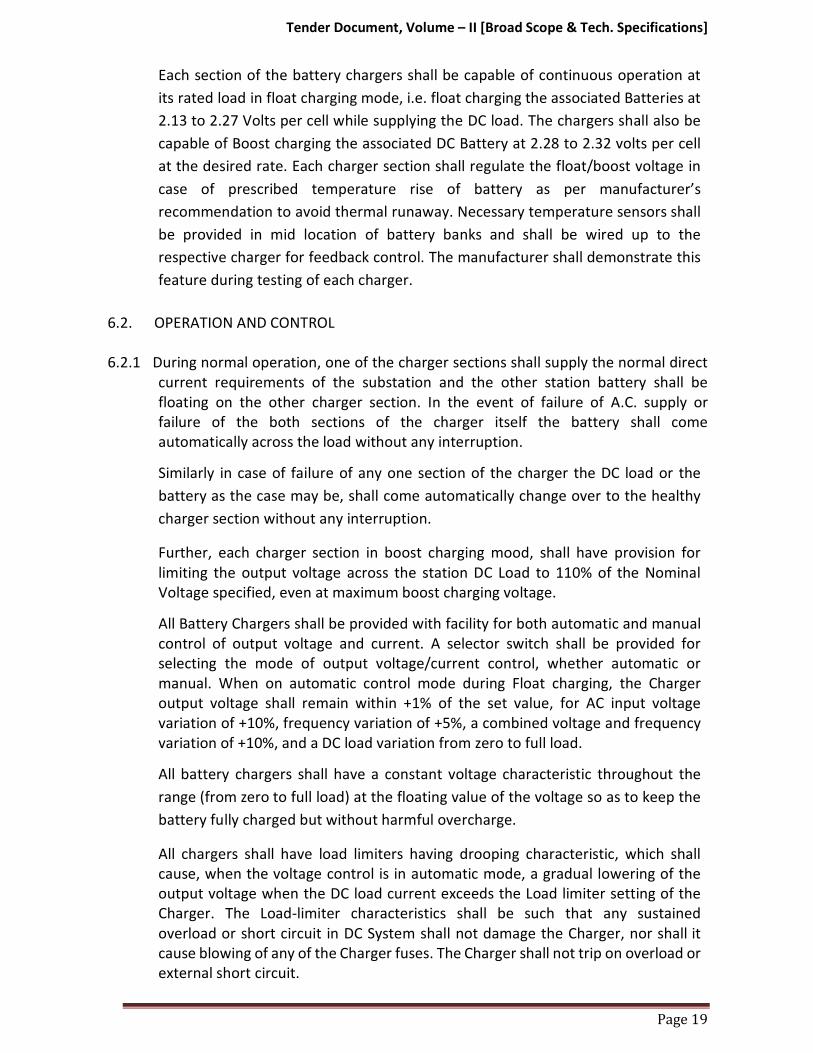
Each section of the battery chargers shall be capable of continuous operation at
its rated load in float charging mode, i.e. float charging the associated Batteries at
2.13 to 2.27 Volts per cell while supplying the DC load. The chargers shall also be
capable of Boost charging the associated DC Battery at 2.28 to 2.32 volts per cell
at the desired rate. Each charger section shall regulate the float/boost voltage in
case of prescribed temperature rise of battery as per manufacturer’s
recommendation to avoid thermal runaway. Necessary temperature sensors shall
be provided in mid location of battery banks and shall be wired up to the
respective charger for feedback control. The manufacturer shall demonstrate this
feature during testing of each charger.
6.2. OPERATION AND CONTROL
6.2.1 During normal operation, one of the charger sections shall supply the normal direct
current requirements of the substation and the other station battery shall be
floating on the other charger section. In the event of failure of A.C. supply or
failure of the both sections of the charger itself the battery shall come
automatically across the load without any interruption.
Similarly in case of failure of any one section of the charger the DC load or the
battery as the case may be, shall come automatically change over to the healthy
charger section without any interruption.
Further, each charger section in boost charging mood, shall have provision for
limiting the output voltage across the station DC Load to 110% of the Nominal
Voltage specified, even at maximum boost charging voltage.
All Battery Chargers shall be provided with facility for both automatic and manual
control of output voltage and current. A selector switch shall be provided for
selecting the mode of output voltage/current control, whether automatic or
manual. When on automatic control mode during Float charging, the Charger
output voltage shall remain within +1% of the set value, for AC input voltage
variation of +10%, frequency variation of +5%, a combined voltage and frequency
variation of +10%, and a DC load variation from zero to full load.
All battery chargers shall have a constant voltage characteristic throughout the
range (from zero to full load) at the floating value of the voltage so as to keep the
battery fully charged but without harmful overcharge.
All chargers shall have load limiters having drooping characteristic, which shall
cause, when the voltage control is in automatic mode, a gradual lowering of the
output voltage when the DC load current exceeds the Load limiter setting of the
Charger. The Load-limiter characteristics shall be such that any sustained
overload or short circuit in DC System shall not damage the Charger, nor shall it
cause blowing of any of the Charger fuses. The Charger shall not trip on overload or
external short circuit.

Tender Document, Volume – II [Broad Scope & Tech. Specifications]
Page 20
Uniform and step less adjustments of voltage setting (in both manual and
automatic modes) shall be provided on the front of the Charger panel covering
the entire float charging output range specified. Step less adjustments of the Load
limiter setting shall also be possible from 80% to 100% of the rated output current
for charging mode.
During Boost Charging, the Battery Charger shall operate on constant current
mode (when automatic regulator is in service). It shall be possible to adjust
the Boost charging current continuously over a range of 50 to 100% of the rated
output current for Boost charging mode.
The Charger output voltage shall automatically go on rising, when it is operating
on Boost mode, as the Battery charges up. For limiting the output voltage of the
Charger, a potentiometer shall be provided on the front of the panel, whereby it
shall be possible to set the upper limit of this voltage anywhere in the output for
range specified boost charging mode.
The Charger manufacturer may offer an arrangement in which the voltage setting
device for Float charging mode is also used as output voltage limit setting device
for Boost charging mode and the Load-limiter of Float charging mode is used as
current setting device in boost charging mode.
Suitable filter circuits shall be provided in all the chargers to limit the ripple
content (Peak to Peak) in the output voltage to 1%, irrespective of the DC load
level, when they are not connected to a Battery.
6.3. MCCB
All Battery Chargers shall have 2 Nos. MCCBs on the input side to receive cables
from two sources. Mechanical interlock should be provided such that only one
shall be closed at a time. It shall be of P2 duty and suitable for continuous duty.
MCCB’s should have auxiliary contacts for annunciation.
6.4. Rectifier Transformer
The rectifier transformer shall be continuously rated, dry air cooled (A.N) and of class F insulation type. The rating of the rectifier transformer shall have 10% overload capacity.
6.5. Rectifier assembly
The rectifier assembly shall be fully/half controlled bridge type and shall be
designed to meet the duty as required by the respective Charger. The rectifier
shall be provided with heat sink having their own heat dissipation arrangements
with natural air cooling. Necessary surge protection devices and rectifier type fast
acting HRC fuses shall be provided in each arm of the rectifier connection
6.6. Instruments
One AC voltmeter and one AC ammeter along with selector switches shall be
provided for each charger sections. One DC voltmeter and DC ammeter (with
shunt) shall be provided for all Charger sections. The instruments shall be flush

Tender Document, Volume – II [Broad Scope & Tech. Specifications]
Page 21
type, dust proof and moisture resistant. The instruments shall have easily
accessible means for zero adjustment. The instruments shall be of 1.5 accuracy
class. In addition to the above a centre zero voltmeter with selector switch shall
also be provided for each charger sections for testing purpose. All instruments
shall be with digital displays.
6.7. Air break switches:
Each circuit breaker shall be equipped with auxiliary switches with sufficient
number of contacts for control, indication and interlocking purposes. Ten
normally open and ten normally closed contacts shall be provided as spares. All
contacts shall be rated for the DC voltage specified in data sheet.
6.8. Fuses
All fuses shall be HRC Link type. Fuses shall be mounted on fuse carriers which are
in turn mounted on fuse bases. Wherever it is not possible to mount fuses on
carriers, fuses shall be directly mounted on plug-in type base. In such case one
insulated fuse pulling handle shall be supplied for each charger. Fuse rating shall
be chosen by the Bidder depending on the circuit requirement. All fuses in the
chargers shall be monitored. Fuse failure annunciation shall be provided on the
failure of any fuse.
6.9. Blocking diode:
Blocking diode shall be provided in the positive pole of the output circuit of each charger to prevent current flow from the DC Battery into the Charger.
6.10. Annunciation System
Audio-visual indications through bright LEDs shall be provided in each Charger
sections for the following abnormalities:
a) AC power failure
b) Rectifier/chargers fuse blown.
c) Over voltage across the battery when boost charging. d) Abnormal voltage (High/Low)
e) Any other annunciation if required.
Potential free NO Contacts of above abnormal conditions shall also be provided
for common remote indication “CHARGER TROUBLE” in Purchaser’s Control
System. Indication for charger in float mode and boost mode through indication
lamps shall be provided for chargers. A potential free contact for float/boost
mode shall be provided for external interlocks.
6.11. Analogue and Digital Inputs
Following Analogue and Digital Inputs for Purchaser’s substation
automation/SCADA purposes in the Charger, the analogue inputs shall be
generated by distinct transducers. These inputs shall be wired up to respective
terminal blocks. The Digital Inputs shall be potential free:
Analogue Inputs
(i) Voltage of 48V Battery

Tender Document, Volume – II [Broad Scope & Tech. Specifications]
Page 22
(ii) Current of 48V Battery from Charger Section I
(iii) Current of 48V Battery from Charger Section II
Digital Inputs
(i) Charger Section I Fails (ii) Charger Section II Fails (iii) Charger Section I Float/Boost Mode
(iv) Charger Section II Float/Boost Mode
6.12. Charger construction:
6.12.1. The Chargers shall be indoor, floor-mounted, self-supporting sheet metal
enclosed cubicle type. The Supplier shall supply all necessary base frames, anchor
bolts and hardware. The Chargers shall be fabricated from 2.0 mm cold rolled
sheet steel and shall have folded type of construction. Removable gland plates for
all cables and lugs for power cables shall be supplied by the Supplier. The lugs for
power cables shall be made of electrolytic copper with tin coat. Power cable sizes
shall be advised to the Supplier at a later date for provision of suitable lugs and
drilling of gland plates. The Charger shall be tropicalized and vermin proof.
Ventilation louvers, if provided shall be backed with screens. All doors and covers
shall be fitted with synthetic rubber gaskets. The chargers shall have hinged
double leaf doors provided on front and on backside for adequate access to the
Charger’s internals. All the charger cubicle doors shall be properly earthed. The
degree of protection of Charger enclosure shall be at least IP-42 as per IS: 13947
Part I. All indicating instruments, control switches and indicating lamps shall be
mounted on the front side of the Charger. Each Charger shall be furnished
completely wired upto power cable lugs and terminal blocks and ready for external
connections. The control wiring shall be carried out with PVC insulated, 1.5 sq.mm
stranded copper wires. Control terminals shall be suitable for connecting two
wires, with 2.5 sq.mm stranded copper conductors. All terminals shall be
numbered for ease of connections and identification. Each wire shall bear a ferrule
or tag on each end for identification. At least 20% spare terminals shall be provided
for control circuits. The insulation of all circuits, except the low voltage electronic
circuits shall withstand test voltage of 2 KV AC for one minute. An air clearance of
at least ten (10) mm shall be maintained throughout for such circuits, right up to
the terminal lugs. Whenever this clearance is not available, the live parts shall be
insulated or shrouded.
6.13. Painting
All sheet steel work shall be pre-treated, in tanks, in accordance with IS:6005.
Degreasing shall be done by alkaline cleaning. Rust and scale shall be removed by
pickling with acid. After pickling, the parts shall be washed in running water. Then
these shall be rinsed in slightly alkaline hot water and dried. The phosphate
coating shall be `Class-C’ as specified in IS: 6005. Welding shall not be done after
phosphating. The phosphating surfaces shall be rinsed and passivated prior to
application of stoved lead oxide primer coating. After primer application, two
coats of finishing synthetic enamel paint of shade-692 (smoke grey) of IS:5 shall
Tender Document, Volume – II [Broad Scope & Tech. Specifications]
be applied, unless required otherwise by the Employer. The inside of the chargers
shall be glossy white. Each coat of finishing synthetic enamel paint shall be
properly staved. The paint thickness shall not be less than fifty (50) microns.
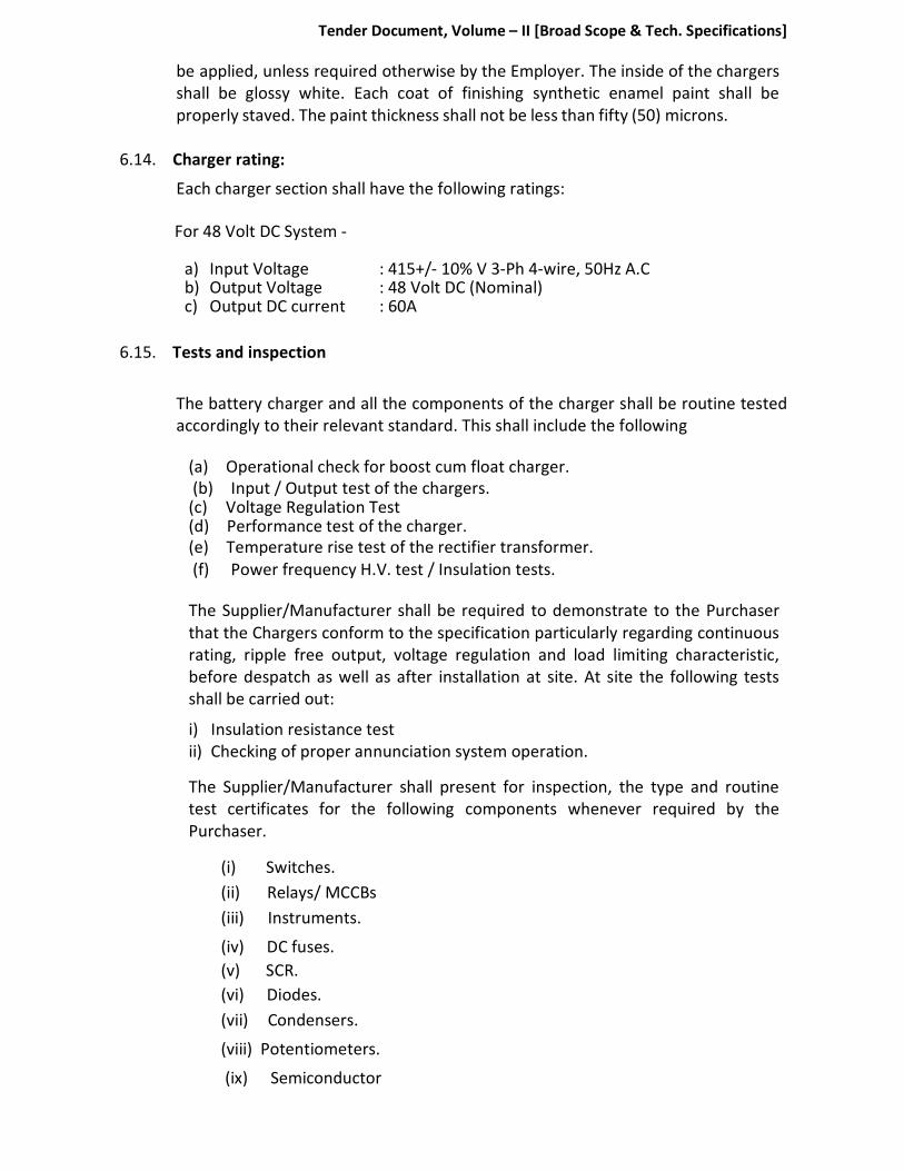
6.14. Charger rating:
Each charger section shall have the following ratings:
For 48 Volt DC System -
a) Input Voltage : 415+/- 10% V 3-Ph 4-wire, 50Hz A.C b) Output Voltage : 48 Volt DC (Nominal) c) Output DC current : 60A
6.15. Tests and inspection
The battery charger and all the components of the charger shall be routine tested
accordingly to their relevant standard. This shall include the following
(a) Operational check for boost cum float charger.
(b) Input / Output test of the chargers. (c) Voltage Regulation Test (d) Performance test of the charger.
(e) Temperature rise test of the rectifier transformer.
(f) Power frequency H.V. test / Insulation tests.
The Supplier/Manufacturer shall be required to demonstrate to the Purchaser
that the Chargers conform to the specification particularly regarding continuous
rating, ripple free output, voltage regulation and load limiting characteristic,
before despatch as well as after installation at site. At site the following tests
shall be carried out:
i) Insulation resistance test
ii) Checking of proper annunciation system operation.
The Supplier/Manufacturer shall present for inspection, the type and routine
test certificates for the following components whenever required by the
Purchaser.
(i) Switches.
(ii) Relays/ MCCBs
(iii) Instruments.
(iv) DC fuses.
(v) SCR.
(vi) Diodes.
(vii) Condensers.
(viii) Potentiometers.
(ix) Semiconductor

Tender Document, Volume – II [Broad Scope & Tech. Specifications]
Page 24
(x) Annunciator.
(xi) Control wiring
(xii) Push buttons and contactors.
7.0. DOCUMENT SUBMISSION
The supplier shall submit following documents for approval:
a) Data sheet as per GTP sheet.
b) GA of cell and layout drawing
c) Discharge Data for 10 Hour, 8 Hour, 3 Hour, 2 Hour, 1 Hour, 15 Minutes
and One Minute indicating capacity factors for end cell voltage of 1.75 V &
1.85 V.
d) Temperature correction factors
e) Installation and commissioning Instructions
f) O & M Manual
8.0. DC DISTRIBUTION BOARD
8.1. General Features:
The D.C. distribution boards shall be indoor, floor mounting of self-supporting,
sheet metal clad, and cubicle type. The panels should be totally enclosed, dust
tight and vermin proof and shall be made of 2.0 mm cold rolled sheet steel. The
boards shall be provided with double leaf hinged doors at the back. All doors and
covers shall be fitted with rubber gaskets. The doors shall be provided with locks
and duplicated covers.
8.2. Bus Bars:
The bus bars shall be of electrolytic copper of ample cross-section. The bus bars
shall be insulated from the structure by means of durable, non-hydroscopic, non-
combustible and non-tracking materials.
8.3. Detail Requirements:
8.3.1. The 48 Volts D.C. distribution boards shall be provided with the following:
i. Mains failure alarm relay. Ii Earth fault alarm relay. iii. 48 Volts D.C. bell to be operated by the mains failure alarm relay. iv. 48 Volts D.C. buzzer to be operated by the earth failure alarm relay.
v. 3 Nos. Double pole air-break circuit breaker/MCCB of 400A capacity with thermal overload tripping arrangement to act as follows:
� One for DC Source-1 (incomer 1) � One for DC Source-2 (incomer 2) � One for Bus Section

Tender Document, Volume – II [Broad Scope & Tech. Specifications]
Page 25
vi. 0-75 volts D.C. moving coil voltmeter to measure the bus-bar voltage.
The display is to be in digital.
vii. Pilot lamp to indicate D.C. on conditions.
viii. 50 volts, double pole MCBs of following ratings for outgoing feeders. For 110 V DCDB a. 16 Amp, 3 Nos in each bus section. b. 32 Amp, 1 No in each bus section.
ix. One terminal Board/block for all feeder outlets including cable glands.
8.3.2. Automatic Supply Changeover:
Automatic changeover between Incomer I and Incomer II is to be carried out
during the failure of supply in any of one the incomers. After the restoration of
the supply, system shall be restored to normal condition automatically. The
requirement of changeover under various conditions are as below:
(a) Under normal conditions i.e. when supply is available in both the incomers,
incomers 1 & 2 of DCDB shall be in closed condition and Bus couplers
breaker shall be in open condition.
(b) In case of failure of either of the sources, the incomer of that source shall trip and Bus coupler shall get closed. On restoration of supply, normal conditions described above are to be established automatically.
8.3.3. Analogue and Digital Inputs:
Following Analogue and Digital Inputs for Purchase’s substation
automation/SCADA purposes shall be provided. The analogue inputs shall be
generated by distinct transducers. These inputs shall be wired up to respective
terminal blocks. The Digital Inputs shall be potential free:
Analogue Inputs
(a) Voltage of 48 volt Bus Section-I
(b) Voltage of 48 volt Bus Section-II
(c) Current from 48 volt Battery charger section - I
(d) Current from 48 volt Battery charger section – II
Digital Inputs
(a) Incomer-I breaker On/Off (b) Incomer-II breaker On/Off
© Bus Section Breaker On/Off (d) 48 Volt DC I earth fault (e) 48 Volt DC II earth fault

Tender Document, Volume – II [Broad Scope & Tech. Specifications]
Page 26
C. 250kVA, 33/0.415KV TRANSFORMER
1.0. SCOPE
1.1. The brief description of scope of work under this Bidding Document is furnished
below:
a) Design, manufacture, testing at manufacturer’s works and supply of 250
KVA, 33/0.415 kV Transformers with all fittings and accessories as specified.
b) Loading at manufacturer’s works, transportation and delivery at respective
substation sites, including unloading at destination sites.
c) Erection, Testing and Commissioning.
1.2. STANDARD
1.2.1 The transformer by this specification shall, unless otherwise stated be
designed, constructed and tested in accordance with the latest revisions of
relevant Indian Standards indicated below or equivalent IEC and shall
conform to the regulations of local statutory authorities except to the
extent explicitly modified in this specification.
1.2.2 In case of any conflict between the Standards and this specification, this
specification shall govern. The transformer shall comply with the latest issue
of the following Indian standard.
a) IS: 1180 (Part 1) 2014 : Specification for oil immersed DTR
(Outdoor type)
b) IS: 335 : Specification for transformer oil.
c) IS: 12444 : Specification for copper wire rod.
2.0. TECHNICAL REQUIREMENTS
2.1 General:
2.1.1 The Transformers shall be of outdoor, three phase, 50 Hz, oil immersed, self-
cooled and suitable for use in the climate conditions of Mizoram, i.e. Active
Monsoon prone area for 7 months in a year and temperature ranges 5o C
to 35o C. The Transformers shall be suitable for Pole mounting as well as
foundation mounting.
2.1.2 The transformer shall be suitable for continuous operation with a frequency
variation of (+/-) 3% from normal 50 Hz. Combined voltage and frequency
variation should not exceed the rated V/f ratio by 10%.
2.2 Core:
2.2.1 The core shall be stacked type of high grade cold rolled grain annealed steel
lamination having low loss and good grain properties, coated with hot oil
proof insulation, bolted together and to the frames firmly to prevent
vibration or noise. The complete design of core must ensure permanency of
the core losses with continuous working of the transformers.
2.2.2 MS channel or plate shall be used on top and bottom. Channel frames on LV
side to be reinforced at equidistance, if holes / cutting are done for LT lead in

Tender Document, Volume – II [Broad Scope & Tech. Specifications]
Page 27
order to avoid bending of channel.
MS channels/plate frames shall be painted with hot oil-resistant varnish or
paint.
2.2.3 The maximum flux density in any part of the core and yokes, of each
transformer at normal voltage and frequency shall be such that the flux
density with (+)12.5% combined voltage and frequency variation from rated
voltage and frequency does not exceed 1.9 Tesla (19,000 lines per cm2). The
manufacturer shall furnish the design calculation in support of flux
density.
2.2.4 The transformers core shall be suitable for over fluxing (due to combined effect
of voltage and frequency) up to 12.5% without injurious heating at full load
conditions and shall not get saturated.
2.2.5 No load current shall not exceed 2% of full load current. Increase in
secondary voltage of 415 volts by 12.5% shall not increase the no load current
beyond 5%.
2.3 Winding:
2.3.1 The winding shall be of electrolytic, super enamel covered/Double paper
covered (DPC) Copper round/strip conductor, free from scales and burrs.
2.3.2 LV winding shall be of strip type copper conductor/copper foil type. The
neutral of the winding shall be brought out to a separate insulated terminal.
2.3.3 HV coil is wound over LV coil as crossover coils or continuous disc coils
2.3.4 Inter layer insulation shall be Kraft paper/Epoxy dotted paper. Proper bonding
of inner layer insulation with the conductor shall be ensured.
2.4 Terminal Arrangement:
2.4.1 Bushing terminals shall be provided with suitable terminal connectors of
approved type and size for overhead conductor termination of HV side and
cable termination on LV side.
2.4.2 The neutral terminals of 415V winding shall be brought out on a bushing
along with the 415 volt phase terminals to form a 4 wire system for the 415
volt. Additional neutral bushing shall also be provided for earthing.
2.5 Cable Boxes:
2.5.1 For LV side cable boxes shall be provided and shall be air insulated. They shall
be of sufficient size to accommodate Purchaser's cables and shall have
suitable removable side/top cover to facilitate cable termination and
inspection. Cable boxes shall be dust & vermin proof.
2.6 Off Circuit Tap Changing equipment:
2.6.1 All transformers shall be provided with a Off Load Tap Changing equipment.
The tap change switch shall be of three phase, hand operated for
simultaneous switching of similar taps on the three phases by operating an
external hand wheel.

Tender Document, Volume – II [Broad Scope & Tech. Specifications]
Page 28
2.7 Transformer Oil:
2.7.1 The insulating oil shall comply with the requirements of relevant standards IS
335. No inhibitors shall be used in oil.
2.8 Transformer Tank:
2.8.1 The transformer tank shall be of robust construction, rectangular plain tank
type and shall be built up of tested MS sheet.
2.8.2 The internal clearance of tank shall be such that it shall facilitate easy lifting
of core with coils from the tank without dismantling LV & HV bushings.
2.8.3 All joints of tank and fittings shall be oil tight and no bulging should occur
during service. The tank design shall be such that the core and windings can
be lifted freely. The tank plate shall be of such strength that the complete
transformers when filled with oil may be lifted bodily by means of lifting lugs.
Inside of tank shall be painted with varnish / hot oil resistant paint.
2.8.4 The four walls of the tank shall be made of two “L” shaped sheets (without
joints) full welded at the corners from inside and outside of the tank for
withstanding a pressure of 0.8 kg/cm2 for 10 minutes.
2.8.5 The tank shall be reinforced by welded angle on all the outside walls on the
edge of the tank to form two equal compartments. Permanent deflection
when the tank without oil is subject to a vacuum of 525 mm of mercury for
rectangular tank and 760 mm of mercury for round tank shall not be more
than 5 mm upto 750 mm length and 6 mm upto 1250 mm length. The tank
shall further be capable of withstanding a pressure of 0.8 kg/sq cm (g) and a
vacuum of 0.3 kg/sq cm (g) without any deformation.
2.8.6 Pressed steel radiators shall be used for cooling. The transformer shall be
capable of giving continuous rated output without exceeding the specified
temperature rise. 4 Nos. welded heavy duty lifting lugs of MS plate 8 mm
thick (min) suitably reinforced by vertical supporting flat welded edgewise
below the lug shall be provided on the side wall.
2.8.7 Pressed steel radiators shall be used for cooling. The transformer shall be
capable of giving continuous rated output without exceeding the specified
temperature rise. 4 Nos. welded heavy duty lifting lugs of MS plate 8 mm
thick (min) suitably reinforced by vertical supporting flat welded edgewise
below the lug shall be provided on the side wall.
2.8.8 Top cover fixing shall be with Stainless Steel bolts and 6 mm Neoprene
bonded cork gasket conforming to IS 4253 part-II shall be placed between
tank and cover. The bolts outside tank shall have 2 flat washers & one spring
washer.
All bolts/nuts/washers exposed to atmosphere shall be as follows:
a) Size 12mm and below : Stainless steel
b) Above 12 mm : Steel with suitable finished like electro
galvanized with passivation
or hot dip galvanized

Tender Document, Volume – II [Broad Scope & Tech. Specifications]
Page 29
2.9. Conservator:
Oil gauge and the plain or dehydrating breathing devise shall be fixed to the
conservator, which shall also be provided with a drain plug and a filling hole
(M30 normal size thread) with cover. The capacity of a conservator tank shall
be designed keeping in view the total quantity of oil and its contraction and
expansion due to temperature variations.
In addition, the cover of main tank shall be provided with an air release plug to
enable air trapped within to be released, unless the conservator is so located
as to eliminate the possibility of air being trapped within the main tank.
The inside diameter of the pipe, connecting the conservator to the main
tank, should be within 20 to 50 mm and it should be projected into the
conservator so that its end is approximately 20 mm above the bottom of the
conservator so as to create a sump for collection of impurities. The minimum
oil level (corresponding to -5 deg.C.) should be above the sump level.
2.10. Surface Preparation and Painting:
Before painting or filling with oil or compound, all ungalvanised parts shall be
completely clean and free from rust, scale and grease, and all external
surface cavities on castings shall be filled by metal deposition. All blast
cleaned surfaces (except machined faces that have to be protected)
must be cleaned in accordance with ISO specification no. ISO 8501 Part 1,
to a minimum standard of ‘ASa2½’ or ‘BSa2½’ prior to paint application.
External and internal surfaces of all transformer tanks and chambers and other
fabricated steel items shall be cleaned of scale, rust and surface dirt by blast
cleaning or other suitable approved method. After cleaning, these surfaces
should be immediately covered with paint. Hot oil resistant varnish on white
synthetic enamel/epoxy paint is to be used for painting the inside of all oil
filled chambers, including transformer tanks. Only one thin layer (≈ 25
microns) of this is to be applied. Except for hardware, which may have to be
removed at site, all external surfaces shall receive at least four coats of
paint.; two coats of epoxy zinc phosphate or zinc chromate primer
topped with two coats of aliphatic polyurethane glossy finish paint. The
total dry film thickness shall be 100 microns minimum.
Any scratch, bruise or paint damage incurred during transportation and
unloading at site should be made good by the Supplier as soon as the
damage is detected. This is to be done by thoroughly cleaning the damaged
area and applying the full number of coats as was applied originally.
One coat of additional paint shall be given at site over all external surfaces,
including hardware, after erection by the Suppler. The make and grade of the
recoat shall be same as the original coat. 2.11 Fittings and Accessories:
Following fittings and accessories shall be provided with each transformer:
(a) Rating and terminal marking plates shall be as per Fig-1 & Fig-3 of

Tender Document, Volume – II [Broad Scope & Tech. Specifications]
Page 30
IS: 1180 (Part-1) -2014.
(b) Two earthing terminals (studs and bolts should be properly galvanized and
conform to IS:1363 and IS:1367.
(c) Two lifting lugs to lift core assembly.
(d) Two lifting lugs to lift complete transformer.
(e) Lifting lugs for tank cover.
(f) Thermometer pocket in accordance with IS: 3580.
(g) Air release plug on the transformer tank to release air trapped inside the
tank when filling oil through conservator.
(h) Conservator tank shall have inter connection pipe projection, 20 mm above
bottom of the conservator so as to create a sump for collection of
impurities. It shall have 30 mm dia drain valve, oil filling hole with cap on
the top of the conservator.
(i) Oil level gauge with toughened glass with “minimum” and ‘maximum’
marking.
(j) De-hydrating breather.
(k) Pressure Relief device or explosion vent.
(l) One drain cum sampling valve.
(m) One filter valve on the upper side of the tank.
(n) Unidirectional flat rollers.
(o) Inspection hole.
(p) Terminal connectors for HV & LV.
(q) One 33 kV 400 Amps DO Fuse set.
(r) One LT 630 Amps MCCB of make preferably ABB/Schneider
(s) 3 numbers, 30kV Polymeric Lightning Arrestor of make LAMCO/equivalent
(t) LA holder clamp with provision of earthing in HV side bushings, 3
numbers.
(u) Grounding material & accessories for earthing of transformer neutral,
transformer tank and LA.
3.0 TESTING AND INSPECTION
3.1 Inspection:
(a) Physical and dimensional check of transformer tank and accessories.
(b) Tank crack detection of major strength weld seams by dye penetration test.
(c) Physical inspection and check of quality of varnish, if used in core.
(d) Check on completed core for measurement of iron loss and check for any
hot spot by exciting the core so as to induce the designed value of flux
density in the core.
(e) Sample checks for physical properties of the insulating material.
(f) Check for dielectric strength of insulating materials.
(g) Sample check on winding conductor for mechanical properties and
electrical conductivity and on installation covering.

Tender Document, Volume – II [Broad Scope & Tech. Specifications]
Page 31
(h) Sample check on insulation paper used for windings for pH value, Bursting
strength, Electric strength. (i) Check complete transformer against
approved outline drawing provision for all fittings, finish etc.
3.2 Factory Tests:
All standard routine tests in accordance with IS: 1180 (Part-1), 2014 and latest
issue of IS: 2026 shall be carried out on each transformer at Manufacturer’s
Works. In addition to above standard Routine tests, following tests shall also
be carried out as Routine Tests for one number transformer of each category
of each Package:
(a) Temperature-rise test as per IS 2026.
(b) No load current at 112.5% of rated voltage.
(c) Pressure and Oil Leakage test. (on each transformer).
(d) Routine Tests on Transformer Tank as per CBIP Manual on Transformer
(CBIP Publication No. 317).
3.3 Pre-Commissioning Tests (Field Tests):
(a) Winding resistance measurement.
(b) Verification of vector group and polarity.
(c) Measurement of voltage ratio test.
(d) Measurement of magnetizing current.
(e) Magnetic balance test.
(f) Magnetic circuit (isolation) test.
(g) Measurement of short circuit impedance at low voltage.
(h) Insulation resistance measurement.
(i) Tests on oil filled in transformer as per IS 1866
3.4 REJECTION
3.4.1 The Purchaser may reject any transformer if during tests or service any of the
following conditions arise:
i) The permissible total loss (No load loss + Load Losses at 75 0 C) at 50% of
rated load and 100% load loss exceeds the guaranteed value by 7½%.
ii) The difference in impedance values of any two phases during single phase
short circuit impedance test exceeds 2% of the average value guaranteed by
the vendor.
iii) Oil or winding temperature rise exceeds the specified value.
iv) Transformer fails on power frequency voltage withstand test.
v) Transformer is proved to have been manufactured not in accordance with
the agreed specification.
Tender Document, Volume – II [Broad Scope & Tech. Specifications]
Page 32
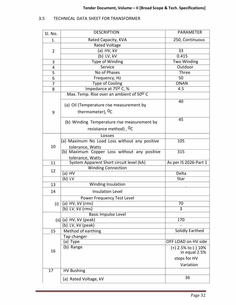
3.5 TECHNICAL DATA SHEET FOR TRANSFORMER
Sl. No. DESCRIPTION PARAMETER
1. Rated Capacity, KVA 250, Continuous
2
Rated Voltage (a) HV, kV 33
(b) LV, kV 0.415
3 Type of Winding Two Winding Transformer 4 Service Outdoor
5 No of Phases Three
6 Frequency, Hz 50
7 Type of Cooling ONAN
8 Impedance at 750 C, % 4.5
9
Max. Temp. Rise over an ambient of 500 C
(a) Oil (Temperature rise measurement by
thermometer), 0C
40
(b) Winding Temperature rise measurement by
resistance method) , 0C
45
10
Losses (a) Maximum No Load Loss without any positive
tolerance, Watts
105
(b) Maximum Copper Loss without any positive
tolerance, Watts
315
11 System Apparent Short circuit level (kA) As per IS 2026-Part 1
12 Winding Connection
(a) HV Delta
(b) LV Star
13 Winding Insulation Unif
14 Insulation Level
(i)
Power Frequency Test Level (a) HV, kV (rms) 70
(b) LV, kV (rms) 3
(ii)
Basic Impulse Level (a) HV, kV (peak) 170
(b) LV, kV (peak) -
15 Method of earthing Solidly Earthed
16
Tap changer (a) Type OFF LOAD on HV side
(b) Range (+) 2.5% to (-) 10% in equal 2.5%
steps for HV
Variation
17 HV Bushing
(a) Rated Voltage, kV 36

Tender Document, Volume – II [Broad Scope & Tech. Specifications]
Page 33
(b) Rated Current, Ampere 400
(c) Basic Impulse Level, kVp
170
(d) Wet & Dry Power frequency Withstand Voltage,Kv (rms)
70
(e) Min. Total Creepage Distance, mm 900
18 LV Neutral Bushing
(a) Rated Voltage, kV 1.1
(b) Rated Current, Ampere 1000
(c) Wet & Dry Power frequency withstand Voltage,kV (rms)
2.0
19 Min. Clearance in Air
(a) Ph-Ph (HV/LV), mm 350/25
b) Ph-Earth (HV/LV), mm 320/25
3.6. ERECTION, TESTING AND COMMISSIONING
3.6.1 Bidders should note that, transformers shall be installed at new/existing
location identified by the site engineer, at various existing substations.
Transformers shall b e erected o n a new RCC pedestal or as decided by
engineer-in-charge.
3.6.2 It is also responsibility of the supplier/Contractor to lay the power cable on LV side to connect the transformer to existing LTAC Panel of the Purchaser.
3.6.3 Bidder shall carry out the required earthing system for the commissioning of
the transformer like two numbers neutral earth, two numbers transformer
body earth & LA earth.
3.6.4 Before commissioning of the transformers, the Supplier/Contractor shall
carry out all the site tests specified and shall take approval of the same from
the Purchaser.
4.0. GUARANTEED TECHNICAL PARTICULARS
4.1. The Guaranteed Technical Particulars of the various items shall be furnished by
the Bidders in the prescribed format furnished under vol. III of this tender
document. The Bidder shall also furnish any other information's as in their
opinion is needed to give full description and details to judge the item(s) offered
by them.

Tender Document, Volume – II [Broad Scope & Tech. Specifications]
Page 34
D. 30kVA DIESEL GENERATING SET.
1.0. SCOPE:-
1.1. The brief description of scope covered under this Bidding Document is furnished
below:
a) Design, manufacture, testing at manufacturer’s works and supply of 30KVA
air cooled Diesel Generating set complete with all accessories like, starting
batteries, standard control panel, interconnecting cable(including cable from
generator panel to change-over panel), tank, fuel/coolant/ exhaust pipes,
silencer, anti vibration mountings, foundation etc.
b) Loading at manufacturer’s works, transportation and delivery at respective
substation sites, including unloading at destination sites.
c) Erection, Testing and Commissioning of the Diesel Generating Set including
construction of concrete foundation platform and protective canopy.
d) Cabling from Generator Panel to Changeover Panel and from thereon to ACDB.
e) Supply of mandatory Spares. 1.2. It is also responsibility of the Contractor to obtain any road permits and any
other permits or licenses to execute the works.
2.0. STANDARD:-
The generating set shall be designed, manufactured and tested in accordance
with the latest revision of Indian standards IS 10002/1981 - Specification for
Diesel Engines as amended upto date IS 4722/2001- Rotating Electrical Machines
-Specification (second revision).
3.0. GENERAL:-
The generating sets shall be robust in construction factory tested and assembled
to ensure perfect alignment of Engine and Alternator on a common base frame.
The base frame shall be fabricated out of adequate thickness rolled steel
sections. The set shall be mounted on anti-vibration mounting to prevent
transfer of vibration to the foundation and structures. The Cable shall be suitable
for operating at a hot humid and saline atmosphere at an ambient temperature
of 45 degree centigrade.
4.0. DIESEL ENGINE
The engine shall be Multi-cylinders, vertical, 4 stroke, Direct Injection, Air/water
cooled type, developing the rated Horsepower at a speed of 1500 rpm. The
engine shall be provided with an Hour meter to record the hours of operation.
Suitable engine heaters shall be provided to ensure quick starting of the engine
after prolonged shut off where necessary.

Tender Document, Volume – II [Broad Scope & Tech. Specifications]
Page 35
4.1 Starting:-
The engine starting shall be by means of totally enclosed axial type electric
starter suitable for 12 volts DC. The DC supply shall be derived from a heavy duty
12 volts maintenance free battery.
4.2 Cooling:-
In case of water cooled Engine, an engine driven centrifugal pump shall be
employed to circulate the coolant through a cooling radiator with an axial blower
fan. A temperature gauge shall be provided with contacts for stopping the engine
on high temperature.
4.3 Lubrication:-
Pressure lubricating oil system with an engine driven pump shall be provided to
cover to complete engine, with built in oil coolant heat exchangers. Full foam
filters removable elements shall be provided and these shall be located at easily
accessible location for ease of maintenance. The supply shall include first filling
of lubricating oil. An oil pressure gauge shall be provided to monitor the
lubrication oil pressure. The gauge shall be provided with contacts for stopping
the engine on failure of lubricating oil flow.
4.4 Governor:-
The governor shall be of electronic type suitable for monitoring constant engine
speed within the specified limits for auto parallel and auto load sharing
operation.
4.5 Exhaust:-
The exhaust piping system shall be supplied with a residential silencer. The
exhaust piping and the silencer shall be wrapped with rock wool and/or calcium
silicate. The outside shall be neatly wrapped with aluminum cladding. The
exhaust line shall be extended beyond the height of the utility building roof as
required by pollution control norms.
4.6 Daily Service Tank:-
The supplier shall supply and install Daily Service Tank of sufficient capacity 120
lts to enable running of the generator set for 12 hours continuous run. The Daily
Service Tank shall be fitted with necessary fuel gauge with shut off cocks.
4.7 Pipe works:-
All necessary pipes and accessories for cooling water, lubricating oil, fuel, oil and
exhaust shall be designed and supplied to suit the standard arrangement for a
system, mounted on anti-vibration mountings.

Tender Document, Volume – II [Broad Scope & Tech. Specifications]
Page 36
4.8 Foundation and Anti-Vibration Footing:-
The generating set shall be mounted on standard size cement concrete
foundation with required number of anti-vibration footings to prevent transfer
of vibration to the foundation and structure.
5.0. ALTERNATOR
The alternator shall be 30 KVA 3 phase 0.8 PF 415V, 4 wire 1500 rpm, housed in
screen protected drip proof enclosure. The alternator shall be capable of
delivering rated output at rated power factor with,
a. Terminal voltage differing from the rated value by not more than +/- 5%.
b. Frequency differing from the rated value by not more than +/- 0.5%.
c. Short circuit capacity of 300% for 10 seconds. .
d. Over load capacity of 110% for one hour.
5.1 Insulation:-
The insulation shall be class H and shall be fully impregnated for use in hot,
humid, tropical climate conditions, with an ambient temperature of 50 deg.C.
The stator and rotor windings of the alternator and the exciter shall be provided
with acid resistant varnish finish.
5.2 Bearings:-
The alternator shall be provided with single bearing or two sleeves to ensure
perfect alignment under all conditions. The bearing shall be self-lubricating type.
Close coupling of single bearing alternator is preferable.
5.3 Voltage Regulator:-
A rapid response voltage regulator shall be provided to regulate the generated
voltage .The overall regulations from no load to full load, including cold to hot
variation and load power factor of 0.8 lag to unity shall be within 2% of the
normal voltage. The excitation system shall be designed to promote rapid
voltage recovery following sudden application and disconnection of load.
6.0. ACOUSTIC ENCLOSURE
The acoustic enclosure should be supplied along with DG set from the
manufacturer outlet itself as per CPCB norm.
6.1 Construction:-
Acoustic enclosure shall be of powder coated and fabricated out of 16 SWG CRCA
MS sheet. Powder coating shall be done after seven tank surface preparation
process of sheet metal. The canopy shall have four hinged doors, one door with
glass window to view proper parameters on the control panel. The canopy and

Tender Document, Volume – II [Broad Scope & Tech. Specifications]
Page 37
doors shall have inside lining of fire retardant foam/glasswool as acoustic
materials.
The base frame shall be fabricated in ISMC channel or in sheet metal, with lifting
hooks for convenient lifting of complete set i.e along with canopy, engine and
alternator.
The sound level shall have less than 75 db (A) at a distance of 1 meter. The
allowable temperature raise inside the canopy is 5 to 7 deg. Centigrade. The
measurement of noise will be as per ISO 3744/ ISO 8528 (Part 10) standard.
6.2. Salient features:-
The canopy shall have the following features-
1. Open air installation
2. Lockable doors
3. External accessible emergency stop button
4. Provision for taking out exhaust gases through suitable pipes to prevent any
leak pressure on the engine.
5. Provision for the second residential / hospital silencer to reduce the noise
level as specified.
7.0 CONTROL & INSTRUMENTATION
7.1 Each D.G. Set shall be provided with suitable instruments, interlock and
protection arrangement, suitable annunciation and indications etc. for proper
start up, control, monitoring and safe operation of the unit. One local AMF
control panel along with each D.G. set shall be provided by the Supplier to
accommodate these instruments, protective relays, indication lamps etc. The
AMF Panel shall have IP-52 degree of Protection as per IS: 12063.
7.2 The D.G. sets shall be provided with automatic start facility to make it possible to
take full load within 30 seconds of Power Supply failure.
7.3 Testing facility for automatic operation of DG Set shall be provided in AMF panel.
7.4 DG set shall be capable of being started/ stopped manually from remote as well
as local. Remote START/STOP push button shall be provided in 415V ACDB).
However, interlock shall be provided to prevent shutting down operation as long
as D.G. Circuit breaker is closed.
7.5 Shutdown sequence of DG set to be provided whenever any of the following
conditions appear in the system:
i) Overspeed
ii) Overload.
iii) High temperature of engine and cooling water.
iv) Low lub oil pressure
v) Short circuit protection

Tender Document, Volume – II [Broad Scope & Tech. Specifications]
Page 38
vi) Under voltage
vii) Over voltage.
7.6 Following instruments shall be provided with Diesel Engine -
i) Lub oil pressure gauge
ii) Water temperature thermometers
iii) Engine tachometer/HR
iv) Any other instruments necessary for DG Set operation shall
be provided.
v) Following indication lamps for purposes mentioned as under shall be
provided in AMF panel: Pilot indicating lamp for the following:
a) Mains ON
b) Alternator ON
c) Charger ON/OFF
d) Breaker ON/OFF
vi) Visual annunciation shall be provided for set shut down due to:
a) Engine overheating
b) Low oil pressure
c) Lack of fuel
d) Set failed to start in 30 secs after receiving the first start impulse
e) High cooling water temperature
f) Low level in daily service fuel tank
g) Over speed trip
h) Audio & visual Annunciation for alternator fault.
7.7 AMF panel for control, metering, alarm and automatic change over shall be
provided.AMF panel shall have facility for adjustment of speed and voltage
including fine adjustments in remote as well as in local mode. The control panel
shall also contain all protective and aux. relays and metering
recommended by the supplier for the alternator including (but not limited to)
the following:
a) Restricted Earth fault protection.
b) Over load protection.
c) Phase to phase and phase to Earth fault protection.
d) Over voltage protection.
7.8 The contractor shall furnish complete protection scheme comprising CT
parameter setting range, type of relays etc.
7. 9 The CT's for different protection shall be of 5A secondary current rating.
7.10 The CTs for metering shall be of 5A secondary current rating, accuracy class 1.0
and rated VA output not less than 30.

Tender Document, Volume – II [Broad Scope & Tech. Specifications]
Page 39
7.11 Following shall also be provided in AMF panel:
a) Frequency meter
b) 3 Nos. single phase CT's for metering
c) One (1) DC (0-40A)
d) One (1) DC Voltmeter (0-30V)
e) One (1) Voltmeter Selector switch
f) One (1) AC Ammeter
g) One (1) AC Voltmeter
h) Three (3) Timers (24V DC)
i) Two (2) Auto / Manual Selector Switch
k) Two (2) Auto / test / Manual Selector Switch
l) Two (2) Set Battery charger as specified in Technical Specification
m) One (1) Set Phase & Neutral bus bars.
o) Any other item required for completion of Control scheme shall be
deemed to be included.
7.12 Thermostatically controlled space heaters and cubicle illumination operated by
Door Switch shall be provided in AMF panel. Necessary isolating switches and
fuses shall also be provided.
8.0 DRAWING AND MANUALS
Technical data and all the drawings and calculation shall be submitted for
approval and statutory approval of CEA shall be obtained for commissioning of
the Diesel Generator set.
9.0 TESTS:-
9.1. Factory Test:
Complete tests at full load and 10% over load shall be carried out at the
manufacturer’s works to determine the performance and operating
characteristics of the assembled generating set and accessories to determine
whether or not the guarantees have been met. Unless otherwise specified, all
routine tests shall be carried out in accordance with the standards and shall be
witnessed by the representatives of the purchaser. Manufacturer test certificate
with manual in triplicate shall be supplied by the vendor.
9.2. Site Test:-
The Contractor shall carryout the following commissioning tests to be carried
out at site:
9.2.1 Load Test: - The engine shall be given test run for a period of at least 6 hours.
The set shall be subjected to the maximum achievable load as decided by
Purchaser without exceeding the specified DG Set rating. The necessary load to
carry out the test shall be provided by the purchaser. During the load test, half
hourly records of the following shall have to be taken:

Tender Document, Volume – II [Broad Scope & Tech. Specifications]
Page 40
a) Ambient temperature.
b) Exhaust temperature if exhaust thermometer is fitted.
c) Cooling water temperature at a convenient point adjacent to the water
output from the engine jacket.
d) Lubricating oil temperature where oil cooler fitted.
e) Lubricating oil pressure.
f) Colour of exhaust gas
g) Speed
h) Voltage, wattage and current output.
i) Oil tank level
9.2.2 Insulation Resistance Test for Alternator:
An insulation resistance in mega-ohms between the coils and the frame of the
alternator when tested with 500Vmegger shall not be less than IR=2x (rated
voltage in KV) +1.
9.2.3 Functional Test:
a) Functional tests on control panel.
b) Functional test on starting provision on the engine.
c) Functional tests on all Field devices.
d) Functional tests on AVR and speed governor.
9.2.4 Measurement of Vibration:
The vibration shall be measured at load as close to maximum achievable load
and shall not exceed 250microns.
9.2.5 Noise Level check as per relevant standard:
The tests shall be carried out with the DG set operating at rated speed and at
maximum achievable load. Necessary correction for Test environment condition
& background noise will be applied as per IS: 12065.
10.0. LT CHANGE OVER PANEL 10.1. Design, fabrication & supply of Indoor L.T. 415V distribution switchgear Panel
made out of 16 SWG CRCA sheet steel Enclosure with powder coated matt grey
finish. The panel shall have proper supporting and mounting structure of suitable
size ‘u’ channel, provision for grouting. Provide sufficient clearance between live
and non live parts as per standards. The panel should have 14 SWG gland plate.
Cable alley and bus-bar chambers should be provided. The panel must have two
MCCBs of requisite capacities; one for DG Set and the rest for Station Service
Transformers. The terminals of the MCCBs must be of adequate size &
mechanical strength to receive the terminals lugs on cables of requisite sizes.
Also the two MCCBs must be so mechanically interlocked that one MCCB may be
switched on at any instant of time and not both.

Tender Document, Volume – II [Broad Scope & Tech. Specifications]
Page 41
.
11.0. ERECTION, TESTING & COMMISSIONING INCLUDING NECESSARY CIVIL WORKS
11.1. The DG Sets shall have to be installed, tested and commissioned by the
contractor after construction of the necessary foundation at the designated
locations inside the respective Sub- stations of P&ED, Mizoram.
11.2. All fittings, unit assemblies, accessories, hardware foundation bolts, terminal
lugs for electrical connections, cable glands and miscellaneous materials or
accessories of items of work which are useful and necessary for efficient
assembly and working of the equipment shall be deemed to be included in the
tender within the overall cost quoted. The equipment shall be complete in all
details whether such details have been mentioned or not.
11.3. Foundation shall be constructed to provide a suitable reinforced cement
concrete Pedestal for both the D-G set and fuel tank with concrete proportion
of1:2:4 and reinforcing steel rods of 12mm dia. RCC bed should rise at least 0.3m
above the ground level. All materials required for the related civil works are
under the scope of the contractor. However, the drawings for the foundation
work shall be got approved by the Employer before taking up the work for
execution.
11.4. 2 Nos. of earth electrodes for body earth and 2 Nos. earth electrode for neutral
earth shall be provided as per IS-3043 with GI pipe (‘B’ Class) earth electrode.
Interconnection of earth electrode, earthing of fuel oil tank, base frame etc.
shall also be carried out as per relevant standards.
11.5. The Change-over panels shall have to be installed by the contractor inside the
ACDB room or any other suitable locations in the Control Room Buildings as
directed by the site engineer of the respective Sub-stations of P&ED, Mizoram.
11.6. The contractor shall lay and execute termination of the necessary power and
control cables from the DG sets to the Change-over panels and from thereof to
the ACDB panels as directed by the site engineer.
11.7. In addition to the checks and test recommended by the manufacturer, the
Contractor shall carry out the commissioning tests as found suitable by
purchaser/owner.
12.0 DOCUMENTS:
12.1 The following drawings and data sheets shall be submitted for approval:
i) Data sheet for Engine, Alternator, Battery, AMF panel and enclosure.
ii) GA drawing of DG set.

Tender Document, Volume – II [Broad Scope & Tech. Specifications]
Page 42
iii) Layout of DG set in the enclosure along with section.
12.2 The DG set shall be supplied with.
i) DG set test certificate.
ii) Engine operation and maintenance.
iii) Engine parts catalogue.
iv) Alternator operation, maintenance &Spare parts Manual.
v) Alternator test certificate.
13.0. Electrical and mechanical characteristics shall be guaranteed by the bidder. In
case of failure of materials to meet the guarantee, P&E Deptt. Mizoram shall
have right to reject the material.
14.0 Guaranteed Technical Particulars (GTP) is to be submitted by the tenderer along
with the bid. Prescribed format of GTP to be furnished is provided in Volume III
of this Tender Document.

Tender Document, Volume – II [Broad Scope & Tech. Specifications]
E. RELAYS
1.0. SCOPE.
1.1. The scope of works is furnished below:
a) Design, manufacture, testing at manufacturer’s works supply,
installation testing and commissioning
b) It is also responsibility of the Contractor to obtain any road permits and
any other permits or licenses to execute the works.
1.2. All the relays under the scope shall be Numerical type and shall comply
with the following requirements of: IS: 3231 / IEC•60255 / IEC 61000 or other
applicable standards. Relays shall be suitable for flush or semi flush mounting
on the front with connections from the rear.
1.3. The offered relays shall be completely numerical.
The communication protocol shall be as per IEC 61850 & IEC60870-5-103
• The test levels of EMI as indicated in IEC 61850 shall be applicable
to these relays.
Protection elements should be realized using software algorithm.
Hardware based measurement shall not be acceptable. 1.4. The relay shall be provided with both 1A and 5A CT inputs and shall be
selectable at site.
1.5. It shall be possible to energies the relay from either AC or DC auxiliary supply. 1.6. The offered relay shall have a comprehensive local MMI for interface. It shall
have the following minimum elements so that the features of the relay can
be accessed and setting changes can be done locally.
At least 48 character alphanumeric backlit LCD display unit
Fixed LEDs (for trip, Alarm, Relay available & Relay out of service) &
programmable LEDs which can be assigned to any protection function for
local annunciation.
Tactile keypad for browsing and setting the relay menu. 1.7. The relay shall have the facility to set the pickup threshold (24-250V)
independently per digital input to prevent the spurious pick up of binary
during inputs DC earth fault condition (ESI 48- 4EB2 compliant). 1.8. The relays supplied should be compatible to redundant communication
architecture, shall be complied with the IEC 62439-3 standards of parallel
redundancy protocol (PRP). 1.9. The relays provided should be complied with the international standards of
NERC CIP for cyber security to provide protection against unauthorized
disclosure, transfer, modification, or destruction of information and/or
information systems, whether accidental or intentional.

Tender Document, Volume – II [Broad Scope & Tech. Specifications]
1.10. All PCB used in relays should have harsh environmental coating as per
standard IEC 60068 (HEC) to increase the particle repellency and thereby
increasing the life of relay
1.11. The relay should comply to IEC 61850 protocol.
The relays shall generate GOOSE messages as per IEC 61850 standards for interlocking and also to ensure interoperability with third party relays.
The relay should be upgradable to process bus interface 61850-9-2LE
(Process Bus) to receive SV from non-conventional CT / PT and
merging unit.
Necessary user friendly configuration tool shall be provided to configure the relays. It should be compatible with SCL / SCD files generated by a third party system.
Goose signals shall be freely configurable for any kind of signals using
graphic tool /user friendly software.
The relay should have time synchronization through SNTP/IRIG-B
1.12. The relays shall have the following tools for fault diagnostics
Fault record – The relay shall have the facility to store at least 5 last
fault records with information on cause of trip, date, time, trip values of
electrical parameters.
Event record – The relay shall have the facility to store atleast 512 time
stamped event records with 1ms resolution.
Disturbance records – The relay shall have capacity to store at least 8
disturbance record waveforms at 10.5 secs. 1.13. The relay settings shall be provided with adequate password protection. The
password of the relay should be of 4 character upper case text to provide
security to setting parameter 1.14. The relay shall have comprehensive self-diagnostic feature. This feature
shall continuously monitor the healthiness of all the hardware and software
elements of the relay. Any failure detected shall be annunciated through a
output watchdog contact. The fault diagnosis information shall be displayed on
the LCD and also through the communication port. 1.15. The Numerical Relays shall be provided with 1 Set of common support
software compatible with up to date Windows platform which will allow easy
settings of relays in addition to uploading of event, fault, disturbance records,
measurements.
The relay settings shall also be changed from local or remote using the same software.
Additional functions can be added to relay by software up-
gradation and downloading this upgraded software to the relays by
simple communication through Laptop.

Tender Document, Volume – II [Broad Scope & Tech. Specifications]
Page 45
1.16. All protective relays shall be in draw out or plug • in type / modular cases with
proper testing facilities. Necessary test plugs/test handles shall be supplied
loose and shall be included in contractor's scope of supply. 1.17. All AC operated relays shall be suitable for operation at 50 Hz. AC Voltage
operated relays shall be suitable for 110 Volts VT secondary and current
operated relays for 1 amp CT secondary. All DC operated relays and timers
shall be designed for the DC voltage specified, and shall operate satisfactorily
between 80% and 110% of rated voltage. Voltage operated relays shall have
adequate thermal capacity for continuous operation.
1.18. The protective relays shall be suitable for efficient and reliable operation of the
protection scheme described in the specification .Necessary auxiliary relays and
timers required for interlocking schemes for multiplying of contacts suiting
contact duties of protective relays and monitoring of control supplies and
circuits, lockout relay monitoring circuits etc. also required for the complete
protection schemes described in the specification shall be provided. All
protective relays shall be provided with at least two pairs of potential free
isolated output contacts. Auxiliary relays and timers shall have pairs of contacts
as required to complete the scheme; contacts shall be silver faced with spring
action. Relay case shall have adequate number of terminals for making
potential free external connections to the relay coils and contacts, including
spare contacts. 1.19. Timers shall be of solid state type. Time delay in terms of milliseconds obtained
by the external capacitor resistor combination is not preferred and shall be
avoided.
a. No control relay, which shall trip the power circuit breaker when the
relay is de- energized, shall be employed in the circuits.
b. Provision shall be made for easy isolation of trip circuits of e a c h
relay for the purpose of testing and maintenance.
c. Auxiliary seal-in-units provided on the protective relays shall preferably
be of shunt reinforcement type.
d. The setting ranges of the relays offered, if different from the ones
specified shall also be acceptable if they meet the functional
requirements. 1.20. Any alternative / additional protections or relays considered necessary for
providing complete effective and reliable protection shall also be offered
separately. The acceptance of this alternative/ additional Cable shall lie with the
P&E Department, Govt. of Mizoram.
1.21. All relays and their drawings shall have phase indications as -
R•Red, Y•Yellow, B•blue.

Tender Document, Volume – II [Broad Scope & Tech. Specifications]
Page 46
2.0. ERECTION:
a) Wiring:
Suitable wiring whenever require for fitting, fixing, commission & testing of
relays and other control Cables have to completed by the bidder without
extra cost for materials etc. All wiring shall be carried out with 1100V grade,
single core, stranded, un-tinned copper conductor wires with PVC (FRLS)
insulation, ferrule marking, crimping lug etc. as required. The wiring shall be
flame, vermin & rodent proof and shall have Oxygen Index of not less than 29
& Temperature Index of not less than 250ºC. The number and minimum size
of the stranded copper conductors (minimum 7 nos.) used for internal wiring
shall be as follows:
All circuits: One 2.5 mm2 per lead.
Each wire shall be continuous from end to end and shall not have any joint in
its run. All internal wiring shall be connected only at the connection terminals
of the terminal blocks, relays, instruments and other switchboard devices.
b) Tests:
The protection relays shall be completely assembled and subjected to the
various routine and acceptance tests as per the relevant standards in the
premises of the manufacturer of
relay in the presence of Purchaser‘s representative, if desired by the Purchaser. Five certified copies of the test reports shall be submitted to the Purchaser for approval before Cable is packed for shipment.
The Contractor shall specifically state the details of testing facilities available
at his own or sub-vendor works.
The type test reports conducted on the protection relays and distance to fault
locator in accordance with relevant IS / IEC, along with verification of degree
of protection in accordance with relevant IS 13947 (Part - I) / relevant IEC
from approved laboratory, shall be submitted along with the bid for Purchaser‘s review.
The Control & Relay panels shall also be subjected to the
following tests:
i) Mechanical operation test
ii) High Voltage test/Insulation resistance test
iii) Electrical control, inter lock and sequential operation test.
iv) Verification of wiring as per approved schematic
v) Verification of degree of protection in accordance with relevant IS: 13947
(Part – I) /relevant IEC from approved laboratory.
c) Instruction manuals:
The following drawings for each item are to be supplied after award of contract:
Six copies of instruction books / descriptive literature of the following shall be
supplied:
i) Literature d e s c r i b in g c o n st r u c t i o n , o p e r at i o n , a d j u s t m e n t , t e s t in g , c a l i b r a t i o n a n d maintenance of all protective and auxiliary

Tender Document, Volume – II [Broad Scope & Tech. Specifications]
Page 47
relays, instruments, control switches etc.
ii) List of spare parts giving identification number of the parts.
E - I: TECHNICAL SPECIFICATION FOR OVER-CURRENT AND EARTH FAULT RELAY.
3.0. The relay shall be numerical type having the following features:
1. Undercurrent protection (37)
2. Negative Sequence Overcurrent protection (46)
3. Broken Conductor protection (46BC)
4. Negative sequence overvoltage protection (47)
5. Thermal overload protection (49)
6. Ground fault protection (50/51N)
7. 3 phase overcurrent protection (50/51P)
8. Circuit breaker failure protection (50BF)
9. Voltage controled overcurrent protection (51V)
10. Over/Under voltage protection (59/27)
11. Residential over voltage protection (59N)
12. Residential earthfault protection (64)
13. Ground fault directional protection (67N)
14. Wattmetric earthfault protection (67W)
15. Autoreclose (79)
16. Under/Over frequency protection (81)
17. Rate of change of frequency (81R)
18. Lock-out (86)
19. Current transformer supervision (CTS)
20. Switch on to fault (SOTF)
21. Trip circuit supervision (TCS)
22. Voltage Transformer supervision (VTS)
E - II: TECHNICAL SPECIFICATION FOR DISTANCE PROTECTION RELAY.
(Numerical IEC-61850 Protocol compliance)
4.0. The relay shall:
1. be static and modular in construction
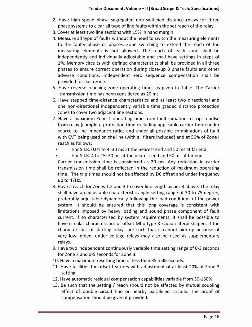
Tender Document, Volume – II [Broad Scope & Tech. Specifications]
Page 48
2. Have high speed phase segregated non switched distance relays for three
phase systems to clear all type of line faults within the set reach of the relay.
3. Cover at least two line sections with 15% in hand margin.
4. Measure all type of faults without the need to switch the measuring elements
to the faulty phase or phases. Zone switching to extend the reach of the
measuring elements is not allowed. The reach of each zone shall be
independently and individually adjustable and shall have settings in steps of
1%. Memory circuits with defined characteristics shall be provided in all three
phases to ensure correct operation during close-up 3 phase faults and other
adverse conditions. Independent zero sequence compensation shall be
provided for each zone.
5. Have reverse reaching zone operating times as given in Table. The Carrier
transmission time has been considered as 20 ms.
6. Have stepped time-distance characteristics and at least two directional and
one non-directional independently variable time graded distance protection
zones to cover two adjacent line sections.
7. Have a maximum Zone 1 operating time from fault initiation to trip impulse
from relay (complete protection time excluding applicable carrier time) under
source to line impedance ratios and under all possible combinations of fault
with CVT being used on the line (with all filters included) and at 50% of Zone I
reach as follows:
• For S.I.R. 0.01 to 4: 30 ms at the nearest end and 50 ms at far end.
• For S.I.R. 4 to 15: 30 ms at the nearest end and 50 ms at far end.
Carrier transmission time is considered as 20 ms. Any reduction in carrier
transmission time shall be reflected in the reduction of maximum operating
time. The trip times should not be affected by DC offset and under frequency
up to 47Hz.
8. Have a reach for Zones 1,2 and 3 to cover line length as per 3 above. The relay
shall have an adjustable characteristic angle setting range of 30 to 75 degree,
preferably adjustable dynamically following the load conditions of the power
system. It should be ensured that this long coverage is consistent with
limitations imposed by heavy loading and sound phase component of fault
current. If so characterised by system requirements, it shall be possible to
have circular characteristics of offset Mho type & Quadrilateral shaped. If the
characteristics of starting relays are such that it cannot pick-up because of
very low infeed, under voltage relays may also be used as supplementary
relays.
9. Have two independent continuously variable time setting range of 0-3 seconds
for Zone 2 and 0-5 seconds for Zone 3.
10. Have a maximum resetting time of less than 35 milliseconds.
11. Have facilities for offset features with adjustment of at least 20% of Zone 3
setting.
12. Have automatic residual compensation capabilities variable from 30-150%.
13. Be such that the setting / reach should not be affected by mutual coupling
effect of double circuit line or nearby paralleled circuits. The proof of
compensation should be given if provided.

Tender Document, Volume – II [Broad Scope & Tech. Specifications]
Page 49
14. Operate instantaneously when circuit breaker is closed to zero volt 3 phase
fault.
15. Be suitable for single and three phase tripping.
16. Have a continuous current rating of twice rated current. The voltage circuit
shall be capable of continuous operation at 1.2 times rated voltage. The
relay shall also be capable of carrying a high short time current of 70 times
rated current without damage for a period of one second.
17. Be selective between internal and external faults.
18. Incorporate three separate high speed trip relays for single phase faults and a
fourth high speed trip relay for multi phase faults. Each of these shall have
adequate contacts to meet the complete scheme requirements. The relay
shall conform to the requirements for tripping relays specified in this
specification.
19. Include power swing blocking protection which shall:
• be of triple pole type
• have suitable setting range to encircle the distance protection described
above.
• have a continuously adjustable time delay on pick up of setting range 0-2
seconds.
• block tripping during power swing conditions.
20. Include fuse failure protection which shall:
• monitor all the three fuses of CVT and associated cable against open circuit.
• inhibit trip circuits on operation and initiate annunciation.
• have an operating time less than seven milliseconds.
• remain inoperative for system earth faults.
21. Have integrated two stage over voltage protection facilities.
22. Shall have comprehensive self test feature including diagnostics at power up.
23. Broken conductor detection facility.
24. Distance to fault locator
4.1. Distance to fault locator:
4.1.1 General
Distance to fault locators shall be the inbuilt features of the distance relay for
both Main I and Main II, shall be capable of locating phase to phase and phase to
earth faults. They shall also preferably be capable of locating open circuit faults.
a) Have built-in display feature.
b) Display directly in percent of line length or kilometres without the
requirement for further calculation.
c) Have an accuracy of 3% or better for all types of faults and fault levels. This
level of accuracy should not be impaired under the following conditions:
• presence of remote end infeed
• predominant DC component in fault current
• high fault arc resistance
• severe CVT transients
d) Have facility for remote data transmission
e) Meet IEC 255 Part IV or other equivalent internationally recognized standard.
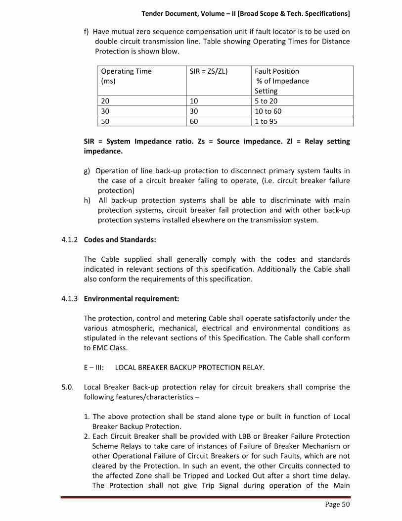
Tender Document, Volume – II [Broad Scope & Tech. Specifications]
Page 50
f) Have mutual zero sequence compensation unit if fault locator is to be used on
double circuit transmission line. Table showing Operating Times for Distance
Protection is shown blow.
Operating Time
(ms)
SIR = ZS/ZL) Fault Position
% of Impedance
Setting
20 10 5 to 20
30 30 10 to 60
50 60 1 to 95
SIR = System Impedance ratio. Zs = Source impedance. Zl = Relay setting
impedance.
g) Operation of line back-up protection to disconnect primary system faults in
the case of a circuit breaker failing to operate, (i.e. circuit breaker failure
protection)
h) All back-up protection systems shall be able to discriminate with main
protection systems, circuit breaker fail protection and with other back-up
protection systems installed elsewhere on the transmission system.
4.1.2 Codes and Standards:
The Cable supplied shall generally comply with the codes and standards
indicated in relevant sections of this specification. Additionally the Cable shall
also conform the requirements of this specification.
4.1.3 Environmental requirement:
The protection, control and metering Cable shall operate satisfactorily under the
various atmospheric, mechanical, electrical and environmental conditions as
stipulated in the relevant sections of this Specification. The Cable shall conform
to EMC Class.
E – III: LOCAL BREAKER BACKUP PROTECTION RELAY.
5.0. Local Breaker Back-up protection relay for circuit breakers shall comprise the
following features/characteristics –
1. The above protection shall be stand alone type or built in function of Local
Breaker Backup Protection.
2. Each Circuit Breaker shall be provided with LBB or Breaker Failure Protection
Scheme Relays to take care of instances of Failure of Breaker Mechanism or
other Operational Failure of Circuit Breakers or for such Faults, which are not
cleared by the Protection. In such an event, the other Circuits connected to
the affected Zone shall be Tripped and Locked Out after a short time delay.
The Protection shall not give Trip Signal during operation of the Main

Tender Document, Volume – II [Broad Scope & Tech. Specifications]
Page 51
Protection Relay of the Circuit concerned. The protection scheme shall be so
designed that if any circuit breaker fails to trip in the event of a fault, then
after a short time delay all the adjacent circuit breakers connected in the same
bus will be tripped. The circuit breaker failure shall also block auto-reclosing
scheme. The scheme shall be complete with timer and auxiliary relays as
necessary including remote end tripping facility. The relay -
a. Shall be of numerical type and shall have continuous self monitoring and
diagnostic feature.
b. Shall have an operating time of less than 15ms
c. Shall have resetting time of less than 15ms.
d. Shall be arranged to get individual initiation from the corresponding phase
of main protections of line.
e. Shall have continuous thermal withstand two times rated current
irrespective of the setting.
f. Shall have a timer with continuously adjustable setting range of 0.1 - 1 sec.
g. Shall have necessary auxiliary relays to make a comprehensive scheme.
h. Be suitable for Station 110 /220 Volt D. C. supply.
5.1. Technical Specifications:
Sl.No. Technical Specification Particular
1. CT Inputs Suitable for CT secondary 1.0 Amp
2. Trip setting 10% -120% for Phase
3. Operating Time : 100ms to 1200ms –in Step of 10ms.
4. Reset Time : 20ms
5. Dropout / Pick-up : Above 90%.
6. CT Burden : Less than 0.2 VA.
7. Auxiliary Burden : Less than 10.0 VA
8 Control Contacts Four set of NO contacts are given;
For Trip & Annunciation (SR Type).
9. Time Accuracy : Within class 2.5 As per IS: 3231.
10. Burden on CTs : Less than 0.2VA
11. Aux. Supply : 110 VD C.
12. Contact Rating Trip Duty : Make and carry for 3sec. –7500VA
with max 30A & 660VAC/DC
Make and carry for continuous -
1250VA with max. 5A & 660VAC/DC
Break AC -1250 VA DC -100 W resistive
50W inductive.
13. Operational Indicators (Flags)
ON : Green LED indicates Relay OK
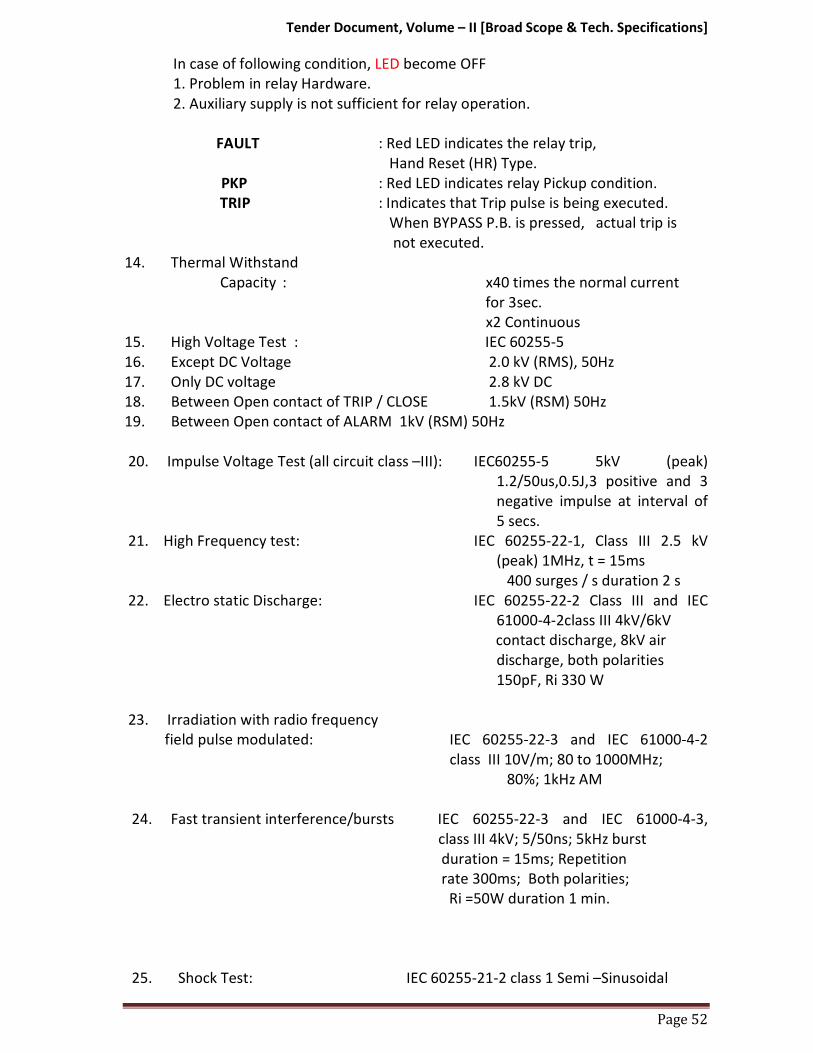
Tender Document, Volume – II [Broad Scope & Tech. Specifications]
Page 52
In case of following condition, LED become OFF
1. Problem in relay Hardware.
2. Auxiliary supply is not sufficient for relay operation.
FAULT : Red LED indicates the relay trip,
Hand Reset (HR) Type.
PKP : Red LED indicates relay Pickup condition.
TRIP : Indicates that Trip pulse is being executed.
When BYPASS P.B. is pressed, actual trip is
not executed.
14. Thermal Withstand
Capacity : x40 times the normal current
for 3sec.
x2 Continuous
15. High Voltage Test : IEC 60255-5
16. Except DC Voltage 2.0 kV (RMS), 50Hz
17. Only DC voltage 2.8 kV DC
18. Between Open contact of TRIP / CLOSE 1.5kV (RSM) 50Hz
19. Between Open contact of ALARM 1kV (RSM) 50Hz
20. Impulse Voltage Test (all circuit class –III): IEC60255-5 5kV (peak)
1.2/50us,0.5J,3 positive and 3
negative impulse at interval of
5 secs.
21. High Frequency test: IEC 60255-22-1, Class III 2.5 kV
(peak) 1MHz, t = 15ms
400 surges / s duration 2 s
22. Electro static Discharge: IEC 60255-22-2 Class III and IEC
61000-4-2class III 4kV/6kV
contact discharge, 8kV air
discharge, both polarities
150pF, Ri 330 W
23. Irradiation with radio frequency
field pulse modulated: IEC 60255-22-3 and IEC 61000-4-2
class III 10V/m; 80 to 1000MHz;
80%; 1kHz AM
24. Fast transient interference/bursts IEC 60255-22-3 and IEC 61000-4-3,
class III 4kV; 5/50ns; 5kHz burst
duration = 15ms; Repetition
rate 300ms; Both polarities;
Ri =50W duration 1 min.
25. Shock Test: IEC 60255-21-2 class 1 Semi –Sinusoidal
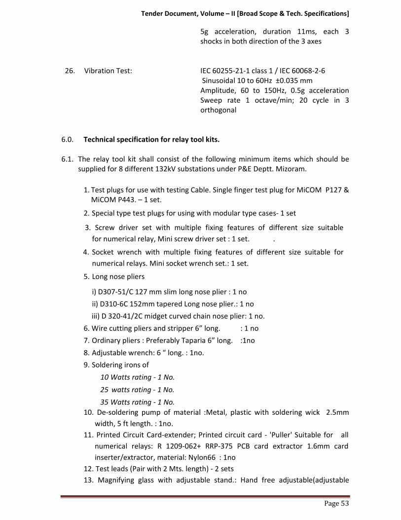
Tender Document, Volume – II [Broad Scope & Tech. Specifications]
Page 53
5g acceleration, duration 11ms, each 3
shocks in both direction of the 3 axes
26. Vibration Test: IEC 60255-21-1 class 1 / IEC 60068-2-6
Sinusoidal 10 to 60Hz ±0.035 mm
Amplitude, 60 to 150Hz, 0.5g acceleration
Sweep rate 1 octave/min; 20 cycle in 3
orthogonal
6.0. Technical specification for relay tool kits.
6.1. The relay tool kit shall consist of the following minimum items which should be
supplied for 8 different 132kV substations under P&E Deptt. Mizoram.
1. Test plugs for use with testing Cable. Single finger test plug for MiCOM P127 &
MiCOM P443. – 1 set.
2. Special type test plugs for using with modular type cases- 1 set
3. Screw driver set with multiple fixing features of different size suitable
for numerical relay, Mini screw driver set : 1 set. .
4. Socket wrench with multiple fixing features of different size suitable for
numerical relays. Mini socket wrench set.: 1 set.
5. Long nose pliers
i) D307-51/C 127 mm slim long nose plier : 1 no
ii) D310-6C 152mm tapered Long nose plier.: 1 no
iii) D 320-41/2C midget curved chain nose plier: 1 no.
6. Wire cutting pliers and stripper 6” long. : 1 no
7. Ordinary pliers : Preferably Taparia 6” long. :1no
8. Adjustable wrench: 6 “ long. : 1no.
9. Soldering irons of
10 Watts rating - 1 No.
25 watts rating - 1 No.
35 Watts rating - 1 No.
10. De-soldering pump of material :Metal, plastic with soldering wick 2.5mm
width, 5 ft length. : 1no.
11. Printed Circuit Card-extender; Printed circuit card - 'Puller' Suitable for all
numerical relays: R 1209-062+ RRP-375 PCB card extractor 1.6mm card
inserter/extractor, material: Nylon66 : 1no
12. Test leads (Pair with 2 Mts. length) - 2 sets
13. Magnifying glass with adjustable stand.: Hand free adjustable(adjustable
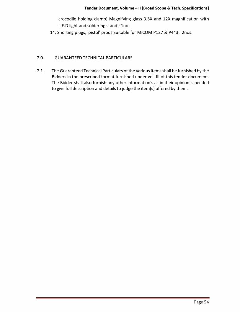
Tender Document, Volume – II [Broad Scope & Tech. Specifications]
Page 54
crocodile holding clamp) Magnifying glass 3.5X and 12X magnification with
L.E.D light and soldering stand.: 1no
14. Shorting plugs, 'pistol' prods Suitable for MiCOM P127 & P443: 2nos.
7.0. GUARANTEED TECHNICAL PARTICULARS
7.1. The Guaranteed Technical Particulars of the various items shall be furnished by the
Bidders in the prescribed format furnished under vol. III of this tender document.
The Bidder shall also furnish any other information's as in their opinion is needed
to give full description and details to judge the item(s) offered by them.

Tender Document, Volume – II [Broad Scope & Tech. Specifications]
F. GPS BASED TIME SYNCHRONIZING EQUIPMENT
1.0. SCOPE:
1.1 The scope of work is design, manufacture, testing, calibration, conducting quality
assurance tests and supply to end user, including installation to purchaser’s
selected sites and commissioning at the satisfaction of Engineer-in-charge.
2.0. SALIENT FEATURES/STANDARD/SPECIFICATION:
2.1. Technical Specifications of bidders shall conform mandatory obligations of
National/International standard which pave way for healthy operation of Time
synchronizing Cable. The following operation has to be ensured by the standard:
i) The Time s h a l l receive the co-coordinated Universal Time (UTC)
transmitted through Geo Positioning Satellite System (GPS) and
synchronize Cables to the Indian Standard Time in a substation.
ii) Time synchronization equipment shall include antenna, all special
cables and processing Cable etc.
iii) It shall be compatible for synchronization of Event Loggers,
Disturbance recorders and SCADA at a substation through individual
port or through Ethernet realized through optic fiber bus.
iv) The synchronization equipment shall have 2 micro second accuracy.
Cable shall give real time corresponding to IST (taking into consideration
all factors like voltage & temperature variations, propagation &
processing delays etc).
v) The equipment shall meet the requirement of IEC 60255 for storage &
operation.
vi) The system shall be able to track the satellites to ensure no
interruption of Synchronization signal.
vii) The output signal from each port shall be programmable at site for either one hour, half hour, minute or second pulse, as per requirement.
viii) The Cable offered shall have six (6) output ports. Various
combinations of output ports shall be selected by the customer, during
detailed engineering, from the following:
Voltage signal: Normally 0-5V with 50milli Seconds minimum pulse duration. In case any other voltage signal required, it shall be decided during detailed engineering.
Potential free contact (Minimum pulse duration of 50 milli Seconds.)

Tender Document, Volume – II [Broad Scope & Tech. Specifications]
IRIG-B
RS 232C
ix) The equipment shall have a periodic time correction facility of
one second periodicity.
x) Time synchronization equipment shall be suitable to operate from 1 1 0
V DC as available at Substation.
xi) Equipment shall have real time digital display in hour, minute, second
(24 hour mode) & have a separate time display unit to be mounted on
the top of control panels having display size of approx. 100 mm height.
3.0. GUARANTEED TECHNICAL PARTICULARS
The Guaranteed Technical Particulars of the various items shall be furnished by the
Bidders in the prescribed format furnished under vol. III of this tender document.
The Bidder shall also furnish any other information's as in their opinion is needed
to give full description and details to judge the item(s) offered by them.
Tender Document, Volume – II [Broad Scope & Tech. Specifications]
Page 57
G. CONTROL CABLES 1.0 SCOPE 1.1. The scope of work is furnished below:
a) Design, manufacture, testing at manufacturer’s works and supply of 1.1 KV
grade PVC insulated Control Cables with stranded Copper conductors
including laying at site.
b) Loading at manufacturer’s works, transportation and delivery at
respective substation sites, including unloading at destination sites.
1.2. It is also responsibility of the Contractor to obtain any road permits and
any other permits or licenses as may be required to execute the works.
2.0 TYPE TEST REPORTS
2.1. Cable, which has never been tested for critical performance, shall not be
accepted. In such cases, a promise or agreement by a bidder to have the Cable
tested after award of a contract is not acceptable.
2.2. All Bids must be accompanied by the full Type Test Certificates of Cable offered. Such type test certificates shall be acceptable only if: -
(a) Tests are conducted in an independent and well known testing
laboratory, or
(b) Tests are conducted in manufacturer’s own laboratory. In this case
(i) the laboratory must have ISO 9000 (or its equivalent) series
certification; and (ii) tests have been witnessed by technically qualified
representatives of earlier clients or purchaser.
2.3. Test reports to be acceptable must be related directly to the materials offered.
Test reports for higher class of items are acceptable with commitment to
perform the type tests free of any charge on the particular items after the
award of contract.
2.4. Type Test Reports older than five (5) years on the date of Technical bid
opening shall not be accepted.
3.0 GUARANTEED TECHNICAL PARTICULARS
3.1. The Guaranteed Technical Particulars of the Cable shall be furnished by the
Bidders in the prescribed format furnished in Volume III of this Tender
Document. The Bidder shall also furnish any other information's as in their
opinion is needed to give full description and details to judge the item(s)
offered by them.
3.2. The data furnished in Guaranteed Technical Particulars should be the minimum
or maximum value (as per the requirement of the specification) required. A
Bidder may guarantee a value more stringent than the specification
requirement. However, for testing purpose or from performance point of view,
the material shall be considered performed successfully if it achieves the

Tender Document, Volume – II [Broad Scope & Tech. Specifications]
Page 58
minimum/maximum value required as per the technical specification. No
preference what so ever shall be given to the bidder offering better/more
stringent values than those required as per specification except where stated
otherwise.
4.0. TECHNICAL SPECIFICATION OF CONTROL CABLES
4.1. General
4.1.1. For all control/protection/instrumentation purposes PVC insulated armoured control cables of minimum 2.5 sq. mm Size with stranded Copper conductors shall be used.
4.1.2. All cables shall be suitable for laying in racks, ducts, trenches, conduits and
underground buried installation with uncontrolled back fill and chances of
flooding by water.
4.1.3. The fillers and inner sheath shall be of non-hygroscopic, fire
retardantmaterial, shall be softer than insulation and outer sheath shall be
suitable for the operating temperature of the cable.
4.1.4. Progressive sequential marking of the length of cable in metres at every
one metre shall be provided on the outer sheath of all cables.
4.1.5. Strip wire armouring method shall not be accepted for any of the cables. For
control, cables only round wire armouring shall be used.
4.1.6. The cables shall have outer sheath of a material with an oxygen index of not
less than 29 and a temperature index of not less than 250°C.
4.1.7. All the cables shall pass fire resistance test as per IS:1554 (Part-I).
4.1.8. The normal current rating of all PVC insulated cables shall be as per IS:3961.
5.0 PVC Insulated Control Cables:
5.1. The PVC (70°C) insulated control cables shall be of FR type C1 category
conforming to IS: 1554 (Part-1) and its amendments, read along with this
specification. The conductor shall be stranded copper. The insulation shall be
extruded PVC to type A of IS: 5831. A distinct inner sheath shall be provided
in all cables whether armoured or not. The over sheath shall be extruded
PVC to type ST-1 of IS: 5831 and shall be grey in colour.
5..2. Cores shall be identified as per IS: 1554 (Part-1) for the cables up to five (5)
cores and for cables with more than five (5) cores the identification of cores
shall be done by printing legible Hindu Arabic Numerals on all cores as per
clause 10.3 of IS 1554 (Part-1).
6.0. Cable Drums:
6.1. Cables shall be supplied in non-returnable wooden or steel drums of heavy
construction. Wooden drum shall be properly seasoned sound and free
from defects. Wood preservative shall be applied to the entire drum.
Drums offered shall conform to relevant standards.

Tender Document, Volume – II [Broad Scope & Tech. Specifications]
Page 59
6.2. A layer of water proof paper shall be applied to the surface of the drums and
over the outer most cable layer.
6.3. A clear space of at least 40 mm shall be left between the cables and the lagging.
6.4. Each drum shall carry the manufacturer's name, the purchaser's name, address
and contract number and type, size and length of the cable, net and gross
weight stencilled on both sides of drum. A tag containing the same information
shall be attached to the leading end of the cable. An arrow and suitable
accompanying wording shall be marked on one end of the reel indicating the
direction in which it should be rolled.
6.5. Packing shall be sturdy and adequate to protect the cables, from any injury due
to mishandling or other conditions encountered during transportation,
handling and storage. Both cable ends shall be sealed with PVC/Rubber caps so
as to eliminate ingress of water during transportation and erection.
7.0. DATA SHEET FOR CONTROL CABLES
Sl. No. Description Particulars
1 Applicable Standard IS: 1554/PT-I & its referred standards 2 Type Designation YWY 3 Rated Voltage(volts) 1100 4 Type & Category FR & C1
5 Suitable for earthed or unearthed system
Suitable for both
6
Conductor
a) Material Plain annealed High Conductivity
Stranded Copper (as per IS 8130)
b) Grade Electrolytic c) Number of wires(No.) As per IS 8130 d) Form of Conductor Non-compacted Stranded circular
e) Direction of lay of stranded layers
Outermost layer shall be R.H lay
7 Insulation
a) Composition of insulation Extruded PVC type A as per IS-5831 b) Thickness of insulation(mm) As per applicable Standard
8 Inner Sheath material Extruded PVC type ST-1 as per IS-5831 9 Type and material of armour Gal. Steel wire
10 Outer Sheath (PVC) ST-1 & FR 11 Overall diameter of cable As per applicable Standard
12 No. of Cores As per Bill of Materials
7.1. Tests
Control cables shall be tested for routine and acceptance tests as per the
relevant IS/IEC standards.

Tender Document, Volume – II [Broad Scope & Tech. Specifications]
Page 60

Tender Document, Volume – II [Broad Scope & Tech. Specifications]
Page 61
H. NITROGEN INJECTION SYSTEM
1.0 SCOPE OF WORK:
1.1. The scope of work covers design, supply, erection and commissioning of Nitrogen
Injection system for protection against the transformer explosion for those power
transformers of 132KV sub-stations indicated in Vol. I sec.6 of this tender
document, including all required civil works of oil sump, foundations, and any
other required for satisfactory working of system. Each oil filled transformer shall
be provided with a dedicated Nitrogen Injection system for prevention against the
transformer explosion which shall use nitrogen as quenching medium. The system
shall prevent transformer oil tank explosion and possible fire in case of internal /
external cause. In the event of fire by external causes such as bushing fire, OLTC
fires, fire from surrounding Cable etc., it shall act as a fast and effective fire fighter.
It shall accomplish its role as fire preventer and extinguisher without employing
water or carbon dioxide. Fire shall be extinguished within reasonable time (not
more than 3 minutes so as not to harm the transformer) of system activation and
within 30 seconds (maximum) of commencement of nitrogen injection. The list of
past supplies in India / Abroad along with performance certificate from users of
the system shall be submitted for approval of purchaser.
2.0 ACTIVATION OF THE SYSTEM
2.1. Mal-functioning of the Nitrogen injection system could lead to interruption in
power supply. The supplier shall ensure that the probabilities of chances of
malfunctioning of the Nitrogen injection system are practically zero. To achieve
this objective, the supplier shall plan out scheme of activating signals which should
not be too complicated to make the system in operative in case of actual need.
The system shall be provided with automatic controls to prevent the explosion of
transformers. Besides automatic control, remote electrical push button control at
Control box and local manual control in the cubicle shall also be provided. The
following electrical-signals shall be used for activating the system under
prevention mode/fire extinguishing mode.
2.2. AUTO MODE
2.2.1 For prevention:
i) Differential relay operation.
ii) Buchholz relay paralleled with pressure relief valve or RPRR (Rapid Pressure
Rise Relay)
iii) Tripping of all circuit breakers (on HV & LV side) associated transformer is
the pre-requisite for activation of system.

Tender Document, Volume – II [Broad Scope & Tech. Specifications]
Page 62
2.2.2. For extinguishing:
i) Fire Detector
ii) Buchholz relay paralleled with pressure relief valve or RPRR (Rapid Pressure
Rise Relay).
iii) Tripping of all circuit breakers (on HV & LV side) associated with transformer is
the pre-requisite for activation of system.
2.2.3 Manual Mode (Local / Remote):
Tripping of all circuit breakers (on HV & LV side) associated with transformer is the
pre-requisite for activation of system.
2.2.4 Manual Mode (Mechanical):
i) Tripping of all circuit breakers (on HV & LV side) associated with transformer is
the pre-requisite for activation of system.
ii) The system shall be designed to be operated manually in case of failure of power
supply to the system.
3.0 GENERAL DESCRIPTION
Nitrogen Injection system should be a dedicated system for each oil filled
transformer. It should have a Fire Extinguishing Cubicle (FEC) placed on a plinth at
a distance of 5-10 m away from transformer or placed next to the firewall (if fire
fighting wall exists). The FEC shall be connected to the top of transformer oil tank
for depressurization of tank and to the oil pit (capacity is approximately equal to
10% of total volume of oil in transformer tank) through oil pipes. The FEC should
house a pressurized nitrogen cylinder (s) which is connected to the oil tank of
transformer. The Transformer Conservator Isolation Valve (TCIV) is fitted between
the conservator tank and Buchholz relay. Cable connections are to be provided
from signal box to the control box in the control room, from control box to FEC
and from TCIV to signal box. Detectors placed on the top of transformer tank are
to be connected in parallel to the signal box by Fire survival cables. Control box is
also to be connected to relay panel in control room for receiving system activation
signals.
3.1 Operation:
On receipt of all activating signals, the system shall drain – predetermined volume
of hot oil from the top of tank (i.e. top oil layer), through outlet valve, to reduce
tank pressure by removing top oil to the oil pit and simultaneously injecting
nitrogen gas at high pressure for stirring the oil at pre-fixed rate and thus bringing
the temperature of top oil layer down. Transformer conservator isolation valve

Tender Document, Volume – II [Broad Scope & Tech. Specifications]
Page 63
blocks the flow of oil from conservator tank in case of tank rupture / explosion or
bushing bursting. Nitrogen occupies the space created by oil drained out and acts
as an insulating layer over oil in the tank and thus preventing aggravation of fire.
3.2 System components:
Nitrogen Injection system shall broadly consist of the following components.
However, all other components which are necessary for fast reliable and effective
working of the system shall deemed to be included in the scope of supply.
3.3 Cubicle (FEC):
3.3.1 The Cubicle Frame shall be made of CRCA sheet of 3 mm (minimum) thick
complete with the base frame, painted inside and outside with post office red
colour (shade 538 of IS -5). It shall have hugged / hinged split doors fitted with
high quality tamper proof lock. The doors, removable covers and panels shall be
gasketted all round with neoprene gaskets. The degree of protection shall be IP55.
The following items shall be provided in the Cubicle.
i) Nitrogen gas cylinder with regulator and falling pressure electrical contact
manometer.
ii) Electro mechanical control Cable for draining of oil of predetermined volume
and injecting regulated volume of nitrogen gas.
iii) Pressure monitoring switch for back-up protection for nitrogen release.
iv) Limit switches for monitoring of the system.
v) Butterfly valve with flanges on the top of panel for connecting oil drain pipe
and nitrogen injection pipes for transformer / reactors.
vi) Panel lighting (LED Type)
vii) Oil drain pipe extension of suitable sizes for connecting pipes to oil pit.
viii) Space heater.
3.4. Control box:
3.4.1 Control box is to be placed in the control room for monitoring system operation,
automatic control and remote operation. The following alarms, indications,
switches, push buttons, audio signal etc. shall be provided.
i) System Oil.
ii) TCIV open.
iii) Oil drain valve closed.
iv) Gas inlet valve closed
v) TCIV closed
vi) Detector trip
vii) Buchholz relay trip

Tender Document, Volume – II [Broad Scope & Tech. Specifications]
Page 64
viii) Oil drain valve open
ix) Extinction in progress
x) Differential relay trip
xi) PRV / RPRR trip
xii) Transformer / reactor trip
xiii) System out of service
xiv) Fault in cable connecting fault detector
xv) Fault in cable connecting differential relay
xvi) Fault in cable connecting Buchholz relay
xvii) Fault in cable connecting PRV / RPRR
xviii) Fault in cable connecting transformer trip
xix) Fault in cable connecting TCIV
xx) Auto / Manual / Off
xxi) Extinction release on / off
xxii) Lamp test
xxiii) Visual / Audio alarm for AC supply fail
xxiv) Visual / Audio alarm for DC supply fail
3.4.2. As far as possible the control box should be such devised that all the transformers
or group thereof should be controlled from single spot.
3.5 Transformer Conservator Isolation Valve:
Transformer conservator isolation valve (TCIV) to be fitted in the conservator pipe
line, between conservator and buchholz relay which shall operate for isolating the
conservator during abnormal flow of oil due to rupture / explosion of tank or
bursting of bushing. The valve shall not isolate conservator during normal flow of
oil during filtration or filling or refilling, locking plates to be provided with handle
for pad locking. It shall have proximity switch for remote alarm indication with
visual position indicator. The TCIV should be of the best quality as malfunctioning
of TCIV could lead to serious consequence. The closing of TCIV means stoppage of
breathing of transformer. Locking plates shall be provided for pad locking.
3.6 Detectors:
The system shall be completing with adequate number of detectors (quartz bulb)
fitted on the top cover of the transformer oil tank.
3.7 Signal box:
It shall be mounted away from transformer main tank, preferably near the
transformer marshalling box, for terminating cable connections from TCIV &

Tender Document, Volume – II [Broad Scope & Tech. Specifications]
Page 65
detectors and for further connection to be control box. The degree of protection
shall be IP55.
3.8 Cables:
3.8.1 Fire survival cables (capable to withstand 750º C.) of 4 core x 1.5 sq. mm size for
connection of detectors in parallel shall be used. The fire survival cable shall
conform to BS 7629-1, BS 8434-1, BS 7629-1 and BS 5839-1, BS EN 50267-2-1 or
relevant Indian standards. 3.8.2 Fire Retardant Low Smoke (FRLS) cable of
adequate size shall be used for connection of signal box / marshalling box near
transformer and FEC mounted near transformer with control box mounted in
control room. Fire Retardant Low Smoke (FRLS) cable of 4 core x 1.5 sq. mm size
shall be used for connection between control box to DC & AC supply source, FEC
to AC supply source, signal box / marshalling box to transformer conservator
isolation valve connection on transformer. Separate cables for AC supply & DC
supply shall be used.
3.9 Pipes:
Pipes complete with connections, flanges, bends and tees etc. shall be supplied
along with the system.
3.10 Construction of oil drain soak pit with capacity to store at least 1000ltrs of oil shall
be included in the said scheme .This oil drain pit should be connected with oil
drain pipe from the power transformer. An arrangement may be made so that the
drained oil may be able to pump back to the oil filtering units or to empty
container/barrels and for which, all connected pipes, joints and flanges etc with
centrifugal pump of required rating shall be fitted and fixed.
4.0 OTHER ITEMS TO BE SUPPLIED
(a) Oil drain and nitrogen injection openings with gate valves on transformer tank
at suitable locations.
(b) Flanges between Buchholz relay and conservator tank for fixing TCIV.
(c) Detector brackets on transformer / reactor tank top cover.
(d) Spare potential free contacts activating the system i.e. in differential relay,
Bucholz relay, Pressure Relief Device / RPRR, Circuit breaker of transformer.
(e) Pipe connections between transformer and FEC and between FEC and oil pit
required for collecting top oil.
(f) Cabling for detectors mounted on transformer top cover.
(g) Inter cabling between signal box, control box and FEC.
(h) Butterfly valves / Gate valves on oil drain pipe and nitrogen injection pipe
which should be able to withstand full vacuum.
(i) Supports, signal box etc. which are to be painted with enameled paint.
(j) Any other item required for satisfactory operation of system.

Tender Document, Volume – II [Broad Scope & Tech. Specifications]
Page 66
5.0 POWER SUPPLY
For Control Box 110 V DC; For FEC Auxiliary 230 V AC
6.0 SPARES FOR THREE (3) YEARS OPERATION & MAINTENANCE
The bidder apart from the below mentioned spares shall submit a list of
recommendation spares for three years trouble free operation of the equipment
and also furnish unit rates. The owners will scrutinize the said list and decide on
the items on spares to be ordered and the quantities. These spares shall be
supplied by the contractor before end of guarantee period. The owner reserves
right to order the spares with six (6) months from the date of order for main
equipment and the rate shall be kept valid till this date. The prices of these spares
shall not be considered for evaluation of the bid.
7.0 MANDATORY SPARES
i) Cylinder filled with Nitrogen of required Capacity per substation. - 1 No.
ii) Detectors per transformer - 3 Nos.
iii) Regulator assembly per sub-station - 1 No.
8.0 MODIFICATION ON THE TRANSFORMER
a) Oil drain opening with pipe flange and manual gate valve at about 120mm
below the top cover.
b) Nitrogen injection openings with suitable size of pipe with flange and manual
gate valve on tank sides at about 50-200mm from the bottom plate.
c) Flanges on conservator pipe between buchholz relay and conservator tank for
fixing PNRV/POBV.
d) Provision for temperature and pressure sensors if required.
e) Supply and welding of fire detector bracket on top cover.
f) Supply and welding of brackets for fixing signal box at a suitable location on top
cover or tank side wall.
Bidder shall confirm adequacy of the above arrangements on transformer. Any
other requirement shall be brought out clearly in the bid itself. Bidder shall also
clearly indicate the sizes of various openings and valves mentioned above. No
modification on the transformer shall be allowed which affects its performance
(i.e. efficiency, losses, heat dissipation ability etc.) safety, life etc. or it’s any other
useful parameter. This requirement shall be paramount importance and shall form
the essence of the contract. However, in any case, performance of transformer
should not be affected in any manner by having Nitrogen Injection Fire Prevention
Cum Extinguishing System (NIFPES) and the Contractor / Sub- Contractor shall give

Tender Document, Volume – II [Broad Scope & Tech. Specifications]
Page 67
an undertaking to this effect. All pipes should be washed / rinsed with transformer
oil. If any damage is done to the transformer and / or any connected Cable during
installation & commissioning full recovery therefore shall be affected from the
Contractor / Sub-Contractor, of NIFPES system. It shall be solely the responsibility
of Contractor / Sub-Contractor to install, carry out pre-commissioning tests &
commission NIFPES at the mentioned Sub-Station in this specification, to the
entire satisfaction of the P&E Deptt. Mizoram.
9.0 INTERLOCKS
It shall be ensured that once the NIFPES gets activated manually or in auto mode,
all the connected breakers shall not close until the system is actually put in OFF
mode. Also PRV shall get closed only if all the connected breakers are open.
10.0 TESTS
10.1 Contractor has to carry out the type test as per relevant IS/IEC. Specifically IP 55
on FEC or have to produce the report from NABL approved Lab. Reports of all
routine test conducted as per relevant IS/IEC standards in respect of various
bought out items including test reports for degree of protection for FEC / control
box / signal box shall be submitted by the supplier.
10.2 The supplier shall demonstrate all the functional test associated with the
following as Factory Acceptance Tests:
• FEC, Control Box
• Fire Detector
• Transformer Conservator Isolation Valve
10.3 The performance test of the complete system shall be carried out after erection
of the system with transformer at site.
11.0. GUARANTEED TECHNICAL PARTICULARS
11.1. The Guaranteed Technical Particulars of the various items shall be furnished by the
Bidders in the prescribed format furnished under vol. III of this tender document.
The Bidder shall also furnish any other information's as in their opinion is needed to
give full description and details to judge the item(s) offered by them.

Tender Document, Volume – II [Broad Scope & Tech. Specifications]
Page 68