e- tender document for - DFCCIL
157
DFCCIL/EL/ TDL/Bhaupur UP link line/T-005 Signature of tendrer Page 1 E- TENDER DOCUMENT FOR Design, Supply, Erection, Testing and Commissioning of 25 kV, AC, 50 HZ, OHE in Connection with Construction of Bhaupur UP link line and Bhaupur Yard Modification under CGM/DFCCIL/Tundla. DEDICATED FREIGHT CORRIDOR CORPORATION OF INDIA LIMITED (A Government of India Undertaking) MINISTRY OF RAILWAY CGM/TDL/DFCCIL OFFICE 3/20, KPS Tower, Mayur Complex, 3rd Floor, Near Tulsi Cinema, NH-02, Nagla Padi, Agra-282002
-
Upload
khangminh22 -
Category
Documents
-
view
0 -
download
0
Transcript of e- tender document for - DFCCIL
DFCCIL/EL/ TDL/Bhaupur UP link line/T-005
Signature of tendrer Page 1
E- TENDER DOCUMENT
FOR
Design, Supply, Erection, Testing and Commissioning of 25 kV, AC,
50 HZ, OHE in Connection with Construction of Bhaupur UP link line
and Bhaupur Yard Modification under CGM/DFCCIL/Tundla.
DEDICATED FREIGHT CORRIDOR
CORPORATION OF INDIA LIMITED
(A Government of India Undertaking)
MINISTRY OF RAILWAY
CGM/TDL/DFCCIL OFFICE 3/20, KPS Tower, Mayur Complex, 3rd Floor,
Near Tulsi Cinema, NH-02, Nagla Padi, Agra-282002

DFCCIL/EL/ TDL/Bhaupur UP link line/T-005
Signature of tendrer Page 2
INDEX
S.N. ITEM PAGE NO.
1 TOP SHEET 3
2 TENDER FORM 4
3 NOTICE INVITING E-TENDER 5-7
4 ELIGIBILTY CRITERIA 8-10
5 INSTRUCTIONS TO TENDERER AND CONDITIONS OF
TENDERING
11-18
6 SPECIAL CONDITION OF CONTRACT 19-31
7 GENERAL CONDITION OF CONTRACT 32
8 ANNEXURES 33-34
9 PRICES AND PAYMENT 35-45
10 SCOPE OF WORK & EXPLANATORY NOTES 46-56
11 OVERHEAD EQUIPMENT 57-63
12 FOUNDATION 64-66
13 STRUCTURES AND STEEL WORK 67-69
14 EQUIPMENT, COMPONENTS AND MATERIALS 70-76
15 DESIGNS & DRAWINGS 77-82
16 ERECTION AND INSTALLATION OF EQUIPMENT 83-87
17 INSPECTION AND TESTING 88-89
18 WRING PROCEDURE 90-93
19 SPECIFICATION OF IMPORTED ITEMS 94-130
20 CERTIFICATION OF FAMILIARISATION 131
21 ANNEXURE 132-138
22 FROM OF AGREEMENT 139-146
FINANCIAL OFFER
1 SCHEDULE OF RATES 147-156
2 OFFER TO BE FILLED BY TENDERER(S) IN OFFER SHEET 157
Total Pages:157 (One Hundred fifty Seven)

DFCCIL/EL/ TDL/Bhaupur UP link line/T-005
Signature of tendrer Page 3
TOP SHEET
Tender No. DFCCIL/EL/TDL/Bhaupur up link line/T-005 Date 06.02.2021
Name of work: Design, Supply, Erection, Testing and Commissioning of 25 kV
AC, 50 HZ, OHE in Connection with Construction of Bhaupur
UP link line and Bhaupur Yard Modification under
CGM/DFCCIL/Tundla.
Estimated Cost of work: Rs:3,89,98,400=20 ( Rs Three Crore Eighty Nine Lakh Ninety
Eight Thousand Four Hundred & Twenty paisa only.)
Earnest Money Deposit/ Bid Security: Bid Security Declaration
Completion Period: Total 06 (Six) Months from the date of issue of letter of acceptance.
Date of Opening:
08.03.2021 at 15:30 hrs
For and on behalf of
CGM/TDL. DFCCIL Office.

DFCCIL/EL/ TDL/Bhaupur UP link line/T-005
Signature of tendrer Page 4
____________ DFCCIL
TENDER FORM
Place:…………..
Date: ……………..
Tender No. ………………
Name of Work ………………………………….
Chief General Manager ,
Dedicated Freight Corridor Corporation of India Limited,
3/20,KPS Tower, Mayur Complex,, 3rd Floor,
Near Tulsi cinema, NH-02, Nagla Padi,
Agra-282002, U.P.
I / We ………………………………………………………………………… have read the
various conditions of tender attached hereto and agree to abide by the said conditions. I / We also
agree to keep this tender open for your acceptance for a period of 45 days from the date fixed for
opening the same and in default thereof, I/We will be liable for forfeiture of my/our “Earnest
Money”. I / We offer to do the work for “Design, Supply, Erection, Testing and
Commissioning of 25 kV, AC, 50 HZ, OHE in Connection with Construction of Bhaupur
UP link line and Bhaupur Yard Modification under CGM/DFCCIL/Tundla”, at the rates
quoted in attached schedule and hereby bind myself/ourselves to complete the work in all
respects within 06 (Six) months from the date of issue of letter of acceptance of the tender.
2. I / We also hereby agree to abide by the all the DFCCIL/Indian Railway Standard General
Conditions of Contract, with all correction slip up to date and to carry out the work according to
the Special Conditions of Contract and Specifications of materials and works as laid down by
DFCCIL/Railway in the annexed Special Conditions/Specifications, Schedule of Rates with all
correction slip up-to-date for the present contract.
3. A sum of Rs. ……………………has already been deposited online as Earnest Money. Full value
of the Earnest Money shall stand forfeited without prejudice to any other rights or remedies in case
my/our Tender is accepted and if:
a) I / We do not execute the contract document within Seven days after receipt of notice issued by
DFCCIL that such documents are ready; and
b) I / We do not commence the work within fifteen days after receipt of orders to that effect.
4. Until a formal agreement is prepared and executed, acceptance of this tender shall constitute a
binding contract between us subject to modifications, as may be mutually agreed to between us and
indicated in the letter of acceptance of my/our offer for this work.
Signature of Witness : Signature of Tenderer(s)
(1)…………………… Date………………..
(2)……………………. Address…………………..
DFCCIL/EL/ TDL/Bhaupur UP link line/T-005
Signature of tendrer Page 5
Dedicated Freight Corridor Corporation of India Limited
(A Government of India Undertaking) MINISTRY OF DFCCIL
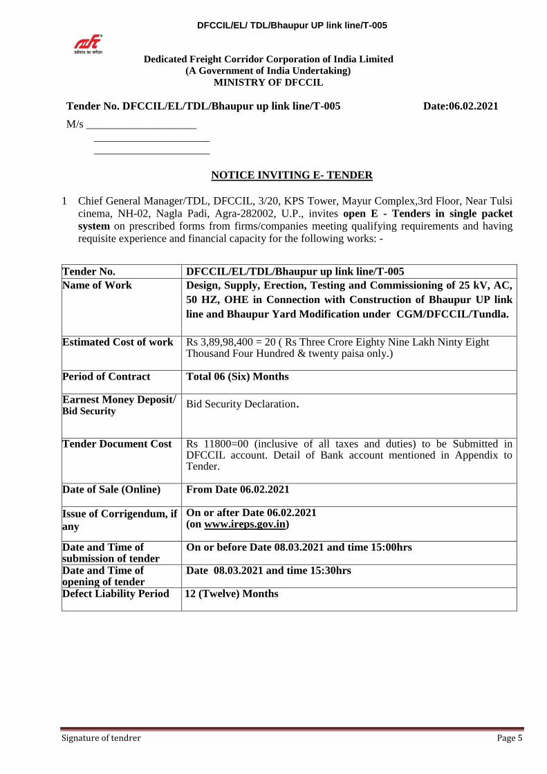
Tender No. DFCCIL/EL/TDL/Bhaupur up link line/T-005 Date:06.02.2021 M/s ____________________
_____________________
_____________________
NOTICE INVITING E- TENDER
1 Chief General Manager/TDL, DFCCIL, 3/20, KPS Tower, Mayur Complex,3rd Floor, Near Tulsi
cinema, NH-02, Nagla Padi, Agra-282002, U.P., invites open E - Tenders in single packet
system on prescribed forms from firms/companies meeting qualifying requirements and having requisite experience and financial capacity for the following works: -
Tender No. DFCCIL/EL/TDL/Bhaupur up link line/T-005
Name of Work Design, Supply, Erection, Testing and Commissioning of 25 kV, AC,
50 HZ, OHE in Connection with Construction of Bhaupur UP link
line and Bhaupur Yard Modification under CGM/DFCCIL/Tundla.
Estimated Cost of work Rs 3,89,98,400 = 20 ( Rs Three Crore Eighty Nine Lakh Ninty Eight Thousand Four Hundred & twenty paisa only.)
Period of Contract Total 06 (Six) Months
Earnest Money Deposit/ Bid Security
Bid Security Declaration.
Tender Document Cost Rs 11800=00 (inclusive of all taxes and duties) to be Submitted in DFCCIL account. Detail of Bank account mentioned in Appendix to Tender.
Date of Sale (Online) From Date 06.02.2021
Issue of Corrigendum, if
any
On or after Date 06.02.2021 (on www.ireps.gov.in)
Date and Time of submission of tender
On or before Date 08.03.2021 and time 15:00hrs
Date and Time of opening of tender
Date 08.03.2021 and time 15:30hrs
Defect Liability Period 12 (Twelve) Months

DFCCIL/EL/ TDL/Bhaupur UP link line/T-005
Signature of tendrer Page 6
2 ELIGIBILITY CRITERIA
Eligibility of the applicants shall be assessed based on the “Eligibility Criteria”,
“Essential Qualifying Criteria” and “Other Qualifying Criteria” as given in Notice
Inviting E-Tender.
The Tender document can be downloaded from IREPS website www.ireps.gov.in and
DFCCIL’s website www.dfccil.com.Tenderers are advised not to make any corrections,
additions or alterations in the downloaded tender documents. In case, any corrections, additions or alterations in the downloaded tender documents are made, such tender shall summarily rejected.
3. The cost of tender documents and EMD shall be deposited in DFCCIL account on IREPS
portal.
4. DFCCIL may issue addendum(s)/corrigendum(s) to the tender documents. In such case, the addendum(s)/corrigendum(s) shall be issued and placed on IREPS website. The
tenderers who have downloaded the tender documents from website must visit the
website and ensure that such addendum(s)/corrigendum(s) (if any) is also downloaded by them. Such addendum(s)/corrigendum(s) (if any) shall also be submitted, duly stamped
and signed, along with the submission of the tenders.
5. The tender documents shall be submitted in online mode through website
www.ireps.gov.in in single bids only. Single offer viz. containing Technical offer and
financial offer along with necessary documents like scanned copy of EMD and scanned
copy of TDC to be uploaded. Detailed credentials as per the requirement of eligibility
criteria in “Technical offer” as well as “Financial offer” to be submitted through IREPS
portal. Bids are required to be submitted only by online mode and uploaded on the
e-tendering web site using Digital Signature for signing the documents. 6. Tenders shall be opened at the address given below at 15:30 hours on the same day in
the presence of the tenderer(s) or their authorized representatives intending to attend the opening.
Address of Office of the Chief General Manager/ TDL (for Opening of E-
tenders):
Chief General Manager/TDL, DFCCIL, 3/20, KPS Tower, Mayur Complex,
3rd Floor, Near Tulsi cinema, NH-02, Nagla Padi, Agra-282005, U.P. All the Bids received shall be opened on the date and time mentioned above in the tender notice, through process of e-tendering. The sequence of opening shall be:
i) Earnest Money Deposit(EMD)/ Bid Security Declaration
ii) Technical offer.
iii) Financial offer.
7. Tender shall be submitted as per “Instructions to Tenderers” as followed on IREPS portal.
8. Any tender received without Earnest Money Deposit / Bid Security Declaration in the form as
specified in tender documents shall not be considered and shall be summarily rejected. 9. DFCCIL reserves the right to cancel the tenders before submission/opening of tenders,
postpone the tender submission/opening date and to accept / reject any or all tenders without assigning any reasons thereof. DFCCIL’s assessment of suitability as per eligibility criteria shall be final and binding.
DFCCIL/EL/ TDL/Bhaupur UP link line/T-005
Signature of tendrer Page 7
10. Tenderers may note that they are liable to be disqualified at any time during tendering
process in case any of the information furnished by them is not found to be true. The decision of DFCCIL in this regard shall be final and binding.
11. DFCCIL reserves the right to pre-qualify the bidder(s) provisionally based on the
documents submitted by them and open financial bid(s), subject to their final verification. In the event of any document being found false, the provisional qualification shall stand withdrawn, and the next lower bidder shall automatically come to the position of such disqualified bidder. Action against such disqualified tenderers shall be taken as per above Clause No. 10.0 of Notice Inviting Tender.
12. The validity of the offer shall be 45 days. 13. The transfer of tender documents purchased by one intending tenderer to another tenderer is
not admissible. Tenderer can submit tenders only on the documents purchased/downloaded from website mentioned above.
We look forward for your active participation.
For and on behalf of DFCCIL
Chief GeneralManager/TDL

DFCCIL/EL/ TDL/Bhaupur UP link line/T-005
Signature of tendrer Page 8
1.0 ELIGIBILTY CRITERIA
The tenderer shall satisfy the following eligibility criteria to qualify for this tender:
I. Essential Qualifying Criteria
A. Firms/companies
(i) The tenderer should have a registered office anywhere in India.
The documentary proof regarding A. above should be submitted as part of the tender
document.
Note: For the purpose of documentary proof of “registered office” asmentioned in (i)
above any address of office as mentioned in any of the following documents submitted
along with the original offer by tenderer(s) may be considered as registered office of the
tenderer(s).
1. Address mentioned in the article of association of company duly registered under
Companies Act, 1956.
2. Address mentioned in Partnership Deed
3. Address mentioned in Trade License obtained by the individual from Govt. body.
4. Address mentioned in any tax departments.
5. Address mentioned in P.F. Registration documents.
B. Technical capability:
1. In support of their credentials, the Tenderer(s) should have to submit documents as
stipulated in tender document along with their tenders.
2. The tenderer(s) should satisfy the following minimum eligibility criteria as under
S.N. Technical capability Requirement 1 The Tenderer(s) should have
physically completed at the time
of opening of tender in the last
Three financial years (i.e current
year and three previous financial
years).
At least one similar single work in Government Organization/ Public sector undertaking (PSU)/ Autonomous body/Public Limited Company/ Private Limited Company for a minimum value of 35% of advertised tender value of work. The work should be physically completed on or before the date of opening of tender.
The Tenderer(s) will produce/attach the certificate of Work completion with the Tender Document as per above and such certificate should clearly supported by following details: -
a) Name of Agency issuing a certificate. b) Date of issue of certificate. c) The name of Work. d) The Acceptance letter no. e) The date of issue of Acceptance letter. f) Agreement no. g) Date of execution of Agreement. h) Date of original Completion of Work as per Acceptance Letter.

DFCCIL/EL/ TDL/Bhaupur UP link line/T-005
Signature of tendrer Page 9
i) Date of Actual completion of Work. j) The Amount of Work done as per Agreement (in Rupees).
k) The Final Amount of Work at the time of Completion of Work (in
Rupees). l) Whether the Work is completed satisfactory or not satisfactory.
Note:
Following will be considered as Similar Work:
“Satisfactory execution of work of Railway Electrification at 25 kV single phase A.C.
involving preparation of design and drawing for OHE, casting of foundation, erection
of masts, Bracket fabrication & erection, wiring and other related works with
experience of working in power and/or traffic blocks anywhere in the Railways”.
C Financial capability
S.N Financial capability Requirement
1 The Tenderer(s) should have
received a total contractual amount
during the last three Financial years
and in the current financial year up
to last date of submission of tender.
Should be a minimum of 150 % of advertised
tender value of work. Certified true copy of
audited annual account are to be submitted as
a proof along with the Bid Document. In
case the annual accounts are not audited, the
contract sum received for the required period
should be duly certified by Charted
Accountant.
1.1 Each tenderer has to satisfy the eligibility criteria for technical capability, competence as well as for financial capacity and organizational resources as specified in the tender documents to qualify for consideration of bid submitted by tenderer(s).
1.2 There should not be any unsatisfactory performance report of the Contractor from any source.
1.3 Tenderer(s) may please note that their offers will be evaluated as per the credentials/ documents attached by the tenderer(s) along with the tender.
II. System of verification of Tenderer’s credentials : -
Railway board letter no. 2017/Trans/01/Policy dated 08.02.2018, accordingly following
changes have been approved by Railway board.
For the works tenders, it has been decided to adopt the affidavit-based system of credential
verification. The tenderer shall submit along with the tender document, documents in
support of his/their claim to fulfill the eligibility criteria as mentioned in the tender
document. Each page of the copy of documents/certificates in support of credentials,
submitted by the tenderer, shall be self-attested/digitally signed by the tenderer or
authorized representative of the tendering firm. Self-attestation shall include signature,
stamp and date (on each page). Only those documents which are declared explicitly by the
tenderer as “ documents supporting the claim of qualifying the laid down eligibility
criteria”, will be considered for evaluating his/their tender. The system shall be applicable
once it is made operational in IREPS. This system is already being followed by some of
Railway/DFCCIL PSUs.

DFCCIL/EL/ TDL/Bhaupur UP link line/T-005
Signature of tendrer Page 10
1. In all works tender documents, followings para may be added in the section describing the
qualification and eligibility criteria.
“The tenderers shall submit a notarized affidavit on a non judicial stamp stating that they are
not liable to be disqualified and all their statements/documents submitted along with bid are
true and factual. Standard format of the affidavit to be submitted by the bidder is enclosed as
Annexure-V. Non submission of an affidavit by the bidder shall result in summary rejection
of his/their bid. And it shall be mandatorily incumbent upon the tenderer to identify, state
and submit the supporting documents duly self attested by which they/he is qualifying the
Qualifying Criteria mentioned in the tender document. It will not be obligatory on the part
of Tender Committee to scrutinize beyond the submitted document of tenderer as far as his
qualification for the tender is concerned”.
With the submission of the affidavit as mentioned above, the practice of verification of
tenderer(s) documents by the Railway/DFCCIL may be dispensed with.
1`
a) The Railway/DFCCIL reserves the right to verify all statements, information and documents
submitted by the bidder in his tender offer, and the bidder shall when so required by the
Railway/DFCCIL, make available such information, evidence and documents as may be
necessary for such verification. Any verification or lack of such verification, by the
Railway/DFCCIL shall not relieve the bidder of its obligations or liabilities hereunder nor
will it affect any right of the Railway/DFCCIL thereafter.
b) In case any wrong information submitted by the tenderer, the contract shall be terminated,
Earnest Money Deposit (EMD), Performance Guarantee (PG) and Security Deposit (SD) of
contract forfeited and agency barred for doing business on entire Indian Railway/DFCCILs
for 5 (five) years.
c) With such a system of self certification of credentials, tender finalization should also be
speed up. It has accordingly been decided that the tender validity period should be reduced
to 45 days for single packet and 60 days for two packet system of tendering ( in place of the
present limits of 90 days and 120 days) for tenderers having affidavit based system of
credential verification.
2. The tenderers shall provide satisfactory documentary evidences acceptable to
Railway/DFCCIL along with the tender to show that:
2.1 They have an established technically competent and adequate staffs organization to ensure
that the services required under this tender can do satisfactorily.
2.2 They have sufficient equipments; plants and machinery to meet the obligations under the
contract and to complete the work contract all within the stipulated time schedule and
accepted by him.
3 The tenderer should submit the details of similar works done in the past.
4 The tenderer should submit the attested copies of the certificates obtained from the agencies
wherever the works have completed successfully. These certificates should indicate the
details of installation and successful commissioning of the similar type of equipments
executed by the tenderer.
5 The tenderer will submit, along with offer list of work in hand indicating description of
work, contract value, approximate value of balance work yet to be done and date of award of
work.
6 They have adequate financial resources to meet the obligations under the contract. They
have also required to submit the report from recognized bank of financial institutions.

DFCCIL/EL/ TDL/Bhaupur UP link line/T-005
Signature of tendrer Page 11
PART – I
CHAPTER –I
Instructions to Tenderer and Conditions of Tendering
1.1.1 General (for on line tendering system)
Submission of Online Bids is mandatory for this Notice Inviting Tender. E-Tendering is a new methodology for conducting Public Procurement in a transparent and secured manner. Suppliers/ Vendors will be the biggest beneficiaries of this new system of procurement. For conducting electronic tendering, DFCCIL, Delhi has decided to use the portal (https://www.ireps.gov.in)ofa Government of India. Benefits to Suppliers/service providers are outlined on the Home-page of the portal.
1.1.2 Instructions
a. Online E-Bidding Methodology: Online E- Bid System – Financial bids and Technical bids shall be submitted by the bidder at the same time in single Packet
b. Broad outline of activities from Bidders perspective: i. Procure a Digital Signing Certificate (DSC) ii. Register on Electronic Tendering System (ETS) iii. Create Users and assign roles on ETS iv. View Notice Inviting Tender (NIT) on ETS v. Download Official Copy of Tender Documents from ETS
vi. Clarification to Tender Documents on ETS – Query to DFCCIL
(Optional) - view response to queries posted by DFCCIL, through
addenda.
vii. Bid-Submission on ETS: Prepare and arrange all document/paper
for submission of bid online and tender fees and EMD deposit on
offline. viii. Attend Public Online Tender Opening Event (TOE) on ETS
ix. Post-TOE Clarification on ETS (Optional)-Respond to DFCCILL‟s Post-
TOE queries x. Attend Public Online Tender Opening Event (TOE) on ETS
For participating in this tender online, the following instructions are to be read carefully. These instructions are supplemented with more detailed guidelines on the relevant screens of the ETS.
Note 1: It is advised that all the documents to be submitted are kept scanned and converted to PDF format in a separate folder on your computer before
starting online submission. Fin. offer tab brings up the Financial Offer Page
DFCCIL/EL/ TDL/Bhaupur UP link line/T-005
Signature of tendrer Page 12
where the bidder can submit his rates against the schedule items included in the tender.
Note 2: While uploading the documents, it should be ensured that the file name should be the name of the document itself.
c. Digital Certificates
For integrity of data and its authenticity/non-repudiation of electronic records
and to be compliant with IT Act 2000, it is necessary for each user to have a
Digital Certificate (DC), also referred to as Digital Signature Certificate (DSC),
of Class-III issued by a Certifying Authority (CA) licensed by Controller of
Certifying Authorities (CCA) [refer http://www.cca.gov.in].
d. Registration
The Tender document can be downloaded from the website www.ireps.gov.in
and to be submitted in the e-format. Cost of the Tender Document has to be
submitted to DFCCIL online through IREPS portal before the scheduled date and
time of submission of the tender and Bid security declaration has to be submitted
otherwise the Bid will not be considered. Amendments, if any, to the tender
document will be notified in the above website as and when such amendments
are notified. It is the responsibility of the bidders who have downloaded the
tender document from the website to keep themselves abreast of such
amendments before submitting the tender document.
Intending bidders are requested to register themselves with www.ireps.gov.infor obtaining user-id, Digital Signature etc. by paying Vendor registration fee and processing fee for participating in the above mentioned tender.
e. DFCCIL, has decided to use process of e-tendering for inviting this tender and thus the physical copy of the tender would not be sold.
1.1.3 General (for tender)
1.1.3.1
Name of the Work: Design, Supply, Erection, Testing and Commissioning
of 25 kV, AC, 50 HZ, OHE in Connection with Construction of Bhaupur
UP link line and Bhaupur Yard Modification under
CGM/DFCCIL/Tundla.
1.1.3.2 “A bidder in the capacity of Individual or Sole Proprietor, Partnership Firm, or
Company can participate in the tender and the bidder must forward attested
copies of the constitution of its firm such as partnership deed, Memorandum and
Articles of Association, etc. along with original Power of Attorney of authorized
signatory”.
1.1.3.3 The work is proposed to be executed under the following relationship.
A) Employer: DFCCIL address - CGM/TDL, DFCCIL,3/20, KPS Tower, Mayur
Complex ,3rd Floor, Near Tulsi Cinema , NH-2 Nagla Padi Agra-282002

DFCCIL/EL/ TDL/Bhaupur UP link line/T-005
Signature of tendrer Page 13
B) Contractor: The successful tenderer to whom the work is awarded shall become the contractor for the execution of this work.
1.1.3.4 Throughout these bidding documents, the terms “bid” and “tender” and their derivatives (“bidder”/“tenderer”), “bid/tendered”, “bidding”/“tendering”, etc.) are synonymous. Day means calendar day. Singular also means plural.
1.1.3.5 Scope of Work - Design, Supply, Erection, Testing and Commissioning of 25 kV, AC, 50 HZ,
OHE in Connection with Construction of Bhaupur UP link line and Bhaupur
Yard Modification under CGM/DFCCIL/Tundla.
The scope given above is only indicative. The detailed scope has been described in
the tender documents.
1.1.3.6 Estimated cost of the work: Rs 3,89,98,400=20 ( Rs Three Crore Eighty Nine Lakh
Ninty Eight Thousand Four Hundred & Twenty paisa only.)
1.1.3.7 Tenderer(s) may carefully note that they are liable to be disqualified at any time
during tendering process in case any of the information furnished by them is not
found to be true. The decision of Employer in this respect shall be final and binding.
1.1.3.8 A bidder shall submit only one bid in the capacity of an Individual or Sole Proprietor,
Partnership firm or Company. Violation of this condition is liable to disqualify the
tenders in which such bidder has participated.
1.1.4 Cost of Bidding
1.1.4.1 The bidder shall bear all costs associated with the preparation and submission of the bid and the Employer will in no case be responsible or liable for these costs regardless of the conduct or the outcome of the bidding process.
B. The Bidding Documents
1.1.5 Content of bidding documents submitted through online mode only
1.1.5.1 The bidding documents include the following:
1. Notice Inviting Tender
2. Instructions to tenderer(s)
3. Tender Form
4. Special Conditions of Contract
5. General Terms and Conditions of Contract
6. Financial bid and Bill of Quantities
1.1.5.2 The bidder is expected to examine all instructions, terms, conditions, forms, specifications and other information in the bidding documents. Failure to furnish all information required by the bidding documents or submission of a bid not
DFCCIL/EL/ TDL/Bhaupur UP link line/T-005
Signature of tendrer Page 14
substantially responsive to the bidding documents in every respect will be at the bidders‟ risk and may result in rejection of his bid.
1.1.6 Understanding and Amendment of Tender Documents
1.1.6.1 The bidder must obtain for itself on its own responsibility and its own cost all the information including risks, contingencies and other circumstances in execution of the work. It shall also carefully read and understand all its obligations and liabilities given in tender documents.
1.1.6.2 The bidder is advised to visit and examine the site where the work is to be executed
and its surroundings or other areas as deemed fit by the bidder and obtain for itself on its own responsibility all information that may be necessary for preparing the bid and execution of the contract. The cost of visiting the site and collecting relevant data shall be at the bidder’s own expenses. It is a condition of the tender that the tenderer is deemed to have visited the site and satisfied himself with all the conditions prevailing including any difficulties for executing the work.
1.1.6.3 At any time prior to the deadline for submission of bids, Employer may for any reason whether at its own initiative or in response to any request by any prospective bidder amend the bidding documents by issuing Corrigendum, which shall be part of the Tender documents.
1.1.6.4 Employer may at its discretion extend the deadline for submission of the bids at any time before the time of submission of the bids.
C. Preparation of the Bids
1.1.7 Language of Bid
1.1.7.1 The bid prepared by the bidder and all documents related to the bid shall be written
in English.
1.1.8 Signing of All Bid papers and Completing Bill of Quantities
1.1.8.1 All the pages of the tender documents and credentials submitted by tenderer shall be digitally signed by the tenderer or his representative holding the Power of Attorney.
1.1.8.2 The tenderer must fill and submit the prices as per instructions given in schedule of rates. He shall not make any addition or alteration in the tender documents. The requisite details should be filled in by the tenderer wherever required in the documents. Incomplete tender or tender not submitted as per instructions is liable to be rejected. If a tenderer does not quote a price/rate as per instructions, his tender shall be summarily rejected.
1.1.8.3 The tenderer must ensure that tender documents shall be submitted on line through
class 3 Digital Signature only. To participate in the E-Bid submission, it is mandatory for the bidders to have user ID and password inwww.ireps.gov.in
through IREPS portal.

DFCCIL/EL/ TDL/Bhaupur UP link line/T-005
Signature of tendrer Page 15
1.1.9 Deviations
The tenderer should clearly read and understand all the terms and conditions, specifications, etc. mentioned in the original tender documents. If the tenderer has any observations, the same may be indicated in his forwarding letter along with the tender. Tenderers are advised not to make any corrections, additions oralterations in the in his own entries the same shall be initialed and stamped by him. If this condition is not complied with, tender is liable to be rejected.
1.1.10 Earnest Money (Bid Security)
Bid Security Declaration: I/We, M/s (Name of bidder) am/are aware that I/We
have been exempted from submission of Bid Security/Earnest Money Deposit in lieu
of this Bid Security Declaration. I/We understand and accept that if I/We withdraw
my/our bid within bid validity period or if awarded the tender and on being called
upon to submit the Performance Guarantee/Performance Security fail to submit the
same within the stipulated time period mentioned in tender documents or on being
called upon to sign the contract agreement fail to sign the same within stipulated
period mentioned in tender documents, I/We i.e., the bidder shall be banned from
submission of bids in any Works / Service Tender issued by Indian
Railways/DFCCIL for a period of 12 months from the date of such banning done on
e-platform IREPS.
1.1.11 Forfeiture of Earnest Money: Not applicable for this tender
1.1.11.1 The Earnest Money of the tenderer shall be forfeited if he withdraws his tender during the period of tender validity specified for 45 days or extended validity period as agreed to in writing by the tenderer.
1.1.11.2 The Earnest Money of the successful tenderer is liable to be forfeited if he fails to:
i) sign the Contract Agreement in accordance with the terms of the tender, or
ii) furnish Performance Guarantee in accordance with the terms of the tender, or
iii) Commence the work within the time period stipulated in the tender.
1.1.11.3 In case of forfeiture of EMD, the tenderer shall be debarred from bidding in case of re-invitation of the tenders.
1.1.11.4 Return of Earnest Money: Not applicable for this tender
The Earnest Money of the unsuccessful tenderer(s) shall be discharged and returned as promptly as possible.
The Earnest Money Deposit of the successful tenderer shall be dealt as under:
i) If the Earnest Money Deposit (EMD) the same shall be retained towards
retention money and further deduction of retention money from the bills shall commence after adjusting this EMD amount.
1.1.12 Period of validity of the tender:
1.1.12.1 The tender shall remain valid for the period 45 days after the date of the opening of the tender. If the Tenderer gives validity period less than that fixed/prescribed by Employer, the tender shall be liable to be rejected.
DFCCIL/EL/ TDL/Bhaupur UP link line/T-005
Signature of tendrer Page 16
1.1.12.2 Notwithstanding the above clause, Employer may solicit the tenderer’s consent to an extension of the validity period of the tender. The request and the response shall be made in writing.
Submission of Bids
1.1.13 Deadline for submission of tender
1.1.13.1 The tender documents shall be submitted in online mode through website
www.ireps.gov.in in single bids only. Single offer viz. containing Technical offer
and financial offer along with necessary documents like scanned copy of EMD and
scanned copy of TDC to be uploaded. Detailed credentials as per the requirement
of eligibility criteria in “Technical offer” as well as in “Financial offerare to be
uploaded”. Bids are required to be submitted only by online mode through e-
tendering web site (IREPS portal) using Digital Signature class 3 for signing
the documents.
1.1.13.2 A tender received without on line to Employer is liable to be rejected.
1.1.13.3 Tender document fees received after opening of the tender shall be rejected.
1.1.14 Withdrawal of tender
No tender can be withdrawn after submission and during tender validity period.
1.1.14.1 Submission of a tender by a tenderer implies that he had read all the tender documents including amendments if any, visited the site and has made himself aware of the scope and specifications of the work to be done, local conditions and other factors having any bearing on the execution of the work.
1.1.15 Submission of tender/bid:-
1.1.15.1 The tenders shall be submitted on or before the due date and time with all the relevant documents as mentioned -
a) Forwarding letter of the tenderer.
b) Documents to be submitted as per required documents
c) Scanned copy of tender document fees.
d) The Bill of Quantities with prices quoted as mentioned.
1.1.15.2 Tender document fees shall be deposited in DFCCIL account and proof of transition along with transaction ID to be scanned and uploaded along with Tender document.
1.1.16 Bid opening and Evaluation
1.1.16.1 Opening of the Tender :- Tenders will be opened on line at the address mentioned
in “Notice Inviting Tender” in presence of tenderer(s) or authorized representatives of tenderer(s) who wish to attend the opening of tenders.
The sequence of opening shall be:
i) Earnest Money Deposit(EMD)/ Bid Security Declaration
ii) Technical offer.

DFCCIL/EL/ TDL/Bhaupur UP link line/T-005
Signature of tendrer Page 17
iii) Financial offer. 1.1.16.2 Tenderer(s) or their authorized representatives who are present shall sign register
in evidence of their attendance.
1.1.16.3 Tenderer’s name, presence or absence of Earnest Money Deposit (EMD)/ Bid
Security Declaration, total cost of work quoted or any other details as Employer
may consider appropriate will be announced and recorded at the time of bid opening.
1.1.17 Clarification of the tenders
1.1.17.1 To assist the examination, evaluation and comparison of the tenders, Employer may at his discretion ask the tenderers for any clarifications as considered essential. All such correspondence shall be in writing and no change in price or substance of the
tender shall be sought or permitted. The above clarification for submission of the details shall form part of the tender and shall be binding on tenderer.
1.1.18 Preliminary examination of bids
1.1.18.1 The Employer shall examine the bids to determine whether they are complete, whether any computational errors have been made, whether the documents have been properly signed and whether the bids are generally in order.
1.118.2 Arithmetical errors shall be rectified on the following basis if found. If there is a discrepancy between the unit price and the total price, which is obtained by
multiplying the unit price and quantity, or between subtotals and the total price, the unit or subtotal price shall prevail, and the total price shall be corrected. If there is a discrepancy between words and figures, the rate in words shall prevail.
1.1.18.3 Prior to the detailed evaluation, Employer shall determine whether each bid is of acceptable quality, is generally complete and is substantially responsive to the
bidding documents. For purposes of this determination, a substantially responsive bid is one that conforms to all the terms, conditions and specifications of the
bidding documents without material deviations, objections, conditionality or
reservation. A material deviation, objections, conditionality or reservation is one:
i) That affects in any substantial way the scope, quality or performance of the contract.
ii) That limits in any substantial way, inconsistent with the bidding
documents, the Employers‟ rights or the successful Bidder’s obligations under the contracts; or
iii) Whose rectification would unfairly affect the competitive position of other
Bidders who are presenting substantially responsive bids.
1.1.18.4 If a bid is not substantially responsive, it shall be rejected by the Employer.
1.1.18.5 In case of tenders containing any conditions or deviations or reservations about contents of tender document, Employer may ask for withdrawal of such
conditions/deviations/reservations. If the tenderer does not withdraw such conditions/deviations/ reservations, the tender shall be treated as non-responsive. Employer’s decision regarding responsiveness or non-responsiveness of a tender shall be final and binding.

DFCCIL/EL/ TDL/Bhaupur UP link line/T-005
Signature of tendrer Page 18
1.1.19 Evaluation and comparison of tenders
1.1.19.1 In case of open tenders, bids, which are determined as substantially responsive, shall be evaluated based on criteria as given in “Eligibility Criteria”. The tenderer must submit all necessary authentic data with necessary supporting certificates of the various items of evaluation criteria failing which his tender is liable to be
rejected.
1.1.19.2 The Employer reserves the right to negotiate the offer submitted by the tenderer to
withdraw certain conditions or to bring down the rates to a reasonable level. The tenderer must note that during negotiations of rates of items of BOQ can only be
reduced and not increased by the tenderer. In case the tenderer introduces any new condition or increases rates of any item of BOQ, his negotiated offer is liable to be
rejected and the original offer shall remain valid and binding on him.
1.1.20. Canvassing
No tenderer is permitted to canvass to Employer on any matter relating to this tender. Any tenderer found doing so may be disqualified and his bid may be rejected.
1.1.21. Right to accept any tender or reject all tenders
Employer reserves the right to accept, split, divide, negotiate, cancel or reject any tender or to annul and reject all tenders at any time prior to the award of the contract without incurring any liability to the affected tenderers or any obligation to inform affected tenderer, the grounds of such action.
1.1.22. If the tenderer, as individual or as a partner of partnership firm, expires after the submission of his tender but before award of work, the Employer shall deem such tender as invalid.
1.1.23 Award of Contract
1.1.23.1 Employer shall notify the successful tenderer in writing by a Registered Letter /Courier /Speed Post/email or per bearer that his tender has been accepted.
1.1.23.2 Letter of Acceptance after it is signed by the Contractor in token of his acceptance shall constitute a legal and binding contract between Employer and the contractor till such time the contract agreement is signed.
1.1.24 Help desk for E-Tendering
1.1.24.1 For any difficulty in downloading and submission of tender document visit at website www.ireps.gov.in.Users can send their queries to the Help desk through E-Mail. E-Mail ID of Help Desk is mentioned on the Help desk page ([email protected]). The reply to the query will be sent to the E-Mail ID of the user.
1.1.24.2 Bidder manual and system requirement is available on web site www.ireps.gov.in for
necessary help.

DFCCIL/EL/ TDL/Bhaupur UP link line/T-005
Signature of tendrer Page 19
PART-I
CHAPTER -II
SPECIAL CONDITIONS OF CONTRACT
1.2.1 INTRODUCTION
Dedicated Freight Corporation of India (DFCCIL) is a Public Sector Undertaking under the administrative control of Government of India (Ministry of DFCCILs) for construction, maintenance and operation of the Dedicated Rail Freight Corridors. At present the company is undertaking construction of Eastern and Western corridors and has its corporate office at New Delhi and Field Units at various cities associated with CGM unit. CGM/Tundla unit have jurisdiction from New Bhaupur to New Khurja with it’s CGM/ Tundla unit at Agra.
1.2.2 Definitions
1.2.2.1 In the Conditions of Contract, the following terms shall have the meanings assigned here under except where the context otherwise requires:
i) “Railway/DFCCIL” shall mean the President of the Republic of India or the
Administrative Officers of the DFCCIL/Railway/DFCCIL or of the successor.
DFCCIL authorized or anyother officer of DFCCIL authorized to deal with any
matters which these presents are concerned on his behalf.
ii) “CHIEF GENERAL MANAGER” shall mean the officer in administrative in-
charge of the project in charge of APL-1 section (Bhaupur –Khurja) and shall mean
and include their successors, of the successor DFCCIL.
iii) “DEPUTY CHIEF PROJECT MANAGER ” shall mean the officer in charge of
lotwise or department /SandT/Electrical/Finance wise (Engineering department) of
the DFCCIL include their successors of and shall mean and the successor DFCCIL.
iv) PROJECT MANAGER/ DEPUTY PROJECT MANAGER/ASSISTANT PROJECT MANAGER shall mean the officer department wise (Engineering /S&T/ Electrical/ Finance Department) of the DFCCIL and shall mean and include their successors of the success of DFCCIL.
v) "TENDER or BID" means the offer (Technical and/or Financial) made by individual, firm, Company, corporation, or Consortium for the execution of the works.
vi) “TENDERER” shall mean the person/ the firm or company whether incorporated ornot who tenders for the work with a view to execute the works on contract with DFCCIL and shall include their personal representatives, successors and permitted assigns.
vii) “WORKS” shall mean the works contemplated in scope and schedules set forth in the tender forms and required to be executed according to terms and condition mentioned.
DFCCIL/EL/ TDL/Bhaupur UP link line/T-005
Signature of tendrer Page 20
viii) "Bill of Quantities (B.O.Q.)"/ “Schedule of Rates” means list of items of work, their quantities and rates as accepted and forming part of contract agreement.
ix) "EMPLOYER" means the Dedicated Freight Corridor Corporation of India Limited,
A Govt. of India Undertaking (DFCCIL in abbreviation) acting through its Managing Director or any other authorized officer and shall include their legal successors in title and permitted assignees.
xi) “CONTRACT” shall mean and include the Agreement or Letter of Acceptance, the
accepted Bill of Quantities and Rates, the General Conditions of Contract, Special Conditions of Contract, Appendix to Tender, Tender Form, and Instructions to the Tenders and other Tender Documents.
xii) “CONTRACTOR” shall mean the person or firm, company, corporation,
whether incorporated or not who enters into the contract with DFCCIL and shall
include legal representatives of such individual or persons comprising such firm or
company or successors of such firm or company as the case may be such
individual, or firm or company. xiii) "ENGINEER OR ENGINEER IN CHARGE" means the Chief General Manager of
DFCCIL/ Tundla(Employer), or any other officer authorized by the Employer to
act on his behalf and for the purpose of operating the contract. “Engineers
Representative” shall mean officer authorized by DFCCIL in direct charge of
works.
xv) “ACCEPTING AUTHORITY” shall mean the Chief General Manager/Tundla of
DFCCIL or any other officer authorized for dealing with the works for the purpose of this tender/Contract.
xvi) Definitions mentioned in these tender documents elsewherewillbefollowed. In Case
there is an ambiguity in any definition, the decision of CHIEF
GENERALMANAGER /Tundla / DFCCIL regarding the interpretation shall be
final and binding.
1.2.3 GENERAL DESCRIPTION OF SITE AREA,CLIMATIC CONDITIONS AND
SYSTEM PARTICULARS
1.2.3.1 The tenderer/s are requested to visit the area of work and ascertain himself/themselves
with the proposed works / services, surroundings and prevailing law and order conditions.
1.2.3.2 The location of work is located in the state of Uttar Pradesh.
1.2.3.3 SCOPE OF WORK:-
Design, Supply, Erection, Testing and Commissioning of 25 kV, AC, 50 HZ, OHE in
Connection with Construction of Bhaupur UP link line and Bhaupur Yard Modification
under CGM/DFCCIL/Tundla.
1.2.4.1 The brief scope of work covers “Design, Supply, Erection, Testing and Commissioning of
25 kV, AC, 50 HZ, OHE in Connection with Construction of Bhaupur UP link line and
Bhaupur Yard Modification under CGM/DFCCIL/Tundla.”

DFCCIL/EL/ TDL/Bhaupur UP link line/T-005
Signature of tendrer Page 21
1.2.4.2 Place of work- In the jurisdiction of DFCCIL, New Bhaupur – New Khurja section under
CGM Tundla and OCC at Allahabad. The work shall be executed under supervision of
authorized representative of CGM/TDL, GM/EL/TDL or PM/EL/TDL .If required by
DFCCIL any other station/Site may be included under Schedule of work and no additional
charges shall be given for this.
1.2.4.3 Quantities in schedule annexed to Contract- The quantities set out in the accepted schedule
of rates with item of work quantified are the estimated quantities of the works and they shall
not be taken as the actual and correct quantities of the works to be executed by the
Contractor in fulfillment of his obligations under the contract. The actual/final quantity shall
be executed as per approved design and drawing which is to be prepared by contractor if
required. All the design calculations, if any, shall be done by contractor before execution of
work. The contractor shall be responsible for any wastage of material due to mistake in
design calculations.
1.2.4.4 New item of work – If during execution of the work, the contractor is called upon to carry
out any new item of work not included in schedule of prices, the contractor shall execute
such work at such prices as may be mutually agreed with the purchaser before
commencement.
If required by DFCCIL, the contractor have to execute some portion of work as per/under
the tender schedule at new location (at the same rate/ Price) over Uttar Pradesh.
1.2.5 LOCAL CONDITIONS :
1.2.5.1 It will be imperative on each tenderer to fully acquaint himself with all the local conditions
and factors which would have any effect on the performance of the contract and cost of
the stores. The DFCCILs shall not entertain any request for clarifications from the
tenderer regarding such local conditions. No request for the change of price, or time
schedule of completion of work on account of any local condition or factor shall be
entertained after the offer is accepted.
1.2.5.2 The intending tenderer will be deemed to have satisfied himself by actual inspection of
the site and locality of the works, that all conditions liable to be encountered during the
execution of the works are taken into account and that the rates he enters in the tender
papers are adequate and all inclusive, for the completion of works to the entire
satisfaction of the DFCCILs.
1.2.5.3 In the event of the intending tenderer desiring to have a field survey before furnishing his
tender/quotations, he may apply to DFCCILs for permission in this regard. The DFCCILs
will give such permission in writing but all the expenses in this regard will be borne by
the tenderers.
1.2.5.4 The intending tenderer is advised to study the tender papers carefully, any submission of
a bid by the tenderers shall be deemed to have been done after a careful study and
examination of these documents with full understanding of the implication thereof. These
conditions and specifications shall be deemed to have been accepted unless otherwise,
specifically commented upon by the Tenderer in his offer. Failure to adhere to anyone of
these instructions may render his offer liable to be ignored without any references.

DFCCIL/EL/ TDL/Bhaupur UP link line/T-005
Signature of tendrer Page 22
1.2.6 INTEGRATION WITH EXISTING WORKS:
1.2.6.1 The tenderer should keep in mind, visit the location of works, take due note and give proper
consideration of integrating the new works (sometimes on replacement account) with the
existing system.
1.2.7 ELECTRIC SUPPLY:
The contractor shall make his own arrangements for electricity required by him for the purpose
of execution of the contract. However, the DFCCIL shall arrange the required power supply
for testing and commissioning of the works completed by the contractor.
1.2.8 SCHEME OF WORK AND PROGRESS REPORT:
1.2.8.1 The Contractor shall within fifteen (15) days of the date of award of the contract submit a
BAR/PERT CHART and scheme for the execution. The contractor shall indicate in the form
of notes of the assumptions and the basis adopted for the preparation of this BAR/PERT
CHART.
1.2.8.2 The contractor shall submit a monthly progress report detailing the actual progress made in
all activities as compared to the above BAR/PERT CHART. The monthly progress report
shall indicate the reasons for the variations if any between the schedule quantities and actual
progress, the action proposed and corrective measures required wherever necessary.
1.2.9 INDIRECT TAXATION
In the event of any new indirect taxation being imposed after the date of opening of tender
and of being of such a nature that the contractor has to bear additional cost of material
directly on account of such additional taxation the purchaser shall reimburse the contractor
for such additional costs on receiving satisfactory proof that such taxation was legally
leviable and that the contractor has actually incurred the additional costs.
1.2.10 FORCE MAJEURE:
If at any time, during the continuance of this contract, the performance in whole or in part by
either party of any obligation under this contract shall be prevented or delayed by reason of
any war, hostility, acts of public enemy, civil commotion, sabotage, serious loss or damage
by fire, explosions, epidemics/pandemic, strikes, lockouts or acts of God (hereinafter,
referred to events) provided, notice of the happening of any such event is given by either
party to the other within 30 days from the date of occurrence thereof, neither party shall by
reason of such event, be entitled to terminate this contract nor shall either party have any
claim for damages against the other in respect of such non-performance of delay in
performance, and works under the contract shall be resumed as soon as practicable after
such event has come to an end or ceased to exist, and the decision of the Engineer as to
whether the works have been so resumed or not shall be final and conclusive, PROVIDED
FURTHER that if the performance in whole or in part of any obligation under this contract
is prevented or delayed by reason of any such event for a period exceeding 120 days, either
party may at its option terminate the contract by giving notice to the other party.
1.2.11 AGREEMENT:
The successful tenderer shall within 14 (fourteen) days after having been called upon by
notice to do so be bound to execute an agreement based on accepted rates and lodge the
same with purchaser together with the conditions of contract, specification and schedule of
prices referred to therein duly completed.
1.2.12 A)EXPENSES OF CONTRACTOR DRAWINGS ETC.:
Any calculation, designs, drawings, schedules information, progress charts etc required by
the purchaser’s Engineers in connection with the contract, shall be furnished by the
contractor at his own expenses.
DFCCIL/EL/ TDL/Bhaupur UP link line/T-005
Signature of tendrer Page 23
B) CONTRACTOR’S DRAWINGS:
If required, before execution of the work the contractor shall submit to the purchaser for
approval, three copies of all required drawings, work schedule programme which are
necessary to ensure correct/ satisfactory performance as detailed in tender papers.
1.2.13 SUB CONTRACTORS
The contractor shall not sublet any part of the work under this contract for the purpose of
this. However contractor may enter into contract with supplier for supply of the material for
the purpose of this work. However such suppliers should be approved sources of RDSO for
materials for which RDSO approved sources are available.
1.2.14 DEFAULT AND DELAY
1.2.14.1 The contractor shall execute the work with due diligence and expedition keeping to the
approved time schedule. Should he refuse or neglect to comply with any reasonable orders
given to him in writing by the Engineer’s representative in connection with the work or
contrivance the provision of the contract or the progress of work lags persistently behind
the time schedule due to his neglect, the purchaser shall be at liberty to give seven (7) days
notice in writing to the contractor requiring him to make good the neglect or contravention
complained and should the contractor fail to comply with requisition made in the notice
within seven days from the receipt thereof, it shall be lawful for the purchaser to take the
work wholly or in part, out of the contractor’s hands without any further reference and get
the work or any part thereof as the case may be completed by other agencies at expense of
the contractor without prejudice to any other right or remedy of the purchaser.
1.2.14.2 LOSS SUSTAINED DUE TO DEFAULT AND DELAY:
In the event of any loss to the purchaser on account of execution and/or completion of the
work or any parts thereof by agencies other than the contractor, the contractor shall be
liable to reimburse the loss to the purchaser without prejudice to any other right and
remedies of the purchaser, and as the case may be met at the option, of the purchaser, from
out of all or any of the following sources viz.
i) Any amount due and payable to the purchaser on any account whatsoever.
ii) The contractor’s security deposit with the purchaser so far as available and
iii) Any other assets whatsoever belonging to contractor.
1.2.15 CONTRACTOR’S RESPONSIBILITY FOR DISCREPANCY:
a) All designs and drawings submitted by the contractor shall be based on thorough study
and shall be such that the contractor is satisfied about their suitability. The purchaser’s
approval will be based on these considerations. Notwithstanding approval
communicated by the purchaser, during the progress of the contract for designs and
drawings, proto type samples of material after inspection of materials after erection and
adjustments to installations the ultimate responsibility for correct designs and
execution of work shall rest with the contractor.
b) The contractor shall be responsible for and bear and pay the costs for any alteration of
works arising from any discrepancies errors or omissions in the design and drawings
supplied by him, whether such designs and drawings have been approved by the
purchaser or not.

DFCCIL/EL/ TDL/Bhaupur UP link line/T-005
Signature of tendrer Page 24
1.2.16 Provision of Efficient and Competent Staff at Work Sites by the Contractor:
1.2.16.1 The Contractor shall place and keep on the works at all times efficient and competent
staff to give the necessary directions to his workmen and to see that they execute their work
in sound and proper manner and shall employ only such supervisors, workmen
andlabourers in or about the execution of any of these works as are careful and skilled in
the various trades.
1.2.16.2 The Contractor shall at once remove from the works any agents, permitted sub-contractor,
supervisor, workman or labourer who shall be objected to by the Engineer and if and
whenever required by the Engineer, he shall submit a correct return showing the names of
all staff and workmen employed by him.
1.2.16.3 In the event of the Engineer being of the opinion that the Contractor is not employing on
the works a sufficient number of staff and workmen as is necessary for proper completion
of the works within the time prescribed, the Contractor shall forthwith on receiving
intimation to this effect deploy the additional number of staff and labour as specified by the
Engineer within seven days of being so required and failure on the part of the Contractor to
comply with such instructions will entitle the Railway/DFCCIL to rescind the contract
under Clause 62 of these conditions.
1.2.17 Deployment of Qualified Engineers at Work Sites by the Contractor:
1.2.17.1 The Contractor shall also employ qualified Graduate Engineer(s) or equivalent, or
qualified Diploma Engineer(s).
1.2.17.2 In case the Contractor fails to employ the Engineer, as aforesaid in Para 4.23.1, he shall be
liable to pay liquidated damages at the rates, as prescribed in the tender documents.
1.2.18 WORKS BY OTHER AGENCIES:
Any other works undertaken at the same time by the purchaser or the DFCCIL direct or
through some other agency at the same site where the contractor is carrying out his
work will not entitle the contractor to prefer any claim, regarding any delays or
hindrance he may have to face on this account. The contractor shall comply with any
instructions which may be given to him by the purchaser in order to permit
simultaneous execution of his own works and of those undertaken by other contractors
or the DFCCIL without being entitled on this account to any extra charge.
1.2.19 ACCESS TO WORK SITE:
a) The purchaser shall afford access to the site for the purpose of this contract to the
contractor at all reasonable times. In the execution of the work, no person other
than the contractor or his only appointed representatives or approved sub contractor
and bona-fide workman shall have access to site. Access to the site of work at all
times shall be allowed by contractor to officials or approved representative of the
purchaser or to DFCCIL staff for purpose of maintenance.
b) The purchaser or his authorized representative shall have the right to refuse
admission to the work site to any. Person employed by the contractor to whom the
purchaser or his engineer may consider undesirable.
c) The engineer or his representative shall be at liberty to object to the presence of any
representative or other person employed by the contractor in or about the works on
the ground of misconduct, incompetence or negligence, the contractor on receipt of
notices of such objection in writing, shall forthwith remove the person so objected
to and provide in his place another competent person and shall not allow such
DFCCIL/EL/ TDL/Bhaupur UP link line/T-005
Signature of tendrer Page 25
person to enter the site of work subsequently. The purchaser will not be able to pay
any cost or damage on this account.
1.2.20 INSURANCE:
1.2.20.1 The contractor shall take out and keep in force a policy or policies of insurance against
all liabilities of the contractor or the purchaser at common law or under any status in
respect of accidents to person who shall be employed by the contractor in or about the
site of the contractor’s office for the purpose of carrying out the works on the site. The
contractor shall also take out and keep in force a policy or policies of insurance against
all recognized risks to their offices and depots. Such insurance shall in all respects be to
the approval of the purchaser and if he so requires in his name.
1.2.21 PENALTY FOR DELAY IN COMPLETION:
a) If the contractor fails to execute and complete the work within time specified in the
agreement or within the period of extension granted except in so far that the delay
is on the purchaser’s account; the contractor shall accept reduction in the total
amount payable to him by the purchaser at the rate of ½% (half percent) per week
of the contract value for the actual delay occurred and until the work shall have
been completed under the contract and such reduction shall be accepted by the
purchaser in full satisfaction of the contractor’s liability arising from delay only.
The Engineer shall at his sole discretion, specify a time limit within which the
unfinished portion of the work shall be completed. In the event of failure of the
contractor, the purchaser shall be at liberty to take action in accordance with
provision in General Conditions of Contract July 2014 (Part-II) of Indian Railway,
along with latest correction slips and amendments.
b) Extension of time- If aforesaid shall have arisen from any cause which the
purchaser may admit as being a responsible ground for extension of time the
purchaser shall allow such additional time as he may in his absolute discretion
consider to be reasonably justified by the circumstances of the case.
c) The contractor in the presence of the purchaser or his representative shall carry out
tests as required under the specification as soon as possible after commissioning.
The contractor at his own expense shall carry out any other additional test that the
purchaser may prescribe for testing the satisfactory operation of the plants.
Necessary electrical power required in C/W the test will be supplied free of any
charges by the purchaser. The contractor shall submit six copies of the results to the
purchaser for acceptance. The contractor shall also submit 6 copies of the
manufacturer’s test certificates for equipments such as motor, cable etc
d) Should the result of the test not be satisfactory, an extension of one month will be
granted to the contractor to make good the defects and or any deficiencies
pointed out by the purchaser a fresh test will then be carried out after the contractor
has attended to the defects and deficiencies. If these do not yield satisfactory
results, the purchaser may proceed at the contractor’s expense, by all means as
deemed expedient to have installation made satisfactory until they comply with the
specification, approved drawings and designs.
e) In such a case or in a case of delay in completion of the work under this contract
within the time limit, the purchaser reserves the right to get the work completed by
contractor as per provisions of contract. The purchaser will give to the contractor
for this purpose 7 days previous notice. The contractor shall then take at his own
DFCCIL/EL/ TDL/Bhaupur UP link line/T-005
Signature of tendrer Page 26
expense all necessary steps to complete the works in accordance with the provision
of the contract. In case it becomes impossible to proceed with the above mentioned
taking over tests, for reason other than for which the contractor is responsible, the
“Provisional Acceptance Certificate” shall be issued at or within a mutually agreed
reasonable period not exceeding 6 months after completion of the work.
f) Imposition of token penalty for delay in the completion of work- Competent
authority while granting extension to the currency of contract under clause 17 (B)
of GCC may also consider levy of token penalty as deemed fit based on the merit
of the case.
1.2.22 FINAL ACCEPTANCE:
a) The final acceptance of the entire plant shall take effect from the date of expiration
of the period of guarantee provided the installations provisionally accepted are still
in perfect working order.
b) If on the other hand the installations are not in the perfect working order at the end
of the guarantee period the purchaser may either extend the period of guarantee
until necessary works are carried out by the contractor, or carry out these works or
have them carried out on behalf of the contractor and at his expense. A certificate
of final acceptance shall then be issued by the purchaser, which will terminate the
contract.
1.2.23 MATERIAL- All the RDSO approved materials, components and fittings etc to be
supplied by the contractor shall only be procured from RDSO/CORE approved
suppliers/ vendors/manufactures.
1.2.24 Safety Gear- During execution of the work, contractors shall ensure that all safety
precautions are taken by their men to protect themselves and site to prevent any
untoward incident. DFCCIL reserve the right to stop the work in the absence of proper
safety gear and no claim shall be entertained in this regard; decision of the Engineer-in-
charge will be final and binding upon the contractor. The cost of all the safety gear is
deemed to have been included in the rates quoted and nothing extra is payable under
this contract.
1.2.25 TIME SCHEDULE: -
1.2.25.1 The entire work is required to be completed in all respects within 06 (Six) month from
the date of issue of acceptance letter/telegram. Time is the essence of contract. The
contractor will be required to maintain steady and regular progress to the satisfaction of
the engineer to ensure that the work will be completed in all respects within the
stipulated time failing which action may be taken by the DFCCIL Administration in
terms of General Conditions of Contract July 2014( Part-II) of Indian Railway, along
with latest correction slips and amendments.
1.2.25.2 The Contractor shall be expected to initiate work immediately after receipt of “Letter of Acceptance”.
1.2.26 RATES: -
1.2.26.1 The rates quoted and accepted by DFCCIL shall be firm and final during the currency of
contract.

DFCCIL/EL/ TDL/Bhaupur UP link line/T-005
Signature of tendrer Page 27
1.2.26.2All statutory taxes and liabilities levied/may be levied in future by the Central and State
Government or any other governing authority/agency from time to time shall be borne by
the contractor and the rate shall be inclusive of all such liabilities.
1.2.26.3GST is inclusive for this tender.
1.2.26.4The Work Provider will, for the purpose, aforesaid continuously monitor the Works being
rendered by it to ensure that these are up to the standards required by DFCCIL.
1.2.26.5The Work Provider shall indemnify and keep DFCCIL indemnified and harmless from
and against all disputes, claims, fines, penalties, litigations criminal as well as civil that
may be initiated against the DFCCIL on account of and/or arising out of the failure of the
Work Provider to adhere to any statutory requirement, or to follow such rules regulations,
guidelines or procedures as may be required under any statute or directive.
1.2.27 QUANTITY VARIATION: -
Rates quoted in the schedule of items shall be valid for a variation of the quantity
up to maximum of (±) 25% for each item. In case of variation in quantities beyond ±25%, the rates for the additional quantities beyond ±25% variation shall be negotiated/decided on mutually acceptable terms, provided the rate so arrived does not exceed the originally accepted rate as per agreement.
(i) Unless otherwise specified in the special conditions of the contract, the accepted
variation in quantity of each individual item of the contract would be upto 25% of the
quantity originally contracted, except in case of foundation work. The Contractor shall
be bound to carry out the work at the agreed rates and shall not be entitled to any claim
or any compensation whatsoever upto the limit of 25% variation in quantity of
individual item of works.
(ii) In case of earthwork, the variation limit of 25% shall apply to the gross quantity of
earth work and variation in the quantities of individual classifications of soil shall not be
subject to this limit.
(iii) In case of foundation work, no variation limit shall apply and the work shall be
carried out by the contractor on agreed rates irrespective of any variation.
(iii) Individual NS items in contracts shall be operated with variation of plus or minus
25% and payment would be made as per the agreement rate. For this, no finance
concurrence would be required.
(iv) In case an increase in quantity of an individual item by more than 25% of the
agreement quantity is considered unavoidable, the same shall be got executed by
floating a fresh tender. If floating a fresh tender for operating that item is considered not
practicable, quantity of that item may be operated in excess of 125% of the agreement
quantity subject to the following conditions:
(a) Operation of an item by more than 125% of the agreement quantity needs the
approval of an officer of the rank not less than S.A. Grade;
(i) Quantities operated in excess of 125% but upto 140% of the agreement quantity
of the concerned item, shall be paid at 98% of the rate awarded for that item in that
particular tender;
(ii) Quantities operated in excess of 140% but upto 150% of the agreement quantity
of the concerned item shall be paid at 96% of the rate awarded for that item in that
particular tender;
(iii) Variation in quantities of individual items beyond 150% will be prohibited and
would be permitted only in exceptional unavoidable circumstances with the
concurrence of associate finance and shall be paid at 96% of the rate awarded for
that item in that particular tender.
(b) The variation in quantities as per the above formula will apply only to the Individual

DFCCIL/EL/ TDL/Bhaupur UP link line/T-005
Signature of tendrer Page 28
items of the contract and not on the overall contract value.
(c) Execution of quantities beyond 150% of the overall agreemental value should not be
permitted and, if found necessary, should be only through fresh tenders or by
negotiating with existing contractor, with prior personal concurrence of
Finance/DFCCIL and approval of General Manager.
(v). In cases where decrease is involved during execution of contract :
(a) The contract signing authority can decrease the items upto 25% of individual item
without finance concurrence.
(b) For decrease beyond 25% for individual items or 25% of contract agreement value,
the approval of an officer not less than rank of S.A. Grade may be taken, after obtaining
'No Claim Certificate' from the contractor and with finance concurrence, giving detailed
reasons for each such decrease in the quantities.
(c) It should be certified that the work proposed to be reduced will not be required in the
same work.
(vi). The limit for varying quantities for minor value items shall be 100% (as against
25% prescribed for other items). A minor value item for this purpose is defined as an
item whose original agreement value is less than 1 % of the total original agreement
value.
(vii). No such quantity variation limit shall apply for foundation items.
(viii). As far as SOR items are concerned, the limit of 25% would apply to the value of
SOR schedule as a whole and not on individual SOR items. However, in case of NS
items, the limit of 25% would apply on the individual items irrespective of the manner
of quoting the rate (single percentage rate or individual item rate).
(ix). For the tenders accepted at Zonal Railways level, variations in the quantities will be
approved by the authority in whose powers revised value of the agreement lies.
(x). For tenders accepted by General Manager, variations upto 125% of the original
agreement value may be accepted by General Manager.
(xi). For tenders accepted by Board Members and Railway Ministers, variations upto
110% of the original agreement value may be accepted by General Manager.
(xii). The aspect of vitiation of tender with respect to variation in quantities should be
checked and avoided. In case of vitiation of the tender (both for increase as well as
decrease of value of contract agreement), sanction of the competent authority as per
single tender should be obtained.
1.2.28 TERMINATION OF CONTRACT: -
In case the work of the contractor is not found satisfactory, or there is a breach of any of the terms and conditions of the contract and/or fails/neglects to carry out any instruction issued to it by DFCCIL from time to time the same can be terminated by DFCCIL on giving of the notice as stipulated in GCC.
1.2.29 IMPLEMENTATION OF INTEGRITY PACT IN DFCCIL :-
As per office memorandum no F.No DPE/13(12)/11-Fin Dated 09.09.2011 issued by Ministry of Heavy Industries (DPE) all PSU should enter into Integrity pact in the required Performa in their procurement transaction/ Contracts with suitable changes specific to the situation in which the pact is to be used. The pact, entering into which would be a preliminary qualification for any bidder, essentially envisages an agreement between the prospective vendors / bidders and the DFCCIL, committing the persons/ officials on both sides not to resort to any corrupt practices in any aspect / stage of the contract. The pact has to be implemented through a panel of independent external monitor who will review independently and objectively the compliance of the obligations by both the parties. As these IEM’s are to be appointed by the CVC in consultation with the CVO and are being processed separately.

DFCCIL/EL/ TDL/Bhaupur UP link line/T-005
Signature of tendrer Page 29
A copy of pre contract integrity pact is enclosed at Annexure IX for signature of bidder as acceptance, as and when Independent External monitor is appointed.
1.2.30 ORDER OF PRIORITY OF CONTRACT DOCUMENTS:-
The documents forming the Contract are to be taken as mutually explanatory of one another. For the purposes of interpretation, the priority of the documents shall be in accordance with the following sequence:
i) The Contract Agreement.
ii) Letter of Acceptance.
iii) Tender Form
iv) General Information
v) Notice Inviting Tender ( with Annexes )
vi) Instructions to Tenderers
vii) Special Conditions of Contract
viii) Annexures
ix) Bill of Quantities (BOQ)/Schedule of Rate
x) General Terms and Conditions of Contract
1.2.31 JURISDICTION OF COURTS:-
In case of any disputes/differences between contractor and DFCCIL the jurisdiction shall be of Agra Courts only.
1.2.32 In case of any deviation in downloaded copy of the tender documents, the Master Copy kept in the office of Chief General Manager/TDL/ DFCCIL, will prevail and the interpretation of CGM/ TDL will prevail.
1.2.33 RISK PURCHASE:- During execution of this Tender, if any delay is observed due
to reasons attributable to tenderer other than force majeure conditions which may cause delay in completion of the work, DFCCIL shall be at liberty to cancel the contract, totally or partially, at any point of time without assigning any reason, whatsoever, and take alternative measures at your risk and cost.
1.2.34 Penalties for Safety Lapses: -Any violation in adhering to the terms and conditions stipulated in I.R GCC July-2014 would also attract to penalties payable by you as per IR GCC July-2014 Provisions.
1.2.35 RETENTION MONEY:
Retention money for all contracts shall be recovered from on account/ final bills of
the Contractor at 10% of gross value of each bill after adjusting EMD amount till
the amount so recovered including EMD amount adds up to 5% of the contract
value of the work etc. variation and extra work. No interest shall be payable to the
Contractor on the amount towards retention money. 1.2.36 RELEASE OF RETENTION MONEY:
1.2.36.1 The Retention Money shall be returned to the contractor after the expiry of the
Defect Liability Period after passing the final bill based on the No Claim Certificate
with the approval of Competent Authority. The competent authority shall normally be

DFCCIL/EL/ TDL/Bhaupur UP link line/T-005
Signature of tendrer Page 30
the authority who is competent to sign the Contract Before releasing the Retention
Money/ Security Deposit, an unconditional and unequivocal ‘No Claim Certificate’
from the contractor concerned should be obtained.
1.2.36.2 If requested by the Contractor, 50% of the Retention money may be released on
deduction of retention money reaching 5% of the contract value against submission of
Bank Guarantee for an equivalent amount by the Contractor in the prescribed
Performs from any scheduled Bank. This Bank Guarantee shall be kept valid till the
period of three months beyond the expiry of Defect Liability Period. Fixed Deposit
Receipt (FDR) from a scheduled bank endorsed in favour of the Employer can be
submitted by the Contractor in lieu of the Bank Guarantee for release of 50%
Retention Money. In case of the requirement, the Bank Guarantee/FDR shall be
extended by the contractor, for the period as directed by the Engineer/Employer.
1.2.37 PERFORMANCE BANK GAURENTEE
The procedure for obtaining Performance Guarantee is outlined below:
(a) The successful bidder shall have to submit a Performance Guarantee (PG) within
30 (Thirty) days from the date of issue of Letter of Acceptance (LOA). Extension
of time for submission of PG beyond 30 (Thirty) days and upto 60 days from the
date of issue of LOA may be given by the Authority who is competent to sign the
contract agreement. However, a penal interest of 15% per annum shall be charged
for the delay beyond 30 (Thirty) days, i.e. from 31st day after the date of issue of
LOA. In case, the Contractor fails to submit the requisite PG even after 60 days
from the date of issue of LOA, the contract shall be terminated duly forfeiting
Earnest Money Deposit and other dues, if any payable against that contract. The
failed Contractor shall be debarred from participating in re-tender for that work.
(b) The successful bidder shall submit the Performance Guarantee (PG) in any of the
following forms, amounting to 3% of the contract value:
(i) A deposit of Cash;
(ii) Irrevocable Bank Guarantee;
(iii) Government Securities including State Loan Bonds at 5% below the market
value;
(iv) Deposit Receipts, Pay Orders, Demand Drafts and Guarantee Bonds. These
forms of Performance Guarantee could be either of the State Bank of India or
of any of the Nationalized Banks;
(v) Guarantee Bonds executed or Deposits Receipts tendered by all Scheduled
Banks;
(vi) Deposit in the Post Office Saving Bank;
(vii) Deposit in the National Savings Certificates;
(viii) Twelve years National Defence Certificates;
(ix) Ten years Defence Deposits;
(x) National Defence Bonds and
(xi) Unit Trust Certificates at 5% below market value or at the face value
whichever is less. Also, FDR in favour of CGM/TDL/DFCCIL/Agra (free
from any encumbrance) may be accepted.
(c) The Performance Guarantee shall be submitted by the successful bidder after the
Letter of Acceptance (LOA) has been issued, but before signing of the contract
agreement. This P.G. shall be initially valid upto the stipulated date of completion
plus 60 days beyond that. In case, the time for completion of work gets extended,

DFCCIL/EL/ TDL/Bhaupur UP link line/T-005
Signature of tendrer Page 31
the Contractor shall get the validity of P.G. extended to cover such extended time
for completion of work plus 60 days.
(d) The value of PG to be submitted by the Contractor will not change for variation
upto 25% (either increase or decrease). In case during the course of execution,
value of the contract increases by more than 25% of the original contract value, an
additional Performance Guarantee amounting to 3% (three percent) for the excess
value over the original contract value shall be deposited by the Contractor. On the
other hand, if the value of contract decreases by more than 25% of the original
contract value, Performance Guarantee amounting to 3% (three percent) of the
decrease in the contract value shall be returned to the Contractor. The PG amount
in excess of required PG for decreased contract value, available with
Railway/DFCCILs, shall be returned to Contractor as per his request duly
safeguarding the interest of Railway/DFCCILs
(e) The Performance Guarantee (PG) shall be released after physical completion of
the work based on 'Completion Certificate' issued by the competent authority
stating that the Contractor has completed the work in all respects satisfactorily. The Security Deposit shall, however, be released only after expiry of the
maintenance period and after passing the final bill based on 'No Claim Certificate'
from the contractor.
(f) Whenever the contract is rescinded, the Security Deposit shall be forfeited and the
Performance Guarantee shall be encashed. The balance work shall be got done
independently without risk & cost of the failed contractor. The failed contractor
shall be debarred from participating in the tender for executing the balance work.
If the failed contractor is a JV or a Partnership firm, then every member/partner of
such a firm shall be debarred from participating in the tender for the balance work
in his/her individual capacity or as a partner of any other JV /partnership firm.
(g) The Engineer shall not make a claim under the Performance Guarantee except for
amounts to which the DFCCIL is entitled under the contract (not withstanding
and/or without prejudice to any other provisions in the contract agreement) in the
event of:
(i) Failure by the Contractor to extend the validity of the Performance Guarantee
as described herein above, in which event the Engineer may claim the full amount
of the Performance Guarantee.
(ii) Failure by the Contractor to pay DFCCIL any amount due, either as agreed by
the Contractor or determined under any of the Clauses/Conditions of the
Agreement, within 30 days of the service of notice to this effect by Engineer.
(iii) The Contract being determined or rescinded under provision of the GCC, the
Performance Guarantee shall be forfeited in full and shall be absolutely at the
disposal of the DFCCIL.
1.2.38 DEFECT LIABILITY PERIOD : The period of defect liability for the works shall
be 12 (Twelve) Months starting from the date of completion of the work or as
certified by the DFCCIL.
1.2.39 ELECTRICAL CONTRACTOR LICENSE:
Contractor must have valid Class-‘A’, Electrical Contractor License issued from
appropriate government authority to execute mentioned works.

DFCCIL/EL/ TDL/Bhaupur UP link line/T-005
Signature of tendrer Page 32
GENERAL CONDITIONS OF CONTRACT
The General Conditions of Contract July 2014 (Part-I & II) of the Indian
Railway/DFCCILs shall be followed with latest correction slips and amendments
issued from Indian Railway/DFCCILs.
The General Conditions of Contract July 2014 (Part-I & II) of the Indian
Railway/DFCCILs, along with latest correction slips and amendments, will form part
of the tender/contract documents.
In case, there is an ambiguity in any definition, the decision of DFCCIL regarding the interpretation shall be final and binding.
Wherever there is conflict in any condition between GCC and special condition mentioned in tender documents. The condition mentioned in special condition of contract will prevail. However, DFCCIL decision in this connection shall be final and binding.

DFCCIL/EL/ TDL/Bhaupur UP link line/T-005
Signature of tendrer Page 33
ANNEXURE-I
Performa for Experience Certificate. {on the letter head of the issuing department}
M/s…….................... has executed the following workto thisdepartment and has completed
the work successfully. The details are as under: 1. Name of work:
2. Agreement/contract number:
3. Date of start of work:
4. Date of completion of work:
5. Total value of work during the contract period (if completed):
6. In case of on-going work, please indicate the annual payment for
a) F.Y. 2020-21 b) F.Y. 2019 -20 c) F.Y.2018-19
(Name and Signature of the officer with seal of the department and phone no.)

DFCCIL/EL/ TDL/Bhaupur UP link line/T-005
Signature of tendrer Page 34
ANNEXURE-II
Performa for Affidavit. {on the letterhead of the bidder}
I _________ Proprietor/Director/Partner of the firm M/s._____ do hereby solemnly affirm that the firm M/s._____ has never been black listed/debarred by any organization/office and
there has not been any work cancelled against them for poor performance in the last three years reckoned from the date of invitation of Tender.
Signature of
Proprietor/Director/Partner
DFCCIL/EL/ TDL/Bhaupur UP link line/T-005
Signature of tendrer Page 35
PART -I
CHAPTER -III
PRICES AND PAYMENT
1.3.1 SCOPE: This chapter deals with prices to be paid to the contractor for completion of various items of work.
The contractor shall be paid for completed works in accordance with accepted schedule of prices
and rates, as stipulated in the tender document.
1.3.2 SCHEDULE OF PRICES:
(a) UNIT PRICES FOR MATERIALS: The unit prices of materials as given in Schedule of quantities shall be inclusive of all charges
including transport, loading/unloading handling all insurance premium, banker’s charges, all Taxes,
Duties and levies (including Octroi etc.) applicable on works contracts etc.
(b) FOR ERECTION: The unit prices given in Schedule of quantities shall include cost of erection, testing,
commissioning and cover all cost of administration of the contract, insurance premium, bankers’
charges for guarantees, cost of storage, loading, unloading and handling of materials, and for any
road transport which the Contractor may use for carriage of materials between his depot and depot/s
and site of work etc.
Unit prices quoted shall be FIRM. No price variation shall be allowed, on any account.
1.3.3 QUANTITIES: The approximate estimated quantities of various items of works are included in Schedule of
quantities and rates. However, quantities can be increased/ decreased as stipulated in Special
Conditions of Contract.
1.3.4 NEW ITEMS OF WORK: If during the execution of the work, the Contractor is called upon to carry out any new item of work
not included in Schedule-1, Section-1, the Contractor shall execute such works at such prices as
may be mutually agreed in writing with the Purchaser.
1.3.5 DEDUCTION OF TAXES FROM CONTRACTOR’S BILLS: Wherever the law makes it statutory for the purchaser to deduct any amount towards Sales
Tax/Income tax on works contract, the same will be deducted and deposited with the concerned
authority.
The tenderer for carrying out any construction work in Uttar Pradesh must get themselves registered
from the Registering Office under Section-7 of the Building and other Construction Workers Act,
1996 and rules made thereto by the Uttar Pradesh Government and submit certificate of
Registration issued from the Registering Officer of the Uttar Pradesh Government (Labor
Department). For enactment of this Act, the tenderer shall be required to pay cess @1% of cost of
construction work to be deducted from each bill. Cost of material shall be outside the purview of
cess, when supplied under a separate schedule item.

DFCCIL/EL/ TDL/Bhaupur UP link line/T-005
Signature of tendrer Page 36
1.3.6 SUBMISSION OF BILLS:
On award of contract, a procedure order for submission of bills for payment shall be jointly drawn
by finance and the purchaser. The contractor will be required to submit the bills as per the joint
procedure order.
1.3.7 PAYMENT:
80% of the item price (material cost) shall be paid on receipt of material in Railway custody after
inspection. If for any item of work, price of material and erection is not separately available, 80%
of the cost of item of work will be considered as material cost.
Further payment of material and erection cost to cover 90% of the cost of item of work shall be
made on successful testing and commissioning of the installation.
Final Payment – Balance 10% payment shall be released on issue of completion certificate by the
Purchasers Engineer.
1.3.8 RELEASE OF PERFORMANCE GUARANTEE:
The Performance Guarantee (PG) shall be released after physical completion of the work based
on 'Completion Certificate' issued by the competent authority stating that the Contractor has
completed the work in all respects satisfactorily.
1.3.9 RELEASE OF SECURITY DEPOSIT: Security Deposit shall be returned to the Contractor after the following:
(a) Final Payment of the Contract as per relevant GCC clause and
(b) Signature of Final Supplementary Agreement or Certification by Engineer that DFCCIL has No
Claim on Contractor and
(c) Issue of Maintenance Certificate on expiry of the maintenance period as per relevant GCC
clause.
Forfeiture of Security Deposit: Whenever the contract is rescinded as a whole under relevant GCC clause , the Security Deposit
already with Railways/DFCCIL under the contract shall be forfeited. However, in case the contract
is rescinded in part or parts under relevant GCC clause , the Security Deposit shall not be forfeited.
No interest shall be payable upon the Earnest Money and Security Deposit or amounts payable to
the Contractor under the Contract, but Government Securities deposited, will be payable with
interest accrued thereon as per relevant GCC –Clause.
1.3.10 RATES FOR ITEMS OF WORKS:
(i) The rates, entered in the accepted Schedule of Rates of the Contract are intended to provide for
works duly and properly completed in accordance with the General and Special (if any) Conditions
of the Contract and the Specifications and drawings together with such enlargements, extensions,
diminutions, reductions, alterations or additions as may be ordered in terms of Clause 42 of these
conditions and without prejudice to the generality thereof and shall be deemed to include and cover
superintendence and labour, supply, including full freight of materials, stores, patterns, profiles,
moulds, fittings, centerings, scaffolding, shoring props, timber, machinery, barracks, tackle, roads,
pegs, posts, tools and all apparatus and plant required on the works, except such tools, plant or
materials as may be specified in the contract to be supplied to the Contractor by the Railway, the
erection, maintenance and removal of all temporary works and buildings, all watching, lighting,
bailing, pumping and draining, all prevention of or compensation for trespass, all barriers and
arrangements for the safety of the public or of employees during the execution of works, all sanitary
and medical arrangements for labour camps as may be prescribed by the Railway/DFCCIL, the
setting of all work and of the construction, repair and upkeep of all centre lines, bench marks and

DFCCIL/EL/ TDL/Bhaupur UP link line/T-005
Signature of tendrer Page 37
level pegs thereon, site clearance, all fees duties, royalties, rent and compensation to owners for
surface damage or taxes and impositions payable to local authorities in respect of land, structures
and all material supplied for the work or other duties of or expenses for which the Contractor may
become liable or may be put to under any provision of law for the purpose of or in connection with
the execution of the contract and all such other incidental charges or contingencies as may have
been specially provided for in the Specifications.
However, if rates of existing GST or cess on GST for Works Contract is increased or any new tax
/cess on Works Contract is imposed by Statute after the date of opening of tender but within the
original date of completion/date of completion extended under relevant GCC clause and the
Contractor thereupon properly pays such taxes/cess, the Contractor shall be reimbursed the amount
so paid.
Further, if rates of existing GST or cess on GST for Works Contract is decreased or any tax/cess on
Works Contract is decreased / removed by Statute after the date of opening of tender, the reduction
in tax amount shall be recovered from Contractor’s bills/Security Deposit or any other dues of
Contractor with the Government of India.
PRICE VARIATION CLAUSE in Works Contracts is dealt with in accordance with provisions of
GCC July 2014 with latest amendments & correction slips.
As per Railway Board’s letter no. 2017/Trans/01/Policy dated 08/02/2018,Since, the Cost of
advertisement value of this tender is less than Rs 5 crore, so PVC will not be applicable.
1.3.12 Maintenance of Works: The Contractor shall at all times during the progress and
continuance of the works and also for the period of maintenance specified in the Tender Form after
the date of issue of the certificate of completion by the Engineer or any other earlier date
subsequent to the completion of the works that may be fixed by the Engineer, be responsible for and
effectively maintain and uphold in good substantial, sound and perfect condition all and every part
of the works and shall make good from time to time and at all times as often as the Engineer shall
require, any damage or defect that may during the above period arise in or be discovered or be in
any way connected with the works, provided that such damage or defect is not directly caused by
errors in the contract documents, act of providence or insurrection or civil riot, and the Contractor
shall be liable for and shall pay and make good to the Railway/DFCCIL or other persons legally
entitled thereto whenever required by the Engineer so to do, all losses, damages, costs and expenses
they or any of them may incur or be put or be liable to by reasons or in consequence of the
operations of the Contractor or of his failure in any respect.
1.3.13.1 Certificate of Completion of Works: As soon as in the opinion of the Engineer,
the work has been completed and has satisfactorily passed any final test or tests that may be
prescribed, the Engineer shall issue a certificate of completion duly indicating the date of
completion in respect of the work and the period of maintenance of the work shall commence from
the date of completion mentioned in such certificate. The certificate, inter alia, should mention that
the work has been completed in all respects and that all the contractual obligations have been
fulfilled by the Contractor and that there is no due from the Contractor to Railways/DFCCIL
against the contract concerned.
The Engineer may also issue such a certificate indicating date of completion with respect to any
part of the work (before the completion of the whole of work), which has been both completed to
the satisfaction of the Engineer and occupied or used by the Railway. When any such certificate is
given in respect of part of a work, such part shall be considered as completed and the period of
maintenance of such part shall commence from the date of completion mentioned in the completion
certificate issued for that part of the work.

DFCCIL/EL/ TDL/Bhaupur UP link line/T-005
Signature of tendrer Page 38
1.3.13.2 Contractor not Absolved by Completion Certificate: The Certificate of Completion in
respect of the works referred to in Sub-Clause (1) of this Clause shall not absolve the Contractor
from his liability to make good any defects imperfections, shrinkages or faults which may appear
during the period of maintenance specified in the tender arising in the opinion of the Engineer from
materials or workmanship not in accordance with the drawings or specifications or instruction of
the Engineer, which defects, imperfections, shrinkages or faults shall upon the direction in writing
of the Engineer be amended and made good by the Contractor at his own cost; and in case of
default on the part of Contractor, the Engineer may employ labour and materials or appoint another
Contractor to amend and make good such defects, imperfections, shrinkages and faults and all
expenses consequent thereon and incidental thereto shall be borne by the Contractor and shall be
recoverable from any moneys due to him under the contract.
1.3.13.3 Final Supplementary Agreement: After the work is completed and taken over by the
Railway/DFCCIL as per terms and conditions of the contract agreement or otherwise concluded by
the parties with mutual consent and full and final payment is made by the Railway to the Contractor
for work done, and there is unequivocal no claim on either side under the contract, the parties shall
execute the final supplementary agreement annexed as Annexure IV.
1.3.14 Approval only by Maintenance Certificate: No certificate other than maintenance
certificate referred to in relevant Clause of GCC of the Conditions shall be deemed to constitute
approval of any work or other matter in respect of which it is issued or shall be taken as an
admission of the due performance of the contract or any part thereof.
1.3.15.1 Maintenance Certificate: The Contract shall not be considered as completed until a
Maintenance Certificate shall have been signed by the Engineer stating that the works have been
completed and maintained to his satisfaction. The Maintenance Certificate shall be given by the
Engineer upon the expiration of the period of maintenance or as soon thereafter as any works
ordered during such period.
The Competent Authority to issue above Maintenance Certificate shall normally be the authority
who is competent to sign the contract. If this Competent Authority is of the rank lower than JA
Grade, then a JA Grade Officer (concerned with the work) should issue the certificate. The
certificate, inter alia, should mention that the work has been completed in all respects and that all
the contractual obligations have been fulfilled by the Contractor and that there is no due from the
Contractor to Railways/DFCCIL against the contract concerned.
1.3.15.2 Cessation of Railway’s/DFCCIL’s Liability: The Railway/DFCCIL shall not be liable to
the Contractor for any matter arising out of or in connection with the contract for execution of the
works unless the Contractor has made a claim in writing in respect thereof before the issue of the
Maintenance Certificate under this clause.
1.3.15.3 Unfulfilled Obligations: Notwithstanding the issue of the Maintenance Certificate the
Contractor and the Railway/DFCCIL shall remain liable for the fulfillment of any obligation
incurred under the provision of the contract prior to the issue of the Maintenance Certificate which
remains unperformed at the time such certificate is issued and for the purposes of determining the
nature and extent of any such obligations, the contract shall be deemed to remain in force between
the parties thereto.
1.3.16.1Final Payment: On the Engineer's certificate of completion in respect of the works,
adjustment shall be made and the balance of account based on the Engineer or the Engineer's
representative's certified measurements or Engineer’s certified “contractor’s authorized engineer’s
measurements” of the total quantity of work executed by the Contractor upto the date of completion
and on the accepted schedule of rates and for extra works on rates determined shall be paid to the
Contractor subject always to any deduction which may be made under these presents and further
subject to the Contractor having signed delivered to the Engineer enclosing either a full account in
detail of all claims he may have on the Railway/DFCCIL in respect of the works or having

DFCCIL/EL/ TDL/Bhaupur UP link line/T-005
Signature of tendrer Page 39
delivered No Claim Certificate. and the Engineer having after the receipt of such account given a
certificate in writing that the whole of the works to be done under the provisions of the Contracts
have been completed, that they have been inspected by him since their completion and found to be
in good and substantial order, that all properties, works and things, removed, disturbed or injured in
consequence of the works have been properly replaced and made good and all expenses and
demands incurred by or made upon the Railway/DFCCIL for or in the respect of damage or loss by
from or in consequence of the works, have been satisfied agreeably and in conformity with the
contract.
1.3.16.2 Post Payment Audit: It is an agreed term of contract that the Railway reserves to itself
the right to carry out a post-payment audit and/ or technical examination of the works and the final
bill including all supporting vouchers, abstracts etc. and to make a claim on the Contractor for the
refund of any excess amount paid to him till the release of security deposit or settlement of claims,
whichever is later, if as a result of such examination any over-payment to him is discovered to have
been made in respect of any works done or alleged to have been done by him under the contract.
1.3.17 PRODUCTION OF VOUCHERS ETC BY THE CONTRACTOR:
(i) For a contract of more than one crore of rupees, the Contractor shall, whenever required,
produce or cause to be produced for examination by the Engineer any quotation, invoice, cost or
other account, book of accounts, voucher, receipt, letter, memorandum, paper of writing or any
copy of or extract from any such document and also furnish information and returns verified in such
manner as may be required in any way relating to the execution of this contract or relevant for
verifying or ascertaining cost of execution of this contract (the decision of the Engineer on the
question of relevancy of any documents, information or return being final and binding in the
parties). The Contractor shall similarly produce vouchers etc, if required to prove to the Engineer,
that materials supplied by him, are in accordance with the specifications laid down in the contract.
(ii) If any portion of the work in a contract of value more than one crore of rupees be carried out
by a sub-contractor or any subsidiary or allied firm or company , the Engineer shall have power to
secure the books of such sub-contract or any subsidiary or allied firm or company, through the
Contractor, and such books shall be open to his inspection.
(iii) The obligations imposed by Sub Clause (i) & (ii) above is without prejudice to the
obligations of the Contractor under any statute rules or orders binding on the Contractor.
1.3.18 LABOUR:
1.3.18.1 Wages to Labour: The Contractor shall be responsible to ensure compliance with the
provision of the Minimum Wages Act, 1948 (hereinafter referred to as the “said Act”) and the
Rules made there under in respect of any employees directly or through petty Contractors or sub-
contractors employed by him for the purpose of carrying out this contract.
If, in compliance with the terms of the contract, the Contractor supplied any labour to be used
wholly or partly under the direct orders and control of the Railways whether in connection with any
work being executed by the Contractor or otherwise for the purpose of the Railway such labour
shall, for the purpose of this Clause, still be deemed to be persons employed by the Contractor.

DFCCIL/EL/ TDL/Bhaupur UP link line/T-005
Signature of tendrer Page 40
If any moneys shall, as a result of any claim or application made under the said Act be directed to
be paid by the Railway, such money shall be deemed to be moneys payable to the Railway by the
Contractor and on failure by the Contractor to repay the Railway any moneys paid by it as aforesaid
within seven days after the same shall have been demanded, the Railways shall be entitled to
recover the same from Contractor’s bills/Security Deposit or any other dues of Contractor with the
Government of India.
1.3.18.2 Apprentices Act: The Contractor shall be responsible to ensure compliance with the
provisions of the Apprentices Act, 1961 and the Rules and Orders issued thereunder from time to
time in respect of apprentices directly or through petty Contractors or sub-contractors employed by
him for the purpose of carrying out the Contract.
If the Contractor directly or through petty Contractors or sub-contractors fails to do so, his failure
will be a breach of the contract and the Railway may, in its discretion, rescind the contract. The
Contractor shall also be liable for any pecuniary liability arising on account of any violation of the
provisions of the Act.
1.3.18.3 Provisions of Payments of Wages Act: The Contractor shall comply with the provisions
of the Payment of Wages Act, 1936 and the rules made there under in respect of all employees
employed by him either directly or through petty Contractors or sub-contractors in the works. If in
compliance with the terms of the contract, the Contractor directly or through petty Contractors or
sub-contractors shall supply any labour to be used wholly or partly under the direct orders and
control of the Engineer whether in connection with the works to be executed hereunder or otherwise
for the purpose of the Engineer, such labour shall nevertheless be deemed to comprise persons
employed by the Contractor and any moneys which may be ordered to be paid by the Engineer shall
be deemed to be moneys payable by the Engineer on behalf of the Contractor and the Engineer may
on failure of the Contractor to repay such money to the Railways deduct the same from any moneys
due to the Contractor in terms of the contract. The Railway shall be entitled to recover the same
from Contractor’s bills/Security Deposit or any other dues of Contractor with the Government of
India all moneys paid or payable by the Railway by way of compensation of aforesaid or for costs
of expenses in connection with any claim thereto and the decision of the Engineer upon any
question arising out of the effect or force of this Clause shall be final and binding upon the
Contractor.
1.3.18.4 Provisions of Contract Labour (Regulation and Abolition) Act, 1970:
(1) The Contractor shall comply with the provision of the contract labour (Regulation and
Abolition) Act, 1970 and the Contract labour (Regulation and Abolition) Central Rules 1971 as
modified from time to time, wherever applicable and shall also indemnify the Railway from and
against any claims under the aforesaid Act and the Rules.
(2) The Contractor shall obtain a valid license under the aforesaid Act as modified from time to
time before the commencement of the work and continue to have a valid license until the
completion of the work. Any failure to fulfill the requirement shall attract the penal provision of
the Act.
(3) The Contractor shall pay to the labour employed by him directly or through sub-contractors the
wages as per provision of the aforesaid Act and the Rules wherever applicable. The Contractor
shall notwithstanding the provisions of the contract to the contrary, cause to be paid the wages
to labour, indirectly engaged on the works including any engaged by sub-contractors in
connection with the said work, as if the labour had been immediately employed by him.
(4) In respect of all labour directly or indirectly employed in the work for performance of the
Contractor's part of the contract, the Contractor shall comply with or cause to be complied with
the provisions of the aforesaid Act and Rules wherever applicable.
(5) In every case in which, by virtue of the provisions of the aforesaid Act or the rules, the Railway
is obliged to pay any amount of wages to a workman employed by the Contractor or his sub-
contractor in execution of the work or to incur any expenditure on account of the contingent,

DFCCIL/EL/ TDL/Bhaupur UP link line/T-005
Signature of tendrer Page 41
liability of the Railway due to the Contractor's failure to fulfill his statutory obligations under
the aforesaid Act or the rules, the Railway will recover from the Contractor, the amount of
wages so paid or the amount of expenditure so incurred and without prejudice to the rights of
the Railway under the Section 20, Sub-Section (2) and Section 2, Sub-Section (4) of the
aforesaid Act, the Railway shall be at liberty to recover such amount or part thereof from
Contractor’s bills/Security Deposit or any other dues of Contractor with the Government of
India. The Railway shall not be bound to contest any claim made against it under Sub-Section
(1) of Section 20 and Sub-Section (4) of Section 21 of the aforesaid Act except on the written
request of the Contractor and upon his giving to the Railway full security for all costs for which
the Railway might become liable in contesting such claim. The decision of the Chief Electrical
Engineer regarding the amount actually recoverable from the Contractor as stated above shall be
final and binding on the Contractor.
1.3.18.5 Provisions of Employees Provident Fund and Miscellaneous Provisions Act, 1952:
The Contractor shall comply with the provisions of Para 30 & 36-B of the Employees Provident
Fund Scheme, 1952; Para 3 & 4 of Employees’ Pension Scheme, 1995; and Para 7 & 8 of
Employees Deposit Linked Insurance Scheme, 1976; as modified from time to time through
enactment of “Employees Provident Fund & Miscellaneous Provisions Act, 1952”, wherever
applicable and shall also indemnify the Railway from and against any claims under the aforesaid Act
and the Rules.
1.3.18.6 Contractor is to abide by the provisions of Payment of Wages act & Minimum Wages act
in terms Indian Railways General Condition of Contract. In order to ensure the same, an application
has been developed and hosted on website ‘www.shramikkalyan.indianrailways.gov.in’. Contractor
shall register his firm/company etc. and upload requisite details of labour and their payment in this
portal. These details shall be available in public domain. The Registration/ updation of Portal shall
be done as under:
(a) Contractor shall apply for one time registration of his company/firm etc. in the
Shramikkalyan portal with requisite details subsequent to issue of Letter of Acceptance.
Engineer shall approve the contractor’s registration in the portal within 7 days of receipt of
such request.
(b) Contractor once approved by any Engineer, can create password with login ID (PAN No.) for
subsequent use of portal for all LOAs issued in his favour.
(c) The contractor once registered on the portal, shall provide details of his Letter of Acceptances
(LOA) / Contract Agreements on shramikkalyan portal within 15 days of issue of any LoA for
approval of concerned engineer. Engineer shall update (if required) and approve the details of
LoA filled by contractor within 7 days of receipt of such request.
(d) After approval of LOA by Engineer, contractor shall fill the salient details of contract labours
engaged in the contract and ensure updating of each wage payment to them on shramikkalyan
portal on monthly basis.
(e) It shall be mandatory upon the contractor to ensure correct and prompt uploading of all salient
details of engaged contractual labour & payments made thereof after each wage period.
(f) While processing payment of any ‘On Account bill’ or ‘Final bill’ or release of ‘Advances’ or
‘Performance Guarantee / Security deposit’, contractor shall submit a certificate to the
Engineer or Engineer’s representatives that “I have uploaded the correct details of contract
labours engaged in connection with this contract and payments made to them during the wage
period in Railway’s Shramikkalyan portal at ‘www.shramikkalyan.indianrailways.gov.in’
till ____Month, ____Year.”

DFCCIL/EL/ TDL/Bhaupur UP link line/T-005
Signature of tendrer Page 42
1.3.18.7 Provisions of “The Building and Other Construction Workers (Regulation of
Employment and Conditions of Service) Act, 1996” and “The Building and Other
Construction Workers’ Welfare Cess Act, 1996”:
The tenderers, for carrying out any construction work, shall get themselves registered with the
Registering Officer under Section-7 of the Building and Other Construction Workers Act, 1996 and
rules made thereto by the concerned State Govt., and submit certificate of Registration issued from
the Registering Officer of the concerned State Govt. (Labour Dept.). The Cess shall be deducted
from contractor’s bills as per provisions of the Act.
1.3.18.8 Reporting of Accidents: The Contractor shall be responsible for the safety of all
employees directly or through petty Contractors or sub-contractor employed by him on the works
and shall report serious accidents to any of them however and wherever occurring on the works to
the Engineer or the Engineers Representative and shall make every arrangements to render all
possible assistance.
1.3.18.9 Provision of Workmen’s Compensation Act: In every case in which by virtue of the
provisions of Section 12 Sub-Section (1) of the Workmen's Compensation Act 1923, Railway is
obliged to pay compensation to a workman directly or through petty Contractor or sub-contractor
employed by the Contractor in executing the work, Railway will recover from the Contractor the
amount of the compensation so paid, and, without prejudice to the rights of Railway under Section
12 Sub-section (2) of the said Act, Railway shall be at liberty to recover such amount or any part
thereof from Contractor’s bills/Security Deposit or any other dues of Contractor with the
Government of India. Railway shall not be bound to contest any claim made against it under
Section 12 Sub-Section (1) of the said Act except on the written request of the Contractor and upon
his giving to Railway full security for all costs for which Railway might become liable in
consequence of contesting such claim.
1.3.18.10 Provision of Mines Act: The Contractor shall observe and perform all the provisions of
the Mines Act, 1952 or any statutory modifications or re-enactment thereof for the time being in
force and any rules and regulations made thereunder in respect of all the persons directly or through
the petty Contractors or sub-contractors employed by him under this contract and shall indemnify
the Railway from and against any claims under the Mines Act, or the rules and regulations framed
thereunder, by or on behalf of any persons employed by him or otherwise.

DFCCIL/EL/ TDL/Bhaupur UP link line/T-005
Signature of tendrer Page 43
1.3.19 DETERMINATION OF CONTRACT:
1.3.19.1 Right of Railway/DFCCIL to Determine the Contract: The Railway/DFCCIL shall be
entitled to determine and terminate the contract at any time, should in the Railway's opinion, the
cessation of work becomes necessary owing to paucity of funds or from any other cause whatever,
in which case the value of approved materials at site and of work done to date by the Contractor
will be paid for in full at the rate specified in the contract. Notice in writing from the Railway of
such determination and the reasons therefore shall be conclusive evidence thereof.
1.3.19.2 Payment on Determination of Contract: Should the contract be determined under sub
clause (1) of this clause and the Contractor claims payment for expenditure incurred by him in the
expectation of completing the whole of the work, the Railways/DFCCIL shall admit and consider
such claims as are deemed reasonable and are supported by vouchers to the satisfaction of the
Engineer. The Railway's/DFCCIL’s decision on the necessity and propriety of such expenditure
shall be final and conclusive.
1.3.19.3 The Contractor shall have no claim to any payment of compensation or otherwise,
howsoever on account of any profit or advantage which he might have derived from the execution
of the work in full but which he did not derive in consequence of determination of contract.
1.3.19.4 Determination of Contract owing to Default of Contractor: If the Contractor should:
(i) Becomes bankrupt or insolvent, or
(ii) Make an arrangement for assignment in favour of his creditors, or agree to carry out the contract
under a Committee of Inspection of his creditors, or
(iii) Being a Company or Corporation, go into liquidation (other than a voluntary liquidation for
the purposes of amalgamation or reconstruction), or
(iv) Have an execution levied on his goods or property on the works, or
(v) Assign the contract or any part thereof otherwise than as provided in Clause 7 of these
Conditions, or
(vi) Abandon the contract, or
(vii) Persistently disregard the instructions of the Engineer, or contravene any provision of the
contract, or
(viii) Fail to adhere to the agreed program of work by a margin of 10% of the stipulated period, or
(ix) Fail to execute the contract documents.
(x) Fails to submit the documents pertaining to identity of JV and PAN. Form available in the
Regulations for Tenders and Contracts.
(xi) Fail to remove materials from the site or to pull down and replace work after receiving from the
Engineer notice to the effect that the said materials or works have been condemned or rejected.
(xii) Fail to take steps to employ competent or additional staff and labour as required.
(xiii) Fail to afford the Engineer or Engineer's representative proper facilities for inspecting the
works or any part thereof as required.
(xiv) Promise, offer or give any bribe, commission, gift or advantage either himself or through his
partner, agent or servant to any officer or employee of the Railway/DFCCIL or to any person on his
or on their behalf in relation to the execution of this or any other contract with this Railway.
(xv)(A) At any time after the tender relating to the contract, has been signed and submitted by the
Contractor, being a partnership firm admit as one of its partners or employee under it or being an
incorporated company elect or nominate or allow to act as one of its directors or employee under it
in any capacity whatsoever any retired Engineer of the gazetted rank or any other retired gazetted
officer working before his retirement, whether in the executive or administrative capacity, or

DFCCIL/EL/ TDL/Bhaupur UP link line/T-005
Signature of tendrer Page 44
whether holding any pensionable post or not, in the Railways/DFCCIL for the time being owned
and administered by the President of India before the expiry of one year from the date of retirement
from the said service of such Engineer or Officer unless such Engineer or Officer has obtained
permission from the President of India or any officer duly authorized by him in this behalf to
become a partner or a director or to take employment under the contract as the case may be, or
(xv)(B) Fail to give at the time of submitting the said tender:
(a) The correct information as to the date of retirement of such retired Engineer or retired officer
from the said service, or as to whether any such retired Engineer or retired officer was under the
employment of the Contractor at the time of submitting the said tender, or
(b) The correct information as to such Engineers or officers obtaining permission to take
employment under the Contractor, or
(c) Being a partnership firm, the correct information as to, whether any of its partners was such a
retired Engineer or a retired officer, or
(d) Being in incorporated company, correct information as to whether any of its directors was such
a retired Engineer or a retired officer, or
(e) Being such a retired Engineer or retired officer suppress and not disclose at the time of
submitting the said tender the fact of his being such a retired Engineer or a retired officer or make at
the time of submitting the said tender a wrong statement in relation to his obtaining permission to
take the contract or if the Contractor be a partnership firm or an incorporated company to be a
partner or director of such firm or company as the case may be or to seek employment under the
Contractor.
(f) Submits copy of fake documents / certificates in support of credentials, submitted by the
tenderer
Then and in any of the said Clause, the Engineer on behalf of the Railway/DFCCIL may serve the
Contractor with a notice in writing to that effect and if the Contractor does not within seven days
after the delivery to him of such notice proceed to make good his default in so far as the same is
capable of being made good and carry on the work or comply with such directions as aforesaid of
the entire satisfaction of the Engineer, the Railway shall be entitled after giving 48 hours’ notice in
writing under the hand of the Engineer to rescind the contract as a whole or in part or parts (as may
be specified in such notice) and after expiry of 48 hours’ notice, a final termination notice should
be issued.
Note: Engineer at his discretion may resort to the part termination of contract with notices ,only in
cases where progress of work is more than or equal to 80% of the original scope of work.
1.3.19.5 Right of Railway/DFCCIL after Rescission of Contract owing to Default of
Contractor: In the event of any or several of the courses, referred to in Sub-Clause (1) of this
Clause, being adopted:
(a) The Contractor shall have no claim to compensation for any loss sustained by him by reason of
his having purchased or procured any materials or entered into any commitments or made any
advances on account of or with a view to the execution of the works or the performance of the
contract and Contractor shall not be entitled to recover or be paid any sum for any work thereto for
actually performed under the contract unless and until the Engineer shall have certified the
performance of such work and the value payable in respect thereof and the Contractor shall only be
entitled to be paid the value so certified.
(b) In the contract which has been rescinded as a whole, the Security Deposit already with railways
under the contract shall be encashed/ forfeited and the Performance Guarantee already submitted for
the contract shall be encashed. The balance work shall be got done independently without risk &
cost of the failed Contractor. The failed Contractor shall be debarred from participating in the

DFCCIL/EL/ TDL/Bhaupur UP link line/T-005
Signature of tendrer Page 45
tender for executing the balance work. If the failed Contractor is a JV or a Partnership firm, then
every member/partner of such a firm shall be debarred from participating in the tender for the
balance work in his/her individual capacity or as a partner of any other JV /partnership firm.
Further the authorized representative of failed Contractor cannot be accepted as authorized
representative in new contract.
(c) In the contract rescinded in part or parts,
(i) The full Performance Guarantee for the contract shall be recovered. No additional Performance
Guarantee shall be required for balance of work being executed through the part terminated
contract. The contract value of part terminated contract stands reduced to the balance value of work
under the contract.
(ii) The Security Deposit of part terminated contract shall be dealt as per relevant clause of GCC.
(iii) The defaulting Contractor shall not be issued any completion certificate for the contract.
(iv) The balance work shall be got done independently without risk & cost of the failed Contractor.
The failed Contractor shall be debarred from participating in the tender for executing the balance
work. If the failed Contractor is a JV or a Partnership firm, then every member/partner of such a
firm shall be debarred from participating in the tender for the balance work in his/her individual
capacity or as a partner of any other JV /partnership firm.
(v) Further the authorized representative of failed Contractor will not be accepted as authorized
representative in new contract.
(d) The Engineer or the Engineer's Representative shall be entitled to take possession of any
materials, tools, implements, machinery and buildings on the works or on the property on which
these are being or ought to have been executed, and to retain and employ the same in the further
execution of the works or any part thereof until the completion of the works without the Contractor
being entitled to any compensation for the use and employment thereof or for wear and tear or
destruction thereof.
(e) The Engineer shall as soon as may be practicable after removal of the Contractor fix and
determine ex-parte or by or after reference to the parties or after such investigation or enquiries as
he may consider fit to make or institute and shall certify what amount (if any) had at the time of
rescission of the contract been reasonably earned by or would reasonably accrue to the Contractor
in respect of the work then actually done by him under the contract and what was the value of any
unused, or partially used materials, any constructional plant and any temporary works upon the site.
The legitimate amount due to the Contractor after making necessary deductions and certified by the
Engineer should be released expeditiously.

DFCCIL/EL/ TDL/Bhaupur UP link line/T-005
Signature of tendrer Page 46
PART – I
CHAPTER- IV
SCOPE OF WORK & EXPLANATORY NOTES
1.4.1 Explanatory notes for various items of work in schedule .
1.4.2 The basic quantities of components and materials required to make up a unit of work for
selected items are indicated for guidance only. There may be minor variation to suit erection but no
adjustment in prices of Schedule 1&2 shall be made on that account. In estimating the prices for
various items of work provision for loss and wastage in transit and erection should be provided for
over and above the basic quantities of components and materials required to make up a unit work,
indicated herein, except where otherwise specified for materials supplied by the purchaser.
1.4.3 In the explanatory notes given in this Chapter, the term 'Small Parts Steel work' is meant to
cover fabricated steel work made from rolled steel sections, complete with bolts and nuts and washers
where required for fastening the small parts steel work to any structural member. The term
"attachment" wherever used is intended to cover castings, forging, machined or welded components
or fittings, which are attached directly to a structural member, or mounted on small parts steel work
and shall include bolts and nuts for fastening the attachment to the structural member or small parts
steel work.
1.4.4 In the explanatory notes given in this Chapter, the term "bimetallic connection" is meant to
cover any connection between a copper conductor and an aluminum conductor. The clamps used for
such connections shall be made up of a suitable aluminum alloy or copper alloy and the
copper/aluminum conductor shall be wrapped with a bimetallic (aluminum copper) strip to prevent
direct contact between aluminum and copper.
1.4.5 Special notes for measurements are included in this chapter under various items, where
necessary.
1.4.6 Reconciliation of Materials Supplied by the Purchaser: (a) The following procedure shall be adopted for the final reconciliation of the various
equipments, materials fittings and conductors supplied by the purchaser.
(b) All the materials supplied by the purchaser shall be correctly accounted for and quantities
reconciled on completion of the work by the Contractor. On completion of work, all surplus
materials supplied by the Purchaser together with the ones found defective or that have become
defective or broken on account of defective materials and/or workmanship shall be returned to
purchaser by the Contractor.
(c) Steel: Cost of rolled steel masts, gantry masts, fabricated steel work damaged or not
accounted for, will be recovered at rates specified in note at the end of this pare.
(d) Wires and Conductors: Same as (c) above.
(e) Other Equipments, Fittings and Components: The purchaser will supply the requirement
of the various other equipment’s, components or fittings listed in Annexure. If there are any shortages
during final reconciliation, their cost will be recovered by the purchaser from the contractor at the
prices inclusive of all charges as specified in Note below:

DFCCIL/EL/ TDL/Bhaupur UP link line/T-005
Signature of tendrer Page 47
Note:
(i)If there are any shortage during final reconciliation, their cost will be recovered by the purchaser
from the contractor at the book rate or the last purchase rate or the prevailing market rate whichever
is higher plus 5% on account of initial freight, 2% on account of incidental charges together with
supervision charges @ 12.5% of the total cost inclusive of material freight and incidental charges.
Freight between the purchaser’s source of supply and the contractor's depot shall be on the
Contractor's account.
(ii) No recovery/reconciliation shall however, be made as per the preceding pares if the items stated
under clause 1.4.6 are made contractor supply by including the respective optional items in the
contract.
(f)Surplus /Excess Material: The quantity of materials indicated in Schedule are approximate. All
the materials supplied / erected by the contractor shall be correctly accounted for quantities and
reconciled on completion of the work by the Contractor. On completion of work all surplus/excess
materials supplied by the contractor shall be taken over back by the contractor and payment shall be
made /adjusted finally only for erected materials. Hence contractor/s are advised to supply the
materials as per approved drawings/ designs only after through study of site conditions.
1.4.7 Released Material: The contractor shall return to the purchaser all the released materials
from the existing system at the first available opportunity but not later than a week at the purchaser's
stores. If the contractor fails to return the released material in specified time, the cost of released
material will be recovered from the progress bill before releasing any payment.
1.4.8EXPLANATORY NOTES
Note: In the case of wires, conductors etc, the prices for erection shall include any assembly work to
be done in the contractor's depot prior to erection at site, such as fabrication of droppers etc to shapes
and sizes required.
1.4.8.1Sub – Section -1 ( General )
Item no 1 : Item 1(a): Preparation of Designs and Drawing for Overhead Equipment:
The price shall cover preparation of all drawings and designs required to be finalized by the
Contractor. The Price shall include the following:
(i) Making and submission of overhead equipment layout plans, including stagger, location of
cut in insulator etc with all adjacent exiting lines.
(ii) Preparation of cross-section drawings and structure erection drawings for each structure location.
(iii) Choice of type and size of foundations to suit soil and loading conditions except for the ones
which are considered as "Works under other Agencies".
(iv) Preparation of long section drawings of overhead equipments where such drawings are
required including detailed study of over line structures such as foot over bridges, road over bridges
etc for maintaining the specified height of contact wire and requisite clearances.
(v) Preparation of other designs and drawings including drawings of small parts steel work (other
than those for which RDSO standard drawings are available)
DFCCIL/EL/ TDL/Bhaupur UP link line/T-005
Signature of tendrer Page 48
(vi) Supply of requisite number of copies of all drawings, including completion drawings to the
Purchaser.
(vii) Supply of requisite number of copies of Bonding plan drawings.
(viii) Preparation of Sectioning diagram, SWR/TWR of each station including adjacent stations and
supply of required numbers of drawings of the same. No extra payment will be made for the
preparation of such sectioning diagram SWR/TWR. This also includes provision of TWR boards at
the station and cabins of approved material.
(ix) If required, the contractor shall prepare pegging plans for the section. No extra payment will
be made for the preparation of such pegging plans.
Notes for Measurements: For the purpose of payment against this item, the length of track shall be
measured.
Item no 2 & 3 : Supply and Erection of Span Wire 150sqmm : This is an imported item . The
price shall cover supply and erection of span wire per meter. The payable length shall be the
horizontal distance between the inner faces of all traction masts/structure on which the mast
attachments are mounted. No extra shall be provided for sag. The price is applicable for all types
of span wires including Head Span Wires. Erections of a meter beyond the first decimal shall be
rounded off to the nearest first decimal.
Item no 4 : Supply without Insulator of Materials for Termination of Single Conductor of
Overhead Equipment (RDSO type) : The price shall cover supply of all material
necessary for the termination of single conductor of overhead equipment or terminating wire on
a traction mast or structure, including appropriate mast anchor fittings, clevis assembly,
adjuster, anchor double straps, ending clamp for the catenary or contact wire or terminating wire
and fittings but excluding 9-ton insulator assembly and terminating wire, if any. The price shall
cover erection of all materials including the 9-ton insulator assembly and terminating wire, if any.
Item no 5 : Supply of Materials for Termination of Single Conductor of Overhead Equipment
(as per DFCCIL drawing & specification) : The price shall cover supply of all material
necessary for the termination of single conductor of overhead equipment or terminating wire on
a traction mast or structure, including appropriate mast anchor fittings, clevis assembly,
adjuster, anchor double straps, ending clamp for the catenary or contact wire or terminating wire
and fittings but excluding 9-ton insulator assembly and terminating wire, if any. The price shall
cover erection of all materials including the 9-ton insulator assembly and terminating wire, if any.
Item no 6 : Erection of Materials for Termination of Single Conductor of Overhead
Equipment (as per DFCCIL drawing & specification & RDSO type) : The price shall cover
erection of all materials including the 9-ton insulator assembly and terminating wire, if any of item
no 4 & 5 of sub- section – 1 .
Item 7:Transfer of Equipment from One Mast or Support to Another: The price shall cover
transfer of overhead equipment to a bracket assembly on a new mast or support and dismantling of
the erected bracket assembly from the old mast of support and consequent adjustment to overhead
equipment required such as re- spacing of droppers, leveling etc. The foundations and steel work
and bracket assembly for the new mast or structure will be paid for under appropriate items.
Item 8 : Dismantling of Overhead Equipment: The price shall cover cost of dismantling of
equipment including Terminations, tensioning devices, guy rod assemblies, bracket assemblies,
ACA and associated small parts steel work (excluding components embedded in concrete).

DFCCIL/EL/ TDL/Bhaupur UP link line/T-005
Signature of tendrer Page 49
Item 9 : Splicing and Extension of Anchored Overhead Equipment: The price shall cover
splicing of terminated overhead equipment for extension and consequent adjustment of the
affected equipment. The dismantled equipment (excluding portions embedded in concrete) shall be
returned to the Purchaser's Engineer. The cost of dismantling of overhead equipment would be paid
for under the item for the whole length of the anchoring span irrespective of the physical position
of the splices. The extended overhead equipment shall be deemed as starting from the center line of
the structure preceding the old terminating structure and the extended overhead equipment shall be
paid for under appropriate item as applicable.
1.4.8.2Sub-section-2. (concrete) - Foundations to be casted in this work is of circular type. In
particular condition RDSO type foundations may be casted with prior approval of DFCCIL .
Design for circular type foundations will be made available by DFCCIL
Item no 1 & 2. Concrete for foundation and plinth : In Hard Soil
The price shall cover excavation, supply and handling of all materials and accessories, temporary
arrangements for excavation in hard soil and concrete/masonry drains/walls requiring use of chisel
and hammer requiring blasting, Shoring where necessary, casting concrete including frame work
where necessary, tamping of concrete, grouting of masts and finishing the top of concrete
foundation or anchor blocks. The price also includes dismantling of all connected temporary
arrangements, back filling with earth and compacting the same to the required height and width as per
drawing to ensure safety of foundation, confining the exposed height of foundation block to within 10
cm., and removal of spoil.The price shall include the cost of cement.
Note- (i) The payable volume of the foundations shall be the designed one as shown in the drawings for
which the hole has been blasted, irrespective of the actual configuration assumed by the latter due
to the blasting.
(ii) The depth of the excavation shall be measured from the formation level to the maximum
excavated point.
Item 3 &4: Concrete for Foundation & Plinth in other than Hard Soil and Rock: The price shall
cover excavation, supply and handling of all material and accessories, temporary arrangements for
excavation in other than hard soil and concrete/masonry drains/walls requiring use of chisel and
hammer or requiring blasting. Shoring where necessary, casting concrete including framework where
necessary, tamping of concrete, grouting of masts and finishing the top of concrete foundation or
anchor blocks. The price also includes dismantling of all concerted temporary arrangements, back
filling with earth and compacting the same to the required height and width as per drawing to ensure
safety of foundation, confining the exposed height of foundation block to within 10 cm and removal
of excavated soil from site to a dumping place as agreeable to purchaser. The price shall include the
cost of cement.
NOTE -:
(i)The prices under Item shall be same for any shape or size of concrete blocks. In calculating the
individual volume of concrete, fraction of a cubic meter beyond the third decimal shall be rounded
off to the next nearest third decimal.
(ii) The prices under Item shall apply for concreting of all foundations for mast, gantries portals
and anchor blocks for guy rods and fencing uprights.

DFCCIL/EL/ TDL/Bhaupur UP link line/T-005
Signature of tendrer Page 50
(iii) For the purposes of computation of volume of concrete under Item, the volume of steel work
embedded in the foundation block and muff if any shall be ignored.
(iv) Cost of all concrete will be paid for only under item.
(v) For the purposes of computation of volume of concrete, under item, the volume of concrete
shall include the volume of sand and bitumen in sand cored foundation. However, for the purpose of
computation, of quantity of cement utilized in sand core foundations, the volume of the sand and
bitumen used in core hole should be deducted from the total volume of the foundation.
(vi) For purposes of computation of volume of concrete the volume of each muff for all masts
shall be taken as 0.02 cum except for masts with balance weights and for each column of portal, each
head span mast, 2 or 3 track cantilever masts, and special fabricated masts for which the volume of
muff shall be taken as 0.08 cum irrespective of the size and shape of muff on a flat basis.
(vii) The prices under item shall also include the cost of concrete cable trenches and trench covers
at the switching stations as well as embodiment of drain pipes, where required.
(viii) The prices under item shall also cover the cost of diversion of masonry/earth drain wherever
necessary for casting of foundations.
1.4.8.3 Sub Section – 3 ( Ferrrous)
Item 1 & 2 Supply & manual erection of steel structure ( traction mast) Galvanised and
fabricated type B-150, B-175, B-200 etc.: The prices shall cover cost of supply, erection, alignment
and setting before grouting of individual traction masts and main masts of switching stations and
masts for LT Supply transformer stations whether rolled or fabricated including those for head spans.
The price shall also include the cost of repairing of plate form shelters in case the shelter is removed/
damaged during the course of erection of a mast/portal at a platform.
Item 3 & 4 Supply & manual erection of fabricated and galvanized structure (O,N,Rtype
portal,TTC) with necessary component other than masts:The prices shall cover cost of supply,
erection, alignment and setting before grouting of individual fabricated structure including those for
head spans. The price shall also include the cost of repairing of plate form shelters in case the shelter
is removed/ damaged during the course of erection of a mast/portal at a platform.
Item 5 & 6 Supply & manual erection of special fabricated and galvanized structure other
than Portal & Traction mast : The prices shall cover cost of supply, erection, alignment and setting
before grouting of individual fabricated special structure including those for head spans. The price
shall also include the cost of repairing of plate form shelters in case the shelter is removed/ damaged
during the course of erection of a mast/portal at a platform.
Note-: The price for the item shall also include the cost of stenciling of location number on
masts/portal uprights in the manner as directed by the Purchaser. The price shall also include the
straightening of masts/portal uprights bent during transit and cutting of masts/portal uprights to suit
the site conditions.
Item 7 & 8 : Supply and Erection of Guy Rod Assembly: The price shall cover supply and
erection of guy rod assembly of various lengths for traction masts, feeder line towers or supports
complete with mast guy rod fittings, guy rod with adjustments and part/s be grouted in the anchor
block. The price shall not include the cost of supply and erection of a dwarf or stub mast with
anchor plates drilled and welded in position, where required, for anchorage, and small parts steel
work complete with bolts and nuts etc, if any, for attaching the mast guy rod fittings to the

DFCCIL/EL/ TDL/Bhaupur UP link line/T-005
Signature of tendrer Page 51
mast/structure which shall be paid for separately under the relevant items. Prices indicated against
all other items should be exclusive of the price of supply and erection of guy rod, if any which will
be paid for under this item.Supply and erection of guy rod assembly at anti creep & portals will also
be paid for this item.
Item 9 &10: Supply and Erection of 25 kV Caution Board/Plates: The price shall cover price of
material including caution boards, SPS items, nuts, bolts etc as required. Erection charges of caution
boards shall be of two types.
Price shall be inclusive of sales tax, excise duty, freight etc. Boards shall required to be installed on
a steel structure/ Rail post/ wall of a building therefore mode of erection shall be as per requirement
of the site.
Item 11 : Supply (with Insulator) single bracket assembly as per DFCCIL drawing &
specifications: This is a imported item.The price shall include the cost of supply of all
components including tube, insulators , complete with bolts and nuts etc, if any. Price shall
including cost of testing, transportation etc.
Item 12: Supply without Insulator Single Bracket Assembly for Conventional type OHE as
per RDSO design :The price shall include the cost of supply of all components including tube,
complete with bolts and nuts etc, if any.
Item 13 : Erection of Single Bracket Assembly both RDSO & DFCCIL Drawings : The price shall cover on a flat rate basis any bracket assembly on a traction mast or support or drop
arm and shall include those on high/low level platform, in the vicinity of turnouts, over-bridges or
overlaps and at a locations with reduced encumbrance or terminating wires.. The price shall cover
erection of all components including dropper wires and solid core insulators & nut bolts etc.
However, this does not include the anti-creep arrangement at masts/structures.
Item 14 : Supply of Auto tensioning Device ( Regulating Equipment ) as per DFCCIL drawing
& specification with counter weight assembly and other associated items. OHE: This is an
imported item have some indigenous components ; The price shall includes cost of all
components including counter weight assembly including 9-tone adjuster with double strap
assembly and normal/ anti-theft guide tube assembly, the supply of regulating equipment and
stainless steel wire rope (of various length as required) required for the regulating equipment etc .
The price shall not include supply and erection of termination which will be paid for under item 18
Item 15 : Supply of Auto tensioning Device ( Regulating Equipment ) RDSO type with
counter weight assembly and other associated items. : The price shall includes cost of all
components including counter weight assembly including 9-tone adjuster with double strap
assembly and normal/ anti-theft guide tube assembly, the supply of regulating equipment and
stainless steel wire rope (of various length as required) required for the regulating equipment etc .
The price shall not include supply and erection of termination which will be paid for under item 18
Item 16 : Erection of Auto tensioning Device ( Regulating Equipment ) both DFCCIL &
RDSO type with counter weight assembly and other associated items. :The price shall cover
erection of counter weight assembly including 9-tone adjuster with double strap assembly and
normal/ anti-theft guide tube assembly, regulating equipment and stainless steel wire rope (of
various length as required) required for the regulating equipment and small parts steel works, if any
etc. The price shall also cover adjustment of the entire regulating equipment. the price shall not
include supply and erection of termination which will be paid for under item 8(b).

DFCCIL/EL/ TDL/Bhaupur UP link line/T-005
Signature of tendrer Page 52
Item17 : Supply (with Insulators) of Materials for Termination of Double OHE’s Conductors
( as per DFCCIL design & specifications ) : This is an imported item have some indigenous
components The price shall cover supply of all materials necessary for the termination of two
overhead equipment conductors on a traction mast or structure, including insulator, appropriate
mast anchor fitting, clevis assembly two adjusters ending clamps for catenary and contact wires,
anchor double strap assembly, equalizing/ compensating plate and fittings but excluding 9-ton
insulators assembly and terminating wire, if any etc. The price shall cover erection of all material
including the 9-ton insulator assembly & terminating wire, if any.
Item18 : Supply (with out Insulators) of Materials for Termination of Double OHE’s
Conductors ( RDSO design) :The price shall cover supply of all materials necessary for the
termination of two overhead equipment conductors on a traction mast or structure, appropriate
mast anchor fitting, clevis assembly two adjusters ending clamps for catenary and contact wires,
anchor double strap assembly, equalizing/ compensating plate and fittings but excluding 9-ton
insulators assembly and terminating wire, if any etc.
Item19 : Erection of Materials for Termination of Double OHE’s Conductors ( RDSO &
DFCCIL design) : The price shall cover erection of all material including the 9-ton insulator
assembly & terminating wire, if any
Item 20 & 21: Supply without Insulator and Erection of anti-creep with Galvanized Steel
Wire Suitable for Conventional type OHE: The price shall cover supply of all materials for anti-
creep including adjusters, galvanized steel wire, mast anchor fittings at its terminations on either
side on structures, ending clamps and fittings but excluding 9-ton insulator assembly and small
parts steel work, if any. The price shall cover erection of all materials including 9-ton insulator
assembly but excluding small parts steel work, if any.
Item 22 , 23,24,25,26& 27 : Supply and Erection of Structure Bond& other types of bonds :
The price shall cover supply of all materials including mild steel flat required to provide a structure
bond connecting a traction mast or structures to the nearest non-track circuited rail, or earth
electrode, including all fasteners at both ends. The price shall include shaping and drilling of the
bond and erection of all materials including the bond. The price shall also include provision of heat
shrinkable PVC tube for structure bond under track circuited rail. This would also cover connection
or earthing terminals of equipments like L.T. Transformers with structure and then to rails as per
relevant drawings. The price shall cover provision of buried rail to running rail as per RDSO drawing No.ETI/OHE/G/05306, with latest mod and shall include supply, fabrication and erection of all connections (including drilling at both ends) and refilling of buried rail pit. The digging up of 1 m deep pit for the purpose of buried rail shall be done by the Railways.
Item 28 & 29 : Supply and Erection of Single Earth Electrode: The price shall cover supply and
erection of an earthing station with a single pipe embedded into the ground by driving or otherwise
complete with protective concrete box and lugs suitable for directly connecting two mild steel flats
of minimum size 50 mm x 6 mm.
Item 30 & 31 : Supply and Erection of MS Earth Bus: The price shall cover the supply of all
materials including 50 mm x 6 mm mild steel flats for providing earth bus. The price shall also
cover erection of earth bus either buried at a depth of 300 mm below ground level painted with 2
coats of red oxide zinc chromate primer and 2 finishing coats of bitumen as per the particulars
specified or fixed on wooden gutties on walls. It shall include connecting the earth bus to earth
electrodes and to various floor-or-wall-mounted equipments or structures to be earthed and also
connections to non-track-circuited rails, wherever required it shall also cover the cost of making

DFCCIL/EL/ TDL/Bhaupur UP link line/T-005
Signature of tendrer Page 53
recesses in concrete foundation blocks or floor or cubicles and covering them up. The connection of
earth strips to each other shall be made either by riveting or by welding. The connection of earth
strips to various equipment, structures or fencing post shall be made with G.I. bolts and nuts and
spring washer/ lock-nuts.
Item 32 : Supply and Erection of Material for earthing of each mast as per DFCCIL drawing
& specification: The price shall cover the supply of all materials including 17.2 mm dia,4 meter
long,250 micron thick copper clad steel rod. The price shall also cover erection of copper earth rod
& connection to structure bonds.
1.4.8.4Sub – Section -4 ( Non Ferrous)
Item No 1 : Supply of150 sqmm Cu-Ag round bottom contact wire as per DFCCIL
specification: This is an imported item . The Price shall cover cost of supply of material as per
specification including testing , transportation etc.
Item No 2 : Supply of120 sqmm Cu-Mg messenger wire : This is an imported item . The Price
shall cover cost of supply of material as per specification including testing , transportation etc.
Item No 3 : Supply of107 sqmm hard drawn grooved copper contact wire : The Price shall
cover cost of supply of material as per specification including testing , transportation etc.
Item No 4 : Supply of65 sqmm Cu-cadmium catenary wire : The Price shall cover cost of
supply of material as per specification including testing , transportation etc.
Item No 5 : Supply of material ( as per DFCCIL design & specification) for erection of Over
head Equipment only : This is an imported item having some indigenous components . The Price
shall cover cost of supply of all material ( both imported & indigenous items) including testing ,
transportation etc.
Item No 6 : Supply of material ( as per RDSO design & specification ) for erection of Over
head Equipment only : . The Price shall cover cost of supply of all material including testing ,
transportation etc.
Item 7: Manual Erection of Overhead Equipment ( both RDSO & DFCCIL type) only: The
price shall cover for manual erection of all components including dropper clips, parallel clamps
for jumpering splices, (where their use is approved), including contact wire, catenary wire,
dropper wire, jumper wire and terminating wire and small parts steel work complete with bolts
and nuts etc, if any. The price shall cover manual erection of all components and wires and
conductors including contact wire, catenary wire, droppers, terminating wires, if any, but
excluding small parts steel work, if any. The price shall include provision of Retro reflective number plates on traction masts or structures. The prices shall include supply of small parts steel work for fixing of retro reflective number plate (like as Clamps & plates) . The price shall include bolts and nuts for attachment of Retro reflective number plates to masts/ structures. The price shall also include the cost of painting the setting distance and rail level on masts/structures, stenciling of symbol for direction of emergency telephone socket.
Item no 8 : Supply of light weight section insulator assembly with suspension ( as per drawing
& specification available in this office) : - This is an imported item . The price shall cover
supply of all components required for a standard section insulator assembly (serving both the

DFCCIL/EL/ TDL/Bhaupur UP link line/T-005
Signature of tendrer Page 54
overhead equipment conductors) including special droppers for supporting the equipment and all
terminal fittings for conductors and the section insulator assembly.
Item no 9 : Supply without insulator of section insulator assembly ( RDSO design) : - The
price shall cover supply of all components required for a standard section insulator assembly
(serving both the overhead equipment conductors) including special droppers for supporting the
equipment and all terminal fittings for conductors and the section insulator assembly but excluding
9-ton Insulator (RI No.6020) and Sectioning insulator (RI No.6110) on the cat nary and dropper
wires as required.
Item 10: Erection of 25 kV Section Insulator Assembly both RDSO & DFCCIL design: The
price shall cover erection and adjustment of all components including section insulator assembly, 9-
ton insulator on the catenary, sectioning insulator and droppers.
Item 11 & 12: Supply & Erection of 25 KV Short Neutral Section Assembly (PTFE) as per
DFCCIL design & specification: The price shall supply of all components required for PTFE
including special droppers for supporting the equipment and all terminal fittings for conductors .
The price shall also cover erection and adjustment of short neutral section assembly (PTFE type
short neutral section assembly). The price would cover fittings for contact and catenary wire as
necessary including supply of required dropper wire.
Item 13 &14 : Supply & Erection of 1250A motorized single pole isolator with out earth
contact assembly : This is an imported item. The prices under this item shall cover supply of
1250A motorized isolator of approved make, complete with arcing horns, operating rods, operating
rods guides mounting base integral locks, as required but excluding solid core post insulator,
operating rod insulator. The price shall cover erection of all components including solid core post
insulator, & operating rod insulator.
The price shall also cover supply and erection of number plate of approved design for each isolator.
The price shall not include supply and erection of small parts steel work complete with bolts and
nuts etc for support of isolators and for support of operating rods on gantries/masts and insulator to
support jumper and jumper connectors.
Item 15 &16 : Supply Without Insulator and Erection of 25 kV S.P. Isolators Without Earth
Contact Assembly: The prices under this item shall cover supply of isolator switches of approved
make, complete with arcing horns, operating rods, operating rods guides mounting base integral
locks, as required but excluding solid core post insulator, operating rod insulator. The price shall
cover erection of all components including solid core post insulator, & operating rod insulator.
The price shall also cover supply and erection of number plate of approved design for each isolator.
The price shall not include supply and erection of small parts steel work complete with bolts and
nuts etc for support of isolators and for support of operating rods on gantries/masts and insulator to
support jumper and jumper connectors.
Item 17 &18 : Supply and Erection of Large Copper Jumper: The prices shall cover the supply
of large jumper wire size 105 sq.mm (19/7/1.02 mm), made of annealed stranded 100% pure copper
conductor as per RDSO specification no. ETI/OHE/2(2/94) with A& C slip no. 1 (or latest
specification) and on a flat rate basis, the supply of all components and fittings required for
providing a flexible copper large jumper connection, including supply of parallel clamps, bi-
metallic and aluminium Copper Al-Cu strips, wherever required and bolted type terminal
connectors whereever required. The price shall also cover the erection of the complete jumper assembly including jumper wire. The
price shall be applicable for any jumper of 105 Sq.mm (19/7/1.02mm) connections in any
combination between two OHE, feeders, lightening arrestors, isolators and booster stations or
Continuity jumper at Boom anchor anti-creep will be payable under this item.

DFCCIL/EL/ TDL/Bhaupur UP link line/T-005
Signature of tendrer Page 55
Item 19 & 20:Supply and Erection of Small Copper Jumper: The prices shall cover the supply
of small jumper wire size 50 sq mm (19/1.8 mm), made of annealed stranded 100% pure copper
conductor, and on a flat rate basis, the supply of all components and fittings required for providing
a flexible small copper jumper connection, including supply of parallel clamps, bi metallic and
aluminum-copper strips, wherever required and bolted type terminal connector wherever required. The price shall also cover the erection of the complete jumper assembly including jumper wire. The price shall be applicable for any small jumper connection in any combination required for lightening arresters and isolators etc. Anti-theft jumper as per drawing No. ETI/OHE/G/ 05107, with latest mod. for connecting out-of-run OHE with the in-running OHE at insulated/un-insulated overlap locations and also anticreep locations at polluted zone wherever considered necessary will be payable under this item.
Item 21 & 22 : Supply and Erection of Copper Strip for Equipments’ Earthing: The price
shall cover supply and erection of 25mm x 3 mm copper strip to connect the earth terminals of
equipment like potential transformers, lightening arrestors, L.T. supply transformers and Isolators
etc. to the main masts of the gantries on which they are mounted. The price shall cover
all fastenings required for fixing the copper strips along any structure member of the gantry.
Item 23 to 27 : Supply & Erection of Solid Copper Bus-Bar Connectors: The Price shall cover
Supply & erection of Solid Copper Bus-Bar, Bus Splice, Bus Terminal and connectors of various
types specified including Bolts, Nuts etc. required at Junctions or Terminations of Solid
CopperBus-Bars.
1.4.8.5 Sub Section -5 (Insulator)
Item 1: Supply of Insulators for items 12 sub section -3 single bracket assembly ( in set) : The
price shall cover only supply of the following Insulators mentioned against each item required for
execution of work covered under items 12 sub section -3 . Material to be supplied in sets.
1. Stay Arm Porcelain (CD-1050 mm). 2. Bracket Porcelain (CD-1050 mm).
Item 2: Supply of Insulators for items 14 sub section -3 single bracket assembly ( in set) : The
price shall cover only supply of the following Insulators mentioned against each item required for
execution of work covered under items 14 sub section -3 .
1. Porcelain 9 Tonne (CD-1050 mm).
Item 3 & 4 : Supply & Erection of Solid Core Cut-in Insulators: The price is applicable to the provision of an additional 9 tone cut – in -insulator on a flat rate basis such as in a head span, cross span or in-span wire or an overhead equipment conductor at an insulated overlap, anti-creep not provided for in other items. The price shall cover supply of all components required for the cut–in insulators assembly, including appropriate terminal fittings for the conductor but excluding the cost of 9-ton insulator assembly. This price shall cover erection of all components, including the 9-ton insulator. This price shall also be applicable as an adjustment price for non-provision of insulators under various items as required .
Item 5 : Supply of 9-Ton and bar insulator (Sectioning Insulators) for Item 9 of sub section 4
: The price shall cover only supply of bar insulator (Sectioning Insulator) with 9-Ton Insulator for
execution of work under item 9 of sub section 4 . Erection cost of insulators is inclusive in items 10
of sub section 4.

DFCCIL/EL/ TDL/Bhaupur UP link line/T-005
Signature of tendrer Page 56
1.4.8.6Sub Section -6 ( Work under power block)
Item no 1 to 14 : The price under this item shall cover extra charges over and above erection rates
of various items (specified in the tender schedule) in the vicinity of energized overhead equipment,
feeders or erection of equipment which joints equipment already energized or on energized
equipment which calls for a power block (Shut off traction power). Contractor shall provide
sufficient trained staff for discharging and earthing of relevant section as directed by purchaser
during power block (Discharge rod shall be arranged by contractor).
Where the price under this item is applicable, the contractor shall finalize the quantities of various
items of work to be done under a power block jointly with the purchaser’s engineer prior to taking
the work in hand.
Note: The extra erection rate under this item will not be payable, if power block is given for a
total duration of 4 hrs or more in a day.
Note for Items of OHE Work: Price shall also contain for relevant items of addition, alteration or
modification required if any for Cement works, cutting of floor, fabrication of steel structures,
drilling of holes in structures, grouting of nut and bolts etc for provision of equipments and
components in place of existing equipments/components at the site in respective items of work.

DFCCIL/EL/ TDL/Bhaupur UP link line/T-005
Signature of tendrer Page 57
PART-II
CHAPTER-I
OVERHEAD EQUIPMENT
2.1.7 Track Gauge & Track Centers:
(a) The track gauge is 1676 mm in multiple track Zones. The normal distance between track
centers shall be generally more than 4270 mm.
(b) Speed: The overhead equipment which shall be of the simple polygonal type and pre-sag
should be designed for a maximum speed of 160Km/h if regulated and for a maximum speed of
80Km/h if un-regulated, unless otherwise specified in Part- III for any particular section.
(c) Curves: The maximum radius permissible is 175 m (573 ft.), i.e., 10° curve. Inside station
limits, the curvature at 1 in 8 1/2 turnout is 8°, i.e., radius 218 m (716 ft).
(d) Super Elevation: The maximum super elevation is 165 mm (6.5") On curves, the
minimum setting of structures shall be decided on the basis of maximum super elevation. For
purposes of design and erection of overhead equipment, the actual super elevation as existing or as
indicated to the Contractor shall be adopted.
(e) Low Joints: For low of loosely packed rail joints a difference of 25mm (1") in the level of
opposite rails may be taken as the basis for estimating the displacement of the pantograph with
respect to its normal position.
(f) Formation: Generally sections with more than one track have common formation. In
certain lengths, however, the formation for different track may be separate.
(g) Displacement: The general design of overhead equipment shall permit a displacement of ±
100mm of tracks without difficulty and any adjustment of the overhead equipment on this
account shall be of such a nature as could be done conveniently without changing any component
of the overhead equipment.
2.1.8 Sectioning:
(a) Insulated overlaps are provided for facility of isolator. Some of the overlaps may be
provided with manually operated isolator switches.
(b) Yard Supply: The sectioning diagram/s also indicate the tracks in station yard and siding
whose equipment is electrically independent from those of other tracks.
The overhead equipment in yards and sidings may be fed through isolator switch or interrupter in
accordance with arrangement indicated in the sectioning diagram/s.
(c) Section Insulators: Section insulators shall be provided as indicated in the sectioning
diagrams, or crossover between main tracks and to isolated sections of overhead equipment in
yards and sidings. Section insulators may also be used to form neutral sections at special locations
as indicated in approved drawings.
(d) Return Conductor: Return conductor may be run on traction structures or masts. A single
'SPIDER' conductor shall be used for such return conductors.

DFCCIL/EL/ TDL/Bhaupur UP link line/T-005
Signature of tendrer Page 58
(e) Sectioning Diagram: The provisional sectioning diagram/s of the sections to be electrified
will be given to the successful tenderer.
2.1.9 (a)Pantographs: The outline of the pantograph, its dimensions and its current collecting area are
shown in a drawing listed in Annexure.
(b) Number and pressure: Each locomotive will be equipped with two pantographs, but only one
pantograph, generally the trailing one, will be in the use at a time. The working pressure of the
pantograph on the contact wire may vary between 5 and 15 Kg.
(c) Spacing in Multiple Headed Trains: The distance between adjacent running pantographs in
the case of multiple heading would normally be 20 m. This distance may however be reduced to
7.9 m between two pantographs in very exceptional cases.
(d) Insulation Clearance: The electrical clearance for the pantograph on tangent tracks and on
curves for design and erection of overhead equipment shall be based on the schedule of
dimensions 1676 mm Gauge (2004 revised), issued by the Ministry of Railway (Railway Board),
Government of India and other orders that may be issued by the Railway Board from time to
time.
2.1.10 Overhead Equipment: (a) Brief Description: Essentially the traction overhead equipment shall consist of a standard
catenary wire from which a grooved contact wire is suitably suspended by means of droppers. In
order to cater for a speed of 160 Kmph the contact wire is given a pre-sag of about 50 mm for
58.5 m span and reduced suitably for other spans or as per latest guideline.
(b) Catenary: The catenary wire shall be either of cadmium copper 19/2.10mm, 65mm² or of
Aluminum Alloy of 115 mm² nominal section, 19/2.79 mm in size.
(c) Contact wire: The contact wire shall be grooved and made of hard drawn copper having 107
sq. mm cross section.
(d) Droppers: Droppers shall be made of hard drawn round copper wire, approximately 5 mm
dia. Dropper shall be spaced not more than 9 m apart.
(e) Encumbrance: As a general rule, the nominal "encumbrance", i.e., the center distance
between the catenary and contact wire at the support shall be 1.40 m. Deviation from this figure
will be permitted in special cases (e.g. spans near over bridges, structures with more than one
cantilever etc.)
(g) Jumper: All jumpers connected to OHE conductors shall be of copper only. The in span
jumpers, potential equalizer jumpers at insulated overlaps and neutral section, shall be of 50 mm²
nominal, 19/1.8mm size Flexible jumpers of nominal section 105 mm², 19/7/1.06 mm size shall
be used at overlaps, turnouts crossings etc.
(g) Bridle Wire: Wire for supporting contact wire for regulated tramway equipment shall be
of Cadmium copper 7/2.10mm in size.
(h) Anti - theft jumper: Anti-theft jumper of 50 mm sq nominal, 19/1.8 mm in size shall be
used in out of run wire of conventional OHE and copper cadmium anti creep wire as an anti-theft
measures.

DFCCIL/EL/ TDL/Bhaupur UP link line/T-005
Signature of tendrer Page 59
The jumper connecting the aluminum conductors to any other conductor’s terminal or clamp shall
be made with the aid of suitable bi-metallic clamps. All aluminum jumpers of size 19/7/1.4 mm
bore 3/4 hard shall be used to connect other aluminum conductors such as return conductors. The
tail ends of feeder wires from the strain clamps at the termination of a feeder, return feeder of
return conductor to be connected directly to a terminal or clamp where possible to avoid the use of
a separate jumper wire.
2.1.11 Type of equipment: The overhead equipment used shall normally be either of the
regulated or unregulated type. Unregulated tramway type equipment (Contact wire only) may be
adopted where specially indicated by the Purchaser.
(a)REGULATED: In the regulated type of overhead equipment, the tension of both the catenary
and the contact wires shall be maintained at a constant value at all temperature by means of
automatic tensioning devices to take up the variation in the length of overhead equipment due to
temperature variation.
An anti- creep shall be provided at a point approximately midway between two tensioning devices
and not more than 750 meter from any one of them. The general arrangement of an anti -creep is
shown in a drawing listed in Annexure. The arrangement shall generally consist of the galvanized
steel wire anchored on the masts adjacent to the anti-creep central mast in accordance with the
relevant drawing. Alternatively, the arrangement may consist of catenary on either side of the
boom of a portal with the contact wire running through and providing a jumper connection as per
general arrangement shown in typical drawing listed in Annexure.
(b) Unregulated: The unregulated type of OHE has no provision for automatic regulation of
tension of either the cat nary or the contact wire.
(c) Tramway Type (Regulated Contact Wire Only):
In tramway type only a contact wire is provided without a continuous catenary wire or droppers.
The tension in the contact wire is regulated. At support, bridle wire is used for supporting the
contact wire.
2.1.12 Plane of Contact:
(a) Regulated: The regulated overhead equipment shall be so erected that the contact wire has the
designed sag.
(b)Un-regulated: The contract wire shall have no sag at an temperature of 35 C.
(c)Tramway type: In tramway type equipment, the contact wire will have its own natural sag
when erected.
(d)Dropper: Dropper charts to be used for standard span of regulated and unregulated OHE would
be supplied by purchaser. Dropper for non-standard spans, spans with section insulators and special
locations shall be calculated by the Contractor in accordance with the method indicated by the
Purchaser and submitted to the Purchaser for approval.
2.1.13 Tensions:
(a) Regulated:
(i) In regulated equipment the tension in the catenary and in the contact wire shall be 1,000
Kgf in each conductor.
DFCCIL/EL/ TDL/Bhaupur UP link line/T-005
Signature of tendrer Page 60
(ii) The regulated tension in the Aluminum alloy catenary shall be 1,000 kgf and 1,000 kgf
in the copper Contact wire.
(b) Unregulated: At 350 C without wind 1000 kgf in each conductor.
(c) Tramway type: In regulated type tramway type, the tension shall be 1250 kgf.
2.1.14 Clearances: (a) General: The distance between live parts and parts at earth potential (or part likely to be
earthed) shall be as large as possible. In all cases the values given in Schedule of Dimensions,
1676mm Gauge (2004 revised) shall be observed along with any other supplementary rules, that
may be issued by the Railway Board and advised to the Contractor.
(b) Over-bridges and Tunnels: The clearances which are to be made available at over
bridges, signal, gantries and other over line structures shall be based on the above rules.
(c) Platform Sheds and Other Structures: In the course of checking the overhead equipment
pegging plans, the Contractor shall prepare a list of platform sheds and other structures in the
vicinity of track to be wired. The clearances to these structures shall be in accordance with those
shown in the relevant drawings listed in Annexure. If these clearances are not available, the
Contractor shall advise the Purchaser in time to enable the latter to take up necessary modification.
2.1.15 Height of Contact Wire:
(a) Normally, the minimum height of contact wire above rail level shall be 5.50 m at mid span
under the worst temperature condition. This height may be reduced under bridges and the in
tunnels to the extent permitted by the Purchaser. The minimum height shall be 4.80 m. In electric
locomotive sheds and over electric locomotive inspection pits, the minimum height shall be 5.80
m.
At level crossing the minimum height shall be 5.50 m. Any infringement restricting minimum
height at level crossings will be removed by the Purchaser. These heights could be varied as per
new guidelines/instructions.
(b) Gradient of Contact wire: Any change in the height of the contact wire shall be made
gradually and the maximum slope shall not normally exceed 3 mm per meter on main line and 10
mm per meter on sidings. The end spans of any section with a gradient of contact wire shall have
a slope not greater than half the main slope.
2.1.16 Stagger: To ensure uniform wear of contact strips of pantographs, the contact wire shall
normally be staggered in a manner which will be indicated by the Purchaser.
2.1.17 Termination:
(a) General: Traction overhead lines shall be terminated using components specified. The
termination may be carried forward by one or two spans if anchoring facilities so required.
(b) Terminating wires shall be electrically connected to the conductors with which they are
likely to approach closely or come into contact under normal conditions.
(c) Supplementary insulation: If a terminating wire passes a live conductor to which it should
not be connected, i.e., in a different elementary section, the portion of the terminating wire close
to the live conductor shall be separated by means of insulators. The insulators shall be located in
such a manner as to clear the swept zone of the pantograph under the worst conditions and as far
away as is possible from live conductors.

DFCCIL/EL/ TDL/Bhaupur UP link line/T-005
Signature of tendrer Page 61
2.1.18 Type of structures: (a) Cantilever: The overhead equipment of main tracks in case of multiple track sections shall
be electrically and mechanically independent of one another by provision of independent
cantilever masts to the maximum extent possible (See Annexure for general arrangement
drawing).
(b) Head spans: Head span construction may be adopted with unregulated overhead
equipment. A single head span shall not normally cover more than six tracks (See Annexure for
general arrangement drawing of head spans carrying complete overhead equipment).
(c) Portals: In case where the tracks in a multiple tracks section do not permit location of
independent masts and where automatic tensioning of overhead equipment is required, rigid
portals may be used. Also in the vicinity of points and crossings, portals may be used, provided it
is not possible to have prescribed setting with independent cantilever masts. These structures
shall be equipped with standard bracket assemblies for supporting individual equipment of
different tracks. The use of such structures is to be avoided as far as possible and for this purpose
the Purchaser will arrange to slew the tracks, if practicable. A single portal shall normally not
cover more than five tracks. Portal structures will also be employed at anti creep central locations
and such portals will have necessary guy arrangement.
(d) Foundations: Foundations for all structures shall be designed in an economical manner by
following the methods of design indicated by the Purchaser and observing the schedule furnished
by him.
2.1.19 Cantilever assembly: The bracket assembly carrying overhead equipment shall be of the
swiveling type. The assembly shall be such that the tubes adopted will permit easy adjustment of
the whole equipment after erection to cater for displacement of the track during maintenance up
to the extent of 100mm on either side except as otherwise relaxed by the Purchaser. In special
locations, pull off arrangements may be used with the approval of the Purchaser with the approval
of the Purchaser (See Annexure for drawing of the bracket assembly and component).
2.1.20 Overlaps: Overlaps shall be provided at suitable intervals such that neither the tension
length exceeds 1,500 m nor the fixed anchor to balance weight anchor exceeds 750 meter.
(a) General: The two contact wires at the overlapping zone shall be parallel to each other in a
place parallel to the track and run separated from each other (See Annexure for general
arrangement drawings).
(b) Insulated: In the case of insulated overlaps the separation between the two contact and the
two catenary wires shall be 0.5m (See Annexure for general arrangement drawings).
2.1.21 Points and Crossings: Arrangements of overhead equipment of different type e.g.
regulated, unregulated or tramway at points and crossings shall be in accordance with the standard
drawings listed in Annexure.
2.1.22 Section Insulators: (a) Brief description: The section insulators shall provide effective electrical isolation of two
elementary electrical sections of overhead equipment and permit smooth passage of the
pantograph in either direction at all speeds up to 70 Km/h. The outline of a section insulator is
shown in a drawing listed in Annexure. The section insulators shall be of the single wire type.
(b) Size and weight: The section insulator assembly shall be such it should be possible to
install the insulator in overhead equipment provided the axial distance between the cat nary and
the contact wire with section insulator in position is not less than 450 mm. The weight of the

DFCCIL/EL/ TDL/Bhaupur UP link line/T-005
Signature of tendrer Page 62
complete assembly shall not be more than 45 kg for single wire type excluding the weight of the
catenary insulator and the catenary ending clamps.
2.1.23 Isolators: Manually operated isolator single or double pole type with or without earth
contact assembly may be required to bridge certain section insulator or insulated overlap. In certain
large Yards, isolators controlling different lines may be grouped together on a gantry (See
Annexure).
2.1.24 Return Conductors: At all booster stations, the return conductor shall be provided with a
cut-in- insulators. At point midway between two booster stations, the return conductor be
connected to the rail through suitable terminal which will provide a means of isolation, when
required. The drawings showing the general arrangement of connection to the return conductor
are listed in Annexure. The connection from the isolating arrangement to the rail shall be by
means of 2 MS flats, each of minimum size 40mm x 6mm and at feeding stations 4 MS flat each of
minimum size 40mm x 6mm. The flats shall be given to coats of red oxide zinc chromate’s
primer to IS:2074 CNSL based and finished with two coats of Bitumen 85/25 blown grade. Return
conductors may be taken underground in special locations such as under overline structure with the
approval of the Purchaser. The return conductor shall also be connected with buried rail on either
side the overlap before the feeding post and cut- in- insulator should be provided on the return
conductor before the feeding post within the overlap limits and two independent rail connection
links from the masts on either side on the cut- in- insulator. The same practice is to be adopted in all
sub - sectioning posts and sectioning posts for the return conductor.
2.1.25 Bridges and tunnels over Bridges: (a) Over Bridge: The complete overhead equipment (i.e., both the catenary and the contact
wires) shall normally pass under overline structures. Additional intermediate suspension points
shall be provided if necessary, to ensure the specified minimum height of contact wire being
maintained. In general case the cat nary may be anchored on either side of the over line structure
and the contact wire carried underneath.
(b) Tunnels and Cuttings: The arrangements proposed for the equipment in tunnels and
cuttings shall take into account the special features of each location and shall be in accordance
with general design specified.
(c) Safety Screen: On overbridges metallic protective screens shall be provided in order to
prevent and person from coming into contact with the live overhead equipment. Such screens
shall be properly earthed.
(d) Height Gauge at Level Crossing: Height gauge is to be provide at all level crossing in accordance with the general arrangement
drawings listed in Annexure.
2.1.26 Bonding and Earthing: (a) Bonding and earthing shall be done in accordance with the code for bonding and earthing.
(b) Longitudinal and Transverse Bonding: Longitudinal and transverse bonding of tracks,
bonding of structures including traction structures to rails and associated earths shall be provided
in accordance with the above code.
(c) Traction Structure Bonding: Every traction mast or structure shall be bonded to a non
-track circulated rail unless it is provided with a continuous earth wire or it is individually earthed
by means of an earthing station. For general arrangement drawings, see Annexure.

DFCCIL/EL/ TDL/Bhaupur UP link line/T-005
Signature of tendrer Page 63
(d) Double Rail Track Circuit: Where track circuits are provided on both rails, traction
masts/structures shall not be bonded to rails but shall be provided with an earth wire made of steel
reinforced aluminum conductor consisting of 6 strands of aluminum and one strand of steel each
of 4.09mm dia. (RACOON) (Conforming to IS 398 Pt. II 1976). The earth wire shall be run on
traction masts or structures. They shall be divided into different electrical sections not exceeding
1,000 m long. The earth wire in each such section shall be connected at two traction structures,
situated at distance not exceeding 250m on either side of the midpoint of the Section to two 10
Ohm, earths which will be provided by the Contractor.
DFCCIL/EL/ TDL/Bhaupur UP link line/T-005
Signature of tendrer Page 64
PART - II
CHAPTER - II
FOUNDATIONS
2.2.1 Scope: This chapter deals with the design of foundations and anchor blocks for traction
structures carrying OHE (including those on bridges) structures at switching and other concrete
work. It also deals with specification for concrete. Both Circular type / RDSO typeFoundations
to be casted in this work. Design for circular type foundations will be made available by
DFCCIL
2.2.2 Design of Foundations:
(a) Soil Pressure: For design of foundations of traction structures carrying overhead
equipment, the Contractor shall determine the type and allowable bearing pressure of soil at
suitable interval and adopt the type and size of the foundation suitable for the particular location
with the help of the approved employment schedules. In cases of particularly weak soil, the bearing
pressure may have to be determined for each location where so advised by Purchaser.
Soil bearing pressure, using SPT (Falling weight equipment) should be determined generally for 5
Km interval or less wherever change of soil is encountered. In general IS/Code of Practices (IS
:6403) shall be followed. In addition, at every 250 m and soil bearing pressure should be
determined by Dial gauge type Penetro-meter. Dial gauge penetro-meter shall be made available
by the Contractor for each foundation site so as to facilitate cross check at each individual location.
For design of foundation for masts and gantries at switching stations and booster stations, the
Contractor shall determine the type and allowable bearing pressure of soil at the locations of such
stations and shall prepare designs for the foundations suitable for each location to suit the bearing
pressure of the soil in consultation with the Purchaser.
(b) Structures Carrying Overhead Equipment: Foundation for traction structures carrying
overhead equipment shall be either of the side bearing side gravity or new pure gravity type
according to the location, formation of the sub grade and bearing pressure of the soil. In new filled
up soil or cinder foundation, pure gravity sand filled core foundations, foundation with cast in-situ
reinforced concrete piles or cantilever type foundation with counter weights guyed foundations
may be adopted.
(c) On Bridge Piers: complete design of foundations for traction structures on bridge to suit
different locations and conditions will be furnished by the Purchaser.
(d) Masts and Fabricated Structures at Switching Stations: Foundations for the masts of
gantries at switching stations shall be of the pure gravity type, the base of which shall rest on
consolidated soil.
(e) Fencing Posts: Foundations for fencing posts shall rest in consolidated soil if the depth of
unconsolidated soil is less than 1.5 m below the datum level and shall be rectangular parallel piped
in shape. If the depth of unconsolidated soil is more than 1.5 m, the foundation block shall rest on
reinforced concrete piles cast–in-situ or reinforced concrete foundation may be adopted as desired
by the Purchaser.
(f) Typical Design: Typical designs and drawings of side bearing and pure gravity and side
gravity type foundations were included in the drawings listed in Annexure.
Latest Employment schedule for standard foundations for traction structures for various locations
and types are to be followed.
DFCCIL/EL/ TDL/Bhaupur UP link line/T-005
Signature of tendrer Page 65
(g) Special Foundations: In the case of foundations at locations not covered by the
employment schedules furnished by the Purchaser, the Contractor shall prepare special designs
and furnish full design calculations justifying the choice of the type of foundations for such
locations. In black cotton soil specially piles foundations of under reamed type as per RDSO's
standard designs (Reference RDSO's drawing No.ETI/C/0062 Mod. `A') or any other approved
design may have to be cast at limited locations for trial purpose. The tenderer may furnish the
technical details of alternative design, construction methods proposed to be adopted and their
previous background/experience, if any. The decision of the Purchaser with regard to feasibility
and suitability of adoption of the alternative design for each type of foundation will be final.
(h) Equipment Pedestals: Pedestals for interrupters and LT supply transformers where
required, shall be of mass concrete with the base resting on consolidated soil.
(i) Cable Trenches: The cable trench shall rest on original ground if the depth of
unconsolidated soil is less than 0.5 m. If the depth of the unconsolidated soil is more than 0.5 m
the cable trench shall be made of reinforced cement concrete of approved design supported at
suitable intervals on concrete pillars.
2.2.3 Bearing Pressure: The following allowable bearing pressure may generally be expected
for various kinds of soil. The information is given for general guidance only.
(i) Average good soil in banks and cutting 11,000 kg per Sq. meter.
(ii) Morrum soil in cutting 22,000 kg per Sq. meter.
(iii) New banks & bad soils in bank & cuttings 5,500 kg per Sq. meter.
(iv) Black Cotton Soil: Pure gravity foundation shall normally be adopted. However, under
reamed pile foundations may be adopted at the option of the Purchaser in limited locations for trial
purpose. In the case of dry black cotton soil, the soil should be subjected to a bearing pressure as
close as possible but not exceeding 16,500 kg/sq. meter the depth of the foundation block being
not less than 2.8m. In the case of wet black cotton soil, the soil should be subjected to a bearing
pressure as close as possible but not exceeding 8,000 kg/sq. meter.
In the case of hard rock, a hole should be blasted in the rock, or by means of any other drilling and
pneumatic method and the mast sealed into it with concrete.
2.2.4 Concrete: Concrete for foundations shall be nominal mix of grade M-10 obtained by
mixing cement, coarse aggregate, fine aggregate and water in accordance with proportions given
vide Table 3 of IS:456, 1978. For grouting, muffing, embedding of structures in foundations and
for cable trenches at switching stations, nominal mix concrete M-15 obtained by mixing materials
in proportions as indicated in Table - 3 of IS:456 - 1978 shall be used. Volume batching may be
adopted vide clause 9.2.2 of IS:456 - 1978.
In judging the acceptability of the materials, quality of concrete and the method of work, the
Purchaser will generally observe the provisions of the "Indian Standard Code of Practice for Plain
and Reinforced Concrete, IS 456-1978. The crushing strength of concrete shall not be less than the
limits given below:

DFCCIL/EL/ TDL/Bhaupur UP link line/T-005
Signature of tendrer Page 66
Crushing Strength of 15 cm cubes by Works Test:
Concrete At 7 days age At 28 days age
(a) M-10 70 Kg cm2 100 Kg/cm
2
(b) M-15 100 Kg cm2 150 Kg/cm
2
Note:
(a) Test specimens of works tests shall be taken at the site of work for mixtures of concrete
ready for pouring into the foundation hole. All tests shall be carried out in accordance with IS:
516-1959 or its latest version. The sample of concrete from which test specimens are made shall
be representative of the entire batch. One Sample will be taken for each 50 cum or part thereof.
(b) Age is reckoned from the day of casting.
2.2.5 Size and Grading of Aggregates: The graded coarse aggregate 40 mm nominal size
(table 2 of IS: 383-1970) shall be used for foundation. A coarse aggregate for grouting muffs and
embedding shall be 20 mm graded nominal size as per table 2 of IS: 383-1970 (Specification for
coarse and fine aggregate from natural sources for concrete).
Fine aggregate shall be graded from 10mm downwards. The maximum size of aggregate for under
reamed pile foundation shall be 20mm graded nominal size.
2.2.6 Sand Cored Foundations: After erection of masts in sand cored foundations, the core
hole of the foundation blocks shall be filled with dried sand and covered with a layer of bitumen
of 80 mm thickness below 30 mm from top level of the block. A hemispherical shaped muff shall
be provided on such foundations in lieu of standard type.
2.2.7 Sinking of Concrete Shells: Where the water table is high, one or more sections of
reinforced concrete shells may have to be sunk before casting concrete. The size of each shell
shall be 1,200 mm outside dia x 50mm thick x 600 mm high reinforced with 6mm (1/4") dia rods
spaced 150mm. Apart from both longitudinally and circumferentially, the concrete shall be of
grade M-15.
2.2.8 Type of Foundation in Black Cotton Soil: The foundations in dry black cotton soil should
be of type BC or NBC or any other type as approved by the Purchaser.
2.2.9 Cement: The cement to be used in the construction of RCC structures should be of ordinary
Portland cement to IS 269-1976.

DFCCIL/EL/ TDL/Bhaupur UP link line/T-005
Signature of tendrer Page 67
PART - II
CHAPTER -III
STRUCTURES AND STEEL WORK
2.3.1 Scope: This chapter deals with the design of steel structures and steel work for overhead
equipment, switching stations and L.T. supply transformer station and the specification for steel
masts.
2.3.2 Types: Structures and gantries may consist of any or more of the following type:
(i) Broad flange beams.
(ii) Rolled steel joists (I Section).
(iii) Fabricated steel structures (Welded/bolted).
Structure/uprights shall generally be embedded in concrete foundation blocks, in special cases
structures may be secured by means of holding down bolts.
2.3.3 Design: (a) Steel Structures: Designs for steel structures shall, except where otherwise provided
comply with the "Indian Standard Code Practice for use of Structural Steel in General
Building Construction" IS 800 -1984. The thickness of smallest steel section used shall be 5mm for
galvanized members.
(b) All the steel structures and small parts steel for carrying overhead equipment are to be
fully galvanized after drilling and fabrication as per specification ETI/OHE/13(4/84) and with A
and C slip number 1 of 5/86, 2 of 4/90, 3 of 4/90, no painted structures are to be used.
2.3.4 Cantilever Mast:
(a) Load: For purposes of all designed and worst possible combination of all loads that may
occur, shall be considered.
The load shall include the following (weights to be assumed for design of structures are shown
against important items):
(i) Weight of overhead equipment (1.60 Kg/meter for each conventional and 1.32 Kg/meter
for each composite OHE).
(ii)Weight of bracket supporting the overhead equipment (60 Kg/normal Bracket).
(iii) Weight of a man (60 kg).
(iv) Weight of an earth wire (0.32 Kg/meter).
(v) Weight of feeder, return conductor or other special equipment wherever they occur.
(vi) The effect of concentricity of vertical and horizontal loads on the bracket due to variation
in temperature.
(vii) Wind loads perpendicular and paralleled to the track.
(viii) Radial forces on the mast, due to stagger, curvature, anchorage etc.
(ix) Weight of the mast itself.
DFCCIL/EL/ TDL/Bhaupur UP link line/T-005
Signature of tendrer Page 68
(x) Any load or loads that may occur due to the special location of the structure.
(b) Deflection: Notwithstanding the provisions contained in IS:800-1984 regarding permissible
deflection, the following shall apply:
(i) The deflection at the top of the mast due to permanent loads shall not exceed 8 cm and the
mast shall be so erected that it becomes reasonably vertical after application of permanent loads.
(ii) The additional deflection under maximum wind pressure shall not be exceed 8 cm at the
level of the contact wire.
(c) Torsion: The tensional rotation of the mast due to permanent loads shall not exceed 0.1
radian.
(d) Typical design: The typical design of traction mast is included in the set of standard
drawings listed in Annexure. Employment schedules for standard masts for various locations and
types are included in the standard drawings listed in Annexure to enable selection of suitable types
for different location and local conditions.
2.3.5 Anchor Masts: (a) Masts at which overhead equipment will be anchored shall also normally be of the same
type as those in other locations. Anchor masts shall normally be provided with suitable
guys but struts may be permitted in special cases.
(b) Dwarf Masts: At certain locations where due to local conditions it is not feasible to anchor
the guy rod on a foundation block in the ground, a dwarf mast shall be used in accordance with
approved designs.
2.3.6 Head spans:
(a) Load: The loads to be considered shall be as detailed in Para 2.3.4(a) as far as applicable
and at their worst combination.
(b) Sag for Head-span Wire: The sag of the head span wire shall be approximately one -
tenth (1/10) of the span.
(c) Minimum Tension in Cross-span and Steady-span Wire: For purpose of design, a
minimum tension of 200 kg shall be ensured in the span wires for worst combination of temperature
and wind load.
(d) Deflection of Mast: Deflection at the top of the mast or structure shall be limited to one
eightieth (1/80th) of its height above foundation.
(e) Typical Design: Typical design for head span mast carrying overhead equipment of 4
tracks will be furnished to the Contractor.
2.3.7 Portal: (a) General: Portals shall be of fabricated steel of standard types of purchaser's designs. The
most important designs are covered by Drawing listed in Annexure.
(b) Load: The loads shall be as detailed in Para 2.3.4(a) applicable.
2.3.8 Structures on Bridges: (a) The structures may be either cantilever masts or portals (Hinged or fixed at base) depending
on the type and condition of bridge pier capping. As for as possible, cantilever masts grouted in

DFCCIL/EL/ TDL/Bhaupur UP link line/T-005
Signature of tendrer Page 69
foundation blocks on piers will be used. Where this is not possible cantilever masts with holding
down bolts or suitable portals (hinged or fixed at the base) may be adopted.
(b) Designs of structures on bridges to suit different locations and local conditions will be
furnished to the Contractor by the Purchaser.
2.3.9Special Structures: In the event of structures at locations not covered by the employment
schedules furnished by the Purchaser, the Contractor shall furnish complete design calculations
justifying the choice of the type of structures for such locations.
2.3.10Setting of Structures: (a) The setting is the distance from the central line of the track, on straight or curve to the face
of the mast/structure of fitting located on the mast.
(b) On straight and outside of curve, the standard setting shall be as per the relevant drawing
included in Annexure. Minimum setting of structures shall be 2.5 m plus curve allowance as
required. Whenever this distance could not be provided, specific approval of Purchaser shall be
obtained before erection. Setting of portal upright, overlap/turn-out structures, anchoring
structures and other masts carrying more than one OHE will be 3.0 m wherever possible.
(c) Extra clearance in curves: The minimum setting of structures on curves shall be
determined by adding to the above minimum figures an extra clearance indicated in the table
included in the set of standard drawings listed in Annexure.
(d) In case of structures carrying counter weight assemblies, the term setting shall refer to the
minimum distance of the counter-weight from the track centre under the worst conditions of wind.
(e) Structure on Platforms: The setting of structures on platforms shall be not less than 4.75
m.
(f) Structures near Signals: In the vicinity of signals, structures shall be located in a manner
which shall ensure good visibility.Where necessary, the setting shall be increased as per the
relevant drawing included in Annexure.
(g) Setting of Structures: The value of setting of masts/structures shall be painted on each
mast/structure. The figure shall be 25mm in size in white on a red background. In addition, the
track level shall also be marked on the mast/structure by a horizontal red painted stroke.
2.3.11Number of Structures Carrying Overhead Equipment: All structures shall be numbered
in accordance with the numbering given in the approved overhead equipment layout plans. Retro-
reflective number plates shall be provided on each mast on structure as per approved design.
2.3.12 Steel: Steel conforming to IS:2062 - 1992 shall be used for all fabricated steel work.

DFCCIL/EL/ TDL/Bhaupur UP link line/T-005
Signature of tendrer Page 70
PART - II
CHAPTER - IV
EQUIPMENT, COMPONENTS AND MATERIALS
2.4.1 General: This chapter deals with the details and specifications of the equipments,
components and materials to be used for traction overhead equipment, switching stations, booster
transformer stations and LT supply transformer stations. This chapter does not cover structures
and foundations, which are dealt in Part II, Chapter II and III. In general based on the specifications
issued by various bodies, such as Indian Standards Institution, British Standards Institution etc,
specifications have been issued by the CORE.
2.4.2 Compliance with Standard Specification: In the technical specification of equipments,
components and materials, references are made to the following standard specifications:
(i) International Electro-technical commission (abbreviated as IEC) publications.
(ii) British Standards (abbreviated as BS).
(iii) Indian standards (abbreviated as IS or BIS).
Tenderers may, however offer equipment in accordance with the appropriate national standard
specifications of the country of manufacture. But such offers will be treated as deviations and
should be quoted clearly English rendering of the text and illustrations of the national standard
specifications and explanatory notes on the specific deviation from IEC, British or Indian Standards
in question, shall also be submitted in Form 3. In case of doubt, the Purchaser shall decide the
clause and specification applicable and the contents of the specification and standard mentioned
above shall guide such decisions.
2.4.3 Quality Assurance: The provision of Part I for quality assurance will apply, including
facilities to be provided by the manufacturer.
2.4.4 Proto-type Tests: (a) Fittings, Components and Materials: All the fittings, components and materials to be
supplied by the Contractor in terms of this contract, the requisite number or proto type of
components shall be supplied free of cost to the Purchaser for tests and approved. The tests will
be conducted in a laboratory selected by the purchaser.
(b) Equipments: This comprises inspection and tests conducted on the first equipment of a
specified manufacturer, which the Purchaser considers sufficient to prove that the design is in
conformity with the specification, at the manufacturer's Factory. The type tests shall be conducted
on each equipments as indicated in the individual specification, in the presence of the Purchaser's
representative. The Contractor shall arrange to get these tests conducted at his own costs.
(c) Responsibility: Any testing and approval by the Purchaser of prototype shall in no way
absolve the contractor of his responsibility under the terms of the contract for the equipment
supplied and erected.
(d) Exemption from Proto-type Test: If proto type sample of equipments, components or
fittings of any manufacture have already been approved in connection with the electrification of
other sections of Indian Railways on the 25 KV, 50 HZ single phased A.C system prototype
samples of such equipments, components or fittings will be exempted from the tests. Supply of bulk

DFCCIL/EL/ TDL/Bhaupur UP link line/T-005
Signature of tendrer Page 71
quantities shall, however, be effected only after the Purchaser's prior approval is obtained in
writing.
(e) The results of proto type tests will be communicated to the Contractor as expeditiously as
possible. Any delay in this respect will be the ground for extension of time for completion of
work.
2.4.5 Inspection and Test: These comprised inspection and tests conducted at the
manufacturer's factory for ensuring quality of manufactured items as part of the Quality Assurance
Program me.
2.4.6 Test Certificates: Three copies of the test certificates of successful prototype tests carried
out at the manufacturer's Factory on all equipments shall be furnished to the Purchaser within a
month after completion of the proto type test. Three copies of the routine test carried out of each
equipment shall also be furnished, after the equipment is passed by the Purchaser's representative
for inspection.
2.4.7 Bulk manufacture: Bulk manufacture may be undertaken only after specifications
approved of the Purchaser or his representative has been obtained indicating that tests on the
proto types are satisfactory. Where prototype has already been approved in connection with
manufacturer may proceed after exemption from proto type tests is received from the purchaser in
writing.
2.4.8 Interchangeability: All equipments, components and fittings shall be interchangeable and
supplies shall be in accordance with the purchaser's design unless otherwise specifically
approved by him. Components such as fuses, indication lamps etc should be replaceable with
substitutes available indigenously as far as possible. Important components and fittings and their
drawings have been listed in Schedule.
2.4.9 Technical specification: Following specifications (latest revision) will govern the supply
and testing of important materials, components and equipments:
Structural Steel: IS 2062-1992
IS 800-1984
IS 808-1989
Tensile Testing: IS 1608 - 1972 for steel products etc.
IS 1731 - 1971
IS 2004 - 1991
Welding: IS 816 - 1969
Tin Bronze Castings: IS 306 - 1983
Aluminum Bronze Castings: IS 3091 - 1965
Malleable Iron Castings: IS 2108 - 1977
Grey Iron Castings: IS 210 - 1978
Aluminum Castings: IS 617 - 1975
Copper Strip for Formed Fittings: IS 1897-1983

DFCCIL/EL/ TDL/Bhaupur UP link line/T-005
Signature of tendrer Page 72
Contact Wire: ETI/OHE/76(6/97)with A & C slip No 1,3,4,5,6,7,8 & 9
Annealed stranded copper Conductor for: ETI/OHE/3(2/94) with A&C
jumper wire slip No.1 issued on 4(95)
Copper Bus-bar: RE/30/OHE/5(11/60)
Steel Tubes: ETI/OHE/11(5/89)
Hot dip zinc galvanization of steel masts: ETI/OHE/13(4/84) with A&C
(Rolled and fabricated) tubes and Fittings slip No.3 of (4/90)
Stainless steel wire rope: TI/SPC/OHE/WR/1060(06/06) with A&C slip
2 of (5/07)
Solid core Porcelain Insulator: TI/SPC/OHE/INS/0070(04/07) with A & C
Slip No-01 & 02 (10/16)
Silicone Composite Insulators: TI/SPC/OHE/INSCOM/1071, Rev-01 (12/16)
25 kV Single and Double pole Isolators: ETI/OHE/16(1/94) with A & C for RE
slip No. 2 (03/04)
Bolts, Nuts and Washers: TI/SPC/OHE/FASTNERS/0120 with A&C slip No.5
of (03/13)
Aluminum Alloy section and tube for 25 kV: ETI/OHE/21(9/74)
Standard Drawings and Traction: ETI/OHE/53(6/88) with A&C slip No.5 of Overhead
Equipment (11/06)
Section Insulator: TI/SPC/OHE/LWTSI/0060 (Rev. 1) with A & C Slip no.1
Enameled Steel Plates: ETI/OHE/33(8/85)
Retro-Reflective Structure Number Plates: ETI/OHE/33A(12/97) with A &C Slip no. 8
(11/12)
Fittings for 25 kV, 50 HZ, AC: ETI/SPC/OHE/FITTINGS/0130 (10/13) with OHE
A&C slip No.1 (10/13)
Cadmium Copper Conductor: ETI/OHE/50(6/97) with A/C slip no-1 to 5
for OHE traction (09/16)
Bimetallic (Al -Cu) Strip : ETI/OHE/55(4/90)
Specification for 3-pulley type regulating: TI/SPC/OHE/ATD/0060 Rev. 1
equipment (3:1 ratio) with A & C Slip No. 1 (09/16)
Technical Specifications for Fittings: ETI/SPC/OHE/FITTINGS/0130(10/13)
for 25 KV AC OHE
Specification for discharge/earthing pole: ETI/OHE/51(9/87)
Assembly for 25 kV ac Traction

DFCCIL/EL/ TDL/Bhaupur UP link line/T-005
Signature of tendrer Page 73
Specification for continuous cast copper: ETI/OHE/65(8/87) with A & C
wire rods Slip No. 1 to 4 (09/16)
Code of bonding and earthing for 25kV: ETI/OHE/71(11/90) (03/93)
AC 50 Hz single phase traction system
Specification for 4 axle car for winding: ETI/OHE/72(11/91)
and/or unwinding of contact wire and
catenary wire
Gearless hand operated pulling and Lifting: TI/SPC/OHE/TOOLPL/1990
machines(TIRFOR) (11/99)
Ratchet lever Hoist (Pull -
lifts): TI/SPC/OHE/TOOLPL/1990
(11/99)
Insulated Cadmium copper catenary: TI/SPC/OHE/INSCAT/0000 with
19/2.1mm. diameter for provision under A & C Slip No. 1 & 2
Over line structures in the 25 KV AC
Electric traction
2.4.10 (a) Nomenclature and Marking: All components and fittings supplied by the contractors
shall bear the respective identification number and a mark to identify the source of supply except
in the case of galvanized tubes, bolts and nuts and/or any other fittings as may be agreed to by the
purchaser.
(b) In case of insulators, galvanized steel tubes, stainless steel wire rope and conductors, name
of manufacturer shall be specified in "As Erected" drawings for identification.
2.4.11 Steel Work and Protection against Rust:
(a) Galvanizing: All ferrous materials and fittings shall be hot dip galvanized according to the
Specification ETI/OHE/13(4/84) with A & C slip No.1 of 5/86), 2 & 3 of (4/90).
(b) Painting: Some components or parts may, with the approval of the purchaser, be protected only
by paint and parts as protected shall be given two coats of composite Aluminum primer and two
coats of aluminum paints. The second coat of aluminum paint shall be applied after erection.
(c) Rectification at Site: In case of modifications, which would damage the protective coat, repairs
to such damage would be allowed only in exceptional circumstances. The part damaged shall be
protected in accordance with the method indicated in specification ETI/OHE/13/(4/84) with A&C
slip 1 of 5/86 or any other method approved by the Purchaser. The contractor shall, in all such cases
obtain prior permission from the purchaser before carrying out repairs.
2.4.12 Bracket for Unregulated Tramway type Equipment: Unregulated equipment shall normally span two tracks and the contact wire carried on V- Type
clamps suspended from a span wire. The span wire shall be provided with a turn buckle at only
one end.
2.4.13 Droppers: (a) General Designs: The droppers shall generally be designed as shown in standard drawings
and made of copper wire about 5mm dia meter conforming to IS:282, and shall be attached to the
cat nary wire by a copper dropper clip. The contact wire shall be held by a clip of aluminum
bronze as shown in the standard drawings. The distribution of dropper shall be in accordance with
standard design.

DFCCIL/EL/ TDL/Bhaupur UP link line/T-005
Signature of tendrer Page 74
(b) Loading: The droppers shall be able to withstand a vertical load of 200 Kg. at the point of
attachment to the contract wire and the clip shall not slide under horizontal load of 120 Kg.
(c) The permissible tolerance in the overall length of a dropper will be ± 5mm.
2.4.14 (a) Insulators: All insulators except those on return conductor and earth wires shall be of
the solid core type. Disc insulators shall be used on return conductors and earth wires or other
locations as desired by the Purchaser. All solid core insulators shall conform to
TI/SPC/OHE/INS/0070 (04/07) with A & C Slip no-01 & 02 (10/16) or
TI/SPC/OHE/INSCOM/1071, Rev-01 (12/16) as the case may be.
(b) Interchangeability: For free inter changeability only the following types of insulators
shall be used. While the shapes of the insulators may vary slightly from those shown in the
drawings, the essential dimensions of the galvanized malleable cast iron caps as given in standard
drawings shall be adopted.
(i) Stay- arm Insulators: These insulators will be used in conjunction with the tubular stay
arm of all bracket assemblies.
(ii) Bracket Insulators: These will be used at the base of each bracket assembly in conjunction
with bracket tubes.
(iii) 9 -Ton Insulators: These will be used at all places for cut in and terminal insulation
including these in return conductors, but excluding those in earth wire.
(iv) Sold Core Post Insulators: These will be used at all places for supporting isolator
mechanism, bus bars, jumpers etc of 25 KV.
2.4.15 Ending Fittings and Splices: (a) General Designs: Terminating or ending fittings and splices on copper conductors shall be
of the cone type clamping on both the inner and outer strands of conductors except for contact
wire ending clamps which may be wedge type. The arrangements shall be easy to install and also
be such as would apply the clamping pressure gradually without shock (See ETI/OHE/49(9/95)
with A&C slip No.1 of 3(97).
For Aluminum Alloy/pure aluminum conductor, the end fittings shall be either cone type, strain
clamp type or any other type as approved by the Purchaser.
(b) Loading: All the parts shall be capable of withstanding, without damage, a load greater than
the ultimate strength of the wires to which they are fitted. In the case of threads no damage shall
occur when they are subjected to a load equal to two third of the ultimate strength of the wire.
(c) Restricted use of Splices: The use of splices shall generally be avoided and their use shall be
restricted to the minimum necessary. Over main tracks, there shall be no splice in the contact wire
on first erection. Elsewhere, not more than one splice be used in any tension length (i.e. anchor to
anchor) for which prior approval shall be taken from the Purchaser. Additional splices may,
however, be provided to enable retention of conductors which are found defective during and/or
after erection. Splices may also be permitted for repair of damage due to theft or railway accidents.
(d) Strength of Assembled Fittings: The strength of fittings assembled with appropriate
conductors or wires shall not be less than that of the conductors or wire itself.
(e) Additional Terminating Wires: Cadmium copper stranded wire of 65 sq.mm nominal
section of 37/.2.1mm (as used in head span construction) may be used as addition al terminating
DFCCIL/EL/ TDL/Bhaupur UP link line/T-005
Signature of tendrer Page 75
wires for extending single and double conductors respectively, if termination at the nearest
structure is not feasible.
2.4.16 Electrical Connections for OHE: (a) General Designs: All electrical connections between conductors shall be made by parallel
clamps. The general arrangements of connections are shown in the standard drawings, listed in
Annexure.
(b) Jumper: Copper jumpers shall be of any of the following:
(i) Large Jumper of annealed copper in accordance with specification ETI/OHE/3 (2/94) A and C
Slip No.1 of April-1995.
(ii) Small jumper of annealed copper in accordance with the specification IS 434 Pt-I. Aluminum
jumpers, wherever used, shall be of all aluminum stranded conductor 19/7/4 mm bare 3/4 H
generally conforming to IS:8130:1984.
(c) Bus Bars: Bus bar or rigid jumpers in copper where used shall be of 18mm dia of copper
rod in accordance with RE/30/OHE/5(11/60). Aluminum bus bars wherever used shall be of
36/30.4mm or 36/28mm tubing. Aluminum tubular bus bars shall be made of alloy to
IS:5082-1981. The tolerance on diameter and thickness shall be as per class-I IS:2673-1979.
(d) Feeders: Feeders shall be of all aluminum conductor 19/3.99mm (Spider).
(e) Return Conductor: The return conductors shall be of all aluminum conductor 19/3.99mm
(SPIDER) and is included in a drawing listed in Annexure.
(f) Earth wire shall be of steel reinforced aluminum conductor 7/4.09mm (Raccoon)
conforming to IS 398 -(Part II) 1976.
2.4.17 Regulating Equipment: (a) A general arrangement is shown in the standard drawings listed in Annexure. The regulating
equipment should have a minimum adjustment range of 950mm. Stainless steel wire rope in
accordance to TI/SPC/OHE/WR/1060 (06/06) with A & C slip no. 1 & 2 (05/07) shall be used in
these equipments and these shall be sufficiently flexible for the purpose.
(b) Counter Weight: Counter weights and arrangements used shall be such that these could
be accommodated within 330 mm (13 in) measured transverse to the track under the worst
condition of wind. The vertical upward movement shall be listed with a fixed top.
(c) Reduction Ratio: Reduction ratio in the arrangement used shall be five for winch type and
three in three pulley type.
2.4.18 Head-span Construction: (a) Size and Factor of Safety: All span wires used in head span construction shall be stranded
cadmium copper of 65 sq.mm or 130 sq.mm cross section. All the wires shall be designed with a
factor of safety of not less than 4 under the most unfavorable conditions.
(b) Turn Buckles: Each span wire shall be equipped with a turn buckle at each end of the
span.
(c) Additional Insulators: Additional insulators shall be provided as necessary in head span,
cross span and steady span, wires to ensure electrical independence between the equipment in
different elementary electrical sections.
DFCCIL/EL/ TDL/Bhaupur UP link line/T-005
Signature of tendrer Page 76
2.4.19 Isolators: 25 KV Isolator switches shall comply with specification as indicated in Para
2.4.9.
2.4.20 Bus Bars: (a) No splicing will normally be allowed in the tubular bus bars unless the length of the bus
bar exceeds 6m.
(b) General: The bus bar shall be clean, smooth, mechanically sound and free from surface
and other defects. Provision shall be made where necessary to allow for expansion and
contraction of bus bars caused by temperature variation. The open ends of bus bars shall be
covered by suitable tubes cap, wherever the tubular bus bars are required to be bent, the radius of
the bend shall be not less than 200mm.
(c) Joint: The joints in bus bars shall be mechanically technically and electrically sound so
that the temperature rise under normal working conditions does not exceed 400 C for an ambient
temperature of 650 C.
(d) All aluminum joints shall be thoroughly cleaned and smeared with suitable corrosion
inhibiting joint compound before and after assembling the joint. Similar procedure shall be
followed for connecting the equipment terminals to the aluminum bus bars with bimetallic
connectors.

DFCCIL/EL/ TDL/Bhaupur UP link line/T-005
Signature of tendrer Page 77
PART – II
CHAPTER -V
DESIGNS & DRAWINGS
2.5.1 General:
(a) This chapter deal with the procedure for approval of designs and drawings.
(b) The type designs shall be as few as possible to cover the largest field of application consistent
with economic consideration.
(c) In all drawings, as far as possible only such symbols as are in international use, shall be used.
2.5.2 Contractor's Drawings: (a) The Contractor shall submit to the Purchaser for approval except where otherwise specified
below, all detailed designs and drawings which are necessary to ensure correct supply of
equipments, components and materials and to enable correct and complete erection of overhead
equipment, witching stations, booster transformer stations and LT supply transformer stations in
an expeditious and economic manner.
(b) Responsibility: It is to be clearly understood that all original designs and drawings shall be
based on a thorough study. General designs and dimensions shall be such that the Contractor is
satisfied about the suitability of the designs for the purpose. The Purchaser's approval will be
based on these considerations and notwithstanding the Purchaser's acceptance, the ultimate
responsibility for the correct design and execution of the work shall rest with the Contractor.
2.5.3 Standards for Drawings: All designs, legends notes on drawings and schedules of materials
shall be in English and shall be prepared in the metric system. All designs and drawings shall
conform to specification RE/OHE/25(3/66).
2.5.4 Basic Designs: (a) Standard Designs: Where the Contractor adopt designs and drawing conforming to standard
designs, drawings and specifications of the Research, Designs and Standards Organization, Manak
Nagar, Lucknow (RDSO) for basic arrangements, equipments, components and fittings of
traction overhead equipment, switching stations booster transformer stations and LT supply
transformer stations and adopts employment schedules furnished by the Purchaser, he shall verify
such designs and drawings and employment schedules and satisfying himself that these are
correct and the latest approved drawings, before use. Within two months of the issue of letter of
Acceptance of Tender the Contractor shall indicate to the Purchaser, the list of standard basic
arrangement, components and fittings, drawings and employment schedules, which he will adopt
for the purpose of the work. The procedure outlined in specification shall be followed for
approval of basic designs.
(b) Deviations: Normally deviation from the standard drawings of the Purchaser will not be
accepted. However, in exceptional cases where the Contractor desires to suggest improvements as
a results of his experience or other developments, he shall justify his proposals with supporting
explanatory note.
2.5.5 Special Designs: (a) In cases where standard designs, drawings or employment schedules do not cover
requirement of special location or site conditions, the Contractor shall submit his own designs or
drawings along with supporting calculations and notes for scrutiny and approval of the Purchaser.
DFCCIL/EL/ TDL/Bhaupur UP link line/T-005
Signature of tendrer Page 78
(b) Such special designs shall generally be in conformity with basic designs furnished by the
Purchaser and in accordance with the specifications. If the Contractor wishes to adopt special
designs which do not conform to the general basic designs of the Purchaser, he shall submit
alternative designs and drawings justifying his proposal.
2.5.6 Particular Designs and Working Drawings for OHE: (a) Contractor's Pegging Plans: The Contractor shall carry out survey and prepare overhead
equipment pegging plans. He shall submit such plans for approval after checking their feasibility
at site.
(b)Principles of Layout: The Contractor shall in all cases ensure that the final pegging plans are
in conformity with the latest "Principles of preparation and checking of OHE layout plans and
sectioning diagram" issued by RDSO.
(c) Provisional Layout Plans: The contractor shall prepare and submit overhead equipment
layout plants incorporating the following information:
(i) The run of wires in different thickness or color in special cases and termination.
(ii) The run of wires for future wiring indicated to the contractor, in dotted lines.
(iii) Exact position of all cut- in- insulators, including section insulators.
(iv) Direction and value of stagger at each traction structure location.
(v) Clearance of live conductors to structures in the vicinity including bridges, signals
gantries etc.
(vi) Layout of feeders.
(vii) Jumper connections and connection to switches and switching stations.
(viii) List of infringements.
(ix) Kilometer numbers and type of structures.
(x) Location and number of switches.
(xi) Schematic sectioning diagram drawn to a convenient scale showing section insulator,
number of switches, elementary sections and connections to the switches and switching stations.
(xii) Table giving reference of approved profile drawings, feeder layout plans and other relevant
drawings.
(d) OHE Profile Drawings: After completion of the overhead equipment layout plans, the
Contractor shall prepare an overhead equipment profile drawing showing the actual height of the
contact wire under each over line structure, the gradient and height of the contact wire on either
side of the structure and the encumbrances at structure until normal height of contact wire and
encumbrances are restored.
(e) Cross Section Drawing: While the layout plans are being finalized, the Contractor shall
submit for approval, insofar as yard between outermost points and crossing are concerned, cross
section drawings for each structure showing guy rods, if any, indicating the cross section of the
formation, height and nature of the bank, whether new or old, nature of soil, type of foundation
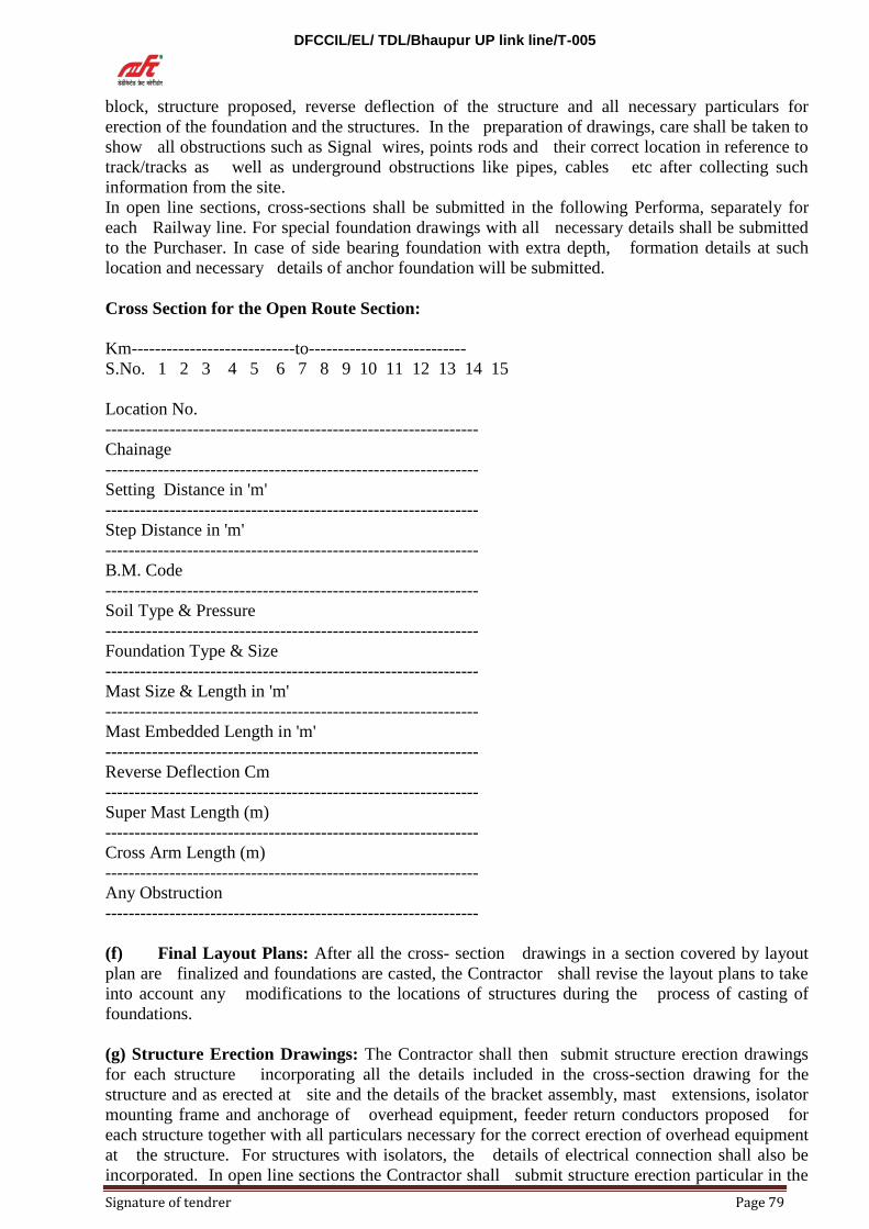
DFCCIL/EL/ TDL/Bhaupur UP link line/T-005
Signature of tendrer Page 79
block, structure proposed, reverse deflection of the structure and all necessary particulars for
erection of the foundation and the structures. In the preparation of drawings, care shall be taken to
show all obstructions such as Signal wires, points rods and their correct location in reference to
track/tracks as well as underground obstructions like pipes, cables etc after collecting such
information from the site.
In open line sections, cross-sections shall be submitted in the following Performa, separately for
each Railway line. For special foundation drawings with all necessary details shall be submitted
to the Purchaser. In case of side bearing foundation with extra depth, formation details at such
location and necessary details of anchor foundation will be submitted.
Cross Section for the Open Route Section:
Km----------------------------to---------------------------
S.No. 1 2 3 4 5 6 7 8 9 10 11 12 13 14 15
Location No.
----------------------------------------------------------------
Chainage
----------------------------------------------------------------
Setting Distance in 'm'
----------------------------------------------------------------
Step Distance in 'm'
----------------------------------------------------------------
B.M. Code
----------------------------------------------------------------
Soil Type & Pressure
----------------------------------------------------------------
Foundation Type & Size
----------------------------------------------------------------
Mast Size & Length in 'm'
----------------------------------------------------------------
Mast Embedded Length in 'm'
----------------------------------------------------------------
Reverse Deflection Cm
----------------------------------------------------------------
Super Mast Length (m)
----------------------------------------------------------------
Cross Arm Length (m)
----------------------------------------------------------------
Any Obstruction
----------------------------------------------------------------
(f) Final Layout Plans: After all the cross- section drawings in a section covered by layout
plan are finalized and foundations are casted, the Contractor shall revise the layout plans to take
into account any modifications to the locations of structures during the process of casting of
foundations.
(g) Structure Erection Drawings: The Contractor shall then submit structure erection drawings
for each structure incorporating all the details included in the cross-section drawing for the
structure and as erected at site and the details of the bracket assembly, mast extensions, isolator
mounting frame and anchorage of overhead equipment, feeder return conductors proposed for
each structure together with all particulars necessary for the correct erection of overhead equipment
at the structure. For structures with isolators, the details of electrical connection shall also be
incorporated. In open line sections the Contractor shall submit structure erection particular in the
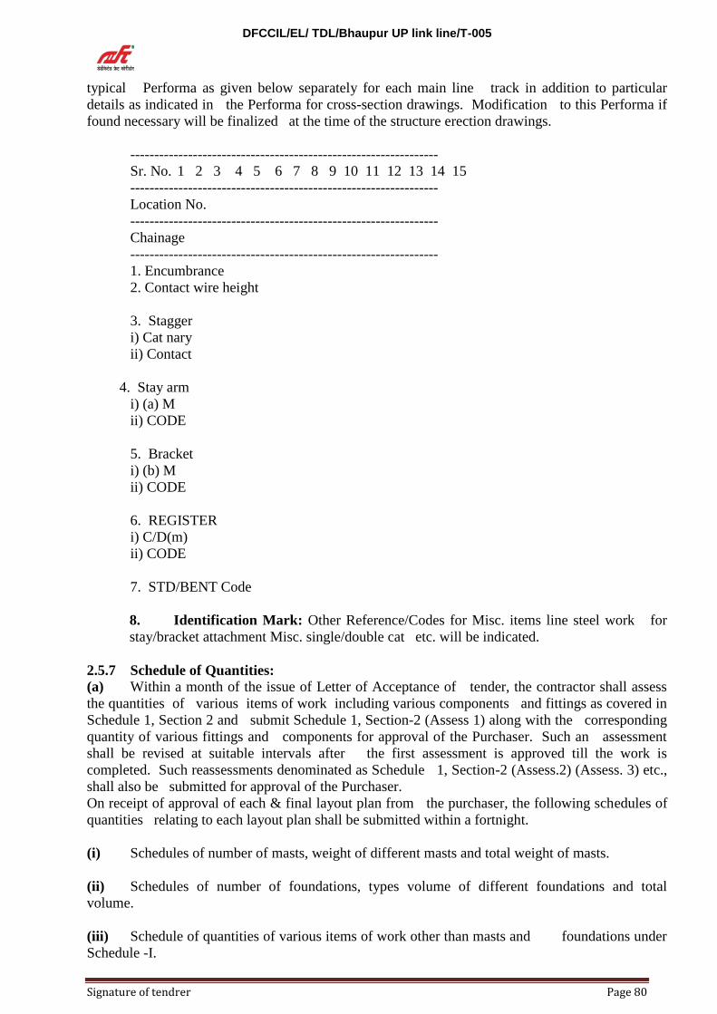
DFCCIL/EL/ TDL/Bhaupur UP link line/T-005
Signature of tendrer Page 80
typical Performa as given below separately for each main line track in addition to particular
details as indicated in the Performa for cross-section drawings. Modification to this Performa if
found necessary will be finalized at the time of the structure erection drawings.
----------------------------------------------------------------
Sr. No. 1 2 3 4 5 6 7 8 9 10 11 12 13 14 15
----------------------------------------------------------------
Location No.
----------------------------------------------------------------
Chainage
----------------------------------------------------------------
1. Encumbrance
2. Contact wire height
3. Stagger
i) Cat nary
ii) Contact
4. Stay arm
i) (a) M
ii) CODE
5. Bracket
i) (b) M
ii) CODE
6. REGISTER
i) C/D(m)
ii) CODE
7. STD/BENT Code
8. Identification Mark: Other Reference/Codes for Misc. items line steel work for
stay/bracket attachment Misc. single/double cat etc. will be indicated.
2.5.7 Schedule of Quantities: (a) Within a month of the issue of Letter of Acceptance of tender, the contractor shall assess
the quantities of various items of work including various components and fittings as covered in
Schedule 1, Section 2 and submit Schedule 1, Section-2 (Assess 1) along with the corresponding
quantity of various fittings and components for approval of the Purchaser. Such an assessment
shall be revised at suitable intervals after the first assessment is approved till the work is
completed. Such reassessments denominated as Schedule 1, Section-2 (Assess.2) (Assess. 3) etc.,
shall also be submitted for approval of the Purchaser.
On receipt of approval of each & final layout plan from the purchaser, the following schedules of
quantities relating to each layout plan shall be submitted within a fortnight.
(i) Schedules of number of masts, weight of different masts and total weight of masts.
(ii) Schedules of number of foundations, types volume of different foundations and total
volume.
(iii) Schedule of quantities of various items of work other than masts and foundations under
Schedule -I.
DFCCIL/EL/ TDL/Bhaupur UP link line/T-005
Signature of tendrer Page 81
(iv) Schedule of net tension lengths of contact, cat nary and feeder wires and lengths required to be
ordered.
(v) Schedule of length of other wires and conductors required to be ordered and
(vi) Schedules of small parts steel-work.
2.5.8 Submission of Drawing Schedules: (a) The submission of designs and drawings for approval shall be done in the manner indicated
below.
In case Contractor wish to deviate from standard drawings, he should submit to the Purchaser
revised drawings with full details of deviation sought explaining the necessity of deviation,
calculations and other supporting documents. The Purchaser, if satisfied about the necessity and
adequacy of deviations, shall refer the matter to RDSO for necessary approval. In case of
deviations on working drawings, decision shall be communicated by the Purchaser to the
Contractor. The number of copies of drawings which shall be submitted are indicated in the
following sub - pares. The Purchaser will return one copy of the drawing either with approval,
subject to modification where necessary or with comments. The Purchaser shall endeavor to return
this copy within a period of fifteen days from the date of receipt and shall normally return the copy
within a month. Where drawings are returned with comments or approval subject to
modifications, the Contractor hall submit to the Purchaser within fifteen days of receipt of such
advice revised drawings for approval taking into account the comments or modifications. Also the
Contractor shall as far as possible avoid correspondence on such comment and shall endeavor to
settle any difference of opinion on the comment by discussions with the Purchaser's Engineers. No
drawings shall be resubmitted without incorporating the modifications required by the comments
of the Purchaser, unless the Purchaser has agreed to the deletion of such comments.
(b) Deviation from Standard: In case of deviations from standard designs and drawings,
copies of correspondence and drawings shall be sent in duplicate to the Dy. Chief Electrical
Engineer/Const/North Central Railway, Allahabad or his successor/nominee. In the particular
case of deviation in the design of fittings the drawings of deviation in the design of fittings the
drawings submitted by the Contractor shall be actual manufacturing drawings complete with
tolerances and full specifications of the materials used. In addition, four samples of the modified
fittings shall also be submitted after the drawings are approved.
(c) Special Design: Special designs to meet the requirement of particular locations and local
conditions shall be submitted in due time in duplicate for approval.
(d) Contractor's Pegging Plans: The contractor should survey and prepare pegging plans and
submit three copies of such plans for approval.
(e) Cross Section Drawings: Cross-section drawings shall be submitted for approval in two
copies for a convenient section at a time separately for sections within station limits. Such
drawings shall be submitted progressively and as for as possible without gap.
(f)OHE Layout Plans and Profile Drawings: Overhead equipment layout plan, provisional and
final and profile drawings shall be submitted for approval in three copies.
(g) Structure Erection Drawings: Structure erection drawings shall be submitted for
approval in two copies for a section at a time separately for section within station limits and
sections outside station limits, progressively and without gaps.
(h) Schedule of Quantities: Schedules of quantities for each approved layout plan/switching
station shall be submitted for approval in two copies.

DFCCIL/EL/ TDL/Bhaupur UP link line/T-005
Signature of tendrer Page 82
(i) Distribution Copies: On receipt of Purchaser's qualified approval to the Contractor's
drawings, Schedule of quantities, the Contractor, shall submit original tracings of those drawings
and schedules for the signature of the Purchaser in token approval within seven days of the receipt
of approval and the Purchaser shall as far as possible return the same to the contractor within 7
working days thereafter. On receipt of the tracing from the purchaser, the contractor shall submit
copies for distributions to field officers and other department as indicated below within 7 days of
receipt of approval tracings:
i. Standard designs including fittings drawings: 8 copies.
ii. Special designs: 8 copies.
iii. Final pegging plans: 8 copies.
iv. Structure cross- section drawings: 6 copies.
v. OHE layout plans: 14 copies
vi. OHE profile drawings: 8 copies
vii. Structure erection drawings: 8 copies
viii. Schedule of quantities: 6 copies
In all the above cases the Contractor has the option to supply only six copies of the approved
drawings provided one of them is a transparent paper print.
2.5.9 Completion Drawings and Schedule: After completion of work, all drawings and designs
submitted by the Contractor and approved by the purchaser shall be made up to date incorporating
actual supply and erection particulars including the name of make of insulators, galvanized steel
tube, stainless steel wire rope etc. The mark of conductors shall be specified in the "As erected"
OHE Layout plans, SED and other relevant drawings for identification. Such drawings and
schedules shall then be verified and corrected, if necessary, by the Contractor jointly with the
Purchaser's representatives. The verified and corrected drawings shall be supplied in four sets, one
of which shall be transparencies of linen or film reproduction or any other durable material
approved by the Purchaser.
DFCCIL/EL/ TDL/Bhaupur UP link line/T-005
Signature of tendrer Page 83
PART - II
CHAPTER -VI
ERECTION AND INSTALLATION OF EQUIPMENT
2.6.1Scope: This chapter deals with the methods of erection and installation of traction equipment,
including casting of foundations and erection of structures.
2.6.2 Methods of Erection: All work shall be done in accordance with methods of erection and
installation of equipment approved by the purchaser. In the case of switching station, booster
transformer stations, LT Supply transformer stations, standard methods adopted for erection and
installation of electrical equipment shall be adopted.
2.6.3 Sectioning: The entire equipment shall be erected in accordance with the finally adopted
sectioning diagram and in such a way so as to facilitate sectioning which may be required in
future and which will be indicated by the purchaser.
2.6.4 Inspection: All erection and installation work shall be subject to inspection by the
purchaser to ensure that the work is done in accordance with the specification, approved designs
and drawings and is of the best quality suitable for the purpose.
2.6.5 Measurements: All measurements for location of structures and foundations shall be made
with the aid of steel tapes. On curves, these measurements shall be taken on the outer rail of the
middle track in the case of odd number of and on the inner Rail of the first outer tracks from the
center of the formation in the case of an even number of tracks, structures on curves shall be located
in the radial of set of the location as determined.
2.6.6 Bolts, Nuts etc: All bolts, nuts, locknuts, screws, locking plates and split cotter pins etc,
hall be properly tightened and secured and the contractor shall carry out systematic inspection of
this aspect of work after all adjustments to overhead equipment are completed and prior to
offering completed section of equipments to the purchaser for inspection and testing.
2.6.7 Damage to Galvanizing Painting: In loading, transport and erection, all galvanized
painted materials shall be handled with care to avoid damage to galvanizing/painting. If
galvanizing/painting is damaged inspire of all care taken, the damaged parts of component shall be
put up for inspection, to obtain permission from the purchaser to carry out repairs.
2.6.8 (a) Foundations: The contractor shall carry out soil pressure tests in accordance with
methods approved by the purchaser to determine permissible bearing pressure of various
representative types of soils in the presence of the purchaser's representative during the pegging
out of site inspection. He shall adopt only those values as accepted by the purchaser for the
design and foundations.
(b) Location: The location of each foundation or anchor block shall be set out correctly in
accordance with approved structure cross- section drawings or foundations layout drawings, as the
case may be, in the presence of the purchaser's representative.
(c) Method of Installation: The contractor shall adopt mechanized method (Concrete mixer)
for installations of foundation in the station areas with five lines or more. The contractor may
adopt either manual or mechanized method for installation of foundations in the other areas. He
may erect traction mast or structures in the same operation as casting of foundations or erect them
subsequently in cored holes left in foundation blocks and grout them separately. In any case, the

DFCCIL/EL/ TDL/Bhaupur UP link line/T-005
Signature of tendrer Page 84
method of casting of foundation blocks and erection of masts or structures shall be subject to the
approval of the purchaser.
(d) Excavation: Normally, excavation of soil for foundations or anchor block along the tracks
may be done up to length of 1 to 1.2 m and depth of 0.8 to 1 m without shoring, providing the
excavated hole is concreted immediately and not left overnight. Shoring shall otherwise be done
unless the hole is re-filled with soil and tempted. In case the length of excavation is 1 to 1.2 m
and depth of excavation is 1 to 1.2 m and depth for foundations and anchor blocks alongside the
tracks is more than 0.8 to 1 m, the excavation may be undertaken only after certification by the
Purchaser's representative to be safe and concrete is cast on the same day. Shoring shall be done to
the satisfaction of the purchaser's representative, if the excavated hole is left overnight. All water
logged locations will come under the purview of this Para. In poor soil or ash banks, no excavation
shall be done without adequate shoring and piling. For large foundations and water logged
locations shoring shall be done in accordance with drawings submitted/shuttering of the pits
should be provided effectively to the satisfaction of the purchaser. Core hole covers should be
provided promptly on casting of foundation (within 48 hours) and their edges cemented to the
foundation block. Prior to doing so, water should be filled in the core hole so as to assist in
curing. The date of casting should be inscribed on the foundation block. In case of platform areas
and level crossings, the core should be filled with sand before provision of core hole covers so as
to prevent any injury to rail users even if the core hole cover gets damaged or is displaced. The
track ballast should be restored to its original form promptly after casting of the foundation
block. The exceed earth should be removed well clear of the area so as to avoid any mixing up
with the track ballast or any obstruction to the track drains. In case of cuttings, the earth should
be thrown well away from the shoulders so that there is no risk of its flowing back to the drain
during the rains.
(e) Concreting: All concreting or grouting shall be done in accordance with Para 2.2.4 with
ballast graded for the purpose specified in Para 2.2.5. The concrete shall be poured and tamped
properly in accordance with the method approved by the purchaser. The contractor shall arrange
to provide concrete testing samples for tests once every week or as and when required by the
purchaser, to determine crushing strength after 7 days or 28 days curing as required.
(f) Muffs: All anchor blocks and foundations of structures carrying overhead equipment shall be
provided with concrete muffs. The top of these muffs shall be above the level of ground of the
track formation and of adequate height of not less than 15 cm to afford reasonable protection
during rainy weather. Muffs may be installed at the same time the masts are grouted or after the
mast/structure is loaded with equipment. The foundations of structures for switching stations need
not, however, be provided with muffs. The top of such foundations shall be given a slope of 1 in
50 towards the edge to ensure that water does not collect at the base of the structure of the frame
work of the equipment.
(g) Suitable grooves or niches shall be provided in the foundation blocks, wherever required,
at the time of casting, to enable embedment of earth strips etc. to avoid the necessary of chipping
off concrete.
(h) Conduits for cables should be embedded in the foundation blocks, wherever required, to
avoid subsequent chipping off and breaking of the foundation blocks.
2.6.9 (a) Masts and Structure Erection: In case traction masts or structures are erected in
cored foundations, till such time they are grouted, they shall be properly wedged to prevent them
leaning towards the track and endanger safety of moving vehicles.
In case traction masts or structures are erected simultaneously with the casting of the foundations,
the contractor shall provide suitable temporary supports approved by the purchaser. The masts
shall be embedded in the foundation blocks for the correct length specified in approved drawings.

DFCCIL/EL/ TDL/Bhaupur UP link line/T-005
Signature of tendrer Page 85
NOTE: Masts/uprights should be grouted on the same day they are dropped in the foundations.
(b) Reverse Deflection: All traction masts and structures shall be erected with the correct
reverse deflection so that they become reasonably vertical after they are loaded. The method of
erection of masts with the correct reverse deflection shall be submitted to the purchaser for
approval.
(c) Infringement to Standard Dimensions: In erection, care shall be taken to ensure that no
part of the traction mast, structure or any fitting located on such mast or structure infringe the
Schedule of Dimensions 1676 gauge 1939 printed in metric units in 1973.
(d) Alignment of Masts at Gantries: The main masts of gantries shall be carefully aligned to
enable easy and good assembly of fabricated steel work.
2.6.10 Overhead Equipment: (a) A suggested method for erection of OHE which would ensure good speed and quality
erection is included in section 2 of this chapter. The contractor may, however, follow other
methods which they consider would speed up and ensure good quality work, subject to the
approval of the purchaser. Any wiring method should take into consideration appreciable stretch
of the catenary and contact wires in the initial days after they are strung and put under tension.
(b) Bracket Tubes: In the erection of bracket assemblies, it shall be ensured that the free length
of the bracket tube beyond the cat nary suspension bracket is at least 200 mm to facilitate
adjustment during maintenance.
(c) Stay Arms: The choice of stay arms shall be such that their adjuster are capable of
adjustments of minimum of 90mm in either direction except as otherwise relaxed.
(d) Insulators: Before insulators are used in bracket assemblies or dispatched to work site for
erection from the contractor's stores depot, they shall be tested as specified for routine
mechanical test. No chipped or cracked insulators shall be installed. All insulators shall be
cleaned before offering complete sections of equipment for inspection and testing.
(e) Stringing Catenary: Care shall be taken to avoid kinking or bride caging of the catenary wire
in stringing and subsequent operations. While stringing, the wire shall be suspended from pulley
blocks hung from the suspension clamp eye of bracket assemblies. The pulleys shall be fitted with
ball bearing free movement in all directions to prevent damage to the strands of the wire. The
design shall also be such that it will prevent slipping off of the wire. The design shall also be
such that it will prevent slip of the wire during stringing operations. The designs of the pulley
shall be submitted to the purchaser for approval. After initial stringing of the catenary, it shall be
maintained of the 'No Load Tension' for a minimum duration of 48 hours before the pulley blocks
are removed and the catenary is clamped to suspension clamps of bracket assemblies. Shorter
periods may, however, be allowed by the purchaser.
(f) Stringing Contact Wire: Care shall be taken to avoid formation of kinks, twists and
damage to contact wire in stringing and subsequent operations, while stringing the contact wire,
it shall be suspended from pulleys hung from droppers fitted to the catenary in their final
position. In curves, the contact wire shall be run in pulleys located at traction masts or supports,
corresponding to the approximate final position of the wire.
(g) Location of Droppers: Droppers shall be correctly positioned in each span to ensure
correct level of contact wire as per dropper chart applicable to the span.

DFCCIL/EL/ TDL/Bhaupur UP link line/T-005
Signature of tendrer Page 86
(h) Clipping Droppers: The droppers shall be clipped on the contact wire only after a
minimum duration of 48 hours from the time the automatic tensioning device is brought into
action. Shorter periods may, however, be allowed by the purchaser.
(i) Auto Tensioning Device: The auto -tensioning device shall be erected with the correct
height of the counter weight above rail level with corresponding distance between the pulleys of
the device for a temperature of 35oC before it is connected to the overhead equipment and put
into action. The installation of the device shall be such as to permit free, easy and unobstructed
movement of counter-weight.
(j) Cut- in Insulators: All insulators in out of run shall be so positioned that they are away
from the swept zone of the pantographs and will not foul with them. The live parts of these
insulators shall also be so located that they are at least 2m away from structures other then these
supporting traction overhead equipment.
(k) Section Insulators: All section insulators shall be so located that they are beyond the swept
zone of the pantograph running on adjacent tracks and there is no unusual sag due to the same.
Where section insulators are installed, the contact plane of the runners of the insulators as well as
those of overhead equipment connected to it shall be parallel to the track plane.
(l) Anti-wind Clamp: Anti-wind clamp shall be provided as shown in drawing (Annexure).
(m) Connections: All jumper connections including anti-theft jumpers shall be made properly
with parallel clamps and finished neatly without any loose wire or cables. The length of flexible
jumpers shall be adequate to avoid any disturbance to overhead equipment or restraint in the
relative movement of conductors, but the jumpers should not be excessively long. The ends of
jumpers shall be tinned, including the portion inside the first parallel clamp.
(n) Separation between OHE: In erection, the physical separation required between overhead
equipments and bracket assemblies on the same structure at insulated overlaps shall be ensured.
(o) Gradient of Contact Wire: The gradient of the contact wire on either side of over line
structures with restricted clearances shall be correctly adjusted and adequate clearance
maintained between the over line structure and live equipment
(p) Adjustment at turnouts etc: Careful adjustment of equipment shall be made on
equipments at turn-outs cross over, diamond crossings, overlaps and special locations for position
of bracket assemblies, stay arms and height of contact wire to ensure that pantographs of electric
rolling stock on the run will not foul with any parts of the bracket assemblies and changeover of
the contact wire is affected smoothly.
(q) For wiring in large yards, the contractor shall prior to the execution of works, submit to the
purchaser's Engineer for his approval the sequence of stringing of catenary and contact wires to
arrange for proper crossing of wire. Endeavor will be made to arrange for traffic blocks to suit
approved sequence of wiring.
2.6.11Isolators: Isolator switches shall normally be so mounted that when the switches are
operated, the operator faces the directions of the motion of trains. The operating handles and
contact blades shall be correctly aligned for easy operation.
2.6.12 Bus-bars and Connections: Bus-bars and connections shall be neatly shaped and bent to
give a good appearance.

DFCCIL/EL/ TDL/Bhaupur UP link line/T-005
Signature of tendrer Page 87
2.6.13 Earthing: The copper earth strips of MS flat used for earthing shall be bent and shaped
neatly before connection to the structure or frame work of equipment. The connection of MS flat
to steel work shall be made at a height not exceeding 15 cm from the datum level of a switching
station. Before making earth connections the ends shall be cleaned copper strips. All junctions
shall be properly secured to void loose contact. Portions of copper earth strips which remain
visible above the ground level should be painted with suitable paint to make them inconspicuous.
2.6.14 Tolerance: The permissible tolerance in dimensions for erection from those included in
the appropriate drawings or schedules for different items are given below:
(a) Measurements: The span length shall not vary more than ± 50mm as measured along the
appropriate rail.
The cumulative error of measurement of all spans in a kilometer shall be not more than 1000mm.
(b) Setting of Structures:The setting of structure shall be not less than that included in the
appropriate cross- section drawings, especially those with the minimum setting of 2.36m. A
tolerance of ±20mm will be permitted subject to minimum specified value, if the structure is
not located in between tracks.
(c) Height of Contact Wire: ± 20mm will be permitted to the height of contact wire at point
of supports as shown in the relevant structures erection drawing, except under over line structures
where no tolerance will be permitted.
(d) Stagger: Generally ± 20 mm will be permitted for stagger.
(e) Dropper Lengths: ± 5mm will be permitted for dropper length.
Dropper location: ± 100mm will be permitted for dropper locations.
2.6.15 Supplementary Instructions: Further working instructions will be issued if considered
necessary by the purchaser, should be considered that the standard of work of the contractor
requires to be improved.
DFCCIL/EL/ TDL/Bhaupur UP link line/T-005
Signature of tendrer Page 88
PART - II
CHAPTER -VII
INSPECTION AND TESTING
2.7.1 Scope: This chapter deals with the inspection and testing of completely erected overhead
equipment, switching stations, booster transformer stations and LT supply transformer stations.
2.7.2 Overall Performance: The overall performance of the overhead equipment should be such
as would permit collection of current by electric rolling stock with full load at speeds, up to and
including the maximum specified for the design of overhead equipment, smoothly, without
mechanical shocks or prejudicial sparks and without undue heating in the case of other
equipments.
2.7.3 Responsibility: The general tests of overall performance stipulated below are only
supplementary to other tests on structures, foundations, equipments, components and fittings as
specified in Part -II, Chapter -II, III and IV. Any testing and acceptance by the purchaser of
overall performance shall be subject to the general terms and guarantee which shall continue to the
valid as provided for in Part -I, Chapter- II.
2.7.4 Test on OHE:
(a) General: As soon as a section is ready for inspection and testing, the Contractor shall
advise the Purchaser in writing. Tests to be carried out by the Purchaser will be done in the
presence of the Contractor's representative and shall include the following apart from other
reasonable tests that the purchaser may like to conduct with a view to ensure, himself of the
soundness of the equipments and their erection in strict compliance with the specification.
(b) Insulation: The strength of the insulation and the di-electric strength of the entire
equipment as installed shall be tested with a 2500V Megger.
(c) Continuity: The electrical continuity of the line and the existence of bad contacts, if any,
will be tested with a Megger.
(d) Electrical Independence: The electrical independence of individual elementary sections in
relation to one another shall also be tested with a merger.
(e) Switches: All isolators shall be tested for smooth and trouble free operation.
(f) Tension Device: All automatic tensioning devices installed shall be tested for sensitive
functioning and adjustment.
(g) Stagger and Height: The stagger and height of contact wire over the entire section of
completed overhead equipment and the clearance available shall be measured and the
measurement shall be checked against approved drawings. These measurements shall be carried
out at low speed with a vehicle or device to be arranged by the Purchaser, the movement of
which will follow the track levels as closely as possible. Tolerances that will be permitted on the
dimensions indicated in the approved drawings.
The actual position of the two contact wires, relative to each other, at overlaps and turnouts shall
also be checked. Special attention shall be paid to a smooth movement of Pantographs over
section insulators, particularly those which are likely to be frequently traversed.

DFCCIL/EL/ TDL/Bhaupur UP link line/T-005
Signature of tendrer Page 89
(h) Mechanical Behavior: The mechanical behavior of the entire equipment shall be tested at
various speeds under normal pantographs pressure without energizing the overhead equipment.
(i) Energizing: If the overhead equipment, after being subjected to the above tests in an
unexercised condition, is found to be satisfactory, it will be energized with the normal 25 KV AC.
supply.
(j) Power Collection: Tests shall then be conducted to check if the power collection
performance of the over head equipment is satisfactory after ensuring that the contact wire is
adequately clean. For this purpose, an observation car shall be attached next to the electric
locomotive. The behavior of the overhead equipment will be watched at various speeds. Power
collection shall be considered unsatisfactory if a long blue flash is observed, indicating that the
contact between the contact wire and the pantograph is not continuous.
2.7.5 Inspection and Testing Of Switching Stations Etc:
(a) Visual Inspection:Visual inspection which shall include check for satisfactory workmanship
shall cover all connections, painting, plastering, cleanliness of all insulators etc. and compliance
with INDIAN ELECTRICITY RULES.
(b) Operation Test: This test will be conducted on every individual item of equipment such as
interrupters, isolators, relays etc. to ensure that the equipment as a whole is functioning properly
and is mechanically sound, e.g. in the particular case of isolators the fixed contact and knife blade
have been correctly aligned and operation does not cause undue strain on the equipment. The
operation tests will be carried out with the high tension installation dis-connection from the
supply, but by actuating power devices where such are provided. Continuity test of high tension
connections after setting such interrupter and isolator in their respective positions shall also be
conducted as part of the operation test.
(c) Insulation: The strength of insulation of the various items of equipment and of the entire
installation as whole shall be tested with a 2500 V/500 V megger as required.
(d) Isolators: All isolators will be tested for smooth and trouble free operation.
2.7.6 Earthing: (a) Earth wires will be checked for continuity and electrical isolation every 1000 m approx.
(b) Clearances between earth wires and out-run wires of overhead equipment and signals shall
be checked.
(c) Earth resistance shall be measured separately for each earth electrode. In this case of
interconnected earth electrodes, the net resistance of the interconnected electrodes shall
also be measured.
2.7.7 Detailed Procedure for Tests: The detailed procedure for inspection and testing will be
furnished to the Contractor. The contractor shall submit the result of tests in the Performa which
will be furnished by the Purchaser, in quadruplicate.

DFCCIL/EL/ TDL/Bhaupur UP link line/T-005
Signature of tendrer Page 90
PART-II
CHAPTER-VIII
WIRING PROCEDURE
2.8.1 Wiring Procedure: This section deals with the wiring procedure which may be adopted
for erection of normal overhead equipment.
The following procedure for erection of overhead equipment has been formulated with a view to
ensure that:
(i) bracket assemblies (brackets) and regulating equipment are correctly installed in their final
position.
(ii) the conductors are correctly tensioned, and
(iii) the need for final adjustments of overhead equipment immediately before energization and
commissioning, is virtually eliminated.
2.8.2 General: In the case of regulated equipment when the regulating equipments are in action,
the tension in the conductors should remain constant, irrespective of variations in the ambient
temperature. As the regulating equipments are brought into action a few days after the stringing of
conductors the equipment is unregulated in the intervening period. Any of the following two
procedures may be followed for tensioning and clamping of conductors of regulated overhead
equipment during stringing operations, i.e., before the regulating equipments are brought into
action.
(i) The catenary in tension to 1,000 Kgf, the stipulated tension at the mean temperature of 35°
C, whatever may be the ambient temperature during the stringing operations. In this case, at the
time of clamping the cat nary to the bracket, the bracket should be placed at angular positions
corresponding to temperature at the time of clamping and the proportionate to their distance from
the anti- creep.
(ii) The aluminum alloy catenary is tensioned at the calculated tension to corresponding to 1000
Kgf. the stipulated tension at the mean temperature of 35° C whatever may be the ambient
temperature during the stringing operations.
(iii) The catenary is strained to a stringing tension corresponding to the ambient temperature for
the equipment span of the tension length. In this case the brackets are placed in the mean position,
i.e., at right angles to the track, when the catenary is clamped or the regulating equipment
commissioned.
The advantage of the second method is that once the catenary is strung at the proper tension, there
would be no necessity to adjust each bracket separately at the time of clamping the catenary or
commissioning the regulating equipment. The erection work is, thus considerably simplified and
the possibility of errors greatly reduced. This is also applicable to erection of unregulated
overhead equipment.
2.8.3 Erection of Brackets: After the brackets are fabricated correctly in the contractor's depot,
in accordance with the approved structure erection drawings, and provided with indelible labels
or/painted marking indicating the intended locations for each bracket, they are removed to the
site of work and erected on traction masts or supports. The brackets are swiveled to a position at

DFCCIL/EL/ TDL/Bhaupur UP link line/T-005
Signature of tendrer Page 91
right angles to the track and secured in that position by means of steel wires tied to similar
brackets located on the opposite side of the track or other suitable means.
2.8.4 Anti-Creep: The anti-creep of the tension length is then installed in its final position.
2.8.5 Locking the Regulating Equipment: In the case of regulated overhead equipment, the
regulating equipments are erected on the terminal masts or structures and their movement locked
by suitable means in the middle position, with the distance between the pulleys of the regulating
equipment corresponding to 35° C.
2.8.6 Temporary Arrangement: A pulley approximately 30 cm dia is attached to the overhead
equipment end of the regulating equipment by means of temporary accommodation fittings at
both ends of the tension length to be wired. Over this pulley a flexible stranded wire is passed
over. At each of the wire two ending clamps, one for cat nary and one contact wire, are attached.
The wire is also clipped in the middle by 'U' - clamp. The length of this temporary arrangement
from the regulating equipment to the extremities of the stranded wire passing over the temporary
pulley shall be a little longer than the distance between the regulating equipment and the ends of
the cat nary and contact wires in their final position, to permit easy clamping of terminal fittings
during the final termination of the wire.
2.8.7 Stringing Catenary: The catenary is initially terminated in the ending clamp of the
temporary arrangement at one end of the tension length. The catenary is thus paid out from the
reel of the wiring train and run on pulley blocks hung from the suspension clamp eyes of brackets
until the terminating point at the other end of the tension length is reached.
2.8.8 Tensioning of Catenary: The catenary is strained up to the 'stringing tension'
corresponding to the 'equivalent' span of the tension length and the ambient temperature at the time
of stringing with the aid of a dynamometers, end terminated at the tension. For this purpose, the
ambient temperature shall be deemed to be the temperature registered by a thermometer tied to a
length of catenary wire 3 to 4 meters long, laid flat on the top platform, on one of the wagons of
the wiring train. Subsequently the tension in the wire is checked by measurement a sag with the
help of leveling lathe attached to suspension points and to the catenary at mid span by a ladder
working party. The sag shall be measured in two spans, each preferably greater than 54 meters,
and situated on either side of anti- creep approximately midway between the anti- creep and the
termination points. The value of sag measured by this method should be within ± 5% of the
theoretical value for the corresponding stringing tension, and the temperature at the time of this
measurement. In case of discrepancy is noted, the tension should be adjusted again and sag
re-checked as above. After the sag is checked, the catenary is terminated at the ending fitting of the
temporary arrangement at the terminating point.
In order to restrict the duration of traffic blocks to the minimum, in the first block, the catenary is
strained to the stringing tension with the aid of dynamometers and the catenary is terminated. In a
subsequent block, the sag is checked and the Tension readjusted with ladders, if necessary.
2.8.9 Clamping the Catenary: The catenary is clamped on the brackets placed at right angles to
the track.
2.8.10Droppering: Droppers are fitted to the catenary at the correct locations. At the contact wire
ends these droppers May be provided with small pulleys or hooks to act as temporary supports
when the contact wire is strung. Hooks made of scrap contact wire, suspended from the catenary
wire, may also be used as temporary supports.

DFCCIL/EL/ TDL/Bhaupur UP link line/T-005
Signature of tendrer Page 92
2.8.11 Stringing Contact Wire: The contact wire is initially terminated in the contact wire
ending clamp of the temporary arrangement at one end of the tension length. The wire is then paid
out from the reel wagon of the wiring train and supported on the pulleys hung from droppers or
on hooks until the terminating points at the either end of the tension, length is reached. In curves,
the contact wire shall be registered on pulleys located at traction masts or supports corresponding
to the approximate final position of the wire. The axes of these pulleys should be more or less
vertical.
2.8.12 Tensioning Of Contact Wire: The contact wire is strained to a tension on approximately
1.2 times the tension corresponding to the ambient temperature and terminated in the ending
clamp of the temporary arrangement.
2.8.13 Regulating Equipment in Action: The regulating equipment is put into action with the
counter weight at the correct height above rail level with distance between pulley or the
regulating equipment corresponding to a temperature of 35°C. The regulating equipment is then
released and brought into action. The 'U' clamp connecting the flexible stranded wire passing round
the temporary pulley is also removed.
2.8.14 Final Adjustment: The entire installation is left in this condition as long as it is possible,
preferably for a period not less than 15 days. The temporary pulleys are removed and the
conductors terminated in the permanent ending fittings, compensating plates, insulators and
turnbuckles. The equalizer plate is kept vertical or at a vertical or at a slightly inclined position
(by 2 or 3 cm the contact wire being shorter than the catenary) and the position of the regulating
equipment is checked in relation to, the temperature at the time. The contact wire is clipped on to
droppers (in the vertical position) and on the steady arms. Contact wire height at the bracket is
adjusted as also the stagger and register arm clearance.
2.8.15Concluding Remarks: If the above method is followed with care, no further adjustment
may be needed.
NOTE:
(1) It should be ensured that sagging is done carefully and accurately. The adjustment of
tension in the catenary after checking of sag, if required, would be easy if a temporary turnbuckle
is inserted in the temporary termination.
The use of leveling lathes is recommended for the following reasons:
(i) The accuracy of adjustment is greater than that with dynamometers.
(ii) No traffic block is required for this operation.
(iii) It obviates the necessary of initial tensioning of the catenary accurately thus permitting a
reduction in the period of traffic block required for the wiring train.
(2) If feasible, without any hindrance to progress of works, the catenary may be maintained at
stringing tension for a period of 48 hours before checking sag and clamping it to the brackets.
This would ensure equalization of tension in the different spans. Before clamping the catenary to
the brackets, the sag should however, be checked in two spans as indicated.
(3) If it is difficult to obtain separate traffic block for stringing contact wire, the wire may be
paid out at the same time, as the catenary, with the following precautions:
(i) The contact wire is run and suspended from independent pulleys hooked on the brackets,
separately from the catenary pulleys, to avoid twisting together of the two conductors.
(ii) The contact wire should not be suspended from the catenary until the later is clamped on
the brackets.
(iii) The tension in the contact wire before termination should be about 1,500 Kgf. This will
ensure that sag is not excessive.

DFCCIL/EL/ TDL/Bhaupur UP link line/T-005
Signature of tendrer Page 93
(iv) The adjustment of tension and checking of sag of the catenary wire is carried out as if the
contact wire had not been strung. Only after adjustment of tension and checking of sag is
completed, the contact wire is transferred to the pulleys attached to the droppers or to hooks
suspended from the cat nary and the tension is adjusted.
(4) When the contact wire is under tension creep takes place which results in an increase in the
length of wire and, consequently, the droppers and the equalizer plates would become oblique.
Though creep may continue for a long time, about a year, the bulk of it would occur during the
days following stringing. If sufficient period of time is allowed, the contact wire may be clipped
to the droppers and the equalizer plates, all in the vertical position and the necessity for any further
adjustments before energization and commissioning of the OHE may be reduced to a great extent.
If this precaution is not taken at the time of energization of the OHE, the droppers may not all be
vertical and staff would have to be deputed for shifting the dropper clips with risk of damage to the
contact wire.
(5) Before the temporary arrangement is removed, a reference mark should be made on each
conductor. After final termination of the conductors, it should be ensured that two marks are in
the same relative longitudinal position as they were before the removal of the temporary
arrangement.

DFCCIL/EL/ TDL/Bhaupur UP link line/T-005
Signature of tendrer Page 94
PART-II
CHAPTER -IX
SPECIFICATION OF IMPORTED ITEMS
2.9.1 Scope- Specification covered in this chapter are for imported items to be used in this work.
These specifications are indicative, details if required by the Contractor will be provided by
DFCCIL. Any specification of material not covered in this chapter will be provided by DFCCIL.
2.9.2 Technical Specifications for Cantilever assembly -
Purpose: The Purpose of this document is to define and elaborate the suitability of cantilever
design to the functional requirements and ultimate loadings of OHE on cantilevers. The cantilever
assembly is commonly referred to as OCS3.
The brief description of assembly is as below:
Material Aluminum
Corrosion No corrosion risk
Allocation distance Up to 4.50 m
Weight (push 3.5m) 30 kg
Components 20
Insulators Composite (1 type)
Tube attachments 1 type
Contact wire clamp With screws
Tubes 2 sizes
Max load on FEM 254MPa (97%)
The cantilevers shall be pivoted to the support structures and capable of swiveling along the track as
well as adjustable in transverse direction. The cantilever assembly shall hold 120sqmm Cu-mg
Messenger wire and 150 sqmm Cu-Ag contract wire tension 14kN in messenger wire and 16kN in
Contact wire respectively.
This specification covers the requirement of cantilever assembly on OHE masts/Portals, tubes and
insulators. The cantilever assembly shall consist of suitable mast attachments, 25kV bracket and
stay insulators, Cantilever tubes, catenary wire suspension system and contact wire registration
system including steady arm and the drop bracket/drop tubes, and any other components or
assemblies essential to support the OHE for smooth current collection.
The Cantilever assembly shall be of a proven design with proven service in mechanical, electrical
and environmental condition similar to those specified in this specification. The cantilever assembly
shall be capable for use with trains speed up to 120 Kmph.
2.9.3 Governing Specifications:
PS and GS of CP- 104 Contracts.
EN 50119:2009+A1:2013 “Railway applications: Fixed installations Electric Traction overhead
contact lines”.
2.9.10 GENERAL AND TECHNICAL REQUIREMENTS
The cantilever shall be fabricated as per the approved SED (tube dimensions) to suit the site
requirement and as per basic arrangement shown in the cantilever assembly drawings.
The cantilever assembly shall be suitable for a maximum span length of 58.5m with a minimum
radius of curvature 700m. The cantilever assembly shall include.
Complete cantilever assembly including steady arms
Both stay and bracket arm insulators (silicone Composite)
Mast/Portal attachments
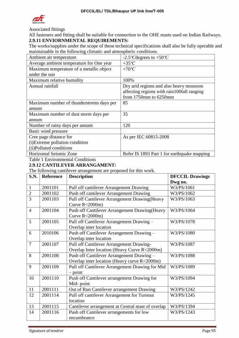
DFCCIL/EL/ TDL/Bhaupur UP link line/T-005
Signature of tendrer Page 95
Associated fittings
All fasteners and fitting shall be suitable for connection to the OHE masts used on Indian Railways.
2.9.11 ENVIORNMENTAL REQUIREMENTS:
The works/supplies under the scope of these technical specifications shall also be fully operable and
maintainable in the following climatic and atmospheric conditions.
Ambient air temperature -2.5 degrees to +50
Average ambient temperature for One year +35
Maximum temperature of a metallic object
under the sun +70
Maximum relative humidity 100%
Annual rainfall Dry arid regions and also heavy monsoon
affecting regions with rain100fall ranging
from 1750mm to 6250mm
Maximum number of thunderstorms days per
annum
85
Maximum number of dust storm days per
annum
35
Number of rainy days per annum 120
Basic wind pressure
Cree page distance for
(i)Extreme pollution condition
(ii)Polluted conditions
As per IEC 60815-2008
Horizontal Seismic Zone Refer IS 1893 Part 1 for earthquake mapping
Table 1 Environmental Conditions
2.9.12 CANTILEVER ARRANGAMENT:
The following cantilever arrangement are proposed for this work.
S.N. Reference Description DFCCIL Drawings
Dwg no.
1 2001101 Pull off cantilever Arrangement Drawing W3/PS/1061
2 2001102 Push off cantilever Arrangement Drawing W3/PS/1062
3 2001103 Pull off Cantilever Arrangement Drawing(Heavy
Curve R<2000m)
W3/PS/1063
4 2001104 Push off Cantilever Arrangement Drawing(Heavy
Curve R<2000m)
W3/PS/1064
5 2001105 Pull off Cantilever Arrangement Drawing –
Overlap inter location
W3/PS/1078
6 2010106 Push off Cantilever Arrangement Drawing –
Overlap inter location
W3/PS/1080
7 2001107 Pull off Cantilever Arrangement Drawing-
Overlap Inter location (Heavy Curve R<2000m)
W3/PS/1087
8 2001108 Push off Cantilever Arrangement Drawing –
Overlap inter location (Heavy curve R<2000m)
W3/PS/1088
9 2001109 Pull off Cantilever Arrangement Drawing for Mid
– point
W3/PS/1089
10 2001110 Push off Cantilever arrangement Drawing for
Mid- point
W3/PS/1094
11 2001111 Out of Run Cantilever arrangement Drawing W3/PS/1242
12 2001114 Pull off cantilever Arrangement for Turnout
location
W3/PS/1245
13 2001115 Cantilever arrangement at Central mast of overlap W3/PS/1394
14 2001116 Push off Cantilever arrangements for low
encumbrance
W3/PS/1243

DFCCIL/EL/ TDL/Bhaupur UP link line/T-005
Signature of tendrer Page 96
15 2001117 Pull off cantilever arrangements for low
encumbrance
W3/PS/1246
2.9.13 CANTILEVER CONSTRUCTION
The catenary is suspended from insulated cantilevers that can be oriented and maintained on the
OHE support structures by means of fastener’s and fittings such as adapters, backing angles and
mast bracket attachments. In case of multiple track portals or twin track cantilever structures the
insulated cantilevers are held in positions by drop members attached to the portals. The cantilevers
are composed of several items.
Component Material Tube
characteristics
Comments
Top tube for all
cantilevers except
out of running
Cantilevers
Aluminum
Alloy tube
Circular
Diameter=60x4mm
Attached to an insulator
MW stagger adjustment
possible by horizontal
movement of suspension
clamp on the top tube.
Top Tube for Out of
running cantilevers
Aluminum
Alloy tube
Circular
diameter=60x6mm
Attached to an insulator
MW stagger adjustment
possible by horizontal
movement of suspension
clamp on the top tube.
Cantilever Tube for
all type of
cantilevers except
low encumbrance
Aluminum
Alloy tube
Circular
Diameter=60x6mm
Attached to an insulator
Cantilever Tube low
encumbrance
Aluminum
Alloy tube
Circular
Diameter=60x4mm
Attached to an insulator. The
strut tube is horizontal and the
top tube is inclined.
Registration Tube Aluminum
Alloy tube
Circular
Diameter=60x4mm
With cripped tennon end
fitting
Reinforcement tube
and wind stay tube
Aluminum
Alloy tube
Circular
Diameter=38x4mm
With cripped tennon end
fitting both sides
Steady Arm Aluminum Circular
Diameter=36mm
Thickness=3mm
Ensures Contact wire bracing
The following cantilevers assemblies are proposed for this work.
S.N. Reference Description DFCCIL
Drawings no.
1 3001101 25kV OCS-3 Cantilever-Standard Push off type W3/PS/1263
2 3001102 25kV OCS-3 Cantilever-Standard Pull off type W3/PS/1264
3 3001103 25kV OCS-3 Cantilever- Heavy curve Push off type W3/PS/1265
4 3001104 25kV OCS-3 Cantilever- Heavy curve Pull off type W3/PS/1266
5 3001105 25kV OCS-3 Cantilever- Intermediate type for Out
of running cables
W3/PS/1267
6 3001107 25kV OCS-3 Cantilever- Push off cantilever
assembly for low encumbrance
W3/PS/1269
7 3001108 25kV OCS-3 Cantilever- pull off cantilever assembly
for low encumbrance
W3/PS/1270
8 3001109 25kV OCS-3 Cantilever- Mid-point Pull off type W3/PS/1271
9 3001110 25kV OCS-3 Cantilever- mid-point Push off type W3/PS/1273
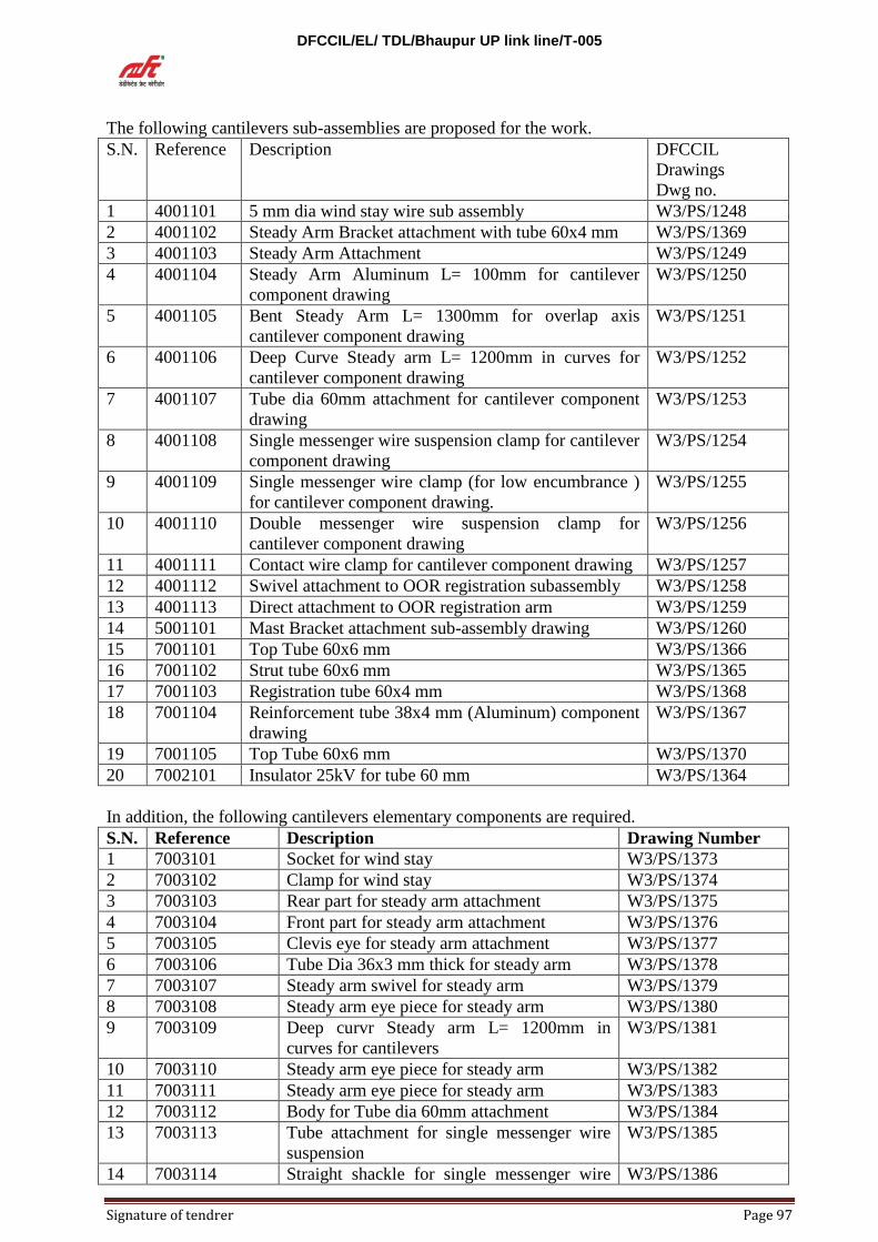
DFCCIL/EL/ TDL/Bhaupur UP link line/T-005
Signature of tendrer Page 97
The following cantilevers sub-assemblies are proposed for the work.
S.N. Reference Description DFCCIL
Drawings
Dwg no.
1 4001101 5 mm dia wind stay wire sub assembly W3/PS/1248
2 4001102 Steady Arm Bracket attachment with tube 60x4 mm W3/PS/1369
3 4001103 Steady Arm Attachment W3/PS/1249
4 4001104 Steady Arm Aluminum L= 100mm for cantilever
component drawing
W3/PS/1250
5 4001105 Bent Steady Arm L= 1300mm for overlap axis
cantilever component drawing
W3/PS/1251
6 4001106 Deep Curve Steady arm L= 1200mm in curves for
cantilever component drawing
W3/PS/1252
7 4001107 Tube dia 60mm attachment for cantilever component
drawing
W3/PS/1253
8 4001108 Single messenger wire suspension clamp for cantilever
component drawing
W3/PS/1254
9 4001109 Single messenger wire clamp (for low encumbrance )
for cantilever component drawing.
W3/PS/1255
10 4001110 Double messenger wire suspension clamp for
cantilever component drawing
W3/PS/1256
11 4001111 Contact wire clamp for cantilever component drawing W3/PS/1257
12 4001112 Swivel attachment to OOR registration subassembly W3/PS/1258
13 4001113 Direct attachment to OOR registration arm W3/PS/1259
14 5001101 Mast Bracket attachment sub-assembly drawing W3/PS/1260
15 7001101 Top Tube 60x6 mm W3/PS/1366
16 7001102 Strut tube 60x6 mm W3/PS/1365
17 7001103 Registration tube 60x4 mm W3/PS/1368
18 7001104 Reinforcement tube 38x4 mm (Aluminum) component
drawing
W3/PS/1367
19 7001105 Top Tube 60x6 mm W3/PS/1370
20 7002101 Insulator 25kV for tube 60 mm W3/PS/1364
In addition, the following cantilevers elementary components are required.
S.N. Reference Description Drawing Number
1 7003101 Socket for wind stay W3/PS/1373
2 7003102 Clamp for wind stay W3/PS/1374
3 7003103 Rear part for steady arm attachment W3/PS/1375
4 7003104 Front part for steady arm attachment W3/PS/1376
5 7003105 Clevis eye for steady arm attachment W3/PS/1377
6 7003106 Tube Dia 36x3 mm thick for steady arm W3/PS/1378
7 7003107 Steady arm swivel for steady arm W3/PS/1379
8 7003108 Steady arm eye piece for steady arm W3/PS/1380
9 7003109 Deep curvr Steady arm L= 1200mm in
curves for cantilevers
W3/PS/1381
10 7003110 Steady arm eye piece for steady arm W3/PS/1382
11 7003111 Steady arm eye piece for steady arm W3/PS/1383
12 7003112 Body for Tube dia 60mm attachment W3/PS/1384
13 7003113 Tube attachment for single messenger wire
suspension
W3/PS/1385
14 7003114 Straight shackle for single messenger wire W3/PS/1386

DFCCIL/EL/ TDL/Bhaupur UP link line/T-005
Signature of tendrer Page 98
suspension
15 7003115 Clamp for single messenger wire suspension W3/PS/1387
16 7003116 Attachment element (for low encumbrance) W3/PS/1388
17 7003117 Cable clamp (for low encumbrance) W3/PS/1389
18 7003118 Double messenger wire suspension clamp for
cantilever
W3/PS/1390
19 7003119 Body for swivel attachment W3/PS/1391
20 6001101 Mast bracket swivel for cantilever W3/PS/1261
2.9.14 FABRICATION, ASSEMBLY AND INSTALLATION OF CANTILEVERS
The vender shall supply his manufacturing drawings, design, dimensioning of components etc. for
the proposed cantilever along with the required technical specifications of the materials and test
documents.
Based on the vendor design, contractor shall prepare the arrangement; assembly and detail drawing
of each component proposed for the cantilever design and get the approval of DFCCIL.
The manufacture will start his activity once the approval for all the drawings and specifications
from DFCCIL conveyed to him.
The OCS designer shall determine the size and prepare the detailed mounting arrangements, of the
cantilevers with dimensioning and calculation of tube lengths based on the inputs details like as
built offset of masts installed received from the site. The mounting sheets shall also include the
detailed interface of cantilevers and other OCS equipment may be mounted on independent
structures such as masts or portal uprights or mounted on drop arms from the boom of portal or
concrete walls and roof of over bridges etc.
The supplier will deliver the materials and tubes with eye clamps as per the required lengths
mentioned in the mounting sheets supplied to him. The delivery of materials shall be packed as per
type pieces like tubes packed per type length, steady arms in crates with labels clamps in boxes per
type and insulators in separated boxes with protection.
Upon delivery at the contractor site workshop, the cantilever tubes, clamps and other components
shall be checked off against the delivery form and then be pre-assembled at the workshop and
transported location wise to site and installed in accordance with the OCS design and as detailed
herein.
A preliminary check shall be made to ensure that the cantilevers are the same as the design cross
sections and ready for installation.
REQUIRED DOCUMENTS
For the quality issues, the supplier has to submit the following:
Supplier’s client references
Supplier’s quality system certifications
The documents produced should follow the requirements below.
The standard language – English
Drawing in autocad or compatible
All the documents and drawings should be updated according to the final installation of the
cantilever on site.
Standard and special cantilever assembly and sub- assembly drawing

DFCCIL/EL/ TDL/Bhaupur UP link line/T-005
Signature of tendrer Page 99
Factory inspection and test procedure (type and routine) for each component.
Detail component and package list before shipping with at least following information.
Quantity of the components individually and in a package
Type of the component in each package
Type of the component in each package
Each component with proper certification number
2.9.15 Technical specification for Copper contact wire 150Sqmm
Scope:
This European Standard specifies the characteristics of copper alloy wire of cross section of 150
sqmm for use on overhead contact lines. For silver copper alloys, 100C is the permanent
temperature limit for material mechanical properties as per table-1 of EN50119.
It establishes the product characteristics, the test methods, checking procedures to be used with the
wires, together with the ordering and delivery condition.
Governing specifications
PS AND GS OF CP- 104 CONTRACT.
EN 50119:2009+A1:2013 “Railway applications: fixed installations Electric Traction
overhead contract lines”.
EN 50149:2012” Railway applications: Fixed installations Electric Traction Copper and
copper alloy grooved contact wires”.
These below standards are in whole or in part, are normatively referenced in EN 50149:2012 and
are indispensable for its application. For dated references, only the edition cited applies. For
undated references, the latest edition of the referenced document (including any amendments)
applies.
EN 1655:1997, Copper and copper alloys- Declarations of conformity.
EN 1977:1998, Copper and copper alloys- Copper drawing stock (wire rod).
EN ISO 6892-1, Metallic materials- Tensile testing- part 1; Method of test at room
temperature (ISO 6892-1).
EN 10204: 2004, Metallic Products- Types of inspection documents.
IEC 60468:1974, method of measurement of resistivity of metallic materials.
Wire generally of circular shape, whose cross section is larger than the wire cross section, from
which the contact wire is then drawn.
Electric conductor of an overhead contact line with which the current collector makes contact and is
characterized by two clamping grooves.
A Environmental conditions
The works/supplies under the scope of these technical specifications shall also be fully operable and
maintainable in the following climatic and atmospheric conditions.
Ambient air temperature -2.5 degrees to +50
Average ambient temperature for one year +35
Maximum temperature of a metallic object
under the sun +70

DFCCIL/EL/ TDL/Bhaupur UP link line/T-005
Signature of tendrer Page 100
Maximum relative humidity 100%
Annual rainfall Dry arid regions and also heavy monsoon
affecting regions with rainfall ranging from
1750mm to 6250mm
Maximum number of thunderstorms days per
annum
85
Maximum number of dust storm days per
annum
35
Number of rainy days per annum 120
Basic wind pressure 120-200 kgf/m2,as per wind map based on IS-
875, For long bridges (more than 150m) and
within 100m from their abutments on either
side and on banks, where the height of the
catenary above surrounding mean retarding
surface is more than 30 meters, the specified
25% reduction in wind pressure shall not be
reckoned for purposes of design.
Creep age distance for
(I)Extreme pollution condition
(II)Polluted conditions
As per IEC 60815 – 2008
Horizontal Seismic Zone Refer IS 1893 part 1 for earthquake mapping
The wire designation is EN 50149 – BC – 150 – Cu Ag 0.1.
The drawing stock or intermediate rod stock shall be copper silver alloy as defined in EN
1977:1998.
The wires shall not present any imperfections (roughness, sliver, seam, inclusion or cracks) liable to
affect the mechanical and/or electrical properties specified in this European Standard or to cause
difficulties during installation/operation.
The surface shall be clean and free of oxide inclusions or supplied generated during the
manufacturing process or foreign substances such as pickling residue.
The colour of the metallic bright surface immediately after manufacturing may change due to
atmospheric influence. This is acceptable.
All wires manufactured from alloys shall be clearly identified. For normal and high strength copper
– silver.
Dimensional examination shall be performed either using a suitable micrometer or sliding caliper,
or using a profile reflector with a minimum amplification of 10, or other appropriate methods.
Electrical properties
The resistivity or resistance per unit length measurements shall be made in conformity with IEC
60468:1974.
MECHANICAL PROPERTIES
Breaking Load And Percentage Elongation After Fracture
This test is performed in accordance with the requirements of EN ISO 6892-1. The gauge length for
percentage elongation measurement shall be 200 mm.

DFCCIL/EL/ TDL/Bhaupur UP link line/T-005
Signature of tendrer Page 101
The original cross sectional area is calculated from the measured mass per unit length and the
density (8890 kg/m3 at 20 ) appropriate to copper silver alloy (seeC.6) of EN 50149:2012. Values
shall be in accordance with 4.7.1.
Reverse bend test
The test is performed using a method similar to that shown in ISO 7801:1984 . The Distance
from the top tangential plane of cylindrical supports to the bottom face of the guide shall be 200
mm max. The wire has to be placed so that the bottom and the head of the wire are tangential to the
gripping faces of the support (as shown in Figure below). For the first bending the bottom of the
wire has to be inside and the head of the wire outside.
The wire shall be subjected to a subjected to a number of bends, through 90 in opposite
directions, around a mandrel with a radius of 30 mm. One bend consists of bending the free end of
the test specimen through 90 and returning it to its original position, in accordance with figure
below. The bends may be made by hand.
Integrity of wire
The internal and surface integrity of the wires may be checked by electro- magnetic. The
test should be performed during the manufacturing process, before coiling the wire on the wire
drum.
Ordering and delivery conditions
a. The nominal length on each drum and the type of drum to be used will be submitted as a
part of drum schedule. The maximum length of wire on each drum will be as below.
All contact wire length which is < 1450m, should be fitted in a 1400mm dia drum.
Whereas,
All contact wire length more than 1450m and less than 1800m, should be fitted in a
1800mm dia drum,
b. Joints are not allowed.
c. The specific tests and test required, viz.
1) The method of stating electrical properties of the wire.
2) Type and testing of joins in wire- this test is not required as joins are not allowed in
wire for the present project.
3) Requirement for reverse bend test
4) Requirement for torsional tests
5) Requirement for the checking of winding property
6) Requirement for tests for microwaves on longitudinal axis of wire
d. Certification of compliance and/or test results
Packaging
The wires shall be delivered on wire drums. Wooden drums are phytosanitary and
protected with wooden staves and iron straps. Each drum shall carry only one continuous length of
wire.
The nominal length on each drum and the type of drum to be used will be submitted as a part of
drum schedule. The maximum length of wire on each drum will be as below.
All contact wire length which is < 1450m, should be fitted in a 1400 dia drum. Whereas,
All contact wire length more than 1450m and less than 1800m, should be fitted in a 1800mm
dia drum.
The wire shall be carefully coiled in layers with the contact side facing the center of the drum. Each
coil shall be contiguous and well packed, particularly near the flanges of the wire drum, such that it

DFCCIL/EL/ TDL/Bhaupur UP link line/T-005
Signature of tendrer Page 102
will not be possible for the coil lay to be disturbed during transit. The ends of the wire are to be
firmly secured to the flanges.
Tolerance on wire length
The tolerance on the length of wire supplied is +30m, -0m. The measurement of this length is taken
from the indication of a length meter mounted on the wire drawing bench.
Wire drum markings
Every wire drum shall bear a permanently marked number, assigned by manufacturer, clearly
visible on each flange, together with an arrow and the words “take off” indicating the direction of
take – off the wire.
A label, resistant to deterioration and indelibly marked, shall be attached to one flange, bearing the
following information.
The name of the manufacture.
The wire designation.
The wire nominal length.
The net mass of the wire.
The gross mass (wire drum plus wire).
A manufacturing number with at least the number of the week of drawing and the year of
manufacture.
The customer order or reference number.
The above information shall be supplied to the customer at his request.
The Employer/ Engineer and manufacturer shall agree the clauses selected from EN 10204:2004 or
EN 1655:1997 relevant to the certificate of compliance and/or test results.
Testing Requirements
Contact wire shall go through following test during this order.
1. Prototype test.
2. Factory Acceptance test.
2.9.16 Technical specification for Hard Drawn Stranded Magnesium Copper Catenary Wires
of sizes 120mm2 (19/2.8D)-
Scope:
The specification covers the requirements of technical specification for Hard Drawn Stranded
Magnesium Coper Catenary Wires of sizes 120mm2 (19/2.8D) for Electric Traction. Far Mg Cu
alias/Ez (0.2),100 is the perment temperature limit for material mechanical properties as per table
– 1 of EN 50119.
Governing Specification
PS and GS of CP-104 Contracts.
DIN 48201- T2: Bronze stranded conductors edition 1981-04.
DIN48200-2 Bronze wire for stranded conductors.
DIN48203-2 Wrought copper alloy Bz. Wires and conductors technical delivery conditions.
EN 50119:2013 Railway applications: Fixed installations electrical Traction overhead
contract lines.
DIN 46391-1:2014-D5 Delivery drums for cables and stranded conductors-Part 1 Delivery
drums with diameter up to 2800mm.
DIN 43138:1980-09 Flexible cables for overhead equipment and return current.
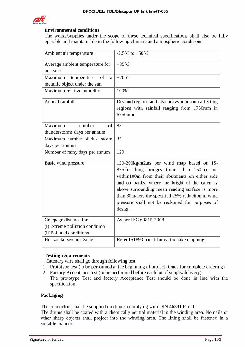
DFCCIL/EL/ TDL/Bhaupur UP link line/T-005
Signature of tendrer Page 103
Environmental conditions
The works/supplies under the scope of these technical specifications shall also be fully
operable and maintainable in the following climatic and atmospheric conditions.
Ambient air temperature -2.5 to +50
Average ambient temperature for
one year
+35
Maximum temperature of a
metallic object under the sun
+70
Maximum relative humidity 100%
Annual rainfall
Dry and regions and also heavy monsoon affecting
regions with rainfall ranging from 1750mm in
6250mm
Maximum number of
thunderstorms days per annum
85
Maximum number of dust storm
days per annum
35
Number of rainy days per annum 120
Basic wind pressure 120-200kg/m2,as per wind map based on IS-
875.for long bridges (more than 150m) and
within100m from their abutments on either side
and on banks, where the bright of the catenary
above surrounding mean reading surface is more
than 30maters the specified 25% reduction in wind
pressure shall not be reckoned for purposes of
design.
Creepage distance for
(i)Extreme pollution condition
(ii)Polluted conditions
As per IEC 60815-2008
Horizontal seismic Zone Refer IS1893 part 1 for earthquake mapping
Testing requirements
Catenary wire shall go through following test.
1. Prototype test (to be performed at the beginning of project- Once for complete ordering)
2. Factory Acceptance test (to be performed before each lot of supply/delivery).
The prototype Test and factory Acceptance Test should be done in line with the
specification.
Packaging-
The conductors shall be supplied on drums complying with DIN 46391 Part 1.
The drums shall be coated with a chemically neutral material in the winding area. No nails or
other sharp objects shall project into the winding area. The lining shall be fastened in a
suitable manner.

DFCCIL/EL/ TDL/Bhaupur UP link line/T-005
Signature of tendrer Page 104
The conductor shall be wound on to the drum as tightly as possible, i.e. turn next to turn. The
two ends of the conductor shall be securely fastened. The layer of the conductor shall be
covered with a chemically neutral material and shall also be protected against mechanical
damage. Unless otherwise agreed, only one length of conductor shall be wound onto one
drum.
The following data shall be applied permanently to the drum:
The direction of rolling of the drum for transportation shall be marked by arrows by
arrows and words” Direction of rolling” on the two drum flanges in the direction
opposite to the unwinding direction.
Material, nominal cross section section, length and mass of the conductor.
Supplier’s works.
Drum number.
Dimensions, mechanical and electrical values for cable 120sq.mm
1 2 3 4 5 6 7 8
Nominal
size mm2
Actual
size
mm2
Strands
No.
Strands
Dia.mm
Cable
dia.mm
Weight
kg/km
Calculated
breaking
strength
KN
Continuous
rating A
Bz I Bz I
120 116.99 19 2.80 14.0 1060 56.68 410
1) The cable weights are calculated on the basis of a density of 8.9 kg/dm3 and the average
lay ratio, which is taken as the arithmetic mean of the lowest and highest value of the
respective lay ratios specified in the table below.
2) Breaking strength calculated in accordance with DIN 48203 part 2
3) Valid for up to 50HZ at a wind speed of 0.6 m/s with an ambient temperature of 35 , to
give a final conductor temperature of 70 . For particularly shielded cases in still air the
values should be reduced by 30% on average.
2.9.17 Technical specification for flexible cable DIN 43138- Bzll- 10x49 for overhead contact
systems-
Scope: The specification covers the requirements of technical specification for flexible cable DIN
43138- Bzll- 10x49 for overhead contact systems.
Governing specification
PS and GS of CP-104 Contracts.
DIN 43138- 1980-09 Flexible cables for overhead contact systems and return circuits.
DIN 48200-2 “Bronze wires for stranded conductors”.
DIN 48203-2 “Wrought copper alloy Bz. Wires and conductors technical delivery
conditions.
DIN 17566 Wrought- copper alloys, alloy treated composition.
DIN 46391-1:2014-05 Delivery drums for cables and stranded conductor- Part 1: Delivery
drum with diameter up to 2800 mm

DFCCIL/EL/ TDL/Bhaupur UP link line/T-005
Signature of tendrer Page 105
Environmental Conditions
The works/supplies under the scope of these technical specifications shall be fully
operable and maintainable in the following climatic and atmospheric and atmospheric
conditions.
Ambient air temperature -2.5 to+50
Average ambient temperature for one year +35
Maximum temperature of a metallic object
under the sun
+70
Maximum relative humidity 100%
Annual rainfall Dry and regains and also heavy monsoon
affecting regions with rainfall ranging from
1750mm to 6250mm
Maximum number of thunderstorms days
per annum
85
Maximum number of dust storm days per
annum
35
Number of rainy days per annum 120
Basic wind pressure 120-200 kgf/m2,as per wind map based on
IS-975,For long bridges (more than 150m)
and within 100m from their abutments on
either side and on banks, where the height
of the catenary above surrounding mean
reading surface is more than 30 meters, the
specified 25% reduction in wind pressure
shall not be reckoned for purposes of
design.
Creep age distance for
(i)Extreme pollution condition
(ii)polluted conditions
As per IEC 60815-2018
Horizontal Seismic Zone Refer IS 1893 part 1 for earthquake
mapping
Properties of strands
Diameter
(mm)±0.03
Material Wires after stranding
Tensile
Strength
Elongation at break
(1=100)
Applied
load
mm N/mm2 %mm N
0.50 Wrought copper
alloy Bzll
589 116

DFCCIL/EL/ TDL/Bhaupur UP link line/T-005
Signature of tendrer Page 106
Electrical conductivity
Electrical conductivity for wrought-copper alloy wires (Bz II)>36/ohm, mm2.
Dimensions, mechanical and electrical values for cable for 10sq.mm Bzll.
Nominal
size mm2
Desired cross
section mm2
Wires Cables
No. Dia.mm ±0.03 Diameter
(mm)±5%
Mean weight
kg/km±8%
10 9.6 49 0.5 4.5 89
Requirements to be met by strands-
1) Material:- The particular wrought copper alloy (BZII) ordered shall be used for the
wrought copper alloy (BZII) wires which shall be hard drawn and comply with
requirements given in subclasses 8.5 and 8.6 before and after stranding.
2) Surface characteristics of the base material :- The surface of the base material to be
worked into wire shall be smooth and shall have no sharp burrs or edges.
3) Wire surface:- The wires to be used for the stranded conductor shall be smooth and free
from all imperfections not consistent with good commercial practice.
4) Welded and soldered joints: - Any welding or soldering on finish drawn wires shall be
carried out with the greatest of care. The joints shall be annealed after the welding or
soldering process over a distance of at least 200mm on each side of the joint and their
mechanical properties need not match those of non- welded or non- soldered wires.
5) Dimensions and tensile strength: - The dimensions and tensile strength of wrought
copper alloy (BZII) wire shall comply with DIN 48200Part 2.
The tensile strength of the specimens shall be determined using an officially verified
tensile testing machine. The test force shall be applied smoothly and uniformly. The rate
of separation of the jaws of the testing machine shall be not less than 25mm per minute
and not greater then 100mm per minute. The tensile specimens shall show a reduction of
area at the point of fracture.
6) Resistivity: - The resistivity values or the electrical conductivity values shall be as
below.
Wire made from Resistivity at 20⁰C(
ohm/mm2/m) Max.
Electrical conductivity( in
m/ohm mm2) Min.
BzII
0.02773
36
7) Testing Requirements: - Dropper wire shall go through following tests.
1. Prototype test (to be performed at the beginning- once as per specification)
2. Factory Acceptance Test FAT (to be performed before each lot of supply/delivery as
per specification).
3. The prototype test and factory acceptance test should be done based on this
specification.

DFCCIL/EL/ TDL/Bhaupur UP link line/T-005
Signature of tendrer Page 107
8) Lengths of wires and conductors at delivery: - Conductor shall be supplied in the
manufacturers usual production lengths with a permissible deviation of ± 5% it is
permissible to supply 5% of any one order in shorter lengths as long as none of these are
shorter than 1/3 of the nominal length.
9) Packing: - These drums shall be coated with a chemically neutral material in the
winding area. No nails or other sharp objects shall project into the winding area. The
lining shall be fastened in a suitable manner.
Theconductor shall be wound onto the drum as tightly as possible, i.e. turn to next to
turn. The two ends of the conductor shall be security fastened. The last layer of the
conductor shall be covered with a chemically neutral material and shall also be protected
against mechanical damage. Unless otherwise agreed, only one length of conductor shall
be wound onto one drum.
The following data shall be applied permanently to the drums.
1) The direction of rolling of the drum for transportation shall be marked by arrows and
the words “Direction of rolling “on the two drum flanges in the direction opposite to
the unwinding direction.
2) Material, nominal cross section, length and mass of the conductor.
3) Supplier’s works;
4) Drum number;
2.9.17 Technical specification for OHE clamps & fittings –
The OHE clamps and fittings shall be designed according to Para 7 and Para 8 of EN 50119: 2013,
Reference Standards
contact lines”
-3:2013 Aluminium and aluminium alloys. Chemical composition and form of
wrought products.Chemical composition and form of products
EN 573-2:1995 Aluminium and aluminium alloys. Chemical composition and form of
wrought products.Chemical symbol based designation system
mechanical properties
02-1:2001 tensile testing of metallic materials. Method of test at ambient
temperature
-2:2013 Aluminium and aluminium alloys. Extruded rod/bar, tube and profiles.
Mechanical properties
ings
-1:2004 Hot rolled products of structural steels. General technical delivery
conditions
-
alloy steels
-2:2014 Stainless steels. Technical delivery conditions for sheet/plate and strip of
corrosion resisting steels for general purposes
cles –
Specification and test methods.
-06 Overhead lines – Requirements and tests for fittings
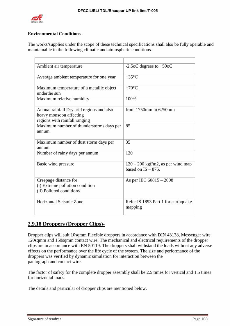
DFCCIL/EL/ TDL/Bhaupur UP link line/T-005
Signature of tendrer Page 108
Environmental Conditions -
The works/supplies under the scope of these technical specifications shall also be fully operable and
maintainable in the following climatic and atmospheric conditions.
Ambient air temperature -2.5oC degrees to +50oC
Average ambient temperature for one year +35°C
Maximum temperature of a metallic object
underthe sun
+70°C
Maximum relative humidity 100%
Annual rainfall Dry arid regions and also
heavy monsoon affecting
regions with rainfall ranging
from 1750mm to 6250mm
Maximum number of thunderstorms days per
annum
85
Maximum number of dust storm days per
annum
35
Number of rainy days per annum 120
Basic wind pressure 120 – 200 kgf/m2, as per wind map
based on IS – 875.
Creepage distance for
(i) Extreme pollution condition
(ii) Polluted conditions
As per IEC 60815 – 2008
Horizontal Seismic Zone Refer IS 1893 Part 1 for earthquake
mapping
2.9.18 Droppers (Dropper Clips)-
Dropper clips will suit 10sqmm Flexible droppers in accordance with DIN 43138, Messenger wire
120sqmm and 150sqmm contact wire. The mechanical and electrical requirements of the dropper
clips are in accordance with EN 50119. The droppers shall withstand the loads without any adverse
effects on the performance over the life cycle of the system. The size and performance of the
droppers was verified by dynamic simulation for interaction between the
pantograph and contact wire.
The factor of safety for the complete dropper assembly shall be 2.5 times for vertical and 1.5 times
for horizontal loads.
The details and particular of dropper clips are mentioned below.

DFCCIL/EL/ TDL/Bhaupur UP link line/T-005
Signature of tendrer Page 109
2.9.19 Catenary wire dropper clip for 120sqmm wire-
Part No: 7005109 DFCCIL DRAWINGS Drg No: W3/PS/1354_Supplier Reference Code:
077250600NM
Material : CuNi2Si EN12163 and Stainless steel Fasteners EN 10088Type Bolted type
Suitable for 4.5 mm dia BZ II flexible dropper wire
Electrical Requirements: Current carrying dropper clip is designed to allow for current to flow
between the messenger wire and the contact wire. The maximum resistant at the joint between the
bronze droppers wire and the clamp, at the contact point between the clamp and the messenger and
contact wire, shall be less than the less than the conductor of the same length. Resistance per meter
length of dropper wire is; Rt = R20 (10.004(t-20)) where, R20 = 0.02773 ohm/m. The dropper is
not required to be short circuit proof.
Mechanical Requirements: Tensile strength of dropper wire 589 N/mm² and the dropper clip is
design to withstand a vertical load of 3 KN. Crimps CH: 9mm, Width: 8mm, Pressure: 400bar,
Number: 2 Usage For in-span flexible dropper on the catenary/messenger wire.
2.9.20 Contact wire dropper clip for 150sqmm wire-
Part No: 7005110. DFCCIL DRAWINGS Drg No: W3/PS/1355. Supplier Reference Code:
077075900NM.
Material : CuNi2Si EN12163 and Stainless steel Fasteners EN 10088. Type Bolted
type.Suitable for 4.5 mm dia BZ II flexible dropper wire.
Electrical Requirements: Current carrying dropper clip is designed to allow for current to flow
between the messenger wire and the contact wire. the maximum resistant at the joint between the
bronze droppers wire and the clamp, at the contact point between the clamp and the messenger and
contact wire, shall be less than the less than the conductor of the same length. Resistance per meter
length of dropper wire is; Rt = R20 (10.004(t-20)) where, R20 = 0.02773 ohm/m`. The dropper is
not required to be short circuit proof.
Mechanical Requirements: Tensile strength of dropper wire 589 N/mm² and the dropper clip is
design to withstand a vertical load of 3 KN. Crimps CH: 9mm, Width: 8mm, Pressure: 400bar,
Number: 2. Usage For in-span flexible dropper on the catenary/messenger wire
2.9.21 Clamps (ending clamps) and Line Fittings (Splices)-
The ending clamps and the splices proposed for this project are in accordance with the electrical
and mechanical requirements mentioned EN 50119. The breaking load of the ending clamps and the
splices shall be more than that of the breaking load of the conductors on which they are intended to
use. The ending clamps and splices shall be tested with a minimum of 2.5 times of the working load
or with 85% of the calculated breaking load of the conductor to which they are secured. The higher
value of the two shall be attained. The ending clamps shall not incur any permanent deformation
when applied 1.33 times of the working loads. Line fittings are designed to provide a specified
normal and short circuit current flow without causing failure wherever applicable.
Messenger wire End Clamp suitable for 120sqmm Cu-Mg 0.2 (BZ I) & Contact wire ending Clamp
suitable for 150sqmm Cu-Ag 0.1.(Ending clamp is same for both messenger wire and contact wire)

DFCCIL/EL/ TDL/Bhaupur UP link line/T-005
Signature of tendrer Page 110
Part No: 7004102 & 7004103. DFCCIL DRAWINGS Drg No: W3/PS/1295.Supplier
Reference Code: 076074504.
Material : Body (X5CrNi1810 –EN 10088 Stainless steel) & Wedge (CuZn40Pb2-EN
12164, Copper alloy).Fasteners (X5CrNi1810, EN 10088-Stainless steel).
Working load - 14 kN & 16 KN respectively for MW and CW (DFCCIL document
W3/PS/4022).
Mechanical requirements - 85% of the breaking load of conductor or 2.5 times the working
(for testing purpose) load. The higher value of the two shall be attained. The anchoring
clamps used shall not incur any permanent deformations which impair operation at 1, 33
times the working load.
Usage- OHE terminations. Section Insulator, Neutral Section and cut in insulation.
2.9.22 Large span wire End Clamp suitable for 150sqmm Cu-Mg 0.5 (BZ II) –
Part No: 7004104. DFCCIL DRAWINGS Drg No: W3/PS/1295. Supplier Reference Code:
077430500.
Material : Body (X5CrNi1810 –EN 10088 Stainless steel) & Wedge (CuZn40Pb2-EN
12164, Copper alloy) Fasteners (X5CrNi1810, EN 10088- Stainless steel).
Working load - 30kN (DFCCIL document W3/PS/4022).
Mechanical requirements- 85% of the breaking load of conductor or 2.5 times the working
(for testing purpose) load. The higher value of the two shall be attained. The anchoring
clamps used shall not incur any permanent deformations which impair operation at 1, 33
times the working load.
Usage - OHE Termination with large span wire in station area where OHE has to cross
multiple tracks before anchoring.
2.9.23 Messenger wire Splice suitable for 120sqmm Cu-Mg 0.1 (BZ I) –
Part No: 7005111. DFCCIL DRAWINGS Drg No: W3/PS/1360. Supplier Reference Code:
077181103.
Material : Cu – ETP (tube) EN 13600.
Type - Compression joint.
Working load - 14 kN (DFCCIL document W3/PS/4022).
Mechanical requirements- 85% of the breaking load of conductor or 2.5 times the working
(for testing purpose) load. The higher value of the two shall be attained. The splices used
shall not incur any permanent deformations which impair operation at 1, 33 times the
working load.
Electrical requirement- Line fittings are designed to provide a specified normal and short
circuit current flow without causing failure.
Suitable for - Conductor dia 14.00 mm to 14.10 mm.
Crimping details - Hexagon CH = 22mm, Wide = 28mm, number of crimps = 6 intotal,
minimum capacity of press = 400 bar.
2.9.24 Contact wire Splice suitable for 150sqmm Cu-Ag-
Part No: 7005112. DFCCIL DRAWINGS Drg No: W3/PS/1361.Supplier Reference Code:
075141600.
Material : CuNi2Si UNI 2528 & EN 10088.
Type- Bolted type (6 bolts).
Working load- 16 kN (DFCCIL document W3/PS/4022).

DFCCIL/EL/ TDL/Bhaupur UP link line/T-005
Signature of tendrer Page 111
Mechanical requirements- 85% of the breaking load of conductor or 2.5 times the
working.(for testing purpose) load. The higher value of the two shall be attained. The
splicesused shall not incur any permanent deformations which impair operation at 1, 33
times the working load.
Electrical requirement- Line fittings are designed to provide a specified normal and short
circuit current flow without causing failure.
Suitable for - Conductor dia 14.50 mm. No of Bolts 6 Nos (Dia 10mm x 30mm).
2.9.25 Negative Feeder wire Splice suitable for 288sqmm AAAC-
Part No: 7005114. DFCCIL DRAWINGS Drg No: W3/PS/1208. Supplier Reference Code:
05450102205
Material : EN-AW 6060 T4 EN 755.
Type - Compression joint.
Working load 21.6 kN (maximum at -2.5°C and equivalent span of 27m)( document
W3/PS/4022availbale in this office ).
Mechanical requirements- 85% of the breaking load of conductor or 2.5 times the working
(for testing purpose) load. The higher value of the two shall be attained. The splices used
shall not incur any permanent deformations which impair operation at 1, 33 times the
working load.
Electrical requirement - Line fittings are designed to provide a specified normal and short
circuit current flow without causing failure.
Suitable for- 22.05 mm.
Crimps- Hexagon CH= 34mm, Wide = 33mm, number of crimps = 10 in total, minimum
capacity of press = 400 bar.
Usage - Negative feeder is proposed for back to back termination at every 8 Kms and at the
end of each drum length (appx. 2 Kms) the negative feeder wire to be spliced.
2.9.26 Contact wire Splice suitable for 150sqmm Cu-Ag –
Part No: 7005112. DFCCIL DRAWINGS Drg No: W3/PS/1361.Supplier Reference Code:
075141600
Material : CuNi2Si UNI 2528 & EN 10088.
Type - Bolted type (6 bolts).
Working load -16 kN (DFCCIL document W3/PS/4022).
Mechanical requirements- 85% of the breaking load of conductor or 2.5 times the
working.(for testing purpose) load. The higher value of the two shall be attained. The splices
used shall not incur any permanent deformations which impair.operation at 1, 33 times the
working load.
Electrical requirement - Line fittings are designed to provide a specified normal and
short.circuit current flow without causing failure.
Suitable for - Conductor dia 14.50 mm. No of Bolts 6 Nos (Dia 10mm x 30mm).
2.9.27 Negative Feeder wire Splice suitable for 288sqmm AAAC –
Part No: 7005114. DFCCIL DRAWINGS Drg No: W3/PS/1208.Supplier Reference Code:
05450102205.
Material : EN-AW 6060 T4 EN 755.
Type - Compression joint.

DFCCIL/EL/ TDL/Bhaupur UP link line/T-005
Signature of tendrer Page 112
Working load - 21.6 kN (maximum at -2.5°C and equivalent span of 27m) (DFCCIL
document W3/PS/4022).
Mechanical requirements- 85% of the breaking load of conductor or 2.5 times the working
(for testing purpose) load. The higher value of the two shall be attained. The splices used
shall not incur any permanent deformations which impair operation at 1, 33 times the
working load.
Electrical requirement - Line fittings are designed to provide a specified normal and short
circuit current flow without causing failure.
Suitable for - 22.05 mm.
Crimps -Hexagon CH= 34mm, Wide = 33mm, number of crimps = 10 in total, minimum
capacity of press = 400 bar.
Usage - Negative feeder is proposed for back to back termination at every 8 Kms and at the
end of each drum length (appx. 2 Kms) the negative feeder wire to be spliced.
2.9.27 Aerial Earth Wire Splice suitable for 91.97sqmm ACSR-
Part No: 7005115. DFCCIL DRAWINGS Drg No: W3/PS/1207.Supplier Reference Code:
05405411227.
Material: Aluminium: EN-AW 6060 T4 EN 755. Steel: C40+N EN 10083.
Type - Compression joint.
Working load - 8.0 kN (maximum at -2.5°C and equivalent span of 27m) (DFCCIL
document W3/PS/4022).
Mechanical requirements - 85% of the breaking load of conductor or 2.5 times the working
(for testing purpose) load. The higher value of the two shall be attained. The splices used
shall not incur any permanent deformations which impair operation at 1, 33 times the
working load.
Electrical requirement - Line fittings are designed to provide a specified normal and short
circuit current flow without causing failure.
Suitable for - 12.27 mm.
Crimps for Aluminium: Wide = 43mm, number of crimps = 4 in total, For Steel: Wide =
40mm, number of crimps = 3 in total. Minimum capacity of press for both aluminium and
steel = 400 bar.
Usage - Aerial Earth wire is proposed for back to back termination at every 8 Kms and at
the end of each drum length (appx. 2.6 to 3 Kms) the Aerial Earth wire to be spliced.
2.9.28 Electrical Connectors (PG Clamps)-
Design of Electrical connectors shall be able to sustain thermal load cycling with no reduction in
mechanical and electrical integrity. The temperature rise with the specified short circuit current for
1 sec. shall not cause fusion or deformation or exceed the maximum allowable temperature of the
wire which is 170°C. The temperature rise at normal operation of the electrical connectors shall not
exceed the maximum allowable temperature of the conductor i.e. 80°C. Electrical connectors shall
not be subjected to mechanical tension and the jumper shall be flexible.
Refer document number W3/PS/4248 – “Design of Jumpers” for various jumpers, sizes, the current
carrying capacity and the temperature rise in the conductors for normal and short circuit currents.
2.9.29 Parallel Groove Clamp (22.05/22.05mm) for 288sqmm Negative Feeder-
Part No: 7005101. DFCCIL DRAWINGS Drg No: W3/PS/1346. Supplier Reference Code:
042288851.

DFCCIL/EL/ TDL/Bhaupur UP link line/T-005
Signature of tendrer Page 113
Material : clamp EN-AC AlSi7Mg EN 1706,Stainless steel Fasteners A2-70 EN 3506.
Type - Bolted type.
Suitable for- 22.05mm/22.05mm AAAC conductor.
Usage For feeder to feeder jumper at feeder termination for continuity.
2.9.30 Parallel Groove Clamp (22.05/19.75 mm) for 288sqmm Negative Feeder
and 160sqmm Cu Jumper wire –
Part No: 7005105. DFCCIL DRAWINGS Drg No: W3/PS/1350. Supplier Reference Code:
042288851E.
Material : Half clamp EN-AC AlSi7Mg EN 1706,Stainless steel Fasteners A2-70 EN 3506
Bimetallic sheet.
Type - Bolted type.
Suitable for- 22.05mm/19.755mm AAAC conductor to Cu Flexible wire.
Usage - For Isolator to feeder jumper at double pole isolator.
2.9.31 Parallel Groove Clamp (22.05/15.2 mm) for 288sqmm Feeder wire and
105sqmm Cu flexible Jumper wire –
Part No: 7005113. DFCCIL DRAWINGS Drg No: W3/PS/1362. Supplier Reference Code:
042288850E.
Material : Half clamp EN-AC AlSi7Mg EN 1706, Stainless steel Fasteners A2-70 EN 3506
Bimetallic sheet
Type - Bolted type.
Suitable for - 22.05mm/15.2mm for AAAC feeder wire to 105sqmm cu flexible wire.
Usage - Jumper between OHE and Feeder at along track feeder termination.(at Switching
station).
2.9.32 Parallel Groove Clamp (14/19.75 mm) for 120sqmm Messenger wire and
160sqmm Cu flexible Jumper wire –
Part No: 7005103. DFCCIL DRAWINGS Drg No: W3/PS/1348. Supplier Reference Code:
077402800.
Material : CuAl10Fe2 (UNI 1982) Stainless steel Fasteners A2-70 (EN 10088).
Type - Bolted type.
Suitable for - 14mm/19.75mm for Messenger wire to 160sqmm cu flexible wire.
Usage - Jumper between OHE and Isolator at double pole and single pole Isolator.
Parallel Groove Clamp (14/15.2 mm) for 120sqmm Messenger wire and
105sqmm Cu flexible Jumper wire-
Part No: 7005104. DFCCIL DRAWINGS Drg No: W3/PS/1349. Supplier Reference Code:
077403000.
Material : CuAl10Fe2 (UNI 1982) Stainless steel Fasteners A2-70 (EN 10088).
Type - Bolted type.
Suitable for - 14mm/15.25mm for Messenger wire to 105sqmm cu flexible wire.
Usage --Jumper between OHE to OHE for full current continuity at UIOL and Turnout.

DFCCIL/EL/ TDL/Bhaupur UP link line/T-005
Signature of tendrer Page 114
2.9.33 Parallel Groove Clamp (12.27/12.27 mm) for 91.97sqmm Aerial Earth
wire-
Part No: 7005107. DFCCIL DRAWINGS Drg No: W3/PS/1352. Supplier Reference Code:
042288803.
Material: Half clamp EN-AC AlSi7Mg EN 1706, Stainless steel Fasteners A2-70 EN 3506.
Type - Bolted type.
Suitable for - 12.27mm/12.27mm ACSR aerial earth wire.
Usage - For earth wire to earth wire jumper at earth wire terminations.
2.9.34 Parallel Groove Clamp (14/9 mm) for 120sqmm Messenger wire and
50sqmm Cu flexible Jumper wire-
Part No: 7005106. DFCCIL DRAWINGS Drg No: W3/PS/1351. Supplier Reference Code:
042288849EE.
Material : Half clamp EN-AC AlSi7Mg EN 1706, Stainless steel Fasteners A2-70 EN 3506
Bimetallic sheet.
Type - Bolted type.
Suitable for - Dia 14mm messenger wire to Dia 9mm Cu jumper wire.
Usage - Anti-theft Jumper (ATJ) and for Potential equalizing jumper.
2.9.35 Lug for 91.97 sqmm ACSR Aerial earth wire-
Part No: 7005108. DFCCIL DRAWINGS Drg No: W3/PS/1347. Supplier Reference Code:
076343700.
Material : Tinned copper tube. Suitable for 91.97 sqmm ACSR Aerial earth wire.
Crimps CH 15mm, crimped for the whole length, pressure 400 bar.
Usage - For terminal lug to 91.97 sqmm ACSR Aerial earth wire
Tolrances-
Tolerance: Wherever not specified in the drawings, the following tolerances shall apply for non
mating surfaces:
Dimension Tolerance
Upto and including 35mm +/- 0.5mm
Over 35mm +/- 1.5%
In case of mating surfaces,
On the holes tolerance shall be +0.50 mm
- 0.50 mm.
On Shafts Tolerance shall be +0.00 mm.
-0.50 mm.
The tolerance for wall Thickness shall be +1.00 mm
-0.50 mm
DFCCIL/EL/ TDL/Bhaupur UP link line/T-005
Signature of tendrer Page 115
2.9.36 Specification of splice for contact wire
References
PS and GS of CP-104 Contract
EN 50019:2009+A1:2013“Railway applications: Fixed installations Electric Traction overhead
contact lines”
Selection of Splice for contact wire
The performance of fittings designed to terminate or splice stranded or individual wires is critical to
the efficient operation and maintenance of the OHE.
The tensile feeling load of the fitting shall exceed the failing load of the wire or stranded wire with
which it is to be assembled and used. The minimum breaking load of high strength contact wire
CuAg 0.1 BC -150 used in the present project is 52.4 kN (DFCCIL ref document W3/PS/4129).
The working load on contact wire is 16 kN (DFCCIL ref design) for the present project.
When the fitting is tested and assembled to the allocated wire or stranded wire the assembly shall
achieve 85% or greater than the specified tensile failing load of the wire stranded wire.
Applicable factors of safety shall be as per European standards EN 50119.
Splices are primarily for use during maintenance and shall not be used in the contact wires by way
of installation or repair. If need arises due to any exceptional reason, same shall be done with
specific approval of engineer.
Mechanical Requirements.
Anchoring clamps should be capable of securing cables and wires with a minimum of 2.5 times the
working load or with 85% of the calculated breaking load of the conductors. The lower value shall
be attained in any case. The anchoring clamps used shall not incur permanent deformations which
impair operation at 1,33 times the working load.
Other clamp and line fitting shall have a factor of safety of 2,5 times the working load. Clamps and
line fittings subject to vibration shall be designed to prevent loosening over time. In addition, the
mass of in-line fitting should be kept to a minimum, within the functional requirement of the
component.
Electrical Requirements
Clamps and line fitting shall provide a path for the specified normal and short- circuit current flow
without cussing failure.
Testing
For testing requirements on clamps, splices and other fittings, reference is made to Para 8.1 and 8.2
of EN 50119.
2.9.37Specification of 3 pulley auto tensioning device for 25Kv AC SINGLE
PHASE 50 HZ traction overhead equipment (OHE).
Purpose
Purpose of this document is to describe and suitability of 3 pulley auto tensioning device to the
functional requirements of 25Kv OHE.
The 3 pulley auto tensioning device conforming to EN50119 shall in this project. The governing
specification for the mechanical testing requirements shall be according to EN 50119.
Scope.
This specification covers the requirement of 3 pulley auto tensioning for 25Kv AC SINGLE
PHASE 50 HZ traction overhead equipment (OHE). Tensioning device is a device to maintain the
tension of conductor within the system design parameters.
Governing specifications
EN 50119:2009+A1:2013 “Railway application: Fixed installation Electric Traction overhead
contact lines”
EN 50149: 2012” Railway applications: Fixed installations Electric Traction Copper and copper
alloy grooved.
OHE Design Data

DFCCIL/EL/ TDL/Bhaupur UP link line/T-005
Signature of tendrer Page 116
The OHE parameters for selection of ATD are as follow;
DFCCIL Reference document W3/PS/4163 E.
Catenary material: 120sq, mm, Cu, Mg Bzl alloy
Catenary wire diameter 14mm
Breaking load of catenary wire; 56.68 kN
Coefficient of thermal expansion of catenary 1.7x 10-³ / (EN 50149:2012)
Catenary tension 1428 Kgf (DFCCIL ref document W3/PS/4022).
DFCCIL Reference document W3/PS/4129 E.
Contact wire material: High strength Copper silver alloy Cu-Ag 0.1 Per EN 50149:2012
Contact wire diameter 14.5mm (EN 50149:2012)
Breaking load of Contact wire : 52.4 KN (En 50149:2012)
Coefficient of thermal expansion of contact wire 1.7x10-³ /K (EN 50149:2012)
Contact wire tension 1632 Kgf (DFCCIL Ref document W3/PS/4022)
Proposed catenary arrangement Flexible polygonal sagged simple auto tensioned overhead
equipment (CI 8.1.1, PS – Elec works)
Design speed of railway line: 120kmph. (CL 8.2.7, PS –Elec works)
Type of Overhead equipment structures for termination: Double channel B series fabricated steel
structure or Four angled lattice steel portal uprights (DFCCIL Doc.W3 PS 4018 for Selection of
OHE masts)
Specification for Auto Tensioning Device
List of components
SN Description of the
Component
Material Supplier
Drawing
number
Governing
Standard
Qty per
unit
1 Pulley dia 265 Al, Alloy castings
EN Ac Alsi 12(b)
P 51229 EN 1706 2
2 Pulley dia 200 Al, Alloy castings
EN AC alsi 12(B)
P 51230 EN 1706 1
3 Clevis 90” with
screws
Galvanized Steel 57006 EN 10083 1
4 Front Right Plate 80x8 Galvanized Steel 64246 EN 10083 1
5 Front left Plate 80x8 Galvanized Steel 64247 EN 10083 1
6 Rear Right Plate 80x8 Galvanized Steel 64248 EN 10063 1
7 Rear Left plate 80x8 Galvanized Steel 64249 EN 10083 1
8 Shaped Plate Galvanized Steel Ps2347/3 EN 10083 2
9 Anticut rods dia 16
with nuts and split pins
Galvanized Steel 64250 EN 10083 2
10 Terminal clamp for
rope
Cu Alloy casting Cu
Al 10 Fe2
52833 EN 1982 2
11 Rope dia 8.75 mm Stainless steel EN 10088 -
12 Axe dia 25/20 Length
73mm
Case Hardening Steel
17NICrMo6-4
PS 2348/2 EN 10084 2
13 Axe dia 25/20 length
92mm
Case Hardening Steel
17NICrMo6-4
PS2348/1 EN 10084 1
14 Bearing SKF 6305- Z
with protection
- - 6
15 Couple of washer SKF
Z- 305
- - 6
16 Washer 21x37 UNI
6592
Stainless steel - EN 10088 6
17 Washer 13x24 UNI
6592
Stainless steel - EN 10088 6
18 Spring washer A13 Stainless steel - EN 10088 3
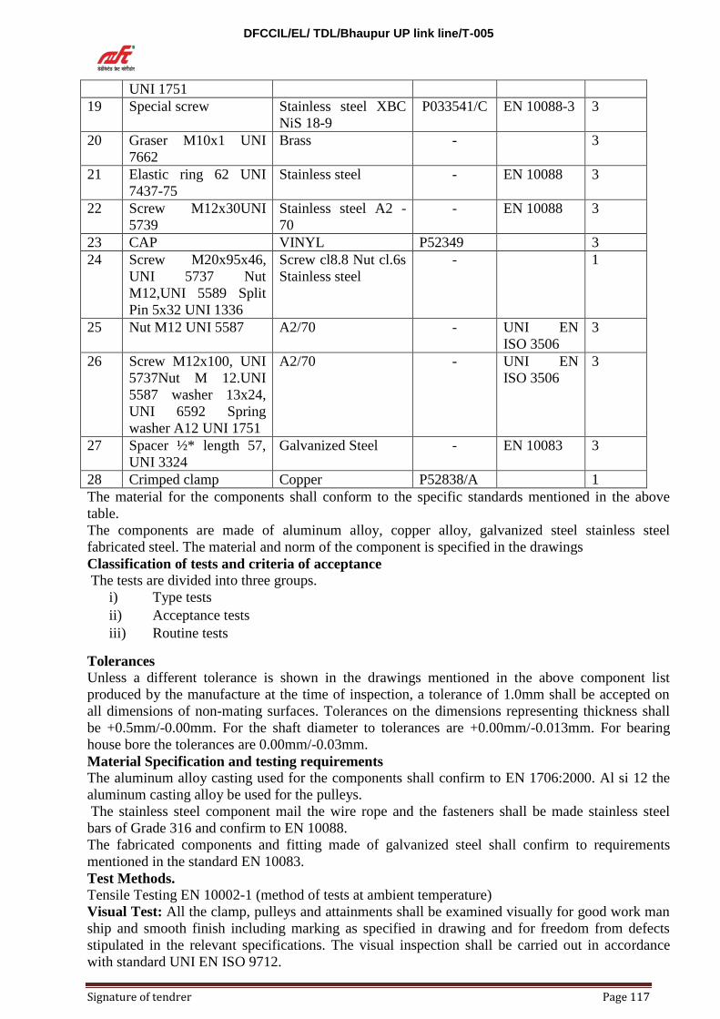
DFCCIL/EL/ TDL/Bhaupur UP link line/T-005
Signature of tendrer Page 117
UNI 1751
19 Special screw Stainless steel XBC
NiS 18-9
P033541/C EN 10088-3 3
20 Graser M10x1 UNI
7662
Brass - 3
21 Elastic ring 62 UNI
7437-75
Stainless steel - EN 10088 3
22 Screw M12x30UNI
5739
Stainless steel A2 -
70
- EN 10088 3
23 CAP VINYL P52349 3
24 Screw M20x95x46,
UNI 5737 Nut
M12,UNI 5589 Split
Pin 5x32 UNI 1336
Screw cl8.8 Nut cl.6s
Stainless steel
- 1
25 Nut M12 UNI 5587 A2/70 - UNI EN
ISO 3506
3
26 Screw M12x100, UNI
5737Nut M 12.UNI
5587 washer 13x24,
UNI 6592 Spring
washer A12 UNI 1751
A2/70 - UNI EN
ISO 3506
3
27 Spacer ½* length 57,
UNI 3324
Galvanized Steel - EN 10083 3
28 Crimped clamp Copper P52838/A 1
The material for the components shall conform to the specific standards mentioned in the above
table.
The components are made of aluminum alloy, copper alloy, galvanized steel stainless steel
fabricated steel. The material and norm of the component is specified in the drawings
Classification of tests and criteria of acceptance
The tests are divided into three groups.
i) Type tests
ii) Acceptance tests
iii) Routine tests
Tolerances
Unless a different tolerance is shown in the drawings mentioned in the above component list
produced by the manufacture at the time of inspection, a tolerance of 1.0mm shall be accepted on
all dimensions of non-mating surfaces. Tolerances on the dimensions representing thickness shall
be +0.5mm/-0.00mm. For the shaft diameter to tolerances are +0.00mm/-0.013mm. For bearing
house bore the tolerances are 0.00mm/-0.03mm.
Material Specification and testing requirements
The aluminum alloy casting used for the components shall confirm to EN 1706:2000. Al si 12 the
aluminum casting alloy be used for the pulleys.
The stainless steel component mail the wire rope and the fasteners shall be made stainless steel
bars of Grade 316 and confirm to EN 10088.
The fabricated components and fitting made of galvanized steel shall confirm to requirements
mentioned in the standard EN 10083.
Test Methods.
Tensile Testing EN 10002-1 (method of tests at ambient temperature)
Visual Test: All the clamp, pulleys and attainments shall be examined visually for good work man
ship and smooth finish including marking as specified in drawing and for freedom from defects
stipulated in the relevant specifications. The visual inspection shall be carried out in accordance
with standard UNI EN ISO 9712.

DFCCIL/EL/ TDL/Bhaupur UP link line/T-005
Signature of tendrer Page 118
Chemical Composition Test: Chemical composition shall be expressed in accordance with the
writing rules given in the following European standards.
For Aluminum and aluminum castings EN 1706 and EN 577-3.
For Coper and Copper alloy EN 1982.
For Stainless Components and Fasteners EN 10083-2
Material shall confirm to the relevant specification and as per the composition given in the table
respective standards. The vendor shall produce the certificate of Rave material and certificate of
ingots in conformance to the table given in the standards.
Tensile Test.
The tension device shall be tested in accordance with the requirements given in 7.5 of EN 50119
which is reproduced below.
The tensioning device shall maintain the mechanical tension in the overhead contact line conductor
(s) defined in the specification i.e. 3060 kgf (1428kgf in catenary wire= 1632 kgf in contact wire).
The device shall be designed to achieve an efficiency > 97% over the specified design temperature
range of the equipment.
Efficiency Test.
The efficiency of ATD shall be >97% and shall be proven by the suppler by means of a test.

DFCCIL/EL/ TDL/Bhaupur UP link line/T-005
Signature of tendrer Page 119
PART - III
LIST OF STANDARD DRAWINGS AND SPECIFICATIONS FOR INDIGENOUS ITEMS
This Annexure contains reference to drawing number, charts, schedule specifications and other data
referred to in various paragraphs of this tender paper.
All references to drawings, charts, schedules or specifications given in this annexure shall be taken
to be the version available as on date of issue of LOA of such drawings, charts and schedule of
specifications as issued by the Purchaser.
LIST OF STANDARD DRAWINGS:
Sl No. Brief Description Drawing Mod
No.
Series Number
1. Extra allowance for setting of structures on
curves (1676 mm Broad gauge)
ETI/OHE/G 00111 Sh-1 B
2. Standard setting of structures in the vicinity of
signals (broad gauge)
-do- 00112 C
3. Typical design of bearing foundation -do- 00131 -
4. Deleted-
5. Typical design of cantilever mast RE/33/G 00141 Sh.3 -
6. Standard drilling schedule of OHE masts 9.5 m
long RSJ and BFB respectively
ETI/OHE/G 00144 Sh.3 C
7. Span and stagger chart for (conventional OHE,
Cad-Cu Catenary & Cu Contact Wire) wind
pressure 75,112.5 & 150 kgf /sq. meter
ETI/OHE/G 00202 -
8. Employment schedule for Cantilever mast
regulated OHE cat.65/Cu and Cont 107/Cu,
WP 112.5 kgf/Sq m without Ex & without RC
ETI/OHE/G 00153 Sh.1 E
9. Employment schedule for Cantilever mast
regulated OHE cat.65/Cu and Cont 107/Cu,
WP 112.5 kgf/sq m without Ex & without RC
ETI/OHE/G 00153 Sh.2 E
10. Employment schedule for Cantilever mast
regulated OHE cat.65/Cu and Cont 107/Cu,
WP 112.5 kgf/sq m without Ex & with RC.
ETI/OHE/G 00153 Sh.3 E
11. Employment schedule for Cantilever mast
regulated OHE cat.65/Cu and Cont 107/Cu,
WP 112.5 kgf/sq m without Ex
& without RC.
ETI/OHE/G 00153 Sh.4 D
12. Employment schedule for Cantilever mast
regulated OHE cat.65/Cu and Cont 107/Cu,
WP 112.5 kgf/sq m at 35 XC & 28 kgf/Sq m at
4xC without (E x & RC)
ETI/OHE/G 00154 D
13. Employment schedule of bracket tubes
regulated pressure Conventional OHE (Cd Cu
catenary & Cu contact wire 1000 kgf tension
Each).
ETI/OHE/G 00158 Sh.1 (
for wind
pressure 75
kgf/sq m)
-
-do- Sh.2(for wind
pressure 112.5
kgf/sq m)
-do- Sh.3(for wind

DFCCIL/EL/ TDL/Bhaupur UP link line/T-005
Signature of tendrer Page 120
pressure 150
kgf/sq.m.)
14. Dropper schedule for – un-insulated Overlap
spans.
-do- 00169 A
15. Dropper schedule for – insulated Overlap
spans.
-do- 00170 A
16. Dropper schedule for conventional regulated
OHE. With Zero pressure (1400/1400).
-do- 00177 A
17. Adjustment chart of Regulating equipment 3-
pulley Type 3:1 ratio.
-do- 00195 A
18. Schematic arrangement of regulated OHE -do- 02101 A
19. Schematic arrangement of un-insulated
overlap(3&4 span overlaps)
-do- 02121 Sh.4 A
20. Schematic arrangement of insulated overlap. ETI/OHE/G 02131 Sh.3 A
21. Termination arrangement of OHE with 3 pulley
type regulating equipment ( 3:1 ratio).
ETI/OHE/G 04212 B
22. General distribution of droppers. ETI/OHE/G 00161 -
23. Outline of Pantograph ( Broad gauge and meter
gauge)
RE/33/G 00181 A
24. General formation of single track
Embankments and cutting (Broad gauge)
RE/33/G
Sh.1
01101 A
25. General formation of double track in
Embankments and cutting (Broad gauge)
-do- 01102 Sh.1 A
26. General formation of multiple tracks (1675mm.
Gauge).
-do- 01103 Sh.1 A
27. Standard anchor arrangement -do- 01401 E
28. Anchor arrangement with dwarf mast. ETI/OHE/G 01402 B
29. Schedule of anchor block for BG track -do- 01403 Sh.1 D
30. Double guy rod arrangement with anchor block
for BG track..
-do- 01403 Sh.2 C
31. Schedule of anchor block for BG track ( Black
cotton soil).
-do- 01403 Sh.3 B
32. Standard guide tube arrangement on a mast and
structures.
ETI/OHE/G 01505 -
33. Trapezoidal counter weight arrangement on
OHE structures.
-do- 01502 -
34. Arrangement of 3 KV & 25 KV Pedestal
insulator supports on OHE masts and portals.
-do- 01601 -
35. Standard arrangement for mounting of number
plate on OHE structure.
ETI/OHE/G 01701 A
36. Schematic arrangement of regulated overhead
equipment.
-do- 02101 A
37. Typical arrangements of OHE on cantilever
masts for double track section.
-do- 02102 -
38. Typical arrangement for fixing of bracket
assembly on 9.5 m mast and structure to suit
raising of tracks( in future)
-do- 02102 Sh.3 -
39. Mast on platforms (1676mm. Gauge) ETI/OHE/G 02104 Sh.2 A
40. Details of bracket arrangement on tangent and
curved tracks.
-do- 02106 Sh.1 A
41. Details of bracket arrangement for OHE ( High
speed).
-do- 02106 Sh.3 C

DFCCIL/EL/ TDL/Bhaupur UP link line/T-005
Signature of tendrer Page 121
42. Single bracket assembly on structures and
dropped arms.
RE/33/G 02107 D
43. Box type cantilever arrangement. ETI/OHE/G 02108 A
44. Arrangement at anti-creep. -do- 02111 A
45. Standard cantilever arrangement for boom
anchor anti-creep location.
-do- 02113 -
46. Schematic arrangement of un-insulated over
Lap (type-I) 3 & 4 span overlaps.
RE/33/G 02121 Sh.1 F
47. Schematic arrangement of insulated overlap. ETI/OHE/G 02131 Sh.1
48. General arrangement of regulated OHE at
turnout (overlap & crossed type).
-do- 02141 C
49. General arrangement of regulated OHE at cross
over (overlap & crossed type).
-do- 02151
50. Arrangement of neutral section -do- 02161 Sh.1 of
2.
C
51. Arrangement of neutral section assembly
(PTFE Type) at SWS
-do- 02162 -
52. Arrangement of short neutral section. -do- 02161 Sh.2 of
2
-
53. Schematic arrangement of unregulated
overhead equipment.
-do- 03101 -
54. Standard termination of OHE (Regulated & un-
regulated)
ETI/OHE/G 03121 D
55. General arrangement of unregulated OHE at
turnout (overlap and crossed type).
-do- 03151 -
56. General arrangement of unregulated OHE
crossovers and diamond crossings (overlap and
crossed type).
-do- 03152 Sh.1 -
57. General arrangement of unregulated OHE
crossovers and diamond crossings.
-do- 03152 Sh.2 -
58. General arrangement of head span. -do- 03301 -
59. General arrangement of pull off. -do- 03201 A
60. In span jumper connection between cat nary &
contact wire.
-do- 05101 -
61. Continuity jumper connection at un-insulated
overlap.
-do- 05102 C
62. Arrangement of anti-theft jumper. -do- 05107 A
63. Connection at turnouts. -do- 05103 B
64. Potential equalizer connection at insulated
overlap and neutral section.
-do- 05104 -
65. Connections at diamond crossing. -do- 05106 A
66. General arrangement of connections to OHE by
copper cross feeder (150)
-do- 05121 Sh.1 C
67. General arrangement of connections at
switching station on double track section by
copper cross feeder (150)
ETI/OHE/G 05122 Sh.1 C
68. General arrangement of connections at
switching station on multiple track section by
copper cross feeder (150)
ETI/OHE/G 05123 Sh.1 C
69. Suspension of 25kv feeder (spider) on OHE
masts.
-do- 05143 B
70. Termination of feeder, return conductor and RE/33/G 05145-1

DFCCIL/EL/ TDL/Bhaupur UP link line/T-005
Signature of tendrer Page 122
return feeder (copper & aluminum).
71. Arrangement of suspension of double spider 25
KV feeder and return feeder between sub-
station and feeding station.
-do- 05152 C
72. Assembly of section insulators. 051181 C
73. General arrangement of earth wire on OHE
mast.
ETI/OHE/G 05201 A
74. General arrangement of earth wire on OHE
mast.
ETI/OHE/G 05201-1 -
75. Arrangement of transverse bonds ETI/OHE/G 05251 A
76. Connection of return conductor to track. -do- 05306 F
77. Suspension arrangement of aluminum return
conductor (spider) on traction structures.
-do- 05306 B
78. Suspension of return conductor (spider) from
boom of structures (with clevis type disc
insulators).
-do- 05312 A
79. Connections between OHE and aluminum
return conductor at booster stations.
ETI/OHE/G 05413 B
80. Mounting of 25kv isolators on OHE structures
(General arrangement).
-do- 05513 Sh.1 A
81. Details of small part steel work for supporting
25kv isolator on new T.C.C. boom.
-do- 05513 Sh.2 A
82. Connection from isolator to OHE -do- 05516 A
83. Characteristics of conductors/bus bar for 25kv
AC traction
-do- 05600 A
84. Arrangement of mounting 25 KV/240,10 KVA
LT supply transformer.
ETI/OHE/G 05522 -
85. Employment schedule for cantilever mast
regulated OHE Caty.65 Cu.Cont.107/CU (WP
75 kgf/sq. m.)
ETI/C 0702(OHE
only)(Sh.1)
A
ETI/C (OHE+EW)(S
h.2)
A
86. Employment schedule for Tramway type
regulated OHE (WP 75 kgf/sq. m.) without
EW& without RC.
ETI/C 0704 A
87. Employment schedule for 8”x8”35 lbs BFB
(9.5 M. long) (WP 112.5 kgf/sq. m. Cat.65/CU
& Cont.107/Cu. cantilever mast regulated OHE
Caty.65 Cu.Cont.107/CU.
ETI/C 0702(OHE
only)(Sh.1)
A
88. Employment Schedule for OHE mast overlap
central location with 3.0 m implantation. Cat.
65/Cu & Cont. 107/Cu. WP 75 kgf/sq. m.
-do- 0709 A
89. Employment Schedule for OHE mast overlap
central location with 3.0 m implantation. Cat.
65/Cu & Cont. 107/Cu. WP 112.5 kgf/sq. m.
-do- 0710 A
90. Employment Schedule for OHE mast (9.5m)
overlap central location with 3.0 m
implantation. Cat. 65/Cu & Cont. 107/Cu. WP
75 kgf/sq. m.
-do- 0711 A
91. Employment Schedule for OHE mast overlap
central location with 3.0 m implantation. Cat.
-do- 0712 A

DFCCIL/EL/ TDL/Bhaupur UP link line/T-005
Signature of tendrer Page 123
65/Cu & Cont. 107/Cu. WP 112.5 kgf/sq. m.
92. Employment Schedule for (9.5m) long
200x200x49.9 kgf.OHE mast overlap inter
location with 3.0 m implantation. Cat. 65/Cu &
Cont. 107/Cu. WP 75 kgf/sq. m.
-do- 0713 A
93. Employment Schedule for 9.5 m. long
200x200x49.9 kg mast Cat. 65/Cu & Cont.
107/Cu. WP 112.5 kgf/sq. m.
-do- 0714 A
94. Employment Schedule for OHE mast ( 9.5 m)
overlap Anchor location with 3.0 m
implantation. Cat. 65/Cu & Cont. 107/Cu. WP
75 kgf/sq. m.
-do- 0715 A
95. Employment Schedule for OHE mast overlap
anchor location with 3.0 m implantation. Cat.
65/Cu & Cont. 107/Cu. WP 112.5 kgf/sq. m.
-do- 0716 A
96. Employment schedule 0721 for regulated OHE
mast (9.5 m) wind pressure 75 kgf/sq. m. for
composite OHE (1000&1000)kgf. tension.
ETI/C 0721 (OHE
only)(Sh.1)
-do- (OHE+EW)(Sh2
-do- (OHE+RC)
(Sh.3)
-do- (OHE+EW+RC)(Sh.4)
97. Employment Schedule for regulated OHE mast
(9.5m) wind pressure 75 kgf/sq. m. for
composite OHE with extra setting distance
Overlap Anchor location.
-do- 0722 -
98. Employment Schedule for regulated OHE mast
(9.5m) wind pressure 75 kgf/sq. m. for
composite OHE with extra setting distance
Overlap center location.
-do- 0723 -
99. Employment Schedule for regulated OHE mast
(9.5m) wind pressure 75 kgf/sq. m. for
composite OHE with extra setting distance
Anchor location.
-do- 0724 -
100. Employment Schedule for pre-stressed concrete
mast (PC-42) 9.5 m long, for conventional
OHE, Normal Location (WP 150,112.5 and 75
kgf/sq. m.) regulated OHE mast (9.5m) wind
pressure 75 kgf/sq. m.
-do- 0725 -
101. Standard portal (N.O,P,R,G & Double BFB
type)
ETI/C 0064
102. Volume chart and equivalent chart of
foundation.
-do- 0058 Sh.1 E
103. -do- new pure gravity -do- 0058 Sh.2A C
104. -do- Dry black cotton soil (NBC type)A -do- 0058 Sh.3A -
105. -do- new pure gravity(500m,exposed) -do- 0058 Sh.4 A
106. -do- Dry black cotton soil (NBC type)2.5m
depth.
-do- 0058 Sh.5 A
107. -do- (for a direct load of 4000 Kg). -do- 0058 Sh.6 A
108. Special BFB portal for 5 tracks(general C
arrangement)
ETI/C 0026 Sh.1 C
109. Protective screen at foot over bridge and road -do- 008 F

DFCCIL/EL/ TDL/Bhaupur UP link line/T-005
Signature of tendrer Page 124
over bridge.
110. Chart for portal foundation -do- 005/68
111. Muff for OHE structures -do- 007/68 D
112. Structure muff for sand core foundations. -do- 0012/69 D
113. 9.5 m standard traction mast (fabricated ‘K’
series)
-do- 0018-2 D
114. Remote control cubicle at switching station,
foundation, RCC slab Building plan & steel
door.
-do- 0067 B
115. 9.5 m standard traction mast (fabricated with
bottom plates ‘B’ series)
ETI/C 0071 E
116. Details of OHE foundation in soft rock
(bearing capacity 45,000 Kgf/sq. m.
-do- 0059 A
117. Details of foundation for fencing upright -do- 0032 A
118. Employment schedule for switching and
booster station main masts
ETI/C 0185 B
119. Drilling schedule for S-1 mast ETI/C 0030 F
120. -do- S-2 mast -do- 0031 D
121. -do- S-3 mast (length 11.4m). -do- 0180 C
122. Drilling schedule for 8”x6”x35 lbs RSJ mast
8.0 m long for booster transformer station Type
S-4
-do- 0036 E
123. Drilling schedule for S-5 mast (11.4m long) -do- 0042 E
124. -do- S-6 mast (length 12.4m) -do- 0181 C
125. -do- S-7 –do- -do- 0182 C
126. -do- S-8 -do- -do- 0182 C
127. -do- S-9 mast (length 9.4m)
-do- 0184 C
128. General arrangement & details of fencing
panels & gate for switching station.
-do- 0186 Sh.1 E
129. Details of fencing upright and anti-climbing
device for switching station
-do- 0186 Sh.2 E
130. S-100 fabricated mast for mounting LT supply
transformer and drop
out fuse switch at switching station.
-do- 0043 B
131. S-101 details of mast for supporting isolator
inside switching station.
ETI/C 0044 A
132. Details of anchor beam or SP, SSP, & FP. -do- 0033 D
133. Details of small part steel for switching station. ETI/C 0034 Sh.1 K
134. Details of bracing for switching & B.T. masts. ETI/C 0034 Sh.2 B
135. Details of small parts steel of out rigger for
switching stations and booster transformer
stations.
0037 C
136. Details of small parts for booster transformer
stations.
ETI/C 0040 E
137. Details of pre-cast cable trench for switching
station.
-do- 0038 E
138. Standard ‘R’ type portal rod laced general
arrangement.
-do- 0011/69 Sh.1 C
139. Standard ‘G’ type portal special upright and
end piece.
-do- 0056 C
140. Short bored pile foundation for traction -do- 0062 C

DFCCIL/EL/ TDL/Bhaupur UP link line/T-005
Signature of tendrer Page 125
mast(permissible BM & volume)
141. Chart for portal foundations in dry black cotton
soil safe bearing capacity 16500 Kg/sq.mm.
-do- 0063 B
142. Dwarf mast foundation on wet & dry black
cotton soil.
RE/ALD/OH
E/SK/C
02 -
143. Typical design of new pure gravity foundation. ETI/SK/C 131 -
144. Typical design of side gravity foundation -do- 142 -
145. Rock Anchor for BG Track. ETI/SK/C 208 -
146. Bracket fitting for PSC Masts capacity- 4.200
kg. m.
ETI/SK/C 214 Sh.1 E
147. SPS details of earth wire clamp of PSC mast. ETI/SK/C 214 Sh.1 of 2 -
148. Special arrangement of OHE under over line
structure.
ETI/OHE/SK 529 D
149. Ear thing and bonding of PSC mast ETI/OHE/SK 537 Sh.2 of 2 D
150. Typical Ear thing arrangement in SPUN D PSC
Mast with 18mm. dia rod.
-do- 537 Sh.2 B
151. Arrangement of antitheft jumper at overlap. ETI/OHE/SK 566 -
152. Cat nary dropper assembly ETI/OHE/P 1190 B
153. Parallel clamp (20/20) ETI/OHE/P 1550 E
154. Standard guide tube assembly. ETI/OHE/P 5060-2 C
155. Standard anti-wind clamp. -do- 2550-1/2 L
156. Multiple cantilever cross arm assembly. RE/33/P 3120 H
157. Anchor fitting assembly on rolled sections. ETI/OHE/P 3230 C
158. Anchor fitting assembly on ‘K’ series, TCC
masts and ‘P’ type portal upright.
-do- 3240 D
159. Anchor assembly on ‘N’ and ‘O’ type portal
upright.
-do- 3250 D
160. Structure bonds -do- 7000 E
161. Ear thing station -do- 7020 B
162. Longitudinal rail bond -do- 7030 F
163. Short super mast assembly. ETI/C/P 8010 G
164. Long super mast assembly -do- 8020 C
165. Bracket attachment assembly on portal upright
(N,O,R,P,G & BFB Type).
-do- 8030 B
166. Super mast assembly on portals. -do- 8050 C
167. Medium super mast assembly. ETI/OHE/P 8060 C
168. Compensating plate. -do- 5191-1/2 D
169. Suspension clamp. RE/33/P 1160 J
170. Double suspension clamp. -do- 1170 K
171. Double suspension lock plate. -do- 1172 C
172. Cat nary splice (65) ETI/OHE/P 1090 -
173. Typical location & schematic connection
diagram for a three interrupter switching
station.
ETI/PSI 003 E
174. Typical general arrangement of a three
interrupter switching station.
-do- 004 E
175. Typical location plan & general arrangement
for sectioning & paralleling station.
-do 005 E
176. Typical location plan & arrangement for A
feeding station.
-do 006 E
177. Typical general arrangement at a Booster
transformer station (with 4 cross feeder) type-
-do 013 B

DFCCIL/EL/ TDL/Bhaupur UP link line/T-005
Signature of tendrer Page 126
III.
178. Typical general arrangement of 280 KVA
Booster transformer station ( with 4 cross
feeder type-III.
-do- 018 A
179. Typical general arrangement at a booster
transformer station. ( without cross feeder
type-I.
-do- 011 C
180. Typical number plate for auxiliary transformer. ETI/PSI/P 7525 -
181. Typical fencing and anti-climbing arrangement
at switching station.
ETI/PSI 104 E
182. Typical ear thing layout of sub-sectioning and
paralleling station.
-do- 201 B
183. Typical ear thing layout of a sectioning and
paralleling station.
-do- 202 B
184. Typical ear thing layout of a feeding station. -do- 203 B
185. Ear thing details for interrupter LT supply
transformer 25 KV lightning arrestors PT
Type-I (S-100 masts, S-101 mast, fencing
upright and n masts).
-do- 204 A
186. Typical ear thing layout at a booster
transformer stations (without cross feeder) for
Type-I & II.
-do- 211-1 A
187. Typical cable run layout of a sub-sectioning &
paralleling station.
-do- 301 C
188. Typical cable run layout of a sectioning and
paralleling station.
-do- 302 C
189. Typical cable run layout of a feeding station. -do- 303 B
190. Typical ear thing layout at a booster
transformer station ( with 4 cross feeder for
Type-III,IV and V.
ETI/PSI 212 B
191. Typical drawing for a terminal board. -do- 501 C
192. 36mm. Aluminum Bus terminal ETI/PSI/P 6480 C
193. -do- Splices. -do- 6490 B
194. -do- Tee connector. -do- 6500 C
195. 36mm. Aluminum terminal. -do- 6510 D
196. 36/15 Tap connector. -do- 6520 B
197. 36mm. Aluminum flexible bus splice. -do- 6550 B
198. 36mm. Alu. Bus splice cum tee connector. -do- 6560 B
199. Typical number plate for interrupter and double
pole isolator.
-do- 7520 B
200. Typical number plate for potential transformer
type.
-do- 7521 B
201. Typical number plate for booster transformer. -do- 7522 B
202. Standard plan Remote Control cubicle at
switching station.
RE/Civil/BS-
11/95
-
203. Typical details of pressed steel door window
and ventilator.
RE/Civil/S-
115/95
R1 -
204. Bolted base connection for portals located
n drains.
ETI/C 0010 C
205. Details of base plate for mast on drains in
station yards.
-do- 6002/68 A

DFCCIL/EL/ TDL/Bhaupur UP link line/T-005
Signature of tendrer Page 127
LIST OF STANDARD DRAWINGS FOR COMPOSITE OHE (REGULATED):
206. Employment schedule for OHE masts
unregulated OHE without RC & EW
(WP=150 kgf/m2 at 10 deg.C).
ETI/OHE/G 00150 D
207. Employment schedule of bracket tube
regulated conventional OHE (Cd-Cu catenary
and Cu-contact wire (1000 kgs tension each))
for wind pressure 150 kgf/m2 at 10 deg C.
ETI/OHE/G 00158 Sh.3 -
208. Employment schedule of bracket tubes un
regulated conventional OHE (Cd-Cu catenary
and Cu-contact wire)
ETI/OHE/G 00159
Sheet-3
-
209. Schematic arrangement of un-insulated
overlap (Al. Alloy) catenary and copper
contact wire.
ETI/OHE/G 02121 Sh.3 -
210. Schematic arrangement of insulated overlap
for (Al. Alloy) catenary & Cu Contact wire.
ETI/OHE/G 02131 Sh.2 -
211. General arrangement of regulated composite
OHE at turnouts (overlap and crossed type)
ETI/OHE/G 02141 Sh.2 -
212. Standard termination of Regulated composite
OHE.
-do- 03121 Sh.2 B
213. In span jumper connection between Alu.
Alloy cat nary & copper contact wire.
-do- 05101 Sh.2 B
214. Continuity jumper connection at un-insulated
overlap(Al. Alloy cat nary and copper contact
wire).
-do- 05102 Sh.2 -
215. Connections at turnouts for composite OHE. -do- 05103 Sh.2 -
216. Potential equalizer connection at insulated
overlap& neutral section ( Al. Alloy cat nary
& copper contact wire).
-do- 05104 Sh.2 -
217. Connection at diamond crossing for
composite OHE.
-do- 05106 Sh.2 C
218. General arrangement of connection to
composite OHE by cross feeder (SPIDER)
-do- 05124 Sh.2 C
219. General arrangement of connection at
switching station on double track section for
composite OHE.
-do- 05125 Sh.2 C
220. General arrangement of connection at
switching station on multiple track sec.(with
composite OHE and spider cross feeder).
-do- 05126 Sh.2 C
221. Assembly of section insulator (with Al. Alloy
cat nary and copper contact wire).
-do- 05181 Sh.2
222. Std. Arrangement of supporting cantilevers on
Boom of portals and TTC ( to avoid Bird’s
nesting).
ETI/C 0076 C
Employment schedule for OHE mast (9.5 M)
wind pressure 112.5 kg/f sq. m. for composite
OHE ( 1000+ 1000) Kgf Tension.
223. OHE only. ETI/C/0717 Sh.1 -
224. -do- OHE + EW Sh.2 -
225. -do- OHE + RC ETI/C/0717 Sh.3 -
226. -do- OHE+EW+RC Sh.4 -

DFCCIL/EL/ TDL/Bhaupur UP link line/T-005
Signature of tendrer Page 128
Employment schedule for OHE Mast (9.5 M)
wind pressure 112.5 kgf/sq.m. with 3.0 m
implantation composite OHE (1000+1000)
KGF Tension.
227. -do- Overlap anchor location. ETI/C/0718 -
228. -do- Overlap Central location ETI/C/0719 -
229. -do- Overlap inter location ETI/C/0720 -
230. Employment schedule for OHE mast (9.5m)
for wind pressure 150 kgf/m2 copper OHE
ETI/C 0726 Sheet-1 -
231. Employment schedule for OHE mast (9.5m)
for wind pressure 150 kgf/m2 copper OHE &
EW.
ETI/C 0726 Sheet-2 -
232. Employment schedule for OHE mast (9.5m)
for wind pressure 150 kgf/m2 copper OHE &
RC.
ETI/C 0726 Sheet-3 -
233. Employment schedule for OHE mast (9.5m)
for wind pressure 150 kgf/m2 copper OHE,
RC & EW.
ETI/C 0726 Sheet-4 -
234. Employment schedule for OHE mast (9.5m)
for wind pressure 150 kgf/m2 copper OHE
with higher implantation overlap anchor
location.
-do- 0727 -
235. Employment schedule for OHE mast (9.5m)
for wind pressure 150 kgf/m2 copper OHE
with higher implantation overlap central
location.
-do- 0728 -
236. Employment schedule for OHE mast (9.5m)
for wind pressure 150 kgf/m2 copper OHE
with higher implantation overlap inter
location.
-do- 0729 -
237. Employment schedule for Tramway type
regulated OHE WP 150 kgf/m2 without RC &
EW.
-do- 0706 A
238. Aluminum Alloy cat nary suspension clamp
(MCI)
ETI/OHE/S
K
176 D
239. Double suspension lock body (Galvanized
MCI)
-do- 205 B
240. Parallel grove clamp (14/9). -do- 123 D
241. Parallel grove clamp (18/14) -do- 231 D
242. Cat nary dropper clip assembly with
bimetallic washer.
-do- 333 D
243. Envelope type end fitting assembly for all Al.
Alloy standard Cat. Wire (size 19/2.79mm).
-do- 436 B
244. Crimp type repair sleeve for AAA standard
cat nary wire.
-do- 285 C
245. Cat nary splice (cone type) AL. Alloy cat
nary.
-do- 134 D
246. Aluminum cat nary suspension clamp
assembly (MCI)
-do- 468 A
247. Double suspension clamp assembly (MCI for
Al. Alloy. Cat nary).
-do- 469 A
248. Span and stagger chart for composite OHE -do- 375 A

DFCCIL/EL/ TDL/Bhaupur UP link line/T-005
Signature of tendrer Page 129
249. Double suspension clamp body for Al. Alloy.
Cat nary.
-do- 1171-1 A
LIST OF STANDARD SPECIFICATIONS:
S. NO. TITLE OF SPECIFICATION SPECIFICATION NO.
1 2 3
1. Annealed standard copper conductor for jumper
wire.
ETI/OHE/3(2/94) with A&C slip No.1 of
4/95.
2. Copper bus bar RE/30/OHE/5(11/60)
3. Structural steel tubes. ETI/OHE/11(5/89)
4. Hot dip zinc galvanization of steel mast (Rolled
and Fabricated) tube and fittings used on 25 kV
AC OHE.
ETI/OHE/13(4/84) with A&C slip No.1
of 5/86, 2 of 4/90 and 3 of 4/90.
5. Stainless steel wire rope. TI/SPC/OHE/WR/1060(06/06) with
A&C slip No. 2 of 05/07
6. Solid core porcelain insulators for 25 kV, 50 Hz
Single phase overhead traction lines.
TI/SPC/OHE/INS/0070(04/07) with A &
C Slip No. 1 & 2 (10/16)
7. 25 KV single and double pole isolators. ETI/OHE/16(1/94) with A & C slip No.
1 & 2 (03/04)
8. Steel Fasteners and Stainless Steel Fasteners for
25 kV AC Traction Steel Overhead Equipment
TI/SPC/OHE/FASTENERS/0120 with A
& C slip No. 5 (03/13)
9. Aluminum alloy section and tubes. ETI/OHE/21(9/74).
10. Principles for OHE Layout Plans and Sectioning
Diagrams for 25 kV AC Traction
ETI/OHE/53 (6/88) with A & C slip no.
5 (11/06)
11. Section insulators assembly. TI/SPC/OHE/LWTSI/0060 (Rev. 1) with
A & C slip no. 1 (07/16)
12. Enameled steel plates ETI/OHE/33(08/85).
13. Retro-reflective Structure Number Plates ETI/OHE/33A(12/97) with A & C Slip
No. 1 to 8 (11/12)
14. Galvanized steel wire Rope ETI/OHE/36(12/73) with A&C slip No.1
of (5/98).
15.
Regulating equipment
(a) winch type (5:1)
ETI/OHE/48(7/84), with A&C slip No.3
(12/04).
(b) 3 pulley type (3:1) TI/SPC/OHE/ATD/0060 Rev. 1 with
A&C slip No. 1 (09/16)
16. Fittings for 25 kV, 50 HZ, AC Overhead Traction
equipment.
ETI/SPC/OHE/FITTINGS/0130 with
A&C slip No.1 (10/13)
17. Cadmium copper conductors for overhead Rly
Traction
ETI/OHE/50(6/97) with A&C slip No. 1
to 5 (09/16)
18. All Alu. Alloy, Stranded catenary wire 19/2.79
mm.
ETI/OHE/54 (2/85) with A&C slip No.2
(10/92)
19. Bimetallic (AL/Cu) strip for 25 KV traction OHE. ETI/OHE/55(4/90)
20. Short neutral section assembly (phase Break). TISPC/OHESNS/0000 (Rev. 1) with
A&C slip No. 1 (01/16).
21. Code for bonding and earthing for 25 kV, single
phase, 50 Hz, AC Traction system.
ETI/OHE/71(11/90) with A&C slip No.2
(3/93)
22. Insulated cadmium copper catenary 19/2.10 mm
dia for provision under overline structures in the
25 kV, AC Electrical Traction.
TI/SPC/OHE/INSCAT/0000 with A & C
slip No. 1 & 2 (09/16).
23. Battery charger for 110 Volt, 40 A-h battery ETI/PSI/1(6/81).
24. Metal Oxyde gapless type lightening arrester for ETI/PSI/MOGTLA/0101 (02/15).

DFCCIL/EL/ TDL/Bhaupur UP link line/T-005
Signature of tendrer Page 130
use on Railway Traction sub-stations and
switching stations
25. 220 kV/132 kV/110 kV/66 kV/25 kV Potential
transformers
TI/SPC/PSI/PTS/0990 (09/99) with
A&C slip No.4(6/97).
26. 25 KV Drop out fuse switch and operating pole
for use with 10 KVA and 100 KVA 25 KV/230
volt LT supply transformer.
ETI/PSI/14(1/86) with A&C slip No.5
(04/09)
27. 25 KV/240 V Auxiliary Transformer (5 kVA/ 10
KVA/ 25 kVA/ 50 kVA
ETI/PSI/15(08/2003)
28. 110 Volt, 40 A-h Lead Acid Batteries ETI/PSI/21(6/81) with A&C slip No.1 of
7/81.
29. 25 kV/ 240 V Auxiliary Transformers, 100 kVA ETI/PSI/15A (07/82) with A & C Slip
No. 1 (09/89)
30. 25 KV single pole, double pole, pole mounted,
outdoor vacuum circuit breaker (VCB) and
vacuum Interrupter (BM)
TI/SPC/PSI/LVCBIN/0120 Rev.0
(12/13) with A & C slip No. 1 (10/16)
NOTE:
1) Above specifications can be purchased from RDSO/office of CAO/CORE/ALD on payment
of their cost.
2) For structural steel (standard quantity) please refer IS:2062 – 1992.
3) Any amendment in specification and drawings subsequent to LOA, if required to be carried out
shall need approval of DFCCIL duly considering the financial implication of the same either in
upward or downward direction.

DFCCIL/EL/ TDL/Bhaupur UP link line/T-005
Signature of tendrer Page 131
Annexure-III
CERTIFICATION OF FAMILIARISATION
A. I/We hereby solemnly declare that I/We have visited the site of work and have familiarized myself/ourselves of the working conditions there in all respects and in particular, the following:
a) Topography of the Area.
b) Climatic condition and law and order situation in project area.
B. I/We have kept myself/ourselves fully informed of the provisions of this tender document comprising Instructions to the Tenderers, General Conditions of the Contract, Special Conditions, special terms and conditions apart from information conveyed to me/us through various other provisions in this tender document.
C. I/We have quoted my / our rates as “Percentage above / below / at par” of costs as per Schedule
of items Rates in Offer Sheet, taking into account all the factors given above.
(Signature of Tenderer/s)
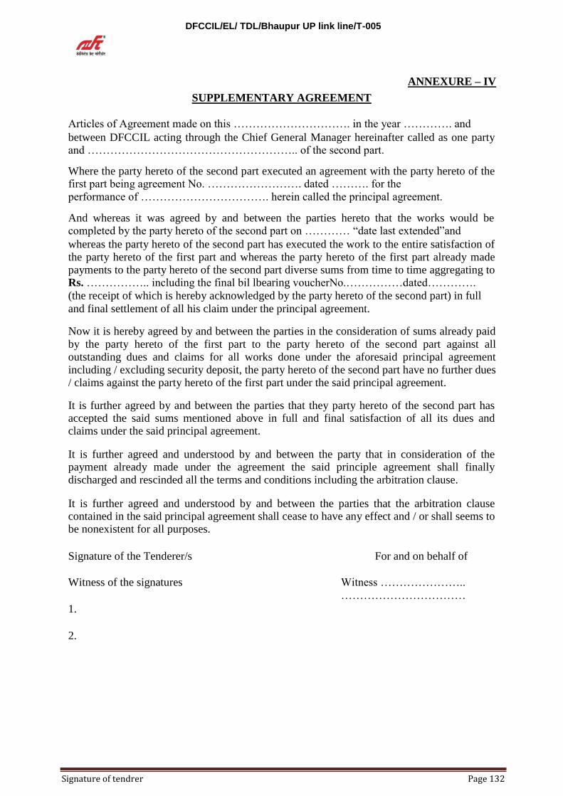
DFCCIL/EL/ TDL/Bhaupur UP link line/T-005
Signature of tendrer Page 132
ANNEXURE – IV
SUPPLEMENTARY AGREEMENT
Articles of Agreement made on this …………………………. in the year …………. and between DFCCIL acting through the Chief General Manager hereinafter called as one party and ……………………………………………….. of the second part. Where the party hereto of the second part executed an agreement with the party hereto of the first part being agreement No. ……………………. dated ………. for the performance of ……………………………. herein called the principal agreement. And whereas it was agreed by and between the parties hereto that the works would be completed by the party hereto of the second part on ………… “date last extended”and whereas the party hereto of the second part has executed the work to the entire satisfaction of the party hereto of the first part and whereas the party hereto of the first part already made payments to the party hereto of the second part diverse sums from time to time aggregating to Rs. …………….. including the final bil lbearing voucherNo.……………dated………….
(the receipt of which is hereby acknowledged by the party hereto of the second part) in full
and final settlement of all his claim under the principal agreement. Now it is hereby agreed by and between the parties in the consideration of sums already paid
by the party hereto of the first part to the party hereto of the second part against all outstanding dues and claims for all works done under the aforesaid principal agreement including / excluding security deposit, the party hereto of the second part have no further dues / claims against the party hereto of the first part under the said principal agreement. It is further agreed by and between the parties that they party hereto of the second part has accepted the said sums mentioned above in full and final satisfaction of all its dues and claims under the said principal agreement. It is further agreed and understood by and between the party that in consideration of the payment already made under the agreement the said principle agreement shall finally discharged and rescinded all the terms and conditions including the arbitration clause. It is further agreed and understood by and between the parties that the arbitration clause contained in the said principal agreement shall cease to have any effect and / or shall seems to be nonexistent for all purposes.
Signature of the Tenderer/s
For and on behalf of
Witness of the signatures
Witness …………………..
…………………………… 1.
2.

DFCCIL/EL/ TDL/Bhaupur UP link line/T-005
Signature of tendrer Page 133
ANNEXURE-V AFFIDAVIT
FORMAT FOR AFFIDAVIT TO BE UPLOADED BY TENDERER ALONGWITH THE TENDER
DOCUMENTS
(To be executed in presence of Public notary on non-judicial stamp paper of the value of Rs. 100/-. The
stamp paper has to be in the name of the tenderer) **
I ... .........(Name and designation)** appointed as the attorney/authorized signatory of the
tenderer (including its constituents),M/s…………………………………(hereinafter called the tenderer) for
the purpose of the Tender documents for the work of ……………………….as per the E- Tender No.: ------
Date---------- of (DFCCIL ), do hereby solemnly affirm and state on the behalf of the tenderer including its
constituents as under:
1) I/we the tenderer (s), am/are signing this document after carefully reading the contents.
2) I/We the tenderer(s) also accept all the conditions of the tender and have signed all the pages in
confirmation thereof.
3) I/we hereby declare that I/we have downloaded the tender documents from Indian Railway
website www.ireps.gov.in . I/we have verified the content of the document from the website and
there is no addition, no deletion or no alteration to the content of the tender document. In case of
any discrepancy noticed at any stage i.e. evaluation of tenders, execution of work or final
payment of the contract, the master copy available with the DFCCIL shall be final and binding
upon me/us.
4) I/we declare and certify that I/we have not made any misleading or false representation in the
forms, statements and attachments in proof of the qualification requirements.
5) I/ We also understand that my/our offer will be evaluated based on the
documents/credentials submitted along with the offer and same shall be binding upon
me/us.
6) I/We declare that the information and documents submitted along with the tender by me/us
are correct and I/we are fully responsible for the correctness of the information and
documents, submitted by us.
7) I/we undersigned that if the certificates regarding eligibility criteria submitted by us are found to
be forged/false or incorrect at any time during process for evaluation of tenders, it shall lead to
forfeiture of the tender EMD besides banning of business for five year on entire IR. Further, I/we
(insert name of the tenderer )**…………………………………..and all my/our constituents
understand that my/our offer shall be summarily rejected.
8) I/we also understand that if the certificates submitted by us are found to be false/forged or
incorrect at any time after the award of the contract, it will lead to termination of the contract,
along with forfeiture of EMD/SD and Performance guarantee besides any other action provided
in the contract including banning of business for five year on entire IR.
DEPONENT
SEAL AND SIGNATURE
OF THE TENDERER
VERIFICATION
I/We above named tenderer do hereby solemnly affirm and verify that the contents of my/our
above affidavit are true and correct. Nothing has been concealed and no part of it is false.
DEPONENT
SEAL AND SIGNATURE
OF THE TENDERER
Place:
Dated:
**The contents in Italics are only for guidance purpose. Details as appropriate, are to be filled in
suitably by tenderer. Attestation before Magistrate/Notary Public .

DFCCIL/EL/ TDL/Bhaupur UP link line/T-005
Signature of tendrer Page 134
ANNEXURE-VI
(Guarantee –Bond offered by bank to DFCC in connection with the execution ofContracts)
(SD)
GUARANTEE BOND FORMAT
(To be used by approved Schedule Banks)
1. In consideration of the Employer DFCCIL (herewith called “ The Employer”) having
agreed to exempt____________________(hereinafter called “The said Contractor(s)”) from the demand, under the terms and conditions of an Agreement No……………. dated____________________made between ______and __________________for___________________________(hereinafter called the
“The Said Agreement”) of security deposit for the due fulfillment by the said contractor(s) of the terms and conditions contained in the said
Agreement,onproductionofaBankGuaranteefor Rs._____________(Rupees__________only),we, _________________(indicate the name of the bank) (hereinafter referred to as “ The Bank”) at the request of contractor(s) do hereby undertake to pay to the Employer an amount not exceeding Rs._____________________________against any loss or damage caused to or suffered or would be caused to or suffered by the Employer by reason of any breach by the said contractor(s) of any of the terms and conditions contained in the said Agreement.
2. We_________________________________________(indicate the name of the Bank)
do hereby undertake to pay the amounts due and payable under this Guarantee without
any demur merely on a demand from the DFCCIL stating that the amount claimed is
due by way of loss or damages caused to or would be caused to or suffered by the
DFCCIL by reason of any breach by the said Contractor(s)of any of the terms or
conditions contained in the said Agreement or by reason of the Contractor(s) failure to
perform the said Agreement. Any such demand made on the Bank shall be conclusive
as regards the amount due and payable by the Bank under this Guarantee. However,
our liability under this Guarantee shall be restricted to an amount not exceeding Rs.
_____________________________________________.
3. We undertake to pay to the Employer any money so demanded not withstanding any dispute or disputes raised by the Contractor(s)/ Supplier(s) in any suit or proceeding pending before any Court or Tribunal relating thereto our liability under this present is
being absolute and unequivocal. The payment so made by us under this Bond shall be valid discharges of our liability for payment hereunder the Contractor(S)/Supplier(s) shall have no claim against us for making such payment.
4. We ___________________(indicate the name of Bank) further agree that the guarantee herein contained shall remain in full force and effect during the period that would be taken for the performance of the said Agreement and that it shall continue to be enforceable till all the dues of the Employer under or by virtue of the said
Agreement have been fully paid and its claims satisfied

DFCCIL/EL/ TDL/Bhaupur UP link line/T-005
Signature of tendrer Page 135
or discharged or till ___________________________the Employer/DFCCIL certify that terms and conditions of the said Agreement have been fully and properly carried out by the said Contractor(s) and accordingly discharges the Guarantee. Unless a demand or claim under this Guarantee is made on us in writing on or before the
_____________________________________, we shall be discharged from all liability under this Guarantee thereafter.
5. At any time during the period in which this guarantee is valid the Employer may request for its extension and the Bank will extend this guarantee under the same condition for the required time at the cost of the Contractor.
6. We______________________________(indicate the name of Bank) further agree
with the DFCC that the DFCC shall have the fullest liberty without our consent and
without affecting in any manner our obligations hereunder to vary any of the terms
and conditions of the said Agreement or to extent time of performance by the said
Contractor(s) from time to time any of the powers exercisable by the DFCCIL against
the said Contractor(s) and to forbear or enforce any of terms and conditions relating to
the said Agreement and we shall not be relieved from our liability by reason of any
such variation or extension being granted to the said Contractor(s) or for any
forbearance, act or omission on the part of the DFCCIL or any indulgence by the
DFCCIL to the said Contractor(s) or by any such matter or thing whatsoever which
under the law relating to sureties for the said reservation would relieve us from the
liability.
7. This Guarantee will not be discharged due to the change in the constitution of the Bank or the contractor(s)/Supplier(s).
8. We__________________________________, (indicate the name of Bank) lastly undertake not to revoke this Bank Guarantee during its currency except with the previous consent of the DFCCIL in writing.
IN WITNESS WHEREOF we of the Bank have signed and stamped this guarantee on this day of……………….. being herewith duly authorized.
Bank Seal Signature of Bank Authorize Official with Seal
Name: -----------------------------------
Designation: -----------------------------
Address: Witness:
1. Name:……………………………………………..
Designation:………………………………………..
Address:
2. Name:……………………………………………. Designation:……………………………………. Address:…………………………………………

DFCCIL/EL/ TDL/Bhaupur UP link line/T-005
Signature of tendrer Page 136
ANNEXURE-VII
Format of Bank Guarantee for Performance Security
Bank Guarantee No. :…………………………… Dated :………………………
To, Dedicated Freight Corridor Corporation of India Limited Metro Station Building Complex 5
th Floor,
Pragati Maidan, New Delhi
Reference: - Contract No. ------------------------, Awarded on ------------------------------
This deed of guarantee made this day of ___________ Between_______ (Name of Bank) having registered office at _____________ (hereinafter referred to as “Bank”) of the one part, and Dedicated Freight Corridor Corporation of India Limited (hereinafter called the “Client”) of the other part.
Whereas Dedicated Freight Corridor Corporation of India Limited has awarded the contract no. _________________ for _______________ (hereinafter called “the Contract”) to ______________ (Name of the Firm/ Consultant) having its registered office at_____________ (hereinafter called the Firm/ Consultant).
AND WHEREAS the Firm/ Consultant is bound by the said Contract to submit to the Client an irrevocable performance security guarantee bond for a total amount of Rs. ______________(Rupees Amount in words).
Now, we the undersigned (name of the Bank official), of the Bank being fully authorized to sign and to incur obligations for and on behalf of the Bank hereby declare that the said Bank will guarantee the Employer the full amount of Rs.----------- -----------(Rs. In words) as stated above.
After the Contractor has signed the aforesaid contract with the Employer, the Bank further
agrees and promise to pay the amount due and payable under this guarantee without any
demure merely on a demand from the Employer stating that the amount claimed is due by way of loss or damage cause to or would be caused or suffered by the Employer by reason of
any breach by the said contractor of any of the terms or conditions contained in the said agreement or by reason of the contractor failure to perform the said agreement. Any such
demand made on the Bank shall be conclusive as regards the amount due and payable by the Bank under this guarantee. However our liability under this guarantee shall be restricted to an
amount not exceeding Rs. --------- (in words) only.
We -----------(indicate the name of Bank), further undertake to pay to the Employer any money so demanded not withstanding any dispute or dispute raised by the contractor in any suit or proceeding pending before any court or Tribunal relating to liability under this present being absolute and unequivocal. The Payment so made by us (name of Bank) under this bond shall be a valid discharges of our liability for payment there under and the Contractor shall have no claim against us for making such payment.

DFCCIL/EL/ TDL/Bhaupur UP link line/T-005
Signature of tendrer Page 137
We--------------------(indicate the name of bank), to further agree that the guarantee herein contained shall remain in full force and effect during the period that would be taken for the performance of the said agreement and that it shall continue to be enforceable till at all the dues of the Employer under or by virtue of the said agreement have been fully paid and its
claims satisfied or discharged by ------ (Designation and address of contract signing authority) on behalf of Employer certify that the terms and conditions of the said agreement have been fully and properly carried out by the said contractor and accordingly discharges this guarantee.
Not with standing anything to the contrary contained herein the liability of the bank under
this guarantee will remain in force and effect until such time as this guarantee is discharged in writing by the Employer or until (date of validity/extended validity) whichever is earlier
and no claim shall be valid under the guarantee unless notice in writing , thereof is given by
the Employer within validity/extended validity period of guarantee from the date aforesaid.
Provided always that we …………………….(name of bank) un conditionally undertakes to renew this guarantee or to extend the period of guarantee from year to year before the expiry of the period or the extended period of guarantee, as the case may be on being called upon to do so by the Employer. If the guarantee is not renewed or the period extended on demand, we ------ (name of bank) shall pay the Employer the full amount of the guarantee on demand without demur.
We----------(indicate the name of Bank), to further agree with the Employer that the
Employer shall have the fullest liberty without our consent and without effecting in any
manner out of obligation hereunder to vary any of the terms and conditions of the said
contract from time to time or to postpone for any time or from time to time any to power
exercisable by the Employer against the said contractor and to forbear or enforce any of the
terms and conditions of the said agreement and we shall not be relieved from our liabilities
by reason of such variation, or extension being granted to the said contractor for any
forbearance act or omission on the part of the Employer or any indulgence by the Employer
to the said contractor or by any such matter or thing whatsoever which under the law relating
to sureties for the said reservation would relieve us from the liability.
The Guarantee hereinbefore contained shall not be affected by any change in the constitution of Bank or of the Contractor.
The expression “The Employer”,”The Bank” and “The Contractor” hereinbefore used shall include their respective successors and assigns.
We----------- (name of the bank lastly undertake not to revoke this guarantee during its currency except with the previous consent of the Employer in writing. Notwithstanding anything to the contrary contained hereinbefore:
i) Our liability under this Bank Guarantee shall not exceed and restricted to Rs. ---
------------ (in words).

DFCCIL/EL/ TDL/Bhaupur UP link line/T-005
Signature of tendrer Page 138
ii) This Bank Guarantee shall be valid up to -----------, unless extended on
demand by Employer.
iii) The Bank is liable to pay the Guaranteed amount or any part thereof under this
Bank Guarantee only if Employer serve a written claim or demand on or before---------------
IN WITNESS WHEREOF we of the Bank have signed and stamped this
guarantee on this day of ----------- being herewith duly authorized.
Bank Seal Signature of Bank Authorize Official with Seal
Name :-----------------------------------
Designation:----------------------------- Address :
Witness:
1. Name :……………………………………………..
Designation :……………………………………….. Address :
2. Name
:…………………………………………….
Designation:…………………………………….
Address :…………………………………

DFCCIL/EL/ TDL/Bhaupur UP link line/T-005
Signature of tendrer Page 139
ANNEXURE-VIII FORM OF AGREEMENT
(To be executed on requisite value of stamp Papers)
AGREEMENT THIS AGREEMENT made on ____________ day of ________ (Month/year) between, DFCCIL , ____________________________ (address). (Hereinafter called “the Employer”)of the one part and ______________________ (name and address of the Contractor) (hereinafter called “the Contractor”) of the other part. WHEREAS the Employer is desirous that certain works should be executed by the Contractor viz. Contract No.____________ _______ (hereinafter called “the works, and has accepted a Bid by the Contractor for the execution and completion of such works and the remedying of any
defects therein.
NOW THIS AGREEMENT WITNESSETH as follows: 1.0 In this Agreement, words and expressions shall have the same meaning as are
respectively assigned to them in the Conditions of Contract hereinafter referred to. 2.0 The following documents shall be deemed to form and be read and construed as part of
this Agreement: - i) The Contract Agreement. ii) Letter of Acceptance. iii) Tender Form iv) General Information v) Notice Inviting Tender ( with Annexes ) vi) Instructions to Tenderers vii) Special Conditions of Contract viii) Annexures ix) Bill of Quantities (BOQ)/Schedule of Rates x) General Terms and Conditions of Contract
3.0 In consideration of the payments to be made by the Employer to the Contractor as
hereinafter mentioned, the Contractor hereby covenants with the Employer to execute
and complete the works and remedy any defects therein in conformity in all respects with
the provisions of the Contract. 4.0 The Employer hereby covenants to pay the Contractor in consideration of the execution
and completion of the works and the remedying of defects therein the Contract Price or
such other sum as may become payable under the provisions of the Contract at the times
and in the manner prescribed by the Contract.
IN WITNESS whereof the parties hereto have caused this Agreement executed the day and year first before written.
(Name, Designation and address of the (Name, Designation and address of
authorized signatory) the authorized signatory)
Signed for and on behalf of the Signed for and on behalf of the
Contractor in the presence of: Employer in the presence of:
Witness: Witness:
1. 1.
2. 2.
DFCCIL/EL/ TDL/Bhaupur UP link line/T-005
Signature of tendrer Page 140
ANNEXURE -IX PRE CONTRACT INTEGRITY PACT
General
This pre-bid pre-contract Agreement (hereinafter called the Integrity Pact) is made on------ ------------------------day of the month of--------------------- 20xx, between, on one hand, the DFCCIL acting through Shri ----------------------------- Designation of the officer, (hereinafter called the CLIENT, which expression shall mean and include, unless the context otherwise requires, his successors in office and assigns) of the First Part and M/s----------- -------- represented by Shri ----------------------Chief Executive Officer (hereinafter called the "BIDDER/SELLER" which expression shall mean and include, unless the context otherwise requires, his successors and permitted assigns) of the Second part.
WHEREAS the CLIENT proposes to procure (Name of the Stores/Equipment/Item, Name of the Consultancy Service, Name of Works Contract, Name of Services) and the [A] is willing to Offer/has offered for stores or works.
WHEREAS the [A] is a private company/ public company/ Government undertaking/ partnership/ registered export agency, constituted in accordance with the relevant law in the matter and the CLIENT is a PSU performing its functions or behalf of the President of India.
NOW, THEREFOR,
To avoid all forms of corruption by following a system that is fair, transparent and free from any influence/prejudiced dealings prior to, during and subsequent to the currency of the contract to be entered into with a view to:-
Enabling the CLIENT to obtain the desired said (Name of the Stores/Equipment/Item, Name of the Consultancy Service, Name of Works Contract, Name of Services) at a competitive price in conformity with the defined specifications by avoiding the high cost and the distortionary impact of corruption on public procurement, and
Enabling BIDDERs to abstain from bribing or indulging in any corrupt practice in order to secure [B] by providing assurance to them that their competitors will also abstain from bribing and other corrupt practices and the CLIENT will commit to prevent corruption, in any form, by its Officials by following transparent procedures.
The parties hereto hereby agree to enter into this Integrity Pact and agree as follows:
Commitments of the CLIENT
1.1 The CLIENT undertakes that no official of the CLIENT, connected directly or indirectly
with the [B], will demand, take a promise for or accept, directly or through intermediaries,
any bribe, consideration, gift, reward, favour or any material or immaterial benefit or any
other advantage from the [A] either for themselves or for any person, organization or third party related to the [B], in exchange for an advantage in the bidding process, bid evaluation,
contracting or implementation process related to the [B]. 1.2 The CLIENT will, during the pre-contract stage, treat all BIDDERs alike, and will provide
to all BIDDERs the same information and will not provide any such information to any particular BIDDER which could afford an advantage to that particular [A] in comparison to other BIDDERs.

DFCCIL/EL/ TDL/Bhaupur UP link line/T-005
Signature of tendrer Page 141
1.3 All the officials of the CLIENT will report to the appropriate Government office any attempted or completed breaches of the above commitments as well as any substantial suspicion of such a breach.
2. In case any such preceding misconduct on the part of such official(s) in reported by the [A]
to the CLIENT with full, and verifiable facts and the same is prima facie found to be correct by the CLIENT, necessary disciplinary proceedings, or any other action as deemed
fit, including criminal proceedings may be initiated by the CLIENT and such a person shall be debarred from further dealings related to the [B] process. In such a case while an
enquiry is being conducted by the CLIENT the proceedings under the [B] would not be stalled.
Commitments of BIDDERS
3. The [A] commits itself to take all measures necessary to prevent corrupt practices, unfair
means and illegal activities during any stage of its bid or during any pre-contract or post-contract stage) in order to secure the [B] contract or in furtherance to secure it and in particular committee itself to the following:-
3.1 The [A] will not offer, directly or through intermediaries, any bribe, gift,
consideration, reward, favour, any material or immaterial benefit or other advantage, commission fees, brokerage or inducement to any official of the
CLIENT, connected directly or indirectly with the bidding process, or to any person, organization or third party related to the (B] in exchange for any advantage
in the bidding, evaluation, contracting and implementation of the [B].
3.2 The (A] further undertakes that it has not given, offered or promised to give, directly or indirectly any bribe, gift, consideration, reward, favour, any Material or
immaterial benefit or other advantage, commission, fees, brokerage or inducement
to any official of the CLIENT or otherwise in procuring the Contract or forbearing to do or having done any act in relation to the obtaining or execution of the [B] or
any other [B] with the Government for showing or forbearing to show favour or disfavor to any person in relation to the [B] or any other [B] with the Government.
3.3 * [A] shall disclose the name and address of agents and representatives and Indian
[A] shall disclose their foreign principals or associates.
3.4 * [A] shall disclose the payments to be made by them to agents/brokers or any other
intermediary, in connection with this bid/contract.
3.5 The [A] further confirms and declares to the CLIENT that the [A] is the original manufacturer/integrator/authorized government sponsored export entity of the defense stores and has not engaged any individual or firm orcompany whether Indian or foreign to intercede, facilitate or in any way to recommend to the CLIENT or any of its functionaries, whether officially or unofficially to the award of the [B] to the [A] nor has any amount been paid, promised or intended to be paid to any such individual, firm or company in respect of any such intercession, facilitation or recommendation.
3.6 The [A] either while presenting the bid or during pre-contract negotiations or before
signing the [B] shall disclose any payments he has made, is committed to or intends to make to officials of the CLIENT or their family members, agents, brokers or any other intermediaries in connection with the [B] and the details of services agreed upon for such payments.

DFCCIL/EL/ TDL/Bhaupur UP link line/T-005
Signature of tendrer Page 142
3.7 The [A] will not collude with other parties interested in the [B] to impair the transparency, fairness and progress of the bidding process, bid evaluation, contracting and implementation of the [B].
3.8 The [A] will not accept any advantage in exchange for any corrupt practice, unfair
means and illegal activities.
3.9 The [A] shall not use improperly, for purposes of competition or personal gain, or pass on to others, any information provided by the CLIENT as part of the business relationship, regarding plans, technical proposals and business details, including information contained in any electronic data carrier. The [A] also undertakes to exercise due and adequate care lest any such information is divulged.
3.10 The [A] commits to refrain from giving any complaint directly or through any other manner without supporting it with full and verifiable facts.
3.11 The [A] shall not instigate or cause to instigate any third person to commit any of
the actions mentioned above.
3.12 If the, [A] or any employee of the [A] or any person acting on behalf of the [A], either directly or Indirectly, is a relative of any of the officers of the CLIENT, or alternatively, if any relative of an officer of the CLIENT has financial. Interest/stake in the Bidder‟s firm, the same shall be disclosed by the [A] at the time of filling of tender.
The term „relative‟ for this purpose would be as defined in section 6 of the companies act 1956.
3.13 The [A] shall not lend to or borrow any money from or enter into any monetary
dealings or transactions, directly or indirectly, with any employee of the CLIENT.
4. Previous Transaction
4.1 The [A] declares that no previous transgression occurred in the last three years
immediately before signing of this integrity Pact, with any other company in any
country in respect of any corrupt practices envisagehereunder or with any public sector
enterprisein India or any Government department in Indiathat could justify BIDDER‟s
from the tender process.
DFCCIL/EL/ TDL/Bhaupur UP link line/T-005
Signature of tendrer Page 143
4.2 The [A] agrees that if it makes incorrect statement on this subject, [A] can be disqualified
from the ender process or the contact, if already awarded, can be terminated for such reason.
5. Earnest Money (Security Deposit)
5.1While submitting commercial bid, the [A] shall deposit an amount __ (to be specified in RFP) as Earnest Money/Security Deposit, with the CLIENT through any of the following instruments:- i. Bank draft or a pay order in favor of ___________. ii. A confirmed guarantee by an Indian nationalized bank, promising payment
of the guaranteed sum to the CLIENT on demand within three working days
without any demur whatsoever and without seeking any reasons whatsoever.
The demand for payment by the CLIENT shall be treated as conclusive
proof or payment.
iii. Any other mode or through any other instrument (to be specified in the
RFP).
5.2 The earnest money/Security deposit shall be valid up to a period of five years or the contractual obligations to the complete satisfaction of both the BIDDER and the CLIENT, including warranty period, whichever is later.
5.3 In case of the successful [A] a clause would also be incorporated in the article pertaining to performance Guarantee in the [B] that the provisions of sanctions for violation shall be applicable for forfeiture of performance bond in case of a decision by client to forfeit the same without assigning any reason for imposing sanction for violation of this pact.
5.4 No interest shall be payable by CLIENT to the [A] on earnest Money/Security
Deposit for the period of its currency.
6. Sanctions for Violations
6.1 Any breach of the aforesaid provisions by the [A] or any one employed by it or
acting on its behalf (whether with or without the knowledge of the [A] shall entitle the CLIENT to take all or any one of the following actions, wherever required :-
(i) To immediately call off the pre-contract negotiations without assigning any
reason or giving any compensation to the [A]. However, the proceedings
with the other BIDDER(s) would continue.
(ii) The earnest money deposit (in pre-contract stage) and/or security
Deposit/performance Bond (after the [B] is signed) shall stand forfeited
fully and the CLIENT shall not be required to assign any reason therefore.

DFCCIL/EL/ TDL/Bhaupur UP link line/T-005
Signature of tendrer Page 144
(iii) To immediately cancel the [B], if already signed, without giving any
compensation to the [A].
(iv) To recover all sums already paid by the CLIENT, and in case of an Indian
[A] with interest thereon at 2% higher that the prevailing prime lending rate
of state bank of India, while in case of a [A] from the country other that
India with interest thereon at 2% higher than the LIBOR. If any outstanding
payment is due to [A] from the CLIENT in connection with any other [B],
such outstanding payment could also be utilized to recover the aforesaid
sum and interest.
(v) To encash the advance bank guarantee and performance bond, if furnished
by the [A], in order to recover the payments, already made by CLIENT,
along with interest.
(vi) To cancel all or any other contracts with the [A]. The [A] shall be liable to
pay compensation for any loss or damage to the Client resulting from such
cancellation/rescission and the client shall be entitled to deduct the amount
so payable from the money(s) due to the [A].
(vii) To debar the [A] from participating in future bidding processes of the
Government of India for a minimum period of five years, which may be
further extended at the discretion of the CLIENT.
(viii) To recover all sums paid in violation of this pact by [A]) to any middleman
or agent or broker with a view a view to securing [B] the contract.
(ix) In cases where irrevocable letters of credit have been received in respect of
any [B] signed by the client with the [A], the shall not be opened.
(x) Forfeiture of Performance Bond in case of a decision by the client to forfeit
the same without assigning any reason for imposing sanction for violation of
this pact.
6.2 The client will entitled to take all or any of the actions mentioned at para 6.1(i) to (x) of this pact also on the commission by the [A] or any one employed by it or acting on its behalf (whether with or without the knowledge of the [A], of an offence as defined in chapter IX of the Indian penal code, 1860 or prevention of Corruption Act, 1988 or any other statute enacted for prevention of corruption.
6.3 The decision of the CLIENT to the effect that a breach of the provisions of this pact has been committed by the [A] shall be final and conclusive on the [A].
However, the [A] can approach the Independent Monitor(s) appointed for thepurposes of this Pact.

DFCCIL/EL/ TDL/Bhaupur UP link line/T-005
Signature of tendrer Page 145
7. Fall Clause
7.1 The [A] undertakes that it has not supplied/is not supplying similar
product/systems or subsystems at a price lower than that offered in the present bid in respect of any other Ministry/Department of the Government of India or PSU and
if it is found at any stage that similar product/system or sub systems way supplied
by [A] to any other Ministry/Department of the Government of India or a PSU at a lower price, then that very price, with due allowance for elapsed time, will be
applicable to the present case and the difference in the cost would be refunded by the [A] to the CLIENT, if the [B] has already been concluded
8. Independent Monitors
8.1 The CLIENT has appointed Independent Monitors (hereinafter referred to as
Monitors) for this pact in consultant with the central vigilance commission (Names and addresses of the Monitors to be given)
8.2 the task of the Monitors shall be to review independently and objectively, whether and to what extent the parties comply with the obligations under this pact.
8.3 The monitors shall not be subject to instructions by the representatives of the parties
and perform their functions neutrally and independently.
8.4 Both the parties accept that the Monitors have the right to access all the documents relating to the project/procurement, including minutes of meetings.
8.5 As soon as the Monitor notices, or has reason to believe, a violation of this Pact,
he will so inform the Authority designated by the CLIENT.
8.6 The BIDDER(s) accepts that the Monitor has the right to access without restriction
to all Project documentation of the CLIENT including that provided by the
BIDDER. The [A] will also grant the Monitor, upon his request and demonstration of a valid Interest, unrestricted and unconditional access
to his project documentation. The same is applicable to Subcontractors. The Monitor shall be und 'contractual obligation to treat the information and documents
of the [A] with confidentiality.
8.7 The client will provide to the Monitor sufficient information about all meetings
among the parties related to the Project provided such meetings could have an impact on the contractual relations between the parties. The parties will offer to the Monitor the option to participate in such meetings.
8.8 The monitor will submit a written report to the MD/DFCCIL within 8 to 10 weeks
from the date of reference or intimation to him by theCLIENT/BIDDER and, should the occasion arise, submit proposal for correcting problematic situations.

DFCCIL/EL/ TDL/Bhaupur UP link line/T-005
Signature of tendrer Page 146
9. Facilitation of Investigation
In case of any allegation of violation of any provisions of this Pact or payment of commission, the CLIENT or its agencies shall be entitled to examine all the documents including the Books of Accounts of the [A] and the [A] shall provide necessary information and documents in English and shall exte4nd all possible help for the purpose of such examination.
10. Law and Place of Jurisdiction
This pact is subject to Indian law. The place of performance and jurisdiction is the seat of the CLIENT.
11. Other Legal Actions
The actions stipulated in this integrity pact are without prejudice to any other legal action that may follow in accordance with the provisions of the extant law in force relating to any civil or criminal proceedings.
12. Validity
12.1 The validity of this integrity pact shall be from date of its signing and extend upto 5 years or the complete execution of the [B] to the satisfaction of both the CLIENT and the [A] including warranty period, whichever is later. In case [A] is unsuccessful, this integrity pact shall expire after six months from the date of the signing of the [B].
12.2 Should one or several provisions of this pact turn out to be invalid; the remainder of this pact shall remain valid. In this case, the parties will strive to come to an agreement to their original intentions.
13. The parties hereby sign this integrity pact at ………………….. on ………………….
CLIENT
BIDDER Name of the officer
CHIEF EXEUCTIVE OFFICER
Designation Deptt./Ministry/PSU
Witness
1……………………………………
Note: [A]- To be replaced by BIDDER/ Seller/
Consultant/Consultancy firm/Service provider as
the case was may be [B]- To be replaced by contract/supply
contract/consultancy contract/works contract as the case was may be.
Witness
2……………..

DFCCIL/EL/ TDL/Bhaupur UP link line/T-005
Signature of tendrer Page 147
SHEDULE OF RATES
Description of work - Design, Supply, Erection, Testing and Commissioning of 25
kV, AC, 50 HZ, OHE in Connection with Construction of Bhaupur UP link line and
Bhaupur Yard Modification under CGM/DFCCIL/Tundla.
SN ITE
M NO
DESCRIPTION OF ITEM
UNIT TOTAL
QTY
RATE TOTAL AMOUNT AMOUNT
SUPPLY ERECTION SUPPLY ERECTION
1 2 3 4 5 6 7 8 9 10
Sub-Section -1 (General)
1 1
Preparation of design and drawing for overhead equipment and verification of purchaser pegging plan
TKM 7 0 18030.16 0 126211.12 126211.12
2 2 Supply of Span wire 150sqmm
Meter
500 1038.78 0.00 519390 0.00 519390.00
3 3 Erection of span wire 150 sqmm
Meter
500 61.15 0 30575.00 30575.00
4 4
Supply of Material( with out insulator ) for Termination of single conductor of overhead equipment ( RDSO Type )
Each 4 5066.46 0 20265.84 0.00 20265.84
5 5
Supply of Material for Termination of single conductor of overhead equipment ( as per DFCCIL drawings & specifications)
Each 10 10938 0 109380 0.00 109380.00
6 6
Erection of material for termination of Single conductor of Over Head Equipment or Termination ( as per DFCCIL drawings & specifications)
Each 14 0 1090.04 0 15260.56 15260.56
7 7
Transfer of Equipment from one Mast or Support to another
Each 20 3136.64 62732.8 0.00 62732.80
8 8 Dismantling of Over Head Equipment
KM 2 0 16756.59 0 33513.18 33513.18
9 9 Splicing & Extension of an anchored Over
Each 4 0 3069.91 0 12279.64 12279.64

DFCCIL/EL/ TDL/Bhaupur UP link line/T-005
Signature of tendrer Page 148
Head Equipment
TOTAL ( Sub - section-1) 929608.14
Sub-Section-2 ( Concrete)
10 1
Concrete for Foundation and Plinth:- In Hard Soil ( supply)
Cum 20 6457.77 0 129155.4 0.00 129155.40
11 2
Concrete for Foundation and Plinth:- In Hard Soil (erection)
Cum 20 0 2132.68 0 42653.60 42653.60
12 3
Concrete for Foundation and Plinth:- In other than Hard Soil & Rock ( supply)
Cum 350 6296.62 2203817 0.00 2203817.00
13 4
Concrete for Foundation and Plinth:- In other than Hard Soil & Rock ( erection)
Cum 350 0 1606.88 0 562408.00 562408.00
TOTAL ( Sub - section-2) 2938034.00
Sub-Section-3 ( Ferrous )
14 1
Supply of steel structure ( traction mast ) Galvanised and fabricated type B-150,B-175,B-200 etc.
MT 55 107550.28
0 5915265.4 0.00 5915265.40
15 2
Manual Erection of steel structure ( traction mast ) Galvanised and fabricated type B-150,B-175,B-200 etc.
MT 55 0 2640.93 0 145251.15 145251.15
16 3
Supply of Fabricated and galvanised structure.( O,N,R type portal, TTC ) with necessary component other than masts.
MT 10 113277.13
0 1132771.3 0.00 1132771.30
17 4
Manual Erection of Fabricated and galvanised structure.( O,N,R type portal, TTC ) with necessary component other than masts.
MT 10 0 13366.49 0 133664.90 133664.90
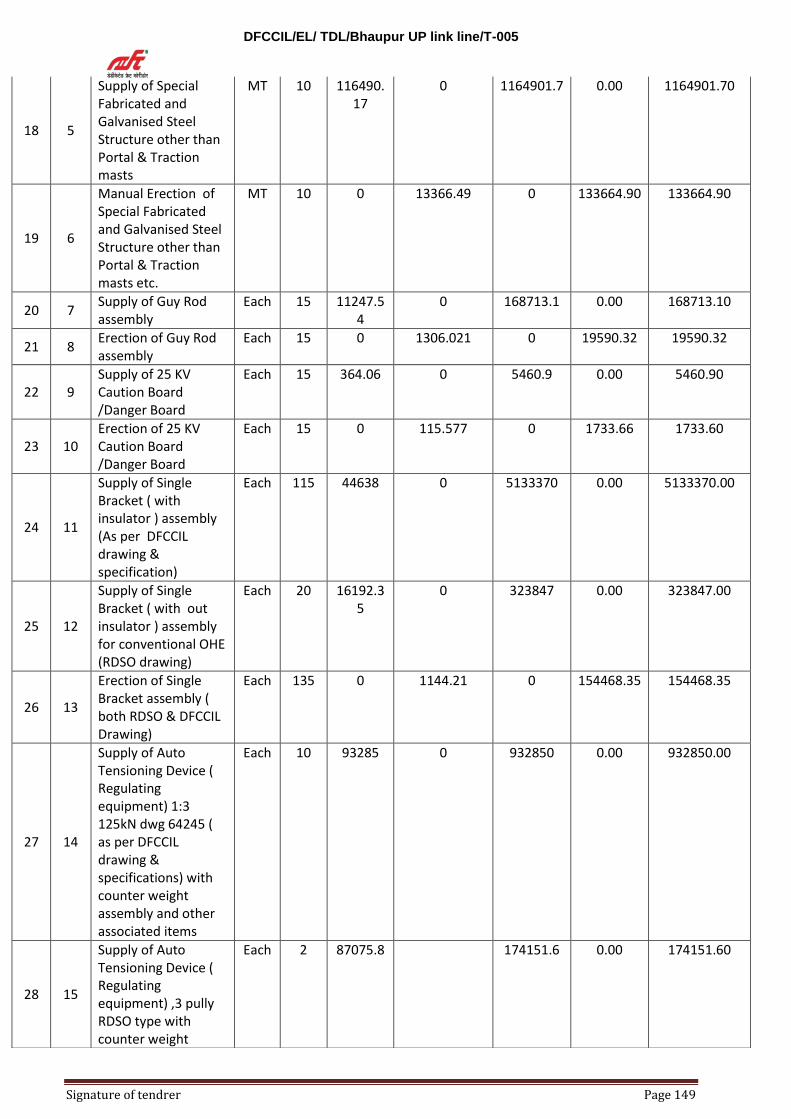
DFCCIL/EL/ TDL/Bhaupur UP link line/T-005
Signature of tendrer Page 149
18 5
Supply of Special Fabricated and Galvanised Steel Structure other than Portal & Traction masts
MT 10 116490.17
0 1164901.7 0.00 1164901.70
19 6
Manual Erection of Special Fabricated and Galvanised Steel Structure other than Portal & Traction masts etc.
MT 10 0 13366.49 0 133664.90 133664.90
20 7 Supply of Guy Rod assembly
Each 15 11247.54
0 168713.1 0.00 168713.10
21 8 Erection of Guy Rod assembly
Each 15 0 1306.021 0 19590.32 19590.32
22 9 Supply of 25 KV Caution Board /Danger Board
Each 15 364.06 0 5460.9 0.00 5460.90
23 10 Erection of 25 KV Caution Board /Danger Board
Each 15 0 115.577 0 1733.66 1733.60
24 11
Supply of Single Bracket ( with insulator ) assembly (As per DFCCIL drawing & specification)
Each 115 44638 0 5133370 0.00 5133370.00
25 12
Supply of Single Bracket ( with out insulator ) assembly for conventional OHE (RDSO drawing)
Each 20 16192.35
0 323847 0.00 323847.00
26 13
Erection of Single Bracket assembly ( both RDSO & DFCCIL Drawing)
Each 135 0 1144.21 0 154468.35 154468.35
27 14
Supply of Auto Tensioning Device ( Regulating equipment) 1:3 125kN dwg 64245 ( as per DFCCIL drawing & specifications) with counter weight assembly and other associated items
Each 10 93285 0 932850 0.00 932850.00
28 15
Supply of Auto Tensioning Device ( Regulating equipment) ,3 pully RDSO type with counter weight
Each 2 87075.8 174151.6 0.00 174151.60
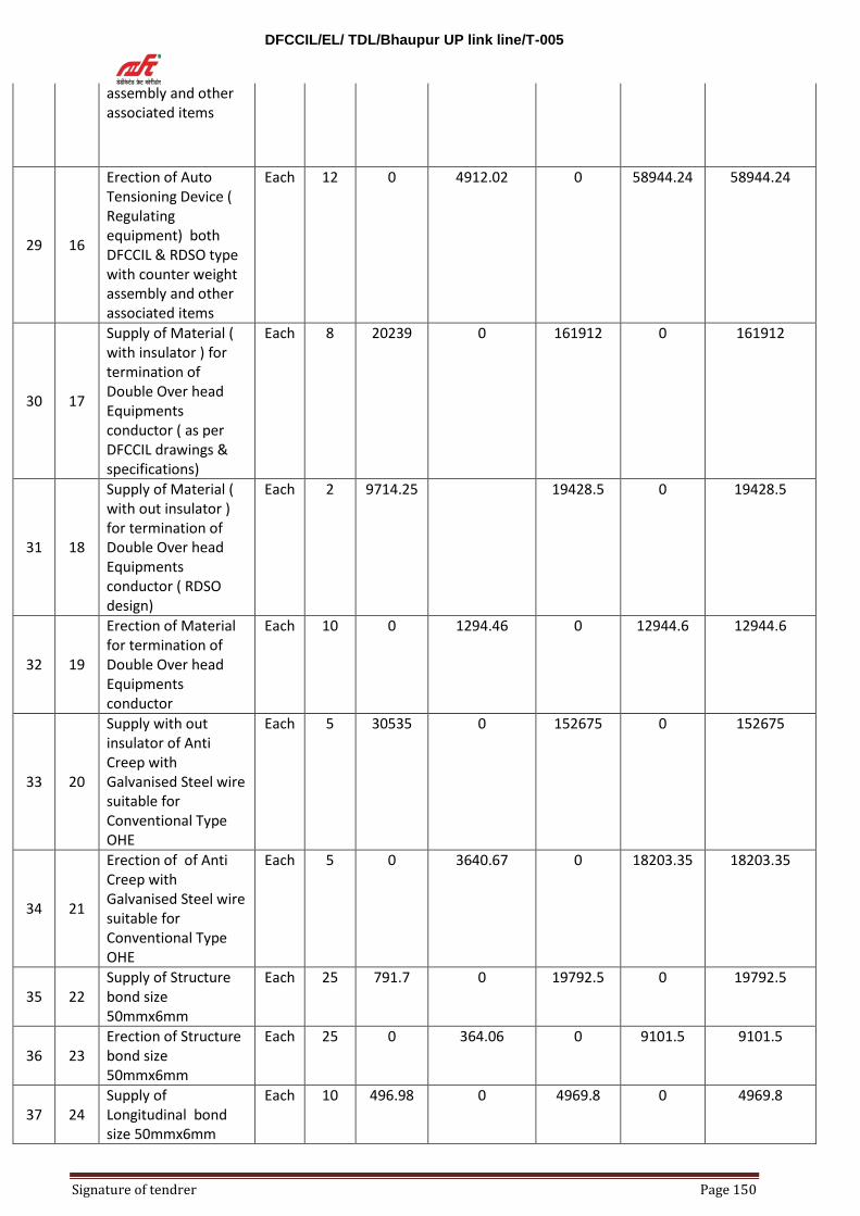
DFCCIL/EL/ TDL/Bhaupur UP link line/T-005
Signature of tendrer Page 150
assembly and other associated items
29 16
Erection of Auto Tensioning Device ( Regulating equipment) both DFCCIL & RDSO type with counter weight assembly and other associated items
Each 12 0 4912.02 0 58944.24 58944.24
30 17
Supply of Material ( with insulator ) for termination of Double Over head Equipments conductor ( as per DFCCIL drawings & specifications)
Each 8 20239 0 161912 0 161912
31 18
Supply of Material ( with out insulator ) for termination of Double Over head Equipments conductor ( RDSO design)
Each 2 9714.25 19428.5 0 19428.5
32 19
Erection of Material for termination of Double Over head Equipments conductor
Each 10 0 1294.46 0 12944.6 12944.6
33 20
Supply with out insulator of Anti Creep with Galvanised Steel wire suitable for Conventional Type OHE
Each 5 30535 0 152675 0 152675
34 21
Erection of of Anti Creep with Galvanised Steel wire suitable for Conventional Type OHE
Each 5 0 3640.67 0 18203.35 18203.35
35 22 Supply of Structure bond size 50mmx6mm
Each 25 791.7 0 19792.5 0 19792.5
36 23 Erection of Structure bond size 50mmx6mm
Each 25 0 364.06 0 9101.5 9101.5
37 24 Supply of Longitudinal bond size 50mmx6mm
Each 10 496.98 0 4969.8 0 4969.8

DFCCIL/EL/ TDL/Bhaupur UP link line/T-005
Signature of tendrer Page 151
38 25 Erection of Longitudinal bond size 50mmx6mm
Each 10 0 323.61 0 3236.1 3236.1
39 26 Supply of Transverse and Special bond size 50mmx6mm
Each 5 959.29 0 4796.45 0 4796.5
40 27
Erection of Transverse and Special bond size 50mmx6mm
Each 5 0 392.96 0 1964.8 1964.8
41 28 Supply of Single Earth Electrode
Each 7 3403.74 0 23826.18 0 23826.18
42 29 Erection of Single Earth Electrode
Each 7 0 1386.92 0 9708.44 9708.44
43 30 Supply of MS Earth Bus of size 50mmx6mm
Meter
10 179.14 0 1791.4 0 1791.4
44 31 Erection of MS Earth Bus of size 50mmx6mm
Meter
10 0 98.24 0 982.4 982.4
45 32
Supply & Erection of material for earthing of each mast ( as per DFCCIL drawings & specifications)
Each 100 3562.8 178.14 356280 17814 374094
TOTAL ( Sub - section-3) 16418075.53
Sub-Section-4 (Non- Ferrous )
46 1 Supply of 150sqmm Cu-Ag round bottom Contact wire
Meter
7000 832.17 0 5825190 0 5825190
47 2 Supply of 120sqmm Cu-Mg Messenger wire
Meter
7000 717.7 0 5023900 0 5023900
48 3 Supply of 107 sqmm Hard drawn grooved copper contact wire
MT 3 584100 0 1752300 0 1752300
49 4 Supply of 65 sqmm Cu-cadmium catenary wire .
MT 2 589328.5 0 1178657 0 1178657
50 5
Supply of Material ( as per DFCCIL drawings & specifications) for Erection of Over Head Equipment only, except contact & messenger wire
KM 5.5 260812 0 1434466 0 1434466
51 6
Supply of Material ( as per RDSO design) for Erection of Over Head Equipment only, except contact & catenary wire.
KM 1.5 51326.62 0 76989.93 0 76989.93

DFCCIL/EL/ TDL/Bhaupur UP link line/T-005
Signature of tendrer Page 152
52 7
Manual Erection of Over Head Equipment only (both RDSO & DFCCIL)
KM 7 0 37081.26 0 259568.82 259568.82
53 8
Supply of 25KV Light weight Section Insulator assembly with suspension ( as per DFCCIL drawings & specifications)
Each 4 217735.27 0 870941.08 0 870941.08
54 9
Supply without insulator of a section insulator assembly ( RDSO design)
Each 2 60213.58 0 120427.16 0 120427.16
55 10
Erection of 25KV Light weight Section Insulator assembly with suspension both RDSO design & ( as per DFCCIL drawings & specifications)
Each 6 0 3836.38 0 23018.28 23018.28
56 11
Supply of 25KV Short Neutral Section Assembly (complete set consisting of 2 half neutral sections) ( as per DFCCIL drawings & specifications)
set 1 574511.79 574511.79 0 574511.79
57 12
Erection of 25KV Short Neutral Section Assembly (complete set consisting of 2 half neutral sections) ( as per DFCCIL drawings & specifications)
set 1 0 5928.442 0 5928.442 5928.442
58 13
Supply of 1250A motorised single pole Isolator with out earth contact assembly
Each 2 71300 0 142600 0 142600
59 14
Erection of 1250A motorised single pole Isolator with out earth contact assembly
Each 2 0 3557.065 0 7114.13 7114.13
60 15
Supply with out insulator of 25 KV Single pole isolator ( manually operated ) with out earth
Each 2 45346.88 90693.76 0 90693.76

DFCCIL/EL/ TDL/Bhaupur UP link line/T-005
Signature of tendrer Page 153
contact assembly
61 16
Erection of 25 KV Single pole isolator with out earth contact assembly
Each 2 0 3557.065 0 7114.13 7114.13
62 17 Supply of large copper jumper wire
Each 15 8641.84 0 129627.6 0 129627.6
63 18 Erection of large copper jumper wire
Each 15 330.62 0 4959.3 4959.3
64 19 Supply of small copper jumper wire
Each 25 5050.576 0 126264.4 0 126264.4
65 20 Erection of small copper jumper wire
Each 25 0 330.62 0 8265.5 8265.5
66 21
Supply of copper strip size 25 mmx3mm for equipment earthing
Meter
2 1008.97 0 2017.94 0 2017.94
67 22
Erection of copper strip size 25 mmx3mm for equipment earthing
Meter
2 0 91.2 0 182.4 182.4
68 23 Supply of solid copper bus bar 18mm
Meter
10 1618.92 0 16189.2 0 16189.2
69 24 Erection of solid copper bus bar 18mm
Meter
10 0 125.4 0 1254 1254
70 25
Supply and erection of solid copper bus bar connector : Bus splice
Each 4 3636.87 14547.48 14547.48
71 26
Supply of solid copper bus bar connectors : Bus terminal
Each 8 5860.037 0 46880.296 46880.296
72 27
Erection of solid copper bus bar connectors : Bus terminal
Each 8 0 51.31 0 410.48 410.48
0
17744019.12
Sub-Section-5 ( Insulator)
73 1
Supply of insulators for item no 12 sub section -3, single bracket assembly ( in set )
Each 20 9693.11 0 193862.2 0 193862.2
74 2 Supply of Insulator for item no 14 sub section -3
Each 10 13175.73 131757.3 0 131757.3

DFCCIL/EL/ TDL/Bhaupur UP link line/T-005
Signature of tendrer Page 154
75 3 Supply of solid core cut in insulator
Each 15 8598.73 0 128980.95 0 128980.95
76 4 Erection of solid core cut in insulator
Each 15 0 727.79 0 10916.85 10916.85
77 5
Supply of 9 ton and bar insulator for item no- 9 of sub section 4
Each 2 18814.77
0
37629.54 0 37629.54
TOTAL ( Sub- section -5 ) 503146.84
Sub-Section -6 ( Work under power block)
78 1
Extra on erection of steel structure ( traction mast ) Galvanised and fabricated type B-150,B-175,B-200 etc.under power block.
MT 20 0 8703.295 0 174065.9 174065.9
79 2
Extra on erection of Fabricated and galvanised structure.( O,N,R type portal, TTC ) with necessary component other than masts.
MT 10 0 8703.29 0 87032.90 87032.90
80 3
Extra on erection of Special Fabricated and Galvanised Steel Structure other than Portal & Traction masts etc. under power block
MT 5 0 8703.29 0 43516.45 43516.45
81 4
Extra on erection of Single Bracket ( with insulator ) assembly for conventional OHE under power block.
Each 10 0 1097.61 0 10976.1 10976.1
82 5
Extra on manual Erection of Over Head Equipment under power block.
KM 1.5 0 36060.46 0 54090.69 54090.69
83 6
Extra on erection of Auto Tensioning Devide ( Regulating equipment) 1:3 125kN dwg 64245 ( DFCCIL DRAWINGS ) with counter weight assembly and other associated items
Each 3 0 4711.97 0 14135.91 14135.91

DFCCIL/EL/ TDL/Bhaupur UP link line/T-005
Signature of tendrer Page 155
under power block
84 7
Extra on Erection of Material ( with insulator ) for termination of Double Over head Equipments conductor under power block .
Each 3 0 1241.74 0 3725.22 3725.22
85 8
Extra on erection of 25KV Light weight Section Insulator assembly with suspension for both i.e. DFCCIL drawings & RDSO type under power block
Each 4 0 3730.77 0 14923.08 14923.08
86 9
Extra on erection of 1250A motorized single pole Isolator with out earth contact assembly under power block.
Each 1 0 3459.14 0 3459.14 3459.14
87 10
Extra on erection of large copper jumper wire under power block.
Each 4 0 321.52 0 1286.08 1286.08
88 11
Extra on erection of small copper jumper wire under power block
Each 10 0 321.52 0 3215.2 3215.2
89 12
Extra on transfer of Equipment from one Mast or Support to another under power block
Each 8 0 3126.53 0 25012.24 25012.24
90 13
Extra on dismantling of Over Head Equipment under power block
KM 2 0 8190.47 0 16380.94 16380.94
91 14
Extra on splicing & Extension of an anchored Over Head Equipment under power block
Each 2 0 3443.36 0 6886.72 6886.72
TOTAL ( Sub - section-6)
458706.57
Sub - Section -7 Transportation of
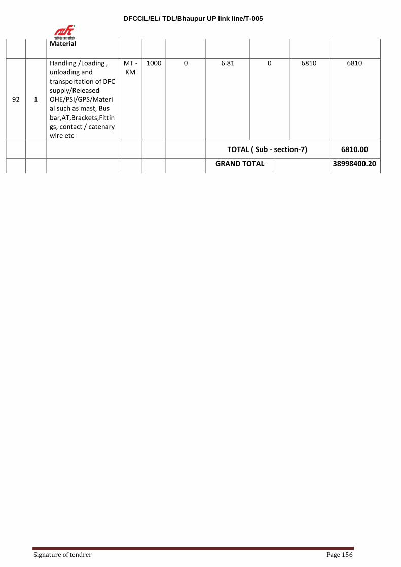
DFCCIL/EL/ TDL/Bhaupur UP link line/T-005
Signature of tendrer Page 156
Material
92 1
Handling /Loading , unloading and transportation of DFC supply/Released OHE/PSI/GPS/Material such as mast, Bus bar,AT,Brackets,Fittings, contact / catenary wire etc
MT -KM
1000 0 6.81 0 6810 6810
TOTAL ( Sub - section-7) 6810.00
GRAND TOTAL 38998400.20
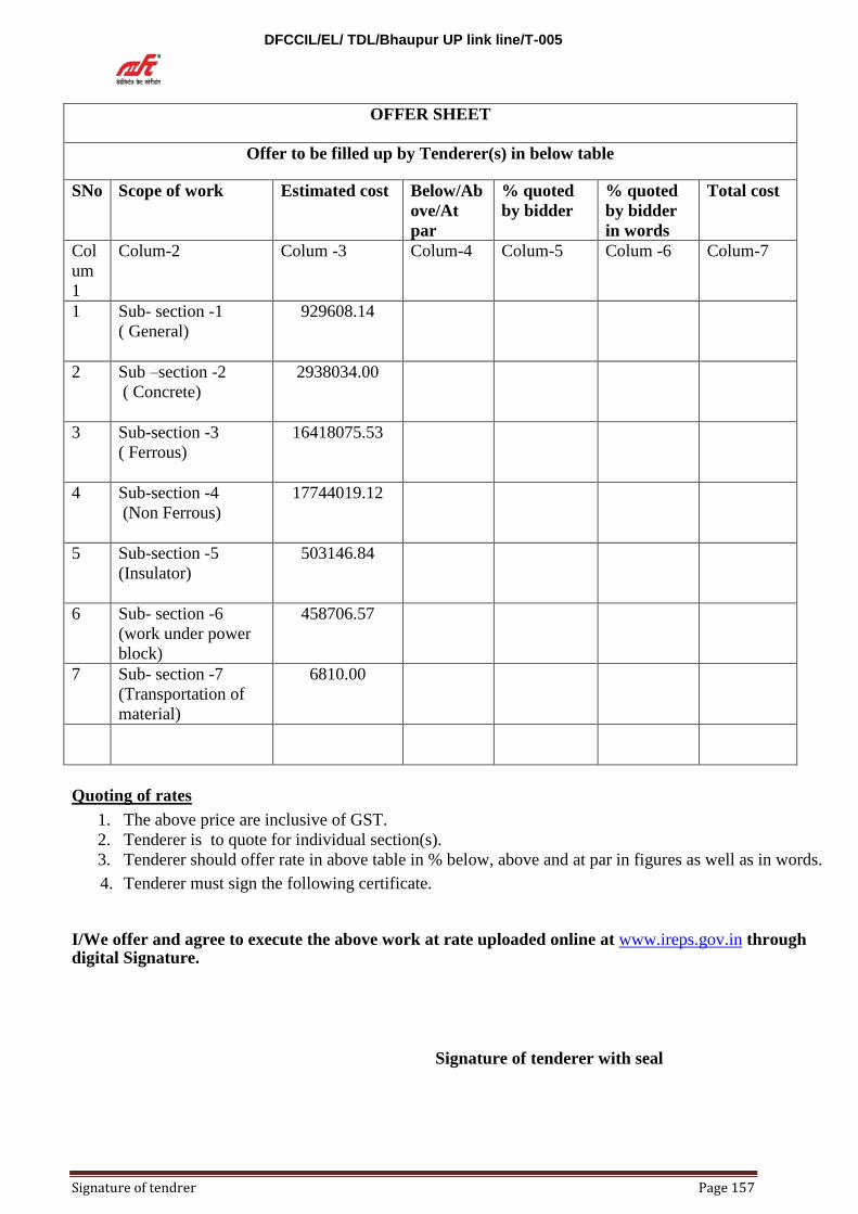
DFCCIL/EL/ TDL/Bhaupur UP link line/T-005
Signature of tendrer Page 157
OFFER SHEET
Offer to be filled up by Tenderer(s) in below table
SNo Scope of work Estimated cost Below/Ab
ove/At
par
% quoted
by bidder
% quoted
by bidder
in words
Total cost
Col
um
1
Colum-2 Colum -3 Colum-4 Colum-5 Colum -6 Colum-7
1 Sub- section -1
( General)
929608.14
2 Sub –section -2
( Concrete)
2938034.00
3 Sub-section -3
( Ferrous)
16418075.53
4 Sub-section -4
(Non Ferrous)
17744019.12
5 Sub-section -5
(Insulator)
503146.84
6 Sub- section -6
(work under power
block)
458706.57
7 Sub- section -7
(Transportation of
material)
6810.00
Quoting of rates 1. The above price are inclusive of GST.
2. Tenderer is to quote for individual section(s).
3. Tenderer should offer rate in above table in % below, above and at par in figures as well as in words. 4. Tenderer must sign the following certificate.
I/We offer and agree to execute the above work at rate uploaded online at www.ireps.gov.in through digital Signature.
Signature of tenderer with seal