TENDER DOCUMENT - SRCC
301
SHRI RAM COLLEGE OF COMMERCE University of Delhi, Maurice Nagar, Delhi – 110007 Phone: 27667905, 27666519 ▪ Fax: 27666510 Website: www.srcc.edu ▪ email: [email protected] TENDER DOCUMENT FOR CONSTRUCTION OF TEMPORARY CLASS ROOMS AT SHRI RAM COLLEGE OF COMMERCE, UNIVERSITY OF DELHI INSTRUCTION TO TENDERERS, GENERAL CONDITIONS OF CONTRACT, SPECIAL TERMS & CONDITIONS, SPECIFICATIONS, SCHEDULE OF QUANTITIES & DRAWINGS. OWNER ARCHITECTS SHRI RAM COLLEGE OF COMMERCE, UNIVERSITY OF DELHI, DELHI-110007 PHONE: 27667905, 27666519 EMAIL: [email protected] Dated:- June 2020 VIJAY GUPTA ARCHITECTS 603- CHIRANJIV TOWER, 43 NEHRU PLACE, NEW DELHI-110019 PHONE: 26414763, 26410790 EMAIL: [email protected]
-
Upload
khangminh22 -
Category
Documents
-
view
0 -
download
0
Transcript of TENDER DOCUMENT - SRCC

SHRI RAM COLLEGE OF COMMERCE University of Delhi, Maurice Nagar, Delhi – 110007 Phone: 27667905, 27666519 ▪ Fax: 27666510
Website: www.srcc.edu ▪ email: [email protected]
TENDER DOCUMENT
FOR
CONSTRUCTION OF TEMPORARY CLASS ROOMS AT SHRI RAM COLLEGE OF COMMERCE, UNIVERSITY OF DELHI
INSTRUCTION TO TENDERERS, GENERAL CONDITIONS OF CONTRACT, SPECIAL TERMS & CONDITIONS,
SPECIFICATIONS, SCHEDULE OF QUANTITIES & DRAWINGS.
OWNER ARCHITECTS SHRI RAM COLLEGE OF COMMERCE, UNIVERSITY OF DELHI, DELHI-110007 PHONE: 27667905, 27666519 EMAIL: [email protected]
Dated:- June 2020
VIJAY GUPTA ARCHITECTS 603- CHIRANJIV TOWER, 43 NEHRU PLACE, NEW DELHI-110019 PHONE: 26414763, 26410790 EMAIL: [email protected]

Tender Document- SRCC, University of Delhi Page no.- 1 Construction of Temporary Class Rooms
TENDER DOCUMENT
CONSTRUCTION OF TEMPORARY CLASS ROOMS AT SHRI RAM COLLEGE OF COMMERCE, UNIVERSITY OF DELHI
ARCHITECTS VIJAY GUPTA ARCHITECTS 603, CHIRANJIV TOWER, 43, NEHRU PLACE NEW DELHI
OWNER SHRI RAM COLLEGE OF COMMERCE,
UNIVERSITY OF DELHI, NEW DELHI-110007
PROJECT CONSTRUCTION OF TEMPORARY CLASS ROOMS AT SHRI RAM COLLEGE OF COMMERCE, UNIVERSITY OF DELHI
Sl.No. Details Page No.
1 Notice Inviting Tender 2-5
2 Instructions of Tenderers 6-29
3 Forwarding letter 30
4 Article of Agreement (Performa) 31-34
5 Appendix to General conditions of Contract 35
6 General conditions of Contract 36-59
7 Special conditions of Contract 60-62
8 Technical Specification 63-244
9 Schedule of Quantities SOQ 1-52
10 Drawings D 1-4

Tender Document- SRCC, University of Delhi Page no.- 2 Construction of Temporary Class Rooms
TENDER DOCUMENT
CONSTRUCTION OF TEMPORARY CLASS ROOMS AT SHRI RAM COLLEGE OF COMMERCE, UNIVERSITY OF DELHI
1.0 NOITICE INVITING TENDERS
Shri Ram College of Commerce invites sealed tenders on Item Rate in Two Bid System (Technical and Financial Bid) from experienced and eligible Contractors for “Construction of Temporary Class Rooms” at Shri Ram college of Commerce, University of Delhi, New Delhi”, as per schedule as under :
PART A - TECHNICAL BID 1. Name of Project : CONSTRUCTION OF TEMPORARY CLASS ROOMS AT SHRI RAM
COLLEGE OF COMMERCE, UNIVERSITY OF DELHI, NEW DELHI
Tendered Amount : Rs 85,00,000/-( Rupees Eighty Five Lacs)
Earnest Money : Rs. 1,00,000/- ( Rupees One Lac Only)
2. Brief Scope of Work : Construction of Temporary Class Rooms at Shri Ram College of Commerce, University of Delhi, New Delhi including Civil work, Plumbing Work, Electrical Work, Fire Fighting Work and HVAC work.
3. The TENDER DOCUMENTS can be downloaded from SRCC website www.srcc.edu.
4. This Notice Inviting Tenders and enclosed specifications, General Conditions, Special Condition and
Schedule of Quantities along with its Tender Drawings etc. shall form the TENDER DOCUMENTS. The specifications, drawings, Schedule of Quantities etc. can also be seen in the Architect’s Office during the said working hours.
5. Sealed TENDERS & EMD with the Following documents shall be submitted by tenderer along with their financial quote.
a) Proposed site organization chart b) Proposed schedule of construction. c) Labour deployment schedule. d) List of equipment to be deployed for this project. e) Cash flow required monthly.
6. TENDERER is to quote on item rate basis and to assist him, item wise tentative quantities are stated in
Schedule of Quantities. Although all precaution have been taken while working out the quantities but Owner does not take any guarantee for correctness of the same. The payment will be made for the actually executed and measured quantities at agreed rates.
7. The rates should be quoted in figures and words and the respective amounts or total shall be given by each
Tenderer. In case of any difference in rates in figures / word, those given in words shall hold good as quoted rate.
8. Sealed TENDERS in two Part - (A) Technical Bid and (B) Commercial bid with the requisite Earnest Money in the form of crossed Demand Draft (issued by any Nationalized or Scheduled Commercial Bank) and drawn in the favour of SHRI RAM COLLEGE OF COMMERCE Payable at NEW DELHI shall be received upto June 26, 2020 (10:00 AM - 1:00 PM & 2:00 PM - 4:00 PM hrs) in the office of ADMINISTRATIVE OFFICER : SHRI RAM COLLEGE OF COMMERCE, UNIVERSITY OF DELHI.

Tender Document- SRCC, University of Delhi Page no.- 3 Construction of Temporary Class Rooms
9. Commercial Bid (Part-B) shall be opened after completion of Technical Bid (Part-A) evaluation
& analysis. Commercial Bid will be opened only for those tenderers, who fulfil the Pre-qualification eligibility criteria and the required documents if found in order under bid Part-A, otherwise the same shall not be opened.
10. The tenderers shall remain valid for acceptance for 120 days from the last date of submission.
11. The successful TENDERER shall be intimated about the award of work. 12. The site is available and is free from any encumbrances and each Tenderer shall be deemed to have visited the site and seen the site conditions before quoting his Tender. No claim on ground for want of Such knowledge / site inspection shall be entertained at any stage.
13. The Owner reserves the right to reject any / all TENDERS without assigning any reason and shall not be
bound to accept the lowest or any other Tender.
14. Incomplete and late Tenders shall be rejected without any further reference.
15. The Time for Completion of work Four (04) months from date of letter of award. 16. Pre-bid meeting shall be held on June 17, 2020 at 11.30 AM in the office of ADMINISTRATIVE
OFFICER : SHRI RAM COLLEGE OF COMMERCE, UNIVERSITY OF DELHI.
Corrigendum or any other related notices, if any, will only be put on the college website www.srcc.edu from time to time. Bidders are requested to check the website regularly.
For any query and clarification may please contact to Vijay Gupta Architects, 603,Chiranjiv Tower, 43, Nehru Place, New Delhi, Email: [email protected], Phone:011-26414763, Ext-110
Date: June 2020
Principal Shri Ram College of Commerce, University of Delhi

Tender Document- SRCC, University of Delhi Page no.- 4 Construction of Temporary Class Rooms
PRE QUALIFICATION CRITERIA
The Contractors will be evaluated on the basis of following Pre-qualification criteria:-
I. The Contractor should have satisfactorily executed similar works during the last 05 years ending 2019. For this
purpose, cost of work shall mean gross value of executed work.
II. Scope of Work-The Contractor shall carry out all the works as may be required to successful completion of project which may be assigned to it on being selected through competitive bidding process. All work shall be executed as per approved drawings, specification and certified by Engineer In Charge.
III. The Contractor should have experience of having satisfactorily completed similar works during last 05 years
should be either of the following : One similar work costing 80% of estimated Cost or Two similar work each costing 60% of estimated Cost.
IV. Bank Solvency Certificate issued from Nationalized or any Schedule Bank should be at least 80% of Estimated
Cost of the Project put to tender. The certificate should have been issued in the current financial year but within 6 months from original last date of the submission of the tender.
V. Certificate of Financial Turnover: At the time of submission of tender, the tenderer shall submit
Affidavit/Certificate from Chartered Accountant mentioning Audited Financial Turnover of last 3 year sending as on 31.03.2019. There is no need to submit entire voluminous Balance Sheet. However, summarized page of Balance Sheet (Audited) and summarized page of Profit &Loss Account (Audited) for last five years may be submitted in hard copy along with Form-C.
Note : In support of above pre-qualification criteria the contractor should attach the following document:
Copy of Work Order for similar work from any Govt. Agency of State or Central or Private Agency.
Copy of completion / satisfaction certificate in case of completed work from client or Payment Certificate in case of ongoing work.
Certificate from a Chartered Account indicating the financial turnover during the last three years with audited report by auditor sealed and signed.

Tender Document- SRCC, University of Delhi Page no.- 5 Construction of Temporary Class Rooms
Annexure-I
Following information’s to be furnished by the contractor is mandatory failing to submit may liable to reject the tender.
Sl.No REQUIRED INFORMATIONS CONTRACTOR’S CONFIRMATION
1. NAME OF THE COMPANY/FIRM
2. ADDRESS OF THE COMPANY/FIRM
3. REGISTRATION NO. OF THE COMPANY/FIRM (with any State Govt./Central Govt./Municipal Corporation) / Local Bodies, etc.)
4. PAN NO. OF THE COMPANY/FIRM
5. TIN NO. OF THE COMPANY/FIRM
6. TURNOVER OF LAST THREE YEARS
2016 –2017
2017 –2018
2018 –2019
7. VALID GST NO. OF THE COMPANY/FIRM
8. VALID REGISTRATION NO. with EPF & ESI
9. LABOUR CESS REGISTRATION NO. UNDER “BUILDING AND OTHER CONSTRUCTION WORKERS WELFARE Cess Act 1996”
10. NAME, DESIGNATION, TELEPHONE NOS., FAX NO. & E-MAIL ID OF THE CONTACT PERSON
Signature of Contractor

Tender Document- SRCC, University of Delhi Page no.- 6 Construction of Temporary Class Rooms
2.0 INSTRUCTIONS TO TENDERERS
1. The Tenderers are required to submit Two Envelope Bids i.e. Technical and Financial, as per prescribed proforma. The two bids should be submitted in two separately sealed envelopes superscribed “Technical Bid for Construction of Temporary Class Rooms at Shri Ram College of Commerce, University of Delhi, New Delhi ” and “Financial Bid for Construction of Temporary Class Rooms at Shri Ram College of Commerce, University of Delhi, New Delhi”
2. Both sealed envelopes should be put in a third sealed envelope superscribed “TENDER FOR CONSTRUCTION OF TEMPORARY CLASS ROOMS AT SHRI RAM COLLEGE OF COMMERCE, UNIVERSITY OF DELHI, NEW DELHI to be submitted to the following address by hand or speed post before Last Date and time of Submission. Any delay in delivery by speed post shall not be considered. Therefore bidders are requested to send the bid accordingly, so that it can be reached within stipulated time.
To,
Administrative Officer Shri Ram College of Commerce, University of Delhi , Maurice Nagar, Delhi-110007
3. The TENDER DOCUMENTS can be downloaded from SRCC website www.srcc.edu.
4. The Financial bids of only those tenderers who are qualified in technical bid evaluation by the concerned committee shall be opened. The financial bids of all those tenderers who have failed to qualify in the technical bid will not be opened under any circumstances.
5. Over writing should be avoided. Correction, if any, should be made by neatly crossing out, initialing, dating and rewriting. Tender not properly filled, mutilated with incorrect calculation or generally not complying with the conditions may be rejected. Conditional tenders are liable to be summarily rejected.
6. TENDERERS should quote their rates both in figures and in words and the respective amounts or total
shall be given by each Tenderer. 7. Any information furnished by the applicant found to be incorrect either immediately or at a later date,
would render him liable to be debarred from tendering/taking up of work in SRCC. If such applicant happens to be enlisted contractor of any class in SRCC, his name shall also be removed from the approved list of contractors.
8. The application not submitted in prescribed form or unsigned by tenderer may not be considered.
9. Tenderer shall share the list of all the completed projects with completion certificate.
10. TENDERER is to quote on Item Rate Basis and to assist him, item wise tentative quantities are stated in
Schedule of Quantities. Although all precaution have been taken while working out the quantities but Owner does not take any guarantee for correctness of the same. The payment will be made for the actually executed and measured quantities at agreed rates.
11. The schedule of quantities as mentioned must be fully priced and the total of each page along with carried
over figures of the previous page shall be given in ink and Signed by the Tenderer.
12. If the tender is submitted by or on behalf of a company incorporated under the Company Act.(1959) it shall be signed by The Secretary or by one of the Directors duly authorized on their behalf. If it is,
Tender Document- SRCC, University of Delhi Page no.- 7 Construction of Temporary Class Rooms
submitted by a partnership firm it shall be signed with the Co-partnership firm name by a member of the firm who shall sign his own name & give the name & address of each partner of the firm and attach a copy of Power of attorney with the tender authorizing him to sign on behalf of the partners. A certified copy of the registered partnership deed shall also be submitted along with the tender. The tender should be in the sealed cover.
13. A schedule of approximate quantities for various items accompanies the tender. It shall be definitely
understood that the owner do not accept any responsibility for the Correctness or completeness of the schedule in respect of items and quantities. This Schedule is liable to alteration by omission, deductions or additions at the discretion of The OWNER without affecting the terms of contract and without any extra claim on account of any reason or reasons.
14. All quoted rates shall include the cost of all materials, labour & transportation of materials to the site, with all taxes. CONTRACTOR’S profit & overheads etc. and the fixing or placing in position for which the items of work is intended to be operated as per specifications excluding GST. Only GST shall be paid extra as applicable on actual basis.
15. No alteration shall be made by the tenderer in the Instructions to the TENDERERS or N.I.T ,Contract Form, Conditions of the Contract ,Drawings and specifications and if any such Alteration are made or any special condition attached, the tender is liable to be rejected.
16. The acceptance of the tender rests with the OWNER, who reserves the right of rejecting any or all the tenders including the lowest tender without assigning any reasons what so ever.
17. The OWNER reserves the rights of accepting the whole or any part of a tender received and the tenderer shall be bound to perform the same at the quoted rates.
18. Every tenderer shall furnish along with the tender, Registration No. / Certificate from G.S.T. etc. failing which his tender is liable to be rejected.
19. From the date of actual handing over of the works to the Owner, the contractor shall be responsible to make good any defects which may occur within a period of 12 months & this period is treated as “Defect Liability period”
20. The CONTRACTOR shall not be entitled to any compensation for any loss suffered by hindrance on account of delays in commencing or executing the work, whatever the cause for such delays may be including delays in procuring Government controlled or other materials.
21. The rates of different items are for all heights, depths, curvatures and width unless otherwise specified in the item of work.
22. The detailed schedule of programme in the form of a BAR CHART for the whole work shall be drawn
and submitted by the contractor within 15 days of the award of work order. The work shall be progressed from month to month and completed in the order and according to the schedule after approval of the same by the ARCHITECTS.
23. If the OWNER wants to occupy areas in part, the contractor shall have to complete the work of these areas in consultation with the OWNER and hand over the same without affecting any of the clauses of contract agreement.
24. After acceptance of the tender the tenderers shall sign the necessary contract papers within 10 days from the receipt of the above intimation.

Tender Document- SRCC, University of Delhi Page no.- 8 Construction of Temporary Class Rooms
25. Electricity: The contractor will make his own arrangement for electricity. The electric connection if required will be arranged by the Contractor himself. Necessary cabling etc. will be done by him at his cost and he will also pay for consumption at the prevailing rates of charges as per bills. The Contractor will purchase or hire generator to meet the requirement of electricity for the works and its cost for running / maintenance will be borne by contractor himself. The OWNER will have no responsibility in this connection.
26. Water: Contractor will make his own arrangement for water & further storage and piping etc. No
responsibility lies with the OWNER. The water used should be suitable for construction purpose and should be got tested from approved laboratory by Contractor at his own cost before start of the work. The running and maintenance shall be done by the contractor at his own cost.
27. Weather: No extension of time will be allowed to the Contractor due to weather conditions prevalent in the area. The contractor is expected to take all the precautions at his own risk and cost so that the workmanship, the materials and progress of work are not affected in the inclement weather.
28. Cleaning up & handing over: Upon completion of the work all the site area should be cleaned. All works shall be cleaned in manner which will render the work acceptable to the OWNER. All rubbish shall be removed from the site and shall not be dumped in the surrounding area.
29. Excavation for foundation below old structure and removing, stacking and disposal of such
material: If any brick, PCC & RCC work consist below old structure. The contractor will make his own arrangement for excavation for foundation below old structure on his own cost. The contractor is expected to take all the precautions at his own risk and cost so that the workmanship. Removing, stacking, disposing and dumping of such material will be as per as directed by Site-in-charge.
30. The work as described in the drawings and schedule of quantities shall be completed on or before the stipulated date of completion.
31. The CONTRACTOR shall not be allowed to possess any space or rooms inside the premises.
32. The CONTRACTORS should quote their offer keeping in view the basic minimum rates of labour wages with upto date corrections as on the day of submission of the tender as per notification by state government Administration.
33. The Contractor shall include in his rate all taxes viz Octroi, royalties (if applicable) & all duties, labour cess
etc and no claim on this account will be entertained. Only GST shall be paid extra by the owner as per the applicable rate.
34. The Income Tax as specified will be deducted as per Govt. notification/regulation from the bills for paying to the Government & by the Employer.
35. The rate quoted by the Contractor shall remain firm till the work is completed. 36. The following specified works shall be got carried out by the contractor through specialized firms or
manufactures with the approval of ARCHITECT.
a) Water proofing : 15 years guarantee bond shall be obtained on Judiciary stamp paper.
b) Anti-termite Treatment : 15 years guarantee bond shall be obtained on stamp paper.
37. Proper record for all the materials required for the above works shall be kept at site by the

Tender Document- SRCC, University of Delhi Page no.- 9 Construction of Temporary Class Rooms
CONTRACTOR jointly with ENGINEER – IN –CHARGE.
38. Owner shall have a right to withdraw any item / items mentioned in the Tender from the Scope of the contractor at any time.
39. Contractor shall take “contractor all risk policy” for the entire value of the work excluding the cost of
steel & cement. And also take third party insurance.
Insurance policies:-Contractor shall obtain "Contractors All Risk Policy" within two weeks from the date of award of work to cover entire contract sum including insurance for Owner’s supplied materials and all enabling works for loss or damage to the works, plant and materials, equipment or property, and personnel injury or death to any employee of the Contractors, Owner ,Owner’s Project Manager, consultant or a member of the general public indemnifying the Owner & Owner’s Project Manager for the same. The policy should also cover contractor’s liability under workmen compensation act. Third party insurance cover for any damages may be taken for value of Rs 50Lacs. (per incident value should be minimum of Rs.10 Lacs). Contractor is required to submit the above said CAR policy to the Owner duly endorsed for encashment of any claim from the insurance company, which shall be appropriated with Contractor after settlement of incidence, if any.
40. Contractor will have to take & deposit copy of workman compensation policy in respect of manpower
deployed by it at the project site. Policy should be in the joint name of Tenderer & Contractor.
41. The owner reserves the right to reject any or all the tenders without assigning any reason and at the same time is not bound to accept the lowest tenderer.
42. The owner also reserves the right to accept the tender in full or in parts and in the latter case the tenderer is bound to execute the work at his quoted rates.
43. Testing of material, installation and commissioning:-The Contractor shall be fully responsible for the tests required at site/ specified labs (3rd party Labs) for all the Materials supplied by contractor / Owner as per the instruction of Project Manager/ Engineer-in-Charge/Architect.
44. Milestones:-Ten or more milestones will be mutually agreed between Contractor and Owner (Refer
Milestone Schedule). If the Contractor fails to achieve any particular Milestones, than Owner has the right to withhold amount for the agreed Milestone amount (to be mutually agreed between the parties) for each milestone. If the Contractor is able to catch up so that the all subsequent Milestones are achieved, then the withheld amount shall be released in full upon such catch up. However, no interest shall be payable on such withheld amount. However in case of partial achievement of the Milestones (i.e. if the numbers of milestones on any date of consideration are not achieved) then all withheld payments shall only be released in the final bill. The above withholdings shall not relieve the Contractor from his obligation to complete the Works, or from any other duties, obligations or responsibilities which he may have under the Contract. If the milestones are not achieved by the contractor and not made up in next milestone also , then the Owner has the right to terminate the contract and withhold payment.
45. Escalation:- No request for additional payment on account of escalation shall be entertained.
46. Laboratory on site:-Contract shall provide laboratory at site for testing of all material supplied by contractor / Owner, like Cement, Aggregate, Brick, Sand etc. The testing lab shall be well equipped with but not limited of the following.
• Theodolite • Total Station • Steel tapes • Weighting Machine

Tender Document- SRCC, University of Delhi Page no.- 10 Construction of Temporary Class Rooms
• Sprit Level • Micro Meter • Thermometer • Complete set of IS Sieves • Moisture meters • Cube Testing machine • Vicat apparatus • Cube moulds- minimum 12 nos (150 x 150 x 150mm sizes) • Weighing Balance - Complete Apparatus • Slump Cones • Oven • Abrasion Apparatus
47. Site safety policy:-The policy is to clearly define responsibilities and then to obtain the commitment of
all Contractors to maintain a high safety standard compatible with this policy. Safe methods of working shall be a main consideration in all operations. Contractors will provide Owner with details of their methods of work, highlighting the safety aspects and they will update this information as necessary. It is the responsibility of all persons employed on this project to act responsibly to prevent accidents to themselves and others.
Each Contractor is responsible for the safety of his work by:
• Providing safe plant, equipment and working conditions.
• Ensuring the establishment of safe working procedures.
• Providing suitable protective equipment / clothing, like gloves, ear muffs, goggles etc.
• Providing adequate job training.
• Providing fire extinguishers and first aid box.
• Reporting all accidents and dangerous occurrences, with copies to Owner.
• Ensuring that hazardous materials, if necessary on site, are stored and used in a safe manner.
It is the duty of all persons employed on site:
• To report defects in any plant or equipment to his supervisor and to cease using that equipment if it is in a dangerous condition.
• To comply with all safety procedures necessary at his place of work as defined by legislation.
• To wear the personal protective equipment required for his own safety.
• To co-operate with management in creating and maintaining a high standard of safety, health and
welfare.
• To familiarize themselves and comply with the agreed methods and systems for working.
• To assist management by taking all possible steps to avoid accidents.

Tender Document- SRCC, University of Delhi Page no.- 11 Construction of Temporary Class Rooms
Persons responsible for safety :
Civil Works - < Name > (Assist Project Manager)
They will be advised by Owner Project Manager, who has been designated the company’s Safety Representative. He is empowered to instruct any Contractor or any of Owner’s staff to stop work in any situation where the circumstances or method of working constitutes a threat to personal safety. Contractor shall deploy one safety person at site.
It remains the responsibility of each Contractor to name his Site Manager, who will be responsible for the safety of his works, and also his company safety officer and the place at which he can be contacted Site safety manual Site Safety Manual
Signature of Contractor

Tender Document-SRCC, University of Delhi Page no.- 12 Construction of Temporary Class Rooms
Contents Introduction Safety Dos & Don’ts
2.0
2.1
2.2
1.0 General Safety Practice
2.0 Personal Protective Equipment
3.0 Housekeeping
4.0 Ladders
5.0 Scaffolding
6.0 Machinery & Vehicles
7.0 Lifting Equipment
8.0 Excavation and Shoring
9.0 Electrical
10.0 Hand Tools
11.0 Welding and Burning
12.0 Work in Confined Spaces
13.0 Work Permit System
14.0 Schedule of Penalties for Non-Compliance of the Prescribed Safety Standards
INTRODUCTION This manual shall be read by all supervisory staff within one week of starting on site. Adequate training must be provided to all supervisors, workers, etc. on the safe systems of work. Tool Box Meetings These are to be held at the project start up and continued on a regular basis; in addition, if an accident (excluding category 5) has occurred on site, a meeting should be held once the cause has been established. A specific topic should be covered at these meetings. Each section with this manual would form a suitable topic. The meeting should not take longer than 10-15 minutes. A record of the meetings is to be filed. PERSONAL PROTECTIVE EQUIPMENT
Whenever there is a possibility of exposure to hazardous material or operations, personal protective equipment or devices shall be worn or used. These include (but are not limited to) hard hats, safety shoes, safety glasses and goggles, gloves, protective suits, hoods, respiratory equipment and proper hearing protection. (Gloves are to be worn to protect from dermatitis due to cement and wet mortar/concrete) The contractors at all levels or supervision will be held responsible for seeing that workers wear proper protective equipment and that it is kept in good repair.

Tender Document-SRCC, University of Delhi Page no.- 13 Construction of Temporary Class Rooms
2.3 Hard Hats : All personnel working in areas where these is a possible danger of head injury from impact, or
from falling objects ,shall be protected by protective helmets. This will be interpreted as all areas within the site boundary except inside permanent or temporary structures not under construction. Helmets shall meet the specifications contained in the National Standards. Employees of contractors who are represented on the construction site, who apply for entry to the project and are not in possession of an approved hard hat, will be asked to remain at the security gate until arrangements can be made by their supervisor / foremen to obtain an approved hard hat.
2.4 Eye Protection: Required when doing work that may cause possible injury to eyes from flying particles, grinding, splashes, or welding/cutting operations.
2.5 Safety Shoes: To be worn by all workers. 2.6 Clothing: To be suitable for the type of work in which engaged. 2.7 Hearing protection: Shall be worn in any posted area and when operating pneumatic equipment.
2.8 Respirators: Whenever and wherever necessary to protect dust, gases, hazardous chemical and vapors.
2.9 Safety belts: Required when working from high places.
3.0 Protective gloves: To be worn as work activity may require.
3.1 Protect from Type
Abrasion Leather or PVC Gloves Grip Knitted Nylon or cloth with latex coated gloves Chemicals Plastic or Rubber Heat Leather Special Rubber
3.2 HOUSEKEEPING
3.3 Place debris, rubbish and waste in proper containers. 3.4 Place and store material and equipment in designated storage areas. 3.5 Working areas, passageways, stairs and exits are to be kept free from all debris, equipment, nails and other sharp
objects 3.6 Avoid spilling liquids. Wipe off spills immediately. Use safety cans to store flammable liquids. Store oily / paint
-soaked rags in approved containers and empty on a daily basis.

Tender Document-SRCC, University of Delhi Page no.- 14 Construction of Temporary Class Rooms
3.7
3.8
4.0
4.1
4.2
4.3
4.4
4.5
4.6
4.7
4.8
4.9
5.0
5.1
5.2
5.3
5.4
Nails or other sharps objects protruding from timber from panels etc are to be pulled or bent over.
Debris and combustible waste shall be disposed off on a regular basis and not allowed to accumulate. Special attention should be given to second floors and higher where adequate means shall be provided to expedite removal of such material.
LADDER
Select the right ladders for the job. Do not use too long or too short ladder. Do not splice two ladders together. Do not use lightweight or household ladders in a heavy construction job. Do not use metal ladders near electrical circuits, fixtures or power lines.
Check condition of ladder for cracked or split side rails; for missing or broken steps, cleats, rungs, treads or U-shapes; for sharp edges or splinters; for general weakened condition. If any of the above conditions exist, withdraw the ladder from use and fix it at once, if possible; if it cannot be fixed, destroy it. Every ladder should have identification tags-records of maintenance and inspection must be maintained.
Use ladder safety. Place it with care; do not lean it against a movable object. Make sure it is not placed on a loose object or uneven footing. Do not place it too close to a wall. The horizontal distance from wall to the foot of the ladder should never be less than 1.4 times the length and it should extend at least 900mm above the upper horizontal edge. Tie ladder with rope or wire. If wire is used, be careful to protect users from injury.
Only one person at a time shall be permitted on a ladder.
Always face the ladder and grasp the side rails or rungs with both hands when ascending or
descending.
Do not carry tools or material when going up or down ladders. Use a bucket or canvas bag on a rope to haul or lower then.
Be sure the soles of your shoes are free from dirt, oil and mud before using ladder.
Never work above the second rung from the top of the ladder.
Stepladders should not be over 3m long. Do not use a stepladder as a straight ladder.
SCAFFOLDING
Scaffold should be tubular and designed for the loads it will carry. Bamboo shall not be used as scaffold. Inspect the scaffold before use.
Scaffold planks must be tested, carefully erected and made secure to prevent slipping by using cleats or tying.
Scaffold to be braced/tied to the permanent structure at suitable intervals to prevent overturning.
All scaffolds shall have handrails and toe boards (minimum 100mm height).
Tender Document-SRCC, University of Delhi Page no.- 15 Construction of Temporary Class Rooms
5.5
5.6
5.7
5.8
5.9
6.0
6.1
6.2
6.3
6.4
6.5
6.6
6.7
6.8
6.9
6.10
6.11
6.12
6.13
There is no such thing as a temporary scaffold.
Ladders should be attached for ascent and descent on scaffolds.
Any defects, loose knots or cracks in a scaffold plank will make that plank useless.
Guard rails shall be 50mm x 100mm or the equivalent, approximately 1m high, with a midrail. Supports shall be at intervals not to exceed 2.5m.
Any scaffold, including accessories such as braces, brackets, trusses, screw legs, ladders etc. weakened from any cause shall be immediately repaired or replaced.
MACHINERY AND VEHICLES
Equipment is only as safe as the operator or mechanic who is handling it.
Only experienced and authorized persons shall operate power equipment. Before being allowed to operate a particular piece of equipment, the employee must prove by actual demonstration to the supervisor that he understands the operation.
Operators shall make careful inspection of their equipment at the start of each shift. Before operating, any repairs required shall be completed.
Cleaning, oiling, fueling or repairing is not to be carried out whilst equipment is in operation.
The operator is to take only standard industry hand signals from only one designated person.
Cranes or other equipment shall not lift loads in excess of the manufacturer’s max load limits displayed on the equipment. Lifting equipment must be tested by a competent authority and records of the same maintained.
Air hoses should not be disconnected at compressors until air pressure in the hose line has been released.
Electrical installations must conform to IE (India Electricity Rules) and BNS (Bureau of India Standards).
Do not operate equipment within 3m of high voltage lines. For lines over 50,000 volts, increase operating clearance 10mm for each additional 1,000 volts.
Where it is difficult for the operator to see overhead high voltage lines or obstacles, a person shall be designated to observe and give him warning required to maintain safe clearance.
Do not work under vehicles supported by jacks or chain hoists without protective blocking that will prevent injury if jacks or hoists should fall.
Examine excavation before backfilling to ensure that no one is in the pit.
Before operating excavating equipment near tops of cuts and banks, be sure no one is below. Tractors,bulldozers and carryalls should be operated with particular care where there is the possibility of overturning on dangerous areas such as edges of deep fills, cut banks and steep slopes.

Tender Document-SRCC, University of Delhi Page no.- 16 Construction of Temporary Class Rooms
6.14 No passengers are allowed to ride on or in equipment that does not have a designated seat for each
rider.
6.15 Vehicular and pedestrian paths and parking spaces should be clear of overhead operating equipment.
7.0 LIFTING EQUIPMENT
7.1 Maximum load carrying capacity of cranes, blocks or chains must be displayed together with the last date tested and the next due date for testing.
7.2 Do not overload cranes, ropes, blocks or chains. If any such equipment has been damaged or is found to
be defective, inform your supervisor.
7.3 No one shall ride loads, concrete buckets or hooks.
7.4 Use a guide of “tag line” on loads.
7.5 Stand clear of taut cables or hoists.
7.6 Keep hands and fingers away from blocks, sheaves or winches.
7.7 Do not stand under overhead loads.
7.8 Stack materials neatly and safely as per established guidelines.
7.9 Keep all material 500mm away from sprinkler heads.
7.10 All material handling equipment must be periodically checked by a competent authority and maintained properly. Records of the same must also be maintained.
8.0 EXCAVATION AND SHORING
All trenches or excavation 1.5m or more in depth shall be effectively guarded against the hazard of
8.1 Moving ground by sloping sides to the angle of repose of the material encountered or by the installation of a shoring system.
8.2 When sides are sloped, it shall be no steeper than 3/4 horizontal to 1 vertical. Slopes must be made
less steep if material encountered is not stable.
8.3 Trenches less than 1.5m deep shall also be guarded when examination indicates hazardous ground movement.
8.4 When a shoring system is used, it shall conform with approved design and the requirements of the
appropriate local agencies.
8.5 Beware of disturbed ground. Ground that has been filled or disturbed will require additional sheeting and bracing, as well as hard compact ground if there is filled ground nearby (A trench wall that is near another recently filled trench, for example, is unstable even though it appears to be compact material).
8.6 Take special precautions where moisture is present. Provide extra sheeting where there is water

Tender Document-SRCC, University of Delhi Page no.- 17 Construction of Temporary Class Rooms
or seepage. Keep excavation pumped out at all times and avoid any accumulation of water, day or night, until work is completed.
8.7
8.8
8.9
8.10
8.11
8.12
9.0
9.1
9.2
Install upper trench jacks or supports first. When trench jacks are used to hold uprights in place against trench walls, the top jack shall be installed before anyone enters the trench to place the lower jack. Shoring does not serve its purpose if men expose themselves to hazards while installing it. Installation work should be done from outside of the trench or by working progressively from top to the bottom of the trench with men always in an area which has already been shored.
Adequate shields or cages shall be used when needed for safety installation of shoring. Prior to starting any excavation work, the foreman shall make a thorough survey or conditions of the site to determine, so far as is practical, the predictable hazards to employees and the kind and extent of safeguards necessary to accomplish the work in a safe manner. Hazards shall be documented together with action required.
Special attention shall be given to locating and protecting underground utilities and to the precautions that must be taken to protect employees from the hazards of working near such utilities.
No part of any shoring system of any excavation shall be removed until proper steps have been taken to avoid hazards to men from moving ground.
All excavated areas must be properly barricaded to prevent people from falling into the pits.
Proper access for workers must be proved to and from excavation pits.
Work permits where required must be issued to authorized persons undertaking any excavation.
Flagmen shall be required at all locations on a construction site where barricades and warning signs cannot control moving traffic. They shall be placed so as to give adequate warning, approximately 30m ahead of impact point. They shall be provided with red flags and hand signs or red lights.
- A warning sign shall be posted ahead of flagmen reading “Flagmen Ahead”.
- The flagmen shall be provided with a red or orange warning garment for flagging. At night, reflective garments shall be used.
- Flagmen shall be instructed in the fundamentals of flagging moving traffic before they perform
this work.
ELECTRICAL
Whenever possible, an electrical line should be de-energized before work is carried out on or near it, no matter how low the voltage. Only qualified persons should do such work. Use proper lockout tagging procedures.
Persons doing electrical work or working near energized circuits should wear the appropriate safety
equipment

Tender Document-SRCC, University of Delhi Page no.- 18 Construction of Temporary Class Rooms
9.3
9.4
9.5
9.6
9.7
9.8
9.9
9.10
9.11
9.12 9.13
9.14
9.15
10.0
10.1
10.2
10.3
10.4
10.5 10.6
All electrical equipment must be properly earthed.
Respect electricity. A little current can kill. If the contact is good, 220 volts can be just as hazardous as 10,000 volts.
Do not overload circuits. Do not use any extension cables that may be damaged. Have exposed wiring or have fault connectors.
Do not leave electrical cables where vehicles will run over them. If electrical cables must cross a roadway, use protective cross-over devices.
Only approved plugs and receptacles shall be used on all jobs.
All electrical work shall be according to local, state or National Electrical Codes.
Only licensed electricians are allowed to carry out electrical work.
Rubber gloves and rubber shoes / boots of correct voltage grade shall be used. Temporary supply shall
be trapped from a source panel which is properly fabricated, permanently fixed and effectively earthed.
Live line testers and test lamp shall not be used. Usage conditions of a multi-meter with long probes are to be followed. Test lamps can be used temporarily if fitted with protective guard.
Makeshift connections are prohibited, ELCBs to be used for Portable Electrical Equipment.
ELCBs should be checked regularly and records maintained.
Portable lamps to be gripper type with caged wire protection. Work
permit system must be used where required.
HAND TOOLS
Do not use defective tools. If found, report them to your supervisor.
Keep faces of hammers in good condition to avoid flying nails, bruising fingers and chipping the hammer head.
Hold cold chisels in such a way that the knuckles will be protected if the hammer misses the head. Chisels struck by others should be held by tongs or other similar devices.
Do not use pipe wrenches as a substitute for other wrenches.
Wrenches should not be altered by the addition of handle extensions. Files shall be equipped with handles.

Tender Document-SRCC, University of Delhi Page no.- 19 Construction of Temporary Class Rooms
10.7 Do not use a screwdriver as a chisel.
10.8 Keep handsaws and other tools sharp and in good condition.
10.9 Do not lift or lower portable electrical tools by their power cords. Use a rope.
10.10 Guards on power hand tools must be kept in proper operating condition at all times.
10.11 Keep electrical cables out of water, oil or chemical.
10.12 Only qualified persons shall be permitted to use power activated tools. Check the other side of walls, floors, ceiling, etc. before using.
10.13 Tools which have been tagged “Out of Order - Do not Use” shall not be used until repaired and tag has
been removed by an authorized person.
10.14 Do not use aluminium handled full floats or aluminium ladders where there is a possibility they may come in contact with power lines.
10.15 Do not use electrical tools while standing in water.
10.16 All electric hand tools shall be double insulated.
10.17 Wire cutting tools and knives shall be provided with safe handles.
11.0 WELDING AND BURNING
11.1 Only experienced persons are allowed to do any electrical or acetylene welding or burning.
11.2 Do not weld or burn in hazardous area without written instructions.
11.3 Do not burn or weld where hot sparks, hot metal or severed sections could fall on cylinders, hoses, machinery, legs or feet or on flammable materials or where they could strike personnel working below.
11.4 Do not weld or burn drums, barrels, enclosed tanks of other containers without making sure that nothing
flammable has been stored in them or until such tanks have been made safe by filling with water or carbon dioxide under the supervision of a foreman.
11.5 Never strike an arc on cylinders.
11.6 Never use matches to light torches. Use a spark lighter or stationary pilot flame.
11.7 Make sure there is plenty of fresh air when welding is closed or confined places and never use oxygen
for ventilation.
11.8 Do not overload welding cables operating with poor connections. Turn off cylinders and machinery when not in use and roll up cables and hoses.
11.9 Wear proper hat (hard hat), eye and face protection when welding, and protect others from arc burns by
using a shield, if possible, or by warning them to wear adequate protection. Welders must see that those working with them have proper head and eye protection.

Tender Document-SRCC, University of Delhi Page no.- 20 Construction of Temporary Class Rooms
11.10 Make welding machine ground connections directly to ground whenever possible.
11.11 Always refer to acetylene as acetylene not gas. Refer to oxygen as oxygen not air.
11.12 Use the cylinder for its intended purposes and nothing else.
11.13 Always consider a cylinder as full and handle it accordingly. Never permit cylinders to strike each other.
11.14 When cylinders are empty, turn off; remove the gauges; put the protective cap on and mark them MT or Empty.
11.15 Always transport, store and use acetylene cylinders in a vertical position.
11.16 Protective caps shall be in place while transporting, moving and storing cylinders.
11.17 When cylinders are being hoisted, they shall be secured in a cradle.
11.18 In keeping empties and fulls separate, use a chain across the storage racks and always tie the bottles. Full cylinders of acetylene and oxygen should be stored at least 6m apart under a shelter and not exposed to sunlight.
11.19 Welding sets shall be properly earthed through an insulated conduit to the nearest earth.
Work permits system must be used for welding operators.
11.20 WORK IN CONFINED SPACES
11.21 When work is performed inside storm drains, sewers, vaults, utility pipelines, manholes and any other structure which might permit the accumulation of dangerous vapours or gases, the followings precautions shall be taken:
12.0 Employees shall be instructed regarding any potential hazards.
Tests for the presence of dangerous and combustible gases and adequate levels of oxygen content
shall be made prior to entering a confined work area and at intervals frequent enough to insure safe working conditions during the time a workman is in such structure. A record of such tests will be maintained on site.
12.1 Sources of ignition, including smoking, will not be allowed until proper tests have been made to ensure
safety.
12.2 When air is not suitable for breathing, approved respiratory equipment will be used. A safety line shall be attached to employee and standby employee shall be within call and sight ready to give assistance in case of emergency.
12.3 No work shall be done in the presence of explosive gases or air unsuitable for breathing.
12.4 Internal combustion engine-driven equipment shall not be operated inside buildings or confined

Tender Document-SRCC, University of Delhi Page no.- 21 Construction of Temporary Class Rooms
Spaces unless adequate steps have been taken to insure protection from dangerous concentrations of gases or fumes. Some of the precautions that may provide adequate control are as follows:
12.5
12.6
13.0
- Piping exhaust gases to outside atmosphere.
- Ventilation which dilutes and removes gases.
- Uses of catalyst - type exhaust scrubbers.
WORK PERMIT SYSTEM
Work permit system must be used prior to starting the following
- Demolition & Excavation
- Electrical work (or equipment which is or could be live)
- Working at Heights
- Welding or hot work
- Working in confined spaces
- Any other hazardous operation.

Tender Document-SRCC, University of Delhi Page no.- 22 Construction of Temporary Class Rooms
LETTER OF NOTICE INVITING TENDER
From :
To
The Principal Shri Ram College of Commerce University of Delhi, New Delhi
SUBJECT: SUBMISSION OF APPLICATION FOR CONSTRUCTION OF TEMPORARY CLASS ROOMS AT SHRI RAM COLLEGE OF COMMERCE.
Sir,
Having examined the details given in Notice Inviting Tender on the subject, I/We hereby submit our application expressing our interest and furnish the requisite documents and other relevant information.
1. I/We hereby certify that all the statements made and information furnished in the enclosed forms,
ANNEXURE I, II, III, V and Form A , B & C accompanying the application are true and correct.
2. I/We have furnished all information and details necessary for Tender.
3. I/We submit the required certificates in support of our suitability, technical know-how and capability for having successfully completed the works mentioned in Form C.
Date of Submission Signature of Applicant
Enclosures: Seal of Applicant

Tender Document-SRCC, University of Delhi Page no.- 23 Construction of Temporary Class Rooms
FINANCIAL
INFORMATION (FORM ‘A’)
I. Financial Analysis – Details to be furnished duly supported by figures in balance sheet/ profit & loss account for the last
five financial years duly certified by the Chartered Accountant, as submitted by the applicant to the Income Tax Department (Copies to be attached).
Financial years
(i) Gross Annual Turn Over on construction works.
(ii) Profit/Loss.
II. Financial arrangements for carrying out the construction work.
Signature of Chartered Accountant with Seal Signature of Bidder(s)

Tender Document-SRCC, University of Delhi Page no.- 24 Construction of Temporary Class Rooms
FORM "B"
BANKERS' CERTIFICATE FROM A SCHEDULED BANK
This is to certify that to the best of our knowledge and information that M/s./Sh…………....................
................................................... having marginally noted address, as a Customer of our bank are/is respectable and can be treated as good for any engagement upto a limit of Rs………………….
(Rupees………………………………………………………………………………..)
This certificate is issued without any guarantee or responsibility on the bank or any of the officers.
(Signature) For the Bank NOTE 1. Bankers Certificates should be on letter head of the Bank, addressed to tendering authority.
2. In case of Partnership firm, certificate should include names of all partners as recorded with the Bank.

Tender Document-SRCC, University of Delhi Page no.- 25 Construction of Temporary Class Rooms
FORM 'C'
DETAILS OF ELIGIBLE SIMILAR NATURE OF WORKS COMPLETED DURING THE LAST FIVE YEARS ENDING PREVIOUS DAY OF LAST DAY OF SUBMISSION OF TENDERS
S. Name of Owner or Cost of Date of Stipulated Actual Litigation/ Name and WHETHER
No. work/project sponsoring work commencement date of date of arbitration address/ THE WORK
and organization in crores of as per contract Completion Completion cases telephone WAS DONE
location
rupees
pending/ number
ON BACK
in progress of officer to
with details* whom TO BACK
reference BASIS
may be YES/ NO
made
1 2 3 4 5 6 7 8 9 10
* Indicate gross amount claimed and amount awarded by the Arbitrator.
Signature of Bidder(s)

Tender Document-SRCC, University of Delhi Page no.- 26 Construction of Temporary Class Rooms
Annexure 'II'
DECLARATION
1. I ….........................................................Son/Daughter of Shri......................................................... Proprietor/Partner/Director/Authorized Signatory of …......................................... am competent to sign this declaration and execute this tender document.
2. I have carefully read and understood all the terms and conditions of the tender and hereby convey my acceptance of the same.
3. The information/document furnished along with the above application are true and authentic to the best of my
knowledge and belief. I/We, am/are well aware of the fact that furnishing of any false information/fabricated document would lead to rejection of my tender at any stage besides liabilities towards prosecution under appropriate law.
Date: Full Name: Place: Company's seal:
The above declaration, duly signed and sealed by the authorized signatory of the company should be enclosed with Technical tender.
Signature of contractor with seal

Tender Document-SRCC, University of Delhi Page no.- 27 Construction of Temporary Class Rooms
Annexure-III
DECLARATION FOR ONLINE PAYMENT
1.0 COMPANY/ FIRM DETAILS: 1.1 Name of Company/ Firm:
1.2 Address:
Phone No.
E-mail ID:
2.0 BANK DETAILS:
2.1 Name of the Bank
2.2 Address of the Branch
Telephone No.
2.3 9 Digit Code number of the Bank and Branch appearing on the MICR cheque issued by the Bank
2.4 11 Digit NEFT/IFSC Code of the Bank Branch
2.5 Account Type (SB/CC/CA)
2.6 Bank Account No.(as appearing on the Cheque)
SIGNATURE OF AUTHORISED SIGNATORY OF
THEFIRM NAME: _
OFFICIALSEAL _
DATE: _

Tender Document-SRCC, University of Delhi Page no.- 28 Construction of Temporary Class Rooms
PART B– FINANCIAL BID Annexure: V
CONSTRUCTION OF TEMPORARY CLASS ROOMS AT SHRI RAM COLLEGE OF COMMERCE, UNIVERSITY OF DELHI, NEW DELHI
To,
The Principal
Shri Ram College of Commerce
University of Delhi, New Delhi
Respected Madam,
1. In accordance with the Conditions of Contract, Specifications, Drawings and Bill of Quantities (BOQ) etc. for
execution of the above named works, we the undersigned offer to construct and install such works and remedy
any defect therein in conformity with the aforesaid contract documents quoted by us for different items included
in the sheet named “Price Schedule” of Financial Bid (Part-II) (Item Rate to be quoted) The total amount of Bill
of Quantities being the Contract Price comes to
Rs…………………………….……………(Rupees………………………………………………………………..
….……………………………….only) inclusive of all taxes but excluding GST.
2. We undertake, if our tender is accepted, to commence the works as stipulated in Clauses of General Conditions of
Contract, after the receipt of the notice to commence work and to complete the whole of the works comprised in
the Contract within the time stated in Clause.
3. We agree to abide by this Bid and it shall remain binding upon us and may be accepted at any time before the
expiration of validity as per sub-cause: Bid Validity (Bids shall remain valid for a period of 120 days after the
date of submission of bids).
4. Unless and until a formal Agreement is prepared and executed, this Bid, together with your written acceptance
thereof, shall constitute a binding Contract between us.
5. We understand that you are not bound to accept the lowest or any bid you may receive.
Dated this…………….Day of……………………..…………2020
Signature………………………………..….………………………..…………..in the capacity
of………………..……………………….
duly authorized to sign bids for and on behalf of
……………………………..…………………………….…………………………..
(in block letters or typed)
Address:…………………………………………………………………..
Witness……………………………………………………………………
Address:……………………………………………………………………
Occupation……………………………………………………………….. Signature of contractor with seal

Tender Document-SRCC, University of Delhi Page no.- 29 Construction of Temporary Class Rooms
Following documents shall form part of invitation to Technical and Financial Bid.
PART-A (Technical Bid)
1 Format for contractor information to be filled up. ( All relevant documents must be attached) Annexure-I
2 Declaration Annexure-II 3 Declaration of online payment Annexure-III
5 Financial Information Form-A
6 Banker Certificate Form-B
7 Similar work Detail Form-C PART-B (Financial Bid) 8 Financial Bid Format Annexure-V

Tender Document-SRCC, University of Delhi Page no.- 30 Construction of Temporary Class Rooms
3.0 FORWARDING LETTER
From:
To
THE PRINCIPAL, SRCC, UNIVERSITY OF DELHI
SUB: CONSTRUCTION OF TEMPORARY CLASS ROOMS AT SHRI RAM COLLEGE OF COMMERCE, UNIVERSITY OF DELHI.
Dear Madam,
With reference to the Tenders invited by you for the above work, I/ We do hereby offer to perform, provide, execute & complete the above work in conformity with the drawings, terms & conditions and specifications for the amount as shown in the schedule of quantities attached hereto.
I/We have satisfied ourselves to the location and conditions of the site and have read the articles of agreement , conditions of contract & specifications etc. and we understand that the work are to be completed within the specified period & fully understood that the time will be the essence of this contract .
Name of the partners / Directors
yours faithfully
1.
Signatures
2. Date
3 Address

Tender Document-SRCC, University of Delhi Page no.- 31 Construction of Temporary Class Rooms
4.0 Articles of Agreement (Proforma)
ARTICLES OF AGREEMENT made on day of 2020 between _______________________________________________ (hereinafter called “the OWNER”) of the one part and M/s. __________________ whose registered office situated at _____________________ (hereinafter “ the CONTRACTOR”) of the other part.
WHEREAS the OWNER is desirous of construction of ______________________ AND has caused
Drawings and bills of quantities showing and describing the work to be done to be prepared by or under
the direction of ARCHITECT - VIJAY GUPTA ARCHITECTS , 603, CHIRANJIV TOWER, 43, NEHRU
PLACE, NEW DELHI. AND WHEREAS the CONTRACTOR has supplied the OWNER with a fully
priced copy of the said bills of Quantities (which copy is hereinafter referred to as “the contract bills “ and
where as the said drawing (herein after referred to as “the Contract drawings”) and the Contract bills have
been signed by or on behalf of the parties hereto.
AND WHEREAS the CONTRACTOR has deposited the sum of Rs. .................. (Rupees ......................
only) with the OWNER for the due performance of this agreement.
NOW IT IS HEREBY AGREED AS FOLLOWS: -
For the consideration hereinafter mentioned the CONTRACTOR will upon and subject to the conditions
annexed carry out and complete with work shown upon the Contract Drawings and described by or referred
to in the Contract Bills and in the said conditions.
The OWNER will pay the CONTRACTOR the sum of Rs……………………….(Rupees
………………………………………only ) or such other sum as shall become payable hereunder at the
time and in the manner specified in the said CONTRACT .
The term “The ARCHITECT in the said conditions shall mean the said VIJAY GUPTA, ARCHITECTS, 603 Chiranjiv Tower, 43, Nehru Place, New Delhi or in the event of his death or ceasing to be the ARCHITECT for the purpose of this Contract, such other person as the OWNER shall nominate for that purpose.
The said condition and appendix thereto shall be read and construed as forming part of this Agreement, and the parties hereto shall respectively abide by and submit themselves to the conditions and perform the agreements on their parts respectively in such conditions contained.

Tender Document-SRCC, University of Delhi Page no.- 32 Construction of Temporary Class Rooms
Not withstanding anything contained in this agreement, THE ENGINEER-IN-CHARGE shall have power to review the decisions / recommendations made or proposed to be made about any matter connected with the work to be executed under this contract, before / after these are implemented, call for additional information from the ARCHITECT / CONTRACTOR or any other source, hold discussions if necessary and arrive at his decision. This decision would be applicable for the work. If the CONTRACTOR feels aggrieved by this decision, he would be free to raise this matter as a dispute for arbitration, under the agreement but would not stop the work on any pretext and proceed with the work in accordance with this decision. As witness the hands of the said parties.
Signed by the said in the presence of OWNER Witness Name Address : Signed by the said in the presence of Witness Name CONTRACTOR Address:
Tender Document-SRCC, University of Delhi Page no.- 33 Construction of Temporary Class Rooms
PROFORMA FOR ADVANCE BANK GUARANTEE (To be executed on non-judicial stamp paper)
(To be given only if the agency wants to avail of advance of 10% amount of the bid. This can be given subsequently after the award of work/contract)
To
1. M/S SRCC, UNIVERSITY OF DELHI having agreed to grant a contract to M/s………………………………………………………………………………………………… …… of …………………………………………………………………………………. for carrying out the work of construction, and allied services for ……………………………………………………………… on the terms and conditions contained in the said Bid Document, which inter alia provides for production of a Bank Guarantee to the extent INR …………………………………… (Rs.………………………………………………… in words) by the selected agency for availing advance up to an extent of 10 percent of the work bring awarded work, we ………………………………………………………….. (indicate the name and address and other particulars of the bank) (hereinafter referred to as 'the Bank') whose principal place of business is at .................... {Insert the full Address] (“the Guarantor”) hereby unconditionally agree and undertake to hold at your disposal, ………………………… (Advance BG amount) and agree with you as follows:
a) Under the terms of the said tender, the ……………. has agreed to pay to the selected agency an advance payment of [insert the Advance Bank Guarantee value in figures and words) …………………………. being …… % of the value of the present work being awarded, against furnishing of an Irrevocable Advance Bank Guarantee of equivalent amount by the selected agency.
b) We, at the request of the selected agency, have agreed to give this unconditional and irrevocable Advance Bank Guarantee and agree and undertake not to revoke the same.
c) We, hereby guarantee that the licensee will duly comply and faithfully perform all their obligations and responsibilities under the said tender/contract, failing which we, the Guarantor, do hereby unconditionally undertake to pay to the …………… ON MERE DEMAND AND WITHOUT ANY DEMUR AND WITHOUT RECOURSE TO THE SELECTED AGENCY such amount or amounts as the Guarantor may be called upon to pay not exceeding in the aggregate a sum of [insert Advance Bank Guarantee value in figures and words] ……………………………………………………………………………… .
d) The Advance Bank Guarantee shall not be determined or affected by liquidation or winding up, dissolution or change of constitution or insolvency of the selected agency but shall in all respects and for all purposes be binding and operative until payment of all monies due to the ……..under the Advance Bank Guarantee are paid.
e) The decision of the ……… that any sum has become payable shall be final and binding on the Bank. f) The Advance Bank Guarantee shall be governed by the laws of India. g) We, shall on simple demand from the ……… pay immediately to the ….., the said amount of (Insert ABG
value in figures and words) .............................................................................. without any demur and without requiring the …… to invoke any legal remedy that may be available to them, to compel the Bank to pay the Advance Payment amount, even if the selected agency considers such demand of the ……… is unjustified.
h) Any notice by way of request, demand or otherwise hereunder may be sent by courier, fax or by post to the
Bank on or before the expiry date of the Advance Bank Guarantee. The ……. may lodge request/demand in writing at our branch…………………………………………. [Insert specific New Delhi branch name and full address with Tel/fax numbers] at New Delhi on or before the expiry of the Advance Bank Guarantee as stated under clause (i).
i) Our liability under the Advance Bank Guarantee is restricted to a sum of [Insert ABG value in figures and words ) ................................................................................................................................... and the

Tender Document-SRCC, University of Delhi Page no.- 34 Construction of Temporary Class Rooms
Advance Bank Guarantee shall remain in force until .................................. (date) or such extended period as may be required by the …………. and the selected agency.
j) We confirm that all your claims under the Advance Bank Guarantee shall be payable at our above mentioned New Delhi Branch immediately.
k) We, further confirm that, we have powers to issue the Advance Bank Guarantee under our Constitution (including Memorandum and Articles of Association) and other applicable documents and the undersigned have full powers to do so under the Power of Attorney / authorization granted to me/us by ………………………………Insert the name of the Bank].
l) We, the bank, do hereby agree that the decision of the ……..as to whether the selected agency has failed to or neglected to perform or discharge his duties and obligations as aforesaid and/or whether the service is free from deficiencies and defects and is in accordance with or not of the terms & conditions of the said contract and as to the amount payable to the …….. by the Bank hereunder shall be final and binding on the Bank.
2. WE, THE BANK, DO HEREBY DECLARE AND AGREE that: a) the ………. shall have the fullest liberty without our consent and without affecting in any manner our
obligations hereunder to vary any of the term and conditions of the said Contract or to extend time of performance of any obligations by the said selected agency from time to time or to postpone for any time or from time to time any of the powers exercisable by the …….. against the said selected agency and to forbear or to enforce any of the terms and conditions relating to the said Contract and we shall not be relieved from out liability by reason of any variation or extension being granted to the said selected agency or forbearance act or omission on the part of the ….. or any indulgence by the ……. to the said selected agency or to give such matter or thing whatsoever which under the law relating to sureties would but for this provision, have effect of so relieving us.
b) any claim which we have against the selected agency shall be subject and subordinate to the prior payment
and performance in full of all the obligations of us hereunder we will
not without prior written consent of the….. exercise any legal right or remedy of any kind in respect of any such payment or performance so long as the obligations of us hereunder remains owing and outstanding.
c) This guarantee shall be irrevocable and the obligations of us herein shall not be conditional of any prior
notice by us or by the selected agency.
7. We the BANK undertake not to revoke this Guarantee during its currency except with the previous consent of the …….in writing.
Date………………………. Name & Signature of authorized signatory (Name of the bank) Official Seal
Witness: 1…………………………………………………………..
2……………………………………………………………..

Tender Document-SRCC, University of Delhi Page no.- 35 Construction of Temporary Class Rooms
5.00 APPENDIX TO GENERAL CONDITIONS OF CONTRACT SCHEDULE OF FISCAL
ASPECTS
NAME OF WORK : CONSTRUCTION OF TEMPORARY CLASS ROOMS AT SHRI RAM COLLEGE OF COMMERCE, UNIVERSITY OF DELHI
DEFECT LIABILITY PERIOD : 12 months after completion of entire work. During. Defect Liability Period of 12 months the contractor will depute his staff for attending to all types of construction defects included under his scope of contract and rectify the defects free of cost.
PERIOD OF FINAL MEASUREMENTS
AND VALUATION
: Within 2 (two) months from date of handing over the work.
DATE OF COMMENCEMENT : Within 10 days of issue of the award letter from the Owner.
TIME FOR COMPLETION : The whole works shall be completed within 4 (Four) months
AGREED LIQUIDATED DAMAGES : The quantum of liquidated damages shall be 0.7% per week of delay with a maximum of 5% of the contract Value of Work.
SECURITY DEPOSIT PERCENTAGE : 5 % from Gross amount of each bill as per conditions of contract.
LIMIT OF SECURITY DEPOSIT : 5% of the Gross amount of work done
REFUND OF SECURITY DEPOSIT AFTER
VIRTUAL COMPLETION
: 50% shall be released after completion of work subject to finalization of bills and rest 50% after defect liability period of 12 months subject to all defects rectified by the Contractor .
MOBILIZATION ADVANCE 10% of Contract Value against Bank Guarantee and to be recovered from Running bill on prorata basis such that full recovery is made by the time the value of work done reaches 80% of contract value.

Tender Document-SRCC, University of Delhi Page no.- 36
6.0 GENERAL CONDITIONS OF CONTRACT
S.No Contents 1 Definitions 2 Contract Documents 3 Type of Contract 4 Schedule of Quantities 5 Contract Drawings 6 Contract Sum 7 Contract Bills 8 Scope and Intent 9 ARCHITECT’S Instructions 10 Facilities and Co-operation 11 Setting Out 12 Site 13 Samples and Shop Drawings 14 Progress Chart 15 Access for Architects to the works 16 Architects Status and Decisions 17 Security Deposit 18 Engineer – in – Charge 19 Contractor’s Field Organization and Equipment 20 Taxes 21 Statutory Obligations, Notices, Fees and Charges 22 Royalties and Patent Rights 23 Licenses & Permits and Materials Under Government Control 24 Water & Electricity construction 25 Assignment of sub-letting 26 Sub- Contractor 27 Artists and Tradesmen 28 Separate Contracts 29 Variations (Extra items) 30 Certificates and Payments 31 Claim for Extra 32 Deduction for Uncorrected Work 33 Fluctuation 34 Unfixed Goods and Materials 35 Materials and Workmanship ( Secured Advance) 36 Defects 37 Possession, Completion and Postponement 38 Possession before virtual completion 39 Extension 40 Damages for Non-Completion 41 Virtual Completion and Defects Liability Period 42 Payment with held 43 Injury to Persons and Property Owners 44 Insurance Against Injury to Person and Property 45 Insurance of the Works Against Fire etc. 46 Determination by the Owner 47 Co-ordination of work 48 Labour 49 Protection of Trees and Shrubs 50 Guarantee 51 Antiquities 52 Arbitration 53 Protection and cleaning 54 Tolerance
Tender Document-SRCC, University of Delhi Page no.- 37
6.0 - GENERAL CONDITIONS OF CONTRACT
1. DEFINITIONS
1.0 The contract document consists of the Agreement, the General Conditions of the Contract, Special Terms & Conditions, Specifications and Schedule of Quantities and Rates contained therein including all modifications thereof incorporated in the document before execution and the Contract Drawings prepared by the ARCHITECT from time to time.
1.1 The OWNER
The ARCHITECT The CONTRACTOR ENGINEER-IN-CHARGE
Are those mentioned as such in the Agreement and shall include their legal representatives, assigns or successors. They are treated throughout the Contract Document as if each were of the singular number and masculine gender.
1.2 “The Site” shall mean the site of the contract work including any building and erections thereon and
any other land allotted by the OWNER for Contractor’s use.
1.3 The term “Sub-contractor”, as employed herein, includes those having a direct contract with the Contractor and it includes one who furnished material worked to a special design according to the plans or specifications of this work but does not include one who merely furnished material not so worked. Anyone doing work on a piece rate basis shall be deemed a Sub-contractor.
1.4 “Written notice” shall be deemed to have been duly served if delivered in person to the individual or to
a member of the firm or to an office of the corporation for whom it is intended or if delivered at or sent by registered mail to the last business address known to him who gives the notice.
1.5 The term “Work” of the Contractor or Sub-contractor includes labour or material or both.
1.6 All time limits stated in the Contract Document are the essence of the Contract.
1.7 The law of the place of work shall govern the construction under the contract.
1.8 The date of virtual completion of a work or specified area of a work is the date when construction is
sufficiently completed, in accordance with the Contract Documents as modified by any change or variation orders agreed to by the parties, so that the OWNER can occupy the works for the use it was intended.
1.9 The Contractor shall only appoint Sub-contractors who are approved by the OWNER/
ARCHITECT.
2. CONTRACT DOCUMENT
The following documents shall constitute the contract document: i) Articles of Agreement ii) General Conditions of Contract iii) Special Terms & Conditions iv) Specifications v) Schedule of Quantities vi) Drawings

Tender Document-SRCC, University of Delhi Page no.- 38
All parts of the Contract document is complementary, what is called for in any one shall be binding, as if called for by all.
The Contract Document shall remain in the custody of the OWNER so as to be available at all reasonable times for the inspection of the ARCHITECT or of the Contractor. Immediately after the execution of the contract one copy of the Contract Document and two copies of the Contract Drawings shall without charge be supplied by the ARCHITECT to the Contractor and one copy of the Contract Document retained with him. Original contract documents and two sets of contract drawings will be sent to the OWNER.
So soon as is possible after the execution of the contract two copies of the Specifications, descriptive schedule or other like document necessary for use in carrying the work shall without charge be supplied by the ARCHITECT to the Contractor.
Provided that nothing contained in the said Specification, Descriptive schedules or other document shall impose any obligation beyond those imposed by the Contract Document namely by the Contract Drawings, the Contract Bills, the Articles of Agreement and these conditions.
After the award of the Contract, the Contractor shall without charge be supplied with all such further drawings and details as may be prepared by the ARCHITECT and his CONSULTANT, from time to time as the work proceeds as are reasonably necessary either to explain or amplify the Contract Drawings or to enable the Contractor to carry out and complete the work in accordance with these Conditions. Provided all such drawings shall be a reasonable development of the work described in the Contract Document.
The Contractor shall keep one copy of the Specifications, Descriptive schedule or other like documents referred to in this clause and one copy of the contract Drawings and such other drawings and details supplied to him from time to time and referred to in this clause and written instructions referred to in clause and sub- clauses 9,16.1,16.2 and 29 shall be kept upon the site so as to be available to the ARCHITECT or his representative at all reasonable times.
None of the documents herein before mentioned shall be used by the Contractor for any purpose other than this contract and neither the OWNER nor the ARCHITECT shall divulge or use except for the purpose of this contract any of the prices in the contract bills.
Upon final payment under clause 30.6 of these conditions the Contractor shall if so requested by the ARCHITECT forthwith return to the ARCHITECT all Drawings, Details, Specifications, Descriptive Schedule and other Documents of like nature which bears his name or that of the CONSULTANT.
3. TYPE OF CONTRACT
The Contract shall be item rate contract. The contractor shall be paid for the actual quantity of work done, as measured at site, at the rates quoted by him in the “Contract Bills” and accepted by OWNER.
4. SCHEDULE OF QUANTITIES
The Schedule of Quantities given in the “Contract Bill” are provisional and are meant to indicate the intent of the work and to provide a uniform basis for tendering. The OWNER reserves the right to increase or decrease any of the quantities upto any extent or to totally omit any item of work and the Contractor shall not claim any extras or damages on these grounds. Any error in description or in quantity or omission of items from the “Contract Bill” shall not vitiate this Contract but shall be treated as a variation.

Tender Document-SRCC, University of Delhi Page no.- 39
5. CONTRACT DRAWINGS
5.1 In general the Drawings shall indicate dimensions, position and type of construction, the Specifications shall indicate the qualities and the methods; and the Schedule of Quantities shall indicate the quantum and the rate for each item of work. Any work indicated on the Drawings and not mentioned in the Specification or vice versa shall be furnished as though fully set forth in both. Work not specifically detailed, marked or specified shall be the same as similar parts that are detailed, marked or specified.
5.2 The Contractor’s work shall not deviate from the Drawings and Specification. The ARCHITECT’s
interpretation of these documents shall be final.
5.3 Errors or inconsistencies discovered in the Drawings and Specification shall be promptly brought to the attention of the ARCHITECT’s, through the ENGINEER-IN-CHARGE, for interpretation or correction. Local conditions which may affect the work shall likewise be brought to the Architect’s attention. If at any time it is discovered that the work is being done which is not in accordance with the Contract Drawings and specifications, the Contractor shall correct the work immediately. Corrections of defective work shall not be a basis for any claim for extension of time or for any additional sum (s). The Contractor shall not carry on work except with the knowledge of the ENGINEER-IN-CHARGE.
5.4 Figured dimensions on the Scale Drawings and large size details shall govern. Large details shall take
precedence over small scale drawings. Any work done before receipt of such details, if not in accordance with the same, shall be removed and replaced or adjusted, as directed, by the Contractor without expense to the OWNER. The general conditions apply with equal force to all the work including authorized extra works.
5.5 All drawings, Schedule of Quantities and Specifications and copies thereof furnished by the
ARCHITECT are his property. They shall not be used on any other work and shall be returned to the ARCHITECT at his request on completion or termination of the Contract.
5.6 Reinforcing steel bar bending schedules shall if requested by the ARCHITECT be furnished to the
ARCHITECT at least fifteen days prior to the fabrication of the reinforcement.
6. CONTRACT SUM
The “Contract Sum” shall not be adjusted or altered in any way whatsoever otherwise that in accordance with the express provisions of these conditions, and subject to clause 5.2 of these conditions any error whether of Arithmetic or in the computation of the Contract Sum shall be deemed to have been accepted by the parties hereto.
7. CONTRACT BILLS
Monthly payments: Upto date monthly measurements relating to the work shall be recorded at the end of the month by the ENGINEER-IN-CHARGE in presence of Contractor’s representative and Contractor shall submit his Bill in duplicate in approved proforma on 15th of every month for payment. All such payments shall be considered as advance payment against final bills.
8. SCOPE AND INTENT
8.1 Scope: The general character and the scope of the work is illustrated and defined by the Specifications
and the Schedule of Quantities herewith attached and by the signed Drawings. If the Contractor shall find any discrepancy in or divergence between the “Contract Drawing and or the “Contract Bills” he shall immediately give to the ARCHITECT a written notice specifying the discrepancy or divergence and the ARCHITECT shall issue instruction in regard thereto.

Tender Document-SRCC, University of Delhi Page no.- 40
8.2 Extent: The Contractor shall carry out and complete the work in every respect in accordance with the contract and with the directions of and to the reasonable satisfaction of the ARCHITECT. The ARCHITECT may in his absolute discretion and from time to time issue further drawings, details and/or written instructions, written directions and written explanations all of which are collectively referred to as ARCHITECT’s instructions .All such Drawings and instructions shall be consistent with the Contract Document, true development thereof and reasonably inferable therefrom.
8.3 Intent: The intention of the documents is to include all labour and materials equipment and
transportation necessary for the proper execution of the work. All such drawings and instructions shall be consistent with the Contract Documents, true development thereof and reasonably inferable therefrom. Materials of work described in words which so applied have a well-known technical or trade meaning shall be held to refer to such recognized standard.
9. ARCHITECT’S INSTRUCTIONS
9.1 The Contractor shall forthwith comply with and duly execute any work comprised in such instructions
issued to him by the ARCHITECT in regard to any matter in respect of which the ARCHITECT is expressly empowered by these conditions to issue instructions, provided always that verbal instructions, directions and explanations given to the Contractor or his work representative by the ARCHITECT shall, if involving a variation, be confirmed in writing.
If within seven days after receipt of a written notice from the ARCHITECT, requiring compliance with an instruction the Contractor does not comply herewith, then the OWNER may employ and pay other persons to execute any work whatsoever which may be necessary to give effect to such instructions and all cost incurred with such employment shall be recoverable from the Contractor by the OWNER as a debt or may be deducted by him from any monies due or to become due to the Contractor under this Contract.
9.2 All instructions issued by the ARCHITECT shall be in writing. Any instruction issued orally shall be of
immediate effect but shall be confirmed in writing by the Contractor to the ARCHITECT within seven days and if not dissented from in writing by the ARCHITECT to the Contractor within seven days from receipt of the Contractor’s confirmation shall take as from the expiration of the latter said seven days.
9.3 Provided Always that if the ARCHITECT within seven days of giving such an oral instruction shall
himself confirm the same in writing, then the Contractor shall not be obliged to confirm as aforesaid and the said instruction shall take effect as from the date of the ARCHITECT’s confirmations.
10. FACILITIES AND CO-OPERATION
In the case of works indicated on the Drawings but not included in the contract, the Contractor shall provide necessary facilities and co-operation for any Sub-contractor or supplier who may be approved by the OWNER. The Contractor shall do all cutting, filling or patching of his work that may be required to make its several parts come together properly and fit it to receive or be received by work of other CONTRACTORS shown upon or reasonably and fit it to receive or be received by work of other CONTRACTORS shown upon reasonably implied by the Drawings and Specifications for the completed structure and he shall make good after them as the ARCHITECT may direct. Any cost caused by the defective or ill-timed work shall be borne by party responsible therefore.
The Contractor shall not endanger any work by cutting; excavating or otherwise altering the work and shall nor cut or alter the work of any other Contractor save with the consent of the ARCHITECT.

Tender Document-SRCC, University of Delhi Page no.- 41
11. SETTING OUT
The ARCHITECT shall determine any lines, levels which may be required for the execution of the work and shall furnish to the Contractor by way of accurately dimensioned drawings such information as shall enable the Contractor to set out the work at ground level.
The Contractor shall set out and level the work and shall be responsible for the accuracy of the same. He shall provide all the instruments and attendance required by the ARCHITECT for checking the work. He shall entirely at his own cost amend to the satisfaction of the ARCHITECT any error found at any stage which may arise through inaccurate setting.
12 SITE
12.1 Visit: Before tendering, the Contractor shall have visited and examined the site and satisfied himself as
to the nature of the existing roads or other means of communication and the character of the soil and of the excavations, the correct dimensions of the work and the facilities for obtaining any special articles called for in the Contract Document and shall have obtained generally his own information on all matters affecting the continuation and progress of the works.
No extra charge made in consequence of any misunderstanding or incorrect information on any of these points, or on the grounds of insufficient description, will be allowed. Should the Contractor after visiting the site, find any discrepancies, omissions, ambiguities or conflicts in or among the Contract Documents, or to be in doubt as to their meaning he shall bring the questions to the ARCHITECT’s attention, not later than three days before the last date for submission of the tender.
12.2 Possession: The Contractor shall be allowed admittance to the site on the Date of Commencement
stated in. the appendix and he shall thereupon and forthwith begin the work and shall regularly proceed with and complete the same on or before the Date of Completion stated in the appendix subject nevertheless to the provision for extension of time hereinafter contained.
12.3 Treasures : Any Treasures, Coins or objects of Antiquity, which may be found at site shall be
handed over to the OWNER.
12.4 Dismantled materials and excavated stone to be OWNER’s property: All dismantled materials and useful stone obtained during excavation shall be the property of the OWNER. All useful stone/ materials shall be stacked/ stored properly and handed over to the ENGINEER-IN-CHARGE against proper receipt. No extra cost will be paid to the Contractor for such operation.
13. SAMPLES AND SHOP DRAWINGS
13.1 After the award of the Contract, the Contractor shall furnish for the approval of the ARCHITECT, with
such promptness as to cause no delay in his work or in that of any other Sub-contractor, samples and shop drawings required by the specifications or by the ARCHITECT. Samples shall be delivered as directed by the ARCHITECT.
13.2 A schedule giving dates for the submission of samples shall be included in the schedule described
under clause 14. Unless specifically authorized all samples must be submitted for approval within Ten days of signing the Contract and not less than twenty days before the date the particular work involved, is scheduled to begin.
13.3 The ARCHITECT shall check and approve such samples, with reasonable promptness only for
conformity with the design concept of the works and for compliance with the information in the Contract Documents. The work shall be executed in accordance with the approved samples.

Tender Document-SRCC, University of Delhi Page no.- 42
14. PROGRESS CHART The Contractor shall prepare program/progress charts and submit the same for approval of the ARCHITECT and for his record within twenty-one-days of the award of the Contract. The charts shall indicate the expected date of commencement and completion of each of the items of the work and shall be in a form approved by the ARCHITECT. The Chart shall also indicate the Scheduling of samples submission of Shop Drawings and approvals.
15. ACCESS FOR ARCHITECT TO THE WORKS
The ARCHITECT and his representative shall at all reasonable time have access to Works and to the workshop or other places of the contract and when work is to be so being prepared in workshops or other places of a Sub-contractor (whether or not a nominated Sub-contractor as defined in clause 26 of these conditions) the contractor shall have a term in the Sub-contract so as to secure a similar right of access to those workshop or places for the ARCHITECT and his representatives and shall do all things reasonably necessary to make such right effective.
16. ARCHITECT’S STATUS AND DECISIONS
16.1 The ARCHITECT shall be the OWNER’s representative. The ARCHITECT shall periodically visit
the site to familiarize himself generally with the progress and the quality of the work an to determine in general if the work is proceeding in accordance with the Contract Document. During such visits and on the basis of the observations while at the site he shall keep the OWNER informed of the progress of the work, shall endeavor to guard the OWNER against defects and deficiencies shall endeavor to guard the OWNER against defects and deficiencies in the work of the Contractor shall endeavor to guard the OWNER against defects and deficiencies in the work of the of the Contractor and he shall condemn work which fails to conform to the Contract Document shall condemn work which fails to conform to the Contract Document. He shall have authority to stop the work whenever such stoppage may be necessary in his reasonable opinion to ensure the proper execution of the Contract.
The ARCHITECT shall be in the first instance the interpreter of the Conditions of the Contract and the judge of its performance. In case of the termination of the appointment of the ARCHITECT the OWNER shall appoint a capable and reputable ARCHITECT against whom the Contractor shall make no objection and whose status under Contract shall be that of the former ARCHITECT.
16.2 Decision: The ARCHITECT shall within a reasonable time make decisions on all claims of the
Contractor and all other matters relating to the execution and progress of the work or the interpretation of the Contract Document.
The ARCHITECT may in his absolute discretion and from time to time issue further Drawings, Details and / or written instructions, written directions and written explanations in regards to :
a) Variation or modification of the design b) The quality or quantity of works or the additions or omission or substitution of any work c) Any discrepancy in or divergence between the Drawings and / or specifications d) The removal and / or re-execution of any works executed by the Contractor. e) The dismissal from the works of any persons employed thereon. f) The opening up for inspection of any work covered up. g) The amending and making good of any defects under Defects Liability Period. h) The removal from the site of any materials brought thereon by the Contractor and the
substitution of any other material therefore.

Tender Document-SRCC, University of Delhi Page no.- 43
i) Assignment and sub-letting. j) Delay and extension of time k) The postponement of any work to be executed under the provision of this Contract.
16.3 Dismissal: The Contractor shall on the instructions of the ARCHITECT immediately dismiss from
the works any person employed thereon by him who may in the opinion of the ARCHITECT be incompetent or misconduct himself and such person shall not be again employed on the work without the permission of the ARCHITECT.
17. SECURITY DEPOSIT
The person/persons whose tender(s) may be accepted (hereinafter called the Contractor) shall permit OWNER to deduct such sum at the rate of 5% of the Gross value of the work done from each Running Bill at the time of making any payment to him for work done under the contract, to deduct such sum as along with the sum already deposited as Earnest Money with tender. Such total deduction to be made by the OWNER by way of Security Deposit subject to maximum of 5% of the gross amount of work done, out of which 50% shall be released after subject to finalization of bills and rest 50% after defect liability period of 12 months subject to all defects rectified by the Contractor. All compensation of other sums of money payable by the Contractor under the terms of this contract may be deducted from or paid out of his security deposit from or may become due to the Contractor by the OWNER on any account whatsoever and in the event of Security Deposit being reduced by reasons of any such deductions the CONTRACTOR shall within 10 days make good the same in cash. The Security Deposit shall be collected from the running bills of the Contractor at the rate mentioned above and the earnest money deposited at the time of tenders will be treated as part of the Security Deposit and to be adjusted.
18. ENGINEER-IN-CHARGE
The term “ENGINEER-IN-CHARGE” shall mean the person nominated by the ARCHITECT and
appointed and paid by the OWNER and acting under the instructions of the ARCHITECT to inspect the works in the absence of the ARCHITECT. The Contractor shall afford the ENGINEER-IN-CHARGE every facility and assistance for inspecting the works and materials and for checking and measuring the work and the materials. Neither the ENGINEER-IN- CHARGE nor any representative of the ARCHITECT shall have power to set out works or to revoke, alter, enlarge or relax any requirements of the Contract or to sanction any day work, additions, alterations, deviations or omissions, of any extra work whatever except in so far as such authority may be specially conferred by a written order the ARCHITECT.
The ENGINEER-IN-CHARGE or any representative of the ‘ARCHITECT, shall have power to give notice to the Contractor or to his representative of non-approval of any work or materials and such work shall be suspended or the use of such materials shall be discontinued until the decision of the ARCHITECT , is obtained. The work will from time to time be examined by the ARCHITECT, the ENGINEER-IN-CHARGE or the ARCHITECT's representative but such examination shall not in any way exonerate the Contractor from the obligation to remedy any defects which may be found to exist at any stage of the work or after the same is completed Subject to the limitation of this clause, the Contractor shall take instructions only from the ARCHITECT/OWNER/ENGINEER IN CHARGE.
19. CONTRACTOR’S FIELD ORGANISATION AND EQUIPMENT
19.1 Site Engineer: The Contractor shall constantly keep on his work during its progress qualified and competent Site Engineer who will be responsible for the carrying out of the works to the true meaning of the Drawings, Specifications and Schedule of the Quantities. ARCHITECT instructions and

Tender Document-SRCC, University of Delhi Page no.- 44
directions to the satisfaction of the ARCHITECT. Any directions or instructions given to him by the ARCHITECT shall be deemed to have been issued to the Contractor. Attention is called to the importance of requesting instructions from the ARCHITECT before undertaking any work where ARCHITECT’s directions or instructions are required. Any such work done in advance of such instructions will be liable to be removed.
19.2 Equipment: The Contractor shall provide and install all necessary hoists, ladders, scaffolding, tools,
tackles, plants, all transport for labour materials and plant necessary for the proper carrying on execution and completion of the work to the satisfaction of the ARCHITECT.
19.3 Watchmen: The Contractor shall make his own security arrangements to guard the Site and premises at
all times, at his own expense. The security arrangement shall be adequate to maintain strict control on the movement of material and labour. The Contractor shall extend the security arrangement to guard the material stored and /or fixed on the premises by the Sub-contractors.
19.4 Storage of Materials: The Contractor shall provide, erect and maintain proper sheds for the storage
and protection of the materials etc. against fire, theft, Rains etc. and also for the execution of work which may be required on the site.
19.5 Sanitary Conveniences: The Contractor shall provide and erect all necessary sanitary convenience
for the Engineer -in –Charge, Site staff and the workmen, maintain in a clean orderly condition and clean and deodorize the ground after removal.
19.6 Scaffolding, Staging, Guardrails: The Contractor shall provide scaffolding, staging, guardrails,
temporary stairs which shall be required during construction. The support for the scaffolding, staging, guardrails and temporary stairs shall be strong, adequate for the particular situation. The temporary access to the various parts of the works under construction shall be rigid and strong enough to avoid any chance of mishaps. The arrangement proposed shall be subject to the approval of the ARCHITECT.
21 TAXES
All quoted rates shall include the cost of all materials & labour & transportation of materials to the site, with all type of taxes . CONTRACTORS profit & overheads etc. and the fixing or placing in position for which the items of work is intended to be operated as per specifications excluding GST. Only GST shall be paid extra as applicable on actual basis.
22 STATUTORY OBLIGATIONS, NOTICES, FEES AND CHARGES
The Contractor shall comply with and give all notices required by any government authority, and instrument, rule or order made under any Act of Parliament or any regulation or Bye-law of any local authority relating to the work or with whose system the same is or will be connected. The Contractor before making any variation from the Contract Drawings or Contract Bills necessitated by such compliance shall give to the ARCHITECT a written notice specifying and giving reasons for such

Tender Document-SRCC, University of Delhi Page no.- 45
variations and the ARCHITECT may issue instructions in regard thereto. If within 10 days of having given the said written notice the Contractor does not receive any instruction in regard to the matters therein specified, he shall proceed with the work confirming to the Act of parliament instrument, rule-order, regulations or Bye-law in question and any variation thereby necessitated shall be deemed to be a variation required by the ARCHITECT.
The Contractor shall pay and indemnify the OWNER against liability in respect of any fees or charges (including any rates and taxes) legally demandable under any Act of Parliament, instrument, rule or order or any regulation or Bye-law or any local authority in respect of the Work.
22. ROYALTIES AND PATENT RIGHTS
All royalties or other sums payable in respect of supply and use in carrying out the work as desired by or referred to in the Contract Bills of any patented articles, process or inventions shall be deemed to have been included in the Contract Sum, and the Contractor shall indemnify the OWNER from and against all claims, proceedings, damages, costs and expenses which may be brought or made against the OWNER or to which he may be put by reason of the Contractor infringing or being held to have infringed any patent rights in relation to any such articles , processes and inventions.
23. LICENSES & PERMITS FOR MATERIALS UNDER GOVERNMENT CONTROL
Licenses and permit for all materials under Government control shall be obtained by the Contractor through the collaboration and help of OWNER, the Contractor shall include in his tender all transport charges and other expenses likely to be incurred to bring materials to the Site.
24. WATER & ELECTRICITY FOR CONSTRUCTION
The contractor will make his own arrangement for electricity. The electric connection if required will be arranged by the Contractor himself. Necessary cabling etc. will be done by him at his cost and he will also pay for consumption at the prevailing rates of charges as per bills. The Contractor will purchase or hire generator to meet the requirement of electricity for the works and its cost for running / maintenance will be borne by contractor himself. The OWNER will have no responsibility in this connection.
Contractor will make his own arrangement for water & further storage and piping etc. No. responsibility lies with the OWNER. The water used should be suitable for construction purpose and should be got tested from approved laboratory by Contractor at his own cost before start of the work. The running and maintenance shall be done by the contractor at his own cost.
25. ASSIGNMENT OR SUB-LETTING
The Contractor shall not without the written consent of the OWNER assign or sub-let this Contract.
26. SUB-CONTRACTOR;
As soon as practicable and before awarding any sub-contract, the Contractor shall notify the ARCHITECT in writing the names of the Sub-contractor proposed for the principal parts of the work and for such other parts as the ARCHITECT may direct, and shall not employ any agency to whom the OWNER may have an objection.
The ARCHITECT however, shall have power to obtain estimate and select other agencies to carry- out any of the work as described in this Contract Document.

Tender Document-SRCC, University of Delhi Page no.- 46
27. ARTISTS AND TRADESMEN
The CONTRACTOR shall permit the execution of work not forming part of this contract by artists, tradesmen, or others engaged by the OWNER. Every such person shall for the purposes of clause 43 of these conditions be deemed to be a person for whom the OWNER is responsible and not be Sub- contractor.
28. SEPARATE CONTRACT
The OWNER reserves the right to let other CONTRACTORS work at site in connection with this work. The Contractor shall afford other Contractor reasonable opportunity for the introduction and storage of their materials and the execution of their work, and shall properly co-ordinate his work with theirs. If any part of Contractor’s or Sub-Contractor’s work depends for proper execution or results upon the work of any other Contractor, or Sub-Contractor, the Contractor shall inspect and promptly report to the ARCHITECT any defects in such work that render it unsuitable for such proper execution and results. Failure of the CONTRACTOR to so inspect and report shall constitute an acceptance of the other Contractor’s work as fit and proper for the rejection of his work, except as to defects which may develop in the other Contractor’s or Sub-contractor’s work after the execution of the work, to ensure the proper execution of his subsequent work the Contractor shall measure work already in place and shall at once report to the ARCHITECT any discrepancy between the executed work and the Drawings.
29. VARIATIONS
Alteration in Specifications and Orders etc. : The ARCHITECT shall have power to make any alterations or omissions, additions, substitution for the original specifications, drawings, design and instructions, that may appear to him to be necessary during the progress of the work. The Contractor shall carry out the work in accordance with any instruction which may be given to him in writing signed by the ARCHITECT and such alterations, omissions, additions or substitution shall not invalidate the contract and orders etc. Any altered, additions or substituted work which the Contractor may be directed to do in the manner above specified as part of the work shall be carried out by the Contractor on the same conditions in all respect on which he agreed to do the main work.
i) If the rates for the additions, altered or substituted work are specified in the contract for the
work the Contractor is bound to carry out the additional, altered or substituted work at the same rates as are specified in the contract for the work.
ii) If the rates for. additional, altered or substituted work are not specifically provided in the
contract for the work the rates shall be derived from the rates for a similar class of work as are specified in the contract for the work. .
iii) If the altered, additional or substituted work includes any work for which no rates is specified in
the contract for the work and cannot be derived from the similar class of work in the contract, then such work shall be carried out at the rates entered in Schedule of Rates DSR 2016 for Civil Works minus / plus percentage which the total tendered amount bears to the estimated cost of the entire work put to tender.
iv) If the rates for the altered, additional or substituted work cannot be determined in the manner
specified in sub-clauses (i) to (iii) above, then the contractor shall within 7 days of the date of receipt of order to carry out the work inform the ARCHITECT the rates which he intends to charge for such class of work supported by analysis of the rate or rates claimed and the ARCHITECT shall determine the rate or rates on the basis of prevailing market rates through the ENGINEER-IN- CHARGE if required and pay the Contractor accordingly. However, the ARCHITECT, by notice in writing will be at

Tender Document-SRCC, University of Delhi Page no.- 47
Liberty to cancel his order to carry out such class of work and arrange to carry it out in such manner as he may consider advisable. But under no circumstances shall the Contractor suspend the works on the plea of non-settlement of rates of extra or such item during of the works till virtual completion certificate issued by the ARCHITECT. The rate for extra and substituted items shall be determined on the basis of actual cost of materials & labour etc. (for this contractor shall produce the sufficient proof) plus 15% to cover Contractor’s all over-heads and profits.
29.2 The rates of material/ labour in the extra items as forwarded by the Contractor shall be checked/verified by the ENGINEER-IN-CHARGE before forwarding to the ARCHITECT
29.3 The rates for all above items will be finally approved by the OWNER. However the Engineer- in-
Charge may allow the provisional rates for such items claimed by the Contractor pending approval of final rates by the OWNER
30 CERTIFICATES AND PAYMENTS
30.1 At the period of Interim Certificate named in the appendix to these conditions the ARCHITECT shall
issue a certificate stating the amount due to the Contractor from the OWNER, and the Contractor shall be entitled to payment thereof within the period for honouring certificate named in the appendix to these conditions and interim valuation shall be made whenever the ARCHITECT considers them to be necessary for the purposes of ascertaining the amount to be stated as due in an interim certificate.
30.2 The amount stated as due in an Interim Certificate shall subject to any agreement between the parties as
to stage payments, be the total value of work properly executed and of the materials and goods delivered to or adjacent to the work for use thereon upto and including a date not more than seven days before the date of the said Certificate less any amount; which may be retained by the OWNER (as provided in Sub-Clause (3) of this condition) and less any installments previously paid under this condition, provided that such certificate shall only include the value of the said materials and goods as and from such time as they are reasonably, properly and not prematurely brought to or placed adjacent to the work and then only if adequately protected against weather or other casualties.
30.3 The OWNER may retain the percentage of the total value of the work, materials and goods referred to
in Sub-Clause (2) of this condition which is named in the appendix to these conditions as Security Deposit. Provided always that when the sum of the amounts so retained equals the amount named in the said appendix as limit of Security Deposit or that amount ,no further amount shall be retained by virtue of this Sub-Clause.
30.4 The amounts retained by virtue of Sub-Clause (3) of this Condition shall be subject to the following
rules:-
30.4 a The OWNER’s interest in any amounts so retained shall be fiduciary as trustee for the Contractor (but without obligation to invest), and the Contractor’s beneficial interest therein shall be subject only to the right of the OWNER to have recourse thereto from time to time for payment of any amount which he is entitled under the provision of this Contract to deduct from any sum due or to become due to the Contract.
30.5 The measurements and valuation of the work shall be completed within the period of final measurements
and valuation as stated in the appendix to these Conditions, and the Contractor shall be supplied with a copy of the priced bills of variation not later than the end of the said period and before the issue of the Final Certificate under sub-clause (6) of this Condition. Either before or within a reasonable time after Virtual Completion of the work the Contractor shall send to the ARCHITECT all documents necessary for the purpose of the computations required by these Conditions.

Tender Document-SRCC, University of Delhi Page no.- 48
30.6 As soon as is practicable but before the expiration of the period the length of which is stated in the appendix to these Conditions or from the end of the “Defects Liabilities Period” also stated in the said appendix or from completion of making good defects under Clause 40 of these conditions or from receipt by the ARCHITECT of the Document referred to Sub-Clause (5) of this condition, whichever is the latest, the ARCHITECT shall issue the Final Certificate. The Final Certificate shall state:-
30.6(a) The sum of the amount paid to the Contractor under Interim Certificate and the amount named in the
said appendix as limit of Security Deposit.
30.6(b) The Contract sum adjusted as necessary in accordance with the terms of these conditions, and the difference ( if any) between the two sums shall be expressed in the said certificate as a balance due to the CONTRACTOR from the OWNER or to the OWNER from the CONTRACTOR as the case may be, and subject to any deductions authorized by these conditions, the said balance shall as from fourteenth day from the issue of the paid certificate be a debt payable as the case may be by the OWNER to the CONTRACTOR or by the CONTRACTOR to the OWNER.
30.7 No certificate of the ARCHITECT shall of itself be conclusive evidence that any works
materials or goods to which it relates are in accordance with this Contract Documents.
31. CLAIM FOR EXTRA
31.1 When any instruction or decision given at site involves an extra or whereby the Contractor may plan to claim an extra, it shall be the responsibility of the Contractor to inform the ARCHITECT the extra amount and get written authorization from the ARCHITECT before proceeding with the work involved.
31.2 Any modification carried out for expanding or simplifying work at the request of the Contractor or
his representatives shall not be taken as the basis for claiming an extra. However, if such modification shall also involve an extra the rate for such modification shall be settled in advance and written authorization obtained by the CONTRACTOR from the ARCHITECT before proceeding with the work involved. If no such information is given by the Contractor in writing to the ARCHITECT such modification shall not be accepted as the basis for extra charge.
32. DEDUCTION FOR UNCORRECTED WORK .
If the ARCHITECT deems it independent to correct work damaged or not done in accordance with the Contract, an equitable deduction from the contract price shall be made therefore.
33 FLUCTUATION
The rates quoted by the CONTRACTOR shall remain firm for entire period of construction
including authorized extension of time. No. escalation shall be payable for this period including authorized extension of time.
34. UNFIXED GOODS AND MATERIALS
Unfixed materials and goods intended for, delivered and placed on or adjacent to the work shall not be removed except for use upon the work unless the ARCHITECT has consented in writing to such removal which consent shall not be unreasonably withheld. Where the value of any such materials or goods has in accordance with clause 30 of these conditions been included in any Interim Certificate under the Contract for which the Contractor has received payment, such materials and
Tender Document-SRCC, University of Delhi Page no.- 49
Goods shall become the property of the OWNER, but the CONTRACTOR shall remain responsible for loss or damage to the same.
35. MATERIALS AND WORKMANSHIP
35.1 All materials and workmanship shall be as laid down in para 1 of special terms and conditions of this
contract and of approved quality and make and the Contractor shall immediately remove from the works any material and/or workmanship which in the opinion of the ARCHITECT are defective or unsuitable and shall substitute proper material and or workmanship at his own cost. The term approval used in connection with this contract shall mean the approval of the ARCHITECT.
35.2 The Contractor shall if required submit satisfactory evidence as to the kind and quality of material.
35.3 All material shall be delivered so as to ensure a speedy and uninterrupted progress of the work. Such
material shall be stored so as to cause no obstruction and so as to prevent overloading of any portion of the structure, and the CONTRACTOR shall be entirely responsible for damage or loss by weather or other cause.
35.4 Within 30 days after signing the Contract, the CONTRACTOR shall submit for approval of the
ARCHITECT a complete list of all materials which he and his Sub- contractors propose to use in the work of the particular brand of any article where more than one is specified as a standard. He shall also list out items not specifically mentioned in the specifications but which are reasonably inferred necessary for the completion of the work.
35.5 Inspection: All materials and workmanship shall be subject to inspection, Examination and test by
the ARCHITECT at any and all times during manufacture and / or construction. The ARCHITECT shall have the right to reject defective material and workmanship or require its correction. Rejected workmanship shall be satisfactorily replaced with proper material without additional charge therefore and CONTRACTOR shall promptly segregate and remove the rejected material from the Works. If the CONTRACTOR fails to proceed at once with the replacement of rejected materials and/or the correction of defective workmanship, the ARCHITECT may by contract or otherwise replace such materials and/or corrects such workmanship and charge the cost thereof to the Contractor, or may terminate the right of the CONTRACTOR to proceed further with the work.
The Contractor shall furnish promptly without additional charge all reasonable facilities, labour and
materials necessary for the safe and convenient inspection and the test that may be required by the OWNER.
35.6 ACCOUNTABILITY OF CEMENT & STEEL
a) Variation in the consumption of Cement: After the completion of the work and also at any
intermediate stage the theoretical quantity of cement used in the work shall be calculated on the basis of cement consumption statement given in the CPWD Schedule of Rates 2016. For the item of work not provided in this statement, the consumption shall be worked out on actual observation basis and the ARCHITECT’s decision in this regard shall be final. Over this theoretical quantity of cement, a variation of 2% plus or minus shall be allowed. If it is discovered that the quantity of cement used is less than the theoretical consumption (allowing variation on minus side), the cost of quantity of cement not so used shall be recovered from the Contractor at twice the market rate.
b) Variation in consumption of Steel: After the completion of work, and also at any intermediate stage
the theoretical quantity of steel used in the work shall be calculated on the basis of the Measurements recorded with cross sectional weights as per CPWD Specifications. 3% wastage shall be allowed due to cutting in small pieces. Over this theoretical quantity, a variation of 2%

Tender Document-SRCC, University of Delhi Page no.- 50
Plus or minus shall be allowed as variation due to wastage being more or less. If it is discovered that the quantity of steel used is less than the theoretical consumption, such quantity shall be recovered “from the CONTRACTOR at twice market rate. The steel reinforcement shall be paid as per cross sectional weights mentioned in the CPWD specifications. The Contractor shall procure and submit vouchers in support of total quantum of steel brought by him at site and will also get the total weight of steel verified from Engineer –in-Charge at his cost. Engineer –in- charge will maintain steel received at site diameter wise.
c) Orders for the quantities, required by the Contractors for the work being executed under this
contract, from time to time would be placed by the Contractor on reputed firms. A copy of supply order would also be sent to the Owner. Material on arrival at site would be received by the Contractor after satisfying himself and the Engineer –in-Charge about the quantity and quality and properly stored. Adequate storage accommodation with its watch and ward would be provided by the Contractor without any extra charge beyond their quoted rates.
d) Safe Storage
i) The Contractor shall at his own cost, make all arrangements for storage and safe custody of material. The Contractor shall construct suitable godown at the site of work for storing material safe against damage due to sun, rain, dampness, fire theft etc. He should also employ necessary watch & ward establishment for purpose.
ii) Cement bags shall be stored in separate godown with weather proof roofs and walls. Each godown shall be provided with single door with two locks. The key of one lock shall remain with Engineer – in- Charge and that of other lock with the authorized agent of the Contractor at the site of work so that the cement is removed from the godown according to the daily requirement with the knowledge of both the parties. The cement bags shall be stacked on proper floors consisting of two layers of dry bricks laid on well consolidated earth at a level at least one foot above ground level. These stacks shall be in rows of 2 and 10 high with a minimum of 2 feet space clear all around.
iii) The day to day receipt and issue accounts of cement shall be maintained by the Engineer- in- charge and signed daily by the Contract or his authorized agent. The proforma is given below:
1. Date of receipt 2. Particulars of receipt quantity received. 3. Progressive total 4. Date of issue. 5. Quantity issued 6. Item of work for which issued 7. Quantity returned at the end of day 8. Total issue 9. Progressive total of issue. 10. Daily balance in hand 11. Contractor’s initial 12. Engineer – in- Chagres’s initial
iv) No material shall be removed by the Contractor from the site of the work on any account without the
knowledge of Engineer- in –Charge. The Contractor shall not be entitled to sell, mortgage, loan or dispose off the material in any other way except to use the same in the construction of works. Any

Tender Document-SRCC, University of Delhi Page no.- 51
Material remaining unused at the time of the completion of the contract shall be removed by the Contractor with the knowledge of Engineer – in- Charge.
35.7 Secured Advance on Materials: The OWNER may allow in the running bills payment against non-
perishable materials brought to the site of work for incorporation in the works to a maximum of 75% of the value of materials. The Contractor on signing an indenture on proper stamp paper in the form to be specified by the OWNER may be entitled to be paid during progress of the execution of the work a secured advance up to 75% of the estimated value of any materials which are in the opinion of the ARCHITECT non-perishable and are in accordance with the contract and which have been brought on the site for bonafide incorporation in the work and are protected against damage by weather or other causes, but which have not at the time of advance been incorporated in the works. When materials on account of which an advance has been made under this sub-clause are incorporated in the work, the amount of such advance shall be deducted from the next payment made under any of the clauses of the contract.
36. DEFECTS
36.1 The Contractor shall make good at his own cost and to the satisfaction of the ARCHITECT, all defects, shrinkages or small faults, arising in the opinion of the ARCHITECT from work or materials not being in accordance with the drawings or Specifications or Schedule of Quantities or the instructions of the OWNER which may appear within “Defect Liability Period” referred to in the appendix.
36.2 Such defects, shrinkage’s shall upon directions in writing of the OWNER and within such
reasonable time as shall be specified therein be amended and made good by the Contractor, at his own cost and in case of default the OWNER may employ and pay other Contractor to amend
and make good such defects, shrinkage, settlements or other faults and all damages, loss and expense consequent thereon or incidental thereto shall be made good and borne by the Contractor and such damage, loss or expense shall be recoverable from him by the OWNER or may become due to the Contractor or the OWNER may, in lieu of such amending and making good by the sum to be determined by the ARCHITECT as equivalent to the cost of amending such work and in the event of the Security Deposit being insufficient recover the balance from the Contractor, together with any expenses the OWNER may have incurred in connection therewith.
37. POSSESSION, COMPLETION AND POSTPONEMENT
37.1 On the date for commencement stated in the appendix to these conditions possession of the site shall be given to the Contractor who shall there upon begin the works and regularly and diligently proceed with the same, and who will complete the same on or before the date for
Completion stated in the said, appendix subject nevertheless to the provisions for extension of time contained in clause 39 of these conditions.
The ARCHITECT may issue instructions in regard to the postponement of any work to be executed under provisions of this Contract.
38 POSSESSION BEFORE VIRTUAL COMPLETION
If at any time or times before Virtual Completion of the work the OWNER with the consent of the Contractor shall take possession of any part or parts of same for handing over to the Finishing Contractor or other agency, then not withstanding anything expressed or implied elsewhere in this Contract:

Tender Document-SRCC, University of Delhi Page no.- 52
38.1 Such part or parts shall not be deemed to be virtually’ Complete.
38.2 Virtual Completion of such part or parts would occur on the completion of the last part of the structure under this Contract.
38.3 The Contractor shall not claim that part or parts are complete and request for refund of Security
Deposit in lieu thereof.
39. EXTENSION
Upon it becoming reasonably apparent that the progress of the work is delayed, the Contractor shall forthwith give written notice of the cause of the delay to the ARCHITECT, and if in the opinion of the OWNER, the completion of the work is likely to be or has been delayed beyond the date for completion stated in the appendix to these conditions or beyond any extended time previously fixed under this clause.
39.1 By Force majeure. Or
39.2 By reason of any exceptionally inclement weather, or
39.3 By reason of civil commotion, local combination of workmen strike or lockout affecting any of the
trades employed upon the works or any of the trades engaged in the preparation, manufacture or transportation of any of the goods or materials required for the work, or
39.4 By reason of ARCHITECT's instructions issued under clauses 9 of these conditions or
39.5 By reason of the Contractor not having received in due time necessary instructions, drawings details or
levels from the ARCHITECT for which he had specifically applied in writing on a date which having regard to the date for completion stated in the appendix to these conditions or to any extension of time then fixed under this clause was neither unreasonably distant from nor unreasonably close to the date on which it was necessary for him to receive the same.
39.6 By reason of the opening up for inspection of any work covered up or of the testing of any of the
work, materials or goods in accordance with clause 35. 5 of these conditions (including making good in consequence of such opening up or testing) unless the inspection of test showed that the work, materials or goods were not in accordance with this Contract.

Tender Document-SRCC, University of Delhi Page no.- 53 Construction of Temporary Class Rooms
40. DAMAGE FOR NON-COMPLETION
If the Contractor fails to complete the works by the date specified in these conditions or within any extended time fixed under clause 39 of these conditions and the ARCHITECT certifies in writing that in his opinion the same ought reasonably so to have been completed, the Contractor shall pay or allow to the OWNER a sum calculated at the rate stated in the appendix as agreed Liquidated Damages for the period during which the said work shall so remain or have remained incomplete, the OWNER may deduct such damages from any monies otherwise payable to the Contractor under this Contract.
41. V1RTUAL COMPLETION AND DEFECTS LIABILITY PERIOD
41.1 When in the opinion of the ARCHITECT the works are practically completed, he shall forthwith
issue a certificate to that effect and Virtual Completion of the works shall be deemed for all the purpose of this Contract to have taken place on the day named in such certificate.
41.2 Any defects, shrinkage or other faults which shall appear within the “Defects Liability Period” stated in
the appendix to these conditions and which are due to materials and workmanship not in accordance with this Contract shall be specified by the ARCHITECT in a Schedule of Defects which he shall deliver to the Contractor not later than 14 days after the expiration of the said Defects Liability Period and within a reasonable time after receipt of such schedule the Defects, Shrinkage’s and other faults therein specified shall be made good by the Contractor and (unless the OWNER shall otherwise instruct in which case the contract sum shall be adjusted accordingly) entirely at his own cost.
41.3 Notwithstanding sub-clause (2) of this condition the ARCHITECT may whenever he considers it
necessary to do so, issue instructions requiring any defects, shrinkages or other fault which shall appear within the Defects Liability Period named in the appendix to these conditions and which is due to materials and workmanship not in accordance with this contract to be made good and the Contractor shall within a reasonable time after receipt of such instructions comply with the same entirely at his own cost, provided that no such instruction shall be issued after 14 days from the expiration of the said defects liability period. If Damages / Defects is not repaired by Contractor within 14 Days, then 50% of Security Deposit amount cannot be claimed.
41.4 When in the opinion of the ARCHITECT any defects, shrinkages or other defaults which he may have required to be made good under sub-clause (2) and (3) of this condition shall have been made good he shall issue a certificate to that effect and completion of making good defects shall be deemed for all the purposes of this contract to have taken place on the day named in such certificates.
42. PAYMENT WITH HELD
The OWNER may withhold or on account of a subsequently discovered evidence nullify the whole or part of any certificate to such extent as may be necessary in his reasonable opinion to protect the OWNER from loss on account of:
42.1 Defective work not remedied.
42.2 Failure of the Contractor to make payments properly to Sub-Contractor or for materials or labour.
42.3 A reasonable doubt that the Contract can be completed for the balance then unpaid.
42.4 Damage to another Contractor or Sub-contractor.
42.5 Claims filed on reasonable evidence indicating probable filing of claims.

Tender Document-SRCC, University of Delhi Page no.- 54 Construction of Temporary Class Rooms
42.6 If Project construction/Milestone is not achieved as per Project Completion Schedule.
When the above grounds are removed, payment shall be made for amounts withheld because of them.
43. INJURY TO PERSONS AND PROPERTY OWNER
43.1 The Contractor shall be liable for and shall indemnify the OWNER against any liability, loss, claim or proceedings whatsoever arising under any statute or at common law in respect of personal injury to or the death of any person whomsoever arising out of or in the course of or caused by the carrying out of the works, unless due to any act or neglect of the OWNER or of any person for whom the OWNER is responsible.
42.2 Except for such loss or damage as at the risk of the OWNER under clause 45 of these conditions ( if
applicable) -the Contractor shall be liable for and shall indemnify the OWNER against any expense, liability, loss, claim or proceedings in respect of any injury or damage whatsoever to any property real or personal in so far as such injury or damage arises out of or in the course of or by reason of the carrying out of the works, and provided always that the same is due to any negligence omission or default of the Contractor, his servants or agents or of any Sub-Contractor, his servants or agents.
44. INSURANCE AGAINST INJURY TO PERSONS AND PROPERTY
44.1 Without the prejudice to his liability to indemnify the OWNER under clause 43 of these conditions the
Contractor shall maintain and shall cause any Sub-Contractor to maintain.
44.1 a. Such insurance as are necessary to cover the liability of the Contractor or as the case may be of Sub- Contractor in respect of personal injuries or deaths arising out of or in the course of or caused by the carrying out of the work and
44.1 b. Such insurance as may be specifically required by the Contract Bills in respect of injury or damage
to property real or personal arising out of or in the course of or by reason of the carrying out of the work, and caused by any negligence, omission or default of the Contractor, his servants or agents or, as the case may be of such sub-contractor, his servants or agents. The Contractor shall produce or cause any Sub-Contractor to produce for inspection the relevant policy or policies of insurance together with the receipts in respect of premiums paid under such policy or policies as and when required to do so by the ARCHITECT provided always that as and when may be reasonably required by the OWNER the production by either the Contractor or any sub-Contractor of a current certificate of insurance from the company or firm which shall have issued the policy or policies aforesaid shall be a good discharge of the Contractor’s obligation to produce or to cause the production of the policy/policies and the receipts in respect of premium paid
44.2 a The Contractor shall maintain in the joint names of the OWNER and Contractor such insurance as may
be required in respect of any expense, liability , loss, claim or proceedings which the OWNER may incur or sustain by reason of injury or damage to property real or personal arising out of or in the course of or by reason of the carrying out the work, and caused otherwise than by the negligence, omission or default of the Contractor, his servants or agents or any sub- Contractor, his servants or agents .
44.2 b. Any such insurance as is referred to in the immediately preceding paragraph shall be placed with insurers
to be approved by the ARCHITECT and the CONTRACTOR shall have to deposit with him the policy or policies and the receipt in respect of premiums paid.
44.3 Should the Contractor or any sub-Contractor make default in insuring or in continuing to insure as
provided in sub-clause (1) and (2) of this condition the OWNER may himself insure against any risk with respect to which the default shall have occurred and may deduct a sum equivalent to the amount paid in respect of premiums from any monies due to or become due to the Contractor.

Tender Document-SRCC, University of Delhi Page no.- 55 Construction of Temporary Class Rooms
45. INSURANCE OF THE WORKS AGAINST FIRE, ETC.
45.1 a. The Contractor shall in the joint names of the OWNER and Contractor insure against loss or damage by fire, storm, tempest, lightning, flood, earthquake, aircraft or anything dropped therefrom, aerial objects, riot and civil commotion for the full value thereof, all work executed and all unfixed materials and goods intended for, delivered to and placed on or adjacent to the work, but excluding temporary building plant, tools and equipment owned or hired by the Contractor or any Sub- Contractor and shall keep such work materials and goods so insured until Virtual Completion of the work. Such insurance shall be approved by the ARCHITECT and the Contractor shall deposit with the ARCHITECT the policy or policies and the receipts in respect of premiums paid and should the Contractor make default in insuring or continuing to insure as aforesaid the OWNER may himself insure against any risk with respect of which the default shall have occurred and deduct a sum equivalent to the amount paid by him in respect of premium from any monies due to or to become due to the Contractor Provided always that if the Contractor shall independently of his obligations under this contract maintain a policy of insurance which covers (internal) the said work, materials and goods against the aforesaid contingencies to the full value thereof, then the maintenance by the Contractor of such policy shall if the Owner’s interest is endorsed thereon, be a discharge of the CONTRACTOR’S obligation to insure in the joint names of the OWNER and Contractor and the production by the Contractor as and when may reasonably be required by the ARCHITECT of a current certificate of insurance from the company or firm which shall have issued the said policy shall be a discharge of the Contractor’s obligation to deposit with the ARCHITECT a policy or policies and the receipts in respect of premiums paid.
45.1 b. Upon settlement of any claim under the insurance aforesaid, the Contractor with due diligence shall
restore work damage, replace or repair unfixed materials or goods which have been destroyed or injured, remove or dispose of any debris and proceed with the carrying out and completion of the work. All monies received from such insurance shall be paid to the Contractor by installment under certificates of the ARCHITECT issued at the period of interim certificates named in the appendix to these conditions. The Contractor shall not be entitled to payment in respect of the restoration of work damaged, the replacement and repair of any unfixed materials or goods and the removal and disposal of debris other than the monies received under the said insurance.
45.2 All work executed and all unfixed materials and goods intended for, delivered to and placed on or
adjacent to the work (except temporary buildings, plant, tools and equipment owned or hired by the Contractor: or any Sub-Contractor) shall be at the sole risk of the Contractor as regards loss or damage by fire, storm, tempest, lightning, flood, earthquake, aircraft or anything dropped therefrom, aerial objects, riot and civil commotion. If any loss or damage affecting the work or any part thereof or such unfixed materials or goods is occasioned by anyone or more of the said contingencies, then:
45.2 (a) The occurrence of such loss or damage shall be disregarded in computing any amounts payable to the
Contractor under or by virtue of this contract. .
45.2 (b) The Contractor with due diligences shall restore work damage, replace or repair any unfixed materials or goods which have been destroyed or injured, remove and dispose off any debris and proceed with carrying out and completion of the work. The restoration of work damaged, the replacement and repair of unfixed material and goods and the removal and disposal of debris shall be done by the Contractor at his cost.
45.3 If the Contractor fails to take insurance of the work against fire etc. the OWNER can take such
insurance at the cost of the Contractor or recover from the Contractor the premium that he would have paid for such insurance.
45.4 All insurance policies shall be valid up to the Date of Virtual Completion of Project.

Tender Document-SRCC, University of Delhi Page no.- 56 Construction of Temporary Class Rooms
46. DETERMINATION BY OWNER
46.1 Default: If the Contractor makes default in anyone or more of the following respects, that is, say:
46.1 (a) If he without reasonable cause suspends the carrying out of the works before completion thereof, or
46.1 b If he fails to proceed regularly and diligently with the works or
46.1 c If he refuses or persistently neglects to comply with a written notice from the ARCHITECT requiring him to remove defective work or improper materials or goods and by such refusal or neglect the work is materially affected, then the ARCHITECT may give him the notice by registered post or recorded delivery specifying the default, and if the Contractor either continues such a default for 7 days after receipt of such a notice and shall at any time thereafter repeat such a default (whether previously repeated or not) then the OWNER without prejudice to any other rights or remedies may within 7 days after such continuance or repetition of notice by registered post or recorded delivery forthwith determine the employment of the Contractor under this Contract.
46.2 Bankruptcy of Contractor: In the event of the Contractor becoming bankrupt or making a composition
or arrangement with his creditors or being a company having a winding up order made or (except for purposes of reconstruction) a resolution for voluntary winding up passed or a receiver or manager of his business or undertaking duly appointed or possession taken by or on behalf of the holders of any debentures secured by a floating charge, of any property comprised in or subject to the floating charge, the employment of the Contractor under this Contract shall be forthwith automatically determined but the said employment may be reinstated and continued if the OWNER and the Contractor, his trustee in bankruptcy liquidate, receiver or manager as the case may be shall so agree.
46.3. The OWNER shall be entitled to determine the employment of the Contractor under this Contract if the
Contractor has offered or given or agreed to give to any person any gift or consideration of any kind as an inducement or reward for doing or forbearing to do or for having done or forborne to do any action in relation to the obtaining or execution of this contract with the OWNER, or for showing or forbearing to show favour or disfavour to any person in relation to this Contract or any other Contract with OWNER, or if the like acts have been done by any person employed by the Contractor or acting on his behalf (whether with or without the knowledge of the Contractor), or if in relation to this Contract or any other Contract with the OWNER, the Contractor or any person employed by him or acting on his behalf has committed any offence under the prevention of corruption act, or has given any fee or reward, the receipt of which is an offence under the Local Government Act.
46.4. In the event of the employment of the Contractor being determined as aforesaid and so long as it has
not been reinstated and continued, the following shall be the respective rights and duties of the OWNER and Contractor.
46.4 a. The OWNER may employ and pay other persons to carry out and complete the works and he or they
may enter upon the works and use all temporary buildings, plant, machinery, appliances, goods and materials intended for, delivered to and placed on or adjacent to the works and may purchase all materials and goods necessary for the carrying out and completion of the works.
46.4 b The Contractor shall if so required by the OWNER within 14 days of the date of determination assign
to the OWNER without payment the benefit of any Agreement for the supply of materials or goods and or for the execution of any works for the purposes of this Contract but on the terms that a supplier or Sub-Contractor shall not be entitled to make any reasonable objection any further assignment thereof by the OWNER.
46.4 c The Contractor shall as and when required in writing by the ARCHITECT to do so (but not before)
remove from the works any temporary buildings, plant, tool, equipment’s, goods and materials

Tender Document-SRCC, University of Delhi Page no.- 57 Construction of Temporary Class Rooms
Belonging to or hired by him. If within a reasonable time after any such requirements has been made, the Contractor has not complied therewith, then the OWNER may (but without being responsible for any loss or damage) remove and sell any such property of the Contractor, holding the proceeds less all costs incurred to the credit of the Contractor.
46.4 d The Contractor shall allow or pay to the OWNER in the manner hereinafter appearing the amount of
any direct loss and/or damage caused to the OWNER by the determination. Until after completion of the works under paragraph ( a) of this Sub-Clause the OWNER shall not be bound by any provisions of this Contract to make any further payment to the Contractor, but upon such completion and the verification within a reasonable time of the accounts therefore the ARCHITECT shall certify the amount of expense properly incurred by the OWNER and the amount of any direct loss and/or damage caused to the OWNER by the determination and if such amount when added to the monies paid to the Contractor before the date of determination exceed the total amount which would have been payable on due completion in accordance with this Contract, the difference shall be a debt payable to the OWNER by the Contractor, and if the said amounts, when added to the said monies be less than the said total amounts, the difference shall be a debt payable by the OWNER to the Contractor.
47. CO-ORDINATION OF WORK
At the commencement of work, and from time to time, the Contractor shall confer with the Sub- contractors, persons engaged on separate contracts in connection with the work, and with the ARCHITECT for the purpose of the co-ordination and execution of the various phases of the work. The Contractor shall ascertain the Sub-contractors, persons engaged on separate contracts in connection with the works, the extent of all chasing, cuttings and forming of all openings, holes, grooves, etc. as may be required to accommodate the various services, the Contractor shall ascertain the routes of all services, and the positions of all Light Points, Junctions Boxes etc. in connection with the installation of plant and services and arrange for the Construction of work accordingly. The breaking and cutting of completed work must be avoided.
48. LABOUR
The Contractor shall employ no child labour less than 18 years of age on the work. If female labours engaged, the Contractor shall make necessary provision for safeguarding small children and keeping them clear of the site of operations. No labourer shall reside within the compound except authorized guards.
49. PROTECTION OF TREES AND SHRUBS
Trees and Shrubs designated by the ARCHITECT shall be protected from damage during the course
of the work and the earth level shall not be changed within three feet of such tree. Where necessary such trees and shrubs shall be protected by means of temporary fencing.
50. GUARANTEE
50.1 Besides guarantees required elsewhere, the Contractor shall guarantee the work in general for one
year as noted under clause of the Conditions.
50.2 All required guarantees shall be submitted to the ARCHITECT by the Contractor when requesting certification of accounts for payment by the OWNER.
51. ANTIQUITIES

Tender Document-SRCC, University of Delhi Page no.- 58 Construction of Temporary Class Rooms
51.1 All fossils, antiquities, and other objects of interest or value which may be found on the site or in excavating the same during the progress of the work shall become the property of the OWNER. The Contractor shall carefully take out and preserve all such objects and shall immediately or as soon as conveniently may be after the discovery of such articles deliver the same into the possession of the ARCHITECT or of the ENGINEER-IN-CHARGE uncleaned and as excavated.
51.2 If in the opinion of the ARCHITECT compliance with the provisions of the preceding Sub- Clause
has involved the Contractor in direct loss and/or expense for which he would not be reimbursed by a payment made under any other provision in this Contract, then the ARCHITECT shall ascertain the amount of such loss and/or expense, any amount from time to time so ascertained shall be added to the Contract sum, and if an Interim Certificate is issued after the date of ascertainment any such amounts shall be added to the amount which would otherwise be stated as due in such certificates.
52. ARB ITRATION
Except where otherwise provided in the contract all questions and disputes relating to the meaning of the specifications designs, drawings and instructions herein before mentioned and as to the quality or workmanship or materials used on the work or as to any other question, claim, right, matter or thing whatsoever in any way arising out of or relating to the contract, designs, drawings, specifications, estimates, instructions, orders or these conditions or otherwise concerning the works, or the execution or failure to execute the same whether arising during the progress of the work or after the completion of, abandonment thereof shall be referred to Arbitration . The party desiring arbitration will appoint one arbitrator, and will notify the other party of such appointment, and the other party will, within 15 days after receiving such notice, appoint an arbitrator, and the two arbitrators so named, before proceeding to act, will, within 15 days after the appointment of the last appointed arbitrator, unanimously agree on the appointment of a third arbitrator to act with them and be chairman of the arbitration herein provided for .The Arbitration Venue will decided by Owner.
Subject as aforesaid the provisions of the latest Arbitration Act or any statutory modification or re- enactment thereof and the rules made thereunder and for the time being in force shall apply to the arbitration proceeding under this clause. It is also a term of the contract that the party invoking arbitration shall specify the dispute or disputes to be referred to arbitration under this clause together with the amount or amounts claimed in respect of each such dispute.
It is also a term of the contract that if the Contractor(s) do/does not make any demand for arbitration in respect of any claim (s) in writing within 90 days of receiving the intimation from the OWNER that the final bill is ready for payment the claim of the Contractor (s) will be deemed to have been waived and absolutely barred and the Chairman shall be discharged and released of all liabilities under the contract in respect of these claims. The Arbitrator shall give a reasoned award if the amount of award is more than Rs. 50,000/- . Chairman of Arbitration decision is final Decision. If the decision of the Chairman of Arbitration is not accepted by any party and the matter is taken to court, then the venue of litigation shall be NEW DELHI DISTRICT JURIDICATION.
53. PROTECTION AND CLEANING
53.1 The Contractor shall protect and preserve the work from all damages or accidents by providing necessary protections/temporary works etc. or other constructions as required by the ARCHITECT This protection shall be provided for all property adjacent to the site as well as on the site.
53.2 The Contractor shall properly clean the work as it progresses and shall remove all rubbish and debris from the site from time to time as is necessary and as directed. On completion the Contractor shall ensure that the premises and/or site are cleaned of surplus materials debris, shed etc. areas under floors cleared of rubbish, gutters and drains cleaned, doors and windows and sashes eased, locks and fastenings oiled, keys clearly labeled and handed over to the

Tender Document-SRCC, University of Delhi Page no.- 59 Construction of Temporary Class Rooms
ENGINEER-IN-CHARGE so that the whole work is left fit for immediate occupation or use and to the satisfaction of the ARCHITECT.
54. TOLERANCE
The Contractor shall exercise every care to ensure that all structural members are sufficiently plumb and true to dimensions called for on the drawings to receive finishing elements such as concrete copings, railings, gates, claddings, washed grit finishes etc. Any variations may require rectification in the structural members or may involve remaking or replacing the finishing elements, fabricated to fit into the openings or spaces, as called for on the Drawings. In case of separate Contract, the Contractor whose work does not conform to dimensions called for, shall be liable for all the expenses which may have to be incurred for rectification or replacement as may be required by the ARCHITECT for the proper installation of the finishing elements. The ARCHITECT decision in this respect shall be final and binding on the parties concerned.

Tender Document-SRCC, University of Delhi Page no.- 60
7.00 SPECIAL CONDITIONS OF CONTRACT
1. GENERAL
i. The entire work shall be done as per CPWD Specifications 2009. Volumes I to II. (with up to date correction slips)
However, in case of any discrepancy in the description of any items as given in the Schedule of Quantities appended with the tender and the specification relating to the relevant item as per CPWD specifications 2009, the former shall prevail. If the specifications for any items are not available in the CPWD specifications referred above, relevant I.S.I. specifications shall be followed. In case I.S.I. specifications are also not available the decision of the OWNER / ARCHITECT shall be final.
Wherever any reference to any Indian standard Specifications occurs in the document referring to this contract, the same shall be inclusive of all the amendments issued thereto or revisions thereof, if any, up to the date of receipt of tenders.
ii. Samples of all building materials required for execution of the work shall be got approved from the
ARCHITECT. Articles manufactured by firms of repute and approved by the ARCHITECT shall only be used. Articles classified as first quality by the manufacturer shall be used unless otherwise specified.
Preference shall be given to those articles which bear ISI certification mark. In case articles bearing 1S1 certification mark are not available the quality of samples brought by the Contractor shall be judged by the standards laid down in the relevant ISI specifications. All materials and articles brought by the Contractor to the site for use shall conform to the sample approved which shall be preserved till the completion of the work.
iii. The work shall be carried out in the manner complying in all respects with requirements of relevant bye
laws of the local body under the jurisdiction of which the work is to be executed as directed by the ARCHITECT and nothing extra shall be paid on this account.
iv. The work will be carried out in accordance with the ARCHITECT drawings and structural drawings. The
structural and Architectural drawings shall at all times have to be properly co-related before executing the work. ARCHITECT’s requirement shall have to be fully satisfied. For finishing items samples shall be prepared for prior approval of the ARCHITECT before starting the particular items of work.
v. The Contractor shall carry out performance tests for the entire installations as per standard specifications
before the work is finally accepted and nothing whatsoever shall be payable to the Contractor without such tests.
vi. The Contractor shall carry out all tests required and pay all charges in connection therewith including fee
for testing as may be specified to be conducted by an approved testing authority by the ARCHITECT. Unless otherwise specified. In all such cases cost of samples and to and for carriage shall be borne by the Contractor. Nothing extra shall be payable to the Contractor on account of above testing charges. .
vii The ENGINEER-IN-CHARGE/Contractor should maintain the Register for cement, steel, paints
etc. and other Registers required by the ARCHITECT and these should be signed by the Contractor or his authorized agent and the ENGINEER-IN-CHARGE of the work
viii. The rates of all items of work shall be considered as inclusive of pumping out or bailing out water if required
for which no extra payment will be made. This will include water available from any source such as rains, floods, and sub-soil water table being high up or due to any other cause whatsoever.
ix The CONTRACTOR shall be responsible to arrange at his own cost all necessary tools
and plants required for the execution of work.

Tender Document-SRCC, University of Delhi Page no.- 61
x. The CONTRACTOR shall provide suitable weighing, measuring and leveling arrangement at site for checking the weight, dimensions, and levels as may be necessary for execution of work.
xi. The CONTRACTOR shall have such openings etc. as may be required for the electric and sanitary works
and nothing extra shall be paid on this account.
xii. The work of electrification, horticulture and other internal and external services may be carried out simultaneously by other agencies. The CONTRACTOR shall afford necessary facilities for the same. No claim in the matter shall be entertained and nothing extra over the agreement rates shall be paid for fixing, laying/burying in the work pipes, cables, conduits, clamps, Junction boxes, etc.
xiii. The rates for items of work included in the Schedule of Quantities shall be applicable for all heights and
depths except for items where specified otherwise.
xiv. Nothing extra whatsoever shall be payable to the CONTRACTOR for executing the work as per specification and conditions referred in all the above paras.
1 (B) SPECIAL CONDITIONS
Contractor will submit the running bills on the basis of joint measurements recorded by Engineer -in-Charge and Contractor in quadruplicate with one copy to the OWNER, two copies to Engineer –in- Charge and one copy to ARCHITECT. 75% payment will be released to the CONTRACTOR within 10 days of submission of bill .The Engineer –in- Charge after certifying the bill forward one copy of bill to ARCHITECT for certification of scrutiny and approval of balance payment against the bill within 20 days. ARCHITECT will certify the quality of work and work adhering to specification and drawings. Contractor shall follow all the relevant laws including labour / provident fund / ESI / local authorities as applicable in the state or notified from time to time and will be responsible for any liability accrued on this account and keep the College indemnified of any liability, whatsoever in connection with the execution of this work.
Necessary insurance of labour under Workman Compensation Act and the building including any injuries to labour or damage to building on any account shall be got done by Contractor and the copy of the same sent to OWNER. Electricity: The contractor will make his own arrangement for electricity. The electric connection if required will be arranged by the Contractor himself. Necessary cabling etc. will be done by him at his cost and he will also pay for consumption at the prevailing rates of charges as per bills. The Contractor will purchase or hire generator to meet the requirement of electricity for the works and its cost for running / maintenance will be borne by contractor himself. The OWNER will have no responsibility in this connection.
Water: Contractor will make his own arrangement for water & further storage and piping etc. No. responsibility lies with the OWNER. The water used should be suitable for construction purpose and should be got tested from approved laboratory by Contractor at his own cost before start of the work. The running and maintenance shall be done by the

Tender Document-SRCC, University of Delhi Page no.- 62
Contractor at his own cost. Contractor shall not sublet the work to any other Contractor or Agency without OWNER/ARCHITECT written consent. The owner has right to withdraw any item of work from the contract or add / delete or change the same. Contractor shall make no extra claim for the same. The work shall be completed within the time as per appendix to General Condition of Contract Timely completion is essence of this order and Contractor shall pay liquidated damages as per Appendix to General conditions of contract. After a period of two weeks, the contract will come to end and the owner shall be at liberty to withdraw the work and get it executed from any other agency at Contractor risk and cost and the site shall be vacated by Contractor immediately.
No escalation in prices shall be allowed as this is a short term contract. Mobilization Advance @ 10% of Contract Value shall be paid to the contractor against Bank Guarantee of nationalized bank of equal amount which shall be recovered from Running bill on prorata basis such that full recovery is made by the time the value of work done reaches 80% of contract value. Ready mix concrete used for RCC Work should be of approved manufacturers on approval of Engineer-In-Charge.
Minimum amount of Running Bill would be as per appendix to General condition of Contract.
Tender should be unconditioned as conditional tenders are liable to be rejected.
In addition to mandatory tests as specified the Contractor will get tests conducted on other materials as per instructions of the Owner /Architect. The cost of all these tests shall be borne by the Contractor. Engineer –in – charge will work under the instructions of Architect. The Contractor shall be responsible to obtain all connections i.e. Water connection, Electric connection etc. form the Concerned Authorities. The contractor shall got all approvals from concerned authorities. He shall submit three sets of AS- BUILT drawings of all modifications carried out a site. All Govt charges shall however be reimbursed to the Contractor on production of original deposit receipts The Architect shall determine any lines, levels which may be required for the execution of and shall the work furnish to the Contractor by way of accurately dimensioned drawings such information as shall enable the Contractor to set out the work at ground level. The Contractor shall be responsible to dealing with Government Officer /any other persons during course of construction in such a way that construction work proceed smoothly.
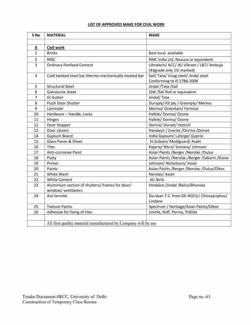
Tender Document-SRCC, University of Delhi Page no.-63 Construction of Temporary Class Rooms
LIST OF APPROVED MAKE FOR CIVIL WORK S No MATERIAL MAKE
A Civil work 1 Bricks Best local available 2 RMC RMC India Ltd, Novuco or equivalent. 3 Ordinary Portland Cement Ultratech/ ACC/ JK/ Vikram / L&T/ Ambuja
(43grade only 1SI marked) 4 Cold twisted steel bar thermo-mechanically treated bar Sail/ Tata/ Vizag steel/ Jindal steel
Conforming to IS 1786-2008 5 Structural Steel Jindal /Tata /Sail 6 Galvalume sheet JSW /SAI Roll or equivalent 7 GI Gutter Jindal/ Tata 8 Flush Door Shutter Duroply/ Kit ply / Greenply/ Merino 9 Laminate Merino/ Greenlam/ Fermica
10 Hardware – Handle, Locks Hafele/ Dorma/ Ozone 11 Hinges Hafele/ Dorma/ Ozone 12 Door Stopper Dorma/ Dorset/ Hettich 13 Door closers Hardwyn / Everite /Dorma /Dorset 14 Gypsum Board India Gypsum/ Lafarge/ Gyproc 15 Glass Panes & Sheet St.Gobain/ Modiguard/ Asahi 16 Tiles Kajaria/ Nitco/ Somany/ Johnson 17 Anti-corrosive Paint Asian Paints /Berger /Nerolac /Dulux 18 Putty Asian Paints /Nerolac /Berger /Sakarni /Dulux 19 Primer Johnson/ Nicholsons/ Asian 20 Paints Asian Paints /Berger /Nerolac /Dulux/Oikos 21 White Wash Nerolac/ Asian 22 White Cement JK/ Birla 23 Aluminium section of shutters/ frames for door/
window/ ventilators Hindalco /Jindal /Balco/Bhoruka
24 Ant termite Dursban T.C. from DE-NOCIL/ Chlorpyriphos/ Lindane
25 Texture Paints Spectrum / Heritage/Asian Paints/Oikos 26 Adhesive for fixing of tiles Unitile, Roff, Perma, Pidilite
All first quality material manufactured by Company will be use

Tender Document-SRCC, University of Delhi Page no.-64 Construction of Temporary Class Rooms
TECHNICAL SPECIFICATIONS
1.0 GENERAL
1.1 The work shall be executed at per CPWD specifications 2009 as amended upto date for various items of work. In case specifications for particular items of work are not available in CPWD specifications, then the relevant I.S specifications will be applicable.
1.2 In case, no specifications are available then the decision of the Architect given in writing based on acceptable engineering practices and local usage shall be final and binding.
2.0 The contractor shall provide and maintain at site throughout the contract period, the following at his own cost and the cost deemed to be included in the contract rates.
i) All Equipment’s instruments and labour required by the Engineer for measurement of the works.
ii) A testing room of suitable size equipped with the following as per I.S Codes with adequate labour and materials required for carrying out test there in.
iii) Set of standard sieves for testing grading of sand and a 75-micron sieve for testing silt content.
iv) Sieves set of standard sieves for testing grading of aggregates with sieve shaker.
v) Oven for drying of earth, sand and aggregate etc.
vi) Glass measuring flasks of ½ and 1 litre capacity
vii) Flask for determining moisture content of sand
viii) Slump cone for slump text
xi) Minimum 18 steel moulds for 150mm x 150 mm x 150mm size. It may be necessary to provide more steel cube mould depending upon concreting programme.
x) Work benches shelves desks, sinks and any other furniture and lights as required by the Engineer –in-charge.
xi) Cube testing machine with calibration certificate.
xii) Any other equipment not specifically mentioned above which can reasonably be necessary for conducting laboratory test, the completion and maintenance of the work to the satisfaction of the Engineer –in-charge and the Architect.
2.0 DRAWINGS / SAMPLES
2.1 The work shall be carried out in accordance with architectural / structural/ electrical drawings to be issued by the Engineer –in –charge / Architect. The structural and architectural drawing shall have to be properly co-related before executing the work. In case of any difference noticed between the structural and architectural drawings, final decision, in writing of the Engineer –in –charge / Architect shall be obtained by the

Tender Document-SRCC, University of Delhi Page no.-65 Construction of Temporary Class Rooms
contractor. For items where so required, sample shall be prepared before starting the particular item of work for prior approval of the Engineer –in –charge / Architect and nothing extra shall be payable on this account.
3.0 MATERIAL
3.1 All materials to be used shall conform to the specifications.
SPECIFICATIONS OF CIVIL WORKS
1. EARTHWORK
The Rates Quoted Shall Include the Following
1. Excavation either straight, inclined or curved in trenches, footings, floor etc., including Raking out, cutting and dressing sides and bottom to true dimension and depositing excavated stuff beyond three meters clear of the edge of the trench, filling back as required and disposal of surplus earth anywhere within the plot as directed by site engineer/ architect.
2. The excavation shall be done true to levels, slope, shape and pattern indicated by the Engineer-
in-charge. Only the excavation shown on the drawings or as required by the Engineer –in-charge shall be measured and recorded for payment.
3. All labor and material required for fencing and protection against risk of accident to open excavations etc., with necessary shoring planking and strutting and for providing gangways, with handrails across open trenches etc., where necessary during the progress of the work.
4. Filling back available excavated earth in plinths, sides of foundations, sides of basements, under floors and for ground formation etc., as and where required in 150 mm thick layers, breaking clods, ramming, watering, consolidation, the same with 10 M.T. Rollers or hand tampers where rollers are not accessible, and dressing the filled up areas.
2. BACKFILLING IN SIDES OF FOUNDATIONS, PLINTH, UNDER FLOOR ETC.
The back filling shall be done after the concrete or masonry has fully set and shall be done in such a way as not to cause under-thrust on any part of the structure. Where suitable excavated material is to be used for back filling, it shall be brought from the place where it was temporarily deposited and shall be used in backfilling. The scope of work for back filling/filling in foundation, plinth, under floors etc. shall include filling for all the buildings covered under the contract. Surplus earth available from one building, if required, shall be used for backfilling/filling for other buildings also within the specified lead mentioned in the item. Earth Filling : The earth shall be well graded and free from organic matter, debris etc. So brought shall be filled up in layers of 20 cm depth, each layer being well watered and consolidated by approved hand or mechanical tampers or other suitable means to achieve the required density as CPWD. Sand Filling : 100 mm thick or as shown in drawing and filling under floors at ground floor only shall be provided. This shall include supplying and filling dry fine sand watered and consolidated including dressing and leveling.

Tender Document-SRCC, University of Delhi Page no.-66 Construction of Temporary Class Rooms
3. ANTITERMITE TREATMENT
In order to ensure uniform distribution of the chemical emulsion and to assist penetration, the following site preparation shall be carried out:
1. Remove all concrete form work if left anywhere, leveling pegs, timber off-cuts and other Builder’s debris from the area to be treated.
2. If the soil to be treated is sandy or porous, preliminary moistening will be required to
fill capillary spaces in soil in order to prevent the loss of emulsion through piping or excessive Percolations.
3. In the event of water logging of foundation, the water shall be pumped out before application of
Chemical emulsion and it should be applied only when the soil is absorbent. 4. On clays and other heavy soils where penetration is likely to be slow and on sloping
sites, Where run-off of the treating solution is likely to occur, the surface of the soil should be scarified to a depth of 75 mm. at least.
5. All sub-floor leveling and grading should be completed, all cutting, trenches and
excavations should be completed with backfilling in place, borrowed fill must be free from organic debris and shall be well compacted. If this is not done supplementary treatments should be made to complete the barrier.
6. Chemicals approved by Central Insecticides Board conforming to relevant Indian Standards
(IS 8944- Chloripyrifos E.C./ IS 632-Lindane E.C.) in water emulsion or as specified in item may be used for soil treatment in order to protect a building from termite attack. The chemical solutions or emulsions are required to be dispersed uniformly in the soil and to the required strength so as to form an effective chemical barrier which is lethal and repellent to termites.
7. Treatment shall be carried through a specialized Agency who is a member of the Indian
Pest Control Association (IPCA) and shall be engaged with prior approval of the Engineer-in-Charge. The contractor should produce voucher(s) for the chemical purchased and should get verified the sealed container(s) of the specified chemical from the Engineer-in-Charge before preparing the emulsion for the treatment.
8. In case of framed structure, the treatment shall start at a depth of 500 mm. below ground level. From this depth the backfill around the columns, beams and R.C.C. basement walls shall be treated @ 7.5 ltrs./SqM of the vertical surface and @ 5 ltrs./Sqm for the horizontal surface at the bottom in the trenches/pits.
9. The top surface of the filled earth within plinth walls shall be treated with chemical emulsion at the rate of 5 litres/SqM of the surface area before sub-base to floor is laid. If filled earth has been well rammed and the surface does not allow the emulsion to seep through, holes upto 50 to 75mm. deep at 150 mm. centers both ways shall be made with crow bars on the surface to facilitate saturation of the soil with the emulsion
4. PLAIN / REINFORCED CONCRETE AND ALLIED WORKS
1. The constituent materials used in the manufacture of concrete shall be as per IS456-2000

Tender Document-SRCC, University of Delhi Page no.-67 Construction of Temporary Class Rooms
2. Cement: Unless otherwise specified or called for in the contract specifications, cement shall be any of the following and the type selected should be appropriate for the intended use and as per the contract conditions , specifications and drawings.
a) 33 Grade Ordinary Portland cement conforming to IS 269 b) 43 Grade ordinary Portland cement conforming to IS 8112 c) 53 Grade ordinary Portland cement conforming to IS 12269 d) Portland slag cement conforming to IS 455. e) Portland pozzolana cement (fly ash based) conforming to IS 1489 (Part I) f) Portland pozzolana cement (calcined clay based conforming to IS 1489 (Part 2) g) Sulphate resisting Portland cement conforming to IS 12330.
3. Mineral Admixtures
a) Pozzolana: Pozzolanic materials conforming to relevant Indian Standards may be used with the Permission of Engineer-in-charge provided uniform blending with cement is ensured.
b) Fly ash (pulverized fuel ash): Fly ash conforming to Grade 1 of IS 3812 may be
used as part replacement of ordinary Portland cement provided uniform blending with cement is ensured.
c) Silica fume: Silica fume conforming to a standard approved by the deciding authority can be
used as part replacement of cement provided uniform blending with the cement is ensured.
Note: The silica fume (very fine non –crystalline silicon dioxide)is a by-product of the manufacture of silicon, ferrosilicon or the like, from quartz and carbon in electric arc furnace. It is usually used in proportion of 5 to 10 percent of the cement content of a mix.
d) Rice husk ash: Rice husk ash giving required performance and uniformity characteristics
may be used with the approval of the deciding authority. Note: Rice husk ash is produced by burning rice husk and contain large proportion of silica. To achieve amorphous state, rice husk may be burnt at controlled temperature. It is necessary to evaluate the product from a particular source for performance and uniformity since it can range from being as deleterious as silt when incorporated in concrete. Water demand and drying shrinkage should be studied before using rice husk.
e) Storage: Stacking and storage of cement and other construction material(s) shall be as per
IS 4082-1996. Cement in bags shall be stored and stacked in a shed, which is dry, leak-proof and moisture proof as far as possible. Storage under tarpaulins will not be permitted. Flooring of the shed shall consists of the two layers of dry bricks laid on well consolidated earth to avoid contact of cement bags with the floor. Stacking shall be done about 150 to 200 mm clear above the floor using wooden planks. Cement bags shall be stacked at least 450 mm clear off the walls and in rows of two bags leaving in a space of at least 600 mm between two consecutive rows. In each row the cement bags shall be kept closed together so as to reduce air circulation. Stacking shall not be more than ten bags high to avoid lumping under pressure. In stacks more than eight bags high, the cement bags shall be arranged in header and stretcher fashion i.e alternately

Tender Document-SRCC, University of Delhi Page no.-68 Construction of Temporary Class Rooms
lengthwise and crosswise so as to tie the stacks together and minimize the danger of toppling over. Damaged or reclaimed or partly set cement will not be permitted to be used and shall be removed from the site. The storage arrangements shall be such that there is no dead storage consignments in cement shall be stored as received and shall be consumed in the order of their delivery. Cement held in store for a period of ninety (90) days or longer shall be retested before use in work. Should at any time the Engineer-in-Charge have reasons to consider that any cement is defective, then irrespective of its origin and/or manufacturers test certificate, such cement shall be tested immediately at a National Test Laboratory/Departmental Laboratory or such approved laboratory, and until the results of such tests are found satisfactory, it shall not be used in any work.
f) Aggregates: Fine Aggregate is aggregate most of which passes through 4.75 mm I.S. sieve
Coarse ggregate is aggregate most of which is retained on 4.75 mm I.S. sieve. Aggregate shall comply with requirement of IS 383. As far as possible preference shall be given to machine broken and graded aggregate. All fine and coarse aggregates proposed for use in the work shall be subject to the Engineer-in-Charge’s approval and after specific materials have been accepted, the source of supply of such materials shall not be changed without prior approval of the Engineer-in-Charge. Aggregate shall, except as noted above, consists of natural sand, crushed stone and gravel from a source known to produce satisfactory aggregate for concrete and shall be chemically inert, strong, hard, durable against weathering, of limited porosity and free from deleterious materials that may cause corrosion to the reinforcement or may impair the strength and/or durability of concrete. The grading of aggregates shall be such as to produce a dense concrete of specified strength and consistency that will work readily into position without segregation and shall be based on the “mix design” and preliminary test on concrete specified herein-after.
g) Storage of : All coarse and fine aggregates shall be stacked separately in stock piles in the
material Aggregates yard near the work site in bins properly constructed to avoid inter mixing of
different aggregates. Contamination with foreign materials and earth during storage and while heaping the materials shall be avoided. The aggregate must be of specified quality not only at the time of receiving at site but also at the time of loading into mixer. Rakers shall be used for lifting the coarse aggregate from bins or stock piles. Coarse aggregate shall be piled in layers not exceeding 1.00 metres in height to prevent conning or segregation. Each layer shall cover the entire area of the stock pile before succeeding layers are started. Aggregates that have become segregated shall be rejected. Rejected material after re-mixing may be accepted, if subsequent tests demonstrate conformity with required gradation.
h) Water : Water used for both mixing and curing shall be clean and free from injurious amounts of deleterious materials .viz oils, acids, alkalis, salts, sugar, organic materials or other substances that may be deleterious to concrete or steel. Potable waters are generally satisfactory for mixing and curing concrete. In case of doubt, the suitability of water for making concrete shall be ascertained by the compressive strength and initial setting time test specified in I.S. 456 - 2000. The sample of water taken for testing shall be typical of the water proposed to be used for concreting, due account being paid to seasonal variation. The samples shall not receive any treatment before testing other than that

Tender Document-SRCC, University of Delhi Page no.-69 Construction of Temporary Class Rooms
envisaged in the regular supply of water proposed for use in concrete. The sample shall be stored in a clean container previously rinsed out with similar water. Average 28 days compressive strength of at least three 150 mm. concrete cubes prepared with water proposed to be used shall not be less than 90% of the average strength of three similar concrete cubes prepared with distilled water as per IS - 516. The initial setting time of test block made with the appropriate cement and the water proposed to be used shall not be less than 30 minutes and shall not differ by more than (±) 30 minutes from the initial setting time of control test block prepared with the same cement and distilled water. The test blocks shall be prepared and tested in accordance with the requirements of I.S. 4031(Part 5). Where water can be shown to contain an excess of acid, alkali, sugar or salt, Engineer-in-Charge may refuse to permit its use. As a guide, the following concentrations represent the maximum permissible values:
i. Limits of acidity: To neutralize 100 ml sample of water, using phenolphthalein
as an indicator, it Should not require more than 5 ml. of 0.02 normal NaOH. The details of test shall be as per I.S. 3025 (Part 22)
ii. Limits of alkalinity: To neutralize 100 ml sample of water, using mixed indicator
, it should not require more than 25 ml. of 0.02 normal H2SO4The details of test shall be as per I.S. 3025 (Part 23).
4. DESIGN MIX CONCRETE
The calculated mix proportions shall be checked by means of trial batches as per IS 10262-2009. The contractor shall submit details of each trial mix of each grade of concrete designed for various workability conditions to the Engineer-in-Charge for his comments and approval. Concrete of any particular design mix and grade shall be produced/ manufactured for works only on obtaining written approval of the Engineer-in-Charge. For any change in quality/ quantity in the ingredients of a particular concrete, for which mix has been designed earlier and approved by the Engineer-in-Charge, the mix has to be redesigned and approval obtained again. Cost of such mix design shall be borne by the contractor. Whenever there is a change either in required strength of concrete or water cement ratio or workability or the source of aggregates and/or cement, fresh trial mix shall be carried out to determine the revised proportion of the mix to suit the altered conditions.
Proportioning by The W/C ratio specified for use by the Engineer-in-Charge shall be maintained. Water-cement ratio Contractor shall determine the water content of the aggregate as frequently as
directed by the Engineer-in-Charge as the work progresses and as specified in I.S. 2386 part III and the amount of mixing water added at the mixer shall be adjusted as directed by the Engineer-in-charge so as to maintain the specified W/C ratio. To allow for the variation in their moisture content, suitable adjustments in the weights of aggregates shall also be made.
Consistency and Concrete shall be of a consistency and workability suitable for the conditions slump of the job. After the amount of water required is determined, the consistency
of mix shall be maintained throughout the progress of the corresponding parts of the work and approved tests e.g. slump tests, compacting factor tests etc. in accordance with I.S. 1199, shall be conducted from time to time to ensure the maintenance of such consistency
Testing : Different tests required to be carried out for concrete works including the mix

Tender Document-SRCC, University of Delhi Page no.-70 Construction of Temporary Class Rooms
design, cube tested as per the above specifications shall be got done by the contractor at his own cost in one of the approved laboratories. The choice of laboratory shall rest with the OWNER/PMC/ARCHITECT. All incidental charges / cost shall be borne by the contractor.
Quantity of Concrete: If the concrete is deemed not to comply pursuant to above the structural
adequacy of the parts affected shall be investigated and any consequential action as needed shall be taken. Concrete is liable to be rejected if it is porous or honey-combed, its placing has been interrupted without providing a proper construction joint, the reinforcement has been displaced beyond the tolerances specified, or construction tolerances have not been met. However, the hardened concrete may be accepted after carrying out suitable remedial measures to the satisfaction of the Engineer-in-Charge.
Immediately after stripping the form work, all concrete shall be carefully inspected and any defective work or small defects, either removed or made good before concrete has thoroughly hardened, as instructed by Engineer-in-Charge.
In case of doubt regarding the grade of concrete used or results of cube strength are observed to be lower than the designed strength as per specifications at 28 days, compressive strength test of concrete based on core test, ultrasonic test and/or load test shall be carried out by the digital ultrasonic concrete tester byan approved agency as directed by the Engineer-in-Charge all at the cost of the contractor. In case these tests do not satisfy the requirements, the Department will be at liberty to reject the concrete, and the contractor, at his own cost, has to dismantle and re-do the same or carry out such remedial measures as approved by the Department.
Testing of Underground Water Tank /Septic Tank/Underground Structures The tank will be tested after the completion according to the procedure laid down
here The middle compartment shall be filled first to its full height and the leakage if any shall be checked on its outer surfaces and if found, the same shall be examined carefully and defects rectified/grouted if necessary. The drop in level of surface of water shall also be recorded for 48 hours. If this drop in level exceeds 20 mm. and shows any leakage in the said walls, necessary steps shall be taken in consultation with the Engineer-in-Charge. After this compartment is tested to the satisfaction of the Engineer-in-Charge, all water from middle compartment shall be pumped into side compartment to the full height and checked for water leakages from the outer surfaces of the tank as well as inner surface of the middle compartment. The drop in level of surface of water shall also be checked as stated above and defects rectified. The external surface of the tank shall then be plastered and cured as per the specifications and back filling shall be taken up thereafter. The water from the compartments shall then be pumped out and the inner surface of the tank in all compartments then be checked and defects rectified. After satisfactory completion of checks, internal plaster shall be taken up as specified in the specifications.
Unsatisfactory Tests : Should the results of any test prove unsatisfactory, or the structure shows
signs of weakness, undue deflection or faulty construction, contractor shall remove and rebuild the member or members involved or carry out such other remedial measures as may be required by Engineer-in-Charge. Contractor shall bear the cost of so doing, unless the failure of the member or members to fulfill

Tender Document-SRCC, University of Delhi Page no.-71 Construction of Temporary Class Rooms
the test conditions is proved to be solely due to faulty design. The cost of load and other tests shall be borne by Contractor .
5. REPAIR AND REPLACEMENT OF UNSATISFACTORY CONCRETE
Immediately after the shuttering is removed, the surface of concrete shall be very carefully gone over and all defective areas called to the attention of Engineer-in-Charge who may permit patching of the defective areas or else reject the concrete unit either partially or entirely. Rejected concrete shall be removed and replaced by Contractor. Holes left by form bolts etc. shall be filled up and made good with mortar composed of one part of cement to one and half parts of sand passing
6. CLEANING AND BONDING OF FORMED CONSTRUCTION JOINTS
Vertical construction joints shall be cleaned as specified above or by other methods approved by Engineer-in-Charge. In placing concrete against formed construction joints, the surfaces of the joints, where accessible, shall be coated thoroughly with the specified bed-joint bonding mortar immediately before they are covered with concrete or by scrubbing with wire brooms, dipped into the fresh concrete. Where it is impracticable to apply such a mortar coating, special precautions shall be taken to ensure that the new concrete is brought into intimate contact with the surface of the joint by carefully puddling and spading with aid of vibrators and suitable tools.
7. EXPANSION & CONTRACTION: Provision shall be made for expansion and contraction in concrete by use of special type joints located as shown in the drawings. Construction joint surfaces shall be treated as specified in the specifications, shown in the drawings or as directed by Engineer-in-Charge. The compaction of the concrete shall be done by mechanical vibrating tables or external vibrators as approved by the Engineer-in- charge and as per clause 5.4.3.2 of specification 2009 CPWD Vo1.I. The rates quoted for the item shall include for both the form work and mechanical vibrators.
8. STEEL FOR CONCRETE REINFORCEMENT
The contractor shall make his own arrangement for procurement of Reinforcement steel bars and wires for use in Reinforced Cement Concrete works. Unless otherwise specified in drawings / Schedule of quantities, the steel bars shall be of “High strength deformed steel bars and wires” conforming to the IS 1786-2008 (Amendment 1)), in the following strength grades:
a) Fe 415, Fe 415D, Fe415S b) Fe 500, Fe 500D, Fe500S c) Fe 550, Fe 550D, and d) Fe 600.
9. TESTS :
The contractor shall submit the test certificate of manufacturer. Regular tests on steel supplied by the contractor shall be performed by the contractor at the approved lab, in presence of the Departmental Engineers as per relevant Indian Standards. Engineer-in-charge may require Contractor to perform necessary tests of samples at random as per relevant B.I.S.

Tender Document-SRCC, University of Delhi Page no.-72 Construction of Temporary Class Rooms
All cost of such tests and incidentals to such tests shall be borne by the Contractor. The quality, grade, colour coding embossing marks etc. all shall be to the entire satisfaction of the Engineer-in-Charge. Steel not conforming to above test criteria shall be rejected. The Chemical, Physical & Mechanical properties of the steel reinforcement bars shall be as per IS 1786. Unless otherwise specified, Selection and Preparation of Test Sample shall be as per the requirements of IS 2062. All test pieces shall be selected either from the cuttings of bars / wires; or from any bar/wire after it has been cut to the required or specified size and the test piece taken from any part of it. In neither case, the test piece shall be detached from the bar/wire except in the presence of the EIC or his authorized representative. The test pieces shall be full sections of the bars/wires and shall be subjected to physical tests without any further modifications. No reduction in size by machining or otherwise shall be permissible, except in case of bars of size 28 mm and above. No test piece shall be annealed or otherwise subjected to heat treatment. Any straightening which a test piece may require shall be done cold.
10. STACKING & STORAGE
Steel for reinforcement shall be stored in such a way as to prevent distorting and corrosion. The steel for reinforcement shall not be kept in direct contact with ground. Fresh / Fabricated reinforcement shall be carefully stored to prevent damage, distortion, corrosion and deteriorations. Care shall be taken to protect steel from exposure to saline atmosphere during storage, fabrication and use. It may be achieved by treating the surface of reinforcement with cement wash or by suitable methods. Bars of different. Classifications, sizes and lengths shall be stored separately to facilitate issue in such sizes and lengths to cause minimum wastage in cutting from standard length.
11. QUALITY:
Steel not conforming to specifications shall be rejected. All reinforcement shall be clean, free from grease, oil, paint, dirt, loose mill, scale, loose rust, dust, bituminous material or any other substances that will destroy or reduce the bond. All rods shall be thoroughly cleaned before being fabricated. Pitted and defective rods shall not be used. All bars shall be rigidly held in position before concreting. No welding of rods to obtain continuity shall be allowed unless approved by the Engineer-in-Charge. If welding is approved, the work shall be carried as per I.S. 2751, according to best modern practices and as directed by the Engineer-in-Charge. In all cases of important connections, tests shall be made to prove that the joints are of the full strength of bars welded. Substitution of reinforcement will not be permitted except upon written approval from Engineer-in-charge.
12. CONCRETING
1. In respect of projected balconies and projected verandahs, the payment for the RCC work shall
be made under the items of RCC work (RCC slabs). The payment for centering shuttering shall similarly be made under the items of centering and shuttering for RCC slabs. Nothing extra shall be paid for the side shuttering at the edges of slabs, projected balconies and projected verandahs. All the exposed edges shall however be finished as per specifications and nothing extra shall be paid.
2. In the item of RCC walls the Railings as per ARCHITECT’s design of any thickness, holes, slits, etc. Not extra shall be paid for these provisions. The finished railing should be perfectly straight and in one plane.
3. The centering and shuttering for all the RCC and R.B. work shall be of steel or ply of approved quality and thickness.

Tender Document-SRCC, University of Delhi Page no.-73 Construction of Temporary Class Rooms
4. Making all drips, grooves, moulds, curved surfaces and chamfered edges etc. in concrete
and/or plaster work as directed
5. All projections, too things, ornamental work etc. and finishing to shape as directed.
6. Installing a calibrated cube-testing machine at site, getting it calibrated every month and submitting test report to the architects. Alternately getting the cubes tested in an approved lab at his own cost by contractor.
7. Preparing 7 days and 28 days test cube, testing them at site and /or getting tested in an approved laboratory including all fees, costs, transportation etc. relating to them.
8. Providing slump tests apparatus at site and test for checking the workability of concrete.
9. Working up or hacking of concrete surfaces for providing keys for further concrete work including applying thick cement slurry or mortar as directed
10. Use of shuttering oil as specified
11. Use of cement slurry over shuttering before commencing concreting.
12. Machine mixing of all concretes and hoisting to all lifts, carrying to all leads, consolidating by rodding, vibrating, tamping and curing.
13. Sinking of floors in specified areas.
14. Providing of dowel bars wherever directed by the architect/engineer.
15. Forming cutouts, openings and concreting at a later stage as required
16. Providing sleeves for pipes etc. before concreting
17. Working in narrow widths, small quantities and curved alignments etc.
18. Removing rust, mild scales, oil, grease, paint etc. from steel reinforcement.
19. Providing 16 gauge annealed binding wire and binding the reinforcement with the same without any extra cost on the account for labour or material
20. Providing cover to steel with cement concrete briquette spacers at no extra cost.
21. Payment of labour for laying steel as per Indian standard section weights actually placed in position as per design and drawing or as directed
22. The contractor shall not undertake the RCC work including form-work of first floor before laying lean concrete on the lowest floor if so directed by the architect/engineer.
23. Wherever new structural slab/beam is to be connected with the old structural slab/beam, the cost of chipping the necessary old concrete members and re-casting the same is to be included in the item.
13. FORMWORK:

Tender Document-SRCC, University of Delhi Page no.-74 Construction of Temporary Class Rooms
i. Shuttering for concrete:
The term `Shuttering’ shall include all centering and formwork required to support the concrete during the process of laying, compacting and setting and all items such as planking, lagging, walling, moulds, covers, cross-bearers, struts, props, bracings etc. shall be covered by the term. Shuttering shall be strong and rigidly constructed so that there may not be any deformation under weight and pressure of wet concrete, constructional loads, wind and /or other forces. It shall be constructed in such a manner that it can be easily removed afterwards. The shuttering shall have smooth and even surface and so constructed as to remain sufficiently rigid during the placing and compacting to concrete and shall be sufficiently tight to prevent loss of liquid from the concrete. Devices shall be provided in the shuttering for forming openings, holes, pockets, chases, recesses etc. where required. Cutting of holes etc. in the concrete after casting shall be avoided. Corner fillets shall be provided in the form work to obtain chamfered edges to beams, columns etc. wherever required and the rate quoted shall be inclusive of the cost of carrying out such work. Shuttering shall conform to IS:456. Forms shall be pre-fabricated standard or shop-built panels or built-in-place units, stiffened and braced. A smearing of oil shall be given on the faces of the shuttering in contact with the concrete. Care shall be taken that oil does not come in contact with the reinforcement. Forms shall be cleaned from all dust and loose materials before applying below ground level on earth face with prior permission of the Engineer. Blocks shall be thoroughly wetted before laying concrete. The shuttering shall be such that after its removal the exposed concrete surface shall be smooth and even. If any unevenness is found, the contractor shall chip the bulged portion of the concrete and plaster with 6mm thick cement plaster (1:4) at his own cost, after obtaining Engineer’s approval. The following table gives the minimum period for removing formwork from various concrete members when normal portland cement is used, it being assumed that the work shall not be loaded for several days after the period given. All formwork shall be removed without shock or vibration to concrete.Minimum period for striking Shuttering or forms 1. Walls, columns, vertical sides of 24 to 48 hours as may be decided by beams and sides of foundations. the Engineer. 2. Slabs (props left under) 7 days. 3. Beam soffits (props left under) 7 days. Removal of props to slabs: (a) Spanning upto 4.5m 7 days (b) Spanning over 4.5m 14 days Removal of props to beams: (a) Spanning upto 6m 14 days (b) Spanning over 6m 21 days
ii. Supports:

Tender Document-SRCC, University of Delhi Page no.-75 Construction of Temporary Class Rooms
Formwork shall be so designed that the side of beams and slabs can be removed without disturbing soffit forms and their supports. Props and supports shall allow accurate adjustment of the formwork to line and level and be capable of being removed in an approved sequence without injury to the concrete. Provision shall be made for removal of formwork without disturbing props required for supporting hardened concrete.
iii. Setting:
Panels and units shall be set to true dimensions and alignment and rigidly tied, walled and braced to prevent distortion and displacement during concreting. All joints shall be tight and close fitting to prevent leakage. At all construction joints, formwork shall be tightly secured against previously cast or hardened concrete. When fixing formwork for beams and slabs tight fitting collars shall be provided around the heads of columns and the joints shall be made grout tight. Slip forms where used shall provide smooth even surface true to dimension and alignment and shall be free of unslightly off-sets fins and bulges.
iv. Ties:
Standard from ties, clamps, bolts, inserts etc. shall be of adequate strength. Spreaders, either removable or embedded type shall be used to maintain the wall thickness. The material and position of any tie passing through the formwork shall be as approved by the Engineer. All tie members which will remain embedded in the concrete shall be fixed a manner that will provide a minimum cover of 12mm at both the ends. Any holes left after removal of ties shall be filled with concrete or mortar as approved by the Engineer. Provision shall made for forming holes and chases for services and for providing pipes, conduits and other fixing as shown in the drawing and / or as directed by the Engineer.
v. Cleaning and Treating of Forms:
All rubbish shall be removed from the interior of the formwork and inside of the formwork shall be wetted with water before commencing of concreting. Mould oil or other approved release agent shall be used to all panels. Care shall be taken to prevent contact of release agent with reinforcement.
14. REINFORCEMENT:
Reinforcement will be used as reinforcement as per drawings and directions.
i. Bar Bending Schedules:
The contractor shall submit to the Engineer for approval, Bar Bending Schedules with working drawings in triplicate, showing clearly the arrangements proposed by the contractor to match available stock of reinforcing steel, within one month of receipt of the letter of intent or of the receipt of the relevant design drawings, whichever is later. Upon receipt of the Engineer’s final approval of the Bar Bending Schedule and drawings, the contractor shall submit six (6) prints of the final drawings with one reproducible print after incorporating necessary modifications or corrections, for final record and distribution. Approval of such detailed drawings by the Engineer shall not relieve the contractor of his responsibility for correctness or of any of his obligations to meet the other requirements of the contract.
ii. Cleaning:
All steel for reinforcement shall be free from loose scales, oil grease, paint or other harmful matters immediately before placing the concrete.

Tender Document-SRCC, University of Delhi Page no.-76 Construction of Temporary Class Rooms
iii. Bending:
Unless otherwise specified, reinforcing steel shall be bent in accordance with the procedure specified in IS: 2502 or as approved by the Engineer. Bends and shapes shall comply strictly with the dimensions corresponding to the approved Bar Bending Schedules. Bar Bending Schedules shall be rechecked by the Contractor before any bending is done. No reinforcement shall be bent when already in position in the work without approval of the Engineer, whether or not it is partially embedded in concrete. Bars shall not be straightened in a manner that will injure the material. Rebending can be done only if approved by the Engineer. Reinforcing bars shall be bent by machine or other approved means producing a gradual and even motion. All the bars shall be cold bent unless otherwise approved. Bending hot at a cherry-red heat (not exceeding 845 Deg. C) may be allowed under very exceptional circumstances except for bars whose strength depends on cold working bars bent hot shall not be cooled by quenching.
iv. Placing in Position:
All reinforcements shall be accurately fixed and maintained in position as shown on the drawings by such approved and adequate means like mild steel chairs and/or concrete spaces blocks irrespective of whether such supports are payable or not bars intended to be in contact at crossing points, shall be securely tied together at all such points by no. 16 SWG annealed soft iron wire or by tack welding in case Bar Binders shall tightly embrace the bars with which they are intended to be in contact and shall be securely held. The vertical distance between successive layers of bars shall be maintained by provision of mild steel spaces bars. They should be spaced such that the main bars do not sag perceptibly between adjacent spacers. Before actual placing, the contractor shall study the drawings thoroughly and inform the Engineer in cases he feel that placement of certain bars is not possible due to congestion. In such cases, he should not start placing any bar before obtaining clearance from the Engineer.
v. Welding:
Normal bond laps in reinforcement may be placed by lap or butt welding reinforcement bars, if asked by the Engineer, under certain conditions the work should be done with suitable safe guards in accordance with relevant Indian Standards for welding of mild steel bars used in reinforced concrete construction as per IS: 2751 and IS: 456. Welded mesh fabrics conforming to IS: 1566 may also be used of specified on the schedule of items and drawings.
vi. Control:
The placing of reinforcements shall be completed well in advance of concrete pouring. Immediately before pouring, the reinforcement shall be examined by the Engineer for accuracy of placement and cleanliness. Necessary corrections as directed by him shall be carried out. Laps and anchorage lengths of reinforcing bars shall be in accordance with IS: 456, not unless other wise specified. If the bars in a lap are not of the same diameter the smaller will guide the lap length. The laps shall be stagged as far as practicable and as directed by the Engineer. Arrangements for placing concrete shall be such that reinforcement in position do not have to bear extra load and get disturbed. The cover for concrete over the reinforcements shall be as shown on the approved drawings less otherwise directed by the Engineer. While concrete blocks are used for measuring the cover and positioning reinforcement, they shall be made of mortar not lean than one (1) part cement to two (2) parts sand by volume and cured in a pond for at least fourteen (14) days. The type shape, size

Tender Document-SRCC, University of Delhi Page no.-77 Construction of Temporary Class Rooms
and location of the concrete blocks shall be as approved by the Engineer.
vii. Opening Chases, Grooves, Rebates, Block outs etc.
Contractor shall leave all openings, grooves, chases etc. in concrete work as shown on the drawings or as specified by the Engineer.
viii. Anchor Bolts, Anchor, Sleeves, Inserts, Hangers/Conduits/Pipe and other Misc. Embedded
Fixtures:
Contractor shall build into concrete work all the items noted below and shall embed them partly or fully as directed and secure the same as may be required. The materials, if required to be supplied by the contractor, shall be as specified and be of best quality available according to relevant Indian Standards of approved manufacture and to the satisfaction of the Engineer. Exposed surfaces of embedded materials are to be painted with one coat of approved anti-corrosion paint and /or bituminous paint without any extra cost to the owner. If welding is to be done subsequently on the exposed surface of embedded material the paint shall be cleaned off the member to a minimum length of 50mm beyond each side of the weld line. Necessary templates, jigs, fixtures, supports, etc. shall be used as may be required or directed by the Engineer, free of cost to the Owner.
ix. Items to be embedded:
a. Inserts, hangers, anchors, frames alround openings, manholes covers, frames, floor clips,
sleeves conduits and pipes. b. Anchor bolts and plates for machinery, equipment and for structural steel work. c. Steel structural to be left embedded for future extension, special connection etc. d. Dowel bars, etc. for concrete work falling under the scope of other contractors. e. Lugs or plugs for door and window frames occuring in concrete work. f. Flaching and jointing in concrete work. g. Any misc. embedments and fixture as may be required.
Correct location and alignments, as per drawings / instruction of all these embedded items shall be entirely the responsibility of the contractor.
15. PLACING OF CONCRETE:
i. Transportation Concrete:
Concrete shall be transported from the mixing plant to the forms as rapidly as possible by means that will prevent segregation or flash set in the concrete during hot weather. The containers shall be such as to prevent heavy evaporation. At the time of placing concrete in very hot weather, care shall be taken to see that the temperature of wet concrete does not exceed 30 degree C. Before placing the concrete, all formwork, embedments and reinforcement shall be checked for completeness, location, dimension, square and plumb. All chips and saw dust base surface shall be well moistened and puddles wiped out. Placing equipment and accessories shall be kept clean and free of partially set grout and concrete, and maintained in proper working order.
ii. Placing aids:
In general, placing shall be direct, by transporting buckets. Where it is necessary to deposit the concrete at level differences of more than 1.5m short chutes shal be used. Short chutes and hoppers shall be so designed and installed that segregation will not take place. In cases where chutes are

Tender Document-SRCC, University of Delhi Page no.-78 Construction of Temporary Class Rooms
impracticable due to excessive drop to placing level, hoppers and sectional tubes (elephant trunks) shall be used.
iii. Compaction:
Concrete in general shall be consolidated by vibration using high frequency mechanically driven vibrators. Concrete shall be placed in layers at least 300mm deep in walls and approximately 450mm in mass pours. Vibrators shall not penetrate more than 50mm into the surface of previously placed layer but shall completely vibrate the working layer. Care shall be taken not to over-vibrate any concrete and especially those with higher slumps. Under no circumstances vibrators shall be attached to or allowed to touch reinforcement. Spare vibrators in good operating condition shall be on hand during placing operations.
iv. Special Concreting:
The placing of underwater concrete shall follow IS: 456 in all respects for the method employed. Special types of concrete shall be placed by methods most suitable for the particular conditions.
v. Curing and Protecting:
Curing of concrete with water shall comply with IS: 456. The contractors shall keep the exposed surfaces of concrete in a constantly wet conditions for at least 7 days from the date of placing the concrete. Curing compound may be used subject to approval by the Engineer. Finished floors and concrete shall be protected carefully until completely set. Protection of concrete against extreme weather conditions shall comply with the code. Curing shall be assured by use of an ample water supply under pressure in pipes with all necessary appliances of hose, sprinklers and spraying devices. Continuous fine mist spraying or sprinkling shall be used. Unless otherwise specified or approved by consultant. Whenever, in the judgement of consultant, it may be necessary to omit the continuous spray method, a covering of clean sand or other approved means such as wet gunny bags which will prevent loss of moisture from the concrete, may be used. No type of covering will be approved which would stain or damage the concrete during or after the curing period. Covering shall be kept continuously wet during the curing period. For curing of concrete in pavements, side / walks, floors, flat roofs or other level surfaces, the ponding method of curing is preferred. The method of containing the ponded water shall be approved by consultant. Special attention shall be given to edges and corners of the slabs to ensure proper protection of these areas. The ponded areas shall be kept continuously filled with water during the curing period. Curing Compounds: Surface coating type curing compounds shall be used only by special permission of consultant. Curing compounds shall be liquid type white pigmented, conforming to U.S. Bureau of Reclamation Specification. No curing compound shall be used on surfaces where future blending with concrete water or acid proof membrane, or painting is specified.
5. BRICK WORK
1. Where fractions of half bricks occur due to Architectural or other reason the work shall be measured as follow:
• If as per drawing, the use of fraction of half bricks is required, the measurements

Tender Document-SRCC, University of Delhi Page no.-79 Construction of Temporary Class Rooms
shall be made for half brick.
• If the thickness of the walls is required to be increased upto 2 cm (3/4”) beyond the structural thickness of half brick multiples, the same shall be made up in mortar and paid for the specified thickness.
• Brick work in steps /treads of stairs, pillars ( square of rectangular) shall be payable under the schedule of quantities ( Volume –II) and nothing extra shall be payable on any account whatsoever ,it may be.
• In case the cracks appear subsequently in those areas, they should be made good
by cement grouting or epoxy putty grouting/ poly sulphide compound grouting or as per standard modern specifications/ methods with the prior approval of the Engineer-in-Charge, at the cost of the contractor. All the courses shall be laid truly horizontal and all vertical joints shall be truly vertical. Specified mortar of good and approved quality shall be used. Lime shall not be used where reinforcement is provided in brick work. The mortar should completely cover the bed and sides of the bricks. Proper care should be taken to obtain uniform mortar joint throughout the construction. the walls should be raised uniformly in proper, approved bond. In construction of the wall, first of all two end corners are carefully laid to line and level and then in between portion is built, with a cord stretching along the headers or stretchers held in position at the ends. This helps in keeping the alignment of the courses and maintaining them in level. Similarly all other courses are built. Care shall be taken to keep the perpends properly aligned within following maximum permissible tolerances :
• Samples of bricks shall be subjected to the following mandatory tests a) Dimensional tolerance, b) Water absorption, c) Efflorescence, d) Compressive Cost of above tests shall be borne by the contractor and the quoted rate shall be inclusive of such testing.
2. Curing of brick work
6. WOOD WORK
Second Class Teak Wood: Individual hard and sound knot shall not be more than 40 mm in diameter and aggregate area of all knots shall not exceed one and half percent of the area of the piece. Wood shall be generally free from sapwood, but traces of sapwood may be allowed.
• All timber mentioned in the item in schedule of quantities shall be from the heart
of a sound tree of nature growth mostly free from sap wood. It shall be uniform in texture, straight in fiber and shall be well and properly seasoned. It will be free from decay ,fungal growth, boxes heart, pitch pockets or streaks on the exposed edges, splits and cracks, and all other defects or any other damages of harmful nature which will affect the strength, durability, appearance and its usefulness for the purpose for which it is required. Only properly seasoned timber shall be used.
• Solid core flush door shutters shall be of 5 ply construction and approved make
generally conforming to the I.S. specification 2202-1991 (specification for wooden flush door shutter- solid core type). The finished thickness of the shutter shall be as mentioned in the schedule of items.

Tender Document-SRCC, University of Delhi Page no.-80 Construction of Temporary Class Rooms
• Commercial face veneers used in flush door shutter shall conform to the
requirements laid down in I.S. 303 -1989 specifications for ply wood for general purposes (revised) interior grade. Decorative face veneers used in flush door shutters shall be of grade - I and shall conform to the requirements of decorative veneer specified for grade - I decorative ply wood in I.S. 1328 - 1982 specifications for veneered decorative ply wood interior grade. Thickness of veneers shall not exceed 1 mm.
• Phenol formaldehyde synthetic resin (liquid type adhesives) conforming to
I.S. 848 specifications for synthetic resins shall be used for bonding.
• Lipping, where specified, shall be provided internally on all edges of the shutters. Internal lipping alround shall be done with single piece battens of best quality hardwood or teakwood as specified of depth not less than 25 mm and width equal to the thickness of core. For double leaved shutters, depth of the lipping at meeting of stiles shall be not less than 35 mm. Joints shall not be permitted in the lipping. Thickness of external lipping, wherever specified in the item, shall not be more than 10mm and not less than 6mm.
• In the case of double leaves shutters the meeting of stiles shall be rebated by 8 mm
to 10 mm. The rebating shall be either splayed or square type as shown in drawing where lipping is provided. The depth of lipping at the meeting of stiles shall not be less than 30 mm.
• All the faces of the door shutter shall be at right angles. The shutter shall be free from twist and warp in its plane. Both faces of the door shutters shall be sanded to a smooth even texture. The workmanship and finish of the face panels shall be in conformity with those specified in I.S. 303 - 1989 specification for plywood for general purpose (revised) for commercial type and I.S. 1659 - 1990 specification for block boards for decorative type.
• Tests shall be conducted as per mandatory test requirement, by the Department at contractors cost and acceptance criteria shall be as per I.S. 2202. The flush door shutter manufactured shall be inspected for its quality and workmanship and tested at the factory before dispatching. All facilities shall be extended for such inspection and testing. The sampling and testing shall be as per the IS requirements and all costs towards test including sample for destructive tests shall be borne by the contractor.
• For side hung shutters of height upto 1.2 m, each leaf shall be hung on two hinges at quarter points and for shutter of height more than 1.2 m, each leaf shall be hung on three hinges one at the centre and the other two at 200 mm from the top and bottom of the shutters. Top hung and bottom hung shutters shall be hung on two hinges fixed at quarter points of top rail or bottom rail. Centre hung shutter shall be suspended on a suitable pivot in the centre of the frame. Size and type of hinges and pivots shall be as specified. Flap of hinges shall be neatly counter sunk into the recesses cut to the exact dimensions of flap. Screws for fixing the hinges shall be screwed in with screw driver and not hammered in. Fittings shall be fixed as per schedule of fittings as specified.
7. FITTINGS AND FIXTURES
Tender Document-SRCC, University of Delhi Page no.-81 Construction of Temporary Class Rooms
• All fittings and fixtures shall conform to relevant IS code and made of brass, anodized aluminium, iron oxidised (M.S.), S.S. or as specified. These shall be well made reasonably smooth and free from sharp edges corners, flaws and other defects. Screw holes shall be counter sunk to suit the heads of the specified screws. All hinges pins shall be of steel for brass hinges and aluminium alloy NR-6 or steel pins for aluminium hinges with nylon washers or as specified. All riveted heads pertaining to hinge pins shall be well formed. Screws supplied for fittings shall be of the same metal and finish as the fittings. However brass cadmium plated/chromium plated screws shall be supplied with aluminium fittings. Samples of each fixture/ fitting shall be furnished by the contractor for approval of the Engineer-in-Charge. Order for procurement of fittings and fixtures in bulk shall be placed only after approval by the Engineer-in-Charge
• The fittings and fixtures to be incorporated in the work shall be strictly according to the approved sample. Fittings shall be fixed in proper position as shown in the drawing and as directed by the Engineer-in-Charge. These shall be truly vertical or horizontal as the case may be. Screws shall be driven home with a screwdriver and not hammered in. Recess shall be cut to the exact size and depth for the counter sinking of hinges. The fittings and fixtures shall be fixed in a workman like manner and any damages done either to fittings and fixtures or to the shutter frames etc. should be rectified by the contractor at his own cost.
• Aluminium hinges shall be manufactured from the extruded sections and shall be free from cracks and other defects. M.S. butt hinges shall be cranked and manufactured from M.S. sheets. All butt hinges shall conform to relevant I.S viz. IS 12817(Stainless Steel), IS 1341 (M.S.) & IS : 205 (Cast brass & aluminium). The size of butt hinges shall be denoted by length of the hinge and other dimensions i.e. breadth of hinge and thickness of its flap should be as specified.
• Tower Bolts shall generally conform to IS 204 (Part I & II). They shall be well made and shall be free from defects. The bolts shall be finished to the correct shape and shall have a smooth action. The knobs of brass tower bolts shall be cast and the bolt fixed into the knob firmly as per I.S. specifications. The tower bolt shall be finished to correct shape and pattern so as to have a smooth action. Wherever specified, aluminium barrel tower bolts shall be manufactured from extruded sections of barrel & bolts Knobs shall be properly screwed to the bolt and riveted at the back. The size of the tower bolt shall be taken as the length of barrel without top socket.
• Aldrop shall be oxidised brass or anodized aluminium, iron oxidised or as specified and shall be capable of smooth sliding action and shall be as per relevant I.S. Brass sliding door bolt (aldrop) shall be made from rolled brass generally confirming to IS : 2681. M.S. sliding door bolt shall generally conform to I.S.281. The hasp shall be of cast brass and screwed to the bolt in a workman like manner. Alternatively the hasp and the bolt may be in one piece. Bolts shall be finished to shape and threaded with worth standard and provided with round brass washers and nuts of square or hexagonal shape. All components shall be smooth and polished. The leading dimensions of aldrop shall be as the length of the bolt and specified diameter
• Door handles generally conform to IS : 208. Unless otherwise specified door handles shall be of 100 mm size & windows handles of 75 mm size. These shall be of cast Brass or cast/sheet Aluminium alloy or mild steel handles as specified

Tender Document-SRCC, University of Delhi Page no.-82 Construction of Temporary Class Rooms
and of specified size, shape and pattern as approved by the Engineer-in-charge. All edges and corners shall be finished smooth and correct to shape and dimensions. Brass handles shall be finished bright, chromium plated or oxidised as specified. Anodised aluminium or iron oxidised (m.s.) handles shall be of specified size, shape and pattern. The size of the handle is taken as the inside grip of the handle. In case of iron oxidised handles, the same shall be manufactured from m.s. sheet pressed into oval section as per I.S.
• Mortise & Latch should generally conform to I.S. 2209. Handles shall conform to IS 4992. Mortise lock with latches and a pair of level handles shall be 6 levers, with zinc alloy pressure die cast/brass or as specified body of approved quality, and shall be right or left handed as specified. The pair of handles shall be either brass chromium plated or anodized aluminium of approved shape and pattern or as specified. It shall be of the best Indian make of approved quality. The size of the lock shall be determined by its length. The lock for single leaf door shall have plain face and that for double leaf door a rebated face. Level handles with springs shall be mounted on plates and shall be of approved quality,anodized aluminium or as specified.
• The floor door stopper shall conform to IS: 1823. This shall be made of cast brass of overall size as specified and shall have rubber cushion. The shape and pattern of stopper shall be approved by the Engineer-in-Charge. It shall be of brass finished bright, chromium plated or oxidised or as specified. The size of door stopper shall be determined by the length of its plate. The body of the door stopper shall be cast in one piece. All parts of the door stopper shall be of good workmanship and finish and free from surface and casting defects. Aluminium stopper shall have anodic coating of not less than grade AC-10 of IS 1868.
8. STEEL WORKS
• All structural steel shall be of standard sections as marked on the drawings
conforming to IS 1173, IS 4923-1997, IS 1161-1998 and shall be free of scale, blisters, laminations, cracked edges and defects of any sort. If the structural steel is not supplied by the Department and the Contractor is required to bring such steel, the Contractor shall furnish duplicate copies of all mill orders and/ or also the test report received from the mills, to satisfy the Engineer-in-Charge.
• Any part which do not fit accurately or which are not in accordance with the drawings and specifications shall be liable to rejection and if rejected, shall be at once be made good.
• Engineer-in-Charge shall have full liberty at all reasonable times to enter the contractors premises for the purpose of inspecting the work and no work shall be taken down, painted or dispatched until it has been in spected and passed. The contractor shall supply free of charge all labour and tools required for testing of work.
• The contractor shall deliver the component parts of the steel work in an undamaged state at the site of the works and the Engineer-in-Charge shall be entitled to refuse acceptance of any portion which has been bent or otherwise

Tender Document-SRCC, University of Delhi Page no.-83 Construction of Temporary Class Rooms
damaged before actual delivery on work.
• The shop drawings of structural steel based on contract drawings shall be submitted to the Engineer-in- Charge. The necessary information for fabrication, erection, painting of structure etc. must be furnished immediately after acceptance of the tender.
• Painting should be strictly according to I.S. 1477-1971 (Part I-Pretreatment) and I.S. 1477-1971 (Part II-painting). Painting should be carried out on dry surfaces free from dust, scale etc. The paint shall be approved by the Engineer-in-Charge.
• Welding shall be in accordance with I.S. 816-1969, I.S. 819-1957, I.S. 1024-1979, I.S. 1261-1959, I.S. 1323-1982 and I.S. 9595-1980 as appropriate. For welding of any particular type of joint, welders shall give evidence of having satisfactory completed appropriate tests as described in any of I.S. 817-1966, I.S. 1393-1961, I.S. 7307 (Part-I)-1974, I.S. 7310 (Part-I)-1974 and I.S. 7318 (Part-I)-1974 as relevant.
• The contractor shall ensure that each welding operator employed on fabrication or erection is an efficient and dependable welder, who has passed qualifying tests on the types of welds which will be called upon to make. Sample test shall have to be given by the contractor to the entire satisfaction of the Engineer-in-charge.
• The truss shall be fabricated to the design and pattern shown in the drawings. All joints shall be made in best workman like manner with slotting and welding as required to the specified size and shape. The edge of the M.S. member shall be suitably mitred before welding to get the desired shape. The complete assembly of truss so fixed shall be firm and there shall not be any lateral movements
• Samples of railings shall be submitted for approval of the Engineer-in-Charge and to be got approved before taking up for mass fabrication.
• Providing, fabrication, cutting binding to required size and shape, drilling
punching, counter-sinking, welding, filling etc. finishing, erecting and fixing in position at all heights and depths with lead and lift.
• No extra shall be paid for transport of fabricated items from one place to another
place.
• Cost of all erection fasteners shall be borne by the contractor.
• All holes shall be drilled and no gas cutting shall be allowed.
9. FLOORING WORK
1. TILE FLOORING
• The tiles shall be of approved make and shall generally conform to IS 15622. They shall be flat and true to shape and free from blisters, cracks, crazing, spots, chips, welts, crawling or other imperfections detracting from their appearance. The tiles shall be tested as per IS 13630 (various parts). Definition and Characteristics of pressed vitrified tiles shall be as per IS 13712. Sampling

Tender Document-SRCC, University of Delhi Page no.-84 Construction of Temporary Class Rooms
and basis for acceptance shall be in accordance with IS 13630 (Part-15). Shapes, Sizes & Requirements of tiles shall be as under
• Wall Tiles: Wall tiles for Skirting/Dado/Facia etc. shall conform to IS 15622, having water absorption E >10% (Group B-III).
• Vitrified tiles: Tiles conforming to IS 15622, having water absorption E ≤ 0.08% (Group B-I).
• Mortar shall be spread, tamped and corrected to proper slope and levels. Over this mortar bedding neat grey cement slurry of honey like consistency shall be spread @ 3.3 kg of cement/sqm. over an area upto one square metre and combed using suitable combing trowel, to receive tiles. Tiles shall be soaked in water, washed clean and shall be fixed on the prepared mortar bed one after another following the arrow mark on back of the tiles. Each tile gently being tapped with a wooden mallet till it is properly bedded and in level with the adjoining tiles. The joints shall be kept as thin as possible and in straight lines or to suit the required pattern, unless specified use of specific spacers. After tiles have been laid, surplus cement slurry shall be cleaned off.
• The surface of the flooring during laying shall be frequently checked with a straight edge of about 2m long, so as to obtain a true surface with the required slope. In bath, toilet, W.C., kitchen and balcony/verandah flooring, suitable tile drop or as shown in drawing shall be given in addition to required slope to avoid spread of water.
• Where full size tiles cannot be fixed, these shall be cut/sawn to the required size, and their edge rubbed smooth to ensure straight and true joints. Tiles which are fixed in the floor adjoining the wall shall enter not less than 10 mm under the plaster, skirting or dado.
• The joints shall be cleaned off the grey cement slurry with wire/coir brush or trowel to a depth of 2 to 3 mm and all dust and loose mortar removed. Joints shall then be flush pointed with white cement added with pigment as required to match the colour of tiles. Where tiles spacer lugs are provided, the half the depth of joint shall be filled with cement grout and the remaining top half of the joint shall be filled with approved tile grouting compound or as specified without the lugs remaining exposed.
• After necessary curing, the finished surface shall be washed and cleaned. The finished floor shall not sound hollow when tapped with a wooden mallet.
• Where the size of flooring tiles and height of risers, skirting or dado does not admit full size of other finished size tiles, the tile(s) are to be cut / sawn to the required size and nothing extra shall be paid for the same.
2. KOTA STONE FLOORING
• The stone shall be hard, sound, durable, homogeneous in texture and resistant to wear.These shall be without any soft veins, cracks or flaws and shall have uniform colour Every stone shall be cut to the required size and shape, fine dressed on all sides to the full depth so that a straight edge laid along the side of the stone is full in contact with it. The top surface of slabs shall be machine polished and exposed edges machine cut, or as specified in the item and as directed by the Engineer-in-charge. The thickness of the slab after it is dressed shall be 20, 25, 30 or 40 mm as specified in the item. Tolerance of (±) 2 mm shall be allowed for the thickness. In respect of length & width, tolerance in length & width shall be permissible upto (±) 5 mm for hand cut slabs & (±) 2 mm for machine cut slabs.

Tender Document-SRCC, University of Delhi Page no.-85 Construction of Temporary Class Rooms
• In case of flooring / skirting / dado, the mortar bedding / backing shall be of cement mortar of
thickness and mix specified in the schedule of work. Cement mortar as specified for bedding shall be uniformly mixed. The amount of water added shall be the minimum necessary to give just sufficient plasticity for laying and satisfactory bedding. Care shall be taken in preparing the mortar to ensure that there are no hard lumps that would interfere with the even bedding of the stones. Before spreading the mortar, the sub-floor or base shall be cleaned of all dirt, set mortar scum or laitance and of loose materials by hacking and brought to original levels and then well wetted without forming pool of water on surfaces.
• Before laying, the stone shall be thoroughly wetted with clean water, neat cement grout (2.75 kg/ sqm.) of honey like consistency shall be spread on the mortar bed over as much areas as could be covered with the slabs within half an hour. The specified type of stone shall be laid on the neat cement float and shall be evenly and firmly bedded to the required level and slope in the mortar bed. Each stone shall be gently tapped with wooden mallet till it is firmly and properly bedded. There shall be no hollows left. If there is a hollow sound on gently tapping off the slab, such slab shall be removed and reset properly. The joints shall be grouted with matching cement slurry. Approved pigment shall be used in cement slurry to match with shade of stone. Pigment required to match the shade of stone shall be supplied by the contractor at no extra cost. The stone adjoining the wall shall go about 12mm. under the plaster, skirting or dado for the wall. All stone slabs, tiles shall be so laid as to have continuous lines from various rooms to the corridors. No change of lines shall be permitted at junction between rooms and corridors. Only one piece machine cut, Kotah stone shall be used for treads and risers, unless otherwise specified in the tender schedule.
• When the bedding and joints have completely set and attained required strength, the surface shall be machine polished to give smooth, even and true plane to the flooring. All flooring shall be thoroughly cleaned and handed over free from any mortar stains etc. The floor shall then be kept wet for a minimum period of 7 days. The polishing shall be carried out using polishing machine fitted with high performance resin bonded diamond tools/pads starting with coarser grit pad then medium grit pad, fine grit pad and very fine grit pad in that sequence to get the required polished surface. The surface shall be ground evenly with machine fitted with coarse grade diamond grit pad (grit size. 100). Water shall be used profusely with grinding. After grinding, the surface shall be thoroughly washed, remove all grindings, mud cleaned and mopped, and the joints opened out during grinding shall be grouted once again wherever necessary with matching cement. The surface shall be again cured. The second grinding shall then be carried out with machine fitted with grit pad (grit size200) and shall be grouted again the opened out joints with matching cement. The process is repeated using medium grit(size400) and then with fine grit diamond pad (Grit 800) for normal shine polish finish .For mirror polished finish(i.e. high gloss finish) the process of polishing is carried out using very fine grit pad/ tool ( grit size 1500). After the final polish, oxalic acid crystals powder(or other approved floor polishing chemical) shall be dusted over the surface (@ 32.5 gm. per m2 , sprinkled water and rubbed hard with Namdah block (pad of woolen rags). The following day the floor shall be wiped with a moist rag and dried with a soft Specification for Civil Works 2015 120 cloth and finished clean. If any tile is disturbed or damaged, it shall be refitted or replaced, properly jointed and polished. For small areas or where circumstances so required, hand polishing using smaller size grit pads of medium to fine grit grades may be permitted in lieu of machine polishing after laying, entirely at the discretion of the Engineer-in-charge. In all other respects, the process shall be similar as for machine polishing. The finished floor shall not sound hollow when tapped with a wooden mallet.
10. PLASTER & POINTING WORK
• The surface to be plastered shall first be thoroughly cleaned of all muck and cleaned down. All joints shall be raked out in case of brick work / stone masonry and closely hacked in case

Tender Document-SRCC, University of Delhi Page no.-86 Construction of Temporary Class Rooms
of concrete, as per the relevant masonry / concrete/formwork items. The surface to be plastered shall be well wetted for a minimum period of 6 hours before commencing the work. The mortar for all plaster work shall be blended cement mortar of mix as specified in the schedule of quantities
• Before commencement of plastering operation, the contractor shall ensure that all the service pipes, electrical conduits, boxes, switch boxes etc. have been installed in position by other agencies and the plastering surface is duly approved by the Engineer-in-Charge. In order to enable other service contractors to fix the electrical conduits, conduit boxes, EDBs, pipes, outlets etc. in proper level and line with reference to the finished surface of the plaster, Thiyyas and Tapanis i.e. finished plaster patches shall be given by the main civil contractor on walls, ceiling at regular intervals well in advance of his plaster work at no extra cost to the Department. The entire work of preparation of surface before plastering shall thus be co-ordinated by the main civil contractor with all other agencies working at site.
• Just before actual plastering work is taken up in hand, all the ceilings and walls etc. shall be marked with Tapanis or Thiyyas indicating the thickness of plaster required and which shall be in true line, level and plumb. The contractor shall get these marks Approved by the Engineer-in-Charge before starting the plastering work. The contractor shall also be responsible to render the final surface true to line, level and plumb etc.
• The grooves shall be of required dimensions. The same shall be made to turn wherever necessary. The finish, inside, shall be of the same finish as that of the plaster. The lines of the grooves shall be well defined and rounded. The grooves are to be provided in plastering in internal and external surfaces and shall be paid extra in the rates given in schedule of quantities.
• The plaster shall be laid with somewhat more than 12 mm. thickness and pressed and levelled with wooden ruler to a finished thickness of 12 mm. Straight edges shall be freely used to ensure a perfectly even surface. All exposed angles and junctions of walls, doors, windows, beams, slabs etc. shall be carefully finished so as to furnish a neat and even surface
• Wall care putty consists of white cement, high quality polymers and specialty chemicals and mineral fillers and is formulated to make it suitable to apply even on damp surfaces. Being cement based putty, it has better compatibility with the base plaster and forms a durable base for paints. It can be applied on both, Interior and exterior plastered surfaces. It is a water resistant base coating to the plastered surfaces to provide fine leveling and a protective base for the surfaces to be painted.
• Wall care Putty shall be in dry free flowing powder form. Required quantity of wall care putty shall be procured from the reputed manufacturers like M/s. Birla White Wall Care Putty / M/s. Walplast Products Pvt. Ltd. or equivalent approved manufacturers, or from their authorised dealers. The putty shall conform to the International standards (viz. HDB-Singapore Standards with Water-resistant properties). The putty shall be procured in the form of FINE or COARSE (MATT) finish as specified in the description of the item.
• Surface should be clean of loose particles, dirt, grease and traces of foreign material. Sand papering or chipping shall be done if so required.
• Loose plastered areas/defective materials shall be removed & surface re-plastered and cracks filled-up properly. Uneven ceiling/wall surfaces shall be made even by re-plastering. Surface should be pre-wetted prior to application. This helps in providing a strong bond with substrate.

Tender Document-SRCC, University of Delhi Page no.-87 Construction of Temporary Class Rooms
• The plastered surface shall be dampened with clean water and excess water shall be allowed to
be drained-off. Over plastered / Coarse putty substrate, two coats of fine wall care putty shall be applied to smoothen the surface with a steel trowel. The thickness of each coat should not exceed 1.0mm and total wall putty thickness should be 1.5mm. Finished surface of wall care putty shall not require any dressing by Emery Paper but if at all it is done, the paper should not be less than 500 number. Coverage of wall care putty depends upon surface quality. The coverage area of wall care putty on smooth normal mortor plastered wall is 2.0 to 2.5 Sqm per Kg per mm thickness. Application of primer before painting is not necessary over the surfaces finished with wall care putty.
11. PAINTING & POLISH
• The surface shall be thoroughly cleaned. All dirt, rust, scales, smoke and grease shall be thoroughly removed before painting is started. Minor patches if any in plastered/form finished surfaces shall be repaired and finished with cement mortar of the same mix and cracks & crevices shall be filled with approved filler by the contractor at no extra cost to the Owner. The surface so prepared shall be inspected by Engineer-in-Charge for his approval to commence the painting work.
• All rust and scales shall be removed by scrapping or by brushing with steel wire brushes. Hard skin of oxide formed on the surface of wrought iron during rolling which becomes loose by rusting, shall be removed. All dust and dirt shall be thoroughly wiped away from the surface. If the surface is wet, it shall be dried before priming coat is undertaken.
• The surface shall ordinarily not be painted until it has dried completely. Trial patches of primer shall be laid at intervals and where drying is satisfactory, painting shall be taken in hand. Before primer is applied, holes and undulations, shall be filled up with plaster of paris and rubbed smooth or with wall care putty, if specified.
• The surface shall be cleaned. All unevenness shall be rubbed down smooth with sand paper and well dusted off. Knots if visible shall be covered with a preparation of red lead and glue size laid on while hot. Holes and indentations on the surface shall be stopped with glaziers putty. The surface shall then be given a coat of wood filler made by mixing whiting (ground chalk) in methylated spirit at the rate of 1.5 kg. of whiting per litre of spirit. The surface shall again be rubbed down perfectly smooth with glass paper and wiped clean.
• The number of coats of polish to be applied shall be as described in the item.
• A pad of woolen cloth covered by fine cloth shall be used to apply the polish. The pad shall be moistened with the polish and rubbed hard on the wood, in a series of overlapping circles applying the mixture sparingly but uniformly over the entire area to give an even level surface. A trace of linseed oil on the face of the pad facilitates this operation. The surface shall be allowed to dry and the remaining coats applied in the same way. To finish off, the pad shall be covered with a fresh piece of clean fine cotton cloth, slightly damped with methylated spirit and rubbed lightly and quickly with circular motions. The finished surface shall have a uniform texture and high gloss.
12. ROOFING
• Roof covering material should be 50/80 mm thick roofing polyurethane panel sandwiched between two layers of pre-colour coated galvalume profile sheet of 1010mm effective cover

Tender Document-SRCC, University of Delhi Page no.-88 Construction of Temporary Class Rooms
width. The sheet material thickness will be 0.5 mm(TCT), high tensile steel with min 550 MPa yield strength, metallic hot dip coated with Aluminium - Zinc Alloy (55% Aluminium,45% Zinc) as per ASTM A-792 Galvalume AZ150(Min 150gms/sq mt) on Top and 0.4 MM sheet on inner face with rigid puf injected CFC free polyurethane foam and puf density 40±2kg/m3.
• The panels to be fixed with self drilling screws, silicone and ridge caps complete in all respects or as per the direction of Engineer-In-charge.
13. FALSE CEILING
• The work covered by these specifications shall consist of providing all materials, labour, and installation of the suspended false ceiling and vertical masking system with NON-ASBESTOS MINERAL FIBER TILES/GYPBOARD/ CALCIUM SILICATE DENSIFIED TILES of specified texture and finish using suspended pressed GI frame grid work, interlocking, suspended by adjustable M.S. suspenders with necessary cut outs in the false ceiling for lighting fixtures, trap doors, A.C. grills etc.providing MS lighting troughs etc., erecting to proper line and level in the specified areas, floors and levels as indicated in the drawing and as directed by the Engineer-in-Charge.
• Gypsum Board (Pain or perforated) 12.5mm thick, moisture resistant-(Gyprock.MR of M/s Saint Gobain or equivalent) as specified/approved.
• Calcium silicate ceiling tile with low thermal conductivity(0.043w/m.0C),non-combustile as per BS476,Part4, 100% RH resistant,12mm or specified thickness with specified surface design and edge profile-(M/s Aerolite or equivalent) as specified/approved.
• The contractor shall take all necessary field measurements before the commencement of the
frame work to ensure proper fittings of the work to actual condition of work at site. Particular care should be taken to examine the positions of all recessed lighting, trap doors and other openings indicated on drawings or as directed by the Engineer-in-Charge. The correct panel sizes shall be decided to suit each location. The false ceiling levels shall then be marked on walls. Mark the position of the runners to suit the span of the area. Fix up the wall angles with approved metal fasteners and level then correctly. The position of suspender shall then be marked on the R.C. slab as per the sizes of the panels decided for each area with due consideration to location of air-conditioning ducts, grills etc.
• Suspenders of type and design fabricated as per drawing and approved by the Engineer-in-Charge, shall then be securely fixed at correct points with approved metal fasteners/expansion bolts of specified dia., as per manufacturers specifications. It shall be ensured that the hanger/suspender shall remain perpendicular and not pulled by the suspension system to any side. Fix up the runner to the suspenders and lock up the runners at the joints, complete the levelling starting from the fixed points and proceed towards the other end. Fix up the the cross tees to every runner joints to have stability while levelling. Neoprene rubber gasket shall then be fixed all along the frame work with approved type of adhesive. As specified in item ceiling tile/board cut to correct sizes shall then be placed on the runner, starting from the centre of the width and work side wards. Connect all cross tees and put on the approved spring type hold down clip/pins as per drawing. Holes if required to be provided in tile/board sheets shall be drilled and on no account holes shall be punched. The runner tees and tiles shall be locked with hold down clips/pins as required. Wherever grouting for frame work, suspenders etc. is required to be done in masonry walls columns/beams etc., the same shall be done after the entire frame work is properly levelled.

Tender Document-SRCC, University of Delhi Page no.-89 Construction of Temporary Class Rooms
• The contractor shall take into consideration all wastage in materials, aluminium grid system frame work/pressed steel frame work, M.S. suspenders, screws, nuts, bolts, washers etc. required for fixing false ceiling and vertical masking while quoting his rates. False ceiling and vertical masking shall be fixed to pressed steel frame or Aluminium grid system by means of spring clip (brass counter sunk) machine screws in case of masking) of approved size, make and at approved spacing or as shown in drawing or as instructed. After fixing the tile/board, all holes of screws etc. shall be filled with approved putty/jointing compound with paper tape and sand papered, so that no sign of screw is visible on the sheets. For all the sheets false ceiling and vertical masking work, the tile/board of required size and shape shall be cut as per approved panel size shown in drawing and fixed on pressed steel frame in the best workman like manner. It is to be noted that in case of mineral fiber board no load (such as fire insulation glass wool)should be put directly over mineral fiber board instead it should be on suspended grid frame.
• Any damage done to the walls/columns/ceilings/plasters/floors etc. shall be made good to the original condition at his own cost. The contractor shall not be entitled for any extra cost on this account. During the execution of this work, the contractor shall take all the precautions to prevent damage to the painted surface, plaster, floor tiles, doors etc. Contractor should specifically note that the area where the false ceiling is required to be provided will be in advance stage of completion with various finishing items such as painting, floor polishing etc. Any damage to these finishes will have to be made good by him at no extra cost to the Department.
• No person other than workman employed by the false ceiling contractor shall be permitted access to any area over which the sheeting is being laid. The contractor should take protective measures during the progress of work. Cat ladders or roof boards, scaffolding etc. should invariably be used by men working on the roof/false ceiling/masking etc. Cost of all labour, false ceiling sheets with anodized aluminium/pressed steel frame work, wastages, adjustable gavanised/ m.s. suspenders, m.s. cleats, nuts, bolts, washers, screws, all labour, materials, tools, plants, approval scaffoldings, providing m.s. cleats and fixing them with metal fasteners/expansion bolts, nuts, washers, screws etc. to the concrete/wall surfaces and then fixing the adjustable suspenders in m.s. clamps, painting two coats of synthetic enamel paint on m.s. work as directed/as shown in drawing. nothing extra shall be paid for making additional framing arrangements around such cut-outs for trap door, lighting troughs and grills/diffusers.
• The MS lighting troughs along with MS frame or aluminium lighting troughs with aluminium frame shall be fixed in position to correct line and level with MS suspenders as per drawings. One or more sample lighting troughs shall be fixed in position and got approved before fixing all the lighting troughs. The end of the lighting troughs on both sides shall be provided with MS. covers of the same gauge as per drawing.
14. DISMENTALING & DEMOLISING
a) Precaution 1. All materials obtained from dismantling or demolition shall be the property of the Government
Unless otherwise specified and shall be kept in safe custody until they are handed over to the Engineer-in-Charge/ authorized representative.
2. The demolition shall always be well planned before hand and shall generally be done in reverse Order of the one in which the structure was constructed. The operations shall be got approved from the Engineer-in-Charge before starting the work.
Tender Document-SRCC, University of Delhi Page no.-90 Construction of Temporary Class Rooms
3. Due care shall be taken to maintain the safety measures prescribed in IS 4130.
4. Necessary propping, shoring and or under pinning shall be provided to ensure the safety of the adjoining work or property before dismantling and demolishing is taken up and the work shall be carried out in such a way that no damage is caused to the adjoining work or property. Wherever specified, temporary enclosures or partitions and necessary scaffolding with suitable double scaffolding and proper cloth covering shall also be provided, as directed by the Engineer-in-Charge.
5. Necessary precautions shall be taken to keep noise and dust nuisance to the minimum. All work needs to be done under the direction of Engineer-in-Charge. Helmets, goggle, safety belts etc. should be used whenever required and as dire cted by the Engineer-in-Charge.
6. The dismantling work shall be proceeded with in such a way that it causes the least damage and nuisance to the adjoining building and the public. It shall be done in a systematic manner. All materials which are likely to be damaged by dropping from a height or by demolishing roofs, masonry etc. shall be carefully removed first. Chisels and cuters may be used carefully as directed. The dismantled articles shall be removed manually or otherwise, lowered to the ground (and not thrown) and then properly stacked as directed by the Engineer-in-Charge.
7. Where existing fixing is done by nails, screws, bolts, rivets, etc., dismantling shall be done by taking out the fixing with proper tool s and not by tearing or ripping off.
8. Any serviceable material, obtained during dismant ling or demolition, shall be separated out and stacked properly as directed by the Engineer-in-Charge within a lead of 50 metres. All unserviceable materials, rubbish etc. shall be disposed off as directed by the Engineer-in-Charge
9. The contractor shall maintain/disconnect exis ting services, whether temporary or permanent, where required by the Engineer-in-Charge.
10. No demolition work should be carried out at night especially when the building or structure to be demolished is in an inhabited area.
11. Screens shall be placed where necessary to prevent injuries due to falling pieces. 12. Water may be used to reduce dust while tearing down plaster from brick work. 13. Safety belts shall be used by labourers while working at higher level to prevent falling from the
structure. 14. First-aid equipment shall be got available at all demolition works of any magnitude.
b) Recommendation 1. If a building has a pitched roof, the roof structure should be removed to wall plate level by hand
method. Sufficient purlins and bracing should be retained to ensure stability of the remaining roof trusses while each individual truss is removed progressively.
2. Temporary bracing should be added, where necessary, to maintain stability. The end frame opposite to the end where dismantling is commenced, or a convenient intermediate frame should be independently and securely guyed in both directions before work starts.
Tender Document-SRCC, University of Delhi Page no.-91 Construction of Temporary Class Rooms
3. On no account should the bottom tie of roof trusses be cut until the principal rafters are prevented from making outward movement.
4. Heavy bulks of steel beams should be supported before cutting at the extremities and should then
be lowered to a safe working place. 5. Before commencing demolition, the nature and condition of the concrete, the condition and
position of reinforcement, and the possibility of lack of continuity of reinforcement should be ascertained.
6. Attention should be paid to the principles of the structural design to determine which parts of the
structure depend on each other to maintain overall stability.
c) Measurement 1. Parts of work required to be dismantled and those required to be demolished shall be measured
separately.
2. Measurements of all work except hidden work shall be taken before demolition or dismantling and no allowance for increase in bulk shall be allowed.
3. Specifications for deduction for voids, openings etc. shall be on the same basis as that adopted
for new construction of the work.
4. Roof coverings generally including battens boarding, mats, bamboo jaffari or other subsidiary supports shall be measured in square metres.
5. Ridges, hips and valleys shall be girthed and included with the roof area. Corrugated or semi corrugated surfaces shall be measured flat and not girthed.
6. Supporting members, such as rafters, purlins, beams joists, trusses etc. of structural steel shall be measured in cubic metres and steel or iron sections, in quintals.
7. The stripping of ceilings shall be measured in square metres.
8. Height above floor level, if it exceeds 3.5 m shall be paid for separately.
9. Dismantling of floors (except concrete and bri ck floors) shall be measured in square metres.
10. Reinforced concrete structures and reinforced brick roofs and walls shall be measured in cubic metres and if reinforcement is required to be salvaged, it shall be so stated.Where reinforcement is required to be separated, scraped and cleaned, the work shall be measured separately in quintal of salvaged steel.
11. Demolition of floors and roofs of concrete or brick shall be measured in cubic metres. Beams cantilevers or other subsidiary supports of similar materials, shall be included in the item. In measuring thickness of roofs provide with water proofing treatments with bitumen felts, the thickness of water proofing treatment shall be ignored.
15. WATERPROOFING TREATMENT
1. Toilet Waterproofing
Water proofing treatment in sunken portion of WCs, bathroom etc. Treatment of plumbing

Tender Document-SRCC, University of Delhi Page no.-92 Construction of Temporary Class Rooms
sleeves/openings made in and around RCC slab for sanitary pipes shall be sealed, grouted and made water tight before commencing on the water proofing treatment work with Epoxy / polymer mortar upto 200 mm dia i.e. around the opening of pipes and subsequently testing the same by ponding of water for 24 hours i.e. before commencing water proofing treatment. Three coat system of Brushbond-Acrylic Polymer Modified Cementitious Coatings consisting of one diluted primer coat and two top coats as per manufacturer’s specification of FOSROC Providing and laying Integral WP Compound mixed Protective Rendering of 15mm thick Cement mortar 1:6 (1 cement : 6 coarse sand admixed with Conplast [email protected] per bag of cement, as per Architect’s direction.
16. MAINTENANCE
The contractor shall maintain in good condition at work executed till the completion of entire work allotted to the Contractor.
17. TAXES
All quoted rates shall include the cost of all materials & labour & transportation of materials to the site, with all taxes. CONTRACTORS profit & overheads etc. and the fixing or placing in position for which the items of work is intended to be operated as per specifications excluding GST. GST as applicable shall be paid on actual basis.
18. SAFETY
The CONTRACTOR must take all safety measure and precautions to avoid accidents by Exhibiting day and night necessary caution boards, speed limits boards, red flags and red lights and by providing attended barriers,railing etc. The CONTRACTOR shall be responsible for all damages and accidents caused due to negligence of his part or his labour or his Sub-Contractor. No. hindrance shall be caused to traffic during execution of work.
19. CLEANING SITE
CONTRACTOR shall clean the site the thoroughly of all rubbish etc. left out waste debris of his materials periodically, dress the site to be free from filth, mosquitoes, flies and other unhygienic conditions like stagnant water and finally on completion of work, all round the building to the satisfaction of the ARCHITECT / ENGINEER –IN-CHARGE at his cost.
20. STORAGE
The Contractor shall consult the ARCHITECT regarding place for storage and stacking of material required for the work. He should not stack any material in any place other than those approved by the ARCHITECT / ENGINEER –IN- CHARGE.
21. DAMAGES
Any damage done by the CONTRACTOR to the building work etc. or ground surface, drains, sewerage, existing available drainage system, pipe line etc. will be made good by the CONTRACTOR at his own cost. No. compensation shall be paid to the CONTRACTOR for any damage caused by rain, wind, storm or floods to the work or the material collected for the execution of the work. He will make good all such damage at his cost and no claim on this account will be entertained. The CONTRACTOR will indemnify the OWNER against all structural

Tender Document-SRCC, University of Delhi Page no.-93 Construction of Temporary Class Rooms
damages caused by his negligence, non-conforming use of partially completed structures, non-compliance of specification, like removing the shuttering prior to due date or use of faulty material or work under such circumstances the CONTRACTOR under written order of ARCHITECT / ENGINEER –IN – CHARGE shall rectify and break all the damaged work at his own cost and rectify the same for which no extra payment will be made. The ARCHITECT may deduct reasonable amount due to the CONTRACTOR till it is rectified or get rectified after 7 days’ notice through other agency and recover the cost there of from the bills of the CONTRACTOR.
22. FACILITIES
The CONTRACTOR will give all facilities at his own cost to the ARCHITECT and OWNER, their Engineers and representative for proper execution of the contract including access to the site works, inspection of all materials and works and measurements of quantities etc. and shall work to their entire satisfaction and shall provide, sign board, proper site office with necessary lighting, toilets, furniture (table & chair & drawings racks etc.) at site at work at own cost.
23. INSTRUCTIONS OF ARCHITECT
All verbal instructions given by the ARCHITECT will be considered as acted upon but the CONTRACTOR should confirm the same is writing within 7 days from the date of such instruction failing which ARCHITECT may not account for items of work arising out of such instructions in the approved bills of the work.
24. INCOME TAX / GST
The Income Tax / as applicable shall be deducted by the OWNER as per Govt. notification /regulation from the bills for payments to the Government. Labour cess will be paid by the owner and GST shall be payable extra as applicable.
25. OCCUPANCY
The OWNER shall have the right to occupy the works in parts as and when such parts are completed and declared fit for occupation by the ARCHITECT. Completion certificate for the work shall be given by the ARCHITECT as per conditions of contracts before such occupation.
26. QUOTED RATES / UNITS
Units of rates as shown in the schedule of quantities should be carefully seen. Rates once given by the CONTRACTOR shall remain unchanged and no excuse on any account will be entertained, after the tenders are opened.
27. SITE ORDER BOOK
A site order book will be kept at the site of the work in which instruction shall be recorded by OWNER / ARCHITECT / ENGINEER – IN- CHARGE and their representative. The CONTRACTOR or his authorized agent shall sign the site order book to acknowledge the instruction in all events and their compliance.
28. SPECIFICATIONS APPLICABLE

Tender Document-SRCC, University of Delhi Page no.-94 Construction of Temporary Class Rooms
The CONTRACTORS are expected to have read the relevant CPWD specification and I.S.Code which will be applicable to the work and with upto date correction slips & the conditions which are mentioned in these contract documents.
29. SAMPLES
Samples of items of work to be executed should be prepared and got approved from the ARCHITECT and OWNER before execution of such item of work is taken up. If the materials of approved make are not used, the item of work of such materials shall be out rightly rejected and not paid for at all. Sample of each finishing items and others as desired shall also be prepared for approval of the ARCHITECT before the execution and no extra cost shall be paid towards preparation of sample.
30. WATER AND POWER DISTRIBUTION
The CONTRACTOR shall have to make their own arrangement for pumping and distribution of water and electricity. The CONTRACTOR will make adequate provision by spreading G.I. pipe lines and cables at site for ensuring proper curing etc. as directed by the ARCHITECT at no extra cost payable to CONTRACTOR.
31. EXTRA WORKS
Any extra item beyond the tender item shall not be executed without the written approval of the ARCHITECT. (In spite of its being mentioned in the drawings / verbal instructions).
32. SITE VISIT
The TENDERERS are advised to see the site of the work and they will be deemed to have familiarized themselves with the scope of work, local conditions, drawings, specification conditions of contract etc. before submitting their tenders.
33. DEPUTING REPRESENTATIVE
On acceptance of the tender, the name of the accredited representative of the CONTRACTOR, who would be responsible for taking instruction from the ARCHITECT /OWNER, shall be communicated in writing to the Owner.
34. THE DEVIATION LIMITS:
The quantities of any item henceforth mentioned in schedule of quantities are liable to vary (Increase or decrease) upto any extent and can even be deleted or substituted as per scope of work or as per ARCHITECT’S instructions. The CONTRACTOR shall not have any claim whatsoever on these varied quantities. This condition shall supersede all other clauses regarding the deviation limit.
35. REINFORCEMENT CUTTING & BENDING SCHEDULE
The CONTRACTOR will have to prepare bar bending schedule of reinforcement in triplicate and the same forwarded to ENGINEER – IN-CHARGE AND ARCHITECT for approval.

Tender Document-SRCC, University of Delhi Page no.-95 Construction of Temporary Class Rooms
Reinforcement will have to be placed strictly in accordance with approved schedule only.
36. REQUEST FOR DRAWINGS
The drawing will be supplied by the ARCHITECT to the CONTRACTOR. At any stage he will have no excuse to delay the work on this account & would ask well in advance within 15 days, in writing to ARCHITECT with copy to OWNER.
37. WORKING LATE HOURS
No work shall be done at night (6 PM to 8 AM) and on National Holidays without the instructions in writing of the ARCHITECT / ENGINEER –IN-CHARGE
38. MIXING OF CEMENT CONCRETE OR CEMENT MORTARS.
The mixing of cement concrete, cement mortars shall be done in mechanical mixer /weigh batcher operated by Diesel or by power. Mixer and vibrators would be kept at site all the time.
39. TESTS
All mandatory tests shall be carried out as per CPWD specifications 2009 Vol .I to VI. The CONTRACTOR shall establish a laboratory at site. He shall have all sieves, weighing balance measuring glass cylinders etc. Whenever desired by Owner.
40. FINAL BILL
Final bill as based on joint measurement of the work executed and duly accepted by the CONTRACTOR shall be submitted by him within 90 days of the completion of work. The final bill shall then be verified and checked by the ARCHITECT and returned to the OWNER for payment. Should the CONTRACTOR fail to take appropriate action as above, within the period prescribed, the ENGINEER-IN-CHARGE shall take the measurements jointly with ARCHITECT’S representative and prepare final bill which will be final and binding on the CONTRACTOR and the CONTRACTOR shall have no right to dispute the same.
41. CLAIM FOR INTEREST
No claim for interest will been entertained by the OWNER with respect to any Security Deposit or balance payments etc. owning to a dispute between OWNER and the CONTRACTOR or with respect to any delay on the part of the OWNER in making interim or final payment or otherwise.
42. SITE-ENGINEER
The CONTRACTOR shall appoint full time experienced Graduate Engineers at site, who will be responsible for quality and measurement of the work. In case CONTRACTOR does not appoint such Engineer Rs.25,000/- p.m. person shall be deducted from his bill for the period he has not employed.
43. REJECTION OF BAD –WORK

Tender Document-SRCC, University of Delhi Page no.-96 Construction of Temporary Class Rooms
The ARCHITECT shall have full power to accept or reject any work due to bad quality, poor workmanship or poor quality of materials used. No. payment will be made for the rejected work. Pre-fixed weekly meeting will be held which should be attended by the CONTRACTOR or his authorized representative. In case no desired results achieved ARCHITECT / OWNER will terminate the contract.
44. SAFE STORAGE
1. The CONTRACTOR shall make all arrangements for storage and safe custody of material issued by OWNER or arranged by himself. The CONTRACTOR shall construct suitable godown at the site of work for storing material safe against damage due to sun, rain, dampness, fire theft etc. He should also employ necessary watch & ward establishment for purpose.
2. Cement bags shall be stored in godown with weather proof roofs and walls . Each godown shall be provided with single door with two locks. The key zone lock shall remain with Engineer –in charge and that of other lock with authorized agent of the CONTRACTOR at the site of work so that cement is removed from the godown according the daily requirement with the knowledge of both the parties. The cement bags shall be stacked on proper floors consisting of two layers of dry bricks laid on well-consolidated earth at a level at least one foot above ground level. These stacks shall be in rows of 2 and 10 high with a minimum of 2 feet space clear alround.
3. All materials shall be used by the CONTRACTOR from his own stocks.
4. All material of supplied by the OWNER to the CONTRACTOR shall remain the absolute property of the OWNER and shall not be removed by the CONTRACTOR from the site of the work on any account. The CONTRACTOR shall not be entitled to sell, mortgage, loan or dispose off the material in any other way except to use the same in the construction of work. Any material remaining unused and in perfectly good condition at the time of the completion of the contract shall have to be returned to the Owner in good condition.
45. VIOLATION OF CONDITIONS
In case the CONTRACTOR breaks any of the above stipulated conditions, he shall, in addition to throw away himself open to action for contravention of the terms of the Contract and criminal breach of trust he will be liable to pay to the OWNER the cost of such material at double the market rate.
Date:_________2020 Signature of Tenderer.

Tender Document-SRCC, University of Delhi Page no.-97 Construction of Temporary Class Rooms
LIST OF APPROVED MAKE FOR PLUMBING S No MATERIAL MAKE
B Plumbing 1 Vitreous China Sanitary ware (IS :2556 Part-I,1974) Duravit, Hindware, Kohler 2 Plastic W.C. Seats Duravit, Hindware, Kohler 3 Stainless steel Sinks Jayna/ Diamond/ Nirali 4 C.P Brass Fittings & Fixtures Grohe/ Hindware/ Jaquar 5 C.P. Brass Accessories Grohe/ Hindware/ Jaquar/ Gem 6 C.P. Wastes, Spreaders, Urinal Flush Pipe Jaquar/ Gem/ ESS ESS 7 Sand Cast Iron Soil, Waste & Vent Pipes and Fittings
(IS:1729-1964) RIF / NECO/ SRIF
8 P.V.C. Pipes and Fittings 8 (a) SWR Soil, Waste & Vent Pipes and Fittings, Type B
(IS :13592) Supreme/ Prince/ Finolex/ Oriplast
8 (b) P.V.C Casing & Screen Pipes Supreme/ Prince/ Finolex/ Oriplast 9 Centrifugally Cast Soil Pipes & Fttings (IS :3989 –
1984) NECO/ HAPCO/ RIF
10 G.I. Pipes Medium (B), Heavy ( C ) Jindal Hissar/ Tata/ Jindal Star 11 G.I. Fittings "R" Brand/ Zoloto/ Unik 12 Flush Valves Gem/ Jaquar 13 C.P. Angle Valves Gem/ Jaquar 14
Ball Valves ITAP, Italy/ TBS Engineers Pvt. Ltd./ Zoloto/ RB Italy
15 Gunmetal Gate valves, Non- return Valves, Float Valves
Leader/ Zoloto
16 Gunmetal Valves (IS: 778-1971) Leader/ Zoloto 17 Brass Stop Cocks, Bib Cocks (IS: 781-1977) Zoloto/ L&K/ Leader 18 Ball Valve with Float (IS: 1703-1977) Leader/ Sant/ Zoloto 19 Stoneware Pipes & Gully Traps (IS:651-1980) ISI Mark 20 RCC Pipes (IS:458-1971) ISI Mark 21 S & S C.I Pipes & Fittings (IS:1536-1976, IS:1538-
1976) Keshoram/ Electrosteel (ISI Mark)
22 C.I. Sluice Valve & Non- Return Valve (IS:780-1969, IS: 778-1971)
Kirloskar/ IVC/ Leader
23 Water Pump
Kirloskar/ KSB/ HBDGM/ Grundfos/ Nocchi
24 SFRC Manhole & Cover, Gully Trap Covers & SFRC Gratings ( IS :12592, Part- I & II )
KK/ Jain Spun Pipes Co.
25 PVC Insulated Tank - 3 layer Frontier/ Euro/ Diplast 26
Water Treatment
Flagmo Marketing Pvt Ltd./ Ion Exchange/ Sterling/ Watcon Water Specialists Pvt. Ltd.
27
Sewerage Treatment
Akar Impex Ltd./ Nitin Eco-Tech Pvt. LTd./ Flagmo Marketing Pvt Ltd./ UEM India Limited
28 Level Controller
21st Century/ Advance Auto/ Sridhan International
29 Self-Closing Taps/Pillar cocks Gem/ Tower Stop – Italy 30 Self-Closing Mixers Gem/ Tower Stop – Italy

Tender Document-SRCC, University of Delhi Page no.-98 Construction of Temporary Class Rooms
31 Submersible Water Pumps RainDrop/ KSB/ Grundfos/ Kirloskar 32 R.O. System Ion Exchange/ Sterling/ Amazon 33 Submersible Drainage Pumps Mody/ Grundfos/ HBDGM/ Zenit 34
Copper pipes (BS:2871, Part-I, Table-10 Rajco Metal Works, Mumbai/ IBP Conex Ltd.
35 Copper Fittings ( Capillary) BS:864 Part-II
Yorkshire Imperial, U.K./ Rajco Metal Works, Mumbai/ IBP Conex Ltd.
36 Hydro Pneumatic System HBDGM/ Grundfoss/ Salmson/ Nocchi 37
Hand Drier Kopal/ UTech Systems/ Blue Circle (India) Pvt. Ltd./ Automat/ Toshi
38 Liquid Soap Container
UTech Systems/ Blue Circle (India) Pvt. Ltd./ Kimberly Claurk
39 Battery operated Auto sensor Urinal flushing system Euronics/ UTech Systems/ AOS Systems 40
PP-R pipes ( PN - 16) Amitex polymers Pvt. Ltd./ Prince/ Supreme
41 Composite pipes Kitec/ Jindal Composite Tubes Pvt. Ltd. 42 Thermal insulation K-Flex/ Vido Flex 43 Automatic variable temperature control/ fixed
temperature control faucets AOS/ Jaguar
44 Automatic hand drier Kopal/ Blue Circle 45
C.I. (LA) Pipe/Fittings
Kesoram Spun Pipes & Foundries/ Indian iron & steel co., Kolkatta/ National, Electro Steel Castings
46 Water level controller
KEY(M/s Manmir Engineering Pvt. Ltd.)/ Active Controls
47 C.I. Rainwater inlet fitting/Bronze gratings etc. Sage Metals/ GMGR 48 Concealed Cistern Geberit/ Hindware/ Commander 49 Sound insulation 26 DB Sound level high quality
(PP) pipes and Fittings OSTEN BORF-Germany/ Astral
All first quality material manufactured by Company will be use

Tender Document-SRCC, University of Delhi Page no.-99 Construction of Temporary Class Rooms
SPECIAL CONDITIONS (PLUMBING)
1. DRAWINGS
The contractor shall submit completion drawings to the Engineer-in-charge after execution of work. Completion certificate will not be issued to the contractor unless completion drawings are submitted to the Engineer-in-charge. These drawings should give following information : a. Position of all sanitary fittings. b. Runs of all pipes including drainage, water supply, soil & vent pipes. c. Position of all manholes, with invert level, traps etc. d. Complete schematic diagram of entire installations.
2. POSITION OF SANITARY FIXTURES, RUNS, PIPES ETC.
a) The recommended position of the sanitary fixtures, runs of all piping etc. as shown in the layout drawings will be adhered to as far as possible or as far as practicable.
b) Should there be any discrepancy of incomplete description ambiguity or omission in the drawings and other documents, whether original or supplementary, forming the contract completion or maintenance of the installation, the Contractor shall immediately on discovering the same draw the attention of the Engineer-in-charge to this.
c) Prior to the installation of all fixtures' fittings, traps etc. final position shall be ascertained from the Engineer-in-charge.
3. COMPLETION TEST
After completion of the work, Contractor shall notify the Engineer-in-charge (in writing) about the completion of the work, within 15 days from the date of this notification the Engineer-in-charge shall send his representative to remain present at the time of carrying out the tests by the Contractor. These tests shall comply with the existing local and central regulations.
4. MAINTENANCE
For a period of twelve months commencing immediately after issue of completion certificate of the work by Employer, the Contractor's liability shall be to replace the defective parts, rectify / reconstruct the defective work that may develop.
If it is necessary for the Contractor to rectify / reconstruct any defective portions of the work under the contract, the provision of this contract shall apply to the portions of work so replaced or renewed until the expirations of work so replaced or date of such replacement or renewal or until the end of the above mentioned period of 12 months, whichever may be later. If any defects be not remedied within a reasonable time the Employer through the Consultants may proceed to do the work at Contractor's risk and expenses, but without prejudice to any other rights which the Employer may have against the contractor in respect of such defects.

Tender Document-SRCC, University of Delhi Page no.-100 Construction of Temporary Class Rooms
The Contractor shall bear the cost of such repairs/rectifications carried out on his behalf at site. Immediately upon expiry of the maintenance period the Architect shall issue a final certificate indicating that the Contractor has completed his obligation under the contract.
5. ELIGIBILITY
On contractors licensed by the concerned local authorities are eligible to execute the sanitary and water supply installation work.
6. All items of work given in this Schedule of Quantities shall be executed in strict accordance with the relevant
drawing and specifications read in conjunction with appropriate I.S.I. Codes.
7. The quantities given in this schedule are provisional, the contractor will be paid for the actual quantity of work executed as measured at site and priced at the rates/quoted in the schedule. The owners reserves the right to increase or decrease any of the quantities without any limit or to totally omit any item or work. Any claim by the contractor on these account will not be entertained.
8. It will be responsibility of the contractor to get all approval from local authority, C & D forms, getting the drainage lines approved from the concerned authorities and submit these certificates to the engineer-in-charge. For such approval the fee deposited by the contractor will be payable by the owner on production of a receipt.
9. The work will be carried out strictly according to I.S.I. codes, 1996 C.P.W.D. specifications with amendments upto date and the requirements of the local authorities concerned.
10. The contractor will co-operate with other agencies working at site.
11. All G.I. water pipes will be tested to a hydraulic test pressure of 7 kg/cm2 before covering.
12. All soil, waste and rain water pipes will be tested with smoke ( machine should be available at site ) and in addition with water filled upto 4.5 meter height.
13. All measurements will be taken in accordance with IS: 1200 unless otherwise specified.
14. The rates for all items of the work shall also include all costs towards necessary testing as called for in the specifications.
15. This schedule shall be fully priced and the extension and the totals duly checked. The rates for each item should be entered both in words and figures and in the case of any discrepancy between two, rates entered in words will be taken as correct.
16. The rates for all items of the work shall also include the following : a) Supplying, storing and handling of all fixtures and fittings.
b) Providing all necessary approved fittings and accessories. Accessories to be supplied to match the fixtures.
c) Cutting and making good walls and floors necessary and restoring the disturbed to their original finish.
d) Effecting proper inlet, outlet, joints and slopes as required.
17. All fixtures, fittings and pipes where mentioned as C.P. shall mean C.P. brass. 18. The rates for HCI pipe work shall include cost towards all lead caulk jointing including cost of the lead, cutting
of pipe and clamps etc. complete in all respects.

Tender Document-SRCC, University of Delhi Page no.-101 Construction of Temporary Class Rooms
19. All pipes will be measured inclusive of all pipe fittings.
20. The specialized work like Water treatment etc. will be done by agency approved by the Engineer-in-
charge/Consultant.
21. Rates for each item should be properly worked out, Employer has right to delete any item and may ask any particular item to be executed and nothing extra will be paid on this account.
22. Rates for each item shall be quoted as given in Schedule of Quantities, otherwise tender will be treated as incomplete tender and can be rejected by the Employer/Consultant.
23. All vitreous chinaware shall be of first quality and of colour as specified in Schedule of Quantities.

Tender Document-SRCC, University of Delhi Page no.-102 Construction of Temporary Class Rooms
GENERAL TECHNICAL CONDITIONS PLUMBING
1. SCOPE OF WORK
1.1 Work under this contract shall consist of furnishing all labour, materials, equipment and appliances necessary and required to completely furnish all the plumbing and other specialized services as described hereinafter and as specified in the Schedule of Quantities or shown on the plumbing drawings.
1.1.1 Without restricting to the generality of the foregoing Sanitary installations shall include the following :
a) Sanitary fixtures.
b) Soil, Waste, Rainwater and Vent pipes.
c) Water Supply ( Internal & External ) including hot water supply.
d) External Sewerage System.
e) Storm Water Drainage System.
f) Miscellaneous Items.
1.1.2 Services rendered under sub-section 1.1.3 shall be done without any extra charge.
1.1.3 The contractor must be get acquainted with the proposed site for the works and study the Specifications and Conditions carefully before tendering. The work shall be executed as per programme approved by the Engineer-in-charge. If part of site is not available for any reason or there is some unavailable delay in supply of materials stipulated by the employer, the programme of construction shall be modified accordingly and the contractor shall have no claim for any extras or compensation on this account.
1.2 SPECIFICATIONS
1.2.1 Work under this contract shall be carried our strictly in accordance with specifications attached with the tender.
1.2.2 Items not covered under these specifications due to any ambiguity or misprints, or additional works, the work shall be carried out as per specifications of the latest Central Public Works Department with latest amendments as applicable in the contract.
1.2.3 Works not covered under para 1.2.1 and 1.2.2 shall be carried out as per relevant Indian standards specifications or codes of practice and, if not available, as per British Standards specifications.
1.3 EXECUTION OF WORK
1.3.1 The work shall be carried out in conformity with the plumbing drawings and within the requirements of Consultantural, HVAC, electrical, structural and other specialized services drawings.
1.3.2 The contractor shall co-operate with all trades and agencies working on the site. He shall make provision for hangers, sleeves, structural openings and other requirements well in advance to prevent hold up of progress of the construction programme.
1.3.3 On award of the work, contractor shall submit a programme of construction in the form of a pert chart or bar chart for approval of the Engineer-in-charge. All dates and time schedule agreed upon shall be

Tender Document-SRCC, University of Delhi Page no.-103 Construction of Temporary Class Rooms
strictly adhered to, within the stipulated time of completion/commissioning alongwith the specified phasing, if any.
1.4 INSPECTION & APPROVAL FROM THE LOCAL AUTHORITIES The Contractor shall arrange all necessary inspections, tests, approvals for the entire installation from the local authorities concerned and submit these to Engineer-in-charge / Consultant. The Contractor shall pay all statutory fee etc. required for the inspection and commissioning of the entire installation and furnish documents to the Engineer-in-charge / Consultant. The fee paid by the Contractor will be reimbursed to him on production of the receipt.
1.5 CUTTING & MAKING GOOD No structural member shall be chased or cut without the written permission of the Engineer-in-charge.
1.6 DRAWINGS The drawings enclosed with the tender are for general guidance of the contractor. The Contractor on award of work will furnish detailed stage-wise working drawings within 10 days of award of the work for the approval of Engineer-in-charge / consultant and work will start after the approval.
1.7 MATERIAL
1.7.1 All materials used in the works shall conform to the tender specifications.
1.7.2 As far as possible materials bearing I.S. certification marks shall be used with the approval of the Engineer-in-charge.
1.7.3 Unless otherwise specified and expressly approved in writing by the Engineer-in-charge, materials of makes and specifications mentioned with tender shall be used.
1.8 MOCK-UP The contractor shall install all pipes, fixtures, clamps and accessories and fixing devices in mock-up shaft and room so constructed as directed by Engineer-in-charge without any cost. The materials used in the mock-up may be reused in the works if found undamaged.
Any tiles or finished surfaces or floors damaged by the contractor while doing his work shall be made good with new tiles or other finishing material. No payment shall be admissible for such repairs. The Engineer-in-charge may, at his discretion get the damaged and debit the cost of such repairs to the contractor.
1.9 SANITARY FIXTURES
1.9.1 Scope of work
1.9.1.1 Work under this section shall consist of furnishing all Material and labour as necessary and required to completely install all sanitary fixtures, brass and chromium plated fittings and accessories as required by the drawings and specified hereinafter or given in the Schedule of Quantities.
1.9.1.2 Without restricting to the generally of the foregoing the sanitary fixtures shall include all sanitary
fixtures, C.P. fittings and accessories etc. necessary and required for the building.

Tender Document-SRCC, University of Delhi Page no.-104 Construction of Temporary Class Rooms
19.1.3 Whether specifically mentioned or not all fixtures and appliances shall be provided with all fixing
devices, nuts, bolts, screws, hangers as required.
1.9.2 General requirements
1.9.2.1 All fixtures and fittings shall be provided with all such accessories as are required to complete the item in working condition whether specifically mentioned or not in the Schedule of Quantities, Specifications. Drawings or not.
1.9.2.2 All fixtures and accessories shall be fixed in accordance with a set pattern matching the tiles or interior
finish as per architectural / interior designers requirements. Wherever necessary the fittings shall be centered to dimensions and pattern desired.
1.9.2.3 Fixing screws shall be half round head chromium plated brass with C.P. washers wherever required as
per directions of Engineer-in-charge. 1.9.2.4 All fittings and fixtures shall be fixed in a neat workmanlike manner true to levels and heights shown
on the drawings and in accordance with the manufacturers recommendations. Care shall be taken to fix all inlet and outlet pipes at correct positions. Faulty locations shall be made good and any damage to the finished floor, tiling or terrace shall be made good at Contractor's cost.
1.9.2.5 When directed, contractor shall install fixtures and accessories in a mock-up room for the approval of
the Engineer-in-charge. Sample room fixtures may be reused on the works if undamaged, but no additional payment for fixing or dismantling shall be admissible.
1.10 SOIL, WASTE, RAINWATER AND VENT PIPES
1.10.1 Scope of work 1.10.1.1 Work under this section consists of furnishing all labour, materials equipment and appliances necessary
and required completely install the soil, waste, rain water and vent pipes as required by the drawings, specified hereinafter and given in the bill of quantities.
1.10.1.2 Without restricting to the generality of the foregoing, the soil, waste, rain water and vent pipes system
shall include the following.
a) Vertical and horizontal soil, waste, rain water and vent pipes and fittings, lead joints, clamps, connections to fixtures, painting and cement concrete alround the pipes as per Schedule of Quantities.
b) Connection of pipes to gully trap and manholes etc.
c) Floor and urinal traps, Clean out plugs, inlet fittings and rain water heads as specified.
d) Waste pipes connections from all fixtures e.g. wash basin, sinks, urinals, kitchen equipments etc.
e) Testing of all pipes and fittings.
1.10.2 General requirements
1.10.2.1 All materials shall be new of the best quality conforming to specifications. All works executed shall be
to the satisfaction of the Engineer-in-charge.

Tender Document-SRCC, University of Delhi Page no.-105 Construction of Temporary Class Rooms
1.10.2.2 Pipes and fittings shall be fixed truly vertical, horizontal or in slopes as required in a neat workmanlike manner.
1.10.2.3 Pipes shall be fixed in a manner as to provide easy accessibility for repair and maintenance and shall not
cause obstruction in shafts, passages etc. 1.10.2.4 Pipes shall be securely fixed to walls and ceilings by suitable clamps at intervals specified. 1.10.2.5 Access doors for fittings and clean outs shall be so located that they are easily accessible for repair and
maintenance. 1.10.2.6 All works shall be executed as directed by Engineer-in-charge.
1.11 WATER SUPPLY
1.11.1 Scope of work 1.11.1.1 Work under this section consists of furnishing all labour, materials equipment and appliances necessary
and required to completely install the water supply system as required by the drawings, specified hereinafter and given in the bill of quantities.
1.11.1.2 Without restricting to the generality of the foregoing, the water supply system shall include the following
:
a) All water lines to different parts of building and making connection from source etc.
b) Pipe protection and painting.
c) Providing hot water geysers / system and insulations of hot water pipe lines, wherever required.
d) Control valves, masonry chambers and other appurtenances.
e) Connections to all plumbing fixtures, kitchen equipment, tanks and appliances.
f) Excavation and refilling of pipe trenches, wherever necessary.
1.11.2 General requirements 1.11.2.1 All materials shall be new of the best quality conforming to specifications. All works executed shall be
to the satisfaction of the Engineer-in-charge. 1.11.2.2 Pipes and fittings shall be fixed truly vertical, horizontal or in slopes as required in a neat workmanlike
manner. 1.11.2.3 Short or long bends shall be formed by means of a hydraulic pipe bending machine for pipes upto 65
mm dia. 1.11.2.4 Pipes shall be fixed in a manner as to provide easy accessibility for repair and maintenance and shall
not cause obstruction in shafts, passages etc. 1.11.2.5 Pipes shall be securely fixed to walls and ceilings by suitable clamps at intervals specified. 1.11.2.6 Valves and other appurtenances shall be so located as to provide easy accessibility for operations
maintenance and repairs.

Tender Document-SRCC, University of Delhi Page no.-106 Construction of Temporary Class Rooms
1.12 SEWERAGE / DRAINAGE SYSTEM
1.12.1 Scope of work 1.12.1.1 Work under this section shall consist of furnishing all labour, materials, equipments and appliances
necessary and required to completely finish sewerage / drainage system as required by the drawings and specified hereinafter or given in the bill of quantities.
1.12.1.2 Without restricting to the generality of the foregoing, the sewerage system shall include
a) Internal / external sewer line.
b) Excavations including refilling etc.
c) Construction of gully traps, collection chambers, manholes etc.
d) Construction of sump etc.
e) Connection to external sewer line.
f) Storm water drainage and disposal.
1.12.2 General requirements 1.12.2.1 All materials shall be new of the best quality conforming to specifications and subject to the approval
of the Engineer-in-charge. 1.12.2.2 Sewerage and drainage lines shall be laid to the required gradients and profiles. 1.12.2.3 All sewerage and drainage work shall be done in accordance with the local municipal bye-laws. 1.12.2.4 Locations of all manholes, gully traps, catch basins etc. shall be got confirmed by the contractor from
the Engineer-in-charge before the actual execution of work at site. 1.12.2.5 All works shall be executed as directed by Engineer-in-charge.
1.13 SUMP PUMPS 1.13.1 Sump pumps shall be submersible type for waste water and sewerage. Pump with impeller of approved
material shall be mounted on water proof motor. The impeller shall be suitable for handling solids into 38 mm dia or as specified.
1.13.2 The pumps shall operate with high level in the sump and stop at low water level by means of Electronic
level controller or automatic float.

Tender Document-SRCC, University of Delhi Page no.-107 Construction of Temporary Class Rooms
TECHNICAL SPECIFICATIONS PLUMBING
1. PLUMBING / SANITARY MATERIALS
1.1 Salt Glazed Stoneware Pipes
Stoneware pipes shall be class A with IS marking, salt glazed, sound, free from cracks, deformities and imperfections in glazing. They shall be cylindrical, straight and to standard dimensions. They shall be made of hard burnt stoneware of dark gray colour, and thoroughly glazed and shall give a sharp clear note when struck with a light hammer.
The pipes shall conform to the requirements of Indian Standard No. 651-1971. Internal Dia Thickness of barrel & socket 100 mm 12 mm 150 mm 16 mm 250 mm 20 mm
1.2 Cement Concrete Pipes
The pipes shall be with or without reinforcement as required and shall be of specified class. These shall conform to IS: 458-1971. The reinforced concrete pipes shall be manufactured by centrifugal (or spun) process while un-reinforced cement concrete pipes by spun or pressure process. All pipes shall be true to shape, straight perfectly sound and free from cracks and flaws. The external surface of the pipes shall be free from defects resulting from imperfect grading of the aggregate mixing or moulding. Concrete used for the manufacture of un-reinforced and reinforced spigot and socketed pipes and collars shall not be leaner than 1:2:4 ( 1 cement : 2 coarse sand : 4 graded stone aggregate ). The maximum size of aggregate should not exceed one third of the thickness of the pipe or 20 mm whichever is smaller. The reinforcement in the reinforced concrete pipes shall extend throughout the length of the pipe. The circumferential reinforcement shall be adequate to withstand the specified hydrostatic pressure and further bending stresses due to the weight of water when running full across a span equal to the length of pipe plus three times its own weight.
1.3 Cast Iron Pipe 1.3.1 Centrifugally Cast (Spun) Pipes
The spun iron pipe shall conform to IS: 1536-1989. The spun iron pipes shall be of cast iron casted centrifugally and vary in diameter from 80mm to 750mm. These shall be either of class LA, class A or class B as specified. Specials : The specials shall conform to IS: 1538-1976.

Tender Document-SRCC, University of Delhi Page no.-108 Construction of Temporary Class Rooms
1.3.2 Pipe - Cast Iron ( Vertically Cast)
The pipes shall conform to IS: 1537-1976. The pipes shall be either with spigot and socket ends or flanges ends. The pipes shall be of cast iron casted vertically and vary in diameter from 80mm to 1500mm. These shall be of either class A or class B as specified. Specials : The specials shall conform to IS: 1538-1976.
1.4 Spigot and socketed Soil, Waste and Ventilating pipes : Sand Cast Iron and Centrifugally Cast ( Spun) Iron Pipes and Fittings.
1.4.1 Sand cast iron spigot and socket soil, waste and ventilating pipes, fittings and accessories shall conform
to IS: 1729-1979. Centrifugally cast (spun) iron spigot and socket soil, waste and ventilating pipes, fittings and accessories shall confirm to IS: 3989 - 1984. All pipes and fittings shall ring clearly when struck with light hammer.
All pipes and fittings shall be coated internally and externally with the same materials at the factory, the fitting being preheated prior to total immersion in a bath containing a uniformly heated composition having a tar or other suitable base. The coating material shall have good adherence and shall not scale off. In all instances where the coating materials has a tar or similar base it shall be smooth and tenacious and hard enough not to flow when exposed to a temperature of 770 C but not so brittle at a temperature of 00 C as to chip off when scribed lightly with a pen knife. The access door fittings shall be designed so as to avoid dead space in which filth may accumulate. Doors shall be provided with 3mm rubber insertion packing and when closed and bolted, these shall be water tight. All pipes shall have uniform wall thickness for the entire length. These shall conform to IS: 1729-79/ IS: 3989-70. The standard weights and thickness of pipes shall be as shown in the following table. A tolerance upto minus 10 percent may however be allowed against these standard weights.
S.No. Nominal Thickness Overall weight of pipes dia of bore in mm excluding ears in Kgs. 1.5m long 1.8m long 2m long 1. 50 mm 5.0 9.56 11.41 12.65 2. 75 mm 5.0 13.83 16.52 18.37 3. 100 mm 5.0 18.14 21.67 24.15 4. 150 mm 5.0 26.70 31.92 35.66
1.4.2 Fittings
Fittings shall b e easy clean type. The thickness of fittings and their sockets and spigot dimensions shall conform to thickness and dimensions specified for the corresponding sizes of straight pipes as per IS codes.
1.4.3 Jointing

Tender Document-SRCC, University of Delhi Page no.-109 Construction of Temporary Class Rooms
Soil, waste, vent or anti-siphonage and rain water pipes shall be jointed with refined pig lead conforming to IS:782. Sufficient skein of jute rope shall be caulked to leave a minimum space for pig lead as given in para 2.8.4 to be poured in. After the pouring the lead shall be caulked into the joint with caulking tool and hammer. All surplus lead shall be cut and joint left flush with the rim of the socket neatly.
1.5 Galvanized Iron Pipes and Fittings. The pipes shall be galvanized mild steel medium / heavy as shown in drawings or as specified, conforming to IS: 1239-1973 Part I & II. All pipes shall be electric resistance welded screwed with taper, threads and sockets shall be cleanly finished, well galvanized in and out and free from cracks, surface flaws, laminations and other defects. All screws threads shall be clean and well cut. The ends shall be cut cleanly and square with axis of the tube. The fittings shall comply with all the requirements that of pipes. The fittings shall be designated by the respective nominal bores of the pipes for which they are intended. The standard weight and thickness of pipes shall be as shown in the following table : Nominal bore Series/Class Wall Thickness Nominal Weight Nominal Weight in mm tube in mm of black tube of Galvanized in Kg/m in Kg/m 15 Medium = M 2.65 1.22 1.274 Heavy = H 3.25 1.45 1.505 20 M 2.65 1.58 1.642 H 3.25 1.90 1.953 25 M 3.25 2.44 2.525 H 4.05 ------ 3.053 32 M 3.25 3.14 3.247 H 4.05 3.84 3.937 40 M 3.25 3.61 3.731 H 4.05 4.43 4.545 50 M 3.65 5.10 5.236 H 4.50 6.17 6.329 65 M 3.65 6.51 6.711

Tender Document-SRCC, University of Delhi Page no.-110 Construction of Temporary Class Rooms
H 4.65 7.90 8.065 80 M 4.05 8.47 8.696 H 4.85 10.10 10.309 100 M 4.50 12.10 12.658 H 5.40 14.40 15.085 150 M 4.85 19.20 20.000 H 5.40 21.20 22.222
1.6 Sanitary Fixtures All glazed vitreous china sanitary ware fixtures shall be of first quality and of the best Indian make of
approved manufacture conforming to IS: 2556. These shall be non porous and fully vitreous with all the visible portions perfectly glazed and should be absolutely free from hair cracks, pinholes and local imperfections. These shall have perfect symmetrical, uniform and smooth curves.
1.7 Flushing Cisterns, Foot Valve and Flushing Pipes
The flushing cistern shall be automatic or manually operated, high level or low level, as specified, for water
closets and urinals. Cisterns shall be cast iron, vitreous china or pressed steel and plastic, as specified, complying with the
requirements of IS: 774-1984, IS: 2326-1987 and IS: 7231-1984 respectively. The body thickness of a cast iron cistern shall not, at any place, less than 5mm and that of vitreous china
10mm. The body of a pressed steel cistern shall be of seamless or welded construction of thickness not less than 1.6mm before coating, and shall be porcelain enameled. The cistern shall be free from manufacturing faults and other defects affecting their utility. All working parts shall be designed to operate smoothly and efficiently. A cistern shall be considered mosquito proof only if there is no clearance anywhere which would permit a 1.6mm wire to pass through in the permanent position of the cistern i.e. in the flushing positions or filling position.
The breadth of a low level cistern from front to back, shall be such that the cover or seat, or both of water
closet pan shall come to rest in a stable position when raised. The cistern shall be supported on two cast iron brackets of size as approved and embedded in cement concrete
1:2:4 block 100x75x150mm. The cast iron brackets shall conform to IS: 775-1970. These shall be properly protected by impervious paint. Alternatively the cisterns shall have two holes in the back set above the overflow level for screwing into the wall, supplemented by two cast iron wall support painted with one coat of primer and two coats of enamel of approved shade.
The cistern shall have a removable cover which shall fit closely on it and be secured against displacement.
The outlet fitting each cistern shall be securely connected to the cistern. In the case of high level cisterns, the

Tender Document-SRCC, University of Delhi Page no.-111 Construction of Temporary Class Rooms
outlet shall be 32mm nominal bore and in the case of low level cisterns, the outlet shall be of 40mm nominal bore.
Ball cock shall be of screwed type 15mm diameter and shall conform to IS: 1703-1968. In the case of high level manually operated cistern the lever arm of the cistern shall have a suitable hole near
the end through which split ring of 'S' hook type shall pass. A chain shall be attached to the ring or hook. The chain shall be of G.I. and strong enough to sustain a suddenly applied pull of 10 Kg or a dead load of 50 Kg without any apparent or permanent deformation to the shape of the link. The chain shall terminate with a suitable handle for pull. The finish shall be smooth and free from burrs. In case of low level flushing cisterns, the handle shall be of chromium plated brass.
The cast iron cisterns shall be painted with two coats of black bitumastic paint on the inside and two or more
coats of paint of approved quality and shade on the outside. In the case of manually operated cisterns the syphonic action of the flushing cistern shall be capable of being
rapidly brought into action by the operating lever, but shall not self siphon or leak. The discharge rate of the cistern shall be about 5 litters in 3 seconds, when connected to an appropriated flush pipe, and there shall be no appreciable change in the force of flush during the period of discharge.
G.I. flush pipe: The flush pipe shall be of (a) medium quality galvanized iron having a normal internal diameter of 32mm.
The flushing pipe shall be of suitable length with bends etc. as required for fixing it with front or the back inlet W.C. pan, (b) Polyethylene pipes, low density conforming to IS: 3076-1985 or high density conforming to IS: 4984-1987, (c) unplasticized pipes conforming to IS: 4985-1988.
Overflow Pipe :
a) G.I. overflow pipe shall be of 20mm nominal bore and shall have a non corrodible mosquito proof brass cover, having 1.25mm dia perforation.
b) The plastic overflow pipes shall be manufactured from high density polyethylene conforming to IS:
4984-1972 or unplasticized PVC conforming to IS: 4985-1988. C.P. Brass Flush pipe and bend for low level Cistern. The flush pipe / bend should be heavy quality C.P. brass 40mm dia. The plating shall conform to IS: 4827-1983. Electroplated of chromium on brass.
1.8 Mirror
The mirror shall be superior sheet glass with edges rounded off or beveled, as specified. It shall be free from flaws, specks or bubbles. The size of the mirror shall be 60x45cm unless specified otherwise and its thickness shall not be less than 5.5mm. It shall be uniformly silver plated at the back as per Indian standards and shall be free from silvering defects. Silvering shall have a protective uniform covering of red lead paint.
Backing of 12mm thick marine plywood shall be provided and fixed with wrapping of polyethylene sheet.
1.9 Seats and Covers of Water Closet

Tender Document-SRCC, University of Delhi Page no.-112 Construction of Temporary Class Rooms
These shall conform to IS: 2548-1967. These shall be made of moulded synthetic materials, which shall be tough and hard with high resistance to solvents and shall be free from blisters and other surface defects and shall have C.P. brass hinges and rubber buffers. These shall be free from twist and the underside shall be flat and underside edge shall be arrised. Each seat shall have at least four rubber buffers of suitable size.
1.10 Stainless Steel Sink and Draining Board :
These shall be of approved make of pressed stainless steel 1.2mm thick sheets and shall have 40mm dia outlet with grating. These shall be connected to 40mm dia C.P. brass 'P' bottle traps or directly with G.I. pipe. Stainless steel sinks shall conform to IS: 13983-1994. Fixing :- These shall be supported on C.I. cantilever brackets or placed on wooden or marble counter. The joint between the masonry or wood work shall be filled with mastic filler to make it absolutely water right. The draining board shall be sloped towards the sink in order to drain out all the water in the sink.
1.11 Bath Tubs
These shall be of cast iron or pressed enameled or polymarble / acrylic, one piece construction including integral overflow and drain out conforming to IS: 3489 with detachable, adjustable, foot of approved manufacture. The interior and the turned over edges of the tub shall be evenly coasted with vitreous enamel thoroughly fused to base. The enameling shall conform to IS: 772-1973 or as revised. The enameling surface shall be glossy, smooth and free from cracks, chips and other flaws which affect the appearance of the serviceability of the tubs. The exteriors of the bath tub except edges shall be painted with two coats of enamel or any other approved paint of specified shade over a priming coat of red lead.
1.12 Water Supply Fixtures
All supply fittings (including mixing fittings and accessories) shall be of brass/copper, heavy chromium plated, or approved make and design specified. The fittings shall be cast fittings, screw type, machined and threaded properly for fixing to the supply pipes. The plating shall conform to IS: 4827-1983. Electroplated coating of nickel and chromium on brass / copper and copper alloys.
The fittings shall be supplied complete with chromium plated matching flanges and extension pieces of required lengths. C.P. brass metallic washers where required shall also be of chromium plated brass. All bib cocks and stop cocks shall conform to IS: 781-1984. Bib taps and stop cocks for water services, sand cast brass screw down (revised) pillar cocks shall conform to IS: 1795-1982 pillar taps; mixing fittings to IS: 1701-1960 Tub spout, shower arm rose, spout and other fittings shall match the supply fittings and appearance. All fixing accessories and screws shall be similar to fittings with all exposed parts chromium plated. All washers shall conform to IS: 4346-1967 washers for water taps for cold water services.
1.13 Waste fittings
All waste fittings ( waste, chain, pop-up, overflow) shall be of brass / copper, heavy chromium plated of the make and design specified and match the supply fittings. They shall conform to IS: 2963-1979 waste fittings for wash basins and sinks.

Tender Document-SRCC, University of Delhi Page no.-113 Construction of Temporary Class Rooms
Bottle traps Bottle traps (for wash basins, sinks, baths etc.) shall be deep seal (minimum 6 seal) cast brass bottle traps, heavy chromium plated. All bottle traps shall be provided with suitable cleaning eye, extension piece flare nut - all chromium plated. Bottle traps shall be of approved make and design. Traps for wash basins shall be 32mm (1-1/4 inch) for sinks 40mm (1-1/2) inch. Wall Caps Wall caps shall be provided on all walls, floors, columns etc. wherever supply and disposal pipes pass through them. These wall caps shall be chromium plated brass snugly fittings and shall be large enough to cover the puncture properly and shall conform to IS: 4291.
1.14 Brass Bib Cock, Stop Cock and Pillar taps:
The brass bib cock and stop cock shall be polished bright and shall conform to IS: 781-1984. The minimum finished weights of bib tap (cock) and stop tap (cock) shall be as given in the IS specifications as reproduced below.
Size Minimum finished weight Bib tap in Kg Stop cock in Kg 15 mm 0.40 0.40 20 mm 0.75 0.75
When the bib or stop cocks are required to be chromium plated the chromium plating shall be of grade B type conforming to IS: 4827-1983. The chromium shall never be deposited on brass unless a heavy coating of nickel in interposed. In case these are required to be nickel plated, the plating shall be of first quality with a good thick deposit of silver whiteness capable of taking high polish which will not easily tarnish or scale. Pillar taps Pillar taps shall be chromium plated brass and shall conform to IS: 1795. The nominal sizes of the pillar taps shall be 15mm or 20mm as specified. The chromium plating shall be of grade B type conforming to IS: 4827-1983. Finished weights of 15mm to 20mm dia pillar taps shall be as shown in the table below.
Particular Weights for 15mm size in gms 20mm size in gms Body 255 505 Washer plate loose valve 15 28 Back nut 40 50 Tap 650 1175
Tender Document-SRCC, University of Delhi Page no.-114 Construction of Temporary Class Rooms
1.15 Valves
All valves (gate, globe, check, safety) shall be either all brass or gunmetal valves suitable for the particulars service. All valves shall be of the particulars duty and design called for. Valves shall be tested to 21 kg/m2 pressure at manufacturer's work. Valves shall either be of the screw type or flange type with suitable flanges and non-corrosive bolts and gasket; tail pieces as required shall be supplied along with valve. Gate, globe and check valves shall conform to IS: 778-1984 and non-return valves to swing check type reflex (non-return) valves IS: 5312 (Part-I) 1969. Sluice Valve Sluice valves, where called shall be flanged sluice valves of cast iron body. The spindle, wall seat and edge nuts shall be of gunmetal. They shall have rising spindle and shall be of the particular duty and design as per specification. The valves shall be supplied with suitable flanges, non-corrosive bolts and asbestos fibre gaskets. Sluice valves shall conform to IS: 780-1984 and IS:2906-1984. Ball Valves with Floats Ball valves with floats to be fixed in storage tanks shall consist of cast brass lever arms having copper balls (28 SWG) screwed to the arm integrally. The copper ball shall have bronze welded seams. The closing / opening mechanism incorporating the position and cylinder shall be of a non corrosive metal and include washers. The size and construction of ball valve and float shall be suitable for desired working pressure operating the supply system. But valves shall be supplied with brass hexagonal beechnuts to secure then to the tanks and a socket to connect to supply pipes. All ball valves with floats shall conform to IS: 1703-1989.
1.16 Ferrule
The ferrules for connections with C.I. main shall generally conform to IS: 2692-1989. IT shall be of the non-ferrous material with a C.I. bell mouth cover and shall be of nominal bore as specified. The ferrule shall be fitted with a screw and plug or valve capable of completely shutting off the water supply to the communication pipe if and when required. For fixing ferrule the empty main is drilled and tapped at 45o in the vertical and the ferrule screwed in. The ferrule must be so fitted that no portion of the projection of the shank shall be left projected within the main into which it is fitted.
1.17 Lawn Hydrants
Lawn hydrants shall be of 2.5 cms size, unless otherwise indicated. All hydrants shall be provided with gate valves and threaded nipple to received hose pipes. Where called for lawn hydrants shall be located in masonry chambers of appropriate size as indicated.
1.18 Water Meters
Water meters of approved make and designs shall be supplied and installed at locations as shown. The water meters shall meet with the approval of the local supply authorities. Valves and chambers to house the meters shall also be provided along with meters. All meters shall conform to IS: 779-1968 or IS: 2373-1968 and of approved manufacture. Where called for water meters shall be located in masonry chambers or appropriate size as indicated.

Tender Document-SRCC, University of Delhi Page no.-115 Construction of Temporary Class Rooms
1.19 Pipes Hangers, Brackets etc.
Sturdy hangers, brackets and caddles of approved design shall be installed to support all pipe lengths which are not embedded over their entire runs. The hangers and brackets shall be of adjustable heights and painted with red oxide primer, and two coats of enamel paint of approved make and shade. Clamps, coils and saddles shall be provided to hold pipes with suitable gaskets of approved quality. The brackets and hangers shall be designed to carry the weights of pipes safely. Wherever required pipes may run along ceiling level in suitable gradient and supported on structural clamps. Spacing for clamps for such pipes shall be as follows: Vertical Horizontal G.I. Pipes 300 cms 240 cms H.C.I. Pipes 180 cms 120 cms
1.20 Pipes Sleeve Adequate number of sleeves (pipe inserts) of Cast Iron or Mild Steel shall be provided where pipes cross
through concrete, masonry and similar work. The pipe inserts shall be provided with removable timber plugs to keep foreign matter out till installation of the services pipe cross the sleeve. The diameter of sleeve should be one size higher than the proposed dia or as instructed by the Engineer-in-charge.
1.21 UPVC pipes and fittings ( Where specified )
UPVC pipes for drainage system shall be rigid uPVC pipes of class 6/10 kg/cm2 as specified, conforming
to IS: 4985-1988. Fittings for pipes shall be injection moulded with approved type of sockets and 'O' rings joint. Jointing shall be done as per the manufacturers recommendation. The pipes and fittings must have
matching dimensions for a perfect joint. Loose or excessively tight joints in the system shall not be accepted. Fittings must have sufficient gap (approx. 10mm) for permissible thermal expansion of pipes.
Use proper uPVC pipe adapters for connections between cast iron pipes, traps and uPVC pipes.
1.21.1 Fittings Fittings shall conform to same Indian Standards as for pipes. Contractor shall use pipes and fittings of
matching specifications. Fittings shall be of required curvature with or without access door. Access door shall be made up with 3 mm thick insertion rubber washer and white lead. The bolts shall be
lubricated with grease or white lead for easy removal later. the fixing shall be air and water tight.
1.21.2 Fixing All vertical pipes shall be fixed by M.S. clamps truly vertical. Branch pipes shall be connected to the stack
at the same angle as that fittings. No collars shall be used on vertical stacks. Each stack shall be terminated at top with a cowl ( terminal guard ).

Tender Document-SRCC, University of Delhi Page no.-116 Construction of Temporary Class Rooms
Horizontal pipes running along ceiling shall be fixed on structural adjustable clamps of special design shown on the drawings or as directed. Horizontal pipes shall be laid true to slop and clamps adjusted to proper levels so that the pipe fully rests on them.
Contractor shall provide all sleeves, openings, hangers, inserts during construction. He shall provide all
necessary information to the Engineer-in-charge for making such provisions in the structure as necessary. All damages shall be made good to restore the surfaces.
1.22 Clamps
Holder bat clamps shall be of standard design and fabricated from M.S. flats 40x3 mm thick, 12mm dia
M.S. road and 6 mm nuts and bolts. They shall be painted with two coats of black bituminous concrete 1:2:4 mix blocks of size 10x10x10 cms deep. Rubber packing shall be provided with clamps on G.I. pipes.
Where holder bat clamps are to fixed in RCC column or slotted angles, walls or beams they shall be fixed
with 40x3 mm flat iron "U" type clamps with anchor fasteners of approved design or 6mm nuts and bolts. Structural clamp shall be fabricated from M.S. structural member e.g. rods, angles, channels, flats as
directed. Contractor shall provide all nuts, bolts, welding material and paint the clamp with one coat of red oxide paint and two or more coats of black enamel paint.
Slotted angle / channel supports on walls shall be provided wherever shown on drawings. Angles / channels shall be of sizes shown on drawings or as specified. Angles / channels shall be fixed to brick wall with bolts embedded in cement concrete blocks and to R.C.C. walls with suitable anchor fasteners. The spacing of support bolts horizontally shall not exceeded 1 m.
Wherever M.S. clamps are required to be anchored directly to brick walls, concrete slabs, beams or columns, nothing extra shall be payable for clamping arrangement and making good with cement concrete 1:2:4 mix (1 cement :2 coarse sand : 4 stone aggregate 20 mm nominal size) as directed by Engineer-in-charge.
1.23 Traps
1.23.1 Floor traps
Floor traps shall be of cast iron, deep seal with an effective seal of 50 mm. The trap and waste pipes shall be set in cement concrete blocks firmly supported on the structural floor. The blocks shall be in 1:2:4 mix (1 cement : 2 coarse sand : 4 stone aggregate 20mm nominal size) and extended to 40 mm below finished floor level. Contractor shall provide all necessary shuttering and centering for the blocks. Size of the block shall be 30x30 cms and of required depth.
All H.C.I. soil / waste pipes in sunken pipes in sunken portion shall be encased in cement concrete 1:2:4 (1 cement : 2 coarse sand : 4 stone aggregate 20 mm nominal size) 75mm thick alround.
1.23.2 Urinal trap
Urinal traps shall be cast iron P or S trap with or without vent and set in cement concrete block as specified in 1.23.1 without extra charge.
1.23.3 Floor trap inlet
Bath room traps and connections shall ensure free and silent flow of discharging water. Where specified, contractor shall provide a special type G.I. / M.S. inlet hopper without or with one, two or three inlet sockets to receive the waste pipe. Joint between waste and hopper inlet socket shall be lead caulked. Hopper shall connected to a C.I. P or S trap with at least 50mm water seal. Floor trap inlet hoppers and traps shall be set in cement concrete blocks as specified in para 1.23.1 without any extra cost.

Tender Document-SRCC, University of Delhi Page no.-117 Construction of Temporary Class Rooms
1.23.4 C.P. stainless steel gratings
Floor trap and urinal trap shall be provided with 110-150 mm square or round C.P. / Stainless steel grating, with rim of approved design and shape. Minimum thickness shall be 4 mm.
1.24 Copper Pipes and Fittings
a. All cold and hot water pipes within the building and upto the water main outside shall be
copper tubing conforming to BS 2871, Part-I table X. The fittings shall be capillary type to BS 864 with silver brazing rings.
b. If any connection of copper pipe is to be made with a G.I. pipe brass connector should be
used in order to prevent direct contact of copper with G.I. pipe.
c. In jointing copper pipes and fittings following procedure should be followed. i. Cut the copper tube square, remove burr inside and outside.
ii. Properly clean the outside portion of the pipe which has to go inside the fitting and also inside of the fitting. Remove all dirt, oxide film, grease and oils.
iii. Apply flux to the cleaned surface and insert pipe in the fittings making sure that the pipe is firmly upto the pipe stop. A small twist shall be given for even spreading of the flux.
iv. Apply heat evenly around the fitting with oxyacetylene torch until a complete ring of solder alloy appears round the mouth of the socket. Heating shall then be stopped and joint allowed to cool without disturbance.
Clamps i. Copper pipes risers shall be supported by brass clamps with PVC strip separators.
1.25 PPR PIPES & FITTINGS
PPR pipes shall be manufactured as per the norms DIN 8077-8078 in pressure class PN 20 where as
Fittings are as per the norms DIN 16962 in pressure class PN 25. PPR pipes shall be durable, lighter in weight and more flexible and make installation work very quick and easy. It shall be absolutely resistant to internal and external corrosion. Pipes shall not burst if water gets frozen in them and do not conduct stray currents. PPR pipes shall be neutral with regards to taste and odour of the water. The non-corrosive nature of pipes shall prevents incrustation and leaching of metal ions into the water thus making water safe for drinking. PPR pipes shall be resistant to chemicals, alkalis, bases and also against majority of known aggressive toxic liquids and gases. They do not require painting and are easily joint by fusion welding system.
Material Properties Density at 23°C : 0.909 g/cm3 Softening temperature : 132 °c E – modulus : 808 MPa Coefficient of thermal coductivity : 0.21 W/m °c Shore hardness : 60 Impact strength: 23°C - No break, 0 °c - 160KJ/m2 CO. of linear thermal expansion : 1.5 x 10⁻⁴ mm/m.K
Jointing Polyfusion Welding

Tender Document-SRCC, University of Delhi Page no.-118 Construction of Temporary Class Rooms
Joints of the PPR pipes and fittings are usually jointec together by poly-fusion welding which is a fundamental property of this system. This process consists of mixing of melted material of external surface of the pipe and internal surface of the fitting, after heating them up to 260°C to ± 10°C on the small welding machine called poly-fusion device. Fusion process gives homogeneous, integral long lasting leak proof joints. Joining Procedure
Preliminary operations:
The surfaces of the pipes and fittings must be clean and without impurities. Fix the required matrices on
the polyfusion device with proper tightening. Check whether the polyfusion device operates correctly and set the temperature to 260°C to ± 10°C.
Cutting:
Cut the pipe square to the required length by cutter. Deburr the cut end if necessary. Pipe ends must be
clean cut at righ angles.
Cleaning: Prior to welding, the pipe and fitting should be dried and properly cleaned.
Marking:
Mark the required insertion depth on the pipe with the help of suitable marker. This depth varies with the diameter of pipe. Heating:
Ensure that the indicator light on the welding device signals that the device is hot enough ( 260°C) for
welding. Heat the pipe and fitting on the polyfusion device as per the recommended heating time. While heating the pipe and fitting in the matrices, apply slight pressure from both sides. Do not turn or twist the pipe or fitting while pushing in to the matrices.
Welding:
After specified heating time, remove the pipe and fitting again without rotating while pulling out of the
matrices. Heated end of pipe should be pushed in to the flared end of the hot fitting down to the previously marked depth. Welding time depends on size of the pipe. Cooling:
After the cooling time, the joint gets a first "stiffness, after this phase fitter/plumber can start to make next joint.
1.26 HIGH PRESSURE uPVC THREADED PIPES & FITTINGS
The pipes shall be as per ASTM –D – 1785 schedule 40 or schedule 80 as required in the bill of quantities. All fittings shall be as per ASTM – D – 2467, schedule 80.

Tender Document-SRCC, University of Delhi Page no.-119 Construction of Temporary Class Rooms
The pipes and fittings shall be threaded as per IS 554. The pipes shall be smooth, durable, lighter in weight and make installation work very quick and easy. The pipes and fittings shall be absolutely resistant to internal and external corrosion. The pipes and fittings shall be neutral with regards to taste and odour of the water. The pipes and fittings shall be resistant to chemicals, alkalis, bases and also against majority of known
aggressive toxic liquids and gases. The pipes and fittings shall be free from cracks, surface flaws, laminations and other defects.
Jointing Where pipes have to cut or re-threaded, ends shall be filled out so that no obstruction to bore is offered.
The end of the pipes shall then be threaded conforming to requirements of IS: 554-1955 with pipes dies and tapes carefully in such a manner as will not result in sacking of joints when two pieces are screwed together. The pipes shall be cleaned and cleared of all foreign matters before being laid. A thin coat of PVC solvent cement shall be applied on outer surface of pipe and inner surface of fitting. All pipes and fittings shall be properly jointed to make the joints completely water right and all pipes kept free from dust and during fixing burr shall be removed after screwing.
1.27 CPVC PIPES & FITTINGS
CPVC pipes and fittings shall be manufactured from the specialty plastic, chemically known as Temperature Chlorinated Poly Vinyl Chloride [CPVC]. This CPVC compound shall meet cell class 23447 B as defined by ASTM D1784 and have a design stress of 2000 PSI and a maximum service temperature upto 93°C.
The CPVC fittings shall be manufactured from compound material which meets all the requirement as per
ASTM standard. The CPVC pipes from 15 mm (½”) to 50 mm (2”) shall be as per IS 15778 standard in both class that is Class 1 (SDR 11) and Class 2 (SDR 13.5).
SDR 11 and SDR 13.5 shall withstand the following temperature and pressure ratings as below:
Pipe Temperature Pressure Rating
(°C) (PSI) (Kg/Sq.Cm)
SDR 11
23 82
400 100
28.1 7.00
SDR 13.5
23 82
320 80
22.5 5.6
Tender Document-SRCC, University of Delhi Page no.-120 Construction of Temporary Class Rooms
CPVC pipes and pipes shall comply with following STANDARDS & SPECIFICATIONS :
ASTM D1784 —Standard Specification for Rigid Poly (Vinyl Chloride) (PVC) Compounds and Chlorinated Poly (Vinyl Chloride) (CPVC) Compounds.
ASTM D2846 —Specification for Chlorinated Poly (Vinyl Chloride) (CPVC) Plastic Hot & Cold water distribution systems.
ASTM F493 —Standard Specification for Solvent Cements for Chlorinated Poly (Vinyl Chloride) (CPVC) Plastic Pipe & Fittings.
ASTM F441 —Standard Specification for Chlorinated Poly (Vinyl Chloride) (CPVC)
Plastic Pipe, SCH 40 & 80.
ASTM F438 : Socket- Type Chlorinated Polyvinyl Chloride Plastic Pipe Fittings. Schedule 40.
ASTM F439 : Socket-Type Chlorinated Polyvinyl Chloride Plastic Pipe Fittings. Schedule 80.
ASTM D2774 : Underground installation of Thermoplastic pipes. IS 15778
Pipes and fittings made from CPVC compounds shall be clearly marked with the manufacturers trademark, material designation, applicable ASTM standard.
CPVC pipes and fittings shall be no corrosive by product ensuring the purest form of water
to the very last drop. CPVC pipes and fittings shall be unaffected by the low pH of water, coastal air or corrosive soils.
CPVC pipes and fittings shall be highly resilient, tough and durable with high tensile and
high impact strength. Joining CPVC Pipe and Fittings: CUTTING :
In order to make a proper and neat joint, measure the pipe length accurately and make a small mark. Ensure that the pipe and fittings are size compatible. Cut the pipe with a wheel type plastic pipe cutter or hacksaw blade. Cutting tubing as squarely as possible provides optimal bonding area within a joint.
DEBURRING / BEVELING :
Burrs and filings shall be removed from the outside and inside of the pipe. Debarking tool,
pocket knife or file are suitable for this. A slight bevel on the end of the tubing will ease entry of the tubing into the fitting socket.
FITTING PREPARATION :
Using a clean, dry rag, wipe dirt and moisture from the fitting sockets and tubing end. The tubing should make contact with the socket wall 1/3 to 2/3 of the way into the fitting socket.
SOLVENT CEMENT APPLICATION :

Tender Document-SRCC, University of Delhi Page no.-121 Construction of Temporary Class Rooms
CPVC cement or an all - purpose cement conforming to ASTM F 493 shall be used only or joint failure may result. When making a joint, apply a heavy, even coat of cement to the pipe end. Use the same applicator without additional cement to apply a thin coat inside the fitting socket. Too much cement can cause clogged water ways.
ASSEMBLY :
Immediately insert the tubing into the fitting socket, rotate the tube ¼ to ½ turn while inserting. This motion ensures and even distribution of cement within the joint. Properly align the fittings. Hold the assembly for approximately 10 seconds, allowing the joint to set-up.
SET AND CURE TIMES :
Solvent cement set and cure times are a function of pipe size, temperature and relative humidity. Curing time is shorter for drier environments, smaller sizes and higher temperatures. It requires 10 to 20 minutes for perfect joint.
Note : For sizes above 65 mm (2½”) use IPS 70 primer before applying solvent cement.
The purpose of a primer is to penetrate and soften the surfaces so they can stick together. The proper use of a primer ensures that the surfaces are prepared for fusion in a wide variety of weather conditions.
BEFORE BEGINNING :
1. Verify the cement is the same as the pipes and fittings being used.
2. Check the temperature where the cementing will take place.
• Cement take longer time to set up in cold weather. Be sure to allow extra time for curing. Do not try to speed up the cure by artificial means - this could cause porosity and blisters in the cement film.
• Solvents evaporate faster in warm weather. Work quickly to avoid the cement setting up before the joint is assembled. Keep the cement as cool as possible. Try to stay out of direct sunlight.
3. Keep the lid on cements, cleaner, and primers when not is use. Evaporation of the
solvent will effect the cement. 4. Stir or shake cement before using. 5. Use 20 mm (¾”) dauber on small diameter pipes, 40 mm (1½”) dauber up through 80
mm (3”) pipe, and a natural bristle brush, swab, or roller ½ the pipe diameter on pipes 4” and up.
6. Do not mix cleaner or primer with cement. 7. Do not use thickened or lumpy cement. It should be like the consistency of syrup or
honey. 8. Do not handle joints immediately after assembly. 9. Do not allow daubers to dry out. 10. Maximum temperature allowable for CPVC pipe is 180°F.

Tender Document-SRCC, University of Delhi Page no.-122 Construction of Temporary Class Rooms
11. All colored cements, primers, and cleaners will have a permanent stain. There is no know cleaning agent.
SAFE HANDLING OF SOLVENT CEMENT: When using solvent cements, primers and cleaners there are some basic safety measures.
All users should keep in mind. • Avoid prolonged breathing of solvent vapors. When pipe and fittings are being joined in
enclosed areas, the use of ventilating devices are advised. • Keep cements, primers and cleaners away from all sources of ignition, heat, sparks and
open flame. • Keep containers of cements, primers and cleaners tightly closed except when the product
is being used. • Dispose of all rags used with solvents in a proper outdoor waste receptacle. • Avoid eye and skin contact. In case of eye contact, flush with plenty of water for 15 minutes
and call a physician.
2. LAYING AND JOINTING OF PIPES
2.1 Alignment of Grade
All pipes shall be laid true to alignment and gradients as shown on the drawings. No deviations from the lines, depth of cutting or gradients called for in the drawings shall be permitted without the approval in writing by the Engineer-in-charge.
2.2 Setting out Trenches
The contractor shall set out all trenches, manholes and such other works to true grades and alignments as called for. He shall provide the necessary facilities for checking and verification of the same. All trenches shall be laid to true and in straight lines and as shown on the drawings. The trenches shall be laid to proper levels by the assistance of bonding rods and sight rails which shall be fixed at intervals not exceeding 10 meters or as directed by the Engineer-in-charge.
2.3 Excavating Trenches for Pipes
The trenches for pipes shall be excavated with bottoms formed to levels and gradients as shown on the drawings or as directed by the Engineer-in-charge. In soft and filled in ground the Engineer-in-charge may require the trenches to be excavated to a greater depth than shown on the drawings and such additional excavation shall be filled up with concrete 1:5:10 consolidated, to bring the required level as shown on the drawings. All excavation shall be properly protected wherever necessary by suitable timber shoring as approved by the Engineer-in-charge. Excavation below water table shall be done after dewatering of the trenches. No blasting shall be allowed without prior approval in writing from the Engineer-in-charge. It shall be carried out under through and competent supervision with the written permission of the appropriate authorities, taking full precautions connected with blasting operations. All excavated earth shall be kept sufficiently clear of the trenches.
2.4 Refilling

Tender Document-SRCC, University of Delhi Page no.-123 Construction of Temporary Class Rooms
Refilling of the trenches shall not be commenced until the length of the pipes therein has been tested and approved. Where the pipes are unprotected by concrete haunching selected fine material shall be carefully hand-packed around the lower half of the pipes so as to buttress them to the sides of the trench. The refilling shall then be continued to 150mm. Over the top of the pipes using selected fine hand packed material, watered and rammed on both sides of the pipes with a wooden rammer. The process of filling and tamping shall be processed evenly in layers not exceeding 150mm and each layer being watered and consolidated so as to maintain an equal pressure on both sides of the pipeline. In gardens and fields the top soil and turf if any shall be carefully replaced and compacted as approved.
2.5 Welding All welding shall be executed only by qualified, certified welders utilizing standard tools and accessories.
Welding shall be done strictly as per IS: 6227-1966 and IS:823-1964. The operation of surfaces, the welding process and finally of the joints shall be subjected to the approval of the Engineer-in-charge. All welded joints shall be structurally sound and absolutely leak proof.
2.6 Drilling and Cutting Drilling and cutting of installed pipe work shall be restricted to absolute minimum. Where such cuttings
and drilling is un avoidable it shall be executed only with the prior permission of the Engineer-in-charge. All cutting and drilling shall be predetermined and suitable sockets and specials shall be employed to effect necessary connections. All cutting and drilling shall be executed by skilled workmen with proper tools.
The disturbed surfaces shall be made smooth upto the satisfaction of the Engineer-in-charge.
2.7 Maker Plates Maker plates indicating the particular service shall be installed along the routes of pipe trenches. Maker
plates shall be of mild steel hot dipped with the type of services and the direction of the flow painted on it. The makers shall be set firmly in a concrete base of approved size and installed at all corners and turning points. Over straight runs, makers shall be spaced at 100 m centers generally.
2.8 Laying and Jointing of Pipes
2.8.1 General
The pipes shall generally be laid with sockets loading uphill and shall rest on solid and even foundations for the full length of the barrel. To accommodate sockets, depressions shall be formed in the foundations sufficiently deep to allow ample space for the pipe jointer to work right round the pipes. Each separate pipe shall be individually set for line and levels as described under "Alignment and Grade" and "Setting Out".
Pipes shall be always be installed in accessible positions except where absolutely necessary and indicated.
2.8.2 Stone Ware Pipes

Tender Document-SRCC, University of Delhi Page no.-124 Construction of Temporary Class Rooms
The laying and jointing of stoneware pipes shall be executed in accordance with code of practice for laying of glazed stoneware pipes IS: 4127-1967. The glazed stoneware pipes shall be jointed as follows:
Tarred gasket shall first be wrapped round the spigot of such pipe and spigot shall then be placed into the socket of the pipe previously laid. The pipe shall then be adjusted and fixed in the correct position and the gasket caulked tightly home so as not to fill more than quarter of the total depth of the socket. The reminder of the socket shall then be filled with a stiff mixture of cement mortar 1:1 ( one part of the cement to one part of washed coarse sand). When the socket is filled shall be formed round the joint with towel, making an angle of 45o with the barrel of the pipe.
After the joint is made, any extra material shall be removed from inside of the joint with a suitable scrapper. The newly made joint shall be protected until set from sun, drying winds, rain or dust. The joint shall be cured by keeping it continuously damp for four days. The inside of the pipes shall be left absolutely clear in bore and free from cement mortar or any other obstruction.
2.8.3 Cement Concrete Pipes
Concrete pipes shall be laid and jointed as described in IS: 783/1959 Code of practice for laying of cement concrete pipes.
After setting out the pipes the collar shall be centered over the joint and filled in with tarred gasket, till sufficient space is left on either side of the collar to receive the mortar. This space shall then be filled with cement mortar 1:2 (1 cement : 2 washed coarse sand) and caulked by means of proper tools. All joints shall be finished at an angle of 45o to the longitudinal axis of the pipe on both sides of the collar. The joints shall be cured for at least four days. The joints shall be tested to a head of 150cms for two hours without developing leaks / falls in pressure. In case of leaks the piping shall be redone in such portions and the test is repeated till satisfactory results are obtained.
2.8.4 Cast Iron Pipes
Cast iron pipes shall be laid and jointed in conformity with the code of practice for laying of cast iron pipes IS: 3114-1960. Cast iron pipes shall be jointed by best quality caulking lead free from all impurities in wet trenches. Joints shall be made with lead wool. The spigot shall be centered in the adjoining socket unfilled for lead. Where the gasket has been caulked right home, a jointing ring shall be placed round the barrel and against the face of the socket, molten lead shall then poured to a depth of 25 mm in the socket in one operation. The lead shall be then be solidly caulked with suitable tools by hammering right round the joint, to make up for the shrinkage of the molten metal on cooling and shall preferably finish 3 mm behind the socket face.
Lead for caulking shall conform to IS: 782-1978. The quantity of lead to be filled per joint in various sizes of cast iron pipes shall be as follows:
1. Drainage Pipes
50 mm (2") pipe 0.77 Kg/joint
80 mm (3") pipe 0.88 Kg/joint

Tender Document-SRCC, University of Delhi Page no.-125 Construction of Temporary Class Rooms
100 mm (4") pipe 0.99 Kg/joint
150 mm (6") pipe 1.50 Kg/joint
2. Water Main Pipes
80 mm (3") pipe 1.8 Kg/joint
100 mm (4") pipe 2.2 Kg/joint
125 mm (5") pipe 2.6 Kg/joint
150 mm (6") pipe 3.4 Kg/joint
200 mm (8") pipe 5.0 Kg/joint
2.8.5 Laying and jointing of G.I. pipes and Fittings
Where pipes have to cut or re-threaded, ends shall be filled out so that no obstruction to bore is offered. The end of the pipes shall then be threaded conforming to requirements of IS: 554-1955 with pipes dies and tapes carefully in such a manner as will not result in sacking of joints when two pieces are screwed together. The pipes shall be cleaned and cleared of all foreign matters before being laid. All pipes and fittings shall be properly jointed to make the joints completely water right and all pipes kept free from dust and during fixing burr shall be removed after screwing. Pipes passing through wall or floor shall be provided with M.S. tube sleeves one size higher than the outside dia of pipe when directed by the Engineer-in-charge.
2.8.6 Pipe Insulation
Material : Insulation material shall be resin bonded Fibre glass, mineral wool or approved equivalent. The thermal conductivity of the insulation material shall not exceed 0.043 K Cal/sqm/deg c/mm. at 32oC (90o F) means temperatures and density shall not be less than 24 Kg/m3 (1.5 lb/cubic foot). Thickness of the insulation shall be as specified for the type of services. Bonding of insulation material shall be with a cold setting compound. Samples of insulation material shall be submitted for approval and shall be got tested for thermal conductivity values. Adhesive used for setting for insulation shall be non-flammable, vapour proof adhesive such as koldfas or approved equivalent.
Pipe Size (mm) Insulation Thickness (mm)
15 to 20 20
25 to 40 25
50 to 100 50
Above 100 75
2.8.7 Valves

Tender Document-SRCC, University of Delhi Page no.-126 Construction of Temporary Class Rooms
Valves shall be provided at accessible locations on every branch from main lines as shown in the drawings. In case of valves with screwed female inlet/outlet, each valve shall be provided with a union, on either side and installed in piping system. On external lines valves shall be installed in a brick masonry chamber with a frame and cover as shown in the drawings.
2.9 Testing
2.9.1 Sewerage and Drainage Pipes ( S.W. and R.C.C. Pipes)
All lengths of sewer and drain lines shall be fully tested for water tightness by means of water pressure maintained for not less than 30 minutes. Testing shall be carried out from manhole to manhole. All pipes shall be subjected to a test pressure of at least 1.5 meter head of water. The test pressure shall, however, not exceed 6 meter head at any point. The pipe shall be plug preferably with standard designed plugs with rubber plugs on both ends. The upper end shall, however, be connected to a pipe for filling water and getting the required head.
Sewer line shall be tested for straightness by :
a) Inserting smooth ball 12mm less than the internal diameter of the pipe. In the absence of obstructions such as yarn or mortar projecting at the joints the ball should roll down to invert of the pipe and emerge at the lower end.
b) Means of a mirror at one end and a lamp at the other end. If the pipe line is straight the full circle of light will be seen otherwise obstruction of deviation will be apparent.
The contractor will give a smoke test to the drains and sewer lines at his own expense and charges.
A test register shall be maintained which shall be maintained which shall be signed and dated by contractor, Engineer-in-charge and representative of Architect / Consultant.
2.9.2 Cast Iron pipes and uPVC pipes
a) All cast iron/uPVC pipes for soil, waste, vent, rainwater, drainage and sewerage shall be tested to a hydraulic test of 45 meter head. A test register shall be maintained which shall be signed and dated by contractor, Engineer-in-charge and representative of Architect / Consultant.
b) Pressure Testing :- The pipeline should be tested for soundness in portions as laying progresses. The procedure for the test as adopted generally is as follows:
i) At a time one section of the pipeline between two sluice valves is taken for testing. The section usually taken is about 500 m long.

Tender Document-SRCC, University of Delhi Page no.-127 Construction of Temporary Class Rooms
ii) One of the valve is closed and the water is admitted into the pipe through the other, manipulating air valves suitably. If there is no sluice valve between the section, the end of the section can be sealed temporarily with an end cap having an outlet which can serve as an air relief or for filling the line as may be required. The pipeline after it is filled should be allowed to stand for 24 hours before pressure testing.
iii) After filling this sluice valve is closed and the pipe section is isolated.
iv) Pressure gauges will be fitted at suitable intervals on the crown in to the holes for the purpose.
v) The pipe section is then connected to the delivery side of a pump through a small valve.
vi) The pump is then worked till the pressure inside reaches the designed valve which can be read from the pressure gauges already fixed.
vii) After the required pressure has been attained the valve is closed and the pump disconnected.
viii) The pipe is then kept under the desired pressure during inspection for any defect i.e. leakages at the joints etc.
ix) The water will be then emptied through scour valves and defects observed in the test will be rectified.
The field test pressure to be imposed should not be less than the greatest of the following:
a) One and half times the maximum sustained operating pressure.
b) One and half times of the maximum pipeline static pressure.
The test pressure will be generally as follows :
Typeof Dia Class Test pressure at works Max Working Pressure at field pipe in mm in Kg/sqcm Period in Kg/sqcm Period in Sec. in Sec. C.I. pipe 80-600 LA 35 15 12 Minimum A 35 15 18 30 B 35 15 24 Minutes
Note : Not less than 2/3 of the test pressure maintained for at least 4 hrs. Where field test pressure are less the period of test should be at least 24 hrs. the test pressure being gradually raised @ 1.0 Kg/sqcm/min.
2.9.3 Water Supply Pipes

Tender Document-SRCC, University of Delhi Page no.-128 Construction of Temporary Class Rooms
All pipes, fittings and valves, after fixing at site, shall be tested by hydrostatic pressure of 7 Kg/sqcm.
Pressure shall be maintained for a period of at least thirty minutes without any drop.
A test register shall be maintained all entries shall be signed and dated by Contractor(s) and Engineer-in-charge.
In addition to the sectional testing carried out during the construction, Contractor shall test the entire installation after connections to overhead tanks or pumping system or mains. He shall rectify all leakages and shall replace all defective materials in the system. Any damage done due to carelessness, open or burst pipes or failure of fittings, to the building, furniture and fixtures shall be made good by the contractor during the defect liability period without any cost.
After commissioning of the water supply system, contractor shall test each valve by closing and opening it a number of times to observe if it is working efficiently. Valves which do not operate effectively shall be replaced by new ones at no extra cost and the same shall be tested as above.

Tender Document-SRCC, University of Delhi Page no.-129 Construction of Temporary Class Rooms
3. PIPING SYSTEM - INSTALLATION AND INSPECTION
3.1 Soil, Waste and Vent Pipes
Unless specified otherwise all soil and waste pipes in shafts, ducts and in concealed locations e.g. false ceiling shall be of sand cast iron pipes, and located in basement floor/service floor shall be of cast iron spun class 'LA'. The soil pipes shall be of minimum diameter of 100 mm and waste pipes 75 mm. Pipes shall be fixed by means of M.S. clamps in two sections, bolted together, built into the walls, wedged and neatly jointed as directed and approved by engineer-in-charge, keeping 50mm distance from the walls. Where indicated, the soil and waste pipes shall be continued upwards without any change in its diameter, without any bend or angle to the height shown in the drawings. Unless specified otherwise soil and waste pipes from urinals/wash basins/sinks upto the floor trap shall be of G.I. medium class pipes. All the traps of water closets and urinals traps shall be provided with antisiphon/relief vent pipes as shown in the drawings and as directed by Engineer-in-charge. All terminal manholes shall be provided with vent pipes. This may be disposed with, if the upper floor soil stacks connected to such manholes are vented. all soil, waste and vent pipes shall be given two coats of approved paint. 3.1.1 All connections between soil, waste, and ventilating pipes shall be made by using pipe fittings with inspection doors for cleaning. The doors shall be provided with 3 mm thick rubber insertion packing, when closed and bolted, shall be air and water tight. Where soil, waste and ventilating pipes are accommodated in shafts/ducts, adequate access to cleaning eye shall be provided. Hydraulic performance :- After installation of all appliance, discharge test shall be made, singly or/ and collectively. Obstruction in any of the pipe lines shall be traced and the whole system examined as per hydraulic performance, including the retention of adequate water seal in each trap. Any defects revealed by the test shall be made good and the test repeated until a satisfactory result is obtained. Embedding Pipes in Masonry Pipes shall be embedded in masonry during construction of the building. A hole of size upto 200mm x 200mm as directed shall be kept in the masonry. The pipes shall be centrally placed in the hole and shall be fixed by fixing the space around pipe stacks with cement concrete 1:2:4 (1 cement: 2 coarse sand : 4 graded stone aggregate 20mm nominal size). Where the thickness of wall is 200mm the cement concrete shall be made flush with masonry surface on both sides and the surface roughened with wire brushes to receive plaster. Where the wall thickness is more than 200mm the other side shall be covered with the same class of brick work or stone masonry as provided on the wall.
3.2 Water Supply Pipes A water supply piping system to cater for all domestic requirements shall be installed as called for on the
drawings. Unless specified otherwise the piping system shall consist of galvanized steel pipes and fittings for water mains. As far as possible all piping inside the building shall run in shaft or ducts provided for this purpose. Outside the buildings, the piping shall be installed as far as possible 60cm below finished

Tender Document-SRCC, University of Delhi Page no.-130 Construction of Temporary Class Rooms
grade. Where called for all galvanized steel piping embedded either in the trenches or in concrete and masonry work shall be rightly wrapped with 1mm thick fiber glass tissue sheeting laid in bitumen after testing the pipe. Gate valves (built into chambers where required ) shall be provided.
3.2.1 Hot Water Supply Pipe Insulation
Vidoflex Insulation
VIDOFLEX is flexible and light weight elastometric material designed for Thermal Insulation and is available in the form of sheets and tubings. It is black in colour.
Characterstics And Advantages:
It has low thermal conductivity (k value), which makes it highly efficient and effective in the insulation of cooling or heating systems.
The hermetic blister closed cell structure forms an impermeable layer which is in itself a good vapour barrier.
It is suitable for application within the temperature range of -40 C to +105 C.
The material has been specially compounded to be self-extinguishing in nature.
VIDOFLEX has excellent Ozone and Ultraviolet ray resistance.
It is CFC, Chlorine and Fiber free and does not cause skin allergy. It is also inert to majority of chemical agents and neutral to pipe metals.
The extreme flexibility makes installation fast, easy and economical. It is able to withstand tearing, rough handling and severe site conditions.
Much lesser space is required for VIDOFLEX as a thinner wall is required due to its low k value and high resistance to moisture. The vapour diffusion co-efficient of u >3700 is very high when compared to other insulation materials, due to this, very less thickness is required in comparison to other materials.
The smooth surface of VIDOFLEX material gives the finished insulation a neat and aesthetic appearance. No surface finishes required in most indoor installations.
VIDOFLEX also retards heat loss in hot water plumbing, dual temperature piping and solar system. .It protects piping by acting as a vibration damper and giving protection against corrosion by atmospheric and industrial environment.
VIDOFLEX inherent flexibility makes it ideally suited for the insulation of large surface area such as tanks irregular shaped vessels, air ducts and large diameter pipes.
The synthetic rubber in VIDOFLEX provides excellent resistance to oil, grease and virtually all chemical,agents used in industrial process.

Tender Document-SRCC, University of Delhi Page no.-131 Construction of Temporary Class Rooms
Technical Specifications
AVERAGE PHYSICAL
PROPERPRTIES RATING TEST METHODS
Density 60-100 Kgs/Cu.Mtrs. ASTM D 1667
Thermal Conductivity at 20 C 0.0340 W/M A ASTM C 177
Temperature Range -40 C to +105 C
Water Vapour Diffuuion > 3700 DIN52615+ ISO663
Water Vapour Perm-in Max 0.2 ASTM E 96
Ozone Resistance Excellent No cracking
Fire Rating Self Extinguishing ASTM D 635-91
Flexibility Excellent
Resistance to Oil & Grease Excellent
Weather & Ultraviolet Rays Good
Chemical Resistance Good
C.F.C. Free
Odour Negligible
Mildew Resistance No fungal Growth
Installation Procedures
Pipe Insulation For Concealed Hot Water Pipes
VIDOFLEX piping insulation is easy and quick to install. It should be applied to pipes that are clean, dry and unheated. There are two methods of application. The Slip On Method and The Snap On Method. For insulating new pipes the Slip on Method is used before they are installed or connected. The Snap on Method is used when the pipes are installed' and connected VIDOFLEX tubing can be cut to length or slit lengthwise with a sharp knife. The inner surface or tubing is lightly powdered to permit the tubing to be slipped easily over the pipe. Seal pipe ends with plugs while installing the pipe insulation to prevent powder from entering the refrigeration system. VIDOFLEX tubing when applied to new ripe installation copes with corners, valves joints and varying diameters.
It is important not to compress the pipe insulation material as the insulation value may be reduced when compressed and condensation may take place on the compressed area. Avoid stitching the material over the pipe. The length of the material cut should be adequate to cover the section of the pipe to be insulated so that there is no strain on the surfaces and joints. Seal all seams and butt joints with adhesive.
Pipe Insulation For Exposed Hot Water Pipes Exposed hot water supply piping and fittings after hydraulic test will be insulated by applying one
coat of bitumastic paint, fixing 25mm thick resin bounded mineral wool pipe section stitched with 24

Tender Document-SRCC, University of Delhi Page no.-132 Construction of Temporary Class Rooms
SWG G.I. wire, wrapping 20mm G.I. wire mesh and wrapping aluminium foil pasting half overlap over the mesh, holded with 16 SWG G.I. wire. Insulation sections should have a density of 122-145 kg/cum.
3.2.2 Cold Water Supply Pipe Concealed cold water pipes and fittings after hydraulic test will have two coat of bitumen paint, two layers
of heavy gauge polyethylene sheet or tape holded with 16 SWG G.I. wire and a final coat of bitumastic paint. The chase will be closed in cement mortar 1:2 ( 1 cement : 2 coarse sand). Pipes shall be clamped to the wall inside the chase.
Exposed cold water supply after hydraulic test will painted with two or more coats of enamel paint of
approved shade over a coat of primer.
3.3 Rain Water Pipes Rain water down take shall be galvanized mild steel pipes or cast iron pipes as called for in the drawings.
The fittings and specials for the pipes shall be of the same materials as that of pipes. The installation of rain water pipes shall be carried out as described in relevant causes under laying and jointing of pipes.
Rain water pipes shall be painted with two coats of approved paint.

Tender Document-SRCC, University of Delhi Page no.-133 Construction of Temporary Class Rooms
4. CEMENT CONCRETE AND MASONRY WORKS FOR MANHOLES AND CHAMBERS ETC.
4.1 Materials
a) Water Water used for all the constructional purposes shall be clear and free from oil, acid, alkali, organic and other harmful matters, which shall deteriorate the strength and / or durability of the structure. In general the water suitable for drinking purposes shall be considered good enough for constructional purpose.
b) Aggregate for Concrete The aggregate for concrete shall be in accordance with IS: 383 in general, these shall be free from all impurities that may cause corrosion of the reinforcement. Before actual use these shall be washed in water, if required as per the direction of Engineer-in-charge. The size of the coarse aggregate shall be done as per IS: 383.
c) Sand
Sand for various constructional purposes shall comply in all respects with IS: 2116. It shall be clean, coarse, hard and strong, sharp, durable, uncoated, free from any mixture of clay, dust, vegetable matters, mica, iron impurities, soft or flaky and elongated particles, alkali, organic matters, salt, loam and other impurities which may be considered by the Engineer-in-charge as harmful for the construction.
d) Cement The cement used for all the constructional purposes shall be ordinary Portland cement or rapid
hardening Portland cement conforming to IS: 269.
e) Mild steel Reinforcement The mild steel for the reinforcement bars shall be in the form of round bars conforming to all
requirements of IS: 432 ( Grade I).
f) Bricks Bricks shall have uniform colour, thoroughly burnt but not over burnt, shall have plan rectangular faces
with parallel sides and sharp right angled edges. They should give ringing sound when struck. Brick shall not absorb more than 20% to 22% of water, when immersed in water for 24 hours. Bricks to be used shall be approved by the Engineer-in-charge.
g) Other Materials Other materials not fully specified in these specifications and which may be required in the work shall
conform to the latest IS. All such materials shall approved by the Engineer-in-charge.
4.2 Cement Concrete (Pain or Reinforced) a) Cement concrete pipes bedding, cradles, foundations and RCC slabs for all works shall be mixed
by a mechanical mixer where quantities of the concrete poured at one time permit. Hand mixing on properly constructed platforms may be allowed for small quantities by the Engineer-in-charge. Rate for cement concrete shall be inclusive of all shuttering and centering at all depth and heights.
b) Concrete work shall be of such thickness and mix as given in the schedule of quantities.

Tender Document-SRCC, University of Delhi Page no.-134 Construction of Temporary Class Rooms
c) All concrete work shall be cured for a period of at least 7 days. Such work shall be kept moist by
means of gunny bags at all times. All pipe trenches and foundations shall be kept dry during the curing period.
4.3 Masonry Work
Masonry work for manholes, chambers, brick masonry pipe trench and such other works as required shall be constructed from 1st class bricks or 2nd class as specified in the bill of quantities in cement mortar 1:5 mix ( 1 cement : 5 coarse sand). All joints shall be properly raked to receive plaster.
4.4 Cement Concrete for Pipe Support
a) Wherever specified or shown on the drawings, all pipes shall be supported in bed, all round or in haunches. The thickness and mix of the concrete shall be given in the bill of quantities.
b) Unless otherwise directed by the Engineer-in-charge cement for bed, all round or in haunches shall
be laid as follows: Upto 1.5m Upto 3m Beyond 3m Depth Depth Depth Stoneware pipes in open ground All round In haunches All round (No sub soil water ) (1:4:8) (1:4:8) (1:4:8) RCC & S.W. Pipes (all) All round In haunches All round in sub soil water condition (1:4:8) (1:4:8) (1:4:8) RCC pipes All round In haunches All round (1:4:8) (1:4:8) (1:4:8) or as specified or as specified SW/RCC pipes or C.I. All round In haunches All round Pipes under the building (1:4:8) (1:4:8) (1:4:8) or at road crossing or under public places. (1=1 cement , 3-5= coarse sand, 6-10= stone aggregate 40mm nominal size)
c) R.C.C. pipes or C.I. pipes may be supported on brick masonry or precast R.C.C. or Cast Insitu cradles. Cradles shall be as shown on the drawings.
d) Pipes in loose soil or above ground shall be supported on brick or RCC anchor blocks as shown on the drawings.
4.5 Manholes and Chambers 4.5.1 All manholes, chambers and other such works as specified shall be constructed in brick masonry in
cement mortar 1:5 (1 cement : 5 coarse sand) or as specified in the bill of quantities. 4.5.2 All manholes, chambers etc. shall be supported on base of cement concrete of such thickness and mix
as given in the bill of quantities or shown on the drawings.

Tender Document-SRCC, University of Delhi Page no.-135 Construction of Temporary Class Rooms
Where not specified, manholes shall be constructed as follows:
(All dimensions internal clear in cms)
Size of manhole 90x80 120x90 140 dia Type Rect. Rect. Circular Maximum depth 100 245 any depth beyond 245 Average thickness of R.C.C. slab 15 15 as specified Size of cover and frame (Internal diameter) 61x45.5 50 or 56 dia 50 or 56 dia Weight of cover and 38 Kg or 116 or 208 Kg 116 or 208 Kg frame Heavier or or as specified or as specified as specified 4.5.3 All manholes shall be proved with cement concrete benching in 1:2:4 mix (1 cement :2 coarse sand :
4 stone aggregate 20mm nominal size). the benching shall have a slope of 10cm or 1:4 whichever is greater towards the channel. The depth of the channel shall be full diameter of the pipe. Benching shall be finished with a floating coat of neat cement.
4.5.4 All manholes shall be plastered with 12/15 mm thick cement mortar 1:3 (1 cement : 3 coarse sand)
and finished with a floating coat of neat cement inside. Manhole shall be plastered above but with rough plaster.
4.5.5 All manholes with depths greater than 1m shall be provided with 20mm square or 25mm round rods
catch rings set in cement concrete blocks 25x10x10 cms in 1:2:4 mix 30cms vertically staggered. foot rests shall be coated with coal tar before embedding.
4.5.6 All manholes shall be provided with cast iron covers and frames and embedded in reinforced cement
concrete slab. Weight of cover, frame and thickness of slab shall be as specified in the bill of quantities or as given above.
4.5.7 All rain water collection chamber shall be of the size 50x45x60cm (internal) with horizontal or
vertical C.I. grating. The grating along with frame, shall be of size 500x450 mm grating having total weight of app. 38 kg and of approved design and quality as per instructions of Engineer-in-charge. The remaining details of construction shall be same as stated above for the construction of the manholes etc.
4.6 Drop Connection 4.6.1 Drop connections shall be provided between branch sewer and main sewer or in the main sewer itself
in steep ground when the difference in invert level of the two exceeds 45cms. 4.6.2 Drop connections from gully traps to main sewer on rectangular manholes shall be made inside the
manholes and shall have H.C.I. special type door on top and heel rest bend at bottom connected by a

Tender Document-SRCC, University of Delhi Page no.-136 Construction of Temporary Class Rooms
H.C.I. pipe. This pipe shall be supported by holder bat clamps at 180cms intervals with at least one clamp for each drop connection. All joints shall be lead caulked joints 25mm deep.
4.6.3 Drop connections from branch sewer to main sewer shall be made outside the manhole wall with
glazed stoneware pipe tee connections, vertical pipe and bend at the bottoms. The top of the tee shall be finished upto the surface level and provided with a C.I. hinged type frame and cover 30cms x 30cms. The connection shall be embedded in cement concrete 1:2:4 mix 15cms all round the pipe and tee upto the surface chamber of the tee.
4.6.4 Drop connection made from vertical stacks directly into manholes shall not be considered as drop
connections. They shall be paid for under the relevant soil and waste pipes. 4.7 Making Connections Contractor shall connect the new sewer line to the existing manhole by cutting the walls, benching
and restoring them to the original condition. A new channel shall be cut in the benching of the existing manholes for the new connection. Contractor shall remove all sewage and water if encountered in making the connection without additional cost.

Tender Document-SRCC, University of Delhi Page no.-137 Construction of Temporary Class Rooms
5.0 ANCILLARY STRUCTURE 5.1 Manhole Excavation, filling back and ramming, disposal of surplus earth, preparation of bottom and sides etc. shall be
of sizes and depths as called for in drawings. The manholes shall be of sizes and depths as called for in drawings. The manhole shall be built on a base of concrete 1:4:8 (1 cement : 4 coarse sand : 8 stone aggregate 40mm nominal size) of 150mm thickness for manhole depth upto 1000mm, 200mm thickness for manhole depth upto 2500mm and 300mm thickness for manholes of depth greater than 2500mm.
The walls shall be of brick / stone work of thickness as shown in drawings, in cement mortar 1:5 (1 cement : 5
coarse sand). The joints of brick / stone work shall be racked and plastered internally with cement plaster 1:3 (1 cement : 3 coarse sand) to a thickness of 12/15mm and finished with a coat of neat cement and externally with rough cement plaster in cement mortar 1:3 (1 cement : 3 coarse sand).
At the bottom of the manhole there shall be a semi circular channels of the same diameter as that of pipes.
Above the horizontal diameter the sides of the channel shall be suitably rounded off. The branch channel shall also be similarly constructed with respect to the benching but at their junction with the main channel an appropriate fall suitably rounded off in the direction of flow in the main channel shall be given. Rings of Mild Steel of suitable dimensions shall be provided in all manholes over 1000mm depth. These rings shall be set at 30 cms intervals vertically and 300mm apart horizontally.
The top ring shall be 450mm below the manhole cover unless otherwise mentioned. Manholes shall be
constructed to the requirements of IS: 4111 (Part I) of 1967 Code of Practice for Ancillary Structures in Sewerage System (Manholes). All manholes shall be constructed so as to be water tight under test. All angles shall be rounded to a 75mm radius. The benching at the sides shall be carried up in such a way that splashing does not occurs incase of accidental flooding.
5.1.1 C.I. Manhole Cover & Frame Manhole covers and frames shall conform to the requirements of IS:1726-1960. Manhole covers with frame
shall be of cast iron of an approved make. The covers and frame shall generally be double seal of 600x450mm, 500mm or 650mm dia of 38kg, 116kg or 208kg in weight respectively. Where manholes are located in drive-ways and such other areas, the covers and frame shall be 560mm dia of 208kg weight.
5.1.2 Precast Fibre Reinforced Concrete Covers and Frames Manhole covers with frame shall be prefabricated Fibre R.C.C. Medium or heavy duty cover and frame shall
be of 600x450mm, 500mm or 560mm dia and of weights as specified in schedule of quantities. Where manhole are located in drive ways and in such other areas heavy duty cover and frame of 560mm internal dia should be provided.
5.2 Gully Traps Gully traps recalled for in the drawings at the feet of all waste pipe shall be salt glazed gully traps of approved
make with 100mm or 150mm dia outlet. The gully trap shall be embedded in cement concrete 1:2:4 and masonry chamber of internal size 300mm x 300mm shall be built around upto ground level and plastered with C.M. 1:3 and finished with a floating coat of cement. A cast iron square grating shall be provided inside the gully trap and at the top a cast iron sealed cover of 300mm x 300mm size and of weighting of 7.3kg shall be provided.
5.3 Grease Traps Grease traps shall be provided on kitchen waste line before it is connected with main sewer lines.
Tender Document-SRCC, University of Delhi Page no.-138 Construction of Temporary Class Rooms
Grease traps shall be built in brick masonry and shall generally have the same specifications of manholes. The sizes and location shall be as shown in drawings. Grease trap shall be provided with drop inlet, drop outlet, galvanized wrought iron sediment pan and baffle wall. Grease trap shall be provided with 2 Nos. double seal manhole cover and frame of 38kg.
5.4 Catch Basin Catch basins shall be of sizes and depths as called for in the drawings. Catch basins shall be provided with cast
iron gratings with frame for effective collection and disposal of surface storm water. 5.5 Intercepting Trap Building sewer line connection to main municipal sewer shall be made through intercepting trap provided in
the manholes as shown on the drawing. Intercepting trap shall be of approved make salt glazed stoneware, with suitable outlet fitted with brass bright stopper with galvanizing iron chain. The intercepting traps shall be set in and surrounded with cement concrete 1:2:4, 150mm thick built into brick and connected to drain.
Tender Document-SRCC, University of Delhi Page no.-139 Construction of Temporary Class Rooms
6.0 SANITARY FIXTURES / FITTINGS 6.1 Installation of Fixtures and Fittings All plumbing sanitary fixtures and fittings shall be stored in covered stores and handled carefully to
prevent damage. The sanitary fittings shall be installed at the correct assigned positions as shown on the drawings and as directed by the Engineer-in-charge. Fixtures shall be installed by skilled workmen with appropriate tools according to the latest practices in the trade. Manufacturer's instructions shall be followed for the installation of the fixtures.
Fixtures in all toilets shall be of standard weight mounted rigid, plumb and true to alignment. The
outlet of water closet pans and similar appliances shall be examined to ensure that outlet ends are abutting properly on the receiving pipes before making the joint. It shall be ensured that the receiving pipes are clear of obstruction. When fixtures are being mounted, attention shall be paid to the possibility of movement and settlement by other causes. A check shall be made to ensure that necessary anchoring devices have been provided for supporting water inlet for lavatory, basins, sinks, flushing cisterns and other appliances. Where the built-in types of brackets are used they shall be securely fixed to the slabs and walls by approved means. It shall be ensured that while fixing the fixtures and fitting no tool marks or scratches are developed.
6.2 Protection of Fixtures Care shall be taken at all times, particularly after fixing to protect fixtures from damage. All opening
shall be temporarily plugged during progress of work to prevent obstruction. Fixtures shall be finally cleaned to the satisfaction of the Engineer-in-charge.

Tender Document-SRCC, University of Delhi Page no.-140 Construction of Temporary Class Rooms
7.0 MISCELLANEOUS WORK 7.1 The contractor shall provide all inlets, outlets, washouts, vents, ball cocks, overflow control valves
and all such other pipe connections including level indicator to water storage tanks as called for. Suitable float controls of an approved make, securely fixed to the tank and set in a position so that
water inlet into the tank is cut off when filled upto the full water line. The water level in the tank shall be adjusted to 25mm below the line of the overflow pipe. Full way gate valve of approved make shall be provided as near the tank as practicable on every outlet pipe from the storage tank except the overflow pipes.
The overflow pipe shall be so placed as to allow the discharge of water being readily seen. The
overflow pipe shall be of size as indicated. A stop valve shall also be provided on the inlet water connection to the tank. The outlet pipes shall be fixed above the bottom of the tank as indicated. A wash out pipe shall be provided at the bottom of the tank towards which the floor of the tank is slopping to enable the tank to be emptied for cleaning.
7.2 Connections to Mechanical Equipment Supplied by other Agencies All inlets, outlets, valves, piping and other identical work connected with installation of all
mechanical equipments supplied by other agencies shall be carried out by the contractor in accordance with the drawings, requirements for proper performance, equipment, manufacturer's instructions and the direction of the Engineer-in charge.
The equipment to be supplied by the other agency of kitchen, laundry, air-conditioning, hospital,
boiler, water treatment, sewerage treatment and all the similar equipments. The connections to the various equipment shall be either made with union or with flange. The work of effecting connections shall be executed in consultation with and according to the requirements of equipment suppliers and under the directions of the engineer-in-charge. the various aspects of connection work shall be executed in a manner similar to the work of respective trades mentioned elsewhere in these specifications.
7.3 Clean out Plug Clean outs shall be provided at the ends of all horizontal runs, wherever same change directions, at
the base of all soil and vent stacks and conductor sink and where shown on plans. Where clean out plugs are in cast iron and wrought iron drainage piping, they shall be made by
caulking G.I. socket with brass plugs for wrench into hubs of fittings. Where piping is under the floor, clean outs shall be brought upto finished floor level and terminated
in nickel bronze deck plugs. Clean outs terminating in finished walls shall be finished with stainless steel plated caps.
7.4 Disinfection of Piping System and Storage Tanks Before commissioning the water supply system, the contractor shall arrange to disinfect the entire
system, described in the succeeding paragraph. Thoroughly mixed sufficient chemical shall be used to give the water a dose of 50 parts of chlorine
to one million parts of the water. If ordinary bleaching powder to 1000 litters of water, the powder shall be mixed with water to creamy consistency before being added to the water in the storage tank. If a proprietary brand of chemical is used the proportion shall be as specified by the markets. When

Tender Document-SRCC, University of Delhi Page no.-141 Construction of Temporary Class Rooms
the storage tank is full, the supply shall be stopped and all the taps on the distributing pipes opened successively, working progressively away from storage tank.
Each tap shall be closed when the water discharge beings to small of chlorine. The storage tank shall
then be filled up with water from supply pipe and added with more disinfecting chemical in the recommended proportions. The storage tank and pipe shall then remain charged at least for three hours. Finally the tank and pipes shall be thoroughly flushed out before any water is used for domestic purposes.
7.5 Water Heaters Water heater shall be automatic pressure type water heater (with pressure release valve) with heavy
gauge copper container duly tinned, thermostats, indicator lamp and glass wool insulator. the water heaters shall be fitted with pressure release valve, non-return valve and inlet and outlet stop valves as required. Water heaters to conform to IS:2082.

Tender Document-SRCC, University of Delhi Page no.-142 Construction of Temporary Class Rooms
8.0 PUMPS & WATER TREATMENT EQUIPMENT 8.1 Scope of work Work under this section consists of furnishing all labour, materials, equipment and appliances
necessary and required to supply install and commission the water supply, drainage and sewerage pumps, filtration or other water treatment equipment, as described hereinafter and given in the Schedule of Quantities and / or shown on the drawings.
8.2 General Requirements 8.2.1 All materials shall be new of the best quality and make conforming to specifications and subject to
the approval of Engineer-in-charge. 8.2.2 All equipment shall be installed on suitable foundation, true to level and in a neat workmanlike
manner. 8.2.3 Equipment shall be so installed as to provide sufficient clearance between the end walls and between
equipment to equipment. 8.2.4 Piping within the pump house shall be so done as to prevent any obstruction in the movement within
the pump house. 8.2.5 Each pumping set shall be provided with a full way gate valve on the suction and delivery side and a
flap non-return valve on the delivery side. 8.3 Water Supply System 8.3.1 Pumping sets 8.3.1.1 Water supply pumps (for domestic water) a) Water supply pumps shall be suitable for clean filtered water. Pumps shall be single or multistage,
monoblock horizontal or vertical centrifugal pumps with iron body and gunmetal/bronze impeller, stainless steel shaft mechanical seal and coupled to a TEFC electric motor by means of a flexible coupling. Each pump should operate upto a curve 15m below specified head.
b) Pump and motor shall be mounted on a common M.S. Structural or C.I. base plate. c) Each pump shall be provided with a totally enclosed fan cooled induction motor of suitable H.P. The
motors shall be suitable for 400/440 volts, 3 phase, 50 cycles A.C. power supply and shall conform to IS:325.
d) Each pumping set shall be provided with a 150mm dia gunmetal "Bourden" type pressure gauge with
gunmetal isolation cock and connecting piping. e) Provide appropriate vibration eliminating pads for each pump. 8.3.1.2 Water supply pumps (for raw water & garden hydrant supply pumps) a) Water supply pumps shall be suitable for tube well water as available at site. Pumps shall be single
or multistage, monoblock horizontal or vertical centrifugal pumps with cast iron body and gunmetal/bronze impeller, stainless steel shaft mechanical seal and coupled to a TEFC electric motor by means of a flexible coupling. Each pump should operate upto a curve 15m below specified head.

Tender Document-SRCC, University of Delhi Page no.-143 Construction of Temporary Class Rooms
b) to e) Same as per item No. 8.3.1.1 b) to e) 8.4 Air compressor a) Air compressor shall be single or double stage having free air displacement as given in the schedule
of quantities. Compressor shall be mounted on a common base plate and connected to a totally enclosed fan cooled motor of required H.P. Compressor shall have suitable pulleys, belt drive, safety valve and all standard accessories supplied by the manufacturer. Compressor shall have the 1st charge of oil. No air vessel shall be required for the compressor.
b) One transparent oil and condensate trap shall be provided. 8.5 Pressure Tank and Accessories 8.5.1 Pressure Tank :- Pressure tank shall be vertical with dish ends fabricated from M.S. plate. Tank shall
be provided with Mcneil type manhole. Tank shall be provided with screwed or flanged connections as required. Tank shall be of fully welded construction. Thickness of plates for shell and ends shall be as given in the Schedule of quantities.
8.5.2 Painting :- Pressure tank shall be shop painted with one coat of red oxide outside. On completion of
the installation, tank will be painted with two coats of synthetic enamel paint of approved quality and shade outside and two coats of non toxic bitumen paint inside.
8.5.3 Float switch :- Pressure tank shall be provided with one mobreys magnetic level control switch model
No. S01/F02 for control of air compressor or equivalent for this application and duty. 8.5.4 Pressure switches :- Differential type pressure switches (One for each pump) suitable for pressure
range specified by Danfoss India Ltd. for duty pumps shall be provided. 8.5.5 Pressure gauge :- One "Bourden" type gunmetal pressure gauge 150mm dia with gunmetal isolation
cock shall be provided on the pressure tank. 8.5.6 Safety valves :- Provide two 25mm dia approved type gunmetal spring loaded pressure relief valves
as given in the schedule of quantities. 8.5.7 Air/water gauge :- Provide one heavy duty air/water level gauge with total length of half the tank
height. Gauge shall be with heavy type gunmetal fittings at top bottom and heavy gauge glass tube. 8.5.8 Globe valve :- Provide one gunmetal globe valve 15mm dia tested to 20kg/sq.cm pressure for air inlet
conforming to IS: 778 8.5.9 Drain valve :- Provide one 50mm dia gunmetal full way valve (IS: 778) tested to 20 kg/sq.cm pressure
for drain. 8.5.10 Water inlet :- One connection with gunmetal full way valve as specified. Note :- All items under para 3 shall constitute one item. Contractor may include any other item
necessary and required to provide a complete working plant without extra cost. 8.6 Sewage Sump Pumps Sewage sump pumps shall be vertical type suitable for raw sewage and solids upto 38mm size. Pumps
shall be wet pit/submersible type, grease lubricated and having ample support arrangement for suspension from sump top slab. Pumps shall have mentioned in the Schedule of Quantities. Impeller

Tender Document-SRCC, University of Delhi Page no.-144 Construction of Temporary Class Rooms
shall be cast iron with open vanes. Pumps shall be provided with necessary support plates and M.S. sections.
Pumps shall operate with high water level in sump and stop at low water level by means of an
electronic level controller or auto float. 8.7 Sump Pumps for Drainage 8.7.1 Drainage sump shall be vertical wet pit submersible type suitable for handling muddy water with
solids upto 12mm size. 8.7.2 Pump shall operate with high water level in sump and stop at low water level by means of an
electronic level controller or auto float. 8.8 Water Filter 8.8.1 Filter shall be designed in accordance with the code of unfired pressure vessel conforming to IS:
2825. 8.8.2 Water filter shall be sand / gravel pressure filters downward or upward flow type suitable for a rate
of filtration given in Schedule of Quantities. 8.8.3 Filter shall be vertical type of required diameter. The shell and dished ends shall be fabricated from
M.S. plates conforming to IS: 2002 Gr. 2A or FRP suitable to withstand a working pressure given in Schedule of quantities. The minimum thickness of shell shall be 6mm and dished ends shall be 8mm. The filter shall have at least one pressure tight manhole cover. Each filter shall be provided with screwed or flanged connections for inlet, outlet individual drain connections and all other connections necessary and required. Filter shall be painted inside with two or more coats of non toxic resistant paint and two coats of red primer outside.
8.9 Air Blower 8.9.1 Air blower shall be rotary type for scouring filter and assisting in back was operation. 8.9.2 Air blower shall be driven by a totally enclosed fan cooled induction motor of required H.P. Blower
shall be of capacity recommended by filter manufacturer and shall be of reputed make as approved by Architect / Consultant.
8.10 Chemical Dosers 8.10.1 Chemical dosers shall be displacement type complete with rubber bag in M.S. vessel duly painted of
50 litters capacity or as specified in Schedule of Quantities. 8.10.2 Doser shall be suitable for working pressure mentioned in the Schedule of Quantities. 8.10.3 Doser shall be provided with orifice plate assembly, injection nozzle and corrosion proof piping.
Piping from main water supply line to the doser shall be G.I. pipes conforming to IS:1239 (Medium class)
8.11 Water Softener 8.11.1 Softener shall be designed in accordance with the code of unfired pressure vessel conforming to IS:
2825.

Tender Document-SRCC, University of Delhi Page no.-145 Construction of Temporary Class Rooms
8.11.2 Softener shall be designed to give zero commercial hardness. Softener shall be with "Cation" exchange resins.
8.11.3 Softener vessel shall be mild steel with dished ends or FRP and self supporting arrangement. Vessel
shall be suitable for a working pressure given in Schedule of Quantities. The shell shall have a minimum thickness of 6mm and dished ends 8mm. The vessel shall be painted internally with non toxic bitumen paint or rubber lined and externally with two coats of red oxide. The materials of both shell and dish ends shall conform to IS:2002.
8.11.4 The vessel shall have an internal collecting and distribution system of manufacturers design. 8.11.5 Softener shall have a set of face piping for inlet, outlet and brine injection with all valves. Suitable
drain shall be provided. Pipes shall be G.I., Heavy Class (65mm dia and below). Pipe 80mm dia and above shall be C.I. double flanged pipes conforming to IS: 1537 with matching fittings.
8.11.6 One set of hydraulic injector with control valve, brine delivery pipes with adjustable indicating lamps. 8.11.7 One cylindrical salt saturator and measuring tanks of M.S. rubber and provided with brine delivery
piping with adjustable level indicating clamp and control valves complete. The tank shall be of capacity as given in the Schedule of Quantities. (The tank shall be paid for separately).
8.11.8 One orifice board for indicating wash and rinse rate to be filtered in drain sump. 8.11.9 One charge of supporting gravel sand and "Cation" resin in requisite quantity. 8.11.10 One water testing kit with instructions for testing water samples. 8.12 Vibration Eliminators Provide on all suction and delivery lines double flanged reinforced neoprene flexible pipe connectors.
Connectors should be suitable for a working pressure of each pump and tested to the test pressure given in the relevant head. Length of the connector shall be as per manufactures details. Flexible connectors shall be as manufactured by Relay Corporation, New Delhi.
8.13 Cable 8.13.1 Contractor shall provide all power and control cables from the motor control centre to various motors. 8.13.2 Cable shall conform to IS:1554 and carry ISI mark. 8.13.3 Wiring cables shall conform to IS: 694. 8.13.4 All power and wiring cables shall be aluminium conductor PVC insulated armoured and PVC
sheathed of 1100 volts grade. 8.13.5 All control cables shall be copper conductor PVC insulated armoured and PVC sheathed 100 volt
grade. 8.13.6 All cable shall have standard conductors. The cables shall be in drums as far as possible and bear
manufacturer's name. 8.13.7 All cable joints shall be made in an approved manner as per standard practice. 8.14 Cables Trays

Tender Document-SRCC, University of Delhi Page no.-146 Construction of Temporary Class Rooms
8.14.1 Contractor shall provide M.S. slotted cables trays at locations as shown on the drawings and of sizes as given in the Schedule of Quantities.
8.14.2 Cables trays shall be supported from the bottom of the slab at intervals of 60 cms at both ends by
welding support rods with insert plates or to reinforcement bars. Cutting of holes in the slab for exposing of reinforcement bars and making good the same after welding of support rods shall be included in the rate of the tray and no separate payment shall be made on this account.
8.14.3 Cost of clips, bolts, nuts, support rods and any other materials required to fix the trays in proper
manner shall be included in the rate for trays. 8.14.4 Cables trays shall of MEK, DEXION OR PILCO. 8.15 Earthing All equipment installed by the contractor shall suitable earthed by making proper connection by
means of G.I. wires to the main earthing system laid by the electrical contractors. 8.16 Motor Control Centre 8.16.1 Switch board cubicles of approved type shall be fabricated from 16 gauge M.S. sheet with dust and
vermin proof construction. It shall be painted with stove enameled paint of approved make and shade. It shall be fitted with suitable etched plastic identification plates for each motor. The cubical shall comprise of the following :- (Switch gear as given in the Schedule of Quantities).
a) Incoming main switch fuse unit of required capacity. b) Isolation switch fuse unit, one for each motor. c) Fully automatic DOL/Star Delta starters suitable for motor H.P. with push bottons one for each motor
and on/off indicating neon lamps. d) Single phasing preventer of appropriate rating for each motor. e) Rotary duty selector switch. f) Panel type ampere meters one for each motor. g) Panel type voltmeter on incoming main with rotary selector switch to read voltage between phase to
neutral and phase to phase. h) Neon phase indicating lamps on the incoming main. i) Rotary switch for manual or auto operation for each pump. j) Fully taped aluminium bus bars of required capacity. k) The panel shall be pre-wired with colour coded wiring. All interconnecting wiring from incoming
main to switch gear, meters and accessories within the switch board panel. 8.16.2 All switch gears and accessories shall be approved make such as "Siemens, English Electric, Larsen
& Turbo" or equivalent. 8.16.3 Switch board cubicles shall be floor or wall mounted type as recommended by manufacturers.

Tender Document-SRCC, University of Delhi Page no.-147 Construction of Temporary Class Rooms
8.17 Measurement 8.17.1 G.I. pipes shall be measured per linear meter of the finished length and shall include all fittings,
jointing, clamps for fixing to walls or hangers and testing. 8.17.2 Suction and delivery headers shall be measured per linear meter of finished length and shall include
all items as given in the Schedule of Quantities. Painting shall be included in the rate of headers. 8.17.3 Pumps, filter, air blower, softener and chlorinator shall be measured by numbers and shall include all
items as given in the specifications and Schedule of Quantities. 8.17.4 Air vessel, fire alarm, motor control panels, earthing station, vibration eliminators and suction strainer
shall be measured by numbers and shall include all items as given in the Schedule of Quantities and Specifications.
8.17.5 Power cables, earth wire and tape shall be measured per linear meter and shall include all items given
in the Specification and Schedule of Quantities.

Tender Document-SRCC, University of Delhi Page no.-148 Construction of Temporary Class Rooms
Pipe Colour Code
Ground Colour 1st Colour Band Wall 2nd Colour band d min d min Proportional width of brand 4:1 Note:- Arrow indicating the direction of flow. Pipe Lines Ground Colour 1st Colour 2nd Colour Band Band
1. Cooling water sea green french blue 2. Boiler feed sea green 3. Condensate sea green light brown 4. Drinking water (all cold water sea green french blue signal red lines after filter) 5. Treated water sea green light orange (soft water) 6. Central heating sea green dark violet 60 deg-100 deg.C. 7. Domestic hot water sea green light grey 8. Compressed air sky blue upto 15 kg/sqcm 9. Steam sliver grey 10. Drainage black 11. Town gas canary yellow 12. Oils Diesel light brown brilliant green (indicate by letter HSD or LDO) 13. Fire Service fire red 14. Medical gases Air sky blue white black Oxygen canary yellow white Nitrous oxide canary yellow french blue Vacuum sky blue black This colour code is as per I.S. 2379-1983.

Tender Document-SRCC, University of Delhi Page no.-149 Construction of Temporary Class Rooms
LIST OF APPROVED MAKE FOR ELECTRICAL
S No MATERIAL MAKE
B Electrical Work 1 HV/MV/LV/ELV Cable-XLPE Insulated as Per-
IS:7098 And Copper Wires as Per IS:694/1990) Havells/ Polycab/ Kei/ Paramount
2 UPS Numeric/ Delta 3 Batteries for UPS Exide/ Amarraja (Quanta) 4 1.1 KV Copper Wires as Per IS: 694/ 1990 and T.V.
Co-Axial Cable Polycab/ Havells/ Paramount/ Great white Electrical
5 HV Capacitor/MV Capacitor/ APFCR/ Reactor Schneider/ ABB/ Epcos 6 Current/Potential Transformers (Note: - For Ht Panel,
Ct, Pt, Shall Be as Per Standard Fitment Of Panel Manufacatures)
Kappa/ Minilec/ Pragati/ Elmax/ Precise/ Transtech
7 Batteries Chargers State On/ Voltamp/ Logicstat 8 MCB/ELCB/DB/RCCB/MPCB Industrial Sockets-
Sheet Metal Clad Legrand/ Schenieder/ Hager/ ABB
9 Ct Short Link / Neutral Link/ Terminal Block Elmax/ Toshiba/ FTC/ Phoenix/ Connect 10 Selector Switches / Rotary Switches Legrand/ Salzer/ C&S 11 Time Switches L&T/ MDS/ Schenieder/ Minilec 12 LED Type Indicating Lamps , Push Buttons L&T/ ABB/ Schenieder/ Kaycee/ C&S/
Teknik/ Vaishano 13 Push Buttons Actuatos L&T ( Esbee)/ABB/ Schenieder/ C&S/
MDS 14 Rcc Hume Pipe Pooja Cement Udyog/ Dynamic Concrete
Products/ Jain Spun Pipe Co/ Hindustan Pipe Co.
15 Hv Cable Joints (Indoor/Outdoor) Raycem/ Mahindra ( M-Seal)/ Birla 3M 16 Cable Trays / Raceway Era Control System/ BEC/ Aditya Steel
Industry/ Anubhav Power & Control 17 DG Sets Supplier/Manufacturers Sudhir/ Caterpiller/ Kirloskar/ Sterling &
Wilson/ Cotton Greaves 18 Light Fixtures Bajaj/ Havells/ Eon/ Philips/ 19 G.I. Poles And Arms. Bajaj/ Philips 20 PVC Conduit & Accessories BEC/ AKG 21 Switches & Socket Modular Type Legrand-Areteor/ Schenieder-Opale/
Greatwhite Electrical 22 Crimping Type Lugs & Thimbles Dowells/ Comet/ Action/ Asian 23 Cable glands 23(a) Brass cable glands Dowells/ Comet/ Polycab 23(b) PVC cable glands Havells/ Trinity/ Lotus 24 Fans Bajaj/ Cromption Greave/ Havells/ Usha 25 Hdpe Pipe Dura-Line/ REX/ BEC 26 M.S. Conduit & Accessories BEC/ AKG 27 G.I. Conduit & Accessories Tata/ BEC 28 Panel Cooling Fans Rexonard/ Rittal/ Havells/ Philips 29 Relays Minilec/ Prok Devices/ Ashida/ Same make
of Switch Gear

Tender Document-SRCC, University of Delhi Page no.-150 Construction of Temporary Class Rooms
30 Switches & Socket Piano Type Legrand-Areteor/ Schenieder-Opale/ Greatwhite Electrical
31 Multifunction Meters/Tvm Door Mounted Dual Source Energy Meters
Enersol/ AMLT/ Trinity/ Same Make Of Switchgear
32 Base Mounted Whole Current Dual Source Energy Meters
Enersol/ Trinity/ Secure/ Elmeasure
33 Lamp & Ballast Osram/ Philips/ Havells/ Bajaj/ Halomax 34 Air circuit breaker (ACB)
ACBs (up to 50ka) Siemens (3Wl)/ Schneider-MVS/ ABB(E-Max) L&T (C-Power)
35 Acbs (Above 50Ka) Siemens (3Wl)/ Schneider-MVS/ ABB(E-Max) L&T (C-Power)
36 Mulded Case Circuit Breaker (Mccb) Spreder Links & Extended Rotary Handle (Same Make Of Switchgears)
Siemesn-3Vl/ L&T (D-Sine)/Schneider-NSX ABB (T-Max)
37 PLC Abb(AC500)/ Siemens(S7400)/ Schneider(Quantum)
38 Soft-Starter/SFU/SDF/HRC Fuse ABB/ Schneider/ Siemens 39 By-Pass Switch Havells/ Hpl-Socomec/ C&S 40 Change Over Switch L&T/ ABB/ C&S 41 Thermoplastic/ Polystyrene Box Polycarbonate
Enclore Hensal/ Clipsal/ Trinity
42 Under Floor POP-UP- Box Legrand/ MK/ Anchor 43 Maintenance free chemical earthing JNR Grounding System/ Ennov Infra
Solutions (P) Ltd./ Ash Gel Earthing Electrode/ LPI
44 Inverter Microtech/ V-Guard/ SU-KAM/ Luminious 45 Fabrication Sheet Tata Sheet/ Bhushan Steel/ Jindal Iron &
Sheet 46 Aluminium Busbars Hindalco 47 Cooper Bus-bars RR Cooper 48 MV/LV Panel & Capacitor Fabricator Sudhir Genset Ltd/ Rish Control
Engineering Pvt. Ltd 49 Fire Alarm System Ravel/ Agni 50 PA System Bosch 51 CCTV System CP Plus/ Sony All first quality material manufactured by Company will be use

Tender Document-SRCC, University of Delhi Page no.-151 Construction of Temporary Class Rooms
TECHNICAL SPECIFICATIONS
A. GENERAL SPECIFICATIONS
1. Drawings:
The work shall be carried out in accordance with the drawings enclosed with the tender documents and also in accordance with modification thereto from time to time as approved by the Owner / Consultant/ Project Manager.
2. Conformity to IE Act, IE Rules and Standards:
All Electrical works shall be carried out in accordance with the provisions of Indian Electricity Act, 1910 and Indian Electricity Rules, 1956 amended up to date (Date of call of tender unless specified otherwise).
3. Quality of Materials:
All materials and equipments supplied by the contractor shall be new. They shall be of such design, size and materials as to satisfactorily function under the rated conditions of operation and to withstand the environmental conditions at site.
4. Inspection of Materials and Equipments:
a) Materials and equipments to be used in the work shall be inspected by the Owner / Consultant/ Project Manager. Such inspection will be of following categories:
i. Inspection of materials/equipments to be witnessed at the Manufacturer's premises in accordance with relevant BIS/ Agreement Inspection Procedure.
ii. To receive materials at site with Manufacturer's Test Certificate(s).
iii. To inspect materials at the Authorized Dealer's Godowns to ensure delivery of genuine materials at site. .
iv. To receive materials after physical inspection at site.
b) The Consultant /Project Manager will take adequate care to ensure that only tested and genuine materials of proper quality are used in work.
c) Similarly, for fabricated equipments, the contractor will first submit dimensional detailed drawings for approval before fabrication is taken up in the factory. Suitable stage inspection at factory also will be made to ensure proper use of materials, workmanship and quality control.

Tender Document-SRCC, University of Delhi Page no.-152 Construction of Temporary Class Rooms
d) The tender specifications will stipulate the Inspection requirements or their waiver for various materials/equipments including norms of inspection in specific cases.
5. Ratings of Components:
a) All components in a wiring installation shall be of appropriate ratings of voltage, current, and frequency, as required at the respective sections of the electrical installation in which they are used. .
b) All conductors, switches and accessories shall be of such size as to be capable of carrying the maximum current, which will normally flow through them, without their respective ratings being exceeded.
6. Conformity to Standards:
a) All components shall conform to relevant Indian Standard Specifications, wherever existing. Materials with ISI certification mark shall be preferred.
7. Interchangeability:
Similar parts of all switches, lamp holders, distribution boards, switch gears, ceiling roses, brackets, pendants, fans and all-other fittings of the same type shall be interchangeable in each installation.
8. WORKMANSHIP:
Good workmanship is an essential requirement to be complied with. The entire work of manufacture/fabrication, assembly and installation shall conform to sound engineering practice.
9. Proper Supervision/Skilled Workmen:
The contractor shall be a licensed electrical contractor of appropriate class suitable for execution of the electrical work. He shall engage suitably skilled/licensed workmen of various categories for execution of work supervised by supervisors / Engineer of appropriate qualification and experience to ensure proper execution of work. They will carry out instructions of Owner / Consultant/ Project Manager during the progress of work.
10. Use of quality materials:
Only quality materials of reputed make as specified in the Approved List of Makes will be used in work. Any other item to be used but not specified in the list shall be approved by Client/Consultants.
11. Fabrication in Reputed Workshop:
Switch boards and LT panels shall be fabricated in a factory/workshop having modern facilities like quality fabrication, seven tank process, powder/epoxy paint plant, proper testing facilities, manned by qualified technical personnel.

Tender Document-SRCC, University of Delhi Page no.-153 Construction of Temporary Class Rooms
The tender shall specify some quality makes of fabricators with modern facilities of design, fabrication and testing capable of delivering high quality LT panels and switch boards after testing as per relevant specifications.
12. TESTING:
All tests prescribed in these General Specifications, to be done before, during and after installation, shall be carried out, and the test results shall be submitted to the Project Manager in prescribed Performa, forming part of the Completion Certificate.
13. COMMISSIONING ON COMPLETION:
After the work is completed, it shall be ensured that the installation is tested and commissioned.
14. GUARANTEE
The installation will be handed over to the Client after necessary testing and commissioning. The installation will be guaranteed against any defective workmanship. Similarly, the materials supplied by the contractor will be guaranteed against any manufacturing defect, inferior quality.

Tender Document-SRCC, University of Delhi Page no.-154 Construction of Temporary Class Rooms
B. WIRING
1. GENERAL
Technical Specifications in this section cover the Internal Wiring Installations comprising of :
Wiring for lights and convenience socket outlets etc. in
concealed/surface conduit/raceways. Wiring for telephone outlets. Submain wiring. Conduiting for Low Voltage System
2. STANDARDS AND CODES
Latest upto date Indian Standard (IS) and Code of Practice will apply to the equipment and the work covered by the scope of this contract. In addition the relevant clauses of the Indian Electricity Act 1910 and Indian Electricity Rules 1956 as amended upto date shall also apply. Wherever appropriate Indian Standards are not available, relevant British and / or IEC Standard shall be applicable.
3. CONDUITS
3.1 Steel Conduits
These shall be of mild steel 16 gauge upto 32mm and 14 gauge for sizes above 32mm, electric resistance welded (ERW), electric threaded type having perfectly circular tubing. Conduits shall be precession welded ERW and shall be fabricated from tested steel strips of thickness as per IS by high frequency induction weld process. Weld shall be smooth and of consistent of high quality to ensure crack proof bending. The conduits shall be black enamel painted inside and outside in its manufactured form. Wherever so specified, the conduit shall be galvanized. All conduits used in this work shall be ISI embossed.
3.2 MS Conduits
The electrical wiring shall be done in recessed MS Conduits, unless mentioned otherwise.
No conduit less than 25 mm in diameter shall be used, unless otherwise specifically ask by Consultant / Project Manager.
3.3 PVC Conduits (if required)
Wiring shall be carried out in recessed /surface PVC conduits. The PVC conduits conform to latest and shall be ISI embossed. The conduits shall be heavy gauge (minimum 2 mm wall thickness) and the interiors of the conduits shall be free from all obstructions. All joints in conduits shall be sealed/cemented with approved solvent cement. Damage conduits/fittings shall not be used. Cut ends of conduits shall not have sharp edges.

Tender Document-SRCC, University of Delhi Page no.-155 Construction of Temporary Class Rooms
3.4 Bends
As far as possible, the conduit system shall be so laid out that it shall obviate use of tees, elbows and sharp bends. No length of conduit shall have more than the equivalent of two quarter bends from inlet to outlet.
3.5 Conduit Accessories.
3.5.1 Standard accessories The conduit wiring system shall be complete in all respects, including their accessories. Bends, couplers etc. shall be solid type in recessed type of works and may be solid or inspection type as required, in surface type of works. The accessories shall conform in all respects to the relevant IS. Samples shall be got approved by Consultant / Project Manager before use.
3.5.2 Fabricated accessories Wherever required, outlet/junction boxes of required sizes shall be fabricated from 1.6 mm thick MS sheets excepting ceiling fan outlet boxes which shall be fabricated from minimum 3 mm thick sheets. The outlet boxes shall be of approved quality, finish and manufacture. Suitable means of fixing connectors etc., if required, shall be provided in the boxes. The boxes shall be protected from rust by zinc phosphate primer process. Boxes shall be finished with minimum 2 coats of enamel paint of approved colour. A screwed brass stud shall be provided in all boxes as earthing terminal.
4. WIRES
Wiring shall be carried out with PVC insulated 660/1100 volt grade unsheathed single core wires with electrolytic annealed stranded copper (unless otherwise stated) conductors conforming to latest IS Code. All wire rolls shall be ISI marked. All wires shall bear manufacturer's label and shall be brought to site in new and original packages. Manufacturer's certificate, certifying that wires brought to site are of their manufacture shall be furnished as required.
5. COAXIAL CABLES
The coaxial cables shall be of videband type with operation up to 300 MHz capability. Aging resistance shall comply with latest code i.e. maximum 5% increase in attenuation at 200 MHz measured by artificial aging (14 days at 80o C) cables shall meet all exceed following specifications Center core Dia 0.8 mm Diaelectric Dia 4.8 mm Dielectric PE Outer Conductor Dia 5.4 mm Outer Dia 7.0 mm
Tender Document-SRCC, University of Delhi Page no.-156 Construction of Temporary Class Rooms
Bending radius more than 30 mm Impedance 75 ohms D.C Resistance 50 ohms/KM Screening factor more than 50 Attenuation 50 MHz 6.5 100 MHz 9 200 MHz 13 300 MHz 16
6. LAYING OF CONDUITS
Conduits shall be laid either recessed in walls and ceilings or on surface on walls
and ceilings or partly recessed and partly on surface, as required.
Same rate shall apply for recessed and surface conduiting in this contract.
Stranded copper conductor insulated wire of size as per schedule of quantities shall be provided in entire conduiting for loop earthing.
GI wire of suitable size to serve as a fish wire shall be left in all conduit runs to facilitate drawing of wires after completion of conduiting.
6.1 Recessed Conduiting
Conduits recessed in concrete members shall be laid before casting, in the upper portion of slabs or otherwise as may be instructed, so as to embed the entire run of conduits and ceiling outlet boxes with a cover of minimum 12 mm concrete. Conduits shall be adequately tied to the reinforcement to prevent displacement during casting at intervals of maximum 1 meter. No reinforcement bars shall be cut to fix the conduits. Suitable flexible joints shall be provided at all locations where conduits cross expansion joints in the building.
Conduits recessed in brick work shall be laid in chases to be cut by electrical Contractor in brick work before plastering. The chases shall be cut by a chase cutting electric machine. The chases shall be of sufficient width to accommodate the required number of conduits and of sufficient depth to permit full thickness of plaster over conduits. The conduits shall be secured in the chase by means of heavy duty pressed steel clamps screwed to MS flat strip saddles at intervals of maximum 1 meter. The chases shall then be filled with cement and coarse sand mortar (1:3) and properly cured by watering.
Entire recessed conduit work in concrete members and in brick work shall be carried out in close coordination with progress of civil works. Conduits in concrete members shall be laid before casting and conduits in brick work shall be laid before plastering. Should it become necessary to embed conduits in already cast concrete members, suitable chase shall be cut in concrete for the purpose. For minimising this cutting, conduits of lesser diameter than 25 mm and outlet boxes of lesser depth than 50 mm could be used by the

Tender Document-SRCC, University of Delhi Page no.-157 Construction of Temporary Class Rooms
Contractor for such extensions only after obtaining specific approval from Consultant /Project Manager . For embedding conduits in finished and plastered brick work, the chase would have to be made in the finished brick work. After fixing conduit in chases, chases shall be made good in most workmanlike manner to match with the original finish.
Cutting chases in finished concrete or finished plastered brick work for recessing conduits and outlet boxes etc shall be done by the Contractors without any extra cost.
6.2 Surface Conduiting
Wherever so desired, conduit shall be laid in surface over finished concrete and/or plastered brickwork. Suitable spacer saddles of approved make and finish shall be fixed to the finished structural surface along the conduit route at intervals not exceeding 600 mm. Holes in concrete or brick work for fixing the saddles shall be made neatly by electric drills using masonry drill bits. Conduits shall be fixed on the saddles by means of good quality heavy duty MS clamps screwed to the saddles by counter sunk screws gitti not to be used for fixing the saddle. Neat appearance and good workmanship of surface conduiting work is of particular importance. The entire conduit work shall be in absolute line and plumb.
6.3 Fixing of conduit fittings and accessories
For concealed conduiting work, the fittings and accessories shall be completely embedded in walls/ceilings leaving top surface flush with finished wall/ceiling surface in a workman like manner.
Loop earthing wire shall be connected to a screwed earthstead inside outlet boxes to make an effective contact with the metal body.
6.4 Painting and Colour coding of conduits
Before laying, conduits shall be painted specially at such places where paint has been damaged due to vice or wrench grip or any other reason.
If so specified, surface conduits shall be provided with 20 mm wide and 100 mm long colour coding strips as below
Use Code colour Low voltage Grey Telephone Black Earthing system Green Control system lighting Purple
6.5 Protection of Conduits
To safeguard against filling up with mortar/plaster etc. all the outlet and switch boxes shall be provided with temporary covers and plugs which shall be replaced by sheet/plate

Tender Document-SRCC, University of Delhi Page no.-158 Construction of Temporary Class Rooms
covers as required. All screwed and socket joints shall be made fully water tight with white lead paste.
6.6 Cleaning of Conduit Runs
The entire conduit system including outlets and boxes shall be thoroughly cleaned after completion of erection and before drawing in of cables.
6.7 Protection Against Dampness
All outlets in conduit system shall be properly drain and ventilated to minimise chances of condensation/sweating.
6.8 Expansion Joints When crossing through expansion joints in buildings, the conduit sections across the joint shall be through approved quality heavy duty metal flexible conduits of the same size as the rigid conduit. The expansion joint crossing shall be done as approved by Project Manager.
6.9 Loop Earthing
Loop earthing shall be provided by means of insulated stranded copper conductor wires of sizes as per Schedule of Quantity laid alongwith wiring inside conduits for all wiring outlets and sub- mains. Earthing terminals shall be provided inside all switch boxes, outlet boxes and draw boxes etc.
7. LAYING AND DRAWING OF WIRES
7.1 Bunching of Wires
Wires carrying current shall be so bunched in conduits that the outgoing and return wires are drawn into the same conduit. Wires originating from two different phases shall not be run in the same conduit.
7.2 Drawing of Wires
The drawing of wires shall be done with due regard to the following precautions:-
No wire shall be drawn into any conduit, until all work of any nature, that may cause injury to wire is completed. Burrs in cut conduits shall be smoothen before erection of conduits. Care shall be taken in pulling the wires so that no damage occurs to the insulation of the wire. Approved type bushes shall be provided at conduit terminations.
Before the wires are drawn into the conduits, conduits shall be thoroughly cleaned of moisture, dust, dirt or any other obstruction by forcing compressed air through the conduits if necessary..
While drawing insulated wires into the conduits, care shall be taken to avoid
scratches and kinks which cause breakage of conductors.

Tender Document-SRCC, University of Delhi Page no.-159 Construction of Temporary Class Rooms
There shall be no sharp bends.
The Contractor shall, after wiring is completed, provide a blank metal/sunmica
plate on all switch / outlet / junction boxes for security and to ensure that wires are not stolen till switches / outlets etc.. are fixed at no extra cost the contractor shall be responsible to ensure that wires and loop earthing conductors are not broken and stolen. In the event of the wire been partly / fully stolen , the contractor shall replace the entire wiring alongwith loop earthing at no extra cost. No joint of any nature whatsoever shall be permitted in wiring and loop earthing .
7.3 Termination /Jointing of Wires
Sub-circuit wiring shall be carried out in looping system. Joints shall be made
only at distribution board terminals, switches/buzzers and at ceiling roses/connectors/lamp holders terminals for lights/fans/socket outlets. No joints shall be made inside conduits or junction/draw/inspection boxes.
Switches controlling lights, fans or socket outlets shall be connected in the phase
wire of the final sub circuit only. Switches shall never be connected in the neutral wire.
Wiring conductors shall be continuous from outlet to outlet. Joints where
unavoidable, due to any special reason shall be made by approved connectors. Specific prior permission from Project Manager in writing shall be obtained before making such joint.
Insulation shall be shaved off for a length of 15 mm at the end of wire like
sharpening of a pencil and it shall not be removed by cutting it square or wringing.
Strands of wires shall not be cut for connecting terminals. All strands of wires shall be twisted round at the end before connection..
Conductors having nominal cross sectional area exceeding 1.5 sq. mm shall
always be provided with crimping sockets. Tinning of the strands shall be done wherever crimping sockets are not available as per instructions of the Project Manager
All wiring shall be labelled with appropriate plastic ferrules for identification.
At all bolted terminals, brass flat washer of large area and approved steel spring
washers shall be used.
Brass nuts and bolts shall be used for all connections.
The pressure applied to tighten terminal screws shall be just adequate, neither too much nor too less.

Tender Document-SRCC, University of Delhi Page no.-160 Construction of Temporary Class Rooms
Switches controlling lights, fans, socket outlets etc. shall be connected to the phase wire of circuits only.
Only certified valid license holder wiremen shall be employed to do wiring /
jointing work.
7.4 Load Balancing
The Contractor shall plan the load balancing of circuits in 3 phase installation and get the same approved by the Project Manager before commencement of the work.
7.5 Colour Code of Conductors
Colour code shall be maintained for the entire wiring installation - red, yellow, blue for three phases, black for neutral and green for earth.
8. SWITCHES AND FIXTURES
8.1 SWITCHES
All 6 and 16 amps switches shall be of the modular enclosed type flush mounted 220 Volt AC of the best quality and standard or as approved by Interior designer/Architect/Project Manager. The switch moving and fixed contacts shall be of silver nickel and silver graphite alloy and contact tips coated with silver. The housing of switches shall be made from high impact resistant, flame retarding and ultra violet stabilized engineering plastic material.
8.2 FLUSH PLATES
Switches, receptacles and telephone system outlets in wall shall be provided with molded cover plates of shape, size and colour approved by the Project Manager made from high impact resistant, flame retarding and ultra violet stabilized engineering plastic material, and secured to the box with counter sunk round head chromium plated brass screws. Where two or more switches are installed together, they shall be provided with one common switch cover plate as described above with notches to accommodate all switches either in one, two or three rows.
One and two gang switch cover plate, telephone outlet cover plate, 6 and 16 amps switched/unswitched plates, shall have the same shape and size. Three and four gang switch cover plates shall have the same shape and size. Six and eight gang switch cover plates shall have the same shape and size. Nine and twelve switch cover plates shall have the same shape and size. Wherever five switches, seven switches, ten switches and eleven switches are to be fixed the next higher size of gang switch cover plate to be used and extra openings shall be provided with blank-off.
8.3 EXTERNALLY OPERATED SWITCHES

Tender Document-SRCC, University of Delhi Page no.-161 Construction of Temporary Class Rooms
Externally operated switches, shall be of general purpose type, 250 volts of the proper size and rating and shall be provided in weather proof enclosures, complete with weather proof gasketed covers. The MCB’s for all externally operated switches shall be separate and of proper rating.
8.4 WALL SOCKET OUTLETS
All 6/16 Amps wall socket outlets unless otherwise mentioned on the drawings shall be switched, five/six round pin and fitted with automatic linear safety shutters to ensure safety from prying fingers. Un-switched 6/16 amp wall socket outlets where called for in the drawings shall be of five/six round pin type. The socket outlets shall be made from high impact resistant, flame retarding and ultra violet stabilized engineering plastic material.
The switch and sockets shall be located in the same plate. The plates for 6 amp switched/un- switched plugs and telephone outlets shall be of the same size and shape.
All the switched and un-switched outlets shall be of the best standard.
An earth wire shall be provided along the cables feeding socket outlets for electrical appliances. The earth wire shall be connected to the earthing terminal screw inside the box. The earth terminal of the socket shall be connected to the earth terminal provided inside the box.
8.5 LIGHTING FIXTURES
The light fixtures and fittings shall be assembled and installed complete and ready for service, in accordance with details, drawings, manufacturer's instructions and to the satisfaction of the Project Manager.
Wires brought out from junction boxes shall be encased in GI flexible pipes for connecting to fixtures concealed in suspended ceiling. The flexible pipes shall be provided with a checknut at the fixture end.
Pendant fixtures specified with overall lengths are subject to change and shall be checked with conditions of the job and installed as directed.
All suspended fixtures shall be mounted rigid and fixed in position in accordance with drawings, instructions and to the approval of the Project Manager.
Fixtures shall be suspended true to alignment, plumb, level and capable of resisting all lateral and vertical forces and shall be fixed as required.
All suspended light fixtures etc. shall be provided with concealed suspension arrangement in the concrete slab/roof members. It is the duty of the Contractor to make these provisions at the appropriate stage of construction.

Tender Document-SRCC, University of Delhi Page no.-162 Construction of Temporary Class Rooms
All switch and outlet boxes shall be bonded to earth with insulated stranded copper wire as specified.
Wires shall be connected to all fixtures through connector blocks.
Flexible pipes, wherever used, shall be of make and quality approved by the Project Manager.
9. MEASUREMENT AND PAYMENT OF WIRING
Wiring for lights, fans, convenience socket outlets and telephone outlets etc. shall be measured and paid for on POINT BASIS as itemized schedule of quantities and as elaborated as below unless otherwise stated.
9.1 Primary and Secondary light point wiring
In respect of group control of lights (more than one light controlled by one switch or MCB), wiring upto the first light in the group shall be measured and paid for as a primary light point. Wiring for other lights looped in one group for switch controlled as also MCB controlled lights shall be measured and paid for as secondary light points. Primary light points for switch controlled lights shall include the cost of control switch whereas primary light points controlled by MCBs shall not include the switch cost. The cost of MCB controlling such lights shall not be included in the primary light point rate since the MCB shall be paid for in the item of DB.
The point wiring basis shall assume average wiring length and average conduiting length per point based on parameters stipulated in para 9.2 below. The average wiring length and average conducting length forming the basis of point wiring payment, shall take the electrical layouts of the entire project into consideration. Tenderers are advised to seek clarifications, if they so desire, on this aspect before submitting their tenders. No claim for extra payment on account of electrical layouts in part or whole of the project requiring larger average wiring and conduiting length per point, whether specifically shown in tender drawings or not, shall be entertained after the award of contract.
9.2 Parameters: Wiring shall be carried out as per following parameters in recessed/
surface conduit system.
9.2.1 Only looping system of wiring shall be adopted throughout. No joints excepting at wiring terminals shall be permitted.
9.2.2 All accessories shall be flush type unless otherwise stated.
9.2.3 Lights, fans and 6 amp socket outlets shall be wired as per the item given in
the Bill of Quantities.
9.2.4 Power circuits shall normally have maximum two/one 16 amps socket outlet unless otherwise stated. Separate circuit shall be run for each Geyser, Window/Split air conditioners and similar appliances.
Tender Document-SRCC, University of Delhi Page no.-163 Construction of Temporary Class Rooms
9.2.5 Wiring rates shall include painting of conduits and other accessories as required.
9.2.6 Wiring rates shall include cleaning of dust, splashes of colour wash or paint from all fixtures, fans, fittings etc. at the time of taking over of the installation.
9.2.7 Wiring rates shall include blanking of outlet boxes to prevent
damage/pilferage of wires.
9.2.8 Wiring rates shall include circuit wiring from DB to first control switch & shall be done as per Bill of Quantities.
9.3 Definitions
9.3.1 Wiring for Lights
Primary Light Points : Wiring for primary light points, as defined in para 9.1 above, shall commence at the Distribution Board terminals and shall terminate at the ceiling rose/connector in ceiling box/lamp holder via the control switch (for switch controlled lights). Rates for primary light point wiring shall be deemed to be inclusive of the cost of entire material and labour require for completion of primary light point thus defined including : .
Recessed / surface conduting system with all accessories,
junction/draw/inspection boxes, bushes, check nuts etc. complete as required,
Wiring with stranded copper conductor PVC insulated 660/1000 volt grade wires including terminations etc. complete as required.
Control switch with switch box and cover plate of specified type including fixing
screws, earth terminal etc. complete as required. Cost of this switch is applicable only for switch controlled points. This cost shall not be applicable for DB controlled points.
Loop earthing with insulated copper wires.
Secondary Light points :
Secondary light points, as defined in para 9.1 above, shall cover the cost of interconnection wiring between group controlled light fittings and shall be deemed to be inclusive of the cost of entire materials and labour required for completion of the secondary light point thus defined including
Recessed / surface conduting system with all accessories, junction/draw/inspection boxes, bushes, check nuts etc. complete as required.
Wiring with stranded copper conductor PVC insulated 660/1000 volt grade

Tender Document-SRCC, University of Delhi Page no.-164 Construction of Temporary Class Rooms
wires including terminations etc. complete as required.
Loop earthing with insulated copper wires.
9.3.2 Wiring for Ceiling Fans
Wiring for ceiling fan points shall be same as for primary light points.
9.3.3 Wiring for Exhaust Fans
Wiring for exhaust fan points shall be same as for primary light points and shall in addition include the cost of providing a 3/5 pin 6 amp socket outlet near the fan alongwith plug top and a 6 amp control switch at convenient location near the room entry.
9.3.4 Wiring for Call Bell Points
Wiring for call bell points shall be the same as for primary light points. A call bell switch which include in lieu of the control switch at a convenient location as required.
9.3.5 Wiring for Telephone Outlets
Wiring for telephone outlets points shall include the entire wiring and conduiting from the telephone tag block to the telephone outlet including the telephone outlet complete as required and as itemized in the Schedule of Quantities
9.3.6 Wiring for TV Outlets
Wiring for TV outlet points shall include the entire wiring and conduiting from the central point to the TV outlet including the TV outlet complete as required and as itemized in the Schedule of Quantities
9.3.7 Wiring for Convenience Socket Outlets
3/5 pin 6 amps and 3/6 pin 16 amps single phase switched convenience socket outlets shall be provided in the building as indicated in the layout drawings. In addition, combined 3 pin 6 / 16 amps socket outlets at modular intervals in special PVC raceway over the work tables in laboratories shall be provided. Wherever required, 20/32/50 amps single phase and 32/50 amps 3 phase outlets shall also be provided.
Wiring for 3/5 pin 6 amps convenience socket outlets
Point wiring for 3/5 pin 6 amps socket outlets (in locations other than over the laboratory work tables) on point wiring basis shall be the same as primary light point defined in para 8.3.1 and shall in addition include 3/5 pin 6 amp socket outlet with 6 amp control switch in MS box with cover including loop earthing of the third pin complete as required as as itemised in scheduled of quantities.
Wiring for 3/6 pin 16 amps convenience socket outlets

Tender Document-SRCC, University of Delhi Page no.-165 Construction of Temporary Class Rooms
Point wiring for 3/6 pin 16 amps socket outlets (in locations other than over the laboratory work tables) on point wiring basis shall be the same as primary light point defined in para 8.3.1 and shall in addition include 3/6 pin 16 amp socket outlet with 16 amp control switch in MS box
with cover including loop earthing of the third pin complete as required as itemised in scheduled of quantities.
Wiring for special socket outlets
In addition to the above, special convenience outlets of 20/32/63 Amps single phase and 32/63 Amps three phase, required in few locations as indicated in the layout drawings, shall be paid for on linear basis as itemised in schedule of quantities. Outlets only shall be paid separately in numbers as per actuals. Wiring alongwith loop earthing shall be paid separately on running meter basis and conduiting /PVC raceway shall be paid separately on running meter basis.
9.3.8 Submains wiring
Submains wiring shall be measured from outer end of the boxes. Extra Loop length shall be left at each end as required.
10. ROUTINE AND COMPLETION TESTS
10.1 Installation Completion Tests
At the completion of the work, the entire installation shall be subject to the following tests:
1. Wiring continuity test 2. Insulation resistance test 3. Earth continuity test 4. Earth resistivity test
Besides the above, any other test specified by the local authority shall also be carried out. All tested and calibrated instruments for testing, labour, materials and incidentals necessary to conduct the above tests shall be provided by the contractor at his own cost.
10.2 Wiring Continuity Test
All wiring systems shall be tested for continuity of circuits, short circuits, and earthing after wiring is completed and before installation is energized.
10.3 Insulation Resistance Test
The insulation resistance shall be measured between earth and the whole system conductors, or any section thereof with all protection in place and all switches closed and except in concentric wiring all lamps in position of both poles of the installation otherwise electrically connected together, a direct current pressure of not less than twice the working pressure provided that it does not exceed 1100 volts for medium voltage

Tender Document-SRCC, University of Delhi Page no.-166 Construction of Temporary Class Rooms
circuits. Where the supply is derived from AC three phase system, the neutral pole of which is connected to earth, either direct or through added resistance, pressure shall be deemed to be that which is maintained between the phase conductor and the neutral. The insulation resistance measured as above shall not be less than 50 megaohms divided by the number of points provided on the circuit the whole installation shall not have an insulation resistance lower than one megaohm.
The insulation resistance shall also be measured between all conductors connected to one phase conductor of the supply and shall be carried out after removing all metallic connections between he two poles of the installation and in those circumstances the insulation shall not be less than that specified above.
The insulation resistance between the frame work of housing of power appliances and all live parts of each appliance shall not be less than that specified in the relevant Standard specification or where there is no such specification, shall not be less than half a Megaohm or when PVC insulated cables are used for wiring 12.5 Megaohms divided by the number of outlets.
Where a whole installation is being tested a lower value than that given by the above formula subject to a minimum of 1 Megaohms is acceptable.
10.4 Testing Of Earth Continuity Path
The earth continuity conductor including metal conduits and metallic envelopes of cable in all cases shall be tested for electric continuity and the electrical resistance of the same alongwith the earthing lead but excluding any added resistance of earth leakage circuit breaker measured from the connection with the earth electrode to any point in the earth continuity conductor in the completed installation shall not exceed one ohm.
10.5 Testing Of Polarity Of Non-Linked Single Pole Switches
In a two wire installation a test shall be made to verify that all non-linked single pole switches have been connected to the same conductor throughout, and such conductor shall be labeled or marked for connection to an outer or phase conductor or to the non-earthed conductor of the supply. In the three of four wire installation, a test shall be made to verify that every non- linked single pole switch is fitted to one of the outer or phase conductor of the supply. The entire electrical installation shall be subject to the final acceptance of the Project Manager as well as the local authorities.
10.6 Earth Resistivity Test
Earth resistivity test shall be carried out in accordance with latest IS Code of Practice for earthing.
10.7 Performance
Should the above tests not comply with the limits and requirements as above the contractor shall rectify the faults until the required results are obtained. The contractor

Tender Document-SRCC, University of Delhi Page no.-167 Construction of Temporary Class Rooms
shall be responsible for providing the necessary instruments and subsidiary earths for carrying out the tests. The above tests are to be carried out by the contractor without any extra charge.
10.8 Tests And Test Reports
The Contractor shall furnish test reports and preliminary drawings for the equipment to the Project Manager for approval before commencing supply of the equipment. The Contractor should intimate with the tender the equipment intended to be supplied with its technical particulars. Any test certificates etc., required by the local Inspectors or any other Authorities would be supplied by the Contractor without any extra charge. All test reports shall be approved by the Project Manager prior to energizing of installation.

Tender Document-SRCC, University of Delhi Page no.-168 Construction of Temporary Class Rooms
C. TELEPHONE WIRING SYSTEM:
1.0 SCOPE :
This section relates to specification for the supply, installation, testing & commissioning of works included telephone system.
The scope of work included in this section is as follows :
a) Supply, installation and laying of telephone cables/ wires.
b) Providing & installing medium duty PVC conduit.
c) Providing & installing G.I./PVC moulded boxes including plug in type telephone outlets.
2.0 CONDUITING :
2.1 All concealed /surface installation including the conduit run above the false ceiling space
shall be heavy gauge black enameled PVC Conduit. The specification for materials & installation shall be same as described in electrical section. All relevant clauses are applicable for telephone system as well. The conduit for telephone system shall be installed minimum 20 cm away from the power conduit. Care shall be taken so that no telephone conduit is run in parallel to Electrical conduit in close proximity. Wherever telephone conduits cross power conduits, they shall be at right angle, to each other. All telephone conduits shall be earthed.
3.0 TELEPHONE DISTRIBUTION BOARDS (TAG BLOCK):
3.1 Telephone distribution network shall be provided with Main Telephone Distribution
board for building located in Basement level. At each floor, Telephone distribution board tag block shall be provided in telephone shaft/cupboard. Telephone tag block shall be double jumpering type.
Tag block shall be mounted in MS box fabricated from 1.63mm thick sheet steel. Box shall undergo a rigorous metal treatment process i.e. degreasing, pickling, phospating, pasivating in deoxalate solution, dry with compressed air in dust free atmosphering facility, disconnection module shall be in multiple of 10 pairs. Disconnection unit shall be mounted on back mounting frame. Protection against over voltage through protection magazine shall be provided from rear of Disconnection Module.
3.2 Telephone distribution box shall have back mounting frame, disconnection module, lock
& key arrangement. Contractor shall also provide one pair of wiring tools, test cord, disconnection plug, wiring base. Cost of these item shall deemed to be included in quoted rates.
3.3 Main telephone distribution board shall be provided with protecting magazine with GD
tubes for protection from over voltage. MTDB shall be complete with back mounting frame. Disconnection module, lock & key arrangement. MTDB box shall be fabricated

Tender Document-SRCC, University of Delhi Page no.-169 Construction of Temporary Class Rooms
from 2mm thick sheet steel.

Tender Document-SRCC, University of Delhi Page no.-170 Construction of Temporary Class Rooms
D. MEDIUM VOLTAGE DISTRIBUTION BOARDS
1 GENERAL
This section covers specification of DBs.
2. STANDARDS AND CODES
The latest and amended upto date Indian Standard Specifications and Codes of Practice will apply to the equipment and the work covered by the scope of this contract. In addition the relevant clauses of the Indian Electricity Act 1910 and Indian Electricity Rules 1956 as amended upto date shall also apply. Wherever appropriate Indian Standards are not available, relevant British and/or IEC Standards shall be applicable.
3. MINIATURE CIRCUIT BREAKERS
The MCB's shall be of the completely moulded design suitable for operation at
240/415 Volts 50 Hz system. The MCB's shall have a rupturing capacity of 10 KA at 0.5 p.f. The MCB's shall have inverse time delayed thermal overload and instantaneous
magnetic short circuit protection. The MCB time current characteristic shall coordinate with XLPE cable characteristic.
Type test certificates from independent authorities shall be submitted with the tender.
4. FINAL DISTRIBUTION BOARDS
Final distribution boards shall be flush mounting, totally enclosed, dust and vermin proof and shall comprise of miniature circuit breakers, earth leakage circuit breakers, neutral link etc as detailed in the schedule of quantities.
The distribution equipment forming a part of the Distribution Boards shall
comply to the relevant Standards and Codes of the Bureau of Indian.
The board shall be fabricated from 16 gauge CRCA sheet steel and shall have a hinged lockable spring loaded cover. All cutouts and covers shall be provided with synthetic rubber gaskets. The entire construction shall give a IP 42 (double door and four tier- arrangement) degree of protection.
The bus-bar shall be of electrical grade copper having a maximum current density of
1.6 ampere per square mm and PVC insulated throughout the length. The minimum spacing between phases shall be 25 mm and between phase and earth 19 mm
Separate neutral link for each phase shall be provided.
All the internal connections shall be with either solid copper PVC insulated or
copper conductor PVC insulated wires of adequate rating.

Tender Document-SRCC, University of Delhi Page no.-171 Construction of Temporary Class Rooms
All the internal connections shall be concealed by providing a hinged protective panel to avoid accidental contact with live points.
All outgoing equipment shall be connected direct to the bus bar on the live side.
The equipment shall be mounted on a frame work for easy removal and maintenance.
The sheet steel work shall undergo a rigorous rust proofing process, two coats of
filler oxide primer and final powder coated paint finish.
All the circuits shall have an independent neutral insulated wire, one per circuit, and shall be numbered and marked as required by the Project Manager.
A sample of the completed board is to be got approved by the Project Manager before commencement of supply and erection.
Before commissioning, the distribution boards shall be megger tested for
insulation and earth continuity.
5 SHEET STEEL TREATMENT AND PAINTING
Sheet Steel materials used in the construction of these units should have undergone a rigorous rust proofing process comprising of alkaline degreasing, descaling in dilute sulphuric acid and a recognized phosphating process. The steel work shall then receive two costs of oxide filler primer before final painting. Castings shall be scrupulously cleaned and fettled before receiving a similar oxide primer coat.
All sheet steel shall after metal treatment be given powder coated finish painted
with two coats of approved shade on the outside and white on the inside. Each coat of paint shall be properly stoved and the paint thickness shall not be less than 50 microns.
6. NAME PLATES AND LABELS
Suitable engraved white on black name plates and identification labels of metal
for all Switch Boards and Circuits shall be provided. These shall indicate the feeder number and feeder designation.

Tender Document-SRCC, University of Delhi Page no.-172 Construction of Temporary Class Rooms
E. MEDIUM VOLTAGE PANELS:
1.0 GENERAL
Medium voltage power control centres (generally termed as switchboard panels) shall be in sheet steel clad cubicle pattern, free floor standing, totally enclosed, compartmentalized design having multitier arrangement of the incomers and feeders as per details given in the schedule of quantities. All panels shall conform to the requirements of the latest addition of IS and shall be suitable for 415 V, 3 phase AC supply or 230 V single phase AC supply as required.
2.0 CONSTRUCTIONAL FEATURES
The Switch Boards shall be totally enclosed, sheet steel cubicle pattern, extensible on either side, dead front, floor mounting type (wall mounting if specifically asked for in BOQ) and shall have a bus bar chamber at the top and the cable entry from the bottom. (For panel requiring top cable entries if any, refer to BOQ). The cable terminations should be inside the feeder compartment only.
The Switch Boards shall be completely dust and vermin proof. Synthetic rubber gaskets between all adjacent units and beneath all covers shall be provided to render the joints dust and vermin proof to provide a degree of ingress protection of IP 43 for indoor & IP 55 for outdoor. All doors and covers shall also be fully gasketed with synthetic rubber. All the live parts shall be properly shrouded with FRP sheets.
The Switch Board shall be fabricated with CRCA Sheet Steel of thickness not less than 2.0mm and shall be folded and braced as necessary to provide a rigid support for all components. The doors and covers shall be constructed from CRCA sheet steel of thickness not less than 1.6 mm. Joints of any kind in sheet metal shall be seam welded and all welding slag ground off and welding pits wiped smooth with plumber metal. Base channel shall be fabricated from ISMC 75 and door shall be provided at the bottom with arrangement for fixing bolts in the foundation.
All panels and door covers shall be properly fitted and square with the frame. The cutouts in the panel shall be correctly positioned.
Lifting lugs of adequate strength shall be provided on each transport section of the panels.
Fixing screws shall enter holes tapped into an adequate thickness of metal or provided with hank nuts. Self threading screws shall not be used in the construction of the Switch Boards.
3.0 SWITCHBOARD DIMENSIONAL LIMITATIONS
A base channel 75 mm x 5 mm thick shall be provided at the

Tender Document-SRCC, University of Delhi Page no.-173 Construction of Temporary Class Rooms
bottom. The overall height of the Switch Board shall be limited
to 2200 mm
The height of the operating handle, push buttons etc shall be restricted between 300 mm and 1900 mm from finished floor level.
4.0 BUS BARS
The bus bars shall be suitable for 4 wire, 415 volts, 50 Hz, system. The main bus bar shall be made of high conductivity electrolytic grade AL 91E Aluminium. The bus bars shall have uniform cross section throughout the panel. The bus bars shall be capable of carrying the rated current at 415 volts continuously. The bus bar will run in a separate busbar chamber using bus insulators made of non-deteriorating, vermin proof, non hygroscopic materials such as epoxy fiber, reinforced polyester or moulding compound (min. 25mm clearance between phase to phase & phase to neutral busbars shall be provided). The interval between the two insulators will be designed after considering the following:
a) Strength and safe load rating of the insulator, b) The vibrating force generated during a fault, c) A Factor of safety of 1.25 d) A set of insulators at both ends of the bus.
Bus bars shall be sized considering maximum current density of 1 Amps/ cross section sq.mm area. The size of the bus bar calculations must be approved by the consultants.
The bus bars shall be designed to withstand a temperature rise of 45oC above the ambient. To limit the temperature rise in the bus bar chamber a set of louvers can be provided at strategical places considering the air circulation.
All the bus bars shall be insulated with PVC heat shrinking sleeves throughout (except at joints) the length of the panel. The electro-galvanised high tensile steel nuts, bolts, plain or spring washers of suitable size will be used in connecting the various section of the bus bars.
5.0 SWITCH BOARD INTERCONNECTIONS
All connections between the bus bars/Breakers terminations shall be through solid Aluminium strips of adequate size to carry full rated current which shall be PVC/fibre glass insulated.
For switch unit ratings upto 63A PVC insulated copper conductor wires of adequate size to carry full load current can be used. The terminations of all such interconnections shall be properly crimped.
6.0 CABLE TERMINATIONS

Tender Document-SRCC, University of Delhi Page no.-174 Construction of Temporary Class Rooms
Knockout holes of appropriate size and number shall be provided in the Switch Board in conformity with the location of incoming and outgoing conduits/cables. All cable entries shall be from bottom until & unless specifically asked for in the BOQ.
The cable terminations of the circuit breakers shall be brought out to terminal cable sockets suitably located in the panel.
All outgoing links for FSU\MCB feeders shall be in the feeder compartment only.
The Switch Boards shall be complete with tinned brass cable sockets, tinned brass compression glands, gland plates, supporting clamps and brackets etc for termination of 1100 volt grade aluminium conductor PVC cables.
7.0 EARTHING
The panels shall be provided with an aluminium earth bus of suitable size running through out the length of the switchboard. Suitable earthling eyes/bolts (at min. two points) shall be provided on the main earthing bus to connect the same to the earth grid at the site. Sufficient number of star washers shall be provided at the joints to achieve earth continuity between the panels and the sheet metal parts.
8.0 INTERLOCKING
The panels shall be provided with the following interlocking arrangement.
a) The door of the switch-fuse compartments is so interlocked with the switch drive or
handle that the door can be opened only if the switch is in `OFF' position. De-interlocking arrangement shall also be provided for occasional inspection.
b) It shall not be possible for the breaker to be withdrawn when in `ON' position.
c) It shall not be possible for the breakers to be switched on unless it is either in fully inserted positions or for testing purposes in fully isolated position.
d) The breaker shall be capable of being raked in to `testing' `isolated' and
`maintenance' positions and kept locked in any of these position.
e) A safety latch to ensure that the movement of the breaker as it is withdrawn, is checked before it is completely out of the cubicle shall be provided.
9.0 WIRING
All wiring for relays and meters shall be with PVC insulated copper conductor wires. The wiring shall be coded and labeled with approved ferrules for identification. The minimum size of copper conductor control wires shall be 1.5 sq.mm except for the circuits related to current transformers or circuits with current carrying capacity more than 5 Amps (for which min. 2.5 Sq.mm copper conductor wires shall be used).

Tender Document-SRCC, University of Delhi Page no.-175 Construction of Temporary Class Rooms
10.0 SHEET STEEL TREATMENT AND PAINTING
Sheet Steel materials used in the construction of these units should have undergone a rigorous rust proofing process comprising of alkaline degreasing, descaling in dilute sulfuric acid and a recognised phosphating process. The steel work shall then receive two coats of oxide primer before final painting. Castings shall be scrupulously cleaned and fettled before receiving a similar oxide primer coat.
All sheet steel shall after metal treatment shall be powder coated with shade RAL 7032 (Siemens Gray) on the outside of the panel and mounting plates shall be of orange shade. Each coat of paint shall be properly stoved and the paint thickness shall not be less than 50 microns (shade of paint may be changed if the client so desires).
11.0 NAME PLATES AND LABELS
Suitable engraved white on black name plates and identification labels of metal for all Switch Boards and Circuits shall be provided. These shall indicate the feeder number and feeder designation.
12.0 INSTALLATION
Installation shall be done by other agencies. However, the foundation requirements shall be submitted by the supplier. In addition the supplier shall coordinate with the erection contractor for shifting & installation of the panels.
13.0 TESTING AND COMMISSIONING
Copies of type tests and routine test as per relevant specification, carried out at manufacturer’s work shall be submitted to the CLIENT as required.
Wiring and connections including earthing shall be checked for continuity and tightness.
Insulation shall be measured with a 500 V megger and insulation resistance shall not be less than 100 Mega ohms
Interlocking operation to be checked as per requirement.
Tests shall be performed in presence of authorized representative of the CLIENT for which the contractor shall give due prior notice.

Tender Document-SRCC, University of Delhi Page no.-176 Construction of Temporary Class Rooms
14.0 HIGH VOLTAGE TEST
A high voltage test with 2.5 KV for one minute shall be applied between the poles and earth. Test shall be carried out on each pole in turn with the remaining poles earthed, all units raked in position and the breakers closed. Original test certificate shall be submitted along with panel.
15.0 PRE-COMMISSION TESTS:
Panels shall be commissioned only after the successful completion of the following tests. The tests shall be carried in the presence of Architect's/Consultant's or their representatives.
i) All main and auxiliary bus bar connections shall be checked and tightened.
ii) All wiring termination and bus bar joints shall be checked and tightened.
iii) Wiring shall be checked to ensure that it is according to the drawing.
iv) All wiring shall be tested for insulation resistance by a 1000 volts meggar.
v) Phase rotation tests shall be conducted
vii) All relays and protective devices shall be tested for correctness of settings and
operation by introducing a current generator and an ammeter in the circuit.
16.0 CLIMATIC CONDITIONS:
The panels & switch gear components shall be suitable for following climatic conditions:
Maximum Minimum DBT 45OC 3OC RH 90% 20%
17.0 HEATING ARRANGEMENT:
The panel shall be provided with a thermostatically controlled heating arrangement for monsoon (200 Watt) to take care of high humidity conditions. A 6/16A service socket outlet (single phase) shall be provided in one of the compartments in all the panels.

Tender Document-SRCC, University of Delhi Page no.-177 Construction of Temporary Class Rooms
F. METERING, INSTRUMENTATION AND PROTECTION
Ratings, type and quantity of meters, instruments and protective devices shall be as per Bill of Quantities.
1.0 CURRENT TRANSFORMERS
CTs shall confirm to latest IS codes in all respects. All CTs used for medium voltage application shall be rated for 1 kV. CTs shall have rated primary current, rated burden and class of accuracy as specified in schedule of quantities/drawings. Rated secondary current shall be 5A unless otherwise stated. Minimum acceptable class for measurement shall be 0.5 to 1 and for protection class 10. CTs shall be capable of withstanding magnetic and thermal stresses due to short circuit faults. Terminals of CTs shall be paired permanently for easy identification of poles. CTs shall be provided with earthing terminals for earthing chassis, frame work and fixed part of metal casing (if any). Each CT shall be provided with rating plate indicating :
Name and make Serial number Transformation ratio Rated burden Rated voltage Accuracy class
CTs shall be mounded such that they are easily accessible for inspection, maintenance and replacement. Wiring for CT shall be with copper conductor PVC insulated wires with proper termination works and wiring shall be bunched with cable straps and fixed to the panel structure in a neat manner.
2.0 POTENTIAL TRANSFORMER
PTs shall confirm to latest amendment upto date IS Codes.
3.0 MEASURING INSTRUMENTS
Direct reading electrical instruments shall conform to latest IS codes in all respects. Accuracy of direct reading shall be 1.0 of voltmeter and 1.5 for ammeters. Other instruments shall have accuracy of 1.5. Meters shall be suitable for continuous operation between -100C and +5000C. Meters shall be flush mounting and shall be enclosed in dust tight housing. The housing shall be of steel or phenolic mould . Design and manufacture of meters shall ensure prevention of fogging of instrument glass. Pointer shall be black in colour and shall have Zero position adjustment device operable from out side. Direction of deflection shall be from left to right. Selector switches shall be provided for ammeters and volt meters used in three phase system.
4.0 AMMETERS

Tender Document-SRCC, University of Delhi Page no.-178 Construction of Temporary Class Rooms
Ammeters shall be of digital type. Ammeters shall be manufacture and calibrated as per latest IS. Ammeters shall normally be suitable for 5 A secondary of current transformers. Ammeters shall be capable of carrying substantial over loads during fault conditions.
5.0 VOLTMETERS
Voltmeters shall be digital type of 3 phase 415 volt voltmeters shall be 0-500. Volt meters shall be provided with protection of 2A MCB.
6.0 KWH METER
Meter shall be of 3 phase digital type and shall be provided with a maximum demand indicator.
7.0 POWER FACTOR METERS
3 phase power factor meters shall be of digital type with current and potential coils suitable for operation with current and potential transformers provided in the panel. Scale shall be calibrated for 50% lag - 100% - 50% lead readings. Phase angle accuracy shall be +40.
8.0 ENERGY AND REACTIVE POWER METERS
Trivector meters shall be two element, integrating type, KWH, KVA, KVA hour reactive meters. Meters shall confirm to latest IS in all respects. Energy meters, KVA, and KVARH meters shall be provided with integrating registers. The registers shall be able to record energy conception of 500 hours corresponding to maximum current at rated voltage and unity power factor. Meters shall be suitable for operation with current and potential transformers available in the panel.
9.0 RELAYS
Protection relays shall be provided with flag type indicators to indicate cause of tripping. Flag indicators shall remain in position till they are reset by hand reset. Relays shall be designed to make or break the normal circuit current with which they are associated. Relay contacts shall be of silver or platinum alloy and shall be designed to withstand repeated operation without damage. Relays shall be of draw out type to facilitate testing and maintenance. Draw out case shall be dust tight. Relays shall be capable of disconnecting faulty section of network without causing interruption to remaining sections. Analysis of setting shall be made considering relay errors, pickup and overshoot errors and shall be submitted to Project Manager for approval.
10.0 OVER CURRENT RELAYS
Over current relays shall be induction type with inverse definite minimum time lag characteristics. Relays shall be provided with adjustable current and time settings. Setting for current shall be 50 to 200 % insteps of 25%. The IDMT relay shall have time lag

Tender Document-SRCC, University of Delhi Page no.-179 Construction of Temporary Class Rooms
(delay) of 0 to 3 seconds. The time setting multiplier shall be adjustable from 0.1 to unity. Over current relays shall be fitted with suitable tripping device with trip coil being suitable for operation on 5 Amps.
11.0 EARTH FAULT RELAY
Same as over current relay excepting the current setting shall be 10% to 40% in steps of 10%.
12.0 UNDER VOLTAGE RELAY
Under voltage relays shall be of induction type and shall have inverse limit operation characteristics with pickup voltage range of 50 to 90% of the rated voltage.
13.0 POWER FACTOR CORRECTION CAPACITORS
Power factor correction capacitors shall conform to latest IS codes in all respects. Approval of insurance association of India shall be obtain if called for. Capacitors shall be suitable for 3 phase 415 volts 50 HZ supply and shall be available in single and three phase units of 25, 50 & 100 kVAR sizes as specified. Capacitor shall be usable for indoor use, permissible overloads being as below.
Voltage overloads shall be 10% for continuous operation and 15% for six hours in a
24 hours cycle.
Current overloads shall be 15 % for continuous operations and 50% for six hours in a 24 hours cycle.
Over load of 30% continuously and 45% for six hours in a 24 hours cycle.
Capacitors shall be hermetically sealed in sturdy corrosion proof sheet steel containers and impregnated with non inflammable synthetic liquid. Every element of each capacitory unit shall be provided with its own built in protection. Capacitors shall have suitable discharge device to reduce the residual voltage from crest value of the rated voltage to 50 volts or less within one minute after capacitor is disconnected from the source of supply. The loss factor of capacitor shall not exceed 0.005 for capacitors with synthetic impregnants The capacitors shall withstand power frequency test voltage of 2500 volts AC for one minute. Insulation resistance between capacitors terminals and containers when a test voltage of 500 volts DC is applied shall not be less than 50 meg.ohms.
14.0 CONTROL DEVICES
a) Push Buttons
The push buttons used in the panels will be rated for more than 415 volts and 2 amps. All the push buttons will be mounted on the front door and the assembly will be in two parts. All the push buttons will be mounted on the front door of the cubicle in regular symmetrical fashion as per the general norms being practiced. Only one make of push buttons will be used in the assembly of all the panels. The selection of the colour of the

Tender Document-SRCC, University of Delhi Page no.-180 Construction of Temporary Class Rooms
push buttons will be as follows
Function Colour Starting/Switching ON Green Stopping/Switching OFF Red Resetting Black Forward ON Yellow Reverse ON Blue Emergency OFF Red/Mushroom
b) Indicating Lights
The indicating lights used in the panel will be pleasant looking and round shape having the following features;
1. A separate front lens for it's easy replacement. 2. Facility to replace the bulb from the front. 3. Baynet pin cap bulbs of standard size to be used. 4. The shape of the lens to allow viewing from sides. 5. Series resistance with use of low voltage bulb for longer life. 6. Clear and distinct indication for light ON and OFF with differences of brightness of the
lens.
The selection of the colours of the indicating lamps will be as follows:
- Red for system in operation - Amber for system ready for operation. - Green for system being put off. - Red, yellow and blue for incoming supply.
15.0 TESTING
15.1 Instrument transformers shall be tested at factory as per IS:2705 & IS:3156. The test
shall incorporate the following:
a) Type tests b) Routine tests

Tender Document-SRCC, University of Delhi Page no.-181 Construction of Temporary Class Rooms
Original test certificates in triplicate shall be provided.
15.2 Meters shall be tested as per IS: 1248. The tests shall include both type tests and routine tests. Original test certificate in triplicate shall be furnished.
15.3 a) Suitable injection tests shall be applied to the secondary circuit of every instrument
to establish the correctness of calibration and working order.
b) All relays and protective devices shall be tested to establish correctness of setting and operation by introducing a current generator and an ammeter in the circuit.

Tender Document-SRCC, University of Delhi Page no.-182 Construction of Temporary Class Rooms
G. MINIATURE CIRCUIT BREAKERS
The MCB's shall be of the completely moulded design suitable for operation at 240/415 Volts 50 Hz system. MCB’s shall be quick make and break type conforming to relevant IS. Housing shall be heat resistant and have a high impact strength. MCB’s shall be flush mounting type and shall be provided with trip free manual operating liver with ON/OFF indications
MCB’s shall be provided with magnetic thermal releases for over current and short circuit protection. The overload or short circuit device shall have a common trip bar in case of DP and TPN MCB’s. The MCB's shall have inverse time delayed thermal overload and instantaneous magnetic short circuit protection. The MCB time current characteristic shall coordinate with H.R.C. fuse/PVC cable characteristic.
The MCB's shall have a minimum breaking capacity of 10 kA at 230/415 volts in accordance with IEC : 898 - 1995 and IS : 8828 - 1996

Tender Document-SRCC, University of Delhi Page no.-183 Construction of Temporary Class Rooms
H. MOULDED CASE CIRCUIT BREAKERS
1.0 GENERAL
Moulded case circuit breakers shall be incorporated in the switch board wherever specified. MCCB shall conform to IEC:947-II or IS:13947-II in all respects. MCCB shall be suitable for three phase 415 volts AC. Suitable discrimination shall be provided between upstream and down stream breakers in the range of 10-20 milli seconds. All MCCBs will have earth fault module (if specifically asked) and front operated. All four pole MCCB shall be suitable for three phase four wire system, with the neutral clearly identified and capable of first make last break feature.
2.0 CONSTRUCTION
The MCCB cover and case shall be made of high strength heat-resistant and flame retardant thermosetting insulating material, operating handle shall be quick make/quick break. The operating handle shall have suitable `ON' `OFF' and `TRIPPED' mechanical indicators notable from outside. All MCCBs shall have a common operating handle for simultaneous operation and tripping of all the three phases. The MCCB should be suitable for disconnection and isolation with marking on front name plate.
Suitable arc extinguishing device shall be provided for each contact. Tripping unit shall be thermal-magnetic type provided on each pole and connected by a common trip bar such that tripping of any one pole operates all three poles to open simultaneously. Thermal magnetic tripping device shall have IDMT characteristics for sustained over load and short circuits. All MCCBs above 250 Amps will also have short circuit magnetic pickup level adjustment.
MCCBs
All MCCBs shall have variable thermal overload releases which can be adjusted at site.
3.0 Contact tips shall be made of suitable arc resistant, sintered alloy for long electrical life. Terminals shall be of liberal design with adequate clearances. All MCCBs of higher ratings above 250 Amps, shall be provided with separate extended arcing contacts.
4.0 INTERLOCKING
Moulded case circuit breakers shall be provided with the following interlocking devices for interlocking the door of a switch board.
a) Handle interlock to prevent unnecessary manipulations of the breaker. b) Door interlock to prevent the door being opened when the breaker is in ON or OFF
position. c) Defeat-interlocking device to open the door even if the breaker is in ON position.
5.0 BREAKING CAPACITY
The moulded case circuit breaker shall have a rated service. Short circuit breaking

Tender Document-SRCC, University of Delhi Page no.-184 Construction of Temporary Class Rooms
capacity of not less than 25 KA rms at 415 volts AC. Wherever required, higher breaking capacity breakers to meet the system short circuit fault shall be used.
6.0 ACCESSORIES
All the accessories like shunt, under voltage contact blocks shall be of snap fitting possible at site.
7.0 TESTING
a) Original test certificate of the MCCB shall be furnished.
b) Pre-commissioning tests on the switch board panel incorporating the MCCB shall be done as per standard specifications.

Tender Document-SRCC, University of Delhi Page no.-185 Construction of Temporary Class Rooms
I. MEDIUM VOLTAGE AIR CIRCUIT BREAKER
1.0 GENERAL
The ACBs shall comply to IEC 60947 Part I & II and IS 13947 Part I & II and shall be suitable for operation on 415 Volts, 50 Hz 3 Phase system.
The breaker shall comply with Isolation function requirements of IEC 60947, Part-II, section 7.12 and shall be clearly marked as “Suitable for Isolation / Disconnection” to ensure safety of operating personnel.
The ACB shall provide Class –II insulation between front panel and internal power circuit as per IEC 60947 Part II Section-7.12 to avoid accidental contact with live parts during inspection & maintenance.
The ACB shall be 3/4 pole with modular construction, draw out, manually/electrical operated and shall be capable of providing short circuit, overload and earth fault protection with time delay through micro processor based control unit sensing the true RMS value to ensure accurate measurement meeting the EMI/EMC requirement as per standard.
The circuit breakers shall be for continuous rating and service short Circuit Breaking capacity shall be as specified on the single line diagram and shall be equal to the short circuit withstand values for 40 KA & 60 KA.
For ALL ACBs Ics = Icu = Icw (1 sec)
Circuit breakers shall be designed to ‘close’ and ‘trip’ without opening the circuit breaker compartment door. The operating handle and the mechanical trip push button shall be at the front of the breakers panel and integral with the breaker. The ACB shall be provided with a door interlock.
2.0 CONSTRUCTIONAL FEATURES
All Air Circuit Breakers (ACB) shall be 3 / 4 pole with modular construction and moulded housing, flush front, and draw out type and shall be provided with a trip free manual operating mechanism or as indicated in drawings and bill of quantities with mechanical “ON” “OFF” “TRIP” indications. ACB shall have inbuilt Anti pumping feature.
The contacts shall be of silver-plated copper with moving and fixed contacts totally enclosed for enhanced safety and inaccessibility to live parts.
The cradle shall be so designed and constructed as to permit smooth withdrawal and insertion of the breaker into it. The movements shall be free from jerks, easy to operate.
The current carrying capacity of neutral pole shall be equal to main poles. Four pole

Tender Document-SRCC, University of Delhi Page no.-186 Construction of Temporary Class Rooms
ACBs shall have 4th pole / neutral protection adjustable at site at 100%, 50% or 0%.
There shall be 4 distinct and separate position of the circuit breaker on the cradle.
Service Position Main Isolating contacts and Control contacts of the breaker are engaged.
Test Position Main Isolating contacts are isolated but control contacts are still
engaged.
Isolated Position Both main isolating and control contacts are isolated.
Maintenance Circuit breaker fully outside the panels ready for maintenance after the cubicle door is opened.
There shall be provision for locking the breaker in any or all of the first three positions.
There shall be mechanical indicator on the front panel for “READY TO CLOSE” situation for the breaker by checking all inter-locking
3.0 PROTECTION FUNCTIONS
a. Microprocessor based Trip Unit
The Microprocessor based release shall be an integral part of ACB provided on circuit breaker for short circuit, over load and earth fault protection with adjustable current & time settings along with LCD display for displaying of instantaneous value of phase, neutral and earth leakage currents. LED bar-graph shall simultaneously display the load level on three phases.
The release shall incorporate microprocessor to offer accurate, faster and versatile protection with complete flexibility and shall offer complete over current protection to the electrical system in the following zones.
i) Overload or long time protection with adjustable time delay ii) Short circuit or short time protection with adjustable time delay. iii) Instantaneous protection with no intentional delay. iv) Ground fault protection with time delay. v) Zone Selective Interlocking.
The release shall sample the current to monitor the actual load current waveform flowing in the system and shall monitor the true RMS value of the load current. It shall take into account the effect of harmonics also. Release shall acknowledge the currents & time delay settings done by user on the LCD display.
The trip unit shall be communication capable for present / future integration into BMS systems.
b. Thermal Memory

Tender Document-SRCC, University of Delhi Page no.-187 Construction of Temporary Class Rooms
When the breaker shall reclose after tripping on overload, then the thermal stresses caused by the overload if not dissipated completely, shall get stored in the memory of the release and this thermal memory shall ensure reduced tripping time in case of subsequent overloads. Realistic Hot/Cold curves shall take into account the integrated heating effects to offer closer protection to the system.
c. Defined Time – Current Characteristics:
A variety of pick-up and time delay settings shall be available to define the current thresholds and the delay to be set independently for different protection zones thereby achieving a close – to – ideal protection curve.
d. Trip Indication:
LED Fault status indicators along with remote fault signaling shall be provided to display the type of fault that caused a trip, without any external auxiliary supply or battery, resulting in faster fault diagnosis and reduced system down time.
e. Test Facility
Test facility to test the operation of the release in different protection zones by simulating CT inputs externally through a testing kit.
f. Self Powered
The release shall draw its power from the main breaker CTs and shall require no external power supply for its operation.
g. Tripping of the Breaker
The release shall trip the breaker directly the breaker trip rod.
h. Zone Selective Interlocking
The release shall be suitable for communication between breakers to enable zone selective interlocking. This feature shall be provided for both short circuit and ground fault protection zones to offer intelligent discrimination between breakers. This feature enables faster clearance of fault conditions, thereby reducing the thermal and dynamic stresses produced during fault conditions and thus minimize the damage to the system.
i. Rated insulation voltage shall be 1000 volts AC.
j. Accessories
All the control wiring of ACB shall be accessible from front along with accessories like Aux contacts U/V, Shunt and Closing coil. All the accessories shall be rated for continuous operation.
4.0 Minimum 4 No and 4 NC auxiliary contacts shall be provided on each breaker. The contacts

Tender Document-SRCC, University of Delhi Page no.-188 Construction of Temporary Class Rooms
shall be rated 4 amps. The auxiliary contact blocks shall be so located as to be accessible from the front. The auxiliary contacts in the trip circuits shall close before the main contacts have closed. All other contacts shall close simultaneously with the main contacts. The auxiliary contacts in the trip circuits shall open after the main contacts open.
5.0 SAFETY FEATURES
1. The safety shutter shall prevent inadvertent contact with isolating contacts when
breaker is withdrawn from the Cradle.
2. It shall not be possible to interchange two circuit breakers of two different thermal ratings.
3. There shall be provision of positive earth connection between fixed and moving
portion of the ACB either thru connector plug or sliding solid earth mechanism. Earthing bolts shall be provided on the cradle or body of fixed ACB.
4. Arc Chute covers wherever necessary shall be provided.
5. The incoming panel accommodating ACB shall be provided with indicating lamps
for ON- OFF positions, digital voltmeter and ammeter of size not less than 96 mm x 96 mm. Selector switches, MCB for protection circuit and current transformers.
6. It shall be possible to bolt the draw out frame not only in connected position but
also in TEST and DISCONNECTED position to prevent dislocation due to vibrating and shocks.

Tender Document-SRCC, University of Delhi Page no.-189 Construction of Temporary Class Rooms
J. H.V. CABLES:
1.0 GENERAL :
The cables shall be supplied, inspected, laid, tested and commissioned in accordance with Drawings. Specifications, Indian Standard Specifications as per latest IS and cable manufacturers instructions. The cables shall be of reputed make.
The recommendations of the cable manufacturer with regard to jointing and sealing shall be strictly followed. The installation of cables shall be done by an approved, qualified and experienced person in this trade.
2.0 MATERIAL :
The H.V. cables shall be 11 KV, aluminium conductor CROSS LINKED POLYETHYLENE (XLPE) steel tape armoured cable laid underground and or in masonry trenches as shown on Drawings. The conductor shall be made of Electrical purity aluminium wires and stranded together and compacted. The cable shall be of 3 Core type. The insulation shall be of high quality cross linked polyethylene applied by extrusion process. Both conductor and the insulator are provided with shielding made of Semi Conducting compound. Armouring is applied over inner sheath and shall be of flat steel strips. The outer sheath shall be of heat resisting tropodur (PVC) compound. This shall be of black colour.
3.0 JOINTS IN CABLES :
The contractor shall take care to see that all the cables received at site are apportioned to various locations in such a manner as to ensure maximum utilisation and avoidance of jointing cable. This apportioning shall be got approved by the Owner/Consultant before the cables are cut to lengths. Where joints are unavoidable, the location of such joints shall be got approved by the Owner/Consultants.
4.0 JOINTING BOXES FOR CABLES:
Cable joint boxes shall be of appropriate size, suitable for aluminium conductor XLPE insulated cables of 11000 volts ratings.
5.0 JOINTING CABLES:
All cable joints shall be made in suitable, approved cable joint boxes. Jointing of cables in the joint boxes and the filling in of compound shall be done in accordance with the best practice in trade, in accordance with manufacturer's instructions and in an approved manner. All straight T- joints shall be done in epoxy mould boxes with TROPOLIN/M-SEAL epoxy resin or approved equal. All jointing accessories shall also be manufactured by Indian Cable Corporation/CCI or approved equal. All terminal ends of conductors shall be heavily soldered upto atleast 50mm length.
All cables shall be jointed colour to colour and tested for continuity and insulation resistance

Tender Document-SRCC, University of Delhi Page no.-190 Construction of Temporary Class Rooms
before jointing commences. The seals of cables must not be removed until preparations for jointing are completed. Joints shall be finished on the same day as commenced and sufficient protection for the weather shall be arranged. Joints shall be made by means of suitable solder for conductors, the conductors being firmly butted into the connections or thimbles or ferrules and the whole soldered with proper solder and soldering flux or resin. The conductors shall be efficiently insulated with high voltage insulating tape and use of spreaders of approved size and pattern. The joints shall be completely filled with epoxy compound being topped as necessary to ensure that the box is properly filled.
6.0 CABLE TERMINATIONS:
Cable termination shall be done in terminal cable box using cable glands as specified in BOQ and the cable ends sealed with sealing compound.
7.0 TESTING OF CABLES:
Prior to burying cables, following tests shall be carried out:
a) Insulation between phases and between phase and earth for each length of cables,
before and after jointing.
b) For H.V. cables, high voltage test by applying 17.5KV DC voltage for 15 minutes for each core and earth.
On completion of cable laying work, the following tests shall be conducted in the presence of the Owner/Consultants.
a) Insulation Resistance Test (sectional and overall)
b) Continuity resistance test.
c) Sheathing continuity test.
d) Earth test.
All tests shall be carried out in accordance with relevant Indian standard code of practice and Electricity Rules. The contractor shall provide necessary instruments, equipment and labour for conducting the above tests and shall bear all expenses in connection with such tests.

Tender Document-SRCC, University of Delhi Page no.-191 Construction of Temporary Class Rooms
K. MV CABLES
1.0 STANDARDS OF CODES
This chapter covers the specifications for supply and laying of Medium Voltage XLPE cables.
All equipments, components, materials and entire work shall be carried out in conformity with applicable and relevant Bureau of Indian Standards and Codes of Practice, as amended upto date. In addition, relevant clauses of the Indian Electricity Act 1910 and Indian Electricity Rules 1956 as amended upto date shall also apply. Wherever appropriate Indian Standards are not available, relevant British and /or IEC Standards shall be applicable.
2.0 CABLES
Medium voltage cables shall be aluminium conductor XLPE insulated, PVC sheathed armoured conforming to latest IS. Cables shall be rated for a 1100 Volts.
All Conductor cables shall be as per BOQ.
Conductors shall be insulated with high quality XLPE base compound. A common covering (bedding) shall be applied over the laid up cores by extruded sheath of unvulcanised compound. Armouring shall be applied below outer sheath of PVC sheathing. The outer sheath shall bear the manufacturer’s name and trade mark at every meter length. Cores shall be provided with following colour scheme of PVC insulation.
1 Core : Red/Black/Yellow/Blue 2 Core : Red and Black 3 Core : Red, Yellow and Blue 3 ½ /4 Core : Red, Yellow, Blue and Black
3.0 STORING, HANDLING, LAYING, JOINTING AND TERMINATION
Storing
All the cables shall be supplied in drums. On receipt of cables at site. It should be ensured that both ends of the cables are properly sealed to prevent ingress/absorption of moisture lay the insulation. The cables shall be inspected and stored in drums with flanges of the cable drum in vertical position. Whenever cable drums have to be moved over short distances, they should be rolled in the direction of the arrow, marked on the drum and while removing cables from the drums the drum shall be properly mounted on jacks or on a cable wheel or any other suitable means making sure the spindle, jack etc. are strong enough to take the weight of the drum.
Laying

Tender Document-SRCC, University of Delhi Page no.-192 Construction of Temporary Class Rooms
Cables shall be laid as per the specifications given below :
i) Duct system
Wherever specified such as road crossing, entry to building or in paved area etc. cables shall be laid in under ground ducts. The duct system shall consists of a required number of stone ware pipes, GI, CI or spun reinforced concrete pipe with simplex joints and all the jointing work shall be done according to the CPWD building specifications or as per the instructions of the Engineer-In-Charge as the case may be. The size of the pipe shall not be less than 100mm in diameter for a single cable and shall not be less than 150mm for more than one cable and so on. The pipe shall be laid directly in ground without making any special bed but wherever asbestos cement pipes are used, the pipes shall be encased in concrete of 75mm thick. The ducts shall be properly anchored to prevent any movement.
The top surface of the cable ducts shall not be less than 60 cm. below the ground level. The ducts shall be laid a gradient of at least 1:300. The duct shall be provided manholes of adequate size at regular intervals for drawing the cables. The manhole cover and frame shall be of cast iron and machine finished to ensure a perfect joint. The manhole covers shall be installed flush with the ground or paved surfaces. The duct entry to the manholes shall be made leakproof with lead-wool joints. The ducts shall be properly plugged at the ends to prevent entry of water, rodents, etc. Suitable duct markers shall be placed along the run of the cable ducts. The duct markers shall at least be 15 cm. square embedded in concrete, indicating duct. Suitable cable supports made of angle iron shall be provided in the manholes for supporting the cables. Proper identification tags shall be provided for each cable in the manholes.
ii) Cables in outdoor trenches
Cable shall be laid in outdoor trenches wherever called for. The depth of the trenches shall not be less than 75cm from the final ground level. The width of the trenches shall not be less than 45 cm. However, where more than one cable is laid, an axial distance of not less than 15 cm. shall be allowed between the cables. The trenches shall be excavated in reasonably straight line with vertical side walls and with uniform depth. Wherever there is a change in direction suitable curvature shall be provided complying with the requirements. Suitable shoring and propping may be done to avoid caving in of trench walls. The bottom of the trench shall be level and free from stone brick bats etc. The trench shall then be provided with a layer of clean, dry sand cushion of not less than 8 cm. in depth.
The cable shall be pulled over rollers in the trench steadily and uniformly without jerks and strains. The entire cable length shall as far as possible be paved of in one stretch. However where this is not possible the remainder of the cable may be removed by "Flaking" i.e. by making one long loop in the reverse direction. After the cable has been uncoiled and laid into the trench over the rollers, the cable shall be lifted slightly over the rollers beginning from one end by helpers standing about 10 mtrs. apart and drawn

Tender Document-SRCC, University of Delhi Page no.-193 Construction of Temporary Class Rooms
straight. The cable should then be taken off the rollers by additional helpers lifting the cable and then laid in a reasonably straight line.
For short cut runs and sizes upto 50 sq.mm of cables upto 1.1 KV grade any other suitable method of direct handling and laying can be adopted with the prior approval of the Engineer-in-charge.
When the cable has been properly straightened, the cores are tested for continuity and insulation resistance and the cable length then measured. The ends of all cables shall be sealed immediately. In case of PVC cables suitable moisture seal tape shall be used for this purpose.
Cable laid in trenches in a single tier formation shall have a covering of clean, dry sand of not less 17 cms above the base cushion of sand before the protective cover is laid. In the case of vertical multi tier formation after the first cable has been laid, a sand cushion of 30 cms shall be provided over the initial bed before the second tier is laid. If additional tiers are formed, each of the subsequent tiers also shall have a sand cushion of 30 cms as stated above. The top most cable shall have final sand covering not less than 17 cms before the protective cover is laid.
Unless otherwise specified, the cables shall be protected by the second class bricks of not less 20 cms x 10 cms x 10 cms (nominal size) protection covers placed on top of the sand (bricks to be laid breadth wise) for the full length of the cable. Where more than one cable is to be laid in the same trench, this protective covering shall cover all the cables and project at 5 cm. over the sides of the end cables. The trenches shall be taken back filled with excavated earth free from stones or other sharp edge debris and shall be rammed and watered, if necessary, in successive layers not exceeding 30 cm, unless otherwise specified.
Route Marker
Cable route marker marked "Cable" shall be provided alongwith the route of the cable and location of loops. The route markers shall be of tapered concrete slab of 60 x 60cm at bottom and 50 x 50cm at top having a thickness of 10cm. Cable marker shall be mounted parallel to and 50cm away from the edge of the trench.
iii) Cables in indoor trenches
Cables shall be laid in indoor trenches wherever specified. The trench shall be made of brick masonry with smooth cement mortar finish with suitable removable covers (i.e. precasted slabs or chequered plates). The dimensions of the trenches shall be determined depending upon the maximum number of cables that is expected to be accommodated and can be conveniently laid. Cables shall be arranged in tier formation in trenches and if necessary, cables may be fixed with clamps. Suitable clamps, hooks and saddles shall be used for securing the cables in position. Spacing between the cables shall not be less than 15 cm centre to centre. Wherever specified, trenches shall be filled with fine sand and covered with RCC or steel chequered
Tender Document-SRCC, University of Delhi Page no.-194 Construction of Temporary Class Rooms
trench covers.
iv) Cable on Trays/Racks
a) Cable shall be laid on cable trays/racks wherever specified. Cable racks/trays shall be of ladder, trough or channel design suitable for the purpose. The nominal depth of the trays/racks shall be 150 mm. The width of the trays shall be made of steel or aluminium. The trays/racks shall be completed with end plates, tees, elbows, risers, and all necessary hardware, steel trays shall be hot dip galvanized. Cable trays shall be erected properly to present a neat and clean appearance. Suitable cleats or saddles made of aluminium strips with PVC covering shall be used for securing the cables to the cable trays. The cable trays shall comply with the following requirements :
b) The tray shall have suitable strength and rigidity to provide adequate support for
all contained cables.
c) It shall not present sharp edges, burrs or projections injurious to the insulation of wiring/cables.
d) If made of metal, it shall be adequately protected against corrosion or shall be
made of corrosion-resistant material.
e) It shall have side rails or equivalent structural members.
f) It shall include fittings or other suitable means for changes in direction and elevation of runs.
Installation
1. Cable trays shall be installed as a complete system. Trays shall be supported
properly from the building structure. The entire cable tray system shall be rigid.
2. Each run of the cable tray shall be completed before the installation of cables.
3. In portions where additional protection is required, non combustible covers/enclosures shall be used.
4. Cable trays shall be exposed and accessible.
5. Where cables of different system are installed on the same cable tray, non
combustible, solid barriers shall be used for segregating the cables.
6. Cable trays shall be grounded by two nos, earth continuity wires. Cable trays shall not be used as equipment grounding conductors.
Jointing and termination’s

Tender Document-SRCC, University of Delhi Page no.-195 Construction of Temporary Class Rooms
Cable jointing shall be done as per the recommendations of the cable manufacturer. All jointing work shall be done only by qualified/licensed cable jointer.
All jointing pits shall be of sufficient dimensions as to allow easy and comfortable working.
Jointing materials and accessories like conductor, ferrules, solder, flex, insulating and protective tapes, filling compound, jointing box etc. of right quality and correct sizes, confirming to relevant Indian Standards.
Each termination’s shall be carried out using brass compression glands and cable sockets. Hydraulic crimping tool hall be used for making the end termination’s. Cable gland shall be bonded to the earth by using suitable size copper wire/tape.
4 TESTING
i) Cable jointing shall be tested at factory as per the requirements of latest IS
amendment upto date. The tests shall incorporate routine tests, type tests and acceptance tests.
ii) Cable shall be tested at site after installation and the results shall be submitted to the
Project Manager.
iii) Insulation resistance between conductors and neutral and conductors and earth.
iv) Pressure test for 15 minutes.

Tender Document-SRCC, University of Delhi Page no.-196 Construction of Temporary Class Rooms
L. EXTERNAL LIGHTING:
The specifications covers the supply, installation, testing and commissioning of the following items (as specified in BOQ):
i) Street/Boundary lighting poles complete with all accessories e.g. looping box, clamps
MCBs and required hardwares etc.
ii) Street/boundary lighting fixtures complete with all accessories e.g lamps, holders, choke, upto terminal box etc.
iii) Wiring of street light fixtures.
iv) Cable laying, earthing and inter connection. G.I. pipes for cable entry to looping box.
v) Foundation of poles and erection.
vi) All the items should be tested and installed as per the latest Indian standards
specifications and all the sundry items such as clamps, bolts, nuts, racks, support miscellaneous wiring etc., required to make the installation complete shall be taken care while quoting the major items.
a) Steel Tubular pole
The poles for street lighting purpose shall be complete in all respects and shall confirm to latest IS unless otherwise specified. All poles shall be complete with base plate of 400 mm x 400 mm x 10 mm thick welded to bottom. The poles shall be provided terminal box for looping in and looping out of cables and shall consists MCB as specified. The looping box shall be suitable for outdoor installation and complete with all hardwares such as clamp, bolts, earthing studs, lockable door etc. and shall be paint also in the same manner as specified for poles. The poles shall be provided with two numbers of GI pipes of suitable dia for cable entry as shown in drawing. The poles shall be painted with two coats of red oxide primer on both outside and the portion of the pole below the ground before erection and two coats of aluminium paint of approved shade after erection over the exposed portion.
b) Erection of pole
While loading, transporting, unloading and erecting the poles care shall be taken so that the poles do not get bent. Out of shape and where necessary such defects shall be rectified before the poles are erected in position. The poles shall be erected in plumb line and correct level as indicated in the drawing and to the satisfaction of the Engineer-in-charge. They shall be kept in this position with the help of manila ropes until the foundation are constructed (for a minimum period of 10 days) and the back filling is complete. Foundation shall be made with reinforced cement concrete (1:2:4) and not less than 200 mm thick all round. The

Tender Document-SRCC, University of Delhi Page no.-197 Construction of Temporary Class Rooms
pole base plate shall be fixed over 150 mm thick concrete bed. Foundation shall be continued upto 300 mm or more above ground level as per location of the pole to avoid ingress of water logging etc. The foundation shall be tapered suitably into a collar. The excavated portion shall be filled back with earth and consolidated. The cement concrete foundations shall be cured properly by covering the same with water soaked or moist gunny bags at least two weeks before loading the pole.
c) Erection of light fixtures
Each light fixture shall be connected to the supply through MCB of a suitable rating mounted in the looping box. The fitting shall be fixed to the pole properly and securely.
d) Wiring of light fixtures
The wiring of lighting fixtures from terminal block by means of 2.5 Sq.mm PVC insulated two core copper conductor through a suitable rated MCB and neutral. Cost of two core connecting cable from junction box to lighting fixture and earth wire complete with connections are included in the quoted rate.
e) Cabling works
All cable installation work shall be done as per relevant clauses of section cable work.
f) Tests
Before handing over the installation, tests on all fittings and cables shall be carried out as per IS specification.
The tests shall include:
Meggar test Continuity test Polarity test and phase sequence test

Tender Document-SRCC, University of Delhi Page no.-198 Construction of Temporary Class Rooms
M. EARTHING
1.0 GENERAL
This section covers the general arrangement of the earthing, i.e. all non-current carrying metal parts of the electrical installation shall be earthed as per latest IS code and general specifications for electrical works (part-1, internal) of CPWD specifications. All metal conduits, trunkings, cable sheaths, switchgear, distribution boards, meters, light fixtures, fans and all other metal parts forming part of the work shall be bonded together and connected by two separate and distinct conductors to earth electrodes. Earthing shall also be in conformity with the provisions of Rule 32, 61, 62, 67 and 88 of IER 1956. The earth electrode shall not be situated less than 1.5 mtr.
2.0 EARTHING SYSTEMS
It shall comprise of earth electrodes, earth strips, earth continuity conductor and all earthing conductors shall be of high conductivity copper, GI or aluminium and shall be protected against mechanical damage and corrosion. The size of earth conductors shall not be less than half that of the largest current carrying conductor. The connection of earth continuity conductors of earth bus and earth electrodes shall be strong and sound and shall be rigidly fixed to the walls, cable trenches, cable trays or conduits and cable by using suitable clamps made of non ferrous metals.
3.0 EARTHING ELECTRODES
Earthing electrodes shall be designed as per the requirement of latest IS codes. The number and size of earth electrodes shall be calculated so that under fault conditions no electrode is loaded above its maximum permissible current density. The resistance of earth electrode shall be as low as possible, the maximum allowable value being one ohm.
Earthing electrodes of either plate type or pipe type may be adopted. The choice of plate or pipe electrode shall be decided according to the anticipated fault level of the network and local soil conditions. Generally, plate electrodes shall be used for substations and large medium voltage network and pipe electrodes for small medium voltage network and installations.
3.1 Location of Earth Electrodes Normally on earth electrode shall not be situated less than 1.5 m from any building. Care shall be taken that the excavation for earth electrode may not effect the column footings or foundation of the buildings. In such cases electrodes may be further away from the building.
The location of the earth electrode will be such where the soil has reasonable chance of remaining moist. As far as possible, entrances, pavements and road ways, are to be definitely avoided for locating earth electrode.
3.2 Water Arrangement Method of watering arrangement shall comply with CPWD General Specifications.

Tender Document-SRCC, University of Delhi Page no.-199 Construction of Temporary Class Rooms
3.3 Plate Electrode
Plate electrodes shall be made of GI plate of 6 mm thick and 60x60 cm. size. The plate shall be buried vertically in ground at depth of not less than 3.5 metres to the top of the plate, the plate being encased in charcoal to a thickness of 15 cm. all round. It is preferable to bury the electrode to a depth where sub-soil water is present. Earth leads to the electrode shall be laid in a GI pipe and connected to the plate electrode with GI bolts, nuts and washers. A GI pipe of not less than 19 mm dia shall be placed vertically over the plate and terminated in a funnel at 5 cm. above ground. The funnel shall be provided with a wire mesh. The funnel shall be enclosed in masonry chamber of 100 x 50 cm. dimensions. The chamber shall be provided with CI frame cover of 100 x 50 cm size. The earth station shall also be provided with a suitable permanent identification label/tag. Note : If copper plate is used it shall be of 3mm thickness.
3.4 Pipe electrode shall comprise of a 2.5 Mtr. long 40 mm dia GI pipe buried vertically in a pit of 35 x 35 cm size and filled with alternate layers of charcoal, salt and river sand and connected at the top to a GI pipe of 19 mm, 1 Mtr. long with a funnel at the other end, 5 cm above the ground. The earth lead shall be properly fixed to the pipe electrode with brass bolts, nuts and washers. The funnel and earth lead connections shall be enclosed in a masonry chamber of 30 x 30 x 30 cm. dimensions. The chamber shall be provided with a CI frame and CI cover. Proper permanent identification tag/label shall be provided for each electrode.
4.0 INSTALLATION
4.1 All joints shall be reverted and sweated. Joints in the earth bar shall be bolted and the joints faces tinned. Where the diameter of the bolt for connecting earth bar to aparatus exceeds one quarter of the width of the earth bar, the connection to the bolt shall be made with a wider piece of flange of copper jointed to earth bar. These shall be tinned at the point of connection and special care taken to ensure a permanent low resistance contact to iron or steel. All steel bolts, nuts, washers, etc shall be cadmium plated. Main earth bars shall be spaced sufficiently away from the surface to which they are fixed, such as walls or the side of trenches to allow for easy connections. Copper earth bars shall not be fixed by ferrous fittings. The earthing shall be suitably protected from mechanical injury by galvanized iron within ground shall be buried at least 60 cm deep. The earthing lead shall be securely bolted and soldered to the plate or pipe as the case may be. In the case of the plate, the lead shall be connected by means of cable socket with two bolts and nuts. All washers shall be of the same materials as the plate or pipe. All iron bolts, nuts and washers shall be galvanized.
4.2 Method of Installation of watering arrangement In the case of plate earth electrode a watering pipe of 20 mm dia of medium class GI pipe shall be provided and attached to the electrode. A funnel with mesh shall be provided on the top for watering the pit. In case of pipe earth electrode a 40 mm x 20 mm reducer shall be used for accessing the funnel. The watering funnel attachment shall be housed in masonary enclosure of not less than 30 cm x 30 cm x 30 cm. A cast iron cover having locking arrangement shall be suitably embedded in the masonary enclosure.

Tender Document-SRCC, University of Delhi Page no.-200 Construction of Temporary Class Rooms
5.0 PRECAUTIONS
5.1 Earthing system shall be mechanically robust and the joints shall be capable of retaining low resistance even after passages of fault currents.
5.2 Joints shall be soldered, tinned and double riveted. All the joints shall be mechanically and electrically continuous and effective. Joints shall be provided against corrosion.
5.3 The earthing lead from electrode onwards shall be suitably protected from mechanical injury by a 15 mm dia GI pipe in case of wire and by 40 mm dia medium class GI pipe in case of strips. Portion of this protection pipe within the ground shall be buried at least 30 cm deep (to be increased to 60 cm in case of road crossing and pavements). The portion within the building shall be recessed in walls and floor to adequate depth.
6.0 TESTING
6.1 On the completion of the entire installation, the following tests shall be conducted and no earth electrode shall have ohmic resistance of more than 2 ohm and in rocky soil not more than 3 ohms.
a) Earth resistance of electrodes b) Impedance of earth continuity conductors as per IEE regulations. c) Effectiveness of earthing as per IEE regulations.
6.2 All meters, instruments and labour required for the tests shall be provided by the
contractor. The test results shall be submitted in triplicate to the Architects for approval.

Tender Document-SRCC, University of Delhi Page no.-201 Construction of Temporary Class Rooms
N. LIGHTNING PROTECTION SYSTEM 1 STANDARDS
The latest Indian Standard Specifications and Codes of Practice will apply to the equipment and the work covered by the scope of the Contract. In addition the relevant clauses of the Indian Electricity Act 1910 and Indian Electricity Rules 1956 as amended upto date shall apply. Wherever appropriate Indian Standards are not available relevant British and/or IEC Standards shall be applicable.
2 GENERAL
The Lightning Protective System shall comprise of Air Terminations, Down Conductors, Earth Terminations etc as required. The System shall preferably use the same conducting material throughout and will comply to the detailed specifications detailed hereinafter.
The entire lightning system should be mechanically strong to withstand the mechanical forces produced in case of a lightning stroke.
3 MATERIALS
The materials of which the protective system is composed shall be resistant to corrosion or be adequately protected against corrosion. The material shall be as specified in the Schedule of Quantities and shall comply to the following requirements:
a) Copper - When solid or stranded copper wire is used it shall be of the grade ordinarily
required for commercial electrical work generally designated as being of 98% conductivity when annealed, conforming to Indian Standard Specifications.
b) Galvanised Steel - Galvanised steel used shall be thoroughly protected against corrosion
by hot dipped Zinc coating. The material coating shall withstand the test specified in latest IS code.
c) The strips to be used shall be in maximum lengths available as manufactured normally
avoiding unnecessary joints. 4 AIR TERMINATIONS
4.1 Vertical Air Terminations
Vertical air terminations shall comprise of finials made of 25 mm dia GI tube with single or multiple prongs at the top. Vertical terminations where provided shall project 30 cms above the project salient point or net work on which it is fixed.
4.2 Horizontal Air Terminations
Horizontal air terminations should be so interconnected that no part of the roof is more

Tender Document-SRCC, University of Delhi Page no.-202 Construction of Temporary Class Rooms
than 9 m away from the nearest horizontal conductor. For a flat roof horizontal air termination along the outer perimeter of the roof is to be used. For a roof of larger area a net work of parallel horizontal conductors shall be installed. Horizontal air terminations should be coursed along contours such as ridges, parapets and edges of the flat roofs and where necessary over flat surfaces in such a way as to join each air termination to the rest and should themselves form a closed network.
All metallic finials, chimneys, duct, vent pipes, railings, gutters, and the like on or above the main surface of the roof of the structure should be bonded to and form part of the air termination network.
5 DOWN CONDUCTORS
The Down Conductors shall be of material as specified in the Schedule of Quantities. These shall be distributed around the outside walls of the structure and shall preferable be run along the corners and other projections. Lift shafts shall not be used for fixing the Down Conductors.
The routing of the Down Conductors shall be such that it is accessible for inspection, testing and maintenance.
6 TESTING JOINTS AND BENDS
The lightning protective system should have as few joints in it as possible.
Wherever joints in the down conductor above ground level are necessary they shall be mechanically and electrically effective.
In the down conductor below ground level there shall be no joints.
The joints may be clamped, screwed, bolted, rivetted, sweated braced or welded. Bolted joints should be used on test points or on bonds to existing metal.
Each down conductor should be provided with a testing joint in a position convenient for testing but inaccessible for interference.
7 FASTENERS
Conductors shall be securely attached to the building by fasteners which shall be substantial in construction, not subject to breakage.
These shall be of galvanised steel or other suitable materials with suitable precautions to avoid corrosion.
The method and nature of the fixing should be simple, solid and permanent. The lightning conductors shall be secured at not more than 1.20 m apart for horizontal run and 1.00 m for vertical run.

Tender Document-SRCC, University of Delhi Page no.-203 Construction of Temporary Class Rooms
8 EARTH TERMINATION
Each down conductor shall have an independent earth termination and all earth terminations should be interconnected.
9 EARTH ELECTRODES
Earth electrodes shall be constructed and installed as laid down in the latest IS code.
9.1 Plate Earth Electrode
The plate electrodes shall be of Copper or G.I. as called for in the Bill of Quantities. The minimum dimensions of the electrode shall be G.I. 600 mm x 600 mm x 6 m thick and for Copper 600 mm x 600 mm x 3 mm.
The electrode shall be buried in ground with its face vertical and top not less than 3 m below ground level.
9.2 Earth Electrode Pit
In the case of plate earth electrode, a watering pipe of 20 mm dia of medium class G.I. Pipe shall be provided and attached to the electrode. A funnel with mesh shall be provided at the top of this pipe for watering the earth. The watering funnel attachment shall be housed in masonry enclosure of not less than 300 x 300 x 300 mm. A cast iron/M.S. frame with cover having locking arrangement shall be suitably embedded in the masonry enclosure.
9.3 Location Of Earth Electrode
The following guidelines shall be followed for locating the earth electrodes
An earth electrode shall not be situated less than 2 metres from any building.
The excavations for electrode shall not affect the column footings or foundations of the
buildings. In such cases electrode may be further away from the building. The location of the earth electrode shall be such where the soil has reasonable chance
of remaining moist, as far as possible. Entrances, pavements and road ways shall not be used for locating the earth electrode.
10 EARTH RESISTANCE
The whole of the lightning protective system should have a combined resistance to earth not exceeding 10 ohms before any bonding has been effected to metal or on a surface or to surface below ground.

Tender Document-SRCC, University of Delhi Page no.-204 Construction of Temporary Class Rooms
NOTE: -
1. Make of any other item left out shall be approved by Client/Consultants before procurement.
2. Make of the accessories for Transformer, HT Panel etc. and any other items shall also be approved by Project Manger.
3. The specifications indicated above are minimum requirement only. The Contractor should
supply, erect and commission the equipments/ system according to latest editions of IEC and EI/IS Standards.

Tender Document-SRCC, University of Delhi Page no.-205 Construction of Temporary Class Rooms
LIST OF APPROVED MAKE FIRE FIGHTING S No MATERIAL MAKE
D Fire Fighting 1 M.S. / G.I. Pipes (IS:1239) TATA/ Jindal Hissar/ Jindal Star 2 G.I. Fittings-Malleable cast iron (IS:1879(Part I to
X) R' , Zoloto, Unik.
3 Forged steel fitting VS/Sant 4 Sluice Valve Kirloskar/ IVC 5 Ball valve (Gunmetal/white metal) Leader/ Zoloto 6 Fire hydrant valves and bra)nch pipe (IS:5290) Minimax/ Newage/ Safex 7 Canvas RRL Fire hose (IS:636 II) Jayshree/ Newage/ CRC 8 First aid hose reels drum (IS:884) Minimax/ Newage/ Safex 9 Rubber hose(20mm) (IS:5132) Deep Jyoti/ Maruti
10 Fire pumps
Mather & Platt/ Kirloskar/ Crompton Greaves
11 Motors Kirloskar/ Siemens/ Crompton Greaves 12 Diesel Engine Kirloskar Oil/ Cummins/Ashoka Leyland 13 Cables
13 (a) Control cables
Gloster/ Cable Corporation Of India/ Finolex
13 (b) Power cables Gloster 14 Fire extinguishers Minimax/ Newage/ Nitin 15 Switchgear Siemens/ L&T/ GE Power 16 Contactors Siemens/ L&T/ GE Power 17 MCCB Siemens/ L&T/ GE Power 18 Terminal Block Elmax/ Wego 19 Pressure Gauge Fiebeg/ H. Guru 20 Flow switch System Sensor/ Potter 21 Pressure switch Indfoss/ Switzer 22 Vibration Isolator Resistoflex/ Kanwal 23 Current Transformer AE/ L&T 24 Meters AE/ Rishab/ Meco 25 Indicating Lamps/ Push buttons Siemens/ L&T/ GE Power 26 Selector switch Kaycee/ Salzer 27 C.I. Butterfly valves (IS:13095) Audco/ Zoloto/ KSB 28 Dual Plat types non-return valves Audco/ Zoloto/ KSB 29 Gate valve(Gunmetal) Leader/ Zoloto 30 C.I. Double flanged sluice valve (IS:780) Kirloskar/ Indian Valve Company 31 C.I. Double flanged non-return valves (IS:5312) Kirloskar/ Indian Valve Company 32 Y-Stainer Leader/ Zoloto 33 Sprinklers (F.M) Factory Mutual U.S.A. Approved
(U.L) Under Writers Laboratories U.S.A Approved (F.O.C ) Loss Prevention Council Approved
Tyco/ Globe
34 Installation valve HD/ Spraysafe/ Mather & Platt 35 Protective tape IWL (Pypkote)/ Rustech Products (Coatek) 36 Enamel Asian/ Nerolac/ ICI/ Berger 37 Primer Jenson/ Nicholson/ Berger 38 Fastners Hilti/ Fischer 39 Welding rods Advani/ Oerlikon/ ESAB 40 Standpost hydrant (IS:908) Minimax/ Safex/ Newage 41 Battery Exide / Amco – yuasa

Tender Document-SRCC, University of Delhi Page no.-206 Construction of Temporary Class Rooms
All first quality material manufactured by Company will be use
SPECIAL CONDITIONS FOR FIRE FIGHTING
1. FIRE PROTECTIONS
1. PRECEDENCE
These Special Conditions shall be read in conjunction with the General Conditions of Contract. In the event of conflict between them, the Special Conditions shall prevail.
2. SCOPE OF WORK
The Scope of work covers the supply, installation, testing & commissioning of Fire Fighting system It will be the responsibility of the Contractor to get all approval and completion certificate from the Local Fire Department without which the work will not be taken over by the owner. All expenses on this account shall be borne by the Contractor.
3. SPECIFICATION
The work of Wet Riser cum down commer Hydrant system will be carried out as per Latest CPWD specifications
4. SITE PARTICULARS
The intending tenderer shall be deemed to have visited the site and familiarized himself thoroughly with the site conditions before submitting the tender. Non - familiarity with the site conditions will not be considered a reason either for extra claims or for not carrying out the work in strict conformity with the drawings and specifications.
5. SHOP DRAWINGS The Contractor shall prepare and furnish all shop drawings in quadruplicate at no extra cost for
approval by the Engineer-in-Charge before commencing fabrication/manufacture of the equipment. Such shop drawings shall be based on the Architect drawings and requirements laid down in the specifications and as per site conditions. the manufacture of equipment shall be commenced only after the shop drawings are approved in writing by the Engineer-in-Charge. Such drawings shall be co-ordinated with all disciplines of work.
6. COMPLETION AS BUILT DRAWINGS
On completion of the work and before issuance of certificate of virtual completion, the Contractor
shall submit to the Engineer-in-Charge. General layout drawings, drawn at approved scale indicating layout of pump house piping and its accessories " As installed ". These drawings shall in particular give the following :
a. General layout of pump house.
b. Panels and other equipment location and sizes etc.
c. Complete Schematic as installed.
d. Location of Hydrants, Earth pipes, route of earthing conductors etc.

Tender Document-SRCC, University of Delhi Page no.-207 Construction of Temporary Class Rooms
e. Route of all cables and pipes run along with detail sizes and mode of installation.
7. DOCUMENTS
The Contractor shall submit to the Engineer-in-Charge, the following documents on completion
of the work and before issuance of virtual completion.
a. Warranty for equipment installed.
b. Test certificates.
c. History sheets of the equipments.
d. Catalogues.
e. Operation and Maintenance manuals.
f. List of recommended spares and consumables.
g. Reconciliation statement.
h. All approvals and sanctions.
8. SUPPLY AND INSTALLATION SCHEDULE The tender shall submit in the bar chart form the supply and installation schedule with in fifteen days
after the award of work .
9. SANCTION/APPROVALS FROM STATUTORY AUTHORITIES/LOCAL FIRE DEPARTMENT
The Contractor shall be fully responsible and shall carry out following activities :-
i. Submission of working drawing.
ii. Obtaining the approval of drawings.
iii. Arranging inspection of site by officials of the Authority.
iv. Obtaining the final no objection/completion certificate after submitting required documents.
v. Any other statutory approvals required.
10. MANUFACTURING The responsibility for ensuring the manufacture of the equipment as per the specifications shall be
solely that of the Contractor. The Contractor shall be responsible for selection of materials as per agreed specifications.
11. MAKE OF MATERIALS
Approved make of material shall be used. Alternative make shall be used with the specific written
approval of Engineer-in-Charge.
12. SAMPLE SUBMISSION AND APPROVAL

Tender Document-SRCC, University of Delhi Page no.-208 Construction of Temporary Class Rooms
List of items, material and equipment to be supplied as a part of the contract together with samples shall be submitted for approval to Engineer-in-Charge within one month of award of contract.
13. SUBSTITUTE MATERIAL Due to non availability of any material mentioned in the specifications, substitute material shall be
used only after detail of material accompanied by all technical data, sizes, particulars of material and manufacturers name shall be submitted to Engineer-in-Charge for obtaining written approval for such material.
14. MANUFACTURER INSTRUCTION Any specific instruction furnished by manufacturer covering the points not mentioned in technical
specifications of the tender shall be brought to the notice of Engineer-in-Charge in writing for further instructions in this regard at the time of tendering.
15. MATERIAL TESTING The Engineer-in-Charge shall have full power to get any material of work to be tested by an
independent agency at Contractor's expense in order to prove the soundness and adequacy.
16. INTERCHANGE ABILITY All similar parts or equipment shall be interchangeable, with one another.
17. WORKS INSPECTION
Prior to shipment of equipment the Engineer-in-Charge reserves the right to inspect the same at
manufacturer's works and the Contractor shall provide and secure for the Engineer-in-Charge or his authorized representative every reasonable access and facility at the manufacturer works for inspection and testing.
18. INSPECTION AND TESTING
i. All equipment shall be inspected and tested as per an agreed Quality Assurance Plan
before the same is packed and dispatched from the Contractor's Works. The Contractor shall carry out tests as specified/directed by Engineer-in-Charge.
ii. Contractor shall perform all such tests as may be necessary to meet requirements of
Local Authorities, Municipal or other statutory laws/ bye-laws in force. No extra shall be paid for these.
iii. The Engineer-in-Charge may, at his sole discretion, carry out inspection at different
stages during manufacturing and final testing after manufacturing.
iv. Approvals or passing of any inspection by the Engineer-in-Charge or his authorized representative shall not, however, prejudice the right of the Engineer-in-Charge to reject the plan if it does not comply with the specification when erected or give complete satisfaction in service.
19. TRAINING OF DEPARTMENT PERSONNEL
i. The Contractor shall train the Owner’s personnel to become proficient in operating the
equipment installed. Training shall be done before the expiry of the defects liability period.

Tender Document-SRCC, University of Delhi Page no.-209 Construction of Temporary Class Rooms
ii. The period of training shall be adequate and mutually agreed upon by the Owner and Contractor.
iii. The Owner’s personnel shall also be trained for routine maintenance work and
lubrication, overhauling, adjustments, testing, minor repairs and replacement.
iv. Nothing extra shall be paid to the Contractor for training Owner’s personnel.
20. PERFORMANCE GUARANTEE At the close of the work and before issue of final certificate of virtual completion by the
Construction Manager, the Contractor shall furnish a written guarantee indemnifying the Owner against defective materials and workmanship for a period of one year after completion and handing over. The Contractor shall hold himself fully responsible for reinstallation or replace free of cost to the Owner.
a. Any defective material or equipment supplied by the Contractor.
b. Any material or equipment supplied by the Owner which is proved to be damaged or destroyed
as a result of defective workmanship by the Contractor.

Tender Document-SRCC, University of Delhi Page no.-210 Construction of Temporary Class Rooms
SPECIFICATIONS FOR FIRE FIGHTING SYSTEMS
2. PIPING FOR WET RISER SYSTEM
Scope This Section covers the details of requirement of piping used in wet riser system, including the
associated auxiliary equipment. General The wet riser system shall remain pressurized at all times during operation, and as such the piping
work shall be carried out to withstand the same. Pipes and fittings Pipes for Wet Riser system shall be of black steel conforming to IS: 1239 (Heavy Class) Fittings for black steel pipes shall be malleable iron suitable for welding or tapered screwed threads. Jointing Joint for black steel pipes and fittings shall be metal to screw grid upto 65mm dia welded joints. A
small amount of red lead may be used for lubrication and rust prevention in threaded joints. Joints between C.I. or black steel pipes, valves and other appurtenances, pumps etc. shall be made with
C.I. or M.S. flanges with appropriate number of bolts. Flanged joints shall be made with 3mm thick insertion rubber gasket.
Dia of Flange and Hole conforming IS: Size of pipe 80mm 100mm 150mm 200mm 300mm Dia of flange 200mm 220mm 285mm 340mm 445mm Dia of bolt 16mm 16mm 16mm 16mm 16mm No. of hole 4 4 8 8 12 Pipe Protection a) All pipes above ground and in exposed locations shall be painted with one coat of red oxide primer
and two or more coats of synthetic enamel paint of approved shade. b) Pipes in chase or buried underground shall be painted with two coats of hot bitumen, wrapped with
bituminised hessian cloth and finished with one coat of hot bitumen paint or with fiber glass tissue paper.
Pipe Supports All pipes shall be adequately supported from ceiling or walls from existing inserts by structural clamps
fabricated from M.S. structurals e.g. rods, channels, angles and flats. All clamps shall be painted with one coat of red lead and two coats of black enamel paint. Where inserts are not provided the Contractor shall used anchor fasteners.
Pipe Support Spacing Horizontal Vertical Pipe upto 50 mm 2 Mtr 3 Mtr Pipe 65 - 100 mm 1.75 Mtr 3 Mtr Pipe above 100mm 1.50 Mtr 3 Mtr

Tender Document-SRCC, University of Delhi Page no.-211 Construction of Temporary Class Rooms
Orifice Flanges Contractor shall provide orifice flanges fabricated from 6mm thick stainless steel plates on the branch
lines feeding different zones/floors so as to allow required flow of water at 3.5 Kg/sq.cm. pressure. The Contractor shall furnish design for these orifice flanges.
Air Vessel and Air release Valve Air vessel on top of each wet riser piping shall be installed before execution for approval fabricated
out of at least 8mm thick steel to withstand the pressure, with dished ends and supporting legs. This shall be of 250mm dia and 1m high. This shall be completed with necessary flange connection to the wet riser piping and air release valve with necessary piping to meet the functional requirement of the system. The air vessel shall be of continuous welded construction and galvanized to IS: 4736-1968. This shall be tested for twice the working pressure.
Valves, gauges and orifice plates Sluice valves above 65mm shall be of cast iron body and bronze/gunmetal seat. They shall conform
to type PN 1.0 of IS: 780-1980, valves upto 65mm shall be of gunmetal construction. Valve wheels shall be of right hand type and have an arrow head engraved or cast thereon the direction for turning open and closing.
Non return valves shall be of cast iron body and bronze / gunmetal seat. They shall be swing conform
to Class 1 of IS: 5312 and have flanged ends. They shall be swing check type in horizontal runs and lift check type in vertical runs of piping. They shall not be spring loaded type.
Pressure gauge of suitable range shall be installed on the discharge side of each pump vacuum gauge
shall be provided on suction side for pumps with negative suction. The dial size shall be 250mm. The gauges shall have brass cocks.
Orifice plates shall be of 6mm thick stainless steel to reduce pressure on individual hydrants to
operating pressure of 3.5kg/sq.cm. Design of the same shall be given by the Contractor as per location and pressure condition of each hydrant.
External yard hydrants External yard hydrants shall be of 'Stand Post' type conforming to IS: 908 - 1975 and comprise stand
post for single outlet, duck foot bend, flange riser and single headed brass/gunmetal valve conforming type A of IS: 5290-1977.
The stand post column shall be of cast iron, cast in one piece, conforming to grade 20 of IS: 210 -1970
or M.S.pipe. The internal diameter at the top shall be at least 80mm. The outlet shall be angled towards ground, with instantaneous spring lock type gunmetal female
coupling of 63mm dia. for connecting to hose pipe. Internal Hydrants The internal hydrant outlet shall comprise 'single/double headed double outlet gunmetal landing valve'
conforming to type A/B of IS: 5290-1977. Separate valves one on each of the two heads shall form part of the landing valve construction.
A brass cap with chain is provided on one head of the outlet which will have an instantaneous pattern
female coupling for connection to the hose pipe. The landing valve shall be fitted to a tee connection on the wet riser at the landing.
First Aid hose reel equipment

Tender Document-SRCC, University of Delhi Page no.-212 Construction of Temporary Class Rooms
First aid hose reel equipment shall comprise reel hose guide fixing bracket, hose tubing globe valve,
stop cock and nozzle. This shall conform to IS: 884-1969. The hose tubing shall conform to IS: 1532-1969.
The hose tubing shall be 20mm dia and 30m long. The gunmetal /brass nozzle and globe valve shall
be of 25mm size. The fixing brackets shall be of swinging type. Operating instructions shall be engraved on the
assembly. Hose pipes, branch pipes and nozzles Hose pipes:- Hose pipes shall be rubber lined woven jacketed 63mm in diameter and 15m long. They
shall conform to type 2 ( reinforced rubber lined ) of IS: 639-1979. The hose shall be sufficiently flexible and capable of being rolled.
Each run of hose pipe shall be complete with necessary coupling at the ends of match with the landing
valve or with another run of hose pipe or with Branch pipe. The coupling shall be of instaneouse spring lock type.
Branch pipe:- Branch pipe shall be of copper, gunmetal or aluminium alloy 63mm dia and be complete
with male instaneouse spring lock type coupling for connection to the hose pipe. The branch pipe shall be externally threaded to receive the nozzle.
Nozzle :- The nozzle shall be of copper or gunmetal, 20mm in internal diameter. The screw threads
at the inlet connection shall match with the threading on the branch pipe. The inlet end shall have a hexagonal head to facilitate screwing of the nozzle on to the branch pipe with the nozzle spanner.
End couplings, branch pipes, and nozzles shall conform to IS:903-1985. Each hydrant point will be
provided with two hoses of 15m each and one gunmetal branch pipe. Hose Cabinet The hose cabinet to accommodate the hose pipes, branch pipe nozzle and the hydrant outlets shall be
fabricated from 1.5mm thick sheet steel. In case of internal hydrants, this shall accommodate the hose reel equipment also. This shall have lockable, center opening glazed doors.
The scope of work includes provision of masonry or steel frame structure, as specified for installation. The hose cabinet shall be painted red stove enameled. Fire Extinguishers These shall be of make as specified. These shall be ISI marked.

Tender Document-SRCC, University of Delhi Page no.-213 Construction of Temporary Class Rooms
ELECTRICAL WORK AND EARTHING Scope This section covers the detailed requirements of electrical works including earthing, for the materials
installation. Electric power supply shall be terminated in the incoming switch gear of the power and control panel
by the electrical contractor approved by the Owner/Department. All further connections to the various components of the riser system shall be the responsibility of the Contractor, for a complete and working system satisfying all the functional requirements.
The scope shall particularly include the following: All inter-connections with multi-core armoured copper cables of size as approved between various
control units and control panel(s). All power cable connections with multi-core armoured aluminium cables of size as approved between
panels motors etc. either clamped on all run on cable trays or laid in duct etc. as the case may be. Trays, clamps, supports and all labour shall be inclusive within the quoted cost.
Necessary earthing with 2 Nos. G.I. pipe electrodes and loop earthing. The work shall be carried out conforming to CPWD General Specifications for electrical works
(Latest)

Tender Document-SRCC, University of Delhi Page no.-214 Construction of Temporary Class Rooms
INSTALLATION AND TESTING Scope This section covers the requirements of installation of the various components of the wet riser system. A survey of the site of the work shall be made by the Contractor before preparation of the detailed
drawings for submission to the department for approval. The installation shall be carried out strictly in accordance with the approved drawing.
The scope of installation work shall include the following, where or not expressly mentioned in the
schedule of work. i. Cement concrete (1:2:4mix) foundation for all pump sets. ii. Vibration isolation arrangement for all pump sets. iii. Filling up the hole in flooring with cement concrete, after laying the wet riser pipes. iv. Necessary supports and clamps for wet riser pump room. v. Necessary supports and clamps for wet riser plumbing the building. vi. Supporting bracket/frame work for the fuel oil tank of the engine. vii. Excavation of the earth, consolidation and refilling after laying of wet riser piping in ground. viii. Provision of necessary brick base or intermediate support as required in approved manner in case of
soils which are no strong enough to support the pipes, thereby likely to case different settlement. ix. Necessary anchor block of ample dimensions in 1:2:4 cement concrete at all bends, tee connections,
foot of the wet riser, and other places as required to stand the pressure thrust in pipes. x. Necessary masonry work/steel work for supporting hose cabinets near external (yard) hydrants. xi. Valve chambers of approved design with external (yard) hydrant. xii. Ground level hydrants of approved design, where specifies. xiii. Cutting and making good the damages for the installation work of the riser system xiv. Strainers and foot valves for pumps with negative suction and strainers for pumps with positive
suction. xv. All the required control piping, exhaust piping (5m long) from engine, oil piping for fuel oil and
lubricating oil for the engine, drain piping from the pumps to the drain pint in the pump room, overflow piping from priming tank to the sump. The piping work shall include all necessary fittings, valve and accessories for effective functional requirements.
xvi. Inter-connecting cable work with controls, control panel, batteries etc. including battery leads. xvii. Orifice plates at individual hydrants, as required.

Tender Document-SRCC, University of Delhi Page no.-215 Construction of Temporary Class Rooms
Where provision of GI/MS pipe shall below ground become inescapable as indicated in 6.1, it shall be protected from soil corrosion by 2 coats of coal tar hot enamel paint and 2 wraps of reinforced fiber glass tissue or bitumenised horizon.
Each CI pipe/GI pipe shall be subjected to hydraulic pressure test before installation, in presence of
the Engineer-in-charge or his authorised representative. External (yard) hydrants shall be located at least 2m away from the face of the buildings but not more
than 15m and be accessible. Where external hydrants below ground level are specifically indicated in tender specifications, there
shall be enclosed in masonry or cast iron structure of size 75cm2 and 8cm above ground level. The hydrant shall be with in 8cm from the top of the enclosure.
Necessary facility for draining the rise pipe shall be provided at ground floor level with 40mm size
sluice valve. Internal hydrants at each floor shall be located at about 1m above floor level. Valve chambers shall be of 1m2 in size, with cover. Hoses and Hose Cabinet All hoses shall be numbered and a record submitted with completion plane. The number and length
shall be easily recognizable on each hose pipe. External hose boxes shall be installed such that the hose is not exposed to sun rays. Painting Painting of the entire wet riser piping over the ground shall be done with anti corrosive primer and 2
coats of approved paint. The colour shall be red to shade No. 536 of Is 5/1961. Paint shall conform to IS: 2932 / 1964.
The pumps and engine shall be painted after installation with a coat of approved paint to similar shade
as per original supply. Testing of the system After laying and jointing, the entire piping shall be tested to hydrostatic test pressure. The pipes shall
be slowly charged with water so that the air is expelled from the pipes. The pipes shall be allowed to stand full of water for a period of not less than 24 hours and then tested under pressure. The test pressure shall be 10kg/cm2. The test pressure shall be applied by means of manually operated test pump or by a power driven test pump to be provided by the Contractor. In either case precautions shall be taken to ensure that the required test pressure is not exceeded.
The open end of the piping shall be temporarily closed for testing. Test shall be conducted on each pump set after completion of the installation with respect of delivery
head, flow and B.H.P. The test shall be carried out by the Contractor at his own cost. All leaks and defects in different joints noticed during the testing and before commissioning shall
satisfaction of Engineer-in-charge. Testing of fittings/equipments shall be carried out either at site or at works in the pressure of a
representative of the Department. Test certificates shall also be furnished by the Contractor.

Tender Document-SRCC, University of Delhi Page no.-216 Construction of Temporary Class Rooms
The automatic operation of the system for the various functional requirements and alarms as laid down in his specification shall be satisfactory carried out on pressure of the Engineer-in-charge.
Approval by Local Bodies It shall be the responsibility of the Contractor to obtain the approval of drawings and to get the
installation inspected and approved by the concerned authorities as may be necessary as per local by laws, any fee payable to the local bodies for such activities shall also be borne by the Owner on production of receipts for money paid and the other expenses will be borne by the Contractor.
Wet Riser Pipe Work : The suction line for each pump shall be independent. No sluice valve shall be provided in suction line, where the pump is located above the water level in
the sump foot valve and strainer shall however be provided. Sluice valve shall be provided in situation line, where the pump is located below the water level in the
sump, strainer at the suction end shall be provided. Each external (yard) hydrant shall be controlled by a sluice valve at ground level. Sluice valves shall be kept in open position and the scope of work includes provision of necessary
leather strap and pad lock so as to prevent unauthorized closing of valve. The installation work includes provision of all clamps, supports, anchors etc. Spacing between vertical supports shall not exceed 1.5m and horizontally at 2m upto 50mm and 1.5m
for higher diameters. Clamps shall be provided on either side of the Tee joints for internal hydrants. Necessary anchors/ thrust pads shall be provided as approved at locations of bends, tees etc. as required within the scope of work.
Under ground pipes of the wet riser system shall be laid 1m below ground level and at least 2m away
from the face of the buildings. The run of piping shall be preferably along roads and foot-paths and shall not be under buildings. Where specifically indicated to cross buildings, these shall be laid in masonry trenches with removable covers. With cut off valves at the entry and exit points.
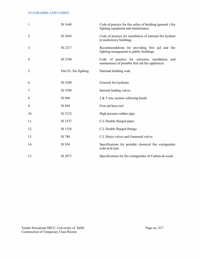
Tender Document-SRCC, University of Delhi Page no.-217 Construction of Temporary Class Rooms
STANDARDS AND CODES 1. IS 1648 Code of practice for fire safety of building (general ) fire
fighting equipment and maintenance. 2. IS 3844 Code of practice for installation of internal fire hydrant
in multistorey buildings 3. IS 2217 Recommendations for providing first aid and fire
fighting arrangement in public buildings. 4. IS 2190 Code of practice for selection, installation and
maintenance of portable first aid fire appliances. 5. Part IV, fire fighting National building code 6. IS 5290 External fire hydrants 7. IS 5290 Internal landing valves 8. IS 904 2 & 3 way suction collecting heads 9. IS 884 First aid hose reel 10. IS 5132 High pressure rubber pipe 11. IS 1537 C.I. Double flanged pipes 12. IS 1538 C.I. Double flanged fittings 13. IS 780 C.I. Sluice valves and Gunmetal valves 14. IS 934 Specifications for portable chemical fire extinguisher
soda acid type. 15. IS 2873 Specifications for fire extinguisher of Carbon-di-oxide.

Tender Document-SRCC, University of Delhi Page no.-218 Construction of Temporary Class Rooms
LIST OF APPROVED MAKE FOR HVAC
S No MATERIAL MAKE
E HVAC 1 Package Units/Cassette Unit/Hi Wall Daikin/ Bluestar/ Trane 2 PVC Pipe for drainage Astral/ Finolex/ Prince/ Supreme 3 GI Sheet ESSAR/ Galvano/ Jindal/ SAIL/ TATA 4 Factory Made Rectangular Duct Ductofab/ Rolastar/ Seven Star/ Zeco 5
Factory Made Spiral Duct Atco/ Lloyd/ Seven Star/ Spiral Tubes
Pvt.Ltd 6
Grille/ Diffuser Air Master/ Dynacraft/ Titus/ Tomkins/ Ravi Star
7 Smoke Damper (UL listed) Greenheck/ Ruskin 8
Fire Damper Ruskin/ Ravistar/ Conaire/ Cosmic/ George Rao
9 Insulation 9 (a) Closed Cell Elastomeric nitrile rubber along Armacell – Armaflex/ Aerocell/ K-Flex 9 (b) Cross link polyethylene foam with adhesive Trocellen / Supreme/ Paramount 9 © Fibre glass (Al. Foil Faced) Owens Corning/ Lloyd Insulation/ Twiga 10 Acoustic insulation
10 (a) Fibre glass Owens Corning/ Lloyd Insulation/ Twiga 10 (b) Nitrile rubber Armacell – Armasound/ K-Flex/ Aerocell
11 Expanded Polystyrene (TF Quality)
Beardsell/ Coolite/ DEBS Products/ Styrene Packaging
12 Power Distribution Panel and Motor Control Centre & Air Insulated Bus ducts
E Fab/ R R Control
13 Cable Trays (Factory Fabricated) / Raceways MEM/ Rico/ Slotco 14 Cables Skyton/ Polycab/ Indian 15 Copper pipe Mandev/ Maxflow/ Pallavi All first quality material manufactured by Company will be use

Tender Document-SRCC, University of Delhi Page no.-219 Construction of Temporary Class Rooms
SPECIAL CONDITIONS FOR HVAC
1. GENERAL These special conditions are intended to amplify the General Conditions of Contract, and shall be read
in conjunction with the same. For any discrepancies between the General Conditions and these Special Conditions, the more stringent shall apply.
SCOPE OF WORK The general character and the scope of work to be carried out under this contract is illustrated in
Drawings, Specifications and Schedule of Quantities. The Contractor shall carry out and complete the said work under this contract in every respect in conformity with the contract documents and with the direction of and to the satisfaction of the Owner’s site representative. The contractor shall furnish all labour, materials and equipment (except those to be supplied by the owner) as listed under Schedule of Quantities and specified otherwise, transportation and incidental necessary for supply, installation, testing and commissioning of the complete air conditioning system as described in the Specifications and as shown on the drawings. This also includes any material, equipment, appliances and incidental work not specifically mentioned herein or noted on the Drawings/Documents as being furnished or installed, but which are necessary and customary to be performed under this contract. The Air-Conditioning (HVAC) system shall comprise of following :
a. Air cooled Package units
b. Air cooled Ductable units
c. High wall split units
d. Cassette type units
e. Electrical control Panel for HVAC system
f. Copper piping , condensate drain piping inclusive of all fittings.
g. Sheet metal ducts inclusive of external insulation, acoustic lining, canvas connections, volume
control dampers as required.
h. Supply and return air registers and diffusers.
i. Insulation of pipes as required
j. Vibration isolators for all HVAC equipment.
k. Wiring and earthing from HVAC Electrical panels to various HVAC equipment, control wiring and interlocking.
l. Balancing, testing and commissioning of the entire HVAC installation.
2. ASSOCIATED CIVIL WORKS Following civil works associated with HVAC installation are excluded from the scope of this contract.
These shall be executed by other agencies in accordance with approved shop drawings of and under direct supervision of the air conditioning contractor. i. RCC foundation for water chilling machines pumps & centrifugal fans with angle iron frame work
at the edges to protect these from damage.

Tender Document-SRCC, University of Delhi Page no.-220 Construction of Temporary Class Rooms
ii. RCC basin & supports & MS Joists for cooling towers.
iii. PCC foundation blocks with angle iron frame work edging for all motor control centre.
iv. PCC foundation for pot strainers.
v. PCC foundation blocks for all air handling units
vi. Air-tight fire doors with minimum one hour fire rating for plant room, AHU rooms, fan rooms
and other equipment rooms.
vii. Water proofing of floors of AHU rooms, air washer rooms and fan rooms.
viii. Masonry drain channels and sumps with CI gratings in AC plant room including provision for sump pump and disposal.
ix. Supply and fixing of G.I./wooden frame for mounting of grilles in masonary walls.
x. Supply and fixing of GSS frame for mounting of grilles / diffusers in false ceiling / boxing.
xi. Thermal insulation of terraces above air-conditioned areas exposed to sun.
3. ASSOCIATED SERVICES WORKS 4.1 All associated ELECTRICAL WORKS listed below are excluded from the scope of this
contract. These shall be installed by other agencies in accordance with approved shop drawings of, and under direct supervision of the air conditioning contractor.
i. Providing power supply with earthing at the incoming of control panel in A/C plant
room.
ii. Providing power supply and earthing at the incoming MCCB in each split unit and cassette unit.
iii. Providing 15 amps power outlet within 2 meter reach of each single phase propeller fan
at locations called for on air conditioning contractor’s shop drawings.
4. PROJECT EXECUTION AND MANAGEMENT
The Contractor shall ensure that senior planning and erection personnel from his organization are assigned exclusively for this project. They shall have minimum 03 years’ experience in this type of installation.
The project management shall be through modern technique. The Contractor’s office at site shall be fully equipped with internet facility, computers, plotter and photocopier. Erection engineer and supervisors shall be provided with mobile communication system so that they can always be reached.
For quality control & monitoring of workmanship, contractor shall assign at least one full-time engineer who would be exclusively responsible for ensuring strict quality control, adherence to specifications and ensuring top class workmanship for the air conditioning installation.
The Contractor shall arrange to have mechanized & modern facilities of transporting material to place

Tender Document-SRCC, University of Delhi Page no.-221 Construction of Temporary Class Rooms
of installation for speedy execution of work.
5. PERFORMANCE GUARANTEE
The contractor shall carry out the work in accordance with the Approved shop drawings, Specifications, Schedule of Quantities and other documents forming part of the Contract. The contractor shall be fully responsible for the performance of the selected equipment (installed by him) at the specified parameters and for the efficiency of the installation to deliver the required end result. The contractor shall guarantee that the HVAC system as installed shall maintain the inside conditions in the air-conditioned spaces as described under “Basis of Design” in the specifications. The guarantee shall be submitted in the proforma given in Appendix - II. Complete set of architectural drawings is available in the Architect/Consultant’s office and reference may be made to same for any details or information. The contractor shall also guarantee that the performance of various equipment individually, shall not be less than the quoted capacity; also actual power consumption shall not exceed the quoted rating, during testing and commissioning, handing over and guarantee period.
6. BYE-LAWS AND REGULATIONS
The installation shall be in conformity with the Bye-laws, Regulations and Standards of the local authorities concerned, in so far as these become applicable to the installation. But if these Specifications and Drawings call for a higher standard of materials and / or workmanship than those required by any of the above regulations and standards, then these Specifications and Drawings shall take precedence over the said regulations and standards. However, if the Drawings and specifications require something which violates the Bye-laws and Regulations, then the Bye-laws and Regulations shall govern the requirement of this installation.
7. FEES AND PERMITS
The contractor shall obtain all required permits/ licenses and pay for any and all fees required for the inspection, approval and commissioning of their installation.
8. DRAWINGS
The HVAC Drawings listed under Appendix-I, which may be issued with tenders, are diagrammatic only and indicate arrangement of various systems and the extent of work covered in the contract. These Drawings indicate the points of supply and of termination of services and broadly suggest the routes to be followed. Under no circumstances shall dimensions be scaled from these Drawings. The architectural/interiors drawings and details shall be examined for exact location of equipment, controls, grilles and diffusers. The contractor shall follow the tender drawings in preparation of his shop drawings, and for subsequent installation work. He shall check the drawings of other trades to verify spaces in which his work will be installed. Maximum headroom and space conditions shall be maintained at all points. Where headroom appears inadequate, the contractor shall notify the Architect/Consultant/Owner’s site representative before proceeding with the installation. In case installation is carried out without notifying, the work shall be rejected and contractor shall rectify the same at his own cost. The contractor shall examine all architectural, structural, plumbing, electrical and other services drawings and check the as-built works before starting the work, report to the Owner’s site representative any discrepancies and obtain clarification. Any changes found essential to coordinate installation of his work with other services and trades, shall be made with prior approval of the

Tender Document-SRCC, University of Delhi Page no.-222 Construction of Temporary Class Rooms
Architect/Consultant/Owner’s site representative without additional cost to the Owner. The data given in the Drawings and Specifications is as exact as could be procured, but its accuracy is not guaranteed.
9. TECHNICAL DATA The successful enderer shall submit alongwith the technical data for all major equipments / Items for
approval prior to procurement
10. SHOP DRAWINGS
10.1 All the shop drawings shall be prepared on computer through Autocad System based on Architectural Drawings, site measurements and Interior Designer’s Drawings. All heat load calculations shall be done using latest version of E-20, Trace 600 only. Within eight weeks of the award of the contract, contractor shall furnish, for the approval of the Architect/Consultant, two sets of detailed shop drawings of all equipment and materials including layouts for Plant room,
Each item of equipment/material proposed shall be a standard catalogue product of an established
manufacturer strictly from the manufacturers listed in Appendix-III and quoted by the tenderer . When the Architect/Consultant makes any amendments in the above drawings, the contractor
shall supply two fresh sets of drawings with the amendments duly incorporated alongwith check prints, for approval. The contractor shall submit further twelve sets of shop drawings to the Owner’s site representative for the exclusive use by the Owner’s site representative and all other agencies. No material or equipment may be delivered or installed at the job site until the contractor has in his possession, the approved shop drawing for the particular material/equipment/installation.
10.2 HVAC Contractor shall prepare coordinated services shop drawings based on the drawings prepared by Electrical, Plumbing & Low Voltage Contractors to ensure adequate clearances are available for installation of services for each trade.
variation in contract amounts and also advise Owner to initiate action for procurement of spare parts and tools at the completion of project.
11. QUIET OPERATION AND VIBRATION ISOLATION All equipment shall operate under all conditions of load without any sound or vibration which is
objectionable in the opinion of the Owner’s site representative. In case of rotating machinery sound or vibration noticeable outside the room in which it is installed, or annoyingly noticeable inside its own room, shall be considered objectionable. Such conditions shall be corrected by the Contractor at his own expense. The contractor shall guarantee that the equipment installed shall maintain the specified dB / NC levels.
12. MATERIALS AND EQUIPMENT All materials and equipment shall conform to the relevant Indian Standards and shall be of the
approved make and design. Makes shall be strictly in conformity with list of approved manufacturers
13. MANUFACTURERS INSTRUCTIONS Where manufacturer has furnished specific instructions, relating to the material and equipment used
in this project, covering points not specifically mentioned in these documents, such instructions shall be followed in all cases.
14. ELECTRICAL INSTALLATION

Tender Document-SRCC, University of Delhi Page no.-223 Construction of Temporary Class Rooms
The electrical work related to air conditioning services, shall be carried out in full knowledge of, and with the complete coordination of the contractor. The electrical installation shall be in total conformity with the control wiring drawings prepared by the contractor and approved by the Architect/Consultant. All air conditioning equipment shall be connected and tested in the presence of an authorized representative of the contractor.
The air conditioning system shall be commissioned only after the contractor has certified in writing
that the electrical installation work for air conditioning services has been thoroughly checked, tested and found to be totally satisfactory and in full conformity with the contract Drawings, Specifications and manufacturers instructions. It is to be clearly understood that the final responsibility for the sufficiency, adequacy and conformity to the contract requirements, of the electrical installation work for air conditioning services, lies solely with the contractor.
15. BALANCING, TESTING AND COMMISSIONING Balancing of all air and water systems and all tests as called for the Specifications shall be carried out
by the contractor through a specialist group, in accordance with the Specifications and ASHRAE Guide lines and Standards. Performance test shall consist of one days of 24 hour each operation of system for summer season. All costs relating to performance witness test of major equipment such as chillers, at factory with two personnel from Owners / Consultant shall be included.
16. COMPLETION DRAWINGS Contractor shall submit completion drawings as and when work in all respects is completed .
17. OPERATING INSTRUCTION & MAINTENANCE MANUAL Upon completion and commissioning of part HVAC system the contractor shall submit two copy of
comprehensive operating instructions, maintenance schedule
18. ON SITE TRAINING Upon completion of all work and the Contractor shall train the Owner’s personnel in the operation,
adjustment and maintenance of all equipment installed.
19. MAINTENANCE DURING DEFECTS LIABILITY PERIOD 19.1 Complaints
The Contractor shall receive calls for any and all problems experienced in the operation of the system under this contract, attend to these within 10 hours of receiving the complaints and shall take steps to immediately correct any deficiencies that may exist.
19.2 Repairs All equipment that require repairing shall be immediately serviced and repaired. Since the period of Mechanical Maintenance runs concurrently with the defects liability period, all replacement parts and labour shall be supplied promptly free-of-charge to the Owner.
20. SOFT WATER AND POWER REQUIREMENT The contractor shall submit with their tender, their requirement of soft make-up water and power
requirement.

Tender Document-SRCC, University of Delhi Page no.-224 Construction of Temporary Class Rooms
TECHNICAL SPECIFICATIONS HVAC
1. BASIS OF DESIGN
1.1 Site Location : New Delhi
1.2 Outdoor Design Conditions Outdoor design conditions are based on weather data compiled jointly by ISHRAE & ASHRAE India Chapter (AIC) and Wedco, corresponding to 0.4% annual cumulative frequency of occurrence for Summer and Monsoon and 99.6 % annual cumulative frequency of occurrence for Winter:
Summer
Dry Bulb Temperature : 44 °C (111.2. ° F)
Mean Coincident Wet Bulb Temperature : 24°C (75.2 ° F)
Monsoon Mean Coincident Dry Bulb Temperature : 39 °C (102.2°F)
Wet Bulb Temperature : 28.3°C (83 ° F)
1.3 Indoor Design Conditions
Following indoor design conditions for centrally air conditioned space shall be applicable
SPACE SUMMER CONDITIONS
NOISE CRITERIA
OUTDOOR AIR
Temp. °C (°F) Relative
Humidity db Ventilation Rate
Auditorium 22±1°C
(72±2°F) Less than
60% 45 7.5 CFM / person

Tender Document-SRCC, University of Delhi Page no.-225 Construction of Temporary Class Rooms
TECHNICAL SPECIFICTAION
1. PACKAGE TYPE AIRCONDITIONER
GENERAL
All the Package type air conditioners units shall be factory assembled and tested complete in all respects and conforming to Indian/ASHRAE standards. They shall be supplied precharged with refrigerant gas and oil ready for installation at site. The Air-cooled package Unit shall be a two piece assembly comprising of the following: CONDENSING UNIT a) Hermetically sealed Scroll type compressors with refrigerant cooled motor. b) Air-cooled Condenser. c) Condenser fan with sufficient air discharging capacity. d) Steel structure with sheet metal casing in which the above are mounted. e) Automatic capacity control devices along with safety gauges/devices. f) Full charge of R-22 along with refrigerant oil. EVAPORATOR UNIT a) Direct expansion-cooling coil. b) Inter connected Seam less copper refrigerant piping. c) Centrifugal fan with motor. CONDENSING UNIT (OUT-DOOR UNIT) The condensers should be fitted with in built circuit breaker or external weather proof isolater with encloser of required capacity. COMPRESSOR The Scroll compressor shall be hermetically sealed in design. The compressor shall be a Direct shaft mounting of the refrigerant cooled hermetic motor. EXTERNAL The compressor housing shall be made of gas tight steel shell which is made up of two shells, these shells are welded together to form a Hermetic (Airtight) seal. One shell is fitted with a suction tube and a Glass-matic terminal used for supplying power to the motor, fitted inside the compressor shell and the other is fitted with a discharge tube. The shell also acts as an oil sump. INTERNAL The internal parts shall be accurately machined for installation of the required parts. The Impellers, valve plate and connecting shaft shall all be made of Aluminum alloy having high compressive strength. LUBRICATION The oil pump formed by drilling number of holes on the surface shall do the lubrication of the bearing. One end of the crankshaft shall be always dipped in the oil. CONDENSER COIL

Tender Document-SRCC, University of Delhi Page no.-226 Construction of Temporary Class Rooms
The condenser coil shall be internally grooved copper tube with split aluminum fins. The Condenser shall be fitted with a fan of propeller type. The condenser shall be built on an air-cooled design using outside ambient air up to 45ºC to condense the refrigerant. The Condenser coils shall be constructed of 12 mm OD integrally enhanced Seam less copper Tubes arranged in staggered rows. This shall have a minimum of 3 rows to provide proper Heat rejection. The copper tubes shall be mechanically expanded into lanced and rippled Aluminum fins of minimum 0.1mm thick with 13 fins per inch. CONDENSER FANS The condenser fans shall be of propeller type with the motor directly fitted to the shaft of the fan. The fan shall have a suitable blades for delivering maximum air quantity of air without any motor overloading. The fan blade should be either moulded unbreakable plastic or die cast aluminum material. The motor shall be of TEFC construction and shall be of IP 55 protection with resistant to high ambient. REFRIGERANT PIPING The refrigerant piping interconnecting all the condensing unit and the evaporator unit shall be of Seam less copper with tube dia as required and having a wall thickness of minimum 2mm and able to withstand pressure up to 450 PSI. Necessary gas mufflers, flexible connections on discharge and suction side shall be provided to reduce vibration / noise of refrigerant/compressor. SAFETY DEVICES The condensing units shall be provided with all necessary safety devices, which are essential for proper operation of the equipment. These shall not be limited to the scope of this specification and shall have all safety devices required for optimum operation of the unit. The following minimum safety devices are suggested: a. Low voltage cutout b. Low evaporating cutout c. In-built internal overload d. Pressure relief valve e. Low pressure cutout f. High condensing pressure cutout g. Motor overload trip/protection MOTOR Motor shall be squirrel cage constant speed, suitable for 220+ 10 % volts, 50 Hz, 1phase power supply. Motor speed shall not exceed 1450 RPM. The fan and motor combination selected for particular requirement shall be for the most efficient type so that sound level and energy consumption is minimal. Motor conduit box shall be mounted on exterior of the casing. Wires from the motor to the conduit box shall be protected from the air stream by enclosing in a flexible metal conduit. EVAPORATOR UNIT FAN Fan impeller and housing shall be fabricated from heavy gauge steel. Fan wheels shall be of double width, double inlet forward-curve multi-blade type enclosed in Housing and

Tender Document-SRCC, University of Delhi Page no.-227 Construction of Temporary Class Rooms
mounted on a common shaft. Fan housing shall be made of die-formed steel sheets with streamlined inlets and guide vanes to ensure smooth airflow into the fans. The fan shall be belt driven with pulley having belt-tensioning arrangements. All rotating parts shall be statically and dynamically balanced. Fan speed shall not exceed 1500 RPM and maximum fan outlet velocity shall be 450 meters per minute (1500 FPM). The average air quantity for the air handling units shall be 400 CFM per TR of refrigeration. However the fan should be facilitated with capacity adjustment for lower or higher air quantities as per individual air requirements as the site demands. Stretch less V-Belts should be used. The fan shall be able to deliver the desired air quantity with sufficient static pressure for carrying out the ducting and also be able to add fresh air. COOLING / COILS Cooling coils shall have 12.5 to 15 mm dia copper tubes min. 24 gauge thick, with aluminum fins firmly bonded to copper tubes assembled in zinc coated steel frame. Face and surface areas shall be such as to ensure rated capacity from each unit and such that the air velocity across each coil shall not exceed 150 meters per minute. The coil shall be pitched in the unit casing for proper drainage. Each coil shall be factory tested at 21 Kg / Sq. cm. air pressure while submerged in water. Tubes shall be hydraulically expanded for minimum thermal contact resistance with the fins. Fin spacing shall be 13 fins per inch. (4-5 Fins/CM.). The units shall be fitted with minimum 3-row coil for giving the cooling effect. STEEL STRUCTURES The evaporator unit shall be assembled on formed corrosion resistant galvanized sheet metal steel sections which shall be pretreated and finished with epoxy painting/polyester powder coating. The steel structure shall be sturdy enough to withstand transport without getting distorted and when stationary handle the equipment load. There should be proper encasing of unit with acoustic lining in all inside to reduce noise level of the equipment. MOTOR Motor shall be squirrel cage constant speed, suitable for 220+ 10 % volts, 50 Hz, 1phase power supply. Motor speed shall not exceed 1450 RPM. The fan and motor combination selected for particular requirement shall be for the most efficient type so that sound level and energy consumption is minimal. Motor conduit box shall be mounted on exterior of the casing. Wires from the motor to the conduit box shall be protected from the air stream by enclosing in a flexible metal conduit. PERFORMANCE The performance of the unit shall be proved at site at the time of installation and also the power consumption should not exceed the confirmed rating through out the period of service of the equipment. The company shall stand guarantee for the aforesaid condition and shall compensate the client in case the power consumption proved at site is more than the stipulated power. The rate of compensation shall be as indicated in penalty clause as given earlier in the conditions of contract. The contractor shall submit along with the tender the rating charts of the machines offered indicating the percentage capacity, power consumed, rated amperage, locked rotor amps and also inrush currents of equipment at maximum ambient conditions PAINTING Shop coats of paint that have become marred during shipment or erection shall be cleaned off with

Tender Document-SRCC, University of Delhi Page no.-228 Construction of Temporary Class Rooms
mineral spirits, wire brushed and spot primed over the affected areas, then coated with enamel paint to match the finish over the adjoining shop painted surfaces. TESTING Cooling capacity of various Unit models shall be computed from the measurements of airflow and dry and wet bulb temperatures of air entering and leaving the coil. Flow measurements meters shall be accurately calibrated. The temperature gauges shall be mercury-in glass thermometers. Computed results shall conform to the specified capacities and quoted ratings. Power consumption shall be computed from measurements of incoming voltage and input current.
2. AIR DISTRIBUTION
(FOR DUCTS FABRICATED IN FACTORY
2.1 SCOPE AS PER “SMACNA” STANDARDS)
The scope of this section comprises supply fabrication, installation and testing of all sheet metal / aluminum ducts, supply, installation, testing and balancing of all grilles, registers and diffusers. All to be in accordance with these specifications and the general arrangement shown on the Drawings.
2.2 DUCT MATERIALS
2.2.1 RAW MATERIALS Galvanizing shall be Class VIII – light coating of zinc, nominal 120gm/sq.m surface area and Lock
Forming Quality prime material along with mill test certificates. In addition, if deemed necessary, samples of raw material, selected at random by owner’s site representative shall be subject to approval and tested for thickness and zinc coating at contractor's expense.
2.2.2. GAUGES, BRACING BY SIZE OF DUCTS
All ducts shall be factory fabricated from galvanized steel / aluminum of the following thickness, as indicated as below :
2.2.2.1For Ducts with external SP upto 250 Pa ( ESP upto 25mmWg)
Rectangular Ducts G. S.
Pressure 250 Pa
Duct Section Length 1.2 m (4 ft) Maximum Duct Size
Gauge Joint Type Bracing Spacing
1–500 mm 26 C&S Connector Nil 501 – 750 mm 26 C&S Connector Nil 751 – 900 mm 26 TDF Flange Nil
901 – 1200 mm
24 TDF Flange Nil
1201 – 1500 mm 22 TDF Flange Nil 1501 – 1800 mm 22 TDF Flange JTR or ZEE
BAR 1801 – 2100 mm 20 TDF Flange JTR or ZEE
BAR 2101 – above 18 TDF Flange JTR or ZEE
BAR

Tender Document-SRCC, University of Delhi Page no.-229 Construction of Temporary Class Rooms
*Distance of reinforcement/bracing from each joint. Bracing material to be same as of material used for joining of duct sections.
2.3 FABRICATION STANDARDS & EQUIPMENT
All duct construction and installation shall be in accordance with SMACNA / NBC 2016 standards. In addition ducts shall be factory fabricated utilizing the following machines to provide the requisite quality of ducts. 1. Coil (Sheet metal in Roll Form) lines to facilitate location of longitudinal seams at
corners/folded edges only, for required duct rigidity and leakage free characteristics. No longitudinal seams permitted along any face side of the duct.
2. All ducts, transformation pieces and fittings to be made on CNC profile cutter for requisite accuracy
of dimensions, location and dimensions of notches at the folding lines. 3. All edges to be machine treated using lock formers, flingers and rollers for turning up edges.
4. Kitchen exhaust ducting shall be with 16 G MS welded construction. Suitable access doors shall be provided at every 3m. Provision shall be made for firefighting agency to install duct mounted sprinklers at every 3m. Generally exhaust ducts shall have slope towards kitchen hood.
2.4 DUCT CONSTRUCTION
2.4.1 All ducts shall be fabricated and installed in workmanlike manner, conforming to relevant SMACNA codes.
a) Ducts so identified on the Drawings shall be acoustically lined and insulated from outside as
described in the section “Insulation” and as indicated in schedule of Quantities. Duct dimensions shown on drawings, are overall sheet metal dimensions inclusive of the acoustic lining where required and indicated in Schedule of quantities. The fabricated duct dimensions should be as per approved drawings and care should be taken to ensure that all connecting sections are dimensionally matched to avoid any gaps.
b) Ducts shall be straight and smooth on the inside with longitudinal seams shall be airtight and
at corners only which shall be either Pittsburgh or snap button as per SMACNA practice, to ensure air tightness.
c) All ducts up to 75cms width within conditioned spaces shall have C&S connector. The
internal ends of slip joints shall be in the direction of airflow. Care should be taken to ensure that Cleats are mounted on the longer side of the duct and Cleats on the shorter side. Ducts and accessories within ceiling spaces, visible from air-conditioned areas shall be provided with two coats of mat black finish paint.
d) Changes in dimensions and shape of ducts shall be gradual (between 1:3 and 1:5). Air-turns
(vanes) shall be installed in all bends and duct collars designed to permit the air to make the turn without appreciable turbulence.
e) Ducts shall be fabricated as per details shown on Drawings. All ducts shall be rigid and shall
be adequately supported and braced where required with standing seams, tees, or angles, of ample size to keep the ducts true to shape and to prevent buckling, vibration or breathing.

Tender Document-SRCC, University of Delhi Page no.-230 Construction of Temporary Class Rooms
f) All sheet metal connection, partitions and plenums, required to confine the flow of air to and through the filters and fans, shall be constructed of 18 gauge GSS / 16gauge aluminum, thoroughly stiffened with 25mm x 25mm x 3mm galvanized steel angle braces and fitted with all necessary inspection doors as required, to give access to all parts of the apparatus. Access doors shall be not less than 45cm x 45cm in size.
g) Plenums shall be shop/factory fabricated panel type and assembled at site. Fixing of
galvanized angle flanges on duct pieces shall be with rivets heads inside i.e. towards GS sheet and riveting shall be done from outside.
h) Self-adhesive Neoprene rubber / UV resistant PVC foam lining 5mm nominal thickness
instead of felt, shall be used between duct flanges and between duct supports in all ducting installation.
i) Ducts within same compartment shall require minimum fire resistance rating of 30 mins.
2.5. INSTALLATION PRACTICE
All ducts shall be installed generally as per tender drawings, and in strict accordance with approved shop drawings to be prepared by the Contractor: a) The Contractor shall provide and neatly erect all sheet metal work as may be required to carry
out the intent of these Specifications and Drawings. The work shall meet with the approval of Owner’s site representative in all its parts and details
b) All necessary allowances and provisions shall be made by the Contractor for beams, pipes, or
other obstructions in the building, whether or not the same are shown on the drawings. Where necessary to avoid beams or other structural work, plumbing or other pipes, and conduits, the ducts shall be transformed, divided or curved to one side (the required area being maintained) all as per the site requirements.
b) If a duct cannot be run as shown on the drawings, the contractor shall install the duct between
the required points by any path available in accordance with other services and as per approval of owner’s site representative.
c) All ductwork shall be independently supported from building construction. All horizontal
ducts shall be rigidly and securely supported, in an approved manner, with hangers formed of galvanized steel wire ropes (as per clause 16.12) and galvanized steel angle/channel or a pair of brackets, connected by galvanized steel wire hangers under ducts, rigid supports may be provided at certain interval if need be. The spacing between supports should be not greater than 2.4 meter. All vertical ductwork shall be supported by structural members on each floor slab. Duct supports may be through galvanized steel insert plates or Toggle end wire fixing left in slab at the time of slab casting. Galvanized steel cleat with a hole for passing the wire rope hanger shall be welded to the plates. Trapeze hanger formed of galvanized steel wire rope using Gripple shall be hung through these cleats. Wherever use of metal insert plates is not feasible, duct support shall be through dash/anchor fastener driven into the concrete slab by electrically operated gun. Wire rope supports shall hang through the cleats or wire rope threaded studs can be screwed into the anchor fasteners.
d) Alternatively, if mentioned in the BoQ, all ductwork shall be independently supported from
building construction. All horizontal ducts shall be rigidly and securely supported, in an approved manner, with trapeze hangers formed of galvanized steel rods and galvanized steel angle/channel or a pair of brackets, connected by galvanized steel rod under ducts. The spacing between supports should be not greater than 2.0 meter. All vertical ductwork shall be supported by structural members on each floor slab. Duct supports may be through galvanized

Tender Document-SRCC, University of Delhi Page no.-231 Construction of Temporary Class Rooms
steel insert plates left in slab at the time of slab casting. Galvanized steel cleat with a hole for passing the hanger rods shall be welded to the plates. Trapeze hanger formed of galvanized steel rods shall be hung through these cleats.
Wherever use of metal insert plates is not feasible, duct support shall be through dash/anchor fastener driven into the concrete slab by electrically operated gun. Hanger rods shall then hang through the cleats or fully threaded galvanized rods can be screwed into the anchor fasteners.
e) Ducting over furred ceiling shall be supported from the slab above, or from beams after
obtaining approval of Owner’s site representative. In no case shall any duct be supported from false ceiling hangers or be permitted to rest on false ceiling. All metal work in dead or furred down spaces shall be erected in time to occasion no delay to other contractor’s work in the building.
f) All ducts shall be totally free from vibration under all conditions of operation. Whenever
ductwork is connected to fans, air handling units or blower coil units that may cause vibration in the ducts, ducts shall be provided with a flexible connection, located at the unit discharge. Flexible connections shall be constructed of fire retarding flexible heavy canvas sleeve at least 10cm long securely bonded and bolted on both sides. Sleeve shall be made smooth and the connecting ductwork rigidly held by independent supports on both sides of the flexible connection. The flexible connection shall be suitable for pressure at the point of installation.
g) Duct shall not rest on false ceiling and shall be in level from bottom. Taper pieces shall taper
from top.
2.6 DAMPERS
a. Dampers : All duct dampers shall be opposed blade louver dampers of robust 20 G GSS construction and tight fitting. The design, method of handling and control shall be suitable for the location and service required.
b. Dampers shall be provided with suitable links levers and quadrants as required for their proper
operation. Control or setting device shall be made robust, easily operable and accessible through suitable access door in the duct. Every damper shall have an indicating device clearly showing the damper position at all times.
c. Dampers shall be placed in ducts at every branch supply or return air duct connection,
whether or not indicated on the Drawings, for the proper volume control and balancing of the air distribution system.
d. Pressure relief dampers: Pressure relief dampers shall be constructed with 18G Aluminum
construction with parallel blade construction. Leafs shall be 100% air tight upon closure. Leafs shall be loaded with spring pressure of stiffness (k value) corresponding to set point pressure.
e. Non return damper (Back draft damper) : Non return damper shall be constructed out of 22G
GSS. Blades shall ensure 100% air leak proof performance on closure. Design shall ensure that no rattling noise is produced at design duty.
2.7 FIRE & SMOKE DAMPERS
a. All supply and return air ducts at AHU room crossings and at all floor crossings or as indicated
in the drawings shall be provided with Motor operated Fire & smoke damper of at least 90 minutes rating. These shall be of multi-leaf type and provided with Spring Return electrical

Tender Document-SRCC, University of Delhi Page no.-232 Construction of Temporary Class Rooms
actuator having its own thermal trip for ambient air temperature outside the duct and air temperature inside the duct. Actuator shall have Form fit type of mounting, metal enclosure and guaranteed long life span.

Tender Document-SRCC, University of Delhi Page no.-233 Construction of Temporary Class Rooms
Dampers shall have a fire rating of 1.5 Hrs. in accordance with CBRI Certification b. Each damper shall be supplied with factory mounted sleeve of galvanized steel of thickness
as per SMACNA and of minimum 500mm long or as specified in schedule of quantities depending up on the wall thickness. The damper shall be fitted in to sleeve either using welding or self-tapping screws. All welded joints shall be finished using heat resistance steel paint . UL listed and approved Silicon sealant shall be applied at all corners as well as at joints between damper frame and sleeve. Damper Frame shall be a roll formed structural hat channel , reinforced at corners, formed from a single piece of 1.6mm galvanized steel . Damper blades shall be airfoil shaped (equivalent to 2.3mm thickness strength) roll formed using 0.8mm thick single piece of galvanized sheet. Bearings shall be of stainless steel fitted in an extruded hole in the damper frame. Blade edge seals shall be silicone rubber and galvanized steel mechanically locked in to the blade edge (adhesive type seals are not acceptable). Side Jam seals of stainless steel and Top and bottom seals of galvanized steel shall be provided. All galvanized steel used shall be with minimum 180GSM Zinc coating Bigger size Dampers shall be supplied in Multiple modules of sizes not exceeding in dimensions of certified module, jack shafted together. Multiple actuators shall be provided for large dampers with higher torque requirements as prescribed in UL.
c. The electric actuator shall be energized either upon receiving a signal from smoke detector
installed in AHU room supply air duct / return air duct. Electric Actuator of suitable Torque and as approved by UL shall be factory mounted and tested. The actuator shall be suitable for 24V AC supply. In addition actuator shall have elevated temperature rating of 250 deg.F. Electric Actuator shall have been energized hold open tested for a period of at least one year with no spring return failure. Each fire/smoke damper shall be equipped with a heat actuated release device which shall allow controlled closure of damper rather than instantaneous to prevent accident.( Electrical fusible link).The EFL shall allow the damper to reopen automatically after a test, smoke detection or power failure condition. The damper shall be equipped with a device to indicate OPEN and CLOSE position of Damper blades through a link mounted on the damper blade.
d. Each damper shall be provided with its own control panel, mounted on the wall and suitable
for 240 VAC supply. This control panel shall be suitable for spring return actuator and shall have atleast the following features: Potential free contacts for AHU fan ON/ Off and remote alarm indication. Accept signal from external smoke / fire detection system for tripping the electrical
actuator. Test and reset facility. Indicating lights / contacts to indicate the following status: Power Supply On Alarm Damper open and close position.
e. Actuators shall be mounted on the sleeve by the damper supplier in his shop and shall furnish
test certificate for satisfactory operation of each Motor Operated Damper in conjunction with it’s control panel. Control panel shall be wall mounted type.

Tender Document-SRCC, University of Delhi Page no.-234 Construction of Temporary Class Rooms
2.8 SUPPLY AND RETURN AIR REGISTERS
Supply & return air registers shall be of either steel or aluminium sections as specified in schedule
of quantities. Steel construction registers shall have primer Coat finish whereas extruded aluminium registers shall be either Anodised or Powder Coated as specified in Schedule of Quantities. These registers shall have individually adjustable louvers both horizontal and vertical. Supply air registers shall be provided with key operated opposed blade extruded aluminium volume control damper anodised in matt black shade.
The registers shall be suitable for fixing arrangement having concealed screws as approved by Architect. Linear continuous supply cum return air register shall be extruded aluminium construction with fixed horizontal bars at 15 Deg. inclination & flange on both sides only (none on top & bottom). The thickness of the fixed bar louvers shall be minimum 5.5 mm in front and 3.8 mm in rear with rounded edges. Flanges on the two sides shall be 20 mm/30 mm wide as approved by Architect. The grilles shall be suitable for concealed fixing. Volume control dampers of extruded aluminium anodised in black color shall be provided in supply air duct collars. For fan coil units horizontal fixed bar grilles as described above shall be provided with flanges on four sides, and the core shall be & suitable for clip fixing, permitting its removal without disturbing the flanges.
a. All registers shall be selected in consultation with the Architect. Different spaces shall require horizontal or vertical face bars, and different width of margin frames. These shall be procured only after obtaining written approval from Architect for each type of register.
b. All registers shall have a soft continuous rubber/foam gasket between the periphery of the
register and the surface on which it has to be mounted. The effective area of the registers for air flow shall not be less than 66 percent of gross face area.
c. Registers specified with individually adjustable bars shall have adjustable pattern as each
grille bar shall be pivotable to provide pattern with 0 to +45 degree horizontal arc and upto 30 degree deflection downwards. Bars shall hold deflection settings under all conditions of velocity and pressure.
d. Bar longer than 45 cm shall be reinforced by set-back vertical members of approved
thickness. e. All volume control dampers shall be anodised aluminium in mat black shade. 2.9 SUPPLY AND RETURN AIR DIFFUSERS Supply and return air diffusers shall be as shown on the Drawings and indicated in Schedule of
Quantities. Mild steel diffusers/dampers shall be factory coated with rust-resistant primer. Aluminium diffusers shall be powder coated & made from extruded aluminium section as specified in schedule of quantities.
a. Rectangular Diffusers shall be steel / extruded aluminium construction, square &
rectangular diffusers with flush fixed pattern for different spaces as per schedule of quantities These shall be selected in consultation with the Architect. These shall be procured only after obtaining written approval from Architect for each type of diffuser.
b. Supply air diffusers shall be equipped with fixed air distribution grids, removable key-
operated volume control dampers, and anti-smudge rings as required in specific applications, and as per requirements of schedule of quantities. All extruded aluminium diffusers shall be provided with removable central core and concealed key operation for volume control damper.
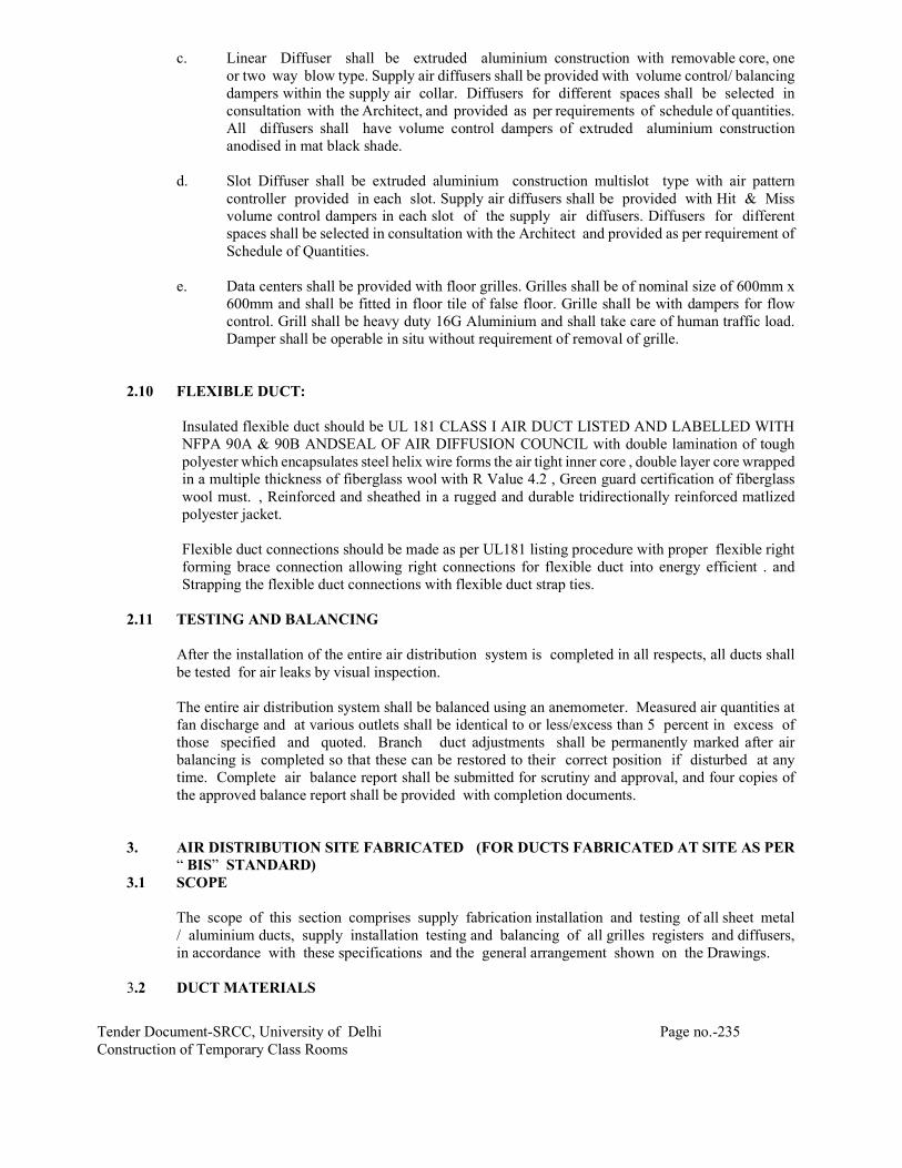
Tender Document-SRCC, University of Delhi Page no.-235 Construction of Temporary Class Rooms
c. Linear Diffuser shall be extruded aluminium construction with removable core, one or two way blow type. Supply air diffusers shall be provided with volume control/ balancing dampers within the supply air collar. Diffusers for different spaces shall be selected in consultation with the Architect, and provided as per requirements of schedule of quantities. All diffusers shall have volume control dampers of extruded aluminium construction anodised in mat black shade.
d. Slot Diffuser shall be extruded aluminium construction multislot type with air pattern
controller provided in each slot. Supply air diffusers shall be provided with Hit & Miss volume control dampers in each slot of the supply air diffusers. Diffusers for different spaces shall be selected in consultation with the Architect and provided as per requirement of Schedule of Quantities.
e. Data centers shall be provided with floor grilles. Grilles shall be of nominal size of 600mm x
600mm and shall be fitted in floor tile of false floor. Grille shall be with dampers for flow control. Grill shall be heavy duty 16G Aluminium and shall take care of human traffic load. Damper shall be operable in situ without requirement of removal of grille.
2.10 FLEXIBLE DUCT:
Insulated flexible duct should be UL 181 CLASS I AIR DUCT LISTED AND LABELLED WITH NFPA 90A & 90B ANDSEAL OF AIR DIFFUSION COUNCIL with double lamination of tough polyester which encapsulates steel helix wire forms the air tight inner core , double layer core wrapped in a multiple thickness of fiberglass wool with R Value 4.2 , Green guard certification of fiberglass wool must. , Reinforced and sheathed in a rugged and durable tridirectionally reinforced matlized polyester jacket.
Flexible duct connections should be made as per UL181 listing procedure with proper flexible right forming brace connection allowing right connections for flexible duct into energy efficient . and Strapping the flexible duct connections with flexible duct strap ties.
2.11 TESTING AND BALANCING After the installation of the entire air distribution system is completed in all respects, all ducts shall
be tested for air leaks by visual inspection. The entire air distribution system shall be balanced using an anemometer. Measured air quantities at
fan discharge and at various outlets shall be identical to or less/excess than 5 percent in excess of those specified and quoted. Branch duct adjustments shall be permanently marked after air balancing is completed so that these can be restored to their correct position if disturbed at any time. Complete air balance report shall be submitted for scrutiny and approval, and four copies of the approved balance report shall be provided with completion documents.
3. AIR DISTRIBUTION SITE FABRICATED (FOR DUCTS FABRICATED AT SITE AS PER
“ BIS” STANDARD) 3.1 SCOPE The scope of this section comprises supply fabrication installation and testing of all sheet metal
/ aluminium ducts, supply installation testing and balancing of all grilles registers and diffusers, in accordance with these specifications and the general arrangement shown on the Drawings.
3.2 DUCT MATERIALS

Tender Document-SRCC, University of Delhi Page no.-236 Construction of Temporary Class Rooms
All ducts shall be fabricated from galvanized steel sheets / aluminium sheets of the following thickness as indicated in Schedule of Quantities.
G S S ALUMINIUM Rectangular ducts upto 75 cm 24 gage 22 gage Rectangular ducts 76 to 150 cm and all round ducts. 22 gage 20 gage Rectangular ducts 151 to 225 cm 20 gage 18 gage Rectangular ducts greater than 225 cm 18 gage 16 gage Sheet metal ducts shall be fabricated out of galvanized steel sheets. Fabrication of ducts shall be
through well-conditioned Triplex lock former or multiple lock formers, conforming to relevant BIS Codes. Sheets used shall be produced by Hot Dip Process and galvanizing shall be Class VII - Light Coating of zinc, Nominal 180 gm /Sq m surface area.
Samples of sheet from each lot selected at random by Owner’s site representative shall be
subject to approval & gotten tested for thickness and zinc coating at contractor’s expenses. 3.3 All ducts shall be fabricated and installed in workmanlike manner, generally conforming to relevant
BIS Codes. Round exposed ducts shall be die-formed for achieving perfect circle configuration. 3.3.1 a. Ducts so identified on the Drawings shall be acoustically lined and insulated from outside as
described in the section “Insulation” and as indicated in Schedule of Quantities. Duct dimensions shown on Drawings are overall sheet metal dimensions inclusive of the acoustic lining where required and indicated in Schedule of Quantities.
b. Ducts shall be straight and smooth on the inside with neatly finished joints. All joints shall
be made air tight.
c. All exposed ducts upto 60 cm width within conditioned spaces shall have slip joints - or flanged joints. The internal ends of slip joints shall be in the direction of air flow. Ducts and accessories within ceiling spaces, visible from air conditioned areas shall be provided with two coats of mat black finish paint.
d. Changes in dimensions and shape of ducts shall be gradual. Air-turns (Vanes) shall be
installed in all bends and duct collars designed to permit the air to make the turn without appreciable turbulence.

Tender Document-SRCC, University of Delhi Page no.-237 Construction of Temporary Class Rooms
e. Ducts shall be fabricated as per details shown on Drawings. All ducts shall be rigid and shall be adequately supported and braced where required with standing seams, tees, or angles, of ample size to keep the ducts true to shape and to prevent buckling, vibration or breathing.
f. All sheet metal connection, partitions and plenums required to confine the flow of air to
and through the filters and fans shall be constructed of 18 gage GSS / 16 gauge aluminium, thoroughly stiffened with 25 mm x 25 mm x 3 mm galvanized steel angle braces and fitted with all necessary inspection doors as required, to give access to all parts of the apparatus. Doors shall be not less than 45 cm x 45 cm in size.
g. Plenums shall be panel type and assembled at site. Fixing of galvanized angle flanges on duct
pieces shall be with rivets heads inside i.e. towards G S sheet and riveting shall be done from outside.
h. Self-adhesive rubber lining minimum 5 mm thick instead of felt, shall be used between duct
flanges and between duct and duct supports in all ducting installation.
i. Kitchen exhaust ducting shall be with 3mm thick MS sheet. Suitable access doors shall be provided
at every 3m. Provision shall be made for firefighting agency to install duct mounted sprinklers at every
3m. Generally exhaust ducts shall have slope towards kitchen hood.
3.4 All ducts shall be installed generally as per tender Drawings, and in strict accordance with
approved shop drawings to be prepared by the Contractor.
a. The Contractor shall provide and neatly erect all sheet metal work as may be required to carry out the intent of these Specifications and Drawings . The work shall meet with the approval of Owner’s site representative in all its parts and details.
b. All necessary allowances and provisions shall be made by the Contractor for beams, pipes, or
other obstructions in the building, whether or not the same are shown on the Drawings. Where necessary to avoid beams or other structural work, plumbing or other pipes, and conduits, the ducts shall be transformed, divided or curved to one side (the required area being maintained) all as per the site requirements.
c. If a duct cannot be run as shown on the Drawings, the Contractor shall install the duct
between the required points by any path available, in accordance with other services and as per approval of Owner’s site representative.
d. All ductwork shall be independently supported from building construction.
All horizontal ducts shall be rigidly and securely supported, in an approved manner, with hangers formed of galvanized steel wire ropes (as per specifications 16.12) and galvanized steel angle/channel or a pair of brackets, connected by galvanized steel wire hangers under ducts, rigid supports may be provided at certain interval if need be. The spacing between supports should be not greater than 2.4 meter. All vertical ductwork shall be supported by structural members on each floor slab. Duct supports may be through galvanized steel insert plates or Toggle end wire fixing left in slab at the time of slab casting. Galvanized steel cleat with a hole for passing the wire rope hanger shall be welded to the plates. Trapeze hanger formed of galvanized steel wire rope using Gripple shall be hung through these cleats. Wherever use of metal insert plates is not feasible, duct support shall be through dash/anchor fastener driven into the concrete slab by electrically operated gun. Wire rope supports shall

Tender Document-SRCC, University of Delhi Page no.-238 Construction of Temporary Class Rooms
hang through the cleats or wire rope threaded studs can be screwed into the anchor fasteners.
Alternatively, if mentioned in the BOQ. All horizontal ducts shall be rigidly and securely supported, in an approved manner, with trapeze hangers formed of galvanized steel rods and galvanized steel angle/channel or a pair of brackets, connected by galvanized steel rod under ducts. The spacing between supports should be not greater than 2.0 meter. All vertical ductwork shall be supported by structural members on each floor slab. Duct supports may be through galvanized steel insert plates left in slab at the time of slab casting. Galvanized steel cleat with a hole for passing the hanger rods shall be welded to the plates. Trapeze hanger formed of galvanized steel rods shall be hung through these cleats. Wherever use of metal insert plates is not feasible, duct support shall be through dash/anchor fastener driven into the concrete slab by electrically operated gun. Hanger rods shall then hang through the cleats or fully threaded galvanized rods can be screwed into the anchor fasteners.
e. Ducting over furred ceiling shall be supported from the slab above, or from beams, after
obtaining approval of Owner’s site representative. In no case shall any duct be supported from false ceiling hangers or be permitted to rest on false ceiling. All metal work in dead or furred down spaces shall be erected in time to occasion no delay to other Contractor’s work in the building.
f. Where ducts pass through brick or masonry openings, it shall be provided with 25 mm thick
TF quality expanded polystyrene around the duct and totally covered with fire sealant such as fire barrier mortar for complete sealing.
g. All ducts shall be totally free from vibration under all conditions of operation. Whenever duct
work is connected to fans, air handling units or blower coil units that may cause vibration in the ducts, ducts shall be provided with a flexible connection, located at the unit discharge. Flexible connections shall be constructed of flame retardant, water proof, silicon rubber impregnated flexible connection atleast 10 cm long securely bonded and flange bolted on both sides. Sleeve shall be made smooth and the connecting duct work rigidly held by independent supports on both sides of the flexible connection. The flexible connection shall be suitable for pressure at the point of installation.
h. Duct shall not rest on false ceiling and shall be in level from bottom. Taper pieces shall taper
from top.

Tender Document-SRCC, University of Delhi Page no.-239 Construction of Temporary Class Rooms
4. INSULATION
4.1 SCOPE The scope of this section comprises the supply and application of insulation conforming to these
specifications.
4.2 MATERIAL Thermal insulation material for Duct & Pipe insulation shall be closed cell Elastomeric Nitrile
Rubber of Thermal conductivity of the insulation material shall not exceed 0.038 W/moK or 0.212 BTU / (Hr-ft2-oF/inch) at an average temperature of 30oC. Density of the nitrile rubber shall be 40-60 Kg/m3. The product shall have temperature range of –40 oC to 105oC. The insulation material shall be fire rated for Class 0 as per BS 476 Part 6 : 1989 for fire propagation test and for Class 1 as per BS 476 Part 7, 1987 for surface spread of flame test. Water vapour permeability shall be not less than 0.024 per inch (2.48 x 10⁻¹⁴ Kg/m.s.Pa i.e. µ>7000: Water vapour diffusion resistance).
Ducting insulation thickness shall be as per table below.
Ducting position Thickness of Insulation SA duct in RA path 13mm Ducted return air system SA duct: 19mm
RA duct: 13mm Both SA& RA exposed Both 25mm
4.3 DUCT ACOUSTIC LINING
Insulation material for Duct Acoustic Lining shall be resin bonded fibre glass. The thermal conductivity of the fibre glass for air-conditioning application shall not exceed 0.034 K Cal/(hr-sq.m-deg C/meter) or 0.23 BTU/(hr.sq.ft.-deg F)/inch) at 32 deg C (90 deg F) mean temperature and density shall be not less than 48 kg/ m3. Thickness of the material shall be as specified for individual application as per schedule of quantity.
Ducts so identified and marked on drawings and included in Schedule of Quantities shall be provided with acoustic lining of thermal insulation material for a distance of minimum 5 meters as follows: The inside surface for the ducts shall be covered with adhesive, and provided with 22 gauge GI Channels 25 x 25 mm screwed back to back and fixed on the inside of duct, spaced not more than 60 cm center to form a frame work of 60 x 60 cms square. Cut panels 60 x 60 cms of resin bonded fiber glass 25 mm thick shall be fitted in the squares. These insulation panels shall be fixed to the sheet metal with cold setting adhesive compound. The inner most surface shall be covered with fiberglass tissue and 28 gage perforated aluminium sheet having atleast 15 percent perforations. The aluminium sheet shall be screwed to GI channels using cup washer and neatly finished to give true inside surface.
4.4 DUCT INSULATION External thermal insulation shall be provided as follows :
The thickness of nitrile rubber shall be as shown on drawing or identified in the schedule of quantity. Following procedure shall be adhered to:

Tender Document-SRCC, University of Delhi Page no.-240 Construction of Temporary Class Rooms
Duct surfaces shall be cleaned to remove all grease, oil, dirt, etc. prior to carrying out insulation work. Measurement of surface dimensions shall be taken properly to cut closed cell elastomeric rubber sheets to size with sufficient allowance in dimension. Cutting of nitrile rubber sheets shall be done with adjustable blade to make 900 cut in thickness of nitrile rubber sheet. Hackshaw or blades are not acceptable tools for cutting the insulation. Material shall be fitted under compression and no stretching of material shall be permitted. A film of adhesive shall be applied on the back of the insulating material sheet and then on to the metal surface. When adhesive is tack dry, insulating material sheet shall be placed in position and pressed firmly to achieve a good bond. All longitudinal and transverse joints shall be sealed by providing 6 mm thick 50 mm wide nitrile rubber tape. The adhesive shall be strictly as recommended by the manufacturer.
4.5 UNDERDECK INSULATION
Underdeck insulation shall be 50mm thick TF Quality expanded polystyrene (32 Kg/m3) or 30mm
thick phenotherm. Underdeck surface of ceiling shall be cleaned and made dirt free. Insulation panels shall be pasted on this surface with black CPRX compound. 28g wire net shall be tightened around insulation so as to avoid any kind of sagging. Ends of net shall be overlapping by at least 25mm. Overlaps shall be screwed with galvanised screws to avoid rusting.
5 CABLES
M.V. Cables shall be PVC insulated aluminium conductor and armoured cables conforming to IS
Codes. Cables shall be armoured and suitable for laying in trenches, ducts, and on cable trays as required. M.V. Cables shall be termite resistant. Cable glands shall be double compression glands. Control cables and indicating panel cables shall be multi core PVC insulated copper conductor and armoured cables.
6 CABLE LAYING
Cable shall be laid in accordance with IS code of Practice. Cables shall be laid on 14 gage factory
fabricated perforated galvanized sheet steel cable trays, and cable drops / risers shall be fixed to ladder type cable trays factory fabricated out of galvanized steel angle. Access to all cables shall be provided to allow cable withdrawal / replacement in the future. Where more than one cable is running on a cable tray, one dia spacing shall be provided between cables to minimize the loss in current carrying capacity. Cables shall be suitably supported with Galvanized saddles when run on walls / trays. When buried, they shall be laid in 350 mm wide and 750 mm deep trench and shall be covered with 250 mm thick layer of soft sifted sand & protected with bricks/tiles. Special care shall be taken to ensure that the cables are not damaged at bends. The radius of bend of the cables when installed shall not be less than 12 times the diameter of cable.
7 WIRE AND WIRE SIZES
1100 volts grade PVC insulted copper conductor wires in conduit shall be used.
For all single phase/ 3 phase wiring, 1100 volts grade PVC insulated copper conductor FRLS wires
shall be used. The equipment inside plant room and AHU room shall be connected to the control panel by means of insulated copper conductor wires of adequate size in exposed conduits. Final connections to the equipment shall be through wiring enclosed in galvanized flexible conduits rigidly clamped at both ends and at regular intervals. An isolator shall be provided near each motor/equipment wherever the motor/equipment is separated from the supply panel through a partition barrier or through ceiling construction. PVC insulated copper conductor wires shall be used inside the control panel for connecting different components and all the wires inside the control

Tender Document-SRCC, University of Delhi Page no.-241 Construction of Temporary Class Rooms
panel shall be neatly dressed and plastic beads shall be provided at both the ends for easy identification of control wiring.
The minimum size of control wiring shall be 1.5 sq. mm PVC insulated stranded soft drawn copper
conductor wires drawn through conduit to be provided for connecting equipment and control panels. Power wiring, cabling shall be of the following sizes:
i. Upto 5 HP motors/ 5 KW heaters 3 x 6 sq. mm copper conductor wires. ii. From 6 HP to 10 HP motors 3 x 6 sq. mm copper wires iii 7.5 HP to 10 HP heaters 3C x 10 sqm. cable. iv. From 12.5 HP to 15 HP 2 Nos. 3 x 10 sq. mm motors copper conductor wires v. From 20 HP to 25 HP motors 2 Nos. 3 x 16 sq. mm copper conductor wires v. From 30 HP to 35 HP 2 nos. 3 x 25 sq. mm motors aluminium conductor armoured cable. vi. From 40 HP to 50 HP 2 Nos. 3 x 25 sq. mm. motors copper conductor armoured cable. vii. From 60 HP to 75 HP motors 1 No. 3 x 95 sq. mm aluminium conductor armoured cable.
viii. 100 HP motors 1 No. 3 x 150 sq. mm. aluminium conductor armoured cable ix. 150 HP motor 1 No. 3 x 240 sq. mm. aluminium conductor armoured cable. x. 250 HP motor 2 Nos. 3 x 240 sq. mm. aluminium conductor armoured cable.
xi. 400 HP motor 3 Nos. 3 x 240 sq. mm. aluminium conductor armoured cable. xii. 600 HP motor 3 Nos. 3 x 400 sq. mm. aluminium conductor armoured cable.
All the switches, contactors, push button stations, indicating lamps shall be distinctly marked with a small description of the service installed. The following capacity contactors and overload

Tender Document-SRCC, University of Delhi Page no.-242 Construction of Temporary Class Rooms
relays shall be provided for different capacity motors or as per manufacturer’s recommendation.
----------------------------------------------------------------------------------------------------------------- TYPE OF CONTACTOR OVERLOAD STARTER CURRENT RELAY CAPACITY RANGE ----------------------------------------------------------------------------------------------------------------- 5 HP Motors D O L 16 amps 6-10 amps 7.5 HP motors D O L 16 amps 9-15 amps 10 HP Motors D O L 25 amps 9-15 amps 12.5 HP Motors Star Delta 16 amps 9-15 amps 15 HP Motors Star Delta 25 amps 9-15 amps 20 HP Motors Star Delta 32 amps 14-23 amps 25 HP Motors Star Delta 32 amps 14-23 amps 30 HP Motors Star Delta 40 amps 20-33 amps 35 HP Motors Star Delta 40 amps 20-33 amps 40 HP Motors Star Delta 40 amps 30-50 amps 50 HP Motors Automatic Star Delta 70 amps 30-50 amps 60 HP Motors Automatic Star Delta 110 amps 3 0-50 amps 75 HP Motors Automatic Star Delta 110 amps 90-150 amps 100 HP Motors Automatic Star Delta 200 amps CT operated relay 125 HP Motors Automatic Star Delta 200 amps CT operated relay 150 HP Motors Automatic Star Delta 200 amps CT operated relay 150 HP Motors Auto Transformer 300 amps CT operated Relay. 200 HP Motors Auto Transformer 300 amps CT operated Relay. 250 HP Motors Auto Transformer 400 amps CT operated Relay. 300 HP Motors Auto Transformer 400 amps CT operated Relay. 400 HP Motors Auto Transformer 600 amps CT operated Relay. 600 HP Motors Auto Transformer 900 amps CT operated Relay. Two speed motors when specified, shall be provided with DOL starter irrespective of it rating.
8 EARTHING Earthing shall be provided in accordance with IS : 3043 – 1987 and shall be copper strips /wires
.The main panel shall be connected to main earthing system of the power supply. All single phase metal clad switches and control panels be earthed with minimum 3 mm diameter copper conductor wire. All 3 phase motors and equipment shall be earthed with 2 numbers distinct and independent copper wires / tapes as follows:
i. Motor upto and including 2 Nos. 3 mm dia copper wires. 10 HP rating. ii. Motor 12.5 HP to 40 HP 2 Nos. 4 mm dia copper wires capacity. iii. Motor 50 to 75 HP capacity. 2 Nos. 6 mm dia copper iv. Motor above 75 HP. 2 Nos. 25 mm x 3 mm copper tapes.

Tender Document-SRCC, University of Delhi Page no.-243 Construction of Temporary Class Rooms
All switches shall be earthed with two numbers distinct and independent copper wires’ tapes as follows:
i. 3 phase switches 2 nos. 3 mm dia copper and control panels upto wires. 60 amps rating. ii. 3 phase switches, and 2 Nos. 4 mm dia copper control panels 63 amps to wires. 100 amps rating. iii. 3 phase switches and control 2 Nos. 6 mm dia copper panels 125 amps to wires. 200 amps rating. iv. 3 phase switches, control 2 Nos. 3 mm x 25 mm panels, bus ducts, above copper tapes. 200 amps rating. The earthing connections shall be tapped off from the main earthing of electrical installation. The
overlapping in earthing strips at joints where required shall be minimum 75 mm. These straight joints shall be riveted with brass rivets & brazed in approved manner. Sweated lugs of adequate capacity and size shall be used for all termination of wires. Lugs shall be bolted to the equipment body to be earthed after the metal body is cleaned of paint and other oily substance, and properly tinned.
9 REFRIGERENT PIPING
(a) All refrigerant pipes and fittings shall be type 'L' hard drawn copper tubes and wrought copper fitting suitable for connection with silver solder. The copper thickness of wall shall be 20G/ 22G(0.7 to 1 mm)
(b) All joints in copper piping shall be swaged joints using low temperature brazing and/ or silver solder. Before joining any copper pipe or fittings, its interior shall be thoroughly cleaned be passing a clean cloth via wire or cable through its entire length. The piping shall be continuously kept clean of dirt etc. while construction of the joints. Subsequently, it shall be thoroughly blown out using nitrogen.
(c) Refrigerant lines shall be sized to limit pressure drop between evaporator and condensing unit to
less than 0.2 kg per Sq.cm.
(d) After the refrigerant piping installation has been completed the refrigerant piping system shall be pressure tested using, Freon mixed with nitrogen at a pressure of 20 Kg per Sq. cm. (High side) and 10 Kg per Sq. cm (Low side). Pressure shall be maintained on the system for 24 hours
(e) The system shall then be evacuated to a minimum vacuum of 70 cm. of mercury and held for 24
hours, during which time; change in 53 vacuum shall not exceed 12 cm of mercury.
(f) All refrigerant piping shall be installed strictly as per the instructions and recommendations of air conditioning equipment manufacturers.
10 POWER SUPPLY
(a) Power supply near the indoor unit will be provided by the department with suitable 6A plug point
socket & switch.

Tender Document-SRCC, University of Delhi Page no.-244 Construction of Temporary Class Rooms
(b) However, where the power requirement is of central control from ODUs, as per the design of the
system, the entire power supply then shall be done by the contractor.
(c) Refrigerant control in the indoor unit shall be through Electronic Expansion Valve.
11 INSTALLATION
(a) The units shall be mounted on ribbed rubber pads for vibration isolation. The contractor shall supply the required charge of refrigerant, lubricant and other consumables, for commissioning and testing of the equipment.
(b) All the equipment shall be thoroughly tested and checked for leaks. All safety controls shall be suitably set and a record of all setting shall be furnished to the project supervisor.
(c) Providing and fixing M.S. structural support for condensing unit with vibration isolator pad in-
between support and structure and vibration isolation suspender and pads for evaporating units shall be in scope of contractor.
12 PAINTING
Shop coats of paint that have become marred during transportation or erection shall be cleaned off with mineral spirits, wire brushed and spot primed over the affected areas, then coated with enamel paint to match the finish over the adjoining shop- painted surfaces.
13 CONDENSATE DRAIN PIPING
All pipes to be used for condensate drain shall be PVC pipe conforming to IS: 4985 - Class I & all joints should be Gluing or solvent cementing as per manufacturer recommendation.
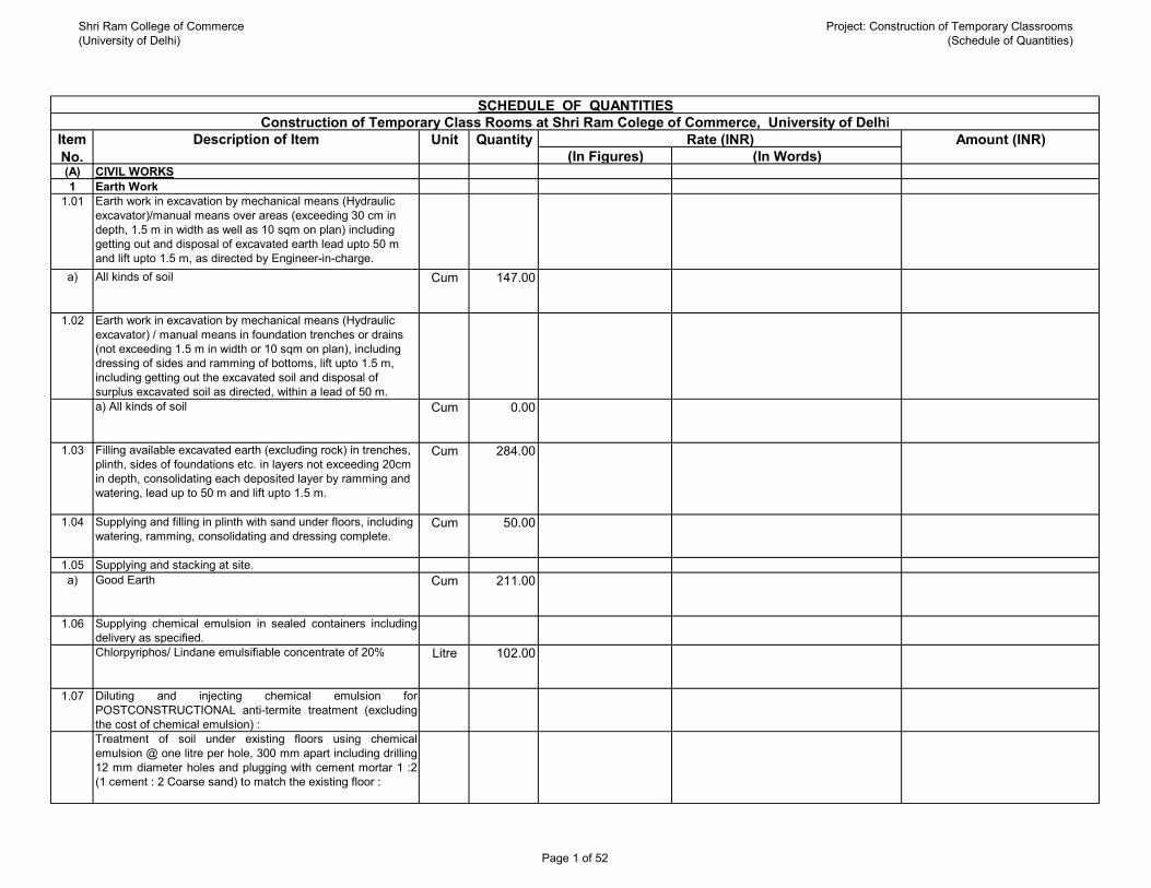
Shri Ram College of Commerce(University of Delhi)
Project: Construction of Temporary Classrooms(Schedule of Quantities)
(In Figures) (In Words)(A) CIVIL WORKS1 Earth Work
1.01 Earth work in excavation by mechanical means (Hydraulic excavator)/manual means over areas (exceeding 30 cm in depth, 1.5 m in width as well as 10 sqm on plan) including getting out and disposal of excavated earth lead upto 50 m and lift upto 1.5 m, as directed by Engineer-in-charge.
a) All kinds of soil Cum 147.00
1.02 Earth work in excavation by mechanical means (Hydraulic excavator) / manual means in foundation trenches or drains (not exceeding 1.5 m in width or 10 sqm on plan), including dressing of sides and ramming of bottoms, lift upto 1.5 m, including getting out the excavated soil and disposal of surplus excavated soil as directed, within a lead of 50 m.a) All kinds of soil Cum 0.00
1.03 Filling available excavated earth (excluding rock) in trenches, plinth, sides of foundations etc. in layers not exceeding 20cm in depth, consolidating each deposited layer by ramming and watering, lead up to 50 m and lift upto 1.5 m.
Cum 284.00
1.04 Supplying and filling in plinth with sand under floors, including watering, ramming, consolidating and dressing complete.
Cum 50.00
1.05 Supplying and stacking at site.a) Good Earth Cum 211.00
1.06 Supplying chemical emulsion in sealed containers includingdelivery as specified.Chlorpyriphos/ Lindane emulsifiable concentrate of 20% Litre 102.00
1.07 Diluting and injecting chemical emulsion forPOSTCONSTRUCTIONAL anti-termite treatment (excludingthe cost of chemical emulsion) :Treatment of soil under existing floors using chemicalemulsion @ one litre per hole, 300 mm apart including drilling12 mm diameter holes and plugging with cement mortar 1 :2(1 cement : 2 Coarse sand) to match the existing floor :
SCHEDULE OF QUANTITIES
Rate (INR) Amount (INR)QuantityUnitDescription of ItemItem No.
Construction of Temporary Class Rooms at Shri Ram Colege of Commerce, University of Delhi
Page 1 of 52

Shri Ram College of Commerce(University of Delhi)
Project: Construction of Temporary Classrooms(Schedule of Quantities)
(In Figures) (In Words)Rate (INR) Amount (INR)QuantityUnitDescription of ItemItem
No.With Chlorpyriphos/Lindane E.C. 20% with 1% concentration Sqm 509.00
Sub-Total: Earth Work :
2 Cement Concrete Work2.01 Providing and laying in position cement concrete of specified
grade excluding the cost of centering and shuttering - All work up to plinth level :
a) 1:4:8 (1 Cement : 4 coarse sand (zone-III) : 8 graded stone aggregate 40 mm nominal size)
Cum 1.00
2.02 Providing and laying cement concrete in retaining walls, return walls, walls (any thickness) including attached pilasters, columns, piers, abutments, pillars, posts, struts, buttresses, string or lacing courses, parapets, coping, bed blocks, anchor blocks, plain window sills, fillets, sunken floor etc., up to floor five level, excluding the cost of centering, shuttering and finishing :
a) 1:2:4 (1 Cement : 2 coarse sand : 4 graded stone aggregate 20 mm nominal size)
Cum 1.00
2.03 Making plinth protection 50mm thick of cement concrete 1:3:6(1 cement : 3 coarse sand : 6 graded stone aggregate 20 mmnominal size) over 75mm thick bed of dry brick ballast 40 mmnominal size, well rammed and consolidated and grouted withfine sand, including necessary excavation, levelling &dressing & finishing the top smooth.
Sqm 57.00
2.04 Providing and laying damp-proof course 40mm thick withcement concrete 1:2:4 (1 cement : 2 coarse sand (zone-III): 4graded stone aggregate 12.5mm nominal size)
Sqm 55.00
2.05 Extra for providing and mixing water proofing material incement concrete work in doses by weight of cement as permanufacturer's specification.
Per 50 kg
cement
15.00
2.06 Providing & applying a coat of residual petroleum bitumen ofgrade of VG-10 of approved quality using 1.7kg per squaremetre on damp proof course after cleaning the surface withbrushes and finally with a piece of cloth lightly soaked inkerosene oil.
Sqm 55.00
Page 2 of 52

Shri Ram College of Commerce(University of Delhi)
Project: Construction of Temporary Classrooms(Schedule of Quantities)
(In Figures) (In Words)Rate (INR) Amount (INR)QuantityUnitDescription of ItemItem
No.Sub-Total: Cement Concrete work :
3 R.C.C. Work3.01 Providing and laying in position ready mixed M-25 grade
concrete for reinforced cement concrete work, using cement content as per approved design mix, manufactured in fully automatic batching plant and transported to site of work in transit mixer for all leads, having continuous agitated mixer, manufactured as per mix design of specified grade for reinforced cement concrete work, including pumping of R.M.C. from transit mixer to site of laying , excluding the cost of centering, shuttering finishing and reinforcement, including cost of admixtures in recommended proportions as per IS : 9103 to accelerate/ retard setting of concrete, improve workability without impairing strength and durability as per direction of the Engineer-in-charge.(Note :- Cement content considered in this item is @ 330 kg/ cum.Excess/less cement used as per design mix is payable/recoverable separately).
a) All works upto Plinth level Cum 62.00
3.02 All works above plinth level upto floor V level Cum 6.00
3.03 Extra for providing richer mixes at all floor levelsNote:- Excess/less cement over the specified cement content used is payable /recoverable separately.
a) Providing M-30 grade concrete instead of M-25 grade BMC/ RMC. (Note:- Cement content considered in M-30 is @ 340 kg/cum)
Cum 9.00
3.04 Reinforcement for RCC work including straightening, cutting, bending, placing in position and binding all complete upto plinth level.
a) Thermo-Mechanically Treated bars of grade Fe-500D or more.
Kg 11406.00
3.05 Reinforcement for RCC work including straightening, cutting, bending, placing in position and binding all complete. Above plinth level.
a) Thermo-Mechanically Treated bars of grade Fe-500D or more.
Kg 393.00
Page 3 of 52

Shri Ram College of Commerce(University of Delhi)
Project: Construction of Temporary Classrooms(Schedule of Quantities)
(In Figures) (In Words)Rate (INR) Amount (INR)QuantityUnitDescription of ItemItem
No.3.06 Centering and shuttering including strutting, propping etc. and
removal of form for :a) Foundation, footing, bases of columns etc. for mass concrete Sqm 70.00
b) Suspended floors, roofs, landings, balconies, and access platform
Sqm R.O
c) Shelves (Cast in situ) Sqm 4.00
d) Lintels, beams, plinth beams, girders, bressumers and cantilevers
Sqm 261.00
e) Columns, Pillars, Piers, Abutments, Posts and Struts Sqm 71.00
f) Small lintels not exceeding 1.5 m clear span, moulding as in cornices, window sills, string courses, bands, copings, bed plates, anchor blocks and the like
Sqm 18.00
g) Edges of slabs and breaks in floors and wallsUnder 20 cm wide metre 38.00
h) Weather shade, Chajjas, corbels etc., including edges Sqm 14.00
3.07 Add for plaster drip course/ groove in plastered surface or moulding to R.C.C. projections.
metre 42.00
Sub-Total: R.C.C. Work
4 Brick Work4.01 Brick work with common burnt clay F.P.S. (non modular)
bricks of class designation 7.5 in foundation and plinth in:a) Cement mortar 1:6 (1 cement : 6 coarse sand) Cum 18.00
4.02 Brick work with common burnt clay F.P.S. (non modular) bricks of class designation 7.5 in superstructure above plinth level up to floor V level in all shapes and sizes in :
a) Cement mortar 1:6 (1 cement : 6 coarse sand) Cum 128.00
Page 4 of 52

Shri Ram College of Commerce(University of Delhi)
Project: Construction of Temporary Classrooms(Schedule of Quantities)
(In Figures) (In Words)Rate (INR) Amount (INR)QuantityUnitDescription of ItemItem
No.4.03 Half brick masonry with common burnt clay F.P.S. (non
modular) bricks of class designation 7.5 in foundations and plinth in :
a) Cement mortar 1:4 (1 cement : 4 coarse sand) Sqm 5.00
4.04 Half brick masonry with common burnt clay F.P.S. (non modular) bricks of class designation 7.5 in superstructure above plinth level up to floor
a) Cement mortar 1:4 (1 cement :4 coarse sand) Sqm 32.00
4.05 Extra for providing and placing in position 2 Nos 6mm dia. M.S. bars at every third course of half brick masonry.
Sqm 37.00
Sub-Total: Brick Work
5 Cladding Work5.01 Providing and fixing 18 mm thick gang saw cut, mirror
polished, premoulded and prepolished, machine cut forkitchen platforms, vanity counters, window sills, facias andsimilar locations of required size, approved shade, colour andtexture laid over 20 mm thick base cement mortar 1:4 (1cement : 4 coarse sand), joints treated with white cement,mixed with matching pigment, epoxy touch ups, includingrubbing, curing, moulding and polishing to edges to give highgloss finish etc. complete at all levels. Granite of any colour and shade
a) Area of slab upto 0.50 sqm Sqm 8.00
b) Area of slab over 0.50 sqm Sqm 4.00
5.02 Providing edge moulding to 18 mm thick marble stonecounters, Vanities etc., including machine polishing to edge togive high gloss finish etc. complete as per design approvedby Engineer-in-Charge.
a) Granite work metre 34.00
Page 5 of 52

Shri Ram College of Commerce(University of Delhi)
Project: Construction of Temporary Classrooms(Schedule of Quantities)
(In Figures) (In Words)Rate (INR) Amount (INR)QuantityUnitDescription of ItemItem
No.5.03 Extra for fixing marble /granite stone, over and above
corresponding basic item, in facia and drops of width upto 150mm with epoxy resin based adhesive, including cleaning etc.complete.
metre 7.00
5.04 Extra for providing opening of required size & shape for washbasin/ kitchen sink in kitchen platform, vanity counter andsimilar location in marble/ Granite/ stone work, includingnecessary holes for pillar taps etc. including moulding,rubbing and polishing of cut edges etc. complete.
Each 3.00
Sub-Total: Cladding Work
6 Wood Work6.01 Providing wood work in frames of doors, windows, clerestory
windows and other frames, wrought framed and fixed in position with hold fast lugs or with dash fasteners of required dia & length ( hold fast lugs or dash fastener shall be paid for separately).
a) Second class teak wood Cum 1.00
6.02 Providing and fixing ISI marked flush door shutters conforming to IS : 2202 (Part I) non-decorative type, core of block board construction with frame of 1st class hard wood and well matched commercial 3 ply veneering with vertical grains or cross bands and face veneers on both faces of shutters:
a) 35 mm thick including ISI marked Stainless Steel butt hinges with necessary screws
Sqm 43.00
6.03 Extra for providing lipping with 2nd class teak wood battens 25 mm minimum depth on all edges of flush door shutters (over all area of door shutter to be measured).
Sqm 43.00
6.04 Extra for providing vision panel not exceeding 0.1 sqm in all type of flush doors (cost of glass excluded) (overall area of door shutter to be measured):
a) Rectangular or square Sqm 43.00
6.05 Providing and fixing panelling or panelling and glazing in panelled or panelled and glazed shutters for doors, windows and clerestory windows (Area of opening for panel inserts excluding portion inside grooves or rebates to be measured). Panelling for panelled or panelled and glazed shutters 25 mm to 40 mm thick :Float glass panes
Page 6 of 52
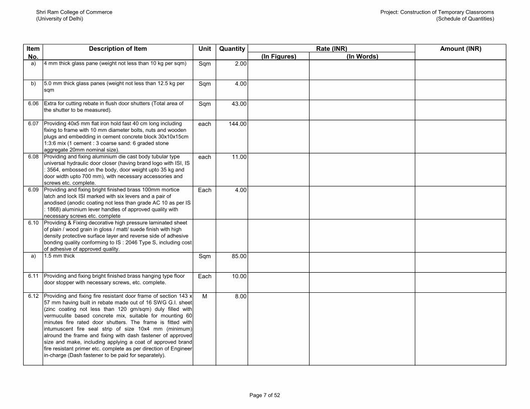
Shri Ram College of Commerce(University of Delhi)
Project: Construction of Temporary Classrooms(Schedule of Quantities)
(In Figures) (In Words)Rate (INR) Amount (INR)QuantityUnitDescription of ItemItem
No.a) 4 mm thick glass pane (weight not less than 10 kg per sqm) Sqm 2.00
b) 5.0 mm thick glass panes (weight not less than 12.5 kg per sqm
Sqm 4.00
6.06 Extra for cutting rebate in flush door shutters (Total area of the shutter to be measured).
Sqm 43.00
6.07 Providing 40x5 mm flat iron hold fast 40 cm long including fixing to frame with 10 mm diameter bolts, nuts and wooden plugs and embedding in cement concrete block 30x10x15cm 1:3:6 mix (1 cement : 3 coarse sand: 6 graded stone aggregate 20mm nominal size).
each 144.00
6.08 Providing and fixing aluminium die cast body tubular type universal hydraulic door closer (having brand logo with ISI, IS : 3564, embossed on the body, door weight upto 35 kg and door width upto 700 mm), with necessary accessories and screws etc. complete.
each 11.00
6.09 Providing and fixing bright finished brass 100mm mortice latch and lock ISI marked with six levers and a pair of anodised (anodic coating not less than grade AC 10 as per IS : 1868) aluminium lever handles of approved quality with necessary screws etc. complete
Each 4.00
6.10 Providing & Fixing decorative high pressure laminated sheet of plain / wood grain in gloss / matt/ suede finish with high density protective surface layer and reverse side of adhesive bonding quality conforming to IS : 2046 Type S, including cost of adhesive of approved quality.
a) 1.5 mm thick Sqm 85.00
6.11 Providing and fixing bright finished brass hanging type floor door stopper with necessary screws, etc. complete.
Each 10.00
6.12 Providing and fixing fire resistant door frame of section 143 x57 mm having built in rebate made out of 16 SWG G.I. sheet(zinc coating not less than 120 gm/sqm) duly filled withvermuculite based concrete mix, suitable for mounting 60minutes fire rated door shutters. The frame is fitted withintumuscent fire seal strip of size 10x4 mm (minimum)alround the frame and fixing with dash fastener of approvedsize and make, including applying a coat of approved brandfire resistant primer etc. complete as per direction of Engineer-in-charge (Dash fastener to be paid for separately).
M 8.00
Page 7 of 52

Shri Ram College of Commerce(University of Delhi)
Project: Construction of Temporary Classrooms(Schedule of Quantities)
(In Figures) (In Words)Rate (INR) Amount (INR)QuantityUnitDescription of ItemItem
No.6.13 Providing and fixing 50 mm thick glazed fire resistant door
shutters of 60 minutes fire rating conforming to IS:3614 (Part-II), tested and certified as per laboratory approved byEngineer-in-charge, with suitable mounting on door frame,consisting of vertical styles, lock rail, top rail 100 mm wide,bottom rail 200 mm wide, made out of 16 SWG G.I.sheet(zinc coating not less than 120 gm/m2) duly filled FRinsulation material and fixing with necessary stainless steelball bearing hinges of approved make, including applying acoat of approved fire resistant primer etc. all complete as perdirection of Engineer-in-charge (panneling to be paid forseparately).
Sqm 7.00
6.14 Providing and fixing glazing in fire resistant door shutters,fixed panels & partitions etc., with G.I. beading made out of1.6 mm thick G.I. sheet (zinc coating not less than 120gm/m²) of size 20 x 33 mm screwed with M4 x 38 mm SSscrews at distance 75 mm from the edges and 150 mm c/c ,including applying a coat of approved fire resistantprimer/powder coating of not less than 30 micron on G.I.beading, & special ceramic tape of 5 x 20 mm size etccomplete in all respect as per NBC 2016, IS 16231 (Part3):2016 and as per direction of Engineer-in-charge with glassof required thickness having 60 minutes of fire resistance bothintegrity & radiation control (EW60) and minimum 20 minutesof insulation (EI20). The manufacturer have to give testreport/certification of fire glass and the glass should have thestamp showing the value of E, EW & EI. The glass shall betested in approved NABL accredited lab
or by any other accreditation body which operates inaccordance with ISO/IEC 17011 and accredits labs as perISO/IEC 17025 for testing and calibration scopes shall beeligible. The maximum glazing size shall not be more than1100x2200 mm (w x h) or 2.42 sqm.
Sqm 7.00
6.15 Providing and fixing panic bar / latch (Double point) fitted with a single body, Trim Latch & Lock on back side of the Panic Latch of reputed brand and manufacture to be approved by the Engineer- in- charge, all complete.
Each 1.00
Sub-Total: Wood Work :
7 Steel Work 7.01 Structural steel work riveted, bolted or welded in built up
sections, trusses and framed work, including cutting, hoisting, fixing in position and applying a priming coat of approved steel primer all complete.
Kgs 1171.00
Page 8 of 52

Shri Ram College of Commerce(University of Delhi)
Project: Construction of Temporary Classrooms(Schedule of Quantities)
(In Figures) (In Words)Rate (INR) Amount (INR)QuantityUnitDescription of ItemItem
No.7.02 Steel work in built up tubular ( round, square or rectangular
hollow tubes etc.) trusses etc., including cutting, hoisting, fixing in position and applying a priming coat of approved steel primer, including welding and bolted with special shaped washers etc. complete.
a) Hot finished welded type tubes Kgs 20030.00
7.03 Providing and fixing bolts including nuts and washers complete.
Kgs 151.00
7.04 Providing and fixing stainless steel ( Grade 304) railing made of Hollow tubes, channels, plates etc., including welding, grinding, buffing, polishing and making curvature (wherever required) and fitting the same with necessary stainless steel nuts and bolts complete, i/c fixing the railing with necessary accessories & stainless steel dash fasteners , stainless steel bolts etc., of required size, on the top of the floor or the side of waist slab with suitable arrangement as per approval of Engineer-incharge, (for payment purpose only weight of stainless steel members shall be considered excluding fixing accessories such as nuts, bolts, fasteners etc.).
Kgs 154.00
7.05 Providing and fixing carbon steel galvanised ( minimum coating 5 micron) dash fastener of 10 mm dia double threaded 6.8 grade (yield strength 480 N/mm2), counter sunk head, comprising of 10 m dia polyamide PA 6 grade sleeve, including drilling of hole in frame , concrete/ masonry, etc. as per direction of Engineer-in-charge.
a) 10 x 80 mm each 78.00
b) 10 x 140 mm each 16.00
Sub-Total: Steel Work
8 Flooring Work
Page 9 of 52

Shri Ram College of Commerce(University of Delhi)
Project: Construction of Temporary Classrooms(Schedule of Quantities)
(In Figures) (In Words)Rate (INR) Amount (INR)QuantityUnitDescription of ItemItem
No.8.01 Providing and fixing Ist quality ceramic glazed wall tiles
conforming to IS: 15622 (thickness to be specified by the manufacturer), of approved make, in all colours, shades except burgundy, bottle green, black of any size as approved by Engineer-in-Charge, in skirting, risers of steps and dados, over 12 mm thick bed of cement mortar 1:3 (1 cement : 3 coarse sand) and jointing with grey cement slurry @ 3.3kg per sqm, including pointing in white cement mixed with pigment of matching shade complete
Sqm 104.00
8.02 Providing and laying Ceramic glazed floor tiles of size 300x300 mm (thickness to be specified by the manufacturer) of 1st quality conforming to IS : 15622 of approved make in colours such as White, Ivory, Grey, Fume Red Brown, laid on 20 mm thick cement mortar 1:4 (1 Cement : 4 Coarse sand), jointing with grey cement slurry @ 3.3kg/sqm including pointing the joints with white cement and matching pigment etc., complete.
Sqm 19.00
8.03 Providing and laying vitrified floor tiles in different sizes (thickness to be specified by the manufacturer) with water absorption less than 0.08% and conforming to IS: 15622, of approved make, in all colours and shades, laid on 20mm thick cement mortar 1:4 (1 cement : 4 coarse sand), jointing with grey cement slurry @ 3.3kg/sqm including grouting the joints with white cement and matching pigments etc., complete.
a) Size of Tile 600x600 mm Sqm 382.00
8.04 Providing and laying Vitrified tiles in different sizes (thickness to be specified by manufacturer), with water absorption less than 0.08 % and conforming to I.S. 15622, of approved make, in all colours & shade, in skirting, dado, riser of steps, over 12 mm thick bed of cement mortar 1:3 (1 cement: 3 coarse sand), jointing with grey cement slurry @ 3.3kg/sqm including grouting the joint with white cement & matching pigments etc. complete.
a) Size of Tile 600x600 mm Sqm 19.00
8.05 Kota stone slab flooring over 20 mm (average) thick base laid over and jointed with grey cement slurry mixed with pigment to match the shade of the slab, including rubbing and polishing complete with base of cement mortar 1 : 4 (1 cement : 4 coarse sand) :
Page 10 of 52

Shri Ram College of Commerce(University of Delhi)
Project: Construction of Temporary Classrooms(Schedule of Quantities)
(In Figures) (In Words)Rate (INR) Amount (INR)QuantityUnitDescription of ItemItem
No.a) 25 mm thick Sqm 120.00
8.06 Kota stone slabs 20 mm thick in risers of steps, skirting, dado and pillars laid on 12 mm (average) thick cement mortar 1:3 (1 cement: 3 coarse sand) and jointed with grey cement slurry mixed with pigment to match the shade of the slabs, including rubbing and polishing complete
Sqm 26.00
8.07 Extra for pre finished nosing in treads of steps of Kota stone/ sand stone slab.
meter 12.00
Sub-Total: Flooring Work
9 Roofing Work
Page 11 of 52
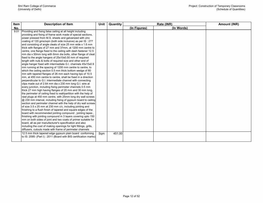
Shri Ram College of Commerce(University of Delhi)
Project: Construction of Temporary Classrooms(Schedule of Quantities)
(In Figures) (In Words)Rate (INR) Amount (INR)QuantityUnitDescription of ItemItem
No.9.01 Providing and fixing false ceiling at all height including
providing and fixing of frame work made of special sections, power pressed from M.S. sheets and galvanized with zinc coating of 120 gms/sqm (both side inclusive) as per IS : 277 and consisting of angle cleats of size 25 mm wide x 1.6 mm thick with flanges of 27 mm and 37mm, at 1200 mm centre to centre, one flange fixed to the ceiling with dash fastener 12.5 mm dia x 50mm long with 6mm dia bolts, other flange of cleat fixed to the angle hangers of 25x10x0.50 mm of required length with nuts & bolts of required size and other end of angle hanger fixed with intermediate G.I. channels 45x15x0.9 mm running at the spacing of 1200 mm centre to centre, to which the ceiling section 0.5 mm thick bottom wedge of 80 mm with tapered flanges of 26 mm each having lips of 10.5 mm, at 450 mm centre to centre, shall be fixed in a direction perpendicular to G.I. intermediate channel with connecting clips made out of 2.64 mm dia x 230 mm long G.I. wire at every junction, including fixing perimeter channels 0.5 mm thick 27 mm high having flanges of 20 mm and 30 mm long, the perimeter of ceiling fixed to wall/partition with the help of rawl plugs at 450 mm centre, with 25mm long dry wall screws @ 230 mm interval, including fixing of gypsum board to ceiling section and perimeter channel with the help of dry wall screws of size 3.5 x 25 mm at 230 mm c/c, including jointing and finishing to a flush finish of tapered and square edges of the board with recommended jointing compound , jointing tapes , finishing with jointing compound in 3 layers covering upto 150 mm on both sides of joint and two coats of primer suitable for board, all as per manufacturer's specification and also including the cost of making openings for light fittings, grills, diffusers, cutouts made with frame of perimeter channels suitably fixed, all complete as per drawings, specification and 12.5 mm thick tapered edge gypsum plain board conforming to IS: 2095- (Part I) : 2011 (Board with BIS certification marks)
Sqm 451.00
Page 12 of 52

Shri Ram College of Commerce(University of Delhi)
Project: Construction of Temporary Classrooms(Schedule of Quantities)
(In Figures) (In Words)Rate (INR) Amount (INR)QuantityUnitDescription of ItemItem
No.9.02 Providing and Fixing 15 mm thick densified tegular edged eco
friendly light weight calcium silicate false ceiling tiles of approved texture of size 595 x 595 mm in true horizontal level, suspended on inter locking metal grid of hot dipped galvanised steel sections (galvanising @ 120 grams per sqm including both side) consisting of main ‘T’ runner suitably spaced at joints to get required length and of size 24x38 mm made from 0.33 mm thick (minimum) sheet, spaced 1200 mm centre to centre, and cross “T” of size 24x28 mm made out of 0.33 mm (Minimum) sheet, 1200 mm long spaced between main’T’ at 600 mm centre to centre to form a grid of 1200x600 mm and secondary cross ‘T’ of length 600 mm and size 24 x28 mm made of 0.33 mm thick (Minimum) sheet to be inter locked at middle of the 1200x 600 mm panel to from grid of size 600x600 mm, resting on periphery walls /partitions on a Perimeter wall angle pre-coated steel of size(24x24X3000 mm made of 0.40 mm thick (minimum) sheet with the help of rawl plugs at 450 mm centre to centre with 25 mm long dry wall screws @ 230 mm interval and laying 15 mm thick densified edges calicum silicate ceiling tiles of approved texture in the grid, including, cutting/ making opening for services like diffusers, grills, light fittings, fixtures, smoke detectors etc., wherever required. Main ‘T’ runners to be suspended from ceiling using G.I. slotted cleats of size 25x35x1.6 mm fixed to ceiling with 12.5 mm dia and 50 mm long dash fasteners, 4 mm G.I. adjustable rods with galvanised steel level clips of size 85 x 30 x 0.8 mm, spaced at 1200 mm centre to centre along main ‘T’, bottom exposed with 24 mm of all Tsections shall be pre-painted with polyster baked paint, for all heights, as per specifications, drawings and as directed by Engineer-in-Charge.
Note :- Only calcium silicate false ceiling area will be measured from wall to wall. No deduction shall be made for exposed frames/ opening (cut outs) having area less than 0.30 sqm.The calcium silicate ceiling tile shall have NRC value of 0.50 (Minimum), light reflection > 85%, non- combustible as per B.S. 476 part IV, 100% humidity resistance and also having thermal conductivity <0.043 w/mK.
Sqm 18.00
9.03 Providing and fixing precoated galvanised steel sheet roofing accessories 0.50 mm (+ 0.05 %) total coated thickness, Zinc coating 120 grams per sqm as per IS: 277, in 240 mpa steel grade, 5-7 microns epoxy primer on both side of the sheet and polyester top coat 15-18 microns using self drilling/ self tapping screws complete :
Page 13 of 52

Shri Ram College of Commerce(University of Delhi)
Project: Construction of Temporary Classrooms(Schedule of Quantities)
(In Figures) (In Words)Rate (INR) Amount (INR)QuantityUnitDescription of ItemItem
No.Gutter .(600 mm over all girth) meter 55.00
Sub-Total: Roofing Work
10 Finishing Work10.01 12 mm cement plaster of mix :
a) 1:6 (1 cement : 6 coarse sand) Sqm 865.00
10.02 6 mm cement plaster of mix:a) 1:3 (1 cement : 3 fine sand) Sqm R.O
10.03 18 mm cement plaster in two coats under layer 12 mm thick cement plaster 1:5 (1 cement : 5 coarse sand) finished with a top layer 6 mm thick cement plaster 1:6 (1 cement : 6 fine sand).
Sqm 311.00
10.04 Providing and applying plaster of paris putty of 2 mm thickness over plastered surface to prepare the surface even and smooth complete.
Sqm 865.00
10.05 Wall painting with premium acrylic emulsion paint of interior grade, having VOC (Volatile Organic Compound ) content less than 50 grams/ litre of approved brand and manufacture, including applying additional coats wherever required to achieve even shade and colour.
a) Two coats Sqm 865.00
10.06 Painting with black anti-corrosive bitumastic paint of approved brand and manufacture to give an even shade :
a) Two or more coats on new work Sqm 700.00
10.07 Finishing walls with Acrylic Smooth exterior paint of required shade :
a) New work (Two or more coat applied @ 1.67 ltr/10 sqm over and including priming coat of exterior primer applied@ 2.20 kg/10 sqm)
Sqm 311.00
10.08 White washing with lime to give an even shade : a) New work (three or more coats) Sqm 10.00
10.09 French spirit polishing :
Page 14 of 52

Shri Ram College of Commerce(University of Delhi)
Project: Construction of Temporary Classrooms(Schedule of Quantities)
(In Figures) (In Words)Rate (INR) Amount (INR)QuantityUnitDescription of ItemItem
No.a) Two or more coats on new works including a coat of wood
fillerSqm 38.00
Sub-Total: Finishing Work
11 Aluminium Work11.01 Providing and fixing aluminium work for doors, windows,
ventilators and partitions with extruded built up standard tubular sections/ appropriate Z sections and other sections of approved make conforming to IS: 733 and IS: 1285, fixing with dash fasteners of required dia and size, including necessary filling up the gaps at junctions, i.e. at top, bottom and sides with required EPDM rubber/ neoprene gasket etc. Aluminium sections shall be smooth, rust free, straight, mitred and jointed mechanically wherever required including cleat angle, Aluminium snap beading for glazing / paneling, C.P. brass / stainless steel screws, all complete as per architectural drawings and the directions of Engineer-in-charge. (Glazing, paneling and dash fasteners to be paid for separately) : For fixed portion
a) Powder coated aluminium (minimum thickness of powder coating 50 micron)
Kg 368.00
11.02 For shutters of doors, windows & ventilators including providing and fixing hinges/ pivots and making provision for fixing of fittings wherever required including the cost of EPDM rubber / neoprene gasket required (Fittings shall be paid for separately)
a) Powder coated aluminium (minimum thickness of powder coating 50 micron)
Kgs 459.00
11.03 Providing and fixing glazing in aluminium door, window, ventilator shutters and partitions etc. with EPDM rubber / neoprene gasket etc. complete as per the architectural drawings and the directions of engineer-in-charge. (Cost of aluminium snap beading shall be paid in basic item):
a) With float glass panes of 5 mm thickness (weight not less than 12.50 kg/ sqm)
Sqm 31.00
b) Toughened glass 12 mm thickness Sqm 6.00
Page 15 of 52

Shri Ram College of Commerce(University of Delhi)
Project: Construction of Temporary Classrooms(Schedule of Quantities)
(In Figures) (In Words)Rate (INR) Amount (INR)QuantityUnitDescription of ItemItem
No.11.04 Filling the gap in between aluminium frame & adjacent RCC/
Brick/ Stone work by providing weather silicon sealant over backer rod of approved quality as per architectural drawings and direction of Engineer-in-charge complete.
a) Upto 5mm depth and 5 mm width rm 69.00
11.05 Providing and fixing aluminium casement windows fastener of required length for aluminium windows with necessary screws etc. complete.
a) Powder coated minimum thickness 50 micron aluminium Each 44.00
11.06 Providing and fixing aluminium round shape handle of outer dia 100 mm with SS screws etc. complete as per direction of Engineerin-charge
a) Powder coated minimum thickness 50 micron aluminium Each 44.00
Sub-Total: Aluminium work
12 Dismantling and Demolishing WorkNote: All dismentling and demolishing work will be done in such manner that no other work will be effected or damaged. If any damage will be occure at site than contractor will be responsible to repair and construction of such work by it's own cost in quoted rate.
12.01 Demolishing cement concrete manually/ by mechanical means including disposal of material within 50 metres lead as per direction of Engineer - in - charge.Note:- Existing flooring is to be considered as Cement concrete flooring of nominal mix (1:3:6).
a) Nominal concrete 1:3:6 or richer mix (i/c equivalent designmix)
Cum 84.00
b) Nominal concrete 1:4:8 or leaner mix (i/c equivalent design mix)
Cum 45.00
12.02 Demolishing R.C.C. work manually/ by mechanical means including stacking of steel bars and disposal of unserviceable material within 50 metres lead as per direction of Engineer - in- charge.
Cum 13.00
12.03 Extra for cutting reinforcement bars manually/ by mechanical means in R.C.C. or R.B. work (Payment shall be made on the cross sectional area of R.C.C. or R.B. work) as per direction of Engineer- in-charge.
Sqm 1.00
Page 16 of 52

Shri Ram College of Commerce(University of Delhi)
Project: Construction of Temporary Classrooms(Schedule of Quantities)
(In Figures) (In Words)Rate (INR) Amount (INR)QuantityUnitDescription of ItemItem
No.12.04 Demolishing brick work manually/ by mechanical means
including stacking of serviceable material and disposal of unserviceable material within 50 metres lead as per direction of Engineer-in-charge.In cement mortar Cum 305.00
12.05 Dismantling doors, windows and clerestory windows (steel or wood) shutter including chowkhats, architrave, holdfasts etc. complete and stacking within 50 metres lead :
a) Of area 3 sq. metres and below Each 25.00
b) Of area beyond 3 sq. metres Each 2.00
12.07 Dismantling wood work in frames, trusses, purlins and rafters up to 10 metres span and 5 metres height including stacking the material within 50 metres lead :Of sectional area below 40 square centimetres meter 605.00
12.08 Dismantling steel work in built up sections in angles, tees, flats and channels including all gusset plates, bolts, nuts, cutting rivets, welding etc. including dismembering and stacking within 50 metres lead.
Kg 9457.00
12.09 Dismantling tile work in floors and roofs laid in cement mortar including stacking material within 50 metres lead.
a) For thickness of tiles 10 mm to 25 mm Sqm 10.00
12.10 Dismantling stone slab flooring laid in cement mortar including stacking of serviceable material and disposal of unserviceable material within 50 metres lead.
Sqm 5.00
12.11 Dismantling roofing including ridges, hips, valleys and gutters etc., and stacking the material within 50 metres lead of:
a) Asbestos sheet Sqm 576.00
12.12 Dismantling and stacking within 50 metres lead, fencing posts or struts including all earth work and dismantling of concrete etc. in base of:
a) T’ or ‘L’ iron or pipe Each 21.00
Page 17 of 52

Shri Ram College of Commerce(University of Delhi)
Project: Construction of Temporary Classrooms(Schedule of Quantities)
(In Figures) (In Words)Rate (INR) Amount (INR)QuantityUnitDescription of ItemItem
No.12.13 Dismantling barbed wire or flexible wire rope in fencing
including making rolls and stacking within 50 metres lead.kg 179.00
12.14 Dismantling C.I. or asbestos rain water pipe with fittings and clamps including stacking the material within 50 metres lead
a) 100 mm dia pipe meter 64.00
12.15 Disposal of building rubbish / malba / similar unserviceable, dismantled or waste materials by mechanical means, including loading, transporting, unloading to approved municipal dumping ground or as approved by Engineer-in-charge, beyond 50 m initial lead, for all leads including all lifts involved.
Cum 445.00
Sub-Total: Dismantling and Demolishing Work
13 Civil Miscellaneous Works13.01 Providing and laying in position ready mixed plain cement
concrete, with cement content as per approved design mix and manufactured in fully automatic batching plant and transported to site of work in transit mixer for all leads, having continuous agitated mixer, manufactured as per mix design of specified grade for plain cement concrete work, including pumping of R.M.C. from transit mixer to site of laying and curing, excluding the cost of centering, shuttering and finishing, including cost of curing, admixtures in recommended proportions as per IS : 9103 to accelerate/ retard setting of concrete, improve workability without impairing strength and durability as per direction of the Engineer-in-charge.
a) 1:4:8 (1 Cement : 4 coarse sand (zone-III) : 8 graded stone aggregate 40 mm nominal size)
Cum 68.00
Page 18 of 52
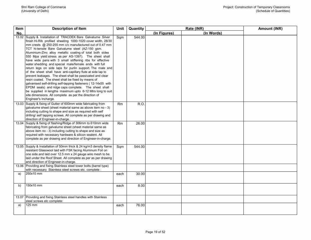
Shri Ram College of Commerce(University of Delhi)
Project: Construction of Temporary Classrooms(Schedule of Quantities)
(In Figures) (In Words)Rate (INR) Amount (INR)QuantityUnitDescription of ItemItem
No.13.02 Supply & Installation of TRACDEK Bare Galvalume Silver
finish Hi-Rib profiled sheeting 1000-1020 cover width, 28/30 mm crests @ 250-255 mm c/c manufactured out of 0.47 mm TCT hi-tensile Bare Galvalume steel (AZ-150 gsm. Aluminium-Zinc alloy metallic coating of total both sides 550 Mpa yield stress as per AS-1397). The sheet shall have wide pans with 3 small stiffening ribs for effective water shedding and special male/female ends with full return legs on side laps for purlin support. The male end of the sheet shall have anti-capillary flute at side lap to prevent leakages. The sheet shall be passivated and clear resin coated. The sheet shall be fixed by means of galvanised self-drilling self-tapping fasteners ( 12-14x55 with EPDM seals) and ridge caps complete. The sheet shall be supplied in lengths maximum upto 6-12 Mtrs long to suit site dimensions. All complete as per the direction of Engineer's Incharge.
Sqm 544.00
13.03 Supply & fixing of Gutter of 600mm wide fabricating from galvalume sheet (sheet material same as above item no - 3) including cutting to shape and size as required with self drilling/ self tapping screws. All complete as per drawing and direction of Engineer-in-charge.
Rm R.O.
13.04 Supply & fixing of flashing/Ridge of 306mm to 610mm wide fabricating from galvalume sheet (sheet material same as above item no - 3) including cutting to shape and size as required with necessary hardware & silicon sealent. All complete as per drawing and direction of Engineer-in-charge.
Rm 26.00
13.05 Supply & Installation of 50mm thick & 24 kg/m3 density flame resistant Glasswool laid with FSK facing Aluminum Foil on one side and laid over 12.5 mm x 24 gauge wire mesh to be laid under the Roof Sheet. All complete as per as per drawing and direction of Engineer-in-charge.
Sqm 544.00
13.06 Providing and fixing Stainless steel tower bolts (barrel type) with necessary Stainless steel screws etc. complete :
a) 250x10 mm each 30.00
b) 150x10 mm each 8.00
13.07 Providing and fixing Stainless steel handles with Stainless steel screws etc complete:
a) 125 mm each 76.00
Page 19 of 52
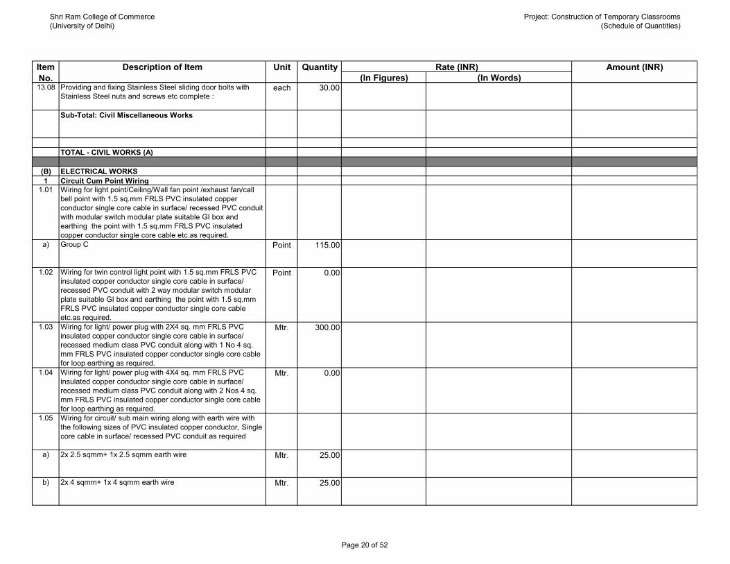
Shri Ram College of Commerce(University of Delhi)
Project: Construction of Temporary Classrooms(Schedule of Quantities)
(In Figures) (In Words)Rate (INR) Amount (INR)QuantityUnitDescription of ItemItem
No.13.08 Providing and fixing Stainless Steel sliding door bolts with
Stainless Steel nuts and screws etc complete :each 30.00
Sub-Total: Civil Miscellaneous Works
TOTAL - CIVIL WORKS (A)
(B) ELECTRICAL WORKS1 Circuit Cum Point Wiring
1.01 Wiring for light point/Ceiling/Wall fan point /exhaust fan/call bell point with 1.5 sq.mm FRLS PVC insulated copper conductor single core cable in surface/ recessed PVC conduit with modular switch modular plate suitable GI box and earthing the point with 1.5 sq.mm FRLS PVC insulated copper conductor single core cable etc.as required.
a) Group C Point 115.00
1.02 Wiring for twin control light point with 1.5 sq.mm FRLS PVC insulated copper conductor single core cable in surface/ recessed PVC conduit with 2 way modular switch modular plate suitable GI box and earthing the point with 1.5 sq.mm FRLS PVC insulated copper conductor single core cable etc.as required.
Point 0.00
1.03 Wiring for light/ power plug with 2X4 sq. mm FRLS PVC insulated copper conductor single core cable in surface/ recessed medium class PVC conduit along with 1 No 4 sq. mm FRLS PVC insulated copper conductor single core cable for loop earthing as required.
Mtr. 300.00
1.04 Wiring for light/ power plug with 4X4 sq. mm FRLS PVC insulated copper conductor single core cable in surface/ recessed medium class PVC conduit along with 2 Nos 4 sq. mm FRLS PVC insulated copper conductor single core cable for loop earthing as required.
Mtr. 0.00
1.05 Wiring for circuit/ sub main wiring along with earth wire with the following sizes of PVC insulated copper conductor, Single core cable in surface/ recessed PVC conduit as required
a) 2x 2.5 sqmm+ 1x 2.5 sqmm earth wire Mtr. 25.00
b) 2x 4 sqmm+ 1x 4 sqmm earth wire Mtr. 25.00
Page 20 of 52

Shri Ram College of Commerce(University of Delhi)
Project: Construction of Temporary Classrooms(Schedule of Quantities)
(In Figures) (In Words)Rate (INR) Amount (INR)QuantityUnitDescription of ItemItem
No.c) 2x 6 sqmm+ 1x 6 sqmm earth wire Mtr. 25.00
d) 2x 10 sqmm+ 1x 6 sqmm earth wire Mtr. 0.00
e) 4x 4 sqmm+ 2x 4 sqmm earth wire Mtr. 0.00
f) 4x 6 sqmm+ 2x 6 sqmm earth wire Mtr. 50.00
g) 4x 10 sqmm+ 2x 6 sqmm earth wire Mtr. 0.00
h) 4x 16 sqmm+ 2x 6 sqmm earth wire Mtr. 0.00
1.06 Telephone wiring in existing conduiting: Supply & drawing following pair, 0.5 sq.mm FRLS PVC insulated copper conductor, unarmoured telephone cable in existing surface/ recessed steel/ PVC conduit as required.
a) 2 pair Mtrs. 75.00
b) 4 pair Mtrs. 0.00
1.07 Supply & fixing of following sizes of PVC conduit along with accessories in surface / recessed including cutting the wall & making good the same in case of recessed conduit as required.
a) 20 mm dia. Mtrs. 0.00
b) 25 mm dia. Mtrs. 50.00
c) 32 mm dia. Mtrs. 50.00
d) 40 mm dia. Mtrs. 0.00
Page 21 of 52

Shri Ram College of Commerce(University of Delhi)
Project: Construction of Temporary Classrooms(Schedule of Quantities)
(In Figures) (In Words)Rate (INR) Amount (INR)QuantityUnitDescription of ItemItem
No.e) 50 mm dia. Mtrs. 0.00
1.08 Supplying and fixing following modular switch/ socket on the existing modular plate & switch box including connections but excluding modular plate etc. as required.
a) 5/6 A switch Each 5.00
b) 15/16 A switch Each 5.00
c) 3 pin 5/6 A socket outlet Each 4.00
d) 6 pin 15/16 A socket outlet Each 4.00
e) Telephone socket outlet Each 5.00
f) TV antenna socket outlet Each 1.00
g) Bell push Each 0.00
1.09 Supplying and fixing two module of Stepped type electronic fan regulator on the existing modular plate & switch box including connections but excluding modular plate etc. as reqd.
Each 36.00
1.10 Supplying and fixing of modular Blanking plate on the existing modular plate & switch box including connections but excluding modular plate etc. as reqd.
Each 5.00
1.11 Supply and fixing of following size/ modules, GI box along with modular base & cover plate for modular switch/ regulator in recess, including connection as required.
a) 1or 2 module (75mmx 75mm) Each 5.00
b) 3 Module (100 mmX75 mm) Each 10.00
c) 4 Module (125 mmX75 mm) Each 5.00
Page 22 of 52

Shri Ram College of Commerce(University of Delhi)
Project: Construction of Temporary Classrooms(Schedule of Quantities)
(In Figures) (In Words)Rate (INR) Amount (INR)QuantityUnitDescription of ItemItem
No.d) 6 Module (200 mmX75 mm) Each 4.00
e) 8 Module (125 mmX125 mm) Each 2.00
f) 12 Module (200 mmX150 mm) Each 5.00
1.12 Supplying and fixing suitable size GI box with modular plate and cover in front on surface or in recess, including providing and fixing 3 pin 5/6 A modular socket outlet and 5/6 A modular switch, connections etc. as required.
Each 30.00
1.13 Supplying and fixing suitable size GI box with modular plate and cover in front on surface or in recess, including providing and fixing 6 pin 5/6 A & 15/16 A modular socket outlet and 15/16 A modular switch, connections etc. as required.
Each 18.00
1.14 Supply and fixing of 3 Pin ,5amp ceiling rose on the existing junction box /wooden block including connection etc as required.
Each 5.00
1.15 Supply and fixing brass batten /angle holder including connection etc. as required.
Each 2.00
1.16 Installation, testing & commissioning of pre-wired, fluorescent fitting / compact fluoroscent fitting of all type, complete with all accessories & tubes etc. directly on ceiling / wall, including connection with 1.5 sq.mm. FRls PVC insulated, copper condutor, single core cable and earthing etc. as required.
Each 0.00
1.17 Installation, testing and commissioning of pre-wired, fluorescent fitting/ compact fluorescent fitting of all types, with all accessories and tube etc., including supplying and fixing ball and socket arrangement, 2 no. down rods of 20 mm dia X 1.6 mm thick steel conduit upto 30 cm length, painting and wiring the down rods and connection with 1.5 sq. mm FRLS PVC insulated, copper conductor, single core cable and earthing etc as required.
Each 0.00
1.18 Providing and fixing extra conduit down rod of 20 mm dia, 2 X 10 cm length wiring with 2 X 1.5 sq. mm FRLS PVC insulated, copper conductor, single core cable including painting etc. as required. (Note : More than 5 cm length shall be rounded to the nearest 10 cm and 5 cm or less shall be ignored)
Each 0.00
Page 23 of 52

Shri Ram College of Commerce(University of Delhi)
Project: Construction of Temporary Classrooms(Schedule of Quantities)
(In Figures) (In Words)Rate (INR) Amount (INR)QuantityUnitDescription of ItemItem
No.1.19 Installation, testing & commissioning of ceiling fan including
wiring the down rods of standard length ( upto 30 cm) with 1.5 sq.mm FRLS PVC insulated, copper conductor, single core cable, including providing and fixing phenolic laminated sheet cover on the fan box etc. as reqd.
Each 0.00
1.20 Supplying and fixing extra down rod of 10 cm length G.I. pipe ,15 mm dia, heavy gauge including painting etc. as required. (Note : More than 5 cm length shall be rounded to the nearest 10 cm and 5 cm or less shall be ignored)
Each 0.00
1.21 Supplying and fixing extra conduit down rod of 20 cm length G.I. pipe 15 mm dia, heavy gauge including painting etc. as required. (Note : More than 5 cm length shall be rounded to the nearest 10 cm and 5 cm or less shall be ignored)
Each 0.00
1.22 Numbering of ceiling fan/ exhaust fan/ fluorescent fittings as required.
Each 40.00
1.23 Installation of Exhaust/Wall fan in the existing opening , including making the hole to suit the size of the above fan, making good the damage connection, testing commissioning etc. as required. Upto 450 mm sweep Each 2.00
1.24 Supplying and Installing following size of perforated pre-painted M.S. cable trays with perforation not more than 17.5% in convinient sections,jointed with connectors, suspended from the ceiling with M.S suspenders including bolts and nuts, painting suspenders etc as required.
a) 100 mm width x 50 mm depth x 1.6 mm thickness Metre 25.00
b) 150 mm width x 50 mm depth x 1.6 mm thickness Metre 15.00
c) 300 mm width x 50 mm depth x 1.6 mm thickness Metre 0.00
1.25 Supplying and Installing following size of perforated pre-painted M.S. cable trays bends with perforation not more than 17.5% in convinient sections,jointed with connectors, suspended from the ceiling with M.S suspenders including bolts and nuts, painting suspenders etc as required.
a) 100 mm width x 50 mm depth x 1.6 mm thickness Each 2.00
Page 24 of 52

Shri Ram College of Commerce(University of Delhi)
Project: Construction of Temporary Classrooms(Schedule of Quantities)
(In Figures) (In Words)Rate (INR) Amount (INR)QuantityUnitDescription of ItemItem
No.b) 150 mm width x 50 mm depth x 1.6 mm thickness Each 2.00
c) 300 mm width x 50 mm depth x 1.6 mm thickness Each 0.00
1.26 Supplying and Installing following size of perforated pre-painted M.S. cable trays reducers with perforation not more than 17.5% in convinient sections,jointed with connectors, suspended from the ceiling with M.S suspenders including bolts and nuts, painting suspenders etc as required.
a) 100 mm width x 50 mm depth x 1.6 mm thickness Each 1.00
b) 150 mm width x 50 mm depth x 1.6 mm thickness Each 1.00
c) 300 mm width x 50 mm depth x 1.6 mm thickness Each 0.00
1.27 Supplying and Installing following size of perforated pre-painted M.S. cable trays tees with perforation not more than 17.5% in convinient sections,jointed with connectors, suspended from the ceiling with M.S suspenders including bolts and nuts, painting suspenders etc as required.
a) 100 mm width x 50 mm depth x 1.6 mm thickness Each 1.00
b) 150 mm width x 50 mm depth x 1.6 mm thickness Each 1.00
c) 300 mm width x 50 mm depth x 1.6 mm thickness Each 0.00
1.28 Supplying and Installing following size of perforated pre-painted M.S. cable trays cross members with perforation not more than 17.5% in convinient sections,jointed with connectors, suspended from the ceiling with M.S suspenders including bolts and nuts, painting suspenders etc as required.
a) 100 mm width x 50 mm depth x 1.6 mm thickness Each 0.00
b) 150 mm width x 50 mm depth x 1.6 mm thickness Each 0.00
Page 25 of 52

Shri Ram College of Commerce(University of Delhi)
Project: Construction of Temporary Classrooms(Schedule of Quantities)
(In Figures) (In Words)Rate (INR) Amount (INR)QuantityUnitDescription of ItemItem
No.c) 300 mm width x 50 mm depth x 1.6 mm thickness Each 0.00
1.29 Supplying & Fixing 20 amps,240 volts,SPN industrial type Socket outlet, with 2 pole and earth, metal enclosed plug top along with 20 amps "C" curve, SP, MCB, in sheet steel enclosure, on surface and recess, with chained metal cover for the socket outlet and complete with connections, testing and commissioning etc. as required.
Each 0.00
1.30 TV cable in existing conduiting: Supply & drawing co-axial TV cable RG-6 grade, 0.7 mm solid copper conductor PE insulated, shielded with fine tinned copper braid and protected with PVC sheath in existing surface/ recessed steel/ PVC conduit as required.
Metre 1.00
1.31 Supplying and fixing of modular TV antenna socket outlet on the existing Modular plate & switch including connection but excluding modular plate etc. as required.
Each 1.00
1.32 Supply & fixing of Call bell/ Buzzer suitable for A.C. single phase, 230 volts complete as required
Each 0.00
1.33 Providing & fixing of M.V. danger notice plate of 200 mm x 150 mm, made of mild steel, at least 2 mm thick, and vitreous enamelled white on both sides, and with inscription in single red colour on front side as required.
Each 1.00
Sub-Total: Circuit Cum Point Wiring
2 Distribution Boards2.01 Supplying and fixing following way, single pole and neutral,
sheet steel, MCB distribution board, 240 V, on surface/ recess, complete with tinned copper bus bar, neutral bus bar, earth bar, din bar, interconnections, powder painted including earthing etc. as required. (But without CB/RCCB/Isolator)
a) 6 way, Double door Each 0.00
b) 8 way, Double door Each 0.00
c) 12 way, Double door Each 0.00
Page 26 of 52

Shri Ram College of Commerce(University of Delhi)
Project: Construction of Temporary Classrooms(Schedule of Quantities)
(In Figures) (In Words)Rate (INR) Amount (INR)QuantityUnitDescription of ItemItem
No.d) 16 way, Double door Each 0.00
2.02 Supplying and fixing following way, horizontal type three pole and neutral, sheet steel, MCB distribution board, 415 V, on surface/ recess, complete with tinned copper bus bar, neutral bus bar, earth bar, din bar, interconnections, powder painted including earthing etc. as required. (But without MCB/RCCB/ Isolator)
a) 4 Way(4+12), Double door Each 2.00
b) 6 Way(4+18), Double door Each 0.00
c) 8 Way(4+24), Double door Each 0.00
2.03 Supplying & fixing 5 amps to 32 amps rating 240/415 volts ,10KA, C curve, Miniature Circuit Breaker suitable for lighting loads of following poles in the existing MCB DB complete with connections, testing and commissioning etc. as required.
a) Single Pole Each 24.00
2.04 Supply and fixing single pole blanking plate in the existing MCB DB complete etc. as required.
Each 2.00
2.05 Supplying and fixing following rating, double pole, (single phase and neutral), 240 volts, residual current circuit breaker (RCCB), having a sensitivity current upto 300 milliamperes in the existing MCB DB complete with connections, testing and commissioning etc. as required.
a) 25A Each 0.00
b) 40A Each 0.00
c) 63A Each 0.00
Page 27 of 52

Shri Ram College of Commerce(University of Delhi)
Project: Construction of Temporary Classrooms(Schedule of Quantities)
(In Figures) (In Words)Rate (INR) Amount (INR)QuantityUnitDescription of ItemItem
No.2.06 Supplying & Fixing of following rating four pole (three phase
and neutral) 415 volts, Residual Current Circuit Breaker (RCCB), having a sensitivity current upto 300 milli-amperes in the existing MCB DB complete with connections, testing and commissioning etc. as required.
a) 25A Each 0.00
b) 40A Each 2.00
c) 63A Each 0.00
2.07 Providing and fixing M.V. danger notice plate of 200x150mm ,made of mild steel at least 2mm thick ,vitreous enameled white on both sides ,and with inscription in single red colour on front side as required.
Each 1.00
Sub-Total: Distribution Boards
3 Fittings & FixturesSupply. Installation, testing & commissioning of the following fixtures complete in all respects including chokes, starters, tube holders, reflector assembly, lamps etc.
3.01 Internal Lighting Fixturesa) 28 Watt Recessed LED Light Fitting (2'x2') ( CAT No.
HAVELLS_PLUTO NEO PANEL : PLUTONEO2X2PLR28WLED857S or equivalent)
Nos. 52.00
b) 12 Watt Recessed LED Light Fitting ( CAT No. HAVELLS_EDGEPRO SQUARE : EDGEPROSQDLR12WLED857S or equivalent)
Nos. 10.00
c) 12 Watt Recessed LED Light Fitting ( CAT No. HAVELLS_EDGEPRO ROUND : EDGEPRORDLR12WLED857S or equivalent)
Nos. 7.00
d) 9 Watt Mirror Light (CAT No. HAVELLS LUMILINE_MODEL NO.- LUMILINEBS9WLED830SPCWH or equivalent)
Nos. 2.00
3.02 1400mm sweep 3 blade Ceiling fan complete with assembling of blades, down rod, shackle insulator, canopy etc. ( Cat No. HAVELLS - XP-390 or equivalent)
Nos. 36.00
3.03 Exhaust Fan 230 mm ( Cat No. HAVELLS - VENTIL AIR-DSP or equivalent)
Nos. 2.00
Sub-Total: Fittings & Fixtures
Page 28 of 52

Shri Ram College of Commerce(University of Delhi)
Project: Construction of Temporary Classrooms(Schedule of Quantities)
(In Figures) (In Words)Rate (INR) Amount (INR)QuantityUnitDescription of ItemItem
No.
4 Electrical Panel Set 1.00
SECTION –1 INCOMER- 125 A, FP, 36 KA, MCCB with following :
a. METERING & CONTROLS- ON/OFF phase indicating lamps with control fuses .- Ammeter complete with CT and selector switches as required.- Voltmeter complete with selector switches as required.SECTION –2BUSBARS- 150 A, TPN, Al Bus Bars with heat shrinkable PVC Sleeves – 1 set. SECTION –3 OUTGOINGS- 63 A, TPN, MCB – 3 N.o.- 40 A, TPN, MCB – 4 N.o.- 32 A, TPN, MCB – 2 N.o.- 32 A, DP, MCB – 2 N.o.NOTE:Any Item necessary for the completion of the system but not mentioned in the BOQ shall be included by the supplierSub-Total: Electrical Panel
5 Earthing System5.01 Earthing with G.I. earth Plate 600mm x 600mm x 6mm thick
including accesssories, and providing masonary enclosure with cover plate having locking arrangement and watering pipe of 2.7 mtrs long etc . ( with charcoal or coke and salt ) as required.
Sets 2.00
5.02 Earthing with Cu. earth Plate 600mm x 600mm x 3mm thick including accesssories, and providing masonary enclosure with cover plate having locking arrangement and watering pipe of 2.7 mtrs long etc. ( with charcoal or coke and salt ) as required.
Sets 0.00
5.03 Supplying and laying 25 mm X 5 mm copper strip at 0.50 metrebelow ground as strip earth electrode, including connection/terminating with nut, bolt, spring, washer etc. as required.(Jointing shall be done by overlapping and with 2 sets of brassnut bolt & spring washer spaced at 50mm)
Mtrs. 0.00
A.
B.
C.
Page 29 of 52

Shri Ram College of Commerce(University of Delhi)
Project: Construction of Temporary Classrooms(Schedule of Quantities)
(In Figures) (In Words)Rate (INR) Amount (INR)QuantityUnitDescription of ItemItem
No.5.04 Supplying and laying 25 mm X 5 mm G.I strip at 0.50 metre
below ground as strip earth electrode, including connection/ terminating with G.I. nut, bolt, spring, washer etc. as required. (Jointing shall be done by overlapping and with 2 sets of G.I. nut bolt & spring washer spaced at 50mm)
Mtrs. 20.00
5.05 Providing and fixing 25 mm X 5 mm G.I. strip on surface or in recess for connections etc. as required.
Mtrs. 10.00
5.06 Providing and fixing 6 SWG dia G.I. wire on surface or in recess for loop earthing as required.
Mtrs. 0.00
Sub-Total: Earthing System
6 L.T. Cables6.01 Laying of One Number PVC insulated and PVC
sheathed/XLPE power cable of 1.1 KV grade of following sizedirect in ground including excavation, sand cushioning,protective covering and refilling the trench etc as required.
a) Upto 35 Sq. mm Meter 0.00
b) Above 35 Sq. mm and upto 95 sq.mm Meter 50.00
c) Above 95 Sq. mm and upto 185 sq.mm Meter 0.00
6.02 Laying of One Number additional PVC insulated and PVCsheathed/XLPE power cable of 1.1 KV grade of following sizedirect in ground in same trench in one tier horizontal formationincluding excavation, sand cushioning, protective coveringand refilling the trench etc as required.
a) Upto 35 Sq. mm Meter 0.00
b) Above 35 Sq. mm and upto 95 sq.mm Meter 0.00
c) Above 95 Sq. mm and upto 185 sq.mm Meter 0.00
Page 30 of 52

Shri Ram College of Commerce(University of Delhi)
Project: Construction of Temporary Classrooms(Schedule of Quantities)
(In Figures) (In Words)Rate (INR) Amount (INR)QuantityUnitDescription of ItemItem
No.6.03 Laying of One Number PVC insulated and PVC
sheathed/XLPE power cable of 1.1 KV grade of following sizedirect in the existing RCC/Hume/Metal Pipe as required.
a) Upto 35 Sq. mm Meter 0.00
b) Above 35 Sq. mm and upto 95 sq.mm Meter 0.00
c) Above 95 Sq. mm and upto 185 sq.mm Meter 0.00
6.04 Supplying and making cable route marker with cementconcrete 1:2:4 ( 1 cement : 2 coarse sand: 4 graded stoneaggregate20 mm nominal size ) of size 60 cm X 60 cm at the
Each 0.00
6.05 Providing, laying and fixing following dia RCC pipe NP2 @class (Light Duty ) in ground complete with RCC collars,jointing with cement mortar 1:2 (1 cement : 2 fine sand )including trenching (75 cm deep) and refilling etc as required.
a) 100 mm dia Meter 6.00
b) 150 mm dia Meter 0.00
c) 250 mm dia Meter 0.00
d) 300 mm dia Meter 0.00
6.06 Supplying & making of end terminations with brasscompression gland and Al. lugs for following sizes of PVCinsulated and PVC sheathed/ XLPE Al. conductor cable of 1.1KV grade as required.
a) 4 x 16 sq.mm. Each 4.00
b) 3.5x 50 sq.mm. Each 2.00
c) 3.5x 95 sq.mm. Each 0.00
Page 31 of 52

Shri Ram College of Commerce(University of Delhi)
Project: Construction of Temporary Classrooms(Schedule of Quantities)
(In Figures) (In Words)Rate (INR) Amount (INR)QuantityUnitDescription of ItemItem
No.d) 3.5x 300 sq.mm. Each 0.00
6.07 Supply of following sizes of XLPE/ PVC insulated Aluminum/Copper conductor strip/ wire Armoured, overall PVC sheathed1.1 KV grade cables conforming to relevant IS code andtechnical specifications.
a) XLPE insulated Al. Ar.Cablei) 4 x 10 sq.mm. Metre 0.00
ii) 4 x 16 sq.mm. Metre 40.00
iii) 3.5x 50 sq.mm. Metre 50.00
iv) 3.5x 95 sq.mm. Metre 0.00
v) 3.5x 300 sq.mm. Metre 0.00
b) PVC insulated Cu. Ar. Cablesi) 2C x 4 Sq.mm. Metre 10.00
ii) 4C x 4 Sq.mm. Metre 0.00
6.08 Supply and making End termination with brass Single/ Doublecompression gland including providing and crimping ofaluminum/copper solderless lugs/ferrules for XLPE/PVCinsulated armoured power aluminum/copper conductor cables1.1 KV grade of following sizes:
a) Single Compression Gland for Cu. Cablei) 2C x 4 Sq.mm. Each 10.00
ii) 4C x 4 Sq.mm. Each 0.00
Sub-Total: L.T. Cables
Page 32 of 52

Shri Ram College of Commerce(University of Delhi)
Project: Construction of Temporary Classrooms(Schedule of Quantities)
(In Figures) (In Words)Rate (INR) Amount (INR)QuantityUnitDescription of ItemItem
No.7 CCTV System
7.01 Dome Camera Supply, installation, testing and commissioning of IP based, 4 MP, FULL HD WDR IR DOME CAMERA - 30 MTRS, colour indoor verifical dome camera, 3.6 MM FIXED LENS, 1/3 ", 4 Mega Pixel PS CMOS Image Sensor, WDR (120 dB), Day/ Night (ICR), IR Range of 30 Mtrs, IP67 and all ancillary equipments and all accessories.
Nos. 6.00
CP PLUS MAKE - UNC DD40L3-D OR EQUIVALENT IN OTHER MAKES LIKE SONY/ HONEYWELL.
7.02 Bullet camerasSupply, installation, testing and commissioning of IP based, 4 MP, FULL HD WDR IR bullet CAMERA - 40 MTRS, colour indoor verifical dome camera, 3.6 MM FIXED LENS, 1/3 ", 4 Mega Pixel PS CMOS Image Sensor, WDR (120 dB), Day/ Night (ICR), IR Range of 40 Mtrs, IP67 and all ancillary equipments and all accessories.
Nos. 1.00
CP PLUS MAKE - UNC TD40L4-D OR EQUIVALENT IN OTHER MAKES LIKE SONY/ HONEYWELL.Network Video Recorder
7.03 Supply, Installation, Testing and Commisioning of 16 CHANNEL NETWORK VIDEO RECORDER, H.264/MJPEG dual codec decoding,Max 256 Mbps incoming bandwidth, HDMI/ VGA simulation video output, support 8 SATA HDD's upto 32 TB, 1 ESATA up to 16 TB, supports multi brand network cameras. Each NVR shall have a storage capacity so as to record a backup for 15 days at 4 CIF @ 25FPS.NVR should have system expandibility feature of at least 20% of current requirement, redundant fan and power supplies, outputs TCPIP network feature & server software monitor outputs. The NVR should be networkable via IP protocol & should be able to connect to a web based system for remote viewing via web system.Vendor should submit the storage / HDD Calculation.
Nos. 0.00
CP PLUS MAKE - UNR 7364R8-R OR EQUIVALENT IN OTHER MAKES LIKE SONY/ HONEYWELL.
7.04 Supply, Installation, Testing and commisioning of 32" inches LCD monitor
Nos. 0.00
7.05 Supplying, drawing, connecting & testing of 4 pair CAT-6 (E) wire for Data Outlet in PVC conduit
Mtr. 200.00
Sub-Total: CCTV System
Page 33 of 52

Shri Ram College of Commerce(University of Delhi)
Project: Construction of Temporary Classrooms(Schedule of Quantities)
(In Figures) (In Words)Rate (INR) Amount (INR)QuantityUnitDescription of ItemItem
No.TOTAL: ELECTRICAL WORKS
( C) PLUMBING WORKS1 Sanitary Fixtures
1.01 Providing and fixing white vitreous china extended wallmounting water closet of size 780x370x690 mm of approvedshape including providing & fixing white vitreous china cisternwith dual flush fitting, of flushing capacity 3 litre/ 6 litre(adjustable to 4 litre/ 8 litres), including seat cover, and cisternfittings, nuts, bolts and gasket etc complete.
Each 4.00
1.02 Providing and fixing wash basin with C.I. brackets, 15 mmC.P. brass pillar taps, 32 mm C.P. brass waste of standardpattern, including painting of fittings and brackets, cutting andmaking good the walls wherever require:
a) White Vitreous China Flat back wash basin size 550x 400 mmwith single 15 mm C.P. brass pillar tap.
Each 2.00
1.03 Providing and fixing Stainless Steel A ISi 304 (18/8) kitchensink as per IS: 13983 with C.I. brackets and stainless steelplug 40 mm, including painting of fittings and brackets, cuttingand making good the walls wherever required :Kitchen sink without drain board
a) 610x510 mm bowl depth 200 mm Each 1.00
1.04 Providing and fixing CP Brass 32mm size Bottle Trap ofapproved quality & make and as per the direction of Engineer-in-charge.
Each 2.00
1.05 Providing and fixing toilet paper holder :a) C.P. brass Each 4.00
1.06 Making khurras 45x45cm with average minimum thickness of5 cm cement concrete 1:2:4 (1 cement : 2 coarse sand : 4graded stone aggregate of 20mm nominal size) over P.V.C.sheet 1mx1mx400 micron, finished with 12mm cementplaster 1:3 (1 cement : 3 coarse sand) and a coat of neatcement rounding the edges and making and finishing theoutlet complete.
Each 4.00
1.07 Providing and fixing to the inlet mouth of rain water pipe castiron grating 15 cm diameter and weighing not less than 440grams.
Each 4.00
Page 34 of 52

Shri Ram College of Commerce(University of Delhi)
Project: Construction of Temporary Classrooms(Schedule of Quantities)
(In Figures) (In Words)Rate (INR) Amount (INR)QuantityUnitDescription of ItemItem
No.Sub-Total: Sanitary Fixtures
2 Water Supply2.01 Providing and fixing Chlorinated Polyvinyl Chloride (CPVC)
pipes, having thermal stability for hot & cold water supply,including all CPVC plain & brass threaded fittings, i/c fixingthe pipe with clamps at 1.00 m spacing. This includes jointingof pipes & fittings with one step CPVC solvent cement and the cost of cutting chases and making good the same includingtesting of joints complete as per direction of Engineer inCharge.Concealed work, including cutting chases and making goodthe walls etc.
a) 15 mm dia nominal outer dia pipes Mtr 30.00
b) 20 mm dia nominal outer dia pipes Mtr 15.00
c) 25 mm dia nominal outer dia pipes Mtr 10.00
d) 32 mm dia nominal outer dia pipes Mtr 5.00
2.02 Providing and fixing G.I. pipes complete with G.I. fittings andclamps, i/c cutting and making good the walls etc.Internal work - exposed on wall
a) 32mm dia nominal bore Mtr 5.00
2.03 Providing and fixing G.I. pipes complete with G.I. fittingsincluding trenching and refilling etc.External work
a) 32mm dia nominal bore Mtr 25.00
2.04 Making connection of G.I. distribution branch with G.I. main of following sizes by providing and fixing tee, including cutting and threading the pipe etc. complete :
a) 50 to 80 mm nominal bore Each 1.00
Page 35 of 52
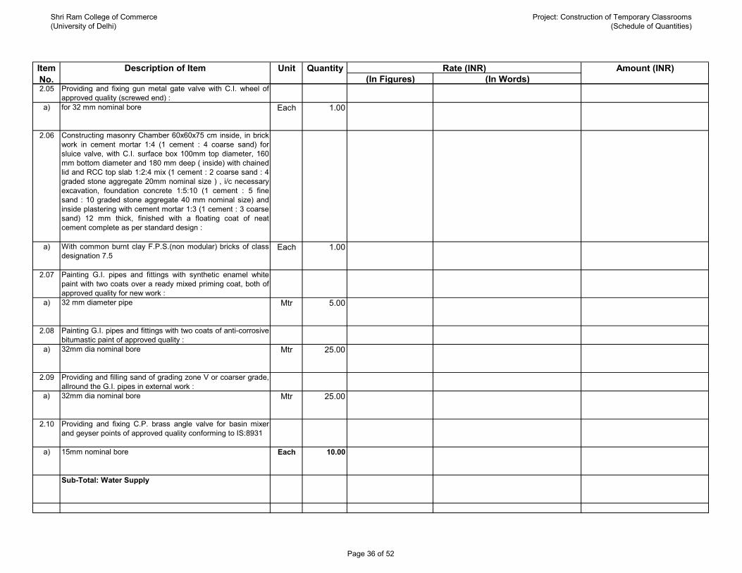
Shri Ram College of Commerce(University of Delhi)
Project: Construction of Temporary Classrooms(Schedule of Quantities)
(In Figures) (In Words)Rate (INR) Amount (INR)QuantityUnitDescription of ItemItem
No.2.05 Providing and fixing gun metal gate valve with C.I. wheel of
approved quality (screwed end) :a) for 32 mm nominal bore Each 1.00
2.06 Constructing masonry Chamber 60x60x75 cm inside, in brickwork in cement mortar 1:4 (1 cement : 4 coarse sand) forsluice valve, with C.I. surface box 100mm top diameter, 160mm bottom diameter and 180 mm deep ( inside) with chainedlid and RCC top slab 1:2:4 mix (1 cement : 2 coarse sand : 4graded stone aggregate 20mm nominal size ) , i/c necessaryexcavation, foundation concrete 1:5:10 (1 cement : 5 finesand : 10 graded stone aggregate 40 mm nominal size) andinside plastering with cement mortar 1:3 (1 cement : 3 coarsesand) 12 mm thick, finished with a floating coat of neatcement complete as per standard design :
a) With common burnt clay F.P.S.(non modular) bricks of classdesignation 7.5
Each 1.00
2.07 Painting G.I. pipes and fittings with synthetic enamel whitepaint with two coats over a ready mixed priming coat, both ofapproved quality for new work :
a) 32 mm diameter pipe Mtr 5.00
2.08 Painting G.I. pipes and fittings with two coats of anti-corrosivebitumastic paint of approved quality :
a) 32mm dia nominal bore Mtr 25.00
2.09 Providing and filling sand of grading zone V or coarser grade,allround the G.I. pipes in external work :
a) 32mm dia nominal bore Mtr 25.00
2.10 Providing and fixing C.P. brass angle valve for basin mixerand geyser points of approved quality conforming to IS:8931
a) 15mm nominal bore Each 10.00
Sub-Total: Water Supply
Page 36 of 52

Shri Ram College of Commerce(University of Delhi)
Project: Construction of Temporary Classrooms(Schedule of Quantities)
(In Figures) (In Words)Rate (INR) Amount (INR)QuantityUnitDescription of ItemItem
No.3 Sewerage and Drainage System
3.01 Earth work in excavation by mechanical means (Hydraulicexcavator) / manual means in foundation trenches or drains(not exceeding 1.5 m in width or 10 sqm on plan), includingdressing of sides and ramming of bottoms, lift upto 1.5 m,including getting out the excavated soil and disposal ofsurplus excavated soil as directed, within a lead of 50 m.
a) All kinds of soil. 75 cum
3.02 Excavating trenches of required width for pipes, cables, etcincluding excavation for sockets, and dressing of sides,ramming of bottoms, depth upto 1.5 m, including getting outthe excavated soil, and then returning the soil as required, inlayers not exceeding 20 cm in depth, including consolidatingeach deposited layer by ramming, watering, etc. anddisposing of surplus excavated soil as directed, within a leadof 50 m :
a) All kinds of soil Pipes, cables etc. exceeding 80 mm dia. but not exceeding300 mm dia.
75 Mtr
3.03 Extra for excavating trenches for pipes, cables etc. in all kindsof soil for depth exceeding 1.5 m, but not exceeding 3 m.(Rate is over corresponding basic item for depth upto 1.5meter).
a) Pipes, cables etc. exceeding 80 mm dia. but not exceeding300 mm dia.
5 Mtr
3.04 Filling available excavated earth (excluding rock) in trenches,plinth, sides of foundations etc. in layers not exceeding 20cmin depth, consolidating each deposited layer by ramming andwatering, lead up to 50 m and lift upto 1.5 m.
75 cum
3.05 Extra for every additional lift of 1.5 m or part thereof inexcavation / banking excavated or stacked materials.
a) All kinds of soil. 40 cum
3.06 Providing, laying and jointing glazed stoneware pipes classSP-1 with stiff mixture of cement mortar in the proportion of1:1 (1 cement : 1 fine sand) including testing of joints etc.complete :
a) 100 mm diameter 2 mtr
Page 37 of 52

Shri Ram College of Commerce(University of Delhi)
Project: Construction of Temporary Classrooms(Schedule of Quantities)
(In Figures) (In Words)Rate (INR) Amount (INR)QuantityUnitDescription of ItemItem
No.b) 200 mm diameter 25 mtr
3.07 Providing and laying cement concrete 1:5:10 (1 cement : 5coarse sand : 10 graded stone aggregate 40 mm nominalsize) all-round S.W. pipes including bed concrete as perstandard design :
a) 100 mm diameter S.W. pipe 2 mtr
b) 200 mm diameter S.W. pipe 25 mtr
3.08 Providing and laying cement concrete 1:5:10 (1 cement : 5coarse sand : 10 graded stone aggregate 40 mm nominalsize) up to haunches of S.W. pipes including bed concrete asper standard design300 mm diameter RCC pipe 50 mtr
3.09 Providing and fixing square-mouth S.W. gully trap class SP-1complete with C.I. grating brick masonry chamber with watertight C.I. cover with frame of 300 x300 mm size (inside) theweight of cover to be not less than 4.50 kg and frame to benot less than 2.70 kg as per standard design:
100x100 mm size P type
a) With common burnt clay F.P.S. (non modular) bricks of classdesignation 7.5
1 each
3.10 Providing and laying non-pressure NP2 class (light duty)R.C.C. pipes with collars jointed with stiff mixture of cementmortar in the proportion of 1:2 (1 cement : 2 fine sand)including testing of joints etc. complete :
a) 300 mm dia. R.C.C. pipe 50 Mtr
Page 38 of 52

Shri Ram College of Commerce(University of Delhi)
Project: Construction of Temporary Classrooms(Schedule of Quantities)
(In Figures) (In Words)Rate (INR) Amount (INR)QuantityUnitDescription of ItemItem
No.3.11 Constructing brick masonry manhole in cement mortar 1:4 ( 1
cement : 4 coarse sand ) with R.C.C. top slab with 1:1.5:3 mix(1 cement : 1.5 coarse sand (Zone-III) : 3 graded stoneaggregate 20 mm nominal size), foundation concrete 1:4:8mix (1 cement : 4 coarse sand : 8 graded stone aggregate 40mm nominal size), inside plastering 12 mm thick with cementmortar 1:3 (1 cement : 3 coarse sand) finished with floatingcoat of neat cement and making channels in cement concrete1:2:4 (1 cement : 2 coarse sand : 4 graded stone aggregate20 mm nominal size) finished with a floating coat of neatcement complete as per standard design :
a) Inside size 90x80 cm and 45 cm deep including with S.F.R.C.perforated cover with frame (heavy duty) 560 mm internaldiameter conforming to IS. 12592, total weight of cover andframe to be less than 182 kg fixing in cement concrete 1:2:4(1 cement : 2 coarse sand : 4 graded stone aggregate 20 mmnominal size) including centering, shuttering all complete.
With common burnt clay F.P.S. (non modular)bricks of classdesignation 7.5
4 each
b) Inside size 120x90 cm and 90 cm deep including withS.F.R.C. perforated cover with frame (heavy duty) 560 mminternal diameter conforming to IS. 12592, total weight ofcover and frame to be less than 182 kg fixing in cementconcrete 1:2:4 (1 cement : 2 coarse sand : 4 graded stoneaggregate 20 mm nominal size) including centering,shuttering all complete.With common burnt clay F.P.S. (non modular) bricks of class
designation 7.52 each
3.12 Extra for depth for manholes :a) Size 90x80 cm
With common burnt clay F.P.S. (non modular)bricks of classdesignation 7.5
2 mtr
b) Size 120x90 cmWith common burnt clay F.P.S. (non modular)bricks of classdesignation 7.5
1 mtr
Page 39 of 52

Shri Ram College of Commerce(University of Delhi)
Project: Construction of Temporary Classrooms(Schedule of Quantities)
(In Figures) (In Words)Rate (INR) Amount (INR)QuantityUnitDescription of ItemItem
No.3.13 Constructing brick masonry circular type manhole 0.91 m
internal dia at bottom and 0.56m dia at top in cement mortar1:4 (1 cement : 4 coarse sand), inside cement plaster 12 mmthick with cement mortar 1:3 (1 cement : 3 coarse sand)finished with a floating coat of neat cement, foundationconcrete 1:3:6 mix (1 cement : 3 coarse sand : 6 gradedstone aggregate 40 mm nominal size), and making necessarychannel in cement concrete 1:2:4 (1 cement : 2 coarse sand :4 graded stone aggregate 20 mm nominal size) finished witha floating coat of neat cement, all complete as per standarddesign :
a) 0.91 m deep with SFRC cover and frame (heavy duty, HD-20grade designation) 560 mm internal diameter conform- ing toI.S. 12592, total weight of cover and frame to be not less than182 kg., fixed in cement concrete 1:2:4 (1 ce- ment : 2 coarsesand : 4 graded stone aggregate 20 mm nominal size)including centering, shuttering all complete. (Excavation, footrests and 12mm thick cement plaster at the external surfaceshall be paid for separately) :With common burnt clay F.P.S. (non modular) bricks of classdesignation 7.5
each 1.00
3.14 Extra depth for circular type manhole 0.91m internal dia (atbottom) beyond 0.91m to 1.67m With common burnt clay F.P.S. (non modular) bricks of classdesignation 7.5
Mtr 0.50
3.15 Constructing brick masonry circular manhole 1.22 m internaldia at bottom and 0.56 m dia at top in cement mortar 1:4 (1cement :4 coarse sand) inside cement plaster 12 mm thickwith cement mortar 1:3 (1 cement : 3 coarse sand) finishedwith a floating coat of neat cement foundation concrete 1:3:6(1 cement : 3 coarse sand : 6 graded stone aggregate 40 mmnominal size) and making necessary channel in cementconcrete 1:2:4 (1 cement : 2 coarse sand : 4 graded stoneaggregate 20 mm nominal size) finished with a floating coat ofneat cement, all complete as per standard design :
Page 40 of 52

Shri Ram College of Commerce(University of Delhi)
Project: Construction of Temporary Classrooms(Schedule of Quantities)
(In Figures) (In Words)Rate (INR) Amount (INR)QuantityUnitDescription of ItemItem
No.a) 1.68 m deep with SFRC Cover and frame (heavy duty HD- 20
grade designation) 560 mm internal diameter conform- ing toI.S. 12592, total weight of cover and frame to be not less than182 kg. fixed in cement concrete 1:2:4 (1 ce- ment : 2 coarsesand : 4 graded stone aggregate 20 mm nominal size)including centering, shuttering all complete. (Excavation, footrests and 12 mm thick cement plaster at the external surfaceshall be paid for separately) :With common burnt clay F.P.S. (non modular) bricks of classdesignation 7.5
each 1.00
3.16 Extra depth for circular type manhole 1.22 m internal dia (atbottom) beyond 1.68 m to 2.29 m :
With common burnt clay F.P.S. (non modular) bricks of classdesignation 7.5
Mtr 1.00
3.17 Providing orange colour safety foot rest of minimum 6 mmthick plastic encapsulated as per IS : 10910, on 12 mm diasteel bar conforming to IS: 1786, having minimum crosssection as 23 mmx25 mm and over all minimum length 263mm and width as 165 mm with minimum 112 mm spacebetween protruded legs having 2 mm tread on top surface byribbing or chequering besides necessary and adequateanchoring projections on tail length on 138 mm as perstandard drawing and suitable to with stand the bend test andchemical resistance test as per specifications and havingmanufacture's permanent identification mark to be visibleeven after fixing, including fixing in manholes with 30x20x15cm cement concrete block 1:3:6 (1 cement : 3 coarse sand : 6graded stone aggregate 20 mm nominal size) complete asper design.
each 30.00
3.18 Making connection of drain or sewer line with existingmanhole including breaking into and making good the walls,floors with cement concrete 1:2:4 mix (1 cement : 2 coarsesand : 4 graded stone aggregate 20 mm nominal size)cement plastered on both sides with cement mortar 1:3 (1cement : 3 coarse sand), finished with a floating coat of neatcement and making necessary channels for the drain etc.complete :
a) For pipes 100 to 250 mm diameter each 1.00
Page 41 of 52

Shri Ram College of Commerce(University of Delhi)
Project: Construction of Temporary Classrooms(Schedule of Quantities)
(In Figures) (In Words)Rate (INR) Amount (INR)QuantityUnitDescription of ItemItem
No.b) For pipes 250 to 300 mm diameter each 2.00
Sub-Total: Sewerage and Drainage System
4 Plumbing: Miscellaneous Items4.01 Providing and fixing C.P. brass Hand shower (Health Faucet)
with 1m flexible tube with wall hook (Jaquar make model No.ALD-CHR-573 or approved equivalent make) with PVC cleatsand S.S. screws including cutting and making good the wallswherever required complete as directed by Engineer incharge.
Each 4.00
4.02 Providing and fixing C.P. twin robe hook (Jaquar Cat No. ACN-CHR-1161N or approved equivalent make) including cuttingand making good the walls wherever required complete asdirected by Engineer in charge.
each 4.00
4.03 Providing and fixing liquid soap dispenser (Jaquar make Catno. ACN-CHR-1135N) including cutting and making good thewalls wherever required complete as directed by Engineer incharge.
Each 2.00
4.04 Providing and fixing SWR (Class B) uPVC soil, waste andvent pipes conforming to IS 13592 including all fittings (plainor access door) e.g. bends, junctions, cowls, offsets, accesspieces etc., jointing with rubber ring joints, fixed with M.S.clamps painted with two or three coats enamel paint ofapproved shade over a coat of primer fixed in cementconcrete 1:2:4 blocks including cutting holes in wall/floors andmaking good wherever required.
a) 110 mm dia Mtr 35.004.05 Providing and fixing HDPE pipes and fittings 10kg/cm2 (class
V ) waste pipes and fittings conforming to IS: 4984 jointedwith cement solvent joints with M.S. clamp/hook includingcutting chases and holes in RCC/Brick wall/Ceilings andmaking good the same in cement mortar 1:3 ( 1 cement : 3coarse sand ) to match with the surroundings for waste fromwash basins, urinals kitchen sink and sump, pump deliveriesand suction etc as shown in drawings and directed by theEngineer in Charge.
a) 40 mm nominal bore Mtr 3.00
b) 50 mm nominal bore Mtr 1.00
Page 42 of 52

Shri Ram College of Commerce(University of Delhi)
Project: Construction of Temporary Classrooms(Schedule of Quantities)
(In Figures) (In Words)Rate (INR) Amount (INR)QuantityUnitDescription of ItemItem
No.4.06 Providing and fixing SWR uPVC P or S deep seal type with
self cleaning design floor/urinal trap with or without ventincluding setting with cement concrete 1:2:4 (1 cement : 2coarse sand: 4 hard stone ballast 20mm nominal size)including cutting and making good the floor/RCC and Brickwall wherever required, complete in all respects.
a) 110x110mm outlet with 125 mm dia SS jali Each 7.00
4.07 Providing and laying cement concrete 1:2:4 (1 cement :2coarse sand: 4 graded stone aggregate 20 mm, nominal size)75mm thick in bed and around PVC soil and waste pipe underfloor/vertical wall including centering and shuttering whereverrequired.
a) 110 mm dia Mtr 30.00
4.08 Providing and fixing centrifugal cast rain water pipesincluding all fittings (plain or access door) (NECO makeconfirming to IS 3989 : 1984 or approved equivalent make)e.g. bends, junctions, cowls, offsets, access pieces etc.,jointing with drip seal joints as per drawing, fixed with C.Iclamps(NECO make confirming to IS 1729 or approvedequivalent make) fixed in cement concrete blocks of size10x10x10cms in 1:2:4 mix (1 cement : 2 coarse sand : 4stone aggregate 20 mm nominal size) including cutting holesin wall/floors and making good wherever required complete asdirected by Engineer in charge. Note: The length of rain waterpipes will be measured along centre line of pipe and fittingincluding joints, nothing extra will be payable for any kind offittings, clamps, drip seal and jointing, complete in allrespects.
a) 150 mm dia pipe Mtr 25.00
4.09 Providing and fixing 40 mm dia C.P. brass bottle trapincluding cutting and making good the walls whereverrequired complete as directed by Engineer in charge.
each 1.00
4.10 Providing and fixing C.P. brass waste including cutting andmaking good the walls wherever required complete asdirected by Engineer in charge.
a) 40 mm dia each 1.00
Page 43 of 52

Shri Ram College of Commerce(University of Delhi)
Project: Construction of Temporary Classrooms(Schedule of Quantities)
(In Figures) (In Words)Rate (INR) Amount (INR)QuantityUnitDescription of ItemItem
No.4.11 Providing and fixing 15 mm dia C.P. brass sink mixer with
swinging type spout with wall flange similar to : Jaquar makeCat No.CON-CHR-309KN" or approved equivalent makeincluding cutting and making good the walls whereverrequired complete as directed by Engineer in charge.
each 1.00
4.12 Providing, fixing, testing and commissioning of storage typewater heater (Geyser) etc. with automatic thermostatic controlelectric element, pressure release valve, M.S. nuts and boltsetc. conforming to IS: 2082, including cutting holes & makinggood the wall wherever required complete in all respects.
a) 25 litres each 1.00
4.13 Providing and fixing 9 mm thick VidoFlex Insulation on hotwater pipe including one layer of chicken mesh complete in allrespect.
a) 15 mm dia Mtr. 5.00
Sub-Total: Plumbing-Miscellaneous Items
TOATL: PLUMBING WORKS
(D) Fire Fighting Work1.01 Providing, fixing, jointing and testing of heavy gauge M.S.
pipes as per relevant IS: 1239 with special accessories liketees, elbows, welded joints for pipe and fitting and flangedjoints rubber insertion nuts & bolts, washers for valvesincluding earth work excavating refilling compaction etc. andtreating under ground pipe with two coats of anti corrosivepaint and wrapping 4mm thick PYKOTE on pipe fitting etc.complete in all respects. Thrust blocks of cement concreteat bends, tees etc. 150mm thick around in 1:2:4 (1cement: 2coarse sand: 4 stone ballast 20mm and down gauge ).
a) 150 mm dia ( IS1239 ) welded joint Metre 25.00
Page 44 of 52

Shri Ram College of Commerce(University of Delhi)
Project: Construction of Temporary Classrooms(Schedule of Quantities)
(In Figures) (In Words)Rate (INR) Amount (INR)QuantityUnitDescription of ItemItem
No.1.02 Providing, fixing, welded joints and testing of heavy class
M.S. pipes as per relevant IS 1239/3580 with specialaccessories tees, elbows, screwed/flanged joints, expansionjoints, rubber insertion, nuts, bolts, washers or welded jointwith flange joints on bends, including fixing the pipe withsuitable flat iron strip clamps/brackets structural members,dash fastener, civil breakage, making good the same etc.painting with a primer coat and two coats of postal red enameletc. complete as required.
a) 80 mm dia welded joint Metre 10.00
b) 50 mm dia screwed joint Metre 20.00
c) 32 mm dia screwed joint Metre 2.00
d) 25 mm dia screwed joint Metre 3.00
1.03 Supplying and fixing First-Aid Hose Reel with MS constructionspray painted in Post office Red, conforming to IS 884 withupto date amendments, complete with the following asrequired.
a) 30 m. 20 mm (nominal internal) dia water hoseThermoplastic(Textile reinforced) Type- 2 as per IS: 12585with 5 mm shut off nozzle.
b) 20 mm (nominal internal) dia gun metal globe valve & nozzle.c) Drum and brackets for fixing the equipments on wall. d) Connections from riser with 40 mm dia stop valve (gun metal)
& M.S. Pipe.Each 3.00
1.04 Providing and fixing Cast Iron body IS: 210 FG 220 anddouble flange simple operation type Butterfly Valveconforming to IS: 13095 with SS304 disc and shaft nitrilerubber replaceable seat of the following size complete withbolts, nuts, washers and rubber insertions as perspecification.
a) 50 mm dia Each 3.00
b) 80 mm dia Each 1.00
Page 45 of 52

Shri Ram College of Commerce(University of Delhi)
Project: Construction of Temporary Classrooms(Schedule of Quantities)
(In Figures) (In Words)Rate (INR) Amount (INR)QuantityUnitDescription of ItemItem
No.1.05 Providing and fixing non-return valve C.I. Body complete with
bolts, nuts washer & rubber insertions as required conformingto IS:5312.
a) 80 mm dia Each 1.00
1.06 Providing and fixing 0-14 kg Pressure Gauge of 100 mm diaincluding making necessary hole accessories etc.
Each 3.00
1.07 Providing and fixing 15 mm nominal bore quartzoid bulb typesprinkler of chromium plated, UL/FM approved suitable foroperating on 68 deg. C as per requirement of local fireservices.
a) Standard Pendent type - 680C Each 2.00
1.08 Supplying 15mm nominal bore quartzoid glass bulb type
sprinkler of approved make, for temperature rating of 680 C.
a) Standard Pendent type - 680C Each 1.00
1.09 Providing and fixing fire extinguisher of Carbon Dioxide typeconsisting of brand new high pressure Steel Cylinder andhaving the approval of controller of explosives Nagpur, wheeltype valve Bearing IS:3224 mark internal discharge tube, 1meter long high pressure discharge hose, non conductinghorn, suspension bracket, fully charged Bearing IS: markingfixed to wall as desired by Engineer-in-Charge.
a) 4.5 kg capacity Cylinder - IS :15683 Each 3.00
1.10 Providing and fixing 4 Kg Dry Powder or ABC extinguisherwith IS: 15683. (ISI marked)
Each 3.00
1.11 Providing and fixing self glowing Exit sign board size350x200mm single side painted made of luminescent safely,rigid sheet in standard colour photo, luminescent sheet madeof crystals consisting mainly sulphide in protective glass likesheet green and yellow crystal luminescent (glass in dark) byaction of light.
Each 3.00
Page 46 of 52

Shri Ram College of Commerce(University of Delhi)
Project: Construction of Temporary Classrooms(Schedule of Quantities)
(In Figures) (In Words)Rate (INR) Amount (INR)QuantityUnitDescription of ItemItem
No.1.12 Constructing masonry Chamber 90x90x100 cm inside, in brick
work in cement mortar 1:4 (1 cement : 4 coarse sand) forsluice valve, with C.I. surface box 100 mm top diameter, 160mm bottom diameter and 180 mm deep (inside) with chainedlid and RCC top slab 1:2:4 mix (1 cement : 2 coarse sand : 4graded stone aggregate 20 mm nominal size ), i/c necessaryexcavation, foundation concrete 1:5:10 (1 cement : 5 finesand : 10 graded stone aggregate 40 mm nominal size ) andinside plastering with cement mortar 1:3 (1 cement : 3 coarsesand) 12 mm thick, finished with a floating coat of neatcement complete as per standard design :
a) With common burnt clay F.P.S.(non modular) bricks ofclass designation 7.5
Each 1.00
1.13 Providing and fixing M.S. structure work fabricated fromstandard sections e.g. MS square bars, flats, rounds, angles,channels including cutting to size drilling, welding, fixing &welding to insert plates in RCC structure members as directedby Site In charge, including cutting and making good thewalls, floors & RCC roof (for pipe supports, clamps, M.S.ladders & manholes for tank covers etc) including painting willtwo or more coats of enamel joint of approved colour over acoat of approved Steel Primer as for drawings & direction ofthe Site In charge.
Kg 100.00
Note: Fire Fighting wet riser pipes are connected to existing Fire Fighting RingTOTAL: FIRE FIGHTING WORK
(E) HVAC Work1 VRF System (Equipment)
1.01 Variable Refrigerant Volume / Flow system (EXISTING ATSITE)Instalaltion, testing & commissioning of Variable RefrigerantFlow modular type airconditioning system with steplessmodulation complete with indoor and outdoor units,individual remote controller & centralized controller,interconnected refrigerant piping , full charge of refrigerantgas& oil, control cabling etc. as per detail given in specifications& having following items: (The prices to be given in Indianrupees on Full Import duty basis ) Refrigerant to be usedshall be - R - 410 A.
a) ITC of Outdoor Unit (EXISTING AT SITE)
Page 47 of 52

Shri Ram College of Commerce(University of Delhi)
Project: Construction of Temporary Classrooms(Schedule of Quantities)
(In Figures) (In Words)Rate (INR) Amount (INR)QuantityUnitDescription of ItemItem
No.Instalaltion, testing & commissioning of Modular typeoutdoor units equipped with highly efficient scrollcompressors with one inverter & other constant speedtype compressor (s) , special heat exchanger, low noisecondenser fan , auto check function for connection error,auto address setting and capacity as mentioned below.18 HP Heat Pump Type (Cooling & Heating ) Nos. 2.00
b) ITC of Indoor Units (EXISTING AT SITE)Instalaltion, testing & commissioning of Indoor unitsaddress setting and capacity as mentioned below. multispeedmotor, coil section with DX coil, outer cabinet, drain pan,drain water lift-up mechanism insulation, pipeconnections, fresh air intake etc. of various capacities as perspecifications and drawings
i) Ceiling Mounted Cassette Type : 2.0 TR Nos. 2.00
ii) Ceiling Mounted Cassette Type : 2.64 TR Nos. 10.00
c) Supply Instalaltion, testing & commissioning of HRV Uniti) 600 CFM Nos. 0.00
ii) 300 CFM Nos. 0.00
d) Supply Instalaltion, testing & commissioning of TFA Unit5.0 HP TFA UNIT Nos. 0.00
e) Supply Instalaltion, testing & commissioning of Y-joints. Nos. 12.00
f) Supply Instalaltion, testing & commissioning of selfdiagnostic type remote controllers . Corded Type NO. 12.00
g) Supply Instalaltion, testing & commissioning of MainIntelligent central controller system suitable for indoor unitsto operate, monitor, on/off, temperature setting etc.
NO. 0.00
Page 48 of 52

Shri Ram College of Commerce(University of Delhi)
Project: Construction of Temporary Classrooms(Schedule of Quantities)
(In Figures) (In Words)Rate (INR) Amount (INR)QuantityUnitDescription of ItemItem
No.Sub-Total: VRF System (Equipment)
2 Low Side - VRF System2.01 Refrigerant Piping
Supply& Fixing of Interconnecting copper refrigerant pipework 25 mm / 19 mm thick duly insulated with XLPE Foamclosed cell cross linked polythene insulation between indoorand outdoor units as per specifications. All piping inside therooms shall be properly supported on MS Slotted trays and allexternal piping shall run in covered slotted tray.
a) 41.3 mm O.D. (insulation – 19 mm thick) RMT 0.00
b) 38.1 mm O.D. (insulation – 19 mm thick) RMT 0.00
c) 34.9 mm O.D. (insulation – 19 mm thick) RMT 0.00
d) 31.7 mm O.D. (insulation – 19 mm thick) RMT 0.00
e) 28.6 mm O.D. (insulation – 19 mm thick) RMT 30.00
f) 25.4 mm O.D. (insulation – 19 mm thick) RMT 10.00
g) 22.2 mm O.D. (insulation – 13 mm thick) RMT 10.00
h) 19.1 mm O.D. (insulation – 13 mm thick) RMT 10.00
I) 15.9 mm O.D. (insulation – 13 mm thick) RMT 150.00
j) 12.7 mm O.D. (insulation – 13 mm thick) RMT 30.00
k) 9.5 mm O.D. (insulation – 13 mm thick) RMT 120.00
Page 49 of 52

Shri Ram College of Commerce(University of Delhi)
Project: Construction of Temporary Classrooms(Schedule of Quantities)
(In Figures) (In Words)Rate (INR) Amount (INR)QuantityUnitDescription of ItemItem
No.L) 6.4 mm O.D. (insulation – 19 mm thick) RMT 0.00
2.02 Drain PipingSupply and fixing of PVC drain water piping complete withfittings, support as per specification and insulated with 6 mmthick insulated with XLPE Foam closed cell cross linkedpolythene insulation.
a) 25 mm dia RMT 70.00
b) 32 mm dia RMT 70.00
2.03 GSS Ducting Supply , fabrication & installation of Sheet Metal ductingcomplete with supports dampers etc. as per ISI specificationand drawings.
a) 0.63 mm ( 24 Gauge) SMT 0.00
b) 0.80 mm ( 22 Gauge) SMT 0.00
2.04 Providing and fixing of aluminium supply air and return airgrilles and diffusers fabricated from extruded aluminiumsections duly powder coated.
a) Supply air grill with damper SMT 0.00
b) Return air grill without damper SMT 0.00
c) Supply air Diffuser with damper SMT 0.00
d) Return air Diffuser without damper SMT 0.00
e) Duct Damper - VCD SMT 0.00
f) Supplying & fixing of Fresh air intake louvers with bird screendampers (Aluminium extruded only).
SMT 0.00
Page 50 of 52

Shri Ram College of Commerce(University of Delhi)
Project: Construction of Temporary Classrooms(Schedule of Quantities)
(In Figures) (In Words)Rate (INR) Amount (INR)QuantityUnitDescription of ItemItem
No.2.05 Supplying and fixing of acoustic lining of duct with Open Cell
Nitrile Rubber density 140-180 Kg/m³. Applied by Adhesive,conforming to standard specification.
a) 10 mm thick open cell nitrile rubber. SMT 0.00
2.06 Supplying and fixing of external thermal insulation on ductswith Closed Cell Cross Linked Polythylene (XLPE) Foam ofdensity 33 Kg/m³ with 13 mm & 09 mm thick & thermalConductivy not exceding 0.035 W/mK at an averageTemperature of 40°C. The Material Shall be rated as Class 1,As per BS476 Part 7 , The Smoke Density as per AS - 1530.3Shall not exceed 1. The Material shall have Fire Approvalfrom CBRI - Roorkie & no toxicity under flaming and non-flaming condition as per AITM 3.000 (1993) . Adhesive usedfor setting the insulation shall be non - flammable, VapourProof. All Joints should be sealed with 3 mm thick 50 mmwide PE tape and Flange to be overlapped by 6" width of thesame material thickness. Finally Duct insulated should bestrapped by 12 mm Plastic Packing strip at every randommeter and conforming to standard Specification
a) 13 mm thick Closed Cell Cross Linked Polythylene( XLPE)Foam with Factory Laminated Al PE Foil for Supply Air Duct
SMT 0.00
2.07 Canvass Connectiona) Providing and Fixing Canvas Connection of Fire Retardant
and non porous double layer material between each indoor units and ducts
SMT 0.00
2.08 POWER & CONTROL CABLINGSupply, laying, testing and commissioning of power andcontrol cabling, as per Standard specification including endtermination as required.Power Cabling ( PVC insulated and PVC sheathed,copper Conductor of 1.1 KV grade).
a) 2C x 1.5 Sq mm RMT 60.00
b) 3C x 1.5 Sq mm RMT 60.00
Sub-Total: Low Side - VRF System
Page 51 of 52

Shri Ram College of Commerce(University of Delhi)
Project: Construction of Temporary Classrooms(Schedule of Quantities)
(In Figures) (In Words)Rate (INR) Amount (INR)QuantityUnitDescription of ItemItem
No.TOTAL: HVAC WORK
S. NO. DESCRIPTION
(A) CIVIL WORK
(B) ELECTRICAL WORK
(C ) PLUMBING WORK
(D) FIRE FIGHTING WORK
(E ) HVAC WORK
GRAND TOTAL
AMOUNT (INR)SOQ SUMMARY
Page 52 of 52

WALL PROPOSED
WALL EXISTING
WALL DEMOLISH
LEGEND:-
11.40 SQM.
TE
AC
HE
R
DE
SK
2 6 8 0 W I D E C O R R I D O R
ELEC. PANEL RM
SIZE AS/SITE
STORE
SIZE AS/SITE
SHOP
SIZE AS/SITE
PHOTO COPIER
SIZE AS/SITE
CONFERENCE ROOM (65 PAX.)
13685 X 8000
109.5 SQMT. (1180 SQFT.)
PANTRY
1685 X 3310
TOILET (F)
3000 X 2115
TOILET (M)
3000 X 2115
60 STUDENTS
60 STUDENTS
60 STUDENTS
60 STUDENTS
RAMP UP
2680 WIDE
STAGE
1800X4000
CLASSROOM
8420X 8000
66.75 SQMT.
(718.5 SQFT.)
W
DD WWW
D
DD
W
TE
AC
HE
R
DE
SK
BLA
CK
B
OA
RD
BLA
CK
B
OA
RD
TE
AC
HE
R
DE
SK
BLA
CK
B
OA
RD
BLA
CK
B
OA
RD
TE
AC
HE
R
DE
SK
WWWWW
W V
DDD
DD D D
D1
D1
D1
UP
CLASSROOM
8420X 8000
66.75 SQMT.
(718.5 SQFT.)
CLASSROOM
8420X 8000
66.75 SQMT.
(718.5 SQFT.)
CLASSROOM
8420X 8000
66.75 SQMT.
(718.5 SQFT.)
UP
80
00
80
00
80
00
8345
80
00
EXISTING SHOPS
DEMOLISH AREA
11.4 SQM. AREA
(EXISTING SHOPS)
EXISTING SHOPS
1 5 0 0 W I D E C O V E R E D C O R R I D O R
GROUND FLOOR PLAN
B
V
MECHANICAL
VENTILATION
MECHANICAL
VENTILATION
UP
B
A
A
X1 X2 X3 X4 X5 X6 X7 X9
Y1
Y2
Y3
Y4
Y5
Y6
A
X8
W
25950
4250
31
40
31
40
18770
15
00
17570
1800
1040
1200
1800
12
00
25950
26
80
26
80
10
00
600
1685
20
10
26
80
ROOF LVL. PLAN
M.S HOLLOW PIPES COLUMN
M.S HOLLOW PIPES PURLINS
M.S HOLLOW PIPES BEAMS
CENTER RIDGE LINE
M.S HOLLOW PIPES BEAMS
M.S HOLLOW PIPES PURLINS
M.S HOLLOW PIPES COLUMN
EXISTING BUILDING
STRUCTURE
EXISTING BUILDING
STRUCTURE
B
A
A
SLO
PE
SLO
PE
SLO
PE
SLO
PE
SLO
PE
SLO
PE
SLO
PE
SLO
PE
SLO
PE
SLO
PE
SLO
PE
SLO
PE
SLO
PE
SLO
PE
SLO
PE
SLO
PE
SLO
PE
SLO
PE
SLO
PE
SLO
PE
SLO
PE
SLO
PE
SLO
PE
SLO
PE
X1 X2 X3 X4 X5 X6 X8
Y1
Y2
Y3
Y4
Y5
Y6
B
X7 X8
V I J A Y G U P T A
SRCC/ CR/A - 101
R - 00
REVISION TABLE
DRAWING:
PROPOSED PLAN FOR CLASSROOM
(IN PLACE CYCLE STAND)
NOTES :-
1. ALL DIMENSIONS AND LVLS ARE IN MM, UNLESS NOTED OTHER WISE.
2. (U.N.O) DO NOT SCALE ANY DRG. FOLLOW WRITTEN DIMENSIONS ONLY.
3. THIS DRG. SHOULD BE READ IN CONJUNCTION WITH RELEVANT STRUCTURE
AND SERVICE DRGS. ANY DISCREPANCY SHOULD BE BROUGHT TO THE
NOTICE OF ARCHITECT IMMEDIATELY.
PROJECT:
CONSTRUCTION OF TEMPORARY
CLASS ROOMS AT SHRI RAM
COLLEGE OF COMMERCE , NORTH
CAMPUS NEW DELHI

CONFERENCE ROOMCLASS ROOM
2680 WIDE
CORRIDOR
M.S HOLLOW PIPES PURLINS
M.S HOLLOW PIPES BEAMS
M.S HOLLOW PIPES COL.
BOTTOM OF MS TRUSS
LVL. +3450
TOP OF MS TRUSS
LVL. +5330
SECTION A-A
COVERED
CORRIDOR
GALVALUME SHEET
AS/SPECS.
Y1Y2Y3Y4Y5Y6
MADE UP LVL
(Consider if Lvl. ±00)
GROUND FLOOR FINISH
LVL. +450
431
0
2680 WIDE
CORRIDOR
2680 WIDE
CORRIDOR
2680 WIDE
CORRIDOR
RAMP UP
(PROPOSED)
MADE UP LVL
(Consider if Lvl. ±00)
GROUND FLOOR FINISH
LVL. +450
BOTTOM OF MS TRUSS
LVL. +3450
TOP OF MS TRUSS
LVL. +5330
M.S HOLLOW PIPES
PURLINS
M.S HOLLOW PIPES
BEAMS
M.S HOLLOW PIPES
BEAMS
GALVALUME SHEET
AS/SPECS.
M.S HOLLOW PIPES
PURLINS
SECTION B-B
X1 X2 X3 X4 X5 X6 X8 X9X7
MADE UP LVL
(Consider if Lvl. ±00)
GROUND FLOOR FINISH
LVL. +450
BOTTOM OF MS TRUSS
LVL. +3450
TOP OF MS TRUSS
LVL. +5330
M.S HOLLOW PIPES
PURLINS
M.S HOLLOW PIPES
BEAMS
M.S HOLLOW PIPES
BEAMS
GALVALUME SHEET
AS/SPECS.
M.S HOLLOW PIPES
PURLINS
ELEVATION-A
X9 X8 X6 X5 X4 X3 X2 X1X7
150
0
60
0
V I J A Y G U P T A
SRCC/ CR/A - 102
R - 00
REVISION TABLE
DRAWING:
SECTIONS AA & BB
ELEVATION-A
(IN PLACE CYCLE STAND)
NOTES :-
1. ALL DIMENSIONS AND LVLS ARE IN MM, UNLESS NOTED OTHER WISE.
2. (U.N.O) DO NOT SCALE ANY DRG. FOLLOW WRITTEN DIMENSIONS ONLY.
3. THIS DRG. SHOULD BE READ IN CONJUNCTION WITH RELEVANT STRUCTURE
AND SERVICE DRGS. ANY DISCREPANCY SHOULD BE BROUGHT TO THE
NOTICE OF ARCHITECT IMMEDIATELY.
PROJECT:
CONSTRUCTION OF TEMPORARY
CLASS ROOMS AT SHRI RAM
COLLEGE OF COMMERCE , NORTH
CAMPUS NEW DELHI