
tender document - Engineering Projects (India) Ltd.
327
TENDER DOCUMENT NIT No.: DLI/CON/883/757 Dated 09.07.2021 FOR Construction of Medical College Campus for 100 MBBS admission annually and Modification in existing Govt. Hospital to convert into Teaching Hospital as per applicable MCI/ NMC norms at Rudrapur, Uttarakhand VOLUME – II Additional Conditions of Contract (ACC), Technical Specifications, Tender Drawings, Preferred Make List ENGINEERING PROJECTS (INDIA) LIMITED (A GOVT. OF INDIA ENTERPRISE) Core-3, Scope Complex, 7,Lodhi Road, New Delhi-110003 TEL NO: 011-24361666, FAX NO. 011- 24363426
-
Upload
khangminh22 -
Category
Documents
-
view
1 -
download
0
Transcript of tender document - Engineering Projects (India) Ltd.

TENDER DOCUMENT
NIT No.: DLI/CON/883/757 Dated 09.07.2021
FOR
Construction of Medical College Campus for 100 MBBS admission annually and Modification in existing Govt. Hospital to convert into Teaching Hospital as per applicable MCI/ NMC norms at Rudrapur, Uttarakhand
VOLUME – II
Additional Conditions of Contract (ACC), Technical Specifications, Tender Drawings, Preferred Make List
ENGINEERING PROJECTS (INDIA) LIMITED (A GOVT. OF INDIA ENTERPRISE)
Core-3, Scope Complex, 7,Lodhi Road, New Delhi-110003
TEL NO: 011-24361666, FAX NO. 011- 24363426

DLI/CON/883/757 Additional Conditions of Contract _________________________________________________________________________ Engineering Projects (India) Limited
_______________________________________________________________________________________________________________________ Signature of Bidder Page 1 EPI
ADDITIONAL CONDITIONS OF CONTRACT
The following Additional Conditions of Contract shall be read in conjunction with General Conditions
of Contract of EPI. If there are any provisions in these Additional Conditions of Contract, which are
at variance with the provisions of General Conditions of Contract, the provisions in these Additional
Conditions of Contract shall take precedence.
INTRODUCTION
Department of Medical Education (DME) ,Govt. of Uttarakhand (UK) the OWNER is proposing to
Construct a Medical College campus for 100 MBBS admission annually and up- gradation of the
Govt. District Hospital into Teaching Hospital as per applicable MCI / NMC norms at Rudrapur,
Uttarakhand. The Medical College Campus site is 0.2 km from existing Hospital and spread over
10.0 acres of Land & the existing Hospital to be run under Medical college is spread in 17.0 acress
Land.
APPROACHES TO WORKSITE
The land is made available to the bidder(s)/contractor(s) free from all encumbrances as Govt. of
Uttarakhand provide to EPI. The approval for Building Plans and Designs has been taken by the
Architect (M/S Enarch Consultant Pvt. Ltd). The contractor shall make his own arrangement for
approach to work site including borrow/ disposal area and for movement of men, materials,
machineries, other equipment etc. required for carrying out the work under this contract.
The access roads/ path to the work site may not be available at all places and at all time. The
contractor shall plan his work as per the availability of access roads/ path at site. All drainage of
works area and all weather truck able haulage roads as required by the contractor shall be
constructed and maintained during the construction period by the contractor at his own cost,
including portions of the road already existing.
Provisions under General Conditions of Contract of EPI are modified/ amended as under:-
S. No.
GCC Clause No.
Modified/Amended provisions as per Additional Conditions of Contract
1 INSTRUCTIONS OF TENDER
1. Clause no 1.0 of Instructions to Tenders i.e. Mode of submission online shall also include the following paras: a) The Envelope-1 shall also contain the documents meeting the eligibility
criteria mentioned in “Notice Inviting Tender and “INSTRUCTIONS TO TENDERERS”.
b) The tenderer who download the tender documents directly from EPI‟s website shall have to submit tender fees of Rs. 25000 + 18% GST = Rs. 29500/- (Rupees Twenty Nine Thousand and Five Hundred only) (Non-Refundable) by Crossed Demand Draft favouring “Engineering Projects (India) Ltd.”, payable at New Delhi along with their bid in Envelope-1 in

DLI/CON/883/757 Additional Conditions of Contract _________________________________________________________________________ Engineering Projects (India) Limited
_______________________________________________________________________________________________________________________ Signature of Bidder Page 2 EPI
hard copy & scan copy of DD to be uploaded online on MSTC portal.
2. CLAUSE NO.1.1 OF INSTRUCTIONS TO TENDERERS as given in Page (2) of INSTRUCTIONS TO TENDERERS stands amended as below:
First the Envelope-1 of the tenderer shall be opened. Tenderers who un-
conditionally accept the tender conditions, deposit the required Bid Security
declaration on Rs 100/- stamp paper dully notarized against Earnest Money
deposit, meet the eligibility criteria mentioned in NIT, deposit the tender fees
and whose Techno-Commercial Bid is found suitable, shall be considered for
the opening of their Price Bid and Envelope-2 online of such tenderers shall be
opened. The Tenders not accompanied by requisite Earnest Money and/or not
accompanied by the requisite tender fees and / or not conveying un-conditional
acceptance of tender conditions and / or not meeting the eligibility criteria or
whose Techno-Commercial Bid are not found acceptable, shall be rejected and
such tenderer shall not be allowed to attend Price Bid opening i.e. opening of
Envelope-2 online. Bidders are requested to submit the technical bid comprise
of all the documents & price bid on line as e-tendering.
2 1.0 General Clause no 1.0 of GCC is amended to the extent as stated under: i) Flooring works shall be executed as per the approved drawings / design &
specifications. The pattern shown in the tender drawings, if any, can be modified as per the site requirements by Engineer-in-Charge within the proportions of the flooring materials to be provided and nothing extra whatsoever shall be payable over and above the rate quoted.
ii) The water proofing for the terraces, underground tanks / toilet floor etc. shall be
got executed only through the authorized applicators of the manufacturers and the guarantee for the same shall be in the name of EPI / owner for a period of ten years after the expiry of defect period liability on the prescribed format given in the GCC.
iii) Plumbing & Sanitary work to be executed by licensed plumber and the plumbing
scheme / drawing to be got approved from statutory authorities through the appointed licensed plumber without any extra cost. The agency shall have to submit the valid license of plumbers before starting the work.
iv) SCI pipes for sanitary and GI pipes for water supply if fixed in RCC members
like columns, beams etc. shall be fixed with scrub plugs.
v) The contractor shall be responsible for all protection of sanitary, water supply, electrical fittings & fixture against pilferage, breakage during period of installation until the completion of work and handed over to EPI.
vi) Welding wherever required in the work like in grill, railing etc shall be done in full
length of the contact area and grinding shall be done properly to get an even surface. SFRC covers for manholes etc, if provided, shall have name of owner /

DLI/CON/883/757 Additional Conditions of Contract _________________________________________________________________________ Engineering Projects (India) Limited
_______________________________________________________________________________________________________________________ Signature of Bidder Page 3 EPI
client and year of manufacturer as engraved.
vii) The electrical works shall be executed only through licensed electrician and
the agency shall have to submit the valid license of electricians before starting the work.
viii) It will be the sole responsibility of contractor to obtain all statutory approvals / compliance required for construction / implementation of the project including right of way excavation by blasting Forest clearance and completion clearance from the all relevant statutory bodies for plumbing, sewerage, Pollution, sanitary and PHE work, fire department for fire protection, fire fighting, fire fighting installation, electrical works etc. and for all other services as included in the scope of contract etc. from the concerned department as required within the stipulated time frame. Liaison work on behalf of EPI / owner with the local bodies will also have to be done by the contractor. Nothing extra shall be payable to contractor on this account.
ix) The contractor shall erect MS sheet fencing along the periphery of the site as
per drawing of EPI with proper colour as directed by the Engineer-in-Charge and name / logo, safety slogan etc. written at appropriate places within ten days of issue of LOI. The contractor shall be responsible for daily cleaning of this fencing with water etc. to keep the fencing in neat & clean condition at all times. The damaged fencing should be replaced immediately by the contractor. The cost of MS sheet fencing, its maintenance etc. is deemed to be included in the quoted rates. The contractor shall engage sufficient number of security guards at his cost to ensure controlled entry to site and not to allow unauthorized personnel at site.
x) The tenderers shall make necessary safety arrangements at site including as
mentioned in GCC and indemnify EPI and DME of Uttarakhand (GOVT. OF UTTARAKHAND) against any consequence of accident at site.
EPI is awarding this Contract on behalf of Directorate of Medical Education, Govt. of Uttarakhand. In case M/s. EPI cease to be an agency for the project, the right and responsibility etc. of EPI in the Contract shall get transferred to DME , Govt. of Uttarakhand or their nominated agency shall operate this Contract.
3 7.0 EARNEST MONEY DEPOSIT
Clause no. 7.0 of GCC is deleted
4 8.2
MOBILIZATION ADVANCE
Clause no. 8.2 of GCC is modified and read as under: Recovery of such sums advanced shall be made by the deduction from the contractors bills commencing after first Ten percent (10%) of the gross value of the work is executed and paid, on pro-rata percentage basis to the gross value of the work billed beyond 10% in such a way that the entire advance is recovered by the time eighty percent (80%) of the gross value of the contract is executed and paid, together with interest due on the entire outstanding amount upto the date of recovery of the installment.

DLI/CON/883/757 Additional Conditions of Contract _________________________________________________________________________ Engineering Projects (India) Limited
_______________________________________________________________________________________________________________________ Signature of Bidder Page 4 EPI
8.4 Clause no. 8.4 of GCC is deleted
5
9.0
SECURITY DEPOSIT CUM PERFORMANCE GURANTEE
"Within 10 (ten) days from the date of issue of letter of Intent or within such extended time as may be granted by EPI in writing, the Contractor shall submit to EPI a Security Deposit cum Performance Bank Guarantee in the form appended, from any Nationalized bank / Scheduled Bank equivalent to 3% (three percent only) of the Contract Value for the due and proper execution of the contract. This bank guarantee shall remain valid up to 90 (ninety) days after the end of defects liability period. In case the Contractor fails to submit the Security Deposit cum Performance Guarantee of the requisite amount within the stipulated period or extended period, letter of intent will stand withdrawn and EMD of Contractor shall be forfeited.
6 10.0
Clause No 10.0 of GCC is read as under:
The Retention Money shall be deducted from each running bill of the contractor at 5% (Five percent only) of gross value of the Running Account bill. The retention Money shall be refunded to contractor after expiry of defect liability period (referred to Clause No 74.) or on payment of the amount of the final bill whichever is later. If the amount of retention Money deduction in cash is more than Rs.10.00 lacs (Rupees Ten Lacs only), the excess amount can be refunded to contractor against submission of Bank Guarantee of equivalent amount from a nationalized bank / Scheduled Bank in the prescribed Performa of Performance Guarantee of EPI.
7 13.6 TAXES & DUTIES
Clause no. 13.0 of GCC is amended to the extent as stated under:
The following shall be also read with clause no. 13 of GCC:
a) The Bidder must be registered with GST in Uttarakhand state and should have
valid GST number. In case the bidder does not have valid GST registration
number, the same shall be obtained by the successful bidder within one month
from the date of LOI or before release of 1st R/A bill whichever is earlier.
b) The Bidder must submit as an compliances of GST Act, the invoices in GST compliant format failing which the GST amount including interest and penalty if any shall be recovered/ adjusted by EPI without any prior notice from the next invoices or available dues with EPI.
c) The Bidders are requested to update/ upload the GST/Taxes data periodically so
as to avail ITC credit by EPI failing which it shall be recovered / adjusted by EPI
without any prior notice from the next invoices or available dues with EPI.
d) Rates to be quoted in this tender inclusive of all taxes & duties including Labor

DLI/CON/883/757 Additional Conditions of Contract _________________________________________________________________________ Engineering Projects (India) Limited
_______________________________________________________________________________________________________________________ Signature of Bidder Page 5 EPI
cess, GST and all hidden costs like Labor camps with all Health Rules &
Facilities, Cost involved in setting up the Site Office, Testing & Lab Charges,
Transportation of Labor & Materials, Officials, all types of approvals from local
authorities like Electrical, Water & Sewage disposals etc. Taxes are to be
disclosed separately in Price Bid /BOQ.
e) Bidder while quoting the rates in the tender must also consider the ITC credit
applicable for the works, if any.
f) Price bid formats shall indicate “inclusive of all taxes and duties including GST.
In addition to the price bid format, an Annexure to indicate the “breakup of
cost and levies such as GST and other taxes” considered in the quoted
prices shall be annexed. This Annexure shall have breakup of all taxes/
duties relevant to the contract.
In case of any reduction in rate of GST or other taxes in future or the project getting exemption status prior to the last date of bid submission or afterwards, the contractor shall pass on the benefit to EPI immediately, failing which EPI shall have the right to recover the differential amount from the amounts due to the sub-Bidder. Further, in case of any increase in rate of GST or other taxes in future or the project losing exemption status prior to last date of bid submission or afterwards, the said increase of taxes shall be paid / reimbursed to the sub- contractor, subject to the condition that the client reimburses the said increased taxes to EPI”.
8 17.0 INSURANCE OF WORKS
The Insurance coverage as stipulated in General Conditions of Contract (GCC) clause no. 17 (Insurance of works), clause no. 18 (Insurance under WCA) and clause no. 19 (Third Party Insurance) shall be in the joint name of DME (Uttarakhand), EPI and the Contractor for the contract period including extended if any plus 12 months after Successful completion / handling over of work. The Insurance coverage shall be on the total value of work awarded to contractor by EPI.
9 18.0
INSURANCE UNDER WORKMEN COMPENSATION ACT
The clause ‟18.0‟ (Insurance Under WCA) at page 22 of General Conditions of Contract (GCC) shall be replaced and read as under:
Contractor is required to take insurance cover under the workmen compensation Act, 1923 amended from time to time from an approved insurance company and pay premium charges thereof. Wherever required by EPI, the contractor shall produce the policy or the policies of Insurance and the receipt of payment of current premium. In the event of an accident, any workmen employed by the contractor for execution of the works, suffers an injury or death and is to be compensated under the provisions sub-section (1) of section 12, of the workmen‟s Compensation Act, 1923 by the contractor and if the contractor fails to compensate, the EPI / DME Govt. of Uttarakhand, shall be entitled to recover

DLI/CON/883/757 Additional Conditions of Contract _________________________________________________________________________ Engineering Projects (India) Limited
_______________________________________________________________________________________________________________________ Signature of Bidder Page 6 EPI
from the contractor the amount of the compensation so paid, without prejudice to the rights of the EPI / DME Govt. of Uttarakhand under section 12, sub-section (2), of the said Act.
EPI / DME Govt. of Uttarakhand shall be at liberty to recover such amount or any part thereof by deducting it from the security deposit or from any sum due to the Contractor whether under this contract or otherwise. EPI / DME Govt. of Uttarakhand shall not be bound to contest any claim made against it under sub-section (1) Section 12, of the said Act, except security for all cost for which EPI / DME Govt. of Uttarakhand might become liable in consequence of contesting such claim.
10 21
LABOUR LAWS TO BE COMPLIED WITH BY THE CONTRACTOR:
GCC Clause 21 is replaced as under
The Contractor shall obtain a valid license under the Contract Labour (Regulation & Abolition) Act 1970 and the Contract Labour Act (R&A) Central Rules 1971 and amended from time to time, and continue to have a valid license until the completion of the work including defect liability period. The Contractor shall also abide by the provision of the Child Labour (Prohibition and Regulation) Act. 1986 and as amended from time to time. Any failure to fulfill this requirement shall attract the penal provisions of this contract arising out of the resultant non execution of the work.
The Contractor shall comply with the provisions of the Payment of Wages Act, 1936, Minimum Wages Act, 1948, Employer's Liability Act, 1938, Employees Compensation Act, 1923, Maternity Benefit Act, 1961 and Mines Act, 1952, Industrial Disputes Act, 1947 or any modifications thereof or any other law relating thereto and rules made there under from, time to time.
11 28.1 Clause no. 28.1 is modified as under:
Land for Site Office, batching plant, labour camp etc. will be provided at Project Site. Other conditions of this clause will remain same.
28.3
FACILITIES: GCC clause no. 28.3 is deleted.
12 35 Regarding - Modification of GCC clause no. 35 Recovery of Secured Advance against non – perishable materials is as under. Interest free secured advance up- to a maximum of 75% (seventy five percent) of the Market value of the materials or the cost of materials as derived from the tendered item rate of the Contractor. Whichever is less, required for incorporation in the permanent works and brought to site and duly certified by EPI site Engineer shall be paid to the contractor for all non-perishable items as per CPWD/ MORTH (as the case may be) norms. The advance will be paid only on submission of indemnity bond in the prescribed pro-forma. The Secured advance shall be recovered from each Running Account bill against consumption to an extent they are used and as certified by EPI Site-Incharge. The contractor shall construct suitable go down at the Site of work for safe storage of the materials against any possible damages due to sun, rain, dampness, fire, theft etc. at his own cost. He shall also employ necessary watch & ward establishment for the purpose at his cost and risks such secured advance shall be payable on other items of perishable nature, fragile and combustible with the approval of the Engineer-In-Charge
DLI/CON/883/757 Additional Conditions of Contract _________________________________________________________________________ Engineering Projects (India) Limited
_______________________________________________________________________________________________________________________ Signature of Bidder Page 7 EPI
provided the contractor provides a comprehensive insurance cover for the full cost of such materials. The decision of the Engineer-In-Charge shall be final and binding on the Contractor in this matter. No secured advance shall however, be paid on high-risk materials such as ordinary glass, sand, petrol etc.
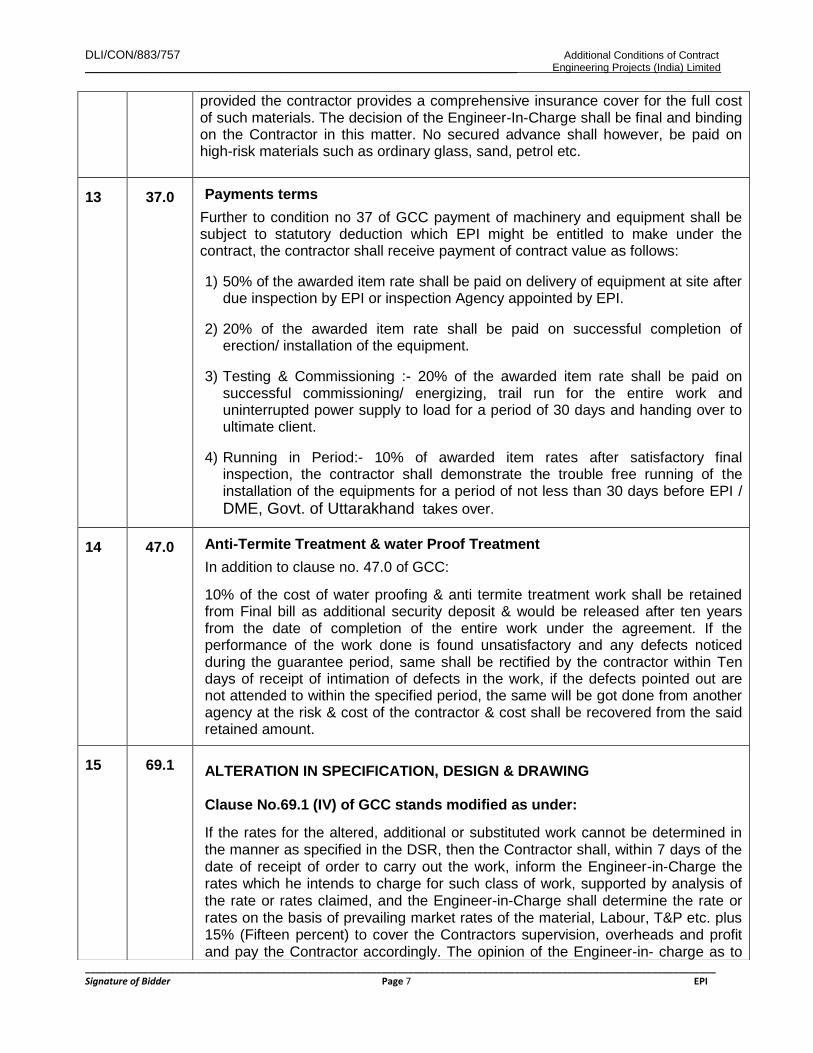
13 37.0
Payments terms
Further to condition no 37 of GCC payment of machinery and equipment shall be subject to statutory deduction which EPI might be entitled to make under the contract, the contractor shall receive payment of contract value as follows: 1) 50% of the awarded item rate shall be paid on delivery of equipment at site after
due inspection by EPI or inspection Agency appointed by EPI.
2) 20% of the awarded item rate shall be paid on successful completion of erection/ installation of the equipment.
3) Testing & Commissioning :- 20% of the awarded item rate shall be paid on successful commissioning/ energizing, trail run for the entire work and uninterrupted power supply to load for a period of 30 days and handing over to ultimate client.
4) Running in Period:- 10% of awarded item rates after satisfactory final inspection, the contractor shall demonstrate the trouble free running of the installation of the equipments for a period of not less than 30 days before EPI / DME, Govt. of Uttarakhand takes over.
14 47.0
Anti-Termite Treatment & water Proof Treatment
In addition to clause no. 47.0 of GCC:
10% of the cost of water proofing & anti termite treatment work shall be retained from Final bill as additional security deposit & would be released after ten years from the date of completion of the entire work under the agreement. If the performance of the work done is found unsatisfactory and any defects noticed during the guarantee period, same shall be rectified by the contractor within Ten days of receipt of intimation of defects in the work, if the defects pointed out are not attended to within the specified period, the same will be got done from another agency at the risk & cost of the contractor & cost shall be recovered from the said retained amount.
15 69.1 ALTERATION IN SPECIFICATION, DESIGN & DRAWING Clause No.69.1 (IV) of GCC stands modified as under:
If the rates for the altered, additional or substituted work cannot be determined in the manner as specified in the DSR, then the Contractor shall, within 7 days of the date of receipt of order to carry out the work, inform the Engineer-in-Charge the rates which he intends to charge for such class of work, supported by analysis of the rate or rates claimed, and the Engineer-in-Charge shall determine the rate or rates on the basis of prevailing market rates of the material, Labour, T&P etc. plus 15% (Fifteen percent) to cover the Contractors supervision, overheads and profit and pay the Contractor accordingly. The opinion of the Engineer-in- charge as to

DLI/CON/883/757 Additional Conditions of Contract _________________________________________________________________________ Engineering Projects (India) Limited
_______________________________________________________________________________________________________________________ Signature of Bidder Page 8 EPI
the current market rates of materials and quantum of labour involved per unit of measurements will be final and binding on the Contractor. However, the Engineer-in-Charge, by notice in writing, will be at liberty to cancel his order to carry out such class of work and arrange to carry it out in such manner, as he may consider advisable. But under no circumstances, the Contractor shall suspend the work on the plea of non-settlement of rates of items falling under the clause.
16 72.1
COMPENSATION FOR DELAY REMEDIES
The clause No.72.1 of GCC shall be replaced as under:
The Contractor shall ensure adequate progress during the execution of work according to the detailed Bar Chart / PERT chart submitted by contractor and agreed by Engineer In-charge so that the activities are completed in the period allowed in the completion schedule as given in Additional Conditions of Contract (ACC).
However, the Contractor shall also maintain monthly progress strictly in accordance with bar chart and / or detailed time schedule that will be worked out on the basis of completion schedule for various stages in ACC. If the Contractor fails to maintain the above progress or to complete the work and clear the site on or before the contract or extended date of completion, he shall without prejudice to any other right or remedy of the EPI on account of such breach. Compensation for delay shall be charged @0.5% of the contract agreement value of work per week of delay, subject to maximum of 10% of the contract agreement value of work.
17 72.4.1
CLAUSE NO. 72.4.1 (TIME ESSENCE OF CONTRACT & EXTENSION FOR DELAY) OF GCC STANDS MODIFIED AS UNDER
As the completion time is the essence of the contract, Agency may require additional resources, men & machinery, which has to be considered while quoting. Within 10 (Ten) days of date of Letter of Intent, the contractor shall submit a Time and Progress Chart (CPM/PERT/Quantified Bar Chart) and get it approved by the Engineer-in-Charge. The Chart shall be prepared in direct relation to the time stated in the contract documents for completion of items / scope of the works. It shall indicate the forecast (mile stones) of the dates of commencement and completion of various items trades, sections of the work and may be amended as necessary by agreement between the Engineer-in-Charge and the Contractor within the limitations of time imposed in the contract documents, to ensure good progress during the execution of the work. The approval by the Engineer-in-Charge of such programme including modifications made by the Engineer-in-Charge in the said programme shall not relieve the contractor of any of his duties or responsibilities under the contract. This is without prejudice to the right of Engineer-in-Charge to take action against the contractor as per terms and conditions of the agreement.
Structural soundness of the Building: Contractor shall be responsible for structural soundness of the project due to construction lacuna in all respects and a certificate thereon shall be furnished by Contractor to the DME Govt. of Uttarakhand / EPI on the completion of work.

DLI/CON/883/757 Additional Conditions of Contract _________________________________________________________________________ Engineering Projects (India) Limited
_______________________________________________________________________________________________________________________ Signature of Bidder Page 9 EPI
The physical report including photographs shall be submitted by the contractor on the prescribed format & the intervals (not later than a month) as decided by the Engineer-in-Charge. The compensation for delay as per clause 72.1 as above shall be leviable in case the required progress is not achieved to meet the time deadlines of the completion period for execution of the complete work as per scope of work.
In case entire work is completed within the total time period of completion or extended period of completion allowed, the compensation for delay due to not achieving progress at intermediates stage, if any, shall be refunded without any interest charges
18 74.0
DEFECT LIABILITY PERIOD
Clause no. 74.0 of GCC shall be read as for a period of 12 months from the date of completion & handing over of the works to DME Govt. of Uttarakhand. Other condition of clause 74.0 of GCC will be same.

DLI/CON/883/757 Additional Conditions of Contract _________________________________________________________________________ Engineering Projects (India) Limited
_______________________________________________________________________________________________________________________ Signature of Bidder Page 10 EPI
19 76.0
ARBITRATION : Modification of arbitration‟s clause no. 76.0 of GCC GCC sub clause no. 76.1, 76.2 and 76.3 of Arbitration clause no. 76.0 are amended as given below.
76.1 Before resorting to arbitration as per the clause given below, the parties if
they so agree may explore the possibility of conciliation as per the provisions of
Part III of the Arbitration and Conciliation Act, 1996 as amended by Arbitration and
Conciliation (Amendment) Act, 2015.When such conciliation has failed, the parties
shall adopt the following procedure for arbitration:
i) Except where otherwise provided for in the contract, any disputes and
differences relating to the meaning of the Specifications, Design, Drawing and
Instructions herein before mentioned and as to the quality of workmanship or
materials used in the work or as to any other questions, claim, right, matter or
things whatsoever in any way arising out of or relating to the Contract, Designs,
Drawings, Specifications, Estimates, Instructions, or these conditions or
otherwise concerning the works of the execution or failure to execute the same
whether arising during the progress of the work or after the completion or
abandonment there of shall be referred to the Sole Arbitrator appointed
mutually by both the parties as per the provision of Arbitration & Conciliation
Act (as amended in 2015 & 2019).
The Arbitrator shall be appointed within 30 days of the receipt of letter of
invocation of arbitration duly satisfying the requirements of this clause.
76.3 JURISDICTION:
The courts in Delhi/ New Delhi alone will have jurisdiction to deal with matters
arising from the contract.

DLI/CON/883/757 Additional Conditions of Contract _________________________________________________________________________ Engineering Projects (India) Limited
_______________________________________________________________________________________________________________________ Signature of Bidder Page 11 EPI
Other Additional Clauses:-
20
STATUTORY REQUIRMENTS
It is the responsibility of the contractor for getting the approval from the local statutory authorities such as town planning / municipal authorities / electricity board / fire / forest department etc. and other department for the total / entire works executed at site / DME Govt. of Uttarakhand premises as per the approved plans and designs etc. The statutory fees payable for approval shall be made directly to the local government department / state authorities by EPIL/ DME Govt. of Uttarakhand authorities. Other incidental expenditure if any shall be borne by the contractor and no reimbursement will be made for the same.
The contractor is responsible for Liaison & obtaining the connection for water supply, sewer connection, electric connection and other connections if any from local authorities/state Electricity board. However the statuary official payments payable to Govt. department shall be paid by EPIL / DME Govt. of Uttarakhand directly to the concerned authorities. The contractor shall have to obtain all Approvals including excavation by blasting, Connections/ NOCs/Completion Certificates/ Occupancy Certificate, etc from the concerned Local/Statutory authorities for civil & electrical works, Sewerage works, Water Supply works, Fire Fighting work, Fire Alarm system work, DG set pollution, Passenger / Goods lifts etc. at his own cost and nothing extra other than statutory fee/charges shall be payable on this account to the contractor. However, the letters required from the owner for the needful stated purposes will be arranged by EPIL from the owner as per the request of contractor along with the statutory charges/fee demanded by the local/statutory authorities shall be reimbursed to agency on submission of proper receipt issued by the said authority. In case of lifts the statutory fees shall not be reimbursed. The contractor is advised to quote his rates for different works considering the above factors.
21
QUALIFICATION OF TENDERERS
To be eligible for this tender the bidders should fulfill the requirements for eligibility as mentioned in the Notice Inviting Tender (NIT) and should submit detailed data and credentials set out in Clause No. 19.0 of ITT at page no.- 6 (Vol-I), NIT of the tender. The bidders are required to fulfill all the eligibility criteria as stipulated in NIT documents and elsewhere in the Tender documents. The price bid of only those bidders who fulfill the eligibility criteria as per evaluation of EPI shall be opened. The decision of EPI/ DME Govt. of Uttarakhand in this regard shall be final & binding on the bidders.
22 SPECIFICATIONS
1. The work under the contract shall be carried out in accordance with the schedule of items of work, the particular specifications, Technical specification, drawings forming part of this tender document, and the general conditions and other provisions of the tender.

DLI/CON/883/757 Additional Conditions of Contract _________________________________________________________________________ Engineering Projects (India) Limited
_______________________________________________________________________________________________________________________ Signature of Bidder Page 12 EPI
2. The work in general shall be carried out as per latest CPWD specifications for Civil Works (updated with correction slips issued upto last date of submission of tender) and latest CPWD specification for electrical works (updated with correction slips issued up to last date of submission of tender) unless otherwise specified in the nomenclature of the individual item or in the particular specifications of concerned items of works.
3. For items not covered under latest CPWD specification, for Civil Works / latest
CPWD specification for Electrical Works and in particular specification, Technical specification or nomenclature of the individual item as above, the work shall be done as per latest relevant IS codes of practice.
4. In case specification are not covered under para 7.1 to 7.3 above the work shall
be carried out as per the provisions of technical specification given in Vol. II 5. In case of non availability of any specification in the above paras or any
overlapping provisions, non-clarity on any issue, applicability of particular provision out of above, shall be decided by Engineer-in-Charge whose decision shall be final & binding on the contractor.
6. Thermo Mechanically Treated bars conforming to IS: 1786, Fe 500D grade and
above as required, from approved manufacturers shall be used. The other provisions of clause 45.2 of G.C.C. remain unchanged. The structural steel used on the works shall also be from prime manufacturers or supplied by then authorized dealers.
7. The Portland Pozzolona Cement (PPC) as per IS:1489-1991 or ordinary
Portland Cement (OPC) as per IS:8112 shall be used in the works, with prior approval of Engineer in charge at site. The other provisions of clause 45.1 of GCC remain unchanged.
8. Specified material viz: cement, steel, structural steel etc shall be used. Material
other than specified can be used only with prior approval of client/EPI and recovery at prevailing market rate shall be done if material other than specified shall be used.
9. The contractor is responsible for executing and completing the work in
accordance with the specified standards and specification and as per requirements of GOLD rating of GRIHA. Construction quality control is intended to provide a comprehensive common and consistent framework of quality control which is comprised of two main elements.
Testing
Inspection.
10. The contractor shall be responsible for the types of test to be carried out, frequency of testing and stage of testing as directed by Engineer-in-charge or as stipulated in Indian Standards / CPWD Specifications for relevant works. The

DLI/CON/883/757 Additional Conditions of Contract _________________________________________________________________________ Engineering Projects (India) Limited
_______________________________________________________________________________________________________________________ Signature of Bidder Page 13 EPI
cost of all these tests shall deemed to be included in the item rates quoted by the contractor and nothing shall be paid as an extra on this account.
11. Specialized work will be carried out by the specialized agency duly approved by Engineer Incharge.
12. Contractor will ensure the compliance with CPWD norms, CTE, CVC and any other guidelines of State Govt & Govt. of India.
13. Contractor shall be responsible for the consequential effects arising out of the inspection of the project by the Chief Technical Examiner Cell, Central Vigilance Commission. CAG or any other technical body appointed by EPI/ DME Govt. of Uttarakhand during the progress or any time after the
completion of project and shall take appropriate action including submission of documentary support, records, replies etc. rectification of defective work at the risk and cost of the Contractor. Rectification of defective work/ replacement of
substandard as pointed out by Chief Technical Cell, CVC, DME Govt. of Uttarakhand / EPI or his authorized representative shall be carried out by
Contractor at their own cost. DME Govt. of Uttarakhand / EPI shall not be
directly responsible to submit requisite information/ details or pay any extra amount for such type of queries/ liabilities
23
DISQUALIFICATION
The bidders may note that they are liable to be disqualified and not considered for the opening of Price Bid online if;
a) Representation in the forms, statements and attachments submitted in the
pre-qualification document are proved to be incorrect, false and misleading. b) To the satisfaction of EPI / DME Govt. of Uttarakhand they have record of
poor performance during the past 10 years such as abandoning the work, rescinding of contract for which the reasons are attributable to the non-performance of the contractor, inordinate delay in completion, consistent history of litigation / arbitration awarded against the contractor or any of its constituents or financial failures due to bankruptcy etc. in their ongoing / past projects.
c) They have submitted incompletely filled in formats without attaching certified
supporting documents and credentials to establish their eligibility to participate in the tender.
d) If the bidders attempt to influence any member of the selection committee.
EPI reserves its right to take appropriate action including disqualification of bidder (s) as may be deemed fit and proper by EPI at any time without giving any notice to the contractor in this regard. The decision of EPI in the matter of disqualification shall be final and binding on the bidders.
24
Bidders must submit the unpriced copy of the price bid duly stamped & signed

DLI/CON/883/757 Additional Conditions of Contract _________________________________________________________________________ Engineering Projects (India) Limited
_______________________________________________________________________________________________________________________ Signature of Bidder Page 14 EPI
along with other documents in the techno-commercial bid as a confirmation of having quoted for all items of the price bid.
25
DRAWINGS a) Before filling in the tender, the tenderer will have to check up all drawings and
schedule of quantities and will have to get the immediate clarification from EPI on any point that he feels is vague or uncertain. No claim for damages or compensation will be entertained on this account, in future. Figured dimensions are in all cases to be followed and in no case should they be scaled. Large scale details take precedence over small scale drawing, in case of the discrepancy; the contractor is to ask for clarification before proceeding with the work.
b) The drawings attached to the tender documents provide a general idea about the work to be performed under the scope of this contract. These are preliminary drawings for tender purpose only and are by no means the final/ GFC drawings and may not be showing the full range of the work under the scope. The details given in the tender drawings are tentative and likely to be changed / modified during the detailed engineering.
c) The work has to be executed according to “Good for Construction” drawings issued by Engineer-in-charge with addition and modifications made from time to time as and when required and approved by Engineer-in-charge. The drawing shall be progressively released to site before the start of the corresponding work.
Before the commencement of any item of work, the contractor shall co-relate all the relevant architectural and structural drawings issued for the work and satisfy himself that the information available there from is complete and unambiguous. The discrepancy, if any, shall be brought to the notice of Engineer-In-Charge before the execution of work. The contractor alone shall be responsible for any loss or damage occurring by the commencement of work on the basis of any erroneous and / or incomplete information. Nothing extra shall be paid on this account.
26
SITE LABORATORY
As part of the contract the contractor shall provide and maintain a site laboratory for the routine testing of construction material under the direction and general supervision of Engineer-in-charge. The laboratory room shall be constructed and installed with the appropriate facilities. Temperature and humidity controls shall be made available wherever necessary during the testing of samples. All equipments shall be provided by the contractor so as to be compatible with the specified testing requirements. The contractor shall maintain the equipment in good working conditions for the duration of the contract.
DLI/CON/883/757 Additional Conditions of Contract _________________________________________________________________________ Engineering Projects (India) Limited
_______________________________________________________________________________________________________________________ Signature of Bidder Page 15 EPI
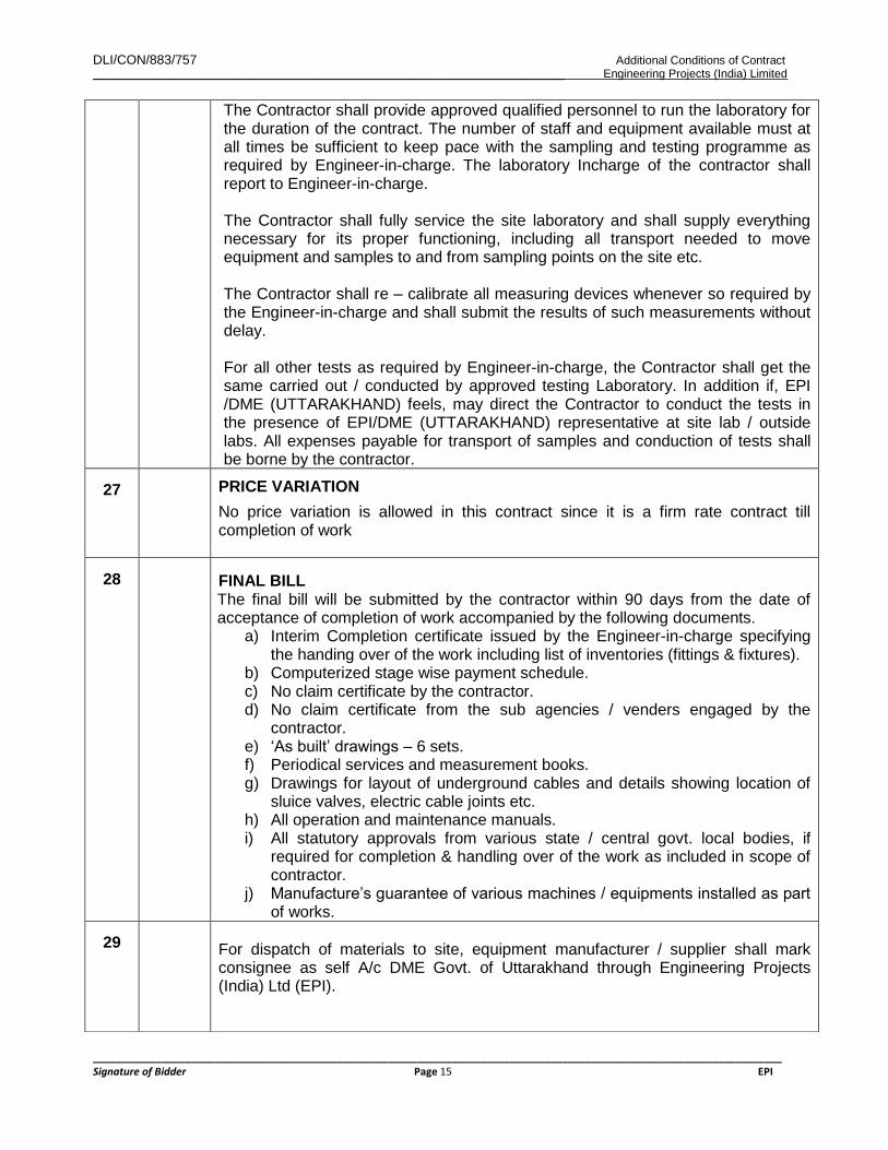
The Contractor shall provide approved qualified personnel to run the laboratory for the duration of the contract. The number of staff and equipment available must at all times be sufficient to keep pace with the sampling and testing programme as required by Engineer-in-charge. The laboratory Incharge of the contractor shall report to Engineer-in-charge. The Contractor shall fully service the site laboratory and shall supply everything necessary for its proper functioning, including all transport needed to move equipment and samples to and from sampling points on the site etc. The Contractor shall re – calibrate all measuring devices whenever so required by the Engineer-in-charge and shall submit the results of such measurements without delay. For all other tests as required by Engineer-in-charge, the Contractor shall get the same carried out / conducted by approved testing Laboratory. In addition if, EPI /DME (UTTARAKHAND) feels, may direct the Contractor to conduct the tests in the presence of EPI/DME (UTTARAKHAND) representative at site lab / outside labs. All expenses payable for transport of samples and conduction of tests shall be borne by the contractor.
27
PRICE VARIATION
No price variation is allowed in this contract since it is a firm rate contract till completion of work
28
FINAL BILL The final bill will be submitted by the contractor within 90 days from the date of acceptance of completion of work accompanied by the following documents.
a) Interim Completion certificate issued by the Engineer-in-charge specifying the handing over of the work including list of inventories (fittings & fixtures).
b) Computerized stage wise payment schedule. c) No claim certificate by the contractor. d) No claim certificate from the sub agencies / venders engaged by the
contractor. e) „As built‟ drawings – 6 sets. f) Periodical services and measurement books. g) Drawings for layout of underground cables and details showing location of
sluice valves, electric cable joints etc. h) All operation and maintenance manuals. i) All statutory approvals from various state / central govt. local bodies, if
required for completion & handling over of the work as included in scope of contractor.
j) Manufacture‟s guarantee of various machines / equipments installed as part of works.
29 For dispatch of materials to site, equipment manufacturer / supplier shall mark consignee as self A/c DME Govt. of Uttarakhand through Engineering Projects (India) Ltd (EPI).

DLI/CON/883/757 Additional Conditions of Contract _________________________________________________________________________ Engineering Projects (India) Limited
_______________________________________________________________________________________________________________________ Signature of Bidder Page 16 EPI
30
ROAD PERMIT
Road permit for transportation of goods across state border shall not be issued by DME (UTTARAKHAND) / EPI and will have to be arranged by contractor on his own. Transit Insurance of the equipment shall be arranged by the contractor. Nothing extra shall be paid on this account.
31
Invoice should be raised by Contractor in the name of Engineering Projects (India) Ltd., at Project Site Office
32
PLANT AND MACHINERY
All plant & machinery required for execution of work shall have to be arranged by the contractor at his own cost. However, the contractor has to deploy following minimum plant & machinery in good condition at site immediately after award of work.
S. No. Description Minimum Number
Required
1
Fully automatic computerized
concrete batching and mixing plant
as per the specifications with print
outs for admixture, concrete batching
and other items. ( 30 cum/Hr.)
01 Nos
2 Transit Mixer 03 Nos
3 Concrete Pump (One stationary and one
boom placer) – 30 cum/hr capacity
01 Nos
4 Total station for surveying work. One
5 Vibrators (Petrol / Electrical) Six
6 Needles of Vibrator Twelve
7 Excavator/Poclain Two
8 Tipper / Dumper (15 cum.) Ten
9 DG Set (63 KVA & 125 KVA) One Each
10 Leveling Instruments Two
11 Bar Cutting and Bending Machine 01 Nos (Each)
12 Welding Machine 04 Nos

DLI/CON/883/757 Additional Conditions of Contract _________________________________________________________________________ Engineering Projects (India) Limited
_______________________________________________________________________________________________________________________ Signature of Bidder Page 17 EPI
13 Water Tanker with Sprinkler Two
14 Roller/ Compactor 02 Nos
15 Tractor with trolley for transportation of
material
Three
16 Core Cutting Machine 1 Set
17 The agency shall provide sufficient area
lighting for the safe execution of works
during night hours through static / mobile
arrangements.
As per requirement of
site
18 Laboratory equipments As required
Note : a) In addition to above contractor has to arrange sufficient plant & machineries to
complete the work as per completion schedule.
b) Any other equipment for site test as outlined in CPWD / BIS specification and as directed by the Engineer–in–charge.
c) The quantities of equipments mentioned above are indicative only and can be increased as per the requirement of quantum work OR as per the direction of Engineer-in-Charge. The above equipment list is indicative and not complete. The contractor has to deploy all the required equipment to complete all the works within stipulated specifications and time period as per contract documents.
d) The contractor will not be allowed to take out equipments from the site without the written permission of Engineer-in-charge.
e) In the event of breakdown of any equipment the contractor should immediately mobilize replacement of the said equipment.
33
CENTERING & SHUTTERING 1. Centering & shuttering works for columns shall be made out of laminated
shuttering plywood of minimum 12mm thickness as per BIS, with angle iron frame. The staging system shall be got approved from the Engineer-in-charge. Scaffolding of latest materials/round steel pipes with couplers and brackets shall be used. Wooden planks, props, ballies etc are not permitted for use and steel plate shuttering is also not permitted for expose work.
2. The shuttering used for beam shall be of laminated shuttering plywood as per BIS. The support system shall be integrated with the slab. For slabs in case ply wood shutters is not used,( because of site or practical consideration) welded steel plates will be allowed to be placed in uniform pattern. The thickness of

DLI/CON/883/757 Additional Conditions of Contract _________________________________________________________________________ Engineering Projects (India) Limited
_______________________________________________________________________________________________________________________ Signature of Bidder Page 18 EPI
plates and pattern to be got approved from the Engineer-in-charge.
3. All joints in the shuttering i.e. plate to plate etc shall have to be sealed with adhesive / foam, to ensure water tightness of the form work.
4. All shuttering work for Architect features shall be with fiber glass moulds and the rate quoted by the contractor in the schedule of rate shall be inclusive of same.
5. All shuttering joints in the slab, beams and lintels etc. shall be treated with tape of required width to make it water tight and the rates quoted for centering shuttering work shall be all inclusive and nothing extra whatsoever shall be payable over and above the quoted price.
6. The shuttering shall be tightened by using runners, tie rods and bracings. No Ghughoo / welded system shall be allowed. Support shall be adequate and proper.
34 CONCRETING The concreting shall be from Batching Plant installed at site. The contractor may opt to use Ready Mixed Concrete of repute after obtaining prior written approval from Engineer-in-charge. No extra payment shall be made on this account. What so ever is the reason. Batching plant of minimum capacity of 30 Cum per hour with a least count of 0.5Kg., drum type 4 load cells, computer compatible print out for each batch only shall be allowed. The concerting shall be placed by concrete pumps of minimum 30 Cum / hour capacity at specified locations. Concreting by crane and buckets will be allowed in rare case with the prior approval of Engineer-in-charge. The contractor shall provide construction joints only at the specified positions and as per BIS codes and the concreting for columns shall be floor to beam height in one lifts, and in case the concreting is to be done in two lifts the minimum height of first lift of columns shall be 2.4 meters. The stone aggregate and sand of required zone shall be from the quarries as approved by Engineer-in-charge. The samples of the materials shall be got approved along with the mix design. Plasticizers/Admixture, of the required specification and make shall only be permitted as per approved mix design. The cost of plasticizers/ admixtures/ additives is deemed to be included in the rates of concrete & nothing extra shall be payable on this account. Ready mix concrete brought from outside sources or produced at site shall have minimum quantity of cement as specified in BIS specifications and as per approved design mix.
35 DESIGN MIX CONCRETE

DLI/CON/883/757 Additional Conditions of Contract _________________________________________________________________________ Engineering Projects (India) Limited
_______________________________________________________________________________________________________________________ Signature of Bidder Page 19 EPI
1. Design mix concrete shall be used in the work for all structural members. For design mix, CPWD specification along with relevant IS codes shall be followed in general along with the specific provisions made herein.
2. The concrete mix design with and without admixture will be carried out by the
contractor through one of the following laboratories/ Test houses to be approved by Engineer-in-charge.
IIT, NIT Or any NABL approved Govt. organization only
3. The contractor shall submit the mix design report from approved laboratory for
approval of Engineer-in-charge within 45 days from the date of issue of letter of acceptance of the tender. No concreting shall be done until the mix design is approved.
4. The contractor shall make cubes of trial mixes as per approved mix design for
all grades of concrete in presence of the Engineer in charge using same ingredients as adopted for design mix, prior to commencement of concreting and get them tested in presence of Engineer-in-charge for 7 days and 28 days. For each design mix, a set of six cubes shall be prepared from each of the three consecutive batches. Three cubes from each set shall be tested at the age of 7 days and three cubes at the age of 28 days. The cubes shall be made, cured, transported and tested strictly in accordance with CPWD specifications. The average strength of nine cubes at the age of 28 days shall exceed the specified target mean strength for which design mix has been approved.
5. 90% of the total tests shall be done at the laboratory established at site by the
contractor and remaining 10% in the NABL approved laboratory as directed by Engineer-in-Charge and the testing charges of the samples shall be borne by the contractor.
6. For each change of source or quality/ characteristic properties of the ingredients
from that approved & used in the concrete mix during the work, a fresh mix design shall be got done by the contractor. Revised trial mix test shall be conducted at laboratory established at site/ reputed Laboratory with prior approval of Engineer-in-charge and shall be submitted by the contractor as per the direction of engineer-in-charge.
7. The cost of packaging, sealing, transportation, loading & unloading cost of all
samples-concrete /cubes/ steel/ other material etc and the testing charges for mix design in all cases shall be borne by the contractor.
DLI/CON/883/757 Additional Conditions of Contract _________________________________________________________________________ Engineering Projects (India) Limited
_______________________________________________________________________________________________________________________ Signature of Bidder Page 20 EPI
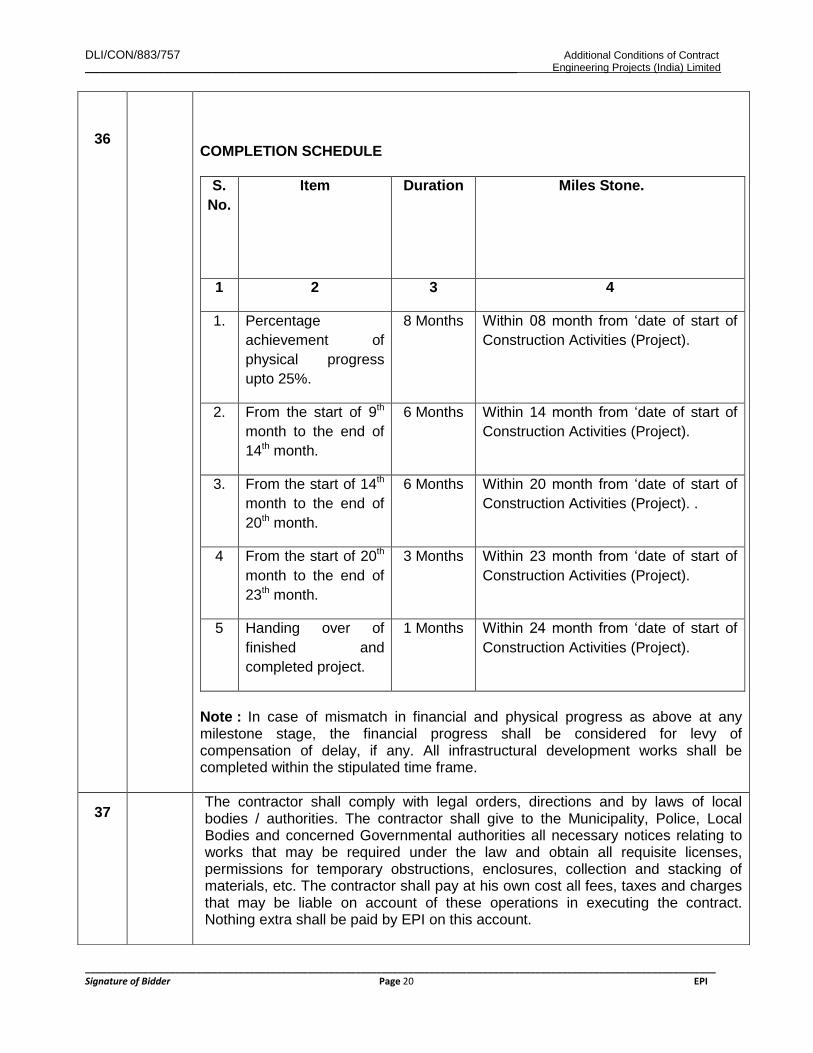
36
COMPLETION SCHEDULE
S.
No.
Item Duration Miles Stone.
1 2 3 4
1. Percentage
achievement of
physical progress
upto 25%.
8 Months Within 08 month from „date of start of
Construction Activities (Project).
2. From the start of 9th
month to the end of
14th month.
6 Months Within 14 month from „date of start of
Construction Activities (Project).
3. From the start of 14th
month to the end of
20th month.
6 Months Within 20 month from „date of start of
Construction Activities (Project). .
4 From the start of 20th
month to the end of
23th month.
3 Months Within 23 month from „date of start of
Construction Activities (Project).
5 Handing over of
finished and
completed project.
1 Months Within 24 month from „date of start of
Construction Activities (Project).
Note : In case of mismatch in financial and physical progress as above at any milestone stage, the financial progress shall be considered for levy of compensation of delay, if any. All infrastructural development works shall be completed within the stipulated time frame.
37 The contractor shall comply with legal orders, directions and by laws of local bodies / authorities. The contractor shall give to the Municipality, Police, Local Bodies and concerned Governmental authorities all necessary notices relating to works that may be required under the law and obtain all requisite licenses, permissions for temporary obstructions, enclosures, collection and stacking of materials, etc. The contractor shall pay at his own cost all fees, taxes and charges that may be liable on account of these operations in executing the contract. Nothing extra shall be paid by EPI on this account.

DLI/CON/883/757 Additional Conditions of Contract _________________________________________________________________________ Engineering Projects (India) Limited
_______________________________________________________________________________________________________________________ Signature of Bidder Page 21 EPI
The contractor shall be bound to follow the instructions and restrictions imposed by the administration / Police authorities on the working and / or movement of labour, materials etc. nothing extra shall be payable due to less / restricted working hours at site or any detours in movement of vehicles.
38
TEST CERTIFICATE
All manufacturer‟s certificates of test showing that the all equipments / materials have been tested in accordance with the requirements of the relevant standard specification and the copy of the test certificate as well as standard shall be supplied free of cost to EPI / DME. Govt. of Uttarakhand
39
GUARANTEE
The contractor shall also guarantee the performance of individual equipment.
40
PERMITS AND INSPECTIONS
The contractor shall obtain all necessary permits from local bodies, central authorities and shall make arrangement for inspection and tests etc. as required at his own cost.
The contractor shall have to make his own arrangements for getting the permission for plying trucks or any Plant & Equipment for execution of works from the Police Department/ Govt. authorities at his own cost. No excuse as to delay in work due to non-availability of permission shall be entertained.
41
LICENSES
The contractor shall arrange for obtaining the license and clearances for the operation. (If required) from the local authorities and statutory bodies at his own cost & nothing extra shall be payable. Certification of various equipments / installations from statutory bodies other agencies as required as per technical specifications, shall be arranged by contractor at his own cost before handing over.
42
The work shall be carried out in accordance with the drawings / documents approved by the EPI / DME. Govt. of Uttarakhand Before the commencement of any item of work, the contractor shall co-relate all the relevant architectural and structural drawings issued for the work and satisfy himself that the information available there from is complete and unambiguous. The discrepancy, if any, shall be brought to the notice of Engineer-In-Charge before carrying out surveying work. The contractor alone shall be responsible for any loss or damage occurring by the commencement of work on the basis of any erroneous and / or incomplete information. Nothing extra shall be paid on this account. Entire construction activities are open for client ( DME. Govt. of Uttarakhand ) inspection at all point of time.
43
The contractor shall be bound to sign the site order book as and when required by Engineer-In-Charge at Site and carry out compliance of instruction promptly to the satisfaction of Engineer In-Charge

DLI/CON/883/757 Additional Conditions of Contract _________________________________________________________________________ Engineering Projects (India) Limited
_______________________________________________________________________________________________________________________ Signature of Bidder Page 22 EPI
44 Bill of Quantities shall be read in conjunction with the specifications and requirement described in tender documents, Instructions to tenderers, General conditions of contract, Additional conditions of contract, Technical specifications, Drawings, Schedules, and Annexure & Addendum etc. to tender document. General directions and description of work and materials are not necessarily repeated or summarized in the Bill of quantities. Reference to the relevant sections of the contract document shall be made by the contractor before entering rates or prices against each item in the Bill of Quantities.
45
SITE ENGINEER OF CONTRACTOR The Contractor shall employ at his cost the adequate number of technical staff during the execution of this work depending upon the requirement of work. For this purpose the number of staff to be deployed, their qualification, experience as decided by EPI shall be final and binding on Contractor. The Contractor shall not be entitled for any extra payment in this regard. The technical staff should be deployed on full time basis & available at Site, whenever required by EPI to take instructions.
However, Minimum qualifications and experience required for principal technical rep. and other minimum technical staff other than supervisor is given below:
S.
No.
Qualification No. Minimum Experience
1. Graduate Civil Engineer/
Engineer – As a Principal
Technical Representative/
Project-in-charge
1 At least 15 years experience in
execution of reputed project of
multi-storey residential / non
residential buildings /
institutional buildings including
external development work etc.
2. Graduate Civil Engineer/
Engineer – As a Project
Manager
1 At least 10 years experience in
execution of reputed project of
multi-storey residential / non
residential buildings / institute
etc.
3. Diploma Engineer (Civil) as a
Site Engineer for execution of
civil work.
2 Minimum 5 years experience in
execution of multi-storey
residential / non residential
buildings / institute etc.
4. Graduate/Diploma (Electrical &
Mechanical Engg.) as a Site
Engineer for execution of
4 Atleast 5-8 years experience in
execution of electrical work in
multi-storey residential / non
residential buildings / institute

DLI/CON/883/757 Additional Conditions of Contract _________________________________________________________________________ Engineering Projects (India) Limited
_______________________________________________________________________________________________________________________ Signature of Bidder Page 23 EPI
electrical & HVAC works. etc.
5. Graduate Civil Engineer for QA
& QC work as a Incharge of
Site Laboratory.
1 Atleast 8-10 years relevant
experience in QC/QA work of
institutional & residential
building.
6. Surveyor with Diploma in
Surveying for Site surveying
work.
1 Minimum 5 years experience in
Surveying work of hilly terrain
using total station.
7. Graduate/ Diploma Engineer
as a Site Safety Engineer
1 Minimum 5 years experience in
safety work of multi-storey
residential / non residential
buildings / institute etc.
46
COMPLETION AND TAKING OVER
As soon as the project is finally completed, the contractor shall inform EPI shall in turn inform to DME. Govt. of Uttarakhand. DME. Govt. of Uttarakhand shall nominate a committee / officers for checking / verifications of completed work as per the scope of work for final taking over the project.
47
It will be the sole responsibility of contractor to obtain all statutory approvals and completion clearance from the all relevant statutory bodies for all other services as included in the scope of contract etc. from the concerned department as required within the stipulated time frame. Liaison work on behalf of EPI with the local bodies will also have to be done by the contractor. Nothing extra shall be payable to contractor on this account. No claim whatsoever in this regard shall be entertained
48
The contractor shall make necessary safety arrangement at site including as mentioned in GCC and indemnify EPI against any consequence of accident at site.
49
ISO COMPLIANCE
Engineering Project (India) Ltd. is an ISO 9001: 2000 & ISO 14001: 1996 certified Company. Therefore the contractor is ought to comply the provisions/ procedure given in EPI‟s ISO Procedure Manual / Quality Manual.
50
The Contractor shall furnish details whether they are covered under micro, small and Medium Enterprise Development Act 2006. If yes, clearly indicate under which category they are covered along with documentary evidence. This information is required to be furnished along with the bid.

DLI/CON/883/757 Additional Conditions of Contract _________________________________________________________________________ Engineering Projects (India) Limited
_______________________________________________________________________________________________________________________ Signature of Bidder Page 24 EPI
51
GENERAL CONDITION OF “GRIHA” REQUIREMENT FOR THE PROJECT The EPI / DME. Govt. of Uttarakhand intends to develop green complex & obtain “GRIHA” requirement for the proposed facilities included “FOUR STAR” rating of “GRIHA” in the project. Bidder to familiarize the requirements and note that all requirements of above pertaining to construction for achieving the above targeted rating. No extra payment shall be made on this account
52
COMPLIANCE OF CONSTRUCTION & DEMOLITION WASTES MANAGEMENT RULES 2016.
The contractor shall comply all the rules & regulation of Construction & Demolition waste Management Rules 2016 as notified by the Government of India as applicable for the said work and subsequent amendment if any, in the said act notified by the Government time to time. Nothing shall be paid extra.
53
FACILITIES TO BE PROVIDED AT SITE FOR LABOUR WELFARE
All facilities to be provided at site for fulfilling all GRIHA & statuary labour welfare schemes are included in contractor‟s scope which shall include the following but not limited to the same.
Separate provision / rooms for First Aid Centre & Reset room and for the safety officer, safety supervisors and other personnel to be engaged by the contractor for H.S.E aspects of the project
Erecting sufficient numbers of Urinals, WC‟s, drinking water, water supply and sanitary arrangements to the supervisory personnel and workmen engaged by them.
Canteen facility to workmen engaged by the contractor.
Treatment of waste from contractor‟s toilets to meet the requirements of “GRIHA”.
The contractor shall deploy an experienced & qualified person exclusively for implementation of “GRIHA” requirements for the entire contract period
54
RUNNING IN PERIOD
The contractor shall demonstrate the trouble free running of the installation of the equipments for a period of not less than 30 days before EPI takes over. After installation has operated for 30 date period without any breakdown or abnormal/ unsatisfactory operation of any equipment/ system during this period, the equipment shall be deemed to have run trouble free. The contractor should include One year of Defect Liability Period after completion of 30 days of trouble free running including replacement of defective parts etc. at his own cost. The contractor shall arrange at his own for all staff and other consumables during system integration, trail run , commissioning and running -in-period upto the date of acceptance. The contractor shall also make his own arrangements for power required during installation, testing & commissioning & trail run etc. Nothing extra shall be paid on this account. Contractor is required to submit a minimum guarantee / warranty of equipment for a period of 2 - 5 years (as per the manufacturer) from the date of handing over of the

DLI/CON/883/757 Additional Conditions of Contract _________________________________________________________________________ Engineering Projects (India) Limited
_______________________________________________________________________________________________________________________ Signature of Bidder Page 25 EPI
particular machinery of the equipments.
55
The Quantities indicated in the BOQ are tentative. However contractor has to execute the works as per drawings and site conditions. Payment will be released for the work executed as per the rates quoted by contractor even if the quantity increases or decreases up to any extent.
56
List of preferred make are indicative makes. Bidder is free to propose any other equivalent make meeting entire Technical requirement, Specification along with required detail in support of the same. The same would be analyzed and accepted if found suitable and shall be used in work after obtaining the prior approval of Engineer in-charge.
57 For items not covered under any of the specifications mentioned in Tender Documents, the works shall be carried out as per CPWD Specifications / manufacturer‟s specifications / General Engineering Practice and / or as per directions of Engineer-in-Charge. The rate for such extra work shall be derived as follows: a) If the item is available in DSR 2018, contractor has to execute the item with the same rate below or at par tender percentage. b) If the item is not available in DSR 2018 and similar item is available, rate for such extra work shall be derived from the similar item by adding or deleting the differences below or at par tender percentage. c) If the rate for any item is not possible to derive as mentioned above, the rate for which shall be derived by analyzing as per the prevailing market rates.
58
Life Cycle Cost
The contractor shall be responsible for safety, quality and soundness of the buildings including structural elements beyond maintenance period. The contractor shall have obligation to rectify such detects minimum upto to 5 (five) years from the date of completion of work. The defects have to be rectified within a reasonable time not exceeding forty five days after issue of notice by Engineer-In-Charge. If contractor does not take corrective action within 45 days, then action for debarring of the agency shall be taken by the appropriate authority.
59 Documents Documents required to be maintained at site, one copy of following:
1. Contract Documents 2. All Drawings 3. Relevant IS codes, Relevant PWD BSR & CPWD DSR 4. Reviewed shop drawings 5. Site order book 6. Other modifications to contract 7. Field test reports 8. Copy of approved work schedule and its updated revisions as
approved. 9. Statutory requirements like labour licence, insurances etc.

DLI/CON/883/757 Additional Conditions of Contract _________________________________________________________________________ Engineering Projects (India) Limited
_______________________________________________________________________________________________________________________ Signature of Bidder Page 26 EPI
10. ISO Documentation as instructed by EPI Engineer In-Charge.
60 Owner’s authorized Representative, Third party inspection
Owner at his discretion may authorize their representative or appoint agency On behalf of them to supervise and monitor project related all activities. Contractor will extend all necessary assistance required and cooperate. Owner/EPI may appoint Third Party Inspection (TPI)/check in order to ensure implementation of design/concept/structural safety and adherence to quality parameters. Contractor will extend all necessary assistance required and cooperate. Contractor will make sitting arrangements for owner’s representative & third party inspector & for their staff if any.
61
Compliance to statutory rules
The CONTRACTOR shall ensure compliance with all Central, State and Local Laws, Rules, Regulations etc. as applicable or may be applicable during the course of execution, maintenance etc. of the works and shall indemnify against any claim or damages whatsoever on such accounts. The CONTRACTOR shall also keep EPI/DME, GOVT. OF UTTARAKHAND indemnified at all times against infringement of any Patent or Intellectual Property rights
62
Work subject to audit
The work executed by the CONTRACTOR shall be subject to audit and quality control checks from Quality Control Division & Technical audit of EPI/DME, GOVT. OF UTTARAKHAND inspecting Agency of the Client and Chief Technical Examiner of Central Vigilance Commission, Govt. of India. In the eventuality of any defect/sub standard works as brought out in the report or noticed otherwise at any time during execution, maintenance period etc., the same shall be made good by the CONTRACTOR without any extra cost. In case the CONTRACTOR fails to rectify the defect/sub- standard work within the time period stipulated by EPI/DME,Govt. of Uttarakhand, necessary action as deemed fit shall be taken by EPI/DME,GOVT. OF UTTARAKHAND and decision of EPI/DME, Govt. of Uttarakhand, shall be final and binding on the contractor.
63 Alterations, Additions and Omissions EPI/DME,Govt.of Uttarakhand can make any variation of the form, quality or quantity of the works or any part thereof that may, in their opinion be necessary and for that purpose, or if for any other reason it shall in his opinion be desirable, they shall have power to order in writing to the contractor to do and the contractor shall do any of the following :

DLI/CON/883/757 Additional Conditions of Contract _________________________________________________________________________ Engineering Projects (India) Limited
_______________________________________________________________________________________________________________________ Signature of Bidder Page 27 EPI
i) Increase or decrease in the quantity of any work included in the contract in which case the value of contract may be increased or decreased.
ii) Omit any such work. iii) Change the levels, .lines, position and dimension of any part of
the works and iv) Execute additional work of any kind necessary for the
completion of the works and no such variation shall in any way vitiate or invalidate the contract, but the value, if any of all such variations shall be taken into account to ascertain the amount of the Contract Price.
v) The contractor shall not effect any of the aforementioned changes without the written order of EPI / DME, GOVT. OF UTTARAKHAND.
64
Liquidated Damages:
The LD provision for this Project shall be as per the “Provisions in the state Transparency in Public Procurement Rules 2013” which provides recovery for @1% of the Project Cost for delay of every week subject to a maximum of 10% of the award value of the work as per applicable Rules/Guidelines.
65 Water and Electricity for Construction
The contractor(s) shall make his / their own arrangement for water and Electricity required for the work and nothing extra will be paid for the same.
66 Contractor’s risks: All risks of loss of or damage to physical property and of personal injury and death which arise during and in consequence of the performance of the contract other than the excepted risks are the responsibility of the contractor
67 Drinking Water Supply
The contractor shall make their own arrangements for water required for construction as well as for drinking and other purposes for their staffs and labour and the personnel of EPI / DME, Govt. of Uttarakhand.
68
Contractor’s Responsibilities
The Contractor shall engage a specialized agency (if required the agency shall have to be approved by Owner) for execution of Electrical /HVAC works as required .The specialized agencies should have relevant license for execution of these works. The Contractor will submit the credentials of the specialized agencies for obtaining the approval of EPIL before engaging them. It may, however, be noted that the entire responsibility towards quantity and quality of the entire project including services shall remain with the main Contractor. Nothing extra will be paid on this account.

DLI/CON/883/757 Additional Conditions of Contract _________________________________________________________________________ Engineering Projects (India) Limited
_______________________________________________________________________________________________________________________ Signature of Bidder Page 28 EPI
Provisions under Integrity Pact of EPI are modified/ amended as under:-
Provisions under Model Rules for the Protection of Health and Sanitary Arrangements for
Workers of EPI are modified/ amended as under:-
69
Submission of Manuals / Catalogues
Maintenance manuals, product catalogues, all warranties and guarantees against each section of work shall be submitted hardbound in triplicate on completion as per direction of EPI
70 Barricading
The height of barricading should be mini. 2.0 M or more as per SPCB rules from the EGL on MS frame with G.I Sheet.
71 Govt Order
Govt. Order No 424/XXIII(5)/2021-20 (मेo.काo)/2020 dated 26.03.2021issued by
Director Medical Education is part of contract.(Copy Enclosed)
S. No.
Section No.
Modified/Amended provisions as per Additional Conditions of Contract
1 8 Section 8 - Independent External Monitor / Monitors Following sub clause shall be added to the said Section: (11) Notwithstanding to anything contained in sub clause (1) to (10), the DME. Govt. of Uttarakhand at its sole discretion and without assigning any reasons whatsoever, shall have the right to appoint any individual and/or organization as it may deem fit to carry out Third Party Quality Assurance check to assess the quality of the construction works carried out the Bidder(s)/ Contractor(s) at the Cost and Expenses of the Contractor(s).
S. No.
Clause No.
Modified/Amended provisions as per Additional Conditions of Contract
1 Following clause shall be added in the Model Rules: 11. Precautionary / Preventive Measures against dissemination / spread of COVID-19
A. Mandatory for every labourer/worker to undergo a health checkup and remain quarantined for a fortnight before beginning work at the site.
B. All construction material entering the site would be left undisturbed for three days to eliminate the threat of COVID-19 Contamination.
C. Keep in-person meetings (including toolbox talks and safety meetings) as

DLI/CON/883/757 Additional Conditions of Contract _________________________________________________________________________ Engineering Projects (India) Limited
_______________________________________________________________________________________________________________________ Signature of Bidder Page 29 EPI
short as possible, limit the number of workers in attendance, and use social distancing practices.
D. Provide employees with access to soap, clean running water, and materials for drying their hands, or if soap and water are not readily available provide alcohol-based hand sanitizers containing at least 60% alcohol at stations around the establishment for use by workers.
E. Coordinate site deliveries in line with the employer's minimal contact and cleaning protocols. Delivery personnel should remain in their vehicles if at all possible.
F. Adopt staggered work schedules, e.g., provide alternating workdays or extra shifts, to reduce the total number of employees on a job site at any given time and to ensure physical distancing.
G. Train construction workers on:
I. The signs and symptoms of COVID-19 and an explanation of how
the disease is potentially spread, including the fact that infected
people can spread the virus even if they do not have symptoms.
II. All policies and procedures that are applicable to the employee's
duties as they relate to potential exposures to COVID-19. It is
helpful to provide employees with a written copy of those standard
operating procedures.
III. Information on appropriate social distancing and hygiene practices,
including:
a. Avoiding physical contact with others and maintaining a
distance of at least 6 feet from customers and other
individuals, whenever possible, including inside work
trailers.
b. Appropriate cleaning practices (i.e., washing hands
frequently with soap and water for at least 20 seconds, or, if
soap and water are not immediately available, using
alcohol-based hand sanitizer that contains at least 60%
alcohol and rubbing hands until they are dry; sanitizing all
surfaces workers will touch).
c. The proper way to cover coughs and sneezes (i.e.,
sneezing or coughing into a tissue or into the upper
sleeve).
d. Importance of workers not touching their own faces (mouth,
nose, eyes).
e. The benefits of driving to work sites or parking areas
individually, when possible, without passengers or
carpools.
IV. The importance of staying home if they are sick.
V. Wearing masks over their noses and mouths to prevent them from
spreading the virus.

DLI/CON/883/757 Additional Conditions of Contract _________________________________________________________________________ Engineering Projects (India) Limited
_______________________________________________________________________________________________________________________ Signature of Bidder Page 30 EPI
H. Ensure clean toilet and hand washing facilities. Clean and disinfect
portable job site toilets regularly. Fill hand sanitizer dispensers regularly.
Disinfect frequently touched items (i.e., door pulls and toilet seats)
regularly. I. Persons having flu-like symptoms should not come to work site and
should seek medical attention from local health authorities. If they test positive for Covid-19, they should inform the authorities concerned in the office immediately.
J. If one or two cases are reported in the office, places visited by the patient over the last 48 hours will be disinfected. Work will only be resumed after disinfection.
K. Every construction site would have weekly doctor visits. An isolation facility would also be created at the work site in case a labourer develops cough, cold or other symptoms.

DLI/CON/883/757 Additional Conditions of Contract _________________________________________________________________________ Engineering Projects (India) Limited
_______________________________________________________________________________________________________________________ Signature of Bidder Page 31 EPI
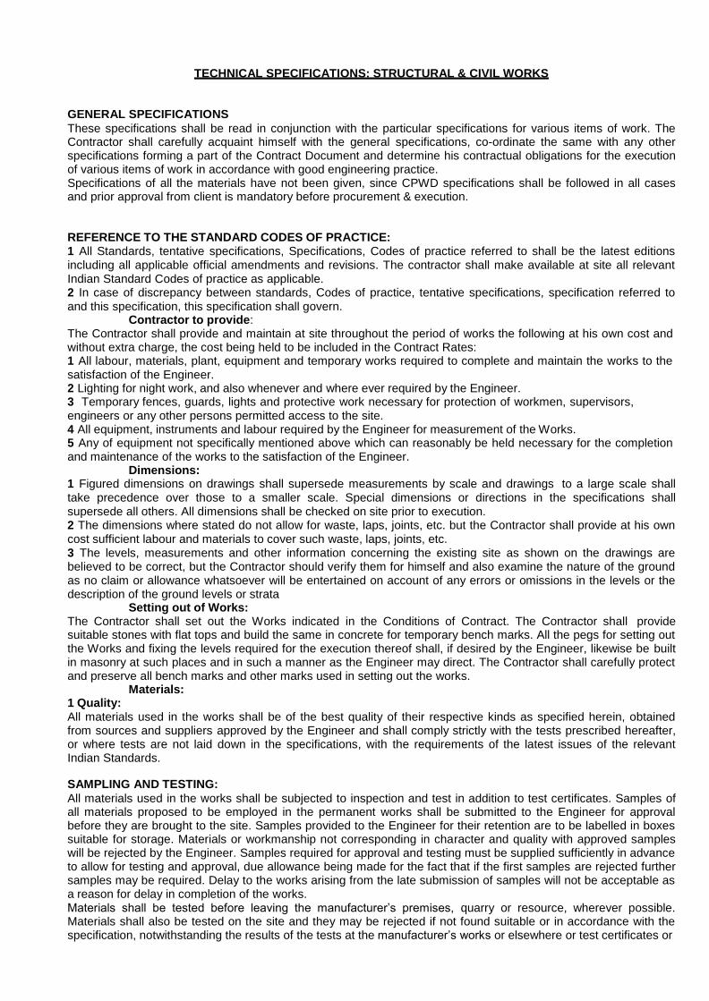
TECHNICAL SPECIFICATIONS: STRUCTURAL & CIVIL WORKS
GENERAL SPECIFICATIONS
These specifications shall be read in conjunction with the particular specifications for various items of work. The Contractor shall carefully acquaint himself with the general specifications, co-ordinate the same with any other specifications forming a part of the Contract Document and determine his contractual obligations for the execution of various items of work in accordance with good engineering practice. Specifications of all the materials have not been given, since CPWD specifications shall be followed in all cases and prior approval from client is mandatory before procurement & execution.
REFERENCE TO THE STANDARD CODES OF PRACTICE: 1 All Standards, tentative specifications, Specifications, Codes of practice referred to shall be the latest editions including all applicable official amendments and revisions. The contractor shall make available at site all relevant Indian Standard Codes of practice as applicable. 2 In case of discrepancy between standards, Codes of practice, tentative specifications, specification referred to and this specification, this specification shall govern.
Contractor to provide: The Contractor shall provide and maintain at site throughout the period of works the following at his own cost and without extra charge, the cost being held to be included in the Contract Rates: 1 All labour, materials, plant, equipment and temporary works required to complete and maintain the works to the satisfaction of the Engineer. 2 Lighting for night work, and also whenever and where ever required by the Engineer. 3 Temporary fences, guards, lights and protective work necessary for protection of workmen, supervisors, engineers or any other persons permitted access to the site. 4 All equipment, instruments and labour required by the Engineer for measurement of the Works. 5 Any of equipment not specifically mentioned above which can reasonably be held necessary for the completion and maintenance of the works to the satisfaction of the Engineer.
Dimensions: 1 Figured dimensions on drawings shall supersede measurements by scale and drawings to a large scale shall take precedence over those to a smaller scale. Special dimensions or directions in the specifications shall supersede all others. All dimensions shall be checked on site prior to execution. 2 The dimensions where stated do not allow for waste, laps, joints, etc. but the Contractor shall provide at his own cost sufficient labour and materials to cover such waste, laps, joints, etc. 3 The levels, measurements and other information concerning the existing site as shown on the drawings are believed to be correct, but the Contractor should verify them for himself and also examine the nature of the ground as no claim or allowance whatsoever will be entertained on account of any errors or omissions in the levels or the description of the ground levels or strata
Setting out of Works: The Contractor shall set out the Works indicated in the Conditions of Contract. The Contractor shall provide suitable stones with flat tops and build the same in concrete for temporary bench marks. All the pegs for setting out the Works and fixing the levels required for the execution thereof shall, if desired by the Engineer, likewise be built in masonry at such places and in such a manner as the Engineer may direct. The Contractor shall carefully protect and preserve all bench marks and other marks used in setting out the works.
Materials: 1 Quality: All materials used in the works shall be of the best quality of their respective kinds as specified herein, obtained from sources and suppliers approved by the Engineer and shall comply strictly with the tests prescribed hereafter, or where tests are not laid down in the specifications, with the requirements of the latest issues of the relevant Indian Standards.
SAMPLING AND TESTING:
All materials used in the works shall be subjected to inspection and test in addition to test certificates. Samples of all materials proposed to be employed in the permanent works shall be submitted to the Engineer for approval before they are brought to the site. Samples provided to the Engineer for their retention are to be labelled in boxes suitable for storage. Materials or workmanship not corresponding in character and quality with approved samples will be rejected by the Engineer. Samples required for approval and testing must be supplied sufficiently in advance to allow for testing and approval, due allowance being made for the fact that if the first samples are rejected further samples may be required. Delay to the works arising from the late submission of samples will not be acceptable as a reason for delay in completion of the works. Materials shall be tested before leaving the manufacturer‘s premises, quarry or resource, wherever possible. Materials shall also be tested on the site and they may be rejected if not found suitable or in accordance with the specification, notwithstanding the results of the tests at the manufacturer‘s works or elsewhere or test certificates or

any approval given earlier. The contractor will bear all expenses for sampling and testing, whether at the manufacturer‘s premises at source, at site or at any testing laboratory or institution as directed by the Engineer. No extra payment shall be made on this account. 3 Test certificates: All manufacturer‘s certificates of test, proof sheets, etc showing that the materials have been tested in accordance with the requirement of this specification and of the appropriate Indian Standard are to be supplied free of charge on request to the Engineer. 4 Rejection: Any materials that have not been found to conform to the specifications will be rejected forthwith and shall be removed from the site by the Contractor at his own cost. 5 The Engineer shall have power to cause the Contractors to purchase and use such materials from any particular source, as may in his opinion be necessary for the proper execution of the work.
Workmanship: 1 All works shall be true to level, plumb and square and the corners, edges and arises in all cases shall be unbroken and neat. 2 Any work not to the satisfaction of the Engineer or his representative will be rejected and the same shall be rectified, or removed and replaced with work of the required standard of workmanship at no extra cost.
RUBBLE MASONRY & RUBBLE SOLING The Stone for the works except where otherwise described shall be of the best quality procurable complying with IS: 1805 latest. No stone with flaws, or traversed with seams of perishable materials or quarry faced, or otherwise in any way defective shall be allowed to be used and the Engineer may reject and refuse to permit the use of any stone which, in his opinion, is unfit for the work. Stone masonry, wherever required, shall conform to the requirements of IS: 1597 latest and shall be composed generally of large stone weighing about 25 kgs. The face stones to be squared on all joints and beds shall be hammered and chisel dressed, true and square for at least 75mm back from the face, and the joints for at least 40mm (IS:1127 latest and IS:1129). The face of the stone is to be hammer dressed and "bushing" shall not project more than 40mm. The stone shall be clean flat bedded properly selected for their places and carefully laid with a suitable proportion of smaller stones and chips to fill up the interstices. The mortar including the constituents shall conform to the requirements of IS: 2250 latest and IS: 1625 latest. The whole masonry shall be hand set and solidly bedded in and surrounded with mortar on every side except the face. There shall be no hollows or dry portions in work nor pinning in the face and no joint shall be more than 10mm. The face stone shall be flat bedded, shall tail back and be bound well into the body of the wall and shall not be of a height greater than either the breadth on face or length of the tail. Through stones covering the whole width or thickness of the walls, or 600mm long where the walls are thicker than 600mm, shall be inserted at every 1000mm measured horizontally and vertically. The rate for stone masonry shall include the extra cost of the through stones. The faces of the walls shall be strictly straight. The masonry shall be shaded from the sun, and kept wet for not less than 14 days after completion. All fixtures, plugs, frames shall be placed securely as the work proceeds and not after completion of the masonry. Iron holdfasts shall be given a coating of bitumen to avoid rusting. Scaffolding as described in clause F.17 above shall be provided as required.
SOIL TREATMENT (ANTITERMITE TREATMENT)
Soil Treatment shall conform to the following specifications:- Pre-construction anti-termite treatment shall be done with Chlorophyriphos 20% E.C. manufactured by any approved manufacturer as pr IS:6313 1981 Part II & III of Bureau of Indian Standards. To make 1% solution of Chlorophyriphos 20% EC.
i) Mix 1 lit of the chemical in 19 ltr. of For wood treatment mix 1 ltr. of the chemical in 19 ltr. of kerosene oil. The tender shall clearly indicate along with his quotation the chemical he proposed to use. A daily record shall be maintained by the Contractor indicating the amount of work done and the quantity of chemical consumed for the work. This record book shall be the property of the Employer.
Method of application The following paragraphs specify the manner and sequence of operation, which must be followed. They also indicate the rates of application of chemicals of stated concentration for various operations. It shall be distinctly understand that these represent the minimum rates of application for each operation and that the Contractor shall actually apply chemicals at rates higher than those specified herein to the extent he may consider them necessary for effectiveness during the 10 years guarantee period. In other work the onus of responsibility of applying adequate amount of chemicals as required to sustain the 10 years guarantee shall be that of the Contractor, but in no case shall actual rates of application be less than these specified herein.

i) The bottom and sides of foundation pits shall be treated to a height of 300 mm at the rate of 5 Litres of 1% solution of chemical in water per square meter. ii) The refill earth shall be treated at the rate of 5 litres of 1% solution of the chemical in water per linear metre on both sides of built up walls. iii) Before laying the floor, the top surface of the consolidated earth within the plinth wall shall be treated at the rate of 5 litres of 1% solution of the chemical in water per square metre. It is advisable to make 20 mm dia 500 mm deep holes at the rate of 300 mm c/c before pouring the chemical. iv) After completion of the building the 300 mm of earth along the external perimeter of the building shall be treated at the rate of 5 litres of 1% solution of the chemical in water per square metre. v) All timber faces in contact with masonary work as in door frames shall be brushed twice with 1% solution of the chemical in kerosene oil. vi) Treatment shall not be made when the soil or fill is excessively wet or immediately after heavy rains to avoid surface flow of the toxicant from application site. Unless the treated areas are to be immediately covered, precautions shall be taken to prevent disturbance of the treatment by human or animal contract with the treated soil.
Guarantee: 10 years In the unlikely event of any treatment becoming necessary subsequently during the guarantee period required inspection and treatment shall be carried out free of cost. The Contractor shall submit an undertaking to the Employer, on a stamp paper, duly notarized, to carry out such repairs as and when required.
Instruction to Contractors for Quotation Rates The tendered should include in his rates given in schedule of quantities in sq.m. area all the stages of treatment to bottom of foundation, sides of trenches, under side of the floor, underside/damp proof course, in the outer face of external wall up to window sill level, door and window frames to ground floor area. Which comes in contact with the brick wall and finally the trenches treatment all round the buildings as per detailed specification mentioned above.
Where the rate of application of the insecticide, has not been specified clearly the rates should be governed to that during the guarantee period no trouble may arise. Payment will be made on the plinth area measurement mentioned above and no extra on this account will be entertained.
DRILLING HOLES AND GROUTING DOWELS Description: Work under this item shall consist of drilling holes in concrete and grouting dowels at the locations shown on the plans, in accordance with the plans, the manufacturer's recommendations, and as directed by the Engineer.
For the purposes of this specification, a dowel may be a reinforcing bar, anchor bolt or threaded rod.
Necessary scaffolding or propping or temporary shuttering required for this work shall not be extra measured or paid. Contractor shall quote rate including necessary arrangements of scaffolding, propping or temporary shuttering work.
Materials: The chemical anchoring material shall conform to Sub article M.03.01-15.
Construction Methods: Before fabricating any materials, the Contractor shall submit manufacturer‘s specifications and installation for the chemical anchoring material to the Engineer for review in accordance with Article 1.05.02.
Holes for the dowels shall be located as shown on the plans. The holes shall clear the existing reinforcement and provide the minimum cover as shown on the plans. A pachometer shall be used to locate existing reinforcing steel. If existing reinforcing is encountered during the drilling operation, the holes shall be relocated and the uncompleted holes shall be filled with the chemical anchoring material and finished smooth and flush with the adjacent surface.
The depth and diameter of each hole shall be as shown on the plans. If the diameter of a hole is not shown, the diameter of the hole shall conform to the manufacturer's recommendations for the diameter of the dowel being anchored. If the depth and diameter of a hole are not shown, the hole shall conform to the manufacturer's recommendations for the diameter of the dowel being anchored such that the grouted dowels will be able to develop in tension 100 percent of its specified yield strength.
Hole drilling methods shall not cause spalling, cracking, or other damage to the existing concrete. The weight of the drill shall not exceed 20 pounds. Those areas damaged by the Contractor shall be repaired by him in a manner suitable to the Engineer and at no expense to the State.

Prior to placing the chemical anchoring material in the holes, the holes shall be cleaned of all dirt, moisture, concrete dust and other foreign material. The dowel and the chemical anchoring material shall be installed in the holes in accordance with the chemical anchoring material manufacturer's recommendations.
The Contractor, as directed by the Engineer, shall take adequate precautions to prevent any materials from dropping to the area below, which may result in damage to any existing construction or to adjoining property. Should any damage occur to the structure as a result of the Contractor's operations, the Contractor shall make repairs at his own expense. The repair work shall be approved in advance and shall be of a quality acceptable to the Engineer.
Method of Measurement: This work will be measured for payment by the actual number of drilled holes in which dowels are embedded and accepted.
Basis of Payment: This work will be paid for at the contract unit price each for "Drilling Holes and Grouting Dowels," which price shall include drilling and preparing holes, furnishing and installing the chemical anchoring material in the holes and all material, equipment, tools and labor. incidental thereto.
STRUCTURAL REPAIR OF CONCRETE, SEALING OF CRACKS, GROUTING OF JOINTS ETC. USING POLYMER/ EPOXY PRODUCTS.
GENERAL:
1 All chemicals required for concrete repair works, sealing of cracks, grouting etc. shall be procured from an approved manufacturing firm who has specialised in this field. The Contractor shall indicate the name of the firm with whom he is associating. 2 The expert from the manufacturing firm shall, in the presence of the Engineer, train the Contractor‘s staff for the proper method of preparing surfaces, method of mixings chemicals in correct proportion and its application etc. In the initial stages of repair work, the expert shall visit the site as often as required by the Engineer and such visits may be reduced when the Engineer is satisfied that the Contractor‘s staff are trained to carry out the work as per requirement of manufacturer‘s specifications. 3 The Contractor shall submit his proposal for repairs along with the methodology and complete specifications for approval of Engineer. The Contractor may propose alternate proposal for repair scheme. 4 All chemicals brought at site shall be tested, for the properties specified by the manufacturer in his catalogues, independently in an approved laboratory. Cost of all such tests is deemed to have been included the rates. Test certificates issued by the manufacturer shall be used only for the purpose of verifying. 5 The Contractor shall maintain a register of all chemicals brought on site for repair works showing manufacturer‘s name, batch number, date of manufacture, quantities and date of consumption etc, and any other information that may be required by the Engineer. The Engineer or his authorised representative shall counter check all entries in the register. 6 The Contractor shall provide suitable weighing apparatus for mixing chemicals by weight. Approved mechanical mixers shall be provided to mix and agitate the chemical mixtures.
HANDLING TOXIC MATERIAL & SAFETY MEASURES:
All chemicals brought at site shall be stored in a proper manner in a separate enclosed room. Smoking shall be not allowed in the room. Welding shall not be carried out within 15 meters from the store. Each container of chemical shall bear a specific hazard warning as applicable. Direct contact of resin/hardener/accelerator etc. with the skin shall be avoided. Workers shall be made to wear disposable rubber gloves and safety glass. Adequate provisions, conforming to manufacturer‘s instructions, shall be made to remove any accidental contamination with the skin. All equipment used for mixing of chemical shall be cleaned with acetone or other approved solvent. Manufacturer‘s instructions on safety shall be strictly followed in the use of each material.
REPAIR OF SPALLED CONCRETE DUE TO CORROSION OF REINFORCEMENT:
1 Repair scheme comprises of: Thorough surface preparation of concrete and reinforcement Application of approved rust remover and passivator/ corrosion inhibitor chemicals to reinforcement Applying approved bonding agent to concrete surface. Repairing with approved polymer mortar. Sealing the repaired surface with approved chemical paint. 2 Surface Preparations: All loose and damaged plaster and unsound concrete shall be removed by means of chisel and hammer. Carbonation tests shall be carried out to determine the extent of removal of concrete. Engineer‘s approval shall be obtained in case the depth of removal of concrete exceeds the depth of the cover plus diameter of reinforcement. In case of slab, if directed and if required, the slab shall be propped adequately prior to removal of concrete. The Form finish concrete and the reinforcement shall be thoroughly cleaned by wire brushing or by water jet using approved pumps to remove laitance, dust, grease loose rust etc. Thin sandpaper shall be used for cleaning the

inaccessible part of reinforcement by inserting the sandpaper between the concrete and reinforcement and scraping on the reinforcement.
REPAIRING WITH VARIOUS PROPRIETARY BRAND CHEMICALS:
3.1 Sunanda Speciality Coatings Pvt Ltd.: a) Rust Remover and Passivator/ Corrosion Inhibitor. Rust Remover: Apply rust removing solution ―RUSTICIDE‖ with cotton swab. The rusted surface shall turn from reddish brown to blackish non-rusted colour. After 24 hours, remove the free/loose rust particles by dusting with brush. Payment & Measurement: Payment shall be made on the quantity of ―Rusticide‖ consumed. Joint measurement shall be taken to determine the quantity consumed by taking the difference in the quantity in the container before use and the quantity in the same container after the use. The rate shall include the cost of cleaning the reinforcement. b) Rust Passivator/ Corrosion Inhibitor. : ―POLYALK FIXOPRIME‖ (PF) shall be used as corrosion inhibitor. The lump free consistent slurry shall be prepared by mixing 1 kg. of PF with 1.25 kg. Of fresh ordinary portland cement. Water shall not be added. Apply the slurry to the surface of reinforcement with paintbrush. Slurry shall be applied within 30 minutes of its preparation. All slurry remaining after 30 minutes of its preparation shall be rejected and removed from the site. The first shall be allowed to set for 24 hours. Second coat of slurry of the same proportion shall be applied 24 hours after the application of the first coat. Payment & Measurement: Payment shall be made on the quantity of ―POLYALK FIXOPRIME‖ consumed. Joint measurement shall be taken to determine the quantity consumed by taking the difference in the quantity in the container before use and the quantity in the same container after the use. The rate shall include the cost of cement, labour, etc. c) Bonding Agent & Polymer Repair Mortar: Apply to the cleaned surface of concrete and reinforcement, one coat of bonding lump free consistent slurry consisting of 1 part by weight of ―POLYALK EP‘ and 1 part by weight of fresh ordinary portland cement. The slurry shall be used within 30 minutes of its preparation. Immediately after application of bonding slurry, in any case not later than 10 minutes, apply polymer mortar consisting of 1 part by weight of ―POLYALK EP‖, 5 parts by weight of ordinary portland cement and 15 parts by weight of well graded quartz sand. Mortar shall be mixed mechanically using approved stirrer. The thickness of application of mortar at a time shall not exceed 15mm. In case of severe corrosion and if the Engineer directs so, the dosage of ―POLYALK EP‖ may be increased suitably in consultation with the manufacturer. The mortar shall be well compacted by trowelling and ensuring that all gaps between reinforcement and the concrete surface are filled completely. Additional thickness of mortar, where required, shall be applied after the initial set of the previous layer is over, which shall be between 15-20 minutes and after applying bonding coat. The thickness of every such additional layer shall not exceed 10 to 15mm. The final layer of mortar shall be finished with trowel smooth and flush with the original surface of concrete trowel. After 48 hour of initial setting of the final layer of mortar, it shall be cured by spraying water or wet gunny bags or other approved means. Curing shall be carried out for a minimum period of 3 days. Final finishing coat shall be either polymer-based paint or cement plaster as directed by the Engineer. Payment & Measurement: Payment shall be made on the quantity of ―POLYALK EP‖ consumed in each layer and in bonding coats. Joint measurement shall be taken to determine the quantity consumed by taking the difference in the quantity in the container before use and the quantity in the same container after the use. The rate shall include the cost of surface preparation and cleaning of the concrete surface. It shall also include the cost of conducting carbonation tests on concrete. 3.2 Huntsman (Hindustan Ciba-Geigy Ltd.): a) Corrosion Inhibitor. Primer Coat: Primer Coat to reinforcement shall consist of following epoxy (Araldite) formulations: Protective Coatings: Araldite GY 257 - 100 parts by weight Hardener HY 840 - 50 parts by weight The above formulation shall be applied on thoroughly prepared surface of reinforcement. The primer should be allowed to be just tack-free prior to the application of top coats. The primer shall not be fully cured before the application of top coats. Top Coatings: Araldite GY 257 - 100 parts by weight Hardener HY 2969 - 60 parts by weight Silica Filler - 20 parts by weight Flow control agent - 2 parts by weight. Flow control agent could be Butylated urea formaldehyde resin or other approved equivalent. The first top coat shall be applied over the primer coat and is left to reach a tack-free state. At this stage, the final top coat shall be applied. The coating shall be allowed to be cured at room temperature (25-30 degree C) for 7 days. b) Bonding agent & epoxy mortar for repair. Bonding agent shall consist of the following epoxy formulation: Araldite GY-250 100 parts by weight Hardener HY 825 20 parts by weight Hardener HY 830 20 parts by weight

Hardener HY 850 20 parts by weight Silica flour 20 parts by weight Epoxy mortar for repair shall consist of following epoxy formulation: Araldite GY 257 100 parts by weight Hardener HY 840 50 parts by weight Quartz sand Mix no.10 900 parts by weight Application for repair with cement mortar/ concrete/ gunite layer: The concrete surface shall be dry before application of any epoxy formulations. Bonding agent shall be applied on thoroughly prepared, dry and clean concrete surface and the new cement mortar/ concrete/ gunite layer shall be applied within the open time of the bonding agent, which shall not be more than 1 hour. Application for repair with Epoxy mortar: The primer coat of resin & hardener (as per formulation given for corrosion inhibitor) shall be applied on the cleaned dry surface of old concrete. Epoxy mortar then shall be applied by trowelling the tacky primer coat. It shall be allowed to cure at room temperature for 3 days.
Mc-Bauchemie (India) Pvt. Ltd: a) Corrosion Inhibitor: Corrosion inhibitor shall consist of two components. The powder component, Colusal MK, shall consist of selected minerals and blend of special cements and the liquid component, Colusal 25, shall be based on pure acrylic dispersion system. The mixing ratio shall be as given below: Colusal MK 100 parts by weight Colusal 25 25 parts by weight Water 15 parts by weight Cplusal 25 shall be mixed with water first and this solution shall be used as gauging solution. Colusal MK shall be slowly added to this solution which is continuously stirred until lump free homogeneous brushable slurry obtained. This slurry shall be applied to the cleaned reinforcement in two coats. The second coat shall be applied about two to three hours after the application of the first coat. b) Bonding Agent Bonding agent shall be of two components. The first component in powder form, Zentrifix HB, highly alkaline in nature, consists of selected cements and well graded minerals and polymers. The second component in liquid form, Nafufill BB2 or Nafufill SBR, is based on high quality polymers and other components to increase the effective bond strengths to enable subsequent mortars to adhere to the base surfaces. Mixing Ratio: Nafufill BB2 or Nafufill SBR 1 parts by weight Water 3 parts by weight Zentrifix HB shall be added slowly to the above solution while continuously stirring till the resulting mixture forms a lump free homogeneous slurry. Application. The slurry shall be brush applied over complete surface including the primer coated reinforcement bars. Only limited areas should be coated so that approximately within thirty minutes of the first application, the next layers can be applied wet on wet. c) Polymer Mortar For Repair. Polymer-modified hydraulically setting, ready-to-use, repair mortar, Zentrifix AS, shall be used in conjunction with Nafufill BB2 or Nafufill SBR. Mix Ratio. Zentrifix AS 100 parts by weight Liquid consisting of 1 pbw Nafufill BB2 or Nafufill SBR and 2 pbw water 15 parts by weight Zentrifix AS shall be added slowly to the above solution while continuously stirring till the resulting mixture forms a lump free homogeneous mortar suitable for use with a trowel. Application. Zentrifix AS mortar shall be applied immediately after applying the bond coat to the concrete surface. The finished surface shall coated with Nafuquick and finished smooth.
Fosroc Chemicals (India) Limited a) Corrosion Inhibitor: The corrosion inhibitor shall consist of two component zinc rich primer applied in one coat and should be allowed to dry. b) Bonding Agent
Bonding agent shall consist of acrylic emulsion cement modifier and water based –Nitobond AR. After thorough surface preparation, the concrete surface to be treated shall be thoroughly washed with clean water. Excess water shall be removed. One coat of Nitobond AR shall be applied on to the surface. Repair mortar shall then be applied when the coating is tacky.

c) Polymer Mortar for Repairs Polymer mortars for repairs, depending upon the recommendation of the manufacturer, could be either Rendroc S2 or Rendroc HB2. i) Rendroc S2: (For high compressive strength) It shall consist of a two component cement based blend of powder and a liquid polymer and shall have the anti-shrinkage properties. Mixing proportion: Rendroc S2 25 Kg Polymer 0.25 Kg Water 3.25 litres. Mixing: A forced-action mixer, with approved spiral paddle and a slow speed (500 rpm), shall be used for mixing powder, polymer and water. Polymer shall be added to water in the mixer and shall be mixed for 2 minutes. Then powder shall be added slowly and mixed for 3 minutes until a homogeneous material is obtained. Properties of the material shall be a follows: Compressive strength 1 day 12 N/mm2 28 days 45 N/mm2 Flexural strength 28 days 8 N/mm2 Water absorption (Immersion test) after 24 hours 0.45% Other properties shall be as given by the manufacturer in the literature for this product. Application: Mixed Rendroc S2 slurry shall be applied by trowel or gloved hand. Mortar layer shall be thoroughly compacted on to the primed surface and around the exposed reinforcement. Minimum thickness shall not be less than 5mm. In vertical sections, for small area, thickness could be upto 100 mm. If sagging occurs during application to vertical surfaces, the Rendroc S2 shall be completely removed and reapplied at a reduced thickness on the correctly reprimed surface. If required, for vertical sections, mortar leak proof shuttering shall be provided. Rendroc S2 shall not be applied on large area as a render. The surface shall be finished with wooden or plastic floats. Curing: The finished surface shall be cured for 7 days immediately after finishing.
ii) Rendroc HB2: (Lightweight for high-build repairs). It shall consist of a two component cement based blend of lightweight powder (cement, graded sand and chemical additives) and a liquid polymer and shall have the anti- shrinkage properties. Mixing proportion: Rendroc HB2 18 Kg Polymer 0.54 Kg Water 3.24 litres. Mixing: A forced-action mixer, with approved spiral paddle and a slow speed (500 rpm), shall be used for mixing powder, polymer and water. Polymer shall be added to water in the mixer and shall be mixed for 2 minutes. Then powder shall be added slowly and mixed for 3 minutes until a homogeneous material is obtained. Properties of the material shall be a follows: Compressive strength 1 day 7 N/mm2 28 days 22N/mm2 Flexural strength 28 days 4.5 N/mm2 Water absorption (BS 1881Pt.5-1970) 10 mins 0.01/ml /m2/Sec 2 hours 0.005/ ml /m2 /Sec
Other properties shall be as given by the manufacturer in the literature for this product. Application: Mixed Rendroc HB2 slurry shall be applied by trowel or gloved hand. Mortar layer shall be thoroughly compacted on to the primed surface (using Nitobond HAR) and around the exposed reinforcement. Minimum thickness shall not be less than 10mm. In vertical sections, for small area, thickness could be upto 100 mm. If sagging occurs during application to vertical surfaces, the Rendroc HB2 shall be completely removed and reapplied at a reduced thickness on the correctly re-primed surface. If required, for vertical sections, mortar leak proof shuttering shall be provided. Aditional build-up on overhead shall be done by application of multiple layers. The surface of the intermediate layer shall be scratch keyed and cured with Nitobond AR. Re-priming with Nitobond HAR and further application of Rendroc HB2 shall then proceed after the layer has set The surface shall be finished with wooden or plastic floats. Curing: The finished surface shall be cured for 7 days immediately after finishing.
REPAIR SCHEME-B: CATHODIC PROTECTION TO REINFORCEMENT a) This method of repair scheme shall be carried out on an experimental basis on some selected RCC walls. The contractor shall engage a consultant/firm who has carried out similar corrosion protection. Cathodic protection of steel in concrete can be accomplished with either impressed current or sacrificial anode systems. Before starting the work on selected wall, half-cell Electro- potential of reinforcement shall be measured and recorded and it shall

be continuously monitored at regular intervals after providing cathodic protection. This is required to evaluate the effectiveness of the cathodic protection used. b) Renderoc Galvashield XP: The sacrificial anode, Renderoc Galvashield XP of FOSROC make or other approved anode system shall be used as cathodic protection. The concrete shall be chipped around and behind reinforcement. The chipping shall be enough to fix the anode units and carry out repairs around it. The anode system shall be tied to the reinforcement using the wire ties and tightened using a suitable wire-twisting tool ensuring good electrical connectivity. The firm manufacturing these anode units shall design the spacing of the anode units. The repair in the chipped portion, with anode unit fixed in position, shall be carried out as per above repair scheme using the product of the same firm who has supplied these anode units. c) Ferro Gard 903: Another alternative to inhibit further corrosion in the existing reinforcement is by applying a protective coating Ferro Gard 903 of Sika Qualcretc Pvt Ltd or any other equivalent on the surface of the existing surface of concrete member. The product has an affinity to steel and forms a protective film on the surface and thus delays the onset of corrosion, thereby reducing the corrosion rate. This shall be verified by taking the current density measurements, to determine the corrosion potential.
REPAIR OF HOLLOW FLOOR SLAB a) For repairing of bottom or top skin of hollow slabs, suitable permanent shuttering consisting of galvanized expanded metal shall be fixed to the slab for receiving any of the polymer mortar described above. Expanded metal shall have mesh size as SWM –3mm & LWM-15mm and strand dimension as 1.5mm width and 1mm thick. The weight of the expanded metal shall not be less than 7.843 Kg/m2. Surface preparation and application of primer coat to concrete edges and anticorrosive treatment to reinforcement shall be carried out as per clause RC4.0. Any additional reinforcement required shall be welded to the portion of the reinforcement that is not corroded. The expanded metal then shall be fixed above the reinforcement, in the case of bottom skin of hollow slab or at the bottom of reinforcement in the case of top skin of hollow slab. The polymer repair mortar shall be applied with trowel in suitable thickness and layers until existing full thickness of slab is achieved. The surface shall be finished smooth and treated with approved sealing coat.
SEALING & INJECTION GROUTING OF CRACKS AND GROUTING OF JOINTS
a) Sealing of non-cracks: The cracks shall be opened into a V-groove shape. The surface shall be clean and free from all dirt, dust, oil and other contaminants. Depending on the material used for sealing of cracks the surface shall be primed as manufacturer‘s instructions. b) Sealing Materials: i) Epoxy Putty: Composition Araldite GY 257 or PY 880 100 pbw Hardener HY 840 or880 50 pbw Silica Flour 300-400 pbw The groove surface shall be dry and clean before application of the putty. The crack shall be filled with the epoxy putty. ii) Polymer Mortar: The cleaned surface of the groove shall be moistened. Apply one coat of bond coat of approved manufacturer as specified in ―Repair Scheme RC 4.0 above. Immediately fill the crack with Polymer modified Mortar of approved manufacturer. Mortar may consist of mix Polyalk EP: Cement: Quartz in the ratio of 2:5:15 or any other polymer modified mortar of an approved manufacturer. c) Injection Grouting: Materials: i) Araldite formulation; Araldite GY 100 pbw Hardener HY 840 50 pbw ii) Sunanda Speciality Coatings Pvt Ltd: Sunepoxy-368 100 pbw Hardener 30 pbw iii) Mc- Bauchemie (India) Pvt Ltd MC-DUR 1264 100 pbw Hardener 18 pbw iv) Fosroc Chemicals (India) Ltd. EP-10 Epoxy formulations of other approved manufacturer may be used with prior approval to the formulations and specifications. Application: Holes of 12mm dia, for a depth up to 30mm to 50 mm inside the concrete, shall be drilled along the length of the crack. The spacing of the holes shall be between 300mm to 500mm or as determined at site based on the flow of grout in the crack. Before grouting, the crack shall be sealed with compatible epoxy putty to prevent the leakage of grout. The injection grouting machine shall be of approved type and capable of achieving the design pressure required for injection grouting. The manufacturer shall specify the grout pressure required and should be suitably

altered to suit the site condition. In the case of single-component machine, the base and the hardener shall be mixed in a slow stirring paddle. In the case of two-component injection machine, the base and the hardener shall be poured into their respective supply reservoirs and shall be mixed in the mixing chamber of the injection gun. The injection shall be continued till refusal. The contractor shall strictly follow the recommendation of the manufacturer regarding cleaning of equipment and safety and precaution while working with resins. d) Grouting of Joints between Pre-cast Members: The grouting shall be carried out to make the joints between precast members leak proof. Any approved polymer- modified cement grout may be used. The ratio of polymer: ordinary Portland cement shall be 1:1.5. The polymer may be Polyalk EP or other approved polymer. Grouting shall be carried out either by gravity or under pressure depending on the site condition.
SPECIAL CONDITION FOR QUALITY CONTROL, TESTING & PAYMENT – 1) Required site testing of concreting material shall be arranged by contractor by his own cost, any extra payment shall not be made for this. 2) Contractor shall maintain bore log data sheet for pile and submitted to consultant/client time to time with progress of work. 3) Cube register, cement register, steel register, chemical admixture register shall be maintained by contractor and submitted to consultant/client time to time with progress of work. 4) Cube testing of design mix concrete shall be done by contractor by 3
rd party at his own cost, any extra
payment shall not be made for this. 5) Triplicate book for comments & instruction of consultant / client maintained by contractor at site. 6) All RCC works must be checked & approved by consultants / client before casting. 7) Testing of bricks (Physical, water absorption, compressive strength) which used at site for brick work shall be done by contractor by 3
rd party at his own cost, any extra payment shall not be made for this.
8) Testing of steel reinforcement (Physical, chemical) which used at site for reinforcement work shall be done by contractor by 3
rd party at his own cost, any extra payment shall not be made for this. Testing
required for all diameter for each lot of steel. 9) Testing of water which used for construction shall be done by contractor at his own cost, Any extra payment shall not be made for this. 10) Water for construction shall be arranged by contractor at his own cost. 11) Any extra Lid/ lift shall not be release for material, contractor shall quote rate including all necessary lid/ lift required for the site. 12) For any extra item of work contractor shall make written notice mentioning approx quantity and rate before application, any extra item shall not be done without approval of analyses of rate for the specific item. 13) Any extra payment shall not be given for temporary walk way, shade or other activities required for construction work. Contractor shall quote all rates including all required activities necessary for work at the site. 14) Contractor shall be cooperate with consultant/client at the time of inspection or checking of construction activities. 15) Extra payment for necessary scaffolding, shuttering, propping or other activities required for repairing & remodeling job shall not be given seperatly. 16) Daily progress report shall be submitted by contractor to consultant / client at every week end. 17) Scope of work shall include bailing out water, shoring work, staging & platform works etc, if required, all complete in foundation & super structure work. 18) For all scheduled items of work CPWD specifications shall be followed. 19) For all non-schedule items of work enclosed Technical Specifications, relevant IS codes, National Building Codes shall be followed. 20) All materials shall be of approved make, brand & specifications and in all case decision of the engineer in charge shall be final. 21) Any discrepancy found during the project it should be brought to the notice of the architect/consultant/PMC/Client before starting the work, installation or procurement. 22) Quantity of individual items can vary upto any magnitude depending upon the modifications during execution stage without affecting the rates.

TECHNICAL SPECIFICATIONS OF BED CUM PASSANGER LIFT/ PASSANGER LIFT
1. Contact Load As per drawing 2. Contact Speed 0.55 meter TO 1.5 meter/ Second 3. 5Type of Control Simplex full collective control 4. Type of Operation Automatic Push Button with/without Attendant. 5. Type of Drive (V3F) Variable voltage &variable frequency drive unit 6. Vertical Travel As per building (number of stop) 7. Travel Height As per specified height 8. .Opening All floors on the same side. 9. Power Supply: 3 phase, 4 wire 400 Volts 50 Hz
10. Location of Machine Room Directly above the Lift Shaft 11. Car • Car Enclosure Stain Less Steel Enclosure in all side including
• Car Inner dimension Size as per Drawing & Chart
• Car Frame, Car floor The car frame which supports the car platform and enclosure will be made of structural steel and equipped with suitable guide and a car safety device mounted underneath the car platform and hoist ropes include adjustable self- aligning hitches M.S Flooring covered with 1.5mm thick P.V.C floor mat of approved colour. Door operation automatic with electronic door detector. Signal Combined luminous hall button with digital hall position indicators at floors. Car operating panel with luminous floor in car. Digital car position indicator in car. All signal fixtures in stainless steel face plates. Battery operated alarm bell and emergency light inside the car with rechargeable compact unit. • Car safety and Governor: The car safety is provided to stop the car whenever excessive descending speed is attained. The safety will be operated by a centrifugal speed Governor located at the top of the hoistway and connected to the Governor through a continuous steel rope, suitable means with the supply to cut off power to the motor and apply the brake on application of the safety. • Top of Car inspection and operation. A car operating fixture will also be provided on car top and will contain continuous pressure buttons for operating the car in both directions and a toggles switch for making the buttons on top of the car perative. This toggle switch when switched to inspection operation will modify the operation of that car to disconnect it from the group operation if any, all buttons, to eliminate all normal operating devices, automatic leveling if provided and power door operation if applicable and the car will run at normal or reduced speed. 12. Hoistway required: As per existing drawing.
13. Light and fan inside the car: As per advice of the Engineer In Charge . 14. Car safety shoe A safety shoe will extend the full height of the doors (centrally opening) and project beyond the front age of the car door. Reversal of the doors will also be accomplished by pressing the ―OPEN DOOR‖ button in the car operating panel
15. Counter balance / well assembly A suitable guided structural steel frame with appropriate filler weights will be furnished to promote smooth and economical operation as per I.S.S 16. Rope: Elevator will be provided with traction steel hoist ropes. The hoist rope will include adjustable self-aligning hitches as per I.SS
17. Terminals and final limit: Terminal limit switches will be provided slowdown and stop the car automatically at the terminal landings and final limit switches will be furnished automatically cut off the power and apply the brake so that thecar travel beyond the terminal landings.
18. Terminal Buffers: Spring Buffers will be installed as a means of stopping the car and counter weight at the extreme limit of the travel. Buffers in the speed will be mounted on steel channels which extend between both the car and counterweights guide rails.

19. Controller A controller will be provided to control starting, stopping and the speed of thee elevator motor and also automatically apply the brake if any of the safety devices operate or power fails from any cause.
20. Reverse Phase relay A reverse phase relay will be provided on the controller which is designed to protect the lift equipment against the phase reversal and phase failure.
21. Guide: Steel Tee guides will furnished for the car and counter weights
22. Machines: Single wrap traction type & will include a motor, Electromechanical brake, Chromium molybdenum steel worm bronze gear chromium molybdenum steel sheave shaft and a sheave all compactly mounted on a single base of bed plate. The necessary matching bearings with lubricating system should be furnished for long life.
23. Brake: The direct current brake will be spring applied and electrically released and designed to provide smooth stop under variable voltage. 24. Motor:
The A.C motor designed for this elevator service will be with high starting torque and low starting current.
25. Microprocessor Based Control Panel: The operational card file contains logic board with a microprocessor chip, Random access memory and Erasable programmable read only memory chips to monitor and take over the commands of the elevator. The motion control consists of high performance, fully digital control variable frequency drive which directly control the torque and speed of the elevator motor and provide constant speed control under all load condition (Variable voltage) The system should be continuously monitor s critical aspects of the system health of the elevator. Any troubleshooting, facilities of quick identification of fault and restoration of normal operation facilities should be provided.
26. Automatic Rescue device: The system should be ready in the Micro processors control panel with a back up alternative direct current power system to rescue the passenger at any odd position such that the car should travel up and down to its nearest landing and car door should automatically be opened.
27. Testing and commissioning: The elevator should be tested as per I.S.S by the inspector of lift, APPOINTED BY CLIENT.

SECTION I SPECIAL CONDITION OF CONTRACT
GENERAL REQUIREMENTS
Scope of Work
The form of Contract shall be according to the “Special Conditions of Contract”. The following clauses shall be considered as an extension and not in limitation of the obligation of the Contractor.
Work under this contract shall consist of furnishing all labour, materials, equipment and appliances necessary and required. The Contractor is required to completely furnish all the Plumbing and other specialized services as described hereinafter and as specified in the Schedule of Quantities and/or shown on the Plumbing Drawings.
Without restricting to the generally of the foregoing, the sanitary installations shall
include the following:-
A. Plumbing Works
a. Sanitary ware Installation
b. Water Supply System (Hot & Cold).
c. Under ground water tanks with all sleeves.
d. Sewerage & Storm water drainage system.
e. Garden Irrigation System.
f. High side works.
g. Sewage treatment plant.
B. Fire Fighting Works
a. Hydrant System b. Sprinkler System c. Fire Extinguishers
Services rendered under this section shall be done without any extra charge.
Specifications
Work under this contract shall be carried out strictly in accordance with Specifications attached with the tender.
Items not covered under these Specifications due to any ambiguity or misprints, or
additional works, the work shall be carried out as per Specifications of the latest Central Public Works Department with upto date amendments as applicable in the contract and or as per the requirement of the client or its representative.

Works not covered above in para 1.2.1 and 1.2.2 shall be carried out as per relevant Indian Standards and in case of its absence as per British Standard Code of Practice.
Execution of Work
The Contractor should visit and examine the site of work and satisfy himself as to the nature of the existing roads and other means of communication and other details pertaining to the work and local conditions and facilities for obtaining his own information on all matters affecting the execution of work. No extra charge made in consequence of any misunderstanding, incorrect information on any of these points or on ground of insufficient description will be allowed.
The work shall be carried out in conformity with the Plumbing drawings and within the requirements of Architectural, HVAC, Electrical, Structural and Other specialized services drawings.
The Contractor shall cooperate with all trades and agencies working on the site. He shall make provision for hangers, sleeves, structural openings and other requirements well in advance to prevent hold up of progress of the construction schedule.
On award of the work, Contractor shall submit a schedule of construction in the
form of a PERT Chart or BAR Chart for approval of the Engineer-in-charge. All dates and time schedule agreed upon should be strictly adhered to, within the stipulated time of completion/commissioning along with the specified phasing, if any.
Drawings
Plumbing drawings are diagrammatic but shall be followed as closely as actual construction permits. Any deviations made shall be in conformity with the Architectural and other services drawings.
Architectural drawings shall take precedence over Plumbing or other services drawings as to all dimensions.
Contractor shall verify all dimensions at site and bring to the notice of the Engineer-in-charge all discrepancies or deviations noticed. Decision of the Engineer-in-charge shall be final.
Large size details and manufacturers dimensions for materials to be incorporated shall take precedence over small scale drawings.
All drawings issued by the Architects/Consultant for the work are the property of
the Architects/Consultant and shall not be lent, reproduced or used on any works other than intended without the written permission of the Architects/Consultant/Engineer-in-charge.

Inspection and Testing of Materials
Contractor shall be required, if requested, to produce manufacturers Test Certificate for the particular batch of materials supplied to him. The tests carried out shall be as per the relevant Indian Standards.
For examination and testing of materials and works at the site Contractor shall
provide all Testing and Gauging Equipment necessary but not limited to the followings:-
a) Theodolite, Steel tapes b) Dumpy level c) Weighing machine d) Plumb bobs, Spirit levels, Hammers e) Micrometers, Tachometers f) Thermometers, Stoves g) Hydraulic test machine h) Smoke test machine
All such equipment shall be tested for calibration at any approved laboratory, if
required by the Engineer-in-charge.
All Testing Equipment shall be preferably located in a special room meant for the purpose.
Samples of all materials shall be got approved before placing order and the approved samples shall be deposited with the Engineer-in-charge or kept at site in a sample room as prepared by the owners. Any materials declared defective by Engineer-in-charge shall be removed from the site within 48 hours.
Metric Conversion
All dimensions and sizes of materials and equipment given in the tender document are commercial metric sizes.
Any weights, or sizes given in the tender having changed due to metric conversion,
the nearest equivalent sizes accepted by Indian Standards shall be acceptable without any additional cost.
Reference Points
Contractor shall provide permanent Bench Marks, Flag Tops and other reference points for the proper execution of work and these shall be preserved till the end of the work.
All such reference points shall be in relation to the levels and locations given in the Architectural and Plumbing drawings.

Reference Drawings
The Contractor shall maintain one set of all drawings issued to him as reference drawings. These shall not be used on site. All important drawings shall be mounted on boards and placed in racks indexed. No drawings shall be rolled.
All corrections, deviations and changes made on the site shall be shown on these
reference drawings for final incorporation in the completion drawings. All changes to be made shall be initialed by the Engineer-in-charge.
Shop Drawings
The Contractor shall submit to the Engineer-in-charge three copies of the shop drawings.
Shop drawings shall be submitted under following conditions:-
(a) Showing any changes in layout in the plumbing drawings.
(b) Equipment layout, piping and wiring diagram.
(c) Manufacturer’s or Contractor’s fabrication drawings for any materials or equipment supplied by him.
The Contractor shall submit two copies of catalogues, manufacturer’s drawings, equipment characteristics data or performance charts as required by the Engineer- in-charge.
Completion Drawings
On completion of work, Contractor shall submit one complete set of original tracings and two prints of “as built” drawings to the Engineer-in-charge. These drawings shall have the following information.
a) Run of all piping, diameters on all floors, vertical stacks and location of external
services.
b) Ground and invert levels of all drainage pipes together with location of all manholes and connections upto outfall.
c) Run of all water supply lines with diameters, locations of control valves, access panels.
d) Location of all mechanical equipment with layout and piping connections.
No completion certificate shall be issued unless the above drawings are submitted.

Contractor shall provide two sets of catalogues, service manuals manufacturer’s drawings, performance data and list of spare parts together with the name and address of the manufacturer for all electrical and mechanical equipment provided by him.
All “Warranty Cards” given by the manufacturers shall be handed over to the
Engineer-in-charge.
Contractors Rates
Rates quoted in this tender shall be inclusive of cost of materials, labour, supervision, erection, tools, plant, scaffolding, service connections, transport to site, taxes, octroi and levies, breakage, wastage and all such expenses as may be necessary and required to completely do all the items of work and put them in a working condition.
Rates quoted are for all heights and depths and in all positions as may be required for this work.
All rates quoted must be for complete items inclusive of all such accessories,
Fixtures and fixing arrangements, nuts, bolts, hangers as are a standard part of the particular item except where specially mentioned otherwise.
All rates quoted are inclusive of cutting holes and chases in walls and floors and making good the same with cement mortar/concrete/water proofing of appropriate mix and strength as directed by Engineer-in-charge. Contractor shall provide holes, sleeves and recesses in the concrete and masonry work as the work proceeds.
The Contractor shall furnish the Engineer-in-charge with vouchers and test certificates, on request, to prove that the materials as specified and to indicate that the rates at which the materials are purchased in order to work out the rate analysis of non tendered items which he may be called upon to be carried out.
Testing
Piping and drainage works shall be tested as specified under the relevant clause(s) of the specifications. (Sub-sections)
Tests shall be performed in the presence of the Engineer-in-charge.
All materials and equipment found defective shall be replaced and whole work tested to meet the requirements of the specifications.
Contractor shall perform all such tests as may be necessary and required by the local authorities to meet Municipal or other bye-laws in force.

Contractor shall provide all labour, equipment and materials for the performance of the tests.
Site Clearance and Cleanup
The Contractor shall, from time to time clear away all debris and excess materials accumulated at the site.
After the Fixtures, equipment and appliances have been installed and commissioned, Contractor shall clean-up the same and remove all plaster, paints stains, stickers and other foreign matter of discoloration leaving the same in a ready to use condition.
On completion of all works, Contractor shall demolish all stores, remove all surplus materials and leave the site in a broom clean condition, failing which the same shall be done at Contractors risk and cost.
License Permits and Authorities
Contractor must keep constant liaison with the Municipal/statutory authority and obtain all approval of all drainage, water supply and other works carried out by him.
Contractor shall obtain, from the Municipal and other authority’s necessary completion certificate(s) with respect to his work as required for occupation of the building. Contractor shall obtain permanent water supply and drainage connections from authorities concerned. Employer shall pay all fees/deposits as required to be paid to the authorities towards connection charges.
Recovery of Cost for Materials issued to Contractors Free of Cost
If any materials issued to the Contractor free of cost, are damaged or pilfered, the cost of the same shall be recovered from the Contractor on the basis of actual cost to owner which shall include all freight and transportation, excise duty, sales tax, octroi, import duty etc. plus 100%. The decision on the actual cost given by the Employer shall be final and binding on the Contractor.
Cutting of Water Proofing Membrane
No walls, terraces shall be cut for making and opening after water proofing has been done without written approval of Engineer-in-charge. Cutting of water proofing membrane shall be done very carefully to ensure that other portion(s) of water proofing is (are) not damaged. On completion of work at such place the water proofing membrane shall be made good and ensured that the opening/cutting is made fully water proof as per specifications and details of water proofing approved by Engineer-in-charges.
Cutting of Structural Members

No structural member shall be chased or cut without the written permission of the Project Manager.
Materials Supplied by Owner
The Contractor shall verify that all materials supplied by the Employer confirm to the specifications of the relevant item in the tender. Any discrepancy found shall be brought to the notice of the Project Manager.
Materials
Unless otherwise specified and expressly approved in writing by the Engineer-in- charge, only materials of makes and specifications mentioned in the list of approved makes attached with the specifications shall be used.
If required, the Contractor shall submit samples of materials proposed to be used in the works. Approved samples shall be kept in the office of the Engineer-in- charge and returned to the Contractor at the appropriate time.

TECHNICAL SPECIFICATION
SECTION-II
SANITARY FIXTURES
SCOPE OF WORK
Work under this section shall consist of furnishing all material and labour as necessary and required to completely install all sanitary fixtures, brass and chromium plated fittings and accessories as required by the drawings and specified hereinafter or given in the schedule of quantities.
Without restricting to the generally of the foregoing the sanitary fixtures shall
include all sanitary fixtures, C.P. fittings and accessories etc. necessary and required for the building.
Whether specifically mentioned or not all fixtures and appliances shall be provided with all fixing devices, nuts, bolts, screws, hangers as required.
GENERAL REQUIREMENTS
All fixtures and fittings shall be provided with all such accessories as are required to complete the item in working condition whether specifically mentioned or not in the schedule of quantities, specifications, drawings or not.
All fixtures and accessories shall be fixed in accordance with a set pattern
matching the tiles or interior finish as per architectural/interior designer’s requirements. Wherever necessary the fittings shall centered to dimensions and pattern desired.
Fixing screws shall be half round head chromium plated brass with C.P. washers wherever required as per directions of Engineer-in-charge.
All fittings and fixtures shall be fixed in a neat workmanlike manner true to levels and heights shows on the drawings and in accordance with the manufacturer’s recommendations. Care shall be taken to fix all inlet and outlet pipes at correct positions. Faulty locations shall be made good and any damage to the finished floor, tiling or terrace shall be made good at contractors cost.
When directed, contractor shall install fixtures and accessories in a mock-up room
for the approval of the Engineer-in-charge. Sample room fixtures may be reused on the works if undamaged, but no additional payment for fixing or dismantling shall be admissible.
INDIAN W.C.

Indian W.C. pan shall be Orissa pattern of size as specified in the schedule of quantities. Each W.C. shall be provided with a 100mm dia cast iron or porcelain P or S trap with or without vent horn.
W.C. shall be flushed by means of a C.I. high level flushing cistern or low level
cistern of polyethylene body complete with accessories on an exposed or concealed type flush valve or as specified in bill of quantities.
The W.C. shall be fixed in level in a neat workmanlike manner. The W.C. and trap
shall be set in cement concrete 1:2:4 mix (1 cement: 2 coarse sand: 4 stone aggregate 20mm nominal size). Joints between W.C. and flush pipe shall be made with a putty or white lead and linseed oil and caulked well or with an approved rubber joint.
ANGLO INDIAN W.C.
Anglo Indian W.C. shall be wash down type 'P' or 'S' Trap set.
Each Anglo Indian W.C. set shall be provided with a solid plastic seat with cover of colour given in the schedule of quantities, rubber buffers and chromium plated hinges.
Plastic seat shall be so fixed that it remains absolutely stationary in vertical
position without falling down on the W.C.
Each Anglo Indian W.C. shall be flushed with a porcelain flushing cistern or an exposed or concealed type flush valve. Flush pipe/bend shall be connected to the
W.C. by means of a suitable rubber adapter.
EUROPEAN W.C.
European W.C. shall be wash down, single or double siphonic type, floor or wall mounted set, flushed by means of porcelain/PVC dual flushing cistern (3/6 liters), or an exposed or concealed type flush valve (dual flush 3/6), as specified in schedule of quantities. Flush pipe/bend shall be connected to the W.C. by means of suitable rubber adapter. Wall hung w.c. shall be supported by C.I. floor mounted chair.
Each W.C. seat shall be so fixed that it remains absolutely stationary in vertical
position without falling down on the W.C.
URINALS
Urinals shall be lipid type half shall white glazed vitreous China of approx. size 630x420x380mm size or as specified in bill of quantities.
Half stall Urinals shall be provided with 15mm dia C.P. spreader, 32mm dia C.P
domical waste and C.P. cast brass bottle trap with pipe and wall flange, and shall

be fixed to wall by one C.I. bracket and two C.I. wall clips as recommended by manufacturers complete as directed by Engineer-in-charge.
Half stall urinals shall be fixed with C.P. brass screws and shall be provided with
32mm dia domical waste leading to urinals trap.
Urinals shall be flushed by means of automatic porcelain/PVC flushing cistern or exposed or concealed type urinal flush valve (sensor type), as specified in schedule of quantities.
Flushing cistern for urinals shall be automatic type cast iron or vitreous china as given in the schedule of quantities. Each flushing cistern shall have a copper siphon and inlet noose cock to control the flow. Flushing cistern shall be fixed to wall with R.S. or C.I. brackets. Cast iron cistern and brackets shall be painted with two coats of white enamel paint. Cistern may be concealed in pipe shafts or false ceilings where required as directed by Engineer-in-charge.
Flush pipes of flushing cistern with sizes of main and branch flush pipes shall be as follows:
No. of Urinals
Capacity of cistern
Size of main flush
branch Size of Size of
Connection
in range litres pipe flush pipe to urinal
One 5 -- -- 15
Two 10 20 -- 15
Three 10 25 -- 15
Alternatively, urinals may be flush with flush valves, exposed or concealed type.
Waste pipes for urinals shall be any one of the following:
a). G.I. pipes
b). Rigid P.V.C.
c). Lead pipes.
Waste pipes may be exposed on wall or concealed in chase as directed by the Engineer-in-charge. Specifications for waste pipes shall be same as given in sub- section III.
LAVATORY BASIN
Lavatory basins shall be white glazed vitreous chine or polymarble of size, shape and type specified in the bill of quantities.

Each basin shall be provided with R.S. or C.I. brackets and clips and the basin securely fixed to wall. Placing of basins over the brackets without secure fixing shall not be accepted.
Each basin shall be provided with 32mm dia C.P. waste with overflow, pop-up
waste or rubber plug and chain as given in the bill of quantities, 32mm dia C.P.Brass bottle trap with C.P. pipe to wall and flange.
Each basin shall be provided with CP fittings (push type) or mixing fitting as
specified in the bill of quantities.
Basins shall be fixed at proper heights as shown on drawings. If height is not specified, the rim level shall be 79 cms above the floor or as directed by Engineer- in-charge.
SINKS
Sinks shall be of precast Terrazzo marble, or white glazed fireclay or vitreous china or stainless steel or any other material as specified in the schedule of quantities.
Each sink shall be provided with R.S. or C.I. brackets and clips and securely fixed.
Counter top sinks shall be fixed with suitable angle iron clips or brackets as recommended by the manufacturer. Each sink shall be provided with 40mm dia C.P. waste with chain and plug or P.V.C. waste. Fixing shall be done as directed by Engineer-in-charge.
Supply fittings for sinks shall be mixing fittings or C.P. taps as specified in the bill of quantities.
MIRRORS
Mirrors shall be electro coated copper 5.5mm thick of guaranteed reputed make. The size shall be as specified in the bill of quantities or shown on the drawings. The image shall be clear and without waviness at all angles of vision.
Mirrors shall be provided with backing of 12mm thick marine plywood sheet fixed
with C.P. brass semi-round headed screws and cup washers or C.P. brass clamps as specified or instructed by Engineer-in-charge.
SHOWER SET
Shower set shall comprise of one/two C.P. Brass concealed stop cocks with two long body brass/C.P. brass bib cock, or bath spout or as given in the bill of quantities.
Each shower set shall also be provided with C.P. Shower arm with wall flange and shower head of approved quality as specified in the bill of quantities.

Concealed stop cocks shall be so fixed as to keep the wall flange clear off the finished wall. Wall flanges embedded in the finishing shall not be accepted.
ACCESSORIES
Contractor shall install all chromium plated and porcelain accessories as shown on
the drawings or directed by Engineer-in-charge, and given in the bill of quantities.
All C.P. accessories shall be fixed with C.P. brass half round head screws and cup washers in wall with rawl plugs or nylon sleeves and shall include cutting and making good as required or directed by Engineer-in-charge.
Porcelain accessories shall be fixed in walls and set in cement mortar 1:2 (1 cement: 2 coarse sand ) and fixed in relation to the tiling work.
URINAL PARTITIONS
Urinal partitions shall be white glazed vitreous china or 25mm thick marble of size specified in the schedule of quantities.
Porcelain partitions shall be fixed at proper heights with C.P. brass bolts, anchor
fasteners and M.S. clips as recommended by the manufacturer and directed by Engineer-in-charge.
MEASUREMENT
Rate for providing and fixing of sanitary fixtures accessories, urinal partitions shall include all items and operations stated in the respective specifications and bill of quantities and nothing extra is payable.
Rates for all items under specifications para above shall be inclusive of cutting holes and chases and making good the same, C.P. screws, nuts, bolts and any fixing arrangements required and recommended by manufacturers, testing and commissioning.

SECTION III
SOIL, WASTE, VENT & RAINWATER PIPES & FITTINGS
3. SOIL, WASTE, VENT & RAINWATER PIPES & FITTINGS
Scope of Work
Work under this section shall consist of furnishing all labour, materials, equipments and appliances necessary and required to completely install all soil, waste, vent and rainwater pipes and fittings as required by the drawings, and given in the Schedule of Quantities.
Without restricting to the generally of the foregoing, the soil, waste, vent pipes system shall include the followings:-
1. Vertical and horizontal soil, waste and vent Pipes, and fittings, joints, clamps, connections to fixtures.
2. Connection of pipes to sewer lines as shown on the drawings at ground floor
levels.
3. Floor and urinal traps, cleanout plugs, inlet fittings and rainwater heads /Khurras. 4. Testing of all pipe lines.
General Requirements
All materials shall be new of the best quality conforming to specifications and subject to the approval of Project Manager.
Pipes and fittings shall be fixed truly vertical, horizontal or in slopes as required in a neat workmanlike manner.
Pipes shall be fixed in a manner as to provide easy accessibility for repair and maintenance and shall not cause obstruction in shafts, passages etc.
Pipes shall be securely fixed to walls and ceilings by suitable clamps at intervals
specified.
Access doors for fittings and cleanouts shall be so located that they are easily accessible for repair and maintenance. Any access panel required in the Civil structure, false ceiling or marble cladding etc. shall be clearly reported to the Owner in the form of shop drawings so that other agencies are instructed to provide the same.
Piping System

Soil, Waste and Vent Pipes
a) The soil and waste pipe system above ground has been planned as a “Two pipe
system” having separate pipes for waste for kitchen sinks, wash basins, AHU’s, condensate drains and floor drains and soil from the WCs and Urinals.
b) All waste water from AHU’s plant and pump rooms, floor channels in
basements (if any) will be provided with a deep seal trap before connecting to the main drain or vertical stack.
c) Vertical soil and waste stacks shall be connected to a separate horizontal drain / single horizontal drain at basement ceiling generally as shown on the drawings.
d) Toilet layouts have been so arranged that the W.C outlets shall be with “P” trap above ground level.
e) All soil/waste from areas in basement areas will be collected in sumps and pumped into sewer lines or as specifically designed.
f) Head (Starting point) of drains and sewage/waste water sumps (as and where applicable) having a length of greater than 4m upto connection to the main drain or manhole shall be provided with a 80/100mmvent pipe terminating above roof / a Maxi-Filtra with an ACF cartridge shall be provided close to the MH as directed by the Project Manager.
Rainwater Pipes
a) All open terraces shall be drained by rain water down takes.
b) Rainwater down takes are separate and independent of the soil and waste system and will discharge into the underground storm water drainage system of the complex.
c) Rainwater in open courtyards shall be collected in catch basins and
connected to the storm water drains.
d) Any dry weather flow from waste appliances e.g. AHU’s, Parking and Drainage Sumps shall connected to the Storm Water Network and Sewerage Sumps will be connected to the Sewerage System.
Balcony/Planter Drainage
Wherever required, all balconies, terraces, planters and other formal landscape areas will be drained by vertical down takes or other type of drainage system shown on the drawings and directed by the Project Manager.

Soil Waste and Vent Pipes and Fittings above Ground
Soil, waste, vent, anti-syphonage and rain water pipes shall be cast iron pipes.
All pipes shall be straight and smooth and inside free from irregular bore, blow holes cracks and other manufacturing defects. Pipes shall be centrifugally spun iron so pipes conforming to IS 3989-1979 and fittings shall be conforming to IS 3989-1979.
Fittings
Fitting shall conform to the Indian Standard as for pipes. Contractor shall use pipes
and fittings of matching specifications.
Fittings shall be of the required degree of curvature with without access door.
Access door shall be up with 3MM thick insertion rubber washer and white lead. The bolts shall be lubricated with grease or white lead for easy removal. The fixing shall be air and water tight.
Floor Traps & Urinal Traps
Floor traps shall be cast iron, deep seal with an effective seal of 50 mm. The trap and waste pipes shall be set in cement concrete blocks firmly supported on the structural floor. The blocks shall be in 1:2:4 mix (1 Cement: 2 Coarse sand: 4 stone aggregate 20 mm nominal size) and extended to 40 mm below finished floor levels. Contractor shall provide all necessary shuttering and centering for the block. Size of the block shall be 30 x 30 cms of the required depth.
CLEANOUT PLUGS
Contractor shall provide cast brass cleanout plugs as required. Cleanout plugs shall be thread and provided with key holes for openings. Cleanout plugs shall be fixed the pipes by a G.I. socket drip seal caulked. (Detail with sketch).
Jointing (CI Soil Pipes & Fittings)
Joints for cast iron soil, waste vent, anti syphonage and rainwater pipes shall be made with drip seal / pipe seal compound and sufficient skein of jute rope dipped in coal tar shall be caulked to leave a minimum space for the sealant compound.
Cleanout Plugs
Floor Clean Out Plug Clean out plug for soil, waste or rain water pipes laid under floors shall be provided near pipe junctions bends, tees, “Yes” and on straight runs at such intervals as required as per site conditions. Clean out plugs shall terminate flush with the floor

levels. They shall be cast brass suitable for the pipe dia. With screwed to a G.I socket. The socket shall be joined to the pipe with drip seal/pipe seal.
Waste Pipe from Appliances
Waste pipe from appliances e.g. washbasins, sinks, urinals shall be of galvanized steel in toilets, kitchens, pantries and service areas where so required, and as given in the Schedule of Quantities or as shown on the drawings.
All pipes shall be fixed in gradient towards the connection to stack or drains. Pipes inside all toilets room shall be in chase unless otherwise shown on drawings. Where so required and shown on drawings or directed by the Project Manager.
(a) Galvanized Pipes (Where specified or required at site for sump drainage only)
Pipes shall be galvanized steel tubes conforming to IS: 1239 (medium class) and quality certificates shall be furnished. Pipes shall be provided with all required fittings e.g. Tees, Couplings, Bends, Elbows, Unions, Reducers, Nipples, Plugs. All G.I. waste pipes shall be terminated at the point of connection with the appliance with an outlet of suitable diameter. Pipes in chase shall be painted with two coats of black bitumen paint and exposed pipes with one coat of red oxide primer and two or more coats of synthetic enamel paint or as given in the Schedule of Quantities. G.I. waste pipes buried in ground or sunken slab shall be protected with multi layer bitumen membrane tape 3mm thick with a final coat of hot or cold applied bitumen. "Pypkote" or equivalent.
3.7.3 (b) uPVC Pipes (Where specified or required at site for waste/rain only)
Pipes shall be uPVC confirming to IS: 4985-2000 (quick fit type) and quality certificates shall be furnished as required. Pipes shall be provided with all required fittings e.g. Tees, Couplings, Bends, Elbows, Unions, Reducers, Nipples, and Plugs. All waste pipes shall be terminated at the point of connection with the appliance with an outlet of suitable diameter.
Drainage under floor/above floor (service floors, basement ceiling etc.)
All drainage lines passing under building, in exposed position above ground e.g. service floors, basement ceiling etc. shall be Multilayered as per details given in sub-clause 3.10 above or shall be as per details given below. Position of such pipes shall generally be shown on the drawings.
(a) SOCKET PIPES
3-layered reinforced polypropylene (PP) sewage pipes, halogen and lead free, with integral push-fit socket and factory-fitted lip ring, tested and monitored according to the Product Standard EN 1852 – 1, having internal layer of PP in light grey color, intermediate layer of PP in grey/titanium-grey color, external layer of PP in copper brown color.

Fittings
3-layered reinforced polypropylene (PP) sewage pipes, halogen and lead free, with integral push-fit socket and factory-fitted lip ring, tested and monitored according to the Product Standard EN 1852 – 1. Fittings upto dimension DN/OD 200 are manufactured by injection molding (1-layer), above DN/OD 200 (250 and above)
The fittings are butt or extrusion welded by the manufacturer. Fabrication of fittings at site shall not be permitted.
Cleanout on Drainage Pipes (CO Plugs)
a) Cleanout plugs shall be provided on head of each drain and in between at locations indicated on plans or directed by. Cleanout plugs shall be of size matching the full bore of the pipe but not exceeding 150mm dia. CO plugs on drains of greater diameters shall be 150mm dia. Fixed with a suitable reducing adapter.
b) Floor cleanout plugs shall be cast brass as given in para 3.10.6 above.
c) PP plugs of material as in item 3.12 above provided at ceiling level pipe shall be
fixed to a socketed end piece.
Pipe Joints
Field-proven push-fit connection with improved and modified lip ring of high ageing-resistant shall be provided with the pipes and fittings for easy push-fit installation, installation procedure as given in clause 3.10 above shall be followed.
Encasing in Cement Concrete
Encasing of pipes is required to provide stability to the line and prevent its damage during construction.
Soil and waste pipes under floor
Pipes laid in sunken slabs and in wall chases (when cut specially for the pipe) shall be encased in cement concrete 1:2:4 mix (1 cement : 2 coarse sand : 4 graded stone aggregate 12mm size) 75mm in bed and all round. When pipes are running
well above the structural slab, the encased pipes shall be supported with suitable cement concrete pillars of required height at intervals of 1.8m. All drainage pipes except when fixed above ground or in exposed locations shall be encased in cement concrete as specified above for soil and waste pipes. The bed and encasing thickness shall however be 150mm in bed and all round as shown on the drawing/specified in the BOQ.

Painting
Paints used shall be of approved quality and shade. Where directed pipes shall be painted in accordance with approved pipe color code.
3.10.3 G.I waste pipes buried in ground or fixed in chase shall be protected with 2mm
thick bitumen membrane tape with a final coat of hot or cold applied bitumen. Exposed waste pipes shall be painted with two or more coats of synthetic enamel paint.
Cutting and Making Good
Contractor shall provide all holes cut outs and chases in structural members necessary and required for the pipe work as building work proceeds. Wherever cut outs, holes are left in the original construction, they shall be made good with cement concrete 1:2:4 (1 cement : 2 coarse sand : 4 stone aggregate 20mm nominal size) or cement mortar 1:2 ( 1 cement : 2 coarse sand) and the surface restored as in original condition.
Sleeves/Cutouts
Contractor shall utilize all cutout and sleeves provided during construction to prevent breaking. The annular space between the pipe and the sleeve shall be filled up with approved type of fire hydrant sealant. When sleeves are misplaced or inaccurately located contractor shall make the holes in the wall or structural members at his own cost but only with the prior permission of the Project Manager.
Testing
Testing procedure specified below apply to all soil, waste and vent pipes above ground including Multilayered PP pipes laid in basement ceiling.
Entire drainage system shall be tested for water tightness and smoke tightness during and after completion of the installation. No portion of the system shall remain untested. Contractor must have adequate number of expandable rubber bellow plugs, manometers, smoke testing machines, pipe and fitting work test benches and any other equipment necessary and required to conduct the tests.
All materials obtained and used on site must have manufacturers hydraulic test
certificate for each batch of materials used on the site.
Measurements
General
a) Rates quoted for all items quoted shall be inclusive of all work and items given in the specifications and Schedule of Quantities

b) Rates are applicable for the work in basements, under the ground, floors, in shafts at ceiling level area for all depths and building upto 45m in height.
Rates are inclusive of cutting holes and chases in masonry work and making good
the same.
Rates are inclusive of pre testing and on site testing of the installations, materials and commissioning of the works.
Pipes (unit of measurement. Linear meter to the nearest centimeter)
Soil, waste, vent, anti syphonage, rain water pipes, and drainage pipes shall be measured net when fixed correct to a centimeter including all fittings along its finished length.
G.I. pipes/uPVC shall be measured per running meter correct to a centimeter for
the finished work, which shall include fittings e.g. Bends, Tees, Elbows, Reducers, Crosses, Sockets, Nipples and Nuts. The length shall be taken along center line of the pipes and fittings. All pipes and fittings shall be classified according to their diameter, method of jointing and fixing substance, quality and finish. The diameter shall be diameter of internal bore.
Cement concrete around pipes shall be measured along the center of the pipe line
measured per linear meter and include any Masonry Supports, Shuttering and Centering Cutting complete as described in the relevant specifications.
Slotted angles/channels shall be measured per linear meter of finished length and shall include support bolts and nuts embedded in masonry walls with cement concrete blocks and nothing extra will be paid for making good the same.
Fittings (excluding pipe fittings) (Unit of measurement by numbers)
Urinal traps, trap gratings, hoppers, cleanout plugs shall be measured by number per piece and shall include all items described in the relevant specifications and Schedule of Quantities.
Painting
Painting of pipes and fittings shall be measured per running meter.
Excavation for soil pipes:
No extra payment shall be admissible with respect to excavation, refilling and disposal of surplus earth for pipes laid below ground, in sunken slabs or over basement rafts.

SECTION IV WATER SUPPLY SYSTEM
4. WATER SUPPLY SYSTEM
Scope of Work
Work under this section consists of furnishing all labour, materials equipment and appliances necessary and required to completely install the water supply system as required by the drawings, specified hereinafter and given in the Schedule of Quantities.
Without restricting to the generality of the foregoing, the water supply system shall include the following:-
a) Distribution system from main supply headers to all fixtures and appliances for
cold/hot water.
b) Cold water supply lines from tube-wells and campus water connections to fire and underground water tanks.
c) Campus water and Bore-well connections to U.G. water tanks.
d) Garden Irrigation system
e) Excavation and refilling of pipes trenches.
f) Pipe protection and painting.
g) Control valves, masonry chambers and other appurtenances.
h) Connections to all plumbing fixtures, tanks, appliances and Municipal mains
i) Inserts for RCC tank.
General Requirements
All materials shall be new of the best quality conforming to specifications. All works executed shall be to the satisfaction of the Project Manager.
Pipes and Fittings shall be fixed truly vertical, horizontal or in slopes as required in a neat workmanlike manner.
Short or Long bends shall be used on all main pipe lines as far as possible. Use of
Elbows shall be restricted for short connections.
Pipes shall be fixed in a manner so as to provide easy accessibility for repair and maintenance and shall not cause obstruction in shafts, passages etc.
Pipes shall be securely fixed to walls and ceilings by suitable clamps at intervals specified.

Clamps, hangers and supports on RCC walls, columns and slabs shall be fixed only by means of approved made of expandable metal fasteners inserted by use of power drills.
All pipe clamps, supports, nuts, bolts, washers shall be galvanized MS steel
throughout the building. Painted MS clamps & MS nuts, bolts and washers shall not be accepted.
Valves and other appurtenances shall be so located as to provide easy accessibility
for operations, maintenance and repairs.
Water Supply System
Contractor should study the site plan and water supply system diagram for an overview of the system.
Source
Water supply will be acquired from Campus water mains to a service connection and captive tube-wells within the site and collected in water storage tanks located in basement.
G.I. Pipes, Fittings & Valves (In Plant rooms and for Equipments)
All pipes inside the buildings and where specified, outside the building shall be galvanized steel tubes conforming to I.S. 1239 of medium/ heavy class as specified in the BOQ.
Fittings shall be malleable iron with a reinforcing ring over the threaded ends upto 50mm dia and without reinforcing rings for sizes 65mm dia and above. Each fitting shall have manufacturer’s trade mark stamped on it. Fittings for G.I. pipes shall include Couplings, Bends, Tees, Reducers, Nipples, Unions, and Bushes. Fittings shall conform to I.S:1879 (Part I to X).
Pipes and fittings shall be jointed with screwed joints. Care shall be taken to
remove burr from the end of the pipe after reaming with a proper time.
Pipe threaded joints will be made by applying suitable grade of TEFLON tape used for drinking water supply.
All pipes shall be fixed in accordance with layout and alignment shown on the drawings. Care shall be taken to avoid air pockets. G.I. pipes inside toilets shall be fixed in wall chases well above the floor. No pipes shall be run inside a sunken floor as far as possible. Pipes may be run under the ceiling or floors and other as shown on drawings.
Pipe Supports

All pipes clamps, supports, hangers, rods, pipe supports, nuts and washers shall be factory made galvanized MS steel or alternatively galvanized after fabrication to suit site requirements.
G.I pipes in shafts and other locations shall be supported by galvanized M.S clamps
of design approved by pipes in wall chases shall be anchored by G.I hooks, pipes at ceiling level shall be supported on structural clamps fabricated from M.S structural steel. Pipes in typical shafts shall be supported on Galvanised slotted angles/channels as specified elsewhere.
Clamps
G.I. pipes in shafts and other locations shall be supported by M.S. clamps of design approved by Project Manager. Pipes in wall chases shall be anchored by iron hooks, Pipes at ceiling level shall be supported on structural clamps fabricated from M.S. structural steel as described above. Pipes in typical shafts shall be supported on slotted angles/channels as specified.
Anchor Fasteners
All pipe supports, hangers and clamps to be fixed on RCC walls, beams, columns, slabs and masonry walls 230mm thick and above by means of galvanised expandable anchor fasteners in drilled holes of correct size and model to carry the weight of pipes. Drilling shall be made only by approved type of power drill as recommend and approved by manufacturer of the anchor fasteners. Failure of any fastening devices shall be the entire responsibility and contractor shall redo or provide additional supports at his own cost. He shall also compensate the owner for any damage that may be caused by such failures.
Unions
Contractor shall provide adequate number of unions on all pipes to enable easy dismantling later when required. Unions shall be provided near each gunmetal valve, stop cock, or check valve and on straight runs as necessary at appropriate locations as required and/or directed by Project Manager.
Flanges
Flanged connections shall be provided on pipes as required or where shown on the drawings, all equipment connections as necessary and required or as directed by connections shall be made by the correct number and size of GI nuts, bolts & washers with 3 mm thick gasket. Where hot water or steam connections are made insertion gasket shall be of suitable high temperature grade and quality approved by Bolt hole dia for flanges shall conform to match the specification for C.I. sluice valve to I.S.780. and C.I. butterfly valve to IS: 3095.
CPVC and UPVC Pipes and Fittings:

Chlorinated Poly Vinyl Chloride (CPVC) compound shall meet cell class 23447 B as defined by ASTM D 1784 and have a design stress of 2000 psi and a maximum service temperature upto 93 degree Celsius. Pipes shall be as per SD 11, material as per ASTM 1784, specifications as per ASTM D2846 and cpvc jointing solvent shall be as per ASTM F493. SCHEDULE PIPES 40 and 80 shall be as per ASTM F441. (for Hot water and Cold water applications)
Clamping for cpvc pipe shall be as per manufacturer’s recommendations only.
Trenches
All water supply pipes below ground shall be laid in trenches with a minimum cover of 60 cms. The width and depth of the trenches shall be as follows
Dia of pipe Width of Trench Depth of Trench 15mm to 50mm 30 cms 75cms 65mm to 100mm 45 cms 100 cms
Sand filling
Pipes in trenches shall be protected with fine sand 15 cms all round before filling in the trenches.
Painting
All pipes above ground shall be painted with one coat of red lead and two coats of synthetic enamel paint of approved shade and quality. Pipes shall be painted to standard color code given in this document or specified by Project Manager.
Pipe protection
All GI pipes in wall chase and below floor in toilets (where so fixed) shall be protected against corrosion by the application of two coats of bitumen paint covered with polythene tape and a final coat of bitumen paint.
4.14.1 G.I. water supply pipes, if buried in ground or sunken slab, shall be protected with
multi layer bitumen membrane tape 3mm thick with a final coat of hot or cold applied bitumen. "Pypkote" or equivalent.
Valves
Ball Valves
Valves upto 50 mm dia. shall be screwed type Ball Valves with stainless steel balls spindle teflon seating and gland packing tested to a hydraulic pressure of 20 kg/sq.cm., and accompanying couplings and steel handles.( to BIS 5351 )

Butterfly Valves – Slim Seal Type
Valves 65 mm dia and above shall be cast iron butterfly valve to be used for isolation. The valves shall be bubble tight, resilient seated suitable for flow in either direction and seal in both direction with accompanying flanges and steel handle.
Butterfly valve shall be of best quality conforming to IS: 13095.
Non Return Valve (Dual Slim Type)
Where specified, non return valve shall be provided through which flow shall occur in one direction only.
Each Butterfly and Slim Type Swing Check (NRV) Valve shall be provided with a pair of flanges screwed or welded to the main line and having the required number of nuts, bolts and washers of correct length.
Storage tanks Underground & Overhead Tank. (Accessories & Connections)
Storage tanks for water supply shall be in reinforced cement concrete built by the building contractor.
Each tank shall be provided with a 560mm Dia Heavy Duty Cast Iron manhole frame and cover.
Storage Tanks
Underground
Underground storage tanks for water supply shall be reinforced cement concrete built by the building contractor.
Each tank shall be provided with a 560mm Dia Heavy Duty Cast Iron manhole frame and cover or as approved by local municipal authority.
Outlets and overflow
All nozzles for puddle flanges in RCC tank for inlet, outlet, overflow and scour etc. shall be provided by civil contractor or as given in the Schedule of Quantities, further connections and accessories shall be provided under this contract.
Testing
All pipes, fittings and valves, after fixing at site, shall be tested by hydrostatic pressure of 1.5 times the working pressure or 7 kg / sq.cm whichever is higher. Pressure shall be maintained for a period of at least thirty minutes without any

drop. A test register shall be maintained and all entries shall be signed and dated by Contractor (s) and Project Manager.
In addition to the sectional testing carried out during the construction, Contractor shall test the entire installation after connections to the overhead tanks or pumping system or mains. He shall rectify all leakages and shall replace all defective materials in the system. Any damage done due to carelessness, open or burst pipes’ or failure of fittings, to the building, furniture and fixtures shall be made good by the Contractor during the defects liability period without any cost.
After commissioning of the water supply system, Contractor shall test each valve by closing and opening it a number of times to observe if it is working efficiently. Valves, which do not effectively operate, shall be replaced by new ones at no extra cost and the same shall be tested as above.
Hot water pipes chased into the walls shall be provided with a 6mm thick insulation with elastic flexible material having hermetic closed cell structure of expanded synthetic material rated for 60ºC hot water supply.
Measurement
a) Pipes above ground shall be measured per linear meter (to the nearest cm)
and shall be inclusive of all fittings e.g. coupling, tees, bends, elbows, unions, flanges and U clamps with nuts, bolts & washers fixed to wall or other standard supports.
b) Jointing with teflon tape, white lead, solvent, crimping and insertion gasket of appropriate temperature grade.
c) Cutting holes, and chases in walls, floors, any pipe support required for pipes
below ground & making good the same.
d) Excavation, backfilling, disposal of surplus earth and restoring the ground & floor in original condition.
Pipe Supports
Fabricated and / or galvanised supports shall be measured by weight. Weight for each type of clamp shall be calculated on basis of the quantity of structurals and MS used from the theoretical weight calculated on basis of the components theoretical weight of the sections.
Rate quoted for supports & hangers shall be inclusive of :
a) Expandable anchor fastens. b) Galvanising of all supports & hangers. c) Cutting holes in walls, ceilings on floors and making good where permitted. d) Nuts, bolts and washers for fixing and assembling.

e) Wooden / PVC pipe saddles for vertical or horizontal runs.
Valves
Gunmetal, cast iron, butterfly and non return valves and puddle flanges shall measured by numbers and shall include wheels I caps, GI nuts, bolts, washers, insertion gasket.
Painting/pipe protection/insulation
Painting/pipe protection /insulation for pipes shall be measured per linear meter over finished surface and shall include all valves and fittings for which no deduction shall be made. No extra payment shall be made for fittings, valves or flanges.

SECTION V DRAINAGE
5. DRAINAGE (Sewers & Storm Water Drains)
Scope of work
Work under this section shall consist of furnishing all labour, materials, equipment
and appliances necessary and required to completely install all the drainage system as required by the drawings and specified hereinafter or given in the Schedule of Quantities.
Without restricting to the generality of the foregoing, the drainage system shall include:-
Sewer lines including excavations, pipelines, manholes, drop connections and connections to the existing sewer.
Storm water drainage, excavation, pipelines, manholes, catch basins, drain channels and connections to the existing storm water drain.
General requirements
All materials shall be new of the best quality conforming to specifications and subject to the approval of the Project Manager.
Drainage lines and open drains shall be laid to the required gradients and profiles.
All drainage work shall be done in accordance with the local municipal bye-laws.
Contractor shall obtain necessary approval and permission for the drainage system from the municipal or any other competent authority.
Location of all manholes, etc. shall be got confirmed by the Contractor from the Engineer-in-charge. As far as possible, no drains or sewers shall be laid in the middle of road unless otherwise specifically shown on the drawings or directed by the Project Manager.
Excavation
Alignment and grade
The sewer pipes shall be laid to alignment and gradient shown on the drawings but subject to such modifications as shall be ordered by the Project Manager. No deviations from the lines, depths of cutting or gradients of sewers shown on the plans and sections shall be permitted except by the express direction in writing of the Project Manager.

Excavation in tunnels
The excavation for sewer works shall be open cutting only, unless the permission of the Project Manager is obtained for laying pipes in tunnel where sewers have to be constructed along narrow passages or difficult ground.
Opening out trenches
In excavating the trenches, etc. the solid road metalling, pavement, kerbing, etc. and turf is to be placed on one side and preserved for reinstatement when the trenches or other excavation shall be filled up. Before any road metal is replaced, it shall be carefully sifted. The surface of all trenches and holes shall be restored and maintained to the satisfaction of the Project Manager.
The Contractor shall grub up and clear the surface over the trenches and other excavations of all trees, stumps roots and all other encumbrances affecting execution of the work and shall remove them from the site to the approval of the Project Manager.
Obstruction of roads
The Contractor shall not occupy or obstruct by his operation more than one half of the width of any road or street and sufficient space shall then be left for public and private transit, he shall remove the materials excavated and bring them back again when the trench is required to be refilled. The Contractor shall obtain the consent of the Project Manager.
Removal of filth
All night soil, filth or any other offensive matter met with during the execution of the works, immediately after it is taken out of any trench, sewer or cess pool, shall not be deposited on to the surface of any street or where it is likely to be a nuisance or passed into any sewer or drain but shall be at once put into the carts and remove to a suitable place to be provided by the Contractor.
Excavation to be taken to proper depths
The trenches shall be excavated to such a depth that the sewer shall rest on concrete as described in the several clauses relating thereto and so that the inverts may be at the levels given in the sections.
Refilling
After the sewer or other work has been laid and proved to be water tight, the trench or other excavations shall be refilled. Utmost care shall be taken in doing this, so that no damage shall be caused to the sewer and other permanent work. The filling in the haunches and upto 75cms above the crown of the sewer shall consist of the finest selected materials placed carefully in 15cms layers and

flooded and consolidated. After this has been laid, the trench and other excavation shall be refilled carefully in 15cms layers with materials taken from the excavation, each layer is being watered to assist in the consolidation unless the Project Manager.
Contractor to restore settlement and damages
The contractor shall, at his own costs and charges make good promptly during the whole period the works are in hand, any settlement that may occur in the surfaces of roads, berms, footpaths, gardens, open spaces etc. Whether public or private caused by his trenches or by his other excavations and he shall be reliable for any accidents caused thereby. He shall also at his own cost and expenses and charges, repair any make of any damage done to the buildings and other property.
Disposal of Surplus Earth
The Contractor shall at his own costs and charges provide places for disposal of all surplus materials not required to be used on the works. As each trench is refilled the surplus soil shall be immediately removed, the surface properly restored and roadways and sides left clear.
Timbering of sewer and trenches
a) The contractor shall at all times support efficiently and effectively the sides of
the sewer trenches and other excavations by suitable timbering, pilling and sheeting and they shall be closed, timbered in loose of sandy strata and below the surface of the sub soil water level.
b) All timbering, sheeting and piling with their walling and supports shall be of adequate dimensions and strength and fully braced and strutted so that no risk of collapse of subsidence of the walls of the trench shall be take place.
c) The contractor shall be held responsible and will be accountable for the sufficiency of all timbering, bracings, sheeting and piling used as also for, all damage to persons and property resulting from improper quality, strength, placing, maintaining or removing of the same.
Shoring of Buildings
The Contractor shall shore up all buildings, walls and other structures, the stability of which is liable to be endangered by the execution of the work and shall be fully responsible for all damages to persons or property resulting from any accident.
Removal of water from sewer, trench etc
a) The Contractor shall at all times during the progress of the work keep the trenches and excavations free from water which shall be disposed of by him in a manner as will neither cause injury to the public health nor to the

public or private property nor to the work completed or in progress nor to the surface of any roads or streets, nor cause any interference with the use of the same by the public.
b) If any excavation is carried out at any point or points to a greater width
than the specified cross section of the sewer with its envelope, the full width of the trench shall be filled with concrete by the Contractor at his own expenses.
Width of trench
Recommended width of trenches at the bottom shall be as follows:-
100 mm dia pipe 55 cms 150 mm dia pipe 55 cms 225-250 mm dia pipe 60 cms 300 mm dia pipe 75 cms
Maximum width of the bed concrete shall also be as above. No additional payment is admissible for widths greater than specified.
Salt glazed stoneware pipes (Where applicable)
Stoneware pipes shall be of first class quality salt glazed and free from rough texture inside and outside and straight. All pipes shall have the manufacturers name marked on it and shall comply to I.S. 65.1
Laying and jointing of stoneware salt glazed pipes
Pipes are liable to be damaged in transit and notwithstanding tests that may have been made before dispatch each pipe shall be examined carefully on arrival at the site. Each pipe shall be rung with a wooden hammer or mallet and those that do not ring true and clear shall be rejected. Sound pipes shall be carefully stacked to prevent damage. All defective pipes should be segregated, marked in a conspicuous manner and their use in the works prevented.
The pipes shall be laid with sockets leading uphill and rest on solid and even foundations for the full length of the barrel. Socket holes shall be formed in the foundation sufficiently deep to allow the pipe jointer room to work right round the pipe and as short as practicable to admit the socket and allow the joint to be made.
Where pipes are not bedded on concrete the trench bottom shall be left slightly high and carefully bottomed up as pipe laying proceeds so that the pipe barrels rest on firm ground. If excavation has been carried too low it shall be made up with cement concrete at the Contractor's cost and charges.

If the bottom of the trench consists of rock or very hard ground that cannot be easily excavated to a smooth surface, the pipes shall be laid on cement concrete bed to ensure even bearing.
Jointing of pipes
Tarred gaskin shall first be wrapped round the spigot of each pipe and the spigot shall then be placed into the socket of the pipe previously laid, the pipe shall then be adjusted and fixed in its correct position and the gaskin caulked tightly home so as to fill not more than one quarter of the total length of the socket.
The remainder of the socket shall be filled with stiff mix of cement mortar (I cement: I clear sharp washed sand). When the socket is filled, a fillet should be formed round the joint with a trowel forming an angle of 45 degrees with the barrel of the pipe. The mortar shall be mixed as needed for immediate use and no mortar shall be beaten up and used after it has begun to set.
After the joint has been made any extraneous materials shall be removed from inside of the joint with a suitable scraper of "badger". The newly made joints shall be protected until set from the sun, drying winds, rain or dust. Sacking or other materials, which can be kept damp, shall be used. The joints shall be exposed and space left all round the pipes for inspection by the inside of the sewer must be left absolutely clear in bore and free from cement mortar or other obstructions throughout its entire length, and shall efficiently drain and discharge.
uPVC Pipes & Fittings.
a) Upvc pipes shall be straight and smooth conforming to IS 4985-1983 of class as specified in Schedule of Quantities.
b) Joints shall be done as per the manufacturer’s recommendations. The pipes and
fittings must have matching dimension for perfect joints in the system shall be with solvent cement as per manufacturers requirements.
Testing
All lengths of the sewer and drain shall be fully tested for water tightness by means of water pressure maintained for not less than 30 minutes. Testing shall be carried out from manhole to manhole. All pipes shall be subjected to a test pressure of at least 1.5 meter head of water. The test pressure shall, however, not exceed 6 meter head at any point. The pipes shall be plugged preferably with standard design plugs with rubber plugs on both ends. The upper end shall, however, be connected to a pipe for filling with water and getting the required head.
Sewer lines shall be tested for straightness by: (i) inserting a smooth ball 12 mm less than the internal diameter of the pipe. In the absence of obstructions such as yarn or mortar projecting at the joints the ball should roll down the invert of the

pipe and emerge at the lower end. (ii) means of a mirror at one and a lamp at the other end. If the pipeline is straight the full circle of light will be seen otherwise obstruction of deviation will be apparent.
The Contractor shall give a smoke test to the drains and sewer at his own expense and charges, if directed by the Project Manager.
A test register shall be maintained which shall be signed and dated by Contractor.
Gully traps
Gully traps shall be of the same quality as described for stoneware pipes in clause 5.4.1 above and used where shown on drawings.
Gully traps shall be fixed in cement concrete 1:5:10 mix (1 cement: 5 coarse sand: 10 stone aggregate 40 mm nominal size) and a brick masonry chamber 30x30 cms inside plastered with cement mortar I:5 with 15x 15 cms grating inside and 30x30 cms C.I. sealed cover and frame weighing not less than 7.3 kg to be constructed as per standard drawing. Where necessary, sealed cover shall be replaced with C.I. grating of the same size.
Reinforced cement concrete pipes
All underground storm water drainage pipes and sewer lines where specified (other than those specified cast iron) shall be centrifugally spun S & S RCC pipes of specified class. Pipes shall be true and straight with uniform bore, throughout. Cracked, warped pipes shall not be used on the work. All pipes shall be tested by the manufacturer and the Contractor shall produce, when directed a certificate to that effect from the manufacturer.
Laying R.C.C. spun pipes shall be laid on cement concrete bed or cradles as specified and shown on the detailed drawings. The cradles may be precast and sufficiently cured to prevent cracks and breakage in handling. The invert of the cradles shall be left 12 mm below the invert level of the pipe properly placed on the soil to prevent any disturbance. The pipe shall then be placed on the bed concrete or cradles and set for the line and gradient by means of sight rails and bonding rods etc. Cradles or concrete bed may be omitted, if directed by the Project Manager.
Jointing After setting out the pipes the socket shall be centered over the spigot and filled in with tarred gaskin, so that sufficient space is left on either side of the collar to receive the mortar. The space shall then be filled with cement mortar 1:2 (1 Cement: 2 fine sand) and caulked by means of proper tools. All joints shall be finished at an angle of 45 degrees to the longitudinal axis of the pipe on both sides of the collar neatly.
Testing

All pipes shall be tested to a hydraulic test of 1.5 m head for at least 30 minutes at the highest point in the section under test. Test shall also be carried out similar to those for stoneware pipes given above. The smoke test shall be carried out by the contractor, if directed by the Project Manager and a test register shall be maintained which shall be signed and dated by the Contractor/Project Manager.
Cement Concrete and masonry works (For Manholes and Chambers)
Materials
a) Water
Water used for all the construction purposes shall be clear and free from Oil, Acid, Alkali, Organic and other harmful matters, which shall deteriorate the strength and/or durability of the structure. In general, the water suitable for drinking purposes shall be considered good enough for construction purpose.
b) Aggregate for Concrete
The aggregate for concrete shall be in accordance with I.S. 383 and I.S. 515 in general, these shall be free from all impurities that may cause corrosion of the reinforcement. Before actual use these shall be washed in water, if required as per the direction of Project Manager. The size of the coarse aggregate shall be done as per I.S.383.
c) Sand
Sand for various constructional purposes shall comply in all respects with I.S 650 and I.S. 2116. It shall be clean, coarse hard and strong, sharp, durable, uncoated, free from any mixture of clay, dust, vegetable matters, mica, iron impurities soft or flaky and elongated particles, alkali, organic matters, salt, loam and other impurities which may be considered by the Project Manager.
d) Cement
The cement used for all the constructional purposes shall be ordinary Portland cement or rapid hardening Portland cement conforming to I.S. 269.
e) Mild Steel Reinforcement
The mild steel for the reinforcement bars shall be in the form of round bars conforming to all requirements of I.S. 432 (Grade I).
f) Bricks
Bricks shall have uniform color, thoroughly burnt but not over burnt, shall have plan rectangular faces with parallel sides and sharp right angled edges. They should give ringing sound when struck. Brick shall not absorb more than 20%

to 22% of water, when immersed in water for 24 hours. Bricks to be used shall be approved by the Project Manager.
g) Other Materials
Other materials not fully specified in these specifications and which may be required in the work shall conform to the latest I.S. All such materials shall be approved by the Project Manager before use.
Cement concrete (plain or reinforced)
a) Cement concrete pipes bedding, cradles, foundations and R.C.C. slabs for all works shall be mixed by a mechanical mixer where quantities of the concrete poured at one time permit. Hand mixing on properly constructed platforms may be allowed for small quantities by the rate for cement concrete shall be inclusive of all shuttering and centering at all depth and heights.
b) Concrete work shall be of such thickness and mix as given in the Schedule of Quantities.
c) All concrete work shall be cured for a period or at least 7 days. Such work shall be kept moist by means of gunny bags at all times. All pipes trenches and foundations shall be kept dry during the curing period.
Masonry
Masonry work for manholes, chambers, septic tanks, and such other works as required shall be constructed from 1st class bricks or 2nd class as specified in the Schedule of quantities in cement mortar 1:5 mix (1 cement: 5 coarse sand). All joints shall be properly raked to receive plaster.
Cement concrete for pipe support
Wherever specified or shown on the drawing, all pipes shall be supported in bed all round or haunches. The thickness and mix of the concrete shall be given in the Schedule of Quantities. Width of the bedding shall be as per para 5.3.1.4.
Unless otherwise directed by the Project Engineer, cement concrete for bed, all- round or in haunches shall be laid as follows: -
upto 1.5 m upto 3 m beyond 3 m depth depth depth
Stoneware pipes All round Haunches All round
In open ground (1:4:8) (1:4:8) (1:4:8) (no sub soil water)

R.C.C or SW (In sub soil water)
C.I Pipes
All round (1:3:6)
All round
Haunches (13:6)
Haunches Haunches
Haunches (1:3:6)
(In all conditions) (1:3:6) (13:6) (1:3:6) R.C.C Pipes
All round
All round
All round
Or C.I Pipes Under or building
(1:3:6) (13:6) (1:3:6)
(Ratio refer to cement: coarse sand: stone aggregate 40 mm nominal size)
R.C.C pipes or C.I. pipes may be supported on brick masonry or precast R.C.C or in situ cradles. Cradles shall be shown on the drawings. Pipes in loose soil or above ground shall be supported on brick or stone masonry pillars as shown on the drawings.
Manholes and chambers
All manholes, chambers and other such works as specified shall be constructed on brick masonry in cement mortar 1:5(1 cement: 5 coarse sand) as specified in the Schedule of Quantities.
All manholes and chambers, etc. shall be supported on base of cement concrete of such thickness and mix as given in the Schedule or Quantities or shown in the drawings.
Where not specified, manholes shall be constructed as follows:- (all dimensions internal clear in cms)
Size of manhole type
90x80 Rect.
120x90 Rect.
91 dia Conical
122 dia Conical
Maximum depth
120
240 167
168
Average thickness Of R.C.C slab
15
15
-
-
Size of cover and frame cms
60x45
50 dia
50 dia
50 dia
Weight of Cover and frame
38 kg ------
116 or 208 kg
116 or 208 kg
116 or 208 kg

All manholes shall be provided with cement concrete benching in 1:2:4 mix. The benching shall have a slope of 10 cms towards the channel. The depth of the channel shall be full diameter of the pipe. Benching shall be finished with a floating coat of neat cement. (1 cement: 2 coarse sand: 4 stone aggregate 20 mm nom. Size) as per standard details.
All manholes shall be plastered with 12mm thick cement mortar 1: 3 (1 cement: 3
coarse sand) and finished with a floating coat of neat cement inside. Manhole shall be plastered outside as above but with rough plaster mixed with water proofing compound.
All manholes with depths greater than 1 m. shall be provided with 20 mm square or 25 mm round rods plastic coated catch rings set in cement concrete blocks 25x10x10 cms in 1:2:4 mix 30 cms vertically and staggered. Foot rests shall be coated with coal tar before embedding.
All manholes shall be provided with cast iron/steel fiber reinforced plastic (SFRC) covers and frames and embedded in reinforced cement concrete slab. Weight of cover, frame and thickness of slab shall be as specified in the Schedule of Quantities or given above.
Road gullies, ramp drains, gratings in basement shall be cast iron with M.S. frame
or Steel Fiber Reinforced Concrete (SFRC) with frame as specified in the Schedule of Quantities.
Making connections
5.11.1 Contractor shall connect the sewer line of the building to the main manhole by providing making holes and channels etc.
Measurement
Excavation
Measurement for excavation of pipe trenches shall be made per linear meter under the respective category of soil classification encountered at site and specified in the tender.
A) Ordinary soil B) Hard soil (hard moorum & soft rock) C) Hard rock requiring chiseling D) Hard rock requiring blasting
Trenches shall be measured between outside walls of manholes at top and the depth shall be the average depth between the two ends to the nearest cm. The rate quoted shall be for a depth up to 1.5 m or as given in the Schedule of Quantities.

Payment for trenches more than 1.5 m in depth shall be made for extra depth as given in the schedule of quantities and above the rate for depth up to 1.5 m.
Timbering and Shoring Timbering and shoring as described above shall be
measured per sq m and paid for as per the type of timbering of shoring done at site and as per the relevant item in the Schedule of Quantities. Rate for timbering and shoring shall be for all depths and types of soil classifications including saturated soil.
Saturated Soil
No extra payment for pumping and bailing out water shall be made for excavation with an average depth of 1.5 m in saturated soil, surface water from rain falls or broken pipes lines, or sieves and other similar sources. An extra rate as quoted in the schedule of quantities shall be paid for excavation in saturated soil for pipe trenches above average depth of 1.5 m. No payment is admissible for water collected from surface sources and broken pipelines or sewers.
Refilling, Consolidation and Disposal of Surplus Earth
Rate quoted for excavation of trenches shall be inclusive of refilling, consolidation and disposal of surplus earth within a lead of 200 m.
Stoneware Pipes/RCC/C.I. pipes
Stoneware/R.C.C./C.I. pipes shall be measured for the finished length of the pipeline per linear meter i.e.
(a) Lengths between manholes shall be recorded from inside of one manhole to inside of other manhole
(b) Length between gully trap and manhole shall be recorded between socket of pipe near gully trap and inside of manhole. Rate shall include all items given in the schedule of quantities and specifications.
Gully Traps
Gully traps shall be measured by the number and rate shall include all excavation, foundation, concrete brick masonry, cement plaster inside and outside, C.I. grating and sealed cover and frame.
Cement Concrete for Pipes
Cement concrete in bed and all-round or in haunches shall be paid per running meter between the outside walls of manholes at bottom of the trench. No additional payment is admissible in respect of concreting done for widths greater than specified, for shuttering or centering and concreting in sub soil water conditions.

Manholes, Catch basins & Ramp drains
a) All manholes and catch basins shall be measured by numbers and shall
include all items specified above and necessary excavation, refilling & disposal of surplus earth.
b) Manholes with depths greater than specified under the main item shall be
paid for under "extra depth" and shall include all items as given for manholes. Measurement shall be done to the nearest cm. Depth of the manholes shall be measured from top of the manhole cover to bottom of chancel.
a) Ramp drains shall be measured per meter length.
Making Connections
Item for making connection to municipal sewer shall be paid for by number and shall include all items given in the Schedule of Quantities and specifications.

SECTION VI GARDEN IRRIGATION
Garden Irrigation System
Scope of Work
Work under this section consists of furnishing all labour, materials equipment and appliances necessary and required to install garden hydrants and sprinklers and drip Irrigation water supplies system as required by the drawings, specified hereinafter and as given in the Schedule of Quantities (BOQ).
Without restricting to the generality of the foregoing, the water supply system
shall include the following:-
a) Connections from the water supply system to all hydrants, sprinklers and drip irrigation points.
b) Garden hydrants, surface sprinklers & pipe emitters.
c) Excavation and refilling of pipes trenches.
d) Control valves, masonry chambers and other appurtenances.
e) Connections to all pumps & appliances.
The System
The garden hydrant and sprinkler irrigation system will be new and fully working system in the complex.
6.4.1 System components shall be pipes, valves, controllers, various types of sprinklers and drip irrigation lines with emitters as approved by the Project Manager.
General requirements
6.3.1 All materials shall be new of the best quality conforming to specifications. All works executed shall be to the satisfaction of the Project Manager.
Pipes and fittings shall be fixed truly vertical, horizontal or in slopes as required in a neat workmanlike manner.
Short or long bends shall be used on all main pipe lines as far as possible. Use of
elbows shall be restricted fur short connections.
Pipes shall be laid in a manner as to provide as far as possible easy accessibility for repair and maintenance. Pipes under roads shall be laid in RCC pipe sleeves.
Valves and other appurtenances shall be so located as to provide easy accessibility for operations, maintenance and repairs.

HDPE Pipes and Fittings.
Garden hydrant mains shall be HDPE pipes conforming to IS: 4984 of class specified. If class is not mentioned in the schedule of quantities the same shall be Material Grade PF100, unless other materials like uPVC schedule 40 or uPVC as per IS 4985 in accordance to specifications given above are specified in the BOQ.
Fittings for HDPE pipes shall be injection molded fitting suitable for thermal weld joints. Fittings must have suitable provision for expansion and shall be rated for the same working pressure as the pipeline, unless other materials like uPVC schedule 40 or uPVC as per IS 4985 in accordance to specifications given above are specified in the BOQ.
Thermal Joints shall be made in an approved manner as recommended by the
manufacturer.
Provide flanges at intervals of 20-25 m. for all pipes 65 mm dia and above.
Provide suitable adapters for connection between pipes & valves.
Provide cement concrete supports and anchor blocks at all bends, tees and other locations as directed by the Project Manager. Connections at garden hydrant outlet, near valves must also be anchored.
Drip Irrigation Pipes
Pipes shall be LLDPE pies of UC 7510 resin conforming to ASAE S-435 standard or as per landscape designer.
G.I. Pipes & Fittings
Vertical connection for garden hydrant points shall be galvanised steel tubes to IS12:1239 (medium class) with matching malleable iron fitting of approved make.
Sprinklers
Pop-up Sprinklers Pop-up sprinklers shall be underground with rugged plastic high impact case with precision jet spray guide arm control with brass head, Sprinklers shall be suitable for pressure and coverage given in the schedule of quantities.

SECTION VII
PUMPING AND WATER TREATMENT PLANT SYSTEM
SCOPE OF WORK
a) Work under this section shall consist of furnishing all labour, materials equipment and appliances necessary and required to completely install all works described hereinafter and shown on the drawings.
b) Without restricting to the generality of the foregoing the system shall include the
following:
a. Raw water, Treated water, Soft water and drainage pumps.
b. Water filtration plant with pressure filter and chlorination plant.
c. Water Softening plant.
GENERAL REQUIREMENT
All materials shall be new as per approved makes complying with the appropriate Indian Standards.
All pump should be at least BEE 5 Star rated pumps/motors wherever available.
EFF1 class motors are recommended.
All equipment other than specified in approved makes shall be of the best available make manufactured by reputed firms to the entire satisfaction of Resident Engineer.
The sample of the items shall be provided on the request of engineer-in-charge.
All equipment shall be so installed on suitable existing foundations, true to level and in a neat work- man like manner.
Equipment shall be installed so as to provide sufficient clearance between the end
walls & between equipment to equipment.
Shop drawings for equipment layout with associated piping, control panels and wiring of equipment showing the route of conduit / cable from equipment to control panel shall be submitted by the Contractor for approval to engineer-in- charge before starting the fabrication of panel and starting the work. On completion of the works, four sets of "As-installed" drawings incorporating all details like equipment layout, piping routes, location of panels etc. shall be furnished by the contractor.
WATER SUPPLY PUMPS

HYDROPNEUMATIC SYSTEM – Fresh Water Supply
Hydro pneumatic system pumps shall be multistage stage, vertical stainless steel
pumps, having stainless steel casing, stainless steel pump foot and diffusers, stainless impeller, stainless steel shaft, ceramic bearings, tungsten carbide shaft protection bushes and hydro pneumatic pump make to mechanical seal driven by 2900 RPM, 220 Volts, 50 Cycles, AC 3 –phase TEFC vertical flange motor. Each pump shall be capable of operating within a performance pressure characteristics range sufficient below and above the required working pressure.
200 lits diaphragm tank fabricated from prime quality steel for long life the tanks
are long lasting epoxy paint treatment for greater protection against atmospheric elements.
Pumps and motors shall be mounts on a common MS structural base plate.
Each pump shall be provides with a totally enclosed fan cooled induction motor of H.P and R.P.M specified in schedule of quantities.
Each pumping set shall be provides with a Gun Metal “Bourden” type pressure
gauge with gunmetal isolation cock and connecting piping and also with pressure switch for its operation controlling.
Appropriate vibration eliminating pads shall be provides with each pump.
The pump set shall be provided with gun metal gate valve of appropriate sizes on delivery. a non-return valve of appropriate size and a pressure gauge with cock shall be provided on the delivery line.
Suction and delivery lines of the pumps shall be provided with double flanged reinforced Neoprene flexible pipe connectors. Connectors shall be suitable for a working pressure of each pump as specified in Schedule of Quantities.
Mega Control Device with one number variable frequency drive.
WATER TREATMENT PLANT FEED PUMPS
Treatment plant feed pumps shall be single stage, vertical stainless steel pumps, having stainless steel casing, stainless steel pump foot and diffusers, stainless impeller, stainless steel shaft, ceramic bearings, tungsten carbide shaft protection bushes and mechanical seal driven by 2900 RPM, 220 Volts, 50 Cycles, AC 3 –phase TEFC vertical flange motor. Each pump shall be capable of operating within a performance pressure characteristics range sufficient below and above the required working pressure.
Pumps and motors shall be mounts on a common MS structural base plate.

Each pump shall be provides with a totally enclosed fan cooled induction motor of H.P and R.P.M specified in schedule of quantities.
Each pump shall be provides with a Gun Metal “Bourden” type pressure gauge
with gunmetal isolation cock and connecting piping.
Appropriate vibration eliminating pads shall be provides with each pump.
The pump set shall be provided with gun metal gate valve of appropriate sizes on delivery. a non-return valve of appropriate size and a pressure gauge with cock shall be provided on the delivery line along with suitable size of Y- strainer at suction side.
Suction and delivery lines of the pumps shall be provided with double flanged reinforced Neoprene flexible pipe connectors. Connectors shall be suitable for a working pressure of each pump as specified in Schedule of Quantities.
SUMP PUMPS
Pumps shall be submersible type as indicated in data sheet.
Pump shall be integral with submersible motor on a common shaft. The pumps shall have 2900 rpm synchronous speed unless stated otherwise in the data sheets.
The pump set shall be installed in vertical position in sumps with level controller cum operated float switches.
Pump casings shall be aluminum and impellers of SS. All pumps shall have combination ball and roller bearings and shaft seals should be mechanical. Motor shall be submersible and shall be rated for minimum hp specified or the BHP absorbed in the operating range of the pump.
DOSING PUMP
Dosing Pump shall be provided for the working pressure of System where the solution is to be dosed.
Metering Pump shall be provided for operation on 220 V, 50 Hz., AC Power Supply.
Piping from the Main Water Supply Line to the doser shall be PVC flexible pipe branded.
All parts of the metering/dosing pump coming in contact with solution shall be of stainless steel of grade SS-304.
LEVEL CONTROLLER

Contractor shall provide and install low voltage transistorised level controllers as specified in Schedule of Quantities. Each level controller shall be provided with required number of PVC sheathed stainless steel probes with necessary wiring and conducting.
FOR FILTER FEED PUMPS
To cut off water treatment plant feed pumps on low water level in raw water tanks and high water level in ground floor treated water tank. To start pumps on low water level in treated water tanks.
FOR SOFTENER FEED PUMPS
To cut off water treatment plant feed pumps on low water level in Treated water tanks and high water level in ground floor Soft water tank. To start pumps on low water level in soft water tanks.
TREATED WATER TRANSFER PUMPS
To cut off treated water transfer pumps on low water level in treated water tank and high water level in overhead treated water tank and start sump on low water level in overhead treated water tank.
IRRIGATION WATER TRANSFER PUMPS
To cut off soft water transfer pumps on low water level in soft water tank and high water level in overhead soft water tank and start sump on low water level in overhead soft water tank.
FOR HYDROPNEUMATIC SYSTEM
To cut off hydro-pneumatic system pumps on low water level in ground level treated water tanks. To start pumps on opening of any taps.
WATER FILTERATION & SOFTENING PLANT
The water treatment equipment shall be based on the raw water criteria as
mentioned.
S.No. Parameters Raw Water
(Inlet)
Properties
of water
Unit Desirable
Limits
Drinking
Water as per
IS 10500
Extended Limits
Drinking Water
as per IS 10500
1 Colour < 1 Max 5

2 Turbidity 0.2 NTU 5
3 PH Valve 7.6 Range 6.5 – 8.5
4 Total Dissolved Solid
800 Mg/l 2000
5 Chlorides (as Cl) 180 Mg/l 250 1000
6 Sulphate as SO4 190 Mg/l 400
7 Fluorides(as F) 0.2 Mg/l 1 1
8 Magnesium as Mg
3.1 Mg/l
9 Total Hardness, CaCO3
267 Mg/l
WATER FILTERS
Water filters shall be sand / gravel pressure filters downward or upward flow type suitable for a rate of filtration given in schedule of quantities.
Filter shall be vertical type of required diameter. The shell shall be fabricated from M.S. plate suitable to withstand a working pressure given in schedule of quantities. The minimum thickness of shall will be 8 mm and dished ends shall be 10 mm. The filter shall have at least one pressure tight manhole cover. Each filter shall be provide with screwed or flanged connections for inlet, outlet individual drain connections and all other connections necessary and required. Filter shall be painted inside with two or more coats of non- toxic corrosion resistant paint and one coat of red oxide primer outside.
UNDER DRAIN SYSTEM: Each filter shall be provides with an efficient under drain system comprising of collecting pipes, gunmetal / poly pr=opylene nozzles of manufacturer’s design. The entire under drain system shall be provides on M.S. plate cement concrete supports.
FACE PIPING: Each filter shall be provides with interconnecting face piping comprising of inlet, outlet, and backwash complete with valves. Piping shall be cast iron double flanged to I.S.1536-1967 and C.I. Double flanged fittings to I.S. 1537- 1967. Sluice valves 65 mm dia. and above shall be cast iron Double flanged sluice valves to I.S. 780. Valves 50 mm and below shall be screwed type gunmetal full way gate valves. Water softener must be of multiport valve.
ACCESSORIES: Each filter shall be provided with following accessories:
Air release valve with connecting piping.
100 mm diameter dial Bourden type gunmetal pressure gauges with gunmetal isolation cock and connecting pipes.

Sampling cocks on raw water inlet and filtered water outlet.
Individual drain connection with gunmetal full way valve.
Connection with valve for air scouring.
Flow meter or water meter (if required).
FILTER MEDIA
Each filter shall be provided with clean and washed filter media. Following is recommended:
Pebbles 13.6mmsize (100mm deep)
Gravel 6-2.5mmsize (100mm deep)
Coarse sand 2.5-.25mm size (100 mm deep)
Fine sand 1.25-.08mm size (650-750mm deep)
Activated 600mm
The above filter media arrangement may be altered to suit contractor’s own design for the most efficient performance.
CHEMICAL DOSER ( Alum Doser, chlorinator )
Chemical doser shall be displacement type complete with rubber bag in vessel duly painted of 50 liters capacity or as mentioned in the schedule of quantities.
Doser shall be suitable for working pressure mentioned in the schedule quantities.
Each doser shall be provided with orifice plate assembly injection and corrosion proof piping. Piping from the main water supply line to the doser shall be G. I. pipes to IS : 1239 (heavy class).
WATER SOFTNER
Softener vessel shall be designed in accordance with the code of unfired pressure vessel conforming to BIS.
Softeners shall be designed to give ‘Soft Water’ of quality of Commercial Zero i.e. hardness less than 5 ppm for soft water tanks and less than 150 ppm for treated water tank. Softener shall provide with suitable grade of CATION exchange resin in quantity to be considered by the Contractor at the time of quoting.

Softener shall be fabricated out of mild steel and suitable for self-supporting arrangement.
Softener shall have a set of face piping for inlet, outlet brine injection with all valves. Suitable drain shall be provided (with multiport valve preferably).
One set of hydraulic injector with control valve and brine delivery pipes.
One cylindrical PVC/HDPE brine saturator and mixing tank, provided with brine delivery piping with adjustable level indicating clamp and control valves complete. The tank shall be of capacity as given in the schedule of quantities.
The first charge of resin, chemicals, media & consumables shall be included in the cost of water softening plant.
INSTALLATION AND TESTING
All pumps, water treatment equipments, R.O. plants and solar heater shall be laid out generally in accordance with the shop drawings (submitted by contractor and approved by engineer-in-charge achieving economy of space and piping.
All pumps, water treatment equipments, R.O. plants and solar heater shall be tested for the rated performance in the presence of the employer's representative and got approved.
Mode of measurement
Pumps for water supply with valves on suction & delivery side, non-return valve on delivery, pressure gauge on delivery, set of high/low control including wiring, foundation bolts, nuts etc. shall be measured as one unit and paid.
Sump pumps with motor, water proof cable, gun metal valve, and non return valve in delivery all installed in position will be measured as one unit and paid.
Level controllers shall be measured by numbers.
Water filter, Softener, Chemical dosers shall be measured by number and shall include all items given in schedule of quantities.
CATALOGUES & MANUAL
The Contractor shall furnish the operation & maintenance manual/ technical literatures in duplicate to engineer-in-charge.

SECTION - XII
ELECTRICAL WORK
Scope
The scope of this section comprises of fabrication, supply, erection, testing and commissioning of electric panels, wiring and earthing of all equipment components and accessories, including supply, installation and wiring of remote mounted push button stations.
All the electrical cables, termination, wires and accessories are also including in the Scope of Work. The main cable from the main distribution board will be supplied and erected by other Agency.
General
Work shall be carried out in accordance with the specifications of CPWD specifications, Indian Electricity Act 1910 and Indian Electricity Rules 1956 as amended up to date.
Construction Features
The control panel shall be metal enclosed sheet steel cubical, indoor type, floor
mounting/wall mounting type as per BS 5486 Part 1, 190 & IEC 439-1. The control panel shall be totally enclosed, completely dust and vermin proof, Gaskets between all adjacent units and beneath, covers shall be provided to render the joints dust proof. Control panels shall be arranged in multitier formations. All doors and covers shall also have sealing & pad locking arrangement. All mild steel sheets used in the construction of control panels shall be minimum 2mm. thick or as specified and shall be folded and braced as necessary to provide a rigid support for all components. Joints of any kind in sheet metal shall be seam welded, all slag grounded off and welding pits wiped smooth with plumber metal.
All panels and covers shall be properly fitted and square with the frame, and holes
in the panel correctly positioned. Fixing screws shall enter into holes tapped into an adequate thickness of metal provided with hank nuts. Self threading screws shall not be used in the construction of control panels. Base channel shall be of 75mm x 40mm x 5mm thick shall be provided at the bottom. Minimum clear space of 250 mm between top of channel of control panel and bottom most unit shall be provided.
The control panels shall be of adequate size with a provision of 10% spare space to accommodate possible future additional switchgear. Knockout holes of appropriate size and number of cables shall be provided in the control panels in conformity with the location of incoming and outgoing conduits/cables. All equipment such as meters and indicating lamps, etc shall be located adjacent to
the unit with which it is associated and care shall be taken to achieve a neat and symmetrical arrangement. Facility shall be provided for termination of cables from both above and below the control panel. Where cables enter below, cables boxes shall be fitted at the rear and arranged in tiers to facilitate making connections to the upper and lower units. Clamps shall be provided to support the weight of the cables. All incoming and outgoing feeders shall be brought out to a terminal block of adequate size at suitable location inside the control panel. All wiring inside the control panel shall be color coded and labeled with approved plastic beads for identification. Circuit diagrams showing the arrangement of circuits shall be pasted on the inside of the panel door and covered with transparent plastic sheet and all labeling shall be provided on the front face of the panel board.
Circuit Compartments
Each circuit breaker, contactor and relay shall be housed in a separate compartment and shall be enclosed on all sides. Sheet steel hinged lockable door shall be duly interlocked with the breaker in the `ON' position. Safety interlocks shall be provided to prevent the breaker or Contactor from being drawn out when the breaker is in the draw out position of the panel. Instruments and indicating lamps shall not be mounted on the panel compartment door. Sheet steel barriers shall be provided between the tiers in a vertical section.
Instrument Accommodation
Separate and adequate compartments shall be provided to accommodate instruments, indicating lamps, control contactors and control fuses etc. These shall be accessible for testing and maintenance without any danger of accident contact with live parts of the circuit breaker and bus bar.
Bus Bars and Bus bar Connection
The bus bar and interconnections shall be of aluminum and of rectangular cross sections suitable for full load current for phase bus bars and half rated current for neutral bus bars and shall be extensible on either side. The bars and inter- connections shall be insulated with PVC heat shrinkable sleeve and color coded. All bus bars shall be supported on unbreakable, non-hygroscopic insulated SMC/DMC type supports at regular intervals not more than 400 mm, to withstand the forces arising in case of short circuit in the system. Bus bars shall be provided in separate chamber of main control panels shall be connected by clamping, no holes shall be drilled in bus bars. If holes have to be drilled for making connections, extra cross section of bus bars shall be provided.
All bus bar connections in smaller control panels shall be done by drilling hole and
connecting by brass bolts and nuts. Additional cross section of bus bars shall be provided in small control panels to cover up the holes drilled in the bus bars.

All connections between the bus bar and breaker and between breaker and contactor shall be through copper strips of proper size to carry full rated current and shall be insulated with coloured PVC heat shrinkable sleeve.
Terminals
The outgoing terminals and neutral links shall be brought out to a terminal block
suitably located in the control panels. The current transformer for instruments, metering and for protection shall be mounted on the terminal blocks. Separate cable compartment shall be provided for incoming and outgoing cables.
Wire ways
A horizontal wire way screwed covers shall be provided at the top to take in the connecting control wiring of different vertical sections.
Cable Compartments
Cable compartments/alley of adequate size shall be provided in the control panels for easy termination of all incoming and outgoing cables entering from bottom or top using detachable gland plates with proper knockouts. Adequate and proper DMC supports shall be provided in cable compartments to support cables. All incoming and outgoing terminals shall be brought out on terminal blocks in the cable compartment.
10.0 Materials
a) Rotary Switches
Switches up to 60 amps shall be rotary type with compact and robust construction, built up from one or more stacks with contacts and a positioning mechanism, with stop as required. The terminals shall be shrouded with insulation to prevent accidental contact with live parts. Rotary switches shall be backed up with moulded type HRC fuse fittings of appropriate rating.
b) Selector Switch
When called for, selector switches of rated capacity shall be provided in control panels, to give the choice of operating equipment in selective mode.
c) Molded Case Circuit Breakers (MCCB)
MCCBs shall be quick make, quick break, and preferably double break contact system, arc extinguishing device, independent manual type with trip free feature with mechanical ON, OFF, and TRIP indications as called for in BOQ. A trip button shall be provided for tripping the breaker.

MCCB shall be a compact high strength, heat resistant, flame retardant; insulating molded case with high withstands capability against thermal and mechanical stresses. All MCCBs shall be capable of defined variable overload adjustment
d) Switches
Switches beyond 60 amps shall be panel mounted double break type and suitable for load break duty, quick make and break action. Switch contacts shall be silver plated and shall be back-up with HRC fuses of appropriate rating. The switch handles shall be located at the front.
e) HRC Fuses
Fuses shall be high Rupturing capacity of not less than 20 MVA at 415 volts. The backup fuse rating of each motor/heater/equipment shall be so chosen that the fuse does not operate on starting of motor/heater/equipment. Fuses shall be of the same make as the switches.
f) Starters
Each motor shall be provided with a starter of suitable rating. Direct on line starters shall be provided for motors up to 10 HP.
Operating coils of contactors shall be suit able for 220/415 +/- 10% volts AC, 50 cycles supply system. The contactor shall drip out when voltage drops to 90% of the rated voltage.
g) Over Load Relays
Contactors shall be provided with a three element, positive acting ambient temperature compensated time lagged hand-reset type thermal over load relay with adjustable setting.
h) Current Transformers
Current Transformer shall be of accuracy class - I and suitable VA burden for operation for the connected meters and relays.
i) Single Phase Preventor
Single phase preventor shall be provided for all the starters. Single phase preventor shall act when the supply voltage drops down to 90% of the rated voltage or on failure of one or more phases.
j) Indicating Lamp and Metering

The meters shall be flush mounted and draw-out type. The indicating lamp shall be neon type and of low burden. Each phase indicating lamp shall be backed up with 2 amps fuse.
k) Push Button Stations
Push button station shall be for manual starting and stopping of motors/equipment as called for. Red and Green colour push buttons shall be provided for starting and stopping operations. Push buttons shall be suitable for panel mounting and accessible from front without opening door.
m) Cables
M.V. cables shall be PVC insulated aluminium conductor armoured cables suitable for laying in trenches, duct, and on cable trays as required.
n) Wires
650/1100 volts grade PVC insulated copper conductor wires in conduit shall be used.
Cable Laying
Easy access to all cables shall be provided to allow cable withdrawal/replacement in the future. Where more than one cable is running, proper spacing shall be provided to minimize the loss in current carrying capacity with necessary saddling/clamps.
Earthing
The earthing of MCC and equipment shall be as per BIS Specification and considered in the main electrical panel. The loop earthing shall be carried out with G.I/Copper Strips/wires.
Painting for Panel
All sheet steel work shall undergo a process of seven tank treatment and painting with powder coating paint of approved shade.
CABLE WORK
This section covers detailed requirements for supply, laying, testing and commissioning of cables.
GENERAL
MV cable shall be supplied inspected, laid, tested and commissioned in accordance with drawings, specifications, relevant Indian Standards Specifications and cable

manufacturer's instructions. The cable shall be delivered at site in original drums with manufacturer's name clearly written on the drum.
MATERIAL
The MV power cable of 660/1100 V. grade shall be PVC insulated Aluminium
conductor armoured cable conforming to IS : 1554 ( part - I ). MV cable shall be 3.5/4 core of size and type as specified.
The MV control cables shall be PVC insulated copper conductor armoured cable.
STORAGE AND HANDLING
All cables shall be inspected upon receipt at site and checked for any damage during transit.
Cable drums shall be stored on a well drained, hard surface, preferably of concrete, so that the drums do not sink in the ground causing rot and damage to the cable drums.
During storage periodical rolling of drums once in 3 months through 90o shall be done. Rolling shall be done in the direction of the arrow marked on the drum.
It should be ensured that both ends of the cable are properly sealed to prevent ingress/absorption of moisture by the insulation.
Protection from rain and sun shall be ensured. Sufficient ventilation between
cable drums, should be ensured during storage.
The drums shall always be rested on the flanges and not on the flat sides.
Damaged battens of drums etc. should be replaced, if necessary.
When cable drums have to be moved over short distances, they should be rolled in the direction of the arrow, marked on the drum.
For transportation over long distances, the drum should be mounted on cable drum wheels strong enough to carry the weight of the drum and pulled by means of ropes. Alternatively, they may be mounted on a trailer or on a suitable mechanical transport.
When unloading cable drums from vehicles, a crane shall preferably be used. Otherwise the drum shall be rolled down carefully on a suitable ramp or rails, where necessary.
While transferring cable from one drum to another, the barrel of the new drum shall have a diameter not less than that of the original drum.

The cables shall not be bent sharp to a small radius. The minimum safe bending radius for all types of PVC cables shall be taken as 12 times the overall diameter of the cable. Wherever practicable, larger radius should be adopted. At joints and terminations, the bending radius of individual cores of a multi core cable shall not be less than 15 times its overall diameter.
Cable with kinks and straightened kinks or with similar apparent defects like
defective armouring etc. shall be rejected.
Cables from the stores shall be supplied by the contractor as per the site requirement in pieces cut in the stores.
INSTALLATION
GENERAL
The cable installation including necessary joints shall be carried out in accordance with the specifications given herein. For details not covered in these specifications, I.S.:1255 shall be followed. No straight through joint shall be permitted in the system. The cables shall be supplied as per cable schedule submitted by the contractor & approved by Engineer-in-Charge.
ROUTE
Before the cable laying work is undertaken, the route of the cable shall be decided
by the Engineer-in-charge in consultation with Owner representative.
While shortest practicable route shall be preferred, cable runs shall generally follow fixed developments such as roads, foot-paths etc. with proper offsets so that future maintenance, identification etc. are rendered easy. Cross country run to shorten the route length is not desirable as it would lead to route identification and maintenance problems, besides posing difficulties during later development of open areas etc.
While selecting cable routes, corrosive soils, ground surrounding sewage and
effluent etc. shall be avoided. Where this is not feasible, special precautions as approved by the Engineer-in-charge shall be taken.
As far as possible, the alignment of the cable route shall be decided taking into consideration the present and future requirements of other agencies and utility services affected by it, the existence of any cable in the vicinity as may be indicated by cable markers or cable schedules or drawing maintained for that area, possibilities of widening of roads/lanes, storm water drains etc. Cable routes shall be planned away from the drains and should be within the property.
Whenever cables are laid along well demarcated or established roads, the MV cables shall be laid further from the kerb line than HV cables.

Cables of different voltages and also power and control cables shall be kept in different trenches with adequate separation. Where available space is restricted, MV cables shall be laid above HV cables.
Where cables cross one another the cable of higher voltage shall be laid at a lower
level than the cable of lower voltage.
WAY LEAVE
It may be necessary to obtain way leave for the cable route from the appropriate authorities some of whom are listed below:
a) Drainage, Public Health and Water Works. b) Telephones and Telegraphs. c) Gas works. d) Other Undertakings. e) Owners of properties.
Where necessary, joint inspection with representatives of other authorities may be arranged so that mutual interests are safeguarded. In case of private property, Section 12/51 of the Indian Electricity Act shall be complied with.
PROXIMITY TO COMMUNICATION CABLES
Power and communication cables shall as far possible cross at right angles. Where power cables are laid in proximity communication cables the horizontal and vertical clearances shall not normally be less than 60 cms.
LAYING METHODS
Cables shall be laid direct in ground or in pipes/closed ducts, in open ducts or on cable trays suspended from slab depending on site conditions.
Laying in Pipes/Closed ducts :
In location such as road crossing, entry to building, on poles, in paved areas etc.
cables shall be laid in pipes or closed ducts.
GI or Hume Pipes (spun reinforced concrete pipes) shall be used for such purposes. In the case of new construction, pipes as required shall be laid along with the Civil works and jointed according to the instructions of the Engineer-in- Charge as the case may be. The size of pipe shall be as indicated in the electrical drawings. GI pipe shall be laid directly in ground without any special bed. Hume pipe (Spun reinforced concrete pipe) shall be laid over 10 cm. thick cement concrete 1:5:10 (1 cement : 5 coarse sand : 10 graded stone aggregate of 40mm nominal size) bed, after which it shall be completely embedded in concrete. No sand cushioning or tiles need be used in such situations. Unless otherwise

specified, the top surface of pipes shall be at a minimum depth of 1mtr. from the ground level when laid under roads, pavement etc.
Where steel pipes are employed for protection of single core cables feeding AC
load, the pipe should be large enough to contain both cables in the case of single phase system and all cables in the case of polyphase system.
The pipes on road crossing shall preferably be on the skew to reduce the angle of
bends as the cable enters and leaves the crossings. This is particularly important for high voltage cables.
Manholes of adequate size as decided by the Engineer-in-Charge shall be provided to facilitate feeding/drawing in of cables and to provide working space for persons. They shall be covered by suitable manhole covers with frame of proper design. The construction of manholes and providing the cover is not in the scope of this Contract and shall be got executed and paid for by the Engineer-in- Charge through another agency.
Pipes shall be continuous and clear of debris or concrete before cable is drawn. Sharp edges at ends shall be smoothened to prevent injury to cable insulation or sheathing.
Pipes for cable entries to the building shall slope downwards from the building and
suitably sealed to prevent entry of water inside the building. Further the mouth of the pipes at the building end shall be suitably sealed to avoid entry of water. This seal in addition to being waterproof shall also be fireproof.
All chases and passages necessary for lying of service cable connections to buildings shall be cut as required and made good to the original finish and to the satisfaction of the Engineer-in-Charge.
Cable grips/draw wires and winches etc. may be employed for drawing cables through pipes/closed ducts etc.
Laying on Cable Trays
Cables, where indicated in approved shop drawings, shall be laid on overhead cable trays which are suspended from ceiling or supported from wall, by anchor fasteners as required.
The Contractor shall provided for all accessories for the installation of the cable trays, such as bends, tees, reducers coupler plates, trifoil clamps and structural steel members (comprising of channels, angles, flats, rods) to be fabricated at site for structural supports for cable trays racks etc.
Termination
Brass single compression glands shall be provided for MV cables termination

Testing
All 650/1100 Volt grade cables before laying shall be tested with a 500 V megger or
with a 2,500/5,000 V megger for cables of higher voltages. The cable cores shall be tested for continuity, absence of cross phasing, insulation resistance to earth/sheath/armour and insulation resistance between conductors.
All cables shall be subject to above mentioned tests during laying, before covering
the cables by protective covers and back filling and also before the jointing operations.
CABLE TRAYS
Prefabricated Cable trays of ladder type and associated accessories, tees, bends, elbows & reducers shall be fabricated from 12 gauge (2.6 mm thick) mild steel. Perforated cable trays and associated accessories tees, elbows, and reducers shall be fabricated from 14 guage (2 mm thick) MS steel.
Cable trays and accessories and covers shall be painted with one shop coat of red
oxide zinc chromate primer and two coats of Aluminium alkyd paint.
The Contractor shall provide for all accessories for the installation of the cable trays, such as bends, tees, reducers coupler plates, trifoil clamps and structural steel members (comprising of channels, angles, flats, rods) to be fabricated at site for structural supports for cable trays racks etc.
EARTHING
This section covers detailed requirements for earthing.
GENERAL
The non-current carrying metal parts of electrical installation shall be earthed properly. All metallic structure, enclosures, junction boxes, outlet boxes, cabinets, machine frame, portable equipments, metal conduits, trunking, cable armour, switchgear, distribution boards, lighting fittings and all other parts made of metal in close proximity with electrical circuits shall be bonded together and connected by means of specified earthing conductors to an efficient earthing system. All earthing will be in conformity with the relevant Indian Electricity Rules 1956 and Indian Standard Specification IS : 3043. Every item of equipment served by the electrical system shall be bonded to earthing system.
Every switch, lighting fixture and 5 Amp outlets shall be provided with insulated
copper conductor of 1.5 sq. mm for earthing. The computer workstations shall be earthed with 2.5 sq.mm. insulated copper conductor wire.

Separate copper earth pits shall be provided for UPS, EPABX & Networking equipment.
The raceways shall not be used as a grounding conductor.
CONNECTION OF EARTHING CONDUCTORS
Main earthing conductor shall be taken from the earth connections at the PDB to
the earthing pit. Circuit earthing conductor shall run from the exposed metal of equipment and shall be connected to any point on the main earthing conductor, or its distribution boards or to an earth leakage circuit breaker. Metal conduits, cable sheathing and armouring shall be earthed at the ends adjacent to switch boards at which they originate, or otherwise at the commencement of the run by an earthing conductor in effective electrical contact with cable sheathing. Where equipment is connected by flexible cord, all exposed metal parts of equipment shall be earthed with 2 no. G.I. strips/wires and non-current carrying metallic parts with, 1 no. G.I. strips/wires.
Neutral conductor, sprinkler pipes, or pipes conveying gas, water or inflammable liquid, structural steel work, metallic enclosures cables and conductors, metallic conduits and lightning protection system conductors shall not be used as a means of earthing an installation or even as a link in earthing system. The Electrical resistance of metallic enclosures for cables and conductors measured between earth connections at the main switch boards and any other point on the completed installation shall be low enough to permit the passage of current necessary to operate circuit breakers and shall not exceed 1 OHM.
EARTH CONNECTIONS
All metal clad switches and other equipment carrying single phase circuit, shall be connected to earth by a single connection. All metal clad switches carrying 3 phase shall be connected with earth by two separate and distinct connections. The earthing conductor inside the building wherever exposed shall be properly protected from mechanical injury by running the same in GI pipe of adequate size. The earthing conductor shall be painted to protect it against corrosion. Earthing conductor outside the building shall be laid 600 mm below finished ground level. The over lapping in G.I. strips in joints shall be welded. Lugs of adequate capacity and size shall be used for all termination of conductor wires. Lugs shall be bolted to the equipment body to be earthed after the metal is cleaned of paint and other oily substance and properly tinned.
PROTECTION FROM CORROSION
Connection between copper and galavanised equipment shall be made on vertical face and protected with paint and grease. Galvanised fixing clamps shall not be used for fixing earth conductors. Only copper fixing clamp shall be used for fixing earth conductors. When there is evidence that the soil is aggresive to copper, buried earthing conductors shall be protected by suitable serving and sheathing.

EARTHING STATION
PLATE ELECTRODE EARTHING
Earthing electrode shall consist of a Copper plate of 600 mm X 600 mm X 3 mm or
G.I. plate of 600mm x 600mm x 6.3 mm as called for in the Schedule of Quantity. The plate electrode shall be buried as far as practicable below permanent moisture level but in any case not less than 3 meters below ground level. Wherever possible, earth electrode shall be located as near the water tap, water drain or a down take pipe as possible. Earth electrode shall be kept clear of the building foundations and in no case shall it be nearer than 2 meters from the outer surface of the wall.
The earth plate shall be set vertically and surrounded with 150 mm thick layer of charcoal dust and salt mixture. A 20 mm dia GI pipe shall run from the top edge of the plate to the ground level. The top of the pipe shall be provided with a funnel and a mesh for watering the earth through the pipe. The funnel over the GI pipe shall be housed in a masonry chamber approximately 300 mm x 300 mm x 300 mm deep. The masonry chamber shall be provided with a cast iron cover resting over a CI frame. Test facility shall be provided with test links for the earthing station.
PIPE ELECTRODE EARTHING
Earthing Electrode shall consist of G.I. medium class. 40 mm dia 4.5 m long pipe (without any joint) G.I. pipe Electrode shall be cut, tapered at the bottom and provided with holes of 12 mm dia drilled not, less than 7.5 cm from each other upto 2 M of length from the bottom. Pipe electrode shall be buried in the ground vertically with its top at not less than 200 mm below the ground level. When more than one pipe is to be installed a separation of not less than 2 M shall be maintained between two adjacent electrodes as called for in the drawings. Wherever possible, earth electrode shall be located as near the water tap, water drain or a down take pipe as possible. Earth electrode shall be kept clear of the building foundations and in no case shall it be nearer than 2 meters from the outer surface of the walls. The pipe electrode shall be set vertically and surrounded with 150 mm thick layer of charcoal dust and salt mixture. A 40 mm x 20 mm reducer shall be used for fixing of funnel with mesh. The funnel and mesh have been provided for watering the earth through the pipe. The funnel over the G.I. Pipe shall be housed in a masonry chamber 300mm x 300mm x 300mm. deep. The masonry chamber shall be provided with a cast iron cover resting over a CI frame. The breaked earth pit will be provided with test links in suitable enclosures.
ARTIFICIAL TREATMENT OF SOIL
If the earth resistance is too high and the multiple electrode earthing does not give adequate low resistance to earth, as specified in Clause no. 7 then the soil resistivity immediately surrounding the earth electrodes shall be reduced by

adding sodium chloride, Calcium chloride, sodium carbonate, copper sulphate, salt and soft coke or charcoal in suitable proportions.
RESISTANCE TO EARTH
The resistance to each earthing system shall not exceed 1.0 ohm.
COMMISSIONING & GUARANTEE
1. SCOPE OF WORK
Work under this section shall be executed without any additional cost. The rates quoted in this tender shall be inclusive of the works given in this section.
Contractor shall provide all tools, equipment, metering and testing devices required for the purpose.
On award of work, Contractor shall submit a detailed proposal giving methods of testing and gauging the performance of the equipment to be supplied and installed under this contract.
All tests shall be made in the presence of the Engineer-in-charge or his representative or any inspecting authority. At least five working days notice in writing shall be given to the inspecting parties before performing any test.
Water flow rates of all equipment and in pipe lines through valves shall be adjusted to design conditions. Complete results of adjustments shall be recorded and submitted.
Contractor shall ensure proper balancing of the hydraulic system and for the pipes / valves installed in his scope of work by regulating the flow rates in the pipe line by valve operation. The contractor shall also provide permanent Tee connection (with plug) in water supply lines for ease of installing pressure gauge, temperature gauge & rotameters. Contractor shall also supply all required pressure gauge, temperature gauge & rotameter for system commissioning and balancing. The balancing shall be to the satisfaction of Consultant / Project Manager.
Three copies of all test results shall be submitted to the Engineer in A4 size sheet paper within two weeks after completion of the tests.
2 PRECOMMISSIONNIG
On completion of the installation of all pumps, piping, valves, pipe connections, insulation etc. the Contractor shall proceed as follows:

Prior to start-up and hydraulic testing, the Contractor shall clean the entire installation including all fitments and pipe work and the like after installation and keep them in a new condition. All pumping systems shall be flushed and drained at least once through to get rid of contaminating materials. All pipes shall be rodded to ensure clearance of debris, cleaning and flushing shall be carried out in sections as the installation becomes completed.
a) All strainers shall be inspected and cleaned out or replaced.
b) Check all clamps, supports and hangers provided for the pipes.
c) Check all the equipment, piping and valves coming under hot water system and operate each and every valve on the system to see if the valves are functioning properly. Thereafter conduct & hydro test of the system as for (b) above.
d) Fill up pipes with water and apply hydrostatic pressure to the system as
given in the relevant section of the specification. If any leakage is found, rectify the same and retest the pipes.
3 FINAL ACCEPTANCE TESTS
Following commissioning and inspection of the entire installation, and prior to issue of the Completion Certificate, the Contractor shall carry out final acceptance tests in accordance with a programme to be agreed with the Engineer-in-charge.
Should the results of the acceptance tests show that plant, systems and/or equipment fail to perform to the efficiencies or other performance figures as given in this Specification, the Contractor shall adjust, modify and if necessary replace the equipment without further payment in order that the required performance is obtained.
Where acceptance tests are required by the relevant Authorities having jurisdiction, these tests shall be carried out by the Contractor prior to the issue of Completion Certificate to the acceptance of the Authorities.
4 REJECTION OF INSTALLATION / PLANT
Any item of plant or system or component which fails to comply with the requirements of this Specification in any respect whatsoever at any stage of manufacture, test, erection or on completion at site may be rejected by the Engineer-in-charge either in whole or in part as he considers necessary/appropriate. Adjustment and/or modification work as required by the Engineer-in-charge so as to comply with the Authority's requirements and the intent of the Specification shall be carried out by the Contractor at his own expense and to the satisfaction of the Authority/Engineer-in-charge.

After works have been accepted, the Contractor may be required to carry out assist in carrying out additional performance tests as reasonably required by the Engineer-in-charge/Employer.
5. WARRANTY AND HANDOVER
The Contractor shall warrant that all plant, materials and equipment supplied and all workmanship performed by him to be free from defects of whatsoever nature before handover to the Owner.
6. HANDING OVER OF DOCUMENTS
All testing and commissioning shall be done by the Contractor to the entire satisfaction of the Owner’s site representative and all testing and commissioning documents shall be handed over to the Owner’s site representative.
The Contractor shall also hand over all maintenance and operation manuals, all certificates and all other documentation as per the terms of the contract to the Owner’s site representative.
8. PIPE COLOUR CODE:
S.No. Pipe Lines Ground / Base Color
First Color Band
Second Color Band
1 Drinking Water (All cold water lines after filter)
Sea Green French Blue Single Red
2 Treated Water (Soft Water) Sea Green Light Orange
3 Domestic Hot Water Sea Green Light Grey
4 Drainage Black
Color code to confirm to IS: 2379:1990

LIST OF STANDARD CODES
S.No. IS Code No. Description
1.
IS:1729:1979
Specification for sand cast iron spigot and socket soil, waste and ventilating pipes, fittings and accessories (1st rev.) (Amendment 4)
2. IS:651:1992 Specification for salt glazed stoneware pipes and fittings (5th rev.) (Amendment 1)
3. IS:456:1978 Code of practice for plain and reinforced concrete (3rd rev.) (Amendment 2)
4. IS:3114:1994 Code of practice for laying of CI pipes (2nd rev.) (Amendment 2)
5. IS:782:1978 Specification for caulking lead (3rd rev.)
6. IS:783:1985 Code of practice rev.)(amendment 1)
for laying of concrete pipes (1st
7. IS:4127:1983 Code of practice for laying of glazed stoneware pipes (1st rev.)
8. IS:780:1984 Specification for sluice valve for water works purposes (6th rev.) (50 to 300 mm size) (amendment 3)
9. IS:1172:1993 Code of basic requirements for water supply, drainage & sanitation (4th rev.)
10. IS:1200 (Part- 16):1979
Code of practice for methods of measurements of building and civil engineering works: Part 16 laying of water and sewer lines including appurtenant items (3rd rev.)
11.
IS:1200(PART- 19):1981
Code of practice for methods of measurements of building and civil engineering works: part 19 water supply, plumbing and drains (3rd rev.)
12. IS:1742:1983 Code of practice for building drainage (2nd rev.)
13. IS:13095:1991 Butterfly valves for general purposes
14. IS:5312 (part 1) :1984
Swing heck type reflux valves (non-return valve): part 1 single door pattern (1st rev.)(amendment 1)
15. IS:1726:1991 CI manhole covers & frames (3rd rev.) 16. IS:2065:1983 Code of practice for water supply in buildings

SECTION I GENERAL INSTRUCTIONS
GENERAL REQUIREMENTS
Scope of Work
The form of Contract shall be according to the “Conditions of Contract”. The following clauses shall be considered as an extension and not in limitation of the obligation of the Contractor.
Work under this contract shall consist of furnishing all labour, materials, equipment and appliances
necessary and required. The Contractor is required to completely furnish all the Plumbing and other specialized services as described hereinafter and as specified in the Schedule of Quantities and/or shown on the Plumbing Drawings.
Without restricting to the generally of the foregoing, the sanitary installations shall include the
following:-
A. Fire Fighting Works
a. Hydrant System
b. Sprinkler System
c. Fire Extinguishers
Services rendered under this section shall be done without any extra charge.
Specifications
Work under this contract shall be carried out strictly in accordance with Specifications attached with the tender.
Items not covered under these Specifications due to any ambiguity or misprints, or additional works, the work shall be carried out as per Specifications of the latest Central Public Works Department with upto date amendments as applicable in the contract and or as per the requirement of the client or its representative.
Works not covered above in para 1.2.1 and 1.2.2 shall be carried out as per relevant Indian
Standards and in case of its absence as per British Standard Code of Practice.
Execution of Work
The Contractor should visit and examine the site of work and satisfy himself as to the nature of the existing roads and other means of communication and other details pertaining to the work and local conditions and facilities for obtaining his own information on all matters affecting the execution of work. No extra charge made in consequence of any misunderstanding, incorrect information on any of these points or on ground of insufficient description will be allowed.
The work shall be carried out in conformity with the fire drawings and within the requirements of Architectural, HVAC, Electrical, Structural and Other specialized services drawings.
The Contractor shall cooperate with all trades and agencies working on the site. He shall make
provision for hangers, sleeves, structural openings and other requirements well in advance to prevent hold up of progress of the construction schedule.
On award of the work, Contractor shall submit a schedule of construction in the form of a PERT
Chart or BAR Chart for approval of the Project Manager/Architect/Consultant. All dates and time

schedule agreed upon should be strictly adhered to, within the stipulated time of completion/commissioning along with the specified phasing, if any.
Drawings
Fire drawings are diagrammatic but shall be followed as closely as actual construction permits. Any deviations made shall be in conformity with the Architectural and other services drawings.
Architectural drawings shall take precedence over Plumbing or other services drawings as to all
dimensions.
Contractor shall verify all dimensions at site and bring to the notice of the Project Manager all discrepancies or deviations noticed. Decision of the Project Manager shall be final.
Large size details and manufacturers dimensions for materials to be incorporated shall take precedence over small scale drawings.
All drawings issued by the Architects/Consultant for the work are the property of the
Architects/Consultant and shall not be lent, reproduced or used on any works other than intended without the written permission of the Architects/Consultant.
Inspection and Testing of Materials
Contractor shall be required, if requested, to produce manufacturers Test Certificate for the particular batch of materials supplied to him. The tests carried out shall be as per the relevant Indian Standards.
For examination and testing of materials and works at the site Contractor shall provide all Testing
and Gauging Equipment necessary but not limited to the followings:-
a) Theodolite, Steel tapes b) Dumpy level c) Weighing machine d) Plumb bobs, Spirit levels, Hammers e) Micrometers, Tachometers f) Thermometers, Stoves g) Hydraulic test machine h) Smoke test machine
All such equipment shall be tested for calibration at any approved laboratory, if required by the Project Manager.
All Testing Equipment shall be preferably located in a special room meant for the purpose.
Samples of all materials shall be got approved before placing order and the approved samples shall be deposited with the Architects or kept at site in a sample room as prepared by the owners. Any materials declared defective by Project Manager/Architect/Consultant shall be removed from the site within 48 hours.
Metric Conversion
All dimensions and sizes of materials and equipment given in the tender document are commercial metric sizes.
Any weights, or sizes given in the tender having changed due to metric conversion, the nearest equivalent sizes accepted by Indian Standards shall be acceptable without any additional cost.
Reference Points

Contractor shall provide permanent Bench Marks, Flag Tops and other reference points for the proper execution of work and these shall be preserved till the end of the work.
All such reference points shall be in relation to the levels and locations given in the Architectural and Plumbing drawings.
Reference Drawings
The Contractor shall maintain one set of all drawings issued to him as reference drawings. These shall not be used on site. All important drawings shall be mounted on boards and placed in racks indexed. No drawings shall be rolled.
All corrections, deviations and changes made on the site shall be shown on these reference
drawings for final incorporation in the completion drawings. All changes to be made shall be initialed by the Project Manager or Architects.
Shop Drawings
The Contractor shall submit to the Project Manager three copies of the shop drawings.
Shop drawings shall be submitted under following conditions:-
(a) Showing any changes in layout in the plumbing drawings.
(b) Equipment layout, piping and wiring diagram.
(c) Manufacturer’s or Contractor’s fabrication drawings for any materials or equipment supplied by him.
The Contractor shall submit two copies of catalogues, manufacturer’s drawings, equipment
characteristics data or performance charts as required by the Project Manager.
Completion Drawings
On completion of work, Contractor shall submit one complete set of original tracings and two prints of “as built” drawings to the Project Manager. These drawings shall have the following information.
a) Run of all piping, diameters on all floors, vertical stacks and location of external services.
b) Ground and invert levels of all drainage pipes together with location of all manholes and connections upto outfall.
c) Run of all water supply lines with diameters, locations of control valves, access panels.
d) Location of all mechanical equipment with layout and piping connections.
No completion certificate shall be issued unless the above drawings are submitted.
Contractor shall provide two sets of catalogues, service manuals manufacturer’s drawings, performance data and list of spare parts together with the name and address of the manufacturer for all electrical and mechanical equipment provided by him.
All “Warranty Cards” given by the manufacturers shall be handed over to the Project Manager.
Contractors Rates

Rates quoted in this tender shall be inclusive of cost of materials, labour, supervision, erection, tools, plant, scaffolding, service connections, transport to site, taxes, octroi and levies, breakage, wastage and all such expenses as may be necessary and required to completely do all the items of work and put them in a working condition.
Rates quoted are for all heights and depths and in all positions as may be required for this work.
All rates quoted must be for complete items inclusive of all such accessories, Fixtures and fixing arrangements, nuts, bolts, hangers as are a standard part of the particular item except where specially mentioned otherwise.
All rates quoted are inclusive of cutting holes and chases in walls and floors and making good the
same with cement mortar/concrete/water proofing of appropriate mix and strength as directed by Project Manager. Contractor shall provide holes, sleeves and recesses in the concrete and masonry work as the work proceeds.
The Contractor shall furnish the Architects with vouchers and test certificates, on request, to prove
that the materials as specified and to indicate that the rates at which the materials are purchased in order to work out the rate analysis of non tendered items which he may be called upon to be carried out.
PAYMENT TERMS
The terms of payments shall be as below:
10% of Contract amount as mobilization advance against submission of Bank guarantee of equivalent amount valid till end of completion period.
60% of Contract amount prorata against supply of materials at site.
10% Contract amount prorata against erection & Testing.
10% on testing, commission & handover of entire system.
10% Contract amount after handing over of all approvals as built drawings designs maintenance manuals and submission of Bank Guarantee of 2.5% and cash deposit of 2.5% of final value of work done (including extra items) valid till successful completion of Defect Liability period
Testing
Piping works shall be tested as specified under the relevant clause(s) of the specifications.
Tests shall be performed in the presence of the Project Manager/ Consultant.
All materials and equipment found defective shall be replaced and whole work tested to meet the requirements of the specifications.
Contractor shall perform all such tests as may be necessary and required by the local authorities to meet Municipal or other bye-laws in force.
Contractor shall provide all labour, equipment and materials for the performance of the tests.
Site Clearance and Cleanup
The Contractor shall, from time to time clear away all debris and excess materials accumulated at the site.

After the Fixtures, equipment and appliances have been installed and commissioned, Contractor shall clean-up the same and remove all plaster, paints stains, stickers and other foreign matter of discoloration leaving the same in a ready to use condition.
On completion of all works, Contractor shall demolish all stores, remove all surplus materials and
leave the site in a broom clean condition, failing which the same shall be done at Contractors risk and cost.
License Permits and Authorities
Contractor must keep constant liaison with the Municipal/statutory authority and obtain all approval of all drainage, water supply and other works carried out by him.
Contractor shall obtain, from the Municipal and other authority’s necessary completion
certificate(s) with respect to his work as required for occupation of the building. Contractor shall obtain permanent water supply and drainage connections from authorities concerned. Employer shall pay all fees/deposits as required to be paid to the authorities towards connection charges.
Recovery of Cost for Materials issued to Contractors Free of Cost
If any materials issued to the Contractor free of cost, are damaged or pilfered, the cost of the same shall be recovered from the Contractor on the basis of actual cost to owner which shall include all freight and transportation, excise duty, sales tax, octroi, import duty etc. plus 100%. The decision on the actual cost given by the Employer shall be final and binding on the Contractor.
Cutting of Water Proofing Membrane
No walls, terraces shall be cut for making and opening after water proofing has been done without written approval of Project Manager/Architects. Cutting of water proofing membrane shall be done very carefully to ensure that other portion(s) of water proofing is (are) not damaged. On completion of work at such place the water proofing membrane shall be made good and ensured that the opening/cutting is made fully water proof as per specifications and details of water proofing approved by Architects.
Cutting of Structural Members
No structural member shall be chased or cut without the written permission of the Project Manager.
1.19. Materials Supplied by Owner
The Contractor shall verify that all materials supplied by the Employer confirm to the specifications of the relevant item in the tender. Any discrepancy found shall be brought to the notice of the Project Manager.
1.20 Materials
Unless otherwise specified and expressly approved in writing by the Project Manager, only materials of makes and specifications mentioned in the list of approved makes attached with the specifications shall be used. If required, the Contractor shall submit samples of materials proposed to be used in the works. Approved samples shall be kept in the office of the Project Manager and returned to the Contractor at the appropriate time.

SECTION – I
FIRE HYDRANT SYSTEM
Scope of work
The scope of work shall cover supply, fabrication, installation, testing and commissioning of the fire hydrant system covering the following but not limited to:
a) Fire Hydrant pumps, electric and diesel driven as shown in the equipment schedule, drawings and as required.
b) Jockey pump, electric driven as shown in the equipment schedule, drawings and as required.
c) Engine Control Panel.
d) Hydrant mains, external ring and yard hydrants.
e) Wet risers in the building as specified and shown on drawings.
f) Landing valves, hose reels, hose cabinets etc.
g) Fire brigade breaching, siamese connections and connections to pumps and appliances.
The contractor shall get the Fire Fighting System approved by the Chief Fire Officer of Local Fire Service.
Standards
The fire hydrant installation shall conform to and meet with the requirements set out by the following:
As relevant IS Code of practice for the safety of buildings (General) fire fighting equipment and its maintenance.
As relevant IS Code of practice for installation of internal fire hydrant in multi-storeyed building.
Compliance with the local fire brigade and the fire enforcing authorities as specifically laid down by them.
Fire pump
The fire pump shall be single stage / double stage suction centrifugal type with split casing type and direct driven by electric motor or diesel engine as specified. The pump rating and performance shall conform to the equipment schedule and meet the TAC duty requirements.
Pump casing shall be of close grained cast iron with bronze impeller. The shaft sleeve shall be brass or SS 304 and the trim shall be brass or bronze.
Pump shall be capable of delivering 150% of the rated capacity at 65% of the rated head and the no-delivery head shall be not more than 140% (150% in case of end suction type) of the rated delivery head. The pump casing shall withstand 1.5 times the no-delivery pressure or 2 times of the duty pressure whichever is higher.
The pump shall be either electrically driven or diesel driven with direct flexible coupling.
The electric drive motor shall be squirrel cage induction conforming to IS 325 - 1978 and rated for continuous duty (S1). Motor shall have not less than class F insulation and minimum enclosure of IP22. The starter shall be air cooled fully automatic star delta or auto transformer type. Starters shall conform to IS 8544 and rated for AC-3 duty conditions.
Drive rating shall be based on the largest of the following:
a) Rated pump discharge at rated head
b) 150% of rated discharge @ 65% of rated head
c) Maximum power absorbed by the pump in its operating range i.e. no-delivery to free discharge.
The diesel engine shall be naturally aspirated (non-turbocharged) and electrically started. The

engine shall be complete with starting batteries full-wave selenium rectifier charger, isolator, leads, mounting frame etc. Engine rating shall be same as for the electric motor. The detailed
specifications of the engine are at Clause no 6.0.
Accessories
The Fire Pumps shall be complete with the following accessories:
a) Suction and discharge eccentric reducers
b) Pump coupling guard
c) Common base frame, fabricated mild steel or cast iron.
Each pump shall have independent set of pressure switches. The pressure switch shall be snap action SP DT switch rated 10A @ 220 V operated through a stainless steel diaphragm. The switch shall have a pointer for manual adjustment of set point, and all electrical connections shall be terminated in a screwed terminal connector. The entire unit shall be encased in a cold drawn steel (heavy gauge) enclosure. The diaphragm shall be designed for a maximum operating pressure of the system. Each pressure switch shall be provided with a pressure gauge in parallel as shown on the drawings and all gauges and pressure switches shall be mounted in an instrument panel with necessary control piping and drainage facility.
System operation and control panels
The fire pump shall be started automatically on loss of pressure and the operation sequence of the booster and fire pumps shall be as follows:
a) Jockey Pump shall start when the system pressure drops by 0.35 kg/cm2 and stop when the system pressure is re-established.
b) The Fire Pump shall start when the system pressure drops by 1.0 kg/cm2 and shall continue to run till manually switched off.
c) Jockey and fire pump starting shall be indicated on the panel with a red indication lamp.
The motor starters (direct on line or star-delta) shall consist of electrically actuated contactors. The starter shall be complete with ON-OFF push buttons, timers and auxiliary contacts and shall be fully automatic. There shall be an indicating lamp with each of the pumps and an ammeter and selector switch with the fire pumps. Fire pump starting shall be annunciated through an electric siren.
The starter along with isolator shall be housed in a 14 SWG MS box duly rust inhibited through a process of degreasing and phosphating.
All cabling to and from the pumps to starter and control switch shall be carried out through armoured PVC cables of approved makes. Cables shall be laid in accordance with section "M V CABLING". The pump motors and panels shall be double earthed in accordance with IS 3043-1966 or as shown on drawings and as approved.
Diesel Engine
The diesel engine shall be of multi cylinder type four stroke cycle with mechanical (airless) injection, cold starting type.
The engine shall be designed with regard to ease of maintenance, repair, cleaning and inspection. This will also provide interchangeability of parts.
All parts susceptible to temperature changes shall have tolerance for expansion and contraction without resulting in leakage, misalignment of parts or injury to parts.
The engine shall be capable of both automatic and manual start. Generally the engine shall start automatically, but in case of the auto-start system failure the engine shall be capable of manual start. Engine shall be able to start without any preliminary heating of combustion chamber; cranking mechanism shall also be provided. All controls / mechanisms which have to be operated in the starting process, shall be within easy reach of the operator. A day oil tank constructed from minimum 1.6 mm thick sheet MS sheet of 200 litres capacity shall be provided as per Engine manufacturer's guide line.

A high torque D.C. motor charged by battery shall initiate automatic start of diesel engine. The battery shall hold adequate retainable charge to provide the starting of the diesel engine. Starting power will be supplied from storage batteries. The battery capacity shall be adequate for ten consecutive starts without recharging with a cold engine under full compression. Battery shall be lead acid type of 12 V, 180 Ah capacity.
The battery banks shall be used for no other purpose other than starting of the engine and shall be fully charged at all times with provision for trickle & boost chargers. After start of the engine the charger shall be disconnected, the battery being fed from the engine dynamo.
The engine shall have a speed control device (Governor) which will control the speed under all conditions of load. The governor shall be suitable for operation without external power supply.
The Engine shall an adjustable governor to regulate engine speed within a range of 10 % between shut-off and maximum load conditions of the pumps. The governor shall be set to maintain rated pump speed at maximum pump load.
The Governor shall have an over speed shutdown device to shutdown the engine at a speed approximately 20 % above rated engine speed with manual reset, so that the automatic engine controller will indicate an over speed signal until the device is manually reset to normal operating position.
The Diesel Engine shall cooled by a Heat Exchanger and the Contractor shall be make arrangement for continuous supply of such water.
The engine shall be mounts on a base plate of fabricated steel construction. Adequate access shall be provides to the big end and main bearings, camshaft and governor drives, water jackets etc.
The engine shall have a base plate made from M S sections. There shall be reasonable space at the big end, camshaft, water jackets, governor drives and main bearings.
The engine shall be provides with intake and discharge ductwork, inlet filter and silencer, outlet muffler, expansion joints, dampers etc. as necessary for efficient operation. Intake air shall be taken from inside the building in which the engine is located, but the exhaust shall be discharged into the air.
The diesel engine shall be provides with adequate instrumentation. The gauges etc. as required are provides for in the Engine Panel.
Diesel Pump Panel:
The Panel shall consist of the following:
Engine Starting System:
It shall be provided with a Lead Acid of minimum 180 Ah capacity to provide adeqaute throttle for starting.
Engine Instruments and Control Panel:
It shall be complete with required connections to set and comprising:
Inlet and out let water temperature gauge (dial type)
Lubrication oil pressure gauge.
Lubrication oil Temperature gauge.
Automatic Start Stop Device.
The Engine shall be provided with Manual Start / Stop Switch by means of Push Buttons.
Start Stop and Failure Control Device.
Start key for manual starting.
Stop Push Button for manual stopping of engine.
Starting failure indication by lamp and Horn Unit.
Engine temperature control with failure indication by red lamp.

Engine temperature very high indication by audio alarm and automatic stopping of engine.
Engine set in operation indication by green lamp.
Mains supply available indicated by yellow lamp.
Push Button for Audio Alarm reset.
Push Button Failure Indication by lamps.
The Panel shall also have an Auto / Manual / Test / Off Selector Switch.
Fire hydrants and hose reels
Hydrants shall be provides internally and externally as shown on the drawings. Internal hydrants shall be provides at each landing of and escape staircase and additionally depending on the floor area as shown on drawings. Landing valve shall be single headed gunmetal valve with 63 mm dia outlets and 80mm inlet conforming to IS 5290-1969. Landing valve shall have flanged inlet and instantaneous type outlets and mounted at 1.0m above the floor level. Instantaneous outlets for the hydrants shall be of standard pattern approved and suitable for 63mm dia fire brigade hoses. Wherever necessary, pressure reducing orifices plate and shall be provided so as to limit the pressure to 3.5 kg/sqcm or any other rating as required by the Local Fire Authority.
Each landing valve shall have a hose reel cabinet as shown on drawings.
a) Landing valve with single 63 mm dia outlet and 80 mm dia inlet.
b) First-aid hose reel with 30 m long 25 mm dia high pressure double braided rubber hose ( IS:444 marked ) with 25 m dia Ball Valve.
c) 2 Nos. 15.0 Meter long 63 mm dia Reinforced Rubber Lined (RRL) hoses with gun metal I.S. marked instantaneous couplings.
d) One gun metal branch pipe.
The First Aid Hose shall conform to IS 884-1969 and be wound on a heavy duty circular hose reel with a bracket. The hose shall be permanently connected on one end to the Wet Riser through a 25m Ball Valve with necessary hose adapter and a gun metal nozzle at the other end.
Hoses shall be in two lengths of 15.0 m each, of RRL type with instantaneous couplings, neatly rolled into bundles and held in position with steel brackets. Hoses shall be tested and certified by the manufacturer, to withstand an internal water pressure of not less than 35 kg/sqcm without bursting. The hose shall also withstand a working pressure of 7 kg/sqcm without leakage.
The hose cabinet shall be fabricated from 2mm mild steel sheet duly rust inhibited through a process of degreasing and phosphating. The cabinet shall have double flap hinged doors with 4mm clear glass and shall have necessary openings for riser main and brackets for all internals. The cabinet shall receive two coats of red oxide primer both inside and outside before two after coats of final paint of approved colour shade.
External hydrants shall be as per IS : 5490 with hand wheel control and a 80 mm dia pipe stand post. Hydrants shall be located at least 2m away from and within 15m from the building wall.
Each hydrant shall be provided with a hose cabinet containing 2x15m 63 dia RRL hoses with couplings. The cabinet shall contain a branch pipe and nozzle. The cabinet shall be 900 x 600 x 400 fabricated out of 2 m mild steel sheet duly rust inhibited through a process of degreasing, phosphating etc. The cabinet shall receive two coats of red oxide primer, inside and outside, before 2 coats of final painting of approved shade. The cabinet shall be wall-mounted or free standing with its own steel legs depending on the site conditions and as shown on drawings and as approved.
The fire brigade connection shall consist of two / three/four headed as specified in BOQ 63mm dia gun metal outlets with built-in check valve and drain plugs connected to a 150mm dia outlet connection to the water reservoir or to the hydrant main. The fire brigade collecting head shall conform to IS 904-1965.

Test & commissioning
The Jockey & fire pump starting and stopping shall be tested by opening the test valve and record the following and the valves should be as furnished below:
1) Jockey pump start/stop
System pressure at start-up : 5.0 kg/sqcm
System pressure at stop : 7.0 kg/sqcm
Time elapsed from start to stop : 2 Seconds
2) Hydrant Pump start
System pressure at start-up : 4.0 kg/sqcm
3) Diesel Engine Pump start 3.0 Kg/sqcm
Maintained system pressure while discharging the landing valve at the highest point.
a) Pump end : 7.0 kg/sqcm
b) Highest outlet : 3.5 kg/sqcm
c) Intermediate points : 5.0 kg/sqcm
10.0 Mode of measurement
Hydrant pump with mounting frame, excluding concrete foundation shall be measured per unit.
Jockey pumps same as hydrant pump.
Instrument panel with pressure gauges, pressure switches, control piping etc. shall be measured as one unit.
Control cabling from pressure gauge panel to the respective starters shall be measured in running meter and paid at unit rates.

SECTION II
PIPING FOR FIRE FIGHTING SYSTEM Scope
The scope of work covers, supply, fabrication, laying, testing, painting and commissioning of the entire piping system for the fire fighting installation i.e. fire hydrant and sprinkler systems.
Piping
External All External pipes shall be, unless otherwise specified, heavy quality mild steel tubes to IS 1239 using
wrought GI steel heavy duty screwed fittings. Flanges shall be provided to mate with valves and other equipment and shall conform to IS 6392. Flanges shall be screwed type. Flanges shall be rated for 2.0 N/sqmm.
Black mild steel pipes, when laid underground, shall be protected against corrosion by two coats of hot bitumen and 2mm thick wrapping of pypkote. Fittings shall be weld able wrought iron, suitable for butt welding and 10% of the welded joints shall be radio graphically tested and found in order. The welded joints shall be random selected for testing in consultation with the Engineer-in-charge. All flanges shall be slip-on welded type to IS 6392 with a 3mm fibre-reinforced teflon gasket and rated for
2.0 N/sq. mm. Underground mains shall be laid not less than 750 mm below the ground level and shall be at least
2m away from the building face and supported on concrete pedestals at every 3.5m and held on with galvanised iron clamps. Concrete thrust anchors shall be provided at all bends and tees as shown on drawing and as directed. All excavation for pipe laying shall be carried out with sufficient width for making proper joints. Backfilling shall be done only after the piping is hydro-statically pressure tested. Piping shall be constantly kept clean till tested.
All valves shall be housed in brick masonry chambers over 150mm cement concrete (1:3:6) foundation. The brick walls of the chamber shall be plastered inside and outside with 20mm cement sand plaster 1:4 with a floating coat of neat cement. Chambers shall be 650 x 650 mm clear for depths upto 1200 mm and 1000 x 1000 mm for depths beyond. Each chamber shall have a cast iron surface box approved by the Engineer in-charge.
Piping laid above ground shall be supported on cement concrete (1:2:4) pedestals raising the bottom of the pipe at least 150mm over the ground level and held to the pedestals with galvanised clamps. Pedestals shall be made at 3.0m centre to centre and as shown on drawings. Cement concrete 1:2:4 thrust anchors shall be provided at all tee-off points and change of direction as shown on drawings and as required. Pipes laid on walls and ceiling shall have galvanised steel brackets.
Internal All internal pipes shall be, unless otherwise specified, heavy quality mild steel tubes to IS 1239 using
wrought steel heavy duty screwed fittings. Flanges shall be provided to mate with valves and other equipment and shall conform to IS 6392. Flanges shall be screwed type. Flanges shall be rated for 2.0 N/sqmm.
Valves shall be suitable for external piping. All pipes shall be of approved make and best quality without rust marks. Pipes and fittings shall be
fixed in a manner as to provide easy accessibility for repair, maintenance and shall not cause obstruction in shafts, passages etc. Pipes and fittings shall be fixed truly vertical, horizontal or in slopes as required in a neat workmanship manner. Pipes shall be securely fixed to walls and ceilings by suitable supports at intervals specified. Only approved type of anchor fasteners shall be used for RCC ceiling and walls.
All pipes shall be adequately supported from ceiling or walls through structural supports fabricated from mild steel structural e.g. rods, channels, angels and flats generally as shown on drawings. Fasteners shall be shear type anchor fasteners in concrete walls and ceilings and wrought steel spikes of at least 75mm long in brick walls. All pipes supports shall be painted with 1 coats of red oxide primer and two coats of black enamel paint.
All low point loops in the piping shall be provided with 25mm Ball Valves with rising spindle for draining the system. All valves shall have screwed brass caps. Likewise 25mm gun metal air vents shall be provided at all high point loops to prevent air-locking.
All piping shall have flanged joints at about 25m intervals to facilitate easy maintenance.

Pipe Jointing All pipes shall be provided with threaded joints up to 50mm diameter and welded joints for pipe
above 50mm diameters. Hold tite shall be used for sealing.
All welded joints shall be tested by radiography test. Joints between CI and GI pipes shall be made by providing a suitable flanged tail or socket piece and
MS flange on the GI pipe. Flanges shall have appropriate number of holes and shall be fastened with nuts, bolts and 1.5mm thick compressed asbestos gasket.
Valves and other accessories Gate Valves Sluice / Gate valves shall be used for isolation of flow in pipe lines For sizes upto 65 mm, gate valves
shall be outside screw rising spindle type and shall be as per IS: 778 Class-I and Class-II, as applicable. For sizes 80 mm to 300 mm, gate valve shall be as per IS: 780, PN=1.0 and shall be of inside screw and non rising type and cast iron double flanged.
Gate valves shall be provided with a hand wheel, draining arrangement of seat valve and locking facility (as required). Gate valves shall have back setting bush to facilitate gland renewal during full open condition.
The Body, bonnet, Stuffing Box, cap and hand wheel shall be of cast iron to IS:210/70, grade FG 200 / 260. The non rising spindle shall be of solid forged high tensile brass or carbon steel to AISI 304 construction. The Body seating and wedge ring shall be of solid leaded gun metal. The Bonnet gasket shall be of high quality rubber.
The Valve shall be PN 1.0 rated but shall withstand tests of upto 20 kg / cm2. The ends shall be
flanged. The batch number of the valve shall be punched on the top of the flange. The spindle shall be removable type, and shall be easily rotated.
Pressure Switch The Pressure switches shall be employed for starting and shutting down operation of pumps
automatically, dictated by line pressure. The Pressure Switch shall be diaphragm type. It shall be suitable for line pressures upto 15 kg / cm2. The scale range for cut in and cut out shall be from 0 to 10 kg / cm2.
The Switch shall be suitable for consistent and repeated operations without change in values. It shall be provided with IP:66 water and environment protection.
The enclosure shall be of aluminium and pressure element and wetted parts shall be of stainless steel. The switch shall be snap acting type with 1 number N O / N C contact.
Air Vessel Air vessel shall be fabricated from 6 mm thick, 300mm x 1000mm MS plate suitable for 7kg/cm
2
working pressure complete with air release valve, safety valve, pressure gauge etc. as required. The air vessel shall be continuous welded construction and painted with two coats of Postal red enamel outside over a coat of primer and epoxy paint inside.
Pressure Vessel The Pressure Vessel shall be provided to compensate for slight loss of pressure in the system and to
provide an air cushion for counter acting pressure surges whenever the pumping set comes into operation. It shall be normally partly full of water, the remaining being filled with air which will be under compression when the system is in normal operation.
Pressure vessel shall be fabricated from 8-10 mm thick MS plate with dished ends and suitable supporting legs. It shall be provided with a 50 mm dia flanged connections from pump, one 25 mm drain with ball valve, one water level gauge and 25 mm sockets for pressure switches. The pressure vessel shall be hydraulically tested as required.
The Pressure Vessel shall be for Hydrant Systems. The Pressure Switches shall be mounted on the drain end of each Vessel. The Vessel shall also be provided with an air release valve mounted at the top.
Pressure Gauge The Pressure Gauge shall be constructed of die cast aluminium and stove enameled. It shall be weather
proof with an IP 55 enclosure. It shall be a stainless steel Bourden tube type Pressure Gauge with a scale range from 0 to 16 Kg / CM2 and shall be constructed as per IS: 3624. Each Pressure Gauge shall have a siphon tube connection. The Shut off arrangement shall be by Ball Valve.
Ball Valve
The Ball Valve shall be made from die cast brass and tested to 14 Kg/cm2 pressure.
The valve shall be internally threaded to receive pipe connections.

The Ball shall be made from brass and machined to perfect round shape and subsequently chrome plated. The seat of the valve body- bonnet gasket and gland packing shall be of Teflon.
The handle shall be of chrome plated steel with PVC jacket. The handle shall also indicate the direction of `open' and `closed' situations. The gap between the ball and the teflon packing shall be sealed to prevent water seeping upto 14 Kg / cm
2 pressure.
The handle shall also be provided with a lug to keep the movement of the ball valve within 90 degree. The lever shall be operated smoothly and without application of any unnecessary force.
Non Return Valve Non-return valves shall be cast iron spring action swing check type. An arrow mark in the direction of
flow shall be marked on the body of the valve. The valve shall bear IS:531 certification. The Valve shall be of cast iron body and cover. The internal flap in the direction of water shall be of
cast iron and hinged by a hinge pin of high tensile brass or stainless steel. Cast iron parts shall be conform to IS:210 / 70, grade 200 / 260 type.
The gasket shall be of high quality rubber and flap seat ring of leaded gun metal to BS 1400 LG 2C. At high pressure of water flow the flapper shall seat tightly to the seat. The Valve shall be capable of handling pressure upto 15 kg / cm
2.
Butterfly Valve The Butterfly Valve shall be suitable for waterworks and tested to minimum of 16 kg / sq cm pressure.
The Valves shall fulfil the requirements of AWWA (American Water Works Association) C 504, API 609 and MSS-SP-67.
The body shall be of cast iron to IS:210 in circular shape and of high strength to take the minimum water pressure of 10 kg / cm2. The disc shall be heavy duty cast iron with anti corrosive epoxy or nickel coating.
The valve seat shall be of high grade elastomer or nitrile rubber. The Valve in closed position shall have complete contact between the seat and the disc throughout the perimeter. The elastomer rubber shall have a long life and shall not give away on continuous applied water pressure. The shaft shall be of EN 8 grade carbon steel.
The Valve shall be fitted between two flanges on either side of pipe flanges. The Valve edge rubber shall be projected outside such that they are wedged within the pipe flanges to prevent leakage.
The Valves shall be supplied with manual gear operated opening / closing system by lever.
Pipe supports All pipes whether horizontal or vertical shall be suitably supported using galvanized mild steel clamps/clevis hanger manufactured by M/s Hitech Support (India) Pvt Ltd or equivalent product of good quality as approved by engineer in-charge.
Vertical Pipes The pipes running vertical shaft shall be supported by galvanised mild steel rigid clamps fixed to wall
with anchor bolts and studs. When the horizontal distance between the centre line of two adjacent pipes is less than 300 mm a
powder coated HITECH/or equivalent rail shall be fixed to wall the pipes independently clamped to the rail with `U' bolt clamps.
Horizontal Pipes Pipes running horizontal shall be supported from structural beam/slab by using appropriate
galvanised m.s. pipe clevis hangers. The spacing of supports shall be as follows:
GI Pipes/MS Pipes CI Spun Pipes
Internal Dia (mm) Spacing (mm) Internal dia (mm) Spacing (mm)
15 1800 75-150 2700 20,25 2400 200-250 3000 32 2700 300 3600 40-50 3000
65-80 3600
100 4000
150 4500
Supports for horizontal piping longer than 15m in a stretch shall be provided with swivel clamps. Otherwise, the clamps shall be universal clamps or rigid clamps as required by the project engineer.

Fixing of clamps/rails etc. All clamps, rails and accessories shall be fixed to the structure (beam, slab, walls etc.) by using approved good quality anchor fasteners of appropriate size.
Painting All exposed piping for fire fighting shall be distinctly painted `Fire red' shade 536 to IS:5-1978. Pipes
shall first receive two coats of red oxide primer uniformly applied and two coats of oil paint applied thereafter. All pipes supports shall be painted black as specified for support & clamps.
Painting Schedule All equipment and piping shall be painted in accordance with the following colour code:
Equipment Colour Distinguishing Mark
a) Pump motors Fire Red Shade No.536 to IS: 5 -1978
b) Internal piping "
"
h) Electric panels Black & Red i) Fire Alarm Panel Black & Red j) Repeater panel Black & Red k) Break Glass Unit Fire Red l) Hooters/Speakers Fire Red m) Sprinkler pipes Fire Red
All surfaces to be painted shall be thoroughly cleaned with wire brush to remove completely rust and other extraneous substances. Over the cleaned surfaces one coat of red oxide primer shall be applied completely covering the exposed surfaces. Finishing coat of enamel paint shall be applied one day after the prime coat, after ensuring that the paint is dry. The second coat shall be done before the installation is handed over and after approval to do so from the Engineer-in-charge.
7.0 Testing & commissioning All piping after installation shall be tested for a hydrostatic test pressure of 10.5 kg/sqcm or 1.5 times the working pressure (whichever is less) maintained for 24 hours. All joints and valves shall be checked for leaks and rectified and retested. During testing all valves except drain & air valves shall be kept fully open.
8.0 Makes of materials For makes of materials refer to list of approved makes of material.
Mode of measurement All external piping shall be measured along the centre line of the pipe and paid per unit length and
shall include: All pipes & fittings Bituminous coating All internal piping shall be measured similarly but shall include for the pipe supports and clamps. All valves, air valves, drain valves together with flanges or tail pieces shall be measured per unit. All excavation and concrete supports and thrust blocks shall be measured as per drawing and paid for
per cum. The cost of pipe supports described above form part of the rate quoted for piping and no extra shall
be payable on the account. All painting shall form part of the cost of equipment piping etc. No separate payment shall be admissible.
c) Landing valves &
Hose reel cabinets d) External Hydrants
"
e) Fire brigade connection " f) Priming tank " g) Air vessel "

Pendant type Sprinkler Head
SECTION - III SPRINKLER SYSTEM
Sprinkler heads shall be of quartzoid bulb type with bulb, valve assembly, yoke and the deflector. The sprinkler shall be of approved make and type with 15 mm nominal dia outlets.
The bulb shall be made of corrosion free material strong enough to withstand any water pressure likely to occur in the system. The bulb shall shatter when the temperature of the surrounding air reaches at 68
o C / 79
o C.
The nominal bore shall be 15 mm dia and colour of liquid shall be Red / Yellow. The Sprinkler head shall be approved by UL / FM.
Upright type Sprinkler Head Upright sprinkler heads shall be similar to Pendent type in material construction and performance but
designed to throw water Droplets upwards in umbrella fashion, to cool the underside of ceiling and extinguish any fire involving combustibles on the floor below.
The Sprinkler head shall be approved by UL / FM. The nominal bore shall be 15 mm dia and the colour of liquid shall be red.
Upright Sprinkler heads shall be use in lower and upper basement parking areas and above the false ceiling.
Side Wall type Sprinkler Head Side wall sprinkler heads shall be similar to Pendent type in material construction and performance
but designed to throw water Droplets horizontally. The Sprinkler head shall be approved by UL / FM. The nominal bore shall be 15 mm diameter and the
colour of liquid shall be red.
Side wall sprinkler heads shall be use in staircase landing and along the ramp.
Powder coated Sprinkler with Powder coated Twin plate Rosette. Most areas below false ceiling shall be provided with powder coated pendant sprinkler with twin
plate sliding rosette. The sprinkler head shall be same as Pendent type above but powder coated white. The sprinkler head shall be provided with a double plate powder coated rosette that shall seal the gap between the false ceiling and he sprinkler head.
The adjustment allowable shall be 12 mm. The lower part shall have flared ends that shall fit tightly into the upper piece.
The Sprinkler head shall be approved by UL / FM. The nominal bore shall be 15 mm diameter and the colour of liquid shall be red.
5.0 Installation Control Valve for Sprinkler The Installation Control Valve shall be double seated clapper type check valve. The Body and cover
shall be made from Cast Iron to IS:210 Grade FG 200. The seat and seat clamp shall be made from bronze to IS: 318, LTB II grade. The sealing to the seat shall be neoprene gasket. The hinges pin and ball shall be from stainless steel.
It shall be vertically mounted and the direction of water travel shall be indicated on the surface. It shall be rated to 12 Kg / cm
2 and tested to 25 Kg / cm
2 pressure.
A By-pass check valve shall be fitted to adjust minor and slow variations in water pressure for balancing so as to avoid any false alarm.
The valve shall also be provided with a Test Control Box. The Box shall house a lever to test and operate the ICV. A brass strainer shall also be provided at the point of water supply to the Alarm gong. A Retarding Chamber shall also be provided.
The Chamber shall be able to balance the water pressure in case of water line surges. Each Installation Control Valve shall have two sets of Pressure Gauges with brass ball valve type shut
off. A Water Motor Alarm. shall also be provided. This shall be mechanically operated by discharge of
water through an impeller. The drive bearing shall be weather resistant. A strainer shall be provided on line before the nozzle. The Gong piece shall be constructed from bronze to IS 318, 2 TB II Grade, and base of cast iron. The Motor Housing, Rotor and Housing Cover shall be pressure die cast aluminium.
Flow Switch

Flow switch shall have a paddle made of flexible material of the width to fit within the pipe bore. The terminal box shall be mounted over the paddle / pipe through a connecting socket. The Switch shall be potential free in either N O or N C position as required. The switch shall be able to trip and make / break contact on the operation of a single sprinkler head. The terminal box shall have connections for wiring to the Annunciation Panel. The seat shall be of stainless steel. The Flow Switch shall have IP:55 protection.
The Flow Switch shall work at a minimum flow rate of 100 LPM. Further, it shall have a 'Retard' to compensate for line leakage or intermittent flows.
7.0 Makes of materials For makes of materials refer to list of approved makes of material.
Mode of measurement
Sprinkler head including supports and clamps for fixing shall be measured as unit. All alarm control valves including drain valves, butterfly valve and all other accessories together with
flanges or tail pieces shall be measured per unit. All floor control valves including drain valves, butterfly valve, sight glass and all other accessories together with flanges or tail pieces shall be measured per unit.

Scope
SECTION - IV PORTABLE FIRE EXTINGUISHERS & EXIT SIGNAGES
The scope of work covers the supply and installation of portable fire extinguishers. The following types are envisaged in these specifications and provided as shown in the schedule of portable fire extinguishers.
Dry powder extinguisher Carbon-dioxide extinguisher Mono ammonia phosphate extinguisher Water expelling type.
Standards The following standards and rules and regulations shall be applicable: Fire protection manual of the tariff advisory committee, Fire Insurance Association of India
IS:2176 :Portable fire extinguisher Dry power type IS:2878 :Portable fire extinguisher carbon-dioxide type Local Fire Brigade/Authority All standards mean the latest.
Extinguishers Dry powder type The extinguishers shall be 2, 5, 10 kg capacity and cartridge type unless specified otherwise. The body shall be of cold rolled carbon steel grade D and 1.5mm thick upto 5 kg and 2mm for 10 kg.
The construction shall be similar to `Soda Acid type' but of the following dimensions.
Capacity (kg) Outside dia (mm) Filler opening (mm) 2.00 100 45 5.00 150 45 10.00 175 45
The discharge fitting shall be with 500mm 10mm dia hose upto 5 kg and 750 mm 12.5 mm dia for 10 kg with a trigger controlled nozzle capable of discharging 85% of the contents as follows:
Capacity (kg) Time (sec) Throw (m) 2.00 8 - 10 2 5.00 15 - 20 4 10.00 23 - 30 6
A carbon dioxide cartridge conforming to IS:4947 shall be fitted in a cartridge holder with an inner shell. A spring loaded piercing device shall be provided in the cap for piercing the seal of the gas cartridge. A syphon tube of copper or PVC shall be provided for upright operation. The cap and neck ring shall be similar to Soda Acid type extinguisher.
All internal and external components and surfaces shall receive anti-corrosive coating of not less than 12 microns shall be applied uniformly as indicated below: a) Body Mild steel Tin alloy b) Cage for acid Brass sheets Lead or tin alloybottle and spring
c) Discharge fittings Leaded – Tin Tin alloy Bronze d) Strainer Brass sheets Lead or Tin alloy
Carbon dioxide type The extinguishers shall be rated for 2.0 and 4.5 kg by weight or carbon dioxide, unless stated
otherwise. The contents shall be with a filling ratio not exceeding 0.667. The body shall be steel cylinder made according to IS:2872 and approved by the chief controller of
explosives. The discharge head shall be simple and safe to operate conforming to IS:3224 with a safety release to
IS:5903 set to 18.0 to 20.0 N/sqmm. A syphon tube of copper or PVC shall be fitted. A non-conducting discharge horn and a high pressure hose (27.5 N/sqmm pressure) shall be fitted with each extinguisher.
The discharge system shall be designed to expel 95% of the contents in continuous discharge as follows:
Capacity (kg) Time (Sec.) 2.0 8 - 18 3.0 10 - 20 4.5 10 – 24
Mono ammonium phosphate type The capacities envisaged are 2 kg & 5 kg. The filling pressure shall be 0.95 +/- 0.055 N/sqmm. The body shall be cylindrical in shape and made of cold rolled carbon steel grade D/DD or hot rolled
steel plate with radiographically tested welded construction. Plate thickness shall conform to IS:11108.
Discharge valve mechanism shall be a simple and safe squeeze grip valve. 4.5 kg and above capacity shall have a high pressure (0.5 N/sqmm) hose and non-conducting horn and shall also be provided with a pressure gauge. 95% of the contents shall be discharged as follows:
Capacity (kg) Time (sec) Throw (m) 2.00 8 - 16 2 6.00 15 - 24 4
The internal and external components and surface shall be treated for anti-corrosion as for dry powder type extinguishers.
Water CO2 Fire Extinguisher The extinguishing medium shall be primarily water stored under normal pressure, the discharge being
effected by release of carbon dioxide gas from a 60 gms cylinder.
The capacity of the cylinder when filled shall be 9 litres +/- 5 %. The cylinder shall be fabricated from MS sheet, welded at seams, with dish and dome, being of same
thickness and of size not exceeding the diameter of the body. The neck shall be externally threaded with leaded tin bronze.
The cap shall be of leaded tin bronze. The siphon tube shall of brass or GI. The cartridge holder, knob, discharge fittings and plunger shall be of leaded tin bronze and plunger of stainless steel with spring also of stainless steel. The discharge tube shall be of braided nylon, of 10 mm dia and 600 mm length with a brass nozzle.
The extinguisher shall be treated for anti corrosion internally and externally and painted fire red externally. The cartridge shall be IS marked. The Extinguisher body shall be tested to 25 bar pressure for 2 minutes. The Extinguisher shall be IS:940 marked.
General requirements All extinguishers shall be standard products approved by the Tariff Advisory Committee and Local Fire
Authority and manufactured and tested strictly in accordance with the relevant Indian Standard. All markings and test results shall be stamped in the appropriate colour markings accordingly to the Indian Standards.
All extinguishers shall have a structurally designed galvanised steel handle and also a suitable wall mounting bracket.
4.0 Illumination signs/EXIT signage The illuminated signs shall have the letters 'FIRE EXIT" or "NO FIRE EXIT" painted in red on a 6mm thick white perspex sheet as the front face of a sheet steel enclosure constructed with minimum 1.5mm thick sheet. The MS box shall be powder coated finished in white colour. The perspex sheet shall be back lit with a rechargeable maintenance free sealed battery integral with a battery charging circuit. The battery backup facility shall operate independent of the mains supply in the event of a mains failure. The batteries shall be of adequate rating so as to support the illumination of the signage for a minimum period of 1 hour without mains power. The preferred dimensions of the illuminated signs shall be 450 mm length and 225mm height with 100 mm high lettering. They shall be suitable for surface or recessed mounting or ceiling hung type as required including all arrangements for suspension, cutting/chasing and making good the defects etc. complete as approved.
Mode of measurement Each extinguisher with its mounting bracket shall be measured per unit and paid for. Exit signages with mounting plate shall be measured per sq.inch and paid for. 6.0 Makes of Equipment and materials
Refer to list of approved makes.

SECTION - V
ELECTRICAL WORK
Scope
The scope of this section comprises of fabrication, supply, erection, testing and commissioning of electric panels, wiring and earthing of all equipment components and accessories, including supply, installation and wiring of remote mounted push button stations.
All the electrical cables, termination, wires and accessories are also including in the Scope of Work. The main cable from the main distribution board will be supplied and erected by other Agency.
General
Work shall be carried out in accordance with the specifications of CPWD specifications, Indian Electricity Act 1910 and Indian Electricity Rules 1956 as amended up to date.
Construction Features
The control panel shall be metal enclosed sheet steel cubical, indoor type, floor mounting/wall
mounting type as per BS 5486 Part 1, 190 & IEC 439-1. The control panel shall be totally enclosed, completely dust and vermin proof, Gaskets between all adjacent units and beneath, covers shall be provided to render the joints dust proof. Control panels shall be arranged in multitier formations. All doors and covers shall also have sealing & pad locking arrangement. All mild steel sheets used in the construction of control panels shall be minimum 2mm. thick or as specified and shall be folded and braced as necessary to provide a rigid support for all components. Joints of any kind in sheet metal shall be seam welded, all slag grounded off and welding pits wiped smooth with plumber metal.
All panels and covers shall be properly fitted and square with the frame, and holes in the panel correctly positioned. Fixing screws shall enter into holes tapped into an adequate thickness of metal provided with hank nuts. Self threading screws shall not be used in the construction of control panels. Base channel shall be of 75mm x 40mm x 5mm thick shall be provided at the bottom. Minimum clear space of 250 mm between top of channel of control panel and bottom most unit shall be provided.
The control panels shall be of adequate size with a provision of 10% spare space to accommodate possible future additional switchgear. Knockout holes of appropriate size and number of cables shall be provided in the control panels in conformity with the location of incoming and outgoing conduits/cables. All equipment such as meters and indicating lamps, etc shall be located adjacent to the unit with which it is associated and care shall be taken to achieve a neat and symmetrical ar- rangement. Facility shall be provided for termination of cables from both above and below the control panel. Where cables enter below, cables boxes shall be fitted at the rear and arranged in tiers to facilitate making connections to the upper and lower units. Clamps shall be provided to support the weight of the cables. All incoming and outgoing feeders shall be brought out to a terminal block of adequate size at suitable location inside the control panel. All wiring inside the control panel shall be color coded and labeled with approved plastic beads for identification. Circuit diagrams showing the arrangement of circuits shall be pasted on the inside of the panel door and covered with transparent plastic sheet and all labeling shall be provided on the front face of the panel board.
Circuit Compartments
Each circuit breaker, contactor and relay shall be housed in a separate compartment and shall be enclosed on all sides. Sheet steel hinged lockable door shall be duly interlocked with the breaker in the `ON' position. Safety interlocks shall be provided to prevent the breaker or Contactor from being drawn out when the breaker is in the draw out position of the panel. Instruments and
indicating lamps shall not be mounted on the panel compartment door. Sheet steel barriers shall be provided between the tiers in a vertical section.
Instrument Accommodation
Separate and adequate compartments shall be provided to accommodate instruments, indicating
lamps, control contactors and control fuses etc. These shall be accessible for testing and maintenance without any danger of accident contact with live parts of the circuit breaker and bus bar.
Bus Bars and Bus bar Connection
The bus bar and interconnections shall be of aluminum and of rectangular cross sections suitable for full load current for phase bus bars and half rated current for neutral bus bars and shall be extensible on either side. The bars and interconnections shall be insulated with PVC heat shrinkable sleeve and color coded. All bus bars shall be supported on unbreakable, non-hygroscopic insulated SMC/DMC type supports at regular intervals not more than 400 mm, to withstand the forces arising in case of short circuit in the system. Bus bars shall be provided in separate chamber of main control panels shall be connected by clamping, no holes shall be drilled in bus bars. If holes have to be drilled for making connections, extra cross section of bus bars shall be provided.
All bus bar connections in smaller control panels shall be done by drilling hole and connecting by brass bolts and nuts. Additional cross section of bus bars shall be provided in small control panels to cover up the holes drilled in the bus bars.
All connections between the bus bar and breaker and between breaker and contactor shall be
through copper strips of proper size to carry full rated current and shall be insulated with coloured PVC heat shrinkable sleeve.
Terminals
The outgoing terminals and neutral links shall be brought out to a terminal block suitably located in
the control panels. The current transformer for instruments, metering and for protection shall be mounted on the terminal blocks. Separate cable compartment shall be provided for incoming and outgoing cables.
Wire ways
A horizontal wire way screwed covers shall be provided at the top to take in the connecting control wiring of different vertical sections.
Cable Compartments
Cable compartments/alley of adequate size shall be provided in the control panels for easy termination of all incoming and outgoing cables entering from bottom or top using detachable gland plates with proper knockouts. Adequate and proper DMC supports shall be provided in cable compartments to support cables. All incoming and outgoing terminals shall be brought out on terminal blocks in the cable compartment.
10.0 Materials
a) Rotary Switches
Switches up to 60 amps shall be rotary type with compact and robust construction, built up from one or more stacks with contacts and a positioning mechanism, with stop as required. The terminals shall be shrouded with insulation to prevent accidental contact with live parts. Rotary switches shall be backed up with moulded type HRC fuse fittings of appropriate rating.

b) Selector Switch
When called for, selector switches of rated capacity shall be provided in control panels, to give the choice of operating equipment in selective mode.
c) Molded Case Circuit Breakers (MCCB)
MCCBs shall be quick make, quick break, and preferably double break contact system, arc extinguishing device, independent manual type with trip free feature with mechanical ON, OFF, and TRIP indications as called for in BOQ. A trip button shall be provided for tripping the breaker.
MCCB shall be a compact high strength, heat resistant, flame retardant; insulating molded case with high withstands capability against thermal and mechanical stresses. All MCCBs shall be capable of defined variable overload adjustment
d) Switches
Switches beyond 60 amps shall be panel mounted double break type and suitable for load break duty, quick make and break action. Switch contacts shall be silver plated and shall be back-up with HRC fuses of appropriate rating. The switch handles shall be located at the front.
e) HRC Fuses
Fuses shall be high Rupturing capacity of not less than 20 MVA at 415 volts. The backup fuse rating of each motor/heater/equipment shall be so chosen that the fuse does not operate on starting of motor/heater/equipment. Fuses shall be of the same make as the switches.
f) Starters
Each motor shall be provided with a starter of suitable rating. Direct on line starters shall be provided for motors up to 10 HP.
Operating coils of contactors shall be suit able for 220/415 +/- 10% volts AC, 50 cycles supply system. The contactor shall drip out when voltage drops to 90% of the rated voltage.
g) Over Load Relays
Contactors shall be provided with a three element, positive acting ambient temperature compensated time lagged hand-reset type thermal over load relay with adjustable setting.
h) Current Transformers
Current Transformer shall be of accuracy class - I and suitable VA burden for operation for the connected meters and relays.
i) Single Phase Preventor
Single phase preventor shall be provided for all the starters. Single phase preventor shall act when the supply voltage drops down to 90% of the rated voltage or on failure of one or more phases.
j) Indicating Lamp and Metering
The meters shall be flush mounted and draw-out type. The indicating lamp shall be neon type and of low burden. Each phase indicating lamp shall be backed up with 2 amps fuse.
k) Push Button Stations

Push button station shall be for manual starting and stopping of motors/equipment as called for. Red and Green colour push buttons shall be provided for starting and stopping operations. Push buttons shall be suitable for panel mounting and accessible from front without opening door.
m) Cables
M.V. cables shall be PVC insulated aluminium conductor armoured cables suitable for laying in trenches, duct, and on cable trays as required.
n) Wires
650/1100 volts grade PVC insulated copper conductor wires in conduit shall be used.
Cable Laying
Easy access to all cables shall be provided to allow cable withdrawal/replacement in the future. Where more than one cable is running, proper spacing shall be provided to minimize the loss in current carrying capacity with necessary saddling/clamps.
Earthing
The earthing of MCC and equipment shall be as per BIS Specification and considered in the main electrical panel. The loop earthing shall be carried out with G.I/Copper Strips/wires.
Painting for Panel
All sheet steel work shall undergo a process of seven tank treatment and painting with powder coating paint of approved shade.
CABLE WORK
This section covers detailed requirements for supply, laying, testing and commissioning of cables.
GENERAL
MV cable shall be supplied inspected, laid, tested and commissioned in accordance with drawings, specifications, relevant Indian Standards Specifications and cable manufacturer's instructions. The cable shall be delivered at site in original drums with manufacturer's name clearly written on the drum.
MATERIAL
The MV power cable of 660/1100 V. grade shall be PVC insulated Aluminium conductor armoured cable conforming to IS : 1554 ( part - I ). MV cable shall be 3.5/4 core of size and type as specified.
The MV control cables shall be PVC insulated copper conductor armoured cable.
STORAGE AND HANDLING
All cables shall be inspected upon receipt at site and checked for any damage during transit.
Cable drums shall be stored on a well drained, hard surface, preferably of concrete, so that the drums do not sink in the ground causing rot and damage to the cable drums.
During storage periodical rolling of drums once in 3 months through 90o shall be done. Rolling shall be done in the direction of the arrow marked on the drum.

It should be ensured that both ends of the cable are properly sealed to prevent ingress/absorption of moisture by the insulation.
Protection from rain and sun shall be ensured. Sufficient ventilation between cable drums, should
be ensured during storage.
The drums shall always be rested on the flanges and not on the flat sides.
Damaged battens of drums etc. should be replaced, if necessary.
When cable drums have to be moved over short distances, they should be rolled in the direction of the arrow, marked on the drum.
For transportation over long distances, the drum should be mounted on cable drum wheels strong
enough to carry the weight of the drum and pulled by means of ropes. Alternatively, they may be mounted on a trailer or on a suitable mechanical transport.
When unloading cable drums from vehicles, a crane shall preferably be used. Otherwise the drum shall be rolled down carefully on a suitable ramp or rails, where necessary.
While transferring cable from one drum to another, the barrel of the new drum shall have a
diameter not less than that of the original drum.
The cables shall not be bent sharp to a small radius. The minimum safe bending radius for all types of PVC cables shall be taken as 12 times the overall diameter of the cable. Wherever practicable, larger radius should be adopted. At joints and terminations, the bending radius of individual cores of a multi core cable shall not be less than 15 times its overall diameter.
Cable with kinks and straightened kinks or with similar apparent defects like defective armouring etc. shall be rejected.
Cables from the stores shall be supplied by the contractor as per the site requirement in pieces cut
in the stores.
INSTALLATION
GENERAL
The cable installation including necessary joints shall be carried out in accordance with the specifications given herein. For details not covered in these specifications, I.S.:1255 shall be followed. No straight through joint shall be permitted in the system. The cables shall be supplied as per cable schedule submitted by the contractor & approved by Engineer-in-Charge.
ROUTE
Before the cable laying work is undertaken, the route of the cable shall be decided by the Architect in consultation with Owner representative.
While shortest practicable route shall be preferred, cable runs shall generally follow fixed developments such as roads, foot-paths etc. with proper offsets so that future maintenance, identification etc. are rendered easy. Cross country run to shorten the route length is not desirable as it would lead to route identification and maintenance problems, besides posing difficulties during later development of open areas etc.
While selecting cable routes, corrosive soils, ground surrounding sewage and effluent etc. shall be avoided. Where this is not feasible, special precautions as approved by the Architect shall be taken.

As far as possible, the alignment of the cable route shall be decided taking into consideration the present and future requirements of other agencies and utility services affected by it, the existence of any cable in the vicinity as may be indicated by cable markers or cable schedules or drawing maintained for that area, possibilities of widening of roads/lanes, storm water drains etc. Cable routes shall be planned away from the drains and should be within the property.
Whenever cables are laid along well demarcated or established roads, the MV cables shall be laid
further from the kerb line than HV cables.
Cables of different voltages and also power and control cables shall be kept in different trenches with adequate separation. Where available space is restricted, MV cables shall be laid above HV cables.
Where cables cross one another the cable of higher voltage shall be laid at a lower level than the
cable of lower voltage.
WAY LEAVE
It may be necessary to obtain way leave for the cable route from the appropriate authorities some of whom are listed below:
a) Drainage, Public Health and Water Works. b) Telephones and Telegraphs. c) Gas works. d) Other Undertakings. e) Owners of properties.
Where necessary, joint inspection with representatives of other authorities may be arranged so
that mutual interests are safeguarded. In case of private property, Section 12/51 of the Indian Electricity Act shall be complied with.
PROXIMITY TO COMMUNICATION CABLES
Power and communication cables shall as far possible cross at right angles. Where power cables are laid in proximity communication cables the horizontal and vertical clearances shall not normally be less than 60 cms.
LAYING METHODS
Cables shall be laid direct in ground or in pipes/closed ducts, in open ducts or on cable trays suspended from slab depending on site conditions.
Laying in Pipes/Closed ducts :
In location such as road crossing, entry to building, on poles, in paved areas etc. cables shall be laid in pipes or closed ducts.
GI or Hume Pipes (spun reinforced concrete pipes) shall be used for such purposes. In the case of new construction, pipes as required shall be laid along with the Civil works and jointed according to the instructions of the Engineer-in-Charge as the case may be. The size of pipe shall be as indicated in the electrical drawings. GI pipe shall be laid directly in ground without any special bed. Hume pipe (Spun reinforced concrete pipe) shall be laid over 10 cm. thick cement concrete 1:5:10 (1 cement : 5 coarse sand : 10 graded stone aggregate of 40mm nominal size) bed, after which it shall be completely embedded in concrete. No sand cushioning or tiles need be used in such situations. Unless otherwise specified, the top surface of pipes shall be at a minimum depth of 1mtr. from the ground level when laid under roads, pavement etc.

Where steel pipes are employed for protection of single core cables feeding AC load, the pipe should be large enough to contain both cables in the case of single phase system and all cables in the case of polyphase system.
The pipes on road crossing shall preferably be on the skew to reduce the angle of bends as the
cable enters and leaves the crossings. This is particularly important for high voltage cables.
Manholes of adequate size as decided by the Engineer-in-Charge shall be provided to facilitate feeding/drawing in of cables and to provide working space for persons. They shall be covered by suitable manhole covers with frame of proper design. The construction of manholes and providing the cover is not in the scope of this Contract and shall be got executed and paid for by the Engineer-in-Charge through another agency.
Pipes shall be continuous and clear of debris or concrete before cable is drawn. Sharp edges at
ends shall be smoothened to prevent injury to cable insulation or sheathing.
Pipes for cable entries to the building shall slope downwards from the building and suitably sealed to prevent entry of water inside the building. Further the mouth of the pipes at the building end shall be suitably sealed to avoid entry of water. This seal in addition to being waterproof shall also be fireproof.
All chases and passages necessary for lying of service cable connections to buildings shall be cut as required and made good to the original finish and to the satisfaction of the Engineer-in-Charge.
Cable grips/draw wires and winches etc. may be employed for drawing cables through pipes/closed
ducts etc.
Laying on Cable Trays
Cables, where indicated in approved shop drawings, shall be laid on overhead cable trays which are suspended from ceiling or supported from wall, by anchor fasteners as required.
The Contractor shall provided for all accessories for the installation of the cable trays, such as
bends, tees, reducers coupler plates, trifoil clamps and structural steel members (comprising of channels, angles, flats, rods) to be fabricated at site for structural supports for cable trays racks etc.
Termination
Brass single compression glands shall be provided for MV cables termination
Testing
All 650/1100 Volt grade cables before laying shall be tested with a 500 V megger or with a 2,500/5,000 V megger for cables of higher voltages. The cable cores shall be tested for continuity, absence of cross phasing, insulation resistance to earth/sheath/armour and insulation resistance between conductors.
All cables shall be subject to above mentioned tests during laying, before covering the cables by protective covers and back filling and also before the jointing operations.
CABLE TRAYS
Prefabricated Cable trays of ladder type and associated accessories, tees, bends, elbows & reducers
shall be fabricated from 12 gauge (2.6 mm thick) mild steel. Perforated cable trays and associated accessories tees, elbows, and reducers shall be fabricated from 14 guage (2 mm thick) MS steel.
Cable trays and accessories and covers shall be painted with one shop coat of red oxide zinc
chromate primer and two coats of Aluminium alkyd paint.

The Contractor shall provide for all accessories for the installation of the cable trays, such as bends, tees, reducers coupler plates, trifoil clamps and structural steel members (comprising of channels, angles, flats, rods) to be fabricated at site for structural supports for cable trays racks etc.
EARTHING
This section covers detailed requirements for earthing.
GENERAL
The non-current carrying metal parts of electrical installation shall be earthed properly. All metallic structure, enclosures, junction boxes, outlet boxes, cabinets, machine frame, portable equipments, metal conduits, trunking, cable armour, switchgear, distribution boards, lighting fittings and all other parts made of metal in close proximity with electrical circuits shall be bonded together and connected by means of specified earthing conductors to an efficient earthing system. All earthing will be in conformity with the relevant Indian Electricity Rules 1956 and Indian Standard Specification IS : 3043. Every item of equipment served by the electrical system shall be bonded to earthing system.
Every switch, lighting fixture and 5 Amp outlets shall be provided with insulated copper conductor
of 1.5 sq. mm for earthing. The computer workstations shall be earthed with 2.5 sq.mm. insulated copper conductor wire.
Separate copper earth pits shall be provided for UPS, EPABX & Networking equipment.
The raceways shall not be used as a grounding conductor.
CONNECTION OF EARTHING CONDUCTORS
Main earthing conductor shall be taken from the earth connections at the PDB to the earthing pit. Circuit earthing conductor shall run from the exposed metal of equipment and shall be connected to any point on the main earthing conductor, or its distribution boards or to an earth leakage circuit breaker. Metal conduits, cable sheathing and armouring shall be earthed at the ends adjacent to switch boards at which they originate, or otherwise at the commencement of the run by an earthing conductor in effective electrical contact with cable sheathing. Where equipment is connected by flexible cord, all exposed metal parts of equipment shall be earthed with 2 no. G.I. strips/wires and non-current carrying metallic parts with, 1 no. G.I. strips/wires.
Neutral conductor, sprinkler pipes, or pipes conveying gas, water or inflammable liquid, structural steel work, metallic enclosures cables and conductors, metallic conduits and lightning protection system conductors shall not be used as a means of earthing an installation or even as a link in earthing system. The Electrical resistance of metallic enclosures for cables and conductors measured between earth connections at the main switch boards and any other point on the completed installation shall be low enough to permit the passage of current necessary to operate circuit breakers and shall not exceed 1 OHM.
EARTH CONNECTIONS
All metal clad switches and other equipment carrying single phase circuit, shall be connected to earth by a single connection. All metal clad switches carrying 3 phase shall be connected with earth by two separate and distinct connections. The earthing conductor inside the building wherever exposed shall be properly protected from mechanical injury by running the same in GI pipe of adequate size. The earthing conductor shall be painted to protect it against corrosion. Earthing conductor outside the building shall be laid 600 mm below finished ground level. The over lapping in G.I. strips in joints shall be welded. Lugs of adequate capacity and size shall be used for all termination of conductor wires. Lugs shall be bolted to the equipment body to be earthed after the metal is cleaned of paint and other oily substance and properly tinned.

PROTECTION FROM CORROSION
Connection between copper and galavanised equipment shall be made on vertical face and protected with paint and grease. Galvanised fixing clamps shall not be used for fixing earth conductors. Only copper fixing clamp shall be used for fixing earth conductors. When there is evidence that the soil is aggresive to copper, buried earthing conductors shall be protected by suitable serving and sheathing.
EARTHING STATION
PLATE ELECTRODE EARTHING Earthing electrode shall consist of a Copper plate of 600 mm X 600 mm X 3 mm or G.I. plate of
600mm x 600mm x 6.3 mm as called for in the Schedule of Quantity. The plate electrode shall be buried as far as practicable below permanent moisture level but in any case not less than 3 meters below ground level. Wherever possible, earth electrode shall be located as near the water tap, water drain or a down take pipe as possible. Earth electrode shall be kept clear of the building foundations and in no case shall it be nearer than 2 meters from the outer surface of the wall.
The earth plate shall be set vertically and surrounded with 150 mm thick layer of charcoal dust and salt mixture. A 20 mm dia GI pipe shall run from the top edge of the plate to the ground level. The top of the pipe shall be provided with a funnel and a mesh for watering the earth through the pipe. The funnel over the GI pipe shall be housed in a masonry chamber approximately 300 mm x 300 mm x 300 mm deep. The masonry chamber shall be provided with a cast iron cover resting over a CI frame. Test facility shall be provided with test links for the earthing station.
PIPE ELECTRODE EARTHING
Earthing Electrode shall consist of G.I. medium class. 40 mm dia 4.5 m long pipe (without any joint) G.I. pipe Electrode shall be cut, tapered at the bottom and provided with holes of 12 mm dia drilled not, less than 7.5 cm from each other upto 2 M of length from the bottom. Pipe electrode shall be buried in the ground vertically with its top at not less than 200 mm below the ground level. When more than one pipe is to be installed a separation of not less than 2 M shall be maintained between two adjacent electrodes as called for in the drawings. Wherever possible, earth electrode shall be located as near the water tap, water drain or a down take pipe as possible. Earth electrode shall be kept clear of the building foundations and in no case shall it be nearer than 2 meters from the outer surface of the walls. The pipe electrode shall be set vertically and surrounded with 150 mm thick layer of charcoal dust and salt mixture. A 40 mm x 20 mm reducer shall be used for fixing of funnel with mesh. The funnel and mesh have been provided for watering the earth through the pipe. The funnel over the G.I. Pipe shall be housed in a masonry chamber 300mm x 300mm x 300mm. deep. The masonry chamber shall be provided with a cast iron cover resting over a CI frame. The breaked earth pit will be provided with test links in suitable enclosures.
ARTIFICIAL TREATMENT OF SOIL If the earth resistance is too high and the multiple electrode earthing does not give adequate low resistance to earth, as specified in Clause no. 7 then the soil resistivity immediately surrounding the earth electrodes shall be reduced by adding sodium chloride, Calcium chloride, sodium carbonate, copper sulphate, salt and soft coke or charcoal in suitable proportions.
RESISTANCE TO EARTH
The resistance to each earthing system shall not exceed 1.0 ohm.
COMMISSIONING & GUARANTEE
1. SCOPE OF WORK
Work under this section shall be executed without any additional cost. The rates quoted in this tender shall be inclusive of the works given in this section.
Contractor shall provide all tools, equipment, metering and testing devices required for the purpose.

On award of work, Contractor shall submit a detailed proposal giving methods of testing and gauging the performance of the equipment to be supplied and installed under this contract.
All tests shall be made in the presence of the Architect or his representative or any inspecting authority. At least five working days notice in writing shall be given to the inspecting parties before performing any test.
Water flow rates of all equipment and in pipe lines through valves shall be adjusted to design conditions. Complete results of adjustments shall be recorded and submitted.
Contractor shall ensure proper balancing of the hydraulic system and for the pipes / valves installed in his scope of work by regulating the flow rates in the pipe line by valve operation. The contractor shall also provide permanent Tee connection (with plug) in water supply lines for ease of installing pressure gauge, temperature gauge & rotameters. Contractor shall also supply all required pressure gauge, temperature gauge & rotameter for system commissioning and balancing. The balancing shall be to the satisfaction of Consultant / Project Manager.
Three copies of all test results shall be submitted to the Engineer in A4 size sheet paper within two weeks after completion of the tests.
2 PRECOMMISSIONNIG
On completion of the installation of all pumps, piping, valves, pipe connections, insulation etc. the Contractor shall proceed as follows:
Prior to start-up and hydraulic testing, the Contractor shall clean the entire installation including all fitments and pipe work and the like after installation and keep them in a new condition. All pumping systems shall be flushed and drained at least once through to get rid of contaminating materials. All pipes shall be rodded to ensure clearance of debris, cleaning and flushing shall be carried out in sections as the installation becomes completed.
a) All strainers shall be inspected and cleaned out or replaced.
b) Check all clamps, supports and hangers provided for the pipes.
c) Check all the equipment, piping and valves coming under hot water system and operate each and every valve on the system to see if the valves are functioning properly. Thereafter conduct & hydro test of the system as for (b) above.
d) Fill up pipes with water and apply hydrostatic pressure to the system as given in the relevant section of the specification. If any leakage is found, rectify the same and retest the pipes.
3 FINAL ACCEPTANCE TESTS
Following commissioning and inspection of the entire installation, and prior to issue of the Completion Certificate, the Contractor shall carry out final acceptance tests in accordance with a programme to be agreed with the Architect.
Should the results of the acceptance tests show that plant, systems and/or equipment fail to perform to the efficiencies or other performance figures as given in this Specification, the Contractor shall adjust, modify and if necessary replace the equipment without further payment in order that the required performance is obtained.
Where acceptance tests are required by the relevant Authorities having jurisdiction, these tests shall be carried out by the Contractor prior to the issue of Completion Certificate to the acceptance of the Authorities.

4 REJECTION OF INSTALLATION / PLANT
Any item of plant or system or component which fails to comply with the requirements of this Specification in any respect whatsoever at any stage of manufacture, test, erection or on completion at site may be rejected by the Architect either in whole or in part as he considers necessary/appropriate. Adjustment and/or modification work as required by the Architect so as to comply with the Authority's requirements and the intent of the Specification shall be carried out by the Contractor at his own expense and to the satisfaction of the Authority/Architect.
After works have been accepted, the Contractor may be required to carry out assist in carrying out additional performance tests as reasonably required by the Architect/Employer.
5. WARRANTY AND HANDOVER
The Contractor shall warrant that all plant, materials and equipment supplied and all workmanship performed by him to be free from defects of whatsoever nature before handover to the Owner.
6. HANDING OVER OF DOCUMENTS All testing and commissioning shall be done by the Contractor to the entire satisfaction of the Owner’s site representative and all testing and commissioning documents shall be handed over to the Owner’s site representative.
The Contractor shall also hand over all maintenance and operation manuals, all certificates and all other documentation as per the terms of the contract to the Owner’s site representative.
LIST OF STANDARD CODES
S.No. IS Code No. Description
1. IS:780:1984 Specification for sluice valve for water works purposes (6th rev.) (50 to 300 mm size) (amendment 3)
2. IS:13095:1991 Butterfly valves for general purposes
3. IS:5312 (part 1) :1984 Swing heck type reflux valves (non-return valve): part 1 single door pattern (1
st rev.)(amendment 1)
4. IS:884:1985 Fire aid hose reel for fire fighting
5. IS:901:1988 Coupling double male and female instantaneous pattern for fire fighting
6. IS:903:1984 Fire hose delivery coupling, branch pipe, nozzles and nozzles spanner
7. NBC-SP-7-1983 Part IV National building code of India 1983, amendment No. 3
8. Central public works division (CPWD) Part-V, wet riser system for fire
fighting 1985, Govt. of India
9. IS:3844-1989 Code of practice for installation and maintenance of internal fire hydrants and hose reels on premises
10. IS:2190:1992 Code of practice for selection and maintenance of first-aid fire extinguisher
11 IS:6382:1984 Code of practice for design and installation of fixed system carbon dioxide fire extinguishing system
12. SP:35 (s&t)-1987 Hand book on water supply & drainage by bureau of Indian standards
13. National Building code (sec-ix)
14. IS:933-1989 Specifications for portable chemical from fire extinguisher
15. IS:2171-1985 Specifications for portable fire extinguishers, dry power

TECHNICAL SPECIFICATIONS
CCTV
TECHNICAL SPECIFICATIONS FOR CLOSED CIRCUIT TELEVISION SYSTEM
1. SCOPE :
The specification of Video Surveillance System covers technical specification and requirement of IP Video Surveillance Systems consisting of Indoor IP dome cameras, Indoor IP PTZ cameras, outdoor IP P/T/Z dome cameras, Video Management Software, Recording servers, switches, colour monitor etc for
surveillance of the facility from a centralized location.
Video Surveillance System shall be an IP enabled system. The recording of the video shall be on an open architecture, non embedded based recorder server from reputed manufacturers like IBM/HP/Dell. The system shall be able to work on a fibre optic backbone network. The entire system shall be based on non proprietary open architecture where the Video Management software can work and integrate with any make of standard cameras and encoders, and IT hardware.
2. SYSTEM DESCRIPTION
A. The Video Management Software should be a fully digital IP-based video
surveillance system licensed for 32 camera channels and atleast 5 client viewing station.
B. The VMS should work with the latest compression technologies viz MPEG-4 and H.264 and should be capable to interface with IP cameras streaming both compressions.
C. Video Surveillance System shall consist of indoor, outdoor IP cameras, recording Servers and PC’s and associated Ethernet cable, fiber cable, video cable, power cable, twisted pair cable etc. Bidder should consider all necessary network equipment and accessories to provide a LAN / WAN infrastructure dedicated for video surveillance on a fibre optic backbone network which should be not less than 1 Gbps speed.
D. The software should provide a single GUI that monitors, records, and offers analysis functionality to deliver the timely, accurate information
required for effectively responding to any challenge. E. The VMS shall have client station software. The client should offer multi-
monitor options, and have drag and drop options and the ability to switch any particular camera onto any monitor through drag operation.
F. It should be possible to set up a video wall from the software. G. Each camera shall have a video at 1.3 MP and 25/30 frames per second
for viewing the videos during live and D1 @ 25/30 frames per second for recording purpose.

3. SYSTEM ARCHITECTURE The following diagram explains the relationship of various system and integration components:
4. GENERAL REQUIREMENTS:
I. Manufactured camera products shall have quality system compliance and shall be UL, CE (EN) and FCC certified.
II. The Video Management software, NVR, Joystick and Cameras should be of the same make.
III. All firmware upgrades shall be free of cost. All the IP cameras shall be
accessible and programmable from the control room by authorized personnel only.
IV. Every control room of surveillance system shall be capable of getting
connected to the optical or other communication backbone.
V. The power supply available shall be 220 V / 50 Hz AC +/- 10%. All modules of the surveillance system should work using this power supply only with requisite converters, if required.
VI. All the cameras and other modules of Video Surveillance System shall be
modular in construction. In case of up-gradation of such modules in future, it shall be possible to upgrade them without replacing the entire modules.

5. TECHNICAL REQUIREMENTS:
The Video Surveillance System shall consist of:
i) CAMERA SPECIFICATIONS
a) 720P/ 1.3 MP Resolution Vari-focal Indoor Dome should have following features:
720P @ 60fps; 1.3M real-time @ 25fps
H.264 (high profile / main profile / baseline) and MJPEG simultaneously
Comprehensive I/O ports: MIC in, audio out, video out, DI, DO, RJ45, uSD
Built in Power over Ethernet (PoE); Gigabit (1000Base-T) Ethernet
Support various protocols: RTSP, UPnP, 3GPP, HTTPS, Samba
Event trigger action: Send to NAS, send to FTP, send to Email, voice alert, go preset and tour, notify to
ONVIF compliant
Specifications
Analog / IP IP
Type of Camera Dome Camera
Effective Pixel 1280 X 720
Image Device 1/3” Sony Exmor image sensor
Minimum Illumination 0.5 Lux at F1.4
IRIS DC IRIS
S/N Ratio 50Db
Lens 3.3 - 12mm vari-focal lens
Alarm 1in/1 out
Audio Encoder RTSP: G.711 64kbps, G.726 32kbps, AAC (option, by request)
Audio Streaming One-way or two-way
Microphone External microphone input
Video Encoder H.264, MPEG4 encoders)
and MJPEG simultaneously (Tri-
Video Profile 12-profile simultaneously H.264 high profile, main profile and baseline
Frame Rate 720P mode: 1280x720, 720x576, 320x180, 160x80 @ 60fps 1.3M mode: 1280x1024, 800x600, 720x576, 320x240 @ 25/30fps

Region of Interest Max. 3 ROI. Editable range
Area of Interest Max. 2 AOI. Editable range
IRIS Exposure Control Auto mode / Outdoor mode / Manual mode Manual mode: 1/25 - 1/47,000 seconds
Image Setting AE, AWB; 3D Noise reduction; Digital WDR; Color, brightness, sharpness, contrast, Hue; Mirror/Flip; Privacy Masks; Text, time and date overlay; Overlay image on video
Streaming Simultaneously multi-profile streaming; Streaming over UDP, TCP, HTTP, or HTTPS; M-JPEG streaming over HTTP (server push); Controllable frame rate and bandwidth; Constant and variable bit rate (MPEG4 / H.264); Region of Interest (ROI)
On Screen Display Text, time and date overlay; Editable OSD (bitmap format)
Supported Protocol IPv4, IPv6, TCP, UDP, HTTP, HTTPS, SMTP, FTP, NTP, DNS, DDNS, DHCP, DIPS, ARP, Bonjour, UPnP, RTSP, RTP, RTCP, IGMP, PPPoE, Samba, ICMP, SNMP
Security Password protection, IP address filtering, HTTPS encrypted data transmission, user access log
Ethernet 10/100/1000M auto negotiation
Access User 8 simultaneous unicast users
Network Interface ONVIF
Local Storage Micro SDHC Card Slot
Motion Detection 10-zone video motion excluded options
detection with included or
Event Detection Intelligent motion detection; audio detection; camera tampering
Audio Detection Audio level 0 - 100
Camera Tampering Camera dis-focus / move direction / mask
Alarm Events File upload via FTP or email; File upload via Samba to NAS; Notification via email, HTTP, and TCP; External output activation; Audio alerting output; Micro SD card local storage
Video Buffer Pre- and post- alarm buffering
Power Supply 12V DC/ 24 VAC
PoE IEEE 802.3af
Operating Humidity 0% ~ 80% (non-condensing)

Operating Temperature -10°C ~ 50°C
Browser IE 8.0 or later
Connector RJ-45 10Base-T/100Base-TX/1000Base-T; 12VDC power jack; 1 alarm input and 1 output; Audio out; External MIC input; Video out; Factory default reset; mSD card
Certification CE, FCC & UL
b) 720P/ 1.3 MP Resolution Varifocal Outdoor IR Box Camera should have following Features:
720P @ 60fps; 1.3M real-time @ 25fps
H.264 (high profile / main profile / baseline) and MJPEG simultaneously
Comprehensive I/O ports: MIC in, audio out, video out, DI, DO, RJ45, uSD
Built-in IR LED and ICR for day & night surveillance without color shift
Built in Power over Ethernet (PoE); Gigabit (1000Base-T) Ethernet
Support various protocols: RTSP, UPnP, 3GPP, HTTPS, Samba
Event trigger action: Send to NAS, send to FTP, send to Email, voice alert, go preset and tour, notify to
ONVIF compliant
Specifications
Analog / IP IP
Type of Camera IR Box Camera
Effective Pixel 1280 x 1024 pixels
Image Device 1/3” Sony Exmor image sensor
Minimum Illumination 0.5 Lux at F1.4 & 0 Lux on IR on
IRIS DC IRIS
IR 20 mtr IR Distance
S/N Ratio 50Db
Lens 3.3 - 12mm vari-focal lens
Alarm 1in/1 out
Audio Encoder RTSP: G.711 64kbps, G.726 32kbps, AAC (option, by request)
Audio Streaming One-way or two-way
Microphone External microphone input
Video Encoder H.264, MPEG4 encoders)
and MJPEG simultaneously (Tri-
Video Profile 12-profile simultaneously H.264 high profile, main profile and baseline

Frame Rate 720P mode: 1280x720, 720x576, 320x180, 160x80 @ 60fps 1.3M mode: 1280x1024, 800x600, 720x576,
320x240 @ 25/30fps
Region of Interest Max. 3 ROI. Editable range
Area of Interest Max. 2 AOI. Editable range
IRIS Exposure Control Auto mode / Outdoor mode / Manual mode Manual mode: 1/25 - 1/47,000 seconds
Image Setting AE, AWB; 3D Noise reduction; Digital WDR; Color, brightness, sharpness, contrast, Hue; Mirror/Flip;
Privacy Masks; Text, time and date overlay; Overlay image on video
Streaming Simultaneously multi-profile streaming; Streaming over UDP, TCP, HTTP, or HTTPS; M-JPEG streaming over HTTP (server push); Controllable frame rate and bandwidth; Constant and variable bit rate (MPEG4 / H.264); Region of Interest (ROI)
On Screen Display Text, time and date overlay; Editable OSD (bitmap format)
Supported Protocol IPv4, IPv6, TCP, UDP, HTTP, HTTPS, SMTP, FTP, NTP, DNS, DDNS, DHCP, DIPS, ARP, Bonjour, UPnP, RTSP, RTP, RTCP, IGMP, PPPoE, Samba, ICMP, SNMP
Security Password protection, IP address filtering, HTTPS encrypted data transmission, user access log
Ethernet 10/100/1000M auto negotiation
Access User 8 simultaneous unicast users
Network Interface ONVIF
Local Storage Micro SDHC Card Slot
Motion Detection 10-zone video motion excluded options
detection with included or
Event Detection Intelligent motion detection; audio detection; camera tampering
Audio Detection Audio level 0 - 100
Camera Tampering Camera dis-focus / move direction / mask
Alarm Events File upload via FTP or email; File upload via Samba to NAS; Notification via email, HTTP, and TCP; External output activation; Audio alerting output; Micro SD card local storage
Video Buffer Pre- and post- alarm buffering

Power Supply 12V DC/ 24 VAC
PoE IEEE 802.3af
Operating Humidity 0% ~ 80% (non-condensing)
Operating Temperature -10°C ~ 50°C
IP Protection IP66
Browser IE 8.0 or later
Connector RJ-45 10Base-T/100Base-TX/1000Base-T; 12VDC power jack; 1 alarm input and 1 output; Audio out; External MIC input; Video out; Factory default reset; mSD card
Certification CE, FCC & UL
c.30X 25/20fps 1MPIP PTZ, H.264, True Day/Night Outdoor Weatherproof High Speed Dome Camera should have following features:
720P high resolution
30x, TDN, WDR, HLC, 3DNR
Electronic image stabilization
H.264 High Profile / MJPEG, VBR / CBR, dual streams
Motion detection, network fail detection, privacy zones
Pan: 360° continuous rotation; Tilt: 0° - 90°rotation; 256 presets, no blind spot
2 alarm input and 1 output, SD card support, RS-485, audio input and output, analog video output
Edge storage - 32G
IP66; IK-10 vandal proof
ONVIF Profile S
Specifications
Analog / IP IP
Type of Camera High Speed Dome PTZ Camera
Video Format 1280 (H) x 720 (V) PAL
Image Device 1/4" CMOS 1.3M
Minimum Illumination 0.15lx @ 50IRE (color); 0.01lx @ 50IRE(B/W)
Electronic Shutter 1/30~1/13,000 Sec
Signal-to-Noise Ratio > 50dB(AGC Close)
HLC HLC ON/OFF
Angular Field of View (Horizontal)
54.8°(wide)-2.01°(tele)
Video Encoder H.264 High Profile, Motion JPEG simultaneously
Dual Stream Stream 1: 720P (1280 x 720), Q1080P (960 x 544)
Stream 2:D1 (720 x 576), VGA (640 x 480), Q720P (640 x

360), CIF (352 x 288), QVGA (320 x 240), QCIF (176 x 144)
Encoding Control CBR/VBR/GOP
Frame Rate Up to 25fps PAL for all profiles
Streaming Constant and variable bit rate
Dual Streaming Stream 1: D1 (704 x 576), CIF (352 x 288) Stream 2: CIF (352 x 288), QCIF (176 x 144)
Protocols IPv4, TCP, UDP, HTTP, HTTPS, SMTP, FTP, NTP, DNS, DDNS, DHCP, ARP, UPnP, RTSP, RTP, RTCP, PPPoE, ICMP, SNMP
Lens f=3.5mm~101mm
Day / Night ICR (Auto)
Auto Gain Control On
S/N Ratio 50dB or better
Pan Angle 360° Rotation Capability
Tilt Angle 0° ~90°
Pan Speed 0. 1°~300°/Sec
Tilt Speed 0. 1°~300°/Sec
Preset Speed 300°/Sec
Accuracy 0.1°
Preset Positions 256 Maximum
Auto Scan ON/OFF
White Balance Indoor/Outdoor/ATW
Wide Dynamic ON/OFF
Zoom 30x Optical Zoom, 12x Digital Zoom
PTZ Tours (Pattern) 4 Programmable
Protocol Pelco D/P
Alarm Events Go to PTZ preset position, and go to a tour; Notification via email, File upload via FTP or email
Protection Class IP66 Rating, weather and vandal proof
Ethernet 10/100M auto negotiation
Housing IP66, with Heater, IK 10 Vandal Proof
Certificate CE, FCC
ii) PC Work Station For Clients Stations:
The PC shall be able to provide high graphics display and with DVD-Drive 52 x, PS/2 mouse and keyboard.
PC Work Station shall be of minimum configuration:
Processor: Intel ® i5 750 2.66 GHz
System Memory (RAM): 4 GB
Optical Drive: DVD-R
Floppy Drive: 3.5 inch 1.44 MB
Hard Disk Drives: 250G,Ensure 20G available space
Network Interface Card (NIC): Dual or compatible pair of NICs, with each port having 1 Gbps capacity.
Human Interface: 102-key keyboard and a mouse pointing device
Graphics Adapter: NVIDIA 1GB Independent Graphic Card

Operating System: Original software CDs and startup installation diskettes for:
Windows® 7 Professional 64-bit (WOW64mode) OR Windows® 7 Professional 32-bit
.Net Framework 4.0
Windows Media Player Version 9 or 10
McAfee VirusScan 7.1.0, McAfee VirusScan 8, or Symantec Antivirus V10
iii) RECORDING-CUM-VIDEO MANAGEMENT SERVER:
VMS SOFTWARE FEATURES:
The VMS application software shall have license for 32 cameras and 5 clients‘ licenses
A. Architecture:
Multi-location:
System shall work on an enterprise class environment over the TCP/IP network. The system shall be designed on central site connected with multiple remote sites along with the following required conditions / aspects:
System shall be capable of local recording, local monitoring and video management at each local site. The system ideally shall not transmit any video through remote VMS Database Server (to optimize the WAN bandwidth) for any local access to videos (LIVE and recorded). System shall be capable of Video monitoring (LIVE / Recorded), system & user management through a master central location.
The system shall be designed & proposed in a way that in the event of connection failure between central VMS Database Server & local location, system shall continue to work & deliver the key functions at local site i.e. local monitoring and local recording.
VMS should connect to all sites simultaneously.
Any camera of any location up to 16/32/64 should be able to be viewed on a single workstation
C. Open Standard Support: VMS Software shall be ONVIF compliant so that it can integrate with multiple digital IP cameras.
D. Health Status – VMs should display health status of all the recorders.
E. System Integration: VMS software shall have Integration capabilities with electronic access control system, Intrusion detection systems if required in future.
Integration capabilities of the system shall be measured on below mentioned aspects as a minimum:
VMS shall support integration with Access Control & Intrusion Detection System. It shall support real time linkage of digital video clips to their associated alarms from the access control & intrusion alarm system. System Administrators shall configure video segments by specifying pre- and post-alarm time marks, then link those defined video segments to specific alarms. The software shall provide at least 10 minutes of tagged pre and post activity recording per event.
In an event of an alarm generated by Access Controller or Intrusion Detection System the software shall ensure that the operator is automatically provided with the CCTV video from the designated camera to view the alarm location as soon as the alarm is received, allowing the operator to visually assess the event and also providing continuous recording. The software shall also automatically focus the nearest PTZ cameras to view to the point of alarm.

In an event of a card being shown to a card reader (where there is camera located near the door), the system shall capture a video clip containing at least 2 minutes before the card swipe, during card swipe event & 2 minutes after card swipe and bundle them together & tag them along with the card event database. When the card event is retrieved then it should be possible to play the associated video clip of that particular Event/Alarm.
VMS shall support defining multiple rule logics which can be assigned to any alarm to run automatically when those alarms received in the system. There shall not be any limitation in defining such rule logic. Example of such rule is ―in case there is an alarm received from a zone of Intrusion Detection System, then specific Camera assigned to that Zones shall automatically Pop up on the VMS-Client GUI and start recording based on the Pre & Post record time defined during the configuration and defined set of Access Controlled doors shall go into Locked/Unlocked state as defined.
VMS shall support operation from Central consol but not limited as defined below:-
Intrusion Alarm integration operation:
Arm, disarm, bypass status shall be displayed on VMS-Client machine.
Zones can be sorted by status.
Arm, disarm, bypass operation can be implemented to all the zones.
Access Control Integration Operation:
User name, card No., card type, privilege and reader No. can be gained upon swiping card.
Door control can be fulfilled manually or automatically assigned in rule defined in the system.
Above information shall be able to be logged in system database.
F. Service Stability: VMS shall integrate with sandbox framework to ensure crash of server will not result in service crash. It will also try to restart a crashed server to increase system accessibility and stability.
G. Compression Techniques: System shall use various compression techniques
simultaneously to utilize storage and network bandwidth effectively. Video compression techniques shall including H.264, MPEG-4 and M-JPEG as minimum.
H. Multi Operations: Managing pentaplex user operations of attached recording devices simultaneously, including live viewing, recording, playback, and handling the exchange of data between the server and a remote workstation.
I. Live View: Live viewing of up to 16cameras on a single VMS-Client on 1080p resolution. VMS-Client application shall have capability to connect to 4 monitors & 16 cameras can be viewed on one Monitor.
J. Alarm Management: System shall receive alarms & events from multiple video, access and alarm devices. It shall provide capability of Alarm & event viewing, management and interlocking. Alarm interlock logic shall reside in VMS Server which will trigger device to execute preset operations on receiving of an alarm.
K. Reports: Log Report shall be used to search the device alarm events, device operations, user login, and web operation. It shall also be used to set queries to get results quickly. Log reports shall be exported in XML, CSV, TIFF, PDF, Web Archive and Excel file formats.
L. Search: System shall manage investigation, post-recording motion detection, motion detection-based recording, Alarm (from any of integrated solution CCTV, Access Control and Intrusion Detection) Based recording and search tools with advanced search capabilities of the recording devices.

M. User Rights: System shall provide multi-level user access rights for viewing and
managing access to the recorder functions. The user level shall range from 0 to 255; the bigger the number, the higher the control priority is.
N. Recording Modes: System shall support recording modes of continuous, scheduled, manual, event and alarm-based recording.
O. Network: System shall support for both multicast and unicast network topologies and
communication protocols.
P. Video Analytics: The server should support video analytics server or edge based video analytics on CCTV cameras. The system shall be able to detect Person/Vehicle Entering restricted area, Person/Vehicle moving in wrong direction, Person/Vehicle tress-passing (trip-wire), Camera Sabotage and Video loss. Video Analytics server to be considered additionally if server based analytics is being proposed and per camera licenses to be quoted as per requirement.
Q. IP Camera Connectivity – VMS should be capable of connecting to IP camera‘s in
future.
R. Rule engine: This capability shall allow for custom scripts and to provide both customization and third party integration. Rules Engine Service shall provide functions such as rules analysis, state monitoring and rules management. By way of logical programming for various devices and event alarms in graphical editing interface, Rules Engine Service shall perform automatic execution of rules when emergency occurs. The visual dynamic user interface shall make it easy to acknowledge alarm circumstances and allows prompt response in case on emergency.
S. Client Application: System shall provide unified VMS-Client login to users. User shall be able to login from any PC loaded with VMS-Client application. User shall have the option of two modes of user logins:
i. Online login: User shall be able to login when at least one VMS service online.
ii. Offline login: User shall be able to login when there is no VMS service online after user at least success one time online login.
T. Hardware: System shall utilize off-the-shelf computer workstations, servers, networking and storage equipment. No proprietary hardware shall be acceptable.
VMS OPERATOR FEATURES:
VMS shall provide the following operator functions:
A. Configuration: The operator (with Administrator privileges) shall have the option to configure the system. It shall support live updates of all configurations. The configurations shall provide the option to add/edit/delete recorders, cameras, switchers, keyboards, users and roles, sites, recording rule, rule engine service etc. Configuration of video recording trigger service and device recovery service parameter shall be basic feature of VMS.
B. Log Report: The operator shall be able to view following log reports:
a. Device alarm log report.
b. Device operation log report.
c. User login log report.
d. Web operation log report.
VMS-CLIENT FEATURES:
VMS-Client Application shall have below mentioned features:

A. Live View: Main video viewing screen capable of showing 1, 4, 9, 16 and other
customized split layout of live or recorded video. Standard presets may be customized to the user preferences.
B. Scenarios: Current view can be saved as scenario and allowing the user to restore this view at any later point in time. These scenarios shall be modified, overwrite or deleted as and when required.
C. Drag and Drop: VMS-Client application shall provide drag and drop functionality.
Particular video device can be dragged onto main video viewing screen to view live video.
D. Favorites: VMS-Client application shall have feature to save favorites, where user can create a device/scenario folder and drag devices/scenarios into it so that these can be quickly accessed.
E. Patrol: VMS-Client application shall provide user the capability of configuring and running
video patrol sequences to automatically play videos of multiple channels in specified windows by turns. A patrol shall include several scenarios and a scenario includes several video channels.
F. PTZ Control: Support both analog and digital PTZ through GUI and the keyboard. PTZ
control shall be used for adjusting PTZ movement and setting the focus, aperture and preset bit of the camera.
G. Snapshot: Capable of capturing snapshot of live video and allowing user to export snapshot. Snapshot tool shall be available in video window itself. Only the authorized users shall have snapshot functionality.
H. Video Export: VMS-Client shall have capability of download and export recorded video from recorders. Exported video clip shall be in OEM‘s native format to ensure data integrity. Download link to the player shall be provided with video exported.
I. Playback: VMS-Client shall be able to playback recorded video from recorders. Different playback modes shall be there as 8x, 16x, 32x, 64x, frame by frame and backward playback. Client should also be able to hear the recorded audio.
J. Instant Playback: Allow the user to view and save 30sec ago instant playback for any playing live video. It shall be used for monitoring emergent situation. This function shall be enabled by default, if required, user may disable this function.
K. Recording: Allows the user to initiate recording through GUI. Recording can be initiated remotely on DVR/Encoder and locally on VMS-Client PC.
L. Alarm Management: Capability of complete alarm management for the alarms coming from recorders, switchers, intrusion detection systems and access control systems. Alarm Management shall be based on below mentioned aspects:
i. User shall get the pop-up message for response plan upon receiving the alarm so that same response plan can be followed by each operator.
ii. E-mail notification can be sent out which shall include alarm information and User editable information along with individual alarm. One or multi receiver addresses and SMTP can be assigned for E-Mail notification.
M. E-Maps: VMS-Client shall have capability to upload GIS Map which shall support .shp, AutoCAD, bmp, jpg, png format file. These maps can be interlinked with 8 levels. Devices including cameras, access control readers and intrusion detectors shall be planted on maps. E-map application shall have below mentioned functionalities:
i. Video verification can be displayed within 1 second after alarm is triggered.
ii. Multi video verification (at least four) can be triggered by same alarm input.
iii. Alarm can come from any kind of event notification which system can recognize.
iv. Software should have 8 layer multi emap monitoring.
v. Simultaneous pop up of 4 Alarm videos on emap

N. Surrounding Camera View: VMS-Client application shall have facility of surrounding
camera view. It shall support setting presets in surrounding cameras.
i. In a surround view, video from a specific device shall be playing in the centre and the other surround videos will be from surrounding video devices. Once the object moves to some other camera‘s FOV, operator can pull that camera in the center and surrounding videos from the associated surrounding camera plays in the surround views. Every video device can be configured one surround view with related 12 surrounding cameras. There shall not be any limit in defining such surround views.
ii. Surround video can be called through keyboard and VMS-Client operation.
iii. Surround video can be configured through web or VMS-Client.
O. Alternate Camera View: For continuous monitoring, system shall have alternative view
functionality. Every camera can be assigned an alternative view camera. If one camera is unavailable, operator can achieve alternative camera to get same/similar scene.
i. Alternative view camera can be called through keyboard and VMS-Client operation.
ii. Alternative view camera can be assigned through web configuration or through Client.
P. Operations: Option to perform various operations through context menu on a particular video (live/recorded/patrol). These operations shall include: Full screen, point and drag, enable square select, digital zoom, start recording, stop recording, take snapshot, show surrounding cameras, trigger alternative view.
Q. Timeline Control: Ability to manage timeline control of the recording device, which provides camera recording statistics. Timeline control shall have following features: time slider, time search, time jump, play controls. Timeline control shall also include dedicated buttons for step reverse and step forward and keyboard shortcuts for playback operations.
R. Keyboard Functionality: VMS-Client shall be controllable by a keyboard controller
connected to the VMS server and shall have following major features: Selecting layout, ending monitor commands, switching operations, PTZ control operations. PTZ control latency shall be less than 500ms
S. Search: The search facility shall include search based on date and time, device type, trigger type, alarm, operator, location and site. The search facility shall be able to search records in specified recorder.
T. Device and Service Status: VMS-Client shall be capable to show the running status of Event & Control services, Rule Engine service and VMS site in bottom status bar. It shall also monitor connected devices status.
U. Server Usage: VMS-Client shall provide facility to view CPU, Memory and Network usage information.
VMS-cum-Recording Server Specifications
Specifications
Operation System Windows Server 2008 Standard 64 bit, SQL Server 2008 Express
CPU Quad Core Intel® 8MB 3.1 GHz
Memory 8 GB
System Hard Disk 3.5" SATA (7200 RPM) upto 32 TB
Network 2 Gigabit NICs
Storage Disk Interface 16 x 3.5" Swappable Trays
Hot Swappable Disk Yes
RAID Levels RAID 0, 1, 5, 6, 10, 50 and 60
RAID Management Support Multi RAID Levels and Stripe Size
RAID Feature Support RAID Banding; Support Hot spare and automatic hot rebuild; Allow online capacity expansion within the enclosure;Local audible event notification alarm
Power Supply AC 90V ~ 264V Full range, 47Hz ~ 63Hz
Operating Temperature 10°C ~ 35°C
Relative Humidity 10% ~ 85% Non-condensing
Certification CE, FCC
vi) Digital Keyboard with Joystick:
1. It should be a fully programmable keyboard controller with LCD screen.
2. It should have following features:
A. The Joystick should have interactive / inituitive buttons & Status display LCD.
B. It should be fully programmable with customized menus. C. Integral back-lit LCD touch screen. D. Ergonomic design with padded wrist rest. E. Variable-speed joystick with integral zoom control.
F. Multiple interface options (RS-232, RS-485 and TCP/IP). G. Two jog/shuttle controls. H. Dedicated keys for commonly used functions. I. Dynamic menu selection. J. All programming should be stored in flash memory.
3. It should comply with the following specifications:
Input Voltage: 10-16VDC
Power: 10 Watts
Control: Elastomeric push-button switches, 320x240 graphics LCD with touch-screen- Proportional 3-axis joystick, 2 Jog/Shuttle switches, and LCD
Pan/Tilt Functions: Rate-proportional pan left, pan right, tilt up, tilt down
Lens Functions: Zoom in, zoom out, focus near, focus far, iris open, and iris close
Control Ports: COM1 - RJ-12 connector (RS-485 only) COM2 - RJ-12 connector (RS-485) or 10BaseT Ethernet RJ-12 connector (RS-232) COM3 - DB-9 connector (RS-232 only)
Keyboard Port: 6-pin mini-DIN for QWERTY keyboard
Communication Speeds: 9600 to 38.4K baud
Control Output Modes : RS-232, RS-485 or TCP/IP
Operating Distances: 4000' (1219 m) maximum w/ RS-485 and 32 devices 50' (12.7 m) maximum w/ RS
Ambient Temperature: 32°F to 122°F (0°C - 50°C)

Ambient Humidity: 0% to 95% (non-condensing)
IP platform will support five clients.
vii) LAYER -2 MANAGEABLE SWITCH
Number of ports: 12/24 Nos. 10/ 1000 base-TX RJ45 ports2 Combo 1000 base T/ SFP with 1 No singlemode 1000 base Fiber LX duplex port module.
Switch: Fabric 8.8 Gbps
Packet forwarding: 6.6 Mbps
Transmission Method: Store and forward
MAC Address Table: 8 K entries per device
MAC Address learning: Dynamic entries: automatic update, static entries: user defined
Packet Buffer Memory: 16 Mbytes per device
Power Supply: AC 230 V @ 50 Hz
vii) LAYER -3 MANAGEABLE SWITCH
Number of ports: 32/48 No 10/ 100/ 1000 base TX RJ 45 port to connect to L2 switch uplink and NVR box
Switch Fabric: 48 Gbps
Packet forwarding: 35 Mbps
Transmission Method: Store and forward
MAC Address Table: 16 K entries per device
Packet Buffer Memory: 16 Mbytes per device
Power Supply: AC 230 V @ 50 Hz
viii) CABLES
S. No. Connectivity Cable Type Connector 1 Camera to L2 Switch UTP CAT 6 RJ45 2 L2 Switch to L3 Switch in
control room Single Mode Fiber/ UTP CAT 6
SC/ RJ45
3 L3 Switch to Video Wall Switches
UTP CAT 6 RJ45
4 From L3 switches to NVR/
NAS Box
UTP CAT 6 RJ45
5 From power source to PTZ camera
3x1.5 sq mm PVC Insulated power cable
ix) INSTALLATION OF UTP CABLE
a) Cables should be dressed and terminated in accordance with the manufacturer’s recommendations and/ or best industry practices. b) Pair untwist at the termination should not exceed one-half an inch. c) Bend radius of the cable in the termination area should not be less than 4 times the outside diameter of the cable.

d) The cable jacket should be maintained as close as possible to the termination point. e) Cables should be neatly bundled and dressed to their respective panels or blocks. Each panel or block should be fed by an individual bundle separated and dressed back to the point of cable entrance into the rack or frame. f) The distance between UTP data cable and any power cable should be more than 4 inches. g) Each cable should be clearly labeled on the cable jacket behind the patch panel at a location that can be viewed without removing the bundle support ties. Cables labeled within the bundle, where the label is obscured from view should not be acceptable.
h) Cables should be installed in continuous lengths from origin to destination (no splices). i) Horizontal distribution cables should be bundled into groups of not greater
than 40 cables. Cable bundle quantities in excess of 40 cables may cause deformation of the bottom cables within the bundle. j) Cables should not be attached to ceiling grid or lighting support wires. k) Any cable dam aged or exceeding recommended installation parameters during installation should be replaced by the contractor prior to final acceptance at no cost. l) A self-adhesive label or PVC marker ferules should identify the Cables. A cable label should be applied to the cable behind the faceplate on a section of cable that can be accessed by removing the cover plate. Similar label or marker ferrules should also be placed on a section of the cable near to the patch panel termination. m) Pulling tension on 4-pair UTP cables should not exceed 25-pounds for a single cable or cable bundle. The pathway should be adequately sized so as not to exceed the 80% cross-section fill of cables. The pathway should be securely installed in the facility.
n) Care should be taken when pulling cables into trucking to avoid damage due to snagging. Trucking partitions should be used to separate the data cables from power, and bridges should be used where data cables have to cross the mains.
x) POWER WIRING SYSTEM Rigid PVC (heavy duty) Conduit Wiring System as per IS: 9537.
xi) MATERIALS Conduits
(i) All rigid conduit pipes shall be of PVC and be ISI marked. The wall thickness shall be not less than 1.6 mm for conduit upto 32 mm dia and less than 2 mm for conduits above 32 mm dia. (ii) The maximum number of PVC insulated sables conforming o ISI: 694- 1990that can be drawn in one conduit as per standard norms. Conduit sizes shall be selected accordingly in each room. (iii) No conduit less than 20 mm in diameter shall be used. Flexible conduits will only be permitted for interconnections between switchgear, DB’s and conduit terminations in wall. All flexible conduits used in the system should be Halogen free, flame retardant and self extinguishing polyamide conduits.
Conduit Accessories
• The conduit wiring system shall be complete in all respects, including their accessories.

• All conduit accessories shall be of solvent cement plastering type and under no circumstances pin grip type of clamp grip type accessories shall be used. • Bends, couplers, etc. shall be solid type in recessed type of works and may be solid or inspection type as required. • Saddles for surface conduit work on wall shall not be less than 0.55 mm (24 gauge) for conduit up to 25 mm dia. and not less than 0.9 mm (20 gauge) for larger diameter. • The minimum width and the thickness of clips used for fixing conduit to steel joints, and clamps shall be per standard norms.
Outlets
• The switch box or regulator box shall be made of metal on all sides, except on the front. In case of cast boxes, the wall thickness shall be at least 2 mm and in case of welded mild steel sheet boxes, the wall thickness shall not less than 1.2
mm (18 gauge) for boxes upto a size of20 cm x 30 cm, and above this size 1.6 mm (16 gauge) thick MS boxes shall be used. The metallic boxes shall be duly painted with anticorrosive paint before erection. • An earth terminal with stud and 2 metal washers shall be provided in each MS box for termination of protective conductors and for connection to socket outlet/ metallic body of fan regular etc. • Clear depth of the box shall not be less than 60 mm, and this shall be increased suitably to accommodate mounting of fan regulators in flush pattern. The fan regulators can also be mounted on the switch box covers, if so stipulated in the tender specifications, or if so directed by the Engineer-in-charge. • Except where otherwise stated, 3 mm thick phenolic laminated sheets as per clause shall befixed on the front with brass or cadmium plated iron screws as approved by the Engineer-incharge.
Wires Wires shall comply the following features: • PVC insulated with a rating of 105 deg. C bright annealed electrotype grade (99.9% pure)copper standard conductors multi drawn simultaneously (Unilay, twisted conductors) foruniformity of resistance, dimension and flexibility. • Color coded as below:
Phase – R - Red Phase – Y - Yellow Phase – B - Blue Neutral - Black Earth – Green
Installation
• Common aspects for recessed and surface conduit works
Conduit joints • The conduit work of each circuit or section shall be completed before the cables are drawn in. • Conduit pipes shall be joined by means of couplers and accessories only. • Cut ends of conduit pipes shall have no sharp edges, nor any burrs left to avoid damage to the insulation of conductors while pulling through such pipes.
Bends in conduit

• All necessary bends in the system, including diversion, shall be done either by neatly bendingthe pipes without cracking with a bending radius of not less than 7.5 cm, or alternatively byinserting suitable solid or inspection type normal bends, elbows or similar fittings, or byfixing cast iron inspection boxes, whichever is most suitable. • No length of conduit shall have more than four bends from outlet to outlet. Additional requirements for recessed conduit work.
i) Making a. The chase in the wall shall be neatly made, and of ample dimensions to permit the conduit to be fixed in the manner desired. b. In the case of buildings under construction, the conduit shall be buried in the wall before plastering, and shall be finished neatly after erection of conduit. c. In case of exposed brick/ rubble masonry work, special care shall be taken to
fix thec onduit and accessories in position along with the building work.
ii) Fixing conduits in chase a. The conduit pipe shall be fixed by means of staples hooks or by means of saddles,not more than 60 cm part, or any other approved means of fixing. b. All joints of conduits pipes shall be treated with some approved preservative compound to secure protection.
iii) Fixing conduits in RCC work
a. The conduit pipe shall be laid in position and fixed to the steel reinforcement bard by steel binding wires before the concreting is done. The conduit pipes shall be fixedfirmly to the steel reinforcement bars to avoid their dislocation during pou ring ofcement concrete and subsequent tamping of the same. b. Fixing of standard bends or elbow shall be avoided as far as practicable, and all curves shall be maintained by bending the conduit pipe itself with a long radius which will permit easy drawing in of conductors. c. Location of inspection/ junction boxes in RCC work should be identified by suitable means to avoid unnecessary chipping of the RCC slab subsequently to locate these boxes.
iv) Fixing inspection boxes a. Suitable inspection boxes o he minimum requirement shall be provided to permit inspection, and to facilitates replacement of wires, if necessary. b. These shall be mounted flush with the wall or ceiling concrete. Minimum 65 mm depth junction boxes shall be used in roof slabs and the depth of the boxes in other places shall be as per IS: 2667 – 1977.
v) Fixing switch boxes and accessories
Switch boxes shall be mounted flush with the wall. All outlets such as switches socket outlets,etc. shall be flush mounting type, unless otherwise specified in the Additional Specifications.
vi) Bunching of cables
a. Cables shall be always be bunched so that the outgoing and return cables are drawn into the same conduit. b. In case of three phase loads, separate conduits shall be run for each phase from the distribution boards to the load points, or outlets as the case may be.

TECHNICAL SPECIFICATIONS AND TENDER DOCUMENT
FOR
DG SET
Scope
This specification covers the requirements of design, manufacture, assembly, testing, packing and
forwarding, transportation, erection and commissioning of following DG Set.
2 Nos. 630 KVA , 415V D.G. Set (Outdoor) with base frame, battery & battery charger & fuel tank.
D.G control panels with required switchgear & protection. Generator control unit (GCU) shall be
included in panel to provide control for DG Synchronous operation.
Acoustics enclosure to restrict the vibration level to 70db at 1mtr distance from the DG set.
Day Oil tank. With level glass tube.
Flue gas ducting with silencer in IS 2002, 6mm thick. (Or A106 Gr. B., Sch 40) SS 304 bellow, lightly
resin branded mineral wool, 100mm thick with 22g Aluminium cladding and exhaust chimney.
Length of chimney shall be as per local regulations.
All statutory approvals such as local supply co. and pollution control board NOC and approval of
electrical inspector for installation drawings and installation work from Electricity Department,
Pollution Control Board etc.
Earthing grid for DG and panel, earth pits in scope of contract.
All civil work, power cabling etc. shall be in scope of contract.
All piping / hose between Day tank and DG set.
AVM pads (gel filled) for engine and alternator frame mounting.
Electrical System
1 Nominal Voltage 415 V + 10%
2 Frequency 50 Hz. + 3%
3 No. of Phases 3 Phase, 4 wire
Standards
The diesel engine, the alternator and accessories shall comply with the latest editions of the
relevant Standards & codes as below but not limited to the following.

1 Diesel engine ISO 3046/1/DIN 6271/BS-5514/BS-649.
2 Alternator BS 2613/IS 4722
3 Control Panel IS 4237
Generating Set
1 Quantity 2 Nos. x 630 KVA
2 Rating 630KVA at 0.8 P.F. at 45C
3 Voltage 415 Volts/3 phase/4 Wire
4 Frequency 50 Hz.
5 Duty 8 Hours, Prime rated
Diesel Engine
Rating 630 KVA generator as indicated above to run continuously with 10%
overload capacity for one hour in any 12 hours. Speed 1500 rpm Type of Governor Electronic Fuel High Speed Diesel (Vendor to indicate other compatible fuels) Starting Battery operated Electric Starter. Type of Cooling Radiator cooled type Lubrication Force-feed for main bearings & by splash for camshaft and other
parts.
Note:
1. Contractor to include running cost and maintenance cost (for period upto handing over).
2. First time change of air filter, lube oil filter, fuel filter, lube oil, fuel oil to be done by
Contractor.
Diesel Engine Accessories
Flywheel & flywheel housing To be Provided Engine speed Governor Electronic To be Provided Manual speed adjusting device To be Provided Air filter & air intake manifold To be Provided Turbocharger & after cooler / intercooler To be Provided Torsional Vibration Damper To be Provided Crankcase breather To be Provided 24V solenoid for Engine shutdown To be Provided
Note:
1. MS day tank of required capacity fabricated out of IS 2062, 3mm thick for each DG set shall be
included in scope of work.
2. Level gauge shall be of borosilicate glass (3/4” OD) and MS channel protected.
3. Piping shall be IS 1239 ‘C’ class and isolation ball valves shall be provided at inlet (50 NB) outlet
(40 NB), drain (40 NB) and level gauge isolation valves (25 NB).
4. This tank shall be floor / wall ceiling /Skid mounted out/In door type with adequate mounting
brackets.

Starting System
a. Starter motor 24V DC (the selection of starter shall be in line with ECBC guidelines-table 8.2.2)
b. Starter gear ring fitter on the flywheel
c. 2 x 12V sealed Lead Acid batteries of suitable AH capacity & battery cable with
interconnections / air bottle (vendor to specify)
d. Static Battery charger for above battery shall be float cum boost type.
e. AMF Panel
f. Electrically operated lubrication pump to lubricate the engine while standstill.
Cooling System
1. Radiator type cooling system required.
Lubrication System
1. Forced feed lubrication with gear pump
To be Provided
2. Lube oil pump To be Provided
3. Lube oil filter To be Provided
4. Lube oil cooler To be Provided
5. Lube oil pipes on the engine To be Provided
6. Lube oil centrifuge To be Provided
Fuel System
1. Fuel injection pumps To be Provided
2. Feed pump for fuel injection pump
To be Provided
3. Fuel filter and pre filter To be Provided
4. Fuel injection pipes To be Provided
Exhaust System
1. Exhaust manifold, insulated for surface protection.
2. Residential heavy-duty silencer (vendor to specify noise levels guaranteed).
3. Exhaust gas turbocharger with after cooler.
4. Flexible pipe for silencers.
5. Exhaust pipe line shall be extended over top of the building as per rules of pollution control
board.
6. Exhaust Pipe Line: Each set shall have individual MS class "B" pipe complete with flanges, bends as required
as per local pollution control norms & practice.
Insulation with 50 mm thick mineral wool covered with chicken mesh and clad with
aluminium foils.

30 Mtrs Ht Exhaust pipe support by means of clamps and bolts on support structure to be
provided with lightning arrester, Sampling or Test point for CPCB testing with required
platform & spiral/ monkey Ladder with hand rails shall be provided.
Aviation light shall be provided for 30 Mtr structure.
Monitoring Instruments for the Engine Safety
1. High temperature gauge
2. Low lube oil pressure switch
3. Over speed detector
Static Instrument panel
Static Instrument panel consisting of indication for following
1. Lubricating oil temp
2. Lubricating oil pressure
3. Digital RPM, Digital hour (integrated)
4. Cooling air temperature
5. Engine start switch
6. Engine shutdown switch
7. Any other (contractor to specify)
Alternator
1. Rated Voltage 415V, 3phase, 4 wire, 50 Hz
2. Rating 630 KVA Each
3. % Voltage regulation
+/- 1% (From no load to full load)
4. Type of Excitation Self excited brushless type exciter with automatic voltage regulator.
5. AVR Electronic
6. Power factor at full load 0.8 Lag.
7. Insulation (for Armature and Field Windings)
Class H
8. No. of bearings Two
9. Enclosure SPDP (IP-22)
10.
Accessories
a) Neutral terminal in cable box with neutral bushing brought out for connecting 2 nos. 50 x 6mm Copper Earth strips.
The cable box shall be suitable for termination of cable from main PCC to alternator.
b) Earthing Lugs – 2 nos.
c) Lifting eyes.
11.
Overload Capacity
1) 10% overload capacity for 1 hr in 12 hours & 50% overload capacity for 15 seconds during starting or as per your standard.

2) Vendor to specify short - time
overload capacity to provide starting current for large motors.
12. Max. Voltage dip during starting
Less than 15% of 415V.
13.
Starting of large Motor
Vendor to specify largest size of Induction motor which can be started with star delta starter, when the generator is loaded up to 50%
14.
Temperature Scanner
Temperature scanner with provision to set alarm & trip temp Shall be provided in the control panel. Temperature sensors 2Nos.per phase winding & 1No. each for bearing to be provided. In the alternator associated wiring to be included.
15. Cable adaptor box. Suitable to terminate panel cable as per requirement.
Coupling
Engine & alternator are coupled together using a flexible rubber coupling & guard.
Base Frame
Engine & alternator are mounted on steady, fabricated, welded construction, channel base frame,
foundation bolts and templates shall be supplied along with the engine.
Batteries, Battery Leads & Battery Charger
The scope covers the supplying, erecting, commissioning of required nos. & voltage of partial
recombination type Nickel-Cadmium alkaline batteries to cater for the electrical starting of the
engine along with the battery leads, with battery charger during idle time. Provide automatic
charging of batteries during idle condition of the DG set with manual switch off facility. These
batteries, battery leads & battery Charger shall be considered in the contractor’s scope.
AMF Panel for 630 KVA DG Sets
General
While in auto mode one or more of the DG sets based on the load connected will automatically
start when grid supply fails through AMF function provided in DG control panel & would operate
till the grid supply restores. AMF Panel considering the logic explained in SLD before fabrication of
panels. The scope of DG manufacturer is indicated clearly in the enclosed schematic diagram,
however the detail scheme shall be designed in co-ordination with the Manufacturer of Main PCC
panel & consultant. Panel should be with neutral isolating contactor.

Panels shall be Cubicle type, floor mounting manufactured out of 2mm CRCA sheet steel, with
concealed hinged doors, dust & vermin proof (IP-54 protection), with powder coated finish of
Shade RAL – 7032. 2.5mm thick gland plates shall be provided.
Protection Relays and CTs
Protection relays and corresponding CTs and other hardware required. Whatever protections are
provided in GCU/Equivalent need not be repeated by relays.
1. 51V- Voltage controlled over current-relay-CDV-62.
2. 32-Reverse power relay.
3. 51N-IDMT earth fault relay.
4. 50-Instantaneous over current relay.
5. 51G-Earth fault relay.
6. 27-Under Voltage relay (VAGM22)
7. 95-Trip circuit supervision relay (VAX31)
8. SHS-Run hour meter.
9. 86-Lockout relay with hand reset.
Components to be Provided for AMF & Power Panels
1. One mechanical “EMERGENCY TRIP” red push button of mushroom head stay put type
2. “ACB ON”, “OFF” & “TRIP” indicating lamp for DG – ACB
3. R, Y, B indication lamp on front of the panel for DG Supply ‘ON’ indication.
4. 24V DC supply ‘ON’ indicating lamp
5. Battery charger float mode and B.C. boost mode indicating lamps.
6. Digital indicating Meters
a. Digital Voltmeter with 6 position selector switch indicating Line-Phase Voltage
b. Digital Ammeter with selector switch indicating Line-Phase current
c. KWH meter. WITH TEST REPORT
d. Digital Hour Meter.
7. Microprocessor based AMF unit with Engine starting facility & protections (24V DC), which can
provide the logic specified.
8. “MAINS ON”, “LOAD ON DG”, “LOAD ON MAINS” indicating lamps.
9. Control Fuses
10. Aux. Contactors with suitable NO/ NC contacts and Auxiliary relays.
11. All protection and metering CTs shall be moulded cast resin type
12. Point solid-state annunciator window facia shall be provided on AMF panel for engine / alternator
protection.
13. Hooter 24V DC
14. Set of power & control terminals
15. Push Buttons (Trip acknowledge, reset) for annunciator
16. Static battery charger with trickle / boost mode, auto / manual selector switch with DC ammeter &
DC voltmeter and Isolation transformer with double pole MCB
17. Reset push button for unhealthy condition like over speed, high water temp. low lube oil pressure
etc.
18. Switches for 24V DC ON/OFF, Battery charger Auto / Manual and Battery charger Float / Boost and

Auto / Manual selector switch.
19. Mains Power sensing Relay with timer for Auto start of Set while Mains is not there.
ENGINE CONTROLS
1 SPEED CONTROL : Speed control shall be so arranged that a 12-1/2% increase over normal rated
speed shall cut off fuel supply, thus stopping the engine
2 OVERLOAD PROTECTION : The engine shall be adequately protected against operating under
overload conditions. The requirements shall be met by the provision of a fixed overload limit stop
on the fuel pump rack control rod to prevent the set being subjected to a load exceeding the site
rating plus 10%.
3 EXCESS STARTING TIME : The starting circuit for the automatic mains failure diesel generator sets
shall be arranged to attempt up to three starting cycles, each not exceeding 10 seconds duration
with a similar OFF period between each cycle. If the set fails to start upon completion of the third
attempt the starting circuit shall be locked out until it is restored manually. An alarm shall be given
and "Set failed to start" indication given on the panel.
Provision shall also be made to avoid re-engagement of the starter pinion until after the engine has
come to rest. Failure of the starter motor to disengage shall close down or lock out the engine.
4 LOW LUBRICATING OIL PRESSURE : Pressure switches shall be fitted such that in the event of a fall
in the lub oil pressure, an alarm and indication shall be actuated. In addition, the engine shall be
automatically shut down in the event of lub oil pressure dropping to a predetermined low value.
5 HIGH WATER TEMPERATURE : An alarm shall be given if the water temperature exceeds the safe
limits and the engine shall be shut down when a pre-determined set water temperature is reached.
6 FUEL LEVEL OPERATION : In the daily service fuel tank, a float operated switch control shall be of
the fuel transfer pump shall be provided to start and stop the pump when the tank contents are
respectively at one third and full levels.
A low level control shall be provided to give visual and audible alarms if the level in the tank falls to
1/4 full.
ACOUSTIC ENCLOSURE:
Scope : This section covers technical requirements of the acoustic enclosures.
As per CPCB norms, restriction has been imposed for new DG sets upto 1000 KVA for noise level
(see Appendix ‘II’). Therefore, in terms of these norms, acoustic enclosure should be type tested at
the climatic conditions specified in para 2.1.4 through one of the authorized laboratory.
Installation
Acoustic enclosures are supplied with built in Anti Vibration Mountings (AVMs). As such
Genset can be installed directly on the leveled surface.

Exhaust piping outlet should not be turned towards window / ventilator of home or
occupied building. Provision of rain cap should be ensured.
The acoustic enclosure placement should be such that there is no restriction in front of air
inlet and outlet from canopy.
Service Accessibility
Gen set / Engine control panel should be visible from outside the enclosure.
Routine / periodical check on engine / alternator (filter replacement and tappet setting
etc.) should be possible without dismantling acoustic enclosure.
For major repairs / overhaul, it may be required to dismantle the acoustic enclosure.
Sufficient space should be available around the Gen set for inspection and service.
General Design Guidelines
To avoid re-circulation of hot air, durable sealing between radiator and canopy is must.
Ventilation fans are must for the Gen set cooled by heat-exchanger/cooling tower system.
Exhaust piping inside the enclosure must be lagged (except bellow).
Temperature rise inside the enclosure should not be more than 5°C for maximum ambient
above 40°C and it should be below 10°C for ambient below 40°C.
There should be provision for oil, coolant drain and fill. Fuel tank should have provision for
cleaning.
The enclosure should be designed to meet the total air requirement for the D.G. Set at full load at
site conditions as recommended by the engine manufacturer.
Specifications for Acoustic Enclosure
The acoustic enclosure shall be designed and manufactured confirming to relevant standards
suitable for outdoor installation exposed to weather conditions, and to limit overall noise level to
75 dB (A) at a distance of 1 mtr. from the enclosure as per CPCB norms under free field conditions.
The construction should be such that it prevents entry of rain water splashing into the enclosure
and allows free & quick flow of rain water to the ground in the event of heavy rain. The detailed
construction shall conform to the details as under:
The enclosure shall be fabricated out the CRCA sheet of thickness not less than 1.6 mm on the
outside cover with inside cover having not less than 0.6 mm thick perforated powder coated CRCA
sheet.
The hinged doors shall be made from not less than 16 SWG (1.6 mm) thick CRCA sheet and will be
made air tight with neoprene rubber gasket and heavy duty locks.
All sheet metal parts should be processed through 7-tank process.

The enclosure should be powder coated.
The enclosure should accommodate the daily service fuel tank of the D.G. Set to make the system
compact. There should be provision of fuel gauge, which should show the level of the fuel even
when the DG Set is not running. The gauge should be calibrated. The fuel tank should be filled from
the outside as in automobiles and should be with a lockable cap.
The batteries should be accommodated in the enclosure in battery rack.
The canopy should be provided with high enclosure temperature safety device.
The acoustic lining should be made up of high quality insulation material i.e. Rockwool/ glass/
mineral wool/ PU foam of appropriate thickness & density for sound absorption as per standard
design of manufacturer’s to reduce the sound level as per CPCB norms. The insulation material
shall be covered with fine glass fiber cloth and would be supported by perforated M. S. Sheet duly
powder coated / GI sheet/ aluminium sheet.
The enclosure shall be provided with suitable size & No. of hinged type doors along the length of
the enclosure on each side for easy access inside the acoustic enclosure for inspection, operation
and maintenance purpose. Sufficient space will be provided inside the enclosure on all sides of the
D.G. set for inspection, easy maintenance & repairs.
The canopy should be as compact as possible with good aesthetic look.
The complete enclosure shall be of modular construction.
The forced ventilation shall be as per manufacturer design using either engine radiator fan or
additional blower fan(s). If the acoustic enclosure is to be provided with forced ventilation then
suitable size of axial flow fan (with motor and auto-start arrangement) and suitable size axial flow
exhaust fan to take the hot air from the enclosure complete with necessary motors and auto start
arrangement should be provided. The forced ventilation arrangement should be provided with
auto stop arrangement to stop after 5 minutes of the stopping of D.G sets.
The acoustic enclosure should be suitable for cable connection/connection through bus- trunking.
Such arrangements on acoustic enclosure should be water proof & dust-proof conforming to IP-65
protection.
The inside of enclosure should be provided with at least two nos. 28 W-T5 fluorescent tube light
luminaire controlled by a 5A switch for adequate lighting during servicing etc. of the DG Set. The
power supply to this luminaire should be from the load side of the AMF Panel so that it can remain
energized under all conditions
The certification for the Noise levels and Pollution levels shall be as per guidelines listed in
Annexure II and annexure III.

EARTHING AND BONDING
General Requirements
Package earthing shall be the responsibility of the Supplier. It shall comply with Indian and regulations and code of practice. Where driven equipment, vessels, tanks, instruments, et cetera comprising part of a package
and directly bolted or welded to the skid, no additional earth connection is required.
The synchronous machine metallic frame shall be bonded to the base frame. Connections to alternator bearing housings with insulated bearing pedestals shall have no connection, including that of the bearing sheath providing a bypass around the insulation.
The DG set base frame mounted on anti-vibration mounts or similarly insulated shall be connected to the main earthing system at two points located diametrically opposite each other. These shall be connected to the skid with suitably sized earthing cable.
Skid-mounted units shall be complete with two earthing bosses. They shall be sized to connect a 120mm cable to the main potential equalization system.
Earthing and bonding conductors shall be single core, stranded annealed copper conductors with green/yellow PVC 600V outer sheath, sized at 120mm2, 70mm2, 35mm2 or 16mm2 depending on their application. The size shall be in accordance with the Indian regulations and earth fault calculations.
Joints in earthing conductors shall be avoided, thus preventing corrosion and other forms of deterioration at the joint.
Where non-metallic enclosures have been used, means shall be provided to preserve the electrical continuity of the installation through the enclosure
All steelwork (such as cable racks, guards, et cetera) attached to non-metallic structures, shall be directly bonded to the potential equalization system or via other earthed metal
The position of all earthing connections shall be visual and easily accessible. Earthing points shall be protected against corrosion and designed to ensure effective electrical connections and mechanical strength is maintained.
Every AMF panel, control panel, marshalling or junction boxes shall be equipped with an integral earth bar and be suitably identified. All removable items of the equipment, such as gland plates, component mounting plates, cable boxes, et cetera, shall be bonded to the earth bar.
Earth connections shall be made with crimped type connectors. Soldered connections shall not be accepted unless specifically authorized.
The supplier shall state the need for any special earthing requirements in their tender.
Where separate reference or instrument earth bars are installed, they shall be clearly labeled as to their function.

Test & Test Certificates
Shop test certificates for Engine and Generator to be furnished, (4 copies). Routine test witnessing
for 3- 4 hrs. will be borne by contractor at the manufacturers place.
Output of the DG set will be tested and proved by running the set continuously as per following
schedule. (A) 15 Mins for NO LOAD, (B) 15 Min for 25 % Load (C) 30 Mins for 50 % Load. (D) 60
Mins for 100% load and then (E) for 1 hour at 110% load during routine test witnessing at
manufacturers place and again tested satisfactorily at site.
Site test including load test, voltage regulation test & governor response to be carried out. Fuel
consumption, lube oil consumption, other consumables and noise levels to be checked at site &
confirmed to be within the guaranteed figures. GTPs will be verified at factory test as well as at site
testing.
1. Guarantee
The DG set and panel with spares shall be guaranteed for trouble free operation for a period of 12
months from the date of handing over.
Any defect due to faulty material / bad workmanship shall be rectified free of cost to the entire
satisfaction of the purchaser.
Performance Guarantee runs shall be conducted after one-month continuous trouble free
operation.
All guarantees from equipment supplied will be vested in the client.
The following items of performance shall be guaranteed by the vendor in respect of diesel
generator set, the auxiliaries, as well as any ingress of water in weather proof acoustic enclosure
shall be repaired/ replaced on site without any charges when operating under the specified site
conditions and when using the specified fuel.
Net electrical output at generator terminals.
Fuel oil consumption at ½, ¾ and full load.
Lube oil consumption at full load.
Generator efficiency at ½, ¾, and full load.
10% overload for 1 hour without overheating or showing signs of undue stresses on engine &
alternator. Alternator should have 50% over load capacity for 15 seconds during starting.
Governor response, over speed trip and over speed capacity.
Voltage regulator response.
2. Testing and Commissioning
Contractor shall carry out testing and commissioning of the D.G. set and AMF panel supplied by
him. Contractor shall also carry out all necessary tests required to establish the guarantee

performance. Contractor shall give necessary erection guidance and complete commissioning will
be carried out with good engineering practice.
3. Civil Works
All civil works such as foundations for D.G. set and day tank, cable trenches, pipe trenches etc. will
be provided by the contractor. However contractor shall furnish necessary foundation details,
weights of equipment, cable / pipe trench / rack details, cable requirement, etc. to the
client/Engineer in charge for approval before commencement of work.
4. Information, Data Drawings
Contractor shall submit the following drawings / manuals for approval of client/Engineer In-charge/
local supply company.
1. General arrangement drawings showing plan, elevation of the D.G. set and its accessories
including control panels, alternator, terminal box etc. complete with overall dimensions,
foundation plans, weight, detail of acoustic enclosure etc.
2. General arrangement drawing of the control panel and battery charger along with foundations
plans, overall dimensions, front view etc.
3. Fuel oil tank drawing along with mounting arrangement.
4. Schematic wiring diagram for the control panel and battery charger along with complete bill of
materials (make, range, rating, size, accuracy class etc.) and control cable requirements.
5. Erection, testing and commissioning, operation and maintenance instruction manuals along
with test certificates, spare parts list (for 2 years trouble free operation) shall be furnished.
TRAINING OF COMPANY’S PERSONNEL FOR OPERATION AND MAINTENANCE:
Upon completion of all work and all tests, the Contractor shall furnish necessary operators, labour
and helpers for operating the entire installation for familiarization of Diesel Generator system, to
enable the Company’s staff to get acquainted with the operation of the system. During this period,
the contractor shall train the Owner’s personnel in the operation, adjustment and maintenance of
all equipment installed.
DEPLOYMENT OF QUALIFIED PERSONNEL
The contractor shall depute competent, licensed, qualified electrical / mechanical engineer having requisite experience for execution of the work of installation in accordance with drawings and specifications.
DEMONSTRATION TO COMPANY:
Upon completion, devices subject to manual operation shall be operated at least five times in presence of EIC/Consultants to demonstrate satisfactory operation.
The contractor shall provide performance tests upon completion of the installation. He shall arrange all necessary instruments, tools and tackles to check sound level, vibration and the effectiveness of acoustical treatment and vibration isolator installed.

TOOLS AND TACKLES: The Contractor shall provide and install all necessary hoists, ladders, scaffolding, tools, tackles,
transportation of labour and materials necessary for the proper execution and completion of the
work to the satisfaction of the EIC.
APPROVAL & CLEARANCE:
All associated activities required for necessary clearances/ permissions/ approvals/ licenses from
concerned authorities are in the scope of Generator Contractor. Only receipted amounts shall be
payable by the Company.
COMMISSIONING REQUIREMENT
LSTK contractor shall be responsible for fulfillment of commissioning requirement as per LEED- IGBC. Following are specification for commissioning.
SCOPE OF COMMISSIONING
All building energy-related systems and building envelope components namely HVAC, Lighting, Power system, STP and BMS shall be commissioned in accordance with commissioning requirements and/or specification as per LEED-IGBC in order to verify and ensure that fundamental building elements and systems are installed, constructed, calibrated to operate and perform according to the Company’s Project Requirements, Basis of Design, and Construction Documents.
ROLES & RESPONSIBILITY
Contractor
1. Work with Commissioning Authority to integrate commissioning activities into the construction process.
2. Ensure that subcontractors execute the commissioning requirements properly. 3. Review test procedures & checklists. 4. Witness start-up procedures & test procedures 5. Assembling & Reviewing O&M Manuals 6. Obtain final inspection approvals.
GENERAL CONDITIONS FOR DESIGN
1. Safety, reliability, power quality, energy efficiency & energy conservation should be the designer’s prime considerations in the design& specifications of all electrical equipments & wiring on the campus.
2. The designer must take every effort to protect the landscape & avoid disturbance of any area within the drip line of trees when routing underground lines.
3. It is preferable to have separate metering for different systems (HVAC, pumping, lighting etc.), with the computer integration. However, a cost effective solution can be designed with the help of combined as well as floor wise Single Line Diagram of the electrical system.

GENERAL CONSIDERATIONS FOR DOCUMENTATION
1. Plans & specifications should include sufficient details to explain electrical design to the extent required to avoid problems, conflicts & questions during construction.
2. The document should be prepared for use by operating & design personnel for reference to as built condition.
3. The contractor should submit a single-line diagram for the entire electrical distribution system as well as individual sub sections and circuits.
4. Vendor should provide the calibration certificates of all the meters/ instruments installed and should do the calibration at site after installation.
5. Drawings should include Single Line Diagrams, Plan & Elevation views, wiring diagrams, panel drawing, earthing arrangments and details as appropriate to convey the design information.
OPERATIONS & MAINTENANCE DOCUMENTATION
1. The Commissioning Procedures/ Manuals must be prepared by the contractor, which would be reviewed & vetted by the Commissioning Authority (CA). The draft documents must be submitted to CA for clearance before the completion of installation.
2. Supplier must submit the O&M manuals clearly explaining the startup & safety check out procedures along with other operational procedures. The manuals must contain the detailed daily, monthly, weekly & yearly maintenance procedures & details including suggestive operational spares.
3. The O&M information shall be system specific, concise, to the point.
SYSTEM DESCRIPTION
1. Detailed description of each system & each of component with diagrams & Illustrations 2. Control sequence describing start-up, all modes of operation, as built drawings. 3. Copies of approved certifications & laboratory test reports. 4. Copies of warranties and Operating Instructions
STARTING UP/ SHUTTING DOWN OF EQUIPMENT.
1. Operating the equipment in emergency or unusual conditions 2. Safety precautions 3. Trouble shooting suggestions 4. Ongoing & Preventive Maintenance
Data Sheet for 630 / 1010 / 1250 KVA DG Set
Sr. No.
Description To be filled in by contractor
1. Diesel Engine
a) Make **
b) Model no. **
c) Bore / Stroke / Mean piston speed /No. of cylinders **
d) Fuel Consumption in Gm/BHP/hr. & liters/hr
i. At 100% load in gm/BHP/hr. **
ii. At 75% load in gm/BHP/hr. **
iii. At 50% load in gm/BHP/hr. **
iv. At 100% load in ltrs./ hr. **
v. At 75% load in ltrs./ hr. **
vi. At 50% load in ltrs./ hr. **

e) Lube Oil Consumption (liters/hr.) **
f) Frequency of lube oil replacement **
g) Coolant conditioner consumption **
h) Frequency of corrosion resistor replacement **
i) Power availability at Generator terminals (units/liter of HSD) **
j) Specific gravity & calorific value of HSD considered for Fuel **
k) Type of AMF controller and Technical details. **
l) Cooling air requirement:
i. Inlet temperature **
ii. Outlet temperature o C **
iii. Water flow required in Ltr/min **
iv. Heat load Ton **
v. Ventilation requirement (water) **
2. Alternator
a) Make **
b) Model **
c) Enclosure Air cooled IP protection class ** d) Insulation class F/F **
e) Temperature sensor for bearings **
f) Temperature sensor for windings **
g) Anti-condensation standstill heaters – Voltage: 220V AC **
h) Tropical/Humidity Protection **
i) Voltage regulator **
3. Protection Relays **
4. Acoustic Enclosure
a) Weatherproof, metallic, sound attenuated **
b) Noise level to be maintained at a level of less than 75 dB. **
c) Self supporting structure **
d) Normal regular conversation possible at a distance of 1.0 mtr. from the enclosure
**
e) Residential silencer with suitable lagging **
f) Warranty offered for weather proof enclosure **
g) Overall Dimension layout with clearances with respect to DG set shall be provided
**
5. Battery & Battery Chargers
1. Battery
1. Make ** 2. Type **
3. Voltage **
2. Battery Charger
i. AH capacity **
6. Maintenance
a) Spares/consumables list for one year trouble free operation after warranty period.
**
b) Maintenance schedule incorporating normal/major maintenance & ** shut down requirements.
Note: ** Data to be filled by contractor.

TECHNICAL SPECIFICATION
FIRE DETECTION AND ALARM SYSTEM
1 System Operation:
(a) Activation of any system fire, supervisory, trouble. or status initiating device
shall cause the following actions and indications at all network display) with
basic graphics and multiple detail screens.
(b) Fire Alarm Condition:
(i) Sound an audible alarm and display a custom screen/message defining the
building in alarm' and the specific alarm point initiating the alarm in a graphic
display. The display shall provide standard NFPA graphical symbols indicating
hazardous materials and personnel situations critical to situation
management. The system shall supply a simple building floor plan and icons
representing alarm devices in off normal or alarm condition.
(ii) Log to the system history archives all activity pertaining to the alarm condition.
(iii) Print to system printer (where required) alarm condition information.
(iv) Audible signals shall be silenced from the fire alarm control panel by an alarm
silence switch. Visual signals shall be programmable to flash until system
reset or alarm silencing, as required.
(v) HVAC shut down shall, be accomplished by system operated duct detectors
as per local requirements, if required.
(c) Supervisory Condition:
(i) Display the origin of the supervisory condition report at the local fire alarm
control panel graphic LCD display.
(ii) Activate supervisory audible and dedicated visual signal.
(iii) Audible signals shall be silenced from the control panel by the supervisory
acknowledge switch.
iv) Record within system history the initiating device and time of occurrence of
the event.

(v) Print to the system printer (where required) the supervisory condition.
(d) Trouble Condition:
i) Display at the local fire alarm control panel graphic LCD display, the origin of
the trouble condition report.
(ii) Activate trouble audible and visual signals at the control panel and as
indicated on the drawings.
(iii) Audible signals shall be silenced from the fire alarm control panel by a trouble
acknowledge switch.
(iv) Trouble reports for primary system power failure to the master control shall be
optionally delayed for a period of time not greater than 200 seconds. Trouble
conditions that have been restored to normal shall be automatically removed
from the trouble display queue and nor require operator intervention. This
feature shall be software selectable and shall not preclude the logging of
trouble events to the historical file.
(v) Record within system history, the occurrence of the event, the time of
occurrence and the device initiating the event.
(vi) Print to the system printer (where required) the trouble condition
2 EQUIPMENTS
a) Smoke detectors (Ionization and optical Type)
Operating Voltage range - 12 Volt/24 Volt DC
Ionization Source Less - than one micro C maximum
Americium 241
Detection (Optical type) - Photo optic sensing chamber
Visual - Twin L.E.D (Stand by&·Alarm)
Operating Temperature - O°C to 50°C
Construction - Flame retardant
b) The detector head should be cylindrical incorporating two Ionization chambers
and double. source mounted on printed circuit board. One chamber shall be

sealed from the environment and other open to the atmosphere. A LED lamp
should be Incorporated, which should be indicating alertness and different
Indication when a fire · is sensed, enabling Immediate identification of the
detector.
c) Detector should be capable of sending fire signal ire the shouldering or
incipient stage. The detector shall be equipped with a smoke response delay
of approximately 5 second or as per UL certification, to prevent false alarm
due to transient smoke. Smoke detectors shall be sensitive to products of
combustion of all materials like wood, paper, ammonia processing paper,
cloth, PVC, Bakelite, nylon, foam, rubber, acrylic, thermo Cole, photo film,
leather etc. The detector shall be fixed to the base by a twist lock action.
d) Optical type smoke detector shall consists of an infra red LED and a high
speed light sensing photo diode within a sensing chamber operating on photo
electric principal and be capable of detecting visible products of combustion
like PVC.
e) The detectors sensitivity shall remain constant and not vary with change in
ambient temperature, humidity, pressure or voltage up to + or -10%. The
performance of the detectors shall not be affected by air currents up to 10 Mtr
I Sec. Detectors shall be suitably protected against dust accumulation and
increase of moisture etc.
It should be possible to functionally test the detector as well as assess its
actual sensitivity without having to remove it. Insect screen to protect the
detector shall be provided.
g) The sensitivity of all types of detectors shall be set I adjusted by the supplier
to suit the site conditions. Removal of a detector from its associated base
shall not affect the continuity of the detection loop.
h) The sensitivity off all detectors shall be adjustable from a software. It shall be
possible to programmed detector sensor sensitivity directly on the loop using
interface with a laptop PC and appropriate programming software from
manufacturer.
i) For MULTI SENSOR detectors, disablement of each sensor element shall be
possible individually or for whole loop. Also this disablement feature shall be
possible to have manually or time / event controlled.
3 Heat Detectors

The heat detector shall be UL certified. They shall be suitable for operation on
rate of rise (15°F/min)""and fixed temperature setting.
Electrical contacts and orders moving parts of the detector shall be enclosed
In such a manner that afford protection against moisture, dust, insects and
other foreign matter. All make and break contain shall be silver or its alloy of
equivalent characteristics. Any adjustment made in the factory shall securely
sealed and any adjusting screws shall be of appropriate type with reliable
means of locking. The means of adjustment should be rendered inaccessible
to prevent tempering. It should have the provision of connecting a response
indicator. The detectors shall be suitable for 2 wire connections with minimum
current consumption.
On detection, the detector shall transmit the signal to the control panel to raise
the alarm. The detector should have no fusible element but should be
resettable automatically. Resetting of the system 'shall be done from the
control panel.
The detectors shall also meet the performance as per IS : 2175.-1988.
4 Manual Call Point
Manual call points shall be of wall mounting type. The housing shall be dust
and moisture proof sheet steel enclosure of 1.5 mm thickness properly sealed
with rubber lining. The glass/plastic surface should be minimum 30 Sqcm in
area and glass thickness should not exceed 2 mm. Once the glass/ plastic is
broken the alarm should sound on the floor as well as on the control and
indicating equipment and light should glow to indicate Its operation. The alam
should be maintained by the control and indicating equipment even someone
press the button subsequently.
A breakable/pull station glass/ plastic cover fixed in such a way that the
actuating push button is kept depressed as long as the glass is intact and
released when the glass /plastic is broken.
A small steel hammer or key shall be attached 10 the assembly with a steel
chain to facilitate breaking/opening of glass plastic cover. The manual call
points shall be suitable for surface or fully / partly recessed mounting. 5 mm
high red painting / printed word "IN CASE OF FIRE BREAK GLASS" shall be
provided on the front face.
5 Electronic Hooter/Sounder

The hooter / sounder should work in conjunction with Public Address System.
It should be wall I ceiling mounting with speaker to cover. The enclosure
should be marked. "FIRE ALARM". All hooters shall produce a similar sound
and shall maintain the same during their operation.
6 Response Indicators
Lamp assembly consisting of lamp/LED holder and shall be suitable for
mounting on walls, partition etc. The housing shall be suitable for surface /
flush mounting of 1.5 mm thick sheet steel and the facia 3 mm acrylic
mounted outside a cabin, and directly connected to the detector inside the
cabin. In normal circumstances the lamp should flicker but in the event the
detector inside the cabin senses a fire, the lamp should glow.
7 Control & Indicating Panel
a) The control & indicating panel shall be of modular construction type and
consisting of all solid state circuitry enclosed, and. shall be Dust/vermin proof.
The panel provides power to audio alarms for fire and also feeds supply to
public address system.
b) Panel should be made in modules of different zones, Each zone will have
audible and visual indications and will monitor the circuit conditions.
c) The system shall be so designed that In case of failure flip. C main supply it
shall automatically change over to battery supply. .
d) All control shall be clearly labeled to indicate the mode of operation and their
function.
e) The control and indicating equipment should have electronic. 1 electrical
relays confirming the relevant Indian Standards voltmeter and ammeter on
main DC power circuit. Following switches, push buttons and indications shall
be provided on panel facial :
1. Mains 'ON' switch with indication.
2. System 'ON indication
3. Mains Failure indication
4. Battery low indication
5. Lamp test push button

6. Fire indication
7. Fault indication
8. Fire test push button per zone
9. Zone isolate switch per zone
10.Standby on indication.
11. System reset push button
12. Alarm cancel push button
13. Trickle boost toggle switch
14. Open I Short circuit fault
The panel should have a sounder with distinct audible sound for fire and fault
alarm.
f) There should be the facility to isolate zonal 1 sector control panel from the
rest of the system. There should be a visual indicator at the main panel, if any
zone at the zonal I sector panel is isolated.
g) Provision shall be included in the control & indicating panel for the system
shall be possible for the system to monitor the removal and pilferage of any of
the detectors. The panel shall be complete with all internal wiring labels
h) The control & indicating panel shall also incorporate public address system
with selector switch for each zone and all call facility to address all the
speaker I hooters simultaneously. Arrangement should be so made, so that
PA system of the zone giving fire Indication automatically get activated. There
should be a switch to changeover from sounder to announcement.
i) Local control panel should have talk back facility. On potential free contract
shall also be provided on each local control panel for future use. The master
station for the talk back system shall be located the main control panel. The
master station shall have the overriding facility to choose and select the
particular talk back station which is apparently more Important. The reset
facility should be at the master station.

j) All panels should be provided with proper earthing.
k) Mimic panel shall also be provided with main control and Indicating panel and
zonal control panel as per standard requirements and design showing building
drawings indicating all fire fighting and alarm equipment, escape routes etc.
Main control & indicating panel and zonal control panels shall fully satisfy all
the requirements laid down in IS : 2189 (2008) amended upto date.
8 Power Supply:
Battery & Battery Charger ( Adequately rated Lead Acid batteries shall be
connected via mains failure relay contact across 12/24 volts regulated DC
supply. The power supply sh~1I be filtered and regulated. The battery
Charger shall be able to charge the system Lead Acid batte~ie5. Battery
charging shall be microprocessor controlled and programmed to select
charging rates and battery sizes
In normal condition, battery shall be kept on constant trickle charge. Battery
can be boost charged by manually operating tickle I boos! toggle switch when
battery low indication is observed on the control panel. In case of mains
failure, battery shall automatically feed full supply load 6f the entire system
consisting of fire alarm, and exit signs taking the maximum load. Battery
capacity shall fully meet the requirements of IS :2189-2008.
The standby power supply should be capable of maintaining the system in
normal operation for 21 period of not less than 48 hours after the failure of
normal mania Supply after which sufficient capacity would remain to provide
full load operation for at least 30 minutes. The batteries should automatically
get disconnected from the load as well as charger when they reach their final
voltage.
9 WIRING
Wiring for fire alarm system in general shall comply with IS : 2189 and IS :
732 -amended up to date. The detectors shall be wired up to the main
Junction boxes by 151 marked 1.5 sq.mm FRLS armored PVC insulated
stranded copper conductor wires of 1100 volts grade in 151 marked rigid PVC
conduits of 25 mm and 20 mm dia as required and desired on site. Crimping
type of lugs are also included in the rates of laying wires and its connections.
PVC insulated copper conductor wires shall conform to IS : 694 and PVC
insulated copper conductor armoured cables should confirm to IS : 1554
(PART -1).

10 Cables connected to detectors should be given '5' loop on both sides of the
detectors which should be properly clamped to the ceiling. Loop should also
be left where cables connect sounders, panels, dampers, etc. Appropriate
glands should be provided where the cable enters the junction box.
11 All the cables and wires should be tagged for proper identification. Wires
should be identified by ferrules at junction and cables by colour bands at
every 3 m distance.
12 TESTING AND COMMISSIONING
(a) GENERAL The contractor shall be responsible for testing and commissioning
the entire services installation described in these specifications and will
demonstrate the operation of the ' system up to the entire satisfaction of the
GE.
The test on fire alarm installation shall be carried out as' per the provisions of
various relevant IS codes and practice, fire protection manuals.
Tests shall be carried out and recorded in the presence of GE/ Engineer-in-
Charge.
The contractor shall be responsible for the keeping all records of tests and on
completion shall provide records and reports of the tests in triplicate. All test
records shall clearly identify the item of the tests and must be signed by a
witness to the test.
If the tests reveal unsatisfactory material, installation or adjustment, the
contractor shall at his own expense, carry out such alternations or
replacements as may be necessary to rectify the defective work. The
contractor shall then repeat the tests as necessary to establish the
satisfactory nature of the alternations or replacements.
All plants and equipment shall be tested at manufacturer's workshop before
dispatch and the test certificate shall be submitted to the GE.
(b) ONSITE TESTING
The contractor shall provide onsite all the necessary instruments, plants,
equipment, materials, and labour necessary for carrying out the specified
tests. All tests shall be carried out as required to meet the construction
programmed and ~he contractor shall be include for all necessary isolation
and other works as may be required for testing the whole or parts of the
installation, The contractor shall also be responsible for re-testing, if

necessary, until satisfactory test results achieved.
COMMISSIONING AND ACCEPTANCE TESTS FOR FIRE ALARM SYSTEM
(i) The commissioning and acceptance tests shall be apart from the standard or
routine tests prescribed and normally conducted by the
manufacturer/contractor and will be irrespective of the fact whether the same
are covered BY such tests or not.
(ii) Each zone shall be tested by a test fire or by it heat source as hair dryer or
shielded heat lamp below anyone detector selected arbitrarily and the time
required for detection shall be rioted. '
(Iii) Each sounder circuit shall be energized separately and the sound level
reading taken to check for conformity with the minimum standards.
(iv) Open circuit and removal of detector for each detection circuit shall be tested.
(v) Short circuit for each detection circuit will be tested.
(vi) Mains failure performance and power back up test for 48 Hrs.
(vii) Battery disconnection test.
(viii) Open circuit of each sounder circuit to be tested.
(ix) Short circuit of each sounder circuit to be tested.
(viii) The results of the above tests either by faults warning or fire alarm shall be
recorded in the logbooks which will be signed both by the contractor and the
Engr -in-charge.
13 REFERENCES FOR INSTALLATION: Standards & Codes:
(a) IS 2189 :2008, & in addition to IS 2189 :2008, the publications Listed below
form a part of this document to the extent referenced. The latest version of each
listed publication shall be adopted.
(b) National Fire Protection Association (NFPA)
1. NFPA 70 National Electrical Code.
2. NFPA 72 National Fire Alarm Code.
3. NFPA 101 Life Safety Code.
(c) Underwriters' laboratories, Inc. (UL) Appropriate "UL" equipment standards.

1. "UL" 864 Control Panels.
2. "UL" 268 Smoke Detectors.
3. UL" 1971, Standard for Visual Signaling Appliances.
14 QUALITY ASSURANCE:
a) Manufacturer's Qualifications: Firms regularly engaged in manufacture of fire
alarm systems and components, whose products have been in satisfactory
use in similar services for not less than 3 years period, and be subject to
approval of Underwriter Laboratory (UL).
b) Installer Qualifications: An experienced specialist sub-contractor who is
authorized by the system manufacturer.
c) Provide system and components specified in this section that are listed and
approved by UL.
17 SYSTEM DESCRIPTION:
a) The fire detection and alarm system shall comprise of Automatic Soft
Addressable Modular design main fire alarm control panels, Dual optical
smoke & heat MULTI Sensors , Blue LED Optical Smoke & Heat MULTI
Sensors, Optical Smoke / Heat / MULTI sensors, Loop powered Dual Optical
Smoke/Heat sensor with integral Sounder / Flasher / Speech units, manual
call points, electronic wall mounted Alarm sounder/flasher/speech combined
devices, Transponder interface units, each with its own short circuit isolators.
All loop cabling and any other components and accessories deemed
necessary for a safe, reliable and satisfactory system shall conform to the
relevant IS codes and applicable requirements and recommendations of UL.
The system shall be fully programmed to accommodate fire alarm zones. The
system shall be configured to allow on site modifications with the minimum of
disruption using the PC based software to facilitate future changes or
alterations to existing buildings/network on site.
b) The fire alarm and detection system shall provide the following facilities as a
minimum:
(i) The system shall be intelligent in operation with advanced decentralized
Intelligence technology. Each detector shall have its own processor with
algorithms built In the device to take a fire or fault decision.

(ii) System shall be of automatically addressable type i.e. all the devices on the
loops of the FIRE ALARM CONTROL PANEL (FACP) shall be allocated
addresses automatically from the PC / panel at the time of system power. The
loop devices shall also be able to commission by using PC interface.
(iii) And also given an address during commissioning, the value of which shall be
stored in non-volatile memory, within the electronics module of the outstation.
This value shall be read during loop allocation and provided It is valid shall be
used to setup the outstations primary address.
(iv) Automatic Addressing shall cover the benefits of Soft Addressing and also
overcome the limitations of Hard Addressing. This means that If the devices
are inserted or removed all (he existing devices shall keep the same address
and programmed activations and use labels remain unchanged. The panel
with PC shall allocate the address to ensure that it is impossible for two
devices to have the same address.
(v) Facilities shall be provided to constantly monitor and check the following
circuits and fault conditions:
The power supply to the loop/loops.
For open-circuit, short-circuit, earth fault and any other fault condition in the
loop wiring
For communication failure and errors in all cards and loops
For faults in keyboard and printer circuits
All devices, etc. shall be installed on ·the same loop.
(vi) In case of fire, fault or warning, the label of device sensing threshold shall
appear on visual display unit of the panel.
15 ANALOGUE ADDRESSABLE FIRE ALARM CONTROL PANEL (FACP)
a) In the event of a fire being reported from the smoke/heat Detectors, activation
of manual 'call points , the sequence of alarm operation shall be as follows: If
a fire condition is reported from a smoke detector then the evacuation will be
done initially by the local integral sounder. Then after a certain delay (to be
agreed at the time of commissioning) the evacuation message shall be
announced on that fire zone only. If after 3 minutes the alarm has not been
acknowledged, the evacuation message shall also be announced on the other
adjacent zones. All other zones shall be given the Alert message. The
evacuation of the building shall be staged in phases to allow orderly
movement of people.
b) If a Manual Break Glass Unit is activated, then the evacuation shall be
transmitted immediately to the affected fire zone plus the adjacent zones.
c) Activation of the fire alarm system shall directly initiate some or all of the
following to be agreed as a part of the overall engineering policy.
Signal to all elevator machine rooms indicating fire status (to control lifts)
Release doors normally locked by magnetic devices.
Release doors normally held open by magnetic devices
Shutdown mechanical equipment ventilation plant
Automatically operate fire dampers
Initiate "'alert signals to panels in the adjacent office tower.
Flow switches and other monitored valves shall be directly supervised by the
fire alarm systems.
16. SYSTEM COMPONENTS AND DEVICES
FIRE ALARM CONTROL PANEL: . .
a. The panel shall be modular Multifunctional computer controlled micro
processor. De-centralized control and monitoring functions to be realized on
the loop and spur. The panel shall be complete with, but not limited to, the
following elements:
1) Visual display unit capable of displaying suitable characters backlit display /
VGA display as optional.
2) Built-in optional 40 character / or more internal protocol printer or external.
3) Built-in full numeric keyboard with function keys.
4) USB· Port
5) SMART Card media slot.
6) Key switch to prevent un authorized operation of keypad.
7) Integral sealed lead acid battery and charger, with 48 hour back up in the
event of supply mains failure.
8) Essential controls -Delay, panel reset, Audible alarm off, Disconnect master
box, additional messages, verify/cancel fault buzzer. Fire, Pre-Alarm, Trouble,
Disconnection lamps. Each lamp shall also have appropriate indication
(Releasing Systems activated, Master box, Delay , Verify, CPU failure, In
operation normal condition & failure of power supply / battery) Simple menu
driven function keys with password protection shall allow users to an
extensive range of software based features such as:
Overview
Service
Time functions

Information
Last 1000 system events
Current fault and warning logs.
Interrogation of sensor cleanliness On/Off, Enable/ disable sensors, zones,
sounders, interface unit channels.
Status of detectors
- Alarm counters
- Printer on, off, line feed and test facilities ..
9) All control buttons and keyboard shall be enclosed behind a lockable cover;
Up to 127 device capacity per 3.5km loop and a TTY/ RS 485 communication
option.
10) The DISPLAY LCD shall provide standard NFPA symbols showing Fire
Service Equipment, Hazards, compliant with NFPA 170 and People in the
area 'of alarm. Systems without this type of display shall supply a "UL" listed
Graphics package with their system. The LCD shall have a keyboard screen
to allow the technician ability to enter test and numbers for passwords or·text
changes
11) In addition to the above, all other necessary controls, elements and
accessories shall be included to provide a complete and efficient panel
conforming to the requirements of UL.
12) System response time from alarm to output shall not exceed 4/5 seconds.
17 SYSTEM EVENT PRINTER
The external/inbuilt printer shall be operated from a Printer Module,. This
module shall provide a parallel port and 2 serial ports for RS 232 protocol.
The system printer shall be suitable characters printer optional in-built
external on the main control panel, and shall log all events, change of status,
alarm and fault messages along with time of the day and date.
The printer shall provide the following:
Hard copy of every event occurring Status read out of every addressable point
Devices tested on a walk test Contaminated detectors needing replacement
Single point scan printout of analogue values Hard copy of historic log.
18 FIELD DETECTION DEVICES

DUAL ANGLE OPTICAL/HEAT DETECTOR WITH INTEGRAL FLASHER
AND SPEECH SOUNDER.
Install as shown in the drawings .These shall comply with the requirements 'of
UL.
The sensor element of the dual angle 'optical/heat detector with' Flasher and
Speech sounder shall be as per the specification for the dual angle
optical/heat sensor.
The sounder element of the dual angle optical/heat detector with Flasher and
Speech sounder shall be as per the specification for the dual angel
optical/heat sensor sounder.
The Integral strobe element. of the dual angle optical/heat detector with
Flasher and Speech sounder shall be as per the specification for the dual
angel optical/heat sensor strobe.
The speech function shall be provided by stored messages on a non-volatile
flash memory component. Output from the flash memory processor shall be
suitable duration of speech.
Additionally there shall be the capability to provide complex tones, such as
bell and DIN tones. Each device shall include 5 standard messages in 3
languages within the flash memory component. At least 4 signal parts
(consisting of tones and speech) can be set into one signal-set. At least 2
signal sets can be programmed for 2 different events, e.g. evacuation and
alert.
As standard, the microprocessor shall contain the following messages In
Hindi/English:
Evacuation: Alarm
Message 1 (Voice)
Evacuation: (Voice)
Evacuation
Alarm Message 2: (Voice)

ALLERT MESSAGE(Voice)
Clear Message: (Voice)
Test Message(Voice)
All the voice messages shall be synchronized across the detection loops by
means of a regular synchronization signal generated by the fire alarm control
panel.
In addition to the voice messages above, a solenoid bell recording shall be
provided as a standard complex tone.
All speech outputs shall be synchronized with all other loop powered sensor
speech devices and other loop powered audible visual units on the panel.
19 DUCT MOUNTED SENSORS
The kit with IP 54 protection with filters shall be mounted at air ducts. This
device shall employ the aforementioned Optical/Heat detector to provide
environmental information. This unit shall be suitable for sensing smoke
particles in ducting which is likely to be in large quantity and flowing fairly
quickly.
20 FIELD ALARM DEVICES
Electronic sounders, combined sounder/strobe and , standalone strobes shall
be loop powered for 'direct connection to the 2 core detection loop shall be
electrically compatible with all initiation devices. These wall mounted units
shall be available for both indoor and outdoor applications with an ingress
protection rating of IP31 and IP65 respectively.
All electronic sounders, sounder/strobe and strobe only versions shall have
alarm signals synchronized across all the detection loops of the fire alarm
control panel.
All sounders shall have a 'soft start' feature controlled by the fire alarm panel,
whereby a low initial volume can be set and then increased at a defined rate
up to a maximum volume; setting.
21 Notification Appliances:
ADDRESSABLE SOUNDER / FLASHER
A combined electronic sounder and flasher shall be capable of providing a
minimum squad level of 97dBA ± 2dBA @ 1 meter. The sounder shall be
capable of providing different sound, signals which, are selected/configured.
The unit shall have its own microprocessor to handle loop communications

and monitoring of the internal flasher element for faults in both the quiescent
and alarm conditions. The microprocessor shall also monitor the sound
producing element during an alarm condition to ensure that faulty devices can
be automatically identified during the daily/weekly test procedure.
All associated electronic components shall be sealed to provide protection
from hostile operating environments.
22 NETWORKING OF CONTROL PANELS (as applicable) The network shall be
configurable so that single panels, groups of panels or all panels on the
network operate the same site configured cause and effect fire plan.
The network shall be able to accommodate intruder alarm panels.
23 PARTICULAR SPECIFICATIONS COMMUNICATION SYSTEM
Two -way telephone communication equipment shall be listed for two-way
telephone communication service and installed in accordance with NFPA-
72/1999.
(a) Two-way telephone communication service, where provided, shall be
available for use by the fire service. Additional uses, where specifically
permitted by the authority having jurisdiction, shall be permitted to include
signaling and communications for building fire warden organization signaling
and communications for reporting a fire and other emergencies (Le. voice call
box service, signaling and communication for guard's tour service), and other'
uses. Variation of equipment and system operation provided to facilitate
additional use of the two-way telephone communications service shall not
adversely affect performance where used by the fire service.
Two-way telephone communication service shall be capable for permitting the
simultaneous operation of any fire telephone atationsIn a common talk
mode.
A notification signal at the fire command center, distinctive from any other
alarm or trouble signal, shall indicate the off-hook condition of a calling
telephone circuit. Where a service talk telephone communications service
is supplied, a distinctive from any other alarm or trouble signal, shall
Indicate the off-hook condition of a calling telephone circuit. Where a
selective talk telephone communications service is supplied, a distinctive
visible indicator shall be furnished for each selectable circuit so that all
circuits with telephones off-hook are continuously and visible indicated.
Exception: Where emergency voice / alarm communications are used to
notify all occupants automatically and Simultaneously to evacuate the

protected premises during a fire emergency, signals (rom the two-way
telephone system shall be required to indicate only at a location approved by
the Authority having jurisdiction.
A switch for silencing the audible calf-in signal sounding appliance shall be
permitted, provided It Is key operated, in a locked cabinet, or provided with
equivalent protection from· use by un authorized persons. Such a switch
shall be permitted, provided that it operates a visible indicator and sounds
a trouble signal whenever the switch Is in the silence position where there
are no telephone circuits in an off-hook condition. . Where a selective talk
telephone system is used, such a switch shall be permitted, provided
subsequent telephone circuits going off-hook operate the distinctive off-
hook condition. Where a 'selective talk telephone system is used, such a
switch shall be permitted, provided subsequent telephone circuits going
off-h9ok operate the distinctive off-hook audible signal sounding appliance.

TECHNICAL SPECIFICATIONS AND TENDER DOCUMENT
FOR
33 KV HT PANEL
TECHNCIAL SPECIFICATIONNS FOR 33 KV PANELS AND ALLIED ITEMS
1. GENERAL
The technical specifications cover the equipment to be supplied for a 33 kV Switchboards suitable for 33 kV 3 phase earthed system. 50 HZ AC supply with a fault level of 350 MVA at 33kV. The equipment shall be suitable for continuous operation at the stipulated ambient conditions.
2. STANDARDS AND CODES
The following Indian Standards Specifications and Codes of Practice shall apply to the equipment covered by this Contract. In addition, the relevant clauses of the Indian Electricity Act 1910 and Indian Electricity Rule 1956 as amended up to date shall also apply. Wherever appropriate Indian Standards are not available, relevant British and/or IEC Standards shall be applicable.
BIS certified equipment shall be used as a part of the Contract in line with Government Regulations. Necessary Test Certificates in support of the certification shall be submitted prior to supply of the equipment.
It is to be noted that updated and current Standards shall be applicable irrespective of those listed below.
33000 volt Circuit Breaker IS 13118; 1991
Metal Enclosed Switchgear and Control gear for voltages above 1000 volts IS 3427:1969 Electrical Relays for Power System Protection IS 3231:1986 Voltage Transformers IS 3156: 978 Current Transformers IS 705:1981 Rubber Mats for Electrical Works IS 5424: 983 Danger Notice Plate IS 2551: 982
3. 33000 VOLT CIRCUIT BREAKERS
Technical Parameters The 33000 volt circuit breakers shall be triple pole Vacuum type suitable for indoor mounting and shall comply with the requirements of the relevant Indian Standards. The Circuit Breakers shall be suitable for operation at 33000 volts 3 phase 50 Hz supply system and shall have a certified symmetrical breaking capacity of 350 MVA at 33000 volts or as stipulated in schedule of quantities.
Technical Specifications
The Circuit Breakers shall be Vacuum type and shall consist of three identical single pole vacuum interrupter units which shall comprise of a pair of butt contacts enclosed within a sealed ceramic body with SS end plates. The moving contacts shall be sealed into the enclosure via a SS steel bellow which shall permit axial movement of the contact. The contact

arrangement shall be surrounded by SS sputter shield to prevent condensation of metal on the inside of the insulating envelop and also to provide good voltage grading across the gap and the outer envelope. The contact material and the contact geometry shall be suitable for the purpose so as to attain current chopping at minimum current to prevent build-up of unduly high over voltages and to prevent the arc to cause localized high spots on the contact.
The Circuits Breaker shall be suitable for switching duty of Transformers
4. CIRCUIT BREAKER CONSTRUCTIONAL FEATURES
The 33000 volt circuit breaker shall be flush front, metal clad, truck mounted , draw out type and fully interlocked. The truck that carries the Circuit Breaker shall be of rigid fabricated construction. Each Circuit Breaker shall be housed in a separate compartment enclosed on all sides.
Each with draw able truck shall have its own Circuit Breaker.
All electrical connections on the truck shall be brought to secondary plugs which engage similar sockets in the housing.
The Circuit Breakers shall be of the double break type. Interphase barriers and tank lining of insulating material shall be provided.
The draw out mechanism shall be so designed and constructed as to permit smooth withdrawal and insertion. The movement shall be free of jerks, easy to operate and positive.
All current carrying parts in the Circuit Breaker shall be silver plated and suitable arcing contacts shall be provided to protect the main contacts.
Isolating contacts of the spring loaded self aligning pattern shall be provided for the Circuit Breaker. Suitable arc control devices shall be mounted around the fixed contacts.
Terminal insulators of synthetic resin bonded paper shall be provided suitable for the specified short circuit level
Sheet steel barriers shall be provided between
- Instrument Panel and Potential Transformer - Instrument Panel and Current Transformers - Bus bar chamber and Circuit Breaker compartments
5. CIRCUIT BREAKER OPERATING MECHANISM
The Circuit Breaker shall be trip free and equipped with a motor power operated closing mechanism. The operating mechanism shall be such that the Circuit Breaker is at all times free to open immediately the trip coil is energized.
Mechanical ON/OFF position indication shall be provided on the front of the circuit breaker.
The operating mechanism shall be mounted on the front panel of the truck.
The operating handle and the mechanical trip push button shall be at the front of and integral with the Circuit Breaker.
The operating mechanism shall provide four distinct and separate positions of the Circuit Breaker on the cradle
- Service - Test - Isolated - Maintenance
6. CIRCUIT BREAKER INTERLOCKING

Each Circuit Breaker shall be provided with the following mechanical safety interlocks to ensure protection to the equipment and the operator.
The Circuit Breaker cannot be closed unless it is in the 'PLUGGED IN' position.
The Circuit Breaker cannot be withdrawn from or pushed into the housing unless the main contacts are open.
The Circuit Breaker cannot be put into service without making the secondary connections between the truck and housing.
The cover of the draw out voltage transformer cannot be opened unless the transformer is isolated.
7. CIRCUIT BREAKER AUXILIARY CONTACTS
The Circuit Breaker shall have a minimum of 6 N.O. and 6 N.C. auxiliary contacts rated at 5 amps. These contacts shall close before the main contacts when the Circuit Breaker is plugged in and vice versa when the Circuit Breaker is lowered.
8. PROTECTIVE RELAYS
The Circuit Breaker shall have overcurrent, earth fault protection and auxiliary relay devices as specified in the Schedule of Quantities. These relays shall be mounted flush on a separate compartment with access from the rear for wiring and maintenance.
9. POTENTIAL AND INSTRUMENT TRANSFORMERS
A draw out type cast resin voltage transformer shall be mounted in the panel and connected to the line. The tank shall be arranged for horizontal isolation.
The Circuit Breaker shall have the required current transformers as specified in the Schedule of Quantities for metering and protection mounted outside the Circuit Breaker compartment but within the free standing cubicle. The transformers shall comply to the relevant Indian Standards. All current transformers for metering shall be Accuracy Class I and of capacity and ratio as required. Separate sets of current transformers shall be provided for metering and protection.
10. INSTRUMENTATION
Instruments and indicating lamps as required in the Schedule of Quantities shall not be mounted on the Circuit Breaker compartment door. A separate adequate compartment shall be provided. The instruments and relays shall be accessible for testing and maintenance without danger of accidental contact with live parts in the Switchgear Panel.
Square pattern flush mounting meters and selector switches of the three way and OFF pattern complying with the requirements of the relevant Indian Standards shall be used.
The current transformers for metering and protection shall be mounted on the solid copper bus bars with proper supports.
Neon type indicating lamps shall be provided for phase and other operational indications.
11. TYPE TEST CERTIFICATES
The Contractor shall submit type test certificates of the Circuit Breakers complying to the relevant Indian Standards from a recognized Test House.
PLEASE NOTE THAT VENDOR / SUPPLIER SHALL SHOW THE COSTS FOR THE HEAT RUN/ TYPE TEST SEPARATELY FOR ONE PANEL AT MANUFACTURERS WORKS , TO BE WITNESSED BY USER/ CONSULTANT.

12. 33 KV SWITCHGEAR PANEL
General
The switchgear panels shall be suitable for operation at 33000 volt 3 phase 50 Hz supply system with a short circuit withstand of 350 MVA at 33,000 volts and a corresponding short time rating for 1 second.
The Switchgear panels shall comply with the requirements of the latest edition with up to date amendments of the relevant Indian Standards Specifications, Indian Electricity Rules and Regulations.
Switchgear Configuration
The panel shall be configured with 33,000 volt Circuit Breakers, associated metering and protective devices and other equipment as called for in the Bill of Quantities.
Each 33,000 volt Circuit Breaker shall be housed in an individual panel in single tier
formation.
Equipment Specifications
All equipment used to configure the Switchgear Panel shall comply to the relevant Standards and Codes of the Bureau of Indian Standards and the detailed technical specifications as included in this tender document.
Constructional Features The 33000 volts Switchgear Panel shall be totally enclosed, dead front, metal clad, cubicle pattern, floor mounting, extensible on both sides and suitable for indoor use.
The Switchgear Panels shall be totally enclosed and completely dust and vermin proof. Synthetic rubber gaskets between all adjacent units and beneath all covers shall be provided to render the joints dust and vermin proof. All doors and covers shall also be fully gasketed with synthetic rubber and shall be lockable.
The Switchgear Panels shall be fabricated with CRCA Sheet Steel of thickness not less than 2.0 mm and shall be folded and braced as necessary to provide a rigid support for all components. The doors and covers shall be constructed from CRCA Sheet Steel of thickness not less than 1.6 mm. Joints of any kind in sheet steel shall be seam welded and all welding slag ground off and welding pits wiped smooth with plumber metal.
All panels and covers shall be properly fitted and square with the frame. The holes in the panel shall be correctly positioned.
Fixing screws shall enter holes tapped into an adequate thickness of metal or provided with hank nuts. Self threading screws shall not be used in the construction of the Switchgear Panels.
Switchgear Panel Limitations
A base channel of 75 mm x 5 mm thick shall be provided at the bottom.
The Switchgear Panel height shall normally be restricted to a maximum of 2300 mm.
Switchgear Panel Compartmentalisation
The Switchgear Panels shall be divided into distinct separate compartments comprising
A completely enclosed ventilated dust and vermin proof bus bar compartment for the vertical and horizontal bus bars.
Each Circuit Breaker shall be housed in a separate compartment enclosed on all sides.

Separate and adequate compartments shall be provided for accommodating instruments, indicating lamps, protective relays, control fuses etc as required. These shall be accessible for testing and maintenance without any danger of accidental contact with live parts.
A horizontal wire way with screwed covers shall be provided at the top to take interconnecting control wiring between vertical sections.
Cable compartment shall be of adequate size for easy termination of all incoming and outgoing cables. Adequate and proper supports shall be provided in the compartment for supporting the cables.
Switchgear Panel Bus bars
The main horizontal and vertical interconnection bus bars shall be of hard drawn high conductivity electrolytic copper and of rectangular cross sections suitable for full rated current. The current density for Aluminum shall be 0.8 amps per sq. mm. and suitable to withstand the electromagnetic and thermal stresses of a 1500 MVA fault level at 33,000 volts for 1 second.
The bus bars and interconnections shall be insulated with fiber glass sleeves.
The bus bars shall be extensible on either side of the Panels.
The bus bars shall be supported on non-breakable, non-hygroscopic insulated supports at regular intervals to withstand the stresses of a 1500 MVA fault level.
All bus bars and interconnections shall be color coded.
The main horizontal bus bars shall run through the entire length of the Switchgear Panels.
Switchgear Panel Interconnections
All interconnections shall be with solid electrolytic copper of adequate size to carry the full rated current and fiber glass insulated.
Draw out Features
All Circuit Breakers shall be provided in fully draw out cubicles. These cubicles shall be such that draw out is possible without disconnection of the wires and the cables. The power and control circuits shall have self aligning and self isolating contacts which shall be easily accessible for maintenance. Mechanical interlocks shall be provided on the draw out cubicles to ensure safety and compliance to the relevant Standards.
Switchgear Panel Interlocks
Each group of bus bars and feeder connections shall be fitted with automatically operated safety shutters with positive opening and closing when the Circuit Breaker is raised or lowered.
Facility shall be provided for hand operation of the shutters and latching in either open or closed position.
Padlocking provision of the shutter in the closed position shall be included for maintenance purposes.
Instruments And Protection Relays
Instruments, indicating lamps and all protection and control relays shall not be mounted on the Circuit Breaker compartment door. A separate adequate compartment shall be provided. The instruments and relays shall be accessible for testing and maintenance without danger of accidental contact with live parts in the Switchgear Panel.
Neon type indicating lamps shall be provided for phase and other operational indications.

The current transformers for metering and protection shall be mounted on the solid copper bus bars with proper supports.
Switchgear Panel Internal Wiring
All wiring for relays and metering shall be with PVC insulated copper conductor wires. The wiring shall be coded and labeled with approved ferrules for identification. The minimum size of copper conductor control wires shall be 2.5 sq.mm.
All control circuits shall be provided with 10 kA MCB's Instrument testing plugs shall be provided for testing the meters.
Cable Terminations
Knock out holes of appropriate size and number shall be provided in the Panels in conformity with the location of the incoming and outgoing cables.
The cable terminations of the Circuit Breakers shall be brought out to terminal cable sockets suitably located in the cable chamber at the rear of the panels.
Space Heaters
The Switchgear Panel shall have in each panel thermostatically controlled space heaters with a controlling 16 amp 230 volt socket outlet with MCB to eliminate condensation.
Earthing
Two main earth bars of copper as required shall be provided throughout the length of the Switchgear Panels with a provision to make connections on both sides to the sub-station earths.
Designation Labels
Suitably engraved white on black name plates and identification labels of metal for all Panels and circuits shall be provided. These shall indicate the feeder number and the designation
Sheet Steel Treatment And Painting Sheet steel materials used in the construction of the Switchgear Panels should have undergone a rigorous rust proofing process comprising of alkaline degreasing, descaling in dilute sulphuric acid and a recognised phosphating process. The sheet steel work shall then receive two coats of oxide filler primer before final painting. Castings shall be scrupulously cleaned and fettled before receiving a similar oxide primer coat.
All sheet steel work shall after metal treatment be spray or powder painted with two coats of shade 692 to IS 5 on the outside and white on the inside. Each coat of paint shall be properly stoved and the paint thickness shall be not less than 50 microns.
The circuit breakers shall be provided with following accessories.
i) Auxiliary switch with 5NO + 5NC contacts. ii) Mechanical operation counter iii) Spring charging handle iv) Recharging in/out handle v) Foundation bolts vi) Maintenance manual vii) Instruction manual
Auxiliary supply
a) The tipping shall be at 24 V DC through a power pack unit b) Space heater, Indication and other auxiliary supply shall be through to 230 V AC
Factory & Site Test Acceptance tests are carried out according to contractual standards, for each Switchgear, with all the panels of the same Switchgear assembled together.

a) Preliminary, at manufacturer-premises before delivery: 1) Visual: general compliance with the contractual documents and with good execution; 2) Mechanical operation of doors, shutters, switching devices; 3) Ratio and polarity of measuring transformers (to be tested at transformer‘s manufacturer‘s
place and will be witnessed by Client). 4) Electrical voltage, at Ui and fn 50 Hz, of main and auxiliary circuits; 5) Electrical insulation, of main and auxiliary circuits by megger and HV; 6) Pick-up and drop-off test of auxiliary relays; 7) Functional test of control circuits; 8) Simulation and operation of protection relays at set points.a)
SUBHEAD -2
RELAYS,CT’S,PT’S INDICATION LAMPS ETC
1. 0 GENERAL
This section covers specifications for Protection and Control Relays for breakers, Instrument Transformers, Measuring Instruments, Push Buttons, Indicating Lamps etc. required in LT and HT switchboards.
2.0 STANDARDS AND CODES
Updated and current Indian Standard Specifications and Codes of Practice will apply to the equipment and the work covered by the scope of this contract. In addition the relevant clauses of the Indian Electricity Act 2003, Indian Electricity Rules 1956, National Building Code 1994, National Electric Code 1985, Code of Practice for Fire Safety of Building (general) :General Principal and Fire Grading – IS 1641 as amended up to date shall also apply. Wherever appropriate Indian Standards are not available, relevant British and/or IEC Standards shall be applicable.
Application guide for Current Transformers IS 4201 : Application guide for Voltage Transformers IS 4140 : Application guide for Relays IS 3842 : Electromagnetic Relays IS 5051 :
3.0 PROTECTION AND CONTROL RELAYS
The Circuit Breaker shall have protection and control relays as specified in the schedule of quantities. Relays shall be approved types complying to relevant ISS and having approved characteristic. Relays shall be flush mounted in dust proof cases. Relays shall be arranged so that adjustments, testing and replacement can be affected with minimum of time and labour.
In case of C.T. operated thermal overload and magnetic instantaneous short circuit release, the overload releases shall be such that each phase can be individually set depending on the phase unbalanced currents. The releases shall have inverse time current characteristics and the magnetic release shall be time delayed with a minimum setting of 25 ms varying up to 300 ms for discrimination without effecting the breaking current capacity of the ACB.
4.0 CURRENT TRANSFORMERS Separate sets of CTs shall be provided for metering and protection. C/Ts shall
confirm to IS 2705 (part -I, II and III) in all respects. All C/Ts used for medium voltage application shall be rated for 1 kV. C/Ts shall have rated primary current, rated burden and class of accuracy as specified in Schedule of Quantities/drawings. Rated secondary current

shall be 5A unless otherwise stated. Minimum acceptable class for measurement shall be class 0.5 and for protection class 5P10. C/Ts shall be capable of withstanding magnetic and thermal stresses due to short circuit faults as applicable. Terminals of C/Ts shall be paired permanently for easy identification of poles. C/Ts shall be provided with earthing terminals for earthing chassis, frame work and fixed part of metal casing (if any). Each C/T shall be provided with rating plate indicating :
Name and make
Serial number
Transformation ratio
Rated burden
Rated voltage
Accuracy class
CTs shall be mounded such that they are easily accessible for inspection, maintenance and replacement. Wiring for CT shall be with copper conductor FRLS PVC insulated wires with proper termination works and wiring shall be bunched with cable straps and fixed to the panel structure in a neat manner. Facilities for shorting terminal shall be provided.
5 POTENTIAL TRANSFORMER
PT‘s shall conform to IS 3156 (Part I, II and III) in all respects. Primary and secondary circuit
wiring star connected and voltage ratio shall be 33 kV /3/110/3 or 415/3/110/3 as specified in Schedule of Quantities. Class of accuracy shall be 0.5 or better accuracy and certified by the manufacturer. Over voltage factor shall be 1.2. Transformer of capacity of 500KVA and above would be equipped with additional metering class current transformers (CTs) & Potential transformer (PTs) additional to requirements of Utilities so that periodic loss monitoring study may be carried out.
6 MEASURING INSTRUMENTS
Direct reading electrical instruments shall conform to IS 1248 or in all respects. Accuracy of direct reading shall be 1.0 of voltmeter and 1.5 for ammeters. Other instruments shall have accuracy of 0.5 class. Meters shall be suitable for continuous operation between -10
o C and
+450C. Meters shall be flush mounting and shall be enclosed in dust tight housing. The
housing shall be of steel or phenolic mould. Design and manufacture of meters shall ensure prevention of fogging of instrument glass. Pointer shall be black in colour and shall have Zero position adjustment device operable from outside. Direction of deflection shall be from left to right. Suitable selector switches shall be provided for ammeters and volt meters used in three phase system unless otherwise stipulated, 144mm x 144 mm instrument shall be used. The rating type and quantity of meters, instruments and protective device shall be as per Schedule of Quantities /drawings. Ammeter on motor circuit shall be provided with suppressed scales to take care of shorting surges.
Ammeters
Ammeters shall be of moving iron type. Moving part assembly shall be with jewel bearings. Jewel bearings shall be mounted on a spring to prevent damage to pivot due to vibrations and shocks. Ammeters shall be manufacture and calibrated as per IS 1248. Ammeters shall normally be suitable for 5 A secondary of current transformers. Ammeters shall be capable of carrying substantial over loads during fault conditions. Ammeters of motor circuits shall be provided with suppressed scale to cater for starting current. Wherever so stipulated in schedule of quantities, ammeter shall be digital type
Voltmeters Voltmeters shall be moving iron / digital type range of 3 phase 415 volt voltmeters shall be 0- 500. Volt meters shall be provided with protection MCB.
Watt meter
Wattmeter shall be of 3 phase electro dynamic/digital type and shall be provided with a maximum demand indicator if required.
Power factor meters
3 phase power factor meters shall be of electro dynamic / digital type with current and potential coils suitable for operation with current and potential transformers provided in the panel. Scale shall be calibrated for 50% lag - 100% - 50% readings. Phase angle accuracy shall be +4
0.

Energy and reactive power meters as per the griha 4 rating
Trivector meters shall be two element, integrating type, KWH, KVA, KVARH meters. Meters shall confirm to IEC 170 in all respects. Energy meters, KVA, and KVARH meters shall be provided with integrating registers. The registers shall be able to record energy consumption of 500 hours corresponding to maximum current at rated voltage and unity power factor. Meters shall be suitable for operation with current and potential transformers available in the panel.
7.0 INDICATING LAMPS
Cluster LED type indicating lamps shall be provided for indication of phases and Breaker position as required in the schedule of quantities. Lamps shall be easily removed and replaced from the front of the panel by manual means not requiring the use of extractors.
8.0 PUSH BUTTONS
Push buttons shall be of non hygroscopic material, non-swelling and fitted to avoid any possibility of sticking. Contacts shall be of adequate strength and have a positive whipping action when in operation
Panel-- A—33KV 630/800A HT Panel. One Incomer Breaker + 3 Nos of out going
Breaker
Sr.No. Equipment Details Incomer 1 No
Breaker Out going panel for Breakers- 3nos
A.1 800/630A TP vacuum circuit breaker/SF6 with anti pumping feature, mechanical ON/OFF Indication breaking capacity – 18kA short time rating – 18 kA for 3 sec. Motor wound spring charging mechanism (MWSCM) – 230 V AC/closing coil, shunt trip coil – 24V DC.
1 of 800 Amps 1 of 630Amps
A.2 Anti pumping relay/contactor 1 1
A.3 Starter for MWSCM 1 1
A.4 Breaker control switch 1 1
A.5 Indicating lamps suitable for 24V DC
a) Red : CB ‗ON‘ 1 1 b) Green : CB ‗OFF 1 1 c) Amber : Auto trip 1 1 d) Blue : Spring charged 1 1
e) White with integral push button
: Trip circuit healthy
1 1
A.6 Amber indicating lamp suitable for 230 V AC for DC failure
1 1
A.7 Potential indicating lamps (PIL) suitable for 110 V AC
1 Set (3 Nos.) -
A.8A Busbars, 800A, 18 KA, 33KV, Copper
A.8B 3 Nos. 1 phase resin cast CTs 80/1A 40/1A a) Core 1 : CL 0.5, 15 VA 1 1 b) Core 2 : CL 5P10, 15 VA 1 1

Sr.No. Equipment Details Incomer 1 No
Breaker Out going panel for Breakers- 3nos
A.9 3 Nos. 1 Phase draw out type resin cast PTs 33 kV / 110V, 100 VA/PH
3 3
1 set -
CL 1
A.10 MISC, 144 mm2 ammeter with ammeter selector switch
- 1
A.11 MISC, 144 mm2 voltmeter with voltmeter selector switch
1 -
A.12 Digital power Demand monitor (A,V, PF, KW, KVAR, F, KWH, KVARH, KW (MD), KVA (MD), with RS 485 port)/TVM meter
1 No TVM -
A.13 Digital load manger Eq EM6400 - 1
A.14 IDMT over current & earth fault relay and (Alstom make CDG 31 or equivalent Numerical relay)
1
A.15 IDMT over current & earth fault relay and (Alstom make CDG 61 or equivalent
- 1
A.16 UVR with Timer VAGM22 1 -
A.17 Trip circuit supervision relay (Alstom make VAX 31 or equivalent)
1 1
A.18.1 6 way Annunciation cum tripping flag relay (Alstom make VAA 33 or equivalent)
1 -
A.18.2 8 way Annunciation cum tripping flag relay (Alstom make VAA 33 or equivalent)
- 1
A.19 Plug in type auxiliary relay for DC failure (Jyoti make RE 300 or equivalent)
1 1
A.20 High speed tripping relay VAJH 13 1 1
A.21 Miniature circuit breaker
a) for DC supply 1 1 a.1) for mains 32A 1 1 a.2) for Individual panel 16A 1 1 b) for AC supply
b.1) for mains 32A 1 1 b.2) for individual panel, 16A 1 1
A.22 Control Fuses
a) for PT supply 1set - b) for control wiring 8 8
A.23 Space heater with DP MCB & thermostat 1 1
A.24 Industrial type metal clad switch socket outlet (20A)
1 1
A.25 Illumination CFL lamp with door limit switch 1 1
A.26 Hooter 1 -
A.27 Disconnecting type measurement links (Elmex make, type CUTD 6 or equivalent)
18 18
A.28 Terminal block 1 Set 1 Set
A.29 Cable termination chamber suitable for 3 x 185 mm2 Al. 33kV(E)
XLPE
3 x 185 mm2 AL. 33kV(E) XLPE

TENDER FOR ELECTRICAL WORKS
CHAPTER 1 : WIRING
1 GENERAL
Technical Specifications in this section cover the Internal Wiring Installations comprising of :
Wiring for lights and convenience socket outlets etc. in concealed/surface conduit/raceways.
Wiring for telephone outlets.
Wiring for fire detection system
Sub main wiring.
2 STANDARDS AND CODES
The following Indian Standard Specifications and Codes of Practice will apply to the equipment and the work covered by the scope of this contract. In addition the relevant clauses of the Indian Electricity Act 1910 and Indian Electricity Rules 1956 as amended up to date shall also apply. Wherever appropriate Indian Standards are not available, relevant British and/or IEC Standards shall be applicable.
BIS certified equipment shall be used as a part of the Contract in line with Government regulations. Necessary test certificates in support of the certification shall be submitted prior to supply of the equipment.
It is to be noted that updated and current Standards shall be applicable irrespective of those listed below.
660/1100 V grade PVC insulated wires. IS 694 : 1990 Rigid steel conduits for electrical wiring. IS 9537 : Part I 1980
IS 9537 : Part II 1981 Accessories for rigid steel conduits IS 3837 : 1990 Flexible steel conduits for electrical wiring IS 3480 : 1990 Switch socket outlets IS 4615 : 1990 Switches for domestic and similar purposes IS 3854 : 1997
Boxes for the enclosure of electrical accessories IS 5133 : Parts I &II 1969
Code of practice for personal hazard fire safety of buildings IS 1644: 1998 Code of practice for electrical installation fire safety of buildings IS 1646 : 1997 Code of practice for electrical wiring installations IS 732 : 1989
3 CONDUITS/ RACEWAYS
PVC Conduits PVC conduits shall be high impact, rigid, FRLS PVC, heavy-duty type and shall comply with relevant Indian Standards.

Conduits up to 32mm dia shall be 2mm thick and above that shall be 2.5mm thick.
Plain conduits shall be joined by slip type of couplers with approved sealing cement. All conduit entries to outlet boxes are to be made with adaptors female thread and screwed male bushes. Conduit fittings and accessories such as inspection boxes, draw boxes and junction boxes shall be of heavy duty rigid PVC installed in such a manner that they can remain accessible for existing wires or for the installation of the additional wires. Fan hook box shall be of M.S. Inspection boxes shall be covered with suitable covers.
Conduit runs shall be so arranged that the cables connected to separate main circuits shall be enclosed in separate conduits and that all lead and return wires of each circuit shall be run with the same circuit.
PVC conduits shall be smooth in bore, true in size and all ends where conduits are cut shall be made carefully smooth. Sharp edges shall be trimmed. All joints between lengths of conduits or between conduits and fittings and boxes shall be held firmly together and glued properly. All joints shall be fully water tight. All jointing of PVC conduits shall be by means of adhesive jointing.
PVC Raceways
Wiring for power convenience socket outlets over work tables in laboratories shall be carried out in 100 mm x 50m PVC raceways in surface on wall just above the laboratory table top as directed by Engineer in charge. The raceway shall be fabricated from superior quality engineering plastics and shall be complete with all standard accessories like couplers, end caps, bends, tees and mounting frames suitable for fixing modular wiring accessories. The raceway and accessories shall be as described in the Schedule of Quantities. Wiring up to the raceway shall be brought in MS conduit and approved adapter box to connect the conduit to the raceway shall be provided. Combined 6/16 amp modular switch socket outlets shall be provided on the raceway at modular intervals or as indicated in layout drawings. Each 6/16 amp outlet shall be wired to a separate circuit. Individual circuits in the raceway shall be bunched separately. Installation of the raceway wiring system shall be carried out as per manufacturers recommendations.
Laying & Fixing of Conduits
Conduits shall be installed so as to avoid steam and hot water pipes. Conduits for LV systems shall be at least 150mm away from the electrical conduits.
Conduits concealed in the ceiling slab shall run parallel to walls and beams and conduit concealed in the walls shall be vertical or horizontal.
The chase in the walls required for the recessed conduit system shall be neatly made and shall be of ample dimensions to permit the conduits to be fixed in the manner desired. Conduits in chase shall be held by steel clamps of approved design. The chase shall be filled up neatly after erection of conduits and brought to the original finish of the wall with cement plaster/cement concrete. The spacing between each clamp shall be 60 cm center to center.

Surface conduits shall be fixed by means of spacer bar saddles at intervals of not more than 500 mm from both sides of fittings/accessories. The saddles shall be of 3mm x 19mm galvanized M.S. flat properly treated, primed and painted securely fixed to support by means of nuts & bolts / raw plugs and brass machine screws.
Where conduits cross expansion joints in the buildings, adequate expansion fittings shall be used to take care of any relative movement.
Separate conduits shall be laid for the following systems:
a) Normal light, Fan and 6 A socket outlets. b) Power points. c) TV outlets. d) PA system. e) Telephone points f) Fire alarm system g) CCTV System h) Emergency Lighting
Contractor shall submit the conduting layout to PMC / Owners for approval before start of work. While laying conduting, care should be taken that water, mortar and dirt etc. do not enter the conduits and boxes.
Conduting system should be such that it shall facilitate easy drawing of new wires/additional wires at any stage. All junction boxes/pull boxes/ draw boxes shall be completely accessible for inspection, maintenance or for future expansion. While drawing of wires, care shall be taken to avoid damage to the wire insulation.
All joints in the wiring shall be made only at switches, distribution boards, socket outlets, lighting outlets and switch boxes only. No joint shall be made in conduits and junction boxes.
Bends Large right angle bends (more than 75 mm radius) or non right angle bends in conduit runs shall be made by means of conduits bending machines carefully so as not to cause any crack in the conduit. Small right angle bends in conduits runs can be made by standard conduit accessories (solid/inspection bends/elbows) no run of conduits shall have more than four right angle bends from outlet to outlet. Bends in multi runs of conduits shall be parallel to each other and neat in appearance, maintaining the same distance as between straight runs of conduits.
Conduit Accessories.
Standard accessories Heavy duty black enamel painted standard conduit fittings and accessories like standard/extra-deep circular boxes, looping in boxes, junction boxes, normal/ inspection bends, solid/inspection elbows, solid/inspection tees, couplers, nipples, saddles, check nuts, earth clips, ball socket joints etc. shall be of superior quality and of approved makes. Heavy duty covers screwed with approved quality screws shall be used. Superior quality screwed PVC bushes shall be used Samples of all conduits fittings and accessories shall be got approved by Owners/Architects before use.
Fabricated accessories

Where ever required, outlet/junction boxes of required sizes shall be fabricated from 1.6 mm thick MS sheets excepting ceiling fan outlet boxes which shall be fabricated from minimum 2 mm thick sheets. The outlet boxes shall be of approved quality, finish and manufacture. Suitable means of fixing connectors etc., if required, shall be provided in the boxes. The boxes shall be protected from rust by zinc phosphate primer process. Boxes shall be finished with minimum 2 coats of enamel paint of approved colour. A screwed brass stud shall be provided in all boxes as earthing terminal.
Outlet Boxes For Light Fittings.
These shall be minimum 75mm x 75mm x 50mm deep and provided with required number of threaded collars for conduit entry. For ceiling mounted florescent fittings, the boxes shall be provided 300 mm off centre for a 1200 mm fitting and 150 mm off centre for a 600 mm fitting so that the wiring is taken directly to the down rod. 3 mm thick Perspex/hylam sheet cover of matching colour shall be provided.
Outlet Boxes For Ceiling
Outlet boxes for ceiling fans shall be fabricated from minimum 2 mm thick MS sheet steel. The boxes shall be hexagonal in shape of minimum 100 mm depth and 60 mm sides. Each box shall be provided with a recessed fan hook in the form of one 'U' shaped 15 mm dia rod welded to the box and securely tied to the top reinforcement of the concrete slab for a length of minimum 150 mm on either side. 3 mm thick Perspex/xylem sheet cover of matching colour shall be provided.
Boxes For Modular Wiring Accessories
Switch Boxes - Modular Type Switch boxes suitable to house modular type switches of required ratings, and fan regulators as required shall be provided. In case the number of switches in one box is not tallying with that available in standard manufacture, the box accommodating the next higher number of switches shall be provided without any extra cost. In case fan regulator/regulators is /are to be provided at a later dated, suitable provision for accommodating such regulators shall be made in the switch boxes and blank off covers shall be provided without any extra cost.
Switch boxes shall be so designed that accessories are mounted on a grid plate with tapped holes for brass machine screws leaving ample space at the back and on the sides for accommodating conductors, check-nuts and screwed bushes at conduit entries etc... The grid plates and M.S. boxes shall be fitted with a brass earth terminal. Boxes shall be attached to conduits by means of check-nuts on either sides of their walls. Moulded front covers made from high impact resistant, flame retardant and ultra violet stabilized engineering plastics shall be fixed by means of counter sunk chromium plated brass machine screws. No timber shall be used for any supports. Switch boxes shall be located with bottom at 1200 mm above floor level unless otherwise indicated.
Modular Type Boxes For Socket/ Telephone/Call Bell Outlets
Outlet boxes shall be suitable for housing modular type switched socket outlets/ telephone outlets/ buzzers and any other outlet as required. These shall be so designed that accessories are mounted on a grid plate with tapped holes for brass machine screws leaving ample space at the back and on the sides for accommodating conductors, check nuts and screwed bushes at conduit entries etc. The grid plates and M.S. boxes shall be fitted with a brass earth terminal. These shall

be attached to conduits by means of check nuts on either sides of their walls. Moulded front covers made from high impact resistant, flame retardant and ultra violet stabilized engineering plastics shall be used to mount the outlets and shall be fixed to the outlet M.S. boxes by means of counter sunk chromium plated brass machine screws. No timber supports shall be used. Boxes shall be located at skirting level or bottom at 1200 mm from floor or inside raceways on laboratory work tables., as indicated in drawings and/or as directed.
Cross Section
The conduits shall be of ample sectional area to facilitate simultaneous drawing of wires and permit future provision also. Total cross section of wires measured overall shall not normally be more than half the area of the conduit. Maximum number of PVC insulated 660/1100 Voltage grade copper conductor cable conforming to IS - 694 - 1990 as per table give below.
Maximum no of PVC insulated 660/1100 V grade aluminium/copper Conductor cable conforming to IS : 694 - 1990
Normal Cross Sectional area of conductor in sq. mm
20 mm 25 mm 32 mm 38 mm 51 mm 64 mm
S B S B S B S B S B S B
1 2 3 4 5 6 7 8 9 10 11 12 13
1.50 5 4 10 8 18 12 - - - - - -
2.50 5 3 8 6 12 10 - - - - - -
4 3 2 6 5 10 8 - - - - - -
6 2 - 5 3 4 8 7 - - - - -
10 2 - 4 3 6 5 8 6 - - - -
16 - - 2 2 3 3 6 5 10 7 12 8
25 3 2 5 3 8 6 9 7
35 3 2 6 5 8 6
Note : 4. The above table shows the maximum capacity of conduits for a simultaneous
drawing in of cables. 5. The columns headed 'S' apply to runs of conduits which have distance not exceeding
4.25 m between draw boxes and which do not deflect form the straight by an angle of more than 15 degrees. The columns headed 'B' apply to runs of conduit which deflect form the straight by an angle of more than 15 degrees.
6. Conduits sizes are the nominal external diameters.
4. WIRES
Wiring shall be carried out with PVC insulated 660/1100 volt grade unsheathed single core wires with electrolytic annealed stranded copper (unless otherwise stated) conductors and conforming to IS 694/1990. All wire rolls shall be ISI marked. All wires shall bear manufacturer's label and shall be brought to site in new and original packages. Manufacturer's certificate, certifying that wires brought to site are of their manufacture shall be furnished as required.
5 COAXIAL CABLES

The coaxial cables shall be of vide band type with operation up to 300 MHz capability. Aging resistance shall comply with DIM 472.52 part 2 i.e maximum 5% increase in attenuation at 200 MHz measured by artificial aging (14 days at 80o C) cables shall meet all exceed following specifications
Center core Dia 0.8 mm Dielectric Dia 4.8 mm Dielectric PE Outer Conductor Dia 5.4 mm Outer Dia 7.0 mm Bending radius more than 30 mm Impedance 75 ohms D.C Resistance 50 ohms/KM Screening factor more than 50 Attenuation
50 MHz 6.5 100 MHz 9 200 MHz 13 300 MHz 16
6 LAYING OF CONDUITS
Conduits shall be laid either recessed in walls and ceilings or on surface on walls and ceilings or partly recessed and partly on surface, as required.
Same rate shall apply for recessed and surface conduting in this contract.
Stranded copper conductor insulated wire of size as per schedule of quantities shall be provided in entire conduting for loop earthing.
GI wire of suitable size to serve as a fish wire shall be left in all conduit runs to facilitate drawing of wires after completion of conduting.
Recessed Conduting
Conduits recessed in concrete members shall be laid before casting, in the upper portion of slabs or otherwise as may be instructed, so as to embedded the entire run of conduits and ceiling outlet boxes with a cover of minimum 12 mm concrete. Conduits shall be adequately tied to the reinforcement to prevent displacement during casting at intervals of maximum 1 meter. No reinforcement bars shall be cut to fix the conduits. Suitable flexible joints shall be provided at all locations where conduits cross expansion joints in the building.
Conduits recessed in brick work shall be laid in chases to be cut by electrical Contractor in brick work before plastering. The chases shall be cut by a chase cutting electric machine. The chases shall be of sufficient width to accommodate the required number of conduits and of sufficient depth to permit full thickness of plaster over conduits. The conduits shall be secured in the chase by means of heavy duty pressed steel clamps screwed to MS flat strip saddles at intervals of maximum 1 meter. The chases shall then be filled with cement and coarse sand mortar (1:3) and properly cured by watering.
Entire recessed conduit work in concrete members and in brick work shall be carried out in close coordination with progress of civil works. Conduits in concrete members shall be laid before casting and conduits in brick work shall be laid before plastering. Should it become necessary to embed conduits in already cast concrete members,

suitable chase shall be cut in concrete for the purpose. For minimizing this cutting, conduits of lesser diameter than 25 mm and outlet boxes of lesser depth than 50 mm could be used by the Contractor for such extensions only after obtaining specific approval from Architects/Owners. For embedding conduits in finished and plastered brick work, the chase would have to be made in the finished brick work. After fixing conduit in chases, chases shall be made good in most workmanlike manner to match with the original finish.
Cutting chases in finished concrete or finished plastered brick work for recessing conduits and outlet boxes etc shall be done by the Contractors without any extra cost.
Surface Conduting Wherever so desired, conduit shall be laid in surface over finished concrete and/or plastered brickwork. Suitable spacer saddles of approved make and finish shall be fixed to the finished structural surface along the conduit route at intervals not exceeding 600 mm. Holes in concrete or brick work for fixing the saddles shall be made neatly by electric drills using masonry drill bits. Conduits shall be fixed on the saddles by means of good quality heavy duty MS clamps screwed to the saddles by counter sunk screws. Neat appearance and good workmanship of surface conduting work is of particular importance. The entire conduit work shall be in absolute line and plumb.
Fixing of conduit fittings and accessories
For concealed conduting work, the fittings and accessories shall be completely embedded in walls/ceilings leaving top surface flush with finished wall/ceiling surface in a workman like manner.
Loop earthing wire shall be connected to a screwed earth stead inside outlet boxes to make an effective contact with the metal body.
Painting and Colour coding of conduits Before laying, conduits shall be painted specially at such places where paint has been damaged due to vice or wrench grip or any other reason.
If so specified, surface conduits shall be provided with 20 mm wide and 100 mm long colour coding strips as below
Use Code colour Low voltage Grey Fire alarm Red Telephone Black PA system Brown Earthing system Green Control system lighting Purple
Protection of Conduits To safeguard against filling up with mortar/plaster etc. all the outlet and switch boxes shall be provided with temporary covers and plugs which shall be replaced by sheet/plate covers as required. All screwed and socketed joints shall be made fully water tight with white lead paste.
Cleaning of Conduit Runs

The entire conduit system including outlets and boxes shall be thoroughly cleaned after completion of erection and before drawing in of cables.
Protection Against Dampness
All outlets in conduit system shall be properly drain and ventilated to minimize chances of condensation/sweating.
Expansion Joints
When crossing through expansion joints in buildings, the conduit sections across the joint shall be through approved quality heavy duty metal flexible conduits of the same size as the rigid conduit.
Loop Earthing Loop earthing shall be provided by means of insulated stranded copper conductor wires of sizes as per Schedule of Quantity laid along with wiring inside conduits for all wiring outlets and sub-mains. Earthing terminals shall be provided inside all switch boxes, outlet boxes and draw boxes etc.
7 LAYING AND DRAWING OF WIRES
Bunching of Wires
Wires carrying current shall be so bunched in conduits that the outgoing and return wires are drawn into the same conduit. Wires originating from two different phases shall not be run in the same conduit.
Drawing of Wires
The drawing of wires shall be done with due regard to the following precautions:-
No wire shall be drawn into any conduit, until all work of any nature, that may cause injury to wire is completed. Burrs in cut conduits shall be smoothen before erection of conduits. Care shall be taken in pulling the wires so that no damage occurs to the insulation of the wire. Approved type bushes shall be provided at conduit terminations.
Before the wires are drawn into the conduits, conduits shall be thoroughly cleaned of moisture, dust, dirt or any other obstruction by forcing compressed air through the conduits if necessary..
While drawing insulated wires into the conduits, care shall be taken to avoid scratches and kinks which cause breakage of conductors.
There shall be no sharp bends.
The Contractor shall, after wiring is completed, provide a blank metal/sun mica plate on all switch / outlet / junction boxes for security and to ensure that wires are not stolen till switches / outlets etc.. are fixed at no extra cost the contractor shall be responsible to ensure that wires and loop earthing conductors are not broken and stolen. In the event of the wire been partly / fully stolen , the contractor shall replace the entire wiring along with loop earthing at no extra cost to the Owners. No joint of any nature whatsoever shall be permitted in wiring and loop earthing .
Termination /Jointing of Wires
Sub-circuit wiring shall be carried out in looping system. Joints shall be made only at
distribution board terminals, switches/buzzers and at ceiling roses/connectors/lamp holders terminals for lights/fans/socket outlets. No joints shall be made inside conduits or junction/draw/inspection boxes.
Switches controlling lights, fans or socket outlets shall be connected in the phase wire of the final sub circuit only. Switches shall never be connected in the neutral wire.
Wiring conductors shall be continuous from outlet to outlet. Joints where unavoidable, due to any special reason shall be made by approved connectors. Specific prior permission from Architect/Owners in writing shall be obtained before making such joint.
Insulation shall be shaved off for a length of 15 mm at the end of wire like sharpening of a pencil and it shall not be removed by cutting it square or wringing.
Strands of wires shall not be cut for connecting terminals. All strands of wires shall be twisted round at the end before connection..
Conductors having nominal cross sectional area exceeding 4 sq. mm shall always be provided with crimping sockets.
At all bolted terminals, brass flat washer of large area and approved steel spring washers shall be used.
Brass nuts and bolts shall be used for all connections.
The pressure applied to tighten terminal screws shall be just adequate, neither too much nor too less.
Switches controlling lights, fans, socket outlets etc. shall be connected to the phase wire of circuits only.
Only certified valid license holder wiremen shall be employed to do wiring / jointing work.
Load Balancing Balancing of circuits in three phase installation shall be planned before the commencement of wiring and shall be strictly adhered to.
Colour Code of Conductors
Colour code shall be maintained for the entire wiring installation - red, yellow, blue for three phases, black for neutral and green for earth.
8. MEASUREMENT AND PAYMENT OF WIRING
Wiring for lights, fans, convenience socket outlets and telephone outlets etc. shall be measured and paid for on POINT BASIS as itemized schedule of quantities and as elaborated as below unless otherwise stated.
Primary and Secondary light point wiring

In respect of group control of lights (more than one light controlled by one switch or MCB), wiring up to the first light in the group shall be measured and paid for as a primary light point. Wiring for other lights looped in one group for switch controlled as also MCB controlled lights shall be measured and paid for as secondary light points. Primary light points for switch controlled lights shall include the cost of control switch whereas primary light points controlled by MCBs shall not include the switch cost. The cost of MCB controlling such lights shall not be included in the primary light point rate since the MCB shall be paid for in the item of DB.
The point wiring basis shall assume average wiring length and average conduting length per point based on parameters stipulated in para 8.2 below. The average wiring length and average conducting length forming the basis of point wiring payment, shall take the electrical layouts of the entire project into consideration. Tenderers are advised to seek clarifications, if they so desire, on this aspect before submitting their tenders. No claim for extra payment on account of electrical layouts in part or whole of the project requiring larger average wiring and conduting length per point, whether specifically shown in tender drawings or not, shall be entertained after the award of contract.
Parameters: Wiring shall be carried out as per following parameters in recessed/ surface conduit system.
Only looping system of wiring shall be adopted throughout. No joints excepting at wiring terminals shall be permitted.
All accessories shall be flush type unless otherwise stated.
For estimation of load, following loads per point shall be assumed.
Light points 100 Watts.
6 amps socket outlet points 100 Watts. Fan points 60 Watts. Exhaust fan points 300 Watts or as specified. 16 amp socket outlet points 1000 Watts.
Lights, fans and 6 amp socket outlets may be wired on a common final such circuit. Such circuit shall not normally have more than a total of ten lights, fans or socket outlets or a load of 800 watts whichever is lesser.
Power circuits shall normally have maximum one 16 amps socket outlet unless otherwise stated. Separate circuit shall be run for each geyser, kitchen equipment, window air conditioners and similar appliances.
Wiring rates shall include painting of conduits and other accessories as required.
Wiring rates shall include cleaning of dust, splashes of colour wash or paint from all fixtures, fans, fittings etc. at the time of taking over of the installation.
Wiring rates shall include blanking of outlet boxes to prevent damage/pilferage of wires as elaborated in Para 7.2.
Definitions
Wiring for Lights
Primary Light Points : Wiring for primary light points, as defined in para 8.1 above, shall commence at the Distribution Board terminals and shall terminate at the ceiling rose/connector in ceiling box/lamp holder via the control switch (for switch controlled lights). Rates for primary light point wiring shall be deemed to be inclusive of the cost

of entire material and labour require for completion of primary light point thus defined including : .
Recessed / surface conduting system with all accessories, junction/draw/inspection boxes, bushes, check nuts etc. complete as required,
Wiring with stranded copper conductor PVC insulated 660/1000 volt grade wires including terminations etc. complete as required.
Control switch with switch box and cover plate of specified type including fixing screws, earth terminal etc. complete as required. Cost of this switch is applicable only for switch controlled points. This cost shall not be applicable for DB controlled points.
Loop earthing with insulated copper wires.
Secondary Light points :
Secondary light points, as defined in para 8.1 above, shall cover the cost of interconnection wiring between group controlled light fittings and shall be deemed to be inclusive of the cost of entire materials and labour required for completion of the secondary light point thus defined including
Recessed / surface conduting system with all accessories, junction/draw/inspection boxes, bushes, check nuts etc. complete as required,
Wiring with stranded copper conductor PVC insulated 660/1000 volt grade wires including terminations etc. complete as required.
Loop earthing with insulated copper wires.
Wiring for Ceiling Fans
Wiring for ceiling fan points shall be same as for primary light points and shall, in addition, include ceiling outlet box with recessed fan hooks and provision in the switch box for mounting the fan regulator.
Wiring for Exhaust Fans Wiring for exhaust fan points shall be same as for primary light points and shall in addition include the cost of providing a 3/5 pin 6 amp socket outlet near the fan and a 6 amp control switch at convenient location near the room entry.
Wiring for Call Bell Points Wiring for call bell points shall be the same as for primary light points and shall in addition include the cost of a call bell/buzzer of approved type and make in the required location and a call bell in lieu of the control switch at a convenient location as required.
Wiring for Telephone Outlets Wiring for telephone outlets points shall include the entire wiring and conduting from the telephone tag block to the telephone outlet including the telephone outlet complete as required and as itemized in the Schedule of Quantities
Wiring for Convenience Socket Outlets

3/5 pin 6 amps and 3/6 pin 16 amps single phase switched convenience socket outlets shall be provided in the building as indicated in the layout drawings. In addition, combined 3 pin 6 / 16 amps socket outlets at modular intervals in special PVC raceway over the work tables in laboratories shall be provided. Wherever required, 20/32/50 amps single phase and 32/50 amps 3 phase outlets shall also be provided.
Wiring for 3/5 pin 6 amps convenience socket outlets Point wiring for 3/5 pin 6 amps socket outlets (in locations other than over the laboratory work tables) on point wiring basis shall be the same as primary light point defined in para 8.3.1 and shall in addition include 3/5 pin 6 amp socket outlet with 6 amp control switch in MS box with cover. Including loop earthing of the third pin complete as required as itemized in scheduled of quantities.
Wiring for 3/6 pin 16 amps convenience socket outlets Point wiring for 3/6 pin 16 amps socket outlets (in locations other than over the laboratory work tables) on point wiring basis shall be the same as primary light point defined in para 8.3.1 and shall in addition include 3/6 pin 16 amp socket outlet with 16 amp control switch in MS box with cover. Including loop earthing of the third pin complete as required as itemized in scheduled of quantities.
Wiring for combined 3 pin 6/16 amps socket outlets in laboratories Wiring for 3 pin 6/16 amp combined socket outlets in existing PVC raceways (provided over laboratory work tables) on point wiring basis shall include the cost of wiring from DB terminals to the outlets along with loop earrthing of the earth pin and the switched combination 6/16 amp outlet with 16 amp control switch housed in the existing raceway, as indicated in layout drawings and as itemized in schedule of quantities. PVC raceway/conduit required for this wiring shall be paid extra as itemized in the schedule of quantities.
Wiring for special socket outlets
In addition to the above, special convenience outlets of 20/32/50 amps single phase and 32/50 amps three phase, required in few locations as indicated in the layout drawings, shall be paid for on linear basis as itemized in schedule of quantities. Outlets only shall be paid separately in numbers as per actuals. Wiring along with loop earthing shall be paid separately on running meter basis and conduting /PVC raceway shall be paid separately on running meter basis.

9. ROUTINE AND COMPLETION TESTS
Installation Completion Tests At the completion of the work, the entire installation shall be subject to the following
tests:
1. Wiring continuity test 2. Insulation resistance test 3. Earth continuity test 4. Earth resistivity test
Besides the above, any other test specified by the local authority shall also be carried out. All tested and calibrated instruments for testing, labour, materials and incidentals necessary to conduct the above tests shall be provided by the contractor at his own cost.
Wiring Continuity Test
All wiring systems shall be tested for continuity of circuits, short circuits, and earthing after wiring is completed and before installation is energized.
Insulation Resistance Test
The insulation resistance shall be measured between earth and the whole system conductors, or any section thereof with all fuses in place and all switches closed and except in concentric wiring all lamps in position of both poles of the installation otherwise electrically connected together, a direct current pressure of not less than twice the working pressure provided that it does not exceed 1100 volts for medium voltage circuits. Where the supply is derived from AC three phase system, the neutral pole of which is connected to earth, either direct or through added resistance, pressure shall be deemed to be that which is maintained between the phase conductor and the neutral. The insulation resistance measured as above shall not be less than 50 meg.ohms divided by the number of points provided on the circuit the whole installation shall not have an insulation resistance lower than one meg.ohms.
The insulation resistance shall also be measured between all conductors connected to one phase conductor of the supply and shall be carried out after removing all metallic connections between the two poles of the installation and in those circumstances the insulation shall not be less than that specified above.
The insulation resistance between the frame work of housing of power appliances and all live parts of each appliance shall not be less than that specified in the relevant Standard specification or where there is no such specification, shall not be less than half a meg.ohms or when PVC insulated cables are used for wiring 12.5 meg.ohms divided by the number of outlets. Where a whole installation is being tested a lower value than that given by the above formula subject to a minimum of 1 Meg.ohms is acceptable.
Testing Of Earth Continuity Path
The earth continuity conductor including metal conduits and metallic envelopes of cable in all cases shall be tested for electric continuity and the electrical resistance of the same along with the earthing lead but excluding any added resistance of earth leakage circuit breaker measured from the connection with the earth electrode to any point in the earth continuity conductor in the completed installation shall not exceed one ohm.

Testing Of Polarity Of Non-Linked Single Pole Switches In a two wire installation a test shall be made to verify that all non-linked single pole switches have been connected to the same conductor throughout, and such conductor shall be labeled or marked for connection to an outer or phase conductor or to the non-earthed conductor of the supply. In the three of four wire installation, a test shall be made to verify that every non-linked single pole switch is fitted to one of the outer or phase conductor of the supply. The entire electrical installation shall be subject to the final acceptance of the Architect as well as the local authorities.
Earth Resistivity Test Earth resistivity test shall be carried out in accordance with IS Code of Practice for earthing IS 3043.
Performance
Should the above tests not comply with the limits and requirements as above the contractor shall rectify the faults until the required results are obtained. The contractor shall be responsible for providing the necessary instruments and subsidiary earths for carrying out the tests. The above tests are to be carried out by the contractor without any extra charge.
Tests And Test Reports
The Contractor shall furnish test reports and preliminary drawings for the equipment to the Architect/owners for approval before commencing supply of the equipment. The Contractor should intimate with the tender the equipment intended to be supplied with its technical particulars. Any test certificates etc., required by the local Inspectors or any other Authorities would be supplied by the Contractor without any extra charge.

CHAPTER 2 : 3300 VOLT GRADE AND 33,000 VOLT GRADE CABLES
1. GENERAL
Technical specifications in this section cover supply and laying of HT & LT cables.
2. APPLICABLE STANDARDS AND CODES
The Standards and Codes applicable to the works are listed in Annexure I of the tender document and may be referred to.
3. 33 KV GRADE POWER CABLES
Conforming to IS 7098 Part II
Aluminium Conductor cables
Standard Cables as
per IS 7098 Part II Cables with ZHLS sheathing
Cables with FRLS sheathing
SPECIFICATIONS APPLICABLE TO ALL TYPES OF CABLES
3.1.1 Voltage Grade 11,000 volts
3.1.2 Conductor Electrolytic aluminium of H2 or H4 grade as per IS 8130
3.1.3 Conductor screening
Layer of semi-conducting material
3.1.4 Conductor Insulation
XLPE insulation of high purity shall be extruded
3.1.5 Insulation screening (non metallic) and metallic
Layer of semi-conducting material and copper tape to prevent partial discharge at insulation surface
3.1.6 Inner Sheath PVC type ST2 as per IS 5831:1984
3.1.7 Armoring Galvanized strip steel armoring
3.1.8 Outer Sheath PVC type ST2 as per IS 5831:1984
Zero Halogen Low Smoke (ZHLS) extruded PVC sheathing
Fire Resistant Low smoke extruded PVC sheathing
3.1.8 Manufacturers Marking
The outer sheath shall bear the manufacturer's name and trade mark at every meter length
Copper Conductor cables
The specifications shall be the same as in para 3.1 above other than that Conductor material as per para 3.1.2 shall be
“Electrolytic grade copper (99.97% purity) as per IS 8130”

3300 VOLT GRADE POWER CABLES Aluminium Conductor cables
Standard Cables as
per IS 7098 Part II Cables with ZHLS sheathing
Cables with FRLS sheathing
SPECIFICATIONS APPLICABLE TO ALL TYPES OF CABLES
4.1.1 Voltage Grade 3300 volts
4.1.2 Conductor Electrolytic grade aluminium H2 or H4 grade as per IS 8130 Stranded circular for sizes up to 10 sq mm Stranded compacted sector shaped 16 Sq. mm. and above
4.1.3 Conductor Insulation
XLPE insulation
4.1.4 Inner Sheath Extruded PVC type ST2 as per IS 5831:1984
4.1.5 Armoring Galvanized steel wire for cable size up to 4 x 10 sq mm and 2 x 16 sq mm Galvanized strip steel for cable sizes 3 x 16 sq mm and above.
4.1.6 Outer Sheath PVC type ST2 as per IS 5831:1984
Zero Halogen Low Smoke (ZHLS) extruded PVC sheathing
Fire Resistant Low smoke extruded PVC sheathing
4.1.7 Manufacturers Marking
The outer sheath shall bear the manufacturer's name and trade mark at every meter length
4.1.8 Colour Coding 1 Core : Red/Black/Yellow/Blue 2 Core : Red and Black 3 Core : Red, Yellow and Blue 3 ½ /4 Core : Red, Yellow, Blue and Black
3300 Volt Grade Control Cables
Cables as per IS:1554/
P-I/88 Cables with
ZHLS Sheathing Cables with
FRLS sheathing
4.2.1 Voltage Grade 3300 Volts
4.2.2 Conductor Electrolytic grade stranded copper conductor as per IS:8130
4.2.3 Conductor insulation
PVC Type-A as per IS:5831
4.2.4 Inner Sheath PVC Type ST-I as per IS:5831
4.2.5 Armoring Galvanized steel wire/ strip as per IS:3975
4.2.6 Outer Sheath PVC Type ST-I as per IS:5831
Zero Halogen Low Smoke (ZHLS) compound sheathing
Fire resistant Low Smoke extruded PVC sheathing
4.2.7 Manufacturers Marking
The outer sheath shall bear the manufacturer‘s name, trade mark, voltage grade, size & sequential length marking at every meter

4.2.8 Colour Coding 1 core – Red/Black/
Yellow/ Blue
2 core – Red & Black
3 core – Red, Yellow & Blue
4 core – Red, Yellow, Blue & Black
5 core – Red, Yellow, Blue, Black & Grey
6 core & Above – By numbering on cores.
Copper Conductor cables
The specifications shall be the same as in para 4.1 above other than that Conductor material as per para 4.1.2 shall be
“Electrolytic grade copper (99.97% purity) as per IS 8130”
5.0 DEFINITION OF CABLES
All cables shall be identified as per the following codes
First
Letter Second Letter
Third Letter
Fourth Letter
5.1 Conductor
- Aluminium A
- Copper No Letter
5.2 Conductor Insulation
- XLPE 2X
- PVC Y
5.3 Armoring
- Steel wire W
- Steel strip F
- Aluminium wire We
- Aluminium strip Far
5.4 Outer Sheath
- PVC Y
CABLE RATINGS
The cables have been selected based on the current ratings on the following conditions.
a) Maximum conductor temperature 90o C for XLPE
b) Ambient air temperature 40o C
c) Ground temperature 30o C
d) Depth of laying 900 mm
Cables have been selected considering conditions of maximum connected loads, ambient temperature, grouping of cables and allowable voltage drop. However, the contractor shall recheck the sizes before cables are fixed and connected to service.
7.0 DELIVERY, STORAGE AND HANDLING
7.1 Cables storage Both ends of cables shall be properly sealed to prevent moisture ingress.
7.2 Storage On a well drained, hard surface, preferably of concrete in
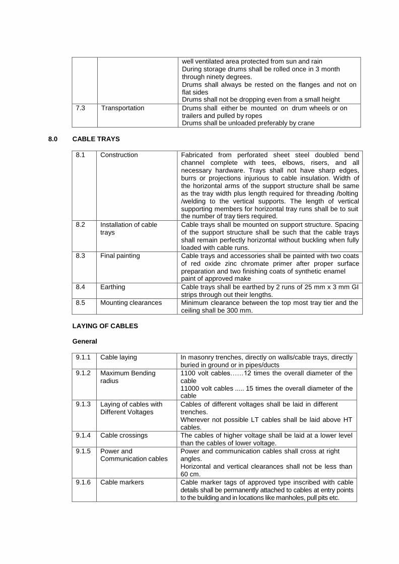
well ventilated area protected from sun and rain
During storage drums shall be rolled once in 3 month through ninety degrees. Drums shall always be rested on the flanges and not on flat sides Drums shall not be dropping even from a small height
7.3 Transportation Drums shall either be mounted on drum wheels or on trailers and pulled by ropes Drums shall be unloaded preferably by crane
8.0 CABLE TRAYS
8.1 Construction Fabricated from perforated sheet steel doubled bend channel complete with tees, elbows, risers, and all necessary hardware. Trays shall not have sharp edges, burrs or projections injurious to cable insulation. Width of the horizontal arms of the support structure shall be same as the tray width plus length required for threading /bolting /welding to the vertical supports. The length of vertical supporting members for horizontal tray runs shall be to suit the number of tray tiers required.
8.2 Installation of cable trays
Cable trays shall be mounted on support structure. Spacing of the support structure shall be such that the cable trays shall remain perfectly horizontal without buckling when fully loaded with cable runs.
8.3 Final painting Cable trays and accessories shall be painted with two coats of red oxide zinc chromate primer after proper surface preparation and two finishing coats of synthetic enamel paint of approved make
8.4 Earthing Cable trays shall be earthed by 2 runs of 25 mm x 3 mm GI strips through out their lengths.
8.5 Mounting clearances Minimum clearance between the top most tray tier and the ceiling shall be 300 mm.
LAYING OF CABLES
General
9.1.1 Cable laying In masonry trenches, directly on walls/cable trays, directly buried in ground or in pipes/ducts
9.1.2 Maximum Bending radius
1100 volt cables……12 times the overall diameter of the cable 11000 volt cables ..... 15 times the overall diameter of the cable
9.1.3 Laying of cables with Different Voltages
Cables of different voltages shall be laid in different trenches. Wherever not possible LT cables shall be laid above HT cables.
9.1.4 Cable crossings The cables of higher voltage shall be laid at a lower level than the cables of lower voltage.
9.1.5 Power and Communication cables
Power and communication cables shall cross at right angles. Horizontal and vertical clearances shall not be less than 60 cm.
9.1.6 Cable markers Cable marker tags of approved type inscribed with cable details shall be permanently attached to cables at entry points to the building and in locations like manholes, pull pits etc.

Cables laid in Masonry Trenches
9.2.1 MS Supports and Spacing
laid on painted MS supports fabricated from minimum 38mm x 38mm x 6mm painted / galvanized angle iron supports grouted in trench walls at intervals not exceeding 600 mm.
9.2.2 Multi tiers If required, cables shall be arranged in tier formation
9.2.3 Clamps and Saddles Suitable clamps, hooks and saddles shall be used for securing the cables in position
9.2.4 Cable dressing Ensure the clear spacing between the cables shall not be less then the diameter of the cable.
9.2.5 Trench filling After dressing of cables, trenches shall be filled with fine sand as directed.
9.2.6 Trench covers Chequered plate/RCC covers.
Cables laid on cable trays
9.3.1 Cable dressing Ensure the clear spacing between the cables shall not be less then the diameter of the cable.
9.3.2 Cable Clamping Type of cables
Size Clamping by Spacing
LT Upton 25 sq mm
Saddles 1 mm thick
45 cm
LT & HT 35 sq mm to 120 sq mm
Clamps 3 mm thick 25 mm wide
60 cm
LT & HT 150 sq mm and above
Clamps 3 mm thick 40 mm wide
60 cm
Spacing specified applies to straight runs. In the case of bends, additional clamping shall be provided at 30 cm from the center of the bend on both sides.
Laying In Pipes/Closed Ducts
9.4.1 Type of Pipes Spun reinforced concrete or PVC pipes shall be used for such purposes
9.4.2 Installation conditions Single cable …Pipe diameter shall not be less than 100 mm Multiple cables …Minimum diameter of pipe 150 mm Top surface of pipes shall be at a minimum depth of 600 mm from the ground level
9.4.3 Pipe cleaning Pipes shall be continuous, clear of debris or concrete and sharp edges at ends smoothened before cable is drawn.
Laying Of Cables In Floors
9.5.1 Restricted Only with prior approval of Engineer –in-charge.
9.5.2 Installation Conditions No cables to be laid directly in floors Cable laying only in GI pipes of adequate size
Buried Directly In Ground
9.6.1 General conditions All water pipes, sewage lines or other structures which become exposed by excavation shall be properly supported and protected from injury until the filling has been rammed solidly in places under and around them.
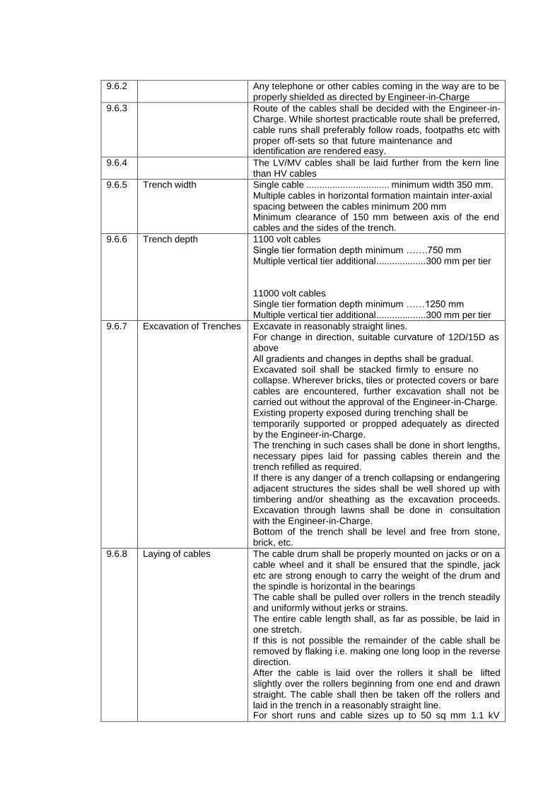
9.6.2 Any telephone or other cables coming in the way are to be
properly shielded as directed by Engineer-in-Charge
9.6.3 Route of the cables shall be decided with the Engineer-in- Charge. While shortest practicable route shall be preferred, cable runs shall preferably follow roads, footpaths etc with proper off-sets so that future maintenance and identification are rendered easy.
9.6.4 The LV/MV cables shall be laid further from the kern line than HV cables
9.6.5 Trench width Single cable ................................ minimum width 350 mm. Multiple cables in horizontal formation maintain inter-axial spacing between the cables minimum 200 mm Minimum clearance of 150 mm between axis of the end cables and the sides of the trench.
9.6.6 Trench depth 1100 volt cables Single tier formation depth minimum …….750 mm Multiple vertical tier additional ................... 300 mm per tier
11000 volt cables Single tier formation depth minimum ……1250 mm Multiple vertical tier additional ................... 300 mm per tier
9.6.7 Excavation of Trenches Excavate in reasonably straight lines. For change in direction, suitable curvature of 12D/15D as above All gradients and changes in depths shall be gradual. Excavated soil shall be stacked firmly to ensure no collapse. Wherever bricks, tiles or protected covers or bare cables are encountered, further excavation shall not be carried out without the approval of the Engineer-in-Charge. Existing property exposed during trenching shall be temporarily supported or propped adequately as directed by the Engineer-in-Charge. The trenching in such cases shall be done in short lengths, necessary pipes laid for passing cables therein and the trench refilled as required. If there is any danger of a trench collapsing or endangering adjacent structures the sides shall be well shored up with timbering and/or sheathing as the excavation proceeds. Excavation through lawns shall be done in consultation with the Engineer-in-Charge. Bottom of the trench shall be level and free from stone, brick, etc.
9.6.8 Laying of cables The cable drum shall be properly mounted on jacks or on a cable wheel and it shall be ensured that the spindle, jack etc are strong enough to carry the weight of the drum and the spindle is horizontal in the bearings The cable shall be pulled over rollers in the trench steadily and uniformly without jerks or strains. The entire cable length shall, as far as possible, be laid in one stretch. If this is not possible the remainder of the cable shall be removed by flaking i.e. making one long loop in the reverse direction. After the cable is laid over the rollers it shall be lifted slightly over the rollers beginning from one end and drawn straight. The cable shall then be taken off the rollers and laid in the trench in a reasonably straight line. For short runs and cable sizes up to 50 sq mm 1.1 kV

grade the alternative method of direct handling can be
adopted with the prior approval of the Engineer-in-Charge.
9.6.9 Testing and measuring cable
When the cable has been properly straightened the cores shall be tested for continuity and insulation resistance and cable measured. Suitable moisture sealing compound/tape shall be used for sealing of the ends.
9.6.10 Cable protection Trench Base Cushion 80 mm layer of clean dry sand Single tier 170 mm covering of clean dry sand above base cushion vertical multi-tier sand cushion of 300 mm after first layer of cables Each additional tiers shall have a sand cushion of 300 mm. Top most cable shall have a final sand covering not less than 170 mm Final protective cover with second class bricks of not less than 200 mm x 100 mm x 100 mm (normal size) laid breadth wise for the full length of the cable covering all the cables and projecting minimum 50 mm over the sides of the end cables. In addition bricks on edge shall be placed along the entire run on either side of the cable run.
9.6.11 Finishing trenches Back filling with excavated earth free from stones or other sharp edged debris and ramming and watering in successive layers not exceeding 300 mm. Unless otherwise specified a crown of earth not less than 50 mm in the centre and tapering towards the side of the trench shall be left to allow for subsidence. Where road berms or lawns have been cut or kern stones displaced the same shall be repaired and made good to the satisfaction of the Engineer-in-Charge and all surplus earth and rocks removed to places as specified.
9.6.12 Cable route markers Cable route markers made out of 100 mm x 5 mm GI plates bolted to 35 mm x 35 mm x 6 mm x 60 cm long angle with details of cables shall be installed at intervals not exceeding 100 m in straight runs and at cable bends. Underground joints shall also be identified with markers.
Cable Entry Into Buildings
Cable entry into buildings through RCC pipes recessed in the floor.
RCC Hume pipes shall slope down wards from the building.
The pipe shall be filled with sand and sealed at both ends with bitumen mastic to avoid entry of water.
Suitable size manholes shall be provided wherever required to facilitate drawing of cables as per requirements.
Wall / Floor Crossing
Adequately sized sleeves shall be provided for all wall and floor crossings. The annular space around the cables at either ends shall be sealed with fire resistance packing material.
10.0 TERMINATION/JOINTING OF CABLES
10.1 3300 volt Grade cables
10.1.1 Type of jointing NO Soldered jointing/termination shall be totally avoided. Only Solder less crimped terminations to be provided

10.1.2 Compression Glands double compression glands
10.1.3 Crimping Tools Any terminations may without use of proper crimping tool is shall be liable to be rejected.
10.1.4 Conductor cleaning Conductor oxidation shall be cleaned with emery paper and a thin coat of tin applied before crimping into any equipment.
10.2 33000 volt grade cables
10.2.1 Terminations Heat shrinkable terminations shall be provided for High Voltage cables
11.0 MEASUREMENT OF CABLE RUNS
The cable runs shall be measured up to the outer end of the boxes without any allowances for over lap in joints. The rate shall include all the above mentioned material, labour etc for laying as required.
CABLE LOOPS
At the time of the installation approximately 3 meters of surplus cable shall be left - at each end of the cable - on each side of underground straight through/tee/termination joints. - at entries to buildings - and such other places as may be decided by the Engineer-in-Charge .
This cable shall be left in the form of a loop.
Wherever long runs of cable length are installed cable loops shall be left at suitable intervals as specified by the Engineer-in-Charge.
13.0 BONDING OF CABLES.
Where a cable enters any piece of apparatus it shall be connected to it by means of an approved type of armored clamp or gland. The clamps must grip the armoring firmly to the gland or casting, so that in the event of ground movement no undue stress is placed on to the cable conductors.
TESTING
Tests At Manufacturer's Work
The cables shall be subjected to shop test in accordance with relevant standards IS 10810 to prove the design and general qualities to the cables as below
Routine test on 100% of cables. Conductor resistance test, High voltage test,
Acceptance tests on drums chosen at random as per IS 7098 for acceptance of the lot. Annealing test for copper,
Aluminium - tensile test, Aluminium wrapping test Conductor resistance test Thickness of insulation and sheath Hot set test for insulation Tensile strength and elongation at break test for insulation and sheath High voltage test Insulation resistance test (volume resistivity)
Type test on each type of cables, inclusive of measurement of armor DC resistance of power cables.

Site Testing
All cables before laying shall be tested with a 500 V mugger for 1.1 kV grade or with a 2,500/5,000 V mugger for cables of higher voltages. The cables cores shall be tested for continuity, absence of cross phasing, insulation resistance to earth/sheath/armor and insulation resistance between conductors.
All cables shall be subject to above mentioned test during laying, before covering the cables by protective covers and back filling and also before the jointing operations.
After laying and jointing, the cable shall be subjected to a 15 minutes AC/DC pressure test. In the absence of facilities for pressure testing, it is sufficient to test for one minute with 1000 V mugger for cables of 1.1 kV grade and with 2500/5000 V mugger for cables of higher voltages.
Test Witness
Tests shall be performed in presence of representative of Engineer-in-Charge. The Contractor shall give at least fifteen (15) days advance notice of the date when the tests are to be carried out.

CHAPTER 3 : 415 VOLTS MV SWITCHBOARDS
1.0 GENERAL
This section covers specification of Switchboards
2.0 STANDARDS AND CODES
The Standards and Codes applicable to the works are listed in Annexure I of the tender document and may be referred to.
SWITCHGEAR
LT Air Circuit Breakers
3.1.1 Type Air Break
3.1.2 Operating voltage 415 volt 3 phase 50 Hz
3.1.3 Insulation Voltage 660 volts
3.1.4 Current rating As per Schedule of Quantities
3.1.5 Fault Level withstand Ices
As per Schedule of Quantities
3.1.6 Ice 100% Ices
3.1.7 Icy 100% Ices
3.1.8 Isolation function As per IEC 60947-2 Section 7.12
3.1.9 Insulation Cass II insulation between the front panel and internal power circuits
3.1.10 Cubicle mounting Draw out unless otherwise stated.
3.1.11 Operating mechanism
Trip free such that the circuit breaker is at all times free to open immediately the trip coil is energized
Independent Manual spring closing (IMS) or motor wound spring closing mechanism (MWS) as per Schedule of Quantities
3.1.12 No of Poles 3 or 4 as required
3.1.13 All current carrying parts
Silver plated
3.1.14 Arcing contacts Shall be provided to protect the main contacts and shall be separate from the main contacts and easily replaceable.
3.1.15 Arc chutes Shall be provided for each pole, and shall be suitable for being lifted out for the inspection of the main and the arcing contacts.
3.1.16 Isolating Contacts Self aligning cluster type
3.1.17 Safety Shutters Earthed metal or insulated automatically operated shutters to screen live cluster contacts when the Breaker is withdrawn from the cubicle
3.1.18 Auxiliary Contacts Self aligning sliding auxiliary contacts. Free / minimum 6 NO/NC auxiliary contacts rated at 16 amps 415 volts 50 Hz These shall be approachable from the front for connecting all external wiring They shall close before the main contacts when the Circuit Breaker is plugged in and vice versa when the Circuit Breaker is Drawn Out of the cubicle. The fixed portion of the sliding contacts shall have easy access for maintenance purposes.
3.1.19 Indications and Mechanical ON/OFF indication

Operations integral
with ACB on front Operating handle
Mechanical trip push button
Mechanical indicator for ‗Ready to close‘ situation for the breaker by checking all interlocking.
Indication of mechanical wear of contacts and hence contact life
3.1.20 Anti pumping mechanism
Mechanical and electrical devices integral to Breaker
3.1.21 Circuit Breaker operational positions
Four distinct and separate positions and shall be indicated on the face of the panel.
"Service" -- Both main and secondary isolating
contacts closed "Test" -- Main isolating contacts open and
secondary isolating contacts closed "Isolated" -- Both main and secondary isolating
contacts open "Maintenance" -- Circuit Breaker fully outside the panel
ready for maintenance
3.1.22 Accessories Control wiring and all accessories shunt trip coil, under voltage release etc shall be fit table and accessible from front.
3.1.23 Circuit Breaker Interlocking
Sequence type strain free interlocks shall be provided to ensure the following:
Breamer cannot be withdrawn from the cubicle when in the "ON" position. Suitable mechanism shall be provided to lock the Breaker in the tripped position before the Breaker is isolated.
Breaker cannot be switched "ON" until it is either in the fully inserted position or, for testing purposes, it is in the fully isolated position.
Circuit Breaker cannot be plugged in unless it is in the OFF position.
A safety latch shall be provided to ensure that the movement of the Breaker is checked when being withdrawn to prevent its accidental fall due its weight.
Sheet steel hinged lockable doors for each separate compartment shall be provided and duly interlocked with the breaker in "ON" and "OFF" position.
3.1.24 Protection Microprocessor based releases EMC (Electro Magnetic Compatible) having built in overload, short circuit & earth fault protection and/or EMI (Electromagnetic indication)/ numeric relays shall be provided for the Circuit Breakers as stipulated in the Schedule of Quantities
3.1.25 Earthing The frame of the Circuit Breaker shall be positively earthed when the Circuit Breaker is racked into the cubicle.
3.1.26 Types of terminals Flexibility in changing at site to suit the bus bar orientation
3.1.27 Electrical endurance with maintenance
Breakers up to 4000 amps …………greater than 5000 cycles Breakers 4000 amps and above .... 1500 cycles
3.1.28 Type test certificates Submit Certificates from a recognized test house for the Circuit Breakers offered.

Moulded Case Circuit Breakers (MCCB)
3.2.1 Type Air Break
3.2.2 Operating voltage 415 volt 3 phase 50 Hz
3.2.3 Insulation Voltage 660 volts
3.2.4 Current rating As per Schedule of Quantities
3.2.5 Fault Level withstand Ices
As per Schedule of Quantities
3.2.6 Ice 100% Ices
3.2.7 Icy 100% Ices
3.2.8 Isolation function As per IEC 60947-2 Section 7.12
3.2.9 Insulation class II insulation between the front panel and internal power circuits
3.2.10 Cubicle mounting Fixed unless otherwise specified
3.2.11 Operating mechanism
Trip free Independent Manual spring closing (IMS) or motor wound spring closing mechanism (MWS) as per Schedule of Quantities
3.2.12 No of Poles 3 or 4 as required
3.2.13 All current carrying parts
Silver plated
3.2.14 Arcing contacts Shall be provided to protect the main contacts and shall be separate from the main contacts and easily replaceable.
3.2.15 Arc chutes Shall be provided for each pole, and shall be suitable for being lifted out for the inspection of the main and the arcing contacts.
3.2.16 Common Operating handle
Required for Three phase MCCBs for simultaneous operation and tripping of all the three phases.
3.2.17 Indications and Operations integral with ACB on front
mechanical ON/OFF/ Tripped indication
Operating handle mechanical trip push button
3.2.18 Accessories Following accessories shall be provided as required
Under voltage trip
Shunt trip
Alarm switch Auxiliary switch
3.2.19 Circuit Breaker Interlocking
Interlocks shall be provided to ensure the following:
Handle interlock to prevent unnecessary manipulations of the breaker.
Door interlock to prevent door being opened when the breaker is in ON position
Deinterlocking device to open the door even if the breaker is in ON position.
Sheet steel hinged lockable doors for each separate compartment shall be provided and duly interlocked with the breaker in "ON" and "OFF" position.
3.2.20 Protection Microprocessor based releases and/or thermal magnetic releases shall be provided for the Circuit Breakers as stipulated in the Schedule of Quantities
3.2.21 Electrical endurance Upton 250 amps ....................... minimum 10,000 operations For 400 amps & above ........... minimum 4,000 operations
3.2.22 Type test certificates Submit Certificates from a recognized test house for the Circuit Breakers offered.
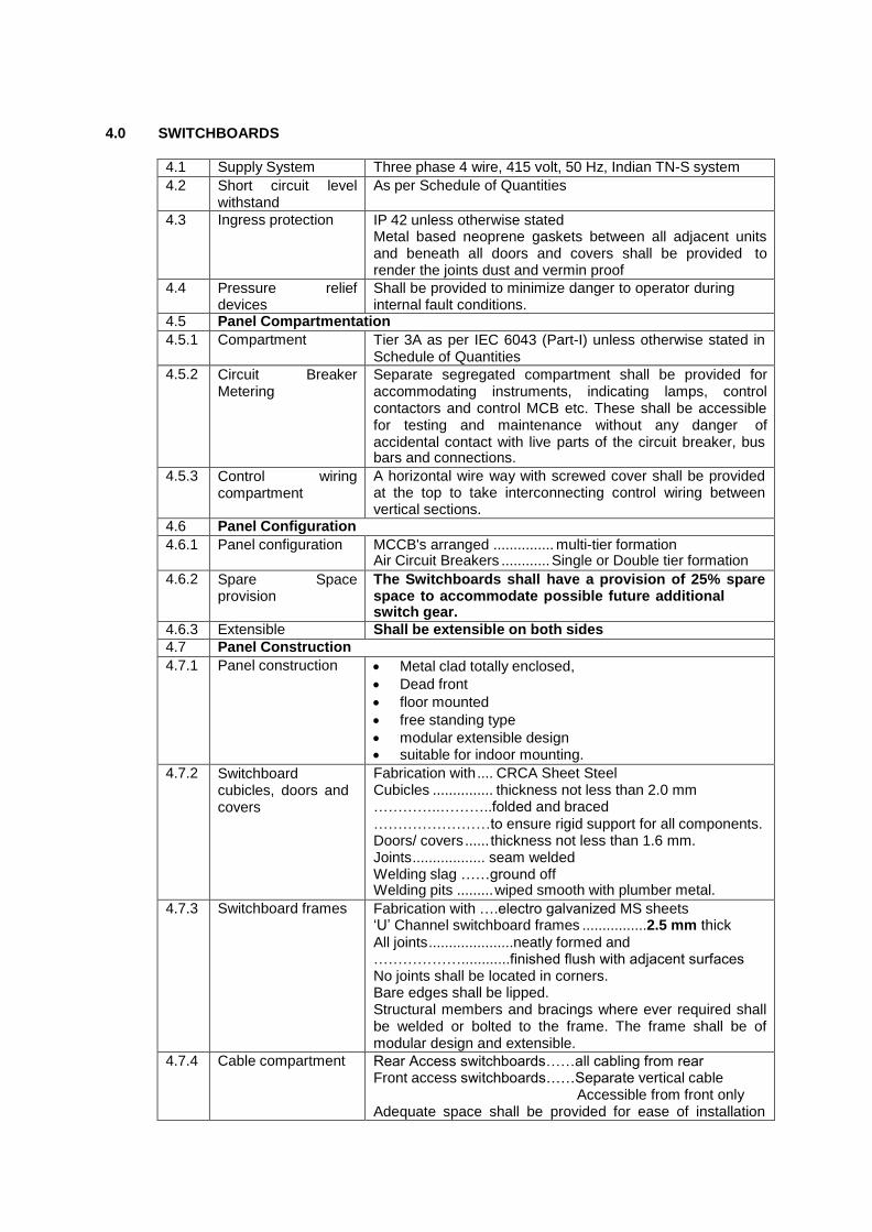
4.0 SWITCHBOARDS
4.1 Supply System Three phase 4 wire, 415 volt, 50 Hz, Indian TN-S system
4.2 Short circuit level withstand
As per Schedule of Quantities
4.3 Ingress protection IP 42 unless otherwise stated Metal based neoprene gaskets between all adjacent units and beneath all doors and covers shall be provided to render the joints dust and vermin proof
4.4 Pressure relief devices
Shall be provided to minimize danger to operator during internal fault conditions.
4.5 Panel Compartmentation
4.5.1 Compartment Tier 3A as per IEC 6043 (Part-I) unless otherwise stated in Schedule of Quantities
4.5.2 Circuit Breaker Metering
Separate segregated compartment shall be provided for accommodating instruments, indicating lamps, control contactors and control MCB etc. These shall be accessible for testing and maintenance without any danger of accidental contact with live parts of the circuit breaker, bus bars and connections.
4.5.3 Control wiring compartment
A horizontal wire way with screwed cover shall be provided at the top to take interconnecting control wiring between vertical sections.
4.6 Panel Configuration
4.6.1 Panel configuration MCCB's arranged ............... multi-tier formation Air Circuit Breakers ............ Single or Double tier formation
4.6.2 Spare Space provision
The Switchboards shall have a provision of 25% spare space to accommodate possible future additional switch gear.
4.6.3 Extensible Shall be extensible on both sides
4.7 Panel Construction
4.7.1 Panel construction Metal clad totally enclosed,
Dead front
floor mounted
free standing type
modular extensible design suitable for indoor mounting.
4.7.2 Switchboard cubicles, doors and covers
Fabrication with .... CRCA Sheet Steel Cubicles ............... thickness not less than 2.0 mm …………..………..folded and braced
……………………to ensure rigid support for all components. Doors/ covers ...... thickness not less than 1.6 mm. Joints .................. seam welded Welding slag ……ground off Welding pits ......... wiped smooth with plumber metal.
4.7.3 Switchboard frames Fabrication with ….electro galvanized MS sheets ‗U‘ Channel switchboard frames ................2.5 mm thick
All joints .....................neatly formed and ………………............finished flush with adjacent surfaces No joints shall be located in corners. Bare edges shall be lipped. Structural members and bracings where ever required shall be welded or bolted to the frame. The frame shall be of modular design and extensible.
4.7.4 Cable compartment Rear Access switchboards……all cabling from rear Front access switchboards……Separate vertical cable
Accessible from front only Adequate space shall be provided for ease of installation

and maintenance with safety for working without coming into
contact with any live parts. The cable chambers shall be complete with
Adequate support for cables.
tinned brass cable sockets,
tinned brass compression glands,
3 mm thick gland plates,
supporting clamps and brackets etc for termination of 1100 volt grade aluminium conductor XLPE/ PVC/ PVCA cables.
4.7.5 Door handles Good quality door handles fitted with toggles to operate rods to latch with suitable slots in both top and bottom of switchboards shall be provided. Latching rods and associated brackets shall be cadmium plated.
4.7.6 Operating handles All operating device shall be located in front of switchgear only.
4.7.7 Fixing Screws Fixing screws shall enter holes tapped into an adequate thickness of metal or provided with hank nuts. Self threading screws shall not be used in switchboards.
4.7.8 Dimensional Limitations
Base channel 75 mm x 5 mm thick shall be provided at the bottohm.
Minimum 200 mm blank space between the floor of switchboard and bottom most unit shall be provided.
Overall height shall be limited to 2300 mm unless otherwise stipulated.
Height of the operating handle, push buttons etc shall be restricted between 300 mm and 1700 mm from finished floor level.
4.8 Switchboard Bus Bars, Interconnections etc rating
4.8.1 Rating of Bus Bars, interconnections and to feeders
These shall be designed as per requirements in Schedule of Quantities to
Carry full load current for phase and neutral bus bars
withstand the stresses of fault level
for aluminium shall have a minimum cross section of 1 amp per sq.mm.
Copper 0.6 amps per sq mm
4.9 Switchboard Bus Bars
4.9.1 Bus Bar material High conductivity, high strength aluminium alloy, complying with requirements of grade E 91E of IS 5082 – 1981 Alternatively Electrical grade 99.99% pure copper As per Schedule of Quantities
4.9.2 Bus Bar Insulation Heat shrunk PVC sleeking of 1.1 kV grade and bus bar joints provided with clip-on shrouds.
4.9.3 Bus Bar supports Non-breakable, non-hygroscopic epoxy resin or glass fiber reinforced polymer insulated supports able to withstand operating temperature of 110
O C at regular intervals, to
withstand the forces arising from a fault level as stipulated in schedule of quantities.
4.9.4 Colour Coding All bus bars shall be colour coded.
4.9.5 Auxiliary Bus Electrolytic copper Auxiliary buses for control power supply, space heater power supply or any other specified service shall be provided. These shall be insulated, adequately supported and sized to suit specific requirement.

4.10 Switchboard Interconnections
4.10.1 Interconnection material
Unit amps,
ratings up to 100 FRLS PVC insulated copper conductor wires with crimped terminations.
Rating of 100 amps and above
Solid copper/ aluminium connections PVC sleeved
4.10.2 Interconnection jointing
All connections, tapings etc
Shall be made to ensure minimum contact resistance.
shall be firmly bolted and clamped with even tension. Before assembly
joint surfaces shall be filed or finished to remove burrs, dents and oxides and silvered to maintain good continuity at all joints.
All screws, bolts, washers shall be cadmium plated. Approved spring washers shall be used with cadmium plated high tensile steel bolts with BSF threads.
4.10.2 Instrument control wiring
and All wiring for relays and meters shall be with ZHFR PVC insulated copper conductor wires. The wiring shall be coded and labelled with approved ferrules for identification. The minimum size of copper conductor control wires shall be 2.5 sq. mm.
4.11 Earthing Continuous earth bus sized for prospective fault current shall be provided with arrangement for connecting to station earth at two points. Hinged doors / frames shall be connected to earth through adequately sized flexible braids.
4.12 Ventilation Fans Panel mounting type ventilation fans shall be provided in each panel with switchgear rated for 2500 amp and above. The fan shall be interlocked with switchgear operation.
4.13 Space Heaters Anti- condensation heaters shall be fitted in each cubicle together with an ON/OFF isolating switch suitable for electrical operation at 230 volts A.C 50 Hz single phase of sufficient capacity to raise the internal ambient temperature by 5
O C operation interlocked with switchgear.
4.14 Sheet Treatment Painting
Steel And
Sheet steel used in the fabrication of switchboards shall undergo a rigorous cleaning and surface treatment seven tank process comprising of alkaline degreasing, descaling in dilute sulphuric acid and a recognized phosphating process after which a coat of primer paint comp actively with the final paint shall be applied over the treated surface. Final paint coat of oven baked powder coating, of minimum 50 micron thickness, of sheet approved by Engineer-in- Charge shall then be provided.
4.15 Labels Suitable engraved white on black metal identification labels shall be provided for each switchgear cubicle in front and back identifying the circuit, switchgear type, rating and duty.
4.16 Testing at manufacturers works
All wiring checks and connections
Relay adjustment
Interlock function check
Continuity checks of wiring, fuses
Insulation test
Trip test Hight voltage test
4.17 Testing commissioning
and Assembly of various sections of panels
Grounding the units
Connecting up bus bars and jointing insulated Insulation test with 500 volts megger. The insulation
resistance not more than 100 mega ohms

4.18 Local Authority
Requirements All requirements by the local Authority including those listed below shall be complied with
Provisoon for Gas nozzles within each cubicle
Danger Notice Plate
Rubber floor mat of 6 m thickness and 1 m width provided for the full length of the switchboard.
A dry chemical type fire extinguisher of required capacity with approved label

CHAPTER 4 : RELAYS, CTs, PTs, METERS, INDICATING LAMPS ETC.
1.0 GENERAL
This section covers specifications for Protection and Control Relays for breakers, Instrument Transformers, Measuring Instruments, Push Buttons, Indicating Lamps etc. required in LT and HT switchboards.
2.0 STANDARDS AND CODES
Updated and current Indian Standard Specifications and Codes of Practice will apply to the equipment and the work covered by the scope of this contract. In addition the relevant clauses of the Indian Electricity Act 1910, Indian Electricity Rules 1956, National Building Code 1994, National Electric Code 1985, Code of Practice for Fire Safety of Building (general) :General Principal and Fire Grading – IS 1641 as amended up to date shall also apply. Wherever appropriate Indian Standards are not available, relevant British and/or IEC Standards shall be applicable.
Application guide for Current Transformers IS 4201 : Application guide for Voltage Transformers IS 4140 : Application guide for Relays IS 3842 : Electromagnetic Relays IS 5051 :
3.0 PROTECTION AND CONTROL RELAYS
The Circuit Breaker shall have protection and control relays as specified in the bill of quantities. Relays shall be approved types complying to relevant ISS and having approved characteristic. Relays shall be flush mounted in dust proof cases. Relays shall be arranged so that adjustments, testing and replacement can be affected with minimum of time and labour.
Incase of C.T. operated thermal overload and magnetic instantaneous short circuit release. The overload releases shall be such that each phase can be individually set depending on the phase unbalanced currents. The releases shall have inverse time current characteristics and the magnetic release shall be time delayed with a minimum setting of 25 ms varying up to 300 ms for discrimination without effecting the breaking current capacity of the ACB.
4.0 CURRENT TRANSFORMERS
Separate sets of CTs shall be provided for metering and protection. C/Ts shall confirm to IS 2705 (part -I, II and III) in all respects. All C/Ts used for medium voltage application shall be rated for 1 kV. C/Ts shall have rated primary current, rated burden and class of accuracy as specified in Bill of Quantities/drawings. Rated secondary current shall be 5A unless otherwise stated. Minimum acceptable class for measurement shall be class 0.5 to 1 and for protection class SP 10. C/Ts shall be capable of withstanding magnetic and thermal stresses due to short circuit faults of 31 MVA on medium voltage. Terminals of C/Ts shall be paired permanently for easy identification of poles. C/Ts shall be provided with earthing terminals for earthing chassis, frame work and fixed part of metal casing (if any). Each C/T shall be provided with rating plate indicating :
Name and make
Serial number
Transformation ratio
Rated burden
Rated voltage
Accuracy class

CTs shall be mounded such that they are easily accessible for inspection, maintenance and replacement. Wiring for CT shall be with copper conductor FRLS PVC insulated wires with proper termination works and wiring shall be bunched with cable straps and fixed to the panel structure in a neat manner.
5.0 POTENTIAL TRANSFORMER
PTs shall confirm to IS 3156 (Part-I, II and III) in all respects.
MEASURING INSTRUMENTS
Direct reading electrical instruments shall conform to IS 1248 or in all respects. Accuracy of direct reading shall be 1.0 of voltmeter and 1.5 for ammeters. Other instruments shall have accuracy of 1.5. Meters shall be suitable for continuous operation between -10
o C and +50
0C.
Meters shall be flush mounting and shall be enclosed in dust tight housing. The housing shall be of steel or phenolic mould. Design and manufacture of meters shall ensure prevention of fogging of instrument glass. Pointer shall be black in colour and shall have Zero position adjustment device operable from out side. Direction of deflection shall be from left to right. Suitable selector switches shall be provided for ammeters and volt meters used in three phase system. The rating type and quantity of meters, instruments and protective device shall be as per Bill of Quantities /drawings
Ammeters
Ammeters shall be of moving iron type. Moving part assembly shall be with jewel bearings. Jewel bearings shall be mounted on a spring to prevent damage to pivot due to vibrations and shocks. Ammeters shall be manufacture and calibrated as per IS 1248
Ammeters shall normally be suitable for 5 A secondary of current transformers. Ammeters shall be capable of carrying substantial over loads during fault conditions.
Voltmeters
Voltmeters shall be moving iron type range of 3 phase 415 volt voltmeters shall be 0-500. Volt meters shall be provided with protection fuse.
Watt meter
Wattmeter shall be of 3 phase electro dynamic type and shall be provided with a maximum demand indicator if required.
Power factor meters
3 phase power factor meters shall be of electro dynamic type with current and potential coils suitable for operation with current and potential transformers provided in the panel. Scale shall be calibrated for 50% lag - 100% - 50% readings. Phase angle accuracy shall be +4
0.
Energy and reactive power meters
Trajectory meters shall be two element, integrating type, KWH, KVA, KVARH meters. Meters shall confirm to IEC 170 in all respects. Energy meters, KVA, and KVARH meters shall be provided with integrating registers. The registers shall be able to record energy conception of 500 hours corresponding to maximum current at rated voltage and unity power factor. Meters shall be suitable for operation with current and potential transformers available in the panel.

7.0 INDICATING LAMPS
Neon type indicating lamps shall be provided for indication of phases and Breaker position as required in the bill of quantities. Lamps shall be easily removed and replaced from the front of the panel by manual means not requiring the use of extractors.
8.0 PUSH BUTTONS
Push buttons shall be of non hygroscopic material, non-swelling and fitted to avoid any possibility of sticking. Contacts shall be of adequate strength and have a positive whipping action when in operation

CHAPTER 5 : BATTERY AND BATTERY CHARGER
1.0 GENERAL
This section covers specifications for lead acid batteries and float cum boost battery chargers. DC is considered as unearthed system.
2.0 STANDARDS AND CODES
Updated and current Indian Standard Specifications and Codes of Practice will apply to the equipment and the work covered by the scope of this contract. In addition the relevant clauses of the Indian Electricity Act 2003, Indian Electricity Rules 1956, National Building Code 1994, National Electric Code 1985, Code of Practice for Fire Safety of Building (general) :General Principal and Fire Grading – IS 1641 as amended up to date shall also apply. Wherever appropriate Indian Standards are not available, relevant British and/or IEC Standards shall be applicable.
Electrical vocabulary secondary cells and batteries IS 1885 Lead Acid SMF VRLA Batteries JIS C8702 Water for storage batteries IS 1069 Sulfuric Acid for storage batteries IS 266 General requirements for tests for lead acid storage batteries IS 8320 Rubber and Plastic containers for batteries IS 1146 Synthetic Separators IS 6071 High performance planet cells BS 6290 (Part II) IE recommendations for sizing of large lead acid storage batteries IEEE 485 Design and installation of storage batteries IEEE 484 Stationary lead acid batteries IEC – 896 (Part I)
3.0 BATTERY
The battery shall be sealed maintenance free / valve regulated led acid (SMF/VRLA) battery. The batteries shall be manufactured using ―absorbent glass matt‖ technology in which the electrolyte is in absorb condition, held within the pores of the glass matt separator. The separator is packed tightly between the positive and negative plates. ―Led Calcium Tin Alloy‖ shall be used in the plate grid structure to eliminate harmful effect of early gassing. The container and the lid of the battery shall be of high grade polypropylene. The vent plugs shall be provided with self resealing relief valves. The battery shall be rated for minimum 100 AH at 30 volt DC unearthed system. The battery sizing calculation to be carried out by vendor during detailed engineering stage and to be submitted to Electrical consultant for verification and approval.
BATTERY CHARGERS
General
The battery charger shall be float cum boost type, thermistors controlled. The charger shall have selector switch for auto float – boost/manual, float /manual boost mode of operation. during auto float – boost mode, automatic changeover shall take place from float mode to boost mode and vice versa. This means that when the batteries are fully charged the charging shall automatically change from boost charge to trickle charge.
Construction feature
The float cum boost charger and DC distribution board shall be housed in sheet steel cubicle of angle iron frame work with panels of 1.6 mm thickness, louvers for ventilation, glands plate will be provided for cable entry from front bottom. The cubicle shall be painted in siemens grey shade. Four wheels/2 nose channels shall be provided at the base.

Performance
The DC output voltage of float /boost charger shall be stabilized within ± 2% for AC. Input variation of 230 V ± 10%, frequency variation of 50 Hz ±5% and DC load variation of 0-100%. The voltage regulation shall be achieved by a constant voltage regulator having fast response SCR & Controlled. The ripple content in output will be within 3% of DC output nominal voltage.
There shall be provision to select auto float/manual float /manual boost modes. During auto float mode the battery charging shall automatically changeover from boost mode to flat mode and vice versa. During manual float/boost modes it shall be possible to set the output volts by separate potentiometers.
The battery charger shall have automatic output current limiting feature.
Components
The battery charger shall essentially comprise of the following
1 no. double pole ON/OFF MCB at AC input
1 no. pilot lamp to indicate charger ON.
1 no. main transformer : Double wound, naturally air cooled, having copper windings.
1 set single phase full wave bridge rectifier consisting of 2 nos. Diodes and 2 nose SCRs liberally rated, mounted on heat sinks and complete with resistor / condenser network for surge suppression.
1 no. rotary switch to select auto float / manual float / manual boost. During auto float mode automatic changeover shall take place from float mode to boost mode and vice versa.
1 set solid state constant potential controller to stabilize the DC output voltage of the float cum boost charger at ±2% of the set value for AC input voltage variation of 230 V ± 10%, frequency variation of ±5% from 50 Hz and simultaneous load variation of 0-100% and also complete with current limiting circuit to drop the float charger output voltage upon overloads to enable the battery to take over.
1 no. electronic controller to automatically changeover battery charging from boost to float and vice versa
1 no. DC ammeter and toggle switch to read charger output current and battery charge/discharge current.
1 no. moving coil DC voltmeter to read the DC output voltage.
2 set potentiometer to adjust the output voltage during manual/auto float and boost modes.
1 no. double pole ON/OFF MCB at charger output.
DC distribution board.
Alarm annunciation
Visual and audible alarm with manual accept/ reset facility shall be provided for the following - AC mains fail - Charger fail - Load / output over volt
Potential free contact for BMS connectivity for maintaining battery status.
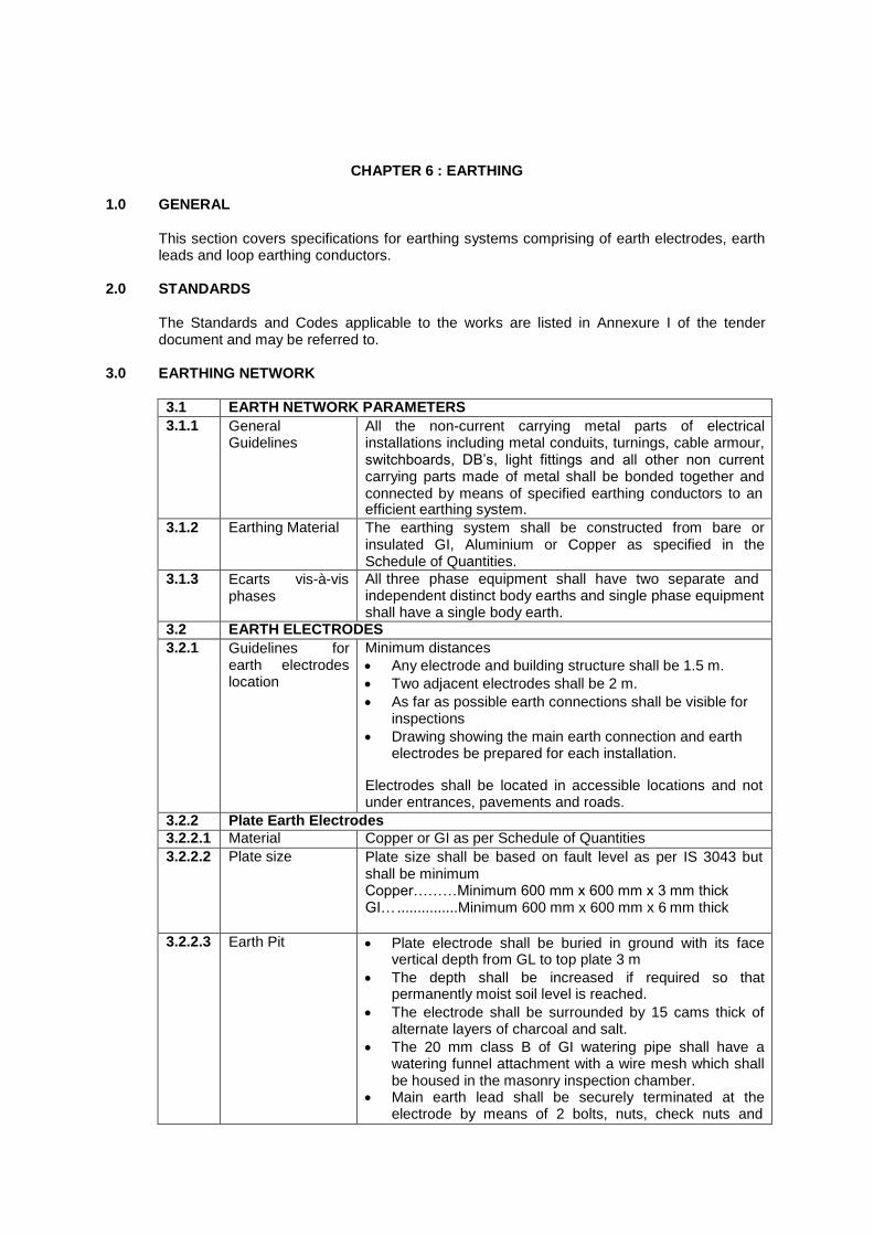
CHAPTER 6 : EARTHING
1.0 GENERAL
This section covers specifications for earthing systems comprising of earth electrodes, earth leads and loop earthing conductors.
2.0 STANDARDS
The Standards and Codes applicable to the works are listed in Annexure I of the tender document and may be referred to.
3.0 EARTHING NETWORK
3.1 EARTH NETWORK PARAMETERS
3.1.1 General Guidelines
All the non-current carrying metal parts of electrical installations including metal conduits, turnings, cable armour, switchboards, DB‘s, light fittings and all other non current carrying parts made of metal shall be bonded together and connected by means of specified earthing conductors to an efficient earthing system.
3.1.2 Earthing Material The earthing system shall be constructed from bare or insulated GI, Aluminium or Copper as specified in the Schedule of Quantities.
3.1.3 Ecarts vis-à-vis phases
All three phase equipment shall have two separate and independent distinct body earths and single phase equipment shall have a single body earth.
3.2 EARTH ELECTRODES
3.2.1 Guidelines for earth electrodes location
Minimum distances
Any electrode and building structure shall be 1.5 m.
Two adjacent electrodes shall be 2 m.
As far as possible earth connections shall be visible for inspections
Drawing showing the main earth connection and earth electrodes be prepared for each installation.
Electrodes shall be located in accessible locations and not under entrances, pavements and roads.
3.2.2 Plate Earth Electrodes
3.2.2.1 Material Copper or GI as per Schedule of Quantities
3.2.2.2 Plate size Plate size shall be based on fault level as per IS 3043 but shall be minimum Copper………Minimum 600 mm x 600 mm x 3 mm thick GI… ............... Minimum 600 mm x 600 mm x 6 mm thick
3.2.2.3 Earth Pit Plate electrode shall be buried in ground with its face vertical depth from GL to top plate 3 m
The depth shall be increased if required so that permanently moist soil level is reached.
The electrode shall be surrounded by 15 cams thick of alternate layers of charcoal and salt.
The 20 mm class B of GI watering pipe shall have a watering funnel attachment with a wire mesh which shall be housed in the masonry inspection chamber.
Main earth lead shall be securely terminated at the electrode by means of 2 bolts, nuts, check nuts and

spring washers to be of GI for GI plate and tinned bras
for copper plate
The earth lead from the electrode up to the test link in masonry chamber shall be drawn in a suitable diameter class B GI pipe for mechanical protection as per BOQ
The lead shall terminate in a test link provided in the inspection chamber to enable the earth electrode to be isolated for measuring earth resistance.
3.2.3 Pipe Earth Electrodes
3.2.3.1 Material Class B (medium) GI pipe
3.2.3.2 Pipe Size 40 mm dia 4500 mm long Pipe shall be tapered at the bottom and shall be provided with 12 mm dia holes drilled at every 75 mm.
3.2.3.3 Earth pit Pipe electrode shall be installed with its top not less than 200 mm below ground level.
The top shall be provided with a 40 mm x 20 mm reducer to fix watering funnel with mesh on top.
The 2 mtrs length of pipe below the inspection chamber shall be surrounded by 15 cams alternate layers of charcoal and salt
Earth lead shall be provided for pipe electrode and shall be terminated using a through GI bolt, nuts, check nuts, spring washers etc. at the top of pipe electrode
3.2.4 Masonry Chamber for pipe and earth electrode
Shall have earth test link and watering funnel
400 mm x 400 mm x 400 mm deep masonry inspection chamber
Lockable 10 mm thick cast iron hinged cover plate with frame
The hinged cover marked on top with identifier.
3.3 EARTH MATS
3.3.1 Separate Earth Conductors
Separate earth conductors of appropriate size shall be provided for.
Electrical Network
UPS system earth bus
Computer system earth bus Telephone system earth bus
3.3.2 Earth Mats Shall be constructed as per IEEE 80-2000, IS 3043:1987 and NBC with Copper /Aluminium /GI for horizontal and vertical conductors as per BOQ and drawing
Brazed / welded joints shall be coated with bituminous compound
Shall be constructed to achieve maximum resistance to earth as per par 3.8
3.3.3 Masonry chamber
450 mm x 450 mm x 450 mm deep Shall have joint plate of earth mat riser as per drawing
3.4 CHEMICAL EARTHING
Suitable for any type of soil conditions
Shall be constructed with ―Chemical component‖ and copper /SS/GI electrodes to achieve maximum resistance as per Para 3.8
Shall not require any maintenance after commissioning and shall have a minimum life of 50 years
3.5 EARTHING CONDUCTOR
3.5.1 Main Earth Lead From earth electrode inspection
Minimum depth …300 mm below ground Minimum depth….600 mm below road crossings/ pavements Earth lead ............ routed through GI pipe of adequate size. GI / copper wire…15 mm dia class B GI pipe.

chamber to main
switchboard GI pipe………….. Provided with a coat of bituminous paint on the outside for minimizing corrosion or wrapped with bituminous jute wrapping.
3.5.2 Secondary conductors
Secondary conductors shall be interconnected to form the earthing network throughout the installation and shall cover
Main earthing conductors from the main switchboards to all other switchboards
Sub-mains earthing conductors from switchboard to the sub distribution boards and to final distribution boards.
Loop earthing conductors from the sub/final distribution boards to any point on the internal wiring system.
Final point earthing within internal wiring to all light fixtures, fans, convenience outlets etc.
Cable armouring shall be earthed at the ends adjacent to switchboards which they connect
Use a permanent fittings (like a screwed down plastic label at copper label at the connection point that is clearly marked with the words ―EARTHING LEAD – DO NOT DISCONNECT‖
3.5.3 Equipotential grid
All earth electrodes shall be interconnected with GI strip enclosed in GI pipe laid directly in the ground to ensure Equipotential within the entire earthing network.
3.5.4 Galvanizing Galvanizing of Earth Electrodes and Earthing Conductors shall conform to class – IV of IS 4736 : 1986.
3.6 INSTALLATION AND JOINTING OF EARTHING CONDUCTORS
3.6.1 General specifications
Earthing conductor routings shall minimize jointing of the conductors in between terminations.
All exposed joints shall be provided with 2 coats of anti corrosive paint.
If the connection is on a painted surface, the paint shall be thoroughly removed and the metal exposed for making effective electrical contact.
3.6.2 Copper conductors
Strip conductors shall be secured to building walls etc. with appropriate size of saddles Spacing not exceeding 900 mm. Saddle shall be gun metal for copper
Jointing of strips Copper…. butt welding /brazing or the mating surfaces shall be tinned, riveted and soldered.
Jointing of wires by means of lugs of appropriate size connected by bolts, nuts, check nuts and washers. For Copper wires …Lugs and bolts shall be of brass
GI Conductors GI Strip conductors shall be secured to building walls etc. with appropriate size of saddles Spacing not exceeding 900 mm. Saddle shall be made from GI
Jointing of GI strips with GI bolts, nuts, check nuts and spring washers of appropriate size.
Jointing of wires by means of lugs of appropriate size connected by bolts, nuts, check nuts and washers. For GI wires………..Lugs and bolts shall be of brass / COPPER

3.7 Prohibited
Connections Sprinkler pipes, or pipes conveying gas, water, or inflammable liquid shall not be used as a means of earthing an installation or even as a link in an earthing system.
3.8 Resistance to Earth
Holmic resistances as measured by an approved earth testing apparatus shall be as follows
Earth electrode maximum holmic resistance 1 ohms
Earth electrode in rocky soil holmic resistance max 3 ohms.
Electrical resistance between earth connection at the main switchboard and any other point on the completed installation shall not exceed 1 ohm.
3.9 Site Testing
3.9.1 Testing Of Earth Continuity Path
The earth continuity conductor including metal conduits and metallic envelopes of cable in all cases shall be tested for electric continuity. The electrical resistance of the same along with the earthing lead but excluding any added resistance of earth leakage circuit breaker measured from the connection with the earth electrode to any point in the earth continuity conductor in the completed installation shall not exceed one ohm.
3.9.2 Earth Resistivity Test
Earth resistivity test shall be carried out in accordance with IS Code of Practice for earthing IS 3043.

Annexure-I
STANDADS AND CODES
LT & HT CABLING
PVC insulated heavy duty cables for working
voltages up to including 1100 volts IS 1554 Part-I- 1988
Cross linked polyethylene insulated PVC sheathed cables for working voltage up to and including 1100 volt
IS 7098 Part-I- 1988
Cross linked polyethylene insulated PVC sheathed cables for working voltages from 3.3 kV up to and including 33 Kv
IS 7098 Part-II – 1985
Rubber gloves for electrical purpose IS 4770 – 1981
Code of practice for installation and maintenance of power cables up to and including 33 kV rating
IS 1255 - 1983
Drums for electrical cable IS 10418 - 1982 Methods of test for cables : General IS 10810 Part-0 - 1988 Recommended current rating IS 3961 Part-II- 1967
Recommended short circuit rating of high voltage PVC cables
IS 5819 - 1970
Flammability Characteristics of cables IEC-332 Flammability Characteristics of cables SS4241475 class F3
Determination of sheath under fire
smoke generation of outer ASTM-D-2843`
LT SWITCHBOARDS
Specification for low voltage switchgear
switchgear and controlgear
General Rules IS 13947 Part-1 : 1993 Circuit breaker IS 13947 Part-2 : 1993
Switches, disconnectors, switch disconnectors and fuse combination units
IS 13947 Part-3 : 1993
Low voltage switchgear and controlgear Specification - Control circuit devices and switching elements
Electro mechanical control circuit devices IS 13947 Part-5 : Sec-1 : 2004 Proximity switches IS 13947 Part-5 : Sec-2 : 2004
Guide for uniform system of marking and identification of conductors and apparatus terminals
IS 113553 : 1985
Electrical relays for power system protection
General introduction and list of parts IS 3231 Part-0 : 1986 General requirement
Contact performance IS 3231 Part-1 : Sec-1 : 1986 Insulation tests IS 3231 Part-1 : Sec-2 : 1986
High frequency disturbance test for static relay
IS 3231 Part-1 : Sec-3 : 1986
Requirements for principal families
All or nothing relays IS 3231 Part-2 : Sec-1 : 1987 General requirement for measuring relay IS 3231 Part-2 : Sec-2 : 1987 General requirements for thermal relay IS 3231 Part-2 : Sec-3 : 1987 Requirements for particular group or relays : IS 3231 Part-3 : Sec-3 : 1987

Biased (percentage) differential relay
Requirements for particular group or relays : Directional relays and power relays
IS 3231 Part-4 : Sec-3 : 1987
Specification for low voltage switchgear and controlgear assemblies :
Requirements for type tested and partially type tested assemblies
IS 8623 : Part 1 : 1993
Particular requirements for bus bar trucking system (bus way)
IS 8623 : Part 2 : 1993
Particular requirements for equipment where unskilled person have access for their use
IS 8623 : Part 3 : 1993
Code of practice for selection, installation, and maintenance of switchgear and control gear
General IS 10118 Part-1 : 1982 Selection IS 10118 Part-2 : 1982 Installation IS 10118 Part-3 : 1982
General requirement for switchgear and control gear for voltage not exceeding 1000 volt AC or 1200 volt DC
IS 4237 : 1982
RELAYS, CTs, PTs, METERS, INDICATING LAMPS ETC.
Application guide for Current Transformers IS 4201 : 1993 Application guide for Voltage Transformers IS 4146 : 1983 Application guide for Relays IS 3842 :
Application guide for electrical relays for AC systems :
Overcurrent relay for feeders and transformers
IS 3842 : Part-1 : 1967
Overcurrent relays for generators and motors IS 3842 : Part-2 : 1966
Phase unbalance relays including negative phase sequence relay
IS 3842 : Part-3 : 1966
Thermal relays IS 3842 : Part-4 : 1966 Distance protection relays IS 3842 : Part-5 : 1968 Power relays IS 3842 : Part-6 : 1972 Frequency relay IS 3842 : Part-7 : 1972 Voltage relay IS 3842 : Part-8 : 1976 Relays for bus bar protection relay IS 3842 : Part-9 : 1977 Relays for traverse differential protection IS 3842 : Part-10 : 1976 Differential relay for transformer IS 3842 : Part-12 : 1976
Specification for relays for electronic and telecommunication equipment : General requirement and tests
IS 5051 Part-1 : 1982
Direct acting indicating analogue electrical measuring instruments and their accessories – specification
Definitions and general requirement IS 1248 Part-1 : 2003 Requirements for ammeters and voltmeters IS 1248 Part-2 : 2003 Special requirement for frequency meter IS 1248 Part-4 : 2003
Special requirements for phase meter, power factor meters and synchroscopes
IS 1248 Part-5 : 2003
Special requirements for multi function instruments
IS 1248 Part-8 : 2003
Current transformer :
General requirements IS 2705 Part-1 : 1992

Measuring current transformer IS 2705 Part-2 : 1992 Protective current transformer IS 2705 Part-3 : 1992 Voltage transformer
General requirements IS 3156 Part-1 : 1992 Measuring voltage transformer IS 3156 Part-2 : 1992 Protective current transformer IS 3156 Part-3 : 1992 Insulating mats IS 15625 : 2006

SPECIAL INSTRUCTIONS TO TENDERER
1. GENERAL
Rates quoted shall be for work to be carried out at all heights and levels as required at site. No extra payment on this account shall be admissible.
2 WIRING
Rates quoted for Point Wiring items shall be based on average wiring and average conduting length in all areas of the project. irrespective of their being shown in tender drawings or not. No extra claim on this account shall be admissible.
Cost of circuit wiring (wiring from DB terminal to the first switch in any sub circuit) is included in the scope of Point Wiring item. Circuit wiring shall not be paid extra.
Rate quoted for Point Wiring for ceiling fan points shall also include the cost of providing fan hook cum outlet box in the ceiling. The switchbox shall have space provision for electronic fan regulator.
Same rate shall be payable for wiring in surface conduting system or recessed conduting system
Recessed conduting work shall be carried out in close co-ordination with progress of civil works Conduting system in slabs shall be laid on shuttering before concrete is poured. Chases in brick work shall be made prior to plastering. Cutting of concrete or plaster for conduit laying shall not be permitted.
Wiring colour code – Red, Yellow, Blue for three Phases, Black for Neutral and Green for Earth – shall be maintained for entire wiring except on UPS
UPS wiring colour code – Red/white, Yellow/white, Blue/white for three Phases, white for Neutral and Green/yellow for Earth shall be maintained for wiring on UPS system.
All wiring accessories (switches, socket outlets, bell pushes etc..), shall be as per approved make, type and colour. Sample of each type shall be got approved by Architect/Owners before use on work.
Socket outlets on UPS and on normal supply shall be designated and labeled as ―UPS‖ and ―Raw Power‖ in a manner specifically got approved from Architects/ Owners
Rates for wiring of IP 56/metalclad 20/32 amps single/three phase socket outlets shall include the cost of matching plugs also.
3 SUB-MAINS AND MAINS.
Payment of sub main wiring in conduit shall be as per the length of conduit measured between conduit terminations. Wires without conduits inside equipments for making terminal connections at either end shall not be payable extra.
Payment of cables shall be based on length of cable laid between cable termination glands on either end. Length of cable leads inside the cable termination arrangement shall not be payable extra..

Single core cables shall be armored with non magnetic material. The core insulations shall
be colour coded (Red/Yellow/Blue for phases and Black for neutral)
Annular space around cables, conduits, bus ducts and rising mains shall be filled by fire resistant compound of approved make and type in accordance with the compound manufacturers instructions.
Annular space around cables/earth strips entering below ground level into the building shall be filled up with suitable mastic compound to prevent ingress of rodents and water into the building.
4 SWITCHBOARDS AND DISTRIBUTION BOARDS
Quoted rates shall be inclusive of the cost of the following.
Details of sub-circuits being fed by DBs shall be affixed on the back of the DB door of each DB
Earth bonding of all hinged doors (of DBs and SWBD cubicles/panels) shall be effectively done by braided flexible copper wire .
All doors and operable covers shall be casketed with neoprene or equivalent approved gaskets.
3 mm thick gland plate shall be provided at top/bottom of SWBDs for cable entry.
1 no. sample DB shall be got approved from Owners/Architects before undertaking bulk procurement /fabrication.
All DBs and SWBDs shall be designated by engraved name plates of approved material, finish and lettering fixed by countersunk nickel/cadmium plated screws. Danger plates shall be affixed on all three phase boards.
An as-built schematic wiring diagram in stenciled permanent ink and housed in wooden frame with clear non- reflective acrylic cover shall be provided near main LT panel in substation/electrical room.
Framed safety instructions complete with emergency telephone numbers shall also be provided inside each switch room and generator room..
5 FIXING OF LIGHTING FIXTURES
Quoted rates shall include the following:
All components that may be required to make the installation complete in all respects such as,
Suitable length of down rod, hanger and connecting wires where called for.. Internal wiring between accessories. Wiring for connecting the fixtures to the point through connection blocks. Metal blocks to serve as base of fixtures. Bonding with earth. Drilling holes in supports where required. Fixing clamps, GI bolts and nuts, brass screws, saddles, rawl plugs and other fixing
accessories as required.
Installation of light fittings shall be with the use of two junction boxes placed 600 mm apart for 36/40 watt fixtures and 300 mm apart for 20 watt fixtures. The junction boxes shall form a part of the conduiting and shall be placed in the slab at the time of concreting.

For any fixtures and fittings required to be fixed to the RCC slab, the Contractor shall drill the
required holes with the use of an appropriate drilling machine with drill bits and no extra charges shall be payable on this account.
6 WIRES AND CABLES
ALL WIRES AND CABLES USED SHALL BE OF THE STIPULATED MAKE. THE CONTRACTOR SHALL PROVIDE A CERTIFICATE FROM THE MANUFACTURER CONFIRMING THAT ALL WIRES AND CABLES SUPPLIED TO SITE ARE OF THEIR MAKE, IRRESPECTIVE OF WHETHER THE WIRES/CABLES ARE PURCHASED FROM THE MANUFACTURER DIRECTLY OR THROUGH A DEALER SUITABLE TEST CERTIFICATES FROM MANUFACTURERS, AS REQUIRED, SHALL BE SUBMITTED TO ARCHITECT/OWNER.
PAYMENT FOR WIRES/CABLES SHALL NOT BE MADE WITHOUT THE MANUFACTURER'S CERTIFICATE BEING FURNISHED TO THE OWNERS.
We confirm that the Special Instructions to Tenderers have been understood and our tender complies to the above in its entirety.
Signature of Tenderer

1
TENDER DOCUMENT FOR MANUFACTURE, SUPPLY
INSTALLATION, COMMISSIONING AND TESTING OF
LIFTS

2
INDEX :-
TERMS PAGE NO.
o SCOPE OF WORK 1-5
o TECHNICAL SPECIFICATIONS 5-14
o CODES AND REFRENCES 6-7
o DEFECTS AND LIABILITY 15
o SAFTY AND PRECAUTION 15-16
o CABIN FINISHES 14-21
o ERECTION 20-21
o ELECTRICAL WORKS 19-21
o TECHNICAL DATA SHEET 22-23

3
1. SCOPE
In general, the contractor shall supply, delivery to site, store, erect, test and commission all
the equipment required for Lift work. The contractor shall furnish all the materials, labour,
tools and equipments for the Lift work, as shown in the accompanying drawings and in the bill
of quantities and specifications hereinafter described.
2. LOCATION & SITE CONDITIONS:-
The works are to be carried out for CLIENT. All electrical equipment and gear shall be
designed for temperatures of: performance under site conditions given below.
WEATHER CONDITONS
2.1 For the purpose of designing, the following conditions shall he considered. However please
note that the installation is proposed at BARMER RAJASTHAN and weather conditions of the BARMER needs to be considered.
3. INSPECTION & APPROVAL OF THE WORK BY LOCAL AUTHORITY
On completion of this work, the contractor shall obtain and deliver to the project managers
the certificates of inspection and approval by officer of local Authority / Administration. The
contractor shall include in his rates all charges necessary for getting approval. Any / all
statuary clearances & approvals required for commencement of lifts work and clearances of
lift during installations and after completion of lift work (Lift License) are to be arranged by
the lift agency. The quoted rates are deemed to be inclusive of any/all the charges in this
respect and nothing extra will be payable on this account.
4. DRAWINGS
The drawings, specifications and bill of quantities shall be considered as a part of this
contract and any work or materials shown on the drawings and not called for in the
specifications or vice-versa, shall be executed as if specifically called for in both. The work
shall be executed as per approved working drawings, subject to any minor changes, if found
essential to co-ordinate installation of this work with other trades. All such changes shall be
without any additional major cost to the project managers. The data given in the documents
and drawings are approximate & their complete accuracy is not guaranteed. The drawings
and data furnished are meant for guidance & assistance to the contractor. The exact
dimension, location, distance and levels, etc., will be governed by the space conditions.
Contractor shall review and confirm the civil/dimensional details of shaft and pit as enclosed
with these specifications. And any changes shall be indicated in bid.

4
5. WORKING DRAWINGS & SHOP DRAWINGS
The contractor shall prepare and submit two copies tracing print and three set of blue print
with soft copy to the project managers for approval detailed working drawings.
6. AS BUILT DRAWINGS
After the completion of work and before issuance of certificate of virtual completion, the
contractor shall submit to the project manager layout drawings drawn on tracing sheet & 5
sets of blue print and approved scale indicating the complete installation along with soft
copies on CDs (5 Sets).
7. INSPECTION OF MATERIALS
The project managers shall have access to the manufacturer‘s premises for inspection of
any items of the tender for which contractor has made arrangement with manufacturer/
suppliers. All such inspection shall not need any prior intimation by the project managers or
architects.
8. TIME OF COMPLETION:-
The work shall be completed as indicated in LOI and contract condition ‗Completion Time‘.
9. Tools and Spares
All tools, tackle, scaffolding and staging required for erection and assembly of the equipment
and installation covered by the contract shall be obtained by the contractor himself. All other
materials such as foundation bolts, nuts, steel inserts etc. required for the installation of the
plant shall also be supplied and included in the contract.
Start-Up and Essential Spares
Commissioning and Start-Up Spares required if any shall be made good by the Contractor
and shall be deemed to have been included in the offer.
TECHNICAL SPECIFICATIONS:
10 Painting
All exposed metal work furnished under these specifications, except as otherwise specified
shall be properly spray painted over an anti-corrosive primer coat and another two coats after
installation.
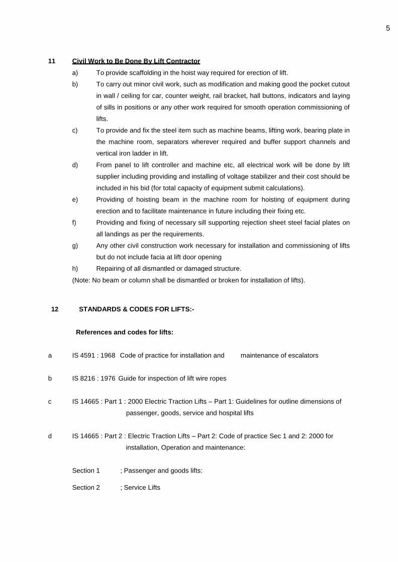
5
11 Civil Work to Be Done By Lift Contractor
a) To provide scaffolding in the hoist way required for erection of lift.
b) To carry out minor civil work, such as modification and making good the pocket cutout
in wall / ceiling for car, counter weight, rail bracket, hall buttons, indicators and laying
of sills in positions or any other work required for smooth operation commissioning of
lifts.
c) To provide and fix the steel item such as machine beams, lifting work, bearing plate in
the machine room, separators wherever required and buffer support channels and
vertical iron ladder in lift.
d) From panel to lift controller and machine etc, all electrical work will be done by lift
supplier including providing and installing of voltage stabilizer and their cost should be
included in his bid (for total capacity of equipment submit calculations).
e) Providing of hoisting beam in the machine room for hoisting of equipment during
erection and to facilitate maintenance in future including their fixing etc.
f) Providing and fixing of necessary sill supporting rejection sheet steel facial plates on
all landings as per the requirements.
g) Any other civil construction work necessary for installation and commissioning of lifts
but do not include facia at lift door opening
h) Repairing of all dismantled or damaged structure.
(Note: No beam or column shall be dismantled or broken for installation of lifts).
12 STANDARDS & CODES FOR LIFTS:-
References and codes for lifts:
a IS 4591 : 1968 Code of practice for installation and maintenance of escalators
b IS 8216 : 1976 Guide for inspection of lift wire ropes
c IS 14665 : Part 1 : 2000 Electric Traction Lifts – Part 1: Guidelines for outline dimensions of
passenger, goods, service and hospital lifts
d IS 14665 : Part 2 : Electric Traction Lifts – Part 2: Code of practice Sec 1 and 2: 2000 for
installation, Operation and maintenance:
Section 1 ; Passenger and goods lifts:
Section 2 ; Service Lifts

6
e IS 14665 : Part 3: Electric Traction Lifts – Part 3: Safety rules
Sec 1 and 2: 2000 Section 1 ; Passenger and goods lifts:
Section 2 ; Service lifts
f IS 14665: Part 4: Electric Traction Lifts – Part 4: Components:
Sec 1-9: 2001 Section 1; Lifts buffers:
Section 2; Lift guide rails and guide shoes:
Section 3; Lift car frame, car, counterweight and suspension:
Section 4; Lift safety gears and governors:
Section 5
g IS 14665: Part 5: 1999 Electric Traction Lifts – Specification –
Part 5: Inspection manual
h IS 14671: 1999 Code of practice for installation and maintenance of hydraulic lifts
i IS 15259: 2002 Installation and maintenance of home lifts Code of practice
j IS 15330: 2003 Installation and maintenance of lifts for handicapped persons – Code of
practice
k IS 15785: 2007 Installation and maintenance of lift without conventional machine rooms –
Code of practice
13. Power Supply
The apparatus shall be suitable to operate on 415 volts 3 phase 4 wire 50Hz alternating
current with a variation of +10% to -15% in Volts and ±3% in frequency respectively. The
supply for illumination and signal equipment shall be 230 V AC. Vendor shall derive any other
voltage required for the equipment being supplied through suitably rated control transformers.
Power and control supply shall be provided at one point in machine room. All or any other
power supply shall be derived from the same by the lift vendor.
14. Warranty
The bidder shall provide for one year warranty after commissioning against all manufacturing
defects and shall provide for free replacement / repair of all materials having manufacturing
defects/operational problems.
15. Defects Liability

7
All equipment and the entire installation shall be guaranteed against defective materials and
workmanship for a period of 3 years reckoned after the plant is commissioned and handed
over to the clients along with the 4 sets of completion documents and in case the testing of
the plant is delayed for any reason, the defects liability shall extend for a minimum period of
6(six) months from the date the test readings are accepted. During the defects liability period,
the contractor shall rectify, repair or replace defective parts and components free of cost
except in the case of those which are due to normal wear & tear.
Quantity: -
Any increase in quantity over and above tender quantity, it has to be brought to the notice of
the Consultant and upon written confirmation only the contractor shall proceed further. In the
absence of obtaining written permission as given above, the owner shall not assume liability
for any of the works carried out.
Safety Precautions
A competent, qualified and authorized Engineer shall be on the site whenever the contractor‘s
men are at work. The Supervisor should ensure that all plant and machinery used on the site
are endured safe for working and meets with the Indian or International safety standards
applicable for the use and operation of such machinery. The supervisor should also ensure
that the workmen are supplied with and made to use safety appliances such as safety belts,
lifelines, helmets etc. The Supervisor shall not leave the work site without permission from
Project Management Consultant or their nominee. The contractor shall provide organization
chart of the personnel to be deployed at site for the execution of the contract.
Smoking shall not be encouraged on the site but altogether strictly prohibited in areas where
combustible and inflammable goods / materials are stored or lying about.
Any hot job such as welding, soldering, gas cutting shall not be carried out without the
permission of the Engineer-in-charge representing the Project Management Consultant. Such
jobs shall not be carried out where inflammable materials are stored or lying about. All electric
onnections shall be through adequately sized mechanically protected cables without any
joints and with proper and adequate terminals. All power supplies shall be through properly
rated fuses with isolating devices. No such hot jobs shall be carried out on holidays and
without the presence of the Contractor‘s Engineer.
It is entirely the responsibility of the contractor to practice the principles of ‗Safety First‘ during
the entire tenure of work with adequate insurance covering injury of death to workmen, loss
by theft or damage to materials and property in position or not and third party liability
stipulated.
The contractor should clear the site of all debris every day to avoid accidents. In case this is

8
not done, the owners may engage necessary labour to maintain the cleanliness of the
premises and removal of debris, and debit all or part of the expenditure so incurred from the
contractor/s.
No breaking of any concrete structure, without permission of the Engineer-in-charge /
Consultant.
16. Erection
The lift Contractor shall commence the erection of the lift equipment immediately after receipt
of the complete equipment from their works and complete the work to the satisfaction of the
Project in charge / Architect within the stipulated time. The lift installation shall be handed
over in perfect working order on completion of the work.
17. Tests
The following tests shall be carried out to the satisfaction of the Client.
a) Insulation and earth test for all electrical apparatus;
b) Continuous operation of the lift under full load conditions for one hour at the end of
which time the temperature of the motor and the operating coils will be tested. This
shall be as per relevant IS specifications.
c) At site, all test shall be carried out as per relevant IS code and the copy of which shall
be supplied before commencing the tests.
18. Handing Over:-
The plant shall be handed over after satisfactory testing along with four sets of documentation
each consisting of:
1. Detailed equipment data in the proforma approved by the PMC/Consulting Engineers /
Project Manager/Owner. 2. Manufacturer‘s maintenance and operating instructions.
3. Set of as-built drawings, showing plant layouts, piping, ducting etc.
4. Approved Test readings for all equipment & installation.
5. Certificates of approval from Statutory or Local Authorities for the operation and
maintenance of the installation and equipment, wherever such approval or certification is
required. 6. List of recommended spares.
7. Certificate from the contractors that they cleared the site of all debris and litter caused by
them during the construction.
8. All tests to be certified by Project Management/Consultant/Engineer-in-charge/Clerk of
works
8. a Submission of the above documentation shall form a precondition for the final
acceptance of the plant and installation and final payment.

9
8. b The contractor has to furnish an undertaking that all materials supplied by him at site
shall be fully tax paid and shall produce all documents for satisfaction of the owner or taxation
authorities. All liabilities of the same shall be of the contractor.
19 Performance guarantee
19. a All equipment and the entire installation shall be guaranteed to yield the specified ratings and
design conditions plus/minus 3% tolerance. Any equipment found short of the specified
ratings by more than the allowable tolerance as determined by the test readings shall be
rejected.
20 Motor
The motor shall be squirrel cage type, particularly designed for elevator service with high
starting torque and low running current. The A.C. lift motor output voltage will be electronically
controlled during acceleration and deceleration to make a smooth and accurate stop.
21. Braking System
Braking of the lift will be done by electronically varying the voltage and the
frequency of the motor feeding current Variable Voltage and Variable Frequency Control i.e.
V.V.V.F. The electromagnetic holding brake will be applied only after the lift has come to a
complete standstill.
22. Control
The control shall be by microprocessor controlled electronically regulated A.C. Variable
Voltage & Variable Frequency drive using pulse width modulation (PWM).
The lift shall be provided with a self leveling feature of two way automatic type. The self
leveling device should automatically correct for under run, over run and rope stretch.
23. Controller with Drive System
Controller with duplex / simplex full collective control and selective, drive control with digital
technology having thermistors controller acceleration and deceleration and digital tachometer
on worm shaft.
24. Car Frame Safety Gear and Governor
The car frame which supports the car platform and enclosure shall be made of structural steel
and equipped with suitable guides and car safety device mounted under car platform. The
safety gear shall be of instantaneous type. Car safety, to stop the car whenever excessive
descending speed is attained, shall be operated by a speed governor through a continuous
steel rope. Suitable device shall be provided to cut off power from the motor and apply the
brake on application of safety. Fast speed/deceleration protection shall be provided.
25. Thermal Overload Protection
Auto Thermal overload protection to be provided to protect the driving motor against

10
overloads. If the car is overloaded, it will not start. The overload indicator and the sounding
buzzer shall signal the overload condition.
26. With and without Attendant Mode
In attendant mode the lifts priority and operations shall be by attendant only. Without
attendant means the lift shall operate without attendant in auto mode.
27. Full Load Control
Full loaded cars should respond only to car commands. Floor calls remain registered and are
served by the next available not fully loaded cars.
28. Counter Weight
All counter weights shall be cast iron and shall travel between rigid guides of steel frame
capable of withstanding buffet impacts. Suitable metallic counter weight guard of required
length shall be provided at the bottom of the hoist way.
29. Sound Reduction
The lift contractor shall provide necessary sound reduction materials, preferably anti-vibration
pads of proper density or effectively isolate the machine from the machine beams or flooring.
30. Terminal and Final Limits
Terminal switches shall be provided to slow down stop the car at the terminal
landings. These terminal switches shall act independently of the operating device or final
limits switches. Ultimate or final limit swatches shall also be provided to automatically cut off
the power and apply brake in case the car travel beyond terminal landings.
31. Terminal Buffer
Suitable spring buffers shall be installed to stop the car and counter weight at the extreme
limits of travels. Buffer must be suitable for installation in the space available.
32. Guides
Car and counter weight guides shall be of rigid steel guides shall be of machined ‘T' section
only the size being in accordance with relevant IS standards. It shall be capable of
withstanding the forces resulting from the application of car or counter weight safety devices.
33. Hoist Ropes
Round stranded steel wire ropes shall be used for lift suspension. The number and sizes of
the hoisting rope shall be so selected to ensure proper factor of safety and proper operation
of the elevator. The suspension ropes shall correspond to relevant IS standard. Governor
ropes shall also be of steel wire ropes. The rope dia and safety factor shall be as per IS
standard.
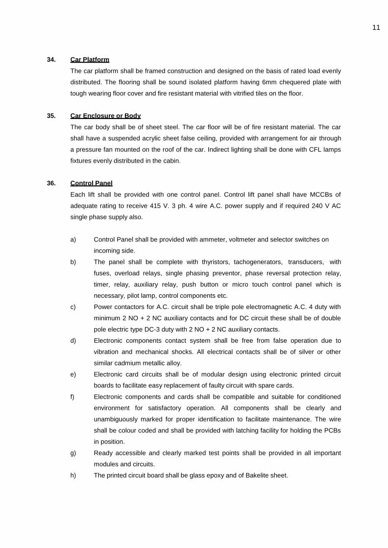
11
34. Car Platform
The car platform shall be framed construction and designed on the basis of rated load evenly
distributed. The flooring shall be sound isolated platform having 6mm chequered plate with
tough wearing floor cover and fire resistant material with vitrified tiles on the floor.
35. Car Enclosure or Body
The car body shall be of sheet steel. The car floor will be of fire resistant material. The car
shall have a suspended acrylic sheet false ceiling, provided with arrangement for air through
a pressure fan mounted on the roof of the car. Indirect lighting shall be done with CFL lamps
fixtures evenly distributed in the cabin.
36. Control Panel
Each lift shall be provided with one control panel. Control lift panel shall have MCCBs of
adequate rating to receive 415 V. 3 ph. 4 wire A.C. power supply and if required 240 V AC
single phase supply also.
a) Control Panel shall be provided with ammeter, voltmeter and selector switches on
incoming side.
b) The panel shall be complete with thyristors, tachogenerators, transducers, with
fuses, overload relays, single phasing preventor, phase reversal protection relay,
timer, relay, auxiliary relay, push button or micro touch control panel which is
necessary, pilot lamp, control components etc.
c) Power contactors for A.C. circuit shall be triple pole electromagnetic A.C. 4 duty with
minimum 2 NO + 2 NC auxiliary contacts and for DC circuit these shall be of double
pole electric type DC-3 duty with 2 NO + 2 NC auxiliary contacts.
d) Electronic components contact system shall be free from false operation due to
vibration and mechanical shocks. All electrical contacts shall be of silver or other
similar cadmium metallic alloy.
e) Electronic card circuits shall be of modular design using electronic printed circuit
boards to facilitate easy replacement of faulty circuit with spare cards.
f) Electronic components and cards shall be compatible and suitable for conditioned
environment for satisfactory operation. All components shall be clearly and
unambiguously marked for proper identification to facilitate maintenance. The wire
shall be colour coded and shall be provided with latching facility for holding the PCBs
in position.
g) Ready accessible and clearly marked test points shall be provided in all important
modules and circuits.
h) The printed circuit board shall be glass epoxy and of Bakelite sheet.

12
i) Heat dissipation components shall not be mounted on PCBs to avoid damage to
PCBs and loosening of soldered connections due to heat.
j) A reverse phase relay shall be provided on the controller which is designed to
protect the lift equipment against phase reversal failure.
k) Motor failure protection shall be provided.
37. Cabin Finishes
a) For Passenger/Service lifts:
Car enclosure shall be of scratch free stainless steel sheet as per design approved by
the Architect. The ceiling panel shall be with CFL down light, Ceiling cabin fan. There
shall be pressure fan inside the lift. The car floor shall have recess of 3mm thick
PVC tiles.
b) Other Cabin Features
a) Handrails on the three sides of the car.
b) Ventilation by motor driven fan built in ceiling panel.
c) Press and speak type intercom lead up to the lift controller at last landing.
d) A pressure sensing device safety for passengers trapped between doors which shall
reverse the door operation in case of obstruction of doors.
38. Car Door
For Passenger/Service lifts: The car entrance shall be protected by two stainless steel panel
SS Vandal proof finish, centre opening and horizontal sliding doors.
39. Landing Door
For Passenger / Service lifts: Each landing shall be provided with stainless steel scratch proof
(moon rock finish) with central opening and horizontal sliding doors.
40. Car and Landing Door Operators
An electric DC-AVVF door operator for opening and closing the car door and the landing door
shall be provided. It shall consist of a machine on the elevator car. The car door and the landing
door shall be mechanically connected and shall move simultaneously in opening and closing.
Every landing door shall be provided with a locking device which shall comply with the following
requirements:
a) It shall not be possible to open the landing door from the landing side until the lift car
is within that particular landing zone.
However, provision shall be made for opening the door by means of special key for
use in case of an emergency.

13
b) It shall not be possible for the car to be started or kept in motion unless all the landing
doors and car door are closed and locked except when the car is coming to a stop at
that landing within the leveling.
c) The electrical and mechanical parts of all locking devices shall be of suitable design
and construction.
d) An electric contact for each car door shall be provided which shall prevent car
movement away from the landing unless the door is in closed position
e) Electronic light curtain door safety with minimum 100 criss-cross beams to be
provided.
f) The doors should have additional safety pressure sensing device which
shall reverse the motion of the closing doors when pressure is sensed on the closing
doors.
The car door and landing door shall open automatically as the car is stopping at a landing.
The closing of car door and landing door must occur before the car is set in motion. An
electronic device shall be provided to stop and reverse the doors during their closing motion.
41. Door Hangers and Tracks
The car and the landing door shall be provided with two point suspension sheave type
hangers complete with tracks. Sheaves and rollers shall be of steel with moulded nylon collar
and shall include shielded ball bearing. Tracks shall be suitable steel section with smooth
surface. The landing doors shall also consist of headers, sills, frames etc. as required.
42. Car Operating Panel in the Car
The car operating panel in one side of car wall shall be full length stainless panel running from
top of car to the floor. The car operating panel shall contain the following: -
a) A series of push buttons numbered to correspond to the landing served which will
light up while in service
b) An emergency 'stop button'
c) An emergency call button connected to a bell to serve as, an emergency signal
d) An alarm buzzer
e) Digital car position indicator and direction arrows
f) a door open button
g) A door close button
h) Auto fan switch
i) Overload indicator with buzzer
j) Overload non-starter
k) Ventilation slots at bottom of panel as per requirement
l) Name plate of manufacturer with load and capacity data
m) Intercom system built into the panel
14
n) Auto-Emergency light
o) Copy of license from the concerned authority like lift inspectorate etc.
p) In built self-diagnostic built-into the central system.
43. Car Direction Indicator
Digital scaling signal indicator in the car shall be provided by the appropriate arrow being
illuminated to indicate the car travel direction. .
44. Emergency Light in Car
A trickle charged battery operated emergency light lamp shall be provided in the car which
shall operate automatically in case of power failure for minimum 90 minutes.
45. Alarm Bell
An emergency alarm bell shall be provided. The alarm bell shall be located in the ground floor
landing and push for the same shall be in the car operating panel. The system shall be
operated by batteries with trickle charger and the bell/siren should work the moment the alarm
button in the car is pressed.
46. Intercom System
Provision of both i.e. telephone with minimum two connections – one at the operator‘s room
and other at guard room and the emergency signal with re- chargeable batteries as source of
supply shall be made in the lift cars.
Intercom station in car operating panel shall be powered by line charge battery. In case of
blackout the intercom system and alarm device will remain operative for at least one hour.
47. Call Button in Landings
An ―up‖ push button and a ―down
‖ push button at each intermediate landing and a single push
button (square flush mounted) at each terminal landing shall be provided to call the lift car in a
particular landing for traveling in a direction desired. The push buttons shall have call
registration lights and shall illuminate when a button is momentarily pressed, to indicate that
the call is registered and the direction of the call is registered. The button shall remain
illuminated until the call is answered. The top covers of landing push button boards shall be of
stainless steel with micro touch control.
48. Voice Synthesis
The pre-recorded system shall be provided in such a way that the person standing in the lift
lobby shall come to know about the lift car which is coming Next or so.
49. Floor Position Indicator & Direction Arrows
15
Digital signal indication at all landing shall be provided by the appropriate
numeral and direction arrow being indicated when the car is passing the corresponding floor.
The indicator shall remain illuminated when the car is stopped at a floor. The top cover of the
floor position and direction arrow indicator units shall be stainless steel.
50. Electronic Door Detector
On the each side of the lift entrance panel‘s infrared light sensor unit shall be
mounted in such a way to continuously monitor the light beam. (No. of beams
shall be more than 100). When any beam is disturbed an electronic circuit shall be interrupted
and the door operating mechanism shall return the door to open position when the entrance is
clear the lift door shall close automatically. Reversed of the doors may also be accomplished
by pressing the "Door Open Button" in the car operating panel.
51. Emergency Key
Emergency key or equivalent device shall be provided by the elevator contractor.
52. Detailed Instructions
Inside the lift car suitable instruction for passenger on car operating panel will be displayed.
Such instructions in lift car shall indicate capacity, No. of persons, 'No Smoking' and such
other instructions as are suitable for proper and safe operation of the lifts.
53. Fireman Switch
Each lift will have fireman switch for access of fireman. The operation of this switch shall
cancel all calls to this lift and lift will stop at the next nearest landing if traveling upward. The
doors will not open at this landing and the lift will start traveling to ground floor. In case of its
travel in the downward direction when the fireman's switch is operated, it will go straight to
ground floor direct without stopping en route. The emergency stop button inside the car will
become inoperative during the journey. Once the car has reached the ground floor, it shall be
safely under the command of fireman by car buttons, landing calls being isolated. The lift can
be put in normal use by putting the fireman switch in its original position.
54. Operation
The operation shall be full collective simplex / duplex with or without attendant. It shall
generally function in the manner described below:-
On every intermediate landing is a Up/Down button with 'Call Registered' lights. The extreme
positions have one call button with a "Call Registered" even. Inside the car is the complete set
of buttons and a key operated change over switch to facilitate operation with or without
attendant. However, in this case the car attends to all calls registered inside the car and at the
landings, in the ascending or the descending order. If it is landing, the last stop is the top-
most registered call. After this, it automatically reverses the direction of travel and attends to

16
all calls registered "Down" on this downward trip, irrespective of the sequence in which the
calls are registered, the car will answer all calls in a sequenced order depending upon the
direction in which it is traveling. If the key is turned to 'Attendant' operation, the lift operation
can select the direction of travel by pushing the right buttons in the car.
55. Emergency Stop Switch
On top of the lift car an emergency stop switch shall be provided for use by
maintenance personnel. Similar switches shall also be provided in the car.
Operation of these switches shall render the car and landing buttons in operative and cancel
all registered calls. Indication to be provided for elevator under maintenance.
56. Emergency Landing Device, ARD
The emergency battery unit shall consist of suitable capacity of SMF (Sealed
Maintenance Free) batteries with battery' charger having auto trikle boost rate of charge. The
unit shall be of such a capacity that in case of power failure, the lift shall come to the nearest
landing automatically. The system shall be capable of 100% load.
The Automatic Rescue Device shall have the following specifications.
a) ARD should move the elevator to the nearest landing in case of power failure during
normal operation of elevator.
b) ARD should monitor the normal power supply in the main controller and shall activate
rescue operation within 10 seconds of normal power supply failure. It should bring the
elevator to the nearest floor at a slower speed than the normal run. While proceeding to
the nearest floor the elevator will detect the zone and stop. After the elevator has
stopped, it automatically opens the doors and parks with door open. After the operation is
completed by the ARD the elevator is automatically switched over to normal operation as
soon as normal power supply resumes.
c) In case the normal supply resumes during ARD in operation the elevator will continue to
run in ARD mode until it reaches the nearest landing and the doors are fully opened. If
normal power supply resumes when the elevator is at the landing, it will automatically be
switched to normal power operation.
d) All the lift safeties shall remain active during the ARD mode of operation.
57. Electrical Wiring
Power wiring between the controller and main board and controller to various
landings shall be done in heavy gauge M.S. conduits confirming to European/I.S. rules and
specification for electrical works. All cables shall be FRLS PVC insulated of appropriate size
and voltage grading. Complete copper wiring for the entire lift installation will be used.
All multi-core trailing cables employed for the car shall satisfy the requirement of relevant
European Standard. There shall be separate trailing cables for the controls, for the lighting

17
and fan and for signal circuits. The length of the cable shall be adequate to prevent any strain
due to movement of the car. All cables shall be so tagged for easy identification. Trailing
cables shall be so suspended, anchored and run that the strain on individual cable conductor
shall be reduced to a minimum and the cables are free from contact with the car counter
weight, shaft sides etc. No intermediate jointing shall be permissible in the trailing cable.
Standards & Codes:-
All electrical work carried out shall conform to the IS 732 -1989 and all equipment, drive
motors etc. shall meet with the relevant Indian Standards.
All electrically operated equipment shall be so designed that it will continue to function without
damage to itself or otherwise if the voltage and frequency vary within the following tolerances:
Voltage : Plus or minus 10 percent
Frequency : Plus or minus three percent
Unbalance : 2 percent
Wiring
All wires and cables shall be insulated with poly vinyl chloride based insulation rendered
flame retardant and rated for 1100 volt service and suitable for use in dry and wet locations.
Make of wires and cables shall be subject to the approval of the Architects/Consultants before
use.
All wires and cables shall be of stranded copper conductor.
Power and control circuits shall be in separate cables or run inside separate heavy gauge
rigid galvanized conduits. Wires and cables subject to movement and abrasion shall be
protected by flexible galvanized steel conduit.
Erection
The elevator Contractor should furnish detailed drawings showing their requirements of
cutouts, holes and beams, before the machine room floor is cast. In case no such details
become available, the machine room floor will be cast and all such openings shall be made by
the Elevator contractor at his own cost and closed properly.
All structural steel required for mounting the machinery, controllers etc. should form part of
elevator suppliers scope of work. This includes all supporting beams, hoisting beam etc. All
minor builders‘ work shall also be included in the scope of work and this shall include chasing

18
of floors, walls, fixing of hoistway brackets etc.
Elevator machine shall be mounted on suitable vibration isolation pads to prevent machine
vibration being transmitted to the structure.
All wiring inside the machine room shall be neatly done in conduit or wire race. The elevator
machine, motor alternator, controller and the car shall be double earthed and will be brought
to the main panel. Suitable guards for counter weights and deflectors shall be provided.
Entire installation shall conform to the requirements of Local Lift Inspectorate and necessary
approvals shall be obtained from the statutory authorities for the use of the elevator.
Commissioning and Testing
The pre-commissioning checks shall among others consist of the following:
1) Insulation resistance testing of drive motors and alternator with
1000 V meggar.
2) Insulation resistance testing of cabling and wiring.
3) Proving tests on various interlocks and safety devices.
4) Vibration/ Noise Levels during start, travel and landing.
All results of the pre-commissioning checks shall be recorded and four copies submitted to the
consultants.
A contract load test under the supervision of the local authority and in the presence of
Architect/Consultant shall be carried out before each elevator is put in regular service. During
the test, the brakes, limit switches, buffers, car safety devices shall be caused to function with
the contract load in the elevator and the operation of various safety devices shall be recorded.
The leveling gear shall be tested on-load and off-load to ensure car leveling within limits.
The elevator must be tested for contract speed with the full contract load.
The emergency landing facility shall be tested for all the elevators and test results recorded.
The elevator shall be accepted upon satisfactory completion of the above tests and after it is
offered for acceptance by contractor.
58. Technical details needs to be filled by the Vendor:-
Sr. No Description Data
1 Manufacturer
2 Capacity

19
3 Maximum Passengers (No)
4 Speed (m/s)
5 Traction Motor
a Type
b Rating (HP)
c Voltage
d Speed (rpm)
e Insulation Class
f Starting Torque
g Gear/Gearless
h Gear ratio
6 Roping
a Number of Ropes
b Size
c Roping Ratio
7 Factor of Safety
8 Guide rail size
9 Car Weight
10 Counter Weight
11 Buffers
12 Elevator Drive
13 Drive Motor
a Make / type designation
b Rating (HP)
c Kw
d allowable Voltage variation
e allowable frequency variation
f No. of phases
g Maximum Speed in mtrs per sec
h Maximum Speed in mtrs per sec
Motor Current at Full load
j during Start
k during run
l Class of insulation with temp rise
m starting torque
n Type of break
Motor starter/controller
o Make/ type designation
p Method for start/control
q Speed choice provided if any

1
TECHNICAL SPECIFICATIONS
NURSE CALL SYSTEM (ADDRESSABLE, FULLY MONITORED, PROGRAMMABLE)
The contractor shall provide a fully monitored, addressable and programmable, nurse call system.
Positions and types of equipment are indicated on the BOQ sheet and associated drawings
which should be read in conjunction with this specification.
GENERAL.
The system shall operate as a self-contained system for each ward, each with its own
power supply unit and nurse station indicator unit, as indicated on the drawings.
The system shall be capable of transferring all calls from one ward to an adjacent ward (full
transfer) where the nurse station indicator unit is unattended (during night shift etc.).
The system shall also be capable of transferring part of a ward; down to single bed level to
another ward (flexible transfer), where nursing of beds in one ward area is being controlled
by nurses in another ward e.g. during busy periods.
The transfer facilities described above shall be pre-programmed by the specialist supplier at
the time of commissioning. Operation of the transfer facilities shall be by simple push
button operation by the nursing staff. The system design shall also allow easy re-
programming of the transfer criteria by hospital personnel as and when required.
The system shall have the facility for two-way speech between patient and staff, and staff
to staff. The two-way speech facility shall be flexible in design to allow the
interchangeability of handsets to provide patients with speech or non-speech handsets at
the discretion of staff.
The two-way speech facility shall be transferred with all other calls when the transfer option
is exercised.
The system shall have the facility to record call activity via software on existing PC to record the time, date and location of each call on the system and staff responses to each call.
Priority of calls shall be as follows: -
1. Cardiac Call.
2. Emergency Call.
3. Bathroom Call. 4. Patient-to-Nurse

2
When calls of the highest priority are on the system, other calls of a lower priority are
stored in the system until they are reset. Calls of all priorities can be scrolled through on the nurse station display.
STANDARDS
Nurse call system should conforms to following standards
DIN VDE 0834 Nurse call systems in hospitals, nursing homes and similar institutions.
Part 1: Requirements for equipment, erection and operation
Part 2: Environmental conditions and electromagnetic compatibility
DIN EN 793 Special requirements for the security of medical supply units.
DIN EN 60601-1 Medical electrical equipment
Part 1: General requirements for basic safety and essential performance
DIN EN 60601-1-1 Medical electrical equipment
Part 1-1: General requirements for safety; Collateral standard: Safety requirements for
medical electrical systems
EN 61000-6-2 Electromagnetic compatibility (EMC)
Part 6-2: Generic standards - Immunity for industrial environments
EN 61000-6-3 Electromagnetic compatibility (EMC) -
Part 6-3: Generic standards - Emission standard for residential, commercial and light
industrial environments
DIN VDE 0100 Erection of power installations, with rated voltages up to 1000 V; chronological
data of installation specifications
DIN VDE 0107 High voltage power installations in medical buildings with stationary or
outpatient areas
FUNCTION & BASIC REQUIREMENTS
The Nurse Call system should be an optical nurse call system, transmitting nurse call
information to the nursing staff via corridor lamps, zone indicator lamps, information displays,
display modules and – when integrated in the system - via SMS to paging and DECT systems.

3
Each bed must have a call trigger assigned to it which can be comfortably reached by the
bedridden patient. Different option of call generations like pneumatic, breathing type, noise
controlled type to be available for specialized applications which can be connected to the
standard connection unit.
Call push-buttons are fundamentally red, have a distinct call symbol and must be easily visible
in the dark.
The call trigger must be optically displayed in immediate proximity to the call device
(reassurance lamp).
Manual or automatic presence indicator switches and acoustic signal devices for call forwarding
must be installed in all rooms in which the personnel to be reached could be detained.
An emergency call by an assistance-giving person to call for further assistance-giving persons
must occur automatically via the available call push-button. This must be arranged by the
displaying of those present in that particular detention area. Bathroom call should be separately
indicated via white lamps.
Outside each room, a mandatory corridor lamp must be provided which at least indicates calls
(red), bathroom call (white) and presence (green). These displays must be clearly identifiable
by an ambient luminosity of 500 lx. A call activation must be indicated within one second.
Additional text displays between 5 lx und 500 lx should be clearly legible in hallways from a
distance of 20m to be installed in duty station and pantry areas.
Optical and acoustic signals are distinctly arranged so that mobile response personnel can
operate the nurse call systems of different manufacturers without instruction. Only continuous
light, slow flashing light and rapidly flashing light is to be permitted in a system. Likewise, a
maximum of three acoustic signals for calls, emergency calls, and alarm calls are selected for
call forwarding. For further applications, a maximum of one additional acoustic signal is
permitted, which must however clearly differentiate itself from the acoustic sequence of the call
signals.
Only a maximum of five seconds may elapse between the time a call is triggered and when the
appropriate personnel receives it.
The indication of the presence of personnel in the call area may be used to cancel the call.
Call and operation devices must not be mounted together with high voltage power installations
under a shared cover plate, and must distinctly differentiate themselves from this physically.
The power supply of the system must not exceed 30 V r.m.s. value or 60 V of DC voltage. This
low voltage may not be additionally used to supply power to other systems or units. Exceptions
are electronic current surge switches for the reading light control and interfaces of the nurse

4
call system to other devices. They must be securely connected and supplied with their own
surge protection.
All nurse call systems must be supplied with emergency power which is able to sustain
operation for at least twenty four hour not later than 15 seconds after the loss of the regular
power supply. Calls pending at power failure must be stored for at least one hour.
Transmission paths of other system installations may not be used for the nurse call system.
All protective ground wires connected to the nurse call system must be connected to the same
primary equipotential bonding. If this is not possible, the individual fields must be galvanically
separated from each other.
Lines that connect buildings with each other must be supplied with surge protection or
galvanically separated at the discharge point.
In nurse call systems with voice communications, remote cancellation of a call must only take
place if a speech connection has in fact occurred. In calls without speech capability, remote
cancellation is not possible. However, these calls may be accepted for a suppression of acoustic
call forwarding if an optical signal occurs.
SAFETY
In the case of power failure, calls are stored for approximately 24 hours. As soon as the power
is switched on again presences and calls which were set prior to power failure are indicated.
In the case of failure of the zone controller, the system operates in an emergency mode which
involves the functions normal and emergency calls, cancellation, presence indication and call
transfer to rooms where presence has been set as well as the visual indication of the corridor
lamps.
The zone controller monitors all active units and displays any malfunctions as a collective
message. Any malfunction in any unit should be detected quickly.
The lamp outputs of the electronic modules should be short circuit protected.
All electronic modules should be fitted with a “self-restoring” fuse. This not only protects the
electronic modules but also should protect the equipment in the room.
An auto-release plug should be mounted on the pear or multiple push button as well as on the
patient handset to prevent damage to the cord. Electric safety and EMV requirements conform
to appropriate CE directives and standards as mentioned above.

5
SYSTEM LAYOUT
The system layout should be based on a 3-level hierarchy. The zone level (ward level) consists
of the zone bus, which presents the communication platform for the zone controllers. Thus,
calls can be transmitted between zones and wards within the whole system. The next level
includes the corridor or ward bus and enables communication within the ward. The components
connected to the ward bus are required to link the call devices in each room via the bed data
bus.
Zone BUS
In the primary level, the zone bus connects a maximum of 16 zone controllers, which in turn
are subdivided in Six zones. Thereby one system can consist of 96 zones.
Zone Controllers
The zone controller should be the central control unit which monitors and synchronises the
complete bus system and at the same time represents a higher-level connection to further zone
controllers. It controls the flashing phases of the corridor and zone signal lamps, as well as
acoustic call signals. Thus, doctor, emergency, normal, remind and telephone calls can be
distinguished. Each zone controller should support 6 sub-zones and has appropriate outputs for
zone indicator lamps, as well as a common malfunction message system. Further inputs allow
staff, meal and/or telephone calls to be coupled. Zone controllers should be able to support
voice based as well as optical nurse call devices.
Corridor BUS
All display and control units in the patient rooms, duty rooms as well as in other monitored
rooms and corridors shall be connected to the corridor bus. The electronic module serves as a
room control unit and connects all call devices within the room. Information displays are also
operated on the corridor bus. As a whole, a maximum of 127 electronic modules and a
maximum of 255 addressable modules such as electronic modules, display modules and call
modules can be operated on the corridor bus. Each bus device is allocated its own address
allowing individual identification.
Electronic Modules
The complete electronics required for call identification and call logging to be located in the
electronic module, which is used as the distribution point for the room wiring. Electronic
modules can be used for the whole system. For duty rooms, special electronic modules with
additional memory for configured zone linking data shall be used.
Bed Data bus
A maximum of 10 room components such as call modules, cancel modules, call/cancel modules
and display modules shall be connected to the bed data bus. Individual calls actuated directly

6
from the bed can be identified via the address of each call module. Electronic modules without
bed databus only allow call modules to be connected as closed-circuit monitored call push-
buttons, cancel push-buttons as well as call/cancel push-buttons.
Room Equipment
Various devices can be installed in the rooms, for example, call modules, call push-buttons, pear
push-buttons and pull cords for releasing calls, as well as cancel push-buttons for cancelling
calls. Patient handsets can also be installed. An auto-release plug mounted on the pear or
multiple push-button, as well as on the patient handset, should prevent damage to the cord.
The information stored in nurse call system with bed data bus can be shown on display
modules. Existing calls to be indicated according to their urgency in plain text. If there are no
calls in the system, presences are indicated.
SYSTEM INTERFACES
The DECT paging system can be connected to the nurse call system via the paging interface
unit. Thus, existing calls on the nurse call system can be transferred to the staff pocket pager
or DECT terminal device, indicating type of call, room number and bed identification if available.
Additionally, internal signals, such as fire alarms or technical alarms, can be connected via
interface units. It is possible to connect the system to an Instabus EIB (European InstBus).
Optionally, further third-party devices can be integrated in the system and a call logging PC or a
PC provided with a graphic display can be connected via a PC system interface.
SYSTEM SAFETY
In case of power failure, calls are stored for approximately 24 hours. As soon as the power is
switched on again, presences and calls which were set prior to power failure are indicated.
In case of a failure occurring in the zone controller, the system operates in an emergency
mode, which involves the functions normal and emergency call, cancellation, presence
indication and calls transfer to rooms where presence has been set, as well as the visual
indication of the corridor lamps. The zone controller monitors all active units and displays any
malfunctions as a collective message or as individual messages on the information display. The
lamp outputs of the electronic modules are short-circuit resilient. All electronic modules are
fitted with a “self-healing” fuse. This not only protects the electronic modules but also the
equipment in the room. The electrical safety and EMC requirements of all the system
components are in accordance with the CE directives. The IP protection classes indicated in the
catalogue refer to the completely assembled appliance including cover plate and mounting
frames.

7
CABLE & WIRING
Cable for bed data & corridor data bus shall be Halogen Free System Cable 4 Pair Twisted J-
Y(ST)Y Lg-4x2x0.8mm Ø as per VDE 0815 Standards along with 19mm Ø MS / GI Conduit.
Cable for power supply shall be Fire Survival armored cable of 600/1000V with Class-2 annealed
copper conductor. Should have cross linkable Halogen Free insulation with special Glass Mica
(Fire barrier) tape as per BS: 7846:2009. Inner & outer sheath should be Low Smoke Zero
Halogen as per BS: 7846:2009 Should meet Fire resistance/survival test as per clause 26.2e of
BS 5839-1 for Enhanced Fire Resisting cables when tested in accordance to BS 8434-2.
MAINTENANCE AND SERVICE
The configuration module is connected to the electronic module via a service socket. This is
used to indicate room numbers and depending on the configuration, bed identification. In
addition, the configuration module can also be used for service purposes. All indicating lamps
should be made of high life LEDs.
Zone controllers should be replaced without difficulties. After installation, the new controller
shall be able to access the data stored in the network users and configures itself. Only
particular special parameters have to be entered again. Electronic module can be replaced at
any given time without interrupting system operation and, in case of identical installations, can
be installed or replaced within the entire system. System should get automatically configured
when connected properly.

1
TECHNICAL SPECIFICATIONS
PUBLIC ADDRESS SYSTEM
GENERAL
The PA system shall be suitable for operation on 240 volts AC single phase power supply.
The PA system shall be such that broadcast can be selected to cover the entire building or group wise zones/areas.
The PA system shall in general comprise of a Central Amplifier Assembly, Microphones, Speaker units audible throughout the building complex, associated wiring and such other apparatus as are necessary to ensure a complete System to achieve the required parameters.
PARAMETERS OF SYSTEM OPERATION
The System shall operate with the following parameters:
- to make announcements over the System the press-talk switch shall be pressed, reducing the music volume level permitting the announcements to be heard. Upon release of the press-talk switch, the music volume shall increase.
- it shall be possible to make a general broadcast with the operation of the all call switch
- normal announcements shall be possible
MAIN CONTROL DESK
The Main Control Desk shall be constructed from 16 SWG CRCA sheet steel folded and braced in a manner to form a floor mounting unit. The Main Control Desk shall be modular allowing expansion at a future date.
All meters and indications shall be provided on the vertical face of the Control Desk and the control switches on the horizontal face for easy operation.
A modular concept of construction of the Main Control Desk shall be adopted. All components and switches shall also be modular. All critical components like pre- amplifiers, relays etc. shall be plug-in modules.
The Main Control Desk shall in general be equipped with the following controls and indications: METERS AND INDICATIONS

2
- VU meter
- LED's to indicate the group selected for announcements
- LED to indicate all call selection
CONTROLS
- switches for selection of broadcast zone one per zone
- all call switch for general broadcast
- press/talk switch
- volume control module
- tone control module
- amplifier changeover switches
- D.C supply changeover switches
The Control Desk shall be complete with all internal wiring, interconnections complete as required.
AMPLIFIER RACK ASSEMBLY
The pre-amplifiers, power amplifiers, power supply units etc. as required in the System shall be provided in a floor mounting MS rack of suitable size. The rack shall be constructed from 16 SWG CRCA sheet and shall have gasketted doors to ensure dust and vermin proofing of the assembly.
The assembly shall be complete with a standby power amplifier and a standby power supply which can be switched into operation from the Control Desks in the event of failure of the main amplifier/power supply or as required.
The amplifiers shall be of the solid state type and shall meet the IEX 65 safety application. The amplifier shall be provided with:
- VU meter to indicate the power being drawn
- thermal fuse protection against short-circuits
- volume and tone controls
The power supply shall be solid state, suitable for operation with a mains voltage variation between 160 and 260 volts and shall be complete with:
- adequately rated transformer,
-short circuit and open circuit protection
The amplifier rack assembly shall be complete with the following mounted on the front face

3
- mains switch
- protection fuses
- indicating LED's
- monitoring speaker module
The amplifier rack assembly shall be complete with internal wiring and interconnections, connectors etc. complete as required.
MICROPHONES
The microphones shall be of the dynamic pressure gradient type having cardoid directional characteristics. They shall be complete with a wind shield, sintered bronze grill and a built-in ON/OFF switch.

1
TECHNICAL SPECIFICATIONS AND TENDER DOCUMENT
FOR
33 KV TRANSFORMER WORKS

2
TECHNICAL SPECIFICATIONS
33 KV/433 OIL COLLED TRANSFORMERS
SCOPE OF SPECIFICATIONS
This specification is intended to cover design manufacture assembly, testing at manufacturer‘s works, supply and delivery of three phases, 50 HZ, 33 /0.433 KV Delta/Star, Vector Group DY II two windings copper wound outdoor type oil immersed naturally air cooled Transformer is per detail furnished here after.
The transformer offered shall be complete with all parts and accessories which are necessary or usual for their efficient and satisfactory operation. Such parts and accessories shall be deemed to be within the scope of this specification whether specifically mentioned or not. Main tank body may be delivered in unpacked condition, but delicate parts like indicating meter, radiator, and conservator. Pressure Relief Valve, equalizer pipe, buchholtz relay etc. shall be packed to avoid damage due to transshipment.
SYSTEM DETAILS:
33 KV system is non- effectively earthed, whereas 433 V systems is to he effectively earthed at neutral point of the star connected windings of the Transformer.
WEATHER CONDITONS
For the purpose of designing, the following conditions shall he considered. However please note that the installation is proposed at Rudrapur, Udhamsingh Nagar, UTTARAKHAND and weather conditions of the Rudrapur needs to be considered.
A Elevation above Mean sea level : 202 M B Maximum Ambient Air Temperature : 34 Deg C C Maximum daily Average Ambient Air Temperature : 23 Deg C D Minimum Ambient Air Temperature : 11 Deg C. E Maximum Humidity : 80% F Average number of thunderstorm day per annum : 100 G Number of months of tropical monsoon : 4-5 H Average Annual rainfall : 1567 mm I Maximum wind pressure : 100 Kg. per sq.m.
APPLICABLE STANDARDS:
Unless otherwise stated, transformer shall be designed, constructed and tested in accordance
with provisions contained in latest revisions of following Indian standards and Rule
i. IS 2026 ii. REC Manual 10/1976. iii. C B.I.P Manual on Transformer
Technical Report 1 : Section A.D : (Revised : 1987) iv. C.B.I.P Technical Report No 72 (June 1989)
v Indian Electricity Rules, 1953 (Ammended upto date) VI other applicable Indian Standards.

3
VII ECBC GUIDELINES(AS PER ECBC GUIDELINE TABLE NO. 8.2) refer data sheet for Transformer
6.0 DEVIATIONS FROM SPECIFICAITONS
The deviations from the purchaser‘s specification to improve utility, performance and efficiency of equipment or to secure overall economy shall be considered if such deviations(s) is (are) mentioned by the Tenderer in the ―Schedule of Deviations‖ with full justification.
RATING AND GENERAL PARTICULARS
Type
Core type, three phase. Oil immersed step-down two winding copper wound transformer for outdoor installation.
7.1 Standard Rating
Continuous with on load tape as mentioned in the schedule of quantities.
Continuous Maximum Rating and Temperature rise
As regards maximum rating and temperature rise, all transformers shall comply with the appropriate requirement of Indian Standards
For the purpose of consideration of maximum temperature rise of oil and winding the following ambient temperature are assumed.
i. Cooling medium : Air ii. Maximum Ambient Air temperature : 50 Deg C. iii. Maximum daily average ambient Air temperature : 40 Deg C iv. Maximum yearly weighted average temperature : 32 Deg C.
With the above ambient temperature condition allowable maximum temperature rise shall be as mentioned below
Type of cooling Oil in deg C Winding in deg C ONAN 50 55
No load voltage ratio
The no load voltage Ratio corresponding to principal (normal) tapping shall be 33000/433 volts
Winding connections and vector group etc.
i. Number of phases : Three ii. Frequency : 50 HZ iii Type of Cooling : ONAN iv. Winding connections : The primary winding (HV) shall be
v.
Vector Group :
connected in delta and secondary winding (LV) shall be connected in star. Windings shall be connected as per Vector
symbol DY II of Indian Standards to produce a penitive displacement of 30 Deg. from the primary to the secondary vectors of the same phase assuming vector rotation counterclockwise.

4
vi. Neutral Earthing : The neutral point of the secondary (LV)
winding shall be brought out to a separate insulated terminal and shall he solidly earthed.
7.6 Taps : Transformer shall be provided with on load taps ranging from +5% to -15% in steps of 1.25% each on H.V winding for H.V. variation. The tap changing switch shall be located in a convenient position so that it can he operated from ground level. The Control Box shall be provided with Tap position indication & locking arrangement.
Technical Specification of on Load Tap Changer to be supplied with 1.6 MVA 33KV/433 V Transformer
1) The on load tap changer shall be designed suitable for local manual as well as local electrical operation
2) The on load tap changer shall include the following
a) An oil immersed tap selector and arching switch or are suppressing tap selector, provided with reactor or resistor for reduction of make and break arcing voltages and short circuits
b) Motor driven mechanism. c) Control and protection devices. d) Local/ remote tap changer position indicator. e) Manual/Electrical operating device.
3) The on-load tap changer shall be designed so that the contacts do not interrupt arc within the
main tank of the Transformer. The tap selector and arcing switch or arc suppressing tap selector switch shall be locate in one or more oil filled compartments. The compartment shall be provided with oil surge Relay. Those compartments shall be designed so as to prevent the oil in tap selector compartments from mixing with the oil in the transformer tank.
A suitable pressure reliving arrangement should be provided to take care to sudden pressure rise in compartment. But this should in no way affect the performance of the oil surge relay provided for the compartment. Oil surge relay to be provided for the OLTC compartments shall have trip contacts.
4) The manual operating device shall be so located on transformer that it can be operated by a man standing at the level of transformer track. It shall be strong and robust in construction.
5) The contracts and associated gear for the tap change driving motors shall be in separate room. The motors shall be suitable for operation with 3-Phase, 400/415 Volts, 50 Cycle Power supply.
Impedance Value
The percentage impedance at 75 Deg C refer to the (normal) principal tapping shall be as follows
Sl No. Rating Voltage Ratio % Impedance
1. 1.6 MVA 33 KV/433 V 6.25 or as per manufacturer‘s Data
The impedance value refer to the (normal) principal tapping are subject to a tolerance of ±10%

5
Terminal: Transformer shall be provided with bushing insulators on both HV and LV sides. HV and LV bushings shall be located on opposite side.
The electrical characteristics of bushing insulator shall be in accordance with IS: 2099 dimensions and type of bushing shall conform to IS 3347 and shall be as follows:
HV. BUSHING (33 KV SIDE)
36 KV Class Porcelain bushing with plain sheds for heavily polluted atmosphere.
NEUTRAL at LV Side
Neutral of L.V. winding shall be brought out through porcelain bushing similar to L.V hushing for connection with earth terminal.
Provision of Current Transformer in L. V. Side of Power Transformer
In order to achieve Restricted Earth fault in Star Connected LV. Side of Power Transformer, a Current Transformer having following particulars shall have to be provided between neutral terminal & neutral bushing of LV. Side of Power Transformer. This CT. is to he mounted at the bottom of LV. Side neutral bushing
i. Type : Suitable for installation in LV Side of power
transformer for reflection of neutral current ii. Ratio : 600-300/IA iii. Accuracy class : PS iv Knee Point voltage vk : Vk >250 Volt at higher ratio v. RCT at 75 deg C lower & higher taps : RCT < 4 Ohm at higher ratio at 75 Deg C &
< 2 Ohm at lower ratio at 75 deg C vi. Magnetising Current at knee
8.0
point voltage :
SHORT CIRCUIT LEVEL
< 30 mA at VK
8.1 Designed maximum fault level of 33 kV and 17.5 KA
INSULATION LEVEL
The transformer shall be capable to withstand test voltage as specified below.
Nominal Highest Rated lightning Rated short duration Voltage Voltage impulse withstand power frequency withstand (In kV for equip- Voltage in KV peak) Voltage (in KV rms) Rms) ment (in
KV rms) _ _
11 70 170 70
CORES
The Cores shall be constructed from high grade cold rolled non-aging grain oriented silicon steel laminations having magnite coating as insulation.
Successful bidder will offer the Core for inspection and/or approval by the purchaser during
the manufacturing stage. Manufacturer‘s Call notice for the purpose should be accompanied with the following as applicable as a proof towards use of Prime Core materials:
i. Invoice of supplier ii. Mill‘s Test Certificate

6
iii. Packing Lists iv. Bill of Lading v. Bill of entry Certificate to Customs
Core materials shall be procured either from the core manufacturer or through their accredited marketing organization of repute.
Tendered should preferably have in-house Core cutting facility for proper monitoring and
Control on quality.
The materials used for insulation shall have high inter lamination resistance and rust inhibiting property. It shall not deteriorate by aging from hottest operating temperature and clamping pressure of the core or disintegrate due to core vibration. It shall not have any tendency to absorb moisture or to react with insulating oil.
The assembled core shall be securely clamped on the limbs and yoke with uniform pressure so as to minimize noise emission from it.
The top main core clamping structure shall be connected to the tank body by a copper strip.
The bottom clamping structure shall be earthed by one or more of the following methods (i) by connecting through vertical tie rods to the top structure (ii) by direct metal to metal contact with the tank base by the weight of the core and winding (iii) by a connection to the top structure on the same side of core as the main earth connection to the tank.
All parts of the cores shall be robust design capable of withstanding any shock, to which they may be subjected during lifting, transport, installation and service.
Adequate lifting lugs shall be provided to enable the core and winding to be lifted.
Adequate provision shall be made to prevent movement of the core and winding relative to the tank during transport and installation or while in service.
The supporting frame work of the cores shall be so designed as to avoid the presence of pockets which would prevent complete emptying of the tank through the drain valve or cause trapping of air during filling.
The insulation structure for the core to bolts and core to clamp plates shall be such as to
withstand a voltage of 2000 V AC at 50HZ for one minute.
FLUX DENSITY OF CORE
The maximum flux density in any part of the core and yokes at principal (normal) tapping and at rated frequency shall not exceed 1.6 Tesla (16000 lines per sq.cm) at normal voltage and
1.9 Tesla (19000 lines per sq.cm) under over voltage condition.
Prior to inspection and testing of the Transformer the supplier shall submit on request following curves of the core manufacturer.
i) Flux density vs Core loss. ii) Flux density vs Excitation
WINDING
All windings shall be fully insulated.
Transformer shall be designed to withstand the impulse and power frequency test voltages specified in clause no.9.1.

7
The windings shall be designed to reduce to a minimum the out of balance forces in the transformer at all voltage ratios.
The insulation of transformer winding and connections shall be free from insulating material liable to soften, ooze out, shrink or collapse and shall be non-catalytic and chemically inactive to transformer oil during service.
The stacks of windings shall receive adequate shrinkage treatment before final assembly.
Adjustable device shall be provided for taking up any possible shrinkage of coils in service.
All the insulating material to be used in the transformer shall preferably be of class - A insulation as specified in Indian Standards, The test certificate of the materials shall be made available by the transformer manufacturer on request during inspection and testing
The coil clamping arrangement and the finished dimensions of any oil ducts shall be such that
it will not impede the free circulation of oil through the ducts.
The windings and connections of transformer shall be braced to withstand shocks which may occur during transport or due to switching short circuit and other transient conditions during service.
Coil clamping rings, if provided, shall be of steel or suitable insulating material. Axially laminated material other than bakelised paper shall not be used.
13. INTER EARTHING ARRANGEMENTS:
General: All metal parts of the transformer with the exception of the individual core laminations, core bolts and associated individual clamping plates shall be maintained at fixed potential.
Earthing of core clamping structure: Core clamping structure shall be earthed in terms of clause no. 10.7 of this Specification.
Earthing of coil clamping rings: Where coil claming rings are of metal at earth potential each ring shall be connected to the adjacent core clamping structure on the same side of transformer as the main earth connection.
TANKS
Construction: Conventional type tank shall be constructed.
The Transformer tank and cover shall be fabricated from good commercial grade low carbon steel suitable for welding and of adequate thickness. The tanks of all transformers shall be complete with all accessories and shall be designed so as to allow the complete transformer in the tank and filled with oil, to be lifted by crane or jacks, transported by- rail, road without overstraining any joint and without causing subsequent leakage of oil.
The main tank body shall be capable of withstanding vacuum gauge pressure 68 KN per Sq meters (500 mm. of Hg). The under carriage of the tank shall be made of channel of suitable size and design.
The base of each tank shall be so designed that it shall be possible to move the complete transformer unit by skidding in any direction without injury when using plate or rails
Where the base is at a channel construction. It shall be designed to prevent retention of water.
Tank stiffeners shall be designed to prevent retention of water.

8
Wherever possible the transformer tank and its accessories shall be designed without pockets wherein gas may accumulate. Where pockets cannot be avoided, pipes shall be provided to vent the gas into the main expansion pipe
All joints other than those which may have to be broken shall be welded when required they shall be double welded. All bolted joints to the tank shall be fitted with suitable oil tight gaskets which shall give satisfactory service under the operating conditions and guaranteed temperature rise conditions. Special attention shall be given to the methods of making hot oil tight joints between the tank and the cover as also between the cover and busing and all other outlets to ensure that the joints can be remade at site satisfactorily.
Tank cover: Each tank cover shall be of adequate strength and shall not distort when lifted.
Inspection openings shall be provided as necessary to give easy access to bushings or changing ratio or testing the earth connection. Each inspection opening shall be of ample size for the purpose for which it is provided.
The tank cover and inspection cover shall be provided with suitable lifting arrangement.
The tank cover shall be fitted with pockets for thermometer and for the bulbs of oil and winding temperature indicators. The thermometer pocket shall be fitted with a captive screwed top to prevent the ingress of water. Protection shall be provided, where necessary for each capillary tube. The pocket shall be located in the position of maximum oil temperature and it shall be possible to remove the instrument bulbs without lowering the oil in the tank. Turrets should provide on tank cover to house the bushing. The tuners of both HV & LV bushings should be connected through pipes with main tank Buchholtz Relay pipe to drive out trapped air or should have air release plug to drive out trapped air as the case may be.
CONSERVATOR VESSELS
Conservator vessels: The conservator should be air cell / atmoseal type to prevent direct
contact of Transformer oil with atmospheric air for retarding oxidation and contamination of oil. The air cell shall be made from suitable material with inner coating resistant to transformer oil & outer coating resistant to ozone & weathering.
The conservator shall be provided with necessary valves to drive out the air in the space between conservator wall & air cell during filling of oil drain valves for complete draining of oil and cut off valves etc.
The conservator complete with necessary valves shall be provided in such a position as not to obstruct the electrical connections to the transformer from H.V& LV. SIDE.
The conservator shall have a capacity to meet the requirement of expansion of the total cold oil volume in the Transformer & cooling equipment.
The conservator shall be designed so that it can drain oil completely by means of the drain valve provided when mounted. One end of the conservator shall be bolted into position so that it can be removed for cleaning purpose.
Oil Gauges: Normally one Magnetic type oil gauge shall be provided. The oil level at 30 Deg
C shall be marked on the gauge
Connection : The oil connection from the transformer tank to the conservator vessel shall be arranged at a raising angel of 3 to 9 degrees to the horizontal up to the Buchholtz relay and shall consist of pipe with inside diameter 50 min/80 mm as per capacity of the transformer and as per IS : 3639. Two valves shall be provided between the conservator and transformer main tank to cut off the oil supply to the transformer after providing a straight run of pipe for at least a length of five times the internal diameter of the pipe on the tank side of the gas and oil actuated relay and at least three times the internal diameter of the pipe on the conservator

9
side of the gas and oil actuated relay. The valves should be fitted on both sides of the Gas and Oil actuated Relay.
Breather
Each conservator vessel shall be fitted with a glass container type breather in which silica gel is dehydrating agent and so designed that :
i. The passage of air through the silica gel ii. The external atmosphere is not continuously in contact with the silica gel iii. The moisture absorption indicated by a change in colour of the tinted crystals can be easily
observed from the distance. iv. All breathers shall be mounted at approximately 1400 mm above ground level and shall be
connected to the air cell of the conservator through pipe for the purpose of breathing during contraction or expansion of the air cell
BUSHINGS
Pollution free type insulator should be used for the bushings as specified. in clause 7. 9. The
bushing should be located on suitable turrets (with air release plugs). Adjustable Arcing horns should be provided on the Bushings; Bushings of identical voltage rating shall be interchangeable. All bushings shall be Equipped with suitable terminals of approved type size and shall be suitable for bimetallic connections
The bushings shall have high factor of safety against leakage to ground and so located as to provide adequate electrical clearance between bushing and grounded parts.
Both HV & LV Bushing should be suitable for use in heavily polluted atmosphere as per IS 8603 (Part I & III). 3 Nos. H.V Bushings & 4 Nos. L.V. Bushing should be supplied extra with the transformer as spare.
FILTER AN DRAIN VALVES, SAMPLING DEVICES AND AIR RELEASE PLUGS
Each transformer shall he fitted with the following
i. The filler and drain valves as specified ii. A drain valves as specified below shall be fitted to each conservator for diameter upto 650
mm: Size of the valve 15 mm: for diameter above 650 mm: Size of the valve 25 mm. iii. Suitable oil sampling device shall be provided at the top and bottom of the main tank. The
sampling device shall not be fitted on the filter valves specified under (ii) above iv. One 15 mm air release plug on the main tank of the transformer v. All other valves opening to atmosphere shall be fitted with blank flanges.
COOLING PLANT
General: Radiators shall be so designed as to avoid pockets in which moisture may collect
and shall withstand the pressure tests.
The radiator tubes / fins shall be seamless, made of mild steel having minimum wall thickness of approx. 1.2 mm and a clean bright internal surface free from dust and scale They shall be suitably braced to protect them from mechanical shocks, normally met in transportation and to damp the modes of vibration transmitted by the active part of the transformer in service. Each cooler unit shall have a lifting eye.
Radiator valves: The butterfly or similar metal valves shall be provided for isolating
detachable radiator assembly.

10
One cock each at the bottom of radiator stack shall be provided for draining oil from radiator stacks.
Air release plug each at the top of radiator stack shall be provided for release of locked air from radiator stack.
Removable blanking plates shall be provided to permit the blanking off main oil connection of each cooler.
Radiator fixing bands in top & bottom of radiators to be provided to minimize the vibration of the same.
LIFTING AND HAULAGE FACILTIES
Each tank shall be provided with (i) Lifting lags suitable for lifting of transformer complete with
oil. (ii) A minimum of four jacking lags, in accessible positions to enable the transformer complete with oil to be raised or lowered using hydraulic or screw jacks. The minimum height of the lugs above the base shall
a) Transformer upto and including 10 tonnes weight -300 mm. b) Transformer above 10 tonnes weight – 500 mm
iii) Suitable haulage holes shall be provided
INSULATING OIL
The transformer and all associated oil filled equipment shall be supplied complete with insulating new oil required for first filling including 5% extra oil for future use during commissioning. The transformer tank shall be dispatched completely filled oil and the balance oil shall be supplied in non-returnable sealed drums along with the Transformers.
The insulating oil shall conform to the requirement of lS:335.
PRESSURE RELIEF DEVICE
Pressure relief device shall be provided of sufficient sizes for rapid release of any pressure that may be generated within the tank, and which might result in damage to the equipment. The device shall operate at a static pressure of less than the hydraulic test pressure for transformer tank. Means shall be provided to prevent ingress of rain. It shall be mounted on the cover of the main tank and shall be designed to prevent gas accumulation. Spring loaded setting type Pressure Relief Valve having suitable opening Port hole according to the capacity of the Transformers should be provided. The Pressure Relief Valve should have provision of visual indication for opening of the valve and also Contact/Micro Switch arrangement for alarm/ Tripping function
AXIS AND WHEELS
The Transformer shall be provided with flanged bidirectional wheels as mentioned below
Transformer rating in MVA-1.6 Type
Flanged wheel suitable for use on a 1435 mm / 1676 mm gauge track.
The wheels shall be suitable for being turned through an angle of 90 Deg and locked in that position when the tank is jacked up.
All wheels shall be detachable and shall be made of Cast iron or Steel.

11
Suitable locking arrangement shall be provided to prevent the accidental movement of the transformer.
PAINTING
Before painting or filling with oil all metallic parts shall be completely cleaned and free from
rust, scale and grease and all external surface cavities on castings shall be filed by metal deposition
The interior of al transformer tank and other oil filled chambers and internal structure steel work shall be thoroughly cleaned of all scale and rust by sand blasting or other approved method. These surface shall be painted with hot Oil resisting varnish or paint. Unexposed weld need not be painted.
Except for nuts, bolts and washers, which may have to be removed for maintenance purposes all external surface shall receive a minimum of three coats of paint.
The primary coat shall be applied immediately after cleaning. The second coat shall be of oil paint of weather resisting nature and preferably of a shade or colour easily distinguishable from the primary and final coats shall be applied after the primary coats have been touched up where necessary. The final coat shall be of a glossy oil and weather resisting non-fading paint of Dark Admirality Grey shade no. 632 of IS:5. Primer paint shall be ready-made zinc chrome as per IS: 104 : intermediate and final costs of paint shall be as per IS:2932.
All interior surfaces of mechanism chambers and kiosks except those which have received anti-corrosion treatment shall receive three coats of paint applied to the thoroughly cleaned metal surface as per procedure mentioned above. The final coat shall be of a light coloured anti-condensation mixture.
Any damage to paint work incurred during delivery shall be made good by the manufacturer by thoroughly cleaning the damage portion and applying the full number of coats of paint that had been applied before the damage caused.
EARTHING TERMINAL
Two earthing terminal capable of carrying the full amount of lower voltage short circuit current of transformer continuously for a period of 5 second provisions shall be made at positions close to each of the bottom two corners of the tank for bolting the earthing terminals to the tank structure to suit local conditions.
TEMPERATURE INDICATING DEVICES
Oil temperature indicator with one electrical contact shall be provided with anti vibration mounting. The oil temperature indicator shall be housed in the marshalling box.
The winding temperature indicator with two electrical contacts for alarm and trip purposes
shall be provided with anti vibration mounting. The winding temperature indicator shall be housed in the marshalling box.
The oil and winding temperature indicator should be of renowned make preferably of ―Perfect Control‖ or ―Pecimeasure‖. The scale on the dial of the thermometer should be 0 Deg C to 150 Deg C. The angular displacement of thermometer should be 270 Deg.
The tripping contracts of indicator shall be adjustable to close the winding temperature indicator between 60 Deg C and 120 Deg C. The alarm contacts of indicator shall be adjustable to close between 30 deg C & 50 Deg C.
12
All contacts shall be adjustable on a scale and shall he accessible on removal of the cover. The Temperature indicators shall be so designed that it shall be possible to check the operation of contacts and associated Equipments.
For measuring winding temperature a hearer coil fed from a C.T has to be provided on the
pocket for winding temperature indicator bulb. The connection from CT to heater should be through a link arrangement on tank cover suitably housed in a weather proof box so that C.T. current and heater coil resistance can be checked. WTI C.T. secondary should be of 5 amps rating.
MARSHALLING BOX
A sheet steel vermin proof well ventilated and weather woof marshalling box of a suitable
construction shall be provided for the transformer ancillary apparatus. The box shall have domed or sloping roofs and the interior & exterior painting shall be in accordance with clause no. 23.
The marshalling box shall accommodate.
i. Winding and oil temperature indicator. ii. Terminal boards and gland plates for incoming and outgoing Cables. iii. One space heater operated by 220 VAC. Aux. Supply, Cubicle illuminating lamp with door
switch.
All the above equipment shall be mounted on panels and back of panel wiring shall be used for interconnection, the temperature indicators shall be so mounted that the dials are visible by standing at ground level.
Door of the compartment shall he provided with glazed window of adequate size.
Ventilation louvers shall be provided.
Suitable removable cable glands plate shall be provided at the bottom of kiosk for passage of incoming and outgoing cables.
GAS AND OIL ACTUATED RELAYS
Each transformer shall be provided with gas and oil actuated relay (Buchholtz relay)
equipment conforming to IS : 3637 double float type with one set of alarm contacts, one set of trip contacts and a testing pet cock. The contacts shall be wired with a PVC armoured cable.
A machined surface shall be provided on the top of Relay to facilitate the setting of Relay and to check the mounting angle in the pipe and cross level of the Relay.
The pipe work shall be so arranged that all gas arising from the transformer shall pass into the gas and oil actuated Relay. The oil circuit through the Relay shall not form a delivery path in paralleled with any circulating oil pipe.
RATING DIAGRAM AND PROPERTY PLATES
The following plates shall he fixed to the transformer tank at a suitable height so that the particulars could be read by standing at ground level.
i. A rating plate bearing the date specified in the relevant clause of IS : 2026 including figures of
temperature rise of oil and winding and high voltage test values. ii. A diagram plate showing the internal numbering of taps, tapping switch connection of
windings and also the voltages vector relationship in accordance with IS:2026 and in addition a plan view of the transformer giving the correct physical relationship of the terminals. No load voltage shall be indicated for each tip.

13
iii. A property plate showing that the equipment belongs to Uttarakhand Slate Electricity Board.
THE CENTRE OF GRAVITY
The centre of gravity of the assembled transformer shall be low and as near the vertical centre line as possible. The transformer shall be stable with or without oil. If the centre of gravity is eccentric relative to track either with or without oil, its location shall be shown on the outline drawing
OPERATION:
The transformer shall be suitable for operating in Board‘s Sub independently or in parallel with one or more transformers.
DUTY UNDER FAULT CONDITIONS
It is to be assumed that normal voltage will be maintained on one side of the transformer when there is a short circuit between phases or to earth on the other side.
The transformer may be directly connected to an underground or overhead line and may be switched into and out of service together with or without its associated incoming / outgoing line.
The thermal ability to withstand short circuit shall be two seconds (2 sec) without injury for 3 phase dead short circuit at the terminal.
RATED VOLTAGE OF OPERATING DEVICE
Rated voltage for indicating and operative device shall be 30 volts DC/110 volts DC / 240
volts DC /230 volts AC with variations as specified in the relevant IS.
FITTINGS
Fittings as listed in schedule ‗A‘ shall be provided.
FOUNDATION
The tenderer shall furnish foundation plan of the transformer showing the fixing arrangement of the transformer so that the purchase may be able to finalize the foundation drawing.
TESTS AND INSPECTION
Routing Test : All transformer shall be subjected to the following routing tests at the manufacturers work. The test shall be carried out in accordance with the details specified in IS : 2026.
i. Measurement of winding resistance ii. Measurement of voltage ratio and check of polarity, voltage vector relationship iii. Measurement of impedance voltage / short circuit impedance iv. Measurement of load loss v. Measurement of no load loss and no load current vi. Measurement of insulation resistance. Vii No Load and Load Losses Viii Impedance Voltage ix. Induced over voltage withstand test. x. Separate source voltage withstand test. xi. Heat Run Test

14
xii. Oil leakage, gas collection, oil surge and voltage tests on gas and oil actuated relay. xiii Measurement of unbalance current and magnetizing current test at 110% rated voltage and
frequency xiv Testing of neutral CT in accordance with provisions in the relevant IS.
Type and special tests.
In addition to routing tests mentioned above the transformer shall be subjected to all kinds of type and acceptance tests in accordance with relevant ISS (IS: 2026)
If type tests have successfully been carried out earlier in compliance with the provisions made in the relevant ISS from a recognized institution then the copy of the same in triplicate shall be furnished along with the tender papers in respect of each of kind of transformer.
If type tests have not yet been carried out then the then the manufacturer shall have to do so at their own cost. Owner if feels, may depute their representative to witness the said Type Tests etc. The manufacturer shall arrange all facilities for such inspection and tests free of cost.
The offer of in manufacturer may not be acceptable, if the test reports are age old beyond 5 (five) years from the due date of submission of offer. Even if the Type Test have successfully been carried out earlier, the Owner shall reserve the right to ask for fresh Type tests specially in respect of Temp. Rise Tests. Short Circuit Test. Lightning impulse Voltage withstand Tests including special tests regarding Measurement of zero sequence impedance in presence of the representative to be deputed by Owner. The manufacturers shall be prepared to take full responsibility to arrange for the said tests at some recognized institution. If any cost for conducting the aforesaid type tests & special Tests are to be paid by Owner (apart from the price of the transformer) the same should be clearly indicated by the Manufacturer Test wise, i.e., financial involvement for each kind of tests by the manufacturer while submitting the quotation. If nothing is clearly mentioned about the involvement of extra cost to the aforesaid Tests then it will be presumed that Owner will not have to pay anything towards the aforesaid Type Tests (other than the quoted price). However, the temp. Rise test on one unit of each type of transformer is to be done free of cost
Inspection and testing
Inspection & Testing as already mentioned the equipment shall be subjected to routine and other acceptance tests as per provisions in the relevant IS.
The Owner reserves the right to send its Engineers if so desires to witness manufacturing process and to reject either raw materials or finished products found to be not complying with the requirement of the specification and also shall have the right to select any/all equipment from the lot offered for tests.
The manufacturer shall give at least (21) twenty one days‘ advance notice regarding readiness of such inspection and testing and shall submit six set of the works test certificates of the material / equipment offered for inspection and testing indicating probable date of inspection and testing.
The supplier shall arrange all possible facilities for such inspection and testing at any lane during the course of manufacture free of cost.
Test certificates
Seven copies of the approved Test certificates as mentioned above are to be furnished to the Owner before dispatch of the equipment.

15
36. DRAWING AND MANUALS
The following drawings and details shall be furnished in triplicate along with the tender:
i. General Arrangement outline drawing with plan, elevation and end views showing various dimensions of transformer and its vital component including height of the bottom most portion of bushing from the bottom of base channel and also indicating thereon physical centre line and position of centre of gravity.
ii. Three copies of sketches for height of crane hook above ground for lifting and undertaking core, shipping dimensions, complete lists of fittings and devices, net weights of core, winding, tank, radiator, oil, conservator and total weight, fixing arrangement of transformer in foundation.
iii. Marshalling Box drawing. iv. Installation, operation, and maintenance manual.
The following drawings and manuals in six sets shall be submitted for approval within 15 (fifteen) days from dale of placement of LOI / ORDER.
i. As stated in clause no.34. 1. ii. Cross sectional details with plan, elevation and views showing all internal clearances. iii. Drawing of Name & rating plate iv. Drawing of diagram & property plate. v. Installation, operation and maintenance manual of transformer, associated equipment like
Buchcholtz Relay, temperature indication, oil level indicator etc.
The manual shall clearly indicate the installation method, check-ups and tests to be carried out before and after commissioning of the transformer.
GUARANTEED TECHNICAL PARTICULARS:
Tenderers shall furnish guaranteed technical particulars of equipment offered as per
Schedule ‗B‘ Performance Guarantee shall be based on guaranteed technical particulars.
SHORT CIRCUIT CALCULATIONS:
Manufacturer shall submit theoretical calculations in support of the ability to withstand short
circuit on consideration of highest value that may attain in triplicate within 15 (fifteen) days from the date of placement of L.O.I./Order.
PERFORMANCE CERTIFICATES:
Copies of performance certificates of similar Equipment supplied to various organizations shall have to be furnished along with Tender
CREDENTIALS
Tendered shall furnish documents in support, delivery, of similar equipment indicating thereon
names of the organization quantity ordered, quality supplied along with tender.
41.0 DEVIATIONS
All deviations from the specifications shall be recorded in the ―Deviation Sheet‖ with reference to respective clauses of the Specification by drawing Specification for the same. Unless deviations are recorded in the Deviation Sheet and submitted with the offer, it will be taken for granted that the offer is made in conformity with Specification.
SPARE PARTS:
he tenderer shall submit a recommended list of spare parts for five years of operation along
with itemwise price for each item of spares.

16
VALIDITY PERIOD
Validity period of the offer shall be reckoned from the date of opening of tender provided it is technically and commercially complete one. Otherwise it will be counted from the date of receipt of complete information.

17
TRANSFORMER FITTING & ACCESSORIES
0.1. All screw threads and nuts shall be made as per ISS and all valves shall be of standard tested quality and leak—proof.
0.2 The following fittings and accessories shall he supplied with each transformer
1. Outdoor type bushing – HV-3 Nos. and LV-4 Nos. 2. Conservator with atmoseal and supporting bracket or structure as the case may be 3. Isolating valve for conservator in between conservator and Buchholtz relay 4. Conservator valves for driven out air between air cell & wall of conservator & connection to
breather. 5. Conservator drain valve 6. Dial type oil level indicator complete with alarm contact. 7. Silicaged breather with oil seal and connecting pipe. The breather shall be accessible for
inspection from ground. . 8. Spring loaded setting type pressure relief valve having suitable opening port. Hole and
provision of visual indication for opening of the valve & alarm / trip contact arrangement. 9. Access / inspection holes with bolted cover for access to inner ends of bushing 10. Cover lifting eyes
11. Lifting eyes for core frame with windings 12. On load tap changing arrangement with RTCC Panel 13. Air release plugs on top of cover and hushing turrets. 14. Upper filter valve and bottom filter valve. 15. Drain valve 16. Top and bottom oil sampling devices. Provision for oil sample collection during process of
filtration should be made. 17. Lifting lugs 18. Jacking pads with handling holes at tour corners. 19 Transport lugs. 20. Undercarriage base channel. 21 Tank earthing terminal - 2 Nos 22. Buchholtz relay double float type with one set of alarm contacts, one set of trip contacts and
testing per cock. The contacts should be wired with a PVC armoured cable. 23. Dial thermometer for winding temperature with alarm contacts and trip contacts. 24. Dial thermometer for oil temperature with alarm contacts. 25. An additional pocket for insetting thermometer for oil temperature indication 26. Weather proof control cabinet for marshalling terminal connections from protective and
indicative devices. The cabinet shall be provided with incandescent filament lighting, plugs tic. 27. Neutral C.T. in LV side of Power Transformer. 28. Rating plate as per ISS 29. Diagram Plate: (item 27 & 2 may be combined into one if desired by the manufacturer) 30. Property label. 31. LT bus duct flange box


TECHNICAL SPECIFICATIONS FOR MODULAR OPERATION THEATER
Pre-fabricated Walls & Ceiling Panels
With the stand alone steel support, the Theatre should be built to suit many modern operation theatre applications. 100x50 mm steel structural I-sections should be used to form Self Standing High Loadbearing framework for the prefabricated composite Operating Theatre’s external structure. The wall panels and the arching ceiling panels should be fabricated to meet actual site situation from 1.5mm first-class AISI Stainless Steel Sheet 304 G (18cr/8ni). Beneath every wall panel, a lining of 12mm Gypsum Board should be appended in order to enhance its ability against collision with thermal and sound insulation. All wall panels and appended elements should be factory prefabricated and delivered to the site directly for installation without delay. Precise technology as well as excellent workmanship should guarantee the product quality. The panel should be press bent at the ends to form a 40 mm panel thickness. The loadbearing in structure forming the exterior of the theatre should be firmly bolted to the building to achieve total stability. Every wall panel should sturdily support, making it possible to append additional devices afterwards. Panels and integral structures should be bolted together. The rigidity of the interior casing should therefore be greatly enhanced. The effect achieved through the technology of bolted joints should be reliable and durable and then the joints should be welded together to make it more sturdy. Metal stuffing should be filled to the junctions. Smooth, seamless and airtight effect should be accomplished by meticulous polishing work that shall follow. All corners in the Operating Theatre should be rounded and designed for easy cleaning and sterilizing.
Anti-Bacterial / Anti-Fungal Paint
The internal surfaces of the SS-304 OT walls should be sprayed with water based, non – reflective liquid plastic, to a color approved be the architect a minimum dry film thickness of 300microns. These plastic coatings should overlap the floor covering, ceiling system and door frames by 25mm to provide a continuous sealed surface. Sterile Coating applied should be water resistant, does not support bacteriological or fungicidal growth and is resistant to most chemicals commonly used in hospital departments. The sterile coating should remains unaffected by radiation and other ionizing radiation at levels in excess of 1000 mrad and is classified to class I when tested in accordance with the requirements specified under BS.476: Part 7 1971,Surface spread of flame Test for Materials. The coating system should be easily maintained and can withstand repeated cleaning with alkaline detergents, antiseptics and fumigation agents without any degradation to the surface finish or performance.
Conductive Seamless Flooring
It should be with 2mm antistatic seamless PVC flooring. Floor should be smooth, non-slip, impervious material conductive enough to dissipate static electricity but not conductive enough to endanger personnel from electric shock. Electrostatic charge dissipation combat PVC seamless flooring of very high quality should be provided. Thickness not less than 2 mm. PVC tiles should be used and joints should be welded by special PVC thermal welding units using PVC welding bars of same color. The sheets should be highly durable with resistance to shock and indentation. It should be scratchproof also. The conductive material should be uniformly impregnated as grains. It should be inert to body fluids, chemicals and disinfectants. Should not be affected by temperature variation within the OT. The floor should efficiently discharge electric charges up to 2 kV.
Laminar Air Flow Ceiling (Size 2,400 x 2,400 mm)
The Operating Room (OR) is a micro-hygienic environment that eliminates all suspended particle and microorganism in the air throughout by means of air purification. The key to preventing patients from infection during operations lies in the design of sterilized air conditioning system and the supply airflow pattern. When the cleanliness of the air around the operation table is assured, patients will unlikely be infected during the surgery. The supply air should go through two filters and be adjusted by the temperature/humidity controller, then it should pass the H-14 class HEPA filters to the ceiling diffuser. The hepa filters achieve 99.99% filtering efficiency for 0.3 particles, meeting the design requirement of 100% clean air into the O.R. The entire room should be in a shield of hygienic air. The air plenum box should be designed in accordance with the actual size and shape of different OT room. Special membrane type damping-layer should be used to effectively control the airflow above the operation table at an even and steady speed. As such, the cleanness of the supply air is guaranteed, and the medical staff will not be uncomforted by the high speed breeze. Ventilation and air conditioning systems for hospitals have always been some of the most demanding areas for the application of ventilation and air-conditioning technology. It should be CE certified

Hermetically Sealed Doors (1500 x 2100) - Automatic
This should be a hermetically sealed, single sliding door of 2100 (H) X 1500 (W) mm. It should be light weight, noise-proof, rust-proof & insulated Door. The controller should be capable of being operated by foot switches as well as touch less sensor. The track should be of Aluminum and the running surface for the top rollers should be suitably angled to reduce resistance to movement. The door leaf should be hung by means of hard plastic rollers of high quality with double bearing at the top. Rollers should be provided under the track to enable smooth and noiseless movement.
Opening and closing of the door should be microprocessor controlled electromechanical movement. The door material should be of HPL Color should match the interior and care should be taken to make the leaf strong and light weight. One should be able to open and close the door effortlessly in case of failure of automatic mechanism. Door opening handle should be strong and sturdy made of SS.
Door leaf should have high quality synthetic rubber gasket with long life to ensure hermetic sealing (to maintain air pressure differential). Air tightness 99.99% at a pressure of 100KPa. The finished floor on either side of the door should be perfectly level (maximum permissible difference +1mm). The overall thickness of the finished door should be 55 to 60mm. The inner part of the door should be filled with CFC free polyurethane foam thickness of 48mm or nearby. (Sealed airtight to prevent further ingress of any microbial organism). The door and controls should comply with IEE regulation. All motors used should be DC brushless motors with essential isolation from mains. Door should be with vision window of minimum 300 mm x 300 mm with double glazed panels and hermetically sealed motorized roller blind inside. Noise level should not exceed 60 db. The starting time after receiving the signal should be adjustable between 0.5 to 20 seconds. The door controller should be CE marked. Test certificate for hermetically sealed door frame (factory test certificate) should be enclosed with the pre dispatch documents.
Surgeon Control Panel
Surgeon Control with Touch Screen Panel, flushed in the theatre wall comprising of the following features: Display of Day Clock, Display of Elapse Time Clock, Dimmer for peripheral lights, Medical Gas Alarm, Hands free telephone, Indicator for temperature & Humidity Timing devices (Lapsed and Real time)
LED Twin X-Ray Viewer
X-Ray Viewer should be LED for low power consumption, provide a homogeneous imaging effect a shadow free design that dissipates very low energy and heat and should be suitable to be used for long hours.
The viewer should be in double plate’s construction as standard product for operating theatre. The system should preferably have electrical safety codes for high & low voltage system. The theatre should be equipped with a 2 plate X-ray viewing screen. It should be designed to provide flicker free luminance for the film viewing purpose. It should be installed flushed with theatre wall for hygienic and ease of cleaning purpose.
Writing List Board
The writing unit shall comprise of flush mounted 1.5 mm thick, white laminate board, bonded to a 40 mm high density fireboard sheet for additional rigidity. The unit shall be opened to create a wall mounted writing surface within the operating room. The white board shall be constructed from 1.6 mm thick, white laminate board.
Storage Cabinets
Providing, Fixing, Supply and Installation of storage unit will be made with the wall cladding material i.e SS-304. The unit will be divided into 2 equal parts and each part will have individual glass doors with locking system. Each part will have glass racks to keep surgical medicines etc. Storage Cabinets should be 2 nos. per O.T
Pressure Release Damper
A modular OT or ICU should always have a positive pressure as compared to the outside environment. As more and more sterile air is being inducted into the room, a suitably sized Air Pressure Releaser should be installed in the room. It should be S.S. fabricated. It should be fitted outside the air ceiling system area and flush ‘(with the ceiling in the operation theatre suitable to required illumination of OT. Peripheral lights and clean room luminaries’ fitted in the frame should be 8 Nos or more depending on the size of OT

Peripheral Lights
Eight sets of double peripheral lights shall be with stepped finish aluminum with reflectors. Peripheral lights shall be clean room compatible. Rating of peripheral lighting shall be IP 54. Control equipment for the peripheral lighting shall be provided in the theatre control panel to allow independent control of the lighting levels by the surgical team. Recessed mounted bottom opening of 2 x 36watt.
2 – Bay Scrub Sink
The unit should be made of 304 grade high quality stainless steel square tubes and the entire body should be out of high quality stainless steel of 16 & 18 Gauge with satin polish finish.The unit should have a floor mount design with pedestal base. Tailor made to suit the site available. The unit should be compatible with all the regular and standard plumbing. The unit should have a sensor to control water flow based on advanced microprocessor system. The unit should have user selectable time-out control for rinse timing. The unit should be thermostatic control of water temperature. The unit should have irrigation facility which allow washing of instruments, tubes, endoscopes etc. The body should be designed to eliminate backsplash, overflow and stagnation. The unit should have an option of manual actuated water supply by or foot operated taps. Soap operation should have hand pump as well as hand free controls. The unit should have jet irrigation facility which allows washing of instruments, tubes, endoscopes etc.
Surgeon’s Double Arm Pendant:
"Pendant should be Double arm (1000mm+800mm) with load carrying capacity of 80 kg. The arm should rotated up to 330º‐ 340ºwith adjustable stopper. Dampened stoppers and very low hand forces for horizontal movements should contribute to an ergonomically optimized workplace. The large interior cross section for supply lines offers should completely new applications with 120 mm diameter. The stoppers should be infinitely variable from 0‐330º‐340º service head should be provided with the modular design to achieve maximum supply with minimum required space. Service head should designed to host, Base, Gas Module, Electric Module and shelves up to 8 Gas outlets & 10 Electrical switches. Racks & shelves should be provided to mount the equipment’s like monitor etc. The total length of the manager should be 800mm. Surgeon pendent should be have 2 arms with shelves as per following details:" a. Horizontal arm system ‐ 2 b. Weight carrying capacity ‐ 40 Kg c. 5/15 Amp. Electrical sockets without switches ‐ 8 to 10 Nos. d. Shelf’s with side rails ‐ 2 Nos. (1 with darwer) e. Provision to fix Gas outlets(i.e.) Oxygen‐ 2, Vacuum‐ 2, Air 4 bar‐1, Air 7 Bar‐1.,CO2‐1 , AGSS‐1 f. Ceiling mounting system for interim ceiling up to 1000 ‐ 1 g. Ceiling cover for interim ceiling ‐
Anesthetist’s Single Arm Pendant:
Pendant should be Single arm(900mm) with load carrying capacity of 80 kg. Dampened stoppers and very low hand forces for horizontal movements should contribute to an ergonomically optimised workplace. The large interior cross section for supply lines offers should completely new applications with 120 mm diameter. The stoppers should be infinitely variable from 0-330º-340º service head should be provided with the modular design to achieve maximum supply with minimum required space. Service head should designed to host, Base, Gas Module, Electric Module and shelves . up to 8 Gas outlets & 10 Electrical switches. Racks & shelves should be provided to mount the equipment’s like monitor etc. The total length of the manager should be 800mm. Anaesthesia pendent should be have 1 arms with shelves as per following details: a. Horizontal arm system ‐ 1 b. Weight carrying capacity ‐ 40kg c. 5/15 Amp. Electrical sockets without switches ‐ 8 to 10 Nos. d. Shelf’s with side rails ‐ 2 Nos (1 with drawer) e. Provision to fix Gas outlets (i.e.) Oxygen‐ 2, Vacuum‐ 2, Air 4 bar‐1, N2O ‐1 f. Ceiling mounting system for interin ceiling upto 1000 ‐ 1 g. Ceiling cover for interim ceiling ‐ 1
. Hatch Box
A hatch box should be provided in each operation theatre to remove waste materials from the operation theatre to dirty linen area/corridor just adjacent to Operation Theatre. Each hatch box should be equipped with two doors and the door should be operated electrically/motorized. The hatch should be designed in such a way that only one door

should be opened at one time. The UV light should be so installed that it is kept on while both the doors are closed. This UV light has to be automatically turned off in case of opening of either of the doors. Indicators should be provided on both sides of the OT so that door open / close status can be monitored from both sides. Hatch Box material should be SS304.
. OT LED Light with HD camera with medical grade monitor (2 Arm) (Imported)
Dual Dome LED Surgical Lighting System with one dedicated Spring Arm Suspension for Progressive Scan High Definition Flat panel with an Integrated In- light Camera system. It will at least have the following features. Operating Room Surgical Lighting System should provide an ideal combination of brightness, manoeuvrability, and shadow resolution without sacrificing colour accuracy through a consistent LED technology with a unique faceted reflector design technology. Such Lighting System should have the following technical specifications: Number of Light heads: Two per suspension Colour Temperature: 4300 k -4700 (±10 %) (White LED) Field Size Diameter: 18 -20cm – 25 - 27cm Depth of Field: 80 -30cm – 120 -60cm Illumination Level: 160000 Lux Major Dome & 160000 Lux Controls: Control Panel (wall and on dome) Rotation : 360 -330degrees Sterilizable Handle: Yes Light head Diameter: 65 -70cm Mounting Type: Ceiling Supply Voltage: 230 VAC 50 Hz Bulb Type: LED Dimming Range: 30% - 80% Operating/Storage Humidity: 10 – 95% Life of Light Source : >40,000 Hrs It should be European CE Declaration of Conformity/USDFA Certified. HD LCD Flat Panel Monitor Should be 24” High Definition Progressive Scan Flat-panel Medical Grade Monitor with ceiling mounted spring arm suspension to support high-definition/HDTV progressive Scan images and should be able to support and display DVI/HDTV, RGBHV, S-Video, Composite video signals. Aspect ratio 16:9/16:10. Resoultion should be 1920 x 108 or better. The flat Panel suspension should be ready with the cables for integration of High Definition Digital (DVI/HDTV), RGBHV (High Resolution), SVHS (S-Video), Composite video signals to travel from the various sources of video like endoscopic camera, room camera, in light camera, high definition flat panel monitors, while assuring native resolution / signal. Recording system Recording system should be full HD medical grade monitor minimum LCD size 21” or more and having the Two TB storage space. It should be on the 3rd arm of the OT Same combination (quoted make of light and monitor as combo) of O.T light with monitor should be installed by the bidder in at least 5 nos. O.T in Govt. hospital in India.
. Electrical Work inside the OT All high voltage equipment is installed in a separate enclosure. The remote cabinet houses the operating lamp
transformers main failure relays, electrical for all circuits within the operating theatre. All internal wiring is terminated in connectors with screw and clamp & spring connections of the clip on type mounted, on a DIN rail labeled with indelible proprietary labels. Individual house or miniature circuit breakers protect all internal circuits with 5/16 amp switch Sockets for Modular Operation Theatre.
Medical Gas Pipeline work inside the OT
The Medical Gas Pipeline inside the OT shall provide Valve box for 5 gases (O2, CO2, N20, Vacuum, Surgical Air-7 Bar) outside each OT and shall bring the Medical Gas Pipeline inside the OT till ceiling pendants and provide NIST connections for each gas pipeline as per EN 737 / HTM standards or equivalent. Pendants shall connect flexible hose piping with Medical Gas Piping by means of NIST connections. "The Gas piping used for transportation should be as EN 13348 / EN 1057 standards with copper fittings as per EN 1254 standards. The outlets fitted for all the 5 gases in the pendants shall in conformity of HTM standards. Other

Accessories of Medical Gas Pipeline like Ward Vacuum Unit having 600 ml autoclavale at 121 degree centigrade collection jar and Theatre.
Aluminum Ducting with Nitrile Insulation & Exhaust Air Grille Ducting shall be made of Aluminum for supply & for return with curves and bends where indicated for easy flow of air and ensured to be air tight by applying Silicon sealant after fabrication .hanger shall be provided to ducts & shall be suspended by means of GI coated rods& these shall not be more than 2.5mtrs apart .Thermal Insulation with 12mm XPE with Aluminum foil for supply & return air ducts. Joints should be lapped with Nitrile rubber tape for better insulation
Exhaust Air Grilles made of SS material shall be provided 3‐4 nos. in corner panels of each OT. These exhaust grills shall exhaust contaminated air both from top & bottom sides and these grilles should be openable type (not with screws) from the front for routine / periodic cleaning.
Performance criteria • Bidder should be a health care company & existing in India for last 10 years. • Bidder should have ISO 9001 & 13485. • Bidder should have solvency of 6 Crore. • The bidder should have executed at least one Medical Services of 6 Crore on turnkey basis with Central State/
Govt. Hospital / PSU. • Bidder must quote strictly as per the desired specifications and as per the approved makes mentioned in Tender
fail in which bid will be rejected. • No penalty should have been levied on the bidding firm by government agencies such as Central Vigilance
Commission (CVC) / Comptroller and Auditor General of India (CAG) / Competition Commission of India (CCI), etc and bidder should never have been blacklisted and or debarred by any central / state government organization
• At the time of submission of the bid, it is imported to put a MOU with the specialized agency and the specialized agency has to confirm the makes.
• In case the main contractor or the Sub contractor does not comply with the above makes, then he will be blacklisted for any other participation.

TECHNICAL SPECIFICATION FOR MEDICAL GAS PIPELINE SYSTEM
OXYGEN SYSTEM (O2)
a) Fully Automatic Oxygen Control Panel.
• Unit must have UL Listing/CE with 4 digits notified no. System Comply HTM 02-01/NFPA 99C/ ISO 7396. • Gas control system should be should be fully automatic, self – shifting to reserve bank on exhaustion of the
service bank without interruption of gas delivery to the system. • Critical connections should be gas specific, non-interchangeable and should be designed to eliminate gas
supply error. • Control system should supply a flow of 1500 L/ Min at 50 psi. • The dual line regulator/single vent Medical Gas Manifold control unit should include right and left header
bars and pigtails for the appropriate medical gas. • The installed system should automatically switch over to the reserve bank when the primary bank is
depleted. • When the depleted cylinders are replaced with full cylinders the system should automatically reset itself in
preparation for the next bank change. • The primary side bank in use and the remaining side bank on reserve. • This designation should automatically change from left to right and right to left as each bank is depleted and,
in turn, refitted with full gas cylinders. • The Control Panel cover should be made of SS Duly powder Coated. • The LED indicator should show a depleted bank by turning red. A buzzer should also sound to indicate an
empty bank. • When the system is reset by replacing the depleted cylinders, the indicator should turn green and also
silence the buzzer.
b) OXYGEN MANIFOLD WITH COMPLETE Required NOS. PIG TAIL PIPES.
• High pressure copper pipes of size should be of 5/8” X 15 SWG. • High pressure brass fitting made of high tensile brass should be used. • Flexible copper tail pipes with bull nose RH threads should be used to connect the gascylinders to the
header assemblies with non-return valves, isolation valve & manual regulator. • High pressure flexible tail pipes should be made of copper pipe. • Manifold should be tested hydraulically at 225 kg/ cm2 Pressure & degreased for oxygen service. • Unit must have UL Listing/CE complied. System Comply HTM 02-01/NFPA 99C/ ISO 7396.
c) OXYGEN MANIFOLD EMERGECY REQUIRED W I TH PIGTAILS
• High pressure copper pipes of size should be of 5/8” X 15 SWG. • High pressure brass fitting made of high tensile brass should be used. • Flexible copper tail pipes with bull nose RH threads should be used to connect the gas cylinders to the
header assemblies with non-return valves, isolation valve & manual regulator. • High pressure flexible tail pipes should be made of copper pipe. • Manifold should be tested hydraulically at 225 kg/ cm2 Pressure & degreased for oxygen service. Unit must
have UL Listing/CE complied. System Comply HTM 02-01/NFPA 99C/ ISO 7396.
NITROUS OXIDE(N2O) SYSTEM
a) Fully Automatic Nitrous oxide Control Panel.
• Unit must have UL Listing/CE with 4 digits notified no. System Comply HTM 02-01/NFPA 99C/ ISO 7396. • Gas control system should be should be fully automatic, self – shifting to reserve bank on exhaustion of the

service bank without interruption of gas delivery to the system. • Critical connections should be gas specific, non-interchangeable and should be designed to eliminate gas
supply error. • Control system should supply a flow of 1000 L/ Min at 50 psi. • The dual line regulator/single vent Medical Gas Manifold control unit should include right and left header
bars and pigtails for the appropriate medical gas. • The installed system should automatically switch over to the reserve bank when the primary bank is
depleted. • When the depleted cylinders are replaced with full cylinders the system should automatically reset itself in
preparation for the next bank change. • The primary side bank in use and the remaining side bank on reserve. • This designation should automatically change from left to right and right to left as each bank is depleted and,
in turn, refitted with full gas cylinders. • The Control Panel cover should be made of SS Duly powder Coated. • The LED indicator should show a depleted bank by turning red. A buzzer should also sound to indicate an
empty bank. • When the system is reset by replacing the depleted cylinders, The indicator should turn green and also
silence The buzzer.
b) N20 MANIFOLD WITH COMPLETE Required NOS. PIG TAIL PIPES.
• High pressure copper pipes of size should be of 5/8” X 15 SWG. • High pressure brass fitting made of high tensile brass should be used. • Flexible copper tail pipes with bull nose RH threads should be used to connect the gas • Cylinders to the header assemblies with non-return valves, isolation valve & manual regulator. • High pressure flexible tail pipes should be made of copper pipe. • Manifold should be tested hydraulically at 225 kg/ cm2 Pressure & degreased for N20 service. • Unit must have UL Listing/CE complied. System Comply HTM 02-01/NFPA 99C/ ISO 7396.
c) N2O MANIFOLD EMERGECY REQUIRED W I TH PIG TAILS.
• High pressure copper pipes of size should be of 5/8” X 15 SWG. • High pressure brass fitting made of high tensile brass should be used. • Flexible copper tail pipes with bull nose RH threads should be used to connect the gas cylinders to the
header assemblies with non-return valves, isolation valve & manual regulator. • High pressure flexible tail pipes should be made of copper pipe. • Manifold should be tested hydraulically at 225 kg/ cm2 Pressure & degreased for N2O service. • Unit must have UL Listing/CE complied. System Comply HTM 02-01/NFPA 99C/ ISO 7396.
CARBON DIOIXIDE (CO2) SYSTEM
a) Fully Automatic CO2 Control Panel.
• Unit must have UL Listing/CE with 4 digits notified no. System Comply HTM 02-01/NFPA 99C/ ISO 7396. • Gas control system should be should be fully automatic, self – shifting to reserve bank on exhaustion of the
service bank without interruption of gas delivery to the system. • Critical connections should be gas specific, non-interchangeable and should be designed to eliminate gas
supply error. • Control system should supply a flow of 1000 L/ Min at 50 psi. • The dual line regulator/single vent Medical Gas Manifold control unit should include right and left header
bars and pigtails for the appropriate medical gas. • The installed system should automatically switch over to the reserve bank when the primary bank is
depleted. • When the depleted cylinders are replaced with full cylinders the system should automatically reset itself in
preparation for the next bank change. • The primary side bank in use and the remaining side bank on reserve. • This designation should automatically change from left to right and right to left as each bank is depleted and,
in turn, refitted with full gas cylinders.

• The Control Panel cover should be made of SS Duly powder Coated. • The LED indicator should show a depleted bank by turning red. A buzzer should also sound to indicate an
empty bank. • When the system is reset by replacing the depleted cylinders, the indicator should turn green and also
silence the buzzer.
b) CO2 MANIFOLD WITH COMPLETE Required NOS. PIG TAIL PIPES as per BOQ qty.
• High pressure copper pipes of size should be of 5/8” X 15 SWG. • High pressure brass fitting made of high tensile brass should be used. • Flexible copper tail pipes with bull nose RH threads should be used to connect the gas
Cylinders to the header assemblies with non-return valves, isolation valve & manual regulator. • High pressure flexible tail pipes should be made of copper pipe. • Manifold should be tested hydraulically at 225 kg/ cm2 Pressure & degreased for CO2 service. • Unit must have UL Listing/CE complied. System Comply HTM 02-01/NFPA 99C/ ISO 7396.
c) CO2 MANIFOLD EMERGECY REQUIRED W I TH PIGTAILS
• High pressure copper pipes of size should be of 5/8” X 15 SWG. • High pressure brass fitting made of high tensile brass should be used. • Flexible copper tail pipes with bull nose RH threads should be used to connect the gas cylinders to the
header assemblies with non-return valves, isolation valve & manual regulator. • High pressure flexible tail pipes should be made of copper pipe. • Manifold should be tested hydraulically at 225 kg/ cm2 Pressure & degreased for CO2 service. • Unit must have UL Listing/CE complied. System Comply HTM 02-01/NFPA 99C/ ISO 7396.
Gas Outlets with matching probes The medical gas terminal unit HTM compliance (should conform to ISO 9170-1:2006 or above and accept probes to BS 5682) or NFPA99 Compliance. The wall mounted first fix assembly should consist of brass pipeline termination block with copper stub pipe permanently secured between a back plate and a gas specific plate which allows limited radial movement of the copper stub to align with the pipeline. Terminal units should be gas specific and only accept the correct medical gas probe. Gas specific components should be pin-indexed or geometric indexed to ensure that a correct gas specific assembly is achieved so that in normal course of dismantling for repair or maintenance, parts from other gases cannot inadvertently be used. Wall mounted terminal units should incorporate an anti-rotation system to engage with connected downstream medical equipment ensuring correct orientation. Terminal units installed in booms or pendants should be attached to their respective flexible gas hose by a gas specific NIST fitting and anti-rotation pins should not be fitted. Terminal units located in a rigid installation should be capable of single-handed insertion and removal of the correct medical gas probe. Main feature of Gas outlet are as:- Main constituent parts made of metal • Less components used • Smooth connection and disconnection The above specifications are in general, however as mentioned above each part should strictly meet either of the HTM 02-01/EN737/NFPA99C/ISO 7396 (Latest Version) Unit must have UL Listing/CE with 4 digits notified no. System Comply HTM 02-01/NFPA 99C/ ISO 7396.
Medical Copper Pipe
Copper pipe should be as per BS: EN 13348:2016/ASTM B819 standard, solid drawn, seamless, deoxidized, non-arsenical, half hard, tempered and degreased copper pipe confirming to the standard. All copper pipes should be degreased & delivered capped at both ends. The supply of pipes be further accompany with inspection certificates from manufacturers as well as from third part inspection like Lloyds/SGS/TUV etc
VACUM SYSTEM Medical Vacuum System should comply with HTM 02-01/ ISO 7396/NFPA. The unit shall consist of electric motor driven pumps vacuum receiver, electrical control system and interconnection piping and wiring. The components shall be modularly assembled for easy service.

Vacuum Central System- Complete with:- 1) 3 Nos. with 10 HP motor, 2) Bacteria filter,
3) interconnecting pipes, NRV, auto switch gear assy., exhaust silencer and 4) Receiver – 2000 litter x 1 nos.
Air Compressor System The design of medical air plant shall fully comply with the requirement of HTM 02-01/ISO 7396. Compressor system should be CE or UL Listed. COMPRESSED AIR SYSTEM - Oil free, air cooled, two cylinders, air compressor.
1. 3 Nos. 30 HP cfm Air compressors. 2. 2 Nos. Refrigeration air dryer 3. 1 No. 2000 litters water capacity air receiver tank. 4. Three stage Air Filtration System
Ward Vacuum Unit
The ward vacuum unit should be designed for minimum servicing and high efficiency. Vacuum unit should have capacity of 600 ml wall mounted jar. Some of the features of the product include:
• Regulator body, which houses an on/off switch, regulation knob, vacuum gauge graduated in mbar. • The on/off switch allows the operator to start or stop suction by turning the switch. • With regulation knob operation, knob operator can set the necessary vacuum amount. • The jar is made of polycarbonate transparent and unbreakable autoclave up to 121 *C. • Well proven fluid control trap (safety) fitted on the unit automatically and efficiently shut off vacuum fully, while
preventing the transfer of liquid to the vacuum regulator, pipeline and pump. • Unit should be equipped with an additional minimum 120 ml polycarbonate safety jar with safety trap filtration
system of hydrophobic filter. Unit must have UL Listing/CE complied. System Comply HTM 02-01/NFPA 99C/ ISO 7396.
Theatre Suction unit
A sturdy trolley with castor base complete with angled high suction controller. The unit should be powered from the medical vacuum supply and with 3 meter of vacuum hose suitable for vacuum outlet Probe. It should have two secretion jars with below mentioned specifications. Suction Jars should have the following: The 2000 ml + 2000ml. Suction Jar made of polycarbonate should be capable to autoclave up to 121 *C. All seals and splatter tube should be designed for long life. The overflow trap in the jar should be designed to ensure maximum efficiency in preventing overflow. Unit must have UL Listing/CE complied. System Comply HTM 02-01/NFPA 99C/ ISO 7396.
Oxygen Flow meter with Humidifier Bottle Back Pressure Compensated flow meter should be of accurate gas flow measurement with following features:- A) Control within a range of 0-15 LPM. B) It should meet strict precision and durability standard. C) The flow meter body should be made of brass chrome plated materials. D) The flow tube and shroud components should be made of clear, impact resistant polycarbonate. E) Flow tube should have large and expanded 0-15 LPM range for improved readability at low flows. F) Inlet filter of stainless steel wire mesh to prevent entry of foreign particles G) The humidifier bottle is made of unbreakable & reusable polycarbonate material autoclavable at 121 °C. H) Humidifier Bottle should be covered under warranty. I) Unit must be manufactured under ISO – 13485 compliance and also compliance of CE accordance.
Unit must have UL Listing/CE complied. System Comply HTM 02-01/NFPA 99C/ ISO 7396.
High pressure antistatic rubber tube for O2, CO2, N2O, Air & Vacuum:
Medical Gas Hoses, conforming to ISO 5359:2014, are used to provide a safe method for transferring low/High pressure Medical Gases to various Medical Devices. The Medical Gas Hoses, as supplied will be suitable for use

with Oxygen, Nitrous Oxide, Medical Air 4, Medical Vacuum and Carbon Dioxide. Unit must have UL Listing/CE complied. System Comply HTM 02-01/NFPA 99C/ ISO 7396.
AVSU/Control-Closing Valve Boxes ( Integrated Area Alarm)
The purpose of Control-Closing Valve Boxes for medical gases is permanent status control of medical gases within the network system installed in a certain building. The boxes are installed in individual floors/area which allows for status control of medical gases throughout the building/floors/area, and shutting-off the supply to individual parts of the building. Also, in case of a central supply outage, they enable emergency supply to individual installation branches. A detailed view of what is going on with an individual media is enabled by the LCD alarm system display of a rather trendy design. User-friendly menus show the decrease or increase of pressure and the flow rate of an individual medium. The temperature is monitored, as well. The REED switch detects, if the box was opened by force. The REED sensor may also be installed on the valve, giving the valve status OPEN/CLOSED. Any potential fault is accompanied by an acoustic warning and signaled by red LEDs. These errors can also be monitored remotely using the GSS system (CAN-BUS technology) or potential-free contacts. Each box has the capacity to house 1-5 different gases, and may be either surface-mounted or sunken-mounted. The block of the control-closing box is a connection unit for copper pipes, shut-off valve, emergency supply, pressure transmitter, pressure gauge, flow meter (optional). The box casing should be made of stainless steel sheet metal for long durability for smooth functioning & operation, the entry of inlet & outlet connection of each services should be from top side of the box. The inlet/outlet pipes are made of copper, with a max. Diameter of Ø22 mm. The slotted nut enables visual inspection to determine, if the blocking or the run-through element is installed. The red coin is installed into the block of the control-closing box when performing the installation pressure test. The green coin is installed into the block of the control-closing box when the latter is in operation. Upstream from each individual block there is a shut-off valve which enables the operator to cut-off the supply to a specific section / floor of the building. The emergency supply connection port may be used in case the central supply fails. The port is installed at buyer's option. (NIST, DISS), The pressure transmitter translates the gas pressure into an electrical signal which is then relayed to the block connection module. The installed pressure gauge enables visual pressure monitoring. The flow meter measures the quantity of the gas flow within the gas installation system. The valve box should have a lockable door (hinged on top) of valve box with a 4mm thick tempered glass installed on door should be opened upwards for easy maintenance access. In case of an emergency the door can be opened by force (hit the lock) without damaging the glass. In the lower section of a control-closing box there is a power supply module which connects to: MAINS SUPPLY, CONNECTION OF PRESSURE TRANSMITTERS (4-20mA), CONNECTION OF FLOW METERS, CONNECTION OF REED CONTACTS, CONNECTION OF POTENTIAL-FREE CONTACTS, CAN – BUS. Signaling: The light of the light emitting diodes can be seen from the distance of 4 m, if the illumination of the room is between 1000 and 1500 Lx. In case of an error the LEDs blink with the frequency of 1 Hz (0.5 s ON – 0.5s OFF). The parameter for blinking is adjustable. The LEDs give the following warnings: • ALARM SYSTEM DISPLAY CONNECTION FAILURE/ • ON/ OFF ALARM DISPLAY FAULT • PRESSURE TOO LOW • PRESSURE TOO HIGH • NORMAL PRESSURE The alarm system incorporates a touch sensitive display which enables easy “Menu cycling”, and with the help of a flow meter (optional), enables or shows: Overview of the flow rate statistics, Current flow rate, Current consumption, Monthly consumption, and at the time of setting of the critical flow limit – THE ALARM GOES OFF and all the values remain stored, even in case of an electrical outage. Unit must have UL Listing/ CE with 4 digits notified no. System Comply HTM 02-01/NFPA 99C/ ISO 7396.

Master Alarm
Master gas alarm should be able to communicate with all gases plant equipment in manifold room/plant room. Should able to connect with LAN network as directed by EIC. (cost for LAN networking connection paid extra as required after approval). Alarm should have this main function/indication for alarming. RIGHT – the right side is empty or full. LEFT – the left side is empty or full. HIGH – the working pressure is too high – red light LOW – the working pressure is too low – red light OK – the working pressure is – green light OK – green light RESET – is used to discontinue the sound alarm TEST – is used to control & Check the alarm Unit must have UL Listing/ CE with 4 digits notified no. System Comply HTM 02-01/NFPA 99C/ ISO 7396.
Anaesthetic Gas Scavenging Plant 2 Nos. Blower Pump (1400 LPM) Pre-Filter & Safety Valve Control Panel for 2 Blowers Remote Control Unit for AGSS Outlet Unit must have UL Listing/ CE complied. System Comply HTM 02-01/NFPA 99C/ ISO 7396. Bead Head unit It should provide a safe efficient means of delivering services to patients staff in both general and special care applications, it is modular design made of high strength extruded Aluminum with anodized finish, and ability to house medical gas terminal units ( as per Requirement) and electrical socket , smooth curved surfaces, no visible screws and choice of colored décor stripe, ease of installation via separate rail-bracket or wall mounting plates, easy removal of covers for maintenance and pipeline connection, with integral medical rail as part of the modular extrusion design. Unit must be manufactured under ISO – 13485 compliance and also compliance of CE accordance. It has segregation of services i.e. extra low voltage, normal voltage and medical gases should be maintained throughout. It has separate compartment for both electrical and gases services according to medical conformity. Its aluminum extrusions have a polyester coating finish on all external surfaces before installation. It have provision for nurse call, data or monitoring sockets, should be made at the point of manufacture .It should be supplied duly pre-piped , prewired and fully tested or in carcass form. Electrical connection from main supply to Bed head unit in not part of contractor scope. It will be done by user department by its own resources. Only internal wiring within unit is in scope of contractor. Unit must have UL Listing/CE complied. System Comply HTM 02-01/NFPA 99C/ ISO 7396.
Isolation valve All valves are to be ball valves, and PTFE or Teflon seals. They shall be suitable for a working pressure of 10.2 Kg/cm² gauge. Pipelines must be properly secured by holder bats in close proximity to the and on either side of each valve. Valves tendered for shall be submitted for approval to the Department prior to installation. Unit must have UL Listing/ CE with 4 digits notified no. System Comply HTM 02-01/NFPA 99C/ ISO 7396.
Performance criteria • Bidder should be a health care company & existing in India for last 10 years. • Bidder should have ISO 9001 & 13485. • Bidder should have solvency of 6 Crore. • The bidder should have executed at least one Medical Services of 6 Crore on turnkey basis with Central State/ Govt.
Hospital / PSU. • Bidder must quote strictly as per the desired specifications and as per the approved makes mentioned in tender failing
which bid will be rejected.

• No penalty should have been levied on the bidding firm by government agencies such as Central Vigilance Commission (CVC) / Comptroller and Auditor General of India (CAG) / Competition Commission of India (CCI), etc and bidder should never have been blacklisted and or debarred by any central / state government organization
• At the time of submission of the bid, it is imported to put a MOU with the specialized agency and the specialized agency has to confirm the makes.
• In case the main contractor or the Sub contractor does not comply with the above makes, then he will be blacklisted for any other participation.

Technical Specification of Nurse Call System
1.0 General Information: The complete system must satisfy the criteria of the standards UL/ VDE0834 part 1 and part 2 in full that apply for call systems and all other standards and regulations mentioned therein. As proof of this, the issuing party must supply on request a valid certificate obtained from an independent and accredited testing Centre.
2.0 General System Characteristics 2.1 Applicable standards:
The system components, functional procedures and data relevant for ensuring the security of the entire system must all conform to the relevant applicable regulations and standards:
- DIN-VDE 0834 – Call systems in hospitals, care homes and similar establishments, valid from 1 April 2000 - DIN-VDE 0834 / Part 1 – Device specifications, installation and operation, valid from 1 April 2000 - DIN-VDE 0834 / Part 2 – Environmental conditions and electromagnetic compatibility, valid from 1 April 2000 - Provision of electricity in accordance with EN60950, EN61000-4-2 to -4-6 as well as EN61000-3-2 and EN55011
(Class B), Discharge current and isolation voltage in accordance with EN60601-1 (DIN750 part 1) as well as all standards and regulations referred to in these standards.
2.2 System architecture
Superordinate and/or centralized controller devices are not permitted for safety reasons. In the event of a system component failing, all other system components and functions must remain available in their entirety. The network must guarantee a data transfer rate of 100Mb/s to end devices when a conventional network topology is used. Data packets must be prioritized to ensure the safe and rapid transfer of critical data e.g. call or alarm messages.
2.3 Centralized configuration
In the event that system extensions or modifications are made, the entire system must not need to be reconfigured in full, and software and firmware upgrades must be carried out in a centralised manner over the network.
2.4 Remote Maintenance
It must also be possible to set up remote maintenance access from the system server, which allows the manufacturer to carry out various services in agreement with the system operator:
- Modification of configuration of individual system components; - Modification of configuration of the entire system; - Execution of software updates as far as the individual system devices; - Downloading of various log files for evaluation in the event of a fault; - Checking for system faults and failures within the system.
2.5 Automatic Software Upload
If, during system operation, it becomes necessary to replace a system module, then this must be automatically detected by the permanently connected system server. The relevant firmware, software and configuration data are then automate- call sent to the module and saved there.
2.6 Autarchic Computer systems
All system devices must, as necessity dictates, be equipped with autarchic ally functioning computer systems and soft- ware for the entire scope of functions. All speech connections must also be established autarchic ally. The required stor- age media must use Flash Prom technology, which allows a software upgrade to be made during operation.
2.7 Enhanced Device Intelligence
2.7.1Communications and patient terminals should be equipped for receiving up to 32 audio streams (e.g. radio programmer or in-house programmers). Furthermore, every system switch should contain an interface to an external TV device, which can be assigned to a specific room via the configuration.
2.7.2 Faults or failures which may occur must be automatically recognized by this technological platform, and indicated and
automatically forwarded.
2.8 Indicator Displays and Membrane Keypads

Communications terminals, staff terminals and ward terminals must be equipped with a graphic display for plain text indication of the call area (ward), call location and type of call. Plain texts and various indicating signals as operator hints should be used for optimizing the functional process. 2.8.2 All system devices must be fitted with membrane keypads for hygiene reasons or to permit simple cleaning. Patient
terminals must be supplied in a splash resistant version.
2.9 Patient terminal plug connection The plug and socket connections between the patient terminal and the accompanying connection sockets in the wall or in the media duct must be done in such a way, that the plug is automatically released regardless of which direction the cable is pulled in. Neither the plugs, nor the plug sockets nor any other components should sustain any form of damage in the process. The disconnection of the plug and socket connection must be automatically recognized by the system, and a relevant message to be sent
2.10 Surfaces of plastic components and membrane keypads The membrane keypads of the communications terminals and the patient terminals as well as the plastic case of the pa- tent terminal must be fitted with anti-microbial surfaces. Antimicrobial surfaces reduce the risk of an outbreak of infect- tons transmitted by contact with the surfaces of the unit. This preventive measure increased hygiene conditions and minimizes the spread of infections.
2.11 Self-monitoring
Constant self-monitoring of all the components in the system as well as constant self-monitoring of all data and call cir- cuits ensures that failures or faults are automatically detected. At the same time, fault indications are generated automat- call and safety functions carried out.
3.0 Integration with Other Systems
There should be possibility to integrate nurse call system with other system like fire alarm, EPBAX, HIS etc.
4.0 Functional Requirements The system to be deployed must be able to contain the following functions, which must be realised without used super- ordinated controllers.
4.1 The server connected to the nurse call network must automatically recognize the system components that are
connected such as system switches, patient, and communications and ward terminals as well as all connected call and cancellation buttons
4.2 System devices must communicate with one another via the network and make the relevant functional decisions
altar- chic ally.
4.3 Light signals, call signs and intervals between signals etc. must conform to the currently applicable VDE standards. In the explanation of functions and system parts, the terms mentioned therein are to be observed.
4.4 Presence marking – Green Color 4.4.1 Rooms where members of the nursing staff are present are to be indicated using light signals in the corridor and at the
location of the query. The marking must be carried out by using presence keys on the communications terminal. These presences are to be indicated by the presence key pressed being permanently lit, in the accompanying room signal lights in the relevant colour on the corridor on the ward terminal and on the control panel.
4.4.2 By pressing the presence buttons, calls and reminders are also cancelled and emergency calls, doctor calls, calls for-
warded and secondary queries initiated by the same process.
4.5 Call types and priorities: All types of calls are ranked according to priority within the entire system. The ranking is based on the wishes of the customer, and it must be possible to change this order at any time using the system configuration.
System Switch
The system switch forms a decentralized communications node for exchanging data between the connected system. Vices and the rest of the communications system, must be equipped for redundant operation, and is supplied with 24V DC by the ward power supply. It contains both a row of IP ports for connecting IP capable end devices, as well as a connection for another data bus for all other system modules. Furthermore, the system switch acts as the data and audio interface to a room TV device and is fitted in a shielded metal case for surface mounting in the distribution case or in a false ceiling.

This system switch may not contain any moving parts and must not contain a ventilator fan. Consisting of Metal case RJ45 socket, IP Port galvanic ally isolated conforming to EN 60950 and VDE 0834, UL; RJ45 sockets, each for a IP system port for connecting all IP capable system modules; RJ45 socket, IP Port for connecting communications, staff and ward terminals as well as control panel PCs; or for re- Dunant use as listed above; Control LEDs for indicating the current operating state RJ45 sockets for connection of the external data bus All IP system modules are supplied with power using Power over LAN technology 2 screw-type terminals for connecting the 24V DC supply voltage
Nurse Station Terminal:- For use as a communications and information Centre within a ward and for use in the relevant staff area or Nurse Sat-Tons. It shall have minimum 5.6” LC display with smash proof glass panel placed in front of the display. Range of functions: Permanent indication of the quantity of calls, reminders and occurring faults, outstanding at the time Displays all presences that are marked, depending on staff category listed on a desk (in the corresponding coolers in accordance with VDE 0834 and with a unique symbol), Displays all calls with their relevant coolers in accordance with VDE 0834 and clear symbols for each type of call, all call indications are automatically shown in accordance with the priorities for indication which are stored in the sys- tem, starting with the highest priority call: The following information must be able to be imparted in this case: the exact type of call with information about the bed number or WC call, doctor calls etc. the exact call location with information about the individual room name and the care group to which. It might have been assigned to, for calls across more than one ward the relevant ward name must also be indicated Emergency calls must always be shown flashing, Color graphic LC display, for displaying all details describe integrated SIP VOIP telephone a smash-resistant glass panel placed in front of the display, Microphone and loudspeaker for hands-free speaking (incl. volume adjustment), Pull Cord with cancel Button - For WC:- Pull cord for WC shall consist of: 1 call button (pull cord) including a finder light & reassurance light, 1 presence button (green) incl. control LED, integrated finder lights or reassurance light micro switch with a 2 meter pull cord and a luminous grip with a nurse call symbol, Pull cord characteristics: max. Force at break: 120N (ca. 12 kg): for hygiene reasons it must also be possible to change the pull cord very easily using a snap hook; Moisture Protected Light module For optical indication of calls, presences and reminders in the relevant color’s conforming to VDE0834 and suitable for fitting on to an installation case, consisting light chambers with light reflectors for homogeneous illumination 1 light chamber fitted with 3 ultra-bright red LEDs, 1 light chamber fitted with 3 ultra-bright white LEDs, 1 light chamber fitted with 3 ultra-bright green LEDs, 1 light chamber fitted with 3 ultra-bright blue LEDs, Every light chamber conforms to the light strength set out by VDE0834, The LED life expectancy is approximately 100,000 operating hours, Opal-cultured, translucent lamp cap Call and Cancel button For installation in a switchbox, consisting of, mounting rail with circuit board with on-board function and monitoring circuits as well as a membrane keypad with: 1 call button (red with nurse symbol) including a finder/reassurance light, 1 presence key (green) including control LED, Moisture protected With a plastic cover Including a mounting frame for screw less attachment to an installation case. Code Blue Call & Cancel Button 1 doctor call key (blue) including a finder light / reassurance light, - Doctor cancel button - a membrane keypad

• Call forwarding for set presences • Integrated sound generator for signalling in case of call forwarding • Germ inhibiting membrane keypad with the following buttons: • Answering button (blue) with status LED • Interfaces/system connection: 2 × RJ-45 sockets for connection • Protection class: IP 44, VDE 0834 Environmental class II Management Servers. For uploading the firmware and the system configuration, for operating interfaces to foreign systems, for logging of all system events and as a central location for system configuration and remote maintenance and is an interface to all other foreign systems. CPU: Intel Xeon Dual core 2.3 GHz RAM: 4GB DDR2-800 1xSATA HDD 300 GB 2xPCI 2x1GB LAN Supply voltage: 115/230 VAC Operating system: Linux (SUSE Server 10.x) Electrical safety conforming to EN 60950-1Software
Server Switch. This switch is used to connect the system server to the communications network, for connecting all the other servers and foreign systems to be connected to the network, which exchange data with the network via an IP interface. Furthermore, backbone switches are also to be used for bridging large distances between the individual servers, foreign systems and peripheral modules. General requirements for all the types should be as per manufacturer recommendation and it should be minimum Layer 3 Switch with DTP and VLAN trucking layer 2 protocol Backbone Switch This switch is used to connect the system server to the communications network, for connecting all the other servers and foreign systems to be connected to the network, which exchange data with the network via an IP interface. Furthermore, backbone switches are also to be used for bridging large distances between the individual servers, foreign systems and peripheral modules. General requirements for all the types should be as per manufacturer recommendation and it should be minimum Layer 3 Switch with DTP and VLAN trucking layer 2 protocol Event Data Base Recording Software Software pack installed on the system server for automatically logging all events in the entire communications system, Such as, e.g., calls, presence markings, call acknowledgements, reminded Performance criteria • Bidder should be a health care company & existing in India for last 10 years. • Bidder should have ISO 9001 & 13485. • Bidder should have solvency of 6 Crore. • The bidder should have executed at least one Medical Services of 6 Crore on turnkey basis with Central State/ Govt.
Hospital / PSU. • The bidder should have executed at least one Nurse Call system for 700 Bedded on turnkey basis with Central State/
Govt. Hospital / PSU. • Bidder must quote strictly as per the desired specifications and as per the approved makes mentioned in Tender
failing which bid will be rejected. • No penalty should have been levied on the bidding firm by government agencies such as Central Vigilance
Commission (CVC) / Comptroller and Auditor General of India (CAG) / Competition Commission of India (CCI), etc and bidder should never have been blacklisted and or debarred by any central / state government organization
• At the time of submission of the bid, it is imported to put a MOU with the specialized agency and the specialized agency has to confirm the makes.
• In case the main contractor or the Sub contractor does not comply with the above makes, then he will be blacklisted for any other participation.

SPECIFICATION OF IP-PBX SYSTEM

1. PRE-QUALIFICATIONS:
The vendors for the IP PBX System should fulfill the following pre-qualification
conditions. If conditions are not met, Company reserves right to refuse to issue the
tender documents or reject the offer.
1.1. Proposed system shall be in compliance with ITU-T (International
Telecommunication Union Telecommunication) standards and technical
recommendation. Any subject matter not governed herein shall be in line with the
applicable recommendations of ITU-T (CCITT).
1.2. Proposed system shall be brand new and there shall not be any scratches, cracks,
broken parts, corrosion etc. on it. All metal parts of the system shall be stainless
steel and corrosion-proof.
1.3. Proposed telephone system shall be manufactured in premises having “ISO9001-
2008" Quality System Certificate.
1.4. Proposed system and system materials shall be of the most recent design and
version. The bidder shall confirm that the proposed system will be unused and has
been manufactured within one (1) year from the date of installation.
1.5. OEM authorization letter should be provide by bidder in the tender addressed to
the Tendering Authority and mentioning Tender reference.
1.6. TEC approval certificate should be provide by bidder in the tender.
1.7. Bidder should provide compliance for product specification.
SPECIFICATIONS FOR IP BASED COMMUNICATION SYSTEM:
2. SYSTEM FEATURE:
2.1. The proposed system should provide a flexible, hardware-independent expansion
model with a web-based licensing and management model. All these devices must
have the same brand or belong to the same manufacturer due to general
compatibility. Solutions which consist of different brands and / or manufacturer
devices will not be evaluated not to cause inconsistency.
2.2. The telephony system should be a converged communication system with ability to
run TDM and IP on the same platform using same software load, based
architecture (SIP based EPABX system ready for unified communication). The system
should be capable of supporting analog, digital and IP phones with a unified

numbering plan. The single IP EPABX system should have a provision of future
expandability to 2500 ports (any mix/percentage of analog/digital/IP).
2.3. Analog extensions / trunks, digital extensions / trunks (ISDN PRI) and GSM modules
should be supported by media gateways.
2.4. System should support SIP and H.323 protocols simultaneously for trunk
applications. External device should not be used for SIP and H.323 trunk
applications. CLI facility for all users should be provisioned from day 1.
2.5. Offered System should have Inbuilt Outlook Integration for all Extension user and
user should be in position to dial number from Outlook Mail Client as Click to Dial.
2.6. Voice Mail Facility: All User should have facility to enable and Disable their Voice mail
Box.
2.7. Offered System should support Hot Standby CPU and must have separate slot for
CPU for hot-standby operation mode, during changeover from main CPU to
redundant CPU, any active/on-going calls across the entire network/location should
not be interrupted or affected.
2.8. The system shall be suitable for 19” cabinet mounting and each shelf shall be
maximum 3U in height in order to save space.
2.9. It shall be possible to terminate fiber optic cables directly in the system. Fiber optic
port shall be converted to minimum 4 (four) Ethernet ports. Mentioned converter
shall be in the form of a card to be placed in the system and shall not require an
external power supply to ensure continuous operation during electricity failures.
2.10. It shall be possible to distribute the system into sub-systems to be installed at
different locations. However, these sub-systems shall work as a unified (single)
system with a unified numbering plan, centralized operation and management. In
case connection between sub-systems fails, it shall be possible for the remotely
located sub-systems to continue operation in self survival mode. When connection
gets restored, sub-systems shall resume its normal operation as a part of main
system.
2.11. In case connection between sub-systems fails:
2.11.1. Extensions and trunks (PRI or analog) on remote gateway should continue to
work locally.
2.11.2. Incoming calls from PRI or analog lines to Remote Gateway should be
answered automatically by auto attendant system and diverted as desired by
the caller.
3. SYSTEM INTERFACES
System should support following extension and trunk interfaces:
3.1 Analog extensions with Caller ID to support long distance connectivity (up-to 10 KM),
minimum loop resistance should be 1800 ohms by default.
3.2 Digital extensions for digital feature phones (2 wire)
3.3 Analog trunk lines with Caller ID (DTMF or FSK).

3.4 E1/PRI trunks. The offered system shall support software configurable E1/PRI Cards. It
should be possible to configure the same card as E1 or PRI or vice versa. E1/PRI cards
should support DP, DTMF, MFCR2, QSIG signalling streams.
3.5 Simultaneous channels for automatic voice recording (voice logger) support on pre-
defined user (extension) or trunk groups or a combination of user/trunk groups. Voice
logger shall be part of the system, which may also record internal calls (extension to
extension). External voice logger solutions shall not be offered.
3.6 Web based Call Record Listing and Call Detail Recording software integrated with voice
recording system.
3.7 Integrated Voice Response System (Auto attendant with multi-level greeting messages)
3.8 Voice mail to e-mail feature. (Sending voice mail files to users as wav files attached to
emails)
4. SYSTEM SPECIFICATIONS
4.1 IP communication shall optionally support following compression algorithms: G.711 or
G.729 and cryptography (sRTP).
4.2 CLI facility for all users should be provisioned from day 1.
4.3 Management, programing and maintenance of the system should be web based.
Proprietary software should not be mandatory for programming. It shall be possible to
manage, program or maintain the system remotely on a web based client through an IP
network.
4.4 Management interface of the system shall support password aging for security
purposes. Further, there shall be minimum 4 different admin/user authority levels for
management interface such as: Admin, port programmer, system programmer, super
admin.
4.5 Central management web interface should be in English and should have user friendly
GUI in order to provide ease of operation and use for technical staff. User should be
able to connect to the system management software with any web browser (Internet
Explorer, Google Chrome, Mozilla Firefox, etc.).
4.6 Activity log page should be on the system’s maintenance interface. So all activities of
users, who logged in to the maintenance interface, should be seen by administrator.
4.7 It shall be possible to centrally monitor all details about all analog, digital or IP ports at
remote (branch) locations, in the form of a single list sorted by port types.
4.8 Programming of IP-PBX system should be real-time synchronized.
4.9 In case a capacity expansion or adding another location to the telecommunication
network will be required, there should be no interruption at the central system (reset,
shut down, etc.).
4.10 Gateways should be programmable from central location through web based
programming interface.

4.11 The system should support SNMP. It shall be possible to have access to systems from
remote locations to monitor the status and to update software or to take system
backup.
4.12 It should be also possible to upload the music on hold, greeting announcement,
and system configuration remotely.
4.13 The system should have an integrated and centralized alarm structure. There shall
be alarm inputs for other devices such as UPS, fire alarm system, burglary alarm or any
device supporting a digital alarm output. It should be possible to view alarms on a web
interface.
4.14 Alarm software shall be capable of collecting and monitoring alarm information
coming from all locations (gateways), simultaneously.
4.15 The system shall have a web-based interface for CRL (Call Record Listing) and CDR
(Call Detail Recording) purposes.
4.16 The system shall be capable of detecting Caller ID signals sent from existing
telecommunication operators (analog, ISDN, GSM, etc.); shall ensure that they are
properly (with name and number info) displayed on operator set, digital telephone sets
and analog telephone sets with Caller ID facility
4.17 System software shall allow independent shut down of each unit/card for
replacement or servicing purposes. During installation/uninstallation of extension or
trunk cards, it shall not be necessary to shut down other units or cards (hot swapping).
4.18 There shall be minimum 2 USB ports on the system. It shall be possible to connect
keyboard/ mouse to USB ports of the system.
4.19 It should be possible to update the system’s software over the Internet.
4.20 In case the energy supplied to the system is cut off entirely, the data available in the
system should be protected and when the power is re-supplied, the system should
resume operating normally without any intervention and loss of data
4.21 The system shall automatically detect the entire hardware configuration and shall
avoid programming of cards if there is an incompatibility between hardware and
programming
4.22 The system’s extension and trunk cards shall be protected against excess voltage or
surges
4.23 Conference: The system shall have 3-party conferencing. Moreover, there shall be
an optional conference room feature to support 8/16 party etc Group conference
4.24 Conference Room: Extensions shall be able to set up password-protected
conference rooms and shall be able to manage conference rooms created by them
through web-based interface. For the purpose of conference management, it shall be
possible to monitor, mute/unmute, invite/disconnect the participants. Conference room
shall support up to 32 participants.
4.25 Conference room multiple invitation: It shall be possible to define different
conference groups (such as sales staff, technical staff, etc.) of minimum 10 participants
in each conference group. The system shall enable a user to invite all participants of a
group to a conference call by a single call, automatically. Users that answer the call shall
automatically enter the conference room.
4.26 Conference management should be done through web interface.
4.27 The system shall support LCR (Least Cost Routing) feature. The system shall be able
to analyse the numbers dialled by extensions and shall automatically divert them to pre-
programmed trunk lines based on days of week or hours of day. Further, the system
shall be able to automatically add/remove digits to/from dialled numbers.
4.28 It should be possible to define chat rooms by system administrator. Bulk messages
should be sent between users at the same chat room.
4.29 Delay, Jitter and packet loss in network between systems connected with IP trunk
should be calculated by systems.
4.30 Threshold values for delay, jitter and packet loss should be set from management
interface. If threshold values exceeded, new calls should be done through alternative
routes according to LCR table.
4.31 There shall be a common memory in which minimum 10000 numbers with 32 digits
can be stored. It shall be possible to call these numbers by short dialling codes. If
required, users having restricted authorization levels shall also be able to dial from
common memory.
4.32 A name of at least 10 (ten) characters can be assigned to system subscribers. These
names should be seen on telephone screen when they make a call.
4.33 In the system, there should be private pool where ten different numbers can be
stored for each subscriber. One of them will be last dialled number. The subscriber will
be able to call these numbers with short codes.
4.34 It shall be possible to connect an optional GSM interface device to the system’s
external lines and it shall be possible to make economic tariff mode calls to GSM
numbers over this device. Moreover it shall be possible to capture the called/ caller
extension details and date and time details of GSM calls through the optional CRL (Call
Record Listing) software.
4.35 GSM lines should support Smart Call Back feature. This feature applies if an
extension of the system calls a GSM number and if GSM number misses that call. Further
if GSM number calls back the missed number, the system should automatically divert
this call to original caller (the extension who made the call).
4.36 The system shall have Inbuilt minimum 16 channels dedicated hardware to
automatic voice recording (voice logger) of pre-defined user (extension) or trunk
groups or a combination of user/trunk groups by enabling License whenever required.
Voice logger shall be part of the system, which may also record internal calls (extension
to extension). External voice logger solutions shall not be accepted and this facility
should be programable. Voice records in the system shall be sent to an e-mail address
to be defined over the system operating web interface as wav attachments. It should be
possible to record conversations on an HDD or USB memory to be directly connected to
the system. It should also be possible to store conversations on a storage device on the

IP network. If storage disk on IP network is full or about to be full, alarm should be sent
by system via e-mail.
4.37 Before a call to be recorded begins, the system shall automatically playback an
announcement that the conversation will be recorded. It shall be possible to change this
announcement by loading a wav file to the system.
4.38 Extensions and external lines, which voice recording will be made, should be
selectable and programmable from web based management interface.
4.39 It shall be possible to mark all or any of external lines in the system as DISA line.
When DISA lines are called, it shall be possible to reach system internal extensions by
sending DTMF tones. Calls from DISA lines shall be answered by an internal dial tone or a
pre-recorded welcome message.
4.40 It should be possible for an out-of-the-office user to make an outgoing call by dialling
DISA line of the system and entering his/her own password as per his/her authority
level.
4.41 It shall be possible to make scheduled system backups automatically. For instance,
it shall be possible to make a system backup on the 1stday of every month.
4.42 The exchange should be in modular structure and each module should operate
independently to ensure software reliability and to facilitate physical settlement and for
the capacity change. To ensure system flexibility, the extension / line cards should be
inserted to any other slot of the system and can be interchanged.
4.43 It shall be possible to expand the capacity of the analog extensions, analog lines,
digital extensions and digital trunks (PRI) of the offered exchange independent of each
other. It shall be possible to expand the capacity through card, cabinet or module
addition and there shall be no need to make changes to the system management /
operating cards such as processors, switching and memory cards.
4.44 The exchange shall be capable of operating with the following units: Dial Pulse (DP)
telephones, DTMF telephones, Digital telephones, Analog telephones, IP telephones, IP
Video Phones, Softphone (software based telephone) applications, Other Exchanges
(PABX), ISDN PRI 2 Mbps (E1) Network, 2 and 4 wired Continuous and Discontinuous
E&M circuits, Fax devices, Voice message systems, IP circuits.
4.45 The system shall operate properly at 0ºC to +40ºC room temperatures and 20% to
80% relative humidity on the basis of 24 hours principal.
4.46 It shall be possible to forward incoming calls for an extension to a predefined
extension, voice message system or operator if the relevant call is not answered
4.47 It shall be possible to limit long distance outgoing calls and it shall also be possible to
divide extensions into at least 30 groups with this purpose. And each extension shall be
able to make outgoing call via the external lines assigned to that extension group.
4.48 The exchange shall include night service mode feature which shall be activated
manually by authorized individuals or automatically at certain times. It shall also be
possible to define and identify those extensions that shall not be affected by the night
service mode.

4.49 "Chief-Secretary feature should work properly between extensions at HQ and at
remote sites which are connected through gateways.
4.50 One extension should be the secretary of more than one boss.
4.51 Secretary should follow the presence information of boss and vice versa.
4.52 One touch dialing should be available between boss and secretary.
4.53 Boss should be able to call secretary even if secretary is busy.
4.54 All incoming calls for the boss phone should be re-routed to the secretary phone
first. If possible/required he/she should be able to transfers the caller to the boss'
phone.
4.55 If necessary routing should be canceled by the boss temporarily."
4.56 SIP subscriber behind NAT must be able to connect to the communication system
without using an external device.
4.57 Incoming calls made to the exchange shall be distributed equally to the operators.
4.58 System should be integrated with Radius server for user authentication to connect
management and user interfaces.
4.59 System should be integrated with Open LDAP and Active directory systems for
services like phonebook.
4.60 System should support T.38 protocol to send fax over IP network.
4.61 System should support integration with MS Outlook without adding any license.
4.62 Music on hold should be available without using any external device.
4.63 Incoming calls should be diverted to operator or pre-defined extension according to
external trunk/line.
4.64 It should be possible to assign external line to an extension. This extension should
use this trunk for outgoing calls and this trunk should not be used by other extensions.
4.65 It shall be possible to direct the incoming calls of extensions to their mail boxes, if
the calls not be answered within a certain time period. Voice mail should be sent to
extension as an e-mail.
4.66 Access to voice mail boxes shall be protected by passwords to prevent third parties
from gaining access to the mail boxes.
4.67 System shall operate on 48 VDC power supply. The required FCBC shall be supplied
with system.
5. NETWORK COMMUNICATION MINIMUM SPECIFICATIONS
5.1 The offered exchange shall be able to establish analog, digital and IP network with other
exchanges. The said network structure shall enable extensions to reach each other
without dialing a preliminary number in line with the single number plan.
5.2 The offered exchange shall be able to establish analog internal-external connection
(junction) and analog network with 2 & 4 wired with other exchanges.

5.3 The exchange shall be capable of establishing 30B+D channel digital connection with
other exchanges using digital line connection with speed of 2 Mbits such as ISDN PRI.
5.4 The exchange shall be able to establish IP network structure with other exchanges
5.5 The system shall support G.711, G.729 a/b, iLBC voice compression algorithms in IP
trunk applications without any E1/T1 links
5.6 Session Traversal Utilities for NAT (STUN) method should be supported by the system.
5.7 System should support TLS and sRTP on SIP trunk.
5.8 The voice and signalling frames in the IP based EPABX system should be tagged in order
to be recognized. The standards of marking supported will be: Layer 2: IEEE 802.1p/Q
and Layer 3: TOS / DiffServ
5.9 Firewall to protect the system against external attacks shall be available.
5.10 Max. Number of packets that system receives per second should be determined
through firewall settings.
5.11 MAC, IP address and port filtering should be done over firewall settings to block data
packets from unauthorized addresses/ports.
6. ANALOG EXTENSION FEATURES
6.1 Obtaining and Transferring the Information: The extensions shall be able to call an
extension or line while on the phone in another line, to get back to the waiting line or to
transfer the waiting line to the second line in which call is ongoing.
6.2 Busy Extension Signaling: Should the extensions be busy, it shall be possible to warn the
extension being called with short tones by dialing a code by the same kind of caller
extension.
6.3 Error Tone & Line Release: Incorrect action tone shall be connected to extension line or
the line used by the extension shall be released when the extension forgets to hang up
or does not dial a number after the line has been open for a certain period of time.
6.4 Call Forwarding: The extension shall be able to forward incoming calls to another
extension. It shall be possible to automatically forward calls that are not answered
within a programmable course of time to another extension in the group. It shall also be
possible to forward the call again to another extension from the point it was forwarded
to. Also, the extension shall be able to forward his/her line from one extension to
another. It shall be possible to forward calls to any external lines (cell phone, etc.) in
addition to extension lines. It shall be possible to cancel all call forwarding by dialing a
certain code.

6.5 Entering/Changing Password: It shall be possible to assign passwords to extensions. This
shall enable the extensions to lock their lines using their passwords. The extensions shall
be able to change their passwords.
6.6 Password-Protected Line Access: Extensions shall be able to use their original authority
levels to make calls via any internal phones by entering the secure calling code followed
by extension number and extension password.
6.7 Reminder Service: The extensions shall be able to enter the reminder service code and
time and the exchange shall notify the extension by calling back at the entered time.
6.8 Do not Disturb: Should this service be activated by a extension, the extension phone
shall only ring once,
6.9 Call Back: The extension shall be able to enter the queue of a busy internal extension by
dialing a certain code. When the busy line becomes available, the exchange shall notify
the caller next in the queue by ringing his/her phone. When the extension that was
placed in queue picks up the phone, the other extension shall be called automatically.
6.10 Group Call Pickup: Extensions within the same group shall be able to answer other
calls belonging to extensions of that group by dialing a two digit code from their own
phones. In order to answer calls made by extensions outside the group, the extension
shall enter a code followed by the number of the extension who is being called.
6.11 Call Hold / Call Park: Extensions shall be able to put calls made to external lines on
hold and to release or to continue the calls which are on hold from any other phone.
6.12 Parallel Extension: It shall be possible to define parallel extension groups in the
exchange. When an extensions in the parallel extension group receives a call, all other
phones in that group shall ring and it shall be possible to answer the call via any of the
ringing phones.
6.13 Follow Me: The extensions with proper authority shall be able to program or change
the extension who will receive their calls, should a second incoming call be made while
the extension is busy or when the call is not answered.
7. Auto attendant and Voice Mail System
7.1 Auto attendant with voice guided facility.
7.2 The exchange shall be equipped with auto attendant and voice mail system to
automatically answer calls from external lines and to transfer calls to extensions whose
numbers are dialed as DTMF without intervention of an operator. The system shall be
capable of recording voice mails to the extension's voice mail box when the extension is
busy or not available.
7.3 It shall be possible to use the system ports for voice mail box and auto-attendant at the
same time.
7.4 It shall be possible to answer incoming calls from different external line groups with
different greetings. It shall be possible to record at least 4 different greetings to the
system.
7.5 It shall be possible to establish sub menus under the greeting message of the system.

7.6 It shall be possible to direct the incoming calls of extensions to their mail boxes, if the
calls not be answered within a certain time period.
7.7 The caller shall be able to leave a voice message, in case the extension is not available or
busy.
7.8 Access to voice mail boxes shall be protected by passwords to prevent third parties from
gaining access to the mail boxes.
7.9 It shall be possible to record the greeting messages in at least two different languages.
7.10 When messages are left for the system extensions, analog phones shall keep ringing
periodically to notify the user of existence of messages.
7.11 Authorized extensions shall be able to access their mail boxes and to listen to their
messages from outside through the external line defined as DID or with the help of an
operator.
7.12 Extensions shall be able to record a special message indicating that they are not in
their offices by dialing a code when leaving their offices.
7.13 Information regarding the features used by extensions (call forwarding, do not
disturb, you have a message, etc.) shall be provided vocally by the system.
7.14 System administrator shall be able to remotely load the remote operator messages
(greeting, putting on hold, etc.).
8. BILLING AND REPORTING PROGRAM
8.1 Billing and reporting software shall be supported by any operating system of Microsoft
windows 7, 8 and 10 etc. and reports can be viewed and printed
8.2 It shall be possible to collect call record information online and it should be converted in
Rupee/paisa
8.3 The application shall have detailed (incoming and outgoing numbers, date, starts and
end times, call duration, etc.) scheduling and billing feature and it shall support different
monetary units. It shall allow defining price tariffs based on extension groups, external
line groups and operator. It shall be possible to bill the calls depending on metering
information or the suffix of the number being called. The application shall have the
capability of providing possibility of billing for internal calls. It shall also be possible to
obtain timed (monthly, weekly, etc.) telephone bills based on extension.
8.4 Users shall be able to use reporting services automatically via e-mail
8.5 Billing and reporting software shall backup and perform maintenance of the database
regularly every day. It shall be possible to archive the existing database when desired
8.6 It must be possible to generate various reports with advanced query builder feature and
also provide summary of all Trunks and Extensions.
8.7 It should be possible to define tariffs and make pricing if metering pulse is not received
by analog trunks.
8.8 Different credit limit should be set for every extension. In case credit of user is finished,
this user should not be able to make outgoing calls.

9. TECHNICAL SPECIFICATION OF IP PHONES :
The Bidder shall offer only products that adhere to the Specifications mentioned below and
shall indicate if it complies or not.
A. IP Phone specifications:
1. Type-I IP Phone(Entry Level IP Phone)
i. The Phone should have 2.4 inch (320x240) color - screen LCD display.
ii. The Phone should have minimum two 10/100 ethernet ports.
iii. The phone shall support PoE and external power adaptor.
iv. The phone should support HD Voice
v. The phone should have Full-duplex hands-free speakerphone
vi. The phone should support headset.
vii. The phone support minimum 2 SIP accounts.
viii. Desktop/Wall mountable
ix. The Phone shall have 4 soft keys, 5 navigation keys, 4 function keys.
x. The Phone shall support auto provision via FTP / TFTP / HTTP/ HTTPS for
easy configuration & fast deployment.
2. Type-II IP Phone(Executive IP Phone)
i. The Phone should have 2.4 inch (320x240) color - screen LCD display.
ii. The Phone should have minimum two 10/100 ethernet ports.
iii. The phone shall support PoE and external power adaptor.
iv. The phone should support HD Voice
v. The phone should have Full-duplex hands-free speakerphone
vi. The phone should support headset.
vii. The phone support minimum 4 SIP accounts.
viii. Desktop/Wall mountable
ix. The Phone shall have 4 soft keys, 5 navigation keys, 6 function keys.
x. The Phone shall have inbuilt 6 DSS Keys with tri-color LED.
xi. The Phone shall support auto provision via FTP / TFTP / HTTP/ HTTPS for
easy configuration & fast deployment.
3. Digital Key Telephone, Hands Free Full Duplex having following specification:
i. The Phone should have 4 lines x 20 Characters LCD display. ii. The Phone should have 16 double function, programmable keys with embedded
LED. iii. The Phone should have 6 special functions keys for menu, park, and phonebook,
flash, transfer, and redial. iv. The Phone should have 4 Soft menu keys. v. The Phone should be hands free, full duplex.
vi. The Phone should support 3-way conference. vii. The Phone should support for using in integration with Net Console computer
telephony integration (CTI) application.

viii. The Phone should have to show Incoming, outgoing, missed and answered calls list.
ix. The Phone should support more keys with extra DSS unit.
10. Bill of Materials:
Sr.
No. Description Qty.
1
The single IP PBX system should have a provision to future expand ability up to 2500 ports (any mix/percentage of analog/digital/IP) without changing or cascading gateways to achieve the future capacity.
Preferred Make: Matrix/NEC/ Syntel Neos Infinity /Alcatel
Analog Extension
Analog Trunk
SIP/IP Extension
As per requirement
2 Analog Extension 300
3 Digital Extension As per requirement
4 IP/SIP Extension license As per requirement
5 Analog Trunk 4
6 ISDN PRI Interface (30 Channel) As per requirement
7 16 DSS Key Digital Phone As per requirement
8 IP Phone, Type-I(As per specification) As per requirement
9 IP Phone, Type-II(As per specification) As per requirement
10 Auto attendant/IVR As per requirement
11 Inbuilt voice logger with recording channel As per requirement

12 Conference As per requirement
13 Call billing software As per requirement
14 LDAP Integration All users
15 Microsoft Outlook integration All users
16 Voice Mail for all users with 2 hrs. Built-in storage. All users