
Tender Document - Engineering Projects (India) Ltd.
275
TENDER DOCUMENT NIT No.: NRO/CON/838/715 Dated 05.03.2022 FOR “Construction of 2 lane ROB (Road Over Bridge on existing level crossing) in lieu of LC 198 at Km 1132/ 08-10 between Shri Mahabirji - Hindaun City stations in Kota- Mathura Section in the state of Rajasthan”. VOLUME – II 1. Additional Conditions of Contract (ACC), 2. Technical Specification, 3. Tender Drawings, 4. Approved Make List 5. Price BOQ ENGINEERING PROJECTS (INDIA) LIMITED (A GOVT. OF INDIA ENTERPRISE) Core-3, Scope Complex, 7, Lodhi Road, New Delhi-110003 TEL NO: 011-24361666, FAX NO. 011- 24363426
-
Upload
khangminh22 -
Category
Documents
-
view
0 -
download
0
Transcript of Tender Document - Engineering Projects (India) Ltd.
TENDER DOCUMENT
NIT No.: NRO/CON/838/715 Dated 05.03.2022
FOR
“Construction of 2 lane ROB (Road Over Bridge on existing level crossing) in lieu of LC 198 at Km 1132/ 08-10 between Shri Mahabirji - Hindaun City stations in Kota-Mathura Section in the state of Rajasthan”.
VOLUME – II
1. Additional Conditions of Contract (ACC), 2. Technical Specification, 3. Tender Drawings, 4. Approved Make List 5. Price BOQ
ENGINEERING PROJECTS (INDIA) LIMITED (A GOVT. OF INDIA ENTERPRISE)
Core-3, Scope Complex, 7, Lodhi Road, New Delhi-110003
TEL NO: 011-24361666, FAX NO. 011- 24363426

NRO/CON/838/715 Engineering Projects (India) Ltd.
VOLUME_II
ADDITIONAL CONDITIONS OF CONTRACT (ACC)
The following Additional Conditions of Contract shall be read in conjunction with General
Conditions of Contract of EPI. If there are any provisions in these Additional Conditions of
Contract, which are at variance with the provisions of General Conditions of Contract, the
provisions in these Additional Conditions of Contract shall take precedence.
INTRODUCTION:
Construction of 2 lane ROB (Road Over Bridge on existing level crossing) in lieu of LC 198 at
Km 1132/ 08-10 between Shri Mahabirji - Hindaun City stations in Kota-Mathura Section in
the state of Rajasthan including defect liability period (DLP) of 12 monthfor repairs/
replacement/ maintenance work.
APPROACHES TOWORK SITE:
The land shall be made available to the bidder(s)/contractor(s) free from all encumbrances
as transferred to EPI through State Government. The approval for ROB Plans/ GAD has
been taken by the Railways. The contractor shall make his own arrangement for approach to
the work site including borrow/ disposal area and for movement of men, materials,
machineries, other equipment etc. required for carrying out the work under this contract.
The access roads/ path to the work site may not be available at all places and at all time. The
contractor shall plan his work as per the availability of access roads/ path at site. All drainage
of works area and all weather truck able haulage roads as required by the contractor shall be
constructed and maintained during the construction period by the contractor at his own cost,
including portions of the road already existing.
Provisions underGeneral Conditions of Contract of EPI are modified/ amended as
under:-
S. No.
GCC Clause No.
Modified/Amended provisions as per Additional Conditions of Contract
1 INSTRUCTIONS TO TENDERERS
1. Clause no 1.0 of Instructions to Tenders is amended as - Mode of submission is through online e-Bids only &shall also include the following paras: a) The Techno-commercial bid shall also contain the documents
meeting the eligibility criteria mentioned in “Notice Inviting Tender and “INSTRUCTIONS TO TENDERERS”.
b) The tenderer who download the tender documentsfrom Portals shall have to submit tender fees of Rs. 10000 + 18% GST = Rs. 11800/- (Rupees Eleven Thousand and Eight Hundred only) (Non-Refundable) by Crossed Demand Draft favouring
NRO/CON/838/715 Engineering Projects (India) Ltd.
“Engineering Projects (India) Ltd.”, payable at New Delhi along with their bid in Envelope-1 in hard copy & scan copy of DD to be uploaded online.
Kindly refer “Special instructions to bidders for e-tendering” for
downloading & uploading of tender documents as per NIT.
2. CLAUSE NO.1.1 OF INSTRUCTIONS TO TENDERERS as given in Page (2) of INSTRUCTIONS TO TENDERERS stands amended as below:
First the Technical bid of the tenderer shall be opened. Tenderers
who un-conditionally accept the tender conditions, deposit the
required Bid Security Declaration against EMD, meet the eligibility
criteria mentioned in NIT, deposit the tender fees and whose
Techno-Commercial Bid is found suitable, shall be considered for
the opening of their Price Bidonline of such tenderers. The Tenders
not accompanied by requisite Bid Security Declaration against
Earnest Money and/or not accompanied by the requisite tender fees
and / or not conveying un-conditional acceptance of tender
conditions and / or not meeting the eligibility criteria or whose
Techno-Commercial Bid are not found acceptable, shall be rejected
and such tenderer shall not be allowed to attend openingof Price
Bidonline. Bidders are requested to submit the technical bid
comprise of all the documents & price bid online as e-tendering.
2 1.0 General Clause no 1.0 of GCC is amended to the extent as stated under: i) The contractor shall erect MS sheet fencing/board along the
periphery of the site as per drawing of EPI with proper colour as directed by the Engineer-in-Charge and name / logo, safety slogan etc. written at appropriate places within ten days of issue of LOI. The contractor shall be responsible for daily cleaning of this fencing with water etc. to keep the fencing in neat & clean condition at all times. The damaged fencing should be replaced immediately by the contractor. The cost of MS sheet fencing, its maintenance etc. is deemed to be included in the quoted rates. The contractor shall engage sufficient number of security guards at his cost to ensure controlled entry to site and not to allow unauthorized personnel at site.
NRO/CON/838/715 Engineering Projects (India) Ltd.
ii) The tenderers shall make necessary safety arrangements at site including as mentioned in GCC and indemnify EPI and PWD against any consequence of accident at site.
iii) EPI is awarding this Contract on behalf of WCR. In case M/s EPI
cease to be an agency for the project, the right and responsibility etc. of EPI in the Contract shall get transferred to WCR Railways or their nominated agency shall operate this Contract.
3 2.2 HANDING OVER & CLEARING OF SITE
4 2.2.10 This Clause is Deleted
5 6.0 SET OF TENDER DOCUMENTS Clause no. 6.0 of GCC is modified as mentioned below. (i) Vol–I : Notice Inviting Tender (NIT), Addendum to Instructions to
Tenderers, Special instructions to Bidders for e-Tendering, Letter of Undertaking, Form of tender, Memorandum, Integrity Pact, Instructions to Tenderers & General Conditions of Contract.
(ii) Vol-II : Additional Conditions of Contract (ACC), Detailed Scope of Work, Technical Specifications, Quality Control Formats, Tender Drawings, Approved Make List, Special Conditions.
(iii) Vol-III : Financial bid format (blank).
6 7.0 EARNEST MONEY DEPOSITED Clause no. 7.0 of GCC is Deleted and shall be as per NIT.
7 8.0 MOBILIZATION ADVANCE Mobilization Advance at the interest rate of State Bank of India Base Rate plus (+) 2% (subject to minimum of 12% p.a.) maximum up to 10% of the contract value shall be paid to the contractor as per clause no 8.0 of GCC. Contractor shall instruct the Bankers to send the Bank Guarantee in duly approved format directly to EPI under registered post AD.
8 8.2 MOBILIZATION ADVANCE Clause no. 8.2 of GCC is modified and read as under: Recovery of such sums advanced shall be made by the deduction from the contractors bills commencing after first Ten percent (10%) of the gross value of the work is executed and paid, on pro-rata percentage basis to the gross value of the work billed beyond 10% in such a way that the entire advance is recovered by the time eighty percent (80%) of the gross value of the contract is executed and paid, together with interest due on the entire outstanding amount upto the date of recovery of the installment.
NRO/CON/838/715 Engineering Projects (India) Ltd.
9 8.4 Clause no. 8.4 of GCC is deleted.
10 9.0 Security Deposit cum Performance Guarantee Clause no. 9.0 of GCC is modified and to be read as given under: The Agency shall furnish performance guarantee on the Performa of EPI from a scheduled / nationalized bank to the extent of 3% of the value of total quoted value bybidder within 10 (ten) days of the issue of LOI or within extended time as may be granted by EPI in writing. The Performance bank guarantee (PBG) shall be submitted in prescribed format alongwith SFMS (Structured Financial Messaging System) message issued by PBG issuing bank. This bank guarantee shall remain valid till execution, completion and successful handing over of all works of the project to the client WCR by executingagency. Performance guarantee shall be released after completion & handing over of the project to client WCR. In case the Contractor fails to submit the Security Deposit cum Performance Guarantee of the requisite amount within the stipulated period or extended period, letter of intent will stand withdrawn and action as per bid security declaration.
11 10.0 RETENTION MONEY Clause no. 10.0 of GCC is to be read as under: 5% (Five percent only) of contract value which shall be deducted from each RA Bill. The retention money shall be release after expiry of defect liability period or on payment of the amount of the final bill, whichever is later. If the amount of Retention Money deduction in cash is more than Rs.10.00 Lakhs (Rupees Ten Lakhs only), the excess amount can be refunded to Contractor againstsubmission of Bank Guarantee of equivalent amount from a Nationalized bank / Scheduled Bank in the prescribed proforma of Performance Guarantee of EPI.
12 13.6 TAXES & DUTIES Clause no. 13.0 of GCC is amended to the extent as stated under:
The following shall be also read with clause no. 13 of GCC:
a) The Bidder must be registered with GST in Rajasthan state and should
have valid GST number. In case the bidder does not have valid GST
registration number, the same shall be obtained by the successful bidder
within one month from the date of LOI or before release of 1st R/A bill
whichever is earlier.
b) The Bidder must submit as a compliance of GST Act, the invoices in GST compliant format failing which the GST amount including interest and penalty if any shall be recovered/ adjusted by EPI without any prior notice
NRO/CON/838/715 Engineering Projects (India) Ltd.
from the next invoices or available dues with EPI. c) The Bidders are requested to update/ upload the GST/Taxes data
periodically so as to avail ITC credit by EPI failing which it shall be
recovered / adjusted by EPI without any prior notice from the next invoices
or available dues with EPI.
d) Rates to be quoted in this tender shall be inclusive of all applicable taxes &
duties, but excluding GST. GST shall be paid extra as per applicable govt.
rate.
e) Bidder while quoting the rates in the tender must also consider the ITC
credit applicable for the works, if any.
f) Price bid formats shall indicate “inclusive of all taxes and duties, but
excluding GST.
In case of any reduction in rate of GST or other taxes in future or the project getting exemption status prior to the last date of bid submission or afterwards, the contractor shall pass on the benefit to EPI immediately, failing which EPI shall have the right to recover the differential amount from the amounts due to the Bidder. Further, in case of any increase in rate of GST or other taxes in future or the project losing exemption status prior to last date of bid submission or afterwards, the said increase of taxes shall be paid / reimbursed to the sub-contractor, subject to the condition that the client reimburses the said increased taxes to EPI”.
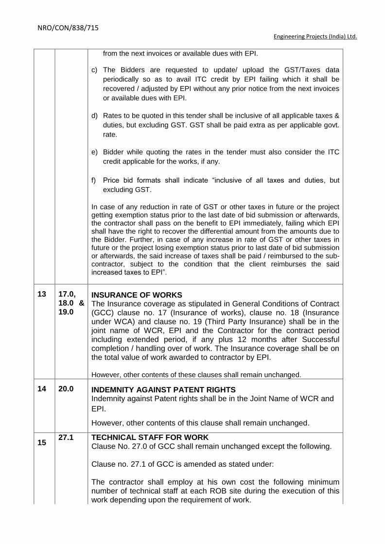
13 17.0, 18.0 & 19.0
INSURANCE OF WORKS The Insurance coverage as stipulated in General Conditions of Contract (GCC) clause no. 17 (Insurance of works), clause no. 18 (Insurance under WCA) and clause no. 19 (Third Party Insurance) shall be in the joint name of WCR, EPI and the Contractor for the contract period including extended period, if any plus 12 months after Successful completion / handling over of work. The Insurance coverage shall be on the total value of work awarded to contractor by EPI. However, other contents of these clauses shall remain unchanged.
14 20.0 INDEMNITY AGAINST PATENT RIGHTS Indemnity against Patent rights shall be in the Joint Name of WCR and
EPI.
However, other contents of this clause shall remain unchanged.
15 27.1 TECHNICAL STAFF FOR WORK
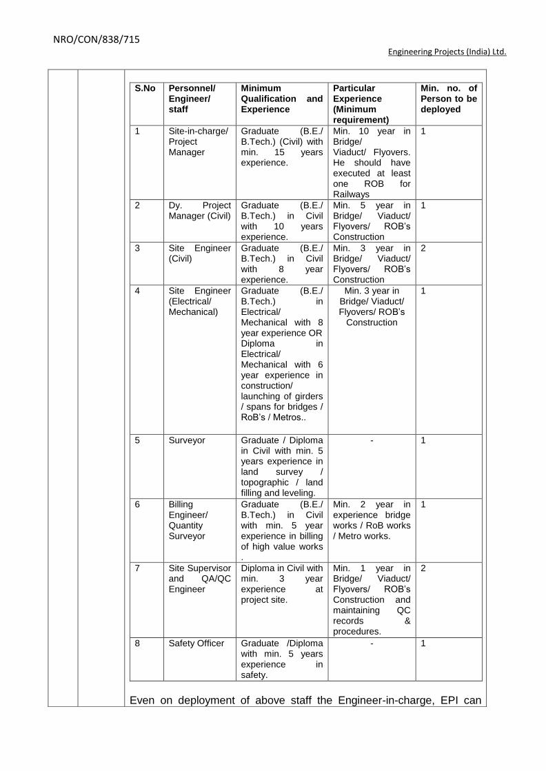
Clause No. 27.0 of GCC shall remain unchanged except the following. Clause no. 27.1 of GCC is amended as stated under: The contractor shall employ at his own cost the following minimum number of technical staff at each ROB site during the execution of this work depending upon the requirement of work.
NRO/CON/838/715 Engineering Projects (India) Ltd.
S.No Personnel/
Engineer/ staff
Minimum Qualification and Experience
Particular Experience (Minimum requirement)
Min. no. of Person to be deployed
1 Site-in-charge/ Project Manager
Graduate (B.E./ B.Tech.) (Civil) with min. 15 years experience.
Min. 10 year in Bridge/ Viaduct/ Flyovers. He should have executed at least one ROB for Railways
1
2 Dy. Project Manager (Civil)
Graduate (B.E./ B.Tech.) in Civil with 10 years experience.
Min. 5 year in Bridge/ Viaduct/ Flyovers/ ROB‟s Construction
1
3 Site Engineer (Civil)
Graduate (B.E./ B.Tech.) in Civil with 8 year experience.
Min. 3 year in Bridge/ Viaduct/ Flyovers/ ROB‟s Construction
2
4 Site Engineer (Electrical/ Mechanical)
Graduate (B.E./ B.Tech.) in Electrical/ Mechanical with 8 year experience OR Diploma in Electrical/ Mechanical with 6 year experience in construction/ launching of girders / spans for bridges / RoB‟s / Metros..
Min. 3 year in Bridge/ Viaduct/ Flyovers/ ROB‟s
Construction
1
5 Surveyor Graduate / Diploma in Civil with min. 5 years experience in land survey / topographic / land filling and leveling.
- 1
6 Billing Engineer/ Quantity Surveyor
Graduate (B.E./ B.Tech.) in Civil with min. 5 year experience in billing of high value works .
Min. 2 year in experience bridge works / RoB works / Metro works.
1
7 Site Supervisor and QA/QC Engineer
Diploma in Civil with min. 3 year experience at project site.
Min. 1 year in Bridge/ Viaduct/ Flyovers/ ROB‟s Construction and maintaining QC records & procedures.
2
8 Safety Officer Graduate /Diploma with min. 5 years experience in safety.
- 1
Even on deployment of above staff the Engineer-in-charge, EPI can

NRO/CON/838/715 Engineering Projects (India) Ltd.
direct the contractor to depute such additional staff as in view of Engineer-in-charge, EPI is necessary due to nature & exigency of work having requisite qualification and experience. The amount of recovery in case of non deployment of min. staff as mentioned above is: for Sr. no. 1is Rs. 1,50,000 /- per month, Sr. no. 2 is Rs. 1,00,000 /- per month, Sr. no. 3 & 4 is Rs. 70,000 /- per month &Sl. No. 5 & 6 is Rs. 60,000 /- per month, Sr. no. 7& 8 is Rs. 30,000 /- per month.
16 28.3 FURNISHED OFFICE ACCOMODATION & MOBILITY AND COMMUNICATION TO BE PROVIDED BY CONTRACTOR TO EPI Clause No. 28.3 GCC shall be deleted
17 35.0 SECURED ADVANCE AGAINST NON-PERISHABLE MATERIALS
Admissible as per GCC 35.0
18 37.0 Payments terms
As per GCC 37.0
19 40.0 Apart from provision of GCC clause 40.0, the Contractor shall follow codes and specification as under during construction of works: I) Indian Railway Specifications& codes. II) State Govt. PWD specifications. III) CPWD Specifications. IV) Bureau of Indian Standards (BIS). V) Norms not covered in (i) to (iv) above and applicable to the
construction work with the approval of the Engineer in Charge.
20 43.1 The completion schedule of the project is as under: From the Date of Start of Construction activities.
S. No.
Item Duration Milestone
1 Mobilization, site survey, deployment of project staff and Plant & machinery.
1 months Within 1 month from “Date of start”.
2 Start of initial activities for execution of project and foundations, pier of ROB structure. Percentage achievement of physical progress up to 25%.
3 months Within 4 months from “Date of start of Construction Activities”.
3 Execution of approach road and all structures. Percentage achievement of physical progress up to 50%.
2 months Within 6 months from “Date of start of Construction Activities”
4 Launching of Girder 2 months Within 08 months
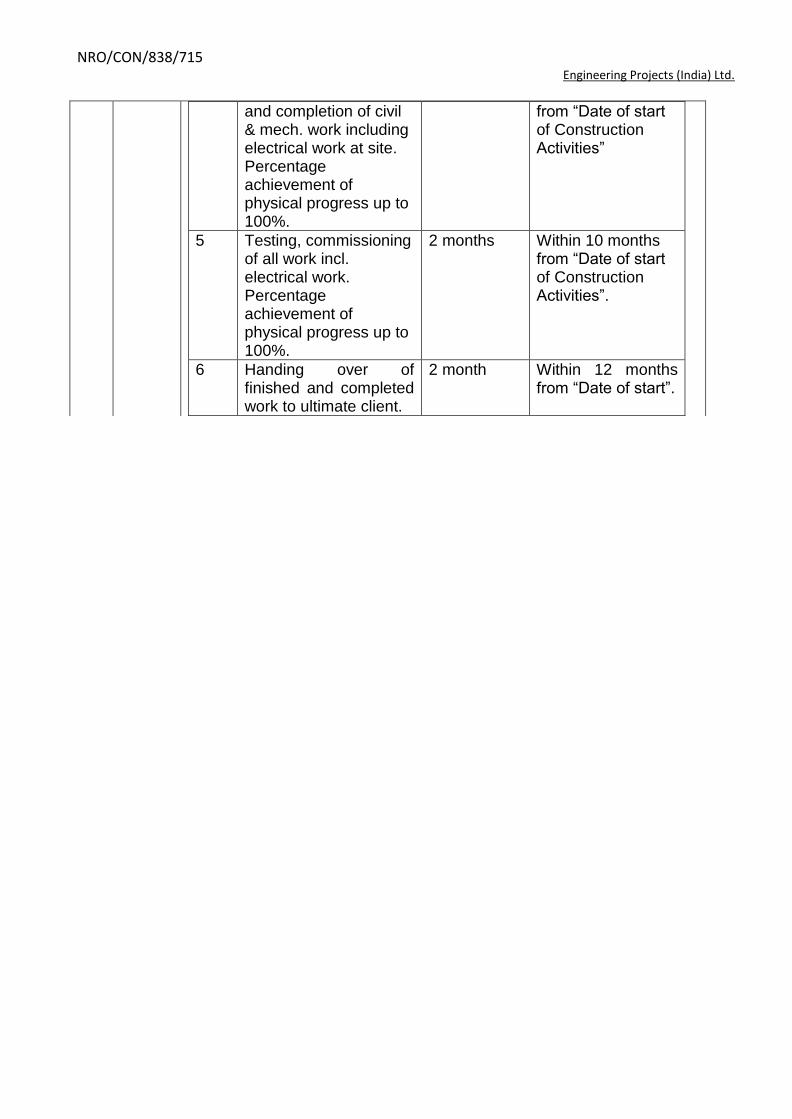
NRO/CON/838/715 Engineering Projects (India) Ltd.
and completion of civil & mech. work including electrical work at site. Percentage achievement of physical progress up to 100%.
from “Date of start of Construction Activities”
5 Testing, commissioning of all work incl. electrical work. Percentage achievement of physical progress up to 100%.
2 months Within 10 months from “Date of start of Construction Activities”.
6 Handing over of finished and completed work to ultimate client.
2 month Within 12 months from “Date of start”.
NRO/CON/838/715 Engineering Projects (India) Ltd.
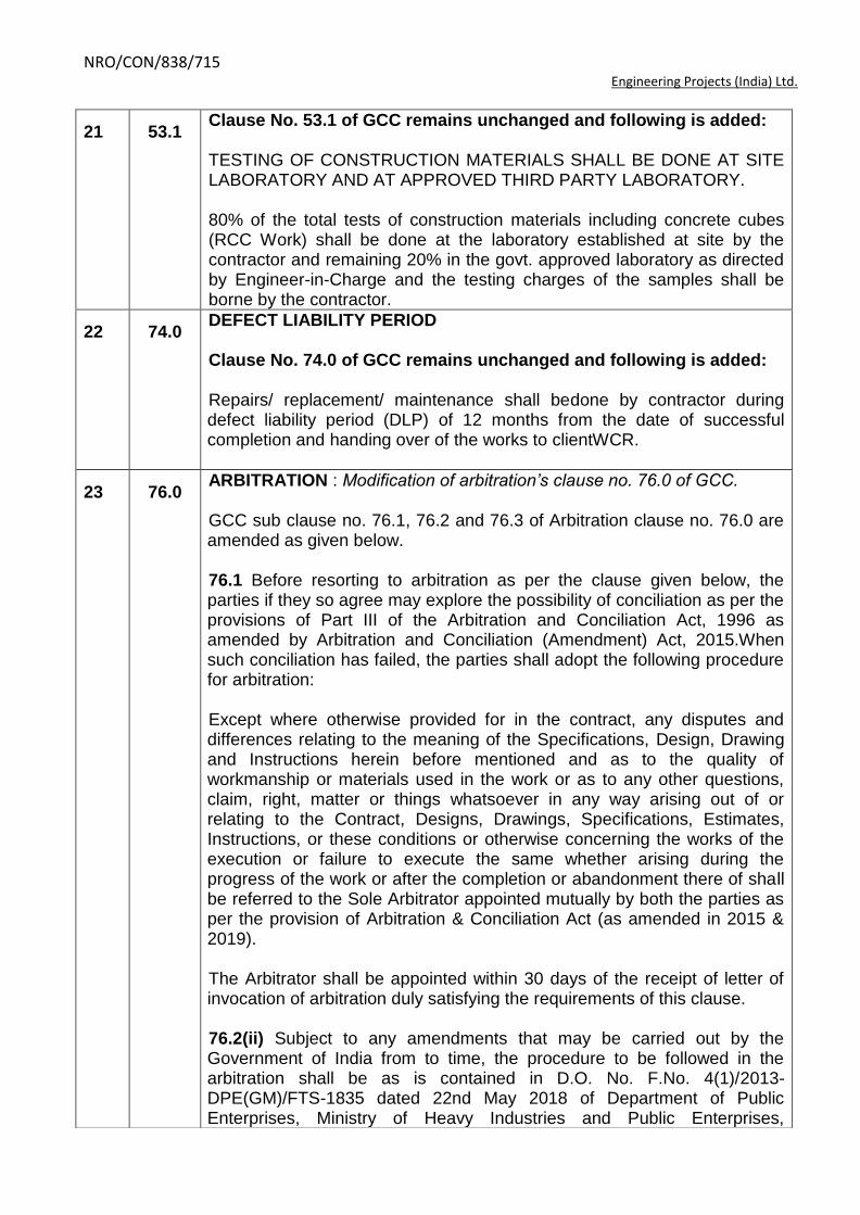
21 53.1 Clause No. 53.1 of GCC remains unchanged and following is added: TESTING OF CONSTRUCTION MATERIALS SHALL BE DONE AT SITE LABORATORY AND AT APPROVED THIRD PARTY LABORATORY. 80% of the total tests of construction materials including concrete cubes (RCC Work) shall be done at the laboratory established at site by the contractor and remaining 20% in the govt. approved laboratory as directed by Engineer-in-Charge and the testing charges of the samples shall be borne by the contractor.
22 74.0 DEFECT LIABILITY PERIOD Clause No. 74.0 of GCC remains unchanged and following is added: Repairs/ replacement/ maintenance shall bedone by contractor during defect liability period (DLP) of 12 months from the date of successful completion and handing over of the works to clientWCR.
23 76.0 ARBITRATION : Modification of arbitration’s clause no. 76.0 of GCC. GCC sub clause no. 76.1, 76.2 and 76.3 of Arbitration clause no. 76.0 are amended as given below. 76.1 Before resorting to arbitration as per the clause given below, the parties if they so agree may explore the possibility of conciliation as per the provisions of Part III of the Arbitration and Conciliation Act, 1996 as amended by Arbitration and Conciliation (Amendment) Act, 2015.When such conciliation has failed, the parties shall adopt the following procedure for arbitration: Except where otherwise provided for in the contract, any disputes and differences relating to the meaning of the Specifications, Design, Drawing and Instructions herein before mentioned and as to the quality of workmanship or materials used in the work or as to any other questions, claim, right, matter or things whatsoever in any way arising out of or relating to the Contract, Designs, Drawings, Specifications, Estimates, Instructions, or these conditions or otherwise concerning the works of the execution or failure to execute the same whether arising during the progress of the work or after the completion or abandonment there of shall be referred to the Sole Arbitrator appointed mutually by both the parties as per the provision of Arbitration & Conciliation Act (as amended in 2015 & 2019). The Arbitrator shall be appointed within 30 days of the receipt of letter of invocation of arbitration duly satisfying the requirements of this clause. 76.2(ii) Subject to any amendments that may be carried out by the Government of India from to time, the procedure to be followed in the arbitration shall be as is contained in D.O. No. F.No. 4(1)/2013-DPE(GM)/FTS-1835 dated 22nd May 2018 of Department of Public Enterprises, Ministry of Heavy Industries and Public Enterprises,
NRO/CON/838/715 Engineering Projects (India) Ltd.
Other Additional Clauses:
Government of India or any modification issued in this regard. 76.3 JURISDICTION: The courts in Delhi/ New Delhi alone will have jurisdiction to deal with matters arising from the contract.
The other additional clauses is detailed below:
24 STATUTORY& GENERAL REQUIRMENTS
The contractor is responsible for Liaison & obtaining the connection for water supply, sewer connection, electric connection and other connections, if any, from local authorities/state Electricity board. However the statutory official payments payable to Govt. department for water, sewer& electricity connection shall be paid by EPILdirectly to the concerned authorities. The contractor is advised to quote his rates considering the above factors.
25 QUALIFICATION OF TENDERERS To be eligible for this tender the bidders should fulfill the requirements for eligibility as mentioned in the Notice Inviting Tender (NIT) and should submit detailed data and credentials set out in Clause No. 19.0 of ITT at page no.- 6 (Vol-I), NIT of the tender. The bidders are required to fulfill all the eligibility criteria as stipulated in NIT documents and elsewhere in the Tender documents. The price bid of only those bidders who fulfill the eligibility criteria as per evaluation of EPI shall be opened. The decision of EPI in this regard shall be final & binding on the bidders.
26 DISQUALIFICATION
The bidders may note that they are liable to be disqualified and not considered for the opening of Price Bid online if;
a) Representation in the forms, statements and attachments submitted
in the pre-qualification document are proved to be incorrect, false and misleading.
b) If bidder have record of poor performance during the past 5 years
such as abandoning the work, rescinding of contract for which the reasons are attributable to the non-performance of the contractor, inordinate delay in completion, consistent history of litigation /

NRO/CON/838/715 Engineering Projects (India) Ltd.
arbitration awarded against the contractor or any of its constituents or financial failures due to bankruptcy etc. in their ongoing / past projects.
c) They have submitted incompletely filled in formats without attaching
certified supporting documents and credentials to establish their eligibility to participate in the tender.
d) If the bidders attempt to influence any member of the selection
committee.
EPI reserves its right to take appropriate action including disqualification of bidder (s) as may be deemed fit and proper by EPI at any time without giving any notice to the contractor in this regard. The decision of EPI in the matter of disqualification shall be final and binding on the bidders.
27 EPI reserves the right to independently verify the performance of the bidder from the existing owners / users / owners‟ Consultants. In case, any execution of work/ Project is found to be performing unsatisfactorily, EPI reserves the right to reject the tender and price bid of such bidder shall not be opened, even if the bidder is meeting the technical and other qualifying requirements. In such circumstances the bidder shall have no claim on EPI of whatsoever nature. Bidder’s specific attention is drawn to above clauses.
28 Bidders must submit the unpriced copy of the price bid duly stamped & signed along with other documents in the techno-commercial bid as a confirmation of having quoted for all items of the price bid.
29 DRAWINGS a) Before filling in the tender, the tenderer will have to check up all
drawings and schedule of quantities and will have to get the immediate clarification from EPI on any point that he feels is vague or uncertain. No claim for damages or compensation will be entertained on this account, in future. Figured dimensions are in all cases to be followed and in no case should they be scaled. Large scale details take precedence over small scale drawing, in case of the discrepancy; the contractor is to ask for clarification before proceeding with the work.
b) The drawings attached to the tender documents provide a general idea about the work to be performed under the scope of this contract. These are preliminary drawings for tender purpose only and are by no means the final/ GFC drawings and may not be showing the full range of the work under the scope. The details given in the tender drawings are tentative and likely to be changed / modified during the detailed engineering.
c) The work has to be executed according to “Good for Construction”

NRO/CON/838/715 Engineering Projects (India) Ltd.
drawings issued by Engineer-in-charge with addition and modifications made from time to time as and when required and approved by Engineer-in-charge. The drawing shall be progressively released to site before the start of the corresponding work.
Before the commencement of any item of work, the contractor shall co-relate all the relevant architectural and structural drawings issued for the work and satisfy himself that the information available there from is complete and unambiguous. The discrepancy, if any, shall be brought to the notice of Engineer-In-Charge before the execution of work. The contractor alone shall be responsible for any loss or damage occurring by the commencement of work on the basis of any erroneous and / or incomplete information. Nothing extra shall be paid on this account.
30 SITE LABORATORY As part of the contract the contractor shall provide and maintain a site laboratory for the routine testing of construction material under the direction and general supervision of Engineer-in-charge. The laboratory room shall be constructed and installed with the appropriate facilities. Cube testing & sieve analysis, etc. facility should in the lab. Temperature and humidity controls shall be made available wherever necessary during the testing of samples. All equipments shall be provided by the contractor so as to be compatible with the specified testing requirements. The contractor shall maintain the equipment in good working conditions for the duration of the contract. The Contractor shall provide approved qualified personnel to run the laboratory for the duration of the contract. The number of staff and equipment available must at all times be sufficient to keep pace with the sampling and testing program as required by Engineer-in-charge. The laboratory In charge of the contractor shall report to Engineer-in-charge. The Contractor shall fully service the site laboratory and shall supply everything necessary for its proper functioning, including all transport needed to move equipment and samples to and from sampling points on the site etc. The Contractor shall re–calibrate all measuring devices, whenever so required by the Engineer-in-charge and shall submit the results of such measurements without delay. For all other tests as required by Engineer-in-charge, the Contractor shall get the same carried out / conducted by approved testing Laboratory. In addition if, EPI feels, may direct the Contractor to conduct the tests in the presence of EPI representative at site lab / outside labs. All expenses payable for transport of samples and conduction of tests shall be borne by the contractor.

NRO/CON/838/715 Engineering Projects (India) Ltd.
31 PRICE VARIATION No price variation is allowed in this contract since it is a firm rate contract till completion of work.
32 FINAL BILL The final bill shall be submitted by the contractor within 90 days from the date of acceptance of completion of work accompanied by the following documents.
a) Interim Completion certificate issued by the Engineer-in-charge specifying the handing over of the work including list of inventories (fittings & fixtures).
b) Computerized stage wise payment schedule. c) No claim certificate by the contractor. d) No claim certificate from the sub agencies / venders engaged by the
contractor. e) „As built‟ drawings – 6 sets. f) Periodical services and measurement books. g) Drawings for layout of underground cables and details showing
location of sluice valves, electric cable joints etc. h) All operation and maintenance manuals. i) All statutory approvals from various state / central govt. local bodies,
if required for completion & handling over of the work as included in scope of contractor.
j) Manufacture‟s guarantee of various machines / equipments installed as part of works (if applicable).
33 For dispatch of materials to site, equipment manufacturer / supplier shall mark through Engineering Projects (India) Ltd (EPI) / designated officer.
34 ROAD PERMIT Road permit for transportation of goods across state border shall not be issued by EPI / WCR-Kotaand it will have to be arranged by contractor on his own. Transit Insurance of the equipment shall be arranged by the contractor. Nothing extra shall be paid on this account.
35 Invoice should be raised by Contractor in the name of Engineering Projects (India) Ltd., at Project Coordination Office, Kota.
36 General The Project shall be reviewed at least once every month jointly by EPI/Client with Contractor at the site and the minutes of such review meeting shall be jointly singed for records and for further implementation / compliance. The modalities and detailsof such review meeting shall be decided by the EPI/Client.
37 The project shall be handed over to the owners WCR-Kota through EPI. The contractor, at the time of handing over or prior to that, shall provide to the EPI/ Client all the as built drawings and other relevant documents related to the services provided in the projects.
38 The Contractor shall remain liable to and shall Indemnify the EPI/Client in respect of losses, damages, or compensation arising out of any accident or injury sustained by the EPI/Client, any workman in the employment of the contractor while in or upon the said work/ any third person or the same arising out or any act, default or negligence, omission and commission,
NRO/CON/838/715 Engineering Projects (India) Ltd.
error in judgments on the part of contractor, its employee or its agent (s) subject to the determination of the compensation or damages by the competent authority as defined in the relevant lows. The contractor shall also remain liable for the defects in construction and shall indemnify damages arising out of such defects in construction.
39 The EPI/Client shall on the request of the contractor assist in shifting of utilities such as water supply line, electrical lines, gas pipe line etc. by communicating with the respective agency/ department to expedite the shifting/ removal of utilities.
40 The Contractor shall be wholly responsible for the safe keeping, security, protection of assets created etc. at the site and any loss or damage to the assets created shall be indemnified by the Contractor.
41 The Contractor shall ensure that required/ adequate measures are adopted for earthquake resistance for construction of project.
42 The Contractor shall provide monthly physical and financial report of the project to EPI.
43 All the material and workmanship shall be of good quality confirming generally to accepted standard of IndianRailway/ BIS/ Indian standardsspecification and codes.
44 Quality Control may also be carried out by the WCR-Kota/ State Govt. through third party at random during or after construction period. Final payments to the contractor shall take into account the deductions in rates (if any) arrived at by the administrative department on the basis of the findings of third party quality control.
45 Defect liability period Defect liability period shall be 12 Months from the date of handing over the project to Client WCR-Kota. Rectification of any kind in the works shall be attended by the contractor immediately at his cost during the DLP period. EPI/ Client may also report the defects during the construction period for which the defects rectification period shall be as indicated by the EPI/Client in its report or otherwise.
46 Thermo Mechanically Treated bars Conforming to IS: 1786, Fe 500 grade as required from approved manufacturers viz SAIL/RINL/TISCO shall be used. In case of non availability of steel of these manufacturers as per IS 1786, Fe 500 grade as required, may be allowed to be used with the prior approval of Engineer-in-charge.
47 CONCRETING The concreting shall be from Batching Plant installed at site. However the
contractor may opt to use Ready Mixed Concrete as standby / alternative arrangement if available in the project vicinity subject to satisfying all the requirements of EPIL / Engineer-in-charge after obtaining prior written approval from Engineer-in-charge.
39.2 Batching plant of minimum capacity of 30 Cum per hour with a least count of 0.5Kg., drum type 4 load cells, computer compatible print out for each batch only shall be allowed.
39.3 The concreting shall be placed by concrete pumps of minimum 30 Cum/hour capacity at specified locations. Concreting by crane and buckets will be allowed in rare case with the prior approval of Engineer-in-charge.
39.4 The contractor shall provide construction joints only at the specified

NRO/CON/838/715 Engineering Projects (India) Ltd.
positions and as per BIS codes and the concreting for columns shall be floor to beam height in one lifts.
39.5 The stone aggregate and sand of required zone shall be from the quarries as approved by Engineer-in-charge. The samples of the materials shall be got approved along with the mix design by the agency at their own cost.
39.6 Plasticizers/Admixture, of the required specification and make shall only be permitted as per approved design mix. The cost of plasticizers/ admixtures/ additives is deemed to be included in the rates of concrete & nothing extra shall be payable on this account.
39.7 Ready mix concrete brought from outside sources or produced at site shall have minimum quantity of cement as specified in BOQ items/ Specifications and as per approved design mix.
48 DESIGN MIX CONCRETE 1. Design mix concrete shall be used in the work for all structural
members. For design mix, Indian Railway/ CPWD specification along with relevant IS codes shall be followed in general along with the specific provisions made herein.
2. The concrete mix design with or without admixture will be carried out by
the contractor through one of the following laboratories/ Test houses/ Govt. Institute to be approved by Engineer-in-charge.
IIT, NIT, reputed test house / NABL laboratories only.
3. The contractor shall submit the mix design report from approved
laboratory for approval of Engineer-in-charge within 45 days from the date of issue of letter of acceptance of the tender. No concreting shall be done until the designmix is approved.
4. The contractor shall make cubes of trial mixes as per approved mix
design for all grades of concrete in presence of the Engineer in charge using same ingredients as adopted for design mix, prior to commencement of concreting and get them tested in presence of Engineer-in-charge for 7 days and 28 days.
For each design mix, a set of six cubes shall be prepared from each of the three consecutive batches. Three cubes from each set shall be tested at the age of 7 days and three cubes at the age of 28 days. The cubes shall be made, cured, transported and tested strictly in accordance with CPWD specifications. The average strength of nine cubes at the age of 28 days shall exceed the specified target mean strength for which design mix has been approved.
5. 80% of the total tests shall be done at the laboratory established at site
by the contractor and remaining 20% in the NABL approved laboratory as directed by Engineer-in-Charge and the testing charges of the samples shall be borne by the contractor.
NRO/CON/838/715 Engineering Projects (India) Ltd.
6. For each change of source or quality/ characteristic properties of the ingredients from that approved & used in the concrete mix during the work, a fresh mix design shall be got done by the contractor. Revised trial mix test shall be conducted at laboratory established at site/ reputed Laboratory with prior approval of Engineer-in-charge and shall be submitted by the contractor as per the direction of engineer-in-charge.
7. The cost of packaging, sealing, transportation, loading & unloading cost
of all samples-concrete /cubes/ steel/ other material etc and the testing charges for mix design in all cases shall be borne by the contractor.
49 BRICK WORK A. The bricks should be minimum class designation 7.5 conforming to
IS 1077:1992. B. The brick work for all external walls should be done from outside.
The rigid scaffolding of MS pipe and the supports shall be sound and strong, with horizontal MS pips. The contractor shall be responsible for providing and maintaining sufficiently strong scaffolding so as to withstand all loads likely to come upon it. Due care shall be taken by the contractor to ensure the execution of brick masonry walls in plumbs from outside. The Contractor shall arrange sufficient quantity of scaffolding for this purpose so as to complete the project within stipulated time.
All brick works shall be with the bricks of specified grade & source as approved by Engineer-in-charge and no efflorescence due to salt water shall be allowed. The contractor shall have to give proper treatment in any such case and nothing extra shall be payable and the rates quoted shall be all inclusive.
50 CENTERING & SHUTTERING A. Centering & Shuttering works for columns shall be made out of
laminated shuttering plywood of minimum 12mm thickness as per BIS, with angle iron frame. The centering, Shuttering and staging system shall be got approved form the Engineer-in Charge.
B. The shuttering used for beam shall be of laminated shuttering plywood as per BIS. The support system shall be integrated with the slab. For beam/slabs in case ply wood shutters is not used, welded steel plates will be allowed to be placed in uniform pattern. The thickness of plates and pattern to be got approved from the Engineer-in-charge.
C. All joints in the shuttering i.e. plate to plate etc. shall have to be sealed with adhesive/foam, to ensure water tightness of the form work.
D. All shuttering work for Architect features shall be with fiber glass moulds and the rate quoted by the contractor in the schedule of rate shall be inclusive of same.
E. All shuttering joints in the slab, beams and lintels etc. Shall be treated with tape of required width to make it water tight and the rates quoted for centering shuttering work shall be all inclusive and nothing extra whatsoever shall be payable over and above the quoted price.

NRO/CON/838/715 Engineering Projects (India) Ltd.
F. The shuttering shall be tightened by using runners, tie rods and bracings. No Ghughoo/ Welded system shall be allowed. Support / staging shall be adequate and proper.
51 Unless otherwise specified in the schedule of quantities, the rates tendered by the contractor shall be all inclusive and shall apply to all heights, floors including terrace, leads and depths and nothing extra shall be payable on this account.
52 Plant & machinery required for execution of workshall have to be arranged by the contractor at his own cost. However, the Contractor has to deploy required plant & machineries to complete the project within stipulated time. Following are minimum plant & machinery to be deployed at site immediately after award of work and as per instructions from Project-in-charge. S. No. Equipment Capacit
y Nos.
1 Fully automatic computerized concrete batching and mixing plant as per the specifications with print outs for admixture, concrete batching and other items.
30 cum/ hr
1
2 Transit mixers 6 cum 3
3 Concrete pumps (One stationery and one placer boom)
30 cum/ hr
1
4 Rollers/Vibratory Rollers (Front Drum) 8-10 Tonnes
1
5 Integrated piling rig (Hydraulic operated rotary type for bored cast-in situ piles)
- 1
6 Tippers & Dumpers - 4
7 Porcelain (excavator) 60 Cum/ hr
1+1
8 Dozer/Grader 160hp 1
9 JCB with breaker & buckets 30 cum / hr
2
10 Cranes (as per required requirement /capacity) - 2
11 Dewatering pumps 15 & 20 HP
2
12 DG Set 50 KVA 2
13 Total Station - 1
14 Auto Level - 1
15 Vibrator with needles (40 & 60 mm) - 4
16 Water tanker with sprinkler 5000 ltrs
1
17 Bar bending and bar cutting machine - 1+1
18 Core cutting Machine - 1 set
19 Welding Machine - 3
20 V B Roller 3 ton 1
21 Painting equipment - 1
22 Loader (as per required capacity) - 1
23 Hydra (as per required capacity) - 1
24 Trailer (as per requirement) - 1

NRO/CON/838/715 Engineering Projects (India) Ltd.
25 Bucket (for pedestal & cross girder concrete) - 1
26 Tractor/Eicher/Ecomet/Tata 407, etc - 2
27 Gentry (if required) - 1
28 Mechanical Tools - 1 set
Note:-
a) Any other equipment for site test as outlined in Railway/CPWD/BIS specification and as directed by the Engineer-in-charge.
b) The quantities of equipment‟s indicated are tentative and can be increased as per the requirement of work OR as per the direction of Engineer-in-charge. The above equipment list is indicative and not complete. The contractor has to deploy all the required equipment to complete all the works within stipulated specifications & time period as per contract documents.
c) The contractor will not be allowed to take out equipments from the site without the written permission of Engineer-in-charge.
53 The project shall be commenced and completed by the contractor as per the timelines agreed hereto and as per the design, plans, specifications prepared by EPI and approved in consultation with owners. Permissions, Permits, Licenses obtained from the relevant authorities to carry out the project are for the purpose of project implementation and thecontractor agrees and acknowledges that the time is essence of the project.
54 A. Contractor shall be liable and responsible to insure and comply with: B. Written jobsite safety and environmental manual (s) C. Site order book at the construction site. D. Compliance to national and/ or local safety regulations. E. Any other rules or regulations introduced by the law time being in force
with respect to the project.
55 Contractor shall ensure that extra/ deviated items are not executed unless approved by the EPI/Client in writing in advance and the rates for the same are finalized. A register for extra/ substituted items shall be maintained by contractor.
56 Contractor shall ensure that safety of personnel working at Construction site/Inspecting the site by taking precautions by insisting compliance of safety code such as use of helmets, safety shoes etc. that may be required for the executing the project in the terms of this project.
57 Contractor shall ensure that the salaries, wages, charges, fees or any dues or liabilities including third party liability relating to the employees/workers/ officers/ engineers etc. employed by him, the Contractors even if the same are appointed/ employed for this particular Project, are duly discharged and cleared in a timely manner. In no event shall the EPI/Owner be liable or responsible for any liability with respect to the same.
58 It is hereby agreed by contractor that EPI/Client shall not be liable or responsible for any accident, loss, injury resulting in death or otherwise of any employees/ Workers/ officers/ engineers/ etc. employed by
NRO/CON/838/715 Engineering Projects (India) Ltd.
contractors. That the EPI/Owner shall not be liable or responsible for any costs or expenses or damages of any kind whatsoever happening or accruing during the term of the Agreement or for execution of the project at the construction site including without limitation loss to materials and equipments or injury to persons and/ or property. Contractor shall fully indemnify, save, protect and hold the EPI/Owner harmless from and against the same. It is further agreed that the EPI/ Owner shall be at liberty to and is hereby empowered to deduct costs, charges, expenses etc. that may arise out of or relate to any such claim or liabilities from the amounts/dues payable to contractor.
59 It is agreed by Contractor that he will not publicize or divulge to any third party any information with respect to the project or the owner. Provided that the name of the EPI/Owner shall only be used with the explicit prior written consent of the EPI/Owner.
60 PERSONAL EMPLOYED/ DEPLOYED BY CONTRACTOR A. Contractor shall be liable and responsible for ensuring that the persons
of proven ability and adequately qualified shall only be employed and/ or deployed at the construction site and work diligently and as per the provisions of this Tender. The CV‟s of each personnel shall be approved by EPI before its induction. No approved person can be removed before without approval from EPI till the completion of project.
B. In case, the EPI/Owner finds any such persons at project site including Engineer/s not up to the mark, contractor will have to withdraw him/them from the construction site and replace him/ them by posting new one‟s in his/their position. The new CV‟s shall be got approved from EPI before their induction.
C. The EPI/Owner reserves the right to remove such personnel and ask for a substitute of required caliber. Provided that the Project shall not be affected by appointment and/ or replacement of the personnel required under this Agreement.
D. In case any person (s) employed at the Construction site resign from their employment, Contractor shall immediately provide a substitute of equivalent caliber and qualification. CV‟s of substitute shall be approved by EPI before induction.
E. Contractor shall not make any changes in the personnel deployed by him on the construction site without prior permission of the EPI/Owner. No personnel shall leave, the site and prior any other site without prior permission from EPI.
F. Contractor shall furnish the list of Engineers and supervisors (Civil and Electrical etc.) with details of their qualifications, experience, etc., to the EPI/Owner before employed or deployed the same on the Construction site. The CV‟s of each personnel shall be submitted & approval to be obtained from EPI before joining.
G. The EPI/Owner shall not be liable or responsible in respect of any life, health, accident, travel and any other insurance for any personnel deployed/employed by contractor under this project.
H. Contractor undertakes to indemnify and hold the EPI/Owner free and harmless against any liability or responsibility arising or relating to personnel employed or deployed at the construction site by contractor.
NRO/CON/838/715 Engineering Projects (India) Ltd.
I. Contractor shall be responsible and liable for all direct or indirect damages or losses, to the EPI/Owner or the construction site on account of neglect of professional duty or conduct on the part of any contractor, staff or Engineer or other employed/deployed by contractors under this project.
J. Contractor undertakes that it does not have objection, if any Engineering staff/ or others are employed/ deployed by the EPI/OWNER at its own cost at the construction site to carryout any work and duties allotted to such persons by the EPI. Owner, in respect of any work at the construction site or other areas outside the scope of contractor works for overall surveillance, security and verification.
K. Contractor shall provide experienced manpower skilled and/or semi skilled at the construction site required for the completion of the project.
61 OBLIGATIONS AND SERVICES Contractor shall ensure that the Agencies engaged by him under this Project undertake to provide the following facilities, services, and support during the term of this project including without limitation to the following, failing which contractor shall be solely liable and responsible:
Contractor shall be liable and responsible for providing and employing all skilled, semi-skilled and unskilled labour/ manpower/ human resources, as may be required for the construction of the construction site as per the plans, specifications, amenities agreed in this agreement.
Also the contractors shall at its their own cost, liability and responsibility engage and employ such professionals as may be required for completing the construction of the construction site.
The responsibility of complying with all statutory regulations and/or any modifications therefore or any other law relating thereto and rules made there under from time to time, with respect to any skilled, semi-skilled and unskilled labour/ manpower/ human resources including but not limited to the professionals, employed by the contractor, and of complying with all the statutory provisions including without limitation to executing of the project as per the obtained licenses, designs, plans specifications, payment of wages dues, submission of necessary returns, challans and declarations shall be that of the contractors.
And whenever called upon by the EPI/Owner forthwith submit a copy of the same to the EPI/Owner and make available all the records for inspection irrespective of whether the same is submitted along with monthly expenditure report. Provided, making available by any contractors the records or copies of the same to the EPI/Owner for inspection shall not absolve contractors from any of its responsibility or liability with respect thereto.
The EPI/Owner shall not be liable for or in respect of any liabilities or damages or compensation payable to any skilled, semi-skilled, and unskilled labour/ manpower/human resources including but not limited to the professionals employed under the employment of the contractors or any of their subsidiaries or their respective agents.
Contractor hereby agrees to indemnify and hold harmless the EPI/Owner against all such liabilities, damages, compensation and claims, proceedings, costs, charges, expenses whatsoever in respect
NRO/CON/838/715 Engineering Projects (India) Ltd.
thereof or in relation thereto including without limitation any third party claims, or claims relation to any accident or injury to any skilled, semi-skilled and unskilled labour/ Manpower, human resources.
Contractor hereby acknowledges and agrees that he shall be solely responsible and liable for any breakdowns, replacements, repairs, maintenance, and all such analogous things for any such equipment, machineries tools etc. used by the contractors.
It is agreed that the EPI/Owner shall not be liable for or in respect of any damages or compensation payable with respect to any use act or omission with respect to any equipment‟s machineries tools etc. used by the contractors or any of their subsidiaries, respective agents etc. contractor shall indemnify and keep indemnified the EPI/Owner against all such claims, proceedings, damages, costs, charges, and expenses whatsoever in respect thereof or in relation thereto.
Contractor shall ensure that all the contractors co-operate and coordinate with each other and with all agencies/ technicians/ professionals working at the construction site.
Contractor shall ensure the all the contractors provide all the necessary guidance, supervision, advice and support as may be necessary for the execution and completion of the project.
Contractor under the instructions from the EPI/Owner may direct any contractors to remove any person employed by such contractors for execution of the project, who in the opinion of the EPI/Owner.
Persists in any misconduct,
Is incompetent or negligent in the performance of his duties,
Fails to conform with any provisions of this tender, orpersists in any conduct which is prejudicial to safety, health, or the protection of the environment.
Contractor shall ensure that the contractors carryout any specific works which are not listed in this Tender, but are incidental or otherwise essential for the execution of this contract. The contractors shall be paid and extra amount as may be mutually decided between the parties for additional or extra work. As directed in writing by the EPI/Owner.
Provided the contractor must get the rates for such additions, extra work, substitutions, or variations approved in writing from the EPI/Owner before carrying out the work. Contractor shall intimate the EPI/Owner in writing before the commencement of any additional work by contractor under this tender.
The bill for additional work shall be submitted separately under the captioned additional work bill. A register for the extra/substituted items shall be maintained by contractor.
Contractor shall ensure and comply with all the directions/ instructions issued by the EPI/Owner from time to time during the term of this project. Non compliance of any such instructions or directions by any of the contractors shall amount to an event of default by contractor.
It shall be the duty of the contractor to execute the project or any part thereof and providing allied services as per design and drawings specified by EPI and approved by the Owner.
It shall be the responsibility and liability of contractor to complete work within the timelines agreed under this tender.
NRO/CON/838/715 Engineering Projects (India) Ltd.
It shall be the responsibility and liability of contractor to ensure that electrical items are installed as specified by the EPI/Owner.
It shallbe the responsibility and liability of contractor to check and ensure all safety norms as specified by EPI.
Contractor shall ensure that the electrical power, potable water and sewerage systems have been installed or modified as per the requirement of the EPI/Owner.
62 SUB-CONTRACTING Except as provided under this Tender, Contractor shall not be permitted to subcontract to third parties, in full or in part, its obligations and rights as stated under this tender without taking the prior written permission of the EPI/Owner. Provided that it is agreed between the parties that any such permission/sub-contracting shall not absolve contractor from its obligations, charges, liability, guarantees or warrantees etc. As stated under this tender towards the EPI/ Owner. Contractor shall be fully and solely liable and responsible for the proper and punctual fulfillment of the obligations of its sub-contractor just like for its own.
63 LEGAL COMPLIANCES
Notwithstanding anything contained herein, Contractor shall comply with all laws as may be required for performing this agreement.
Notwithstanding anything contained herein, contractor shall solely be responsible and liable for compliance with all labour laws and laws applicable to laborers/ employees/ personnel working under this agreement.
Notwithstanding anything contained herein, contractor shall abide by all laws and restrictions applicable in respect of children, female and weaker sections of the society in respect of the laborers/ workers working under this tender. No child labour or any labour in violation of applicable statute shall be employed. It female labour is engaged, contractor shall make necessary provision for crèche, safeguarding small children and keeping them clear of the construction site of operations. No labour shall reside within the construction site. The movement of labour at the construction site shall be as per the safety regulations, norms and safety policies of the EPI/Owner.
Notwithstanding anything contained herein contractor shall abide by laws relating to minimum Wages Act/remuneration payable to the man power and shall ensure timely payment of contributions/ compensation/ outgoes under all labour laws including but not limited to provident fund, family pension scheme, ESI, gratuity etc. In respect of the laborers/workers working under the contract.
All disputes, charges complaints etc. relating to the manpower working under/ though the contractors shall be properly addressed by contractor at its own cost without any reference, recourse to the EPI/Owner.
Contractor shall keep the EPI/Owner always safe and indemnified against any legal actions, demand, claim, or expenses arising out of any violation of labour law/ Statutory provision by the contractor. The EPI/Owner has no private of contract with any
NRO/CON/838/715 Engineering Projects (India) Ltd.
agent/Contractor/labouror third party except contractor, any claim of any labour, contractor, sub-contractor employee agent licensee, supplier shall be the sole liability of contractor and EPI/ Owner is not even remotely liable in any manner.
Contractor specifically agrees that the EPI/Owner shall at it option have the right to recover/deduct/claim the amount of any contributions/ dues/money, if any, paid by the EPI/Owner to the legal authorities in respect of laborers/ Manpower working under this project.
64 INDEMNIFICATION
Contractor shall indemnify and hold the EPI/Owner harmless for any incidental special, or punitive damages whether occasioned due to breach of contract, tort (including negligence), breach of warranties, failure of essential purpose of otherwise and even if advised of the possibility of such damages, to the maximum extent permitted by applicable laws.
Contractor shall indemnify, defend and hold the EPI/Owner harmless from and against any and all liabilities connected with or arising out of :
Any contribution/ amounts paid under any laws rules regulations, demands from legal authorities in relation to laborers/ man power employed/ working/ providing services under this tender by contractor
Any mishap/injury/ damage/ loss to man poser working for or through the contractors under this project and;
Any damage/ loss caused to the EPI/Owner due to mishandling/act/ negligence on the part of the contractors or its/ their representatives/ agencies/ manpower working for or through or under its/ their instructions and;
Any damage/ loss/fault/ complaint etc. in the project arising during the guarantee/ warranty period a envisaged herein above and;
Any costs/ legal consequences/ legal actions/ penalties/ charges/ damages as may be borne/ suffered by the EPI/Owner due to noncompliance/ part compliance/ breach of any of the legal provisions relation to laborers and / or man power including compliances and contributions under the gratuity act. Provident fund, ESI/Workman‟s compensation act, Minimum Wages act etc./ materials/ equipment‟s or any matter directly or indirectly related to the execution of the project by contractor and/ or the contractors and;
Any costs/ legal consequences/ legal actions/ penalties/ charges/ damages suffered by the EPI/Owner due to breach of any of the clauses of this Tender including but not limited to the confidentiality cum Secrecy clause.
65 CONFIDENTIALITY Contractor shall maintain strict confidentiality and secrecy in regard to all the plans, designs, specifications, information, documents, information, etc. received from or in respect of the EPI/Owner and all such designs, specifications, information, documents, etc. [hereinafter referred to as confidential information] shall always be owned by the Owner. Upon completion of the construction or determination of this project, contractor shall return of the EPI/Owner all the confidential information, without retaining any copy of the same. The said clause of confidentiality and
NRO/CON/838/715 Engineering Projects (India) Ltd.
secrecy shall remain in force forever.
66 AMENDMENT No provision of this Tender will be amended, modified, discharged other than by the express written agreement of the parties hereto in writing. Any subsequent additions, modifications or deletions hereto shall be by prior written consent of all the parties hereto and shall be annexed to this tender by way or addendum.
67 The contractor shall comply with legal orders, directions and by laws of local bodies / authorities. The contractor shall give to the Municipality, Police, Local Bodies and concerned Governmental authorities all necessary notices relating to works that may be required under the law and obtain all requisite licenses, permissions for temporary obstructions, enclosures, collection and stacking of materials, etc. The contractor shall pay at his own cost all fees, taxes and charges that may be liable on account of these operations in executing the contract. Nothing extra shall be paid by EPI on this account. The contractor shall be bound to follow the instructions and restrictions imposed by the administration / Police authorities on the working and / or movement of labour, materials etc. nothing extra shall be payable due to less / restricted working hours at site or any detours in movement of vehicles.
68 TEST CERTIFICATE All manufacturer‟s certificates of test showing that the all equipments/ materials have been tested in accordance with the requirements of the relevant standard specification and the copy of the test certificate as well as standard shall be supplied free of cost to EPI/State PWD
69 PERMITS AND INSPECTIONS The contractor shall obtain all necessary permits from local bodies, central authorities and shall make arrangement for inspection and tests etc. as required at his own cost. The contractor shall have to make his own arrangements for getting the permission for plying trucks or any Plant & Equipment for execution of works from the Police Department/ Govt. authorities at his own cost. No excuse as to delay in work due to non-availability of permission shall be entertained.
70 LICENSES The contractor shall arrange for obtaining the license and clearances for the operation (If required) from the local authorities and statutory bodies at his own cost & nothing extra shall be payable. Certification of various equipments / installations from statutory bodies other agencies as required as per technical specifications, shall be arranged by contractor at his own cost before handing over.
71 The work shall be carried out in accordance with the drawings/documents approved by the EPI / Owners. Before the commencement of any item of work, the contractor shall co-relate all the relevant architectural and

NRO/CON/838/715 Engineering Projects (India) Ltd.
structural drawings issued for the work and satisfy himself that the information available there from is complete and unambiguous. The discrepancy, if any, shall be brought to the notice of Engineer-In-Charge before carrying out surveying work. The contractor alone shall be responsible for any loss or damage occurring by the commencement of work on the basis of any erroneous and / or incomplete information. Nothing extra shall be paid on this account. Entire construction activities are open for client/ State PWD inspection at all point of time.
72 The contractor shall be bound to sign the site order book as and when required by Engineer-In-Charge at Site and carry out compliance of instruction promptly to the satisfaction of Engineer In-Charge
73 Bill of Quantities shall be read in conjunction with the specifications and requirement described in tender documents, Instructions to tenderers, General conditions of contract, Additional conditions of contract, Technical specifications, Drawings, Schedules, and Annexure & Addendum etc. to tender document. General directions and description of work and materials are not necessarily repeated or summarized in the Bill of quantities. Reference to the relevant sections of the contract document shall be made by the contractor before entering rates in the Bill of Quantities.
74 COMPLETION AND TAKING OVER As soon as the project is finally completed, the contractor shall inform EPI and EPI after its satisfaction shall in turn inform to clientWCR-Kota. Thereafter, WCRshall nominate a committee / officers for checking / verifications of completed work as per the scope of work for final taking over the project.
75 It will be the sole responsibility of contractor to obtain all statutory approvals and completion clearance from the all relevant statutory bodies for all other services as included in the scope of contract etc. from the concerned department as required within the stipulated time frame. Liaison work on behalf of EPI with the local bodies will also have to be done by the contractor. Nothing extra shall be payable to contractor on this account. No claim whatsoever in this regard shall be entertained
76 ISO COMPLIANCE Engineering Project (India) Ltd. is an ISO 9001: 2015& ISO 14001: 2015 certified Company. Therefore the contractor is ought to comply the provisions/ procedure given in EPI‟s ISO Procedure Manual / Quality Manual.
77
The Contractor shall furnish details whether they are covered under micro, small and Medium Enterprise Development Act 2006. If yes, clearly indicate under which category they are covered along with documentary evidence. This information is required to be furnished along with the bid.
78 FACILITIES TO BE PROVIDED AT SITE FOR LABOUR WELFARE All facilities is to be provided by contractor at site for fulfilling all statuary labour welfare schemes are included in contractor‟s scope, which shall
NRO/CON/838/715 Engineering Projects (India) Ltd.
include the following but not limited to the same.
Separate provision / rooms for First Aid Centre & Reset room and for the safety officer, safety supervisors and other personnel to be engaged by the contractor for H.S.E aspects of the project.
Erecting sufficient numbers of Urinals, WC‟s, drinking water, water supply and sanitary arrangements to the supervisory personnel and workmen engaged by them.
Canteen facility to workmen engaged by the contractor.
79 The Quantities indicated in the BOQ are tentative. However, contractor has to execute the works as per drawings and site conditions. Payment will be released for the work executed as per the rates quoted by contractor even if the quantity increases or decreases and shall beas per direction of Engineer-in-charge.
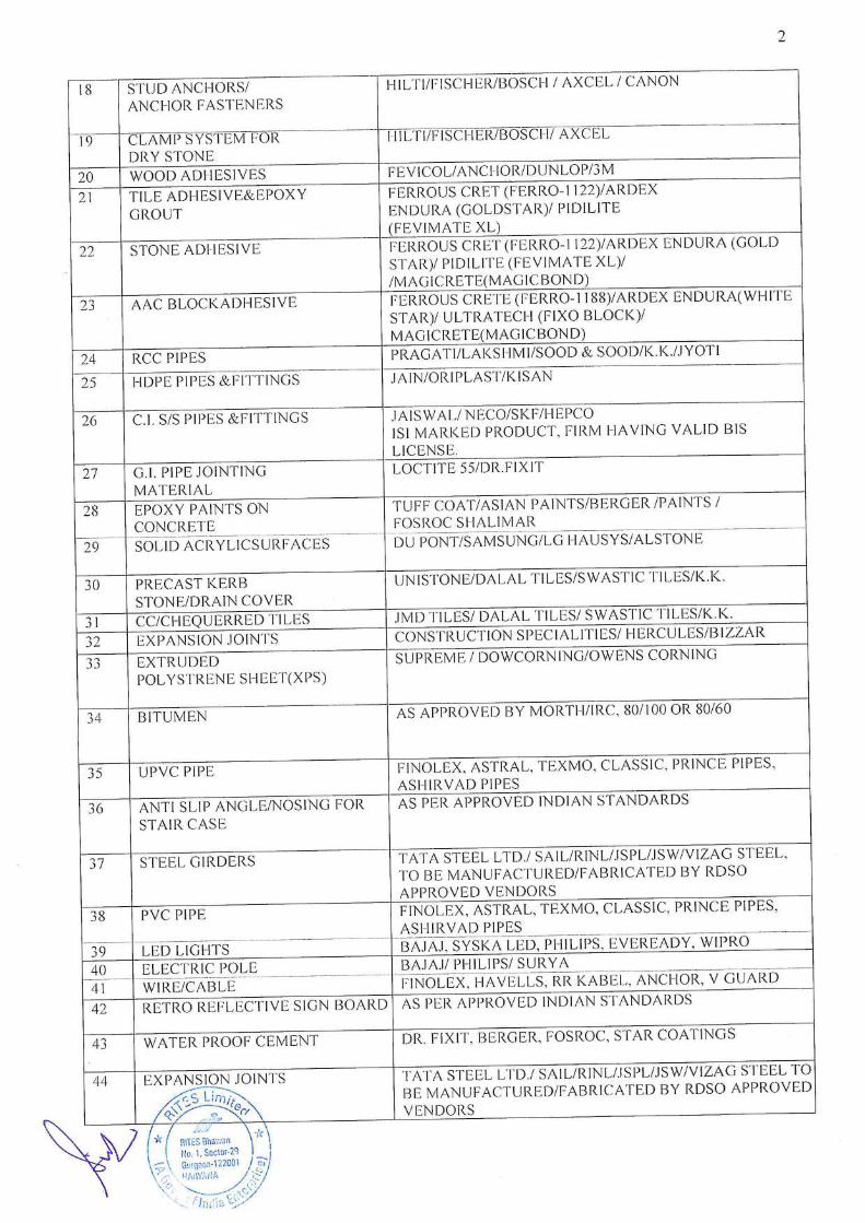
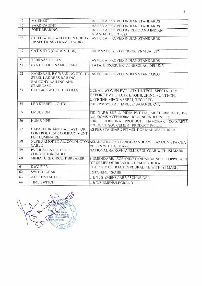
80 In addition to the preferred/ approved make of materials / equipment/ items, contractor can propose for any other equivalent make, in case of non-availability in the market / non-manufacturing of items by the approved manufacturer (manufacturer certificate to be enclosed from all vendors) for approval of Engineer-in-Charge of EPI. Decision in this regard by the EPI‟s Engineer-in-Chargeshall be final and binding to contractor.
81 For items not covered under any of the specifications mentioned in Tender Documents, the works shall be carried out as per Indian Railway/ CPWD Specifications/manufacturer‟s specifications/General Engineering Practice and/ or as per directions of Engineer-in-Charge. The rate for such extra work shall be derived as follows: a) If the item is available in latest USSOR of Railway, contractor has to execute the item with the same rate below or at par with tendered percentage. b) If the item is not available in latest USSOR of Railwayand similar item is available, rate for such extra work shall be derived from the similar item by adding or deleting the differences below or at par tender percentage. c) If the rate for any item is not possible to derive as mentioned above, the rate for which shall be derived by analyzing as per the prevailing market rates. Decision in this regard by the EPI‟s Engineer-in-Chargeshall be final and binding to contractor.
82 Life Cycle Cost The contractor shall be responsible for safety, quality and soundness of the projectstructures including structural elements beyond maintenance period. The contractor shall have obligation to rectify such defects minimum upto to 1 (one) year from the date of completion of work. The defects have to be rectified within a reasonable time not exceeding 10(ten) days after issue of notice/ intimation by Engineer-In-Charge. If contractor does not take corrective action within 10 days, then appropriate action may be taken by EPI incl. execution of the work at the risk & cost of contractor.
NRO/CON/838/715 Engineering Projects (India) Ltd.
Provisions under Integrity Pact of EPI are modified/ amended as under:-
Provisions under Model Rules for the Protection of Health andSanitary Arrangements
for Workers of EPI are modified/ amended as under:-
83 The height of barricading should be min. 2.0 M or more as per SPCB rules from the EGL on MS frame with G.I Sheet. The design shall be provided by EPIL and the cost for the same shall be deemed to be included in the quoted rates of the agency.
S. No.
Section No.
Modified/Amended provisions as per Additional Conditions of Contract
84 8 Section 8 - Independent External Monitor / Monitors Following sub clause shall be added to the said Section: (11) Notwithstanding to anything contained in sub clause (1) to (10), the client WCR at its sole discretion and without assigning any reasons whatsoever, shall have the right to appoint any individual and/or organization as it may deem fit to carry out Third Party Quality Assurance check to assess the quality of the construction workscarried out the Bidder(s)/ Contractor(s) at the Cost and Expenses of the Contractor(s).
S. No.
Clause No.
Modified/Amended provisions as per Additional Conditions of Contract
85 Following clause shall be added in the Model Rules: 11. Precautionary/Preventive Measures against dissemination/spread of COVID-19:
A. Mandatory for every labourer/worker to undergo a health checkup / covid test and/ or ensure covid vaccination before beginning work at the site.
B. Keep in-person meetings (including toolbox talks and safety meetings) as short as possible and use social distancing practices.
C. Provide employees with access to soap, clean running water, and materials for drying their hands, or if soap and water are not readily available, provide alcohol-based hand sanitizers containing at least 60% alcohol at stations around the establishment for use by workers.
D. Coordinate site deliveries in line with the employer's minimal contact and cleaning protocols. Delivery personnel should remain in their vehicles if at all possible.
E. Adopt staggered work schedules. F. Train construction workers on:
I. The signs and symptoms of COVID-19 and an explanation of
how the disease is potentially spread, including the fact that
NRO/CON/838/715 Engineering Projects (India) Ltd.
SCOPE OF WORKS
infected people can spread the virus even if they do not have
symptoms.
II. All policies and procedures that are applicable to the
employee's duties as they relate to potential exposures to
COVID-19. It is helpful to provide employees with a written
copy of those standard operating procedures.
III. Information on appropriate social distancing and hygiene
practices, including:
a. Avoiding physical contact with others and maintaining
a distance of at least 6 feet from customers and other
individuals, whenever possible, including inside work
trailers.
b. Appropriate cleaning practices (i.e., washing hands
frequently with soap and water for at least 20 seconds,
or, if soap and water are not immediately available,
using alcohol-based hand sanitizer that contains at
least 60% alcohol and rubbing hands until they are
dry; sanitizing all surfaces workers will touch).
c. The proper way to cover coughs and sneezes (i.e.,
sneezing or coughing into a tissue or into the upper
sleeve).
d. Importance of workers not touching their own faces
(mouth, nose, eyes).
e. The benefits of driving to work sites or parking areas
individually, when possible, without passengers or
carpools.
IV. The importance of staying home if they are sick.
V. Wearing masks over their noses and mouths to prevent them
from spreading the virus.
G. Ensure clean toilet and handwashing facilities. Clean and disinfect
portable job site toilets regularly. Fill hand sanitizer dispensers
regularly. Disinfect frequently touched items (i.e., door pulls and
toilet seats) regularly. H. Persons having flu-like symptoms should not come to work site and
should seek medical attention from local health authorities. If they test positive for Covid-19, they should inform the authorities concerned in the office immediately.
I. If one or more cases are reported in the office, it is advised to resume the work only after disinfection.
J. Every construction site would have weekly doctor visits. An isolation facility would also be created at the work site in case a laborer develops cough, cold or other symptoms.
To prevent the spread of COVID-19, the latest guidelines issued by the state/ center govt. should be followed.
NRO/CON/838/715 Engineering Projects (India) Ltd.
The “Works” consist of Construction of ROB in the state of Rajasthanin Kota- Mathura
section of Railway including 1 year maintenance. The works shall, inter-alia, include
the following, as specified or as directed.
A. Road Works
Site clearance; setting-out and layout; widening of existing carriageway and
strengthening including camber correction in the approaches; construction of
new/parallel service road; bituminous pavements remodeling/construction of junctions,
intersections, bus bays, lay byes; supplying and placing of drainage, channels, flumes,
guard rails and other related items; construction/extension of cross drainage works,
bridges, approaches and roads/bridges; all aspects of quality assurance of various
components of works, rectification of the defects in the completed works during the
Defect Liability Period; submission of “As built Drawings and any other related
documents; and other items of work as my be required to be carried out for completing
the works in accordance with the drawing and provision of the Contract to insure
safety.
B. ROB Works
Site clearance; setting out, provision of foundations, piers, abutments and bearing,
bowstring steel truss, pre-stressed/ post tensioned reinforced cement concrete
superstructure; wearing course, hand railings, expansion joints, approach slabs,
drainage spouts/down superstructure; wearing course, hand railings, expansion joints
etc.; provision of suitably designed protective works, providing protective coating to
concrete and reinforcement; providing wing / return walls; rehabilitation of existing
bridges/culverts; provision of road works on completion; rectification of the defects
during Liability Period and submission of “ As – built‟ drawings and any other related
documents; and other items of work as may be required to be carried out for
completing the works in accordance with the drawings and provisions of the Contract to
ensure safety.
C. Other Items
Execution of any other items of work for the construction and completion of the
Works in accordance with the provisions of the Contract including all incidental items
as well as preparation and submittal of reports, plans as may be required.
Execution of Electrical items as per BOQ items shall be executed in totality for overall
completion of ROB work.
During the period of the Contract the right of way (ROW) and all existing roads shall be
kept open for traffic and maintained in a safe and usable condition. Residents along
and adjacent to the works are to be provided with safe and convenient access to their
properties at all times. Traffic control and traffic diversion shall be used as necessary to

NRO/CON/838/715 Engineering Projects (India) Ltd.
protect the works and maintenance will be carried out as directed by the Engineer and
provided in the Contract.
D. Maintenance
The Contractor shall maintain the project for a period of one year, correspondence to
the defect liability period, commencing from the date of the completion& handing over
certificate as per conditions and clauses in Vol-IV of tender document.
Any other items as required to fulfill all contractual obligations as per Bid Documents.
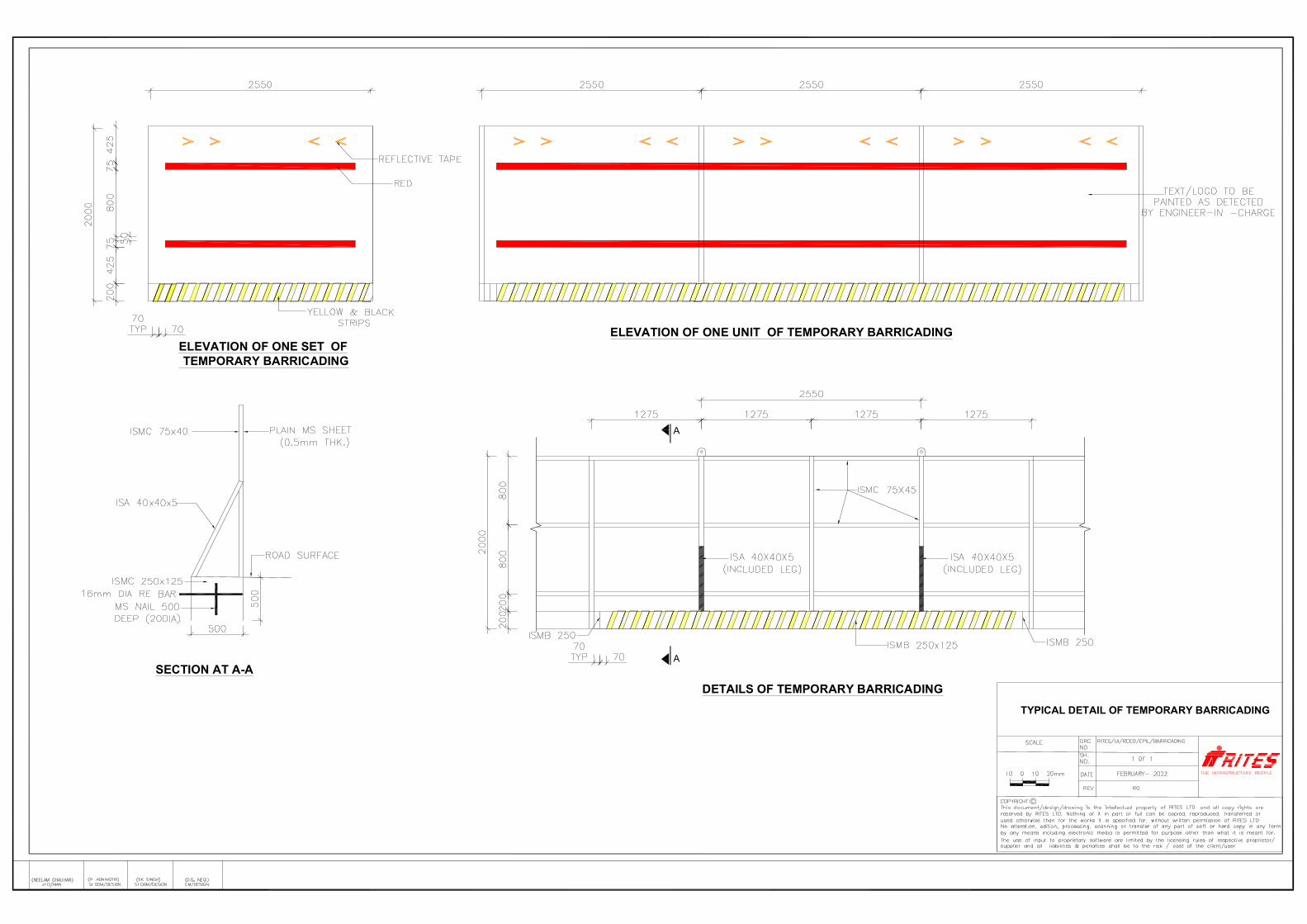
A
A
DETAILS OF TEMPORARY BARRICADING
ELEVATION OF ONE UNIT OF TEMPORARY BARRICADING
SECTION AT A-A
ELEVATION OF ONE SET OF TEMPORARY BARRICADING
TYPICAL DETAIL OF TEMPORARY BARRICADING

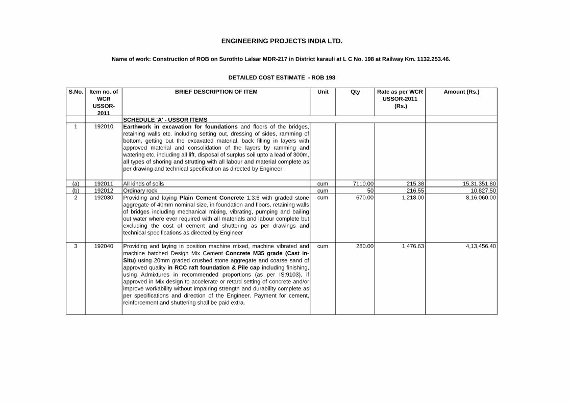
S.No. Item no. of
WCR
USSOR-
2011
BRIEF DESCRIPTION OF ITEM Unit Qty Rate as per WCR
USSOR-2011
(Rs.)
Amount (Rs.)
1 192010 Earthwork in excavation for foundations and floors of the bridges,
retaining walls etc. including setting out, dressing of sides, ramming of
bottom, getting out the excavated material, back filling in layers with
approved material and consolidation of the layers by ramming and
watering etc. including all lift, disposal of surplus soil upto a lead of 300m,
all types of shoring and strutting with all labour and material complete as
per drawing and technical specification as directed by Engineer
(a) 192011 All kinds of soils cum 7110.00 215.38 15,31,351.80
(b) 192012 Ordinary rock cum 50 216.55 10,827.50
2 192030 Providing and laying Plain Cement Concrete 1:3:6 with graded stone
aggregate of 40mm nominal size, in foundation and floors, retaining walls
of bridges including mechanical mixing, vibrating, pumping and bailing
out water where ever required with all materials and labour complete but
excluding the cost of cement and shuttering as per drawings and
technical specifications as directed by Engineer
cum 670.00 1,218.00 8,16,060.00
3 192040 Providing and laying in position machine mixed, machine vibrated and
machine batched Design Mix Cement Concrete M35 grade (Cast in-
Situ) using 20mm graded crushed stone aggregate and coarse sand of
approved quality in RCC raft foundation & Pile cap including finishing,
using Admixtures in recommended proportions (as per IS:9103), if
approved in Mix design to accelerate or retard setting of concrete and/or
improve workability without impairing strength and durability complete as
per specifications and direction of the Engineer. Payment for cement,
reinforcement and shuttering shall be paid extra.
cum 280.00 1,476.63 4,13,456.40
SCHEDULE 'A' - USSOR ITEMS
ENGINEERING PROJECTS INDIA LTD.
Name of work: Construction of ROB on Surothto Lalsar MDR-217 in District karauli at L C No. 198 at Railway Km. 1132.253.46.
DETAILED COST ESTIMATE - ROB 198
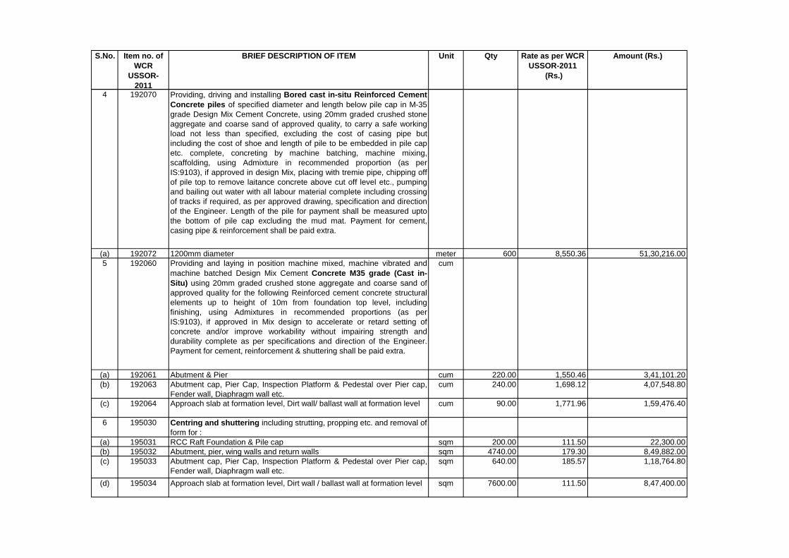
S.No. Item no. of
WCR
USSOR-
2011
BRIEF DESCRIPTION OF ITEM Unit Qty Rate as per WCR
USSOR-2011
(Rs.)
Amount (Rs.)
4 192070 Providing, driving and installing Bored cast in-situ Reinforced Cement
Concrete piles of specified diameter and length below pile cap in M-35
grade Design Mix Cement Concrete, using 20mm graded crushed stone
aggregate and coarse sand of approved quality, to carry a safe working
load not less than specified, excluding the cost of casing pipe but
including the cost of shoe and length of pile to be embedded in pile cap
etc. complete, concreting by machine batching, machine mixing,
scaffolding, using Admixture in recommended proportion (as per
IS:9103), if approved in design Mix, placing with tremie pipe, chipping off
of pile top to remove laitance concrete above cut off level etc., pumping
and bailing out water with all labour material complete including crossing
of tracks if required, as per approved drawing, specification and direction
of the Engineer. Length of the pile for payment shall be measured upto
the bottom of pile cap excluding the mud mat. Payment for cement,
casing pipe & reinforcement shall be paid extra.
(a) 192072 1200mm diameter meter 600 8,550.36 51,30,216.00
5 192060 Providing and laying in position machine mixed, machine vibrated and
machine batched Design Mix Cement Concrete M35 grade (Cast in-
Situ) using 20mm graded crushed stone aggregate and coarse sand of
approved quality for the following Reinforced cement concrete structural
elements up to height of 10m from foundation top level, including
finishing, using Admixtures in recommended proportions (as per
IS:9103), if approved in Mix design to accelerate or retard setting of
concrete and/or improve workability without impairing strength and
durability complete as per specifications and direction of the Engineer.
Payment for cement, reinforcement & shuttering shall be paid extra.
cum
(a) 192061 Abutment & Pier cum 220.00 1,550.46 3,41,101.20
(b) 192063 Abutment cap, Pier Cap, Inspection Platform & Pedestal over Pier cap,
Fender wall, Diaphragm wall etc.
cum 240.00 1,698.12 4,07,548.80
(c) 192064 Approach slab at formation level, Dirt wall/ ballast wall at formation level cum 90.00 1,771.96 1,59,476.40
6 195030 Centring and shuttering including strutting, propping etc. and removal of
form for :
(a) 195031 RCC Raft Foundation & Pile cap sqm 200.00 111.50 22,300.00
(b) 195032 Abutment, pier, wing walls and return walls sqm 4740.00 179.30 8,49,882.00
(c) 195033 Abutment cap, Pier Cap, Inspection Platform & Pedestal over Pier cap,
Fender wall, Diaphragm wall etc.
sqm 640.00 185.57 1,18,764.80
(d) 195034 Approach slab at formation level, Dirt wall / ballast wall at formation level sqm 7600.00 111.50 8,47,400.00
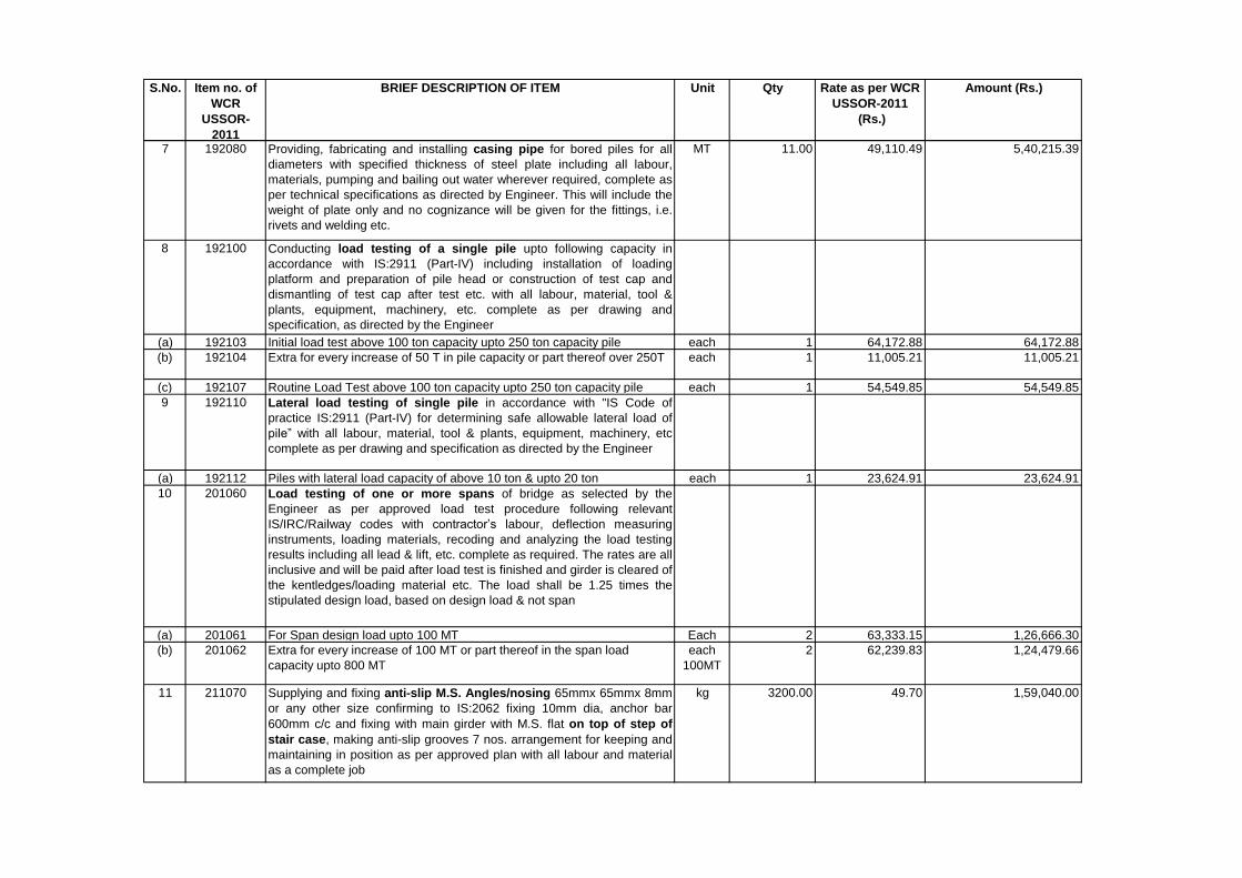
S.No. Item no. of
WCR
USSOR-
2011
BRIEF DESCRIPTION OF ITEM Unit Qty Rate as per WCR
USSOR-2011
(Rs.)
Amount (Rs.)
7 192080 Providing, fabricating and installing casing pipe for bored piles for all
diameters with specified thickness of steel plate including all labour,
materials, pumping and bailing out water wherever required, complete as
per technical specifications as directed by Engineer. This will include the
weight of plate only and no cognizance will be given for the fittings, i.e.
rivets and welding etc.
MT 11.00 49,110.49 5,40,215.39
8 192100 Conducting load testing of a single pile upto following capacity in
accordance with IS:2911 (Part-IV) including installation of loading
platform and preparation of pile head or construction of test cap and
dismantling of test cap after test etc. with all labour, material, tool &
plants, equipment, machinery, etc. complete as per drawing and
specification, as directed by the Engineer
(a) 192103 Initial load test above 100 ton capacity upto 250 ton capacity pile each 1 64,172.88 64,172.88
(b) 192104 Extra for every increase of 50 T in pile capacity or part thereof over 250T each 1 11,005.21 11,005.21
(c) 192107 Routine Load Test above 100 ton capacity upto 250 ton capacity pile each 1 54,549.85 54,549.85
9 192110 Lateral load testing of single pile in accordance with "IS Code of
practice IS:2911 (Part-IV) for determining safe allowable lateral load of
pile” with all labour, material, tool & plants, equipment, machinery, etc
complete as per drawing and specification as directed by the Engineer
(a) 192112 Piles with lateral load capacity of above 10 ton & upto 20 ton each 1 23,624.91 23,624.91
10 201060 Load testing of one or more spans of bridge as selected by the
Engineer as per approved load test procedure following relevant
IS/IRC/Railway codes with contractor’s labour, deflection measuring
instruments, loading materials, recoding and analyzing the load testing
results including all lead & lift, etc. complete as required. The rates are all
inclusive and will be paid after load test is finished and girder is cleared of
the kentledges/loading material etc. The load shall be 1.25 times the
stipulated design load, based on design load & not span
(a) 201061 For Span design load upto 100 MT Each 2 63,333.15 1,26,666.30
(b) 201062 Extra for every increase of 100 MT or part thereof in the span load
capacity upto 800 MT
each
100MT
2 62,239.83 1,24,479.66
11 211070 Supplying and fixing anti-slip M.S. Angles/nosing 65mmx 65mmx 8mm
or any other size confirming to IS:2062 fixing 10mm dia, anchor bar
600mm c/c and fixing with main girder with M.S. flat on top of step of
stair case, making anti-slip grooves 7 nos. arrangement for keeping and
maintaining in position as per approved plan with all labour and material
as a complete job
kg 3200.00 49.70 1,59,040.00
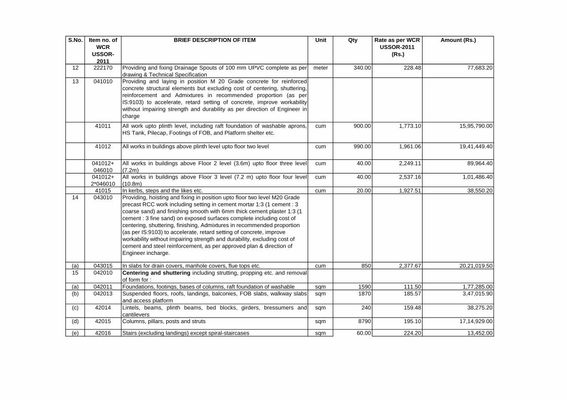
S.No. Item no. of
WCR
USSOR-
2011
BRIEF DESCRIPTION OF ITEM Unit Qty Rate as per WCR
USSOR-2011
(Rs.)
Amount (Rs.)
12 222170 Providing and fixing Drainage Spouts of 100 mm UPVC complete as per
drawing & Technical Specification
meter 340.00 228.48 77,683.20
13 041010 Providing and laying in position M 20 Grade concrete for reinforced
concrete structural elements but excluding cost of centering, shuttering,
reinforcement and Admixtures in recommended proportion (as per
IS:9103) to accelerate, retard setting of concrete, improve workability
without impairing strength and durability as per direction of Engineer in
charge
41011 All work upto plinth level, including raft foundation of washable aprons,
HS Tank, Pilecap, Footings of FOB, and Platform shelter etc.
cum 900.00 1,773.10 15,95,790.00
41012 All works in buildings above plinth level upto floor two level cum 990.00 1,961.06 19,41,449.40
041012+
046010
All works in buildings above Floor 2 level (3.6m) upto floor three level
(7.2m)
cum 40.00 2,249.11 89,964.40
041012+
2*046010
All works in buildings above Floor 3 level (7.2 m) upto floor four level
(10.8m)
cum 40.00 2,537.16 1,01,486.40
41015 In kerbs, steps and the likes etc. cum 20.00 1,927.51 38,550.20
14 043010 Providing, hoisting and fixing in position upto floor two level M20 Grade
precast RCC work including setting in cement mortar 1:3 (1 cement : 3
coarse sand) and finishing smooth with 6mm thick cement plaster 1:3 (1
cement : 3 fine sand) on exposed surfaces complete including cost of
centering, shuttering, finishing, Admixtures in recommended proportion
(as per IS:9103) to accelerate, retard setting of concrete, improve
workability without impairing strength and durability, excluding cost of
cement and steel reinforcement, as per approved plan & direction of
Engineer incharge.
(a) 043015 In slabs for drain covers, manhole covers, flue tops etc. cum 850 2,377.67 20,21,019.50
15 042010 Centering and shuttering including strutting, propping etc. and removal
of form for :
(a) 042011 Foundations, footings, bases of columns, raft foundation of washable sqm 1590 111.50 1,77,285.00
(b) 042013 Suspended floors, roofs, landings, balconies, FOB slabs, walkway slabs
and access platform
sqm 1870 185.57 3,47,015.90
(c) 42014 Lintels, beams, plinth beams, bed blocks, girders, bressumers and
cantilevers
sqm 240 159.48 38,275.20
(d) 42015 Columns, pillars, posts and struts sqm 8790 195.10 17,14,929.00
(e) 42016 Stairs (excluding landings) except spiral-staircases sqm 60.00 224.20 13,452.00
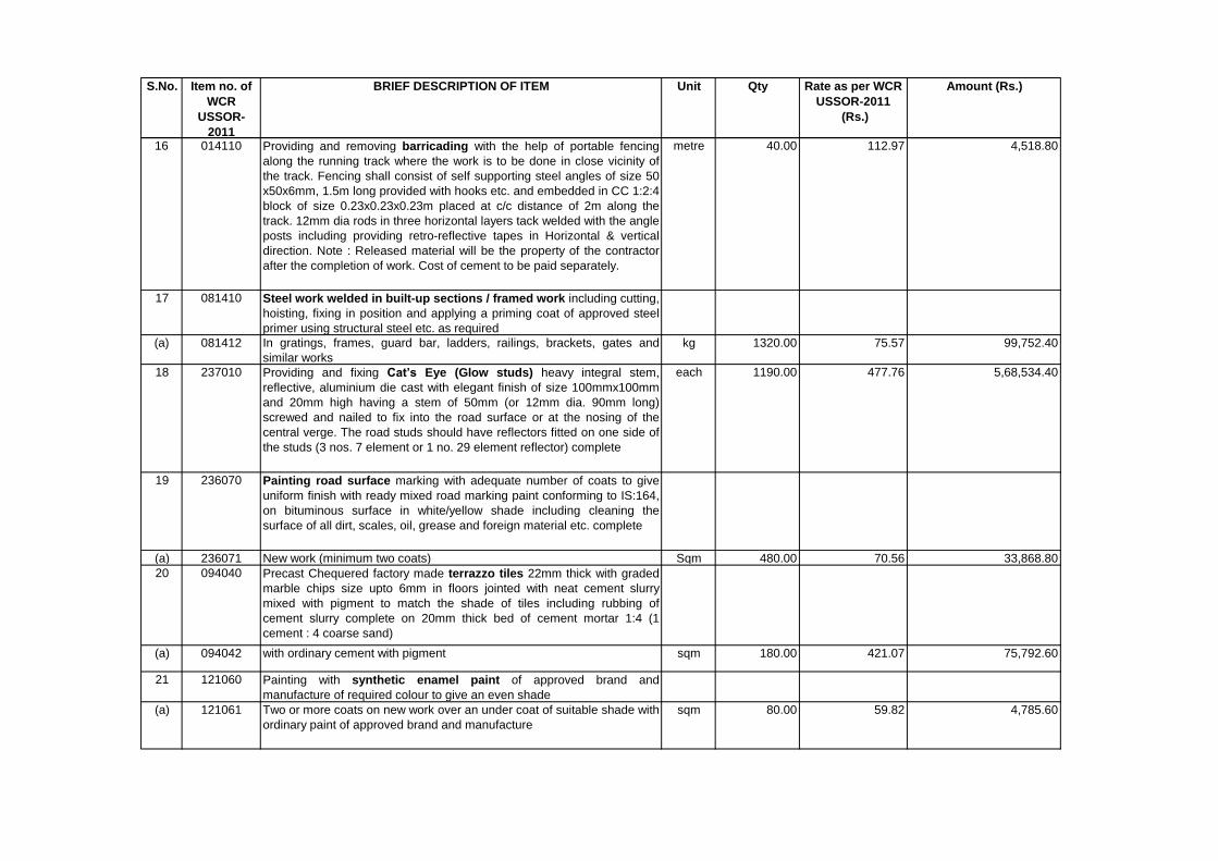
S.No. Item no. of
WCR
USSOR-
2011
BRIEF DESCRIPTION OF ITEM Unit Qty Rate as per WCR
USSOR-2011
(Rs.)
Amount (Rs.)
16 014110 Providing and removing barricading with the help of portable fencing
along the running track where the work is to be done in close vicinity of
the track. Fencing shall consist of self supporting steel angles of size 50
x50x6mm, 1.5m long provided with hooks etc. and embedded in CC 1:2:4
block of size 0.23x0.23x0.23m placed at c/c distance of 2m along the
track. 12mm dia rods in three horizontal layers tack welded with the angle
posts including providing retro-reflective tapes in Horizontal & vertical
direction. Note : Released material will be the property of the contractor
after the completion of work. Cost of cement to be paid separately.
metre 40.00 112.97 4,518.80
17 081410 Steel work welded in built-up sections / framed work including cutting,
hoisting, fixing in position and applying a priming coat of approved steel
primer using structural steel etc. as required
(a) 081412 In gratings, frames, guard bar, ladders, railings, brackets, gates and
similar works
kg 1320.00 75.57 99,752.40
18 237010 Providing and fixing Cat’s Eye (Glow studs) heavy integral stem,
reflective, aluminium die cast with elegant finish of size 100mmx100mm
and 20mm high having a stem of 50mm (or 12mm dia. 90mm long)
screwed and nailed to fix into the road surface or at the nosing of the
central verge. The road studs should have reflectors fitted on one side of
the studs (3 nos. 7 element or 1 no. 29 element reflector) complete
each 1190.00 477.76 5,68,534.40
19 236070 Painting road surface marking with adequate number of coats to give
uniform finish with ready mixed road marking paint conforming to IS:164,
on bituminous surface in white/yellow shade including cleaning the
surface of all dirt, scales, oil, grease and foreign material etc. complete
(a) 236071 New work (minimum two coats) Sqm 480.00 70.56 33,868.80
20 094040 Precast Chequered factory made terrazzo tiles 22mm thick with graded
marble chips size upto 6mm in floors jointed with neat cement slurry
mixed with pigment to match the shade of tiles including rubbing of
cement slurry complete on 20mm thick bed of cement mortar 1:4 (1
cement : 4 coarse sand)
(a) 094042 with ordinary cement with pigment sqm 180.00 421.07 75,792.60
21 121060 Painting with synthetic enamel paint of approved brand and
manufacture of required colour to give an even shade
(a) 121061 Two or more coats on new work over an under coat of suitable shade with
ordinary paint of approved brand and manufacture
sqm 80.00 59.82 4,785.60
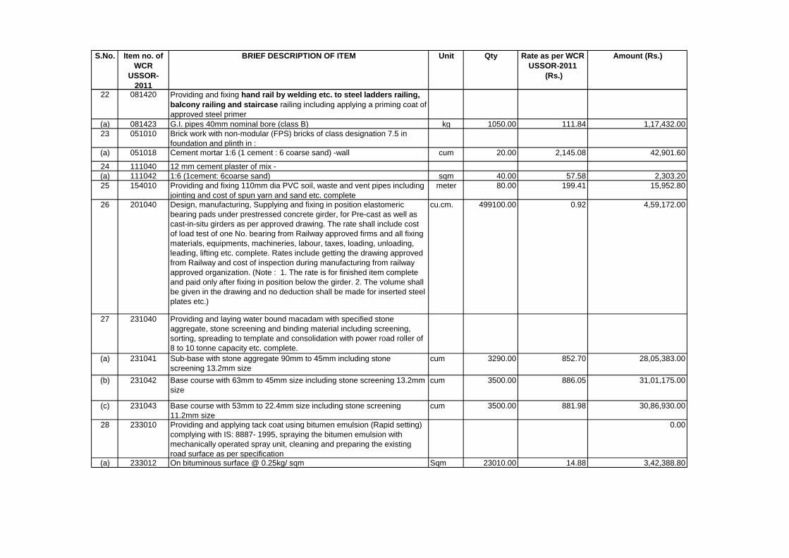
S.No. Item no. of
WCR
USSOR-
2011
BRIEF DESCRIPTION OF ITEM Unit Qty Rate as per WCR
USSOR-2011
(Rs.)
Amount (Rs.)
22 081420 Providing and fixing hand rail by welding etc. to steel ladders railing,
balcony railing and staircase railing including applying a priming coat of
approved steel primer
(a) 081423 G.I. pipes 40mm nominal bore (class B) kg 1050.00 111.84 1,17,432.00
23 051010 Brick work with non-modular (FPS) bricks of class designation 7.5 in
foundation and plinth in :
(a) 051018 Cement mortar 1:6 (1 cement : 6 coarse sand) -wall cum 20.00 2,145.08 42,901.60
24 111040 12 mm cement plaster of mix -
(a) 111042 1:6 (1cement: 6coarse sand) sqm 40.00 57.58 2,303.20
25 154010 Providing and fixing 110mm dia PVC soil, waste and vent pipes including
jointing and cost of spun yarn and sand etc. complete
meter 80.00 199.41 15,952.80
26 201040 Design, manufacturing, Supplying and fixing in position elastomeric
bearing pads under prestressed concrete girder, for Pre-cast as well as
cast-in-situ girders as per approved drawing. The rate shall include cost
of load test of one No. bearing from Railway approved firms and all fixing
materials, equipments, machineries, labour, taxes, loading, unloading,
leading, lifting etc. complete. Rates include getting the drawing approved
from Railway and cost of inspection during manufacturing from railway
approved organization. (Note : 1. The rate is for finished item complete
and paid only after fixing in position below the girder. 2. The volume shall
be given in the drawing and no deduction shall be made for inserted steel
plates etc.)
cu.cm. 499100.00 0.92 4,59,172.00
27 231040 Providing and laying water bound macadam with specified stone
aggregate, stone screening and binding material including screening,
sorting, spreading to template and consolidation with power road roller of
8 to 10 tonne capacity etc. complete.
(a) 231041 Sub-base with stone aggregate 90mm to 45mm including stone
screening 13.2mm size
cum 3290.00 852.70 28,05,383.00
(b) 231042 Base course with 63mm to 45mm size including stone screening 13.2mm
size
cum 3500.00 886.05 31,01,175.00
(c) 231043 Base course with 53mm to 22.4mm size including stone screening
11.2mm size
cum 3500.00 881.98 30,86,930.00
28 233010 Providing and applying tack coat using bitumen emulsion (Rapid setting)
complying with IS: 8887- 1995, spraying the bitumen emulsion with
mechanically operated spray unit, cleaning and preparing the existing
road surface as per specification
0.00
(a) 233012 On bituminous surface @ 0.25kg/ sqm Sqm 23010.00 14.88 3,42,388.80
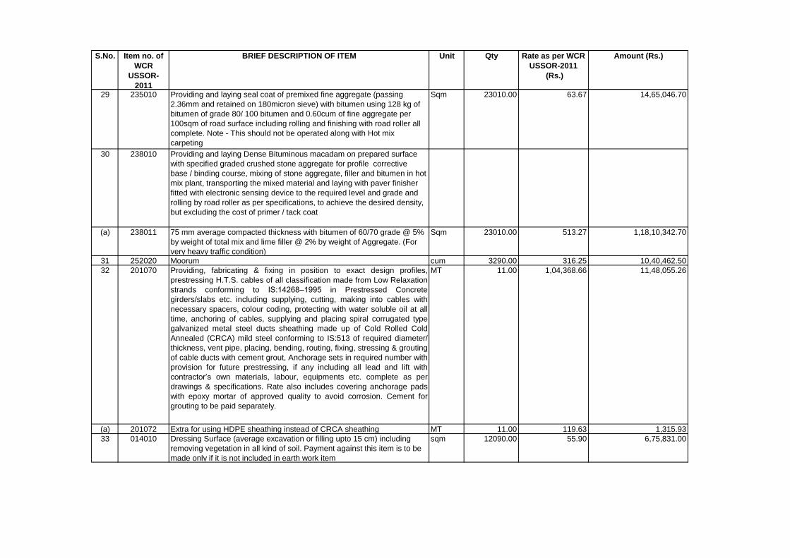
S.No. Item no. of
WCR
USSOR-
2011
BRIEF DESCRIPTION OF ITEM Unit Qty Rate as per WCR
USSOR-2011
(Rs.)
Amount (Rs.)
29 235010 Providing and laying seal coat of premixed fine aggregate (passing
2.36mm and retained on 180micron sieve) with bitumen using 128 kg of
bitumen of grade 80/ 100 bitumen and 0.60cum of fine aggregate per
100sqm of road surface including rolling and finishing with road roller all
complete. Note - This should not be operated along with Hot mix
carpeting
Sqm 23010.00 63.67 14,65,046.70
30 238010 Providing and laying Dense Bituminous macadam on prepared surface
with specified graded crushed stone aggregate for profile corrective
base / binding course, mixing of stone aggregate, filler and bitumen in hot
mix plant, transporting the mixed material and laying with paver finisher
fitted with electronic sensing device to the required level and grade and
rolling by road roller as per specifications, to achieve the desired density,
but excluding the cost of primer / tack coat
(a) 238011 75 mm average compacted thickness with bitumen of 60/70 grade @ 5%
by weight of total mix and lime filler @ 2% by weight of Aggregate. (For
very heavy traffic condition)
Sqm 23010.00 513.27 1,18,10,342.70
31 252020 Moorum cum 3290.00 316.25 10,40,462.50
32 201070 Providing, fabricating & fixing in position to exact design profiles,
prestressing H.T.S. cables of all classification made from Low Relaxation
strands conforming to IS:14268–1995 in Prestressed Concrete
girders/slabs etc. including supplying, cutting, making into cables with
necessary spacers, colour coding, protecting with water soluble oil at all
time, anchoring of cables, supplying and placing spiral corrugated type
galvanized metal steel ducts sheathing made up of Cold Rolled Cold
Annealed (CRCA) mild steel conforming to IS:513 of required diameter/
thickness, vent pipe, placing, bending, routing, fixing, stressing & grouting
of cable ducts with cement grout, Anchorage sets in required number with
provision for future prestressing, if any including all lead and lift with
contractor’s own materials, labour, equipments etc. complete as per
drawings & specifications. Rate also includes covering anchorage pads
with epoxy mortar of approved quality to avoid corrosion. Cement for
grouting to be paid separately.
MT 11.00 1,04,368.66 11,48,055.26
(a) 201072 Extra for using HDPE sheathing instead of CRCA sheathing MT 11.00 119.63 1,315.93
33 014010 Dressing Surface (average excavation or filling upto 15 cm) including
removing vegetation in all kind of soil. Payment against this item is to be
made only if it is not included in earth work item
sqm 12090.00 55.90 6,75,831.00
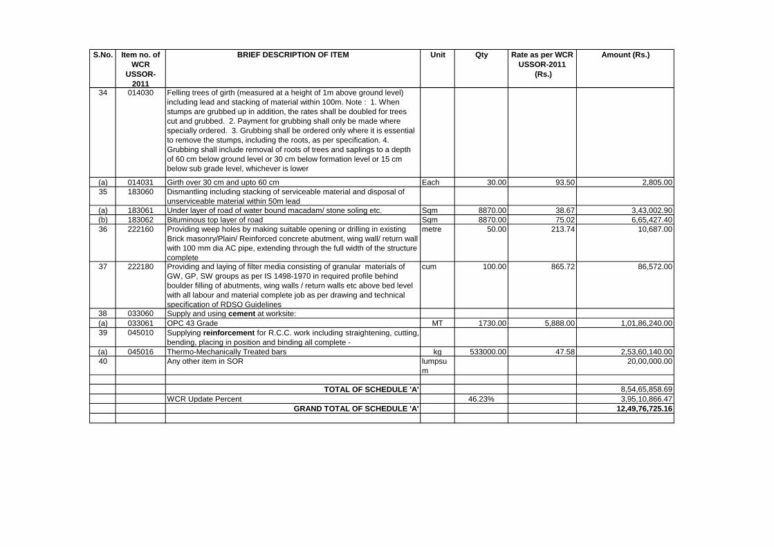
S.No. Item no. of
WCR
USSOR-
2011
BRIEF DESCRIPTION OF ITEM Unit Qty Rate as per WCR
USSOR-2011
(Rs.)
Amount (Rs.)
34 014030 Felling trees of girth (measured at a height of 1m above ground level)
including lead and stacking of material within 100m. Note : 1. When
stumps are grubbed up in addition, the rates shall be doubled for trees
cut and grubbed. 2. Payment for grubbing shall only be made where
specially ordered. 3. Grubbing shall be ordered only where it is essential
to remove the stumps, including the roots, as per specification. 4.
Grubbing shall include removal of roots of trees and saplings to a depth
of 60 cm below ground level or 30 cm below formation level or 15 cm
below sub grade level, whichever is lower
(a) 014031 Girth over 30 cm and upto 60 cm Each 30.00 93.50 2,805.00
35 183060 Dismantling including stacking of serviceable material and disposal of
unserviceable material within 50m lead
(a) 183061 Under layer of road of water bound macadam/ stone soling etc. Sqm 8870.00 38.67 3,43,002.90
(b) 183062 Bituminous top layer of road Sqm 8870.00 75.02 6,65,427.40
36 222160 Providing weep holes by making suitable opening or drilling in existing
Brick masonry/Plain/ Reinforced concrete abutment, wing wall/ return wall
with 100 mm dia AC pipe, extending through the full width of the structure
complete
metre 50.00 213.74 10,687.00
37 222180 Providing and laying of filter media consisting of granular materials of
GW, GP, SW groups as per IS 1498-1970 in required profile behind
boulder filling of abutments, wing walls / return walls etc above bed level
with all labour and material complete job as per drawing and technical
specification of RDSO Guidelines
cum 100.00 865.72 86,572.00
38 033060 Supply and using cement at worksite:
(a) 033061 OPC 43 Grade MT 1730.00 5,888.00 1,01,86,240.00
39 045010 Supplying reinforcement for R.C.C. work including straightening, cutting,
bending, placing in position and binding all complete -
(a) 045016 Thermo-Mechanically Treated bars kg 533000.00 47.58 2,53,60,140.00
40 Any other item in SOR lumpsu
m
20,00,000.00
TOTAL OF SCHEDULE 'A' 8,54,65,858.69
WCR Update Percent 46.23% 3,95,10,866.47
GRAND TOTAL OF SCHEDULE 'A' 12,49,76,725.16
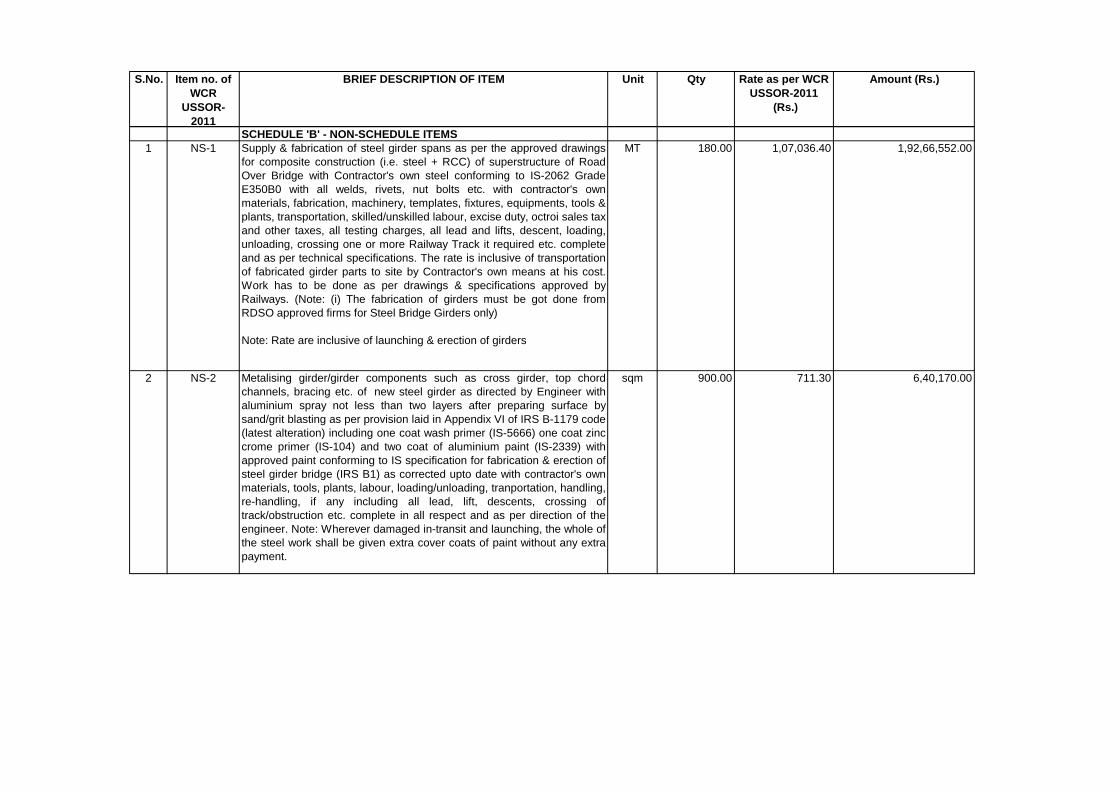
S.No. Item no. of
WCR
USSOR-
2011
BRIEF DESCRIPTION OF ITEM Unit Qty Rate as per WCR
USSOR-2011
(Rs.)
Amount (Rs.)
SCHEDULE 'B' - NON-SCHEDULE ITEMS
1 NS-1 Supply & fabrication of steel girder spans as per the approved drawings
for composite construction (i.e. steel + RCC) of superstructure of Road
Over Bridge with Contractor's own steel conforming to IS-2062 Grade
E350B0 with all welds, rivets, nut bolts etc. with contractor's own
materials, fabrication, machinery, templates, fixtures, equipments, tools &
plants, transportation, skilled/unskilled labour, excise duty, octroi sales tax
and other taxes, all testing charges, all lead and lifts, descent, loading,
unloading, crossing one or more Railway Track it required etc. complete
and as per technical specifications. The rate is inclusive of transportation
of fabricated girder parts to site by Contractor's own means at his cost.
Work has to be done as per drawings & specifications approved by
Railways. (Note: (i) The fabrication of girders must be got done from
RDSO approved firms for Steel Bridge Girders only)
Note: Rate are inclusive of launching & erection of girders
MT 180.00 1,07,036.40 1,92,66,552.00
2 NS-2 Metalising girder/girder components such as cross girder, top chord
channels, bracing etc. of new steel girder as directed by Engineer with
aluminium spray not less than two layers after preparing surface by
sand/grit blasting as per provision laid in Appendix VI of IRS B-1179 code
(latest alteration) including one coat wash primer (IS-5666) one coat zinc
crome primer (IS-104) and two coat of aluminium paint (IS-2339) with
approved paint conforming to IS specification for fabrication & erection of
steel girder bridge (IRS B1) as corrected upto date with contractor's own
materials, tools, plants, labour, loading/unloading, tranportation, handling,
re-handling, if any including all lead, lift, descents, crossing of
track/obstruction etc. complete in all respect and as per direction of the
engineer. Note: Wherever damaged in-transit and launching, the whole of
the steel work shall be given extra cover coats of paint without any extra
payment.
sqm 900.00 711.30 6,40,170.00
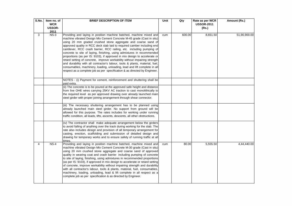
S.No. Item no. of
WCR
USSOR-
2011
BRIEF DESCRIPTION OF ITEM Unit Qty Rate as per WCR
USSOR-2011
(Rs.)
Amount (Rs.)
3 NS-3 Providing and laying in position machine batched, machine mixed and
machine vibrated Design Mix Cement Concrete M-45 grade (Cast in situ)
using 20 mm graded crushed stone aggregate and coarse sand of
approved quality in RCC deck slab laid to required camber including end
cantilever, RCC crash barrier, RCC railing, etc. including pumping of
concrete to site of laying, finishing, using admixtures in recommended
proportions (as per IS: 9103), if approved in mix design to accelerate or
retard setting of concrete, improve workability without impairing strength
and durability with all contractor's labour, tools & plants, material, fuel,
consumables, machinery, loading, unloading, lead and lift complete in all
respect as a complete job as per specification & as directed by Engineer.
cum 600.00 8,651.50 51,90,900.00
NOTES - (i) Payment for cement, reinforcement and shuttering shall be
paid extra.
(ii) The concrete is to be poured at the approved safe height and distance
from live OHE wires carrying 25KV AC traction to cast monolithically to
the required level as per approved drawing over already launched main
steel girder with proper joining arrangement through shear connector.
(iii) The necessary shuttering arrangement has to be planned using
already launched main steel girder. No support from ground will be
allowed for this purpose. The rates includes for working under running
traffic condition, all leads, lifts, ascents, descents, all other obstructions.
(iv) The contractor shall make adequate arrangement below the girders
to avoid falling of anything over the track during working for the slab. The
rate also includes design and provision of all temporary arrangement for
casting, erection, scaffolding and submission of detailed design and
drawing for temporary works and to ensure safety of running traffic at all
times.4 NS-4 Providing and laying in position machine batched, machine mixed and
machine vibrated Design Mix Cement Concrete M-30 grade (Cast in situ)
using 20 mm crushed stone aggregate and coarse sand of approved
quality in wearing coat and crash barrier including pumping of concrete
to site of laying, finishing, using admixtures in recommended proportions
(as per IS: 9103), if approved in mix design to accelerate or retard setting
of concrete, improve workability without impairing strength and durability
with all contractor's labour, tools & plants, material, fuel, consumables,
machinery, loading, unloading, lead & lift complete in all respect as a
complete job as per specification & as directed by Engineer.
cum 80.00 5,555.50 4,44,440.00
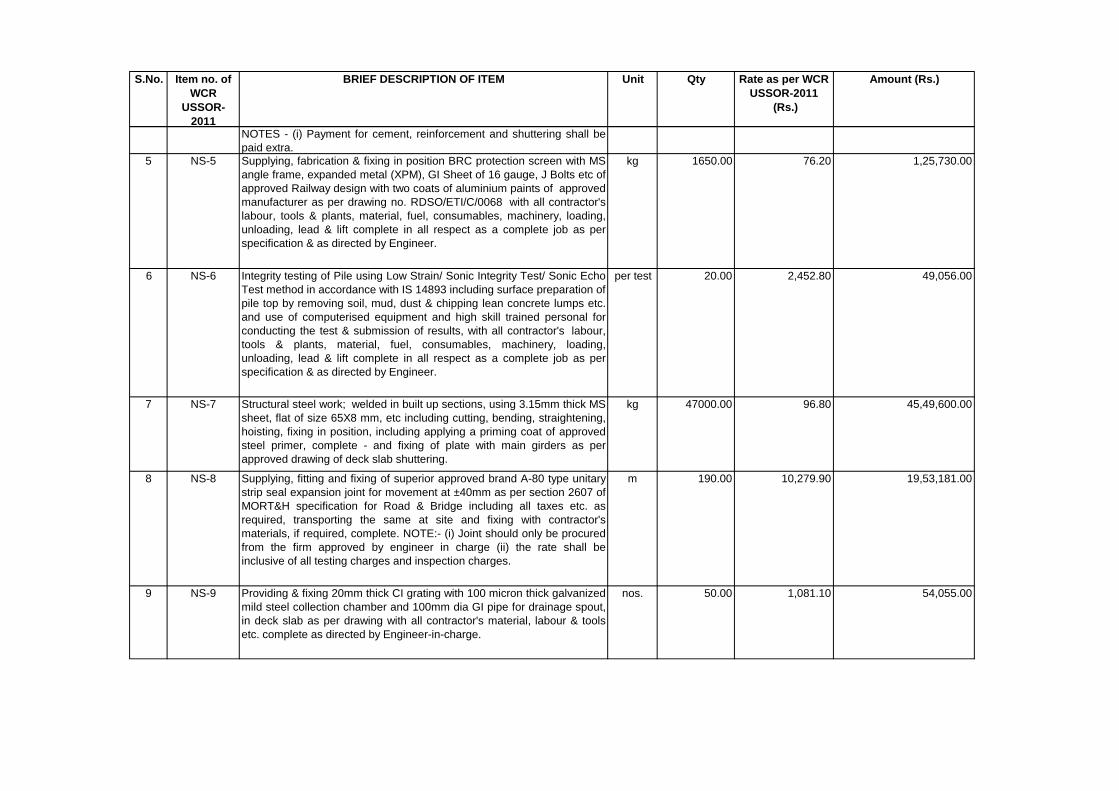
S.No. Item no. of
WCR
USSOR-
2011
BRIEF DESCRIPTION OF ITEM Unit Qty Rate as per WCR
USSOR-2011
(Rs.)
Amount (Rs.)
NOTES - (i) Payment for cement, reinforcement and shuttering shall be
paid extra.
5 NS-5 Supplying, fabrication & fixing in position BRC protection screen with MS
angle frame, expanded metal (XPM), GI Sheet of 16 gauge, J Bolts etc of
approved Railway design with two coats of aluminium paints of approved
manufacturer as per drawing no. RDSO/ETI/C/0068 with all contractor's
labour, tools & plants, material, fuel, consumables, machinery, loading,
unloading, lead & lift complete in all respect as a complete job as per
specification & as directed by Engineer.
kg 1650.00 76.20 1,25,730.00
6 NS-6 Integrity testing of Pile using Low Strain/ Sonic Integrity Test/ Sonic Echo
Test method in accordance with IS 14893 including surface preparation of
pile top by removing soil, mud, dust & chipping lean concrete lumps etc.
and use of computerised equipment and high skill trained personal for
conducting the test & submission of results, with all contractor's labour,
tools & plants, material, fuel, consumables, machinery, loading,
unloading, lead & lift complete in all respect as a complete job as per
specification & as directed by Engineer.
per test 20.00 2,452.80 49,056.00
7 NS-7 Structural steel work; welded in built up sections, using 3.15mm thick MS
sheet, flat of size 65X8 mm, etc including cutting, bending, straightening,
hoisting, fixing in position, including applying a priming coat of approved
steel primer, complete - and fixing of plate with main girders as per
approved drawing of deck slab shuttering.
kg 47000.00 96.80 45,49,600.00
8 NS-8 Supplying, fitting and fixing of superior approved brand A-80 type unitary
strip seal expansion joint for movement at ±40mm as per section 2607 of
MORT&H specification for Road & Bridge including all taxes etc. as
required, transporting the same at site and fixing with contractor's
materials, if required, complete. NOTE:- (i) Joint should only be procured
from the firm approved by engineer in charge (ii) the rate shall be
inclusive of all testing charges and inspection charges.
m 190.00 10,279.90 19,53,181.00
9 NS-9 Providing & fixing 20mm thick CI grating with 100 micron thick galvanized
mild steel collection chamber and 100mm dia GI pipe for drainage spout,
in deck slab as per drawing with all contractor's material, labour & tools
etc. complete as directed by Engineer-in-charge.
nos. 50.00 1,081.10 54,055.00
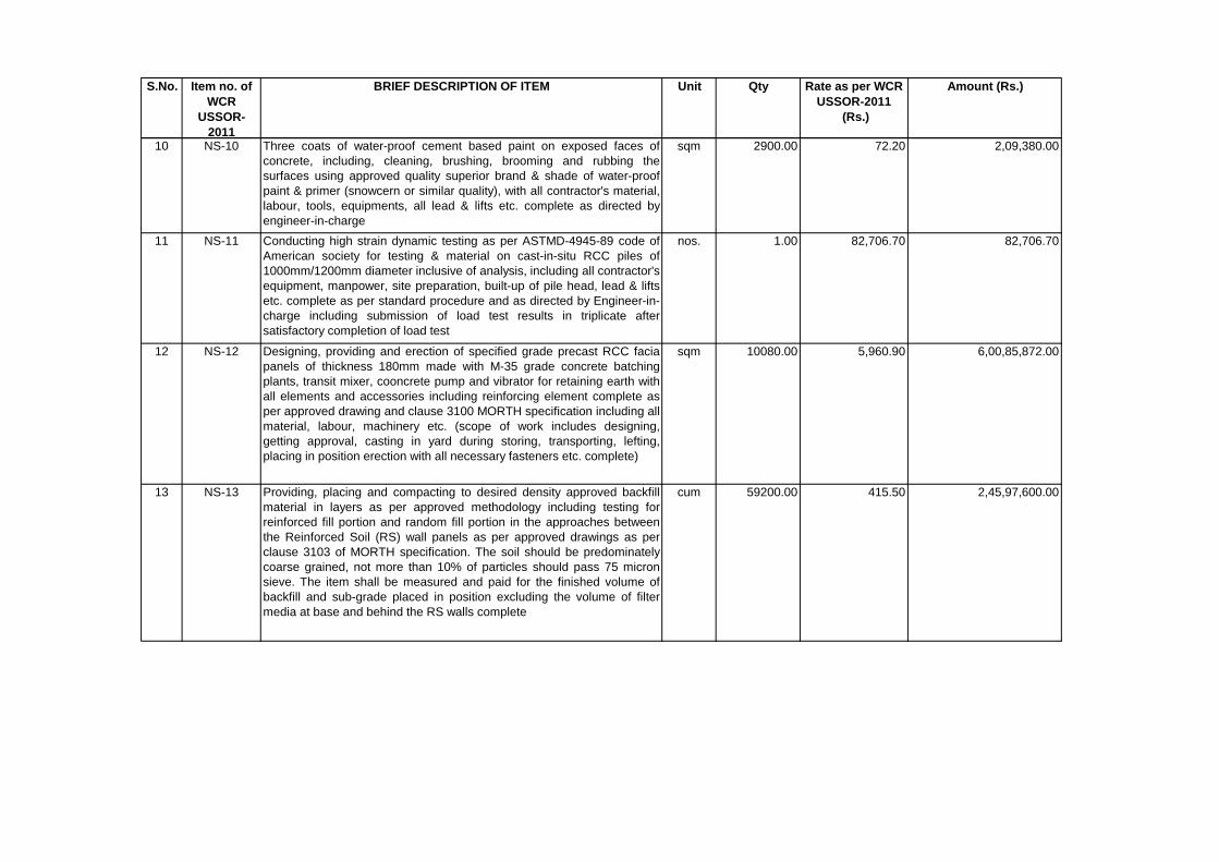
S.No. Item no. of
WCR
USSOR-
2011
BRIEF DESCRIPTION OF ITEM Unit Qty Rate as per WCR
USSOR-2011
(Rs.)
Amount (Rs.)
10 NS-10 Three coats of water-proof cement based paint on exposed faces of
concrete, including, cleaning, brushing, brooming and rubbing the
surfaces using approved quality superior brand & shade of water-proof
paint & primer (snowcern or similar quality), with all contractor's material,
labour, tools, equipments, all lead & lifts etc. complete as directed by
engineer-in-charge
sqm 2900.00 72.20 2,09,380.00
11 NS-11 Conducting high strain dynamic testing as per ASTMD-4945-89 code of
American society for testing & material on cast-in-situ RCC piles of
1000mm/1200mm diameter inclusive of analysis, including all contractor's
equipment, manpower, site preparation, built-up of pile head, lead & lifts
etc. complete as per standard procedure and as directed by Engineer-in-
charge including submission of load test results in triplicate after
satisfactory completion of load test
nos. 1.00 82,706.70 82,706.70
12 NS-12 Designing, providing and erection of specified grade precast RCC facia
panels of thickness 180mm made with M-35 grade concrete batching
plants, transit mixer, cooncrete pump and vibrator for retaining earth with
all elements and accessories including reinforcing element complete as
per approved drawing and clause 3100 MORTH specification including all
material, labour, machinery etc. (scope of work includes designing,
getting approval, casting in yard during storing, transporting, lefting,
placing in position erection with all necessary fasteners etc. complete)
sqm 10080.00 5,960.90 6,00,85,872.00
13 NS-13 Providing, placing and compacting to desired density approved backfill
material in layers as per approved methodology including testing for
reinforced fill portion and random fill portion in the approaches between
the Reinforced Soil (RS) wall panels as per approved drawings as per
clause 3103 of MORTH specification. The soil should be predominately
coarse grained, not more than 10% of particles should pass 75 micron
sieve. The item shall be measured and paid for the finished volume of
backfill and sub-grade placed in position excluding the volume of filter
media at base and behind the RS walls complete
cum 59200.00 415.50 2,45,97,600.00
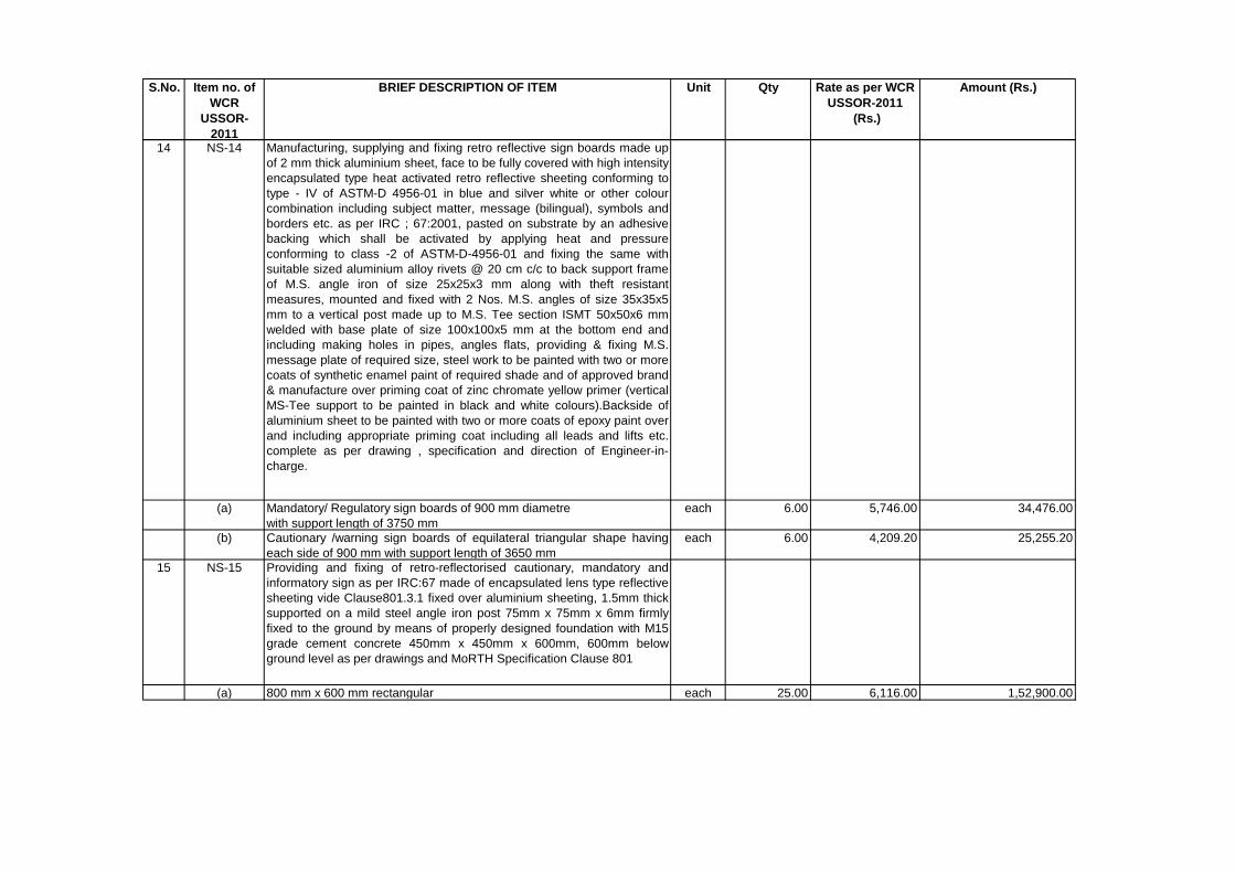
S.No. Item no. of
WCR
USSOR-
2011
BRIEF DESCRIPTION OF ITEM Unit Qty Rate as per WCR
USSOR-2011
(Rs.)
Amount (Rs.)
14 NS-14 Manufacturing, supplying and fixing retro reflective sign boards made up
of 2 mm thick aluminium sheet, face to be fully covered with high intensity
encapsulated type heat activated retro reflective sheeting conforming to
type - IV of ASTM-D 4956-01 in blue and silver white or other colour
combination including subject matter, message (bilingual), symbols and
borders etc. as per IRC ; 67:2001, pasted on substrate by an adhesive
backing which shall be activated by applying heat and pressure
conforming to class -2 of ASTM-D-4956-01 and fixing the same with
suitable sized aluminium alloy rivets @ 20 cm c/c to back support frame
of M.S. angle iron of size 25x25x3 mm along with theft resistant
measures, mounted and fixed with 2 Nos. M.S. angles of size 35x35x5
mm to a vertical post made up to M.S. Tee section ISMT 50x50x6 mm
welded with base plate of size 100x100x5 mm at the bottom end and
including making holes in pipes, angles flats, providing & fixing M.S.
message plate of required size, steel work to be painted with two or more
coats of synthetic enamel paint of required shade and of approved brand
& manufacture over priming coat of zinc chromate yellow primer (vertical
MS-Tee support to be painted in black and white colours).Backside of
aluminium sheet to be painted with two or more coats of epoxy paint over
and including appropriate priming coat including all leads and lifts etc.
complete as per drawing , specification and direction of Engineer-in-
charge.
(a) Mandatory/ Regulatory sign boards of 900 mm diametre
with support length of 3750 mm
each 6.00 5,746.00 34,476.00
(b) Cautionary /warning sign boards of equilateral triangular shape having
each side of 900 mm with support length of 3650 mm
each 6.00 4,209.20 25,255.20
15 NS-15 Providing and fixing of retro-reflectorised cautionary, mandatory and
informatory sign as per IRC:67 made of encapsulated lens type reflective
sheeting vide Clause801.3.1 fixed over aluminium sheeting, 1.5mm thick
supported on a mild steel angle iron post 75mm x 75mm x 6mm firmly
fixed to the ground by means of properly designed foundation with M15
grade cement concrete 450mm x 450mm x 600mm, 600mm below
ground level as per drawings and MoRTH Specification Clause 801
(a) 800 mm x 600 mm rectangular each 25.00 6,116.00 1,52,900.00
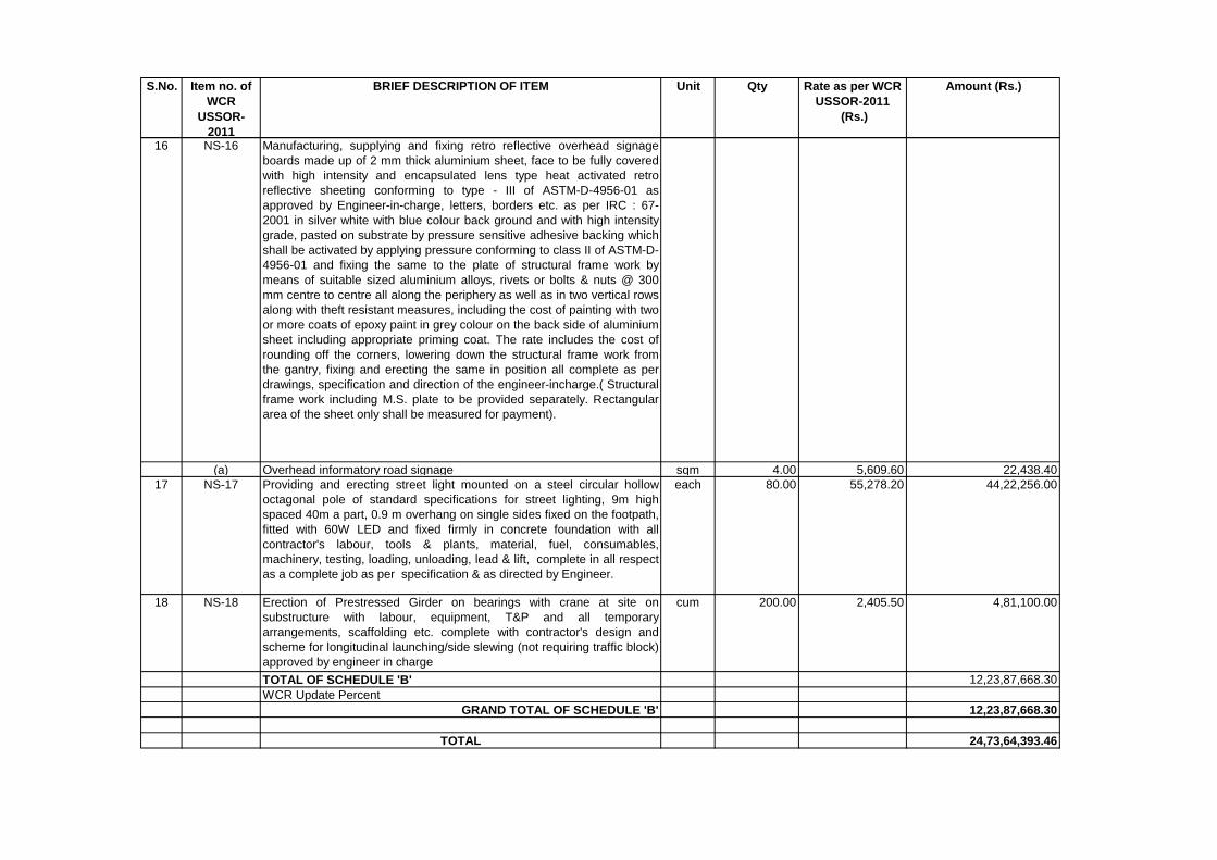
S.No. Item no. of
WCR
USSOR-
2011
BRIEF DESCRIPTION OF ITEM Unit Qty Rate as per WCR
USSOR-2011
(Rs.)
Amount (Rs.)
16 NS-16 Manufacturing, supplying and fixing retro reflective overhead signage
boards made up of 2 mm thick aluminium sheet, face to be fully covered
with high intensity and encapsulated lens type heat activated retro
reflective sheeting conforming to type - III of ASTM-D-4956-01 as
approved by Engineer-in-charge, letters, borders etc. as per IRC : 67-
2001 in silver white with blue colour back ground and with high intensity
grade, pasted on substrate by pressure sensitive adhesive backing which
shall be activated by applying pressure conforming to class II of ASTM-D-
4956-01 and fixing the same to the plate of structural frame work by
means of suitable sized aluminium alloys, rivets or bolts & nuts @ 300
mm centre to centre all along the periphery as well as in two vertical rows
along with theft resistant measures, including the cost of painting with two
or more coats of epoxy paint in grey colour on the back side of aluminium
sheet including appropriate priming coat. The rate includes the cost of
rounding off the corners, lowering down the structural frame work from
the gantry, fixing and erecting the same in position all complete as per
drawings, specification and direction of the engineer-incharge.( Structural
frame work including M.S. plate to be provided separately. Rectangular
area of the sheet only shall be measured for payment).
(a) Overhead informatory road signage sqm 4.00 5,609.60 22,438.40
17 NS-17 Providing and erecting street light mounted on a steel circular hollow
octagonal pole of standard specifications for street lighting, 9m high
spaced 40m a part, 0.9 m overhang on single sides fixed on the footpath,
fitted with 60W LED and fixed firmly in concrete foundation with all
contractor's labour, tools & plants, material, fuel, consumables,
machinery, testing, loading, unloading, lead & lift, complete in all respect
as a complete job as per specification & as directed by Engineer.
each 80.00 55,278.20 44,22,256.00
18 NS-18 Erection of Prestressed Girder on bearings with crane at site on
substructure with labour, equipment, T&P and all temporary
arrangements, scaffolding etc. complete with contractor's design and
scheme for longitudinal launching/side slewing (not requiring traffic block)
approved by engineer in charge
cum 200.00 2,405.50 4,81,100.00
TOTAL OF SCHEDULE 'B' 12,23,87,668.30
WCR Update Percent
GRAND TOTAL OF SCHEDULE 'B' 12,23,87,668.30
TOTAL 24,73,64,393.46
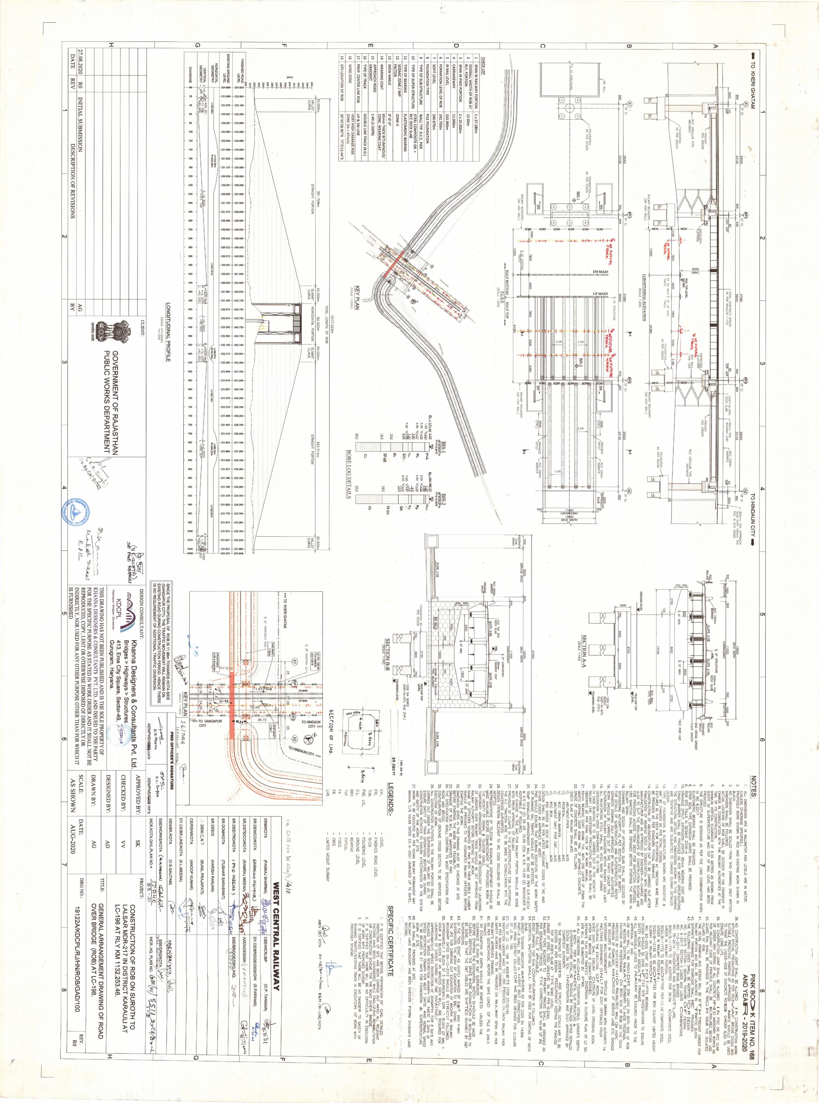
Signature of tenderer (s) Page 1 with seal
TECHNICAL SPECIFICATION
Signature of tenderer (s) Page 2 with seal
TECHNICAL SPECIFICATIONS
For technical specifications, refer Indian Railways Unified Standard Specifications (Works and Materials), 2010 amended upto date and the specification for fabrication and erection of steel girder bridges and Locomotive Turn Table (Fabrication Specification), Serial No B1 - 2001 amended upto date.
Indian Railways Unified Standard Specifications (Works and materials),
Volume I & II are available for sale at the offices of General Managers and DRMs at all Zonal Railways& Production Units.
For open foundation / PSC girder / RE wall / Pre-tensioning MORTH
specification shall be followed. 1.1 GENERAL GUIDELINES REGARDING SPECIFICATIONS AND
SPECIAL CONDITIONS FOR SUPPLY OF CEMENT FOR CONSTRUCTION WORKS
1.1.1 SUPPLY OF CEMENT: 1.1.1.1 Supply of cement to various specifications as required for various items
under different schedules will be paid under the items in Schedule. 1.1.1.2 The cement required for various items of work under Schedule shall be
supplied by the Contractor at the site of work in accordance with the requirements and specifications.
1.1.1.3 For supply and use of cement in various works, relevant Indian Railways
Unified Standard Specifications (Works and Materials), Volume I & II - 2010, IRS codes and IS Specifications will be applicable. Wherever, relevant specifications are not available, decision of the Engineer shall be final and binding on the contractor.
1.1.2 SPECIFICATIONS FOR CEMENT: 1.1.2.1The cement used shall conform to any of the following standards.
(i) 33 Grade Ordinary Portland Cement conforming to IS: 269 (ii) 43 Grade Ordinary Portland Cement conforming to IS: 8112 (iii) 53 Grade Ordinary Portland Cement conforming to IS: 12269 (iv) Rapid Hardening Ordinary Cement conforming to IS: 8041 (v) High Strength Portland Cement conforming to IRS: T: 40 (vi) Hydrophobic Portland cement conforming to IS: 8043
Signature of tenderer (s) Page 3 with seal
(vii) Low heat Portland cement conforming to IS: 12600 (viii) Sulphate Resistance Cement conforming to IS: 12330
1.1.3 SOURCE AND PACKAGING: 1.1.3.1 Cement to be used on the works shall be procured from the main /
reputed cement plants or from their authorized dealers. Decision of EPIL regarding reputed firms shall be final and binding on the contractor.
1.1.3.2 Cement shall be packed in jute sacking bags conforming to IS: 2580-
1982, double hessian bituminised (CRI type) or woven HDPE conforming to IS: 11652-1986, woven polypropylene conforming to IS: 11653:1986, Jute synthetic union conforming to IS: 12174:1987or any other approved composite bags, bearing the following information in legible markings:
(i) Manufacturer’s name or Registered Trade Mark of manufacturer, if
any.
(ii) Grade of cement
(iii) Type of cement
(iv) Weight of each bag in Kg.
(v) Date of manufacture,
(vi) IS Code No. to which the cement conforms
1.1.3.3 All cement bags shall have company stitches intact and if any sign of tampering with company stitches is noticed, the same will be rejected without any test and no compensation shall be payable in this regard.
1.1.4 TEST CERTIFICATE REGARDING QUALITY OF CEMENT:
1.1.4.1 Necessary test certificates will have to be produced by the contractor
regarding the quality of the cement conforming to the specification in addition to the manufacturer’s certificates.
1.1.4.2 EPIL reserves the right to take samples during the course of the work and
get the cement tested in reputed laboratories to ascertain the conformity to the specification. Cost of such testing shall be borne by the contractor without any extra payment.
1.1.4.3 Tests on cement shall be done as per relevant IS Codes. These tests are
as follows:
(i) Compressive strength.
Signature of tenderer (s) Page 4 with seal
(ii) Initial and final setting time.
(iii) Consistency.
(iv) Soundness.
(v) Fineness. 1.1.4.4 The Contractor shall arrange to carryout above tests for every 100
Tonnes of cement and for every change in lot/batch and the same shall be submitted to the EPIL and take approval of the EPIL before using in work. No extra payment will be made for conducting such tests.
1.1.4.5 Any temporary structure required for storage of cement, has to be
provided by the tenderer at his cost and shall be removed after completion of work. The EPIL will only provide suitable land wherever land is available and is free for use. On completion of the work or as directed by the Engineer, the shed if put up by the Contractor, should be removed by the contractor and site cleared at his cost.
1.1.5 CONSUMPTION OF CEMENT: 1.1.5.1 The cement consumption for other than design mix concrete, shall be as
per North Central Railway Unified Standard Schedule of Rates (Works and Materials), Engineering Department - 2010 and for approved design mix concrete, the quantity of cement will be decided based on the approved design mix keeping in mind Minimum and Maximum cement content specified for various grades. Excess cement used will not be paid for and the decision of the Engineer in this connection shall be final and binding on the Contractor.
1.1.6 PAYMENT FOR CEMENT: - Cement supplied for the work and measured under the Schedule will be
paid only after its use in various works under the Schedules of the contract as per conditions and no advance payment for supply will be admissible.
1.1.7 GENERAL: - 1.1.7.1 No wastage of any of the materials supplied and used in the work by the
contractor including cement is payable by EPIL, contractor shall make his own arrangements for storing cement for use in work.
1.1.7.2 Contractor should take proper precautionary measures to store the
cement in good condition against rains, etc. Storage of cement at the work site shall be at the contractor's expense and risk. Any damage occurring to cement due to faulty storage in contractor's shed or on account of negligence on his part shall be the liability of the contractor.
Signature of tenderer (s) Page 5 with seal
1.1.7.3 53 Grade/43 Grade of cement should be stacked separately in countable manner.
1.1.7.4 Admixture as per IS: 9103 of approved manufacturer by the Engineer
shall be permitted to be used in concrete wherever required. However, no extra payment for the admixtures used shall be payable unless otherwise specified in the Schedule.
1.1.7.5 Cement for temporary and enabling works shall be arranged by the
contractor at his own cost and no extra payment will be paid on this account.
1.1.7.6 Empty Cement bags on release from the work is the property of the
Contractor and shall be disposed off by the Contractor himself. 2 GENERAL GUIDELINES REGARDING SPECIFICATIONS AND
SPECIAL CONDITIONS FOR CONCRETE WORKS
2.1 Specifications: - 2.1.1 Concrete for PCC, RCC (Including piling and RCC deck slab) shall be as
per relevant Indian Railway Unified Standard Specifications (Works & Materials) Volume I & II, Engineering Department, 2010 and IS Specifications. Some important guide lines are listed below. Along with these, all other relevant IRS, IRC and IS specifications with their up to date versions shall also govern. These govern all concrete works in bridges, etc. as applicable.
(i) IRS Concrete Bridge Code.
(ii) IS 456: Code of Practice for Plain and Reinforced Concrete.
(iii) Relevant Indian Railway Unified Standard Specifications (Works &
Materials) Volume I & II, Engineering Department, 2010.
(iv) Relevant IRS/IRC/IS Specifications/Codes.
2.1.2 Specifications for cement, steel, GI binding wire, used in concrete construction shall be as per IRS/IRC/IS specifications. Any other specifications/rules/guidelines issued from time to time by Railway Board/RDSO shall also govern the works.
2.1.3 In all matters of execution, including testing of various components,
where the above codes/specifications/guidelines are not clear or explicit or at variance, the directions given by the Engineer shall be final and binding on the contractor.
Signature of tenderer (s) Page 6 with seal
2.2 Cement: - 2.2.1 The cement used in concrete construction shall be minimum 43 Grade
Ordinary Portland cement as per the design and as specified in the relevant schedules. Specifications for cement are covered under the supply schedule.
2.3 Reinforcement: - 2.3.1 All Reinforcement Steel (TMT Bars of Grade Fe 500 D/550D) shall be
procured as per specification mentioned in IS: 1786. Independent tests shall be conducted, wherever required, to ensure that the materials procured conform to the Specifications.
These steel shall be procured only from those firms, which are Established, Reliable, Indigenous & Primary Producers of Steel, having Integrated Steel Plants (ISP), using iron ore as the basic raw material and having in – house iron rolling facilities, followed by production of liquid steel and crude steel, as per Ministry of Steel’s guidelines.
2.3.2 Bars shall be cut, bent and placed correctly and accurately to the size and
shape as shown in the detailed drawing. Preferably bars of full length shall be used. The reinforcement shall be tied with annealed steel binding wire. Overlapping of bars, where necessary, shall be done as directed by Engineer. Rates quoted include the cost of annealed steel binding wire of appropriate specifications. Rate also include necessary cutting and straightening is also included.
2.3.3 Welding of reinforcement will not be generally permitted except in special circumstances under the written approval of the Engineer.
2.3.4 A register shall be maintained by the Contractor with full details of
reinforcement provided for accountable and payment of steel reinforcement. The contractor should sign a similar such register maintained by EPIL before undertaking concreting works, as a token of acceptance of the details of reinforcement steel provided in works, failing which the details as recorded by EPIL shall be binding on the contractor for the purpose of payment and no dispute will be entertained by EPIL on this account.
2.3.5 Contractor shall remove from site any steel materials rejected by the
Engineer within a reasonable time as specified by him. 2.3.6 Protective Coatings: -In order to offer adequate resistance against
corrosion, reinforcement bars may be provided with suitable protective coatings depending upon the environmental conditions in aggressive environments (severe, and extreme) application of cement slurry coating after removal of rust and other loose material from the surface of the reinforcement bar will generally be sufficient.
Signature of tenderer (s) Page 7 with seal
2.3.7 The steel consumption shall be as per the drawings issued by the EPIL.
Quantity of steel reinforcement consumption shall be as per reinforcement actually utilized in the work based on approved bar bending schedule. Nothing extra will be paid for wastage or for cut rods, if any, which will be property of the contractor. The weight of the steel will be calculated from the nominal weight given in the producer’s hand / IRUSS (W & M), 2010-Volume-I books.
2.4 Coarse & Fine Aggregates: -
2.4.1 Aggregates shall comply with the requirements of IS: 383 and shall be
subjected to the tests in accordance with IS: 2386. Coarse aggregates shall be from crushed stone from approved quarries. Sand shall be from good river sources of approved quarries only.
2.4.2 The size of the coarse aggregates shall be as per relevant IRS / IS specifications.
2.4.3 The size of the fine aggregates shall be as per relevant IRS / IS specifications.
2.4.4 Coarse aggregate shall be crushed and roughly cubical in shape. Fine
aggregate shall be naturally produced. Creek/ Marine sand shall not be used in permanent works.
2.4.5 The grading of the sand shall conform to relevant IS specification. The
sand shall be screened on a 4.75 mm size screen to eliminate over size particles. The sand, if required, shall be washed in screw type mechanical washers in potable water to remove excess silt, clay and chlorides wherever required. The screening and washing of sand shall be completed at least one day before using it in concrete. The washed sand shall be stored on a sloping platform and in such a manner as to avoid contamination.
2.5 Water: - 2.5.1 Water used for washing of aggregates and for mixing and curing concrete
shall be clean, potable and free from injurious amounts of oils, acids, alkalis, salts, sugar, organic materials or other substances that may be deleterious to concrete or steel and shall conform to clause 5.4 of IS: 456.
2.5.2 In case of doubt regarding development of strength, the suitability of
water for making concrete shall be ascertained by the compressive strength as per IS: 4031 (Part VI) and initial setting time tests IS:4031 (Part V).
2.5.3 Water found satisfactory for mixing is also suitable for curing concrete.
However, water used for curing should not produce any objectionable
Signature of tenderer (s) Page 8 with seal
stain or unsightly deposit on the concrete surface. The presence of tannic acid or iron compounds is objectionable.
2.6 Admixtures: - 2.6.1 In bridges, use of admixtures is governed by clause 4.4 of IRS Concrete
Bridge Code. 2.6.2 The admixtures, when permitted, shall conform to IS: 9103.Calcium
chloride or admixtures containing calcium chloride shall not be used in structural concrete containing reinforcement, pre-stressing tendon or other embedded metal. The admixture containing Cl& SO3 ions shall not be used. Admixtures containing nitrates shall also not be used. Admixtures based on thiocyanate may promote corrosion and therefore shall be prohibited.
2.6.3 Concrete admixtures shall be obtained only from established manufactures
with proven track record or as per approved list wherever available. 2.6.4 The contractor shall provide the following information concerning each
admixture after obtaining the same from the manufacturer before the same is put to use:
(a) The chemical names of the main ingredients in the admixtures. (b) The chloride iron content, if any, expressed as a percentage by
mass of the total admixture. (c) Values of dry material content, ash content and relative density of
the liquid admixture which can be used for Uniformity Tests. (d) Whether or not the admixture leads to the entrainment of air when
used as per the manufacturer’s recommended dosage, and if so to what extent.
(e) Where two or more admixtures are proposed to be used in any one
mix, confirmation as to their compatibility. (f) There would be no increase in risk of corrosion of the reinforcement
or other embodiments as a result of using the admixture. (g) Retardation achieved in initial setting time. (h) Normal dosage and detrimental effects, if any, of under dosage and
over dosage. (i) Recommended dosages and expected results, including proof for
the same wherever required. Independent test results shall be produced by the contractor on demand/as specified.
Signature of tenderer (s) Page 9 with seal
2.7 Storage of materials: - 2.7.1 Storage of materials shall be as per IS: 4082.All materials may be stored
at proper places so as to prevent their deterioration or intrusion by foreign matter and to ensure their satisfactory quality and fitness for the work. The storage space must also permit easy inspection, removal and restoring of the materials. All such materials even though stored in approved godowns / places, must be subjected to acceptance test prior to their immediate use.
2.7.2 Aggregate shall be stored at site on a hard and dry level patch of ground.
If such a surface is not available, a platform of planks or of corrugated iron sheets, or a floor of dry bricks, or a thin layer of lean concrete shall be made so as to prevent the admixture of clay, dust, vegetable and other foreign matter.
Stacks of fine and coarse aggregate shall be kept in separate stack piles,
sufficiently removed from each other to prevent the materials at the edge of the piles getting intermixed. On a large job it is desirable to construct dividing walls to give each type of aggregate its own compartment. Fine aggregate shall be stacked in place where loss due to the effect of wind is minimum.
Unless specified otherwise or necessitated by site conditions, stacking of
aggregate should be carried out in regular sizes. 2.7.3 Cement shall be transported, handled and stored at the site in such a
manner as to avoid deterioration or contamination. Cement shall be stored above ground level in perfectly dry and water-tight sheds and shall be stacked not more than eight bags high. Wherever bulk storage containers are used their capacity should be sufficient to cater to the requirement at site and should be cleaned at least once every 3 months. Cement older than 3 months from the date of manufacture shall not be used. Each consignment shall be stored separately so that it may be readily identified and inspected and cement shall be used in the sequence in which it is delivered at site. Any consignment or part of a consignment of cement which had deteriorated in any way, during storage, shall not be used in the works and shall be removed from the site by the Contractor without charge to EPIL. For more details regarding stacking and storage of cement, refer clause 17.10.1, 17.10.2 and 26.1.2.7of Indian Railway Unified Standard Specifications (Works & Materials), Volume II, - 2010.
2.7.4 The reinforcement bars, when delivered on the job, shall be stored above
the surface of the ground level by at least by 150mm and shall ordinarily be stored in such a way as to avoid distortion and to prevent deterioration and corrosion. Every bar shall be inspected before assembling on the works and any defective, brittle, excessively rusted or burnt bars shall be removed. Cracked ends of bars shall be cut out.
Signature of tenderer (s) Page 10 with seal
2.8 Testing of cement &others: -
Cement and other items shall be tested as per specifications. However, the contractor shall also arrange for additional tests at his own cost as required by the Engineer as and when required. The decision of the Engineer shall be final in this regard.
2.9 Concreting: 2.9.1 The contractor shall make his own arrangements for supply of water and
electricity for all his works at his own cost. He shall arrange potable quality water for use in all concrete works and samples of water shall be got tested from approved laboratory/approved by the Engineer before being used in concreting. Apart from water, fine & coarse aggregates and all other materials shall be tested from time to time by the contractor at his cost to ensure proper quality works.
2.9.2 Maximum / minimum size of aggregates, standards of quality of materials,
minimum cover for concrete, use of admixtures / chemicals, treatment to reinforcement / finished surfaces, etc., shall be as per relevant Codes, IS / IRS specifications and conditions of contract as specified.
2.9.3 All exposed concrete surfaces shall be finished smooth by the contractor
at his own cost. Shuttering materials for RCC in superstructure shall be strictly of steel only to permit vigorous vibration and to ensure no deviation of finished dimensions by more than +5/-0 mm and wooden shutters are not permitted. For other works also, proper quality of shuttering materials which will permit vibrating and will not require additional finishing shall only be used. If there is any variation in the surface, alignment or lines in the products beyond permissible rejection limits indicated in these conditions, the EPIL reserves the right to reject the same and the contractor shall not have any claim in this regard and cost of EPIL materials involved will be recovered from the contractor including penalties, if any imposed.
2.10 Weigh batching, vibrating, curing & testing by Batching plant with
computerized control: 2.10.1 All concrete shall be machine batched, machine mixed and machine
vibrated, by using appropriate vibrators. Weigh batching plant, mixers, vibrators, etc., of appropriate capacity, as specified/directed by the Engineer, shall be arranged by the contractor at his cost. In this case, Weigh batching plants shall have computerized control for weighing, loading, mixing and delivery.
2.10.2 Batching plants, transit mixers, concrete pumps, etc., shall be installed
by the contractor necessarily at site. In case of failure of any of the above, standby arrangements for ensuing continuous concreting has to be provided by the contractor at his cost. For piling works concreting shall be done continuously as per the volumes designed without break
Signature of tenderer (s) Page 11 with seal
and accordingly standby arrangements shall be ensured by the contractor.
2.10.3 Curing & vibrating shall be arranged by the contractor at all
locations/heights at his own cost and no extra payment on this account will be admissible. Curing of concrete shall be done as per relevant IS Codes / Specifications. If curing is not done by the contractor properly, EPIL may get it done through any other means at the Contractor’s cost without any notice to him and recover from his bills the same including penalty if any at the discretion of the Engineer. The concrete shall be kept wet constantly by ponding or covered with a layer of sacking canvas etc.
2.10.4 Test cubes shall be cast at regular intervals and tested to ascertain the strength of concrete. The contractor shall establish a cube testing facility along with operator at the site or nearby area to facilitate prompt testing of concrete. Test cube moulds as required as per IS Codes shall be made available by the contractor at his cost.
2.11 Design Mix Concrete:
(a) General: Design Mix is mandatory for grades higher than M20. For concrete of compressive strength greater than M55, specialized literature should be consulted. Admixtures may be used while designing. Only design mix shall be used for all items of concrete. Prior to the start of construction, the contractor shall submit details of each trial mix of each grade of concrete to the Engineer for approval. When the proportions of the mix are approved, the contractor shall not vary any of the design parameters or the source of the materials without the approval of the Engineer. Wherever there is a significant change in materials used, fresh trial mix shall be arranged by the contractor as required by the Engineer. The concrete shall be designed keeping in view the minimum cement content and maximum cement content. Minimum cement content depends upon the environmental exposure conditions but maximum Cement Content shall be limited to 500kg/m.3
(b) Mix Design and Proportioning: Recommended guidelines for
Concrete Mix Design are given in IS: 10262 which may be referred to for details. As mentioned therein in order that not more than the specified proportion of test results is likely to fall below the characteristic strength, the concrete mix has to be designed for a somewhat higher target average compressive strength. In terms of clause 9.2.2 of IS: 456, the Target Mean Strength of Concrete mix should be equal to the characteristic strength plus 1.65 times the Standard Deviation. Mix proportion shall be designed to ensure that the workability of fresh concrete is suitable for conditions of handling and placing, so that after compaction it surrounds all reinforcement and completely fill the form work. When concrete is hardened, it shall have the stipulated strength, durability and im-permeability.
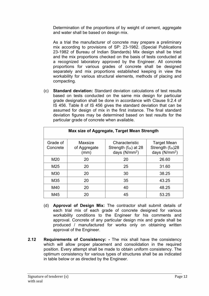
Signature of tenderer (s) Page 12 with seal
Determination of the proportions of by weight of cement, aggregate and water shall be based on design mix.
As a trial the manufacturer of concrete may prepare a preliminary mix according to provisions of SP: 23-1982. (Special Publications 23-1982 of Bureau of Indian Standards) Mix design shall be tried and the mix proportions checked on the basis of tests conducted at a recognized laboratory approved by the Engineer. All concrete proportions for various grades of concrete shall be designed separately and mix proportions established keeping in view the workability for various structural elements, methods of placing and compacting.
(c) Standard deviation: Standard deviation calculations of test results
based on tests conducted on the same mix design for particular grade designation shall be done in accordance with Clause 9.2.4 of IS 456. Table 8 of IS 456 gives the standard deviation that can be assumed for design of mix in the first instance. The final standard deviation figures may be determined based on test results for the particular grade of concrete when available.
Max size of Aggregate, Target Mean Strength
Grade of Concrete
Maxsize of Aggregate
(mm)
Characteristic Strength (fck) at 28
days (N/mm2)
Target Mean Strength (fck)28 days (N/mm2)
M20 20 20 26.60
M25 20 25 31.60
M30 20 30 38.25
M35 20 35 43.25
M40 20 40 48.25
M45 20 45 53.25
(d) Approval of Design Mix: The contractor shall submit details of
each trial mix of each grade of concrete designed for various workability conditions to the Engineer for his comments and approval. Concrete of any particular design mix and grade shall be produced / manufactured for works only on obtaining written approval of the Engineer.
2.12 Requirements of Consistency: - The mix shall have the consistency
which will allow proper placement and consolidation in the required position. Every attempt shall be made to obtain uniform consistency. The optimum consistency for various types of structures shall be as indicated in table below or as directed by the Engineer.
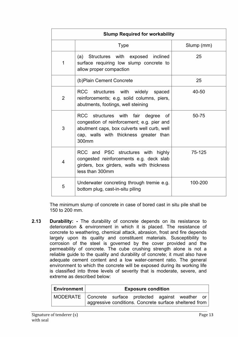
Signature of tenderer (s) Page 13 with seal
Slump Required for workability
Type Slump (mm)
1 (a) Structures with exposed inclined surface requiring low slump concrete to allow proper compaction
25
(b)Plain Cement Concrete 25
2 RCC structures with widely spaced reinforcements; e.g. solid columns, piers, abutments, footings, well steining
40-50
3
RCC structures with fair degree of congestion of reinforcement; e.g. pier and abutment caps, box culverts well curb, well cap, walls with thickness greater than 300mm
50-75
4
RCC and PSC structures with highly congested reinforcements e.g. deck slab girders, box girders, walls with thickness less than 300mm
75-125
5 Underwater concreting through tremie e.g. bottom plug, cast-in-situ piling
100-200
The minimum slump of concrete in case of bored cast in situ pile shall be
150 to 200 mm. 2.13 Durability: - The durability of concrete depends on its resistance to
deterioration & environment in which it is placed. The resistance of concrete to weathering, chemical attack, abrasion, frost and fire depends largely upon its quality and constituent materials. Susceptibility to corrosion of the steel is governed by the cover provided and the permeability of concrete. The cube crushing strength alone is not a reliable guide to the quality and durability of concrete; it must also have adequate cement content and a low water-cement ratio. The general environment to which the concrete will be exposed during its working life is classified into three levels of severity that is moderate, severe, and extreme as described below:
Environment Exposure condition
MODERATE Concrete surface protected against weather or aggressive conditions. Concrete surface sheltered from
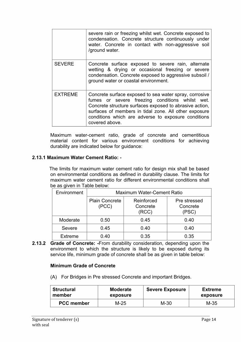
Signature of tenderer (s) Page 14 with seal
severe rain or freezing whilst wet. Concrete exposed to condensation. Concrete structure continuously under water. Concrete in contact with non-aggressive soil /ground water.
SEVERE Concrete surface exposed to severe rain, alternate wetting & drying or occasional freezing or severe condensation. Concrete exposed to aggressive subsoil / ground water or coastal environment.
EXTREME Concrete surface exposed to sea water spray, corrosive fumes or severe freezing conditions whilst wet. Concrete structure surfaces exposed to abrasive action, surfaces of members in tidal zone. All other exposure conditions which are adverse to exposure conditions covered above.
Maximum water-cement ratio, grade of concrete and cementitious
material content for various environment conditions for achieving durability are indicated below for guidance:
2.13.1 Maximum Water Cement Ratio: -
The limits for maximum water cement ratio for design mix shall be based on environmental conditions as defined in durability clause. The limits for maximum water cement ratio for different environmental conditions shall be as given in Table below:
Environment Maximum Water-Cement Ratio
Plain Concrete(PCC)
Reinforced Concrete
(RCC)
Pre stressed Concrete
(PSC)
Moderate 0.50 0.45 0.40
Severe 0.45 0.40 0.40
Extreme 0.40 0.35 0.35
2.13.2 Grade of Concrete: -From durability consideration, depending upon the environment to which the structure is likely to be exposed during its service life, minimum grade of concrete shall be as given in table below:
Minimum Grade of Concrete (A) For Bridges in Pre stressed Concrete and important Bridges.
Structural member
Moderate exposure
Severe Exposure Extreme exposure
PCC member M-25 M-30 M-35
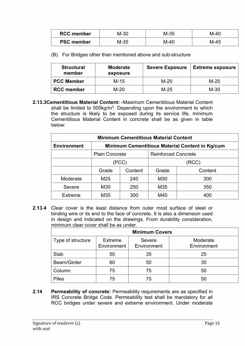
Signature of tenderer (s) Page 15 with seal
RCC member M-30 M-35 M-40
PSC member M-35 M-40 M-45
(B) For Bridges other than mentioned above and sub-structure
Structural member
Moderate exposure
Severe Exposure Extreme exposure
PCC Member M-15 M-20 M-25
RCC member M-20 M-25 M-30
2.13.3Cementitious Material Content: -Maximum Cementitious Material Content
shall be limited to 500kg/m3. Depending upon the environment to which the structure is likely to be exposed during its service life, minimum Cementitious Material Content in concrete shall be as given in table below:
Minimum Cementitious Material Content
Environment Minimum Cementitious Material Content in Kg/cum
Plain Concrete Reinforced Concrete
(PCC) (RCC)
Grade Content Grade Content
Moderate M25 240 M30 300
Severe M30 250 M35 350
Extreme M35 300 M40 400
2.13.4 Clear cover is the least distance from outer most surface of steel or
binding wire or its end to the face of concrete. It is also a dimension used in design and indicated on the drawings. From durability consideration, minimum clear cover shall be as under.
Minimum Covers
Type of structure Extreme Environment
Severe Environment
Moderate Environment
Slab 50 35 25
Beam/Girder 60 50 35
Column 75 75 50
Piles 75 75 50
2.14 Permeability of concrete: Permeability requirements are as specified in
IRS Concrete Bridge Code. Permeability test shall be mandatory for all RCC bridges under severe and extreme environment. Under moderate
Signature of tenderer (s) Page 16 with seal
environment, permeability test shall be mandatory for all major bridges and for other bridges and structures.
2.15 Mixing of concrete: 2.15.1 Concrete shall be mixed either in a mini mobile batching plant or in a
batching and mixing plant as per the specifications. Hand mixing shall not be permitted. The mixer or the plant shall be at an approved location considering the properties of the mixes and the transportation arrangements available with the Contractor. The mixer or the plant shall be approved by the Engineer.
2.15.2 Mixing shall be continued till materials are uniformly distributed and a
uniform colour of the entire mass is obtained, and each individual particle of the coarse aggregate shows complete coating of mortar containing its proportionate amount of cement.
2.15.3 Mixers which have been out of use for more than 30 minutes shall be
thoroughly cleaned before putting in a new batch. The first batch of concrete from the mixer shall contain only two thirds of the normal quantity of coarse aggregate. Mixing plant shall be thoroughly cleaned before changing from one type of mix to another.
2.16 Transporting, Placing and Compaction of Concrete: 2.16.1 The method of transporting and placing concrete shall be approved by
the Engineer. Concrete shall be transported and placed as near as practicable to its final position, so that no contamination, segregation or loss of its constituent materials takes place. Concrete shall not be freely dropped into place from a height exceeding 1.5 metres.
2.16.2 When concrete is conveyed by chute, the plant shall be of such size and design as to ensure practically continuous flow. Slope of the chute shall be so adjusted that the concrete flows without the use of excessive quantity of water and without any segregation of its ingredients. The delivery end of the chute shall be as close as possible to the point of deposit. The chute shall be thoroughly flushed with water before and after each working period and the water used for this purpose shall be discharged outside the formwork.
2.16.3 All formwork and reinforcement contained in it shall be cleaned and made
free from standing water, dust, immediately before placing of concrete. 2.16.4 No concrete shall be placed in any part of the structure until approval of
the Engineer has been obtained. 2.16.5 If concreting is not started within 24 hours of the approval being given, it
shall have to be obtained again from the Engineer. Concreting then shall proceed continuously over the area between the construction joints. Fresh concrete shall not be placed against concrete which has been in
Signature of tenderer (s) Page 17 with seal
position for more than 30 minutes unless a proper construction joint is formed.
2.16.6 Except where otherwise agreed to by the Engineer, concrete shall be
deposited in horizontal layers to a compacted depth of not more than 450 mm when internal vibrators are used and not exceeding 300 mm in all other cases.
2.17 Concrete when deposited shall have a temperature of not less than 50 C
and not more than 40°C. It shall be compacted in its final position within 30 minutes of its discharge from the mixer, unless carried in properly designed agitators, operating continuously. It may be necessary to add retarding admixtures to concrete if trials show that the period indicated above are unacceptable. In all such matters, engineer's decision shall be final.
2.18 Concrete shall be thoroughly compacted by vibration or other means
approved by Engineer, during placing and worked around the reinforcement, embedded fixtures and into corners of the formwork to produce a dense homogenous void-free mass having the required surface finish. When vibrators are used, vibration shall be done continuously during the placing of each batch of concrete until the expulsion of air has practically ceased and in a manner that does not promote segregation. Over vibration shall be avoided to minimize the risk of forming a weak surface layer. When external vibrators are used, the design of formwork and disposition of vibrator shall be such as to ensure efficient compaction and to avoid surface blemishes. Vibrators shall not be applied through reinforcement and where vibrators of immersion type are used, contact with reinforcement and all inserts like ducts etc., shall be avoided. The internal vibrators shall be inserted in an orderly manner and the distance between insertions should be about one and half times the radius of the area visibly affected by vibration. Additional vibrators in serviceable condition shall be kept at site so that they can be used in the event of breakdowns.
2.19 Mechanical vibrators used shall be of appropriate specifications, type and
capacity and as directed by the Engineer. 2.20 Equipment and machinery for concreting: 2.20.1 For concrete works, the following equipments in numbers indicated are
considered necessary for efficient and speedier concreting at each site. However, the actual numbers may be arranged as required by the Engineer, taking into account the site conditions.
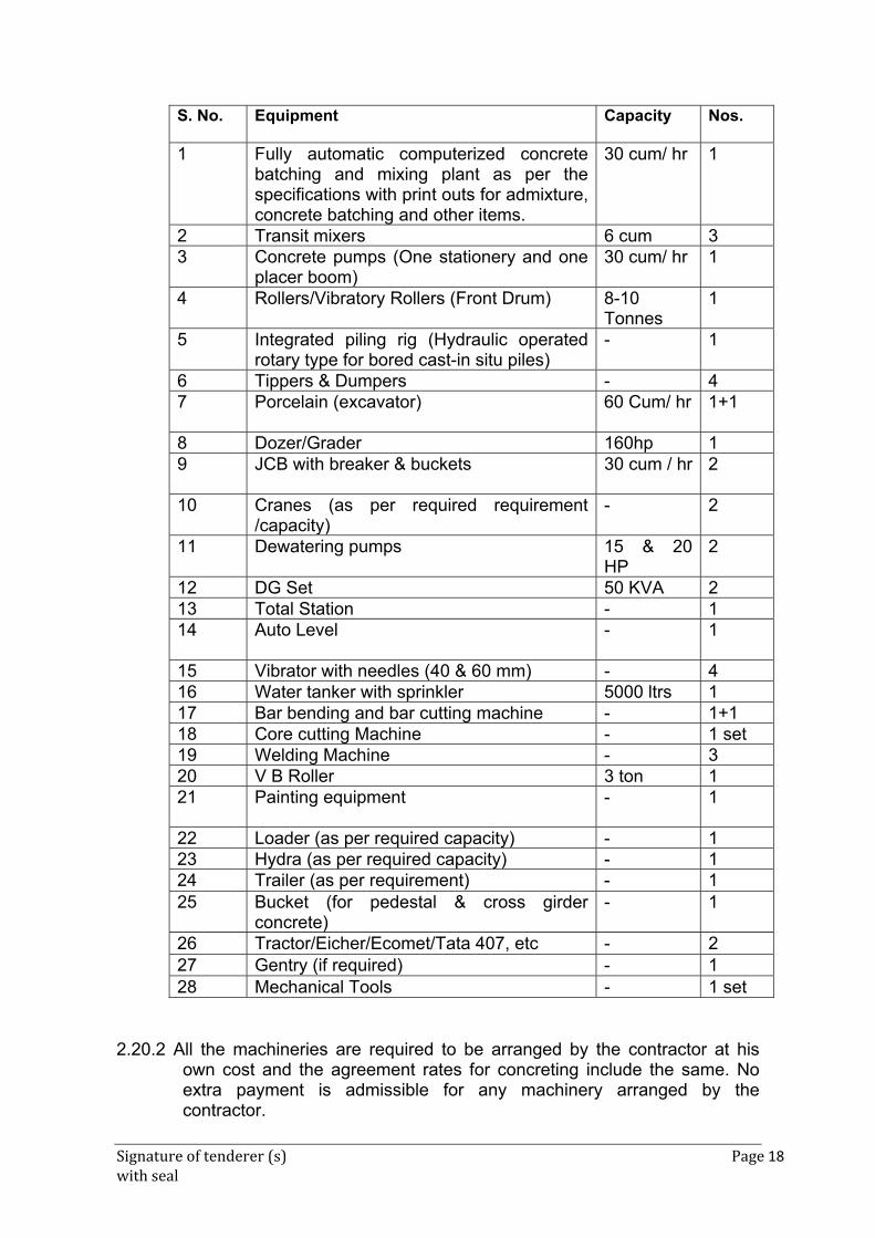
Signature of tenderer (s) Page 18 with seal
S. No. Equipment Capacity Nos.
1 Fully automatic computerized concrete batching and mixing plant as per the specifications with print outs for admixture, concrete batching and other items.
30 cum/ hr 1
2 Transit mixers 6 cum 3 3 Concrete pumps (One stationery and one
placer boom) 30 cum/ hr 1
4 Rollers/Vibratory Rollers (Front Drum) 8-10 Tonnes
1
5 Integrated piling rig (Hydraulic operated rotary type for bored cast-in situ piles)
- 1
6 Tippers & Dumpers - 4 7 Porcelain (excavator) 60 Cum/ hr 1+1
8 Dozer/Grader 160hp 1 9 JCB with breaker & buckets 30 cum / hr 2
10 Cranes (as per required requirement /capacity)
- 2
11 Dewatering pumps 15 & 20 HP
2
12 DG Set 50 KVA 2 13 Total Station - 1 14 Auto Level - 1
15 Vibrator with needles (40 & 60 mm) - 4 16 Water tanker with sprinkler 5000 ltrs 1 17 Bar bending and bar cutting machine - 1+118 Core cutting Machine - 1 set19 Welding Machine - 3 20 V B Roller 3 ton 1 21 Painting equipment - 1
22 Loader (as per required capacity) - 1 23 Hydra (as per required capacity) - 1 24 Trailer (as per requirement) - 1 25 Bucket (for pedestal & cross girder
concrete) - 1
26 Tractor/Eicher/Ecomet/Tata 407, etc - 2 27 Gentry (if required) - 1 28 Mechanical Tools - 1 set
2.20.2 All the machineries are required to be arranged by the contractor at his
own cost and the agreement rates for concreting include the same. No extra payment is admissible for any machinery arranged by the contractor.
Signature of tenderer (s) Page 19 with seal
2.21 TRANSPORTATION OF CONCRETE & PUMPING OF CONCRETE 2.21.1 General
Fresh concrete can be transported to the placement area by a variety of methods. Common among them are:
- Mixer trucks
- Stationary truck bodies with or without agitators.
- Buckets hauled by trucks.
- Conveyor belts.
- Hose or pipe line by pumping.
Each type of transportation has specific advantages and limitations depending on the condition of use, mix, accessibility and location of placing.
2.21.2 Transportation by Mixer Trucks 2.21.2.1 These are essentially revolving drums mounted on truck chassis. Truck
mixers used in the job shall be labelled permanently to indicate the manufacturer's specifications for mixing like: -
- Capacity of drum.
- Total number of drum revolutions for complete mixing.
- Mixing speed
- Maximum time limit before completion of discharge and after cement
has
entered the drum.
- Reduction in time period of discharge due to warm weather or other
variables.
All above information shall only form guidelines for the manufacturer/producer of concrete.
2.21.2.2Fulfilment of the stipulated number of revolutions or elapsed time shall not be the acceptable criterion. As long as the mixing water limit is not exceeded and the concrete has satisfactory plastic physical properties and is of satisfactory consistency and homogeneity for satisfactory placement and consolidation and is without initial set, the concrete shall be acceptable.
Signature of tenderer (s) Page 20 with seal
2.21.2.3When the concrete is totally mixed in transporting trucks volume of
concrete being transported shall not exceed 63% of the rated capacity of the drum. In case the concrete is totally mixed in the central batching plant, the transporting truck may be loaded up to 80% of the rated capacity of the drum. In this case the drum shall be rotated at charging speed during loading and reduced to agitating speed after loading is complete.
2.21.2.4 When transporting concrete by truck mixers, delivery time shall be
restricted to 90 minutes or initial setting time whichever is less from the time cement has entered the mixer to completion of discharge.
2.21.3 Transporting by Agitating / Non-agitating Trucks.
2.21.3.1 Transporting ready mix concrete by this method shall consist of truck
chassis mounted with open top bodies. The metal body shall be smooth and streamlined for easy discharge. Discharge may be from the rear when the body is mechanically titled. Body of the truck shall have a provision of discharge gate. Mechanical vibrators shall be installed at the discharge gate for control of discharge flow.
2.21.3.2 Agitators, if mounted, also aid in the discharging of concrete from the
truck in addition to keeping the concrete alive. 2.21.3.3 Water shall not be added to concrete in transport through this system. 2.21.3.4 Bodies of trucks shall be provided with protective covers during period
of inclement weather. 2.21.3.5 Delivery period, when adopting this system of transporting concrete
shall be restricted to 30 minutes from the moment all ingredients including cement and water enter in mixer to completion of discharge.
2.21.4 Transporting by Buckets
This method of transportation is very common for transportation of centrally mixed concrete. Buckets of suitable capacities may be filled with concrete which is totally mixed in central plant and hauled to the job site. Buckets then may be conveyed to the actual point of placement either with the help of crane/hoist or they may be carted
. As in the case of open truck transportation, extra water shall not be added to concrete transported in buckets. Concrete shall be protected from inclement weather by necessary covering arrangements. Also, maximum delivery period for this system of transportation from the time cement is introduced into the mixer to completion of discharge shall not exceed 30 minutes.
Signature of tenderer (s) Page 21 with seal
2.21.5 Cleaning
Before loading concrete in either truck mixer, open bodied trucks or buckets, the containers shall be thoroughly cleaned, washed and dried, so that there is no water or moisture in the container which may affect the designed water content of the concrete.
2.21.6 Other Methods of Transportation
Transportation of concrete either by belt conveyors or by pumping is envisaged in some works. If, the producer/manufacturer/purchaser/contractor of ready-mix concrete desires to use such methods of transportation, they may do so provided their scheme and complete specifications are submitted to the Engineer for his record and approval.
2.21.7 Objective
Method of transportation used shall ensure: - - Efficient delivery of concrete - No significant alteration of properties with regard to water cement
ratio, slump, air content and homogeneity. - All variables in transportation, considering type and accessibility of
placement locations, distance, time interval etc., shall be carefully studied before arriving at the method used.
2.21.8 Pumpable Concrete (Extracted from Para 8.9 of Concrete Bridge
Code, 1997)
General- Pumpable concrete is the concrete which is conveyed by pressure through either rigid pipe or flexible hose and discharged directly into the desired area. It is especially used where space for construction equipment is very limited. Pumping Rate and Range – Depending on the equipment, pumping rate should be 10 to 70 cum. per hour. Effective pumping range is upto 300m horizontally and 90m vertically. (i) Proportioning Pumpable Concrete
a) Basic Consideration - More emphasis on quality control is essential to the proportioning and use of a dependable pump mix. Concrete mixes for pumping must be plastic. Particular attention must be given to the mortar and to the amounts and sizes of coarse aggregates.
Signature of tenderer (s) Page 22 with seal
b) The maximum size of angular coarse aggregate is limited to one-
third of smallest inside diameter of the hose or pipe. Provisions should be made for elimination of oversized particles in the concrete by finish screening or by careful selection of aggregates.
(ii) Pumping Concrete
a) Proper planning of concrete supply, pump locations, line layout, placing sequences and the entire pumping operation will result in saving of cost and time. The pump should be placed as near the placing area as practicable and the entire surrounding area must have adequate bearing strength. Lines from the pump to the placing area should be laid out with a minimum of bends. The pipe line shall be rigidly supported.
b) While pumping downward 15m or more, it is desirable to provide an air release valve at the middle of the top bend to prevent vacuum or air build up. When pumping upward, it is desirable to have a valve near the pump to prevent reverse flow.
2.22 Construction Joints: - 2.22.1 Construction joints shall be avoided as far as possible and in no case the
locations of such joints shall be changed or increased from those shown on the drawings, except with express approval of the Engineer. The joints shall be provided in a direction perpendicular to the member axis. Sequencing of concrete placement should be organized in such a way that cold joints are totally eliminated. The sequence of concreting shall be submitted for approval of Engineer prior to concreting of the structural element. Concreting shall be carried out continuously up to the construction joints, the position and arrangement of which shall be predetermined by the designer.
2.22.2 Construction joints should be positioned to minimize the effect of the
discontinuity on the durability, structural integrity and appearance of the structure. Joints should be located away from regions of maximum stress caused by loading particularly where shear and bond stresses are high.
2.22.3 Laitance, both on the horizontal and vertical surfaces of the concrete,
should be removed before fresh concrete is cast. The surface should be roughened to promote good adhesion. Various methods for removal can be used but they should not dislodge the course aggregate particles. Concrete may be brushed with a stiff brush soon after casting while the concrete is still fresh and while it has only slightly stiffened. If the concrete has partially hardened, it may be treated by wire brushing or with a high pressure water jet, followed by drying with an air jet, immediately before the new concrete is placed. Fully hardened concrete should be treated
Signature of tenderer (s) Page 23 with seal
with mechanical hand tools or grit blasting, taking care not to split or crack aggregate particles.
2.22.4 Where there is likely to be a delay before placing the next concrete lift,
protruding reinforcement should be protected. Before the next lift is placed, rust loose mortar, or other contamination should be removed from the bars and where conditions are particularly aggressive and there has been a substantial delay between lifts, the concrete should be cut back to expose the bars for a length of about 50 mm to ensure that contaminated concrete is removed.
2.22.5 In all cases, when construction joints are made, it should be ensured that
the joint surface is not contaminated with release agents, dust, or curing membrane and that the reinforcement is fixed firmly in position at the correct cover.
2.22.6 When the formwork is fixed for the next lift, it should be inspected to
ensure that no leakage can occur from the fresh concrete. It is a good practice to fix a 6 mm thick sponge which seals the gap completely. The practice of first placing a layer of mortar or grout is not recommended. The old surface should be soaked with water without leaving puddles, immediately before starting concreting; then the new concrete should be thoroughly compacted against it. When fresh concrete is cast against existing mature concrete or masonry the older surfaces should be thoroughly cleaned and soaked to prevent the absorption of water from the new concrete. Standing water should be removed shortly before the new concrete is placed and the new concrete should be thoroughly vibrated in the region of the joint.
2.23 Finishing of concrete: The finished surface of concrete after removal of
formwork shall be such that no touching up is required. All fins/holes caused by form joints, supports, rods etc., shall be ground/filled up effectively using appropriate machinery shutters, formwork etc., used in construction shall be as specified in the conditions and the labour used shall be skilled to suit the quality requirements of the work. Any surface, finished poorly in the opinion of the Engineer shall require repair/remedial measures at the cost of the contractor and the Engineer’s decision in this regard shall be final. Any structure, which has deficiencies in finishing including product parameters beyond the rejection limits, as specified in these conditions, are liable to be rejected and the decision of the Engineer shall be final in this regard.
2.24 Coatings for concrete: Normally finished concrete structures do not
require any surface protective coatings in non-aggressive environment (moderate) for all structures. For aggressive environment (severe and extreme conditions), Epoxy phenolic IPN coating or CECRI Integrated four coat system can be used in superstructure of bridges and coal tar epoxy coating for sub structure of bridges (in affected part only).
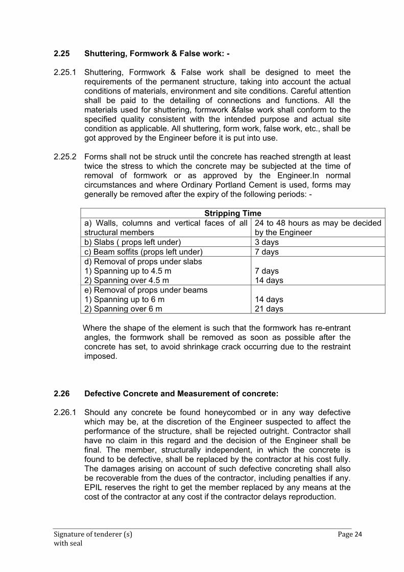
Signature of tenderer (s) Page 24 with seal
2.25 Shuttering, Formwork & False work: - 2.25.1 Shuttering, Formwork & False work shall be designed to meet the
requirements of the permanent structure, taking into account the actual conditions of materials, environment and site conditions. Careful attention shall be paid to the detailing of connections and functions. All the materials used for shuttering, formwork &false work shall conform to the specified quality consistent with the intended purpose and actual site condition as applicable. All shuttering, form work, false work, etc., shall be got approved by the Engineer before it is put into use.
2.25.2 Forms shall not be struck until the concrete has reached strength at least
twice the stress to which the concrete may be subjected at the time of removal of formwork or as approved by the Engineer.In normal circumstances and where Ordinary Portland Cement is used, forms may generally be removed after the expiry of the following periods: -
Stripping Time
a) Walls, columns and vertical faces of all structural members
24 to 48 hours as may be decided by the Engineer
b) Slabs ( props left under) 3 daysc) Beam soffits (props left under) 7 daysd) Removal of props under slabs 1) Spanning up to 4.5 m 2) Spanning over 4.5 m
7 days 14 days
e) Removal of props under beams 1) Spanning up to 6 m 2) Spanning over 6 m
14 days 21 days
Where the shape of the element is such that the formwork has re-entrant angles, the formwork shall be removed as soon as possible after the concrete has set, to avoid shrinkage crack occurring due to the restraint imposed.
2.26 Defective Concrete and Measurement of concrete: 2.26.1 Should any concrete be found honeycombed or in any way defective
which may be, at the discretion of the Engineer suspected to affect the performance of the structure, shall be rejected outright. Contractor shall have no claim in this regard and the decision of the Engineer shall be final. The member, structurally independent, in which the concrete is found to be defective, shall be replaced by the contractor at his cost fully. The damages arising on account of such defective concreting shall also be recoverable from the dues of the contractor, including penalties if any. EPIL reserves the right to get the member replaced by any means at the cost of the contractor at any cost if the contractor delays reproduction.
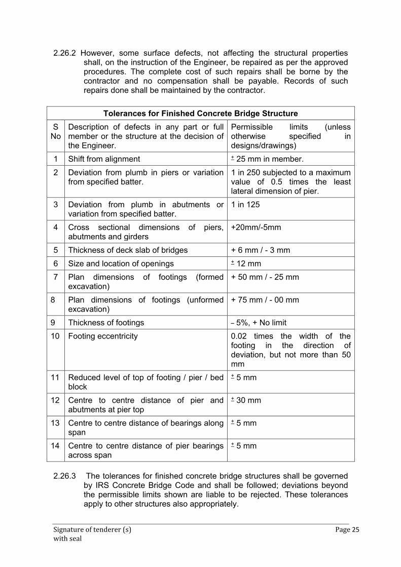
Signature of tenderer (s) Page 25 with seal
2.26.2 However, some surface defects, not affecting the structural properties shall, on the instruction of the Engineer, be repaired as per the approved procedures. The complete cost of such repairs shall be borne by the contractor and no compensation shall be payable. Records of such repairs done shall be maintained by the contractor.
2.26.3 The tolerances for finished concrete bridge structures shall be governed
by IRS Concrete Bridge Code and shall be followed; deviations beyond the permissible limits shown are liable to be rejected. These tolerances apply to other structures also appropriately.
Tolerances for Finished Concrete Bridge Structure
S No
Description of defects in any part or full member or the structure at the decision of the Engineer.
Permissible limits (unless otherwise specified in designs/drawings)
1 Shift from alignment + 25 mm in member.
2 Deviation from plumb in piers or variation from specified batter.
1 in 250 subjected to a maximum value of 0.5 times the least lateral dimension of pier.
3 Deviation from plumb in abutments or variation from specified batter.
1 in 125
4 Cross sectional dimensions of piers, abutments and girders
+20mm/-5mm
5 Thickness of deck slab of bridges + 6 mm / - 3 mm
6 Size and location of openings + 12 mm
7 Plan dimensions of footings (formed excavation)
+ 50 mm / - 25 mm
8 Plan dimensions of footings (unformed excavation)
+ 75 mm / - 00 mm
9 Thickness of footings _ 5%, + No limit
10 Footing eccentricity 0.02 times the width of the footing in the direction of deviation, but not more than 50 mm
11 Reduced level of top of footing / pier / bed block
+ 5 mm
12 Centre to centre distance of pier and abutments at pier top
+ 30 mm
13 Centre to centre distance of bearings along span
+ 5 mm
14 Centre to centre distance of pier bearings across span
+ 5 mm
Signature of tenderer (s) Page 26 with seal
2.27 Sampling and Strength Testing of Concrete: 2.27.1 General: Samples from fresh concrete shall be taken as per IS: 1199
(method of sampling and analysis of concrete). Concrete for making 3 test cubes shall be taken from a batch of concrete at point of delivery into construction according to procedure laid down in IS: 1199 and 150 mm cubes shall be made, cured and tested at the age of 28 days for compressive strength in accordance with IS:516. The 28 days’ test strength result for each cube shall form an item of sample.
Concrete shall conform to the surface finish and tolerance as prescribed
in Unified specifications. Random sampling and lot by lot of acceptance / inspection shall be made for the 28 days cube strength of concrete.
Concrete under acceptance shall be notionally divided into lots for the
purpose of sampling, before commencement of work. The delimitation of lots shall be determined by the following:
(i) No individual lot shall be more than 30 cum in volume. (ii) At least one cube forming an item of the sample representing the lot
shall be taken from concrete of the same grade and mix proportions cast on any day.
(iii) Different grades of mixes of concrete shall be divided into separate
lots. (iv) Concrete of a lot shall be used in the same identifiable component of
the bridge. 2.27.2 Sampling 2.27.2.1 Frequency of Sampling Sampling procedure: A random sampling procedure shall be adopted to
ensure that each concrete batches forming the lot under acceptance / inspection shall have a reasonable chance of being tested that is, sampling should be spread over the entire period of concreting and cover all mixing units.
Frequency: The minimum frequency of sampling of concrete of each
grade shall be in accordance with table below. At least one sample shall be taken from each shift of work.
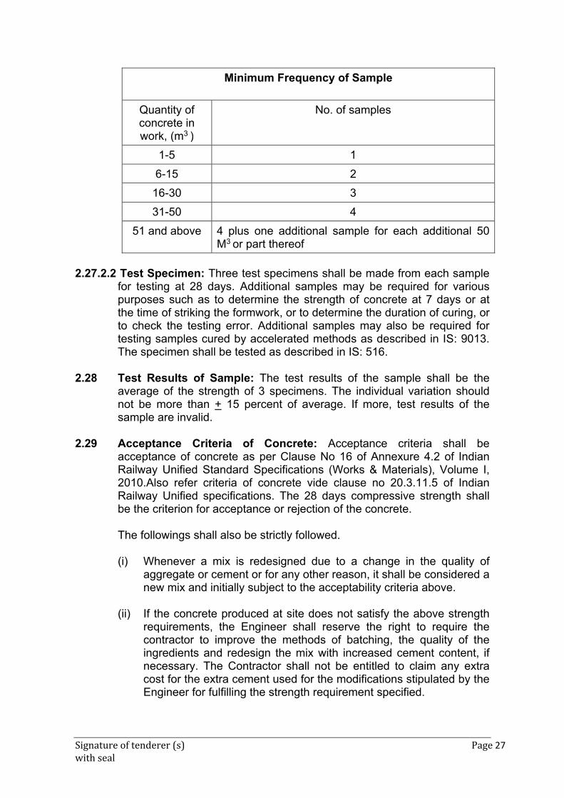
Signature of tenderer (s) Page 27 with seal
Minimum Frequency of Sample
Quantity of concrete in work, (m3 )
No. of samples
1-5 1
6-15 2
16-30 3
31-50 4
51 and above 4 plus one additional sample for each additional 50 M3 or part thereof
2.27.2.2 Test Specimen: Three test specimens shall be made from each sample
for testing at 28 days. Additional samples may be required for various purposes such as to determine the strength of concrete at 7 days or at the time of striking the formwork, or to determine the duration of curing, or to check the testing error. Additional samples may also be required for testing samples cured by accelerated methods as described in IS: 9013. The specimen shall be tested as described in IS: 516.
2.28 Test Results of Sample: The test results of the sample shall be the
average of the strength of 3 specimens. The individual variation should not be more than + 15 percent of average. If more, test results of the sample are invalid.
2.29 Acceptance Criteria of Concrete: Acceptance criteria shall be
acceptance of concrete as per Clause No 16 of Annexure 4.2 of Indian Railway Unified Standard Specifications (Works & Materials), Volume I, 2010.Also refer criteria of concrete vide clause no 20.3.11.5 of Indian Railway Unified specifications. The 28 days compressive strength shall be the criterion for acceptance or rejection of the concrete.
The followings shall also be strictly followed.
(i) Whenever a mix is redesigned due to a change in the quality of aggregate or cement or for any other reason, it shall be considered a new mix and initially subject to the acceptability criteria above.
(ii) If the concrete produced at site does not satisfy the above strength
requirements, the Engineer shall reserve the right to require the contractor to improve the methods of batching, the quality of the ingredients and redesign the mix with increased cement content, if necessary. The Contractor shall not be entitled to claim any extra cost for the extra cement used for the modifications stipulated by the Engineer for fulfilling the strength requirement specified.
Signature of tenderer (s) Page 28 with seal
(iii) It is the complete responsibility of the contractor to redesign the concrete mixes by approved standard methods and to produce the reinforced concrete conforming to the specification and the strength requirements approved by the Engineer. It is expected that the Contractor will have competent staff to carry out this work.
2.30 Setting of field laboratory by the Contractor: 2.30.1 For all works, the Contractor shall set up a field laboratory of his own for
testing of cement/water/concrete at work site, which should be open for use and inspection by the EPIL officials at any time and carryout the tests with his own equipments, gauges, machinery, consumables and operators, at his own cost. The laboratory shall be equipped with necessary equipment to carry out various tests such as property tests, sieve analysis, setting time of cement, compression tests on cubes, slump test, workability test etc., on aggregate, cement, water and concrete required for ensuring the required quality. For steel however, test reports of reputed institutes/laboratories are acceptable.
2.30.2 The cost of setting up the laboratory, equipping the same, maintaining
conducting all tests on materials and cubes shall be borne by the contractor, within his quoted rates for works and no extra payment is eligible for the same.
2.30.3 All gauges, machines, equipments and other measuring and testing
equipments of the laboratory shall be got checked / calibrated regularly and the necessary certificates furnished to the Engineer by the Contractor.
2.30.4 All the equipments, machinery etc., shall be kept in good working condition. Contractor shall also maintain the required qualified / experienced staff at the laboratory.
2.30.5 The following is the minimum laboratory facilities at the site which are to be provided and operated by the contractor at his cost.
(i) Testing of fine and coarse aggregates as per IS:383 and IS:2386. (ii) Testing of cement concrete as per IS: 8142 and IS:516. (iii) Testing of water as per IS: 456 and IS: 3025. (iv) Certain non-routine testing such as (a) Testing of admixtures, (b)
Chemical testing of fine and coarse aggregates (c) Permeability of concrete (permeability test on concrete shall be got done when the mix design is approved / changed of the reputed laboratories as approved by Engineer). The frequency and need for these tests shall be decided by the Engineer, based on stipulations contained in conditions of contract or on the basis of accepted Engineering
Signature of tenderer (s) Page 29 with seal
practice (e.g. whenever source of admixture is changed, tests stipulated in the codes will have to be carried out afresh, etc).
2.30.6 As frequently as the Engineer may require, testing shall be carried out in
the field for:
(a) Moisture content and absorption and density of sand and
aggregate.
(b) Silt content of sand.
(c) Grading of sand and aggregates.
(d) Slump test of concrete.
(e) Concrete cube test.
(f) Permeability test for concrete
(g) Density of Plasticizer.
(h) PH Value of water
2.31 Ladders for inspections: Steel ladders are to be provided at the
abutments and all pier locations on both sides of girder bridges to enable inspecting officials to get down from the track level to the top of the piers / abutments.
2.32 Supplying, fitting & fixing of superior approved brand A-80 type
Unitary expansion: 2.32.1 Unless otherwise specifically stated, the detailed scope of work of this item
shall be deemed to include the cost of the under mentioned works including cost of all materials to be supplied and used, welding, grouting, T & P, Equipments, temporary works, epoxy mortar, skilled supervisors, labours, consumables, all taxes, etc. complete as required for the successful completion of the work at contractor’s cost.
2.32.2 Components:
Strip seal expansion joint shall comprise the following items :- a) Edge beam - This special claw leg profiled members shall be of
extruded rolled steel section combining good weldability with notch toughness.
b) Strip seal – This shall be of chloroprene with high tear strength, insensitive to oil, gasoline and ozone. It shall have high resistance to aging. This component, provided to ensure water tightness, shall have bulbous shape of the part of the seal which is inserted into the groove, provided in the edge beam. The seal should be vulcanized in single operation for minimum full length of joint.
c) Rigid Anchorage – This shall be welded to the edge beam at staggered distance.
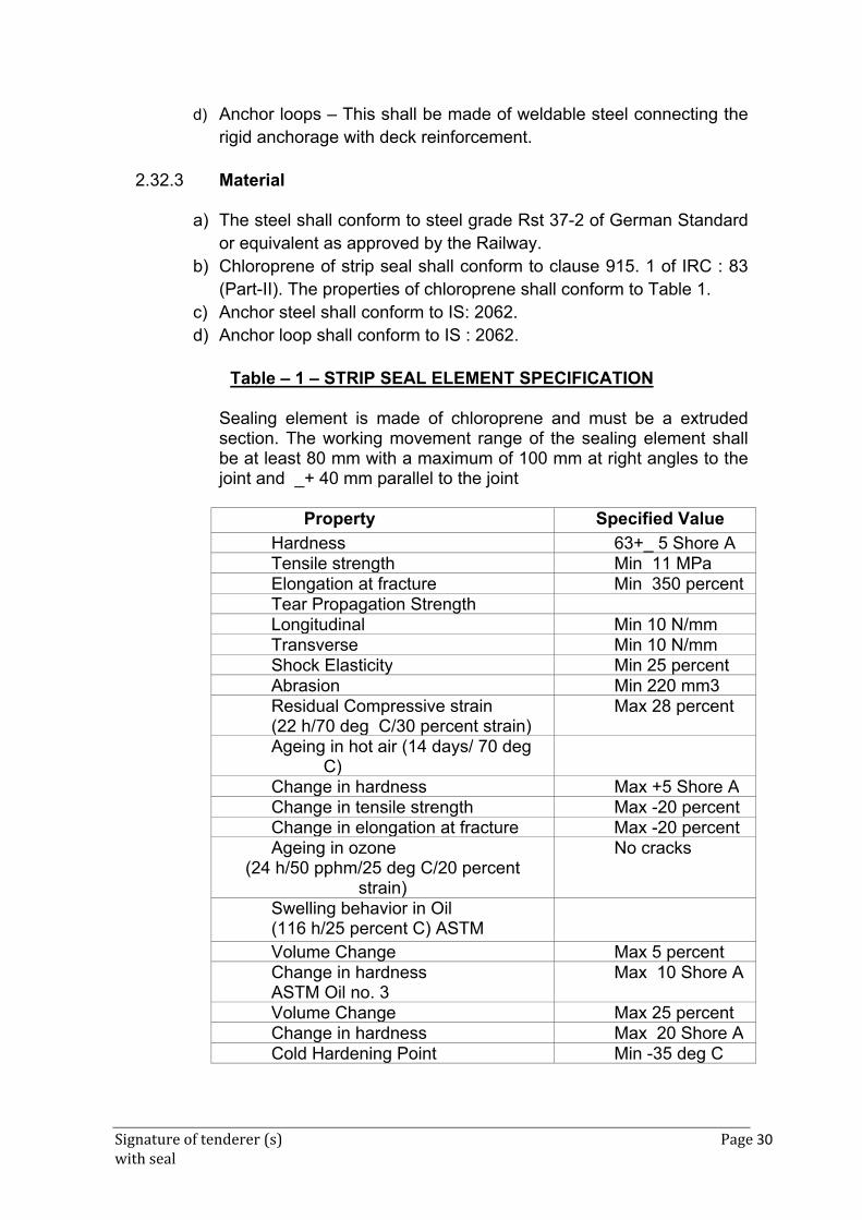
Signature of tenderer (s) Page 30 with seal
d) Anchor loops – This shall be made of weldable steel connecting the rigid anchorage with deck reinforcement.
2.32.3 Material
a) The steel shall conform to steel grade Rst 37-2 of German Standard
or equivalent as approved by the Railway. b) Chloroprene of strip seal shall conform to clause 915. 1 of IRC : 83
(Part-II). The properties of chloroprene shall conform to Table 1. c) Anchor steel shall conform to IS: 2062. d) Anchor loop shall conform to IS : 2062.
Table – 1 – STRIP SEAL ELEMENT SPECIFICATION
Sealing element is made of chloroprene and must be a extruded section. The working movement range of the sealing element shall be at least 80 mm with a maximum of 100 mm at right angles to the joint and _+ 40 mm parallel to the joint
Property Specified Value
Hardness 63+_ 5 Shore ATensile strength Min 11 MPa Elongation at fracture Min 350 percentTear Propagation Strength Longitudinal Min 10 N/mmTransverse Min 10 N/mmShock Elasticity Min 25 percentAbrasion Min 220 mm3Residual Compressive strain (22 h/70 deg C/30 percent strain)
Max 28 percent
Ageing in hot air (14 days/ 70 deg C)
Change in hardness Max +5 Shore AChange in tensile strength Max -20 percentChange in elongation at fracture Max -20 percentAgeing in ozone
(24 h/50 pphm/25 deg C/20 percent strain)
No cracks
Swelling behavior in Oil (116 h/25 percent C) ASTM
Volume Change Max 5 percentChange in hardness ASTM Oil no. 3
Max 10 Shore A
Volume Change Max 25 percentChange in hardness Max 20 Shore ACold Hardening Point Min -35 deg C
Signature of tenderer (s) Page 31 with seal
2.32.4 Fabrication (Pre-installation) a) Rolled steel profiles for edge beams shall be long enough to cater
for a 2-lane carriage way. These shall be cut to size of actual requirements by means of a meter box saw.
b) Alignment of the cut-to-size steel profiles shall then be made in accordance with the actual bridge cross section on work tables. For this purpose, the contour of bridge cross section shall be sketched onto these tables.
c) After the steel profiles are aligned, they will be chucked to the tables by means of screw clamps and tacked by arc welding.
d) Anchor plates shall be cut to the required size by gas cutting. These shall be Welded to the edge beams.
e) Anchor loops shall be bent to the required shape and welded to anchor plates.
f) The finally assembled joint shall then be clamped and transported to the work site.
2.32.5 Handling and Storage
a) For transportation and storage, auxiliary brackets shall be provided
to hold the Joint assembly together. b) The manufacturer shall supply either directly to the Engineer-in-
Charge or to the Bridge contractor all the materials of strip seal joints including Salamanca and all other accessories for the effective installation of the jointing.
c) Expansion joint material shall be handled with care. It shall be stored under cover on suitable lumber padding by the Contractor to prevent damage. Any damage occurring after delivery shall be made good at the Bridge Contractor’s expense to the satisfaction of the Engineer-in-Charge.
2.32.6 Installation
a) The width of the gap to cater for movement due to thermal effect, pre-stress, shrinkage and creep, superstructure deformations (if any) and sub-structure deformations (if upon) shall be determined and intimated to the manufacturer. Depending upon the temperature at which the joint is likely to be installed, the gap dimension shall be preset.
b) Taking the width of gap for movement of the joint into account, the dimensions of the recess in the decking shall be established in accordance with the drawings or design data of the manufacturer. The surfaces of the recess shall be thoroughly cleaned and all dirt debris removed. The exposed reinforcement shall be suitable adjusted to permit unobstructed lowering of the joint into the recess.
c) The recess shall be shuttered in such a way that dimensions in the joint drawing are maintained. The formwork shall be tight.
d) Immediately prior to placing the joint, the presetting shall be inspected. Should the actual temperature of the structure be different from the temperature provided for presetting, correction of
Signature of tenderer (s) Page 32 with seal
the presetting shall be done. After adjustment, the brackets shall be tightened again.
e) The joint shall be lowered in a pre-determined position. Following placement of the joint in the prepared recess, the joint shall be leveled and finally aligned and the anchor loops on one side of the joint welded to the exposed reinforcement bars of the structure Upon completion the same procedure shall be followed for the other side of the joint to take up the movement of the structure.
f) High quality concrete shall then be filled into the recess. The packing concrete must feature low shrinkage and have the same strength as that of the superstructure, but in any case not less than M 35 grade. Good compaction and careful curing of concrete is particularly important. After the concrete has cured, the movable installation brackets still in place shall be removed.
g) Rolled up neoprene strip seal shall be cut into the required length and inserted between the edge beams by using a crow bar pushing the seal into the steel grooves of the edge beams. A landing to a bead shall be formed in the thickened end of the edges of the seal which would force the thickened end against the steel beam due to wedge effect when the strip seal is buttoned in place.
h) As soon as the concrete in the recess has become initially set, a sturdy ramp shall be placed over the joint to protect the exposed steel beams and neoprene seals from site traffic Expansion joint shall not be exposed to traffic loading before the carriageway surfacing is placed.
i) The carriageway surfacing shall be finished flush with the top of steel sections. The actual junction of the surfacing/wearing coat with the steel edge section shall be formed by a wedge shaped joint with a sealing compound. The horizontal leg of the edge beam shall be cleaned beforehand. It is particularly any premature forming in it.
2.32.7 Acceptance Test
a) All steel element shall be finished with corrosion protection system. b) For neoprene seal, the acceptance test shall conform to the
requirements stipulated in Table 1 it shall also be stretch tested. if a manufactured is to supply this type joint, they will have to produce a test certificate accordingly conducted in a recognizes laboratory, in India or abroad.
c) In view of the importance of the built up edge mean, special investigation of fatigue strength of this section with anchorages to withstand 2x10 load change cycles without showing signs of damage, will be required . The supplier shall have to produce a test certificate in this regard, conducted in a recognized laboratory in India or abroad.
d) The manufacture shall product test certificates indicating that anchorage system had been tested recognized laboratory to determine optimum configuration of anchorage assembly under dynamic loading.
Signature of tenderer (s) Page 33 with seal
e) The manufacturer shall satisfy the Engineer-in-charge that water tightness test for the type of joint has been carried out in a recognized laboratory to check the water tightness under pressure of 4 bars.
f) As strip type of joint is specialized in nature, generally of the proprietary type the manufacture shall be required to produce evidence satisfactory performance of this type of joint.
2.32.8 Tests and standards of acceptance
a) The materials shall be tested in accordance with these specifications
and shall meet the prescribed criteria. b) The work shall conform to these specifications and shall meet the
prescribed standards of acceptance.
2.32.9 Method of measurement The expansion joint shall be measured in running metres. For filled joints, the rate per running metre shall include the cost of sealant for the depth provided in the drawing.
2.33 Seating of foundations:
As far as possible, open foundations should be located on the firm ground having stable strata. The strata shall be well compacted before levelling course and foundations are laid on the levelling.
In case foundations resting on rock, no foundation shall be laid on sloping
rock. The rock shall be made level for the width of the foundation before levelling course is laid. Before seating on the rock, capacity of the rock shall be assessed properly and safe bearing capacity assessed in the designs is to be confirmed.
The seating of the rock shall be achieved by cutting into the rock atleast
by 0.50m depth to ensure removal of all weak layers and for obtaining adequate anchorage in case of open foundations. After level surface is made on the rock, a rich mix layer of 150mm thick shall be laid to even the bedding surface.
If the rock is encountered while piling, pile shall be anchored into rock to
the depth as per codal provision. 2.34 Drainage outlets: 50mm galvanized GI pipes in case of deck slab in
bridges will serve as drainage spouts.
Signature of tenderer (s) Page 34 with seal
2.35 Providing & fixing 20mm thick CI grating
Rate is inclusive of Providing & fixing in position 20mm cast-iron grating with 100mm micron thick galvanized mild steel collection chamber and 100m dia pipe for drainage spouts, in deck slab as per railway's drawing, with all contractor's material labour. The drainage spouts shall be fixed properly, to receive surface water from deck slabs, and disposes-off, through spouts.
2.36 Supplying and fabricating protective screen
Rate is inclusive of fabrication of MS angles/pipe frame with mesh, G.I. plain sheet including all nut, bolts/clamps etc. complete & fixing in peripherals with suitable clamps, filling gaps making good in cement mortar complete with primer & painting. All fabrication work shall confirm to relevant IS standards. The work shall be carried out to the complete satisfaction of Engineer-In-Charge.
2.37 Supplying, Jointing & fixing un-plastisized (rigid) PVC pipe
The work shall be inclusive of Supplying & jointing & fixing unplastisized (rigid) PVC pipe of 110mm dia confirming to IS 4985 to with stand a test pressure of 4 kg/Cm2 for rain water down take pipes with all specials & galvanized steel clamps including fixing cleats etc. jointing with drainage spouts. The rate is inclusive of all temporary works/arrangements staging platform etc. are required for fixing of pipes as per Railway’s drawings/ requirements and nothing extra will be paid for such work. The above temporary staging to be maintained in safe and tidy manner during complete execution of work with the satisfaction of Engineer-in-charge and as instruction of time to time during inspection.
2.38 Three coats of water-proof cement based paint The rates are inclusive of cleaning of surfaces, slabs/beams/parapets etc. by brooming, hard wire-brushed to remove all loose material, dirt’s etc. Applying one coat of waterproof cement primer white or equivalent substitute, Applying two coats of approved waterproof paint.
The rate is inclusive of all leads lifts, crossing the lines, ensuring safety in working from nearby OHE –live conductors, tools & plants, consumables, labor etc. complete. The material confirming to various IS/Railway’s standards/approved by railways shall only be supplied and used in work after getting approval for the same from engineer –in-charge.
Signature of tenderer (s) Page 35 with seal
2.39 Painting lines, dashes, arrows etc
Work to be carried out as per instruction as per Engineer in-charge of the work.
3 GENERAL GUIDELINES AND SPECIFICATIONS FOR BORED CAST-
IN-SITU RCC PILE FOUNDATIONS: 3.1 The piles shall be bored cast-in-situ. The scope of the work included in
relevant schedules is for the provision and testing of bored cast-in-situ RCC pile foundations with the pile cap. Items for piling in soil has been provided in schedule. If any boulder in the form of obstruction comes in the boring, no extra payment for piling in boulders shall be made. Bore log provided by the EPIL for construction are only indicative in this regard and it is the contractors’ responsibility to make correct assessment of ground conditions before starting the piling operation. Rate of Item of piling includes cost of all materials and labour involved in all operations as specified excluding supply of cement and steel reinforcement only.
3.2 CONCRETING IN BORED CAST-IN-SITU PILES
(i) Bored Cast-in-situ concrete piles shall be installed by making a bore into the ground by removal of material. Cast-in-situ concrete piles may be cast in metal liners which may remain permanently in place. The metal casing shall be of sufficient thickness and strength to hold its original form and show no harmful distortion after it and adjacent casings have been driven and the driving core, if any, has been withdrawn.
(ii) Concreting and reinforcement work will be done in accordance with
relevant clauses in Chapters 3 and 4 of Indian Railway Unified Standard Specifications (Works & Materials) Volume - I, 2010 supplemented by these specifications.
(iii) Any liner or bore-hole which is improperly located or shows partial
collapse that would affect the load carrying capacity of the pile, shall be rejected or repaired as directed by the Engineer at the cost of the Contractor.
(v) Bored cast-in-situ piles in soils which are stable may often be
installed with only a small casing length at the top. A minimum of 2.0 m length of top of bore shall invariably be provided with casing to prevent any loose soil falling into the bore. In cases in which the side soil lower down can fall into the hole, it is necessary to stabilise the side of the bore hole with drilling mud, or a suitable steel casing. The casing may be left in position permanently specially in cases where the aggressive action of the ground water is to be avoided, or in the
Signature of tenderer (s) Page 36 with seal
cases of piles built in water or in cases where significant length of piles could be exposed due to scour.
(vi) For bored cast-in-situ piles, casing / liner shall be driven open ended
with a pile driving hammer capable of achieving penetration of the liner to the length as approved by the Engineer. Materials inside the casing shall be removed progressively by air lift, grab or percussion equipment or other approved means. Unless otherwise approved by the Engineer, the diameter of the bore-holes shall be not more than the inside diameter of the liner.
(vii) Where bored cast-in-situ piles are used in soils liable to flow, the
bottom of the casing shall be kept enough in advance of the boring tool to prevent the entry of soil into the casing, thus preventing the formation of cavities and settlements in the adjoining ground. The water level in the casing should generally be maintained at the natural ground water level for the same reasons. The joints of the casing shall be made as tight as possible to minimise inflow of water or leakage of slurry during concreting. Where mud flow conditions exist, the casing of cast-in-situ piles shall not be allowed to be withdrawn. Prior to the lowering of the reinforcement cage into the pile shaft, the shaft shall be cleaned of all loose materials. Cover to reinforcing steel shall be maintained by suitable spacers, tied in advance to the reinforcement.
(viii) Wherever practicable, concrete should be placed in a clean dry hole.
Where concrete is placed in dry condition and there is casing present, the top 3m of the pile shall be compacted using internal vibrators.
(ix) Before concreting under water, the bottom of the hole shall be
cleaned of drilling mud and all soft or loose material very carefully. In case a hole is bored with use of drilling mud, concreting should not be taken up when the specific gravity of bottom slurry is more than 1.2. The drilling mud should be maintained at 1.5m above the ground water level.
(x) Where the casing is withdrawn from cohesive soils for the formation
of cast-in-situ pile, the concreting should be done with necessary precautions to minimise the softening of the soil by excess water. Care shall be taken during concreting to prevent as far as possible the segregation of the ingredients. The displacement or distortion of reinforcement during concreting and also while extracting the tube shall be avoided.
(xi) The concrete shall be properly graded, shall be self-compacting and
shall not get mixed with soil, excess water, or other extraneous matter. Special care shall be taken in silty, clays and other soils with the tendency to squeeze into the newly deposited concrete and
Signature of tenderer (s) Page 37 with seal
cause necking. Sufficient head of green concrete shall be maintained to prevent inflow of soil or water into the concrete.
(xii) The placing of concrete shall be a continuous process from the toe
level to the top of the pile. To prevent segregation, a tube or tremie pipe as appropriate shall be used to place concrete in all piles.
(xiii) To ensure compaction by hydraulic static heads, rate of placing
concrete in the pile shaft shall not be less than 6m (length of pile) per hour. Under water concreting should be done with tremie.
(xiv) The maximum water cement ratio shall be 0.50 for cast in situ piles. (xv) The cement content shall not be less than 400 kg/cum of concrete. (xvi) The minimum slump of concrete for bored cast-in-situ piles shall 150
mm to 200 mm, but the slump should not exceed 200 mm in any case.
(xvii) Concreting under water: -General requirements and precautions
for concreting under water shall be as given in concreting chapter 3 of IR Unified Standard Specifications (Work & Materials), Volume - I, 2010 supplemented by following instructions:
(a) The concreting of a pile must be completed in one continuous
operation. Also, for bored holes, the finishing of the bore, cleaning of the bore, lowering of reinforcement cage and concreting of pile for full height must be accomplished in one continuous operation without any stoppage.
(b) The concrete should be coherent, rich in cement with high
slump and restricted water cement ratio. (c) The tremie pipe will have to be large enough with due regard
to the size of aggregate. For 20mm aggregate the tremie pipe should be of diameter not less than 150mm and for larger aggregate, larger diameter tremie pipes may be necessary.
(d) The first charge of concrete should be placed with a sliding
plug pushed down the tube ahead of it to prevent mixing of water and concrete.
(e) The tremie pipe should always penetrate well into the
concrete with an adequate margin of safety against accidental withdrawal if the pipe is surged to discharge the concrete.
(f) The pile should be concreted wholly by tremie and the
method of deposition should not be changed part way up the pile to prevent the laitance from being entrapped within the pile.

Signature of tenderer (s) Page 38 with seal
(g) All tremie tubes should be scrupulously cleaned after use. (h) In special circumstances, the Engineer may permit use of any
other proved method of concrete placement designed for under water concrete. In such cases, a detailed method statement should be prepared and got approved by the Engineer.
(xviii) The diameter of the finished pile shall not be less than that
specified and a continuous record shall be kept by the Engineer as to the volume of concrete placed in relation to the pile length cast.
3.3 The schedule of quantities in this contract is based on bored cast-in-situ
pile of required capacity and for approximate anticipated depth as indicated in the drawings. Depth of piles is likely to vary and contractor shall have no claim whatsoever irrespective of the depth of piles provided at any and all locations. Installation of piles shall be carried out as per layout drawings, installation criteria and the instructions of the Engineer. The method of installing the piles, including details of the equipment shall be submitted by the contractor and got approved by the Engineer before start of work.
3.4 Piling work shall conform to specifications IS: 2911 Parts 1 & 4 unless otherwise specified.
3.5 Workmanship of bored cast-in-situ piles includes the provisions for control
of piling installation, use of drilling mud, cleaning of borehole, tremie concreting, defective pile, recording of data shall be as per Clause 8 of IS: 2911(Part 1/Section 2).
3.6 The specifications for safe load, test load, total displacement, net
displacement etc., shall also conform to provisions as per IS: 2911 (Part 4).
3.7 The contractor shall set out piles with precision survey duly erecting
permanent bench marks and other references. He shall be responsible for correct maintenance of position and plumb thereafter and these shall be checked periodically. The control of alignment and inclination of piles shall be as per IS:2911(Part 1/Section 2). Tolerances as specified in the above code or as specified shall govern.
3.8 Level marks shall be put accurately on each pile immediately after it is
installed. If any pile shows subsequently a tendency to heave up due to installation of other piles later or due to any other reason, corrective course of action shall be suggested and taken by the contractor after approval by the Engineer at the cost of contractor.
Signature of tenderer (s) Page 39 with seal
3.9 Durability provisions such as clear cover to reinforcements, minimum and maximum cement content, maximum water-cement ratio and permeability of concrete shall be adhered to as mentioned earlier and below.
The exposed area of pile above the ground level. In case of harmful chemical constituents found in subsoil and in water
such as chlorides and sulphides, special provisions as per relevant codes of practice shall be followed for protection against reinforcement corrosion and disintegration of concrete and for such protection against corrosion and bio-fouling, the pile concrete/liner below cut-off level shall be painted with appropriate material, if ordered by Engineer for which payment will be made separately as specified in relevant schedules.
3.10 Sulphate resistant cement may be used on need-based consideration
after conducting the soil investigation and water investigation. It shall not be used under such conditions where concrete is exposed to risk of excessive chlorides and sulphate attack both. Requirements of concrete exposed to sulphate attack shall be as per Table 4 of IS:456. Where chloride is encountered along with sulphate in soil or ground water, Ordinary Portland Cement with C3A contents from 5 to 8 % shall be desirable to be used in concrete instead of sulphate resisting cement. For pH around 4, steel and concrete both have to be specially quoted. If sulphate resistant cement is used which has faster setting properties, curing shall start within five hours of concreting.
3.11 Method of boring, namely, Bailer and Chisel, Rotary, Direct Mud
Circulation (DMC), Reverse Mud Circulation (RMC), Percussion, etc., shall be chosen as appropriate to strata and site conditions. The agreement rates for piling are inclusive of any type of boring/any type of supporting arrangements adopted by the contractor and no extra payments are admissible for any type of scheme adopted by the contractor.
3.12 Borehole stability shall be maintained with casing and/or mud circulation. 3.13 Use of drilling mud (Bentonite) in stabilizing the sides of bore holes is
mandatory in soils of inadequate capacity. The decision on the need of use of Bentonite will be taken by the Engineer which is final. The bentonite slurry shall be maintained at 1.5m above the ground water level during boring operations and till the pile is concreted. The bentonite slurry shall be under constant circulation till start of concreting and shall meet the requirements stipulated in the subsequent clauses. Agreemental rates for piling includes the cost of Bentonite and related operations and the contractor cannot claim any extra cost on this account.
3.14 Providing MS Liners: This item is for supply and fixing contractor’s
permanent MS liners for the pile from the top of working platform upto the required depth as may be decided by the Engineer. The contractor shall fabricate the MS liners from his own MS sheets to suit the diameter of the pile as directed. Required length of MS liners will be made up by welding each unit outside by the contractor with his own equipments and plants. It
Signature of tenderer (s) Page 40 with seal
shall be clearly noted that the MS sheets required for manufacture of the liners shall not be supplied by the EPIL. The welding shall be of proper quality so as to withstand the hammering forces. The payable depth shall however, be measured only from the cut off level though the liner might have been provided right from the level of working platform on practical considerations, since the length above the cut off level has to be necessarily removed by gas cutting for facilitating peeling of the top portion of the pile and for interlacing its reinforcement bars into the capping slab. Therefore, the rate quoted shall cater for the element of cutting and removing the surplus length of MS liners. There is, however, no objection for the surplus pieces, if usable, are united and are re-welded to the required length for reuse on some of the other piles. No claim shall be entertained if the cut pieces cannot be reused by the contractor.
3.15 The contractor shall take all necessary precautions while piling close to
existing structures/other foundations/track so as to minimize vibrations and ground movement. Bores shall be encased as directed by the Engineer and boring shall commence only after precautionary measures are taken. While working near the existing track, infringements and other safety aspects shall be specially considered and taken care of.
3.16 The contractor shall indemnify the EPIL Administration against any claim
or obligations arising out of any damage to structure or out of any injury to any person/persons due to piling working done by him.
3.17 The contractor shall mobilize and maintain requisite resources for piling
including concreting. Additional resources, as a standby shall also be available in advanceof work, to take care of any eventualities. Admixtures as approved by Engineer, shall be kept in readiness before concreting to meet any exigencies. After boring and/or cage lowering to avoid borehole instability and settlement of bentonite, boreholes shall not be left un-concreted for long.
3.18 The spoils arising out of boring shall be disposed off as directed by
Engineer within the agreemental rates. In case of piling close to Railway track or near the existing road, contractor shall make adequate arrangements for disposing the muck away properly. Contractor shall also make adequate drainage arrangement for mud slurry so that the same does not affect the tracks or roads or adjoining properties.
3.19 The bored spoils may be dumped in a low lying area as directed by
Engineer so that work site is restored back to normal condition after completion of work.
3.20 When the bore has reached its final depth, it shall be free from any
foreign matter before placing the reinforcement cage and concreting for the pile is started. Reinforcement for the pile shall be carefully placed in position and concreting then started. The cover block used also shall satisfy strength and permeability criteria.
Signature of tenderer (s) Page 41 with seal
3.21 If hard rock is encountered, socketing in hard rock shall also be provided
as per codal provision. 3.22 In case of sloping bedrock profile, the requisite depth of socketing shall
be ensured as minimum all round piling and the payment will be made for the least depth of socketing only and no claims of differential depth of socketing are admissible.
3.23The bottom level of pile cap will be decided by Engineer, depending upon
capacity and ground level. 3.24 Care shall be taken for free flow of concrete through splices and
congested reinforcement zones with proper detailing and monitoring. 3.25 The quantity of concrete required for a particular pile shall be calculated
as per depth of the pile and nominal diameter of the pile. This quantity shall be checked with the actual quantity of concrete used, which is to be recorded and signed jointly by the contractor and representative of the EPIL. Theoretical quantity of concrete, calculated as per depth and nominal diameter of the pile shall form the basis of calculating the cement quantity as per approved design mix, for payment to the contractor,
3.26 For the finishing of pile heads, the clearances of reinforcements in the
pile cap and the keying of the pile head into the pile cap shall be as given in IS: 2911.
3.27 The contractor shall maintain bore log register and bored samples for
each pile boring and concreting. The details shall contain various operations in pile boring with time, type of soil met with depth of penetration with levels, liner welding and lowering details, obstruction to boring, if any, machine down time, rock touch level and final socketed level. The flushing out details before cage lowering and before concreting shall also be recorded. The concreting details such as mix proportions, sounding at various depths vis-à-vis cement / concrete consumption, unusual observations while concreting, interruption to concreting, if any and overflow concrete shall be recorded. The swelling and/or squeezing of borehole in uncased portion shall be specially monitored with recording of sounding depth, quantity concreted actually and quantity theoretically estimated corresponding to that sounding depth.
3.28 The payable depth of piles shall be taken up to the clear distance from
the cut-off level (bottom of pile cap) to the average bottom of the bore. The depth so measured shall be rounded off to the nearest first decimal of a metre (0.05 metre or more to be reckoned as 0.10 metre whereas below 0.05 metre to be reckoned as 0.00 metre) for the purpose of making payment.
3.29 In group of two or more piles, piles of same diameter and same load
carrying capacity shall be installed. The distance between centre to
Signature of tenderer (s) Page 42 with seal
centre of such piles shall be governed by IS:2911. In case the contractor offers to install the piles closer than this spacing, he shall state the reduction in the working load of the pile which will be subject to the approval of Engineer. The additional piles required on this account shall be provided by the contractor without any extra cost to the EPIL. Also cost of cement and steel reinforcement used on this score will have to be borne by the contractor. New MS liners shall also be to contractors account.
3.30 If any pile during boring has deviated from the design position or from the
verticality or if the safe allowable load of the pile is not obtainable as per the design, all these facts shall be reported promptly to the Engineer during the execution of the work with suggestion from the contractor regarding adequate corrective measures. The Engineer shall consider the suggestions of the contractor and shall give necessary directions for the corrective measure which shall be done by the contractor at his own cost and risk. However, if certain piles are rejected by the Engineer on account of improper location / verticality / alignment / capacity, the Engineer may allow the rejected piles to be left in their places and additional piles may be installed to take up the safe working load of the rejected piles with satisfaction of Engineer without any extra cost to the EPIL. If any such changes involve additional expenditure due to increase in size of pile cap, etc., the same shall also be borne by the contractor including the extra cost involved in the usage of the extra quantity of cement and steel used in such changes.
3.31 No payment will be made for rejected piles and also for the cement, steel
and the MS liners provided for the rejected piles.
3.32 Pile load Test: IS: 2911 (Part 4) prescribes various guidelines and procedures for load tests on piles. Pile load test shall be conducted as per IS: 2911 (Part 4) and as directed by the Engineer. Vertical load tests (compression) and lateral load tests shall be adopted for testing of piles. There shall be two categories of tests on piles for each type of loading (vertical and lateral), namely, initial tests and routine tests. Initial tests should be carried out on test piles which are not to be incorporated in the work. Routine tests shall be carried out as a check on working piles.
Initial load test is carried out to determine the ultimate load capacity and arrival at the safe load by application of factor of safety whereas routine test is conducted to determine the safe load of pile, checking the safety load and extent of safety. In other words, routine test is conducted to check whether the pile is capable of taking the working load assigned to it. Non-destructive testing i.e. Integrity testing of pile using Low Strain / Sonic Integrity Test / Sonic Echo test method in accordance with IS: 14893 shall be carried out for integrity testing of concrete in the installed pile.
Signature of tenderer (s) Page 43 with seal
The vertical load test and lateral load test shall be carried out as per clause 6 and 7 of IS: 2911 (Part 4). Safe load on a pile is derived by applying a factor of safety on ultimate load capacity of pile as determined by a load test whereas working load is the load assigned to pile according to design. The safe loads on single pile and on group of piles for the initial test and routine test shall be in accordance clause 6.1.5 and 6.1.6 of IS: 2911(Part 4). Test load shall be 2.5 times the safe capacity load for Initial Load. For routine test, test load shall be at least 1.5 times the working load for maximum settlement not exceeding 12mm in case of single pile whereas test load shall be equal to the working load for maximum settlement not exceeding 25mm in case of group piles. The test shall be carried out at cut off level wherever practicable, otherwise suitable allowance shall be made in the interpretation of the test results / test load if the test is not carried out at cut-off level. The contractor shall submit all data along with load vs settlement, time vs settlement, interpretation of the pile load test, etc., in a report along with characteristics of the pile as per IS 2911 and as directed by the Engineer. For any other type of test such as pull-out tests, etc. if considered necessary, the contractor shall make arrangements in consultation with the Engineer and payments for the same will be eligible as decided mutually in advance. Payment for initial vertical load test, routine vertical load test and lateral load test will be made against a separate item provided in the schedule.
3.33 The contractor is required to carry out load test inpile or group of piles as per provisions contained in IS: 2911 (Part 4) of and shall provide all the designing, testing, loading, supporting, instrumenting, recording & reporting arrangements at the agreement rates. The design, instrumentation etc., shall be approved by the CGM / GM/ROB, /CPM, EPIL.
3.34 The payment for the test of the pile or group of piles shall be made to the
contractor only when the test is found to be satisfactory. For tests which are found to be unsatisfactory or which are not completed due to any reasons whatsoever, no payment shall be made to the contractor.
3.35 The agreemental rates for tests include instrumentation, reporting,
arranging of necessary kentledge, R.S. Joists, sand bags, etc., required for loading the platform for successful testing of the pile or group of piles and removing the same from the site of work after the test is completed and clearing the site to the satisfaction of the Engineer and no extra payment shall be made on this account.
3.36 In case of defective piles, EPIL reserves the right to order, at the cost of
contractor, non-destructive test for integrity and / or capacity assessment
Signature of tenderer (s) Page 44 with seal
or additional static load tests as confirmatory tests at the cost of the contractor. The test shall be considered satisfactory only if the criteria laid in specifications are satisfied and the behaviour of the pile or pile group during the period of test does not disclose any defects as specified in relevant codes and as directed by the Engineer.
3.37 Each pile shall be identified with a reference member. Level marks shall be
accurately painted on each pile immediately after its installation. The contractor shall record all the information during installation of piles as directed by the Engineer. Pile records in triplicate shall be submitted by the contractor.
3.38 Approval of the termination depth of the pile by the Engineer shall, in no
way, absolve the contractor on the integrity of the pile. 3.39 Control of Position and Alignment: Piles shall be installed as accurately
vertical (for vertical piles) as possible. The permissible limits for deviation with respect to position and alignment shall confirm to IS: 2911 (Part 1/Section 2).
3.40 working level shall be above the cut-off-level. After the initial boring of
about 1m, temporary guide casing of suitable length shall be lowered in the pile bore for vertical pile. The diameter of guide casing shall be such as to give the necessary finished diameter of the concrete pile. The centre line of guide casing shall be checked before continuing further boring. Guide casing shall be minimum of 1.0m length. Additional length of casing may be used depending on the condition of the strata, ground water level etc. The temporary guide casing (if provided) shall be withdrawn cautiously, after concreting is done upto the required level. While withdrawing the casing, concrete shall not be disturbed.
3.41 Permanent MS Liners shall be provided for piles upto point of refusal or
as directed by the Engineer. The bottom end of the MS Liner shall be stiffened by welding additional plates to withstand the impact during driving.
3.42 In case hard rock is encountered, chiselling is essentially required for
softening of the rock, the same may be adopted only on approval of the Engineer, at no extra cost to the EPIL. Advancement of pile bore shall be done by drilling only, in case of use of rotary hydraulic drilling rig.
3.43 Specifications for Bentonite shall be as follows: Liquid limit of bentonite
when tested in accordance with IS: 2720(Part V) shall be 400 percent or more. Bentonite solution should be made by mixing it with fresh water using pump for circulation. The density of the freshly prepared bentonite suspension shall be between 1.03 and 1.10 gm / ml depending upon the pile dimensions and type of soil in which the pile is to be installed. However, the density of bentonite suspension after mixing with deleterious materials in the pile bore may be upto 1.25 gm / ml. The marsh viscosity when tested by a marsh cone shall be between 30 to
Signature of tenderer (s) Page 45 with seal
60stoke. The pH value of the bentonite suspension shall be between 9 and 11.5.
3.44 Cleaning of borehole: - After completion of bore hole upto the required
depth, the bore hole shall be cleaned as per clause 8.3 of IS: 2911 (Part 1/Section 2).
3.45 A protocol shall be maintained regarding the strata at the founding level, SPT value, percent core recovery, Unconfined Compressive Strength (UCS) from the nearest borehole, socketing horizon, flushing of pile bore, time interval between end of boring and start of concreting, bentonite density before start of concreting.
3.46 Top of Concrete in Pile and Cut off-level (COL): - Cut-Off-Level of piles
shall be as indicated in drawings released for construction. The top of concrete in pile as cast shall be above the cut-off-level by 1.0 metre (maximum) to remove all laitance and weak concrete and to ensure good concrete at cut-off-level, for proper embedment into the pile cap. The area surrounding the piles shall be excavated up to the bottom of the pile caps. After seven days of concreting of pile, the exposed part of concrete above the COL shall be removed / chipped off and made rough at COL. The projected reinforcement above COL shall be properly cleaned and bent to the required shape and level to be anchored into the pile cap. The pile top shall be embedded into the pile cap by 150 mm or clear cover to reinforcement, whichever is higher. All loose material on the top of pile head after chipping to the desired level shall be removed and disposed off as directed by the Engineer.
3.47 Reinforcement: The longitudinal reinforcement shall project 50 times its diameter above cut-off-level unless otherwise indicated. Proper cover to reinforcement and central placement of the reinforcement cage in the pile bore shall be ensured by use of suitable concrete spacers or rollers, cast specifically for the purpose. Placement of reinforcement cage to its full length shall be ensured before concreting. Minimum clear cover to the reinforcement shall be 75 mm, unless otherwise mentioned.
3.48 Building Up of Piles: If any pile, already cast as per construction drawing,
requires any extra casting due to any change in cut-off-level, then the pile shall be built up by using at least one grade higher concrete than specified for piles, ensuring proper continuity with the existing concrete and to the satisfaction of the Engineer. Necessary reinforcement, as per design requirement and suitable shuttering shall be provided, before casting the concrete. Surrounding soil shall also be built up to the required level by proper compaction, to ensure lateral capacity of the pile.
3.49 Breaking Off: If any pile already cast requires breaking, due to
subsequent change of Pile’s cut-off-level, then the same shall be carried out, not before seven days of casting without affecting the quality of existing pile, such as loosening, cracking etc., and to the satisfaction of
Signature of tenderer (s) Page 46 with seal
the Engineer. If any pile is cracked, the same shall be replaced by the contractor at his own cost.
3.50 Bore Hole testing: Bore hole shall be made as per IS: 1892.
3.51 IMPORTANT CONSIDERATIONS, INSPECTION / PRECAUTIONS
(b) Contractor will ensure the layout of bridge and its component to the complete satisfaction of Engineer-in-charge before start of any work.
(i) While concreting uncased piles, voids in concrete shall be
avoided and sufficient head of concrete shall be maintained to prevent inflow of soil or water into the concrete. It is also necessary to take precautions during concreting to minimise the softening of the soil by excess water. Uncased cast-in-situ piles shall not be permitted where mudflow conditions exist.
(ii) The drilling mud such as bentonite suspension shall be
maintained at a level sufficiently above the surrounding ground water level to ensure the stability of the strata which is being penetrated all through the boring operation and until the pile has been concreted.
(iii) Where bentonite suspension is used to maintain the stability
of the bore-hole, it is essential that the properties of the material be carefully controlled at stages of mixing; circulating through the bore-hole and immediately before concrete is placed. It is advisable to limit:
(a) The density of bentonite suspension to 1.05 g/cc and maintain it.
(b) The marsh cone viscosity between 30 and 40
(c) The pH value between 9.5 and 11.50
(d) The silt content less than 1 per cent
(e) The liquid limit of bentonite not less than 400 per cent
These aspects shall act as controlling factors for preventing contamination of bentonite slurry by clay and silt. (iv) The bores shall be washed by bentonite flushing to ensure
clean bottom at two stages viz. (a) after completion of boring and (b)prior to concreting after placing of reinforcement cage. Flushing of bentonite shall be done continuously with fresh bentonite slurry till the consistency of inflowing and outflowing slurry is similar.
Signature of tenderer (s) Page 47 with seal
(v) Tremie of 150mm to200mm diameter shall be used for concreting. The tremie should have uniform and smooth cross-section inside, and shall be withdrawn slowly ensuring adequate height of concrete outside the tremie pipe at all stages of withdrawal. Other precautions to be taken while tremie concreting are:
(a) The sides of the bore-hole have to be stable throughout
(b) The tremie shall be water tight throughout its length and have a hopper attached at its head by a water tight connection.
(c) The tremie pipe shall be large enough in relation to the size ofaggregates.For20mm aggregate the tremie pipe shall be of diameter not less than 150mm and for larger size aggregate tremie pipe of larger diameter is required.
(d) The tremie pipe shall always be kept full of concrete and shall penetrate well into the concrete in the bore-hole with adequate margin of safety against accidental withdrawal if the pipe is surged to discharge the concrete.
(e) For very long or large diameter piles, use of retarding plasticiser in concrete is desirable.
3.52 Pile Data:
The contractor shall submit data in the following Proforma for each pile indicating all technical details along with date and time of various operations in adequate permanent forms/copies for record.
Proforma (i) Reference No. Location (Co-ordinates) __ area. (ii) Sequence of installation of piles in group (iii) Pile diameter & type (iv) Working level (Platform level) (v) Cut off level (COL) (vi) Actual length below COL (vii) Pile termination level
(a) Start of socket (Level) (b) Termination of pile (Level):
Signature of tenderer (s) Page 48 with seal
(viii) Top of finished concrete level (ix) Date and time of start and completion of boring. (x) Depth of ground water table in the vicinity. (xi) Type of soil/ rock at pile tip (xii) Method of boring operation
(xiii) Details of drilling mud (Bentonite) as used:
(a) Freshly supplied mud:
Liquid limit Sand content Density Marsh viscosity Swelling index, PH value (b) Contaminated mud: Density Sand content
(xiv) (a) Standard Penetration Test (SPT) Penetration for 100 blows at
Socketing Level for reference pile:
(b) Unconfined Compression Strength (UCS) Value in rock (from the nearest bore hole): Core recovery (from the nearest bore hole):
(c) Rate of drilling in mm / hr:
(1) At start of socketing horizon (2) At termination level
(xv) Date and time of start and completion of concreting.
(xvi) Method of placing concrete (xvii) Concrete quantity Actual: Theoretical: (xviii)Ref. number of test cubes
Signature of tenderer (s) Page 49 with seal
(xix) Grade and slump of concrete (xx) Results of test cubes (xxi) Reinforcement details:
Main reinforcement Stirrups: Type No._______________ No.___________ Dia ______________ Dia ___________ Depth_____________ Spacing________
(xxii) Any other information regarding obstructions, delay and other
interruption to the Sequence of work.
(xxiii) Pile bore log details (in brief). 3.53 Such structure or parts of the structure which fail or pass the specified
tests, shall be removed from the site by the tenderer/contractor at his cost and the contractors shall redo the work. Payments made on account of the rejected structure/part structure work shall be recovered from the contractor and the work will be redone by him at the same rates.
4 GENERAL GUIDELINES AND SPECIFICATIONS FOR OPEN
FOUNDATIONS:
4.1 EXTRACT FROM THE SECTION 2100 OF SPECIFICATION FOR ROAD AND BRIDGES WORKS, 5TH REVISION MORTH 2013 (The para / section reference in this Chapter refer to the MoRTH Specification Para/ Section).
2101 DESCRIPTION
The work shall cover furnishing and providing plain or reinforced concrete foundation placed in open excavation, in accordance with the drawings and these Specifications or as directed by the Engineer.
2102 MATERIALS
Materials shall conform to Section 1000 of MoRTH Specifications. 2103 GENERAL
A method statement indicating the following shall be submitted by the Contractor for approval of the Engineer, well in advance of the commencement of construction of open foundation:
Signature of tenderer (s) Page 50 with seal
i) Sources of materials ii) Design, erection and removal of formwork iii) Production, transportation, laying and curing of concrete iv) Personnel employed for execution and supervision v) Tests and sampling procedures vi) Equipment details vii) Quality Management System to be adopted including Quality
Manual viii) Any other relevant information
Details of necessary arrangements for execution under water wherever necessary, shall be included in the method statement.
Dimensions, lines and levels shall be set out and checked with respect to permanent reference lines and permanent bench mark so that the foundations are located correctly and in accordance with the drawings.
Formwork, steel reinforcement and structural concrete for open foundations shall conform to Sections 1500, 1600 and 1700 respectively of MoRTH Specifications.
2104 WORKMANSHIP 2104.1 Preparation of Foundations
Excavation for laying the foundation shall be carried out in accordance with Section 300 of MoRTH Specifications. The last 300 mm of excavation shall be done just before laying of lean concrete below foundation. Excavation shall be made only to the exact depth as shown on the drawing. In the event of excavation having been made deeper than that shown on the drawing or as ordered by the Engineer, the extra depth shall be made up with M10 concrete in case of foundation resting on soil and with concrete of the same grade as that of the foundation, in case of foundation resting on rock. This shall be done at the cost of the Contractor and shall be considered as incidental to the work. Open foundations shall be constructed in dry conditions and the Contractor shall provide for adequate dewatering arrangements, wherever required, to the satisfaction of the Engineer. Where light blasting is required for excavation in rock or other hard strata, the same shall be carried out in accordance with Clause 302 of
Signature of tenderer (s) Page 51 with seal
these Specifications. Where blasting is likely to endanger adjacent foundations or other structures, controlled blasting with all necessary precautions shall be resorted to.
2104.2 Setting Out
The plan dimensions of the foundation shall be set out at the bottom of foundation trench and checked with respect to original reference line and axis.
2104.3 Construction
i) Excavation for open foundations shall be carried out in accordance with Section 300 of MoRTH Specifications. For guidance regarding safety precautions to be taken, IS:3764 may be referred.
ii) For foundation resting on soil, a layer of M10 concrete of
minimum thickness 1 00 mm shall be provided above the natural ground to provide an even surface to support the foundation concrete. Before laying of lean concrete layer, the earth surface shall be cleaned of all loose material and wetted. Care shall be taken to avoid muddy surface. If any part of the surface has become muddy due to over-wetting, the same shall be removed. If required, the M10 concrete may be laid to a thickness of more than 100 mm, as per the direction of the Engineer. No construction joint shall be provided in the lean concrete. For foundations resting on rock, the rock surface shall be cleaned of any lose material and then levelled with a layer of concrete of the same grade as that of the foundation, so as to provide an even surface.
iii) No point of the surface of the lean concrete, in the case of
foundation on soil or the surface of hard rock, in the case of foundation on hard rock, shall be higher than the founding level shown on the drawing or as ordered by the Engineer. Levels of the surface shall be taken at intervals of not more than 3 meters centre-to-centre in each direction, subject to a minimum of nine levels on the surface.
iv) No formwork is necessary for the lean concrete layer. Side
formwork shall be used for foundation concrete work. When concrete is laid in slope without top formwork, the slump of
Signature of tenderer (s) Page 52 with seal
the concrete shall be carefully maintained to ensure that compaction is possible without slippage of freshly placed concrete down the slope. In certain cases, it may be necessary to build the top formwork progressively as the concreting proceeds up the slope. Reinforcement shall be laid as shown on the drawing.
v) Before laying foundation concrete, the lean concrete or hard
rock surface shall be cleaned of all loose material and lightly moistened. Foundation concrete of required dimensions and shape shall be laid continuously up to the location of construction joint shown on the drawing or as directed by the Engineer.
vi) The concrete surface shall be finished smooth with a trowel.
The location of construction joint and its treatment shall be done as per requirements of Section 1700 of MoRTH Specifications. Formwork shall not be removed earlier than 24 hours after placing of concrete. Where formwork has been provided for top surface, the same shall be removed as soon as concrete has hardened. Curing of concrete shall be carried out by wetting of formwork before removal. After its removal, curing shall be done by laying not less than, 100 mm thickness of loose moistened sand free from clods or gravel, over the concrete. The sand shall be kept continuously moist for a period of 7 days. Before backfilling is commenced, the loose sand shall be removed and disposed of as directed by the Engineer.
vii) Normally, open foundations shall be laid dry. Where
dewatering is necessary for laying of concrete, it shall be carried out adopting any one of the following methods or any other method, approved by the Engineer:
a) A pit or trench of suitable size, deeper than the
founding level as necessary, is dug beyond the foundation excavation so that the water flows into it and the excavated surface at founding level is fully drained.
b) Water table is depressed by well point system or other methods.
c) Steel/concrete caissons or sheet piling are used for creating an enclosure for the foundations, which can subsequently be dewatered.
Signature of tenderer (s) Page 53 with seal
No pumping of water shall be permitted from the time ꞏof placing of concrete up to 24 hours after placement.
viii) In situations where foundations cannot be laid dry or where
percolation is too heavy to keep foundation strata dry, concrete may be laid under water only by tremie. In case of flowing water or artesian spring, the flow shall be stopped or reduced to the feasible extent at the time of placing the concrete.
ix) Where blasting is required, it shall be carried out in
accordance with Section 300 of MoRTH Specifications, observing all precautions indicated therein. Where blasting is likely to endanger adjoining foundations or other structures, necessary precautions such as controlled blasting, providing rubber mat cover to prevent flying of debris etc., shall be taken to prevent any damage.
x) All spaces excavated and not occupied by the foundations or
other permanent works shall be refilled with earth up to surface of surrounding ground with sufficient allowance for settlement. All backfill shall be thoroughly compacted and in general, its top surface shall be neatly graded. Backfilling shall be in accordance with Section 300 of MoRTH Specifications.
xi) In case of excavation in rock, the annular space around the
footing shall be filled with M15 concrete up to the level of top of rock. Filling with M15 concrete shall also be carried out for excavations having depth up to 1.5 m in ordinary rock or 0.6 m in hard rock. In case, the excavations are even deeper so as to require further filling up to the level of top of rock, the same shall be done by boulders grouted with cement.
xii) Protective works, where provided shall be completed before
the onset of floods so as to avoid the risk of the foundation getting undermined.
2105 TESTS AND STANDARDS OF ACCEPTANCE
The materials shall be tested in accordance with these Specifications and shall meet the prescribed criteria.
Signature of tenderer (s) Page 54 with seal
The work shall conform to these Specifications and shall meet the prescribed standards of acceptance.
2106 TOLERANCES
a) Variation in dimensions : +50 mm, -10 mmb) Misplacement from specified position in plan : 15 mmc) Surface unevenness measured with 3 m straight edge : 5 mmd) Variation of levels at the top : ± 25 mm
2107 MEASUREMENT FOR PAYMENT
Excavation in foundation shall be measured in cubic meters in accordance with USSOR specification, based on the quantity ordered or as shown on the drawing. Lean concrete shall be measured in cubic meters in accordance with USSOR specification, based on the quantity ordered or as shown on the drawing. Concrete in foundation shall be measured in cubic meters in accordance with USSOR Specifications, based on the quantity ordered or as shown on the drawing. Reinforcement steel shall be measured in kg in accordance with USSOR Specifications, based on the quantity ordered or as shown on the drawing.
2108 RATE
The contract unit rates for excavation in foundation, lean concrete, including dewatering and blasting where required, concrete in foundation and reinforcement steel shall include all works as given in respective Sections of these Specifications and cover all incidental items for furnishing and providing open foundation as mentioned in this Section and as show on the drawings.
5 GENERAL GUIDLINES AND SPECIFICATIONS FOR SUPPLY OF
REINFORCEMENT AND STRUCTRURAL STEEL 5.1 SUPPLY OF STEEL FOR VARIOUS WORKS: Supply of steel to various specifications as required under various
schedules in the contract are governed by the Technical specifications and Special Conditions specified hereunder.
All steel shall be supplied by the Contractor at the site of work and
stacked, stored, protected and maintained by him at his cost till they are put into use. Any temporary structure required for storage of steel etc.,
Signature of tenderer (s) Page 55 with seal
has to be provided by the Contractor at his cost and should be removed after completion of the work.The EPIL will only provide suitable land for construction of the above temporary shed free of cost wherever available.
For supply and use of steel in various works, relevant IRS Codes
Specifications, IS Specifications and Railways specifications will be applicable.
5.2 SPECIFICATIONS FOR STEEL: 5.2.1 The steel supplied by the contractor must satisfy any of the following
material specifications as required for the work along with other concerned specifications.
(i) The reinforcement steel shall be Thermo mechanical Treated bars of
grade Fe 500 D/Fe550D conforming / satisfying to IS 1786 (Upto date).
(i) The structural steel shall be conforming to IS 2062 (Upto date) as
specified. It shall have Sub quality ‘B0’ & Grade E250 (Fe 410) and E350 (Fe 490) as mentioned in the tender schedule and the requirements of IRS B1-2001 shall be fulfilled for all components for all spans. 12 mm thick & above plates are fully killed and fully normalized / controlled cooled as mentioned in the tender schedule. 'B0' sub quality indicate the requirement of impact test at 0-degreetemperature and should conform to Charpy Impact Test at 0-degreetemperaturein accordance with relevant I.S. Code.
(iii) Relevant other IS and IRS Specifications with regard to properties,
testing and use of the above steel items also shall govern.
5.2.2 The contractor shall produce the manufacturers test certificate for each lot of supply satisfying the requirements of relevant IS specifications and at the specific frequency as laid down.
5.2.3The Contractor shall arrange to carryout additional tests on physical
properties of steel for every 50 metric tonne (t) of steel and for every change in lot / batch for reinforcement steel and structural steel at his cost. No extra payment will be made for conducting such tests and the agreemental rate is inclusive of above testing charges.
5.3 PROCUREMENT OF STEEL: 5.3.1 All Reinforcement steel (TMT bars) and Structural Steel shall be procured
as per specification mentioned in BIS’s documents – IS: 1786 and IS: 2062. Independent tests shall be conducted, wherever required, to ensure that the materials procured conform to the Specifications.
These steel shall be procured only from those firms, which are
Established, Reliable, Indigenous & Primary Producers of Steel, having
Signature of tenderer (s) Page 56 with seal
Integrated Steel Plants (ISP), using iron ore as the basic raw material and having in–house iron rolling facilities, followed by production of liquid steel and crude steel, as perMinistry of Steel's (Government of India) guidelines.
However, only certain isolated sections of structural steel, not being rolled
by ISPs, can be procured from the authorized re-rollers of ISPs or authorized licensee of BIS having traceability system and who use billets produced by ISPs with the approval of Engineer.
5.3.2 The contractor shall have to submit the cash memo and challans along
with the lot / batch of steel purchased in token of proof of purchase of steel from reputed dealers. Steel shall be approved by Engineer only after production of necessary certificates before use in works.
5.4 REINFORCEMENT AND STRUCTURAL STEEL: 5.4.1 Payment for supply of all types of steel shall be made for the quantity
required / used as per the drawings issued from time to time. No payment will be admissible for quantity supplied in excess of the required quantity as per drawings. However, contractor will be permitted to take the excess quantity back by his own means, but no claim for payment for transportation so involved will be admissible. No payment will be made for more supply of steel at the site / excess used in Construction. No payment will be made for steel used in temporary or enabling works unless explicitly provided for in the Schedules. Steel for enabling/temporary works shall be arranged by the Contractor at his own cost.
5.5 STAGE PAYAMENTS FOR STRUCTURAL STEEL: 5.5.1 No Advance Payment shall be made. However, stage payment for
manufacturer of steel girders shall be made as per Bills of Quantities by the EPIL for steel physically brought to site by the contractor.
5.5.2 Stage payment for steel will be released subject to the following
conditions:
(i) The steel shall be delivered at site and properly stored under covered sheds in measurable stacks and separately maintained for various sizes, sections and dates of supply.
(ii) The quantities of steel shall be brought to the site only in such
instalments that would facilitate smooth progress of work and consumed in reasonable time. The payment will be restricted to a maximum of 30% of the schedule quantity at any point of time.
(iii) Proper accountable in the Steel Register is to be maintained in the
prescribed format at the site for the receipt and use of the steel.
Signature of tenderer (s) Page 57 with seal
(iv) Ownership of such steel shall be deemed to vest with the EPIL. (v) Before releasing the stage payment, the contractor shall insure the
steel at his own cost in favour of EPIL against theft, misuse, damages, fire etc.
(vi) The price variation claim for steel will continue to be governed as per
extant PV clause and with reference to delivery at site. (vii) The Stage payment will be made, only when the Engineer or his
authorized representative certifies that the said quantity of steel is received at site and entered in the register and that in his opinion the steel is actually required in accordance with the contract.
(viii) No Stage payment is permitted for steel required for temporary and
enabling works. 5.5.3 Any Stage payment found to be made against the materials brought to
the site in excess over the actual materials consumed in work shall be recovered from the contractor dues.
5.6 OTHERS: 5.6.1 Reinforcement steel and structural steel, shall be stored in such a way so
as to avoid distortion and to prevent deterioration by corrosion. All steel used should be free from loose Mill scale, loose rust, paints and oil covering / coating etc.
5.6.2 Steel material, for which stage payment has been availed by the
Contractor, shall be property of EPIL and will be issued to contractor by Engineer whenever required for the work. Contractor will be solely responsible for guarding against theft / misuse of the consignment due to any cause what so ever. The stage payment will be made, only when the Engineer certifies that in his opinion that the materials are actually required in accordance with the contract. It is the responsibility of the agency to ensure that steel as per the requirement is brought to site as per approved drawings / requirements.
5.6.3 The contractor shall be bound to store the materials at site of work
earmarked for the purpose by the Engineer and shall not remove from the site nor use for any other purposes than exclusively for execution of the work for which the materials are intended for. Safe guarding of the materials is the responsibility of the contractor even if the material is deemed to be owned by the EPIL and insurance etc., have been arranged by the contractor.
5.6.4 Contractor shall remove from site any steel materials rejected by the
Engineer within reasonable time as specified by him.
Signature of tenderer (s) Page 58 with seal
5.6.5 Before the test pieces are selected, the Contractor shall furnish copies of the mill records of the reinforcement steel giving number of coils in each cast with sizes and identity marks to enable identification of the material with the bill produced.
6 GENERAL GUIDELINES AND SPECIFICATIONS FOR FABRICATION
& ERECTION OFCOMPOSITE PLATE GIRDER/BOW STRING GIRDER AND SPECIAL CONDITIONS
6.1 GENERAL:
This chapter covers the supply of material, fabrication, assembly and erection of Composite Girder, Bowstring Steel Girder and bearings. The following are the brief specifications and general guidelines for fabricating and erecting the girders but not limited to. For detailed technical specifications for fabrication and erection of girders, refer Indian Railways Unified Standard Specifications (IRUSS) (Works and Materials), 2010 amended up to date, Issued under the authority of Chief Engineer, Railway from time to time or as amplified, added to superseded by Additional Specifications if any, appended to or as modified from time to time and Indian Railway Specification for Fabrication and Erection of Steel Girder Bridges and Locomotive Turn-Tables (Serial No B1-2001) shall be followed. The Road Over Bridges (ROBs) are to be constructed for eliminating level crossings between Kota- Mathura Section of WCR. Level crossing Nos., their chainages and span configurations of these are given below in table. The superstructure of ROBs composed of: - (i) Composite girder: Composite girder is a combination of steel
girders and RCC deck slab. These girders involve the use of shear connector also. These are two lane ROBs as per attached GADs. The superstructure includes two RCC crash barriers in all ROBs, two RCC railings as per approved drawings in case of composite girder. The wearing coat is made of plain concrete. The wearing coat is 80 mm thick. The cross-drainage slope of 1: 40 is in the deck slab to drain the water. 100 mm Dia UPVC pipe shall be used as drainage spouts.
The RCC deck slab has been designed with design Mix Concrete with grade of Concrete M45. The environmental exposure condition of this area where ROBs are being constructed is moderate. As per moderate condition, minimum grade of concrete required as per Concrete Bridge Code - 1997 is M30. Minimum grade of concrete requirement is for durability of the structure. Hence, M45 satisfies the codal provisions of Concrete Bridge Code. The bearings used in these girders are elastomeric. These bearings have been either as per RDSO design in case of standard RDSO girder or to be

Signature of tenderer (s) Page 59 with seal
designed by the contractor in case of non-RDSO girder. The contractor has to purchase the bearings from the approved manufacturers as per approved drawing. All Composite girderare to be fabricated as per Indian Railway Specification for Fabrication and Erection of Steel Girder Bridges and Locomotive Turn-Tables (Serial No B1-2001). High Strength Friction Grip Bolts (HSFGB) shall be used as per drawings of RDSO. Notes for use of HSFGB are given in drawing no. RDSO/B-11760/R. Protection screen is to be provided as per RDSO Drawing No RDSO/ETI/0068 in each ROB. The protective coating is to be given to the composite girder by metallizing with sprayed aluminium as recommended in RDSO drawings. The Contractor will be required to develop jigs & Masters for each components of composite Girder. Same will be approved by EPIL authorized inspecting officials. Masters templates should be stored & handled carefully and should be used only for checking the correctness of the jigs from time to time. All workshop fabrication shall be done using SAW (Submerged Arc Welding) process only. All welding, other than workshop welding, shall be done through Gas Shielded FCAW (Flux Core Arc Welding) process only. SMAW (Shielded Metal Arc Welding) also known as Manual Metal Arc Welding shall NOT be permitted anywhere in the structure. FCAW wire to be used shall be Flux Core Tubular consumable electrode to generate flux gas in addition to gas cover of CO2, Argon or /CO 2- Argon mixture only. In FCAW process, wind screen and /or enclosures shall be providing around the welding location to prevent shielding gas from blown out. Welding shall be performed on prepared metal surfaces free from rust, dust, moisture etc. And before every new pass, slag must be carefully chipped off from weld surface. Radiography test shall be conducted to ensure weld quality. Method of launching shall be approved by RDSO. Pier and foundation used here are to represent arrangement of own string girder Actual dimensions of pier and foundation is site specific. Staircase may be modified as per site requirement.
Signature of tenderer (s) Page 60 with seal
After successful inspection of the fabricated components, appropriate surface treatment i.e. metallizing shall be rendered & components transported to bridge sites. Contractor will be responsible for making material dumping and girder erection yard as per the requirement for which no extra payment will be made by the EPIL to the Contractor.
6.2 Site Inspection
Tenderers are requested to inspect the site and carry out careful examination to satisfy them as to the nature of work involved and facilities available at the site. They should note carefully all the existing structures and those under construction through other agencies. They should also study the suitability of utilizing the different equipments and the machinery that they intend to use for the execution of the work. The tenderers should also select suitable sites for the purpose of locating their store yard, laboratory, staff quarters etc., and satisfy themselves with regard to the feasibility of transporting the plate girders from the yard to the final site of placement etc.
6.3 Brief Design Data
The Composite plate girderhas been designed as per relevant IRS / IRC / RDSO codes.
6.4 Codes and Specifications:
The materials as well as execution of works shall be confirming to the following specifications and codes of practice (Latest Revision of the Specification /Codes &upto date correction slips to be referred).
6.4.1 Indian Railway Standard Codes and Specifications:
(i) IR Specification for Fabrication of steel girder bridge & Locomotives
turn tables (fabrication specification)–SERIAL NO. B1-2001 issued
by RDSO
(ii) IRS: Welded Bridge Code
(iii) IRS: Steel Bridge Code
(iv) IRS: M-28 Specifications for electrodes.
(v) IRS: M-39 Specification for wire flux for SAW.
6.4.2Indian Standard Specification:
(i) IS: 2062-2011 Specification for structural steel.
Signature of tenderer (s) Page 61 with seal
(ii) IS: 813-1986 Scheme of symbols for welding.
(iii) IS: 800-2007.
(iv) IS: 9595-1996 Manual for metal arc welding.
(v) IS: 818-1968 Code of Practice for safety and Health requirements in
electric and gas welding operations.
(vi) IS: 5666-1970 Etch (Pre-treatment) Primer
(vii) IS: 104-1979 Specification for Ready mixed paint, brushing, zinc
chrome, Priming
(viii) IS: 2339-1963: Aluminium paint
(ix) IS: 2004-1991 Carbon steel forgings for general engineering
purposes.
(x) IS: 1852-1985 Rolling and cutting tolerances for hot-rolled steel
products.
(xi) IS: 1148-2009 Rivet bars for structural purposes.
(xii) IS: 4353-1995 Recommendations of Sub-Merged Arc welding of
mild steel and low alloy steel.
(xiii) IS: 3935-1966 (shear connector)
6.5 Materials 6.5.1 Steel (Plates and Rolled sections) should conform to IS: 2062-2011. It
shall have Sub quality ‘B0’ & Grade E350as mentioned in the tender schedule and the requirements of IRS B1-2001 shall be fulfilled for all components for all spans. 12 mm thick & above plates are fully killed and fully normalized / controlled cooled as mentioned in the tender schedule.
Material supplied by the manufacturers shall be ultrasonically tested as per codal provisions at the manufacturer’s premises before dispatch. The contractor on receipt of supply in his factory premises/fabrication workshop may have to carry out random USFD testing as per standards laid down in various codes and verify them with the list received from manufacturers, if instructed by the inspection agency/ Site Engineer. Only tested steel shall be used for fabrication. The steel shall comply in all respects with the requirements of approved drawings and relevant codes and specifications and it may be noted that quality of steel used for fabrication shall be the essence of the contract & shall be rigidly followed.
6.5.2 Structural Steel shall be procured as per specification mentioned in BIS’s
documents – IS: 2062-2011. Independent tests shall be conducted, wherever required, to ensure that the materials procured conform to the Specifications.
Signature of tenderer (s) Page 62 with seal
These steel shall be procured only from those firms, which are
Established, Reliable, Indigenous & Primary Producers of Steel, having Integrated Steel Plants (ISP), using iron ore as the basic raw material and having in – house iron rolling facilities, followed by production of liquid steel and crude steel, as per Ministry of Steel's (Government of India) guidelines.
However, only certain isolated sections of structural steel, not being rolled
by ISPs, can be procured from the authorized re-rollers of ISPs or authorized licensee of BIS having traceability system and who use billets produced by ISPs with the approval of Engineer.
6.6 Test Certificates & Testing
All materials for the work shall pass Mechanical test, Charpy test, Chemical Analysis, etc. prescribed by the relevant IS specifications or such other equivalent specifications. For all materials including HSFG bolts, the contractor shall furnish copies of test certificates from the manufacturers including proof sheets, mill test certificates, etc. showing that the materials have been tested in accordance with the requirements of various specifications and codal provisions. If any further testing of materials is required by Engineer in respect of these and other items, it shall be arranged for by the contractor at a reputed laboratory/National test house as approved by Engineer. For this, nothing extra shall be payable and accepted rates in the schedule of items shall be deemed to include this. Even satisfactory outcome of such tests or analysis shall in noway limit, dilute or interfere with the absolute right of the Engineer to reject the whole or part of such materials supplied, which in the judgement of the inspecting authority does not comply with the conditions of the contract. The decision of the Engineer in this regard shall be final, binding and conclusive for all purposes. The Engineer shall be empowered, at his/her discretion to make or have made under the supervision, any of the tests specified in the specifications mentioned herein in addition to such other tests as he/she may consider necessary, at any time upto the completion of the contract and to such an extent as he/she may think necessary to determine the quality of all materials used therein. In doing so, he/she shall be at liberty under any reasonable procedure, he/she may think fit to select, identify, have cut-off and take possession of test pieces from the material either before, during or after its being worked up into the finished product.
The Engineer shall also be empowered to call for a duly authenticated series of mechanical tests to be obtained from the maker for this material
Signature of tenderer (s) Page 63 with seal
used in the work and to accept the same in lieu of other tests to the extent he/she deems fit. The Contractor shall supply the material required for the test pieces and shall also prepare the test pieces necessary. The test shall be carried out by the Contractor, for which Contractor shall provide all facilities including supply of labour and plant. Engineer may at his/her discretion direct the Contractor to despatch such tests pieces as he/she may require to the National Test House or elsewhere as he/she may think fit for such testing purposes.
The Engineer may at his/her discretion, check test results obtained at Contractor's work by independent tests at National Test House.
The Engineer shall at all times be empowered to examine and check the working of the Contractor's plant before and after using it. Should the Contractor's plant be found, in the Engineer's opinion, unreliable, he/she is empowered to cancel any tests already carried out in this contract and have these tests carried out at any National Test House or elsewhere, as he/she may think fit.
6.7 Packing
All projecting plates or bars shall be kept in shape by timber or angle bars spiked or bolted to them and the ends of chord lengths, end posts etc. at their shipping joints shall be protected and stiffened so as to prevent damage or distortion in transit as the Engineer may direct. All threaded ends and machined surfaces are to be efficiently protected against damage in transit. The parts shall be transported in convenient lengths. All straight bars and plates except small pieces are to be transported in convenient bundles temporarily riveted or bolted together or bound with wrought iron or suitable wire as the Engineer may direct. All bolts, nuts, washers, plates under 300mm square and small articles generally are to be packed separately for each span in cases each weighing when full not more than 350 kg or in strong petroleum casks, or barrels as approved by Engineer. If not entirely filled by the contents the space left shall be closely packed with wood shaving or other suitable material. HSFG & other temporary Bolts of different sizes shall be separately packed in bags, each bag having a label indicating its contents. A list of contents shall be placed on top of each case or cask.
6.8 Stacking Materials:
(i) The materials, on receipt at site, shall be carefully unloaded, examined for defects, checked, sorted and stacked securely on a level bed out of danger from flood and out of contact with water or ground moisture. All materials shall be available for inspection by the Engineer.
Signature of tenderer (s) Page 64 with seal
(ii) The materials shall be verified with the marking shown on the
marking plan of part list, which shall be supplied by the manufacturers or the Engineer.
(iii) Any materials found damaged during transit or while unloading
should be stacked separately and damaged portions shall be indicated by paint with distinctive colour. All such materials shall be dealt with under the orders of the Engineer without delay. If any component after receipt at site, has in the opinion of the Engineer or Purchaser, been damaged in transit, such component shall be replaced or repaired to the satisfaction of the Engineer or Purchaser free of cost.
(iv) All such damaged material shall be dealt with as per the orders of
the Engineer. Badly damaged portions may require replacement. Slightly distorted parts may be straightened by gradual pressure without heat or annealing. Badly distorted or broken parts must be dealt with as the case demands and as directed by the Engineer.
(v) Where the work has been passed in the manufacturer’s works as
strictly interchangeable, all members bearing the same marks can be stacked together without reference to any particular span.
(vi) The tenderer shall unload the material promptly on delivery;
otherwise the tenderer shall be responsible for demurrage charges. (vii) On receipt of rolled steel at workshop or fabrication yard, they shall
be carefully unloaded and stacked properly to avoid bending, twisting, corrosion etc.
6.9 Manufacturing – The whole work shall be representative of the highest
class of workmanship. The greatest accuracy shall be observed in the design, manufacture and erection of every part of the work to ensure that all parts will fit accurately together on erection and similar parts shall be strictly inter changeable as explained interchange ability paragraph. The contractor shall state which of the following alternative methods of manufacture, he intends to adopt.
(i) The whole of work to be erected complete and pieces marked to
place. (ii) All spans to be made strictly interchangeable as specified below.
6.10 Interchangeability:
(i) Every span is to be temporarily erected complete in Contractor's works. and all parts as marked to their place, unless the whole of the work is made completely interchangeable by the use of steel jigs and hard steel bushes controlled by master gauges, in which case
Signature of tenderer (s) Page 65 with seal
the first span must be completely erected to test the accuracy of the templates. Further spans or part span assemblies built from parts selected at random by the Engineer shall be erected from time to time to check the accuracy of the work as the Engineer may require.
(ii) If the work is considered interchangeable by the Engineer a
simplified scheme of marking will be permitted, i.e. all pieces which are identical shall bear one distinguishing mark irrespective of the span to which they belong. Should the interchange ability not to the satisfaction of the Engineer, the whole of the spans must be erected complete and all parts marked to their place without additional charge. The tenderers must state in their tenders whether they intend to adopt complete interchange ability or not.
(iii) Under special arrangement with the Engineer, it shall be permissible
for approved portions of the work to be despatched before complete erection of the first span, provided the Contractor satisfies the Engineer that such portions of the work are strictly interchangeable and will assemble correctly and accurately in the complete structure.
6.11 The tenderer may fabricate the steel work at his workshop or at the site of
the work as is convenient to him. If the fabrication is done in his own workshop, the transportation of the fabricated materials may be done by Road or Rail transport at his own cost. The tenderer must inspect the approach roads right from the workshop and should ensure that it would be possible for him to transport the materials by Road.
6.12 If the tenderer proposes to fabricate the steel at site, land / site would be
given to the tenderer to make temporary workshop free of cost, if available, but on completion of work, the site would be restored to normal condition.
6.13 HSFG bolts shall be provided as per approved drawing. 6.14 The responsibility of custody of the materials, in Tenderer’s workshop or
site will remain with tenderer till the completion of work and then handed over to the EPIL.
6.15 All welding consumables (electrodes, wire, flux etc.) shall be procured
only from the manufacturers approved by RDSO subject to final approval by Engineer.
6.16 Removal of Unused Materials etc:
(a) The contractor shall take steps as desired by the Engineer to ensure that rejected work is not resubmitted for inspection.
(b) On the completion of the work, the tenderer shall remove all his
unused and surplus materials, plant, staging and refuse, or other
Signature of tenderer (s) Page 66 with seal
materials produced by his operations and shall leave the site in a clean and tidy condition.
6.17 Fabrication 6.17.1 General:
The fabrication of the girders and its accessories shall be carried out by the contractor in his factory premises or in a well-established fabrication workshop to be set up by the contractor at bridge site or any other location as approved by the Engineer. The workshop staff shall have requisite experience, proven skill and experience in the technique of fabricating large components. Accuracy of fabrication shall be realized through controlled high precision jigs, fixtures and templates, which shall be inspected and passed by Engineer specifically approved in prior by CGM/ GM /ROB or CGM/Kota, EPIL. The fabrication shall be preceded by Quality Assurance plans to be submitted by the contractor and every activity shall be documented in detail. The Quality Assurance Plans shall clearly indicate how individual processes such as cutting of raw steel, making, drilling, assembly bolting, welding, painting, handling etc. shall be monitored for quality. The quality parameters for monitoring shall be identified. These identified quality parameters shall also be specified in these quality plans. The contractor shall get these quality plans approved from Engineer before start of fabrication work. The Engineer shall be empowered to check the manufacturing process from time to time to ensure that the work is executed as per approved quality plans. The quality records shall be submitted to Engineer for record, after completion of fabrication work.
The works of fabrication in contractor’s fabrication shop will at all times be open for inspection by Engineer / agency as nominated by Engineer. Before dispatch of fabricated steel work from the shops, the same will be inspected in the contractor’s fabrication workshop by Engineer who will thereafter issue inspection certificate.
Any defect noticed during inspection in the execution of work shall be rectified or replaced by the contractor at his own cost. The decision of Engineer or any other agency nominated for inspection as to be rectified or replaced, shall be final and conclusive.
6.17.2 Fabrication Drawings
The contractor shall prepare detailed shop drawings including drawing office dispatch lists (DODL’s) on the basis of design drawings supplied by Engineer in such size and in such details as may be specified by Engineer. The shop drawings shall be submitted to Engineer in triplicate. No work of fabrication will be started without such approval being obtained. Contractor has to arrange the proof checking of the working fabrication drawings from the nominated Institution / Consultant. The cost

Signature of tenderer (s) Page 67 with seal
will be borne by the contractor. Nomination of the Institution/Consultant for proof checking works will be decided by concerned CGM / GM / ROB, EPIL. Engineer will make all efforts to approve the drawings submitted by the contractor within reasonable time but no claim from contractor for any delay on this account shall be entertained by Engineer.
For Engineer’s use and record, the contractor shall supply free of charge, four sets of prints on string paper and one set of neatly executed tracings of all approved detailed drawings and fabrication drawings, soon after communication of approval for use at site.
6.17.3 Maintenance of records by Fabricators
The records of fabrication shall be maintained by the fabricator in the registers such as Jigs register, HSFG bolt checking register, Material offering and inspection register, RDSO / Inspecting Agency inspection notes and compliance register, Welding procedure data register, Radiographic inspection register and Statement of material test certificates, etc. The formats are given in Appendix I of IRS B1 – 2001. Inspections will be carried out by the agency/official nominated by EPIL.
6.17.4 Tolerance in Fabrication
Fabrication tolerance for plate girders shall be as stipulated in Appendix II of IRS–B1– 2001. All members of the girder and joints are to be either welded or bolted as shown in the approved structural drawings. No welding except where approved by the Engineer is to be carried out at site. All welding and bolting are to be carried out as per relevant IRS Specifications.
6.18 Steel Tape
The Contractor shall maintain a master steel tape of approved make for which he/she has obtained a certificate of accuracy from any National Test House or Government recognised institutions competent to do so.
6.19 Flattening and Straightening
6.19.1 All steel materials, plates, bars and structural shall have straight edges, flat
surfaces and be free from twist. If necessary, they shall be cold straightened or flattened by pressure before being worked or assembled unless they are required to be of curvilinear form. Pressure applied for straightening or flattening shall be such as it would not injure the material and adjacent surfaces or edges shall be in close contact or at uniform distance throughout.
6.19.2 Flattening and straightening under hot condition shall not be carried out
unless authorized and approved by the Engineer.
Signature of tenderer (s) Page 68 with seal
6.20 Planning and Shearing 6.20.1Except where otherwise indicated, cutting of all plates and sections shall be
affected by shearing or sawing. All edges shall be clean, reasonably square and true. Wherever possible the edges shall be cut in a shearing machine, which will take the whole length of the plate in one cut.
6.20.2 Should the inspection find it necessary; the cut edges shall be ground after
wards. 6.20.3 Planning or machining of the edges or surface shall be carried out when so
specified in the contract drawings or where specifically ordered by the Engineer. Where machining is specified, the plates or all sections shall be cut in the first instance to such a size so as to permit not less than 3mm of metal being removed from each sheared edge or end, in the case of plates or sections of 12mm or less in thickness and not less than 6mm of metal being removed in the case of plates and sections exceeding 12mm in thickness.
6.20.4 The butting ends of all booms and struts where spliced shall be faced in an
end milling machine after members have been completely fabricated. In the case of compression members, the face shall be machined so that the faces are at right angle to the axis of the members and the joint when made, will be in close contact throughout. At the discretion of the Engineer, a tolerance of 0.4mm may be permitted at isolated places on the butting line.
6.21 Flame Cutting 6.21.1 Flame cutting by mechanically controlled torch/torches shall be accepted
both in the case of mild steel and high tensile steelwork. Provided the edge as given by the torch is reasonably clean and straight, plates may be cut to shape and beams and other sections cut to length with a gas cutting torch, preferably oxyacetylene gas should be used.
6.21.2All flame cut edges shall be ground to obtain reasonably clean square and
true edges. Draglines produced by flame cut should be removed. 6.21.3 Unless machining has been specifically provided for, special care is to be
taken to ensure that ends of all plates and members are reasonably in close contact and the faces are at right angles to the axis of the members and joints, when made, are also reasonably in close contact.
6.21.4 Use of multi-head flame cutting machine having multiple oxy acetylene
torches is desirable for higher productivity and reducing the distortion due to cutting operation. Plasma-arc cutting method can also be employed. This process offers less heat input causing less distortion.
Signature of tenderer (s) Page 69 with seal
6.22 Method of fabrication
Considering the length and height of span, jigs and fixtures shall be used to guide and support drilling of holes and fixtures during entire fabrication work. Jigs after manufacture shall be checked and approved by Engineer or any other Inspecting agency as nominated by CGM / GM /ROB, /CPM, EPIL. Only approved and stamped jigs shall be used for fabrication.
6.22.1 Tack Assembly Tack assembly is the next step in fabrication which assembles the
components to get the form of component or girder. This activity is to be done carefully so that the final components/ girders are fabricated to correct geometric shape and the size is within the tolerance specified.
For tack assembly, the components shall be kept on a firm hard bed and
shall be held in position using suitable fixtures so that once the measurements are taken to set a component at proper location, these shall not move till the final tack assembly is done. The entire work shall be done in area where arrangements for manipulating the member such turning over, shifting etc can be conveniently done using EOT or other type of cranes and suitable covered shelter for sufficient protection against the weather is available.
Quality of tack Welds: as per clause 24 of Welded Bridge Code,
(i) Tack welds shall be not less than the throat thickness or leg length of the root run to be used in the joint.
(ii) Length of the tack weld shall not be less than four times the
thickness of the thicker part or 50mm whichever is the smaller. (iii) Where tack weld is incorporated in a welded joint, the shape, size
and quality shall be suitable for incorporation in the finished weld and it shall be free from all cracks and other welding defects. Tack welds, which have poor quality and can crack, shall be cut out, ground and re-welded.
(iv) Tack welds shall not be made at extreme ends of joints. (v) Tack welds are equally important in the overall quality and
performance of the girder and these shall also be made by qualified welders.
(vi) After the tack assembly is complete, the girder/ component shallbe
checked for dimensional accuracy as per clause 13 of IRS B1. Drilling Jig and tacked members shall be clamped to a fixture to avoid shifting of jig during handling and drilling.
Signature of tenderer (s) Page 70 with seal
Tack welding may be permitted only at ends or locations, which will eventually be cut and removed. No active part of the component shall be tack welded as this would initiate crack formation in service.
6.23 Template
The contractor shall supply and provide templates at his own cost. No separate payment shall be made for this and accepted rates shall be deemed to include this aspect. The templates throughout the work shall be of steel of similar category. The templates shall be used for marking of cutting materials and as well as for profile machining for girders. Templates shall be used for marking of drilling holes in steel structure. In case where actual materials from a bridge have been used as templates for drilling similar pieces the Engineer will decide whether these are fit to be used as part of finished structure.
6.24 Template Shop
Fully covered template shop consisting of uninterrupted steel or concrete floor as approved having true and correct level covering adequate area shall be provided by the contractor.
6.25 Drilling and Sub punching
All holes shall be drilled but the Contractor may, if he/she so prefers sub-punch them to a diameter 6mm less than that of finished holes, e.g. a punched hole which is to be drilled out to 25mm in diameter shall not exceed 19mm in diameter at the die end. When the bolt holes are to be sub-punched, they shall be marked with a centre punch and made with a nipple punch or preferably, shall be punched in a machine in which the position of the hole is automatically regulated. The punching shall be so accurate that when the work has been put together before drilling, a gauge 1.5mm less in diameter than the size of the punched holes can be passed easily through all the holes. Holes for turned bolts, should be 1mm under drilled in shop and should be reamed at site to suit the diameter of turned bolt. The steel bushes shall be case hardened by an approved process and checked for diameter after the heat-treatment. The bores of bushes shall initially have a tolerance of -0mm, 0.1mm. The tolerance shall be checked from time to time and when the bores exceed a tolerance of, -0mm, +0.4mm, the bushes shall be rejected. For this purpose, go and no-go gauges are to be used. Tolerances for checking jigs from master plates shall be +0mm-0.13mm.
The work shall be taken apart after drilling and all burrs left by the drill and the sharp edges of all the bolt holes completely removed.
Signature of tenderer (s) Page 71 with seal
Drifting to enlarge unfaired holes is prohibited. The holes required to be enlarged shall be reamed provided the Engineer permits such reaming after satisfying himself about the extent of inaccuracy and the effect of reaming on the soundness of the structure. The Engineer reserves the right to reject all steel work if the holes are not properly matched. On completion of drilling of holes in each component and before shifting the jig, it shall be ensured that all holes are drilled to their correct diameter to reconfirm quality of work.
6.26 Temporary Bolts, Nuts & Washers:
Refer Cl.28.1 to CI.28.8 of IR Fabrication Specification Serial No. IRS-B1-2001 issued by RDSO. Anchor bolts shall be provided in holes (max.dia 40MM) made in pier top/pedestals.
Anchor bolts and nuts shall be hot dip galvanized 100 microns thick, as per IS: 4759.
6.27 Alterations in the Work:
The Contractor shall not in any case or in any circumstances have authority to make any alterations in, modifications of, substitution for, addition to, or omission of work or any method or system of construction, unless an alteration order in writing directing such alteration, modification, substitution, addition, omission or change shall have been given by the EPIL prior to the commencement of the work or part of work nor shall the Contractor be entitled to any payment for or in respect of any such alteration, modification, substitution, addition, omission or change may have been actually made and executed and no course of conduct shall be taken to be a waiver of the obligation and conditions hereby imposed.
All altered, modified, substituted, additional and changed work, labour and materials and all omitted work shall be valued by the Purchaser on the basis of the rates specified in the schedule.
6.28 Welding
Welded construction work shall be carried out generally in accordance with the provisions of Indian Railway Standard Welded Bridge Code and subject to further specifications given in the following paragraphs. All welds should be done by submerged-arc welding process either fully automatic or semi-automatic. Carbon di oxide welding or manual metal-arc welding may be done only for welds of very short runs or of minor importance or where access of the locations of weld do not permit automatic or semi-automatic welding.
Signature of tenderer (s) Page 72 with seal
Except for special types of edge preparation, such as single and double 'U' single and double 'J'the fusion edges of all the plates which are to be joined by welding may be prepared by using mechanically controlled automatic flame cutting equipment and then ground to a smooth finish. Special edge preparation should be made by machining or gouging. Site welding should not be undertaken except in special circumstances with the approval of the Chief Bridge Engineer. Site welding should be confined to connections having low stresses, secondary members, bracings etc. Manual metal arc welding may be done taking adequate precautions as per IS:9595 and under strict supervision.
6.29 Welding Procedure
The welding procedure shall be such as to avoid distortion and minimize residual shrinkage stresses. Properly designed jigs should be used for assembly. The welding techniques and sequences, quality, size of electrodes, voltage and current required shall be as prescribed by manufacturers of the material and welding equipment. The contractor should submit full details of welding procedure in Proforma given at Appendix-V of IRS B1-2001.
6.30 Sequence of welding and welding pass
For fabrication of welded Composite plate, channel shear connectors shall be welded on top flange plate prior to assembly of I-section. This facilitates correction of any distortion of flange plate developed during the welding of channel shear connectors. In making a typical I-section four fillet welds are to be made. The welding sequence to be followed is indicated by number 1 to 4 as shown in the Fig. 3 of IR Fabrication Specification Serial No. IRS-B1-2001 issued by RDSO. Whenever a square butt weld in a 10 or 12mm thick plate is required to be made, the sequence to be adopted is shown in Fig. 3 of IR Fabrication Specification Serial No. IRS-B1-2001 issued by RDSO.
6.31 Procedure Trials for welding and cutting
Where required by the Engineer, welding and flame cutting trials as per following shall be carried out and completed before fabrication on representative samples of materials to be used in the work, as follows.
(i) The samples of material shall be selected and marked by the
ENGINEER when the materials for the work are inspected at the mills.
Signature of tenderer (s) Page 73 with seal
(ii) The trials of flame cutting shall be carried out in material representative of all thicknesses to be used in the work.
(iii) The welding & flame cutting trials shall be commensurate to the
satisfaction of Engineerand the procedures to be adopted in the fabrication of work which shall include:
(a) Welding procedure in accordance with IRS Welded Bridge
Code supplemented by IS 813 and IS 1980. (b) Heat control techniques required to ensure that the flame cut
surface of steel are suitable for inclusion in welds.
(ii) The trials shall include specimen weld details from the actual construction which shall be welded in a manner simulating the most unfavourable instances of fit-up and preparation. After welding the specimens shall be held as long as possible at room temperature but in any case, not less than 72 hours, and then shall be sectioned and examined for cracking. Six representative samples of each weld joint similar to joint used in fabrication of all components shall be prepared by qualified and certified welding operators.
(v) Procedure trials: Testing shall be to relevant IS code or if approved
to BS 709. The following groups of tests shall be carried out with the type of welds.
(a) Butt welds: Transverse tensile test, transverse & longitudinal
bend test with the root of weld in tension and compression respectively, charpy V-notch impact test.
(b) Fillet welds: Fillet weld fracture test. (c) Track welds: Inspection for cracking. (d) All welds: Macro examination.
Additional tests may also be carried out as per requirement and instruction of Engineer, the cost of which shall be borne by the contractor. Shop welded joints will be radiographically examined for 100 %. Following tests are normally performed on welds. (a) Non-Destructive Tests (NDT):
- Visual inspection/profile gauge for dimensional check of size
and throat thickness of weld.
- Etching test for penetration of joint.
- Magnetic particle or Ultra Sonic Pulse Velocity (USPV)
Signature of tenderer (s) Page 74 with seal
- Gamma Radiography & x-ray (only for butt welds)
- Dye penetration of all welding joints.
(b) Destructive Test:
- Tensile test
- Bend test
- Impact test
- Load test.
Once samples representing the weld joint used in fabrication of all components are tested and test results are found satisfactory, then approval shall be taken from the Engineer for the welding of built up components by approved welding operators. Welding Procedure Qualification Records (WPQR’S) shall include joint details, welding consumables (i.e. electrode/wire & flux combination), weld parameters (i.e. welding current, wire feed speed), welding position, welding equipment carriage speed (for SAW process), are Length, arc voltage etc.
6.32 Preparation of Faces
Preparation of joint face: Except for special types of edge preparation such as single or double ‘U’ & ‘J’ joints, the fusion edges of all plates which are to be joined by welding shall be prepared by using mechanically controlled automatic flame cutting equipment with the cutting allowance. It shall be ensured by Non-destructive tests that the fusion face and adjacent surface are free from cracks, notches or other irregularities that are likely to cause defects during service or interfere with deposition of the weld. Fusion faces and the surrounding surface up to 50 mm shall be free from mill scale, moisture, oil, paint dirt or any other substance which may affect the quality of the weld, and same shall be removed by grinding or flame cleaning/grit blasting. Details of joint, fusion faces, root face and gap shall be as per details given in fabrication drawing or as stipulated in IS: 9595.
6.33 Welding Operation
Parts to be welded shall be assembled such that the joints to be welded are accessible and visible to the operator. Assembly jig and fixture shall be used for accuracy.
Signature of tenderer (s) Page 75 with seal
Manipulators should preferably be used to execute the sequence of welding without disturbance, in the most suitable position. Fixture shall maintain the alignment with minimum restraint in order to reduce the possibility of locked up stresses. Run in and run out plate shall be provided for fabrication of built up members or truss to ensure that weld will start on run in plate and weld will stop on run out plate and thus avoid crater defects on the components. The size and length of weld shall not be less than those specified in the drawing nor shall they be in excess of the requirement without prior approval of the Inspecting Officer. The location of weld shall not be changed without prior approval of the Engineer. During design and detailing of component lengths, care is to be taken to avoid butt weld in built up members of truss. Therefore, it is essential to use only nearest size and length or rolled sections that have been procured to scheduled sizes and lengths by proper planning. No butt weld shall be carried out without approval of Engineer. Fabrication of components subject to dynamic loading in the structure need careful inspection during fabrication by qualified, experienced and certified Engineer from contractor’s side and final approval by Inspecting Officer. This inspection shall be carried out as stipulated in Indian Railway Welded Bridge Code before, during and after welding.
6.34 Precautions during welding
The Contractor shall submit list of weld joints of different combined thickness for approval of welding procedure for all members. The welding of built up component shall be carried out only by approved welding operators and in accordance with Welding Procedure Qualification Records (WPQR). WPQR’s shall be prepared in advance and approved by the Engineer. Proper welding sequence shall be followed to avoid distortion and minimize residual shrinkage stress, and surface defects, within acceptable tolerance limits. To ensure sound and defect free welding of built up members, record of welding adopted as per approved qualifying procedure shall be maintained in Performa prescribed in guidelines for welded fabrication issued by TPIA (Third Party Inspecting Agency)specifically approved in prior by CGM / GM /ROB, EPIL. Any change during welding for fabrication of built up member, such as welding sequence, welding process, positioning, wire and flux combination joint details, increase or decrease in combined thickness of joint by 5 mm etc. shall be carried out only after representative samples
Signature of tenderer (s) Page 76 with seal
test and procedure qualification, is accepted. In no case deviation from WPQR’s without approval of Engineer shall be adopted.
6.35 Additional Precautions during Welding
Following precautions shall further be observed during fabrication.
(i) All equipments shall be provided with calibrated gauges to observe limits of variation for parameters prescribed in WPQR’S for welding current, arc voltage, speed of travel of equipment etc.
(ii) Covered shed for environmental control (particularly against dust,
moisture and water) shall be provided to avoid entrapment of hydrogen which is likely to cause crack initiation in weld or under bed of weld (i.e. Heat Affected Zone HAZ). Also baking of flux use for submerged arc welding in oven for an hour at 200-degree C shall be carried out o ensure that no moisture is contained in flux during welding.
(iii) All tack weld shall be carried out by qualified and approved welder
only. As tack weld will become part of the final weld, it shall be free from all cracks and other welding defects.
(iv) If multiple runs are used for fabrication of built up member, inter run
cleaning shall be carried out and subsequent weld bed made only after approval of inspecting officer or his authorized representative. This is to check free defects in the weld. Also visible defects such as cracks, cavities, if any, shall be removed by grinding. It shall be ensuring during welding that craters are avoided.
(v) Stray arcing of components, which cause local hard spots or
cracking of parent metal, shall be avoided. (vi) Flux of approved quality will be permitted for use. (vii) The Auto melt grade wire spools of wires for Submerged Arc
Welding and Carbon Dioxide (CO2) consumables of only the approved quality will be permitted.
(viii) Pre Heat Treatment will be given to the consumables to remove the
moisture if any. (ix) No violation of welding procedure will be permitted on any account.
6.36 Technical Organisation/tools, equipments and plants
(A) Contractor should have qualified and trained manpower suitable to do the work in terms of technical specifications and contract conditions.
Signature of tenderer (s) Page 77 with seal
(B) Contractor should have suitable and adequate plants, machinery and equipments required to execute the work like:
(i) Cutting machine.
(ii) Radial drilling machine.
(iii) Edge milling machine, end milling machines.
(iv) Plate/structural steel straightening machine.
(v) Pneumatic grinding machine, drilling machines, chipping
machines and wrenches etc.
(vi) Sand blasting equipment and metalizing equipments.
(vii) Welding machines. (a). SAW
(b). MIG/MAG
(viii) Welding transformers3+
(ix) Cranes of adequate capacity.
(x) Suitable Jigs and fixtures.
(xi) To test the raw material and girders to conform to relevant specification, testing facilities, for the following should be available either in house or through outsourcing. (a). Elcometer for measurement of thickness of paints.
(b). Steel measuring taps duly calibrated.
(c). Ultrasonic flow detection testing facilities for checking
internal flaws.
(xii) Suitable Welding manipulator.
(xiii) Macro etching/DP or MP testing facilities.
(xiv) Tongue tester for measuring current and voltage.
(xv) Gauges for checking weld size throat thickness and edge preparation etc.
(xvi) All equipments must meet the requirements of corresponding IS, IRS or other international specifications.
Signature of tenderer (s) Page 78 with seal
(C) Manpower: Adequate No. of trained qualified welders shall be available with the contractor. The welder must be trained in accordance with the provision of IS: 817. They must be trained either from recognized welding institutes or by in house training, where proper training facilities exist. The welder must be tested as per requirements of IS: 7310 and proper records maintained.
List of equipments mentioned above is only indicated and not exhaustive. The firm shall be required to deploy all other machineries, tools & plants etc. required for successful completion of the work of fabrication, assembly and launching of the girders.
6.37 General: Bolting & Welding
Qualified trained and experienced supervision is essential at all times during fabrication, and for maintenance of records. After welding of welded components, they shall be finished finally by grinding or matching with the help of a profile template. All the butting ends of components shall be faced in milling machine after members haven completely fabricated. In the case of compression members, the face shall be machined so that the faces are of proper angle as shown in drawing and the joint when made will be in close contact throughout within a gap tolerance of less than 0.15 mm. The Engineer may permit a tolerance of (-) 0.4 mm at isolated points in butting line.
6.38 PAINTING Specification for metalizing and painting will be done as per Clause no 39.2.1 of Indian Railway Specification for Fabrication and Erection of Steel Girder Bridges and Locomotive Turn-Tables (Serial No B1-2001).
6.38.1 Surface Preparation
This is the most important factor in ensuring good performance of the steel girder. The surface should be clean, dry and free from contaminants and it should be rough enough to ensure adhesion of the paint film. However, it should not be so rough that the film cannot cover the surface peaks. The cleaning of the surface shall be done initially with the use of emery paper, wire brushes, scrapers etc. for spot cleaning to remove rust, scale etc. Subsequently, sand blasting of the surface shall be done to remove rust, mill scale along with some of the base metal. This will be achieved by high velocity impact of abrasive material against the surface in accordance with the provisions of IS: 6586, which will also create a base for good adhesion. The abrasive material once used for cleaning heavily contaminated surface should not be reused even though re-screened.
Signature of tenderer (s) Page 79 with seal
Washed salt free angular silica sand of mesh size 12 to 30 with a minimum of 40% retained on a 20-mesh screen shall be used for blasting. The material specifications and other requirements shall be as provided in Indian Railways Bridge Manual, 1998. All site bolts, nuts and washers shall be thoroughly cleaned and dipped in boiled linseed oil. All machined surfaces are to be well coated with a mixture of white lead conforming to IS: 34 and Mutton tallow conforming to IS: 887 as per specifications before despatch to site. Nothing extra shall be payable to contractor on this account. All the components in the floor and deck system in open web girders shall be metalized as IRS specifications.
6.38.2 Metal Spraying
The metal spraying shall be carried out as soon as possible after surface preparation but in any case, within such period that the surface is still completely clean, dry and without visible oxidation. If deterioration in the surface to be coated is observed by comparison with a freshly prepared metal surface of similar quality which has undergone the same preparation, the preparation treatment should be repeated on the surface to be coated The wire method shall be used for the purpose of metallising the diameter of the wire being 3mm or 5mm. Specified thickness of coating shall be applied in multiple layers and in no case less than 2 passes of the metal spraying unit shall be made over every part of the surface. At least one layer of the coating must be applied within 4 hours of blasting and the surface must be completely coated to the specified thickness within 8 hours of blasting.
6.38.2.1 Purity of Aluminium
The chemical composition of aluminium to be sprayed shall be 99.5% aluminium conforming to IS: 2590.
6.38.2.2Appearance of the Coating
The surface of the sprayed coating shall be of uniform texture and free from lumps, coarse areas and loosely adherent particles.
6.38.2.3 Thickness of the Coating
The nominal thickness of the coating shall be 150 μ(microns). The minimum local thickness, determined in accordance with procedure given in clause 2.5.38.3 below, shall be not less than 110 μ(microns).
Signature of tenderer (s) Page 80 with seal
6.38.3 Shop Painting
Any oil, grease or other contamination should be removed by thorough washing with a suitable thinner until no visible traces exist and the surfaces should be allowed to dry thoroughly before application of paint. The coatings may be applied by brush or spray. If sprayed, pressure type spray guns must be used. One coat of wash primer to IS: 5666 shall be applied first. After 4 to 6 hours of the application of the wash primer, one coat of Zinc chrome primer to IS: 104 with the additional proviso that zinc chrome to be used in the manufacture of primer shall conform to type 2 of IS: 51 shall be applied. After hard drying of zinc chrome primer, one coat of Aluminium paint to IS: 2339 (brushing or spraying as required) shall be applied.
6.38.4 Site Painting
After the steel work is erected at site a second cover coat of Aluminium paint to IS: 2339 (brushing or spraying as required) shall be applied after touching up the primer and the cover coat given in the shop if damaged in transit
6.38.5 Method for the Determination of Local Thickness 6.38.5.1 Equipment Any magnetic or electro-magnetic thickness meter that will measure local
thickness of a known standard with an accuracy of ± 10 percent. 6.38.5.2 Calibration of Instrument Calibrate and check the meter on one of the following standards (as
appropriate):
(i) (Applicable to magnetic and elecro-maganetic meters other than the pull-off type) A soft brass shim, free from burrs, in contact with the grit-blasted surface of the base metal prior to its being sprayed. The thickness of the shim shall be measured by micro meter and shall be approximately the same as the thickness of the coating.
(ii) A sprayed metal coating of uniform known thickness approximately
the same as the thickness of the sprayed coating to be tested, applied to a base of similar composition and thickness to the article being sprayed, grit-blasted in accordance with Clause 2.5.38.1.
6.38.5.3 Procedure
For each measurement of local thickness, make an appropriate number of determinations, according to the type of instrument used.
Signature of tenderer (s) Page 81 with seal
With instrument measuring the average thickness over an area of not less than 0.645 sq.cm, the local thickness shall be the result of the one reading. With instruments having one or more pointed or rounded probes, the local thickness shall be the mean of three readings within a circle of 0.645 cm2 area. With meters having two such probes, each reading shall be the average of two determinations with the probes reversed position.
6.38.6 Method of Test for Adhesion
Using a straight edge and hardened steel scriber which has been ground to a sharp 30-degree point, scribe two parallel lines at a distance apart equal to approximately 10 times the average coating thickness. In scribing the two lines, apply enough pressure on each occasion to cut through the coating to the base metal in a single stroke.
6.38.7 Inspection 6.38.7.1 Determination of Local Thickness The minimum local thickness shall be determined by the method
described above. 6.38.7.2 Adhesion
The sprayed metal coating shall be subjected to an adhesion test using the method described above. If any part of the coating between the lines breaks away from the base metal, it shall be deemed to have failed the test Articles, which have been rejected shall have the defective sections blasted clean of all sprayed metal prior to re-spraying. Where the rejection has been solely due to too thin a coating, sprayed metal of the same quality may be added provided that the surface has been kept dry and is free from visible contamination.
6.39 Paints: Source & Quality
Paint and other accessories including those for metallising work will be supplied by the contractor. Paints manufactured by the following firms (or more) may be used subject to their being in the approved list of RDSO and final approval by the Engineer. M/s.Jenson Nicholson. Paints M/sBritish / Berger paints. M/s.Shalimar Paints
Signature of tenderer (s) Page 82 with seal
M/s.I.C.I. paints M/s.Nerolac. Paints The contractor shall furnish to the Engineer, the date of manufacture of paint as certified by the manufacturers with the necessary container marking and test certificate for paint conforming to relevant IS code. In addition to this, he shall also submit the necessary vouchers in respect of paint purchased by him. The Engineer reserves the right to get the paint tested at contractor’s expenses as considered necessary by the Engineer. It the test results do not conform to relevant IS specifications fully, then the loss of paint shall be rejected and got removed from the contractor(s) storage. If the paint has already been applied it shall be removed. In addition to above, the following tests are required to be carried out in the field.
- Weight per litre
- Consistency test
- Scratch test.
- Flexibility and adhesive test.
The Engineer reserves the right to reject the lot of paint even on the basis of field results.
6.40 Painting - General Instructions
Painting shall not be commenced till the surface preparation has been approved by the Engineer or his representative. Sealed containers of paint of approved brand shall be used. The paint drums must be rolled, turned upside down and shaken before opening. The paint must be stirred well before use. Over stirring which results in invisible air bubbles etc, shall be avoided. Where brush painting is accepted, the paint must be applied by means of flat brushes not more than 75 mm in width having soft flexible bristles conforming to IS: 384. Round and oval brushes of approved quality conforming IS: 487 may also be used as per the instructions of the Engineer or his representative or inspecting officer. All new brushes should be soaked in raw linseed oil conforming to IS: 77 for at least 24 hours before use. The date of painting shall be marked with paint on the member.
Signature of tenderer (s) Page 83 with seal
6.41 Care during Painting
Paint should be mixed in small quantities sufficient to be consumed within one hour in the case of red lead paint. The applied coat of paint shall be uniform, and free from brush marks, sack marks, blemishes, scratching, non-uniform thickness, holes, log marks, fuel staining, cracking, scaling, and other defects. Paint shall be applied only on dry and clean surface free from moisture or dust (including scrapping dust). Paint should be used within the prescribed life from the date of manufacture.
6.41.1 Each coat of paint shall be left dry till it sufficiently hardens before the subsequent coat is applied. Each coat of paint shall be inspected by the Engineer and certified as satisfactory before applying subsequent coat.
6.42 ASSEMBLEY & ERECTION 6.42.1 General
The contractor shall provide at his own cost all tools, machinery, equipment and erection material, including all temporary works and shall assemble all components in every respect as stipulated in the contract and in accordance with approved drawings and specifications. Before starting the work, the contractor shall seek the Engineer’s approval as to the method he proposes to follow and the type and suitability of equipment he proposes to use for assembly of girder components and launching of girder. The approval of the Engineer shall however not in any way relieve the contractor of the responsibility for the adequacy and safety of methods and/or equipments he proposes to use for carrying our work in full accordance with drawings and specifications. All temporary work shall be properly designed and substantially constructed for the loads, which it will be called upon to support. Adequate allowance and provision of a lateral forces and wind loads shall be made according to local conditions and ensure that support shall not settle during erection. When chains are used for lashing care must be taken to protect the edges of members from twisting and distortion, damage to paint and similar effects. Temporary bracing shall be provided to take care of stresses caused by erection equipment or other incidental loads during erection.
Signature of tenderer (s) Page 84 with seal
The method uses for lifting and slinging flexible members shall be brought to the notice of the Engineer and shall be subject to his approval. The contractor shall observe sufficient accuracy in the assembly of every part of the work to ensure that all parts fit accurately together.
6.42.2Procedure for Assembly in Workshop & Site
The contractor is required to undertake test assembly of the girders in his fabrication workshop to prove accuracy of templates and Jigs. This assembly can be done in horizontal position. In case the fabrication workshop is set up by the contractor at bridge site itself the test assembly may be done at assembly platform and after testing of accuracy of jigs, fixtures & templates and the same assembly can be launched after bolting.
The test assembly shall be certified by Inspecting agency of the Engineer.
Launching of girders: once sufficient number of girders are assembled
and the sub structure has been certified to be ready, launching of girders shall be taken up. The scheme for launching shall be approved beforehand by EPIL/WCR (in consultation with RITES LTD) and any statutory clearances such as CRS sanction must be obtained. Launching can be done by any of the various methods such as using single crane, using multiple cranes, end launching or using derricks.
6.42.3 Erection for Open web girder 1. The joints of the chords shall be drifted, bolted and preferably riveted
to their geometric out line. 2. All other members are to be elastically strained into position by
external forces, so that as many holes as possible are fair when filled with rivets.
3. Drifting of joints shall be avoided as far as possible, and when
necessary should be done with greater care and under close expert supervision. Hammers not exceeding 1 kg (2lb) in weight should be used with turned barrel drifts and a number of holes drifted simultaneously, the effect of the drifting being checked by observation of adjacent unfilled holes.
4. The first procedure during erection consists of placing camber jacks
in position on which to support the structure. The camber jacks should be set with their top level and with sufficient run-out to allow for lowering of panel points except the centre by the necessary amount to produce the required camber in the main girders. It is essential that the camber is accurately maintained throughout the process of erection and it should be constantly checked. The jacks shall be spaced so that they will support the ends of the main girders
Signature of tenderer (s) Page 85 with seal
and the panel points. The bottom chord members shall then be placed on the camber jacks carefully leveled and checked for straightness and the joints made and riveted up.
5. The vertical and diagonal web members, except the end posts, shall
then be erected in their proper position of the bottom chords. Temporary top gussets, the positions of the holes in which they are corrected, for the camber change of length in the members, should be used to connect the top ends of the members. Given by the nominal outline of the girders. The verticals and diagonals shall then be riveted to the lower chords.
6. All panel points, except the centre, shall now be lowered by the
amount to produce the correct camber in the main girders as shown on the camber diagram.
7. The top chord shall be erected pieces working symmetrically starting
from the centre outwards, each piece being cambered in turn. 8. The temporary top gussets, if used, shall be replaced by the
permanent gussets in the same sequence as the erection of the top boom members.
9. The end posts shall be erected last. The upper end connection
should preferably be made first and if there is no splice in the end raker, the final closure made at the bottom end connection. If there is a splice, the final closure should be made at the splice.
10. When cantilever method of erection is used, the above procedure
does not apply.
6.43 Care during Assembly at Workshop
6.43.1Drilling & Drifting of Holes Drilling of joints shall be avoided as far as possible and when necessary should be done with great care and under expert supervision. Hammers not exceeding 1kg (2 lb) in weight may be used with turned barrel drifts and a number of holes drifted simultaneously, the effect of drifting shall be checked by observation of adjacent unfilled hole. Any apparent error in shop work which prevents the assembling and fitting of the mating parts by the proper use of drifts shall be investigated immediately. As all work is rigidly inspected at the fabrication shop before dispatch, these difficulties should not arise and the cause could possibly be due to the use of incorrect components. It is usually important that parts be correctly handed. Should errors still persist, the matter shall be
Signature of tenderer (s) Page 86 with seal
immediately reported to the Engineer who will decide what action is to be taken.
6.43.2 Inspection, Testing & Marking All components shall be offered for inspection prior to painting. All approved components shall be stamped defect free, painted as per specifications prior to dispatch to bridge site. On final finishing of each component, it shall be marked distinctly with paint with shipping mark for guidance, during assembly of component.
6.43.3 Stud shear connectors shall be subjected to the following tests: The appearance test and test to check the fixing of shear studs shall be as per approved/RDSO drawings.
6.44 Transports from Workshop & Stacking at Site
All items fabricated in the workshop shall be marked and packaged with accompanying package list. The items after fabrication shall be transported by contractor to site by Rail/Road in a manner as to cause no damage to the components. Contractor shall be liable for all losses and damages in transit for the materials consigned by him till materials are erected and work completed and taken over by the Engineer. Insurance against loss or damage in transit, if any, shall be the responsibility of the contractor. After identification & correct marking, all components of each girder shall be dismantled & similar components shall be grouped together & labelled; bolts and plates of each size shall be packed separately, after approval by the Engineer. The packages shall be of such size by length & weight that they are safely transportable by Rail/Road. The components shall be provided with necessary packing to avoid damage to painting & members in transit.
Dimensions for transport shall be as per standard schedules.
6.45 Assembly at site 6.45.1 Holes
After drilling holes in temporary tack assembled components, the components shall be taken apart after match marking and all burrs left by drill and sharp edges of all holes shall be removed by spot grinding to ensure full contact when assembled.
Signature of tenderer (s) Page 87 with seal
Assembly fixture shall be used to build components for turned bolt connection. These connections will help realize correct position of member and matching of coaxial holes in opposite members besides true alignment and level. After assembly, all blank holes shall be checked with plug gauge of diameter 0.8mm less than hole diameter, to check fair matching of holes before riveting / bolting.
6.45.2 Drifts
Drifts as per IRS specifications may be used for drawing light members into position, but their use on heavy members should be restricted to securing them in their correct position. In no case shall drifting be allowed to such an extent that holes are distorted. Drifting to enlarge unfaired holes is prohibited.
6.45.3 Making of joints
Cleaning of permanent contact surfaces: - Surfaces which will have permanent contact shall be removed of paints and mill scale down to bare metal, clean and dried and immediately a coating of zinc chrome red oxide priming to IS:2074 shall be applied. Care shall be taken to see that all burrs are removed and no surface defects exist before the parts are assembled.
6.45.3.1 Reaming No reaming shall be undertaken without the written authority of Engineer
or his authorized representative except for under drilled holes meant for turned bolts.The contractor shall supply special bolts to fill reamed hole, where reaming is approved. Record of all such variations shall be kept. However, these provisions should not apply for under drilled holes meant for turned bolts. Copies of all correspondence pertaining to the recourse of reaming and the use of oversize bolts shall be sent by the contractor for information to Engineer.
6.45.3.2 Service Bolts & Drifts
Joints shall normally be made by filling not less than 50% of the holes with service bolts and barrel drifts in the ratio of four to one. The service bolts are to be fully tightened up as soon as the joint is assembled.
6.45.3.3 In cases where the joints have to withstand stresses arising from special
methods of erection, provision is to be made to take the whole stress that will or may occur. Cylindrical drifts and turned bolts shall be used to withstand such stresses and no reliance is to be placed on service bolts for this purpose. Up to a maximum of 40 percent of the holes of each member of the joint are to be filled with drifts and balance of strength
Signature of tenderer (s) Page 88 with seal
required is to be attained with turned bolts. The position and number of the drifts and bolts will be decided by Engineer.
6.45.4 Painting of Joints All surfaces, which are in permanent contact, shall be thoroughly cleaned down to the bare metal, to remove mill scale, grease etc. They shall be painted immediately before assembly with one coat of suitable primer and raw linseed oil freshly ground and the surface prepared for painting as per painting specification at Clause 2.5.38.
6.46 Assembly and Launching
The launching of girders shall be done as per approved drawings. For this purpose, the contractor shall submit in triplicate, detailed launching schemes of all the girders including design calculations, safety procedures and method statement with such plans, sketches and other details as may be necessary to determine the suitability and adequacy of the schemes proposed. The scheme will be checked by RITES Ltd. The methods adopted shall not, under any circumstances, cause the stresses in various members of girder spans to exceed permissible and safe limits at any stage of launching. One copy duly approved by the Engineer shall be returned to the contractor. For the Engineer’s use and record, the contractor shall supply free of charge, four sets of prints of approved detailed drawings of assembly and launching schemes on strong paper with back of linen for use at site and one set of neatly executed tracings. The launching system & procedure shown on enclosed drawings are purely indicative of the method proposed for launching for which the permanent members of the girders are designed. The contractor shall provide full structural details of the temporary members and their connections to the girder, along with necessary design calculations not only justifying member’s sizes but also for the entire launching system adopted. Contractor will be responsible for getting approval of launching scheme submitted by him from the Engineer.
In order to ensure perfect fit of the temporary components, holes may be carefully drilled for the connecting members in between the girders in situ and T & F High tension grip bolts used. The launching system shall be test tried if directed by the Engineer and no separate payment for this shall be made. Nothing extra will be paid to the contractor for adopting any scheme for launching. All temporary members shall be removed after launching and may be taken back by the contractor. Erection gussets provided for connecting the members may be cut and edges ground as required by the Engineer.
Signature of tenderer (s) Page 89 with seal
6.47 Field Bolts, Nuts and Service Accessories 6.47.1 The work is to include supply of all units, bolts, nuts, washers etc.
required to complete erection at site with an allowance for wastage etc. 12.5% of the net number of field bolts and washers required subject to a minimum number of five in each item.
6.47.2 The Contractor shall be responsible for supplying site rivets/bolts of
approved length. The length of such bolts shall be verified by snapping a few bolts of each length in the presence of the Engineer.
6.47.3 Black hexagonal bolts (Service bolts) with nuts and ordinary platter’s
washers and drifts for use in the erection of the work shall also be supplied at 60% (45% bolts and 15% drifts) of the number of field bolts per span in each size (this includes wastage).
6.48 Temporary Strengthening
The launching arrangement may include fabrication of launching nose or restraining girders, sway restraining devices such as sway ropes, restraining cables etc. the supply and fixing of members for temporary strengthening of girder members to take care of erection stresses and strains and other relevant components for satisfactory and successful completion of the defined scope of work. Erection stresses must be kept within safe and permissible limits at every stage of erection. The contractor has to make arrangements at his own cost for the steel for temporary arrangements including sway restraining devices for launching and temporary strengthening of girder, as may be required for the launching operations. The rate quoted should take into account these factors as nothing extra shall be paid.
6.49 Inspection and Rectification
During erection of girders, the contractor shall provide all facilities and permit the Engineer to inspect the field assembly, site bolting and erection of spans.
After inspection by the Engineer, the contractor shall identify cause of any defect, imperfection and/or fault noticed during such inspection and initiate corrective action as per the direction of the Engineer. All defects, imperfections of faults for which the contractor is liable under the contract, shall be made good by the contractor to Engineer’ satisfaction and the cost of identifying and rectifying such defects, imperfection or faults shall be borne by the contractor.
A neat casting bearing the name of the contractor, the place and date of manufacture, the contact number and the standard of
Signature of tenderer (s) Page 90 with seal
loading to be specified by the Engineer shall be bolted conspicuously on all girders. The drawing of the name plate shall be approved by the Engineer.
6.50 Erection & Equipment: 6.50.1 The Contractor shall provide at his/her own cost all tools, machinery,
equipment and erection material necessary for the expeditious execution of the work and shall erect the structural steel and iron work, in every respect as covered by the contract and in accordance with the drawings and specifications.
6.50.2 If any labour, material, plant staging haulage and storage facilities are to
be provided by the Engineer, details of such items and the conditions under which these are to be supplied shall be clearly specified in the contract agreements. In the absence of any such provisions in the agreement, the Contractor shall make his/her own arrangement for such items.
6.50.3 Before starting the work, the Contractor shall advise the Engineer fully as
to the method he/she proposes to follow and the amount and character of equipment he/she proposes to use, which shall be subjected to the approval of the Engineer. The approval of the Engineer shall not be considered as relieving the Contractor of the responsibility for the safety of his/her method or equipment or from carrying the work in full accordance with the drawings and specifications.
6.50.4 All temporary work shall be properly designed and substantially
constructed for the loads, which it will be called upon to support. Adequate allowance and provision of a lateral forces and wind loads shall be made according to local conditions and ensure that support shall not settle during erection.
6.50.5 Careful and periodical inspection of plants shall be made by the Contractor
to ensure that all tackle, ropes, chains and other important lifting gear and machinery are in good order and fit for service and well upto the capacity for which they are required.
6.50.6 When chains are used for lashing, care must be taken to protect the edges
of members to avoid the marking and distortion otherwise caused. 6.50.7 Span erected upon staging shall be supported upon suitable blocks, which
shall ensure that the girders shall be at the correct elevation and alignment when completed. If other methods of erection be adopted where staging in situ is not employed, special means shall be used to ensure this.
6.50.8 The method used for lifting and slinging flexible members shall be
brought to the notice of the Engineer and shall be subject to his/her approval.
Signature of tenderer (s) Page 91 with seal
6.50.9 Temporary bracing shall be provided to take care of stresses from
erection equipment or other loads carried during erection. 6.51 ADDITIONAL SPECIAL CONDITIONS: 6.51.1 Land:
EPIL will at its discretion, and, if available, arrange land free for use for contractor’s office at sites, field workshop, stores, assembly and erection yard. Land required by the contractor for labour or staff colony or other purpose will have to be arranged by him at his own cost.
6.52.2 Further Drawing and Instructions:
(i) GGM / GM /ROB, /CGM, EPIL shall have full power to make and
issue further drawings or instructions or direction from time to time as may appear necessary and proper to the contractor for efficient construction, completion and maintenance of the works. The contractor shall be bound by the same as fully as be if they had been mentioned or referred to in the contract, and the contractor shall not be entitled to any extra payment in respect of any work or materials shown or directed to be done supplied by such further drawings or instructions required for completion of unless the GGM / GM /ROB, /CGM,EPIL have given an extra order for the same in writing.
(ii) The tenderer’s rate should provide for cutting M. S. Plates for
making out M. S. Flats from plates, in case M. S. Flats are not available, no extra payment for such cutting and grinding that may be necessary for converting M. S. Plates to Flats will be admissible.
(iii) If the works are required to be done in Railway Yards and Tracks
are to be crossed, the tenderer shall inspect the site and make himself thoroughly acquainted with site condition and quote rate considering these aspects.
(iv) The work shall have to be done in such a manner that the normal
working of the Railway within the railway yard does not get disturbed. No material/temporary structures should be kept adjacent to the running trackwhich may infringe rail traffic. The contractor shall take necessary precaution to prevent/cause damage to the Railway property & staff during the execution of the work.
6.52.3 Commencement of the Erection Work at site:
The contractor shall commence the erection work when and as soon as, but not until, he receives instructions from Engineer to do so. On such order being given, possession of site/authority shall be given to the
Signature of tenderer (s) Page 92 with seal
contractor of such portion or portions of the site as the Engineer may determine.
6.52.4 Contractor to Study Drawing & Specification etc. and his Liability:
The contractor shall be responsible for close scrutiny of the approved drawings supplied by the EPIL, for any discrepancies, error or omission in the drawings or other particulars indicated therein, the contractor shall approach the EPIL immediately for rectification of indicated therein, the contractor shall approach the EPIL immediately for rectification of such discrepancies, errors and omission. If any dimension/figure/features etc. on approved drawings or plans differ from those drawings or plans issued to the contractors at the time of calling the tender, the dimensions as figured upon the approved drawings or plans shall be taken as correct.
6.52.5 Contractor to Submit His Time Table:
The contractor shall submit a monthly progress of work done during the month by the 4th day of the following month. He will also give the programme of coming month by 25th of each month. The programme will be subject to alteration at the discretion of the EPIL officials.
6.52.6 Any Doubted Points to be referred to the GGM/ GM / ROB, /CPM,EPIL:
Should there be any doubt or obscurity as to anything to be done or not to be done by the contractor or as to these instructions or as to any matter or thing, the contractor must set forth such doubt or obscurity in writing and submit the same to GGM/ GM/ROB, /CGM,EPIL. Only such reply as the said GGM/ROB, /CGM,EPIL may be in writing given shall be taken as the authoritative interpretation of the point in doubt or obscurity.
6.52.7 Contractor’(s) Liability:
Any fitting, accessory or apparatus which may not have been mentioned in this specification or the drawings, but which are usual or necessary in the execution of such work, are to be provided by the Contractor without extra payment. The whole work must be completed in all details, whether mentioned in this specification or not, with the exception of such work as has been specified in the schedule of items to be separately provided for in the Contract.
Notwithstanding the specifications and conditions stated in the contract, the contractor shall keep the Engineer/ Employer authority fully indemnified and free from all liabilities and risks consequential to any lapse on his part in respect of material quality, standard of workmanship, accuracy of fabrication and the like. He shall provide all labour and material required for execution of the work as per all standards and specifications.
Signature of tenderer (s) Page 93 with seal
6.52.8 EPIL desires that successful contractor should establish (at his own cost) the fabrication workshop near the site only for close monitoring of all the quality aspects of this contract work. Contractor’s request for establishing workshop/using workshop proposed/located away from the bridge site shall require prior approval.
6.52.9 Contractor shall establish fully equipped laboratory for all the tests required
on materials/processes/products as per provisions of the contract, Specifications and the direction/approval of the Engineer. Costs of these are deemed to be included in the quoted rates. Prior approval of the engineer shall be obtained for non-installation of such testing equipments which cannot be installed in normal course due to any reason. However, engineer’s decision (for installation and non-installation) in this regard shall be final binding and conclusive.
6.52.10 Site Facilities by the Contractor:
Contractor shall provide office / site facilities at the bridge site / other locations for ensuring smooth and efficient communication and work execution. Cost of these facilities deemed to be included in the quoted rates and nothing extra shall be paid for this item.
(i) Contractor shall supply round the clock electricity in site offices of
EPIL located at the bridge during the entire contract work. Contractor shall also maintain the electric fittings/wirings/plants of both the offices in the good condition.
(ii) To provide proper communication the contractor shall (at his own
cost) establish interoffice communication system between EPIL office, fabrication workshops and contractor’s offices at site. Adequate number of intercom / telephone/ mobile sets or are similar suitable equipments as decided/approved by Engineer fully communicable shall be established in each of the above fabrication shops & at site of bridge work. The entire expenditure incidental to running and maintenance of above shall be borne by the contractor within quoted rates.
(iii) Contractor shall (at his own cost) depute / nominate safety
officers(s) for supervising safety aspects of all works/process including enabling arrangements for execution and inspection of the work. Safety systems/arrangements should be made for each activity of fabrication/erection and its inspection and same should be certified by nominated safety officer. Special care/arrangements are required to be made for supervising the erection/launching process of such high girders and concreting in road deck: arrangements should facilitate satisfactory and fearless inspection of each activity of launching / erection.
Signature of tenderer (s) Page 94 with seal
6.52.11 Declaration of designed fabrication/assembly yard as a part of site: EPIL may issue necessary declaration onspecific request of the
contractor subjectin the condition that the workshop area is earmarked exclusively for fabrication of girder components for this bridge with separate entry/exit arrangements. This is with further stipulation that such an arrangement should be acceptable to excise department by way of a no objection certificate. Necessary follow up with Excise Department will be solely the contractor’s responsibility. In the event of excise department not agreeing to such an arrangement, the contractor shall not have anyclaims whatsoever, and shall pay excise tax and other extant taxes as per extant rules within quoted rates and nothing extra would be payable to them on this account.
6.53 METHOD OF MEASUREMENT FOR PAYMENT 6.53.1 Measurement
For the purpose of payment, quoted rates apply to the weights of structural steel work calculated from final working drawings based on theoretical weights given in the producer’s hand books/IRUSS (W &M),2010-Volume-I and using minimum square overall dimensions, no deductions being made for skew cuts, holes or notches. Each gusset shall be measured as equivalent to the dimension of the smallest enclosing rectangle. The rates items quoted by the tenderer shall include all wastage. The wastage of steel in the form of skew cuts etc. shall be the property of the contractor.
Payment shall be made on the weight to be calculated in the accordance
with the nominal weight of the sections as specified on the drawings. No deduction for holes and no addition for rivets/bolts/welds etc. shall be made.
The drawing office dispatch lists (D.O.D. Ls) when prepared according to
procedure shall be submitted by the contractor to the Engineer for approval.
The payment for steel work as per item in the schedule of items shall be released in stages of accepted item rates for quantities executed, as mentioned in the tender schedule. The payment after receipt of material in fabrication shop shall be made on the basis of measurements contained in the supplier’s vouchers, if required, these measurements shall be further verified by the representative of Engineer in charge by measuring dimensions/sizes of the sections and multiplying the same by standard weight. Sampling for actual weight of the sections shall also be done by him as per procedure and frequency prescribed by Engineer.
The payment for complete metallizing / painting of all components of
girders including all accessories, painting of contact surface etc. including

Signature of tenderer (s) Page 95 with seal
all labour and material, tools and plants, machinery required for all operations of work is included in the accepted rates of item in the schedule. Nothing extra shall be paid.
In the event of a dispute arising as to a portion of steel work, weightment shall be made in the presence of the engineer.
No separate payment shall be made for the field bolts, nuts and service
accessories for temporary works. The cost of temporary erection and testing at the Contractor’s workshop,
marking, packing and delivery at the site of work is to be included in the price quoted on the tender.
Rate include fabrication of all the types of battens, bracings, ties, stiffeners, packing, diaphragms, shop bolts / welding, T&F bolts, drifts, shop welds, templates, jigs, fixtures, back up supports, accessories, transporting various components from fabrication shop to site including loading, unloading, lift and taxes complete including assembly of girders. Rate of girder item includes assembling of temporary support for side slewing, raising of girders to the bed block level, providing sliding arrangements and slewing the girder in position and lowering of girder on bearings. Grouting of holes with epoxy-based compounds in the bed block for fixing of HD bolts/anchor pins of bed plates as directed by Engineer are included in the bearing rates. Rate of girder item includes the Assembling, bolting with contractor’s own material, erection, launching, lowering, aligning and placing at exact position as per approved scheme of steel plate girder for required span in proper level and alignment, grip bolts and with all necessary works like making holes. The rate of girder item will inclusive of supplying /erection and dismantling of staging, scaffolding and other temporary arrangement required for assembling, erection, launching and lowering of the girder. The rate shall be also inclusive of cold straightening of deformed bent girder parts before the assembling including contractor’s all labour, materials T & P, testing etc. complete.
6.54 BEARING
Elastomeric bearings is applicable here as perRDSO drawings No. RDSO/B-11773/9 for 24m composite girder, RDSO/B-11774/9 for 30m composite girder and RDSO/B-11775/9 for 36m composite girder. Contractor shall arrange these bearings as per these drawings. Its
Signature of tenderer (s) Page 96 with seal
specification shall be referred to para 22.4 of Indian Railway Unified Standard Specifications (Works and Materials), Volume - II, 2010. The bearing sets will be paid separately as per relevant item, but it includes the cost of H. D. Bolts also (If required). Bearings shall be provided before concreting of deck slab is taken up. Bearings shall be protected during concreting or providing holding down bolts’ operations. Any mortar or foreign material contaminating the bearing shall be completely removed.
Manufacture & finishing of bearings shall be as per IRC 83 Part II. Manufacturing tolerances shall be as per IRC 83 Part II. Acceptance of bearing shall be as per IRC 83 Part II.
6.55 DEFLECTION TESTS:
The deflection test shall be carried out as per additional specifications. Load testing will be paid separately as per relevant item.
7 GENERAL GUIDELINES AND SPECIFICATIONS SPECIFICATION FOR PRESTRESSING
7.1 EXTRACT FROM THE SECTION 1800 OF ‘SPECIFICATION FOR
ROAD AND BRIDGES WORKS, 5TH REVISION MORTH 2013 (The para / section reference in this Chapter refer to the MoRTH Specification Para/ Section)
1801 DESCRIPTION
The work shall consist of imparting prestress to structural concrete members by stressing of wires/strands/tendons/cables with jacks of required capacity and holding them between appropriately designed anchorages fixed internally or externally to the members.
1802 GENERAL
The work shall be carried out in accordance with the drawings and these Specifications or as approved by the Engineer.
Structural concrete and untensioned steel for the production of prestressed concrete members shall conform to the requirements of Section 1700 and Section 1600 respectively, of MoRTH Specifications, unless specifically modified by requirements set forth in this Section.
Signature of tenderer (s) Page 97 with seal
1803 MATERIALS 1803.1 All materials shall conform to Section 1000 of MoRTH Specifications. 1803.2 Sheathing 1803.2.1 General
The sheathing ducts shall be of the spiral corrugated type either in mild steel or HDPE or in PP for internal tendons. They shall be in as long lengths as practicable from considerations of handling and transportation without getting damaged.
External tendons shall be housed in either High Density Poly-Ethylene (HDPE) sheaths or metallic steel sheaths (plain or with protective coatings), which have smooth internal surfaces.
1803.2.2 M.S. Sheathing Ducts
The material shall be Cold Rolled Cold Annealed (CRCA) Mild Steel conforming to IS:513 intended for mechanical treatment and surface refining but not for quench hardening or tempering. The material shall be clean and free from rust and normally be bright finished. However, where specified, as in case of use in aggressive environment, galvanized or lead-coated mild steel strips shall be used.
The sheathing shall conform to the requirements specified in Table 1800-1 and Appendix 1800/1. All the joints of sheathing shall be water tight and conform to provisions contained in Clause 1804.6.
Table 1800-1: Details of Ducts
No. of Strands/ Dia in mm
Diameter of Duct in mm
Thickness of MS Sheathing in mm
Thickness of HDPE Duct in mm Metallic HDPE
6/13 50 50 0.3 2.0 12/13 75 75 0.4 2.5 19/13 85 85 0.4 2.5 27/13 100 100 0.5 3.0 12/15 85 85 0.4 2.5 19/15 100 100 0.5 3.0 27/15 125 130 0.5 4.0
1803.2.3 Corrugated HDPE Sheathing Ducts
The material for the ducts shall be high density polyethylene or polypropylene with more than 2 percent carbon black to provide resistance to ultraviolet degradation. The ducts shall be corrugated on both sides. All tests on raw materials and tests to be conducted on the
Signature of tenderer (s) Page 98 with seal
finished product, shall be in accordance with fib Technical Report Bulletin 7 "Corrugated plastic ducts for internal bonded post tensioning".
Each batch of the HDPE ducts supplied to the site shall be accompanied by the supplier's certificate for properties of the raw materials which shall comply with the Technical Report Bulletin 7. In addition, the shore hardness for D-3 sec value shall be 60±5. For the approval of the finished product, the tests mentioned in the Appendix A1 to A9 of fib Technical Report Bulletin 7, shall be conducted at the reputed institutions or at the manufacturer's laboratories. Results shall comply with the provisions of the fib Technical Report Bulletin 7, except for the wear resistance, minimum bending radius and bond length test which are modified as follows: Wear resistance test: The wear resistance of the duct i.e. the minimum residual wall thickness after loss, shall not be less than 1.5 mm for ducts up to 85 mm in diameter and not less than 2 mm for ducts greater than 85 mm in diameter.
Minimum bending resistance: The test apparatus shall be identical to the wear test apparatus with the same clamping force. However, sample shall not be moved but shall be as held in position for a period of 7 days. The residual wall thickness shall be as mentioned in (a) above.
Bond length test: The ducts shall transmit full tendon strength from the tendon to the surrounding concrete over a length of not greater than 40 times duct diameter.
Each supply of the ducts shall be accompanied by test report of the finished product also. The test certificates issued by the institutes will be valid for a period of two years.
1803.2.4 Diameter and Thickness of Sheathing Ducts
The internal diameter and thickness of sheathing shall be as shown in the drawing or as indicated in Table 1800-1, whichever is greater:
Where prestressing tendons are required to be threaded after concreting, the internal diameter of sheathing shall be about 5 mm larger than required above for spans more than 30 m. In severe environment, cables shall be threaded after concreting. In such cases a temporary tendon shall be inserted in the sheathing or the sheathing shall be stiffened by other suitable method during concreting.
1803.3 Anchorages 1803.3.1 Prestressing accessories like jacks, anchorages, wedges, block
plates, etc. shall be procured from authorized manufacturers only. Anchorages shall conform to "Recommendations for acceptance and
Signature of tenderer (s) Page 99 with seal
application of prestressing systems" published by FIB. The prestressing accessories shall be subjected to an acceptance test prior to their actual use on the work. Test certificates from a laboratory fully equipped to carry out the tests shall be furnished to the Engineer. Such test certificates shall not be more than 12 months old at the time of making the proposal for adoption of a particular system for the project.
No damaged anchorages shall be used. Steel parts shall be protected from corrosion at all times. Threaded parts shall be protected by greased wrappings and tapped holes shall be protected by suitable plugs until used. The anchorage components shall be kept free from mortar and loose rust and any other deleterious coating.
1802.3.2 Swages of prestressing strand and button-heads of prestressing wire,
where provided shall develop a strength of at least 95 percent of the specified breaking load of the strand or wire as the case may be. Where swaging/button-heading is envisaged, the Contractor shall furnish details of his methodology and obtain approval of the Engineer, prior to taking up the work.
1802.3.3 Untensioned steel reinforcements, around anchorages shall conform to
the details of prestressing system and as shown on the drawing. 1803.4 Couplers
Couplers or other similar fixtures used in conjunction with the prestressing strands or bars shall have an ultimate tensile strength of not less than the strengths of the individual strands or bars being joined and shall also meet the requirements of individual anchorages.
1804 TESTING OF PRESTRESSING STEEL AND ANCHORAGES
All materials specified for testing shall be furnished free of cost by the Contractor and shall be delivered in time for tests to be made, well in advance of anticipated time of use.
All wires, strands or bars to be shipped to the site, shall be assigned a lot number and tagged for identification purposes. Anchorage assemblies to be shipped shall also be similarly identified.
All samples submitted shall be representative of the lot to be furnished and in the case of wire or strand, shall be taken from the same master roll. The Contractor shall furnish samples of atleast 5 m length selected from each lot for testing. Also, two anchorage assemblies, complete with distribution plates of each size or type to be used, shall be furnished along with short lengths of strands as required.
Signature of tenderer (s) Page 100 with seal
1805 WORKMANSHIP 1805.1 Cleaning
Tendons shall be free from loose rust, oil, grease, tar, paint, mud or any other deleterious substance.
Cleaning of the steel may be carried out by immersing in suitable solvent solutions, wire brushing or passing through a pressure box containing carborundum powder. However, the tendons shall not be brought to a polished condition.
1805.2 Straightening
High tensile steel wire and strand shall be supplied in coils of sufficiently large diameter, such that tendons shall retain their physical properties and shall be straight as they unwind from the coil. Tendons of any type that are damaged, kinked or bent shall not be used.
The packing of prestressing wire/strand shall be re moved only just prior to forming of cable for placement. Suitable stands shall be provided to facilitate uncoiling of wires/strands without damage to steel. Care shall be taken to avoid the possibility of steel coming into contact with the ground.
1805.3 Positioning 1805.3.1 Post Tensioning
prestressing tendons shall be accurately located and maintained in position, both vertically and horizontally, as per drawings.
Tendons shall be so arranged that they have a smooth profile without sudden bends or kinks. The location of prestressed cables shall be such as to facilitate easy placement and vibration of concrete in between the tendons. High capacity tendons shall be used to reduce the number of cables thereby eliminating the necessity of grouping. The selected profiles of the tendons shall be such that their anchorages are not located in the top deck surface. Where two or more rows of cables have to be used, the cables shall be vertically in line to enable easy flow of concrete. The clear vertical and horizontal distance between any two cable ducts shall in no case be less than 50 mm or diameter of duct, whichever is greater, when grouping of cableꞏ is not involved. Where precast segments are used, the clear distance between cables shall be at least 150 mm.
Signature of tenderer (s) Page 101 with seal
Sheathing shall be placed in correct position and profile by providing suitable ladders and spacers. Such ladders may be provided at intervals of approximately 1.0 m. Sheathing shall be tied rigidly with such ladders/spacer bars, so that they do not get disturbed during concreting.
The method of supporting and fixing shall be such that profile of cables is not disturbed during vibrations, by pressure of wet concrete, by workmen or by construction traffic. Sheathing in which the permanent tendon will not be in place during concreting shall have a temporary tendon inserted or shall be stiffened by some other method to the approval of the Engineer. The temporary tendon shall be pulled out by a special threading machine or other contrivance, before threading the permanent tendon.
Where possible, tendons shall be placed prior to stressing. Tendons shall be handled with care to avoid damage or contamination, to either the tendon or the sheathing. Any tendons, which are damaged or contaminated shall be cleaned or replaced.
1805.3.2 Pre-tensioning
Prestressing steel shall be accurately located and maintained in position, both vertically and horizontally, as per drawings.
1805.3.3 Each anchorage device shall be set square to the line of action of the
corresponding prestressing tendon and shall be positioned securely to prevent movement during concreting.
The anchorage devices shall be cleaned to the satisfaction of the Engineer, prior to the placing of concrete. After concreting, any mortar or concrete which adheres to bearing or wedging surfaces, shall be removed immediately.
1805.4 Cutting
Cutting and trimming of wires or strands shall be done by suitable mechanical or flame cutters. When a flame cutter is used, care shall be taken to ensure that the flame does not come in contact with other stressed steel. The flame cutting of wire or strand shall be carried out at least 75 mm beyond the point where the tendon will be gripped by the anchorage or jacks. In post tensioned members, the ends of prestressing steel projecting beyond the anchorages, shall be cut after the grout has set.
1805.5 Protection of Prestressing Steel
Prestressing steel shall be continuously protected against corrosion, until grouted. The corrosion protector shall have no deleterious effect on
Signature of tenderer (s) Page 102 with seal
the steel or concrete or on the bond to concrete. Grouting shall conform to these Specifications or as directed by the engineer. In the case of external prestressing, steel shall be encased in suitable polyethylene pipes before grouting.
1805.6 Sheathing Duct Joints 1805.6.1 General
The sheathing and all joints shall be water tight and shall withstand a pressure of 1.1 times the grouting pressure and maximum grouting head due to grout. Any temporary opening in. the sheathing shall be satisfactorily plugged and all joints between sheathing and any other part of the prestressing system, shall be effectively sealed to prevent entry of mortar, dust, water or other deleterious matter. Sheathing shall be neatly fitted at joints without internal projection or reduction of diameter.
Enlarged portions of the sheathing at couplings or anchorages shall be of sufficient length tq- provide for the extension of the tendons.
Special attention shall be paid to the junction at the anchorage end, where the sheathing must be tightly fitted on the protruding trumpet end of anchorage and thereafter sealed preferably with tape, to make it water-proof.
1805.6.2 Coupling of MS Sheathing Ducts
For major projects, the sheathing duct should preferably be manufactured at the project site utilizing appropriate machines. With such an arrangement, long lengths of sheathing ducts may be used with consequent reduction in the number of joints and couplers. Where sheathing duct joints are unavoidable, they shall be made cement slurry tight by the use of corrugated threaded sleeve couplers, which can be tightly screwed on to the outer side of the sheathing ducts. The length of the coupler should not be less than 150 mm but should be increased upto 200 mm, wherever practicable. The joints between the end of coupler and duct shall be sealed with tape to prevent penetration of slurry during concreting. The couplers of adjacent ducts shall be staggered wherever practicable. As far as possible, couplers should not be located in curved zones. The corrugated sleeve couplers can be conveniently manufactured using the sheath making machine with the next higher size of die set. For typical details of coupling refer Appendix 1800/1 of MoRTH Specifications.
Signature of tenderer (s) Page 103 with seal
1805.6.3 Coupling of HDPE Sheathing Ducts The HDPE sheathing can be joined by any one of the following three methods.
a) Use of threaded sleeve couplers in the same manner as given for metallic sheathing.
b) Welding of two ends of HDPE sheathing using appropriate
machine such as Roaster Machine or Mirror Machine. c) Use of heat shrink couplers made of HDPE sleeves. The
sleeves are integrated with the parent sheathing by hot process by using heating torch.
For typical details of coupling, refer Appendix 1800/1 of MoRTH Specifications
1805.7 Grout Vents Grout vents of at least 20 mm diameter shall be provided at both ends of the sheathing and at all valleys and crests along its length. For cables longer than 50 m grout vents or drains may be provided at or near the lowest points. Additional vents shall also be provided along the length of sheathing such that the spacing of consecutive vents do not exceed 20 m. Each of the grout vents shall be provided with a plug or similar device capable of withstanding pressure of 1.0 MPa without leakage of water, air pressure or grout .
1805.8 Anchorages All bearing surfaces of the anchorages shall be cleaned prior to concreting and tensioning. Anchor cones, blocks and plates shall be securely positioned and maintained during concreting such that the centre line of the duct passes axially through the anchorage assembly. The anchorages shall be recessed from the concrete surface by a minimum of 100 mm. After the prestressing operations are completed and prestressing wires/strands are cut, the surface shall be painted with two coats of epoxy of suitable formulation having a dry film thickness of 80 microns per coat and entire recess shall be filled with concrete or non-shirk/ pre-packaged mortar of epoxy concrete.
1806 SUPERVISION Prestressing operation and grouting shall be entrusted only to specially trained and qualified personnel. All prestressing accessories shall be
Signature of tenderer (s) Page 104 with seal
procured from authorized manufacturers with in-house testing facilities. The Contractor shall be required to engage specialized agencies who should also be entrusted with the total service contract for fabrication of cables, protection of cables during concreting, prestressing and grouting. Necessary certificates shall be accorded by such specialized agencies that the work has been carried out in accordance with prescribed specifications. In exceptional cases, the prestressing and grouting operations could be entrusted to the bridge Contractor himself, if the Employer is convinced that he is well experienced and has qualified personnel and sufficient track record to substantiate his performance in the particular system of prestressing being adopted,
1807 TENSIONING EQUIPMENT All tensioning equipment shall be procured from authorized manufacturers only and be approved by the Engineer prior to use. Where hydraulic jacks are used, they shall be power- driven unless otherwise approved by the Engineer. The tensioning equipment shall satisfy the following requirements:
i) The means of attachments of the prestressing steel to the jack or any other tensioning apparatus shall be safe and secure.
ii) Where two or more wires/strands constitute a tendon, a single
multi- pull stressing jack shall be used, which is capable of tensioning simultaneously all the wires/strands of the tendon. Suitable facilities for handling and attaching the multi-pull jack to the tendons shall be provided
iii) The tensioning equipment shall be such that it can apply
controlled total force gradually on the concrete without inducing dangerous secondary stresses in steel, anchorage or concrete.
iv) Means shall be provided for direct measurement of the force
by use of dynamometers or pressure gauges fitted in the hydraulic system itself to determine the pressure in the jacks. Facilities shall also be provided for the liner measurement of the extension of prestressing steel to the nearest mm and of any slip of the gripping devices at transfer.
All dynamometers and pressure gauges including a master gauge shall be calibrated by an approved laboratory immediately prior to use and then at intervals not exceeding 3 months and the true force determined from the calibration curve. Pressure gauges shall be concentric scale type gauges accurate to within two percent of their full capacity. The minimum nominal size of
Signature of tenderer (s) Page 105 with seal
gauge shall be 100 mm. The gauge shall be so selected that when the tendon is stressed to 75 percent of its breaking load, the gauge is reading between 50 percent and 80 percent of its full capacity. Suitable safety devices shall be fitted to protect pressure gauges against sudden release of pressure. Provision shall be made for the attachment of the master gauge to be used as a check, whenever requested for by the Engineer. Jack and pump shall be calibrated from an approved laboratory prior to use and then at intervals not exceeding three months.
1808 POST TENSIONING Tensioning force shall be applied in gradual and steady steps, in such a manner that the applied tensions and elongations can be measured at all times. The sequence of stressing, applied tensions and elongations shall be in accordance with the approved drawing or as directed by the Engineer. It shall be ensured that in no case, the load is applied to the concrete before it attains the strength specified on the drawing or as stipulated by the prestressing system supplier, whichever is more. After prestressing steel has been anchored, the force exerted by the tensioning equipment shall be decreased gradually and steadily so as to avoid shock to the prestressing steel or anchorage. The tensioning force applied to any tendon shall be determined by direct reading of the Pressure gauges or dynamo-meters and by comparison of the measured elongation with the calculated elongation. The calculated elongation shall be invariably adjusted with respect to the modulus of elasticity of steel for the particular lot as given by the manufacturer.
The difference between calculated and observed tension and elongation during prestressing operations shall be regulated as follows:
a) If the calculated elongation is reached before the specified
gauge pressure, continue tensioning till the specified gauge pressure i: attained, provided the elongation does not exceed 1.05 times the calculated elongation. If 1.05 times the calculated elongation is reached before the specified gauge pressure is attained, stop stressing and inform the Engineer.
b) If the calculated elongation has not been reached at the specified gauge pressure, continue tensioning by intervals of 5 kg/sq. cm until the calculated elongation is reached,
Signature of tenderer (s) Page 106 with seal
provided the gauge pressure does not exceed 1.05 times the specified gauge pressure.
c) If the elongation at 1.05 times the specified gauge pressure is
less than 0.95 times the calculated elongation, the following measures must be taken, in succession, to determine the cause of this discrepancy: i) Check the correct functioning of the jack, pump and
leads. ii) De-tension the cable. Slide it in its duct to check that it
is not blocked by mortar which has entered through holes in the sheath. Re-tension the cable, if free.
iii) Re-establish the modulus of elasticity of steel for the particular lot from an approved
laboratory. If the required elongation is still not obtained, further finishing operations such as cutting or sealing, should not be undertaken without the approval of the Engineer.
d) When stressing from one end only, the slip at the end remote from the jack, shall be accurately measured and an appropriate allowance made in the measured extension at the jacking end.
A complete record of prestressing operations along with elongation and jack pressure data shall be maintained in the format given in Appendix 1800/11 of MoRTH Specifications. The number of stages of prestressing and grouting shall be kept to a minimum, preferably two in the case of simply supported girders.
1809 GROUTING OF PRESTRESSED TENDONS Grouting of prestressed tendons shall be carried out in accordance with provisions given in Appendix 1800/111 of MoRTH Specifications. A record of grouting operations shall be maintained in the format given in Appendix 1800/IV of MoRTH Specifications.
1810 PRE-TENSIONING 1810.1 General
The planning and construction aspects of the tensioning bed, tensioning bench, abutments at location of anchorage, steam curing system, formwork of the concrete elements and arrangements for de-moulding, lifting, stacking and transportation of the pre-tensioned concrete elements are all specialized items of work and shall be entrusted to engineers specifically experienced in this type of work.
Signature of tenderer (s) Page 107 with seal
1810.2 Concrete Mix Requirements Minimum cement content, maximum water cement ratio and other durability requirement shall be same as indicated in Table 1700-2 and Table 1700-3 of these Specifications except that minimum grade of concrete shall be M40.
1810.3 Form Work All sides, bottoms and header forms shall be of steel or any other
suitable material. Forms shall be of sufficient thickness, with adequate external bracing and shall be stiffened and adequately anchored to withstand the forces due to placement and vibration of concrete. All joints of form work shall be leak proof. The bottom shutter shall have arrangement to permit longitudinal movement of girder concrete, which occurs while imparting prestress. Identifying marks shall be placed on the girders to indicate the correct orientation to ensure correct deboning locations, which may not be symmetrical, longitudinally.
1810.4 Laying of Deflected Tendons
For long span pre-tensioned girders, deflected tendons shall be used instead of the conventional straight tendons. This requires the use of hold-up/hold-down devices at each deflected location, in order to hold the tendons in the desired profile and location. A hold-down device normally consists of rollers attached to a vertical rod, which passes through the bottom form and is anchored to the formꞏ substructure or foundation to resist the prestress force. The force which must be resisted by the hold-up/hold-down device, and therefore its size, depends on the number of deflected strands and the trajectory angles of the strands. The strand can be either tensioned after it is held in its deflected profile by means of hold-up/old-down devices or it can be tensioned first and then brought into its deflected profile. The number of deflected strands and their angle directly influence the size and cost of the holdup/hold-down devices.
1810.5 Production and Testing of Concrete A fully automated, computer-controlled batching plant shall be used.
The batching plant shall be provided with moisture measuring and compensating devices and automatic pump for dispensing admixtures.
Sampling and testing of concrete shall be as per Section 1700 of
MoRTH Specification Additional cubes shall be prepared to determine the concrete strength at the time of removal of forms and transfer of prestress. Adequate number of samples shall be taken for this purpose, which shall be cured in identical conditions to those of the concrete of respective girders.
1810.6 Compaction, Removal of Form Work and Curing Compaction of concrete may be achieved through needle vibrators or
form vibrators along with needle vibrators. For casting of precast beams, any of the two commonly known techniques of precasting viz. (i) Long Line method or (ii) Short Line method maybe used.
Signature of tenderer (s) Page 108 with seal
The girders shall not be moved from the casting location until stipulated
strength requirements have been attained. The concrete shall have attained a minimum compressive strength of 20 MPa at the time of removal of forms. Curing of concrete may be achieved through water or steam followed by water curing. Approved curing compound may also be used.
Longitudinal movement of the girders that takes place while releasing
the prestress shall be suitably catered for. In case of long line method of precasting, adequate longitudinal gap shall be provided between girder ends during precasting, to accommodate projecting reinforcement and required length of the projecting strands.
1810.7 Stressing Bed for Pretensioning The abutments and bed for pre-tensioning of tendons shall be designed
to withstand the tensioning force. A notice shall be displayed adjacent to the stressing bed showing the
maximum tensioning force permitted. Where concrete elements are cast and prestressed individually, the
stressing bench or molds shall be rigid enough to sustain the reaction of the prestressing force without distortion.
In the long line method of prestressing, sufficient locator plates should
be distributed throughout the length of the bed to ensure that the wires are maintained in their proper position during concreting. The moulds shall be free to slide in the direction of their length and thus permit the transfer of the prestressing force to all the concrete elements along the whole line.
Sufficient space shall be left in between the ends of concrete elements
to permit access for cutting the strands/wires after transfer. Hold-downs or deflectors shall be used for holding or deflecting the tendons in required position firmly. Deflectors which are in contact with the tendon shall have a diameter not less than the tendon or 15 mm, whichever is more.
The tensioning force required to be applied as stated on the drawings
shall be the force remaining in the strands/wires after all strands/wires have been anchored to the abutments of the stressing bed and after the anchorage slip has already taken place. The tensioning force shall be determined by direct reading of the pressure gauges or dynamo-meters and by the measured elongation after slip.
The Contractorꞏ shall submit method of tensioning the tendons including
the arrangement and layout of prestressing beds and all tendon deflection points, to the Engineer for approval before manufacture commences. The Contractor shall carry out trial stressing operations to
Signature of tenderer (s) Page 109 with seal
establish the frictional resistance offered by the hold-downs and the slip during anchoring.
Debonding of strands, wherever required, shall be carried out using
HOPE debonding tubes. PVC tubes shall not be permitted for this purpose. After pre-tensioning the strands and before concreting, a recheck shall be made to ensure that the debonding tubes are placed at the intended locations. Both ends of debonding tubes shall be effectively sealed against ingress of any cement slurry using epoxy putty or any other suitable material.
The Contractor shall also submit calculation showing that the hold-
downs have been designed and constructed to withstand concentrated loads resulting from the application of the tensioning force.
1810.8 Pre-tensioning and De-Tensioning Operations 1810.8.1 Pre-tensioning of Strands Pretensioning of strands may be carried out either using single-pull jack
or multi-pull jack. In case of the former, it shall be ensured at each stage, that the strands are stressed symmetrically, so that the supporting system of the strands does not rotate or distort. This may be achieved through suitably designed moving trolley engaging the strands or any other suitable arrangement. Prestressing force shall be transferred to metallic spacer, trolley, etc. so that the force does not remain on the hydraulic system for long.
It is necessary to apply a small prestressing force, through hydraulic
jacks to remove slackness of the strands. After removal of the slackness, the strands must be thoroughly examined to ensure correct alignment, including that of the debonding tubes; Reference marks for measuring elongation shall then be established and the full strand load is applied thereafter loads indicted by the gauging system shall control the tensioning, with elongation checked on every strand.
It shall be ensured that the entire length of each strand between the
grips is free of defects. This is of particular importance while precasting girders using long line method entailing, longer pieces of strands between the grips.
Transfer of prestress shall not proceed until the Engineer has approved
the proposed method. Strands and deflection devices shall be released in such a pre-determined order that unacceptable tensile stresses are not induced in the concrete.
Prior to transfer of the force to the units, all strands shall be tested for
tightness and any loose strands shall be reported to the Engineer, who will decide whether the affected units should be rejected.
Signature of tenderer (s) Page 110 with seal
The Engineer may require that strands be marked at each end of any unit to allow measurement of the pull-in of the strands.
The sequence of transfer of prestressing force shall be done strictly as
indicated in drawings and ensuring that eccentricities of the prestressing force in the vertical and horizontal directions of the concrete element are minimum during the entire sequence.
The maximum slip of any tendon during transfer shall not exceed 3 mm
for bottom strands and 5.5 mm for a top strands at any end of the concrete element. In case the slip exceeds above value, design of the member shall be got checked for the actual slip before acceptance.
1810.8.2 De-tensioning of Strands Detensioning, in order to impart the prestress shall be effected gradually, so that there is no significant loss of bond due to slippage of strands and consequent increase in the transmission length. For detensioning, the trolley is pulled outward by a small distance, in order to release the metallic spacers, before releasing the prestressing force. Even when the Pretensioning is carried out through single-pull jack, the release of the force in all the strands, while imparting the prestress to the concrete, shall be simultaneous. It shall be ensured that, during this process, prestressing forces at any stage does not exceed 90 percent of 0.1 percent proof stress.
1810.9 Cutting of Strands Cutting of strands shall be carried out carefully so as not to affect the untensioned reinforcement which is in their close proximity. Diamond bit saw shall be used to cut the strands. Strands and untensioned reinforcement shall be so arranged that the untensioned reinforcement and those strands which are required to be extended into the adjoining cast in-situ concrete, do not get affected during cutting operation. Under factory conditions, flame cutting may be resorted to. Yellow flame should be used first to heat the strand without introducing undue stresses and then blue flame for the actual cutting. Heat cutting of strand shall be carried out symmetrically about the vertical axis of the members. One strand at a time on each side of the vertical axis for all girders in a long line shall be cut in the same manner. The above process shall be repeated till all the strands are cut. This will ensure gradual and uniform transfer of prestress to girders.
1811 PROTECTION OF ENDS The exposed ends of the strands and the concrete surfaces of the ends of the units shall be wire brushed clean of all rust, loose mortar, grease and dirt. The exposed ends of the strands and concrete surface within 50 mm of tendons shall be then abraded to provide a clean sound surface. An
Signature of tenderer (s) Page 111 with seal
epoxy tar paint suitably formulated to give a dry film thickness of 80 microns per coat, shall then be immediately applied over the ends of the tendons unless otherwise directed. A second coat of paint shall be applied prior to the drying out of the first coat.
1812 SAFETY PRECAUTIONS DURING TENSIONING Care shall be taken during tensioning to ensure the safety of all persons in the vicinity. Jacks shall be secured in such a manner that they will remain in position, even if their grip on the strand is lost. No person shall be allowed to stand behind the jacks or close to the line of the tendons while tensioning is in progress. The operations of the jacks and measurement of the elongation shall be carried out in such a manner and that the safety of all concerned is ensured. A safety barrier shall be provided at both ends to prevent any tendon which might become loose, from recoiling unchecked. During actual tensioning operation, warning signs shall be displayed at both ends of the tendon. After prestressing, concrete shall not be drilled cut, chipped, or disturbed in anyway, without express approval of the Engineer. No welding shall be permitted on or near strands nor shall any heat be applied to tendons. Any strand which has been affected by welding or weld spatter or heat shall be rejected.
1813 SURFACE PREPARATION All surface coming in contact with deck slab/diaphragm shall be adequately prepared by green cutting, using surface retarders, by mechanical means to remove the laitance and just expose the aggregates. Usually, precast girders join the cast in-situ concrete of end diaphragms at the points of high shear stress. Therefore, it is extremely important to adequately prepare the end faces of the girders for effective bonding of the new concrete. This shall be done using suitable mechanical means (such as 100% hacking) to ensure that the course aggregates are just exposed. Surface retarders, may also be used for this purpose.
1814 TRANSPORTATION STORAGE AND HANDLING OF PRECAST
GIRDERS Precast girders shall be transported in an upright position. Points of support and the direction of the reactions with respect to the girder shall
Signature of tenderer (s) Page 112 with seal
approximately be the same during transportation, and storage as when the girder is placed in final position. Method of transportation should be planned in such a way that the vehicle employed transport the long girders can successfully negotiate the available road geometry. Adequate care shall be taken to ensure that the girder being transported does not topple due to unstable arrangement. For this purpose, height of the vehicle shall be kept as low as possible. This will also help in accommodating greater height of the system during transportation below existing bridges or through any other constraints. Girders should be transported only after 28-day concrete strength is achieved. When members are to be stacked, they shall be firmly supported at such bearing positions as will ensure the stresses induced in them are always less than the permissible design stresses. Further, inclined side supports shall be provided at the ends and along the length of a precast girder to prevent lateral movements or instability. Care shall be taken during storage, hoisting and handling of precast units to prevent them from being cracked or damaged. Units cracked or damaged by improper storing or handling, shall be replaced by the Contractor at his cost. Handling of precast girders from precasting location to the bridge site requires careful operation. Lifting location shall be strictly as indicated on the construction drawings. Lifting devices generally consist of loops of prestressing strand or mild steel bars or any other suitable arrangement. If it is anticipated that embedded material for lifting devices will be cast into the face of the member that will be exposed to view or to corrosive materials in the completed structure, the depth of removal of the embedded material and the method of filling the resulting cavities, shall be as shown on the construction drawings. The depth of removal shall not be less than the clear cover required to the reinforcing steel. The cavity so formed shall be suitably grouted for protecting the embedded metal. Also, the projecting reinforcement shall be suitably protected against corrosion.
1815 TOLERANCES 1815.1 Permissible Tolerances for Structural Unit
The dimensional tolerances for precast girders shall be as under: Length ± 10mm Flange width and thickness ±5mm Depth ±5mm Web thickness ±5mm Minimum surface unevenness 1.5 mm on 3 m
template
Signature of tenderer (s) Page 113 with seal
1815.2 Tolerances for Prestressing Strands Permissible tolerances for positional deviation of prestressing strands shall be as under:
Variation from the specified horizontal profile 5mm Variation form the specified vertical Profile 5mm Variation form the specified position in member 3mm
1816 TESTS AND STANDARDS OF ACCEPTANCE The material shall be tested in accordance with these Specifications and shall meet the prescribed criteria and requirements The work shall conform to these Specifications and shall meet the prescribed standards of acceptance.
1817 MEASUREMENTS FOR PAYMENT Prestressed concrete shall be measured in cubic meters. The volume occupied by mild steel reinforcement/HYSD bars, high tensile steel, sheathing and anchorages shall not be deducted. High tensile (prestressing) steel shall be paid for separately. Its length, as actually incorporated in the finished work, shall be measured and weight calculated therefrom in tonnes on theoretical basis, for payment. Anchorage devices, additional length of cables for attaching jack, ducts or sheathing, grouting, non-prestressed steel reinforcement fixed to the anchorage devices, making of recesses and filling the same, protection by painting with epoxy and furnishing samples for testing, shall all be deemed to be incidental to and included in the item of high tensile steel and shall not be measured separately.
1818 RATE The contract unit rate for cast in-situ prestressed concrete shall cover the cost of all materials labour, tools and plant required for mixing, placing in position, vibrating and compacting finishing as per directions of the Engineer, curing and other incidental expenses for producing concrete of specified strength to complete the structure or its components as shown on the drawings and according to specifications. The contract unit rate shall also include the cost of making, fixing and removing of all centering and formwork required for the work unless otherwise specified in the contract. For precast prestressed concrete members, the unit rate, in addition to above, shall also include the cost of all materials, labour, tools and plant required, manufacturing in casting bed, transporting and placing the
Signature of tenderer (s) Page 114 with seal
members in their final position as shown on the drawings and as directed by the Engineer. The contract unit rate for high tensile steel shall cover the cost of material, labour, tools and plant required for procuring, placing, tensioning, anchoring and grouting the high tensile steel in the prestressed concrete as shown on the drawings and as per specifications or as directed by the Engineer. The cost of anchorage devices, additional length of cables for attaching jack, ducts or sheathing, grout, non-prestressed steel reinforcement fixed to the anchorage devices, making of recesses and filling the same, protection by painting with epoxy and furnishing samples for testing, shall all be included in the unit rate. Rate shall also include payments, if any, to be made to the supplier of the prestressing system, who has to monitor, ensure and certify the correctness of all operations.
SPECIFICATION FOR REINFORCED EARTH CONSTRUCTION
8 EXTRACT FROM THE SECTION 3100 OF SPECIFICATION FOR
ROAD AND BRIDGES WORKS, 5TH REVISION MORTH 2013 (The para / section reference in this Chapter refer to the MoRTH Specification Para/ Section).
3101 SCOPE
The work covers construction of reinforced soil structures together with the construction of earthwork in layers, assembly and placing of reinforcing elements and facia elements during the construction process and all associated works.
The work shall include the design and construction of the reinforced soil structure and ground improvement measures required, if any. The reinforced soil retaining structures can be used as, (i) Reinforced soil retaining wall, (ii) Reinforced soil abutment, (iii) Reinforced soil slope. Reinforced soil structures with slope face angles sleeper than 700 are categorized as reinforced soil walls and those with slope face angle less than 700 are considered as reinforced soil slopes.
3102 DESIGN
Guidelines for design are given in Annexure-1 3103 REINFORCING ELEMENT 3103.1 The reinforcing element shall be metallic in the form of strips (abutment
alloy strip. Copper strip, carbon steel strip, galvanized steel strip, stainless steel strip, ladder) or mats of metal (steel grids, woven and welded steel wire meshes) or synthetic (PET, HDPE, PVA, PP)
Signature of tenderer (s) Page 115 with seal
reinforcement in the form of grid or strip or strap or combination of metallic or synthetic or any other proprietary material which may be approved by the Engineer and shown on the drawings.
3103.2 Aluminum alloy strip shall comply with BS:1470 quality 5454 in the H 24
condition. 3103.3 Copper strip shall comply with BS :2870 quality C 101 or C 102 in the ½
H condition and shall have 0.2 percent proof stress of not less than 180 N/mm2.
3103.4 Carbon steel strip shall comply with BS EN 10025 or IS:2062 and have
a silicon content of not more than 0.55 percent. The fabricated element shall be galvanized in accordance with IS:4759 and IS 2629 and the minimum zinc coating weight shall not be less than 1000gm/sqm.
The steel strips with minimum bearing and shear strength of 490N/mm2 shall comply with the requirements of BS EN 10025, Grade S 355 JR, or IS:2062 grade Fe 490. Except the elongation (on base metal) for which minimum 22 percent is acceptable.
The panel lugs shall be manufactured from hot-rolled steel strips with the same steel quality and grades as specified above, except that the minimum zinc coating weight not less than 600 gm/sqm.
All permanent metallic connectors (exposed to soil), tie strips and lugs shall be hot dip galvanized. Nuts/bolts (fasteners) shall be galvanized as per requirement of IS: 1367-Part 3. Nuts/bolts (fasteners) shall be of grade 10.9.
For all metallic components, where holes or penetrations are made through the reinforcing elements to accommodate connection such as bolts, pins, or other, the cross section thickness and/or width of metallic component shall be increased to account for section loss caused by the hole or penetration.
3103.5 Stainless steel strip shall comply with BS: 1449 (Part 2) quality 315 S 31
or 3/6 S 33 except that the material shall be cold rolled to provide a 0.2 percent proof stress of not less than 400 N/mm2 and the tensile strength shall not be less than 540 N/mm2.
3103.6 All metallic components buried in soil shall be of electrolytically
compatible materials. 3103.7 Geotextile, Geogrids and other Geosynthetic Materials used as
Reinforcing Elements 3103.7.1 Geotextile
Signature of tenderer (s) Page 116 with seal
High strength high tenacity geotextile fabrics used as reinforcement in the construction of reinforced slopes or in the base of reinforced soil structure as reinforcement, shall be considered as reinforcing element and shall satisfy all the requirements stipulated for Geosynthetic reinforcing elements, in Clause 3103.7.2.
Geotextile fabric used for separation, filtration and/or drainage shall satisfy the requirements given in relevant Clauses of Section 700 Geosynthetic.
3103.7.2 Geogrids
The manufacturer of geogrids, geotextiles, geostrips, polymeric strips or straps, polymeric ties or any other Geosynthetic material, including any proprietary Geosynthetic material, for use as reinforcing element shall fulfill the following requirements:
a) Shall have ISO (ISO-9001) or CE Certification for manufacturing process and quality control, and
b) The product shall have certification for use as soil reinforcing
material from an agency accredited for certifying geosynthetic reinforcement products.
c) The manufacturer shall provide text reports from an independent
laboratory with valid accreditation, for all the tests needed to establish all the reduction factors listed below
RF CR - Reduction factor for creep RF ID - Reduction factor for installation damage RF W - Reduction factor for weathering RF CH - Reduction factor for chemical/environmental effects fs - Factor for the extrapolation of data
All the above factors shall be determined in accordance with the provisions of ISO/TR 20432- “Guide to the determination of long-term strength of Geosynthetic for soil reinforcement”
Project Specific Tests/Data
Test for the ultimate tensile strength shall be carried out on a random sample for each grade of reinforcement as per ISO-10319. The test results shall be accompanied by stress-strain curves showing strength at 2% and 5% strain and strain/elongation at failure.
The manufacturer shall also provide the results of ultimate tensile strength for each lot and all grades of reinforcement proposed for use in the project.
Annual Average Daily Temperatures (AADT)/design temperature of the project site shall be worked out and values of reduction factor for creep
Signature of tenderer (s) Page 117 with seal
RF CR and for RF CH shall be provided as per procedures given in ISO/TO-20432.
Tests shall be carried out to provide values of
i) Pull-out coefficient as per ASTM D 6706 “Standard Test
Method for Measuring Geosynthetic Pullout Resistance in Soil” and
ii) Coefficient of interaction between reinforced fill soil and
geogrids as per ASTM D 5321-“Standard Test method for Determining the Coefficient of Soil and Geosynthetic or Geosynthetic and Geosynthetic Friction by the Direct Shear method” or as per IS: 13326: Part 1-1992 “Method of test for the evaluation of interface friction between Geosynthetic and soil: Part 1 Modified direct shear technique” for all types of geogrids.
One set of project specific tests shall be conducted at third party accredited laboratory or at a reputed institute.
Each roll shall have at least one identification label with roll number and product type.
3104 EARTH FILL
The fill material in the reinforced soil zone shall have drained or effective angle of friction not less than 300, measured in accordance with IS:2720 (Part 13), by conducting a drained direct shear test. In case the fill material has 25 percent or more particles of 4.75 mm or larger, drained shear test using large shear box may be conducted (IS:2720: Part 39: Section 1)
Sieve Size Percentage Passing 75 mm 100% 425 microns 0-60% 75 microns less than 15 PI< 6
Materials with more than 15 percent passing 75-micron sieve, but less than 10 percent of particles smaller than 15 microns are acceptable provided PI is less than 6 and angle of friction is not less than 300.
Fly ash may be used as fill material in reinforced soil walls provided its angle of internal friction is not less than 300 and PI is less than 6. Gradation requirements need not be completely satisfied. Reference may be made to IRC Guide lines on Use of Flyash in Road Embankments (IRC: SP-58). Fly ash shall also satisfy requirements concerning pH and environmental conditions of the fill vis-à-vis the reinforcement type as specified in Clause 3014.1.
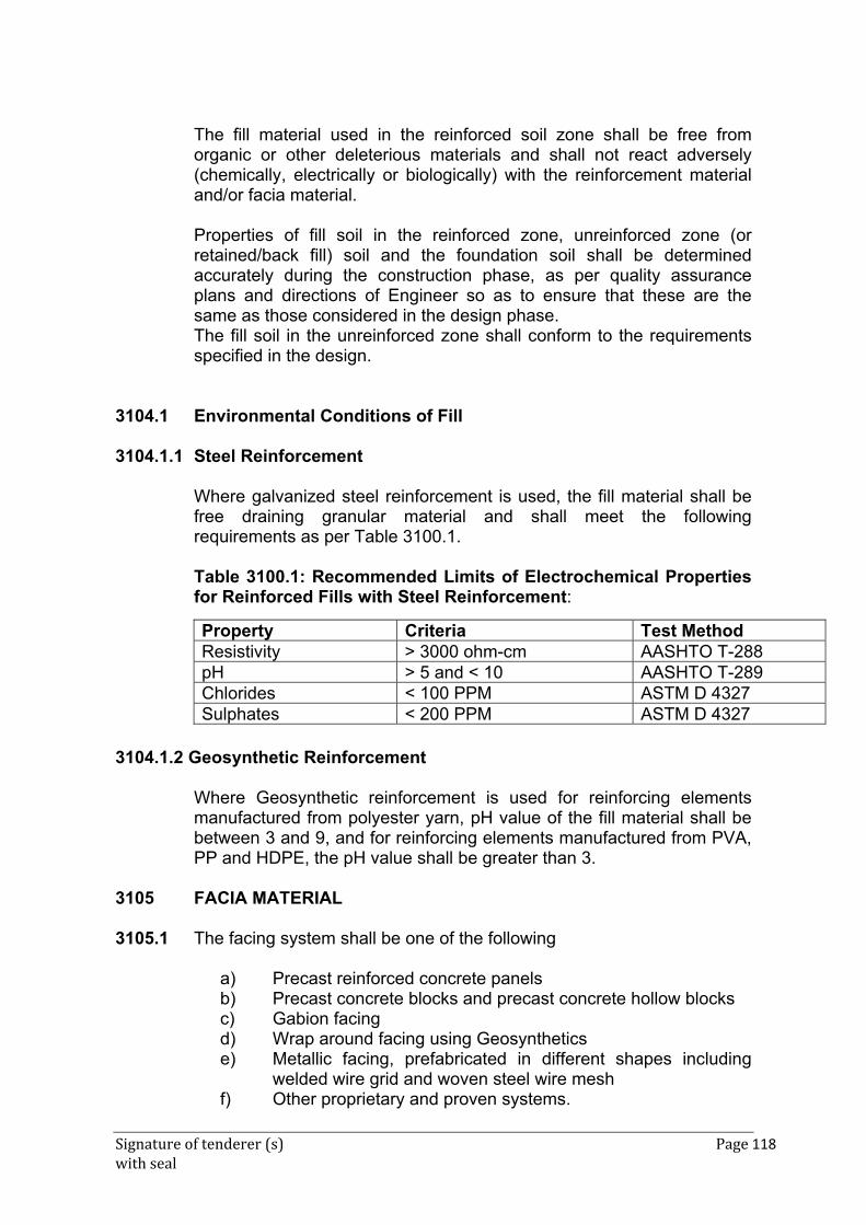
Signature of tenderer (s) Page 118 with seal
The fill material used in the reinforced soil zone shall be free from organic or other deleterious materials and shall not react adversely (chemically, electrically or biologically) with the reinforcement material and/or facia material.
Properties of fill soil in the reinforced zone, unreinforced zone (or retained/back fill) soil and the foundation soil shall be determined accurately during the construction phase, as per quality assurance plans and directions of Engineer so as to ensure that these are the same as those considered in the design phase. The fill soil in the unreinforced zone shall conform to the requirements specified in the design.
3104.1 Environmental Conditions of Fill 3104.1.1 Steel Reinforcement
Where galvanized steel reinforcement is used, the fill material shall be free draining granular material and shall meet the following requirements as per Table 3100.1.
Table 3100.1: Recommended Limits of Electrochemical Properties for Reinforced Fills with Steel Reinforcement:
3104.1.2 Geosynthetic Reinforcement
Where Geosynthetic reinforcement is used for reinforcing elements manufactured from polyester yarn, pH value of the fill material shall be between 3 and 9, and for reinforcing elements manufactured from PVA, PP and HDPE, the pH value shall be greater than 3.
3105 FACIA MATERIAL 3105.1 The facing system shall be one of the following
a) Precast reinforced concrete panels b) Precast concrete blocks and precast concrete hollow blocks c) Gabion facing d) Wrap around facing using Geosynthetics e) Metallic facing, prefabricated in different shapes including
welded wire grid and woven steel wire mesh f) Other proprietary and proven systems.
Property Criteria Test Method Resistivity > 3000 ohm-cm AASHTO T-288 pH > 5 and < 10 AASHTO T-289 Chlorides < 100 PPM ASTM D 4327 Sulphates < 200 PPM ASTM D 4327
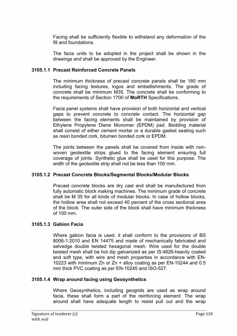
Signature of tenderer (s) Page 119 with seal
Facing shall be sufficiently flexible to withstand any deformation of the fill and foundations.
The facia units to be adopted in the project shall be shown in the
drawings and shall be approved by the Engineer. 3105.1.1 Precast Reinforced Concrete Panels
The minimum thickness of precast concrete panels shall be 180 mm including facing textures, logos and embellishments. The grade of concrete shall be minimum M35. The concrete shall be conforming to the requirements of Section 1700 of MoRTH Specifications.
Facia panel systems shall have provision of both horizontal and vertical gaps to prevent concrete to concrete contact. The horizontal gap between the facing elements shall be maintained by provision of Ethylene Propylene Diene Monomer (EPDM) pad. Bedding material shall consist of either cement mortar or a durable gasket seating such as resin bonded cork, bitumen bonded cork or EPDM.
The joints between the panels shall be covered from inside with non-woven geotextile strips glued to the facing element ensuring full coverage of joints. Synthetic glue shall be used for this purpose. The width of the geotextile strip shall not be less than 100 mm.
3105.1.2 Precast Concrete Blocks/Segmental Blocks/Modular Blocks
Precast concrete blocks are dry cast and shall be manufactured from fully automatic block making machines. The minimum grade of concrete shall be M 35 for all kinds of modular blocks. In case of hollow blocks, the hollow area shall not exceed 40 percent of the cross sectional area of the block. The outer side of the block shall have minimum thickness of 100 mm.
3105.1.3 Gabion Facia
Where gabion facia is used, it shall conform to the provisions of BS 8006-1:2010 and EN 14475 and made of mechanically fabricated and selvedge double twisted hexagonal mesh. Wire used for the double twisted mesh shall be hot dip galvanized as per IS:4826-heavily coated and soft type, with wire and mesh properties in accordance with EN-10223 with minimum Zn or Zn + alloy coating as per EN-10244 and 0.5 mm thick PVC coating as per EN-10245 and ISO-527.
3105.1.4 Wrap around facing using Geosynthetics
Where Geosynthetics, including geogrids are used as wrap around facia, these shall form a part of the reinforcing element. The wrap around shall have adequate length to resist pull out and the wrap
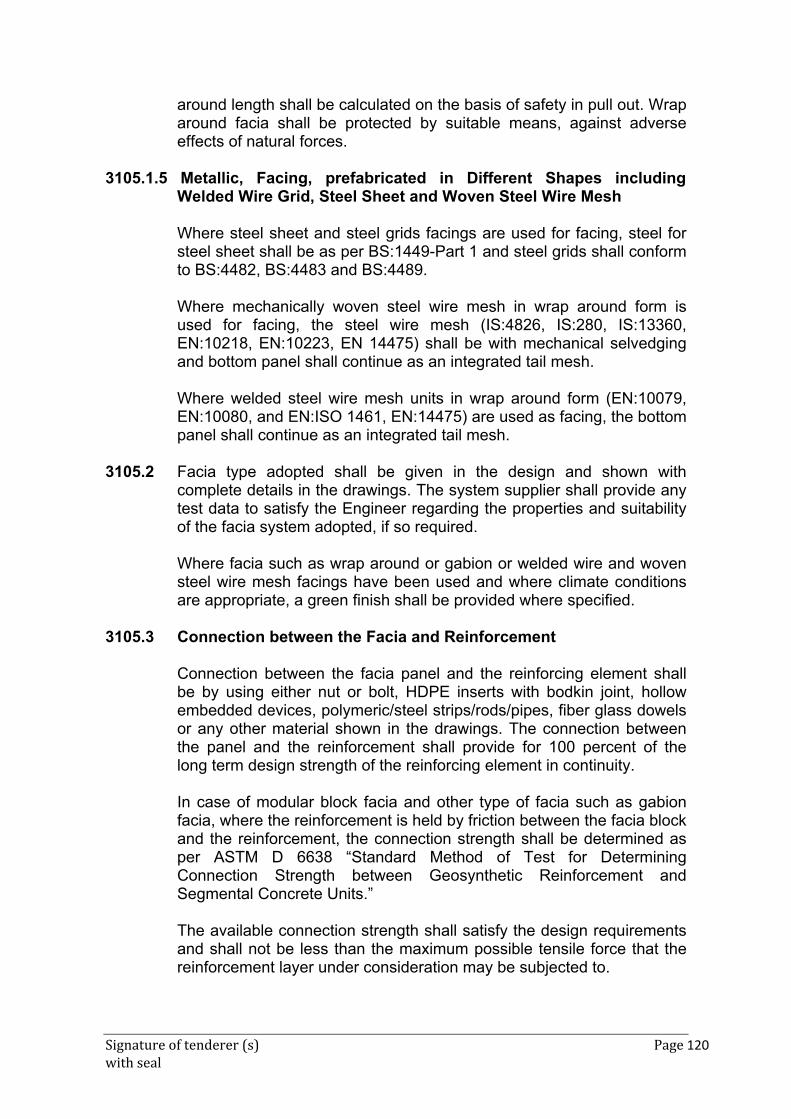
Signature of tenderer (s) Page 120 with seal
around length shall be calculated on the basis of safety in pull out. Wrap around facia shall be protected by suitable means, against adverse effects of natural forces.
3105.1.5 Metallic, Facing, prefabricated in Different Shapes including
Welded Wire Grid, Steel Sheet and Woven Steel Wire Mesh
Where steel sheet and steel grids facings are used for facing, steel for steel sheet shall be as per BS:1449-Part 1 and steel grids shall conform to BS:4482, BS:4483 and BS:4489.
Where mechanically woven steel wire mesh in wrap around form is used for facing, the steel wire mesh (IS:4826, IS:280, IS:13360, EN:10218, EN:10223, EN 14475) shall be with mechanical selvedging and bottom panel shall continue as an integrated tail mesh.
Where welded steel wire mesh units in wrap around form (EN:10079, EN:10080, and EN:ISO 1461, EN:14475) are used as facing, the bottom panel shall continue as an integrated tail mesh.
3105.2 Facia type adopted shall be given in the design and shown with
complete details in the drawings. The system supplier shall provide any test data to satisfy the Engineer regarding the properties and suitability of the facia system adopted, if so required.
Where facia such as wrap around or gabion or welded wire and woven steel wire mesh facings have been used and where climate conditions are appropriate, a green finish shall be provided where specified.
3105.3 Connection between the Facia and Reinforcement
Connection between the facia panel and the reinforcing element shall be by using either nut or bolt, HDPE inserts with bodkin joint, hollow embedded devices, polymeric/steel strips/rods/pipes, fiber glass dowels or any other material shown in the drawings. The connection between the panel and the reinforcement shall provide for 100 percent of the long term design strength of the reinforcing element in continuity.
In case of modular block facia and other type of facia such as gabion facia, where the reinforcement is held by friction between the facia block and the reinforcement, the connection strength shall be determined as per ASTM D 6638 “Standard Method of Test for Determining Connection Strength between Geosynthetic Reinforcement and Segmental Concrete Units.”
The available connection strength shall satisfy the design requirements and shall not be less than the maximum possible tensile force that the reinforcement layer under consideration may be subjected to.
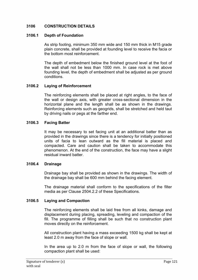
Signature of tenderer (s) Page 121 with seal
3106 CONSTRUCTION DETAILS 3106.1 Depth of Foundation
As strip footing, minimum 350 mm wide and 150 mm thick in M15 grade plain concrete, shall be provided at founding level to receive the facia or the bottom most reinforcement.
The depth of embedment below the finished ground level at the foot of the wall shall not be less than 1000 mm. In case rock is met above founding level, the depth of embedment shall be adjusted as per ground conditions.
3106.2 Laying of Reinforcement
The reinforcing elements shall be placed at right angles, to the face of the wall or design axis, with greater cross-sectional dimension in the horizontal plane and the length shall be as shown in the drawings. Reinforcing elements such as geogrids, shall be stretched and held taut by driving nails or pegs at the farther end.
3106.3 Facing Batter
It may be necessary to set facing unit at an additional batter than as provided in the drawings since there is a tendency for initially positioned units of facia to lean outward as the fill material is placed and compacted. Care and caution shall be taken to accommodate this phenomenon. At the end of the construction, the face may have a slight residual inward batter.
3106.4 Drainage
Drainage bay shall be provided as shown in the drawings. The width of the drainage bay shall be 600 mm behind the facing element.
The drainage material shall conform to the specifications of the filter media as per Clause 2504.2.2 of these Specifications.
3106.5 Laying and Compaction
The reinforcing elements shall be laid free from all kinks, damage and displacement during placing, spreading, leveling and compaction of the fill. The programme of filling shall be such that no construction plant moves directly on the reinforcement.
All construction plant having a mass exceeding 1500 kg shall be kept at least 2.0 m away from the face of slope or wall.
In the area up to 2.0 m from the face of slope or wall, the following compaction plant shall be used:
Signature of tenderer (s) Page 122 with seal
i) Vibratory roller having a weight per metre width not exceeding
1300 kg with total weight not exceeding 1500 kg ii) Vibratory plate compactor of maximum weight 1000 kg iii) Vibro tamper having a weight not exceeding 75 kg
Before allowing the movement of vehicles over the reinforcement, a minimum compacted thickness of 150 mm shall be provided over the reinforcement and the speed of the vehicles shall be restricted to 10 km/hr.
During construction of reinforced fill, the retained material beyond the reinforcement at the rear of the structure shall be maintained at the same level as reinforced fill.
Fill shall not be placed on surface that contains mud, organic soil area that have not met compaction requirement.
The thickness of compacted layer shall not be more than 200mm, compacted to 97percent of maximum laboratory density measured as per IS:2720 (Part18)
3106.6 Construction and serviceability tolerance
The construction tolerances shall be as per the following. Casting of pre-cast RCC panels: All elements shall be manufactured within the following tolerances:
- All dimension within+5mm
- Evenness of the front face +5mm over 1500 mm - Difference between lengths of two diagonals: 5 mm max - Thickness: 5 MM (-)0mm
Table 3100.2: tolerances for faces of Retaining Wall and Abutments Tolerance
Location of plane of structure ± 50mm- metallic reinforcement
± 75mm- synthetic reinforcement Bulging (Vertical) and Bowing
(Horizontal) ± 20mm in 4.5 m template (Metallic) ± 30mm in 4.5 m template (Synthetic)
Step at joints ± 10mm
Dimensional tolerances for Modular blocks
Dimensions of modular concrete blocks shall not differ more than ± 2.5 mm for length and width and ± 1.5 mm in height.
Signature of tenderer (s) Page 123 with seal
Minimum Vertical Movement Capacities of Facing Systems Minimum vertical movement capacities required for facing system to cope with vertical internal settlement of reinforced fill shall be as below.
Table 3100.3: Minimum Vertical Movement Capacities of Facing Systems
Structure Form Minimum Vertical Movement capacity of
System Discrete panels Joint closure of 1 in 150 relative to panel height Full height panels Vertical movements capacity of connections 1 in
150 relative to panel height Semi- Elliptical facing Vertical distortion of 1 in 150 relative to panel
height Geotextile/ Geogrid wrap around facing
No specific limit except for appearance or serviceability
3106.7 Capping Beam Crash Barrier and friction Slab
Capping beam crash barrier and friction slab shall be provided as per the design and drawing.
3107 REINFORCING SOIL SLOPES
This section deals with construction of reinforced soil structures that have a slope face angle flatter than 70°.
3107.1 Reinforcing Elements
Any type of material used as reinforcing element for the construction of a reinforced soil slope shall meet all the requirements provided in the clause 3103. Any Geosynthetic material used as reinforced clement of the construction of a reinforced soil slope shall meet all the requirement in Clause 3103.7.
3107.2 Fill Material
The fill material used as the reinforcing fill in the reinforced soil slope shall meet all the requirements for fill material specified in Clause 3104. However, the friction angle of the fill material in this case shall not be less than 28°.
3107.3 Facia for reinforced soil Slope
Facia of reinforced soil slope shall be one of the following types
a) Wrap around facing using Geosynthetic b) Gabion facing
Signature of tenderer (s) Page 124 with seal
c) Metallic facing, prefabricated in different shapes including welded wire gird and woven steel wire mesh.
d) Precast reinforced concrete panels e) Precast concrete blocks and precast concrete hollow blocks.
The specification for the materials used for above facing types shall be as provided in Clause 3105.1
3107.3.1 Wrap Around Facia using Prefabricated Geosynthetic Bags
Where specified wrap around facia using prefabrication geosynthetic bags shall be used in the construction of reinforced soil slopes for slope angles less than 45 Such type of facia shall conform to the provision in EN:14475.
3107.4 Connection between the Facia and Reinforcement
Connection between facia and reinforcement in the reinforced soil slope shall satisfy the design requirements.
3107.5 Facia type adopted shall be given in the design and shown with complete details in the drawings. The system supplier shall provide any test data to satisfy the Engineer regarding the properties and suitability of the facia system adopted if so required by the Engineer.
Where facia such as wrap around or gabion or welded wire and woven steel wire mesh facings have been used and where climate conditions are approved a green finish shall be provided where specified.
3107.6 Laying and compaction
Laying of the reinforcement in the reinforced soil slope and the compaction of the fill shall conform to the provisions of Clause 3106.5
3108 SYSTEM RESPOSIBILITY, PERFORMANCE BND 3108.1 System responsibility
If specified in the control, the system supplier shall provide performance bond in conformance with the contract requirements. The performance bond shall be valid for at least 20 years.
3109 MEASUREMETN FOR PAYMENT 3109.1 Reinforced soil Wall
The measurement for payment for reinforced soil wall shall be in square metres of finished work of each face and shall be measured in the plane of final inclination specified in the drawings. The measurement of length shall be the finished work along the length of the road. The
Signature of tenderer (s) Page 125 with seal
measurement of height along the slope shall be done from the top level of the footing on which the facia element is placed to the top capping beam. Measurement for friction slab and crash barrier shall be in liner meters.
3109.2 Reinforced Soil slope
The measurement for payment for reinforced soil slope shall be in square meters of finished work of each face and shall be measured in the plane of final inclination specified in the drawings. The measurement of length shall be the finished work along the length of the road. The measurement of height along the slope shall be done from the top of the leveling pad, where provided, to the top of the embankment. Where leveling pad is not provided, the bottom of the slope face.
3110 RATES
The rate shall include cost of material, labour, plant, royalties, handling storage and transportation expenses, cost of bed block, leveling pad, facia elements, capping beam, connectors, reinforcing elements, scaffolding, supply of the specified filter media material, supply of soil fill for the reinforced as well as unreinforced zone of the quality specified in the contract, placing spreading and compaction through mechanical means.
The rate shall include full compensation for design, drawing and testing of materials. The rate shall include the cost of investigations. Design and construction of ground improvement measures.
The payment for friction slab and crash barrier shall be made separately.
ANNEXURE TO SECTION 3100
A1 DESIGN AND DRAWINGS A1-1.1 Where the contract provides for the design of reinforced soil structures,
the same shall be carried out in accordance with the following standards as applicable
1.1.1 BS:8006-1-2010 “Code of Practice for
Strengthened/Reinforced Soils and other Fills” 1.1.2 AFNOR NF-P94-274- “Geotechnical Design – Retaining
Structures-Reinforced and Soil Nailing Structures”.
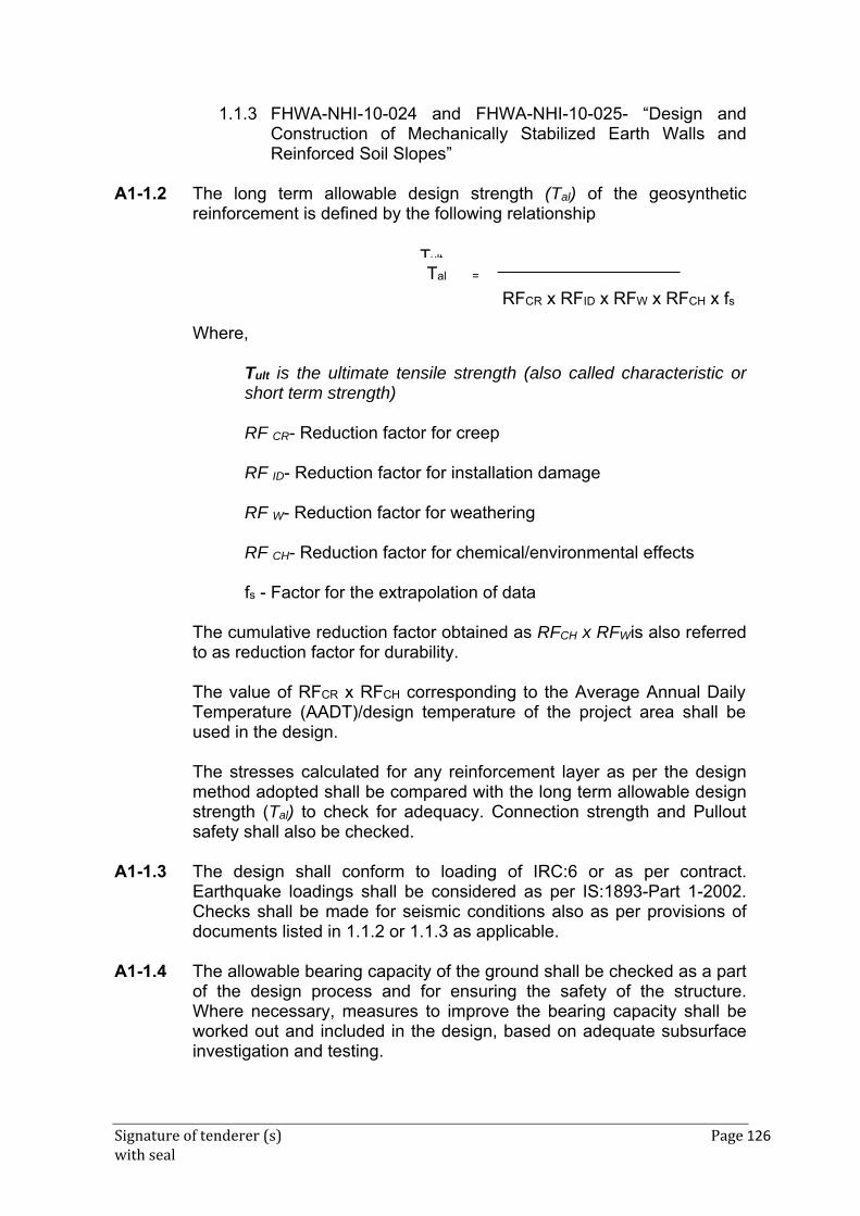
Signature of tenderer (s) Page 126 with seal
1.1.3 FHWA-NHI-10-024 and FHWA-NHI-10-025- “Design and Construction of Mechanically Stabilized Earth Walls and Reinforced Soil Slopes”
A1-1.2 The long term allowable design strength (Tal) of the geosynthetic
reinforcement is defined by the following relationship
Where,
Tult is the ultimate tensile strength (also called characteristic or short term strength)
RF CR- Reduction factor for creep
RF ID- Reduction factor for installation damage
RF W- Reduction factor for weathering
RF CH- Reduction factor for chemical/environmental effects
fs - Factor for the extrapolation of data
The cumulative reduction factor obtained as RFCH x RFWis also referred to as reduction factor for durability. The value of RFCR x RFCH corresponding to the Average Annual Daily Temperature (AADT)/design temperature of the project area shall be used in the design. The stresses calculated for any reinforcement layer as per the design method adopted shall be compared with the long term allowable design strength (Tal) to check for adequacy. Connection strength and Pullout safety shall also be checked.
A1-1.3 The design shall conform to loading of IRC:6 or as per contract. Earthquake loadings shall be considered as per IS:1893-Part 1-2002. Checks shall be made for seismic conditions also as per provisions of documents listed in 1.1.2 or 1.1.3 as applicable.
A1-1.4 The allowable bearing capacity of the ground shall be checked as a part
of the design process and for ensuring the safety of the structure. Where necessary, measures to improve the bearing capacity shall be worked out and included in the design, based on adequate subsurface investigation and testing.
Tult
RFCR x RFID x RFW x RFCH x fs
Tal =
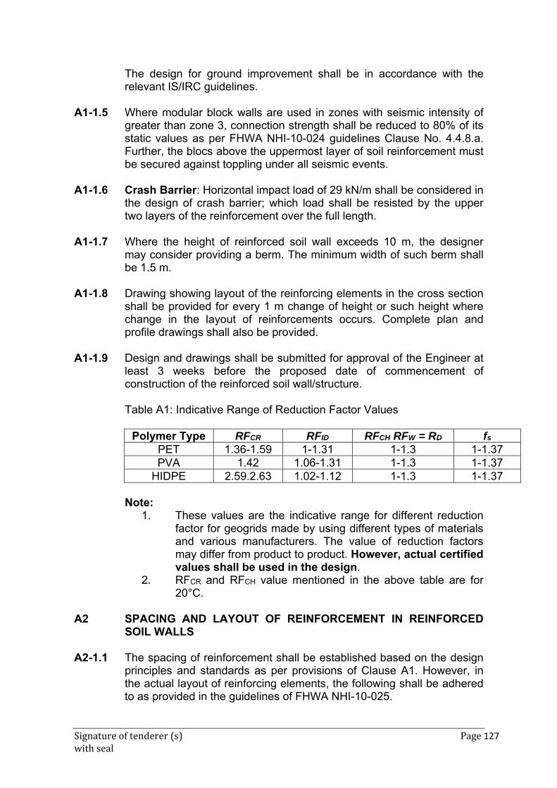
Signature of tenderer (s) Page 127 with seal
The design for ground improvement shall be in accordance with the relevant IS/IRC guidelines.
A1-1.5 Where modular block walls are used in zones with seismic intensity of greater than zone 3, connection strength shall be reduced to 80% of its static values as per FHWA NHI-10-024 guidelines Clause No. 4.4.8.a. Further, the blocs above the uppermost layer of soil reinforcement must be secured against toppling under all seismic events.
A1-1.6 Crash Barrier: Horizontal impact load of 29 kN/m shall be considered in
the design of crash barrier; which load shall be resisted by the upper two layers of the reinforcement over the full length.
A1-1.7 Where the height of reinforced soil wall exceeds 10 m, the designer
may consider providing a berm. The minimum width of such berm shall be 1.5 m.
A1-1.8 Drawing showing layout of the reinforcing elements in the cross section
shall be provided for every 1 m change of height or such height where change in the layout of reinforcements occurs. Complete plan and profile drawings shall also be provided.
A1-1.9 Design and drawings shall be submitted for approval of the Engineer at
least 3 weeks before the proposed date of commencement of construction of the reinforced soil wall/structure.
Table A1: Indicative Range of Reduction Factor Values
Polymer Type RFCR RFID RFCH RFW = RD fs
PET 1.36-1.59 1-1.31 1-1.3 1-1.37PVA 1.42 1.06-1.31 1-1.3 1-1.37
HIDPE 2.59.2.63 1.02-1.12 1-1.3 1-1.37
Note: 1. These values are the indicative range for different reduction
factor for geogrids made by using different types of materials and various manufacturers. The value of reduction factors may differ from product to product. However, actual certified values shall be used in the design.
2. RFCR and RFCH value mentioned in the above table are for 20°C.
A2 SPACING AND LAYOUT OF REINFORCEMENT IN REINFORCED
SOIL WALLS A2-1.1 The spacing of reinforcement shall be established based on the design
principles and standards as per provisions of Clause A1. However, in the actual layout of reinforcing elements, the following shall be adhered to as provided in the guidelines of FHWA NHI-10-025.
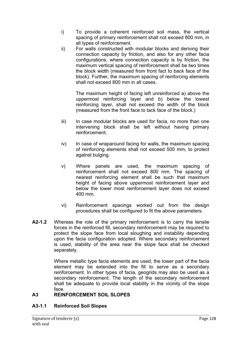
Signature of tenderer (s) Page 128 with seal
i) To provide a coherent reinforced soil mass, the vertical spacing of primary reinforcement shall not exceed 800 mm, in all types of reinforcement.
ii) For walls constructed with modular blocks and deriving their connection capacity by friction, and also for any other facia configurations, where connection capacity is by friction, the maximum vertical spacing of reinforcement shall be two times the block width (measured from front fact to back face of the block). Further, the maximum spacing of reinforcing elements shall not exceed 800 mm in all cases. The maximum height of facing left unreinforced a) above the uppermost reinforcing layer and b) below the lowest reinforcing layer, shall not exceed the width of the block (measured from the front face to tack face of the block.)
iii) In case modular blocks are used for facia, no more than one intervening block shall be left without having primary reinforcement.
iv) In case of wraparound facing for walls, the maximum spacing of reinforcing elements shall not exceed 500 mm, to protect against bulging.
v) Where panels are used, the maximum spacing of reinforcement shall not exceed 800 mm. The spacing of nearest reinforcing element shall be such that maximum height of facing above uppermost reinforcement layer and below the lower most reinforcement layer does not exceed 400 mm.
vi) Reinforcement spacings worked out from the design
procedures shall be configured to fit the above parameters.
A2-1.2 Whereas the role of the primary reinforcement is to carry the tensile forces in the reinforced fill, secondary reinforcement may be required to protect the slope face from local sloughing and instability depending upon the facia configuration adopted. Where secondary reinforcement is used, stability of the area near the slope face shall be checked separately.
Where metallic type facia elements are used, the lower part of the facia element may be extended into the fill to serve as a secondary reinforcement. In other types of facia, geogrids may also be used as a secondary reinforcement. The length of the secondary reinforcement shall be adequate to provide local stability in the vicinity of the slope face.
A3 REINFORCEMENT SOIL SLOPES A3-1.1 Reinforced Soil Slopes
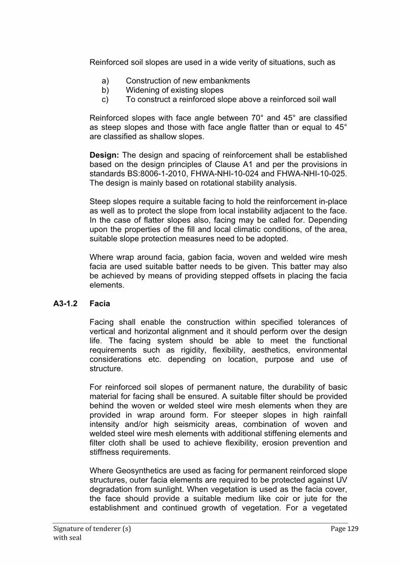
Signature of tenderer (s) Page 129 with seal
Reinforced soil slopes are used in a wide verity of situations, such as
a) Construction of new embankments b) Widening of existing slopes c) To construct a reinforced slope above a reinforced soil wall
Reinforced slopes with face angle between 70° and 45° are classified as steep slopes and those with face angle flatter than or equal to 45° are classified as shallow slopes. Design: The design and spacing of reinforcement shall be established based on the design principles of Clause A1 and per the provisions in standards BS:8006-1-2010, FHWA-NHI-10-024 and FHWA-NHI-10-025. The design is mainly based on rotational stability analysis. Steep slopes require a suitable facing to hold the reinforcement in-place as well as to protect the slope from local instability adjacent to the face. In the case of flatter slopes also, facing may be called for. Depending upon the properties of the fill and local climatic conditions, of the area, suitable slope protection measures need to be adopted. Where wrap around facia, gabion facia, woven and welded wire mesh facia are used suitable batter needs to be given. This batter may also be achieved by means of providing stepped offsets in placing the facia elements.
A3-1.2 Facia
Facing shall enable the construction within specified tolerances of vertical and horizontal alignment and it should perform over the design life. The facing system should be able to meet the functional requirements such as rigidity, flexibility, aesthetics, environmental considerations etc. depending on location, purpose and use of structure. For reinforced soil slopes of permanent nature, the durability of basic material for facing shall be ensured. A suitable filter should be provided behind the woven or welded steel wire mesh elements when they are provided in wrap around form. For steeper slopes in high rainfall intensity and/or high seismicity areas, combination of woven and welded steel wire mesh elements with additional stiffening elements and filter cloth shall be used to achieve flexibility, erosion prevention and stiffness requirements. Where Geosynthetics are used as facing for permanent reinforced slope structures, outer facia elements are required to be protected against UV degradation from sunlight. When vegetation is used as the facia cover, the face should provide a suitable medium like coir or jute for the establishment and continued growth of vegetation. For a vegetated
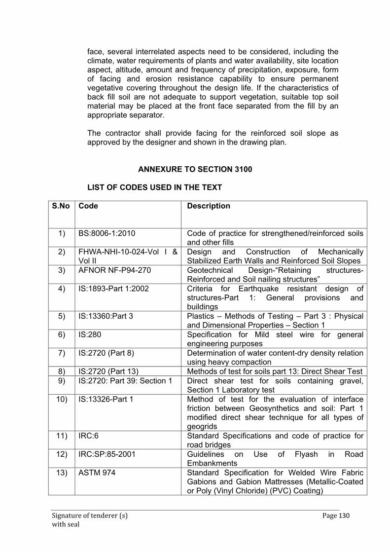
Signature of tenderer (s) Page 130 with seal
face, several interrelated aspects need to be considered, including the climate, water requirements of plants and water availability, site location aspect, altitude, amount and frequency of precipitation, exposure, form of facing and erosion resistance capability to ensure permanent vegetative covering throughout the design life. If the characteristics of back fill soil are not adequate to support vegetation, suitable top soil material may be placed at the front face separated from the fill by an appropriate separator. The contractor shall provide facing for the reinforced soil slope as approved by the designer and shown in the drawing plan.
ANNEXURE TO SECTION 3100 LIST OF CODES USED IN THE TEXT
S.No Code Description
1) BS:8006-1:2010 Code of practice for strengthened/reinforced soils and other fills
2) FHWA-NHI-10-024-Vol I & Vol II
Design and Construction of Mechanically Stabilized Earth Walls and Reinforced Soil Slopes
3) AFNOR NF-P94-270 Geotechnical Design-“Retaining structures-Reinforced and Soil nailing structures”
4) IS:1893-Part 1:2002 Criteria for Earthquake resistant design of structures-Part 1: General provisions and buildings
5) IS:13360:Part 3 Plastics – Methods of Testing – Part 3 : Physical and Dimensional Properties – Section 1
6) IS:280 Specification for Mild steel wire for general engineering purposes
7) IS:2720 (Part 8) Determination of water content-dry density relation using heavy compaction
8) IS:2720 (Part 13) Methods of test for soils part 13: Direct Shear Test 9) IS:2720: Part 39: Section 1 Direct shear test for soils containing gravel,
Section 1 Laboratory test 10) IS:13326-Part 1 Method of test for the evaluation of interface
friction between Geosynthetics and soil: Part 1 modified direct shear technique for all types of geogrids
11) IRC:6 Standard Specifications and code of practice for road bridges
12) IRC:SP:85-2001 Guidelines on Use of Flyash in Road Embankments
13) ASTM 974 Standard Specification for Welded Wire Fabric Gabions and Gabion Mattresses (Metallic-Coated or Poly (Vinyl Chloride) (PVC) Coating)
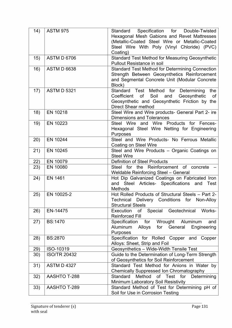
Signature of tenderer (s) Page 131 with seal
14) ASTM 975 Standard Specification for Double-Twisted Hexagonal Mesh Gabions and Revet Mattresses (Metallic-Coated Steel Wire or Metallic-Coated Steel Wire With Poly (Vinyl Chloride) (PVC) Coating)
15) ASTM D 6706 Standard Test Method for Measuring Geosynthetic Pullout Resistance in soil
16) ASTM D 6638 Standard Test Method for Determining Connection Strength Between Geosynthetics Reinforcement and Segmental Concrete Unit (Modular Concrete Block)
17) ASTM D 5321 Standard Test Method for Determining the Coefficient of Soil and Geosynthetic of Geosynthetic and Geosynthetic Friction by the Direct Shear method
18) EN 10218 Steel Wire and Wire products- General Part 2- ire Dimensions and Tolerances
19) EN 10223 Steel Wire and Wire Products for Fences-Hexagonal Steel Wire Netting for Engineering Purposes
20) EN 10244 Steel and Wire Products- No Ferrous Metallic Coating on Steel Wire
21) EN 10245 Steel and Wire Products – Organic Coatings on Steel Wire
22) EN 10079 Definition of Steel Products 23) EN 10080 Steel for the Reinforcement of concrete –
Weldable Reinforcing Steel – General 24) EN 1461 Hot Dip Galvanized Coatings on Fabricated Iron
and Steel Articles- Specifications and Test Methods
25) EN 10025-2 Hot Rolled Products of Structural Steels – Part 2-Technical Delivery Conditions for Non-Alloy Structural Steels
26) EN-14475 Execution of Special Geotechnical Works-Reinforced Fill
27) BS:1470 Specification for Wrought Aluminum and Aluminum Alloys for General Engineering Purposes
28) BS:2870 Specification for Rolled Copper and Copper Alloys: Sheet, Strip and Foil
29) ISO-10319 Geosynthetics – Wide-Width Tensile Test 30) ISO/TR 20432 Guide to the Determination of Long-Term Strength
of Geosynthetics for Soil Reinforcement 31) ASTM D 4327 Standard Test Method for Anions in Water by
Chemically Suppressed Ion Chromatography 32) AASHTO T-288 Standard Method of Test for Determining
Minimum Laboratory Soil Resistivity 33) AASHTO T-289 Standard Method of Test for Determining pH of
Soil for Use in Corrosion Testing
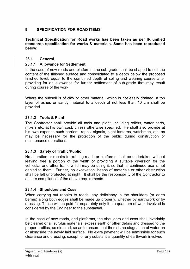
Signature of tenderer (s) Page 132 with seal
9 SPECIFICATION FOR ROAD ITEMS
Technical Specification for Road works has been taken as per IR unified standards specification for works & materials. Same has been reproduced below:
23.1 General
23.1.1 Allowance for Settlement
In the case of new roads and platforms, the sub-grade shall be shaped to suit the content of the finished surface and consolidated to a depth below the proposed finished level, equal to the combined depth of soling and wearing course after providing for an allowance for further settlement of sub-grade that may result during course of the work.
Where the subsoil is of clay or other material, which is not easily drained, a top layer of ashes or sandy material to a depth of not less than 10 cm shall be provided.
23.1.2 Tools & Plant
The Contractor shall provide all tools and plant, including rollers, water carts, mixers etc. at his own cost, unless otherwise specified. He shall also provide at his own expense such barriers, ropes, signals, night lanterns, watchmen, etc. as may be necessary for the protection of the public during construction or maintenance operations.
23.1.3 Safety of Traffic/Public
No alteration or repairs to existing roads or platforms shall be undertaken without leaving free a portion of the width or providing a suitable diversion for the vehicular and other traffic which may be using it, so that its continued use is not denied to them. Further, no excavation, heaps of materials or other obstruction shall be left unprotected at night. It shall be the responsibility of the Contractor to ensure compliance of the above requirements.
23.1.4 Shoulders and Cess
When carrying out repairs to roads, any deficiency in the shoulders (or earth berms) along both edges shall be made up properly, whether by earthwork or by dressing. These will be paid for separately only if the quantum of work involved is considered by the Engineer to the substantial.
In the case of new roads, and platforms, the shoulders and cess shall invariably be cleared of all surplus materials, excess earth or other debris and dressed to the proper profiles, as directed, so as to ensure that there is no stagnation of water on or alongside the newly laid surface. No extra payment will be admissible for such clearance and dressing, except for any substantial quantity of earthwork involved.
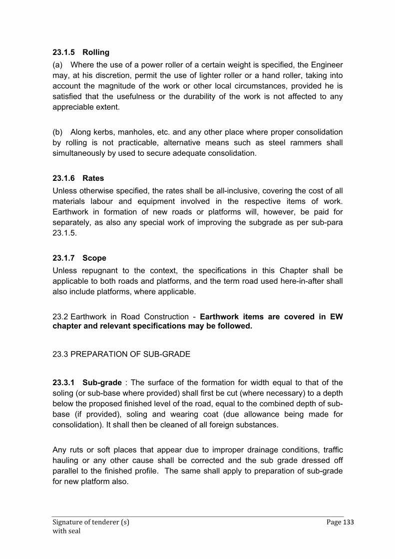
Signature of tenderer (s) Page 133 with seal
23.1.5 Rolling
(a) Where the use of a power roller of a certain weight is specified, the Engineer may, at his discretion, permit the use of lighter roller or a hand roller, taking into account the magnitude of the work or other local circumstances, provided he is satisfied that the usefulness or the durability of the work is not affected to any appreciable extent.
(b) Along kerbs, manholes, etc. and any other place where proper consolidation by rolling is not practicable, alternative means such as steel rammers shall simultaneously by used to secure adequate consolidation.
23.1.6 Rates
Unless otherwise specified, the rates shall be all-inclusive, covering the cost of all materials labour and equipment involved in the respective items of work. Earthwork in formation of new roads or platforms will, however, be paid for separately, as also any special work of improving the subgrade as per sub-para 23.1.5.
23.1.7 Scope
Unless repugnant to the context, the specifications in this Chapter shall be applicable to both roads and platforms, and the term road used here-in-after shall also include platforms, where applicable.
23.2 Earthwork in Road Construction - Earthwork items are covered in EW chapter and relevant specifications may be followed.
23.3 PREPARATION OF SUB-GRADE
23.3.1 Sub-grade : The surface of the formation for width equal to that of the soling (or sub-base where provided) shall first be cut (where necessary) to a depth below the proposed finished level of the road, equal to the combined depth of sub-base (if provided), soling and wearing coat (due allowance being made for consolidation). It shall then be cleaned of all foreign substances.
Any ruts or soft places that appear due to improper drainage conditions, traffic hauling or any other cause shall be corrected and the sub grade dressed off parallel to the finished profile. The same shall apply to preparation of sub-grade for new platform also.
Signature of tenderer (s) Page 134 with seal
23.3.2 Consolidation : The sub-grade shall then be consolidated with a road roller. Water shall be applied uniformly to the sub-grade one evening prior to rolling. Any low spots that develop in the sub-grade during rolling shall be brought to grade with the excavated approach earth and re-rolled. Rolling shall be done with a light road roller or sheep foot roller or any vibratory roller as approved by the Engineer. All soft and unsuitable materials and surplus earth shall be removed as directed by the Engineer and the area where it is disposed off shall be dressed, for which nothing extra shall be paid.
23.4 SUB-BASE
23.4.1 Type and Thickness : Where the sub-grade made up of natural soil has poor bearing capacity (less than11.0 tonnes per sqm), a sub-base consisting of dense granular material shall be provided. This may be of moorum, bajri, shingle, or other easily drainable material. The thickness of the sub-base, where ordered to be used by the Engineer, shall not be less than 15 cm. The sub-base shall preferably be provided over the full formation width and in any case for a width of 60 cm more than the width of the base course. In case of platforms it may be 30 cm more than the width to be paved or surfaced.
23.4.2 Sub-Base or Poor Subgrade : When the sub-grade or formation consists of black cotton soil or other soil subject to capillary action of water, a sub-base of moorum or coarse sand shall be provided below the base course consisting of stone or boulder soling. It will be watered and rolled lightly. It will be for a thickness of 150 mm (minimum), unless otherwise specified.
23.5 SOLING
23.5.1 General :
In the conventional system of road making, soling shall always be provided except where the road is founded on a very hard natural soil such as hard moorum, well compacted gravel, laterite, hard kankar soil, hard conglomerate or rock. Soling may consist of graded stone ballast or hard stony moorum, or hard laterite, or kankar or well burnt bricks or brick jhama or similar material, as ordered by the Engineer.
23.5.2 Width : The width of soling course shall be 30 cm (i.e.15 cm on either side) more than that of the wearing coat, unless otherwise ordered by the Engineer.
Signature of tenderer (s) Page 135 with seal
23.5.3 Thickness:-The thickness of soling shall be as laid down by the Engineer depending upon the material used and sub-grade.
23.5.4 Sizes : The size of the soling materials shall be in the range of thickness in below for various types of materials.
(a) Bricks : Over burnt and jhama bricks.
(b) Stone ballast, Kankar : This may by of the same gauge as for wearing coat (WBM), or if economical and convenient, of slightly bigger size preferably. Brickbats of approved quality and dimensions can be used for soling for minor roads and for patch repairs.
23.5.5 Laying and Consolidation
23.5.5.1 The sub grade prepared as per specification shall be approved by the Engineer before soling work is commenced.
23.5.5.2 If Kankar is used, the laying and consolidation shall be done as specified for kankar roads.
23.5.5.3 If brick bats or stone ballast is used, laying and consolidation shall be done in the same manner as specified for the wearing coat.
23.5.5.4 In case of bricks, the same shall be laid on edge or flat as specified by the Engineer and hand packed in such a manner that no interstices are generally left. The interstices may profitably be filled with locally available sand, not earth.
23.5.5.5 Cushion : 25 mm thick layer of moorum (or small kankar or laterite) shall be laid on top of the soling except incase of laterite, kankar or hard moorum soling. This shall be watered and rolled lightly before the wearing coat is laid. For brick soling, the cushioning layer shall be rolled by hand roller.
23.6 WATER BOUND MACADAM
23.6.1 Scope
23.6.1.1 This work shall consist of clean, crushed aggregates mechanically interlocked by rolling and bonding together with screening, binding material where necessary and water laid on a properly prepared sub grade/sub-base/base or existing pavement, as the case may be and finished in accordance with the

Signature of tenderer (s) Page 136 with seal
requirements of these specifications and in close conformity with the lines, grades, cross-sections and thickness as per approved plans or as directed by the Engineer.
It is, however, not desirable to lay water bound macadam on an existing thin black topped surface without providing adequate drainage facility for water that would get accumulated at the interface of existing bituminous surface and water bound macadam.
23.6.1.2 General : The wearing surface either receives directly or through the finishing layer, the wheel loads and transmits them to the underlying layers. It must therefore :
(a) be sufficiently hard and tough to resist abrasion and the wearing action of traffic. (The smoothness of the surface also affects abrasion, hence the surface shall also be made as smooth as possible, if it is the wearing course);
(b) be composed of tough stones which will resist the disruptive action of traffic with a minimum of maintenance and repair work;
(c) be capable of transmitting loads to the base under all weather conditions without undue deformation or creeping occurring. At the same time it shall have sufficient flexibility to adjust itself to the sub-grade without rupture; be non-slippery for traffic under all weather conditions
23.6.2 Thickness : Unless otherwise specified, the thickness of the wearing coat, if laid for the first time over soling course shall be 11.5 cm consolidated. For renewals it shall vary from 7.5 cm to 11.5 cm or as specified or as directed by Engineer.
23.6.3 Camber : The camber shall be 1 in 48 or as directed by the Engineer or otherwise specified.
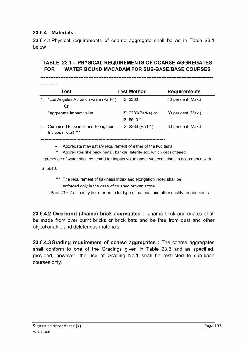
Signature of tenderer (s) Page 137 with seal
23.6.4 Materials :
23.6.4.1 Physical requirements of coarse aggregate shall be as in Table 23.1 below :
TABLE 23.1 - PHYSICAL REQUIREMENTS OF COARSE AGGREGATES FOR WATER BOUND MACADAM FOR SUB-BASE/BASE COURSES
-------------------------------------------------------------------------------------------------------------------
Test Test Method Requirements
1. *Los Angeles Abrasion value (Part-4) IS: 2386 40 per cent (Max.)
Or
*Aggregate Impact value IS: 2386(Part-4) or 30 per cent (Max.)
IS: 5640**
2. Combined Flakiness and Elongation IS: 2386 (Part-1) 30 per cent (Max.)
Indices (Total) ***
------------------------------------------------------------------------------------------
Aggregate may satisfy requirement of either of the two tests.
** Aggregates like brick metal, kankar, laterite etc. which get softened
in presence of water shall be tested for impact value under wet conditions in accordance with
IS: 5640.
*** The requirement of flakiness index and elongation index shall be
enforced only in the case of crushed broken stone
Para 23.6.7 also may be referred to for type of material and other quality requirements.
23.6.4.2 Overburnt (Jhama) brick aggregates : Jhama brick aggregates shall be made from over burnt bricks or brick bats and be free from dust and other objectionable and deleterious materials.
23.6.4.3 Grading requirement of coarse aggregates : The coarse aggregates shall conform to one of the Gradings given in Table 23.2 and as specified, provided, however, the use of Grading No.1 shall be restricted to sub-base courses only.
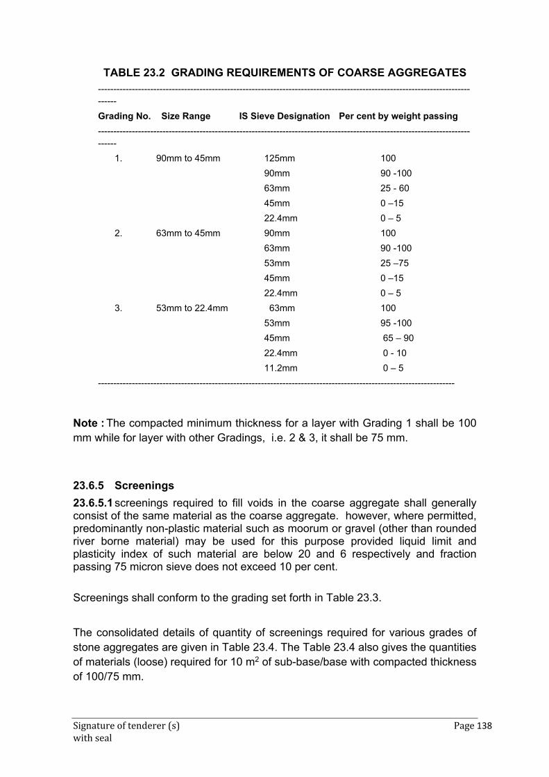
Signature of tenderer (s) Page 138 with seal
TABLE 23.2 GRADING REQUIREMENTS OF COARSE AGGREGATES
-------------------------------------------------------------------------------------------------------------------------------
Grading No. Size Range IS Sieve Designation Per cent by weight passing
-------------------------------------------------------------------------------------------------------------------------------
1. 90mm to 45mm 125mm 100
90mm 90 -100
63mm 25 - 60
45mm 0 –15
22.4mm 0 – 5
2. 63mm to 45mm 90mm 100
63mm 90 -100
53mm 25 –75
45mm 0 –15
22.4mm 0 – 5
3. 53mm to 22.4mm 63mm 100
53mm 95 -100
45mm 65 – 90
22.4mm 0 - 10
11.2mm 0 – 5
--------------------------------------------------------------------------------------------------------------------
Note : The compacted minimum thickness for a layer with Grading 1 shall be 100 mm while for layer with other Gradings, i.e. 2 & 3, it shall be 75 mm.
23.6.5 Screenings
23.6.5.1 screenings required to fill voids in the coarse aggregate shall generally consist of the same material as the coarse aggregate. however, where permitted, predominantly non-plastic material such as moorum or gravel (other than rounded river borne material) may be used for this purpose provided liquid limit and plasticity index of such material are below 20 and 6 respectively and fraction passing 75 micron sieve does not exceed 10 per cent.
Screenings shall conform to the grading set forth in Table 23.3.
The consolidated details of quantity of screenings required for various grades of stone aggregates are given in Table 23.4. The Table 23.4 also gives the quantities of materials (loose) required for 10 m2 of sub-base/base with compacted thickness of 100/75 mm.
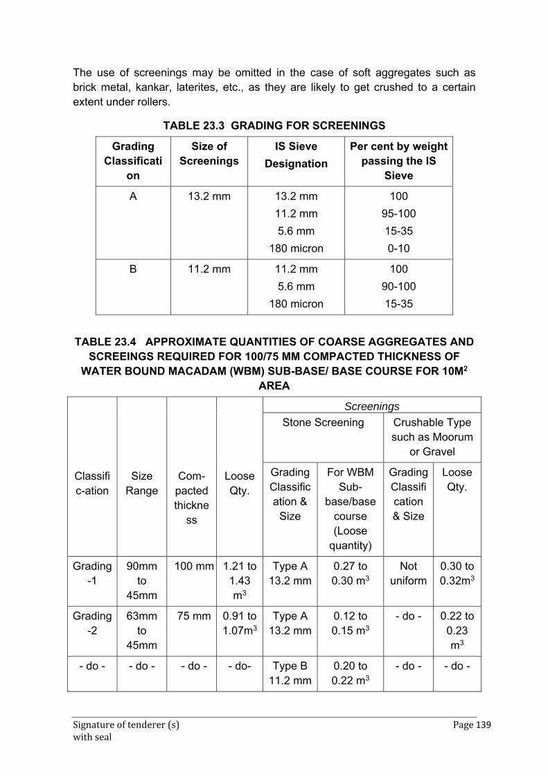
Signature of tenderer (s) Page 139 with seal
The use of screenings may be omitted in the case of soft aggregates such as brick metal, kankar, laterites, etc., as they are likely to get crushed to a certain extent under rollers.
TABLE 23.3 GRADING FOR SCREENINGS
Grading Classificati
on
Size of Screenings
IS Sieve
Designation
Per cent by weight passing the IS
Sieve
A
13.2 mm
13.2 mm
11.2 mm
5.6 mm
180 micron
100
95-100
15-35
0-10
B
11.2 mm 11.2 mm
5.6 mm
180 micron
100
90-100
15-35
test
TABLE 23.4 APPROXIMATE QUANTITIES OF COARSE AGGREGATES AND SCREEINGS REQUIRED FOR 100/75 MM COMPACTED THICKNESS OF
WATER BOUND MACADAM (WBM) SUB-BASE/ BASE COURSE FOR 10M2 AREA
Classific-ation
Size Range
Com-pacted thickne
ss
Loose Qty.
Screenings
Stone Screening Crushable Type such as Moorum
or Gravel
Grading Classification &
Size
For WBM Sub-
base/base course (Loose
quantity)
Grading Classification & Size
Loose Qty.
Grading-1
90mm to
45mm
100 mm 1.21 to 1.43 m3
Type A 13.2 mm
0.27 to 0.30 m3
Not uniform
0.30 to 0.32m3
Grading-2
63mm to
45mm
75 mm 0.91 to 1.07m3
Type A 13.2 mm
0.12 to 0.15 m3
- do - 0.22 to 0.23 m3
- do - - do - - do - - do- Type B 11.2 mm
0.20 to 0.22 m3
- do - - do -
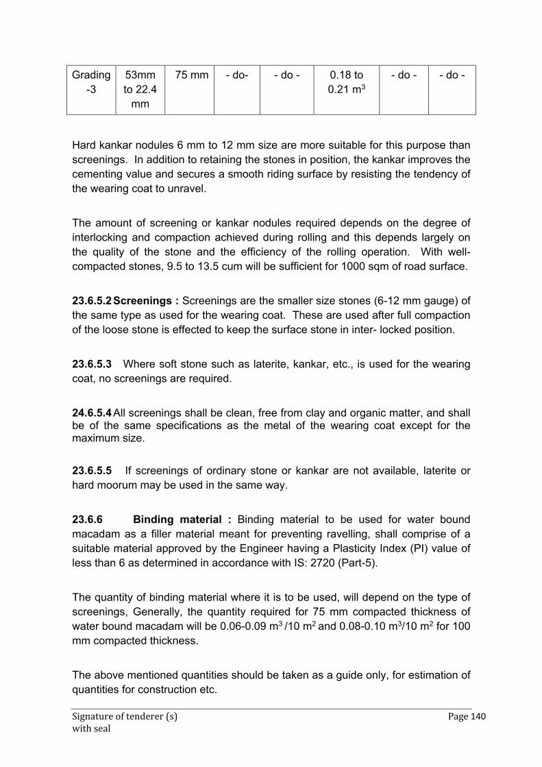
Signature of tenderer (s) Page 140 with seal
Grading-3
53mm to 22.4
mm
75 mm - do- - do - 0.18 to 0.21 m3
- do - - do -
Hard kankar nodules 6 mm to 12 mm size are more suitable for this purpose than screenings. In addition to retaining the stones in position, the kankar improves the cementing value and secures a smooth riding surface by resisting the tendency of the wearing coat to unravel.
The amount of screening or kankar nodules required depends on the degree of interlocking and compaction achieved during rolling and this depends largely on the quality of the stone and the efficiency of the rolling operation. With well-compacted stones, 9.5 to 13.5 cum will be sufficient for 1000 sqm of road surface.
23.6.5.2 Screenings : Screenings are the smaller size stones (6-12 mm gauge) of the same type as used for the wearing coat. These are used after full compaction of the loose stone is effected to keep the surface stone in inter- locked position.
23.6.5.3 Where soft stone such as laterite, kankar, etc., is used for the wearing coat, no screenings are required.
24.6.5.4 All screenings shall be clean, free from clay and organic matter, and shall be of the same specifications as the metal of the wearing coat except for the maximum size.
23.6.5.5 If screenings of ordinary stone or kankar are not available, laterite or hard moorum may be used in the same way.
23.6.6 Binding material : Binding material to be used for water bound macadam as a filler material meant for preventing ravelling, shall comprise of a suitable material approved by the Engineer having a Plasticity Index (PI) value of less than 6 as determined in accordance with IS: 2720 (Part-5).
The quantity of binding material where it is to be used, will depend on the type of screenings, Generally, the quantity required for 75 mm compacted thickness of water bound macadam will be 0.06-0.09 m3 /10 m2 and 0.08-0.10 m3/10 m2 for 100 mm compacted thickness.
The above mentioned quantities should be taken as a guide only, for estimation of quantities for construction etc.
Signature of tenderer (s) Page 141 with seal
Application of binding materials may not be necessary when the screenings used are of crushable type such as moorum or gravel.
23.6.7 Stone Meal
23.6.7.1 Collection of stone metal : The stone metal shall be stacked in convenient units clear of the roadway, either on the berm or on level platforms provided for the purpose. No metal in excess to that required for the work shall be stacked at site and all excess quantity shall be removed from the site of work before stack measurements are recorded. The height of a stack shall not be less than 60 cm. The quantity of material required for a particular finished thickness shall make due allowance for the reduction in thickness during consolidation. For payment, the quantity measured in stacks shall be reduced by 15% to allow for looseness and compaction.
23.6.7.2 Choice of Coarse aggregates : Coarse aggregates shall be either crushed or broken stone, crushed slag, over burnt (Jhama) brick aggregates or any other naturally occurring aggregates such as kankar and laterite of suitable quality. Materials other than crushed or broken stone shall be used in sub-base courses only. If crushed gravel/shingle is used, not less than 90 per cent by weight of the gravel/shingle pieces retained on 4.75 mm sieve shall have at least two fractured faces. The type and size range of aggregate shall be specified in the Contract or shall be as specified by the Engineer. It the water absorption value of the coarse aggregate is greater than 2 per cent, the soundness test shall be carried out on the material delivered to site as per IS: 2386 (Part 5).
23.6.7.3 Crushed or broken stone : The crushed or broken stone shall be hard, durable and free from excess flat, elongated, soft and disintegrated particles, dirt and other deleterious material.
23.6.8 Construction
23.6.8.1 Preparation of base : The surface of the subgrade/sub -base/base to receive the water bound macadam course shall be prepared to the specified lines and cross fall (camber) and made free of dust and other extraneous material. Any ruts or soft yielding places shall be corrected in an approved manner and rolled until firm surface is obtained, if necessary by sprinkling water. Any sub-base/base/surface irregularities, where predominant, shall be made good by providing appropriate type of profile corrective course (leveling course).
As far as possible, laying water bound macadam course over an existing thick bituminous layer may be avoided since it will cause problems of internal drainage

Signature of tenderer (s) Page 142 with seal
of the pavement at the interface of two courses. It is desirable to completely pick out the existing thin bituminous wearing course where water bound macadam is proposed to be laid over it. However, where the intensity of rain is low and the interface drainage facility is efficient, water bound macadam can be laid over the existing thin bituminous surface by cutting 50 mm x 50 mm furrows at an angle of 45 degrees to the centre line of the pavement at one metre intervals in the existing road. The directions and depth of furrows shall be such that they provide adequate bondage and also serve to drain water to the existing granular base course beneath the existing thin bituminous surface.
23.6.8.2 Inverted Choke : If water bound macadam is to be laid directly over the subgrade, without any other intervening pavement course, a 25mm course of screenings (Grading B) or coarse sand shall be spread on the prepared subgrade before application of the aggregates is taken up. In case of a fine sand or silty or clayey sub grade, it is advisable to lay 100 mm insulating layer of screening or coarse sand on top of fine grained soil, the gradation of which will depend upon whether it is intended to act as a drainage layer as well. As a preferred alternative to inverted choke, appropriate geosynthetics performing functions of separation and drainage may be used over the prepared subgrade as directed by the Engineer.
23.6.8.3 Spreading coarse aggregates : The coarse aggregates shall be spread uniformly and evenly upon the prepared subgrade/sub-base/base to proper profile by using templates placed across the road about 6 m apart, in such quantities that the thickness of each compacted layer is not more than 100 mm for Grading 1 and 75 mm for Grading 2 and 3. In larger works and wherever possible, approved mechanical devices such as aggregates spreader shall be used to spread the aggregates uniformly so as to minimize the need for manual rectification afterwards. Aggregates placed at locations which are inaccessible to the spreading equipment, may be spread in one or more layers by any approved means so as to achieve the specified results.
The spreading shall be done from stockpiles along the side of the roadway or directly from vehicles. No segregation of large or fine aggregates shall be allowed and the coarse aggregate as spread shall be of uniform gradation with no pockets of fine material.
The surface of the aggregates spread shall be carefully checked with templates and all high or low spots remedied by removing or adding aggregates as may be required. The surface shall be checked frequently with a straight edge / template while spreading and rolling so as to ensure a finished surface as per approved drawings.
Signature of tenderer (s) Page 143 with seal
The coarse aggregates shall not normally be spread more than 3 days in advance of the subsequent construction operations.
23.6.8.4 Rolling : Immediately following the spreading of the coarse aggregate, rolling shall be started with three wheeled power rollers of 80 to 100 kN capacity or tandem or vibratory rollers of 80 to 100 kN static weight. The type of roller to be used shall be approved by the Engineer based on trial run.
Except on super elevated portions where the rolling shall proceed from inner edge to the outer, rolling shall begin from the edges gradually progressing towards the centre. First the edge/edges shall be compacted with roller running forward and backward. The roller shall then move inward parallel to the centre line of the road, in successive passes uniformly lapping preceding tracks by at least one half width.
Rolling shall be discontinued when the aggregates are partially compacted with sufficient void space in them to permit application of screenings. However, where screenings are not to be applied, as in the case of crushed aggregates like brick metal, laterite and kankar, compaction shall be continued until the aggregates are thoroughly keyed. During rolling, slight sprinkling of water may be done, if necessary. Rolling shall not be done when the sub-grade is soft or yielding or when it causes a wave-like motion in the sub-grade or sub-base course.
The rolled surface shall be checked transversely and longitudinally with templates and any irregularities corrected by loosening the surface, adding or removing necessary amount of aggregates and re-rolling until the entire surface conforms to desired cross fall (camber) and grade. In no case shall the use of screenings be permitted to make up depressions
Material which gets crushed excessively during compaction or becomes segregated shall be removed and replaced with suitable aggregates.
It shall be ensured that shoulders are built up simultaneously along with water bound macadam courses.
23.6.8.5 Test for Dry rolling for interlocking and compaction : The metal shall be dry rolled until compaction is completed as judged by the following tests :
(i) No lines of the roller are left on the surface.
(i) A loaded cart leaves no indentation when passing over the rolled surface.
Signature of tenderer (s) Page 144 with seal
(ii) A piece of 25 mm gauge metal placed on the surface gets crushed under the roller without being driven in. The surface shall then be checked for camber and any inequalities in the surface corrected.
23.6.9 Application of screenings : After the coarse aggregate has been rolled, screenings to completely fill the interstices shall be applied gradually over the surface. These shall not be damp or wet at the time of application. Dry rolling shall be done while the screenings are being spread so that vibrations of the roller cause them to settle into the voids of the coarse aggregate. The screenings shall not be dumped in piles but be spread uniformly in successive thin layers either by the spreading motions of hand shovels of by mechanical spreaders, or directly from tipper with suitable grit spreading arrangement. Tipper operating for spreading the screenings shall be so driven as not to disturb the coarse aggregate.
The screenings shall be applied at a slow and uniform rate (in three or more applications) so as to ensure filling of all voids. This shall be accompanied by dry rolling and brooming with mechanical brooms, hand-brooms or both. In no case shall the screenings be applied so fast and thick as to form cakes or ridges on the surface in such a manner as would prevent filling of voids or prevent the direct bearing of the roller on the coarse aggregate. These operations shall continue until no more screenings can be forced into the voids of the coarse aggregate.
The spreading, rolling, and brooming of screenings shall be carried out in only such lengths of the road which can be completed within one day’s operation.
23.6.10 Wet rolling and spreading of binding material : The surface shall then be copiously watered and rolled. After a few rollings, binding material like moorum or prepared earth shall be spread evenly to a thickness of 6 mm to 12 mm, copiously watered and rolled until a slurry of binder and water begins to flow ahead of the roller. The slurry shall be swept in with hand brooms so as to fill the voids properly and the surface rolled again, water being applied to the wheels in order to wash down the binder that may be sticking to them. The slurry shall be swept up from the haunches to the crown and no part of the slurry shall be allowed to flow off the road surface as this will result in the loss of soil fines, which impart binding properties to the material. The spreading of binder, sprinkling of water, sweeping with brooms and rolling shall continue until the slurry is formed after filling of voids, forms a wave before the wheels of the moving roller. The rolling at all times shall begin at the sides and progress towards the centre thoroughly covering the entire surface with the rear wheels till a hard smooth solid paving is produced.
Signature of tenderer (s) Page 145 with seal
23.6.11 General precautions during consolidation : Only such lengths shall be taken for consolidation as can be completed in a day. The scarifying and preparing of the surface may, however, be pushed on well in advance by two day’s length and metal spreading by one day’s length.
23.6.11.1 When the work is done over only half the width of the road at a time, the rolling shall be done over not more than half the width. The marginal 40 cm width in the middle should not be rolled nor should be treated with screenings until the second half width is taken up.
23.6.11.2 No sudden steps should be left, but the junctions of old and new surfaces should be made perfect so that fast moving vehicle do not experience any bumps.
23.6.12 Spreading sand : Next day, sand should be spread to a thickness of 6 mm and the surface lightly rolled.
23.6.13 Curing : In dry weather, the surface shall be kept lightly sprinkled with water for about a week. No traffic shall be allowed on it till the macadam has set. This will be for 2 to 3 days depending on the weather.
23.6.14 Finished surface : There shall be no variation in the finished surface beyond the following limits :
(a) Transversely 8 mm in the camber template
(b) Longitudinally 12 mm in a distance of 3m
23.6.15 (i) Opening the road to traffic : After the macadam has set, the road shall be opened to traffic in sections. For a week after the traffic is let on to the road, attempt should be made to distribute the traffic over the full width of the metalled surface by placing obstacles in any tracks that may be forming in the newly consolidated surface. This is especially necessary where bullock cart traffic is predominant on a newly consolidated road founded on a moorum or similar base course, which may have been softened during the final watering. Nothing extra shall be paid for opening to traffic and distributing the same as specified above.
(ii) The compacted water bound macadam course should be allowed to completely dry and set before the next pavement course is laid over it.
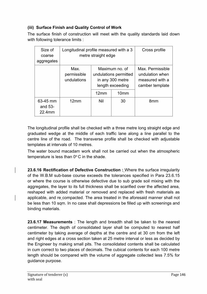
Signature of tenderer (s) Page 146 with seal
(iii) Surface Finish and Quality Control of Work
The surface finish of construction will meet with the quality standards laid down with following tolerance limits :
Size of coarse
aggregates
Longitudinal profile measured with a 3 metre straight edge
Cross profile
Max. permissible undulations
Maximum no. of undulations permitted
in any 300 metre length exceeding
Max. Permissible undulation when measured with a camber template
12mm 10mm
63-45 mm and 53-22.4mm
12mm Nil 30 8mm
The longitudinal profile shall be checked with a three metre long straight edge and graduated wedge at the middle of each traffic lane along a line parallel to the centre line of the road. The transverse profile shall be checked with adjustable templates at intervals of 10 metres.
The water bound macadam work shall not be carried out when the atmospheric temperature is less than 0o C in the shade.
23.6.16 Rectification of Defective Construction : Where the surface irregularity of the W.B.M sub-base course exceeds the tolerances specified in Para 23.6.15 or where the course is otherwise defective due to sub grade soil mixing with the aggregates, the layer to its full thickness shall be scarified over the affected area, reshaped with added material or removed and replaced with fresh materials as applicable, and re compacted. The area treated in the aforesaid manner shall not be less than 10 sqm. In no case shall depressions be filled up with screenings and binding materials.
23.6.17 Measurements : The length and breadth shall be taken to the nearest centimeter. The depth of consolidated layer shall be computed to nearest half centimeter by taking average of depths at the centre and at 30 cm from the left and right edges at a cross section taken at 25 metre interval or less as decided by the Engineer by making small pits. The consolidated contents shall be calculated in cum correct to two places of decimals. The cubical contents for each 100 metre length should be compared with the volume of aggregate collected less 7.5% for guidance purpose.
Signature of tenderer (s) Page 147 with seal
Test1
23.6.18 Rate : Unless otherwise specified, the rate shall include the cost of all labour and materials involved in all the operations described above, except cost of stone aggregate, kankar, moorum, screenings and bajri, for which separate payments shall be made. Where W.B.M. is to be laid over an existing road, scarifying and consolidation of the aggregate received from scarifying shall be paid for separately.
23.6.19 Water bound Macadam with Brick Aggregate/Overburnt (Jhama) Brick Aggregate
Quantities of materials : Approximate quantity of brick aggregate (to be paid for separately) required to be stacked for 100 mm average compacted thickness of W.B.M. sub-base for 10 sqm. area shall be 1.60 cum (approximate). The quantity of binding material, if required shall be as specified by the Engineer. Brick aggregate shall be broken from over burnt or well burnt brick bats. It shall be homogeneous in texture, roughly cubical in shape, clean and free from dirt and other foreign matter.
Foundation shall be prepared as specified in para 23.6.8.1.
For spreading aggregate clause 23.6.8.3 shall apply except that the quantities of materials shall be as given above.
The rolling shall be done as specified in 23.6.8.4 except that rolling shall be done with a light power roller. The use of screenings shall also be omitted. Rolling shall be done 3 to 5 times for each layer.
For rolling with Binding material clause 23.6.10 shall apply except that rolling shall be done with a light power roller instead of a heavy road roller and water shall not be used during rolling. Rolling shall be done 3 to 5 times for each layer.
Surface evenness, rectification of defective construction, Measurements and Rate shall be as specified under 23.6.15 to 23.6.18.
23.7 Bases
23.7.1 General : The base course may consist of any one of the following (with aggregate size 63 mm – 45 mm or 53 mm – 22.4 mm)
(a) Water Bound Macadam (WBM) with stone Aggregate : The stone aggregate of size 63 mm to 45 mm or 53 mm to 22.4 mm as specified shall be used. This is a standard type of base course used in road work. In important roads such as
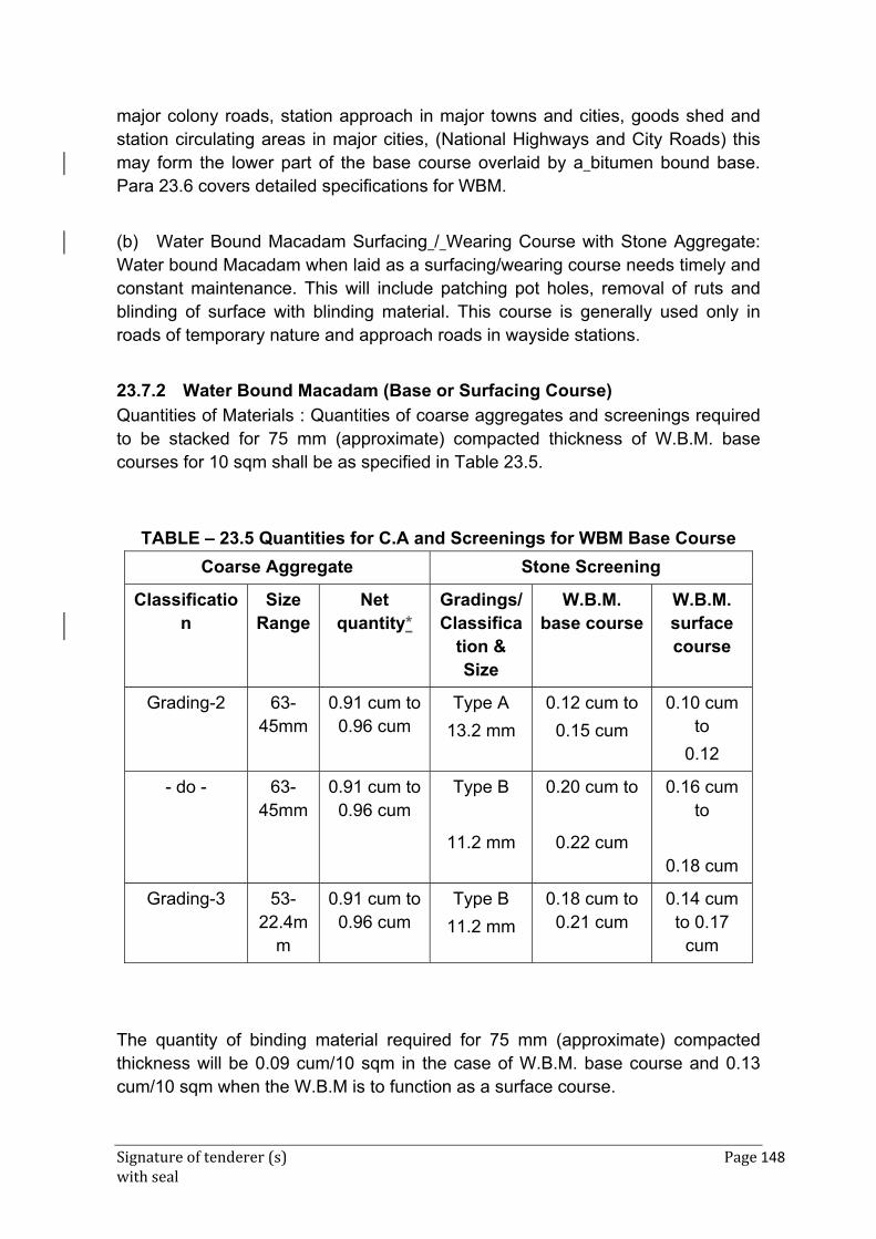
Signature of tenderer (s) Page 148 with seal
major colony roads, station approach in major towns and cities, goods shed and station circulating areas in major cities, (National Highways and City Roads) this may form the lower part of the base course overlaid by a bitumen bound base. Para 23.6 covers detailed specifications for WBM.
(b) Water Bound Macadam Surfacing / Wearing Course with Stone Aggregate: Water bound Macadam when laid as a surfacing/wearing course needs timely and constant maintenance. This will include patching pot holes, removal of ruts and blinding of surface with blinding material. This course is generally used only in roads of temporary nature and approach roads in wayside stations.
23.7.2 Water Bound Macadam (Base or Surfacing Course)
Quantities of Materials : Quantities of coarse aggregates and screenings required to be stacked for 75 mm (approximate) compacted thickness of W.B.M. base courses for 10 sqm shall be as specified in Table 23.5.
TABLE – 23.5 Quantities for C.A and Screenings for WBM Base Course
Coarse Aggregate Stone Screening
Classification
Size Range
Net quantity*
Gradings/ Classifica
tion & Size
W.B.M. base course
W.B.M. surface course
Grading-2 63-45mm
0.91 cum to 0.96 cum
Type A
13.2 mm
0.12 cum to
0.15 cum
0.10 cum to
0.12
- do - 63-45mm
0.91 cum to 0.96 cum
Type B
11.2 mm
0.20 cum to
0.22 cum
0.16 cum to
0.18 cum
Grading-3 53-22.4m
m
0.91 cum to 0.96 cum
Type B
11.2 mm
0.18 cum to 0.21 cum
0.14 cum to 0.17
cum
Test2
The quantity of binding material required for 75 mm (approximate) compacted thickness will be 0.09 cum/10 sqm in the case of W.B.M. base course and 0.13 cum/10 sqm when the W.B.M is to function as a surface course.
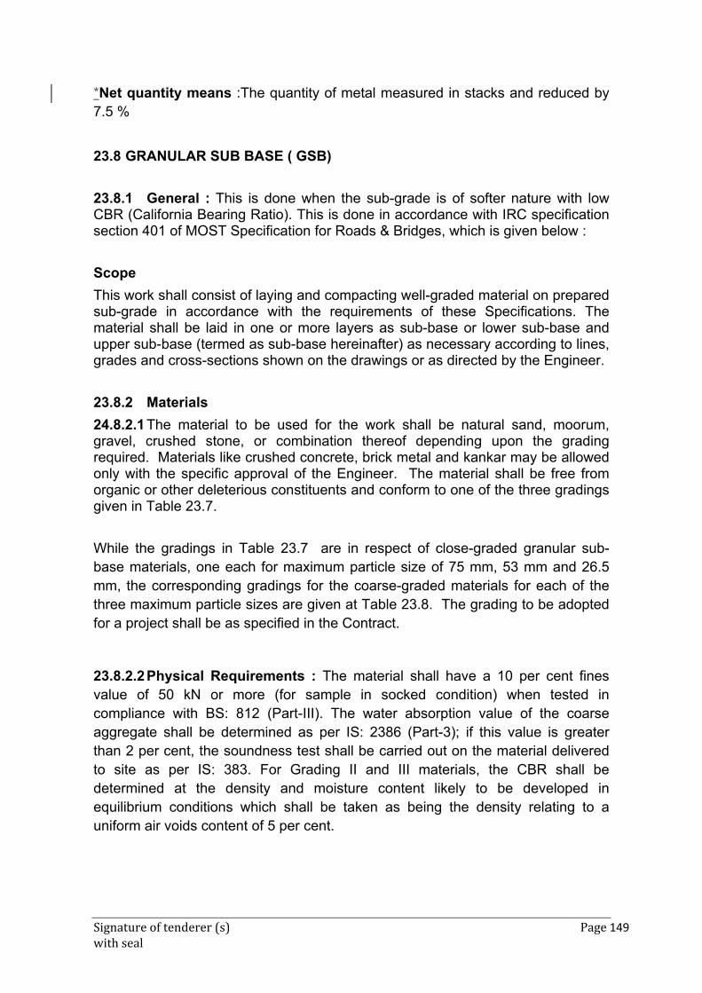
Signature of tenderer (s) Page 149 with seal
*Net quantity means :The quantity of metal measured in stacks and reduced by 7.5 %
23.8 GRANULAR SUB BASE ( GSB)
23.8.1 General : This is done when the sub-grade is of softer nature with low CBR (California Bearing Ratio). This is done in accordance with IRC specification section 401 of MOST Specification for Roads & Bridges, which is given below :
Scope
This work shall consist of laying and compacting well-graded material on prepared sub-grade in accordance with the requirements of these Specifications. The material shall be laid in one or more layers as sub-base or lower sub-base and upper sub-base (termed as sub-base hereinafter) as necessary according to lines, grades and cross-sections shown on the drawings or as directed by the Engineer.
23.8.2 Materials
24.8.2.1 The material to be used for the work shall be natural sand, moorum, gravel, crushed stone, or combination thereof depending upon the grading required. Materials like crushed concrete, brick metal and kankar may be allowed only with the specific approval of the Engineer. The material shall be free from organic or other deleterious constituents and conform to one of the three gradings given in Table 23.7.
While the gradings in Table 23.7 are in respect of close-graded granular sub-base materials, one each for maximum particle size of 75 mm, 53 mm and 26.5 mm, the corresponding gradings for the coarse-graded materials for each of the three maximum particle sizes are given at Table 23.8. The grading to be adopted for a project shall be as specified in the Contract.
23.8.2.2 Physical Requirements : The material shall have a 10 per cent fines value of 50 kN or more (for sample in socked condition) when tested in compliance with BS: 812 (Part-III). The water absorption value of the coarse aggregate shall be determined as per IS: 2386 (Part-3); if this value is greater than 2 per cent, the soundness test shall be carried out on the material delivered to site as per IS: 383. For Grading II and III materials, the CBR shall be determined at the density and moisture content likely to be developed in equilibrium conditions which shall be taken as being the density relating to a uniform air voids content of 5 per cent.
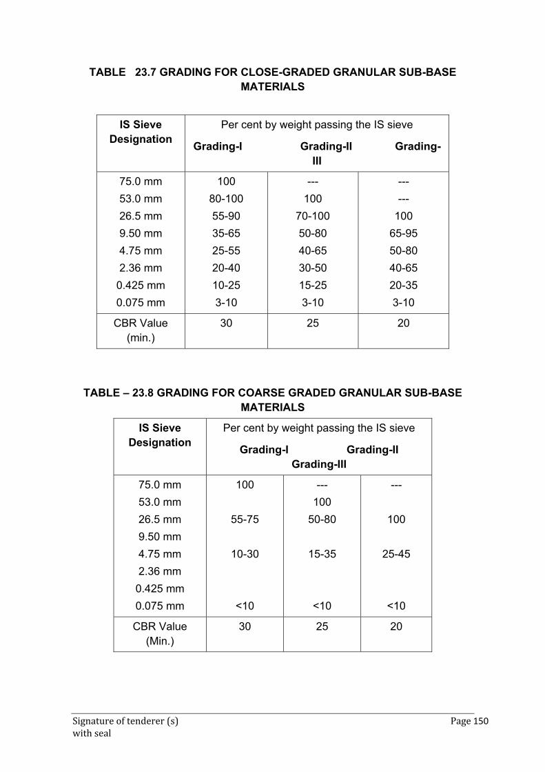
Signature of tenderer (s) Page 150 with seal
TABLE 23.7 GRADING FOR CLOSE-GRADED GRANULAR SUB-BASE MATERIALS
IS Sieve Designation
Per cent by weight passing the IS sieve
Grading-I Grading-II Grading-III
75.0 mm
53.0 mm
26.5 mm
9.50 mm
4.75 mm
2.36 mm
0.425 mm
0.075 mm
100
80-100
55-90
35-65
25-55
20-40
10-25
3-10
---
100
70-100
50-80
40-65
30-50
15-25
3-10
---
---
100
65-95
50-80
40-65
20-35
3-10
CBR Value (min.)
30 25 20
TABLE – 23.8 GRADING FOR COARSE GRADED GRANULAR SUB-BASE MATERIALS
IS Sieve Designation
Per cent by weight passing the IS sieve
Grading-I Grading-II Grading-III
75.0 mm
53.0 mm
26.5 mm
9.50 mm
4.75 mm
2.36 mm
0.425 mm
0.075 mm
100
55-75
10-30
<10
---
100
50-80
15-35
<10
---
100
25-45
<10
CBR Value (Min.)
30 25 20
Signature of tenderer (s) Page 151 with seal
Note : The material passing 425 micron (0.425 mm) sieve for all the three gradings when tested according to IS: 2720 (Part-5) shall have liquid limit and plasticity index not more than 25 and 6 per cent respectively.
23.8.3 Strength of sub-base
It shall be ensured prior to actual execution that the material to be used in the sub –base satisfies the requirements of CBR and other physical requirements when compacted and finished.
When directed by the Engineer, this shall be verified by performing CBR tests in the laboratory as required on specimens remoulded at field dry density and moisture content and any other tests for the “quality” of materials, as may be necessary.
23.8.4 Construction Operations
23.8.4.1 Preparation of sub-grade : Immediately prior to the laying of sub-base, the surface of sub-grade already finished to requirement of Para 23.3 shall be prepared by removing all vegetation and other elevation and shall commence at the edges and progress towards the centre for portions having crossfall on both sides.
Each pass of the roller shall uniformly overlap not less than one-third of the track made in the preceding pass. During rolling, the grade and crossfall (camber) shall be checked and any high spots or depressions, which become apparent, corrected by removing or adding fresh material. The speed of the roller shall not exceed 5 km per hour.
Rolling shall be continued till the density achieved is at least 98 percent of the maximum dry density for the material determined as per IS: 2720 (Part-8). The surface of any layer of material on completion of compaction shall be well closed, free from movement under compaction equipment and from compaction planes, ridges, cracks or loose material. All loose, segregated or otherwise defective areas shall be made good to the full thickness of layer and re-compacted.
23.8.4.2 Surface Finish and Quality Control of Work
Control on the quality of materials and works shall be exercised by the Engineer in accordance with Section 900 of MOST Specification for Road and Bridge Works.
Signature of tenderer (s) Page 152 with seal
23.8.4.3 Arrangements for Traffic
During the period of construction, arrangement of traffic shall be maintained in accordance with directions of Engineer-in-charge.
23.8.4.4 Measurements for Payment
Granular sub-base shall be measured as finished work in position in cubic metres. The length and breadth shall be taken to the nearest centimeter. The depth of consolidated layer shall be computed to nearest half centimeter by taking average of depths at the centre and at 30 cm from the left and right edges at a cross section taken at 25 metre interval or less as decided by the Engineer by making small pits. The consolidated contents shall be calculated in cum correct to two places of decimals.
The protection of edges of granular sub-base extended over the full formation as shown in the drawing shall be considered incidental to the work of providing granular sub-base and as such no extra payment shall be made for the same.
23.8.4.5 Rate
The Contract unit rate for granular sub-base shall be payment in full for carrying out of required operations including full compensation for:
(i) making arrangements for traffic as instructed by Engineer except for initial treatment to verges, shoulders and construction of diversions; which will be paid for separately.
(ii) furnishing all materials to be incorporated in the work including all royalties, fees, rents where necessary and all leads and lifts;
(iii) all labour, tools, equipment and incidentals to complete the work to the specifications;
(iv) carrying out the work in part widths of road where directed; and
(v) carrying out the required tests for quality control
23.9 Surface Courses - The main functions of surface course are:
(a) To provide a dust free wearing course over base course such as water-bound macadam, or bitumen macadam.
(b) To provide a water-proof surface.
(c) To protect water-bound macadam by preventing removal of binder between aggregate pieces.
(d) To prevent disintegration of an old bitumen surface (e) To provide a non-skid riding surface. This type of treatment is normally done
for roads with medium density, rubber tyred traffic.
Signature of tenderer (s) Page 153 with seal
The surface course may consist of any one of the following :
(a) Surface dressing using hot bitumen : Two coats
(b) Surface dressing on new surface with hot bitumen : One coat
(c) Surface dressing on old surface with hot bitumen : One coat
(d) Surface dressing on new surface with bitumen emulsion : One coat
(e) Surface dressing on old surface with bitumen emulsion : One coat
(f) Premix carpet with hot bitumen
(g) Premix carpet with bitumen emulsion
(h) Bituminous Macadam using hot-mix plant and paver equipment
(i) Semi-dense Asphaltic concrete using hot-mix plant and paver equipment
(j) Dense Asphaltic concrete using hot-mix plant and paver equipment.
23.9.1 Surface Dressing Using Hot Bitumen – Two Coats
23.9.1.0 This consists of the application of two coats of surface dressing each coat consisting of a layer of bituminous binder sprayed on a base prepared previously, followed by a cover of stone chippings properly rolled to form a wearing course. The existing water-bound macadam, kankar or gravel surface shall be cleaned thoroughly before application of bituminous binder. The work shall be carried out only when the atmospheric temperature in shade is 16 deg. C or above. No bituminous material shall normally be applied when the road surface or material is damp, when the weather is foggy or rainy, or during dust storms.
23.9.1.1 Materials : Binder shall be as specified and shall conform to Table 23.9 and stone chippings shall confirm to grading as the Table 23.10. Unless otherwise specified or directed by the Engineer the quantities of materials shall be as specified in Table 23.10. A proper record will be kept to ensure that the daily out-turn of work is co-related with the quantity of bitumen used as per proforma given by Engineer or otherwise specified.
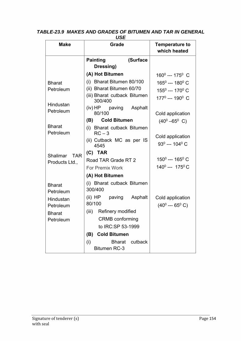
Signature of tenderer (s) Page 154 with seal
TABLE-23.9 MAKES AND GRADES OF BITUMEN AND TAR IN GENERAL USE
Make Grade Temperature to which heated
Bharat Petroleum
Hindustan Petroleum
Bharat Petroleum
Shalimar TAR Products Ltd.,
Bharat Petroleum
Hindustan Petroleum
Bharat Petroleum
Painting (Surface Dressing)
(A) Hot Bitumen
(i) Bharat Bitumen 80/100
(ii) Bharat Bitumen 60/70
(iii) Bharat cutback Bitumen 300/400
(iv) HP paving Asphalt 80/100
(B) Cold Bitumen
(i) Bharat cutback Bitumen RC – 3
(ii) Cutback MC as per IS 4545
(C) TAR
Road TAR Grade RT 2
For Premix Work
(A) Hot Bitumen
(i) Bharat cutback Bitumen 300/400
(ii) HP paving Asphalt 80/100
(iii) Refinery modified
CRMB conforming
to IRC:SP 53-1999
(B) Cold Bitumen
(i) Bharat cutback Bitumen RC-3
1600 --- 1750 C
1650 --- 1800 C
1550 --- 1700 C
1770 --- 1900 C
Cold application
(400 –650 C)
Cold application
930 --- 1040 C
1500 --- 1650 C
1400 --- 1750 C
Cold application
(400 --- 650 C)
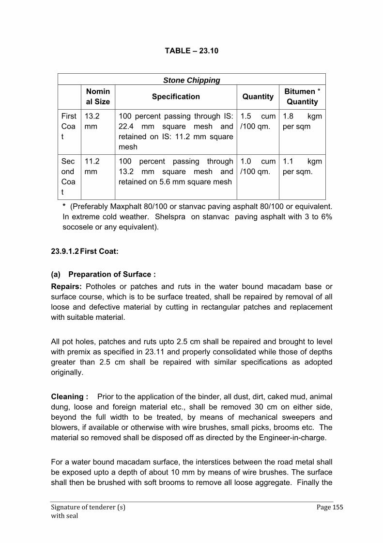
Signature of tenderer (s) Page 155 with seal
TABLE – 23.10
Stone Chipping
Nominal Size
Specification Quantity Bitumen * Quantity
First Coat
13.2 mm
100 percent passing through IS: 22.4 mm square mesh and retained on IS: 11.2 mm square mesh
1.5 cum /100 qm.
1.8 kgm per sqm
Second Coat
11.2 mm
100 percent passing through 13.2 mm square mesh and retained on 5.6 mm square mesh
1.0 cum /100 qm.
1.1 kgm per sqm.
* (Preferably Maxphalt 80/100 or stanvac paving asphalt 80/100 or equivalent. In extreme cold weather. Shelspra on stanvac paving asphalt with 3 to 6% socosele or any equivalent).
23.9.1.2 First Coat:
(a) Preparation of Surface :
Repairs: Potholes or patches and ruts in the water bound macadam base or surface course, which is to be surface treated, shall be repaired by removal of all loose and defective material by cutting in rectangular patches and replacement with suitable material.
All pot holes, patches and ruts upto 2.5 cm shall be repaired and brought to level with premix as specified in 23.11 and properly consolidated while those of depths greater than 2.5 cm shall be repaired with similar specifications as adopted originally.
Cleaning : Prior to the application of the binder, all dust, dirt, caked mud, animal dung, loose and foreign material etc., shall be removed 30 cm on either side, beyond the full width to be treated, by means of mechanical sweepers and blowers, if available or otherwise with wire brushes, small picks, brooms etc. The material so removed shall be disposed off as directed by the Engineer-in-charge.
For a water bound macadam surface, the interstices between the road metal shall be exposed upto a depth of about 10 mm by means of wire brushes. The surface shall then be brushed with soft brooms to remove all loose aggregate. Finally the
Signature of tenderer (s) Page 156 with seal
traces of fine dust, which get accumulated while brushing, shall be thoroughly removed from the surface by blowing with gunny bags.
The prepared surface shall be closed to traffic and maintained fully clean till the binder is applied.
(b) Applying Binder (hot bitumen)
The binder shall be heated in a boiler to a temperature as specified in Table-23.9 for the grade used and maintained at the temperature, the use of a thermometer being essential.
The binder shall be applied evenly to the clean dry surface by means of a pressure sprayer at the rate specified. The binder shall be applied longitudinally along the length of the road and never across it. The edges of the binder surface shall be defined by wire or a rope stretched in position.
Heating in cut out drums and pouring from perforated tins, cans and such other methods shall not be permitted, except in the case of petty works and repairs with the specific approval of the Engineer-in-Charge.
Excessive deposits of binder caused by stopping or starting of the sprayer or through leakage or any other reason shall be suitably corrected before the stone chippings are spread.
(c) Blinding or Spreading Stone Chippings
Immediately after the binder is applied and while it is still hot, stone chippings free from dust and in a dry and clean state shall be spread evenly over the surface at the rate specified above. Spreading shall be done preferably by means of a mechanical gritter, otherwise manually with a twisting motion to avoid segregation which otherwise shall have to be removed by brushing the excess stone chippings over the surface into hungry spots to obtain a uniform surface, free from waviness, depressions and other irregularities. The surface shall be checked by means of a camber board laid across the road and a three metre straight edge laid parallel to the centre line of the road, and undulations if any shall be corrected by addition or removal of blindage till a surface free from undulation is obtained.
If a uniform surface is assured at this stage the completed surface should be normally free from undulations and unevenness.
Signature of tenderer (s) Page 157 with seal
(d) Consolidation of Blindage
Immediately following the application of the stone chippings and light brooming, the road surface shall be compacted by a power roller of 6 to 8 tonnes, starting at edges and working towards the centre (or to the outside edge in case of super elevated curve). Each pass of the roller shall uniformly overlap not less than one third of the track made in the preceding pass. The roller shall be worked or started and stopped without jerks and shall not be stopped or reversed each time at the same location to cause displacement of stone and other irregularities. Consolidation shall be considered complete when the stone chippings are firmly embedded.
Generally five to six trips shall be made for thorough compaction of the surface or as may be specified by the Engineer-in-Charge.
Along kerbs, manholes and all places not accessible to the roller, compaction shall be secured by means of steel rammers or hand rollers.
23.9.1.3 Second Coat :
(a) Cleaning the road surface
The surface shall be examined and any loose material and foreign matter shall be removed by brooming or blowing off by fanning with gunny bags, care being taken not to loosen the blindage already set.
(b) Applying binder (hot Bitumen)
The second coat of binder shall be applied immediately after the blinding has been set and the surface has been cleaned. The binder shall be applied at the specified rate in the manner specified for the first coat.
(c) Blinding or spreading stone chippings.
Immediately after the second application of binder, the stone chippings shall be spread at the specified rate in the manner described.
(d) Consolidation of blindage
The specifications described in Para 23.9.1.2 (c) shall apply. Further the prepared finished surface shall be protected from traffic for 24 hours or such period as may be specified by the Engineer-in-Charge.
Signature of tenderer (s) Page 158 with seal
23.9.1.3.1 Surface Finishing : The finished surface shall be uniform and conform to the lines, grades and typical cross-sections shown in the drawings.
23.9.1.4 The finished surface shall be thrown open to traffic on the following day. Controlling traffic shall be done by suitable methods like barricading, posting of watchman etc.
23.9.1.4.1 Measurements : The length and width of the finished work shall be measured correct to a cm along the finished surface of the road. The area shall be calculated in square metre, correct to two places of decimal.
The measurement for binder and stone chippings shall be taken before they are actually used on the work for guidance. These measurements of materials simply serve as a guide and shall not form the basis for payment.
23.9.1.4.2 Rate : The rate shall include the cost of materials and labour involved in all the operations described above, except for repairs described under 23.9.1.2 (a).
23.9.2 Surface Dressing on New Surface with Hot Bitumen One Coat
23.9.2.0 This type of treatment shall consist of cleaning the existing water bound macadam, kankar or gravel surfaces, and applying one coat of hot bitumen on the prepared base, blinding it with stone chippings of 12.5 mm nominal size and consolidation with a road roller. This type of treatment is normally done for a road with light density rubber tyred traffic and roads for temporary construction. This treatment is also done on existing water bound macadam before applying the final surface treatment. In the latter case, after applying a coat of painting the road is thrown open to traffic till the road is consolidated. The final treatment is then given after making good the undulations etc. in the road surface.
23.9.2.1 Preparation of Surface (Repairs and Cleaning) shall be as specified under 23.9.1.2 (a).
23.9.2.2 Applying binder, blinding, consolidation, surface finishing, measurements and rates shall be as specified under 23.9.1 except that binder shall be applied at the rate of 2.25 kg per sqm and stone chippings of size 13.2 mm at 1.65 cum per 100 sqm unless otherwise specified.
Signature of tenderer (s) Page 159 with seal
23.9.3 Surface Dressing on Old Surface with Hot Bitumen – One Coat
23.9.3.0 This treatment consists of cleaning old painted surfaces and applying a coat of hot bitumen on the prepared base, blinding with stone chippings and consolidation with road roller.
23.9.3.1 Materials : Binder shall be as specified and conform to Table 23.9 Stone chipping shall conform to grading given in Table 23.10 for 11.2mm. Unless otherwise specified or directed by the Engineer-in-Charge stone chippings of 11.2 mm nominal size shall be used @ 1.5 cum per 100 sqm area and bitumen @ 1.95 kg per square metre area. A proper record shall be kept to ensure that the daily out turn of work is co-related with the quantity of bitumen used as per proforma given by Engineer or otherwise specified in the item.
23.9.3.2 Preparation of Surface (Repairs and cleaning) shall be as specified under 23.9.1.2 (a).
23.9.3.3 Applying binder, Blinding, Consolidation, Surface Finishing, Measurement and Rate shall be as specified under 23.9.1 except that the binder and chippings shall be applied at the specified rate as above or otherwise by Engineer.
23.9.4 Surface Dressing on New Surface with Bitumen Emulsion – One Coat
23.9.4.0 This treatment consists of cleaning the existing water bound macadam, kankar gravel or stabilized base and other black top surfaces, applying a coat of bitumen emulsion at atmospheric temperature, blinding it with stone chippings including consolidation with a road roller.
This type of treatment is normally applied under damp conditions and for minor repair works during rainy season for roads with medium density, rubber tyred traffic such as service roads. This treatment is also done on existing water bound macadam before applying the final surface treatment. In the latter case, the road is consolidated. The final treatment is then given after making good the undulations depressions etc, in the road surface.
23.9.4.1. Materials : Binder shall be as specified and shall conform to RS grade IS: 8837. Stone chipping of 13.2 mm size shall conform to Table 23.11(a). Unless otherwise specified of directed by the Engineer-in-Charge 13.2 mm stone chippings shall be used @ 1.5 cum per 100 sqm area and bitumken @ 1.95 kg/sqm area. A proper record shall be kept to ensure that the daily out turn of work is correlated with the quantity of bitumen used as per proforma given by Engineer or specified otherwise
23.9.4.2 Preparation of Surface : The specification described in 23.9.1.2 (a) shall apply except that the binder used for patch repairs etc., shall be bitumen emulsion.
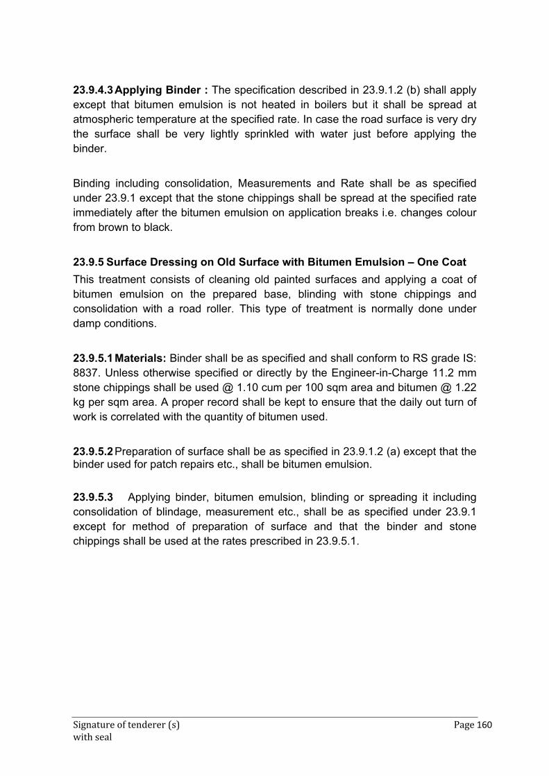
Signature of tenderer (s) Page 160 with seal
23.9.4.3 Applying Binder : The specification described in 23.9.1.2 (b) shall apply except that bitumen emulsion is not heated in boilers but it shall be spread at atmospheric temperature at the specified rate. In case the road surface is very dry the surface shall be very lightly sprinkled with water just before applying the binder.
Binding including consolidation, Measurements and Rate shall be as specified under 23.9.1 except that the stone chippings shall be spread at the specified rate immediately after the bitumen emulsion on application breaks i.e. changes colour from brown to black.
23.9.5 Surface Dressing on Old Surface with Bitumen Emulsion – One Coat
This treatment consists of cleaning old painted surfaces and applying a coat of bitumen emulsion on the prepared base, blinding with stone chippings and consolidation with a road roller. This type of treatment is normally done under damp conditions.
23.9.5.1 Materials: Binder shall be as specified and shall conform to RS grade IS: 8837. Unless otherwise specified or directly by the Engineer-in-Charge 11.2 mm stone chippings shall be used @ 1.10 cum per 100 sqm area and bitumen @ 1.22 kg per sqm area. A proper record shall be kept to ensure that the daily out turn of work is correlated with the quantity of bitumen used.
23.9.5.2 Preparation of surface shall be as specified in 23.9.1.2 (a) except that the binder used for patch repairs etc., shall be bitumen emulsion.
23.9.5.3 Applying binder, bitumen emulsion, blinding or spreading it including consolidation of blindage, measurement etc., shall be as specified under 23.9.1 except for method of preparation of surface and that the binder and stone chippings shall be used at the rates prescribed in 23.9.5.1.
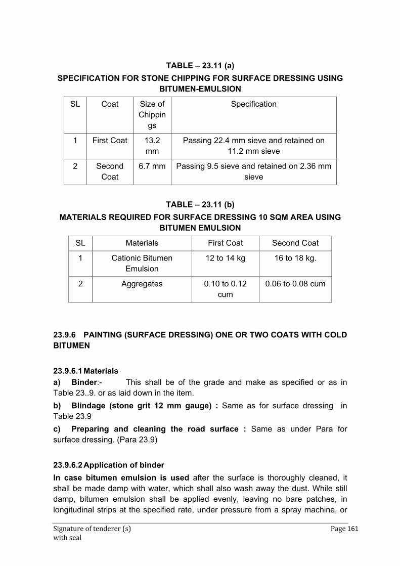
Signature of tenderer (s) Page 161 with seal
TABLE – 23.11 (a)
SPECIFICATION FOR STONE CHIPPING FOR SURFACE DRESSING USING BITUMEN-EMULSION
SL Coat Size of Chippin
gs
Specification
1 First Coat 13.2 mm
Passing 22.4 mm sieve and retained on 11.2 mm sieve
2 Second Coat
6.7 mm Passing 9.5 sieve and retained on 2.36 mm sieve
TABLE – 23.11 (b)
MATERIALS REQUIRED FOR SURFACE DRESSING 10 SQM AREA USING BITUMEN EMULSION
SL Materials First Coat Second Coat
1 Cationic Bitumen Emulsion
12 to 14 kg 16 to 18 kg.
2 Aggregates 0.10 to 0.12 cum
0.06 to 0.08 cum
23.9.6 PAINTING (SURFACE DRESSING) ONE OR TWO COATS WITH COLD BITUMEN
23.9.6.1 Materials
a) Binder:- This shall be of the grade and make as specified or as in Table 23..9. or as laid down in the item.
b) Blindage (stone grit 12 mm gauge) : Same as for surface dressing in Table 23.9
c) Preparing and cleaning the road surface : Same as under Para for surface dressing. (Para 23.9)
23.9.6.2 Application of binder
In case bitumen emulsion is used after the surface is thoroughly cleaned, it shall be made damp with water, which shall also wash away the dust. While still damp, bitumen emulsion shall be applied evenly, leaving no bare patches, in longitudinal strips at the specified rate, under pressure from a spray machine, or
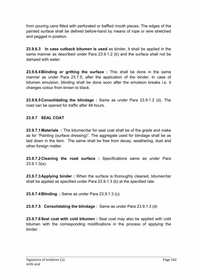
Signature of tenderer (s) Page 162 with seal
from pouring cans fitted with perforated or baffled mouth pieces. The edges of the painted surface shall be defined before-hand by means of rope or wire stretched and pegged in position.
23.9.6.3 In case cutback bitumen is used as binder, it shall be applied in the same manner as described under Para 23.9.1.2 (b) and the surface shall not be damped with water.
23.9.6.4 Blinding or gritting the surface : This shall be done in the same manner as under Para 23.7.5, after the application of the binder. In case of bitumen emulsion, blinding shall be done soon after the emulsion breaks i.e. it changes colour from brown to black.
23.9.6.5 Consolidating the blindage : Same as under Para 23.9.1.2 (d). The road can be opened for traffic after 48 hours.
23.9.7 SEAL COAT
23.9.7.1 Materials : The bitumen/tar for seal coat shall be of the grade and make as for “Painting (surface dressing)”. The aggregate used for blindage shall be as laid down in the item. The same shall be free from decay, weathering, dust and other foreign matter.
23.9.7.2 Cleaning the road surface : Specifications same as under Para 23.9.1.3(a).
23.9.7.3 Applying binder : When the surface is thoroughly cleaned, bitumen/tar shall be applied as specified under Para 23.9.1.3 (b) at the specified rate.
23.9.7.4 Blinding : Same as under Para 23.9.1.3 (c).
23.9.7.5 Consolidating the blindage : Same as under Para 23.9.1.3 (d)
23.9.7.6 Seal coat with cold bitumen : Seal coat may also be applied with cold bitumen with the corresponding modifications in the process of applying the binder.
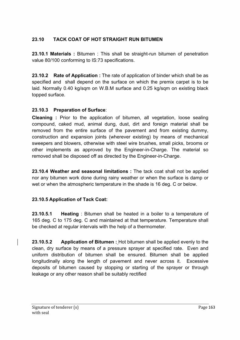
Signature of tenderer (s) Page 163 with seal
23.10 TACK COAT OF HOT STRAIGHT RUN BITUMEN
23.10.1 Materials : Bitumen : This shall be straight-run bitumen of penetration value 80/100 conforming to IS:73 specifications.
23.10.2 Rate of Application : The rate of application of binder which shall be as specified and shall depend on the surface on which the premix carpet is to be laid. Normally 0.40 kg/sqm on W.B.M surface and 0.25 kg/sqm on existing black topped surface.
23.10.3 Preparation of Surface:
Cleaning : Prior to the application of bitumen, all vegetation, loose sealing compound, caked mud, animal dung, dust, dirt and foreign material shall be removed from the entire surface of the pavement and from existing dummy, construction and expansion joints (wherever existing) by means of mechanical sweepers and blowers, otherwise with steel wire brushes, small picks, brooms or other implements as approved by the Engineer-in-Charge. The material so removed shall be disposed off as directed by the Engineer-in-Charge.
23.10.4 Weather and seasonal limitations : The tack coat shall not be applied nor any bitumen work done during rainy weather or when the surface is damp or wet or when the atmospheric temperature in the shade is 16 deg. C or below.
23.10.5 Application of Tack Coat:
23.10.5.1 Heating : Bitumen shall be heated in a boiler to a temperature of 165 deg. C to 175 deg. C and maintained at that temperature. Temperature shall be checked at regular intervals with the help of a thermometer.
23.10.5.2 Application of Bitumen : Hot bitumen shall be applied evenly to the clean, dry surface by means of a pressure sprayer at specified rate. Even and uniform distribution of bitumen shall be ensured. Bitumen shall be applied longitudinally along the length of pavement and never across it. Excessive deposits of bitumen caused by stopping or starting of the sprayer or through leakage or any other reason shall be suitably rectified
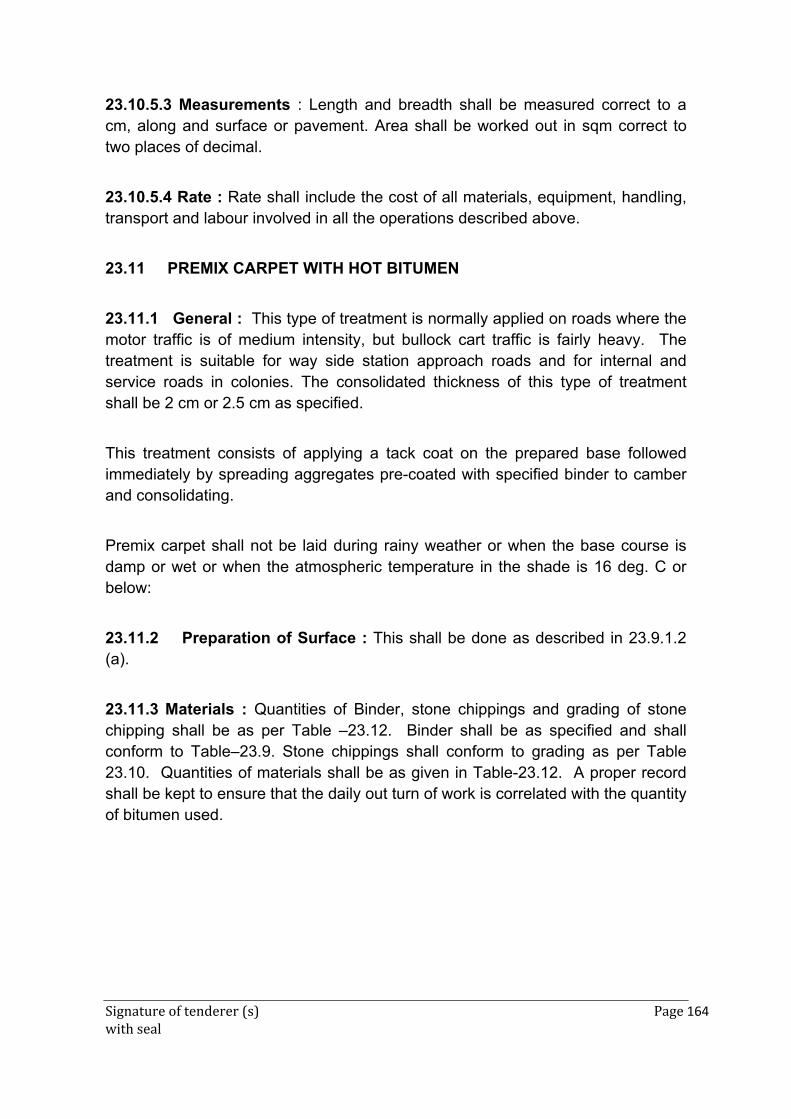
Signature of tenderer (s) Page 164 with seal
23.10.5.3 Measurements : Length and breadth shall be measured correct to a cm, along and surface or pavement. Area shall be worked out in sqm correct to two places of decimal.
23.10.5.4 Rate : Rate shall include the cost of all materials, equipment, handling, transport and labour involved in all the operations described above.
23.11 PREMIX CARPET WITH HOT BITUMEN
23.11.1 General : This type of treatment is normally applied on roads where the motor traffic is of medium intensity, but bullock cart traffic is fairly heavy. The treatment is suitable for way side station approach roads and for internal and service roads in colonies. The consolidated thickness of this type of treatment shall be 2 cm or 2.5 cm as specified.
This treatment consists of applying a tack coat on the prepared base followed immediately by spreading aggregates pre-coated with specified binder to camber and consolidating.
Premix carpet shall not be laid during rainy weather or when the base course is damp or wet or when the atmospheric temperature in the shade is 16 deg. C or below:
23.11.2 Preparation of Surface : This shall be done as described in 23.9.1.2 (a).
23.11.3 Materials : Quantities of Binder, stone chippings and grading of stone chipping shall be as per Table –23.12. Binder shall be as specified and shall conform to Table–23.9. Stone chippings shall conform to grading as per Table 23.10. Quantities of materials shall be as given in Table-23.12. A proper record shall be kept to ensure that the daily out turn of work is correlated with the quantity of bitumen used.
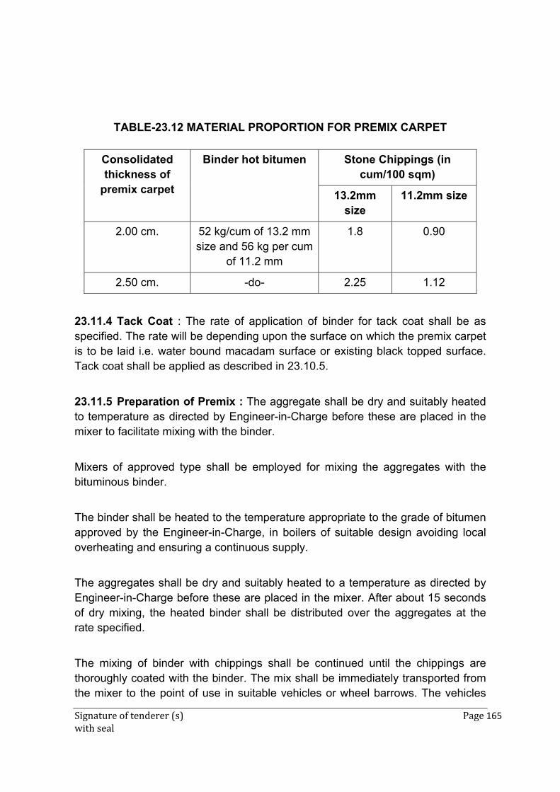
Signature of tenderer (s) Page 165 with seal
TABLE-23.12 MATERIAL PROPORTION FOR PREMIX CARPET
Consolidated thickness of
premix carpet
Binder hot bitumen Stone Chippings (in cum/100 sqm)
13.2mm size
11.2mm size
2.00 cm. 52 kg/cum of 13.2 mm size and 56 kg per cum
of 11.2 mm
1.8 0.90
2.50 cm. -do- 2.25 1.12
Test4
23.11.4 Tack Coat : The rate of application of binder for tack coat shall be as specified. The rate will be depending upon the surface on which the premix carpet is to be laid i.e. water bound macadam surface or existing black topped surface. Tack coat shall be applied as described in 23.10.5.
23.11.5 Preparation of Premix : The aggregate shall be dry and suitably heated to temperature as directed by Engineer-in-Charge before these are placed in the mixer to facilitate mixing with the binder.
Mixers of approved type shall be employed for mixing the aggregates with the bituminous binder.
The binder shall be heated to the temperature appropriate to the grade of bitumen approved by the Engineer-in-Charge, in boilers of suitable design avoiding local overheating and ensuring a continuous supply.
The aggregates shall be dry and suitably heated to a temperature as directed by Engineer-in-Charge before these are placed in the mixer. After about 15 seconds of dry mixing, the heated binder shall be distributed over the aggregates at the rate specified.
The mixing of binder with chippings shall be continued until the chippings are thoroughly coated with the binder. The mix shall be immediately transported from the mixer to the point of use in suitable vehicles or wheel barrows. The vehicles
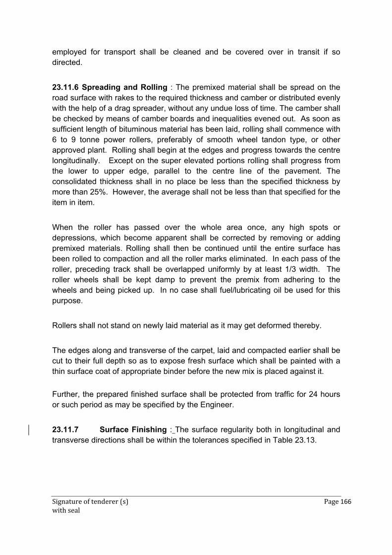
Signature of tenderer (s) Page 166 with seal
employed for transport shall be cleaned and be covered over in transit if so directed.
23.11.6 Spreading and Rolling : The premixed material shall be spread on the road surface with rakes to the required thickness and camber or distributed evenly with the help of a drag spreader, without any undue loss of time. The camber shall be checked by means of camber boards and inequalities evened out. As soon as sufficient length of bituminous material has been laid, rolling shall commence with 6 to 9 tonne power rollers, preferably of smooth wheel tandon type, or other approved plant. Rolling shall begin at the edges and progress towards the centre longitudinally. Except on the super elevated portions rolling shall progress from the lower to upper edge, parallel to the centre line of the pavement. The consolidated thickness shall in no place be less than the specified thickness by more than 25%. However, the average shall not be less than that specified for the item in item.
When the roller has passed over the whole area once, any high spots or depressions, which become apparent shall be corrected by removing or adding premixed materials. Rolling shall then be continued until the entire surface has been rolled to compaction and all the roller marks eliminated. In each pass of the roller, preceding track shall be overlapped uniformly by at least 1/3 width. The roller wheels shall be kept damp to prevent the premix from adhering to the wheels and being picked up. In no case shall fuel/lubricating oil be used for this purpose.
Rollers shall not stand on newly laid material as it may get deformed thereby.
The edges along and transverse of the carpet, laid and compacted earlier shall be cut to their full depth so as to expose fresh surface which shall be painted with a thin surface coat of appropriate binder before the new mix is placed against it.
Further, the prepared finished surface shall be protected from traffic for 24 hours or such period as may be specified by the Engineer.
23.11.7 Surface Finishing : The surface regularity both in longitudinal and transverse directions shall be within the tolerances specified in Table 23.13.
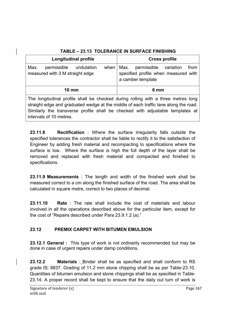
Signature of tenderer (s) Page 167 with seal
TABLE – 23.13 TOLERANCE IN SURFACE FINISHING
Longitudinal profile Cross profile
Max. permissible undulation when measured with 3 M straight edge
Max. permissible variation from specified profile when measured with a camber template
10 mm 6 mm
The longitudinal profile shall be checked during rolling with a three metres long straight edge and graduated wedge at the middle of each traffic lane along the road. Similarly the transverse profile shall be checked with adjustable templates at intervals of 10 metres.
23.11.8 Rectification : Where the surface irregularity falls outside the specified tolerances the contractor shall be liable to rectify it to the satisfaction of Engineer by adding fresh material and recompacting to specifications where the surface is low. Where the surface is high the full depth of the layer shall be removed and replaced with fresh material and compacted and finished to specifications.
23.11.9 Measurements : The length and width of the finished work shall be measured correct to a cm along the finished surface of the road. The area shall be calculated in square metre, correct to two places of decimal.
23.11.10 Rate : The rate shall include the cost of materials and labour involved in all the operations described above for the particular item, except for the cost of “Repairs described under Para 23.9.1.2 (a).”
23.12 PREMIX CARPET WITH BITUMEN EMULSION
23.12.1 General : This type of work is not ordinarily recommended but may be done in case of urgent repairs under damp conditions.
23.12.2 Materials : Binder shall be as specified and shall conform to RS grade IS: 8837. Grading of 11.2 mm stone chipping shall be as per Table-23.10. Quantities of bitumen emulsion and stone chippings shall be as specified in Table-23.14. A proper record shall be kept to ensure that the daily out turn of work is
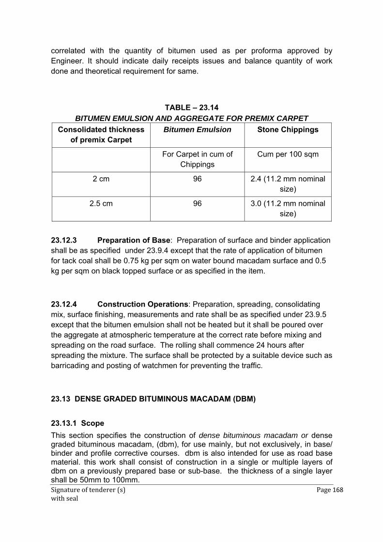
Signature of tenderer (s) Page 168 with seal
correlated with the quantity of bitumen used as per proforma approved by Engineer. It should indicate daily receipts issues and balance quantity of work done and theoretical requirement for same.
TABLE – 23.14
BITUMEN EMULSION AND AGGREGATE FOR PREMIX CARPET
Consolidated thickness of premix Carpet
Bitumen Emulsion Stone Chippings
For Carpet in cum of Chippings
Cum per 100 sqm
2 cm 96 2.4 (11.2 mm nominal size)
2.5 cm 96 3.0 (11.2 mm nominal size)
23.12.3 Preparation of Base: Preparation of surface and binder application shall be as specified under 23.9.4 except that the rate of application of bitumen for tack coal shall be 0.75 kg per sqm on water bound macadam surface and 0.5 kg per sqm on black topped surface or as specified in the item.
23.12.4 Construction Operations: Preparation, spreading, consolidating mix, surface finishing, measurements and rate shall be as specified under 23.9.5 except that the bitumen emulsion shall not be heated but it shall be poured over the aggregate at atmospheric temperature at the correct rate before mixing and spreading on the road surface. The rolling shall commence 24 hours after spreading the mixture. The surface shall be protected by a suitable device such as barricading and posting of watchmen for preventing the traffic.
23.13 DENSE GRADED BITUMINOUS MACADAM (DBM)
23.13.1 Scope
This section specifies the construction of dense bituminous macadam or dense graded bituminous macadam, (dbm), for use mainly, but not exclusively, in base/ binder and profile corrective courses. dbm is also intended for use as road base material. this work shall consist of construction in a single or multiple layers of dbm on a previously prepared base or sub-base. the thickness of a single layer shall be 50mm to 100mm.
Signature of tenderer (s) Page 169 with seal
23.13.2 Materials
23.13.2.1 Bitumen : The bitumen shall be paving bitumen of Penetration Grade complying with Indian Standard Specifications for “Paving Bitumen” IS:73, and of the penetration indicated in Table 23.16 for dense bitumen macadam, or this bitumen as modified by one of the methods specified by the Engineer or as otherwise specified in the Contract. In case of non-availability of the above grades of bitumen, S 90 (80/100) grade may be used with the approval of the Engineer. Guidance on the selection of an appropriate grade of bitumen is given in the Manual for Construction and Supervision of Bituminous works.
23.13.2.2 Coarse aggregates : The coarse aggregates shall consist of crushed rock, crushed gravel or other hard material retained on the 2.36 mm sieve. They shall be clean, hard, durable, of cubical shape, free from dust and soft or friable matter, organic or other deleterious substances. Where the Contractor’s selected source of aggregates have poor affinity for bitumen, as a condition for the approval of that source, the bitumen shall be treated with an approved anti-stripping agent, as per the manufacturer’s recommendations, without additional payment. Before approval of the source, the aggregates shall be tested for stripping. The aggregates shall satisfy the physical requirements specified for dense bituminous macadam.
Where crushed gravel is proposed for use as aggregate, not less than 90% by weight of the crushed material retained on the 4.75mm sieve shall have at least two fractured faces.
23.13.2.3 Fine aggregates : Fine aggregates shall consist of crushed or naturally occurring mineral material, or a combination of the two, passing the 2.36mm sieve and retained on the 75 micron sieve. They shall be clean, hard, durable, dry and free from dust, and soft or friable matter, organic or other deleterious matter.
The fine aggregate shall have a sand equivalent value of not less than 50 when tested in accordance with the requirement of IS:2720 (Part 37).
The plasticity index of the fraction passing the 0.425mm sieve shall not exceed 4 when tested in accordance with IS:2720 (Part 5).
23.13.2.4 Filler : Filler shall consist of finely divided mineral matter such as rock dust, hydrated lime or cement approved by the Engineer. The filler shall be graded within the limits indicated in Table 23.15.
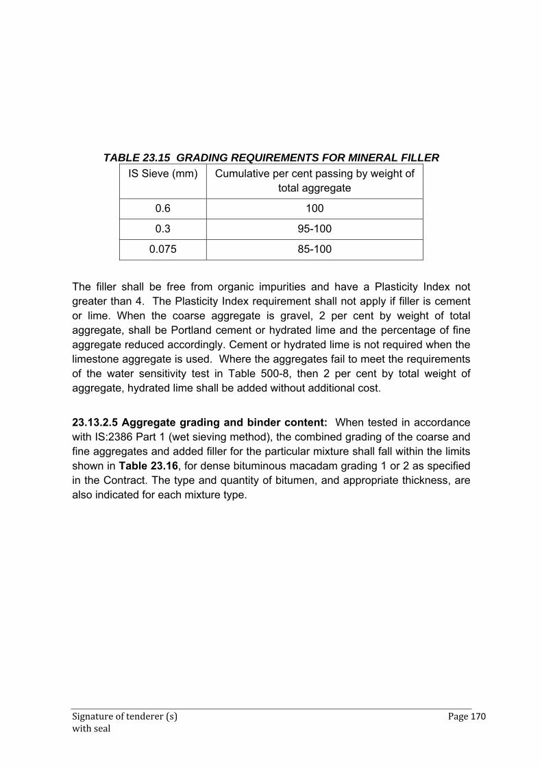
Signature of tenderer (s) Page 170 with seal
TABLE 23.15 GRADING REQUIREMENTS FOR MINERAL FILLER
IS Sieve (mm) Cumulative per cent passing by weight of total aggregate
0.6 100
0.3 95-100
0.075 85-100
The filler shall be free from organic impurities and have a Plasticity Index not greater than 4. The Plasticity Index requirement shall not apply if filler is cement or lime. When the coarse aggregate is gravel, 2 per cent by weight of total aggregate, shall be Portland cement or hydrated lime and the percentage of fine aggregate reduced accordingly. Cement or hydrated lime is not required when the limestone aggregate is used. Where the aggregates fail to meet the requirements of the water sensitivity test in Table 500-8, then 2 per cent by total weight of aggregate, hydrated lime shall be added without additional cost.
23.13.2.5 Aggregate grading and binder content: When tested in accordance with IS:2386 Part 1 (wet sieving method), the combined grading of the coarse and fine aggregates and added filler for the particular mixture shall fall within the limits shown in Table 23.16, for dense bituminous macadam grading 1 or 2 as specified in the Contract. The type and quantity of bitumen, and appropriate thickness, are also indicated for each mixture type.
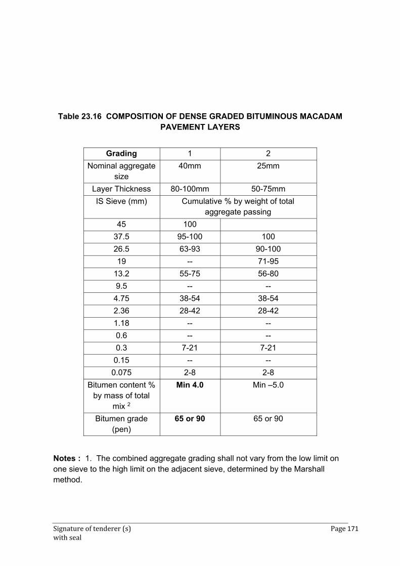
Signature of tenderer (s) Page 171 with seal
Table 23.16 COMPOSITION OF DENSE GRADED BITUMINOUS MACADAM PAVEMENT LAYERS
Grading 1 2
Nominal aggregate size
40mm 25mm
Layer Thickness 80-100mm 50-75mm
IS Sieve (mm) Cumulative % by weight of total aggregate passing
45 100
37.5 95-100 100
26.5 63-93 90-100
19 -- 71-95
13.2 55-75 56-80
9.5 -- --
4.75 38-54 38-54
2.36 28-42 28-42
1.18 -- --
0.6 -- --
0.3 7-21 7-21
0.15 -- --
0.075 2-8 2-8
Bitumen content % by mass of total
mix 2
Min 4.0 Min –5.0
Bitumen grade (pen)
65 or 90 65 or 90
Notes : 1. The combined aggregate grading shall not vary from the low limit on one sieve to the high limit on the adjacent sieve, determined by the Marshall method.
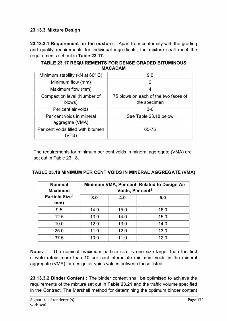
Signature of tenderer (s) Page 172 with seal
23.13.3 Mixture Design
23.13.3.1 Requirement for the mixture : Apart from conformity with the grading and quality requirements for individual ingredients, the mixture shall meet the requirements set out in Table 23.17.
TABLE 23.17 REQUIREMENTS FOR DENSE GRADED BITUMINOUS MACADAM
Minimum stability (kN at 60o C) 9.0
Minimum flow (mm) 2
Maximum flow (mm) 4
Compaction level (Number of blows)
75 blows on each of the two faces of the specimen
Per cent air voids 3-6
Per cent voids in mineral aggregate (VMA)
See Table 23.18 below
Per cent voids filled with bitumen (VFB)
65-75
The requirements for minimum per cent voids in mineral aggregate (VMA) are set out in Table 23.18.
TABLE 23.18 MINIMUM PER CENT VOIDS IN MINERAL AGGREGATE (VMA)
Nominal Maximum
Particle Size1 mm)
Minimum VMA, Per cent Related to Design Air Voids, Per cent2
3.0 4.0 5.0
9.5 14.0 15.0 16.0
12.5 13.0 14.0 15.0
19.0 12.0 13.0 14.0
25.0 11.0 12.0 13.0
37.5 10.0 11.0 12.0
Notes : The nominal maximum particle size is one size larger than the first sieveto retain more than 10 per cent.Interpolate minimum voids in the mineral aggregate (VMA) for design air voids values between those listed.
23.13.3.2 Binder Content : The binder content shall be optimised to achieve the requirements of the mixture set out in Table 23.21 and the traffic volume specified in the Contract. The Marshall method for determining the optimum binder content
Signature of tenderer (s) Page 173 with seal
shall be adopted as described in. The Asphalt Institute Manual MS-2, replacing the aggregates retained on the 26.5mm sieve by the aggregates passing the 26.5mm sieve and retained on the 22.4 mm sieve, where approved by the Engineer.
23.13.3.3 Job mix formula : The Contractor shall inform the Engineer in writing, atleast 20 days before the start of the work, of the job mix formula proposed for use in the works, and shall give the following details.
1. Source and location of all materials
2. Proportions of all materials expressed as follows where each is applicable
3. Binder type and percentage by weight of total mixture
4. Coarse aggregate / Fine aggregate / Mineral filler as percentage by weight of total aggregate including mineral filler.
5. A single definite percentage passing each sieve for the mixed aggregate
6. The individual gradings of the individual aggregate fractions and thee proportion of each in the combined grading
7. The results of tests as obtained by the Contractor.
8. Where the mixer is a batch mixer, the individual weights of each type of aggregate, and binder per batch.
9. Test results of physical characteristics of aggregates to be used
10. Mixing temperature and compacting temperature.
While establishing the job mix formula, the Contractor shall ensure that it is based on a correct and truly representative sample of the materials that will actually be used in the work and that the mixture and its different ingredients satisfy the physical and strength requirements of these Specifications.
Approval of the job mix formula shall be based on independent testing by the Engineer for which samples of all ingredients of the mix shall be furnished by the Contractor as required by the Engineer.
The approved job mix formula shall remain effective unless and until a revised Job Mix Formula is approved. Should a change in the source of materials to be proposed, a new job mix formula shall be forwarded to the Engineer for approval before the placing of the material.
23.13.3.4 Plant trials – permissible variation in job mix formula :
Once the laboratory job mix formula is approved, the Contractor shall carry out plant trials at the mixer to establish that the plant can be set up to produce a
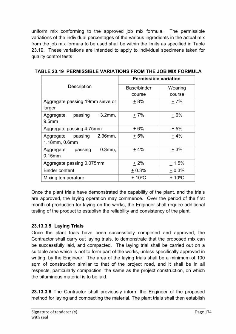
Signature of tenderer (s) Page 174 with seal
uniform mix conforming to the approved job mix formula. The permissible variations of the individual percentages of the various ingredients in the actual mix from the job mix formula to be used shall be within the limits as specified in Table 23.19. These variations are intended to apply to individual specimens taken for quality control tests
TABLE 23.19 PERMISSIBLE VARIATIONS FROM THE JOB MIX FORMULA
Description
Permissible variation
Base/binder course
Wearing course
Aggregate passing 19mm sieve or larger
+ 8% + 7%
Aggregate passing 13.2mm, 9.5mm
+ 7% + 6%
Aggregate passing 4.75mm + 6% + 5%
Aggregate passing 2.36mm, 1.18mm, 0.6mm
+ 5% + 4%
Aggregate passing 0.3mm, 0.15mm
+ 4% + 3%
Aggregate passing 0.075mm + 2% + 1.5%
Binder content + 0.3% + 0.3%
Mixing temperature + 10oC + 10oC
Once the plant trials have demonstrated the capability of the plant, and the trials are approved, the laying operation may commence. Over the period of the first month of production for laying on the works, the Engineer shall require additional testing of the product to establish the reliability and consistency of the plant.
23.13.3.5 Laying Trials
Once the plant trials have been successfully completed and approved, the Contractor shall carry out laying trials, to demonstrate that the proposed mix can be successfully laid, and compacted. The laying trial shall be carried out on a suitable area which is not to form part of the works, unless specifically approved in writing, by the Engineer. The area of the laying trials shall be a minimum of 100 sqm of construction similar to that of the project road, and it shall be in all respects, particularly compaction, the same as the project construction, on which the bituminous material is to be laid.
23.13.3.6 The Contractor shall previously inform the Engineer of the proposed method for laying and compacting the material. The plant trials shall then establish
Signature of tenderer (s) Page 175 with seal
if the proposed laying plant, compaction plant, and methodology is capable of producing satisfactory results. The density of the finished paving layer shall be determined by taking cores, no sooner than 24 hours after laying, or by other approved method.
Once the laying trials have been approved, the same plant and methodology shall be applied to the laying of the material on the project, and no variation of either shall be acceptable, unless approved in writing by the Engineer, who may at his discretion require further laying trials.
23.13.4 Construction Operations
23.13.4.1 Weather and seasonal limitations: The provisions of Clause 23.13.3.1 shall apply.
23.13.4.2 Preparation of base : The base on which Dense Graded Bituminous Material is to be laid shall be prepared in accordance with Para 23.9.1.2 (a) and (b) as appropriate, or as directed by the Engineer. The surface shall be thoroughly swept clean by a mechanical boom, and the dust removed by compressed air. In locations where mechanical broom cannot access, other approved methods shall be used as directed by the Engineer.
23.13.4.3 Geosynthetics : Where Geosynthetics are specified in the Contract this shall be in accordance with the requirements stated in relevant supplier’s specifications or as per Engineer’s instructions.
23.13.4.4 Stress absorbing layer : Where a stress absorbing layer is specified in the Contract, this shall be applied in accordance with the requirements stated in relevant specifications or as per Engineer’s instructions.
23.13.4.5 Prime Coat : Where the material on which the dense bituminous macadam is to be laid is other than a bitumen bound layer, a prime coat shall be applied, as specified, in accordance with the provisions of Para 23.9.1.2 (b), or as directed by the Engineer.
23.13.4.6 Tack coat : Where the material on which the dense bituminous macadam is to be placed is a bitumen bound surface, a tack coat shall be applied as specified, in accordance with the provisions of Para 23.10, or as directed by the Engineer.
Signature of tenderer (s) Page 176 with seal
23.13.4.7 Mixing and transportation of the mixture : The provisions as specified in Para 23.13.3.4.
23.13.4.8 Spreading : The provisions of Clause 23.13.3.5 shall apply.
23.13.4.9 Rolling : The general provisions of Clauses 23.13.3.6 shall apply, as modified by the approved laying trials. The compaction process shall be carried out by the same plant, and using the same method, as approved in the laying trials, which may be varied only with the express approval of the Engineer in writing.
23.13.5 Opening to Traffic
The newly laid surface shall not be open to traffic for at least 24 hours after laying and completion of compaction, without the express approval of the Engineer in writing.
23.13.6 Surface Finish and Quality Control of work
The surface finish of the completed construction shall conform to the requirements of Para 23.13.4.
23.13.7 Arrangements for Traffic
During he period of construction, arrangements for traffic shall be made in accordance with the directions of the Engineer.
23.13.8 Measurement for Payment Dense Graded Bituminous Materials shall be measured as finished work either in cum or by the sqm at a specified thickness as detailed on the Contract drawings, or as directed by the Engineer.
23.13.9 Rate
The contract unit rate for Dense Graded Bituminous Macadam shall be payment in full for carrying out the all required operations as specified, and shall include, but not necessarily limited to all components listed in Para 23.13.8. The rate shall include the provision of bitumen, at the rates specified in the relevant item by weight of the total mixture. The variance in actual percentage of bitumen used will be assessed and the payment adjusted, up or down, accordingly.
23.14 CEMENT CONCRETE PAVEMENT UNDER CONTROLLED CONDITIONS
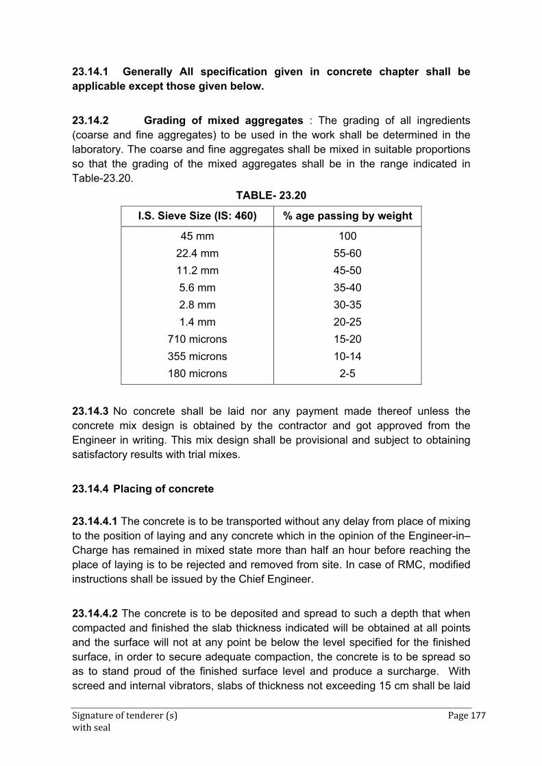
Signature of tenderer (s) Page 177 with seal
23.14.1 Generally All specification given in concrete chapter shall be applicable except those given below.
23.14.2 Grading of mixed aggregates : The grading of all ingredients (coarse and fine aggregates) to be used in the work shall be determined in the laboratory. The coarse and fine aggregates shall be mixed in suitable proportions so that the grading of the mixed aggregates shall be in the range indicated in Table-23.20.
TABLE- 23.20
I.S. Sieve Size (IS: 460) % age passing by weight
45 mm
22.4 mm
11.2 mm
5.6 mm
2.8 mm
1.4 mm
710 microns
355 microns
180 microns
100
55-60
45-50
35-40
30-35
20-25
15-20
10-14
2-5
23.14.3 No concrete shall be laid nor any payment made thereof unless the concrete mix design is obtained by the contractor and got approved from the Engineer in writing. This mix design shall be provisional and subject to obtaining satisfactory results with trial mixes.
23.14.4 Placing of concrete
23.14.4.1 The concrete is to be transported without any delay from place of mixing to the position of laying and any concrete which in the opinion of the Engineer-in–Charge has remained in mixed state more than half an hour before reaching the place of laying is to be rejected and removed from site. In case of RMC, modified instructions shall be issued by the Chief Engineer.
23.14.4.2 The concrete is to be deposited and spread to such a depth that when compacted and finished the slab thickness indicated will be obtained at all points and the surface will not at any point be below the level specified for the finished surface, in order to secure adequate compaction, the concrete is to be spread so as to stand proud of the finished surface level and produce a surcharge. With screed and internal vibrators, slabs of thickness not exceeding 15 cm shall be laid
Signature of tenderer (s) Page 178 with seal
on one layer. Concrete for slabs of greater thickness will be laid in two layers. The second layer will be laid over the unfinished but thoroughly compacted first layer within the initial setting time of cement used in the concrete. Second layer shall also be compacted thoroughly after laying.
23.14.4.3 Concrete shall be deposited in such a manner as to require as little handling as possible. Spreading, compacting and finishing (except final broom/belt finishing) operations shall be completed within a period not exceeding half an hour from the time the mixing starts or as specified otherwise in case of RMC. In case of dry and hot weather this time shall not exceed 25 minutes.
23.14.5 Finishing of concrete
During compaction, any low or high spots shall be made up by adding or removing concrete. After longitudinal floating has been completed but while concrete is still plastic, the slab surface shall be tested for trueness with a 3 m straight edge. Any depressions or high spots showing departure from the true surface shall be immediately rectified. High spots shall be cut down and refinished. Depressions shall be enlarged to about 8–10 cm and filled up with fresh concrete, compacted and finished.
23.14.5.1 The straight edge testing the re-floating is to continue until the entire surface —
(a) is free from observable departure from the straight edge.
(b) Conforms to the required levels and cross section, and
(c) Shall conform to the specified surface when the concrete has hardened.
23.14.5.2 The foregoing work is to be carried out while the concrete is still plastic and workable.
23.14.6 Belting
Just before concrete becomes non-plastic, the surface shall be belted with a two ply canvas belt not less than 20 cm wide and at least 1 metre longer than the width of the slab. Hand belts shall have suitable handles to permit controlled uniform manipulation. The belt shall be operated with short strokes transverse to the centre line of the pavement and with rapid advance parallel to the centre line.
23.14.7 Brooming
After belting and as soon as the surplus water if any, has risen to the surface, the pavement shall be given a broom finish with an approved steel or fiber broom not less than 45 cm wide. The broom shall be pulled gently over the surface of the pavement from edge to edge. Adjacent strokes shall be slightly overlapped. Brooming shall be perpendicular to the centre line of the pavement and so
Signature of tenderer (s) Page 179 with seal
executed that the corrugations formed shall be uniform in character and width and not more than 1.5 mm deep.
Brooming shall be completed before the concrete reaches such a stage that the surface is likely to be torn or unduly roughened by the operation. The broomed surface shall be free from porous or rough spots, irregularities, depressions, and small pockets such as may be caused by accidental disturbing of particles of coarse aggregates embodied near the surface. The brooming shall be of uniform pattern all through.
23.14.8 Edging
After belting/brooming has been completed but before the initial setting of concrete, the edges of the slab shall be carefully finished with an edger of 6 mm radius, and the pavement edges shall be left smooth and true to line.
23.14.9 Honey combing
The side forms shall not be removed until 12 hours or such longer period as the Engineer-in-Charge may decide after the laying of concrete. As soon as the side forms are removed, any minor honey combed area shall be filled with mortar composed of one part of cement and two parts of fine aggregate. Major honey combing areas or segregated concrete or other defective work or areas damaged by removal of the forms or concrete damaged by rain or due to any other reason whatsoever shall be considered as defective work and shall be removed and replaced by the contractor at his own expense. The total area of honeycombed surface shall not exceed 4 per cent of the area of the slab side. However, no individual honeycomb patch shall exceed 0.1 sqm. Engineer-in-Charge’s decision as to whether the concrete is defective or not shall be final and binding.
23.14.10 Surface Accuracy
23.14.10.1 After the concrete has sufficiently hardened for about 12 hours and not later than 24 hours, the surface shall be tested again for high spots. All high spots shall be marked and those exceeding 3 mm shall be ground down immediately. Care shall be taken to see that the grinding does not in any way damage the concrete surface.
23.14.10.2 The final surface finish is to be such that when tested with a profilograh / roughness indicator /or a 3 metre long straight edge or an equivalent mechanical unevenness indicator placed anywhere within the same or adjoining slab in any direction on the surface, there shall be no variation greater than 3 mm.
Signature of tenderer (s) Page 180 with seal
23.14.10.3 If the surface irregularity exceeding 3 mm still remains despite grinding as per Para 23.17.14.1 the concrete shall be removed to its full depth. The area of concrete to be removed shall be complete slab between the nearest joints and where the defective slab is less than 4.5 metres from the expansion joint, the whole area upto the expansion joint shall be removed to the full depth. The concrete so removed shall not be reused in the work. Fresh concrete shall be laid in the manner already described in these specifications and shall again be subject to test for surface accuracy and other quality control measures. Nothing extra shall be paid for the same.
23.14.10.4 Every slab shall bear an impression not exceeding 3 mm in depth comprising the number allotted to the slab and the date on which it is laid. This impression shall be formed by the contractor when the concrete is green so as to leave permanent mark on setting.
23.14.11 Construction Joints
Construction joints shall be provided as shown in the drawing and also at places where concreting is stopped due to unforeseen circumstances. The joints shall be straight and vertical through the full thickness of the slab. While concrete in adjacent bay is still green, flats of suitable size shall be drawn along the edge and a groove of size 10mm x 25 mm deep shall be neatly formed and finished. The edges of the groove shall be full nosed. After curing of concrete is complete, this groove shall be thoroughly cleaned of all sand dust and shall be perfectly dried and filled with hot poured sealing compound conforming to Grade B of IS: 1834. Before filling with sealing compound the faces of concrete of the joint shall be coated with Shalijet primer or equivalent to a depth of 25 mm at the rate of 2.6 litres per 10 square meters.
23.14.12 Dummy Joints
23.14.12.1 The joints shall be 10 mm wide and shall extend vertically from the surface of the slab to be depth equal to 1/3rd of the thickness of the slab but not less than 4 cm in any case. The joint may be formed by depressing into the soft but compacted concrete , a high tensile M.S. or other approved Tee or flat bar of depth not less than required depth of the joint plus 25 mm. The bar used for forming the groove shall be coated with soft soap or other suitable lubricant to facilitate its removal when the steel Tee or flat is removed. Joints shall be neatly formed with proper tools and mortar material from the slab itself. No additional cement mortar (rich or otherwise) shall be used.
23.14.12.2 Cutting or sawing by a saw mounted on a movable frame and driven mechanically shall also be permitted as a method for making the dummy joint. In this case the width may be reduced to 6 mm. Any other method for making joints can be followed with the prior approval of the Engineer-in-Charge.
Signature of tenderer (s) Page 181 with seal
23.14.12.3 In all cases, except where cutting is done with saw, the joint edges shall be bullnosed. Care should be taken to see that the edges of the grooves are not damaged.
23.14.12.4 The grooves shall be filled with hot poured sealing compound conforming to Grade B of IS: 1834. Prior to filling with sealing compound, the joints shall be cleaned by compressed air and primed with Shalijet primer or equivalent.
23.14.12.5 All joints shall be sealed as soon as practicable after 28 days of placing of slabs. Joints shall be sealed flush with the adjacent pavement surface in summer and 3-4 mm below finished concrete surface in winter. The pavement shall be opened to traffic only after joint sealing over the entire pavement. To prevent tackiness or pickup under traffic, the exposed surfaces of the sealing compound shall be dusted with hydrated lime, if directed by Engineer, for which nothing extra shall be paid to the contractor.
23.14.12.6 In case of sudden rain or storm, the work can be concluded at the dummy joints but these will then be formed as construction joints.
23.14.12.7 Before sealing of joints, it may be ensured that the groove extends fully across the bay between consecutive longitudinal joints, in the case of transverse joints. Any concrete or other foreign matter must be removed from the groove.
23.14.13 Defects Liability Period
This period shall be reckoned in the case of concrete pavement work as one year from the date of completion of work or as specified otherwise and it shall be the liability of the contractor to repair, strengthen or reconstruct any portion of the work which has shown damage or any defect, arising out of any bad workmanship or defective material used in the work during this period. In the case of this rectification not being commenced by the contractor within 7 days from the date of notice from the Engineer and completed expeditiously the Engineer reserves the right to get the repair work executed at the risk and cost of the contractor.
23.14.14 Measurements
23.14.14.1 For the purpose of ascertaining the quantity of concrete in the pavement, thickness shall be measured by means of a scale correct to the nearest 2 mm. The thickness of the concrete pavement slabs shall be taken on either side of the pavement at each dummy joint at four corners of the slab immediately after removal of the side forms. In case the average thickness of the slab exceeds the specified thickness, payment shall be restricted to the specified

Signature of tenderer (s) Page 182 with seal
thickness. Payment will be made in cum corrected to two decimals unless otherwise specified.
23.14.14.2 The dimensions of each slab of pavement shall be measured as follows to the nearest 5 mm.
(a) Length
(i) Between the end of a pavement to the centre line of the expansion joints
(ii) Between the centre lines of consecutive expansion joints.
(b) Width
(i) Between the edge of a pavement and the centre line of the construction joints.
(ii) Between the centre lines of construction joints and expansion joints.
(iii) Between the centre lines of consecutive construction joints.
Note : The quantity of concrete in the pavement slab shall be worked out by multiplying the area of the slab and its average thickness or specified thickness whichever is less. No deduction shall be made for any joints in the concrete slab.
23.14.14.3 Measurements of concrete slabs shall be recorded jointly by the Engineer or his authorized subordinate and the contractor or his authorized agent.
23.14.15 Rate
The rate of the item for concrete in pavement shall include the cost of all materials and labour including charges for form work machinery tools & plants in all the operations described above. Rate includes provision of all joints specified above including infilling. The rate also includes all cost of setting up the laboratory at site and carrying out the quality control measures/tests enumerated above by the contractor at his own cost in the presence of Engineer or his authorized representative and submission of test results on completion of tests to the Engineer thereof.
23.14.16 Expansion Joint (With Non Extruding Filler Pad) in Concrete Pavements
23.14.16.1 Materials
Pre-moulded Joint Filler: It shall conform to IS: 1838 (Pt. I). The thickness shall be 20 mm and shall be of the maximum available standard length.
Signature of tenderer (s) Page 183 with seal
Joint sealing compound : The joint sealing compound shall be fuel and heat resistant type complying to grade B of IS: 1834. It shall be capable of adhering to the concrete without cracking, spalling and disintegration.
Primer : It shall be Shalijet or Expanjet primer or equivalent. Bituminous emulsions shall not be used as primers.
23.14.16.2 Construction Procedure
Expansion joints shall be provided as shown in the drawing and as per directions of Engineer-in-Charge. All joints shall be constructed true to line with their faces perpendicular to the surface of the pavement. The joint shall be 20 mm wide. The depth of the non-extruding filler paid shall be 25 mm less than the depth of the concrete slab.
Before the provision of expansion joint, the face of the already laid concrete slab shall be painted with primer at the rate of 2.6 liters per 10 square metres. The expansion pad shall be properly cut to shape and shall then be placed in position abutting the painted face of the already laid concrete slab. The adjacent slab shall then be concreted. The face of the pad against which the new concrete slab is to be laid shall also be painted with primer before laying the concrete, while concreting a neat groove 20 mm x 25 mm as per drawing shall be formed on top of the pad taking care that the edges are absolutely straight and that the groove so made does not get filled with any materials like concrete, mortar and other rubbish.
Before the curing process is started, the top of expansion joint shall be filled with bitumen sand mixture in order to ensure that no foreign material used in curing enters into the joint. This filling shall be removed before filling the joints with sealing compound.
For sealing the joints following operations shall be carried out:-
(a) The joints are cleared of any foreign matter to the full depth upto the top of expansion pad with steel spatula.
(b) The joints are blown with compressed air.
(c) Cleaning is done with Kerosene oil.
(d) Priming is done with spray gun @ 2.6 liters per 10 sqm of the surface to be primed
(e) The primer is allowed to dry completely before pouring the sealing compound.
(f) The sealing compound grade ‘A’ is heated to the required temperature ranging between 155 deg. C to 165 deg. C or to the temperature range specified by the manufacturer. Over heating shall be avoided. Pouring shall be done from
Signature of tenderer (s) Page 184 with seal
vessel with spout in such a manner that the material will not get spilled on the exposed surface of the concrete, any excess filler on the surface of the pavement shall be removed immediately and the pavement surface cleaned.
(g) The filling shall be worked in to the joints with hot flats to ensure escape of trapped air.
(h) The filling is then ironed with hot iron. It is recommended that while in summer the joints may be sealed flush with the adjacent pavement surface, in winter the sealing compound may be filled to a depth 3-4 mm below the surface.
(i) The edges of the joints are then cut and trimmed to ensure neat and straight-line finish.
(j) To prevent tackiness or pick up under traffic, the exposed surfaces of the sealing compound shall be dusted with hydrated lime, if so directed by Engineer (Nothing extra shall be paid for the same).
23.14.16.3 Measurements
The measurement of the specified depth of joint shall be recorded in metres correct to two places of decimals.
23.14.16.4 Rate
Rate for the item shall include the cost of all materials, plant, machinery and labour involved in all operations described above, including all cartages and lifts.
23.15 BLACK TOPPED SURFACE ON PLATFORMS (HOT PROCESS)
23.15.1 Base : The base may be made the same way as for cold process except that it should be finished 25 mm below the top level of the finished platform surface.
23.15.2 Priming coat/Tack coat : If the base consists of non-absorbant surfaces such as lateriate, kankar or moorum or clay gravel, a priming coat of approved make shall be applied. This shall be allowed to soak into the platform surface for 48 hours.
In case of brick ballast surface (or stone ballast surface), a tack coat shall be applied as detailed in Para 23.10.
23.15.3 Bitumastic Sheet : 25 mm thick carpet of bitumastic sheet (shel-sheet) shall then be laid.
23.15.4 Limitation : Since having a special bitumen mixer of the paddle type is essential for mixing of the aggregates and binder, shell- sheet carpet on platform
Signature of tenderer (s) Page 185 with seal
can be laid only at important and zonal / divisional headquarter stations where the paddle mixer is available. A 6 to 8 tonnes power roller is also preferable though a 3 to 4 tonnes hand roller can serve the purpose, if approved by Engineer.
23.16 PAINTING ROAD/MARKINGS
23.16.1 Materials
23.16.1.1 Special Road marking paint of approved brand and manufacture shall be used. The paint shall conform to IS: 164. Ready mixed paint as received from the manufacturer shall be used without adding any admixture.
23.16.1.2 During work, if the consistency of the paint gets thick and thinning becomes necessary it shall be done by use of thinner of the specific brand of paint recommended by the manufacturer and with the approval of the Engineer.
23.16.1.3 The paint shall be brought to the site of work by the contractor in original sealed containers. The material shall be brought in one lot in adequate quantity to suffice for the entire work. The material shall be kept in the joint custody of the contractor and the Engineer. The empties shall not be removed from the site of work, till the work has been completed and permission obtained from the Engineer-in-Charge.
23.16.2 Preparation of surface
The surface shall be thoroughly cleaned and dusted. All the dirt, scales, oil and grease shall be thoroughly removed before painting is started. The prepared surface shall be inspected and approved by the Engineer-in-Charge before painting is commenced.
23.16.3 Application
23.16.3.1 Before pouring into smaller containers for use, the paint shall be stirred thoroughly in its original container. During use also, it shall be continuously kept stirred.
23.16.3.2 The painting shall be applied evenly and smoothly by means of crossing and laying off. The crossing and laying off consists of covering the area over with paint, brushing the surface hard for the first time over and then brushing alternately in opposite direction, two or three times and then finally brushing lightly in a direction at right angle to the same. In this process, no brush marks shall be left after the laying off is finished. The full process of crossing and laying off will constitute one coat.
Signature of tenderer (s) Page 186 with seal
23.16.3.3 Each coat shall be allowed to dry out thoroughly before the next coat is applied.
23.16.3.4 Earlier applied coat shall be cleaned off dust before the next coat is laid.
23.16.3.5 No left over paint shall be put back into the stock tins. When not in use, the containers shall be kept properly closed.
23.16.3.6 No hair marks from the brush or clogging of paint puddles shall be left on the work.
23.16.3.7 The surface shall ordinarily not be painted until it has dried up completely. Trial patches of paint shall be laid at intervals to check if drying is satisfactory.
23.16.3.8 Marking on Roads shall be in accordance with the drawings or specifications prepared based on IRC standards. It should be done using templates, unless otherwise permitted by the Engineer.
23.16.4 Brushes and Containers
23.16.4.1 After work, the brushes shall be completely cleaned of paint by rinsing with turpentine. A brush in which paint has dried up is spoiled and shall on no account be reused for painting work. On no account kerosene oil shall be used for washing the brushes.
23.16.4.2 When the paint has been used, the containers shall be washed with turpentine and wiped dry with soft clean cloth so that they are clean, and can be used again.
23.16.5 Measurement
23.16.5.1 Length and breadth shall be measured correct to a cm. Area shall be worked out in square metre of painted area, correct to two places of a decimal.
23.16.6 Rate
23.16.6.1 Rate shall include cost of all materials, tools and labour involved in all the operations described above including all cartages, temporary protection and barricading till the paint dries, if required, and all miscellaneous works.
23.17 BAJRI PATHS
23.17.1 Preparation of Sub-Grade
The formation for a width equal to that of the bajri path shall first be cut to a depth, below the proposed finished level, equal to the thickness of the course of brick
Signature of tenderer (s) Page 187 with seal
aggregate (due allowance being made for consolidation) and dressed off level to the finished profile.
In case of made up soil, adequate watering shall be done so that earth settles down as much as possible and the same rolled up with a minimum three tonnes or light power roller or as directed by the Engineer.
23.17.2 Laying and Packing Brick Aggregate
Shall be as specified in 23.6.8.3 except that brick aggregate shall be used instead of stone aggregate and laid to 7.5 cm depth, unless specified otherwise.
23.17.3 Consolidation
Shall be as specified in 23.6.8.4 & 23.6.8.5 except that rolling shall be done by three 187ones or light power roller instead of by heavy road roller or as directed by the Engineer.
23.17.4 Rolling with Blinding Materials
Shall be as specified in 23.6.10 except that rolling shall be done by three tones or light power roller instead of by heavy road roller as directed by the Engineer.
23.17.5 Measurements
The finished work shall be measured between the kerb or channel stones or brick edging etc., as the case may be. Length and breadth shall be measured correct to a cm. The area shall be calculated in square metres, correct to two places of decimal for each specified thickness.
23.17.6 Rate
The rate shall include the cost of materials and labour tools and plant; transportation involved in all the operations described above.
23.18 SPREADING AND CONSOLIDATING 6 mm THICK RED BAJRI ON ROADS AND PLATFORMS (WITH ROAD ROLLER)
23.18.1 Preparation of Surface
23.18.1.1 All undulations in the old surface, such as holes or patches and ruts shall be repaired by cutting in square or rectangular shape. These shall be cleaned and hand packed with new stone aggregate of 40 mm nominal size. This shall be well consolidated with heavy iron rammers with sufficient application of water and blinding materials and brought to camber/grade or level.
Signature of tenderer (s) Page 188 with seal
23.18.1.2 All high humps and depressions shall be levelled by scarifying and re-compaction. red bajri shall then be spread on the surface to 6 mm thickness. care shall be taken to avoid thick layers at particular spots. adequate water shall then be sprinkled on the surface and rolled till the red bajri is formed into a paste before the wheels of the roller. the rolling shall be done for a minimum of three passes. wet red-bajri, if sticks to wheels shall be removed by brushes and pouring water on it.
23.18.1.3 finished surface shall give a uniform appearance and necessary obstructions shall be placed on the road/platform to avoid moving of traffic till next day or lapse of 24 hours.
23.21.2 Measurements
The finished work shall be measured between the wall, coping, kerb or channel stones or brick edging etc., as the case may be. Length and breadth shall be measured, correct to a cm. The area shall be calculated in square metres, correct to two places a decimal.
23.18.3 Rate
The rate shall include the cost of all labour and materials involved in all the operations described above excluding cost of supply red bajri unless specified otherwise in the description of the item.
23.19 KERB AND CHANNEL STONES
23.19.1 Laying
23.19.1.1 Trenches shall first be made along the edge of the wearing course of the road to receive the kerb and the channel stones. The bed of the trenches shall be compacted manually with steel rammers to a firm and even surface and then the stones shall be set in cement mortar of specified proportion.
23.19.1.2 The kerb stones with top 20 cm wide shall be laid with their length running parallel to the road edge, true in line and gradient at a distance of 30 cm from the road edge to allow for the channel an shall project about 12.5 cm above the latter. The channel stories with top 30 cm wide shall be laid in position in camber with finished road surface and with sufficient slope towards the road gully chamber. The joints of kerb and channel stones shall be staggered and shall be not more than 10 mm thick. Wherever specified all joints shall be filled with mortar 1:6 (1 cement: 6 coarse sand) and pointed with mortar 1:2 (1 cement: 2 fine sand) which shall be cured for 7 days.
Signature of tenderer (s) Page 189 with seal
23.19.1.3 The necessary drainage openings of specified sizes shall be made through the kerb and foot path as per drawings or as directed by the Engineer for connecting to storm water drains.
23.19.1.4 For detailed specifications for Kerb stone, see Annexure 24.1 which gives extracts from relevant IS codes.
23.19.2 Finishing
Berms and road edges shall be restored and all surplus earth including rubbish etc., disposed off as directed by the Engineer. Nothing extra shall be paid for this.
23.19.3 Measurements
Length of the finished work shall be measured in running metre along the edge of the road correct to a cm.
23.19.4 Rate
The rate shall include the cost of all the materials and labour including stone of specified material involved in all the operations described above.
23.20 BRICK EDGING
23.20.1 Edging
Trenches of specified width and depth shall first, be made along the edges of the wearing coarse of the road or pathway to receive the bricks. The bed of trenches shall be compacted to a firm and even surface and then the bricks shall be laid with its length at right angle or parallel to the side of the road pathway depending upon the width of edging as specified in the BOQ item or as indicated by Engineer. The bricks shall be abutting against the wearing course, true to line, gradient and in camber with the finished road surface at the edge.
23.20.2 Finishing
Berms and road edges shall be restored with excavated earth and consolidated by hand packing. All surplus earth including rubbish etc. shall be disposed off as directed by the Engineer-in-Charge.
23.20.3 Measurements
Length of the finished work shall be measured in running metres along the edges of the road correct to a cm.
23.20.4 Rate
Signature of tenderer (s) Page 190 with seal
The rate shall include the cost of materials and labour, tools and plant, handling, transport etc. involved in all the operations described above.
23.21 SCARIFYING METALLED (WATER BOUND) SURFACE
23.21.1 Scarifying
All dirt, dust, checked up mud, slush, animal droppings, vegetation and all other rubbish shall be removed from the water bound macadam surface.
The macadam surface shall be scarified to a depth of approximately 5 cm with such additional picking of high parts of the road as may be necessary to the required camber and gradient as directed by the Engineer. Any hollows that remain after picking shall be filled with new aggregate 50 mm nominal size and well consolidated to bring the surface to template.
23.21.2 Finishing
The scarified aggregate shall be raked to bring smaller stones on the top and surface brought to the required camber and gradient with tolerance of 12 mm longitudinally as well as transversely.
All rubbish etc., shall be disposed off as directed by the Engineer. Scarifying operation will also include consolidation with road roller the aggregate received from scarifying, although this aggregate will be consolidated along with aggregate of new wearing course to be paid for separately.
23.21.3 Measurements
The finished work shall be measured between the kerb or channel stones or brick edging etc., as the case may be. Length and breadth shall be measured correct to a cm. The area shall be calculated in square metres correct to two places of decimal.
23.21.4 Rate
The rate shall include the cost of labour and materials, tools and plants, handling and transport etc. involved in all the operations described above except the cost of stone aggregate which shall be paid for separately.
Signature of tenderer (s) Page 191 with seal
23.22 CUTTING W.B.M. ROADS AND MAKING GOOD
23.22.1 Cutting
All road crossings shall be cut in half the width at a time and repaired, unless otherwise permitted by the Engineer. Cutting shall be straight and uniform in width. Soling stone and aggregate obtained from cutting macadam shall be stacked separately, clear of the road surface. Aggregate shall be screened stones of smaller size below 20 mm and with rounded edges discarded and disposed.
23.22.2 Making Good
23.22.2.1 After the trenches have been filled in with excavated earth in layers of 15 cm thickness, watered, well consolidated with heavy iron rammers and brought to sub grade level, soling stone obtained from cutting shall be laid as per existing soling and consolidated with heavy iron rammers. Where the earth consolidation is well done, no settlement need occur subsequently. For this, excess watering should be avoided.
23.22.2.2 New aggregate 50 mm nominal size, as required, shall be added to old aggregate and spread over to a depth of 7.5 cm as specified in 23.6.2. This shall then be consolidated with hand roller or heavy iron rammers, as directed, first with light sprinkling then with sufficient application of water till the aggregate has become adequately consolidated and does not get displaced. All undulations shall be loosened by hand picking, surplus aggregate removed from high spots and depressions filled with surplus and new aggregate and the surface compacted again. When thoroughly consolidated, kankar moorum and red bajri, freshly collected shall be spread over it in 12 mm layer and consolidated with hand roller or heavy iron rammers, with sufficient application of water till a uniform surface is obtained.
23.22.2.3 The finished surface shall be in (camber) and left a little higher than the adjoining road surface to allow for any settlement on drying.
23.22.3 Measurement
Length and width of cutting shall be measured correct to a cm. The area shall be calculated in square metre, correct to two places of decimal.
23.22.4 Rate
The rate shall include the cost of materials and labour, tools and plants, transport handling etc involved in all the operations described above.
Signature of tenderer (s) Page 192 with seal
23.23 CUTTING BITUMINOUS ROADS AND MAKING GOOD
23.23.1 General
Cutting, making good and measurements shall be as specified in 23.22 except the top bituminous surface shall be finished as per the existing surface or as directed by the Engineer. The item shall include cutting and restoration of W.B.M. portion as well as Bitumen portion. (by corresponding replacement)
23.23.2 Rate
The rate shall include the cost of materials and labour involved in all the operations described above.
23.24 CUTTING BAJRI PATHS AND MAKING GOOD
23.24.1 Cutting
Cutting shall be straight and uniform in width. Brick aggregate obtained from cutting shall be screened, aggregates of smaller size discarded and disposed off and rest stacked clear off pathway.
23.24.2 Making Good
After the trench has been filled in with excavated earth, consolidated and brought to sub-grade level, brick / stone aggregates obtained from cutting and mixed with new aggregates 50 mm nominal size, as required shall be spread to a depth of 7.5 cm or earlier existing depth as specified in 23.6.8.3. This shall then be consolidated with blinding materials and finished as specified in 23.22.2.1
23.24.3 Measurements
Length and width of cutting shall be measured correct to a cm. The area shall be calculated in square metre correct to two places of decimal.
23.24.4 Rate
The rate shall include the cost of materials and labour, tools and plant, transport, handling etc. involved in all the operations described above.
23.25 Specifications of Reflective Raised Pavement Markers
Raised Pavement Markers made of polycarbonate moulded body and reflective Panels with micro prismatic lens made out of Polycarbonate with abrasion resistant coating capable of providing total internal reflection of the light entering the lens face and conforming to ASTM D 4280 Type H. The length, height and width of the body will not exceed 95mm and 105mm respectively. The lower surface of the RPM will be supported with two nylon shanks, each of length not
Signature of tenderer (s) Page 193 with seal
less than 25mm. The area of each reflective surface will not be less than 15sqcm and the slope to the base shall be 35+/-5 degree. The marker shall support a load of minimum 18,000 Kg. Fixing will be without nails but by sing twin polymer shanks using bitumen adhesive on bitumen roads or without polymer shanks and epoxy resin based adhesive on CC Roads as per manufacturer’s recommendation including site clearance etc and complete as directed by the engineer.
ANNEXURE 23.1
RELEVANT EXTRACTS FROM B.I.S. CODES (IS: 5758)
A23. SPECIFICATION FOR PRECAST CONCRETE KERBS, CHANNELS,
A23.1 Materials
Coarse aggregate, suitable having regards to strength, durability and freedom from harmful properties, may be used, but such aggregates shall not contain more than on percent of sulphate and shall not absorb more than 10 percent of its own mass of water.
The maximum size of coarse aggregates may be as large as possible within the limits specified but in no case greater than one-fourth of the minimum thickness of the section.
A23.2 Concrete :
The concrete shall be minimum of M 20 grade, with the strength requirements specified in IS: 456-1978. Air entrained concrete may also be used for freezing and thawing conditions.
A23.3 Designation of Sizes
In the designation of the sizes of kerbs, channels, etc., the dimensions of the face which will be horizontal after laying shall be given first, and the dimensions of the face which will be vertical, second.
A23.4 Dimensions
A23.4.1 The nomenclature of kerbs and channels are shown in Fig. 1.
Dimensions of Straight Kerbs : Unless otherwise specified straight kerbs shall be manufactured to a uniform length of one metre and to the sections shown in Fig. 1A to 1H.
Note : It is recommended that the sections shown in Fig.1D and Fig. 1E should not be used where the footway is immediately adjacent to the carriageway. Their use should be confined to cases where a strip of substantial width, but in no case less than 1500 mm, separates the footway from the carriageway.
Signature of tenderer (s) Page 194 with seal
A23.4.2 Dimensions of Straight Channels : Unless otherwise specified, straight channels shall be manufactured to a uniform length of one metre and to the sections shown in Fig. 1A , 1B, 1C (laid flat) and Fig.2.
A23.4.6 Lengths : The straight kerbs shall be manufactured to a maximum length of one metre normally, however, smaller lengths may be permitted for larger sections, so as to make them lighter and facilitate their handling and placement. The typical sections of kerb and gutter are given at Fig.5.
A23.4.7 Tolerances
The following tolerances shall be permitted on the dimensions:
Length (mm) Width (mm) Height (mm)
3 + 1.5 to - 3 3
________________________________________________________
Note : Slope depending on the camber –
heavy rainfall areas – 1 in 60,
moderate to low rainfall areas – 1 in 72 to 1 in 100.
Signature of tenderer (s) Page 195 with seal
A23.4.8 Finish and Colour
Unless otherwise specified by the purchaser, the kerbs, channels, etc., shall be supplied in natural colour. When these are ordered coloured, the colour shall be as agreed to between the purchaser and the supplier at the time of placing the order. These may be coloured throughout or only in a surface layer as agreed to between the purchaser and the supplier and the surface layer shall be not less than 12.5 mm thick.
Freedom from Defects
All angles of the precast units with the exception of the angles resulting from the splayed or chamfered faces in the sections shown in figures shall be true right angles. The arises shall be clean and, with the exception of the rounded arrises, sharp. The wearing surfaces shall be true and out of winding. On being fractured, the interior of the products shall present a clean homogeneous appearance.
A23.4.9 Moulding
The kerbs, channels, etc. may be made by any process. Where they are made under hydraulic pressure, the pressure employed shall be not less than 7 MN m2 over the entire surface receiving the pressure. The escape of the finer particles of cement during the process of pressing shall be prevented as far as practicable.
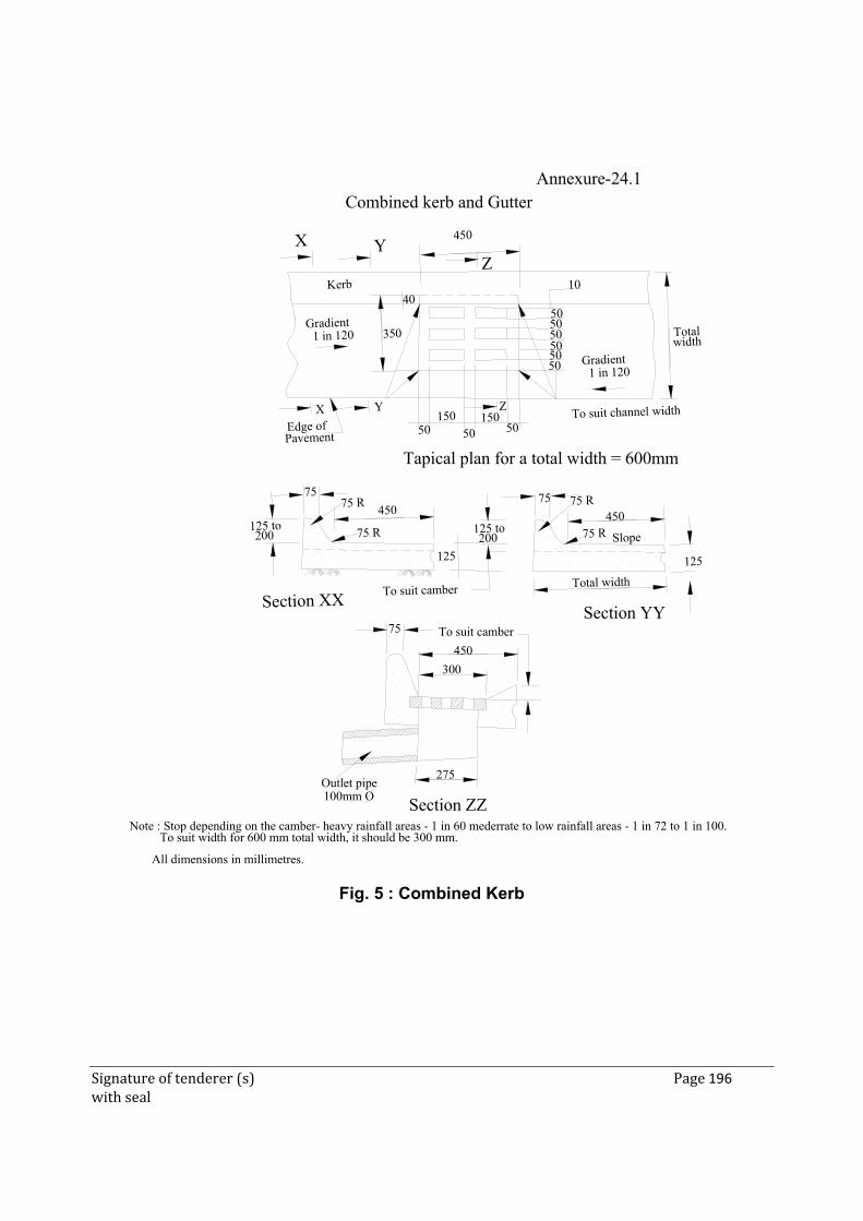
Signature of tenderer (s) Page 196 with seal
Outlet pipe
Combined kerb and Gutter
100mm O
275
75
300
450
To suit camber
To suit camber Total width
Section YY
125
Slope
75 R75
125 to200
125
75
450
Edge of Pavement
X Y
50150 To suit channel width
Gradient1 in 120
50
10
450YX
40Kerb
Totalwidth
3505050505050
Section ZZ
Tapical plan for a total width = 600mm
Section XX
125 to200 75 R75 R
75 R
Z
50 50150
450
Note : Stop depending on the camber- heavy rainfall areas - 1 in 60 mederrate to low rainfall areas - 1 in 72 to 1 in 100.To suit width for 600 mm total width, it should be 300 mm.
All dimensions in millimetres.
Gradient1 in 120
Z
Annexure-24.1
Fig. 5 : Combined Kerb

Signature of tenderer (s) Page 197 with seal
ADDITIONAL TECHNICAL SPECIFICATION
Signature of tenderer (s) Page 198 with seal
PART - III
ADDITIONAL TECHNICAL SPECIFICATIONS
1 STUD SHEAR CONNECTOR 1.1 Material: - The stud shear connector and ceramic ferrules shall conform to type SD1/UF as
per BS EN ISO 13918-2008. The diameter of ceramic ferrule D 7 as per Figure 13/Table 18 of BS EN ISO 13918 shall be 26. Mechanical properties of stud shear connectors shall be as per ISO 6892/BS EN ISO 13918–2008. Shape of tip of stud shear connectors may be chosen by manufacturer. The stud tip shall be supplied with flux in the form of press fitted aluminium ball or Aluminium spray coating
1.2 Welding: -
The welding of stud shear connectors shall be done by “Drawn arc stud welding with ceramic ferrule” Technique. The stud and the surface to which studs are welded shall be free from scale, moisture, rust and other foreign material. The stud base shall not be painted, galvanized or cadmium plated prior to welding. Welding shall not be carried out when temperature is below 10 degrees Celsius or surface is wet or during periods of strong winds unless the work and the welder are adequately protected. The welds shall be visually free from cracks and shall be capable of developing at least the nominal ultimate strength of studs. The procedural trial for welding the stud shall be carried out when specified by the Engineer
1.3 Testing: -
(a) Appearance test:
1. The weld to a stud shear connector should form a complete collar around the shank and free from cracks, excessive splashes of weld material, free from injurious laps fins, seams, twist, bends or other injurious defects.
2. Weld material should have a `Steel Blue’ appearance.
(b) Test to check the fixing of shear studs All studs need to be checked by a ring test.
1. Ring Test: Involves striking the side of the head of the stud with a 2 kg hammer. A Ringing tone achieved after striking indicates good fusion
whereas dull tone indicates a lack of fusion (BS 5400 – 6).
Signature of tenderer (s) Page 199 with seal
2. Bend Test: Test requires the head of a stud to be displaced laterally
by approximate 25% of its height using a 6 kg hammer. - The weld should then be checked for signs of cracking or lack of
fusion - Stud should not be bent back as this is likely to damage the weld. - The testing rate should be 1 in 50 (BG 5400 – 6).
1.4 Deleted. 1.5 Deleted. 2 Load Testing of Bridge
2.1 General
These guidelines cover testing of superstructures, excluding arches for evaluation of their flexural capacity. Testing for shear capacity is not considered. This test is not intended to assess ultimate load carrying capacity of bridge superstructure.
2.2 Test Procedures – Method of Loading The method of loading should be such as to either simulate the specific class of
vehicle or induce in the member(s) the calculated forces, viz., the bending moments at critical sections.
The test loads may be in the form of static loads on wheel/ track imprints of the
specific class of vehicle.
2.3 Static Loads 2.4 Simulation of the specific IRC vehicle The load effect on a span can be produced by building up pre weighed units on
loading imprints spaced as per codal provisions. The imprints are built either with brick masonry or concrete and rolled steel sections placed across pairs of imprints, so that platforms could be built on a group of four imprints for placement of pre weighed units. The area of each platform depends on the magnitude of the load and unit weight of individual unit. A pre weighed unit normally comprises sand or soil filled gunny bags, concrete cubes, bricks etc., which can be carried manually. Otherwise, large concrete blocks, containers of water or (stone) ballast or steel ingots could be used if mechanical handling facilities are available to load and unload them from test vehicles. Fig. below shows a scheme for building up 2 lanes of IRC Class A loading on the carriageway of a bridge. The loads are placed
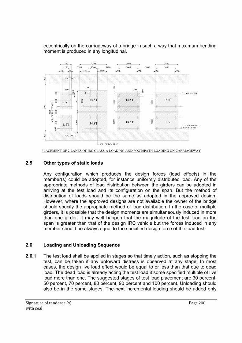
Signature of tenderer (s) Page 200 with seal
eccentrically on the carriageway of a bridge in such a way that maximum bending moment is produced in any longitudinal.
3300
3300
3200 12001100
43001800
350 350 1550 1550
3000
3000
3000
3600
3400
3000
3000
3000
3600
3000
300 300 300 300
3500
400
400
1800
1700
1800
7500
1500
1500
150250
500
8.2T
8.2T 34.8T
34.8T 18.5T 18.5T
18.5T 18.5T
1400
C.L. OF WHEELNEAR CURB
C.L. OF WHEEL
1800
PLACEMENT OF 2-LANES OF IRC CLASS-A LOADING AND FOOT6PATH LOADING ON CARRIAGEWAY
FOOTPATH
FOOTPATH
C.L. OF BEARING
C.L
. OF
PL
AT
FO
RM
200 200
380
2.5 Other types of static loads
Any configuration which produces the design forces (load effects) in the
member(s) could be adopted, for instance uniformly distributed load. Any of the appropriate methods of load distribution between the girders can be adopted in arriving at the test load and its configuration on the span. But the method of distribution of loads should be the same as adopted in the approved design. However, where the approved designs are not available the owner of the bridge should specify the appropriate method of load distribution. In the case of multiple girders, it is possible that the design moments are simultaneously induced in more than one girder. It may well happen that the magnitude of the test load on the span is greater than that of the design IRC vehicle but the forces induced in any member should be always equal to the specified design force of the load test.
2.6 Loading and Unloading Sequence 2.6.1 The test load shall be applied in stages so that timely action, such as stopping the
test, can be taken if any untoward distress is observed at any stage. In most cases, the design live load effect would be equal to or less than that due to dead load. The dead load is already acting the test load it some specified multiple of live load more than one. The suggested stages of test load placement are 30 percent, 50 percent, 70 percent, 80 percent, 90 percent and 100 percent. Unloading should also be in the same stages. The next incremental loading should be added only
Signature of tenderer (s) Page 201 with seal
after the deflections under the previous load have stabilized and all the stipulated observations are completed.
2.6.2 The selection of first stage of loading depends on the general condition of a bridge
and the load carrying capacity theoretically assessed. It is advisable to monitor the appearance and widening of flexural cracks at every stage of loading, so as to decide about placement of next incremental load. It is expected that the load deflection characteristics at every increment are linear and any abnormal behaviour is reflected in the load v/s deflection data. It the deflection observed exceeds the limit prescribed in the code the further loading shall be stopped. Subsequent actions shall be taken in consultation with appropriate authorities. Occasionally, crackling sounds at the locations of expansion joints are heard when the rotation capacity is exceeded, particularly, in balanced cantilever bridges. Spalling of delaminated concrete is also possible during load tests.
2.7 Preparatory Work
- All visual defects should be measured, mapped and plotted.
- It should be ensured that bearings are functional.
- Expansion gaps, joints should be cleared of all debris.
- It will be useful to give the surface of the superstructure a coat of white wash, so
that appearance of cracks becomes immediately perceptible.
2.8 Precautions
- Staging should be stable and safe.
- Staging for instruments and that for observers should be quite independent.
- Staging for instruments should be rigid.
- Due to temperature change, the superstructure may tend to hog or sag; therefore, it should be ensured that when this occurs, contact with the spindle of the dial gauge is not lost. Spindle extensions should be fixed to take care of this.
During the 24-hour retention period of built up load, care shall be taken to cover the pre weighed units with tarpaulin, so that rain or strong winds do not affect the stacking on the platforms.
2.9 Observations The following should be observe, measured and recorded at regular intervals of
one hour over a period of 24 hours:
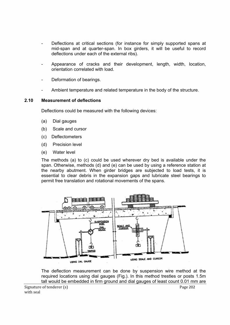
Signature of tenderer (s) Page 202 with seal
- Deflections at critical sections (for instance for simply supported spans at mid-span and at quarter-span. In box girders, it will be useful to record deflections under each of the external ribs).
- Appearance of cracks and their development, length, width, location, orientation correlated with load.
- Deformation of bearings.
- Ambient temperature and related temperature in the body of the structure.
2.10 Measurement of deflections Deflections could be measured with the following devices:
(a) Dial gauges
(b) Scale and cursor
(c) Deflectometers
(d) Precision level
(e) Water level
The methods (a) to (c) could be used wherever dry bed is available under the span. Otherwise, methods (d) and (e) can be used by using a reference station at the nearby abutment. When girder bridges are subjected to load tests, it is essential to clear debris in the expansion gaps and lubricate steel bearings to permit free translation and rotational movements of the spans.
The deflection measurement can be done by suspension wire method at the
required locations using dial gauges (Fig.). In this method trestles or posts 1.5m tall would be embedded in firm ground and dial gauges of least count 0.01 mm are
Signature of tenderer (s) Page 203 with seal
clamped to them. The spindles of the dial gauges are connected by a pair of adapters in plumb line with a GI or Invar wire. The wire is made taut by attaching a weight at the end. The method could be partly modified by using a (steel) scale and cursor instead of dial gauge, when the order of anticipated deflection exceeds 100mm. Fig. 2 also shown the scale and cursor method for measurement of large defections.
2.11 Procedure for Temperature Correction
A set of thermocouples are to be fixed at different locations of deflection
measurement for monitoring temperature of the bridge deck. In absence of thermocouples, hand held instruments could be used wherein a probe could be inserted in a preformed hole in concrete surface, for recording temperature. As a last resort, thermometers could also be suspended from trestles used for deflection measurement to measure the shade temperature. The number of thermocouples/thermometers/probes used could be about half the total number of locations for deflection measurement.
The superstructure tends to hog or sag due to variation in ambient temperature
and it is necessary to apply correction to the deflection data during static load test. This is so since the duration of loading or unloading operation in static load test could be for 4-5 hours.
For this purpose, the platforms on masonry imprints meant for building up static
loads should be placed in respective positions for observing thermal response of the bridge deck prior to load test. The deflection values and ambient temperature data are generally collected from dawn to dusk for two or three consecutive days at 1 hour intervals. The temperature vs. deflection data are collected on these days and a curve drawn for each station (dial gauge location), which is taken as basic curve for temperature correction. Usually the temperature – deflection characteristic would be a best fit obtained from a cluster of readings. The deflection reading at any location and temperature during load test, is super-imposed on the basic curve. The difference between the two values give the true deflection for the location under reference, corresponding to the same temperature. Fig. below shows typical characteristic of thermal response, super imposed on load vs. deflection data during a proof test.
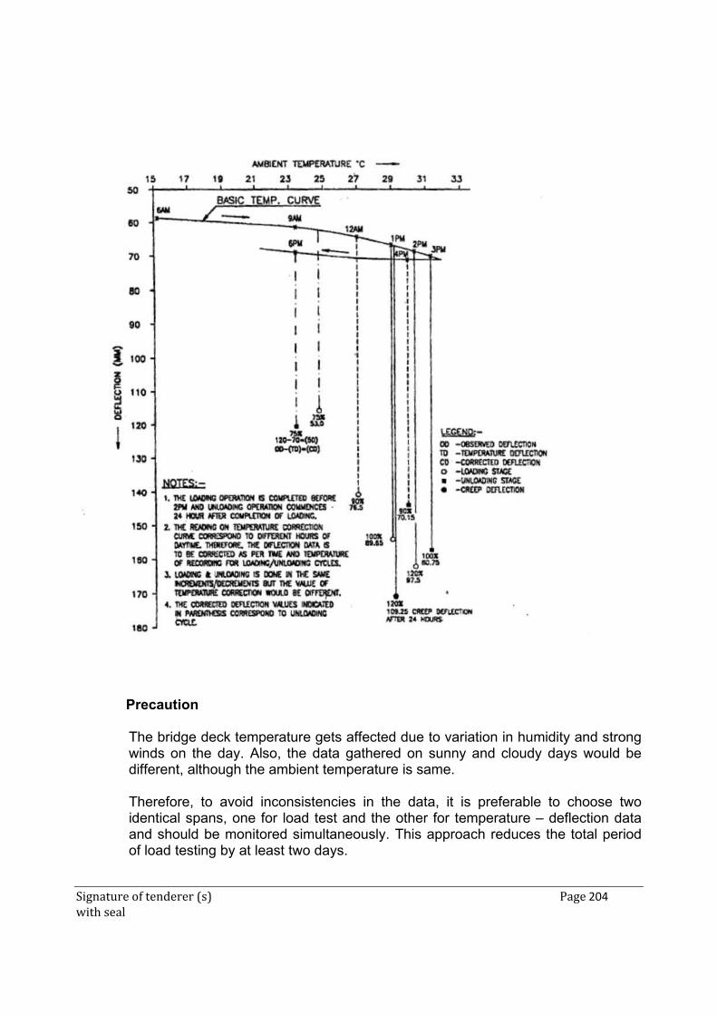
Signature of tenderer (s) Page 204 with seal
Precaution The bridge deck temperature gets affected due to variation in humidity and strong
winds on the day. Also, the data gathered on sunny and cloudy days would be different, although the ambient temperature is same.
Therefore, to avoid inconsistencies in the data, it is preferable to choose two
identical spans, one for load test and the other for temperature – deflection data and should be monitored simultaneously. This approach reduces the total period of load testing by at least two days.
Signature of tenderer (s) Page 205 with seal
2.12 Percentage Recovery of Deflection The percentage recovery could be calculated for values of deflection. The
percentage recovery is calculated at 24 hours after removal of load.
The calculation is done as follows after effecting temperature and/or rotation correction to deflection data:
Initial value (on dial gauge) … R1
Final value after placement of test load … R2
[Thereafter, measurements are to be taken at regular intervals of one hour].
Value at 24 hours after placement of test load ... R3
Value immediately after removal of test load … R4
[Thereafter, measurement is to be taken at regular intervals of one hour]
Value at 24 hours after removal of test load R5
Total deflection … R3-R1
Total recovery 24 hrs. after removal of test load .... R3-R5
Percentage of recovery of deflection … (R3-R5) x 100
24 hrs. after removal of test load (R3-R1)
2.13 Acceptance Criteria 2.13.1 The criterion of acceptance is based on recovery of deflection after removal of test
load. It is necessary to specify the quantum of applied load, the duration of the load on the span and the percentage recovery of deflection on removal of load.
2.13.2 For bridges designed for IRC Standard loadings, criteria for load testing of steel,
PSC and RCC superstructures are given in table below:
Signature of tenderer (s) Page 206 with seal
Table Acceptance Criteria
Sl. No.
Type of Bridges
Live Load Intensity for
Testing
Duration of Retention of Test Load
(Hrs.)
Minimum percentage recovery of Deflection at 24 hrs after removal of
Test Load
1 Reinforced concrete
* 24 75
2 Prestressed concrete
* 24 85
3 Steel * 24 85
4 Composite * 24 75
(* 1.0L plus corresponding impact as per IRC Codes)
A general acceptance criterion for the behavior of a structure under test load is that it shall not show “visible evidence of failure” which include appearance of cracks of width more than 0.3mm, spalling or deflections which are excessive and incompatible with safety requirements.
3 NON-DESTRUCTIVE INTEGRITY TESTING OF PILE 3.1 SCOPE
This specification covers the methods on non-destructive testing as per IS: 14893 of all types of concrete piles covered in IS 2911 (Part I/Sections 1, 2, 3 and 4).
3.2 SITE INFORMATION REQUIRED FOR THE TESTS The following information is generally required to carry out integrity tests:
(a) Location of site. (b) Pile types including size, material and reinforcement. (c) Layout of piles. (d) Details of pile installation (including construction and driving sequence and
rest periods). (e) Number of piles to be tested; (f) Subsurface profile/driving de ta i l s of the piles (More if variations are noted) (g) Depth of water table and soil investigation report, if any.
Signature of tenderer (s) Page 207 with seal
(h) Density of concrete; Strength of concrete. (i) Abnormal conditions noted while driving/boring or concreting of piles. The
normal daily report produced by the piling site should contain this information. In addition, any other information concerning planning and conducting the tests including relevant past experiences covering similar test(s) in the area, and,
(j) Details of test piles(s), if any.
3.3 TYPES OF TESTS
Various methods are available for checking the integrity of concrete piles after installation. In the most widely used method, impulses or vibrations are applied to the pile and measurements made of timings and attenuation of reflected signals.
The commonly used sonic methods, vibration methods, sonic logging techniques, etc, have been tried within the last 15-20 years in different parts of the world. However, the methods based on One Dimensional Stress Wave approach known as Sonic Integrity Testing, a Low Strain Integrity testing or Sonic Echo Testing have been used successfully in various parts of the world. The method is simple and quick enabling dozens of piles to be examined in a single working day without much interference in site activities.
The work carried out on sonic integrity testing of pile in the country has shown its efficiency; in assessing the structural quality of piles and therefore it is appropriate to frame in this code the salient features of this method.
3.3.1 The Low Strain Integrity Testing
This is a system of assessing the integrity of piles by the use of low stress wave imparted to the pile shaft and is also known as Sonic Integrity or Sonic Echo Test. A small metal/hard rubber hammer is used to produce a light tap on top of the pile. The shock travelling down the length of the pile is reflected back from the toe of the pile and recorded through a suitable transducer/accelerometer (also held on top of the pile close to the point of impact) in a computer disk or diskette for subsequent analysis.
The primary shock wave which travels down the length of the shaft is reflected from the toe by the change in density between the concrete and sub-strata. However, if the pile has any imperfections or discontinuities within its length these will set up secondary reflections which will be added to the return signal. (See Fig.).
By a careful analysis of the captured signal and knowledge of the conditions of the ground, age of concrete, etc., a picture of the locations of such problems can
Signature of tenderer (s) Page 208 with seal
be built up. The reflected stress wave can be monitored using either processing technique ; the observed signals are amplified and converted into digital display as velocity versus length or frequency versus mobility records, providing information o n structural integrity of piles.
The stress wave velocity and approximate pile lengths are provided as input for the integrity testing. The stress wave velocity is dependent on the Young's modulus and mass density of pile concrete. This value generally lies between 3000-4000 meter per second depending on the grade of concrete used (M15-M25).
3.3.2 Normally more than one recording of signals is done until repeatability of signals
is achieved. If necessary, averaging of signals is also done to achieve more informative signals. In a suspected pile the test should be repeated at more than one location on top of the pile.
3.3.3 The tests shall be conducted on piles whose length is correctly recorded or on
test piles where available, to determine the value of stress wave velocity and characteristic or reference signal for comparing the signals for testing subsequent piles.
3.3.4 The method of testing involves high skill and use of computerized equipment.
Therefore, the tests should be performed and interpreted b y trained and experienced personnel.
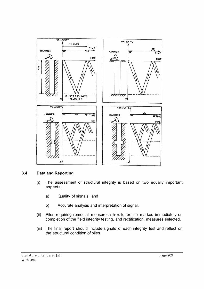
Signature of tenderer (s) Page 209 with seal
3.4 Data and Reporting
(i) The assessment of structural integrity is based on two equally important aspects:
a) Quality of signals, and b) Accurate analysis and interpretation of signal.
(ii) Piles requiring remedial measures shou ld be so marked immediately on
completion of the field integrity testing, and rectification, measures selected. (iii) The final report should include signals of each integrity test and reflect on
the structural condition of piles.
Signature of tenderer (s) Page 210 with seal
3.5 GENERAL REQUIREMENTS OF THE TESTS
(i) Piles shall be trimmed to cut off level or sound concrete level before the test with all laitance removed. No pile cap blindage work should be undertaken prior to the test.
(ii) The area surrounding the pile should be free from standing water a n d kept
dewatered during the tests. (iii) The pile head should be accessible. (iv) Testing should be free of work likely to cause disturbance. (v) The cast-in-situ piles should not be tested normally before 14 days of
casting. (vi) The test piles, if available at site, can be used to determine the pulse
velocity and characteristic or reference signal generated. Where no test pile is available information can be obtained from cast piles whose length is accurately recorded.
3.6 LIMITATIONS OF NDT METHODS
(i) Non-Destructive Testing of piles does not provide the load carrying capacity of piles.
(ii) It does not provide information regarding verticality or displacement in
position of piles. (iii) Minor deficiencies like local loss of cover, small intrusions or type of
conditions of materials at the base of piles are undetectable. Integrity testing may not identify all imperfections, but it can be useful tool in identifying major defects within the effective lengths. The test may identify minor impedance variations that may not affect the bearing capacity of piles. In such cases, the engineer should use judgment as to the acceptability of these piles considering other factors such as load redistribution to adjacent pile, load transfer to the soil above the defect, applied safety factors and structural load requirements.
(iv) Based on the latest information available, the limitations relating to the
depths up to which the integrity tests can be carried on piles depends on the surrounding strata and damping within the concrete.
(v) The present experience of Non-Destructive Testing of piles is up to a
diameter of 1500 mm.
Signature of tenderer (s) Page 211 with seal
(vi) Soil stiffness or founding on rock of similar density as the pile will attenuate the signals such that there will be little or no toe reflection.
(vii) The low strain integrity method is applicable to cast – in – situ concrete
bored and driven piles. Conclusive results are rarely obtained in case of segmented precast reinforced concrete driven piles or precast piles in pre bored holes.
3.7 METHOD OF MEASUREMENTS: It will be measured in number. 3.8 PAYMENTS: The rate includes cost of all materials, labour, equipments &
operations required to do this test. 4 HIGH-STRAIN DYNAMIC TESTING OF PILES
This test method covers the procedure for testing vertical or batter piles individually to determine the force and velocity response of the pile to an impact force applied axially by a pile driving hammer to the top of the pile. This test method is applicable to deep foundation units that function in a manner similar to foundation piles, regardless of their method of installation provided that they are receptive to high strain impact testing.
ASTM standard D4945-89 may involve hazardous materials, operations, and equipment. This standard does not purport to address all of the safety problems associated with its use. It is the responsibility of the user of this standard to establish appropriate safely and health practices and determine the applicability of regulatory limitations prior to use.
Note 1: High-strain dynamic testing requires a strain at impact which is representative of a force in the pile having the same order of magnitude, or greater, than the ultimate capacity of the pile.
Note 2: This standard method may be applied for high, strain dynamic testing of piles with the use of only force or strain transducers and/or acceleration, velocity or displacement transducers as long as the test results dearly state how the testing deviates from the standard.
Note 3: A suitable follower may be required for testing cast- in-place concrete piles. This follower should have an impedance within 10% of that of the pile. For mandrel driven piles, the mandrel may be instrumented in a similar way to a driven pile.
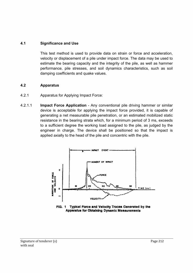
Signature of tenderer (s) Page 212 with seal
4.1 Significance and Use This test method is used to provide data on strain or force and acceleration,
velocity or displacement of a pile under impact force. The data may be used to estimate the bearing capacity and the integrity of the pile, as well as hammer performance, pile stresses, and soil dynamics characteristics, such as soil damping coefficients and quake values.
4.2 Apparatus 4.2.1 Apparatus for Applying Impact Force: 4.2.1.1 Impact Force Application - Any conventional pile driving hammer or similar
device is acceptable for applying the impact force provided, it is capable of generating a net measurable pile penetration, or an estimated mobilized static resistance in the bearing strata which, for a minimum period of 3 ms, exceeds to a sufficient degree the working load assigned to the pile, as judged by the engineer in charge. The device shall be positioned so that the impact is applied axially to the head of the pile and concentric with the pile.
Signature of tenderer (s) Page 213 with seal
4.2.2 Apparatus for Obtaining Dynamic Measurements: 4.2.2.1 Force or Strain Transducers-The apparatus shall include transducers, which
are capable of independently measuring strain and acceleration versus time at a specific location along the pile axis during the impact event. A minimum of two of each of these devices shall be securely attached on opposite sides of the pile so that they do not slip. Bolt-on, glue-on, or weld-on transducers are acceptable. The strain transducers shall have a linear output over the entire range of possible pile strains. When attached, their natural frequency shall be in excess of 7500 Hz. The measured strain shall be converted to force using the pile cross-section area and dynamic modulus of elasticity at the measuring location. The dynamic modulus of elasticity may be assumed to be 29 to 30 x 106 psi for steel. The dynamic modulus of elasticity for concrete and wood piles may be estimated by measure-ment during a compression test in accordance with Test Method C469 and Methods D198. Alternatively, they may be calculated from the wave speed determined.
4.2.2.1.1 Force measurements also can be made by force transducers placed between
the pile head and the driving hammer, although it should be recognized that such a transducer may alter the dynamic characteristics of the driving system. Force transducers shall have an impedance between 50% and 200% of the pile impedance. The output signal must be linearly proportional to the axial force, even under eccentric load application. The connection between the force transducers and the pile shall have the smallest possible mass and least possible cushion necessary to prevent damage.
4.2.2.2 Acceleration, Velocity or Displacement Transducers - Velocity data shall
be obtained with accelerometers, provided the signal can be processed by integration in the apparatus for reducing data. A minimum of two accelerom-eters with a resonant frequency above 7500 Hz shall be at equal radial distances on diametrically opposite sides of the pile, attached to the pile securely so that they do not slip. Bolt-on, glue-on, or weld-on transducers are acceptable. The accelerometers shall be linear to at least 1000 g and 7500 Hz for satisfactory results on concrete piles. For steel piles, it is advisable to use accelerometers that are linear up to 5000 g. Either a-c or d-c accelerometers can be used. If a-c devices are used, the time constant shall be at least 0.2 s. Alterna-tively, velocity or displacement transducers may be used to obtain velocity data, provided they are equivalent in per-formance to the specified accelerometers.
4.2.2.3 Placement of Transducers - The transducers shall be placed, diametrically
opposed and on equal radial distances, at the same axial distance from the
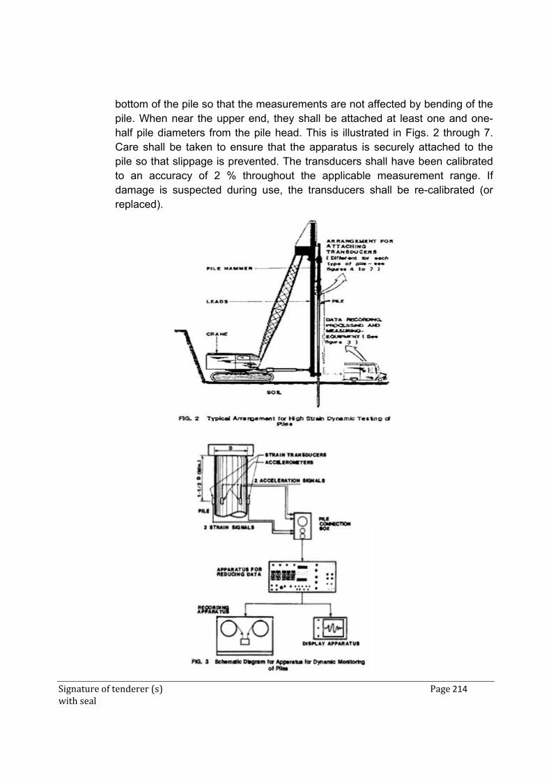
Signature of tenderer (s) Page 214 with seal
bottom of the pile so that the measurements are not affected by bending of the pile. When near the upper end, they shall be attached at least one and one-half pile diameters from the pile head. This is illustrated in Figs. 2 through 7. Care shall be taken to ensure that the apparatus is securely attached to the pile so that slippage is prevented. The transducers shall have been calibrated to an accuracy of 2 % throughout the applicable measurement range. If damage is suspected during use, the transducers shall be re-calibrated (or replaced).
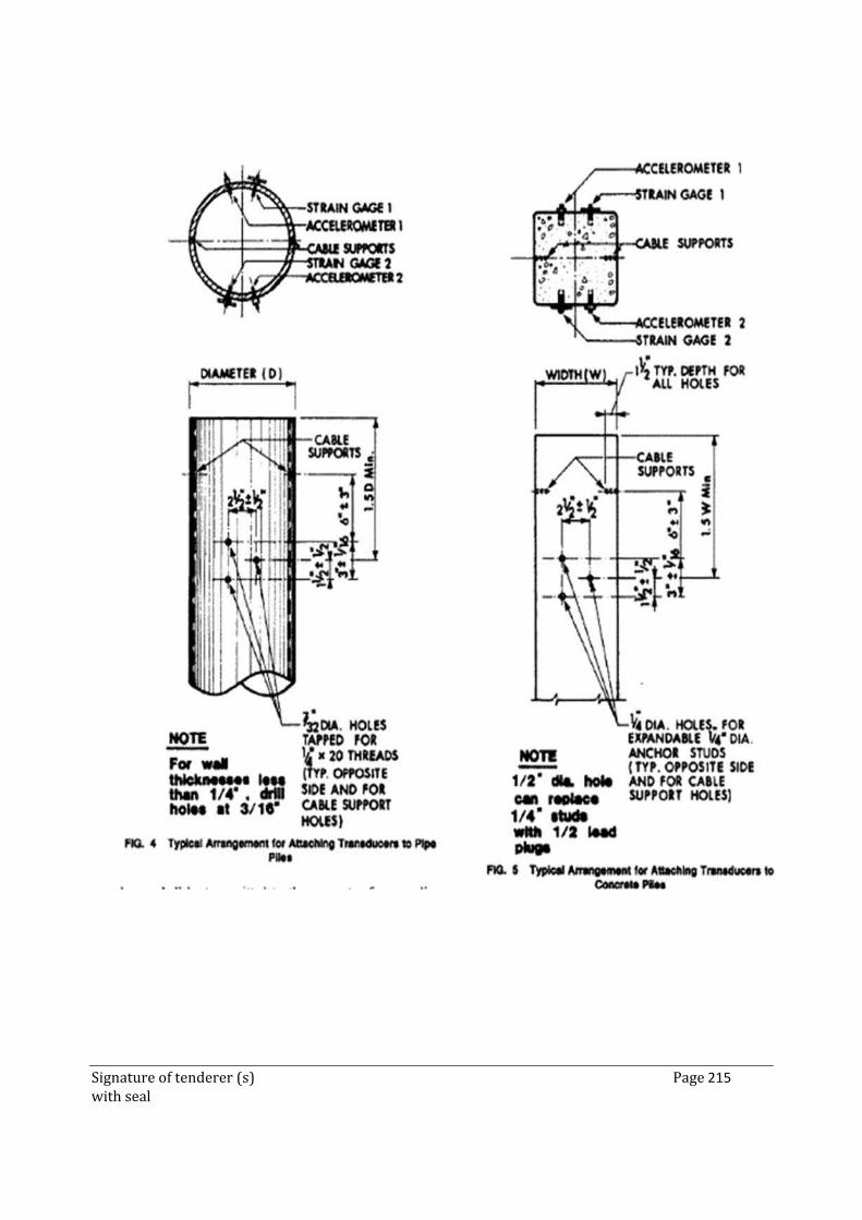
Signature of tenderer (s) Page 215 with seal
Signature of tenderer (s) Page 216 with seal
4.3 Signal Transmission-The signals from the transducers shall be transmitted to
the apparatus for recording, reducing, and displaying the data (see 5.4) by means of a cable or equivalent. This cable shall limit electronic or other interferences to less than 2 % of the maximum signal expected. The signals arriving at the apparatus shall be linearly proportional to the measurements at the pile over the frequency range of the equipment.
4.4 Apparatus for Recording, Reducing and Displaying Data: 4.4.1 General - The signals from the transducers during the impact event shall be
transmitted to an apparatus for recording, reducing, and displaying data to allow deter-mination of the force and velocity versus time. It may be desirable to also determine the acceleration and displace-ment of the pile head, and the energy transferred to the pile. The apparatus shall include an oscilloscope or oscillograph for displaying the force and velocity traces, a tape recorder or equivalent for obtaining a record for future analysis, and a means to reduce the data. The apparatus for recording, reducing, and displaying data shall have the capability of making an internal calibration check of strain, acceleration, and time scales. No error shall exceed 2 % of the maximum signal expected. A typical schematic arrangement for this apparatus is illustrated in Fig. 3.
4.4.2 Recording Apparatus - Signals from the transducers shall be recorded
electronically in either analog or digital form so that frequency components have a low pass cut-off frequency of 1500 Hz (-3 dB). When digitizing, the sample frequency shall be at least 5000 Hz for each data channel.
4.4.3 Apparatus for Reducing Data - The apparatus for reducing signals from the
transducers shall be an analog or digital computer capable of at least the following functions:
4.4.3.1 Force Measurements - apparatus shall provide signal conditioning,
amplification and calibration for the force measurements system. If strain transducers are used (see 5.2.1), the apparatus shall be able to compute the force. The force output shall be continuously balanced to zero except during Velocity the impact Data-If event.
4.4.3.2 Velocity Data - accelerometers are used (see 5.2.2), the apparatus shall
integrate the acceleration over time to obtain velocity. If displacement transducers are used, the apparatus shall differentiate the displacement over
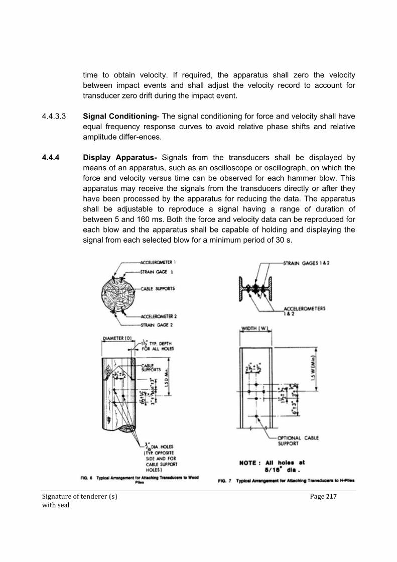
Signature of tenderer (s) Page 217 with seal
time to obtain velocity. If required, the apparatus shall zero the velocity between impact events and shall adjust the velocity record to account for transducer zero drift during the impact event.
4.4.3.3 Signal Conditioning- The signal conditioning for force and velocity shall have
equal frequency response curves to avoid relative phase shifts and relative amplitude differ-ences.
4.4.4 Display Apparatus- Signals from the transducers shall be displayed by
means of an apparatus, such as an oscilloscope or oscillograph, on which the force and velocity versus time can be observed for each hammer blow. This apparatus may receive the signals from the transducers directly or after they have been processed by the apparatus for reducing the data. The apparatus shall be adjustable to reproduce a signal having a range of duration of between 5 and 160 ms. Both the force and velocity data can be reproduced for each blow and the apparatus shall be capable of holding and displaying the signal from each selected blow for a minimum period of 30 s.
Signature of tenderer (s) Page 218 with seal
4.5 Procedure 4.5.1 General-Record applicable project information (Section 7). Attach the
transducers (see 5.2) to the pile, perform the internal calibration check, and take the dynamic measurements for the impacts during the interval to be monitored together with routine observations of penetration resistance. Determine properties from a minimum of ten impact records during initial driving and, when used for soil resistance computations, normally from one or two represcn ..tative blows at the beginning of restriking. The force and velocity versus time signals may be reduced by computer or may be reduced manually to calculate the developed force, velocity, acceleration, displacement, and energy over the impact event.
4.5.2 Determination of Strain Wave Speed (optional) - Place the pile on supports
or level ground free and clear from neighbouring piles and obstructions. Attach accelerometer to one end of the pile and strike the other end of the pile with a sledge hammer of suitable weight. Take care not to damage or dent the pile. Record (see 5.4.2) and display (see 5.4.4) the accelerometer signal. Measure the time between acceleration peaks for as many cycles of reflection as possible. Divide this time by the appropriate travel length of the strain waves during this interval to determine the wave speed.
4.5.3 Preparation - Mark the piles clearly at appropriate intervals. Attach the
transducers securely to the piles by bolting, gluing, or welding. For pile materials other than steel, determine the wave speed (see 6.2). Position the apparatus for applying the impact force so that the force is applied axially and concentrically with the pile. Set up the apparatus for recording, reducing, and displaying data so that it is operational and the force and velocity signals are zeroed.
4.5.4 Taking Measurements - Record the number of im-pacts for a specific
penetration. For drop hammers and single acting diesel and steam hammers, record the drop of the ram or ram travel length. Record the number of blows per minute delivered by the hammer. For double acting diesel hammers, measure the bounce pressure, and, for double acting steam or compressed-air hammers, measure the steam or air pressure in the pressure line to the hammer. Take, record, and display a series of force and velocity
Signature of tenderer (s) Page 219 with seal
measurements. Compare the force and the product of velocity and imped-ance (see 3.2.1) at the moment of impact.
Note 4: If the dynamic measurements are to be used for bearing capacity
computations, take the dynamic measurements during restriking of the pile at time periods sufficiently long after the end of initial driving to allow pore water pressure and soil strength changes to occur. Further geotechnical conditions. such as underlying compressible layers, need always be considered, as they should be in any type of bearing capacity computation.
Note 5: Warning-Before approaching a pile being driven, check that no material or other appurtenances can break free and jeopardize the safety of persons in the vicinity.
Note 6: If set-rebound measurements are required. attach a remov-able sheet to the pile and install a horizontal reference beam in the ground adjacent to the pile. Draw a baseline on the sheet from the reference beam before and after each impact.
4.5.5 Data Quality Checks - For confirmation of data quality, periodically compare
the force and the product of the velocity and pile impedance at the moment of impact for proportionality agreement and the force and velocity versus time over a series of selected and generally consecutive impact events for consistency. Consistent and proportional signals from the force or strain transducers and the accelera-tion, velocity or displacement transducers are the result of the transducers systems and the apparatus for recording, reducing and displaying data being properly calibrated. If the signals are not in proportionality agreement, investigate the cause and correct the situation. If the cause is determined to be a transducer, it must be recalibrated before further use. Perform internal calibration checks at the beginning and end of each data set.
NOTE 7-lt is generally recommended that all components of the apparatus for obtaining dynamic measurements and the apparatus for recording, reducing and displaying data be calibrated at least once a year.
4.5.6 Analysis of Measurements: 4.5.6.1 Obtain force and velocity from the readout of the apparatus for reducing data
(see 5.4.3) or from the display apparatus (see 5.4.4). Record the impact force and velocity and the maximum and minimum forces for the selected representative blows. Obtain the maximum acceleration directly from the accelerometer signal or by differentiation of the velocity versus time record.
Signature of tenderer (s) Page 220 with seal
Obtain the displacement from the pile driving record, the set-rebound curve, and from the displacement transducer, if used in accordance with 5.2.2 or by integration of the velocity versus time record. Obtain the maximum energy transferred to the location of the transducers.
4.5.6.2 The recorded data may be subjected to analysis in a computer. The results of
the analysis may include an assessment of integrity of the pile, the driving system performance, and the maximum dynamic driving stresses. The results may also be used for evaluation of static soil resistance and its distribution on the pile at the time of the testing. Such further use of the data is a matter of proper engineering judgment.
Note 8 - Normally, there is better correlation between mobilized resistance and
bearing capacity where there is a measurable net penetration per impact. Note 9 - Evaluation of static soil resistance and its distribution can be based on
a variety of analytical methods and is the subject of individual engineering judgment. The input into the analytical methods may or may not result in the dynamic evaluation matching static load test data. It is desirable and often necessary to calibrate the result of the dynamic analysis with those of a static pile load test carried out according to Method D 1143.
4.6. Report The report of the dynamic testing shall include the all the information as per
given in ASTM D4945. 4.7 METHOD OF MEASUREMENTS: It will be measured in number. 4.8 PAYMENTS: The rate includes cost of all materials, labour, equipments &
operations required to do this test. 5 PROVIDING AND ERECTING STREET LIGHT 5.1 A stand alone Street Light comprises a compact LED, and control electronics, inter-
connecting wires/cables, module mounting hardware, battery box, Operation, instruction and maintenance manual on a 9m high steel circular hollow octagonal pole.
Signature of tenderer (s) Page 221 with seal
5.2 COMPONENT SPECIFICATIONS Pole 9m high steel circular hollow octagonal pole 9m high
spaced 40m a part, 0.9 m overhang on single sides fixed on the footpath,
Overhang hot dipped galvanised Overhang (60 X 3.25 mm) with cap (250 x 137.9 x 4.05 mm)
Cable trays 150 mm width X 50 mm depth X 1.6 mm thickness M.S. cable trays bends with perforation not more than 17.5%,, joined with connectors, suspended from the ceiling with M.S. suspenders including bolts & nuts, painting suspenders etc as required
LED 60 W IP-65/ IP-66 protected street light luminaries on existing bracket. Fixture made from powder coated single piece pressure die cast aluminum housing with heat dissipation fins on housing with high power LEDs . Diffuser / glass cover for ensuring IP-65 protection for lamp and control gear compartment, system lumen output of 100 lum/watt high power LED. Integrated driver shall be high efficiency having efficiency more than 85 % and in compliance to IEC standards. System life of 50000 burning hours with 70 % of initial lumens maintained. Fixture shall be in CE compliance.
Earth wire 2 X 1.5 sq. mm + 1 X 1.5 sq. mm Wiring for circuit/ submain wiring alongwith earth wire with the following sizes of FRLS PVC insulated copper conductor, single core cable in surface/ recessed steel conduit as required
MCB Triple Pole, 5 A to 32 A rating, 240/415 V, 10 kA, "C" curve, miniature circuit breaker suitable for inductive load of following poles in the existing MCB DB complete with connections, testing and commissioning etc. as required
Earthing plate Earthing with G.I. earth plate 600 mm X 600 mm X 6 mm thick including accessories, and providing masonry enclosure with cover plate having locking arrangement and watering pipe of 2.7 metre long etc. (but without charcoal/ coke and salt ) as required.
Earth pipe Earthing with G.I. earth pipe 4.5 metre long, 40 mm dia including accessories, and providing masonry enclosure with cover plate having locking arrangement and watering pipe etc. with charcoal/ coke and salt as required
Earth wire Supplying and laying 6 SWG G.I. wire at 0.50 metre below ground level for conductor earth electrode, including connection/ termination with GI thimble etc. as required
Earth connection
Providing and laying earth connection from earth electrode with 6 SWG dia G.I. Wire in 15 mm dia G.I. pipe from earth electrode including connection with G.I. thimble excavation and re-filling as required.

Signature of tenderer (s) Page 222 with seal
GI strip in pipe Providing and fixing 25 mm X 5 mm G.I. strip in 40 mm dia G.I. pipe from earth electrode including connection with G.I. nut, bolt, spring, washer excavation and re-filling etc. as required.
GI strip Providing and fixing 25 mm X 5 mm G.I. strip on surface or in recess for connections etc. as required.
Time switch Supplying, installation, testing and commissioning of Astronomical time switch of following configuration to be mounted in feeder pillars / Lighting DBs for automatic switching On & OFF of street lights at sun set & sun rise or twilight(Auto ON, Auto OFF, Auto modes) with manual override facility with 12/24 hour display format with suitable battery and indication for relay status i/c programming at site complete as required.
End termination
Supplying and making end termination with brass compression gland and aluminium lugs for following size of PVC insulated and PVC sheathed / XLPE aluminium conductor cable of 1.1 KV grade as required. 4 X 16 sq. mm (28mm)
FRLS Supplying and drawing following sizes of FRLS PVC insulated copper conductor, single core cable in the existing surface/ recessed steel/ PVC conduit as required. 3 x 2.5 sq. mm
Other Control electronics, Module mounting hardware, Battery box, Interconnecting wires/cables, Switches Etc
5.3 DUTY CYCLE The System should be designed to automatically switch ON at dusk, operate throughout the night and automatically switch OFF at the down. 5.4 MECHANICAL HARDWARE
(i) A metallic frame structure (with corrosion resistance paint) to be fixed on the pole to hold the SPV module(s). The frame structure should have provision to adjust its angle of inclination to the horizontal between 0 and 45, so that the module(s) can be oriented at the specified tilt angle.
(ii) The pole should be made of mild steel pipe of appropriate thickness with a height
of 9 meters above the ground level after erection. The erected pole should be able to withstand the wind pressure in heavy storm hence sufficient length of the pole should be kept below ground level.
(iii) The pole should have the provision to hold the weather proof lamp housing. It
should be painted with a corrosion resistant paint.

Signature of tenderer (s) Page 223 with seal
5.5. WARRANTEE/ GUARANTEE
(i) The complete Street Light must be warranted against any manufacturing/ design/ erection defects for a minimum period of 5 years.
(ii) The Warrantee/ Guarantee Card to be supplied with the Street Light must
contain the details of the system supplied. The manufacturers can provide additional information about the system and conditions of warranty as necessary.
(iii) During the Warrantee/ Guarantee period, EPIL users will have all the rights to
cross check the performance of the Street Lights. EPIL may carry out the frequent inspections of the Street Lights erected and randomly pick up to get them tested at Govt. approved any test center. If during such tests the Street Lights or its any component is not found as per the specified technical parameters, EPIL will take the necessary action. The decision of EPIL in this regard will be final and binding on the tenderer.
5.6. OTHER FEATURES
(i) Components and parts used in the Solar Street Lights should conform to the latest BIS specifications, wherever such specifications are available and applicable.
(ii) Necessary lengths of wires/cables and fuses should be provided with the system.
(iii) An Operation, Instruction and Maintenance Manual, in English and the local language, should be provided with the Street Lights. The following minimum details must be provided in the Manual: • About LED. • Clear instructions about erection of pole and mounting of assembly on the
pole. • About electronics. • Clear instructions on regular maintenance and trouble shooting of the Street Lights. • Name and address of the contact person for maintenance
Signature of tenderer (s) Page 224 with seal
ADDITIONAL SPECIAL CONDITIONS:-
1. Contractor shall have to arrange precision measuring equipments like, leveling instrument, staff, measuring tape etc. during execution of work.
2. Adequate traffic block will be arranged for launching girder. If block could not be arranged for some valid reasons, Railway will not be liable to pay any claim/compensation.
3. Contractor shall set up a well equipped laboratory at site along with site office. The size of laboratory shall be 3.00 m x 4.00 m or more constructed with suitable material fully covered and secured, neat and clean. The laboratory shall be provided with necessary equipments placed suitably to perform various tests on materials, i.e. cement, steel concrete & others etc and shall be supervised by contractor’s qualified lab supervisor.
4. Contractor should keep following equipments at site. Auto level Jack hammer along with compressor in case of Rocky strata /dismantling of
existing concrete. Other equipments in Laboratory for testing of concrete such as cube testing
machine, cone apparatus and sieve set etc. 5. A Detailed report of work done along with sketches, about the work done shall be
submitted by contractor in two copies duly incorporating photographs of the work done at various stages along with video of the work at different stages.
6. Detailed specifications for design mix concrete and equipment should be followed according to Railway specifications.
7. For M20 & M 35/40 grade concrete, contractor should use mix design. The design mix are to be submitted by the contractor from any from IITs/NITs/ Reputed Govt engineering colleges or NABL approved lab only for which nothing extra will be paid.
8. To maintain workability of concrete, super plasticizer of reputed brand like Fosroc or equivalent only should be used. The super plasticizer shall be as per IS specification. To ensure this, super plasticizer should be got tested by contractor as per the IS: 6925 & IS: 9013 specifications from IITs/NITs/ Reputed Govt / NABL Approved laboratories only.
9. Contractor should arrange suitable lighting arrangement at site either taking connection from state electricity board or keeping generator at site.
10. For bringing crane at site contractor will have to prepare road up to site. At some place railways land may not be available for bringing crane to bridge site. Contractor will have to arrange the crane shifting from private land. For this purpose contractor will have to bear all cost and railway will not pay any extra amount.
11. Whenever required contractor shall arrange accommodation for inspecting officials near by site. No extra payment will be made for this.

Signature of tenderer (s) Page 225 with seal
Site office accommodation :
The contractor shall develop one site office at site within one month from the date of commencement of the work. The site office should be sufficient enough to meet the contractor’s own requirement apart from Railway’s requirement, which should be well furnished for at least two officer/ supervisor & class –IV staff for office & camping purpose.
No extra payment will be made for this item.