Tender Document: FWA610 - Wirt Artna
398
i Closing Date: 15 th July 2013 at 10:00am Advert Notice FWA 610 Date Published: 3 rd June 2013 TENDER FOR RESTORATION, ALTERATION WORKS, FINISHING WORKS, MECHANICAL AND ELECTRICAL WORKS AT THE LASCARIS TUNNELS, GARRISION CHURCH CRYPT AND ST PETER AND ST PAUL’S COUNTERGUARD. Tender Document: FWA610 Cost of this tender dossier: Not Applicable Operational Programme I – Cohesion Policy 2007-2013 Investing in Competitiveness for a Better Quality of Life Tender part-financed by the European Union European Regional Development Fund (ERDF) Co-financing rate: 72.25% EU funds; 12.75% National Funds; 15% Private Share Investing in your future
-
Upload
khangminh22 -
Category
Documents
-
view
0 -
download
0
Transcript of Tender Document: FWA610 - Wirt Artna

i
Closing Date: 15th July 2013 at 10:00am Advert Notice FWA 610
Date Published: 3rd June 2013
TENDER FOR RESTORATION, ALTERATION WORKS, FINISHING
WORKS, MECHANICAL AND ELECTRICAL WORKS AT THE LASCARIS TUNNELS, GARRISION CHURCH CRYPT AND ST PETER AND ST PAUL’S
COUNTERGUARD.
Tender Document: FWA610 Cost of this tender dossier: Not Applicable
Operational Programme I – Cohesion Policy 2007-2013 Investing in Competitiveness for a Better Quality of Life Tender part-financed
by the European Union European Regional Development Fund (ERDF)
Co-financing rate: 72.25% EU funds; 12.75% National Funds; 15% Private Share
Investing in your future

ii

i | P a g e
Table of Contents
Table of Contents ............................................................................................ i VOLUME 1 SECTION 1 – INSTRUCTIONS TO TENDERERS...............................................1 A. GENERAL PART ............................................................................................1
1. General Instructions........................................................................................................................... 1 2. Timetable............................................................................................................................................. 1 3. Lots........................................................................................................................................................ 2 4. Financing .............................................................................................................................................. 2 5. Eligibility .............................................................................................................................................. 2 6. Selection Criteria................................................................................................................................ 2 7. Only One Tender Per Tenderer ........................................................................................................ 3 8. Tender Expenses ................................................................................................................................. 3 9. Site Inspection..................................................................................................................................... 3
B. TENDER DOCUMENTS .....................................................................................4 10. Content of Tender Document......................................................................................................... 4 11. Explanations/Clarification Notes Concerning Tender Documents........................................... 4 12. Labour Law ........................................................................................................................................ 4 13. Law...................................................................................................................................................... 4
C. TENDER PREPARATION...................................................................................5 14. Language of Tenders........................................................................................................................ 5 15. Presentation of Tenders .................................................................................................................. 5 16. Content of Tender (Single-Envelope System).............................................................................. 5 17. Tender Prices .................................................................................................................................... 6 18. Currencies of Tender and Payments ............................................................................................. 6 19. Period of Validity of Tenders ......................................................................................................... 7 20. Tender Guarantee (Bid Bond) ........................................................................................................ 7 21. Variant Solutions............................................................................................................................... 7 22. Preparation and Signing of Tenders .............................................................................................. 7
D. SUBMISSION OF TENDERS................................................................................8 23. Sealing and Marking of Tenders ..................................................................................................... 8 24. Extension of Deadline for Submission of Tenders....................................................................... 8 25. Late Tenders ..................................................................................................................................... 8 26. Alterations and Withdrawal of Tenders........................................................................................ 8
E. OPENING AND EVALUATION OF OFFERS ..............................................................9 27. Opening of Tenders .......................................................................................................................... 9 28. Secrecy of the Procedure................................................................................................................ 9 29. Clarification of Tenders .................................................................................................................. 9 30. Tender Evaluation Process.............................................................................................................. 9 31. Correction of Arithmetical Errors ................................................................................................ 10
F. CONTRACT AWARD...................................................................................... 11 32. Criteria for Award .......................................................................................................................... 11 33. Right Of Fondazzjoni Wirt Artna To Accept Or Reject Any Tender ...................................... 11 34. Notification of Award, Contract Clarifications ......................................................................... 11 35. Contract Signing and Performance Guarantee.......................................................................... 12 36. Commencement of Works (Order To Start Works) ................................................................... 12
G. MISCELLANEOUS......................................................................................... 13 37. Ethics Clauses.................................................................................................................................. 13 38. Data Protection and Freedom of Information ........................................................................... 13 39. Gender Equality .............................................................................................................................. 14
VOLUME 1 SECTION 2 – TENDER FORM ................................................................. 15

ii | P a g e
VOLUME 1 SECTION 3 – TENDER GUARANTEE FORM................................................. 18 VOLUME 1 SECTION 4 - TENDERER’S STATEMENTS ................................................. 19
1. Statement on Conditions of Employment .................................................................................... 19 2. Experience as Contractor ................................................................................................................ 20 3. Literature/List of Samples.............................................................................................................. 22
VOLUME 1 SECTION 5 – GLOSSARY ...................................................................... 24 VOLUME 1 SECTION 6 – EXTRACTS FROM THE PUBLIC PROCUREMENT REGULATIONS........ 26
Part XIII - Appeals.................................................................................................................................. 26 Form 10 - Graphic Work Schedule ...................................................................................................... 27
VOLUME 2 SECTION 1 – DRAFT CONTRACT FORM .................................................... 28 VOLUME 2 SECTION 2 – GENERAL CONDITIONS ....................................................... 30 VOLUME 2 SECTION 3 – SPECIAL CONDITIONS......................................................... 31
Article 2: Law and language of the contract ............................................................................ 31 Article 3: Order of precedence of contract documents ............................................................... 31 Article 4: Communications................................................................................................. 31 Article 5: Supervisor and Supervisor's representative.................................................................. 31 Article 8: Supply of Documents ........................................................................................... 32 Article 10: Assistance with Local Regulations........................................................................... 32 Article 11: The Contractor’s Obligations................................................................................. 32 Article 13: Performance Guarantee ...................................................................................... 33 Article 14: Insurance........................................................................................................ 33 Article 15: Performance Programme (Timetable) ...................................................................... 34 Article 17: Contractor’s Drawings......................................................................................... 34 Article 18: Tender Prices................................................................................................... 34 Article 22: Interference with Traffic ..................................................................................... 34 Article 25: Demolished Materials ......................................................................................... 34 Article 26: Discoveries...................................................................................................... 34 Article 31: Commencement Date ......................................................................................... 34 Article 32: Period of Performance ........................................................................................ 35 Article 34: Delays in Execution............................................................................................ 35 Article 35: Variations and Modifications ................................................................................. 35 Article 39: Quality of Works and Materials .............................................................................. 35 Article 40: Inspection and Testing ........................................................................................ 35 Article 42: Ownership of Plants and Materials .......................................................................... 35 Article 43: Payments: General Principles................................................................................ 35 Article 44: Pre-financing ................................................................................................... 36 Article 45: Retention Monies .............................................................................................. 36 Article 46: Price Revision .................................................................................................. 36 Article 47: Measurement ................................................................................................... 37 Article 48: Interim Payments .............................................................................................. 37 Article 50: Delayed Payments ............................................................................................. 37 Article 53: End Date ........................................................................................................ 37
VOLUME 2 SECTION 4 – SPECIMEN PERFORMANCE GUARANTEE................................... 39 VOLUME 2 SECTION 6 – SPECIMEN RETENTION GUARANTEE ....................................... 40 VOLUME 3 - TECHNICAL SPECIFICATIONS.............................................................. 41
Part 2 –The Contractor’s Technical Offer ....................................................................................... 170 VOLUME 4 - FINANCIAL BID ............................................................................. 171
(Unit-Price Contracts) .....................................................................................................171 BILL OF QUANTITIES ..................................................................................... 171
I. Preamble ........................................................................................................................................... 171 II. Terms Relating To Payments........................................................................................................ 172 III. Pricing ............................................................................................................................................. 172 IV. Completing the bill of quantities ............................................................................................... 172 V. Description Of Unit Prices ............................................................................................................ 173
VOLUME 5 – DRAWINGS .................................................................................. 174 List of drawings attached .................................................................................................................. 174

1 | P a g e
VOLUME 1 SECTION 1 – INSTRUCTIONS TO TENDERERS A. GENERAL PART 1. General Instructions 1.1 In submitting a tender, the tenderer accepts in full and in its entirety, the content of this tender
document, including subsequent Clarifications issued by Fondazzjoni Wirt Artna, whatever his own corresponding conditions may be, which he hereby waives. Tenderers are expected to examine carefully and comply with all instructions, forms, contract provisions and specifications contained in this tender document.
No account can be taken of any reservation in the tender as regards the tender document; any disagreement, contradiction, alteration or deviation shall lead to the tender offer not being considered any further.
The Evaluation Committee shall, after having obtained approval by the Evaluation Committee, request rectifications in respect of incomplete/non-submitted information pertinent to the documentation as outlined in sub-Clause 16.1(a), 16.1(b), and 16.1(c) of these Instructions to Tenderers. Such rectification/s must be submitted within two (2) working days from notification, and will be subject to a non-refundable administrative penalty of €50: failure to comply shall result in the tender offer not being considered any further.
No rectification shall be allowed in respect of the documentation as outlined in sub-Clause 16.1(d), 16.1(e) and 16.1(f) of these Instructions to Tenderers. Only clarifications on the submitted information in respect of the latter may be eventually requested.
1.2 This is a call for tenders for the refurbishment works at THE LASCARIS TUNNELS, GARRISION CHURCH
CRYPT AND ST PETER AND ST PAUL’S COUNTERGUARD as indicated on drawings.
1.3 This is a unit-price (Bill of Quantities) contract. 1.4 The tenderer will bear all costs associated with the preparation and submission of the tender.
Fondazzjoni Wirt Artna will in no case be responsible or liable for such costs, whatever the conduct or outcome of the procedure.
1.5 Fondazzjoni Wirt Artna retains ownership of all tenders received under this tender procedure.
Consequently, tenderers have no right to have their tenders returned to them. 2. Timetable
DATE TIME*
Clarification Meeting/Site Visit (Refer to Clause 9.2) 17th June 2013 1200hrs
Deadline for request for any additional information from the Contracting Authority
24th June 2013 1200hrs
Last date on which additional information are issued by the Contracting Authority
1st July 2013 1200hrs
Deadline for submission of tenders / Tender Opening Session (unless otherwise modified in terms of Clause 11.3)
15th July 2013 1000hrs
* All times Central European Time (CET)

2 | P a g e
3. Lots 3.1 This tender is not divided into lots, and tenders must be for the whole of quantities indicated. Tenders
will not be accepted for incomplete quantities. 4. Financing 4.1 The project is co-financed by the European Union/Government of Malta, in accordance with the rules
of European Regional Development Fund programme. 4.2 The beneficiary of the financing is Fondazzjoni Wirt Artna. 5. Eligibility 5.1 Participation in tendering is open on equal terms to all natural and legal persons of the Member States
of the European Union, the beneficiary country, any other country in accordance with Regulation 76 of the Public Procurement Regulations.
5.2 Natural persons, companies or undertakings who fall under any of the conditions set out in Regulation
50 of the Public Procurement Regulations, 2010 (Legal Notice 296 of 2010) may be excluded from participation in and the award of contracts. Tenderers or candidates who have been guilty of making false declarations will also incur financial penalties representing 10% of the total value of the contract being awarded.
5.3 Tenders submitted by companies forming a joint venture/consortium must also fulfil the following
requirements:
• One partner must be appointed lead partner and that appointment confirmed by submission of powers of attorney signed by legally empowered signatories representing all the individual partners. The tender must include a preliminary agreement or letter of intent stating that all partners assume joint and several liability for the execution of the contract, that the lead partner is authorised to bind, and receive instructions for and on behalf of, all partners, individually and collectively.
• All partners in the joint venture/consortium are bound to remain in the joint venture/consortium until the conclusion of the contracting procedure. The consortium/joint venture winning this contract must include the same partners for the whole performance period of the contract other than as may be permitted or required by law.
5.4 All materials, equipment and services to be supplied under the contract must originate in an eligible
country. For these purposes, "origin" means the place where the materials and/or equipment are mined, grown, produced or manufactured and/or from which services are provided.
6. Selection Criteria 6.1 In order to be considered eligible for the award of the contract, tenderers must provide evidence that
they meet or exceed certain minimum qualification criteria described hereunder. In the case of a joint venture, the joint venture as a whole must satisfy the minimum qualifications required below.
6.1.1 No evidence of economic and financial standing is required. 6.1.2 Information about the tenderer's technical capacity.
(An economic operator may, where appropriate and for a particular contract, rely on the capacities of other entities, regardless of the legal nature of the links which it has with them. It must in that case prove to the contracting authority that it will have at its disposal the resources necessary for the execution of the contract, for example, by producing an undertaking by those entities to place the necessary resources at the disposal of the economic operator)

3 | P a g e
This information must follow the forms in Volume 1, Section 4 of the tender documents and include:
• evidence of relevant experience in execution of works of a similar nature over the past [5 years], including the nature and value of the relevant contracts, as well as works in hand and contractually committed.
• The minimum number of Finishing projects, each with a minimum value of €500,000, of a
similar scope/nature completed in the last [5] years must be at least [2] in number, and the number of Restoration projects each with a minimum value of €500,000, of a similar scope/nature completed in the last [5] years must be at least [2] in number.
• In so listing the end clients, the tenderer is giving his consent to the Evaluation Committee, so
that the latter may, if it deems necessary, contact the relevant clients, with a view to obtain from them an opinion on the works provided to them, by the tenderer.
• Data concerning sub-contractors and the percentage of works to be sub-contracted:
• The maximum amount of sub-contracting must not exceed [40%] of the total contract value.
• The main contractor must have the ability to carry out at least [60%] of the contract works by
his own means. 7. Only One Tender Per Tenderer 7.1 Submission or participation by a tenderer in more than one tender for a contract will result in the
disqualification of all those tenders for that contract in which the party is involved. 7.2 A company may not tender for a given contract both individually and as a partner in a joint
venture/consortium. 7.3 A company may not tender for a given contract both individually/partner in a joint
venture/consortium, and at the same time be nominated as a sub-contractor by any another tenderer, or joint venture/consortium.
7.4 A company may act as a sub-contractor for any number of tenderers, and joint ventures/consortia,
provided that it does not participate individually or as part of a joint venture/consortium, and that the nominations do not lead to a conflict of interest, collusion, or improper practice.
8. Tender Expenses 8.1 The tenderer will bear all costs associated with the preparation and submission of the tender. 8.2 Fondazzjoni Wirt Artna will neither be responsible for, nor cover, any expenses or losses incurred by
the tenderer through site visits and inspections or any other aspect of his tender. 9. Site Inspection 9.1 A tenderer may visit the site of the works and its surroundings for the purpose of assessing, at his own
responsibility, expense and risk, factors necessary for the preparation of his tender and the signing of the contract for the works.
9.2 A clarification meeting and/or a site visit will be held by the Contracting Authority 17th June 2013 at
1200hrs.

4 | P a g e
B. TENDER DOCUMENTS 10. Content of Tender Document 10.1 The set of tender documents comprises the following documents and should be read in conjunction
with any clarification notes issued in accordance with Clause 24:
Volume1 Instructions to Tenderers Volume2 • Draft Contract
• General Conditions (available online from www.contracts.gov.mt/conditions) • Special Conditions
Volume3 Technical Specifications Volume4 Model Financial Bid/Bill of Quantities Volume5 Drawings 10.2 Tenderers bear sole liability for examining with appropriate care the tender documents, including
those design documents available for inspection, and any clarification notes to the tender documents issued during the tendering period, and for obtaining reliable information with respect to conditions and obligations that may in any way affect the amount or nature of the tender or the execution of the works. In the event that the tenderer is successful, no claim for alteration of the tender amount will be entertained on the grounds of errors or omissions in the obligations of the tenderer described above.
10.3 The tenderer must provide all documents required by the provisions of the tender document. All such
documents, without exception, must comply strictly with these conditions and provisions and contain no alterations made by the tenderer.
11. Explanations/Clarification Notes Concerning Tender Documents 11.1 Tenderers may submit questions in writing to Fondazzjoni Wirt Artna through:
• sending an email to [email protected] • fax number +356 21422404
up to 1200hrs of the of 24th June 2013 . Fondazzjoni Wirt Artna must reply to all tenderers' questions, and amend the tender documents by publishing clarification notes, up to 1st July 2013.
11.2 Questions and answers, and alterations to the tender document will be published as a clarification
note on the website of Fondazzjoni Wirt Artna (www.wirtartna.org) within the respective tender’s page, under the subheading “Preview & Free Tender Documents, and Clarifications”. Clarification notes will constitute an integral part of the tender documentation, and it is the responsibility of tenderers to visit this website and be aware of the latest information published online prior to submitting their Tender.
11.3 Fondazzjoni Wirt Artna may, at its own discretion, as necessary and in accordance with Clause 24,
extend the deadline for submission of tenders to give tenderers sufficient time to take clarification notes into account when preparing their tenders.
12. Labour Law 12.1 Particular attention is drawn to the conditions concerning the employment of labour in Malta and the
obligation to comply with all regulations, rules or instructions concerning the conditions of employment of any class of employee.
13. Law
5 | P a g e
13.1 By submitting their tenders, tenderers are accepting that this procedure is regulated by Maltese Law,
and are deemed to know all relevant laws, acts and regulations of Malta that may in any way affect or govern the operations and activities covered by the tender and the resulting contract.
C. TENDER PREPARATION 14. Language of Tenders 14.1 The tender and all correspondence and documents related to the tender exchanged by the tenderer
and Fondazzjoni Wirt Artna must be written in English. 14.2 Supporting documents and printed literature furnished by the tenderer may be in another language,
provided they are accompanied by an accurate translation into English. For the purposes of interpretation of the tender, the English language will prevail.
15. Presentation of Tenders 15.1 Tenders must satisfy the following conditions:
(a) All tenders must be submitted in one original, clearly marked “original”, and one identical copy (including all documentation as in the original) signed in the same way as the original and clearly marked “copy”.
(b) Both documents are to be separately sealed and placed in another sealed envelope/package so that the bid can be identified as one tender submission. Following the tender opening session, the copy shall be kept, unopened, at the Department of Contracts, for verification purposes only should the need arise.
(c) All tenders must be received by date and time indicated in the timetable at Clause 2 and deposited in the tender box at the entrance of Fondazzjoni Wirt Artna, Notre Dame Gate, St. Edward’s Street, Vittoriosa, BRG 9038.
(d) All packages, as per (b) above, must bear only: (i) the above address; (ii) the reference of the invitation to tender concerned; (iii) the number of the lot(s) to which the tender refers; (iv) the name of the tenderer.
16. Content of Tender (Single-Envelope System) 16.1 The tender must comprise the following duly completed documents, inserted in a single, sealed
envelope (unless their volume requires a separate submission): (a) An original bid-bond for the amount of [€15,000], in the form provided in Volume 1, Section
3(Note 1) (b) General/Administrative Information(Note 2)
(i) Statement on Conditions of Employment (Volume 1, Section 4)
(ii) Tender Form (Volume 1 Section 2) (iii) Data on Joint Venture (Volume 1 Section 7)
Selection Criteria (c) Financial and Economic Standing(Note 2) (Not Applicable) (d) Technical Capacity(Note 3)

6 | P a g e
(i) Experience as Contractor (Volume 1 Section 4) (ii) Sub-contracting (Volume 1 Section 7)
(e) Evaluation Criteria/Technical Specifications(Note 3) (i) Tenderer’s Technical Offer in response to specifications (Volume 3) (ii) Literature (Volume 1 Section 4)
(iii) Samples (Volume 1 Section 4) (iv) Graphic Works Schedule (Volume 1 Section 7)
(f) Financial Offer/Bill of Quantities(Note 3)
(i) The Tender Form in accordance with the form provided in Volume 1, Section 2; (ii) Breakdown of the overall price, in the form provided in Volume 4 (Bill of Quantities);
Notes to Clause 16.1:
1. Tenderers will be requested to clarify/rectify, within two working days from notification, the tender guarantee only in the following two circumstances: either incorrect validity date, and/or incorrect value.
2. Tenderers will be requested to either clarify/rectify any incorrect and/or incomplete documentation, and/or submit any missing documents within two working days from notification.
3. No rectification shall be allowed. Only clarifications on the submitted information may be requested.
Tenderers must indicate where the above documentation is to be found in their offer by using an
index. All documentation is to be securely bound/filed. Tenderers are NOT required NOR expected to submit, with their offer, any components of the tender document except those specifically mentioned in Clause 16.
17. Tender Prices 17.1 The tender price must cover the whole of the works as described in the tender documents. 17.2 The tenderer must provide a breakdown of the overall price in Euro (€). 17.3 Tenderers must quote all components of the price inclusive of taxes, customs and import duties, and
any discounts. Except as may otherwise be provided for in the contract, no payment will be made for items which have not been costed, such items will be deemed to be covered by other items on the bill of quantities.
17.4 Different options are to be clearly identifiable in the technical and financial submission; a separate
Tender Form (as per Volume 1, Section 2) marked ‘Option 1’, ‘Option 2’ etc. for each individual option clearly outlining the price of the relative option is to be submitted.
17.5 If the tenderer offers a discount, the discount must be absorbed in the rates of the Bill of
Quantities/Financial Statement. 17.7 The prices for the contract, must include all of the works to be provided. The prices quoted are fixed
and not subject to revision or escalation in costs, unless otherwise provided for in the Special Conditions.
18. Currencies of Tender and Payments 18.1 The currency of the tender is the Euro (€). All sums in the breakdown of the overall price, in the
questionnaire and in other documents must be expressed in Euro (€), with the possible exception of originals of bank and annual financial statements.

7 | P a g e
18.2 Payments will be made upon certification of works by the Contracting Authority, based on the invoice
issued by the Contractor, in accordance with the timeframes, terms and conditions of the contract. 18.3 All correspondence relating to payments, including invoices and interim and final statements, must be
submitted as outlined in the contract. 19. Period of Validity of Tenders 19.1 Tenders must remain valid for a period of 150 days after the deadline for submission of tenders
indicated in the contract notice, the tender document or as modified in accordance with Clauses 11.3 and/or 24. Any tenderer who quotes a shorter validity period will be rejected.
19.2 In exceptional circumstances Fondazzjoni Wirt Artna may request that tenderers extend the validity
of tenders for a specific period. Such requests and the responses to them must be made in writing. A tenderer may refuse to comply with such a request without forfeiting his tender guarantee (Bid Bond). However, his tender will no longer be considered for award. If the tenderer decides to accede to the extension, he may not modify his tender. He is, however, bound to extend the validity of his tender guarantee for the revised period of validity of the tender.
19.3 The successful tenderer must maintain his tender for a further 60 days from the date of notification of
award. 20. Tender Guarantee (Bid Bond) 20.1 The tender guarantee is set at €15,000 (Fifteen Thousand Euros) and must be an original and valid
guarantee presented in the form specified in Section 3. The guarantee must be issued by a local Maltese Bank or a Financial Institution licensed by a recognized Financial Regulator in the country where the company is located and who assumes responsibility for claims and payments to the amount as stated above. It must remain valid up to and including the 150 day period after the tender closing date. The tender guarantee must be drawn up in the name of the Chairman of Fondazzjoni Wirt Artna, Notre Dame Gate, St. Edward’s Street, Vittoriosa, BRG 9038. The tender guarantee (bid bond) is intended as a pledge that the tenderer will not retract his offer up to the expiry date of the guarantee and, if successful, that he will enter into a contract with the Chairman of Contracts on the terms and conditions stated in the tender document. Hence, the guarantee shall be forfeited if the tenderer withdraws his tender before the above-mentioned validity date or if the tenderer fails to provide the Performance Guarantee. Tender guarantees provided by tenderers who have not been selected shall be released within 30 calendar days from the signing of the contract. The tender guarantee of the successful tenderer shall be released on the signing of the contract, and on submission of a valid performance guarantee. Offers that are not accompanied with the mandatory Tender Guarantee (Bid Bond) by the Closing Date and Time of the tender will be automatically disqualified. Tenderers will be requested to clarify/rectify, within two working days from notification, the tender guarantee submitted, only in the following two circumstances: either incorrect validity date, and/or incorrect value. Such rectification/s must be submitted within two (2) working days, and will be subject to a non-refundable administrative penalty of €50. Failure to comply shall result in the tender offer not being considered any further.
21. Variant Solutions
21.1 No variant solutions will be accepted. Tenderers must submit a tender in accordance with the
requirements of the tender document. 22. Preparation and Signing of Tenders

8 | P a g e
22.1 All tenders must be submitted in one original, clearly marked “original”, and one identical copy
(including all documentation as in the original) signed in the same way as the original and clearly marked “copy”. Tenders must comprise the documents specified in Clause 16 above. It is the responsibility of the tenderers to ensure that both the original and the copy are an identical representation of one another.
22.2 The tenderer’s submission must be typed in, or handwritten in indelible ink. Any pages on which
entries or corrections to his submission have been made must be initialled by the person or persons signing the tender. All pages must be numbered consecutively by hand, machine or in any other way acceptable to Fondazzjoni Wirt Artna.
22.3 The tender must contain no changes or alterations, other than those made in accordance with
instructions issued by Fondazzjoni Wirt Artna (issued as clarification notes) or necessitated by errors on the part of the tenderer. In the latter case, corrections must be initialled by the person signing the tender.
22.4 The tender will be rejected if it contains any alteration, tampering, addition or deletion to the tender
documents not specified in a clarification note issued by Fondazzjoni Wirt Artna. D. SUBMISSION OF TENDERS 23. Sealing and Marking of Tenders 23.1 The tenders must be submitted in English and deposited in Fondazzjoni Wirt Artna’s tender box
before the deadline specified in Clause 2 or as otherwise specified in accordance with Clause 11.1 and/or 24.1. They must be submitted: EITHER by recorded delivery (official postal/courier service) or hand delivered to: Fondazzjoni Wirt Artna, Notre Dame Gate, St. Edward’s Street, Vittoriosa, BRG 9038 Tenders submitted by any other means will not be considered.
23.2 Tenderers must seal the original and the copy of their tender as outlined in Clause 15. 23.3 If the outer envelope is not sealed and marked as required in Sub clause 15.1, Fondazzjoni Wirt Artna
will assume no responsibility for the misplacement or premature opening of the tender. 24. Extension of Deadline for Submission of Tenders 24.1 Fondazzjoni Wirt Artna may, at its own discretion, extend the deadline for submission of tenders by
issuing a clarification note in accordance with Clause 11. In such cases, all rights and obligations of Fondazzjoni Wirt Artna and the tenderer regarding the original date specified in the contract notice will be subject to the new date.
25. Late Tenders 25.1 All tenders received after the deadline for submission specified in the contract notice or these
instructions will be kept by Fondazzjoni Wirt Artna. The associated guarantees will be returned to the tenderers.
25.2 No liability can be accepted for late delivery of tenders. Late tenders will be rejected and will not be
evaluated. 26. Alterations and Withdrawal of Tenders

9 | P a g e
26.1 Tenderers may alter or withdraw their tenders by written notification prior to the above deadline. No
tender may be altered after the deadline for submission. 26.2 Any notification of alteration or withdrawal must be prepared, sealed, marked and submitted in
accordance with Clause 23, and the envelope must also be marked with "alteration" or "withdrawal". 26.3 The withdrawal of a tender in the period between the deadline for submission and the date of expiry
of the validity of the tender will result in forfeiture of the tender guarantee provided for in Clause 20. E. OPENING AND EVALUATION OF OFFERS 27. Opening of Tenders 27.1 Tenders will be opened in public session on the date and time indicated in the timetable at Clause
2 (or as otherwise specified in accordance with Clause 11.1 and/or 24.1) at Fondazzjoni Wirt Artna, Notre Dame Gate, St. Edward’s Street, Vittoriosa, BRG 9038 by the Evaluation Committee. They will draw up a ‘Summary of Tenders Received’ which will be published on the notice board at the Department of Contracts and shall also be available to view on the Department’s website, www.wirtartna.org.
27.2 At the tender opening, the tenderers' names, the tender prices , written notification of alterations and
withdrawals, the presence of the requisite tender guarantee and any other information Fondazzjoni Wirt Artna may consider appropriate will be published.
27.3 Envelopes marked "withdrawal" will be read out first and returned to the tenderer. 27.4 Reductions or alterations to tender prices made by tenderers after submission will not be taken into
consideration during the analysis and evaluation of tenders. 28. Secrecy of the Procedure 28.1 After the opening of the tenders, no information about the examination, clarification, evaluation
or comparison of tenders or decisions about the contract award may be disclosed before the notification of award.
28.2 Information concerning checking, explanation, opinions and comparison of tenders and
recommendations concerning the award of contract, may not be disclosed to tenderers or any other person not officially involved in the process unless otherwise permitted or required by law.
28.3 Any attempt by a tenderer to approach any member of the Evaluation Committee/Fondazzjoni Wirt
Artna directly during the evaluation period will be considered legitimate grounds for disqualifying his tender.
29. Clarification of Tenders 29.1 When checking and comparing tenders, the evaluation committee may, after obtaining approval from
the Evaluation Committee, ask a tenderer to clarify any aspect of his tender. 29.2 Such requests and the responses to them must be made by e-mail or fax. They may in no circumstances
alter or try to change the price or content of the tender, except to correct arithmetical errors discovered by the evaluation committee when analysing tenders, in accordance with Clause 31.
30. Tender Evaluation Process 30.1 The following should be read in conjunction with Clause 27. 30.2 Part 1: Administrative Compliance
The Evaluation Committee will check the compliance of tenders with the instructions given in the

10 | P a g e
tender document, and in particular the documentation submitted in respect of Clause 16. The Evaluation Committee shall, after having obtained approval by the Evaluation Committee, request rectifications in respect of incomplete/non-submitted information pertinent to the documentation as outlined in sub-Clause 16.1(a), 16.1(b), and 16.1(c) of these Instructions to Tenderers. Such rectification/s must be submitted within two (2) working days from notification, and will be subject to a non-refundable administrative penalty of €50: failure to comply shall result in the tender offer not being considered any further. No rectification shall be allowed in respect of the documentation as outlined in sub-Clause 16.1 (d), 16.1(e), and 16.1(f) of these Instructions to Tenderers. Only clarifications on the submitted information in respect of the latter may be eventually requested.
30.3 Part 2: Eligibility and Selection Compliance
Tenders which have been considered administratively compliant shall be evaluated for admissibility as outlined below: (i) Eligibility Criteria
• Tender Form (Volume 1, Section 2) • Sub-contracting (Volume 1 Section 7)
(ii) Selection Criteria • Evidence of technical capacity and his response to specifications • Graphic Works Schedule • Response to Specifications • Samples • Technical Literature
30.4 Part 3: Technical Compliance
At this step of the evaluation process, the Evaluation Committee will analyse the administratively-compliant tenders’ technical conformity in relation to the technical specifications (Volume 3, and the documentation requested by the Contracting Authority as per sub-Clause 16(e)), classifying them technically compliant or noncompliant. Tenders who are deemed to be provisionally technically compliant through the evaluation of their technical offer (especially the specifications) may be requested to submit clarifications on the submitted information so that the Evaluation Committee will corroborate the technical compliance of the offers received.
30.5 Part 4. Financial Evaluation
The financial offers for tenders which were not eliminated during the technical evaluation (i.e., those found to be technically compliant) will be evaluated. The Evaluation Committee will check that the financial offers contain no arithmetical errors as outlined in Clause 31. The financial evaluation will have to identify the best financial offer.
31. Correction of Arithmetical Errors 31.1 Admissible tenders will be checked for arithmetical errors by the Evaluation Committee. Errors will be
corrected as follows:
(a) where there is a discrepancy between amounts in figures and in words, the amount in words will prevail;
(b) where there is a discrepancy between a unit price and the total amount derived from the multiplication of the unit price and the quantity, the unit price as quoted will prevail.

11 | P a g e
31.2 The amount stated in the tender will be adjusted by the Evaluation Committee in the event of error,
and the tenderer will be bound by that adjusted amount. In this regard, the Evaluation Committee shall seek the prior approval of the Evaluation Committee to communicate the revised price to the tenderer. If the tenderer does not accept the adjustment, his tender will be rejected and his tender guarantee forfeited.
31.3 When analysing the tender, the evaluation committee will determine the final tender price after
adjusting it on the basis of Clause 31.1.
F. CONTRACT AWARD 32. Criteria for Award 32.1 The sole award criterion will be the price. The contract will be awarded to the cheapest priced tender
satisfying both the administrative and technical criteria. 33. Right Of Fondazzjoni Wirt Artna To Accept Or Reject Any Tender 33.1 Fondazzjoni Wirt Artna reserves the right to accept or reject any tender and/or to cancel the whole
tender procedure and reject all tenders. Fondazzjoni Wirt Artna reserves the right to initiate a new invitation to tender.
33.2 Fondazzjoni Wirt Artna reserves the right to conclude the contract with the successful tenderer within
the limits of the funds available. Should the lowest technically compliant tender exceed the available budget, Fondazzjoni Wirt Artna reserves the right to consult with the relevant tenderer with a view to reducing the scope of the works or revising other terms of the contract in order to bring the tender price down to a level satisfactory to Fondazzjoni Wirt Artna. Such discussions will be finished within ten (10) calendar days of the receipt by the tenderer of the consultation process with the aim of a reduction in the works.
33.3 In the event of a tender procedure's cancellation, tenderers will be notified by Fondazzjoni Wirt Artna.
If the tender procedure is cancelled before the outer envelope of any tender has been opened, the sealed envelopes will be returned, unopened, to the tenderers.
33.4 Cancellation may occur where:
(a) the tender procedure has been unsuccessful, namely where no qualitatively or financially worthwhile tender has been received or there has been no response at all;
(b) the economic or technical parameters of the project have been fundamentally altered; (c) exceptional circumstances or force majeure render normal performance of the project
impossible; (d) all technically compliant tenders exceed the financial resources available; (e) there have been irregularities in the procedure, in particular where these have prevented fair
competition. In no circumstances will Fondazzjoni Wirt Artna be liable for damages, whatever their nature (in particular damages for loss of profits) or relationship to the cancellation of a tender, even if Fondazzjoni Wirt Artna has been advised of the possibility of damages. The publication of a contract notice does not commit Fondazzjoni Wirt Artna to implement the programme or project announced.
34. Notification of Award, Contract Clarifications 34.1 Prior to the expiration of the period of validity of tenders, Fondazzjoni Wirt Artna will notify the
successful tenderer, in writing, that his tender has been recommended for award by the Evaluation Committee, pending any appeal being lodged in terms of Part XIII of the Public Procurement Regulations (being reproduced in Volume 1, Section 6).
34.2 Unsuccessful bidders shall be notified with the outcome of the evaluation process, and will be provided
the following information:

12 | P a g e
(i) the criteria for award; (ii) the name of the successful tenderer; (iii) the recommended price of the successful bidder; (iv) the score obtained by the unsuccessful bidder, and the score of the successful bidder; (v) the deadline for filing a notice of objection (appeal); (vi) the deposit required if lodging an appeal. 34.3 The recommendations of the Evaluation Committee shall be published on the Notice Board of the
Department of Contracts, and published online on the Department’s website, www.wirtartna.org. 35. Contract Signing and Performance Guarantee 35.1 After the lapse of the appeals period, and pending that no objections have been received and/or
upheld, the successful tenderer may be invited to clarify certain contractual questions raised therein. Such clarification will be confined to issues that had no direct bearing on the choice of the successful tender. The outcome of any such clarifications will be set out in a Memorandum of Understanding, to be signed by both parties and incorporated into the contract.
35.2 Within 15 calendar days of receiving the contract (against acknowledgment of receipt) from
Fondazzjoni Wirt Artna, the successful tenderer will sign and date the contract and return it to Fondazzjoni Wirt Artna with the performance guarantee and the Financial Identification Form (if applicable). On signing of the contract by Fondazzjoni Wirt Artna, the successful tenderer will become the Contractor and the contract will enter into force.
35.3 Before Fondazzjoni Wirt Artna signs the contract with the successful tenderer, the successful tenderer
may be requested to provide the documentary proof or statements required to show that it does not fall into any of the exclusion situations listed in Clause 7 of the Tender Form (Volume 1, Section 2). The above mentioned documents must be submitted by every member of a Joint Venture/Consortium (if applicable).
35.4 If the selected tenderer fails to sign and return the contract, other required documentation, and any
guarantees required within the prescribed 15 calendar days, Fondazzjoni Wirt Artna may consider the acceptance of the tender to be cancelled without prejudice to Fondazzjoni Wirt Artna's right to seize the guarantee, claim compensation or pursue any other remedy in respect of such failure, and the successful tenderer will have no claim whatsoever on Fondazzjoni Wirt Artna. The tenderer whose tender has been evaluated as second most economically advantageous may be recommended for award, and so on and so forth.
35.5 Only the signed contract will constitute an official commitment on the part of Fondazzjoni Wirt Artna,
and activities may not begin until the contract has been signed by Fondazzjoni Wirt Artna and the successful tenderer.
35.6 Tender guarantees (bid bonds) provided by tenderers who have not been selected shall be released
within 30 calendar days from the signing of the contract. The tender guarantee of the successful tenderer shall be released on the signing of the contract, and on submission of a valid performance guarantee.
35.7 The performance guarantee referred to in the General Conditions is set at 10% of the amount of the
contract and must be presented in the form specified in Volume 2, Section 4, to the tender document the performance guarantee shall be released within 30 days of the signing of the Final Statement of Account (Final Bill), unless the Special Conditions provide otherwise.
36. Commencement of Works (Order To Start Works) 36.1 Following the signing of the contract by both parties, the Supervisor will issue a written notice of
commencement of the works in accordance with the General Conditions, as specified by the Special Conditions.
36.2 The Contractor must inform Fondazzjoni Wirt Artna's representative by return that he has received the
notice.

13 | P a g e
G. MISCELLANEOUS 37. Ethics Clauses 37.1 Any attempt by a candidate or tenderer to obtain confidential information, enter into unlawful
agreements with competitors or influence the committee or Fondazzjoni Wirt Artna during the process of examining, clarifying, evaluating and comparing tenders will lead to the rejection of his candidacy or tender and may result in administrative penalties.
37.2 Without Fondazzjoni Wirt Artna's prior written authorisation, the Contractor and his staff or any other
company with which the Contractor is associated or linked may not, even on an ancillary or sub-contracting basis, supply other services, carry out works or supply equipment for the project. This prohibition also applies to any other programmes or projects that could, owing to the nature of the contract, give rise to a conflict of interest on the part of the Contractor.
37.3 When putting forward a candidacy or tender, the candidate or tenderer must declare that he is
affected by no potential conflict of interest, and that he has no particular link with other tenderers or parties involved in the project.
37.4 The Contractor must at all times act impartially and as a faithful adviser in accordance with the code
of conduct of his profession. He must refrain from making public statements about the project or services without the Contracting Authority's prior approval. He may not commit the Contracting Authority in any way without its prior written consent.
37.5 For the duration of the contract, the Contractor and his staff must respect human rights and undertake
not to offend the political, cultural and religious morals of Malta. 37.6 The Contractor may accept no payment connected with the contract other than that provided for
therein. The Contractor and his staff must not exercise any activity or receive any advantage inconsistent with their obligations to the Contracting Authority.
37.7 The Contractor and his staff are obliged to maintain professional secrecy for the entire duration of the
contract and after its completion. All reports and documents drawn up or received by the Contractor are confidential.
37.8 The contract governs the Parties' use of all reports and documents drawn up, received or presented by
them during the execution of the contract. 37.9 The Contractor shall refrain from any relationship likely to compromise his independence or that of his
staff. If the Contractor ceases to be independent, Fondazzjoni Wirt Artna may, regardless of injury, terminate the contract without further notice and without the Contractor having any claim to compensation.
37.10 The tender(s) concerned will be rejected or the contract terminated if it emerges that the award or
execution of a contract has given rise to unusual commercial expenses. Such unusual commercial expenses are commissions not mentioned in the main contract or not stemming from a properly concluded contract referring to the main contract, commissions not paid in return for any actual and legitimate service, commissions remitted to a tax haven, commissions paid to a recipient who is not clearly identified or commissions paid to a company which has every appearance of being a front company.
38. Data Protection and Freedom of Information 38.1 Any personal data submitted in the framework of the procurement procedure and/or subsequently
included in the contract shall be processed pursuant to the Data Protection Act (2001). It shall be processed solely for the purposes of the performance, management and follow-up of the procurement procedure and/or subsequent contract by Fondazzjoni Wirt Artna/Contracting Authority without prejudice to possible transmission to the bodies charged with a monitoring or inspection task in conformity with National and/or Community law.
38.2 The provisions of this contract are without prejudice to the obligations of Fondazzjoni Wirt Artna in

14 | P a g e
terms of the Freedom of Information Act (Cap. 496 of the Laws of Malta). Fondazzjoni Wirt Artna, prior to disclosure of any information to a third party in relations to any provisions of this contract which have not yet been made public, shall consult the contractor in accordance with the provisions of the said Act, pertinent subsidiary legislation and the Code of Practice issued pursuant to the Act. Such consultation shall in no way prejudice the obligations of Fondazzjoni Wirt Artna in terms of the Act.
39. Gender Equality 39.1 In carrying out his/her obligations in pursuance of this contract, the tenderer shall ensure the
application of the principle of gender equality and shall thus ’inter alia’ refrain from discriminating on the grounds of gender, marital status or family responsibilities. Tenderers are to ensure that these principles are mainfest in the organigram of the company where the principles aforementioned, including the selection criteria for access to all jobs or posts, at all levels of the occupation hierarchy are amply proven. In this document words importing one gender shall also include the other gender.

15 | P a g e
VOLUME 1 SECTION 2 – TENDER FORM
(A separate, distinct Tender Form must be submitted for EACH OPTION)
Publication reference: FWA 610 TENDER FOR RESTORATION, ALTERATION WORKS, FINISHING WORKS, MECHANICAL AND ELECTRICAL WORKS AT THE LASCARIS TUNNELS, GARRISION CHURCH CRYPT AND ST PETER AND ST PAUL’S COUNTERGUARD.
A TENDER SUBMITTED BY Name(s) of tenderer(s) Nationality Proportion of
Responsibilities2 Leader 1
Partner 1
Etc …
1. Add/delete additional lines for partners as appropriate. Note that a sub-contractor is not considered to be a partner for the purposes of this tender procedure. If this tender is being submitted by an individual tenderer, the name of the tenderer should be entered as 'leader' (and all other lines should be deleted) 2. Proposed proportion of responsibilities between partners (in %) with indication of the type of the works to be performed by each partner (the company acting as the lead partner in a joint venture/consortium, they must have the ability to carry out at least 50% of the contract works by its own means. If a company is another partner in a joint venture/consortium (i.e. not the lead partner) it must have the ability to carry out at least 10% of the contract works by its own means). Work intended to be sub-contracted
Name and details of sub-contractors
Value of sub-contracting as percentage of the total cost 3
Experience in similar works (details to be specified)
1
2
(.)
3. The maximum amount of sub-contracting must not exceed 40%] of the total contract value. The main contractor must have the ability to carry out at least [60%] of the contract works by his own means. B CONTACT PERSON (for this tender)
Name Surname
Telephone (____) ________________________ Fax (____) ________________________
Address
............................................................................................................... ............................................................................................................... ...............................................................................................................

16 | P a g e
C TENDERER'S DECLARATION(S)
To be completed and signed by the tenderer (including each partner in a consortium). In response to your letter of invitation to tender for the above contract, we, the undersigned, hereby declare that:
1 We have examined, and accept in full and in its entirety, the content of this tender document
(including subsequent Clarifications Notes issued by Fondazzjoni Wirt Artna) for invitation to tender No [________________] of [……/……/……]. We hereby accept the contents thereto in their entirety, without reservation or restriction. We also understand that any disagreement, contradiction, alteration or deviation shall lead to our tender offer not being considered any further.
2 We offer to execute, in accordance with the terms of the tender document and the conditions and
time limits laid down, without reserve or restriction, the following works:
FWA 610‐ TENDER FOR RESTORATION, ALTERATION WORKS, FINISHING WORKS, MECHANICAL AND ELECTRICAL WORKS AT THE LASCARIS TUNNELS, GARRISION CHURCH CRYPT AND ST PETER AND ST PAUL’S COUNTERGUARD.
3 The total price of our tender (inclusive of duties, VAT, other taxes and any discounts) is: €_____________________________ 4 This tender is valid for a period of 150 days from the final date for submission of tenders.
5 If our tender is accepted, we undertake to provide a performance guarantee of 10% of the contract value as required by the General Conditions.
6 We are making this application in our own right and [as partner in the consortium led by < name of the leader / ourselves > ] for this tender. We confirm that we are not tendering for the same contract in any other form. [We confirm, as a partner in the consortium, that all partners are jointly and severally liable by law for the performance of the contract, that the lead partner is authorised to bind, and receive instructions for and on behalf of, each member, and that all partners in the joint venture/consortium are bound to remain in the joint venture/consortium for the entire period of the contract's performance]. We are fully aware that, in the case of a consortium, the composition of the consortium cannot be modified in the course of the tender procedure.
7 We are not bankrupt or under an administration appointed by the Court, or under proceedings leading to a declaration of bankruptcy. We also declare that we have not been convicted criminally, or found guilty of professional misconduct. Furthermore, we are up-to-date in the payment of social security contributions and other taxes.
8 We accept that we shall be excluded from participation in the award of this tender if compliance
certificates in respect of declarations made under Clause 7 of this declaration are not submitted by the indicated dates.
9 We agree to abide by the ethics clauses of the instructions to tenderers and, in particular, have no potential conflict of interests or any relation with other candidates or other parties in the tender procedure at the time of the submission of this application. We have no interest of any nature whatsoever in any other tender in this procedure. We recognise that our tender may be excluded if we propose key experts who have been involved in preparing this project or engage such personnel as advisers in the preparation of our tender.
10 We will inform Fondazzjoni Wirt Artna immediately if there is any change in the above circumstances
at any stage during the implementation of the contract. We also fully recognise and accept that any false, inaccurate or incomplete information deliberately provided in this application may result in our exclusion from this and other contracts funded by the Government of Malta and the European Communities.
17 | P a g e
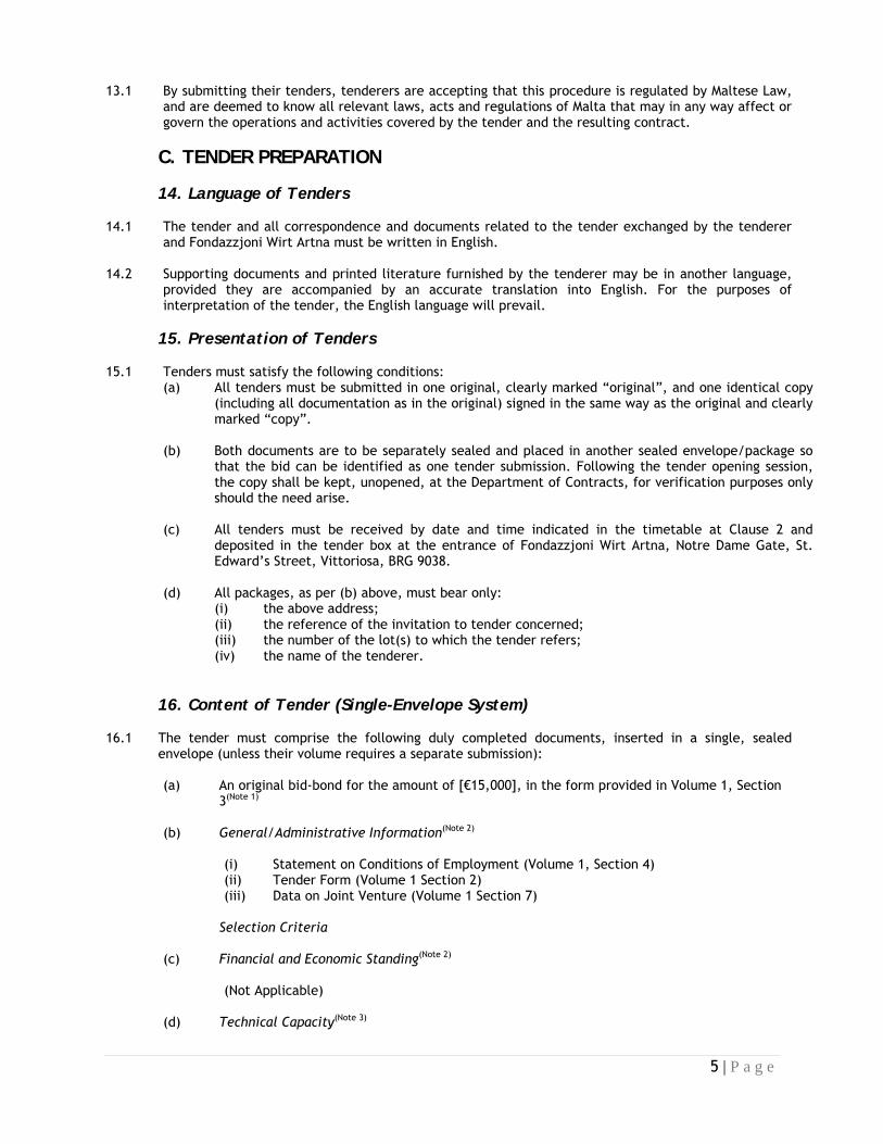
11 Our tender submission has been made in conformity with the Instructions to Tenderers, and in this respect we confirm having included in the appropriate packages as required, the following documentation:
(a) Tender Guarantee (Note 1) o Bid Bond (b) General Information (Note 2) o Tender Form o Statement on Conditions of Employment Selection Criteria (Note 2) (c) Technical Capacity (Note 3) ● Experience as Contractor
● Sub-contracting (d) Evaluation Criteria/Technical Specifications (Note 3) ● Graphic Works Schedule
● Response to Specifications ● Tenderer’s Technical Offer
● Literature /List of Samples (e) Tender Form, and Financial Offer/Bill of Quantities (Note 3) Notes:
1. Tenderers will be requested to clarify/rectify, within two working days from
notification, the tender guarantee only in the following two circumstances: either incorrect validity date, and/or incorrect value. This is indicated by the symbol ○
2. Tenderers will be requested to either clarify/rectify any incorrect and/or incomplete documentation, and/or submit any missing documents within two working days from notification. This is indicated by the symbol ○
3. No rectification shall be allowed. Only clarifications on the submitted information may be requested. This is indicated by the symbol ●
12 I acknowledge that Fondazzjoni Wirt Artna shall request rectifications in respect of incomplete/non-
submitted information pertinent to the documentation listed in Clause 11(a), 11(b), and 11(c) of this Tender Form. We understand that such rectification/s must be submitted within two (2) working days, and will be subject to a non-refundable administrative penalty of €50, and that failure to comply shall result in our offer not being considered any further.
13 We note that Fondazzjoni Wirt Artna is not bound to proceed with this invitation to tender and that it
reserves the right to cancel or award only part of the contract. It will incur no liability towards us should it do so.
Name and Surname: _________________________________________ I.D. / Passport Number: _________________________________________ Signature of tenderer: _________________________________________ Duly authorised to sign this tender on behalf of: _________________________________________
Company/Lead Partner VAT No: _________________________________________ (if applicable) Stamp of the firm/company: _________________________________________ Place and date: _________________________________________

18 | P a g e
VOLUME 1 SECTION 3 – TENDER GUARANTEE FORM
[On the headed notepaper of the financial institutions providing the guarantee]
Whereas the Chairman of Fondazzjoni Wirt Artna has invited tenders for
......................................................................................................................................
...,
and whereas Messrs .................................................................................... [Name of tenderer]
(hereinafter referred to as the Tenderer) is submitting such a tender in accordance with such invitation, we
................................................... [Name of Bank], hereby guarantee to pay you on your first demand
in writing a maximum sum of ................................................................. Euro (€...............) in
case the Tenderer withdraws his tender before the expiry date or in the case the Tenderer fails to provide
the Performance Bond, if called upon to do so in accordance with the Conditions of Contract.
The guarantee becomes payable on your first demand and it shall not be incumbent upon us to verify
whether such demand is justified.
This guarantee is valid for a period of one hundred and fifty (150) days from the closing date of submission of
tenders, and expires on the .................................... Unless it is extended by us or returned to us for
cancellation before that date, any demand made by you for payment must be received at this office in
writing not later than the above-mentioned expiry date.
This document should be returned to us for cancellation or utilisation or expiry or in the event of the
guarantee being no longer required.
After the expiry date and in the absence of a written demand being received by us before such expiry date,
this guarantee shall be null and void, whether returned to us for cancellation or not, and our liability
hereunder shall terminate.
Yours faithfully,
..................................
Bank Manager
..................................
Date

19 | P a g e
VOLUME 1 SECTION 4 - TENDERER’S STATEMENTS
1. Statement on Conditions of Employment
It is hereby declared that all employees engaged on this contract shall enjoy working conditions such as wages, salaries, vacation and sick leave, maternity and parental leave as provided for in the relative Employment Legislation. Furthermore, we shall comply with Chapter 424 of the Laws of Malta (Occupational Health and Safety Authority Act) as well as any other national legislation, regulations, standards and/or codes of practice or any amendment thereto in effect during the execution of the contract. In the event that it is proved otherwise during the execution of the contract it is hereby being consented that the contract is terminated with immediate effect and that no claim for damages or compensation be raised by us.
Signature: .............................................................
(the person or persons authorised to sign on behalf of the tenderer)
Date: .............................................................

20 | P a g e
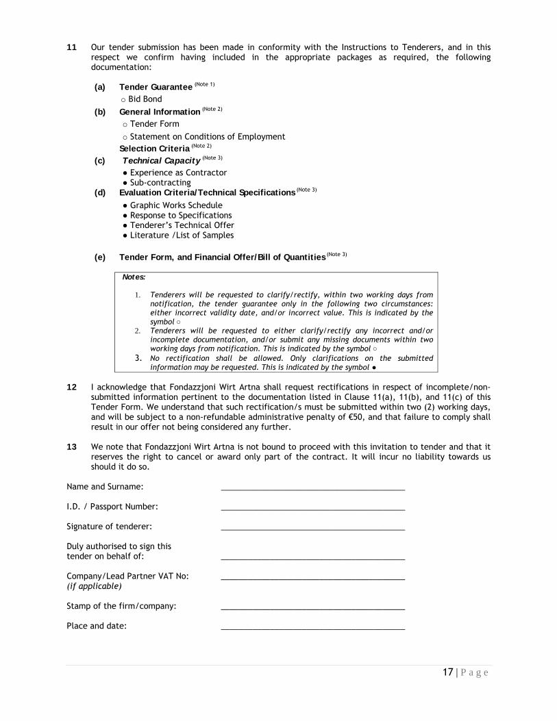
2. Experience as Contractor
List of contracts of similar nature and extent performed during the past [5] years:
Name of Project/
Kind of works
Total value of works the
contractor was responsible for
Period of Contract
Starting Date
Percentage of works
completed
Client/Contracting Authority and
place
Prime Contractor
(P) Or Sub-
Contractor (S)
Final Acceptance
Issued? • Yes • Not Yet (current contract) • No
(A) Malta
21 | P a g e
Name of Project/
Kind of works
Total value of works the
contractor was responsible for
Period of Contract
Starting Date
Percentage of works
completed
Client/ Contracting
Authority and place
Prime Contractor
(P) Or Sub-
Contractor (S)
Final Accepance
Issued? • Yes • Not Yet (current contract) • No
(B) Abroad
Signature: ....................................................................
(the person or persons authorised to sign on behalf of the tenderer)
Date: ....................................................................
22 | P a g e
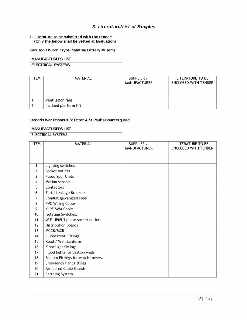
3. Literature/List of Samples
1. Literature to be submitted with the tender: (Only the below shall be vetted at Evaluation) Garrison Church Crypt (Saluting Battery Musem) MANUFACTURERS LIST ELECTRICAL SYSTEMS
ITEM MATERIAL SUPPLIER /
MANUFACTURER LITERATURE TO BE
ENCLOSED WITH TENDER
1 Ventilation fans 2 Inclined platform lift
Lascaris War Rooms & St Peter & St Paul’s Counterguard. MANUFACTURERS LIST ELECTRICAL SYSTEMS ITEM MATERIAL SUPPLIER /
MANUFACTURER LITERATURE TO BE
ENCLOSED WITH TENDER
1 Lighting switches 2 Socket outlets 3 Fused Spur Units 4 Motion sensors. 5 Contactors 6 Earth Leakage Breakers 7 Conduit galvanized steel 8 PVC Wiring Cable 9 XLPE SWA Cable 10 Isolating Switches. 11 W.P. IP65 3 phase socket outlets. 12 Distribution Boards 13 MCCB/MCB 14 Fluorescent Fittings 15 Road / Wall Lanterns 16 Floor light fittings 17 Flood lights for bastion walls 18 Sodium Fittings for watch towers. 19 Emergency light fittings 20 Armoured Cable Glands 21 Earthing System.

23 | P a g e
Technical Specifications/Literature to be submitted with Tender Document.
• EPDM Gaskets • Glass Reinforced Polyester (FibreGlass) Sheeting • Copper cladding • Waterproofing Concrete Admixture • Concrete surface hardener
Signature: ....................................................................
(the person or persons authorised to sign on behalf of the tenderer)
Date: ....................................................................

24 | P a g e
VOLUME 1 SECTION 5 – GLOSSARY
Definitions Note: the present definitions are given here for convenience only, in the context of the tender procedure. The definitions set out in the contract as concluded are determining for the relations between the parties to the contract. Administrative order: Any instruction or order issued by the Engineer to the Contractor in writing regarding the execution of the works. Breakdown of the overall price: A heading-by-heading list of the rates and costs making up the price for a lump sum contract. Conflict of interest: Any event influencing the capacity of a candidate, tenderer or supplier to give an objective and impartial professional opinion, or preventing him, at any moment, from giving priority to the interests of Fondazzjoni Wirt Artna. Any consideration relating to possible contracts in the future or conflict with other commitments, past or present, of a candidate, tenderer or supplier, or any conflict with his own interests. These restrictions also apply to sub-contractors and employees of the candidate, tenderer or supplier. Contract value: The total value of the contract to be paid by the Contracting Authority in terms of the agreed terms and conditions. Contractor: The successful tenderer, once all parties have signed the contract. Day: Calendar day. Dayworks: Varied work inputs subject to payment on an hourly basis for the Contractor's employees and plant. Defects Notification Period: The period stated in the contract immediately following the date of provisional acceptance, during which the Contractor is required to complete the works and to remedy defects or faults as instructed by the Engineer. Drawings: Drawings provided by the Contracting Authority and/or the Engineer, and/or drawings provided by the Contractor and approved by the Engineer, for the carrying out of the works. Engineer's representative: Any natural or legal person, designated by the Engineer as such under the contract, and empowered to represent the Engineer in the performance of his functions, and in exercising such rights and/or powers as have been delegated to him. In this case, references to the Engineer will include his representative. Equipment: Machinery, apparatus, components and any other articles intended for use in the works Evaluation committee: a committee made up of an odd number of voting members (at least three) appointed by Fondazzjoni Wirt Artna and possessing the technical, linguistic and administrative capacities necessary to give an informed opinion on tenders. Final acceptance certificate: Certificate(s) issued by the Engineer to the Contractor at the end of the defects notification period stating that the Contractor has completed his obligations to construct, complete, and maintain the works concerned. Final Beneficiary: The Department/Entity or other government body on whose behalf the Department of Contracts has issued this tender. Foreign currency: Any currency permissible under the applicable provisions and regulations other than the Euro, which has been indicated in the tender.

25 | P a g e
General conditions: The general contractual provisions setting out the administrative, financial, legal and technical clauses governing the execution of contracts. General damages: The sum not stated beforehand in the contract, which is awarded by a court or an arbitration tribunal, or agreed between the parties, as compensation payable to an injured party for a breach of the contract by the other party. In writing: This includes any hand-written, typed or printed communication, including fax transmissions and electronic mail (e-mail). Liquidated damages: The sum stated in the contract as compensation payable by the Contractor to the Contracting Authority for failure to complete the contract or part thereof within the periods under the contract, or as payable by either party to the other for any specific breach identified in the contract. Modification: An instruction given by the Engineer which modifies the works. National currency: The currency of the country of the Contracting Authority. Period: A period begins the day after the act or event chosen as its starting point. Where the last day of a period is not a working day, the period expires at the end of the next working day. Plant: appliances and other machinery, and, where applicable under the law and/or practice of the state of the Contracting Authority, the temporary structures on the site required to carry out the works but excluding equipment or other items required to form part of the permanent works. Provisional sum: A sum included in the contract and so designated for the execution of works or the supply of goods, materials, plant or services, or for contingencies, which sum may be used in whole or in part, or not at all, as instructed by the Engineer. Site: The places provided by the Contracting Authority where the works are to be carried out and other places stated in the contract as forming part of the site. Special conditions: The special conditions laid down by the Contracting Authority as an integral part of the tender document, amplifying and supplementing the general conditions, clauses specific to the contract and the terms of reference (for a service contract) or technical specifications (for a supply or works contract). Supervisor/Engineer: The legal or natural person responsible for administering the contract on behalf of the Contracting Authority. Tender document/s: The dossier compiled by the Contracting Authority and containing all the documents needed to prepare and submit a tender. Tender price: The sum stated by the tenderer in his tender for carrying out the contract. Works: Works of a permanent or temporary nature executed under the contract. Written communications: Certificates, notices, orders and instructions issued in writing under the contract.

26 | P a g e
VOLUME 1 SECTION 6 – EXTRACTS FROM THE PUBLIC PROCUREMENT REGULATIONS
Part XIII - Appeals The procedure for the submission of appeals is stipulated in Part XIII of the Public Procurement
Regulations (Legal Notice 296/2010), reproduced hereunder for ease of reference. Any tenderer or candidate concerned, or any person, having or having had an interest or who has been
harmed or risks being harmed by an alleged infringement or by any decision taken including a proposed award in obtaining a contract or a cancellation of a call for tender, may file a notice of objection with the Review Board. The notice shall be filed within ten calendar days following the date on which the contracting authority has by fax or other electronic means sent its proposed award decision. The communication to each tenderer of the proposed award shall be accompanied by a summary of the relevant reasons relating to the rejection of the tender as set out in regulation 44(3), and by a precise statement of the exact standstill period. The notice of objection shall only be valid if accompanied by a deposit equivalent to one per cent of the estimated value of the tender submitted by the tenderer, provided that in no case shall the deposit be less than one thousand and two hundred euro (€1,200) or more than fifty-eight thousand euro (€58,000). The Secretary of the Review Board shall immediately notify the Director that an objection had been filed with his authority thereby immediately suspending the award procedure. The Department of Contracts or the contracting authority involved, as the case may be, shall be precluded from concluding the contract during the period of ten calendar days allowed for the submission of appeals. The award process shall be completely suspended if an appeal is eventually submitted. The procedure to be followed in submitting and determining complaints as well as the conditions under which such complaints may be filed shall be the following: (a) any decision by the Evaluation Committee (or a Special Contracts Committee) and by a contracting authority, shall be made public at the Department of Contracts or at the office of the contracting authority prior to the award of the contract; (b) the notice of objection duly filed in accordance with sub-regulation (1) shall be made public by the Review Board not later than the next working day following its filing; (c) within three working days of the publication of the replies the Secretary of the Review Board shall prepare a report (the Analysis Report) analysing the letter of objection. This report shall be circulated to the persons who file an objection and interested parties. After the preparatory process is duly completed, the Head of the contracting authority shall forward to the Chairman of the Review Board all documentation pertaining to the call for tenders in question including files, tenders submitted, copies of deposit receipts, any motivated letter, who shall then proceed as stipulated in Part XIV; (d) the Director or the Head of the contracting authority shall publish a copy of the decision of the Review Board at his department or at the premises of the relevant contracting authority, as the case may be. Copies of the decision shall be forwarded by the Secretary of the Board to the complaining tenderer, any persons who had registered or had an implied interest, the Director of Contracts and to the contracting authority concerned.

27 | P a g e
Form 10 - Graphic Work Schedule
Please attach the Graphic Work Schedule in relation to this tender, showing primarily the critical path and
resources.
Signature: ....................................................................
(the person or persons authorised to sign on behalf of the tenderer)
Date: ....................................................................

28 | P a g e
VOLUME 2
VOLUME 2 SECTION 1 – DRAFT CONTRACT FORM
Financed by: ................................................. [Specify Source of Financing]
Project: ................................................. [Title and Number]
Contract Number: ................................................. [Contract Number]
This contract is concluded between: Fondazzjoni Wirt Artna, Notre Dame Gate, St. Edward’s Street, Vittoriosa,
BRG 9038 (hereinafter called “Fondazzjoni Wirt Artna”) on behalf of [name of Contracting Authority and address] on the one part, and [Name of Contractor] [Address] (Hereinafter called “The Contractor”) on the other part, Whereas Fondazzjoni Wirt Artna is desirous that certain works should be executed by the Contractor, viz.: FWA 610‐ TENDER FOR RESTORATION, ALTERATION WORKS, FINISHING WORKS, MECHANICAL AND ELECTRICAL WORKS AT THE LASCARIS TUNNELS, GARRISION CHURCH CRYPT AND ST PETER AND ST PAUL’S COUNTERGUARD. and has accepted a tender by the Contractor for the execution and completion of such works and the remedying of any defects therein.
It is hereby agreed as follows: 1. In this contract words and expressions shall have the meanings assigned to them in the contractual
conditions set out below. 2. The following documents shall be deemed to form and be read and construed as part of this contract, in
the following order of precedence: (a) this Contract,
(b) the Special Conditions, (c) the General Conditions, (d) the technical specifications, bill of quantities and design documentation, (e) the Contractor’s technical offer (including any clarifications made during adjudication), (f) the bill of quantities (after arithmetical corrections)/breakdown, (g) the tender form, (h) any other documents forming part of the contract. Addenda shall have the order of precedence of the document they are modifying.
3. In consideration of the payments to be made by the Contracting Authority to the Contractor as hereinafter mentioned, the Contractor undertakes to execute and complete the works and remedy defects therein in full compliance with the provisions of the contract.

29 | P a g e
4. The Contracting Authority hereby agrees to pay the Contractor in consideration of the execution and completion of the works and remedying of defects therein the amount of:
• Contract price (including VAT/other taxes): €.....................................
• Contract price in words:................................................................. Euro
or such other sum as may become payable under the provisions of the contract at the times and in the manner prescribed by the contract. VAT shall be paid in compliance with National Law (in particular the VAT Act 1998, the Act No X of 2003 and relevant Legal Notices).
5. The Contractor hereby agrees to submit a performance guarantee amounting to €............... equivalent to
10% of the contract value together with the signed contract. 6. In witness whereof the parties hereto have signed the contract. This contract shall take effect on the date
on which it is signed by the last party. Done in English in three originals: one for Fondazzjoni Wirt Artna, one for the Contracting Authority, and one for the Contractor.
Fondazzjoni Wirt Artna:
Contractor:
Signed by: ...........................................................
Signed by: ...........................................................
In the capacity of: ...........................................................
In the capacity of: ...........................................................
Being fully authorized by and acting on behalf of ...........................................................
Being fully authorized by and acting on behalf of ...........................................................
Date: ....................................................
Date: ....................................................

30 | P a g e
VOLUME 2 SECTION 2 – GENERAL CONDITIONS The full set of General Conditions for Works Contracts (Version 1.01 dated 15 March 2010) can be viewed/downloaded from: www.contracts.gov.mt/conditions It is hereby construed that the tenderers have availed themselves of these general conditions, and have read and accepted in full and without reservation the conditions outlined therein, and are therefore waiving any standard terms and conditions which they may have. These general conditions will form an integral part of the contract that will be signed with the successful tenderer/s.

31 | P a g e
VOLUME 2 SECTION 3 – SPECIAL CONDITIONS
These conditions amplify and supplement, if necessary, the General Conditions governing the contract. Unless the Special Conditions provide otherwise, those General Conditions remain fully applicable. The numbering of the Articles of the Special Conditions is not consecutive but follows the numbering of the Articles of the General Conditions. Other Special Conditions should be indicated afterwards.
Article 2: Law and language of the contract 2.1 The Laws of Malta shall apply in all matters not covered by the provisions of the contract. 2.2 The language used shall be English.
Article 3: Order of precedence of contract documents The contract is made up of the following documents, in order of precedence:
(a) the Contract, (b) the Special Conditions, (c) the General Conditions, (d) the Contracting Authority’s technical specifications and design documentation, (e) the Contractor’s technical offer, and the design documentation (drawings), (f) the bill of quantities (after arithmetical corrections)/breakdown, (g) the tender form,, (h) any other documents forming part of the contract.
Addenda have the order of precedence of the document they are modifying.
Article 4: Communications All communications must be done in the English Language and addressed to Fondazzjoni Wirt
Artna, Notre Dame Gate, St. Edward’s Street, Vittoriosa. Tel: (356) 21 800992, 21 800992
Article 5: Supervisor and Supervisor's representative Further to Article 5.1 of the General Conditions, the Supervisor may also be referred to in this
contract as the Engineer/Project Manager. The Supervisor shall be responsible for all the technical aspects of the project aimed at meeting the Contracting Authority’s requirements and ensuring completion on time within the costs and to the required quality standards, including but not limited to:
1. Monitoring conformity of the materials and works, including workmanship, to the specifications, appropriate standards and works’ practices as indicated in Volume 3 and good workmanship.
2. Monitoring the contractor’s performance and progress 3. Reviewing the literature provided by the contractor and programme of works. 4. Monitoring the contractor’s quality control. 5. Reviewing the contractor’s contractual claims and reporting 6. Preparing monthly progress reports, including projected completion date and financial
projection of the works. 7. Measuring works.
Further to Article 5.2 of the General Conditions the Supervisor’s Representative shall

32 | P a g e
undertake the Supervisor’s responsibilities on site on a day by day basis. He shall also:
1. Act as a liaison between the contractor and the Contracting Authority 2. Chair weekly progress meetings with the contractor 3. Receive and review the contractor’s documentation 4. Monitor the contractor’s adherence to agreed procedures 5. Issue administrative orders to the contractor 6. Keep stakeholders informed of progress on site and issue periodic progress reports. 7. Agreed measurement of the works with the contractor, review the contractor’s
applications for payment and certify payment He shall enjoy the powers such as expected of supervisors and/or other powers as deemed proper by the Supervisor due to the exigencies of the contract. In the absence of his representative, the Supervisor shall also carry out the responsibilities listed above.
Article 8: Supply of Documents If the need arises for the contractor to submit additional working drawings and/or technical
literature, these are to be submitted to the Supervisor who shall liaise with the Contracting Authority to ascertain compliance with the original tender specifications and the contractor’s submissions. The contractor shall allow seven days for the Supervisor to comment.
Article 10: Assistance with Local Regulations
The Contracting Authority shall provide assistance to the Contractor on his request by obtaining copies of the Laws of the Malta which are relevant to the Contract but are not readily available.
Article 11: The Contractor’s Obligations The contractor is responsible to meet all obligations as set out in the contract document and
as required by law, regulations and relevant Authorities. The staff, workmen and operatives employed by the contractor and any sub-contractor or agent must be sufficient in number and each must have the appropriate qualifications/skills and experience to ensure due progress and satisfactory execution of works in conformity with the contract. Fondazzjoni Wirt Artna shall not be liable for or in respect of any damages or compensation payable to any workman or other person in the employment of the contractor, or any subcontractor or any agent. The contractor shall indemnify and keep indemnified the Fondazzjoni Wirt Artna against all such damages and compensation and against all claims, proceedings, costs, charges and expenses whatsoever thereof or in relation thereto. The contractor must have employed/engaged on contract the following personnel: Project Manager (Perit) responsible for the management, co-ordination and quantitative and qualitative output of the works proposed in this tender: must be an experienced professional or highly qualified technical person and be available on site when required. Health and Safety Officer responsible for occupational, second party and third party health and safety planning, implementation and control in compliance with the local regulations and legislation; Must be certified and registered with the OHSA. The adjudication committee reserves the right to ash the contractor to submit full CVs of the key personnel and a recent ETC certificate of all the employees. The contractor shall take full responsibility for the adequacy, stability and safety of all

33 | P a g e
operations and methods of works under the contract, which are to be supervised by the contractor’s Perit who shall, as required, submit applications/notification and obtain on behalf of the Contracting Authority any approval/permit required from any other authority at the expense of the contractor. Particular attention is being drawn to the special requirements in the Technical Specifications (Volume 3). If any loss or damage happens to the works, or any part thereof, or materials or plant for which the contractor is responsible for the care thereof, from any cause whatsoever, including but not limited to loss and or damage arising from weather and sea conditions, the contractor shall at his own cost, rectify such loss or damage so that the works conform in every respect with the provisions of the contract to the satisfaction of the Supervisor. The contractor shall also be liable for any loss or damage to the works occasioned by him in the course of any operations carried out by him for the purpose of complying with his obligations under Articles 58 and 59. The contractor shall supply drawings, information, documentation and items as specified in the contract document and any further information and documentation required by the Supervisor within the timeframes requested. The Contracting Authority may agree to supply the contractor with document following a written request to the Supervisor in which case Article 11.9 of the General Conditions shall apply. Unless the contractor shall give an address in accordance with Article 11.6 of the General Conditions all notifications concerning the contractor shall be sent to the address shown in the Contract Form (Volume 2 Section1). The contractor shall ensure that the provisions of Article 11.7 of the General Conditions apply to any of his subcontractors, agents or servants. The contractor at his own expense shall provide, erect and maintain in good condition throughout the duration of the contract, a board publicising the project according to the template and dimensions provided by the Supervisor. The contractor shall be responsible for any operation of, ant any loss and/or consequence due to forces of nature against which an experienced contractor could reasonably have been expected to take effective and timely precautions. The contractor shall be liable for damage, cost and losses which have been caused by him, his subcontractors, agents or representatives wheresoever to any objects whosesoever, to any person whomsoever in any way and for any cause wheresoever to the disadvantage of third parties or their personnel or their agents.
Article 13: Performance Guarantee 13.1 The Performance Guarantee shall amount to 10% of the Contract amount. 13.2 The performance guarantee shall be in the format given in Volume 2, Section 4 and shall be
provided in the form of a bank guarantee. It shall be issued by a bank in accordance with the eligibility criteria applicable for the award of the contract.
13.3 The Performance Guarantee shall be released within 30 days of the issue of the
Completion Certificate and upon it being replaced by a Retention Guarantee.
Article 14: Insurance
14.1 Without any prejudice to General Conditions, Article 14, Clauses 14.1 a, b, c, the contractor is
required to insure against professional indemnity for the minimum amount of € 500,000

34 | P a g e
14.2 The contractor is required to insure against all risks and civil liabilities resulting from an act or
omission attributed to the Contractor, to his legal successors or agents for the minimum amount of € 1,500,000.00 per accident with the number of occurrences unlimited.
14.3 The contractor is required to insure against damages to third parties (property or personal
injuries) for the minimum amount of € 1,500,000.00 per accident with the number of occurrences unlimited
Article 15: Performance Programme (Timetable) The Contractor shall provide a detailed programme works within 15 days of signature of
Contract in a form of a bar chart produced as a result of a ‘critical path analysis’ and must abide by the constraints indicated on signature of Contract. It shall show the level of detail appropriate to each stage of the Works and all activities and restraints, each of which shall be given a short title. All events shall be numbered and annotated with earliest and latest event dates.
Article 17: Contractor’s Drawings
The Contractor shall make any revisions to the Design as may reasonably be required from
time to time by the Contracting Authority including changes resulting from changes to Work and changes resulting from conditions on site.
Article 18: Tender Prices
The Contractor shall pay all taxes, duties, and fees required to be paid by him under the
Contract, and the Contract Price shall not be adjusted for any of these costs except of changes in the Laws of the Malta or in the judicial or official government interpretation of such Laws made after the base date.
Article 22: Interference with Traffic The Contractor shall obtain official permits from the relevant authorities (Local Councils and
Malta Transport Authority) and directly make the necessary arrangements with the involved entities for the deviation of traffic and shall inform the Project Manager accordingly of such arrangements, according to Volume 3 – Technical Specifications. All expenses related to these procedures shall be covered by the Contractor. Any work, causing interference with traffic, cannot start before the necessary permits have been issued.
Article 25: Demolished Materials
25.1 Demolished materials shall become the property of the contractor. 25.4
Carting away and disposal of demolished materials shall be the responsibility of the contractor. All demolished materials are to be disposed of at an approved dumping site.
Article 26: Discoveries
26.2 Any discoveries of archeological importance and/or which Fondazzjoni Wirt Artna deems of
value shall become the property of Fondazzjoni Wirt Artna.
Article 31: Commencement Date

35 | P a g e
31.1 The Supervisor shall give the Contractor not less than 7 days’ notice of each
Commencement Date. The Supervisor shall inform the Contractor in writing with the commencement date.
Article 32: Period of Performance 32.1 The total period of performance shall be 20 weeks from the commencement notice.
Article 34: Delays in Execution 34.1 The contractor shall be liable to a deduction of a sum equivalent to Euro 250 per calendar
day for any delay. The maximum amount of damages shall not exceed 20% of the contract value, pursuant to which Fondazzjoni Wirt Artna will have the right to invoke the clauses relating to the termination of the contract and subsequent penalties.
Article 35: Variations and Modifications 35.7 The Supervisor shall not authorise any variations prior to obtaining the approval by
Fondazzjoni Wirt Artna. 35.8 The Contractor is deemed to have determined his prices on the basis of his own
calculations, operations and estimates, he shall, if the Contract is awarded to him, at no additional charge, carry out any work that is the subject of any item whatsoever in his Tender for which he indicates neither a unit price nor a lump sum.
Article 39: Quality of Works and Materials 39.2 The contractor must submit all necessary documentation, including test certificates and
samples to the Supervisor for technical acceptance if requested.
Article 40: Inspection and Testing 40.2 The contractor is to produce a sample door for both internal and external doors for inspection
of the Supervisor or his representative. The contractor shall not proceed with the fabrication of the other door prior to the approval of the sample.
Article 42: Ownership of Plants and Materials 42.2 All materials delivered to the site to be incorporated in the works for which payments have
been made to the contractor shall become the property of Contracting Authority.
Article 43: Payments: General Principles
43.1 Payments will be made in Euro. Payments shall be carried out as follows:
Pre-Financing 20% at Commencment 1st Interim Payment 4 weeks from the Commencement of
Works. 2nd Interim Payment 4 weeks from 1st Interim Payment

36 | P a g e
upon Certification 3rd Interim Payment 4 weeks from 2nd Interim Payment
upon Certification 4th Interim Payment 4 weeks from 3rd Interim Payment
upon Certification Final Payment On certificate of Full Completion
43.3 The maximum period in which payments are to be effected is 60 days, failing which the
provisions of the Late Payments Directive will come into effect (30 days as per General Conditions).
Article 44: Pre-financing 44.1 20% Pre-financing is OBLIGATORY for this contract. Pre-financing (Advanced Payment) is
permitted on this contract. The total amount of the prefinancing is set as a maximum of 20% of the original contract price. In order to obtain prefinancing payment, the Contractor must forward to the contracting authority the payment request, the performance guarantee in accordance with General Conditions - Article 13 and a pre-financing guarantee (Volume 2 Section 5) for the full amount of the pre-financing payment.
Article 45: Retention Monies 45.2 A 10 % retention shall be retained from each interim payment to a maximum amount of 10% of
the contract price. The amount will be released by the Contracting Authority at the Provisional Acceptance and upon submission of Bank Guarantee amounting to 10% of the total Contract Amount as Retention Guarantee for a period of one (1) year.
Article 46: Price Revision 46.1 Tender prices are fixed and not subject to revision. 46.2 Prices contained in the Contractor's tender shall be deemed:
a) to have been determined on the basis of the conditions in force 30 days prior to the
latest date fixed for submission of tenders or, in the case of direct agreement contracts, on the date of the contract;
b) to have taken account of the legislation and the relevant tax arrangements applicable at the reference date fixed in Article 46.3(a).
46.3 Prices contained in the Contractor's tender shall be deemed:
c) to have been determined on the basis of the conditions in force 30 days prior to the
latest date fixed for submission of tenders or, in the case of direct agreement contracts, on the date of the contract;
d) to have taken account of the legislation and the relevant tax arrangements applicable at the reference date fixed in Article 46.3(a).
46.4 In the event of changes to, or introduction of, any national or state statute, ordinance, decree
or other law, or any regulation or bye-law of any local or other public authority, after the date stated in Article 46.3 which causes a change in the contractual relationship between the parties to the contract, the Contracting Authority and the Contractor shall consult on how best to proceed further under the contract, and may as a result of such consultation decide, with the prior approval of Fondazzjoni Wirt Artna:
a) to modify the contract; or

37 | P a g e
b) to provide for compensation for any imbalance caused by one Party to the other; or c) to terminate the contract by mutual agreement.
46.5 In the event of a delay in the execution of the works for which the Contractor is responsible,
or at the end of the period of performance revised as necessary in accordance with the contract, there shall be no further revision of prices within the 30 days before provisional acceptance, except for the application of a new price index, if this is to the benefit of the Contracting Authority.
Article 47: Measurement 47.2 Measurement of works shall only be carried out on installation of items on site.
Article 48: Interim Payments 48.1 Interim payments shall only be made on certification of the works by the Project Manager.
Article 50: Delayed Payments 50.1 The period quoted in Article 50.1 of the General Conditions may be subject to change
according to the particular needs of the Department 50.2 Once the deadline laid down in Article 50.1 has expired, the Contractor may, within two
months of late payment, claim late-payment interest:
• A contractor would become entitled to the payment of interest at 3%. • By way of exception, when the interest calculated in accordance with this provision is
lower than or equal to €200, it shall be paid to the Contractor only upon a demand submitted within two months of receiving late payment.
Article 53: End Date European Regional Development Funds
The date on which the commitment of Community funds ends is the last quarter of 2013.
Article 56: Partial Acceptance
The maintenance period begins on the date of partial acceptance. Article 57: Provisional Acceptance 56.3 Provisional acceptance shall be considered as when all the works listed in the Bill of Quantities
are carried out excluding reinstatement of areas in close proximity to the works. Article 58: Maintenance Obligations
The contractor shall be held responsible to fix any latent defects which can arise within the
period of retention guarantee. Article 66: Dispute Settlement by Litigation

38 | P a g e
58.6 Any dispute between the Parties that may arise during the performance of this contract and that has not been possible to settle otherwise between the Parties shall be submitted to the arbitration of the Malta Arbitration Centre in accordance with the Arbitration Act (Chapter 387) of the Laws of Malta. This law is based on “Model Law” which is the Model Law on International Commercial Arbitration adopted on June 21, 1985 by the United Nations Commission on International Trade Law reproduced in the First Schedule of the Arbitration Act.
Article 71: Further Additional Clauses

39 | P a g e
VOLUME 2 SECTION 4 – SPECIMEN PERFORMANCE GUARANTEE
(LETTERHEAD OF THE REGISTERED FINANCIAL INSTITUTION PROVIDING THE GUARANTEE) The Chairman Fondazzjoni Wirt Artna, Notre Dame Gate, St. Edward’s Street, Vittoriosa, BRG 9038 [Date]
Dear Sir, Our Guarantee Number .......................... for €...................... Account: [Account Holder’s Name]
In connection with the contract entered into between yourself on behalf of the Director of Contracts and [Name and Address of Contractor] hereinafter referred to as “the Contractor” as per the latter’s tender and your acceptance under [Fondazzjoni Wirt Artna Reference], whereby the contractor undertook the [title of contract] in accordance with Article 13 of the Special Conditions the [works] as mentioned, enumerated or referred to in the Specification and/or Bills of Quantities forming part of the contract documents, we hereby guarantee to pay you on demand a maximum sum of €[amount in works and numbers] in case the obligations of the above-mentioned contract are not duly performed by the Contractor.
This guarantee will become payable on your first demand and it shall not be incumbent upon us to verify whether such demand is justified. For avoidance of doubt it is hereby declared that although this instrument gives rise to legal relations between the guarantor and the beneficiary, it is hereby specifically declared for all intents and purposes of law that this guarantee does not exempt the above-mentioned Contractor from any obligations, acts of performance or undertaking assumed under the tender documents as ratified in the contract. Any payments due to the contractor in respect of the obligations entered into under the contract above referred to shall be made through this Bank. This guarantee expires on the [expiry date] and unless it is extended by us or returned to us for cancellation before that date any demand made by you for payment must be received in writing not later than the aforementioned expiry date. This document should be returned to us on utilization or expiry or in the event of the guarantee being no longer required. After the expiry date and in the absence of a written demand being received by us before such expiry date, this guarantee shall be null and void, whether returned to us or not, and our liability hereunder shall terminate. This guarantee is personal to you, and is not transferable or assignable. Yours Faithfully, ............................................. [Signatory on behalf of Guarantor]

40 | P a g e
VOLUME 2 SECTION 6 – SPECIMEN RETENTION GUARANTEE
(LETTERHEAD OF THE REGISTERED FINANCIAL INSTITUTION PROVIDING THE GUARANTEE) The Chairman Fondazzjoni Wirt Artna, Notre Dame Gate, St. Edward’s Street, Vittoriosa, BRG 9038 [Date]
[Tender Reference] Dear Sir, We, the undersigned, [name, company name, address], hereby declare that we will guarantee, as principal debtor, to [Fondazzjoni Wirt Artna's name and address] on behalf of [Contractor's name and address], the payment of [indicate the amount], corresponding to the guarantee mentioned in Article 45 of the Special Conditions without dispute, on receipt of a first written request from the beneficiary.
We further agree that no change or addition to or other modification of the terms of the contract or of the works to be performed thereunder or of any of the contract documents which may be made between you and the Contractor shall in any way release us from any liability under this guarantee. We hereby waive notice of any such change, addition or modification. The guarantee will enter into force and take effect from the [indicate the date of payment of the sums retained under the contract] and shall be valid until the date of issue of the certificate of final acceptance. We note that you will release the guarantee and notify us of the fact at the latest within thirty days of the date of issue of this certificate. Done at ………….., ../../.. Name and first name: …………………………… On behalf of: ………………… Signature: …………….. [stamp of the body providing the guarantee]

41 | P a g e
VOLUME 3 - TECHNICAL SPECIFICATIONS
Vide attachment

42 | P a g e

170 | P a g e
Part 2 –The Contractor’s Technical Offer

171 | P a g e
VOLUME 4 - FINANCIAL BID
(Unit-Price Contracts) VOLUME 4
BILL OF QUANTITIES
I. Preamble
Tenderers must price each item in the bill of quantities separately and follow the instructions regarding the transfer of various totals in the summary. The bill of quantities must be read with all the other contract documents and the Contractor shall be deemed to have thoroughly acquainted himself with the detailed descriptions of the works to be done and the way in which they are to be carried out. All the works must be executed to the satisfaction of the Engineer. 1.1. Quantity of items The quantities set forth against the items in the bill of quantities are an estimate of the quantity of each kind of the work likely to be carried out under the contract and are given to provide a common basis for bids. There is no guarantee to the Contractor that he will be required to carry out the quantities of work indicated under any one particular item in the bill of quantities or that the quantities will not differ in magnitude from those stated. When pricing items, reference should be made to the conditions of contract, the specifications and relevant drawings for directions and descriptions of work and materials involved. The quantities given in the bill of quantities are provisional and reflect the estimates made at the time of approval to provide a basis for this document and tenders. Tenderers must consider every aspect of the tender document carefully. Any comments concerning the quantities must be made in the form of an attachment, following the system of itemisation, quoting the codes and brief descriptions, as in the present documents, including the rates and prices. Save where the technical specifications or the bill of quantities specifically and expressly state otherwise, only permanent works are to be measured. Works will be measured net to the dimensions shown on the drawings or ordered in writing by the Engineer, save where described or prescribed elsewhere in the contract. In adjusting extras or variations on the contract, works will be measured on the same basis as that on which the quantities were prepared. All works not specifically mentioned in the bill of quantities will be taken as included in the prices of various items. Where, in the opinion of the Engineer, extra works cannot be properly measured or valued, the Contractor may, if so directed by the Engineer, carry out the work at the day work rates shown in the schedule of day work. All completed day work sheets must be signed by the Engineer on or before the end of the week in which the works are executed. No allowance will be made for loss of materials or volume thereof during transport or compaction.

172 | P a g e
1.2. Units of measurement
The units of measurement used in the annexed technical documentation are those of the International System of Units (SI). No other units may be used for measurements, pricing, detail drawings etc. (Any units not mentioned in the technical documentation must also be expressed in terms of the SI.) Abbreviations used in the bill of quantities are to be interpreted as follows: mm means millimetre m means metre mm² means square millimetre m² means square metre m³ means cubic metre kg means kilogram to means tonne (1000 kg) pcs means pieces h means hour L.s. means Lump sum km means kilometre l means litre % means per cent N.d means nominal diameter m/m means man-month m/d means man-day
II. Terms Relating To Payments
The method for measuring completed works for payment must be in accordance with the Contract. The provisional sums in the bill of quantities must be used in whole or in part at the discretion of the Engineer or as otherwise set out in the contract. Each item in the bill of quantities for which payment is to be made in a lump sum, and for which no payment schedule is provided, must be paid after the work covered by the lump sum has been completed to the satisfaction of the Engineer.
III. Pricing
The prices and rates inserted in the bill of quantities are to be the full inclusive values of the works described under the items, including all costs and expenses which may be required in and for the construction of the works described together with any temporary works and installations which may be necessary and all general risks, liabilities and obligations set forth or implied in the documents on which the tender is based. It will be assumed that establishment charges, profit and allowances for all obligations are spread evenly over all the unit rates. The rates and prices tendered in the priced bill of quantities will be quoted at the rates current prior to the date of submission. Rates and prices must be entered against each item in the bill of quantities. The rates will cover all tax, duty or other liabilities which are not stated separately in the bill of quantities and the tender.
IV. Completing the bill of quantities

173 | P a g e
In the bill of quantities, rates and prices will be entered in the appropriate columns in Euro. Errors will be corrected as follows:
a) where there is a discrepancy between amounts in figures and in words, the amount in words will prevail; and
b) where there is a discrepancy between the unit rate and the total amount derived from the
multiplication of the unit price and the quantity, the unit rate as quoted will prevail.
V. Description Of Unit Prices
The tables that follow give the description of the rates (or unit prices) by using the relevant clauses of Volume 3 (Technical specifications).
Bills of Quantities
Vide attachment
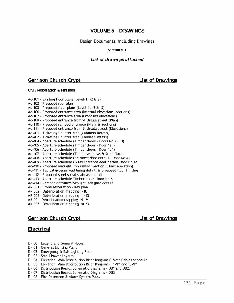
174 | P a g e
VOLUME 5 – DRAWINGS
Design Documents, including Drawings
Section 5.1
List of drawings attached
Garrison Church Crypt List of Drawings
Civil/Restoration & Finishes
Ac-101 - Existing floor plans (Level-1, -2 & 3) Ac-102 - Proposed roof plan Ac-103 - Proposed floor plans (Level-1, -2 & -3) Ac-106 - Proposed entrance area (Internal elevations, sections) Ac-107 - Proposed entrance area (Proposed elevations) Ac-109 - Proposed entrance from St Ursula street (Plan) Ac-110 - Proposed ramped entrance (Plans & Sections) Ac-111 - Proposed entrance from St Ursula street (Elevations) Ac-401 - Ticketing Counter area (Cabinets Details) Ac-402 - Ticketing Counter area (Counter Details) Ac-404 - Aperture schedule (Timber doors – Doors No 2 & 3) Ac-405 - Aperture schedule (Timber doors – Door “a”) Ac-406 - Aperture schedule (Timber doors – Door “b”) Ac-407 - Aperture schedule (Timber windows & Steel Gate) Ac-408 - Aperture schedule (Entrance door details - Door No 4) Ac-409 - Aperture schedule (Glass Entrance door details–Door No 4a) Ac-410 - Proposed wrought iron railing (Section & Part elevation) Ac-411 - Typical gypsum wall lining details & proposed floor finishes Ac-412 - Proposed steel spiral staircase details Ac-413 - Aperture schedule Timber doors- Door No 6 Ac-414 - Ramped entrance-Wrought Iron gate details AR-001 - Stone restoration - Key plan AR-002 - Deterioration mapping 1-10 AR-003 - Deterioration mapping 11-13 AR-004 -Deterioration mapping 14-19 AR-005 - Deterioration mapping 20-23
Garrison Church Crypt List of Drawings
Electrical
E – 00 Legend and General Notes. E – 01 General Lighting Plan. E – 02 Emergency & Exit Lighting Plan. E – 03 Small Power Layout. E – 04 Electrical Main Distribution Riser Diagram & Main Cables Schedule. E – 05 Electrical Main Distribution Riser Diagrams – ‘MP’ and ‘SMP’. E – 06 Distribution Boards Schematic Diagrams – DB1 and DB2. E – 07 Distribution Boards Schematic Diagrams – DB3 E – 08 Fire Detection & Alarm System Plan.

175 | P a g e
E – 10 Fire Alarm & PA Systems Block Diagrams. E – 14 Telephone & Data Points Plan. S1 Lighting Fixtures Schedule.
Garrison Church Crypt List of Drawings
Mechanical
LIST OF DRAWINGS: Dwg No Title Size M/01 Ventilation system A1 M/02 Plumbing system A1

176 | P a g e
LASCARIS TUNNELS AND ST PETER’S AND ST PAUL’S COUNTER GUARD
List of Drawings
Civil/Restoration & Finishes
Acg-100 - St Peter’s & St Paul’s Counterguard – Rooms “a”&”c” (Proposed and existing plans) Acg-101 - St Peter’s & St Paul’s Counterguard – Level 1&2 (Proposed intervention) Acg-102 - St Peter’s & St Paul’s Counterguard – Gunpowder room & Lighting passage (Plans & sections Acg-400 - St Peter’s & St Paul’s Counterguard – Timber gates schedule - Gate L3, L4 & L5 Acg-401 - St Peter’s & St Paul’s Counterguard – Steel gates schedule - Gates L6 Acg-402 - St Peter’s & St Paul’s Counterguard – Gunpowder room -Timber doors schedule 1 Acg-402a - St Peter’s & St Paul’s Counterguard – Gunpowder room -Timber window schedule Acg-403 - St Peter’s & St Paul’s Counterguard –Lighting passage – Entrance timber door Acg-403a - St Peter’s & St Paul’s Counterguard –Gunpowder room – Entrance timber door Acg-403b - St Peter’s & St Paul’s Counterguard –Gunpowder room –Timber doors schedule 2 Acg-403c - St Peter’s & St Paul’s Counterguard –Gunpowder room – Copper coated timber door Acg-404 - St Peter’s & St Paul’s Counterguard – Proposed furniture for Gunpowder room & Shifting lobby Acg-405 - St Peter’s & St Paul’s Counterguard – Reinstatement of original railing – Section A-A & Part elevation E) Acg-406 - St Peter’s & St Paul’s Counterguard – Proposed furniture for Lamp room An-100 - Lascaris war rooms– Tunnels restoration An-101 - Lascaris war rooms – Proposed intervention An-201 - Lascaris war rooms – Existing & proposed schematic sections An-406 - Lascaris war rooms – Entrance Timber gate An-410 - Lascaris war rooms – Steel door schedule – Steel Doors at the Entrance & Exit Am-001 - Lascaris war rooms – Deterioration mapping – Proposed intervention Am-002 - Lascaris war rooms – Deterioration mapping – Wall elevation - Part 01 Am-003 - Lascaris war rooms – Deterioration mapping – Wall elevation - Part 02

177 | P a g e
LASCARIS TUNNELS AND ST PETER’S AND ST PAUL’S COUNTER GUARD
List of Drawings
Mechanical & Electrical
Dwg. No.
Sheet Drawing Title Revision Pages
HVAC - HEATING.VENTILATION & AIR CONDITIONING LASCARIS WAR ROOMS
555 13 10 1/1 LASCARIS WAR ROOMS HVAC INSTALLATION LAYOUTS - PAGES 1 TO 12
- 1 TO 12
555 13 11 1/1 LASCARIS WAR ROOMS HVAC INSTALLATION LAYOUTS - PAGE 1 A 1
555 13 12 1/1 LASCARIS WAR ROOMS HVAC INSTALLATION LAYOUTS - PAGE 2 A 2
555 13 13 1/1 LASCARIS WAR ROOMS HVAC INSTALLATION LAYOUTS - PAGE 3 A 3
555 13 14 1/1 LASCARIS WAR ROOMS HVAC INSTALLATION LAYOUTS - PAGE 4 A 4
555 13 15 1/1 LASCARIS WAR ROOMS HVAC INSTALLATION LAYOUTS - PAGE 5 A 5
555 13 16 1/1 LASCARIS WAR ROOMS HVAC INSTALLATION LAYOUTS - PAGE 6 A 6
555 13 17 1/1 LASCARIS WAR ROOMS HVAC INSTALLATION LAYOUTS - PAGE 7 A 7
555 13 18 1/1 LASCARIS WAR ROOMS HVAC INSTALLATION LAYOUTS - PAGE 8 A 8
555 13 19 1/1 LASCARIS WAR ROOMS HVAC INSTALLATION LAYOUTS - PAGE 9 A 9
555 13 20 1/1 LASCARIS WAR ROOMS HVAC INSTALLATION LAYOUTS -PAGE 10 A 10
555 13 21 1/1 LASCARIS WAR ROOMS HVAC INSTALLATION LAYOUTS - PAGE 11 A 11
555 13 22 1/1 LASCARIS WAR ROOMS HVAC INSTALLATION LAYOUTS - PAGE 12 A 12
Dwg. No. Sheet Drawing Title Revision Pages
PLUMBING LASCARIS WAR ROOMS
555 20 10 1/1 LASCARIS WAR ROOMS PLUMBING INSTALLATION LAYOUTS -PAGES 1 TO 12
- 1 TO 12
555 20 11 1/1 LASCARIS WAR ROOMS PLUMBING INSTALLATION LAYOUTS - PAGE 1
A 1
555 20 12 1/1 LASCARIS WAR ROOMS PLUMBING INSTALLATION LAYOUTS - PAGE 2
A 2
555 20 13 1/1 LASCARIS WAR ROOMS PLUMBING INSTALLATION LAYOUTS - PAGE 3
A 3
555 20 14 1/1 LASCARIS WAR ROOMS PLUMBING INSTALLATION LAYOUTS - PAGE 4
A 4
555 20 15 1/1 LASCARIS WAR ROOMS PLUMBING INSTALLATION LAYOUTS - PAGE 5
A 5
555 20 16 1/1 LASCARIS WAR ROOMS PLUMBING INSTALLATION LAYOUTS - PAGE 6
A 6
555 20 17 1/1 LASCARIS WAR ROOMS PLUMBING INSTALLATION LAYOUTS - PAGE 7
A 7
555 20 18 1/1 LASCARIS WAR ROOMS PLUMBING INSTALLATION LAYOUTS - PAGE 8
A 8
555 20 19 1/1 LASCARIS WAR ROOMS PLUMBING INSTALLATION LAYOUTS - PAGE 9
A 9
555 20 20 1/1 LASCARIS WAR ROOMS PLUMBING INSTALLATION LAYOUTS -PAGE 10
A 10

178 | P a g e
555 20 21 1/1 LASCARIS WAR ROOMS PLUMBING INSTALLATION LAYOUTS -PAGE 11
A 11
555 20 22 1/1 LASCARIS WAR ROOMS PLUMBING INSTALLATION LAYOUTS -PAGE 12
A 12
ELECTRICAL LASCARIS WAR ROOMS
ELECTRICAL LASCARIS WAR ROOMS
Dwg. No. Sheet Drawing Title Revision Pages 555 80 10 1/1 LASCARIS WAR ROOMS ELECTRICAL INSTALLATION LAYOUTS - PAGE 1 TO
12 A 1 TO
12
555 80 11 1/1 LASCARIS WAR ROOMS ELECTRICAL INSTALLATION LAYOUTS - PAGE 1 A 1
555 80 12 1/1 LASCARIS WAR ROOMS ELECTRICAL INSTALLATION LAYOUTS - PAGE 2 A 2
555 80 13 1/1 LASCARIS WAR ROOMS ELECTRICAL INSTALLATION LAYOUTS - PAGE 3 A 3
555 80 14 1/1 LASCARIS WAR ROOMS ELECTRICAL INSTALLATION LAYOUTS - PAGE 4 A 4
555 80 15 1/1 LASCARIS WAR ROOMS ELECTRICAL INSTALLATION LAYOUTS - PAGE 5 A 5
555 80 16 1/1 LASCARIS WAR ROOMS ELECTRICAL INSTALLATION LAYOUTS - PAGE 6 A 6
555 80 17 1/1 LASCARIS WAR ROOMS ELECTRICAL INSTALLATION LAYOUTS - PAGE 7 A 7
555 80 18 1/1 LASCARIS WAR ROOMS ELECTRICAL INSTALLATION LAYOUTS - PAGE 8 A 8
555 80 19 1/2 LASCARIS WAR ROOMS ELECTRICAL INSTALLATION LAYOUTS - PAGE 9A A 9a
555 80 19 2/2 LASCARIS WAR ROOMS ELECTRICAL INSTALLATION LAYOUTS - PAGE 9B A 9b
555 80 20 1/1 LASCARIS WAR ROOMS ELECTRICAL INSTALLATION LAYOUTS - PAGE 10 A 10
555 80 21 1/1 LASCARIS WAR ROOMS ELECTRICAL INSTALLATION LAYOUTS Low Level - PAGE 11A
A 11a
555 80 22 1/1 LASCARIS WAR ROOMS ELECTRICAL INSTALLATION LAYOUTS - PAGE 12 A 12
ELECTRICAL COUNTERGUARD
Dwg. No. Sheet Drawing Title Revision Pages
555 80 30 ST PETER AND ST PAUL'S COUNTERGUARD ELECTRICAL INSTALLATION LOWER LEVEL LAYOUTS - PAGE 1 TO 6
- 1 TO 6
555 80 31 ST PETER AND ST PAUL'S COUNTERGUARD ELECTRICAL INSTALLATION LOWER LEVEL LAYOUTS - PAGE 1
A 1
555 80 32 ST PETER AND ST PAUL'S COUNTERGUARD ELECTRICAL INSTALLATION LOWER LEVEL LAYOUTS - PAGE 2
A 2
555 80 33 ST PETER AND ST PAUL'S COUNTERGUARD ELECTRICAL INSTALLATION LOWER LEVEL LAYOUTS - PAGE 3
A 3
555 80 34 ST PETER AND ST PAUL'S COUNTERGUARD ELECTRICAL INSTALLATION LOWER LEVEL LAYOUTS - PAGE 4
A 4

179 | P a g e
555 80 35 ST PETER AND ST PAUL'S COUNTERGUARD ELECTRICAL INSTALLATION LOWER LEVEL LAYOUTS - PAGE 5
A 5
555 80 36 ST PETER AND ST PAUL'S COUNTERGUARD ELECTRICAL INSTALLATION LOWER LEVEL LAYOUTS - PAGE 6
A 6
555 80 37 ST PETER AND ST PAUL'S COUNTERGUARD ELECTRICAL INSTALLATION UPPER LEVEL EXTERNAL
A -
555 80 38 ST PETER AND ST PAUL'S COUNTERGUARD ELECTRICAL INSTALLATION UPPER LEVEL INTERNAL
A -
555 82 10 1/1 DISTRIBUTION BOARD SCHEDULES A -

42
CONTENTS C50 REPARING/RENOVATING/ CONSERVING OF METAL ................................ 43 F10 BRICK/BLOCK WALLING .......................................................................... 45 F21 NATURAL STONE WALLING/DRESSINGS ............................................... 50 F30 ACCESSORIES/SUNDRY ITEMS FOR BRICK/BLOCK/STONE WALLING ............................................................. 51 F31 PRECAST CONCRETE SILLS/LINTELS /COPINGS /FEATURES .................. 55 G12 ISOLATED STRUCTURAL METAL MEMBERS .............................................. 60 G30 METAL PROFILED SHEET DECKING .......................................................... 61 J20 MASTIC ASPHALT TANKING/DAMP PROOF MEMBRANES .................... 63 J40 FLEXIBLE SHEET TANKING/DAMP PROOF MEMBRANES ........................... 66 J41 REINFORCED BITUMEN MEMBRANE COVERINGS ................................ 68 K10 DRYLININGS/PARTITIONS/CEILINGS ......................................................... 73 K20 TIMBER BOARD LININGS ......................................................................... 80 K41 RAISED ACCESS FLOORS ....................................................................... 81 L10/L20 DOORS/WINDOWS AND GENERAL JOINERY ..................................... 90 M10 CEMENT: SAND/CONCRETE SCREEDS/TOPPINGS ........................... 100 M20 PLASTERED/ RENDERED/ ROUGHCAST COATING ................................. 105 M40 QUARRY/ CERAMIC TILING .................................................................... 112 M60 PAINTING/PAINT STRIPPING ................................................................. 119 N30 SANITARY APPLIANCES AND FITTINGS ................................................... 129 N11 GENERAL FIXTURES FURNISHINGS AND EQUIPMENT ...................... 133 P21 DOOR IRONMONGERY .......................................................................... 135 R11 FOUL DRAINAGE ABOVE GROUND ...................................................... 138 R12 BELOW GROUND DRAINAGE SYSTEMS .................................................. 141 S/V VENTILATION AND PLUMBING SYSTEMS ............................................... 144 V ELECTRICAL/ DATA SYSTEMS/ CCTV ...................................................... 149 Z20 FIXINGS / ADHESIVES ............................................................................ 157 Z11 PURPOSE MADE METALWORK .............................................................. 159 Z31 POWDER COATINGS .............................................................................. 161
ADDENDUM TO SPECIFICATIONS ( Annex 1& 2) ............................................. 165 PARTICULAR CIVIL/FINISHING SPECIFICATIONS ................................................. (Annex 1) LASCARIS WAR ROOMS WITH ST. PETER’S & ST.PAUL’S COUNTER-GUARD M&E SERVICES SPECIFICATIONS .................................................................................. ...................................................................................................................................... (Annex 2)

43
C50 REPARING/RENOVATING/ CONSERVING OF METAL
WROUGHT IRON
REMOVAL FROM SITE
- Most work is ideally carried out in workshop conditions.
PAINT REMOVAL Grit blasting:
- Avoid and request approval of Supervisor if absolutely necessary
Paint stripping by chemical means:
- Thoroughly remove chemical agents, preferably by steam cleaning to its original appearance as it was immediately prior to painting.
REMOVAL OF RUST DEPOSITS
- Application of heat until rust detaches from the metal.
DISMANTLING OF COMPONENTS
- Avoid the parting of frame joints
- Where tenoned joints must be parted, replace the tenon with a screw or screwed tenon, to regain adequate strength.
REPAIRS AND REPLACEMENTS
- The replication of components is to be carried out in a manner similar to that which was used for the original creation of the piece, and in similar materials.
- For structural purposes, where part replacement is required, arc, mig or tig welding is to be used to join on the new part.
- Welding must be carried out through the full depth of the section and a ferrous non-corrodible alloy must be used. - Brazing should be used, for the attachment of components when the original method of forge welding or riveting
cannot be done. - Sections which are heavily pitted, or wasted, but which are still structurally sound, are to be repaired by the puddling
in of new wrought iron, in the form of thin rods by the gas welding process. - Iron thus deposited has no laminar structure, and hence little tensile strength, but otherwise appears to exhibit the
properties of the parent metal. Alternatively, these sections can be built up by electric welding, but again use must be made of a suitable alloy.
- Care should be taken to avoid distortion of any section so treated. - Gain approval of the Supervisor for the replacing of sheet work, which is impossible to access.
REASSEMBLY
Care should be taken to ensure that visible and mating surfaces are protected by epoxy paint. Suitable silicone mastic filler is to be applied before the work is assembled.

44
CAST IRON WROUGHT IRON FIXINGS
To be released by mechanical means, i.e. drilling out of the wrought iron fixing. Drilling should be central to the bolt or stud.
REPAIR OF BROKEN CASTINGS
Brazing, using oxy-acetylene and a brass filler rod:
- Surfaces to be brazed are to be tinned prior to filling the joint. - Excess brass is to be dressed by grinding or filing.
Bonding with an epoxy adhesive:
- Stainless pins are to be located in holes drilled into the mating surfaces. If difficulty is experienced in getting alignment, one or both of the holes may be drilled oversize, and the gaps filled with the epoxy adhesive.
Plating with cast iron or non-ferrous plates or straps on the back of the broken casting:
- Applicable to thin castings only where the backside is not going to be visible. - Plates may be attached with screws or copper rivets, and a bonding agent should be used between casting and
plate. - Mild steel screws are not acceptable.
NEW CASTINGS AND COMPONENTS
New components are to be made by moulding from the original, consult with the Project Manager when different methods are to be adopted. Allow for shrinkage from the original mould.
FIXINGS
Use Stainless steel. Non-ferrous materials, bronze or brass can be used upon approval from the Project Manager. Water must be excluded Joint surfaces should be painted prior to mating Filling with non-setting bituminous mastic.
PROTECTION & FINISHING
- Prime and black Coat with epoxy paint as per Section M60

45
F10 BRICK/BLOCK WALLING
(To be read with Preliminaries/General Conditions)
TYPE(S) OF WALLING CONCRETE FACING BLOCKWORK
- Blocks: Dense aggregate to EN 771-3:2003: Part 1.
- Manufacturer and reference: To be approved by Architect/Engineer - Minimum average compressive strength: 8 N/sq mm
- Work size(s): 460 x 260 x 114, 153, 178, 229
- Finish/colour: Fairfaced
- Special shapes: Jumper blocks (to break up regular coursing), quoins, end blocks, sills, lintels
- Mortar: As section Z21. - Mix: 1:0.5:4 Cement: lime: sand Group 2
- Special colour: unless otherwise indicated use natural mortar - subject to approval of sample panel - Bond: Running
- Joints: Flush pointed
- Features: To be reinforced and/or filled with concrete where indicated
CONCRETE COMMON BLOCKWORK
Blocks: Dense aggregate to EN 771-3:2003. Manufacturer and reference: To be approved by Architect/Engineer Minimum average compressive strength: 8 N/sq mm Thermal resistance: Not less than 2.35 sq m deg C/W at 3% moisture content for internal leaves of cavity walls and at a moisture content of 5% for the external leaf with a rendered coating. Work size(s): 460 x 260 x 114, 153, 178, 229 Special shapes: Jumper blocks (to break up regular coursing), quoins, end blocks, sills, lintels Mortar: As section Z21. Mix: Group 2 Cement: lime: sand Bond: Running bond
WORKMANSHIP GENERALLY
- RELATED WORK is specified in the following sections:
- F30 Accessories/Sundry items for brick/block/stone walling. - F31 Precast concrete sills/lintels/copings/features.
BASIC WORKMANSHIP
- Comply with the clauses of BS 8000: Part 3 or technically equivalent which are relevant to this section.
ACCURACY - Notwithstanding BS 8000: Part 3, clause 3.1.2 or technically equivalent, comply with preliminaries clause
A33/340 and any required critical dimensions given in the specification or on the drawings.
CONDITIONING OF BRICKS/BLOCKS
- Do not use clay bricks, calcium silicate bricks or autoclaved concrete blocks when still warm from the manufacturing process.

46
- Do not use non-autoclaved concrete bricks/blocks until four weeks after casting.
MORTAR GROUPS
Where mortar is specified by group number, select any mortar in that group as set out below. Use the same mortar throughout any one type of facing work.
Group 1 Group 2 Group 3 Group 4
Cement: lime: sand 1:0-0.25:3 1:0.5:4-4.5 1:1:5-6 1:2:8-9
Cement: premixed lime & sand (proportion of lime to sand given in brackets)
1:3 (1:12)
1:4-4.5 (1:9)
1:5-6 (1:6)
1:8-9 (1:4.5)
Cement: sand & air entrainer
1:3-4 1:5-6 1:7-8
Masonry cement: Sand 1:2.5-3.5 1:4-5 1:5.5-6.5
TESTING - MORTAR STRENGTH
- Have tests carried out to determine compressive strength of mortars listed below, in accordance with EC 6: Part 1, Appendix A.1. Tests to be carried out by an approved laboratory
- A provisional sum for testing is included elsewhere. - Preliminary tests: Specimens to be prepared at least six weeks before walling commences, using materials
from the sources from which the site will be supplied. Half of the specimens to be tested at seven days and the remainder at 28 days.
- Site tests: During construction, specimens to be prepared for every 150 sq m of each walling type, or for every storey of the building, whichever is the more frequent.
- Half of the specimens to be tested at seven days and the remainder at 28 days. Seven day test results to be not less than two thirds of strength specified for 28 days.
- Submit results to Architect/Engineer immediately they are available.
Mean compressive strength of mortar at 28 days to be not less than, and not more than 1.5 times, the following:
Walling type Preliminary tests
(N/sq mm) Site tests
(N/sq mm) 1 16.0 11.0 2 6.5 4.5 3 3.6 2.5 4 1.5 1.0

47
TESTING - CEMENT CONTENT OF MORTAR
- When instructed by Architect/Engineer, test mortar for walling type(s) F10/250 F10/350 before use, to determine cement content.
- Carry out tests using the BREMORTEST method described in Building Research
- Establishment Information Paper 8/ 89, or other equivalent. - Cost for testing is to be borne by the Contractor.
OVERHAND LAYING
- Must not be used without approval.
LEVELLING OF SEPARATE LEAVES
Bring both leaves of cavity walls to the same level at:
1. Every course containing vertical twist ties.
2. Every third tie course for double triangle/butterfly ties. 3. Courses in which lintels are to be bedded.
COURSING
- Arrange brick courses to line up with existing work.
BOND NOT SPECIFIED
- Build walls in stretching half lap bond when not specified otherwise.
SUPPORT OF EXISTING WORK
- Where new lintels or walling are to support existing structure, completely fill top joint with semidry mortar, hard packed and well rammed to ensure full load transfer after removal of temporary supports.
BLOCK BOND new walls to existing, unless specified otherwise by cutting pockets into existing walls, not less than 100 mm deep, the full thickness of the new wall, and vertically as follows:
1. Brick to brick: 4 courses high at 8 course centres. 2. Brick to block, block to brick or block to block: Every alternate block course. 3. Bond new walling into pockets with all voids filled solid with mortar.
BRICKWORK TO RECEIVE ASPHALT DPC - Finish flush with mortar to give a smooth level bed.
FIRE STOPPING
- Ensure a tight fit between brickwork and cavity barriers to prevent fire and smoke penetration.

48
ADDITIONAL REQUIREMENTS FOR FACEWORK
THE TERM FACEWORK, where used in this specification, applies to all brick/block walls finished fair. Where any facework is to be painted, the only specification requirement to be waived is that relating to colour.
SAMPLES
- Submit samples of Hollow concrete blocks representing the range of variation in appearance and obtain approval of appearance before placing orders with suppliers.
COLOUR MIXING
- Agree with manufacturer and The Engineer methods for ensuring that the supply of facing bricks/blocks is of a consistent, even colour range, batch to batch and within batches.
- Check each delivery for consistency of appearance with previous deliveries and do not use if variation is excessive.
- Mix different packs and deliveries which vary in colour to avoid patches, horizontal stripes and racking back marks in the finished work.
APPEARANCE
- Select bricks/blocks with unchipped arrises. Cut with a masonry saw where cut edges will be exposed to view.
- Set out and lay bricks to match appearance of relevant approved reference panel(s). - Keep courses evenly spaced using gauge rods. Set out carefully to ensure satisfactory junctions and
joints with adjoining or built-in elements and components. - Protect facework against damage and disfigurement during the course of the works, particularly arrises of
openings and corners.
GROUND LEVEL
- Facework to start not less than 150 mm below finished level of external paving or soil except where shown otherwise.
PUTLOG SCAFFOLDING to facework
- Will not be permitted.
TOOTHED BOND
- Except where a straight vertical joint is specified, new and existing facework in the same plane to be bonded together at every course to give a continuous appearance.
CRACKED JOINTS
- In existing facework which is not to be repointed: joints with cracks wider than 1.5 mm to be cut out to form a square recess of 15-20 mm depth.
- Remove dust, lightly wet and neatly point in 1:1:6 cement: lime: sand mortar to match existing work.
REPOINTING
- Where specified carefully rake out existing joints by hand to form a square recess of 15-

49
20 mm depth. Remove dust, lightly wet and neatly point in 1:1:6 cement: lime: sand mortar to a flush profile in a continuous operation.

50
F21 NATURAL STONE WALLING/DRESSINGS
(To be read with Preliminaries/General Conditions)
The specifications in section F10 apply unless otherwise stated.
TYPE(S) OF WALLING/DRESSINGS ASHLAR WALLING
- Stone: globigerina limestone ("franka stone") free from vents, cracks, fissures, discolouration, or other defects which may adversely affect strength, durability or appearance. Thoroughly seasoned, dressed and worked before delivery to site.
- Finish: smooth on all exposed faces. - Bond: running bond unless otherwise stated
- Joints: Flush.
GENERAL REQUIREMENTS/PRODUCTION OPERATIVES
- Cutting, dressing, laying and jointing of stone to be carried out by skilled masons.
LAYING AND JOINTING
WORKMANSHIP GENERALLY
- Dampen stones and lay on a full even bed of mortar with all joints filled and pointed approximately 6mm wide. - Keep courses level and in line, and accurately plumb all wall faces, angles and features

51
F30 ACCESSORIES/SUNDRY ITEMS FOR BRICK/BLOCK/STONE WALLING
(To be read with Preliminaries/General Conditions)
CAVITIES CONCRETE FILL
- Fill cavities with concrete up to 225 mm below ground level dpc. Concrete mix to Specification clause E10, high workability.
CLEANLINESS
- Clean off surplus mortar from joints on cavity faces as the work proceeds. Keep cavities, ties and dpcs free from mortar and debris with laths or other suitable means.
WEEP HOLES
- Leave perpends at 900 mm centres completely open in the brick course immediately above base of cavity, external openings and stepped dpcs. Provide not less than two weep holes over openings.
PARTIAL FILL CAVITY INSULATION
- Insulation: Expanded polystyrene board to comply with BS 3837:Part 1, grade E1 - Size to suit wall tie spacings, thickness: 50 mm. - Manufacturer and reference: To be approved by The Engineer - Fix securely to inner leaf as BS 8000: Part 3, clause 3.4.5. SUPPORT SYSTEM FOR DOORS
- Manufacturer and reference: To be approved the relevant design professional - Material: as indicated in the drawings
- Components, arrangement and dimensions as shown on drawings.
REINFORCING/FIXING ACCESSORIES
WALL TIES FOR CAVITY WALLS
- BS EN 845-1:2003, type: to be approved by The Engineer. - Material/finish: Stainless steel grade 208; every 0.9m distance and staggered every 530mm vertically (alternate
courses). - Size(s): C-shaped, 175mm horizontal with two vertical legs of 25mm at each end.
WALL TIES FOR JUNCTION in blockwork, tying to columns and floor slabs where required
- Manufacturer and reference: To be approved by The Engineer - Material/finish: stainless steel; every 0.9m distance and staggered every 530mm vertically (alternate courses). - Size(s): according to one of the above uses
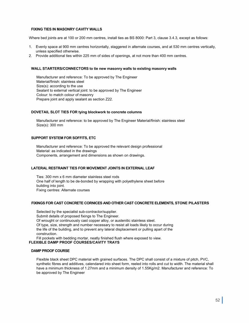
52
FIXING TIES IN MASONRY CAVITY WALLS
Where bed joints are at 100 or 200 mm centres, install ties as BS 8000: Part 3, clause 3.4.3, except as follows:
1. Evenly space at 900 mm centres horizontally, staggered in alternate courses, and at 530 mm centres vertically, unless specified otherwise.
2. Provide additional ties within 225 mm of sides of openings, at not more than 400 mm centres.
WALL STARTERS/CONNECTORS to tie new masonry walls to existing masonry walls
Manufacturer and reference: To be approved by The Engineer Material/finish: stainless steel Size(s): according to the use Sealant to external vertical joint: to be approved by The Engineer Colour: to match colour of masonry Prepare joint and apply sealant as section Z22.
DOVETAIL SLOT TIES FOR tying blockwork to concrete columns
Manufacturer and reference: to be approved by The Engineer Material/finish: stainless steel Size(s): 300 mm
SUPPORT SYSTEM FOR SOFFITS, ETC
Manufacturer and reference: To be approved the relevant design professional Material: as indicated in the drawings Components, arrangement and dimensions as shown on drawings.
LATERAL RESTRAINT TIES FOR MOVEMENT JOINTS IN EXTERNAL LEAF
Ties: 300 mm x 6 mm diameter stainless steel rods One half of length to be de-bonded by wrapping with polyethylene sheet before building into joint. Fixing centres: Alternate courses
FIXINGS FOR CAST CONCRETE CORNICES AND OTHER CAST CONCRETE ELEMENTS, STONE PILASTERS
Selected by the specialist sub-contractor/supplier. Submit details of proposed fixings to The Engineer. Of wrought or continuously cast copper alloy, or austenitic stainless steel. Of type, size, strength and number necessary to resist all loads likely to occur during the life of the building, and to prevent any lateral displacement or pulling apart of the construction. Fill pockets with bedding mortar, neatly finished flush where exposed to view.
FLEXIBLE DAMP PROOF COURSES/CAVITY TRAYS
DAMP PROOF COURSE
Flexible black sheet DPC material with grained surfaces. The DPC shall consist of a mixture of pitch, PVC, synthetic fibres and additives, calendared into sheet form, reeled into rolls and cut to width. The material shall have a minimum thickness of 1.27mm and a minimum density of 1.55Kg/m2. Manufacturer and reference: To be approved by The Engineer

53
FLEXIBLE SHEET CAVITY TRAYS
Bitumen based dpc material to BS 6398, class D, E or F Manufacturer and reference: To be approved by The Engineer
PREFORMED DPC/CAVITY TRAY JUNCTION CLOAKS/STOP ENDS
Manufacturer: To be approved by The Engineer Type(s) and location(s): As and where indicated in the assembly/component drawings Seal all laps with dpcs and/or cavity trays using adhesive/mastic/torching in accordance with manufacturer's recommendations to ensure a fully watertight installation.
JUNCTIONS/STOPENDS FORMED IN SITU
Where preformed junction cloaks/stop ends are not specified form three dimensional changes of shape in dpcs and/or cavity trays carefully and neatly to ensure a fully watertight installation, using folds wherever possible to achieve the required shape. Seal all laps using adhesive/mastic/ torching in accordance with manufacturer's recommendations. Preformed junction cloaks/stop ends may be used in lieu, subject to approval.
INSTALLATION OF DPCS/CAVITY TRAYS
Comply with the relevant clauses of BS 8000: Part 3, section 3.3. Horizontal flexible dpcs and the next course to be laid on thin, even mortar beds to keep joint thickness as close to normal as possible. Vertical dpcs to be in one piece wherever possible. Otherwise overlap by not less than 100 mm with upper piece outermost. Where timber frames are to be built in, fix jamb dpc to back of frame using galvanized clout nails or staples.
FACEWORK
Keep leading edge of dpcs/cavity trays flush with face of wall in all locations .Do not bridge with mortar. JOINTS
MOVEMENT JOINTS WITH SEALANT BETWEEN BUILDING BLOCKS WHERE EXPOSED
- To internal facing blockwork/between slabs - Filler: Cellular polyethylene with brand to approval or equivalent - Build in as the work proceeds ensuring no projections into cavities and correct depth of joint to receive sealant
system. Thickness of filler to match design width of joint. - Sealant: should not be oil based - Colour: to match materials - Prepare joints and apply sealant as section Z22.
MOVEMENT JOINTS WITHOUT SEALANT BETWEEN BUILDING BLOCKS IN UNEXPOSED AREAS
- Fire resistant filler: To be approved by The Engineer - Thickness: According to joint width - Fire resistance period: 2 hours - Compress, insert and slide into place in open joint. Install with accessories or adhesives where recommended by
manufacturer.

54
CONTRACTION JOINTS
- which will not be exposed to view to be close-butt joints formed as the work proceeds.
POINTING IN FLASHINGS
- Remove dust, lightly wet and neatly point with mortar specified for walling. Ensure joint is completely filled and finish flush.
POINTING IN ASPHALT ROOF SKIRTINGS
- Remove dust, lightly wet and neatly point with 1:4 cement: sand mortar incorporating a bonding agent and colour matched to adjacent work. Ensure joint is completely filled and finish flush.
PINNING UP TO SOFFITS
- Completely fill joint at top of load-bearing walls with mortar, well rammed into position using temporary shuttering.
TOPS OF NONLOADBEARING WALLS
- Restraint: In accordance with BS 5628:Part3, clause 18.5 - Joint filler: either 75 x 230 mm galvanised steel sheet channel or 2 in number 75 x 75 mm galvanised steel sheet
angles to BS EN 10143 fixed to underside of precast planks with appropriate screws at 450 mm centres - Securely fix restraints to soffit and completely fill space between wall and soffit leaving no gaps to ensure
compliance with design requirements

55
F31 PRECAST CONCRETE SILLS/LINTELS /COPINGS /FEATURES (To be read with Preliminaries/General Conditions)
TYPE(S) OF COMPONENT
EXTERNAL EXPOSED PRECAST CONCRETE ARCHITECTURAL ELEMENTS (concrete seating elements, copings, mass concrete block for retaining walls)
- Concrete grade and cover to reinforcement as clause 360 - Finish: Generally as specified under 'Fair faced components'. - To match approved sample - Mould material/lining: fibre glass or steel. Timber or plywood moulds are not acceptable. - Aggregate: 10 mm - Matrix colour: stone colour as directed by The Engineer - Work on surface: smooth - Mortar for bedding and jointing: 1: 1/2: 4 - Other requirements: note cast-in water-bars, sinkings for dowels and cramps, recesses for light fittings, PVC pipe
sleeves for handling rods and chains.
CONCEALED PRECAST LINTELS
- To BS EN 845-2:2003. Provide copies of calculations or test certificates showing that the design complies with the Standard.
CONCEALED PRECAST LINTELS
Concrete: To BS 8500, Designated mix not less than RC30 or Designed mix not less than C30, maximum nominal size of aggregate 20 mm.
Clear span Section Bearing Reinforcement
Up to 900 mm:
50 mm deep x width of wall,150 mm at both ends 1 no. 12 mild steel bar for each 105 mm of wall thickness
900 to 1800mm:
225 mm deep x width of wall, 225 mm at both ends, 1 no. 16mm mild steel bar for each 105 mm of wall thickness
Minimum nominal cover to reinforcement: 30 mm.
For greater spans and/or greater than normal loadings see detailed drawings or obtain instructions.
CONCEALED PRECAST PADSTONES
Concrete: To BS 8500, Designated mix not less than RC30 or Designed mix not less than C30, maximum nominal size of aggregate 20 mm. Other requirements: To include cast in fixings and pockets as required
GENERAL REQUIREMENTS
MOULDS must be:
- Constructed accurately to give straight, square and true components. Permissible deviations on length +0, -6 mm, other dimensions +/-3 mm.
- Maintained in clean, sound condition and inspected carefully for defects before each reuse.

56
- Damaged moulds must not be repaired and reused if this would impair the surface appearance of the components. - Constructed to prevent loss of grout. - Designed to permit demoulding without damage to the components. - Coated evenly with a suitable release agent, which must not be allowed to touch the reinforcement.
CONCRETE GENERALLY
- Constituent materials, composition of mixes, production of concrete, information to be provided, sampling, testing and compliance to be in accordance with BS 8500 unless otherwise specified.
AGGREGATES (Unless specified otherwise)
- To comply with BS EN 12620:2002. - To give a drying shrinkage of concrete not exceeding 0.075% when tested to BS 812: Part 120.
CHLORIDES
- The total chloride ion content of the constituents of each mix, expressed as a percentage by weight of cement (including GGBS or PFA if used) in the mix, must not exceed 0.4. Do not use admixtures containing calcium chloride.
REINFORCEMENT
- In addition to reinforcement required for structural purposes, precast units must be reinforced as necessary to resist shrinkage and handling stresses.
- Type of reinforcement, unless otherwise specified: To BS 4449 and/or BS 4483, cut and bent to BS 4466. - Galvanized reinforcement: Galvanized to BS EN ISO 1461:1999 after cutting, chromate treated. - Stainless steel reinforcement: To BS 6744, type 304 or 316. - Ensure that the metal of the reinforcement is compatible with the metal of any fixings and accessories that may
make contact. - At time of placing concrete, reinforcement to be clean and free of corrosive pitting, loose mill scale, loose rust,
ice, oil and other substances which may adversely affect the reinforcement, concrete, or bond between the two. - Fix accurately and securely using tying wire, approved steel clips, or tack welding if permitted. Wire or clips must
not encroach into the concrete cover.
CASTING AND CURING
- Thoroughly compact concrete by vibration. - Do not de-mould components prematurely. - Prevent damage to and distortion of immature components from movement, vibration, overloading, physical shock,
rapid cooling and thermal shock. - Ensure that components are protected from sun and drying winds until they are at least 5 days old. - Do not deliver components to site until at least 14 days after casting.
FAIR FACED COMPONENTS
CONTROL SAMPLES
- After finalisation of all details, prepare one of each of the following, in addition to the quantity required for the project, and obtain approval of appearance before proceeding with manufacture of the remaining quantity:
- Keep the samples at the factory for comparison purposes.

57
DETAILS OF SAMPLES
- After approval of appearance of samples and before making production components: - Confirm details of proposed aggregates, including type, maximum nominal size, grading and source. - Submit evidence to demonstrate compliance in respect of compressive strength and free water/ cement ratio.
AGGREGATES FOR EXPOSED WORK
- To BS EN 12620:2002, of consistent colour, free from absorbent particles which may cause - 'popouts', and other particles such as coal and iron sulphide which may be unsightly or cause unacceptable staining.
Obtain from one source, and ensure that adequate supplies can be maintained throughout the contract.
FACING MIXES
- Use exactly the same ingredients and batch proportions for all components required to have the same finish. - Materials, batching and mixing must be carefully controlled to ensure consistency of colour and appearance.
QUALITY OF FINISHES
- Must match the approved samples and be consistent throughout the contract. - Components having arrises or faces which are broken, chipped, cracked, crazed, honeycombed, irregular,
inconsistent, stained or otherwise marred such that their appearance or performance is significantly impaired will not be accepted.
GRADE AND COVER FOR EXTERNAL COMPONENTS
- Subject to other specified requirements, concrete to Specification E10/104 must be used. - Nominal cover to reinforcement on bedded faces: 30 mm. - Increase the nominal cover to allow for depth of exposure on exposed aggregate finishes.
If galvanized or stainless steel reinforcement is to be used submit proposals for nominal cover and grade for approval. Air entrainment to be by use of an admixture to BS EN 480-2:1997 in accordance with manufacturer's recommendations to give 5% air content by volume. Sample and cube test every batch of concrete.
COVER SPACERS
Must not be visible in finished concrete faces which will be exposed in the finished work.
UNIFORMITY OF METHOD
Exposed faces which are specified to be of the same finish must be identical in appearance. If different methods of producing such faces are proposed, submit evidence that there will be no difference in appearance and obtain approval; otherwise all such faces must be produced in the same way.
INSPECTION
All completed components must be carefully inspected and checked by the manufacturer for match with approved sample(s) and compliance with specification before despatch to site.

58
Make arrangements with the Engineer for him to inspect completed components in the factory.
DAMAGED COMPONENTS
Do not repair without approval. Such approval will not be given where the components are badly damaged or where the proposed repair will impair appearance or performance.
INSTALLATION
PROTECTION
Prevent overstressing of components during transit, handling, storage and fixing. Store components on level bearers clear of the ground and separate with resilient spacers. Prevent damage to components and any chipping, staining, marking or dirtying of surfaces which will be visible in the completed work.
LAYING
Unless specified otherwise, lay components on a full bed of mortar used for adjacent work. If packing is required use slate. Position components accurately, true to line and level. Faces which will be exposed to view in the finished work to be kept clean with no mortar encroachment. Rubbing to remove marks or stains will not be permitted.
SUPPORT OF EXISTING WORK
- Where new lintels are to support existing structure, completely fill top joint with semidry mortar, hard packed and well rammed to ensure full load transfer after removal of temporary supports.
ONE PIECE SILLS/THRESHOLDS
- Leave bed joints open except under end bearings. - On completion point with mortar to match adjacent work.
PRESTRESSED CONCRETE LINTELS
- Manufacturer and reference: to be approved by The Engineer - Bed on mortar used for adjacent work with bearing of not less than 150 mm unless specified otherwise. Adequately
prop at not more than 1.2 m centres during construction of walling above. Retain props in position for not less than 14 days or until mortar has matured, whichever is longer.
PRECAST CONCRETE COPING UNITS
- To BS 5642: Part 2. - Manufacturer and reference: To be approved by The Engineer - Finish: smooth - Finish, colour and texture to match approved sample. - Lay on a full bed of 1: 1/2 : 4 mortar, accurately to line and level, with all joints filled and neatly finished flush.
COPING SYSTEM

59
- May be used to replace 760 subject to approval - Manufacturer and reference: To be approved By The Engineer - Material/finish: as in 760
MISCELLANEOUS ITEMS
TILE SILLS
Plain clay tiles to BS EN 538:1994, size to fit on a 230 mm thick wall Manufacturer and reference: To be approved by architect Lay two courses as detailed, to break joint, true to line and level, fully bedded in 1:1/4:3 cement: lime: sand mortar as section Z21, with all joints filled and neatly finished flush.
BUILDING IN FRAMES
- Adequately support and protect frames permitted to be built in, to prevent distortion and damage. Remove horns from frames and fully bed cramps in mortar.
TEMPLATES
- Where frames are not to be built in (specified elsewhere) form openings using rigid templates accurately fabricated to the required size.
WALL PLATES
- Bed solid in mortar to give a level top surface.
REFUSE CHUTE(S) AND ACCESSORIES
- Build in as the work proceeds to provide a smooth and even interior surface free from voids and restrictions. Fill void between chute and surrounding work with concrete.

60
G12 ISOLATED STRUCTURAL METAL MEMBERS
(To be read with Preliminaries/ General Conditions)
FABRICATION OF MEMBERS
- Steel sections: To BS 4-1, BS EN 10055, BS EN 10056 or BS EN 10210, as appropriate. - Steel: To BS EN 10025, grade S275. - Surface condition: Free from heavy pitting and rust, burrs, sharp edges and flame cutting dross. - Cuts and holes: Form neatly and accurately. - Welding: Metal arc method to BS EN 1011-2. - Welded joints: Fully fused, with mechanical properties not less than those of the parent metal. - Site welding: Not allowed without permission.
SHOP PRIMING
- Preparation: Remove loose scale and rust, burrs, fins, sharp edges and weld spatter. Clean out crevices. Thoroughly degrease and rinse with clean water. Allow to dry.
- Primer: high build zinc phosphate
- Application: Apply one full coat within 8 hours of cleaning surfaces, free from runs and sags.
NUTS, BOLTS & WASHERS
- to be protected against corrosion: - galvanised to BS ISO 1461
- sheradised to BS4921 class 1
- zinc plated to BS3382
INSTALLATION
- Accuracy: Position members true to line and level. If necessary, use steel packs of sufficient area to allow full transfer of loads to bearing surfaces.
- Fixing: Use washers under bolt heads and nuts. Tapered washers: Provide under bolt heads and nuts bearing on sloping surfaces. Match taper to slope angle and align correctly.

61
G30 METAL PROFILED SHEET DECKING
(To be read with Preliminaries/ General Conditions)
PERFORMANCE SPECIFIED ROOF/ FLOOR DECKING
- The decking has been designed to take the loading of mechanical equipment as specified in the bill of quantities and occasional maintenance operations at intermediate floor in Room 10.
STRUCTURAL DESIGN OF ROOF DECKING
- Refer to attached drawings.
FIXING DECKING
PAINTING STRUCTURE
- Sequence: Before the decking is attached paint surfaces of supporting structure that will be subsequently inaccessible.
- Note: Top flanges of composite beams to receive decking are to be left unpainted. - Paint: The paint shall be epoxy refer to M60
PREVENTION OF ELECTROLYTIC ACTION
- Isolating tape: Neoprene. - Location: To contact surfaces of supports and sheets of dissimilar metals.
FIRE RESISTING PROFILE FILLERS
- Supplier: Decking manufacturer. - Type/ shape: To match decking profile void. - Location: Refer to CA. - Fixing: Fit securely, as recommended by manufacturer, to form fire compartment.
FIXING DECKING GENERALLY
- Cut sheets: Clean edges with true lines and no burrs. - Treatment of edges: Remove sharp edges. - Penetrations: Cut openings to the minimum size necessary. - Reinforce edges with: Refer to drawings fro any specific requirements. - Fixings: Drill all holes. - Cleanliness: Remove debris from within decking construction. - Installation: Seams and ribs of deck must be parallel, with no damage to deck coating.
ATTACHMENT OF DECKING AND ACCESSORIES
- Scope of Contactor’s design: Design fixings and accessories to comply with the requirements as stated on the drawings.
- Requirement: To resist specified wind load. - Additional requirements: Refer to drawings. - Standard: In accordance with BS 6399-2, using appropriate location, exposure, height, building shape, size, and

62
taking account existing and known future adjacent and attached buildings. - Design method: Detailed. - Shelter from upwind obstructions: Calculate.
- Internal pressures (without dominant opening):
1. Pressure coefficient (Cpi): Calculate. 2. Size effect factor (Ca): Calculate. 3. Features: Refer to drawings.
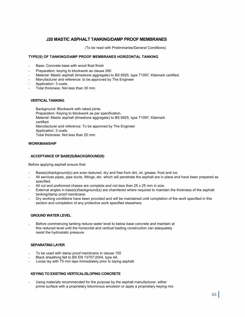
63
J20 MASTIC ASPHALT TANKING/DAMP PROOF MEMBRANES
(To be read with Preliminaries/General Conditions)
TYPE(S) OF TANKING/DAMP PROOF MEMBRANES HORIZONTAL TANKING
- Base: Concrete base with wood float finish
- Preparation: keying to blockwork as clause 260
- Material: Mastic asphalt (limestone aggregate) to BS 6925, type T1097, Kitemark certified. - Manufacturer and reference: to be approved by The Engineer - Application: 3 coats. - Total thickness: Not less than 30 mm.
VERTICAL TANKING
Background: Blockwork with raked joints Preparation: Keying to blockwork as per specification. Material: Mastic asphalt (limestone aggregate) to BS 6925, type T1097, Kitemark certified. Manufacturer and reference: To be approved by The Engineer Application: 3 coats. Total thickness: Not less than 20 mm.
WORKMANSHIP
ACCEPTANCE OF BASE(S)/BACKGROUND(S)
Before applying asphalt ensure that:
- Base(s)/background(s) are even textured, dry and free from dirt, oil, grease, frost and ice. - All services pipes, pipe ducts, fittings, etc. which will penetrate the asphalt are in place and have been prepared as
specified. - All cut and preformed chases are complete and not less than 25 x 25 mm in size. - External angles in base(s)/background(s) are chamfered where required to maintain the thickness of the asphalt
tanking/damp proof membrane. - Dry working conditions have been provided and will be maintained until completion of the work specified in this
section and completion of any protective work specified elsewhere.
GROUND WATER LEVEL
- Before commencing tanking reduce water level to below base concrete and maintain at this reduced level until the horizontal and vertical loading construction can adequately resist the hydrostatic pressure.
SEPARATING LAYER
- To be used with damp proof membrane in clause 150
- Black sheathing felt to BS EN 13707:2004, type 4A. - Loose lay with 75 mm laps immediately prior to laying asphalt.
KEYING TO EXISTING VERTICAL/SLOPING CONCRETE
- Using materials recommended for the purpose by the asphalt manufacturer, either prime surface with a proprietary bituminous emulsion or apply a proprietary keying mix

64
of cement: sand slurry incorporating a bonding agent.
KEYING TO EXISTING BRICKWORK/BLOCKWORK
- Lightly rake out horizontal joints and remove all dust.
KEYING TO SMOOTHFACED BRICKWORK/BLOCKWORK
- Ensure that all joints are raked out and prime wall surface with a proprietary bitumen and rubber emulsion recommended for the purpose by the mastic asphalt manufacturer.
APPLICATION OF ASPHALT
- Ensure thorough mixing when remelting and do not heat to more than 230 deg C. - Temperature of asphalt in heating cauldron to be constantly checked by thermometer. Do not use reheated asphalt. - Hardness of asphalt at time of laying not to exceed 40 at 25 deg C when tested to BS 5284. - The Engineer may, at his discretion, request the Contractor to take representative samples of asphalt within 24
hours of laying for testing of hardness within 5 days. - Apply each coat to even thickness using suitable gauges and float to a smooth surface free from imperfections.
Apply successive coats without delay and within the same working period. - Ensure complete fusion of asphalt at all joints to give a continuous watertight membrane. - Fusion to be achieved by cleaning and warming the edges of previously laid coats with hot asphalt which is to be
removed and discarded before jointing with new material whilst previously laid coat is still hot. Torching will not be permitted.
- Stagger junctions of bays in successive coats by not less than 150 mm. - Pierce any blows and make good affected areas while asphalt is still at working temperature. - Form solid fillets in all internal angles, fully fused to asphalt coating, not less than 40 mm wide on face and at an
angle of approximately 45 degrees to the horizontal. - Maintain full thickness of asphalt around external angles. - Turn asphalt into splayed chase at top edge of vertical work.
SERVICE PIPES/PIPE DUCTS PENETRATING TANKING
- Clean pipe surfaces which will be covered with asphalt. - Prime cleaned area with a proprietary bituminous emulsion recommended for the purpose by the asphalt
manufacturer. - Sleeve pipe with two coats of asphalt to a total thickness of 20 mm. Length of sleeve to be not less than wall
thickness plus 150 mm unless specified otherwise. - Incorporate sleeved pipes into surrounding construction with asphalt sleeve projecting no less than 75 mm from
surface to be tanked. - Fully bond tanking to sleeve. Form an asphalt collar around pipe in three coats not less than
- 30 mm thick, incorporating pipe clips if required and with top coat overlapping asphalt sleeve. Complete junction between sleeve and tanking with an angle fillet.
PROTECTION OF TANKING
Ensure that:
- Protective screeds are laid immediately after the application of horizontal tanking. - Loading/protective walls are built as soon as possible after the application of vertical tanking. - The perimeter of horizontal external tanking is protected temporarily by screed on an isolating membrane prior to
applying vertical tanking.
PROTECTION OF DAMP PROOF MEMBRANE

65
- Ensure that the membrane is protected from damage and the specified cement: sand screed is laid as soon as possible after application of the membrane.
GUARANTEE
- The contractor is to provide a guarantee for the all areas where waterproofing membrane is applied. The guarantee is to be for ten years and is to incorporate the material as well as the application.

66
J40 FLEXIBLE SHEET TANKING/DAMP PROOF MEMBRANES (To be read with Preliminaries/General Conditions)
HARDCORE BEDS
- Blind with not less than 12 mm of soft sand or pulverised fuel ash and consolidate to provide a smooth bed free of sharp projections.
POLYETHYLENE DPM
- Manufacturer and reference: To be approved by The Engineer - Thickness/gauge: 300 microns (1200 gauge) - Lay sheets neatly and tuck well into angles to prevent bridging. - Joint sheets with continuous strips of mastic between not less than 150 mm overlaps and seal with tape along the
edge of the upper sheet, leaving no gaps. Ensure that sheets are clean and dry at time of jointing. - Mastic and tape: Types recommended for the purpose by sheet manufacturer. - If sheets cannot be kept dry, double welted joints may be used provided they are temporarily weighted to hold the
folds in position prior to laying concrete. - Form folded welts at corners in upstands.
WORKMANSHIP GENERALLY
- Apply materials carefully to provide a completely waterproof, continuous membrane. - Ensure that surfaces to be covered are clean, dry, smooth and free from voids, sharp protrusions and frost. - Protect finished sheeting adequately to prevent puncturing during following work. - Cover sheeting with permanent overlying construction as soon as possible. - Immediately prior to covering check for damage and repair as necessary.
INSPECTION
Inform The Engineer a reasonable length of time before covering any part of membrane with overlying construction, to allow inspection.
PRIMER(S)
Type(s) recommended for the purpose by the sheet manufacturer. Apply by mopping, brushing or spraying to achieve an even and full cover of the surface. Allow to dry thoroughly before covering.
BONDING COMPOUND(S)
Hot laid oxidised bitumen to BS 3690: Part 2, grade as recommended by the sheet manufacturer for the conditions and type of surface. Lay at a temperature sufficient to ensure full bonding over the whole surface. Do not overheat. Cold laid bonding compound of a type recommended by the sheet manufacturer may be used for small areas and repair work.
ANGLES IN FULLY BONDED SHEETING
- Fit internal angles with a bitumen impregnated fibre fillet, not less than 40 x 40 mm, bedded in bitumen mastic or bonding compound.
- Reinforce all angles with a strip of the specified damp proofing material, not less than 300 mm wide, applied before the main sheeting.
- Continue main sheeting around angles, extending not less than 100 mm on to adjacent surfaces.

67
JUNCTIONS WITH DPCS
- Identify position of adjoining damp proof courses and expose to view where concealed. - Thoroughly clean away all mortar, debris and dirt from vicinity of DPCs, including any projecting portions of DPCs. - DPCs which project from the wall: Fully lap and fully bond/seal sheeting to DPC projection using bonding
compound
- DPCs which do not project from the wall: Extend sheeting 50 mm past DPC and fully bond to wall using bonding compound or mastic tape if using plastics sheet or plastics DPC.
PIPES, DUCTS, CABLES, ETC
- Where these pass through sheeting, make junctions completely watertight using preformed EPDM collars fully bonded/sealed to both pipes and sheeting.
BACKFILL PROTECTION
- Cover tanking against which backfill material will be placed with 19 mm thick bitumen impregnated fibreboard. Provide temporary support as necessary to ensure boards remain fully in contact with tanking during backfilling operations.

68
J41 REINFORCED BITUMEN MEMBRANE COVERINGS (To be read with Preliminaries/ General Conditions)
TYPES OF COVERING SINGLE LAYER REINFORCED BITUMEN MEMBRANE WARM COVERING
- Substrate: Concrete screed, laid to falls.
- Preparation: Primer as per specification. - Vapour control layer: Not required
- Insulation: Rigid board expanded polystyrene to BS EN 13167, thickness as per clause 230. - Overlay to insulation: Stone spalls (torba).
Waterproof covering
- Type: Polyester-reinforced, plastomeric polymer-bitumen torch-weldable membrane to BS EN 13707, BS 8747 type S2P3 (equivalent to BS 747 Type 5U).
- Product weight: 5kg/m2
- Attachment: Torch-on welding/bonding. - Flashings and detail work: Additional layer of type S2P3 Membrane. - Surface protection: Slate chippings. - Accessories: EPDM pipe collars, vents and rain water outlets. All accessories are to be sandwiched between two
layers of torch-welded membrane. The assembly is to fit into a prepared recess in the roof construction such that no obstruction to the flow of water is created by the additional thickness of the sandwich construction.
PERFORMANCE
ROOF PERFORMANCE
General: Secure, free draining and weathertight.
VAPOUR CONTROL
Interstitial condensation risk of roof: Determine as recommended in BS 6229. Modify calculation method to conform to BS 5250. Maximum relative humidity recorded to be considered in calculations: 100% Detailed meteorological data can be obtained from the Meteorological Office, Malta International Airport, Tel: +356 2369 6527, www.maltairport.com/weather
Indoor psychrometric conditions (notional): As follows:
■ Temperature: No heating of the interior of the building will take place.
■ Relative humidity: no specific sources of water vapour are envisaged.
Winter interstitial condensate:
■ Calculated amount (maximum): 0.35 kg/m2.
■ Calculated annual net retention: Nil
Water vapour resistance to be assumed in calculations: ■ One layer bitumen membrane fully bonded: 300 MN.s/g. ■ Two layers bitumen membrane, fully bonded: 500 MN.s/g. ■ Three layers bitumen membrane, BS 747 type 3B, 5B or 5U, fully bonded to a continuous supporting
substrate: 900 MN.s/g.

69
Vapour control layer: If calculated amounts of condensate exceed allowed maxima, provide a suitable membrane so that damage and nuisance from interstitial condensation do not occur.
PRODUCTS
PRIMER
Type: Bitumen cut back with volatile solvent. Characteristics when tested to BS EN 13357: - Volatile solvent content (minimum): 40% by mass. - Viscosity (maximum) (STV at 25°C, 4 mm orifice): 10s.
ANGLE FILLETS
Material: sand cement mix. Size (minimum): triangular 50mm by 50mm Restriction: Fillets under torch-on bitumen membranes to be non-combustible.
MOVEMENT JOINTS
Create using two layers of bitumen membrane as per clause 115, with 50mm diameter ethafoam (polyethylene) rod/strip in between. Upper membrane layer to cover one half of the circumference of the rod.
STONE BALLAST
Type: limestone spalls (hardstone upper or lower coralline limestone). Supplier: to be approved by The Engineer Size: Graded 16–32 mm, free from fines and sharps. Colour: white or light beige. Dressing compound: To BS EN 12591
EXECUTION GENERALLY
ADVERSE WEATHER General
- Do not lay coverings in high winds, wet or damp conditions or in extremes of temperature unless effective temporary cover is provided over working area.
- Unfinished exposed areas: Keep dry.
INCOMPLETE WORK End of working day: Provide temporary seal to prevent water infiltration. On resumption of work: Cut away tail of membrane from completed area and remove from roof.
APPLYING PRIMERS
Coverage per coat (minimum): as per manufacturer’s recommendations. Surface coverage: Even and full. Coats: Fully bond. Allow volatiles to dry off thoroughly between coats.

70
WATERPROOF COVERINGS/ ACCESSORIES
LAYING REINFORCED BITUMEN MEMBRANES GENERALLY
- Direction of laying: Unrolled up the slope. - Where practicable, install so that water drains over and not into laps. - Side and end laps: 100mm
- Head and side laps: Offset. - Intermediate and top layer/ cap sheet: Fully bond. - Successive layers: Apply without delay. Do not trap moisture. - Strips of bitumen membrane for 'linear' details: Cut from length of roll. - Completed coverings: Firmly attached, fully sealed, smooth, weatherproof and free draining.
LAYING REINFORCED BITUMEN MEMBRANES ON ROOFS PITCHED MORE THAN 5°
- Timber battens: Fix flush with surface in substrates that will not securely accept nails. - Locations: To BS 8217, table 5. - Setting out: Parallel to roof slope, with successive layers carried over ridges. - Lengths (maximum): As recommended by bitumen membrane manufacturer. - End laps: Half stagger and align on alternate bitumen membranes.
PARTIAL BONDING OF REINFORCED BITUMEN MEMBRANES
- Venting first layer: Loose lay, align and cut to length. Do not carry up angle fillets and vertical surfaces or through details.
- Long edges: Overlap minimum 50 mm. - Ends: Butt together. - Intermediate layer: Fully bond to first layer and through to substrate. - Top layer/ Cap sheet: Remove.
TORCH-ON BONDING OF REINFORCED BITUMEN MEMBRANES
- Bond: Full over whole surface, with no air pockets. - Excess compound at laps of top layer/ capsheet: Leave as continuous bead.
LAYING MINERAL FACED REINFORCED BITUMEN MEMBRANES
- Lap positions and detailing of ridges, eaves, verges, hips, abutments, etc: Submit proposals. - Setting out: Neat, with carefully formed junctions. - Lap bonding: Carry out only at pre-finished margins or prepared 'black to black' edges. - Excess bonding compound at laps: Remove whilst still warm.
WELDED JOINTING OF SINGLE LAYER REINFORCED BITUMEN MEMBRANES
Side and end joints:
- Preparation: Clean and dry surfaces for full width of joint.
- Sealing: Hot air welded
SKIRTINGS AND UPSTANDS
- Angle fillets: Fix by bitumen bonding or nailing, unless formed of sand-cement mix. - Venting first layer of bitumen membrane: Stop at angle fillet. Fully bond in bitumen for 300mm strip around
perimeters. Overlap onto upstand with strips of BS 8747 type S2P3 bitumen membrane, fully bonded. - Other layers of bitumen membrane: Carry in staggered formation up upstand, with each layer fully bonded.

71
Where practicable, carry top layer over top of upstand.
Upstands (minimum 100mm above angle fillet)
- At ends of rolls: Form with bitumen membrane carried up without using separate strip. - Elsewhere: Form with matching strips of bitumen membrane, maintaining laps. - Additional fixing of bitumen membranes: use galvanized strip 50mm high fixed to parapet wall using galvanized
screws with plastic anchors
INSTALLING ROOF VENTILATORS
- Setting out: Position evenly over roof area. - Centres (maximum): 4000mm. - Distance in from roof edges: 600mm minimum.
Holes for ventilators: Cut neatly to suit size of vents through roof membrane.
- Substrate below vents: Do not prime or apply bonding compound. - Vent skirts: Prime before sheeting, if recommended by manufacturer. SURFACING LAYING STONE BALLAST
Condition of substrate: Clean. Gravel guards: Fit to outlets. Laying: Spread evenly. Do not pile to excessive heights. Depth (minimum): 50mm Previously laid materials: Protect during laying of ballast.
APPLYING CHIPPINGS
Condition of substrate: Clean. Gravel guards: Fit to outlets. Dressing compound: Hot or cold application. Evenly pour at 1.5 kg/m². Chippings application (approximately): 16 kg/m².
- Completion: Remove loose excess chippings without exposing dressing compound. COMPLETION INSPECTION
- Interim and final roof inspections: Submit roof covering manufacturer's reports.
FLOOD TEST of horizontal roofs
- Condition of roof before testing: Complete to a stage where integrity of bitumen membrane covering can be tested. - Outlets: Externally cover and seal. Protect against damage from water pressure using temporary kerbs. Do not use
plugs to seal outlets. - Flood levels: Submit proposals. In no case higher than kerbs. - Flood duration: Three days
- Inspection to detect leaks: Regular. - Completion of test: Slowly drain roof. Do not overload or flood outlets. - Test results: Submit.
COMPLETION
Roof areas: Clean. Outlets: Clear.

72
Work necessary to provide a weathertight finish: Complete. Storage of materials on finished surface: Not permitted. Completed membrane: Do not damage. Protect from chemicals, traffic and adjacent or high level working.

73
K10 DRYLININGS/PARTITIONS/CEILINGS (To be read with Preliminaries/ General Conditions.)
MOISTURE RESISTANT METAL STUD LININGS OF WALLS – NON-FIRE RATED
- Location: as specified in drawings and/or the Bill of Quantities
- Nominal thickness (excluding finishes): 80mm overall unless otherwise indicated in tender drawings
- Nominal height: as specified in tender drawings and/or the Bill of Quantities
PERFORMANCE CRITERIA
- Fire resistance of complete partition assembly: NA
- Fire resistance- Integrity/insulation (minutes): NFR
STUDS
- Type: 70mm or as per manufacturer’s specifications
- Centres: 600mm
- Deflection allowance: 15mm deflection heads to manufacturer’s recommendations. - Thickness: 50mm or as per manufacturer’s specifications
LININGS
- Type: To BS 1230: Part 1: 1985 Type 3 & 4
- 1 layer Wall Board 15mm backed with water repellent additives in the core, square ended and taped and jointed to receive generally a skim finish.
PRIMER/SEALER
- To manufacturer’s recommendations.
ACCESSORIES
Extruded Aluminium Trims Tape and jointing compound to suit boards Plaster board and thin coat angle, edge and stop beads to manufacturer’s recommendations where applicable.
MOISTURE RESISTANT METAL STUD LININGS OF WALL – FIRE RATED
- Location: as specified in the drawings and Bill of Quantities
- Nominal thickness (excluding finishes): 80mm overall unless otherwise indicated in tender drawings. - Nominal height: as specified in tender drawings and/or the Bill of Quantities
PERFORMANCE CRITERIA - Fire resistance of complete partition assembly to BS476: Parts 20&22
- Fire resistance- Integrity/insulation (minutes): 60 minutes
- Thermal conductivity: 0.25 W/Mk or better
STUDS
- Type: 70mm or as per manufacturer’s specifications
- Centres: 600mm
74
- Deflection allowance: 15mm deflection heads to manufacturer’s recommendations. - Thickness: 50mm or as per manufacturer’s specifications
LININGS
- Type: To BS 1230: Part 1: 1985 Type 3, 4 & 5
- 1 layer Wall higher density core Board 12.5mm with water repellent additives in the core, square ended and taped and jointed to receive generally a skim finish.
PRIMER/SEALER
- To manufacturer’s recommendations.
ACCESSORIES
Extruded Aluminium Trims Tape and jointing compound to suit boards Plaster board and thin coat angle, edge and stop beads to manufacturer’s recommendations where applicable.
CEMENT BOARDS
- Water-resistant cement-based board shall be supplied shrink wrapped or with cardboard covers on pallets. Packs shall be lifted with a fork lift truck, the forks being set so there is an even weight distribution and no deformation of the pack. Handling equipment shall be of adequate capacity, and personnel shall be advised of handling procedures and safety clothing. Care shall be taken at all times to avoid strain to the handlers. Boards shall not be lifted at the short edges or carried horizontally.
- Water-resistant cement-based board shall be stored flat in a clean dry environment on a flat surface. If timber bearers are used to store boards on site, they shall be a minimum 40mm wide and placed at maximum 450mm centres.
- Metal sections shall be supplied in small packs, strapped together to form larger packs for forklift truck off-loading. These packs shall be stacked in single packs, in a safe and stable manner on a flat surface. These bands or straps shall not be used for lifting, since metal sections may spring apart when banding is released.
- Jointing compounds and plasters shall be stored in a dry location within the building, taking into account their shelf life.
BOARD SUSPENDED CEILING SYSTEM
Structural soffits: refer to the drawings. Ceiling system manufacturer and product reference: submit technical literature to The Engineer.
■ Ceiling type:
Grid form: non-interlocking. Grid exposure: Concealed.
■ Suspension system:
Primary grid centres: as recommended by the manufacturer. Hanger centres: as recommended by the manufacturer. Secondary grid centres: as recommended by the manufacturer. Access: access panels as indicated on the drawings. Ceiling soffit above finished floor level: refer to the drawings. Boards: as clause ‘GYPSUM PLASTERBOARD (FIRE PROTECTION)’. Accessories: as required, refer to the drawings. Integrated services fittings: for air diffusers, luminaries, etc. Other requirements: cut-outs for fittings.

75
METAL STUD PARTITION SYSTEM
LOW PARTITIONS
Partition type: double row studs Partition height: 1.50m Head condition: unrestrained Structural performance: medium Strength grade to BS 5234-2: Fire resistance of complete partition assembly: as shown on drawings Metal framing: Type recommended by board manufacturer to complete the partition assembly and achieve specified performance. Thickness: 12mm gypsum boards and an overall width of 100mm Linings: Finishing: skin coat plaster Primer/ Sealer: For plastered areas it is not required.
FLOOR TO SUSPENDED CEILING HEIGHT PARTITIONS – FIRE RATED
GENERAL
- 1HR FIRE RATED
- Location: Existing building in Audio Visual Room
- Nominal thickness (excluding finishes):
- 122mm overall plus 9mm plaster finish with 3mm skim plaster - Nominal height: as per drawings
STUDS
- Type: 70mm C-Studs unless otherwise specified in drawings
- Centres: 600mm
Head condition: as per drawings Deflection allowance: 15mm deflection heads to manufacturer’s recommendations and with continuous line Firestrip.
INSULATION
None
FINISHING:
- Plaster finish to match existing as Spec M20
PRIMER/SEALER
- To manufacturers recommendations.

76
ACCESSORIES
- Extruded aluminium trims: as per drawings
- Tape and jointing compound to suit boards
- Plaster board and thin coat angle, edge and stop beads to manufacturer’s recommendations where applicable.
OTHER REQUIREMENTS
- Fire stopping around all service penetrations. - To be locally reinforced as necessary - Details and locations as shown on drawings. - All cornices, existing walls and ceilings within the existing building affected by new inserted plasterboard walls, linings
& ceilings to be made good and/or reinstated. COMPONENTS
SAMPLES
- General: Submit representative samples of the described materials.
GYPSUM PLASTERBOARD (IMPROVED FIRE PROTECTION)
Type: To BS 1230-1, type 5. Core density (minimum): 800 kg/m³. Core: Including fibres for improved cohesion. Thickness: adequate for the clear span between the supports. S i z e s : submit proposals. Fillets/ cover strips: required at the movement joints. Finish: smooth acrylic coating. Colour: white.
GYPSUM PLASTERBOARD (FIRE PROTECTION)
Type: To BS 1230: Part 1: 1985 Type 5 Core density (minimum): 800 kg/m³. Core: Including fibres for improved cohesion. Thickness: adequate for the clear span between the supports. Sizes: submit proposals. Fillets/ cover strips: required at the movement joints. F i n i s h: smooth plastic emulsion coating. Colour: white or as approved
PERFORMANCE CRITERIA
Fire resistance of complete partition assembly to BS476: Parts 20&22 Fire resistance- Integrity/insulation (minutes): 60 minutes Manufacturer: British Gypsum – or similar approved. Product reference: GypWall Classic – System Ref: A206230
INSTALLATION
SETTING OUT
General: Accurate, continuous, even, and jointed at regular intervals. Infill and access units, integrated services: Fitted correctly and aligned. Permitted deviations from nominal sizes: Allow for. Suitability of construction: Give notice where building elements and features to which the ceiling systems relate are not square, straight or level.

77
PROTECTION
Loading: Do not apply loads for which the suspension system is not designed. Ceiling materials: Remove and replace correctly using special tools and clean gloves, etc. as appropriate
INSTALLING HANGERS
Wire hangers: Straighten and tension before use. Installation: Install vertical or near vertical without bends or kinks. Do not allow hangers to press against fittings, services, insulation covering ducts/ pipes. Obstructions: Where obstructions prevent vertical installation, either brace diagonal hangers against lateral movement, or hang ceiling system on an appropriate rigid sub-grid bridging across obstructions and supported to prevent lateral movement. Extra hangers: Provide as required to carry additional loads.
FIXING
Wire hangers: Tie securely at top with tight bends to loops to prevent vertical movement. Angle/ strap hangers: Do not rivet for top fixing.
INTEGRATED SERVICES
GENERAL
- Position services accurately, support adequately. Align and level in relation to the ceiling and suspension system. Do not diminish performance of ceiling system.
SMALL FITTINGS
Support with rigid backing boards or other suitable means. Do not damage or distort the ceiling. Surface spread of flame rating of additional supporting material: Match ceiling material.
SERVICE OUTLETS
Supported by ceiling system: Provide additional hangers. Independently supported: Provide flanges to support ceiling system.
MECHANICAL SERVICES
FAN COIL UNITS
- Inlet and outlet grilles: Trim ceiling grid and infill units to suit. - Space beneath: Sufficient for ceiling system components. - Suspension and connections: Permit accurate setting out and levelling of fan coil units.
AIR GRILLES AND DIFFUSERS
- Setting out: Accurate and level.
LINEAR AIR DIFFUSERS
- Provide flanges for support of grid and infill units. - Provide for displacement of ceiling grid.

78
- Retain in place with lateral restraint.
- Grille/ diffuser ceiling joints: Provide smudge rings and edge seals.
METAL FRAMING FOR PARTITIONS/ WALL LININGS
- Setting out: Accurately aligned and plumb. - Frame/ Stud positions: Equal centres to suit specified linings, maintaining sequence across openings. - Additional studs: To support vertical edge of boards. - Fixing centres at perimeters (maximum): 600 mm. - Openings: Form accurately.
CAVITY FIRE BARRIERS WITHIN PARTITIONS/ WALL LININGS
- Metal framed systems: - Material:
- Installation: Form accurately and fix securely with no gaps to provide a complete barrier to smoke and flame.
ADHESIVE FIXED WALL LINING SYSTEM
- Material: Adhesive compound. - Installation: Form in a continuous line with no gaps to provide a complete barrier to smoke and flame.
FIRE STOPPING AT PERIMETERS OF DRY LINING SYSTEMS
- Material: Tightly packed mineral wool or intumescent mastic/ sealant. - Application: To perimeter abutments to provide a complete barrier to smoke and flame.
JOINTS BETWEEN BOARDS
- Tapered edged plasterboards: - Bound edges: Lightly butted. - Cut/ unbound edges: 3 mm gap. - Square edged plasterboards: 3 mm gap. - Square edged fibre reinforced gypsum boards: 5 mm gap.
VERTICAL JOINTS
- Joints: Centre on studs. - Partitions: Stagger joints on opposite sides of studs. - Two layer boarding: Stagger joints between layers.
HORIZONTAL JOINTS
- Surfaces exposed to view: Horizontal joints not permitted. Seek instructions where height of partition/ lining exceeds maximum available length of board.
- Two layer boarding: Stagger joints between layers by at least 600 mm. - Edges of boards: Support using additional framing. - Two layer boarding: Support edges of outer layer.K10.

79
INSULATION BACKED PLASTERBOARD
- General: Do not damage or cut away insulation to accommodate services. - Installation at corners: Carefully cut back insulation or plasterboard as appropriate along edges of boards to give
a continuous plasterboard face, with no gaps in insulation.
FIXING PLASTERBOARD TO METAL FRAMING
- Partitions/ Wall linings: Fix securely and firmly at the following centres (maximum) - Position of screws from edges of boards (minimum): 10 mm. - Screw heads: Set in a depression. Do not break paper or gypsum core.
FINISHING
LEVEL OF DRY LINING ACROSS JOINTS
- Sudden irregularities: Not permitted. - Joint deviations: Measure from faces of adjacent boards using methods and straightedges (450 mm long
with feet/ pads) to BS 8212, clause 3.3.5. - Tapered edge joints: Permissible deviation (maximum) across joints when measured with feet resting on boards: 3 mm. - External angles: Permissible deviation (maximum) for both faces: 4 mm. - Inter nal angles: Permissible deviation (maximum) for both faces: 5 mm.
SKIM COAT PLASTER FINISH
Plaster type: as recommended by board manufacturer Thickness: 2-3 mm Joints: Fill and tape except where coincident with metal beads. Finish: Tight, matt, smooth surface with no hollows, abrupt changes of level or trowel marks.
RIGID BEADS/STOPS
- ype: Galvanized steel to BS 6452-1.
INSTALLING BEADS/ STOPS
- Cutting: Neatly using mitres at return angles. - Fixing: Securely using longest possible lengths, plumb, square and true to line and level, ensuring full contact of
wings with substrate. - Finishing: After joint compounds/ plasters have been applied, remove surplus material while still wet from surfaces
of beads exposed to view.

80
K20 TIMBER BOARD LININGS (To be read in conjunction with Contract Conditions)
MARINE PLYOOD TIMBER BOARDS
- Marine grade plywood to BS EN 314: Part 2, BS EN 635: Parts 1-3, BS EN 636 DD CEN/TS 1099 and BS 1088: Parts 1 and 2.
METAL FRAMING FOR WALL LININGS
- Refer to K10
WORKMANSHIP
FIXING BOARDS
- Protection during and after installation: Keep boards dry, clean and undamaged. - Boards to be used internally: Do not install until building is weathertight. - Fixing: Fix boards securely to each support to give flat, true surface free from undulations, lipping, splits and
protruding fasteners. Reference is to be made to - Timber movement: Position boards and fixings to prevent cupping, springing, excessive opening of joints and other
defects. - Heading joints: Tightly butted, central over supports and at least two boards widths apart on any one support. - Edges: Plane off proud edges.

81
K41 RAISED ACCESS FLOORS
(To be read in conjunction with Contract Conditions)
SCOPE, SUBMITTALS, TESTING AND PERFORMANCE
SYSTEM TYPES
- Type 35KA: Mineral Core high density calcium sulphate, bonded with fibres heavy duty access panel with ceramic finish providing a fully accessible raised access floor.
SAMPLES, MOCK-UPS, PROTOTYPES AND QUALITY BENCHMARKS
Pre-contract Samples (if requested)
Sufficient samples of the following, including relevant trade literature and technical specifications, shall be provided in accordance with Section A.4000:
a) 1 No. floor panel of each system. b) Floor pedestal. c) Perimeter plenum with floor grille. d) 1 No. inset floor box
Post Contract Samples
Post contract samples of the following shall be provided (if requested):
a) 1 No. floor panel of each system.
b) Floor pedestal of each system. c) Perimeter plenum with floor grille. d) 1 No. inset floor box e) Typical step with integral lighting and row number (RAF-02) f) Balustrade sample (RAF-02) Mock-ups Not Required.
Prototypes
Prototype shall be constructed to meet written specification and to include all associated fixings, finishes and inset services.
a) 5m² section of each raised flooring system RAF-01 & RAF-03 including complete system build up, specified floor finishes, integrated floor boxes and ventilation grills. Each prototype to be tested for live loading criteria specified.
b) 5m² section of specialist raised floor / seating rake system RAF-02 including complete system build up, specified floor finishes, integrated floor boxes, ventilation grills swivel seats, steps to aisle and balustrade. Each prototype to be tested for live loading criteria specified. Refer to section N21 for specialist seating requirements.
The following quality benchmarks shall be provided in accordance with Section A.4000: First 9m² of each type in location to be agreed.
TESTING
Test Requirements
- In accordance with MOB PF2 PS/ SPU Section T0.00. Full Access Floor
Systems

82
- In accordance with MOB PF2 PS/ SPU Sections T1.00 to T20a.00. Partial Access Floor
Systems
- In accordance with MOB PF2 PS/ SPU Sections T21.00 to T41a.00. Site Quality Control
Tests
- In accordance with MOB PF2 PS/ SPU Sections T42.00, T43.00 and T44.00.
ROLLING LOADS (Applicable to Steel Encapsulated Panels)
- The panels shall be subjected to a rolling load test and subsequently meet the requirements of the point load test and safety load test as set out below.
- Should a satisfactory rolling load test as described below not be available, such a test shall be carried out prior to production of materials for this contract by an independent testing authority acceptable to the Architect as set out below.
- The testing shall be carried out in a rolling load rig and comprise 7 No. full panels, a simulated door threshold with an adjacent half panel and 1 No. length of metal to simulate a door threshold with an additional cut panel. The floor panels for the test shall be selected by laboratory staff of the independent testing authority from the place of manufacture and installed in the rig by the Contractor. The rig shall consist of a carriage travelling to and from on rails with 2 No. nylon wheels, 150mm diameter x 40mm, wide set 800mm apart on the underside. The wheels will be set to traverse the centre line of the panels at a speed of one mile per hour (=0.45/ second) with a load of 3kN on each. The test shall comprise a minimum of 20,000 passes.
- Method T1.00 of the PSA specification shall be used to determine the "bow" of the panels using a bridge and dial gauge. Such measurements shall be recorded for information purposes.
On completion of the rolling load test, each panel shall be subjected to:
1. A 25mm point load of 3kN at centre edges for a period of 5 minutes. This test shall be as stated in MOB PF2 PS/ SPU Test T8.00 but for the reduced time span and;
2. A safety factor load test of 9kN for 5 minutes via a 25mm square plate, as MOB PF2 PS/ SPU Test T11.00.
Allow in the Tender for any necessary modifications to the flooring system to enable it to satisfactorily pass the pre-production tests, and for any further pre-production testing necessary to prove that the modified flooring meets the test requirements.
A Certificate of Testing confirming a pass shall be submitted to the Project Manager prior to the commencement of production.
SLIP RESISTANCE TESTING (Walkable Glass)
Testing for slip resistance shall comply with the following documents:
1. 'The assessment of pedestrian slip risk' by The Health and Safety Executive (latest published version). 2. 'The assessment of floor slip resistance, the UK Slip Resistance Group guidelines' by The UK Slip Resistance
Group (latest published version).
- Testing shall be performed at an independent UKAS accredited laboratory accredited to perform the specified test methods.
- Pendulum Test: Internal flooring shall be evaluated in both dry and wet conditions using the TRL Pendulum Tester in accordance with BS 7976 and the recommendations of the UK Slip Resistance Group to obtain the pendulum test value (PTV) specified.

83
- Roughness Test: Internal flooring shall be evaluated using a surface roughness meter, in accordance with the recommendations of the UK Slip Resistance Group, to obtain the surface roughness (Rz) value specified.
Samples shall be tested at the following stages of the project:
1. Approval. 2. Production. 3. Post-installation (in-situ).
- Submit test results to the Project Manager for acceptance in due time, prior to each of the project stages or as agreed with the Architect.
- Test samples must include any surface treatments to be applied to the glass.
- Sealing of builders work in plenums utilised for pressurised supply air ventilation, particularly where other mechanical and electrical services pass through the plenum walls
- Plenums shall be leakage tested and shall have a maximum allowable leakage of 1 L/ s per m² of plenum surface area, at 50 Pa. Leakage shall be conducted in the presence of the Services Engineer.
PERFORMANCE REQUIREMENTS
- Comply with the general performance of the following specific performance requirements.
- Comply generally with the MOB PF2 PSU/ SPU 'Performance Specification for Raised Access Floors', or acceptable equivalent European Standard.
STRUCTURAL GENERAL
- The works shall be installed to withstand all deflections and tolerances of the building structure under all design loads or combination of loads without reduction in the performance or appearance of the works or applied finishes. Refer to the Engineers movement and tolerances report.
- All fixings shall be capable of providing adequate adjustment to achieve a level floor.
- The works shall accommodate all movement joints as necessary.
- The works shall withstand static and dynamic design loads without causing deformation of components or the failure of members and shall transmit such loads safely to the points of support.
DEFLECTION
- A calculated deflection of no more than 2.5x10 (-3) mm
FLOOR LOADS
- The works shall take account of all loadings and deflections of the structure to which they are fixed. All assemblies, adjustment mechanisms, fixings and support systems shall be capable of achieving a firm and level floor.
- Movement Noise: The works shall be installed such that movements over the floor or changes in temperature do not result in audible 'creaking', 'squeaking' or 'slip-stick' noise.
LIVE LOADS
1. A minimum vertical live load capacity of 2.4kN/m2 UDL and 8kN point load + finishes
2. Lateral live loading: 10% of the maximum vertical load with the vertical imposed simultaneously.
3. A natural frequency of not less than 12 Hz at 2.4KN/ m².

84
ENVIRONMENTAL MOISTURE REQUIREMENTS FOR TIMBER WITHIN FLOORING SYSTEMS - Areas for storage and installation shall be clean, dry, ventilated and free from excessive or rapid variations of
temperature and humidity. Relative humidity shall not exceed 75%.
- No part of the sub-floor or surrounding walls shall show readings of more than 75% RH when tested for moisture content using an accurately calibrated hygrometer in accordance with BS 8201.
- The systems shall be designed and suited to the locations indicated on the Design Drawings in accordance with the environmental conditions specified in the requirements of MOB PF2 PS/ SPU 'Performance Specification for Raised Access Floors' or BS EN 12825.
- Notwithstanding the above, delivery of materials and installation of the works shall be taken as the responsibility of the Contractor for the suitability of the environmental conditions.
RAISED FLOOR AIR LEAKAGE TESTS
- Ensure the air tightness at all perimeter conditions including seals around services penetrations at core walls. Include for air testing the complete void of all areas of the building on a zone by zone basis. Any failure of the raised floor or floor voids found on testing shall require retesting.
- The underfloor fire/ smoke barriers shall also form an effective airtight seal to reduce the size of the area of each raised floor and raised floor void that is tested. The size of test rig and areas for testing shall be agreed with the Architect prior to ordering.
- The tests shall be carried out by an independent testing laboratory accepted by the Project Manager.
The works shall not exceed the following leakage rates:
1. Floor surface 1.5 litres/ m²/ second at 50N/ m² test pressure. 2. Floor void 0.9 litres/ m²/ second at 50N/ m² test pressure.
ACOUSTIC
Specific Acoustic Requirements
1. Airborne sound insulation shall be to BS EN ISO 140: Part 3; measured in accordance with BS EN ISO 717: Part 1 and BS EN ISO 10848: Part 2.
FIRE
Cavity Barriers
- All concealed spaces below the works shall have firebreaks. Firebreaks shall be located on the line of the required compartments as indicated on the plan area.
- The firebreaks shall have a resistance of not less than 30 minutes as specified or meet the required level of resistance indicated on the Working Drawings and required by the Specification.
- Material: PVC sleeved mineral wool or similar shall meet the performance criteria specified. - Fire resistance to BS 476: Part 20.
- Integrity/ insulation: 60 minutes. Refer to the fire strategy and accompanying fire strategy drawings.
- All openings into the void and through any cavity barriers shall be fire stopped to 30 minutes fire resistance and provide a complete barrier to smoke and flame.
- Barriers shall subdivide floor voids into areas not exceeding 400m².

85
- Barriers shall be fixed securely to the sub-floor at joints and as necessary to ensure permanent stability and continuity with no gaps, thus providing an effective barrier to smoke and flame.
- Access panels above cavity barriers shall be screwed down or otherwise firmly secured.
- Where systems incorporate insulation, these products should conform to the clients insurer’s requirements; Roof and wall insulation to be either non-combustible or as approved by the Project Manager.
- Spread of flame: Type RAF-02 Class 0 spread of flame acoustic foam to underside of plasterboard.
FIRE STOPPING
- All gaps at junctions of the works with walls, cavity barriers, ducts, pipes, other floors at different levels, etc. shall be sealed with fireproof material to prevent penetration of smoke and flame.
SYSTEMS, MATERIALS AND FABRICATION SYSTEMS
Raised Access Floor Construction Generally;
1. The thickness and type of the panels shall be determined with due regard to the performance requirements of the Specification and the location within the building.
2. The joints between flooring panels shall be constant. These shall be sealed with a serrated compressible neoprene strip, or similar. The exact fixing detail shall be accommodated in the design and detailed on the Working Drawings.
3. Cut-outs in panels shall be carried out at the point of manufacture and not on Site. All exposed ends, cuts, etc. shall be suitably finished and sealed.
4. Panels shall be protected against corrosion after fabrication and prior to application of finishes. All exposed faces of metal, including ends, shall be treated to avoid corrosion.
5. No panels shall have sharp edges.
6. The core of the panel shall be protected by metal encapsulation, foil or steel backing.
7. Cutting and drilling of flooring panels and associated works shall take place before the application of finishes.
Other Requirements: 1. Steps and ramps shall be provided where indicated on the Design Drawings. Steps shall include riser panels, vertical
infill panels and flush nosings and general profiles as indicated on the Design Drawings.
2. Vertical closure panels where steps or floor systems are provided (by others) shall be fully sealed to achieve the specified pressurisation requirements.
3. Provide perimeter seal to cladding at perimeter conditions.
4. Provide all underfloor cavity barriers to comply with Building Regulations.
5. Structural movement joints, where visible, shall be to the acceptance of the Project Manager.
6. Earth bonding of the works to the Services Engineer's Specifications.
7. Seal all gaps at the junction of the works with the walls with fireproof material to prevent penetration of smoke and flame.
8. Seal all encapsulated tiles with sealant or welding material to prevent egress of water into the core material.

86
9. Systems to be installed to incorporate all floor-mounted / recessed services as identified on the design drawings and specified by the services engineer. Refer to services Engineers documentation.
RAISED FLOORING SYSTEMS
Type 35KA
A mineral core high density calcium sulphate, bonded with fibres heavy duty access panel with ceramic finish providing a fully accessible raised access floor to suit a raised floor height (max 150mm void) as indicated on the Design Drawings.
Sub-floor: Concrete or as indicated on the Design Drawings.
Panel type:
i) Loading capacity: ii) System weight: iii) Panel size: iv) Floor zone: v) Finish:
Pedestals:
1. All mild steel base with threaded mild steel tube with threaded stud and locking nut.
2. Head of pedestal shall be 90mm diameter or as approved, capable of loose lay, screw down or stringer support.
Accessories:
1. Cut-out panels shall incorporate floor box electrical outlets/ air supply outlets services as indicated on the M&E Services Engineer's.
Documentation:
- Allow for all associated trims and cavity barriers. - System to be designed to support internal MWEP wheel loading as identified within the cleaning and maintenance
strategy documents and associated drawings.
- System shall include all necessary integrated balustrade, handrails, steel treads as indicated on the Design Drawings and in accordance with the Building Regulations.
- System to be designed to support dead load of fully fitted out museum.
- System to include cav ity barr iers benea th mobile partitions to provide acoustic and fire separation to meet the performance requirements of the specification.
- System to be installed generally onto existing hardstone floor. Allow for the raised access floor system to be installed in environmentally acceptable conditions in accordance with manufactures recommendations.
Other Requirements:
- Cut-out panels shall incorporate floor box electrical outlets and all other services as indicated on the M&E Services Engineer's Documentation.
- System to incorporate access ramps and steps as identified on the design drawings. Allow for recessed step lighting to be integrated into stepped aisles and the fixing of row identification labels in Brushed Stainless Steel.
1. Balustrade assembly ramp perimeter to extend down to floor level at entrance to Room 10
Finishes:
1. Steel frame: Polyester powder coated RAL colour 9011 black or as approved.
2. Finish: Ceramic Finish
Heavy duty. 0.44KN/ m² max. 600mm x 600mm. Refer to the Design Drawings. ceramic finish

87
3. All recessed floor boxes and access panels to receive match finished and to be fitted flush.
4. Steps and ramps to be visually identified with colour contrasting nosings to be installed to meet the requirements of the Building Regulations.
MATERIALS
GENERAL
- The floor system and all its associated components shall be constructed of moisture resistant, vermin-proof and rot-proof material.
- Renewable Sources: When selecting metal raised flooring systems, the contractor must provide written confirmation of all types of system proposed, including country of origin, before starting on Site to demonstrate all materials have been sustainable sourced and are supported by a full chain of custody.
MILD STEEL - All steel panels shall be fabricated from CR4 mild steel in accordance with BS 1449: Part 1 and BS EN 10132: Parts
1-3, unless otherwise accepted. All panel core materials shall be of stable, homogeneous and durable material, free from toxic and harmful products.
FABRICATION
Manufacturing Tolerances:
- The pedestals shall be adjustable to provide a finished floor level within ±1.5mm over any 5m².
- Panel Flatness: The concavity or convexity of any panel under no load conditions shall not exceed 0.75mm when measured across a 600mm module and parallel to any edge or diagonally across the module.
- Panel Squareness: The panel deviation from square shall not exceed 0.06% of the diagonal length.
- Panel Dimensions: The deviation from the specified size of the panel shall not exceed ±1.00mm.
SITE INSTALLATION PREPARATION
- Before installation works commence, ensure that the cementitious surface to the sub-floor, including within the floor void up to the level of the platform floor, is completed.
- Ensure that any mechanical fixings are clear of the reinforcement in the structural slab.
- The existing floor to become the sub-floor shall be properly cleaned before the installation of the works commences. Cleaning shall continue during installation to prevent entrapment of dirt or rubbish.
- Surfaces to be sealed shall be clean, dry and free from dust, grease and other contaminants.
- Sealer shall be as recommended by the Raised Floors manufacturer, applied in two contrasting colour coats in accordance with the manufacturer's written instructions to all substrates within the floor void to prevent dusting throughout the life of the installation.
MARKING OUT
- Pedestal positions shall be marked out using (using a marking system which can be removed without leaving trace
88
after removal) in advance of the services installation. Ensure no conflict of location.
IRREGULAR SPACES - Where surrounding walls, or other building elements and features to which the works relate, are not square,
straight or level, proposals shall be submitted to the Architect and Project Manager on setting out. Cutting of tiles shall be kept to a minimum and located in unobtrusive locations. Grid pattern shall be maintained wherever possible. All cut tiles adjacent to door thresholds, lift lobbies and other openings shall have an additional pedestal support at mid span.
- Adhesives shall be those recommended by the floor tile manufacturer for the particular covering material and the panel substrate.
- Coverings shall be bonded to a smooth and level panel substrate covering the entire top surface area of the panel. Joints in the material within one panel shall not be acceptable.
- The bond shall remain effective for the design life of the covering materials.
- Where the panels are to be lifted by means of a lifting device applying force to the covering, the adhesion between the covering and the panel shall be adequate for panels of up to 20kg to be lifted without causing any failure or weakening of the bond. The lifting device shall not cause damage to the covering material when used in accordance with the manufacturer's instructions.
- Pedestals shall be bonded and remain rigid and firmly secured to the existing sub-floor. All pedestals shall be fixed plumb.
- All pedestal fittings, stringers, bridging structures, perimeter support and cavity barriers shall be provided as necessary, including movement joints, steps, ramps and cut-outs for floor boxes, where indicated on the Design Drawings.
- The floor system shall have a panel location system to securely locate each panel. It shall exhibit no rocking and the system shall not rely on the perimeter wall for lateral stability but provide resistance to rolling loads. The floor system shall remain stable when groups of panels are removed for access or maintenance or any other reason.
- Ensure that all changes in level of substrates are accommodated and that the required finished floor datum level is achieved.
CO-ORDINATION WITH OTHERS
- The correct location of pedestals and services shall be ensured and where considered necessary, positions of pedestals shall be indelibly marked in advance of services installations.
- Related work shall be suitably coordinated and shall proceed without damage to the floor, which shall be protected as necessary.
- Before commencing work, all fixtures around which panels are to be cut or over which supports are to bridge shall be checked to ensure that they are complete.
SETTING OUT
- Refer to the Design Drawings for setting-out requirements.
- The works shall be set out within the discipline of a dimensional framework based on BS 6750.
- The setting out shall follow the planning grid and be coordinated with the setting out of ceilings, walls and partitions so as to achieve the dimensional requirements of MOB PF2
- PS/ SPU 'Method of Building Performance Specification for Raised Access Floors' (clause P3.00).
- Where not indicated otherwise, set out the works as specified above. Any conflict occurring between the operations of the above clauses shall be referred to the Architect and a setting-out method agreed.

89
- Whenever possible, use oversize panels to ensure that cut panels are not less than half in width, particularly at doorways, thresholds, perimeters, etc. and provide suitable panel support arrangements which shall not create a hazard to pedestrians.
- Co-ordinate pedestals/supports with the Working Drawings regarding all services requirements within the Raised Floors voids, particularly with respect to all requirements for bridging as necessary. Refer also to the Services Engineer's Specifications and Drawings.
- Refer to the Structural Engineer's Drawings for requirements for raised structures/ beams, etc. and ensure that pedestals are suitably raised or bridged as necessary.
SEALING OF CUT PANELS
- All exposed cut edges of panels shall be sealed with Class 0 rated aluminium foil self- adhesive tape.
PERIMITERS
- The works shall have sufficient lateral stability to enable them to be independent of abutting elements.
- A 10mm gap shall be provided at all abutments and shall be filled with a resilient closed cell filler before fixing skirting, cover strips, etc.
PROTECTION
- No part of the works shall be used as a platform for storage of equipment and materials.
- No part of the works shall be subjected to static or dynamic loads, which exceed those for which it is designed. Adequate precautions, including the use of spreader plates, shall be taken during installation of equipment and any work on other elements, e.g. ceilings.
- No part of the works shall be walked on within 48 hours following the use of adhesives to fix pedestals to the sub-floor.
- No part of the works shall be left unprotected prior to Practical Completion. A protective covering shall be supplied and fitted.
CHANGES OF LEVELS
- Ramps and Steps: Construct to accepted details to achieve performance requirements specified for the associated works.
- Ensure that air tightness is maintained at steps, ramps, etc. as specified and as indicated on the Design Drawings.
PANEL LIFTING DEVICES
- Upon completion, two sets of lifting devices suitable for each of the floor finishes installed shall be provided. One set shall be used by others requiring access to the void and the other for handing over to the Architect at Practical Completion.
POST INSTALLATION EXAMINATION
After completion of the mechanical and electrical installation and other associated work:
1. Thoroughly inspect the floor installation for defects and prepare a schedule of outstanding defects for submittal to the Architect.

90
2. Thoroughly clean all accessible areas of the sub-floor and apply a further coat of sealer to all accessible areas.
MOVMENT JOINTS
- The works shall accommodate all movement joints in the building structure without compromising the integrity, appearance or performance of the system.
- Refer to the Structural Engineer's Specifications and Drawings for locations and types of movement joints and accommodate the works accordingly.
TOLERANCES
Installation Tolerances:
- The pedestals shall be adjustable to provide a finished floor level within ±2.5mm deviation from the defined finished floor level; the defined finished floor level may be varied, when accepted by the Architect, to accept variations in levels due to construction tolerances and deviations in adjacent interfacing works.
- Sudden irregularities shall not occur.
- The variation in gap under a straightedge placed anywhere on the surface shall be not more than the following:
1. 5mm under a 3m straightedge.
2. 2mm under a 1m straightedge.
Ensure that the installed works remain free from undulations, steps, ridges, bumps, ripples, rocking and lipping.
- The works shall be flat, flush and true at abutments with adjacent surfaces at the same relative level.
- The works shall be installed such that finished surfaces shall be capable of being installed to achieve the design tolerances, providing a flush, true and flat interface with adjacent finishes, free from steps or flaws.
- Bay divisions and movement joints shall be accommodated in the design and coordinate with wall joints and other elements indicated on the Design Drawings.
- The difference in height between adjacent finished panels shall not exceed 1.0mm after the application of the specified load and shall not exceed 3.25mm between the edge of any panel being subjected to any of the static loadings specified for any adjacent unloaded panel.
- The deviation due to twisting under no load conditions of any corner in relation to the other three shall not exceed 1.0mm over a 600mm module. The flatness shall be maintained when the panel is subjected to any environmental conditions and also after the removal of any concentrated or distributed loads.
On-Site Dimensions:
- All dimensions to be checked on Site.
- The final installation shall accommodate all specified tolerances and differences between actual Site dimensions and dimensions shown on the Working Drawings.

91
L10/L20 DOORS/WINDOWS AND GENERAL JOINERY
COMPLIANCE – TESTING AND CERTIFICATION (Where Applicable)
Where applicable, compliance shall be demonstrated through testing and/or certification of products and/or processes as outlined in the ensuing clauses.
ON SITE MEASUREMENT
- For items to be installed within a structure the Contractor shall ascertain the actual dimensions of the part of the structure accommodating the respective item by means of site measurement prior to the manufacture of such item.
SAMPLES
- The Contractor may be required to submit a pre-production assembled sample of the unit/s inclusive of glazing, hinges, locks and any other fixings and fixtures to the Project Manager for approval.
TECHNICAL LITERATURE
- The Contractor may be requested to submit further detailed technical information in addition to that presented with the tender regarding the type of assembly, test performance characteristics, the proposed finish and any other information which may be required to clarify construction details.
DESIGN AND DRAWINGS
- The Contractor shall provide shop drawings in A1 hardcopy format (and in electronic format) and detailed schedules for all units when so requested by the Project Manager.
- Prior to the start of the works the Contractor shall submit for the approval of the Project Manager all construction and dimensional details, template designs of mouldings/panelling and details of all fittings.
TRANSPORT AND INSTALLATION
- The Contractor is responsible for the safe transport and installation of the units ensuring that all are in good working order and that the locking devices and holding pegs are all in place.
TIMBER GENERAL
- All timber materials used shall be of good quality, properly seasoned to its particular end use and generally free from defects.
- Defective timbers showing decay, heavy sap stain, active insect attack, distortion, high moisture content or heavy checking shall be rejected.
- Timber shall be cut square and be free from large, loose or dead knots, shakes, or other defects.
MATERIAL
- The timber shall comply with EN 942: Class J30 or higher for external locations and J40 or higher for internal general joinery.

92
STRENGTH AND MOISTURE
- The supplier shall state the strength class of the timber used in the works for the approval of the Project Manager. The strength class of timber shall be designated in accordance with EN 519.
- The moisture content for dimension purposes shall be 20%.
DURABILITY
- The supplier shall state the durability class of timber in accordance with BS EN 335- 1:2006. This shall not be less than Class 2 for internal use with occasional wetting, Class 3.1 for timbers to be used externally and painted and Class 3.2 for timbers to be used externally and unprotected.
WORKMENSHIP
- The fabricated units shall comply with BS 1186, Timber for and Workmanship in Joinery with due regard to the particular purpose for which it is required.
- All joinery immediately after delivery to site is to be stored and protected from the weather.
- Should any joinery shrink, warp or expand before the end of the maintenance period, the work is to be taken down and new work fixed in its place, together with any work which may be affected. This is to be carried out at the Contractor's sole expense.
- All carpentry shall be accurately set out, framed together and securely fixed in the best possible. Framing shall be properly braced and checked, halved, screwed or bolted together as required. Longitudinal joints in plates, ridge, fascias, etc. shall be formed over supports. Those members with lapped joints shall lap at least 150 mm or twice the depth whichever is the greater. Nails, screws, spikes, plugs, bolts, framing anchors and wood connectors shall be provided wherever necessary. Other than those detailed, no joints are permitted in joinery work.
- Joinery shall be blind mortise and ten on construction, sized for a tight fit, with tenon set in adhesive and pinned. Frames shall be assembled at the commencement of the work and all members shall be carefully mortised and tenoned together but no wedging, pinning or gluing shall be done until the framing is prepared in readiness for immediate fixing. All timber units shall be properly stored on site and immediately before fixing in its final position, joinery shall be wedged and pinned. Any portions that warp, twist or develop any other defects shall be replaced before wedging up. All framed work shall be pinned before being framed together.
- The frame and hinging arrangement shall be such as to support the weight of the structure without any jamming, excessive sagging, twisting or distortion.
- The Contractor shall comply with any special security provisions and incorporate any such requirements if so instructed by the Project Manager.
- The vertical and upper horizontal gap between the swing structure and frame shall not exceed 3mm. The lower horizontal gap between the swing structure and floor shall not exceed 10mm.
- The design shall incorporate air and/or dust seals.
- Where joints occur in long members of carcass timber they shall be scarfed and secret wedged to prevent movement.
- All wrought faces of timber shall be finished with fine glass paper or similar surface in readiness for further treatment.
- Framing timbers shall be carried out in the best practical manner. In general rails and stiles etc, in doors and windows are to be mortised and tenoned, with housed joints and mitres lost to the best advantage.
- All hardwood that is directly in contact with plaster, brickwork, masonry etc, shall be dressed with proprietary sealer, immediately before fixing and before plastering is carried out. Afterwards the timber shall be properly cleaned off.
- All softwood joinery shall be primed with a proprietary primer before fixing. No fixings are to be left proud.

93
- Care shall be taken to ensure that all units are stored on level bearers, free of ground contact, allowing free access of air to all surfaces. For joinery work the sizes specified shall be considered as nominal sizes.
- Any timber splitting or opening to the extent of 1mm within the Contract maintenance period shall be replaced. Tonguing shall be cross-grained. Work is to be prepared and framed up as soon as possible after the order to commence work is given, and stored dry under cover so that the air will circulate freely around it. No work is to be glued or wedged up until required for use, unless otherwise specified or directed. All joinery is to be finished die square, and when in work is to hold the full dimensions shown on the drawings. No piecing, lengthening or unnecessary joining will be permitted.
- Work exposed to view is to be wrought and that exposed to weather is to be put together with a mixture of red and white lead linseed oil.
TREATMENT AND PRESERVATIVE
- All wood, including carcass, shall be impregnated with wood preservatives. All surfaces cut after impregnation shall be liberally swabbed with preservative in accordance with the manufacturers instructions.
- The wood shall, as far as is practical, be cut to its final dimensions before treatment, and timber for joinery shall be fully worked and ready for framing before treatment. Where cross-cutting cannot be avoided or where further dressing is necessary, all surfaces exposed by such work shall be liberally swabbed with the approved wood preservatives.
- All organic solvent preservative solutions must comply with Class F/N Treatment: (fungicidal/insecticidal) of BS 5707: Part 1 and/or BS 5268 Part 5. The level of service life to BS 5589, table 5 shall be level B.
- All wood shall be penetrated by the preservative and the minimum depth of penetration shall be 12mm.
- Treated external joinery shall not be machined, drilled, etc. and shall not be reduced in size. - Where treated timbers are cut, e.g. bird's mouthing, notches, etc., these exposed areas
shall receive two liberal brush coats of a preservative complying with BS 5707.
SURFACES
- The quality of the surface, as finished, should be appropriate to the position and use of the unit, and in accordance with the details shown in the drawings.
- Surfaces at any joint in an assembly should be such that the parts may be brought into contact over the whole area of the joint before connectors are inserted or any pressure or restraint from the fastening is applied. These surfaces should have a good sawn or planed finish.
- Bearing surfaces of notches and other cuttings should be true and smooth and in appropriate relation to the other surfaces of the piece.
- Notches should be U-shaped formed by parallel cuts to previously drilled holes. The diameter of the hole should be equal to the width of the required notch.
- Where splitting is likely to have a deleterious effect, end sealing is mandatory. For wood known to split and check the ends of the boards and scantlings shall be protected with a coating designed to minimise end checking and splitting.
JOINTS
- Where necessary to avoid splitting, nails should be driven into pre-bored holes of diameter not greater than four-fifths of the diameter of the nails. Care should be taken to avoid placing nails in any end split.
- Lead holes should be used to ensure good workmanship in making screwed joints; the diameter of the hole for the shank should be equal to the diameter of the shank, and for the threaded portion the diameter of the hole should not be greater than seven-eighths of the diameter of the root of the screw thread adjacent to the shank. Care should be taken to avoid placing screws in any end split.

94
- Bolt holes should be drilled to diameters as close as possible to the nominal diameter of the bolt and in no case more than 1.6 mm larger than the bolt diameter. Care should be taken to avoid placing a bolt in any end split. A minimum of one complete thread should protrude from the nut.
- A washer should be fitted under the head of each bolt and under each nut.
- To prepare a joint using split-rings, the members of the joints should be fitted together in their appropriate positions and clamped or spiked together before drilling. Alternatively, drilling jigs or multiple head boring machines may be used, or individual members may be marked out from the setting-out or by use of prepared templates.
- If either of the latter methods is employed, sample members (usually the first ones produced) should be carefully checked against the setting-out.
- In all instances bolt hole positions should be accurately determined by reference to the point of intersection of the centrelines of the member. Great care is necessary if the first set members so marked out are to be used subsequently as drilling templates. Greater accuracy can usually be obtained by the use of special marking or drilling templates located by a pin at the intersection of the centrelines.
- Bolt holes should be drilled at right angles to the surface of the joint. The contact surfaces of the members should be grooved to the appropriate dimensions.
- Drilling and grooving may be done in a single operation; alternatively, if the hole is pre-drilled the pilot of the grooving tool should fit in the bolt hole, thus centring the groove about the hole.
- Care should be taken to ensure that all chips and shavings are removed, and rings should be expanded before being placed in the grooves.
- The joint should be finally assembled and bolts inserted. Washers of the correct dimension should be placed under the head of the bolt and the nut, and the nut tightened to hold the members together.
FASCIAS AND BORADS
- Unless otherwise shown in the drawings, fascia and boards shall be supplied in long lengths. The boards shall be fixed in whole lengths and where joints are necessary, they shall be scarf jointed and the joints shall occur only over the ends of roof framing members and mitred at corners. Boards 250 mm wide and less shall be in one width and those deeper shall be formed by two or more boards jointed together by tongue and groove and 'V' joint.
INSTALLATION
- During installation units and frames shall not be twisted nor forced to fit them into openings. - The selection of the sealant shall be based on its adhesion compatibility with the specified wood and adjacent
wall materials. - All units shall be checked for correct alignment and operation and before permanent anchoring. - Anchoring shall have countersink anchor heads. All anchors shall be concealed by closed door or, in the case of fixed
units, with plugs. DOORS
EVIDENCE OF PERFORMANCE
Certification: Provide independently certified evidence that all incorporated components comply with specified performance requirements.
SITE DIMENSIONS

95
- Procedure: Before starting work on designated items take site dimensions, record on shop drawings and use to ensure accurate fabrication.
- Designated items: Internal timber doors in the administration and emergency buffer building; steel roll doors in the emergency buffer building.
DOOR SCHEDULE
- Refer to the drawings for the basic door requirements. IRONMONGERY
Refer to section P21
COMPONENTS
STEEL DOORSETS and/or louvered openings.
- Manufacturer: Contractor’s choice. - Door leaf: galvanized steel sheet - Finish as delivered: as in clause M60/130; stone colour, matt. - Frame and architraves: galvanized steel.
- Finish as delivered: stone colour, matt. - Ironmongery: as in section P21. - Perimeter seals: as in section Z22. - Fixing: plugged and screwed to masonry as section Z20.
INSTALLATION
PROTECTION OF COMPONENTS
- General: Do not deliver to site components that cannot be installed immediately or placed in clean, dry, floored and covered storage.
- Stored components: Stacked on level bearers, separated with spacers to prevent damage by and to projecting ironmongery, beads, etc.
CORROSION PROTECTION
- Surfaces to be protected: where required. - Protective coating: Two coats of bitumen solution to BS 6949 or an approved mastic impregnated tape. - Timing of application: Before fixing components.
FIXING DOORSETS
- Timing: After associated rooms have been made weather tight and the work of wet trades is finished and dried out.
BUILDING IN
- General: Not permitted unless indicated on drawings.
FIXING OF LOOSE THRESHOLDS

96
- Spacing of fixings: Maximum 150 mm from each end and at 600 mm maximum centres.
SEALANT JOINTS
- Sealant: - Manufacturer: Contractor’s choice. Product reference: submit literature. - Colour: white. - Application: As section Z22 to prepared joints. Triangular fillets finished to a flat or slightly convex profile.
FIXING IRONMONGERY GENERALLY
- Fasteners: Supplied by ironmongery manufacturer. - Finish/ Corrosion resistance: To match ironmongery. - Holes for components: No larger than required for satisfactory fit/ operation. - Adjacent surfaces: Undamaged. - Moving parts: Adjusted, lubricated and functioning correctly at completion.
LOCATION OF HINGES
- Primary hinges: Where not specified otherwise, positioned with centre lines 250 mm from top and bottom of door leaf.
- Third hinge: Where specified, positioned on centre line of the door leaf. - Hinges for fire resisting doors: Positioned in accordance with door leaf .manufacturer's
recommendations. TIMBER DOORS & WINDOWS
GENERAL
- Timber doors, windows, gates and shutters shall comply with EU directive 89/106/EEC as implemented by decision 95/204/EC of 1995.
HARDWARE & IRONMONGERY
GENERAL
- Refer to Section Door Ironmongery Section P21. - All hardware shall be fixed in accordance with the manufacturer’s instructions. Hardware shall be protected prior to
and after fixing until completion of the works and damages shall be replaced at the contractors own expense. - Doors shall be complete with three sets of keys. Bolt throw shall be at least 20mm with a single turn of the key. - Anchor bolts shall be galvanized or stainless steel.
SWING DOORS
- Refer to Section P21
Door closers shall be of two types:
- Rack and pinion type EN 2-4 overhead in a cast aluminium body with selectable closing force, adjustable closing speed and latching action (requiring a door stop).
- Type EN 2-6 with adjustable back check action (restraining a flung-open door) and delayed action 9for disabled or load carrying users).
WINDOWS AND DOORS

97
OPERATING FORCES
The requirements and classification of operating forces for doors shall comply with EN 12217. Methods of test for operating forces shall be in accordance with EN 12046-1 (Windows) and EN 12046-2 (Doors).
MECHANICAL PROPERTIES
The classification of racking, torsion and operating forces shall comply with EN 13115.
MECHANICAL DURABILITY
The requirements and classification of mechanical durability shall comply with EN 12400. The resistance to repeated closing and opening shall comply with EN 1191.
STRENGTH REQUIREMENTS (Doors)
The classification of strength requirements shall comply with EN 1192.
WEATHER PERFORMANCE
The thermal break shall be 9mm formed from a 15mm double flush polyamide strip. Weather-stripping shall be extruded ethylene propylene, neoprene or other plastic that remains flexible and non-sticky at ambient temperature. The classification or test methods for conformity purposes shall be as follows:
■ Air Permeability Class 4 (EN 12207) ■ Resistance to repeated Closing and Opening Severe (EN 12400) ■ Resistance to wind Load Class C5 (EN 12210) ■ Water tightness (Exposed) Class 9A (EN 12208) ■ Water tightness (Unexposed) Class 6B (EN 12208) ■ Resistance to Soft and heavy body Impact (Windows) Heavy Duty (EN 13049) ■ Resistance to Soft, Heavy and Hard Body Impact (Doors) Severe (EN 949, EN 950)
Timber Industrial, Commercial and Garage Doors and Gates without Fire Resistance or Smoke Control
Provisions Industrial, commercial and garage doors and gates without fire resistance or smoke control provisions shall comply with EN 13241-1.
The classification shall be as follows:
• Air Permeability • Mechanical Aspects • Resistance to Water penetration • Resistance to wind Load • Safety (If power operated)
The test methods shall be as follows:
Air Permeability EN 12427 Mechanical Aspects EN 12605 Resistance to Water penetration EN 12489 Resistance to wind Load EN 12444 Safety (If power operated) EN 12445
EN 12426 EN 12604 EN 12425 EN 12424 EN 12453

98
The installation and use shall comply with EN 12635.
ACCESSIBILITY FOR ALL
Timber doors shall comply with the requirements of the document “Design Guidelines – Access for All, KNPD, Malta, 2005”.
ACCESSORIES & FIXTURES
CUBICLES
- Doors installed in toilet cubicles shall have automatic “Vacant / Occupied” indicators.
GLAZING
- All glass for glazing shall comply with EU Directive 89/106/EEC as implemented by the relevant decision.
- All glazing shall be installed in compliance with the recommendations in BS 6262, Code of Practice for Glazing for Buildings.
- All glass shall be laminated safety glass complying with BS EN ISO 12543-1, 2, 5 and 6.
- Any pane of glass which is positioned within an area defined as within a critical impact zone or prone to human impact by BS 6206 shall comply with Class 2(B)2 of EN 12600.
- Doors and side panels must be Class 2(B)2 of EN 12600 if the width is greater than 900mm.
- The impact test method shall comply with EN 12600.
- No wired glass shall be used.
- All glass shall be free from scratches, bubbles, cracks, ripples, dimples and other
defects.
- No wired glass shall be used.
- The thickness and appearance of glass shall be as indicated in the Drawings.
- The maximum light transmission shall be 89% with a minimum solar control factor of 82%.
- Where fire resistance of the glass is to be specified it shall be in accordance with the classification in EN 357.
- All external glazing shall be designed to resist a pressure of 600Pa in both air (wind) permeability and water- tightness testing. Testing shall be performed in accordance with BS 6375 - Performance of Windows, under all conditions and with full allowance made for deflections and other movements.
- All glazing shall be accurately sized, with clean undamaged edges. Glazing units shall be set on all four sides of the frame and sealed with neoprene or equivalent weather gaskets in such a way as not to be disturbed should gaskets need replacing. Proprietary compressible rubber shall be applied at intervals between the profiles and the glass.
- The Contractor may be requested to provide certification documentation to show that glazing elements comply with the specifications. The Contractor shall submit the manufacturer's recommendations for cleaning and for on-going maintenance of the glazing units, and upon completion, shall leave all glazing units clean in accordance with these recommendations, and to the satisfaction of the Project Manager.
DOUBLE GLAZING
99
- Double-glazed units shall be hermetically sealed, with aluminium spacers, and consisting of two sheets of 6mm clear float glass with a 8mm gap with a partial vacuum, or filled with dessicated argon.
- Double-glazed units for toilet areas and where indicated should have the outer pane in hammered or patterned glass.
DOOR MASTER KEY SYSTEM (Where Specified)
- Doors shall be equipped with a mechanical master key system if so indicated in the Bills of Quantities. The system shall permit the opening of locks by their own individual key and by the master key.
- The locking system shall be patented by a manufacturer accredited to and/or certified by a renowned certification body. The cylinder aperture shall offer protection from picks and breaking tools with supplementary anti-drill protection. The key combinations shall be in compliance with current European Standards.
- The system shall allow for future additions and expansions.
The cylinders shall comply with BS EN 1303, Building Hardware. Cylinders for locks, Requirements and test methods.
The classification level shall be as follows: (i) Digit1 (ii) Digit2 (iii) Digit3 (iv) Digit4 (v) Digit5 (vi) Digit6 (vii) Digit7 - The manufacturer shall maintain a key duplication control system whereby
authorization for duplication is mandatory. - On completion, the Contractor shall provide a detailed “MASTER KEY CHART” showing the floor level,
location, door number, cylinder type and key marking.
RESTORATION OF EXISTING UNITS
- When existing joinery is to be restored all accessories and hardware are to be inspected for wear and damage. - Restored units shall be impregnated on all surfaces with an approved wood preservative. All wood shall be
penetrated by the preservative and the minimum depth of penetration shall be 12mm from all sides. - All door elements which are deemed by the Project Manager to have deteriorated beyond repair are to be substituted
with other of same material and design. Deteriorated mouldings are to be retained until completion of the restoration process.
CLEANING
- After installation is complete and any surrounding work is substantially complete, the Contractor shall clean all units and lubricate all hinges / pivots and locks.
Grade1 Grade5
NA Grade0
NA Grade0 Grade4

100
M10 CEMENT: SAND/CONCRETE SCREEDS/TOPPINGS
(To be read with Preliminaries/General Conditions)
TYPE(S) OF SCREED/TOPPING CONCRETE SCREED TO EXISITNG FLOOR -
(Room 10)
- Base: Hollow precast prestressed concrete planks in various locations
- Construction: Not Bonded
- Minimum thickness at any point: 75 mm. - Concrete grade RC20
- Coarse aggregate: 10mm single sized
- Other requirements: insert reinforcing mesh OR as indicated in drawings. - Finish: As in clause TROWELLED FINISH TO RECEIVE APPLIED FLOOR FINISHES
GENERALLY/PREPARATION
SUITABILITY OF BASES
Before starting work ensure that:
1. Bases are such as to permit specified levels and flatness/regularity of finished surfaces, bearing in mind the permissible minimum and maximum thicknesses of the screed/topping.
2. Bases are sound and free from significant cracks and gaps. 3. Bases are clean and free from plaster, dirt, dust and oil. 4. Concrete slabs to receive fully or partially bonded construction have been allowed to dry out by exposure to the
air for not less than 6 weeks.
PROPRIETARY SCREEDS/TOPPINGS
- Where any screed/topping is described as 'proprietary', all materials, mix proportions, mixing methods, minimum/maximum thicknesses and workmanship must be in accordance with the recommendations of the stated manufacturer even though that manufacturer may not supply all of the required materials.
CONTROL SAMPLE
- Lay an area of topping type M10 in advance of the remainder, in an approved location, size 50 sq m and obtain approval of appearance before proceeding.
ROOF SCREEDS
- Before laying screed cut small neat holes through roof slab at low points to effectively drain surplus water. - Locations and method of cutting to be approved. - When screed has drained completely, fill and seal holes to approval.
CONDUITS UNDER FLOATING SCREEDS - Haunch up in (1: 4) cement: sand on both sides of conduits before laying insulation for
floating screeds.
CONDUITS TO BE CAST INTO OR UNDER SCREEDS

101
- Overlay with 500 mm wide strip of steel fabric to BS 4483, reference D49, or - Welded mesh manufactured in rolls from mild steel wire not less than 1.5 mm diameter to BS 1052, mesh size 50 x
50 mm. - Place the reinforcement at mid depth between the top of the conduit and the screed surface.
PIPE DUCTS/TRUNKING
- Before laying screed, ensure that preformed access ducts are securely fixed to the base and accurately levelled in relation to the finished floor surface.
FULLY BONDED CONSTRUCTION
- Shortly before laying screed/topping completely remove mortar matrix from surface to expose coarse aggregate over entire area of hardened base using abrasive blasting or, for in situ slabs only, pneumatic scabbling. Remove all dust and debris and wash clean.
- Keep surface well wetted for several hours before laying screed/topping. Remove free water then brush in a slurry bonding coat of creamy consistency.
- Slurry: Neat cement - As an alternative to wetting and slurrying, prepare, prime as necessary and apply a bonding agent to
manufacturer's recommendations. - Bonding agent: As recommended by the screed/topping manufacturer - Lay screed/topping while slurry or bonding agent is still wet to ensure a good bond.
BATCHING/MIXING/LAYING
BATCHING
- Proportions of mixes made with dense aggregates are specified by weight and, where practicable, should be batched by weight. Volume batching will be permitted on the basis of the previously established weight: volume relationship(s) of the particular materials and using accurate gauge boxes. Allow for bulking of damp sand.
MIXING
- Do not use admixtures containing calcium chloride. - Water content of mixes to be the minimum necessary to achieve full compaction, low enough to prevent excessive
water being brought to the surface during compaction. - Mix materials thoroughly to a uniform consistence. Mixes other than no-fines must be mixed in a suitable forced
action mechanical mixer. Do not use a free fall type (drum) mixer. - Use while sufficiently plastic for full compaction. - Use ready-mixed retarded screed mortar within the working time and site temperatures recommended
by the manufacturer. Do not re-temper.
ADVERSE WEATHER - Do not lay screeds/toppings unless their surface temperature can be maintained above 5 deg C for not less than 4
days thereafter. - In hot weather reduce the time between operations or use other measures to prevent premature setting or drying
out.
JOINTS IN SCREEDS
- Unless otherwise specified: - Cast screeds continuously, as far as possible without defined joints, using 'wet screeds' between strips or bays.
Obtain approval for positions of bay joints.

102
- Form day joints with a vertical edge.
JOINTS IN TOPPINGS
- Unless otherwise specified, bay sizes to be not more than 20 sq m for 20 - 30 mm thick toppings, 15 sq.m for 30 - 50 mm thick topping, ratio of length to breadth not more than
- 3:2, a joint occurring over every construction joint in the base slab. - Where location of bay joints is not shown on drawings obtain approval before starting work. - Forms to be square edged with steel top surfaces, securely fixed. Compact thoroughly at edges to give level, closely
abutted joints with no lipping. - Alternatively, toppings may be cast continuously, bay joints being formed with approved plastics or metal
dividing strips.
LEVELS OF FLOOR SCREEDS/TOPPINGS
- Permissible deviation in level of surface of screeds (allowing for thickness of coverings) and toppings from datum: +/- 10 mm.
FLATNESS/REGULARITY OF FLOOR SCREEDS
- Sudden irregularities are not permitted. When measured with a slip gauge to BS 8204:Part 1, Figure 3 or equivalent, the variation in gap under a straightedge (with feet) placed anywhere on the surface to be not more than the following:
- Screeds to receive toppings or beds 15-30 mm thick: 10 mm under a 3 m straightedge
- Screeds to receive mastic asphalt flooring/underlays: 1. 5 mm under a 3 m
straightedge
- Screeds to receive sheet or tile finishes bedded in adhesive (Room 10):
1. 5 mm under a 3 m straightedge
2. 2 mm under a 1 m straightedge
FLATNESS/REGULARITY OF TOPPINGS
Sudden irregularities not permitted. When measured with a slip gauge to BS 8204: Part 1, Figure 3 or equivalent, the variation in gap under a straightedge (with feet) placed anywhere on the surface to be not more than the following:
- 5 mm under a 3 m straightedge
- 2 mm under a 1 m straightedge. FLATNESS/REGULARITY OF ROOF SCREEDS
- Sudden irregularities not permitted. Variation in gap under a 2 m straightedge (with feet) placed anywhere on the surface to be not more than 6 mm.
- Ensure that falls are sufficiently even to prevent ponding.
COMPACTION OF SCREEDS
- Compact proprietary screeds using methods recommended by the manufacturer.
Compact other screeds as follows:
- Compact screed layer(s) thoroughly by mechanical means (e.g. plate vibrator) or, where this is not practicable, by hand using a handrammer or weighted roller.
- Lay screeds over 50 mm thick in two layers of approximately equal thickness. Roughen the surface of the

103
compacted lower layer and immediately lay the upper layer.
COMPACTION OF TOPPINGS
- Compact proprietary toppings using methods recommended by the manufacturer. Compact other toppings thoroughly with a double beam vibrator or plate vibrator.
FINISHING/CURING TIMING
- Carry out all finishing operations at optimum times in relation to the setting and hardening of the material. Do not wet surfaces to assist surface working. Do not sprinkle cement onto surface.
WOOD FLOATED FINISH
- Use a wood float to give an even slightly coarse texture with no ridges or steps.
SMOOTH FLOATED FINISH
- Use a hand float, skip float or power float to give an even surface with no ridges or steps.
TROWELLED FINISH TO RECEIVE APPLIED FLOOR FINISHES – (Room 10)
- Float to an even surface with no ridges or steps. - Hand or power trowel to give a uniform smooth but not polished surface free from trowel marks and other
blemishes, and suitable to receive the specified flooring material. - If, because of inadequate finishing or protection, the surface of the screed is not suitable to receive the specified
flooring material, it must be made good by application of a smoothing compound by and to the satisfaction of the flooring subcontractor. Allow for the cost of any such making good.
TROWELLED FINISH for wearing surfaces
- Float to an even surface with no ridge or steps. - As soon as the surface is sufficiently hard, steel trowel by hand or machine. Retrowel at least twice at intervals until
a hard closed finish is obtained and there is little or no effect from further trowelling. - Finished surfaces must be uniform, smooth and free from trowel marks and other blemishes.
DEWATERED TROWELLED FINISH FOR WEARING SURFACES
- Immediately after compaction of the concrete, apply the vacuum dewatering process in accordance with the equipment manufacturer's recommendations.
- Without delay float the surface using a power float to give an even surface with no ridges or steps. - As soon as the surface is sufficiently hard, steel trowel by hand or machine. Retrowel at least twice at intervals until
a hard closed finish is obtained and there is little or no effect from further trowelling. - Finished surfaces must be uniform, smooth and free from trowel marks and other blemishes.
NONSLIP TROWELLED FINISH FOR WEARING SURFACES
- Float to an even surface with no ridges or steps. - As soon as the surface is sufficiently hard, steel trowel by hand or machine. Retrowel at least twice at intervals until
a hard closed finish is obtained and there is little or no effect from further trowelling. - Finished surfaces must be uniform, smooth and free from trowel marks and other blemishes. - Apply silicon carbide or aluminium oxide, graded between BS 410 (ISO 3310-1:2000) sieves 1.7 mm and 500
micrometres, sprinkling evenly at the rate of 1 kg/sq m. Trowel into the surface while the concrete is still plastic.

104
POWER GROUND FINISH FOR WEARING SURFACES
- Float to an even surface with no ridges or steps. - When concrete is sufficiently hard for sand particles not to be torn from the surface, power grind to remove 1-2
mm from surface to give an even glass-paper texture, free from blemishes and trowel marks. - Remove all dust and wash down. Replace waterproof sheeting without delay to complete the specified curing.
CURING
Unless otherwise specified:
- Immediately after laying, protect surface from wind, draughts and strong sunlight. - As soon as screed/topping has set, closely cover with polyethylene sheeting and keep in position for not less than 7
days. - Do not heat screeds/toppings or the building artificially during first 4 to 6 weeks after laying, thereafter raise
temperature slowly.
PROTECTION - Adequately protect screeds/toppings from damage and contamination by subsequent building operations.
ROOF SCREEDS
- Cover screeds during wet weather and arrange building programme to ensure that they are as dry as practicable when weathertight coverings are laid.

105
M20 PLASTERED/ RENDERED/ ROUGHCAST COATING
(To be read with the Preliminaries/ Conditions of Contract)
TYPES OF COATING CEMENT: LIME: SAND PLASTER TO WALLS AND
CEILINGS
- Substrate: in-situ slabs.
- Preparation: stipple key
- Cement: lime: sand mortar - Procurement: contractor’s choice. - Pigment: not required. - Undercoats: - Mix (cement: lime: sand): 1:1.5-6.
- Cement type: ordinary Portland.
- Thickness (excluding dubbing out and keys): 8-12mm. - Final coat: - Mix (cement: lime: sand): 1:2:8-9.
- Cement type: white
- Other requirements: none. - Thickness: 6-10mm. - Finish: Plain. - Accessories: angle beads, bell cast stops, reinforcing mesh, and PVC cover strips over movement joints.
GYPSUM PLASTER ON CEMENT BASED UNDERCOAT(S)
- Location: walls and ceilings. - Background: HC blockwork and smooth dense concrete
- Preparation: no special preparation to HC blockwork but add bonding agent to smooth dense concrete surfaces
- Undercoat(s): The following mix using sand to BS 1199, type A:
- Cement: lime: sand and plasticizer, using Portland cement and admixture
- Mix designation: 2
- Admixture: Rheomix 158, Sikalatex or similar product, approved by the Engineer. - Thickness (excluding dubbing out): 6 - 8 mm
- Second coat: Gypsum plaster to BS 1191: Part 1, Class B. - Thickness: 4-6mm.
- Final coat: Gypsum plaster to BS 1191: Part 1, Class B. - Proprietary reference: Thistle Multi-finish or equivalent - Thickness: 3-5mm
- Finish: plain
- Accessories: aluminium angle beads and bell cast stops; pvc cover strips over movement joints. - Sample: Before placing orders submit for approval a representative sample. Size of sample 3m x 3m minimum.
Obtain approval before starting work.

106
MATERIALS AND MAKING OF MORTAR
READY-TO-USE CEMENT GAUGED MORTARS
Time and temperature limitations: Use within limits prescribed by mortar manufacturer. Re-tempering: Restore workability with water only within prescribed time limits.
CEMENTS FOR MORTARS
Cement: To BS EN 197-1 and CE marked. Types: Portland cement, CEM I. Portland slag cement, CEM II/S. Portland fly ash cement, CEM II/V or W. Strength class: 32.5, 42.5 or 52.5. White cement: To BS EN 197-1 and CE marked. Type: Portland cement, CEM I. Strength class: 52.5. Sulphate resisting Portland cement: To BS 4027 and Kitemarked. Strength class: 42.5. Masonry cement: To BS 5224 and Kitemarked. Class: MC 12.5 (with air entraining agent).
SAND FOR CEMENT GAUGED MORTARS
Standard: To BS EN 13139. Grading: 0/2 or 0/4 (CP or MP); category 2 fines. Colour and texture: Consistent. Obtain from one source.
LIME FOR CEMENT GAUGED MORTARS
- Standard: To BS EN 459-1. - Type: CL 90S.
PIGMENT FOR COLOURED MORTARS
- Standard: To BS EN 12878.
ADMIXTURES FOR CEMENT GAUGED MORTARS
Suitable admixtures: Select from: Air entraining (plasticizing) admixtures: To BS 4887-1 and compatible with other mortar constituents. Other admixtures: Submit proposals. Prohibited admixtures: Calcium chloride and any admixture containing calcium chloride.
HYDRAULIC LIME
Standard: To BS EN 459-1. Type: Natural hydraulic lime (NHL).

107
HAIR REINFORCEMENT
- Manufacturer: Submit technical literature of the proposed material to The Engineer. - Proportions (approximate): 5 kg hair to 1 m³ of coarse stuff. - Condition: Clean, free from grease and other impurities. Well teased before adding to the mix. - Distribution: Evenly throughout with no balling into lumps. - Storage period for haired mortar (maximum): Four weeks.
MIXING
- Render mortars (site-made): - Batching: By volume. Use clean and accurate gauge boxes or buckets. - Mix proportions: Based on damp sand. Adjust for dry sand. - Lime: sand: Mix thoroughly. Allow to stand, without drying out, for at least 16 hours before using. - Mixes: Of uniform consistence and free from lumps. Do not retemper or reconstitute mixes. - Contamination: Prevent intermixing with other materials.
COLD WEATHER
- General: Do not use frozen materials or apply coatings on frozen or frost bound substrates. - External work: Avoid when air temperature is at or below 5°C and falling or below 3°C and rising. Maintain
temperature of work above freezing until coatings have fully hardened. - Internal work: Take precautions to enable internal coating work to proceed without detriment when air temperature is
below 3°C.
PREPARING SUBSTRATES
SUITABILITY OF SUBSTRATES
Soundness: Free from loose areas and significant cracks and gaps. Cutting, chasing, making good, fixing of conduits and services outlets and the like: Completed. Tolerances: Permitting specified flatness/ regularity of finished coatings. Cleanliness: Free from dirt, dust, efflorescence and mould, and other contaminants incompatible with coatings.
STIPPLE KEY
Materials: Cement: To BS EN 197-1 and CE marked. Sand: Clean, coarse. Admixture: SBR bonding agent. Mix proportions (cement: sand): 1:1.5-2. Consistency: Thick slurry, well stirred. Application: Brushed and stippled to form deep, close textured key. Curing: Controlled to achieve a firm bond to substrate.
BONDING AGENT APPLICATION
General: Apply evenly to substrate to achieve effective bond of plaster/ render coat. Protect adjacent surfaces.

108
REMOVING DEFECTIVE EXISTING RENDER
- Render for removal: Detached, hollow, soft, friable, badly cracked, affected by efflorescence or otherwise damaged. - Removing defective render: Cut out to regular rectangular areas with straight edges. - Horizontal and vertical edges: Square cut or slightly undercut. - Bottom edges to external render: Do not undercut. - Render with imitation joints: Cut back to joint lines. - Cracks: - Fine hairline cracking/ crazing: Leave. - Other cracks: cut out to a width of 75mm minimum. - Dust and loose material: Remove from exposed substrates and edges.
REMOVING DEFECTIVE EXISTING PLASTER
- Plaster for removal: Detached, soft, friable, badly cracked, affected by efflorescence or otherwise damaged. - Hollow, detached areas: remove. - Stained plaster: remove. - Removing defective plaster. Cut back to a square, sound edge. - Faults in substrate (structural deficiencies, damp, etc.): Submit proposals. - Cracks: - Fine hairline cracking/ crazing: Leave. - Other cracks: cut out to a width of 75mm minimum. - Dust and loose material: Remove from exposed substrates and edges.
BACKINGS/ BEADS/ JOINTS BEADS/ STOPS FOR
INTERNAL USE
- Material: Aluminium
BEADS/ STOPS FOR EXTERNAL USE
- Material: Aluminium
BEADS/ STOPS GENERALLY
- Location: External angles and stop ends, except where specified otherwise. - Corners: Neat mitres at return angles. - Fixing: Secure, using longest possible lengths, plumb, square and true to line and level, ensuring full contact of
wings with substrate. - Beads/ stops for external render: Fix mechanically. - Finishing: After coatings have been applied remove surplus material, while still wet, from surfaces of beads/ stops
exposed to view.
CRACK CONTROL AT JUNCTIONS BETWEEN DISSIMILAR SOLID SUBSTRATES
- Locations: Where defined movement joints are not required. Where dissimilar solid substrate materials are in same plane and rigidly bonded or tied together.
- Crack control materials: - Isolating layer: Building paper to BS 1521.

109
Metal lathing: Aluminium internally; stainless steel externally. Installation: Fix metal lathing over isolating layer. Stagger fixings along both edges of lathing. Width of installation over single junctions: Isolating layer: 150 mm. Lathing: 300 mm. Width of installation across face of dissimilar substrate material (column, beam, etc. with face width not greater than 450 mm): Isolating layer: 25 mm (minimum) beyond junctions with adjacent substrate. Lathing: 100 mm (minimum) beyond edges of isolating layer.
COVER STRIPS OVER CONSTRUCTION JOINTS-EXTERNALLY
Manufacturer and product reference: contractor’s choice; submit technical literature to the Engineer. Material and finish: brushed stainless steel, grade 316. Installation: as recommended by the manufacturer. Fixing: stainless steel concealed clips. Type: plain and corner types.
COVER STRIPS OVER CONSTRUCTION JOINTS-INTERNALLY
Manufacturer and product reference: contractor’s choice; submit technical literature to the Engineer. Material and finish: PVC, white. Installation: as recommended by the manufacturer. Fixing: concealed clips. Type: plain and corner type.
INTERNAL PLASTERING
APPLICATION GENERALLY
Application of coatings: Firmly and in one continuous operation between angles and joints. Achieve good adhesion. Appearance of finished surfaces: Even and consistent. Free from rippling, hollows, ridges, cracks and crazing. Accuracy: Finish to a true plane, to correct line and level, with angles and corners to a right angle unless specified otherwise, and with walls and reveals plumb and square. Drying out: Prevent excessively rapid or localised drying out.
FLATNESS/ SURFACE REGULARITY
Sudden irregularities: Not permitted. Deviation of plaster surface: Measure from underside of a straight edge placed anywhere on surface. Permissible deviation (maximum) for plaster not less than 13 mm thick: 3 mm in any consecutive length of 1800 mm.
DUBBING OUT
General: Correct substrate inaccuracies. New smooth, dense concrete and similar surfaces: Dubbing out prohibited unless total plaster thickness is within range recommended by plaster manufacturer.

110
Thickness of any one coat (maximum): 10 mm. Mix: As undercoat. Application: Achieve firm bond. Allow each coat to set sufficiently before the next is applied. Cross scratch surface of each coat.
UNDERCOATS GENERALLY
General: Rule to an even surface. Cross scratch to provide a key for the next coat. Undercoats on metal lathing: Work well into interstices to obtain maximum key. Undercoats gauged with Portland cement: Do not apply next coat until drying shrinkage is substantially complete.
SMOOTH FINISH
- Appearance: A tight, matt, smooth surface with no hollows, abrupt changes of level or trowel marks. Avoid water brush, excessive trowelling and over polishing.
WOOD FLOAT FINISH
- Appearance: An even overall texture. Finish with a dry wood float as soon as wet sheen has disappeared.
EXTERNAL RENDERING
APPLICATION GENERALLY
- Application of coatings: Firmly and in one continuous operation between angles and joints. Achieve good adhesion. - Appearance of finished surfaces: Even and consistent. Free from rippling, hollows, ridges, cracks and crazing. - Accuracy: Finish to a true plane, to correct line and level, with angles and corners to a right angle unless specified
otherwise, and with walls and reveals plumb and square. - Drying: Prevent excessively rapid or localized drying out.
FLATNESS/ SURFACE REGULARITY OF RENDERING TO RECEIVE CERAMIC TILES
- Sudden irregularities: Not permitted. - Deviation of render surface: Measure from underside of a 2 m straight edge placed anywhere on surface. - Permissible deviation (maximum): 3 mm.
DUBBING OUT FOR RENDERING
- General: Correct substrate inaccuracies. - Thickness of any one coat (maximum): 16 mm. - Total thickness (maximum): 20 mm, otherwise obtain instructions. - Mix: As undercoat. - Application: Achieve firm bond. Allow each coat to set sufficiently before the next is applied. Comb surface of each
coat.

111
UNDERCOATS GENERALLY
- General: Rule to an even surface. Comb to provide a key for the next coat. Do not penetrate the coat. - Undercoats on metal lathing: Work well into interstices to obtain maximum key.
FINAL COAT - PLAIN FLOATED FINISH
- Finish: Even, open texture free from laitance.
FINAL COAT - SCRAPED FINISH
- Finish: Scraped to expose aggregate and achieve an even texture.
FINAL COAT - ROUGHCAST (HARLING) FINISH
- Finish: Left as cast with an even thickness and texture.
CURING AND DRYING
- General: Prevent premature setting and uneven drying of each coat. - Curing coatings: Keep each coat damp by covering with polyethylene sheet and/ or spraying with water. - Curing period (minimum): 4 days.
- Final coat: Hang sheeting clear of the final coat. - Drying: Allow each coat to dry thoroughly, with drying shrinkage substantially complete before applying next coat. - Protection: Protect from frost and rain.

112
M40 QUARRY/ CERAMIC TILING (To be read with the Preliminaries/ Conditions of Contract)
TYPES OF TILING
GRES CERAMIC TILING TO BATHROOM FLOOR – Sanitary Facility (Room 10)
- Tiles: dry-pressed vitrified gres tiles (B), group IIa, matt, to BS EN 14411
- Manufacturer and product reference: submit a sample and technical literature for approval.
- Moisture absorption: Less than 3%
- Surface hardness: min. 5 -6 Mohs scale
- Modulus of rapture: min 60N/mm2
- Staining: (class 1 -stain removed by water, class 2 –stain removed by cleaning agent, class 3 – stain not removed) - Methylene blue – not exceeding class 2
- Potassium permanganate – not exceeding class 2
- Potassium permanganate – not exceeding class 2
- Hydrogen Peroxide – not exceeding class 2
- Colour: as submitted sample. - Finish: matt. - Size: 450mm x 450mm
- Thickness: 8mm or as approved. - Slip resistance value (SRV): 60 dry, 40 wet - Surface Roughness(Rz) minimum to BS 1134: 20µm minimum
- Technical requirements: to Annex J, BS EN 14411:2006
- Background/ Base: as per existing. - Preparation: clean base thoroughly before spreading intermediate substrate. - Intermediate substrate: Concrete screed Grade C20, 75mm or as instructed by Project Manager - Bedding: cement/sand bedding as per relevant specification. - Joint width: 3mm. - Grout: cement-based grout. Submit technical literature for approval. - Colour: dark grey, sample to be approved. - Movement joints: as per relevant section. - Accessories: as per shop drawings
- Grouting: as for wall tiles. - Adhesive: as per relevant specification.
GRES CERAMIC TILING TO BATHROOM WALLS – Sanitary Facility (Room 10)
- Tiles: dry-pressed vitrified gres tiles (B), group IIa, matt, to BS EN 14411
- Manufacturer and product reference: submit a sample and technical literature for approval.
- Moisture absorption: Less than 3%
- Surface hardness: min. 5 -6 Mohs scale 2
- Modulus of rapture: min 60N/mm
- Staining: (class 1 -stain removed by water, class 2 –stain removed by cleaning agent, class 3 – stain not removed) - Methylene blue – not exceeding class 2
- Potassium permanganate – not exceeding class 2
- Potassium permanganate – not exceeding class 2
- Hydrogen Peroxide – not exceeding class 2

113
Colour: as submitted sample. Finish: matt. Size: 450mm x 450mm Thickness: 8mm or as approved. Slip resistance value (SRV): 60 dry, 40 wet Surface Roughness(Rz) minimum to BS 1134: 1µm Technical requirements: to Annex J, BS EN 14411:2006 Background/ Base: as required Bedding: not applicable. Joint width: 3mm. Grout: cement-based grout. Submit technical literature for approval. Colour: light grey, sample to be approved. Movement joints: as per relevant section. Accessories: as per shop drawings Grouting: as for floor tiles. Adhesive: as per relevant specification.
RESISTANCE TO ACID/ALKALINE
- Citrus Acid (100g/l) – no stain/damage
- Potassium Hydroxide – no stain/damage
SURFACE FINISH
- as approved by architect in charge
PHYSICAL PROPERTIES
- Straightness of edge – true
- Squareness – true
- Surface flatness – truly flat - Uniformity in size – equal throughout - Background/ Base: smooth-finished screed.
PREPARATION
- Smoothing underlayment as per specification. - Intermediate substrate: not required. - Bedding: thick bed adhesive-solid, as per specification. - - Adhesive: as recommended by the tile manufacturer. - Joint width: 3mm. - Grout: use proprietary grout with mould-inhibiting additive; colour to match tiles; submit technical literature for
approval. - Dividing strips: as per specification. - Accessories: plain skirtings if not indicated otherwise on the drawings.
GRANITE/ MARBLE THRESHOLDS OR OTHER USES
- Stone type: sample for the Engineer’s approval. Quality: Free from vents, cracks, fissures, discoloration, or other defects deleterious to strength/colour. Colour: as per shop drawing

114
Size: door size or as indicated on drawings. Thickness: 20 mm. Background/Base: Concrete slab or as indicated on drawings Preparation: smoothing underlayment or as instructed by Engineer Bedding: semi-dry, or as instructed by Engineer. Adhesive: as recommended by the tile/granite supplier. Joint width: 3mm. Grout: as per specification.
GENERALLY
SUITABILITY OF BACKGROUNDS/ BASES
- Background/ base tolerances: To permit specified flatness/ regularity of finished surfaces given the permissible minimum and maximum thickness of bedding.
New background drying times (minimum):
- Concrete walls: 6 weeks. - Brick/ block walls: 6 weeks. - Rendering: 2 weeks. - Gypsum plaster: 4 weeks. - New base drying times (minimum): - Concrete slabs: 6 weeks. - Cement: sand screeds: 3 weeks.
FALLS IN BASES
- General: Give notice if falls are inadequate.
PREPARATION
EXISTING BACKGROUNDS/ BASES GENERALLY
- Efflorescence, laitance, dirt and other loose material: Remove. - Deposits of oil, grease and other materials incompatible with the bedding: Remove. - Tile, paint and other nonporous surfaces: Clean. - Wet backgrounds: Dry before tiling.
EXISTING PLASTER
- Plaster which is loose, soft, friable, badly cracked affected by efflorescence: Remove. Cut back to straight horizontal and vertical edges.
- Making good: Use plaster or non-shrinking filler.
EXISTING PAINT - Paint with unsatisfactory adhesion: Remove so as not to impair bedding adhesion.
NEW IN SITU CONCRETE
- Mould oil, surface retarders and other materials incompatible with bedding: Remove.

115
NEW PLASTER
Plaster: Dry, solidly bedded, free from dust and friable matter. Plaster primer: Apply if recommended by adhesive manufacturer.
PREPARING CONCRETE BASES FOR UNBONDED BEDDING - WITHOUT SEPARATING LAYER
Surface finish: Smooth. Surface preparation: Before laying mortar bed, dampen lightly.
SMOOTHING UNDERLAYMENT
Type: Recommended by adhesive manufacturer. Condition: Allow to dry before tiling.
FIXING
FIXING GENERALLY
- Colour/ shade: Unintended variations within tiles for use in each area/ room are not permitted. - Variegated tiles: Mix thoroughly. - Adhesive: Compatible with background/ base. Prime if recommended by adhesive manufacturer. - Cut tiles: Neat and accurate. - Fixing: Provide adhesion over entire background/ base and tile backs. - Final appearance: Before bedding material sets, make adjustments necessary to give true, regular appearance
to tiles and joints when viewed under final lighting conditions. - Surplus bedding material: Clean from joints and face of tiles without disturbing tiles.
SETTING OUT
- Joints: True to line, continuous and without steps. - Joints on walls: Horizontal, vertical and aligned round corners.
- Joints in floors: Parallel to the main axis of the space or specified features. - - Cut tiles: Minimize number, maximize size and locate unobtrusively. - Joints in adjoining floors and walls: Align. - Joints in adjoining floors and skirtings: Align. - Movement joints: If locations are not indicated, submit proposals.
FLATNESS/ REGULARITY OF TILING
116
Sudden irregularities: Not permitted. Deviation of surface: Measure from underside of a 2 m straightedge placed anywhere on surface. The straightedge should not be obstructed by the tiles and no gap should be greater than 3 mm.
LEVEL OF TILING ACROSS JOINTS
- Deviation (maximum) between tile surfaces either side of any type of joint: - 1 mm for joints less than 6 mm wide. - 2 mm for joints 6 mm or greater in width.
MORTAR BEDDING
Bedding mix:
- Cement: Portland to BS EN 197-1 type CEM I/42.5. - Sand for walls: To BS 1199, type A, or technically equivalent. - Sand for floors: To BS 882, or technically equivalent. - Grading limit: To BS 8204-1, table 1, or technically equivalent. - Batching: Select from: - Batch by weight. - Batch by volume: Permitted on the basis of previously established weight: volume relationships of the particular
materials. Use accurate gauge boxes. Allow for bulking of damp sand. - Mixing: Mix materials thoroughly to uniform consistence. Use a suitable forced action mechanical mixer.
Do not use a free fall type mixer. - Application: At normal temperatures use within two hours. Do not use after initial set. Do not retemper.
CRACK CONTROL REINFORCEMENT
- Type to BS 4483: D49, or technically equivalent. - Installation: Place centrally in depth of bed. Lap not less than 100 mm and securely tie together with steel wire. - Corners: Avoid a four layer build at corners.
SIT-ON TILE SKIRTINGS
- Sequence: Bed solid to wall after laying floor tiles. - Bedding: cement based adhesive.
THIN BED ADHESIVE - SOLID (WALLS)
- Application: Apply floated coat of adhesive to dry background in areas of about 1 m². Comb surface. - Tiling: Apply thin even coat of adhesive to backs of dry tiles. Press tiles firmly onto float coat. - Finished adhesive thickness (maximum): 3 mm.
THICK BED ADHESIVE - SOLID (WALLS)
- Application: Apply floated coat of adhesive to dry background. Comb surface. - Tiling: Apply thin even coat of adhesive to backs of dry tiles. Press tiles firmly onto float coat. - Finished adhesive thickness: Within range recommended by manufacturer.

117
CEMENT: SAND (WALLS)
- Preparation: Dampen background. - Application: Apply floated coat: 1:3-4 cement: sand mortar bedding. - Thickness (maximum): 10 mm. - Finish: Equivalent to wood float. Before tiling allow to stiffen slightly. - Tiling: Without delay, apply 2 mm thick coat of 1:2 cement: fine sand mortar to backs of tiles, filling keys.
Press tiles firmly onto float coat. Tap firmly into position.
THICK BED ADHESIVE - SOLID (FLOORS)
- Application: Apply floated coat of adhesive to dry base and comb surface. - Tiling: Apply coat of adhesive to backs of tiles, filling depressions or keys. Press tiles firmly onto position. - Finished adhesive thickness: Within range recommended by manufacturer.
SEMIDRY CEMENT: SAND BED (FLOORS)
- Mortar bedding mix: 1:3.5-4 cement: sand. - Water content: A film of water must not form on surface of bed when fully compacted. - Preparation: Dampen base. - Laying: Lay suitably small working areas of screeded bed. Compact thoroughly to level. - Finished bed thickness (minimum): 40mm
- Tiling: Within two hours and before bedding sets, evenly coat backs of tiles with a neat cement slurry. Beat tiles firmly into position.
MOVEMENT JOINTS/ GROUTING/ COMPLETION
DIVIDING STRIPS
Material: stainless steel. Thickness: 4-6mm. Colour: natural. Installation: Set to exact finished level of floor.
CEMENT: SAND GROUTING MIX
Grout mix:
- Cement: White Portland cement to BS EN 197-1 type CEM Í√42.5. - Sand: Joint widths of 6 mm or greater: To BS 1199, table 1, Type B, or technically equivalent. Joint widths of 3 - 6
mm: To BS 5385-5 table 2, or technically equivalent. - Mixing: Mix thoroughly. Use the minimum of clean water needed for workability.
GROUTING
- Sequence: Grout when bed/ adhesive has set sufficiently to prevent disturbance of tiles. - Joints: 6 mm deep (or depth of tile if less). Free from dust and debris. - Grouting: Fill joints completely, tool to profile, clean off surface. Leave free from blemishes. - Profile: horizontal.

118
- Polishing: When grout is hard, polish tiling with a dry cloth.
COLOURED GROUT
- Staining of tiles: Not permitted. - Evaluating risk of staining: Apply grout to a few tiles in a small trial area. If discoloration occurs apply a
protective sealer to tiles and repeat trial. - General: Give notice if falls are inadequate.

119
M60 PAINTING/PAINT STRIPPING (To be read with the Preliminaries/ Conditions of Contract)
GENERAL
- Generally, painting work shall comply with the recommendations of BS 6510 – Code of Practice for Painting of Buildings.
- General workmanship and preparation of surfaces shall comply with BS 8000: Part 12. - The appropriate environmental category is to be considered as severe for exterior conditions as defined in BS 6150. - Application standard: To BS 6150, Section 5, or technically equivalent. - Conditions: Maintain suitable temperature, humidity and air quality during application and drying. - Colours and textures shall be approved by the Project Manager and provision must be made for the execution of
trial areas on site as required. - No primer coats shall be applied until the surfaces have been approved by the Project Manager. Undercoats and
finishing coats shall not be applied until the previous coats have been inspected and approved.
Surfaces
- Clean and dry at time of application. - Thinning and intermixing of coatings: Not permitted unless recommended by manufacturer. - Over painting: Do not paint over intumescent strips or silicone mastics.
Priming coats
- Thickness: To suit surface porosity. - Application: As soon as possible on same day as preparation is completed.
Finish
- Even, smooth and of uniform colour. - Free from brush marks, sags, runs and other defects. - Cut in neatly. -
COMPATIBILITY
Coating materials selected by contractor:
- Recommended by their manufacturers for the particular surface and conditions of exposure. - Compatible with each other. - Compatible with and not inhibiting performance of preservative/ fire retardant pre-treatments. PREPARATION
- Standard: To BS 6150, Section 4, or technically equivalent. - Preparation materials: Types recommended by their manufacturers and the coating manufacturer for the
situation and surfaces being prepared. - Substrates: Sufficiently dry in depth to suit coating. - Efflorescence salts: Remove. - Dirt, grease and oil: Remove. - Give notice if contamination of surfaces/ substrates has occurred.
Joints, cracks, holes and other depressions:
Fill with stoppers/ fillers. Work well in and finish off flush with surface. Abrade to a smooth finish. Water based stoppers and fillers:

120
Apply before priming unless recommended otherwise by manufacturer. If applied after priming: Patch prime.
Oil based stoppers and fillers:
- Apply after priming.
- Surface irregularities: Abrade to a smooth finish.
- Dust, particles and residues from abrasion: Remove.
Doors, opening windows and other moving parts:
- Ease before coating.
- Prime resulting bare areas.
HANDLING AND STORAGE
Coating materials: Deliver in sealed containers, labelled clearly with brand name, type of material and manufacturer’s batch number. Materials from more than one batch: Store separately. Allocate to distinct parts or areas of the work.
PROTECTION
- ‘Wet paint’ signs and barriers: Provide where necessary to protect other operatives and the general public, and to prevent damage to freshly applied coatings.
PAINT
Testing of paint may be requested by the Project Manager and the testing shall be done in accordance with BS 3900 or equivalent . Unless otherwise specified in this document the type of paint to be applied is to fall with the following limits:-
EMULSION FOR EXTERNAL USE

121
Gloss Levels
The following are guidelines for the specified gloss levels as per EN ISO 2813:
EPOXY POWDER PAINT to galvanized steel external apertures.
COMPOSITION
Fast cure epoxy powder consisting of epoxy resin and an amide type hardener blended with heat resistant and light fast pigments. To have very good chemical and UV resistance
COLOUR
As specified.
FILM PROPERTIES
Epoxy powders are to have excellent chemical resistance and mechanical properties.

122
CONTINUOUS HEAT RESISTANCE
Gradual yellowing at 120°C.
APPLICATION
Refer to Section Z31 EPOXY ZINC PRIMER FOR STEEL WORKS
PRODUCT DESCRIPTION
A single pack epoxy shop primer or as approved by Project Manager with a high zinc content for the protection of steel elements against corrosion.
TECHNICAL PROPERTIES
- Colour Grey or as approved - Finish Matt - Specific Gravity 2.25 - Volume Solids 38% - Recommended Film Thickness 60-90µm WFT / 23-34µm DFT - Theoretical Spreading Rate 11-16 m2/litre - Application Method Brush, Roller, Spray - Flash Point <12°C - VOC <200g/ltr - Drying Times 10ºC 20ºC 30ºC
* The surface should be dry and free from contaminants prior to overcoating. The best intercoat adhesion is achieved when the subsequent coat is applied before the preceding coat is fully cured. After prolonged exposure times it may be necessary to roughen the surface to ensure intercoat adhesion.
EPOXY FINISHING PAINT
GENERAL
Fast cure brush applied epoxy;

123
Specific gravity 1.2-1.7 depending on colour Shelf life 6 months from date of despatch Storage Cool and dry below 25°C
COMPOSITION
Fast cure epoxy powder consisting of epoxy resin and an amide type hardener blended with heat resistant and light fast pigments. To have very good chemical and UV resistance
COLOUR
FILM PROPERTIES
- Epoxy coats are to have excellent chemical resistance and mechanical properties.
MECHANICAL PROPERTIES
Cross reference BS3900E6-No loss of adhesion Mandrel bend test BS3900E1-2 mm pass Impact resistance ASTM D2794 100 in/lbs pass Scratch test BS3900E2 4,500 grams Abrasion resistance Excellent Erichson pencil hardness 4H Erichson indentation 6.0-8.0 mm
CORROSION RESISTANCE
Salt spray ASTM B117 500 hours Less than 1 mm creep QUV exposure 50 hours Slight chalking Humidity BS3900F2 1000 hours No blistering Exterior exposure 6 months Slight chalking, protective properties unimpaired
CONTINUOUS HEAT RESISTANCE
APPLICATION
Brush applied
WATER-BASED PRESEVATIVE (BASECOAT) FOR TIMBER
COLOUR
Light
COMPOSITION
Pigment: Fine Quality Transparent Iron Oxides. Binder: Adhesion Promoted Acrylic Copolymer Emulsion with 2 separate Fungicides/Preservatives Solvent: Water.

124
VOLUME SOLIDS
18% (nominal) or as approved by Project Manager. VOC Content: <200g/ltr
THINNING
As per manufacturer’s specifications
APPLICATION
Single coat at standard thickness: As per manufacturer’s specifications Drying Times: As per manufacturer’s specifications Recoat: As per manufacturer’s specifications Remove and treat any mould, algae, lichen or moss with Fungicidal Wash. Remove defective glazing material.
- Clean the rebates and any loose or open joints. - Replace any rotten wood and troublesome knots with new preservative treated timber. - Thoroughly rub down all surfaces in the direction of the grain to remove any grey, weathered wood and then dust off. - Do not use direct from the can or return any unused basecoat to the container. - Excess basecoat should be wiped off surrounding paintwork before it dries. - Fill any surface defects, open joints etc. and replace any missing glazing material. - Do not use linseed oil putty for glazing (or making good) with natural wood finishes, use external beads set in an
appropriate non-setting mastic or a special glazing compound. WATER-BASED UNDERCOAT
STANDARD
- BS 7956:2000
COLOUR
- Light
COMPOSITION
- Pigment: Non Lead Pigments. - Binder: Acrylic Copolymer. - Solvent: Water.
VOLUME SOLIDS
- 36% (nominal) or as approved by Project Manager.
VOC CONTENT
- <130g/ltr (EU LIMIT 2010)
APPLICATION
- Single coat at standard thickness: As per manufacturer’s specifications - Drying Times: As per manufacturer’s specifications - Recoat: 2 hours: As per manufacturer’s specifications - Conventional spray application: As per manufacturer’s specifications

125
THINNING
- Airless spray application: As per manufacturer’s specifications.
SPRAY RECCOMENDATIONS
- Conventional Spray: Satisfactory through most equipment. - Airless Spray: A typical set up for airless spray application would be a minimum working pressure on paint of 133 bars
with a spray tip size 0.43mm and a spray tip angle 60. WATER-BASED FINISHING COAT COLOUR
- Stone Colour or as specified
COMPOSITION (NOMINAL)
- Pigment: Lightfast Non Lead Pigments. - Binder: Adhesion-promoted Acrylic Copolymer Emulsion and a Fungicide. - Solvent: Water.
VOLUME SOLIDS
- as approved by Project Manager
VOC CONTENT
- <130g/l (EU limit 2010)
APPLICATION
- Single coat at standard thickness: As per manufacturer’s specifications - Drying Times: As per manufacturer’s specifications - Recoat: 2 hours or as per manufacturer’s specifications SURFACE PREPARATION
STEEL
- Ensure surfaces are clean, dry and free from dirt, grease and other contamination. - Remove weld spatter and smooth weld seams and sharp edges as applicable. Blast clean to a minimum SA2½ and
prime within 2 hours.
REPAIR
- Corroded areas should be power tooled cleaned to ST3 or blast cleaned to SA2 or better. - Existing systems should be dry and free from loose paint, salt, grease and other contaminants prior to overcoating. APPLICATION
MIXING
- Stir thoroughly before use. THINNERS
- Thinner No.5 or as manufacturer’s specifications.

126
BRUSH
- Use as per manufacturers specifications
ROLLER
- Use as per manufacturers specifications
CONVENTIONAL SPRAY
- Thin up to 10% Thinner No.5 Use 40-50 psi pressure and 1.8 mm diameter nozzle.
AIRLESS SPRAY
- Use tip 0.38-0.53 mm, 40-80° angle and 2000-2500 psi pressure or as per manufacturer’s specifications.
AIR ASSISTED AIRLESS SPRAY
- Thin up to 5% Thinner No.5 Use 1000-1500 psi pressure, 50-65° angle and 1.5-1.8 mm diameter nozzle.
CLEANER
- As per manufacturer’s specifications
HEALTH, SAFETY & ENVIRONMENTAL
- This product must be used in accordance with the Material Safety Data Sheet supplied by the manufacturer. - The user must observe health, safety and environmental regulations when using this product. - Ensure water contamination is avoided.
PREPRIMED STEEL
- Defective primer, corrosion and loose scale: Abrade back to bare metal. - Bare areas: Re-prime as soon as possible.
GALVANIZED STEEL
- White rust: Remove. - Pre-treatment: Apply one of the following: - ‘T wash’/ mordant solution to blacken whole surface. - Etching primer recommended by coating system manufacturer.
CONCEALED METAL SURFACES
- General: Apply additional coatings to surfaces that will be concealed when fixed in place. - Additional coatings: one finishing coat on a zinc phosphate primer. - Components: concealed brackets.
WATER REPELLENT
Application:

127
- Liberally flood surface, giving complete and even coverage. Timber:
- Surfaces must be sound, clean and dry before treating.
- Remove all loose and defective coatings, if necessary stripping back to bare wood. - Prime all bare wood with one coat of Primer including any new or bare replacement beading. - Excess primer should be wiped off surrounding paintwork. - Apply one coat of the appropriate coloured undercoat to all primed wood. - Apply a second coat of undercoat overall for non-primed wood, - Apply one coat of Exterior Quick Drying Paint. - Where a strong colour change is involved, 2 coats may be required. - Allow a minimum of 2 hours before overcoating Undercoat or as specified by the manufacturer - After use, remove as much paint as possible from brushes before cleaning with clean water. PAINT STRIPPING GENERAL
Try out adopted method on a 'hidden' area until sure of good results. Take out work pieces/door furniture out-of-doors prior to stripping. Always use a heavy-duty dust mask and eye protection to all the staff in the same room where the works are to be executed.
HAND SANDING
Thin Coats:
- Use coarse sandpaper until the grain begins to appear change and subsequently use medium grade. - On flat surfaces, wrap the sandpaper around a wood or cork block. - Use wet and dry sandpaper with a wetting of water, but avoid this if you are intending to
- Allow full drying of the wood before the final dry sanding and painting. - Do not us this method for carved or shaped timber. - Do not use grade A sandpaper with hand sanding.
MECHANICAL SANDING
Flat Surfaces:
- Use a Sanding Drum.
- The drum is to comprise of a foam drum with an abrasive belt fixed to it. - The belt should be used along the grain to avoid any scuff across the grain of the wood. - Start with a coarse grade and change to a fine grade as the grain becomes exposed. - Do not use grade A with hand sanding. - Use only in very good ventilated environments
Curved Surfaces:
- Use an Orbital Sander power tool. - Change the grade of abrasive as you strip the paint. - Keep the sandpaper free of dust and keep the sander moving, - Adopt small circular movements
Thick Paint:
- Use a power drill accessory (a metal disc with perforations punched through
- Remove only the top layers of thick paint - Do not use once the wood grain is exposed.

128
HEAT STRIPPING
Use blowtorches and heat-guns are available to strip paint, Use scrapers to remove the paint. Hold the tool at a constant distance, (generally 150-200mm from the paintwork). Move the tool back and forth across a small area and the paint should start to wrinkle and then bubble, it is then ready to be scraped off. If the paint sticks to the adjacent paint rather than easily lifts off, play the flame/hot air over the area again and scrap again. Keep the heating tool moving to avoid heating of the timber. Extreme care should be taken when using this method close to glazing. Sand the exposed timber until a satisfactory surface is achieved for painting. Keep away from plastics and fabrics You will always need to sand the stripped timber before painting, use coarse/medium/fine sandpaper as necessary.
CHEMICAL STRIPPING
Use Non flammable Methylene chloride (also called dichloromethane) and only by gaining approval of the
Project Manager.
It is very important to reduce exposure to methylene chloride vapours.
• Use only in cross ventilated rooms, preferably outdoors.
• For indoor use, also a mechanical ventilation to keep fresh air moving throughout the work area.
• Do not use in the proximity of equipment which can cause sparks. Remove door furniture and decorations prior to using the chemical stripper.
Thin Paint Coats:
Carry out one application.
Thick Paints:
Carry out two or three applications as may be required.
Application:
- As per manufacturer’s instructions. - Keep the scraper upright to avoid it digging into the wood and damaging the surface. - After the first application of stripper has been scrapped off, inspect the workpiece, if large areas of paint are still in
place, repeat the process with another application of chemical. - As a final stage, apply a thin layer of stripper to the surface and carefully rub over using medium or fine wire
wool. - Use only small pieces of the wool at any one time and keep turning/replacing it so that a clean area is always
presented to the surface. - Thoroughly wipe down the surface with the appropriate solvent recommended by the manufacturer. - Where the manufacturer recommends water to neutralise the chemical stripper, sand down the wood before
painting. - Don't let the surface dry out. - Where the stripping chemicals effect the fillers used in the underlying wood, replace the filler before painting. - The chemicals and fumes may be harmful so always follow the manufacturers recommended safety precautions.

129
N30 SANITARY APPLIANCES AND FITTINGS
(To be read with Preliminaries/ General Conditions) PRODUCTS
WC AND CONCEALED CISTERN FOR BATHROOMS WC
- Standard: to BS EN 997:2003, Class 2
TYPE
- Back to wall, with concealed, dual flush, low-level cistern.
PAN
- Standards: To BS EN 997 and BS EN 33. - Manufacturer: to be approved by the Engineer - Material: White vitreous china to BS 3402:1969.
SEAT AND COVER
Standard: To BS 1254. Manufacturer: to be approved by the Engineer Material: Plastic.
PAN CONNECTOR
Standard: To BS 5627. Manufacturer: to be approved by the Engineer Colour: to match pan.
CISTERN
Standard: to BS EN 997:2003. Manufacturer: to be approved by the Engineer, but chosen product to ensure compatibility with chosen pan model. Material: plastic Colour and finish: any Location: within service corridor at the back of the bathrooms.
FLUSHING ARRANGEMENT
- Plastics body, diaphragm to BS 1212-3. - Manufacturer: be approved by the Engineer, but chosen product to ensure compatibility with chosen pan and cistern
models. - Operating control: push button, chrome plated and complete with matching face plate, front mounted through tiles. - Water supply connection: side, to enable easy access from top of concealed space
Flush volume: Dual flush 6Litres or 4 Litres. Flush pipe: not required.
WC AND CISTERN FOR BATHROOM FOR PERSONS WITH SPECIAL NEEDS

130
WC standard: to BS EN 997:2003, Class 2 Type: Back to wall, with dual flush, low-level cistern.
PAN
Standards: To BS EN 997 and BS EN 33. Manufacturer: to be approved by the Engineer Material: White vitreous china to BS 3402:1969.
SEAT AND COVER
Standard: To BS 1254. Manufacturer: to be approved by the Engineer Material: Plastic.
PAN CONNECTOR
- Standard: To BS 5627. - Manufacturer: to be approved by the Engineer - Colour: to match pan. - Type: to connect to floor drain
CISTERN
- Standard: to BS EN 997:2003. - Manufacturer: to be approved by the Engineer, but chosen product to ensure compatibility with chosen pan model. - Material: White vitreous china to BS 3402:1969
- Colour and finish: White, to match pan
- Location: wall hung
FLUSHING ARRANGEMENT
- Plastics body, diaphragm to BS 1212-3. - Manufacturer: be approved by the Engineer, but chosen product to ensure compatibility with chosen pan and cistern
models. - Operating control: push button, chrome plated and complete with matching face plate, front mounted through tiles. - Water supply connection: side, to enable easy access from top of concealed space
- Flush volume: Dual flush 6 Litres or 4 Litres. - Flush pipe: not required.
WALL HUNG WASH BASINS FOR BATHROOMS
- Manufacturer and product reference: submit technical literature to The Engineer. - Size: 500mm x 400mm. - Material: white vitreous china to BS 3402:1969. - Tap/ Chainstay/ Overflow holes: one tap hole, centre, no chainstay hole, overflow hole. - Water supply fittings: chrome plated, pillar, single lever joystick, basin mixer, ½” with mixing device. - Standards: To BS 5388, Nickel chromium electroplating to BS EN 248
- Manufacturer & product: to be approved by the Engineer, design to be compatible with all other water supply fittings in the same bathroom.
WASTE FLUSH
- Chrome plated, with pop-up plug operated via pillar mixer - Standards: To BS EN 274-1, -2 and -3. - Manufacturer: to be approved by the Engineer

131
TRAPS: BOTTLE-TYPE
- Standards: To BS EN 274-1, -2 and -3. - Size: DN 30. - Material: plastic
- Depth of seal (minimum): 75 mm. - Manufacturer: to be approved by the Engineer
ACCESSORIES
- Pedestal: white vitreous china to BS 3402:1969, of same manufacturer and design suite as washbasin.
HANDRAILS AND GRAB RAILS
- Manufacturer and product reference: submit technical literature to The Engineer.
- Type: Brushed stainless steel
Requirements:
- pair of vertical handrails adjacent to wash hand basin, 600mm in length
- Horizontal and vertical grab rails adjacent to WC, 600mm in length
- Drop down rail, 750mm length next to WC
MIRRORS
- Manufacturer and product reference: submit technical literature to The Engineer. - Size: 900mm wide by 1000mm high, 6mm mirror glass, chamfered edges (2mm by 2mm) - Fixing: stainless steel screws with nylon grommets/washers and brushed stainless steel screw-on cover cap
PAPER TOWEL DISPENSERS
- Manufacturer and product reference: submit technical literature to The Engineer. - Material: Brushed stainless steel.
SANITARY TOWELS DISPOSAL BINS
Manufacturer and product reference: submit technical literature to The Engineer. Material: Brushed stainless steel.
SOAP DISPENSERS
Manufacturer and product reference: submit technical literature to The Engineer. Material: Polished stainless steel.
TOILET PAPER HOLDERS
Manufacturer and product reference: submit technical literature to The Engineer. Material: Vitreous china with plastic axle Fixing: integral with wall tiles.
SEALANT POINTING

132
Sealant: anti-mould. Colour: transparent. Application: As section Z22.
EXECUTION
INSTALLATION GENERALLY
Assembly and fixing: Surfaces designed to falls to drain as intended. Fasteners: Nonferrous or stainless steel. Supply and discharge pipework: Fix before appliances. Fixing: Fix appliances securely to structure. Do not support on pipework. Jointing and bedding compounds: Recommended by manufacturers of appliances, accessories and pipes being jointed or bedded. Appliances: Do not use. Do not stand on appliances. On completion: Components and accessories working correctly with no leaks. Labels and stickers: Remove.
NOGGINGS AND BEARERS
Noggings, bearers, etc. to support sanitary appliances and fittings: Position accurately. Fix securely.
TILED BACKGROUNDS OTHER THAN SPLASHBACKS
Timing: Complete before fixing appliances. Fixing appliances: Do not overstress tiles.
INSTALLING CISTERNS
Cistern operating components: Obtain from cistern manufacturer. Float operated valve: Matched to pressure of water supply. Overflow pipe: Fixed to falls and located to give visible warning of discharge. Location: Agreed, where not shown on drawings.
INSTALLING TAPS
Fixing: Secure against twisting. Seal with appliance: Watertight. Positioning: Hot tap to left of cold tap as viewed by user of appliance.
INSTALLING WASTES AND OVERFLOWS
Bedding: Waterproof jointing compound. Fixing: With resilient washer between appliance and backnut.

133
N11 GENERAL FIXTURES FURNISHINGS AND EQUIPMENT (To be read with Preliminaries/ Conditions of Contract)
GENERAL
Cross-reference
- General: Read with A90 General technical requirements.
PRODUCTS
Double Bowl Catering Sink
- Sink top to be fitted with double bowl, single drainer. Fitted with 2 bowls, the smaller one is supplied with a 38mm basket strainer waste and the larger bowl is fitted with a 38mm waste, plug, chain and overflow.
- 2 tap holes at 180mm centres provided centrally behind the bowls, suitable for 13mm deck pattern mixers only. - Sink to be supplied complete with a stainless steel underframe incorporating a full length shelf supplied in a knock
down form for assembly on site.
- Dimensions: 1500mm x 600mm without drainer - Sink top: 1400 x 600 mm - Bowl size: 400 x 400 x 250 mm
- Material: 1.2mm thick stainless steel - satin polish finish.
Work Cabinet with Backsplash
General
- 18 gauge stainless steel Type 304 - Stainless steel kitchen cabinets with doors and splash, 1100 x 600mm, 800 x 600 mm - Underside of top to be reinforced and rigidly braced, top to have an integral 150mm high back-splash including 1 ½”
return to wall at 45 degree angle with enclosed ends.
Body
- Gauge 20 stainless steel
Shelves (bottom and intermediate):
- Gauge 18 stainless steel - Back and side edges rolled up with bends, intersecting in mitred corners and meeting body in sanitary joint shelf
welded to body - Front of bottom shelf flush welded to stiles. - Rear of stiles enclosed with the same material as the body.
Doors
Gauge 18 stainless steel Double pan type fitted with stainless steel pull handles Mounted on overhead track, riding on ball bearing rollers with a sanitary guide on bottom shelf. Removable without the use of tools.

134
Leg Supports
- Gauge 16 stainless steel tubular legs with stainless steel adjustable bullet feet.
Work Table with Undershelve
General
18 gauge stainless steel type 18-8, 304 2140 x 600mm with undershelve Tables to be supplied with six leg supports
Top
Underside to be reinforced and rigidly braced. Welded to channels to be fully enclosed sanitary gussets which are to be designed to securely hold the 1-5/8” O.D. x 16 gauge stainless steel tubular legs with stainless steel adjustable bullet feet.
Undershelf
18 gauge stainless steel Square channel edges, with corners notched forming sanitary joints with all points of contact with legs. Welded to legs. 254mm off floor.
EXECUTION
Installation generally
- Fixing and fasteners: As reference specification section Z20.
Taps
- Fixing: Form secure, watertight seal with the appliance. - Positioning: Install hot tap to left of cold tap as viewed by appliance user.
Wastes and overflows - Bedding: Waterproof jointing compound. - Fixing: Insert resilient washer between appliance and backnut.
Sealant pointing
- Application: As reference specification section Z22.
Trims
- General: Wherever possible, use continuous lengths for open runs and between angles. - Running joints: Where unavoidable, obtain approval of location and method of jointing. - Angle joints: Mitre, unless specified otherwise.

135
P21 DOOR IRONMONGERY
(To be read with Preliminaries/ Conditions of Contract)
PRE-TENDER
QUANTITIES AND LOCATIONS
Quantities and locations of ironmongery are to be scheduled by the supplier. Fixing: As sections L10 and L20.
GENERALLY
IRONMONGERY RANGE SELECTED BY CONTRACTOR
Source: Single coordinated range. Notification: Submit details of selected range, manufacturer and/ or supplier. Principal material/ finish: stainless steel satin finish. Items unavailable within selected range: Submit proposals.
SAMPLES
General: Before placing orders with suppliers submit labelled samples of the following: refer to the list of samples to be submitted. Conformity: Retain samples on site for the duration of the contract. Ensure conformity of ironmongery as delivered with labelled samples.
DOOR HANGING DEVICES
PERFORMANCE SPECIFICATION FOR SINGLE AXIS DOOR HINGES
Standard: To BS EN 1935. Hinges to doors on escape routes and fire/ smoke control doors: CE marked. Minimum classification grades: Category of use: grade 3. Durability: grade 7. Test door mass: grade 5. Suitability for use on fire/ smoke doors: grade 1. Safety: 1. Corrosion resistance: grade 4. Security - Burglar resistance: grade 1. Hinge grade: grade 2.
Type: double ball bearing butt. Size: 100 x 75mm. Material/ finish: stainless steel satin.

136
DOOR OPERATING DEVICES PERFORMANCE SPECIFICATION FOR OVERHEAD DOOR CLOSERS
- Standard: To BS EN 1154. - Door closing devices to fire/ smoke control doors: CE marked. - Minimum classification grades: - Category of use: 4 - Durability: 8. - Door closer power size: adjustable 3-6. - Suitability for use on fire/ smoke doors: 1. - Safety: 1. - Corrosion resistance: 4.
- Type: face fixed. - Other functions: back check. - Casing finish: powder coated, colour as door furniture. - Operational adjustment:
- Variable power: Matched to the sizes and weights of doors. - Latched doors: Override latches and/ or door seals when fitted. - Unlatched doors: Hold shut under normal working conditions. - Closing against smoke seals of fire doors: Positive. No gaps. DOOR SECURING DEVICES
THIEF RESISTANT DOOR LOCKS
- Standard: To BS 3621, or technically equivalent and Kitemarked. - Manufacturer: Contractor’s choice. - Product reference: Contractor’s choice. - Type: cylinder mortice lock: oval pattern cylinder to BS EN 1303 classification 16-1-14. - Backset: 57mm. - Material/ finish: stainless steel satin. - Keying: in master key suite.
COIN OPERATED DOOR LOCKS
- Colour: Marine Grade Stainless Steel (or as specified). - Manufacturer: Contractor’s choice. - Product reference: Contractor’s choice - Capacity of coin storage: 400 to 600 coins. - Integrated counter. - Weight: ≤4 kg or as approved by Project Manager/Architect. - Dimensions: Depth approx. 70 mm (approx.135 mm with handle), Width approx. 75 mm, Height approx. 370mm or
as approved by Project Manager/Architect. - Able to take master key and 0.10, 0.20, 0.50, 1 or 2 € coins - Only after coin insertion shall the handle be able to operate to open the door.
The user shall be able to shut and lock the door from the inside without special instructions. The lock cannot be left closed allowing free access for a second user. Lock shall show easy to distinguish FREE (Green) and OCCUPIED (Red). Installation: Simple without electrical connections to all standard door types for thicknesses between 30 and 70 mm. In case of emergency a pass/master key shall allow the door to be opened from the exterior.
DOOR LATCHES
Standard: To BS EN 12209. Manufacturer: Contractor’s choice. Product reference: Contractor’s choice.

137
Type: mortise latch. Backset: 57mm. Material/ finish: stainless steel satin faceplate. Latch spring strength: Select to prevent unsprung lever handles drooping.
PANIC EXIT DEVICES
Standard: To BS EN 1125. Panic exit devices for locked doors on escape routes: CE marked. Manufacturer: Contractor’s choice. Product reference: Contractor’s choice. Type: push bar Material/ finish: colour to match door furniture. Additional requirements: security alarmed.
DOOR BOLTS
Standard: To BS EN 12051. Manufacturer: Contractor’s choice. Product reference: Contractor’s choice. Type: slide action. Size: 200mm. Material/ finish: stainless steel satin.
DOOR FURNITURE PULL HANDLES
Standard: To BS 8424, or technically equivalent. Manufacturer: Contractor’s choice. Product reference: Contractor’s choice. Shape: ‘D’-shape handle. Diameter: 18-22mm. Distance between centres: 165mm. Material/ finish: stainless steel satin. Mounting: bolt through.
ESCUTCHEONS
Manufacturer: Contractor’s choice. - Product reference: Contractor’s choice. - Material/ finish: stainless steel satin. - Keyhole type: to suit the specified lock.
DOOR STOPS
- Manufacturer: Contractor’s choice. - Product reference: Contractor’s choice. - Type: floor or wall-mounted; stainless steel satin finish.. - Usage: to doors opening against walls other than those fitted with a back check facility.
DOOR HOLDERS
- Manufacturer: Contractor’s choice. - Product reference: Contractor’s choice. - Type: foot operated - Size: range 150 to 200mm. - Material/ finish: stainless

138
R11 FOUL DRAINAGE ABOVE GROUND (To be read with Preliminaries/General Conditions)
TYPE(S) OF PIPEWORK
PLASTICS PIPEWORK FOR FOUL DRAINAGE
- Pipes, fittings and accessories: MUPVC to BS 5255, Kitemark certified. - Manufacturer and reference: To be approved by The Engineer - Size(s): 50mm, 110mm diameter. - Method of fixing: Plastics clips (colour to match pipes)
FLOOR DRAINS
- Floor construction: Smooth finished concrete paving on reinforced concrete floor slab or ceramic tiling on stone spalls.
- Manufacturer and reference: To be approved by The Engineer - Body type/material: Deep sump in MUPVC plastic
- Grating/Cover type/material: flat - Outlet: Type and direction to suit pipework with adaptors and connections recommended for the purpose by drain
manufacturer. - Accessories: Sediment buckets, removable traps
FLOOR CHANNEL(S)
- Floor construction: Smooth finished concrete screed on pc floor slab
- Manufacturer and reference: TO be approved by The Engineer - Channel type/material: HEAVY DUTY TYPE
- Grating/Cover type/material: Flat - Method of jointing: Silicone sealant and steel nuts and bolts supplied by channel manufacturer
RODDING EYES
- Manufacturer and reference: Same as used in foul drainage stacks
- Body material: MUPVC
- Cover type/material: MUPVC
INSTALLATION
PERFORMANCE CRITERIA
Above ground foul drainage pipework has been designed to BS EN 12056-2:2002. Install pipework, fittings and accessories to ensure that: Appliances drain quickly, quietly and completely at all times without nuisance or risk to health. Discharge is conveyed without crossflow, backfall, leakage or blockage.
- Air from the drainage system does not enter the building. - Pressure fluctuations in pipework do not vary by more than +/- 38 mm water gauge and traps retain a water seal of
not less than 25 mm. - The system can be adequately tested, cleaned and maintained.
INSTALLATION GENERALLY
- Install pipes, fittings and accessories in accordance with BS 8000: Part 13, Section 3 and BS 5572. - Obtain all components for each type of pipework from the same manufacturer unless specified otherwise. - Form junctions using fittings intended for the purpose.

139
- Fix pipes at centres not greater than those specified in BS 8000: Part 13. Provide additional supports as necessary at junctions and changes in direction. Fix every length of soil vent pipe at or close below the socket collar.
- Where not specified otherwise use plated, sheradised, galvanized or nonferrous fastenings, suitable for the purpose and background, and compatible with the material being fixed or fixed to.
BUILDER'S WORK
- Restrictions on the cutting of holes, chases, notches, etc., installation of pipe sleeves and stopping are specified in section P31.
PIPE ROUTES
- To be the shortest practical, with as few bends as possible and no bends in wet portion of soil stacks, unless specified otherwise. Pipe routes not shown on drawings to be approved before commencing work.
CONNECT PLASTICS PIPEWORK
- To pipework of other materials using approved connectors and methods in accordance with plastics pipework manufacturer's recommendations, to form a watertight joint.
ELECTRICAL CONTINUITY
- Use clips supplied for the purpose by pipework manufacturer to ensure electrical continuity at all joints in metal pipes with flexible couplings and which are to be earth bonded.
MASKING PLATES
- Type: Heavy, split on the diameter - Material/Finish: Copper alloy
- Fixing: Chrome raised head screws
IDENTIFICATION OF INTERNAL FOUL DRAINAGE PIPEWORK
- To BS 1710 using self-adhesive bands or identification clips located at junctions, at both sides of each slab, bulkhead and wall penetration, and elsewhere as directed.
TESTING GENERALLY
- Inform the Engineer sufficiently in advance to give him a reasonable opportunity to observe tests. - Check that all sections of installation are securely fixed and free from obstruction and debris. - Ensure that all traps are filled with clean water. - Carry out tests as specified. After testing, locate and remedy all defects without delay and retest as instructed. Do
not use smoke to trace leaks. - Keep a record of all tests and provide a copy of each to The Engineer.
PIPEWORK TEST
- Temporarily seal open ends of pipework with plugs. - Connect a 'U' tube water gauge and air pump to the pipework via a plug or through the trap of an appliance. - Pump air into pipework until gauge registers 38 mm. - Allow a period for temperature stabilisation, after which the pressure of 38 mm is to be maintained without
loss for not less than 3 minutes.
SIPHONAGE AND BACK PRESSURE TESTS

140
- Test WC pans by flushing and test other appliances by filling to overflow level, then removing the plug. - Carry out tests at least 3 times with traps recharged before each test. - Test each appliance individually for self siphonage, then test for induced siphonage and back pressure by
discharging the following numbers of appliances simultaneously on each stack: WCs: 2 Washbasins: 2 Agree selection of appliances with The Engineer.

141
R12 BELOW GROUND DRAINAGE SYSTEMS (To be read with Preliminaries/ General Conditions)
GLOSSARY OF TERMS
GEOTEXTILE FILTER
- Geotextile filter is a permeable sheet of synthetic material used like a granular filter for filtration and in-plane drainage.
FILTER PIPE
- Filter pipe is a perforated or non-perforated pipe used for draining groundwater.
GRANULAR FILTER
- Granular filter is a graded sand or gravel placed against a soil to prevent the migration of fine particles out of the soil caused by water flow, and graded such that free discharge of water flowing into the filter is allowed.
TRENCH DRAIN
- Trench drain is a trench wholly or partly filled with granular material or clean crushed rock, with or without filter pipes and geotextile filter.
PRODUCTS PIPES, BENDS AND JUNCTIONS – SUPPLY -
Pipes and fittings: From same manufacturer for each pipeline. PIPES, BENDS AND JUNCTIONS - PVC-U - PLAIN WALL for surface water drainage.
- Standard: BS EN 1401-1, class SN4, with flexible joints, Kitemark certified. - Manufacturer and product reference: submit proposals. - Sizes: 300mm, 350mm, 400mm and 450mm diameter, depending on the location. - Application area code: UD.
FLEXIBLE COUPLINGS
- Standard: To BS EN 295-4 or WIS 04-41-01 and Kitemark certified, or Agrément certified. - Manufacturer and product reference: submit proposals.
GRANULAR MATERIAL
- Standard: To BS EN 12620. - Size: Dependent on location - see Execution clauses in this section.

142
EXECUTION
EXCAVATED MATERIAL
Topsoil, hardcore, etc: Set aside for use in reinstatement.
SELECTED FILL FOR BACKFILLING
Selected fill: As-dug material, free from vegetable matter, rubbish, and material retained on a 40 mm sieve. Compaction: By hand in 100 mm layers.
FORMATION FOR BEDDINGS
Timing: Excavate to formation immediately before laying beddings or pipes. Mud, rock projections, boulders and hard spots: Remove. Replace with consolidated bedding material. Local soft spots: Harden by tamping in bedding material. Inspection of excavated formations: Give notice.
LAYING PIPELINES
Laying pipes: To true line and regular gradient on even bed for full length of barrel with sockets (if any) facing up the gradient. Ingress of debris: Seal exposed ends during construction. Timing: Minimize time between laying and testing.
JOINTING PIPELINES
- Connections: Durable, effective and free from leakage. - Junctions, including to differing pipework systems: With adaptors intended for the purpose. - Cut ends of pipes: Clean and square. Remove burrs and swarf. Chamfer pipe ends before inserting into ring seal
sockets. - Jointing or mating surfaces: Clean and, where necessary, lubricate immediately before assembly. - Allowance for movement: Provide and maintain appropriate clearance at ends of spigots as fixing and jointing
proceeds. - Jointing material: Do not allow to project into bore of pipes and fittings.
INSTALLING FLEXIBLE COUPLINGS
Ends of pipes to be joined: Cut cleanly and square. Outer surfaces of pipes to be joined: Clean and smooth. Where necessary, e.g. on concrete or iron pipes, smooth out mould lines and/ or apply a cement grout over the sealing area. Clamping bands: Tighten carefully to make gastight and watertight seals.
BACKFILLING TO PIPELINES
Backfilling above top of surround or protective cushion: Material excavated from trench, compacted in layers 300 mm (maximum) thick. Heavy compactors: Do not use before there is 600 mm (total) of material over pipes.

143
BACKFILLING UNDER ROADS AND PAVINGS
- Backfilling from top of surround or protective cushion up to formation level: Granular sub-base material, laid and compacted in 150 mm layers.
COMPLETION
REMOVAL OF DEBRIS AND CLEANING
- Preparation: Lift covers and grilles to manholes, inspection chambers and access points. - Remove mortar droppings, debris and loose wrappings. - Timing: Before cleaning, final testing, CCTV inspection if specified, and immediately before handover. - Cleaning: Thoroughly flush pipelines with water to remove silt and check for blockages. Rod pipelines between
access points if there is any indication that they may be obstructed. - Washings and detritus: Do not discharge into sewers or watercourses. - Covers: Securely replace after cleaning and testing.
TESTING AND INSPECTION
- Dates for testing and inspection: Give notice. - Period of notice: 5 days.
WATER TESTING OF MANHOLES AND INSPECTION CHAMBERS
Timing: Before backfilling. Standard Exfiltration: To BS EN 1610. Method: Testing with water (method W). Infiltration: No identifiable flow of water penetrating the chamber

144
S/V VENTILATION AND PLUMBING SYSTEMS
(To be read with Preliminaries/ General Conditions)
Saluting Battery Museum - Garrison Church Crypt MECHANICAL INSTALLATIONS
Scope of works
To supply, install, test and commission ventilation, plumbing and inclined platform lift
installations at the Saluting Battery Museum, Garrison Church Crypt, Valletta. The full scope of
works is as shown on the enclosed drawings and bills of quantities.
General Notes
Design temperatures
The external and internal design conditions are indicated on the enclosed schedules. The
capacities of all equipment have been calculated around these conditions and tenderers are to
ensure that all equipment offered is likewise suitably sized.
Noise levels
All ventilation systems shall be selected, designed and installed to produce maximum sound
pressure levels as indicated in the schedules.
Vibration transmission
Vibration transmission from the equipment to the building must be eliminated by means of
appropriate ant vibration mountings. Any such mountings shall be supplied with the equipment
and included in the tendered price. The successful Tenderer shall be required to supply the
information required for the construction of concrete plinths and other builder’s work as
necessary.
Equipment specifications
All external static pressures, motor ratings and pumps delivery heads as included in these
specifications are indicative and for Tender propose only.
Quoted prices are to include for coordination with all other contractors on site, such
coordination shall also include for the development of coordinated installation drawings.
To include for cranaege of all equipment as necessary. Tenderers are required to visit the site
and acquaint themselves with the access to the site, in order to be able to price costs related
to craneage, hoisting, scaffolding, etc. All openings in walls up to 300mm by 270mm shall be
marked, opened and made good by the mechanical contractor. All electrical works associated
with the mechanical works in this Tender document shall be carried out by Licence B
electricians. The Contractor shall ensure that all the work is carried out in the most diligent,
competent and professional manner to ensure a high standard of workmanship. He shall
ensure compliance with all the relevant local legislation in particular Health and Safety and the
current Electrical Supply Regulations. All prices quoted in the bills of quantities are to exclusive
of VAT (VAT to be entered separately in summary page).
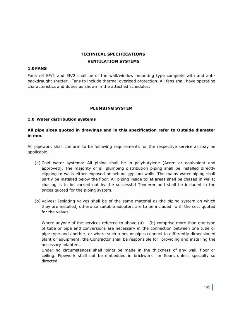
145
TECHNICAL SPECIFICATIONS
VENTILATION SYSTEMS
1.0 FANS
Fans ref EF/1 and EF/2 shall be of the wall/window mounting type complete with and anti-
backdraught shutter. Fans to include thermal overload protection. All fans shall have operating
characteristics and duties as shown in the attached schedules.
PLUMBING SYSTEM
1.0 Water distribution systems
All pipe sizes quoted in drawings and in this specification refer to Outside diameter
in mm.
All pipework shall conform to be following requirements for the respective service as may be
applicable.
(a) Cold water systems: All piping shall be in polybutylene (Acorn or equivalent and
approved). The majority of all plumbing distribution piping shall be installed directly
clipping to walls either exposed or behind gypsum walls. The mains water piping shall
partly be installed below the floor. All piping inside toilet areas shall be chased in walls;
chasing is to be carried out by the successful Tenderer and shall be included in the
prices quoted for the piping system.
(b) Valves: Isolating valves shall be of the same material as the piping system on which
they are installed, otherwise suitable adopters are to be included with the cost quoted
for the valves.
Where anyone of the services referred to above (a) – (b) comprise more than one type
of tube or pipe and conversions are necessary in the connection between one tube or
pipe type and another, or where such tubes or pipes connect to differently dimensioned
plant or equipment, the Contractor shall be responsible for providing and installing the
necessary adapters.
Under no circumstances shall joints be made in the thickness of any wall, floor or
ceiling. Pipework shall not be embedded in brickwork or floors unless specially so
directed.

146
Hydraulic tests on all pressurized pipework systems are to be performed at 8 bar for 4
hours. Any parts of the piping system, like controls, etc, which are not suitable for such
a test pressure shall be isolated prior testing.
Hydraulic tests on waste drains shall be carried out by air to a pressure of 3” water
gauge and any leaks found shall be remedied and the system re-tested.
2.0 Packaged Automatic Cold water Booster Pump Set
The booster pump set shall comprise of 2 pumps, complete with adequately sized pressure
vessel/s, pressure switches/transducers, pressure gauges and a control panel. Duties for the
pumps may be rotated say weekly, but however on operation, both pumps supplement each
other on rise demand. As such the pumps within the booster set shall operate on a duty/assist
basis. Pumps shall be of the constant speed type.
The control panel on booster set shall incorporate a door interlocked isolator, individual pump
hand / off / auto switches, run / trip / low water level lamps, overloads and motor fuses. It
shall feature a multi-purpose display and programming keyboard which indicates all
parameters and allows them to be adjusted as required. A time delay shall be programmed to
prevent simultaneous pump starts following initial switch-on / power failure. Automatic
exchange of duty pumps shall be provided. The panel shall also include common fault
indication lamp. Pumps shall be protected against dry running.
The package shall also include manually settable pressure switches, and a hydraulic
accumulator with a safe working pressure of not less than 10 bar.
The booster set shall also include all the necessary isolating valves and non-return valves
together with a pressure gauge on the common discharge header.
All the foregoing shall be fully assembled together and mounted on a substantial steel base
plate, piped together to flanged inlet and outlet stainless steel 304 grade headers, wired up,
painted and tested under simulated conditions by the manufacturers.
2.1 Cold water booster set, ref CW/1
This booster set shall be installed and connected as shown on drawings.
Performance characteristics shall be as follows:
Flow capacity (with two pumps running) 8 m³/h
Delivery head 15 m
Motor rating (each pump x 2) 0.45 kW x 2
Electricity supply 400V/3ph/50Hz
A suitable electrical supply shall be provided by others in close proximity of the booster set.
The Tenderer shall allow for electrical cabling between the electrical power supply and the
booster set.

147
3.0 Water storage tank
This shall be supplied having a capacity of 1000 liters’, and shall be installed in the area as
shown on drawings. The tank shall be manufactured from UV stabilized plastic, suitable for
use with potable water systems, and shall be of the HORIZONTAL CYLINDRICAL TYPE, and
complete with ball float valve, manhole with removable cover, inlet, outlet and overflow/vent
connections.
4.0 Fire extinguishers
Portable (hand held) type fire extinguishers complying with BS EN3: 1996, and complete with
suitable bracket for wall mounting, shall be supplied as follows in quantities as indicated in the
bills of quantities:
9kg dry powder
5kg carbon dioxide
TECHNICAL SPECIFICATIONS
INCLINED PLATFORM LIFT
One inclined platform lift shall be supplied and installed. Lift shall be for outdoor installation,
having a foldable platform 800mm wide and 1200mm deep, and foldable armrests. Lift shall
comply with safety requirements for stairs lifts EN 81-40 Standard.
Inclined platform lift shall be complete as follows:
- Automatic landing ramps with gripface surface and oversize dimensions to facilitate
access to the platform by wheelchair users.
- Motorized platform with anti-slip floor.
- Motorized armrests , closing within the platform at the rest position.
- Up/down push button integrated on machine body requesting a constant pressure for
operation.
- Wireless push button control panels at landings activated by key, operating call/return
controls (requiring a constant pressure) and platform opening/closing control (one-
touch).
- On/off activation switch with extractable key.
- Emergency stop button fitted on the machine body.
- 24V battery operated rechargeable at the guide extremity.
- Safety sensors on the automated movements of the platform and armrests.
- Safety sensors under the platform and on the machine body against the risk of impact
of crushing during movements.

148
- Parachute and overspeed controller safety devices
- Electrical and mechanical limit stops on the guide extremities.
- Environmental service conditions: 0 deg C to 40 deg C.
Operating specifications for the platform lift shall be as follows:
Inclined platform lift, ref IPL/2:
Horizontal travel: approximately 9363mm
Vertical rise: approximately 3450mm
Rated load: 250kg
Speed: 0.1m/s
Power rating: 24V battery
Notes:
1 In case of lift IPL/2 the stairs are split into two with landing in between (refer
to Tender drawings).
2 Tenderers are to submit full technical details of lifts offered clearly indicating
headroom required, together with all other installation dimensions.
3 Prices quoted shall include for certification by Notified Body
SCHEDULES FANS
Ref Location Flow rate ESP Motor rating Power supply Litres/sec Pa Watts V/ph/Hz EF/1 Museum hall 100 0 80 230/1/50
EF/2 Museum hall 100 0 80 230/1/50

149
V ELECTRICAL/ DATA SYSTEMS/ CCTV (To be read with Preliminaries/ General Conditions)
Saluting Battery Museum - Garrison Church Crypt
1. Scope
The project involves the electrical Low Voltage (LV) and Extra Low Voltage (ELV) systems
installation at the Saluting Battery Museum located in the Garrison Church Crypt, Castille
Place, Valletta.
The Premises consist of underground vaults having :
• A Reception Area at the main entrance at the Upper Level,
• Two large Exhibits Halls at the lower level, and
• Toilets located at a level below the Halls.
There is also a Plant Room located at the Lascaris Ditch Level. At present there is no direct
access to the Plant Room from the Museum.
2. Existing Installation
The Premises has a three-phase Enemalta incoming supply located in the corner at the top of
the ramp/stairs (that lead to the Exhibits Halls) at the Reception/Ticketing Area level.
Distribution Boards at each level distributed the lighting and small power circuits.
The installation is a mix of concealed and surface points. The lighting fixtures have been
removed and only the points and switches remain. The socket outlets, fuse connection units,
Distribution Boards and wiring that distributed the various circuits also remain.
On the right-hand-side at the bottom of the main entrance stairs a power cable runs on the
surface and then drops into the wall and below the finished floor presumably to terminate at
one of the two large electrical enclosures (probably a main switch and a fuse board
respectively) located on the left-hand wall of the proposed Reception Area. The cable and the
two electrical enclosures seem to belong to the 1950’s military installation.
The 1950’s military installation is to be investigated to determine whether it forms part of a
live system. Following the results of the investigation, the Client will decide whether to retain
this part of the installation.
Unfortunately as-built drawings of the electrical installation are not available and only a
detailed survey would establish the existing electrical distribution.
3. Proposed Installation
The entire existing electrical installation, except for the Enemalta meter is to be removed.
However, the existing Enemalta supply requires upgrading to 63A in order to cater for the
Museum’s projected electrical load.

150
The Low Voltage installation shall generally consist of, but not be limited to :
• Distribution Boards.
• Cables and wiring containment (LV and ELV).
• Socket outlets (radial circuits).
• Small power circuits
• Fused connection units.
• Isolators.
• Lighting points and lighting fixtures with associated switches/sensors.
• Lighting Tracks and associated Spotlights.
• Emergency and exit lighting points and fixtures.
• Earthing and bonding.
The Extra Low Voltage installation shall consist of :
• Fire Detection and Alarm System.
• Data outlets wired to a Wiring Cabinet.
• Telephone points.
The entire installation in the Museum shall be carried out in rigid PVC conduit (minimum 20mm
diameter) concealed below the finished surfaces and floors. However in the case of the cables
feeding the Distribution Boards DB1, DB2 the cables shall be installed in rigid PVC sleeves
below the floor up to the ramp. At the ramp they can be installed in the wall recess behind the
light fixtures (type I) and from the bottom of the ramp to the respective DB again below the
floor.
It is the intention that those surface cables inside the Museum are clipped (with propriety cable
cleats) to the walls at the highest unobtrusive level.
4. Outline Specifications
1. Main Panel ‘MP’.
Shall be a 6-way, three-phase, 200A, IP 44 rated sheet steel pan type panel assembly
complete with integral phase busbars, earth bar, neutral bar, main 63A mcb 4Pole, main
rcd (30mA trip) 4Pole and outgoing mcb’s. The panel shall be rated and sized as indicated
on Drawing No. E-05 and shall have 25% spare capacity for the future.
The MP shall be surface mounted and shall be adequately ventilated for heat dispersion
such that every component does not exceed its rated temperature limit. The MP shall be
provided with a typed circuit directory, placed in a clear plastic folder and attached to the
inside of the panel door.
2. Distribution Boards : DB1, DB2 and DB3
Shall be surface IP 44 three-phase sheet steel pan type panel assembly complete with
integral phase busbars, earth bar, neutral bar, main switch and outgoing mcb’s/rcbo’s.
The DB’s shall be rated and sized as indicated on Drawing Nos. E-06 and E-07 and shall
have 25% spare capacity for the future.
The mcbs for Extract Fans EF1 and EF2 shall incorporate a timer (7 day, 24 hour) and
relay to switch off the fans which will be energised by a signal from the Fire Alarm Panel.

151
The DB’s shall be provided with a typed circuit directory, placed in a clear plastic folder
and attached to the inside of the panel door.
3. Miniature Circuit Breakers (mcbs).
The mcb’s shall conform to BSEN 60898 and be rated as indicated on the Schematic One-
Line Diagrams on Drawing Nos. E-06 and E-07. The minimum short-circuit rating shall be
6 kA.
4. Earth Leakage Circuit Breakers (RCBO/RCD).
The RCBO’s and RCD’s shall conform to BS EN 61009-1 and BS EN 61008 and be rated as
indicated on the Schematic One-Line Diagrams on Drawing Nos. E-06 and E-07. The
minimum short-circuit rating shall be 6 kA.
5. Conduits and Fittings.
a. PVC conduits and associated fittings (e.g. bushes, sockets, pull boxes, bends
etc) shall conform to BS4607.
b. Galvanised steel conduits and associated fittings (e.g. bushes, sockets, pull
boxes, bends etc) shall conform to BS 31 : 1988.
6. Cables.
a. XLPE/PVC cables shall be flexible multi-core, stranded copper, 600V grade sized
as indicated on the Cables Schedule on Drawing No. E-04. Cables shall comply
with BS6346 and BS5467.
b. PVC/PVC cables shall be flexible multi-core, stranded copper, 600V grade sized
as indicated on the DB’s Schematic Diagrams. Cables shall comply with BS6004.
Cables are to be terminated at the respective Panelboards and equipment using properly
sized propriety cable glands.
7. Wires.
Wires shall be single core PVC insulated, stranded copper, 450V grade complying with
BS6004.
8. Light Switches.
Lighting switches shall be of white moulded material and be
manufactured in accordance with BS 3676 as a minimum standard.
All lighting switches shall have a minimum rating of 20A and mounted on one switch
plate
9. Lighting Sensors.
For ceiling sensors - 360º detection field, 7m minimum range, 6A, 230 V fluorescent load.
Sensors to comply with BS EN 60669-2-1.

152
10. 13A Socket Outlets.
Socket outlets shall be switched type made of white moulded material and comply to BS
1363.
11. Data Outlets.
Data outlets shall be with two RJ45 straight sockets for CAT 5e screened terminations
and made of white moulded material.
12. 13 A Fuse Connection Units.
Shall be switched or unswitched, made of white moulded material and comply to BS
1363-4. FCU’s shall be 2 pole with neon indicator, fuse carrier and flex outlet. Fuse size
to be rated according to the load supplied.
13. Flex Outlets.
Flex outlets shall rated at 13A, complete with cord grip and made of white moulded
material complying to BS 5733.
14. Isolators.
Isolators shall be made of reinforced polyester with a rotary two position switch and
rated as indicated on the drawings.
2 pole switches shall be rated at 20A with neon indicator and made of white moulded
material complying to BS EN 60669-1.
15. Cable Basket.
Steel wire cable basket shall be made of electroplated zinc having dimensions as
indicated on the drawings and a minimum depth of 35mm.
The Contractor shall supply and erect the cable baskets complete with all propriety
supports, brackets, bends, tees, ancillary items and fixings required for installing the
data cabling and other ELV wiring.
16. Cable Tray.
The cable tray including tees and bends shall be the perforated type with return flange
made of hot-dipped galvanised steel in accordance to BS EN 61537 : 2002.
Where trays are cut, the cut ends shall be adequately rust proofed and painted with
cold galvanised paint to prevent deterioration.
The Contractor shall supply and erect the cable trays complete with all propriety
supports, brackets and fixings required for installing the LV cabling as shown on the
drawings.
The externally mounted cable trays shall be complete with a galvanised sheet steel clip-
on cover.
17. Lighting Tracks.
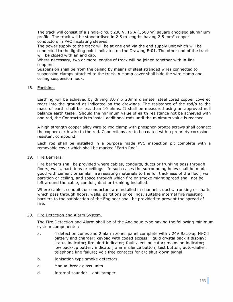
153
The track will consist of a single-circuit 230 V, 16 A (3500 W) square anodised aluminium
profile. The track will be standardised in 2.5 m lengths having 2.5 mm² copper
conductors in PVC insulating sleeves.
The power supply to the track will be at one end via the end supply unit which will be
connected to the lighting point indicated on the Drawing E-01. The other end of the track
will be closed with an end cap.
Where necessary, two or more lengths of track will be joined together with in-line
couplers.
Suspension shall be from the ceiling by means of steel stranded wires connected to
suspension clamps attached to the track. A clamp cover shall hide the wire clamp and
ceiling suspension hook.
18. Earthing.
Earthing will be achieved by driving 3.0m x 20mm diameter steel cored copper covered
rod/s into the ground as indicated on the drawings. The resistance of the rod/s to the
mass of earth shall be less than 10 ohms. It shall be measured using an approved null
balance earth tester. Should the minimum value of earth resistance not be achieved with
one rod, the Contractor is to install additional rods until the minimum value is reached.
A high strength copper alloy wire-to-rod clamp with phosphor-bronze screws shall connect
the copper earth wire to the rod. Connections are to be coated with a propriety corrosion
resistant compound.
Each rod shall be installed in a purpose made PVC inspection pit complete with a
removable cover which shall be marked "Earth Rod".
19. Fire Barriers.
Fire barriers shall be provided where cables, conduits, ducts or trunking pass through
floors, walls, partitions or ceilings. In such cases the surrounding holes shall be made
good with cement or similar fire resisting materials to the full thickness of the floor, wall
partition or ceiling, and space through which fire or smoke might spread shall not be
left around the cable, conduit, duct or trunking installed.
Where cables, conduits or conductors are installed in channels, ducts, trunking or shafts
which pass through floors, walls, partitions or ceilings, suitable internal fire resisting
barriers to the satisfaction of the Engineer shall be provided to prevent the spread of
fire.
20. Fire Detection and Alarm System.
The Fire Detection and Alarm shall be of the Analogue type having the following minimum
system components :
a. 4 detection zones and 2 alarm zones panel complete with : 24V Back-up Ni-Cd
battery and charger; keypad with coded access; liquid crystal backlit display;
status indicator; fire alert indicator; fault alert indicator; mains on indicator;
low back-up battery indicator; alarm silence button; test button; auto-dialler;
telephone line failure; volt-free contacts for a/c shut-down signal.
b. Ionisation type smoke detectors.
c. Manual break glass units.
d. Internal sounder – anti-tamper.

154
e. External sounder with strobe light – anti-tamper and incorporating a minimum
2.0 Ah rechargeable battery.
f. Fire resistant wiring for the sounders and break glass units, 1.0mm² minimum.
g. Fire retardant wiring for the detectors, 1.0mm² minimum.
The Fire Alarm System shall comply with BS 5839 and the wiring to BS 6387 categories
AWX or SWX.
As an option, the Tenderer is to price for a wireless Fire Detection and Alarm System
which will give the same coverage as the wired one specified above.
21. Data System
The data system shall generally consist of :
a. Cat 5e data cabling – one cable to each outlet.
b. Data outlets (as described in 14 above).
c. 32 port patch panel for Cat 5e cables.
d. Minimum 5HU wall mounted data cabinet.
22. Mounting Heights.
Unless otherwise specified all units shall be mounted at the following heights from
finished floor level taken to the centre of the unit:
• Lighting switches 1400 mm
• Socket outlets – general 300 mm
• Fused spur boxes 300 mm
• Telephone outlets 300 mm
• Wall mounted phone outlets 1400 mm
• Fire alarm outlets 1400 mm
• Fire alarm bells 2250 mm
• Fire alarm indicators 2150 mm
• Individual items of switchgear 1400 mm
• Isolators and fuse connection units 1400 mm
• Generally, switchboards and distribution boards shall be installed so that any item to
which easy access is required such as fuse, circuit breakers, instruments, etc., is not
more than 1800mm above finished floor level. In all cases care must be taken to
ensure that adequate space is left below and above equipment for manipulating
incoming and outgoing cables and conduits.
5. Installation Notes and Conditions
1. The electrical installation shall be carried out according to the latest Enemalta Electricity
Supply Regulations (ESR) and to BS 7671 : 2008 – Requirements for Electrical Installations
(IEE Wiring Regulations, 17th Edition).
2. Prior to compiling the Tender, Contractors are advised to visit the project site to verify the
site conditions, quantities and positioning/location/routes of the installation and equipment

155
required for the completion of the works. Any variations from the Contract Documents,
Specifications, BOQ or omissions by the Engineer in the design considerations or
material/equipment quantities are to be notified in writing to the Client prior to submitting
the Tender.
3. Should any changes or modifications be made to the proposed new installation, the
Contractor is to notify the Client in order to obtain the Engineers approval.
4. Fully detailed installation drawings are to be prepared by the Contractor and submitted to
the Client or the Engineer for approval. Details are to include in particular, the arrangement
and positioning of the Distribution Boards, Main and sub-Main Panels and the Plant Room
layout – which is to be coordinated with the mechanical installation. No works are to
proceed prior to receipt of approval.
5. Prior to the installation, all the materials and components of the electrical system are to be
submitted for approval by the Client or the Engineer.
6. The Contractor shall be responsible for the co-ordination of the installation with the existing
mechanical and electrical installations and the civil, structural and architectural features of
the premises. Co-ordination shall avoid the conflict of services and present an acceptable
arrangement of all exposed details. Where any obstructions or major conflicts occur, the
Contractor is to inform the Client so as to resolve the problem prior to continuing the work.
Any damage caused to buildings, surfaces, roads, paved/tiled areas, services etc. shall be
repaired by the Contractor at his own expense and the damaged area is to be restored to
its original condition.
7. Contractor shall use purpose-trained employees to carry out the respective works.
Employees shall be suitably certified or licensed by a recognised body as having achieved
the required standard or competence in their chosen trade.
8. The installation is to be carried out in a neat and workman-like manner. No shoddy, rough
work or improvisations shall be allowed. Contractor is to use propriety components for the
installation. All the materials and equipment shall be the best of their respective kind, free
from defects and manufactured to ensure satisfactory operation under the conditions
prevailing at the respective sites. No defective items shall be accepted.
9. Contractor shall ensure at all times that the contract works are executed in a safe and correct
manner such that the Contractor, the Contractor’s employees, Client, Engineer, passers-by and
any authorised visitors shall be free of danger or injury. The Contractor is responsible for
supplying ladders, scaffolding, temporary barriers, signs and safety equipment to affect these
measures. The use of all safety equipment and systems on site by the Contractor shall be
governed by the requirements of the Health and Safety Act.
10. The Client and/or the Engineer shall have the right to inspect any of the Contractor’s machines,
tools and equipment on site and if required instruct the Contractor to remove any sub-standard or
defective items forthwith.
11. Circuits and mcb’s in the Distribution Boards are to be clearly labelled for identification by
means of a circuit directory. The DB’s are to be labelled with engraved plastic labels
mounted on the front doors.
12. Three hard copies and one soft copy (CD) of the ‘as-built’ record drawings of the completed
installation are to be provided to the Client.

156
13. The complete installation is to be tested in accordance to the IEE Wiring Regulations.
Sample test sheets are to be provided to the Client or the Engineer for approval prior to
testing. The testing is to be witnessed and approved by the Engineer and the test results
handed over to the Client.

157
Z20 FIXINGS / ADHESIVES (To be read with Preliminaries/General Conditions)
FIXING GENERALLY
Use fixing and jointing methods and types, sizes, quantities and spacings of fastenings which are suitable having regard to:
- Nature of and compatibility with product/material being fixed and fixed to, - Recommendations of manufacturers of fastenings and manufacturers of components, products or materials
being fixed and fixed to, - Materials and loads to be supported, - Conditions expected in use, - Appearance, this being subject to approval.
FASTENINGS FOR MATERIALS AND COMPONENTS
Forming part of external construction but not directly exposed to the weather to be of corrosion resistant material or have a corrosion resistant finish. Directly exposed to the weather to be of corrosion resistant material.
FIXING THROUGH FINISHES
- Ensure that fastenings and plugs (if used) have ample penetration into the backing.
PACKINGS
Provide suitable, tight packings at fixing points to take up tolerances and prevent distortion. Use non-compressible, rot proof, non-corrodible materials positioned adjacent to fixing points. Ensure that packings do not intrude into zones which are to be filled with sealants.
CRAMP FIXING
Fix with stainless or galvanized steel strip cramps as EN 845-1:2003 vertical twist ties except with no twist, split one end only and once bent. Position cramps 150 mm from each end of jambs and at 600 mm maximum centres. Secure cramps to frames with two sheradised screws and fully bed in mortar.
NAILING
Nails: To BS 1202 or equivalent technically. In joints, use not less than two nails and opposed skew nailing unless specified otherwise. Drive nails fully in without splitting or crushing the material being fixed. Punch nail heads below surfaces which will be visible in the completed work.

158
PLUGS
Proprietary types selected to suit the background, loads to be supported and conditions expected in use. Locate plugs accurately in correctly sized holes in accordance with manufacturer's recommendations.
SCREW FIXING
Screws: To BS 1210 or technically equivalent. All screws to have clearance holes. Screws of 8 gauge or more and all screws into hardwood to have pilot holes about half the diameter of the shank. Before using brass, aluminium or other soft metal wood screws pre-cut the thread with a matching steel wood screw. Do not hammer screws unless specifically designed to be hammered. Countersink screw heads not less than 2 mm below timber surfaces which will be visible in completed work unless specified otherwise. Washers and screw cups, where specified, to be of the same material as the screw
PELLETING
Countersink screw heads 6 mm below timber surface and glue in grain-matched pellets not less than 6 mm thick, cut from matching timber. Finish off flush with face.
POWDER ACTUATED FIXING SYSTEMS
Do not use without approval. Tools to be to BS 4078: Part 2 or technically equivalent and Kitemark certified. Fasteners, accessories and consumables to be types recommended by the tool manufacturer. Tools to be used in accordance with BS 4078: Part 1 or technically equivalent. Operatives to be trained and certified as competent by tool manufacturer. Ensure that operatives take full precautions against injury to themselves and others. Remove all unspent cartridges from the site when no longer required. Apply zinc rich primer to heads of fasteners used externally, in external walls or in other locations subject to dampness. Use top hat section plastics washers to isolate cartridge fired nails from stainless steel components fixed externally, in external walls or in other locations subject to dampness.
ADHESIVES
- Adhesive types: As specified in the relevant section. - Surfaces to receive adhesive to be sound, unfrozen, free from dust, grease and any other contamination likely
to affect bond. Where necessary, clean surfaces using methods and materials recommended by adhesive manufacturer.
- Surfaces to be of sufficient smoothness and evenness to suit gap filling and bonding characteristics of adhesive. Adjust as necessary.
- Ensure that operatives observe manufacturer's and statutory requirements for storage and safe usage of adhesives. - Do not use adhesives in unsuitable environmental conditions or beyond the manufacturer's recommended time
period. - Apply adhesives using recommended spreaders/applicators to ensure correct coverage. Bring surfaces together
within recommended time period and apply pressure evenly over full area of contact surfaces to ensure full bonding. - Remove surplus adhesive using methods and materials recommended by adhesive manufacturer and without
damage to affected surfaces.

159
Z11 PURPOSE MADE METALWORK (To be read with the Preliminaries/ Conditions of Contract)
MATERIALS GENERALLY
- Grades of metals, section dimensions and properties: To the appropriate British Standard and suitable for the purpose.
- Pre-finished metal: May be used if methods of fabrication do not damage or alter appearance of finish, and finish is adequately protected.
- Fasteners: To appropriate British Standard and, unless specified otherwise, of same metal as component, with matching coating or finish.
FABRICATION GENERALLY
- Contact between dissimilar metals in components that are to be fixed where moisture may be present or occur: Avoid.
- Finished components: Rigid and free from distortion, cracks, burrs and sharp arrises. - Moving parts: Free moving without binding. - Corner junctions of identical sections: Mitred unless specified otherwise.
COLD FORMED WORK
- Profiles: Accurate, with straight arrises.
ADHESIVE BONDING
- Surfaces of metals to receive adhesives: Prepare by degreasing and abrading mechanically or chemically. - Adhesive bond: Form under pressure.
THERMAL CUTTING OF STAINLESS STEEL
- Carbonation in the heat affected zone: Remove, after cutting, by machining or acid pickling.
WELDING/ BRAZING
GENERALLY
- Surfaces to be joined: Thoroughly cleaned. - Tack welds: Use only for temporary attachment. - Joints: Made with parent and filler metal fully bonded throughout with no inclusions, holes, porosity or cracks. - Surfaces of materials that will be self-finished and visible in completed work: Protect from weld spatter. - Traces of flux residue, slag and weld spatter: Removed.

160
WELDING OF STEEL
- Preferred method: Metal arc welding to BS EN 1011-1 and -2. - Alternative methods: Submit proposals.
BRAZING
- Standard: To BS 1723, or technically equivalent.
FINISHING WELDED/ BRAZED JOINTS VISIBLE IN COMPLETED WORK
- Butt joints: Smooth, and flush with adjacent surfaces. - Fillet joints: Neatly executed and ground smooth where specified.
PREPARATION FOR APPLICATION OF COATINGS
- General: Fabrication complete and fixing holes drilled before applying coatings. - Paint, grease, flux, rust, burrs and sharp arrises: Removed.
GALVANIZING
Standard: To BS EN ISO 1461. Vent and drain holes: Provide in approved locations and seal to approval after galvanizing.
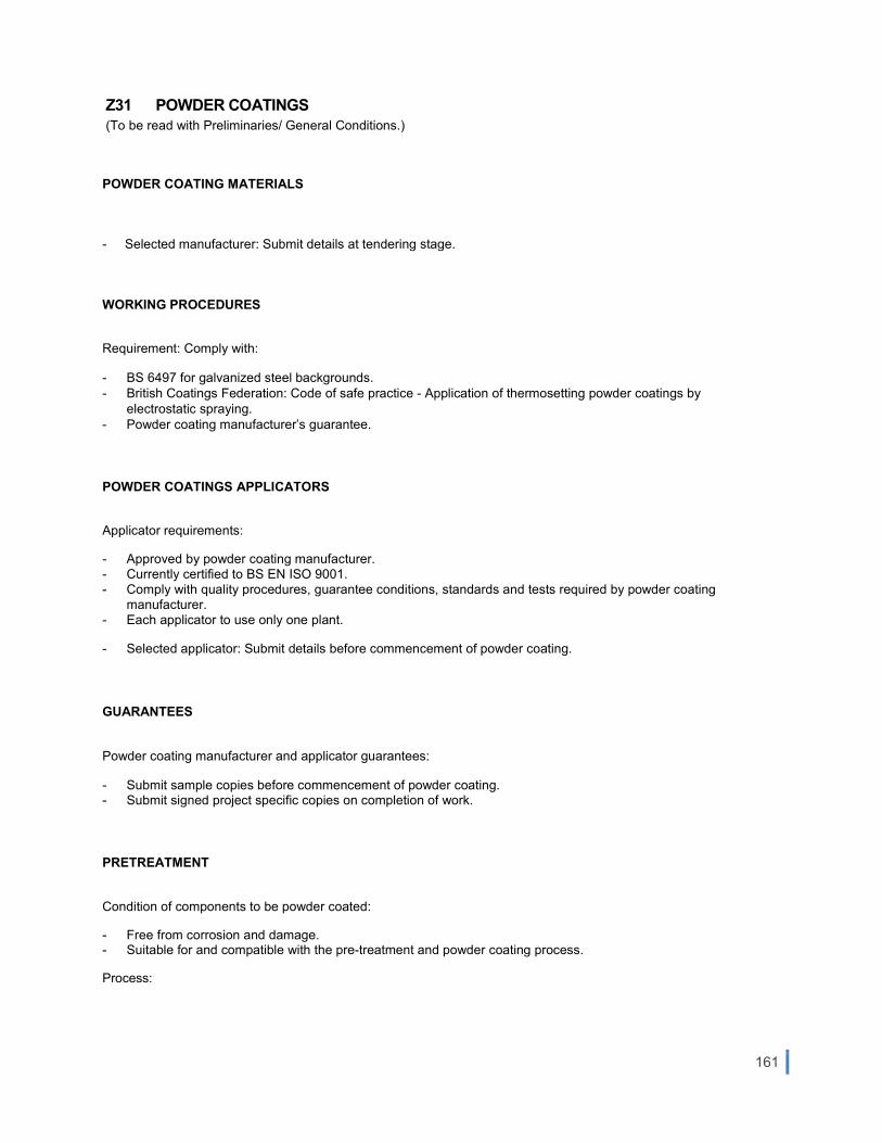
161
Z31 POWDER COATINGS (To be read with Preliminaries/ General Conditions.)
POWDER COATING MATERIALS
- Selected manufacturer: Submit details at tendering stage.
WORKING PROCEDURES
Requirement: Comply with:
- BS 6497 for galvanized steel backgrounds. - British Coatings Federation: Code of safe practice - Application of thermosetting powder coatings by
electrostatic spraying. - Powder coating manufacturer’s guarantee.
POWDER COATINGS APPLICATORS
Applicator requirements:
- Approved by powder coating manufacturer. - Currently certified to BS EN ISO 9001. - Comply with quality procedures, guarantee conditions, standards and tests required by powder coating
manufacturer. - Each applicator to use only one plant.
- Selected applicator: Submit details before commencement of powder coating.
GUARANTEES
Powder coating manufacturer and applicator guarantees:
- Submit sample copies before commencement of powder coating. - Submit signed project specific copies on completion of work.
PRETREATMENT
Condition of components to be powder coated:
- Free from corrosion and damage. - Suitable for and compatible with the pre-treatment and powder coating process.
Process:

162
- Clean, conversion coat, condition, rinse in demineralised water, drain and dry components in accordance with the powder coating manufacturer’s requirements and the pre-treatment supplier’s recommendations.
EXTENT OF POWDER COATINGS
Application:
- To visible component surfaces, and concealed surfaces requiring protection. - Coated surfaces will be deemed ‘significant surfaces’ for relevant BS 6496/ BS 6497 performance
requirements.
APPLICATION OF POWDER COATINGS
- Surfaces to receive powder coatings: Free from dust or powder deposits.
- Completion of powder coatings: Within 48 hours of pre-treatment of components.
- Jig points: Not visible on coated components.
- Curing: Controlled to attain metal temperatures and hold periods recommended by powder coating manufacturer.
- Stripping and recoating of components: Only acceptable by prior agreement of powder coating manufacturer. Stripping, pre-treatment and powder coating are to be in accordance with manufacturer’s requirements and must be carried out at applicator’s plant.
- Over-coating of components: Not acceptable.
PERFORMANCE AND APPEARANCE OF POWDER COATINGS
- Standard: To BS 6496/ BS 6497.
STEEL FABRICATIONS
- Unit assembly: Wherever practical, before powder coating.
- Exposure of uncoated background metal: Not acceptable.
- Assembly sealants: Compatible with powder coatings. Obtain approval of colour if sealants are visible after fabrication.
FIXINGS - Exposed metal fixings: Powder coat together with components, or coat with matching repair paint system applied in
accordance with the powder coating manufacturer’s recommendations.

163
FABRICATION DAMAGE REPAIR/ REPLACEMENT
- Inspection: Check all components before delivery to site for damage to powder coatings. Submit proposals for repair or replacement.
PROTECTION
Powder coated surfaces of components:
- Protect from damage during handling and installation, or by subsequent site operations.
Protective coverings: Must be:
- Resistant to weather conditions. - Partially removable to suit building in and access to fixing points.
Protective tapes in contact with powder coatings: Must be:
- Low tack, self adhesive and light in colour. - Applied and removed in accordance with tape and powder coating manufacturers’ recommendations.
Do not use solvents to remove residues.
- Inspection of protection:
Promptly repair any deterioration or deficiency.
SITE DAMAGE REPAIR/ REPLACEMENT
Damage to powder coatings: Rectify immediately damage caused during handling and installation, or by subsequent site operations. Submit proposals for extensive repair or replacement.
DOCUMENTATION
- Submit the following information for each batch of powder coated components:
- Supplier. - Trade name. - Colour. - Type of powder. - Method of application. - Batch and reference number. - Statutory requirements.

164
COMPLETION
Cleaning and maintenance of powder coatings:
- Carry out in accordance with procedures detailed in powder coating manufacturer and applicator guarantees.
Duration:
- From removal of protection until Practical Completion.
COATING APPLICATION
Surface cleanliness
No coating shall be applied to any surface containing traces of grit, grease, oil, loose rust, mill scale, surface contaminants (i.e. dust) or corrosive products of any kind.
The following requirements shall apply prior to coating:
- All traces of oil, grease, and other contaminants shall be washed by a method acceptable to the coating manufacturer from the surface and the surface dried prior to painting.
- All surfaces to which coating is applied shall be free of moisture and containments. - If the blasted surface changes colour or rust bloom begins to form, the surface shall be re-blasted. - The surface to be coated shall be free of soluble salts. The maximum allowable level of soluble salts is 120mg per
square meter.
Mixing
- All material shall be power mixed for a minimum period of 5 minutes. - Where relevant, two components shall then be combined and power mixed in accordance with the per the
manufacturer’s recommendations. Only the full quantities of dual component materials shall be mixed. There shall be no partial mixing of dual component materials.
- The induction time recommended by the coating manufacture shall be observed. - During application, containers shall be agitated often enough to keep pigments in suspension.
Coating
- All surfaces shall be coated as specified. - Surfaces, which do not require coating, shall be suitably protected. - Successive coats shall be of a distinctly different colour to the previous coat to ensure total obliteration.
Special attention shall be given to cracks, crevices and edges to ensure complete coverage and thickness.

165
Addendum to Specifications ( Annex 1& 2)
Particular Civil/Finishing Specifications (Annex 1)
LASCARIS WAR ROOMS WITH ST. PETER’S & ST.PAUL’S COUNTER-GUARD M&E SERVICES SPECIFICATIONS (Annex 2)

166
Particular Civil/Finishing Specifications (Annex 1)

167
Glass Reinforced Polyester (FibreGlass) Specifications
Specifications
UV and Yellowness resistant, Aging resistant
Width: Thickness: 4mm
Surface: smooth or embossed
Color: all kinds of colors (RAL) Excellent bonding characteristics
Available in various specifications Moisture resistance
Easy to clean and install Solid ,yellowness and aging resistant
corrosion resistance optimum strength
Excellent UV / weathering protection superior physical chemical properties
Fiberglass Flat Sheet
Data
Specifications units Cited Thickness
1.0mm 1.5mm 2.0mm 2.5mm 3.0mm
Weight Kg/m2 1.3 2 2.6 3.2 4.0
Glass content % 19 25 29 30 30
Tensile strength Mpa 60 80 92 95 97
Elongation at break % 1.5 1.5 1.5 1.5 1.5
Elastic modulus Gpa 5.5 7 7.3 7.6 7.8
Izod impact strength KJ/m2 45 55 70 80 95
Panels are to be supplied to satisfy BS 476, Part 7, Class I and II, surface spread of flame and ASTM E 84 Class 1.
BS 4592 Part 6: 2008 BS 6399 Part 1: 1996
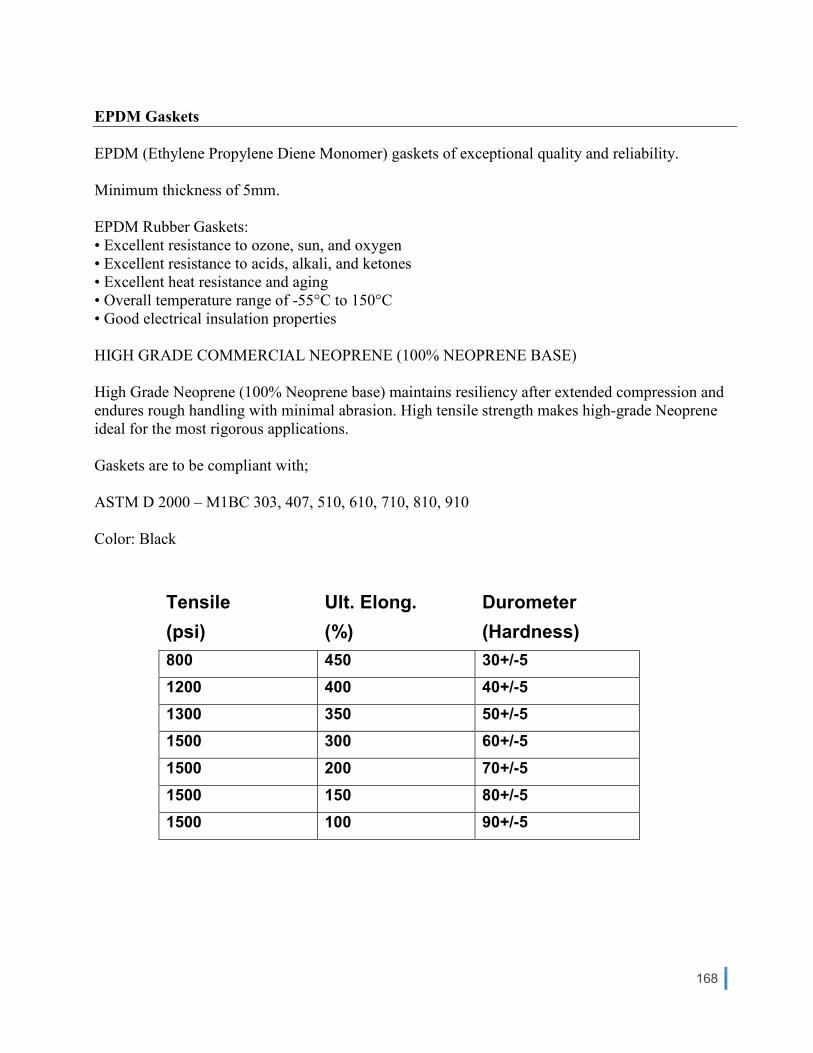
168
EPDM Gaskets
EPDM (Ethylene Propylene Diene Monomer) gaskets of exceptional quality and reliability.
Minimum thickness of 5mm.
EPDM Rubber Gaskets:
• Excellent resistance to ozone, sun, and oxygen
• Excellent resistance to acids, alkali, and ketones
• Excellent heat resistance and aging
• Overall temperature range of -55°C to 150°C
• Good electrical insulation properties
HIGH GRADE COMMERCIAL NEOPRENE (100% NEOPRENE BASE)
High Grade Neoprene (100% Neoprene base) maintains resiliency after extended compression and
endures rough handling with minimal abrasion. High tensile strength makes high-grade Neoprene
ideal for the most rigorous applications.
Gaskets are to be compliant with;
ASTM D 2000 – M1BC 303, 407, 510, 610, 710, 810, 910
Color: Black
Tensile Ult. Elong. Durometer
(psi) (%) (Hardness)
800 450 30+/-5
1200 400 40+/-5
1300 350 50+/-5
1500 300 60+/-5
1500 200 70+/-5
1500 150 80+/-5
1500 100 90+/-5

169
Timber Specifications
Any material or timber works specified in this tender shall be carried out as specified in below standards;
Structural timber
BS 5268: The structural use of timber.
Part 2: Code of practice for permissible stress design, materials and workmanship.
Part 3: Code of practice for trussed rafter roofs.
Part 4: Fire resistance of timber structures.
Part 5: Code of practice for the preservative treatment of structural timber.
Part 6: Code of practice for timber frame walls.
Part 7: Recommendations for the calculation basis of span tables.
BS EN 1995 Eurocode 5. Design of timber structures.
BS EN 14080 Timber structures. Glued laminated timber. Requirements.
BS EN 14081-1 Timber structures. Strength graded timber with rectangular cross section. General
requirements.
BS 4978 Visual strength grading of softwood.
BS EN 519 Structural timber - Grading - Requirements for machine strength graded timber and grading
machines.
BS 5756 Specification for visual strength grading of hardwood.
BS EN 385 Finger jointed structural timber.
Timber sizes
BS EN 336 Structural timber. Sizes, permissible deviations.
BS EN 844 Round and sawn timber.
Trussed rafters
BS 5268:Part 3: Code of practice for trussed rafter roofs.
Tiling/slating battens
BS 5534 Code of practice for slating and tiling.
Joinery and wood trim
BS EN 942 Timber in joinery. General requirements. Replaces BS 1186 Part 1.
BS 1186: Timber for and workmanship in joinery.
Part 2: Specification for workmanship.
Part 3: Specification for wood trim and its fixing.
Wood based sheet materials
Plywood
BS EN 313 Plywood. Classification and terminology.
BS EN 635 Plywood. Replaces BS 6566
BS EN 635 - 1 Classification by surface appearance: General.
BS EN 635 - 2 Classification by surface appearance: Hardwood.
BS EN 635 - 3 Classification by surface appearance: Softwood.

170
BS EN 636. Plywood. Specifications.
BS EN 636-1: Requirements for plywood for use in dry conditions.
BS EN 636-2: Requirements for plywood for use in humid conditions.
BS EN 636-3: Requirements for plywood for use in exterior conditions.
Structural plywood
BS 5268:Part 2: Code of practice for permissible stress design, materials and workmanship.
Marine plywood
BS1088-1 Specifications for plywood for marine craft. Replaces BS1088 and BS4079.
Particleboard (chipboard, OSB, cement bonded particleboard).
BS EN 309: Wood particleboards. Definition and classification. Replaces BS 5669.
BS EN 312: Particleboards. Specifications.
Part 2: Specification for wood chipboard.
Part 3: Specification for oriented strand board (OSB).
Part 4: Specification for cement bonded particleboard.
Fibreboard, including hardboard, medlumboard, softboard and MDF.
BS 1142: Specification for fibre building boards.
Oriented strand board (OSB)
BS EN 300: OSB. Definitions, classification and specification.
Glue laminated timber (glulam).
BS EN 386. Glue laminated timber. Performance requirements and minimum production requirements.
Preservative treatment
BS 5268:Part 5: Code of practice for the preservative treatment of structural timber.
BS 5589: Code of practice for the preservation of timber.
Exterior finishes for timber
BS EN 927-1. Paints and varnishes. Coating materials and coating systems for exterior wood. Classification
and selection.
Floors and flooring
BS 1297: Specification for tongued and grooved softwood flooring.
BS 8201: Code of practice for flooring of timber, timber products and wood based panel products.

171
Copper cladding
Copper sheeting to clad timber doors/windows shall be as outlined below; The follwoing copper grade shall be utilized; Grade C106 non-arsenical copper, 99.9% pure general purpose copper, that is a phosphorus-deoxidised copper, with a thickness of 3mm.
Compliant to BS EN 506 :2000 Roofing products from metal sheet. Specification for self-supporting
products of copper or zinc sheet

172
LASCARIS WAR ROOMS WITH ST. PETER’S & ST.PAUL’S COUNTER-GUARD
M&E SERVICES SPECIFICATIONS
(Annex 2)
MECHANICAL AND ELECTRICAL WORKS

173
MECHA&ICAL A&D ELECTRICAL E&GI&EERI&G SERVICES
Compliance
The Engineering Services equipment and installations detailed in this specification shall conform (as applicable) with the following:-
• European and British Standards Institution documents • HVCA Publications • CIBSE Publications • BSRIA Publications • IEE Wiring Regulations 17th Edition • IEC Regulations • CENELEC Harmonization Documents • EU Medical Devices Directives • CSA • BRE • EUROVENT • BCAS • BCGA • BFACMA • BARMA • ISO9000 Certification and CE marking all materials and equipment. • BS ISO 14520-1:2000 • Local standards and mandatory orders as issued by the; • Malta Standards Authority, Enemalta and Wireless and Telegraphy. • Health and Safety Regulations • Good trade practices and other applicable regulations • Technical Guidance Series issued by the Local Services Division – Building Regulation Offices • Design Guidelines on fire safety for buildings in Malta • Policy And Design Guidelines issued by MEPA
Testing and Commissioning The following general procedure shall be adopted when conducting the testing and commissioning for the Mechanical and Electrical Systems. Preliminary Testing Upon completion of the installations testing shall be carried in conformance with relevant specifications and requirements of the respective system. If deficiencies are found, corrections shall be made and the system shall be re-tested to assure that it is functional. After completing the preliminary testing the Contractor shall complete and submit a Certificate of Completion with a copy of the ‘As Built Drawings’ endorsed by the Contractor’s Representative Engineer. Acceptance Testing After the installation is completed and approval received, the Contractor shall conduct functional and operational tests. Parts and components which fail during the tests shall be replaced with new ones. The tests shall be performed in accordance with the approved test procedures in the presence of the Engineer. The Contractor shall furnish instruments and personnel required for the tests.

174
The equipment manufacturer's representative shall be present to supervise tests. The Certificate of Acceptance shall be issued by the Contractor for approval by the Engineer. The “AS BUILT” drawings and O&M Manuals shall be submitted with this certificate. The Contractor shall notify the Engineer at least 10 days before the preliminary and acceptance tests are to be conducted.
Factory and Site Tests; The test plan and test procedures shall explain in detail, step-by-step actions and expected results to demonstrate compliance with the requirements of this specification, and the methods for simulating the necessary conditions of operation to demonstrate performance of the system. Test plan documentation for the factory test, 30 days prior to the factory test. Test procedures and report documentation for the factory test, after receipt of written approval for the test plan and 15 days prior to the scheduled factory test. Test plan documentation for the site test, 15 days prior to the site tests. Test procedure and report documentation for the site tests, after receipt of written approval of the test plan. Test Reports Test reports in booklet form, upon completion and testing of the installed system. Each test report shall indicate the final position of controls and operation mode of the equipment, and the manufacturer, model number, and serial number of test equipment used in each test. Test Reports shall be endorsed by the Contractor’s Representative Engineers. Drawings Detailed workshop drawings consisting of a complete list of equipment and materials, including manufacturer's descriptive and technical literature, performance charts, etc. Detail drawings shall include a written description of operation for each system and subsystem in each of the various operating modes and schematic and line diagrams for the total system indicating appropriate interconnections between equipment and other systems.
The Workshop Drawings shall be issued for construction after approval by the Engineer. During the course of the works, the Contractor shall maintain a fully detailed record of all the changes from the Workshop Drawings to facilitate easy and accurate preparation of the “As Fitted Drawings” and to ensure that these Drawings are in all respects a true record of the installation and including the location of all equipment. After the works have been completed the Contractor shall amend the latest workshop drawings and prepare the ‘AS FITTED” drawings for submittal. All drawings shall be in any of the standard sizes to conform with BS 3429. Operation and Maintenance Manuals The O&M manuals shall clearly illustrate Operating and Maintenance Instructions. Operating instructions outline the step-by-step procedures required for system startup operation and shutdown. Maintenance instructions list routine maintenance procedures, possible breakdown and repairs, and troubleshooting

175
guides. Final copies of the manuals bound in hardback, loose-leaf binders, to be submitted within 30 days of the Certificate of Completion. A draft copy of the manuals shall be submitted for approval. The manuals shall be updated with any changes required prior to final delivery of the manuals. Each manual's contents shall be identified on the cover. The manuals shall include the name, address, and telephone number of each subcontractor installing equipment and systems, and of the nearest service representative for each item of equipment and each system. The manuals shall have a table of contents and tab sheets. Tab sheets shall be placed at the beginning of each chapter or section and at the beginning of each appendix. The final copies delivered after completion of the site test shall include all modifications made during installation, checkout, and acceptance. Manuals provided shall include: a. Functional Design Manual. b. Equipment Manual. c. Operator's Manual. d. Maintenance Manual. The functional design manual shall identify the operational requirements for the system and explain the theory of operation, design philosophy, and specific functions. A description of hardware and software functions, interfaces, and requirements shall be included for all system operating modes. The hardware manual shall describe all equipment provided, including:
o General description and specifications. o Installation and checkout procedures. o Equipment mechanical and electrical schematics and layout drawings. o System schematics. o Manufacturer's repair parts list indicating sources of supply.

176
Unscheduled Repairs of Breakdowns The Employer (or any other person authorised to act on his behalf) will initiate emergency service calls when any of the critical systems are not functioning properly. Qualified personnel shall be available to provide service to the complete system. The Employer shall be furnished with a telephone number where the service supervisor can be reached at all times. Service personnel shall be at site within 2 hours after receiving a request for service. Critical systems shall be restored to proper operating condition within 8 hours after service personnel arrive on site. Maximum downtime on other systems shall be not more than 48 hours during working days.
The Contractor shall replace all equipment, materials, parts etc which in the opinion of the Employer has not performed according to the specifications or performance promised by the Contractor and/or manufacturer or which during the defects liability period has repeatedly required repair or maintenance or which has become defective. The defects liability period on such items shall be deemed to recommence on the day the new equipment, materials, parts etc are put into operation.
The Contractor should ensure that a list of new materials and equipment of the same type and manufacturer shall be readily available for replacement as and when required during the three year maintenance contract. The Contractor shall forward a comprehensive list of spare items, as recommended by the manufacturer and based on the Contractor’s previous experience, to the Employer with the Tender document. The items shall be safely stored by the Contractor.
Training of Personnel The Contractor shall;
o advise the Employer on the organisation, personnel and their skills that are required and records that are to be kept to ensure the proper maintenance repair and upkeep of the works
o assist the Employer in the setting up of such an organisation, in the selection of the maintenance personnel and the implementation of a record system
o train the Employer’s personnel on and off the site in the proper maintenance, repair and upkeep of the works in such a manner to be able to take responsibility of the running and maintenance of the works at the end of the Defects Liability Period
Equipment Guarantee and Defects Liability The periods for the Equipment Guarantee and Defects Liability shall commence when the Engineer endorses the Certificate of Acceptance. The Contractor shall maintain a record of the guarantee periods of all major equipment and log the number and nature of failures. Emergency Personnel The Contractor shall submit to the Engineer at the start of site work, the name and address and telephone number of a member (or members) of his staff who can be contacted at all times outside normal hours, by the Employer or Police in any emergency affecting the Works. The staff member shall be competent and

177
have authority to take the necessary action. Companies not operating a 24 hour Emergency Breakdown Services shall make alternative contact provisions, such as a pager number, during the course of the works. Call Outs The Contractor shall respond in the event of a fault or breakdown of the equipment within reasonable time of being notified by the Employer or his representative of such a fault. The Contractor shall be available for call out at any time during the defects liability period. Following a Call Out the Contractor shall submit a written report to the Employer clearly indicating the nature of the fault, rectification and any other remarks deemed fit. Training The Contractor shall allow for as many site visits as required for the training of the personnel concerned. Training is considered essential to reduce problems arising from mal operation of the systems. Training sessions shall be properly organised by the Contractor with close co-ordination with the Employer. Trained persons shall be listed by name, surname and identity card number for records purposes. Coordination The Contractor shall be responsible for the true and proper setting out of works in relation to the original points, lines and levels of reference given by the client, and for the correctness of the position, levels, dimensions and alignments of all parts of the works. Final positions of equipment shall be determined in accordance with the agreed architectural room layouts and the Engineer. As most of the rooms are similar, a sample bedroom shall be provided by the Contractor at an early stage of the contract. This shall enable all concerned to discuss and establish convenient locations of all equipment and accessories. Coordinated electrical and mechanical layouts shall then be approved for Construction by the Engineer. Builder’s works Builders work drawings detailing concrete bases and holes greater than 100mm by 100mm shall be provided by the Contractor for co-ordination with the Architect and the Engineer, prior to the execution of works on site. The Contractor shall provide for the entire builder’s works and making good to existing finished construction. The M&E Services Supervisor shall coordinate with the building sub-contractor and the main building contractor to determine the exact locations and any other requirements on site. All builder’s work shall be made good by appropriate fire rated barriers. Refer to Design Documents for delineation of Fire Compartments. Materials, to be supplied and installed by the Contractor. The Contractor shall provide at tender stage the relevant pricing for such works. Temporary Power Supply, Lighting, Plumbing, Drainage & Fire Fighting

178
The Contractor shall be responsible to make available for his own use and provide all the necessary temporary power supplies to all other trades, indoor and outdoor perimeter security lighting throughout all the phases of the project. Temporary installations shall conform with IEE regulations Section 604. The Contractor shall also be responsible to provide temporary plumbing, drainage facilities and fire fighting equipment during the execution of the works. Temporary service shall be included in the Preliminaries BOQ. Temporary Storage / Personnel Requirements The Contractor shall provide his own (portable) accommodations during the tenure of the project. This includes stores, toilets, and offices. Site locations will be provided by the Client. Tender Drawings A list of tender drawings detailing the Mechanical and Electrical Engineering Services is included in the this tender document.

179
Electrical Distribution Boards
The Schedules of all sub-distribution boards are included in the particular specifications. Further to the above instructions, the Tenderer is to strictly adhere to the following guidelines when compiling the package for technical literature and information to be submitted with the Tender Document. The Schedule of Equipment is to be compiled by the Tenderer and is to include a comprehensive list of equipment and materials to be supplied and installed, with all the respective manufacturer’s reference model, type, and/or part numbers and critical parameters. The Schedule of Equipment is to be compiled by the Tenderer and is to include a comprehensive list of equipment and materials to be supplied and installed, with all the respective manufacturer’s reference model, type, and/or part numbers and critical parameters. The Tenderer shall compile a List of Deviations to the Tender Specifications and briefly describe the advantages. TWO COPIES OF TECHNICAL LITERATURE AS DESCRIBED BELOW MUST BE SUBMITTED WITH THE TENDER DOCUMENT Technical literature shall be presented as follows
1. Technical Covering Letter 2. Schedule of Equipment 3. Schedule of Materials 4. Technical Literature in the order described below
The Schedule of Equipment must contain the following information (where relevant) presented in table format:
a. Equipment reference b. Installation location c. Equipment description/ type d. Model reference e. Manufacturer f. Place of origin g. Dimensions h. Air flow rate litres/seconds i. Static pressure Pascal j. Sound pressure levels @ 3m dB(A) k. RPM l. Single or three phase m. Power kW n. Nominal current amps o. Starting method p. Control method q. Technical deviation
The Schedule of Materials must contain the following information (where relevant) presented in table format:
r. Material description/ type s. Model reference t. Manufacturer u. Place of origin v. Dimensions w. Technical deviation

180
Manufacturer’s data sheets should be submitted for all plant equipment and materials, and for all components of all systems. Data sheets shall clearly highlight the relevant details. The Tenderer shall compile a List of Deviations to the Tender Specifications and briefly describe the advantages. TWO COPIES OF TECHNICAL LITERATURE AS DESCRIBED BELOW MUST BE SUBMITTED WITH THE TENDER DOCUMENT
A1
A2
A3
DOCNO. A4
DOC TITLE A5
A6
TENDER REF. A7
An
Schedules of Equipment
Deviations to Technical Specifications
Technical Covering Letter
Technical Literature in the order described below
Technical Literature in the order described below

181
MECHANICAL SERVICES Document No. M1 Document Title Blank Document No. M2 Document Title Mechanical Ventilation Systems Document No. M3 Document Title Water Supply Services Document No. M4 Document Title Black Water System

182
ELECTRICAL SERVICES Document No. E1 Document Title Electrical Low Voltage Services Distribution Boards Document No. E2 Document Title Electrical Low Voltage Services Cables, Cable Containment & Wiring Accessories Document No. E3 Document Title Electrical Low Voltage Services Emergency Lighting Document No. E4 Document Title Electrical Low Voltage Services Light Fittings Document No. E5 Document Title Electrical Extra Low Voltage Services

Particular Mechanical Technical Specifications
Lascaris War Rooms With St Peter’s & St Paul’s Counter Guard Valletta
MECHANICAL ENGINEERING SERVICES
Particular Technical Specifications
Scope of Mechanical Services Works
General
It is very important to note that the works will be carried out in a historical building and not a
new building site. The majority of works consists in restoration. However, due to the state
of some of the equipment and materials replacement is required. The method of installation
of the mechanical services from the time of the second world war till now has evolved a
great deal especially for the method of supporting and bracketing of the services. The
works to be carried out at this site require very skilled installers with experience and
capabilities in order to carry out the works in the same manner as per the existing
installations. No drilling, chasing or other interventions will be allowed in walls and ceiling
unless permission is granted by Fondazzjoni Wirt Artna Personnel irrelevant of the size of
the holes or other builder’s works required. Also special care will be required not to inflict
further damages to the site and services. It is a must, for all the Contractors submitting the
offer, to visit the site irrelevant of the information provided within this tender document.
The mechanical services works are required for the following systems:
1. Mechanical Ventilation System EF -1
2. Mechanical Ventilation System EF -2
3. Mechanical Ventilation System EF -3
4. Plumbing System
5. Drains Systems

Particular Mechanical Technical Specifications
Lascaris War Rooms With St Peter’s & St Paul’s Counter Guard Valletta
1. Mechanical Ventilation System EF-1
This system consists of a long metal ductwork and covers large part of the tunnel. The
existing system is made of black steel sheets and welded to create the ducts. A survey
needs to be carried out in order to determine which parts can be kept and those parts to be
removed. Part of the ductwork is deteriorated beyond repair and this shall be dismantled
and carted away as per Fondazzjoni Wirt Artna instructions. The ductwork to be kept shall
be labelled, photographed and recorded on a drawing so that it is re-installed in the same
manner and same place. Then the ductwork to be kept shall be dismantled in order to be
chemical cleaned - disinfect and treat rusting and corrosion. A report from a specialist shall
be provided to this regard to ensure the correct treatment for the disinfection and restoration
of the duct and accessories. The outside surface shall then be painted by a special primer,
undercoat and finish paint. Exact colour of the finish paint shall be approved by the Client
before applied. Reinstallation of the existing ductwork shall be done using the same
supports and brackets if in good condition and using the same holes in the walls and ceiling.
These brackets need also to be checked and reconditioned. As for the new ductwork if new
brackets are required these shall be done as a replica of the original and using the same
holes in the walls and ceiling. The new brackets shall be manufactured using the same
metal profiles with same gauge and should be hot dipped galvanised. Three coats of paints
shall then be applied a primer, undercoat and a finish coat. Exact colour of finish coat to be
approved by Client before applied. The new material for the ductwork shall be galvanized
steel. DW 144 should be followed for the manufacturing of the new ductwork. The
thickness of the plate shall be according to DW 144 table 2 and the zinc coating shall be
according to DW 144 table 24 Z350. The new ductwork shall be manufactured as a replica
of the ductwork being replaced with the exception of the welding. Longitudinal seams shall
be manufactured as per DW 144. The outside surface shall then be painted by a special
primer, undercoat and finish paint. Exact colour of the finish paint shall be approved by the
Client before applied. A paint specialist should be consulted in order to recommend the
right etching primer (or similar paint) to use and the other type of paints. A report shall be
provided to this regard.

Particular Mechanical Technical Specifications
Lascaris War Rooms With St Peter’s & St Paul’s Counter Guard Valletta
Photo No. 1 Duct outlet from the tunnel at highest point.
Photo No. 2 Ductwork installed inside

Particular Mechanical Technical Specifications
Lascaris War Rooms With St Peter’s & St Paul’s Counter Guard Valletta
Photos Nos. 3,4 & 5 Ductwork supports, bracketing and method of joining
Photos Nos. 6, 7 & 8 Ductwork requiring replacement and restoration.
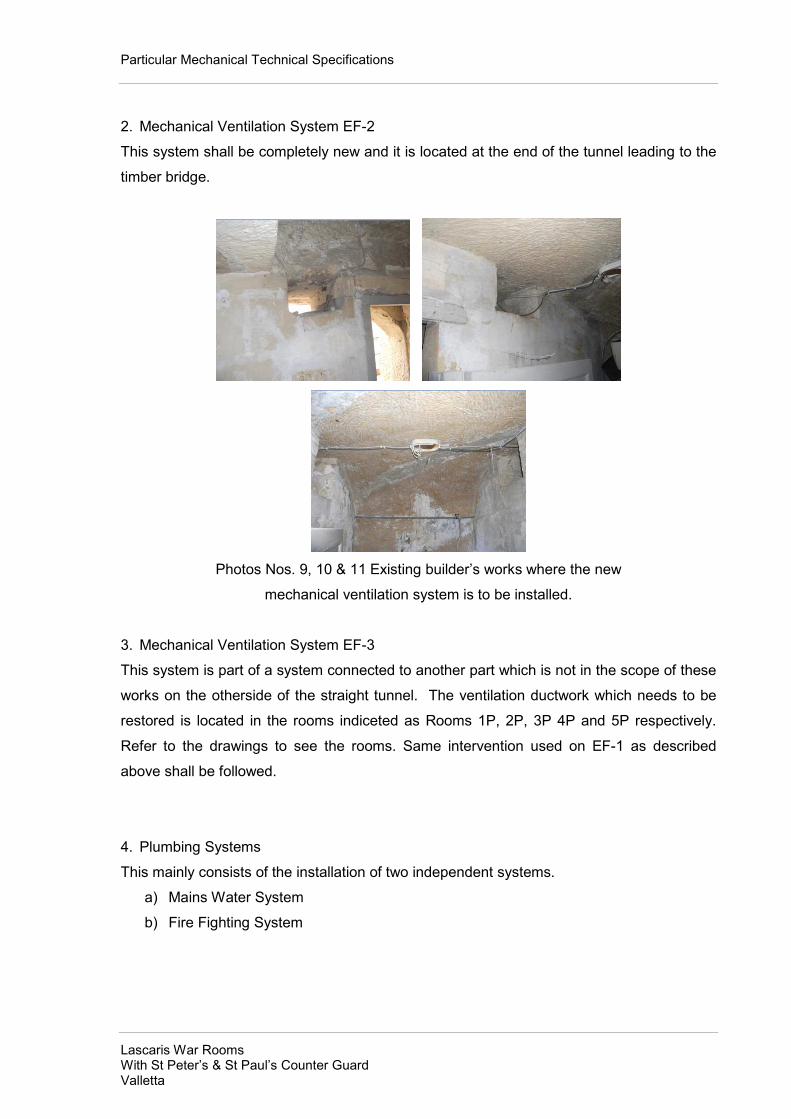
Particular Mechanical Technical Specifications
Lascaris War Rooms With St Peter’s & St Paul’s Counter Guard Valletta
2. Mechanical Ventilation System EF-2
This system shall be completely new and it is located at the end of the tunnel leading to the
timber bridge.
Photos Nos. 9, 10 & 11 Existing builder’s works where the new
mechanical ventilation system is to be installed.
3. Mechanical Ventilation System EF-3
This system is part of a system connected to another part which is not in the scope of these
works on the otherside of the straight tunnel. The ventilation ductwork which needs to be
restored is located in the rooms indiceted as Rooms 1P, 2P, 3P 4P and 5P respectively.
Refer to the drawings to see the rooms. Same intervention used on EF-1 as described
above shall be followed.
4. Plumbing Systems
This mainly consists of the installation of two independent systems.
a) Mains Water System
b) Fire Fighting System

Particular Mechanical Technical Specifications
Lascaris War Rooms With St Peter’s & St Paul’s Counter Guard Valletta
a) Mains Water System
The mains water system consists of replacing the existing galvaised pipework as indicated
in the drawing. Where parts of the pipework are missing the new installation shall follow the
same route of the previous system using the same holes for supporting the pipe using
galvanized J hooks. Some sections of the pipes need to be bent as per the existing
installation to follow the original path. The pipework to be replaced shall be labeled,
photographed and recorded on a drawing so that it is re-installed in the same manner and
place.
Photo No. 12 Galvanised water supply pipework installed using galvanized J hooks.
b) Fire Fighting System
The scope of this work is to install the missing pipe to make complete the system using
same type of pipe and support and bracketing. Care should be taken to avoid dissimilar
metals which can lead to galvanic action. Some sections of the pipes need to be bent as
per the existing installation to follow the original path. There are a number of lockable bib
tapes indicated on the drawings. These might require relocation to accommodate the
needs of the museum. The systems apart the lockable bib taps supply water to the canteen
and toilets.

Particular Mechanical Technical Specifications
Lascaris War Rooms With St Peter’s & St Paul’s Counter Guard Valletta
Photos Nos. 13 & 14 Existing copper pipework found near the entrance close to the tank.
Photo No. 15 Existing copper pipework to which the new pipework need to be connected to
complete the system.

Particular Mechanical Technical Specifications
Lascaris War Rooms With St Peter’s & St Paul’s Counter Guard Valletta
Photos Nos. 16, 17 & 18 Photos showing pipework jointing using flanges, bent
pipework and support and bracketing. .
5. Drains Systems
a) A new drain system shall be installed for a new sink located at the entrance of the tunnel.
The drain system shall be connected to the existing sewer system and is completely a new
system.
b) The second system is the replacment of an existing system. The pipework to be
replaced shall be labeled, photographed and recorded on a drawing so that it is re-installed
in the same manner and place.

Particular Mechanical Technical Specifications
Lascaris War Rooms With St Peter’s & St Paul’s Counter Guard Valletta
Photos Nos. 19, 20 & 21 Photos showing parts of the drain pipework of the
canteen sink.
c) The third system is an existing system. It consists of 2 in number WCs, 1 in number
shower and 2 in number sinks. Refer to drawings for the location of the toilets. At the
time of the preparation of the tender no information was available. A survey is required
in order to trace the route of the pipework, inspect the condition of the pipework and
clean or replace in order to make the it operational again. All the sanitaryware and
fittings such as shower head, mixers and cisterns shall be supplied by others.

Particular Mechanical Technical Specifications
Lascaris War Rooms With St Peter’s & St Paul’s Counter Guard Valletta
Photos Nos. 22, 23, 24 & 25 Photos showing the two WCs, shower and two sinks

Particular Mechanical Technical Specifications
Lascaris War Rooms With St Peter’s & St Paul’s Counter Guard Valletta
MECHANICAL VENTILATION SYSTEMS
Acoustically Lined Centrifugal Fans EF- 1
Acoustically lined centrifugal fans shall be single fan unit. The unit housing shall be
fabricated from heavy gauge galvanised steel sheet with circular spigots at both ends
suitable for ISO standard spiral ducting. Mounting brackets shall be factory fitted to the
sides of the casing. Casings are to be lined with 25 mm thick fireproof fibreglass acoustic
insulation. Access to the fan motor shall be through an easily removable panel sealed with
non hygroscopic neoprene. All fixings shall be non-corrodible. Anti vibration mounts to
reduce vibration and noise transmissions shall be provided.
The design has been based on CHAT/4/500 F400-120 manufactured by S&P. Alternative
offer will be considered provided that flow and noise characteristics are equivalent or better.
Acoustically lined fans shall be provided with attenuators where indicated. The attenuators
shall be cylindrical, of the same diameter as the fan spigots, having a casing manufactured
from galvanised sheet steel with one piece spun ends. The sound absorbing material shall
be mineral fibre with a glass fibre facing tissue enclosed within a perforated galvanised mild
steel inner lining. The attenuators shall be supplied by the fan manufacturer.
The units shall be connected to the adjoining ducting with galvanised steel circular clamps
having a neoprene lining and supplied by the fan manufacturer.
Each unit shall be designed and manufactured with procedures as defined in BS EN ISO
9001:2000 and tested to ISO 5801:1997 (airside performance) and BS 848 part 2:1985
(sound performance). The units shall also meet EEC directives.
In-line duct backdraught dampers shall be installed with each fan. The vanes shall be
profiled to produce a strong upward force thus reducing air resistance. The vanes shall
open fully at low air velocities. The housing shall be constructed from galvanised sheet
steel. The damper inside the box shall be manufactured in weather-resistant and shock
proof material. The pressure drop at design speed shall not exceed 30Pa.

Particular Mechanical Technical Specifications
Lascaris War Rooms With St Peter’s & St Paul’s Counter Guard Valletta
In-line mixed flow duct fan EF- 2
The fan shall be of the low profile type, mixed flow, with sound-absorbent insulation and
plastic material.
The design has been based on TD-500/150-160 Silent manufactured by S&P. Alternative
offer will be considered provided that flow and noise characteristics are equivalent or better.
Motors shall be speed controllable 230V 50Hz. Motors shall be IP44, Class B with ball
bearings and safety thermal overload protection.
Units shall be designed and manufactured with procedures as defined in BS EN ISO
9001:2000. EEC directives shall be met. All units are to be tested to ISO 5801:1997 (airside
performance) and BS 848 pt 2:1985 (sound performance).
External Static Pressures
The indicated external static pressures of all fans in the drawings are for reference purpose
only. The MVAC Contractor shall ensure that the ESPs for all the fans have been
recalculated and checked based on equipment and accessories offered and the actual
ductwork arrangement on site.
Fans Control Panel
The monitoring and manual control functions shall be as follows:
Enclosure: Manufactured from steel sheet, gauge 18, rust proof treated, finish in RAL
XXX colour, with transparent key lockable front door.
Façade controls:
1No. Start/Stop button EF-01
1No. Start/Stop button EF-02

Particular Mechanical Technical Specifications
Lascaris War Rooms With St Peter’s & St Paul’s Counter Guard Valletta
1No. Auto/Manual (Auto to be controlled by schedule timer/ Manual override timer) EF-01
1No. Auto/Manual (Auto to be controlled by schedule timer/ Manual override timer) EF-02
Speed Control
Independent speed control facility for EF-01 & EF-02
Schedule timer
7 day built in timer facility shall also be included in the control panel in order to switch on/off
the units at set times of the day. Features of schedule timer shall include, simple to operate,
battery backup, and overriding facility.
10mm LED Indicators:
Audio-visual general alarm with flashing and mute facilities
1No. Mains available
2No. Run trip indication for EF-01 & EF-02.
Lamp test
Duct Mounted Sound Attenuators
Duct mounted sound attenuators shall be provided where indicated on the drawings.
Duct mounted sound attenuators and splitters shall be manufactured from 1 mm thick
galvanised steel sheets to BS 2989 grade Z2 G275. The casings shall be formed with either
stand up or lock formed seams with a mastic sealant. The construction shall conform to DW
144 class B.
The splitters shall contain acoustic infill that complies with Class O of the Building
Regulations. The infill shall have a glass facing tissue contained behind perforated
galvanised metal sheets to prevent damage and fibre erosion by the airway velocity. The
splitters shall be radiussed at both ends to minimise pressure loss and noise regeneration.
The pressure drop through the attenuators must not exceed 30 Pa.

Particular Mechanical Technical Specifications
Lascaris War Rooms With St Peter’s & St Paul’s Counter Guard Valletta
Ductwork
Fabricated ductwork shall conform to HVCA specification DW 144 Class C (high pressure)
standards for duct air leakage.
The design of ductwork fittings shall be in conformance with HVCA specification DW 144.
Access doors shall be provided according to HVCA specifications. These may be as part of
the manufacturer’s system of components or a commercially available pre-insulated access
door may be incorporated. This access door must be insulated to the same standard as the
panel system and the integrity of the vapour barrier must be maintained.
Connection to standard ductwork system components such as fans, dampers etc. shall be
achieved by the selection of the appropriate aluminium flange from the manufacturer’s
range of components. Flexible connections shall be made between the ductwork and any
item which is subject to vibration. Circular flexible ducts shall be connected to the phenolic
duct by means of the manufacturer’s tap in collars.
It shall be the responsibility of the contractor to ensure that the ductwork system is properly
and adequately supported using a support system available from, and recommended by,
the manufacturer. All metal support members, in contact with the ductwork, shall be
separated by a soft gasket material. Supports on straight runs of ductwork shall be
positioned at centres not exceeding 3 metres. Additionally, ductwork shall be supported at
changes of direction, at branch duct connections, Tee fittings etc. All duct accessories such
as dampers and attenuators shall be independently supported.
Threaded hanger rods used in the supports shall be zinc plated and not less than 8 mm
diameter. Protruding ends of hanger rods and bolts shall be cut off close to nuts. Hanger
rods shall be secured to the building fabric by means of expansion bolts. Where expansion
bolts are to be inserted into pre-cast elements of the building fabric, the location of the
expansion bolt within the pre-cast element shall be approved by the Architect / Engineer.

Particular Mechanical Technical Specifications
Lascaris War Rooms With St Peter’s & St Paul’s Counter Guard Valletta
Sheet Metal Ductwork
The ductwork shall be constructed from hot-dip galvanized steel to EN 10142:1991, Grade
DX51D+Z, coating type Z350. Spirally wound duct shall be used for the round ductwork.
Spirally-wound ducts sheet thickness
For maximum nominal diameter of 800mm minimum sheet thickness shall be 0.8mm, for
maximum nominal diameter of 315mm minimum sheet thickness shall be 0.6mm and for
maximum nominal diameter of 160mm minimum sheet thickness shall be 0.5mm.
Circular Duct Fittings sheet thickness
For maximum nominal diameter of 280mm minimum sheet thickness shall be 0.6mm and
for maximum nominal diameter of 500mm minimum sheet thickness shall be 0.7mm
HVCA specifications for sheet metal ductwork DW/144 shall be strictly adhered for the
galvanised ductwork material, construction and installation.
Acoustic Type Flexible Duct
The acoustic type flexible duct shall have a fibreglass scrim inner duct with a uniform layer
of fibreglass insulation all enclosed by a reinforced aluminium laminate vapour barrier. It
shall be specifically designed for noise attenuation and shall give exceptional insertion loss
over a wide frequency spectrum
Ductwork Sleeves
Wherever ducts penetrate through the building envelope (walls, floors, partitions ) the
contractor shall enclose ducts in purpose made sleeves. The sleeves can be made from
the same material and packed with non inflammable material to form a fire/smoke stop of at
least half an hour rating and prevent the movement of noise and air.
Balancing & Control Dampers
The respective functions, types and general constructional requirements of dampers shall
be in accordance with the HVCA ductwork specification DW/144. Sufficient dampers shall

Particular Mechanical Technical Specifications
Lascaris War Rooms With St Peter’s & St Paul’s Counter Guard Valletta
be provided to regulate and balance the system. Dampers on grilles or diffusers shall be
used for fine control only. All dampers shall be of flanged type for connection to ductwork
and shall be sufficiently rigid to prevent fluttering. Air leakage rate for dampers shall be
tested according to EN 1751 Section 3 when the damper is in the closed position. For
dampers installed for shut- off purpose, the maximum air leakage rate shall be tested
according to EN 1751 Section 4.
Air volume control dampers shall be of the aerofoil, double skin, opposed blade type with
low pressure drop and noise regeneration characteristics. Damper blades in rectangular
ductwork shall not exceed 225 mm in width and 1500 mm in length. Blades shall be of
hollow section constructed from stainless steel encapsulating an internal double contoured
steel longitudinal reinforcing bar, mounted on square section steel spindles. Bearings shall
be of nylon material and the units shall be of low-leakage design by incorporation of
synthetic trailing edge seals and a peripheral gasket which shall be tested according to BS
476 Part 6 and 7. All manually and automatically operated dampers shall include a means
for indicating externally the position of the blades. Manual dampers shall include a device
for positioning and locking the damper blades. The positions of all dampers 'as-set' after
final regulation shall be indelibly marked at the adjusting device. Quadrants and operating
handles shall be of die-cast aluminium or other approved material with the words 'OPEN'
and 'SHUT' cast on the quadrant. Quadrants shall be securely fixed and the damper
spindles shall be closely fitted in the quadrant hubs to prevent any damper movement when
the damper levers are locked.
The electric controls of modulating dampers shall be fitted with Belimo Actuators for spring
return and 24V modulating. These shall comply with EMC European Directive.
Specification for Motorised Smoke & Fire Dampers
Inside the data room two motorised dampers shall be installed on the main supply branch
and on the main return air branch. In case of a fire inside the data room these motorised
fire dampers shall close immediately prior to the release of the extinguishing gas in order to
safeguard the room data integrity.
Automatic smoke and fire dampers shall be of double skin spigot case having continuously
welded corners and spigot connections. They shall have stainless steel aerofoil blades of

Particular Mechanical Technical Specifications
Lascaris War Rooms With St Peter’s & St Paul’s Counter Guard Valletta
double skin construction, interlocking within twin trailing edges, the interlocking providing a
double metal seal. Incorporated within the blade profile shall be a synthetic seal to ensure
low closed blade smoke leakage at ambient temperature. Accurate bearing, alignment,
positive cap and bar drive, and blade retention shall combine to provide a slimline double
skin casing of high rigidity, complying with DW 144 classes A, B and C. Shutter type fire
dampers to be provided with stainless steel springs.
Automatic smoke and fire dampers shall be tested to and comply with BS ISO 10294/1
classification ES, and European Standard EN1366-2. Automatic smoke and fire dampers
shall be complete with factory fitted installation frames to the HVC 06/05/83 specification.
Automatic smoke and fire dampers shall be fitted with a snap lock interface and control
mode 5. The snap lock interface and control mode shall provide closure with proportional
torque control and give visual indication of damper status.
Dampers shall be fail-safe by means of an electrical thermal release that operates at 72 ºC
or by loss of power, complying with BS5588 part 9.
Access Openings
Access openings with readily removable air sealed covers shall be provided adjacent to all
dampers. Subject to limitations of ductwork size the dimensions of access openings shall
not be less than 300 mm x 300 mm and they shall be located so as to afford easy access
for inspection and maintenance.
Test Holes
Test holes and caps shall be provided wherever necessary for effective balancing and
testing, whether these provisions are shown in the drawings or not. Test holes shall be of 15
mm diameter and fitted with an effective removable sealed cap. Test points shall be
provided for all dampers and items of equipment to enable fan duties to be assessed and
for the commissioning of the system.

Particular Mechanical Technical Specifications
Lascaris War Rooms With St Peter’s & St Paul’s Counter Guard Valletta
Air Terminal Devices
General
Air terminal devices shall be performance tested to EN 12238 and EN 25135.
All air terminal devices shall be procured from a single supplier holding a current ISO 9001
quality control certification.
Grilles and diffusers shall not be smaller than the dimensions indicated on the drawings. All
grilles and diffusers located directly on the side or underside of the duct shall be installed in
a short spigot such that no part of the grille, diffuser or their control dampers project into the
airstream. Supply grilles and diffusers located directly on the side or underside of the duct
shall have a rhomboidal volume control damper to equalise the air volume flow rate and
velocity across the face of the grille or neck of the diffuser. Rhomboidal volume control
dampers shall be installed with their blades parallel to the airstream. Grilles and diffusers
located in false ceilings and connected to the main duct with a short length of flexible
ducting shall be complete with a plenum box provided by the manufacturer and designed
specifically for the selected air device. Flexible duct connections between the main ducts
and the plenum boxes shall not have any tightly radius bends or “concertina” effects.
Where grilles and diffusers are located in tiled false ceilings, the grille or diffuser shall be
fixed centrally in the tile.
All air return grilles and supply diffusers which shall be installed within the 600 x 600 soffit
tiles located inside the offices, circulation areas, entrances and lobbies shall be complete
with tegular plates. This metals sheet shall be of the same colour as the soffit slab. The
tegular plate shall be an integral part of the air terminal device.
Supply Air Grilles
Supply air grilles shall be constructed from aluminium and be of the double deflection type.
Supply air grilles shall have two sets of separately adjustable aerofoil section blades, one
set vertical and one set horizontal with the vertical set being parallel to the short dimension.
The blades shall be mounted in a rigid frame with welded or closely mitred and cleated
Particular Mechanical Technical Specifications
Lascaris War Rooms With St Peter’s & St Paul’s Counter Guard Valletta
corners and incorporating a sealing gasket. The blades shall be secured to the frame with
star lock washers and securing wire. The complete grille assembly shall have a powder
coated finish. Supply grilles shall be complete with a steel opposed blade or rhomboidal
volume control damper, depending on their location. Volume control dampers shall be easily
adjustable from the front of the grille and shall have a black enamel finish.
Supply Air Diffusers
Supply air diffusers shall be of the louver face type having an adjustable removable core to
give the possibility of horizontal or vertical air distribution. Diffusers mounted at heights of
3.5 m and above shall have the core fitted at the high position for vertical air distribution
whilst, at lower heights, the core shall be in the low position for horizontal air distribution.
Supply air diffusers shall be fabricated from extruded aluminium sections with mitred and
welded frame and inner core. The inner core shall be retained in the frame using a spring
and bar. A safety retention cord shall be fitted to each unit. The frame shall incorporate a
sealing gasket. The complete diffuser assembly shall have a powder coated finish. Supply
diffusers shall be complete with a steel opposed blade or rhomboidal volume control
damper, depending on their location. Volume control dampers shall be adjustable from the
front of the grille and shall have a black enamel finish.
Extract Grilles
Extract grilles shall be fabricated from aluminium extrusions and be of the lattice core (egg
crate) type. The 12.5 mm aluminium lattice core shall be located within the outer frame and
held in place by the extrusions of the flange frame. The frame shall be of rigid construction
with welded or closely mitred and cleated corners. The complete grille assembly shall have
a powder coated finish. Extract grilles shall be complete with a steel opposed blade volume
control damper. Volume control dampers shall be easily adjustable from the front of the
grille and shall have a black enamel finish.
Weather Louvers
Weather resistant louvers for protection against ingress of rain, leaves, insects, birds into
the intake and discharge points of the ventilation systems. Comprising of a border frame

Particular Mechanical Technical Specifications
Lascaris War Rooms With St Peter’s & St Paul’s Counter Guard Valletta
with inset, rain resistant blade sections with raised lip on rear of blades, bottom blade with
lip protruding out of frame for improved drainage.
Weather louver shall be of the horizontal fixed blade type constructed from aluminium
extrusions. The blades shall be at an angle of 450 and on a 75 mm pitch. For louvers with a
height of less than 300 mm, the pitch of the blades may be 50 mm. The blades shall be
screwed or riveted to the frame. The frame shall be flanged and of rigid construction with
closely mitred and cleated corners. Rear wire mesh shall be in aluminium. Weather louvers
shall be supplied with a masonry sub-frame.
Ductwork Identification
All ductwork shall be identified by 150 mm equilateral triangles. The triangles shall be
custom made from flexible plastic with an UV inhibitor and attached to the duct with a self
adhesive backing. One side of the triangle shall be vertical resulting in a triangle pointing in
the direction of the air flow. Triangle shall be colour coded in accordance with HVCA
specification DW 144 Appendix B and BS 4800 colour references. Adjacent to each triangle,
there shall be fixed a 50 mm wide self adhesive tape label with black lettering on a white
background indicating the system to which the duct is connected.
Ductwork identification triangles shall be applied to both sides of dampers, both sides of
building penetrations, duct mounted devices and at intervals not exceeding 5.0 m on duct
runs. On all ducts with a width exceeding 350 mm, the identification shall appear on both
sides of the duct.
A laminated wall mounted chart identifying all the colour codes and tapes shall be installed
in the relevant plant rooms.
Cleaning of Ductwork from inside
The method used for cleaning shall remove any containments. Dislodged containments
from the duct surfaces shall be conveyed from the duct using the airflow, to a filter unit
where the particles are collected. The vacuum collection device should have appropriate
air filters to prevent pollutants from spreading to the surrounding space during duct cleaning
work. The cleaning direction of the ducts should be the same as the airflow in the ductwork

Particular Mechanical Technical Specifications
Lascaris War Rooms With St Peter’s & St Paul’s Counter Guard Valletta
A risk assessment for the cleaning work should be prepared and submitted. This should
indicate the best method to the used for cleaning and the measures taken for the safety of
the workers.
Mechanical brushing using a special Y-designed brush pair may be required for
inaccessible rectangular ducts.
When using vacuum collection device within the tunnel, the equipment should use HEPA or
similar filtration with 99.97% efficiency at 0.3 micron size.
A camera robot may also be needed in places where there is no openings to view the
process and to ensure the correct result.
Upon completion of the cleaning of the ductwork and air devices a certificate signed by a
competent person shall be submitted indicating that the ductwork is safe for reuse.
HVAC component replacement must take place if acceptable cleanliness levels cannot be
achieved through mechanical cleaning and restoration methods.
Procedures for ductwork cleaning shall strictly follow NADCA specifications and procedures.
Acceptable Noise Levels
Location
NR level
Maximum noise level to external areas 3 metre from air
intakes, air exhausts or casings.
NR 60
Maximum noise level 2 metres above finished floor
Tunnel/ Offices/ control rooms
NR 35
Toilets, Archives, Canteen, Fax rooms, etc.
NR 40

Particular Mechanical Technical Specifications
Lascaris War Rooms With St Peter’s & St Paul’s Counter Guard Valletta
Workmanship General
General Site Operations
It is important to ensure that all open ends of equipment and ducts are correctly fitted with
temporary caps/ covers at all times during construction. Every precaution shall be taken to
keep foreign matter (dust, dirt, metal filings, cleaning materials, etc.) out of all installations at
all times.
The design and installation guides/ manuals provided by the manufacturer of the
equipment, duct and fittings, and all accessories should be followed in order to ensure
good installation practice. Manufacturer’s recommendations shall be followed for the correct
laying (in case of ductwork), fixing and support. Recommended suppliers tools should be
used to carry out the installation works were relevant.
Testing
After the installations are finished, ducting, accessories, fans and electrical wiring must be
checked to ensure proper setup of systems with minimum leakages and undue vibration
and noises.
After the preliminary testing in the presence of the Consultant Engineer the measurements
taken during the test run should be handed to the Engineer in charge on a test run
inspection sheet. These shall include currents, voltages, air volume flow rates and under
critical parameters. A complete list of equipment, indicating clearly the model type and
essential specifications, which have been supplied and installed are to be supplied in
duplicate.
The following parameters shall be recorded for each unit as part of the commissioning:
� currents
� voltages
� volume flow rates
� rpm where possible

Particular Mechanical Technical Specifications
Lascaris War Rooms With St Peter’s & St Paul’s Counter Guard Valletta
� ambient conditions
� measuring and recording of noise levels from fans.
The contractor shall be responsible to provide all test points, instruments and any related
equipment for carrying out such tests, even if such requirements are not detailed and
specified elsewhere on these documents.
Commissioning of the Air-Handling Units, Ventilation Fans and Distribution systems
Commissioning for the ventilation system shall consist in:
� measuring and adjusting of flow rates of every volume control damper, diffuser and
grille
� measuring and recording of flow rates close to fans
� measuring and recording currents on fan motors
� measuring and recording of noise levels from equipment and diffusers and grilles.
All the instrumentation required shall be provided by The Contractor.
After balancing has been completed the following shall precede:
� All volume air-flows in the supply and extract ducts and from grilles and diffusers
must be measured and recorded.
� The main supply and extract duct volume control dampers must be locked and their
position marked.
� All grille and diffuser volume control registers must be locked to prevent alteration.
The testing and commissioning highlighted above is a general guidelines. CIBSE
Commissioning Guides, Commissioning Specialist Association Technical Memoranda and
General Notes and BSRIA Guides shall be strictly adhered.
Handover Procedure
Records required after commissioning:
� a record of the ductwork leakage tests taken during installation
� external wet and dry bulb temperatures
� internal wet and dry bulb temperatures for each room

Particular Mechanical Technical Specifications
Lascaris War Rooms With St Peter’s & St Paul’s Counter Guard Valletta
� air-flow rates for the different fans speed settings where relevant
� wet and dry bulb temperatures on inlet and outlet sides of each recuperator
� air-flow rate at plant inlet, main supply duct, main extract duct and extract discharge
at different speeds
� air-flow rate for each extraction fan in main extract duct
� air-flow rate at each supply and extract grille with all doors closed
� nominal currents of fans at different speeds
� speeds of air fans at different speeds
� results of a simulation of “replace filter” and “low air flow” alarms
� noise readings at 1m distance (or as elsewhere recommended) in dBA for each
indoor equipment and outdoor equipment taking in consideration the background
noise.
PLUMBING SERVICES
Pipe work Identification
All pipes shall be clearly identified together with the direction of flow of their contents. Pipes
shall be marked with colour-coded self-adhesive tapes complying with EC Directive
92/58/EEC.
All pipelines shall be identified by means of 400 mm wide colour coded bands. The bands
shall be custom made from flexible plastic with an UV inhibitor and attached to the pipe or
the insulation with an acrylic based double sided tape. The bands shall be colour coded in
accordance with BS 1710:1984 and BS 4800 colour references. Adjacent to the colour
band, there shall be fixed a 50 mm wide self adhesive tape with a black arrow on a white
background indicating the direction of fluid flow. In the case or circulating systems, the word
FLOW or RETURN shall also appear on the tape. Where it is necessary to differentiate
between types fluid e.g. Cold Water Service, RO Water, Softened Cold Water, an additional
50 mm wide band shall be applied carrying an agreed abbreviation for the fluid.
Pipeline identification bands shall be applied at:
• junctions
• both sides of valves
• both sides of building penetrations

Particular Mechanical Technical Specifications
Lascaris War Rooms With St Peter’s & St Paul’s Counter Guard Valletta
• service appliances and
• intervals not exceeding 5.0 m on pipe runs.
A laminated wall mounted chart identifying all the colour bands and tapes shall be installed
in the relevant plant rooms.
Samples of identification bands and tapes shall be submitted for approval prior to
purchasing.
Workmanship General
General Site Operations
It is important to ensure that all open ends of the pumps are correctly fitted with temporary
caps at all times during construction. Every precaution shall be taken to keep foreign matter
(metal filings, cleaning materials, dirt, etc.) out of all installations at all times.
The design and installation guides/ manuals provided by the manufacturer of the pumps and
accessories should be followed in order to ensure good installation practice. Manufacturer’s
recommendations shall be followed for the correct laying fixing and support. Recommended
suppliers tools should be used to carry out the installation works.
Checks and inspections during installations
Installation Checks
The system shall be regularly checked during installation to ensure that open pipes, valve
ends, etc are sealed to prevent the ingress of dust/debris which can cause problems during
commissioning and subsequent operation.
Inspection of joints
Before pressure testing, the site Engineer shall identify a number of fittings to be cut for
examination in order to establish whether the quality of the finished joint meets the
specifications. The exact number to be cut out will vary according to the size of the

Particular Mechanical Technical Specifications
Lascaris War Rooms With St Peter’s & St Paul’s Counter Guard Valletta
installation. A minimum of two and not more than five fittings shall be cut out for
examination.
The fittings cut out shall be cut open (quartered longitudinally) and examined. If
unacceptable joints are found, adjacent fittings shall be cut out until the extent of any faulty
workmanship has been established.
Pressure testing
• The contractor is expected to test all appliances against leaks and proper service
from the respective appliances. Allowance shall be made for an air pressure test
when deemed necessary by the Engineer.
• Standard testing shall be carried out on all pipes carrying fluids covered by this
contract.
• Piping shall not be buried or insulated before tests have been carried out to the
satisfaction of the Engineer. Piping will be buried after the authorisation of the
Engineer.
• The contractor shall provide all necessary instrumentation and forms and inform the
client in advance of the testing. Pressure testing must be carried out before
disinfections. Except where otherwise specified, testing of underground pipelines
should be carried out in accordance with BS 5886 or equivalent, as appropriate for
the pipeline material.
• Open pipes shall be capped and valves closed to avoid contamination.
A record of the hydraulic pressure test has to be prepared and signed by the Engineer in
charge and the contractor. Test record sheets supplied by manufacturer are to be followed
and employed.
Guidance on procedure to be followed for testing is given in CIBSE, HVCA and BSRIA
documents.
Commissioning and handing over

Particular Mechanical Technical Specifications
Lascaris War Rooms With St Peter’s & St Paul’s Counter Guard Valletta
Commissioning
“As installed” record drawings, schematics and operating/maintenance instructions must be
supplied at the time of handover. Certified records of pressure testing and disinfection
should also be made available.
The whole commissioning procedure shall be carried out under the guidance of a single
authority, although the involvement of specialists or manufacturers may be required for
specific items of plant.
A commissioning brief shall be made available prior to commissioning, which shall include:
i) full design data on temperatures, water flow and pressures;
ii) plant and equipment data;
iii) drawings and schematics;
iv) a list of test certificates to be provided.
Valid calibration certificates shall be submitted and checked for all measuring equipment to
be used prior to commencement of commissioning.
The commissioning shall be carried out in a logical and methodical manner.
Guidance on procedure to be followed is given in CIBSE Commissioning Code W: Water
Distribution Systems and BSRIA Application Guidelines.
The installation, on completion, shall be operated by the Contractor as a whole and
subjected to specified functional or performance tests.
Disinfections
Cold water systems
Proprietary solutions of disinfectant shall be used in accordance with the manufacturers’
instructions.

Particular Mechanical Technical Specifications
Lascaris War Rooms With St Peter’s & St Paul’s Counter Guard Valletta
A suitable proprietary test kit shall be used for site measurements of residual disinfections
agents.
All cisterns shall be internally cleaned to remove all visible dirt and debris. Cisterns and
distributing pipe work shall be drained, filled with fresh water and then drained completely.
The cisterns shall then be refilled and their supply servicing valves closed. On re-filling it is
normal practice to add high doses of sodium hypochlorite to the water in the cisterns and
leave the water to stand for one hour. Whatever disinfections method is used, the
concentration shall be adjusted if necessary. The use of a high dose ensures an adequate
residual concentration to allow proper disinfections of the downstream services. Each tap or
fitting shall then be opened, progressively away from the cisterns, and water discharged
until disinfectant is detected. Each tap or fitting shall be closed, and the cisterns and pipes
left charged for a further one hour. The tap(s) furthest from the cisterns shall be opened and
the level of disinfectant in the water discharged from the tap(s) measured. If the levels set
are not achieved, the disinfections process shall be repeated.
Appropriate hazard warnings shall be placed on all taps throughout the building during
disinfections procedures.
As soon as possible after disinfections, the distribution pipe work shall be drained and
thoroughly flushed through with fresh water and refilled.
After disinfections, microbiological tests for bacteria colony counts at 22°C and 37°C and
coliform bacteria including Escherichia coli for drinking water at 37°C and 44°C shall be
carried out under the supervision of the infection control team to establish that the work has
been satisfactorily completed. Water samples shall be taken from selected areas within the
distribution system. The system shall not be brought into service until the infection control
team certifies that the water is of potable quality.
Documentation
It is essential that a full report of all commissioning and testing activities is complied and
handed over to the responsible Engineer for incorporation within the operation and
maintenance manuals.

Particular Mechanical Technical Specifications
Lascaris War Rooms With St Peter’s & St Paul’s Counter Guard Valletta
These commissioning and testing records will be required in order that maintenance
personnel can make periodic checks to ensure that the installation continues to operate as
intended.

Particular Electrical Technical Specifications
Lascaris War Rooms with St Peter’s & St Paul’s Counter Guard Valletta
ELECTRICAL ENGINEERING SERVICES
Particular Technical Specifications
Scope of Work
This specification relates to the manufacture, works testing, supply and delivery to site, erection, connecting-up, site testing, adjusting and setting to work of the Electrical Works as detailed in `Services' below for the NATO Tunnels.
GUN POWDER BASTION Scope of Work
The picture on the right is the bridge between the tunnel and the Gun Powder Room Bastion. This bridge will be lit via eight (8) floor light fittings as shown on drawing on L1-External lighting DB.
This circuit continues to supply three other floor light fittings in the area just in front of the bridge as shown in drawing. This is one of the few areas where chasing of the ground is advised. The contractor is strictly advised to consult with the site engineer prior to any chasing, or drilling is carried out.

Particular Electrical Technical Specifications
Lascaris War Rooms with St Peter’s & St Paul’s Counter Guard Valletta
The photo to the right shows the downward ramp and stairway to the lower part of the Bastion. From the External Lighting distribution Board at the entrance to the Bastion tunnel , a conduit is to be installed SURFACE down to the ground, chased up to the right hand side wall (as one is descending). The conduit shall emerge SURFACE to a junction box at low level. This junction box will supply Circuits L4, L5, and L6.
This conduit shall proceed SURFACE along the low bastion wall supplying 5 light fittings on L4, L5, and L6 until the corner.
The same conduit shall turn along the low Bastion wall and continue along at low level supplying 3 light fittings before rising parallel to the stairs.
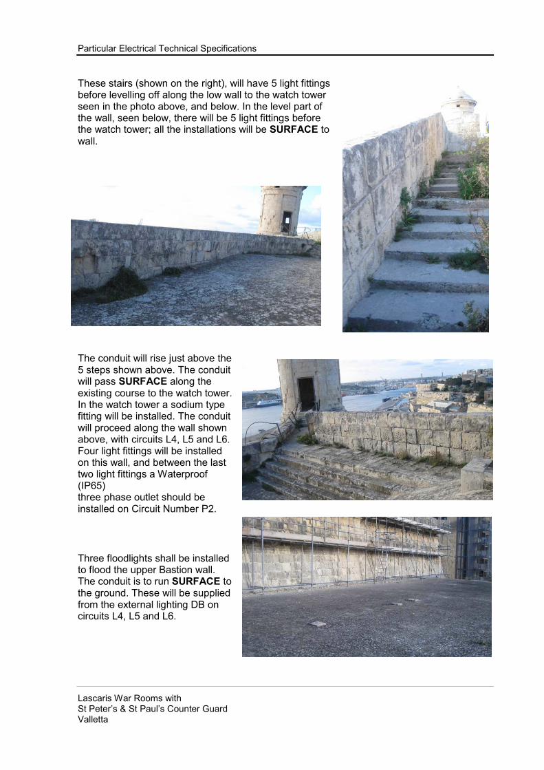
Particular Electrical Technical Specifications
Lascaris War Rooms with St Peter’s & St Paul’s Counter Guard Valletta
These stairs (shown on the right), will have 5 light fittings before levelling off along the low wall to the watch tower seen in the photo above, and below. In the level part of the wall, seen below, there will be 5 light fittings before the watch tower; all the installations will be SURFACE to wall.
The conduit will rise just above the 5 steps shown above. The conduit will pass SURFACE along the existing course to the watch tower. In the watch tower a sodium type fitting will be installed. The conduit will proceed along the wall shown above, with circuits L4, L5 and L6. Four light fittings will be installed on this wall, and between the last two light fittings a Waterproof (IP65) three phase outlet should be installed on Circuit Number P2.
Three floodlights shall be installed to flood the upper Bastion wall. The conduit is to run SURFACE to the ground. These will be supplied from the external lighting DB on circuits L4, L5 and L6.

Particular Electrical Technical Specifications
Lascaris War Rooms with St Peter’s & St Paul’s Counter Guard Valletta
Going back up to the Bastion Tunnel entrance near the bridge (shown in the photo above), a conduit emerging from the External lighting DB in the entrance to the tunnel will descend SURFACE to the wall and chased in ground will advance towards the above shown wall, and will be installed SURFACE along this wall at low level, supplying six light fittings along the stairway. After the sixth fitting the conduit will rise to high level (this area is shown in the photos below) and to proceed at high level to the Gun powder room Entrance; supplying 6 external light fittings.
There will also be 2 branch offs supplying the internal lighting with L1-DBT as shown on drawings.

Particular Electrical Technical Specifications
Lascaris War Rooms with St Peter’s & St Paul’s Counter Guard Valletta
The photo to the right relates to the stairs leading to the upper part of the gun Powder room. The conduit installation here is to drop from the external lighting Distribution Board SURFACE to wall, and chased into ground until the stairway, then to rise from the ground SURFACE to the side of the stairs and runs SURFACE on top of the small edge just above the stairs. The circuit number is L2 and L3 External lighting DB.
In the photo on the right the conduit is to precede SURFACE above the small edge. There are to be seven (7) light fittings along the stairs.
At the top of the stairs the conduit is to level off, again just above the ledge, and to continue round the Bastion low wall.
When the ledge disappears, the conduit is to retain the same level and advance SURFACE along the wall.

Particular Electrical Technical Specifications
Lascaris War Rooms with St Peter’s & St Paul’s Counter Guard Valletta
The conduit is to proceed above the few stairs and level off after they finish along the wall shown beneath. In total there will be six (6) light fittings along this wall on circuits L2 & L3.
The conduit is to feed a sodium type fitting inside the turret, also shown in the photo above.
After supplying the sodium type fitting in the turret the conduit should proceed along the wall shown above at the same low level. There should be four (4) further light fittings supplied by the circuits L2 and L3.
Between the last two light fittings a Waterproof (IP65) three phase outlet should be installed. Circuit Number P1.
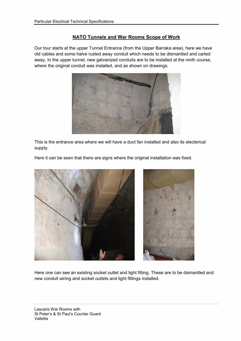
Particular Electrical Technical Specifications
Lascaris War Rooms with St Peter’s & St Paul’s Counter Guard Valletta
NATO Tunnels and War Rooms Scope of Work
Our tour starts at the upper Tunnel Entrance (from the Upper Barraka area), here we have
old cables and some halve rusted away conduit which needs to be dismantled and carted
away. In the upper tunnel, new galvanized conduits are to be installed at the ninth course,
where the original conduit was installed, and as shown on drawings.
This is the entrance area where we will have a duct fan installed and also its electerical
supply.
Here it can be seen that there are signs where the original installation was fixed.
Here one can see an existing socket outlet and light fitting. These are to be dismantled and
new conduit wiring and socket outlets and light fittings installed.

Particular Electrical Technical Specifications
Lascaris War Rooms with St Peter’s & St Paul’s Counter Guard Valletta
The original installation can
be seen just above the low
wall (at the ninth course).
In the photos above are examples of the
original installation. For the upper tunnel all
the existing electrical installations shall be
dismantled and new installations shall be
carried out as shown on drawings and
specifications.

Particular Electrical Technical Specifications
Lascaris War Rooms with St Peter’s & St Paul’s Counter Guard Valletta
On the left hand photograph one can notice that although the conduits have rusted away, it
is clear that the services were passing through the crevice between the rock and the duct.

Particular Electrical Technical Specifications
Lascaris War Rooms with St Peter’s & St Paul’s Counter Guard Valletta
The photos shown above are
of the upper tunnel, where
on the left; one can see a
gradually descending
stairway, where lighting,
socket outlets, Emergency
lights, and a supply for a
turnstile will be installed. On
the left hand side motion
sensors shall be installed
controlling the lighting on
both sides.
On the right hand side there
are 9 rooms which will all
need to have lights installed.
So on the left side there will be lighting, Emergency lights and the 3 phase supply for the fan
(P1-NT1).
The conduits on both sides will connect to the existing Fuse box FB1 shown in the last 3
photos above. The left hand side conduit will replace the conduit entering from the left as
shown in photo above on the left. The conduit for the right hand side will enter the FB1
directly. Conduits from the back of FB1 will go to the new DB-NT1 in the new Control Room1.

Particular Electrical Technical Specifications
Lascaris War Rooms with St Peter’s & St Paul’s Counter Guard Valletta
The following photographs are of the Lower part of the tunnel, leading to the
bridge.
The photo on the left is the “corridor side” of the tunnel and the right hand photo is of a room
on the right hand side of the tunnel. Please note that the first room will be the Control room 1,
where DB-NT1 will be housed, while the second room will be control room 2.
It can also be seen that there is an existing conduit on the ceiling which has to be removed
and replaced with a conduit on each side of the tunnel. One will be on the left hand side
(corridor side), with lighting, socket outlets, Emergency fittings, and movement detectors
controlling all Tunnel lights except for the toilets. On the right hand side there will be lighting,
motion detectors for toilets and a supply for a small toilets extractor fan.

Particular Electrical Technical Specifications
Lascaris War Rooms with St Peter’s & St Paul’s Counter Guard Valletta
Further down the tunnel one
can find the 4” metal pipe
dropping down.
The five photos below show the toilets which the last 4 rooms of the tunnel and which are
leading to the outlet to the bridge shown in the below photo to the right. Over this tunnel
outlet area there will be an extractor fan for the toilets.

Particular Electrical Technical Specifications
Lascaris War Rooms with St Peter’s & St Paul’s Counter Guard Valletta
The following photographs are of the corridors, the War Rooms and other
Support Rooms.

Particular Electrical Technical Specifications
Lascaris War Rooms with St Peter’s & St Paul’s Counter Guard Valletta
The above photographs show the corridor “TEEING OFF” from the Tunnel from the FB1
area. As soon as one turns to the right into this corridor, one encounters a few steps and to
the right one finds the FB2 box. This box has to be emptied from its present fuse carriers and
replaced with the switchgear specified in the schedules and specifications and drawings. FB2
will supply the electrical power to Distribution Board NT1, the electrical lighting to the rooms
12, 12A, 12B, and 12C; Electrical lighting and socket outlets to rooms 8, 9 and 10. Most of
the conduit in these rooms will be kept, maintained and re-used. The wiring will be replaced
as indicated in drawings and schedules. In some cases the conduit will be replaced as in
rooms 12, 12A, 12B and 12C. In rooms 8, 9, and 10 the light fittings that can be maintained
will be refurbished and re-used, while the missing ones and the ones which cannot be
maintained will have to be replaced by similar units. Switches will be maintained, but will not
be wired or re-used as motion sensors will be used. Socket outlets will be replaced by metal
clad units to the specified standards. Emergency light fittings will be to the specified
standards. See below.
The pictured Distribution Board hereunder to the left is FB3. This Fuse Box was used to
supply the power to FB 2 and lighting to the corridor and stairs. It is the intension to strip out
the existing fuse carriers and replace them with the specified switchgear. Please see the
schedules and drawings.

Particular Electrical Technical Specifications
Lascaris War Rooms with St Peter’s & St Paul’s Counter Guard Valletta
Again the existing conduit is to be maintained and re-used as indicated in drawings. New
cables and switchgear are to be used. The supply to FB3 is supplied from FB4 via a conduit
passing through the stairwell to the left of FB3. FB 4 is shown hereunder to the left.

Particular Electrical Technical Specifications
Lascaris War Rooms with St Peter’s & St Paul’s Counter Guard Valletta
Again FS4 will be stripped from its original fuse carriers and replaced with the specified
switchgear. FB4 will supply power for FB3, lighting to rooms 2p, 3p and 4p, and supply to
new plant room panel DBP. DBP will be supplied via an armoured cable as specified.
FS4 will be supplied with power from an existing main panel pictured hereunder on the left.
The panel position is down the FS4 corridor to the left.
The main panel is not only supplying FS4, but also supplying electrical power to FS5. Now
FS5 is a panel inside the Operations Room. This FS5 panel in turn supplies the electrical
needs for the Operations room lighting, socket outlets and a single phase supply to a
consumer unit to the supporting room, which is adjoining the Operations room. Pictured
bottom right.
The middle photo above shows the light fittings to be maintained and re-used. The photo to
the right above shows socket outlets and lighting conduit for the area behind the Operation’s
room wall map of Europe and the Mediterranean.

Particular Electrical Technical Specifications
Lascaris War Rooms with St Peter’s & St Paul’s Counter Guard Valletta
Above are two photos of the operations room light fittings to be maintained and re-used.

Particular Electrical Technical Specifications
Lascaris War Rooms with St Peter’s & St Paul’s Counter Guard Valletta
Services
The electrical systems to be supplied and installed by the Contractor shall comprise all the sections necessary for the complex to be completed and commissioned as per this specification and the related annexed drawings, and can be summarised as follows:
• Main distribution boards;
• Secondary electrical panels;
• Primary LV distribution;
• Secondary LV distribution;
• Wiring and sockets system;
• Indoor lighting systems;
• Emergency lighting system;
• Grounding system;
• Outdoor lighting system.
Other Services
Other services shall comprise the Mechanical and Extra Low voltage Systems which are listed in separate documents.
Related Documents
This Specification shall be read in conjunction with the Conditions of Contract, and shall form an integral part of the Employer’s Requirements and any supplementary specifications, scope of works, product data sheets, schedules, drawings and BOQ’s issued with it and enumerated in the invitation to tender or in the appendix to it. In the event of a discrepancy between the Specification and its related documents the Bidder must inform the Employer.
Regulations Published by the Local Authorities
All work shall be carried out in accordance with the IEE Regulations, British or European Standards, as agreed with the Employer’s Authorised Person, relevant Code of Practice and the Local authorities’ relevant safety and fire precaution regulations.
Other Regulations
All the materials used in the works shall conform to the requisites set out in the technical specifications, to the IEE Regulations 17th Edition (Institution of Electrical Engineers, British Standards Institution and ASHRAE 90.1). The materials shall moreover be CE marked, of first-quality new manufacture, and sourced from a primary supplier.
Special care shall be taken to choose the equipment with a view to guaranteeing
continuous duty operation and ease of maintenance. The definitive specification is binding for the Contractor. The materials used shall also conform to the following:
• All materials and equipment used for the systems in the Permanent Object shall be suitable for the ambient working conditions in which they are installed, and able to withstand the mechanical wear and corrosive effects resulting from exposure to heat or humidity during operation;

Particular Electrical Technical Specifications
Lascaris War Rooms with St Peter’s & St Paul’s Counter Guard Valletta
• All the materials used in the works shall have the characteristics and dimensions mandated by the regulations in force.
The installations shall comply with all the relevant statutory instruments and regulations current at the date of Tender, and in particular with the following:
• The IEE Regulations for the Electrical Equipment of Buildings 17th Edition.
Compliance with British Standards
The equipment and/or installations shall comply with all relevant British Standards and Codes of Practice. In the event of a discrepancy between this specification and any BS or CP this specification shall be followed.
Electricity Supply
Electrical energy will be supplied at low voltage, 3phase 4 wire 400/230 Volt 50Hz earthed neutral system.
Unless otherwise indicated all apparatus and wiring shall be suitable for use with this system. Earthing system is to be to BS 7430:1991.
Definitions of Approval
For the purpose of this specification, the following definitions apply: ‘Approved’ and ‘Approved by the Authorised Person: normally a design or equipment
must be proven to have been operated successfully for not less than two years under conditions generally similar to those required by this contract.
Facilities shall be given at the tender stage, if required by the Employer, to enable it to evaluate the equipment's features and performance. The approval of a design or of equipment shall be without prejudice to the acceptance tests required after installation.
Extent of Works
The Works shall comprise the whole of the labour and, unless otherwise indicated, all the materials necessary to form a complete installation and such tests, adjustments and commissioning as are prescribed in subsequent clauses and as may otherwise be required to give an effective working installation to the satisfaction of the Authorised Person. The words ‘Complete Installation’ in these Specifications shall mean not only the major items of plant and equipment conveyed by this specification, but all the incidental sundry components necessary for the complete execution of the works and for the proper operation of the installation, with their labour charges, whether or not these sundry components are mentioned in detail in the tender documents issued in connection with the contract. The words ‘as indicated’, ‘where indicated’, ‘unless otherwise indicated’, refer to items or requirements which are or may be given elsewhere in the specification documents issued in connection with the Contract.
Space for Equipment
The Contractor shall ensure that all the equipment to be supplied by it can be installed in the available space and that there is adequate access to place all equipment into its position and for maintenance. For this purpose outline building drawings and section drawings are supplied to the Contractor at the tendering stage.

Particular Electrical Technical Specifications
Lascaris War Rooms with St Peter’s & St Paul’s Counter Guard Valletta
Comments by the Bidder
Any comments by the Bidder on the efficiency of the design, the availability of equipment, materials and labour and the time required for the completion of the work shall be made in writing when the Tender is returned.
Other Information
The Contractor shall prepare for submission with the tender manufacturer’s technical data giving full information as to dimensions, materials, performance and all information pertinent to the adequacy of the equipment proposed by itself for the approval of the Employer.
The manufacturer’s technical data shall cover the major equipment; distribution boards and panels, etc.
Name, sizes, catalogue numbers and references shall be clearly marked to indicate the particular item.
Existing Panels and Conduit Maintenance.
All existing ferrous metal work which shall remain installed shall be maintained and shall be given a protective coat of paint or other approved material before dispatch from works. Any deterioration or damage to the existing or new materials’ protecting coating, following the installation of the new wiring, shall be made good as directed and to the satisfaction of the Authorised Person.
Surfaces
The surfaces of all ferrous metal including hangers, supports, etc., shall be primed and finished with two coats of good quality non-metallic paint of approved colour. The Contractor shall ensure that:
• all surfaces are cleaned before they are painted;
• those parts of the installation required to be left unpainted (e.g. brass work) shall be so left;
LIGHTING POINTS
The cost of lighting points shall include the heavy duty Galvanised conduit SURFACE TO WALLS AND/OR CEILINGS, the required METALCLAD electrical accessories, and the cables as specified.
GENERAL PURPOSE POWER POINTS
The cost of socket outlet points shall include the heavy duty Galvanised conduit SURFACE TO WALLS AND/OR CEILINGS, the 3 x 4 mm sq (or as specified) P.V.C. cable for radial circuits, or 6 x 2.5 mm sq. P.V.C. cable for ring circuit, and the 13 ampere METALCLAD switched socket as specified.
The cost of the spur-fused point shall include the heavy duty Galvanised conduit
SURFACE TO WALLS AND/OR CEILINGS, the 3 x 4 mm sq. (or as specified) P.V.C. cable, and the 13 ampere METALCLAD switched spur fused unit.

Particular Electrical Technical Specifications
Lascaris War Rooms with St Peter’s & St Paul’s Counter Guard Valletta
LIGHT FITTINGS & ANCILLARY EQUIPMENT & LAMPS
General Requirements
For the sourcing of the lighting fixtures described herein, preference should be given to the standard commercially available components featured in supplier catalogues. The metal used should be first quality steel, minimum thickness 8/10, suitable for all types of processing such as stamping and bending, of sufficient thickness to confer adequate sturdiness and rigidity to the lighting fixtures.
The metal plates shall be phosphate and corrosion-resistant treated finish, and stove dried at 180°C. This finish shall be long lasting, and sufficiently durable to withstand the knocks which may occur during transport, assembly and maintenance. Any reflectors shall be in aluminium of purity exceeding 99.8%, with a corrosion-resistant polished finish. The design and structure of the lighting fixtures should ensure adequate dissipation of heat, preventing the formation of hot spots potentially harmful to the apparatus. Particular care shall be taken to ensure adequate heat dissipation in lighting fixtures with a backup power supply, in view of the restrictive working conditions.
Where covered lighting fixtures are specified, the coverings shall be in long-lasting polycarbonate, resistant to yellowing; the material used shall be self-extinguishing according to the CEI BS regulations in force.
The coverings shall be injection moulded (with no visible parting seam) with a prismatic surface of transparency no lower than 92%. The coverings shall be easily removable for cleaning. The coverings shall not expose the lamp, and should be fixed to the supporting framework using a gasket to ensure the mandated protection level. The lighting fixtures must be accessible enough for them to incorporate the necessary electrical components, consisting of fuse holder, terminals and connecting conductors mounted on a single metal strip. All lighting fixtures shall meet the following requirements, for ease of maintenance:
- easily removable cover, with provision made for hanging;

Particular Electrical Technical Specifications
Lascaris War Rooms with St Peter’s & St Paul’s Counter Guard Valletta
- electrical components accessed by removing the lamps and reflectors, via wing nut or similar release system, component strip anchored by secure plastic hangers (any screws used must be non-removable);
- component strip removable, after having released a possible spring catch;
- PG 11 cable clamp inserted at the base of the fixture, sized for the cable cross section specified for each fixture;
The lighting fixtures shall be connected to the earthing circuit of the building. For this purpose, they shall be provided with a bolt welded to the metallic part, a nut and a 2.5 mm2 insulated yellow conductor, connected to the bolt and to the terminal on the component strip. The earth conductor shall reach the terminal on the metal strip via the same cable that supplies the fixture.
The lighting fixtures shall be EC marked and accompanied by certification documenting their protection level and conformance to the regulations in force. The power supplies for the fluorescent tubes shall be of the 230 V 50 Hz single-lamp starter type with high-resistance cathodes, power factor corrected with fuse holder and bayonet coupling, complete with fast-blow fuse in glass cylinder. Given the ambient working conditions the Contractor shall guarantee, for a period of two years, the quality of the finishes and treatments of the metal, covers and reflectors, in relation to their reflective properties and the overall efficiency of the lighting fixtures. The above warranty applies to all those defects which fall outside the scope of the efficiency reduction attributable to normal wear and tear of the paint finishes, treatments and materials. According to this warranty, the Contractor undertakes to repaint, repair and/or replace - free of charge and in as timely a manner as possible - the lighting fixtures whose normal operation is thus compromised, within the above warranty period, by defects in the materials, treatment, processing and/or finish. In the event of replacements or repairs, the charges for transport and packing shall be covered by the Contractor. The supply is inclusive of delivery to the construction yard, complete with lightweight cardboard packing materials and protection against moisture. The transport costs are therefore also included in the price.
Light Fittings for Use with Tungsten Filament Lamps
Light fittings for use with Tungsten filament lamps shall comply with BS3820. Light fittings for use with mercury electric discharge lamps shall comply with BS1950.

Particular Electrical Technical Specifications
Lascaris War Rooms with St Peter’s & St Paul’s Counter Guard Valletta
Light fittings for use with tubular fluorescent lamps shall comply with BS3820.
Lampholders
Lamp holders for use with Tungsten filament lamps shall be suitable for use with the type of lamp cap in Table 2. Lamp holders for use with tubular fluorescent lamps shall be bi-pin type complying with BS1875. Lamp holders for use with flexible cords shall be of the grip type. Heat resisting type lamp holders shall be used with flexible cords and enclosed type lighting fittings regardless of the lamp cap position, i.e. cap-up or cap-down. Lamp holders incorporated in weatherproof fittings shall be of porcelain or brass.
Tube Pendants
Tube pendants shall comprise a dome cover complying with BS31 or BS4568, and a screwed conduit, complying with BS31 or BS4568, of not less than 20 mm outside diameter and of a length to give the required mounting height of the light fitting. A locknut shall be provided to bear against the conduit entry of the light fitting. The dome cover, if of swivelling type, shall be provided with a flexible copper bond between the fixed and moving portions. Dome covers, conduit and locknuts shall have protection against corrosion according with Class 2 where mounted inside a building.
LIGHTING SWITCHES
• All switches are to be METALCLAD type full rocker plate and rated 10/16 amperes as specified in bills of quantity. To BS 60669-1-2-3
• Ferrous parts of accessories shall be adequately rust protected.
• Accessories mounted within a building or used with conduit having protection against corrosion according with Class 2 shall be of the dust-protecting type.
• Boxes shall have protection against corrosion according with Class 2 and may have fixing holes inside or outside the enclosure.
• Accessories mounted outside a building or used with conduit having protection against corrosion with Class 4 shall be of the weatherproof type. Boxes shall have external fixing lugs.
SOCKET OUTLETS
• All METALCLAD socket outlets, shuttered and complete with a switch.
• They shall be rated 13 amperes. To BS 1363-1.
FUSED SPUR OUTLET
• All METALCLAD outlets shall be fused and complete with a switch. They shall be rated 13 ampere. To BS 1363-1.
Switch Boxes, Socket-Outlet Boxes-MC
Switch boxes, socket-outlet boxes and similar items shall comply with BS4662.
Switch Plates, Socket-Outlet Plates
Switch plates, socket-outlet plates and similar items shall be of metal as indicated in this section, and as directed by the Employer.

Particular Electrical Technical Specifications
Lascaris War Rooms with St Peter’s & St Paul’s Counter Guard Valletta
Decorative finishes of metal plates shall comply with BS1448 and the finish and/or colour shall be standard throughout the installation unless otherwise directed by the Employer. Any metallic parts (containers, support frames, faceplates etcL) must be earthed.
Switches-MC
Switches shall comply with BS60669-1-2-3 and shall be suitable for use on inductive
or resistive loads. Their current ratings shall be of 5 amperes minimum and they shall
be rated according to their loads. They shall be single pole, unless otherwise
indicated or directed by the Employer, and where mounted adjacent to one another
they shall be grouped in a single enclosure (multi-gang box) and share a common
switch plate.
Switch with Outlet for Flexible Cord-mc
Outlets in metal switch plates shall be provided with a grommet complying with BS60669-1-2-3. Means shall be provided for anchoring the flexible cord and terminating the earth conductor of a flexible cord.
Socket-Outlets and Plugs Other than Voltage and Frequency Discriminating Types
Switch socket-outlets shall be provided as indicated or as directed by the Employer. Weatherproof type socket-outlet shall be provided with a screw-on cap. Where a pilot
lamp is to be provided, it must be an integral part of the switch socket-outlet.
Plugs
Plugs shall be provided for every socket outlet installed. They shall be handed over to the Employer at the commissioning stage.
Insulated Terminal Blocks
The rated voltage of terminal blocks shall be 400 volts between terminals, 230 volts to earth. Terminal blocks shall comprise of brass tubular connectors with screw connections contained within a moulded block formed of nylon 6, melamine - formaldehyde resin or phenol formaldehyde resin. Phenolic moulding materials shall comply with BS771, Type G material, and phenolic mouldings with BS2907. Terminals shall be designed to clamp the conductor between metal surfaces with sufficient contact pressure but without causing damage to the conductor. With the largest recommended conductor in position, and tightly clamped, there shall be at least two full threads of the screw engaging in the connector. The diameter of the hole in the connector relative to the diameter of the screw employed shall be as specified in Table 1.

Particular Electrical Technical Specifications
Lascaris War Rooms with St Peter’s & St Paul’s Counter Guard Valletta
SWITCHGEAR, DISTRIBUTION BOARDS, CIRCUIT-BREAKERS, CONTACTORS AND BUSBAR CHAMBERS.
GENERAL REQUIREMENTS.
Rated Voltage
The rated voltage of switchgear and distribution boards shall be not less than 400
Volts A.C. between poles (230 Volts to earth).
Enclosures
The type of enclosure, shall comply with BS 60439 Parts 1 and 2 as indicated or as
directed by the Employer shall be:
• Dust-protecting for all apparatus mounted inside a building and shall be protected to IP31 of BS5420: 1977; weatherproof for all apparatus mounted outside a building to IP 65.
• The enclosure of all apparatus other than Isolating switches shall be of metal.
• Ferrous parts of dust-protecting type enclosures shall be adequately rust protected and shall be finished with a coat of paint, stove dried and hardened.
• Weatherproof type enclosures shall be provided with a hot-dip galvanised coating complying with BS729 Part 1 or a sherardised coating complying with BS729 Part 2. A decorative finish is not required.
• Provision of locking of padlocking of covers of apparatus shall not be made unless so indicated by the Employer.
• Fixing holes in dust-protecting type enclosures of apparatus may be inside or outside the enclosure. Weatherproof type enclosures shall have external fixing lugs.
Fuses – Fuse holder.
Cartridge type fuse-links shall be provided where necessary or as indicated or directed by the Employer. Cartridge fuse links shall comply with BS1361. Cartridge fuse links complying with BS 1362 shall have a category of duty AC46 and a fusing factor as for Class Q1 fuses and shall have dimensions according with Figures 1 to 4. Where cartridge fuses-links are used to provide back-up protection for miniature circuit breakers their normal current rating and fusing factor shall be as directed by the Employer. Low voltage fuses: To BS EN 60296-1. Breaking range and utilization catagories: general application – Gg; To protect contactors or auxiliary circuits, fuse holder bases and fuses must be fitted with the following characteristics:
- EC reference standards: IEC 32-1; IEC 32-4; IEC 32-5;
- voltage rating 380V;
- fuse holder bases for cartridge fuses; (Fuses for domestic use and similar usage must meet requirements specified in table IEC-UNEL 06716);
- ceramic body or similar;
- no. poles 1-3;

Particular Electrical Technical Specifications
Lascaris War Rooms with St Peter’s & St Paul’s Counter Guard Valletta
- for panel installation:
- cartridge fuses;
- porcelain body or similar
- standard rating up to 100 A
- interrupting power 100 kA
- fuse holder bases for NH fuses size 00-0-1-2-3-4.
Fuses for industrial use must meet requirements specified in table IEC-UNEL 06711
- steatite body or similar;
- n. poles 1-3;
- for wall installation;
- NH fuses:
- steatite body or similar;
- standard rating up to 1250A;
- interrupting power 100 kA.
Switchgear
Air-break switches and isolators for rated currents not exceeding 800 amperes shall comply with BS EN 60947-2-3:2009.
Moulded Case Circuit-Breakers & Enclosures
Moulded case circuit breakers shall comply with BS EN 60898-1 unless otherwise indicated or directed by the Employer the standard a.c. rated short-circuit capacity shall be: 70KA for Main Panels; 50KA for Sub-Main Panels. Ratings for distribution boards are as stated in schedules, but in general should not exceed 25 kA. Auxiliary devices, e.g. power closing devices and under-voltage releases, shall be provided only where necessary or as directed by the Employer. Enclosures shall be as specified above.
Residual Current Devices
Double pole and four pole RCDs shall be employed having current rating and RCD sensitivity as specified or as directed by the Employer. These shall comply with BS 61009-1:2004 and shall have a positive contact indication and shall incorporate a test button.
Contactors.
Contactors shall comply with BS EN 60470:2001, IEC 60470:2000. Then shall be rated in accordance with `uninterrupted duty' and `utilisation category AC23. Contactor coils shall be d.c. or rectified a.c. operated. They shall be wound for 230 volts unless otherwise directed by the Employer, and shall be protected by a cartridge type fuse-link as specified. Latched-in contactors shall be provided only when approved by the Employer. Circuits or devices protected with contactors must have the following characteristics:
- voltage 660V;
- range up to approx.: 250 kW (AC3) to 380V;
- auxiliary contactors up to 4 kW approx. 380V (AC11)
- assembly:

Particular Electrical Technical Specifications
Lascaris War Rooms with St Peter’s & St Paul’s Counter Guard Valletta
Snap on profile rail BS 5584:1978, EN 50022 (DIN 35) for contactors up to approx. 15 kW power; The contactors in the power range from 4 to 8 kW approx. 380V - (AC3) must be designed to fit accessories, whether they are auxiliary contactors, time delay auxiliary contactors or mechanical coupling.
Contactors must also be designed to be fitted with additional blocks at a later date:
- Mechanical opening/closing 10 x 10^ 6;
- Electrical opening/closing 1 x 10^ 6 (AC3) up to 250 kW;
- Accessories that can be installed by the user;
- Thermal relays detecting missing phase available for the entire range.
Identification of Switchgear & Distribution Boards
Switchgear and distribution boards shall be permanently identified. Labels shall be laminated plastics material (white or black) attached to the apparatus by adhesive or with screws. The main control switches shall be labelled, MAIN ISOLATOR - ESSENTIAL and MAIN ISOLATOR - NON ESSENTIAL respectively on the incoming supplies. The characters shall be at least 10 mm high and 1.5 mm thick On all other labels the characters shall be at least 4 mm high and 0.5 mm thick.
Schematic diagrams
Every panel, no matter how simple, shall be fitted with a special document pocket for stowing the plastic-wrapped power circuit diagrams and functional drawings, which must be kept rigorously up to date.
SWITCHGEAR – PARTICULAR REQUIRMENTS.
FUSE SWITCHES.
All fused switches shall be of the front switch handle type and shall be constructed from heavy gauge zinc coated steel, damp- and dust-proof protective. Insulated barrier plates shall be fitted inside to prevent accidental access to the live busbars.
All units shall be finished in light grey stove enamel coating and all items supplied shall be of the same manufacture and type.
Standard: BS EN 60947-3. Ingress Protection: BS EN 60529: IP 54. Operation: Frequent (category A). Terminals: Suitable for copper conductors. Ratings: As per schedules. Main switches and isolators category of duty shall be AC-23. Fuse links: BS 1362. Cartridge fuses: BS 1361 – TYPE 1.
Isolating switches .
On special circuits which include isolating switches - isolating switches with or without fuses, modular unit devices, which complete the range of automatic thermal

Particular Electrical Technical Specifications
Lascaris War Rooms with St Peter’s & St Paul’s Counter Guard Valletta
magnetic and residual current circuit breakers, must be used with the following characteristics:
• EC reference standards: BS EN 60947-3;
• Utilisation category: AC-23.
• Operation: Frequent (category A).
• Ingress Protection: BS EN 60529: IP 65.
• Voltage 380V;
• No. poles 1-4;
• Standard rating; As circuit schedules.
• The following choice of accessories: terminal shrouds; caps; indicators.
AUTOMATIC THERMAL MAGNETIC AND RCCB UP TO 50 KA
General
Automatic thermal magnetic and residual current circuit breakers with interrupting capacity up to 50 kA must have the following characteristics:
• EC reference standards: IEC 17-5;
• Reference to residual current: IEC 755;
• Metal-clad frame or insulated moulded case.
• BS EN 60947-2 and BS EN 61009-1 as appropriate.
• Ratings: as indicated in schematic and schedules.
MODULAR THERMAL MAGNETIC AND RCCB
Automatic thermal magnetic and RCCB up to 50 kA, 17.5 mm DIN module
Automatic thermal magnetic and residual current circuit breakers with interrupting power up to 50 kA must have the following characteristics:
• EC reference standards:
• IEC 23-3
• IEC 23-18
• IEC 17-5;
• IEC 755;
• voltage rating 380V - 50-60 Hz;
• standard rating up to 53A;
• interrupting power up to 50 kA (particular rating in schematic / schedules);
• fixed calibration;
• no. poles 1-4;
• snap fixing on profile rails;
• the range can also include the automatic thermal magnetic circuit breaker with residual current protection on various values (0.03-0.3-0.5A);
• Sensitivity to waveform: AC type for use with alternating current;
• A type for use with class I devices with electronic circuits which give rise to pulsating current and/or direct current.
• Standards: BS EN 61009-1.
• Operation: Frequent (category A).

Particular Electrical Technical Specifications
Lascaris War Rooms with St Peter’s & St Paul’s Counter Guard Valletta
Each device must be equipped to accommodate an auxiliary element with a width of 1/2 or 1 module on its side, containing one or more auxiliary contact with tripping indication relay or open releases.
A wide choice of accessories which can be installed on the profile rail must be offered, among which:
• Isolating switches;
• RCCB’s;
• Priority relays;
• Transformers;
• Push buttons and light signals, bells and buzzers;
• Hour-meter, UNEL ASTA compliant sockets, switches;
• Circuit breaker timers;
• Step relay;
• Time delay relay;
• Mono-stable relay;
• Timers.
Automatic MCCB with thermal magnetic release 17.5 mm DIN Module
On circuits for which automatic current circuit breakers have been designed, modular unit circuit breakers, which complete the range of automatic thermal magnetic current circuit breakers, must be used with the following characteristics:
• Standard: BS EN 60947-2.
• Operation: Frequent (category A).
• Utilisation category: A.
• Category of duty shall be AC-23
• Standard ratings: As per schematic and schedules.
• no. poles 1-4;
• snap fixing on DIN profile rail;
• no. poles 2-4;
• overload protection: provided by other device;
• Sensitivity to waveform: A type for use with class 1 devices with electronic circuits which give rise to pulse currents and/or direct current.
• Interrupting medium: Air.
• Design: Moulded Case.
• Ingress protection: BS EN 60529-IP40.
• Operation: Manual operation.
• Terminals: Suitable for copper cable connection.
• Material: Polycarbonate.
MINIATURE CIRCUIT BREAKER – MCB:
General
Circuits or devices designed with overload cut-out protection must have the following characteristics:
• BS EN 60898-1
• EC reference standards: IEC 17-7; IEC 70-1;
• type K (VDE-0660) tripping;
• wide range of possible uses which include the following:
• three-phase thermal releases with simultaneous adjustment;
• any assembly position;

Particular Electrical Technical Specifications
Lascaris War Rooms with St Peter’s & St Paul’s Counter Guard Valletta
• protection levels and types of installation: in a line on profile rail EN 50022 (DIN 35) (at least IP30);
• wall mounted with case (at least IP65);
• flush panel fitting (at least IP 54);
• optional locking in open position;
• Optional mounting of under-voltage and open releases.
DISTRIBUTION BOARD
Standard: BS EN 61439-1-2:2011 Approval: ASTA certified. Ingress Protection: BS EN 60529:IP31 Busbars and Connections: Fully shrouded. Neutral and earth Bars: Individual terminal for each individual circuit. Spare Current Capacity: 10%. Spare ways: As per circuit schedules. Cable (L,N,E) terminal identification: As per outgoing circuit reference. MCB Identification: MCB numbered according to attached DB schedule.
Distribution Boards and switchgear shall be labelled with White-Black Traffolyte with 3 mm high lettering.
All distribution boards shall be complete with glazed circuit charts indicating, the ways, number, equipment, rating of MCBs’ or MCCBs’, size of cable used and phase to which equipment is connected. Current and short circuit ratings will be as specified on the Schedules.
All circuit breakers shall be supplied from the same manufacturer. MCB referred as spares in the room panels, or distribution boards, shall be provided
for future use. Each neutral busbar shall have an outgoing terminal for each neutral conductor connected to it. Distribution boards shall incorporate miniature circuit breakers as specified and as per schedules.
KILO-WATT HOUR METER
For each of the 2 Main Panels, a Kilo-Watt Hour Meter shall be installed by the local authorities. Their precise locations shall be agreed with the local authorities, and all testing commissioning, applications and expenses shall be borne by the contractor.

Particular Electrical Technical Specifications
Lascaris War Rooms with St Peter’s & St Paul’s Counter Guard Valletta
STARTER & CONTROL PANELS
General
All starters and thermostatic control equipment, and other control equipment, shall be enclosed in a purpose-made sheet steel or reinforced plastic material panel.
Where plastic materials are used, the Contractor shall obtain the written approval of the Employer prior to installation. Thermostatic control equipment shall be housed in separate section of the enclosure with its own isolator.
Starter panels, motor starters and controllers shall comply with BS EN 60470:2001, IEC 60470:2000; BS EN 60947:2001; enclosures shall be `dust and damp protecting' as specified under enclosures.
Starter and control panels shall be suitable for operation in the ambient conditions being installed; the temperature shall not be higher than 40 Deg C as stated in the relevant British Standards.
Sections housing heat emitting apparatus shall be ventilated to prevent over- heating. Panels shall be constructed of folded mild steel sheet of minimum thickness 2.5 mm,
or of a proprietary system of construction, as approved by the Employer. Where steel panels are employed they shall be painted matt white internally; panels
shall be finished externally semi-gloss stove enamelled or cellulose enamel, colour grey.
Equipment & Wiring
All indicating lamps, instruments and controls shall be of the same style and manufacture, to provide uniformity of appearance and to facilitate maintenance. Glasses of not less than 25 mm diameter shall be fitted.
Externally visible equipment shall be flush mounted with minimum projection and be fixed securely to the front panels or other members. Internal equipment shall be secured to purpose made rails or mounting bars. All fixing shall incorporate shake-proof washers or other vibration- resistant fastenings. Fuses, terminal blocks and each item of equipment shall be readily identified by clearly visible labels. The arrangement of switches, lights, instruments, etc shall be neat and as near symmetrical as possible.
Internal wiring shall be colour-coded and in general shall be bunched and run on trays or in purpose made slotted plastic cable trunking. Positive fixing of cable ends shall be ensured by purpose made clamps or pinch type terminals, or by use of crimped cable tags or other approved termination devices. Each cable shall be permanently identified.
Terminal Blocks
Grouped terminal blocks of adequate capacity and fully numbered, with permanent labels, shall be provided for all wires leading to equipment outside a panel. Terminal numbers or markings shall correspond with those used on related apparatus and wiring diagrams. Removable plates or other facility shall be provided for entry of incoming cable, conduits, trunking, etc, with means of effective earthing to the cubical chassis. Provision shall be made for the earthing of all non current-carrying metal work. For main power terminals incorporated within the panel, soldered socket type terminals shall be provided.
Fuses
Starters and control circuits shall be protected by fuses of the HRC cartridge type complying with BS EN 60269-1:2007+A1:2009 BS 88-1:2007, BS 88-1:2007.

Particular Electrical Technical Specifications
Lascaris War Rooms with St Peter’s & St Paul’s Counter Guard Valletta
Fuses shall be grouped and mounted so as to be readily accessible without danger. One spare set of fuses for each rating of fuses installed shall be supplied.
Starters
Starters shall normally be rated for `intermittent' or `frequent' duty, but where, due to the form of thermostatic or automatic control, the number of starts is likely to exceed 15 per hour starters for `frequent' duty shall be provided. The type of starter which will be accepted depends on the capacity of the electrical supply and the mains; in certain cases special requirements shall be necessary.
Generally the following types will be accepted:
• Motors up to 0.5KW output - on/off switch or Direct-on-line.
• Over 0.5KW and up to 2.0KW - Direct- on-line or star – delta.
• Over 2.0KW and up to 25KW - Star- delta, auto-transformer, or rotor resistance.
• Over 25KW - Auto-transformer or rotor resistance. Starters shall be provided on each phase with combined thermal overload devices
and single phasing protection, with adjustable time lag, and an under voltage release. Unless otherwise indicated, they shall be arranged to provide manual restart on restoration of mains voltage. Contactor operating coils shall be wound for not less than 230 Volts.
Where a contactor is arranged for remote operation the coil circuit shall be protected by a fuse. Terminals shall be accessible and have adequate clearance between phases and to earth.Where duplicate plant is provided the starters for each plant shall be housed in a separate panel or cubicle. For refrigeration plants, where the compressor motor starter is housed separately from the control panel, provision shall be made for any electrical interlocking which is required between the compressor motor switchgear and the starters for the remainder of the plant. Where a fan is provided with duplicate motors two starters shall be supplied; a single starter with local changeover switch will not be accepted.
HVAC CONTROL PANEL. This panel consists of a single phase DOL starter for the toilets extract fan; a three
phase DOL starter for the fan at the Upper tunnel entrance; a set of start / stop push buttons for the VRV, and 2 AHU’s controlled remotely via a multi-core cable from the Control room to the HVAC plant room; and a set of Run / Stop push buttons which are again activated by the same multi-core cable from the HVAC plant room. The control panel is to be constructed to per the above mentioned specifications.
CABLES AND CONDUCTORS – GENERAL.
All the cables used in the systems described in these specifications shall conform to the British Standard BS 7671 or equivalent EU Standards.
PARTICULAR SPECIFICATIONS: 1) SINGLE CORE CABLES: Standard: To BS 7211, Insulation Type: Thermosetting insulated, Protection: Non-armoured cables for voltages up to and including 450/750V, Use: For electric power, lighting and internal wiring,

Particular Electrical Technical Specifications
Lascaris War Rooms with St Peter’s & St Paul’s Counter Guard Valletta
Special Feature: Low emission of smoke and corrosive gasses when affected by fire. 2) MULTI-CORE CABLES: Standard: To BS6724, IEC 60502-1 cable, Insulation Type: Thermosetting insulation, Special Feature: Non flame propagating, and low emission of smoke and corrosive gases when affected by fire. Use: For rated voltages of up to 1000V; for feeder circuits and for main power supplies, on cable trays or buried outdoor conduits;
3) FLEXIBLE CORDS Standard: BS 6500 Insulation type: PVC. Colour: Black. The power cable cross sections indicated in the annexed drawings, which are an integral part of this specification; do not exempt the Contractor from verifying the cross sections with reference to the following parameters:
- Connected load;
- Cable carrying capacity equal to the MCB/MCCB rating;
- Ambient temperature of 30°C (for inside installation), 40°C (for outside runs in raceways);
- Grouping reduction coefficient;
- Voltage drops between the Electrical meters and the furthest supplied load not exceeding 4% for power and lighting final sub-circuits.
The cross section must in any case be no less than:
- 1 mm2 for the signalling circuits
- 1.5 mm2 for the lighting circuits
- 2.5 mm2 for the traction power circuits The cables must be marked to permit ready identification of the supplied load, with the sheaths colour-coded as follows:
CABLE INSTALLATION – GENERAL: Cables are to be installed to BS 7671.
Cable runs in utility tunnels or buried underground
1) Armoured cables shall be run surface in general and any holes, chasing or cutting of the stone or ground works have to be specifically approved by the client and /or engineer approved by client.
2) Cables laid inside utility tunnels shall run in metal raceways fixed to the walls of the tunnels, with a minimum spacing of 30 cm.
3) Fire barriers shall be installed at the points where the utility tunnel passes from one room to the next.

Particular Electrical Technical Specifications
Lascaris War Rooms with St Peter’s & St Paul’s Counter Guard Valletta
4) The outside cables shall generally be in perforated raceways, while buried runs shall use “underground” PVC conduits with concrete backing, with a minimum ground cover of 60 cm for LV and telecommunications lines, and of 100 cm for MV lines.
Cable runs in cable trays and/or raceways
1) The cables shall be laid in an orderly side by side arrangement on a single layer. If this is not possible, stacked cable trays shall be used, with a minimum vertical spacing of 30cm.
2) Single-core cables shall be twisted to avoid dangerous overheating and/or impedance increases due to magnetic fields.
3) The cables shall be labelled at 20 m intervals with a PVC marker secured with a plastic collar, indicating the type of system or supplied load.
4) Along incline or riser runs, the cables shall be fixed to the raceways by means of cable ties (covered raceways must be fitted with special internal fasteners).
5) Cables run on cable trays shall be to Reference Method E OR F.
6) As in the case of utility tunnels, fire barriers shall be installed at the points
where the cables pass from one fire compartment to the next.
Cable runs in conduits
1) The inside diameter of the conduits, which must never be less than 16mm, must be chosen to ensure a maximum fill coefficient of 0.4 (fill coefficient = ratio of the total cable cross section to the inside cross section of the tube). The conduit diameter shall therefore always be greater than or equal to 1.4 times the diameter of the circle circumscribed by the cables inside. In any case, the diameters specified in drawings should be adhered to, and if there is any discrepancy, the contractor is advised to consult with the engineer in charge.
2) Smooth conductor pushing and pulling must in any case always be assured.
Conduits
1) Conduits shall be run surface in general and any holes, chasing or cutting of the stone or ground works have to be specifically approved by the client and /or engineer approved by client.

Particular Electrical Technical Specifications
Lascaris War Rooms with St Peter’s & St Paul’s Counter Guard Valletta
2) The following types of conduits shall be used in the works, in accordance with the specifications set out in the drawings and descriptions of the individual systems.
3) Heavy duty galvanized steel with threaded fittings for damp areas and/or for dry
areas subject to high mechanical stresses and/or very low temperatures.
4) Any parts or equipment subject to vibration shall be connected to the conduits via flexible fittings.
5) Overlapping or diagonal routings are not permitted for cable runs built into walls and such.
6) Conduits on exposed runs or in suspended ceilings must be fixed with approved plastic fasteners, spaced at intervals dependent on the conduit diameter.
7) Entry into pull boxes shall be through special fittings and adapters, such that the mandated mechanical protection level is maintained.
8) Bends shall be formed using an approved tube bender.
9) Tee and elbow joints are only permitted by specific approval of the client’s engineer.
10) Conduit dimensions shall be determined as a function of the number and cross section of the conductors inside, and as directed in drawings.
11) The inside diameter of the conduits shall in no case be less than 1.4 times the diameter of the circle circumscribed by the bundle of conductors inside. The raceway cross section shall never be less than 2 times the area occupied by the conductors inside.

Particular Electrical Technical Specifications
Lascaris War Rooms with St Peter’s & St Paul’s Counter Guard Valletta
Cable trays and raceways:
1) Cable trays and raceways for runs inside the building can be made from galvanized sheet steel, while those installed outdoors shall be hot galvanized.
2) All joints shall be manufactured so as to avoid the risk of abrading the cable sheaths during insertion.
3) The electrical continuity of the raceways shall also be assured, and in the case
of the earthing conductor an earth clamp shall be fitted with a maximum spacing of 8 m.
4) The raceways shall be supported by brackets attached to the existing
structures and framework; the spacing of the brackets shall be such that, for the applied load, the camber does not exceed 1/150 of the clear span.
5) The brackets shall have the same surface finish as the cable trays or
raceways.
6) In general, cable trays shall be used for the main feeder circuits and for exposed runs, while closed raceways shall be used for the feeders or wherever there exists a fire risk which mandates protection level IP 40 for the raceways.
7) For exposed runs (or where stated), galvanized steel cable trays and/or
raceways shall be used as specified.
8) The hot dip galvanised steel cable trays shall be fitted with hot galvanized metal barriers wherever it is necessary to separate cables supplying different loads, and fitted with hot galvanized sheet metal covers.
Junction boxes and pull boxes
1) All joints and branches shall be made exclusively via junction boxes or pull boxes.
2) As a rule, junction boxes and pull boxes shall also be used at every abrupt
deviation of the conduit path, every two bends, every 15 m in straight runs, at the entrance to each supplied room and at each lighting fixture.
3) Conductors belonging to different systems or loads may not be routed through
a common pull box.
4) The conduits shall be installed flush with the boxes, taking care to smooth down any rough edges in order to avoid damaging the conductor sheaths during wire pushing or pulling.
5) In the case of exposed systems, the conduits shall be connected exclusively
via plastic or die cast threaded compression fittings, as per the specifications.
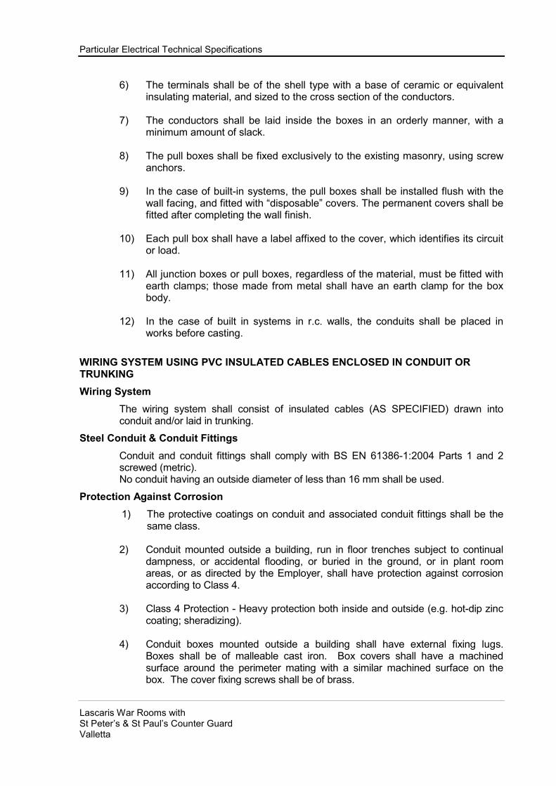
Particular Electrical Technical Specifications
Lascaris War Rooms with St Peter’s & St Paul’s Counter Guard Valletta
6) The terminals shall be of the shell type with a base of ceramic or equivalent insulating material, and sized to the cross section of the conductors.
7) The conductors shall be laid inside the boxes in an orderly manner, with a
minimum amount of slack.
8) The pull boxes shall be fixed exclusively to the existing masonry, using screw anchors.
9) In the case of built-in systems, the pull boxes shall be installed flush with the
wall facing, and fitted with “disposable” covers. The permanent covers shall be fitted after completing the wall finish.
10) Each pull box shall have a label affixed to the cover, which identifies its circuit
or load.
11) All junction boxes or pull boxes, regardless of the material, must be fitted with earth clamps; those made from metal shall have an earth clamp for the box body.
12) In the case of built in systems in r.c. walls, the conduits shall be placed in
works before casting.
WIRING SYSTEM USING PVC INSULATED CABLES ENCLOSED IN CONDUIT OR TRUNKING
Wiring System
The wiring system shall consist of insulated cables (AS SPECIFIED) drawn into conduit and/or laid in trunking.
Steel Conduit & Conduit Fittings
Conduit and conduit fittings shall comply with BS EN 61386-1:2004 Parts 1 and 2 screwed (metric).
No conduit having an outside diameter of less than 16 mm shall be used.
Protection Against Corrosion
1) The protective coatings on conduit and associated conduit fittings shall be the same class.
2) Conduit mounted outside a building, run in floor trenches subject to continual
dampness, or accidental flooding, or buried in the ground, or in plant room areas, or as directed by the Employer, shall have protection against corrosion according to Class 4.
3) Class 4 Protection - Heavy protection both inside and outside (e.g. hot-dip zinc
coating; sheradizing).
4) Conduit boxes mounted outside a building shall have external fixing lugs. Boxes shall be of malleable cast iron. Box covers shall have a machined surface around the perimeter mating with a similar machined surface on the box. The cover fixing screws shall be of brass.

Particular Electrical Technical Specifications
Lascaris War Rooms with St Peter’s & St Paul’s Counter Guard Valletta
Fittings Complying to BS EN 60670-22:2006.
The following fittings shall comply: 1) Adaptable boxes of metal. 2) Internally screwed flanged couplers. 3) Spacer saddle bars. 4) Distance saddles.
Conduit Unions
Unions shall be of malleable cast iron and shall be hot-dip galvanised complying with BS ISO 15686-1:2000.
Conduit Installation:
Conduit shall be run neatly on the surface as may be necessary or directed by the Employer. Conduit runs shall be determined by the Contractor and agreed by the Employer before any work is started. Conduit shall be run at least 150 mm clear of plumbing and mechanical services. Conduit run on the surface shall be run truly vertical, horizontal or parallel with the features of the building. Conduit when approved can be buried in concrete shall have at least 35 mm depth of cover over its entire length. Conduit buried in plaster shall have at least 5 mm depth of cover over its entire length. Where conduit is buried in the carcass of a building or in the ground, all open ends shall be temporarily plugged to prevent ingress of foreign matter, moisture or water. Where conduit buried in concrete, crosses an expansion joint in the concrete, it shall be wrapped with waterproof building paper for a distance of 300 mm on each side of the joint. Conduit shall be bent on site to suit local conditions. Expansion type elbows, bends or tees shall be used with the written consent of the Employer. Solid (non-inspection) conduit elbows or tees shall not be used anywhere in the installation. A draw-in box shall be provided in all conduit runs exceeding 15 m in length or containing more than two right-angle bends. Conduit shall be supported at regular intervals - not exceeding 1.2 m on horizontal runs and 1.5 m on vertical runs.
Conduit boxes, both standard and adaptable, shall be fixed to the structure of the building independently of the conduit. The length of the thread on the ends of steel conduit shall suit the length of internal thread in the end of the fitting or accessory. Excess length of thread will not be permitted. Spanners or purpose made tools shall be used to tighten hexagon bushes. Pliers and toothed wrenches shall not be used. Exposed conduit threads, or when conduit surface has been damaged by vice or wrench teeth, they shall be given a coat of zinc rich paint. Conduit run on the surface of a building shall be fixed by means of spacer bar saddles. Fixing screws for saddles shall be of brass. Conduit terminating at boxes, trunking or accessories not provided with spout or tapped entries shall be made mechanically and electrically continuous therewith by means of a coupler and bush with male thread. Bushes may be of any of the materials listed on standard BS EN 61386-1:2004.

Particular Electrical Technical Specifications
Lascaris War Rooms with St Peter’s & St Paul’s Counter Guard Valletta
Conduit systems erected outside a building shall be weatherproof and shall comply with BS EN 2817:2009. Running couplers with back nuts shall not be used; three-piece conduit unions only will be accepted. Steel conduit buried in the ground shall be wrapped with PVC self-adhesive tape half lapped. The taping shall extend for a distance of 150 mm beyond the point where the conduit emerges from the ground.
Joints to Conductors
Joints in conductors, will not be accepted in general, and shall only be made with the
written consent of the Employer. When approved joints in conductors shall be made
using insulated terminal blocks as specified in this document. The terminal blocks
shall be contained in metal enclosures complying with this Specification.
Adhesive Tape for Electrical Purposes
Insulating tape shall comply with BS3924, Group 31/90, type Tp (plasticised PVC) and
have a thickness of 0.2 mm.
Cable Supports
Cable supports shall be non-ferrous metal or plastics material.
Cable Glands
Mechanical cable glands shall comply generally with BS 6121-5:2005. Where proprietary forms of gland made of nylon or similar plastics material are available for use with un-armoured cables they may be used.
Installation
Cable shall be run neatly on the surface of the building, or if absolutely necessary and approved by client it/they can be laid in the floor trenches or drawn into ducts or buried in the ground as necessary and applicable. Cable routes shall be determined by the Contractor and agreed by the Employer before the work is started. Cable runs shall be at least 150 mm clear of plumbing and mechanical services and below heating and hot water pipe work. Cables buried in the ground minimum depth to be 600mm shall be provided with an outer sheath and shall be laid on and covered by at least 25 mm of sand or earth passing through a 6 mm sieve and protected by interlocking cable covers complying with BS2484:1985.

Particular Electrical Technical Specifications
Lascaris War Rooms with St Peter’s & St Paul’s Counter Guard Valletta
FLEXIBLE CORDS
The nominal cross sectional area of conductor shall not be less than 0.75 sq mm. Where an earthing conductor is required for the earthing of metalwork in apparatus and lighting fittings it shall be contained within the flexible cord.
Flexible Cords for Use With Lighting Pendants & Electric Lighting Fittings
Flexible cords for use with lighting pendants emptying tungsten filament lamps shall be heat resisting PVC or Butyl rubber of EP rubber insulated and shall comply with BS6500 Table 2 or 14 and as specified.
Flexible cords for use with lighting fittings employing tubular fluorescent lamps, or apparatus operating at normal room temperature shall be vulcanised rubber or PVC insulated and sheathed and shall comply with BS6500 Table 6 or 11.
Table 2 Lamp Caps Rated Wattage Type of Lamp BS of Lamp Cap _____________ _____________ __ Up to & incl 150 Watts Bayonet 52 200 Watts Edison Screw 98 300 Watts & Goliath Edison above Screw 98
Flexible Steel Conduit
Flexible steel conduit shall comply with BS EN 61386-1:2004 and shall be Type B (Packed) for damp situations.
Adapters for Flexible Steel Conduit
Adapters shall be of the solid type complying with BS EN 61386-1:2004
ELECTRICAL EQUIPMENT & WIRING
General
The responsibility of electrical equipment and wiring shall be of the Contractor and the Contractor shall provide and install all electrical equipment and controls necessary for the complete installation and shall carry out all wiring from points of supply which will be provided by the same Contractor.
The Contractor shall be responsible for the accuracy of all wiring diagrams provided by him and for the correct internal wiring of all pre-wired equipment supplied for the

Particular Electrical Technical Specifications
Lascaris War Rooms with St Peter’s & St Paul’s Counter Guard Valletta
Contract; he shall reimburse the full cost of abortive or remedial work arising from any error in these respects.
All electrical equipment and installations shall be suitable for use in ambient temperatures up to 30 Deg C and a relative humidity of up to 90%; it shall be proof against atmospheric corrosion, including that of saline air and materials shall not be susceptible to mould growth or attach by termite and similar hazards.
Electric Motors
Electric motors shall comply with BS 5000-11:1973 (fractional H.P. motors up tp 0.75Kw) or with BS EN 60034 as appropriate. All motors shall have Class e insulation (BS2757) and be continuously rated. They shall be screen protected (BS2817). Each motor shall be rated to drive the fan, pump, compressor etc., under all normal conditions without being overloaded. All motors larger than 0.75KW output shall be three-phase; for motors up to 15KW output the type of motor and method of staring shall be such as to limit starting and run-up currents to three times the rated full load current. No motor shall run faster than 25 rev/s.
Motors which are remotely controlled shall be provided with a prominent label of durable material bearing clearly inscribed characters the following legend:
DANGER. THIS MOTOR IS REMOTELY CONTROLLED AND MAY START
WITHOUT WARNING. ISOLATE BEFORE INSPECTION.

Particular Electrical Technical Specifications
Lascaris War Rooms with St Peter’s & St Paul’s Counter Guard Valletta
EARTHING SYSTEM
General
The main earthing system and the safety earth conductors shall be of TNC-S design and construction compliant with the BS 7671 and BS 7430.
There shall be a single earthing circuit to each of the electrical supplies.
Earthing bars
The earthing bars / electrodes are to be connected to the main electrical Panel of each installation circuit, and its characteristics shall therefore comply with the pertinent regulations. Earth resistance shall be 1.0 Ohm maximum.
Safety earth conductors
Constructed from insulated wire with yellow-green sheath, they shall follow the same pathways as the power supply conductors. The safety earth conductors shall always be differentiated from the neutral conductors. For example, the safety earth conductor should be connected to the following:
- earthing bus bars of electrical panels;
- earth terminals of outlets;
- class 1 lighting fixtures;
- pull boxes;
- metalwork structures containing electrical apparatus;
- electric motors;
- to any other enclosures containing electrical apparatus, or to the corresponding metal framework.
The minimum cross section of the cables used shall be as prescribed by the regulations.
N.B.: On metal cable trays the earth conductor may also be in bare copper plate.
Equipotential bonding conductors
Insulated conductors with yellow-green sheath. For connection to the earthing system of all extraneous earths - that is to say all non-current carrying metallic masses which may nonetheless introduce an earth potential.
In particular (mandated minimum conductor cross section):
- main distribution cable tray (25 mm2);
- secondary distribution cable tray (16 mm2);
- fluid conduits, air intake and exhaust conduits, metal tanks in thermal systems (16mm2);
- fixtures and other metal components in electrical equipment rooms (16 mm2);

Particular Electrical Technical Specifications
Lascaris War Rooms with St Peter’s & St Paul’s Counter Guard Valletta
Coordination between the earthing system and the automatic circuit breakers
At every point of the power supply circuit, any equipotential ground fault shall be recalculated to withstand a short circuit between phase and earth. The over current must trigger the current limiting devices (breakers or fuses), thereby eliminating any dangerous situations. The circuit breakers shall need to have a sufficiently fast trigger time. For greater safety, protection against indirect contacts shall be implemented on the secondary panels, using automatic circuit breakers. The automatic circuit breakers shall be installed to protect lighting circuits and outlets as well as particular services as specified in the project drawings. All the automatic circuit breakers shall be of the type protected against surges and lightning.
Contact potential protection system
All accessible metallic parts of the electrical system and the supplied equipment, which are normally isolated but may accidentally be energised, shall be protected against contact potential. The protection is effected by rigidly connecting all metallic parts to earth, provided that faults are eliminated within 5 seconds by disconnecting the power supply, so that a contact potential greater than 50 V does not persist. In this respect, if the sizing of the earthing system or the protection trigger times are higher, the system may be integrated using automatic circuit breakers.
Earth connections
The earth connections of the aforesaid metallic parts shall normally be effected using insulated or bare copper cable/plate or strip, with sufficient cross section to carry the fault current as prescribed by the BS & CEI standards.
For example, the earth conductor shall be connected to the following components:
- suspended ceiling frames which house the lighting fixtures or conceal the passage of electrical conductors metal uprights of prefabricated wall partitions containing electrical equipment and controls
- pipes carrying fluids to and from the building installations
- Steel (fuel, sprinklers, wet risers etc) pipes
- motors
- fan-coil cabinets
- structural building frameworks
- external metal door and window frames
- outdoor metal fencing
The bare earth cable/bus bars shall be painted yellow, and the insulated cable earth conductors shall have a yellow-green striped sheath. Plates buried directly underground shall be exclusively of the tin plate type. The main branches departing from the main panel shall be hard-soldered or bolted using cable end connectors and lock spring washers. The main conductor shall be connected to the earthing circuit in at least one other point (diametrically opposite the main panel), taking particular care to ensure electrical continuity.

Particular Electrical Technical Specifications
Lascaris War Rooms with St Peter’s & St Paul’s Counter Guard Valletta
Inside the pull boxes or wherever the safety earth conductor doubles back on itself, a single snap-on cable end connector or terminal (screw-clamping terminals are not permitted) shall be used to group all the branched conductors.
Earthing circuit
TOILETS EQUIPOTENTIAL EARTHING SYSTEM
Supply and install an equipotential earthing system for toilets, complete with connection earthing Y/G cables, 6 mm sq, clamps and fittings.
TESTING AND COMMISSIONING
INSPECTION BY INSURANCE COMPANY
The Contractor shall advise the Employer, as soon as possible, as to when equipment, which is subject to inspection and certification, will be ready for any examination. The Employer will then place an order with the Insurance Company for inspection during construction and will advise the Contractor of the details and nature of the order so placed.
It will be the Contractor's responsibility to provide detail drawings of the equipment to
enable the Insurance Company to approve, and to give every facility to the Insurance Company Representative, for inspection and testing the work as required by it.
RESPONSIBILITY FOR REPORTING INFRINGEMENT OR REGULATIONS
Throughout the execution of the works, the Contractor shall be responsible for ensuring compliance with the requirements listed herewith and shall notify the Employer of any infringements which directly or indirectly detract from the safe and satisfactory operation of the installation(s) whether or not such infringements relate to the works covered in this Contract or to associated works of others.
INSPECTION AND TESTS ON COMPLETION
General
Tests shall be carried out in accordance with the appropriate BS or CP. Prior notification of all site tests shall be given to the Employer. Test certificates for works tests, site tests and tests required by BS shall be submitted in duplicate to the Employer.
Testing
Where an individual inspection or test takes place at a sub-contractor's works representative of the Contractor will normally be required to be present. The Contract shall include the cost of all tests, necessary instruments, equipment supervision and labour both at works and on site. The accuracy of the test instruments shall be demonstrated where so directed by the Employer. When all specified tests have been completed, the test record sheets shall be signed by the Contractor or independent specialist and handed over to the Employer. Each installation shall be fully commissioned. For the purpose of this specification, commissioning shall include the correct adjustment and setting of all equipment, including

Particular Electrical Technical Specifications
Lascaris War Rooms with St Peter’s & St Paul’s Counter Guard Valletta
the balancing and regulation of distribution systems and the final adjustment of control systems and other mechanisms, as required, to achieve the design performances indicated by this Specification and related documents.
Notification
The Contractor shall give prior notification (21 days), in writing, of the commissioning period, to the Employer.
Procedure
The commissioning procedure shall be undertaken by the Contractor or by a competent independent commissioning specialist acting for the Contractor and approved by the Employer. The Employer reserves the right, to require an independent commissioning specialist to be nominated. The commissioning procedure shall include attendance by the Contractor (or his appointed specialist) at the appropriate tests as specified in the IEE Regulations 17th Edition (Institution of Electrical Engineers, British Standards Institution, ASHRAE 90.1, and local regulations. The Contractor (or his appointed specialist) shall also carry out the balancing and regulation of distribution systems and the final adjustments of control systems and other mechanisms, to the satisfaction of the Employer. The results of the commissioning shall be recorded by the Contractor (or his appointed specialist) on the commissioning certificates which shall form part of the commissioning documentation requirements and shall be endorsed by the Employer or by the Employer's witness. The items on the certificate shall be read in conjunction with the appropriate clauses of this specification and the design requirements. The certified results and statements and remarks pertaining to the commissioning procedure shall be interpreted accordingly.

Particular Electrical Technical Specifications
Lascaris War Rooms with St Peter’s & St Paul’s Counter Guard Valletta
OPERATING AND MAINTENANCE INSTRUCTIONS
GENERAL
The Contract shall be responsible to demonstrate and explain the equipment and the method of operation to such staff as the Employer shall nominate.
The Contractor shall provide three sets of Operating and Maintenance Instructions, which shall be enclosed in durable covers. The Operating and Maintenance Instructions shall include the following:
• A brief outline of the operation of each item of equipment and/or installation.
• Instructions on how to operate equipment and/or installation, noting any safety and/or sequencing arrangements.
• Details of required maintenance with suggested frequency of action.
• Spare parts list detailing each part numbered of all equipment supplied as indicated by the manufacturer.
• Details of each item of equipment including the name and address of the manufacturer, type, model, serial number, duty and rating.
• The Operating and Maintenance Instruction shall be handed to the Employer not later than at the end of the commissioning period.

Particular Electrical Technical Specifications
Lascaris War Rooms with St Peter’s & St Paul’s Counter Guard Valletta
DISTRIBTION BOARD SCHEDULES

WAY PHASE CABLE DESCRIPTION
1
1 2
3
1
2 2
3
1 Blank
3 2 Blank
3 Blank
1 Blank
4 2 Blank
3 Blank
1 Blank
5 2 Blank
3 Blank
1 Blank
6 2 Blank
3 Blank
1 Blank
7 2 Blank
3 Blank
1 Blank
8 2 Blank
3 Blank
1 Blank
9 2 Blank
3 Blank
1 Blank
10 2 Blank
3 Blank
1 Blank
11 2 Blank
3 Blank
1 Blank
12 2 Blank
3 Blank
Enclosure : 12 way TP&N Metal Clad, IP31 to BS EN 60529 within ORIGINAL Enclosure
Drawing No. : 555 82 10
Revision : B
Date: 15 April 2013
Rating : Busbar 125A, Voltage 380/400Vac
Ultimate Breaking Capacity Icu=10kA
Service Breaking Capacity Ics=7.5kA
PROTECTION DEVICE
63A MCB Type B 5x16.0mm2 LSF Supply For FB4
32A MCB Type C 5x4.0mm2 LSF Supply For FB5
Lascaris War RoomsSupplied FROM : Enemalta Cable
REFERENCE: DB-MAIN
Incomer : 4 pole 100A MCCB @ 0.4In LOCATION: Next to New HVAC Plant Room Entrance
Supply Cable : 4core x 70mm2 XLPE/SWA/LSF
+ CPC 35mm2 PVC
c/w 4P 125A RCCB with Adjustable Sensitivity 0.03-10A
and Adjustable Time Delay 0-3s and Automatic Reclosing
Schedule of Distribution Boards 50 of (58)
SCICLUNA & ASSOCIATES
Building Services Engineering Consultant

WAY PHASE CABLE DESCRIPTION
1
1 2
3
1 10A RCBO 30mA 3x1.5mm2 LSF L1 - 19 pts. & 6 Emergency In Rooms 11,12,12A, 12B, 12C, 8, 9 and 10.
2 2 32A RCBO 30mA 6x2.5mm2 LSF R1 - 13 pts.I n Rooms 11,12,12A, 12B, 12C, 8, 9 and 10.
3 16A RCBO 30mA Spare
1 16A RCBO 30mA Spare
3 2 10A RCBO 30mA Spare
3 Blank
1 Blank
4 2 Blank
3 Blank
1 Blank
5 2 Blank
3 Blank
1 Blank
6 2 Blank
3 Blank
Enclosure : 6 way TP&N Metal Clad, IP31 to BS EN 60529-2:2011- within ORIGINAL Enclosure
Drawing No. : 555 82 10
Revision : B
Date: 15 April 2013
Lascaris War RoomsSupplied FROM : Fuse Box 3 (FB3)
REFERENCE: FB2Supply Cable : 5core x 6mm
2 XLPE/SWA/LSF
+ CPC 6mm2 PVC
Service Breaking Capacity Ics=7.5kA
Rating : Busbar 63A, Voltage 380/400Vac
Ultimate Breaking Capacity Icu=10kA
Incomer : 4 pole 40A MCB Type C LOCATION: Corridor near Rm. 11 door
P1 - Power Circuit - For DB-NT1.
PROTECTION DEVICE
5x6.0mm2 LSFMCB Type B40A
Schedule of Distribution Boards 51 of (58)
SCICLUNA & ASSOCIATES
Building Services Engineering Consultant

WAY PHASE CABLE DESCRIPTION
1
1 2
3
1 10A RCBO 30mA 3x1.5mm2 LSF L1 - 8 pts. & 4 Emergency In Corridors and stairs
2 2 10A RCBO 30mA Spare
3 32A RCBO 30mA Spare
1 Blank
3 2 Blank
3 Blank
Enclosure : 3 way TP&N Metal Clad, IP31 to BS EN 60529-2:2011 within ORIGINAL Enclosure
Drawing No. : 555 82 10
Revision : B
Date: 15 April 2013
Lascaris War RoomsSupplied FROM : Fuse Box 4 (FB4)
REFERENCE: FB3Supply Cable : 5core x 6mm
2 XLPE/SWA/LSF
+ CPC 6mm2 PVC
Rating : Busbar 125A, Voltage 380/400Vac
Ultimate Breaking Capacity Icu=10kA
Service Breaking Capacity Ics=7.5kA
PROTECTION DEVICE
P1 - Power Circuit - For FB25x6.0mm2 LSFMCB40A
Incomer : 4 pole 40A MCB Type C LOCATION: Corridor near Rm.8 door
Schedule of Distribution Boards 52 of (58)
SCICLUNA & ASSOCIATES
Building Services Engineering Consultant

WAY PHASE CABLE DESCRIPTION
1
1 2
3
1 10A RCBO 30mA 3x1.5mm2 LSF L1 - 5 pts. & 3 Emergency In stairs and rooms 2p, 3p, and 4p.
2 2 10A RCBO 30mA Spare
3 16A RCBO 30mA Spare
1
3 2
3
1 16A RCBO 30mA Spare
4 2 Blank
3 Blank
Enclosure : 4 way TP&N Metal Clad, IP31 to BS EN 60529-2:2011 within ORIGINAL Enclosure
Drawing No. : 555 82 10
Revision : B
Date: 15 April 2013
Supply Cable : 5core x 16mm2 XLPE/SWA/LSF
+ CPC 16mm2 PVC
Lascaris War RoomsSupplied FROM : DB-MAIN
REFERENCE: FB4
Rating : Busbar 63A, Voltage 380/400Vac
Ultimate Breaking Capacity Icu=10kA
Service Breaking Capacity Ics=7.5kA
5x6.0mm2 LSFMCB40A
PROTECTION DEVICE
Incomer : 4 pole 63A MCB Type B LOCATION: Corridor near Operations Room
P1 - Power Circuit - For Plant Panel DBP4x10.0mm2
LSOH/SWAMCB50A
P1 - Power Circuit - For FB3
Schedule of Distribution Boards 53 of (58)
SCICLUNA & ASSOCIATES
Building Services Engineering Consultant

WAY PHASE CABLE DESCRIPTION
1 10A RCBO 30mA 3x1.5mm2 LSF L1 Lighting Circuit - 2x1.8fittings & 2xCeiling fittings & 1 Emergency
1 2 10A RCBO 30mA 3x1.5mm2 LSF L2 Lighting Circuit - 2x2.5fittings & 1 Emergency
3 10A RCBO 30mA 3x1.5mm2 LSF L3 Lighting Circuit - 2x2.5fittings
1 32A RCBO 30mA 3x4.0mm2 LSF R1 power Cct. - 6 socket outlet points
2 2 32A RCBO 30mA 3x4.0mm2 LSF R2 power Cct. - 3 socket outlet points
3 32A RCBO 30mA 3x4.0mm2 LSF P1 power point - 12 way consumer unit - CU1. in support room.
1 16A RCBO 30mA Spare
3 2 16A RCBO 30mA Spare
3 Blank
1 Blank
4 2 Blank
3 Blank
Enclosure : 4 way TP&N Metal Clad, IP31 to BS EN 60529-2:2011 within ORIGINAL Enclosure
Drawing No. : 555 82 10
Revision : B
Date: 15 April 2013
Lascaris War RoomsSupplied FROM : DB-MAIN
REFERENCE: FB5Supply Cable : 5core x 4mm
2 XLPE/SWA/LSF
+ CPC 4mm2 PVC
PROTECTION DEVICE
Rating : Busbar 63A, Voltage 380/400Vac
Ultimate Breaking Capacity Icu=10kA
Service Breaking Capacity Ics=7.5kA
Incomer : 4 pole 32A MCB Type C LOCATION: Operations Room
Schedule of Distribution Boards 54 of (58)
SCICLUNA & ASSOCIATES
Building Services Engineering Consultant

WAY PHASE CABLE DESCRIPTION
1 10A RCBO 30mA 3x1.5mm2 LSF L1 Ltg Cct-8 Wall points & 3 Emergency-Upper Tunnel Corridor side
1 2 10A RCBO 30mA 3x1.5mm2 LSF L2 Ltg Cct-8 Wall points & 1 Emergency-Upper Tunnel Rooms side
3 32A RCBO 30mA 3x4.0mm2 LSF R1 power Cct. - 3 socket outlet points-Upper Tunnel-Corridor side.
1
2 2
3
1 10A RCBO 30mA 3x1.5mm2 LSF P2 power point - Turnstile - Upper Tunnel Corridor side.
3 2 10A RCBO 30mA 3x1.5mm2 LSF L3 Ltg Cct-6 Wall points & 4 Emergency-Lower Tunnel Corridor side
3 10A RCBO 30mA 3x1.5mm2 LSF L4 Ltg Cct-12 Wall, 2 Ceiling & 2 Emergency-Lower Tunnel Rooms side
1 32A RCBO 30mA 3x4.0mm2 LSF R2 power Cct. - 3 socket outlet points-Lower Tunnel-Corridor side.
4 2 10A RCBO 30mA 3x1.5mm2 LSF P3 power point - Ext Fan - Lower Tunnel Rooms side.
3 20A RCBO 30mA 3x4.0mm2 LSF R3a power Cct. - 2 Twin socket outlet points-Lower Tunnel-Control Rm.
1 20A RCBO 30mA 3x4.0mm2 LSF R3b power Cct. - 2 Twin socket outlet points-Lower Tunnel-Control Rm.
5 2 20A RCBO 30mA 3x4.0mm2 LSF R3c power Cct. - 2 Twin socket outlet points-Lower Tunnel-Control Rm.
3 20A RCBO 30mA 3x4.0mm2 LSF R3d power Cct. - 2 Twin socket outlet points-Lower Tunnel-Control Rm.
1 16A RCBO 30mA Spare
6 2 16A RCBO 30mA Spare
3 16A RCBO 30mA Spare
1 16A RCBO 30mA 3x2.5mm2 LSF P4 power point - Water Heater - Lower Tunnel Room Side
7 2 Blank
3 Blank
1 Blank
8 2 Blank
3 Blank
1 Blank
9 2 Blank
3 Blank
1 Blank
10 2 Blank
3 Blank
1 Blank
11 2 Blank
3 Blank
1 Blank
12 2 Blank
3 Blank
Drawing No. : 555 82 10
Revision : B
Date: 15 April 2013
Incomer : 4 pole 40A MCB Type B LOCATION: Control Room 1
Ultimate Breaking Capacity Icu=10kA
Service Breaking Capacity Ics=7.5kA
Rating : Busbar 63A, Voltage 380/400Vac
Lascaris War RoomsSupplied FROM : Fuse Box 2 (FB2)
REFERENCE: DB-NT1Supply Cable : 5core x 6mm
2 XLPE/SWA/LSF
+ CPC 6mm2 PVC
P1 - Power Circuit - For 3 phase Fan-Upper Tunnel-Rooms side.
PROTECTION DEVICE
4x2.5mm2 LSFRCBO 30mA16A
Enclosure : 12 way TP&N Metal Clad, IP31 to BS EN 60529-2:2011-Surface mounted.
Schedule of Distribution Boards 55 of (58)
SCICLUNA & ASSOCIATES
Building Services Engineering Consultant

WAY PHASE CABLE DESCRIPTION
1 10A RCBO 30mA 3x1.5mm2 LSF L1 Lighting Circuit - 2x1.8fittings & 3xWall fittings & 2 Emergency
1 2 10A RCBO 30mA 3x1.5mm2 LSF L2 Lighting Circuit - 6x1.8fittings & 1 Emergency
3 32A RCBO 30mA 3x4.0mm2 LSF R1 power Cct. - 6 socket outlet points
1 16A RCBO 30mA Spare
2 2 16A RCBO 30mA Spare
3 Blank
1 Blank
3 2 Blank
3 Blank
1 Blank
4 2 Blank
3 Blank
Enclosure : 4 way SP&N Metal Clad, IP31 to BS EN 60529-Surface mounted
Drawing No. : 555 82 10
Revision : B
Date: 15 April 2013
Lascaris War RoomsSupplied FROM : Fuse Box 5 (FB5)
REFERENCE: CU1Supply Cable : 3core x 4mm
2 XLPE/SWA/LSF
+ CPC 4mm2 PVC
PROTECTION DEVICE
Rating : Busbar 63A, Voltage 380/400Vac
Ultimate Breaking Capacity Icu=10kA
Service Breaking Capacity Ics=7.5kA
Incomer : 4 pole 32A MCB Type C LOCATION: Operations Room's support room
Schedule of Distribution Boards 56 of (58)
SCICLUNA & ASSOCIATES
Building Services Engineering Consultant

Lascaris War Rooms
Supplied FROM : ENEMALTA Distribution Network
REFERENCE: DBT
LOCATION: Counterguard Dormitory
WAY PHASE CABLE DESCRIPTION
1 16A RCBO 30mA 3x2.5mm2 LSF L1 Lighting Circuit - 25 Wall points x 14w & 5 Emergency.
1 2 10A RCBO 30mA 3x1.5mm2 LSF L2 Lighting Circuit - 11 Wall points x 14w & 5 Emergency.
3 10A RCBO 30mA 3x1.5mm2 LSF L3 Lighting Circuit - 11 Wall points x 14w & 5 Emergency.
1 32A RCBO 30mA 3x4.0mm2 LSF R1 power Cct. - 6 socket outlet points
2 2 16A RCBO 30mA Spare
3 16A RCBO 30mA Spare
1 16A RCBO 30mA Spare
3 2 Blank
3 Blank
1 Blank
4 2 Blank
3 Blank
Enclosure : 4 way TP&N Metal Clad, IP31 to BS EN 60529-2:2011-Surface mounted.
Rating : Busbar 63A, Voltage 380/400Vac Drawing No. : 555 82 10
Ultimate Breaking Capacity Icu=10kA Revision : B
Service Breaking Capacity Ics=7.5kA Date: 15 April 2013
PROTECTION DEVICE
Incomer : 4 pole 32A MCB Type C
Supply Cable : 4core x 6mm2 XLPE/SWA/LSF
+ CPC 6mm2
PVC
c/w 63A 4P RCCB with Adjustable Sensitivity 0.03-3A and Adjustable
Time Delay 0-0.5s and Automatic Reclosing
Schedule of Distribution Boards 57 of (58)
SCICLUNA & ASSOCIATES
Building Services Engineering Consultant

WAY PHASE CABLE DESCRIPTION
1 16A RCBO 30mA Spare
1 2 16A RCBO 30mA Spare
3 16A RCBO 30mA Spare
1
2 2
3
1
3 2
3
1 Blank
4 2 Blank
3 Blank
1 Blank
5 2 Blank
3 Blank
1 Blank
6 2 Blank
3 Blank
Drawing No. : 555 82 10
Revision : B
Date: 15 April 2013
P1 - Power Circuit - For 3 phase weatherproof IP65 socket outlet5x2.5mm2 LSFRCBO 30mA16A
LOCATION: Tunnek Entrance - Bridge Side
Lascaris War RoomsSupplied FROM : External Lighting Distribution Network
REFERENCE: External Lighting DBSupply Cable : 4core x 6mm
2 XLPE/SWA/LSF
+ CPC 6mm2 PVC
Incomer : 4 pole 32A MCB Type C
c/w 63A 4P RCCB with Adjustable Sensitivity 0.03-3A and
Adjustable Time Delay 0-0.5s and Automatic Reclosing
PROTECTION DEVICE
Rating : Busbar 63A, Voltage 380/400Vac
Ultimate Breaking Capacity Icu=10kA
Service Breaking Capacity Ics=7.5kA
Enclosure : 6 way TP&N Metal Clad, IP31 to BS EN 60529-2:2011-Surface mounted.
P2 - Power Circuit - For 3 phase weatherproof IP65 socket outlet5x2.5mm2 LSFRCBO 30mA16A
Schedule of Distribution Boards 58 of (58)
SCICLUNA & ASSOCIATES
Building Services Engineering Consultant

TE�DER FOR RESTORATIO�, ALTERATIO� WORKS, FI�ISHI�G WORKS,
MECHA�ICAL A�D ELECTRICAL WORKS AT THE LASCARIS TU��ELS,
GARRISIO� CHURCH CRYPT A�D ST PETER A�D ST PAUL’S
COU�TERGUARD.
SUMMARY SHEET

ITEM DESCRIPTION AMOUNT INCL. VAT €
BILL A
BILL FOR THE REFURBISHMENT &
RESTORATION OF THE GARRISON
CHURCH CRYPT - VALLETTA FOR USE AS
THE SALUTING BATTERY MUSEUM
BILL B
BILL FOR THE COMPLETE
REFURBISHMENT OF THE LASCARIS
TUNNELS & THE ST PETER'S & PAUL
COUNTERGUARD
SUB-TOTAL € INCLUDING VAT
TOTAL INCLUDING VAT

THE REFURBISHMENT & RESTORATION
OF
THE GARRISON CHURCH CRYPT - VALLETTA
FOR USE AS
THE SALUTING BATTERY MUSEUM
BILL A
REF: G-0458

� �������� ������������
���������
������������������
����� �����������������������
�������������������
����������������������
�������������������
�����������������������
������������������������������
����� �������������������
�����������

� �������� ������������
������������������
� ����

� �������� ������������
��� ���������� �� ����
�����
�����
���
������
��������
�!""!"" ������������
�#$%& '(% )&%*+,+#-&+%. �+** /! � '(% �/#'&-0'/& +. '/ -**/1 2/& -#$ )&+0% -#3
+'%,.�1(+0(�-&%�#/'�+#0*4$%$�+#�'(%�2/**/1+#5��+**.!
�2 #/ )&+0% +. .(/1# -5-+#.' -#3 +'%, +# '(% �&%*+,+#-&+%. �+** /! � '(%# +' 1+**
6% -..4,%$ '(-' '(%.% +'%,. -&% 0/7%&%$ 63 '(% &-'%. -#$ )&+0%. 84/'%$ +#
'(%�2/**/1+#5��+**.! 99 99 ��
�!"�!"" �����������������������
�!"�!"� �&/:%0'�#-,%�;
����������� � �!� "������� �!���! ����� # �������� ��
��������!���������"�$����������� 99 99 99
�!" !"" ��������%��%%������
�!" !"� �(%��,)*/3%&;
���&&'����(��������� 99 99 99
�!" !" �(%��&0(+'%0'�+#��(-&5%;
��������������)�����������
�&0(+'%0'.<�+7+*�-#$��'&40'4&-*��#5+#%%&+#5��/#.4*'-#'.
� �<��&0(6+.(/)��'&%%'<�=-**%''-!�����
�%*;����� � � ><���-?;���� � � �� 99 99 99
�!"�!"" �*�������
�!"�!"� �(% .+'% +. */0-'%$ -' �-.'+**% )*-0% =-**%''-< )-&' -$:-0%#' -#$ )-&' 4#$%&
'(%�-*'-��'/0@��?0(-#5%! 99 99 99
�!"�!" �00%..�'/�'(%�.+'%�+.�*+,+'%$! 99 99 99
�!"�!"��(% 0/#'&-0'/& +. '/ %#.4&% '(-' #/ $+.'4&6-#0% +. 0-4.%$ '/ '(% .4&&/4#$+#5
#%+5(6/4&. +# -#3 2/&, 1(-'./%7%& -#$ .(-** 6% (%*$ *+-6*% 2/& $-,-5%. '/
'(+&$�)-&'3�)&/)%&'3!99 99 99
�!"�!"��#3 1/&@ &%84+&%$ '/ 6% 0-&&+%$ /4' /4'.+$% #/&,-* 1/&@+#5 (/4&. ,-3 /#*3
6% $/#% -2'%& )&+/& -))&/7-* /2 '(% 0*+%#' -#$ '(% #%0%..-&3 -))&/7-* 2&/,
#%+5(6/4&.�-#$A/&�)/*+0%�)%&,+'.�-#$A/&�/'(%&�-4'(/&+'3�-&%�'/�6%�/6'-+#%$!99 99 99
������%��+��+������+�
� ����

� �������� ������������
��� ���������� �� ����
�����
�����
���
������
��������
�!"�!"� �*� �+������+� �� ���+�,�� �%-���% �+ -���� �*� ���� .�/+�� ��.������, *��
$�%0 ��� ����� 1*���+�-�� ������, 2����� +� 1*+��� /�+� �*� �+������+�
�+� *�-��, -�����% �*� ���� %����, �*� 2��2�����+� +/ �*� $�% 1��� �+� .�
����������%0�99 99 99
�!"�!"� �** .%&7+0%. /# -#$ -&/4#$ '(% .+'% -&% '/ 6% )&/'%0'%$! �#3 $-,-5% 0-4.%$
$4&+#5 '(% %?%04'+/# /2 '(% 1/&@. +. '/ 6% ,-$% 5//$ -' '(% 0/#'&-0'/&�.
%?)%#.%! 99 99 99
�!"�!"" ��+2��+/�(+�3��
�!"�!"� �(%�1/&@.�0/7%&%$�63�'(+.��/#'&-0'�+#0*4$%�64'�-&%�#/'�*+,+'%$�'/;
�(% -*'%&-'+/# /2 '(% ,-+# %#'&-#0%< '(% &%.'/&-'+/# /2 '(% 4#$%&5&/4#$
&//,.< &-,) -#$ .'-+&.< '(% &%9+#.'-'%,%#' /2 '(% 6-&&%* 7-4*'< '(%
2/&,-'+/#�/2�-#�-00%..�'4##%*�2&/,��'��&.4*-��'&%%'�! 99 99 99
�!"�!"" �+���������1��,���
�09�"���B����������������
�09�" ����������������������������
�09�"���������������������
�09�"�����������������������C�*-#<��//2�)*-#����%'-+*.D
�09�"�-����������������������C�*-#<��//2�)*-#����*-$$+#5��%'-+*.D
�09�"�����������������������C�%0'+/#.����//2��%'-+*.D
�09�"�����������������������C�#'%&#-*�%*%7-'+/#.D
�09�"�����������������������C�&/)/.%$��*%7-'+/#.D
�09�" �������������C�*-#.���%*%7-'+/#.D
�09�">����������������������������������C�&/)/.%$�&-+*+#5�)*-#D
�09��" �������� ����� ������ �� ������ ������ C�*-#. �
�%0'+/#.D�09�������������������������������������C�*%7-'+/#D
�09�"�����������������������C�-6+#%'�$%'-+*.D
�09�" ����������������������C�/4#'%&�$%'-+*.D
�09�"��������������������C�*-..�$//&9�//&�/��D
�09�"��������������������C�+,6%&�$//&.9�//&.�/� <�D
�09�"��������������������C�+,6%&�$//&.9�//&E-ED
�09�"��������������������C�+,6%&�$//&.9�//&E6ED
�09�"��������������������C�+,6%&�1+#$/1.����'%%*�5-'%D
�09�" �������������C�//&�/��D
�09�">�������������������C�*-..��#'&-#0%��//&�9��%'-+*.��//&�/��-D
�09��"��������������������C�%0'+/#����-&'�%*%7-'+/#D
�09�����������������������������������
�09�� �������������������������������
�09����������������������C�+,6%&�$//&.9�//&�/��D
�09�����������������2&/,��'!��&./*-��'&!�����-'%!
������%��+��+������+�
� ����
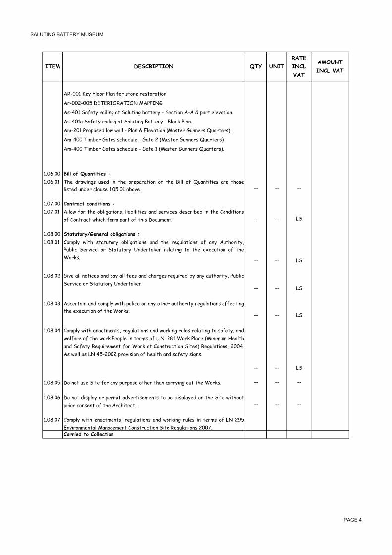
� �������� ������������
��� ���������� �� ����
�����
�����
���
������
��������
��9""���%3��*//&��*-#�2/&�.'/#%�&%.'/&-'+/#
�&9"" 9""��������������������
�.9�"���-2%'3�&-+*+#5�-'��-*4'+#5�6-''%&3�9��%0'+/#��9����)-&'�%*%7-'+/#!
�.9�"�-��-2%'3�&-+*+#5�-'��-*4'+#5��-''%&3�9��*/0@��*-#!
�,9 "���&/)/.%$�*/1�1-**�9��*-#����*%7-'+/#�C-.'%&��4##%&.�F4-&'%&.D!
�,9�""��+,6%&��-'%.�.0(%$4*%�9��-'%� �C-.'%&��4##%&.�F4-&'%&.D!
�,9�""��+,6%&��-'%.�.0(%$4*%�9��-'%���C-.'%&��4##%&.�F4-&'%&.D!
�!"�!"" $����+/� �����������
�!"�!"� �(% $&-1+#5. 4.%$ +# '(% )&%)-&-'+/# /2 '(% �+** /2 F4-#'+'+%. -&% '(/.%
*+.'%$�4#$%&�0*-4.%��!"�!"��-6/7%! 99 99 99
�!"�!"" �+��������+�%���+����
�!"�!"� �**/1 2/& '(% /6*+5-'+/#.< *+-6+*+'+%. -#$ .%&7+0%. $%.0&+6%$ +# '(% �/#$+'+/#.
/2��/#'&-0'�1(+0(�2/&,�)-&'�/2�'(+.��/04,%#'! 99 99 ��
�!" !"" ������+��4"�������+.��,���+����
�!" !"� �/,)*3 1+'( .'-'4'/&3 /6*+5-'+/#. -#$ '(% &%54*-'+/#. /2 -#3 �4'(/&+'3<
�46*+0 �%&7+0% /& �'-'4'/&3 �#$%&'-@%& &%*-'+#5 '/ '(% %?%04'+/# /2 '(%
�/&@.! 99 99 ��
�!" !" �+7% -** #/'+0%. -#$ )-3 -** 2%%. -#$ 0(-&5%. &%84+&%$ 63 -#3 -4'(/&+'3< �46*+0
�%&7+0%�/&��'-'4'/&3��#$%&'-@%&!99 99 ��
�!" !"� �.0%&'-+# -#$ 0/,)*3 1+'( )/*+0% /& -#3 /'(%& -4'(/&+'3 &%54*-'+/#. -22%0'+#5
'(%�%?%04'+/#�/2�'(%��/&@.!99 99 ��
�!" !"� �/,)*3 1+'( %#-0',%#'.< &%54*-'+/#. -#$ 1/&@+#5 &4*%. &%*-'+#5 '/ .-2%'3< -#$
1%*2-&% /2 '(% 1/&@ �%/)*% +# '%&,. /2 �!! � �/&@ �*-0% C+#+,4, �%-*'(
-#$ �-2%'3 �%84+&%,%#' 2/& �/&@ -' �/#.'&40'+/# �+'%.D �%54*-'+/#.< ""�!
�.�1%**�-.�����9 "" �)&/7+.+/#�/2�(%-*'(�-#$�.-2%'3�.+5#.!
99 99 ��
�!" !"� �/�#/'�4.%��+'%�2/&�-#3�)4&)/.%�/'(%&�'(-#�0-&&3+#5�/4'�'(%��/&@.! 99 99 99
�!" !"� �/ #/' $+.)*-3 /& )%&,+' -$7%&'+.%,%#'. '/ 6% $+.)*-3%$ /# '(% �+'% 1+'(/4'
)&+/&�0/#.%#'�/2�'(%��&0(+'%0'! 99 99 99
�!" !"� �/,)*3 1+'( %#-0',%#'.< &%54*-'+/#. -#$ 1/&@+#5 &4*%. +# '%&,. /2 � >�
�#7+&/#,%#'-*�-#-5%,%#'��/#.'&40'+/#��+'%��%54*-'+/#.� ""�!������%��+��+������+�
� ���

� �������� ������������
��� ���������� �� ����
�����
�����
���
������
��������
�!">!"" ���,�����4�%����������+����+��%�����
�!">!"� �(% �/#'&-0'/& 1+** 6% &%.)/#.+6*% 2/& '(% 0//&$+#-'+/# -#$ %?%04'+/# /2 '(%
'/'-* 1/&@. -#$ 2/& '(% 1/&@ /2 .460/#'&-0'/&. 1(%'(%& #/,+#-'%$ /&
$/,%.'+0! 99 99 ��
�!">!" �(% �/#'&-0'/& +. '/ )&%)-&% -#$ .46,+' 1+'( (+. '%#$%& -# /4'*+#%
)&/5&-,,% 2/& '(% 1/&@.< .422+0+%#' '/ +$%#'+23 %-0( '&-$%< 1(+*.' 2/**/1+#5
'(%�'+,%2&-,%.�-#$�$%-$*+#%.�+,)/.%$�63��(%��,)*/3%&! 99 99 ��
�!">!"��# -1-&$ /2 0/#'&-0'< '(% 0/#'&-0'/& +. '/ )&%)-&% +# -# -))&/7%$ 2/&,< -
$%'-+*%$ 1/&@. .0(%$4*% 2/& '(% 1(/*% 1/&@. 6-.%$ /# '(% 0/,)*%'+/# $-'% -.
.46,+''%$�1+'(�'(%�6+$!99 99 ��
�!">!"� �46,+..+/# /2 )&/5&-,,%. 1+** #/' &%*+%7% '(% �/#'&-0'/& /2 (+. /6*+5-'+/#.
'/�-))*3�+#�1&+'+#5�2/&�+#.'&40'+/#.�-.�&%84+&%$�63�'(%�0/#$+'+/#.! 99 99 99
�!">!"� �%0%+)' /2 )&/5&-,,%. 63 '(% �&0(+'%0' 1+** #%+'(%& -22%0' '(% �/#'&-0'
0/,)*%'+/# $-'% #/& &%*+%7% '(% 0/#'&-0'/& /2 (+. &%.)/#.+6+*+'3 '/ 0/,)*%'%
'(%��/&@.�63�'(+.�$-'%! 99 99 99
�!">!"� �%7+%1 '(% )&/5&-,,% /#0% %-0( 1%%@ '/ '-@% +#'/ -00/4#' /2 -#3
0+&04,.'-#0%. 1(+0( -&+.% -22%0'+#5 '(% )&/5&%.. /2 '(% �/&@.! �&/$40% -
&%7+.%$�)&/5&-,,%�-#$�.46,+'�0/)+%.�'/�'(%��&0(+'%0'! 99 99 ��
�!">!"� �''%#$ .40( &%54*-& .+'% ,%%'+#5. -. -&% #%0%..-&3 2/& '(% )&/)%&
,-#-5%,%#'�-#$�0//&$+#-'+/#�/2�'(%��/#'&-0'! 99 99 ��
�!">!" �(%��/#'&-0'/&�1+**�'-@%�-#$�$+.'&+64'%�,+#4'%.�/2�.+'%�,%%'+#5.! 99 99 ��
������%��+��+������+�
� ���
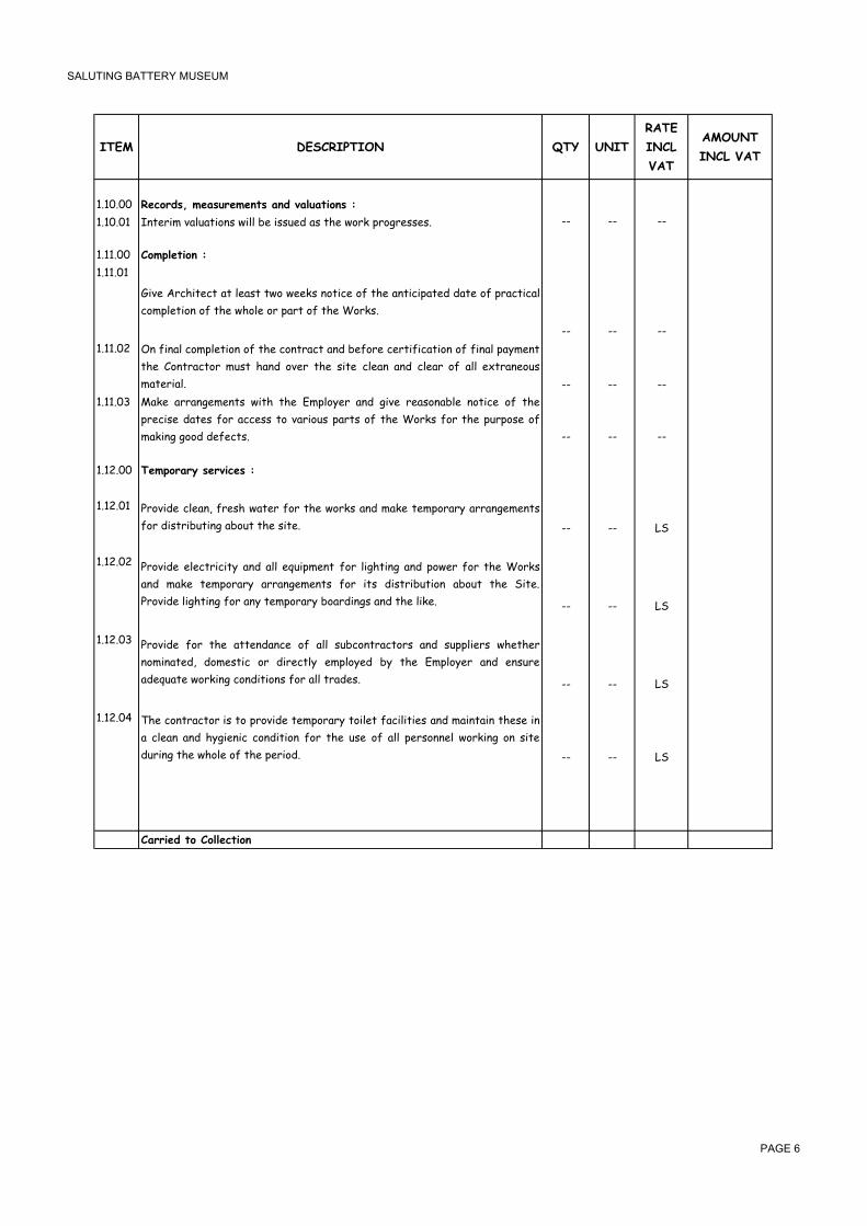
� �������� ������������
��� ���������� �� ����
�����
�����
���
������
��������
�!�"!"" ���+�%�5����������������%�-������+����
�!�"!"� �#'%&+,�7-*4-'+/#.�1+**�6%�+..4%$�-.�'(%�1/&@�)&/5&%..%.! 99 99 99
�!��!"" �+�2����+���
�!��!"�
�+7% �&0(+'%0' -' *%-.' '1/ 1%%@. #/'+0% /2 '(% -#'+0+)-'%$ $-'% /2 )&-0'+0-*
0/,)*%'+/#�/2�'(%�1(/*%�/&�)-&'�/2�'(%��/&@.!
99 99 99
�!��!" �# 2+#-* 0/,)*%'+/# /2 '(% 0/#'&-0' -#$ 6%2/&% 0%&'+2+0-'+/# /2 2+#-* )-3,%#'
'(% �/#'&-0'/& ,4.' (-#$ /7%& '(% .+'% 0*%-# -#$ 0*%-& /2 -** %?'&-#%/4.
,-'%&+-*! 99 99 99
�!��!"� -@% -&&-#5%,%#'. 1+'( '(% �,)*/3%& -#$ 5+7% &%-./#-6*% #/'+0% /2 '(%
)&%0+.% $-'%. 2/& -00%.. '/ 7-&+/4. )-&'. /2 '(% �/&@. 2/& '(% )4&)/.% /2
,-@+#5�5//$�$%2%0'.! 99 99 99
�!� !"" ���2+��������-������
�!� !"� �&/7+$% 0*%-#< 2&%.( 1-'%& 2/& '(% 1/&@. -#$ ,-@% '%,)/&-&3 -&&-#5%,%#'.
2/&�$+.'&+64'+#5�-6/4'�'(%�.+'%! 99 99 ��
�!� !" �&/7+$% %*%0'&+0+'3 -#$ -** %84+),%#' 2/& *+5('+#5 -#$ )/1%& 2/& '(% �/&@.
-#$ ,-@% '%,)/&-&3 -&&-#5%,%#'. 2/& +'. $+.'&+64'+/# -6/4' '(% �+'%!
�&/7+$%�*+5('+#5�2/&�-#3�'%,)/&-&3�6/-&$+#5.�-#$�'(%�*+@%! 99 99 ��
�!� !"� �&/7+$% 2/& '(% -''%#$-#0% /2 -** .460/#'&-0'/&. -#$ .4))*+%&. 1(%'(%&
#/,+#-'%$< $/,%.'+0 /& $+&%0'*3 %,)*/3%$ 63 '(% �,)*/3%& -#$ %#.4&%
-$%84-'%�1/&@+#5�0/#$+'+/#.�2/&�-**�'&-$%.! 99 99 ��
�!� !"� �(% 0/#'&-0'/& +. '/ )&/7+$% '%,)/&-&3 '/+*%' 2-0+*+'+%. -#$ ,-+#'-+# '(%.% +#
- 0*%-# -#$ (35+%#+0 0/#$+'+/# 2/& '(% 4.% /2 -** )%&./##%* 1/&@+#5 /# .+'%
$4&+#5�'(%�1(/*%�/2�'(%�)%&+/$! 99 99 ��
������%��+��+������+�
� ����

� �������� ������������
��� ���������� �� ����
�����
�����
���
������
��������
�!��!"" ����������
�!��!"� �**/1 .4, 2/& .%''+#5 /4' '(% 1/&@. -004&-'%*3 2&/, +#2/&,-'+/# )&/7+$%$<
+#2/&, �&0(+'%0' 1(%# .%''+#5 /4' +. 0/,)*%'% -#$ 6%2/&% 0/,,%#0+#5 '(%
�/&@.! 99 99 ��
�!��!" �%&,+' 4.% /2 +#.'&4,%#'. -*&%-$3 /# �+'% 2/& 0(%0@+#5 '(% .%''+#5 /4' -#$
*%7%*.<�1+'(/4'�0(-&5%! 99 99 ��
�!��!"" ��+�����+���
�!��!"� �*� ��� +/ �62�+��-�� �� 2�+*�.���%! �(+. %?0*4$%. '(% 4.% )%&04..+/# '3)%
%84+),%#'<�*+@%�(-,,%&�54#.! 99 99 99
�!��!" �-2%54-&$ '(% �+'%< '(% �/&@.< -'%&+-*. -#$ �*-#' 2&/, $-,-5% -#$ '(%2'!
�-@% -** &%-./#-6*% )&%0-4'+/#. '/ )&%7%#' 4#-4'(/&+.%$ -00%.. '/ '(% �+'%<
'(%��/&@.�-#$�-$:/+#+#5�)&/)%&'3! 99 99 ��
�!��!"" !+����+/��2�����+���
�!��!"� �(%��/#'&-0'/&�.(-**�1/&@�-'�'(%�'+,%.�.)%0+2+%$�+#�'(%��,)*/3%&! 99 99 99
�!��!"" ��*����.��,���+��
�!��!"�
�**/1 .4, 2/& -#3 /'(%& /6*+5-'+/#. #/' .)%0+2+0-**3 ,%#'+/#%$ +# �+** � 64'
-))%-&+#5A&%84+&%$ +# '(% �)%0+2+0-'+/#. /& -#3 /'(%& $/04,%#' 2/&,+#5 )-&'
/2�'(+.�6+$!
99 99 ��
�!��!" ����������������
��.�����+��+/��*��2����%����%���1����.����%����++%��+�������*���
�*���+������+��*��������/��%�*�����/�1��*�1*��������7����%�+/�*���
��%��������2���,��+�������+����*��1+�3������%��,����������1*��*�
���*+�,*��+���2���/������������+��%����+/����+����,�����������/+��
�*��2�+2����+�2����+��+/��*���+���������%��*����+�-������+���1����
.������2��%�/�+���*���2+����+�1��%�099 99
������%��+��+������+�
� ����

� �������� ������������
��� ���������� �� ����
�����
�����
���
������
��������
$����8
�����������������������
���������/!�
���������/!��
���������/!��
���������/!��
���������/!��
���������/!��
���������������������
� ����

� �������� ������������
����� �����������������������
� ���

� �������� ������������
��� ���������� �� ����
�����
�����
���
�����������
���
90::0:: "�����(��;�
�** �?0-7-'+/# �/&@. .(-** 6% 0-&&+%$ /4' +# -00/&$-#0% 1+'( '(% ��������
������������� -#$ ,%-.4&%$ +# -00/&$-#0% 1+'( '(% ����� ��
���������+#�'(%��������!�
� %-.4&%,%#'�/2��/&@.;
�D �(% ,%-.4&%,%#'. /2 -** %?0-7-'+/#. -&% '(/.% 6%2/&% %?0-7-'+#5 -#$ '/ -#3
$%)'( &%84+&%$! �(% +#0&%-.% +# 64*@< -#$ -#3 %?'&- %?0-7-'+/# &%84+&%$ 2/&
)*-#@+#5�-#$�.'&4''+#5�-#$�2/&,1/&@�-&%�'/�6%�-**/1%$�2/&�63�'(%��/#'&-0'/&!
D �-'%. 84/'%$ -&% '/ +#0*4$% 2/& '&-#.)/&'+#5< */-$+#5< /229*/-$+#5< -#$ 0-&'+#5
-1-3�-**�,-'%&+-*�'/�-#�-4'(/&+.%$�$4,)+#5�-&%-!
�D �# -** 0-.%.< )&+0+#5 +. '/ 6% %#'%&%$ -. - &-'% )%& 4#+' /2 1/&@< 4#*%..
.)%0+2+0-**3 &%84%.'%$ /'(%&1+.%< -#$ -&% '/ 6% +#0*4.+7% /2 -** 1/&@. -. .)%0+2+%$<
-. 1%** -. -#3 /'(%& 1/&@. 1(+0( -&% /2 - 0/#'+#5%#' /& +#$+.)%#.-6*% #-'4&% 2/&
0/,)*%'+#5�'(%�1/&@�+#�+'.�%#'+&%'3!
� �-'%.�'/��#0*4$%�;
�(% 0/#'&-0'/& .(/4*$ -**/1 '/ 1/&@ 1+'(+# '(% 0/#2+#%. /2 '(% .+'%! �(%
�/#'&-0'/& .(/4*$ +#7%.'+5-'% '(% .+'% -#$ 6% 24**3 -1-&% /2 +'. $+22+04*'3 -#$
,-@%�)&/7+.+/#�+#�(+.�&-'%.�2/&�'(%�2/**/1+#5;
-D �.+#5 .,-** %?0-7-'+/# %84+),%#' -#$ '-@+#5 0-&% #/' '/ $-,-5% -#3
4#$%&5&/4#$ .%&7+0%.! �#3 $-,-5% '/ '(% %?+.'+#5 .%&7+0%. .(-** 6% &%+#.'-'%$ -'
'(%��/#'&-0'/&.�%?)%#.%G
6D �&/7+.+/# +# (+. &-'%. 2/& -** $/46*% -#$ ,4*'+)*% (-#$*+#5 /2 -** '(% 64+*$+#5
,-'%&+-*�+#�-#$�/4'�/2�'(%�.+'%�-.�$%%,%$�#%0%..-&3G
0D�@%%)+#5�'(%�%?0-7-'+/#�$&3�-'�-**�'+,%.!
$D �(% &%,/7-* -#$ 0-&'+#5 -1-3 '/ -# -))&/7%$ $4,)+#5 .+'% /2 -#3
%?+.'+#5�+'%,�'(-'�+.�'/�6%�&%#%1%$! !""!"� �**/1 .4, 2/& '-@+#5 *%7%*.A)&/:%0'+#5 *%7%*.< .%''+#5 /4' /2 '(% 1/&@. -' -**
.'-5%. /2 %?0-7-'+/# -#$ 0/#.'&40'+/#! �(% 0/#'&-0'/& +. '/ +#2/&, �+� -' %7%&3
.'-5%�/2�'(%�.%''+#5�/4'�-.�1%**�-.�&%)/&'�-#3�-#/,-*+%.!
� ��
�4
� ����

� �������� ������������
��� ���������� �� ����
�����
�����
���
�����������
���
$4
!""!" �&/7+$% -#$ +#.'-** )&%0-.' 0/#0&%'% 6/**-&$. C:%&.%3.D '/ 6% )4' 4) -*/#5 '(% -&%-
%-&,-&@%$ 2/& %?0-7-'+/#< '(%.% 6/**-&$. -&% '/ +#0*4$% 7%&'+0-* .'%%* .4))/&'
)/.'. -#$ 0(-+#*+#@ 2%#0% ! �(%.% 6/**-&$. .(-** 6% ,/7%$ -. -#$ 1(%# &%84+&%$ 63
'(%��&0(+'%0'�-#$�@%)'�/#�.+'%�2/&�'(%�24**�$4&-'+/#�/2�'(%�0/#'&-0'!
�(% )&%0-.' 0/#0&%'% 6/**-&$. .(-** 6% - ,+#+,4, /2 �!�, +# *%#5'( -#$ �!", (+5(
-#$ !�", /7%&-* (%+5(' +#0*4$+#5 '(% 0(-+#*+#@ 2%#0% -** .46:%0' '/ '(% -))&/7-*
/2 '(% �&0(+'%0'! �(%.% .(-** 6% )*-0%$ %?-0'*3 #%?' '/ %-0( /'(%& 2/&,+#5 -
0/#'+#4/4. 4#+#'%&&4)'%$ */1 0/#0&%'% 1-** %?0%)' 1(%&% '(% -00%.. 5-'% 1+** 6%
.+'4-'%$!
�**/1 2/& '(% )&/7+.+/# -#$ ,-+#'%#-#0% /2 -** )&%0-.' 0/#0&%'% 6/**-&$.G *+5('.G
54-&$.G 1-&#+#5 .+5#.G -#$ 0(-+# *+#@ 2%#0% 1(%# -#$ 1(%&% #%0%..-&3 /& &%84+&%$
63 '(% �&0(+'%0' 2/& '(% )&/'%0'+/# /2 '(% 1/&@. /& 2/& '(% .-2%'3 -#$
0/#7%#+%#0% /2 '(% )46*+0 /& /'(%&.! �*./ -**/1 2/& '(% )&/7+.+/# /2 - */0@-6*%
-00%..�5-'%!
� ��
!""!"� �**/1 .4, 2/& '(% +#.)%0'+/# /2 '(% -&%- 1(%&% %?0-7-'+/# 1+** '-@% )*-0% 1+'(
-))&/)&+-'% $%'%0'/&. 2/& -#3 4#$%&5&/4#$ .%&7+0%.< 0-6*%.< )+)%.< $40'. -#$
)&%.%#' - 1&+''%# .'-'%,%#' /# '(% 2+#$+#5. '/ '(% �&0(+'%0' 6%2/&% )&/0%%$+#5
1+'(�-#3�1/&@�/#�'(%�.+'%!
�+-.% 1+'( -** &%*%7-#' �4'(/&+'+%. +!%! �#%,-*'-< �/< �-'%& �%&7+0%. �/&)/&-'+/#<
%*+'- �-6*%< %'0! 2/& -#3 .%&7+0%. +#.'-**%$ /# .+'% /& +,,%$+-'%*3 -$:-0%#' '/
'(%�.+'%�-#$�+#2/&,�'(%��&0(+'%0'!
� ��
!""!"� �?0-7-'% /7%& .+'% +# ,-$% 4) -#$ 0/,)-0' 5&/4#$ /& ,-./#&3 1-**.< +#0*4$+#5
*/-$+#5 -#$ 0-&'+#5 -1-3 /2 .4&)*4. ,-'%&+-* /22 .+'% -#$ $%)/.+' +# -4'(/&+.%$
$4,)+#5�-&%-.!�
� !"" ,�
!""!"� �?0-7-'+/# +# ./2' -#$ (-&$ &/0@ '/ &%$40% *%7%*.! �(% 0/#'&-0'/& .(-** )&/7+$% +#
(+. &-'% 2/& 1/&@+#5 1+'(+# '(% &%.'&+0'%$ 0/#2+#%. /2 '(% .+'%! �-&' -1-3 -** '(%
&%.4*'+#5�,-'%&+-*�'/�-#�-))&/7%$�$4,)!
�** '(% %?0-7-'+/# .(/4*$ 6% 0-&&+%$ )%&2%0'*3 7%&'+0-* $/1# '(% %?0-7-'+/#
)%&+,%'%&�*+#%�.4&&/4#$+#5�'(%�1(/*%�.+'%!�(% �/#'&-0'/& 1+** /#*3 6% -**/1%$ '/ 4.% .,-** %84+),%#' +2 '(% .+'% 0/#$+'+/#.
$+0'-'%�+'! ��!"" ,�
�4
� ����

� �������� ������������
��� ���������� �� ����
�����
�����
���
�����������
���
$4
!""!"� �&%-@ 4) -#$ 0-&' -1-3 '(% %?+.'+#5 2*//& .*-6 -&%- *%-$+#5 '/ '(% %?+.'+#5 &-,)
-#$ '(% %?+.'+#5 &%+#2/&0%$ 0/#0&%'% &-,) .4&2-0% '/ - $%)'( /2 "",, -#$
4#$%&*3+#5 ,-'%&+-* -#$ .'-+&. *%-$+#5 $/1# '/ '(% */1%& ,-+# 0(-,6%&. -#$
)&%)-&% '/ '-@% #%1 &-,) -#$ .'-+&.! �%)'( /2 %?0-7-'+/# '/ 6% %.'-6*+.(%$ 1+'(
�+�!��-&'�-1-3�&%.4*'+#5�,-'%&+-*!��**/1�2/&�'(%�&%,/7-*�/2�'(%�%?+.'+#5�(-#$&-+*! � ��
!""!"� �-&24**3 '-@% 4) '(% 0/#0&%'% *-3%& *3+#5 /# '(% 4))%& %#'&-#0% .'-+&. -#$
)-..-5% '/ - $%)'( /2 �,, -#$ 0-&' -1-3! �%3 .4&2-0% /2 %-0( .'%) C&+.%& �
5/+#5D -#$ -))*3 +# *-3%&. .-#$A0%,%#' &%#$%& %#.4&+#5 '(-' -** *%7%*. -#$ (%+5('.
-&% &%.)%0'%$! �**/1 2/& %$5% 6%-$. 1(%&% &%84+&%$! �+#+.( -** .4&2-0%. )%&2%0'*3
.,//'(! �**/1 2/& 0/&6/&4#$4, -#'+ .*+) .'&+). /# %-0( .'%) /& -# -))&/7%$
%84+7-*%#'!� ��
!""!" �-@% $/1# 0-&%24**3 -#$ 0-&' -1-3 '/ -# -))&/7%$ $4,)+#5 .+'% %?+.'+#5 ,-./#&3
1-**. �",, /& ���,, '(+0@< +#0*4.+7% /2 -#3 2+#+.(%. *3+#5 '(%&%/#! �-'% +. '/
-**/1 2/& -#3 $/46*% /& ,4*'+)*% (-#$*+#5 -. 1%** -. '(% &%,/7-* /2 -** '&-0%. /2
,/&'-&�2&/,�'(%�-$:-0%#'�1-**.!� ��
!""!">
�%#%&-**3 '/ -** .4&2-0%. &%,/7% -** (//@.< #-+*.< .0&%1.< .'%%* 1+&% -#$ '+,6%&
2-.0+-�'&+,�%'0�-#$�,-@%�5//$�&%.4*'-#'�(/*%.�1+'(�-�.-#$A(3$&-4*+0�*+,%�,+?!�� ��
!""!�"
�' .'&%%' *%7%* %#'&-#0% 6&%-@ 4) -#$ 0-&' -1-3 %?+.'+#5 $/46*% 2&-#@- .'/#%
1-**�-.�+#$+0-'%$�/#�-''-0(%$�$&-1+#5!��**/1�2/&�,-@+#5�5//$�&%.4*'+#5�:-,6.!
� ��
!""!�� �-&%24**3 '-@% $/1# %?+.'+#5 2&-#@- .'/#% )+*-.'%& -' .'&%%' *%7%* -#$ 0-&' -1-3
&%.4*'+#5�,-'%&+-*!��%0/#.'&40'�1-**�+#�7-0-'%$�-&%-�/2�)+*-.'%&!�
� ��
!""!� �**/1�.4,�2/&�'(%�&%,/7-*�/2�'1/�&%$4#$-#'�'+,6%&�1+#$/1�2&-,%.�.+'4-'%$�+#�
'(%�/4'%&�)-&'�/2�'(%�'1/�*/1%&�,-+#�0(-,6%&�1+#$/1.!� ��
!""!���**/1�.4,�2/&�'(%�6&%-@+#5�4)�/2�'(%�*/1%&�(-*2�/2�'(%�%?+.'+#5�%#'&-#0%�.'%).�
-#$�&%0-.'+#5�.-,%�+#����0/#0&%'%�,-+#'-+#+#5�-**�5/+#5�-#$�&+.%&�.+H%.�-.�%?+.'+#5!�
�**/1�2/&�2+#+.(+#5�.,//'(�-#$�+#�-�#/#�.*+)�,-'%&+-*!� ��
�4
� ����

� �������� ������������
��� ���������� �� ����
�����
�����
���
�����������
���
$4
90:80:: $�����<��(��;
�������)����������(��;�
��� ��+��� ) �+������ (+�3� �*��� .� ������% +�� �� ���+�%���� 1��* �*�
���!����������� ��������0
%-.4&%,%#'�/2��/&@.�;
�D �'/#% -#$ 6*/0@1/&@ ,-./#&3 1+** 6% ,%-.4&%$ +# .84-&% ,%'&%. C+!%! *%#5'(
+#�,%'&%.�63�(%+5('�+#�,%'&%.D
D �** /)%#+#5. 4) '/ �! ", 1+$'( .(-** 6% ,%-.4&%$ -. 6*/0@%$ '/ 0/,)%#.-'%
2/&�'(%�1/&@�'/�*+#'%*�-#$�:-,6.!��)%#+#5.�1+$%&�'(-#��! ",�.(-**�(-7%�'(%�%?0%..�
/7%&��! ",�$%$40'%$!�
�D I-,6. '/ /)%#+#5 -&% +#0*4$%$ +# '(% &-'%. 2/& 1-**+#5< 64' :-,6. '/
&%0%..%$�)-#%*.�CE,%,6&+ED�.(-**�6%�,%-.4&%$�%?'&-�/7%&�1-**+#5!
�D �/&,-'+/# /2 ,-./#&3 *+#'%*. 2/& /)%#+#5. 4) '/ �! ", .(-** 6% $%%,%$ '/ 6%
+#0*4$%$�+#�'(%�&-'%.�2/&�1-**+#5!
�-'%.�'/��#0*4$%�;
�D �-'%. 2/& E�?'&- �7%&E �'%,. .(-** 6% -$$+'+/#-* '/ '(% &-'%. 2/& )*-+#
,-./#&3�1/&@! D �//'(+#5 /2 '(% #%1 1-**. '/ '(% %?+.'+#5 1-**. -#$ +. '/ 6% 0-&&+%$ /4' -.
&%84+&%$�-#$�1+**�#/'�6%�,%-.4&%$�.%)-&-'%*3!
!"�!"��/#.'&40' .+#5*% $%#.+'3 (/**/1 0/#0&%'% 6*/0@ 1-**.G &-'% .(-** +#0*4$% 2/& *-3+#5
/#�+#0*+#%$�.4&2-0%�-#$�-#3�$/46*%�(-#$*+#5�'(-'�,-3�6%�&%84+&%$!
C+D ���,,�'(@! �!"" , �
C++D �",,�'(@! �"!"" , �
C+++D �",,�'(@!��/46*%�$%#.+'3�'3)%! �"!"" , �
!"�!" �/#.'&40'� �",,�'(@�2&-#@-�./2'�.'/#%�1-**.�226.�-#$�.%'�+#�5-45%$�,/&'-&! ��!"" , �
!"�!"� ���+'%,� !"�!" �2/&�E248�+*92+*E�2+#+.(! ��!"" , �
!"�!"� �4))*3 -#$< *-3 6+'4,%# 0/-'%$ *%-$ .(%%'< (/&+H/#'-* $-,) )&//2 0/4&.% �",,
1+$%<�/&�-))&/7%$�%84+7-*%#'!� � !"" ,
!"�!"� �?'&-�/7%&�+'%,� !"�!"��2/&�'(%�2+**+#5�/2�����7/+$.�1+'(�� "�0/#0&%'%! �"!"" , �
!"�!"� �4))*3< 0-.' -#$ 0/,)-0' "",, '(@ ��" &-,) -#$ .'-+&. *%-$+#5 2&/, '(% 4))%&
0(-,6%& '/ '(% */1%& 4#$%&5&/4#$ 0(-,6%&. -. $%'-+*%$ +# $&5 �09�"�! �-'% +. '/
-**/1 2/& '(% 2/**/1+#5 +'%,.; � � ,%.( '/) -#$ 6/''/,< ��" 6-& -' %-0( .'%)<
�*-.'/0&%'% -#$ �+@- � -$$+'+7%.< �-&6/&4#$4, #/# .*+) .4&2-0% 2+#+.( -#$
(-&$%#%& -#$ ���! �4''+#5 /2 6%-&+#5 0(-.%. /# %+'(%& .+$% /2 '(% &-,) -#$ %?'&-
0(-&5%�2/&�0-.'+#5�/#�'(%�+#0*+#%�-&%�$%%,%$�'/�6%�+#0*4$%$�+#�'(%�&-'%! �!"" ��
�4
� ����

� �������� ������������
��� ���������� �� ����
�����
�����
���
�����������
���
$4
!"�!"� �**/1�.4,�2/&�)/1%&2*/-'�2+#+.(�'/�0-.'�0/#0&%'%�.4&2-0%.! ��"!"" , �
!"�!"
�4))*3 -#$ .)&%-$ -#$ +# -00/&$-#0% 1+'( ,-#42-0'4&%&�. +#.'&40'+/#. (-&$
1%-&+#5< )&/)&+%'3 %-.39'/90*%-# .%*2 *%7%**+#5 0/#0&%'% '(-' +. 0-)-6*% /2
1+'(.'-#$+#5 (%-73 */-$ +,)-0' '/ '(% -&%-. .(/1# /# $15. �09�"� � �09�"�< �09
�"�< �09���! �**/1 2/& )&/)&+%'3 .4&2-0% (-&$%#%& -#$ #/# .*+) -$$+'+7%.!
�/#'&-0'/& +. '/ )&/7+$% .-,)*%. -#$ .)%0+2+0-'+/#. /2 ,-'%&+-* '/ 6% 4.%$ '/ '(%
�+��2/&��%7-*4-'+/#�-#$�-))&/7-*!�
��"!"" , �
!"�!"> �4))*3< 0-.' -#$ 0/,)-0' 4#&%+#2/&0%$ � " 0/#0&%'% 6*+#$+#5 *-3%& ��,, '(+0@
/#�0/,)-0'%$�2+**�/&�/#�&/0@!��4&2-0%�2+#+.(%$�.,//'(! ��!"" , �
!"�!�"�/#.'&40' '(% �� 0/**%0'+/# .4,) -. $%'-+*%$ +# $&5!�09��"! �/,)&+.+#5 /2 ��
5&/4#$ .*-6 ���,, '(@<� � 2+**%$ �",, ��� 1-**. +#0*4$+#5 ��"
&%6-&<0%,%#'+/4. *+84+$ ,%,6&-#%< �� &+#5 6%-, -#$ �� 6%-, +#0*4.+7% /2 -** '(%
.)%0+2+%$ &%+#2/&0%,%#' -#$ '(% (%-73 $4'3 0-.' +&/# 5&-'+#5. -6/7%! �-'% +. '/
-**/1 2/& '(% )&/7+.+/# /2 - .4+'-6*% .46,%&.+6*% )4,) +#0*4.+7% /2 -** '(%
#%00%..-&3�%*%0'&+0-*�+#.'-**-'+/#<�.4))*3�-#$�.-2%'3�$%7+0%.!�!"" ��
!"�!�� �4))*3 0-.' -#$ 0/,)-0' � ",, '(+0@ ��" -00%.. &-,)< +#0*4.+7% /2 � '/) -#$ �
6/''/, *-3%& � � ,%.( &%+#2/&0%,%#'< �/*3)&/)3*%#% �/&' �+6&% �<
�*-.'/0&%'% -#$ �+@- � -$$+'+7%! �&5 �09��" &%2%&.! �-'% +. '/ -**/1 2/& -
)-7%,%#'�'3)%�%$5%�2+#+.(�-#$�6&//,�6&4.(%$�.4&2-0%! � !"" , �
!"�!� �4))*3< .)&%-$ -#$ *-3 -))&/7%$ (-&$0/&% 2+** '/ -# -))&/?+,-'% $%)'( /2 �"",,<
/& -. $+&%0'%$ 63 �+�< 0/#.+.'+#5 /2 �/&-**+#% (-&$ .'/#% 1%** 5&-$%$ -#$ 1+'(/4'
2+#%. *-+$ +# *-3%&. #/' %?0%%$+#5 ��",,! �-0( *-3%& &-,,%$ $/1#< 1%' -#$ &/**%$
/7%&�'/�-$%84-'%�0/,)-0'#%..!�(% ,%-.4&%,%#' /2 -** 6-0@2+** -#$ &%+#.'-'%,%#' -&% '(/.% -2'%& 0/,)-0'+#5!
�(%�$%0&%-.%�+#�64*@�+.�'/�6%�-**/1%$�2/&�63�'(%�0/#'&-0'/&!
�-0@2+** ,-'%&+-* .(-** (-7% - ,-?+,4, )-&'+0*% .+H% /2 �",, -#$ - ,+#+,4,
-**/1-6*%�)-&'+0*%�.+H%�/2�� ,,!
�/#'&-0'/&�.(-**�-**/1�+#�(+.�&-'%�2/&�(-#$�)*-0+#5�-&/4#$�2/4#$-'+/#�1-**.! >!"" ,��
!"�!�� �4))*3 -#$ *-3 )/*3,%& 0/#0&%'% &-+#1-'%& 54''%&. 0/,)*%'% 1+'( )%&2/&-'%$
.'-+#*%.. .'%%* 5&-'+#5!! �-'% +. '/ -**/1 2/& *-3+#5 '/ '(% 0/&&%0' 2-**. -#$ 2/& '(%
.4))*3 -#$ *-3+#5 /2 - ��",, $+- ��=� $+.0(-&5% )+)% -#$ ��",, $+- )+)% '/ '(%
.4,)!��&5��09�"�����09��"�&%2%&.!C+D� ��"?��"?�>",, �!"" ��
C++D����"?��"?�>",, �!"" ��
!"�!�� �. )%& +'%, !"�!�> -6/7% 64' .+H% �"""?��"?�>",, -#$ 1+'( (%-73 $4'3 0-.'
+&/#�)%&2/&-'%$�5&-'+#5�$+.0(-&5+#5�7+-�-���",,�$+-�4)70�&1)�+#��'��&.4*-��'&%%'!�!"" ��
�4
� ���

� �������� ������������
��� ���������� �� ����
�����
�����
���
�����������
���
$4
!"�!�� �**/1 .4, 2/& '(% ��-����,���+� -#$ ��3��, ,++% /2 1-'%& )%#%'&-'+/# 2&/, '(%
&/-$ -6/7% +#'/ '(% */1%& 0(-,6%& C)&/)/.%$ '+0@%'+#5 -&%-D! �-'% +. '/ +#0*4$%
2/& '(% )&%)-&'+/# /2 - ,%'(/$ .'-'%,%#' +#$+0-'+#5 '(% ./*4'+/# '(% 0/#'&-0'/&
+#'%#$.�-$/)'+#5�'/�./*7%�'(%�)&/6*%,! �!"" ��
!"�!�� �-&%24**3 $+.,-#'*% '(% %?+.'+#5 7/4../+&. /2 '(% -&0(%$ 7-4*' /7%& '(% $//&
*%-$+#5 2&/, '(% */#5 &-,) *-#$+#5 '/ '(% #%1 &-,) 4) '/ �'! �&.4*- �'&%%' -#$
.%' -.+$%! �/&, #%1 7/4../+&. 2&/, -))&/)&+-'% .+H%$ .'/#%. -#$ &%0/#.'&40'
-&0(%$ 7-4*' +#0/&)/&-'+#5 '(% /&+5+#-* )&%7+/4.*3 .%' -.+$% /#%.! �/,)*%'% '(%
:-,6. +# �",, �&-#@- .'/#%! �**/1 2/& -** )&/))+#5 -#$ .'&4''+#5 '(-' ,-3 6%
&%84+&%$ )&+/& '/ $+.,-#'*+#5 -#$ $4&+#5 &%0/#.'&40'+/#! �-'% +. '/ +#0*4$% 2/& '(%
0-.'+#5 /2 - ��" �� .*-6 /7%& '(% .-+$ 7-4*' +#0*4.+7% /2 -** &%+#2/&0%,%#'!
�-&'-1-3�-**�&%$4#$-#'�,-'%&+-*�'/�-#�-))&/7%$�$4,)+#5�.+'%! �!"" ��
!"�!� �?0-7-'%�'&%#0(%.�+#�%+'(%&�,-$%�4)�5&/4#$<�0/#0&%'%�.'-+&.�/&�+#�&/0@�
'/�'-@%���=����",,�$+-,%'%&�&-+#�1-'%&�)+)%.!��-'%�+.�'/�-**/1�2/&�2+**+#5�
/7%&�*-+$�)+)%�1+'(�� "�0/#0&%'%!��**/1�2/&�'&/1%*�.,//'(�.4&2-0%�2+#+.(�
-#$�0-&'+#5�-1-3�-**�&%.4'+#5�,-'%&+-*!� �" ,
!"�!�> �4))*3�-#$�*-3���=��&-+#�1-'%&�)+)%.�+#�)&%7/+4.*3�%?0-7-'%$�'&%#0(%.�/&�
%?0-7-'%$�.4&2-0%!��**/1�2/&�0/##%0'+#5�1+'(�%?+.'+#5�)+)%.�/&�2+''+#5�
+#'/�0/**%0'+/#�0(-##%*.<�.4,).�-#$�,-#(/*%.!
!"�!�>- ��",,�$+-,%'%&�"!"" ,
!"�!�>6 ��",,�$+-,%'%&�"!"" ,
!"�! " �/&, 0/7%&%$ ,-#(/*%. -. $%'-+*%$ +# $&-1+#5 ��9�"�< (-7+#5 -# +#'%&#-* .+H% /2
-))&/?+,-'%*3 �"" ? �"" ? � ""< $%)'( ,-3 7-&3 1+'( '(% &%84+&%$ 2-**.! �-'% +.
'/ -**/1 2/& -** '(% 0/#.'&40'+/# $%'-+*%$ +# '(% $&-1+#5 -. 1%** -. %?0-7-'+#5
.4+'-6*3 .+H%$ )+'. '/ '-@% '(% )&/)/.%$ 0/#.'&40'+/# 6/'( +# 0/,)-0'%$ 2+** /&
&/0@�-#$�0-&'+#5�-1-3�'(%�&%.4*'-#'�,-'%&+-*! �!"" #&
!"�! � �**/1 .4, 2/& '(% 0-&%24* &%,/7-* /2 '&-7%&'+#% 0*-$$+#5 )&%.%#' -' '(% %#'&-#0%
/2 /2 '(% �&3)'! �-'% +. '/ -**/1 2/& '(% 0/,)*%'% &%,/7-* /2 -#3 -$(%&+#5 ,/&'-&
/& 5*4%! �%.'/&-'+/# /2 '(% 4#$%&*3+#5 1-** +. $%-*' 1+'( +# �+** �! �-&' -1-3 -#3
&%.4*'+#5�,-'%&+-*�'/�-#�-4'(/&+.%$�$4,)+#5�.+'%! �!"" ��
!"�! �/&, �� 0/#0&%'% (//$ /7%& '(% #%1 %#'&-#0% 2/&,%$ 63 '(% &-,) +# �' �&.4*-
�'&%%'! �-'% +. '/ -**/1 2/& -** 2/&,1/&@< )&/))+#5< &%+#2/&0%,%#' -#$ 2/&,-'+/#
/2�6%-&+#5�0(-.%.! �!"" ��
!"�! � �4))*3 .)&%-$ -#$ *-3 (/' '-&,-0 1%-&+#5 0/4&.% /7%& '(% 0/#0&%'% &%*%-7+#5 .*-6
0-.' /7%& '(% 7-4*' -. 1%** -. '(% 0/#0&%'% (//$! �-'% +. '/ +#0*4$% 2/& -#3
04''+#5 /2 '(% %?+.'+#5 &/-$ .4&2-0% -. 1%** -. -#3 /'(%& 1/&@ '(-' +. /2 -
0/#'+#5%#'�#-'4&%�'/�'(%�:/6�2/&�+'.�)&/)%&�%?%04'+/#! �!"" ��
���������������������
� ���

� �������� ��������������
�������������������
�������

� �������� ��������������
��� ���������� �� ����
�����
�����
���
������
��������
�!""!"" ����� ����!��������������
�(% 0/#'&-0'/& +. .'&/#5*3 -$7+.%$ '/ .46,+' -** '(% '%0(#+0-*
*+'%&-'4&%�-#$�.-,)*%.�1(%#�./�&%84%.'%$!�** -&%-. .(-** 6% ,%-.4&%$ #%' %?0*4.+7% /2 1-.'-5%! �%#$%&%& +.
'/�-**/1�2/&�1-.'-5%�+#�(+.�&-'%.!
�!""!"� �-@% 4) -#$ 0-&' -1-3 '(% %?+.'+#5 2*//& 2+#+.(%. '/ - $%)'( /2
0+&0- ��",, +# '(% '/+*%' -&%-. -#$ '(% 0/&&+$/& *%-$+#5 '/ '(%,<
+#0*4$+#5�-#3�0/#0&%'%�.0&%%$�*3+#5�'(%&%�4#$%&�-#$�%?)/.%�&/0@!��
���= , 890::
�!""!" �4))*3< *-3< 0/,)-0' -#$ *%7%* �"",, '(+0@#%.. �&-$% " 0/#0&%'%
.0&%%$ -. - .46 2*//& 6%*/1 '(% 0%&-,+0 2*//&+#5! �-'% .(-** 6%
-))*+0-6*% '/ -** *%7%*. -#$ -** */0-'+/#.! �/#0&%'% .0&%%$ *-+$ *%7%*
-#$�&%-$3�'/�&%0%+7%�'(%�0%&-,+0�2*//&�'+*%.!���= , 8=0>=
�!""!"� �?'&-�/7%&��!""!" �2/&�� ��0/#0&%'%�+#�*+%4�/2�� "��/#0&%'% ���= ,� 980?@
�!""!"� �?'&- /7%& �'%, �!""!" 2/& '(% +#0*4.+/# /2 � � %.(
&%+#2/&0%,%#' +# '(% .0&%%$! �**/1 2/& �"",, *-). -' -** %#$. /2
'(%�,%.(!�C���=������D
���= , A09=
�4
�������

� �������� ��������������
��� ���������� �� ����
�����
�����
���
������
��������
$4
�!""!"� �&/7+$% -#$ *-3 #/#9.*+) ,/#/*+'(+0 5&%. 0%&-,+0 2*//& '+*%. #-'4&-*
2+#+.( +# -00/&$-#0% 1+'( '%0(#+0-* .)%0+2+0-'+/#. 2/& �������
-&%-.! �+*%. .(-** 6% *-+$ $+&%0'*3 /7%& 0/#0&%'% .0&%%$! �+*% .+H%
�"",, ? �"",, ? >,,! �-'% .(/4*$ +#0*4$% 2/& *-3+#5 4.+#5
,+#+,4,�:/+#'.�1+$'(.<�-#$��)/?3��&/4'+#5!
�/*/4& .(-** 6% - ./*+$ $-&@ 5&%3 0/*/4& 1+'( #/ )-''%&# -. )%&
$&-1+#5.! �%?'4&% .(-** 6% )*-+#92*-'! �** .(-** 6% .46:%0' '/
�&0(+'%0'�.�-))&/7-*!�
�%#$%&%& +. '/ .46,+' 24** '%0(#+0-* .)%0+2+0-'+/#. -#$
,-#42-0'4&%&. *+'%&-'4&% -#$ .-,)*% 2/& '(% ,/#/*+'(+0 C�&%.D #/#
.*+)�'+*%.�6%+#5�/22%&%$!
���= , � ?:0::
�!""!"� (���� ���3 �� ��+�� �++�! �4))*3 -#$ )*-0% /# '(% #%1*3 *%7%**%$
.'/&% &//, 2*//&< �#/ ���>" .'%%* 6%-,. � "",, */#5 .%' -'
�"",, 0%#'&% '/ 0%#'&%< 1+'( -# /7%&*3+#5 ,, '(@ .'%%* )*-'%<
� "" ? �"""! �-'% +. '/ -**/1 2/& )*-0+#5 +# )/.+'+/# -#$ )-+#'+#5 -**
+'%,. +# - )&/)&+%'-&3 &4.')&//2+#5 )-+#' &%5+,%! �+,%#.+/#. /2
.'%%*�6%-,.�4.%$�.46:%0'�'/�1-'%&�'-#@�.+H%! ���= �� ?::0::
�4
�������

� �������� ��������������
��� ���������� �� ����
�����
�����
���
������
��������
$4
�!"�!"" (���� ����!��
�(% 0/#'&-0'/& +. '/ .46,+' -** '(% '%0(#+0-* *+'%&-'4&% -#$
.-,)*%. 2/& -** 1-** 2+#+.(%. (% +#'%#$. 4.+#5 +# '(+. )-&' /2 '(%
'%#$%&!��** -&%-. .(-** 6% ,%-.4&%$ #%' %?0*4.+7% /2 1-.'-5%! �%#$%&%& +.
'/ -**/1 2/& 1-.'-5% +# (+. &-'%. -#$ 2/& 0-&&3+#5 /4' '(% 1/&@ -'
-#3�*%7%*!
�!"�!"� �%.'/&% '/ /&+5+#-* 0/#$+'+/# '(% '+,6%& 1-** ,/4#'%$ (-#$ &-+*.
*%-$+#5 $/1# '/ '(% '/+*%'.! �#3 ,+..+#5 '+,6%& +. '/ 6% &%)*-0%$
1+'( .+,+*-& '3)% 1//$ -. 1%** -. -#3 +&/#,/#5%&3! �** 1-**
,/4#'+#5 6&-0@%' (-7% '/ 6% 0(%0@%$ 2/& .'4&$+#%.. -#$ '(%
-0'4-* ,/4#' (/*%. &%)-0@%$ 1+'( )&/)&+%'3 2+**%& 1(%&% #%0%..-&3!
�+#+.( +. '/ 6% .+,+*-& '/ %?+.'+#5 64' .-,)*%. /2 -** ,-'%&+-*. -#$
2+#+.(%. '/ 6% 4.%$ -&% '/ 6% .46,+''%$ '/ '(% 0/#.4*'-#'
-&0(+'%0'�2/&�-�)&/)%&�%7-*4-'+/#!�!"" ��
�!" !"" ������"� ����!��
�!" !"� �*%-# $/1# &/0@2-0% 0%+*+#5. /& /'(%& -#$ -))*3 � 0/-'. /2
*+,%1-.(! ��!"" , �
���������������������
�������

� �������� ��������������
�����������������������
�������

� �������� ��������������
��� ���������� �� ����
�����
�����
���
������
��������
�!""!"" ��������� �����"�
�*� �+������+� �� �+ ��.��� ��� �*� ���*����� ���������� ��%
���2���������7�����%0
�!""!"� �4))*3 -#$ 2+' 2*//& $&-+# '&-))%$ -#$ 1+'( .'-+#*%.. .'%%* 0/7%&
)*-'% 0/,)*%'% 1+'( �",, $&-+# '/ +#.)%0'+/# 0(-,6%& /& '/
(/&+H/#'-*�./+*�)+)%!
!"" &
�!""!" �4))*3 -#$ 2+' 1(+'% 0/*/4&%$ (+5( 84-*+'3 7+'&%/4. 0(+#- '/+*%' &/**
(/*$%& +#0*4$+#5 .'-+#*%.. .'%%* 2+?+#5. -#$ 0/*/4& 0/9/&$+#-'%$
.0&%1�0/7%&.!
�%#$%&%& +. '/ .46,+' 24** '%0(#+0-* *+'%&-'4&% -#$ .)%0+2+0-'+/#.
2/&�%7-*4-'+/#�63��+�! !"" &
�!""!"� �4))*3 -#$ 2+' 1(+'% 0/*/4&%$ (+5( 84-*+'3 )&/)&+%'3 1-** ,/4#'%$
)-)%&�'/1%*�$+.)%#.%&�+#0*4.+7%�/2�-**�(-&$1-&%�-#$�2+''+#5.!
�%#$%&%& +. '/ .46,+' 24** '%0(#+0-* *+'%&-'4&% -#$ .)%0+2+0-'+/#.
2/&�%7-*4-'+/#�63��+�! !"" &
�!""!"� �4))*3 -#$ 2+' 1(+'% 0/*/4&%$ (+5( 84-*+'3 )&/)&+%'3 1-** ,/4#'%$
*+84+$�./-)��$+.)%#.%&�+#0*4.+7%�/2�-**�(-&$1-&%�-#$�2+''+#5.!
�%#$%&%& +. '/ .46,+' 24** '%0(#+0-* *+'%&-'4&% -#$ .)%0+2+0-'+/#.
2/&�%7-*4-'+/#�63��+�! !"" &
�!""!"� �4))*3 -#$ 2+? -. &%84+&%$ '(% 2/**/1+#5 '/+*%' -00%../&+%. +# %-0(
'/+*%'�046+0*%!
/!��&4.(%$��'-+#*%..��'%%*��/-'�(//@.! �!"" &
�/+*%'�6&4.(���(/*$%&�.'-+#*%..�.'%%*�2+#+.(! !"" &
�'-+#*%..��'%%*�)%$-*�$4.'6+#! !"" &
���������������������
�������

� �������� ��������������
��������������������
�������

� �������� ��������������
��� ���������� �� ����
�����
�����
���
������
��������
�!""!"" (���� ����!��
�(% 0/#'&-0'/& +. .'&/#5*3 -$7+.%$ '/ .46,+' -** '(% '%0(#+0-*
*+'%&-'4&%�-#$�.-,)*%.�1(%#�./�&%84%.'%$!�** -&%-. .(-** 6% ,%-.4&%$ #%' %?0*4.+7% /2 1-.'-5%!
�%#$%&%& +. '/ -**/1 2/& 1-.'-5% +# (+. &-'%. -#$ 2/& 0-&&3+#5
/4' '(% 1/&@ -' -#3 *%7%* 4.+#5 .0-22/*$+#5 +2 &%84+&%$!
�#'%&#-* 1-** 2+#+.(%. 1+** 6% '-@%# 4) '/ "! �, -6/7% '(%
./22+'�*+#%!
�!""!"��-0@ .4&2-0% /2 #%1 2&-#@- 1-**. '/ )&/7+$% @%3 2/& '(%
-))*+0-'+/#�/2�.-#$A0%,%#'�&%#$%&!��!"" , �
�!""!" �&%)-&% -#$ &%#$%& +# 0%,%#' -#$ .-#$ C�; D ,/&'-& 1+'(
)&/)&+%'-&3 )*-.'+0+.%& -$$+'+7%< +#'%&#-* 0/#0&%'%
6*/0@A2&-#@- 1-**. -#$ 0/#0&%'% .4&2-0%. '/ - .,//'( 2+#+.(
-#$�'/�-�)%&2%0'�)*4,6!�
�/&@. '/ +#0*4$% %?)-#$%$ ,%'-* *-'( 1(%&% $%%,%$
&%84+&%$ '/ &%+#2/&0% '(% &%#$%& -#$ ./2' .'%%* %$5% 6%-$.
'/ -** %?'%&#-* 0/&#%&.! �/#'&-0'/& 1+** 6% $%%,%$ '/ (-7%
+#0*4$%$ 2/& *-3%&+#5 .0&%%$. +# '(/.% -&%-. '(-' ,-3 &%84+&%
2+**+#5�+#! �"!"" , �
�!""!"� �&%)-&% -** +#'%&#-* 1-** .4&2-0%.< &46 $/1# 1+'( 2+#%
.-#$)-)%& '/ - .,//'( 2+#+.( 1(%&% &%84+&%$ -#$ -))*3 '(&%%
0/-'.�/2�(+5(�84-*+'3�*+,%1-.(! �"!"" , �
�!""!"� �4))*3 -#$ %&%0' � !�,, ,/+.'4&% &%.+.'-#' 53).4, 6/-&$
0*-$$+#5 '/ '(% +#$+0-'%$ ,4.%4, 1-**.! �-'% +. '/ -**/1 2/& -
)&/)&+%'-&3 .'%%* ,/4#'+#5 .462&-,% '(-' )&/:%0'. -
,+#+,4, $+.'-#0% /2 �>",, -. +#$+0-'%$ /# '(% '%#$%& $&5.!
2&/, '(% 2-0% /2 '(% %?+.'+#5 1-**.! �-'% +. '/ +#0*4$% 2/&
.'-+#*%.. .'%%* � )&/2+*% .@+&'+#5 2+?%$ '/ $&31-** .4692&-,%!
$&5��09����&%2%&.! ���= , �
�!""!"� �&%)-&% -** )*-.'%&6/-&$ .4&2-0%. -#$ -))*3 /#% ,+.' 0/-' -#$
'1/ 24** 0/-'. /2 -))&/7%$ 84-*+'3 ,-'' =+#3* �,4*.+/# 0/*/4&
�(+'% /& .+,+*-& -))&/7%$! �-,)*%. -#$ .)%0. '/ 6%
.46,+''%$�'/��+��2/&�-))&/7-*! ���= , �
�!""!"� �&%)-&% -** +#'%&#-* 0%+*+#5 .4&2-0%.< &46 $/1# 1+'( 2+#%
.-#$)-)%& '/ - .,//'( 2+#+.( 1(%&% &%84+&%$ -#$ -))*3 '(&%%
0/-'.�/2�(+5(�84-*+'3�*+,%1-.(!���= , �
���������������������
������

� �������� ��������������
������������������������
�������

� �������� ��������������
��� ���������� �� ����
�����
�����
���
������
��������
�!""!"" �������������(��;�
��1��,����#::85::95::?5::A5::=
%-.4&%,%#';
�D �-'%. 84/'%$ -&% '/ +#0*4$% 2/& '&-#.)/&'+#5< */-$+#5< /229*/-$+#5< -#$
0-&'+#5�-1-3�-**�,-'%&+-*�'/�-��/7%&#,%#'��))&/7%$��4,)+#5��+'%!
D �# -** 0-.%.< )&+0+#5 +. '/ 6% %#'%&%$ -. - �4,) �4,< 4#*%.. .)%0+2+0-**3
&%84%.'%$ /'(%&1+.% -#$ &-'%. -&% '/ 6% +#0*4.+7% /2 -** 1/&@. -.
.)%0+2+%$< -. 1%** -. -#3 /'(%& 1/&@. 1(+0( -&% /2 - 0/#'+#5%#' /&
+#$+.)%#.-6*%�#-'4&%�2/&�0/,)*%'+#5�'(%�1/&@�+#�+'.�%#'+&%'3
�-'%.�'/��#0*4$%�;
�(% 0/#'&-0'/& .(/4*$ -**/1 '/ 1/&@ 1+'(+# '(% 0/#2+#%. /2 '(% .+'%! �(%
�/#'&-0'/& .(/4*$ +#7%.'+5-'% '(% .+'% -#$ 6% 24**3 -1-&% /2 +'. $+22+04*'3
-#$�,-@%�)&/7+.+/#�+#�(+.�&-'%.�2/&�'(%�2/**/1+#5;
-D �&/7+.+/# +# (+. &-'%. 2/& -** $/46*% -#$ ,4*'+)*% (-#$*+#5 /2 -** '(%
$+.,-#'*%$�,-'%&+-*�-.�$%%,%$�#%0%..-&3G
6D �(% &-'%. .46,+''%$ .(/4*$ 0-'%& 2/& -** '(% &%.'&+0'+/#. )&%.%#' /#
'(%�.+'%!��/&@�.(-**�/#*3�6%�0-&&+%$�/4'�-'�'(%�'+,%.�-**/1%$�63�'(%��*+%#'G
0D �(% &-'%. 2/& -** �'%,. .(-** 6% $%%,%$ '/ +#0*4$% 2/& (/+.'+#5 -#$
0&-#-5%�'/�-**�-&%-.�/2�'(%�.+'%G
$D �&/'%0' -** '(% %?+.'+#5 2*//& 2+#+.(%.< -#$ -** '(% .%&7+0%. )&%.%#' /#
.+'%�-.�1%**�-.�/2�'(%�.4&&/4#$+#5�-&%-!
�B �*� �+������+� �*+��% ���+1 /+� ���//+�%��, �� *�� ����� �� ��%
1*��� ��������� 1��* � 2�+2�������5 ��+C��� ���*����� �22�+-�%5
���//+�%��, ������ �+ 1+�3 �� /��� �+�2������ 1��* ��� �*� ������
��,�����+�� ��% ����%����� +/ �*� !����* ��% ��/��� ���0 �+ +�*��
������/+���*������+/����//+�%��,�1����.������������%0
$D �(% &%,/7-* -#$ 0-&'+#5 -1-3 '/ -# -))&/7%$ $4,)+#5 .+'% /2
-#3�%?+.'+#5�+'%,�'(-'�+.�'/�6%�&%#%1%$!
�����
C+D �** ,%'(/$. /2 &%.'/&-'+/# -&% '/ 6% $+.04..%$ 1+'( '(% �+� -#$ -))&/7-*
./45('!C++D �4&+#5 -** 0*%-#+#5 -#$ &%.'/&-'+/# /)%&-'+/#. %7%&3 0-&% .(/4*$ 6% '-@%#
'/�)&%.%&7%�'(%�/&+5+#-*�)-'+#-�/2�'(%�.'/#%!
C+++D �#.)%0'+/# /2 -** .4&2-0%. 1+'( �+� '/ $%'%&,+#% 1(-' &%.'/&-'+7%
,%-.4&% +. &%84+&%$ -#$ '/ -..%. '(% .%7%&+'3 /2 '(% )-&'+04*-&
$%'%&+/&-'+/#!
�4
�������

� �������� ��������������
��� ���������� �� ����
�����
�����
���
������
��������
$4
�!""!"� �-&%24**3�&%,/7%�-**�(//@.<�#-+*.<�4#1-#'%$�0-.'9+&/#�)+)%.<�%*%0'&+0+'3�
1+&%.�-#$�0-6*%.<�%'0!�2&/,�'(%�%?'%&#-*��.4&2-0%.!�(%�0/#'&-0'/&�+.�'/�
%#.4&%�'(-'�'(%.%�-&%�&%,/7%$�1(/**3�-#$�#/'�04'�$/1#�'/�'(%�.4&2-0%�/2�
'(%�.'/#%1/&@!��,-**�(/*%.�$&+**%$�-*/#5.+$%�/6.'+#-'%�+#.%&'.�1+**�6%�
-**/1%$�'/�2-0+*+'-'%�'(%+&�&%,/7-*!��**�&%.4*'+#5�(/*%.�-#$�,-&@.�1+**�6%�
2+**%$�1+'(�(3$&-4*+0�*+,%�,/&'-&<�0/*/4&%$�'/�'(%�.-,%�.(-$%�-.�'(-'�/2�
'(%�.4&&/4#$+#5�,-./#&3!�(%&%�6&%-@.�+#�'(%�,-./#&3�-&%�*-&5%�-.�-�
&%.4*'�/2�%?'&-0'+/#<�'(%�-22%0'%$�.'/#%�.(-**�6%�&%)*-0%$�1+'(�.'/#%�
+#.%&'.�(-7+#5�-�.+,+*-&�0/*/4&�-#$�'%?'4&%�-.�'(%�%?+.'+#5!
�/�'(%�.'/#%�.4&2-0%<�6&4.(�/&�1-.(�$/1#�-.�#%0%..-&3�-&%-.�/2�,-./#&3�
.'/#%1/&@�'(-'�-&%�$4.'�/&�5&+'�%#0&4.'%$!�/�,%0(-#+0-*�'//*.<�.40(�-.<�
%*%0'&+0�/&�)#%4,-'+0�$&+7%#�&/'-&3�6&4.(%.�/&�:+55%&.�-&%�'/�6%�4.%$!�
�#*3�.,-**�(-#$�'//*.�-#$�(-&$�#3*/#�6&4.(%$�-&%�)%&,+..+6*%<�1+&%�
6&4.(%.�1+**�#/'�6%�4.%$!���)/1%&�1-.(�,-3�6%�4.%$�4#$%&�0/#'&/**%$�
)&%..4&%�/2�#/'�,/&%�'(-#�'1/�-',/.)(%&%.�-*/#5�1+'(�.%0/#$�0*-..�
1-'%&!��-)�1-'%&�,4.'�#/'�6%�%,)*/3%$�-.�+'�0/#'-+#.�'&%-',%#'�
0(%,+0-*.�1(+0(�-&%�(-&,24*�'/�'(%�,-./#&3!�/�5&+'�/&�.-#$�6*-.'+#5�1+**�
6%�-**/1%$!��**/1�2/&�.0-22/*$+#5!
�>" ,
�!""!" �.�)%&�+'%,��!""!"��64'�0*%-#+#5�/2�6*-0@�0&4.'.�63�)/4*'+0+#5�4.+#5�)-)%&�
)4*)�1+'(�-�.4+'-6*%�-5%#'�.40(�-.�����!�" ,
�!""!"� �.�)%&�+'%,��!""!"��64'�0*%-#+#5�/2�24#54.�/&�*+0(%#.�1(+0(�-&%�0-4.+#5�
$-,-5%�'/�,-./#&3�.(-**�6%�&%,/7%$�63�4.+#5�-�.'+22�6&+.'*%�6&4.(%.�-#$�
-#��+��-))&/7%$�6+/0+$%! �" ,
�!""!"� �-@%�/4'�:/+#'.�0-&%24**3�63�(-#$!��3�,%-#.�/2�-�)4,)A,%0(-#+0-*�,%-#.�
+#:%0'<�1+'(�(3$&-4*+0�*+,%A.-#$�,+?�C,+?�&-'+/��; �+!%!�/#%�)-&'�(3$&-4*+0�
*+,%�-#$�'1/�)-&'.�2+#%�.-#$D�0-7+'+%.�6%'1%%#�%?+.'+#5�,-./#&3�.*-6.�
.'/))+#5�.(/&'� ",,�2&/,�'(%�2-0%�/2�'(%�1-**!��(%�&%,-+#$%&�1+**�6%�
2+**%$�+#�63�(-#$�-*./�+#�(3$&-4*+0�*+,%A.-#$�,+?�,-'0(+#5�0/*/4&�/2�'(%�
.4&&/4#$+#5�-&%-.�C.-,)*%.�'/�6%�.46,+''%$�-#$�-))&/7%$D��-'%�+.�'/�
+#0*4$%�2/&�'(%�$4.'+#5�$/1#�/2�'(%�.-+$�:/+#'.�/#�.%''+#5<�1+'(�-�.'+22�
#3*/#�6&4.(!�>" ,
�!""!"� �-&%24**3 &%,/7% 63 ,%-#. /2 (-#$ '//*. /#*3< 0/#0&%'% &%)-+&.< +#0*4$+#5
&%#$%&. -#$ )/+#'+#5< %?)/.+#5 0-&%24**3 '(% .46.'&-'%! �-#$6*-.'+#5 1%'
/&�$&3�1+**�#/'�6%�-**/1%$!�" ,
�!""!"� �/ )-+#' -))*+%$ $+&%0'*3 /# ,-./#&3 /& /# &/0@ -))*3 - #%4'&-* )-+#'9
&%,/7%& 0%&'+2+%$ '/ 0/#'-+# #/ .-*'. /& /'(%& $%*%'%&+/4. -5%#'! �(+. 1+**
6% -))*+%$ &%)%-'%$*3 +# )-.'% 2/&, '+** -** '&-0%. /2 )-+#' /& .'-+# -&%
&%,/7%$!�" ,
�4
�������
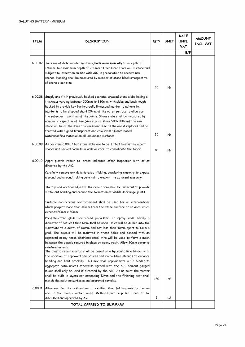
� �������� ��������������
��� ���������� �� ����
�����
�����
���
������
��������
$4
�!""!"� �/�-&%-.�/2�$%'%&+/&-'%$�,-./#&3<�*��3���������������'/�-�$%)'(�/2�
��",,��'/�-�,-?+,4,�$%)'(�/2� �",,�-.�,%-.4&%$�2&/,�1-**�.4&2-0%�-#$�
.46:%0'�'/�+#.)%0'+/#�/#�.+'%�1+'(��+�<�+#�)&%)-&-'+/#�'/�&%0%+7%�#%1�
.'/#%.!��-0@+#5�.(-**�6%�,%-.4&%$�63�#4,6%&�/2�.'/#%�6*/0@�+&&%.)%0'+7%�
/2�.'/#%�6*/0@�.+H%!
�� &
�!""!" �4))*3�-#$�2+'�+#�)&%7+/4.*3�(-0@%$�)/0@%'.<�$&%..%$�.'/#%�.*-6.�(-7+#5�-�
'(+0@#%..�7-&3+#5�6%'1%%#���",,�'/� �",,<�1+'(�.+$%.�-#$�6-0@�&/45(�
(-0@%$�'/�)&/7+$%�@%3�2/&�(3$&-4*+0�*+,%A.-#$�,/&'-&�'/�-$(%&%�'/!�
/&'-&�+.�'/�6%�.'/))%$�.(/&'� ",,�/2�'(%�/4'%&�.4&2-0%�'/�-**/1�2/&��
'(%�.46.%84%#'�)/+#'+#5�/2�'(%�:/+#'.!��'/#%�.*-6.�.(-**�6%�,%-.4&%$�63�
#4,6%&�+&&%.)%0'+7%�/2�.+H%!C�7%�.+H%�/2�.'/#%��""?�"",,D��(%�#%1�
.'/#%�1+**�6%�/2�'(%�.-,%�'(+0@#%..�-#$�.+H%�-.�'(%�/#%�+'�&%)*-0%.�-#$�6%�
'&%-'%$�1+'(�-�5//$�'&-#.)-&%#'�-#$�0/*/4&*%..�E.+*-#%E�6-.%$�
1-'%&)&//2+#5�,-'%&+-*�/#�-**�4#%?)/.%$�.4&2-0%.!� �� &
�!""!"> �.�)%&�+'%,��!""!"��64'�.'/#%�.*-6.�-&%�'/�6%��2+''%$�'/�%?+.'+#5�7-0-#'�
.)-0%.�#/'�(-0@%$�)/0@%'.�+#�1-**.�/&�&/0@��'/�0/#./*+$-'%�'(%�2-6&+0! �" &
�!""!�" �))*3 )*-.'+0 &%)-+& '/ -&%-. +#$+0-'%$ -2'%& +#.)%0'+/# 1+'( /& -.
$+&%0'%$�63�'(%��+�!
�-&%24**3 &%,/7% -#3 $%'%&+/&-'%$< 2*-@+#5< )/1$%&+#5 ,-./#&3 '/ %?)/.%
-�./4#$�6-0@5&/4#$<�'-@+#5�0-&%�#/'�'/�1%-@%#�'(%�-$:-0%#'�,-./#&3!
�(% '/) -#$ 7%&'+0-* %$5%. /2 '(% &%)-+& -&%- .(-** 6% 4#$%&04' '/ )&/7+$%
.422+0+%#'�6/#$+#5�-#$�&%$40%�'(%�2/&,-'+/#�/2�7+.+6*%�.(&+#@-5%�:/+#'.!
�4+'-6*% #/#92%&&/4. &%+#2/&0%,%#' .(-** 6% 4.%$ 2/& -** +#'%&7%#'+/#.
1(+0( )&/:%0' ,/&% '(-# �",, 2&/, '(% .'/#% .4&2-0% /& -# -&%- 1(+0(
%?0%%$.��",,�?��",,!�
�&%92-6&+0-'%$ 5*-.. &%+#2/&0%$ )/*3%.'%&< /& %)/?3 &/$. (-7+#5 -
$+-,%'%& /2 #/' *%.. '(-# �,, .(-** 6% 4.%$! �/*%. 1+** 6% $&+**%$ +#'/ '(%
.46.'&-'% '/ - $%)'( /2 �",, -#$ #/' *%.. '(-# �",, -)-&' '/ 2/&, -
5&+$! �(% $/1%*. 1+** 6% ,/4#'%$ +# '(%.% (/*%. -#$ 6/#$%$ 1+'( -#
-))&/7%$ %)/?3 &%.+#! �'-+#*%.. .'%%* 1+&% 1+** 6% 4.%$ '/ 2/&, - ,%.(
6%'1%%# '(% $/1%*. .%04&%$ +# )*-0% 63 %)/?3 &%.+#! �**/1 ",, 0/7%& '/
&%+#2/&0+#5�&/$.!�(% )*-.'+0 &%)-+& ,/&'-& .(-** 6% 6-.%$ /# - (3$&-4*+0 *+,% 6+#$%& 1+'(
'(% -$$+'+/# /2 -))&/7%$ -$,+?'4&%. -#$ ,+0&/ 2+6&% .'&-#$. '/ %#(-#0%
6/#$+#5 -#$ *+,+' 0&-0@+#5! �(+. ,+? .(-** -))&/?+,-'% - �;� 6+#$%& '/
-55&%5-'% &-'+/ 4#*%.. /'(%&1+.% -5&%%$ 1+'( '(% �+�! �%,%#' 5-45%$
,+?%. .(-** /#*3 6% 4.%$ +2 $+&%0'%$ 63 '(% �+�! �' #/ )/+#' '(% ,/&'-&
.(-** 6% 64+*' +# *-3%&. #/' %?0%%$+#5 � ,, -#$ '(% 2+#+.(+#5 0/-' .(-**
,-'0(�'(%�%?+.'+#5�.4&2-0%.�-#$�-))&/7%$�.-,)*%.!��" ,
�!""!�� �**/1 .4, 2/& '(% &%.'/&-'+/# /2 %?+.'+#5 .'%%* 2/*$+#5 6%$. */0-'%$ /#
/#% /2 '(% ,-+# 0(-,6%& 1-**.! %'(/$. -#$ )&/)/.%$ 2+#+.( '/ 6%
$+.04..%$�-#$�-))&/7%$�63��+�! � ��
���������������������
�������

� �������� ��������������
�������������������������������
�������

� �������� ��������������
��� ���������� �� ����
�����
�����
���
������
��������
�!""!"" ����5�(���(��)� ��������
�4))*3 -#$ +#.'-** $//&.< 1+#$/1. -#$ 24&#+'4&% +# -00/&$-#0% 1+'( '%0(#+0-*
.)%0+2+0-'+/#.< -#$ '(% &%*%7-#' $%'-+* $&-1+#5.; �09�"�< �09�" < �09�"�<�09
�"�<��09�"�<�09�"�<�09�"�<��09����-#$��09�� !
�-'%.�-&%�'/�+#0*4$%;
C+D �** $//&. .(-** 6% +#.'-**%$ 0/,)*%'% 1+'( #%/)&%#% $//& 5-.@%' .%-*. 1(%&%
#%00%.-&3!
C++D �/& '(% .%-*+#5 /2 5-) 6%'1%%# $//& -&0(+'&-7% ,/4*$+#5 -#$ 1-** 4.+#5
.+*+0/#% A -0&3*+0 .%-*-#' /# 6/'( .+$%.< �/-, )-0@+#5 ,-3 6% &%84+&%$ +# '(%
1+$%&�:/+#'.�)&+/&�'/�'(%�-))*+0-'+/#�/2�'(%�.%-*-#'!
C+++D �/& '(% )&/7+.+/# -#$ 2+?+#5 /2 1//$%# 04). /2 .-,% 0/*/4& -#$ -))%-&-#0%
/7%& -** .0&%1. 2+?+#5 '(% '+,6%& 2&-,% '/ '(% 1-** 1(%&% '(+. +. &%84+&%$!
�'(%&�,%-#.�/2�.%-*+#5�.(-**�6%�$%%,%$�4#-00%)'-6*%!
C7+D �/#'&-0'/& +. '/ -**/1 +# (+. &-'%. 2/& -#3 1/&@ #/' .)%0+2+0-**3 ,%#'+/#%$ +#
'(% 2/**/1+#5 +'%,. 64' '(-' +. /2 - 0/#'+5%#' #-'4&% '/ '(% 1/&@ 2/& +'.
)&/)%&�%?%04'+/#�-#$�0/,)*%'+/#!
C7D ��� ����-��� *��%1��� �����%��, *��,��5 �+�3�5 .+��� ���05 ��� %����% �+
.� �����%�% �� �*� ����� ��% ��� �+ .� 2�+-�%�% �� �2���/��% +� �*�
����-�����+�������%��1��,�0
C7+D �*� ���+-�� ��% ������, �1�� �+ �� �22�+-�% %��2��, ���� +/ ���
�6�����,�������*�������+�.������1�%0
�������

� �������� ��������������
��� ���������� �� ����
�����
�����
���
������
��������
�!""!"� �4))*3 -#$ 2+' '(% ��$���� ���� +# �+0@%'+#5 -&%-< $%'-+*%$ +# $&-1+#5
��#A:8!
�** $+,%#.+/#. -&% '/ 6% 0(%0@%$ -#$ 7%&+2+%$ /# .+'% -#$ -#3 $+.0&%)-#0+%.
&%)/&'%$ '/ '(% �+�! �/#'&-0'/& +. '/ )&/7+$% .-,)*%. /2 -** ,-'%&+-*.<
2+#+.(%. -#$ (-&$1-&% 1(+0( 1+** 6% 4.%$ +# '(% 0/#.'&40'+/# /2 '(% 0-6+#%'.
2/& %7-*4-'+/# -#$ -))&/7-* 63 '(% �+�! �&-$% ��� 6&4.( 2+#+.(%$ .'-+#*G%..
.'%%*�2&-,%�-#$�*%5.�$%%,%$�+#0*4$%$!� ��
�!""!" �4))*3�-#$�2+'�'(%����;����"���������-.�$%'-+*%$�+#�$&-1+#5���#A:9!
-'%&+-*. -#$ 2+#+.(%. '/ ,-'0( '(/.% /2 '(% 0-6+#%'. )&/7+$%$ +# +'%,
�!""!"�!�-'% +. '/ -**/1 2/& 0/4#'%& '/) '/ 6% �",, '(+0@ �/&+-#< .(%*7%. -#$
'%,)%&%$�5*-..�$//&.!���-,)*%.�'/�6%�)&/7+$%$!�/#'&-0'/& +. '/ )&/7+$% .-,)*%. /2 -** ,-'%&+-*.< 2+#+.(%. -#$ (-&$1-&%
1(+0( 1+** 6% 4.%$ +# '(% 0/#.'&40'+/# /2 '(% 0/4#'%& 2/& %7-*4-'+/# -#$
-))&/7-*�63�'(%��+�! � ��
�!""!"� �������� ���� # ������� ��� "���� �������� ���
(��!� �D������"��&���������#�����A�
�4))*3 -#$ 2+' '(% -*4,+#+4, 5*-.. $//& $%'-+*%$ +# $&-1+#5 �09�">! �-'% +.
'/ -**/1 2/& '(% )&/7+.+/# -#$ 2+?+#5 +# )*-0% /2 6/'( '(% -0'4-* $//& -. 1%**
-. '(% 2+?%$ 5*-H%$ )-#%*. '/ '(% .+$%. -#$ -' '(% '/)! �**/1 2/& 2/&,+#5
2&-,% '/ 2+' %?+.'+#5 7-4*' 04&7-'4&%< -** */0@.< (-#$*%. -#$ (+#5%. -. 1%** -.
'(% .%-*+#5 /2 -** 5-). 1+'( - )&/)&+%'3 .+*+0/#% 6-.%$ .%-*%&! �+#+.( '/ 6%
-#/$+.%$�$-&@�5&%3�,-''�2+#+.(!
�/#'&-0'/& +. '/ )&/7+$% .-,)*%. /2 -** ,-'%&+-*.< 2+#+.(%. -#$ (-&$1-&%
1(+0( 1+** 6% 4.%$ +# '(% 0/#.'&40'+/# /2 '(% $//& 2/& %7-*4-'+/# -#$
-))&/7-*�63�'(%�0/#.4*'-#'��&0(+'%0'!� �!"" &!
�!""!"� �����������$��� ���!�����#������+�9
�4))*3 -#$ 2+' '(% �%$ �%-* '+,6%& 2*4.( $//& / $%'-+*%$ +# $&-1+#5
�09�"��-'% +. '/ -**/1 2/& -** #%0%..-&3 (-&$1-&%< 2+?+#5 +# )*-0% -#$ .%-*+#5!
�/*/4&�)-+#'%$��(+'%!
�/#'&-0'/& +. '/ )&/7+$% .-,)*%. /2 -** ,-'%&+-*.< 2+#+.(%. -#$ (-&$1-&%
1(+0( 1+** 6% 4.%$ +# '(% 0/#.'&40'+/# /2 '(% $//& 2/& %7-*4-'+/# -#$
-))&/7-*�63�'(%��+�! �!"" &!
�!""!"� �����������$��� ���!�����#������+�?
�4))*3 -#$ 2+' '(% �%$ �%-* '+,6%& 2*4.( $//& / � $%'-+*%$ +# $&-1+#5
�09�"��-'% +. '/ -**/1 2/& -** #%0%..-&3 (-&$1-&%< 2+?+#5 +# )*-0% -#$ .%-*+#5!
�/*/4&�)-+#'%$��(+'%!
�/#'&-0'/& +. '/ )&/7+$% .-,)*%. /2 -** ,-'%&+-*.< 2+#+.(%. -#$ (-&$1-&%
1(+0( 1+** 6% 4.%$ +# '(% 0/#.'&40'+/# /2 '(% $//& 2/& %7-*4-'+/# -#$
-))&/7-*�63�'(%��+�! �!"" &!
0A2
�������

� �������� ��������������
��� ���������� �� ����
�����
�����
���
������
��������
6A2
�!""!"� �4))*3 -#$ 2+' +# )*-0% ++� �+ A -. $%'-+*%$ +# $&-1+#5 �09�" � �09�"�!
�/#'&-0'/& +. '/ .4))*3 .-,)*%. /2 -** ,-'%&+-*. '/ 6% 4.%$ +# '(%
0/#.'&40'+/#�/2�'(+.�$//&�2/&�-�)&/)%&�%7-*4-'+/#�63�'(%��+�! �!"" &
�!""!"� �D���������$��� ����"������#������+�@
�4))*3�-#$�2+'�'(%��&/@/�'+,6%&�$//&�/!��$%'-+*%$�+#�$&-1+#5��09���
�-'% +. '/ -**/1 2/& -** #%0%..-&3 (-&$1-&%< 2+?+#5 +# )*-0% -#$ .%-*+#5!
�/*/4&�)-+#'%$��-#!
�/#'&-0'/& +. '/ )&/7+$% .-,)*%. /2 -** ,-'%&+-*.< 2+#+.(%. -#$ (-&$1-&%
1(+0( 1+** 6% 4.%$ +# '(% 0/#.'&40'+/# /2 '(% $//& 2/& %7-*4-'+/# -#$
-))&/7-*�63�'(%��+�! �!"" &!
�!""!" �����������$��� ���!�����#�����E�E
�4))*3 -#$ 2+' '(% �%$ �%-* '+,6%& 2*4.( $//& $%'-+*%$ +# $&-1+#5 �09
�"��-'% +. '/ -**/1 2/& -** #%0%..-&3 (-&$1-&%< 2+?+#5 +# )*-0% -#$ .%-*+#5!
�/*/4&�)-+#'%$��(+'%!
�/#'&-0'/& +. '/ )&/7+$% .-,)*%. /2 -** ,-'%&+-*.< 2+#+.(%. -#$ (-&$1-&%
1(+0( 1+** 6% 4.%$ +# '(% 0/#.'&40'+/# /2 '(% $//& 2/& %7-*4-'+/# -#$
-))&/7-*�63�'(%��+�! �!"" &!
�!""!"> �����������$�����$������ �����#�����E.E
�4))*3 -#$ 2+' '(% �%$ �%-* '+,6%& $/46*% *%-2 $//& -. $%'-+*%$ +# $&-1+#5
�09�"��-'% +. '/ -**/1 2/& -** #%0%..-&3 (-&$1-&%< 2+?+#5 +# )*-0% -#$ .%-*+#5!
�/*/4&�)-+#'%$��(+'%!
�/#'&-0'/& +. '/ )&/7+$% .-,)*%. /2 -** ,-'%&+-*.< 2+#+.(%. -#$ (-&$1-&%
1(+0( 1+** 6% 4.%$ +# '(% 0/#.'&40'+/# /2 '(% $//& 2/& %7-*4-'+/# -#$
-))&/7-*�63�'(%��+�! �!"" &!
�!""!�" ������"���������8
�4))*3 -#$ 2+' - #%1 ,+*$ .'%%* 5-*7-#+.%$A)-+#'%$ 5-'% .+,+*-& '/ '(%
%?+.'+#5�-#$�-.�$%'-+*%$�+#�$&-1+#5��������09�"�
�-'% +. '/ -**/1 2/& '(% &%,/7-* -#$ $4,)+#5 /2 '(% %?+.'+#5 5-'%< -**
#%0%..-&3�(-&$1-&%<�2+?+#5�+#�)*-0%�-#$�.%-*+#5!��/*/4&�'/�,-'0(�%?+.'+#5!
�/#'&-0'/& +. '/ )&/7+$% .-,)*%. /2 -** ,-'%&+-*.< 2+#+.(%. -#$ (-&$1-&%
1(+0( 1+** 6% 4.%$ +# '(% 0/#.'&40'+/# /2 '(% 5-'% 2/& %7-*4-'+/# -#$
-))&/7-*�63�'(%��+�! �!"" &!
0A2
�������

� �������� ��������������
��� ���������� �� ����
�����
�����
���
������
��������
6A2
�!""!�� ��$���(���(������8
�4))*3 -#$ 2+' '(% $/46*% 5*-H%$ '+,6%& 1+#$/1 C�%$ �%-*D $%'-+*%$ +#
$&-1+#5��������09�"��-'% +. '/ -**/1 2/& -** #%0%..-&3 (-&$1-&%< 2+?+#5 +# )*-0% -#$ .%-*+#5!
�/*/4&�)-+#'%$��-#!
�/#'&-0'/& +. '/ )&/7+$% .-,)*%. /2 -** ,-'%&+-*.< 2+#+.(%. -#$ (-&$1-&%
1(+0( 1+** 6% 4.%$ +# '(% 0/#.'&40'+/# /2 '(% 1+#$/1 2/& %7-*4-'+/# -#$
-))&/7-*�63�'(%��+�! �!"" &!
�!""!� ��$���(���(������9
�4))*3 -#$ 2+' '(% $/46*% 5*-H%$ '+,6%& 1+#$/1 C�%$ $%-*D $%'-+*%$ +#
$&-1+#5��������09�"��-'% +. '/ -**/1 2/& -** #%0%..-&3 (-&$1-&%< 2+?+#5 +# )*-0% -#$ .%-*+#5!
�/*/4&�)-+#'%$��-#!
�/#'&-0'/& +. '/ )&/7+$% .-,)*%. /2 -** ,-'%&+-*.< 2+#+.(%. -#$ (-&$1-&%
1(+0( 1+** 6% 4.%$ +# '(% 0/#.'&40'+/# /2 '(% 1+#$/1 2/& %7-*4-'+/# -#$
-))&/7-*�63�'(%��+�! �!"" &!
�!""!�� ��$���(���(������8�
�4))*3 -#$ 2+' '(% $/46*% 5*-H%$ '+,6%& 1+#$/1 C�%$ $%-*D $%'-+*%$ +#
$&-1+#5��������09�"��-'% +. '/ -**/1 2/& -** #%0%..-&3 (-&$1-&%< 2+?+#5 +# )*-0% .%-*+#5 -#$
04''+#5�/2�%?'&-0'/&�/)%#+#5!��/*/4&�)-+#'%$��-#!
�/#'&-0'/& +. '/ )&/7+$% .-,)*%. /2 -** ,-'%&+-*.< 2+#+.(%. -#$ (-&$1-&%
1(+0( 1+** 6% 4.%$ +# '(% 0/#.'&40'+/# /2 '(% 1+#$/1 2/& %7-*4-'+/# -#$
-))&/7-*�63�'(%��+�! �!"" &!
�!""!�� ��$���(���(������9�
�4))*3 -#$ 2+' '(% $/46*% 5*-H%$ '+,6%& 1+#$/1 C�%$ �%-*D $%'-+*%$ +#
$&-1+#5��������09�"��-'% +. '/ -**/1 2/& -** #%0%..-&3 (-&$1-&%< 2+?+#5 +# )*-0% .%-*+#5 -#$
04''+#5�/2�%?'&-0'/&�/)%#+#5!��/*/4&�)-+#'%$��-#!
�/#'&-0'/& +. '/ )&/7+$% .-,)*%. /2 -** ,-'%&+-*.< 2+#+.(%. -#$ (-&$1-&%
1(+0( 1+** 6% 4.%$ +# '(% 0/#.'&40'+/# /2 '(% 1+#$/1 2/& %7-*4-'+/# -#$
-))&/7-*�63�'(%��+�! �!"" &!
�!""!�� �4))*3�-#$�2+'�+#�)*-0%�.'%%*�.)+&-*�.'-+&0-.%�$%'-+*%$�+#��&5��09�� !
�** $+,%#.+/#. -&% '/ 6% 0(%0@%$ -#$ 7%&+2+%$ /# .+'%! �/#'&-0'/& +. '/ -**/1
2/& '(% &%,/7-* /2 '(% .'-+&. 04&&%#'*3 +# )*-0% -. 1%** -. '(% $%.+5# -#$
64+*$ $%'-+*. /2 '(% #%1 .'-+&.! �-,)*%. '/ 6% )&/7+$%$ 2/& %7-*4-'+/# -#$
-))&/7-*!�!"" &!
0A2
������

� �������� ��������������
��� ���������� �� ����
�����
�����
���
������
��������
6A2
�!""!�� �%)*-0% '(% %?+.'+#5 .'%%* -00%.. (-'0( 0/7%& 1+'( - .+,+*-&*3 .+H%$
&%,/7-6*% 5-*7-#+.%$ .'%%* '&-3 /2 .4+'-6*% '(+0@#%.. '/ '-@% 2+#+.(%. -.
2/4#$ +# '(% %#'&-#0% -&%- 1(%&% +' +. .+'4-'%$! �))&/?+,-'% .+H% � "" ?
>"" ? �" ,, +# �-'% +. '/ -**/1 2/& '(% &%,/7-* /2 '(% %?+.'+#5 (-'0( -#$
'(% .4))*3 -#$ *-3+#5 /2 -** '(% &%84+&%$ 2+#+.(%. +#.+$% '(% '&-3! �%2%& '/
$&-1+#5��09�"��$%'-+*�>���>-!
�/#'&-0'/& +. '/ )&/7+$% .-,)*%. /2 -** ,-'%&+-*.< 2+#+.(%. -#$ (-&$1-&%
1(+0( 1+** 6% 4.%$ +# '(% 0/#.'&40'+/# /2 '(% (-0( 0/7%& 2/& %7-*4-'+/# -#$
-))&/7-*�63�'(%��+�!� ���= &!
�!""!�� �4))*3 -#$ 2+' +# )*-0% '(% 5-*7-#+.%$ ,+*$ .'%%* &%,/7-6*% 5-'% -. $%'-+*%$
+# $&-1+#5 �09��� -. 1%** -. $&5 �09���! �-'% +. '/ -**/1 2/& -** '(%
&%84+&%,%#'.�*+.'%$�+#�'(%.%�$&-1+#5.! �!"" ��
�!""!� �4))*3 -#$ 2+' +# )*-0% ,+*$ .'%%* &-+*+#5. -. $%'-+*%$ +# �&5 �09��"! �-'% +.
'/ -**/1 2/& '(% 0/#.'&40'+/# /2 � 0&. (+5( ,-./#&3 1-** 0(-,2%&%$ /# +'.
4))%& %$5%. '/ '-@% '(% &-+*+#5.< -. 1%** -. '(% &%,/7-* -#$ 0-&'+#5 -1-3 /2
'(%�%?+.'+#5�.'%%*�&-+*+#5! �!"" ,
�!""!�> �4))*3 -#$ )*-0% #/ 5-*7-#+.%$ ,+*$ .'%%* (-#$&-+*. %-0( -))&/?+,-'%*3 ",
*/#5 '/ '(% &-,) *%-$+#5 $/1# '/ '(% ,-+# 0(-,6%& $&5 �09�"� -#$ �,-5% �"
C�09�"�D &%2%&.! �(% (-#$&-+* 1+** 6% 0/,)/.%$ /2 - ��,, $+- .'%%* '46%
.4))/&'%$ /# �",, '(@ ./*+$ .'%%* 1-** ,/4#'%$ 6&-0@%'. .%' -' �""",,
0A0! �(% (-#$&-+* 2+#+.( 1+** 6% - $-&@ 5&%3 %)/?3 )-+#' -))*+%$ -00/&$+#5 '/
,-#42-0'4&%&. +#.'&40'+/#.! �-,)*%. /2 ,-'%&+-*. -#$ 2+#+.( '/ 6%
.46,+''%$ 2/& %7-*4-'+/# -#$ -))&/7-* 63 '(% 0/#.4*'-#' �+�! �** +'%,.
�-*7-#+H%$!� �!"" ��
���������������������
������

����� ���������������
�������

��������������������������
���� �����2��+� ���� ��
����������
��� �+��������0����
�/�.4))*3<�+#.'-**<�0/##%0'<�'%.'�-#$�0/,,+..+/#
'(%�2/**/1+#5<�0/,)*%'%�-.�.)%0+2+%$
� =%#'+*-'+/#�2-#.�0/,)*%'%�-.�.)%0+2+%$�;
�!� ��A� / �
�! ��A / �
�%.'+#5�-#$�0/,,+..+/#+#5�/2�-**�-+&90/#$+'+/#+#5�-#$ �4,) �4,
7%#'+*-'+/#�.3.'%,.
� �.�2+''%$�$&-1+#5.�C(-&$�0/)+%.D �%'. �
� �.�2+''%$�$&-1+#5.�C./2'�0/)+%.D �%'. �
� ���,-#4-*. �%'.
0A2
�������

6A2
���� �����2��+� ���� ��
����������
��� �+��������0����
�/�.4))*3<�+#.'-**<�'%.'�-#$�0/,,+..+/#�
'(%�2/**/1+#5<�0/,)*%'%�-.�.)%0+2+%$
� �+.,-#'*%�-#$�0-&'�-1-3�%?+.'+#5�)*4,6+#5� �4,) �4,
+#.'-**-'+/#�+#�%?(+6+'+/#�&//,.
�"""�*+'&%.�1-'%&�.'/&-5%�'-#@<�0/,)*%'%�1+'(� / �
6-**�2*/-'
� -+#.�1-'%&�)+)+#5�+#�)/*364'3*%#%<�$+-���,,� , ��
� =-*7%.�/#�,-+#.�1-'%&�)+)+#5<���� /
� �/*$�1-'%&�6//.'%&�)4,)�.%' / �
� �+.'&+64'+/#�1-'%&�)+)+#5�+#�)/*364'3*%#%�;
�!� �+-� ,,�C.4&2-0%�+#.'-**-'+/#D , �
�! �+-���,,�C.4&2-0%�+#.'-**-'+/#D , ��
�!� �+-� ,,�C�(-.%$�+#�1-**.D , �"
�!� �+-���,,�C0(-.%$�+#�1-**.D , �
� =-*7%.�/#�$+.'&+64'+/#�1-'%&�)+)+#5�;
�!� �+-� ,, / �
�! �+-���,,�2*%?+6*%�0/##%0'/&.�C��A��'/���A�D / �
�+-��A E�-#5*%�7-*7%. /
> �+-��A E�2*%?+6*%�0/##%0'/&. /
�" �+-��A E�6+6�'-) / �
�� �=��1-.'%�$&-+#.�;
��!� �+-��",, , �
��! �+-��",, ,
� �&3�)/1$%&�2+&%�%?'+#54+.(%&.<�>�@5. / �
�� �-&6/#�$+/?+$%�2+&%�%?'+#54+.(%&.<���@5. / �
�� �%.'�-#$�0/,,+..+/#�)*4,6+#5�.3.'%,. �4,) �4,
�� �.�2+''%$�$&-1+#5.�C(-&$�0/)+%.D �%'. �
�� �.�2+''%$�$&-1+#5.�C./2'�0/)+%.D �%'. �
�� ���,-#4-*. �%'
0A2
���$��"���� ���� �"!���"��������������
�������

6A2
������������ ����� ��
���� �����2��+� ���� ��
����������
��� �+��������0����
�/�.4))*3<�+#.'-**<�'%.'<�0/,,+..+/#�-#$�0%&'+23�
'(%�2/**/1+#5<�0/,)*%'%�-.�.)%0+2+%$
� �#0*+#%$�)*-'2/&,�*+2'�&%2����� / �
��������������������� ���+
�������

�����>�����������������
������

��� ���������� ���� �� ��������� �����
��� ��������
���������$�����
�4))*3�-#$�+#.'-**�-+#��-#%*�J�K�-.�
)%&�.0(%,-'+0�$+-5&-,�C)*4.� �L�.)-&%D�/#�
$&-1+#5��9"�!
�4))*3�-#$�+#.'-**��+.'&+64'+/#��/-&$�
�����-.�)%&�.0(%,-'+0�$+-5&-,�C)*4.� �L�
.)-&%D�/#�$&-1+#5��9"�!�
�4))*3�-#$�+#.'-**��+.'&+64'+/#��/-&$�
��� �-.�)%&�.0(%,-'+0�$+-5&-,�C)*4.� �L�
.)-&%D�/#�$&-1+#5��9"�!�
�4))*3�-#$�+#.'-**��+.'&+64'+/#��/-&$�
�����-.�)%&�.0(%,-'+0�$+-5&-,�C)*4.� �L�
.)-&%D�/#�$&-1+#5��9"�!�
�4))*3�-#$�+#.'-**��!",�*/#5�?� ",,�$+-,%'%&�
.'%%*�0/&%�0/))%&�%-&'(�&/$�+#�+#.)%0'+/#�)+'!
� �4))*3�-#$�+#.'-**� �(/*%�./*+$�0/))%&�%-&'(�6-&�,/4#'%$�/#�+#.4*-'/&.! /! �
�4))*3�-#$�+#.'-**�������������-#$�-�������� �-'%��"",��C1+'(�'+,%�$%*-3%$�'&+)D�0/,)*%'% /#*31+'(�������#0*/.4&%!
������$���
�4))*3<�+#.'-**�-#$�'%&,+#-'%��0�?��"�,,M��
�=��+#.4*-'%$�%-&'(�1+&%�2&/,���'/��-&'(��-&�
-#$�'/�'(%�%-&'(�&/$!
�4))*3<�+#.'-**<�0/##%0'�-#$�'%&,+#-'%���?��0�?
���,,M�0-6*%.�6%'1%%#�-+#��1+'0(�-#$�
�#%,-*'-����&�%'%&
�4))*3<�+#.'-**�-#$�'%&,+#-'%�+#����'3)%�5*-#$.G� �-'%�0�?����,,M�B����A�����A��=���-6*%�2&/,�-+# /#*3�1+'0(�63��#%,-*'-�%'%&!
�4))*3<�+#.'-**�-#$�'%&,+#-'%��0�?���,,M�B���
0-6*%�2&/,�J�K�'/�����!��+&04+'��A�!
�4))*3<�+#.'-**�-#$�'%&,+#-'%��0�?���,,M�B���
0-6*%�2&/,�J�K�'/���� !��+&04+'��A !
�4))*3<�+#.'-**�-#$�'%&,+#-'%��0�?���,,M�B���
0-6*%�2&/,�J�K�'/�����!��+&04+'��A�!
��"!���"� �D�����
�4))*3<�+#.'-**�-#$�0/##%0'�*+5('+#5�2+?'4&%.�
�3)%��!
�4))*3<�+#.'-**�-#$�0/##%0'�*+5('+#5�2+?'4&%.�
�3)%��!
�4))*3<�+#.'-**�-#$�0/##%0'�*+5('+#5�2+?'4&%.�
�3)%��!
�4))*3<�+#.'-**�-#$�0/##%0'�*+5('+#5�2+?'4&%.�
�3)%��!
� �4))*3<�+#.'-**�-#$�0/##%0'�%,%&5%#03�*+5('+#5�2+?'4&%.��3)%��! /! ��
�4))*3<�+#.'-**�-#$�0/##%0'�%?+'�*+5('+#5�2+?'4&%.�
�3)%��B!
�4))*3<�+#.'-**�-#$�0/##%0'�*+5('+#5�2+?'4&%.�
�3)%��!
�4))*3<�+#.'-**�-#$�0/##%0'�*+5('+#5�2+?'4&%.�
�3)%��!
0A2
� /!
�
� /!
�
�� /!�
��/! ��
/! �
�
/! �
�/! �
, �
� ���= �
�>
��, �
�
,
��, ��
� ,
�" ���= �
>
��/! �
�� /!�
�>/!
"/! �
�/! �
������

6A2
��� ���������� ���� �� ��������� �����
��� ��������
�4))*3<�+#.'-**�-#$�0/##%0'�*+5('+#5�2+?'4&%.�
�3)%��!
�4))*3<�+#.'-**�-#$�0/##%0'�*+5('+#5�2+?'4&%.�
�3)%��!
�4))*3<�+#.'-**�-#$�0/##%0'�*+5('+#5�2+?'4&%.�
�3)%��!
�4))*3�-#$�+#.'-**�*+5('�'&-0@�+#0*4.+7%�/2�)/1%&�
.4))*3�4#+'<�%#$�0-)<�0/4)*%&.�-#$�.4.)%#.+/#�
2+''+#5.!
��"!���"���������
�(%�2/**/1+#5�*+5('+#5�0+&04+'.�.(-**�6%�.4))*+%$<�+#.'-**%$�-#$�0/##%0'%$�
2&/,�'(%�&%.)%0'+7%����4)�'/�'(%�*+5('�)/+#'A.�+#0*4.+7%�/2�1+&+#5<�0/#$4+'<�.1+'0(%.<�+./*-'/&.<�
.%#./&.�64'�%?0*4$+#5�'(%�&%.)%0'+7%�,06<�&%*-3�-#$�*+5('�2+?'4&%�;��
� �+&04+'�/!����A�!� ��
� �+&04+'�/!����A ! ��
�+&04+'�/!����A�! ��
> �+&04+'�/!����A�! ��
�" �+&04+'�/!����A� ��
�� �+&04+'�/!����A� ��
� �+&04+'�/!����A� ��
�� �+&04+'�/!����A� ��
�� �+&04+'�/!��� A�! ��
�� �+&04+'�/!��� A ! ��
�� �+&04+'�/!��� A�! ��
�� �+&04+'�/!��� A�! ��
� �+&04+'�/!��� A�! ��
�> �+&04+'�/!��� A�! ��
�" �+&04+'�/!��� A�! ��
�� �+&04+'�/!��� A ! ��
� �+&04+'�/!��� A��! ��
�� �+&04+'�/!����A�! ��
�� �+&04+'�/!����A ! ��
�� �+&04+'�/!����A��! ��
�� �+&04+'�/!����A��! ��
�������(��
�(%�2/**/1+#5�.,-**�)/1%&�0+&04+'.�.(-**�6%�
.4))*+%$<�+#.'-**%$�-#$�0/##%0'%$�+#0*4.+7%�/2�
1+&+#5<�0/#$4+'�-#$�1+&+#5�-00%../&+%.�64'�
%?0*4$+#5�'(%�&%.)%0'+7%�,06A&06/<�'+,%&<�&%*-3�;��
�� �+&04+'�/!����A �N�1-**�./0@%'�/4'*%'.�C&-$+-*D!� ��
� �+&04+'�/!����A>�N�1-**�./0@%'�/4'*%'.�C&-$+-*D! ��
�> �+&04+'�/!����A�"�N�2*//&�./0@%'�/4'*%'.�C&-$+-*D! ���+&04+'�/!����A���N��?'&-0'��-#��� �+#0*4$+#5�
2*%?�/4'*%'!
�� �+&04+'�/!��� A>�N�1-**�./0@%'�/4'*%'.�C&-$+-*D!� ��
� �+&04+'�/!��� A�"�N�1-**�./0@%'�/4'*%'.�C&-$+-*D!� ��
�� �+&04+'�/!��� A���N�2*//&�./0@%'�/4'*%'.�C&-$+-*D!� ��
�� �+&04+'�/!��� A� �N�1-**�./0@%'�/4'*%'.�C&-$+-*D!� ���+&04+'�/!��� A���N��?'&-0'��-#�����+#0*4$+#5
2*%?�/4'*%'!
�� �+&04+'�/!��� A���N��//.'%&��4,)��%'�+#0*4$+#5�+./*-'/&! ��
0A2
�� ��
�
/! ��
�/! >
�/! �
/! �
�" ��
������

6A2
��� ���������� ���� �� ��������� �����
��� ��������
�� �+&04+'�/!����A��N�1-**�./0@%'�/4'*%'.�C&-$+-*D!� ��
� �+&04+'�/!����A��N�1-**�./0@%'�/4'*%'.�C&-$+-*D!� ���+&04+'�/!����A��N�4#.1+'0(%$�24.%�0/##%0'+/#�
4#+'�2/&����!
�+&04+'�/!����A��N�4#.1+'0(%$�24.%�0/##%0'+/#�
4#+'�2/&�����!
�+&04+'�/!����A��N�4#.1+'0(%$�24.%�0/##%0'+/#�
4#+'�2/&����=!
�+&04+'�/!����A �N��#'&-#0%��'-+&.��(-+&��+2'
+#0*4$+#5�+./*-'/&!
�+&04+'�/!����A�"�N��46��+&+#5��-6+#%'�
+#0*4$+#5�+./*-'/&!
�+&04+'�/!����A���N�&+5+$�5-*7-#+.%$�.'%%*
.4&2-0%�0/#$4+'�-#$�,%'-*0*-$�1-**�./0@%'�
/4'*%'.�C&-$+-*D!�
��(��
�(%�2/**/1+#5�)/1%&�0+&04+'.�.(-**�6%�
.4))*+%$<�+#.'-**%$�-#$�0/##%0'%$�+#0*4.+7%�/2�
1+&+#5<�0/#$4+'�C1(%&%�4.%$D�-#$�+./*-'/&�64'�
%?0*4$+#5�'(%�&%.)%0'+7%�,06��;��
�� �+&04+'�/!������A �N��4,).��/#'&/*��-#%*�����+#0*4$+#5�+./*-'/&! ��
���������
�/46*%��I���/4'*%'.�+#0*4.+7%�/2��-'�%�0-6*+#5�
-#$�'%&,+#-'+/#.!�
�� ����1-**�,/4#'%$��-'-��-6+#%'! /! �
� � ��/&'��-'0(��-#%*�+#0*4.+7%�/2�'%&,+#-'+/#.! / �
�> �%.'�-#$��/,,+..+/#�'(%��-'-��3.'%,! ��
�" �)%&-'+/#���-+#'%#-#0%�-#4-*.�-#$�J�.9�4+*'K�$&-1+#5.�2/&��-'-��3.'%,! ��
�������������)�����������
�(%��3.'%,�.(-**�6%�.4))*+%$<�+#.'-**%$�-#$�
0/##%0'%$�+#0*4.+7%�/2�0/#$4+'.<�-#$�
1+&+#5A0-6*+#5!��
�� �4))*3�-#$�+#.'-**��+&%��*-&,��/#'&/*��-#%*�����!� /! �
� �4))*3<�+#.'-**�-#$�0/##%0'�.,/@%�$%'%0'/&.!� /! �
�� �4))*3<�+#.'-**�-#$�0/##%0'�6&%-@�5*-..�4#+'.!� /! �
�� �4))*3<�+#.'-**�-#$�0/##%0'�+#'%&#-*�-*-&,�./4#$%&! /! �
�� �4))*3<�+#.'-**�-#$�0/##%0'�%?'%&#-*�-*-&,�./4#$%&�-#$�.'&/6%! /!
�� �/##%0'�-4'/$+-**%&�'/�'%*%)(/#%A$-'-�/4'*%'! /! �
�� �/##%0'�-A0�.(4'$/1#�.+5#-*�'/�.(4#'�'&+)�/2��*-#'��-#%*�0+&04+'���A ! /! �
� �/##%0'�%?'&-0'�2-#�.(4'$/1#�.+5#-*�'/�.(4#'�'&+)�/2����0+&04+'.����A���-#$�
�� A�!
/!
�> �%.'+#5�-#$��/,,+..+/#+#5�����3.'%,�/#*3! ��
" �)%&-'+/#���-+#'%#-#0%�-#4-*.�-#$�J�.9�4+*'K�$&-1+#5.�2/&��+&%��*-&,�
�3.'%,!
��
� �����!����
�4))*3�-#$�+#.'-**�'(&%%�C��/!D�'%*%)(/#%�)/+#'.�0/,)*%'%�1+'(�0/#$4+'.<�
#3*/#�)4**�1+&%�-#$�/4'*%'.!�
��
0A2
�> ��
�" ��
�� ��
�� ��
� ��
�� ��
�� /! �"
������

6A2
��� ���������� ���� �� ��������� �����
��� ��������
������������
� �%,/7%�%?+.'+#5�%*%0'&+0-*�+#.'-**-'+/#!� ��
� �4))*3�-#$�+#.'-**��+&%��-&&+%&.�-'�%-0(�1-**A2*//&�)%#%'&-'+/#! ��
� �/9/&$+#-'+/#�1+'(��+&%��%'%0'+/#����*-&,��3.'%,�.4))*+%&A+#.'-**%&! ��
� �/9/&$+#-'+/#�1+'(�'(%��-'-��3.'%,�.4))*+%&A+#.'-**%&! ��
� �/9/&$+#-'+/#�1+'(�'(%��#'%&+/&��+#+.(%.�.4))*+%&A+#.'-**%&! ��
�-6%**+#5�/2�-**�0+&04+'.�-#$�)-#%*.! ��
> �&%)-&-'+/#�/2�'(%��=��#.'-**-'+/#��&-1+#5.! ���%.'+#5�-#$��/,,+..+/#+#5�'(%��=�+#.'-**-'+/#�
/#*3!
�#%,-*'-��))*+0-'+/#�-#$�2/&�.(+2'+#5�/2�'(%
�?+.'+#5�'(&%%�)(-.%�.4))*3�'/�'(%�,-+#
�#'&-#0%!
�+-+./#�1+'(����2/&�'(%�&%84+&%,%#'.�-#$�
*/0-'+/#�/2�'(%�+#0/,+#5�'%*%)(/#%A�����
.%&7+0%!�
��������������������� ���+�
>" ��
>� ��
> ��
�����

������������� �������
�������������� ���������

������������� �������
��� �������� � ���� �������������
�������� ������������ � ��
����� �������� �� !" �# ���#$ ��% &$�# ��
"��'��"'
�������
�������� �#�'(�"&�)"'(* +"$'
�������, �"'�!�� +"$'
�������- ��*"� +"$'
�������. ��'�����' +"$'
�������/ �#$!0�'�1�#���'����� +"$'
�������2 �#�����'�3�' +"$'
�������4 ��3���#�����'�3�' +"$'
�������5 �(�##� ���0"$'�' +"$'
�������6 ��*(�##� ���0"$'�' +"$'
�������� ��!��*(�##� ���0"$'�' +"$'
�������� ����#���7�' +"$'
������
�������, �'�����$00�'���'� �4��"���* +"$'
�������- �'�����$00�'���'� ��,��"���* +"$'
�������. �'�����$00�'���'� ��/��"���* +"$'
�������/ �'�����$00�'���'� �-���"���* +"$'
�������2 �$!��'�������������$0���!��'� +"$'
�������4 �"!�'�**"' �3�'�%� '��� ��' �""#8 �## ���#$*�3�8
���#���0#���"�0'��(�'*8� '�##�'*8�9�%%�'*����� +"$'
�������5 �!�##��'���"'��+"3�' +"$'
�������6 �!�##�� '�$#���7��3��"' +"$'
������,� �"''�������'�:������"������������ +"$'
������,� ��#&��'�!��%��$!� +"$'
������,, �")�'��'��� +"$'
������,- ���&&"# ��%�:�!" $#��"&���/�!�7���/�!�7���/�!
.�)��(*
������,. ;�# ��%��� ��$����%��<$��!��� +"$'

������������� �������
��� �������� � ���� �������������
�������
������,/ 3�'+�� * �� �'"&�� &"' )"'(* �7��$�� 0�
)���"&� ��)"'(*�����=
��0"$' >
�#��� >
����'��# >
������������� �������
����������

������������� �������
���� ��������� �� ����
������ ������������
������ �� ������ ����������
������ ����������
������ �����������������
������ �������������
������ ��������������
��������������������� ���� ��
����� ���������������
�����! ���������������
������"� ����� ����������� ##
� �#����������� �����$��
��������� �����$��

BILL B
THE ST PETER & PAUL COUNTER GUARD
THE COMPLETE REFURBISHMENT
OF
THE LASCARIS TUNNELS
&
REF: G-0458

� �� ������������
������������ ������������ ���
���������
������������������
����� ������������������
����������������������������������������
�����������������������
���������������������
�����������������������
�������������������������
���� ������

� �� ������������
������������ ������������� ��
������������������
� ����

� �� ������������
������������ ������������� ��
��� ���������� �� ���������
������
������������
���
��!!�!! ������������
��!��!! ����������������������
��!��!� �"#$%&��'()%�*
���!���"#���$���#�%�������"��&� �����#"
�$���� ���� �'����##� �(��������##� �
����������(����������#�����)���!�
��! �!! ���� ���!��!!�� �
��! �!� �+%��),-#.%"*
*���++,����'��������� // // //
��! �! �+%��"&+0�%&��0'��+("1%*
��������������(�����������
�"&+0�%&�23�040-�('5���"6&�6"(-��'10'%%"0'1��#'26-�('�2
� �3��"&+702+#,���"%%�3�8(--%��(������
�%-*����� � �99:3���(;*���� � �9�� // // //
��!��!! �$�������
��!��!� �+%�20�%�02�-#&(�%5�#<<����=()%2��0�&+�8(--%��(� // // //
��!��! �&&%22��#��+%�20�%�02�1##5� // // //
��!��!�
�+% &#'�"(&�#" 02 �# %'26"% �+(� '# 502�6"7('&% 02 &(62%5 �# �+%
26""#6'50'1 '%01+7#6"2 0' ('. <#") >+(�2#%4%" ('5 2+(-- 7% +%-5 -0(7-%
<#"�5()(1%2��#��+0"5�,("�.�,"#,%"�.�
// // //
��!��!�
�'. >#"? "%@60"%5 �# 7% &(""0%5 #6� #6�205% '#")(- >#"?0'1 +#6"2 )(.
#'-.�7%�5#'%�(<�%"�,"0#"�(,,"#4(-�#<��+%�&-0%'��('5��+%�'%&%22(".�(,,"#4(-�
<"#) '%01+7#6"2 ('5A#" ,#-0&% ,%")0�2 ('5A#" #�+%" (6�+#"0�. ("% �# 7%
#7�(0'%5�
// // //
��!��!� �(�%2 @6#�%5 ("% �# 0'&-65% <#" �"('2,#"�0'13 -#(50'13 #<</-#(50'13 ('5
&("�0'1�(>(.�(--�)(�%"0(-��#�(��#4%"')%'���,,"#4%5��6),0'1��0�%�// // //
��!��!� �-- "(�%2 267)0��%5 ("% 5%%)%5 �# 0'&-65% <#" 2&(<<#-50'1 >+%"% 0�
"%26-�2 �+(� �+02 02 '%&%22(". ('5 �+(� 0� &#'<#")2 >0�+ (-- &6""%'� -#&(-
�%(-�+�('5��(<%�.�"%16-(�0#'2�
// // //
������!��#��#������#�
� ����

� �� ������������
������������ ������������� ��
��� ���������� �� ���������
������
������������
���
��!��!� �$� �#������#� � &���) ��#�)�� �!-� �! �# -� �� �$� ��� &�"#��
�&������) $� .�! ��! "�������� � $�� ��" /��$ ��� �$� ���� � ��
%�� ���� ��� ����� /$�� #�-�� ��� ��) %����� #� /$#��� "�#� �$�
�#������#� �#� $�-��) -� ���! �$� ��� ��! "�������� �! $�� ��" /��$ ���
�$� -���#� ��0�������� #" �$� 1#& %��#� �# �$� %��%�����#� #" �$�
.�!�/�����#��&������������!�� // // //
��!��!9 �-- 2%"40&%2 #' ('5 ("#6'5 �+% 20�% ("% �# 7% ,"#�%&�%5� �'. 5()(1%
&(62%5 56"0'1 �+% %;%&6�0#' #< �+% >#"?2 02 �# 7% )(5% 1##5 (� �+%
&#'�"(&�#"B2�%;,%'2%� // // //
��!��!! ��#%��#"�'#�2 �
��!��!� �+%�>#"?2�%"%5�7.��+02��#'�"(&��0'&-65%�76��("%�'#��-0)0�%5��#*
�$� �#��� !������! ��"��&� ���� ��! �#�� �#���) #" �$� ������ �&#-�
�����#��!� ��� ���!��$�����#����� � // // //
�+% <#--#>0'1 5"(>0'12 <#") ,("� #< �+% �#'�"(&� �#&6)%'�2� �#"?2+#,
5"(>0'12 ("% �# 7% ,"#405%5 7. �+% &#'�"(&�#" ('5 +%'&% ("% '#� 0'&-65%5
0'��+02�-02�� // // //
��!��!� �)/!!��/���(2&("02�>("�"##)2�C��%�%"0#"(�0#'�)(,,0'1�C��%.�%-%4(�0#'�
�)/!! ��/���(2&("02�>("�"##)2�C��%�%"0#"(�0#'�)(,,0'1�C��(--�%-%4(�0#'�/�
�("��!��)/!!��/���(2&("02�>("�"##)2�C��%�%"0#"(�0#'�)(,,0'1�C��(--�%-%4(�0#'�/�
�("��! �)/!!���/���(2&("02�>("�"##)2�C��%�%"0#"(�0#'�)(,,0'1�C��'�"('&%��#�
�(-6�0'1��(��%".�%-%4(�0#'�)/!!��/���(2&("02�>("�"##)2�C��%�%"0#"(�0#'�)(,,0'1�C��(2�0#'�>(--�
%-%4(�0#'�C��("����)/!!���/���(2&("02�>("�"##)2�C��%�%"0#"(�0#'�)(,,0'1�C��(2�0#'�>(--�
%-%4(�0#'�C��("�� �)/!!��/���(2&("02�>("�"##)2�C��%�%"0#"(�0#'�)(,,0'1�C��(2�0#'�>(--�
%-%4(�0#'�C��("����)/!!9�/���(2&("02�>("�"##)2�C��%�%"0#"(�0#'�)(,,0'1�C��'�"('&%��#�
�(-6�0'1��(��%".��C��;02�0'1��,(40'1
�,/�!!��/���(2&("02�>("�"##)2�C��%2�#"(�0#'�#<�%;02�0'1��-('��"##)
�,/����/���(2&("02�>("�"##)2��0'5#>�2&+%56-%�C��-('��"##)
�,/�� �/���(2&("02�>("�"##)2���%%-��(�%2�2&+%56-%�C��-('��"##)
������!��#��#������#�
� ����

� �� ������������
������������ ������������� ��
��� ���������� �� ���������
������
������������
���
�'/�!!�/���(2&("02�>("�"##)2C��%2�#"(�0#'�#<�%;02�0'1��0)7%"�5##"2�D�
�&+%)(�0&�,-('E
�'/�!���/���(2&("02�>("�"##)2�C��"#,#2%5�0'�%"4%'�0#'
�'/�!���/���(2&("02�>("�"##)2�C��;02�0'1�('5�,"#,#2%5�2&+%)(�0&�2%&�0#'2�
�'/�!��/���(2&("02�>("�"##)2�C��0)7%"�5##"�2&+%56-%�C��-050'1�5##"��.,%�
�
�'/�!��/���(2&("02�>("�"##)2�C��'�"('&%��0)7%"�1(�%�
�'/�!��/���(2&("02�>("�"##)2�C��0)7%"�5##"�2&+%56-%�C��0)7%"�+0'1%5�
5##"
�'/�!9�/���(2&("02�>("�"##)2�C��##"�2&+%56-%�C��#0-%��A��+#>%"�5##"23�
��%%-�1(�%2�F�G�G�G
�'/�!:�/���(2&("02�>("�"##)2�C���%%-�5##"�2&+%56-%�C���%%-�1(�%2�
F�G�G��G
�'/��!�/���(2&("02�>("�"##)2�C���%%-�5##"�2&+%56-%�C���%%-��##"2�(���+%�
�'�"('&%A�;0�
�&1/�!!�/������%�%"H2�������(6-H2��#6'�%"16("5�C��##)2�F(G�G&G�D�"#,#2%5�
('5�%;02�0'1�,-('2E
�&1/�!��/������%�%"H2�������(6-H2��#6'�%"16("5�C��%4%-��� �D�"#,#2%5�
0'�%"4%'�0#'E
�&1/�! ��/������%�%"H2�������(6-H2��#6'�%"16("5�C��6',#>5%"�"##)���
�01+�0'1�,(22(1%�D�-('2����2%&�0#'2E
�&1/�!!�/������%�%"H2�������(6-H2��#6'�%"16("5�C��0)7%"�1(�%2�2&+%56-%�/�
�(�%���3���3����
�&1/�!�/������%�%"H2�������(6-H2��#6'�%"16("5�C���%%-�1(�%2�2&+%56-%�/�
�(�%2���
�&1/�! �/������%�%"H2�������(6-H2��#6'�%"16("5�C��6',#>5%"�"##)�/�
�0)7%"�5##"2�2&+%56-%��
�&1/�!��/������%�%"H2�������(6-H2��#6'�%"16("5�C��01+�0'1�,(22(1%�/�
�'�"('&%��0)7%"��##"�
�&1/�!�(�/������%�%"H2�������(6-H2��#6'�%"16("5�C��6',#>5%"�"##)�/�
�'�"('&%��0)7%"��##"�
�&1/�!�7�/������%�%"H2�������(6-H2��#6'�%"16("5�C��6',#>5%"�"##)�/�
�0)7%"��##"�2&+%56-%� �
�&1/�!�&�/������%�%"H2�������(6-H2��#6'�%"16("5�C��6',#>5%"�"##)�/�
�#,,%"�&#(�%5��0)7%"�5##"�
�&1/�!��/������%�%"H2�������(6-H2��#6'�%"16("5�C��"#,#2%5�<6"'0�6"%�
16',#>5%"�"##)���2+0<�0'1�-#77.�
������!��#��#������#�
� ���
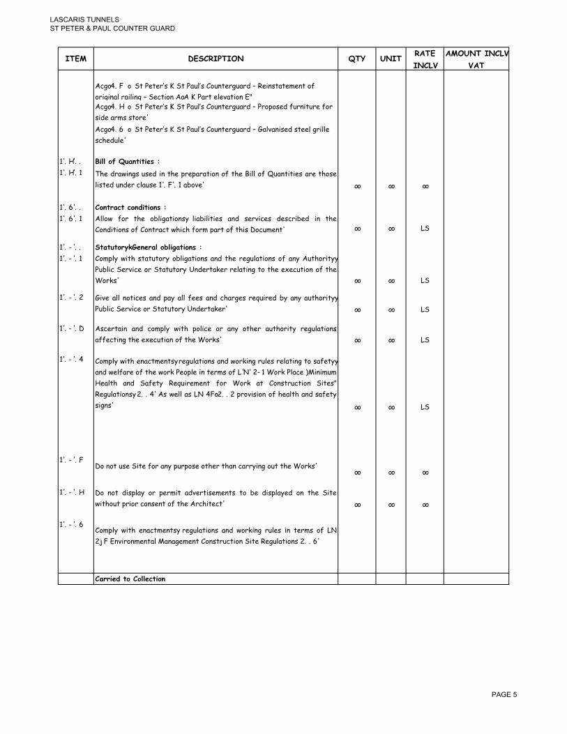
� �� ������������
������������ ������������� ��
��� ���������� �� ���������
������
������������
���
�&1/�!���/������%�%"H2�������(6-H2��#6'�%"16("5�C��%0'2�(�%)%'��#<�
#"010'(-�"(0-0'1�C��%&�0#'��/�����("��%-%4(�0#'��E�&1/�!���/������%�%"H2�������(6-H2��#6'�%"16("5�C��"#,#2%5�<6"'0�6"%�<#"�
205%�(")2�2�#"%�
�&1/�!���/������%�%"H2�������(6-H2��#6'�%"16("5�C��(-4('02%5�2�%%-�1"0--%�
2&+%56-%�
��!��!! .����#"� �������� ��
��!��!� �+% 5"(>0'12 62%5 0' �+% ,"%,("(�0#' #< �+% �0-- #< I6('�0�0%2 ("% �+#2%
-02�%5�6'5%"�&-(62%���!��!��(7#4%� // // //
��!��!! �#��������#�!���#� ��
��!��!� �--#> <#" �+% #7-01(�0#'23 -0(70-0�0%2 ('5 2%"40&%2 5%2&"07%5 0' �+%
�#'50�0#'2�#<��#'�"(&��>+0&+�<#")�,("��#<��+02��#&6)%'�� // // ��
��!9�!! ������#��34�������#&��)���#� ��
��!9�!� �#),-. >0�+ 2�(�6�#". #7-01(�0#'2 ('5 �+% "%16-(�0#'2 #< ('. �6�+#"0�.3
�67-0& �%"40&% #" ��(�6�#". �'5%"�(?%" "%-(�0'1 �# �+% %;%&6�0#' #< �+%
�#"?2� // // ��
��!9�! �04% (-- '#�0&%2 ('5 ,(. (-- <%%2 ('5 &+("1%2 "%@60"%5 7. ('. (6�+#"0�.3
�67-0&��%"40&%�#"���(�6�#".��'5%"�(?%"� // // ��
��!9�!� �2&%"�(0' ('5 &#),-. >0�+ ,#-0&% #" ('. #�+%" (6�+#"0�. "%16-(�0#'2
(<<%&�0'1��+%�%;%&6�0#'�#<��+%��#"?2� // // ��
��!9�!� �#),-. >0�+ %'(&�)%'�23 "%16-(�0#'2 ('5 >#"?0'1 "6-%2 "%-(�0'1 �# 2(<%�.3
('5 >%-<("% #< �+% >#"? �%#,-% 0' �%")2 #< ��� 9� �#"? �-(&% D0'0)6)
�%(-�+ ('5 �(<%�. �%@60"%)%'� <#" �#"? (� �#'2�"6&�0#' �0�%2E
�%16-(�0#'23 !!�� �2 >%-- (2 � ��/ !! ,"#4020#' #< +%(-�+ ('5 2(<%�.
201'2� // // ��
��!9�!��#�'#��62%��0�%�<#"�('.�,6",#2%�#�+%"��+('�&("".0'1�#6���+%��#"?2�
// // //
��!9�!� �# '#� 502,-(. #" ,%")0� (54%"�02%)%'�2 �# 7% 502,-(.%5 #' �+% �0�%
>0�+#6��,"0#"�&#'2%'��#<��+%��"&+0�%&�� // // //
��!9�!��#),-. >0�+ %'(&�)%'�23 "%16-(�0#'2 ('5 >#"?0'1 "6-%2 0' �%")2 #< �
:���'40"#')%'�(-�('(1%)%'���#'2�"6&�0#'��0�%��%16-(�0#'2� !!��
������!��#��#������#�
� ���

� �� ������������
������������ ������������� ��
��� ���������� �� ���������
������
������������
���
��!:�!! ���)�����3�!���� �����#����#��!��� �
��!:�!� �+% �#'�"(&�#" >0-- 7% "%2,#'207-% <#" �+% &##"50'(�0#' ('5 %;%&6�0#' #<
�+% �#�(- >#"?2 ('5 <#" �+% >#"? #< 267&#'�"(&�#"2 >+%�+%" '#)0'(�%5
#"�5#)%2�0&� // // ��
��!:�! �+% �#'�"(&�#" 02 �# ,"%,("% ('5 267)0� >0�+ +02 �%'5%" (' #6�-0'%
,"#1"())% <#" �+% >#"?23 26<<0&0%'� �# 05%'�0<. %(&+ �"(5%3 >+0-2�
<#--#>0'1��+%��0)%<"()%2�('5�5%(5-0'%2�0),#2%5�7.��+%��),-#.%"�// // ��
��!:�!� �' (>("5 #< &#'�"(&�3 �+% &#'�"(&�#" 02 �# ,"%,("% 0' (' (,,"#4%5 <#")3
( 5%�(0-%5 >#"?2 2&+%56-% <#" �+% >+#-% >#"?2 7(2%5 #' �+% &#),-%�0#'
5(�%�(2�267)0��%5�>0�+��+%�705� // // ��
��!:�!��67)0220#' #< ,"#1"())%2 >0-- '#� "%-0%4% �+% �#'�"(&�#" #< +02
#7-01(�0#'2 �# (,,-. 0' >"0�0'1 <#" 0'2�"6&�0#'2 (2 "%@60"%5 7. �+%
&#'50�0#'2�// // //
��!:�!� �%&%0,� #< ,"#1"())%2 7. �+% �"&+0�%&� >0-- '%0�+%" (<<%&� �+% �#'�"(&�
&#),-%�0#' 5(�% '#" "%-0%4% �+% &#'�"(&�#" #< +02 "%2,#'2070-0�. �#
&#),-%�%��+%��#"?2�7.��+02�5(�%� // // //
��!:�!�
�%40%> �+% ,"#1"())% #'&% %(&+ >%%? �# �(?% 0'�# (&'� #< ('.
&0"&6)2�('&%2 >+0&+ ("02% (<<%&�0'1 �+% ,"#1"%22 #< �+% �#"?2� �"#56&%
(�"%402%5�,"#1"())%�('5�267)0��&#,0%2��#��+%��"&+0�%&��
// // ��
��!:�!� ���%'5 26&+ "%16-(" 20�% )%%�0'12 (2 ("% '%&%22(". <#" �+% ,"#,%"
)('(1%)%'��('5�&##"50'(�0#'�#<��+%��#'�"(&�� // // ��
��!:�!9 �+%��#'�"(&�#"�>0--��(?%�('5�502�"076�%�)0'6�%2�#<�20�%�)%%�0'12� // // ��
���!�!! ���#�! 5���� ������� ���!�-������#� ��
���!�!� �'�%"0)�4(-6(�0#'2�>0--�7%�0226%5�(2��+%�>#"?�,"#1"%22%2� // // //
�����!! �#�%����#���
�����!�
�04% �"&+0�%&� (� -%(2� �># >%%?2 '#�0&% #< �+% ('�0&0,(�%5 5(�% #<
,"(&�0&(-�&#),-%�0#'�#<��+%�>+#-%�#"�,("��#<��+%��#"?2�
// // //
�����! �' <0'(- &#),-%�0#' #< �+% &#'�"(&� ('5 7%<#"% &%"�0<0&(�0#' #< <0'(-
,(.)%'� �+% �#'�"(&�#" )62� +('5 #4%" �+% 20�% &-%(' ('5 &-%(" #< (--
%;�"('%#62�)(�%"0(-� // // //
�����!� (?% (""('1%)%'�2 >0�+ �+% �),-#.%" ('5 104% "%(2#'(7-% '#�0&% #< �+%
,"%&02% 5(�%2 <#" (&&%22 �# 4("0#62 ,("�2 #< �+% �#"?2 <#" �+% ,6",#2%
#<�)(?0'1�1##5�5%<%&�2� // // //
������!��#��#������#�
� ����
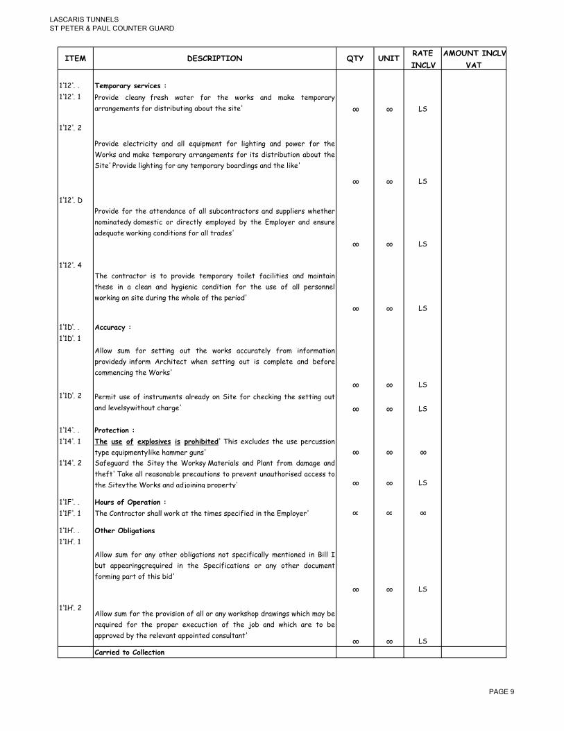
� �� ������������
������������ ������������� ��
��� ���������� �� ���������
������
������������
���
��� �!! ���%#����� ��-��� ��
��� �!� �"#405% &-%('3 <"%2+ >(�%" <#" �+% >#"?2 ('5 )(?% �%),#"(".
(""('1%)%'�2�<#"�502�"076�0'1�(7#6���+%�20�%� // // ��
��� �!
�"#405% %-%&�"0&0�. ('5 (-- %@60,)%'� <#" -01+�0'1 ('5 ,#>%" <#" �+%
�#"?2 ('5 )(?% �%),#"(". (""('1%)%'�2 <#" 0�2 502�"076�0#' (7#6� �+%
�0�%���"#405%�-01+�0'1�<#"�('.��%),#"(".�7#("50'12�('5��+%�-0?%�
// // ��
��� �!�
�"#405% <#" �+% (��%'5('&% #< (-- 267&#'�"(&�#"2 ('5 26,,-0%"2 >+%�+%"
'#)0'(�%53 5#)%2�0& #" 50"%&�-. %),-#.%5 7. �+% �),-#.%" ('5 %'26"%
(5%@6(�%�>#"?0'1�&#'50�0#'2�<#"�(--��"(5%2�
// // ��
��� �!�
�+% &#'�"(&�#" 02 �# ,"#405% �%),#"(". �#0-%� <(&0-0�0%2 ('5 )(0'�(0'
�+%2% 0' ( &-%(' ('5 +.10%'0& &#'50�0#' <#" �+% 62% #< (-- ,%"2#''%-
>#"?0'1�#'�20�%�56"0'1��+%�>+#-%�#<��+%�,%"0#5�
// // ��
�����!! ����������
�����!�
�--#> 26) <#" 2%��0'1 #6� �+% >#"?2 (&&6"(�%-. <"#) 0'<#")(�0#'
,"#405%53 0'<#") �"&+0�%&� >+%' 2%��0'1 #6� 02 &#),-%�% ('5 7%<#"%
&#))%'&0'1��+%��#"?2�
// // ��
�����! �%")0� 62% #< 0'2�"6)%'�2 (-"%(5. #' �0�% <#" &+%&?0'1 �+% 2%��0'1 #6�
('5�-%4%-23�>0�+#6��&+("1%� // // ��
�����!! ��#�����#���
�����!� �$� � � #" �6%�# �-� � %�#$�&���!� �+02 %;&-65%2 �+% 62% ,%"&6220#'
�.,%�%@60,)%'�3�-0?%�+())%"�16'2� // // //
�����! �(<%16("5 �+% �0�%3 �+% �#"?23 (�%"0(-2 ('5 �-('� <"#) 5()(1% ('5
�+%<�� �(?% (-- "%(2#'(7-% ,"%&(6�0#'2 �# ,"%4%'� 6'(6�+#"02%5 (&&%22 �#
�+%��0�%3��+%��#"?2�('5�(5$#0'0'1�,"#,%"�.� // // ��
�����!! 7#�� �#"��%�����#���
�����!� �+%��#'�"(&�#"�2+(--�>#"?�(���+%��0)%2�2,%&0<0%5�0'��+%��),-#.%"� // // //
�����!! ��$����&��)���#�
�����!�
�--#> 26) <#" ('. #�+%" #7-01(�0#'2 '#� 2,%&0<0&(--. )%'�0#'%5 0' �0-- �
76� (,,%("0'1A"%@60"%5 0' �+% �,%&0<0&(�0#'2 #" ('. #�+%" 5#&6)%'�
<#")0'1�,("��#<��+02�705�
// // ��
�����! �--#> 26) <#" �+% ,"#4020#' #< (-- #" ('. >#"?2+#, 5"(>0'12 >+0&+ )(. 7%
"%@60"%5 <#" �+% ,"#,%" %;%&6&�0#' #< �+% $#7 ('5 >+0&+ ("% �# 7%
(,,"#4%5�7.��+%�"%-%4('��(,,#0'�%5�&#'26-�('��// // ��
������!��#��#������#�
� ����

� �� ������������
������������ ������������� ��
��� ���������� �� ���������
������
������������
���
.����8
���������#��
���������#���
���������#���
���������#���
���������#���
���������#���
���������������������
� ����

� �� �����������
������������ ������������ ��
����� ������������������
��� �!
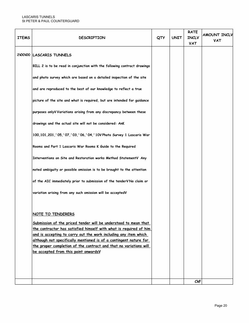
� �� �����������
������������ ������������ ��
���� ���������� �� ����
�����
������
���
������������
���
9�::�:: ����������������
.����9�� ��#�&�����!�����#�1�����#��/��$��$��"#��#/��)��#�������!��/��) �
��!�%$#�#� ��-���/$��$�����&� �!�#����!������!��� %����#��#"��$�� ����
��!�������%�#!���!��#��$��&� ��#"�#���2�#/��!)���#���"������������
%�������#"��$�� ������!�/$���� ���0����!5�&������������!�!�"#��)��!�����
%��%# � �#������������#� ���� ��)�"�#������!� ���%�����&��/�����$� ��
!��/��) ���!��$��������� ����/�����#��&���#� �!���!����;
8::58:859:85<:=5<:>5<:?5<:@5<:A5<8:���$#�#����-���8��� ���� �'���
�##� ���!������8��� ���� �'����##� �;�4��!���#��$����0����!�
�����-����#� �#���������!��� �#����#��/#�2 ���$#!�����������������
�#��!���&�)�����#��%# �&���#�� �#��� ��#�&��&�#�)$���#��$���������#��
#"��$����������!�������%��#���#� �&�� �#��#"��$�����!�����#�������#��#"��$����������!�������%��#���#� �&�� �#��#"��$�����!�����#�������#��
-������#����� ��)�"�#������ ��$�#�� �#��/����&������%��!�
����������������
��&�� �#��#"��$��%����!����!���/����&����!�� �##!��#�������$���
�$���#������#��$� � ��� "��!�$�� ��"�/��$�/$���� ���0����!�#"�$���
��!�� �����%���)��#�������#����$��/#�2������!��)����������/$��$�
���$#�)$��#�� %���"������������#��!�� �#"����#����)�����������"#��
�$��%�#%����#�%����#��#"��$���#���������!��$����#�-������#� �/����
&������%��!�"�#���$� �%#����#�/��! �
�3*
��� ���

� �� �����������
������������ ������������ ��
���� ���������� �� ����
�����
������
���
������������
���
.3*
9�:8�:: �����7������ ��*��.��7��� �* �7� ��������
�������
� %(26"%)%'��#<��#"?2*
�+02 02 ( ���% ��� �#������3 @6('�0�0%2 >+%' @6#�%5 0' �+02 ��I ('5
5"(>0'12�("%�#������!�����-���
�+% &#'�"(&�#"2 ("% �# )(?% �+%0" #>' &(-&6-(�0#'2 ('5 '# &-(0)2 <#"
(550�0#'(- ,(.)%'�2 #' �+% 1"#6'52 #< 502&"%,('&0%2 7%�>%%' ('. @6#�%5
('5�(&�6(-�<016"%2�>0--�7%�%'�%"�(0'%5�
�+% �%") "%<6"702+)%'� 0' �+% &#'�%;� #< �+02 ��I >0-- 7% 6'5%"2�##5 �#
)%(' �+% &#),-%�% #4%"+(6- #< ('. ,("�0&6-(" 0�%) #" ("%( �# 0�2 #"010'(-
&#'50�0#' 0'&-650'1 �+% 2672�0�6�0#' #< ('. 5%<%&�04%3 )0220'1 #" >#"'
)%)7%" <#")0'1 ,("� #< �+% #"010'(- 0�%) #" ("%(� �'. <(7"0&(�0#' 0'4#-4%5
>0-- <#--#> �+% �"(50�0#'(- )%�+#52 %),-#.%5 (� �+% �0)% #< 0�2 #"010'(-
)('6<(&�6"% #" (' (,,"#4%5 %@604(-%'� (&&#),('0%5 7. ( )%�+#5 2�(�%)%'��
�+% &#'�"(&�#" 02 �# ,"%2%'� 7#�+ �+% &-0%'� ('5 �+% &#'26-�('� >0�+
2(),-%2 #< (-- �+#2% )(�%"0(-2 �+(� >0-- 7% %),-#.%5 0' ('. "%<6"702+)%'�
%;%"&02% (2 >%-- (2 ('. >#"?2+#, 5"(>0'1 �+(� )(. 7% "%@60"%5 <#" ( ,"#,%"
%4(-6(�0#'�('5�(,,"#4(-�,"0#"��#�%;%&6�0#'�#<��+%�>#"?�
�+% &#'�"(&�#" 2+#6-5 (--#> <#" >#"?0'1 >0�+0' �+% &#'<0'%2 #< �+% 20�%� �+%�
�#'�"(&�#" 02 �# 0'4%2�01(�% �+% 20�% ('5 7% <6--. (>("% #< 0�2 "%@60"%)%'�23
50<<0&6-�0%2 #" "%2�"0&�0#'2 ('5 )(?% �+% '%&%22(". ,"#4020#'2 0' +02 "(�%2�
�# -������#� ��� ��) "�#� /#�2 �#� �!����"��! ��! %����! &� �$�
�#������#� &�� !����! �����!�! &� �$� ������ #� �#� ������ �� �$� %��
���!����)� ��)��/����&������%��!�
�3*
��� ���

� �� �����������
������������ ������������ ��
���� ���������� �� ����
�����
������
���
������������
���
.3*
�'. 5()(1% �# �+% %),-#.%"B2 #" �+0"5 ,("�. ,"#,%"�. 2+(-- 7% "%&�0<0%5 (�
�+%�%;,%'2%�#<��+%�&#'�"(&�#"�
�+% "(�%2 267)0��%5 2+#6-5 &(�%" <#" (-- �+% "%2�"0&�0#'2 ,"%2%'� #' �+%
20�% '# 4("0(�0#' ("020'1 <"#) &-(0)2 "%26-�0'1 <"#) '#� +(40'1 6'5%"2�##5
�+%2%�"%2�"0&�0#'2��>0--�7%�&#'205%"%5�
��%)2 #< ( )%&+('0&(- #" %-%&�"0&(- '(�6"% >0-- 7% 5%(-� >0�+ %-2%>+%% 0'
�+02��%'5%"�('5�("%�'#��%"%5�7.��+02�70--�
�3*
��� ���

� �� �����������
������������ ������������ ��
���� ���������� �� ����
�����
������
���
������������
���
.3*
� ���� ������#������!���
D0E �"0&0'1 02 �# 7% %'�%"%5 #' ( �6), �6) 7(202 6'-%22 2,%&0<0&(--.
"%@6%2�%5 #�+%">02% ('5 02 �# 7% 0'&-6204% #< (-- >#"?2 "%@60"%5 <#" �+%
,"#,%" %;%&6�0#' #< �+% "%@60"%5 "%<6"702+)%'� #" "%2�#"(�0#' $#7 3 (2 >%--
(2 ('. #�+%" >#"?2 >+0&+ ("% #< ( &#'�0'1%'� #" 0'502,%'2(7-% '(�6"% <#"
&#),-%�0'1 �+% >#"? 0' 0�2 %'�0"%�. %4%' 0< '#� 2,%&0<0&(--. "%<%"%5 �# #"
)%'�0#'%5 0' (' 0�%)� �# -������#� ��� ��) "�#� /#�2 �#� �!����"��! ��!
%����! &� �$� �#������#� �� �$� %�� ���!����) ��)� /��� &� ����%��!�
��� ���� ��� !����! �# �����!� ��� !#�&�� $��!���)5 ������)�5
�������� 5 ��&#��5 ��""#�!��)5 �������) ��! ������) �/�� � /��� �
!��%��)��$��)� �
B��C�������������������������
���� ������#����#/�"#��
D(E��"0#"��#�('.�>#"?�&#))%'&0'1�#'�20�%��+%��#'�"(&�#"�(-#'1�>0�+��+%�
�-0%'�����#'26-�('��02��#�&("".�#6��(�26"4%.��#�&#),0-%�(�5%�(0-%5�0'4%'�#".�
#<�>+(��02�,"%2%'��#'�20�%�('5�02��#�7%�2(<%16("5%5��"%2�#"%53�"%<6"702+%5�
#"�"%&#))0220#'%5���+02�26"4%.�>0--�5%<0'%��+%�%;�%'�2�#<��+%�,"#$%&��
%"%5�7.��+02�70--�
B���C�����������
���� ������#����#/�"#��
D(E �%'%"(--. �# 2�%%- 0�%)23 "(�%2 ("% �# (--#> ('5 0'&-65% �+% <#--#>0'1 (2
>%-- (2 ('. #�+%" >#"?2 >+0&+ ("% #< ( &#'�0'1%'� #" 0'502,%'2(7-% '(�6"%
<#"�&#),-%�0'1��+%��>#"?�0'�0�2�%'�0"%�.�%4%'�0<�'#��2,%&0<0&(--.�)%'�0#'%5*
D7E �%"62�0'1 7. 2('5A1"0� 7-(2�0'1 #" 2&"(,0'1 5#>' )('6(--. �# %;,#2%
+%(-�+.�7(2%�)%�(-�
D&E��,,-0&(�0#'�#<�+#��50,�1(-4('0J0'1�
D5E �%'%"(--. 6'-%22 #�+%">02% 2�(�%5 '%> 2�%%- 0�%)2 �# 7% <(7"0&(�%5 #6�
#<�)0-5�2�%%-��
�3*
��� ���

� �� �����������
������������ ������������ ��
���� ���������� �� ����
�����
������
���
������������
���
.3*
D%E �%,(0" #" "%,-(&%)%'� #< 5%<%&�04% #" )0220'1 ,("�2 1%'%"(--. 0'&-650'1
&#),-%�%�2�%%-�7%()2�('5�&#-6)'2�
D<E �%)('6<(&�6"%3 620'1 �"(50�0#'(- )%�+#52 #< <(7"0&(�0#'3 ('. )0220'1 #"
"%@60"%5 '%> 0�%)2 20�6(�%5 0' #" <#")0'1 ,("� #< �+% >#"?23 0'&-650'1 -#&?23
+0'1%23 +(2,23 5"(> 7#-�23 5##" ?'#72 ('5 +('5-%23 )%2+%23 +##?23 &-#�+
+('1%" ,%123 � 7"(&?%�2 2+%-< +('1%"2 ('5 26,,#"�23 -(55%"23 &(� -(55%"2 #"
20'1-% "6'12 #< 2()%3 <#-50'1 7%523 <#-50'1 7%5 26,,#"�23 )%2+3 5##" "(0-2
('5�2-05%"2�%�&�
D1E �+% 5"0--0'1 #6� #< �+% "62�%5 "%)(0'2 #< 2�%%- >(-- )#6'�0'1 ,0'2 #< ('.
2�%%- >(-- )#6'�%5 <0;�6"% 0'&-650'1 7%52 ('5 �+%0" 26,,#"�23 5##"23 "(0-23
+('5"(0-23 1(�%23 2�(0"23 ,0,%23 )#6'�0'1 <"()%2 #< ('. 2#"�3 56&� 7"(&?%�23
7%()23�&(��-(55%"�"6'12�%�&��
D+E �%��0'1 #< ('. 2�%%- >(-- )#6'�%5 <0;�6"% 0' ,"%40#62-. 5"0--%5 +#-%2 >0�+
�+%�(05�#<�(�,"#,"0%�.�('&+#"0'1�&#),#6'5�
D0E �0;0'1 #< ('. 2�%%- +('5"(0-3 #" +('5"(0- 26,,#"�3 #" 1(�% 0�%) #" 20)0-(" 0'
)(2#'". #" "#&? 620'1 -%(5 (2 �+% 2%��0'1 )%506) 0'&-650'1 �+% <#")(�0#' #<)(2#'". #" "#&? 620'1 -%(5 (2 �+% 2%��0'1 )%506) 0'&-650'1 �+% <#")(�0#' #<
,#&?%�2�<#"�26&+�(�,6",#2%�
D$E �2 ,%" 0�%) D+E (7#4% 76� <0;%5 �# >(--2 7. )%('2 #< ,"#,"0%�. %;,('20#'
7#-�2�#"�7"(223�2�%%-�#"�2�(0'-%22�2�%%-�2&"%>2�('5�,-612�
D?E �,,-0&(�0#' #< ( �"(50�0#'(- #0- 7(2%5 #" %,#;. ,(0'� "%10)% 0' )(�&+0'1
&#-#6"2 �# %;02�0'1 #" '%> %-%)%'�2 #" (2 50"%&�%53 �# &-%(' ,"0)%5
1(-4('02%5�#"�'#'�1(-4('02%5�2�%%-�0�%)2�
D-E �+% 2%��0'1 (205% <#" <6�6"% "%<6"702+)%'� ('5 62% #< ('. %(")("?%5
,0%&%�#<�0"#'�)#'1%".�<#6'5�#'��+%�,"#$%&��20�%�
�3*
��� ��

� �� �����������
������������ ������������ ��
���� ���������� �� ����
�����
������
���
������������
���
.3*
D)E �+% "%<6"702+)%'� #< ('. ,0%&% #< 0"#')#'1%". ,"%2%'� #' 20�% #" 0�2
2672�0�6�0#' >0�+ ( 20)0-(" #" (,,"#4%5 #'%� �(7"0&(�0#' +(2 �# <#--#> �+%
�"(50�0#'(- )%�+#52 #< >#"?)('2+0, ('5 )(�%"0(-2 %),-#.%5 (� �+% �0)% #<
#"010'(-�)('6<(&�6"%�
D'E �+% "%<6"702+)%'� #" "%'%>(- #< ('. 2�%%- -#64%"%5 0�%) #" 1"0--% #"
)%2+3 0'&-650'1 �+% "%)#4(- #< (-- %;02�0'1 <0'02+%2 -.0'1 �+%"%#'3 (,,-0&(�0#'
#< ( "62� 0'+07�#"3 0'&-650'1 1(-4('020'1 ('5 (,,-0&(�0#' #< (' (,,"#4%5 ,(0'�
"%10)%�
B�-C���.�������
���� ������#����#/�"#��
D(E ��"0,,0'1 5#>' �# 7("% >##5 %;02�0'1 �0)7%" 0�%)2 ('5 (-- �"(&%2 #< #-5
,(0'��#"�4("'02+�"%)#4%5�
D7E �672�0�6�0#' #< ('. )0220'1 #" "#��%5 ,("�2 0' 20)0-(" >##5 620'1
�"(50�0#'(-�)%�+#52��#�$#0'�#"�<0;��+%�'%>�,("�2��#��+%�#-5�
D&E %> �0)7%" 0�%)2 0'&-650'1 (,%"�6"%2 #< ('. 2#"� ('5 20J%3 %1 1(�%23
5##"23 >0'5#>23 �"(, 5##"23 <-##" 7#("523 2+#6-5 7% )('6<(&�6"%5 0' 20)0-("
�0)7%" (2 ,%" %;02�0'1 #" (2 (5402%5 7. &-0%'� #" &#'26-�('� ('5 7.�0)7%" (2 ,%" %;02�0'1 #" (2 (5402%5 7. &-0%'� #" &#'26-�('� ('5 7.
�"(50�0#'(- (,,"#4%5 )%�+#52 0'&-650'1 ('. 1-(J0'1 ('5 (-- +("5>("% �+(�
)(. 7% "%@60"%5 0'&-650'1 5##" ?'#723 +('5-%23 -#&?23 +0'1%23 "(0-23 "6''%"23
&#(� +('1%"23 2+%-< +('1%"23 2+%-< 26,,#"�23 %�&� �(�% 02 �# (--#> <#" �+%
,"#56&�0#'�#<�>#"?2+#,�5"(>0'12�>+%"%�'%>�0�%)2�'%%5��#�7%�,"#56&%5�
D5E �,,-0&(�0#' #< ( �"(50�0#'(- #0- 7(2%5 #" %,#;. ,(0'�3 #" 4("'02+ "%10)% 0'
)(�&+0'1 &#-#6"2 ('5 <0'02+ �# %;02�0'1 &-%(' ,"0)%5 �0)7%" 0�%)2 #" '%>-.
)('6<(&�6"%5�#'%2�
D<E��+%�&#),-%�%�"%<6"702+)%'��#<��0)7%"�<-##"�7#("52�0'&-650'1��+%�
"%,-(&%)%'��#<�('.�)0220'1�,("�2�#"��+%�&#),-%�%�"%)('6<(&�6"%�0'�
�"(50�0#'(-�)%�+#52�#<��+%�&#),-%�%�<-##"��
D1E �-- '%> �0)7%" 0�%)2 �# 7% )('6<(&�6"%5 0' >%-- 2%(2#'%5 �%5 �%(-
6'-%22�#�+%">02%�2�(�%5�
�3*
��� ��
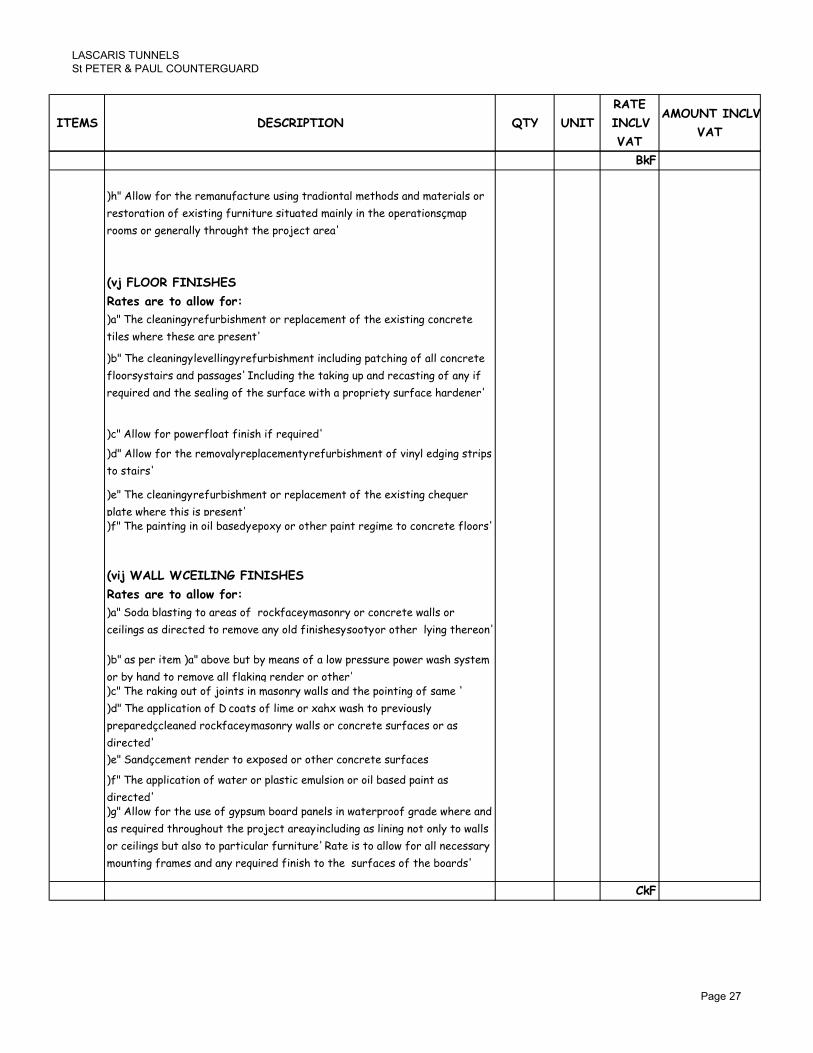
� �� �����������
������������ ������������ ��
���� ���������� �� ����
�����
������
���
������������
���
.3*
D+E��--#>�<#"��+%�"%)('6<(&�6"%�620'1��"(50#'�(-�)%�+#52�('5�)(�%"0(-2�#"�
"%2�#"(�0#'�#<�%;02�0'1�<6"'0�6"%�20�6(�%5�)(0'-.�0'��+%�#,%"(�0#'2A)(,�
"##)2�#"�1%'%"(--.��+"#61+���+%�,"#$%&��("%(�
B-C�*�����*����7��
���� ������#����#/�"#��
D(E��+%�&-%('0'13�"%<6"702+)%'��#"�"%,-(&%)%'��#<��+%�%;02�0'1�&#'&"%�%�
�0-%2�>+%"%��+%2%�("%�,"%2%'��
D7E��+%�&-%('0'13�-%4%--0'13�"%<6"702+)%'��0'&-650'1�,(�&+0'1�#<�(--�&#'&"%�%�
<-##"23�2�(0"2�('5�,(22(1%2���'&-650'1��+%��(?0'1�6,�('5�"%&(2�0'1�#<�('.�0<�
"%@60"%5�('5��+%�2%(-0'1�#<��+%�26"<(&%�>0�+�(�,"#,"0%�.�26"<(&%�+("5%'%"��
D&E��--#>�<#"�,#>%"<-#(��<0'02+�0<�"%@60"%5�
D5E��--#>�<#"��+%�"%)#4(-3�"%,-(&%)%'�3�"%<6"702+)%'��#<�40'.-�%510'1�2�"0,2�
�#�2�(0"2�
D%E��+%�&-%('0'13�"%<6"702+)%'��#"�"%,-(&%)%'��#<��+%�%;02�0'1�&+%@6%"�
,-(�%�>+%"%��+02�02�,"%2%'��D<E��+%�,(0'�0'1�0'�#0-�7(2%53�%,#;.�#"�#�+%"�,(0'��"%10)%��#�&#'&"%�%�<-##"2�
B-�C�'����(�������4�*����7��
���� ������#����#/�"#������ ������#����#/�"#��
D(E��#5(�7-(2�0'1��#�("%(2�#<��"#&?<(&%3�)(2#'".�#"�&#'&"%�%�>(--2�#"�
&%0-0'12�(2�50"%&�%5��#�"%)#4%�('.�#-5�<0'02+%23�2##�3�#"�#�+%"��-.0'1��+%"%#'�
D7E�(2�,%"�0�%)�D(E�(7#4%�76��7.�)%('2�#<�(�-#>�,"%226"%�,#>%"�>(2+�2.2�%)�
#"�7.�+('5��#�"%)#4%�(--�<-(?0'1�"%'5%"�#"�#�+%"�D&E��+%�"(?0'1�#6��#<�$#0'�2�0'�)(2#'".�>(--2�('5��+%�,#0'�0'1�#<�2()%��
D5E��+%�(,,-0&(�0#'�#<���&#(�2�#<�-0)%�#"�;(+;�>(2+��#�,"%40#62-.�
,"%,("%5A&-%('%5�"#&?<(&%3�)(2#'".�>(--2�#"�&#'&"%�%�26"<(&%2�#"�(2�
50"%&�%5��
D%E��('5A&%)%'��"%'5%"��#�%;,#2%5�#"�#�+%"�&#'&"%�%�26"<(&%2�
D<E��+%�(,,-0&(�0#'�#<�>(�%"�#"�,-(2�0&�%)6-20#'�#"�#0-�7(2%5�,(0'��(2�
50"%&�%5�D1E��--#>�<#"��+%�62%�#<�1.,26)�7#("5�,('%-2�0'�>(�%","##<�1"(5%�>+%"%�('5�
(2�"%@60"%5��+"#61+#6���+%�,"#$%&��("%(3�0'&-650'1�(2�-0'0'1�'#��#'-.��#�>(--2�
#"�&%0-0'12�76��(-2#��#�,("�0&6-("�<6"'0�6"%���(�%�02��#�(--#>�<#"�(--�'%&%22(".�
)#6'�0'1�<"()%2�('5�('.�"%@60"%5�<0'02+��#��+%��26"<(&%2�#<��+%�7#("52�
�3*
��� ���

� �� �����������
������������ ������������ ��
���� ���������� �� ����
�����
������
���
������������
���
.3*
B-��C�������������.�
���� ������#����#/�"#��
D(E��+%�7"%(?0'1�6,�('5�&("�0'1�(>(.�#<�5%1"(5%5����2-(72�('5��+%�
"%&(2�0'1�#<�2()%�(��('.�-%4%-3�+%01+��#"�,#20�0#'���#'�"(&�#"�02��#�267)0��
>#"?2+#,�5"(>0'12�<#"�('.�'%>�#"�,("��2-(73�2+#>0'1�1"(5%3��+0&?'%22�#<�
&#'&"%�%�('5�"%@60"%5�"%0'<#"&%)%'��
D7E��+%�)(?0'1�1##5�#<�2,(--0'1����2-(72�(��('.�-%4%-�#"�+%01+��7.�)%('2�#<�(�
,"#,"0%�.�,"#56&��#"�"%10)%�<0��<#"��+%�,6",#2%�D&E��+%�"%0'2�(�%)%'�3�#"�"%<6"702+)%'��#<�,("�2�#<3�#"�('�%'�0"%�"##<�("%(3�
#<�('.�502�6"7%5�"##<0'1�0�%)2�0'&-650'1�2,(--2�D�#"7(E�"##<�2&"%%5�#"�
>(�%","##<0'1�)%)7"('%�
D5E �(�%2 <#" &#'&"%�% >#"? ("% �# 7% 0'&-6204% #< (-- <#")>#"?3 ,"#,,0'13
%"%&�0#' ('5 2�"0?0'1 #< <#")>#"? ('5 "%0'<#"&%)%'� 5%,%'50'1 #' �+%
'(�6"% #< �+% 62% #< �+% ,("�0&6-(" &#'&"%�% ,#6"� �#'�"(&�#" �# ,"#405%
2+#,�5"(>0'1�1040'1�(--��+%�'%&%22(".�5%�(0-2�
D%E �(�%2 <#" "%0'<#"&0'1 2�%%-3 >+%�+%" 7("2 #" <(7"0&3 2+(-- 0'&-65%
26,,-.3��"('2,#"���#�20�%3�&6��0'13�('5��.0'1�0'�,#20�0#'��
D<E �(�%2 <#" �#'&"%�% �#"? ("% �# 7% 0'&-6204% #< &#'2#-05(�0#' 7.
407"(�0#' #" #�+%" 260�(7-% )%�+#52 �# �+% (,,"#4(- #< �+% �"#$%&�
�"&+0�%&��
D1E �(�%2 <#" ,"%/&(2� #" &(2� 0' 20�6 &#'&"%�% 2-(72 2+(-- 7% 0'&-6204% <#"
�+% <#")(�0#' #< ( �!!)) )0'0)6) 5%%, 7%("0'1 &+(2% 0'�# �+% 26,,#"�0'1
>(--2�>(--2�
B-���C��������
���� ������#����#/�"#��
D(E��+%�"%0'2�(�%)%'�3�"%<6"702+)%'��#"�"%&#'2�"6&�0#'�#<�('.�20'1-%�#"�
)6-�0,-%�2?0'�)(2#'".�>(--�(��('.�-%4%-�#"�+%01+��620'1�)(2#'".�7-#&?2��#<�
�+%�2()%��+0&?'%22�('5�+%01+��(2�#"010'(-�('5�2%��0'�1(61%5�)#"�("�����>0--�
7%�(&&%,�(7-%��#�62%�&6""%'��)(2#'".�760-50'1�7-#&?�20J%2�>+%"%��+%2%�("%�
1#0'1��#�7%�>+0�%>(2+%5�D7E��+%�<#")0'1�#<�('.�4#622#0"3�4(6-�3�"%7(�%3�&+(2%3�2?%>�('1-%3��##�+0'1�
�#�%;02�0'1�"#&?<(&%�#"�%;02�0'1�>(--�
D&�E��--#>�<#"��+%�"%&#'2�"6&�0#'�#"�"%<6"702+)%'��#<�>(--2�0'�+#--#>�
&#'&"%�%�7-#&?�#<�('.��+0&?'%22�#"��.,%�2%��0'�1(61%5�)#"�("�
D5E��--#>�<#"��+%�(,,-0&(�0#'�#<�2�('5("5�&6""%'��)(2#'".�"%2�#"(�0#'�
)%�+#523�0'&-650'1�"(?0'1�#6��#<�$#0'�2�('5�,#0'�0'1�0'�+.5"(6-0&�-0)%3�
,"#4020#'�#<�2�#'%�,#&?%�2��#�"%)#4%�5%�%"0#"(�%5�2�#'%�7-#&?�26"<(&%2�('5�
'%>�2�#'%2��#�7%�<0��%5�0'205%��+%2%�,#&?%�23�5#>%--0'1�#<�'%>�2�#'%2��#�
%;02�0'1�5%�%"0#"(�%5�)(2#'".�%-%)%'�23�,-(2�0&�"%,(0"3�&-%('0'1�#<�
%'&"62�%5�)(2#'".�26"<(&%23�"%)#4(-�#<�-(�%"�5(.�(&&"%�0#'2�#'��+%�26"<(&%�
#<�)(2#'".�>(--23�"%)#4(-�#<�"%56'5('��+##?23�'(0-23�>0"%23�,0,%23�7"(&?%�23�
%�&���
�3*
��� ���

� �� �����������
������������ ������������ ��
���� ���������� �� ����
�����
������
���
������������
���
.3*
B�6C����*��4�����
���� ������#����#/�"#��
D(E��%0'2�(�%)%'��#<�('.�"##<0'1�0�%)�'()%-.*�>(�%","##<0'1�)%)7"('%3�
"##<�2&"%%5�0'&-650'1�2#<��2�#'%�2,(--2�-(05��#�<(--2�
D7E��+%�-(.0'1��#�<(--2�#<�(�"##<�2&"%%5�0'&-650'1��+%�6'5%"-.0'1�2#<��2�#'%�
2,(--2�D�#"7(E�-(05��#�<(--2�
D&�E��+%�-(.0'1�#<�(��))��+?�>(�%","##<0'1�)%)7"('%�#4%"�,"%40#62-.�-(05�
2&"%%5�
B6C����������*�����4�
���� ������#����#/�"#��
D(E��%,-(&%)%'��#<�5()(1%5�#"�)0220'1�2('0�(".>("%�>0�+�(,,"#4%5�#"010'(-�
,%"0#5�0�%)23�0'&-6204%�#<�,%"0#5�('1-%�4(-4%2�('5�&#''%&�#"2�(2�>%--�(2�(--�
#�+%"�"%-(�%5�<0��0'12����%)2�5%%)%5��#�7%�0'&-65%5�("%3��#0-%��260��
&#),-%�%�>0�+�2%(��('5�262,%'5%5�<-62+0'1�&02�%"'3��#0-%��"#--�+#-5%"23�>(2+�
+('5�7(20'�&#),-%�%�>0�+�(--��(,2�('1-%�4(-4%2�&#''%&�#"2�('5�26,,#"�23�
2+#>%"��"(.23�2+#>%"�+%(52�('5�"%16-(�0'1��(,2�#"�)0;%"2���#>%-�"(0-�#"�
,(,%"��#>%-�502,%'2%"2�
B6�C������7��������������
���� ������#����#/�"#��
D(E��--#>�<#"��+%�,"%2%"4(�0#'�('5�,#2207-%�"%2�#"(�0#'�#<�('.�+02�#"0&(-�D(E��--#>�<#"��+%�,"%2%"4(�0#'�('5�,#2207-%�"%2�#"(�0#'�#<�('.�+02�#"0&(-�
1"(<<0�0�05%'�0<0%5�<#"�"%�%'�0#'���(�%�>0--�0'&-65%�<#"�%"0'1�('.�26&+�
1"(<<0��0�>0�+�(�>(--�)#6'�%5�'#'�"%<-%&�04%�1-(22�2+%%��('5�(�)%�+#5�
2�(�%)%'��0'50&(�0'1�+#>��+%�>#"?�>0--�7%�&(""0%5�#6��
�3*
��� ���

� �� �����������
������������ ������������ ��
���� ���������� �� ����
�����
������
���
������������
���
.3*
�! �!! �%<6"702+3�"%2�#"%3�"%'%>�('5�&#))0220#'��+%�,"#$%&��("%(�?'#>'�(2��+%�
�(2&("02��("��##)23��2+#>'�#'��+%�"%<%"%'&%�,-('�('5�(--��+%�0�%)2�
5%2&"07%5�0'���("����#<��+%��(2&("02��("��##)2�/��605%��#��+%��%@60"%5�
�'�%"4%'�0#'2�#'��0�%����#"?�02��#�(-2#�0'&-65%��('.�#�+%"�>#"?2�"%@60"%5�
('5�05%'�0<0%5�56"0'1��+%�20�%�26"4%.�5%2&"07%5�0'�0�%)��D00E�(7#4%�<#"���+%�
&#),-%�%�%;%&6�0#'�#<��+%�"%@60"%53�)('6<(&�6"%3�"%<6"702+)%'��#"�
"%2�#"(�0#'�$#73�(2�>%--�(2�('.�#�+%"�>#"?2�>+0&+�("%�#<�(�&#'�0'1%'��#"�
0'502,%'2(7-%�'(�6"%�<#"�&#),-%�0'1��+%��>#"?�0'�0�2�%'�0"%�.�%4%'�0<�'#��
2,%&0<0&(--.�"%<%"%5��#�#"�)%'�0#'%5�0'�('.�0�%)�#"�5%2&"0,�0#'� ��!! // ��
�! �!� �6,,-.�('5�%"%&��0'�<07"%1-(22�#'�(�,"#,"0%�.�1(-4('02%5�2�%%-�<"()%��+%�
>(�%","##<0'1�-0'0'1�2�"6&�6"%�5%�(0-%5�0'�5"(>0'1��'/�!!���--#>�<#"�('.�
2&(<<#-50'1��#�('.�+%01+����+(��)(.�7%�"%@60"%5�('5�(--�,"#,,0'1�(2��+%�>#"?�
,"#1"%22%2���(�%�02�(-2#��#�(--#>�<#"�('.�6'%4%'�)#6'�0'1�26"<(&%��+(��)(.�
7%�%''�%"%5�(2�>%--�(2�('.�#�+%"�0�%)��+(��02�#<�(�&#'�01%'��'(�6"%��#�
�+%�>#"?�0'�+('5�<#"�0�2�,"#,%"�%;%&6�0#'�
�9!�!! 2@�)
���������������������
��� ��!

�������������
�� ���������� ���������������
�������������������� ������������ ��
�������

�������������
�� ���������� ���������������
����� ��������� �� ����
�����
������
���
������������
���
������� �������������������������������
������������������ !��"�#�"$%"#���"�&��'��'��(�))�&�"*�#�"�� #��!� &�"*��
"!�+'�����%�,�-�&'�#'� ���� ��!��"� �!�� �)�!��"�+�#���"��(��'������� "!� "!�+'�����%�,�-�&'�#'� ���� ��!��"� �!�� �)�!��"�+�#���"��(��'������� "!�
�����+��!%#�!�����'��������(��%��."�&)�!*�������()�#�� ���%��+�#�%����(�
�'������� "!�&' �������/%���!0��%�� ����"��"!�!�(���*%�! "#��+%�+�����
�")-��� �� ���"�� ����"*�(��1� "-�!��#��+ "#-����&��"��'����!� &�"*�� "!�
�'�� #�% )������&�))�"������#�"��!���!2�, �� ���"� ����"*�(��1� "-��%#'�
�1�����"�&�))���� ##�+��!� (�����%�1�����"�
�#*34��04�404�506��06�406�506��06�� 06���06��#06�606�706�8�'����
�%�,�-�������������� %)���%"�����% �!� "!� ���������������� %)�
��%"�����% �!�3��%�!������'����/%���!��"���,�"���"���"������ "!�
������ ���"�&��.�����'�!��� ��1�"�����"-�"���!� 1��*%��-����+�����)��
�1�����"�������������%*'������'�� ���"���"��(��'���)��"�� "!�����
�11�!� ��)-�+���������%�1�����"��(��'����"!�������#) �1����, �� ���"� ����"*�
(��1� "-��%#'��1�����"�&�))���� ##�+��!��
���������������
�%�1�����"��(��'��+��#�!���"!���&�))����%"!������!����1� "��' ��
�'��#�"�� #����' ��� ���(��!�'�1��)(�&��'�&' �������/%���!��(�'�1��'��#�"�� #����' ��� ���(��!�'�1��)(�&��'�&' �������/%���!��(�'�1�
"!���� ##�+��"*����# ��-��%���'��&��.��"#)%!�"*� "-����1�&'�#'�
)�'�%*'�"����+�#�(�# ))-�1�"���"�!�����(� �#�"��"*�"��" �%���(���
�'��+��+���#�1+)����"��(��'��#�"�� #�� "!��' ��"��, �� ���"��&�))����
##�+��!�(��1��'���+��"���"& �!��
�9:
�������

�������������
�� ���������� ���������������
����� ��������� �� ����
�����
������
���
������������
���
�9:
���4��� ����;������ ��:�����;���� : �;� ��� ���� � ���
����������������
������������������ �!
�"#� #� � �%1+ �%1 ��"�� #�$ �"� %����#�#�� %����& #� �"#� ��' ��� �")-�
�"!�# ��,���
�"� (�����(���� ��� �� �� � �"�#� �)� (�*(�*��#��� ��& �� (*�#�� ��� �&&#�#���*
+�,����� �� �"� -����&� �� &#�(��+��(#�� .��)��� ��, %����& ��& �(���*+�,����� �� �"� -����&� �� &#�(��+��(#�� .��)��� ��, %����& ��& �(���*
�#-�����)#**�.���������#��&�
�, &���-� �� �"� ��+*�,��/� �� �"#�& +���, +��+���, �"�** .� ��(�#�#�& �� �"�
�0+���������"��(�����(����
�"� ����� ��.�#���& �"��*& (���� ��� �** �"� �����#(�#��� +������ �� �"� �#���"� ����� ��.�#���& �"��*& (���� ��� �** �"� �����#(�#��� +������ �� �"� �#��
�� 1��#��#�� ��#�#�- ���� (*�#�� ����*�#�- ���� ��� "�1#�- ��&������& �"���
�����#(�#�����)#**�.��(���#&���&�
����� �� � ��("��#(�* �� �*�(��#(�* ������ )#** .� &��*� )#�" �*��)"��
#���"#�����&�����&���������(�1���&�.,��"#��.#**�
�9:
�������

�������������
�� ���������� ���������������
����� ��������� �� ����
�����
������
���
������������
���
�9:
� � ���� �������"#)%!��2
2#3 �#(#�- #� �� .� ������& �� � ���+ ��� .��#� ��*��� �+�(#�#(�**, ��%�����&
��"��)#�� ��& #� �� .� #�(*��#1� �� �** )�� � ��%�#��& ��� �"� +��+�� �0�(��#����"��)#�� ��& #� �� .� #�(*��#1� �� �** )�� � ��%�#��& ��� �"� +��+�� �0�(��#��
�� �"� ��%�#��& �����.#�"���� �� ��������#�� 4�.$ �� )�** �� ��, ��"�� )�� �
)"#(" ��� �� � (���#�-��� �� #�&#�+����.*� ������ ��� (��+*��#�- �"� )�� #�
#�� ���#���, �1�� #� ��� �+�(#�#(�**, ������& �� �� ����#���& #� �� #���� ���
, �� ���"� ����"* (��1 &��. "�� �!�"��(��! "! +��#�! �- �'� #�"�� #��� �
�'� +�� ��"!���"* �� *� &�)) �� ##�+��!� �)) � ��� �� !��1�! �� �"#)%!�
)) !�%�)� ' "!)�"*0 #� "� *�0 1 ���� )�0 ) ��%�0 �# ((�)!�"*0 #)� "�"* "!
# ���"*� & -� ��&�))� ��!%1+�"*�#' �*���# ���"*� & -� ��&�))� ��!%1+�"*�#' �*���
<��=����������� ������������
� ���� ������ ))�&�(��2
2�3��#��������,�)�� �(�����(#�-�����#����"��������(�����*��-�)#�"��"���*#������
�����*�����#�����(���,����������1�,����(��+#*����&���#*�&�#�1�����,����)"���#��
+�����������#�����&�#�����.������-���&�&���������&$������.#�"�&����
��(���#��#���&���"#�����1�,�)#**�&��#����"���0����������"��+��4�(��(�1���&�.,�
�"#��.#**�<���=������������<���=������������
� ���� ������ ))�&�(��2
2�3 ������**, �� ����* #����$ ����� ��� �� �**�) ��& #�(*�&� �"� ��**�)#�- �� )�**
�� ��, ��"�� )�� � )"#(" ��� �� � (���#�-��� �� #�&#�+����.*� ������ ���
(��+*��#�-��"���)�� �#��#������#���,��1���#�������+�(#�#(�**,�����#���&!
2.3 ������#�- ., ���&5-�#� .*���#�- �� �(��+#�- &�)� �����**, �� �0+���
"��*�",�.��������*�"��*�",�.��������*�
2(3� ++*#(��#������"���&#+�-�*1��#6#�-�
2&3 ��+�#� �� ��+*�(����� �� &���(�#1� �� �#��#�- +���� -�����**, #�(*�&#�-
(��+*��������*�.�������&�(�*�����
2�3 ��������(����$ ��#�- ���&#�#���* ���"�&� �� ��.�#(��#��$ ��, �#��#�- ��
��%�#��& ��) #���� �#�����& #� �� ����#�- +��� �� �"� )�� �$ #�(*�&#�- *�( �$
"#�-��$ "��+�$ &��) .�*��$ &��� ��.� ��& "��&*��$ ���"��$ "�� �$ (*��" "��-��"#�-��$ "��+�$ &��) .�*��$ &��� ��.� ��& "��&*��$ ���"��$ "�� �$ (*��" "��-��
+�-�$ .��( ��� �"�*� "��-��� ��& ��++����$ *�&&���$ (�� *�&&��� �� �#�-*�
���-� �� ����$ ��*&#�- .�&�$ ��*&#�- .�& ��++����$ ���"$ &��� ��#*� ��& �*#&���
��(�
2&3 ������**, ��*��� ��"��)#�� �����& ��) ����* #���� �� .� ��.�#(���& ��� ��
�#*&�����*���#*&�����*��
�9:
�������

�������������
�� ���������� ���������������
����� ��������� �� ����
�����
������
���
������������
���
�9:
2�3 �"� &�#**#�- ��� �� �"� �����& ����#�� �� ����* )�** �����#�- +#�� �� ��,
����* )�** ������& �#0���� #�(*�&#�- .�&� ��& �"�#� ��++����$ &����$ ��#*�$
"��&��#*�$ ���(��$ -����$ ���#��$ +#+��$ �����#�- ������ �� ��, ����$ &�(�"��&��#*�$ ���(��$ -����$ ���#��$ +#+��$ �����#�- ������ �� ��, ����$ &�(�
.��( ���$�.����$�(���*�&&������-������*����+�$���(��
2�3 ����#�- �� ��, ����* )�** ������& �#0���� #� +��1#���*, &�#**�& "�*�� )#�"
�"���#&������+��+�#��,���("��#�-�(��+���&�
2-3 7#0#�- �� ��, ����* "��&��#*$ �� "��&��#* ��++���$ �� -��� #��� �� �#�#*�� #�
������, �� ��( ��#�- *��& �� �"� ����#�- ��&#�� #�(*�&#�- �"� ������#�� ��
+�( ����������("���+��+����
2"3 � +�� #��� 2"3 �.�1� .�� �#0�& �� )�**� ., ����� �� +��+�#��, �0+���#��
.�*������.����$�����*�������#�*��������*��(��)����&�+*�-��
2#3 ++*#(��#�� �� � ���&#�#���* �#* .���& �� �+�0, +�#�� ��-#�� #� ���("#�-
(�*���� �� �0#��#�- �� ��) �*������ �� �� &#��(��&$ �� (*��� +�#��& -�*1��#��&
�������-�*1��#��&�����*�#�����
243 �"� ����#�- ��#&� ��� ������ �����.#�"���� ��& ��� �� ��, ������ �& +#�(�
���#�������-��,�����&�����"��+��4�(���#���
2 3 �"� �����.#�"���� �� ��, +#�(� �� #������-��, +������ �� �#�� �� #��
��.��#���#�� )#�" � �#�#*�� �� �++��1�& ���� 7�.�#(��#�� "�� �� ��**�) �"�
���&#�#���* ���"�&� �� )�� ����"#+ ��& �����#�*� ��+*�,�& �� �"� �#�� ��
��#-#��*�������(�����
2*3 �"� �����.#�"���� �� ����)�* �� ��, ����* *��1���& #��� �� -�#**� �� ���"$
#�(*�&#�- �"� ����1�* �� �** �0#��#�- �#�#�"�� *,#�- �"�����$ �++*#(��#�� �� � ����
#�"#.���$�#�(*�&#�-�-�*1��#�#�-���&��++*#(��#����������++��1�&�+�#�����-#���
<�,=�������������
� ���� ������ ))�&�(��2
2�3 ���#++#�- &�)� �� .��� )��& �0#��#�- �#�.�� #���� ��& �** ���(�� �� �*&
+�#������1���#�"�����1�&�
2.3 ��.��#���#�� �� ��, �#��#�- �� �����& +���� #� �#�#*�� )��& ��#�- ���&#�#���*
���"�&�����4�#������#0��"����)�+���������"���*&����"�&�����4�#������#0��"����)�+���������"���*&�
2(3 ��) �#�.�� #���� #�(*�&#�- �+������� �� ��, ���� ��& �#6�$ �- -����$ &����$
)#�&�)�$ ���+ &����$ �*��� .���&�$ �"��*& .� ������(����& #� �#�#*�� �#�.�� ��
+�� �0#��#�- �� �� �&1#��& ., (*#��� �� (����*���� ��& ., ���&#�#���* �++��1�&
���"�&� #�(*�&#�- ��, -*�6#�- ��& �** "��&)��� �"�� ��, .� ��%�#��& #�(*�&#�-
&��� ��.�$ "��&*��$ *�( �$ "#�-��$ ��#*�$ �������$ (��� "��-���$ �"�*� "��-���$
�"�*� ��++����$ ��(� ���� #� �� �**�) ��� �"� +��&�(�#�� �� )�� �"�+ &��)#�-�
)"������)�#��������&����.��+��&�(�&�
2&3 ** ��) �#�.�� #���� �� .� ������(����& #� )�** �������& ��& ���* ��*���
��"��)#����+�(#�#�&�
�9:
�������
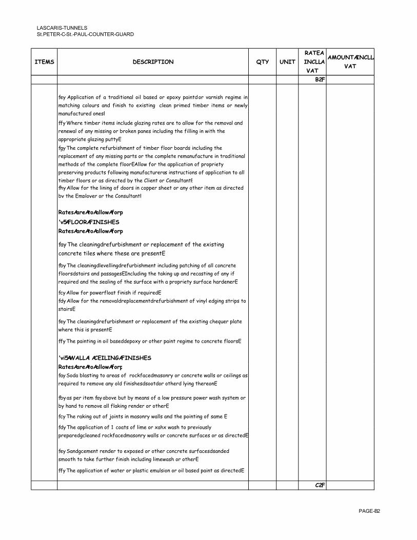
�������������
�� ���������� ���������������
����� ��������� �� ����
�����
������
���
������������
���
�9:
2�3 ++*#(��#�� �� � ���&#�#���* �#* .���& �� �+�0, +�#��$ �� 1���#�" ��-#�� #�
���("#�- (�*���� ��& �#�#�" �� �0#��#�- (*��� +�#��& �#�.�� #���� �� ��)*,
������(����&������������(����&������
2�3��"�����#�.���#�����#�(*�&��-*�6#�-���������������**�)������"������1�*���&�
����)�*������,��#��#�-����.�� ���+�����#�(*�&#�-��"���#**#�-�#��)#�"��"��
�++��+�#����-*�6#�-�+���,�
2-3��"��(��+*���������.#�"���������#�.����*����.���&��#�(*�&#�-��"��
��+*�(�����������,��#��#�-�+���������"��(��+*������������(�����#�����&#�#���*�
���"�&������"��(��+*�����*����� **�)������"���++*#(��#������+��+�#��,�
+�����1#�-�+��&�(�����**�)#�-�������(�����/��#�����(�#��������++*#(��#�������**�+�����1#�-�+��&�(�����**�)#�-�������(�����/��#�����(�#��������++*#(��#�������**�
�#�.����*�����������&#��(��&�.,��"���*#������������*�����2"3� **�)������"��*#�#�-����&�����#��(�++����"���������,���"���#�������&#��(��&�
.,��"���+*�,�������"�������*�����
� ���� ������ ))�&�(��2
<,=�:���:����;��
� ���� ������ ))�&�(��2
2�3��"��(*���#�-$������.#�"����������+*�(����������"���0#��#�-�
(��(������#*���)"�����"��������+�������
2.3��"��(*���#�-$�*�1�**#�-$������.#�"�����#�(*�&#�-�+��("#�-�����**�(��(�����
�*����$����#�����&�+����-������(*�&#�-��"���� #�-��+���&���(���#�-������,�#��
��%�#��&���&��"�����*#�-�����"�������(��)#�"���+��+�#��,������(��"��&������
2(3� **�)�����+�)���*�����#�#�"�#����%�#��&�
2&3� **�)������"������1�*$���+*�(�����$������.#�"��������1#�,*��&-#�-����#+�����2&3� **�)������"������1�*$���+*�(�����$������.#�"��������1#�,*��&-#�-����#+�����
���#���
2�3��"��(*���#�-$������.#�"����������+*�(����������"���0#��#�-�("�%����+*����
)"�����"#��#��+�������
2�3��"��+�#��#�-�#���#*�.���&$��+�0,������"���+�#�����-#������(��(������*�����
<,�=�>��������������:����;��
� ���� ������ ))�&�(��2� ���� ������ ))�&�(��2
2�3���&��.*���#�-����������������( ��(�$�������,����(��(�����)�**�����(�#*#�-�����
��%�#��&��������1����,��*&��#�#�"��$�����$������"��$��*,#�-��"������
2.3����+���#����2�3��.�1��.���.,������������*�)�+��������+�)���)��"��,��������
.,�"��&��������1���**��*� #�-����&��������"���
2(3��"���� #�-��������4�#����#��������,�)�**����&��"��+�#��#�-����������
2&3��"���++*#(��#��������(��������*#������0�"0�)��"����+��1#���*,�2&3��"���++*#(��#��������(��������*#������0�"0�)��"����+��1#���*,�
+��+���&5(*����&���( ��(�$�������,�)�**�����(��(����������(���������&#��(��&��
2�3����&5(���������&�������0+���&������"���(��(����������(��$����&�&�
�����"������ ������"����#�#�"�#�(*�&#�-�*#��)��"������"����
2�3��"���++*#(��#������)��������+*���#(����*�#�������#*�.���&�+�#������&#��(��&�
�9:
�������

�������������
�� ���������� ���������������
����� ��������� �� ����
�����
������
���
������������
���
�9:
<,��=��������������
� ���� ������ ))�&�(��2
2�3��"��.��� #�-��+���&�(���#�-��)�,����&�-��&�&�����*�.����&��"����(���#�-����
����������,�*�1�*$�"�#-"�����+��#�#����������(����#�������.�#��)�� �"�+�����������,�*�1�*$�"�#-"�����+��#�#����������(����#�������.�#��)�� �"�+�
&��)#�-��������,���)����+�����*�.$��"�)#�-�-��&�$��"#( ��������(��(�������&�
��%�#��&���#����(������2.3��"���� #�-�-��&�����+�**#�-�����*�.�������,�*�1�*����"�#-"��.,������������
+��+�#��,�+��&�(�������-#����#�������"��+��+����
2(3��"����#����������$���������.#�"��������+�������$����������#������������$����
��,�&#����.�&�����#�-�#�����#�(*�&#�-��+�**��2���.�3�������(���&����
)����+����#�-����.�����)����+����#�-����.�����
2&3 ����� ��� (��(���� )�� ��� �� .� #�(*��#1� �� �** ����)�� $ +��++#�-$
���(�#�� ��& ���# #�- �� ����)�� ��& ��#����(����� &�+��&#�- �� �"� ������
�� �"� ��� �� �"� +���#(�*�� (��(���� +���� ������(��� �� +��1#&� �"�+ &��)#�-
-#1#�-��**��"����(�����,�&���#*��
2�3 ����� ��� ��#����(#�- ����*$ )"��"�� .��� �� ��.�#($ �"�** #�(*�&� ��++*,$
�����+��������#��$�(���#�-$���&��,#�-�#��+��#�#����
2�3 ����� ��� ���(���� ��� ��� �� .� #�(*��#1� �� (����*#&��#�� ., 1#.���#��2�3 ����� ��� ���(���� ��� ��� �� .� #�(*��#1� �� (����*#&��#�� ., 1#.���#��
�����"�����#��.*�����"�&������"���++��1�*�����"����4�(�� �("#��(��
2-3 ����� ��� +��8(��� �� (��� #� �#�� (��(���� �*�.� �"�** .� #�(*��#1� ��� �"�
������#��������9::����#�#����&��+�.���#�-�("����#�����"����++���#�-�)�**��
<,���=������ �
� ���� ������ ))�&�(��2
2�3��"����#����������$������.#�"����������(������(�#��������,��#�-*�����2�3��"����#����������$������.#�"����������(������(�#��������,��#�-*�����
��*�#+*��� #��������,�)�**������,�*�1�*����"�#-"����#�-�������,�.*�( �������"��
������"#( �������&�"�#-"�������#-#��*���&�����#��-��-�&������������)#**�.��
�((�+��.*���������(�������������,�.�#*&#�-�.*�( ��#6���)"�����"��������-�#�-�
���.��)"#��)��"�&�
2.3��"������#�-������,�1�����#�$�1��*�$���.���$�("���$�� �)���-*�$�����"#�-����
�0#��#�-���( ��(������0#��#�-�)�**�
2(�3� **�)������"����(������(�#�����������.#�"��������)�**��#��"�**�)�(��(�����2(�3� **�)������"����(������(�#�����������.#�"��������)�**��#��"�**�)�(��(�����
.*�( ������,��"#( ���������,+������#��-��-�&��������
2&3� **�)������"���0����#�������0#��#�-����+��#��;���-��������*8'�))#;����
�++��1�&��%�#1�*����
2�3� **�)������"����++*,���&��#��#�-�#��+*�(������#��#�-�������,�#������#�����&�
#���"���++���+��������"��(�������-���&���������#6����&�%��*#�,�������("�
�0#��#�-��2�3� **�)������"���++*#(��#����������&��&�(�������������,���������#������"�&�$�2�3� **�)������"���++*#(��#����������&��&�(�������������,���������#������"�&�$�
#�(*�&#�-��� #�-��������4�#������&�+�#��#�-�#��",&���*#(�*#��$�+��1#�#������������
+�( �����������1��&����#�����&�������.*�( ������(�����&���)�����������.��
�#���&�#��#&���"����+�( ���$�&�)�**#�-������)������������0#��#�-�&����#�����&�
������,��*������$�+*���#(���+�#�$�(*���#�-������(�����&�������,������(��$�
����1�*����*�����&�,��((���#��������"�������(�����������,�)�**�$�����1�*����
��&��&����"�� �$���#*�$�)#���$�+#+��$�.��( ���$���(���
�9:
�������

�������������
�� ���������� ���������������
����� ��������� �� ����
�����
������
���
������������
���
�9:
<�?=��:���������
� ���� ������ ))�&�(��2
2�3���#����������������,�����#�-�#��������*,!�)����+����#�-����.����$������2�3���#����������������,�����#�-�#��������*,!�)����+����#�-����.����$������
�(���&�#�(*�&#�-�������������+�**��*�#&������**��
2.3��"��*�,#�-������**�������������(���&�#�(*�&#�-��"����&��*,#�-������������
�+�**��2���.�3�*�#&������**��
2(�3��"��*�,#�-������<����" �)����+����#�-����.������1���+��1#���*,�*�#&�
�(���&�
<?=�������� �:�������
� ���� ������ ))�&�(��2
2�3���+*�(���������&���-�&�����#��#�-����#���,)����)#�"��++��1�&���#-#��*�
+��#�&�#����$�#�(*��#1�����+��#�&���-*��1�*1�����&�(����(��������)�**�����**���"���
��*���&��#��#�-���������&����&����.��#�(*�&�&����$���#*�����#��(��+*����)#�"�
�������&����+��&�&��*��"#�-�(#�����$���#*�����**�"�*&���$�)��"�"��&�.��#��
(��+*����)#�"��**���+����-*��1�*1���(����(�������&���++����$��"�)������,�$�
�"�)���"��&����&���-�*��#�-���+������#0���$���)�*���#*����+�+�����)�*�
&#�+������
<?�=������;��������������
� ���� ������ ))�&�(��2
2�3� **�)������"��+�����1��#�����&�+���#.*����������#��������,�"#����#(�*�
-����#�#�#&���#�#�&�����������#���������)#**�#�(*�&������(�1��#�-���,���("�-����#�#�#&���#�#�&�����������#���������)#**�#�(*�&������(�1��#�-���,���("�
-����#��#�)#�"���)�**�������&��������*�(�#1��-*�����"������&������"�&�
����������#�&#(��#�-�"�)��"��)�� �)#**�.��(���#�&�����
<?��=��������������� ������
� ���� ������ ))�&�(��2
2�3� **�)������"��(��+*��������1�*������"��.�$�.��"��$���������&���"���2�3� **�)������"��(��+*��������1�*������"��.�$�.��"��$���������&���"���
1�-����#���������"��1��#����*�1�*������"�������������������*�������������&�
�9:
�������

�������������
�� ���������� ���������������
����� ��������� �� ����
�����
������
���
������������
���
�9:
��:=�:: �����.#�"$��������$�����)���&�(���#��#����"��+��4�(������� ��)������"������
�������������*�������������&$���"�)������"���������(��+*�����&�&��(�#.�&�#���
����������"�������������������*�������������&��8���#&������"����%�#��&�����������"�������������������*�������������&��8���#&������"����%�#��&�
�����1���#��������#�������� �#�����#�(*�&����**�)�� ����%�#��&������"��+��+���
�0�(��#�������"����%�#��&������.#�"����������������#���4�.�$����)�**������,�
��"���)�� ��)"#("����������(���#�-�������#�&#�+����.*�������������(��+*��#�-�
�"���)�� �#��#������#���,��1���#�������+�(#�#(�**,�������&�����������#���&�#�����
#���9�:: 88 ��
��:��:: ��#.���"��)�! ���"�
��:��:9 #��#�-�����#��������++������#��������������&������*��++��������(��������#�����
�**�)������"��&�#**#�-�����++��0#����*,�=>����9:::���0�=?���"�*���#���"��
�#�����&���( $�#�����#������>?:���0�9@���&#��������7����&��#���"��
+��1#���*,�&�#**�&�"�*�����&��"��#�4�(�#�����������"�#� �*#���.���&�*�)�1#�(��#�,�
+��+�#��,�-������������++��1�&��%�#1�*����#�����"��"�*������+��1�&���"���-"�
�"���#�������� **�)������"��&�#**#�-����(�����*�"�*������("�( ��0��������-�����
+�������#�����&����++�������"�*����(�+�����-������������**�&#����#����"�1�����
.��("�( �&���&�1��#�#�&�����#�����&�����.�#�-�-#1�������-�#&��(��+��+�������*,� 9�:: 88 ��.��("�( �&���&�1��#�#�&�����#�����&�����.�#�-�-#1�������-�#&��(��+��+�������*,� 9�:: 88 ��
��:��:= ��++*,���&����(������*�#������*���( ���++���#�-�����(��������&���#*�&�#��
&��)#�-���� (-89::�)#�"#���"��(�������-���&������*�������#����"���+�**#�-����
�"���#�����&���( ������(���.�1��
����#������**�)�����A���B�9C: �2�:�<: -5�3���&�<������==:�2�9�9: -5�3�
�=>?�����#�-��"����#�������������:::���#����1�*���=>?�����#�-��"����#�������������:::���#����1�*��
@������9A:�2=9�@: -5�3��=>?�.�*��&�"��#6����**,�����"����#��������
��&���)�*&�&����#�*��������*����"��#�&��1����"������(�����
*�)��(��#�����.����&�������**��"����%�#��&�"�*&�&�)��.�*�����&�+*����$�+�#���
��-#��$����)�**������,���"���#���������%�#��������"���#�������(���#�-�������������-#��$����)�**������,���"���#���������%�#��������"���#�������(���#�-�����������
����"��+��+���(��+*��#�������"��4�.�
9�:: 88 ��
���������������������
�������

�������������
�� ���������� �������������
���������������� ���
�������

�������������
�� ���������� �������������
���� ��������� �� ����
�����
������
���
������������
���
������� ��������������������������� �����
�������������������������������� �����������������!"!��
���� � �� ����� ������� ��� �� ������� � � �� ��
������ � ��� ���� ����� ��������� �� ��� ��������
���� � ��� ��� ������� ��� ��� ��� �� ������� ���
��� � �������� ��� ��� � ���� ������ � ����
��� ���� ���� � ���� ��� ��� �������� � ��� ���
������� � ���� � ��� �������� ������ � ���������
��� ������� � �� ��������� ����� ��� �� �� ������
���� �� ���������
�� ������ � ��� ��� ��� �� �� ��� ���������
������� � �������� ��� ��� ����� ���������� ����
�����������������������������
#!��$�!�!�%&
���������������
�� !"##"$%�$&�'()�*+",)-�')%-)+�."//� )��%-)+#'$$-�'$�!)0%�'(0'�
'()�,$%'+0,'$+�(0#�#0'"#&")-�("!#)/&�."'(�.(0'�"#�+)1�"+)-�$&�
("!�0%-�"#�0,,)*'"%2�'$�,0++3�$�'�'()�.$+4�"%,/�-"%2�0%3�"')!�
.(",(�0/'($�2(�%$'�#*),"&",0//3�!)%'"$%)-�"#�$&�0�,$%'"%2)%'�.(",(�0/'($�2(�%$'�#*),"&",0//3�!)%'"$%)-�"#�$&�0�,$%'"%2)%'�
%0'�+)�&$+�'()�*+$*)+�,$!*/)'"$%�$&�'()�,$%'+0,'�0%-�'(0'�%$�
50+"0'"$%#�."//� )�0,,)*')-�&+$!�'("#�*$"%'�$%.0+-#�
'()
�������

�������������
�� ���������� �������������
���� ��������� �� ����
�����
������
���
������������
���
�()
��%!��%*���+,$-!�&
.! +*�%��+%*� �.*$,- �,,*� %* �*�/ ��%.�� %.! +*�"��!� *" %.! ��%!� .!
'*�%��+%*� �.*$,- ��0!�%���%! %.! ��%! ��- 1! "$,,2 ����! *" �%� -�""�+$,%2
��-���/!�3�*0���*�����.�����%!��"*��%.!�"*,,*����&
�4 5�*0���*� �� .�� ��%!� "*� �,, -*$1,! ��- �$,%�3,! .��-,��� *" �,, %.!
-�����%,!-���%!���,����-!!�!-��!+!����2�
14 .! ��%!� �$1��%%!- �.*$,- +�%!� "*� �,, %.! �!�%��+%�*�� 3�!�!�% *� %.!
��%!�� *�/��.�,,�*�,2�1!�+����!-�*$%��%�%.!�%��!���,,*�!-�12�%.!�',�!�%�
+4 .! ��%!� "*� �,, �%!�� �.�,, 1! -!!�!- %* ��+,$-! "*� .*��%��� ��-
+���!��!�%*��,,���!���*"�%.!���%!�
-4 5�*%!+% �,, %.! !6��%��� ",**� "����.!�� ��- �,, %.! �!�0�+!� 3�!�!�% *�
��%!�����!,,����*"�%.!��$��*$�-������!��
)6 �() �$%'+0,'$+ #($�/- 0//$. &$+ #,0&&$/-"%2 "% ("# +0')# 0# 0%-
.()+) %),)##0+3 ."'( 0 *+$*+")'3� +$7),' �+,("'),' 0**+$5)-�
#,0&&$/-"%2 #3#')! '$ .$+4 "% &�// ,$!*/"0%,) ."'( 0// '() /0')#'
+)2�/0'"$%# 0%- 0!)%-!)%'# $& '() �)0/'( 0%- �0&)'3 �,'� �$ $'()+
,/0"!�&$+�'()��#)�$&�#,0&&$/-"%2�."//� )�)%')+'0"%)-�
7"4�5��*��%*���2��*�/�+*��!�+����*����%!�%.!�'*�%��+%*���,*�����%.�%.!�7"4�5��*��%*���2��*�/�+*��!�+����*����%!�%.!�'*�%��+%*���,*�����%.�%.!�
',�!�%���'*��$,%��%����%*�+���2�*$%����$�0!2�%*�+*�3�,!���-!%��,!-���0!�%*�2�
*"��.�%����3�!�!�%�*����%!���-����%*�1!���"!�$��-!-���!�%*�!-���!"$�1��.!-�
*���!+*������*�!-��.����$�0!2���,,�-!"��!�%.!�!6%!�%��*"�%.!�3�*8!+%�
+*0!�!-�12�%.���1�,,���%����$3�%*�%.!�+*�%��+%*��%*�"���,�����!�.���!,"�
+*�3,!%!,2���%.�%.!��*�/��!9$��!-�*"�.������!�3!+%�0!��.!%.!��%.���
*10�*$��*��*%.!����!��
'()
�������

�������������
�� ���������� �������������
���� ��������� �� ����
�����
������
���
������������
���
�()
��������
������������������������������������������
������� '��!"$,,2��!�*0!��,,��.�$1����**%���.**/������,����!-$�-��%�+��%���*��3�3!��
��-�!,!+%��+�%2����!����-�+�1,!���!%+�"�*��%.!�!6%!���,���$�"�+!���.!�
+*�%��+%*�����%*�!��$�!�%.�%�%.!�!���!��!�*0!-��.*,,2���-��*%�+$%�-*���%*�
%.!��$�"�+!�*"�%.!��%*�!�*�/�����,,�.*,!��-��,,!-��,*����-!�*1�%���%!�
���!�%����,,�1!��,,*�!-�%*�"�+�,�%�%!�%.!����!�*0�,���,,��!�$,%����.*,!����-�
���/����,,�1!�"�,,!-���%.�.2-��$,�+�,��!��*�%����+*,*$�!-�%*�%.!����!��.�-!�
���%.�%�*"�%.!��$��*$�-�������*��2�� .!�!�1�!�/�����%.!����*��2���!�
,���!�������!�$,%�*"�!6%��+%�*���%.!��""!+%!-��%*�!��.�,,�1!��!3,�+!-���%.�
�%*�!����!�%��.�0����������,���+*,*$����-�%!6%$�!����%.!�!6��%����
���� �� ��
������� ��$�.�*�����.�-*�������!+!����2���!���*"����*��2��%*�!�*�/�*��%.!�
"�+�-!�%.�%���!�-$�%�*�����%�!�+�$�%!-�*���%���!-���*��!+.���+�,�%**,���
�$+.�����!,!+%��+�*��3�!$��%�+�-��0!���*%��2�1�$�.!��*��8���!�����!�%*�1!�
$�!-���,2����,,�.��-�%**,����-�.��-��2,*��1�$�.!����!�3!������1,!�����!�
1�$�.!����,,��*%�1!�$�!-����3*�!�����.���2�1!�$�!-�$�-!��+*�%�*,,!-�
3�!��$�!�*"��*%��*�!�%.���%�*��%�*�3.!�!���,*�����%.��!+*�-�+,������%!���
�3���%!���$�%��*%�1!�!�3,*2!-�����%�+*�%�����%�!�%�!�%�+.!��+�,���.�+.��3���%!���$�%��*%�1!�!�3,*2!-�����%�+*�%�����%�!�%�!�%�+.!��+�,���.�+.�
��!�.���"$,�%*�%.!����*��2���*����%���*-��*�����-�1,��%������,,�1!��,,*�!-��
�,,*��"*���+�""*,-����
���� �� ��
'()
�������

�������������
�� ���������� �������������
���� ��������� �� ����
�����
������
���
������������
���
�()
������� ��/!�*$%�8*��%��+��!"$,,2�1*%.�!6%!���,,2���-���%!���,,2���-�12��!����*"���
3$�3(�!+.���+�,��!������8!+%����%.�.2-��$,�+�,��!(���-���6�7��6���%�*��&��
��!��*�!�3��%�.2-��$,�+�,��!���-�%�*�3��%��"��!����-4�+�0�%�!��1!%�!!��
!6��%�������*��2��,�1���%*33�����.*�%������"�*��%.!�"�+!�*"�%.!���,,��.!�
�!����-!����,,�1!�"�,,!-����12�.��-��,�*����.2-��$,�+�,��!(���-���6���%+.����
+*,*$��*"�%.!��$��*$�-������!���7���3,!��%*�1!��$1��%%!-���-��33�*0!-4�
��%!����%*���+,$-!�"*��%.!�-$�%����-*���*"�%.!����-�8*��%��*���!%%�������%.���
�%�""��2,*��1�$�.�
���� �� ��
������� *���!���*"�-!%!��*��%!-����*��2��(0,4�0+)0�!0%�0//3�%*��������$��-!3%.�
*"��:��������!��$�!-�"�*����,,��$�"�+!����3�!3���%�*��%*��!+!�0!��!��
�%*�!�����2�-!3%.�*0!��%.!��3!+�"�!-��:���������$�����%*�1!��$�0!2!-�
��-��33�*0!-�12�%.!���'�
���� �� ��
������: �$33,2���-�"�%����3�!0�*$�,2�.�+/!-�3*+/!%���-�!��!-��%*�!��,�1��.�0������
%.�+/�!���*"��:����*��*%.!����'��33�*0!-�%.�+/�!������%.���-!����-�1�+/�
�*$�.�.�+/!-�%*�3�*0�-!�/!2�"*��.2-��$,�+�,��!(���-��*�%���%*��-.!�!�%*��
#*�%������%*�1!��%*33!-��.*�%������*"�%.!�*$%!���$�"�+!�%*��,,*��"*���%.!�#*�%������%*�1!��%*33!-��.*�%������*"�%.!�*$%!���$�"�+!�%*��,,*��"*���%.!�
�$1�!9$!�%�3*��%����*"�%.!�8*��%���7�0!���;!�*"��%*�!�:��6�����4�.!�
�!���%*�!���,,�1!�*"�%.!����!�%.�+/�!�����-���;!����%.!�*�!��%��!3,�+!����-�
1!�%�!�%!-���%.����**-�%����3��!�%���-�+*,*$�,!���<��,��!<�1��!-�
��%!�3�**"������%!���,�*���,,�$�!63*�!-��$�"�+!���
���� �� ��
'()
�������

�������������
�� ���������� �������������
���� ��������� �� ����
�����
������
���
������������
���
�()
������= ���3!���%!��������:�1$%��%*�!��,�1����!�%*�"�%�!6��%����0�+��%��3�+!���*%�
.�+/!-�3*+/!%�����!�3!+%�0!�*"���;!�*���.�3!������ �� ��
������> ���3!���%!���������:���-�������=�1$%�-!3%.�*"�.�+/!-�3*+/!%���-�
��%+.�����%*�!�%*�!6+!!-�%.!��%�3$,�%!-�-!3%.�*"��:���� ���� �� ��
������ �33,2 3,��%�+ �!3��� %* %.*�! ��!�� ��-�+�%!- *� -������ *� �� -��!+%!- 12
%.!���'�
'��!"$,,2 �!�*0! ��2 -!%!��*��%!-� ",�/���� 3*�-!���� ���*��2 %* !63*�! �
�*$�-�1�+/��*$�-��%�/����+��!��*%�%*��!�/!��%.!��-8�+!�%����*��2�
.! %*3 ��- 0!�%�+�, !-�!� *" %.! �!3��� ��!� �.�,, 1! $�-!�+$% %* 3�*0�-!
�$""�+�!�%�1*�-������-��!-$+!�%.!�"*���%�*��*"�0���1,!��.���/��!�8*��%��
�$�%�1,! �*��"!��*$� �!��"*�+!�!�% �.�,, 1! $�!- "*� �,, ��%!�0!�%�*��
�.�+. 3�*8!+% �*�! %.�� ���� "�*� %.! �%*�! �$�"�+! *� �� ��!� �.�+.
!6+!!-��:����6�:���
3�!�"�1��+�%!- �,��� �!��"*�+!- 3*,2!�%!�� *� !3*62 �*-� .�0��� � -���!%!�
*" �*% ,!�� %.�� =�� �.�,, 1! $�!-� ?*,!� ��,, 1! -��,,!- ��%* %.! �$1�%��%!
%* � -!3%. *" =��� ��- �*% ,!�� %.�� ���� �3��% %* "*�� � ���-� .!
-*�!,� ��,, 1! �*$�%!- �� %.!�! .*,!� ��- 1*�-!- ��%. �� �33�*0!- !3*62
�!���� �%���,!�� �%!!, ���! ��,, 1! $�!- %* "*�� � �!�. 1!%�!!� %.! -*�!,�
�!+$�!-����3,�+!�12�!3*62��!������,,*�������+*0!��%*��!��"*�+�����*-��
.! 3,��%�+ �!3��� �*�%�� �.�,, 1! 1��!- *� � .2-��$,�+ ,��! 1��-!� ��%..! 3,��%�+ �!3��� �*�%�� �.�,, 1! 1��!- *� � .2-��$,�+ ,��! 1��-!� ��%.
%.! �--�%�*� *" �33�*0!- �-��6%$�!� ��- ��+�* "�1�! �%���-� %* !�.��+!
1*�-������-�,���%�+��+/�����
.�����6��.�,,��33�*6���%!����&��1��-!��%*�����!��%!���%�*�$�,!���*%.!����!�
���!!- ��%. %.! ��'� '!�!�% ��$�!- ��6!� �.�,, *�,2 1! $�!- �" -��!+%!-
12 %.! ��'� �% �* 3*��% %.! �*�%�� �.�,, 1! 1$�,% �� ,�2!�� �*% !6+!!-���
���� ��- %.! "����.��� +*�% �.�,, ��%+. %.! !6��%��� �$�"�+!� ��-
�33�*0!-����3,!�� ���� �� ��
������@ * %.*�! ��!�� *" %.! ��,, %.�% .�0! 1!!� �!�-!�!�!- �� ���-(+!�!�%�
��%. *� ��%.*$% .��- �%*�! ���!�%�� 1�!�/ $3 %.! +*�+�!%!(.��- �%*�!
�$�"�+! $���� *�,2 .��- %**,�� %* !63*�! %.! *������, ,��!�%*�! ��,,
$�-!��!�%.� 5�!3��! �$�"�+! %* %�/! !�%.!� 3,��%�+ �!3��� *� �%*�!
�$1�%�%$%�*�� ���� �� ��
������� �33,2 $��"*���,,2 %* %.! "�A�-! � �"%!� �,, �!�%*��%�*� �*�/ .�� 1!!�
+*�3,!%!- ��- �� �� ���2 +*�%� %.�% ��2 1! �!9$��!-� � -�,$%! %����3��!�%
.2-��$,�+ ,��! ���. <0!,�%$��< �� *�-!� %* *1%��� � ����,! +*����%!�% +*,*$�
*" %.! "�+�-!�� !�% ��!�� .�0! %* 1! +����!- *$% 3��*� %* %.! �33,�+�%�*�
*" %.! ���- 0!,�%$�� %* �!!% %.! ��'B� �33�*0�, ��- %* -!%!����! %.!
�$�1!��*"�+*�%��%.�%���2�1!��!9$��!-� ���� �� ��
���������������������
�������
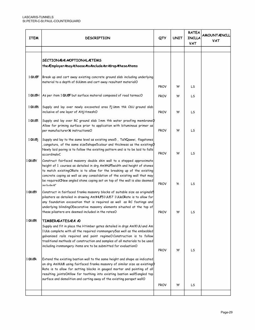
�������������
�� ���������� �������������
���� ��������� �� ����
�����
������
���
������������
���
���������8�������������
'()��!*/$3)+�!03�,($$#)�'$�"%,/�-)�$+�-+$*�'()#)�"')!#
������� ��!�/ $3 ��- +��% ���2 !6��%��� +*�+�!%! ��*$�- �,�1 ��+,$-��� $�-!�,2���
��%!���,�%*���-!3%.�*"���������-�+��%����2��!�$,%��%���%!���,��
5�C �� ��
������� ���3!���%!����������1$%��$�"�+!���%!���,�+*�3*�!-�*"��*�-�%����+�� 5�C �� ��
������� �$33,2 ��- ,�2 *0!� �!�,2 !6+�0�%!- ��!� �:��� %./ '�� ��*$�- �,�1
��+,$��0!�*"�*�!�,�2!��*"���:���!�.�� 5�C �� ��
������� �$33,2 ��- ,�2 *0!� �' ��*$�- �,�1 ��� %./ ��%!� 3�**"��� �!�1���!�
�,,*� "*� 3������ �$�"�+! 3��*� %* �33,�+�%�*� ��%. 1�%$���*$� 3���!� ��
3!�����$"�+%$�!�B�����%�$+%�*���� 5�C �� ��
������: �$33,2 ��- ,�2 %* %.! ���! ,!0!, �� !6��%��� *�!�� < �,�D����< ",���%*�!�
<+����%$��< *" %.! ���! ��;!� �.�3!� +*,*$� ��- %.�+/�!�� �� %.! !6��%����
�!�,2 ,��- 3�0��� �� %* "*,,*� %.! !6��%��� 3�%%!�� ��- �� %* 1! ,��- %* "�,,�
�++*�-���,2�� 5�C �� ��
������= '*��%�$+% "���"�+!- ���*��2 -*$1,! �/�� ��,, %* � �%!33!- �33�*6���%!
.!��.% *" � +*$��!� �� -!%��,!- �� -�� ������� ��-%. ��- .!��.% *" �%*�!�
%* ��%+. !6��%���� ��%! �� %* �,,*� "*� %.! 1�!�/��� $3 *" %.! !6��%���
+*�+�!%! +*3��� �� �!,, �� ��2 +*��*,�-�%�*� *" %.! !6��%��� ��,, %.�% ��2
1! �!9$��!-� �!� ���,!- �%*�! +*3��� �!% *� %*3 *" %.! ��,, �� �,�* -!!�!-
��+,$-!-�� 5�C �� ����+,$-!-�� 5�C �� ��
������> '*��%�$+% �� "���"�+!- "���/� ���*��2 1,*+/� *" �$�%�1,! ��;! �� *������,��
3�,��%!�� �� -!%��,!- �� -������ ������� ���� � ����� ��%! �� %* �,,*� "*�
��2 "*$�-�%�*� !6+�0�%�*� %.�% �� �!9$��!- �� �!,, �� �' "**%���� ��-
$�-!�,2��� 1,��-���� �!+*��%�0! ���*��2 !,!�!�%� ��%$�%!- �% %.! %*3 *"
%.!�!�3�,��%!�����!�-!!�!-���+,$-!-����%.!���%!��� 5�C �� ��
������ �������������9���:
�$33,2 ��- "�% �� 3,�+! %.! � %��1!� ��%!� -!%��,!- �� -��� ������ ��- ���
���� +*�3,!%! ��%. �,, %.! �!9$��!- ��*��*��!�2� �� �!,, �� %.! !�1!--!-
��,0����!- ���,� �!9$��!- ��- 3���% �!���!� '*��%�$+%�*� �� %* "*,,*�
%��-�%�*��, �!%.*-� *" +*��%�$+%�*� ��- ���3,!� *" �,, ��%!���,� %* 1! $�!-
��+,$-������*��*��!�2��%!�����!�%*�1!��$1��%%!-�"*��!0�,$�%�*���5�C �� ��
������@ �6%!�- %.! !6��%��� 1��%�*� ��,, %* %.! ���! .!��.% ��- �.�3! �� ��-�+�%!-
*� -�� ����� $���� "���"�+!- "���/� ���*��2 *" ����,�� ��;! �� !6��%����
��%! �� %* �,,*� "*� �!%%��� 1,*+/� �� ��$�!- �*�%�� ��- 3*��%��� *" �,,
�!�$,%��� 8*��%�� �,,*� "*� %**%.��� ��%* !6��%��� 1��%�*� ��,,� ���,!- %*3
�$�"�+!���-�-!�*,�%�*����-�+��%�������2�*"�%.!�!6��%����3���3!%���,,��
5�C �� ��
�������

�������������
�� ���������� �������������
�����:�#�'?���'��� ���
����
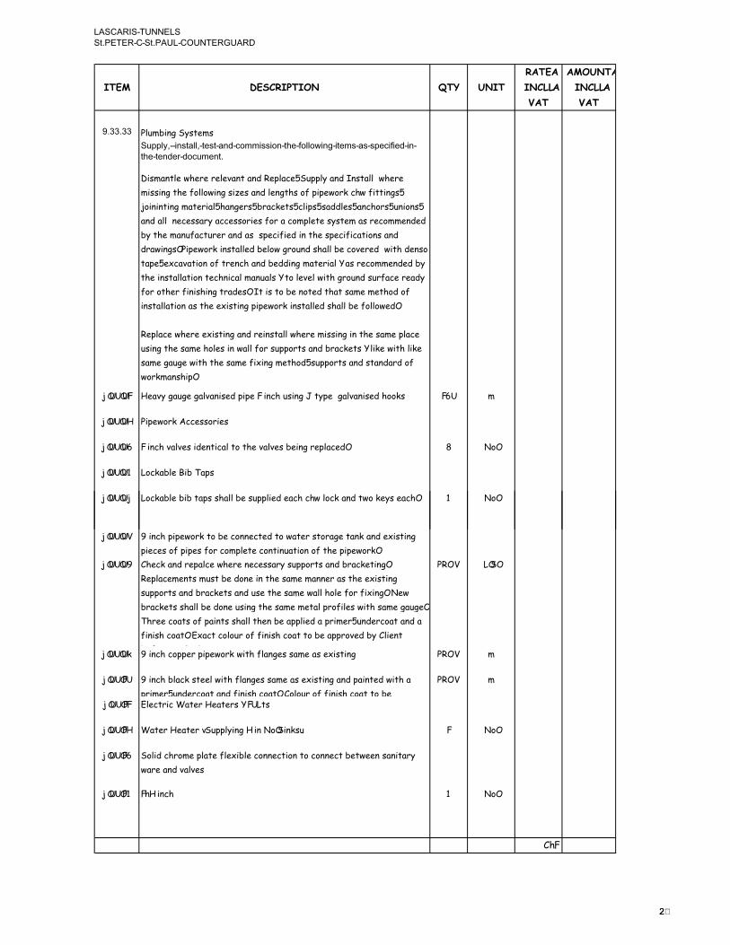
�������������
�� ���������� �������������
���� ��������� �� ����
�����
������
���
������
������
���
� �� �� 5,$�1�����2�%!��
���� !"��#$%�� "���%���$&�'())#%%#($��*��+( (,#$��#��)%��%�%��'#+#�&�#$�
�*����$&�-�&('�)�$�
������%,!��.!�!��!,!0��%���-��!3,�+!���$33,2���-����%�,,���.!�!�
��������%.!�"*,,*�������;!����-�,!��%.��*"�3�3!�*�/�+(��"�%%������
8*����%������%!���,��.���!����1��+/!%���+,�3�����--,!�����+.*����$��*����
��-��,,���!+!����2��++!��*��!��"*����+*�3,!%!��2�%!������!+*��!�-!-�
12�%.!����$"�+%$�!����-������3!+�"�!-����%.!��3!+�"�+�%�*�����-�
-���������5�3!�*�/����%�,,!-�1!,*����*$�-��.�,,�1!�+*0!�!-����%.�-!��*�
%�3!��!6+�0�%�*��*"�%�!�+.���-�1!--������%!���,�������!+*��!�-!-�12�
%.!����%�,,�%�*��%!+.��+�,����$�,����%*�,!0!,���%.���*$�-��$�"�+!��!�-2�
"*��*%.!��"����.����%��-!�����%����%*�1!��*%!-�%.�%����!��!%.*-�*"�
���%�,,�%�*�����%.!�!6��%����3�3!�*�/����%�,,!-��.�,,�1!�"*,,*�!-���
�!3,�+!��.!�!�!6��%������-��!���%�,,��.!�!������������%.!����!�3,�+!�
$�����%.!����!�.*,!�������,,�"*���$33*�%����-�1��+/!%����,�/!���%.�,�/!�
���!���$�!���%.�%.!����!�"�6�����!%.*-���$33*�%����-��%��-��-�*"�
�*�/����.�3���
:������ ?!�02���$�!���,0����!-�3�3!�����+.�$�����E�%23!����,0����!-�.**/� ��� �
:������ 5�3!�*�/��++!��*��!�
:������ ����+.�0�,0!���-!�%�+�,�%*�%.!�0�,0!��1!�����!3,�+!-� �*�
:������ �*+/�1,!���1��3�
:�����: �*+/�1,!�1�1�%�3���.�,,�1!��$33,�!-�!�+.�+(��,*+/���-�%�*�/!2��!�+.� � �*�
�.
:�����= >���+.�3�3!�*�/�%*�1!�+*��!+%!-�%*���%!���%*���!�%��/���-�!6��%����
3�!+!��*"�3�3!��"*��+*�3,!%!�+*�%��$�%�*��*"�%.!�3�3!�*�/�
:�����> '.!+/���-��!3�,+!��.!�!��!+!����2��$33*�%����-�1��+/!%������
�!3,�+!�!�%���$�%�1!�-*�!����%.!����!�����!�����%.!�!6��%����
�$33*�%����-�1��+/!%����-�$�!�%.!����!���,,�.*,!�"*��"�6�������!��
1��+/!%���.�,,�1!�-*�!�$�����%.!����!��!%�,�3�*"�,!����%.����!���$�!���
.�!!�+*�%��*"�3���%���.�,,�%.!��1!��33,�!-���3���!���$�-!�+*�%���-���
"����.�+*�%����6�+%�+*,*$��*"�"����.�+*�%�%*�1!��33�*0!-�12�',�!�%�
1!"*�!��33,�!-�
5�C ����
:�����@ >���+.�+*33!��3�3!�*�/���%.�",���!�����!����!6��%��� 5�C �
:������ >���+.�1,�+/��%!!,���%.�",���!�����!����!6��%������-�3���%!-���%.���
3���!���$�-!�+*�%���-�"����.�+*�%���'*,*$��*"�"����.�+*�%�%*�1!�
5�C �
:������ �,!+%��+� �%!��?!�%!��������%�
:������ �%!��?!�%!��7�$33,2����������*����/�4 � �*�
:������ �*,�-�+.�*�!�3,�%!�",!6�1,!�+*��!+%�*��%*�+*��!+%�1!%�!!������%��2�
���!���-�0�,0!�
:������ �(����+. � �*�
'()
�.

�������������
�� ���������� �������������
�()
���� ��������� �� ����
�����
������
���
������
������
���
:�����: '*��!+%����$3�*"��!�����+.�3�3!�*�/���2�%!����%.�%.!��!����%!��
�!%!�����%�,,!-�12�*%.!�����
� ����
:�����= ��1!,,����*"�!9$�3�!�%��3�3!���0�,0!�����-��++!��*��!������3!+�"�!-� � ����
:�����> !�%�����+*������*�������-�.��-����*0!��*"�%.!�3,$�1������2�%!��7���
�3!+�"�!-4���+,$-����+*������*������!3*�%����-�%!�%�+!�%�"�+�%!��
����!-�12���������%!-������!!���!�3*���1,!�"*��%.!��$3!�0���*����-�
9$�,�%2�*"��*�/��
� ����
:����� �*+$�!�%�%�*�&����!%��*"����%�,,�%�*����!�0�+!��!����!!�����-�%����-�
*3!��%�*��,����$�,��������,��.�����$��!�
� ����
:�����@ �$�,-!�F����*�/��"*�����%�,,�%�*��*"�%.!�5,$�1�����2�%!���.����.�,,�
��+,$-!��,,�%.!��!+!����2�+*�����3!�!%��%�*�����-�+.���������
��,,�(�,�1�����-���/�����**-�"*���������%!������!�����-��3,��%!�����
��*$�-�.*,!��
� ����
'*��%�$+%�*��-�������
:������ ��.��-�+*3�!� � ����
�/
:������ ��+*3�!�����!,!+%�*��+�"*���% � ����
���"�%%!-�-�������
:������ ��.��-�+*3�!� � ����
:������ ��+*3�!�����!,!+%�*��+�"*���% � ����
:������ �--�%�*��,��%!��
�*����$&�-�-�#%��(�&���# �0� (,�,(-1%"�2��$�#�#�%��$&�-���%�+(-�#��)%��*���
�-��$(��#$' �&�&�� %�,*�-��#$��*#%�&('�)�$���$&��*����-��-�2�#-�&��(�
'()� �����*����$&�-��-#'��+(-��*#%�%�'�#($�(+��*��,(-1% ��*(� &��*��
��$&�-�-�+�# ��(��&&�#��)%�*�-�"��*���(�� �%�)�#%�&��)�&��(�#$' �&��� �
#��)%��$&�$(�%�0%�2��$��' �#)%�+(-��&&#�#($� �#��)%�,# �0��'($%#&�-�&
� ����
���������������������
�/

�������������
�� ���������� �������������
�����=����'��'��� ���
����

�������������
�� ���������� �������������
���� ��������� �� ����
�����
������
���
������
������
���
+)/"!"%0+")#
5�*0���*��.���1!!����-!�"*��%.!�%*%�,�*"�!�+.�3��!�*"��$,%��3��!�1�,,��%*�
1!�+*,,!+%!-��%�%.!�!�-�*"�!�+.�1�,,�*"�%.!�!���,,��*"�D$��%�%�!��������������������
.!��%!�����+,$-!-����%.�����,,��33,2�%*�%.!��.*,!�*"�%.!� *�/������
-!�+��1!-����%.!�!�1�,,��*"�9$��%�%�!�����%.!���%!����-(*����*$�%�����!�%!-�
12�%.!�'*�%��+%*���.�,,�1!�-!!�!-�%*��33,2�%*�%.!��.*,!�*"�%.!� *�/��
+����!-�*$%�$�-!��%.���'*�%��+%�.!�'*�%��+%*���.�,,�1!�-!!�!-�%*�.�0!��,,*�!-����.���%!�-!��"*���,,�+*�%��
����!�3!+%�*"��,,��%!���-!�+��1!-����%.!�5�!,�������!���!+%�*��*"�%.!���,,��*"�
D$��%�%�!��
���%.!��1�!�+!�*"���2��$��������%���2��%!��*���%!������2��*�!%��2�+*�%�
�%%��1$%�1,!�%.!�!�%*��.�,,�1!�-!!�!-�%*�1!���+,$-!-�!,�!�.!�!����%.!�
5�!,�������!���!+%�*��*��%.!�$��%���%!��"*��%.!� *�/����������������������������������������������������������������
.!��*+$�!�%����!�%*�1!�%�/!������$%$�,,2�!63,���%*�2�����2��$�����!�%!-�
.!�!��.�,,�1!�-!!�!-�%*�+*0!��%.!�+*�3,!%!��!9$��!�!�%��*"�%.!�
'*�-�%�*����!+.��+�,��3!+�"�+�%�*��������������
���%.!�!0!�%�%.�%�%.!���*$�%����!�%!-�������%�����%!�����%.�����,,��"*��
�.�+.��.*,!�3�2�!�%��*$,-��*���,,2�1!���-!��%�%.!�*$%�!%�*"�%.!�
'*�%��+%�����.��.!��%.���%.!���*$�%�%.!�'*�%��+%*��+����$1�%��%��%!��
3�2�!�%�"*��%.!�!6+!�����*$�%���,,�1!�!""!+%!-�*0!��%.!�3!��*-�*"�
+*�%��+%������������������������������%.!�!0!�%�%.�%��*���*$�%����!����!�%!-�12�%.!�'*�%��+%*������!�3!+%�*"�
%.�����,,���*��!,�%�0!�3�2�!�%���,,�1!���+,$-!-������%!����3�2�!�%����"���,�
�++*$�%������������������������������������������������
��
,��$���+!��������%��++�-!�%��%*� *�/�!�&��$+.����$���+!��.�,,�1!��
����%���!-�-$�����%.!��.*,!�*"�%.!�%��!�%.�%���2�3!��*�����!�!�3,*2!-�12�
.���*��%.!��*�/����5�*0�-!-�%.�%�������!�3!+%�*"���2�3!��*����!�3,*2!-��12��
��2���$1�'*�%��+%*����%.!�'*�%��+%*���*1
*�-����3��%����%.!�����$,���*�,2��.�,,��,�*���+,$-!�%.!�3,$��,���0��!�0!����
�.!�!�%.!�+*�%!6%��!9$��!������������������������������
.!�"*,,*������11�!0��%�*�����!�$�!-&
���G����%��.��%��-��-��3!+�"�+�%�*��
���G��$�*3!����%��-��-�
.!�%!���%.!�B *�/�B��.�,,��!���%.!��.*,!�*"�%.!��*�/��!�0����!-�12�%.���
'*�%��+%����+,$-�����$�,!���!63�!��,2��%�%!-�*%.!����!��%.!��*�/��*"�%.!�
H*0!���!�%�*"�%.!��!3$1,�+�*"�#�,%����$%.*��%�!���$%�,�%2��!�0�+!�3�*0�-!���
��*%.!��+*�3!%!�%�1*-�!��������������������
� �)#,+"*'"$%�$&�'()��$+4#������������������������������������������������
� .!� *�/�������%$�%!-��%�%.!����+����� ����**��
�%.�%�5!%!�B�����%�5�$,B��'*$�%!��H$��-��C�,,!%%����.!�!6%!�%�*"�%.!�
�*�/����%.���%.���3�!���!�����-!%��,!-�*��-������������������������������������������������������
� .!�'*�%��+%*���.�,,���/!�3�*0���*��"*�����,,�������!�!�%��*��%.!���%!�������������������������
� .!�'*�%��+%*����,,�1!�.!,-�%*�.�0!�0���%!-�%.!���%!������3!+%!-�%.!���%!���
%*�.�0!��,,*�!-�"*��!0!�2�+*�%���!�+2�����!���-���++!���*��*%.!����!�%.�%�
��2������2���2�!""!+%�%.!�+*�%�*"�%.!� *�/��
'()
��

�������������
�� ���������� �������������
�()
���� ��������� �� ����
�����
������
���
������
������
���
=������ �#5�I������DJ���#���������������������������������
=������ #����!�!�%�*"�%.!� *�/�����������������������������������������
=������ �$3!�0���*�
'()����$��� �'�-#'� 34�'*�$#'� ��$�#$��-��$&�5(-�)�$6#$6�*�-���%*� �0��
1����($�%#������7' �%#8� !��)� (!�&�($��*��9(-1%�+(-��*��+� �&�-��#($���,*(%��
&��#�%�%*� �#$' �&���*(%��(+�&#-�'�#($3%���-8#%#($����$%�-#$���*��2�� #�!�(+�
,(-1)�$%*#��-�2�#-�&�0!��*���)� (!�-���$�'�%%�-!��-(�-�%%��(��$%�-��
'()� ��#($�($�(-�0�+(-���*���#)��+(-�'()� ��#($ �:��3�%*��%*� �$(��0��-�� �'�&�
,#�*(����*���-#(-�,-#���$�(+��*���)� (!�-
�� ��
=������ �!%%����$%
��0)#��&���# %�(+�)��*(&%����2�#�)�$���(�0���%�&�#$�%���#$��(����*��9(-1% ��
�*�'1� �8� %���&#)�$%#($%�(+��*���#������#$%���*(%��%*(,�($��*���-�,#$�%���
#))�&#��� !�$(�#+!��)� (!�-�(+��$!�&#%'-���$'#�%���(0��#$�#$%�-�'�#($%�0�+(-��
�-('��&#$� ���$+(-)��*���)� (!�-�,*�$�(8�-� �%���#$��(���#%�'()� �������0�+(-��
'())�$'#$���$!�,(-1 ��-���-����%�0)#���(��*���)� (!�-��$!��&&#�#($� �%���#$��
(���(-� �8� %�&�-#$���*��'(�-%��(+��*��,(-1%�(-�&�-#$���*����-#(&�(+�(�#+!#$��
��+�'�%
�� ��
=������ 5.*%*���3.�
�-(8#&��$(�� �%%��*�$�����-(�-�%%��*(�(%�(+���'*�+ ((-��$&�(+���'*�0 ('1�
;,*�-��,(-1%��-��#$��-(�-�%%<���1�$�+-()�&#++�-�$���$� �%�($��*��%#������)($�* !�
#$��-8� %���%�0)#�����-#$�%�%#=�����))�7����))�(+���'*�$����#8� ���#�#�� �
�*(�(%�($��((&�2�� #�!�����-��-���''����& �
�� ��
=�����: #����!�!�%����%�""
� (,�+(-�� �'(%�%�#$�'($$�'�#($�,#�*��*��)�$���)�$����%��++�-�2�#-�&�0!��*��
�($�-�'�(-��(�'()� �����*��9(-1%�#$��''(-&�$'��,#�*��*���($�-�'�
�� ��
=�����= �,!+%��+�,��� �%!���$33,2�"*��%.!� *�/�
� (,�+(-��--�$�#$��,#�*��*���)� (!�-�+(-��*���-(8#%#($�(+�� �'�-#'� ��$&�,���-�
%��� !"���!�� �'*�-��%�#$�'($$�'�#($��*�-�,#�* ���������������������������
�� ��
=�����> �!��%!���� �� ��
��
=�����> �!��%!����
�-(8#&����)�(-�-!�&-�#$%"�)�$*( �%"���)�%���(�*�-�� �$��$�'�%%�-!��(�-�)(8��
,���-���%�,����+-()��*��9(-1% ��� ��-�+-()��#)���(��#)��� �$�'�%%�-!�
��)�(-�-!�&-�#$%"�)�$*( �%"���)�%���(�*�-�� �$���%�-�2�#-�&�&�-#$���*��'(�-%��
(+��*��,(-1���-�)(8��($�'()� ��#($ �������������
�� ��
=����� ��"!%2���5�*%!+%�*�
=�����@ 5�*%!+%�*����',!�����
�-(��'���*��9(-1%�+-()�#$' �)�$��,���*�- ���8�-!�,(-1#$��&�!�����($�
'()� ��#($�-�)(8��� �-�00#%* �����8��$(�)���-#� �(��%#&���*�����-(8�&�
*(�-&#$����&��(%#��$(�)���-#� �#$�(��*��%�� ������*���$&�(+��8�-!�,(-1#$��&�!�
%,�����*��%#����$&��&>�'�$����0 #'�%��'�% ��-�8�$��� � #2�#&���%( #&�)���-#� %�
+-()�+� #$��#$�(��*��%�� ���������������������������������������
�� ��
=������ 5�*%!+%�*����',!�����
�''����-�%�($%#0# #�!�+(-��*��%��0# #�!���%�-�'��-� �#$���-#�!�(+��*��9(-1%���
�&>(#$#$���-(��-�!��++�'��&�0!��*��9(-1%�&�-#$���*���($�-�'�"���%���(-���%�
$�'�%%�-! ���-�8�$��(8�- (�&#$� ��������������������������������������
�� ��
=������ ?!�,%.�����"!%2�7)���%���-4��!�$,�%�*��
�-(8#&���&�2����������-(�-#����+#-%���#&��--�$��)�$�%�+(-�%#���%��++���
���*(-#%�&�8#%#�(-% ��������������������������������������
�� ��
=������ ��"!�$��-����%.!� *�/���#�%!���,����5,��%
� (,�+(-�� �$#�*����,��1�$&�,��'*#$���� #�*�#$���%�)�!�0��-�2�#-�&���+(-��$!�
(�*�-�%�+����-&%����-�'���#($%�$�'�%%�-!�+(-��*���-�8�$�#($�(+��''#&�$�%"��*��
%�+����-&#$��(+��*��9(-1%"�)���-#� %���� �$�����#$%��&�)�������*�+�"���+(-��*��
'($8�$#�$'��(+��*����$�-� ���0 #' ���1��� �$�'�%%�-!��-�'���#($%��(��-�8�$��
�$���*(-#%�&��''�%%��(��*��%#������*��,(-1% ��������������������������������������
�� ��
'()
��

�������������
�� ���������� �������������
�()
���� ��������� ���� ��
�����
������
���
������
������
���
=������ ������)�DJ�����������������������������������������������
�%!������%.!�5�!,�������!���!+%�*����%.!�3�!��1,!��*"�%.!���,,��*"�
D$��%�%�!����!�-!!�!-�%*�9$�,�"2���1!�3��%�*"�!0!�2�-!�+��3%�*��*"�
�!��$�!-��*�/�%*��.�+.�%.!2�*++$��������������������������������������������������
� �
�*���!�-�!�%���.�+.�.����*%�1!!���$%.*���!-�������%����12�%.!���3,*2!��
�.�,,�1!���-!�%*�%.!�!���,,��*"�D$��%�%�!�����������������������������
� �
�"�%.!�'*�%��+%*�����.!��%*�$�!�%.!�!���,,��*"�D$��%�%�!��"*��%.!�3$�3*�!�
*"�*�-!�������%!���,��.!��.�,,�"���%�+*�"������%.�%.!���3,*2!��%.�%��$+.�
��%!���,�����*�/���,,��*%�1!�0���!-���.!(�.!��.�,,�%�/!��,,��!��$�!�!�%��
"�*����%!����*�+,����"�*��%.!�'*�%��+%*��"*��*�-!�����%.!���*���%23!�*��
9$��%�%2�*"���%!���,�*���!�0�+!���,,�1!��+/�*�,!-�!-�
� �
�,,�3��%��*"�%.!� *�/����!�1!��$18!+%�%*��!��!��$�!�!�%���%.!�9$��%�%�!��
��0!�����%.!�!���,,��*"�D$��%�%�!��-*��*%��!+!�����,2��!3�!�!�%�%.!�!0!�%$�,�
!6%!�%�*"�%.!��*�/�%*�1!�!6!+$%!-����*�+,����"*�������+�!��!����$��%���%!��
1!+�$�!�*"�0����%�*������%.!�9$��%�%2�*"��*�/�!6!+$%!-���,,�1!��+/�*�,!�!-�������������������������
� �
=������ '*�"����%�*��*"�C!�1�,����%�$+%�*��
?����($��*���#�����-�'(-&�(+�� �8�-0� �#$%�-�'�#($%���%�$&�'(�#�%��(��*��
�)� (!�-�,#�*#$�%�8�$�&�!%�(+�0�#$���#8�$ ����������������������
�� ��
� '*�%�+%���%!�
$ �%%�(�*�-,#%��%����&��*��+( (,#$��%*� �0��&��)�&��(�0��#$' �&�&�#$��*���$#��
-���%@
����-8#%#($A� �0(�-���� �'(%�%�#$�'($$�'�#($��*�-�,#�*A�� �$�����2�#�)�$����� �
'(%��#$�'($$�'�#($��*�-�,#�*A�)���-#� %���� �'(%�%�#$�'($$�'�#($��*�-�,#�*�;� � �
'($8�!�$'�"�&� #8�-!"��$ (�&#$�"�%�(-#$�"�*�$& #$�"� (,�-#$�"�+#��#$����+#7#$��#$�
� �
��
'($8�!�$'�"�&� #8�-!"��$ (�&#$�"�%�(-#$�"�*�$& #$�"� (,�-#$�"�+#��#$����+#7#$��#$�
�(%#�#($<A�'���#$��*( �%"�)(-�#%�%"��('1��%"��-((8�%����*�� #1�A�,�%��"��$&%�
�$� �%�)#�-�%"�+�#-6-(�$&�&"�+# ���&"�'(8�-�&���(�*�-��&��%A���)�(-�-!�%�-���#$�A�
��)� ���%���)(� &%A�%*(-�� �$�*�%A�%)� ��-��%���2��$�#�#�%A�$�--(,�,#&�*%A�
%�-�#�*��,(-1A�% (�#$��,(-1A�,(-1��(�#--��� �-�'($+#��-��#($%���#$�'($+#$�&�
%��'�%�&(�0 ��*�$& #$��)�$�� �%*#+�#$��(+�� �)���-#� % �������������������������������
� #�%!���,�
��$�-� !�)���-#� %��-���(�0���(�B � ���,*�-��$(��%��'#+#'� !�%����&�)���-#� %�
�-���(�0��(+��*��0�%��2�� #�!�'($%#%��$��,#�*��*��'*�-�'��-�(+��*��,(-1 ����)� �%�
(+�� �)���-#� %���,(-1)�$%*#���(�0���%�&�($��*#%��($�-�'���-���(�0��%�0)#���&�
�(��*���)� (!�- ��*��+#$#%*�&�,(-1�#%��(�'(--�%�($&�,#�*��*��%�)� �% ����������������������������������
��� *�/����.�3
9(-1)�$%*#��#%��(�0��(+�*#�*�%��$&�-&��*-(��*(�����-�#'� �- !�,#�*�-���-&��(�
�*���''�-�'!�(+�&#)�$%#($%"� #$�%"�� �$�%"� �8� %����*��2�� #�!�(+�%�-+�'����7��-��
��#%��(�0���*���$�#-��%��#%+�'�#($�(+��*���)� (!�- ���������������������������������������������
� .!�!���'*-!�*"�5��+%�+!�!6��%���%.������%*�1!�"*,,*�!-�
���������
�$�2�(�#$��+(-��*��#��)%� #%��&�#$��*#%�B�C"��*����$&�-�-�#%����-�$���#$���*���� �
-�2�#-�)�$�%��$&�%��$&�-&%��%�%��'#+#�&�#$��*����$&�-�&('�)�$�%"�%*� �0��
+� +# �&
'()
��

�������������
�� ���������� �������������
�()
���� ��������� �� ����
�����
������
���
������
������
���
=������ ���J������5�5���
�#����5 �������H?��H
=������ �$33,2�����%�,,��+*��!+%�%!�%���-�+*������*��%.!����%+.�!�������-!
%.!�!6��%�������������� ���������������� ���������������������
����%!���+!���-�3���%�*�/�*"�%.!�!6��%����3��!,�+*����%����*"&
�4��������5�#����#''��K��� ���+(��!,!+%�*��+�%��3�$��% � �*�
14���:���5�#�����''����%.��-8$�%�1,!��!���%�0�%2������������-�
�-8$�%�1,!���!��!,�2��������-��$%*��%�+��!+,*����
� �*�
+4������5�#'��%23!�'��"*��)�: � �*�
-4�=����5�#'��%23!���"*��)�� � �*�
=������ �$33,2�����%�,,��+*��!+%��%!�%���-�+*������*��%.!�+�1,!���$33,�!-
"�*��%.!����������� �����������������������������
����%!���+!���-�3���%�*�/�*"�%.!�+*�-$�%����"*,,*��&
�4�:6�������)�+�1,!�����!6��%����+*�-$�%�"*��)�: �� �
14�:6�=������)�+�1,!�����!6��%����+*�-$�%�"*��)��� = �
=������ �$33,2�����%�,,��+*��!+%�%!�%���-�+*������*��%.!����%+.�!�������-!
%.!�!6��%����� ������������������� ������
����%!���+!���-�3���%�*�/�*"�%.!�!6��%����3��!,�+*����%����*"&
�4������5�#����#'��%23!�'� � �*�
14������5����'��%23!���"*�����.%����'��+$�%���� � �*�
+4������5����'��%23!���"*�����.%����'��+$�%��� � �*�
-4������5����'��%23!���"*�����.%����'��+$�%��� � �*�
!4������5����'��%23!���"*���*+/!%�$%,!%�'��+$�%��� � �*�
"4������5����'��%23!���"*���*+/!%�$%,!%�'��+$�%��� � �*�
�4������5����'��%23!�'�"*����� �2�'*��$�!��J��%�'J�� � �*�
.4��=���5����'��%23!����3��! � �*�
��
.4��=���5����'��%23!����3��! � �*�
�4��=���5����'��%23!����3��! � �*�
=������ �$33,2�����%�,,��+*��!+%�%!�%���-�+*������*��%.!�+�1,!�����++!��*��!�
�$33,�!-�"�*��%.!�� ������������������������������ ���������
��-�3���%�*�/�*"�%.!�+*�-$�%���'J�����"*,,*��&
�4����.%����'��+$�%������%.��6��:������)�+�1,!�� � �*�
14����.%����'��+$�%������%.��6��:������)�+�1,!�� � �*�
+4����.%����'��+$�%������%.��6��:������)�+�1,!�� � �*�
-4��*+/!%�$%,!%�'��+$�%������%.��6�������)�+�1,!�� � �*�
!4��*+/!%�$%,!%�'��+$�%������%.��6�������)�+�1,!�� � �*�
"4���� �2�'*��$�!��J��%7'J�4�'��+$�%�5����%.��6�������)�+�1,!�� �= �
7���.%����3*��%��%*�1!�%!�����%!-������+*��*��.*,-!����-�1$,14�
7���.%����+��+$�%��%*���+,$-!��*%�*���!��*������3!��-�������4�
=�����: �$33,2�����%�,,��+*��!+%�%!�%���-�+*������*��%.!����%+.�!�������-!
%.!�!6��%����� � ������������������� ������������ �������
����%!���+!���-�3���%�*�/�*"�%.!�!6��%����3��!,�+*����%����*"&
�4������5�#����#'��%23!�'� � �*�
14������5����'��%23!���"*�����.%����'��+$�%���� � �*�
+4������5����'��%23!���"*�����.%����'��+$�%��� � �*�
-4������5����'��%23!���"*���*+/!%�$%,!%�'��+$�%��� � �*�
!4��=���5����'��%23!����3��! � �*�
"4��=���5����'��%23!����3��! � �*�
'()
��

�������������
�� ���������� �������������
�()
���� ��������� �� ����
�����
������
���
������
������
���
=�����= �$33,2�����%�,,��+*��!+%�%!�%���-�+*������*��%.!�+�1,!�����++!��*��!��$33,�!-�"�*��%.!�� � ������������������������������ �����������-�3���%�*�/�*"�%.!�+*�-$�%����"*,,*��&�4����.%����'��+$�%������%.��6��:������)�+�1,!�� � �*�14����.%����'��+$�%������%.��6��:������)�+�1,!�� � �*�+4��*+/!%�$%,!%�'��+$�%������%.��6�������)�+�1,!�� � �*�7���.%����3*��%��%*�1!�%!�����%!-������+*��*��.*,-!����-�1$,14�7���.%����+��+$�%��%*���+,$-!��*%�*���!��*������3!��-�������4�
�=�����> �$33,2�����%�,,��+*��!+%�%!�%���-�+*������*��%.!����%+.�!�������-!
%.!�!6��%����� ��������������������������������� ����������%!���+!���-�3���%�*�/�*"�%.!�!6��%����3��!,�+*����%����*"&�4�=����5�#����#'��%23!��� � �*�14������5�#'��%23!�'��"*��)��� � �*�+4������5����'��%23!���"*�����.%����'��+$�%���� � �*�-4������5����'��%23!����3��! � �*�!4������5����'��%23!����3��!� � �*�"4�:����5�#'��%23!�'��"*����5� � �*��4��=���5����'��%23!����3��! � �*�
=����� �$33,2�����%�,,��+*��!+%�%!�%���-�+*������*��%.!�+�1,!�����++!��*��!��$33,�!-�"�*��%.!�� ������������������������������ ��������� ���-�3���%�*�/�*"�%.!�+*�-$�%����"*,,*��&�4�:6=������)�+�1,!�����!6��%����'*�-$�%�"*��)��� �� �14����.%����'��+$�%������%.��6��:������)�+�1,!�� � �*�+4��+��������?(� ��+�1,!����%�,,!-��$�"�+!�"*����5� �: �7���.%����3*��%��%*�1!�%!�����%!-������+*��*��.*,-!����-�1$,14�7���.%����+��+$�%��%*���+,$-!��*%�*���!��*������3!��-�������4�
=�����@ �$33,2�����%�,,��+*��!+%�%!�%���-�+*������*��%.!����%+.�!�������-!%.!�!6��%����� ����������������������� �������������
��
%.!�!6��%����� ����������������������� �����������������%!���+!���-�3���%�*�/�*"�%.!�!6��%����3��!,�+*����%����*"&�4������5�#����#'��%23!�'� � �*�14������5�#'��%23!�'��"*��)��� � �*�+4������5����'��%23!���"*�����.%����'��+$�%���� � �*�-4������5����'��%23!����3��!� � �*�!4������5����'��%23!����3��!� � �*�
=������ �$33,2�����%�,,��+*��!+%�%!�%���-�+*������*��%.!�+�1,!�����++!��*��!��$33,�!-�"�*��%.!�� ������������������������������ �����������-�3���%�*�/�*"�%.!�+*�-$�%����"*,,*��&�4�:6=������)�+�1,!�����!6��%����'*�-$�%�"*��)��� �> �14����.%����'��+$�%������%.��6��:������)�+�1,!�� � �*�7���.%����3*��%��%*�1!�%!�����%!-������+*��*��.*,-!����-�1$,14�7���.%����+��+$�%��%*���+,$-!��*%�*���!��*������3!��-�������4�
=������ �$33,2�����%�,,��+*��!+%�%!�%���-�+*������*��%.!����%+.�!�������-!%.!�!6��%����� ����������������������� ������������������%!���+!���-�3���%�*�/�*"�%.!�!6��%����3��!,�+*����%����*"&�4������5�#����#'��%23!�'� � �*�14������5�#'��%23!����"*�������� � �*�+4������5����'��%23!���"*�����.%����'��+$�%���� � �*�-4������5����'��%23!���"*���*+/!%�$%,!%�'��+$�%���� � �*�!4��=���5����'��%23!����3��!� � �*�"4��=���5����'��%23!����3��!� � �*��4������5����'��%23!����3��!� � �*�
'()
��

�������������
�� ���������� �������������
�()
���� ��������� �� ����
�����
������
���
������
������
���
=������ �$33,2�����%�,,��+*��!+%�%!�%���-�+*������*��%.!�+�1,!�����++!��*��!�
�$33,�!-�"�*��%.!�� ������������������������������ ���������
��-�3���%�*�/�*"�%.!�+*�-$�%����"*,,*��&
�4�:6=������)�+�1,!������!���:���H�,0����!-�'*�-$�%�"*�������� � �
14����.%����'��+$�%������%.��6��:������)�+�1,!�� � �*�
+4��*+/!%�$%,!%�'��+$�%������%.��6�������)�+�1,!�� � �*�
7���.%����3*��%��%*�1!�%!�����%!-������+*��*��.*,-!����-�1$,14�
7���.%����+��+$�%��%*���+,$-!��*%�*���!��*������3!��-�������4�
=������ �$33,2�����%�,,��+*��!+%�%!�%���-�+*������*��%.!���� �������������
���%��1$%�*���*��-������� ������������� �����������������
�4������5�#����#'��%23!��� � �*�
14������5����'��%23!���"*�����.%����'��+$�%��� � �*�
+4������5����'��%23!���"*�����.%����'��+$�%��� � �*�
-4������5����'��%23!���"*���*+/!%�$%,!%�'��+$�%��� � �*�
!4��=���5�#'��%23!����"*����3.��!�)������J33!��%$��!,�!�%���+!� � �*�
"4������5����'��%23!����3��!� � �*�
�4������5����'��%23!���"*�����.%����'��+$�%��� � �*�
.4������5����'��%23!���"*�����.%����'��+$�%��� � �*�
�4������5����'��%23!���"*���*+/!%�$%,!%�'��+$�%��� � �*�
84������5����'��%23!���"*��*�,!%�!6%��"�������*�!��%$��!,�!�%���+!� � �*�
/4������5����'��%23!���"*���*+/!%�$%,!%�'��+$�%���� � �*�
,4������5����'��%23!���"*���*+/!%�$%,!%�'��+$�%���1 � �*�
�4������5����'��%23!���"*���*+/!%�$%,!%�'��+$�%���+ � �*�
�4������5����'��%23!���"*���*+/!%�$%,!%�'��+$�%���- � �*�
*4��=���5����'��%23!����3��!� � �*�
34��=���5����'��%23!����3��!� � �*�
94��=���5����'��%23!����3��!� � �*�
�4��=���5����'��%23!���"*�� �%!��?!�%!��'��+$�%�5�� � �*�
��
�4��=���5����'��%23!���"*�� �%!��?!�%!��'��+$�%�5�� � �*�
=������ �$33,2�����%�,,��+*��!+%�%!�%���-�+*������*��%.!��!��+*�-$�%��+�1,!���
���++!��*��!���$33,�!-�"�*��%.!������ ���������������
�4����.%����'��+$�%������%.��6��:������)�+�1,!�� � �*�
14����.%����'��+$�%������%.��6��:������)�+�1,!�� � �*�
+4��*+/!%�$%,!%�'��+$�%������%.��6�������)�+�1,!�� � �*�
-4��6��:������)�+�1,!��"*����3.��!�"���5�� � �*�
!4����.%����'��+$�%������%.��6��:������)�+�1,!�� � �*�
"4����.%����'��+$�%������%.��6��:������)�+�1,!�� � �*�
�4��*+/!%�$%,!%�'��+$�%������%.��6�������)�+�1,!�� � �*�
.4��6%��+%�)���5����%.��6��:������)�+�1,!�� � �*�
�4��*+/!%�$%,!%�'��+$�%�������%.��6�������)�+�1,!�� � �*�
84��*+/!%�$%,!%�'��+$�%���1���%.��6�������)�+�1,!�� � �*�
/4��*+/!%�$%,!%�'��+$�%���+���%.��6�������)�+�1,!�� � �*�
,4��*+/!%�$%,!%�'��+$�%���-���%.��6�������)�+�1,!�� � �*�
�4� �%!��?!�%!��'��+$�%�5����%.��6��:������)�+�1,!�� � �*�
7���.%����3*��%��%*�1!�%!�����%!-������+*��*��.*,-!����-�1$,14�
7���.%����+��+$�%��%*���+,$-!��*%�*���!��*������3!��-�������4�
'()
��

�������������
�� ���������� �������������
�()
���� ��������� �� ����
�����
������
���
������
������
���
=�����: �$33,2�����%�,,��+*��!+%�%!�%���-�+*������*��%.!����%+.�!���"*�
������������������������������ ���� ��������������� �����
�33,�+�%�*���+*����%����*"&
�4�������5�#����#'� � �*�
14�=�����5�#�����''����%.��-8$�%�1,!��!���%�0�%2�����������-��-8$�%�1,!�
��!��!,�2�����:����-��$%*��%�+��!+,*����
� �*�
+4��=���5����'��%23!���"*�����.%����'��+$�%��� � �*�
-4������5����'��%23!���"*�����.%����'��+$�%��� � �*�
!4������5����'��%23!���"*�����.%����'��+$�%��� � �*�
"4������5����'��%23!���"*���*+/!%�$%,!%�'��+$�%��� � �*�
�4��=���5����'��%23!����3��!� � �*�
.4��=���5����'��%23!����3��!� � �*�
�4��=���5����'��%23!����3��!� � �*�
=�����= �$33,2�����%�,,��+*��!+%�%!�%���-�+*������*��%.!��!��+*�-$�%��+�1,!���
���++!��*��!���$33,�!-�"�*��%.!��� ���������������
�4����.%����'��+$�%������%.��6��:������)�+�1,!�� � �*�
14����.%����'��+$�%������%.��6��:������)�+�1,!�� � �*�
+4����.%����'��+$�%������%.��6��:������)�+�1,!�� � �*�
-4��*+/!%�$%,!%�'��+$�%������%.��6�������)�+�1,!�� � �*�
7���.%����3*��%��%*�1!�%!�����%!-������+*��*��.*,-!����-�1$,14�
7���.%����+��+$�%��%*���+,$-!��*%�*���!��*������3!��-�������4�
=�����> �$33,2�����%�,,��+*��!+%�%!�%���-�+*������*��%.!����%+.�!���"*�
���������������������������������� �!"���!���#���$������������
+*����%����*"&
�4�������5�#����#'� � �*�
14�=�����5�#�����''���%.��-8$�%�1,!��!���%�0�%2�����������-��-8$�%�1,!�
��!��!,�2�����:����-��$%*��%�+��!+,*����
� �*�
+4��=���5����'��%23!����3��!� � �*�
-4��=���5����'��%23!����3��!� � �*�
��
-4��=���5����'��%23!����3��!� � �*�
!4��=��#'��%23!���"*����3.��!� �%!�3�**"�$%,!%��5�=:��5� � �*�
"4��=��#'��%23!���"*����3.��!� �%!�3�**"�$%,!%��5�=:��5� � �*�
�4��=���5����'��%23!����3��! � �*�
=����� �$33,2�����%�,,��+*��!+%�%!�%���-�+*������*��%.!��!��+*�-$�%��+�1,!���
���++!��*��!���$33,�!-�"�*��%.!��6%!���,����.%�������%��1$%�*���*��-�
+*����%����*"&
�4���5.��!� �5���*+/!%�$%,!%�5����%.�:6��:������)�+�1,!�� � �*�
.4���5.��!� �5���*+/!%�$%,!%�5����%.�:6��:������)�+�1,!�� � �*�
=������ �#��H��'I���H?�)���H�
����D���D��)�-��$'!��#�*��5#��#$�%@
=������ )*����&
�4���!��!�+2�����%23!�"�%%���� �: �*
=������ *�������&
�4���!��!�+2�����%23!�"�%%���� �� �*
=������ )*��)��&
�4���!��!�+2�����%23!�"�%%���� = �*
=������ )*��)��&
�4���!��!�+2�����%23!�"�%%���� � �*
=�����: )*��)��&
�4���!��!�+2�����%23!�"�%%���� � �*'()
�$33,�!-�12�',�!�%
�$33,�!-�12�',�!�%
�$33,�!-�12�',�!�%
�$33,�!-�12�',�!�%
�$33,�!-�12�',�!�%
��

�������������
�� ���������� �������������
�()
���� ��������� �� ����
�����
������
���
������
������
���
=�����= )*��)�:&
�4���!��!�+2�����%23!�"�%%���� � �*
=�����> )*��'J�&
�4���!��!�+2�����%23!�"�%%���� @ �*
���������D��)�-��$'!��#�*��5#��#$�%@
=����� )*����&
�4���!��!�+2�����%23!�"�%%���� �: �*
=�����@ )*�������&
�4���!��!�+2�����%23!�"�%%���� �� �*
=������ )*��)��&
�4���!��!�+2�����%23!�"�%%���� = �*
=������ )*��)��&
�4���!��!�+2�����%23!�"�%%���� � �*
=������ )*��)��&
�4���!��!�+2�����%23!�"�%%���� � �*
=������ )*��)�:&
�4���!��!�+2�����%23!�"�%%���� � �*
=������ )*��'J�&
�4���!��!�+2�����%23!�"�%%���� @ �*
=������ ���%.����5�*%!+%�*���2�%!�&
���� !"��$%�� "�'($$�'�"���%���$&�'())#%%#($��*��+( (,#$�@
�$33,�!-�12�',�!�%
�$33,�!-�12�',�!�%
�.
���� !"��$%�� "�'($$�'�"���%���$&�'())#%%#($��*��+( (,#$�@
=������ �:���L�����1��!�+*33!��%�3!�+*�3,!%!���%.�3�*3��!%��2�+,��3�����
�!9$��!-
:�� �
=������ ���%.�!,!+%�*-!�+*�3,!%!���%.����3!+%�*��3�%���-�%!�%�+,��3 @ �*�
=������ �*�-����*"��,,��!�0�+!��!��%.�����2�%!� � ��
=������ �9$�3*%!�%��,�1*�-����*"��,,�!��%.�����2�%!����%�,*+�,�!,!+%��+�,�
-��%��1$%�*��1*��-���!�������%!�%*���+,$-!����*��,*+�,�!��%.�1���7:����6�
=���� �.*,!�4�+*�3,!%!���%.�-��+*��!+%����,��/�
@ �*�
=�����: .�!!�3.��!��$��!��$33�!��*����/��+*�3,!%!���%.�!�+,*�$�!���-�
+*��!+%����,!�-����-�3�*%!+%�*��-!0�+!��%��$1�-��%��1$%�*��1*��-��
'�%!�*�2�'�3*�!��-��%��1$%�*�
� �*�
=�����= ����,!�3.��!�,*��+$��!�%����������,��!�3�*%!+%*���"*������� ��0*,%��#��
�$33,�!��$3�%*�:���3�
'�%!�*�2�����%!��!-��%!���/��
�*�
=�����> ���.%�����1����!���"*����+*�����%!,!3.*�!�,��!���%�%!,!3.*�!������
-��%��1$%�*��"���!�7���3����.21��-�3�*%!+%*�4
� �*�
'()
�.

�������������
�� ���������� �������������
�()
���� ��������� �� ����
�����
������
���
������
������
���
=��:��� ����H�����'##�������H
=��:��� 5�!,������2�!�%���
!�%���-�+*������*���,,�%.!��,!+%��+�,��2�%!�����'*�3�,�%�*��*"�-!%��,!-�
'*������*������!3*�%�12�%.!�'*�%��+%*��%*�1!���+,$-!-����%.����%!��
�� ��
=��:��� �++!3%��+!�!�%���
!�%���-�+*������*��%.!��,!+%��+�,��2�%!��������%�$+%!-�12�%.!�'*��$,%��%�
�����!!��
�� ��
=��:��� ?��-����0!��%*�',�!�%
�2�%!��.��-�*0!��%*�+,�!�%���+,$-�����$�%�1,!���-��3!+�"�+��2�%!��
*3!��%�*��,�%��������%*�3!��*��!,�
�� ��
=��:��� 5�*0�-!���3�!0!�%�0!�����%!���+!�+*�%��+%�"*����3!��*-�*"�%�*�2!����"�*��
%.!�-�%!�*��%.!�*""�+��,�+*������*�����-�%!��.!�#���%!���+!�'*�%��+%�
�.�,,���+,$-!�%�*�0���%��7!0!�2���6��*�%.�4����$�,,2�
�� ��
=��:��: .�!!��!%��*"�3!��%�*����-�#���%!���+!�#��$�,��%*�!%.!����%.�%.�!!�
�!%��*"��'���-���<���)�%%!-<�-��������
�� ��
=��:��= �--�%�*��,��%!��
�*����$&�-�-�#%��(�&���# �0� (,�,(-1%"�2��$�#�#�%��$&�-���%�+(-�#��)%��*����-��
$(��#$' �&�&�� %�,*�-��#$��*#%�&('�)�$���$&��*����-��-�2�#-�&��(�'()� �����*��
��$&�-��-#'��+(-��*#%�%�'�#($�(+��*��,(-1% ��*(� &��*����$&�-�-�+�# ��(��&&�#��)%�
*�-�"��*���(�� �%�)�#%�&��)�&��(�#$' �&��� �#��)%��$&�$(�%�0%�2��$��' �#)%�+(-�
�&&#�#($� �#��)%�,# �0��'($%#&�-�&
���������������������
�/
���������������������
�/

��������������� ��������� ���������������
�������������� ��������

��������������� ��������� ���������������
��� ��������� ���� �������������
������� ������������ � ��
����� �������� � ! "#!�$ � �$%!� & '%�$
� !�#��(��#(
��������������
������) �$�(*�#'�+#(*, -#%(
������. #(�"� -#%(
������/ ��,# -#%(
������0 ��(�� ��( -#%(
������� �$%"1�(�2�$���(���� -#%(
������3 �$� ��(�4�( -#%(������3 �$� ��(�4�( -#%(
������5 � ,*�$$�!���1#%(�( -#%(
�����)� ��"��,*�$$�!���1#%(�( -#%(
�����)) ����$� �6�( -#%(
������
�����). �(� ���%11�(���(�!����# �, -#%(�����). �(� ���%11�(���(�!����# �, -#%(
�����)/ �(� ���%11�(���(�!�).��# �, -#%(
�����)0 �(� ���%11�(���(�!�)���# �, -#%(
�����)� �(� ���%11�(���(�!�/���# �, -#%(
�����)3 %"��(����������)��%1���"��(� -#%(
�����)� �#"�(�,,#( �4�(�&� (��� ��( �##$7 �$$�����)� �#"�(�,,#( �4�(�&� (��� ��( �##$7 �$$
� �$%,�4�7 ���$���1$� �# 1(��*�(,7 !(�$$�(,7
8�&&�(,����� -#%(
�����)9 �"�$$��(���#(��-#4�( -#%(
�����)5 �"�$$���!(�%$���6��4��#( -#%(
�����.� �#((�������(�:��� ��# ���������� -#%(
�����.) ��$'��(�"� &��%"� -#%(
�����.. �#+�(��(� � -#%(
�����./ ���''#$!� & : "#!%$� #' )���" 6 )���" 6
)���" 0�+��*,
�����.0 ;�$!� &�� !��%��� &��<%��"� � -#%(
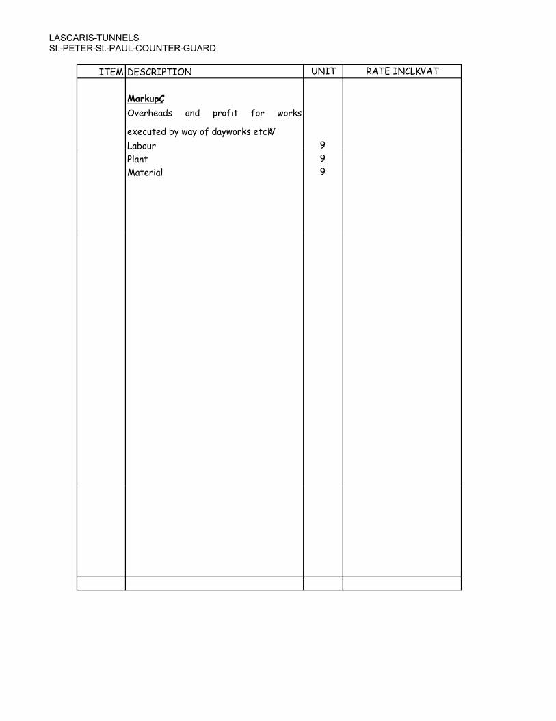
��������������� ��������� ���������������
��� ��������� ���� �������������
�������
�4�(-��!, � ! �(#'�� '#( +#(*,
�6��%��!�1��+���#'�!��+#(*,�����=
��1#%( >��1#%( >
�$� � >
����(��$ >

�������������
�� �������� ��������������
����������

�������������
�� �������� ��������������
���� ��������� �� ��������������
������ ������������
������ ���������� �����
��� ���� � ��� � � � ����������
��� ���� � ��� � � � ����
� ���
������ ��������������
� ������������ �����
������ ���������������
������ ���������������
����� ����� ���!������� ""����� ����� ���!������� ""
� �"����������� ��������
��������� ��������

LASCARIS TUNNELS REF G-0458
GUIDANCE BOQ
DESCRIPTION QUANTITY UNIT RATE INC
VAT
AMOUNT INCL
VAT
BILL B ITEM 2.02.00
PRICED GUIDE TO THE REQUIRED INTERVENTIONS ON SITE
REFERNCE PLAN 1
LASCARIS TUNNELS ENTRANCE
(Starting point: the Entrance from Battery Street)
* Reference document:
PHOTO SURVEY - PART 1 – LASCARIS TUNNELS
GENERAL METHOD STATEMENTS
• METHOD STATEMENT FOR RESTORATION OF GALVANIZED STEEL GATES:
To clean from rust (sand blasting), repair, galvanize, re-paint with one
undercoat and two coats of paint.
• METHOD STATEMENT FOR RESTORATION OF EXISTING STEEL BUNK BEDS:
to remove from wall, clean from rust (sand blasting), repair, heavily
deteriorated or missing parts to be replaced with the same new one (using
same materials and same method of manufacturing and fixing), galvanize,
paint with undercoat and two coats of paint (original color light gray – to be
instructed and approved by Client). Mounting method to be checked or
repaired as required. Existing galvanized steel mesh to be re-instated with the
same or approved similar one.
• METHOD STATEMENT FOR FIXING STEEL BUNK BEDS TO THE WALL:
Removal method: To drill out carefully to dislodge existing hanger hooks
Replacement method: to include setting in propriety anchor fix in drilled holes
• METHOD STATEMENT FOR REPAIR OF EXISTING CONCRETE STAIRS: To
clean, cut out damaged part of concrete surface and replace it with new
concrete up to 3” depth. Where damaged part is deeper it is necessary to use
dovetail system for repairing)
• METHOD STATEMENT FOR REPAIR OF EXISTING CONCRETE FLOORS: To
clean, cut out damaged part of concrete surface and replace it with new
concrete (up to 4” depth.)
• METHOD STATEMENT FOR REPAIR OF EXISTING STEEL BEAMS: To clean
from the rust, paint with one undercoat and 2 coats of epoxy paint)
PAGE 1

LASCARIS TUNNELS REF G-0458
GUIDANCE BOQ
DESCRIPTION QUANTITY UNIT RATE INC
VAT
AMOUNT INCL
VAT
1. The entrance area:
Full restoration of existing wall at the entrance of the tunnels including
replacement of missing and eroded stones, cleaning, plastic repair, re-pointing
and consolidation of stone (at the Entrance from Battery Street)
(Pic. 1) (Reference: Dwgs: An-001; An-008) --
2. Re-instatement of existing timber gate frame using same materials,
methods and design as original frame
(Pic. 2)(Reference: Dwg: An-406) 1.00 LS
3. Dismantle and cart away existing steel door at the entrance to tunnel area.
Supply and install new side hinged one leaf galvanized steel door beyond
timber gate following design and method of manufacturing of original gate
(Pic. 2) (Reference: Dwg. An-410) 1.00 LS
4. Guard room at Entrance area – as Ticketing point:
Clean existing walls and floor * 496.00 sq m
*(Reference: Method statement for repair of concrete stairs) .
Manufacture and install lockable one leaf, side hinged solid steel door at the
entrance 1.00 LS
(Reference: Dwg: An-101)
5. Clean and repair existing concrete stands: clean and treat against rust exposed
reinforcement and metal plates, repair, replace broken pieces of concrete* 6.00 nr
*(Reference: Method statement for repair of concrete stairs)
( Pic. 3)
6. Repair existing blast wall*
*(Reference: Method statement for restoration of masonry walls and ceiling) 1.00 LS
(Pic. 4)
7. Supply and install turnstile at the Entrance (Type and position to be specified
by Client) PROV LS
8. To restore metal water tank currently at Fort Rinella, dismantle, repair and
transport to and re-erect over previously restored supports located in the
entrance area of the Lascaris tunnel ( at Battery Street-end) PROV LS
c/f
BILL 4 SECTION A REFERS
PAGE 2

LASCARIS TUNNELS REF G-0458
GUIDANCE BOQ
DESCRIPTION QUANTITY UNIT RATE INC
VAT
AMOUNT INCL
VAT
b/f
LASCARIS TUNNELS
9. Clean existing walls, repair masonry walls (where necessary) and ceilings all
the way from the entrance to the exit at Timber bridge area 2540.00 sq m
*(Reference: Method statement for restoration of masonry walls and ceiling)
(Pic. 5) (Reference: Dwg: An-101)
10. GENERAL NOTE: Manufacture and install in one sample room coat hangers
and timber shelves (as per original design - sample to be supplied by Client) 1.00 nr
11. GENERAL NOTE: Existing concrete stairs to be cleaned, repaired and made
good where necessary *
*(Reference: Method statement for repair of concrete stairs) 1.00 LS
(Pic. 9)
12. GENERAL NOTE: Inspect existing steel beams and their bearing for rust –
where possible repair the existing ones *(Reference: Method statement for
repair of existing steel beams);
where damage is excessive - replace the existing steel beams with new ones
(1 in room No 1; 1 in room No 2; 3 in room No 6; Room 5 beams to be replaced
– Number to be checked and verified on site) 5.00 nr
(Pic. 10)
13. Manufacture or restore where necessary and install side hinged single leaf
solid timber doors in each cubicles (marked on Dwg An-101).
Doors to be manufactured per original design, using original methods and
materials (8 in Number – for first part of Tunnels – till Gate “A”; 1 in Number
Second part of tunnels) PROV nr
(Reference: Dwg An-100)
14. Restore and where missing re-instate folding steel bunk beds
Total Number: first part of tunnels till gate “A” - 8 in No, second part....)*
Number to be checked and verified on site 8.00 nr
* (Reference: Method statement for restoration of existing steel bunk beds;
Method statement for fixing steel bunk beds to the wall)
(Pic. 11) (Reference: Dwg An-101)
15. Restore and where missing re-instate steel racks as original one (first part
of tunnels till gate “A” - 4 in No,...)* (Number to be checked and verified on
site) 4.00 nr
*(Reference: Method statement for restoration of existing steel bunk beds;
Method statement for fixing steel bunk beds to the wall)
(Pic. 12)
16. Supply and install galvanized steel cat ladder - 5 in No (material, finish and
method of fixing to follow the original one 1.00 LS
(Pic. 8)
17. Repair existing concrete light hole in ceiling
Clean and protect exposed reinforcement, repair concrete of closing light hole
using propriety materials * 1.00 nr
*(Reference: Method statement for repair of existing concrete floor)
(Pic. 13)
c/f
PAGE 3

LASCARIS TUNNELS REF G-0458
GUIDANCE BOQ
DESCRIPTION QUANTITY UNIT RATE INC
VAT
AMOUNT INCL
VAT
b/f
18. Clean and repair original existing sliding timber door (area beyond gate
“B”)*
*(Reference: Method statement for repair of existing timber doors )
(Pic. 14) (Reference: Dwg. An-100) PROV nr
19. Manufacture and install missing sliding timber doors as per existing original
sample in Corridor area beyond gate ”B” using original materials and methods
of manufacturing (10 in Number) and 1 hinged single leaf timber door
(Reference Dwg. An-405) PROV nr
20. Clean, repair, touch up and re-paint existing toilet timber doors – 3 in
Number*
*(Reference: Method statement for repair of existing timber doors )
(Pic. 15) 3.00 nr
21. Replace the existing toilet fittings with original one (except for one toilet
where WC is original) (Information’s and actual toilet furniture to be supplied
along with instructions by Client) 1.00 LS
(Pic. 16)
22. Clean from dirt and rust and restore 2 in No existing steel gates in Area “A”-
Gates A &E.
(Steel plate from second gate to be removed)*
* (Reference: Method statement for restoration of galvanized steel gates):
(Pic. 17,18) (Reference: Dwg: An-100) 2.00 nr
23. Clean and cart away remains of existing timber spiral staircase and lose
material.
(Reference: Dwg. An-101; Ac-412) 1.00 LS
24. Manufacture and install side hinged one leaf steel gate at the end of
tunnels – towards existing Timber Bridge. Design to follow design of steel door
at the Entrance from Battery street)
(Pic.21) (Reference: Dwg. An-410) 1.00 nr
TIMBER BRIDGE AREA
1) Restore existing timber planks and timber railing of the timber bridge. (Pic.
61)
(i) timber planks 22.75 sq m
2) Re-instate Timber gate at the end of Timber Bridge. Design to follow
design of Douglas fir timber gate of the Entrance to Tunnels.
Old ironmongery to be removed, cleaned and re-used for a new gate. New
ironmongery to be manufactured using same materials and methods like the
old one.
(Pic. 21,22) (Reference: Dwg Acg-400). 1.00 nr
3) Install new steel railing fixed to the ground 40.00 m
(Reference: Dwg: Acg-405)
TOTAL CARRIED TO BILL B ITEM 2.02.00
PAGE 4

Lascaris War Rooms
St. Peter St. Paul Counter Guard
Our Ref G-0485
Guidance BOQ
DESCRIPTION QUANTITY UNIT RATE AMOUNT
BILL B ITEM 3.02.00
GUIDE TO THE REQUIRED INTERVENTIONS ON SITE
QUANTITIES ARE ONLY INDICATIVE, CLAIMS ARISING FROM DISCREPANCIES
BETWEEN QUOTED AND ACTUAL FIGURES WILL NOT BE ACCEPTED.
ST.PETER’S AND ST. PAUL’S COUNTER- GUARD – PART A - Rooms”a”&”c”(Starting point: the Entrance from Lascaris war rooms area from the
ditch)
* Reference document:
PHOTO SURVEY - PART 3 - ST.PETER’S AND ST.PAUL’S COUNTER-GUARD
GENERAL METHOD STATEMENTS
• METHOD STATEMENT FOR RESTORATION OF GALVANIZED STEEL
GATES: To clean from rust (sand blasting), repair, galvanize, re-paint with
one undercoat and two coats of paint.
• METHOD STATEMENT FOR RESTORATION OF EXISTING STEEL BUNK
BEDS: to remove from wall, clean from rust (sand blasting), repair, heavily
deteriorated or missing parts to be replaced with identical replacments
(using same materials and same methods of manufacturing and fixing),
galvanize, paint with undercoat and two coats of paint (original color light
gray – to be instructed and approved by Client). Mounting method to be
checked or repaired as required. Existing galvanized steel mesh to be re-
instated with the same or approved similar one.
• METHOD STATEMENT FOR FIXING STEEL BUNK BEDS TO THE WALL:
Removal method: To drill out carefully to dislodge existing mounting pins
and hanger hooks.
Replacement method: to include setting in Sika anchor fix in drilled holes.
• METHOD STATEMENT FOR REPAIR OF EXISTING CONCRETE STAIRS: To
clean, cut out damaged part of concrete surface and replace it with new concrete
up to a 3” depth. Where damaged part is deeper it is necessary to use a dovetail
system for repairing.
• METHOD STATEMENT FOR REPAIR OF EXISTING CONCRETE FLOORS: To
clean, cut out damaged part of concrete surface and replace it with new concrete
(up to a 4” depth. )
PAGE 1
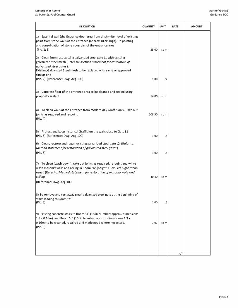
Lascaris War Rooms
St. Peter St. Paul Counter Guard
Our Ref G-0485
Guidance BOQ
DESCRIPTION QUANTITY UNIT RATE AMOUNT
1) External wall (the Entrance door area from ditch) –Removal of existing
paint from stone walls at the entrance (approx 10 crs high). Re pointing
and consolidation of stone voussoirs of the entrance area
(Pic. 1; 3) 35.00 sq m
2) Clean from rust existing galvanized steel gate L1 with existing
galvanized steel mesh (Refer to: Method statement for restoration of
galvanized steel gates ).
Existing Galvanized Steel mesh to be replaced with same or approved
similar one
(Pic. 2) (Reference: Dwg. Acg-100) 1.00 nr
3) Concrete floor of the entrance area to be cleaned and sealed using
propriety sealant. 14.00 sq m
4) To clean walls at the Entrance from modern day Graffiti only. Rake out
joints as required and re-point. 108.50 sq m
(Pic. 4)
5) Protect and keep historical Graffiti on the walls close to Gate L1
(Pic. 5) (Reference: Dwg. Acg-100) 1.00 LS
6) Clean, restore and repair existing galvanized steel gate L2 (Refer to:
Method statement for restoration of galvanized steel gates )
(Pic. 6) 1.00 LS
7) To clean (wash down), rake out joints as required, re-point and white
wash masonry walls and ceiling in Room “b” (height 11 crs- crs higher than
usual) (Refer to: Method statement for restoration of masonry walls and
ceiling ) 40.40 sq m
(Reference: Dwg. Acg-100)
8) To remove and cart away small galvanized steel gate at the beginning of
stairs leading to Room “a” (Pic. 8) 1.00 LS
9) Existing concrete stairs to Room “a” (18 in Number; approx. dimensions
1.3 x 0.16m) and Room “c” (16 in Number; approx. dimensions 1.3 x
0.16m) to be cleaned, repaired and made good where necessary. 7.07 sq m
(Pic. 8)
c/f
PAGE 2

Lascaris War Rooms
St. Peter St. Paul Counter Guard
Our Ref G-0485
Guidance BOQ
DESCRIPTION QUANTITY UNIT RATE AMOUNT
b/f
10) To rake-out masonry walls and ceiling of staircase areas, re-pointed
where required and white wash. (Refer to: Method statement for
restoration of masonry walls and ceiling ) 175.50 sq m
(Pic. 8; 9)
11) To clean, wash down, rake out and re-point walls and ceiling in Room
“c” (refer to: Method statement for restoration of masonry walls and
ceiling) 235.25 sq m
(Pic. 14)
12) White wash walls and ceiling in Room “c”.* 235.25 sq m
(Refer to: Method statement for restoration of masonry walls and ceiling )
(Pic.16)
13) To clean and patch up concrete floor in Room “c”
(Refer to: Method statement for repair of existing concrete floors ) 25.00 sq m
(Pic.16)
14) To dismantle, refurbish and re-install existing galvanized steel railing
along the existing stairs to Room “c” 1.00 LS
(Pic. 22)
15) Supply and install new galvanized steel railing same as the existing to
area leading to Gate L3 in Room “c” (approx. length: 30m) 30.00 m
16) Clean from rust, repair and restore to original state galvanized steel
frames of 27+15 in Number folding bunk beds in Room “c”. Galvanized
steel mesh to be replaced with similar one. (Refer to: Method statement
for restoration of existing steel bunk beds.) 42.00 nr
(Pic. 19, 20) (Reference: Dwg. Acg-100)
17) Construct 2 in Number blast walls in “Franka” masonry in 2x230mm
thickness + 200mm cavity, 2.83m high (one near upper gate, the other
near small window G2) in Room ”c”. Position of blast walls to be
determined and instructed by Client. 11.32 sq m
(Reference: Dwg. Acg-100)
c/f
PAGE 3

Lascaris War Rooms
St. Peter St. Paul Counter Guard
Our Ref G-0485
Guidance BOQ
DESCRIPTION QUANTITY UNIT RATE AMOUNT
b/f
ST.PETER’S AND ST.PAUL’S COUNTER-GUARD – PART B - LOWER LEVEL
1) Dismantle and cart away existing, manufacture and install new Timber
gate (Douglas fir) L3 on the end of Room “c”, L4 (gate outside of Room “c”)
and L5 gate (leading to tunnels under the bridge) 3.00 nr
(Pic. 21) (Reference: Dwg. Acg-400)
2) Manufacture and install 1 in No galvanized steel gate L5 for the
existing opening under the Valletta bridge (as per drawings) 1.00 nr
(Pic. 22) (Reference: Dwg: Acg-401)
3) Repair and/or touch up existing concrete flooring in tunnel area (
between gates L4 & L5) up to thickness of 4”* 3.50 cu m
*(Refer to: Method statement for repair of concrete floors )
(Pic.22)
4) Uproot, remove and cart away all plants and all vegetation along the
Counter-Guard wall and in Lower level area of Counter-guard as instructed
by Client. 1.00 LS
(Pic. 25, 26)
GUNPOWDER STORE
1) Dismantle, remove and cart away existing galvanized steel door at the
entrance to Gunpowder store. Manufacture and install (to replace existing
galvanized steel door with timber door (Red Deal as per Dwg: Acg-403a)
(Pic. 27) REMOVAL 1.00 LS
REMANUFACTURE 1.00 LS
2) Clean and wash down walls and ceiling of Gunpowder store , Lamp
room, Shifting lobby and entrance corridor– original graffiti to be kept (to
be directed and instructed by Client prior cleaning) * 863.50 sq m
*(Refer to: Method statement for restoration of masonry walls and
ceiling ) (Pic. 28)
3) Take down existing timber door and restore to original state, allow for
replacing back . 1.00 LS
(Pic. 30) (Reference: Dwg. Acg-402, Acg-102)
4) Recreate timber flooring in Gunpowder store using existing timber
and same kind of timber as the original one. No use of screws in fastening
allowed – copper nails would be requested to be used. (Timber to be used
is to be Red Deal ) 86.00 sq m
(Pic. 29)
c/f
PAGE 4

Lascaris War Rooms
St. Peter St. Paul Counter Guard
Our Ref G-0485
Guidance BOQ
DESCRIPTION QUANTITY UNIT RATE AMOUNT
b/f
5) Restore stone pilasters under the timber floor in Gunpowder store
using existing material (where possible) and where necessary to replace it
with new one using replication of original methods 344.00 nr
(Pic. 29)
6) Clean from dirt, strip of paint, repair and re-paint (1 under coat, 2
coats of paint) two other existing internal timber doors in Gunpowder
store 2.00 nr
(Pic. 31, 32)
7) Clean, repair and restore existing Copper lined door to Gunpowder
store. Copper nails to be used 1.00 LS
(Pic.33)
8) Re-instate as per original sketch Gunpowder store and Shifting Lobby
furniture using traditional methods of manufacturing and Red Deal
Timber. 1.00 LS
(Reference: Dwg. Acg-404; Acg-406)
9) Re-instate to original condition, 8 in Number glazed timber Lighting
windows as per sample provided by Client. Rate is to include for a solid
cast brass frame, a brass outer mesh and 5mm thick float glass. Drg. Acg-
402a. PROV nr
(Pic. 34)
10) Remove existing vent pipe and cart away 1.00 LS
LIGHTING PASSAGE
1) To dismantle and cart away existing steel entrance door. To
manufacture and install Red Deal timber door at the entrance.
(Pic.35) (Reference: Dwg .Acg-403) 1.00 LS
2) Clean room of all extraneous materials and cart away, remove all wall
papers and cart away; clean and wash walls and floor of Lighting passage
room
(Pic. 36, 37) 1.00 LS
3) Restore existing deteriorated timber grating to the existing gutter on
the way to upper level of Counter-Guard . 1.00 LS
(Pic.38)
c/f
PAGE 5

Lascaris War Rooms
St. Peter St. Paul Counter Guard
Our Ref G-0485
Guidance BOQ
DESCRIPTION QUANTITY UNIT RATE AMOUNT
b/f
ST.PETER’S AND ST.PAUL’S COUNTER-GUARD – PART C - UPPER LEVEL
1) Dismantle and cart away existing railing , remanufacture and install
galvanized mild steel railing as per approved design along stairs up to
Upper level and along perimeter of walls. Traditional materials and
methods to be used for manufacturing and installation. PROV m
(Pic. 39, 40) (Reference: Dwg. Acg-405)
2) Uproot existing vegetation on roof area of Lighting passage and
Gunpowder store and around existing vent chimneys and cart away 1.00 LS
(Pic. 41)
3) To waterproof roof area of Gunpowder store and Lighting Passage
room
(Method to be used: to repair and close off existing cracks in roof
structure with propriety materials) 1.00 LS
(Pic. 41)
4) To replace missing stones along the roof of Lighting Passage and
Gunpowder room and repair damaged one 1.00 LS
(Pic. 41)
5) Restore to its original state Observation Room at Upper level– clean
stones of graffiti, restore masonry walls , re-point walls, restore and
reinstate 3 existing timber windows, manufacture and install missing
timber sliding door in Red Deal at the entrance, to repair concrete
structure of the roof (to clean and protect exposed mesh, repair damaged
concrete using propriety materials) (Dimensions Viewing Point: W=2.71m;
L=2.67m)
(Pic. 45, 46, 47, 48, 50)– (Reference: Dwg. Acg-101; An-405) PROV LS
6) Clean from vegetation the area in front of Observation Room, prepare
ground and supply and erect stone stairs (3 in Number) leading to
Observation Room from upper roof area. 1.00 LS
(Pic. 49) (Reference: Dwg. Acg-101)
7) Remove existing concrete remains of artillery ramps and to replace the
area with hard stone slabs – Important note: Paving to be done in the
same fashion and with the same sizes of joints in flooring as the rest of
existing paved area 50.00 sq m
(Pic. 44) (Reference: Dwg. Acg-101)
8) To supply quantity of 100 in No 24 Pounder solid iron Cannon shot (All
information’s to be provided by Client) PROV kg
9) To supply 120 replica British War Department gun powder barrels as
per example held at Saluting Battery Gun Powder Store. Same dimensions,
materials and method of fabrication PROV nr
10) Transportation from Fort Rinella in Kalkara, lifting and putting in place
on the upper tier of the Counter-guard two replica British 24-pounder
iron-carronades. 1.00 LS
11) General cleaning of shrubs and small plants and weeds of the upper
part of the counter guard (circa 600sq m) Pic 51. 1.00 LS
TOTAL CARRIED TO BILL B ITEM 3.02.00
PAGE 6