Invitation To Bid for - Canton
306
Charter Township of Canton Invitation To Bid for SUMMIT SENIOR CENTER RENOVATIONS Contact: Brad Sharp Phone: 734 394-5363 E-mail: [email protected] Date Issued: 2/22/2018 Due Date & Time: 3:00 p.m., Thursday, March 15, 2018
-
Upload
khangminh22 -
Category
Documents
-
view
0 -
download
0
Transcript of Invitation To Bid for - Canton

Charter Township of Canton
Invitation To Bid
for
SUMMIT SENIOR CENTER RENOVATIONS
Contact: Brad Sharp
Phone: 734 394-5363 E-mail: [email protected]
Date Issued: 2/22/2018
Due Date & Time: 3:00 p.m., Thursday, March 15, 2018
The deadline established for the receipt of your sealed bid is 3/15/2018 at 3:00 p.m. The bid is to be submitted to the Clerk's Office, 1150 S. Canton Center Road, Canton, Michigan 48188. Address the bid to:
Canton - Clerk’s Office SUMMIT SENIOR CENTER RENOVATIONS
DUE 3/15/2018 at 3:00 P.M. 1150 Canton Center S
Canton MI 48188 GENERAL REQUIREMENTS & INSTRUCTIONS
1. SUBMISSION OF OFFERS: All offers should be submitted in a sealed envelope or
package. The invitation title, opening date and time, company name, address and telephone number shall be clearly displayed on the outside of the sealed envelope or package. The delivery of responses to the Clerk’s Office prior to the specified date and time is solely and strictly the responsibility of the offeror. Any submittal received in the Clerk’s Office after the specified date and time will not be considered. Responses shall be submitted on the forms provided by Canton. Additional information may be attached to the submittal. Facsimile submissions are NOT acceptable. No offer may be modified after acceptance. No offer may be withdrawn after opening for a period of sixty days unless otherwise specified. Bid must include all costs. All offers must include the original and at least two (2) copies.
2. EXECUTION OF OFFER: Offer shall contain a manual signature in the space(s) provided
of a representative authorized to legally bind the offeror to the provisions therein.
3. EXECUTION OF ACCEPTANCE: Canton Township legally recognizes acceptance of formal offer when a written contract is signed by both parties. Offerer is not to assume that the Canton Board of Trustees resolution approving the bid or proposal is a binding contract.
4. OPENING & RECORDING: Opening shall be public in the Clerk’s Office immediately
following the advertised deadline date and time for receipt of submittals. 5. INTEGRITY: Canton Township does not discriminate on the basis of race, color, national
origin, sex, religion, age or disability in employment or the provision of services. 6. TABULATION: Bid results will be posted on the Township’s website at www.canton-
mi.org Please click on Doing Business, Bids & Proposals
7. BOARD AWARDS: As the best interest of Canton may require, Canton reserves the right to make award(s) by an individual item, group of items, all or none, or a combination thereof; on a geographical basis and/or on a countrywide basis with one or more supplier(s) or provider(s); to reject any and all offers or waive any irregularity or technicality in offers received. Offerors are cautioned to make no assumptions. Any or all awards made as a result of this invitation shall conform to applicable ordinances and policies of Canton Township. Bid awards will be posted on the Township’s website at www.canton-mi.org.
8. BRAND NAME OR EQUAL: If items requested by this invitation have been identified in the specifications by a brand name “OR EQUAL” description, such identification is intended to be descriptive and not restrictive and is to indicate the quality and characteristics of products that will be acceptable. Offers proposing “equal” products will be considered for award if such products are clearly identified in the offer and are determined by Canton to meet fully the salient characteristic requirements listed in the specifications.
9. PRICING: Unless otherwise specified prices offered shall remain firm for a period of at
least sixty (60) days; all pricing of goods shall include FOB Canton Township, all packing, handling, shipping charges and delivery to any point(s) within Canton to a secure area or inside delivery.
10. PAYMENT TERMS: Canton Township will remit full payment on all undisputed invoices
within thirty (30) days from receipt by the appropriate person(s) of the invoice or receipt of all products or services ordered.
11. INCURRED EXPENSE: This invitation does not commit Canton to make an award nor
shall Canton be responsible for any cost or expense which may be incurred by any respondent in preparing and submitting a reply, or any cost or expense incurred by any respondent prior to the execution of a purchase order or contract agreement.
12. QUESTIONS/ ADDENDA: Any questions concerning the conditions or specifications shall
be directed to the designated contact person. Addenda items will be posted on the township website, on the Purchasing Division page under Requests for Bids, Proposals and Qualifications. It is the bidder’s responsibility to check and verify that addenda have been issued. Failure to acknowledge addenda may result in the offer not being considered.
13. CLARIFICATION/CORRECTION OF ENTRY: Canton reserves the right to allow for
the clarification of questionable entries and the correction of OBVIOUS MISTAKES. 14. INSURANCE: The successful bidder is required to furnish evidence of the following
insurance requirements in accordance with Canton’s Risk Management Policy O:02. Work may not commence until the Certificates of Insurance have been received. The coverage requirements are as follows:
Workers’ Compensation Insurance: The Contractor shall procure and maintain during the life of this contract, Workers’ Compensation Insurance, including Employers’ Liability Coverage, in accordance with all applicable statutes of the State of Michigan. Commercial General Liability Insurance: The Contractor shall procure and maintain during the life of this contract, Commercial General Liability Insurance on an “Occurrence Basis” with limits of liability not less than $1,000,000 per occurrence and aggregate combined single limit, Personal Injury, Bodily Injury, and Property Damage. Coverage shall include the following extensions: (A) Contractual Liability; (B) Products and Completed Operations; (C) Independent Contractors Coverage; (D) Broad Form General Liability Extensions or equivalent. Motor Vehicle Liability: The Contractor, or its subcontractors, shall procure and maintain during the life of this contract Motor Vehicle Liability Insurance, including Michigan No-Fault
Coverage, with limits of liability not less than $1,000,000 per occurrence combined single limit, Bodily Injury, and Property Damage. Coverage shall include all owned vehicles, all non-owned vehicles, and all hired vehicles. Additional Insured: Commercial General Liability Insurance as described above, shall include an endorsement stating that the following shall be Additional Insured: The Charter Township of Canton, all elected and appointed officials, all employees and volunteers, all boards, commissions, and/or authorities and board members, including employees and volunteers thereof. Cancellation Notice: The Insurance coverage described above, shall include an endorsement stating the following: “It is understood and agreed that Thirty (30) days Advance Written Notice of Cancellation, Non-Renewal, Reduction, and/or Material Change shall be sent to: Mike Sheppard, 1150 Canton Center S., Canton MI, 48188. Indemnification: To the fullest extent permitted by law, the (name of contractor) agrees to defend, pay on behalf of, indemnify, and hold harmless the Charter Township of Canton, its elected and appointed officials, employees and volunteers, and others working on behalf of the Charter Township of Canton against any and all claims, demands, suits, or loss, including all costs connected therewith, and for any damages which may be asserted, claimed, or recovered against or from the Charter Township of by reason of personal injury, including bodily injury or death and/or property damage, including loss of use thereof, which arises out of or is in any way connected or associated with this agreement. 15. PUBLIC ACT 517 OF 2012: In accordance with Public Act 517 of the Public Acts of 2012,
any Iran linked business is not eligible to submit a bid on a request for proposal with a public entity in Michigan. An “Iran linked business” includes the following: (1) A person engaging in investment activities in the energy sector of Iran, including a
person that provides oil or liquefied natural gas tanker or products used to construct or maintain pipelines used to transport oil or liquefied gas for the energy section of Iran; and
(2) A financial institution that extends credit to another person, if that person will use the credit to engage in investment activities in the energy sector of Iran.
For purposes of this prohibition, “person” includes an individual, corporation, company, limited liability company, business association, partnership, society, trust, or any other non-governmental entity, organization or group. It also includes a governmental entity or instrumentality of a governmental entity, or any successor, subunit, parent company or subsidiary of, or company under common ownership or control with and of the foregoing.

REQUEST FOR BID SPECIFICATIONS Canton Township
Summit Senior Center Renovations
REQUIREMENTS
1. The Contractor shall be duly licensed by the appropriate authorities to perform this work. 2. Insurance shall be in accordance with the Charter Township of Canton insurance requirements. 3. The signed contract is not assignable or transferable to any other company without approval of
the Charter Township of Canton. 4. The Contractor will conform to all applicable Federal, State and local laws. 5. No bid bond required. INSTRUCTIONS TO BIDDERS A MANDATORY pre-bid meeting is scheduled for Thursday, March 8, 2018 at 10:00 AM located in front lobby of the Summit on the Park, 46000 Summit parkway, Canton MI 48188. The names and legal status of the Bidder, that is, as a corporation, partnership or individual, shall be stated in the Bid and legal documentation of the status of the company, such as corporate papers or partnership papers shall be provided, if requested by the Charter Township of Canton. Anyone signing a Bid as an agent of another or others must submit with the Bid legal evidence of his/her authority to do so. The place of residence of each Bidder, or the office address in the case of a firm or company, with county and state, must be given after his signature.
Any questions regarding the material contained in this Request for Bid, please contact Brad Sharp at 734-394-5363 or [email protected]. Amendments will be issued for clarification on the Township website should the Township deem it necessary to do so.
CONTRACTOR QUALIFICATIONS It is the intention of Canton Township to award this Contract to a Contractor fully capable, both financially and with applicable experience, to perform and complete the work in a satisfactory manner. The Contractor shall be duly licensed by the appropriate authorities to handle the specified work. Documentation to verify such license must accompany the bid. The Contractor shall at all times utilize staff at appropriate times and in a proper manner to assure the project work is performed in a safe, efficient and professional manner. All work shall be performed in a professional and competent manner using quality equipment and materials, all of which must be maintained and operated with the highest standard as well as meeting all OSHA and MIOSHA safety standards.
GENERAL SPECIFICATIONS
All demolition work shall be done on the following dates:
Tuesday, September 4, 2018 through the end of the day Friday, September 7, 2018. All flooring in area 101, PT3, RB, CPT3 is to be done on the following days:
Tuesday, September 4, 2018 through the end of the day Friday, September 7, 2018. All additional work shall be done following September 7th in a continuous effort during regular
work hours. Note: Starting after September 7th the facility will be open and all necessary steps shall be followed to limit disruption to the facility operations.
No exceptions to schedule will be allowed
The Contractor agrees that he/she will not discriminate against any employee or applicant for the employment during the performance of this contract with respect to hire, tenure, terms and conditions, privileges of employment, color, religion, national origin, age, sex height, weight, or marital status.
Any deviation from these specifications must be approved in writing by Canton Township. Contract is
to perform the work as provided in the attached drawings and specification section. Contractor to be responsible for all demolition and disposal costs. INCREASE OR DECREASE IN CONTRACT QUALTITIES
The Owner reserves the right to increase, decrease or delete items in the Bids in order to match the Contract amount to the funds available. AWARD OF CONTRACT
The Owner reserves the right to reject any or all Bids and to waive irregularities in Bidding. The successful Bidder shall be required to furnish certificates of insurance. DESCRIPTION OF PROJECT
The project includes the renovation of the Summit on the Park Senior Center in accordance with the project manual and drawings.
TERMINATION
Either party may terminate this Agreement at any time upon 30 days prior written notice to the other
party. The Township shall pay any accrued charges incurred prior to the date of the termination. ALLOWANCE
In addition to the scope of work identified above, the Contractor must provide a total project contingency allowance of $5,000 to be used to fund permits, material testing, and unforeseen conditions as approved by the Township designated representative.
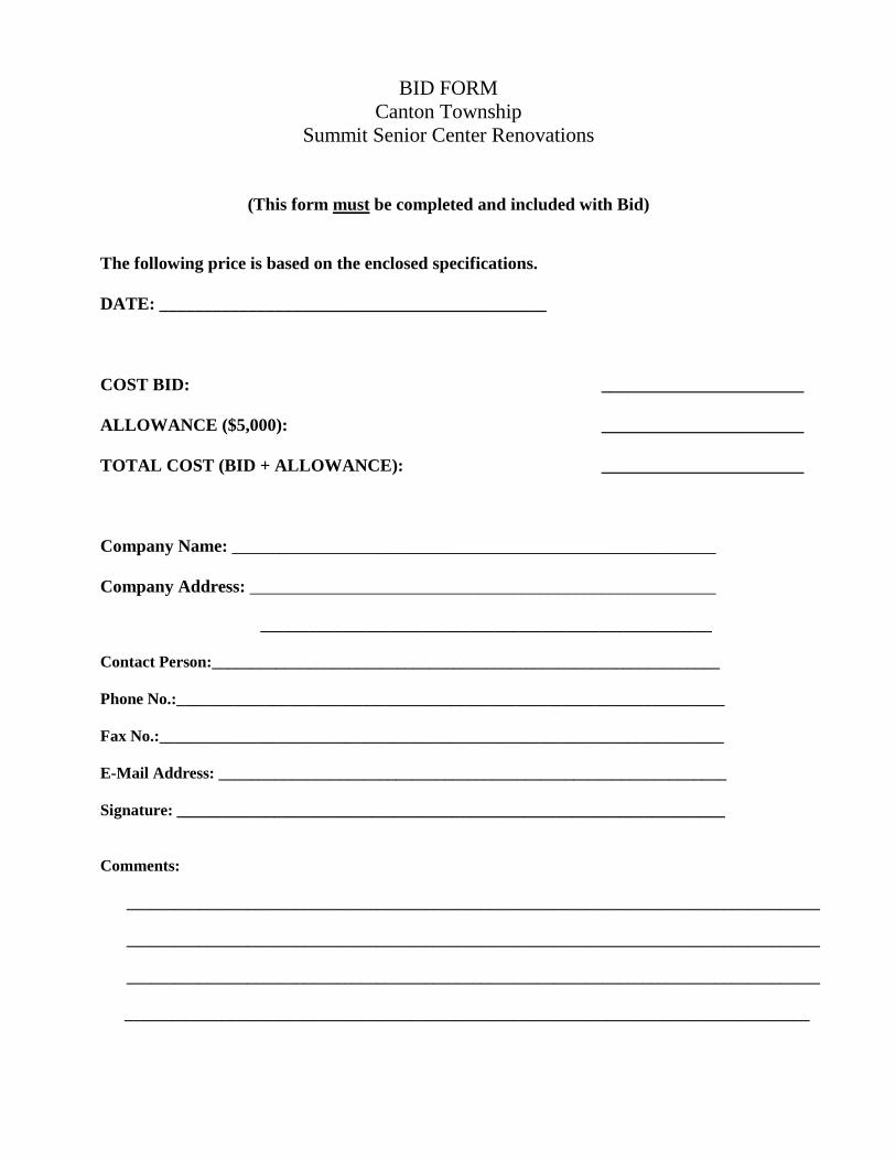
BID FORM
Canton Township Summit Senior Center Renovations
(This form must be completed and included with Bid)
The following price is based on the enclosed specifications. DATE: ____________________________________________
COST BID: _______________________ ALLOWANCE ($5,000): _______________________ TOTAL COST (BID + ALLOWANCE): _______________________ Company Name: _______________________________________________________ Company Address: _____________________________________________________ ________________________________________________________ Contact Person:_______________________________________________________________ Phone No.:____________________________________________________________________
Fax No.:______________________________________________________________________ E-Mail Address: _______________________________________________________________ Signature: ____________________________________________________________________
Comments:
______________________________________________________________________________________
______________________________________________________________________________________
______________________________________________________________________________________
_____________________________________________________________________________________

CONTRACT INFORMATION SHEETS
Canton Township Summit Senior Center Renovations
These sheets must be completed and included with Bid)
COMPANY NAMES: _______________________________________________________ ADDRESS:_______________________________________________________________ ESTABLISHED: ________________________ _______________ (Month) (Year) TYPE OF ORGANIZATION: (Circle One)
A) Individual B) Partnership C) Corporation D) Joint Venture E) Other________________________________________________________ (Specify)
(If Applicable) FORMER FIRM NAME(S): YEARS IN BUSINESS ______________________________________ ____________________ ______________________________________ _____________________ YEARS OF WORK IN A RELATED FIELD: (Describe any Related Work) __________________________________________________________________________________
__________________________________________________________________________________
_______________________________________________________
USE OF SUBCONTRACTORS:
To provide all the services listed in the specifications, would any services be handled by subcontractors? _________________Yes/No If “Yes”, please explain: __________________________________________________________________________________
__________________________________________________________________________________
Subcontractor Names(s):____________________________________________________
THE FOREGOING IS A TRUE STATEMENT OF FACTS:
I/we hereby certify under penalty of law that we are not an Iran linked business as defined in PA 517 of
2012.
Signature of Authorized Company Representative: _______________________________
Company _______________________________
Address: _______________________________
_______________________________
Date: _______________________________
Representative’s Name _______________________________
(Please Print)
PROJECT MANUAL FOR THE CONSTRUCTION OF: PROJECT: SUMMIT ON THE PARK CLUB 55+ SENIOR CENTER RENOVATION PHASE 1 OWNER: CANTON TOWNSHIP SUMMIT ON THE PARK 46000 Summit Parkway Canton Michigan 48188 TMP PROJECT NO.: 16128 DATE: November 2, 2017 ISSUED FOR BIDS
ARCHITECT TMP ARCHITECTURE, INC. 1191 West Square Lake Road Bloomfield Hills, Michigan 48302-0374 PH (248) 338-4561 FX (248) 338-0223 Email [email protected]
MECHANICAL & ELECTRICAL ENGINEER PETER BASSO ASSOCIATES, INC. 5145 Livernois Road, Suite 100 Troy, MI 48098-3276 PH (248) 879-5666 FX (248) 879-0007 Email [email protected]

TABLE OF CONTENTS
11/02/17 ISSUED FOR BIDS TMP16128 PHASE 1 TC - 1
TABLE OF CONTENTS TITLE PAGE TABLE OF CONTENTS LIST OF DRAWINGS BIDDING REQUIRMENTS – TO BE PROVIDED BY OWNER INFORMATION AVAILABLE TO BIDDERS Availability of Electric Files
TECHNICAL SPECIFICATIONS
DIVISION 01 - GENERAL REQUIREMENTS Sections 013300 Electronic Submittal Procedures 014000 Quality Requirements 014213 Abbreviations 014216 Standards and Definitions 015000 Temporary Facilities and Controls 016000 Product Requirements 017329 Cutting and Patching 017400 Cleaning 017700 Closeout Procedures 017836 Warranties
DIVISION 02 – EXISTING CONDITIONS Sections 024119 Selective Demolition
DIVISIONS 03 thru 05 – NOT USED
DIVISION 06 – WOOD, PLASTICS, AND COMPOSITES Sections 061000 Rough Carpentry
DIVISIONS 07 and 08 – NOT USED
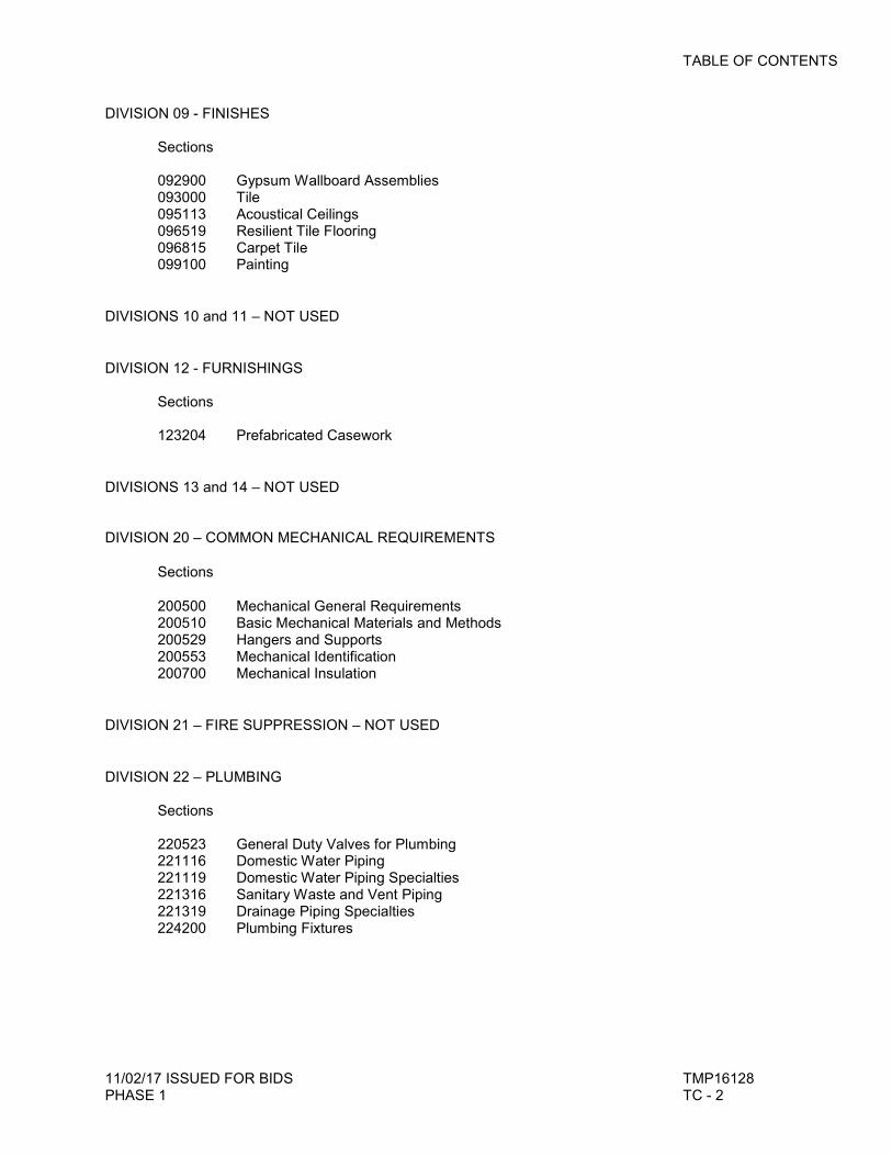
TABLE OF CONTENTS
11/02/17 ISSUED FOR BIDS TMP16128 PHASE 1 TC - 2
DIVISION 09 - FINISHES Sections 092900 Gypsum Wallboard Assemblies 093000 Tile 095113 Acoustical Ceilings 096519 Resilient Tile Flooring 096815 Carpet Tile 099100 Painting
DIVISIONS 10 and 11 – NOT USED
DIVISION 12 - FURNISHINGS Sections 123204 Prefabricated Casework
DIVISIONS 13 and 14 – NOT USED DIVISION 20 – COMMON MECHANICAL REQUIREMENTS
Sections
200500 Mechanical General Requirements 200510 Basic Mechanical Materials and Methods 200529 Hangers and Supports 200553 Mechanical Identification 200700 Mechanical Insulation
DIVISION 21 – FIRE SUPPRESSION – NOT USED
DIVISION 22 – PLUMBING Sections 220523 General Duty Valves for Plumbing 221116 Domestic Water Piping 221119 Domestic Water Piping Specialties 221316 Sanitary Waste and Vent Piping 221319 Drainage Piping Specialties 224200 Plumbing Fixtures

TABLE OF CONTENTS
11/02/17 ISSUED FOR BIDS TMP16128 PHASE 1 TC - 3
DIVISION 23 – HEATING VENTILATING AND AIR CONDITIONING Sections 230593 Testing, Adjusting, and Balancing 233113 Metal Ducts 233300 Duct Accessories 233713 Diffusers, Registers, and Grilles DIVISION 26 – ELECTRICAL Sections 260010 Electrical General Requirements 260519 Conductors and Cables 260529 Hangers and Supports for Electrical Systems 260533 Raceways and Boxes 262726 Wiring Devices DIVISIONS 28 thru 33 – NOT USED
**END OF SECTION**
SECTION 000300 LIST OF DRAWINGS
11/02/17 ISSUED FOR BIDS TMP16128 PHASE 1 000300-LD-1
LIST OF DRAWINGS
1.1 LIST OF DRAWINGS
A. Drawings: Drawings consist of the Contract Drawings and other drawings listed on the TITLE SHEET (TS.1) page of the separately bound drawing set titled Summit on the Park Community Center, Senior Center Renovations – Phase 1, dated November 2, 2017, as modified by subsequent Addenda and Contract modifications.
***END OF DOCUMENT***
AVAILABILITY OF ELECTRONIC FILES
11/02/17 ISSUED FOR BIDS TMP16128 PHASE 1 Page-1
AVAILABILITY OF ELECTRONIC FILES
PART 1 – GENERAL
1.1 POLICY
A. As a service to contractors, subcontractor, vendors, material suppliers and others needing electronic copies of drawing files, the Architect will provide CAD files electronically in accordance with the following policy:
1. By acceptance it is understood and agreed that the data and medium being supplied is to
be used only for the project referenced.
2. It is further understood and agreed that the undersigned will hold TMP Architecture harmless and indemnify TMP Architecture from all claims, liabilities, losses, etc., including attorney's fees arising out of the use or misuse of the transferred items.
3. It is understood and agreed that the items transmitted are prepared from CAD files
current at the time of preparation. All files are AutoCAD version 2009 dwg files. 4. This information does not waive the need to verify and review current field conditions and
the status of Addenda and/or Bulletin documentation.
5. As a record of information to be transmitted, TMP Architecture will prepare a duplicate electronic back-up for its record.
6. Compensation for providing this material will be as follows:
a. Base Fee of $250 for 1 to 3 drawings. b. Base Fee of $500 for 4 to 10 drawings. c. For each additional drawing after 10 the fee is $40.00 per drawing (i.e., 11 drawings = $540).
7. Payment must be provided along with a signed copy of the Release Letter before files will
be released.
1.2 REQUEST PROCEDURE
A. To receive files the attached Release Letter must be completed in full and submitted to the Construction Manager to be forwarded to the Project Manager at TMP Architecture.
1. A signed copy of the Release Letter must be submitted; faxed or emailed copies will be
accepted.
2. Upon remittance of the signed Release Letter and Fee, allow five working days for processing.
3. Transmission of documents will be provided electronically after the receipt of payment.
AVAILABILITY OF ELECTRONIC FILES
11/02/17 ISSUED FOR BIDS TMP16128 PHASE 1 Page-2
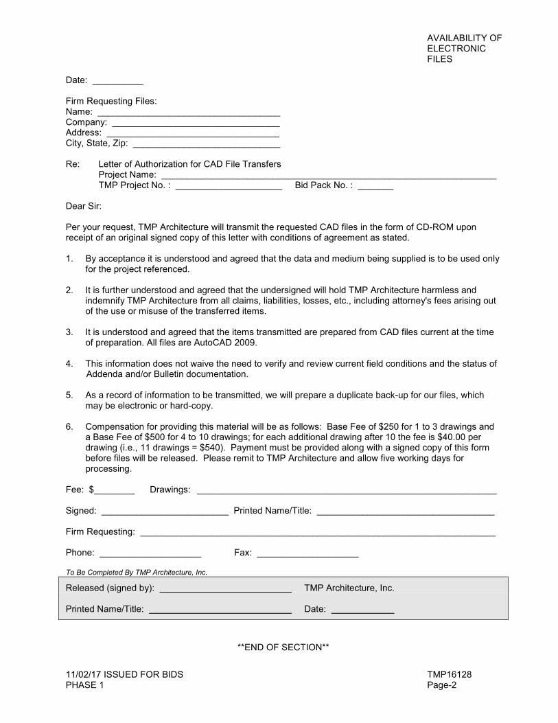
Date: __________ Firm Requesting Files: Name: ____________________________________ Company: _________________________________ Address: __________________________________ City, State, Zip: _____________________________ Re: Letter of Authorization for CAD File Transfers Project Name: __________________________________________________________________ TMP Project No. : _____________________ Bid Pack No. : _______ Dear Sir: Per your request, TMP Architecture will transmit the requested CAD files in the form of CD-ROM upon receipt of an original signed copy of this letter with conditions of agreement as stated. 1. By acceptance it is understood and agreed that the data and medium being supplied is to be used only
for the project referenced.
2. It is further understood and agreed that the undersigned will hold TMP Architecture harmless and indemnify TMP Architecture from all claims, liabilities, losses, etc., including attorney's fees arising out of the use or misuse of the transferred items.
3. It is understood and agreed that the items transmitted are prepared from CAD files current at the time of preparation. All files are AutoCAD 2009.
4. This information does not waive the need to verify and review current field conditions and the status of Addenda and/or Bulletin documentation.
5. As a record of information to be transmitted, we will prepare a duplicate back-up for our files, which may be electronic or hard-copy.
6. Compensation for providing this material will be as follows: Base Fee of $250 for 1 to 3 drawings and a Base Fee of $500 for 4 to 10 drawings; for each additional drawing after 10 the fee is $40.00 per drawing (i.e., 11 drawings = $540). Payment must be provided along with a signed copy of this form before files will be released. Please remit to TMP Architecture and allow five working days for processing.
Fee: $________ Drawings: ___________________________________________________________ Signed: _________________________ Printed Name/Title: ___________________________________ Firm Requesting: ______________________________________________________________________ Phone: ____________________ Fax: ____________________ To Be Completed By TMP Architecture, Inc.
Released (signed by): TMP Architecture, Inc. Printed Name/Title: Date:
**END OF SECTION**
SECTION 013300 ELECTRONIC SUBMITTAL PROCEDURES
11/02/17 ISSUED FOR BIDS TMP16128 PHASE 1 013300-1
ELECTRONIC SUBMITTAL PROCEDURES
PART 1 - GENERAL
1.1 SUMMARY
A. Specified Herein: General Requirements for preparation, submittal, and distribution of Shop Drawings, Samples, Product Data, and similar information required to be furnished by the Contractors by electronic means.
B. Related Work: The following items of work are specified under other Sections of these Specifications:
1. Division 01 Section "Project Record Documents" for project record documents.
1.2 DEFINITIONS
A. Samples: See General Conditions.
1. Preliminary Samples: Hand made or simulated examples or proposed materials submitted to demonstrate anticipated finished appearance.
2. Product Samples: Representative examples of materials proposed for use.
3. Range Samples: Samples showing extremes of variations in appearance, texture or color and the limits within which the Contractor agrees to hold the materials used in the work.
4. Sample Installation: Trial run or initial example provided for review and acceptance by the Architect before continuing with the work.
5. Test Samples: Samples provided for purposed of physical or chemical test analysis. If samples are submitted directly to the Testing Laboratory, submit copy of letter of transmittal.
B. File Transfer Protocol (FTP): Communications protocol that enables transfer of files to and from another computer over a network and that serves as the basis for standard Internet protocols. An FTP site is a portion of a network located outside of network firewalls within which internal and external users are able to access files.
C. Portable Document Format (PDF): Adobe Acrobat (www.adobe.com), Bluebeam PDF Revue (www.bluebeam.com) or other similar PDF review software for applying electronic stamps and comments for representing documents in a device-independent and display resolution-independent fixed-layout document format.
D. Shop Drawings: See General Conditions
1. Electronic File: Drawings and other data submitted electronically in PDF format only.

SECTION 013300 ELECTRONIC SUBMITTAL PROCEDURES
11/02/17 ISSUED FOR BIDS TMP16128 PHASE 1 013300-2
2. Preliminary Shop Drawings: Drawings and other data submitted electronically prior to acceptance of systems and only required to show information necessary for evaluation and coordination with other work.
3. Project Shop Drawings: Drawings and other data illustrating materials and assemblies proposed for the Project.
4. Coordination Drawings: Original electronic drawings prepared by the Trades to investigate conflicts and coordinate locations of each with the work of the other.
E. Identification: All shop drawings, samples and product data shall be identified by the project title, the Architect's name and the Architect's project number or numbers.
1.3 SUBMITTALS IN ELECTRONIC FORM:
A. Contractors to submit shop drawings and product data in electronic form. Submittals are to be made to the General Contractor in the following form.
1. Shop drawing: Combined together into one pdf file for each assembly or product. 2. Product data: Provide product data in individual pdf file.
B. File naming shall be in the following format. (Specification Section Number-consecutive number of submittal for that section) Description of file being submitted.
1. Example: (079200-01) Joint Sealants.pdf B. Contractor shall fill out Submittal Transmittal found at the end of this Section and include at
the beginning of the file. PDF version of Submittal Transmittal form is available upon request from the Architect.
C. Physical Samples must be submitted through the General Contractor and must be
accompanied by an electronic (PDF) copy of the completed TMP Shop Drawing and Transmittal Form.
D. General Contractor shall provide a reasonable means of transmitting files. Either through a
data management provider (i.e. Submittal Exchange) or an established data management system specifically for the Project by General Contractor or an approved method agreed to by the Architect and Owner.
1.4 SCHEDULES
A. Prepare Sample and Shop Drawing Submittal Schedule as required.
B. Recognize and allow for lead-time required for manufacture, fabrication, delivery to the site, and for review.
C. Arrange schedule in orderly sequence in compliance with Project Schedule.
D. Request for approval of materials, systems, substitutions, or for deviations from the Contract Documents shall be submitted according to Section 016000 – “Product Requirements” and shall be Preliminary submittal with allowances for time for review prior to submittal of Product Samples or Project Shop Drawings.
SECTION 013300 ELECTRONIC SUBMITTAL PROCEDURES
11/02/17 ISSUED FOR BIDS TMP16128 PHASE 1 013300-3
1.5 SAMPLES - GENERAL
A. Samples in general, are required for all materials that form an exposed part of the finished Project. Samples of concealed components are not required unless specifically called for.
B. Typical Samples shall be taken from production run material and shall be representative examples of proposed quality and finish.
C. Preliminary Samples shall, as far as possible, anticipate the quality and finish of production run material.
D. Samples will be retained at the job site for comparison purposes. Samples of manufactured items will be returned to the Contractor for installation in the Work after approval of materials. Use in locations where directed.
E. All materials in the completed installation shall be equal in every respect to the approved product samples and within the limits defined by the approved range samples.
1.6 SAMPLES SUBMITTALS
A. Size and quantity, unless otherwise specified: Four (4) each; 8 inches by 12 inches, or 12 inches long, as applicable; not over one inch thick for masonry or cementitious materials.
B. Preliminary or Range Samples shall be resubmitted as directed until an acceptable Sample or Range is established, at which time Project Samples shall be submitted.
C. Furnish Samples to other trades where required to match color or finish.
D. Required Samples are scheduled or are listed in the Trade Sections. Optional Samples will be accepted and reviewed by the Architect.
E. Review will be for shape and appearance only. Physical and chemical properties shall be established by adequate documentation that shall accompany samples.
F. In all cases where preliminary approval samples have been submitted, final production run, or in-place installation samples will be required for verification.
G. Notify Architect in advance and obtain directions for place and time to ship large, heavy or bulky samples. Ship such samples "Prepaid." If return is requested, they will be returned "Collect."
1.7 SHOP DRAWINGS AND PRODUCT DATA - GENERAL
A. Shop Drawings shall be prepared by a qualified detailer and shall be complete including erection diagrams and shall show the fabrication and construction of all items required for complete assembly.
B. Provide pertinent information relating to installation and connection to work of other trades, and coordinate with work of other trades as required for proper placing, anchorage and support of the work. Indicate in detail, the precise location and spacing of all embedded anchor bolts, sleeves and other features required to be placed in the concrete, structural steel or masonry or otherwise required to be built into the structure.
SECTION 013300 ELECTRONIC SUBMITTAL PROCEDURES
11/02/17 ISSUED FOR BIDS TMP16128 PHASE 1 013300-4
C. Identify details by reference to the Contract Drawings, other Shop Drawings or other information as required to properly identify and locate the portion of the Work covered.
D. Indicate on the Drawings and explain by covering letter all proposed deviations from the requirements of the Contract Documents.
E. Manufacturer's Standard Documents:
1. Drawings and similar documents submitted as PDF electronic document from original documents: Modify drawings to delete information which is not applicable to the Project. Provide additional information where required and submit electronically.
2. Brochures and other pre-printed data, clearly mark PDF information as follows: a. Identify pertinent material, product, and model. b. Number or otherwise reference each item to applicable Contract Document or
other Shop Drawing. c. Show dimensions and clearances required. d. Provide all other information required for Shop Drawings including, where
applicable, wiring diagrams and controls. e. Delete all options, or variations from the Contract Documents, except where such
items are specifically noted as proposed deviations.
F. Where proper installation of the work requires that other work be set to special detail, held to tolerance, or dimension be established, so indicate on the Shop Drawings.
G. Where items must fit spaces previously constructed, take measurements at the site, not from drawings.
H. Where applicable, indicate mechanical and electrical characteristics of, or required to be provided for, the material shown on the Shop Drawings.
I. Each shop drawing or coordination drawing shall have a blank area (5 x 8 inches), located adjacent to the title block. The title block shall display the following:
1. Number and title of drawing
2. Date of drawing or revision
3. Name or project building or facility
4. Name of Contractor and (if appropriate) name of Subcontractor submitting drawings.
5. Clear identity of contents and location of the work.
6. Project title and contract number.
7. Initials or party preparing drawings.
8. Signature of party responsible and, where applicable, professional engineers seal.
SECTION 013300 ELECTRONIC SUBMITTAL PROCEDURES
11/02/17 ISSUED FOR BIDS TMP16128 PHASE 1 013300-5
1.8 SHOP DRAWING SUBMITTALS
A. Submit all Shop Drawings, required to be reviewed, to the General Contractor, in electronic file PDF except where otherwise specified. The General Contractor shall review the Shop Drawings prior to submitting for review by the Architect and the Engineer(s). The Architect will review and will note his comments or corrections and return electronic file. Product Data, Brochures and other pre-printed material shall be submitted electronically.
B. The Architect will return the electronic file to the General Contractor for resubmission or final distribution, as indicated. The Contractor shall then distribute as needed whether electronically or hard copy.
C. Submittals returned with the notation "Not Approved" - "Resubmit" or "Revise and Send Record Copy" shall be promptly revised and resubmitted.
D. Contractor to furnish drawings to other contractors, electronically or hard copy, as required to prepare openings, supports, for verification of matching details, and obtain approval before submittal.
E. Required Shop Drawings are scheduled and are listed in the Technical Sections.
F. Schedule and lists of required Shop Drawings are provided for convenience of reference only and do not necessarily include all Shop Drawings necessary for completion of the Work. Procedures for additional for optional Shop Drawings will be the same as for required Shop Drawings.
1.9 SHOP DRAWINGS - TYPES
A. Preliminary Shop Drawings:
1. Preliminary Shop Drawings shall be provided for portions of the Work where interpretations or variations from the Contract Documents are proposed, or otherwise required.
B. Project Shop Drawings:
1. Project Shop Drawings shall show all changes to building details to coordinate with required modifications and indicate approval by other trades for required modifications to their work.
2. Where Shop Drawings are based on the use of a particular material, such material shall be submitted for review independently of the Shop Drawing.
3. When Shop Drawings are submitted in the form of brochures indicate all current variations from the information in effect at time documents were issued for bids.
C. Coordination Drawings:
1. Coordination Drawings unless otherwise agreed shall consist of notations in colored upon a PDF version of the Shop Drawings for the First Trade in the area of potential conflict.
SECTION 013300 ELECTRONIC SUBMITTAL PROCEDURES
11/02/17 ISSUED FOR BIDS TMP16128 PHASE 1 013300-6
2. Coordination Drawings shall be prepared for all conditions where the exercise of the installing Trade's option concerning selection or location of materials or equipment could conflict with other work.
3. First contractor: That contractor so designated by the General Contractor or another Section of this Project Manual. The other contractors shall review in order and sequence as directed by the General Contractor or another Section of this Project Manual.
4. Preparation: a. First contractor will prepare complete Shop Drawings at adequate scale and
provide white prints at earliest practicable date. b. Subsequent contractors shall mark routing and layout on the print each in a
different colored pencil than previously used. c. When drawing is completed, all parties shall meet to examine the completed
layout and determine areas of conflict. d. The contractors shall negotiate re-routing and cooperation to resolve conflict. If
they cannot agree, the General Contractor will determine an equitable solution. e. Determinations shall be indicated in a Shop Drawing Submittal for review.
Deviations from agreed layout shall be remedied at the expense of the Trade that did not follow agreed layout.
5. Conflicts that cannot be resolved by simple re-routing or relocation may involve a change in the work but no extra cost will be allowed for tearing out or re-building work which could have been avoided but use of Coordination Drawings.
6. Each Contractor shall be fully and individually responsible for coordination. In the event of conflict, the Trade Contractor responsible for the mislocation or ill timed work, determined by the Architect and General Contractor, will be required to assume all costs for relocation and adjustment unless he has called attention to the conflict at the time he reviewed the coordination documents.
1.10 CONTRACTOR'S RESPONSIBILITIES
A. The Contractor shall obtain, review, stamp with his approval and submit for review all Shop Drawings and Samples required by the Contract Documents. The General Contractor shall be required to utilize the "Shop Drawing Transmittal Form attached to this section. Only one (1) specification section trade shall be submitted per each transmittal form.
B. By approving and submitting Shop Drawings and Samples, the Contractor thereby represents that he has determined and verified all field measurements and field construction criteria at the site, and all materials, catalog numbers and similar data, or will do so, and that he has checked and coordinated each Shop Drawing and Sample with the requirements of the work and of the Work and of the Contract Documents.
C. The Contractor shall not be relieved of responsibility for any deviation from the requirements of the Contract Documents by the Owner's, General Contractor or the Architect's acceptance or Shop Drawings, Product Data or Samples, unless the Contractor has informed the Owner, General Contractor and the Architect, in writing, of such deviation at the time of submission and the Architect has given written acceptance to the specific deviation. The Contractor shall
SECTION 013300 ELECTRONIC SUBMITTAL PROCEDURES
11/02/17 ISSUED FOR BIDS TMP16128 PHASE 1 013300-7
not be relieved from responsibility for errors or omissions in the Shop Drawings, Product Data or Samples by the acceptance thereof.
D. The Contractor shall direct specific attention, in writing or on resubmitted Shop Drawings, Product Data or Samples to revisions other than those requested on previous submittals.
E. No portion of the Work requiring submission of Shop Drawings, Product Data or Sample shall be commenced until the submittal has been accepted as provided herein. All such portions of the Work shall be in accordance with accepted submittals.
1.11 ARCHITECT'S REVIEW
A. The Architect will complete review of Shop Drawings within fifteen (15) working days, and of Samples within twenty-one (21) working days of receipt thereof except that:
1. Shorter time limits will be negotiated on a basis of need for each specific case for "fast track" or critical path items.
2. With respect to those areas with special architectural finishes and coordination of various material sources the parties shall agree upon a mutually satisfactory time schedule.
3. Review time will be considered as starting when Drawings and Samples are substantially correct and so submitted.
4. Incomplete or incorrect submittals will be returned without review, for proper submission.
B. Shop Drawings, Samples and Product Data will be reviewed only for conformance with the design concept, compliance with the information given in the Contract Documents, arrangement and appearance. Deviations from the Contract Documents will be noted with comments and required corrections or changes will be noted on the returned submittal.
C. Shop Drawings will be returned electronically.
D. Architect will retain electronic file of Product Data and an electronic file of A-E "mark-ups" or corrections of mark-ups. The Architect will not accept physical copies (hard copies) of shop drawings or product data submittals. Physical submittals will be accepted for Samples only. Physical Samples must be submitted through the General Contractor and must be accompanied by an electronic (PDF) copy of the completed TMP Shop Drawing and Sample Transmittal Form.
E. One sample from each set will be returned to the Contractor, one filed at the office of the Architect, one at the office of the General Contractor and one at the jobsite. If the Contractor intends that samples such as hardware or fixtures be installed on the project or returned at completion of the Project, he shall indicate at time of submittal, otherwise the Owner and the Architect assume no responsibility for protection or return of such samples.
1.12 EQUIPMENT ROOM LAYOUT DRAWINGS
A. The Contractor shall prepare and submit equipment room layout drawings as required by the technical specifications and additionally for areas where equipment proposed for use could
SECTION 013300 ELECTRONIC SUBMITTAL PROCEDURES
11/02/17 ISSUED FOR BIDS TMP16128 PHASE 1 013300-8
present interface or space difficulties. Such drawings shall be prepared in the same manner as coordination drawings.
1.13 MATERIALS, EQUIPMENT AND FIXTURE LISTS
A. Where required by the Technical Provisions, lists of materials, equipment and fixtures shall be submitted by the Contractor. The lists shall be supported by sufficient descriptive material, such as catalogs, cuts, diagrams, and other data published by the manufacturer, as well as evidence of compliance with safety and performance standards, to demonstrate conformance to the specification requirements; catalog numbers alone will not be acceptable.
B. The data shall include the name and address of the nearest service and maintenance organization that regularly stocks repair parts. No consideration will be given to partial lists submitted from time to time.
C. Materials, equipment and fixtures will not be approved for use at capacity ratings in excess of manufacturer's published data.
D. Approval of materials and equipment will be tentative subject to submission of complete shop drawings indicating compliance with the Contract Documents.
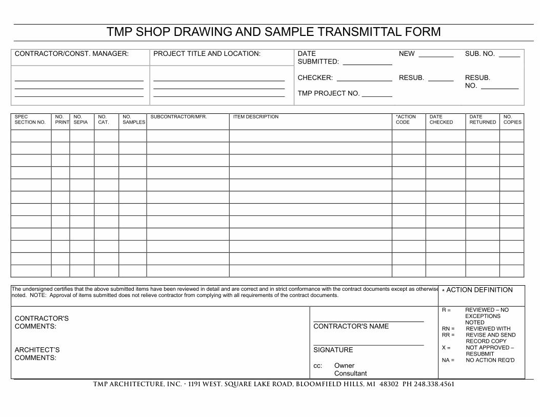
TMP SHOP DRAWING AND SAMPLE TRANSMITTAL FORM
CONTRACTOR/CONST. MANAGER: PROJECT TITLE AND LOCATION: DATE SUBMITTED:
NEW SUB. NO.
CHECKER: TMP PROJECT NO.
RESUB.
RESUB. NO.
SPEC SECTION NO.
NO. PRINT
NO. SEPIA
NO. CAT.
NO. SAMPLES
SUBCONTRACTOR/MFR. ITEM DESCRIPTION *ACTION CODE
DATE CHECKED
DATE RETURNED
NO. COPIES
The undersigned certifies that the above submitted items have been reviewed in detail and are correct and in strict conformance with the contract documents except as otherwise noted. NOTE: Approval of items submitted does not relieve contractor from complying with all requirements of the contract documents.
* ACTION DEFINITION
CONTRACTOR'S COMMENTS: ARCHITECT’S COMMENTS:
CONTRACTOR'S NAME SIGNATURE cc: Owner Consultant
R = REVIEWED – NO
EXCEPTIONS
NOTED
RN = REVIEWED WITH RR = REVISE AND SEND RECORD COPY X = NOT APPROVED –
RESUBMIT
NA = NO ACTION REQ'D
qjm=~êÅÜáíÉÅíìêÉI=fåÅK=√=NNVN=tbpqK=pnr^ob=i^hb=ol^aI=_illjcfbia=efiipI=jf==QUPMO==me=OQUKPPUKQRSN=
SECTION 014000 QUALITY REQUIREMENTS
11/02/17 ISSUED FOR BIDS TMP16128 PHASE 1 014000-1
QUALITY REQUIREMENTS
PART 1 - GENERAL
1.1 SUMMARY
A. Specified Herein: Requirements and procedures for the work and services of Independent Testing Laboratories and Consultants employed by the Owner to perform materials testing and special inspections during the course of the Work.
1.2 OWNER'S OPTION
A. The Owner will employ the services of Independent Testing Laboratories or Consultants or both to perform specified tests and inspections for the Owner's benefit. This inspection and testing shall not obligate the Owner to provide inspection or testing services, or both, for the benefit of the Contractor or any person party or agency associated with the work.
B. The Owner may, at its option, perform inspections and tests in addition to those specified herein in accordance with the General Conditions.
C. The Contractor shall provide free, safe and convenient access to the Work at all locations of the Work including the Site, Fabrication Works and other applicable locations to allow thorough meaningful inspections and obtaining of physical samples for testing. Free access shall include turning, lifting, moving and positioning of the Work or components to allow reasonable access for inspection.
D. In the event that the accuracy or adequacy of any Owner's inspection or tests is challenged by the Contractor for any reason and re-inspection or re-testing is performed, all costs for each specific instance or re-inspection or re-testing shall be paid by the Contractor or other party challenging the original report. Results of such inspections or tests will be accepted for consideration by the Owner only when performed by a Testing Laboratory or Consultant approved, in writing, by the Owner prior to the beginning of the subject re-tests or re-inspections.
E. All tests and Laboratory Inspection specified to be performed for the project shall be performed by the selected Testing Laboratory and the cost for services shall be paid by the Owner except where otherwise specified.
F. Testing Laboratory Qualifications:
1. ASTM E548-94: Guide for General Criteria Used for Evaluating Laboratory Competence.
2. ASTM E329: Specification agencies Engaged in the Testing and/or Inspection of Materials used in Construction.
3. ASTM D3740: Practice for minimum Requirements for Agencies Engaged in the Testing and/or Inspection of Soil and Rock as Used in Engineering Design and Construction.
1.3 RESPONSIBILITIES
A. Testing Laboratories or Consultants will be properly equipped and qualified to perform the duties and tests for which they are hired.
B. Specialized testing such as acoustics will be performed by the Laboratory designated by the Owner.
SECTION 014000 QUALITY REQUIREMENTS
11/02/17 ISSUED FOR BIDS TMP16128 PHASE 1 014000-2
C. The Contractor is not obligated to employ the Owner's Testing Laboratory for Contractor's tests or other services required as a part of the Work. The cost of Owner's review and evaluation of Contractor's tests by Owner's Testing Laboratory or Consultants will be paid by the Owner; all costs of other services performed by the Owner's Testing Laboratory or Consultants in the interest of the Contractor shall be paid by the Contractor.
D. Testing performed by the Owner's Testing Laboratory shall not act to relieve the Contractor from his responsibility to provide all testing laboratory services called for in this Section or under individual Trade
E. Measurements and surveys performed by the Testing Laboratory shall be under the supervision of a surveyor licensed to practice in the State of Michigan.
1.4 OTHER MATERIALS TO BE TESTED
A. When so instructed by the Owner, or the Architect, the Contractor shall deliver samples and materials to Owner's Testing Laboratory so that independent tests can be made to determine compliance with the requirements of the Specifications.
B. When instructed by the Owner or the Architect, the Contractor shall take samples form materials being installed at the job site and deliver these to locations as directed. Samples shall be selected at random by Testing Laboratory, or Consultant, from material being applied or installed.
C. Samples of various materials or equipment delivered on the site or in place may be taken by the Owner for testing. Samples failing to meet Contract requirements will automatically void previous approvals of items tested. The Contractor shall replace such materials or equipment found not to have met Contract requirements, unless a proper adjustment of the Contract price is made and is accepted by the Owner.
1.5 MISCELLANEOUS TESTING SERVICES
A. The following Laboratory Testing and Inspection Services will be performed during the course of the work. The Contractor shall provide support services and cooperation as specified.
B. Earthwork:
1. Fill and backfill will be tested for specified consolidation of materials.
2. Coordinate Work and cooperate with Soils Inspector and Testing Laboratory to permit compacting tests as described in "Earthwork" Section of Division 2, as each layer of material is placed.
C. Special Foundations: None required.
D. Concrete Testing:
1. Concrete testing shall be as specified herein and under other sections as referenced.
2. The Contractor shall provide necessary site labor to assist in taking and preparing job samples; coordinated with the Testing Laboratory for scheduling, testing and inspection; submit samples of materials for concrete, admixtures, and cement to the Laboratory for testing.

SECTION 014000 QUALITY REQUIREMENTS
11/02/17 ISSUED FOR BIDS TMP16128 PHASE 1 014000-3
3. Concrete testing will be required for all concrete work performed under individual Sections of Division 2, "Site Work," and Sections of Division 3, "Concrete" including all cast-in-place and pre-cast concrete used on the Project.
E. Reinforcing Steel Testing:
1. Inspect before and after setting in forms, prior to concrete placement.
2. Certify compliance with Contract Documents; do not check using shop drawings.
F. Steel Testing:
1. Reinforcing Steel: Tests as specified under Concrete and Masonry Sections Division 2, 3 and 4.
2. Structural Steel: As specified under Division 5.
3. Steel Joints: As specified under Division 5.
1.6 SOIL CONSULTANT
A. The Owner may, in its sole interest, employ and pay for the services of a Soils Consultants to observe the work and advise the Owner concerning activities in connection with the performance of excavation and foundation work.
B. Obtain Consultant's approval for construction schedule and sequence of operations.
C. Discontinue any practice immediately when notified, that in the Consultant's opinion, it is not in accordance with the intent of the Specification or will act to the detriment of the system. All work affected by the practice will be subject to complete replacement.
D. See applicable Trade Sections for procedures.
PART 2 - PRODUCTS (NOT USED)
PART 3 - EXECUTION
3.1 SOILS TESTING AND INSPECTION
A. Materials Testing:
1. Test soil materials proposed for use in the work and promptly submit test result reports of: a. Test reports on borrow material. b. Field density test reports. c. One optimum moisture-maximum density curve for each type of soil encountered. d. Other tests and materials certificates as required.
2. Provide one optimum moisture-maximum density curve for each type of soil encountered in subgrade and fills. Determine maximum densities in accordance with ASTM D 1557.
3. Analyze material within 3 feet of finished grades of paved areas to determine content of chemicals deleterious to concrete.
SECTION 014000 QUALITY REQUIREMENTS
11/02/17 ISSUED FOR BIDS TMP16128 PHASE 1 014000-4
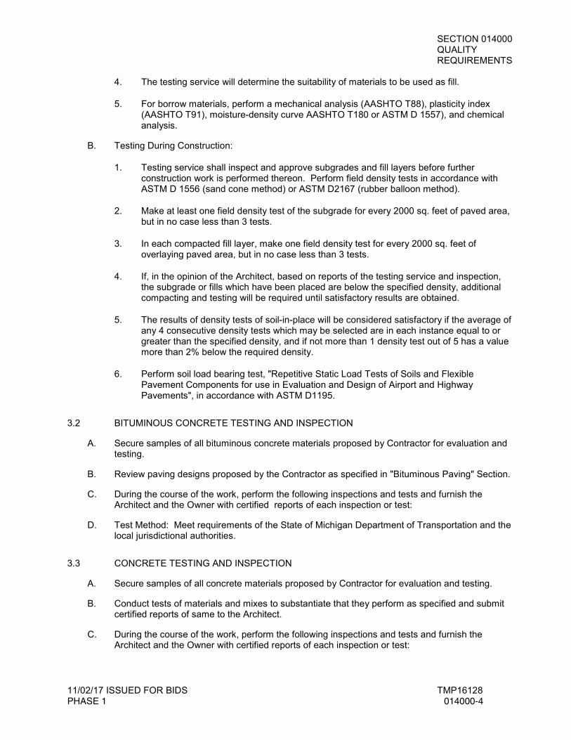
4. The testing service will determine the suitability of materials to be used as fill.
5. For borrow materials, perform a mechanical analysis (AASHTO T88), plasticity index (AASHTO T91), moisture-density curve AASHTO T180 or ASTM D 1557), and chemical analysis.
B. Testing During Construction:
1. Testing service shall inspect and approve subgrades and fill layers before further construction work is performed thereon. Perform field density tests in accordance with ASTM D 1556 (sand cone method) or ASTM D2167 (rubber balloon method).
2. Make at least one field density test of the subgrade for every 2000 sq. feet of paved area, but in no case less than 3 tests.
3. In each compacted fill layer, make one field density test for every 2000 sq. feet of overlaying paved area, but in no case less than 3 tests.
4. If, in the opinion of the Architect, based on reports of the testing service and inspection, the subgrade or fills which have been placed are below the specified density, additional compacting and testing will be required until satisfactory results are obtained.
5. The results of density tests of soil-in-place will be considered satisfactory if the average of any 4 consecutive density tests which may be selected are in each instance equal to or greater than the specified density, and if not more than 1 density test out of 5 has a value more than 2% below the required density.
6. Perform soil load bearing test, "Repetitive Static Load Tests of Soils and Flexible Pavement Components for use in Evaluation and Design of Airport and Highway Pavements", in accordance with ASTM D1195.
3.2 BITUMINOUS CONCRETE TESTING AND INSPECTION
A. Secure samples of all bituminous concrete materials proposed by Contractor for evaluation and testing.
B. Review paving designs proposed by the Contractor as specified in "Bituminous Paving" Section.
C. During the course of the work, perform the following inspections and tests and furnish the Architect and the Owner with certified reports of each inspection or test:
D. Test Method: Meet requirements of the State of Michigan Department of Transportation and the local jurisdictional authorities.
3.3 CONCRETE TESTING AND INSPECTION
A. Secure samples of all concrete materials proposed by Contractor for evaluation and testing.
B. Conduct tests of materials and mixes to substantiate that they perform as specified and submit certified reports of same to the Architect.
C. During the course of the work, perform the following inspections and tests and furnish the Architect and the Owner with certified reports of each inspection or test:
SECTION 014000 QUALITY REQUIREMENTS
11/02/17 ISSUED FOR BIDS TMP16128 PHASE 1 014000-5
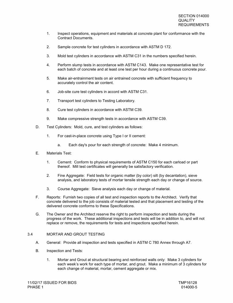
1. Inspect operations, equipment and materials at concrete plant for conformance with the Contract Documents.
2. Sample concrete for test cylinders in accordance with ASTM D 172.
3. Mold test cylinders in accordance with ASTM C31 in the numbers specified herein.
4. Perform slump tests in accordance with ASTM C143. Make one representative test for each batch of concrete and at least one test per hour during a continuous concrete pour.
5. Make air-entrainment tests on air entrained concrete with sufficient frequency to accurately control the air content.
6. Job-site cure test cylinders in accord with ASTM C31.
7. Transport test cylinders to Testing Laboratory.
8. Cure test cylinders in accordance with ASTM C39.
9. Make compressive strength tests in accordance with ASTM C39.
D. Test Cylinders: Mold, cure, and test cylinders as follows:
1. For cast-in-place concrete using Type I or II cement:
a. Each day's pour for each strength of concrete: Make 4 minimum.
E. Materials Test:
1. Cement: Conform to physical requirements of ASTM C150 for each carload or part thereof. Mill test certificates will generally be satisfactory verification.
2. Fine Aggregate: Field tests for organic matter (by color) silt (by decantation), sieve analysis, and laboratory tests of mortar tensile strength each day or change of source.
3. Course Aggregate: Sieve analysis each day or change of material.
F. Reports: Furnish two copies of all test and inspection reports to the Architect. Verify that concrete delivered to the job consists of material tested and that placement and testing of the delivered concrete conforms to these Specifications.
G. The Owner and the Architect reserve the right to perform inspection and tests during the progress of the work. These additional inspections and tests will be in addition to, and will not replace or remove, the requirements for tests and inspections specified herein.
3.4 MORTAR AND GROUT TESTING
A. General: Provide all inspection and tests specified in ASTM C 780 Annex through A7.
B. Inspection and Tests:
1. Mortar and Grout at structural bearing and reinforced walls only: Make 3 cylinders for each week’s work for each type of mortar, and grout. Make a minimum of 3 cylinders for each change of material, mortar, cement aggregate or mix.

SECTION 014000 QUALITY REQUIREMENTS
11/02/17 ISSUED FOR BIDS TMP16128 PHASE 1 014000-6
2. Test cylinders at the following ages: For concrete made with Type II cement, one at 7 days, two at 28 days.
3. Provide complete evaluation in accordance with ASTM C78 Annex A8 for design mix and at each change of materials thereafter.
3.5 STRUCTURAL STEEL TESTING AND INSPECTION
A. Where material identity is maintained and readily demonstrable, certified mail test certificates will be acceptable. Material not satisfactorily and clearly traceable to an acceptable mill test certificate shall not be used in the Work. The Testing Laboratory shall verify conformance of all structural steel materials.
B. Conduct tests of materials and assemblies to substantiate that they perform as specified and submit certified reports of same to the Owner and the Architect.
C. Tests for Welding and Bolting: The Testing Laboratory shall test all shop and field welding and inspect all high strength bolting. The Laboratory shall furnish Inspectors approved by the Owner and shall be registered in, and shall comply with, all regulations of the Department of Building and Safety of the Local Governing Authority and shall certify in writing, upon completion of the work, that the welding and high strength bolting have been performed in accordance with the Drawings and Specifications and all codes and ordinances.
3.6 MECHANICAL AND ELECTRICAL TRADES
A. Tests performed by the Owner's Testing Laboratory for Mechanical and Electrical Trades shall include materials testing only.
B. Balancing, testing, and other checking required to verify proper performance of systems shall be by the Contractor as specified.
**END OF SECTION**
SECTION 014213 ABBREVIATIONS
11/02/17 ISSUED FOR BIDS TMP16128 PHASE 1 014213-1
ABBREVIATIONS
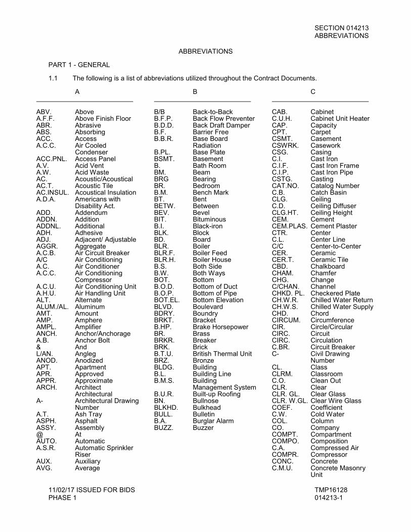
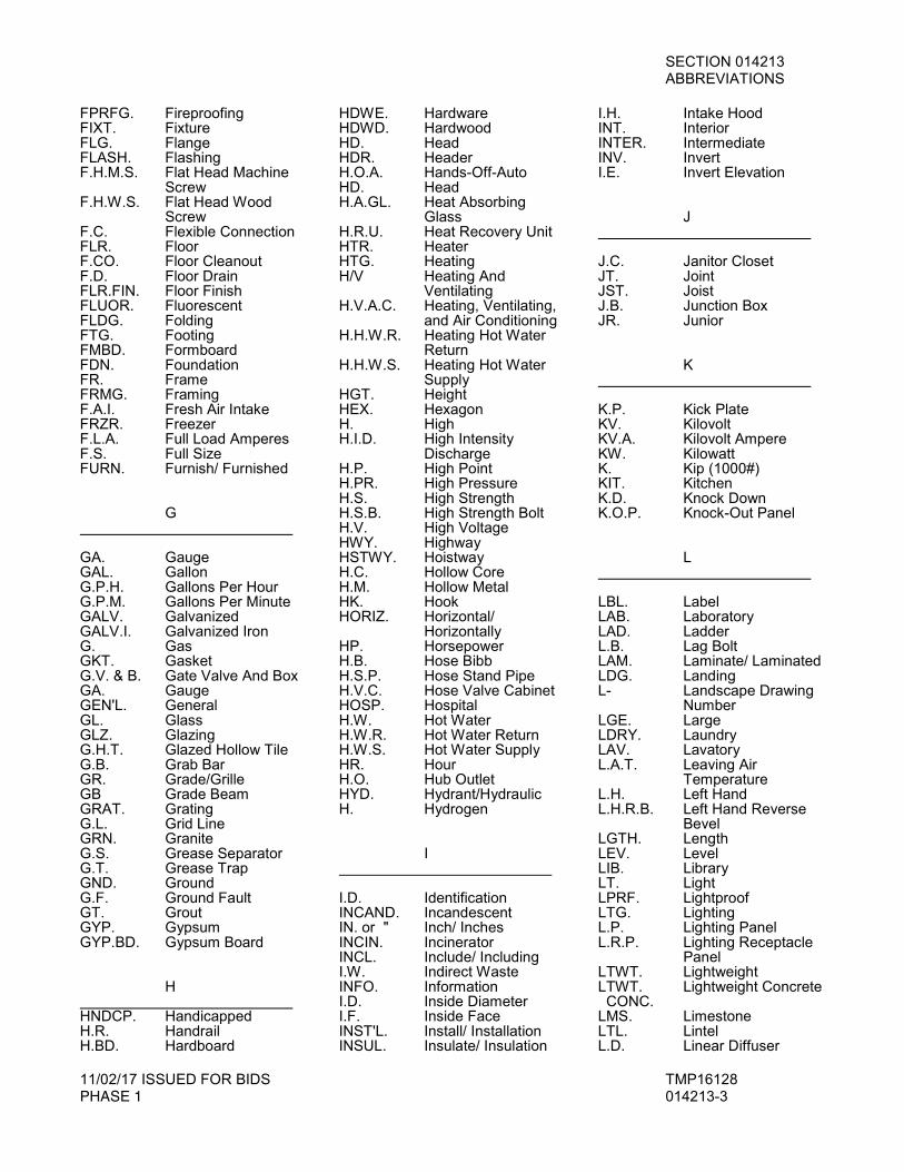
PART 1 - GENERAL 1.1 The following is a list of abbreviations utilized throughout the Contract Documents.
A ABV. Above A.F.F. Above Finish Floor ABR. Abrasive ABS. Absorbing ACC. Access A.C.C. Air Cooled
Condenser ACC.PNL. Access Panel A.V. Acid Vent A.W. Acid Waste AC. Acoustic/Acoustical AC.T. Acoustic Tile AC.INSUL. Acoustical Insulation A.D.A. Americans with Disability Act. ADD. Addendum ADDN. Addition ADDNL. Additional ADH. Adhesive ADJ. Adjacent/ Adjustable AGGR. Aggregate A.C.B. Air Circuit Breaker A/C Air Conditioning A.C. Air Conditioner A.C.C. Air Conditioning Compressor A.C.U. Air Conditioning Unit A.H.U. Air Handling Unit ALT. Alternate ALUM./AL. Aluminum AMT. Amount AMP. Amphere AMPL. Amplifier ANCH. Anchor/Anchorage A.B. Anchor Bolt & And L/AN. Angleg ANOD. Anodized APT. Apartment APR. Approved APPR. Approximate ARCH. Architect Architectural A- Architectural Drawing Number A.T. Ash Tray ASPH. Asphalt ASSY. Assembly @ At AUTO. Automatic A.S.R. Automatic Sprinkler Riser AUX. Auxiliary AVG. Average
B B/B Back-to-Back B.F.P. Back Flow Preventer B.D.D. Back Draft Damper B.F. Barrier Free B.B.R. Base Board
Radiation B.PL. Base Plate BSMT. Basement B. Bath Room BM. Beam BRG Bearing BR. Bedroom B.M. Bench Mark BT. Bent BETW. Between BEV. Bevel BIT. Bituminous B.I. Black-iron BLK. Block BD. Board BLR. Boiler BLR.F. Boiler Feed BLR.H. Boiler House B.S. Both Side B.W. Both Ways BOT. Bottom B.O.D. Bottom of Duct B.O.P. Bottom of Pipe BOT.EL. Bottom Elevation BLVD. Boulevard BDRY. Boundry BRKT. Bracket B.HP. Brake Horsepower BR. Brass BRKR. Breaker BRK. Brick B.T.U. British Thermal Unit BRZ. Bronze BLDG. Building B.L. Building Line B.M.S. Building
Management System B.U.R. Built-up Roofing BN. Bullnose BLKHD. Bulkhead BULL. Bulletin B.A. Burglar Alarm BUZZ. Buzzer
C CAB. Cabinet C.U.H. Cabinet Unit Heater CAP. Capacity CPT. Carpet CSMT. Casement CSWRK. Casework CSG. Casing C.I. Cast Iron C.I.F. Cast Iron Frame C.I.P. Cast Iron Pipe CSTG. Casting CAT.NO. Catalog Number C.B. Catch Basin CLG. Ceiling C.D. Ceiling Diffuser CLG.HT. Ceiling Height CEM. Cement CEM.PLAS. Cement Plaster CTR. Center C.L. Center Line C/C Center-to-Center CER. Ceramic CER.T. Ceramic Tile CBD. Chalkboard CHAM. Chamfer CHG. Change C/CHAN. Channel CHKD. PL. Checkered Plate CH.W.R. Chilled Water Return CH.W.S. Chilled Water Supply CHD. Chord CIRCUM. Circumference CIR. Circle/Circular CIRC. Circuit CIRC. Circulation C.BR. Circuit Breaker C- Civil Drawing
Number CL. Class CLRM. Classroom C.O. Clean Out CLR. Clear CLR. GL. Clear Glass CLR. W.GL. Clear Wire Glass COEF. Coefficient C.W. Cold Water COL. Column CO. Company COMPT. Compartment COMPO. Composition C.A. Compressed Air COMPR. Compressor CONC. Concrete C.M.U. Concrete Masonry
Unit
SECTION 014213 ABBREVIATIONS
11/02/17 ISSUED FOR BIDS TMP16128 PHASE 1 014213-2
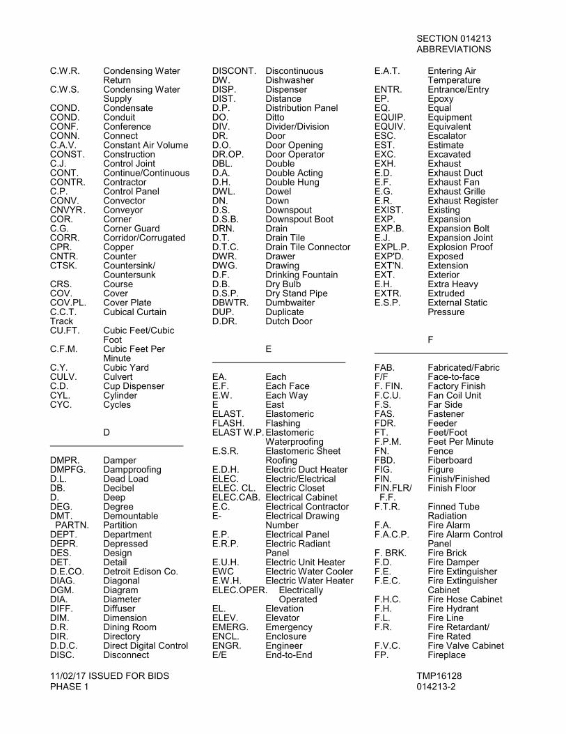
C.W.R. Condensing Water Return C.W.S. Condensing Water Supply COND. Condensate COND. Conduit CONF. Conference CONN. Connect C.A.V. Constant Air Volume CONST. Construction C.J. Control Joint CONT. Continue/Continuous CONTR. Contractor C.P. Control Panel CONV. Convector CNVYR . Conveyor COR. Corner C.G. Corner Guard CORR. Corridor/Corrugated CPR. Copper CNTR. Counter CTSK. Countersink/ Countersunk CRS. Course COV. Cover COV.PL. Cover Plate C.C.T. Cubical Curtain Track CU.FT. Cubic Feet/Cubic
Foot C.F.M. Cubic Feet Per
Minute C.Y. Cubic Yard CULV. Culvert C.D. Cup Dispenser CYL. Cylinder CYC. Cycles D DMPR. Damper DMPFG. Dampproofing D.L. Dead Load DB. Decibel D. Deep DEG. Degree DMT. Demountable PARTN. Partition DEPT. Department DEPR. Depressed DES. Design DET. Detail D.E.CO. Detroit Edison Co. DIAG. Diagonal DGM. Diagram DIA. Diameter DIFF. Diffuser DIM. Dimension D.R. Dining Room DIR. Directory D.D.C. Direct Digital Control DISC. Disconnect
DISCONT. Discontinuous DW. Dishwasher DISP. Dispenser DIST. Distance D.P. Distribution Panel DO. Ditto DIV. Divider/Division DR. Door D.O. Door Opening DR.OP. Door Operator DBL. Double D.A. Double Acting D.H. Double Hung DWL. Dowel DN. Down D.S. Downspout D.S.B. Downspout Boot DRN. Drain D.T. Drain Tile D.T.C. Drain Tile Connector DWR. Drawer DWG. Drawing D.F. Drinking Fountain D.B. Dry Bulb D.S.P. Dry Stand Pipe DBWTR. Dumbwaiter DUP. Duplicate D.DR. Dutch Door E EA. Each E.F. Each Face E.W. Each Way E East ELAST. Elastomeric FLASH. Flashing ELAST W.P. Elastomeric Waterproofing E.S.R. Elastomeric Sheet Roofing E.D.H. Electric Duct Heater ELEC. Electric/Electrical ELEC. CL. Electric Closet ELEC.CAB. Electrical Cabinet E.C. Electrical Contractor E- Electrical Drawing Number E.P. Electrical Panel E.R.P. Electric Radiant
Panel E.U.H. Electric Unit Heater EWC Electric Water Cooler E.W.H. Electric Water Heater ELEC.OPER. Electrically
Operated EL. Elevation ELEV. Elevator EMERG. Emergency ENCL. Enclosure ENGR. Engineer E/E End-to-End
E.A.T. Entering Air Temperature ENTR. Entrance/Entry EP. Epoxy EQ. Equal EQUIP. Equipment EQUIV. Equivalent ESC. Escalator EST. Estimate EXC. Excavated EXH. Exhaust E.D. Exhaust Duct E.F. Exhaust Fan E.G. Exhaust Grille E.R. Exhaust Register EXIST. Existing EXP. Expansion EXP.B. Expansion Bolt E.J. Expansion Joint EXPL.P. Explosion Proof EXP'D. Exposed EXT'N. Extension EXT. Exterior E.H. Extra Heavy EXTR. Extruded E.S.P. External Static Pressure F FAB. Fabricated/Fabric F/F Face-to-face F. FIN. Factory Finish F.C.U. Fan Coil Unit F.S. Far Side FAS. Fastener FDR. Feeder FT. Feet/Foot F.P.M. Feet Per Minute FN. Fence FBD. Fiberboard FIG. Figure FIN. Finish/Finished FIN.FLR/ Finish Floor F.F. F.T.R. Finned Tube
Radiation F.A. Fire Alarm F.A.C.P. Fire Alarm Control Panel F. BRK. Fire Brick F.D. Fire Damper F.E. Fire Extinguisher F.E.C. Fire Extinguisher Cabinet F.H.C. Fire Hose Cabinet F.H. Fire Hydrant F.L. Fire Line F.R. Fire Retardant/ Fire Rated F.V.C. Fire Valve Cabinet FP. Fireplace
SECTION 014213 ABBREVIATIONS
11/02/17 ISSUED FOR BIDS TMP16128 PHASE 1 014213-3
FPRFG. Fireproofing FIXT. Fixture FLG. Flange FLASH. Flashing F.H.M.S. Flat Head Machine Screw F.H.W.S. Flat Head Wood
Screw F.C. Flexible Connection FLR. Floor F.CO. Floor Cleanout F.D. Floor Drain FLR.FIN. Floor Finish FLUOR. Fluorescent FLDG. Folding FTG. Footing FMBD. Formboard FDN. Foundation FR. Frame FRMG. Framing F.A.I. Fresh Air Intake FRZR. Freezer F.L.A. Full Load Amperes F.S. Full Size FURN. Furnish/ Furnished G GA. Gauge GAL. Gallon G.P.H. Gallons Per Hour G.P.M. Gallons Per Minute GALV. Galvanized GALV.I. Galvanized Iron G. Gas GKT. Gasket G.V. & B. Gate Valve And Box GA. Gauge GEN'L. General GL. Glass GLZ. Glazing G.H.T. Glazed Hollow Tile G.B. Grab Bar GR. Grade/Grille GB Grade Beam GRAT. Grating G.L. Grid Line GRN. Granite G.S. Grease Separator G.T. Grease Trap GND. Ground G.F. Ground Fault GT. Grout GYP. Gypsum GYP.BD. Gypsum Board H HNDCP. Handicapped H.R. Handrail H.BD. Hardboard
HDWE. Hardware HDWD. Hardwood HD. Head HDR. Header H.O.A. Hands-Off-Auto HD. Head H.A.GL. Heat Absorbing
Glass H.R.U. Heat Recovery Unit HTR. Heater HTG. Heating H/V Heating And Ventilating H.V.A.C. Heating, Ventilating, and Air Conditioning H.H.W.R. Heating Hot Water Return H.H.W.S. Heating Hot Water Supply HGT. Height HEX. Hexagon H. High H.I.D. High Intensity Discharge H.P. High Point H.PR. High Pressure H.S. High Strength H.S.B. High Strength Bolt H.V. High Voltage HWY. Highway HSTWY. Hoistway H.C. Hollow Core H.M. Hollow Metal HK. Hook HORIZ. Horizontal/ Horizontally HP. Horsepower H.B. Hose Bibb H.S.P. Hose Stand Pipe H.V.C. Hose Valve Cabinet HOSP. Hospital H.W. Hot Water H.W.R. Hot Water Return H.W.S. Hot Water Supply HR. Hour H.O. Hub Outlet HYD. Hydrant/Hydraulic H. Hydrogen I I.D. Identification INCAND. Incandescent IN. or " Inch/ Inches INCIN. Incinerator INCL. Include/ Including I.W. Indirect Waste INFO. Information I.D. Inside Diameter I.F. Inside Face INST'L. Install/ Installation INSUL. Insulate/ Insulation
I.H. Intake Hood INT. Interior INTER. Intermediate INV. Invert I.E. Invert Elevation J J.C. Janitor Closet JT. Joint JST. Joist J.B. Junction Box JR. Junior K K.P. Kick Plate KV. Kilovolt KV.A. Kilovolt Ampere KW. Kilowatt K. Kip (1000#) KIT. Kitchen K.D. Knock Down K.O.P. Knock-Out Panel L LBL. Label LAB. Laboratory LAD. Ladder L.B. Lag Bolt LAM. Laminate/ Laminated LDG. Landing L- Landscape Drawing Number LGE. Large LDRY. Laundry LAV. Lavatory L.A.T. Leaving Air Temperature L.H. Left Hand L.H.R.B. Left Hand Reverse Bevel LGTH. Length LEV. Level LIB. Library LT. Light LPRF. Lightproof LTG. Lighting L.P. Lighting Panel L.R.P. Lighting Receptacle Panel LTWT. Lightweight LTWT. Lightweight Concrete CONC. LMS. Limestone LTL. Lintel L.D. Linear Diffuser
SECTION 014213 ABBREVIATIONS
11/02/17 ISSUED FOR BIDS TMP16128 PHASE 1 014213-4
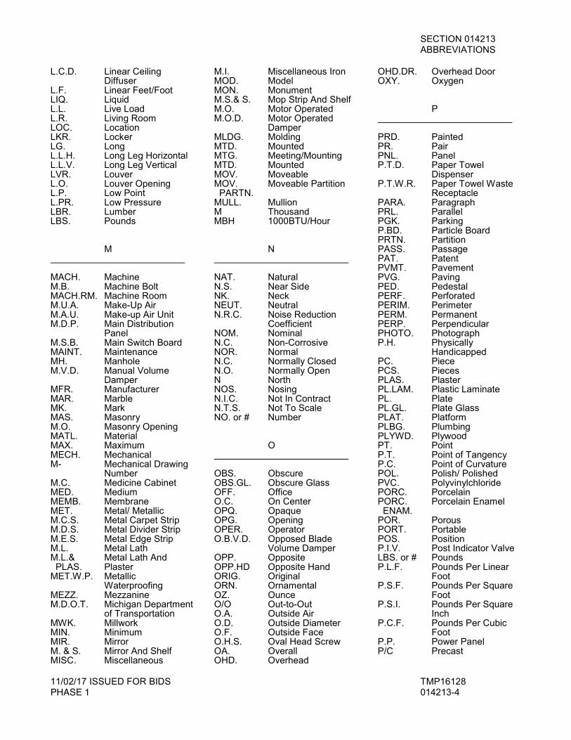
L.C.D. Linear Ceiling Diffuser
L.F. Linear Feet/Foot LIQ. Liquid L.L. Live Load L.R. Living Room LOC. Location LKR. Locker LG. Long L.L.H. Long Leg Horizontal L.L.V. Long Leg Vertical LVR. Louver L.O. Louver Opening L.P. Low Point L.PR. Low Pressure LBR. Lumber LBS. Pounds M MACH. Machine M.B. Machine Bolt MACH.RM. Machine Room M.U.A. Make-Up Air M.A.U. Make-up Air Unit M.D.P. Main Distribution Panel M.S.B. Main Switch Board MAINT. Maintenance MH. Manhole M.V.D. Manual Volume Damper MFR. Manufacturer MAR. Marble MK. Mark MAS. Masonry M.O. Masonry Opening MATL. Material MAX. Maximum MECH. Mechanical M- Mechanical Drawing Number M.C. Medicine Cabinet MED. Medium MEMB. Membrane MET. Metal/ Metallic M.C.S. Metal Carpet Strip M.D.S. Metal Divider Strip M.E.S. Metal Edge Strip M.L. Metal Lath M.L.& Metal Lath And PLAS. Plaster MET.W.P. Metallic
Waterproofing MEZZ. Mezzanine M.D.O.T. Michigan Department of Transportation MWK. Millwork MIN. Minimum MIR. Mirror M. & S. Mirror And Shelf MISC. Miscellaneous
M.I. Miscellaneous Iron MOD. Model MON. Monument M.S.& S. Mop Strip And Shelf M.O. Motor Operated M.O.D. Motor Operated Damper MLDG. Molding MTD. Mounted MTG. Meeting/Mounting MTD. Mounted MOV. Moveable MOV. Moveable Partition PARTN. MULL. Mullion M Thousand MBH 1000BTU/Hour N NAT. Natural N.S. Near Side NK. Neck NEUT. Neutral N.R.C. Noise Reduction Coefficient NOM. Nominal N.C. Non-Corrosive NOR. Normal N.C. Normally Closed N.O. Normally Open N North NOS. Nosing N.I.C. Not In Contract N.T.S. Not To Scale NO. or # Number O OBS. Obscure OBS.GL. Obscure Glass OFF. Office O.C. On Center OPQ. Opaque OPG. Opening OPER. Operator O.B.V.D. Opposed Blade Volume Damper OPP. Opposite OPP.HD Opposite Hand ORIG. Original ORN. Ornamental OZ. Ounce O/O Out-to-Out O.A. Outside Air O.D. Outside Diameter O.F. Outside Face O.H.S. Oval Head Screw OA. Overall OHD. Overhead
OHD.DR. Overhead Door OXY. Oxygen P PRD. Painted PR. Pair PNL. Panel P.T.D. Paper Towel
Dispenser P.T.W.R. Paper Towel Waste Receptacle PARA. Paragraph PRL. Parallel PGK. Parking P.BD. Particle Board PRTN. Partition PASS. Passage PAT. Patent PVMT. Pavement PVG. Paving PED. Pedestal PERF. Perforated PERIM. Perimeter PERM. Permanent PERP. Perpendicular PHOTO. Photograph P.H. Physically Handicapped PC. Piece PCS. Pieces PLAS. Plaster PL.LAM. Plastic Laminate PL. Plate PL.GL. Plate Glass PLAT. Platform PLBG. Plumbing PLYWD. Plywood PT. Point P.T. Point of Tangency P.C. Point of Curvature POL. Polish/ Polished PVC. Polyvinylchloride PORC. Porcelain PORC. Porcelain Enamel ENAM. POR. Porous PORT. Portable POS. Position P.I.V. Post Indicator Valve LBS. or # Pounds P.L.F. Pounds Per Linear
Foot P.S.F. Pounds Per Square Foot P.S.I. Pounds Per Square Inch P.C.F. Pounds Per Cubic Foot P.P. Power Panel P/C Precast

SECTION 014213 ABBREVIATIONS
11/02/17 ISSUED FOR BIDS TMP16128 PHASE 1 014213-5
P.T.C. Precast Terrazzo Receptor PREFAB. Prefabricated PFN. Prefinished P.C.T./C.M. Pressure Control Terminal/Control Module P.G. Pressure Gauge P.R.G. Pressure Relief Grille P.R.V. Pressure Reducing Valve PRIM. Primary PROJ. Project/ Projection PROP. Property/ Proposed P.L. Property Line P.A. Public Address P.S. Purse Shelf P.B. Push Button Q QTY. Quantity Q.T. Quarry Tile QTR. Quarter QTR.RD. Quarter Round R RBT. Rabbet R.C.P. Radiant Ceiling Panel RAD. or R. Radius R.W.C. Rain Water
Conductor R.R. Railroad RECV. Receive/ Receiving RECPT. Receptacle R.P. Receptacle Panel REC. Recess RECIRC. Recirculation RECT. Rectangle /
Rectangular RED. Reducer RWD. Redwood REF. Refer/Reference REFL. Reflected/Reflective REFRIG. Refrigerant REFR. Refrigerator REG. Register RH.C. Reheat Coil REINF. Reinforce/Reinforcing Reinforcement R.H. Relief Hood REM. Remove/ Removable REP. Repair REQ'D. Required RESIL. Resilient RET. Return R.A. Return Air
R.A.D. Return Air Duct R.A.F. Return Air Fan REV. Revised/Revision R.P.M. Revolutions Per Minute R. Riser R.H. Right Hand R.H.R.B. Right Hand Reverse Bevel R.O.W. Right Of Way RVT. Rivet RD. Road R.S.C. Rolling Steel Curtain RF. Roof R.C. Roof Conductor R.D. Roof Drain RF.H. Roof Hatch R.T.U. Roof Top Unit R.S. Roof Sump R.V. Roof Ventilator RFG. Roofing R.W.C. Rain Water
Conductor RM. Room R.O. Rough Opening RND. or O Round R.H.M.S. Round Head
Machine Screw R.H.W.S. Round Head Wood Screw R.T. Rubber Tile S SAN. Sanitary S.N.D. Sanitary Napkin Dispenser S.N.R. Sanitary Napkin Receptacle SCHED. Schedule SCN. Screen STG. Seating SECT. Section SERV. Service S.S. Service Sink SHTHG. Sheathing SHT. Sheet SHT.MET. Sheet Metal SH. & P. Shelf And Pole SHWR. Shower S.C.R. Shower Curtain Rod S.DR. Shower Door SW. Sidewalk SIM. Similar SGL. Single SK. Sink S.D. Soap Dispenser S.C. Solid Core S.T.C. Sound Transmission Class S South SP. Space
SPR. Spare SPKR. Speaker SPEC. Specifications S.D. Splitter Damper SPRYD. Sprayed SPKLR. Sprinkler SQ. Square S.F. Square Feet/ Square Foot STAG. Staggered ST.STL Stainless Steel STD. Standard SP. Standpipe S.P. Static Pressure STA. Station STM. Steam STL. Steel STL.PL. Steel Plate STIFF. Stiffener STO.FR. Storefront STOR. Storage ST. Storm STR. Straight ST. Street STRUCT. Structural Drawing Number S.G.F.T. Structural Glazed Facing Tile S.STL. Structural Steel SS.D. Subsoil Drain SS.D.C. Subsoil Drain Connection SUB. Substation S.A.G. Supply Air Grille S.D. Supply Diffuser/ Duct SUBST. Substitute S.A.R. Supply Air Register S.F. Supply Fan S.A. Supply Air S.A.D. Supply Air Diffuser SUPP. Support SURF. Surface/Surfacing SUSP. Suspend/Suspension SW. Switch SWBD. Switchboard SWGR. Switchgear SYM. Symbol/Symmetrical SYS. System T T.BD. Tackboard TAN. Tangent TECH. Technical TEL. Telephone TEL.CAB. Telephone Cabinet TV Television TV.M. Television Monitor TEMP. Temperature TEMP.GL. Tempered Glass T.W. Tempered Water T.U. Terminal Unit
SECTION 014213 ABBREVIATIONS
11/02/17 ISSUED FOR BIDS TMP16128 PHASE 1 014213-6
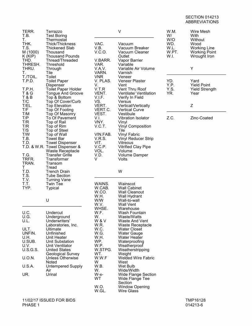
TERR. Terrazzo T.B. Test Boring T. Thermostat THK. Thick/Thickness T.S. Thickened Slab M (1000) Thousand K (KIP) Thousand Pounds THD. Thread/Threaded THRESH. Threshold THRU. Through T. Tile T./TOIL. Toilet T.P.D. Toilet Paper Dispenser T.P.H. Toilet Paper Holder T & G Tongue And Groove T & B Top & Bottom T/C Top Of Cover/Curb T/EL. Top Elevation T/F Top Of Footing T/M Top Of Masonry T/P To Of Pavement T/R Top of Rail T/R Top of Rim T/S Top of Steel T/W Top of Wall T.B. Towel Bar T.D. Towel Dispenser T.D. & W.R. Towel Dispenser & Waste Receptacle T.G. Transfer Grille TRFR. Transformer TRAN. Transom T Tread T.D. Trench Drain T.S. Tube Section T.V. Turning Vane T.T. Twin Tee TYP. Typical U U.C. Undercut U.G. Underground U.L. Underwriters' Laboratories, Inc. ULT. Ultimate UNFIN. Unfinished U.H. Unit Heater U.SUB. Unit Substation U.V. Unit Ventilator U.S.G.S. United States Geological Survey U.O.N. Unless Otherwise Noted U.S.A. Untempered Supply Air UR. Urinal
V VAC. Vacuum V.B. Vacuum Breaker V.C.O. Vacuum Cleaner Outlet V.BARR. Vapor Barrier VAR. Variable V.A.V. Variable Air Volume VARN. Varnish VNR Veneer V. PLAS. Veneer Plaster V. Vent V.T.R Vent Thru Roof VENT. Ventilate/ Ventilation V.I.F. Verify In Field VS. Versus VERT. Vertical/Vertically VERT.C. Vertical Curve VEST. Vestibule V.I. Vibration Isolator VNY. Vinyl V.C.T. Vinyl Composition
Tile VIN.FAB. Vinyl Fabric V.R.S. Vinyl Reducer Strip VIT. Vitreous V.C.P. Vitrified Clay Pipe VOL. Volume V.D. Volume Damper V Volts W WAINS. Wainscot W.CAB. Wall Cabinet W.CO. Wall Cleanout W.H. Wall Hydrant W/W Wall-to-wall W.V. Wall Vent WHSE. Warehouse W.F. Wash Fountain W. Waste/Watts W & V Waste And Vent W.R. Waste Receptacle W.C. Water Closet W.G. Water Gauge W.H. Water Heater WP. Waterproofing W.P. Weatherproof W.STPG. Weatherstripping WT. Weight W.W.F Welded Wire Fabric W West W.B. Wet Bulb W. Wide/Width W-x- Wide Flange Section WT Wide Flange Tee Section W.O. Window Opening W.GL. Wire Glass
W.M. Wire Mesh W/ With W/O Without WD. Wood W.L. Working Line W.PT. Working Point W.I. Wrought Iron Y YD. Yard Y.P. Yield Point Y.S. Yield Strength YR. Year Z Z.C. Zinc-Coated
SECTION 014216 STANDARDS AND DEFINITIONS
11/02/17 ISSUED FOR BIDS TMP16128 PHASE 1 014216-1
STANDARDS AND DEFINITIONS
PART 1 - GENERAL
1.1 SUMMARY
A. Specified Herein: Standards and Definitions Definitions Specification Content Quality Standard of the Industry
1.2 DEFINITIONS
A. Certain terms used in the Contract Documents are defined generally in this article. Definitions and explanations of this section are not necessarily either complete or exclusive, but are general for the work to extent not stated more explicitly in another provision of the Contract Documents.
B. Indicated: A cross-reference to details, notes or schedules on the drawings, to other paragraphs or schedules in the Specifications, and to similar means of recording requirements in the Contract Documents. Where terms such as "shown", "noted", "scheduled", and "specified" are used in lieu of "indicated", it is for purpose of helping reader locate cross-reference, and no limitation of location is intended except as specifically noted.
C. Furnish: Supply and deliver to project site, ready for unloading, unpacking, assembly, installation, etc., as applicable in each instance.
D. Install: Perform operations at project site including unloading, unpacking, assembly, erection, placing, anchoring, applying, working to dimension, finishing, curing protecting, cleaning and similar operations, as applicable in each instance.
E. Provide: Furnish and install, complete and ready for intended use, as applicable in each instance.
F. Installer: The entity (person or firm) engaged by the Contractor or its subcontractor or sub-subcontractor for the performance of a particular unit of work at the project site, including installation, erection, application and similar required operations. It is a general requirement that such entities (Installers) be expert in operations they are engaged to perform.
1.3 FORMAT AND SPECIFICATION EXPLANATIONS
A. Specification Production: None of these explanations will be interpreted to modify substance of requirements. Portions of these Specifications have been produced by Architect's/Engineer's standard methods of editing master Specifications, and may contain minor deviations from traditional writing formats. Such deviations are a normal result of this production technique, and no other meaning will be implied or permitted.
B. Format Explanation: The format of principal portions of these Specifications can be described as follows; although other portions may not fully comply and no particular significance will be attached to such compliance or non-compliance:
1. Sections and Divisions: For convenience, basic unit of Specification text is a "section", each unit of which is named and numbered. These are organized into related families of sections, and various families of sections are organized into "divisions", which are
SECTION 014216 STANDARDS AND DEFINITIONS
11/02/17 ISSUED FOR BIDS TMP16128 PHASE 1 014216-2
recognized as the present industry-consensus on uniform organization and sequencing of Specifications. The section title is not intended to limit meaning or content of section, nor to be fully descriptive of requirements specified therein, nor to be an integral part of text.
2. Each section of specifications has been subdivided into 3 (or less) "parts" for uniformity and convenience (Part 1 - General, Part 2 - Products, and Part 3 - Execution). These do not limit the meaning of and are not an integral part of text which specifies requirements.
3. Imperative Language: Requirements expressed imperatively shall be performed by Contractor. For clarity of reading at certain locations, contrasting subjective language is used to describe responsibilities which must be fulfilled indirectly by Contractor, or when so noted, by others.
4. Section Numbering: Used to facilitate cross-reference in Contract Documents. Sections are placed in Project Manual in numeric sequence; however, numbering sequence is not complete, and listing of sections at beginning of project Manual must be consulted to determine numbers and names of specification sections in the Contract Documents.
5. Page Numbering: Numbered independently for each section; recorded in listing of sections (Index or Table of Contents) in Project Manual. Section number is shown with page number at bottom or each page, to facilitate location of text in Project Manual.
1.4 SPECIFICATION CONTENT
A. Specifying Methods: The techniques or methods of specifying to record requirements varies throughout text, and may include "prescriptive", "open generic-descriptive", "compliance with standards", "performance", "proprietary", or a combination of these. The method used for specifying one unit of work has no bearing on requirements for another unit or work.
B. Overlapping and Conflicting Requirements: Where compliance with 2 or more industry standards or sets of requirements is specified, and overlapping of these different standards or requirements establishes different or conflicting minimums of levels of quality, most stringent requirement (which is generally recognized to be also most costly) is intended and will be enforced, unless specifically detailed language written into the Contract Documents (not by way of reference to an industry standard) clearly indicated that a less stringent requirement is to be fulfilled. Refer apparently equal but different requirements, and uncertainties as to which level of quality is more stringent, to Architect for a decision before proceeding.
1. Contractor's Options: Except for overlapping or conflicting requirements, where more than one set of requirements are specified for a particular unit of work, option is intended to be Contractor's regardless of whether specifically indicated as such.
C. Specified Quality Standards: The fact that a specified product or model number is in conflict with specified quality requirements such as "concealed fasteners" or "special colors" such specification shall be construed to mean that acceptance is contingent upon manufacturer or fabricator modifying the product to comply with the Specifications.
D. Minimum Quality/Quantity: In every instance, quality level or quantity shown or specified is intended as minimum for the work to be performed or provided. Except as otherwise specifically indicated, actual work may either comply exactly with that minimum (within specified tolerances), or may exceed that minimum within reasonable limits. In complying with requirements, indicated numeric values are either minimums or maximums as noted or a
SECTION 014216 STANDARDS AND DEFINITIONS
11/02/17 ISSUED FOR BIDS TMP16128 PHASE 1 014216-3
appropriate for context of requirements. Refer instances of uncertainty to Architect for decision before proceeding.
E. Specialists; Assignments: In certain instances, specification text requires (or at least implies) that specific work be assigned to specialists or expert entities, who must be engaged for performance of those units of work. These must be recognized as special requirements over which Contractor has no choice or option. These assignments must not be confused with (and are not intended to interfere with) normal application of regulations, union jurisdictions and similar conventions. One purpose of such assignments is to establish which party or entity involved in a specific unit of work is recognized as "expert" for indicated construction processes or operations. Nevertheless, final responsibility for fulfillment or entire set of requirements remains with Contractor.
F. Abbreviations: The language or Specifications and other Contract Documents is of the abbreviated type in certain instances, and implies word and meanings which will be appropriately interpreted. Actual work abbreviations of a self-explanatory nature have been included in the text. Specific abbreviations have been established, principally for lengthy technical terminology and primarily in conjunction with coordination of Specification requirements with notations on drawings and in schedules. These are frequently defined in sections at first instance of use. Trade association names and titles of general standards are frequently abbreviated. Singular words will be interpreted as plural and plural words will be interpreted as singular where applicable and where full context of the Contract Documents so indicates.
1.5 QUALITY STANDARDS OF THE INDUSTRY
A. General Applicability of Standards: Applicable standards of construction industry have same force and effect (and are made a part of Contract Documents by reference) as if copied directly into Contract Documents, or as if published copies were bound herewith.
1. Reference standards (referenced directly in Contract Documents or by governing regulations) have precedence over non-referenced standards.
2. Non-referenced standards have no particular applicability except as a measure of compliance with standards recognized in construction industry.
B. Copies of Standards:
1. Where copies of standards are needed for proper performance of the work, the Contractor is required to obtain such copies directly from the publication source.
2. The Architect reserves the right to reasonably require the Contractor to submit, or maintain at the jobsite, copies of all applicable standards as needed for enforcement of the requirements.
C. Publication Dates: Except as otherwise indicated, where compliance with an industry standard is required, comply with standard in effect as of date of Contract Documents.
D. Abbreviations and Names: Acronyms or abbreviations used in Contract Documents mean the industry recognized name applicable to context of text provision.
1.6 DRAWINGS, DETAILS, SCHEDULES
A. Large scale details are provided to show arrangement, attachment, and otherwise indicate relationships of component materials and for purposes of clarify often do not show all

SECTION 014216 STANDARDS AND DEFINITIONS
11/02/17 ISSUED FOR BIDS TMP16128 PHASE 1 014216-4
materials. The fact that a material is, or is not indicated on such details shall not act to relieve the Contractor of responsibility for providing a specified item.
B. Schedules are provided for convenience of reference only. In the event of an omission or conflict between schedules and other documents, the more restrictive document shall govern as directed by the Architect.
1.7 CODES AND STANDARDS
A. Comply with latest revisions to date of all Governing Codes and with all other legal provisions relating to the Work. Other standards and references shall be current edition as of date of issue of Bidding Documents.
B. Conform to all laws, ordinances and regulations affecting the erection, sequence of erection, and completion of the whole or any part of the work; and conform to the requirements of the Owner and of public authorities having lawful or customary jurisdiction.
C. These requirements shall take precedence over the Contract Documents except where the Contract Documents require higher standards also acceptable to the authorities.
1.8 PERMITS, CODES, ORDINANCES AND NOTICES
A. See General Conditions for permits.
B. Obtain and keep available at the job, copy of building ordinances pertinent to the work.
C. Inform the Owner and the Architect, in writing, of the manner and time in which each of the requirements of the General Conditions concerning permits are complied with.
D. Make all necessary arrangements and obtain permits for blockage of streets and for all interference with the public right of way.
E. Special Inspections: All special inspections required to be made under provisions by building code of utility company regulations shall be arranged and paid for by the Contractor whose work requires such inspection.
**END OF SECTION**
SECTION 015000 TEMPORARY FACILITIES AND CONTROLS
11/02/17 ISSUED FOR BIDS TMP16128 PHASE 1 015000-1
TEMPORARY FACILITIES AND CONTROLS
PART 1 - GENERAL
1.1 SUMMARY
A. Specified Herein: Miscellaneous Contractor assigned items of work or services necessary to all construction, but which will be assigned to particular trades.
B. The General Contractor shall perform preparatory and temporary work with its own forces or reassign to the appropriate trade.
1.2 DIVISION OF RESPONSIBILITIES
A. General: Each prime contractor is specifically assigned certain responsibilities for temporary services and facilities to be used by other prime contractors, and other entities at the site. The Contractor for General Work is responsible for providing temporary services and facilities that are not related to other prime contractors’ normal work and are not specifically assigned otherwise by the Architect/Engineer.
B. Except as otherwise indicated, each prime contractor is responsible for the following:
1. Installation, operation, maintenance and removal of each temporary service or facility usually recognized as related to its own normal scope of work, and the costs and use charges associated with each such service or facility.
2. Plug-in electric power cords and extension cords, and supplementary plug-in task lighting and special lighting necessary exclusively for its own work.
3. Collection and disposal of its own hazardous, dangerous, unsanitary or otherwise harmful waste material.
4. Construction aids and miscellaneous services and facilities necessary for its own work.
1.3 QUALITY ASSURANCE
A. Regulations: Each prime contractor shall comply with local laws and regulations governing construction and local industry standards, in the installation and maintenance of temporary services and facilities.
B. Each prime contractor shall comply with “Environmental Impact” commitments the Owner or previous Owners of the site have made to secure local approval to proceed with construction of the project.
C. Inspections: Inspect and test each service before placing temporary utilities in use. Arrange for required inspections and tests by governing authorities. Obtain required certifications and permits for use.
D. During the progress of the Work, each prime contractor shall submit copies of reports and permits required by governing authorities, or necessary for the installation and efficient operation of temporary services and facilities.
SECTION 015000 TEMPORARY FACILITIES AND CONTROLS
11/02/17 ISSUED FOR BIDS TMP16128 PHASE 1 015000-2
1.4 CONSTRUCTION FACILITIES AND PROTECTION
A. General Site Protection:
Each Contractor shall:
a. Provide protection for the public, visitors and for other non-employees of the contractor on the site similar to that legally required for protection of employees.
b. Take all necessary precautions to prevent trespass and limit access to authorized visitors, employees and others having business at the site.
c. Make all necessary arrangements with subcontractors to provide prompt compliance with the above requirements and upon completion of the work of such contract make arrangements to continue the protection until no longer required.
2. All Contractors, suppliers and others performing work at the Site shall have the right to the use and benefit of protective devices in place or otherwise required to be furnished under the various contracts.
3. Design, construct, and maintain construction aids and miscellaneous services and facilities as needed to accommodate performance of work. Construction aids and miscellaneous services and facilities include, but are not limited to the following:
a. Temporary stairs and ladders. b. Guardrails and barriers. c. Walkways.
4. Additional protections required by the nature of special hazards in connection with the work of the contractors will be the responsibility of the contractor performing such work.
B. Each contractor shall assume full responsibility for building security during construction. As soon as building is enclosed, provide and maintain temporary doors, locked against unauthorized trespass. See "Hardware" for temporary key control.
C. Each contractor shall repair and replace all structures, including curbing, walks, paving or street road surfaces that is damaged or destroyed by its construction operations.
D. Delivery, Storage, handling all contractors and sub contractors:
1. The contractor shall be responsible for the cost of delivery of all materials and equipment pertaining to the work. Location of contractor's items of plant and tools such as booms, hoist towers, mixers, cutters, etc. shall be approved in advance by the Architect.
2. All materials shall be carefully handled and protected during loading, delivery, unloading, storage, etc., until installed in place. Material shall be stored as directed and located by the Architect. No materials, apparatus, plant or vehicles shall be stored or parked on sidewalks, roadways, parking areas beyond the limits specified on the drawings or as directed by the opportunity for the introduction and storage or their materials and equipment and the execution of their work.
SECTION 015000 TEMPORARY FACILITIES AND CONTROLS
11/02/17 ISSUED FOR BIDS TMP16128 PHASE 1 015000-3
3. Any movement of stored materials necessitated by progress of the work, as directed by the Architect, will be accomplished promptly by the appropriate contractor at no extra cost to the Owner.
4. The contractors shall be responsible for cost of expediting all fabrication and delivery of its materials.
5. Deliveries of materials to the site by the contractors, their sub-contractors, or their suppliers shall be coordinated in advance by the Contractor with the crane or hoist contractor to prevent conflicts with work or deliveries of other contractors.
6. Any materials which cannot be received on site will be stored off site per the above paragraphs in a place paid for by the appropriate contractor at no extra cost to the Owner, until they can be received on the site for storage or installation.
1.5 CONSTRUCTION OPERATIONS
A. Safety Program:
1. In order to protect the lives and health of its employees under the contract, each contractor shall comply with all pertinent provisions of the construction safety act applicable at the place of performance of that portion of the work as it pertains to health and safety standards; and shall maintain an accurate record of all cases of death, occupational disease, and injury requiring medical attention or loss of time from work, arising out of an in the course of employment on work under the contract. Each contractor alone shall be responsible for the safety, efficiency, and adequacy of its plant, appliances, and methods and for all damage which may result from their failure or their improper construction, maintenance, or operation.
2. Comply with all safety requirements specified in other sections of these specifications.
3. The Superintendent on the work for the contractor shall be in charge of, and be responsible for, complying with all safety regulations.
4. The contractor shall hold weekly safety meetings with its workmen and submit minutes to the Architect.
5. Provide in the field office all articles necessary for first aid treatment.
6. Make arrangements with the nearest hospital for treatment of anyone seriously injured at the site.
B. Parking:
1. There will be parking provided for construction personnel at the job site. This parking will be provided and maintained by the Contractor with allowances for reasonable dislocation to permit installation or permanent parking lots.
C. Protection:
1. Each contractor will take appropriate precautions to prevent any damage to the work of any other contractor.
SECTION 015000 TEMPORARY FACILITIES AND CONTROLS
11/02/17 ISSUED FOR BIDS TMP16128 PHASE 1 015000-4
2. All damage which may be caused to another contractor's work, will be repaired at the damaging contractor's own expense. The Owner shall not be held liable for any acts or omissions of any contractor involved in the construction program.
3. Each contractor shall be responsible for protection of its own work against vandalism, theft and weather, for materials and apparatus under this contract.
4. If any contractor considers it necessary to have watchman service for its own interest, then it shall provide such service at its own expense.
5. The contractor performing work which gave rise to the necessity shall provide and maintain guard lights at all barricades, railings, obstructions in the streets or sidewalks or similar protective devices.
6. Fire Protection: a. Secure approval of the local fire department as required. b. The Superintendent of Construction for the contractor shall be responsible for the
prevention of fire and shall formulate plans and instruct all workmen in emergency action.
7. Each contractor shall remove all snow and ice as may be required for the proper protection and execution of its work.
D. Supervision and Coordination of Work:
1. Each contractor is required to provide a superintendent on site during the period of time it is working on the job. This superintendent will be empowered to make decisions and to make commitments for the contractor regarding the conduct of the work.
2. Each superintendent will be experienced in similar work and be capable of scheduling and coordinating the contract work.
E. Daily Construction Reports:
1. All contractors will be required to submit a daily construction report by 12:00 noon or the following day on a form designated by the Architect. Report shall indicate number of workers by trade or craft, type and location of work. It will include subcontractors, and other information, as requested by the Architect.
2. Each contractor shall furnish its own forms and submit two copies of each report.
F. Each contractor shall prevent an accumulation of mud on wheels of vehicles form being deposited on any street or roadway. Any contractor violating the requirement shall clean the streets and roadways, at its own expense, as directed.
PART 3 - EXECUTION
3.1 GENERAL
A. Unless, and until, otherwise provided, each contractor shall:
1. Provide temporary water, electrical service, telephone, and sanitary facilities immediately after starting work and maintain until use of corresponding permanent

SECTION 015000 TEMPORARY FACILITIES AND CONTROLS
11/02/17 ISSUED FOR BIDS TMP16128 PHASE 1 015000-5
services are authorized. a. With the establishment of the job progress schedule, each prime contractor shall
establish a schedule for implementation and termination of service for each temporary utility. At the earliest feasible time, and when acceptable to the owner and Architect/Engineer, change over from use of temporary utility service to use of the permanent service, to enable removal of temporary utilities and to eliminate possible interference with completion of the work.
b. Toilets: Use of the Owner’s existing toilet facilities as indicated will be permitted,
so long as these facilities are properly cleaned and maintained in a condition acceptable to the Owner. At substantial completion, restore the Owner’s facilities to the condition prevalent at time of initial use.
2. Be responsible for the proper operation, maintenance and protection of all utility systems on the project.
a. Temporary use of permanent facilities: Regardless of previously assigned responsibilities for temporary services and facilities, the installer of each permanent service or facility shall assume responsibility for its operation, maintenance and protection during use as a construction service of facility prior to the Owner’s acceptance and operation of the facility.
3. Provide the amount and type of temporary utilities and facilities required by law.
4. The count of employees estimated to be on the site shall include a reasonable allowance for others performing independent services of the Owner. Facilities shall be available to all persons.
5. Conditions of use: Operate temporary services and facilities in a safe and efficient manner. Do not overload, and do not permit temporary services and facilities to interfere with the progress of work. Do not allow unsanitary conditions, public nuisances or hazardous conditions to develop or persist on the site.
6. Provide daily janitorial services for temporary offices, first aid stations, toilets, wash facilities, lunchrooms and similar areas. Require users of other temporary facilities to help maintain a clean and orderly premises.
B. Light and Power:
1. Electrical Power Service Use Charges: Electric power from the Owner’s existing system is to be used without payment of use charges.
2. Each trade shall provide and pay for its own extensions for lights or power tools beyond the receptacle outlets provided above.
3. The Electrical Contractor shall furnish and install 100 watt lamps for general circuit lighting and all fuses as may be required for a complete job. Replacement of lamps, fuses, including theft, will be the responsibility of the Electrical Contractor throughout the life of the project.

SECTION 015000 TEMPORARY FACILITIES AND CONTROLS
11/02/17 ISSUED FOR BIDS TMP16128 PHASE 1 015000-6
4. Provide local switching of temporary lighting, spaced to allow lighting to be turned off in patterns to conserve energy, retain light suitable for work-in-progress, access traffic, security check and project lock-up.
C. Temporary Water:
1. Water Service Use Charges: Water from the Owner’s existing water system is to be used without metering, and without payment of use charges.
3.2 WEATHER PROTECTION AND ENCLOSING THE BUILDING
A. Definitions:
1. Weather Protection: Protective covers and enclosures required for protection against extremes of hot or cold temperatures and precipitation, for protection from wind blown water, sand, dust, other foreign material; shelter from sun or rapid drying; portable heaters to prevent freezing of materials, work in place, and the subgrade below building structures.
2. After excavation, the Contractor shall provide weather protection including supplementary heat as necessary to prevent freezing of concrete and masonry until cured, and to prevent freezing of sub-grade within the building limits until Temporary Heat is in operation.
3. Whenever mean daily temperature is less than 40 degrees F., the Concrete Contractor and the Masonry Contractor shall provide temporary measures to permit respective scheduled work to continue. Provide portable heaters to maintain temperatures above 50 degrees F., during working hours, and not less than 40 degrees F. outside of working hours, or during times when no work is performed. Provide fuel, service and attendance for portable heaters.
4. Heating devices shall be properly shielded and vented to protect adjacent work from excessive heat. Open fires or salamanders are not permitted with enclosures.
5. The same requirements apply for the protection of finished work in vacant enclosed areas as would be required by law if workmen were present.
B. Enclosing the Building:
1. As the schedule permits and as each portion of the building becomes enclosed, each contractor shall be responsible to remove its temporary weather protection enclosures.
2. Weather protection for the work prior to the building being permanently enclosed with cold weather protection is each contractor's responsibility. Each contractor shall provide at its own expense all cold weather protection as required to carry on its work expeditiously during inclement weather and to protect all its work and materials from damage by the weather.
C. Fuel and Maintenance: Prior to installation of temporary heat each contractor shall take all necessary precautions to ensure that heat will be maintained as specified without undue loss of heat and that all equipment and fuel is provided and stored in a legal manner.
**END OF SECTION**
SECTION 016000 PRODUCT REQUIREMENTS
11/02/17 ISSUED FOR BIDS TMP16128 PHASE 1 016000-1
PRODUCT REQUIREMENTS
PART 1 - GENERAL
1.1 RELATED DOCUMENTS:
A. DRAWINGS AND GENERAL PROVISIONS of Contract, including General and Supplementary Conditions and other Division 1 Specification sections, apply to work of this section.
1.2 SUBMITTALS
A. Substitution Request Submittal: Requests for substitution will be considered if presented to the Architect at least 10 days in advance of bid due date.
1. Identify the product, or the fabrication to be replaced in each request. Include related Specification Section and Drawing numbers. Provide complete documentation showing compliance with the requirements for substitutions, and the following information, as appropriate:
a. Product Data, including Drawings and descriptions of products, fabrication and installation procedures.
b. Samples, where applicable or requested. c. A detailed comparison of significant qualities of the proposed substitution with
those of the Work specified. Significant qualities may include elements such as size, weight, durability, performance and visual effect.
d. Coordination information, including a list of changes or modifications needed to other parts of the Work and to construction performed by the Owner and separate Contractors that will become necessary to accommodate the proposed substitution.
e. A Statement indicating the substitution's effect on the Contractor's Construction Schedule compared to the schedule without approval of the substitution. Indicate the effect of the proposed substitution on overall Contract Time.
f. Cost information, including all related costs under this Contract and excluding Architect's redesign costs, net change, if any, in the Contract Sum, and waiving all claims for additional costs related to the substitution which subsequently became apparent.
g. Certification by the Contractor that the substitution proposed is appropriate in every significant respect to that required by the Contract Documents, and that it will perform adequately in the application indicated. Include the Contractor's waiver of rights to additional payment or time that may subsequently become necessary because of the failure of the substitution to perform adequately.
B. Product Presentation: Conduct a presentation at the Architect's office if required by the Architect to prove appropriateness to the specified product.
C. Architect's Action: Within one (1) week of receipt of Bids, the Architect may request additional information or documentation necessary for evaluation of the request. Within two (2) weeks of receipt of the request, or one (1) week of receipt of the additional information or documentation, which ever is later, the Architect will notify the Contractor of acceptance or rejection of the proposed substitution. If a decision on use of a proposed substitute is not made or obtained within the time allocated, use the product specified by name. If acceptance is made prior to award, it will be included in the Contract Amount. If acceptance is made after Award, it will be in the form of a Change Order.

SECTION 016000 PRODUCT REQUIREMENTS
11/02/17 ISSUED FOR BIDS TMP16128 PHASE 1 016000-2
1.3 GENERAL REQUIREMENTS FOR SUBSTITUTIONS
A. Substitutions During Bidding:
1. Substitutions shall be included in the proposal under the following conditions only and shall follow all requirements of "Acceptance of Substitutions."
a. When the Contractor is unable to obtain competitive prices from more than one of the specified manufacturers.
b. When the Contractor knows of another product of equal or better quality and performance.
c. When the Contractor has had unsatisfactory experience with one or more of the specified products or has reason to believe that the specified Manufacturer will not provide the necessary guarantees or assume responsibility for performance.
B. Substitutions After Contract:
1. Substitutions proposed after Award of the contract will only be considered for the following reasons.
2. A substantial advantage is offered the Owner, in terms of cost, time, energy conservation or other considerations of merit, after deducting offsetting responsibilities the Owner may be required to bear. Additional responsibilities for the Owner may include additional compensation to the Architect for redesign and evaluation services, increased cost of other construction by the Owner or separate Contractors, and similar considerations.
C. Acceptance of Substitutions:
1. Substitutions will be considered for any manufacturer except those followed by the words "No Substitutions" in the Specifications.
2. In all cases where substitutions are proposed by the Contractor, it shall be the sole responsibility of the Contractor to provide adequate data and samples as required by the Architect to evaluate the substitution.
3. The Architect shall not be obliged to justify his reason for rejecting a proposed substitution.
4. In the event that a substitution is accepted conditionally on the Contractor's agreement to assume full responsibility for equality and performance, the Contract shall provide a full value warranty and agree to make good all damages resulting from the failure of the substitute product.
1.4 ACCEPTANCE OF MATERIALS AND MANUFACTURERS
A. Standard Materials:
1. Architect's acceptance applies to the Manufacturer only and shall not act to permit any deviation from other requirements of the Specifications.
2. Acceptance will be based on the Manufacturer's specifications at time of issuance of Bidding Documents. Deviations from such specifications shall be considered as a substitution.
SECTION 016000 PRODUCT REQUIREMENTS
11/02/17 ISSUED FOR BIDS TMP16128 PHASE 1 016000-3
3. Requests for acceptance shall be in tabular form stating Specification paragraph and material selected, except as otherwise provided.
4. Shop Drawings shall not indicate any material for which acceptance has not been received, unless accompanied by a separate request for approval. In no case shall Architect's review and return of Shop Drawings constitute and acceptance of either specified or substitute manufacturers or materials.
B. Materials Involving Supplementary Warranty of Maintenance Contract:
1. These materials shall be submitted as a request for acceptance over the signature of a qualified technical representative in the direct employ of the Manufacturer of such other person as the manufacturer may authorize in writing. Request for acceptance shall contain the following information.
a. Name of project. b. Name of Contractor, Subcontractor or other party to whom material is furnished. c. Reference to Specification Section and Article where material is specified and
other Contract Documents necessary for identification. d. Statement of acceptance of documents, conditions, and performance
requirements:
1) Statement that documents as issued are in accordance with manufacturer's recommendations for use of specified materials, or
2) Recommended modification of detail, use, application or for substitution of different product by same manufacturer as being more suitable for the performance requirements of the warranty.
e. Statement that detailed installation instructions will be provided. f. Extent of job site technical services, consultants or instructors proposed, if any. g. Statement that warranty will be provided. h. Special provisions required to keep warranty in force.
2. Requests for acceptance may be in the form of a letter including the above items and addressed to the subcontractor responsible for installation of the material, or may be according to a sample form of Material Proposal, provided by the Architect.
3. Upon receipt of the manufacturer's proposal, the subcontractor shall add his own statement agreeing to comply with the manufacturer's requirements and warranting his own workmanship.
4. The Contractor shall submit letter of endorsement of copies of all documents, including letters of comment, to the Architect for approval. In the event that the request for approval recommends a change in the work, modification of detail, or substitution of material, the Contractor shall indicate his concurrence with the change as being within the scope of the Contract or indicate the change in the Contract Sum for making such change, or state his objections to the change.
**END OF SECTION**
SECTION 017329 CUTTING AND PATCHING
11/02/17 ISSUED FOR BIDS TMP16128 PHASE 1 017329-1
CUTTING AND PATCHING
PART 1 - GENERAL
1.1 RELATED DOCUMENTS
A. Drawings and general provisions of the Contract, including General and Supplementary Conditions and other Division 1 Specification Sections, apply to this Section.
1.2 SUMMARY
A. This Section includes procedural requirements for cutting and patching.
B. Related Sections include the following:
1. Division 02 Section "Selective Demolition" for demolition of selected portions of the building for alterations.
2. Divisions 02 through 35 Sections for specific requirements and limitations applicable to cutting and patching individual parts of the Work.
1.3 DEFINITIONS
A. Cutting: Removal of existing construction necessary to permit installation or performance of other Work.
B. Patching: Fitting and repair work required to restore surfaces to original conditions after installation of other Work.
1.4 SUBMITTALS
A. Cutting and Patching Proposal: Submit a proposal describing procedures at least 10 days before the time cutting and patching will be performed, requesting approval to proceed. Include the following information:
1. Extent: Describe cutting and patching, show how they will be performed, and indicate why they cannot be avoided.
2. Changes to Existing Construction: Describe anticipated results. Include changes to structural elements and operating components as well as changes in building's appearance and other significant visual elements.
3. Products: List products to be used and firms or entities that will perform the Work.
4. Dates: Indicate when cutting and patching will be performed.
5. Utilities: List utilities that cutting and patching procedures will disturb or affect. List utilities that will be relocated and those that will be temporarily out of service. Indicate how long service will be disrupted.
6. Structural Elements: Where cutting and patching involve adding reinforcement to structural elements, submit details and engineering calculations showing integration of reinforcement with original structure.

SECTION 017329 CUTTING AND PATCHING
11/02/17 ISSUED FOR BIDS TMP16128 PHASE 1 017329-2
7. Architect's Approval: Obtain approval of cutting and patching proposal before cutting and patching. Approval does not waive right to later require removal and replacement of unsatisfactory work.
1.5 QUALITY ASSURANCE
A. Roofing: When modifying an existing roof and adding new penetrations comply with the following requirements:
1. Notify original roof manufacturer prior to beginning any work and comply with all manufacturer guidelines and requirements.
2. Provide original roof manufacturer with a brief description of the proposed work, including any required submittals.
3. Work shall not begin until written approval is received from original roof manufacturer.
4. Work must be done by an approved roofing manufacturer’s contractor.
5. Original roof manufacturer shall inspect all modifications to the original roof system.
B. Structural Elements: Do not cut and patch the following structural elements in a manner that could change their load-carrying capacity or load-deflection ratio.
1. Obtain approval of the cutting and patching proposal before cutting and patching the following structural elements:
a. Foundation construction. b. Bearing and retaining walls. c. Structural concrete. d. Structural steel. e. Lintels. f. Timber and primary wood framing. g. Structural decking. h. Stair systems. i. Miscellaneous structural metals. j. Shoring, bracing and sheeting. k. Structural systems of special construction in Division 13 Sections.
C. Operational Elements: Do not cut and patch the following operating elements and related components in a manner that results in reducing their capacity to perform as intended or that results in increased maintenance or decreased operational life or safety.
1. Obtain approval of the cutting and patching proposal before cutting and patching the following operating elements or safety related elements:
a. Primary operational systems and equipment. b. Air or smoke barriers. c. Fire-protection systems. d. Control systems. e. Communication systems. f. Conveying systems. g. Electrical wiring systems. h. Operating systems of special construction in Division 13 Sections.
SECTION 017329 CUTTING AND PATCHING
11/02/17 ISSUED FOR BIDS TMP16128 PHASE 1 017329-3
D. Miscellaneous Elements: Do not cut and patch the following elements or related components in a manner that could change their load-carrying capacity, that results in reducing their capacity to perform as intended, or that results in increased maintenance or decreased operational life or safety.
1. Water, moisture, or vapor barriers.
2. Membranes and flashings.
3. Exterior curtain-wall construction.
4. Equipment supports.
5. Piping, ductwork, vessels, and equipment.
6. Noise- and vibration-control elements and systems.
E. Visual Requirements: Do not cut and patch construction in a manner that results in visual evidence of cutting and patching. Do not cut and patch construction exposed on the exterior or in occupied spaces in a manner that would, in Architect's opinion, reduce the building's aesthetic qualities. Remove and replace construction that has been cut and patched in a visually unsatisfactory manner.
1. If possible, retain original Installer or fabricator to cut and patch exposed Work listed below. If it is impossible to engage original Installer or fabricator, engage another recognized, experienced, and specialized firm. a. Processed concrete finishes. b. Stonework and stone masonry. c. Ornamental metal. d. Matched-veneer woodwork. e. Preformed metal panels. f. Roofing. g. Firestopping. h. Window wall system. i. Stucco and ornamental plaster. j. Terrazzo. k. Finished wood flooring. l. Fluid-applied flooring. m. Aggregate wall coating. n. Wall covering. o. Swimming pool finishes. p. HVAC enclosures, cabinets, or covers. q. Acoustical Ceilings r. Carpeting
F. Cutting and Patching Conference: Before proceeding, meet at Project site with parties involved in cutting and patching, including mechanical and electrical trades. Review areas of potential interference and conflict. Coordinate procedures and resolve potential conflicts before proceeding.
1.6 WARRANTY
A. Existing Warranties: Remove, replace, patch, and repair materials and surfaces cut or damaged during cutting and patching operations, by methods and with materials so as not to void existing warranties.
SECTION 017329 CUTTING AND PATCHING
11/02/17 ISSUED FOR BIDS TMP16128 PHASE 1 017329-4
1. Existing Roof: The existing roof is a roof system which is still under warranty. Comply with the requirements stated in the “Quality Assurance” paragraph above.
PART 2 - PRODUCTS
2.1 MATERIALS
A. General: Comply with requirements specified in other Sections of these Specifications.
B. Existing Materials: Use materials identical to existing materials. For exposed surfaces, use materials that visually match existing adjacent surfaces to the fullest extent possible.
1. If identical materials are unavailable or cannot be used, use materials that, when installed, will match the visual and functional performance of existing materials.
PART 3 - EXECUTION
3.1 EXAMINATION
A. Examine surfaces to be cut and patched and conditions under which cutting and patching are to be performed.
1. Compatibility: Before patching, verify compatibility with and suitability of substrates, including compatibility with existing finishes or primers.
2. Proceed with installation only after unsafe or unsatisfactory conditions have been corrected.
3.2 PREPARATION
A. Temporary Support: Provide temporary support of Work to be cut.
B. Protection: Protect existing construction during cutting and patching to prevent damage. Provide protection from adverse weather conditions for portions of Project that might be exposed during cutting and patching operations.
C. Adjoining Areas: Avoid interference with use of adjoining areas or interruption of free passage to adjoining areas.
D. Existing Services: Where existing services are required to be removed, relocated, or abandoned, bypass such services before cutting to avoid interruption of services to occupied areas.
3.3 PERFORMANCE
A. General: Employ skilled workers to perform cutting and patching. Proceed with cutting and patching at the earliest feasible time, and complete without delay.
1. Cut existing construction to provide for installation of other components or performance of other construction, and subsequently patch as required to restore surfaces to their original condition.
B. Cutting: Cut existing construction by sawing, drilling, breaking, chipping, grinding, and similar operations, including excavation, using methods least likely to damage elements retained or adjoining construction. If possible, review proposed procedures with original Installer; comply with original Installer's written recommendations.
SECTION 017329 CUTTING AND PATCHING
11/02/17 ISSUED FOR BIDS TMP16128 PHASE 1 017329-5
1. In general, use hand or small power tools designed for sawing and grinding, not hammering and chopping. Cut holes and slots as small as possible, neatly to size required, and with minimum disturbance of adjacent surfaces. Temporarily cover openings when not in use.
2. Existing Finished Surfaces: Cut or drill from the exposed or finished side into concealed surfaces.
3. Concrete and Masonry: Cut using a cutting machine, such as an abrasive saw or a diamond-core drill.
4. Excavating and Backfilling: Comply with requirements in applicable Division 2 Sections where required by cutting and patching operations.
5. Mechanical and Electrical Services: Cut off pipe or conduit in walls or partitions to be removed. Cap, valve, or plug and seal remaining portion of pipe or conduit to prevent entrance of moisture or other foreign matter after cutting.
6. Proceed with patching after construction operations requiring cutting are complete.
C. Patching: Patch construction by filling, repairing, refinishing, closing up, and similar operations following performance of other Work. Patch with durable seams that are as invisible as possible. Provide materials and comply with installation requirements specified in other Sections of these Specifications.
1. Inspection: Where feasible, test and inspect patched areas after completion to demonstrate integrity of installation.
2. Exposed Finishes: Restore exposed finishes of patched areas and extend finish restoration into retained adjoining construction in a manner that will eliminate evidence of patching and refinishing.
3. Floors and Walls: Where walls or partitions that are removed extend one finished area into another, patch and repair floor and wall surfaces in the new space. Provide an even surface of uniform finish, color, texture, and appearance. Remove existing floor and wall coverings and replace with new materials, if necessary, to achieve uniform color and appearance.
a. Where patching occurs in a painted surface, apply primer and intermediate paint coats over the patch and apply final paint coat over entire unbroken surface containing the patch. Provide additional coats until patch blends with adjacent surfaces.
4. Ceilings: Patch, repair, or rehang existing ceilings as necessary to provide an even-plane surface of uniform appearance.
5. Exterior Building Enclosure: Patch components in a manner that restores enclosure to a weathertight condition.
**END OF SECTION**
SECTION 017400 CLEANING
11/02/17 ISSUED FOR BIDS TMP16128 PHASE 1 017400-1
CLEANING
PART 1 - GENERAL
1.1 SUMMARY
A. Specified Herein: General Requirements for Cleaning Up during construction and upon completion of the Work.
1.2 CLEANING UP - GENERAL MAINTENANCE
A. During the entire construction period, each Contractor, Subcontractor, and other persons at the site when performing any work with their own forces, shall collect and deposit trash such as waste materials, packaging materials, and other rubbish accumulated in connection with the execution of their work to locations and containers located by the General Contractor shall remove trash daily from those locations and shall be responsible for removal of trash from the site and legal disposal thereof. No rubbish shall be allowed to remain on the floors overnight.
B. Additional responsibilities:
1. Maintain the Site and all of the Work in an orderly and clean condition at all times.
2. Keep all floors, roads, sidewalks, pavements and parking areas free from accumulation of dirt, rubbish, general refuse, water, snow and ice at all times.
3. Keep all roof areas clean and free from accumulation of dirt, rubbish, and general refuse at all times.
4. Broom clean the floors of dirt, rubbish, and general refuse in the interior of structures when necessary and practicable, or as directed by the Architect, and take all precautions to avoid dust accumulation on completed Work.
C. Other contractors and other persons at the site shall cooperate with the contractor and each shall use reasonable diligence and shall make every effort, in connection with their Work, to avoid excessive dirt. rubbish and general refuse thereof required herein of the Contractor.
D. Other contractors and subcontractors shall keep their materials in proper storage arrangement at all times; otherwise the Contractor, when cleaning the interior of structures or the Site as required herein shall have the right to remove scattered material at such contractor or subcontractor's expense.
E. No charges shall be made by the Contractor to the Owner for any cleaning work required herein, unless done pursuant to a prior written order. All charges against other contractors require prior approval by the Architect.
F. Each contractor and his subcontractors shall remove from the Site all tools, scaffolding, surplus materials and all temporary work and structures upon completion of the Work and shall leave the Work and the Site clean and acceptable to the Architect.
G. Upon completion of installation of each portion of the work, and with the approval of the Architect, each contractor shall remove all temporary protective coverings from all exposed surfaces of its portion of the Work and clean these surfaces of all soil and discoloration ready for acceptance.

SECTION 017400 CLEANING
11/02/17 ISSUED FOR BIDS TMP16128 PHASE 1 017400-2
1.3 CLEANING UP - GENERAL BUILDING AND GLASS CLEANING
A. Immediately before turning completed portion of the Work over to Owner, the Contractor shall have all glass cleaned by professional window washers. Care shall be taken not to scratch glass or to use any acid or any other material which could injure or mar the glass surface or adjacent work. All damage shall be made good, including the replacement of glass and other work damaged or disturbed, in accordance with Contract Documents.
B. Mortar deposits or cement runoff shall not be allowed to remain on glass during construction.
C. The Safety and Clean-Up Contractor shall:
1. Wash glass at least monthly during construction or otherwise protect as required to prevent etching by alkali or other chemicals, in accordance with published recommendations of glass manufacturer.
2. Clean metal, masonry, and glass using procedures and materials recommended by the manufacturer of the particular material being cleaned. Do all cleaning immediately before application of sealers of coatings where specified.
3. Submit to the Architect, for approval, list of major chemical components of all cleaning compounds used for building cleaning or finish cleaning of any portion of the work. If the chemical formulation is not available, submit a written warranty that the material will not damage building or paving.
4. Ensure that run-off and salts from cleaning materials shall be directed away and not permitted to accumulate in planting areas. Coordinated work so that cleaning work is completed before topsoil is placed in planters adjacent to the building.
D. Each Contractor will be required to supply his drum containers for the depositing of miscellaneous trash generated within the Contractor's office and shanty areas. This includes any space used by a Contractor's personnel within the building for coffee breaks and meals. Each Contractor will also be responsible for keeping these areas clean and sanitary. The containers shall be emptied by the Contractor as required.
E. All waste material which can be broken down (i.e.. cardboard cartons, wooden boxes, discarded shipping containers) shall be broken down and neatly stacked by the responsible Contractor, in a location as directed for pick- up by the Contractor.
F. The offices of the Owner and the Architect shall be maintained in a clean and orderly condition at all times by the Contractor
1.4 RESTORATION OF SITE
A. At completion of the work, all areas adjacent to the actual work which have been disturbed due to these operations, and the alteration or restoration of which is not specifically included in any section of the specifications, shall be restored to the original condition by the Contractor(s) and Subcontractors whose operations caused the disturbance. This shall include removal and replacement of damaged paving, sidewalks, curbs, lawn areas, shrubbery and plantings and any other incidental items.
B. At completion, all temporary utility poles, under or above ground utility lines and similar items shall be removed and the areas restored as above.
SECTION 017400 CLEANING
11/02/17 ISSUED FOR BIDS TMP16128 PHASE 1 017400-3
C. Restoration work shall be in accordance with the requirements of these specifications for similar or adjacent work where such exist, otherwise work shall be as directed by the Architect.
1.5 ADJACENT MUNICIPAL OR PRIVATE PROPERTY
A. At completion of the work any areas of adjacent municipal or private property which are damaged or disturbed as a result of the operations under this contract shall be corrected or replaced.
B. Corrective work on municipal property shall be in accordance with requirements of the Architect and municipal authority having jurisdiction.
C. Corrective work on private property generally shall be in accordance with requirements of work of a similar nature under this contract, and shall be at least equal to the adjacent undamaged surfaces. All such work shall be carried out to the satisfaction of the Architect, the Owner of the property, and the municipal authority having jurisdiction.
1.6 FINAL CLEAN-UP
A. Upon completion of the work or of an individual section thereof, the Contractor, immediately prior to turning over the work or the completed portion thereof to the Owner, shall arrange for the proper and complete performance of the following:
1. Removal of paint spillage or overspray, smeared caulking or sealing compounds and similar defects, from all finish surfaces including mechanical and electrical devices and equipment.
2. Removal and replacement of caulking or sealant beads not properly adhering to substrate.
3. Removal of temporary coverings in applied floor finish areas and final, thorough broom cleaning of all finished floors. If final broom cleaning does not, in the opinion of the Development Manager, provide a floor surface which is suitable for moving in of the Owner's equipment, scrub and polish or otherwise refinish areas as directed until acceptable to the Development Manager.
4. Reconditioning of permanent heating equipment used for provision of temporary heat during construction, including replacement of all filter elements.
5. Restoration of previously finished surfaces damaged due to failure or removal of protective measures.
6. Cleaning by washing of all soiled concrete walls where exposed.
7. Replacement of all burned-out light bulbs, tubes, fuses, etc., related to new construction.
B. In addition to the above and upon completion of the work, or of an individual section thereof, the Contractor, immediately prior to turning over the work or the completed portions thereof to the Owner, shall arrange for the proper and complete performance of the following:
1. Cleaning and polishing of all glass and mirrors, and replacement of any broken items.
SECTION 017400 CLEANING
11/02/17 ISSUED FOR BIDS TMP16128 PHASE 1 017400-4
2. Cleaning and polishing of finish hardware, and adjustment of closers, holders, locksets, etc., as required for proper operation.
3. Removal of fingerprints, soot smudges and similar deposits from finished surface.
**END OF SECTION**

SECTION 017700 CLOSEOUT PROCEDURES
11/02/17 ISSUED FOR BIDS TMP16128 PHASE 1 017700-1
CLOSEOUT PROCEDURES
PART 1 - GENERAL
1.1 SUMMARY
A. Specified Herein: General Requirements for Completion of Work prerequisites for Project close-out.
1.2 SUBSTANTIAL COMPLETION
A. Each Contractor shall submit written certification to the Owner that project or designated portion of project is substantially complete.
B. The Owner and the Architect will make an inspection within seven days after receipt of certification.
C. Should the Owner and the Architect consider that work is substantially complete:
1. Contractor shall prepare, and submit to the Architect, a list of items to be corrected, as determined by the inspection.
2. The Architect will prepare and issue a Certificate of Substantial Completion, AIA Document G704, complete with signatures of Owner and Contractor, accompanied by Contractor's list to items to be completed or corrected as verified and amended by the Architect.
3. Owner occupancy of project or designated portion of project:
a. Contractor shall: 1) Apply for Certification of Occupancy 2) Direct final cleaning
b. Owner will occupy Project, under provisions stated in Certificate of Substantial
Completion. c. Contractor: Complete work listed for completion or correction, within designated
time. d. Should the Architect consider that work is not substantially complete:
1) The Architect shall immediately notify the Contractor, in writing, stating
reasons. 2) The Contractor shall complete work, and submit written notice, certifying
that the project of designated portion of the project, is substantially complete.
3) The Architect will reinspect work.
1.3 FINAL INSPECTION
A. The Contractor shall submit written certification that:
1. The Contract Documents have been reviewed.
SECTION 017700 CLOSEOUT PROCEDURES
11/02/17 ISSUED FOR BIDS TMP16128 PHASE 1 017700-2
2. The Work has been completed and inspected in accordance with the Contract Documents.
3. Equipment and systems have been tested in presence of the Contractor and are operational.
4. The Project is completed, and ready for final inspection.
5. The Architect will make final inspection after receipt of certification.
6. Should the Architect consider that work is finally complete in accordance with requirements of Contract Documents they shall request project closeout submittals from the Contractor.
7. Should they consider that work is not finally complete: a. They shall notify Contractor, in writing, stating reasons. b. The Contractor shall take immediate steps to remedy the stated deficiencies, and
send second written notice certifying that work is complete. c. The Architect will reinspect work.
1.4 SUBMITTALS
A. Operation and Maintenance Manuals: As specified in respective sections.
B. Test Reports: As specified in respective sections.
C. Guarantees: Written guarantees where specified.
**END OF SECTION**
SECTION 017836 WARRANTIES
11/02/17 ISSUED FOR BIDS TMP16128 PHASE 1 017836-1
WARRANTIES
PART 1 - GENERAL
1.1 SUMMARY
A. Specified Herein: Warranties and continuing services required to be provided by manufacturers of materials and systems where required for proper performance.
B. The word "Guarantee" when appearing in any Contract Document or construction correspondence shall be defined as warranty in accordance with Article 9.4 of the General Conditions.
1.2 SUBMITTALS
A. Submit warranties in accordance with Article 9.4 of the General Conditions as modified by Supplementary Conditions and additional requirements specified under the individual Trade Sections.
B. Required types of warranties and additional services are scheduled and listed in the Trade Sections.
C. In all cases where "Special Warranties" or "Service Contracts" are required, the request for approval of materials will be accepted by the Owner and the Architect on the understanding that manufacturer agrees to provide the specified warranty or other service unless stated otherwise in the request.
D. The Owner will not be bound to accept any limitations or variations from the specified warranty which were not filed with the request for acceptance and accepted prior to purchase of materials.
E. Warranties shall be submitted prior to request for payment for 100% completion in each case, shall acknowledge the responsibilities defined under Supplementary Conditions and shall include:
1. Manufacturer's warranty that all materials comply with its published standards, comply with the requirements of the Specifications and where specified, are adequate for the proposed use.
2. Subcontractor's warranty that all workmanship complies with the requirements of the Specifications and of the manufacturer
3. Contractor's warranty covering the entire work and accepting responsibility for all limitations imposed by the manufacturer or sub- contractor except where such limitations have been previously accepted by the Architect.
4. Certification and verification of previously submitted information including statement of all limitations, required maintenance and similar conditions of the warranty.
1.3 STANDARD WARRANTIES
A. A standard warranty is a warranty whose terms are essentially the same as normally offered by the manufacturer of standard with the industry.
SECTION 017836 WARRANTIES
11/02/17 ISSUED FOR BIDS TMP16128 PHASE 1 017836-2
B. General Conditions require that standard warranties apply as a minimum requirement notwithstanding the fact that submittal of a copy of the warranty is not required.
C. Unless otherwise specified a standard warranty shall be for a period on one (1) year from Date of Substantial Completion.
D. Contractor shall obtain and furnish to the Owner from each manufacturer of materials or equipment incorporated into the Work a warranty at least as favorable to Owner as that customarily given by such manufacturer to others. Contractor shall inform itself as to any conditions precedent to the effectiveness of each manufacturer's warranty and comply with all such conditions (or obtain waivers thereof from the manufacturer) so that such warranty shall be fully effective. If any event occurs which might invalidate any manufacturer's warranty, Contractor shall promptly notify the Owner and the Architect.
E. All warranty periods shall commence on the Date of Substantial Completion except that, if it is discovered after said date that certain work or materials were not in fact in conformance with the requirements of the Contract Documents, the applicable warranty period shall re-commence from the completion of the repair or replacement of such Work to make it so conform.
F. The fact that a manufacturer's warranty differs in its terms from those of the Contractor or any Subcontractor, the acceptance by the Owner of any warranty of a manufacturer or Subcontractor, or the fact that the Owner has claimed initially on such warranty, shall not in any way release Contractor from his warranty obligations under the Contract.
1.4 SPECIAL WARRANTIES
A. A special warranty is one whose terms, in addition to the standard coverage offered by the manufacturer, contain other special provisions, including:
1. Acknowledgment of specified list of items which shall be specifically noted as being covered by the warranty.
2. Acknowledgment of specific conditions for use or exposure.
3. Extension of warranty to waive standard exceptions or to extend limits including time.
4. Requirements for specific performance by other trades including method of separation and protection from, or assurance of compatibility with, adjacent materials.
5. Assemblies and systems which may include products of other manufacturers.
6. Conditions where certain performance criteria are specified and must be either acknowledged or actual limits are required to be determined by performance testing subject to Owner's review and acceptance.
7. Conditions where manufacturer's continuing involvement such as maintenance or advisory service is required.
B. Maintenance Service During Warranty Period:
1. Reference to routine maintenance required to be performed by the Owner during the warranty period shall be listed in the original submittal of proposed warranty.
SECTION 017836 WARRANTIES
11/02/17 ISSUED FOR BIDS TMP16128 PHASE 1 017836-3
2. All other administration and maintenance service required during the warranty period, including installation of items repaired or replaced under the terms of the warranty shall be included in the original Contract.
1.5 SERVICE CONTRACTS
A. Required types of Service Contract Proposals are scheduled under Schedule of Required Submittals and are listed in the Trade Sections.
B. Where specified, the Subcontractor or Manufacturer originally supplying services and skills required for proper maintenance and agreeing to maintain availability of replacement parts and materials.
C. The Service Contract is in addition to, and independent of, the Warranty and shall not act to either extend the Warranty or to reduce the Contractor's responsibilities thereunder.
D. Unless otherwise specified or agreed, Service Contracts shall be written for a period of five (5) years starting with the termination of similar services included under the warranty and shall include cancellation privilege annually when exercised at least 60 days prior to anniversary date.
E. The Contractor shall:
1. Prior to submittal of Manufacturer of Subcontractor for approval, verify that specified service is available and will be offered.
2. Secure from the Manufacturer of Subcontractor a bona fide proposal to perform the specified services.
3. When so directed, assist the Architect in obtaining proposals for the performance of the specified services by other competent parties.
1.6 ADVISORY AND INSPECTION SERVICE
A. Advisory and Inspection Service consists of:
1. Periodic inspection on a regular scheduled basis. Include schedule of proposed inspections in the agreement.
2. All necessary information, including special training, where required to adequately instruct Owner's maintenance personnel in preventative maintenance procedures, and periodic inspection to verify that such procedures are adequate.
3. Providing recommendations for additional preventative maintenance repairs and treatments. If such maintenance work is recommended: a. Obtain or submit price quotations for recommended work. b. When so instructed by the Owner, make all necessary arrangements for the
performance of the Work.
B. Parts and Materials Agreement:
1. Where standard commercially available parts of materials are suitable for maintenance or repair, inform Owner concerning trade name or description and location where they may be obtained.
SECTION 017836 WARRANTIES
11/02/17 ISSUED FOR BIDS TMP16128 PHASE 1 017836-4
2. Where parts or materials are not readily available maintain replacement stocks at a location as required to prevent undue delay in repairs or loss of use of equipment pending delivery.
1.7 MAINTENANCE SERVICE
A. A Maintenance Service Contract is an agreement that in addition to Advisory and Inspection Service, the Manufacturer will provide, or otherwise make available through his agent, a regular maintenance service program scheduled during normal working hours.
B. Proposals shall schedule proposed times for servicing and list the services to be performed.
C. Maintenance service of equipment shall be performed solely by the original Equipment Contractor and shall not be assigned or transferred to any agent or subcontractor without the approval of the Owner.
D. Repairs:
1. Permanent repairs shall be started within seven (7) days after notification by the Owner.
2. In the event that emergency and permanent repairs are not started within the specified time limits, or if the work is stopped without the Owner's consent, the Owner shall have the same options to have repairs performed by others as specified under Warranties without invalidating this agreement.
E. Equipment maintenance shall include systematic examinations, and adjustments and lubrication of all equipment. The Equipment Maintenance Contractor shall repair and replace electrical and mechanical parts whenever required using only genuine standard parts recommended or produced by the manufacturer of the equipment.
F. Addition work when so directed by the Owner shall be included under the work of the Maintenance Contract and the Contractor shall be reimbursed at the then prevailing rate for the cost of materials, labor and services. Such additional work shall include:
1. Repairs or replacement required as a result of negligence, abuse, or other actions contrary to the Equipment Contractor's operating instructions.
2. Improvement or additional equipment required by the Owner, Insurance Companies, or Governmental Authorities.
3. Except for emergency service, the additional cost for overtime work based on the difference between regular and overtime labor when the Owner requests that such work be performed outside of regular working and so authorized in writing.
G. Additional requirements for specific maintenance contracts are specified in the various Trade Sections.
1.8 CERTIFICATION
A. Product Certification: See Division 1.
B. Workmanship Certification is a statement by the applicator or installer that all materials and workmanship in connection with the system, have been furnished and installed in complete conformance with Contract Documents, and with the manufacturer's specifications and requirements for the particular type of use specified.
SECTION 017836 WARRANTIES
11/02/17 ISSUED FOR BIDS TMP16128 PHASE 1 017836-5
C. A product certification where specified as a requirement shall be in a form similar to the following: "We, the (Manufacturing Company), certify that the complete system as detailed and specified can be installed and will perform in accordance with the requirements of the specifications and the ASTM Standards referenced therein for the guarantee period of one year or such longer period as may be negotiated between the Owner and the (Manufacturing Company). Upon completion of the Project we will inspect the work and certify to the Owner that the system as installed is in accordance with the Manufacturer's requirements or indicated in writing what remedial action is necessary in order that it does so conform."
**END OF SECTION**

SECTION 024119 SELECTIVE DEMOLITION
11/02/17 ISSUED FOR BIDS TMP16128 PHASE 1 024119-1
SELECTIVE DEMOLITION
PART 1 - GENERAL
1.1 RELATED DOCUMENTS
A. Drawings and general provisions of the Contract, including General and Supplementary Conditions and other Division 1 Specification Sections, apply to this Section.
1.2 SUMMARY
A. This Section includes the following:
1. Demolition and removal of selected portions of a building or structure.
2. Demolition and removal of selected site elements.
3. Repair procedures for selective demolition operations.
B. Related Sections include the following:
1. Division 1 Section "Temporary Facilities and Controls" for temporary construction and environmental-protection measures for selective demolition operations.
2. Division 1 Section "Cutting and Patching" for cutting and patching procedures for selective demolition operations.
1.3 DEFINITIONS
A. Remove: Detach items from existing construction and legally dispose of them off-site, unless indicated to be removed and salvaged or removed and reinstalled.
B. Remove and Salvage: Detach items from existing construction and deliver them to Owner.
C. Remove and Reinstall: Detach items from existing construction, prepare them for reuse, and reinstall them where indicated.
D. Existing to Remain: Existing items of construction that are not to be removed and that are not otherwise indicated to be removed, removed and salvaged, or removed and reinstalled.
1.4 MATERIALS OWNERSHIP
A. Except for items or materials indicated to be reused, salvaged, reinstalled, or otherwise indicated to remain Owner's property, demolished materials shall become Contractor's property and shall be removed from Project site.
B. Historic items, relics, and similar objects including, but not limited to, cornerstones and their contents, commemorative plaques and tablets, antiques, and other items of interest or value to Owner that may be encountered during selective demolition remain Owner's property. Carefully remove and salvage each item or object in a manner to prevent damage and deliver promptly to Owner.
SECTION 024119 SELECTIVE DEMOLITION
11/02/17 ISSUED FOR BIDS TMP16128 PHASE 1 024119-2
1.5 SUBMITTALS
A. Qualification Data: For firms and persons specified in "Quality Assurance" Article to demonstrate their capabilities and experience. Include lists of completed projects with project names and addresses, names and addresses of architects and owners, and other information specified.
B. Proposed Dust-Control and Noise-Control Measures: Submit statement or drawing that indicates the measures proposed for use, proposed locations, and proposed time frame for their operation. Identify options if proposed measures are later determined to be inadequate.
C. Schedule of Selective Demolition Activities: Indicate the following:
1. Detailed sequence of selective demolition and removal work, with starting and ending dates for each activity. Ensure Owner's on-site operations are uninterrupted.
2. Interruption of utility services.
3. Coordination for shutoff, capping, and continuation of utility services.
4. Use of elevator and stairs.
5. Locations of temporary partitions and means of egress.
6. Coordination of Owner's continuing occupancy of portions of existing building and of Owner's partial occupancy of completed Work.
D. Inventory: After selective demolition is complete, submit a list of items that have been removed and salvaged.
E. Predemolition Photographs or Videotape: Show existing conditions of adjoining construction and site improvements, including finish surfaces, that might be misconstrued as damage caused by selective demolition operations. Submit before Work begins.
F. Landfill Records: Indicate receipt and acceptance of hazardous wastes by a landfill facility licensed to accept hazardous wastes.
G. Statement of Refrigerant Recovery: Signed by refrigerant recovery technician responsible for recovering refrigerant, stating that all refrigerant that was present was recovered and that recovery was performed according to EPA regulations. Include name and address of technician and date refrigerant was recovered.
1.6 QUALITY ASSURANCE
A. Demolition Firm Qualifications: An experienced firm that has specialized in demolition work similar in material and extent to that indicated for this Project.
B. Refrigerant Recovery Technician Qualifications: Certified by EPA-approved certification program.
C. Regulatory Requirements: Comply with governing EPA notification regulations before beginning selective demolition. Comply with hauling and disposal regulations of authorities having jurisdiction.
D. Standards: Comply with ANSI A10.6 and NFPA 241.
SECTION 024119 SELECTIVE DEMOLITION
11/02/17 ISSUED FOR BIDS TMP16128 PHASE 1 024119-3
E. Predemolition Conference: Conduct conference at Project site to comply with requirements in Division 1. Review methods and procedures related to selective demolition including, but not limited to, the following:
1. Inspect and discuss condition of construction to be selectively demolished.
2. Review structural load limitations of existing structure.
3. Review and finalize selective demolition schedule and verify availability of materials, demolition personnel, equipment, and facilities needed to make progress and avoid delays.
4. Review requirements of work performed by other trades that rely on substrates exposed by selective demolition operations.
1.7 PROJECT CONDITIONS
A. Owner will occupy portions of building immediately adjacent to selective demolition area. Conduct selective demolition so Owner's operations will not be disrupted. Provide not less than 72 hours' notice to Owner of activities that will affect Owner's operations.
B. Maintain access to existing walkways, corridors, and other adjacent occupied or used facilities.
1. Do not close or obstruct walkways, corridors, or other occupied or used facilities without written permission from authorities having jurisdiction.
C. Owner assumes no responsibility for condition of areas to be selectively demolished.
1. Conditions existing at time of inspection for bidding purpose will be maintained by Owner as far as practical.
D. Hazardous Materials: It is not expected that hazardous materials will be encountered in the Work.
1. Hazardous materials will be removed by Owner before start of the Work.
2. If materials suspected of containing hazardous materials are encountered, do not disturb; immediately notify Architect and Owner. Hazardous materials will be removed by Owner under a separate contract.
E. Storage or sale of removed items or materials on-site will not be permitted.
F. Utility Service: Maintain existing utilities indicated to remain in service and protect them against damage during selective demolition operations.
1. Maintain fire-protection facilities in service during selective demolition operations.
1.8 WARRANTY
A. Existing Warranties: Remove, replace, patch, and repair materials and surfaces cut or damaged during selective demolition, by methods and with materials so as not to void existing warranties.
SECTION 024119 SELECTIVE DEMOLITION
11/02/17 ISSUED FOR BIDS TMP16128 PHASE 1 024119-4
1. If possible, retain original Installer or fabricator to patch the exposed Work listed below that is damaged during selective demolition. If it is impossible to engage original Installer or fabricator, engage another recognized experienced and specialized firm. a. Processed concrete finishes. b. Stonework and stone masonry. c. Ornamental metal. d. Matched-veneer woodwork. e. Preformed metal panels. f. Roofing. g. Firestopping. h. Window wall system. i. Wall covering. j. HVAC enclosures, cabinets, or covers.
PART 2 - PRODUCTS
2.1 REPAIR MATERIALS
A. Use repair materials identical to existing materials.
1. If identical materials are unavailable or cannot be used for exposed surfaces, use materials that visually match existing adjacent surfaces to the fullest extent possible.
2. Use materials whose installed performance equals or surpasses that of existing materials.
B. Comply with material and installation requirements specified in individual Specification Sections.
PART 3 - EXECUTION
3.1 EXAMINATION
A. Verify that utilities have been disconnected and capped.
B. Survey existing conditions and correlate with requirements indicated to determine extent of selective demolition required.
C. Inventory and record the condition of items to be removed and reinstalled and items to be removed and salvaged.
D. When unanticipated mechanical, electrical, or structural elements that conflict with intended function or design are encountered, investigate and measure the nature and extent of conflict. Promptly submit a written report to Architect.
E. Engage a professional engineer to survey condition of building to determine whether removing any element might result in structural deficiency or unplanned collapse of any portion of structure or adjacent structures during selective demolition operations.
F. Perform surveys as the Work progresses to detect hazards resulting from selective demolition activities.
SECTION 024119 SELECTIVE DEMOLITION
11/02/17 ISSUED FOR BIDS TMP16128 PHASE 1 024119-5
3.2 UTILITY SERVICES
A. Existing Utilities: Maintain services indicated to remain and protect them against damage during selective demolition operations.
B. Do not interrupt existing utilities serving occupied or operating facilities unless authorized in writing by Owner and authorities having jurisdiction. Provide temporary services during interruptions to existing utilities, as acceptable to Owner and to authorities having jurisdiction.
1. Provide at least 72 hours' notice to Owner if shutdown of service is required during changeover.
C. Utility Requirements: Locate, identify, disconnect, and seal or cap off indicated utilities serving areas to be selectively demolished.
1. Owner will arrange to shut off indicated utilities when requested by Contractor.
2. Arrange to shut off indicated utilities with utility companies.
3. If utility services are required to be removed, relocated, or abandoned, before proceeding with selective demolition provide temporary utilities that bypass area of selective demolition and that maintain continuity of service to other parts of building.
4. Cut off pipe or conduit in walls or partitions to be removed. Cap, valve, or plug and seal remaining portion of pipe or conduit after bypassing.
5. Refer to Divisions 15 and 16 for other applicable requirements and limitations.
3.3 PREPARATION
A. Dangerous Materials: Drain, purge, or otherwise remove, collect, and dispose of chemicals, gases, explosives, acids, flammables, or other dangerous materials before proceeding with selective demolition operations.
B. Site Access and Temporary Controls: Conduct selective demolition and debris-removal operations to ensure minimum interference with roads, streets, walks, walkways, and other adjacent occupied and used facilities.
1. Do not close or obstruct streets, walks, walkways, or other adjacent occupied or used facilities without permission from Owner and authorities having jurisdiction. Provide alternate routes around closed or obstructed traffic ways if required by governing regulations.
2. Erect temporary protection, such as walks, fences, railings, canopies, and covered passageways, where required by authorities having jurisdiction.
3. Protect existing site improvements, appurtenances, and landscaping to remain.
4. Erect a plainly visible fence around drip line of individual trees or around perimeter drip line of groups of trees to remain.
C. Temporary Facilities: Provide temporary barricades and other protection required to prevent injury to people and damage to adjacent buildings and facilities to remain.
SECTION 024119 SELECTIVE DEMOLITION
11/02/17 ISSUED FOR BIDS TMP16128 PHASE 1 024119-6
1. Provide protection to ensure safe passage of people around selective demolition area and to and from occupied portions of building.
2. Provide temporary weather protection, during interval between selective demolition of existing construction on exterior surfaces and new construction, to prevent water leakage and damage to structure and interior areas.
3. Protect walls, ceilings, floors, and other existing finish work that are to remain or that are exposed during selective demolition operations.
4. Cover and protect furniture, furnishings, and equipment that have not been removed.
D. Temporary Enclosures: Provide temporary enclosures for protection of existing building and construction, in progress and completed, from exposure, foul weather, other construction operations, and similar activities. Provide temporary weathertight enclosure for building exterior.
1. Where heating or cooling is needed and permanent enclosure is not complete, provide insulated temporary enclosures. Coordinate enclosure with ventilating and material drying or curing requirements to avoid dangerous conditions and effects.
E. Temporary Partitions: Erect and maintain dustproof partitions and temporary enclosures to limit dust and dirt migration and to separate areas from fumes and noise.
F. Temporary Shoring: Provide and maintain interior and exterior shoring, bracing, or structural support to preserve stability and prevent movement, settlement, or collapse of construction to remain, and to prevent unexpected or uncontrolled movement or collapse of construction being demolished.
1. Strengthen or add new supports when required during progress of selective demolition.
3.4 POLLUTION CONTROLS
A. Dust Control: Use water mist, temporary enclosures, and other suitable methods to limit spread of dust and dirt. Comply with governing environmental-protection regulations.
1. Do not use water when it may damage existing construction or create hazardous or objectionable conditions, such as ice, flooding, and pollution.
2. Wet mop floors to eliminate trackable dirt and wipe down walls and doors of demolition enclosure. Vacuum carpeted areas.
B. Disposal: Remove and transport debris in a manner that will prevent spillage on adjacent surfaces and areas.
1. Remove debris from elevated portions of building by chute, hoist, or other device that will convey debris to grade level in a controlled descent.
C. Cleaning: Clean adjacent structures and improvements of dust, dirt, and debris caused by selective demolition operations. Return adjacent areas to condition existing before selective demolition operations began.

SECTION 024119 SELECTIVE DEMOLITION
11/02/17 ISSUED FOR BIDS TMP16128 PHASE 1 024119-7
3.5 SELECTIVE DEMOLITION
A. General: Demolish and remove existing construction only to the extent required by new construction and as indicated. Use methods required to complete the Work within limitations of governing regulations and as follows:
1. Proceed with selective demolition systematically, from higher to lower level. Complete selective demolition operations above each floor or tier before disturbing supporting members on the next lower level.
a. Remove debris from elevated portions by chute, hoist, or other device that will
convey debris to grade level in a controlled descent.
2. Neatly cut openings and holes plumb, square, and true to dimensions required. Use cutting methods least likely to damage construction to remain or adjoining construction. Use hand tools or small power tools designed for sawing or grinding, not hammering and chopping, to minimize disturbance of adjacent surfaces. Temporarily cover openings to remain.
3. Cut or drill from the exposed or finished side into concealed surfaces to avoid marring existing finished surfaces.
4. Do not use cutting torches until work area is cleared of flammable materials. At concealed spaces, such as duct and pipe interiors, verify condition and contents of hidden space before starting flame-cutting operations. Maintain portable fire-suppression devices during flame-cutting operations.
5. Maintain adequate ventilation when using cutting torches.
6. Remove decayed, vermin-infested, or otherwise dangerous or unsuitable materials and promptly dispose of off-site.
7. Remove structural framing members and lower to ground by method suitable to avoid free fall and to prevent ground impact or dust generation.
8. Locate selective demolition equipment and remove debris and materials so as not to impose excessive loads on supporting walls, floors, or framing.
9. Dispose of demolished items and materials promptly.
10. Return elements of construction and surfaces that are to remain to condition existing before selective demolition operations began.
11. Explosives: Use of explosives is not permitted.
B. Existing Facilities: Comply with building manager's requirements for using and protecting elevators, stairs, walkways, loading docks, building entries, and other building facilities during selective demolition operations.
C. Removed and Salvaged Items: Comply with the following:
1. Clean salvaged items.
2. Pack or crate items after cleaning. Identify contents of containers.
SECTION 024119 SELECTIVE DEMOLITION
11/02/17 ISSUED FOR BIDS TMP16128 PHASE 1 024119-8
3. Store items in a secure area until delivery to Owner.
4. Transport items to Owner's storage area on-site .
5. Protect items from damage during transport and storage.
D. Removed and Reinstalled Items: Comply with the following:
1. Clean and repair items to functional condition adequate for intended reuse. Paint equipment to match new equipment.
2. Pack or crate items after cleaning and repairing. Identify contents of containers.
3. Protect items from damage during transport and storage.
4. Reinstall items in locations indicated. Comply with installation requirements for new materials and equipment. Provide connections, supports, and miscellaneous materials necessary to make item functional for use indicated.
E. Existing Items to Remain: Protect construction indicated to remain against damage and soiling during selective demolition. When permitted by Architect, items may be removed to a suitable, protected storage location during selective demolition and cleaned and reinstalled in their original locations after selective demolition operations are complete.
F. Concrete: Demolish in small sections. Cut concrete to a depth of at least 3/4 inch (19 mm) at junctures with construction to remain, using power-driven saw. Dislodge concrete from reinforcement at perimeter of areas being demolished, cut reinforcement, and then remove remainder of concrete indicated for selective demolition. Neatly trim openings to dimensions indicated.
G. Concrete Slabs-on-Grade: Saw-cut perimeter of area to be demolished, then break up and remove.
H. Building Components: Remove metal gratings, metal ladders, doors, windows, door hardware, cabinets, mirrors, chalkboards and marker boards, tackboards, toilet accessories, plumbing fixtures, and light fixtures, as whole units, intact and undamaged.
I. Equipment: Disconnect equipment at nearest fitting connection to services, complete with service valves. Remove as whole units, complete with controls.
J. Carpet and Pad: Remove in large pieces and roll tightly after removing demolition debris, trash, adhesive, and tack strips.
K. Resilient Floor Coverings: Remove floor coverings and adhesive according to recommendations in RFCI-WP and its Addendum.
1. Remove residual adhesive and prepare substrate for new floor coverings by one of the methods recommended by RFCI.
3.6 PATCHING AND REPAIRS
A. General: Promptly repair damage to adjacent construction caused by selective demolition operations.
B. Patching: Comply with Division 1 Section "Cutting and Patching."
SECTION 024119 SELECTIVE DEMOLITION
11/02/17 ISSUED FOR BIDS TMP16128 PHASE 1 024119-9
3.7 DISPOSAL OF DEMOLISHED MATERIALS
A. General: Promptly dispose of demolished materials. Do not allow demolished materials to accumulate on-site.
B. Burning: Do not burn demolished materials.
C. Disposal: Transport demolished materials off Owner's property and legally dispose of them.
3.8 SELECTIVE DEMOLITION SCHEDULE
A. Existing Items and Construction to Be Removed: As indicated on Drawings.
B. Existing Items to Be Removed and Salvaged: As indicated on Drawings.
C. Existing Items to Be Removed and Reinstalled: As indicated on Drawings.
D. Existing Items to Remain: As indicated on Drawings.
**END OF SECTION**
SECTION 061000 ROUGH CARPENTRY
11/02/17 ISSUED FOR BIDS TMP16128 PHASE 1 061000-1
ROUGH CARPENTRY
PART 1 - GENERAL
1.1 RELATED DOCUMENTS:
A. Drawings and General Provisions of Contract, including General and Supplementary Conditions and Division-1 Specification sections, apply to work of this section.
1.2 SUMMARY:
A. Types of work in this section include rough carpentry for the following:
1. Wood grounds, nailers and blocking
2. Sheathing roof and wall
3. Gypsum sheathing
4. Fiber reinforced gypsum board sheathing
5. Exterior cement board sheathing
6. Roof sheathing and insulation system
7. Framing with dimension lumber.
8. Framing with engineered wood products.
B. Related Sections: The following Sections contain requirements that relate to this Section:
1. Division 06 Section "Interior Architectural Woodwork" for nonstructural carpentry items exposed to view and not specified in another Section. – NOT USED
2. Division 07 Section “Interior/Exterior Finish System” for interior/exterior finish system. –NOT USED
3. Division 07 Section “Exterior Insulation and Finish System - Class PB” for exterior insulation finish system. – NOT USED
4. Division 07 Section “Exterior Insulation and Finish System - Class PM” for exterior insulation finish system. – NOT USED
1.3 DEFINITIONS:
A. Rough carpentry includes carpentry work not specified in other sections and not exposed to view, except as otherwise indicated.
1.4 ACTION SUBMITTALS
A. Product Data: For each type of process and factory-fabricated product. Indicate component materials and dimensions and include construction and application details.
1. Include data for wood-preservative treatment from chemical treatment manufacturer and certification by treating plant that treated materials comply with requirements. Indicate type of preservative used and net amount of preservative retained.
SECTION 061000 ROUGH CARPENTRY
11/02/17 ISSUED FOR BIDS TMP16128 PHASE 1 061000-2
2. Include data for fire-retardant treatment from chemical treatment manufacturer and certification by treating plant that treated materials comply with requirements. Include physical properties of treated materials based on testing by a qualified independent testing agency.
3. For fire-retardant treatments, include physical properties of treated lumber both before and after exposure to elevated temperatures, based on testing by a qualified independent testing agency according to ASTM D 5664.
4. For products receiving a waterborne treatment, include statement that moisture content of treated materials was reduced to levels specified before shipment to Project site.
5. Include copies of warranties from chemical treatment manufacturers for each type of treatment.
B. Fastener Patterns: Full-size templates for fasteners in exposed framing.
1.5 INFORMATIONAL SUBMITTALS
A. Material Certificates: For dimension lumber specified to comply with minimum allowable unit stresses. Indicate species and grade selected for each use and design values approved by the ALSC Board of Review.
B. Evaluation Reports: For the following, from ICC-ES:
1. Wood-preservative-treated wood.
2. Fire-retardant-treated wood.
3. Engineered wood products.
4. Shear panels.
5. Power-driven fasteners.
6. Powder-actuated fasteners.
7. Expansion anchors.
8. Metal framing anchors.
1.6 QUALITY ASSURANCE
A. Single source responsibility for Fire-Retardant-Treated wood: Obtain each type of fire-retardant-treated wood product from one source and by a single producer.
1.7 DELIVERY, STORAGE AND HANDLING
A. Keep materials under cover and dry. Protect against exposure to weather and contact with damp or wet surfaces. Stack lumber as well as plywood and other panels, provide for air circulation within and around stacks and under temporary coverings including polyethylene and similar materials.
B. For lumber and plywood pressure treated with waterborne chemicals, place spacers between each bundle to provide air circulation.
SECTION 061000 ROUGH CARPENTRY
11/02/17 ISSUED FOR BIDS TMP16128 PHASE 1 061000-3
1.8 PROJECT CONDITIONS:
A. Coordination: Fit carpentry work to other work; scribe and cope as required for accurate fit. Correlate location of furring, nailers, blocking, grounds and similar supports to allow attachment of other work.
PART 2 - PRODUCTS
2.1 MANUFACTURERS
A. Manufacturers: Subject to compliance with requirements, provide products by one of the following:
1. Wood Preservative-Treated materials:
a. Baxter: J.H. Baxter Co. b. Chemical Specialties, Inc. c. Continental Wood Preservers, Inc. d. Hickson Corp. e. Hoover Treated Wood Products, Inc. f. Osmose Wood Preserving, Inc.
2. Fire-Retardant-Treated Materials, Interior Type A
a. Baxter: J.H. Baxter Co. b. Chemical Specialties, Inc. c. Continental Wood Preservers, Inc. d. Hickson Corp. e. Hoover Treated Wood Products, Inc.
3. Fire-Retardant-Treated Materials, Exterior Type:
a. American Wood Treaters, Inc. b. Hoover Treated Wood Products, Inc.
4. Gypsum Sheathing Board:
a. BPB America Inc. b. Georgia-Pacific Corp. c. National Gypsum Co.; Gold Bond Building Products Division d. United States Gypsum Co.
5. Fiber Reinforced Gypsum Board Sheathing: Provide one of the following product types:
a. Glass-Fiber-Surfaced Gypsum Sheathing Board:
1) Georgia-Pacific Corp., “Dens-Glass Gold”
b. Glass-Fiber-Embedded Gypsum Sheathing Board:
1) BPB America Inc., “GlasRoc Brand Sheathing”
c. Cellulose-Fiber-Embedded Gypsum Sheathing Board:
1) United States Gypsum Co., “Fiberock Brand Aqua-Tough Sheathing”
SECTION 061000 ROUGH CARPENTRY
11/02/17 ISSUED FOR BIDS TMP16128 PHASE 1 061000-4
6. Exterior Cement Board Sheathing:
a. U.S. Gypsum "Durock Brand Exterior Cement Board" b. National Gypsum Co. “PermaBase Cement Board.”
7. Air-Infiltration Barriers:
a. Amaco Foam Products Co. b. Celotex Corporation (The); Building Products Division. c. DuPont (E. I. du Pont de Nemours and Company). d. Parsec, Inc. e. Raven Industries, Inc. f. Reemay, Inc. g. Simplex Products. h. Sto-Cote Products, Inc.
2.2 LUMBER, GENERAL:
A. Lumber Standards: Manufacture lumber to comply with DOC PS 20 “American Lumber Standard” and with applicable grading rules of inspection agencies certified by American Lumber Standards Committee’s (ALSC) Board of Review.
B. Inspection Agencies: Inspection agencies and the abbreviations to reference them, include the following:
1. NELMA - Northeastern Lumber Manufacturers Association
2. RIS - Redwood Inspection Service.
3. SPIB - Southern Pine Inspection Bureau.
4. WCLIB - West Coast Lumber Inspection Bureau.
5. WWPA - Western Wood Products Association.
6. APA - American Plywood Association.
C. Grade Stamps: Factory-mark each piece of lumber with grade stamp of inspection agency evidencing compliance with grading rule requirements and identifying grading agency, grade, species, moisture content at time of surfacing, and mill.
1. Provide seasoned lumber with 19 percent maximum moisture content at time of dressing and shipment for sizes 2 inches or less in nominal thickness, unless otherwise indicated.
2. For exposed lumber, furnish pieces with grade stamps applied to ends or back of each piece, or omit grade stamps and provide grade-compliance certificates issued by the inspection agency.
D. Where nominal sizes are indicated, provide actual sizes required by DOC PS 20 for moisture content specified. Where actual sizes are indicated, they are minimum dressed sizes for dry lumber.
E. Plywood Standards: Comply with PS1 "U.S. Product standard for Construction and Industrial Plywood" for plywood construction panels and, for products not manufactured under PS1
SECTION 061000 ROUGH CARPENTRY
11/02/17 ISSUED FOR BIDS TMP16128 PHASE 1 061000-5
provision, with APA PRP-108. Furnish panels factory marked with APA trademarks evidencing compliance with grade requirements.
2.3 MISCELLANEOUS LUMBER AND PLYWOOD:
A. Provide wood for support or attachment of other work including rooftop equipment curbs and support bases, cant strips, bucks, nailers, blocking, furring, grounds, stripping and similar members. Provide lumber of sizes indicated, worked into shapes shown, or as required, and as follows:
B. Moisture content: 19 percent maximum for lumber items not specified to receive wood preservative treatment.
C. Grade: Standard Grade light framing size lumber of any species or board size lumber as required. No. 3 Common or Standard grade boards per WCLIB or WWPA rules or No. 3 boards per SPIB rules.
D. Plywood Grade: APA C-D PLUGGED EXTERIOR, with minimum space rating to suit support spacing and plywood thickness indicated.
E. Particle Boards: Particle Board Standard: Manufacture and factory-mark each particle board panel to comply with ANSI A208.01 "Mat-Formed Wood Particle Board" for grade indicated.
2.4 MISCELLANEOUS MATERIALS:
A. Fasteners and Anchorages: Provide size, type, material and finish as indicated and as recommended by applicable standards, complying with applicable Federal Specifications for nails, staples, screws, bolts, nuts, washers and anchoring devices. Provide metal hangers and framing anchors of the size and type recommended by the manufacturer for each use including recommended nails.
1. Where rough carpentry work is exposed to weather, in ground contact, or in area of high relative humidity, provide fasteners and anchorages with a hot-dip zinc coating (ASTM A 153).
2.5 PRESERVATIVE WOOD TREATMENT BY PRESSURE PROCESS:
A. General: Where lumber or plywood is indicated as preservative- treated wood or is specified herein to be treated, comply with applicable requirements of AWPA Standards C2 (Lumber) and C9 (Plywood). Mark each treated item with the AWPB or SPIB Quality Mark Requirements.
1. Do not use chemicals containing chromium or arsenic.
B. Pressure-treat above-ground items with water-borne preservatives to a minimum retention of 0.25 pcf. For interior uses, after treatment, kiln-dry lumber and plywood to a maximum moisture content, respectively, of 19% and 15%. Treat indicated items and the following:
1. Wood cants, nailers, curbs, equipment support bases, blocking, stripping, and similar members in connection with roofing, flashing, vapor barriers, and waterproofing.
2. Wood sills, sleepers, blocking, furring, stripping, and similar concealed members in contact with masonry or concrete.
C. Complete fabrication of treated items prior to treatment, where possible. If cut after treatment, coat cut surfaces to comply with AWPA M4. Inspect each piece of lumber or plywood after drying and discard damaged or defective pieces.
SECTION 061000 ROUGH CARPENTRY
11/02/17 ISSUED FOR BIDS TMP16128 PHASE 1 061000-6
2.6 FIRE-RETARDANT TREATMENT BY PRESSURE PROCESS:
A. General: Where fire-retardant-treated wood is indicated, pressure impregnate lumber and plywood with fire-retardant chemicals to comply with AWPA C20 and C27, respectively, for treatment type indicated; identify "fire-retardant-treated wood" with appropriate classification marking of Underwriters Laboratories, Inc. (UL), U.S. Testing, Timber Products Inspection, Inc. or other testing and inspecting agency acceptable to authorities having jurisdiction.
1. Current Evaluation/Research Reports: Provide fire-retardant- treated wood for which a current model code evaluation/research report exists that is acceptable to authorities having jurisdiction and that evidences compliance of fire-retardant- treated wood for application indicated.
B. Interior Type A: For interior locations use fire-retardant chemical formulation that produces treated lumber and plywood with the following properties under conditions present after installation:
1. No reduction takes place in bending strength, stiffness, and fastener holding capacities below values published by manufacturer of chemical formulation that are based on tests by a qualified independent testing laboratory of treated wood products identical to those indicated for this Project under elevated temperature and humidity conditions simulating installed conditions.
2. No other form of degradation occurs due to acid hydrolysis or other causes related to manufacture and treatment.
3. No corrosion of metal fasteners results from their contact with treated wood.
C. Exterior Type: Use for exterior locations and where indicated.
D. Inspect each piece of treated lumber or plywood after drying and discard damaged or defective pieces.
2.7 DIMENSION LUMBER
A. General: Provide dimension lumber of grades indicated according to the ALSC National Grading Rule (NGR) provisions of the inspection agency indicated.
1. Grade: Select Structural
2. Grade: No.1
3. Grade: No. 2
4. Grade: Construction or No. 2
5. Grade: Construction, Stud, or No.3
6. Species:
a. Douglas fir-larch; WCLIB or WWPA b. Hem-fir; WCLIB or WWPA c. Southern Pine; SPIB d. Douglas fir south; WWPA e. Any species above
SECTION 061000 ROUGH CARPENTRY
11/02/17 ISSUED FOR BIDS TMP16128 PHASE 1 061000-7
2.8 GYPSUM SHEATHING
A. Gypsum Sheathing Board with Water-Resistant Core: Gypsum sheathing board consisting of noncombustible gypsum core incorporating a water-resistant material, surfaced on face, back, and long edges with water-repellent paper; complying with ASTM C 79 and requirements indicated below:
1. Type: Regular.
2. Edge and End Configuration: V-shaped tongue and groove long edges, square ends.
3. Thickness: 1/2 inch.
4. Size: 4 feet by 8 feet.
2.9 FIBER REINFORCED GYPSUM BOARD SHEATHING
A. Glass-Fiber-Surfaced Gypsum Sheathing Board: Gypsum sheathing board consisting of noncombustible gypsum core incorporating a water-resistant material, surfaced on face and back with glass fiber mats with alkali-resistant coating, and with unsurfaced square edges; complying with ASTM C 1177 and requirements indicated below:
1. Type: Type X.
2. Thickness: 5/8 inch.
3. Size: 4 feet by 8 feet.
B. Glass-Fiber-Embedded Gypsum Sheathing Board: Paperless gypsum sheathing board consisting of noncombustible gypsum core incorporating a water-resistant material and fully embedded glass fiber mats covered with an acrylic coating; unsurfaced square edges; complying with ASTM C 1177 and requirements indicated below:
1. Type: Type X.
2. Thickness: 5/8 inch.
3. Size: 4 feet by 8 feet.
C. Cellulose-Fiber-Embedded Gypsum Sheathing Board: Paperless gypsum sheathing board consisting of noncombustible gypsum core incorporating a water-resistant material and fully embedded cellulose fiber; built-in water drainage channels embossed on the panel backs; unsurfaced square edges; complying with ASTM C 1177 and requirements indicated below:
1. Type: Type X.
2. Thickness: 5/8 inch.
3. Size: 4 feet by 8 feet.
PART 3 - EXECUTION
3.1 INSTALLATION GENERAL:
A. Discard units of material with defects which might impair quality of work, and units which are too small to use in fabricating work with minimum joints or optimum joint arrangement.
SECTION 061000 ROUGH CARPENTRY
11/02/17 ISSUED FOR BIDS TMP16128 PHASE 1 061000-8
B. Set carpentry work to required levels and lines, with members plumb and true and accurately cut and fitted.
C. Securely attach carpentry work to substrate by anchoring and fastening as shown and as required by recognized standards.
D. Countersink nail heads on exposed carpentry work and fill holes.
E. Use common wire nails, except as otherwise indicated. Use finishing nails for finish work. Select fasteners of size that will not penetrate members where opposite side will be exposed to view or will receive finish materials. Make tight connections between members. Install fasteners without splitting of wood; pre-drill as required.
F. Apply field treatment complying with AWPA M4 to cut surfaces of preservative treated lumber and plywood.
3.2 WOOD GROUNDS, NAILERS, BLOCKING AND SLEEPERS:
A. Provide wherever shown and where required for screeding or attachment of other work. Form to shapes as shown and cut as required for true line and level of work to be attached. Coordinate location with other work involved.
B. Attach to substrates as required to support applied loading. Countersink bolts and nuts flush with surfaces, unless otherwise indicated. Build into masonry during installation of masonry work. Where possible, anchor to form work before concrete placement.
C. Provide permanent grounds of dressed, preservative treated, key-beveled lumber not less than 1-1/2" wide and of thickness required to bring face of ground to exact thickness of finish material involved. Remove temporary grounds when no longer required.
3.3 WOOD FURRING:
A. Install plumb and level with closure strips at edges and openings. Shim with wood as required for tolerance of finished work.
3.4 WOOD FRAMING, GENERAL:
A. Provide framing members of sizes and on spacings shown, and frame openings as shown, or if not shown, comply with recommendations of "Manual for House Framing" of National Forest Products Association (N.F.P.A.). Do not splice structural members between supports.
3.5 GYPSUM SHEATHING
A. General: Install gypsum board sheathing where shown. Fasten to exterior face of stud framing for exterior walls. Use 1-1/2-inch long (at 1/2” board), 11 gage galvanized roofing nails with 7/16-inch head or No. 6, Type S or S-12, wafer or bulge head, self-tapping, and corrosion resistant screws. . Keep perimeter fasteners 3/8 inch from edges and ends of board units. Fit boards tightly against each other and around openings.
B. Install 2-foot by 8-foot sheathing horizontally with long edges at right angles to studs with V-grooved edge down and tongue edge up. Interlock tongue with groove to bring long edges in contact with edges of adjacent board without forcing. Abut ends of boards over centers of studs and stagger end joints of adjacent boards not less than one stud spacing, two where possible. Nail or staple to each support to comply with manufacturer's recommended spacing,
SECTION 061000 ROUGH CARPENTRY
11/02/17 ISSUED FOR BIDS TMP16128 PHASE 1 061000-9
but install not less than 4 fasteners per each 2-foot width per stud if framing is diagonally braced, or not less than 7 fasteners per 2- foot width per stud if not braced.
C. Install 4-foot by 8-foot or longer sheathing vertically with long edges parallel to, and centered over, studs. Install solid wood blocking where end joints do not bear against framing sills or plates. Nail to each support to comply with manufacturer's recommended spacing, but space fasteners not more than 4 inches o.c. around perimeter at edge and end supports and 8 inches o.c. at intermediate supports.
3.6 FIBER REINFORCED GYPSUM BOARD SHEATHING
A. Examine subframing; verify that surface of framing and furring members to receive sheathing does not vary more than ¼” from the place of faces of adjacent members.
B. Install sheathing in accordance with manufacturer’s instructions and applicable instructions in GA-253 and ASTM C 1280.
1. Use maximum lengths possible to minimize number of joints.
C. Attach sheathing to metal framing with screws speced 8” o.c. at perimeter where there are framing supports; and 8” o.c. along intermediate framing in field.
1. Drive fasteners to bear tight against and flush with surface of sheathing. Do not countersink.
2. Locate fasteners minimum 3/8” from edges and ends of sheathing panels.
**END OF SECTION**
SECTION 092900 GYPSUM WALLBOARD ASSEMBLIES
11/02/17 ISSUED FOR BIDS TMP16128 PHASE 1 092900-1
GYPSUM WALLBOARD ASSEMBLIES
PART 1 - GENERAL
1.1 RELATED DOCUMENTS
A. Drawings and general provisions of Contract, including General and Supplementary and Supplementary Conditions and Division 01 Specification Sections, apply to work of this section.
1.2 SUMMARY
A. This Section includes the following:
1. Interior gypsum wallboard.
2. Tile backing panels.
3. Non-load-bearing steel framing.
B. Related Sections include the following:
1. Division 05 Section "Cold-Formed Metal Framing” for load-bearing steel framing.
2. Division 06 Section "Rough Carpentry" for wood framing and furring, exterior gypsum sheathing, and air infiltration barriers.
3. Division 09 Section “Glass Fiber Reinforced Gypsum Units (GFRG)” for GFRG units.
4. Division 09 Section “Painting” for painting.
1.3 DEFINITIONS
A. Gypsum Board Terminology: Refer to ASTM C 11 for definitions of terms for gypsum board assemblies not defined in this Section or in other referenced standards.
1.4 SYSTEM DESCRIPTION
A. In order to be acceptable, the appearance of all exposed wallboard surfaces in finished locations, after painting, shall be equivalent, in the judgment of the Architect, to the appearance of painted putty coat plaster surfaces and as follows:
1. The finish shall be equal to a Level 5 Finish as described in the current edition of the “Gypsum Construction Handbook” of the United States Gypsum Company.
1.5 SUBMITTALS
A. Product Data: For each type of product indicated.
1.6 QUALITY ASSURANCE
A. Comply with the provisions and recommendations of the United States Gypsum Company - “Gypsum Construction Handbook” (current edition) except where otherwise specified.
B. Single-Source Responsibility: Obtain each type of gypsum board and related joint treatment materials from a single manufacturer.

SECTION 092900 GYPSUM WALLBOARD ASSEMBLIES
11/02/17 ISSUED FOR BIDS TMP16128 PHASE 1 092900-2
C. Fire-Test-Response Characteristics: For gypsum board assemblies with fire-resistance ratings and fire rated shaft-wall assemblies, provide materials and construction identical to those tested in assembly indicated according to ASTM E 119 by an independent testing and inspecting agency acceptable to authorities having jurisdiction.
1. Fire-Resistance-Rated Assemblies: Indicated by design designations from UL's "Fire Resistance Directory," GA-600, "Fire Resistance Design Manual," or of other testing agency acceptable to authorities having jurisdiction.
D. Sound Transmission Characteristics: For gypsum board assemblies and fire rated shaft-wall assemblies with STC ratings, provide materials and construction identical to those tested in assembly indicated according to ASTM E 90 and classified according to ASTM E 413 by a qualified independent testing agency.
1.7 DELIVERY, STORAGE, AND HANDLING
A. Deliver materials in original packages, containers, or bundles bearing brand name and identification of manufacturer or supplier.
B. Store materials inside under cover and keep them dry and protected against damage from weather, direct sunlight, surface contamination, corrosion, construction traffic, and other causes. Stack gypsum panels flat to prevent sagging.
C. Handle gypsum boards to prevent damage to edges, ends and surfaces. Do not bend or otherwise damage metal corner beads and trim.
1.8 PROJECT CONDITIONS
A. Environmental Limitations: Comply with ASTM C 840 requirements or gypsum board manufacturer's written recommendations, whichever are more stringent.
B. Minimum Room Temperatures: For non-adhesive attachment of gypsum board to framing, maintain not less than 40°F (4°C). For adhesive attachment and finishing of gypsum board maintain not less than 50°F (10°C) for 48 hours prior to application and continuously thereafter until drying is complete.
C. Ventilate building spaces to remove water not required for drying joint treatment materials. Avoid drafts during dry, hot weather to prevent materials from drying too rapidly.
1.9 SCAFFOLDING
A. Provide necessary scaffolding and staging required for proper execution of wallboard work.
B. Allow access and use of scaffolding by other trades whose work must be coordinated with wallboard work at no additional cost or back-charge and during regular working hours.
1.10 COORDINATION
A. Make detailed inspection of all areas and surfaces to be covered.
B. Verify dimensions, details, partition schedule and relationship to other work.
C. Observe benchmarks and thickness of materials. Where diffusers or other accessories are mis-located notify installing trade with copy to the Architect.
SECTION 092900 GYPSUM WALLBOARD ASSEMBLIES
11/02/17 ISSUED FOR BIDS TMP16128 PHASE 1 092900-3
PART 2 - PRODUCTS
2.1 MANUFACTURERS
A. In other Part 2 articles where titles below introduce lists, the following requirements apply for product selection:
1. Manufacturers: Subject to compliance with requirements, provide products by the manufacturers specified.
a. USG Sheetrock b. XYZ Co.
2.2 STEEL PARTITION AND SOFFIT FRAMING
A. Manufacturers: Subject to compliance with requirements, provide products by one of the following:
1. Steel Framing and Furring:
a. Clark Steel Framing Systems. b. Dale Industries, Inc. - Dale/Incor. c. Dietrich Industries, Inc. d. National Gypsum Company. e. Unimast, Inc. f. Western Metal Lath & Steel Framing Systems.
B. Components, General: As follows:
1. Comply with ASTM C 754 for conditions indicated.
2. Steel Sheet Components: Complying with ASTM C 645 requirements for metal and with ASTM A 653/A 653M, G60 (Z180), hot-dip galvanized zinc coating.
C. Steel Studs and Runners: ASTM C 645.
1. Minimum Base Metal Thickness: 0.0454 inch (1.15 mm).
2. Depth: As indicated.
D. Deep-Leg Deflection Track: ASTM C 645 top runner with 2-inch- (50.8-mm-) deep flanges.
E. Flat Strap and Backing Plate: Steel sheet for blocking and bracing in length and width indicated.
1. Minimum Base Metal Thickness: 0.0312 inch (0.79 mm).
F. Hat-Shaped, Rigid Furring Channels: ASTM C 645.
1. Minimum Base Metal Thickness: 0.0312 inch (0.79 mm).
2. Depth: As indicated.
G. Resilient Furring Channels: 1/2-inch- (12.7-mm-) deep, steel sheet members designed to reduce sound transmission.
SECTION 092900 GYPSUM WALLBOARD ASSEMBLIES
11/02/17 ISSUED FOR BIDS TMP16128 PHASE 1 092900-4
1. Configuration: Asymmetrical, with face attached to single flange by a slotted leg (web).
a. Product: U.S. Gypsum No. RC-1 or equal.
H. Z-Shaped Furring: With slotted or nonslotted web, face flange of 1-1/4 inches (31.8 mm), wall attachment flange of 7/8 inch (22.2 mm), minimum bare metal thickness of 0.0179 inch (0.45 mm), and depth required to fit insulation thickness indicated.
I. Fasteners for Metal Framing: Of type, material, size, corrosion resistance, holding power, and other properties required to fasten steel members to substrates.
2.3 STEEL SUSPENDED CEILING AND SOFFIT FRAMING
A. Manufacturers: Subject to compliance with requirements, provide products by one of the following:
1. Steel Framing and Furring:
a. Clark Steel Framing Systems. b. Dale Industries, Inc. - Dale/Incor. c. Dietrich Industries, Inc. d. National Gypsum Company. e. Unimast, Inc. f. Western Metal Lath & Steel Framing Systems.
B. Components, General: Comply with ASTM C 754 for conditions indicated.
C. Tie Wire: ASTM A 641/A 641M, Class 1 zinc coating, soft temper, 0.0625-inch- (1.59-mm-) diameter wire, or double strand of 0.0475-inch- (1.21-mm-) diameter wire.
D. Hangers: As follows:
1. Wire Hangers: ASTM A 641/A 641M, Class 1 zinc coating, soft temper, 0.162-inch (4.12-mm) diameter.
E. Carrying Channels: Cold-rolled, commercial-steel sheet with a base metal thickness of 0.0538 inch (1.37 mm), a minimum 1/2-inch- (12.7-mm-) wide flange, with ASTM A 653/A 653M, G60 (Z180), hot-dip galvanized zinc coating.
1. Depth: Minimum 2 inches (50.8 mm) unless otherwise indicated.
F. Furring Channels (Furring Members): Commercial-steel sheet with ASTM A 653/A 653M, G60 (Z180), hot-dip galvanized zinc coating.
1. Hat-Shaped, Rigid Furring Channels: ASTM C 645, 7/8 inch (22.2 mm) deep.
a. Minimum Base Metal Thickness: 0.0312 inch (0.79 mm).
2. Resilient Furring Channels: 1/2-inch- (12.7-mm-) deep members designed to reduce sound transmission.
a. Configuration: Asymmetrical or hat shaped, with face attached to single flange by a slotted leg (web) or attached to two flanges by slotted or expanded metal legs.
SECTION 092900 GYPSUM WALLBOARD ASSEMBLIES
11/02/17 ISSUED FOR BIDS TMP16128 PHASE 1 092900-5
2.4 WALLBOARD
A. Panel Size: Provide in maximum lengths and widths available that will minimize joints in each area and correspond with support system indicated.
B. Gypsum Wallboard: Gypsum core wall panel surfaced with a natural-finish face paper on front and a liner paper on back. Comply with ASTM C36 and the following:
1. Type X:
a. Thickness: 5/8 inch (15.9 mm). b. Long Edges: Tapered. c. Location: As indicated and where required for fire-resistance-rated assembly.
2. Products: Subject to compliance with requirements, provide one of the following:
a. BPB America Inc., ProRoc products. b. Georgia-Pacific Corp., ToughRock Gypsum Board products. c. National Gypsum Company, Gold Bond Brand products. d. United States Gypsum Co., Sheetrock Brand Gypsum products.
2.5 TILE BACKING PANELS
A. Panel Size: Provide in maximum lengths and widths available that will minimize joints in each area and correspond with support system indicated.
B. Cementitious Backer Units (Cement Board): ANSI A118.9.
1. Thickness: As indicated.
2. Products: Subject to compliance with requirements, provide one of the following:
a. National Gypsum Co., PermaBase Cement Board. b. United States Gypsum Co., Durock Cement Board
2.6 TRIM ACCESSORIES
A. Interior Trim: ASTM C 1047.
1. Material: Galvanized or aluminum-coated steel sheet or rolled zinc.
2. Shapes:
a. Cornerbead: Use at outside corners.
1) Product: U.S. Gypsum No. 103 Dur-A-Bead or equal.
b. LC-Bead (Casing Bead): J-shaped; exposed long flange receives joint compound; use at exposed panel edges and where indicated.
1) Product: U.S. Gypsum No. 200-A Metal Trim or equal.
c. L-Bead (Casing Bead): L-shaped; exposed long leg receives joint compound; use where indicated.
1) Product: U.S. Gypsum No. 200-B Metal Trim or equal.
SECTION 092900 GYPSUM WALLBOARD ASSEMBLIES
11/02/17 ISSUED FOR BIDS TMP16128 PHASE 1 092900-6
d. Control Joint: Use at control joint locations in walls, ceilings, bulkheads, fasciae and soffits:
2.7 JOINT TREATMENT MATERIALS
A. General: Comply with ASTM C 475.
B. Joint Tape:
1. Interior Gypsum Wallboard: Paper.
2. Tile Backing Panels: As recommended by panel manufacturer.
C. Joint Compound for Gypsum Wallboard: For each coat use formulation that is compatible with other compounds applied on previous or for successive coats.
1. Prefilling: At open joints and damaged surface areas, use setting-type taping compound.
2. Embedding and First Coat: For embedding tape and first coat on joints, fasteners, and trim flanges, use setting-type taping compound or drying-type, all-purpose compound.
3. Fill Coat: For second coat, use setting-type, sandable topping compound or drying-type, all-purpose compound.
4. Finish Coat: For third coat, use setting-type, sandable topping compound or drying-type, all-purpose compound.
5. Skim Coat: For final coat of Level 5 finish, use setting-type, sandable topping compound or drying-type, all-purpose compound.
D. Joint Compound for Tile Backing Panels:
1. Cementitious Backer Units: As recommended by manufacturer.
2.8 ACOUSTICAL SEALANT
A. Acoustical Sealant for Concealed Joints: Nondrying, nonhardening, nonskinning, nonstaining, gunnable, synthetic-rubber sealant, with a VOC content of 250 g/L or less when calculated according to 40 CFR 59, Subpart D (EPA Method 24), recommended for sealing interior concealed joints to reduce airborne sound transmission.
B. Products: Subject to compliance with requirements, provide the following:
1. Acoustical Sealant for Concealed Joints:
a. Tremco, Inc.; Tremco Acoustical Sealant.
2.9 AUXILIARY MATERIALS
A. General: Provide auxiliary materials that comply with referenced installation standards and manufacturer's written recommendations.
B. Laminating Adhesive: Adhesive or joint compound recommended for directly adhering gypsum panels to continuous substrate and for adhering second layer of wallboard to first layer.
SECTION 092900 GYPSUM WALLBOARD ASSEMBLIES
11/02/17 ISSUED FOR BIDS TMP16128 PHASE 1 092900-7
1. Use adhesives that have a VOC content of 50 g/L or less when calculated according to 40 CFR 59, Subpart D (EPA Method 24).
C. Steel Drill Screws: ASTM C 1002, unless otherwise indicated.
1. Use screws complying with ASTM C 954 for fastening panels to cold formed metal framing and steel members from 0.033 to 0.112 inch (0.84 to 2.84 mm) thick.
2. For fastening cementitious backer units, use screws of type and size recommended by panel manufacturer.
D. Isolation Strip at Exterior Walls:
1. Foam Gasket: Adhesive-backed, closed-cell vinyl foam strips that allow fastener penetration without foam displacement, 1/8 inch (3.2 mm) thick, in width to suit steel stud size.
E. Sound Attenuation Blankets: ASTM C 665, Type I (blankets without membrane facing) produced by combining thermosetting resins with mineral fibers manufactured from glass, slag wool, or rock wool.
1. Fire-Resistance-Rated Assemblies: Comply with mineral-fiber requirements of assembly.
2. Density: 2.5 pounds per cubic foot.
3. Thickness: 3 inches unless indicated otherwise on the drawings
4. Products: Subject to compliance with requirements, provide the following:
a. Thermafiber Sound Attenuation Fire Blankets as manufactured by United States Gypsum Co.
F. Thermal Insulation: As specified in Division 7 Section "Building Insulation."
G. Polyethylene Vapor Retarder: As specified in Division 7 Section "Building Insulation."
2.10 FIRE RATED SHAFT-WALL ASSEMBLIES – NOT USED
PART 3 - EXECUTION
3.1 EXAMINATION
A. Examine areas and substrates, with Installer present, and including welded hollow-metal frames, cast-in anchors, and structural framing, for compliance with requirements and other conditions affecting performance. Proceed with installation only after unsatisfactory conditions have been corrected.
3.2 PREPARATION
A. Suspended Ceilings: Coordinate installation of ceiling suspension systems with installation of overhead structure to ensure that inserts and other provisions for anchorages to building structure have been installed to receive ceiling hangers at spacing required to support ceilings and that hangers will develop their full strength.
1. Furnish concrete inserts and other devises indicated to other trades for installation in advance of time needed for coordination and construction.
SECTION 092900 GYPSUM WALLBOARD ASSEMBLIES
11/02/17 ISSUED FOR BIDS TMP16128 PHASE 1 092900-8
3.3 INSTALLING STEEL FRAMING, GENERAL
A. Installation Standards: ASTM C 754, and ASTM C 840 requirements that apply to framing installation.
B. Install supplementary framing, blocking, and bracing at terminations in gypsum board assemblies to support fixtures, equipment services, heavy trim, grab bars, toilet accessories, furnishings, or similar construction. Comply with details indicated and with gypsum board manufacturer's written recommendations or, if none available, with United States Gypsum's "Gypsum Construction Handbook."
C. Isolate steel framing from building structure at locations indicated to prevent transfer of loading imposed by structural movement.
1. Isolate ceiling assemblies where they abut or are penetrated by building structure.
2. Isolate partition framing and wall furring where it abuts structure, except at floor. Install slip-type joints at head of assemblies that avoid axial loading of assembly and laterally support assembly.
a. Use deep-leg deflection track where indicated.
D. Do not bridge building control and expansion joints with steel framing or furring members. Frame both sides of joints independently.
E. All mechanical heating and cooling system components shall be independently supported; not supported by gypsum board framing system.
F. Provide gypsum panel bulkheads and closures where ducts penetrate fire separations.
3.4 INSTALLING STEEL PARTITION AND SOFFIT FRAMING
A. Install tracks (runners) at floors, ceilings, and structural walls and columns where gypsum board assemblies abut other construction.
1. Where studs are installed directly against exterior walls, install foam-gasket isolation strip between studs and wall.
2. Anchor tracks 24 inches o.c. with not less than two fasteners per section.
a. Review electrical conduit layout in slab, avoid penetration of conduits running directly below walls.
3. Secure studs to top and bottom runner tracks by either welding or screw fastening at both inside and outside flanges.
4. Allow for differential movement between floors and at roofs by use of nested runners unless otherwise noted.
B. Installation Tolerance: Install each steel framing and furring member so fastening surfaces vary not more than 1/8 inch (3 mm) from the plane formed by the faces of adjacent framing.
C. Extend partition framing full height to structural supports or substrates above suspended ceilings, except where partitions are indicated to terminate at suspended ceilings. Continue framing over frames for doors and openings and frame around ducts penetrating partitions above ceiling to provide support for gypsum board.
SECTION 092900 GYPSUM WALLBOARD ASSEMBLIES
11/02/17 ISSUED FOR BIDS TMP16128 PHASE 1 092900-9
1. For fire-resistance-rated and STC-rated partitions that extend to the underside of floor/roof slabs and decks or other continuous solid-structure surfaces to obtain ratings, install framing around structural and other members extending below floor/roof slabs and decks, as needed to support gypsum board closures and to make partitions continuous from floor to underside of solid structure.
2. Metal studs which cannot extend full height to structure above, due to interference with ductwork and the like, shall be tied to cross stiffening, or diagonal bracing to structure above.
3. Terminate partition framing at suspended ceilings where indicated.
D. Install supplementary framing, blocking, backing plates and bracing in metal framing system wherever walls or partitions are indicated to support fixtures, equipment, services, casework, heavy trim and furnishings, and similar work.
E. Install steel studs and furring at the following spacings:
1. Single-Layer Construction: 16 inches (406 mm) o.c., unless otherwise indicated.
F. Install horizontal stiffeners in stud system, spaced (vertical distance) not more than 4'-6" o.c. Weld at each intersection.
G. Install steel studs so flanges point in the same direction and leading edge or end of each panel can be attached to open (unsupported) edges of stud flanges first.
H. Sound Insulation (where indicated): Install in accordance with manufacturer’s recommendations.
I. Frame door openings to comply with GA-600 and with gypsum board manufacturer's applicable written recommendations, unless otherwise indicated. Screw vertical studs at jambs to jamb anchor clips on door frames; install runner track section (for cripple studs) at head and secure to jamb studs.
1. Install two studs at each jamb, unless otherwise indicated.
2. Extend jamb studs through suspended ceilings and attach to underside of floor or roof structure above.
J. Frame openings other than door openings the same as required for door openings, unless otherwise indicated. Install framing below sills of openings to match framing required above door heads.
3.5 INSTALLING STEEL SUSPENDED CEILING AND SOFFIT FRAMING
A. All ceiling construction shall be fully "unrestrained". Interrupt main runners, furring, or wallboard ceilings at walls of all full sized rooms as required to accommodate building movement. Use appropriate trim pieces to accomplish the work.
1. Cut furring, reinforce, support, and fit for electric outlet boxes, recessed fixtures, grilles and similar items.
2. Provide allowance for anticipated building movement between floors and ceilings or soffits.
B. Suspend ceiling hangers from building structure as follows:

SECTION 092900 GYPSUM WALLBOARD ASSEMBLIES
11/02/17 ISSUED FOR BIDS TMP16128 PHASE 1 092900-10
1. Install hangers plumb and free from contact with insulation or other objects within ceiling plenum that are not part of supporting structural or ceiling suspension system. Splay hangers only where required to miss obstructions and offset resulting horizontal forces by bracing, countersplaying, or other equally effective means.
a. Do not support ceilings directly from permanent metal forms. Furnish cast-in-place hanger inserts that extend through forms.
b. Do not attach hangers to steel deck tabs. c. Do not attach hangers to steel roof deck. Attach hangers to structural members. d. Do not connect or suspend steel framing from ducts, pipes, or conduit.
2. Where width of ducts and other construction within ceiling plenum produces hanger spacings that interfere with the location of hangers required to support standard suspension system members, install supplemental suspension members and hangers in form of trapezes or equivalent devices. Size supplemental suspension members and hangers to support ceiling loads within performance limits established by referenced standards.
3. Secure wire hangers by looping and wire-tying, either directly to structures or to inserts, eyescrews, or other devices and fasteners that are secure and appropriate for substrate, and in a manner that will not cause them to deteriorate or otherwise fail.
C. Tie carrying channels to hangers with single (only) wrap of wire to avoid lifting channel.
D. Installation Tolerances: Install steel framing components for suspended ceilings so members for panel attachment are level to within 1/8 inch in 12 feet (3 mm in 3.6 m) measured lengthwise on each member and transversely between parallel members.
E. Wire-tie furring channels to supports, as required to comply with requirements for assemblies indicated.
1. Saddle tie furring channels to carrying channels with double strand tie wires.
2. Screw furring to wood framing.
F. Install suspended steel framing components in sizes and spacings indicated, but not less than that required by the referenced steel framing and installation standards.
1. Hangers: 48 inches (1219 mm) o.c.
2. Carrying Channels (Main Runners): 48 inches (1219 mm o.c.
3. Furring Channels (Furring Members): 16 inches (406 mm) o.c.
3.6 APPLYING AND FINISHING PANELS, GENERAL
A. Gypsum Board Application and Finishing Standards: ASTM C 840 and GA-216.
B. Install sound attenuation blankets before installing gypsum panels, unless blankets are readily installed after panels have been installed on one side.
C. Install ceiling board panels across framing to minimize the number of abutting end joints and to avoid abutting end joints in the central area of each ceiling. Stagger abutting end joints of adjacent panels not less than one framing member.
SECTION 092900 GYPSUM WALLBOARD ASSEMBLIES
11/02/17 ISSUED FOR BIDS TMP16128 PHASE 1 092900-11
D. Install gypsum panels with face side out. Butt panels together for a light contact at edges and ends with not more than 1/16 inch (1.5 mm) of open space between panels. Do not force into place.
E. Locate edge and end joints over supports, except in ceiling applications where intermediate supports or gypsum board back-blocking is provided behind end joints. Do not place tapered edges against cut edges or ends. Stagger vertical joints on opposite sides of partitions. Do not make joints other than control joints at corners of framed openings.
F. Attach gypsum panels to steel studs so leading edge or end of each panel is attached to open (unsupported) edges of stud flanges first.
G. Attach gypsum panels to framing provided at openings and cutouts.
H. Do not attach gypsum panels across the flat grain of wide-dimension lumber, including floor joists and headers. Float gypsum panels over these members using resilient channels, or provide control joints to counteract wood shrinkage.
I. Form control and expansion joints with space between edges of adjoining gypsum panels.
J. Cover both faces of steel stud partition framing with gypsum panels in concealed spaces (above ceilings, etc.), except in chases braced internally.
1. Unless concealed application is indicated or required for sound, fire, air, or smoke ratings, coverage may be accomplished with scraps of not less than 8 sq. ft. (0.7 sq. m) in area.
2. Fit gypsum panels around ducts, pipes, and conduits.
3. Where partitions intersect open concrete coffers, concrete joists, and other structural members projecting below underside of floor/roof slabs and decks, cut gypsum panels to fit profile formed by coffers, joists, and other structural members; allow 1/4- to 3/8-inch- (6.4- to 9.5-mm-) wide joints to install sealant.
K. Isolate perimeter of non-load-bearing gypsum board partitions at structural abutments, except floors. Provide 1/4- to 1/2-inch- (6.4- to 12.7-mm-) wide spaces at these locations, and trim edges with U-bead edge trim where edges of gypsum panels are exposed. Seal joints between edges and abutting structural surfaces with acoustical sealant.
L. Hold gypsum panels free from all surfaces subject to condensation or moisture.
M. STC-Rated Assemblies: Seal construction at perimeters, behind control and expansion joints, and at openings and penetrations with a continuous bead of acoustical sealant. Install acoustical sealant at both faces of partitions at perimeters and through penetrations. Comply with ASTM C 919 and manufacturer's written recommendations for locating edge trim and closing off sound-flanking paths around or through gypsum board assemblies, including sealing partitions above acoustical ceilings.
N. Space fasteners in gypsum panels according to referenced gypsum board application and finishing standard and manufacturer's written recommendations.
O. Space fasteners in panels that are tile substrates a maximum of 8 inches (203.2 mm) o.c.

SECTION 092900 GYPSUM WALLBOARD ASSEMBLIES
11/02/17 ISSUED FOR BIDS TMP16128 PHASE 1 092900-12
3.7 PANEL APPLICATION METHODS
A. General:
1. Plenum wall, ceiling drops, skirts or baffles that are beyond reach of user or occupant are to be constructed to meet L/120 deflection criteria.
2. Partitions, ceiling drops, baffles or other assemblies within user or occupant contact or with painted or vinyl finishes or that some vibration or movement is not detrimental to perceived structural integrity shall be constructed to meet L/240 deflection criteria.
3. Partitions, or assemblies where finish is a rigid veneer, such as plaster, skim coat, tile or stone work or mounted mirror or any use that would be compromised by vibration or deflection shall be constructed to meet L/360 deflection criteria.
4. Do not proceed with work until temperature and humidity of building meet requirements of manufacturer's standard specifications.
5. Fastening system shall be power driven drywall screws. Where hand driven fasteners are used, double nailing will be required.
6. Set all nails and screws to slightly dimple, but not break surface of board. Space nails 6 to 8 inches, 3/8 inch from edges, staggered at joints; double spacing for screws.
7. Repair areas scarified or otherwise damaged by cutting out damaged areas, back blocking set with adhesive, and patching with patching plaster.
8. Grout anchors for door frames. Jamb board into door frame to provide rigidity. Full grout frames at label doors, shaftwall, and elsewhere as indicated.
9. Metal studs with finish one side are to receive stiffener channels at no more than 4'-6" maximum spacing.
B. Single-Layer Application:
1. On ceilings, apply gypsum panels before wall/partition board application to the greatest extent possible and at right angles to framing, unless otherwise indicated.
2. On partitions/walls, apply gypsum panels vertically (parallel to framing) unless otherwise indicated or required by fire-resistance-rated assembly, and minimize end joints.
a. Stagger abutting end joints not less than one framing member in alternate courses of board.
b. At stairwells and other high walls, install panels horizontally, unless otherwise indicated or required by fire-resistance-rated assembly.
3. On Z-furring members, apply gypsum panels vertically (parallel to framing) with no end joints. Locate edge joints over furring members.
C. Single-Layer Fastening Methods: Apply gypsum panels to supports with steel drill screws.
D. Laminating to Substrate: Where gypsum panels are indicated as directly adhered to a substrate (other than studs, joists, furring members, or base layer of gypsum board), comply
SECTION 092900 GYPSUM WALLBOARD ASSEMBLIES
11/02/17 ISSUED FOR BIDS TMP16128 PHASE 1 092900-13
with gypsum board manufacturer's written recommendations and temporarily brace or fasten gypsum panels until fastening adhesive has set.
E. Tile Backing Panels:
1. Cementitious Backer Units: ANSI A108.11, at locations indicated to receive tile.
a. Where indicated install standard gypsum wallboard panels to produce a flat surface at tiled areas not subject to wetting.
2. Examine framing; verify that framing and furring members to receive cement board has a maximum spacing of 16” o.c. and is minimum 20 gauge with a maximum deflection of L/360.
3. Install cement board in accordance with manufacturer’s instructions.
a. Install cement board with rough side out. b. Use maximum lengths possible to minimize number of joints.
4. Attach cement board to framing with screws spaced 8” o. c. at perimeter where there are framing supports, and 8” o. c. along intermediate framing in field.
a. Drive fasteners to bear tight against and flush with surface of cement board. Do not countersink. Locate fasteners minimum 3/8” from edges and ends of cement board.
5. Where tile backing panels abut other types of panels in the same plane, shim surfaces to produce a uniform plane across panel surfaces.
3.8 INSTALLING TRIM ACCESSORIES
A. General: For trim with back flanges intended for fasteners, attach to framing with same fasteners used for panels. Otherwise, attach trim according to manufacturer's written instructions.
B. Control Joints: Install control joints at locations specified and per reviewed Coordination Drawings, subject to Architect’s approval. Install control joint trim in accordance with manufacturer’s recommendations.
C. All aluminum in contact with joint compound shall have contact faces treated with zinc chromate primer.
3.9 FINISHING GYPSUM BOARD ASSEMBLIES
A. General: Treat gypsum board joints, interior angles, edge trim, control joints, penetrations, fastener heads, surface defects, and elsewhere as required to prepare gypsum board surfaces for decoration. Promptly remove residual joint compound from adjacent surfaces.
1. Apply perforated tape and compound at all joints, at inside corner and as required to conceal all fasteners and finish off all trim. Protect outside corners with corner beads.
2. Finished appearance shall be perfectly smooth so that, after painting, there shall be no evidence of taping or patching. Areas where the location of joints or fasteners may be determined by visual inspection due to bulges, irregularities in surface of variations in texture, will be considered defective.

SECTION 092900 GYPSUM WALLBOARD ASSEMBLIES
11/02/17 ISSUED FOR BIDS TMP16128 PHASE 1 092900-14
3. If dry-out or over-sanding of finish coat of compound leaves surface requiring special treatment or sealing, provide such sealer or treatment and leave entire surface acceptable to the finishing trades as specified under Division 9 Section "Painting."
4. Repair all nail pops, wrinkles, buckles and other defects occurring during the Guarantee period and make good all damage to other work resulting from such repairs.
B. Prefill open joints and damaged surface areas.
C. Apply joint tape over gypsum board joints, except those with trim having flanges not intended for tape.
D. Gypsum Board Finish Levels: Finish panels to levels indicated below, according to ASTM C 840, for locations indicated:
1. Level 5: Embed tape and apply separate first, fill, and finish coats of joint compound to tape, fasteners, and trim flanges, and apply skim coat of joint compound over entire surface where indicated or required by Architect.
E. Cementitious Backer Units: Finish according to manufacturer's written instructions.
3.10 ACOUSTICAL BULKHEADS IN PLENUM SPACE
A. Provide acoustical separation by bulkhead in ceiling plenum space where indicated.
B. Bulkhead: Tight assembly of screw studs and wallboard with all cracks sealed or gasketed. Bulkheads between adjacent rooms require wallboard on one side only (where so indicated.).
C. Coordinate with acoustical ceiling work.
D. Where bulkheads are built to enclose and shield noisy ducts, no part of the bulkhead structure may touch the duct.
3.11 PATCHING AND REPAIRS
A. Prior to start of painting or installation of wall covering, neatly and accurately patch and repair all damaged wallboard to match finish of adjoining work. Cut out cracks, damaged areas, blemished, defective portions and re-work to match adjacent area.
B. Apply chemical treatment where required to remedy defects.
C. After sizing and seal coats have been applied, as specified under Division 9 Section "Painting,” patch and repair any hair cracks or fine cracks which become visible, as necessary to render finish painting free from visible cracks.
3.12 CLEAN UP
A. Upon completion of the work, in each area, brush all surfaces clean including floors, ledges and other areas carrying droppings or debris resulting from the work.
B. Upon completion of work in any area or as often as directed, remove from the premises and legally dispose of all surplus materials, and construction debris.
C. Do not bury lime or gypsum materials on the site.
**END OF SECTION**
SECTION 093000 TILE
11/02/17 ISSUED FOR BIDS TMP16128 PHASE 1 093000-1
TILE
PART 1 - GENERAL
1.1 RELATED DOCUMENTS
A. Drawings and general provisions of Contract, including General and Supplementary Conditions and Division 1 Specification Sections, apply to this Section.
1.2 SUMMARY
A. This Section includes the following:
1. Glass mosaic tile.
2. Setting Materials
B. Related Sections: The following sections contain requirements that relate to this Section:
1. Division 9 Section "Gypsum Wallboard Assemblies" for cementitious backer units installed as part of gypsum wallboard systems.
1.3 SUBMITTALS
A. General: Submit the following in accordance with Conditions of Contract and Division 1 Specification Sections.
B. Product data for each type of product specified.
C. Samples for initial selection purposes in form of manufacturer's color charts consisting of actual tiles or sections of tile showing full range of colors, textures, and patterns available for each type and composition of tile indicated. Include samples of grout and accessories involving color selection.
D. Samples for verification purposes of each item listed below, prepared on samples of size and construction indicated, products involve color and texture variations, in sets showing full range of variations expected.
1. Each type and composition of tile and for each color and texture required, at least 12 inches square, mounted on plywood or hardboard backing and grouted.
2. Full-size units of each type of trim and accessory for each color required.
1.4 QUALITY ASSURANCE
A. Single-Source Responsibility for Tile: Obtain each color, grade, finish, type, composition, and variety of tile from a single source with resources to provide products of consistent quality in appearance and physical properties without delaying progress of the Work.
B. Single-Source Responsibility for Setting and Grouting Materials: Obtain ingredients of a uniform quality from one manufacturer for each cementitious and admixture component and from one source or producer for each aggregate.
C. Installer Qualifications: Engage an experienced Installer who has successfully completed tile installations similar in material, design, and extent to that indicated for Project.
SECTION 093000 TILE
11/02/17 ISSUED FOR BIDS TMP16128 PHASE 1 093000-2
1.5 DELIVERY, STORAGE, AND HANDLING
A. Deliver and store packaged materials in original containers with seals unbroken and labels intact until time of use. Comply with requirement of ANSI A137.1 for labeling sealed tile packages.
B. Prevent damage or contamination to materials by water, freezing, foreign matter, and other causes.
C. Handle tile with temporary protective coating on exposed surfaces to prevent coated surfaces from contacting backs or edges of other units. If despite these precautions coating does contact bonding surfaces of tile, remove coating from bonding surfaces before setting tile.
1.6 PROJECT CONDITIONS
A. Maintain environmental conditions and protect work during and after installation to comply with referenced standards and manufacturer's printed recommendations.
B. Vent temporary heaters to exterior to prevent damage to tile work from carbon dioxide buildup.
C. Maintain temperatures at 50°F (10°C) or more in tiled areas during installation and for 7 days after completion, unless higher temperatures are required by referenced installation standard or manufacturer's instructions.
D. Do not install mortar, set or grout tile exterior when inclement weather conditions are expected within 48 hours after work is completed unless properly protected.
E. Protection: Protect adjacent work surfaces during tile work until mortar and grout has set.
1.7 EXTRA MATERIALS
A. Deliver extra materials to Owner. Furnish extra materials that match products installed as described below, packaged with protective covering for storage and identified with labels clearly describing contents.
1. Tile and Trim Units: Furnish quantity of full-size units equal to 3 percent of amount installed, for each type, composition, color, pattern, and size.
PART 2 - PRODUCTS
2.1 MANUFACTURERS
A. Tile: Subject to compliance with requirements, provide products as follows:
1. CT1: Daltile Amity Random Linear Mosaic Thickness: 3/16” Sheet Size: 11-7/16” x 13-7/8” Mesh Mounted Maximum Grout Joint Width:1/8” Color: Grey AM52 Manufactuer’s Representative: Kelly Reich 734.787.7332
SECTION 093000 TILE
11/02/17 ISSUED FOR BIDS TMP16128 PHASE 1 093000-3
2.2 PRODUCTS, GENERAL
A. ANSI Standard for Ceramic Tile: Comply with ANSI A137.1 "American National Standard Specifications for Ceramic Tile" for types, compositions, and grades of tile indicated.
1. Furnish tile complying with "Standard Grade" requirements unless otherwise indicated.
B. ANSI Standard for Tile Installation Materials: Comply with ANSI standard referenced with products and materials indicated for setting and grouting.
C. Colors, Textures, and Patterns: Where manufacturer's standard products are indicated for tile, grout, and other products requiring selection of colors, surface textures, patterns, and other appearance characteristics, provide specific products or materials complying with the following requirements:
1. Provide selections made by Architect from manufacturer's full range of colors, textures, and patterns as indicated for each product.
2. Provide tile trim and accessories that match color and finish of adjoining flat tile.
D. Factory Blending: For tile exhibiting color variations within the ranges selected during sample submittals, blend tile in factory and package accordingly so that tile units taken from one package show the same range in colors as those taken from other packages and match approved samples.
E. Factory-Applied Temporary Protective Coating: Where indicated under tile type, protect exposed surfaces of tile against adherence of mortar and grout by precoating them with a continuous film of petroleum paraffin wax, applied hot. Do not coat unexposed tile surfaces.
2.3 TRIM UNITS:
A. Trim Units: Provide tile trim units to match characteristics of adjoining flat tile and to comply with following requirements:
1. Size: As indicated, coordinated with sizes and coursing of adjoining flat tile where applicable.
2. Shapes: As selected by Architect from manufacturer's standard shapes, and as necessary for a complete installation.
2.4 SETTING MATERIALS
A. Polymer Enhanced Mortars: ANSI A118.4/ANSI A118.15, composition as follows:
1. For TCNA defintied Large Format Tiles, provide medium bed mortar.
2. For Glass Tiles, provide white mortar.
3. Provide product that is approved by manufacturer for application thickness of 5/8”.
2.5 GROUTING MATERIALS
A. High Performance Latex-Portland Cement Grout: ANSI A118.7, color as indicated
1. Grout shall be MAPEI Corporation. Ultra Color Plus FA (Fine Aggrigate), or equal by the following:
a. Custom Building Products.
SECTION 093000 TILE
11/02/17 ISSUED FOR BIDS TMP16128 PHASE 1 093000-4
b. H. B. Fuller Co. c. LATICRETE International Inc. d. Summitville Tiles, Inc. e. TEC Specialty Products Inc.
2. Grout shall be colored as selected by Architect from manufacturer's full line of colors.
2.6 MISCELLANEOUS MATERIALS
A. Metal Edge Strips: Schluter Systems Jolly Brushed Chrome Anodized Aluminum Height acceptable for use with CT1
2.7 MIXING MORTARS AND GROUT
A. Mix mortars and grouts to comply with requirements of referenced standards and manufacturers including those for accurate proportioning of materials, water, or additive content; type of mixing equipment, selection of mixer speeds, mixing containers, mixing time, and other procedures needed to produce mortars and grouts of uniform quality with optimum performance characteristics for application indicated.
PART 3 - EXECUTION
3.1 EXAMINATION
A. Examine substrates and areas where tile will be installed, with Installer present, for compliance with requirements for installation tolerances and other conditions affecting performance of installed tile.
1. Verify that substrates for setting tile are firm, dry, clean, and free from oil or waxy films and curing compounds.
2. Verify that installation of grounds, anchors, recessed frames, electrical and mechanical units of work, and similar items located in or behind tile has been completed before installing tile.
B. Do not proceed with installation until unsatisfactory conditions have been corrected.
3.2 PREPARATION
A. Blending: For tile exhibiting color variations within the ranges selected during sample submittals, verify that tile has been blended in factory and packaged accordingly so that tile units taken from one package show the same range in colors as those taken from other packages and match approved samples. If not factory blended, either return to manufacturer or blend tiles at Project site before installing.
3.3 INSTALLATION, GENERAL
A. ANSI Tile Installation Standard: Comply with parts of ANSI 108 series of tile installation standards included under "American National Standard Specifications for the Installation of Ceramic Tile" that apply to type of setting and grouting materials and methods indicated.
B. TCNA Installation Guidelines: TCNA "Handbook for Ceramic, Glass, and Stone Tile Installation"; comply with TCNA installation methods indicated.

SECTION 093000 TILE
11/02/17 ISSUED FOR BIDS TMP16128 PHASE 1 093000-5
C. Extend tile work into recesses and under or behind equipment and fixtures to form a complete covering without interruptions except as otherwise shown. Terminate work neatly at obstructions, edges, and corners without disrupting pattern or joint alignments.
D. Accurately form intersections and returns. Perform cutting and drilling of tile without marring visible surfaces. Carefully grind cut edges of tile abutting trim, finish, or built-in items for straight aligned joints. Fit tile closely to electrical outlets, piping, fixtures, and other penetrations so that plates, collars, or covers overlap tile.
E. Jointing Pattern: Unless otherwise shown, lay tile in grid pattern. Align joints when adjoining tiles on floor, base, walls, and trim are same size. Lay out tile work and center tile fields in both directions in each space or on each wall area. Adjust to minimize tile cutting. Provide uniform joint widths unless otherwise shown.
1. For tile mounted in sheets, make joints between tile sheets same width as joints within tile sheets so that extent of each sheet is not apparent in finished work.
F. Lay out tile wainscots to dimensions indicated.
G. Grout tile to comply with the requirements of the following installation standards:
1. For ceramic tile grouts (and latex-portland cement grouts), comply with ANSI A108.10.
2. For glass tile, comply with manufacturer’s explicit installation methods.
3.4 WALL TILE INSTALLATION METHODS
A. Install types of tile designated for wall application to comply with requirements indicated below for setting-bed methods, TCNA installation methods related to subsurface wall conditions, and grout types:
1. Polymer Enhanced Mortars: ANSI A108.5.
a. Metal Studs with Gypsum Board, Interior: TCNA W243. b. Grout: Latex-portland cement.
3.5 CLEANING AND PROTECTION
A. Cleaning: Upon completion of placement and grouting, clean all ceramic tile surfaces so they are free of foreign matter.
1. Remove latex-portland cement grout residue from tile as soon as possible.
2. Unglazed tile may be cleaned with acid solutions only when permitted by tile and grout manufacturer's printed instructions, but no sooner than 14 days after installation. Protect metal surfaces, cast iron, and vitreous plumbing fixtures from effects of acid cleaning. Flush surface with clean water before and after cleaning.
3. Remove temporary protective coating by method recommended by coating manufacturer that is acceptable to brick and grout manufacturer. Trap and remove coating to prevent it from clogging drains.
B. Finished Tile Work: Leave finished installation clean and free of cracked, chipped, broken, unbonded, and otherwise defective tile work.
SECTION 093000 TILE
11/02/17 ISSUED FOR BIDS TMP16128 PHASE 1 093000-6
C. Provide final protection and maintain conditions in a manner acceptable to manufacturer and installer that ensures that tile is without damage or deterioration at time of Substantial Completion.
1. When recommended by tile manufacturer, apply a protective coat of neutral protective cleaner to completed tile walls and floors. Protect installed tile work with kraft paper or other heavy covering during construction period to prevent staining, damage, and wear.
2. Prohibit foot and wheel traffic from tiled floors for at least 7 days after grouting is completed.
D. Before final inspection, remove protective coverings and rinse neutral cleaner from tile surfaces.
**END OF SECTION**
SECTION 095113 ACOUSTICAL CEILINGS
11/02/17 ISSUED FOR BIDS TMP16128 PHASE 1 095113-1
ACOUSTICAL CEILINGS
PART 1 - GENERAL
1.1 RELATED DOCUMENTS
A. Drawings and general provisions of Contract, including General and Supplementary Conditions and Division 1 Specification Sections, apply to this Section.
1.2 SUMMARY
A. This Section includes the following types of acoustical ceilings.
1. Acoustical panel ceilings installed with exposed suspension systems.
B. Related Sections: The following sections contain requirements that relate to this section:
1. Division 9 Section "Gypsum Wallboard Assemblies" for gypsum board substrate for adhered acoustical tile.
2. Division 23 for grilles, registers, and diffusers and sprinkler heads in acoustical ceilings.
3. Division 26 for lighting fixtures in acoustical ceilings.
1.3 SUBMITTALS
A. General: Submit the following in accordance with Conditions of Contract and Division 1 Specification Sections.
B. Product data for each type of product specified.
C. Samples for initial selection purposes in form of manufacturer's color charts consisting of actual acoustical units or sections of units showing full range of colors, textures, and patterns available for each type of unit indicated.
D. Samples for verification purposes of each type of exposed finish required, prepared on samples of size indicated below and of same thickness and material indicated for final unit of Work. Where finishes involve normal color and texture variations, include sample sets showing full range of variations expected.
1. 6-inch-square samples of each acoustical panel type, pattern, and color.
2. Set of 12-inch-long samples of exposed suspension system members, including moldings, for each color and system type required.
E. Qualification data for firms and persons specified in "Quality Assurance" article to demonstrate their capabilities and experience. Include list of completed projects with project names, addresses, names of Architects and Owners, and other information specified.
F. Product test reports from qualified independent testing laboratory that are based on its testing of current products for compliance of acoustical ceiling systems and components with requirements.
SECTION 095113 ACOUSTICAL CEILINGS
11/02/17 ISSUED FOR BIDS TMP16128 PHASE 1 095113-2
1.4 QUALITY ASSURANCE
A. Installer Qualifications: Engage an experienced Installer who has successfully completed acoustical ceilings similar in material, design, and extent to those indicated for Project.
B. Fire-Performance Characteristics: Provide acoustical ceilings that are identical to those tested for the following fire-performance characteristics, per ASTM test method indicated below, by UL or other testing and inspecting organizations acceptable to authorities having jurisdiction. Identify acoustical ceiling components with appropriate markings of applicable testing and inspecting organization.
1. Surface Burning Characteristics: As follows, tested per ASTM E 84 and complying with ASTM E 1264 for Class A products. a. Flame Spread: 25 or less. b. Smoke Developed: 50 or less.
2. Fire-Resistance Ratings: As indicated by reference to design designations in UL "Fire Resistance Directory," for types of assemblies in which acoustical ceilings function as a fire-protective membrane and tested per ASTM E 119.
a. Protect lighting fixtures and air ducts to comply with requirements indicated for rated assembly.
C. Single-Source Responsibility for Ceiling Units: Obtain each type of acoustical ceiling unit from a single source with resources to provide products of consistent quality in appearance and physical properties without delaying progress of the Work.
D. Single-Source Responsibility for Suspension System: Obtain each type of suspension system from a single source with resources to provide products of consistent quality in appearance and physical properties without delaying progress of the Work.
E. Coordination of Work: Coordinate layout and installation of acoustical ceiling units and suspension system components with other construction that penetrates ceilings or is supported by them, including light fixtures, HVAC equipment, fire-suppression system components (if any), and partition system (if any).
1.5 DELIVERY, STORAGE, AND HANDLING
A. Deliver acoustical ceiling units to project site in original, unopened packages and store them in a fully enclosed space where they will be protected against damage from moisture, direct sunlight, surface contamination, and other causes.
B. Before installing acoustical ceiling units, permit them to reach room temperature and a stabilized moisture content.
C. Handle acoustical ceiling units carefully to avoid chipping edges or damaging units in any way.
1.6 PROJECT CONDITIONS
A. Space Enclosure: Do not install interior acoustical ceilings until space is enclosed and weatherproof, wet-work in space is completed and nominally dry, work above ceilings is complete, and ambient conditions of temperature and humidity will be continuously maintained at values near those indicated for final occupancy.
SECTION 095113 ACOUSTICAL CEILINGS
11/02/17 ISSUED FOR BIDS TMP16128 PHASE 1 095113-3
1.7 EXTRA MATERIALS
A. Deliver extra materials to Owner. Furnish extra materials described below that match products installed, are packaged with protective covering for storage, and are identified with appropriate labels.
1. Acoustical Ceiling Units: Furnish quantity of full-size units equal to 2.0 percent of amount installed.
2. Exposed Suspension System Components: Furnish quantity of each exposed component equal to 2.0 percent of amount installed.
PART 2 - PRODUCTS
2.1 ACOUSTICAL PANELS
A. Manufacturer: Subject to compliance with requirements provide products as follows:
1. ACT1 USG Interiors Radar ClimaPlus Item No. : 2220 Size: 24” x 24” x 5/8” Edge: SLT Color: White Or Equal By: Armstrong, CertainTeed
2.2 METAL SUSPENSION SYSTEMS
A. Suspension systems shall conform to ASTM C-635 for "intermediate duty" classification, except that where quantity or weight of ceiling fixtures would create deflection of greater than 1/360 of the span length, "heavy duty" system shall be used or ceiling grid shall be reinforced in a manner to maintain deflection of less than 1/360 of the span length. The General and Supplementary Conditions shall take precedence over Section 6 (Inspection) of ASTM C-635. All recessed light fixtures shall be supported by main runners on not less than two opposite sides.
1. Exposed portions shall receive a factory applied matte white baked enamel finish.
B. Manufacturer: Subject to compliance with requirements provide products as follows:
1. Grid at ACT1:
a. USG Interiors Donn DX Suspension System with 15/16” Exposed Face
Color: White Or Equal By: Armstrong, CertainTeed
C. Edge trim system: Subject to compliance with requirements provide products as follows:
1. Edge trim: Provide where indicated on Drawings. Include all required accessories and components for a complete installation.
a. USG Interiors Compasso Suspension Trim
Depth: As indicated on Drawings
SECTION 095113 ACOUSTICAL CEILINGS
11/02/17 ISSUED FOR BIDS TMP16128 PHASE 1 095113-4
Color: White Or Equal By: Armstrong, CertainTeed
PART 3 - EXECUTION
3.1 EXAMINATION
A. Examine substrates and structural framing to which ceiling system attaches or abuts, with Installer present, for compliance with requirements specified in this and other sections that affect installation and anchorage of ceiling system. Do not proceed with installation until unsatisfactory conditions have been corrected.
3.2 PREPARATION
A. Measure each ceiling area and establish layout of acoustical units to balance border widths at opposite edges of each ceiling. Avoid use of less-than-half-width units at borders, and comply with reflected ceiling plans.
3.3 INSTALLATION
A. General: Install acoustical ceiling systems to comply with installation standard referenced below, per manufacturer's instructions and CISCA "Ceiling Systems Handbook."
1. Standard for Installation of Ceiling Suspension Systems: Comply with ASTM C 636.
B. Arrange acoustical units and orient directionally patterned units (if any) in a manner shown by reflected ceiling plans.
C. Suspend ceiling hangers from building structural members and as follows:
1. Install hangers plumb and free from contact with insulation or other objects within ceiling plenum that are not part of supporting structural or ceiling suspension system. Splay hangers only where required to miss obstructions and offset resulting horizontal forces by bracing, counter-splaying, or other equally effective means.
2. Where width of ducts and other construction within ceiling plenum produces hanger spacings that interfere with the location of hangers at spacings required to support standard suspension system members, install supplemental suspension members and hangers in form of trapezes or equivalent devices. Size supplemental suspension members and hangers to support ceiling loads within performance limits established by referenced standards.
3. Secure wire hangers by looping and wire-tying, either directly to structures or to inserts, eyescrews, or other devices that are secure and appropriate for substrate, and in a manner that will not cause them to deteriorate or otherwise fail due to age, corrosion, or elevated temperatures.
4. Secure flat, angle, channel, and rod hangers to structure, including intermediate framing members, by attaching to inserts, eyescrews, or other devices that are secure and appropriate for structure to which hangers are attached as well as for type of hanger involved, and in a manner that will not cause them to deteriorate or fail due to age, corrosion, or elevated temperatures.
5. Do not support ceilings directly from permanent metal forms; furnish cast-in-place hanger inserts that extend through forms.
SECTION 095113 ACOUSTICAL CEILINGS
11/02/17 ISSUED FOR BIDS TMP16128 PHASE 1 095113-5
6. Do not attach hangers to steel deck tabs.
7. Do not attach hangers to steel roof deck. Attach hangers to structural members.
8. Space hangers not more than 4'-0" o.c. along each member supported directly from hangers, unless otherwise shown, and provide hangers not more than 8 inches from ends of each member.
D. Install edge moldings of type indicated at perimeter of acoustical ceiling area and where necessary to conceal edges of acoustical units.
1. Sealant Bed: Apply continuous ribbon of acoustical sealant, concealed on back of vertical leg before installing moldings.
2. Screw-attach moldings to substrate at intervals not over 16 inches o.c. and not more than 3 inches from ends, leveling with ceiling suspension system to tolerance of 1/8 inch in 12'-0". Miter corners accurately and connect securely.
E. Install acoustical panels in coordination with suspension system, with edges concealed by support of suspension members. Scribe and cut panels to fit accurately at borders and at penetrations.
1. Install hold-down clips in areas indicated and in areas where required by governing regulations or for fire-resistance ratings; space as recommended by panel manufacturer, unless otherwise indicated or required.
3.4 CLEANING
A. Clean exposed surfaces of acoustical ceilings, including trim, edge moldings, and suspension members. Comply with manufacturer's instructions for cleaning and touch-up of minor finish damage. Remove and replace work that cannot be successfully cleaned and repaired to permanently eliminate evidence of damage.
**END OF SECTION**
SECTION 096519 RESILIENT TILE FLOORING
11/02/17 ISSUED FOR BIDS TMP16128 PHASE 1 096519-1
RESILIENT TILE FLOORING
PART 1 - GENERAL
1.1 RELATED DOCUMENTS
A. Drawings and general provisions of Contract, including General and Supplementary Conditions and Division 1 Specification sections, apply to work of this section.
1.2 DESCRIPTION OF WORK:
A. Extent of resilient tile flooring and accessories is shown on drawings and in schedules.
1.3 QUALITY ASSURANCE
A. Manufacturer: Provide each type of resilient tile flooring and accessories as produced by a single manufacturer, including recommended primers, adhesives, sealants, and leveling compounds.
B. Fire Test Performance: Provide resilient tile flooring which complies with the following fire test performance criteria as determined by an independent testing laboratory acceptable to authorities having jurisdiction.
1. Flame Spread: Not more than 75 per ASTM E 84.
2. Smoke Developed: Not more than 450 per ASTM E 84.
3. Smoke Density: Not more than 450 per NFPA 258.
1.4 SUBMITTALS
A. Product Data: Submit manufacturer's technical data for each type of resilient flooring and accessory.
B. Samples for Initial Selection Purposes: Submit manufacturer's standard color charts in form of actual sections of resilient flooring, including accessories, showing full range of colors and patterns available, for each type of resilient tile flooring required.
C. Samples for Verification Purposes: Submit the following samples of each type, color, and pattern of resilient tile flooring required, showing full-range of color and pattern variations.
1. Full size tile samples.
2. 2-1/2 long samples of resilient flooring accessories.
3. Other materials as requested.
D. Certification for Fire Test Performance: Submit certification from an independent testing laboratory acceptable to authorities having jurisdiction that resilient tile flooring complies with fire test performance requirements.
E. Maintenance Instructions: Submit 2 copies of manufacturer's recommended maintenance practices for each type of resilient tile flooring and accessory required.
SECTION 096519 RESILIENT TILE FLOORING
11/02/17 ISSUED FOR BIDS TMP16128 PHASE 1 096519-2
1.5 PROJECT CONDITIONS
A. Maintain minimum temperature of 65°F (18°C) in spaces to receive resilient tile flooring for at least 48 hours prior to installation, during installation, and for not less than 48 hours after installation. Store resilient flooring materials in spaces where they will be installed for at least 48 hours before beginning installation. Subsequently, maintain minimum temperature of 55°F (13°C) in areas where work is completed.
B. Install resilient tile flooring and accessories after other finishing operations, including painting, have been completed. Do not install resilient flooring over concrete slabs until the latter have been cured and are sufficiently dry to achieve bond with adhesive as determined by resilient flooring manufacturer's recommended bond and moisture test.
1.6 EXTRA STOCK:
A. Deliver stock of maintenance materials to Owner. Furnish maintenance materials from same manufactured lot as materials installed and enclosed in protective packaging with appropriate identifying labels.
1. Tile Flooring: Furnish not less than one box for each 50 boxes or fraction thereof, for each type, color, pattern and size installed.
PART 2 - PRODUCTS
2.1 ACCEPTABLE MANUFACTURERS
A. Vinyl Composition Tile: Subject to compliance with requirements, provide products as follows:
1. VCT1 Armstrong Imperial Texture Standard Excelon Size: 12” x 12” Pattern: As indicated on Drawings. Color: Architect shall select up to two (2) colors from manufacturer’s full line.
B. Resilient Wall Base: Subject to compliance with requirements provide products as follows:
1. RB1 Provide one of the following: a. Johnsonite
Rubber Wall Base Height: 4” Color: Architect shall select one (1) color from manufacturer’s full line.
b. Roppe Rubber Wall Base Height: 4” Color: Architect shall select one (1) color from manufacturer’s full line.
2.2 RESILIENT FLOORING COLORS AND PATTERNS
A. Color shall be as selected by the Architect from manufacturer's full line.
2.3 TILE FLOORING
A. Vinyl Composition Tile: FS SS-T-312, Type IV; 12" x 12" unless otherwise indicated, and as follows:
SECTION 096519 RESILIENT TILE FLOORING
11/02/17 ISSUED FOR BIDS TMP16128 PHASE 1 096519-3
1. Composition 1 - asbestos-free.
2. Gage: 1/8".
2.4 ACCESSORIES
A. Rubber Wall Base: Provide rubber base complying with FS SS-W-40, Type I, with matching end stops and preformed or molded corner units, and as follows:
1. Height: 4".
2. Thickness: 1/8" gage.
3. Style: Standard top-set cove at resilient tile areas. Straight base without cove at carpeted areas.
4. Finish: Matte.
B. Resilient Edge Strips: 1/8" thick, homogeneous vinyl or rubber composition, tapered or bullnose edge, color to match flooring, or as selected by Architect from standard colors available; not less than 1" wide.
C. Adhesives (Cements): Waterproof, stabilized type as recommended by flooring manufacturer to suit material and substrate conditions.
D. Concrete Slab Primer: Non-staining type as recommended by flooring manufacturer.
E. Leveling and Patching Compounds: Latex type as recommended by flooring manufacturer.
F. Caulk: As recommended by flooring manufacturer. Architect shall select color.
PART 3 - EXECUTION
3.1 INSPECTION
A. Require Installer to inspect subfloor surfaces to determine that they are satisfactory. A satisfactory subfloor surface is defined as one that is smooth and free from cracks, holes, ridges, coatings preventing adhesive bond, and other defects impairing performance or appearance.
B. Perform bond and moisture tests on concrete subfloors to determine if surfaces are sufficiently cured and dry as well as to ascertain presence of curing compounds.
C. Do not allow resilient flooring work to proceed until subfloor surfaces are satisfactory.
3.2 PREPARATION
A. Prepare subfloor surfaces as follows:
1. Use leveling and patching compounds as recommended by resilient flooring manufacturer for filling small cracks, holes and depressions in subfloors.
2. Remove coatings from subfloor surfaces that would prevent adhesive bond, including curing compounds incompatible with resilient flooring adhesives, paint, oils, waxes and sealers.
SECTION 096519 RESILIENT TILE FLOORING
11/02/17 ISSUED FOR BIDS TMP16128 PHASE 1 096519-4
B. Broom clean or vacuum surfaces to be covered, and inspect subfloor.
C. Apply concrete slab primer, if recommended by flooring manufacturer, prior to application of adhesive. Apply in compliance with manufacturer's directions.
3.3 INSTALLATION, GENERAL:
A. Where movable partitions are shown, install resilient flooring before partitions are erected.
B. Install resilient flooring using method indicated in strict compliance with manufacturer's printed instructions. Extend resilient flooring into toe spaces, door reveals, and into closets and similar openings.
C. Scribe, cut, and fit resilient flooring to permanent fixtures, built-in furniture and cabinets, pipes, outlets and permanent columns, walls and partitions.
D. Maintain reference markers, holes, or openings that are in place or plainly marked for future cutting by repeating on finish flooring as marked on subfloor. Use chalk or other non-permanent marking device.
E. Install resilient flooring on covers for telephone and electrical ducts, and similar items occurring within finished floor areas. Maintain overall continuity of color and pattern with pieces of flooring installed on these covers. Tightly cement edges to perimeter of floor around covers and to covers.
F. Tightly cement resilient flooring to subbase without open cracks, voids, raising and puckering at joints, telegraphing of adhesive spreader marks, or other surface imperfections. Hand roll resilient flooring at perimeter of each covered area to assure adhesion.
3.4 INSTALLATION OF TILE FLOORS:
A. Lay tile from center marks established with principal walls, discounting minor offsets, so that tile at opposite edges of room area of equal width. Adjust as necessary to avoid use of cut widths less than 1/2 tile at room perimeters. Lay tile square to room axis, unless otherwise shown.
B. Match tiles for color and pattern by using tile from cartons in same sequence as manufactured and packaged if so numbered. Cut tile neatly around all fixtures. Broken, cracked, chipped, or deformed tiles are not acceptable.
1. Lay tile with grain running in one direction.
C. Adhere tile flooring to substrates using full spread of adhesive applied in compliance with flooring manufacturer's directions.
D. Where resilient tile is used with ceramic or masonry base, caulk joint where flooring meets base.
3.5 INSTALLATION OF ACCESSORIES:
A. Apply wall base to walls, columns, pilasters, casework and other permanent fixtures in rooms or areas where base is required. Install base in lengths as long as practical, with preformed outside corner units, and fabricated with mitered or coped inside corners. Tightly bond base to substrate throughout length of each piece, with continuous contact at horizontal and vertical surfaces.
SECTION 096519 RESILIENT TILE FLOORING
11/02/17 ISSUED FOR BIDS TMP16128 PHASE 1 096519-5
1. On masonry surfaces, or other similar irregular substrates, fill voids along top edge of resilient wall base with manufacturer's recommended adhesive filler material.
B. Place resilient edge strips tightly butted to flooring and secure with adhesive. Install edging strips at edges of flooring which would otherwise be exposed.
3.6 CLEANING AND PROTECTION:
A. Perform following operations immediately upon completion of resilient flooring:
1. Sweep or vacuum floor thoroughly.
2. Do not wash floor until time period recommended by resilient flooring manufacturer has elapsed to allow resilient flooring to become well-sealed in adhesive.
3. Damp-mop floor being careful to remove black marks and excessive soil.
4. Remove any excess adhesive or other surface blemishes, using appropriate cleaner recommended by resilient flooring manufacturers.
B. Protect flooring against damage during construction period to comply with resilient flooring manufacturer's directions.
1. Apply protective floor polish to resilient flooring surfaces free from soil, excess adhesive or surface blemishes. Use commercial available metal cross-linked acrylic product acceptable to resilient flooring manufacturer.
2. Protect resilient flooring against damage from rolling loads for initial period following installation by covering with plywood or hardboard. Use dollies to move stationary equipment or furnishings across floors.
3. Cover resilient flooring with undyed, untreated building paper until inspection for substantial completion.
C. Clean resilient flooring not more than 4 days prior to date scheduled for inspections intended to establish date of substantial completion in each area of project. Clean resilient flooring by method recommended by resilient flooring manufacturer.
1. Strip protective floor polish, which was applied after completion of installation, prior to cleaning.
2. Reapply floor polish after cleaning.
**END OF SECTION**
SECTION 096815 CARPET TILE
11/02/17 ISSUED FOR BIDS TMP16128 PHASE 1 096815-1
CARPET TILE
PART 1 - GENERAL
1.1 RELATED SECTIONS
A. Drawings and general provisions of Contract, including General and Supplementary Conditions and Division 1 Specification Sections, apply to this Section.
1.2 SUMMARY
A. This Section includes carpet tile, installation, and accessories.
B. Related Sections: The following sections contain requirements that relate to this Section:
1. Division 9 Section "Resilient Tile Flooring" for resilient wall base, resilient stair nosings, and accessories installed with carpet.
1.3 SUBMITTALS
A. General: Submit the following in accordance with Conditions of Contract and Division 1 Specification Sections.
B. Product Data: Submit manufacturer's technical product data for each type of carpet tile specified to verify compliance with specifications.
C. Shop Drawings: Provide shop drawings showing layout and placement of cut tiles. Indicate pile or pattern direction, start points, and locations and types of edge strips. Indicate columns, doorways, enclosing walls or partitions, built-in cabinets, and locations where cutouts are required in carpet tile. Show installation details at special conditions.
D. SAMPLES:
1. For verification purposes of each carpet tile specified.
2. For verification purposes of any edge strips to be used.
1.4 QUALITY ASSURANCE
A. Carpet Tile Surface Burning Characteristics: Provide written data, if requested, for the following fire performance characteristics, per test method indicated below, by UL or other testing and inspecting organizations acceptable to authorities having jurisdiction. Identify carpet tile with appropriate markings of applicable testing and inspecting organization.
1. Test Method: DOC FF 1-70. Pill Test
2. Rating: Pass.
1.5 DELIVERY, STORAGE, AND HANDLING
A. Deliver materials to project site in original factory wrappings and containers, labeled with identification of manufacturer, brand name, and lot number.
B. Store materials in original undamaged packages and containers, inside well-ventilated area protected from weather, moisture, soiling, extreme temperatures, and humidity. Lay flat, blocked off ground. Maintain minimum temperature of 68 deg F (20 deg C) at least three days prior to and during installation in area where materials are stored.

SECTION 096815 CARPET TILE
11/02/17 ISSUED FOR BIDS TMP16128 PHASE 1 096815-2
1.6 PROJECT CONDITIONS
A. Substrate Conditions: No condensation on underside of 4-foot by 4-foot polyethylene sheet within 48 hours, fully taped at perimeter to substrate.
B. Substrate Conditions: pH of 9 or less when substrate wetted with potable water and pHydrion paper applied.
1.7 CONTRACTOR TURNOVER REQUIREMENTS
A. Warranty: Provide copies of manufacturer's warranty for each product used.
B. Maintenance: Provide maintenance data consisting of manufacturer's printed instructions for each carpet tile used. Include methods and frequency of recommended cleaning as well as any precautions.
C. Replacement Materials: Before installation begins, provide to Owner a quantity of material in full size units equal to 5 percent of the amount installed.
PART 2 - PRODUCTS
2.1 MANUFACTURERS
A. Provide the following Carpet Tile:
1. CPT1 Shaw Contract Group Rewoven Tile Size: 12” x 12” Pattern: Sculpt 5T007 Color: Architect shall select up to two (2) colors from manufacturer’s full line.
2. CPT2 Shaw Contract Group Colour Plank Size: 18” x 36” Pattern: solid Color: Architect shall select up to two (2) colors from manufacturer’s full line.
3. CPT3 Shaw Contract Group Rewoven Tile Size: 12” x 12” Pattern: Sculpt 5T007 Color: Architect shall select up to two (2) colors from manufacturer’s full line.
2.2 ACCESSORIES
A. Carpet Edge Guard: Extruded or molded heavy-duty vinyl or rubber of size and profile indicated; minimum 2-inch-wide anchorage flange; manufacturer's standard colors.
B. Adhesives: Water-resistant, mildew-resistant, nonstaining, pressure-sensitive type to suit products and subfloor conditions indicated, that complies with flammability requirements for installed carpet tile and is recommended by carpet tile manufacturer for releasable installation.
SECTION 096815 CARPET TILE
11/02/17 ISSUED FOR BIDS TMP16128 PHASE 1 096815-3
PART 3 - EXECUTION
3.1 PREPARATION
A. If substrate is new concrete, clear away debris and scrape up cementitious deposits from concrete surfaces to receive carpet tile; apply sealer to prevent dusting.
B. If the substrate is existing concrete, patch holes and level to a smooth surface. If previous finish was chemically stripped, reseal concrete. Seal powdery or porous surfaces with sealer recommended by carpet tile manufacturer.
C. If the substrate is resilient flooring, replace missing pieces of existing resilient flooring or patch to level. Cut out peaked sheet goods seams and fill with latex underlayment.
3.2 INSTALLATION
A. Comply with manufacturer's recommendations for a "Glue down" installation of carpet tile; maintain uniformity of carpet direction and lay of pile, unless otherwise indicated.
B. Installation Method: Glue down; install every tile with full-spread, releasable, pressure-sensitive adhesive.
C. Extend carpet tile under removable flanges and furnishings and into alcoves and closets of each space.
D. Install carpet edge guard where edge of carpet tile is exposed; anchor guards to substrate.
E. Install with pattern parallel to walls and borders. Perimeter modules shall be half-size or larger.
3.3 CLEANING
A. Remove any tape or adhesive from carpet tile surface with manufacturer's recommended cleaning agent.
B. Remove and dispose of debris and unusable scraps. Vacuum using commercial machine with face-beater element. Remove soil. Replace carpet tiles where soil cannot be removed. Remove protruding face yarn.
C. Vacuum carpet tile.
3.4 PROTECTION
A. Provide final protection and maintain conditions, in a manner acceptable to manufacturer and installer, to ensure carpet tile is not damaged or deteriorated at time of Substantial Completion.
**END OF SECTION**
SECTION 099100 PAINTING
11/02/17 ISSUED FOR BIDS TMP16128 PHASE 1 099100-1
PAINTING
PART 1 - GENERAL
1.1 RELATED DOCUMENTS
A. Drawings and general provisions of Contract, including General and Supplementary Conditions and Division 01 Specification Sections, apply to this Section.
1.2 SUMMARY
A. This Section includes, labor, materials and equipment for Painting and Finishing.
1.3 SUBMITTALS
A. Product Data: For each type of product indicated.
B. Samples for Verification: For each type of paint system and in each color and gloss of topcoat indicated.
1. Submit 8-1/2 x 11 color downs on heavy paper to match Architect's color chips for each color and type of paint specified for Architect's approval.
a. Architect will furnish a schedule after beginning of construction. The schedule will include color chips for matching.
2. Step coats on Samples to show each coat required for system.
3. Label each coat of each Sample.
4. Label each Sample for location and application area.
C. Material Certificates: For scrub resistance and washability, signed by manufacturers.
1.4 QUALITY ASSURANCE
A. Architect has the option of requesting test patches in place for Architect's approval of final color and finish.
1. Notify Architect 48 hours in advance of the time the test patches will be ready for inspection.
B. Manufacturer shall certify that tests have been performed on semi-gloss wall finish and others as selected by the Architect. Acceptance of materials is conditional upon demonstration of washability and abrasion resistance of test patches. Testing shall include the following:
1. Scrub resistance per ASTM D2486-79: Value as specified in approved finish schedule but not less than 1200.
2. Washability per ASTM D3450-80: Value as specified in approved finish schedule but not less than 80% for sponge and 90% for brush.
SECTION 099100 PAINTING
11/02/17 ISSUED FOR BIDS TMP16128 PHASE 1 099100-2
1.5 DELIVERY, STORAGE, AND HANDLING
A. Store materials not in use in tightly covered containers in well-ventilated areas with ambient temperatures continuously maintained at not less than 45 deg F (7 deg C).
1. Maintain containers in clean condition, free of foreign materials and residue.
2. Remove rags and waste from storage areas daily.
a. Do not store oil or paint soaked rags inside the building.
3. Do not store materials in any room containing a direct-fired heating unit.
B. Mix and thin paints in strict accordance with recommendations of the manufacturer.
1. Mix paints only in areas designated, and provided proper protection for walls and floors.
1.6 PROJECT CONDITIONS
A. Apply paints only when temperature of surfaces to be painted and ambient air temperatures are between 50 and 95 deg F (10 and 35 deg C).
B. Do not apply interior paints when relative humidity exceeds 85 percent; at temperatures less than 5 deg F (3 deg C) above the dew point; or to damp or wet surfaces.
C. Do not apply exterior paints in snow, rain, fog, or mist; when relative humidity exceeds 85 percent; at temperatures less than 5 deg F (3 deg C) above the dew point; or to damp or wet surfaces.
PART 2 - PRODUCTS
2.1 MANUFACTURERS
A. In other Part 2 articles where titles below introduce manufacturer and product lists, the following requirements apply for product selection:
1. Products: Subject to compliance with requirements, provide one of the products specified.
2.2 PAINT, GENERAL
A. Material Compatibility:
1. Provide materials for use within each paint system that are compatible with one another and substrates indicated, under conditions of service and application as demonstrated by manufacturer, based on testing and field experience.
2. For each coat in a paint system, provide products recommended in writing by manufacturers of topcoat for use in paint system and on substrate indicated.
2.3 COLORS
A. The Architect has the option of accenting certain building elements different colors; (i.e.: doors, frames, columns, ceilings, walls) to be defined in a Schedule.
B. The Architect reserves the right to select colors from manufacturer's standard or premium price groups, including deep tone colors for both interior and exterior products.
SECTION 099100 PAINTING
11/02/17 ISSUED FOR BIDS TMP16128 PHASE 1 099100-3
C. Furnish an equal product by the same manufacturer only in those instances where a deep tone color specified by the Architect is not available in the specified product. This is subject to Architect's approval.
D. Tinted primer shall be used whenever deep tone colors are specified.
2.4 EXTERIOR FINISHES – NOT USED
2.5 INTERIOR FINISHES
A. Plaster and Gypsum Board Ceilings and Ceiling Drops
1. First Coat: a. Benjamin Moore: Moorcraft Vinyl Latex Primer-Sealer 273. b. Glidden Professional: High Hide Interior Primer Sealer 1000-1200. c. Pittsburgh Paints:4-603 Permacrete interior/exterior Acrylic Alkali Resistant
Primer for plaster; 6-2 Interior Latex Sealer for gypsum board. d. Pratt & Lambert: Plaster: Pro Hide Gold Z1001 Gypsum: Pro Hide Gold High
Holdout Latex Primer/Sealer Z8165 e. Sherwin Williams: ProMar 200 Zero VOC Primer B28W2600
2. Second Coat: a. Benjamin Moore: Moorcraft Vinyl Latex Flat 275 b. Glidden Professional: Ultra-Hide 150 Interior Flat Paint 1210V Series. c. Pittsburgh Paints: Speedhide Latex Flat 6-70 (for all colors) d. Pratt & Lambert: Pro Hide Gold Latex Flat Z8100, Eggshell Z8200, Satin Z9400
or Semi Z8300. e. Sherwin Williams: ProMar 200 Zero VOC Latex Flat B30 Series
3. Third Coat: a. Benjamin Moore: Moorcraft Vinyl Latex Flat 275 b. Glidden Professional: Ultra-Hide 150 Interior Flat Paint 1210V Series. c. Pittsburgh Paints: Speedhide Latex Flat 6-70 (for all colors) d. Pratt & Lambert: Pro Hide Gold Latex Flat Z8100, Eggshell Z8200, Satin Z9400,
or Semi Z8300. e. Sherwin Williams: ProMar 200 Zero VOC Latex Flat B30 Series
B. Plaster and Gypsum Board Walls and Columns – Non-epoxy:
1. First Coat: a. Benjamin Moore: Moorcraft Vinyl Latex Primer-Sealer 273 b. Glidden Professional: High Hide Interior Primer Sealer 1000-1200. c. Pittsburgh Paints:4-603 Permacrete interior/exterior Acrylic Alkali Resistant
Primer for plaster; 6-2 Interior Latex Sealer for gypsum board. d. Pratt & Lambert: Plaster: Pro Hide Gold Z1001 Gypsum: Pro Hide Gold High
Holdout Latex Primer/Sealer Z8165. e. Sherwin Williams: ProMar 200 Zero VOC Primer B28W2600
2. Second and Third Coats: a. Benjamin Moore: Moorcraft Latex Eggshell Enamel 274 b. Glidden Professional: Ultra-Hide 150 Interior Eggshell Paint 1412V Series.
SECTION 099100 PAINTING
11/02/17 ISSUED FOR BIDS TMP16128 PHASE 1 099100-4
c. Pittsburgh Paints: Speedhide Latex Eggshell 6-411 d. Pratt & Lambert: Pro Hide Gold Latex Flat Z8100, Eggshell Z8200, Satin Z9400
or Semi Z8300. e. Sherwin Williams: ProMar 200 Zero VOC Latex Eg-Shel B20 Series
2.6 ELECTRICAL
A. Interior Exposed Electrical Items in areas where walls and/or ceilings are painted including electrical panels, cabinets, exposed conduit, etc.
1. First Coat - Galvanized: a. Benjamin Moore: M04 Acrylic Metal Primer b. Glidden Professional: Devoe Coatings Devflex 4020PF Direct to Metal Primer &
Flat Finish. c. Pittsburgh Paints: 90-708 Series, Pitt-Tech One Pack Interior/Exterior Industrial
Primer. d. Pratt & Lambert: Steel Tech Acrylic Prime & Finish Z190 e. Sherwin Williams: ProCryl Universal Metal Primer B66-310 Series.
2. First Coat - Ferrous Metal: a. Benjamin Moore: M04 Acrylic Metal Primer b. Glidden Professional: Devoe Coatings Devflex 4020PF Direct to Metal Primer &
Flat Finish. c. Pittsburgh Paints: 90-708 Series, Pitt-Tech One Pack Interior/Exterior Industrial
Primer. d. Pratt & Lambert: Steel Tech Acrylic Prime & Finish Z190 e. Sherwin Williams: ProCryl Universal Metal Primer B66-310 Series.
3. Second and Third Coats: a. Benjamin Moore: Moorcraft Latex Semi Gloss Enamel 276 b. Glidden Professional: Devoe Coatings Devflex 4216HP High Performance
Waterborne Acrylic Semi-Gloss Enamel. c. Pittsburgh Paint: 90-474 Series, Pitt-Tech One Pack Interior/Exterior Satin High
Performance Industrial Enamel. d. Pratt & Lambert: Enducryl Acrylic Gloss Z6611 e. Sherwin Williams: Pro Industrial Zero VOC Acrylic Semi-Gloss B66-600 Series.
PART 3 - EXECUTION
3.1 EXAMINATION
A. Examine substrates and conditions, with Applicator present, for compliance with requirements for maximum moisture content and other conditions affecting performance of work.
B. Maximum Moisture Content of Substrates: When measured with an electronic moisture meter as follows:
1. Concrete: 12 percent.
2. Masonry (Clay and CMU): 12 percent.
3. Wood: 15 percent.
4. Gypsum Board: 12 percent.
SECTION 099100 PAINTING
11/02/17 ISSUED FOR BIDS TMP16128 PHASE 1 099100-5
5. Plaster: 12 percent.
C. Verify suitability of substrates, including surface conditions and compatibility with existing finishes and primers.
D. Begin coating application only after unsatisfactory conditions have been corrected and surfaces are dry.
1. Beginning coating application constitutes Contractor's acceptance of substrates and conditions.
3.2 PREPARATION OF NEW SUBSTRATES
A. Comply with manufacturer's written instructions and recommendations in "MPI Architectural Painting Specification Manual" applicable to substrates and paint systems indicated.
B. Remove plates, machined surfaces, and similar items already in place that are not to be painted. If removal is impractical or impossible because of size or weight of item, provide surface-applied protection before surface preparation and painting.
1. After completing painting operations, use workers skilled in the trades involved to reinstall items that were removed. Remove surface-applied protection if any.
2. Do not paint over labels of independent testing agencies or equipment name, identification, performance rating, or nomenclature plates.
C. Clean substrates of substances that could impair bond of paints, including dirt, oil, grease, and incompatible paints and encapsulants.
1. Remove incompatible primers and reprime substrate with compatible primers as required to produce paint systems indicated.
D. Concrete Substrates: Remove release agents, curing compounds, efflorescence, and chalk. Do not paint surfaces if moisture content or alkalinity of surfaces to be painted exceeds that permitted in manufacturer's written instructions.
E. Wood Substrates:
1. Refer to Division 6 Section "Finish Carpentry and Millwork" for preparation specified under other trades.
2. Countersink all nails and finish with putty or plastic wood filler. Sand smooth when dried.
3. Sand surfaces that will be exposed to view, and dust off.
4. Prime edges, ends, faces, undersides, and backsides of wood.
5. After priming, fill holes and imperfections in the finish surfaces with putty or plastic wood filler. Sand smooth when dried.
F. Gypsum Board Substrates: Do not begin paint application until finishing compound is dry and sanded smooth.
3.3 PREPARATION OF EXISTING SUBSTRATES
A. Preparation of Previously Painted Surfaces: Comply with requirements as specified for preparation of new substrates as well as the following:

SECTION 099100 PAINTING
11/02/17 ISSUED FOR BIDS TMP16128 PHASE 1 099100-6
1. Scrub clean existing surfaces with a stiff brush and a solution of clean water and mild detergent.
2. Scuff sand surface to allow new finish to hold.
3. De-gloss painted surfaces in a manner appropriate to the substrate.
4. Fill cracks, holes, voids and defects, and leave a smooth surface ready for application of primer.
5. Remove loose paint and feather edges or patch as required to provide a smooth, seamless finish.
6. Prepare a 36" x 36" minimum test area to see if a reaction occurs between existing and new finishes prior to proceeding with the specified work. If a reaction occurs, alert Architect and propose solution(s).
3.4 FIELD QUALITY CONTROL
A. Testing of Paint Materials: Owner reserves the right to invoke the following procedure at any time and as often as Owner deems necessary during the period when paints are being applied:
1. Owner will engage the services of a qualified testing agency to sample paint materials being used. Samples of material delivered to Project site will be taken, identified, sealed, and certified in presence of Contractor.
2. Testing agency will perform tests for compliance of paint materials with product requirements.
3. Owner may direct Contractor to stop applying paints if test results show materials being used do not comply with product requirements. Contractor shall remove noncomplying-paint materials from Project site, pay for testing, and repaint surfaces painted with rejected materials. Contractor will be required to remove rejected materials from previously painted surfaces if, on repainting with complying materials, the two paints are incompatible.
3.5 CLEANING AND PROTECTION
A. At end of each workday, remove rubbish, empty cans, rags, and other discarded materials from Project site.
B. After completing paint application, clean spattered surfaces. Remove spattered paints by washing, scraping, or other methods. Do not scratch or damage adjacent finished surfaces.
C. Protect work of other trades against damage from paint application. Correct damage to work of other trades by cleaning, repairing, replacing, and refinishing, as approved by Architect, and leave in an undamaged condition.
D. At completion of construction activities of other trades, touch up and restore damaged or defaced painted surfaces.
**END OF SECTION**
SECTION 123204 PREFABRICATED CASEWORK
11/02/17 ISSUED FOR BIDS TMP16128 PHASE 1 123204-1
PREFABRICATED CASEWORK
PART 1 - GENERAL
1.1 RELATED DOCUMENTS
A. Drawings and general provisions of the Contract, including General and Supplementary Conditions and Division 1 Specification Sections, apply to this Section.
1.2 SUMMARY
A. This Section includes the following:
1. Prefabricated laminate clad casework and components.
2. Countertops.
3. Miscellaneous pieces including mobile storage units and tables.
B. Related Sections include the following:
1. Division 6 Section “Rough Carpentry” for blocking within walls.
2. Division 6 Section “Finish Carpentry and Millwork” for custom cabinetry.
3. Division 9 Section “Resilient Tile Flooring” for resilient base molding.
4. Division 15 for sinks and service fixtures, service waste lines, connections, ducting within or adjacent to casework, and vents.
5. Division 16 for electrical services.
1.3 DEFINITIONS
A. Identification of casework components and related products by surface visibility.
1. Exposed Surfaces:
a. Any storage unit exterior front, side, or rear surface that is visible after installation.
b. Faces of doors and drawers when closed. c. Tops of cabinets less than 72 inches above furnished floor. d. Any open interior of a storage unit without solid door or drawer fronts and units
with glass insert doors.
2. Semi-Exposed Surfaces:
a. Any interior surface of a storage unit that is behind solid doors, drawer fronts, or sliding solid doors.
b. Bottoms of wall cabinets. c. Tops of cabinets 72 inches or more above finished floor.
3. Concealed Surfaces: Any surface not visible after installation.
SECTION 123204 PREFABRICATED CASEWORK
11/02/17 ISSUED FOR BIDS TMP16128 PHASE 1 123204-2
1.4 SUBMITTALS
A. Product Data: For each type of product indicated. Include construction details, material descriptions, dimensions of individual components and profiles, and finishes.
B. Shop Drawings: Include plans, elevations, sections, details, and attachments to other work.
1. Indicate dimensions, description of materials and finishes, general construction, specific modifications, component connections, anchorage methods, hardware, and installation procedures.
2. Indicate locations of plumbing and electrical service field connection by others.
C. Samples for Initial Selection: Provide color charts for the following:
1. Plastic laminates.
2. PVC edging.
3. Hardware finishes.
D. Samples for Verification: Provide the following:
1. Laminate clad panel products, 8-1/2 inches, by 11 inches for each type, color, pattern, and surface finish including edging, with separate samples of unfaced panel products used for core.
2. Exposed cabinet hardware, one unit of each type and finish.
E. Casework Samples: To be provided only upon request of the Architect.
1. Base cabinet: Cabinet conforming to specifications, with drawer, door and countertop.
2. Wall cabinet: Cabinet conforming to specifications, with door.
3. Cabinet samples shall be complete with specified hardware for doors, drawers and shelves.
F. Qualification Data: For Manufacturer and Installer.
1.5 QUALITY ASSURANCE
A. Manufacturer: Minimum of ten (10) years experience in providing manufactured casework systems for similar types of projects.
B. Installer Qualifications: An installer with not less than five (5) years of successful experience in installing prefabricated casework similar to that required for this project and which is approved by manufacturer.
C. Comply with applicable provisions of the following specifications and documents:
1. Michigan Building Code and Michigan Barrier Free requirements.
2. ANSI A117.1 - 1998, Accessible and Usable Buildings and Facilities.
SECTION 123204 PREFABRICATED CASEWORK
11/02/17 ISSUED FOR BIDS TMP16128 PHASE 1 123204-3
3. ADA, Accessibility Guidelines for Buildings and Facilities, Federal Register Volume 56, Number 144, Rules and Regulations.
1.6 DELIVERY, STORAGE, AND PRODUCT HANDLING
A. Do not deliver completed laminate clad casework, countertops, and related products until spaces to receive them are clean, dry, and ready for casework installation.
B. Environmental Requirements:
1. Do not deliver or install casework until interior concrete work, masonry, plastering and other wet operations are complete.
2. Store casework in a ventilated place, protected from the weather, with relative humidity
range of 20 percent to 50 percent.
C. Protect finished surfaces from soiling and damage during handling and installation with a protective covering.
1.7 PROJECT CONDITIONS
A. Field Measurements: Verify the following by field measurements before fabrication and indicate measurements on Shop Drawings:
1. Concealed framing, blocking, and reinforcements that support casework before they are
enclosed.
2. Cabinet layouts and locations.
3. Established Dimensions: Where field measurements cannot be made without delaying the Work, establish recessed opening dimensions and proceed with fabricating casework without field measurements. Coordinate construction to ensure that actual dimensions correspond to established dimensions.
1.8 COORDINATION
A. Coordinate sizes and locations of framing, blocking, furring, reinforcements, and other related units of Work specified in other Sections to ensure that casework can be supported and installed as indicated.
1.9 WARRANTY
A. Special Warranty: Manufacturer's standard form in which manufacturer agrees to repair or replace components of casework that fail in materials or workmanship within specified warranty period.
1. Warranty Period: Five (5) years from date of Substantial Completion.
PART 2 – PRODUCTS
2.1 MANUFACTURERS
A. General Basis-of-Design: Products and catalog numbers specified on the Drawings are from the catalog of TMI Systems Design Corporation and shall be used as a basis for identification, configuration, size, and quality. The design for each unit is based on the product called out on the Drawings.
SECTION 123204 PREFABRICATED CASEWORK
11/02/17 ISSUED FOR BIDS TMP16128 PHASE 1 123204-4
B. Manufacturers: Subject to compliance with requirements, provide products by TMI Systems Design Corporation or equal by one of the following:
1. Case Systems, Inc.
2. LSI Corporation.
3. Wood-Metal Industries, a division of Wood-Mode, Inc.
2.2 MATERIALS
A. Core Materials:
1. Particleboard up to 7/8 inch thick: Industrial Grade average 47-pound density particleboard, ANSI A 208.1-1999, M-3.
2. Particleboard 1 inch thick and thicker: Industrial Grade average 45-pound density
particle-board, ANSI A 208.1-1999, M-2.
3. Moisture Resistant Particle Board, 1 inch thick: ANSI A208.1-1999 M-3 MR.
4. Medium Density Fiberboard 3/4 inch thick: Average 48-pound density grade, ANSI A208.2.
B. Decorative Laminates:
1. High-pressure decorative laminate VGS (.028), NEMA Test LD 3-1995.
2. High-pressure decorative laminate HGS (.048), NEMA Test LD 3-1995.
3. High-pressure decorative laminate HGP (.039), NEMA Test LD 3-1995.
4. High-pressure cabinet liner CLS (.020), NEMA Test LD 3-1995.
5. High-pressure backer BKL (.020), NEMA Test LD3-1995.
6. Thermally fused melamine laminate, NEMA Test LD 3-1995.
7. Adhesive (LEED): Water based low Volatile Organic Compound (VOC), non-toxic, PVA adhesive.
C. Edging Materials: Edging shall be a high impact, crack and chip resistant, rigid material, with integral color throughout.
1. 1mm PVC banding.
2. 3mm PVC banding.
D. Glass: All glass shall be 1/4 inch thick laminated safety glass.
2.3 CABINET HARDWARE
A. Hinges: Five knuckle, steel, institutional grade, capable of 270 degree swing, hospital tipped with non-removable pin. 0.095 inch thick. ANSI-BHMA standard A156.9, Grade 1.
SECTION 123204 PREFABRICATED CASEWORK
11/02/17 ISSUED FOR BIDS TMP16128 PHASE 1 123204-5
1. Doors 48 inches and over in height have 3 hinges per door.
B. Door Catches: Door catches shall be heavy-duty spring loaded large diameter roller type. Each door shall have a single catch mounted at the bottom edge. All doors over 48" high shall have a catch at both the top and bottom of the door.
1. Catch strike plates shall be injection molded nylon, with an integral molded engagement ridge. Strike plate shall also provide a wide face bumper insuring a positive doorstop.
C. Pulls: Architect shall select from manufacturer’s wire pulls and plastic molded pulls.
1. Molded pulls shall be injection molded ABS plastic contour style, semi-recessed.
2. Wire pulls shall be prefinished metal.
D. Drawer Slides:
1. Kneespace, pencil drawers and all drawers 4” deep or less: Single extension, 100-pound load rated epoxy coated steel, bottom corner mounted with smooth and quiet nylon rollers. Positive stop both directions with self-closing feature.
2. File and all drawers over 4” deep: Full extension, 150-pound load rated epoxy coated
steel, bottom corner or side mounted with smooth and quiet nylon rollers. Positive stop both directions with self-closing feature.
E. Adjustable Shelf Supports: Injection molded clear polycarbonate clip with two (2) integral support pins, 5mm diameter, that shall friction fit into cabinet end panels and vertical dividers, adjustable on 32mm centers.
1. Clips shall incorporate integrally molded lock tabs to retain shelf from tipping or
inadvertently being lifted out.
2. Each clip shall be capable of supporting a minimum of 200 pounds without failure.
3. Clips shall be adjustable with the option of being permanently fixed.
F. Sliding Door Track: Anodized aluminum double channel.
G. Coat Rods: 1 inch diameter, 14-gauge chrome plated steel installed in captive mounting hardware.
H. Locks: Locks shall be die cast, cylinder type with a five-disc tumbler mechanism and a removeable core. Locks shall be cam style for drawers and doors. At other locations, use lock style required to suit application.
1. Locks shall be provided where indicated on Drawings but not less than one (1) cabinet and one (1) drawer per room.
a. Coordinate lock locations with the Architect.
2. All locks within a room shall be keyed alike and different than adjacent rooms. All locks
on the Project shall be master keyed.
a. Provide two (2) keys for each room and three (3) master keys.
SECTION 123204 PREFABRICATED CASEWORK
11/02/17 ISSUED FOR BIDS TMP16128 PHASE 1 123204-6
2.4 MISCELLANEOUS ITEMS
A. Provide all accessories and hardware for a complete installation including the following:
1. Mounting hardware.
2. Undercounter laminated support panels or undercounter metal support brackets as selected by the Architect.
3. Metal leg supports and free-standing table hardware.
Mobile unit hardware:
4. Casters: Non-marking, soft, rubber wheels with ball bearing assembly. Provide a minimum of two (2) brakes per unit. Load capacity per caster shall be a minimum of 200 pounds.
B. Grommets: Provide manufacturer’s standard plastic grommets.
C. Keyboard Tray: Manufacturer’s standard articulating undercounter mount with slide, tilt, and rotation mechanism including pull-out mouse pad.
D. Tote Trays: Heavy-duty vacuum-formed polypropylene plastic with full top rim and pull. Trays shall be manufacturer’s standard color, equipped with label holder.
1. Tote tray cabinets shall be equipped with injection molded polycarbonate, continuous
side rail support glides. Each side rail support glide with integral support pins shall friction fit into cabinet end panels and vertical dividers, adjustable on 32mm centers.
2.5 FABRICATION
A. General: Fabricate casework, countertops and related products to dimensions, profiles, and details shown.
1. Prefabricated casework shall comply with ANSI-A 161.1-1998.
B. Tops and bottoms shall be glued and doweled to cabinet sides and internal cabinet components such as fixed horizontals, rails and verticals. Minimum 6 dowels each joint for 24 inch deep cabinets and a minimum of 4 dowels each joint for 12 inch deep cabinets.
1. Dowels shall be fluted hardwood, minimum 8mm diameter.
2. Assemble components with clamps under controlled conditions in order to maintain
cabinet squareness and properly set joints.
3. All joints shall be tight fitting and shall not rupture or loosen due to the following:
a. Dimensional changes in core materials. b. Racking of casework during installation and shipping. c. Normal use.
4. Base and tall cabinets shall have one piece side panels continuous to floor.
C. Back panels: Secure by one of the following methods:
1. Set securely in grooved channel along entire prerimeter and glued or screwed.
SECTION 123204 PREFABRICATED CASEWORK
11/02/17 ISSUED FOR BIDS TMP16128 PHASE 1 123204-7
2. Securely screwed or doweled in place and captured and supported by mounting rails.
D. Mounting rails (stretchers) shall be fully concealed behind backs and sides. Rails shall be doweled into cabinet sides, sub-tops and/or bottoms.
1. Wall and tall cabinets shall incorporate two mounting rails.
a. Wall cabinets shall have rails positioned at top and bottom. b. Tall cabinets shall have rails positioned at top and intermediate location.
2. Base units shall have rail positioned in the upper back area.
E. Base units, except sink base units, shall have a full sub-top. Sink base units shall be manufacturer’s standard reinforced open top with a removable split back panel.
F. Side panels and vertical dividers shall be bored to receive adjustable shelf supports at 32mm on center.
G. Drawers shall be full box design with a separate front, glued and doweled.
1. Four sides shall be glued and doweled together.
2. Bottom shall be screwed directly to bottom edges of the sides or set in grooves along all four sides and glued and screwed.
3. Front face shall be screwed to subface of full box.
H. Component minimum thicknesses shall be as follows:
1. Structural components shall be 3/4 inch thick core material.
2. Tops, sides and bottoms shall be 3/4 inch thick core material.
3. Back panels shall be 1/4 thick core material.
4. Mounting rails (stretchers) shall be 3/4 inch thick structural components.
5. Exposed cabinet backs shall be 3/4 inch decorative laminated backs in lieu of mounting stretchers.
6. Doors and drawer faces shall be 3/4 inch thick core material.
7. Drawer sides and bottom shall be 1/2 inch thick core material.
8. Shelves shall be 3/4 inch thick up to 30 inches wide, 1 inch thick over 30 inches wide.
I. Component finishes shall be as follows:
1. Decorative Laminates:
a. Exposed Surfaces: High-pressure decorative laminate VGS (.028) b. Semi-Exposed Surfaces: Thermally fused melamine laminate.
2. All laminated panels shall have balanced construction. Unfinished core stock surfaces,
even on concealed surfaces (excluding edges), shall not be permitted.
SECTION 123204 PREFABRICATED CASEWORK
11/02/17 ISSUED FOR BIDS TMP16128 PHASE 1 123204-8
a. Concealed Surfaces: High-pressure cabinet liner CLS (.020).
3. PVC Banding: Exposed and semi-exposed edges shall be PVC banding applied with
hot melt adhesive. Thicknesses shall be as follows:
a. Door and drawer fronts shall be edged with 3mm PVC. b. All other edges including exposed exterior cabinet members, top edges of drawer
boxes, adjustable shelves, and interior panels shall be edged with 1 mm PVC.
2.6 WORK SURFACES
A. Countertop design shall be full wrap postformed edge with separate rectangular backsplash.
1. Continuous tops shall be joined with minimum number of splice joints and aligned with tight joint fasteners as required to provide a uniform and gapless joint.
B. Core: 1 inch thick moisture resistant material.
C. Surface: High-pressure decorative laminate HGS (.048) and HGP (.039).
1. Exposed edges shall be covered with same laminate as top surface.
2. Backing sheet on underside shall be high-pressure backer BKL (.020).
2.7 FINISHES
A. Cabinet exteriors:
1. Decorative laminate colors at cabinet exteriors, including door and drawer fronts, shall be selected by the Architect from manufacturer’s full line.
2. PVC edges shall be selected by Architect from manufacturer’s full line of colors.
3. Exposed cabinet body edges shall be color matched to cabinet sides.
4. The underside of wall cabinets and the interior of open and glass door cabinets shall
match the exterior cabinet colors.
B. Cabinet interiors:
1. The interior of closed-door cabinets and drawer boxes shall be manufacturer’s standard almond or white color.
2. PVC edges on adjustable shelves, drawer boxes and interior panel components shall
match the color of the interior cabinet.
C. Cabinet hardware: Cabinet hardware finishes, including those for drawer pulls, drawer slides and hinges, shall be selected by Architect from manufacturer’s full lines.
D. Work surfaces: Colors shall be selected by Architect from any of the standard or premium solid color or pattern lines of Nevamar, WilsonArt, Formica and Pionite.
SECTION 123204 PREFABRICATED CASEWORK
11/02/17 ISSUED FOR BIDS TMP16128 PHASE 1 123204-9
PART 3 - INSTALLATION
3.1 EXAMINATION
A. Examine walls and floors with Installer present, for compliance with requirements for installation tolerances and other conditions affecting performance of work.
1. For the record, prepare written report, endorsed by Installer, listing conditions
detrimental to performance of work.
B. Proceed with installation only after unsatisfactory conditions have been corrected.
INSTALLATION
C. Install according to manufacturer’s written instructions.
D. Erect casework, plumb, level, true and straight with no distortions. Shim as required. Where laminate clad casework abuts other finished work, scribe and cut to accurate fit.
3.2 ADJUSTING, CLEANING, AND PROTECTION
A. Adjust casework and hardware so that doors and drawers operate smoothly without warping or binding.
1. Verify that all locking devices operate properly.
B. Repair minor damage per manufacturer’s recommendations. Replace damaged items that cannot be restored to their original condition.
C. Protect prefabricated casework from damage, abuse, dust, dirt, stain, or paint. Do not permit use of casework during construction.
D. Clean Up: Remove all cartons, debris, sawdust, scraps, etc., and leave spaces clean and all prefabricated cabinets and countertops ready for Owner's use.
**END OF SECTION**

SECTION 200500 MECHANICAL GENERAL REQUIREMENTS
11/2/17 ISSUED FOR BIDS TMP16128 PHASE 1 200500 - 1
MECHANICAL GENERAL REQUIREMENTS
PART 1 - GENERAL ..................................................................................................................................... 1
1.1 RELATED DOCUMENTS .............................................................................................................. 1
1.2 SUMMARY .................................................................................................................................... 1
1.3 INDUSTRY STANDARDS ............................................................................................................. 1
1.4 PERFORMANCE REQUIREMENTS ............................................................................................ 5
1.5 QUALITY ASSURANCE ................................................................................................................ 5
1.6 CODES, PERMITS AND FEES ..................................................................................................... 5
1.7 DRAWINGS ................................................................................................................................... 5
1.8 MATERIAL AND EQUIPMENT MANUFACTURERS .................................................................... 6
1.9 INSPECTION OF SITE .................................................................................................................. 6
1.10 ITEMS REQUIRING PRIOR APPROVAL ..................................................................................... 7
1.11 SUBMITTALS ................................................................................................................................ 7
1.12 COORDINATION DRAWINGS ...................................................................................................... 7
1.13 OPERATION AND MAINTENANCE INSTRUCTIONAL MANUALS ............................................. 8
1.14 RECORD DRAWINGS .................................................................................................................. 8
1.15 INSTRUCTION OF OWNER PERSONNEL .................................................................................. 8
1.16 WARRANTY .................................................................................................................................. 9
PART 2 - PRODUCTS .................................................................................................................................. 9
PART 3 - EXECUTION ................................................................................................................................. 9
3.1 MECHANICAL DEMOLITION WORK ........................................................................................... 9
3.2 WORK IN EXISTING BUILDINGS .............................................................................................. 10
3.3 TEMPORARY SERVICES........................................................................................................... 10
3.4 WORK INVOLVING OTHER TRADES ....................................................................................... 10
3.5 ACCEPTANCE PROCEDURE .................................................................................................... 10
PART 1 - GENERAL
1.1 RELATED DOCUMENTS
A. Drawings and General Provisions of the Contract, including General and Supplementary Conditions and Division 01 Specification Sections, apply to work of this Section.
1.2 SUMMARY
A. This Section includes mechanical general administrative and procedural requirements. The following requirements are included in this Section to supplement the requirements specified in Division 01 Specification Sections.
1.3 INDUSTRY STANDARDS
A. Applicability of Standards: Unless the Contract Documents include more stringent requirements, applicable construction industry standards have the same force and effect as if bound or copied directly into the Contract Documents to the extent referenced. Such standards are made a part of the Contract Documents by reference.
1. AABC - Associated Air Balance Council; www.aabc.com.
2. AASHTO - American Association of State Highway and Transportation Officials; www.transportation.org.
SECTION 200500 MECHANICAL GENERAL REQUIREMENTS
11/2/17 ISSUED FOR BIDS TMP16128 PHASE 1 200500 - 2
3. ABMA - American Bearing Manufacturers Association; www.americanbearings.org.
4. ABMA - American Boiler Manufacturers Association; www.abma.com.
5. AGA - American Gas Association; www.aga.org.
6. AHRI - Air-Conditioning, Heating, and Refrigeration Institute (The); www.ahrinet.org.
7. AMCA - Air Movement and Control Association International, Inc.; www.amca.org.
8. ANSI - American National Standards Institute; www.ansi.org.
9. ASHRAE - American Society of Heating, Refrigerating and Air-Conditioning Engineers; www.ashrae.org.
10. ASME - ASME International; (American Society of Mechanical Engineers); www.asme.org.
11. ASSE - American Society of Sanitary Engineering; www.asse-plumbing.org.
12. ASTM - ASTM International; www.astm.org.
13. AWS - American Welding Society; www.aws.org.
14. AWWA - American Water Works Association; www.awwa.org.
15. CDA - Copper Development Association; www.copper.org.
16. CGA - Compressed Gas Association; www.cganet.com.
17. CISPI - Cast Iron Soil Pipe Institute; www.cispi.org.
18. CSA - CSA International; (Formerly: IAS - International Approval Services); www.csa-international.org.
19. CSI - Construction Specifications Institute (The); www.csiresources.org.
20. CTI - Cooling Technology Institute; (Formerly: Cooling Tower Institute); www.cti.org.
21. FM Approvals - FM Approvals LLC; www.fmglobal.com.
22. HI - Hydraulic Institute; www.pumps.org.
23. ICC - International Code Council; www.iccsafe.org.
24. IEEE - Institute of Electrical and Electronics Engineers, Inc. (The); www.ieee.org.
25. IGSHPA - International Ground Source Heat Pump Association; www.igshpa.okstate.edu.
26. Intertek - Intertek Group; (Formerly: ETL SEMCO; Intertek Testing Service NA); www.intertek.com.
27. MSS - Manufacturers Standardization Society of The Valve and Fittings Industry Inc.;
SECTION 200500 MECHANICAL GENERAL REQUIREMENTS
11/2/17 ISSUED FOR BIDS TMP16128 PHASE 1 200500 - 3
www.mss-hq.org
28. NADCA - National Air Duct Cleaners Association; www.nadca.com.
29. NAIMA - North American Insulation Manufacturers Association; www.naima.org.
30. NEBB - National Environmental Balancing Bureau; www.nebb.org.
31. NECA - National Electrical Contractors Association; www.necanet.org.
32. NEMA - National Electrical Manufacturers Association; www.nema.org.
33. NETA - InterNational Electrical Testing Association; www.netaworld.org.
34. NFPA - National Fire Protection Association; www.nfpa.org.
35. NSF - NSF International; www.nsf.org.
36. NSPE - National Society of Professional Engineers; www.nspe.org.
37. SMACNA - Sheet Metal and Air Conditioning Contractors' National Association; www.smacna.org.
38. STI - Steel Tank Institute; www.steeltank.com.
39. TEMA - Tubular Exchanger Manufacturers Association, Inc.; www.tema.org.
40. UL - Underwriters Laboratories Inc.; www.ul.com.
41. USGBC - U.S. Green Building Council; www.usgbc.org.
42. Where copies of standards are needed to perform a required construction activity, obtain copies directly from publication source.
43. Contract Documents are complimentary, and what is required by one shall be as binding as if required by all. In the event of inconsistencies or disagreements within the Construction Documents bids shall be based on the most expensive combination of quality and quantity of the work indicated.
44. Notify the Architect/Engineer in writing before submitting a proposal should any changes in Drawings or Specifications be required to conform to the above codes, rules or regulations.
45. If the Contractor performs any work knowing it to be contrary to such laws, ordinances, rules and regulations, and without notice to A/E, the Contractor shall bear all costs arising from corrective measures.
46. Where equipment changes are made that involve additional Electrical Work (larger size motor, additional wiring of equipment, etc.) the Mechanical Trades involved shall compensate the Electrical Trades for the cost of the additional Work required.
47. Equipment to be considered for prior approval shall be equal in quality, durability, appearance, capacity and efficiency through all ranges of operation, shall fulfill the
SECTION 200500 MECHANICAL GENERAL REQUIREMENTS
11/2/17 ISSUED FOR BIDS TMP16128 PHASE 1 200500 - 4
requirements of equipment arrangement and space limitations of the equipment shown on the plans and/or specified and shall be compatible with the other components of the system.
48. All costs incurred to make equipment comply with other requirements, including providing maintenance, clearance, piping, sheet metal, electrical, replacement of other components, and building alterations shall be included in the original bid.
49. By the review of shop drawings, the Architect/Engineer does not assume responsibility for actual dimensions or for the fit of completed work in position, nor does such review relieve Mechanical Trades of full responsibility for the proper and correct execution of the work required.
50. Contractor is responsible for:
51. PDF electronic file. Assemble each manual into a composite electronically indexed file. Submit on digital media acceptable to Architect.
52. Routine maintenance procedures.
53. Lubrication chart listing all types of lubricants to be used for each piece of equipment and the recommended frequency of lubrication.
54. Trouble-shooting procedures.
55. Contractor's telephone numbers for warranty repair service.
56. Submittals.
57. Recommended spare parts lists.
58. Names and telephone numbers of major material suppliers and subcontractors.
59. System schematic drawings.
60. Cap or plug piping with same or compatible piping material.
61. Cap or plug ducts with same or compatible ductwork material.
62. Air Handling Systems.
63. Heating Systems.
64. Temperature Controls.
65. Exhaust Systems.
B. Publication Dates: Comply with standards in effect as of date of the Contract Documents unless otherwise indicated.
C. Copies of Standards: Each entity engaged in construction on Project should be familiar with industry standards applicable to its construction activity. Copies of applicable standards are not bound with the Contract Documents.
SECTION 200500 MECHANICAL GENERAL REQUIREMENTS
11/2/17 ISSUED FOR BIDS TMP16128 PHASE 1 200500 - 5
1.4 PERFORMANCE REQUIREMENTS
A. Systems Components Pressure and Temperature Ratings: Not less than indicated and as required for system pressures and temperatures.
1.5 QUALITY ASSURANCE
A. Scope of Work: Furnish all labor, material, equipment, technical supervision, and incidental services required to complete, test and leave ready for operation the mechanical systems as specified and as indicated on Drawings.
B. Ordinances and Codes: Perform all Work in accordance with applicable Federal, State and local ordinances and regulations, the Rules and Regulations of ASHRAE, NFPA, SMACNA and UL, unless otherwise indicated.
C. Source Limitations: Obtain equipment and other components of the same or similar systems through one source from a single manufacturer.
D. Tests and Inspections: Perform all tests required by state, city, county and/or other agencies having jurisdiction. Provide all materials, equipment, etc., and labor required for tests.
E. Performance Requirements: Perform all work in a first class and workmanlike manner, in accordance with the latest accepted standards and practices for the trades involved.
F. Sequence and Schedule: Perform work to avoid interference with the work of other trades. Remove and relocate work which in the opinion of the Owner’s Representatives causes interference.
G. Labeling Requirement for Packaged Equipment: Electrical panels on packaged mechanical equipment shall bear UL label or label of other Nationally Recognized Testing Laboratory (NRTL) (Intertek, CSA, etc.).
1.6 CODES, PERMITS AND FEES
A. Unless otherwise indicated, all required permits, licenses, inspections, approvals and fees for Mechanical Work shall be secured and paid for by the Contractor. All Work shall conform to all applicable codes, rules and regulations.
B. Rules of local utility companies shall be complied with. Check with each utility company supplying service to the installation and determine all devices including, but not limited to, all valves, meter boxes, and meters which will be required and include the cost of all such items in proposal.
C. All work shall be executed in accordance with the rules and regulations set forth in local and state codes. Prepare any detailed drawings or diagrams which may be required by the governing authorities. Where the drawings and/or specifications indicate materials or construction in excess of code requirements, the drawings and/or specifications shall govern.
1.7 DRAWINGS
A. The drawings show the location and general arrangement of equipment, piping and related items. They shall be followed as closely as elements of the construction will permit.
B. Examine the drawings of other trades and verify the conditions governing the work on the job site. Arrange work accordingly. Provide fittings, valves, and accessories as required to meet actual conditions.
SECTION 200500 MECHANICAL GENERAL REQUIREMENTS
11/2/17 ISSUED FOR BIDS TMP16128 PHASE 1 200500 - 6
C. Deviations from the drawings, with the exception of minor changes in routing and other such incidental changes that do not affect the functioning or serviceability of the systems, shall not be made without the written approval of the Architect/Engineer.
D. The Architectural and Structural Drawings take precedence in all matters pertaining to the building structure, Mechanical Drawings in all matters pertaining to Mechanical Trades and Electrical Drawings in all matters pertaining to Electrical Trades. Where there are conflicts or differences between the drawings for the various trades, report such conflicts or differences to the Architect/Engineer for resolution.
E. Drawings are not intended to be scaled for rough-in or to serve as shop drawings. Take all field measurements required to complete the Work.
1.8 MATERIAL AND EQUIPMENT MANUFACTURERS
A. Equipment: All items of equipment shall be furnished complete with all accessories normally supplied with the catalog items listed and all other accessories necessary for a complete and satisfactory operating system. All equipment and materials shall be new and shall be standard products of manufacturers regularly engaged in the production of plumbing, heating, ventilating and air conditioning equipment and shall be the manufacturer's latest design.
B. If an approved manufacturer is other than the manufacturer used as the basis for design, the equipment or product provided shall be equal in size, quality, durability, appearance, capacity, and efficiency through all ranges of operation, shall conform with arrangements and space limitations of the equipment shown on the plans and/or specified, shall be compatible with the other components of the system and shall comply with the requirements for Items Requiring Prior Approval specified in this section of the Specifications. All costs to make these items of equipment comply with these requirements including, but not limited to, piping, sheet metal, electrical work, and building alterations shall be included in the original Bid.
C. All package unit equipment and skid mounted mechanical components that are factory assembled shall meet, in detail, the products named and specified within each section of the Mechanical and Electrical Specifications.
D. Changes Involving Electrical Work: The design of the mechanical systems is based on the equipment scheduled on the Drawings. Equipment of higher electrical characteristics may be furnished provided such proposed equipment is approved in writing and connecting electrical services, circuit breakers, and conduit sizes are appropriately modified with no additional cost to project. If minimum energy ratings or efficiencies are specified, equipment shall comply with requirements.
1.9 INSPECTION OF SITE
A. Visit the site, examine and verify the conditions under which the Work must be conducted before submitting Proposal. The submitting of a Proposal implies that the Contractor has visited the site and understands the conditions under which the Work must be conducted. No additional charges will be allowed because of failure to make this examination or to include all materials and labor to complete the Work.
B. No contract sum adjustments or contract time extensions will be made for Contractor claims arising from conditions which were or could have been observable, ascertainable or reasonably foreseeable from a site visit or inquiry into local conditions affecting the execution of the work.

SECTION 200500 MECHANICAL GENERAL REQUIREMENTS
11/2/17 ISSUED FOR BIDS TMP16128 PHASE 1 200500 - 7
1.10 ITEMS REQUIRING PRIOR APPROVAL
A. Bids shall be based upon manufactured equipment specified. All items that the Contractor proposes to use in the Work that are not specifically named in the Contract Documents must be submitted for review prior to bids. Such items must be submitted in compliance with Division 01 specifications. Requests for prior approval must be accompanied by complete catalog information, including but not limited to, model, size, accessories, complete electrical information and performance data in the form given in the equipment schedule on the drawings at stated design conditions. Where items are referred to by symbolic designations on the drawings, all requests for prior approval shall bear the same designations.
B. Voluntary alternates may be submitted for consideration, with listed addition or deduction to the bid, but will not affect the awarding of the contract.
1.11 SUBMITTALS
A. Submit project specific submittals for review in compliance with Division 01.
B. Prepare shop drawings to scale for the Architect/Engineer for review. Equipment and material submittals required are indicated in the Mechanical; Fire Suppression; Plumbing; and Heating, Ventilating and Air Conditioning Sections. Refer to Division 01 for submittal quantities.
C. All submittals shall be submitted in groupings of similar and/or related items. Plumbing fixture submittals shall be submitted as one package including all fixtures intended to be used for this project. Incomplete submittal groupings will be returned “Rejected”. Submit shop drawing with identification mark number or symbol numbers as specified or scheduled on the Mechanical Drawings.
D. All submittals shall be project specific. Standard detail drawings and schedule not clearly indicating which data is associated with this Project will be returned “Rejected”.
E. Shop drawings shall be reviewed by the Mechanical Contractor for completeness and accuracy prior to submitting to the Architect/Engineer for review. The shop drawings shall be dated and signed by the Mechanical Contractor prior to submission.
F. No equipment shall be shipped from stock or fabricated until shop drawings for them have been reviewed by the Architect/Engineer. Review is only for general conformance with the design concept of the project and general compliance with the information given in the Contract Documents. Any action indicated is subject to the requirement of the plans and specifications.
a. Dimensions, which shall be confirmed and correlated at the job site. b. Fabrication processes and techniques of construction. c. Quantities. d. Coordination of Contractor’s work with all other trades. e. Satisfactory performance of Contractor’s work. f. Temporary aspects of the construction process.
G. If deviations (not substitutions) from Contract Documents are deemed necessary by the Contractor, details of such deviations, including changes in related portions of the project and the reasons therefore, shall be submitted with the submittal for approval.
1.12 COORDINATION DRAWINGS
A. Submit project specified coordination drawings for review in compliance with Division 01

SECTION 200500 MECHANICAL GENERAL REQUIREMENTS
11/2/17 ISSUED FOR BIDS TMP16128 PHASE 1 200500 - 8
Specification Sections.
1.13 OPERATION AND MAINTENANCE INSTRUCTIONAL MANUALS
A. Submit project specific Operation and Maintenance Instructional Manuals for review in compliance with Division 01 Specification Sections.
B. Provide complete operation and maintenance instructional manuals covering all mechanical equipment herein specified, together with parts lists. Maintenance and operating instructional manuals shall be job specific to this project. Generic manuals are not acceptable. One copy of all manuals shall be furnished for Owner. Maintenance and operating instructional manuals shall be provided when construction is approximately 75 percent complete.
C. Format: Submit operations and maintenance manuals in the following format:
a. Name each indexed document file in composite electronic index with applicable item name. Include a complete electronically linked operation and maintenance directory.
b. Enable inserted reviewer comments on draft submittals.
D. Operation and maintenance instructional manuals shall be submitted a minimum of four (4) weeks prior to functional testing.
E. The operating and maintenance instructions shall include a brief, general description for all mechanical systems including, but not limited to:
1.14 RECORD DRAWINGS
A. Submit record drawings in compliance with Division 01.
B. Contractor shall submit to the Architect/Engineer, record drawings on electronic media or vellum which have been neatly marked to represent as-built conditions for all new mechanical work.
C. The Contractor shall keep accurate note of all deviations from the construction documents and discrepancies in the underground concealed conditions and other items of construction on field drawings as they occur. The marked up field documents shall be available for review by the Architect, Engineer and Owner at their request.
1.15 INSTRUCTION OF OWNER PERSONNEL
A. Before final inspection, instruct Owner's designated personnel in operation, adjustment, and maintenance of mechanical equipment and systems at agreed upon times. A minimum of 24 hours of formal instruction to Owner's personnel shall be provided for each building. Additional hours are specified in individual specification sections.
B. For equipment requiring seasonal operation, perform instructions for other seasons within six months.
C. Use operation and maintenance manuals as basis for instruction. Review contents of manual with personnel in detail to explain all aspects of operation and maintenance.
D. In addition to individual equipment training provide overview of each mechanical system. Utilize the as-built documents for this overview.
E. Prepare and insert additional data in operation and maintenance manual when need for such

SECTION 200500 MECHANICAL GENERAL REQUIREMENTS
11/2/17 ISSUED FOR BIDS TMP16128 PHASE 1 200500 - 9
data becomes apparent during instruction.
1.16 WARRANTY
A. Warranty: Comply with the requirements in Division 01 Specification Sections. Contractor shall warranty that the mechanical installation is free from defects and agrees to replace or repair, to the Owner’s satisfaction, any part of this mechanical installation which becomes defective within a period of one year (unless specified otherwise in other Mechanical; Fire Suppression; Plumbing; or Heating, Ventilating and Air Conditioning Sections) from the date of substantial completion following final acceptance, provided that such failure is due to defects in the equipment, material, workmanship or failure to follow the contract documents.
B. File with the Owner any and all warranties from the equipment manufacturers including the operating conditions and performance capacities they are based on.
PART 2 - PRODUCTS
A. Not Applicable
PART 3 - EXECUTION
3.1 MECHANICAL DEMOLITION WORK
A. All demolition of existing mechanical equipment and materials shall be done by the Contractor unless otherwise indicated. Include all items such as, but not limited to, existing piping, pumps, ductwork, supports and equipment where such items are not required for the proper operation of the modified system.
B. Include draining of piping systems where required for demolition, modification of, or connection to existing systems.
C. In general, demolition work is indicated on the Drawings. However, the Contractor shall visit the job site to determine the full extent and character of this Work.
D. Unless specifically noted to the contrary, removed materials shall not be reused in the work. Salvaged materials that are to be reused shall be stored safe against damage and turned over to the appropriate trade for reuse. Salvaged materials of value that are not to be reused shall remain the property of the Owner unless such ownership is waived. Remove items from the systems and turn over to the Owner in their condition prior to removal. The Owner shall move and store these materials. Items on which the Owner waives ownership shall become the property of the Contractor, who shall remove and legally dispose of same, away from the premises.
E. Work that has been cut or partially removed shall be protected against damage until covered by permanent construction.
F. Clean and flush the interior and exterior of all existing relocated equipment and its related piping, valves, and accessories that are to be reused of all mud, debris, pipe dope, oils, welding slag, loose mill scale, rust and other extraneous material so that the existing equipment and all accessories can be repainted and repaired as required to place in first-class working condition.
G. Where existing equipment is to be removed, cap piping under floor, behind face of wall, above
SECTION 200500 MECHANICAL GENERAL REQUIREMENTS
11/2/17 ISSUED FOR BIDS TMP16128 PHASE 1 200500 - 10
ceiling or at mains. Cap or plug piping with same or compatible piping material.
H. Cap ductwork and cap piping immediately adjacent to demolition as soon as demolition commences in order to allow existing systems to remain in operation.
3.2 WORK IN EXISTING BUILDINGS
A. The Owner will provide access to existing buildings as required. Access requirements to occupied buildings shall be identified on the project schedule. The Contractor, once Work is started in the existing building, shall complete same without interruption so as to return work areas as soon as possible to Owner.
B. Adequately protect and preserve all existing and newly installed Work. Promptly repair any damage to same at Contractor's expense.
C. Consult with the Owner’s Representative as to the methods of carrying on the Work so as not to interfere with the Owner's operation any more than absolutely necessary. Accordingly, all service lines shall be kept in operation as long as possible and the services shall only be interrupted at such time as will be designated by the Owner's Representative.
D. Prior to starting work in any area, obtain approval for doing so from a qualified representative of the Owner who is designated and authorized by the Owner to perform testing and abatement, if necessary, of all hazardous materials including but not limited to, asbestos. The Contractor shall not perform any inspection, testing, containment, removal or other work that is related in any way whatsoever to hazardous materials under the Contract.
3.3 TEMPORARY SERVICES
A. Provide temporary service as described in Division 01.
B. The existing building will be occupied during construction. Maintain mechanical services and provide necessary temporary connections and their removal at no additional cost to the Owner.
3.4 WORK INVOLVING OTHER TRADES
A. Certain items of equipment or materials specified in the Mechanical Division may have to be installed by other trades due to code requirements or union jurisdictional requirements. In such instances, the Contractor shall complete the work through an approved, qualified subcontractor and shall include the full cost for same in proposal.
3.5 ACCEPTANCE PROCEDURE
A. Upon successful completion of start-up and recalibration, but prior to building acceptance, substantial completion and commencement of warranties, the Architect/Engineer shall be requested in writing to observe the satisfactory operation of all mechanical control systems.
B. The Contractor shall demonstrate operation of equipment and control systems, including each individual component, to the Owner and Architect/Engineer.
C. After correcting all items appearing on the punch list, make a second written request to the Owner and Architect/Engineer for observation and approval.
D. After all items on the punch list are corrected and formal approval of the mechanical systems is provided by the Architect/Engineer, the Contractor shall indicate to the Owner in writing the
SECTION 200500 MECHANICAL GENERAL REQUIREMENTS
11/2/17 ISSUED FOR BIDS TMP16128 PHASE 1 200500 - 11
commencement of the warranty period.
E. Operation of the following systems shall be demonstrated:
F. For systems requiring seasonal operation, demonstrate system performance within six months when weather conditions are suitable.
**END OF SECTION**

SECTION 200510 BASIC MECHANICAL MATERIALS AND METHODS
11/2/17 ISSUED FOR BIDS TMP16128 PHASE 1 200510 - 1
BASIC MECHANICAL MATERIALS AND METHODS
PART 1 - GENERAL ..................................................................................................................................... 1
1.1 RELATED DOCUMENTS .............................................................................................................. 1
1.2 SUMMARY .................................................................................................................................... 2
1.3 DEFINITIONS ................................................................................................................................ 2
1.4 SUBMITTALS ................................................................................................................................ 2
1.5 QUALITY ASSURANCE ................................................................................................................ 3
1.6 DELIVERY, STORAGE, AND HANDLING .................................................................................... 3
1.7 COORDINATION ........................................................................................................................... 3
PART 2 - PRODUCTS .................................................................................................................................. 4
2.1 MANUFACTURERS ...................................................................................................................... 4
2.2 PIPE, TUBE, AND FITTINGS ........................................................................................................ 4
2.3 JOINING MATERIALS ................................................................................................................... 4
2.4 PIPE THREAD COMPOUNDS ...................................................................................................... 4
2.5 DIELECTRIC FITTINGS ................................................................................................................ 5
2.6 MODULAR MECHANICAL SEALS ............................................................................................... 5
2.7 SLEEVES ...................................................................................................................................... 6
2.8 ESCUTCHEONS ........................................................................................................................... 6
2.9 GROUT .......................................................................................................................................... 6
2.10 EPOXY BONDING COMPOUND .................................................................................................. 7
2.11 LEAK DETECTOR SOLUTION ..................................................................................................... 7
PART 3 - EXECUTION ................................................................................................................................. 7
3.1 PIPING SYSTEMS - COMMON REQUIREMENTS ...................................................................... 7
3.2 PIPING JOINT CONSTRUCTION ............................................................................................... 10
3.3 ACCESS DOORS ........................................................................................................................ 11
3.4 EQUIPMENT CONNECTIONS ................................................................................................... 11
3.5 PIPING CONNECTIONS ............................................................................................................. 11
3.6 EQUIPMENT INSTALLATION - COMMON REQUIREMENTS .................................................. 11
3.7 PAINTING .................................................................................................................................... 12
3.8 CUTTING, CORING AND PATCHING ........................................................................................ 12
3.9 FLASHING ................................................................................................................................... 12
3.10 LUBRICATION ............................................................................................................................ 12
3.11 CLEANING .................................................................................................................................. 12
PART 1 - GENERAL
1.1 RELATED DOCUMENTS
A. Drawings and general provisions of the Contract, including General and Supplementary Conditions and Division 01 Specification Sections, apply to this Section.
B. Related Sections include the following:
1. Division 20 Section “Mechanical General Requirements.”
2. Division 22 Section “Domestic Water Piping” for flushing and cleaning of potable water piping.
3. Division 23 Section “Piping Systems Flushing and Chemical Cleaning” for flushing and cleaning of HVAC piping.
SECTION 200510 BASIC MECHANICAL MATERIALS AND METHODS
11/2/17 ISSUED FOR BIDS TMP16128 PHASE 1 200510 - 2
1.2 SUMMARY
A. This section includes mechanical materials and installation methods common to mechanical piping systems, sheetmetal systems and equipment. This section supplements all other Division 20, 21, 22, and 23 Mechanical Sections, and Division 01 Specification Sections.
1.3 DEFINITIONS
A. Finished Spaces: Spaces other than mechanical and electrical equipment rooms, furred spaces, pipe and duct shafts, unheated spaces immediately below roof, spaces above ceilings, unexcavated spaces, crawlspaces, and tunnels.
B. Exposed, Interior Installations: Exposed to view indoors. Examples include finished occupied spaces and mechanical equipment rooms.
C. Exposed, Exterior Installations: Exposed to view outdoors or subject to outdoor ambient temperatures and weather conditions. Examples include rooftop locations.
D. Concealed, Interior Installations: Concealed from view and protected from physical contact by building occupants. Examples include above ceilings and in duct shafts.
E. Concealed, Exterior Installations: Concealed from view and protected from weather conditions and physical contact by building occupants but subject to outdoor ambient temperatures. Examples include installations within unheated shelters.
F. The following are industry abbreviations for plastic materials:
1. ABS: Acrylonitrile-butadiene-styrene plastic.
2. CPVC: Chlorinated polyvinyl chloride plastic.
3. PE: Polyethylene plastic.
4. PVC: Polyvinyl chloride plastic.
5. RTRF: Reinforced thermosetting resin (fiberglass) fittings.
6. RTRP: Reinforced thermosetting resin (fiberglass) pipe.
G. The following are industry abbreviations for rubber materials:
1. EPDM: Ethylene-propylene-diene terpolymer rubber.
2. NBR: Acrylonitrile-butadiene rubber.
1.4 SUBMITTALS
A. Product Data: For the following:
1. Transition fittings.
2. Dielectric fittings.
3. Mechanical sleeve seals.
SECTION 200510 BASIC MECHANICAL MATERIALS AND METHODS
11/2/17 ISSUED FOR BIDS TMP16128 PHASE 1 200510 - 3
4. Escutcheons.
1.5 QUALITY ASSURANCE
A. Regulatory Requirements: Comply with requirements in Public Law 111-380, "Reduction of Lead in Drinking Water Act," about lead content in materials that will be in contact with potable water for human consumption.
B. Comply with NSF 61, "Drinking Water System Components - Health Effects; Sections 1 through 9," for potable domestic water piping and components.
C. Comply with NSF 372, “Drinking Water System Components – Lead Content” for potable domestic water piping and components.
D. Installer Qualifications:
1. Installers of Pressure-Sealed Joints: Installers shall be certified by the pressure-seal joint manufacturer as having been trained and qualified to join piping with pressure-seal pipe couplings and fittings.
1.6 DELIVERY, STORAGE, AND HANDLING
A. Storage and Protection: Provide adequate weather protected storage space for all mechanical equipment and materials deliveries to the job site. Storage locations will be designated by the Owner’s Representative. Equipment stored in unprotected areas must be provided with temporary protection.
1. Protect equipment and materials from theft, injury or damage.
2. Protect equipment outlets, pipe and duct openings with temporary plugs or caps.
3. Materials with enamel or glaze surface shall be protected from damage by covering and/or coating as recommended in bulletin “Handling and Care of Enameled Cast Iron Plumbing Fixtures”, issued by the Plumbing Fixtures Manufacturer Association, and as approved.
4. Electrical equipment furnished by Mechanical Trades and installed by the Electrical Trades: Turn over to Electrical Trades in good condition, receive written confirmation of same.
5. Deliver pipes and tubes with factory-applied end caps. Maintain end caps through shipping, storage, and handling to prevent pipe end damage and to prevent entrance of dirt, debris, and moisture.
6. Store plastic pipes protected from direct sunlight. Support to prevent sagging and bending.
1.7 COORDINATION
A. Arrange for pipe spaces, chases, slots, and openings in building structure during progress of construction, to allow for mechanical installations. Coordinate with other trades to ensure accurate locations and sizes of mechanical spaces, chases, slots, shafts, recesses and openings.
SECTION 200510 BASIC MECHANICAL MATERIALS AND METHODS
11/2/17 ISSUED FOR BIDS TMP16128 PHASE 1 200510 - 4
B. Coordinate installation of required supporting devices and set sleeves in poured-in-place concrete and other structural components as they are constructed.
C. Install Work to avoid interference with work of other trades including, but not limited to, Architectural and Electrical Trades. Remove and relocate any work that causes an interference at Contractor's expense.
D. Coordinate requirements for and provide access panels and doors for mechanical items requiring access that are concealed behind finished surfaces. Access panels and doors are specified in Division 08 Section "Access Doors and Frames."
E. The mechanical trades shall be responsible for all damage to other work caused by their work or through the neglect of their workers.
1. All patching and repair of any such damaged work shall be performed by the trades which installed the work. The cost shall be paid by the Mechanical Trades.
PART 2 - PRODUCTS
2.1 MANUFACTURERS
A. In other Part 2 articles where subparagraph titles below introduce lists, the following requirements apply for product selection:
1. Manufacturers: Subject to compliance with requirements, provide products by the manufacturers specified.
2.2 PIPE, TUBE, AND FITTINGS
A. Refer to individual Division 21, 22, and 23 piping Sections for pipe, tube, and fitting materials and joining methods.
B. Pipe Threads: ASME B1.20.1 for factory-threaded pipe and pipe fittings.
2.3 JOINING MATERIALS
A. Refer to individual Division 21, 22, and 23 piping Sections for special joining materials not listed below.
B. Unions: Pipe Size 2 Inches and Smaller:
1. Ferrous pipe: Malleable iron ground joint type unions.
2. Unions in galvanized piping system shall be galvanized.
3. Copper tube and pipe: Bronze unions with soldered joints.
2.4 PIPE THREAD COMPOUNDS
A. Pipe thread compounds for the fluid service compatible with piping materials provided.
B. Compounds for potable water service and similar applications acceptable to U.S. Department of Agriculture (USDA) or Food and Drug Administration (FDA). Compounds containing lead are prohibited.
SECTION 200510 BASIC MECHANICAL MATERIALS AND METHODS
11/2/17 ISSUED FOR BIDS TMP16128 PHASE 1 200510 - 5
C. Inorganic zinc-rich coatings or corrosion inhibited proprietary compounds for galvanized carbon steel systems to coat raw carbon steel surfaces, in lieu of subsequent painting.
1. Manufacturers:
a. Carboline "Carbo-Zinc 12." b. Tnemec. c. Koppers.
2.5 DIELECTRIC FITTINGS
A. Description: Combination fitting of copper alloy and ferrous materials with threaded, solder-joint, plain, or weld-neck end connections that match piping system materials.
B. Insulating Material: Suitable for system fluid, pressure, and temperature.
C. Brass Unions, Brass Nipples, Brass Couplings: For systems up to 286 deg F.
D. Dielectric-Flange Kits: Include full-face- or ring-type neoprene or phenolic gasket, phenolic or polyethylene bolt sleeves, phenolic washers, and steel backing washers.
1. Manufacturers:
a. Advance Products & Systems, Inc. b. Calpico, Inc. c. Capitol Manufacturing Co. d. Central Plastics Company. e. Epco Sales, Inc. f. Pipeline Seal and Insulator, Inc. g. Watts Water Technologies, Inc.; Watts Regulator Co. h. Zurn Industries, Inc.; Wilkins Div.
2. Separate companion flanges and steel bolts and nuts shall have 150- or 300-psig minimum working pressure where required to suit system pressures.
E. Dielectric Nipple/Waterway Fittings: Electroplated steel nipple with inert and noncorrosive, thermoplastic lining; plain, male NPT threaded, or grooved ends; and 300-psig minimum working pressure at 230 deg F.
1. Manufacturers:
a. Anvil International, Inc.; Gruvlok Manufacturing; DI-LOK Nipples. b. Elster Group; Perfection Corp.; ClearFlow. c. Precision Plumbing Products, Inc.; ClearFlow. d. Sioux Chief Manufacturing Co., Inc. e. Tyco Fire & Building Products; Grinnell Mechanical Products; Figure 407
ClearFlow. f. Victaulic Co. of America; Style 47 ClearFlow.
2.6 MODULAR MECHANICAL SEALS
A. Description: Modular sealing element unit, designed for field assembly, to fill annular space between pipe and sleeve or pipe and core drilled hole.
SECTION 200510 BASIC MECHANICAL MATERIALS AND METHODS
11/2/17 ISSUED FOR BIDS TMP16128 PHASE 1 200510 - 6
1. Manufacturers:
a. Advance Products & Systems, Inc.; Innerlynx. b. Calpico, Inc. c. Metraflex Co. d. Pipeline Seal and Insulator, Inc.; Thunderline Link Seal.
2. Sealing Elements: EPDM interlocking links shaped to fit surface of pipe. Include type and number required for pipe material and size of pipe.
3. Pressure Plates: Carbon steel. Include two for each sealing element.
4. Connecting Bolts and Nuts: Carbon steel with corrosion-resistant coating of length required to secure pressure plates to sealing elements. Include one for each sealing element.
2.7 SLEEVES
A. Steel Pipe: ASTM A53, Type E, Grade B, Schedule 40, and 0.375 inch wall black.
B. Steel Pipe: ASTM A53, Type E, Grade B, Schedule 40, and 0.375 inch wall galvanized, plain ends.
C. Stack Sleeve Fittings: Manufactured, cast-iron sleeve with integral clamping flange. Include clamping ring and bolts and nuts for membrane flashing.
1. Underdeck Clamp: Clamping ring with set screws.
2.8 ESCUTCHEONS
A. Description: Manufactured wall and ceiling escutcheons, with an ID to closely fit around pipe, tube, and insulation of insulated piping and an OD that completely covers opening.
1. New Piping:
a. Piping with Fitting or Sleeve Protruding from Wall: One-piece, deep-pattern type. b. Chrome-Plated Piping or Piping in High Humidity Areas: One-piece, cast-brass
type with polished chrome-plated finish. c. Insulated Piping: One-piece, stamped-steel type with spring clips. d. Bare Piping in Finished Spaces: One-piece, stamped-steel type. e. Bare Piping in Unfinished Service Spaces or Equipment Rooms: Split-plate,
stamped-steel type with concealed hinge and set screw.
2. Existing Piping: Use the following:
a. Chrome-Plated Piping or Piping in High Humidity Areas: Split-casting, cast-brass type with chrome-plated finish.
b. Insulated Piping: Split-plate, stamped-steel type with concealed hinge and spring clips.
c. Bare Piping: Split-plate, stamped-steel type with set screw or spring clips.
2.9 GROUT
A. Description: ASTM C 1107, Grade B, nonshrink and nonmetallic, dry hydraulic-cement grout.
SECTION 200510 BASIC MECHANICAL MATERIALS AND METHODS
11/2/17 ISSUED FOR BIDS TMP16128 PHASE 1 200510 - 7
1. Characteristics: Post-hardening, volume-adjusting, nonstaining, noncorrosive, nongaseous, and recommended for interior and exterior applications.
2. Design Mix: 5000-psi, 28-day compressive strength.
3. Packaging: Premixed and factory packaged.
2.10 EPOXY BONDING COMPOUND
A. Two-component system suitable for bonding wet or dry concrete to each other and to other materials.
B. Manufacturers:
1. Euco 452 #450; Euclid Chemical Co.
2. Epobond; L & M Construction Chemicals.
3. Sikadur 87; Sika Corp.
2.11 LEAK DETECTOR SOLUTION
A. Commercial leak detector solution for pipe system testing.
B. Manufacturers:
1. American Gas and Chemicals Inc.; Leak Tec.
2. Cole-Parmer Inst. Co.; Leak Detector.
3. Guy Speaker Co. Inc.; Squirt 'n Bubbles.
PART 3 - EXECUTION
3.1 PIPING SYSTEMS - COMMON REQUIREMENTS
A. Refer to piping application schedules on the Drawings.
B. Install piping according to the following requirements and Division 21, 22, and 23 Sections specifying piping systems, and in accordance with manufacturer’s instructions.
C. Drawing plans, schematics, and diagrams indicate general location and arrangement of piping systems. Indicated locations and arrangements were used to size pipe and calculate friction loss, expansion, pump sizing, and other design considerations. The Drawings shall be followed as closely as elements of construction will permit.
D. During the progress of construction, protect open ends of pipe, fittings, and valves to prevent the admission of foreign matter. Place plugs or flanges in the ends of all installed work whenever work stops. Plugs shall be commercially manufactured products.
E. Prior to and during laying of pipe, maintain excavations dry and clear of water and extraneous materials. Provide minimum 4 inches of clearance in all directions for pipe passing under or through building grade beams.
SECTION 200510 BASIC MECHANICAL MATERIALS AND METHODS
11/2/17 ISSUED FOR BIDS TMP16128 PHASE 1 200510 - 8
F. Clean and lubricate elastomer joints prior to assembly.
G. Install piping to conserve building space and not interfere with use of space.
H. Group piping whenever practical at common elevations.
I. Install piping to allow for expansion and contraction without stressing pipe, joints, or connected equipment.
J. Slope piping and arrange systems to drain at low points.
K. Slope horizontal piping containing noncondensible gases 1 inch per 100 feet, upward in the direction of the flow.
L. Install piping in concealed locations, unless otherwise indicated and except in equipment rooms and service areas.
M. Install piping indicated to be exposed and piping in equipment rooms and service areas at right angles or parallel to building walls. Diagonal runs are prohibited unless specifically indicated otherwise.
N. In concealed locations where piping, other than black steel, cast-iron, or galvanized steel, is installed through holes or notches in studs, joists, rafters or similar members less than 1-1/2 inches from the nearest edge of the member, the pipe shall be protected by shield plates. Protective shield plates shall be a minimum of 1/16 inch thick steel, shall cover the area of the pipe where the member is notched or bored, and shall extend a minimum of 2 inches above sole plates and below top plates.
O. Do not penetrate building structural members unless specifically indicated on drawings.
P. Install piping above accessible ceilings to allow sufficient space for ceiling panel and light fixture removal.
Q. Install valves with stems upright or horizontal, not inverted.
R. Provide clearance for installation of insulation and access to valves and fittings.
S. Install piping to permit valve and equipment servicing. Do not install piping below valves and/or terminal equipment. Do not install piping above electrical equipment.
T. Install piping at indicated slopes. Provide drain valves with hose end connections and caps at all piping low points, where piping is trapped and at all equipment.
U. Install piping free of sags and bends.
V. Install fittings for changes in direction and branch connections.
W. Unless otherwise indicated or specified, install branch connections to mains using tee fittings in main pipe:
1. Branch connected to bottom of main pipe for HVAC systems. Side connection is acceptable. Connection above centerline of main is unacceptable. For up-feed risers, connect branch to top of main pipe.
2. Branch connected to top of main for steam and condensate, plumbing systems, compressible gasses, and vacuum.
SECTION 200510 BASIC MECHANICAL MATERIALS AND METHODS
11/2/17 ISSUED FOR BIDS TMP16128 PHASE 1 200510 - 9
X. Install piping to allow application of insulation.
Y. Select system components with pressure rating equal to or greater than system operating pressure.
Z. Install escutcheons for penetrations of walls below ceiling, and ceilings.
AA. Sleeves are not required for core-drilled holes in poured concrete walls.
BB. Permanent sleeves are not required for holes formed by removable PE sleeves in poured concrete walls.
CC. Install sleeves for pipes passing through footings and foundation walls, masonry walls, gypsum-board partitions, and concrete floor and roof slabs.
1. Cut sleeves to length for mounting flush with both surfaces of walls.
a. Exception: Extend sleeves installed in floors 2 inches above finished floor level.
2. Install sleeves in new walls and slabs as new walls and slabs are constructed.
3. Install sleeves that are large enough to provide 1/4-inch annular clear space between sleeve and pipe or pipe insulation. Use the following sleeve materials:
a. Schedule 40 Black Steel Sleeves: For pipes smaller than NPS 12 penetrating interior walls.
b. 0.375 Inch Wall Black Steel Sleeves: For pipes NPS 12 and larger penetrating interior walls.
c. Schedule 40 Galvanized Steel Sleeves: For pipes smaller than NPS 12 penetrating floors, and roof slabs.
d. 0.375 Inch Wall Galvanized Steel Sleeves: For pipes NPS 12 and larger penetrating floors and roof slabs.
e. For pipes penetrating floors with membrane water proofing provide cast iron sleeve with clamping flanges. Secure/seal membrane to sleeves with clamping flanges.
4. Seal sleeves in concrete floors roof slabs and masonry walls with grout.
5. Seal sleeves in plaster/gypsumboard partitions with plaster or dry wall compound and caulk with non-hardening silicone sealant to provide airtight installation.
6. Except for underground wall penetrations, seal annular space between sleeve and pipe or pipe insulation, using joint sealants appropriate for size, depth, and location of joint. Refer to Division 07 Section "Joint Sealants" for materials and installation.
DD. Fire-Barrier Penetrations: Maintain indicated fire rating of walls, partitions, ceilings, and floors at pipe penetrations. Seal pipe penetrations with firestop materials.
EE. Verify final equipment locations for roughing-in.
FF. Refer to equipment specifications in other Sections of these Specifications for roughing-in requirements.
SECTION 200510 BASIC MECHANICAL MATERIALS AND METHODS
11/2/17 ISSUED FOR BIDS TMP16128 PHASE 1 200510 - 10
3.2 PIPING JOINT CONSTRUCTION
A. Join pipe and fittings according to the following requirements and Division 21, 22, and 23 Sections specifying piping systems.
B. Cut piping square.
C. Ream ends of pipes and tubes and remove burrs. Bevel plain ends of steel pipe.
D. Remove scale, slag, dirt, oil, and debris from inside and outside of pipe and fittings before assembly.
E. Clean damaged galvanized surfaces and touch-up with a zinc rich coating.
F. Use standard long sweep pipe fittings for changes in direction. No mitered joints or field fabricated pipe bends will be permitted. Short radius elbows may be used where specified or specifically authorized by the Architect.
G. Make tee connections with screwed tee fittings, soldered fittings or specified welded connections. Make welded branch connections with either welding tees or forged branch outlet fittings in accordance with ASTM A234, ANSI B16.9 and ANSI B16.11. For forged branch outlets, furnish forged fittings flared for improved flow where attached to the run, reinforced against external strains and to full pipe-bursting strength requirements. "Fishmouth" connections are not acceptable.
H. Use eccentric reducers for drainage and venting of pipe lines; bushings are not permitted.
I. Provide pipe openings using fittings for all systems control devices, thermometers, gauges, etc. Drilling and tapping of pipe wall for connections is prohibited.
J. Provide temperature sensing device thermal wells and similar piping specialty connections.
K. Provide instrument connections except thermal wells with specified isolating valves at point of connection to system.
L. Locate instrument connections in accordance with manufacturer’s instructions for accurate read-out of function sensed. Locate instrument connections for easy reading and service of devices.
M. Threaded Joints: Thread pipe with tapered pipe threads according to ASME B1.20.1. Cut threads full and clean using sharp dies. Ream threaded pipe ends to remove burrs and restore full ID. Join pipe fittings and valves as follows:
1. Apply appropriate tape or thread compound to external pipe threads unless dry seal threading is specified.
2. Damaged Threads: Do not use pipe or pipe fittings with threads that are corroded or damaged. Do not use pipe sections that have cracked or open welds.
N. Pressure-Sealed Joints: Use manufacturer-recommended tool and procedure. Leave insertion marks on pipe after assembly.
O. Dissimilar-Metal Piping Joints: Construct joints using dielectric fittings compatible with both piping materials. Refer to Application Schedules on the Drawings.
P. Remake joints which fail pressure tests with new materials including pipe, fittings, gaskets
SECTION 200510 BASIC MECHANICAL MATERIALS AND METHODS
11/2/17 ISSUED FOR BIDS TMP16128 PHASE 1 200510 - 11
and/or a filler.
3.3 ACCESS DOORS
A. Provide access doors for installation by architectural trades. Provide access doors in the walls, as required to make all valves, controls, coils, motors, air vents, filters, electrical boxes and other equipment installed by the Contractor accessible. Minimum size 12 inches x 12 inches. Provide access doors in the ceiling, for accessibility as mentioned above, 24 inches x 24 inches minimum size. Areas with accessible ceilings (ceilings where lay-in panels are not fastened in place and can be individually removed without removal of adjacent tiles) will not require access doors. Refer to Division 08 Section “Access Doors and Frames” for manufacturers and model numbers and additional information.
B. When access doors are in fire resistant walls or ceilings, they shall bear the Underwriters' Laboratories, Inc., Label, with time design rating equal to or greater than the wall or ceiling unless they were a part of the tested assembly.
3.4 EQUIPMENT CONNECTIONS
A. Make connections to equipment, fixtures, and other items included in the work in accordance with the submittals and rough-in measurements furnished by the manufacturers of the particular equipment furnished.
1. Any and all additional connections not shown on the drawings but shown on the equipment manufacturer’s submittal or required for the successful operation of the equipment shall be installed as part of this Contract at no additional charge to the Owner.
B. All piping connections to pumps, coils, and other equipment shall be installed without strain at the pipe connection of this equipment. When directed, remove the bolts in flanged connections or disconnect piping to demonstrate that piping has been so connected.
3.5 PIPING CONNECTIONS
A. Make connections according to the following, unless otherwise indicated:
1. Install unions, in piping NPS 2 and smaller, where indicated on Drawings, at final connection to each piece of equipment and at all control valves.
3.6 EQUIPMENT INSTALLATION - COMMON REQUIREMENTS
A. Install equipment to allow maximum possible headroom unless specific mounting heights are indicated. Housekeeping pad locations and sizes shall be coordinated by mechanical contractor prior to the placement of concrete slabs.
B. Install equipment level and plumb, parallel and perpendicular to other building systems and components in exposed interior spaces, unless otherwise indicated.
C. Install mechanical equipment to facilitate service, maintenance, and repair or replacement of components. Connect equipment for ease of disconnecting, with minimum interference to other installations. Extend grease fittings to accessible locations.
D. Install equipment to allow right of way for piping installed at required slope.
E. For suspended equipment, furnish and install all inserts, rods, structural steel frames, brackets
SECTION 200510 BASIC MECHANICAL MATERIALS AND METHODS
11/2/17 ISSUED FOR BIDS TMP16128 PHASE 1 200510 - 12
and platforms required. Obtain approval of Architect for same including loads, locations and methods of attachment.
F. The Contract Documents indicate items to be purchased and installed. The items are noted by a manufacturer’s name, catalog number and/or brief description. The catalog number may not designate all the accessory parts for a particular application. Arrange with the manufacturer for the purchase of all items required for a complete installation.
3.7 PAINTING
A. Painting of mechanical systems, equipment, and components is specified in Division 09.
B. Damage and Touchup: Repair marred and damaged factory-painted finishes with materials and procedures to match original factory finish.
3.8 CUTTING, CORING AND PATCHING
A. Refer to Division 01 Specification Sections for requirements for cutting, coring, patching and refinishing work necessary for the installation of mechanical work.
B. All cutting, coring, patching and repair work shall be performed by the Contractor through approved, qualified subcontractors. Contractor shall include full cost of same in bid.
3.9 FLASHING
A. Provide all flashing required for mechanical work. Refer to Division 07 Specification Sections.
3.10 LUBRICATION
A. Provide all lubrication for the operation of the equipment until acceptance by the Owner. Contractor is responsible for all damage to bearings up to the date of acceptance of the equipment. Protect all bearings and shafts during installation. Thoroughly grease steel shafts to prevent corrosion. Provide covers as required for proper protection of all motors and other equipment during construction.
3.11 CLEANING
A. Each Mechanical Trade shall be responsible for removing all debris daily as required to maintain the work area in a neat, orderly condition.
B. Flushing, cleaning, and disinfection of domestic water piping is specified in Division 22 Section “Domestic Water Piping.”
C. Exterior surfaces of all piping, ductwork and equipment shall be wiped down to remove excess dirt and debris prior to concealment by Architectural Trades work.
D. Upon completion of work in each respective area, clean and protect work. Just prior to final acceptance, perform additional cleaning as necessary to provide clean equipment and areas to the Owner.
**END OF SECTION**
SECTION 200529 HANGERS AND SUPPORTS
11/2/17 ISSUED FOR BIDS TMP16128 PHASE 1 200529 - 1
HANGERS AND SUPPORTS
PART 1 - GENERAL ..................................................................................................................................... 1
1.1 RELATED DOCUMENTS .............................................................................................................. 1
1.2 DEFINITIONS ................................................................................................................................ 1
1.3 PERFORMANCE REQUIREMENTS ............................................................................................ 1
1.4 SUBMITTALS ................................................................................................................................ 2
1.5 QUALITY ASSURANCE ................................................................................................................ 2
PART 2 - PRODUCTS .................................................................................................................................. 2
2.1 MANUFACTURERS ...................................................................................................................... 2
2.2 HANGER ROD MATERIAL ........................................................................................................... 2
2.3 STEEL PIPE HANGERS AND SUPPORTS.................................................................................. 2
2.4 METAL INSULATION SHIELDS ................................................................................................... 3
2.5 PIPE COVERING PROTECTION SADDLES................................................................................ 3
2.6 THERMAL-HANGER SHIELDS .................................................................................................... 4
2.7 FASTENER SYSTEMS ................................................................................................................. 4
2.8 MISCELLANEOUS MATERIALS .................................................................................................. 5
PART 3 - EXECUTION ................................................................................................................................. 5
3.1 HANGER AND SUPPORT APPLICATIONS ................................................................................. 5
3.2 HANGER AND SUPPORT INSTALLATION ................................................................................. 7
3.3 ADJUSTING .................................................................................................................................. 9
PART 1 - GENERAL
1.1 RELATED DOCUMENTS
A. Drawings and general provisions of the Contract, including General and Supplementary Conditions and Division 01 Specification Sections, apply to this Section.
B. Related Sections include the following:
1. Division 05 Section "Metal Fabrications" for structural-steel shapes and plates for trapeze hangers for pipe and equipment supports.
2. Division 21 Section "Fire-Suppression Piping" for pipe hangers for fire-protection piping.
3. Division 20 Section “Mechanical General Requirements.”
4. Division 20 Section “Basic Mechanical Materials and Methods.”
5. Division 23 Section(s) "Metal Ducts" for duct hangers and supports.
1.2 DEFINITIONS
A. MSS: Manufacturers Standardization Society for The Valve and Fittings Industry Inc.
B. MFMA: Metal Framing Manufacturers Association.
1.3 PERFORMANCE REQUIREMENTS
A. Design supports for multiple pipes, including pipe stands, capable of supporting combined weight of supported systems, system contents, and test water.
SECTION 200529 HANGERS AND SUPPORTS
11/2/17 ISSUED FOR BIDS TMP16128 PHASE 1 200529 - 2
B. Design equipment supports capable of supporting combined operating weight of supported equipment and connected systems and components.
1.4 SUBMITTALS
A. Product Data: For the following:
1. Steel pipe hangers and supports.
2. Thermal-hanger shield inserts.
1.5 QUALITY ASSURANCE
A. MSS Standards: Pipe hangers, supports, and accessories shall comply with the following:
1. MSS SP-58, Pipe Hangers and Supports – Materials, Design and Manufacture.
2. MSS SP-69, Pipe Hangers and Supports – Selection and Application.
3. MSS SP-89, Pipe Hangers and Supports – Fabrication and Installation Practices.
PART 2 - PRODUCTS
2.1 MANUFACTURERS
A. In other Part 2 articles where titles below introduce lists, the following requirements apply to product selection:
1. Manufacturers: Subject to compliance with requirements, provide products by one of the manufacturers specified.
2.2 HANGER ROD MATERIAL
A. Threaded, hot rolled, steel rod conforming to ASTM A 36 or A575.
1. Rod continuously threaded.
2. Use of rod couplings is prohibited.
2.3 STEEL PIPE HANGERS AND SUPPORTS
A. Description: MSS SP-69, Types 1 through 58, factory-fabricated components. Refer to Part 3 "Hanger and Support Applications" Article, and schedules and details on the Drawings for where to use specific hanger and support types.
1. Hangers and Supports for Fire Protection Piping: UL listed or FMG approved.
B. Manufacturers:
1. Anvil International, Inc.
2. B-Line by Eaton.
3. Carpenter & Paterson, Inc.
SECTION 200529 HANGERS AND SUPPORTS
11/2/17 ISSUED FOR BIDS TMP16128 PHASE 1 200529 - 3
4. Hilti USA.
5. Pentair Electrical & Fastening Solutions; CADDY.
6. PHD Manufacturing, Inc.
C. Galvanized, Metallic Coatings: Pregalvanized or hot dipped.
D. Nonmetallic Coatings: Plastic coating, jacket, or liner.
E. Padded Hangers: Hanger with fiberglass or other pipe insulation pad or cushion for support of bearing surface of piping.
2.4 METAL INSULATION SHIELDS
A. Manufacturers:
1. Anvil International, Inc.
2. B-Line by Eaton.
3. Carpenter & Paterson, Inc.
4. Pentair Electrical & Fastening Solutions; CADDY.
5. PHD Manufacturing, Inc.
B. Description: MSS SP-69, Type 40, protective shields. Shields shall span an arc of 180 degrees.
C. Shield Dimensions for Pipe: Not less than the following:
1. NPS 1/4 to NPS 2: 12 inches long and 0.048 inch thick.
2.5 PIPE COVERING PROTECTION SADDLES
A. Manufacturers:
1. Anvil International, Inc.
2. B-Line by Eaton.
3. Carpenter & Paterson, Inc.
4. Pentair Electrical & Fastening Solutions; CADDY.
5. PHD Manufacturing, Inc.
B. Description: MSS SP-69, Type 39A and Type 39B, for suspension of insulated hot pipe where heat losses are to be kept to a minimum.
1. Saddles shall match insulation thickness.
2. Saddle length: 12 inches.
SECTION 200529 HANGERS AND SUPPORTS
11/2/17 ISSUED FOR BIDS TMP16128 PHASE 1 200529 - 4
3. Furnish with center rib for pipe sized NPS 12 and larger.
2.6 THERMAL-HANGER SHIELDS
A. Manufacturers:
1. B-Line by Eaton. 2. Pipe Shields, Inc.; a subsidiary of Piping Technology & Products, Inc. 3. Rilco Manufacturing Company, Inc. 4. American Mechanical Insulation Sales Inc. (AMIS). 5. ERICO International Corp. 6. Value Engineered Products, Inc.
B. Thermal-Hanger Shields for Flexible Foamed Elastomeric Insulated Piping:
1. Manufacturer:
a. B-Line by Eaton/Armacell; Armafix IPH.
2. Insulation-Insert Material for Copper Piping with Flexible Foamed Elastomeric Insulation: Use the following:
a. Flexible foamed elastomeric, ASTM 534, Type I-Tubular Grade 1 with PUR/PIP support inserts.
C. Thermal-Hanger Shields for Small Diameter Piping:
1. Manufacturer:
a. Hydra-Zorb Company; Klo-Shure Insulation Couplings.
2. Insulation-Insert Material for Small Diameter Piping with Flexible Foamed Elastomeric or Glass Fiber Insulation: Use the following:
a. Rigid Hytrel thermoplastic insulation coupling designed for use with pipe or tube NPS 1-1/2 and smaller, and insulation from 3/8 inch to 1-1/2 inch thick.
2.7 FASTENER SYSTEMS
A. Mechanical-Expansion Anchors: Insert-wedge-type zinc-coated steel, for use in hardened portland cement concrete with pull-out, tension, and shear capacities appropriate for supported loads and building materials where used.
1. Manufacturers:
a. B-Line by Eaton. b. Empire Industries, Inc. c. Hilti, Inc. d. ITW Ramset/Red Head. e. MKT Fastening, LLC. f. Powers Fasteners.
B. Chemical Fasteners: Insert-type-stud bonding system anchor for use with hardened portland cement concrete, and tension and shear capacities appropriate for application. Exception: Do
SECTION 200529 HANGERS AND SUPPORTS
11/2/17 ISSUED FOR BIDS TMP16128 PHASE 1 200529 - 5
not use chemical fasteners to support hanger systems for fire protection piping.
1. Manufacturers:
a. Hilti, Inc. b. ITW Ramset/Red Head. c. MKT Fastening, LLC. d. Powers Fasteners.
2. Bonding Material: ASTM C 881, Type IV, Grade 3, 2-component epoxy resin suitable for surface temperature of hardened concrete where fastener is to be installed.
3. Stud: ASTM A 307, zinc-coated carbon steel with continuous thread on stud, unless otherwise indicated.
4. Washer and Nut: Zinc-coated steel.
2.8 MISCELLANEOUS MATERIALS
A. Structural Steel: ASTM A 36/A 36M, steel plates, shapes, and bars; black and galvanized.
B. Grout: ASTM C 1107, factory-mixed and -packaged, dry, hydraulic-cement, nonshrink and nonmetallic grout; suitable for interior and exterior applications.
1. Properties: Nonstaining, noncorrosive, and nongaseous.
2. Design Mix: 5000-psi, 28-day compressive strength.
PART 3 - EXECUTION
3.1 HANGER AND SUPPORT APPLICATIONS
A. Refer to application schedules on the Drawings.
B. For insulated pipe, oversize hanger elements to accommodate insulation thickness.
C. Specific hanger and support requirements are specified in Sections specifying piping systems and equipment.
D. Comply with MSS SP-69 for pipe hanger selections and applications that are not specified in piping system Sections.
E. Use nonmetallic coatings on attachments for electrolytic protection where attachments are in direct contact with copper tubing.
F. Use padded hangers for piping that is subject to scratching.
G. Vertical-Piping Clamps: Unless otherwise indicated and except as specified in piping system Sections, install the following types:
1. MSS Type 8 or spring type to meet system requirements.
H. Hanger-Rod Attachments: Unless otherwise indicated and except as specified in piping system Sections, install the following types:

SECTION 200529 HANGERS AND SUPPORTS
11/2/17 ISSUED FOR BIDS TMP16128 PHASE 1 200529 - 6
1. Steel Turnbuckles (MSS Type 13): For adjustment up to 6 inches for heavy loads.
2. Steel Clevises (MSS Type 14): For 120 to 450 deg F piping installations.
3. Swivel Turnbuckles (MSS Type 15): For use with MSS Type 11, split pipe rings.
4. Malleable-Iron Sockets (MSS Type 16): For attaching hanger rods to various types of building attachments.
5. Steel Weldless Eye Nuts (MSS Type 17): For 120 to 450 deg F piping installations.
I. Concrete Structure Building Attachments: Unless otherwise indicated and except as specified in piping system Sections, install the following types:
1. Use mechanical-expansion anchors where required in concrete construction.
2. Use chemical fasteners where required in concrete construction.
J. Steel Frame Structure Building Attachments: Unless otherwise indicated and except as specified in piping system Sections, install the following types:
1. Beam Clamps:
a. Center Loading: TYPE 21, 28, 29 and 30, unless otherwise indicated. Type 27 shall be allowed to support single pipes NPS 6 size or smaller only.
b. "C" Clamps: Type 19, 20 or 23, for supporting single pipes NPS 2-1/2 size or smaller only. Use of "C" clamps, or beam clamps of "C" pattern, or any modification thereof, is prohibited for supporting multiple pipes or pipes larger than NPS 2-1/2.
K. Spring Hangers and Supports: Unless otherwise indicated and except as specified in piping system Sections, install the following types:
1. Use spring supports and sway braces TYPES 48, 49, 50, 51, 52, 53, 54, 55 or 56. For specific points:
a. Provide spring supports at point of support where vertical movement will occur. b. For light loads and vertical movement less than 1/4 inch, TYPES 48 or 49 spring
cushion supports. c. For vertical movements in excess of 1/4 inch but less than 1/2 inch, TYPES 51,
52 or 53 variable spring supports shall be used, loaded to not more than 75 percent of published load rating.
d. For vertical movements of 1/2 inch and more, TYPES 54, 55 and 56 constant support spring hangers.
e. Sway braces; TYPE 50. f. Variable spring hangers in accordance with referenced MSS Standards with
"medium" allowable load change.
L. Comply with MSS SP-69 for trapeze pipe hanger selections and applications that are not specified in piping system Sections.
M. Comply with MFMA-102 for metal framing system selections and applications that are not specified in piping system Sections.
SECTION 200529 HANGERS AND SUPPORTS
11/2/17 ISSUED FOR BIDS TMP16128 PHASE 1 200529 - 7
3.2 HANGER AND SUPPORT INSTALLATION
A. Steel Pipe Hanger Installation: Comply with MSS SP-69 and MSS SP-89. Install hangers, supports, clamps, and attachments as required to properly support piping from building structural frame.
B. Provide necessary piping and equipment supporting elements including: building structure attachments, supplementary steel, hanger rods, stanchions and fixtures, vertical pipe attachments, horizontal pipe attachments, anchors, guides, spring supports in accordance with the referenced codes, standards, and requirements specified. Support piping and equipment from building structure, not from roof deck, floor slab, other pipe, duct or equipment.
C. At connections between piping systems, hangers and equipment of dissimilar metals, insulate, using dielectric insulating material, nonferrous piping against direct contact with the building steel by insulating the contact point of the hanger and pipe or the hanger and building steel. Test each point of dielectric insulation with an ohm meter to ensure proper isolation of dissimilar materials. Test shall be observed by the Owner's Representative and/or Architect.
D. Use copper plated or plastic coated supporting element in contact with copper tubing or glass piping.
E. File and paint cut ends and shop or field prime paint supporting element components.
F. Hang piping parallel with the lines of the building, unless otherwise indicated. Route piping in an orderly manner and maintain gradient. Space piping and components so a threaded pipe fitting may be removed between adjacent pipes and so there will be not less than 1/2 inch of clear space between finished surfaces and piping. Arrange hangers on adjacent parallel service lines in line with each other.
G. Flange loads on connected equipment shall not exceed 75 percent of maximum allowed by equipment manufacturer. Flange loads in liquid containing systems shall be checked in the presence of the Architect when piping is full of liquid. No flange load is allowed on pumps, vibration isolated equipment or flexible connectors.
H. Spring supports, within specified limitations: Constant support type, where necessary to avoid transfer of load from support to support or onto connected equipment; otherwise, variable support type located at points subject to vertical movement.
I. Where necessary, brace piping and supports against reaction, sway and vibration.
J. Do not hang piping from joist pans, floor decks, roof decks, equipment, ductwork, or other piping.
K. Install turnbuckles, swing eyes and clevises to accommodate temperature changes, pipe accessibility, and adjustment for load pitch. Rod couplings are not acceptable.
L. Install hangers and supports for piping at intervals specified, at locations not more than 3 feet from the ends of each runout, not more than 3 feet from connections to equipment, and not over 25 percent of specified interval from each change in direction of piping and for concentrated loads such as valves, etc.
M. Base the load rating for pipe support elements on loads imposed by insulated weight of pipe filled with water. The span deflection shall not exceed slope gradient of pipe.
N. If structural steel, roofs, or tunnels will allow support spacing greater than that shown above, Contractor shall submit proposed support system along with structural calculations
SECTION 200529 HANGERS AND SUPPORTS
11/2/17 ISSUED FOR BIDS TMP16128 PHASE 1 200529 - 8
documenting the allowance of such spacing, in accordance with ANSI, B31.1, and MSS Guidelines.
O. Support vertical risers independently of connected horizontal piping whenever practical, with supports at the base and at intervals to accommodate system range of load with thermal conditions. Support vertical risers at each floor penetration for piping in shafts or chases. Guide for lateral stability. Fit horizontal piping connected to moving risers with two spring supports connected adjacent to riser, spaced according to required hanger spacing.
P. For risers at temperatures of 100 deg F or less place riser clamps under fittings. Support carbon steel pipe at each operating level or floor and at not more than 15-foot intervals for pipe 2 inches and smaller, and at not more than 20 foot intervals for pipe 2-1/2 inches and larger.
Q. After the piping systems have been installed, tested and placed in satisfactory operation, firmly tighten hanger rod nut and jam nut and upset threads to prevent movement of fasteners.
R. Attach supporting elements connected to structural steel columns to preclude vertical slippage and cascading failure.
S. Attach pipe hangers and other supporting elements to roof purlins and trusses at panel points.
T. Where eccentric loading beam clamps are approved and where other work is supported by similar eccentric loading support element from the same structural member, locate eccentric loading support elements to minimize structural member torsion load.
U. Limit the location of supporting elements for piping and equipment, when supported from roof, to panel points of the bar joists.
V. Building structure shall not be reinforced except as approved by the Architect in writing.
W. Support piping and equipment from concrete building frame, not from roof or floor slabs unless otherwise indicated.
X. Attach piping supports to the side of concrete beams and concrete joist. Provide supplementary support steel as required. Cast-in-place or drilled anchors will not be permitted in the bottom of concrete beams and concrete joist.
Y. Attach piping supports to the side of concrete beams or concrete joist. Where intermediate hangers are required to meet the hanger spacing schedule, the Contractor may propose attachment of intermediate pipe supports to the bottom of the concrete slab pending submittal of a satisfactory pull out test. The Contractor shall submit pull out test criteria, pull out test results, proposed hanger detail and hanger point loads to the Architect for written approval.
Z. Fastener System Installation:
1. Install mechanical-expansion anchors in concrete after concrete is placed and completely cured. Install fasteners according to manufacturer's written instructions.
AA. Install hangers and supports complete with necessary inserts, bolts, rods, nuts, washers, and other accessories.
BB. Install hangers and supports to allow controlled thermal movement of piping systems, to permit freedom of movement between pipe anchors, and to facilitate action of expansion joints, expansion loops, expansion bends, and similar units.
CC. Install lateral bracing with pipe hangers and supports to prevent swaying.
SECTION 200529 HANGERS AND SUPPORTS
11/2/17 ISSUED FOR BIDS TMP16128 PHASE 1 200529 - 9
DD. Install building attachments within concrete slabs or attach to structural steel. Install additional attachments at concentrated loads, including valves, flanges, and strainers, NPS 2-1/2 and larger and at changes in direction of piping. Install concrete inserts before concrete is placed; fasten inserts to forms and install reinforcing bars through openings at top of inserts.
EE. Load Distribution: Install hangers and supports so piping live and dead loads and stresses from movement will not be transmitted to connected equipment.
FF. Pipe Slopes: Install hangers and supports to provide indicated pipe slopes and so maximum pipe deflections allowed by ASME B31.1 (for power piping) and ASME B31.9 (for building services piping) are not exceeded.
GG. Refer to individual piping sections for hanger spacing and hanger rod sizes.
3.3 ADJUSTING
A. Hanger Adjustments: Adjust hangers to distribute loads equally on attachments and to achieve indicated slope of pipe.
B. Trim excess length of continuous-thread hanger and support rods to 1-1/2 inches.
**END OF SECTION**
SECTION 200553 MECHANICAL IDENTIFICATION
11/2/17 ISSUED FOR BIDS TMP16128 PHASE 1 200553 - 1
MECHANICAL IDENTIFICATION
PART 1 - GENERAL ..................................................................................................................................... 1
1.1 RELATED DOCUMENTS .............................................................................................................. 1
1.2 SUBMITTALS ................................................................................................................................ 1
1.3 QUALITY ASSURANCE ................................................................................................................ 1
1.4 COORDINATION ........................................................................................................................... 1
PART 2 - PRODUCTS .................................................................................................................................. 2
2.1 MANUFACTURERS ...................................................................................................................... 2
2.2 PIPING IDENTIFICATION DEVICES ............................................................................................ 2
2.3 DUCT IDENTIFICATION DEVICES .............................................................................................. 2
PART 3 - EXECUTION ................................................................................................................................. 3
3.1 APPLICATIONS, GENERAL ......................................................................................................... 3
3.2 PIPING IDENTIFICATION ............................................................................................................. 3
3.3 DUCT IDENTIFICATION ............................................................................................................... 3
3.4 ADJUSTING .................................................................................................................................. 3
3.5 CLEANING .................................................................................................................................... 4
3.6 SCHEDULES ................................................................................................................................. 4
PART 1 - GENERAL
1.1 RELATED DOCUMENTS
A. Drawings and general provisions of the Contract, including General and Supplementary Conditions and Division 01 Specification Sections, apply to this Section.
B. Related Sections include the following:
1. Division 20 Section “Mechanical General Requirements.”
1.2 SUBMITTALS
A. Product Data: For each type of product indicated.
B. Samples: For color, letter style, and graphic representation required for each identification material and device.
C. Valve numbering scheme.
D. Valve Schedules: For each piping system. Furnish extra copies (in addition to mounted copies) to include in Maintenance Manuals.
1.3 QUALITY ASSURANCE
A. ASME Compliance: Comply with ASME (ANSI) A13.1, "Scheme for the Identification of Piping Systems," for letter size, length of color field, colors, and viewing angles of identification devices for piping.
1.4 COORDINATION
A. Coordinate installation of identifying devices with completion of covering and painting of surfaces where devices are to be applied.
SECTION 200553 MECHANICAL IDENTIFICATION
11/2/17 ISSUED FOR BIDS TMP16128 PHASE 1 200553 - 2
B. Coordinate installation of identifying devices with location of access panels and doors.
C. Install identifying devices before installing acoustical ceilings and similar concealment.
PART 2 - PRODUCTS
2.1 MANUFACTURERS
A. Manufacturers: Subject to compliance with requirements, provide products by one of the manufacturers specified:
1. Seton.
2. Brady.
3. EMED.
4. Craftmark.
5. Brimar Industries, Inc.
6. Marking Services Inc. (MSI).
7. Kolbi Pipe Marker Co.
2.2 PIPING IDENTIFICATION DEVICES
A. Manufactured Pipe Markers, General: Preprinted, color-coded, with lettering indicating service, and showing direction of flow.
1. Colors: Comply with ASME (ANSI) A13.1, unless otherwise indicated.
2. Type and Size of Letters: Comply with ANSI A13.1, unless otherwise indicated.
3. Legends: Spelled out in full or commonly used and accepted abbreviations.
4. Pipes with OD, Including Insulation, Less Than 6 Inches: Full-band pipe markers extending 360 degrees around pipe at each location.
5. Arrows: Integral with piping system service lettering to accommodate both directions; or as separate unit on each pipe marker to indicate direction of flow.
B. Self-Adhesive Pipe Markers: Plastic with pressure-sensitive, permanent-type, self-adhesive back.
2.3 DUCT IDENTIFICATION DEVICES
A. Duct Markers: Vinyl, 2-inch minimum character height, with permanent pressure sensitive adhesive. Include direction and quantity of airflow, air handling unit or fan number, and duct service (such as supply, return, and exhaust).
SECTION 200553 MECHANICAL IDENTIFICATION
11/2/17 ISSUED FOR BIDS TMP16128 PHASE 1 200553 - 3
PART 3 - EXECUTION
3.1 APPLICATIONS, GENERAL
A. Products specified are for applications referenced in other Division 20, 21, 22, and 23 Sections. If more than single-type material, device, or label is specified for listed applications, selection is Installer's option.
3.2 PIPING IDENTIFICATION
A. Install manufactured pipe markers indicating service on each piping system. Install with flow indication arrows showing direction of flow.
1. Pipes with OD, Including Insulation, Less Than 6 Inches: Self-adhesive pipe markers. Use color-coded, self-adhesive plastic tape, minimum 3/4 inch wide, lapped at least 1-1/2 inches at both ends of pipe marker, and covering full circumference of pipe.
B. Locate pipe markers and color bands where piping is exposed in finished spaces; machine rooms; accessible maintenance spaces such as shafts, tunnels, and plenums; and exterior nonconcealed locations as follows:
1. Near each valve and control device.
2. Near each branch connection, excluding short takeoffs for fixtures and terminal units. Where flow pattern is not obvious, mark each pipe at branch.
3. Near penetrations through walls, floors, ceilings, and nonaccessible enclosures.
4. At access doors, manholes, and similar access points that permit view of concealed piping.
5. Near major equipment items and other points of origination and termination.
6. Spaced at maximum intervals of 50 feet along each run. Reduce intervals to 25 feet in areas of congested piping and equipment.
7. On piping above removable acoustical ceilings. Omit intermediately spaced markers.
C. Underground Pipe Markers: Install 6 to 8 inches below finished grade, directly above buried pipe.
3.3 DUCT IDENTIFICATION
A. Identify ductwork with vinyl markers and flow direction arrows.
B. Locate markers at air handling units, each side of floor and wall penetrations, near points where ducts enter into concealed spaces and at maximum intervals of 50 feet in each space where ducts are exposed or concealed by removable ceiling system.
3.4 ADJUSTING
A. Relocate mechanical identification materials and devices that have become visually blocked by other work.

SECTION 200553 MECHANICAL IDENTIFICATION
11/2/17 ISSUED FOR BIDS TMP16128 PHASE 1 200553 - 4
3.5 CLEANING
A. Clean faces of mechanical identification devices and glass frames of valve schedules.
3.6 SCHEDULES
A. Paint colors are listed here for reference only. Painting is specified under Division 9.
PIPE LABELING AND COLOR CODING Pipe System Label Drawing Abbrev. Labels Piping
Sanitary Sewer SAN White on Green Dark Brown Sanitary Vent V White on Green Dark Brown Domestic Cold Water CW White on Green Light Green Domestic Hot Water HW Black on Yellow Dark Green Domestic Hot Water Return HWR Black on Yellow Dark Green Fire Protection FP White on Red Bright Red
SHEET METAL WORK
Service Abbrev. Labels Ductwork Air Conditioning Supply Supply Air White on
Green White
Air Conditioning Return Return Air White on Green
White
Exhaust Systems Exhaust Air Black on Yel-low
Green
**END OF SECTION**
SECTION 200700 MECHANICAL INSULATION
11/2/17 ISSUED FOR BIDS TMP16128 PHASE 1 200700 - 1
MECHANICAL INSULATION
PART 1 - GENERAL ..................................................................................................................................... 1
1.1 RELATED DOCUMENTS .............................................................................................................. 1
1.2 SUMMARY .................................................................................................................................... 2
1.3 DEFINITIONS ................................................................................................................................ 2
1.4 INDOOR PIPING INSULATION SYSTEMS DESCRIPTION ........................................................ 2
1.5 INDOOR DUCT AND PLENUM INSULATION SYSTEMS DESCRIPTION .................................. 2
1.6 FIELD-APPLIED JACKETING SYSTEMS DESCRIPTION ........................................................... 2
1.7 SUBMITTALS ................................................................................................................................ 2
1.8 QUALITY ASSURANCE ................................................................................................................ 3
1.9 DELIVERY, STORAGE, AND HANDLING .................................................................................... 3
1.10 COORDINATION ........................................................................................................................... 3
1.11 SCHEDULING ............................................................................................................................... 3
PART 2 - PRODUCTS .................................................................................................................................. 3
2.1 INSULATION MATERIALS, GENERAL REQUIREMENTS .......................................................... 3
2.2 PIPE INSULATION MATERIALS .................................................................................................. 4
2.3 DUCTWORK INSULATION MATERIALS ..................................................................................... 4
2.4 ADHESIVES .................................................................................................................................. 5
2.5 SEALANTS .................................................................................................................................... 6
2.6 FACTORY-APPLIED JACKETS .................................................................................................... 7
2.7 FIELD-APPLIED JACKETS ........................................................................................................... 7
2.8 TAPES ........................................................................................................................................... 7
2.9 SECUREMENTS ........................................................................................................................... 9
2.10 CORNER ANGLES ....................................................................................................................... 9
PART 3 - EXECUTION ................................................................................................................................. 9
3.1 EXAMINATION .............................................................................................................................. 9
3.2 PREPARATION ........................................................................................................................... 10
3.3 COMMON INSTALLATION REQUIREMENTS ........................................................................... 10
3.4 PENETRATIONS ......................................................................................................................... 11
3.5 GENERAL PIPE INSULATION INSTALLATION ......................................................................... 12
3.6 FLEXIBLE ELASTOMERIC PIPE INSULATION INSTALLATION .............................................. 13
3.7 GLASS-FIBER PIPE INSULATION INSTALLATION .................................................................. 13
3.8 CELLULAR-GLASS PIPE INSULATION INSTALLATION .......................................................... 14
3.9 DUCT AND PLENUM INSULATION INSTALLATION ................................................................ 15
3.10 FIELD-APPLIED JACKET INSTALLATION ................................................................................ 17
PART 1 - GENERAL
1.1 RELATED DOCUMENTS
A. Drawings and general provisions of the Contract, including General and Supplementary Conditions and Division 01 Specification Sections, apply to this Section.
B. Related Sections include the following:
1. Division 20 Section “Mechanical General Requirements.”
2. Division 20 Section “Basic Materials and Methods.”
3. Division 20 Section “Hanger and Supports” for thermal hanger shield inserts.
SECTION 200700 MECHANICAL INSULATION
11/2/17 ISSUED FOR BIDS TMP16128 PHASE 1 200700 - 2
4. Division 22 Section “Plumbing Fixtures: for protective shielding guards.
5. Division 23 Section "Metal Ducts" for duct liners.
1.2 SUMMARY
A. This Section includes mechanical insulation for pipe, duct, and equipment.
1.3 DEFINITIONS
A. ASJ: All-service jacket.
B. FSK: Foil, scrim, kraft paper.
C. PVC: Polyvinyl Chloride.
D. SSL: Self-sealing lap.
1.4 INDOOR PIPING INSULATION SYSTEMS DESCRIPTION
A. Acceptable preformed pipe and tubular insulation materials and thicknesses are scheduled on the Drawings, or identified for each piping system and pipe size range.
1.5 INDOOR DUCT AND PLENUM INSULATION SYSTEMS DESCRIPTION
A. Acceptable indoor duct and plenum insulation materials and thicknesses are scheduled on the Drawings.
1.6 FIELD-APPLIED JACKETING SYSTEMS DESCRIPTION
A. Acceptable field-applied jacketing materials and thicknesses are scheduled on the Drawings, or identified for each piping system and pipe specialty.
1.7 SUBMITTALS
A. Product Data: For each type of product indicated, identify thermal conductivity, thickness, and jackets (both factory and field applied, if any).
1. ESR Report: For fire-rated grease duct insulation.
B. Shop Drawings: Show details for the following:
1. Application of protective shields, saddles, and inserts at hangers for each type of insulation and hanger.
2. Attachment and covering of heat tracing inside insulation.
3. Insulation application at pipe expansion joints for each type of insulation.
4. Insulation application at elbows, fittings, flanges, valves, and specialties for each type of insulation.
5. Removable insulation at piping specialties, equipment connections, and access panels.
6. Application of field-applied jackets.
SECTION 200700 MECHANICAL INSULATION
11/2/17 ISSUED FOR BIDS TMP16128 PHASE 1 200700 - 3
7. Application at linkages of control devices.
8. Field application for each equipment type
9. Manufacturer's Color Charts: For products where color is specified, show the full range of colors available for each type of finish material.
1.8 QUALITY ASSURANCE
A. Fire-Test-Response Characteristics: Insulation and related materials shall have fire-test-response characteristics indicated, as determined by testing identical products per ASTM E 84, by a testing and inspecting agency acceptable to authorities having jurisdiction. Factory label insulation and jacket materials and adhesive, mastic, and cement material containers, with appropriate markings of applicable testing and inspecting agency.
1. Insulation Installed Indoors: Flame-spread index of 25 or less, and smoke-developed index of 50 or less.
B. Ductwork Maximum Temperature Limits: Based on ASTM C 411 test procedures.
1.9 DELIVERY, STORAGE, AND HANDLING
A. Prior to installation, protect insulation from exposure to water and from physical damage. Prior to installation, store insulation in manufacturer’s original packaging.
1.10 COORDINATION
A. Coordinate size and location of supports, hangers, and pre-insulated pipe shields/supports specified in Division 20 Section "Hangers and Supports."
B. Coordinate clearance requirements with piping Installer for piping insulation application, duct Installer for duct insulation application, and equipment Installer for equipment insulation application. Before preparing piping and ductwork Shop Drawings, establish and maintain clearance requirements for installation of insulation and field-applied jackets and finishes and for space required for maintenance.
C. Coordinate installation and testing of heat tracing.
1.11 SCHEDULING
A. Schedule insulation application after pressure testing systems and, where required, after installing and testing heat tracing. Insulation application may begin on segments that have satisfactory test results.
B. Complete installation and concealment of plastic materials as rapidly as possible in each area of construction.
PART 2 - PRODUCTS
2.1 INSULATION MATERIALS, GENERAL REQUIREMENTS
A. Products shall not contain asbestos, lead, mercury, or mercury compounds.
B. Products that come in contact with stainless steel shall have a leachable chloride content of less than 50 ppm when tested according to ASTM C 871.

SECTION 200700 MECHANICAL INSULATION
11/2/17 ISSUED FOR BIDS TMP16128 PHASE 1 200700 - 4
C. Insulation materials for use on austenitic stainless steel shall be qualified as acceptable according to ASTM C 795.
D. Foam insulation materials shall not use CFC or HCFC blowing agents in the manufacturing process.
E. Adhesives used shall be fire resistant in their dry states and UL listed.
2.2 PIPE INSULATION MATERIALS
A. Flexible Elastomeric: Closed-cell, sponge- or expanded-rubber materials. Comply with ASTM C 534, Type I for tubular materials.
1. Products: Subject to compliance with requirements, provide one of the products specified.
a. Armacell LLC; AP Armaflex. b. IK Insulation Group; K-Flex USA LLC; Insul-Tube and Insul-Sheet.
B. Glass-Fiber, Preformed Pipe Insulation, Type I:
1. Products: Subject to compliance with requirements, provide one of the products specified.
a. Johns Manville; Micro-Lok. b. Knauf Insulation; 1000 Pipe Insulation. c. Manson Insulation Inc.; Alley-K. d. Owens Corning; Fiberglas Pipe Insulation.
2. Type I, 850 deg F Materials: Glass fibers bonded with a thermosetting resin. Comply with ASTM C 547, Type I, Grade A, with factory-applied ASJ or ASJ-SSL. Factory-applied jacket requirements are specified in Part 2 "Factory-Applied Jackets" Article.
2.3 DUCTWORK INSULATION MATERIALS
A. Blanket Insulation: Glass fibers bonded with a thermosetting resin. Comply with ASTM C 553, Type II and ASTM C 1290, Type III with factory-applied FSK jacket. Factory-applied jacket requirements are specified in Part 2 "Factory-Applied Jackets" Article.
1. Products: Subject to compliance with requirements, provide one of the products specified.
a. CertainTeed Corp.; Duct Wrap. b. Johns Manville; Microlite EQ. c. Knauf Insulation; Duct Wrap. d. Manson Insulation Inc.; Alley Wrap FSK. e. Owens Corning; All-Service Duct Wrap.
B. Board Insulation: Glass fibers bonded with a thermosetting resin. Comply with ASTM C 612, Type IA or Type IB. For duct and plenum applications, provide insulation with factory-applied FSK jacket. Factory-applied jacket requirements are specified in Part 2 "Factory-Applied Jackets" Article.
1. Products: Subject to compliance with requirements, provide one of the products specified.
SECTION 200700 MECHANICAL INSULATION
11/2/17 ISSUED FOR BIDS TMP16128 PHASE 1 200700 - 5
a. CertainTeed Corp.; Commercial Board. b. Fibrex Insulations Inc.; FBX. c. Johns Manville; 800 Series Spin-Glas. d. Knauf Insulation; Insulation Board. e. Manson Insulation Inc.; AK Board. f. Owens Corning; Fiberglas 700 Series.
2.4 ADHESIVES
A. Materials shall be compatible with insulation materials, jackets, and substrates and for bonding insulation to it and to surfaces to be insulated, unless otherwise indicated.
B. Flexible Elastomeric Adhesive: Comply with MIL-A-24179A, Type II, Class I.
1. Products: Subject to compliance with requirements, provide one of the products specified.
a. Armacell LCC; 520 Adhesive. b. Foster Products Corporation, H. B. Fuller Company; 85-75. c. RBX Corporation; Rubatex Contact Adhesive.
C. Mineral-Fiber Adhesive: Comply with MIL-A-3316C, Class 2, Grade A.
1. Products: Subject to compliance with requirements, provide one of the products specified.
a. Childers Products, H.B. Fuller Company; CP-82. b. Foster Products Corporation, H. B. Fuller Company; 85-20. c. ITW TACC, Division of Illinois Tool Works; S-90/80. d. Marathon Industries, Inc.; 225. e. Mon-Eco Industries, Inc.; 22-25. f. Vimasco Corporation.
D. ASJ Adhesive, and FSK and PVDC Jacket Adhesive: Comply with MIL-A-3316C, Class 2, Grade A for bonding insulation jacket lap seams and joints.
1. Products: Subject to compliance with requirements, provide one of the products specified.
a. Childers Products, H.B. Fuller Company; CP-82. b. Foster Products Corporation, H. B. Fuller Company; 85-20. c. ITW TACC, Division of Illinois Tool Works; S-90/80. d. Marathon Industries, Inc.; 225. e. Mon-Eco Industries, Inc.; 22-25.
E. PVC Jacket Adhesive: Compatible with PVC jacket.
1. Products: Subject to compliance with requirements, provide one of the products specified.
a. Dow Chemical Company (The); 739, Dow Silicone. b. Johns-Manville; Zeston Perma-Weld, CEEL-TITE Solvent Welding Adhesive. c. P.I.C. Plastics, Inc.; Welding Adhesive. d. Red Devil, Inc.; Celulon Ultra Clear. e. Speedline Corporation; Speedline Vinyl Adhesive.

SECTION 200700 MECHANICAL INSULATION
11/2/17 ISSUED FOR BIDS TMP16128 PHASE 1 200700 - 6
2.5 SEALANTS
A. FSK and Metal Jacket Flashing Sealants:
1. Products: Subject to compliance with requirements, provide one of the products specified.
a. Childers Products, H.B. Fuller Company; CP-76-8. b. Foster Products Corporation, H. B. Fuller Company; 95-44. c. Marathon Industries, Inc.; 405. d. Mon-Eco Industries, Inc.; 44-05. e. Vimasco Corporation; 750.
2. Materials shall be compatible with insulation materials, jackets, and substrates.
3. Fire- and water-resistant, flexible, elastomeric sealant.
4. Service Temperature Range: Minus 40 to plus 250 deg F.
5. Color: Aluminum.
B. ASJ Flashing Sealants, and Vinyl, PVDC, and PVC Jacket Flashing Sealants:
1. Products: Subject to compliance with requirements, provide one of the products specified.
a. Childers Products, H.B. Fuller Company; CP-76.
2. Materials shall be compatible with insulation materials, jackets, and substrates.
3. Fire- and water-resistant, flexible, elastomeric sealant.
4. Service Temperature Range: Minus 40 to plus 250 deg F.
5. Color: White.
C. Joint Sealants for Cellular-Glass:
1. Products: Subject to compliance with requirements, provide one of the products specified.
a. Childers Products, H.B. Fuller Company; CP-76. b. Foster Products Corporation, H. B. Fuller Company; 30-45. c. Marathon Industries, Inc.; 405. d. Mon-Eco Industries, Inc.; 44-05. e. Pittsburgh Corning Corporation; Pittseal 444. f. Vimasco Corporation; 750.
2. Materials shall be compatible with insulation materials, jackets, and substrates.
3. Permanently flexible, elastomeric sealant.
4. Service Temperature Range: Minus 100 to plus 300 deg F.
5. Color: White or gray.
SECTION 200700 MECHANICAL INSULATION
11/2/17 ISSUED FOR BIDS TMP16128 PHASE 1 200700 - 7
2.6 FACTORY-APPLIED JACKETS
A. Insulation systems indicate factory-applied jackets on various applications. When factory-applied jackets are indicated, comply with the following:
1. ASJ: White, kraft-paper, fiberglass-reinforced scrim with aluminum-foil backing; complying with ASTM C 1136, Type I.
2. ASJ-SSL: ASJ with self-sealing, pressure-sensitive, acrylic-based adhesive covered by a removable protective strip; complying with ASTM C 1136, Type I.
3. FSK Jacket: Aluminum-foil, fiberglass-reinforced scrim with kraft-paper backing; complying with ASTM C 1136, Type II.
2.7 FIELD-APPLIED JACKETS
A. Field-applied jackets shall comply with ASTM C 921, Type I, unless otherwise indicated.
B. FSK Jacket: Aluminum-foil-face, fiberglass-reinforced scrim with kraft-paper backing.
C. PVC Fitting Covers: High-impact-resistant, UV-resistant PVC complying with ASTM D 1784, Class 16354-C, and including flexible glass fiber insulation inserts.
1. Products: Subject to compliance with requirements, provide one of the products specified.
a. Johns Manville; Zeston and Ceel-Co. b. P.I.C. Plastics, Inc.; FG Series. c. Proto PVC Corporation; LoSmoke. d. Speedline Corporation; SmokeSafe.
2. Adhesive: As recommended by manufacturer.
3. Color: White.
4. Factory-fabricated fitting covers:
a. Shapes: 45- and 90-degree, short- and long-radius elbows, tees, valves, flanges, unions, reducers, end caps, soil-pipe hubs, traps, and mechanical joints.
2.8 TAPES
A. ASJ Tape: White vapor-retarder tape matching factory-applied jacket with acrylic adhesive, complying with ASTM C 1136 and UL listed.
1. Products: Subject to compliance with requirements, provide one of the products specified.
a. Avery Dennison Corporation, Specialty Tapes Division; Fasson 0835. b. Compac Corp.; 104 and 105. c. Ideal Tape Co., Inc., an American Biltrite Company; 428 AWF ASJ. d. Venture Tape; 1540 CW Plus, 1542 CW Plus, and 1542 CW Plus/SQ.
2. Width: 3 inches.
SECTION 200700 MECHANICAL INSULATION
11/2/17 ISSUED FOR BIDS TMP16128 PHASE 1 200700 - 8
3. Thickness: 11.5 mils.
4. Adhesion: 90 ounces force/inch in width.
5. Elongation: 2 percent.
6. Tensile Strength: 40 lbf/inch in width.
7. ASJ Tape Disks and Squares: Precut disks or squares of ASJ tape.
B. FSK Tape: Foil-face, vapor-retarder tape matching factory-applied jacket with acrylic adhesive; complying with ASTM C 1136 and UL listed.
1. Products: Subject to compliance with requirements, provide one of the products specified.
a. Avery Dennison Corporation, Specialty Tapes Division; Fasson 0827. b. Compac Corp.; 110 and 111. c. Ideal Tape Co., Inc., an American Biltrite Company; 491 AWF FSK. d. Venture Tape; 1525 CW, 1528 CW, and 1528 CW/SQ.
2. Width: 3 inches.
3. Thickness: 6.5 mils.
4. Adhesion: 90 ounces force/inch in width.
5. Elongation: 2 percent.
6. Tensile Strength: 40 lbf/inch in width.
7. FSK Tape Disks and Squares: Precut disks or squares of FSK tape.
C. PVC Tape: White vapor-retarder tape matching field-applied PVC jacket with acrylic adhesive. Suitable for indoor and outdoor applications.
1. Products: Subject to compliance with requirements, provide one of the products specified.
a. Avery Dennison Corporation, Specialty Tapes Division; Fasson 0555. b. Compac Corp.; 130. c. Ideal Tape Co., Inc., an American Biltrite Company; 370 White PVC tape. d. Venture Tape; 1506 CW NS.
2. Width: 2 inches.
3. Thickness: 6 mils.
4. Adhesion: 64 ounces force/inch in width.
5. Elongation: 500 percent.
6. Tensile Strength: 18 lbf/inch in width.
SECTION 200700 MECHANICAL INSULATION
11/2/17 ISSUED FOR BIDS TMP16128 PHASE 1 200700 - 9
2.9 SECUREMENTS
A. Bands:
1. Products: Subject to compliance with requirements, provide one of the products specified.
a. PABCO-Childers Metals; ITW Insulation Systems; Pab-Bands and Fabstraps. b. RPR Products, Inc.; Bands.
2. Aluminum: ASTM B 209 (ASTM B 209M), Alloy 3003, 3005, 3105, or 5005; Temper H-14, 0.020 inch thick, 1/2 inch wide with wing or closed seal.
B. Insulation Pins and Hangers:
1. Cupped-Head, Capacitor-Discharge-Weld Pins: Copper- or zinc-coated steel pin, fully annealed for capacitor-discharge welding, 0.106-inch- diameter shank, length to suit depth of insulation indicated with integral 1-1/2-inch galvanized carbon-steel washer.
a. Products: Subject to compliance with requirements, provide one of the products specified.
1) AGM Industries, Inc.; CWP-1. 2) GEMCO; Cupped Head Weld Pin. 3) Midwest Fasteners, Inc.; Cupped Head. 4) Nelson Stud Welding; CHP.
C. Wire: 0.062-inch soft-annealed, stainless steel.
1. Manufacturers:
a. ACS Industries, Inc. b. C & F Wire. c. PABCO-Childers Metals; ITW Insulation Systems. d. RPR Products, Inc.
2.10 CORNER ANGLES
A. PVC Corner Angles: 30 mils thick, minimum 1 by 1 inch, PVC according to ASTM D 1784, Class 16354-C. White or color-coded to match adjacent surface.
PART 3 - EXECUTION
3.1 EXAMINATION
A. Examine substrates and conditions for compliance with requirements for installation and other conditions affecting performance of insulation application.
1. Verify that systems and equipment to be insulated have been tested and are free of defects.
2. Verify that surfaces to be insulated are clean and dry.
3. Proceed with installation only after unsatisfactory conditions have been corrected.

SECTION 200700 MECHANICAL INSULATION
11/2/17 ISSUED FOR BIDS TMP16128 PHASE 1 200700 - 10
3.2 PREPARATION
A. Surface Preparation: Clean and dry surfaces to receive insulation. Remove materials that will adversely affect insulation application.
B. Coordinate insulation installation with the trade installing heat tracing. Comply with requirements for heat tracing that apply to insulation.
C. Mix insulating cements with clean potable water; if insulating cements are to be in contact with stainless-steel surfaces, use demineralized water.
3.3 COMMON INSTALLATION REQUIREMENTS
A. Install insulation materials, accessories, and finishes with smooth, straight, and even surfaces; free of voids throughout the length of equipment, ducts and fittings, and piping including fittings, valves, and specialties.
B. Install insulation materials, forms, vapor barriers or retarders, jackets, and thicknesses required for each item of equipment, duct system, and pipe system as specified in insulation system schedules.
C. Install accessories compatible with insulation materials and suitable for the service. Install accessories that do not corrode, soften, or otherwise attack insulation or jacket in either wet or dry state.
D. Install insulation with longitudinal seams at the 4 o’clock or 8 o’clock position on horizontal runs.
E. Install multiple layers of insulation with longitudinal and end seams staggered.
F. Do not weld brackets, clips, or other attachment devices to piping, fittings, and specialties.
G. Keep insulation materials dry during application and finishing.
H. Install insulation with tight longitudinal seams and end joints. Bond seams and joints with adhesive as recommended by insulation material manufacturer.
I. Install insulation with least number of joints practical.
J. For services with surface temperatures below ambient, install a continuous unbroken vapor barrier. Seal joints, seams, and penetrations in insulation at hangers, supports, anchors, and other projections with vapor-barrier mastic.
1. Install insulation continuously through hangers and around anchor attachments.
2. For insulation application where vapor barriers are indicated, extend insulation on anchor legs from point of attachment to supported item to point of attachment to structure. Taper and seal ends at attachment to structure with vapor-barrier mastic.
3. Install thermal hanger insert materials and install insulation to tightly join the insert. Seal insulation to insulation inserts with adhesive or sealing compound recommended by insulation material manufacturer.
4. Cover thermal hanger inserts with jacket material matching adjacent pipe insulation. Install shields over jacket, arranged to protect jacket from tear or puncture by hanger, support, and shield.
SECTION 200700 MECHANICAL INSULATION
11/2/17 ISSUED FOR BIDS TMP16128 PHASE 1 200700 - 11
K. Apply adhesives, mastics, and sealants at manufacturer's recommended coverage rate and wet and dry film thicknesses.
L. Install insulation with factory-applied jackets as follows:
1. Draw jacket tight and smooth.
2. Cover circumferential joints with 3-inch- wide strips, of same material as insulation jacket. Secure strips with adhesive and outward clinching staples along both edges of strip, spaced 4 inches o.c.
3. Overlap jacket longitudinal seams at least 1-1/2 inches. Install insulation with longitudinal seams at the 4 o’clock or 8 o’clock position on the pipe. Clean and dry surface to receive self-sealing lap. Staple laps with outward clinching staples along edge at 4 inches o.c.
a. For below ambient services, apply vapor-barrier mastic over staples.
4. Cover joints and seams with tape as recommended by insulation material manufacturer to maintain vapor seal.
5. Where vapor barriers are indicated, apply vapor-barrier mastic on seams and joints and at ends adjacent to duct and pipe flanges and fittings.
M. Cut insulation in a manner to avoid compressing insulation more than 75 percent of its nominal thickness. Where compression of insulation is possible, fabricate/install insulation per manufacturer’s recommendations.
N. Finish installation with systems at operating conditions. Repair joint separations and cracking due to thermal movement.
O. Repair damaged insulation facings by applying same facing material over damaged areas. Extend patches at least 4 inches beyond damaged areas. Adhere, staple, and seal patches similar to butt joints.
P. For above ambient services, do not install insulation to the following:
1. Vibration-control devices.
2. Testing agency labels and stamps.
3. Nameplates and data plates.
4. Manholes.
5. Handholes.
6. Cleanouts.
3.4 PENETRATIONS
A. Insulation Installation at Interior Wall and Partition Penetrations that Are Not Fire Rated: Install insulation continuously through walls and partitions.
B. Insulation Installation at Fire-Rated Wall and Partition Penetrations:
SECTION 200700 MECHANICAL INSULATION
11/2/17 ISSUED FOR BIDS TMP16128 PHASE 1 200700 - 12
1. Terminate ductwork insulation at angle closure of fire damper sleeves.
2. Install pipe insulation continuously through penetrations of fire-rated walls and partitions.
a. Firestopping is specified in Division 07 Section “Through-Penetration Firestop Systems.”
C. Insulation Installation at Floor Penetrations:
1. Duct: Install insulation continuously through floor penetrations that are not fire rated. For penetrations through fire-rated assemblies, terminate insulation at angle closure of fire damper sleeves.
2. Pipe: Install insulation continuously through floor penetrations.
a. Seal penetrations through fire-rated assemblies according to Division 07 Section "Through-Penetration Firestop Systems."
3.5 GENERAL PIPE INSULATION INSTALLATION
A. Requirements in this Article generally apply to all insulation materials except where more specific requirements are specified in various pipe insulation material installation articles.
B. Insulation Installation on Fittings, Valves, Strainers, Flanges, and Unions:
1. Install insulation over fittings, valves, strainers, flanges, unions, and other specialties with continuous thermal and vapor-retarder integrity, unless otherwise indicated.
2. Insulate pipe elbows using preformed fitting insulation or mitered fittings made from same material and density as adjacent pipe insulation. Each piece shall be butted tightly against adjoining piece and bonded with adhesive. Fill joints, seams, voids, and irregular surfaces with insulating cement finished to a smooth, hard, and uniform contour that is uniform with adjoining pipe insulation.
3. Insulate tee fittings with preformed fitting insulation or sectional pipe insulation of same material and thickness as used for adjacent pipe. Cut sectional pipe insulation to fit. Butt each section closely to the next and hold in place with tie wire. Bond pieces with adhesive.
4. Insulate valves using preformed fitting insulation or sectional pipe insulation of same material, density, and thickness as used for adjacent pipe. Overlap adjoining pipe insulation by not less than two times the thickness of pipe insulation, or one pipe diameter, whichever is thicker. For valves, insulate up to and including the bonnets, valve stuffing-box studs, bolts, and nuts. Fill joints, seams, and irregular surfaces with insulating cement.
5. Insulate flanges and unions using a section of oversized preformed pipe insulation. Overlap adjoining pipe insulation by not less than two times the thickness of pipe insulation, or one pipe diameter, whichever is thicker.
6. For services not specified to receive a field-applied jacket except for flexible Elastomeric, install fitted PVC cover over elbows, tees, strainers, valves, flanges, and unions. Terminate ends with PVC end caps. Tape PVC covers to adjoining insulation facing using PVC tape.
SECTION 200700 MECHANICAL INSULATION
11/2/17 ISSUED FOR BIDS TMP16128 PHASE 1 200700 - 13
7. Stencil or label the outside insulation jacket of each union with the word "UNION." Match size and color of pipe labels.
C. Insulate instrument connections for thermometers, pressure gages, pressure temperature taps, test connections, flow meters, sensors, switches, and transmitters on insulated pipes, vessels, and equipment. Shape insulation at these connections by tapering it to and around the connection with insulating cement and finish with finishing cement, mastic, and flashing sealant.
3.6 FLEXIBLE ELASTOMERIC PIPE INSULATION INSTALLATION
A. Seal longitudinal seams and end joints with manufacturer's recommended adhesive to eliminate openings in insulation that allow passage of air to surface being insulated.
B. Insulation Installation on Pipe Flanges:
1. Install pipe insulation to outer diameter of pipe flange.
2. Make width of insulation section same as overall width of flange and bolts, plus twice the thickness of pipe insulation.
3. Fill voids between inner circumference of flange insulation and outer circumference of adjacent straight pipe segments with cut sections of sheet insulation of same thickness as pipe insulation.
4. Secure insulation to flanges and seal seams with manufacturer's recommended adhesive to eliminate openings in insulation that allow passage of air to surface being insulated.
C. Insulation Installation on Pipe Fittings and Elbows:
1. Install mitered sections of pipe insulation.
2. Secure insulation materials and seal seams with manufacturer's recommended adhesive to eliminate openings in insulation that allow passage of air to surface being insulated.
D. Insulation Installation on Valves and Pipe Specialties:
1. Install preformed valve covers manufactured of same material as pipe insulation when available.
2. When preformed valve covers are not available, install cut sections of pipe and sheet insulation to valve body. Arrange insulation to permit access to packing and to allow valve operation without disturbing insulation.
3. Install insulation to flanges as specified for flange insulation application.
4. Secure insulation to valves and specialties and seal seams with manufacturer's recommended adhesive to eliminate openings in insulation that allow passage of air to surface being insulated.
3.7 GLASS-FIBER PIPE INSULATION INSTALLATION
A. Insulation Installation on Straight Pipes and Tubes:
SECTION 200700 MECHANICAL INSULATION
11/2/17 ISSUED FOR BIDS TMP16128 PHASE 1 200700 - 14
1. Secure each layer of preformed pipe insulation to pipe with wire or bands and tighten bands without deforming insulation materials.
2. Where vapor barriers are indicated, seal longitudinal seams, end joints, and protrusions with vapor-barrier mastic and joint sealant.
3. For insulation with factory-applied jackets on above ambient surfaces, secure laps with outward clinched staples at 6 inches o.c.
4. For insulation with factory-applied jackets on below ambient surfaces, do not staple longitudinal tabs but secure tabs with additional adhesive as recommended by insulation material manufacturer and seal with vapor-barrier mastic and flashing sealant.
B. Insulation Installation on Pipe Fittings and Elbows:
1. Install PVC fitting covers when available.
2. When PVC fitting covers are not available, install mitered sections of pipe insulation, to a thickness equal to adjoining pipe insulation. Secure insulation materials with wire or bands.
C. Insulation Installation on Valves and Pipe Specialties:
1. Install PVC fitting covers when available.
2. When PVC fitting covers are not available, install mitered sections of pipe insulation to valve body.
3. Arrange insulation to permit access to packing and to allow valve operation without disturbing insulation.
4. Install insulation to flanges as specified for flange insulation application.
3.8 CELLULAR-GLASS PIPE INSULATION INSTALLATION
A. Insulation Installation on Straight Pipes and Tubes:
1. Secure each layer of insulation to pipe with wire or bands and tighten bands without deforming insulation materials.
2. Where vapor barriers are indicated, seal longitudinal seams, end joints, and protrusions with vapor-barrier mastic and joint sealant.
3. For insulation with factory-applied jackets on below ambient services secure longitudinal tabs with additional adhesive as recommended by insulation material manufacturer and seal with vapor-barrier mastic and flashing sealant.
B. Insulation Installation on Pipe Fittings and Elbows:
1. Install preformed sections of same material as straight segments of pipe insulation when available. Secure according to manufacturer's written instructions.
2. When preformed sections of insulation are not available, install mitered sections of cellular-glass insulation. Secure insulation materials with wire or bands.
SECTION 200700 MECHANICAL INSULATION
11/2/17 ISSUED FOR BIDS TMP16128 PHASE 1 200700 - 15
C. Insulation Installation on Valves and Pipe Specialties:
1. Install preformed sections of cellular-glass insulation to valve body.
2. Arrange insulation to permit access to packing and to allow valve operation without disturbing insulation.
3. Install insulation to flanges as specified for flange insulation application.
3.9 DUCT AND PLENUM INSULATION INSTALLATION
A. Blanket Insulation Installation on Ducts and Plenums: Secure with insulation pins.
1. Apply adhesives according to manufacturer's recommended coverage rates per unit area, for 100 percent coverage of duct and plenum surfaces.
2. Apply adhesive to entire circumference of ducts and to all surfaces of fittings and transitions. Adhesive may be omitted from top surface of horizontal rectangular ducts.]
3. Install either capacitor-discharge-weld pins and speed washers or cupped-head, capacitor-discharge-weld pins on sides and bottom of horizontal ducts and sides of vertical ducts as follows:
a. On duct sides with dimensions 18 inches and smaller, place pins along longitudinal centerline of duct. Space 3 inches maximum from insulation end joints, and 16 inches o.c.
b. On duct sides with dimensions larger than 18 inches, place pins 16 inches o.c. each way, and 3 inches maximum from insulation joints. Install additional pins to hold insulation tightly against surface at cross bracing.
c. Pins may be omitted from top surface of horizontal, rectangular ducts and plenums.
d. Do not over compress insulation during installation. e. Impale insulation over pins and attach speed washers. f. Cut excess portion of pins extending beyond speed washers or bend parallel with
insulation surface. Cover exposed pins and washers with tape matching insulation facing.
4. For ducts and plenums with surface temperatures below ambient, install a continuous unbroken vapor barrier. Create a facing lap for longitudinal seams and end joints with insulation by removing 2 inches from 1 edge and 1 end of insulation segment. Secure laps to adjacent insulation section with 1/2-inch outward-clinching staples, 1 inch o.c. Install vapor barrier consisting of factory- or field-applied jacket, adhesive, vapor-barrier mastic, and sealant at joints, seams, and protrusions.
a. Repair punctures, tears, and penetrations with tape or mastic to maintain vapor-barrier seal.
b. Install vapor stops for ductwork and plenums operating below 50 deg F at 18-foot intervals. Vapor stops shall consist of vapor-barrier mastic applied in a Z-shaped pattern over insulation face, along butt end of insulation, and over the surface. Cover insulation face and surface to be insulated a width equal to 2 times the insulation thickness but not less than 3 inches.
5. Overlap unfaced blankets a minimum of 2 inches on longitudinal seams and end joints. At end joints, secure with steel bands spaced a maximum of 18 inches o.c.
SECTION 200700 MECHANICAL INSULATION
11/2/17 ISSUED FOR BIDS TMP16128 PHASE 1 200700 - 16
6. Install insulation on rectangular duct elbows and transitions with a full insulation section for each surface. Install insulation on round and flat-oval duct elbows with individually mitered gores cut to fit the elbow.
7. Insulate duct stiffeners, hangers, and flanges that protrude beyond insulation surface with 6-inch- wide strips of same material used to insulate duct. Secure on alternating sides of stiffener, hanger, and flange with pins spaced 6 inches o.c.
B. Board Insulation Installation on Ducts and Plenums: Secure with adhesive and insulation pins.
1. Apply adhesives according to manufacturer's recommended coverage rates per unit area, for 100 percent coverage of duct and plenum surfaces.
2. Apply adhesive to entire circumference of ducts and to all surfaces of fittings and transitions.
3. Install either capacitor-discharge-weld pins and speed washers or cupped-head, capacitor-discharge-weld pins on sides and bottom of horizontal ducts and sides of vertical ducts as follows:
a. On duct sides with dimensions 18 inches and smaller, place pins along longitudinal centerline of duct. Space 3 inches maximum from insulation end joints, and 16 inches o.c.
b. On duct sides with dimensions larger than 18 inches, space pins 16 inches o.c. each way, and 3 inches maximum from insulation joints. Install additional pins to hold insulation tightly against surface at cross bracing.
c. Pins may be omitted from top surface of horizontal, rectangular ducts and plenums.
d. Do not over compress insulation during installation. e. Cut excess portion of pins extending beyond speed washers or bend parallel with
insulation surface. Cover exposed pins and washers with tape matching insulation facing.
4. For ducts and plenums with surface temperatures below ambient, install a continuous unbroken vapor barrier. Create a facing lap for longitudinal seams and end joints with insulation by removing 2 inches from 1 edge and 1 end of insulation segment. Secure laps to adjacent insulation section with 1/2-inch outward-clinching staples, 1 inch o.c. Install vapor barrier consisting of factory- or field-applied jacket, adhesive, vapor-barrier mastic, and sealant at joints, seams, and protrusions.
a. Repair punctures, tears, and penetrations with tape or mastic to maintain vapor-barrier seal.
b. Install vapor stops for ductwork and plenums operating below 50 deg F at 18-foot intervals. Vapor stops shall consist of vapor-barrier mastic applied in a Z-shaped pattern over insulation face, along butt end of insulation, and over the surface. Cover insulation face and surface to be insulated a width equal to 2 times the insulation thickness but not less than 3 inches.
5. Install insulation on rectangular duct elbows and transitions with a full insulation section for each surface. Groove and score insulation to fit as closely as possible to outside and inside radius of elbows. Install insulation on round and flat-oval duct elbows with individually mitered gores cut to fit the elbow.
6. Insulate duct stiffeners, hangers, and flanges that protrude beyond insulation surface with 6-inch- wide strips of same material used to insulate duct. Secure on alternating
SECTION 200700 MECHANICAL INSULATION
11/2/17 ISSUED FOR BIDS TMP16128 PHASE 1 200700 - 17
sides of stiffener, hanger, and flange with pins spaced 6 inches o.c.
C. Flexible Elastomeric Thermal Insulation Installation for Ducts and Plenums: Install insulation over entire surface of ducts and plenums.
3.10 FIELD-APPLIED JACKET INSTALLATION
A. Install jacket over insulation material. For insulation with factory-applied jacket, install the field-applied jacket over the factory-applied jacket.
B. Where FSK jackets are indicated, install as follows:
1. Draw jacket material smooth and tight.
2. Install lap or joint strips with same material as jacket.
3. Secure jacket to insulation with manufacturer's recommended adhesive.
4. Install jacket with 1-1/2-inch laps at longitudinal seams and 3-inch- wide joint strips at end joints.
5. Seal openings, punctures, and breaks in vapor-retarder jackets and exposed insulation with vapor-barrier mastic.
C. Where sound barrier jackets are indicated, install in accordance with manufacturer’s instructions.
**END OF SECTION**
SECTION 220523 GENERAL DUTY VALVES FOR PLUMBING
11/2/17 ISSUED FOR BIDS TMP16128 PHASE 1 220523 - 1
GENERAL DUTY VALVES FOR PLUMBING
PART 1 - GENERAL ..................................................................................................................................... 1
1.1 RELATED DOCUMENTS .............................................................................................................. 1
1.2 SUMMARY .................................................................................................................................... 1
1.3 DEFINITIONS ................................................................................................................................ 1
1.4 SUBMITTALS ................................................................................................................................ 2
1.5 QUALITY ASSURANCE ................................................................................................................ 2
1.6 DELIVERY, STORAGE, AND HANDLING .................................................................................... 2
PART 2 - PRODUCTS .................................................................................................................................. 3
2.1 VALVES, GENERAL ..................................................................................................................... 3
2.2 BRONZE BALL VALVES ............................................................................................................... 3
2.3 BRONZE CHECK VALVES ........................................................................................................... 4
2.4 DRAIN VALVES ............................................................................................................................ 4
2.5 SOURCE QUALITY CONTROL .................................................................................................... 4
PART 3 - EXECUTION ................................................................................................................................. 4
3.1 EXAMINATION .............................................................................................................................. 4
3.2 VALVE INSTALLATION ................................................................................................................ 5
3.3 JOINT CONSTRUCTION .............................................................................................................. 5
3.4 ADJUSTING .................................................................................................................................. 5
PART 1 - GENERAL
1.1 RELATED DOCUMENTS
A. Drawings and general provisions of the Contract, including General and Supplementary Conditions and Division 01 Specification Sections, apply to this Section.
B. Related Sections include the following:
1. Division 21 fire-suppression piping and fire pump Sections for fire-protection valves.
2. Division 20 Section "Mechanical Identification" for valve tags and charts.
3. Division 22 Piping Sections for specialty valves applicable to those Sections only.
4. Division 23 Section "Temperature Controls" for control valves and actuators.
1.2 SUMMARY
A. This Section includes valves for general plumbing applications. Refer to piping Sections for specialty valve applications.
1.3 DEFINITIONS
A. The following are standard abbreviations for valves:
1. CWP: Cold working pressure.
2. EPDM: Ethylene-propylene-diene terpolymer rubber.

SECTION 220523 GENERAL DUTY VALVES FOR PLUMBING
11/2/17 ISSUED FOR BIDS TMP16128 PHASE 1 220523 - 2
3. NBR: Acrylonitrile-butadiene rubber.
4. NRS: Nonrising stem.
5. OS&Y: Outside screw and yoke.
6. PTFE: Polytetrafluoroethylene plastic.
7. RPTFE: Reinforced polytetrafluoroethylene plastic.
8. SWP: Steam working pressure.
9. TFE: Tetrafluoroethylene plastic.
10. WOG: Water, oil, and gas.
1.4 SUBMITTALS
A. Product Data: For each type of valve indicated. Include body, seating, and trim materials; valve design; pressure and temperature classifications; end connections; arrangement; dimensions; and required clearances. Include list indicating valve and its application. Include rated capacities; shipping, installed, and operating weights; furnished specialties; and accessories.
1. Certification that products for use in potable water systems comply with NSF 61 and NSF 372.
1.5 QUALITY ASSURANCE
A. ASME Compliance for Ferrous Valves: ASME B16.10 and ASME B16.34 for dimension and design criteria.
B. Regulatory Requirements: Comply with requirements in Public Law 111-380, "Reduction of Lead in Drinking Water Act," about lead content in materials that will be in contact with potable water for human consumption.
C. NSF Compliance: NSF 61 and NSF 372 for valve materials for potable-water service.
1.6 DELIVERY, STORAGE, AND HANDLING
A. Prepare valves for shipping as follows:
1. Protect internal parts against rust and corrosion.
2. Protect threads, flange faces, grooves, and weld ends.
3. Set angle, gate, and globe valves closed to prevent rattling.
4. Set ball and plug valves open to minimize exposure of functional surfaces.
5. Set butterfly valves closed or slightly open.
6. Block check valves in either closed or open position.
SECTION 220523 GENERAL DUTY VALVES FOR PLUMBING
11/2/17 ISSUED FOR BIDS TMP16128 PHASE 1 220523 - 3
B. Use the following precautions during storage:
1. Maintain valve end protection.
2. Store valves indoors and maintain at higher than ambient dew-point temperature. If outdoor storage is necessary, store valves off the ground in watertight enclosures.
C. Use sling to handle large valves; rig sling to avoid damage to exposed parts. Do not use handwheels or stems as lifting or rigging points.
PART 2 - PRODUCTS
2.1 VALVES, GENERAL
A. Isolation valves are scheduled on the Drawings. For other general plumbing valve applications, use the following:
1. Shutoff Service: Ball valves.
B. Valve Pressure and Temperature Ratings: Not less than indicated and as required for system pressures and temperatures.
C. If valves with specified SWP classes or CWP ratings are not available, the same types of valves with higher SWP class or CWP ratings may be substituted.
D. For valves not indicated in the Application Schedules, select valves with the following end connections:
1. For Copper Tubing, NPS 2 and Smaller: Solder-joint or threaded ends, except provide valves with threaded ends for condenser water, heating hot water, steam, and steam condensate services.
2. For Grooved-End Systems: Valve ends may be grooved.
E. Bronze valves shall be made with dezincification-resistant materials. Bronze valves made with copper alloy (brass) containing more than 15 percent zinc are not permitted unless otherwise noted.
F. Valve Sizes: Same as upstream pipe, unless otherwise indicated.
G. Valve Actuators:
1. Lever Handle: For quarter-turn valves NPS 6 and smaller.
H. Extended Valve Stems: On insulated valves.
I. Valve Grooved Ends: AWWA C606.
2.2 BRONZE BALL VALVES
A. Bronze Ball Valves, General: MSS SP-110 and have bronze body complying with ASTM B 584, except for Class 250 which shall comply with ASTM B 61, full-depth ASME B1.20.1 threaded or solder ends, and blowout-proof stems.
SECTION 220523 GENERAL DUTY VALVES FOR PLUMBING
11/2/17 ISSUED FOR BIDS TMP16128 PHASE 1 220523 - 4
B. Two-Piece, Regular Port Bronze Ball Valves with Stainless-Steel Trim: Type 316 stainless-steel ball and stem, reinforced TFE seats, blow-out-proof stem, with adjustable stem packing, soldered or threaded ends; and 150 psig SWP and 600-psig CWP ratings.
1. Manufacturers: Subject to compliance with requirements, provide products by one of the following:
a. Apollo Valves; by Conbraco Industries, Inc.; Series 70LF-140/240. b. Hammond Valve. c. Milwaukee Valve Company; Model UPBA100S/150S. d. NIBCO INC.; Models S-580-70-66-LF/T-580-70-66-LF. e. Watts Water Technologies, Inc.
2.3 BRONZE CHECK VALVES
A. Bronze Check Valves, General: MSS SP-80.
B. Class 125, Bronze, Swing Check Valves with Bronze Disc: ASTM B-62 bronze body and seat with regrinding-type bronze disc, Y-pattern design, soldered or threaded end connections, and having 200 psig CWP rating.
1. Manufacturers: Subject to compliance with requirements, provide products by one of the following:
a. Apollo Valves; by Conbraco Industries, Inc.; Model 162T-LF and 163T-LF (61YLF Series).
b. Milwaukee Valve Company; Model UP509/UP1509. c. NIBCO INC.; Models S-413-B-LF or T-413-B-LF. d. Watts Water Technologies; LFCVY/LFCVYS.
2.4 DRAIN VALVES
A. Ball-Valve-Type, Hose-End Drain Valves:
1. Bronze ball valve as specified in this Section. Lead free construction is not required.
2. Outlet: Threaded, short nipple with garden-hose thread complying with ASME B1.20.7 and cap with brass chain.
2.5 SOURCE QUALITY CONTROL
A. Identification: Factory label or color coding to identify lead free valves.
PART 3 - EXECUTION
3.1 EXAMINATION
A. Examine piping system for compliance with requirements for installation tolerances and other conditions affecting performance.
1. Proceed with installation only after unsatisfactory conditions have been corrected.
B. Examine valve interior for cleanliness, freedom from foreign matter, and corrosion. Remove
SECTION 220523 GENERAL DUTY VALVES FOR PLUMBING
11/2/17 ISSUED FOR BIDS TMP16128 PHASE 1 220523 - 5
special packing materials, such as blocks, used to prevent disc movement during shipping and handling.
C. Operate valves in positions from fully open to fully closed. Examine guides and seats made accessible by such operations.
D. Examine threads on valve and mating pipe for form and cleanliness.
E. Examine mating flange faces for conditions that might cause leakage. Check bolting for proper size, length, and material. Verify that gasket is of proper size, that its material composition is suitable for service, and that it is free from defects and damage.
F. Do not attempt to repair defective valves; replace with new valves.
3.2 VALVE INSTALLATION
A. Piping installation requirements are specified in other Division 20 and 22 Sections. Drawings indicate general arrangement of piping, fittings, and specialties.
B. Install valves with unions or flanges at each piece of equipment arranged to allow service, maintenance, and equipment removal without system shutdown.
C. Locate valves for easy access and provide separate support where necessary.
D. Install valves in horizontal piping with stem at or above center of pipe. Butterfly valves shall be installed with stem horizontal to allow support for the disc and the cleaning action of the disc.
E. Install valves in position to allow full stem movement.
F. Install check valves for proper direction of flow and as follows:
1. Swing Check Valves: In horizontal position with hinge pin level.
3.3 JOINT CONSTRUCTION
A. Refer to Division 20 Section "Basic Mechanical Materials and Methods" for basic piping joint construction.
3.4 ADJUSTING
A. Adjust or replace valve packing after piping systems have been tested and put into service but before final adjusting and balancing. Replace valves if persistent leaking occurs.
**END OF SECTION**
SECTION 221116 DOMESTIC WATER PIPING
11/2/17 ISSUED FOR BIDS TMP16128 PHASE 1 221116 - 1
DOMESTIC WATER PIPING
PART 1 - GENERAL ..................................................................................................................................... 1
1.1 RELATED DOCUMENTS .............................................................................................................. 1
1.2 SUMMARY .................................................................................................................................... 1
1.3 PERFORMANCE REQUIREMENTS ............................................................................................ 1
1.4 SYSTEMS DESCRIPTION ............................................................................................................ 2
1.5 SUBMITTALS ................................................................................................................................ 2
1.6 QUALITY ASSURANCE ................................................................................................................ 2
1.7 PROJECT CONDITIONS .............................................................................................................. 2
PART 2 - PRODUCTS .................................................................................................................................. 2
2.1 MANUFACTURERS ...................................................................................................................... 2
2.2 PIPING MATERIALS ..................................................................................................................... 3
2.3 COPPER TUBE AND FITTINGS ................................................................................................... 3
2.4 VALVES ......................................................................................................................................... 4
PART 3 - EXECUTION ................................................................................................................................. 4
3.1 PIPING SYSTEM INSTALLATION ................................................................................................ 4
3.2 JOINT CONSTRUCTION .............................................................................................................. 4
3.3 HANGER AND SUPPORT INSTALLATION ................................................................................. 4
3.4 CONNECTIONS ............................................................................................................................ 5
3.5 FIELD QUALITY CONTROL ......................................................................................................... 5
3.6 ADJUSTING .................................................................................................................................. 6
3.7 CLEANING AND DISINFECTION ................................................................................................. 6
PART 1 - GENERAL
1.1 RELATED DOCUMENTS
A. Drawings and general provisions of the Contract, including General and Supplementary Conditions and Division 01 Specification Sections, apply to this Section.
B. Related Sections include the following:
1. Division 20 Section “Mechanical General Requirements.”
2. Division 20 Section “Basic Mechanical Materials and Methods” for materials and methods common to mechanical piping systems.
3. Division 20 Section “Hangers and Supports.”
4. Division 22 Section “Plumbing Valves” for general duty plumbing valves.
5. Division 22 Section "Domestic Water Piping Specialties" for water distribution piping specialties.
1.2 SUMMARY
A. This Section includes domestic water piping inside the building.
1.3 PERFORMANCE REQUIREMENTS
A. Where not indicated on the Drawings, provide components and installation capable of
SECTION 221116 DOMESTIC WATER PIPING
11/2/17 ISSUED FOR BIDS TMP16128 PHASE 1 221116 - 2
producing domestic water piping systems with 125 psig, unless otherwise indicated.
1.4 SYSTEMS DESCRIPTION
A. Potable and non-potable domestic water piping system materials are scheduled on the Drawing.
B. Refer to Application Schedules on the Drawings for valve types to be used.
C. Transition and special fittings with pressure ratings at least equal to piping rating may be used unless otherwise indicated.
1.5 SUBMITTALS
A. Product Data: For pipe, tube, fittings, and couplings.
B. Field quality-control test reports.
1.6 QUALITY ASSURANCE
A. Piping materials shall bear label, stamp, or other markings of specified testing agency.
B. Regulatory Requirements: Comply with requirements in Public Law 111-380, "Reduction of Lead in Drinking Water Act," about lead content in materials that will be in contact with potable water for human consumption.
C. Comply with NSF 61, "Drinking Water System Components - Health Effects; Sections 1 through 9," and NSF 372 Drinking Water System Components – Lead Content for potable domestic water piping and components.
D. All grooved joint couplings, fittings, valves, and specialties shall be the products of a single manufacturer. Grooving tools shall be as recommended by the manufacturer of the grooved components.
1.7 PROJECT CONDITIONS
A. Interruption of Existing Water Service: Do not interrupt water service to facilities occupied by Owner or others unless permitted under the following conditions and then only after arranging to provide temporary water service according to requirements indicated:
1. Notify Owner no fewer than two days in advance of proposed interruption of water service.
2. Do not proceed with interruption of water service without Owner's written permission.
PART 2 - PRODUCTS
2.1 MANUFACTURERS
A. In other Part 2 articles where titles below introduce lists, the following requirements apply to product selection:
1. Manufacturers: Subject to compliance with requirements, provide products by one of the manufacturers specified.
SECTION 221116 DOMESTIC WATER PIPING
11/2/17 ISSUED FOR BIDS TMP16128 PHASE 1 221116 - 3
2.2 PIPING MATERIALS
A. Transition Couplings for Aboveground Pressure Piping: Coupling or other manufactured fitting the same size as, with pressure rating at least equal to and ends compatible with, piping to be joined.
2.3 COPPER TUBE AND FITTINGS
A. Hard Copper Tube: ASTM B 88, Type L, water tube, drawn temper.
1. Copper Pressure Fittings: ASME B16.18, cast-copper-alloy or ASME B16.22, wrought- copper, solder-joint fittings. Furnish wrought-copper fittings if indicated.
2. Bronze Flanges: ASME B16.24, Class 150, with solder-joint ends. Furnish Class 300 flanges if required to match piping.
3. Copper Unions: MSS SP-123, cast-copper-alloy, hexagonal-stock body, with ball-and-socket, metal-to-metal seating surfaces, and solder-joint or threaded ends.
B. Grooved-Joint Systems:
1. Manufacturers:
a. Anvil International, Inc.; Gruvlok Manufacturing; Model 7401. b. Tyco Fire & Building Products; Grinnell Mechanical Products; Model 672. c. Victaulic Company; Style 606 and Style 607.
2. Grooved-End-Tube Couplings: Copper-tube dimensions and design similar to AWWA C606. Include ferrous housing sections, gasket suitable for hot water, and bolts and nuts.
3. Copper, Grooved-End Fittings: ASTM B 75 copper tube or ASTM B 584 bronze castings.
C. Copper or Bronze Pressure-Seal Fittings:
1. Manufacturers: Subject to compliance with requirements, provide products by the following:
a. Viega North America; ProPress System. b. NIBCO Inc.; Press System. c. Elkhart Products Corporation; an Aalberts Industries Company; Xpress. d. Apollo Valves; by Conbraco Industries; ApolloXpress.
2. Housing: Copper.
3. O-Rings and Pipe Stops: EPDM.
4. Tools: Manufacturer's special tools.
5. Maximum 200-psig working-pressure rating at 250 deg F.
D. Copper, Mechanically Formed Tee Option: For forming T-branch on copper water tube. Mechanically formed tee fittings may be used up to half size of main.
SECTION 221116 DOMESTIC WATER PIPING
11/2/17 ISSUED FOR BIDS TMP16128 PHASE 1 221116 - 4
1. Manufacturers: Subject to compliance with requirements, provide products by the following:
a. T-DRILL Industries Inc.
2.4 VALVES
A. General-duty plumbing valves; and drain valves are specified in Division 22 Section "Plumbing Valves."
B. Balancing valves are specified in Division 22 Section "Domestic Water Piping Specialties."
PART 3 - EXECUTION
3.1 PIPING SYSTEM INSTALLATION
A. Basic piping installation requirements are specified in Division 20 Section "Basic Mechanical Materials and Methods."
B. Install under-building-slab copper tubing according to Copper Development Association’s "Copper Tube Handbook." Joints under slab are not allowed. Install PVC sleeve where piping penetrates slab.
C. Install domestic water piping level without pitch and plumb.
3.2 JOINT CONSTRUCTION
A. Basic piping joint construction requirements are specified in Division 20 Section "Basic Mechanical Materials and Methods."
3.3 HANGER AND SUPPORT INSTALLATION
A. Pipe hanger and support devices are specified in Division 20 Section "Hangers and Supports." Install the following:
1. Vertical Piping: MSS Type 8 or Type 42, clamps.
2. Individual, Straight, Horizontal Piping Runs: According to the following:
a. 100 Feet and Less: MSS Type 1, adjustable, steel clevis hangers. b. Longer than 100 Feet: MSS Type 43, adjustable roller hangers. c. Longer than 100 Feet: MSS Type 49, spring cushion rolls, if indicated.
3. Multiple, Straight, Horizontal Piping Runs 100 Feet or Longer: MSS Type 44, pipe rolls. Support pipe rolls on trapeze.
4. Base of Vertical Piping: MSS Type 52, spring hangers.
B. Install supports according to Division 20 Section "Hangers and Supports."
C. Support vertical piping and tubing at base and at each floor.
D. Rod diameter may be reduced 1 size for double-rod hangers, to a minimum of 3/8 inch.
E. Install hangers for drawn-temper copper tubing with the following maximum horizontal spacing
SECTION 221116 DOMESTIC WATER PIPING
11/2/17 ISSUED FOR BIDS TMP16128 PHASE 1 221116 - 5
and minimum rod diameters:
1. NPS 3/4 and Smaller: 60-inches with 3/8-inch rod.
2. NPS 1 and NPS 1-1/4: 72 inches with 3/8-inch rod.
3. NPS 1-1/2 and NPS 2: 96 inches with 3/8-inch rod.
F. Install supports for vertical copper tubing every 10 feet.
G. Alternate support for copper tubing NPS 3/4 and smaller: Continuous support using v-shaped plastic pipe channel, maximum hanger spacing 8 feet with 3/8-inch rod.
H. Support piping and tubing not listed above according to MSS SP-69 and manufacturer's written instructions.
3.4 CONNECTIONS
A. Drawings indicate general arrangement of piping, fittings, and specialties.
B. Connect domestic water piping to distribution side of water meter with shutoff valve.
C. Connect domestic water piping to existing domestic water distribution piping. Use dielectric fitting if connection dissimilar metals. Refer to Application Schedule on the Drawings and Division 20 Section “Basic Mechanical Materials and Methods” for dielectric fittings.
D. Install piping adjacent to equipment and machines to allow service and maintenance.
E. Connect domestic water piping to the following:
1. Plumbing Fixtures: Cold- and hot-water supply piping in sizes indicated, but not smaller than required by plumbing code. Refer to Division 22 Section "Plumbing Fixtures."
2. Equipment: Cold- and hot-water supply piping as indicated, but not smaller than equipment connections. Provide shutoff valve and union for each connection. Use flanges instead of unions for NPS 2-1/2 and larger.
3.5 FIELD QUALITY CONTROL
A. Inspect domestic water piping as follows:
1. Do not enclose, cover, or put piping into operation until it has been inspected and approved by authorities having jurisdiction.
2. During installation, notify authorities having jurisdiction at least 24 hours before inspection must be made. Perform tests specified below in presence of authorities having jurisdiction:
a. Roughing-in Inspection: Arrange for inspection of piping before concealing or closing-in after roughing-in and before setting fixtures.
b. Final Inspection: Arrange final inspection for authorities having jurisdiction to observe tests specified below and to ensure compliance with requirements.
3. Reinspection: If authorities having jurisdiction find that piping will not pass test or inspection, make required corrections and arrange for reinspection.
SECTION 221116 DOMESTIC WATER PIPING
11/2/17 ISSUED FOR BIDS TMP16128 PHASE 1 221116 - 6
4. Reports: Prepare inspection reports and have them signed by authorities having jurisdiction.
B. Test domestic water piping as follows:
1. Fill domestic water piping. Check components to determine that they are not air bound and that piping is full of water.
2. Test for leaks and defects in new piping and parts of existing piping that have been altered, extended, or repaired. If testing is performed in segments, submit separate report for each test, complete with diagram of portion of piping tested.
3. Leave new, altered, extended, or replaced domestic water piping uncovered and unconcealed until it has been tested and approved. Expose work that was covered or concealed before it was tested.
4. Cap and subject piping to static water pressure of 150 psig. Isolate test source and allow to stand for four hours. Leaks and loss in test pressure constitute defects that must be repaired.
5. Repair leaks and defects with new materials and retest piping or portion thereof until satisfactory results are obtained.
6. Prepare reports for tests and required corrective action.
3.6 ADJUSTING
A. Perform the following adjustments before operation:
1. Open shutoff valves to fully open position.
2. Open throttling valves to proper setting.
3. Remove plugs used during testing of piping and plugs used for temporary sealing of piping during installation.
4. Check plumbing specialties and verify proper settings, adjustments, and operation.
3.7 CLEANING AND DISINFECTION
A. Clean interior of domestic water piping system. Remove dirt and debris as work progresses.
B. Clean and disinfect potable domestic water piping as follows:
1. Purge new piping and parts of existing domestic water piping that have been altered, extended, or repaired before using.
2. Use purging and disinfecting procedures prescribed by authorities having jurisdiction or, if methods are not prescribed, procedures described in either AWWA C651 or AWWA C652 or as described below:
a. Flush piping system with clean, potable water until dirty water does not appear at outlets.
b. Fill and isolate system according to either of the following:
SECTION 221116 DOMESTIC WATER PIPING
11/2/17 ISSUED FOR BIDS TMP16128 PHASE 1 221116 - 7
1) Fill system or part thereof with water/chlorine solution with at least 50 ppm of chlorine. Isolate with valves and allow to stand for 24 hours.
2) Fill system or part thereof with water/chlorine solution with at least 200 ppm of chlorine. Isolate and allow to stand for three hours.
c. Flush system with clean, potable water until no chlorine is in water coming from system after the standing time.
d. Submit water samples in sterile bottles to authorities having jurisdiction. Repeat procedures if biological examination shows contamination.
C. Prepare and submit reports of purging and disinfecting activities.
**END OF SECTION**
SECTION 221119 DOMESTIC WATER PIPING SPECIALTIES
11/2/17 ISSUED FOR BIDS TMP16128 PHASE 1 221119 - 1
DOMESTIC WATER PIPING SPECIALTIES
PART 1 - GENERAL ..................................................................................................................................... 1
1.1 RELATED DOCUMENTS .............................................................................................................. 1
1.2 PERFORMANCE REQUIREMENTS ............................................................................................ 1
1.3 SUBMITTALS ................................................................................................................................ 1
1.4 QUALITY ASSURANCE ................................................................................................................ 1
PART 2 - PRODUCTS .................................................................................................................................. 2
2.1 BACKFLOW PREVENTERS ......................................................................................................... 2
2.2 AIR VENTS .................................................................................................................................... 3
PART 3 - EXECUTION ................................................................................................................................. 3
3.1 INSTALLATION ............................................................................................................................. 3
3.2 CONNECTIONS ............................................................................................................................ 3
3.3 LABELING AND IDENTIFYING .................................................................................................... 4
3.4 FIELD QUALITY CONTROL ......................................................................................................... 4
PART 1 - GENERAL
1.1 RELATED DOCUMENTS
A. Drawings and general provisions of the Contract, including General and Supplementary Conditions and Division 01 Specification Sections, apply to this Section.
B. Related Sections include the following:
1. Division 20 Section “Mechanical General Requirements.”
2. Division 20 Section “Basic Mechanical Materials and Methods.”
3. Division 22 Section "Domestic Water Piping" for water meters.
1.2 PERFORMANCE REQUIREMENTS
A. Minimum Working Pressure for Domestic Water Piping Specialties: 125 psig, unless otherwise indicated.
1.3 SUBMITTALS
A. Product Data: For each type of product indicated.
B. Field quality-control test reports.
C. Operation and Maintenance Data: For domestic water piping specialties to include in emergency, operation, and maintenance manuals.
1.4 QUALITY ASSURANCE
A. Regulatory Requirements: Comply with requirements in Public Law 111-380, "Reduction of Lead in Drinking Water Act," about lead content in materials that will be in contact with potable water for human consumption.
B. NSF Compliance:
SECTION 221119 DOMESTIC WATER PIPING SPECIALTIES
11/2/17 ISSUED FOR BIDS TMP16128 PHASE 1 221119 - 2
1. Comply with NSF 61, "Drinking Water System Components - Health Effects; Sections 1 through 9."
2. Comply with NSF 372, “Drinking Water System Components – Lead Content” for components with wetted surfaces in contact with potable water.
PART 2 - PRODUCTS
2.1 BACKFLOW PREVENTERS
A. Double-Check Backflow-Prevention Assemblies:
1. Manufacturers: Subject to compliance with requirements, provide products by one of the following:
a. Apollo Valves; Conbraco Industries, Inc. b. FEBCO; a Division of Watts Water Technologies, Inc. c. Watts Water Technologies, Inc.; Ames Fire & Waterworks. d. Watts Water Technologies, Inc.; Watts Regulator Co. e. Zurn Plumbing Products Group; Wilkins Div.
2. Standard: ASSE 1015.
3. Operation: Continuous-pressure applications, unless otherwise indicated.
4. Pressure Loss: 5 psig maximum, through middle 1/3 of flow range.
5. Size and Capacities: As scheduled on the drawings.
6. Body: Bronze for NPS 2 and smaller; cast-iron or ductile-iron, with interior lining complying with AWWA C550 or that is FDA approved for NPS 2-1/2 and larger.
7. End Connections: Threaded for NPS 2 and smaller; flanged for NPS 2-1/2 and larger.
8. Configuration: Designed for horizontal, straight through flow.
9. Accessories:
a. Valves: Ball type with threaded ends on inlet and outlet ofNPS 2 and smaller; gate-type with flanged ends on inlet and outlet of NPS 2-1/2 and larger.
B. Beverage-Dispensing-Equipment Backflow Preventers:
1. Manufacturers: Subject to compliance with requirements, provide products by one of the following:
a. Apollo Valves; Conbraco Industries, Inc. b. Watts Water Technologies, Inc.; Watts Regulator Co. c. Zurn Plumbing Products Group; Wilkins Div.
2. Standard: ASSE 1022.
SECTION 221119 DOMESTIC WATER PIPING SPECIALTIES
11/2/17 ISSUED FOR BIDS TMP16128 PHASE 1 221119 - 3
3. Operation: Continuous-pressure applications.
4. Size: NPS 1/4 or NPS 3/8.
5. Body: Stainless steel or Acetal plastic.
6. End Connections: Threaded.
2.2 AIR VENTS
A. Bolted-Construction Automatic Air Vents:
1. Body: Bronze.
2. Pressure Rating: 125-psig minimum pressure rating at 140 deg F.
3. Float: Replaceable, corrosion-resistant metal.
4. Mechanism and Seat: Stainless steel.
5. Size: NPS 3/8 minimum inlet.
6. Inlet and Vent Outlet End Connections: Threaded.
PART 3 - EXECUTION
3.1 INSTALLATION
A. Refer to Division 20 Section "Basic Mechanical Materials and Methods" for piping joining materials, joint construction, and basic installation requirements.
B. Install backflow preventers in each water supply to mechanical equipment and systems and to other equipment and water systems that may be sources of contamination. Comply with authorities having jurisdiction.
1. Locate backflow preventers in same room as connected equipment or system.
2. Install drain for backflow preventers with atmospheric-vent drain connection with air-gap fitting, fixed air-gap fitting, or equivalent positive pipe separation of at least two pipe diameters in drain piping and pipe to floor drain. Locate air-gap device attached to or under backflow preventer. Simple air breaks are not acceptable for this application.
C. Install air vents at high points of water piping.
3.2 CONNECTIONS
A. Piping installation requirements are specified in other Division 20 and 22 Sections. Drawings indicate general arrangement of piping and specialties.
B. Connect wiring according to Division 26 Section "Conductors and Cables."
SECTION 221119 DOMESTIC WATER PIPING SPECIALTIES
11/2/17 ISSUED FOR BIDS TMP16128 PHASE 1 221119 - 4
3.3 LABELING AND IDENTIFYING
A. Equipment Nameplates and Signs: Install engraved plastic-laminate equipment nameplate or sign on or near each of the following:
1. Double-check backflow-prevention assemblies.
B. Distinguish among multiple units, inform operator of operational requirements, indicate safety and emergency precautions, and warn of hazards and improper operations, in addition to identifying unit. Nameplates and signs are specified in Division 20 Section "Mechanical Identification."
3.4 FIELD QUALITY CONTROL
A. Perform the following tests and prepare test reports:
1. Test each backflow prevention device according to authorities having jurisdiction and the device's reference standard.
B. Remove and replace malfunctioning domestic water piping specialties and retest as specified above.
**END OF SECTION**
SECTION 221316 SANITARY WASTE AND VENT PIPING
11/2/17 ISSUED FOR BIDS TMP16128 PHASE 1 221316 - 1
SANITARY WASTE AND VENT PIPING
PART 1 - GENERAL ..................................................................................................................................... 1
1.1 RELATED DOCUMENTS .............................................................................................................. 1
1.2 DEFINITIONS ................................................................................................................................ 1
1.3 SYSTEMS DESCRIPTIONS ......................................................................................................... 2
1.4 SUBMITTALS ................................................................................................................................ 2
1.5 QUALITY ASSURANCE ................................................................................................................ 2
1.6 PROJECT CONDITIONS .............................................................................................................. 2
PART 2 - PRODUCTS .................................................................................................................................. 2
2.1 MANUFACTURERS ...................................................................................................................... 2
2.2 HUBLESS CAST-IRON SOIL PIPE AND FITTINGS .................................................................... 2
PART 3 - EXECUTION ................................................................................................................................. 3
3.1 PIPING SYSTEM INSTALLATION ................................................................................................ 3
3.2 JOINT CONSTRUCTION .............................................................................................................. 3
3.3 HANGER AND SUPPORT INSTALLATION ................................................................................. 4
3.4 CONNECTIONS ............................................................................................................................ 4
3.5 IDENTIFICATION .......................................................................................................................... 5
3.6 FIELD QUALITY CONTROL ......................................................................................................... 5
3.7 CLEANING .................................................................................................................................... 6
PART 1 - GENERAL
1.1 RELATED DOCUMENTS
A. Drawings and general provisions of the Contract, including General and Supplementary Conditions and Division 01 Specification Sections, apply to this Section.
B. Related Sections include the following:
1. Division 20 Section “Mechanical General Requirements”.
2. Division 20 Section “Basic Mechanical Materials and Methods”.
3. Division 22 Section “Drainage Piping Specialties”.
1.2 DEFINITIONS
A. ABS: Acrylonitrile-butadiene-styrene plastic.
B. EPDM: Ethylene-propylene-diene terpolymer rubber.
C. LLDPE: Linear, low-density polyethylene plastic.
D. NBR: Acrylonitrile-butadiene rubber.
E. PE: Polyethylene plastic.
F. PVC: Polyvinyl chloride plastic.
G. TPE: Thermoplastic elastomer.

SECTION 221316 SANITARY WASTE AND VENT PIPING
11/2/17 ISSUED FOR BIDS TMP16128 PHASE 1 221316 - 2
1.3 SYSTEMS DESCRIPTIONS
A. Sanitary waste and vent piping system materials are scheduled on the Drawing.
1.4 SUBMITTALS
A. Product Data: For pipe, tube, fittings, and couplings.
1.5 QUALITY ASSURANCE
A. Piping materials shall bear label, stamp, or other markings of specified testing agency.
B. Cast-iron soil pipe shall be marked with the collective trademark of Cast Iron Soil Pipe Institute (CISPI).
1.6 PROJECT CONDITIONS
A. Interruption of Existing Sanitary Waste Service: Do not interrupt service to facilities occupied by Owner or others unless permitted under the following conditions and then only after arranging to provide temporary service according to requirements indicated:
1. Notify Owner no fewer than days in advance of proposed interruption of sanitary waste service.
2. Do not proceed with interruption of sanitary waste service without Owner's written permission.
PART 2 - PRODUCTS
2.1 MANUFACTURERS
A. In other Part 2 articles where titles below introduce lists, the following requirements apply to product selection:
1. Manufacturers: Subject to compliance with requirements, provide products by one of the manufacturers specified.
2.2 HUBLESS CAST-IRON SOIL PIPE AND FITTINGS
A. Pipe and Fittings: ASTM A 888 or CISPI 301.
B. CISPI, Hubless-Piping Couplings:
1. Manufacturers:
a. ANACO-Husky; McWane Plumbing Group. b. Ferguson Enterprises, Inc.; ProFlo (Private labeled IDEAL-TRIDON). c. IDEAL-TRIDON. d. Mission Rubber Company; a division of MCP Industries, Inc. e. Tyler Pipe; McWane Plumbing Group.
2. Standards: CISPI 310.
SECTION 221316 SANITARY WASTE AND VENT PIPING
11/2/17 ISSUED FOR BIDS TMP16128 PHASE 1 221316 - 3
3. Description: NSF certified for compliance with CISPI 310. Stainless-steel corrugated shield with stainless-steel bands and tightening devices; and ASTM C 564, rubber sleeve with integral, center pipe stop.
PART 3 - EXECUTION
3.1 PIPING SYSTEM INSTALLATION
A. Drawing plans, schematics, and diagrams indicate general location and arrangement of piping systems. Indicated locations and arrangements were used to size pipe and calculate friction loss, expansion, pump sizing, and other design considerations. Install piping as indicated unless deviations to layout are approved on coordination drawings.
B. Basic piping installation requirements are specified in Division 20 Section "Basic Mechanical Materials and Methods."
C. Install cleanouts at grade and extend to where building sanitary drains connect to building sanitary sewers.
D. Install cleanout fitting with closure plug inside the building in sanitary force-main piping.
E. Install underground, ductile-iron, special pipe fittings according to AWWA C600.
F. Install cast-iron soil piping according to CISPI's "Cast Iron Soil Pipe and Fittings Handbook," Chapter IV, "Installation of Cast Iron Soil Pipe and Fittings."
G. Make changes in direction for soil and waste drainage and vent piping using appropriate branches, bends, and long-sweep bends. Sanitary tees and short-sweep 1/4 bends may be used on vertical stacks if change in direction of flow is from horizontal to vertical. Use long-turn, double Y-branch and 1/8-bend fittings if 2 fixtures are installed back to back or side by side with common drain pipe. Straight tees, elbows, and crosses may be used on vent lines. Do not change direction of flow more than 90 degrees. Use proper size of standard increasers and reducers if pipes of different sizes are connected. Reducing size of drainage piping in direction of flow is prohibited.
H. Install soil and waste drainage and vent piping at the following minimum slopes, unless otherwise indicated:
1. Horizontal Sanitary Drainage Piping: 1/8-inch per foot downward in direction of flow, unless otherwise noted.
2. Vent Piping: 1/8-inch per foot down toward vertical fixture vent or toward vent stack.
I. Sleeves are not required for cast-iron soil piping passing through concrete slabs-on-grade if slab is without membrane waterproofing.
J. Do not enclose, cover, or put piping into operation until it is inspected and approved by authorities having jurisdiction.
3.2 JOINT CONSTRUCTION
A. Basic piping joint construction requirements are specified in Division 20 Section "Basic Mechanical Materials and Methods."
SECTION 221316 SANITARY WASTE AND VENT PIPING
11/2/17 ISSUED FOR BIDS TMP16128 PHASE 1 221316 - 4
B. Join hubless cast-iron soil piping according to CISPI 310 and CISPI's "Cast Iron Soil Pipe and Fittings Handbook" for hubless-coupling joints.
3.3 HANGER AND SUPPORT INSTALLATION
A. Pipe hangers and supports are specified in Division 20 Section "Hangers and Supports." Install the following:
1. Vertical Piping: MSS Type 8 or Type 42, clamps.
2. Install individual, straight, horizontal piping runs according to the following:
a. 100 Feet and Less: MSS Type 1, adjustable, steel clevis hangers. b. Longer Than 100 Feet: MSS Type 43, adjustable roller hangers. c. Longer Than 100 Feet, if Indicated: MSS Type 49, spring cushion rolls.
3. Multiple, Straight, Horizontal Piping Runs 100 Feet or Longer: MSS Type 44, pipe rolls. Support pipe rolls on trapeze.
4. Base of Vertical Piping: MSS Type 52, spring hangers.
B. Install supports according to Division 20 Section "Hangers and Supports."
C. Support vertical piping and tubing at base and at each floor.
D. Rod diameter may be reduced 1 size for double-rod hangers, with 3/8-inch minimum rods.
E. Install hangers for cast-iron soil piping with the following maximum horizontal spacing and minimum rod diameters:
1. NPS 1-1/2 and NPS 2: 60 inches with 3/8-inch rod.
F. Install supports for vertical cast-iron soil piping every 15 feet.
G. Install hangers for copper tubing with the following maximum horizontal spacing and minimum rod diameters:
1. NPS 1-1/4: 72 inches with 3/8-inch rod.
2. NPS 1-1/2 and NPS 2: 96 inches with 3/8-inch rod.
3. NPS 2-1/2: 108 inches with 1/2-inch rod.
H. Install supports for vertical copper tubing every 10 feet.
I. Support piping and tubing not listed above according to MSS SP-69 and manufacturer's written instructions.
3.4 CONNECTIONS
A. Drawings indicate general arrangement of piping, fittings, and specialties.
B. Connect soil and waste piping to exterior sanitary sewerage piping. Use transition fitting to join dissimilar piping materials.
SECTION 221316 SANITARY WASTE AND VENT PIPING
11/2/17 ISSUED FOR BIDS TMP16128 PHASE 1 221316 - 5
C. Connect drainage and vent piping to the following:
1. Plumbing Fixtures: Connect drainage piping in sizes indicated, but not smaller than required by plumbing code.
2. Plumbing Fixtures and Equipment: Connect atmospheric vent piping in sizes indicated, but not smaller than required by authorities having jurisdiction.
3. Plumbing Specialties: Connect drainage and vent piping in sizes indicated, but not smaller than required by plumbing code.
4. Equipment: Connect drainage piping as indicated. Provide shutoff valve, if indicated, and union for each connection. Use flanges instead of unions for connections NPS 2-1/2 and larger.
3.5 IDENTIFICATION
A. Identify exposed sanitary waste and vent piping. Comply with requirements for identification specified in Division 20 Section "Mechanical Identification."
3.6 FIELD QUALITY CONTROL
A. During installation, notify authorities having jurisdiction at least 24 hours before inspection must be made. Perform tests specified below in presence of authorities having jurisdiction.
1. Roughing-in Inspection: Arrange for inspection of piping before concealing or closing-in after roughing-in and before setting fixtures.
2. Final Inspection: Arrange for final inspection by authorities having jurisdiction to observe tests specified below and to ensure compliance with requirements.
B. Reinspection: If authorities having jurisdiction find that piping will not pass test or inspection, make required corrections and arrange for reinspection.
C. Reports: Prepare inspection reports and have them signed by authorities having jurisdiction.
D. Test sanitary drainage and vent piping according to procedures of authorities having jurisdiction or, in absence of published procedures, as follows:
1. Test for leaks and defects in new piping and parts of existing piping that have been altered, extended, or repaired. If testing is performed in segments, submit separate report for each test, complete with diagram of portion of piping tested.
2. Leave uncovered and unconcealed new, altered, extended, or replaced drainage and vent piping until it has been tested and approved. Expose work that was covered or concealed before it was tested.
3. Roughing-in Plumbing Test Procedure: Test drainage and vent piping, except outside leaders, on completion of roughing-in. Close openings in piping system and fill with water to point of overflow, but not less than 10-foot head of water. From 15 minutes before inspection starts to completion of inspection, water level must not drop. Inspect joints for leaks.
4. Finished Plumbing Test Procedure: After plumbing fixtures have been set and traps
SECTION 221316 SANITARY WASTE AND VENT PIPING
11/2/17 ISSUED FOR BIDS TMP16128 PHASE 1 221316 - 6
filled with water, test connections and prove they are gastight and watertight. Plug vent-stack openings on roof and building drains where they leave building. Introduce air into piping system equal to pressure of 1-inch wg. Use U-tube or manometer inserted in trap of water closet to measure this pressure. Air pressure must remain constant without introducing additional air throughout period of inspection. Inspect plumbing fixture connections for gas and water leaks.
5. Repair leaks and defects with new materials and retest piping, or portion thereof, until satisfactory results are obtained.
6. Prepare reports for tests and required corrective action.
3.7 CLEANING
A. Clean interior of piping. Remove dirt and debris as work progresses.
B. Protect drains during remainder of construction period to avoid clogging with dirt and debris and to prevent damage from traffic and construction work.
C. Place plugs in ends of uncompleted piping at end of day and when work stops.
**END OF SECTION**
SECTION 221319 DRAINAGE PIPING SPECIALTIES
11/2/17 ISSUED FOR BIDS TMP16128 PHASE 1 221319 - 1
DRAINAGE PIPING SPECIALTIES
PART 1 - GENERAL ..................................................................................................................................... 1
1.1 RELATED DOCUMENTS .............................................................................................................. 1
1.2 DEFINITIONS ................................................................................................................................ 1
1.3 SUBMITTALS ................................................................................................................................ 1
1.4 QUALITY ASSURANCE ................................................................................................................ 2
PART 2 - PRODUCTS .................................................................................................................................. 2
2.1 CAST-IRON CLEANOUTS ............................................................................................................ 2
2.2 AIR-ADMITTANCE VALVES ......................................................................................................... 3
PART 3 - EXECUTION ................................................................................................................................. 4
3.1 INSTALLATION ............................................................................................................................. 4
3.2 CONNECTIONS ............................................................................................................................ 5
3.3 PROTECTION ............................................................................................................................... 5
PART 1 - GENERAL
1.1 RELATED DOCUMENTS
A. Drawings and general provisions of the Contract, including General and Supplementary Conditions and Division 01 Specification Sections, apply to this Section.
B. Related Sections include the following:
1. Division 20 Section “Mechanical General Requirements.”
2. Division 20 Section “Basic Mechanical Materials and Methods.”
3. Division 22 Section "Plumbing Fixtures" for hair interceptors.
1.2 DEFINITIONS
A. ABS: Acrylonitrile-butadiene-styrene plastic.
B. FRP: Fiberglass-reinforced plastic.
C. HDPE: High-density polyethylene plastic.
D. PE: Polyethylene plastic.
E. PP: Polypropylene plastic.
F. PVC: Polyvinyl chloride plastic.
1.3 SUBMITTALS
A. Product Data: For each type of product indicated. Include rated capacities, operating characteristics, and accessories.
B. Operation and Maintenance Data: For drainage piping specialties to include in operation and maintenance manuals.
SECTION 221319 DRAINAGE PIPING SPECIALTIES
11/2/17 ISSUED FOR BIDS TMP16128 PHASE 1 221319 - 2
1.4 QUALITY ASSURANCE
A. Drainage piping specialties shall bear label, stamp, or other markings of specified testing agency.
B. Electrical Components, Devices, and Accessories: Listed and labeled as defined in NFPA 70, Article 100, by an NRTL acceptable to authorities having jurisdiction, and marked for intended use.
PART 2 - PRODUCTS
2.1 CAST-IRON CLEANOUTS
A. Size: Cleanouts shall be same nominal size as the pipe they serve up to 4 inches. For pipes larger than 4 inches nominal size, minimum size of cleanout shall be 4 inches.
B. Exposed Cast-Iron Cleanouts:
1. Manufacturers: Subject to compliance with requirements, provide products by one of the following:
a. Josam Company; Josam Div.; Series 58910. b. MIFAB, Inc.; C1460. c. Smith, Jay R. Mfg. Co.; Division of Smith Industries, Inc.; 4510 Series. d. Tyler Pipe; Wade Div. e. Watts Drainage Products Inc. f. Zurn Plumbing Products Group; Specification Drainage Operation.
2. Standard: ASME A112.36.2M for cast iron for cleanout test tee.
3. Body Material: Hub-and-spigot, cast-iron soil pipe T-branch or hubless, cast-iron soil pipe test tee as required to match connected piping.
4. Closure: Countersunk or raised-head, brass or bronze plug with tapered threads.
C. Cast-Iron Floor Cleanouts (On-Grade Interior Floor Areas):
1. Manufacturers: Subject to compliance with requirements, provide products by one of the following:
a. Josam Company; Josam Div. b. MIFAB, Inc.; C1220-R. c. Sioux Chief Manufacturing Company, Inc. d. Smith, Jay R. Mfg. Co.; Division of Smith Industries, Inc.; Model 4023S-F. e. Tyler Pipe; Wade Div. f. Watts Drainage Products Inc. g. Zurn Plumbing Products Group; Specification Drainage Operation.
2. Standard: ASME A112.36.2M.
3. Type: Adjustable housing.
4. Body or Ferrule: Cast iron.
SECTION 221319 DRAINAGE PIPING SPECIALTIES
11/2/17 ISSUED FOR BIDS TMP16128 PHASE 1 221319 - 3
5. Clamping Device: Not required.
6. Outlet Connection: Spigot.
7. Closure: Brass, bronze, or plastic plug with tapered threads.
8. Adjustable Housing Material: Cast iron with threads, set-screws or other device.
9. Frame and Cover Material and Finish: Nickel-bronze, copper alloy with scoriated cover in service areas, and recessed cover to accept floor finish material in finished floor areas.
10. Frame and Cover Shape: Round.
11. Top Loading Classification: Medium Duty.
12. Riser: ASTM A 74, Service class, cast-iron drainage pipe fitting and riser to cleanout.
D. Cast-Iron Wall Cleanouts (Finished Wall Areas):
1. Manufacturers: Subject to compliance with requirements, provide products by one of the following:
a. Josam Company; Josam Div.; Model 58790-20. b. MIFAB,Inc.; C1460-RD. c. Smith, Jay R. Mfg. Co.; Division of Smith Industries, Inc. d. Tyler Pipe; Wade Div. e. Watts Drainage Products Inc. f. Zurn Plumbing Products Group; Specification Drainage Operation.
2. Standard: ASME A112.36.2M. Include wall access.
3. Body: Hub-and-spigot, cast-iron soil pipe T-branch or hubless, cast-iron soil pipe test tee as required to match connected piping.
4. Closure: Countersunk or raised-head, drilled-and-threaded bronze or brass plug with tapered threads.
5. Wall Access: Round flat, chrome-plated brass or stainless-steel cover plate with screw.
2.2 AIR-ADMITTANCE VALVES
A. Fixture Air-Admittance Valves:
1. Manufacturers: Subject to compliance with requirements, provide products by one of the following:
a. Ayrlett, LLC. b. Durgo, Inc. c. Oatey. d. ProSet Systems Inc. e. RectorSeal. f. Studor, Inc.
SECTION 221319 DRAINAGE PIPING SPECIALTIES
11/2/17 ISSUED FOR BIDS TMP16128 PHASE 1 221319 - 4
2. Standard: ASSE 1051, Type A for single fixture or Type B for branch piping.
3. Housing: Plastic.
4. Operation: Mechanical sealing diaphragm.
5. Size: Same as connected fixture or branch vent piping.
B. Wall Box:
1. Manufacturers: Subject to compliance with requirements, provide products by one of the following:
a. Durgo, Inc. b. Oatey. c. RectorSeal. d. Studor, Inc.
2. Description: White plastic housing with white plastic grille, made for recessed installation. Include bottom pipe connection and space to contain one air-admittance valve.
3. Size: About 9 inches wide by 8 inches high by 4 inches deep.
PART 3 - EXECUTION
3.1 INSTALLATION
A. Refer to Division 20 Section "Basic Mechanical Materials and Methods" for piping joining materials, joint construction, and basic installation requirements.
B. Install backwater valves in building drain piping. For interior installation, provide cleanout deck plate flush with floor and centered over backwater valve cover, and of adequate size to remove valve cover for servicing.
C. Install cleanouts in aboveground piping and building drain piping according to the following, unless otherwise indicated:
1. Size same as drainage piping up to NPS 4. Use NPS 4 for larger drainage piping unless larger cleanout is indicated.
2. Locate at each change in direction of piping greater than 45 degrees.
3. Locate at minimum intervals of 50 feet for piping NPS 4 and smaller and 100 feet for larger piping.
4. Locate at base of each vertical soil and waste stack.
D. For floor cleanouts for piping below floors, install cleanout deck plates with top flush with finished floor.
E. For cleanouts located in concealed piping, install cleanout wall access covers, of types indicated, with frame and cover flush with finished wall.

SECTION 221319 DRAINAGE PIPING SPECIALTIES
11/2/17 ISSUED FOR BIDS TMP16128 PHASE 1 221319 - 5
F. Install fixture air-admittance valves on fixture drain piping.
G. Install air-admittance-valve wall boxes recessed in wall.
H. Install air-gap fittings on draining-type backflow preventers and on indirect-waste piping discharge into sanitary drainage system.
I. Install sleeve flashing device with each riser and stack passing through floors with waterproof membrane.
J. Install escutcheons at wall, floor, and ceiling penetrations in exposed finished locations and within cabinets and millwork. Use deep-pattern escutcheons if required to conceal protruding pipe fittings.
3.2 CONNECTIONS
A. Piping installation requirements are specified in other Division 20 and 22 Sections. Drawings indicate general arrangement of piping, fittings, and specialties.
B. Install piping adjacent to equipment to allow service and maintenance.
3.3 PROTECTION
A. Protect drains during remainder of construction period to avoid clogging with dirt or debris and to prevent damage from traffic or construction work.
B. Place plugs in ends of uncompleted piping at end of each day or when work stops.
**END OF SECTION**
SECTION 224200 PLUMBING FIXTURES
11/2/17 ISSUED FOR BIDS TMP16128 PHASE 1 224200 - 1
PLUMBING FIXTURES
PART 1 - GENERAL ..................................................................................................................................... 1
1.1 RELATED DOCUMENTS .............................................................................................................. 1
1.2 DEFINITIONS ................................................................................................................................ 1
1.3 SUBMITTALS ................................................................................................................................ 2
1.4 QUALITY ASSURANCE ................................................................................................................ 2
PART 2 - PRODUCTS .................................................................................................................................. 3
2.1 COUNTER-MOUNTING SINKS .................................................................................................... 3
2.2 DISPOSERS .................................................................................................................................. 3
PART 3 - EXECUTION ................................................................................................................................. 3
3.1 EXAMINATION .............................................................................................................................. 3
3.2 INSTALLATION ............................................................................................................................. 3
3.3 CONNECTIONS ............................................................................................................................ 4
3.4 FIELD QUALITY CONTROL ......................................................................................................... 4
3.5 ADJUSTING .................................................................................................................................. 5
3.6 CLEANING .................................................................................................................................... 5
3.7 PROTECTION ............................................................................................................................... 5
PART 1 - GENERAL
1.1 RELATED DOCUMENTS
A. Drawings and general provisions of the Contract, including General and Supplementary Conditions and Division 01 Specification Sections, apply to this Section.
B. Related Sections include the following:
1. Division 20 Section “Mechanical General Requirements.”
2. Division 20 Section “Basic Mechanical Materials and Methods.”
3. Division 22 Section "Domestic Water Piping Specialties" for backflow preventers; individual-fixture, water tempering valves; and specialty fixtures not included in this Section.
4. Division 22 Section “Drainage Piping Specialties” for floor drains, and specialty fixtures not included in this Section.
1.2 DEFINITIONS
A. ABS: Acrylonitrile-butadiene-styrene plastic.
B. Accessible Fixture: Plumbing fixture that can be approached, entered, and used by people with disabilities.
C. Cast Polymer: Cast-filled-polymer-plastic material. This material includes cultured-marble and solid-surface materials.
D. Cultured Marble: Cast-filled-polymer-plastic material with surface coating.
E. Fitting: Device that controls the flow of water into or out of the plumbing fixture. Fittings specified in this Section include supplies and stops, faucets and spouts, shower heads and
SECTION 224200 PLUMBING FIXTURES
11/2/17 ISSUED FOR BIDS TMP16128 PHASE 1 224200 - 2
tub spouts, drains and tailpieces, and traps and waste pipes. Piping and general-duty valves are included where indicated.
F. FRP: Fiberglass-reinforced plastic.
G. PMMA: Polymethyl methacrylate (acrylic) plastic.
H. PVC: Polyvinyl chloride plastic.
I. Solid Surface: Nonporous, homogeneous, cast-polymer-plastic material with heat-, impact-, scratch-, and stain-resistance qualities.
1.3 SUBMITTALS
A. Product Data: For each type of plumbing fixture indicated. Include selected fixture and trim, fittings, accessories, appliances, appurtenances, equipment, and supports. Indicate materials and finishes, dimensions, construction details, and flow-control rates.
B. Shop Drawings: Diagram power, signal, and control wiring.
C. Coordination Drawings: Counter cutout templates for mounting of counter-mounted plumbing fixtures.
D. Operation and Maintenance Data: For plumbing fixtures and trim to include in operation and maintenance manuals.
1.4 QUALITY ASSURANCE
A. Source Limitations: Obtain plumbing fixtures, faucets, and other components of each category through one source from a single manufacturer.
1. Exception: If fixtures, faucets, or other components are not available from a single manufacturer, obtain similar products from other manufacturers specified for that category.
B. Electrical Components, Devices, and Accessories: Listed and labeled as defined in NFPA 70, Article 100, by an NRTL acceptable to authorities having jurisdiction, and marked for intended use.
C. Regulatory Requirements: Comply with requirements in ICC A117.1, "Accessible and Usable Buildings and Facilities” for plumbing fixtures for people with disabilities.
D. Regulatory Requirements: Comply with requirements in Public Law 102-486, "Energy Policy Act," about water flow and consumption rates for plumbing fixtures.
E. Regulatory Requirements: Comply with requirements in Public Law 111-380, "Reduction of Lead in Drinking Water Act," about lead content in materials that will be in contact with potable water for human consumption.
F. Comply with NSF 61, "Drinking Water System Components - Health Effects; Sections 1 through 9," and NSF 372 Drinking Water System Components – Lead Content for potable domestic water piping and components.
G. Select combinations of fixtures and trim, faucets, fittings, and other components that are compatible.
H. Comply with applicable ANSI, ASME, ASSE, ASTM, ICC, NSF, and UL standards and other

SECTION 224200 PLUMBING FIXTURES
11/2/17 ISSUED FOR BIDS TMP16128 PHASE 1 224200 - 3
requirements specified for plumbing fixtures, trim, fittings, components, and features.
PART 2 - PRODUCTS
2.1 COUNTER-MOUNTING SINKS
A. Sinks, SK-1:
1. Refer to plumbing fixture schedule on drawings.
2.2 DISPOSERS
A. Disposers, D-1:
1. Refer to plumbing fixture schedule on drawings.
PART 3 - EXECUTION
3.1 EXAMINATION
A. Examine roughing-in of water supply and sanitary drainage and vent piping systems to verify actual locations of piping connections before plumbing fixture installation.
B. Examine cabinets, counters, floors, and walls for suitable conditions where fixtures will be installed.
C. Proceed with installation only after unsatisfactory conditions have been corrected.
3.2 INSTALLATION
A. Assemble plumbing fixtures, trim, fittings, and other components according to manufacturers' written instructions.
B. Install off-floor supports, affixed to building substrate, for wall-mounting fixtures.
1. Use carrier supports with waste fitting and seal for back-outlet fixtures.
2. Use carrier supports without waste fitting for fixtures with tubular waste piping.
3. Use chair-type carrier supports with rectangular steel uprights for accessible fixtures.
C. Install counter-mounting fixtures in and attached to casework.
D. Install fixtures level and plumb according to roughing-in drawings. Install accessible fixtures at heights required by local codes.
E. Install water-supply piping with stop on each supply to each fixture to be connected to water distribution piping. Attach supplies to supports or substrate within pipe spaces behind fixtures. Install stops in locations where they can be easily reached for operation.
F. Install ASSE 1070 water-temperature limiting devices on supplies for lavatories and sinks that will be used for handwashing, and where specified. Refer to Division 20 Section “Domestic Water Piping Specialties.”
SECTION 224200 PLUMBING FIXTURES
11/2/17 ISSUED FOR BIDS TMP16128 PHASE 1 224200 - 4
G. Install trap and tubular waste piping on drain outlet of each fixture to be directly connected to sanitary drainage system.
H. Install tubular waste piping on drain outlet of each fixture to be indirectly connected to drainage system.
I. Install protective shielding guards on exposed traps and supplies of lavatories, and sinks used for hand washing.
J. Install faucet-spout fittings with specified flow rates and patterns in faucet spouts if faucets are not available with required rates and patterns. Include adapters if required.
K. Install water-supply flow-control fittings with specified flow rates in fixture supplies at stop valves.
L. Install faucet flow-control fittings with specified flow rates and patterns in faucet spouts if faucets are not available with required rates and patterns. Include adapters if required.
M. Install traps on fixture outlets.
1. Exception: Omit trap on fixtures with integral traps.
2. Exception: Omit trap on indirect wastes, unless otherwise indicated.
N. Install disposer in outlet of each sink indicated to have disposer. Install switch where indicated or in wall adjacent to sink if location is not indicated.
O. Install dishwasher air-gap fitting at each sink indicated to have air-gap fitting. Install in sink deck. Connect inlet hose to dishwasher and outlet hose to disposer.
P. Install escutcheons at piping wall ceiling penetrations in exposed, finished locations and within cabinets and millwork. Use deep-pattern escutcheons if required to conceal protruding fittings. Escutcheons are specified in Division 20 Section "Basic Mechanical Materials and Methods."
Q. Seal joints between fixtures and walls, floors, and countertops using sanitary-type, one-part, mildew-resistant silicone sealant. Match sealant color to fixture color. Sealants are specified in Division 7 Section "Joint Sealants."
3.3 CONNECTIONS
A. Piping installation requirements are specified in other Division 20 and 22 Sections. Drawings indicate general arrangement of piping, fittings, and specialties.
B. Connect fixtures with water supplies, stops, and risers, and with traps, soil, waste, and vent piping. Use size fittings required to match fixtures.
C. Individual water line branches, waste lines, vents, and traps for connection to individual fixtures, fixture fittings and specialties shall be in accordance with the schedule on the Drawings.
D. Ground equipment according to Division 26 Section "Grounding and Bonding."
E. Connect wiring according to Division 26 Section "Conductors and Cables."
3.4 FIELD QUALITY CONTROL
A. Verify that installed plumbing fixtures are categories and types specified for locations where
SECTION 224200 PLUMBING FIXTURES
11/2/17 ISSUED FOR BIDS TMP16128 PHASE 1 224200 - 5
installed.
B. Check that plumbing fixtures are complete with trim, faucets, fittings, and other specified components.
C. Inspect installed plumbing fixtures for damage. Replace damaged fixtures and components.
D. Test installed fixtures after water systems are pressurized for proper operation. Replace malfunctioning fixtures and components, then retest. Repeat procedure until units operate properly.
3.5 ADJUSTING
A. Operate and adjust faucets and controls. Replace damaged and malfunctioning fixtures, fittings, and controls.
B. Operate and adjust disposers and controls. Replace damaged and malfunctioning units and controls.
C. Adjust water pressure at faucets to produce proper flow and stream.
D. Replace washers and seals, or cartridges of leaking and dripping faucets and stops.
3.6 CLEANING
A. Clean fixtures, faucets, and other fittings with manufacturers' recommended cleaning methods and materials. Do the following:
1. Remove faucet spouts and strainers, remove sediment and debris, and reinstall strainers and spouts.
2. Remove sediment and debris from drains.
B. After completing installation of exposed, factory-finished fixtures, faucets, and fittings, inspect exposed finishes and repair damaged finishes.
3.7 PROTECTION
A. Provide protective covering for installed fixtures and fittings.
B. Do not allow use of plumbing fixtures for temporary facilities unless approved in writing by Owner.
**END OF SECTION**
SECTION 230593 TESTING, ADJUSTING, AND BALANCING
11/2/17 ISSUED FOR BIDS TMP16128 PHASE 1 230593 - 1
TESTING, ADJUSTING, AND BALANCING
PART 1 - GENERAL ..................................................................................................................................... 1
1.1 RELATED DOCUMENTS .............................................................................................................. 1
1.2 SUMMARY .................................................................................................................................... 1
1.3 DEFINITIONS ................................................................................................................................ 2
1.4 SUBMITTALS ................................................................................................................................ 2
1.5 QUALITY ASSURANCE ................................................................................................................ 3
1.6 PROJECT CONDITIONS .............................................................................................................. 4
1.7 COORDINATION ........................................................................................................................... 4
PART 2 - PRODUCTS (NOT APPLICABLE) ................................................................................................ 4
PART 3 - EXECUTION ................................................................................................................................. 4
3.1 EXAMINATION .............................................................................................................................. 4
3.2 PREPARATION ............................................................................................................................. 5
3.3 GENERAL PROCEDURES FOR TESTING AND BALANCING ................................................... 6
3.4 GENERAL PROCEDURES FOR BALANCING AIR SYSTEMS ................................................... 6
3.5 PROCEDURES FOR VARIABLE-AIR-VOLUME SYSTEMS ........................................................ 6
3.6 PROCEDURES FOR MOTORS .................................................................................................... 7
3.7 PROCEDURES FOR TESTING, ADJUSTING, AND BALANCING EXISTING SYSTEMS ......... 8
3.8 TOLERANCES .............................................................................................................................. 9
3.9 REPORTING ................................................................................................................................. 9
3.10 FINAL REPORT ............................................................................................................................ 9
3.11 INSPECTIONS ............................................................................................................................ 12
3.12 ADDITIONAL TESTS .................................................................................................................. 13
PART 1 - GENERAL
1.1 RELATED DOCUMENTS
A. Drawings and general provisions of the Contract, including General and Supplementary Conditions and Division 1 Specification Sections, apply to this Section.
B. Related Sections include the following:
1. Division 20 Section “Mechanical General Requirements.”
2. Division 20 Section “Basic Mechanical Materials and Methods.”
3. Division 23 Section “Common Work Results for HVAC.”
1.2 SUMMARY
A. This Section includes testing, adjusting, and balancing to produce design objectives for the following:
1. Air Systems:
a. Variable-air-volume systems.
2. Existing systems TAB.
SECTION 230593 TESTING, ADJUSTING, AND BALANCING
11/2/17 ISSUED FOR BIDS TMP16128 PHASE 1 230593 - 2
3. Verifying that automatic control devices are functioning properly.
4. Reporting results of activities and procedures specified in this Section.
B. Include rebalancing of air systems, or system portions affected by recommended sheave changes.
1.3 DEFINITIONS
A. Adjust: To regulate fluid flow rate and air patterns at the terminal equipment, such as to reduce fan speed or adjust a damper.
B. AHJ: Authority having jurisdiction.
C. Balance: To proportion flows within the distribution system, including submains, branches, and terminals, according to indicated quantities.
D. Barrier or Boundary: Construction, either vertical or horizontal, such as walls, floors, and ceilings that are designed and constructed to restrict the movement of airflow, smoke, odors, and other pollutants.
E. Draft: A current of air, when referring to localized effect caused by one or more factors of high air velocity, low ambient temperature, or direction of airflow, whereby more heat is withdrawn from a person's skin than is normally dissipated.
F. NC: Noise criteria.
G. Procedure: An approach to and execution of a sequence of work operations to yield repeatable results.
H. RC: Room criteria.
I. Report Forms: Test data sheets for recording test data in logical order.
J. System Effect: A phenomenon that can create undesired or unpredicted conditions that cause reduced capacities in all or part of a system.
K. System Effect Factors: Allowances used to calculate a reduction of the performance ratings of a fan when installed under conditions different from those presented when the fan was performance tested.
L. TAB: Testing, adjusting, and balancing.
M. Terminal: A point where the controlled medium, such as fluid or energy, enters or leaves the distribution system.
N. Test: A procedure to determine quantitative performance of systems or equipment.
O. Testing, Adjusting, and Balancing (TAB) Firm: The entity responsible for performing and reporting TAB procedures.
1.4 SUBMITTALS
A. Qualification Data: Within 30 days from Contractor's Notice to Proceed, submit 2 copies of evidence that TAB firm and this Project's TAB team members meet the qualifications specified in "Quality Assurance" Article.
SECTION 230593 TESTING, ADJUSTING, AND BALANCING
11/2/17 ISSUED FOR BIDS TMP16128 PHASE 1 230593 - 3
B. Contract Documents Examination Report: Within 30 days from Contractor's Notice to Proceed, submit 2 copies of the Contract Documents review report as specified in Part 3.
C. Strategies and Procedures Plan: Within 30 days from Contractor's Notice to Proceed, submit 2 copies of TAB strategies and step-by-step procedures as specified in Part 3 "Preparation" Article. Include a complete set of report forms intended for use on this Project.
D. Certified TAB Reports: Submit two copies of reports prepared, as specified in this Section, on approved forms certified by TAB firm.
E. Sample Report Forms: Submit two sets of sample TAB report forms.
F. Warranties specified in this Section.
1.5 QUALITY ASSURANCE
A. TAB Firm Qualifications: Engage a TAB firm certified by either AABC or NEBB.
B. Approved Balancing Agencies.
1. The TAB firm selected shall be from the following list:
a. Absolut Balance Company, Inc.; South Lyon, MI. b. Air Solutions, Inc.; Lapeer, MI. c. Airflow Testing Inc.; Lincoln Park, MI. d. Barmatic Inspecting Co., Inc.; Lincoln Park, MI. e. Control Solutions, Inc.; Byron Center, MI. f. Ener-Tech Testing; Holly, MI. g. Enviro-Aire/Total Balance Co.; St. Clair Shores, MI. h. International Test & Balance Inc.; Southfield, MI. i. Quality Air Service; Portage, MI.
C. TAB Conference: Meet with Owner's and Architect's representatives on approval of TAB strategies and procedures plan to develop a mutual understanding of the details. Ensure the participation of TAB team members, equipment manufacturers' authorized service representatives, HVAC controls installers, and other support personnel. Provide seven days' advance notice of scheduled meeting time and location.
1. Agenda Items: Include at least the following:
a. Submittal distribution requirements. b. The Contract Documents examination report. c. TAB plan. d. Work schedule and Project-site access requirements. e. Coordination and cooperation of trades and subcontractors. f. Coordination of documentation and communication flow.
D. Certification of TAB Reports: Certify TAB field data reports. This certification includes the following:
1. Review field data reports to validate accuracy of data and to prepare certified TAB reports.
2. Certify that TAB team complied with approved TAB plan and the procedures specified and referenced in this Specification.
SECTION 230593 TESTING, ADJUSTING, AND BALANCING
11/2/17 ISSUED FOR BIDS TMP16128 PHASE 1 230593 - 4
E. TAB Report Forms: Use standard forms from AABC's "National Standards for Testing and Balancing Heating, Ventilating, and Air Conditioning Systems" or NEBB's "Procedural Standards for Testing, Adjusting, and Balancing of Environmental Systems." TAB firm's forms approved by Architect.
F. Instrumentation Type, Quantity, and Accuracy: As described in AABC's "National Standards for Testing and Balancing Heating, Ventilating, and Air Conditioning Systems or NEBB's "Procedural Standards for Testing, Adjusting, and Balancing of Environmental Systems," Section II, "Required Instrumentation for NEBB Certification."
G. Instrumentation Calibration: Calibrate instruments at least every six months or more frequently if required by instrument manufacturer.
1. Keep an updated record of instrument calibration that indicates date of calibration and the name of party performing instrument calibration.
1.6 PROJECT CONDITIONS
A. Full Owner Occupancy: Owner will occupy the site and existing building during entire TAB period. Cooperate with Owner during TAB operations to minimize conflicts with Owner's operations.
1.7 COORDINATION
A. Coordinate the efforts of factory-authorized service representatives for systems and equipment, HVAC controls installers, and other mechanics to operate HVAC systems and equipment to support and assist TAB activities.
B. Notice: Provide seven days advance notice for each test. Include scheduled test dates and times.
C. Perform TAB after leakage and pressure tests on air and water distribution systems have been satisfactorily completed.
PART 2 - PRODUCTS (Not Applicable)
PART 3 - EXECUTION
3.1 EXAMINATION
A. Examine system and equipment installations to verify that they are complete and that testing, cleaning, adjusting, and commissioning specified in individual Sections have been performed.
B. Examine system and equipment test reports.
C. Examine terminal units, such as variable-air-volume boxes, to verify that they are accessible and their controls are connected and functioning.
D. Examine equipment for installation and for properly operating safety interlocks and controls.
E. Examine automatic temperature system components to verify the following:
1. Dampers, valves, and other controlled devices are operated by the intended controller.
2. Dampers and valves are in the position indicated by the controller.
SECTION 230593 TESTING, ADJUSTING, AND BALANCING
11/2/17 ISSUED FOR BIDS TMP16128 PHASE 1 230593 - 5
3. Integrity of valves and dampers for free and full operation and for tightness of fully closed and fully open positions. This includes dampers in multizone units, mixing boxes, and variable-air-volume terminals.
4. Thermostats and humidistats are located to avoid adverse effects of sunlight, drafts, and cold walls.
5. Sensors are located to sense only the intended conditions.
6. Sequence of operation for control modes is according to the Contract Documents.
7. Controller set points are set at indicated values.
8. Interlocked systems are operating.
9. Changeover from heating to cooling mode occurs according to indicated values.
F. Report deficiencies discovered before and during performance of TAB procedures. Observe and record system reactions to changes in conditions. Record default set points if different from indicated values.
3.2 PREPARATION
A. Prepare a TAB plan that includes strategies and step-by-step procedures.
B. Perform the following field tests and inspections to new and renovated portions of duct systems according to SMACNA's "HVAC Air Duct Leakage Test Manual" and prepare test reports:
1. Conduct tests at static pressures equal to maximum design pressure of system or section being tested. If pressure classes are not indicated, test entire system at maximum system design pressure. Do not pressurize systems above maximum design operating pressure. Give seven days' advance notice for testing.
2. Maximum Allowable Leakage: Leakage rates are scheduled on the Drawings.
C. Complete system readiness checks and prepare system readiness reports. Verify the following:
1. Permanent electrical power wiring is complete.
2. Hydronic systems are filled, clean, and free of air.
3. Automatic temperature-control systems are operational.
4. Equipment and duct access doors are securely closed.
5. Balance, smoke, and fire dampers are open.
6. Isolating and balancing valves are open and control valves are operational.
7. Ceilings are installed in critical areas where air-pattern adjustments are required and access to balancing devices is provided.
8. Windows and doors can be closed so indicated conditions for system operations can be met.
SECTION 230593 TESTING, ADJUSTING, AND BALANCING
11/2/17 ISSUED FOR BIDS TMP16128 PHASE 1 230593 - 6
3.3 GENERAL PROCEDURES FOR TESTING AND BALANCING
A. Perform testing and balancing procedures on each system according to the procedures contained in AABC's "National Standards for Testing and Balancing Heating, Ventilating, and Air Conditioning Systems" or NEBB's "Procedural Standards for Testing, Adjusting, and Balancing of Environmental Systems" and this Section.
B. Mark equipment and balancing device settings with paint or other suitable, permanent identification material, including damper-control positions, valve position indicators, fan-speed-control levers, and similar controls and devices, to show final settings.
C. Take and report testing and balancing measurements in inch-pound (IP) units.
3.4 GENERAL PROCEDURES FOR BALANCING AIR SYSTEMS
A. Prepare test reports for both fans and outlets. Obtain manufacturer's outlet factors and recommended testing procedures. Crosscheck the summation of required outlet volumes with required fan volumes.
B. Prepare schematic diagrams of systems' "as-built" duct layouts, or use reduced scale contract documents with notations.
C. For variable-air-volume systems, develop a plan to simulate diversity.
D. Determine the best locations in main and branch ducts for accurate duct airflow measurements.
E. Cut insulation, and drill ducts for installation of test probes to the minimum extent necessary to allow adequate performance of procedures. After testing and balancing, close probe holes with neat patches, neoprene plugs, threaded plugs, or threaded twist-on metal caps, and patch insulation with new materials identical to those removed. Restore vapor barrier and finish according to insulation Specifications for this Project.
F. Check air flow within intake plenums and mixing boxes of air handling units for uneven flow and temperature stratification and prepare a report with profile elevations (temperature and velocity) on each coil or filter face for Architect.
G. Locate start-stop and disconnect switches, electrical interlocks, and motor starters.
H. Verify that motor starters are equipped with properly sized thermal protection.
I. Check dampers for proper position to achieve desired airflow path.
J. Check for airflow blockages.
K. Check condensate drains for proper connections and functioning.
L. Check for proper sealing of air-handling unit components.
M. Check for proper sealing of air duct system.
3.5 PROCEDURES FOR VARIABLE-AIR-VOLUME SYSTEMS
A. Compensating for Diversity: When the total airflow of all terminal units is more than the indicated airflow of the fan, place a selected number of terminal units at a maximum set-point airflow condition until the total airflow of the terminal units equals the indicated airflow of the fan. Select the reduced airflow terminal units so they are distributed evenly among the branch ducts.

SECTION 230593 TESTING, ADJUSTING, AND BALANCING
11/2/17 ISSUED FOR BIDS TMP16128 PHASE 1 230593 - 7
B. Pressure-Independent, Variable-Air-Volume Systems: After the fan systems have been adjusted, adjust the variable-air-volume systems as follows:
1. Set outside-air dampers at minimum, and return- and exhaust-air dampers at a position that simulates full-cooling load.
2. Select the terminal unit that is most critical to the supply-fan airflow and static pressure. Measure static pressure. Adjust system static pressure so the entering static pressure for the critical terminal unit is not less than the sum of terminal-unit manufacturer's recommended minimum inlet static pressure plus the static pressure needed to overcome terminal-unit discharge system losses.
3. Measure total system airflow. Adjust to within indicated airflow.
4. Set terminal units at maximum airflow and adjust controller or regulator to deliver the designed maximum airflow. Use terminal-unit manufacturer's written instructions to make this adjustment. When total airflow is correct, balance the air outlets downstream from terminal units as described for constant-volume air systems.
5. Set terminal units at minimum airflow and adjust controller or regulator to deliver the designed minimum airflow.
a. If air outlets are out of balance at minimum airflow, report the condition but leave outlets balanced for maximum airflow.
6. Remeasure the return airflow to the fan while operating at maximum return airflow and minimum outside airflow. Adjust the fan and balance the return-air ducts and inlets as described for constant-volume air systems.
7. Measure static pressure at the most critical terminal unit and adjust the static-pressure controller at the main supply-air sensing station to ensure that adequate static pressure is maintained at the most critical unit.
8. Record the final fan performance data.
3.6 PROCEDURES FOR MOTORS
A. Motors, 1/2 HP and Larger: Test at final balanced conditions and record the following data:
1. Manufacturer, model, and serial numbers.
2. Motor horsepower rating.
3. Motor rpm.
4. Efficiency rating.
5. Power factor.
6. Nameplate and measured voltage, each phase.
7. Nameplate and measured amperage, each phase.
SECTION 230593 TESTING, ADJUSTING, AND BALANCING
11/2/17 ISSUED FOR BIDS TMP16128 PHASE 1 230593 - 8
8. Starter size.
9. Starter thermal-protection-element rating.
10. Fuse number and size.
B. Motors Driven by Variable-Frequency Controllers: Test for proper operation at speeds varying from minimum to maximum. Test the manual bypass for the controller to prove proper operation. Record observations, including controller manufacturer, model and serial numbers, and nameplate data.
3.7 PROCEDURES FOR TESTING, ADJUSTING, AND BALANCING EXISTING SYSTEMS
A. Perform a preconstruction inspection of existing equipment that is to remain and be reused.
1. Measure and record the operating speed, airflow, and static pressure of each fan.
2. Measure motor voltage and amperage. Compare the values to motor nameplate information.
3. Check the condition of filters.
4. Check the condition of coils.
5. Check the operation of the drain pan and condensate drain trap.
6. Check bearings and other lubricated parts for proper lubrication.
7. Report on the operating condition of the equipment and the results of the measurements taken. Report deficiencies.
B. Before performing testing and balancing of existing systems, inspect existing equipment that is to remain and be reused to verify that existing equipment has been cleaned and refurbished.
1. New filters are installed.
2. Coils are clean and fins combed.
3. Drain pans are clean.
4. Fans are clean.
5. Bearings and other parts are properly lubricated.
6. Deficiencies noted in the preconstruction report are corrected.
C. Perform testing and balancing of existing systems to the extent that existing systems are affected by the renovation work.
1. Compare the indicated airflow of the renovated work to the measured fan airflows and determine the new fan, speed, filter, and coil face velocity.
2. If calculations increase or decrease the airflow and water flow rates by more than 5 percent, make equipment adjustments to achieve the calculated airflow and water flow
SECTION 230593 TESTING, ADJUSTING, AND BALANCING
11/2/17 ISSUED FOR BIDS TMP16128 PHASE 1 230593 - 9
rates. If 5 percent or less, equipment adjustments are not required.
3. Air balance each air outlet.
3.8 TOLERANCES
A. Set HVAC system airflow and water flow rates within the following tolerances:
1. Air handling equipment and outlets: Plus or minus 5 percent.
a. Where terminal units serve 6 or more outlets within a common room, individual outlets may vary up to plus or minus 10 percent of design flow rates if overall room supply is within plus or minus 5 percent.
3.9 REPORTING
A. Initial Construction-Phase Report: Based on examination of the Contract Documents as specified in "Examination" Article, prepare a report on the adequacy of design for systems' balancing devices. Recommend changes and additions to systems' balancing devices to facilitate proper performance measuring and balancing. Recommend changes and additions to HVAC systems and general construction to allow access for performance measuring and balancing devices.
B. Status Reports: As Work progresses, prepare reports to describe completed procedures, procedures in progress, and scheduled procedures. Include a list of deficiencies and problems found in systems being tested and balanced. Prepare a separate report for each system and each building floor for systems serving multiple floors.
3.10 FINAL REPORT
A. General: Typewritten, or computer printout in letter-quality font, on standard bond paper, in three-ring binder, tabulated and divided into sections by tested and balanced systems.
B. Include a certification sheet in front of binder signed and sealed by the certified testing and balancing engineer.
1. Include a list of instruments used for procedures, along with proof of calibration.
C. Final Report Contents: In addition to certified field report data, include the following:
1. Pump curves.
2. Fan curves.
3. Manufacturers' test data.
4. Field test reports prepared by system and equipment installers.
5. Other information relative to equipment performance, but do not include Shop Drawings and Product Data.
D. General Report Data: In addition to form titles and entries, include the following data in the final report, as applicable:
1. Title page.
SECTION 230593 TESTING, ADJUSTING, AND BALANCING
11/2/17 ISSUED FOR BIDS TMP16128 PHASE 1 230593 - 10
2. Name and address of TAB firm.
3. Project name.
4. Project location.
5. Architect's name and address.
6. Engineer's name and address.
7. Contractor's name and address.
8. Report date.
9. Signature of TAB firm who certifies the report.
10. Table of Contents with the total number of pages defined for each section of the report. Number each page in the report.
11. Summary of contents including the following:
a. Indicated versus final performance. b. Notable characteristics of systems. c. Description of system operation sequence if it varies from the Contract Documents.
12. Nomenclature sheets for each item of equipment.
13. Notes to explain why certain final data in the body of reports varies from indicated values.
14. Test conditions for fans and pump performance forms including the following:
a. Settings for outside-, return-, and exhaust-air dampers. b. Conditions of filters. c. Cooling coil, wet- and dry-bulb conditions. d. Face and bypass damper settings at coils. e. Fan drive settings including settings and percentage of maximum pitch diameter. f. Inlet vane settings for variable-air-volume systems. g. Settings for supply-air, static-pressure controller. h. Other system operating conditions that affect performance.
E. System Diagrams: Include schematic layouts of air and hydronic distribution systems. Present each system with single-line diagram and include the following:
1. Quantities of outside, supply, return, and exhaust airflows.
2. Water flow rates.
3. Terminal units.
4. Balancing stations.
F. Apparatus-Coil Test Reports:
SECTION 230593 TESTING, ADJUSTING, AND BALANCING
11/2/17 ISSUED FOR BIDS TMP16128 PHASE 1 230593 - 11
1. Coil Data:
a. System identification. b. Location. c. Coil type. d. Number of rows. e. Fin spacing in fins per inch o.c. f. Make and model number. g. Face area in sq. ft. h. Tube size in NPS. i. Tube and fin materials. j. Circuiting arrangement.
2. Test Data (Indicated and Actual Values):
a. Airflow rate in cfm. b. Average face velocity in fpm. c. Air pressure drop in inches wg. d. Outside-air, wet- and dry-bulb temperatures in deg F. e. Return-air, wet- and dry-bulb temperatures in deg F. f. Entering-air, wet- and dry-bulb temperatures in deg F. g. Leaving-air, wet- and dry-bulb temperatures in deg F. h. Water flow rate in gpm. i. Water pressure differential in feet of head or psig. j. Entering-water temperature in deg F. k. Leaving-water temperature in deg F.
G. Fan Test Reports: For supply, return, and exhaust fans, include the following:
1. Fan Data:
a. System identification. b. Location. c. Make and type. d. Model number and size. e. Manufacturer's serial number. f. Arrangement and class. g. Sheave make, size in inches, and bore. h. Sheave dimensions, center-to-center, and amount of adjustments in inches.
2. Motor Data:
a. Make and frame type and size. b. Horsepower and rpm. c. Volts, phase, and hertz. d. Full-load amperage and service factor. e. Sheave make, size in inches, and bore. f. Sheave dimensions, center-to-center, and amount of adjustments in inches. g. Number of belts, make, and size.
3. Test Data (Indicated and Actual Values):
a. Total airflow rate in cfm. b. Total system static pressure in inches wg.
SECTION 230593 TESTING, ADJUSTING, AND BALANCING
11/2/17 ISSUED FOR BIDS TMP16128 PHASE 1 230593 - 12
c. Fan rpm. d. Discharge static pressure in inches wg. e. Suction static pressure in inches wg.
H. Round, Flat-Oval, and Rectangular Duct Traverse Reports: Include a diagram with a grid representing the duct cross-section and record the following:
1. Report Data:
a. System and air-handling unit number. b. Location and zone. c. Traverse air temperature in deg F. d. Duct static pressure in inches wg. e. Duct size in inches. f. Duct area in sq. ft. g. Indicated airflow rate in cfm. h. Indicated velocity in fpm. i. Actual airflow rate in cfm. j. Actual average velocity in fpm. k. Barometric pressure in psig.
I. Air-Terminal-Device Reports:
1. Unit Data:
a. System and air-handling unit identification. b. Location and zone. c. Test apparatus used. d. Area served. e. Air-terminal-device make. f. Air-terminal-device number from system diagram. g. Air-terminal-device type and model number. h. Air-terminal-device size. i. Air-terminal-device effective area in sq. ft..
2. Test Data (Indicated and Actual Values):
a. Airflow rate in cfm. b. Air velocity in fpm. c. Preliminary airflow rate as needed in cfm. d. Preliminary velocity as needed in fpm. e. Final airflow rate in cfm. f. Final velocity in fpm. g. Space temperature in deg F.
3.11 INSPECTIONS
A. Initial Inspection:
1. After testing and balancing are complete, operate each system and randomly check measurements to verify that the system is operating according to the final test and balance readings documented in the Final Report.
2. Randomly check the following for each system:
SECTION 230593 TESTING, ADJUSTING, AND BALANCING
11/2/17 ISSUED FOR BIDS TMP16128 PHASE 1 230593 - 13
a. Measure airflow of at least 10 percent of air outlets. b. Measure room temperature at each thermostat/temperature sensor. Compare the
reading to the set point. c. Verify that balancing devices are marked with final balance position. d. Note deviations to the Contract Documents in the Final Report.
B. Final Inspection:
1. After initial inspection is complete and evidence by random checks verifies that testing and balancing are complete and accurately documented in the final report, request that a final inspection be made by Owner.
2. TAB firm test and balance engineer shall conduct the inspection in the presence of Owner.
3. Owner shall randomly select measurements documented in the final report to be rechecked. The rechecking shall be limited to either 10 percent of the total measurements recorded, or the extent of measurements that can be accomplished in a normal 8-hour business day.
4. If the rechecks yield measurements that differ from the measurements documented in the final report by more than the tolerances allowed, the measurements shall be noted as "FAILED."
5. If the number of "FAILED" measurements is greater than 10 percent of the total measurements checked during the final inspection, the testing and balancing shall be considered incomplete and shall be rejected.
6. TAB firm shall recheck all measurements and make adjustments. Revise the final report and balancing device settings to include all changes and resubmit the final report.
7. Request a second final inspection. If the second final inspection also fails, Owner shall contract the services of another TAB firm to complete the testing and balancing in accordance with the Contract Documents and deduct the cost of the services from the final payment.
3.12 ADDITIONAL TESTS
A. Within 90 days of completing TAB, perform additional testing and balancing to verify that balanced conditions are being maintained throughout and to correct unusual conditions.
B. Seasonal Periods: If initial TAB procedures were not performed during near-peak summer and winter conditions, perform additional testing, inspecting, and adjusting during near-peak summer and winter conditions.
**END OF SECTION**
SECTION 233113 METAL DUCTS
11/2/17 ISSUED FOR BIDS TMP16128 PHASE 1 233113 - 1
METAL DUCTS
PART 1 - GENERAL ..................................................................................................................................... 1
1.1 RELATED DOCUMENTS .............................................................................................................. 1
1.2 SUMMARY .................................................................................................................................... 1
1.3 DEFINITIONS ................................................................................................................................ 1
1.4 SUBMITTALS ................................................................................................................................ 2
1.5 QUALITY ASSURANCE ................................................................................................................ 2
1.6 COORDINATION ........................................................................................................................... 3
PART 2 - PRODUCTS .................................................................................................................................. 3
2.1 MANUFACTURERS ...................................................................................................................... 3
2.2 SHEET METAL MATERIALS ........................................................................................................ 3
2.3 SEALANTS AND GASKETS ......................................................................................................... 3
2.4 HANGERS AND SUPPORTS ....................................................................................................... 5
2.5 RECTANGULAR DUCT FABRICATION ....................................................................................... 5
PART 3 - EXECUTION ................................................................................................................................. 6
3.1 DUCTWORK APPLICATION SCHEDULE .................................................................................... 6
3.2 DUCT INSTALLATION .................................................................................................................. 6
3.3 DUCT SEALING ............................................................................................................................ 7
3.4 HANGER AND SUPPORT INSTALLATION ................................................................................. 7
3.5 CONNECTIONS ............................................................................................................................ 8
3.6 PAINTING ...................................................................................................................................... 8
3.7 FIELD QUALITY CONTROL ......................................................................................................... 8
3.8 START UP ..................................................................................................................................... 8
PART 1 - GENERAL
1.1 RELATED DOCUMENTS
A. Drawings and general provisions of the Contract, including General and Supplementary Conditions and Division 01 Specification Sections, apply to this Section.
B. Related Sections include the following:
1. Division 20 Section "Mechanical General Requirements."
2. Division 23 Section "Duct Accessories" for dampers, sound-control devices, duct-mounting access doors and panels, turning vanes, and flexible ducts.
1.2 SUMMARY
A. This Section includes metal ducts for supply, return, outside, relief air, and exhaust air-distribution systems.
1.3 DEFINITIONS
A. Duct Sizes: Inside clear dimensions. For lined ducts, maintain sizes inside lining.
B. Low Pressure: Up to and including 2 inch WG and velocities less than 1,500 fpm.
C. Medium Pressure: Greater than 2 inch WG to 6 inch WG and velocities greater than 1,500 fpm and less than 2,500 fpm.
D. High Pressure: Greater than 6 inch WG to 12 inch WG and velocities greater than 2,500 fpm.
SECTION 233113 METAL DUCTS
11/2/17 ISSUED FOR BIDS TMP16128 PHASE 1 233113 - 2
E. FRP: Fiberglass-reinforced plastic.
F. PVC: Polyvinyl Chloride.
1.4 SUBMITTALS
A. Shop Drawings: Drawn to scale. Show fabrication and installation details for metal ducts. Shop drawings shall be reviewed and approved by the Architect prior to any fabrication.
1. Fabrication, assembly, and installation, including plans, elevations, sections, components, and attachments to other work.
2. Duct layout indicating sizes and pressure classes.
3. Elevations of top and bottom of ducts.
4. Dimensions of main duct runs from building grid lines.
5. Fittings.
6. Reinforcement and spacing.
7. Seam and joint construction.
8. Penetrations through fire-rated and other partitions.
9. Equipment installation based on equipment being used on Project.
10. Duct accessories, including access doors and panels.
11. Hangers and supports, including methods for duct and building attachment, vibration isolation.
B. Coordination Drawings: Reflected ceiling plans, drawn to scale, on which the following items are shown and coordinated with each other, based on input from installers of the items involved:
1. Ceiling suspension assembly members.
2. Other systems installed in same space as ducts.
3. Ceiling- and wall-mounting access doors and panels required to provide access to dampers and other operating devices.
4. Ceiling-mounting items, including lighting fixtures, diffusers, grilles, speakers, sprinklers, access panels, and special moldings.
C. Field quality-control test reports.
1.5 QUALITY ASSURANCE
A. NFPA Compliance:
1. NFPA 90A, "Installation of Air Conditioning and Ventilating Systems."
2. NFPA 90B, "Installation of Warm Air Heating and Air Conditioning Systems."
SECTION 233113 METAL DUCTS
11/2/17 ISSUED FOR BIDS TMP16128 PHASE 1 233113 - 3
B. Comply with NFPA 96, "Ventilation Control and Fire Protection of Commercial Cooking Operations," Ch. 3, "Duct System," for range hood ducts, unless otherwise indicated.
C. Duct Liner Maximum Temperature Limits: Based on ASTM C 411 test procedures.
1.6 COORDINATION
A. Sheet metal trades shall cooperate fully with the Test and Balance Contractor and provide all miscellaneous caps and any other materials required for structural integrity and leakage testing of the complete duct system in whole or in part. Refer to Division 23 Section "Testing, Adjusting and Balancing."
1. Disassemble, reassemble, and seal segments of systems to accommodate leakage testing and for compliance with test requirements.
B. Sheet metal trades shall participate in the above ceiling coordination program. Refer to Division 01 requirements.
PART 2 - PRODUCTS
2.1 MANUFACTURERS
A. In other Part 2 articles where titles below introduce lists, the following requirements apply to product selection:
1. Manufacturers: Subject to compliance with requirements, provide products by one of the manufacturers specified.
2.2 SHEET METAL MATERIALS
A. Comply with SMACNA's "HVAC Duct Construction Standards--Metal and Flexible" for acceptable materials, material thicknesses, and duct construction methods, unless otherwise indicated. Sheet metal materials shall be free of pitting, seam marks, roller marks, stains, discolorations, and other imperfections.
B. Galvanized Sheet Steel: Lock-forming quality; complying with ASTM A 653/A 653M and having G90 coating designation.
C. Reinforcement Shapes and Plates:
1. Galvanized-steel reinforcement where installed on galvanized sheet metal ducts.
2. Compatible materials for aluminum and stainless-steel ducts.
D. Tie Rods:
1. Galvanized Steel Duct: Galvanized steel, 3/8-inch minimum diameter.
2.3 SEALANTS AND GASKETS
A. General Sealant and Gasket Requirements: Surface-burning characteristics for sealants and gaskets shall be a maximum flame-spread index of 25 and a maximum smoke-developed index of 50 when tested according to UL 723; certified by an NRTL.
B. Elastomeric Sealant Tape: 3 inches wide; modified butyl adhesive backed.
SECTION 233113 METAL DUCTS
11/2/17 ISSUED FOR BIDS TMP16128 PHASE 1 233113 - 4
1. Manufacturers:
a. Hardcast; Foil-Grip 1402 and Foil-Grip 1402-181BFX.
C. Water-Based Joint and Seam Sealant:
1. Manufacturers:
a. Design Polymerics; DP1010 Water Based Duct Sealant. b. Hardcast; Flex-Grip 550 and Versa-Grip 181. c. Polymer Adhesives; No. 11. d. United McGill.
2. Application Method: Brush on.
3. Solids Content: Minimum 63 percent.
4. Shore A Hardness: Minimum 20.
5. Water resistant.
6. Mold and mildew resistant.
7. VOC: Maximum 75 g/L (less water).
8. Maximum Static-Pressure Class: 10-inch wg, positive and negative.
9. Service: Indoor or outdoor.
10. Substrate: Compatible with galvanized sheet steel (both PVC coated and bare), stainless steel, or aluminum sheets.
D. Flanged Joint Sealant: Comply with ASTM C 920.
1. General: Single-component, acid-curing, silicone, elastomeric.
2. Type: S.
3. Grade: NS.
4. Class: 25.
5. Use: O.
E. Gaskets: Chloroprene elastomer, 40 durometer, 1/8 inch thick, full face, one piece vulcanized or dovetailed at joints.
F. Round Duct Joint O-Ring Seals:
1. Seal shall provide maximum leakage class of 3 cfm/100 sq. ft. at 1-inch wg and shall be rated for 10-inch wg static-pressure class, positive or negative.
2. EPDM O-ring to seal in concave bead in coupling or fitting spigot.
3. Double-lipped, EPDM O-ring seal, mechanically fastened to factory-fabricated couplings and fitting spigots.
SECTION 233113 METAL DUCTS
11/2/17 ISSUED FOR BIDS TMP16128 PHASE 1 233113 - 5
2.4 HANGERS AND SUPPORTS
A. Building Attachments: Concrete inserts, or structural-steel fasteners appropriate for construction materials to which hangers are being attached.
B. Hanger Materials: Galvanized sheet steel or threaded steel rod.
1. Hanger Rods for Noncorrosive Environments: Cadmium-plated steel rods and nuts.
2. Strap and Rod Sizes: Comply with SMACNA's "HVAC Duct Construction Standards - Metal and Flexible," Table 4-1, "Rectangular Duct Hangers Minimum Size," and Table 4-2, "Minimum Hanger Sizes for Round Duct."
3. Galvanized-steel straps attached to aluminum ducts shall have contact surfaces painted with zinc-chromate primer.
C. Duct Attachments: Sheet metal screws, blind rivets, or self-tapping metal screws; compatible with duct materials. Attachments for stainless steel and PVC-coated duct shall be stainless steel.
D. Load Rated Cable Suspension System for Noncorrosive Environments: Tested to five times the Safe Working Loads and verified by the SMACNA Testing and Research Institute.
1. Cable: Aircraft quality 7 x 7 and 7 x 19 wire rope.
a. Cables for Galvanized-Steel Ducts: Galvanized steel complying with ASTM A 603.
b. Cables for Stainless-Steel Ducts: Stainless steel complying with ASTM A 492.
2. Fastener: One-piece, die-cast zinc housing with Type 302 S26 stainless steel hardened and tempered springs, and oil impregnated, sintered, hardened and tempered steel locking wedges.
3. End Fixings: Loop, stud or toggle; or plain end suitable for wire rope beam clamp.
4. Manufacturers:
a. Ductmate Industries, Inc.; Clutcher and EZ-Lock. b. Duro Dyne Corp.; Dyna-Tite System. c. Gripple Inc.; Hang-Fast System.
2.5 RECTANGULAR DUCT FABRICATION
A. Fabricate ducts, elbows, transitions, offsets, branch connections, and other construction according to SMACNA's "HVAC Duct Construction Standards--Metal and Flexible" and complying with requirements for metal thickness, reinforcing types and intervals, tie-rod applications, and joint types and intervals.
1. Lengths: Fabricate rectangular ducts in lengths appropriate to reinforcement and rigidity class required for pressure class.
2. Deflection: Duct systems shall not exceed deflection limits according to SMACNA's "HVAC Duct Construction Standards--Metal and Flexible."
3. Internal Tie Rods: As allowed by SMACNA's "HVAC Duct Construction Standards--Metal and Flexible."

SECTION 233113 METAL DUCTS
11/2/17 ISSUED FOR BIDS TMP16128 PHASE 1 233113 - 6
B. Transverse Joints: Prefabricated slide-on joints and components constructed using manufacturer's and SMACNA guidelines for material thickness, reinforcement size and spacing, and joint reinforcement.
1. Manufacturers:
a. Ductmate Industries, Inc. b. Nexus Inc. c. Ward Industries, Inc.
C. Cross Breaking or Cross Beading: Cross break or cross bead duct sides 19 inches and larger and 0.0359 inch thick or less, with more than 10 sq. ft. of nonbraced panel area unless ducts are lined.
PART 3 - EXECUTION
3.1 DUCTWORK APPLICATION SCHEDULE
A. Ductwork materials and performance requirements are scheduled on the Drawing.
3.2 DUCT INSTALLATION
A. Construct and install ducts according to SMACNA's "HVAC Duct Construction Standards--Metal and Flexible," unless otherwise indicated.
B. Install round and flat-oval ducts in lengths not less than 12 feet unless interrupted by fittings.
C. Install ducts with fewest possible joints.
D. Install fabricated fittings for changes in directions, size, and shape and for connections.
E. Install couplings tight to duct wall surface with a minimum of projections into duct. Secure couplings with sheet metal screws. Install screws at intervals of 12 inches, with a minimum of 3 screws in each coupling.
F. Install ducts, unless otherwise indicated, vertically and horizontally and parallel and perpendicular to building lines; avoid diagonal runs.
G. Install ducts close to walls, overhead construction, columns, and other structural and permanent enclosure elements of building.
H. Install ducts with a clearance of 1 inch, plus allowance for insulation thickness.
I. Conceal ducts from view in finished spaces. Do not encase horizontal runs in solid partitions unless specifically indicated.
J. Coordinate layout with suspended ceiling, fire- and smoke-control dampers, lighting layouts, and similar finished work.
K. Seal all joints and seams. Apply sealant to male end connectors before insertion, and afterward to cover entire joint and sheet metal screws.
L. Electrical Equipment Spaces: Route ducts to avoid passing through transformer vaults and electrical equipment spaces and enclosures.
M. Non-Fire-Rated Partition Penetrations: Where ducts pass through interior partitions and exterior walls and are exposed to view, conceal spaces between construction openings and
SECTION 233113 METAL DUCTS
11/2/17 ISSUED FOR BIDS TMP16128 PHASE 1 233113 - 7
ducts or duct insulation with sheet metal flanges of same metal thickness as ducts. Overlap openings on 4 sides by at least 1-1/2 inches.
N. Fire-Rated Partition Penetrations: Where ducts pass through interior partitions and exterior walls, install appropriately rated fire dampers, and sleeves. Fire and smoke dampers are specified in Division 23 Section "Duct Accessories."
1. Where ducts not having fire dampers, smoke dampers, or combination fire and smoke dampers pass through fire-rated partitions, maintain indicated fire rating. Seal penetrations with firestop materials. Refer to Division 07 Specification Sections for materials and UL classified firestop systems.
O. Protect duct interiors from moisture, construction debris and dust, and other foreign materials.
P. Comply with SMACNA's "IAQ Guidelines for Occupied Buildings Under Construction," Appendix G, "Duct Cleanliness for New Construction Guidelines."
1. Intermediate level.
3.3 DUCT SEALING
A. Seal duct seams and joints according to SMACNA's "HVAC Duct Construction Standards--Metal and Flexible" for duct pressure class indicated. Ducts must be properly cleaned and sealed in strict accordance with sealant manufacturer’s instructions.
1. Seal Class: Refer to Application Schedule on the Drawings.
2. Seal ducts before external insulation is applied.
3. After pressure testing, remake leaking joints until leakage is equal to or less than maximum allowable. Refer to Application Schedule on the Drawings for allowable leakage rates.
3.4 HANGER AND SUPPORT INSTALLATION
A. Comply with SMACNA's "HVAC Duct Construction Standards - Metal and Flexible," Chapter 5, "Hangers and Supports."
B. Hanger Spacing: Comply with SMACNA's "HVAC Duct Construction Standards - Metal and Flexible," Table 5-1, "Rectangular Duct Hangers Minimum Size," and Table 5-2, "Minimum Hanger Sizes for Round Duct," for maximum hanger spacing; install hangers and supports within 24 inches of each elbow and within 48 inches of each branch intersection.
C. Support vertical ducts with steel angles or channel secured to the sides of the duct with welds, bolts, sheet metal screws, or blind rivets; support at each floor and at a maximum intervals of 16 feet.
D. Install concrete inserts before placing concrete.
E. Support ductwork from building structure, not from roof deck, floor slab, pipe, other ducts, or equipment.
F. Install upper attachments to structures with an allowable load not exceeding one-fourth of failure (proof-test) load.
G. Use load rated cable suspension system for round duct in exposed locations.
SECTION 233113 METAL DUCTS
11/2/17 ISSUED FOR BIDS TMP16128 PHASE 1 233113 - 8
3.5 CONNECTIONS
A. Make connections to equipment with flexible connectors according to Division 23 Section "Duct Accessories."
B. Comply with SMACNA's "HVAC Duct Construction Standards--Metal and Flexible" for branch, outlet and inlet, and terminal unit connections.
3.6 PAINTING
A. Paint interior of metal ducts that are visible through registers and grilles and that do not have duct liner. Apply one coat of flat, black, latex paint over a compatible galvanized-steel primer. Paint materials and application requirements are specified in Division 09 painting Sections.
3.7 FIELD QUALITY CONTROL
A. Duct System Cleanliness Tests:
1. Visually inspect duct system to ensure that no visible contaminants are present.
B. Duct system will be considered defective if it does not pass tests and inspections.
C. Prepare test and inspection reports.
3.8 START UP
A. Air Balance: Comply with requirements in Division 23 Section "Testing, Adjusting, and Balancing."
**END OF SECTION**
SECTION 233300 DUCT ACCESSORIES
11/2/17 ISSUED FOR BIDS TMP16128 PHASE 1 233300 - 1
DUCT ACCESSORIES
PART 1 - GENERAL ..................................................................................................................................... 1
1.1 RELATED DOCUMENTS .............................................................................................................. 1
1.2 DEFINITIONS ................................................................................................................................ 1
1.3 SUBMITTALS ................................................................................................................................ 2
1.4 QUALITY ASSURANCE ................................................................................................................ 2
PART 2 - PRODUCTS .................................................................................................................................. 2
2.1 MANUFACTURERS ...................................................................................................................... 2
2.2 SHEET METAL MATERIALS ........................................................................................................ 2
2.3 LOW PRESSURE MANUAL VOLUME DAMPERS ...................................................................... 3
2.4 MOTORIZED CONTROL DAMPERS ........................................................................................... 4
2.5 TURNING VANES ......................................................................................................................... 4
2.6 DUCT-MOUNTING ACCESS DOORS .......................................................................................... 5
2.7 FLEXIBLE CONNECTORS ........................................................................................................... 5
2.8 FLEXIBLE DUCTS, LOW AND MEDIUM PRESSURE ................................................................. 6
2.9 FLEXIBLE DUCT ELBOW SUPPORTS ........................................................................................ 6
2.10 DUCT ACCESSORY HARDWARE ............................................................................................... 7
PART 3 - EXECUTION ................................................................................................................................. 7
3.1 APPLICATION AND INSTALLATION ........................................................................................... 7
3.2 FIELD QUALITY CONTROL ......................................................................................................... 8
3.3 ADJUSTING .................................................................................................................................. 8
PART 1 - GENERAL
1.1 RELATED DOCUMENTS
A. Drawings and general provisions of the Contract, including General and Supplementary Conditions and Division 01 Specification Sections, apply to this Section.
B. Related Sections include the following:
1. Division 20 Section “Mechanical General Requirements.”
2. Division 23 Section “Testing, Adjusting, and Balancing” for duct test holes.
3. Division 23 Section “Temperature Controls” for motorized control dampers.
1.2 DEFINITIONS
A. NVLAP: National Voluntary Laboratory Accreditation Program.
B. Low Pressure: Up to 2 inch WG and velocities less than 1,500 fpm. Construct for 2 inch WG positive or negative static pressure.
C. Medium Pressure: Greater than 2 inch WG to 6 inch WG and velocities greater than 1,500 fpm and less than 2,500 fpm. Construct for 6 inch WG positive or negative static pressure.
D. High Pressure: Greater than 6 inch WG to 12 inch WG and velocities greater than 2,500 fpm. Construct for 12 inch WG positive or negative static pressure.

SECTION 233300 DUCT ACCESSORIES
11/2/17 ISSUED FOR BIDS TMP16128 PHASE 1 233300 - 2
1.3 SUBMITTALS
A. Product Data: For each type of product indicated.
1. For turning vanes, include data for pressure loss generated sound power levels.
B. Shop Drawings: For duct accessories. Include plans, elevations, sections, details and attachments to other work.
1. Detail duct accessories fabrication and installation in ducts and other construction. Include dimensions, weights, loads, and required clearances; and method of field assembly into duct systems and other construction. Include the following:
a. Special fittings. b. Manual volume damper installations. c. Control damper installations. d. Fire-damper, smoke-damper, combination fire- and smoke-damper, ceiling, and
corridor damper installations, including sleeves; and duct-mounted access doors and remote damper operators.
e. Duct security bars.
C. Coordination Drawings: Reflected ceiling plans, drawn to scale and coordinating penetrations and ceiling-mounting items. Show ceiling-mounting access panels and access doors required for access to duct accessories.
D. Source quality-control reports.
E. Operation and Maintenance Data: For air duct accessories to include in operation and maintenance manuals.
1.4 QUALITY ASSURANCE
A. Comply with NFPA 90A, "Installation of Air Conditioning and Ventilating Systems," and NFPA 90B, "Installation of Warm Air Heating and Air Conditioning Systems."
B. Comply with AMCA 500-D testing for damper rating.
PART 2 - PRODUCTS
2.1 MANUFACTURERS
A. In other Part 2 articles where titles below introduce lists, the following requirements apply to product selection:
1. Manufacturers: Subject to compliance with requirements, provide products by one of the manufacturers specified.
2.2 SHEET METAL MATERIALS
A. Comply with SMACNA's "HVAC Duct Construction Standards--Metal and Flexible" for acceptable materials, material thicknesses, and duct construction methods, unless otherwise indicated.
B. Galvanized Sheet Steel: Lock-forming quality; complying with ASTM A 653/A 653M and having G90 coating designation.
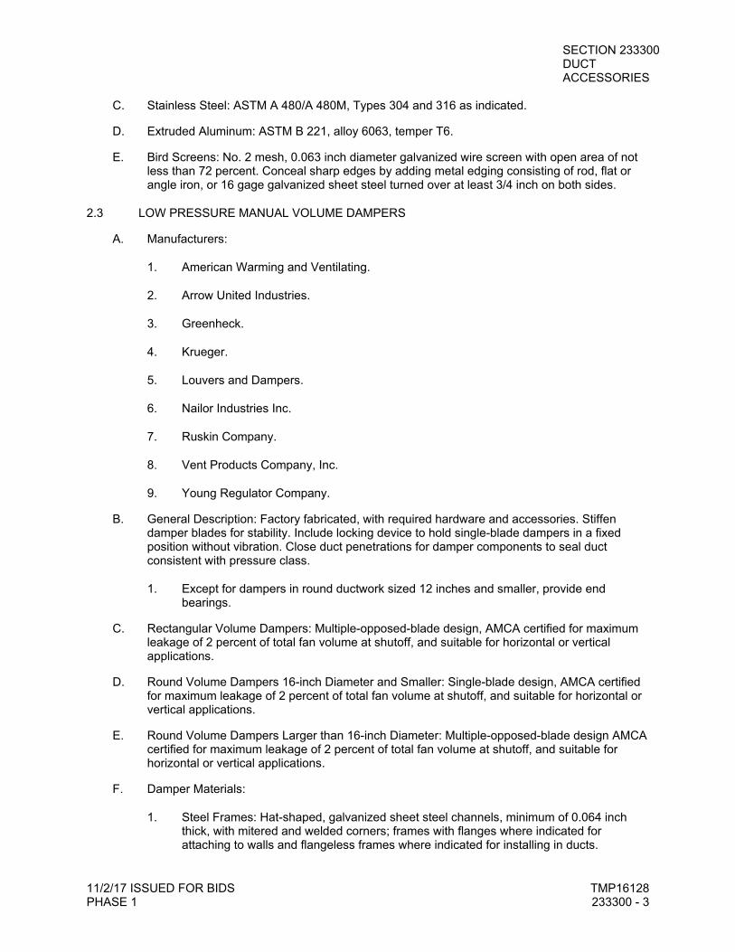
SECTION 233300 DUCT ACCESSORIES
11/2/17 ISSUED FOR BIDS TMP16128 PHASE 1 233300 - 3
C. Stainless Steel: ASTM A 480/A 480M, Types 304 and 316 as indicated.
D. Extruded Aluminum: ASTM B 221, alloy 6063, temper T6.
E. Bird Screens: No. 2 mesh, 0.063 inch diameter galvanized wire screen with open area of not less than 72 percent. Conceal sharp edges by adding metal edging consisting of rod, flat or angle iron, or 16 gage galvanized sheet steel turned over at least 3/4 inch on both sides.
2.3 LOW PRESSURE MANUAL VOLUME DAMPERS
A. Manufacturers:
1. American Warming and Ventilating.
2. Arrow United Industries.
3. Greenheck.
4. Krueger.
5. Louvers and Dampers.
6. Nailor Industries Inc.
7. Ruskin Company.
8. Vent Products Company, Inc.
9. Young Regulator Company.
B. General Description: Factory fabricated, with required hardware and accessories. Stiffen damper blades for stability. Include locking device to hold single-blade dampers in a fixed position without vibration. Close duct penetrations for damper components to seal duct consistent with pressure class.
1. Except for dampers in round ductwork sized 12 inches and smaller, provide end bearings.
C. Rectangular Volume Dampers: Multiple-opposed-blade design, AMCA certified for maximum leakage of 2 percent of total fan volume at shutoff, and suitable for horizontal or vertical applications.
D. Round Volume Dampers 16-inch Diameter and Smaller: Single-blade design, AMCA certified for maximum leakage of 2 percent of total fan volume at shutoff, and suitable for horizontal or vertical applications.
E. Round Volume Dampers Larger than 16-inch Diameter: Multiple-opposed-blade design AMCA certified for maximum leakage of 2 percent of total fan volume at shutoff, and suitable for horizontal or vertical applications.
F. Damper Materials:
1. Steel Frames: Hat-shaped, galvanized sheet steel channels, minimum of 0.064 inch thick, with mitered and welded corners; frames with flanges where indicated for attaching to walls and flangeless frames where indicated for installing in ducts.
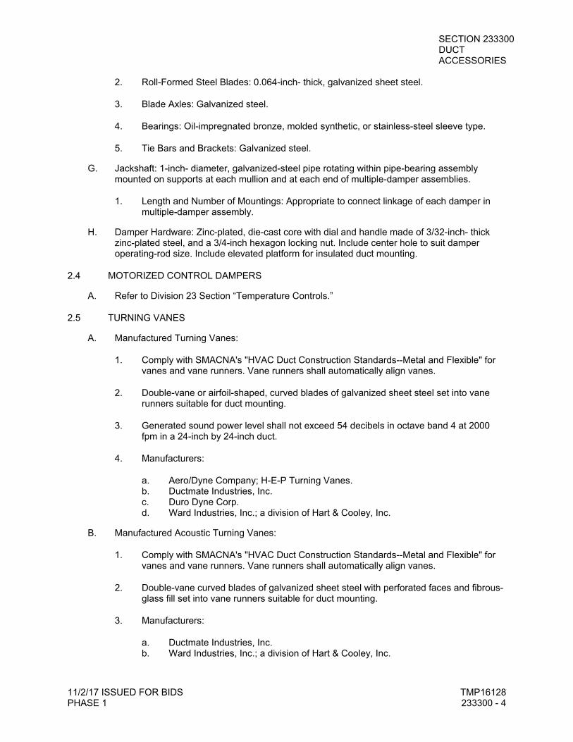
SECTION 233300 DUCT ACCESSORIES
11/2/17 ISSUED FOR BIDS TMP16128 PHASE 1 233300 - 4
2. Roll-Formed Steel Blades: 0.064-inch- thick, galvanized sheet steel.
3. Blade Axles: Galvanized steel.
4. Bearings: Oil-impregnated bronze, molded synthetic, or stainless-steel sleeve type.
5. Tie Bars and Brackets: Galvanized steel.
G. Jackshaft: 1-inch- diameter, galvanized-steel pipe rotating within pipe-bearing assembly mounted on supports at each mullion and at each end of multiple-damper assemblies.
1. Length and Number of Mountings: Appropriate to connect linkage of each damper in multiple-damper assembly.
H. Damper Hardware: Zinc-plated, die-cast core with dial and handle made of 3/32-inch- thick zinc-plated steel, and a 3/4-inch hexagon locking nut. Include center hole to suit damper operating-rod size. Include elevated platform for insulated duct mounting.
2.4 MOTORIZED CONTROL DAMPERS
A. Refer to Division 23 Section “Temperature Controls.”
2.5 TURNING VANES
A. Manufactured Turning Vanes:
1. Comply with SMACNA's "HVAC Duct Construction Standards--Metal and Flexible" for vanes and vane runners. Vane runners shall automatically align vanes.
2. Double-vane or airfoil-shaped, curved blades of galvanized sheet steel set into vane runners suitable for duct mounting.
3. Generated sound power level shall not exceed 54 decibels in octave band 4 at 2000 fpm in a 24-inch by 24-inch duct.
4. Manufacturers:
a. Aero/Dyne Company; H-E-P Turning Vanes. b. Ductmate Industries, Inc. c. Duro Dyne Corp. d. Ward Industries, Inc.; a division of Hart & Cooley, Inc.
B. Manufactured Acoustic Turning Vanes:
1. Comply with SMACNA's "HVAC Duct Construction Standards--Metal and Flexible" for vanes and vane runners. Vane runners shall automatically align vanes.
2. Double-vane curved blades of galvanized sheet steel with perforated faces and fibrous-glass fill set into vane runners suitable for duct mounting.
3. Manufacturers:
a. Ductmate Industries, Inc. b. Ward Industries, Inc.; a division of Hart & Cooley, Inc.
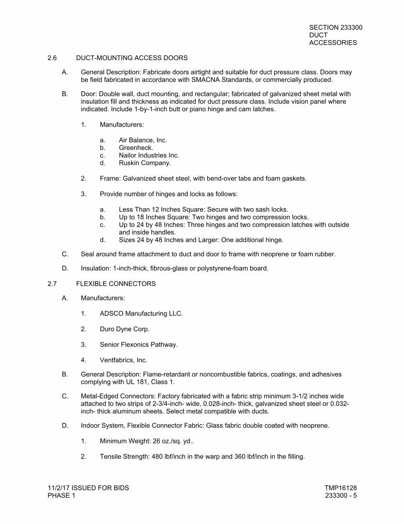
SECTION 233300 DUCT ACCESSORIES
11/2/17 ISSUED FOR BIDS TMP16128 PHASE 1 233300 - 5
2.6 DUCT-MOUNTING ACCESS DOORS
A. General Description: Fabricate doors airtight and suitable for duct pressure class. Doors may be field fabricated in accordance with SMACNA Standards, or commercially produced.
B. Door: Double wall, duct mounting, and rectangular; fabricated of galvanized sheet metal with insulation fill and thickness as indicated for duct pressure class. Include vision panel where indicated. Include 1-by-1-inch butt or piano hinge and cam latches.
1. Manufacturers:
a. Air Balance, Inc. b. Greenheck. c. Nailor Industries Inc. d. Ruskin Company.
2. Frame: Galvanized sheet steel, with bend-over tabs and foam gaskets.
3. Provide number of hinges and locks as follows:
a. Less Than 12 Inches Square: Secure with two sash locks. b. Up to 18 Inches Square: Two hinges and two compression locks. c. Up to 24 by 48 Inches: Three hinges and two compression latches with outside
and inside handles. d. Sizes 24 by 48 Inches and Larger: One additional hinge.
C. Seal around frame attachment to duct and door to frame with neoprene or foam rubber.
D. Insulation: 1-inch-thick, fibrous-glass or polystyrene-foam board.
2.7 FLEXIBLE CONNECTORS
A. Manufacturers:
1. ADSCO Manufacturing LLC.
2. Duro Dyne Corp.
3. Senior Flexonics Pathway.
4. Ventfabrics, Inc.
B. General Description: Flame-retardant or noncombustible fabrics, coatings, and adhesives complying with UL 181, Class 1.
C. Metal-Edged Connectors: Factory fabricated with a fabric strip minimum 3-1/2 inches wide attached to two strips of 2-3/4-inch- wide, 0.028-inch- thick, galvanized sheet steel or 0.032-inch- thick aluminum sheets. Select metal compatible with ducts.
D. Indoor System, Flexible Connector Fabric: Glass fabric double coated with neoprene.
1. Minimum Weight: 26 oz./sq. yd..
2. Tensile Strength: 480 lbf/inch in the warp and 360 lbf/inch in the filling.
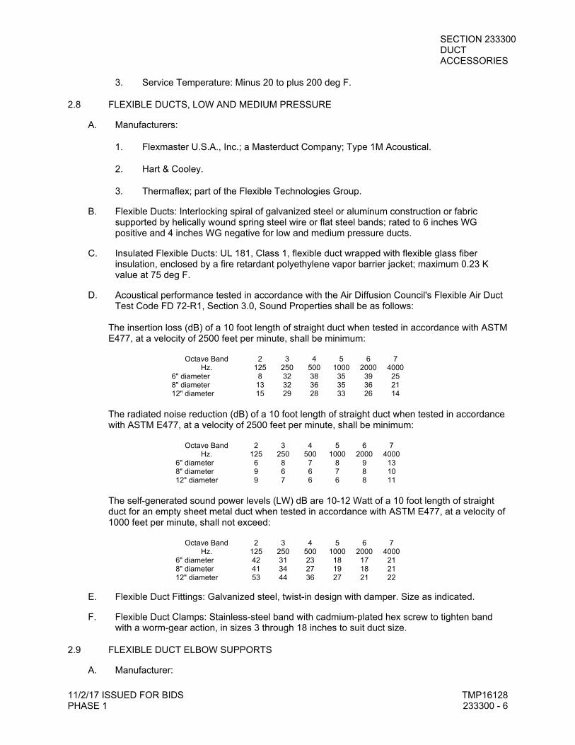
SECTION 233300 DUCT ACCESSORIES
11/2/17 ISSUED FOR BIDS TMP16128 PHASE 1 233300 - 6
3. Service Temperature: Minus 20 to plus 200 deg F.
2.8 FLEXIBLE DUCTS, LOW AND MEDIUM PRESSURE
A. Manufacturers:
1. Flexmaster U.S.A., Inc.; a Masterduct Company; Type 1M Acoustical.
2. Hart & Cooley.
3. Thermaflex; part of the Flexible Technologies Group.
B. Flexible Ducts: Interlocking spiral of galvanized steel or aluminum construction or fabric supported by helically wound spring steel wire or flat steel bands; rated to 6 inches WG positive and 4 inches WG negative for low and medium pressure ducts.
C. Insulated Flexible Ducts: UL 181, Class 1, flexible duct wrapped with flexible glass fiber insulation, enclosed by a fire retardant polyethylene vapor barrier jacket; maximum 0.23 K value at 75 deg F.
D. Acoustical performance tested in accordance with the Air Diffusion Council's Flexible Air Duct Test Code FD 72-R1, Section 3.0, Sound Properties shall be as follows:
The insertion loss (dB) of a 10 foot length of straight duct when tested in accordance with ASTM E477, at a velocity of 2500 feet per minute, shall be minimum:
Octave Band 2 3 4 5 6 7 Hz. 125 250 500 1000 2000 4000
6" diameter 8 32 38 35 39 25 8" diameter 13 32 36 35 36 21 12" diameter 15 29 28 33 26 14
The radiated noise reduction (dB) of a 10 foot length of straight duct when tested in accordance with ASTM E477, at a velocity of 2500 feet per minute, shall be minimum:
Octave Band 2 3 4 5 6 7 Hz. 125 250 500 1000 2000 4000
6" diameter 6 8 7 8 9 13 8" diameter 9 6 6 7 8 10 12" diameter 9 7 6 6 8 11
The self-generated sound power levels (LW) dB are 10-12 Watt of a 10 foot length of straight duct for an empty sheet metal duct when tested in accordance with ASTM E477, at a velocity of 1000 feet per minute, shall not exceed:
Octave Band 2 3 4 5 6 7 Hz. 125 250 500 1000 2000 4000
6" diameter 42 31 23 18 17 21 8" diameter 41 34 27 19 18 21 12" diameter 53 44 36 27 21 22
E. Flexible Duct Fittings: Galvanized steel, twist-in design with damper. Size as indicated.
F. Flexible Duct Clamps: Stainless-steel band with cadmium-plated hex screw to tighten band with a worm-gear action, in sizes 3 through 18 inches to suit duct size.
2.9 FLEXIBLE DUCT ELBOW SUPPORTS
A. Manufacturer:
SECTION 233300 DUCT ACCESSORIES
11/2/17 ISSUED FOR BIDS TMP16128 PHASE 1 233300 - 7
1. Thermaflex; part of the Flexible Technologies Group; FlexFlow Elbow.
2. Smart Air & Energy Solutions; SMART Flow Elbow.
B. Elbow supports shall be constructed of durable composite material and be fully adjustable to support flexible duct diameters 6 inches through 16 inches.
C. Elbow supports shall be UL listed for use in return air plenum spaces.
2.10 DUCT ACCESSORY HARDWARE
A. Adhesives: High strength, quick setting, neoprene based, waterproof, and resistant to gasoline and grease.
PART 3 - EXECUTION
3.1 APPLICATION AND INSTALLATION
A. Install duct accessories according to applicable details in SMACNA's "HVAC Duct Construction Standards--Metal and Flexible" for metal ducts and in NAIMA AH116, "Fibrous Glass Duct Construction Standards," for fibrous-glass ducts.
B. Provide duct accessories of materials suited to duct materials; use galvanized-steel accessories in galvanized-steel and fibrous-glass ducts, stainless-steel accessories in stainless-steel ducts and PVC coated ducts; and aluminum accessories in aluminum ducts.
C. Install volume dampers at points on supply, return, and exhaust systems where branches extend from larger ducts. Where dampers are installed in ducts having duct liner, install dampers with hat channels of same depth as liner, and terminate liner with nosing at hat channel.
1. Install steel volume dampers in steel ducts.
2. Install stainless steel volume dampers in stainless steel ducts.
3. Install aluminum volume dampers in aluminum ducts.
D. Set dampers to fully open position before testing, adjusting, and balancing.
E. Install duct access doors on ducts to allow for inspecting, adjusting, and maintaining accessories and equipment at the following locations:
1. On upstream side of duct coils.
2. Upstream from duct filters.
3. At outdoor-air intakes and mixed-air plenums.
4. At drain pans.
5. Downstream from control dampers, backdraft dampers, and duct mounted equipment.
6. Adjacent to and close enough to fire or smoke dampers, to reset or reinstall fusible links.
SECTION 233300 DUCT ACCESSORIES
11/2/17 ISSUED FOR BIDS TMP16128 PHASE 1 233300 - 8
7. Control devices requiring inspection, including airflow measuring devices. Size access doors appropriately to facilitate service of each device.
8. Elsewhere as indicated.
F. Install access doors with swing against duct static pressure.
G. Install duct-mounting, rectangular access doors with long dimension at right angles to direction of airflow and of largest standard size which can be accommodated in duct. Maximum size: 21 by 14 inches.
H. Label access doors according to Division 20 Section "Mechanical Identification."
I. Install flexible connectors immediately adjacent to equipment in ducts associated with fans and motorized equipment supported by vibration isolators.
J. Connect terminal units to supply ducts directly or with maximum 12-inch lengths of flexible duct. Do not use flexible ducts to change directions.
K. Connect diffusers or light troffer boots to low pressure ducts flexible duct clamped or strapped in place.
L. Connect flexible ducts to metal ducts with draw bands.
M. Install flexible duct elbow supports at each diffuser, grille, or register, and elsewhere as indicated.
N. Install turning vanes in rectangular duct elbows in excess of 45 degrees, and where indicated:
1. Use manufactured double-vane turning vanes unless otherwise specified.
2. Seat outboard-most vane in heal of duct elbow.
3. Provide vanes for all runner punchings, practice of eliminating every other vane is prohibited.
4. Use single-vane turning vanes in low pressure square elbows.
3.2 FIELD QUALITY CONTROL
A. Tests and Inspections:
B. Operate dampers to verify full range of movement.
C. Inspect locations of access doors and verify that purpose of access door can be performed.
D. Inspect turning vanes for proper and secure installation.
3.3 ADJUSTING
A. Adjust duct accessories for proper settings.
B. Final positioning of manual-volume dampers is specified in Division 23 Section "Testing, Adjusting, and Balancing."
**END OF SECTION**
SECTION 233713 DIFFUSERS, REGISTERS, AND GRILLES
11/2/17 ISSUED FOR BIDS TMP16128 PHASE 1 233713 - 1
DIFFUSERS, REGISTERS, AND GRILLES
PART 1 - GENERAL ..................................................................................................................................... 1
1.1 RELATED DOCUMENTS .............................................................................................................. 1
1.2 SUBMITTALS ................................................................................................................................ 1
PART 2 - PRODUCTS .................................................................................................................................. 2
2.1 AIR DIFFUSION DEVICES ........................................................................................................... 2
2.2 SOURCE QUALITY CONTROL .................................................................................................... 2
PART 3 - EXECUTION ................................................................................................................................. 2
3.1 EXAMINATION .............................................................................................................................. 2
3.2 INSTALLATION ............................................................................................................................. 3
3.3 ADJUSTING .................................................................................................................................. 3
PART 1 - GENERAL
1.1 RELATED DOCUMENTS
A. Drawings and general provisions of the Contract, including General and Supplementary Conditions and Division 01 Specification Sections, apply to this Section.
B. Related Sections include the following:
1. Division 20 Section “Mechanical General Requirements.”
2. Division 23 Section "Duct Accessories" for fire and smoke dampers and volume-control dampers not integral to diffusers, registers, and grilles.
1.2 SUBMITTALS
A. Product Data: For each product indicated, include the following:
1. Data Sheet: Indicate materials of construction, finish, and mounting details; and performance data including throw and drop, static-pressure drop, and noise ratings.
2. Diffuser, Register, and Grille Schedule: Indicate Drawing designation, room location, quantity, model number, size, and accessories furnished.
B. Coordination Drawings: Reflected ceiling plans, drawn to scale, on which the following items are shown and coordinated with each other, based on input from installers of the items involved:
1. Ceiling suspension assembly members.
2. Method of attaching hangers to building structure.
3. Size and location of initial access modules for acoustical tile.
4. Ceiling-mounted items including lighting fixtures, diffusers, grilles, speakers, sprinklers, access panels, and special moldings.
5. Duct access panels.
SECTION 233713 DIFFUSERS, REGISTERS, AND GRILLES
11/2/17 ISSUED FOR BIDS TMP16128 PHASE 1 233713 - 2
PART 2 - PRODUCTS
2.1 AIR DIFFUSION DEVICES
A. Manufacturers: Subject to compliance with requirements, provide the product indicated on Drawings or a comparable product by one of the following:
1. Krueger-HVAC; Air Distribution Technologies, Inc.; a JCI Company.
2. Nailor Industries, Inc.
3. Price Industries.
4. Titus; Air Distribution Technologies, Inc.; a JCI Company.
5. Tuttle & Bailey; Air Distribution Technologies, Inc.; a JCI Company.
B. Terminal air diffusion devices have been chosen in terms of specific air distribution requirements, spacing, and sound characteristics.
C. Provide plaster frames for units installed in plaster ceilings.
D. Provide gaskets for supply terminal air devices mounted in finished surfaces.
E. Finish:
1. Device Face and Visible Trim: Standard off white baked enamel finish unless noted otherwise.
2. Device Interior Surfaces, Including Blank-Offs and Boots: Black matte finish.
F. Air pattern adjustments shall be made from the face of the device.
G. Refer to drawings and schedules for quantities, types, and finishes.
H. Coordinate frame types with Architectural Reflected Ceiling Plan.
2.2 SOURCE QUALITY CONTROL
A. Verification of Performance: Rate diffusers, registers, and grilles according to ASHRAE 70, "Method of Testing for Rating the Performance of Air Outlets and Inlets."
B. Acoustical Applications and Sound Evaluation: Based on ARI Standard 885-98, “Procedure for Estimating Occupied Space Sound Levels in the Application of Air Terminals and Air Outlets.”
PART 3 - EXECUTION
3.1 EXAMINATION
A. Examine areas where diffusers, registers, and grilles are to be installed for compliance with requirements for installation tolerances and other conditions affecting performance of equipment.
B. Proceed with installation only after unsatisfactory conditions have been corrected.
SECTION 233713 DIFFUSERS, REGISTERS, AND GRILLES
11/2/17 ISSUED FOR BIDS TMP16128 PHASE 1 233713 - 3
3.2 INSTALLATION
A. Install diffusers, registers, and grilles level and plumb.
B. Ceiling-Mounted Outlets and Inlets: Drawings indicate general arrangement of ducts, fittings, and accessories. Air outlet and inlet locations have been indicated to achieve design requirements for air volume, noise criteria, airflow pattern, throw, and pressure drop. Make final locations where indicated, as much as practicable. For units installed in lay-in ceiling panels, locate units in the center of panel. Where architectural features or other items conflict with installation, notify Architect for a determination of final location.
C. Wall-Mounted Supply Registers: Install 6 inches below finished ceiling unless otherwise indicated.
D. Install diffusers, registers, and grilles with airtight connections to ducts and to allow service and maintenance of dampers, air extractors, and fire dampers.
3.3 ADJUSTING
A. After installation, adjust diffusers, registers, and grilles to air patterns indicated, or as directed, before starting air balancing.
**END OF SECTION**

SECTION 260010 ELECTRICAL GENERAL REQUIREMENTS
11/2/17 ISSUED FOR BIDS TMP16128 PHASE 1 260010 - 1
ELECTRICAL GENERAL REQUIREMENTS
PART 1 - GENERAL ..................................................................................................................................... 1
1.1 RELATED DOCUMENTS .............................................................................................................. 1
1.2 SUMMARY .................................................................................................................................... 1
1.3 REFERENCES .............................................................................................................................. 1
1.4 QUALITY ASSURANCE ................................................................................................................ 2
1.5 CODES, PERMITS AND FEES ..................................................................................................... 3
1.6 DRAWINGS ................................................................................................................................... 3
1.7 MATERIAL AND EQUIPMENT MANUFACTURERS .................................................................... 3
1.8 INSPECTION OF SITE .................................................................................................................. 4
1.9 ITEMS REQUIRING PRIOR APPROVAL ..................................................................................... 4
1.10 SHOP DRAWINGS/SUBMITTALS ................................................................................................ 4
1.11 RECORD DRAWINGS .................................................................................................................. 5
1.12 WARRANTY .................................................................................................................................. 5
1.13 USE OF EQUIPMENT ................................................................................................................... 5
1.14 COORDINATION ........................................................................................................................... 5
PART 2 - PRODUCTS (NOT APPLICABLE) ................................................................................................ 6
PART 3 - EXECUTION ................................................................................................................................. 6
3.1 COMMON REQUIREMENTS FOR ELECTRICAL INSTALLATION ............................................. 6
3.2 DEMOLITION WORK .................................................................................................................... 6
3.3 INSTALLATION OF EQUIPMENT ................................................................................................ 7
3.4 WORK IN EXISTING BUILDINGS ................................................................................................ 7
3.5 DISPOSAL ..................................................................................................................................... 7
3.6 CUTTING, PATCHING AND DAMAGE TO OTHER WORK ......................................................... 8
3.7 EQUIPMENT CONNECTIONS ..................................................................................................... 8
3.8 CLEANING .................................................................................................................................... 8
3.9 PROTECTION AND HANDLING OF EQUIPMENT AND MATERIALS ........................................ 9
3.10 DRAWINGS AND MEASUREMENTS ........................................................................................... 9
PART 1 - GENERAL
1.1 RELATED DOCUMENTS
A. Drawings and General Provisions of the Contract, including General and Supplementary Conditions and Division 01 Specification sections, apply to work of this section.
1.2 SUMMARY
A. This Section includes electrical general administrative and procedural requirements. The following requirements are included in this Section to supplement the requirements specified in Division 1 Specification Sections.
1.3 REFERENCES
A. All materials shall be new. The electrical and physical properties of all materials, and the design, performance characteristics, and methods of construction of all items of equipment, shall be in accordance with the latest issue of the various, applicable Standard Specifications of the following recognized authorities:
1. ANSI - American National Standards Institute; www.ansi.org.
SECTION 260010 ELECTRICAL GENERAL REQUIREMENTS
11/2/17 ISSUED FOR BIDS TMP16128 PHASE 1 260010 - 2
2. ASTM - ASTM International; www.astm.org.
3. CSI - Construction Specifications Institute (The); www.csiresources.org.
4. ICEA - Insulated Cable Engineers Association, Inc.; www.icea.net.
5. IEEE - Institute of Electrical and Electronics Engineers, Inc. (The); www.ieee.org.
6. NEC - National Electrical Code
7. NECA - National Electrical Contractors Association; www.necanet.org.
8. NECA 1-2000, “Practices for Good Workmanship in Electrical Contracting (ANSI).”
9. NEMA - National Electrical Manufacturers Association; www.nema.org.
10. NETA - InterNational Electrical Testing Association; www.netaworld.org.
11. UL - Underwriters Laboratories Inc.; www.ul.com.
1.4 QUALITY ASSURANCE
A. Scope of Work: Furnish all labor, material, equipment, technical supervision, and incidental services required to complete, test and leave ready for operation the electrical systems as specified in the Division 26 Sections and as indicated on Drawings.
1. Contract Documents are complimentary, and what is required by one shall be as binding as if required by all. In the event of inconsistencies or disagreements within the Construction Documents bids shall be based on the most expensive combination of quality and quantity of the work indicated.
2. The Contractor understands that the work herein described shall be complete in every detail.
B. Ordinances and Codes: Perform all Work in accordance with applicable Federal, State and local ordinances and regulations, the Rules and Regulations of NFPA, NECA, and UL, unless otherwise indicated.
1. Notify the Architect/Engineer before submitting a proposal should any changes in Drawings or Specifications be required to conform to the above codes, rules or regulations. After entering into Contract, make all changes required to conform to above ordinances, rules and regulations without additional expense to the Owner.
C. Source Limitations: All equipment of the same or similar systems shall be by the same manufacturer.
D. Tests and Inspections: Perform all tests required by state, city, county and/or other agencies having jurisdiction. Provide all materials, equipment, etc., and labor required for tests.
E. Performance Requirements: Perform all work in a first class and workmanlike manner, in accordance with the latest accepted standards and practices for the trades involved.
F. Sequence and Schedule: Work so as to avoid interference with the work of other trades. Be responsible for removing and relocating any work which in the opinion of the Owner’s
SECTION 260010 ELECTRICAL GENERAL REQUIREMENTS
11/2/17 ISSUED FOR BIDS TMP16128 PHASE 1 260010 - 3
Representatives causes interference.
1.5 CODES, PERMITS AND FEES
A. Unless otherwise indicated, all required permits, licenses, inspections, approvals and fees for electrical work shall be secured and paid for by the Contractor. All work shall conform to all applicable codes, rules and regulations.
B. Rules of local utility companies shall be complied with. Coordinate with the utility company supplying service to the installation and determine all devices including, but not limited to, all current and potential transformers, meter boxes, C.T. cabinets and meters which will be required and include the cost of all such items and all utilities costs in proposal.
C. All work shall be executed in accordance with the rules and regulations set forth in local and state codes. Prepare any detailed Drawings or diagrams which may be required by the governing authorities. Where the Drawings and/or Specifications indicate materials or construction in excess of code requirements, the Drawings and/or Specifications shall govern.
1.6 DRAWINGS
A. The Drawings show the location and general arrangement of equipment, electrical systems and related items. They shall be followed as closely as elements of the construction will permit.
B. Examine the Drawings of other trades and verify the conditions governing the work on the job site. Arrange work accordingly, providing such fittings, conduit, junction boxes and accessories as may be required to meet such conditions.
C. Deviations from the Drawings, with the exception of minor changes in routing and other such incidental changes that do not affect the functioning or serviceability of the systems, shall not be made without the written approval of the Architect/Engineer.
D. The architectural and structural Drawings take precedence in all matters pertaining to the building structure, mechanical Drawings in all matters pertaining to mechanical trades and electrical Drawings in all matters pertaining to electrical trades. Where there are conflicts or differences between the Drawings for the various trades, report such conflicts or differences to the Architect/Engineer for resolution.
E. Drawings are not intended to be scaled for rough-in or to serve as shop drawings. Take all field measurements required to complete the Work.
1.7 MATERIAL AND EQUIPMENT MANUFACTURERS
A. All items of equipment shall be furnished complete with all accessories normally supplied with the catalog items listed and all other accessories necessary for a complete and satisfactory operating system. All equipment and materials shall be new and shall be standard products of manufacturers regularly engaged in the production of electrical equipment and shall be of the manufacturer's latest design.
B. If an approved manufacturer is other than the manufacturer used as the basis for design, the equipment or product provided shall be equal in size, quality, durability, appearance, capacity, and efficiency through all ranges of operation, shall conform with arrangements and space limitations of the equipment shown on the plans and/or specified, shall be compatible with the other components of the system and shall comply with the requirements for Items Requiring Prior Approval specified in this section of the Specifications. All costs to make these items of equipment comply with these requirements including, but not limited to, electrical work, and
SECTION 260010 ELECTRICAL GENERAL REQUIREMENTS
11/2/17 ISSUED FOR BIDS TMP16128 PHASE 1 260010 - 4
building alterations shall be included in the original Bid. Similar equipment shall be by one manufacturer.
C. Where existing equipment is modified to include new switches, circuit breakers, metering or other components, the new components shall be by the original equipment manufacturer and shall be listed for installation in the existing equipment. Where original equipment manufacturer components are not available, third party aftermarket components shall be listed for the application and submitted to the engineer for approval. Reconditioned or salvaged components shall not be used unless specifically indicated on the drawings.
1.8 INSPECTION OF SITE
A. Visit the site, examine and verify the conditions under which the Work must be conducted before submitting Proposal. The submitting of a Proposal implies that the Contractor has visited the site and understands the conditions under which the Work must be conducted. No additional charges will be allowed because of failure to make this examination or to include all materials and labor to complete the Work.
1.9 ITEMS REQUIRING PRIOR APPROVAL
A. Bids shall be based upon manufactured equipment specified. All items that the Contractor proposes to use in the Work that are not specifically named in the Contract Documents must be submitted for review prior to bids. Such items must be submitted in compliance with Division 1 specifications. Requests for prior approval must be accompanied by complete catalog information, including but not limited to, model, size, accessories, complete electrical information and performance data in the form given in the equipment schedule on the drawings at stated design conditions. Where items are referred to by symbolic designations on the drawings, all requests for prior approval shall bear the same designations.
1. Equipment to be considered for prior approval shall be equal in quality, durability, appearance, capacity and efficiency through all ranges of operation, shall fulfill the requirements of equipment arrangement and space limitations of the equipment shown on the plans and/or specified and shall be compatible with the other components of the system.
2. All costs incurred to make equipment comply with other requirements, including providing maintenance, clearance, electrical, replacement of other components, and building alterations shall be included in the original bid.
B. Voluntary alternates may be submitted for consideration, with listed addition or deduction to the bid.
1.10 SHOP DRAWINGS/SUBMITTALS
A. Submit project-specific submittals for review in compliance with Division 1.
B. All shop Drawings shall be submitted in groupings of similar and/or related items (lighting fixtures, switchgear, etc.). Incomplete submittal groupings will be returned unchecked.
C. If deviations (not substitutions) from Contract Documents are deemed necessary by the Contractor, details of such deviations, including changes in related portions of the project and the reasons therefore, shall be submitted with the submittal for approval.
D. Submit for approval shop drawings for all electrical systems or equipment but not limited to the items listed below. Where items are referred to by symbolic designation on the Drawings and
SECTION 260010 ELECTRICAL GENERAL REQUIREMENTS
11/2/17 ISSUED FOR BIDS TMP16128 PHASE 1 260010 - 5
Specifications, all submittals shall bear the same designation (light fixtures). Refer to other sections of the electrical Specifications for additional requirements.
1. Wiring Devices
2. Lighting Control Devices
3. Interior Lighting
1.11 RECORD DRAWINGS
A. Submit record drawings in compliance with Division 01.
B. Contractor shall submit to the Architect/Engineer, record drawings on electronic media which have been neatly marked to represent as-built conditions for all new electrical work. Modifications to original drawings shall be clearly marked with a contrasting color so the marks are readily apparent.
C. The Contractor shall keep accurate note of all deviations from the construction documents and discrepancies in the underground concealed conditions and other items of construction on field drawings as they occur. The marked up field documents shall be available for review by the Architect, Engineer and Owner at their request during the course of construction.
1.12 WARRANTY
A. Warranty: Comply with the requirements in Division 01 Specification Sections. Contractor shall warranty that the electrical installation is free from defects and agrees to replace or repair, to the Owner’s satisfaction, any part of this electrical installation which becomes defective within a period of one year (unless specified otherwise in other Division 26 sections) from the date of substantial completion following final acceptance, provided that such failure is due to defects in the equipment, material, workmanship or failure to follow the contract documents.
B. Contractor shall be responsible for any temporary services including equipment and installation required to maintain operation as a result of any equipment failure or defect during warranty period.
C. File with the Owner any and all warranties from the equipment manufacturers including the operating conditions and performance capacities they are based on.
1.13 USE OF EQUIPMENT
A. The use of any equipment, or any part thereof for purposes other than testing even with the Owner's consent, shall not be construed to be an acceptance of the work on the part of the Owner, nor be construed to obligate the Owner in any way to accept improper work or defective materials.
B. Do not use Owner's lamps for temporary lighting except as allowed and directed by the Owner. Equip lighting fixtures with new lamps when the project is turned over to the Owner.
1.14 COORDINATION
A. Coordinate arrangement, mounting, and support of electrical equipment:
1. To allow maximum possible headroom unless specific mounting heights that reduce headroom are indicated.
SECTION 260010 ELECTRICAL GENERAL REQUIREMENTS
11/2/17 ISSUED FOR BIDS TMP16128 PHASE 1 260010 - 6
2. To provide for ease of disconnecting the equipment with minimum interference to other installations.
3. To allow right of way for piping and conduit installed at required slope.
4. So connecting raceways, cables, wireways, cable trays, and busways will be clear of obstructions and of the working and access space of other equipment.
B. Coordinate location of access panels and doors for electrical items that are behind finished surfaces or otherwise concealed. Access doors and panels are specified in Division 8 Section "Access Doors and Frames."
C. Coordinate electrical testing of electrical, mechanical, and architectural items, so equipment and systems that are functionally interdependent are tested to demonstrate successful interoperability.
PART 2 - PRODUCTS (not applicable)
PART 3 - EXECUTION
3.1 COMMON REQUIREMENTS FOR ELECTRICAL INSTALLATION
A. Comply with NECA 1.
B. Measure indicated mounting heights to bottom of unit for suspended items and to center of unit for wall-mounting items.
C. Headroom Maintenance: If mounting heights or other location criteria are not indicated, arrange and install components and equipment to provide maximum possible headroom consistent with these requirements.
D. Equipment: Install to facilitate service, maintenance, and repair or replacement of components of both electrical equipment and other nearby installations. Connect in such a way as to facilitate future disconnecting with minimum interference with other items in the vicinity.
E. Right of Way: Give to raceways and piping systems installed at a required slope.
3.2 DEMOLITION WORK
A. All demolition of existing electrical equipment and materials will be done by this Contractor unless otherwise indicated. Include all items such as, but not limited to, electrical equipment, devices, lighting fixtures, conduit, and wiring called out on the Drawings and as necessary whether such items are actually indicated on the Drawings or not in order to accomplish the installation of the specified new work.
B. In general, demolition work is indicated on the Drawings. However, the Contractor shall visit the job site to determine the full extent and character of this work.
C. Unless specifically noted to the contrary, removed materials shall not be reused in the work. Salvaged materials that are to be reused shall be stored safe against damage and turned over to the appropriate trade for reuse. Salvaged materials of value that are not to be reused shall remain the property of the Owner unless such ownership is waived. Items on which the Owner waives ownership shall become the property of the Contractor, who shall remove and legally

SECTION 260010 ELECTRICAL GENERAL REQUIREMENTS
11/2/17 ISSUED FOR BIDS TMP16128 PHASE 1 260010 - 7
dispose of same, away from the premises.
D. Where equipment or fixtures are removed, outlets shall be properly blanked off, and conduits capped. After alterations are done, the entire installation shall present a "finished" look, as approved by the Architect/Engineer. The original function of the present electrical work to be modified shall not be changed unless required by the specific revisions to the system as specified or as indicated.
E. Reroute signal wires, lighting and power wiring as required to maintain service. Where walls and ceilings are to be removed as shown on the Drawings, the conduit is to be cut off by the Electrical Trades so that the abandoned conduit in these walls and ceilings may be removed with the walls and ceilings by the Architectural Trades. All dead-end conduit runs shall be plugged at the remaining line outlet boxes or at the panels.
F. Where new walls and/or floors are installed which interfere with existing outlets, devices, etc., the Electrical Trades shall adjust, extend and reconnect such items as required to maintain continuity of same.
G. All electrical work in altered and unaltered areas shall be run concealed wherever possible. Use of surface raceway or exposed conduits will be permitted only where approved by the Architect/Engineer.
H. Existing lighting shall be reused where indicated on plans. Reused fixtures shall be detergent cleaned, relamped and reconditioned suitable for satisfactory operation and appearance.
3.3 INSTALLATION OF EQUIPMENT
A. Install all equipment in strict accordance with all directions and recommendations furnished by the manufacturer. Where such directions are in conflict with the Drawings and Specifications, report such conflicts to the Architect/Engineer for resolution.
B. Device Location:
1. Allow for relocation prior to installation of wiring devices and other control devices, for example, receptacles, switches, fire alarm devices, and access control devices, within a 10-foot radius of indicated location without additional cost.
3.4 WORK IN EXISTING BUILDINGS
A. The Owner will provide access to existing buildings as required. Access requirements to occupied buildings shall be identified on the project schedule. The Contractor, once Work is started in the existing building, shall complete same without interruption so as to return work areas as soon as possible to Owner.
B. Adequately protect and preserve all existing and newly installed Work. Promptly repair any damage to same at Contractor's expense.
C. Consult with the Owner’s Representative as to the methods of carrying on the Work so as not to interfere with the Owner's operation any more than absolutely necessary. Accordingly, all service lines shall be kept in operation as long as possible and the services shall only be interrupted at such time as will be designated by the Owner's Representative.
3.5 DISPOSAL
A. Fluorescent Lamps

SECTION 260010 ELECTRICAL GENERAL REQUIREMENTS
11/2/17 ISSUED FOR BIDS TMP16128 PHASE 1 260010 - 8
1. Fluorescent lamps are known to contain mercury and are classified as hazardous material. All fluorescent lamps shall be assumed to contain mercury unless tested and confirmed otherwise with a toxicity characteristic leaching procedure (TCLP).
2. Hazardous materials (fluorescent lamps), shall be sent to a lamp recycling facility. The materials shall be properly packaged with labels that meet the Department of Transportation Regulations and stored in a secure location prior to transportation.
3. The Contractor shall identify the costs of the lamp disposal process including, but not limited to, the lamp packaging, storage, transportation, disposal, and any profile fees.
4. At the completion of the project, provide documentation to verify that the lamps have been properly disposed of in accordance with all local, state and federal guidelines.
B. Ballasts
1. Lighting ballasts manufactured prior to 1979 have been known to contain polychlorinated biphenyls (PCBs). Unless specifically noted on the ballast as containing "No PCBs," the ballast shall be assumed to contain components with PCB materials.
2. Hazardous materials (ballasts with PCBs), shall be disposed of at a hazardous waste incineration facility, or at a recycling facility in accordance with the Code of Federal Regulations as administered by the EPA in regards to this issue. The ballasts shall be packaged/stored in fifty-five gallon steel drums with labels that meet the Department of Transportation Regulations.
3. The Contractor shall identify the costs of the ballast disposal process including, but not limited to, the packaging, storage, transportation, disposal, and any profile fees.
4. Provide at completion of the project documentation (manifests) to verify that the ballasts have properly been disposed of in accordance with all local, state and federal guidelines.
3.6 CUTTING, PATCHING AND DAMAGE TO OTHER WORK
A. Refer to General Conditions for requirements.
B. All cutting, patching and repair work shall be performed by the Contractor through approved, qualified subcontractors. Contractor shall include full cost of same in bid.
3.7 EQUIPMENT CONNECTIONS
A. Make connections to equipment, motors, lighting fixtures, and other items included in the work in accordance with the approved shop Drawings and rough-in measurements furnished by the manufacturers of the particular equipment furnished. All additional connections not shown on the Drawings, but called out by the equipment manufacturer's shop Drawings shall be provided.
3.8 CLEANING
A. All debris shall be removed daily as required to maintain the work area in a neat, orderly condition.
B. Final cleanup shall include, but not be limited to, washing of fixture lenses or louvers, switchboards, substations, motor control centers, panels, etc. Fixture reflectors and lenses or louvers shall be left with no water marks or cleaning streaks.

SECTION 260010 ELECTRICAL GENERAL REQUIREMENTS
11/2/17 ISSUED FOR BIDS TMP16128 PHASE 1 260010 - 9
3.9 PROTECTION AND HANDLING OF EQUIPMENT AND MATERIALS
A. Equipment and materials shall be protected from theft, injury or damage.
B. Protect conduit openings with temporary plugs or caps.
C. Provide adequate storage for all equipment and materials delivered to the job site. Location of the space will be designated by the Owner's representative or Architect/Engineer. Equipment set in place in unprotected areas must be provided with temporary protection.
3.10 DRAWINGS AND MEASUREMENTS
A. The Drawings are not intended to be scaled for rough-in measurements nor to serve as Shop Drawings. Field measurements necessary for ordering materials and fitting the installation to the building construction and arrangement are the Contractor’s responsibility. The Contractor shall check latest Architectural Drawings and locate light switches from same where door swings are different from Electrical Drawings.
**END OF SECTION**
SECTION 260519 CONDUCTORS AND CABLES
11/2/17 ISSUED FOR BIDS TMP16128 PHASE 1 260519 - 1
CONDUCTORS AND CABLES
PART 1 - GENERAL ..................................................................................................................................... 1
1.1 RELATED DOCUMENTS .............................................................................................................. 1
1.2 SUMMARY .................................................................................................................................... 1
1.3 SUBMITTALS ................................................................................................................................ 1
1.4 QUALITY ASSURANCE ................................................................................................................ 1
PART 2 - PRODUCTS .................................................................................................................................. 1
2.1 CONDUCTORS AND CABLES ..................................................................................................... 1
2.2 CONNECTORS AND SPLICES .................................................................................................... 2
PART 3 - EXECUTION ................................................................................................................................. 2
3.1 CONDUCTOR MATERIAL APPLICATIONS ................................................................................. 2
3.2 CONDUCTOR INSULATION AND MULTICONDUCTOR CABLE APPLICATIONS AND WIRING METHODS ..................................................................................................................................... 2
3.3 INSTALLATION OF CONDUCTORS AND CABLES .................................................................... 2
3.4 CONNECTIONS ............................................................................................................................ 3
3.5 IDENTIFICATION .......................................................................................................................... 4
3.6 FIRESTOPPING ............................................................................................................................ 4
PART 1 - GENERAL
1.1 RELATED DOCUMENTS
A. Drawings and general provisions of the Contract, including General and Supplementary Conditions and Division 01 Specification Sections, apply to this Section.
1.2 SUMMARY
A. Section includes:
1. Building wires and cables rated 600V and less.
2. Connectors, splices, and terminations rated 600 V and less.
1.3 SUBMITTALS
A. Field Quality-Control Test Reports
1.4 QUALITY ASSURANCE
A. Electrical Components, Devices, and Accessories: Listed and labeled as defined in NFPA 70, Article 100, by a testing agency acceptable to authorities having jurisdiction, and marked for intended use.
B. Comply with NFPA 70.
PART 2 - PRODUCTS
2.1 CONDUCTORS AND CABLES
A. Copper Conductors: Comply with NEMA WC 70/ICEA S-95-658.
SECTION 260519 CONDUCTORS AND CABLES
11/2/17 ISSUED FOR BIDS TMP16128 PHASE 1 260519 - 2
B. Conductor Insulation: Comply with NEMA WC 70/ICEA S-95-658 for types THHN/THWN-2.
C. Multiconductor Cable: Comply with NEMA WC 70/ICEA S-95-658 for Metal-clad cable, Type MC with ground wire.
2.2 CONNECTORS AND SPLICES
A. Description: Factory-fabricated connectors and splices of size, ampacity rating, material, type, and class for application and service indicated.
PART 3 - EXECUTION
3.1 CONDUCTOR MATERIAL APPLICATIONS
A. Feeders: Copper. Solid for No. 10 AWG and smaller; stranded for No. 8 AWG and larger.
B. Branch Circuits: Copper. Solid for No. 10 AWG and smaller; stranded for No. 8 AWG and larger, except VFC cable, which shall be extra flexible stranded.
C. Each feeder shall be of the same conductor and insulation material (phase, neutral, and parallel).
D. Use conductor not smaller than 12 AWG for power and lighting circuits. Unless indicated otherwise, all circuits shall be 2#12, 1#12G, ¾”C.
E. Use conductor not smaller than 14 AWG for control circuits, provided by Electrical Contractor.
3.2 CONDUCTOR INSULATION AND MULTICONDUCTOR CABLE APPLICATIONS AND WIRING METHODS
A. Feeders Concealed in Ceilings, Walls, and Partitions: Type THHN/THWN-2, single conductors in raceway.
B. Feeders Concealed in Concrete, below Slabs-on-Grade, and in Crawlspaces: Type THHN/THWN-2, single conductors in raceway.
C. Branch Circuits Concealed in Ceilings, Walls, and Partitions: Type THHN/THWN-2, single conductors in raceway and metal-clad cable, Type MC, for branch circuit drops to devices and within partition walls. MC cable shall not be run in ceiling space in lengths greater than 6’-0”.
D. Branch Circuits Concealed in Concrete and below Slabs-on-Grade: Type THHN/THWN-2, single conductors in raceway.
E. Underground Feeders and Branch Circuits: XHHW-2 single conductors in conduit.
F. Feeders and Branch Circuits on Rooftops: XHHW-2 single conductors in conduit.
G. Cord Drops and Portable Appliance Connections: Type SO, hard service cord with stainless-steel wire-mesh strain relief device at terminations to suit application.
H. Fire Alarm Circuits: Type THHN/THWN-2, in raceway.
3.3 INSTALLATION OF CONDUCTORS AND CABLES
A. Conceal cables in finished walls, ceilings, and floors, unless otherwise indicated.
SECTION 260519 CONDUCTORS AND CABLES
11/2/17 ISSUED FOR BIDS TMP16128 PHASE 1 260519 - 3
B. Complete raceway installation between conductor and cable termination points according to Section 260533 "Raceways and Boxes for Electrical Systems" prior to pulling conductors and cables.
C. Use manufacturer-approved pulling compound or lubricant where necessary; compound used must not deteriorate conductor or insulation. Do not exceed manufacturer's recommended maximum pulling tensions and sidewall pressure values.
D. Use pulling means, including fish tape, cable, rope, and basket-weave wire/cable grips, that will not damage cables or raceway.
E. Install exposed cables parallel and perpendicular to surfaces of exposed structural members, and follow surface contours where possible.
F. Support cables according to Division 26 Section "Hangers and Supports for Electrical Systems."
G. Neatly train and lace wiring inside boxes, equipment, and panelboards.
H. Branch circuits may be combined up t0 3 circuits in a homerun conduit.
I. Provide a separate neutral conductor for each circuit.
J. Electrical Contractor shall be responsible for de-rating of conductors as required by N.E.C. when more than three current carrying conductors are installed in a single raceway or cable.
K. Type MC cable shall be supported and secured at intervals not exceeding 4'-0".
L. MC cable shall not be used for home runs to receptacle or distribution panels.
M. Between support, hangers and termination no more than 3" deflection from the bottom of the cable to a horizontal line between the support/hanger or termination.
N. Do not route conductors across roof without prior approval from engineer. Where approved, conductors shall be installed in rigid steel conduit and shall be de-rated for ambient temperature per the NEC.
3.4 CONNECTIONS
A. Tighten electrical connectors and terminals according to manufacturer's published torque-tightening values. If manufacturer's torque values are not indicated, use those specified in UL 486A and UL 486B.
B. Make splices and taps that are compatible with conductor material and that possess equivalent or better mechanical strength and insulation ratings than un-spliced conductors.
1. Use oxide inhibitor in each splice and tap conductor for aluminum conductors.
2. Use compression type terminations for aluminum conductors.
C. Wiring at Outlets: Install conductor at each outlet, with at least 6 inches of slack.
D. Clean conductor surfaces before installing lugs and connectors.
E. Make splices, taps, and terminations to carry full ampacity of conductors with no perceptible temperature rise.
SECTION 260519 CONDUCTORS AND CABLES
11/2/17 ISSUED FOR BIDS TMP16128 PHASE 1 260519 - 4
F. Use Sta-Kon connectors to terminate stranded conductors #10 AWG and smaller to screw terminals.
G. Use insulated spring wire connectors with plastic caps for copper conductor splices and taps, 10 AWG and smaller.
3.5 IDENTIFICATION
A. Identify and color-code conductors and cables according to Section 260553 "Identification for Electrical Systems."
B. Identify each spare conductor at each end with identity number and location of other end of conductor, and identify as spare conductor.
3.6 FIRESTOPPING
A. Apply firestopping to electrical penetrations of fire-rated floor and wall assemblies to restore original fire-resistance rating of assembly according to Division 07 Section "Penetration Firestopping”.
**END OF SECTION**
SECTION 260529 HANGERS AND SUPPORTS FOR ELECTRICAL SYSTEMS
11/2/17 ISSUED FOR BIDS TMP16128 PHASE 1 260529 - 1
HANGERS AND SUPPORTS FOR ELECTRICAL SYSTEMS
PART 1 - GENERAL ..................................................................................................................................... 1
1.1 RELATED DOCUMENTS .............................................................................................................. 1
1.2 SUMMARY .................................................................................................................................... 1
1.3 DEFINITIONS ................................................................................................................................ 1
1.4 PERFORMANCE REQUIREMENTS ............................................................................................ 1
1.5 QUALITY ASSURANCE ................................................................................................................ 1
PART 2 - PRODUCTS .................................................................................................................................. 2
2.1 SUPPORT, ANCHORAGE, AND ATTACHMENT COMPONENTS.............................................. 2
2.2 FABRICATED METAL EQUIPMENT SUPPORT ASSEMBLIES .................................................. 3
PART 3 - EXECUTION ................................................................................................................................. 3
3.1 APPLICATION ............................................................................................................................... 3
3.2 SUPPORT INSTALLATION .......................................................................................................... 4
PART 1 - GENERAL
1.1 RELATED DOCUMENTS
A. Drawings and general provisions of the Contract, including General and Supplementary Conditions and Division 01 Specification Sections, apply to this Section.
1.2 SUMMARY
A. This Section includes the following:
1. Hangers and supports for electrical equipment and systems.
1.3 DEFINITIONS
A. EMT: Electrical metallic tubing.
B. IMC: Intermediate metal conduit.
C. RMC: Rigid metal conduit.
1.4 PERFORMANCE REQUIREMENTS
A. Design supports for multiple raceways capable of supporting combined weight of supported systems and its contents.
B. Design equipment supports capable of supporting combined operating weight of supported equipment and connected systems and components.
1.5 QUALITY ASSURANCE
A. Comply with NFPA 70.

SECTION 260529 HANGERS AND SUPPORTS FOR ELECTRICAL SYSTEMS
11/2/17 ISSUED FOR BIDS TMP16128 PHASE 1 260529 - 2
PART 2 - PRODUCTS
2.1 SUPPORT, ANCHORAGE, AND ATTACHMENT COMPONENTS
A. Steel Slotted Support Systems: Comply with MFMA-4, factory-fabricated components for field assembly.
1. Manufacturers: Subject to compliance with requirements, provide products by one of the following:
a. Allied Tube & Conduit; a part of Atkore International. b. B-Line, by Eaton. c. GS Metals Corp. d. Pentair Electrical & Fastening Solutions. e. Thomas & Betts Corporation. f. Unistrut; a part of Atkore International. g. Wesanco, Inc.
2. Metallic Coatings: Hot-dip galvanized after fabrication and applied according to MFMA-4.
3. Painted Coatings: Manufacturer's standard painted coating applied according to MFMA-4.
4. Channel Dimensions: Selected for applicable load criteria.
B. Raceway and Cable Supports: As described in NECA 1 and NECA 101.
C. Conduit and Cable Support Devices: Steel hangers, clamps, and associated fittings, designed for types and sizes of raceway or cable to be supported.
D. Support for Conductors in Vertical Conduit: Factory-fabricated assembly consisting of threaded body and insulating wedging plug or plugs for non-armored electrical conductors or cables in riser conduits. Plugs shall have number, size, and shape of conductor gripping pieces as required to suit individual conductors or cables supported. Body shall be malleable iron.
E. Structural Steel for Fabricated Supports and Restraints: ASTM A 36/A 36M, steel plates, shapes, and bars; black and galvanized.
F. Mounting, Anchoring, and Attachment Components: Items for fastening electrical items or their supports to building surfaces include the following:
1. Powder-Actuated Fasteners: Threaded-steel stud, for use in hardened portland cement concrete, steel, or wood, with tension, shear, and pullout capacities appropriate for supported loads and building materials where used.
a. Manufacturers: Subject to compliance with requirements, provide products by one of the following:
1) Hilti Inc. 2) ITW Ramset/Red Head; a division of Illinois Tool Works, Inc. 3) MKT Fastening, LLC.
SECTION 260529 HANGERS AND SUPPORTS FOR ELECTRICAL SYSTEMS
11/2/17 ISSUED FOR BIDS TMP16128 PHASE 1 260529 - 3
4) Simpson Strong-Tie Co., Inc.; Masterset Fastening Systems Unit.
2. Mechanical-Expansion Anchors: Insert-wedge-type, zinc-coated steel, for use in hardened portland cement concrete with tension, shear, and pullout capacities appropriate for supported loads and building materials in which used.
a. Manufacturers: Subject to compliance with requirements, provide products by one of the following:
1) B-Line by Eaton. 2) Empire Tool and Manufacturing Co., Inc. 3) Hilti Inc. 4) ITW Ramset/Red Head; a division of Illinois Tool Works, Inc. 5) MKT Fastening, LLC.
3. Concrete Inserts: Steel or malleable-iron, slotted support system units similar to MSS Type 18; complying with MFMA-4 or MSS SP-58.
4. Clamps for Attachment to Steel Structural Elements: MSS SP-58, type suitable for attached structural element.
5. Through Bolts: Structural type, hex head, and high strength. Comply with ASTM A 325.
6. Toggle Bolts: All-steel springhead type.
7. Hanger Rods: Threaded steel.
2.2 FABRICATED METAL EQUIPMENT SUPPORT ASSEMBLIES
A. Description: Welded or bolted, structural-steel shapes, shop or field fabricated to fit dimensions of supported equipment.
B. Materials: Comply with requirements in Division 05 Section "Metal Fabrications" for steel shapes and plates.
PART 3 - EXECUTION
3.1 APPLICATION
A. Comply with NECA 1 and NECA 101 for application of hangers and supports for electrical equipment and systems except if requirements in this Section are stricter.
B. Maximum Support Spacing and Minimum Hanger Rod Size for Raceway: Space supports for EMT, IMC, and RMC as required by NFPA 70 or as scheduled in NECA 1. Minimum rod size shall be 1/4 inch in diameter.
C. Multiple Raceways or Cables: Install trapeze-type supports fabricated with steel slotted support system, sized so capacity can be increased by at least 25 percent in future without exceeding specified design load limits.
1. Secure raceways and cables to these supports with:
a. Single-bolt conduit clamps

SECTION 260529 HANGERS AND SUPPORTS FOR ELECTRICAL SYSTEMS
11/2/17 ISSUED FOR BIDS TMP16128 PHASE 1 260529 - 4
b. Single-bolt conduit clamps using spring friction action for retention in support channel.
D. Support single runs of MC cable using spring-steel clamps from suspended ceiling hangers, hanger wire or building structure at intervals not to exceed three feet. Do not support MC cable from ceiling grid.
3.2 SUPPORT INSTALLATION
A. Comply with NECA 1 and NECA 101 for installation requirements except as specified in this Article.
B. Raceway Support Methods: In addition to methods described in NECA 1, EMT may be supported by openings through structure members, as permitted in NFPA 70.
C. Strength of Support Assemblies: Where not indicated, select sizes of components so strength will be adequate to carry present and future static loads within specified loading limits. Minimum static design load used for strength determination shall be weight of supported components plus 200 lb.
D. Mounting and Anchorage of Surface-Mounted Equipment and Components: Anchor and fasten electrical items and their supports to building structural elements by the following methods unless otherwise indicated by code:
1. To Wood: Fasten with lag screws or through bolts.
2. To New Concrete: Bolt to concrete inserts.
3. To Masonry: Approved toggle-type bolts on hollow masonry units and expansion anchor fasteners on solid masonry units.
4. To Existing Concrete: Expansion anchor fasteners.
5. To Steel:
a. Welded threaded studs complying with AWS D1.1/D1.1M, with lock washers and nuts.
b. Beam clamps (MSS Type 19, 21, 23, 25, or 27) complying with MSS SP-69 c. Spring-tension clamps.
6. To Light Steel: Sheet metal screws.
7. Items Mounted on Hollow Walls and Nonstructural Building Surfaces: Mount cabinets, panelboards, disconnect switches, control enclosures, pull and junction boxes, transformers, and other devices on slotted-channel support systems attached to substrate.
E. Slotted support systems applications:
1. Indoor dry and damp Locations: Painted Steel
2. Outdoors and interior wet locations: Galvanized Steel
SECTION 260529 HANGERS AND SUPPORTS FOR ELECTRICAL SYSTEMS
11/2/17 ISSUED FOR BIDS TMP16128 PHASE 1 260529 - 5
3. Corrosive Environments, including pool equipment rooms: Nonmetallic
F. Drill holes for expansion anchors in concrete at locations and to depths that avoid reinforcing bars.
G. Do not fasten supports to pipes, ducts, mechanical equipment, and conduit.
H. Obtain permission from Architect/Engineer before using powder-actuated anchors.
I. Obtain permission from Architect/Engineer before drilling or cutting structural members.
J. Fabricate supports from structural steel or steel channel. Rigidly weld members or use hexagon head bolts to present neat appearance with adequate strength and rigidity. Use spring lock washers under all nuts.
K. Install surface-mounted cabinets and panelboards with minimum of four anchors.
L. In wet and damp locations use steel channel supports to stand cabinets and panelboards one inch off wall.
M. Use sheet metal channel to bridge studs above and below cabinets and panelboards recessed in hollow partitions.
N. The Contractor shall replace all supports and channels that sag, twist, and/or show signs of not providing proper structural support, to the equipment, it is intended for, as determined by the Owner and Architect/Engineer. All costs associated with replacing supports and steel channels shall be incurred by the Contractor.
**END OF SECTION**
SECTION 260533 RACEWAYS AND BOXES
11/2/17 ISSUED FOR BIDS TMP16128 PHASE 1 260533 - 1
RACEWAYS AND BOXES
PART 1 - GENERAL ..................................................................................................................................... 1
1.1 RELATED DOCUMENTS .............................................................................................................. 1
1.2 SUMMARY .................................................................................................................................... 1
1.3 DEFINITIONS ................................................................................................................................ 1
1.4 QUALITY ASSURANCE ................................................................................................................ 1
1.5 COORDINATION ........................................................................................................................... 2
PART 2 - PRODUCTS .................................................................................................................................. 2
2.1 METAL CONDUIT AND TUBING .................................................................................................. 2
2.2 NONMETALLIC CONDUIT AND TUBING .................................................................................... 3
2.3 BOXES, ENCLOSURES, AND CABINETS ................................................................................... 3
PART 3 - EXECUTION ................................................................................................................................. 4
3.1 RACEWAY APPLICATION ........................................................................................................... 4
3.2 INSTALLATION ............................................................................................................................. 4
3.3 FIRESTOPPING ............................................................................................................................ 6
3.4 CLEANING .................................................................................................................................... 6
PART 1 - GENERAL
1.1 RELATED DOCUMENTS
A. Drawings and general provisions of the Contract, including General and Supplementary Conditions and Division 1 Specification Sections, apply to this Section.
1.2 SUMMARY
A. This Section includes raceways, fittings, boxes, enclosures, and cabinets for electrical wiring.
B. Related Sections include the following:
1. Division 26 Section "Wiring Devices" for devices installed in boxes and for floor-box service fittings, and for access floor boxes and service poles.
2. Division 26 “Hangers and Supports for Electrical Systems” for concrete bases.
1.3 DEFINITIONS
A. EMT: Electrical metallic tubing.
B. ENT: Electrical nonmetallic tubing.
C. FMC: Flexible metal conduit.
D. IMC: Intermediate metal conduit.
E. LFMC: Liquidtight flexible metal conduit.
F. RNC: Rigid nonmetallic conduit.
1.4 QUALITY ASSURANCE
A. Electrical Components, Devices, and Accessories: Listed and labeled as defined in NFPA 70, Article 100, by a testing agency acceptable to authorities having jurisdiction, and marked for
SECTION 260533 RACEWAYS AND BOXES
11/2/17 ISSUED FOR BIDS TMP16128 PHASE 1 260533 - 2
intended use.
B. Comply with NFPA 70.
1.5 COORDINATION
A. Coordinate layout and installation of raceways, boxes, enclosures, cabinets, and suspension system with other construction that penetrates ceilings or is supported by them, including light fixtures, HVAC equipment, fire-suppression system, and partition assemblies.
PART 2 - PRODUCTS
2.1 METAL CONDUIT AND TUBING
A. Manufacturers: Subject to compliance with requirements, provide products by one of the following:
1. AFC Cable Systems, Inc.
2. Alflex Inc.
3. Allied Tube Triangle Century.
4. Anamet Electrical, Inc.; Anaconda Metal Hose.
5. International Metal Hose.
6. Electri-Flex Co
7. Grinnell Co./Tyco International; Allied Tube and Conduit Div.
8. LTV Steel Tubular Products Company – Manhattan/CDT/Cole-Flex.
9. Maverick.
10. O-Z Gedney; unit of General Signal.
11. Wheatland.
B. Rigid Steel Conduit: ANSI C80.1.
C. EMT: ANSI C80.3.
D. LFMC: Flexible steel conduit with PVC jacket.
E. Fittings for Conduit (Including all Types and Flexible and Liquidtight), EMT, and Cable: NEMA FB 1; listed for type and size raceway with which used, and for application and environment in which installed.
1. Fittings for EMT: Steel, set-screw type.
2. Coating for Fittings for PVC-Coated Conduit: Minimum thickness, 0.040 inch, with overlapping sleeves protecting threaded joints.
SECTION 260533 RACEWAYS AND BOXES
11/2/17 ISSUED FOR BIDS TMP16128 PHASE 1 260533 - 3
2.2 NONMETALLIC CONDUIT AND TUBING
A. Manufacturers: Subject to compliance with requirements, provide products by one of the following:
1. American International.
2. Anamet Electrical, Inc.; Anaconda Metal Hose.
3. Arnco Corp.
4. Cantex Inc.
5. Certainteed Corp.; Pipe and Plastics Group.
6. Condux International.
7. ElecSys, Inc.
8. Electri-Flex Co.
9. Integral.
10. Kor-Kap.
11. Lamson and Sessions: Carlon Electrical Products.
12. Manhattan/CDT/Cole-Flex.
13. RACO; Division of Hubbell, Inc.
14. Scepter.
15. Spiralduct, Inc./AFC Cable Systems, Inc.
16. Thomas & Betts Corporation.
B. ENT: NEMA TC 13.
C. RNC: NEMA TC 2, Schedule 40 and Schedule 80 PVC.
D. ENT and RNC Fittings: NEMA TC 3; match to conduit or tubing type and material.
2.3 BOXES, ENCLOSURES, AND CABINETS
A. Sheet Metal Outlet and Device Boxes: NEMA OS 1. Shall be used within walls or ceiling.
B. Cast-Metal Outlet and Device Boxes: NEMA FB 1, Type FD, with gasketed cover. Shall be used in all exposed, non-recessed, locations.
C. Small Sheet Metal Pull and Junction Boxes: NEMA OS 1.
SECTION 260533 RACEWAYS AND BOXES
11/2/17 ISSUED FOR BIDS TMP16128 PHASE 1 260533 - 4
PART 3 - EXECUTION
3.1 RACEWAY APPLICATION
A. Provide raceways in interior and exterior locations in accordance with the “Raceway Application Matrix” included on the drawings.
B. Boxes and Enclosures, Exterior Aboveground: NEMA 250, Type 3R.
C. Boxes and Enclosures: NEMA 250, Type 1, except use NEMA 250, Type 4, nonmetallic in damp or wet locations.
D. Minimum Raceway Size: 1/2-inch trade size.
E. Raceway Fittings: Compatible with raceways and suitable for use and location.
1. Rigid and Intermediate Steel Conduit: Use threaded rigid steel conduit fittings, unless otherwise indicated.
2. PVC Externally Coated, Rigid Steel Conduits: Use only fittings listed for use with that material. Patch and seal all joints, nicks, and scrapes in PVC coating after installing conduits and fittings. Use sealant recommended by fitting manufacturer.
3. EMT: Use setscrew or compression, steel fittings. Comply with NEMA FB 2.10.
4. Flexible Conduit: Use only fittings listed for use with flexible conduit. Comply with NEMA FB 2.20.
F. Install surface raceways only where indicated on Drawings.
3.2 INSTALLATION
A. Comply with NECA 1 and NECA 101 for installation requirements except where requirements on Drawings or in this article are stricter. Comply with NECA 102 for aluminum conduits. Comply with NFPA 70 limitations for types of raceways allowed in specific occupancies and number of floors.
B. Keep raceways at least 6 inches away from parallel runs of flues and steam or hot-water pipes. Install horizontal raceway runs above water and steam piping.
C. Complete raceway installation before starting conductor installation.
D. Support raceways as specified in Division 26 Section "Hangers and Supports for Electrical Systems."
E. Install temporary closures to prevent foreign matter from entering raceways.
F. Make bends and offsets so ID is not reduced. Keep legs of bends in the same plane and keep straight legs of offsets parallel, unless otherwise indicated.
G. Install no more than the equivalent of three 90-degree bends in any conduit run except for control wiring conduits, for which fewer bends are allowed. Support within 12 inches of changes in direction.
H. Conceal conduit and EMT within finished walls, ceilings, and floors, unless otherwise indicated.

SECTION 260533 RACEWAYS AND BOXES
11/2/17 ISSUED FOR BIDS TMP16128 PHASE 1 260533 - 5
1. Install concealed raceways with a minimum of bends in the shortest practical distance, considering type of building construction and obstructions, unless otherwise indicated.
I. Support conduit within 12 inches of enclosures to which attached.
J. Install exposed raceways parallel or at right angles to nearby surfaces or structural members and follow surface contours as much as possible.
1. Run parallel or banked raceways together on common supports.
2. Make parallel bends in parallel or banked runs. Use factory elbows only where elbows can be installed parallel; otherwise, provide field bends for parallel raceways.
K. Raceway Terminations at Locations Subject to Moisture or Vibration: Use insulating bushings to protect conductors, including conductors smaller than No. 4 AWG.
L. Terminate threaded conduits into threaded hubs or with locknuts on inside and outside of boxes or cabinets. Install bushings on conduits up to 1-1/4-inch trade size and insulated throat metal bushings on 1-1/2-inch trade size and larger conduits terminated with locknuts. Install insulated throat metal grounding bushings on service conduits.
M. Install raceways square to the enclosure and terminate at enclosures with locknuts. Install locknuts hand tight plus 1/4 turn more.
N. Do not rely on locknuts to penetrate nonconductive coatings on enclosures. Remove coatings in the locknut area prior to assembling conduit to enclosure to assure a continuous ground path.
O. Cut conduit perpendicular to the length. For conduits 2-inch trade size and larger, use roll cutter or a guide to make cut straight and perpendicular to the length.
P. Threaded Conduit Joints, Exposed to Wet, Damp, Corrosive, or Outdoor Conditions: Apply listed compound to threads of raceway and fittings before making up joints. Follow compound manufacturer's written instructions.
Q. Where raceways are terminated with threaded hubs, screw raceways or fittings tightly into hub so end bears against wire protection shoulder. Where chase nipples are used, align raceways so coupling is square to box; tighten chase nipple so no threads are exposed.
R. Install pull wires in empty raceways. Use polypropylene or monofilament plastic line with not less than 200-lb tensile strength. Leave at least 12 inches of slack at each end of pull wire.
S. Flexible Conduit Connections: Comply with NEMA RV3. Use maximum of 72 inches of flexible conduit for recessed and semirecessed lighting fixtures; for equipment subject to vibration, noise transmission, or movement; and for all motors. Use LFMC in damp or wet locations. Install separate ground conductor across flexible connections.
T. Horizontally separate boxes mounted on opposite sides of walls so they are not in the same vertical channel.
U. Locate boxes so that cover or plate will not span different building finishes.
V. Support boxes of three gangs or more from more than one side by spanning two framing members or mounting on brackets specifically designed for the purpose.
W. Fasten junction and pull boxes to or support from building structure. Do not support boxes by conduits.
SECTION 260533 RACEWAYS AND BOXES
11/2/17 ISSUED FOR BIDS TMP16128 PHASE 1 260533 - 6
X. Route conduits in finished areas with exposed ceilings at underside of structural deck or as high as possible.
3.3 FIRESTOPPING
A. Apply firestopping to electrical penetrations of fire-rated floor and wall assemblies to restore original fire-resistance rating of assembly. Firestopping materials and installation requirements are specified in Division 07 Section "Through-Penetration Firestop Systems."
3.4 CLEANING
A. After completing installation of exposed, factory-finished raceways and boxes, inspect exposed finishes and repair damaged finishes.
**END OF SECTION**
SECTION 262726 WIRING DEVICES
11/2/17 ISSUED FOR BIDS TMP16128 PHASE 1 262726 - 1
WIRING DEVICES
PART 1 - GENERAL ..................................................................................................................................... 1
1.1 RELATED DOCUMENTS .............................................................................................................. 1
1.2 SUMMARY .................................................................................................................................... 1
1.3 DEFINITIONS ................................................................................................................................ 1
1.4 REFERENCES .............................................................................................................................. 2
1.5 SUBMITTALS ................................................................................................................................ 2
1.6 QUALITY ASSURANCE ................................................................................................................ 2
1.7 COORDINATION ........................................................................................................................... 2
PART 2 - PRODUCTS .................................................................................................................................. 2
2.1 RECEPTACLES ............................................................................................................................ 2
2.2 CORD AND PLUG SETS .............................................................................................................. 3
2.3 WALL SWITCHES ......................................................................................................................... 3
2.4 DIMMER SWITCHES .................................................................................................................... 4
2.5 WALL PLATES .............................................................................................................................. 4
2.6 FINISHES ...................................................................................................................................... 5
PART 3 - EXECUTION ................................................................................................................................. 5
3.1 INSTALLATION ............................................................................................................................. 5
3.2 IDENTIFICATION .......................................................................................................................... 6
3.3 CONNECTIONS ............................................................................................................................ 6
3.4 FIELD QUALITY CONTROL ......................................................................................................... 6
PART 1 - GENERAL
1.1 RELATED DOCUMENTS
A. Drawings and general provisions of the Contract, including General and Supplementary Conditions and Division 1 Specification Sections, apply to this Section.
1.2 SUMMARY
A. This Section includes the following:
1. Single and duplex receptacles
2. Ground-fault circuit interrupter receptacles
3. Single- and double-pole snap switches and dimmer switches.
4. Device wall plates.
1.3 DEFINITIONS
A. EMI: Electromagnetic interference.
B. GFCI: Ground-fault circuit interrupter.
C. PVC: Polyvinyl chloride.
D. RFI: Radio-frequency interference.
E. UTP: Unshielded twisted pair.
SECTION 262726 WIRING DEVICES
11/2/17 ISSUED FOR BIDS TMP16128 PHASE 1 262726 - 2
F. USB: Universal serial bus.
1.4 REFERENCES
A. DSCC W-C-596G: Federal Specification Connector, Electrical, Power, General Specification.
B. DSCC W-C-896F: Federal Specification Switches, Toggle (Toggle and Lock), Flush Mounted (General Specification).
C. IEC 309-1, Part 1: General Requirements: Plugs, Socket-Outlets and Couplers for Industrial Purposes
D. NEMA WD 1: General Requirements for Wiring Devices.
E. NEMA WD 6: Wiring Device – Dimensional Requirements.
F. UL 20: General-Use Snap Switches.
G. UL 486A: Wire Connectors and Soldering Lugs for Use with Copper Conductors.
H. UL 498: Electrical Attachment Plugs and Receptacles.
I. UL 943: Ground Fault Circuit Interrupters.
J. NECA 130-2010: Installing and Maintaining Wiring Devices.
1.5 SUBMITTALS
A. Product Data: Provide manufacturer’s catalog information showing dimensions, colors, and configurations for each type of product indicated.
1.6 QUALITY ASSURANCE
A. Source Limitations: Obtain each type of wiring device through one source from a single manufacturer. Insofar as they are available, obtain all wiring devices and associated wall plates from a single manufacturer and source.
B. Electrical Components, Devices, and Accessories: Listed and labeled as defined in NFPA 70, Article 100, by a testing agency acceptable to authorities having jurisdiction, and marked for intended use.
C. Comply with NFPA 70.
1.7 COORDINATION
A. Receptacles for Owner-Furnished Equipment: Match plug configurations.
1. Cord and Plug Sets: Match equipment requirements.
PART 2 - PRODUCTS
2.1 RECEPTACLES
A. Straight-Blade-Type Receptacles: Comply with NEMA WD 1, NEMA WD 6, DSCC W-C-596G, and UL 498. Configuration 5-20R duplex receptacle.
1. Manufacturers: Subject to compliance with requirements, provide products by one of
SECTION 262726 WIRING DEVICES
11/2/17 ISSUED FOR BIDS TMP16128 PHASE 1 262726 - 3
the following:
a. Hubbell: 5352. b. Eaton/Arrow Hart: 5352. c. Bryant: 5362. d. Pass & Seymour/Legrand; wiring Devices Division: 5362, PT5362 (use with
PTRA6STRNA prewired pigtail connector).
B. Self-Test GFCI’s: Duplex GFCI Convenience Receptacles, 125 V, 20 A. Comply with NEMA WD1, NEMA WD6 configuration 5-20R, UL 498, Federal Specification W-C-596 and UL 943, Class A, and include indicator light that is lighted when device is tripped. Must have self-test feature and SafeLock protection™: conducts an automatic test every second, ensuring its always ready to protect. If the device fails the self-test, the indicator light flashes to signal that the GFCI should be replaced. With SafeLock Protection™, if critical components are damaged and ground fault protection is lost, power to receptacle must be discontinued.
1. Available Products: Subject to compliance with requirements, products that may be incorporated into the Work, include, but are not limited to the following:
2. Products: Subject to compliance with requirements, provide one of the following:
a. Pass & Seymour/Legrand; Wiring Devices Division: 2096. b. Eaton/Arrow Hart Wiring Devices SGF20.
2.2 CORD AND PLUG SETS
A. Description: Match voltage and current ratings and number of conductors to requirements of equipment being connected.
1. Cord: Rubber-insulated, stranded-copper conductors, with Type SOW-A jacket; with green-insulated grounding conductor and equipment-rating ampacity plus a minimum of 30 percent.
2. Plug: Nylon body and integral cable-clamping jaws. Match cord and receptacle type for connection.
2.3 WALL SWITCHES
A. Manufacturers: Subject to compliance with requirements, provide products by one of the following:
1. Hubbell Incorporated; Wiring Device-Kellems 1220 Series.
2. Eaton/Arrow Hart Wiring Devices AH1220 Series.
3. Leviton 1220 Series.
4. Bryant 4900 Series.
5. Pass & Seymour/Legrand; Wiring Devices Division PS20AC Series.
B. Device body: Plastic handle.
C. Single- and Double-Pole Switches: Comply with DSCC W-C-896F and UL 20.
D. Snap Switches: Heavy Duty specification grade, quiet type; rated 20A, 120-277 V AC.
SECTION 262726 WIRING DEVICES
11/2/17 ISSUED FOR BIDS TMP16128 PHASE 1 262726 - 4
E. Provide single-pole, two-pole, three-way and four-way switches as indicated.
F. Provide pilot light where indicated.
G. Provide key type where indicated. Furnish four keys to Owner.
2.4 DIMMER SWITCHES
A. General:
1. Dimmer Switches: Modular, full-wave, solid-state units with integral, quiet on/off switches and audible frequency and EMI/RFI filters.
2. Dimmer switches shall provide full-range, variable control of light intensity utilizing a continuous Square Law dimming curve.
3. Provide protected memory during temporary power failures that restores lights to same level of intensity set prior to power interruption.
4. Provide dimmer switches UL listed for the type of load being served (incandescent, fluorescent, magnetic low voltage transformer, electronic low voltage transformer). Universal load-type dimmer switches shall not be acceptable.
5. Provide dimmers that provide no adverse effects on other components of the electrical system being served (low voltage transformers, ballasts, lamps, etc.).
2.5 WALL PLATES
A. Manufacturers:
1. Provide wall plates and corresponding wiring devices from same manufacturer.
B. Single and combination types to match corresponding wiring devices.
1. Plate-Securing Screws: Metal with head color to match plate finish.
2. Material for Finished Spaces:
a. 0.035-inch- thick, satin-finished stainless steel
3. Material for Unfinished Spaces:
a. Galvanized steel b. Smooth, high-impact thermoplastic.
4. Material for Wet Locations: Gasketed Thermoplastic with spring-loaded cover, and listed and labeled for use in "wet locations."
a. Manufacturers:
1) Bryant RB5752-0 (polycarbonate), Hubbell. 2) Pass & Seymour WIUC10C (polycarbonate) 3) Eaton/Arrow Hart WIU-1 (polycarbonate). 4) Red Dot CKNM (polycarbonate).
5. Material for Wet Locations: Gasketed Cast aluminum with spring-loaded cover, and
SECTION 262726 WIRING DEVICES
11/2/17 ISSUED FOR BIDS TMP16128 PHASE 1 262726 - 5
listed and labeled for use in "wet locations."
a. Manufacturers:
1) Red Dot Model CKSUV, Thomas & Betts. 2) Eaton/Arrow Hart WIUM-Series. 3) Pass & Seymour: WIUCAST1 (single gang), WIUCAST2 (2 gang)
2.6 FINISHES
A. Color:
1. Wiring Devices Connected to Normal Power System: White, unless otherwise indicated or required by NFPA 70.
2. Wall Switches: White, unless otherwise indicated.
3. Dimmer Switches: White, unless otherwise indicated.
PART 3 - EXECUTION
3.1 INSTALLATION
A. Install products in accordance with manufacturer’s instructions.
B. Prior to installation of devices, verify wall openings are neatly cut and will be completely covered by wall plates, clean debris from outlet boxes and provide extension rings to bring outlet boxes flush with finished surface.
C. Install devices and assemblies level, plumb, and square with building lines.
D. Install wall dimmers to achieve full rating specified and indicated after derating for ganging according to manufacturer's written instructions.
E. Install unshared neutral conductors on load side of dimmers according to manufacturers' written instructions.
F. Arrangement of Devices:
1. Coordinate locations of outlet boxes provided under Division 26 Section “Raceways and Boxes” to obtain mounting heights indicated on Drawings.
2. Unless otherwise indicated, mount flush, with long dimension vertical, and with grounding terminal of receptacles on top.
3. Where multiple switches, dimmers, and/or occupancy sensors are adjacent to each other, provide a single cover plate. Custom fabricate, if required, for all combinations. Provide separate boxes or barriers as required for the application.
4. Install horizontally mounted receptacles with grounding pole on the left.
5. Install GFCI receptacles so that the “Push To Test” and “Reset” designations can be read correctly. If printed in both directions, install with ground pole on top.
6. Install switches with OFF position down.
SECTION 262726 WIRING DEVICES
11/2/17 ISSUED FOR BIDS TMP16128 PHASE 1 262726 - 6
G. Install cover plates on switch, receptacle, and blank outlets in finished areas.
H. Install galvanized steel plates on outlet boxes and junction boxes in unfinished areas, above accessible ceilings, and on surface mounted outlets.
I. Remove wall plates and protect devices and assemblies during painting.
J. Adjust devices and wall plates to be flush and level. Three corners of wall plates must be in contact with wall surfaces. Devices shall be solidly mounted against the box.
3.2 IDENTIFICATION
A. Comply with Division 26 Section "Electrical Identification."
1. Receptacles: Identify panelboard and circuit number from which served. Use adhesive label as specified in Division 26 Section “Electrical Identification” with black-filled lettering on face of wall plate, and durable wire markers or tags inside outlet boxes.
3.3 CONNECTIONS
A. Connect wiring according to Division 26 Section "Conductors and Cables." Connect wiring devices by wrapping conductor around screw terminal or by using back wiring and tightening the screw securely.
B. Tighten electrical connectors and terminals according to manufacturer's published torque-tightening values. If manufacturer's torque values are not indicated, use those specified in UL 486A and UL 486B.
3.4 FIELD QUALITY CONTROL
A. Perform the following field tests and inspections and prepare test reports:
1. Inspect each wiring device for defects.
2. Operate each wall switch with circuit energized and verify proper operation.
3. After installing wiring devices and after electrical circuitry has been energized, test each receptacle for proper polarity, ground continuity, and compliance with requirements.
4. Test each GFCI receptacle for proper operation with both local and remote fault simulations according to manufacturer's written instructions.
B. Remove malfunctioning units, replace with new units, and retest as specified above.
**END OF SECTION**
BID ATTACMENT
Canton Township Summit Fitness Center Carpeting Replacement
Drawings
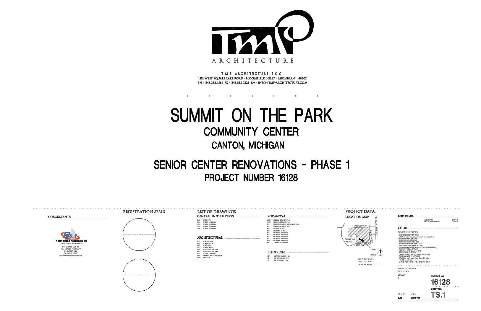
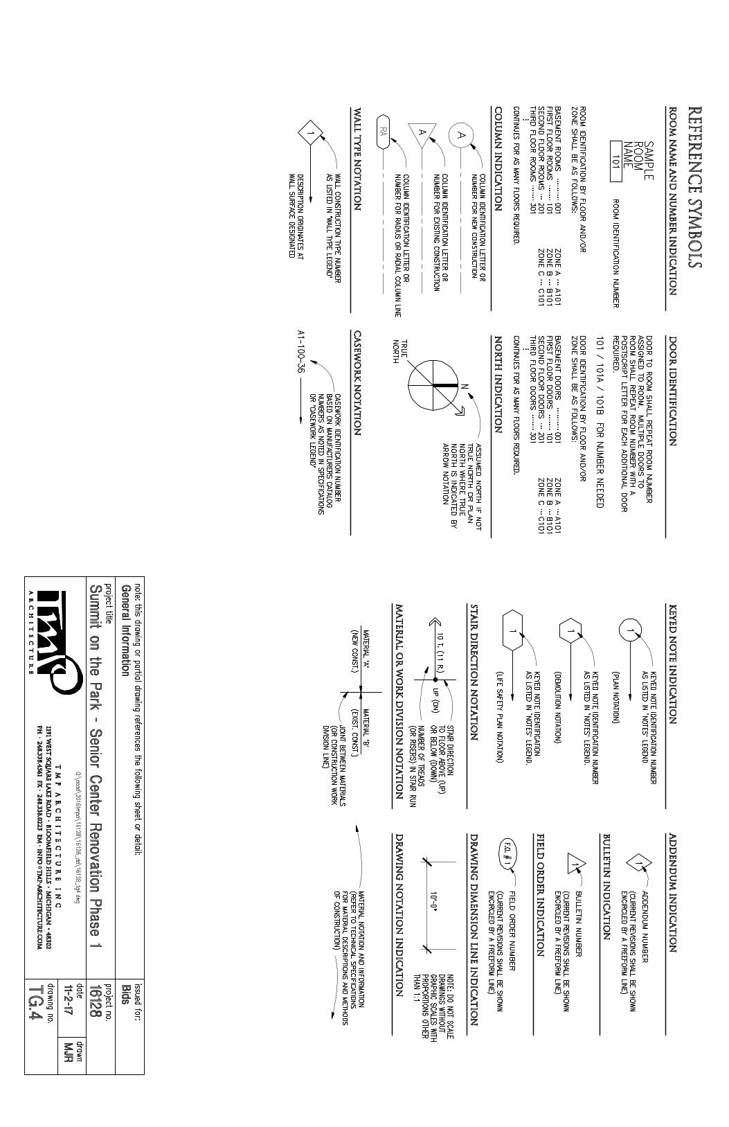

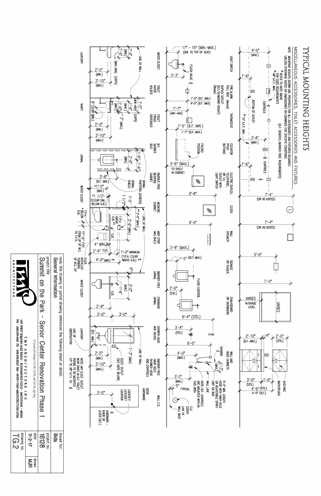


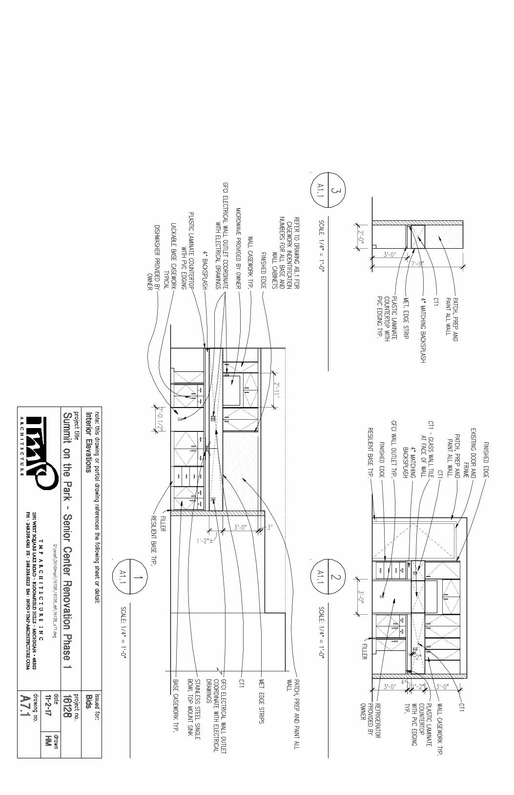
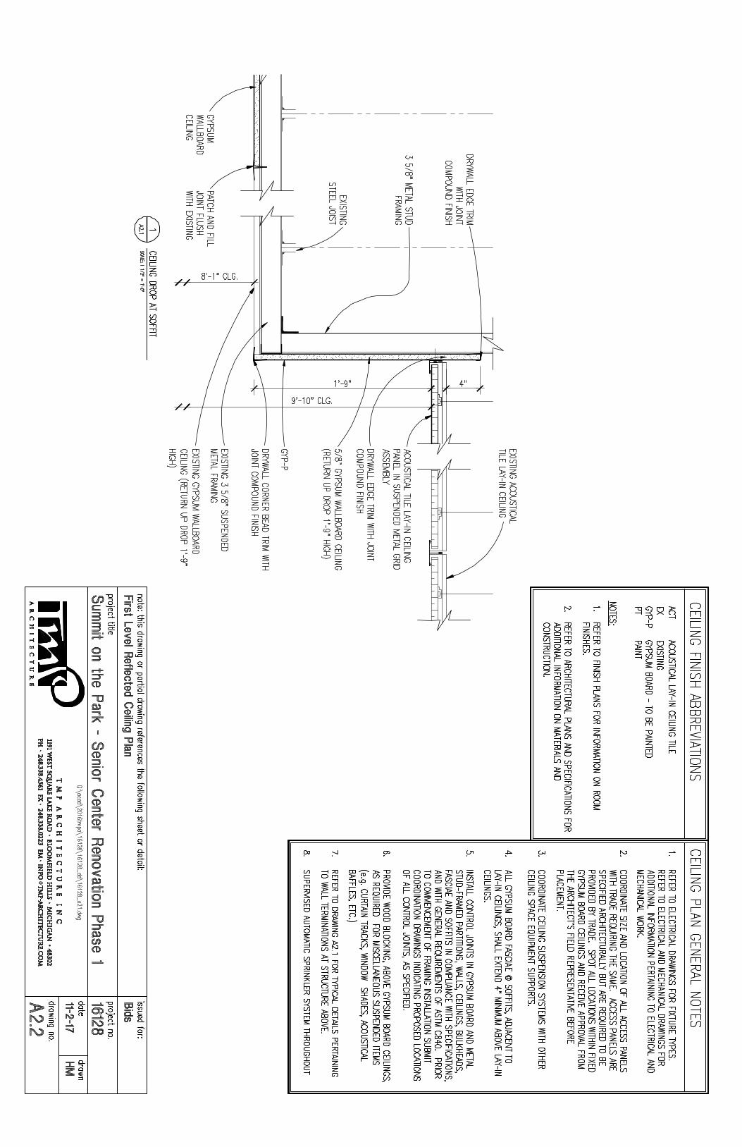

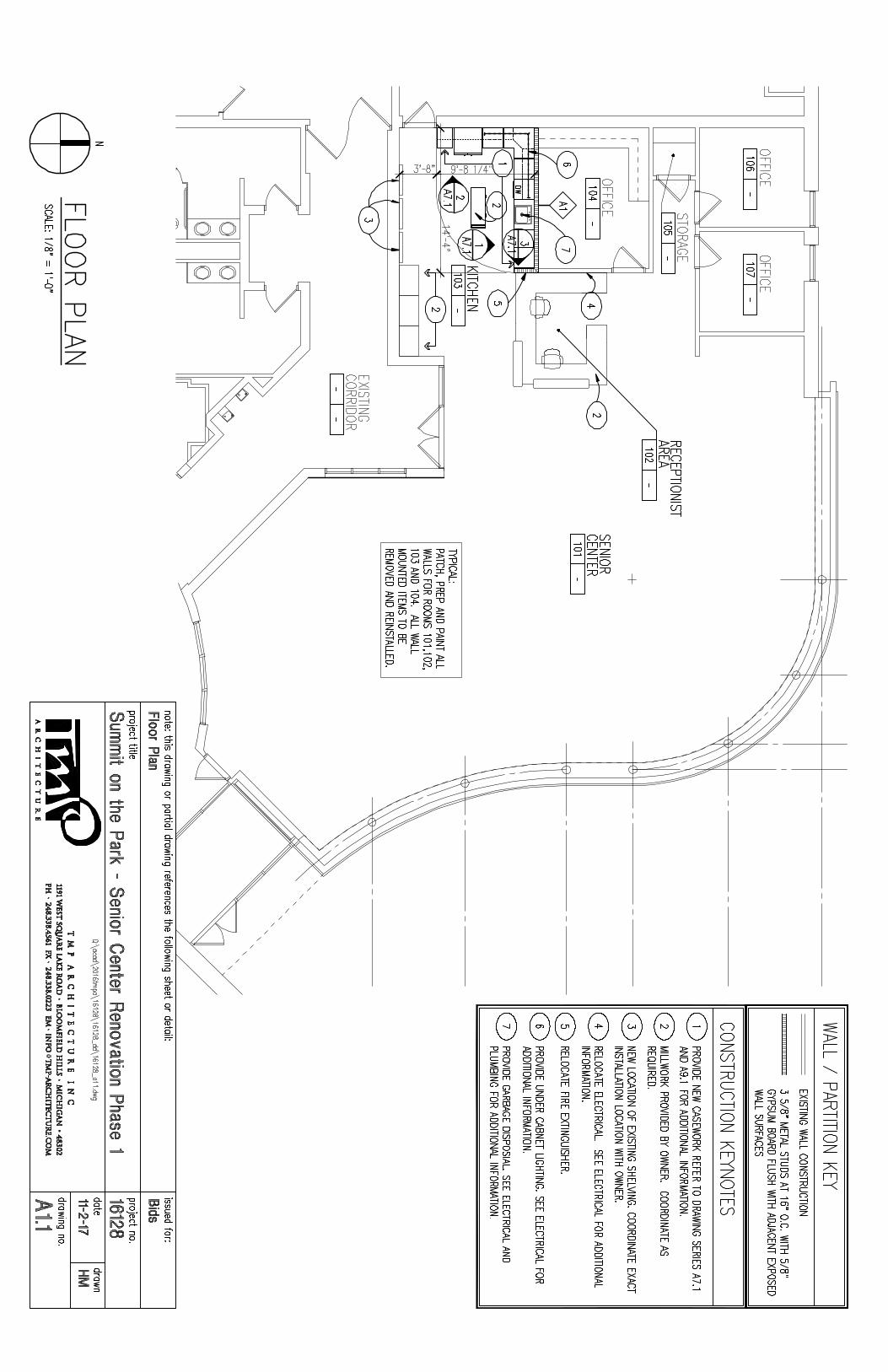
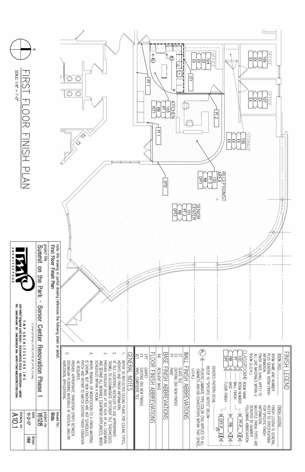
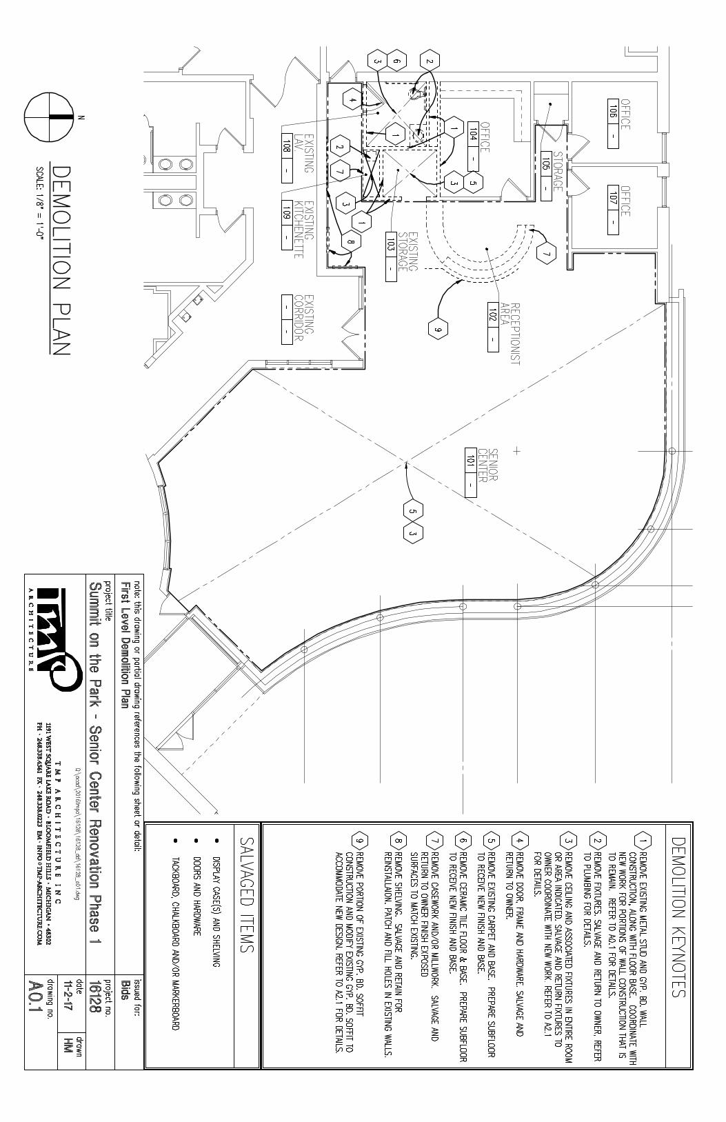
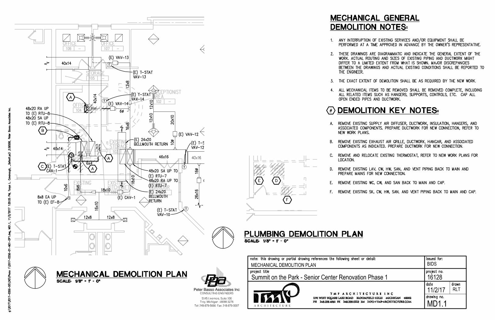
A R C H I T E C T U R E
BIDS
16128Summit on the Park - Senior Center Renovation Phase 1
Tel: 248-879-5666 Fax: 248-879-0007
Peter Basso Associates Inc
5145 Livernois, Suite 100
CONSULTING ENGINEERS
Troy, Michigan 48098-3276
11/2/17
MECHANICAL DEMOLITION PLAN
RLT
MD1.1
AutoCAD SHX Text
%%UDEMOLITION KEY NOTES:
AutoCAD SHX Text
#
AutoCAD SHX Text
A. REMOVE EXISTING SUPPLY AIR DIFFUSER, DUCTWORK, INSULATION, HANGERS, AND REMOVE EXISTING SUPPLY AIR DIFFUSER, DUCTWORK, INSULATION, HANGERS, AND ASSOCIATED COMPONENTS. PREPARE DUCTWORK FOR NEW CONNECTION, REFER TO NEW WORK PLANS. B. REMOVE EXISTING EXHAUST AIR GRILLE, DUCTWORK, HANGAR, AND ASSOCIATED REMOVE EXISTING EXHAUST AIR GRILLE, DUCTWORK, HANGAR, AND ASSOCIATED COMPONENTS AS INDICATED. PREPARE DUCTWORK FOR NEW CONNECTION. C. REMOVE AND RELOCATE EXISTING THERMOSTAT, REFER TO NEW WORK PLANS FOR REMOVE AND RELOCATE EXISTING THERMOSTAT, REFER TO NEW WORK PLANS FOR LOCATION. D. REMOVE EXISTING LAV, CW, HW, SAN, AND VENT PIPING BACK TO MAIN AND REMOVE EXISTING LAV, CW, HW, SAN, AND VENT PIPING BACK TO MAIN AND PREPARE MAINS FOR NEW CONNECTION. E. REMOVE EXISTING WC, CW, AND SAN BACK TO MAIN AND CAP. REMOVE EXISTING WC, CW, AND SAN BACK TO MAIN AND CAP. F. REMOVE EXISTING SK, CW, HW, SAN, AND VENT PIPING BACK TO MAIN AND CAP.REMOVE EXISTING SK, CW, HW, SAN, AND VENT PIPING BACK TO MAIN AND CAP.
AutoCAD SHX Text
1. ANY INTERRUPTION OF EXISTING SERVICES AND/OR EQUIPMENT SHALL BE ANY INTERRUPTION OF EXISTING SERVICES AND/OR EQUIPMENT SHALL BE PERFORMED AT A TIME APPROVED IN ADVANCE BY THE OWNER'S REPRESENTATIVE. 2. THESE DRAWINGS ARE DIAGRAMMATIC AND INDICATE THE GENERAL EXTENT OF THE THESE DRAWINGS ARE DIAGRAMMATIC AND INDICATE THE GENERAL EXTENT OF THE WORK. ACTUAL ROUTING AND SIZES OF EXISTING PIPING AND DUCTWORK MIGHT DIFFER TO A LIMITED EXTENT FROM WHAT IS SHOWN. MAJOR DISCREPANCIES BETWEEN THE DRAWINGS AND ACTUAL EXISTING CONDITIONS SHALL BE REPORTED TO THE ENGINEER. 3. THE EXACT EXTENT OF DEMOLITION SHALL BE AS REQUIRED BY THE NEW WORK. THE EXACT EXTENT OF DEMOLITION SHALL BE AS REQUIRED BY THE NEW WORK. 4. ALL MECHANICAL ITEMS TO BE REMOVED SHALL BE REMOVED COMPLETE, INCLUDING ALL MECHANICAL ITEMS TO BE REMOVED SHALL BE REMOVED COMPLETE, INCLUDING ALL RELATED ITEMS SUCH AS HANGERS, SUPPORTS, CONTROLS, ETC. CAP ALL OPEN ENDED PIPES AND DUCTWORK.
AutoCAD SHX Text
%%UDEMOLITION NOTES:
AutoCAD SHX Text
%%UMECHANICAL GENERAL
AutoCAD SHX Text
OFFICE
AutoCAD SHX Text
104
AutoCAD SHX Text
-
AutoCAD SHX Text
OFFICE
AutoCAD SHX Text
106
AutoCAD SHX Text
-
AutoCAD SHX Text
OFFICE
AutoCAD SHX Text
107
AutoCAD SHX Text
-
AutoCAD SHX Text
STORAGE
AutoCAD SHX Text
105
AutoCAD SHX Text
-
AutoCAD SHX Text
EXISTING
AutoCAD SHX Text
CORRIDOR
AutoCAD SHX Text
-
AutoCAD SHX Text
-
AutoCAD SHX Text
EXISTING
AutoCAD SHX Text
LAV.
AutoCAD SHX Text
108
AutoCAD SHX Text
-
AutoCAD SHX Text
EXISTING
AutoCAD SHX Text
STORAGE
AutoCAD SHX Text
103
AutoCAD SHX Text
-
AutoCAD SHX Text
EXISTING
AutoCAD SHX Text
KITCHENETTE
AutoCAD SHX Text
109
AutoCAD SHX Text
-
AutoCAD SHX Text
RECEPTIONIST
AutoCAD SHX Text
AREA
AutoCAD SHX Text
102
AutoCAD SHX Text
-
AutoCAD SHX Text
6x4
AutoCAD SHX Text
12x8
AutoCAD SHX Text
12x8
AutoCAD SHX Text
12x10
AutoCAD SHX Text
12x10
AutoCAD SHX Text
20x10
AutoCAD SHX Text
10
AutoCAD SHX Text
16
AutoCAD SHX Text
26x16
AutoCAD SHX Text
10x6
AutoCAD SHX Text
8x6
AutoCAD SHX Text
18x10
AutoCAD SHX Text
18x10
AutoCAD SHX Text
16x10
AutoCAD SHX Text
T
AutoCAD SHX Text
T
AutoCAD SHX Text
T
AutoCAD SHX Text
T
AutoCAD SHX Text
T
AutoCAD SHX Text
(E) T-STAT VAV-13
AutoCAD SHX Text
(E) T-STAT VAV-14
AutoCAD SHX Text
(E) T-STAT VAV-10
AutoCAD SHX Text
(E) T-STAT VAV-12
AutoCAD SHX Text
(E) T-STAT CAV-1
AutoCAD SHX Text
8x8 EA UP TO (E) EF-8
AutoCAD SHX Text
(E) VAV-11
AutoCAD SHX Text
(E) VAV-12
AutoCAD SHX Text
(E) VAV-14
AutoCAD SHX Text
(E) VAV-13
AutoCAD SHX Text
(E) CAV-1
AutoCAD SHX Text
16x8
AutoCAD SHX Text
12x8
AutoCAD SHX Text
48x20 SA UP TO (E) RTU-7 48x20 RA UP TO (E) RTU-7
AutoCAD SHX Text
48x20 RA UP TO (E) RTU-8 48x20 SA UP TO (E) RTU-8
AutoCAD SHX Text
6
AutoCAD SHX Text
A
AutoCAD SHX Text
B
AutoCAD SHX Text
A
AutoCAD SHX Text
A
AutoCAD SHX Text
C
AutoCAD SHX Text
(E) 24x20 BELLMOUTH RETURN
AutoCAD SHX Text
(E) 24x20 BELLMOUTH RETURN
AutoCAD SHX Text
D
AutoCAD SHX Text
E
AutoCAD SHX Text
F
AutoCAD SHX Text
SCALE: 1/8" = 1' - 0"
AutoCAD SHX Text
%%UMECHANICAL DEMOLITION PLAN
AutoCAD SHX Text
g:\2017\2017-0256-00\CAD\Phase 1\2017-0256-01-MD1-DP1.dwg, MD1.1, 11/2/2017 1:20:25 PM, Tonya L. Cavanaugh, _Default.pc3 ,0.56558, Peter Basso Associates Inc., MD1.1, 11/2/2017 1:20:25 PM, Tonya L. Cavanaugh, _Default.pc3 ,0.56558, Peter Basso Associates Inc.MD1.1, 11/2/2017 1:20:25 PM, Tonya L. Cavanaugh, _Default.pc3 ,0.56558, Peter Basso Associates Inc., 11/2/2017 1:20:25 PM, Tonya L. Cavanaugh, _Default.pc3 ,0.56558, Peter Basso Associates Inc.11/2/2017 1:20:25 PM, Tonya L. Cavanaugh, _Default.pc3 ,0.56558, Peter Basso Associates Inc., Tonya L. Cavanaugh, _Default.pc3 ,0.56558, Peter Basso Associates Inc.Tonya L. Cavanaugh, _Default.pc3 ,0.56558, Peter Basso Associates Inc., _Default.pc3 ,0.56558, Peter Basso Associates Inc._Default.pc3 ,0.56558, Peter Basso Associates Inc. ,0.56558, Peter Basso Associates Inc.0.56558, Peter Basso Associates Inc., Peter Basso Associates Inc.
AutoCAD SHX Text
issued for:
AutoCAD SHX Text
note: this drawing or partial drawing references the following sheet or detail:
AutoCAD SHX Text
project title
AutoCAD SHX Text
drawing no.
AutoCAD SHX Text
project no.
AutoCAD SHX Text
date
AutoCAD SHX Text
drawn
AutoCAD SHX Text
T M P A R C H I T E C T U R E I N C
AutoCAD SHX Text
PH 248.338.4561 FX 248.338.0223 EM INFO TMP-ARCHITECTURE.COM
AutoCAD SHX Text
@
AutoCAD SHX Text
1191 WEST SQUARE LAKE ROAD BLOOMFIELD HILLS MICHIGAN 48302
AutoCAD SHX Text
SCALE: 1/8" = 1' - 0"
AutoCAD SHX Text
%%UPLUMBING DEMOLITION PLAN
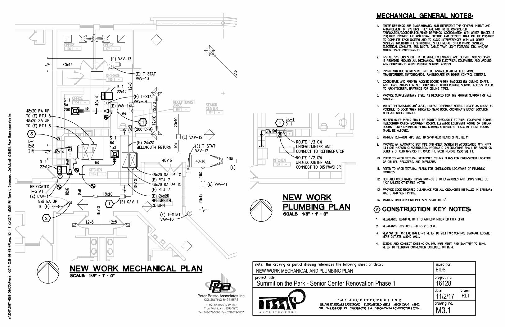
A R C H I T E C T U R E
BIDS
16128Summit on the Park - Senior Center Renovation Phase 1
Tel: 248-879-5666 Fax: 248-879-0007
Peter Basso Associates Inc
5145 Livernois, Suite 100
CONSULTING ENGINEERS
Troy, Michigan 48098-3276
11/2/17
NEW WORK MECHANICAL AND PLUMBING PLAN
RLT
M3.1
AutoCAD SHX Text
SENIOR
AutoCAD SHX Text
CENTER
AutoCAD SHX Text
101
AutoCAD SHX Text
-
AutoCAD SHX Text
OFFICE
AutoCAD SHX Text
104
AutoCAD SHX Text
-
AutoCAD SHX Text
OFFICE
AutoCAD SHX Text
106
AutoCAD SHX Text
-
AutoCAD SHX Text
OFFICE
AutoCAD SHX Text
107
AutoCAD SHX Text
-
AutoCAD SHX Text
STORAGE
AutoCAD SHX Text
105
AutoCAD SHX Text
-
AutoCAD SHX Text
KITCHEN
AutoCAD SHX Text
103
AutoCAD SHX Text
-
AutoCAD SHX Text
EXISTING
AutoCAD SHX Text
CORRIDOR
AutoCAD SHX Text
-
AutoCAD SHX Text
-
AutoCAD SHX Text
RECEPTIONIST
AutoCAD SHX Text
AREA
AutoCAD SHX Text
101
AutoCAD SHX Text
-
AutoCAD SHX Text
DW
AutoCAD SHX Text
12x8
AutoCAD SHX Text
12x8
AutoCAD SHX Text
12x10
AutoCAD SHX Text
12x10
AutoCAD SHX Text
12x10
AutoCAD SHX Text
20x10
AutoCAD SHX Text
10
AutoCAD SHX Text
16
AutoCAD SHX Text
26x16
AutoCAD SHX Text
10x6
AutoCAD SHX Text
8x6
AutoCAD SHX Text
18x10
AutoCAD SHX Text
18x10
AutoCAD SHX Text
16x10
AutoCAD SHX Text
T
AutoCAD SHX Text
T
AutoCAD SHX Text
T
AutoCAD SHX Text
T
AutoCAD SHX Text
(E) T-STAT VAV-13
AutoCAD SHX Text
(E) T-STAT VAV-14
AutoCAD SHX Text
(E) T-STAT VAV-10
AutoCAD SHX Text
(E) T-STAT VAV-12
AutoCAD SHX Text
8x8 EA UP TO (E) EF-8
AutoCAD SHX Text
16
AutoCAD SHX Text
(E) VAV-11
AutoCAD SHX Text
(E) VAV-10
AutoCAD SHX Text
(E) VAV-12
AutoCAD SHX Text
(E) VAV-14
AutoCAD SHX Text
(E) VAV-13
AutoCAD SHX Text
(E) CAV-1
AutoCAD SHX Text
16x8
AutoCAD SHX Text
12x8
AutoCAD SHX Text
48x20 SA UP TO (E) RTU-7 48x20 RA UP TO (E) RTU-7
AutoCAD SHX Text
48x20 RA UP TO (E) RTU-8 48x20 SA UP TO (E) RTU-8
AutoCAD SHX Text
6
AutoCAD SHX Text
(E) 24x20 BELLMOUTH RETURN
AutoCAD SHX Text
(E) 24x20 BELLMOUTH RETURN
AutoCAD SHX Text
S-1
AutoCAD SHX Text
8%%C
AutoCAD SHX Text
200
AutoCAD SHX Text
R-1
AutoCAD SHX Text
22x12
AutoCAD SHX Text
E-1
AutoCAD SHX Text
8x8
AutoCAD SHX Text
215
AutoCAD SHX Text
S-1
AutoCAD SHX Text
6%%C
AutoCAD SHX Text
150
AutoCAD SHX Text
T
AutoCAD SHX Text
RELOCATED T-STAT (E) CAV-1
AutoCAD SHX Text
2
AutoCAD SHX Text
1
AutoCAD SHX Text
1
AutoCAD SHX Text
R-1
AutoCAD SHX Text
22x12
AutoCAD SHX Text
3
AutoCAD SHX Text
8
AutoCAD SHX Text
6
AutoCAD SHX Text
8x8
AutoCAD SHX Text
(200 CFM)
AutoCAD SHX Text
%%UCONSTRUCTION KEY NOTES:
AutoCAD SHX Text
#
AutoCAD SHX Text
1. REBALANCE TERMINAL UNIT TO AIRFLOW INDICATED (XXX CFM). REBALANCE TERMINAL UNIT TO AIRFLOW INDICATED (XXX CFM). 2. REBALANCE EXISTING EF-8 TO 215 CFM. REBALANCE EXISTING EF-8 TO 215 CFM. 3. NEW SWITCH FOR EXISTING EF-8 REFER TO M8.1 FOR CONTROL DIAGRAM. LOCATE NEW SWITCH FOR EXISTING EF-8 REFER TO M8.1 FOR CONTROL DIAGRAM. LOCATE NEAR OUTLETS ALONG WALL. 4. EXTEND AND CONNECT EXISTING CW, HW, HWR, VENT, AND SANITARY TO SK-1. EXTEND AND CONNECT EXISTING CW, HW, HWR, VENT, AND SANITARY TO SK-1. REFER TO PLUMBING CONNECTION SCHEDULE ON M7.4.
AutoCAD SHX Text
1. THESE DRAWINGS ARE DIAGRAMMATIC, AND REPRESENT THE GENERAL INTENT AND THESE DRAWINGS ARE DIAGRAMMATIC, AND REPRESENT THE GENERAL INTENT AND ARRANGEMENT OF SYSTEMS. THEY ARE NOT TO BE CONSIDERED FABRICATION/COORDINATION/SHOP DRAWINGS. COORDINATION WITH OTHER TRADES IS REQUIRED. PROVIDE THE ADDITIONAL FITTINGS AND OFFSETS THAT WILL BE REQUIRED TO COMPLETE EACH SYSTEM AND TO AVOID INTERFERENCES WITH ALL OTHER SYSTEMS INCLUDING THE STRUCTURE, SHEET METAL, OTHER PIPING SYSTEMS, ELECTRICAL CONDUITS, BUS DUCTS, CABLE TRAY, LIGHT FIXTURES, ETC. AND/OR OTHER SPACE CONSTRAINTS. 2. INSTALL SYSTEMS SUCH THAT REQUIRED CLEARANCE AND SERVICE ACCESS SPACE INSTALL SYSTEMS SUCH THAT REQUIRED CLEARANCE AND SERVICE ACCESS SPACE IS PROVIDED AROUND ALL MECHANICAL AND ELECTRICAL EQUIPMENT, AND AROUND ANY COMPONENTS WHICH REQUIRE SERVICE ACCESS. 3. PIPING AND DUCTWORK SHALL NOT BE INSTALLED ABOVE ELECTRICAL PIPING AND DUCTWORK SHALL NOT BE INSTALLED ABOVE ELECTRICAL TRANSFORMERS, SWITCHBOARDS, PANELBOARDS OR MOTOR CONTROL CENTERS. 4. COORDINATE AND PROVIDE ACCESS DOORS WITHIN INACCESSIBLE CEILING, SHAFT, COORDINATE AND PROVIDE ACCESS DOORS WITHIN INACCESSIBLE CEILING, SHAFT, AND CHASE AREAS FOR ALL COMPONENTS WHICH REQUIRE SERVICE ACCESS. REFER TO ARCHITECTURAL DRAWINGS FOR CEILING TYPES. 5. PROVIDE SUPPLEMENTARY STEEL AS REQUIRED FOR THE PROPER SUPPORT OF ALL PROVIDE SUPPLEMENTARY STEEL AS REQUIRED FOR THE PROPER SUPPORT OF ALL SYSTEMS. 6. MOUNT THERMOSTATS 48" A.F.F., UNLESS OTHERWISE NOTED. LOCATE AS CLOSE AS MOUNT THERMOSTATS 48" A.F.F., UNLESS OTHERWISE NOTED. LOCATE AS CLOSE AS POSSIBLE TO DOOR WHEN INDICATED NEAR DOOR. COORDINATE EXACT LOCATION WITH ALL OTHER TRADES. 7. NO SPRINKLER PIPING SHALL BE ROUTED THROUGH ELECTRICAL EQUIPMENT ROOMS, NO SPRINKLER PIPING SHALL BE ROUTED THROUGH ELECTRICAL EQUIPMENT ROOMS, TELECOMMUNICATION EQUIPMENT ROOMS, ELEVATOR EQUIPMENT ROOMS OR SIMILAR ROOMS. ONLY SPRINKLER PIPING SERVING SPRINKLERS HEADS IN THOSE ROOMS SHALL BE ALLOWED. 8. MINIMUM RUN-OUT PIPE SIZE TO SPRINKLER HEADS SHALL BE 1". MINIMUM RUN-OUT PIPE SIZE TO SPRINKLER HEADS SHALL BE 1". 9. PROVIDE AN AUTOMATIC WET PIPE SPRINKLER SYSTEM IN ACCORDANCE WITH NFPA PROVIDE AN AUTOMATIC WET PIPE SPRINKLER SYSTEM IN ACCORDANCE WITH NFPA VIDE AN AUTOMATIC WET PIPE SPRINKLER SYSTEM IN ACCORDANCE WITH NFPA AN AUTOMATIC WET PIPE SPRINKLER SYSTEM IN ACCORDANCE WITH NFPA 13 LIGHT HAZARD CLASSIFICATION. HYDRAULIC CALCULATIONS SHALL BE BASED ON DENSITY OF 0.10 GPM/SQ FT. OVER THE MOST REMOTE 1500 SQ. FT. 10. REFER TO ARCHITECTURAL REFLECTED CEILING PLANS FOR DIMENSIONED LOCATION REFER TO ARCHITECTURAL REFLECTED CEILING PLANS FOR DIMENSIONED LOCATION OF GRILLES, REGISTERS, AND DIFFUSERS. 11. REFER TO ARCHITECTURAL PLANS FOR DIMENSIONED LOCATIONS OF PLUMBING REFER TO ARCHITECTURAL PLANS FOR DIMENSIONED LOCATIONS OF PLUMBING FIXTURES. 12. HOT AND COLD WATER PIPING RUN-OUTS TO LAVATORIES AND SINKS SHALL BE HOT AND COLD WATER PIPING RUN-OUTS TO LAVATORIES AND SINKS SHALL BE 1/2" UNLESS OTHERWISE NOTED. 13. PROVIDE CODE REQUIRED CLEARANCE FOR ALL CLEANOUTS INSTALLED IN SANITARY PROVIDE CODE REQUIRED CLEARANCE FOR ALL CLEANOUTS INSTALLED IN SANITARY WASTE AND VENT PIPING. 14. MINIMUM UNDERGROUND PIPE SIZE SHALL BE 3".MINIMUM UNDERGROUND PIPE SIZE SHALL BE 3".
AutoCAD SHX Text
%%UMECHANCIAL GENERAL NOTES:
AutoCAD SHX Text
DW
AutoCAD SHX Text
CW
AutoCAD SHX Text
ROUTE 1/2 CW UNDERCOUNTER AND CONNECT TO DISHWASHER
AutoCAD SHX Text
SK-1 D-1
AutoCAD SHX Text
ROUTE 1/2 CW UNDERCOUNTER AND CONNECT TO REFRIGERATOR
AutoCAD SHX Text
4
AutoCAD SHX Text
KITCHEN
AutoCAD SHX Text
103
AutoCAD SHX Text
-
AutoCAD SHX Text
SCALE: 1/8" = 1' - 0"
AutoCAD SHX Text
%%UNEW WORK MECHANICAL PLAN
AutoCAD SHX Text
g:\2017\2017-0256-00\CAD\Phase 1\2017-0256-01-M3-HP1.dwg, M3.1, 11/2/2017 1:20:34 PM, Tonya L. Cavanaugh, _Default.pc3 ,0.56558, Peter Basso Associates Inc., M3.1, 11/2/2017 1:20:34 PM, Tonya L. Cavanaugh, _Default.pc3 ,0.56558, Peter Basso Associates Inc.M3.1, 11/2/2017 1:20:34 PM, Tonya L. Cavanaugh, _Default.pc3 ,0.56558, Peter Basso Associates Inc., 11/2/2017 1:20:34 PM, Tonya L. Cavanaugh, _Default.pc3 ,0.56558, Peter Basso Associates Inc.11/2/2017 1:20:34 PM, Tonya L. Cavanaugh, _Default.pc3 ,0.56558, Peter Basso Associates Inc., Tonya L. Cavanaugh, _Default.pc3 ,0.56558, Peter Basso Associates Inc.Tonya L. Cavanaugh, _Default.pc3 ,0.56558, Peter Basso Associates Inc., _Default.pc3 ,0.56558, Peter Basso Associates Inc._Default.pc3 ,0.56558, Peter Basso Associates Inc. ,0.56558, Peter Basso Associates Inc.0.56558, Peter Basso Associates Inc., Peter Basso Associates Inc.
AutoCAD SHX Text
issued for:
AutoCAD SHX Text
note: this drawing or partial drawing references the following sheet or detail:
AutoCAD SHX Text
project title
AutoCAD SHX Text
drawing no.
AutoCAD SHX Text
project no.
AutoCAD SHX Text
date
AutoCAD SHX Text
drawn
AutoCAD SHX Text
T M P A R C H I T E C T U R E I N C
AutoCAD SHX Text
PH 248.338.4561 FX 248.338.0223 EM INFO TMP-ARCHITECTURE.COM
AutoCAD SHX Text
@
AutoCAD SHX Text
1191 WEST SQUARE LAKE ROAD BLOOMFIELD HILLS MICHIGAN 48302
AutoCAD SHX Text
SCALE: 1/8" = 1' - 0"
AutoCAD SHX Text
%%uNEW WORK
AutoCAD SHX Text
%%UPLUMBING PLAN
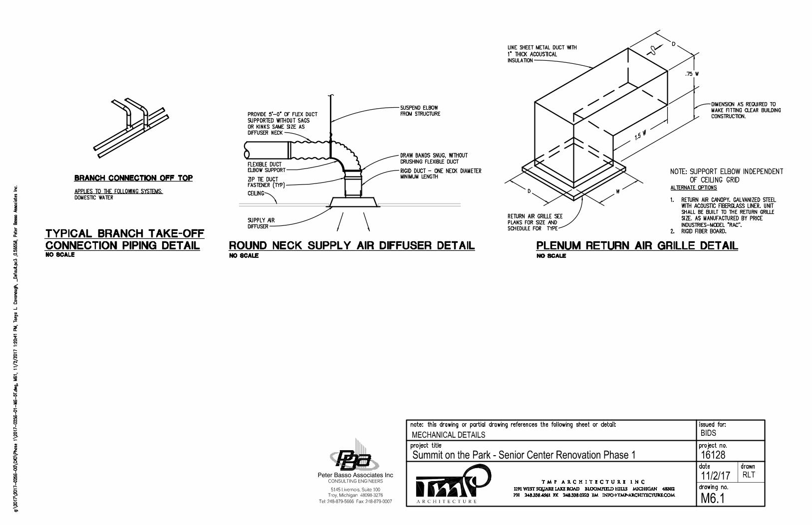
A R C H I T E C T U R E
BIDS
16128Summit on the Park - Senior Center Renovation Phase 1
Tel: 248-879-5666 Fax: 248-879-0007
Peter Basso Associates Inc
5145 Livernois, Suite 100
CONSULTING ENGINEERS
Troy, Michigan 48098-3276
11/2/17
MECHANICAL DETAILS
RLT
M6.1
AutoCAD SHX Text
DOMESTIC WATER
AutoCAD SHX Text
%%UBRANCH CONNECTION OFF TOP
AutoCAD SHX Text
%%UCONNECTION PIPING DETAIL
AutoCAD SHX Text
%%UTYPICAL BRANCH TAKE-OFF
AutoCAD SHX Text
%%UAPPLIES TO THE FOLLOWING SYSTEMS:
AutoCAD SHX Text
NO SCALE
AutoCAD SHX Text
%%UROUND NECK SUPPLY AIR DIFFUSER DETAIL
AutoCAD SHX Text
NO SCALE
AutoCAD SHX Text
DIFFUSER
AutoCAD SHX Text
SUPPLY AIR
AutoCAD SHX Text
RIGID DUCT - ONE NECK DIAMETER
AutoCAD SHX Text
FLEXIBLE DUCT
AutoCAD SHX Text
ELBOW SUPPORT
AutoCAD SHX Text
DRAW BANDS SNUG, WITHOUT
AutoCAD SHX Text
CRUSHING FLEXIBLE DUCT
AutoCAD SHX Text
ZIP TIE DUCT
AutoCAD SHX Text
FASTENER (TYP)
AutoCAD SHX Text
CEILING
AutoCAD SHX Text
MINIMUM LENGTH
AutoCAD SHX Text
PROVIDE 5'-0" OF FLEX DUCT SUPPORTED WITHOUT SAGS OR KINKS SAME SIZE AS DIFFUSER NECK
AutoCAD SHX Text
SUSPEND ELBOW FROM STRUCTURE
AutoCAD SHX Text
%%UPLENUM RETURN AIR GRILLE DETAIL
AutoCAD SHX Text
NO SCALE
AutoCAD SHX Text
D
AutoCAD SHX Text
W
AutoCAD SHX Text
1.5 W
AutoCAD SHX Text
.75 W
AutoCAD SHX Text
D
AutoCAD SHX Text
RETURN AIR GRILLE SEE PLANS FOR SIZE AND SCHEDULE FOR TYPE
AutoCAD SHX Text
DIMENSION AS REQUIRED TO MAKE FITTING CLEAR BUILDING CONSTRUCTION.
AutoCAD SHX Text
LINE SHEET METAL DUCT WITH 1" THICK ACOUSTICAL INSULATION
AutoCAD SHX Text
NOTE: SUPPORT ELBOW INDEPENDENT SUPPORT ELBOW INDEPENDENT OF CEILING GRID
AutoCAD SHX Text
ALTERNATE OPTIONS 1. RETURN AIR CANOPY. GALVANIZED STEEL RETURN AIR CANOPY. GALVANIZED STEEL WITH ACOUSTIC FIBERGLASS LINER. UNIT SHALL BE BUILT TO THE RETURN GRILLE SIZE. AS MANUFACTURED BY PRICE INDUSTRIES-MODEL "RAC". 2. RIGID FIBER BOARD.RIGID FIBER BOARD.
AutoCAD SHX Text
g:\2017\2017-0256-00\CAD\Phase 1\2017-0256-01-M6-DT.dwg, M61, 11/2/2017 1:20:41 PM, Tonya L. Cavanaugh, _Default.pc3 ,0.56558, Peter Basso Associates Inc., M61, 11/2/2017 1:20:41 PM, Tonya L. Cavanaugh, _Default.pc3 ,0.56558, Peter Basso Associates Inc.M61, 11/2/2017 1:20:41 PM, Tonya L. Cavanaugh, _Default.pc3 ,0.56558, Peter Basso Associates Inc., 11/2/2017 1:20:41 PM, Tonya L. Cavanaugh, _Default.pc3 ,0.56558, Peter Basso Associates Inc.11/2/2017 1:20:41 PM, Tonya L. Cavanaugh, _Default.pc3 ,0.56558, Peter Basso Associates Inc., Tonya L. Cavanaugh, _Default.pc3 ,0.56558, Peter Basso Associates Inc.Tonya L. Cavanaugh, _Default.pc3 ,0.56558, Peter Basso Associates Inc., _Default.pc3 ,0.56558, Peter Basso Associates Inc._Default.pc3 ,0.56558, Peter Basso Associates Inc. ,0.56558, Peter Basso Associates Inc.0.56558, Peter Basso Associates Inc., Peter Basso Associates Inc.
AutoCAD SHX Text
issued for:
AutoCAD SHX Text
note: this drawing or partial drawing references the following sheet or detail:
AutoCAD SHX Text
project title
AutoCAD SHX Text
drawing no.
AutoCAD SHX Text
project no.
AutoCAD SHX Text
date
AutoCAD SHX Text
drawn
AutoCAD SHX Text
T M P A R C H I T E C T U R E I N C
AutoCAD SHX Text
PH 248.338.4561 FX 248.338.0223 EM INFO TMP-ARCHITECTURE.COM
AutoCAD SHX Text
@
AutoCAD SHX Text
1191 WEST SQUARE LAKE ROAD BLOOMFIELD HILLS MICHIGAN 48302
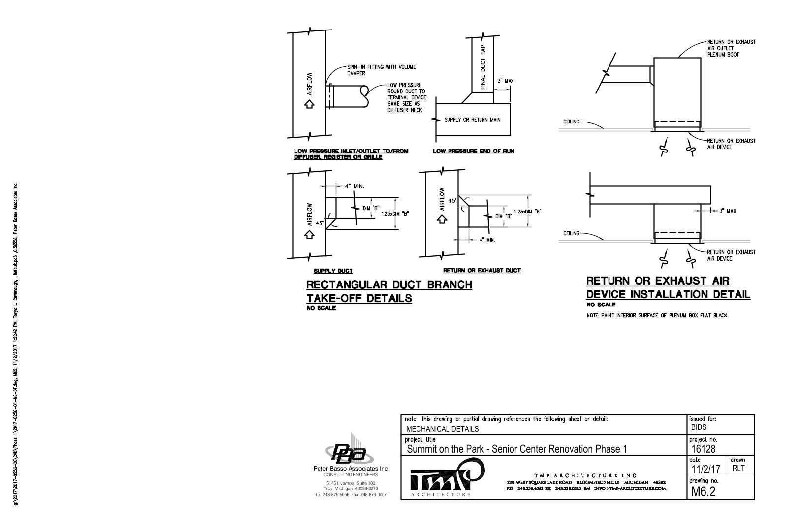
A R C H I T E C T U R E
BIDS
16128Summit on the Park - Senior Center Renovation Phase 1
Tel: 248-879-5666 Fax: 248-879-0007
Peter Basso Associates Inc
5145 Livernois, Suite 100
CONSULTING ENGINEERS
Troy, Michigan 48098-3276
11/2/17
MECHANICAL DETAILS
RLT
M6.2
AutoCAD SHX Text
NO SCALE
AutoCAD SHX Text
%%UDEVICE INSTALLATION DETAIL
AutoCAD SHX Text
CEILING
AutoCAD SHX Text
AIR DEVICE
AutoCAD SHX Text
RETURN OR EXHAUST
AutoCAD SHX Text
PLENUM BOOT
AutoCAD SHX Text
AIR OUTLET
AutoCAD SHX Text
RETURN OR EXHAUST
AutoCAD SHX Text
CEILING
AutoCAD SHX Text
AIR DEVICE
AutoCAD SHX Text
RETURN OR EXHAUST
AutoCAD SHX Text
3" MAX
AutoCAD SHX Text
NOTE:PAINT INTERIOR SURFACE OF PLENUM BOX FLAT BLACK.PAINT INTERIOR SURFACE OF PLENUM BOX FLAT BLACK.
AutoCAD SHX Text
1.25xDIM "B"
AutoCAD SHX Text
%%UTAKE-OFF DETAILS
AutoCAD SHX Text
%%USUPPLY DUCT
AutoCAD SHX Text
NO SCALE
AutoCAD SHX Text
AIRFLOW
AutoCAD SHX Text
45%%d
AutoCAD SHX Text
4" MIN.
AutoCAD SHX Text
DIM "B"
AutoCAD SHX Text
DIM "B"
AutoCAD SHX Text
%%URETURN OR EXHAUST DUCT
AutoCAD SHX Text
4" MIN.
AutoCAD SHX Text
AIRFLOW
AutoCAD SHX Text
45%%d
AutoCAD SHX Text
1.25xDIM "B"
AutoCAD SHX Text
DAMPER
AutoCAD SHX Text
%%ULOW PRESSURE INLET/OUTLET TO/FROM
AutoCAD SHX Text
AIRFLOW
AutoCAD SHX Text
SPIN-IN FITTING WITH VOLUME
AutoCAD SHX Text
DIFFUSER NECK
AutoCAD SHX Text
SAME SIZE AS
AutoCAD SHX Text
TERMINAL DEVICE
AutoCAD SHX Text
ROUND DUCT TO
AutoCAD SHX Text
LOW PRESSURE
AutoCAD SHX Text
%%UDIFFUSER, REGISTER OR GRILLE
AutoCAD SHX Text
3" MAX
AutoCAD SHX Text
%%ULOW PRESSURE END OF RUN
AutoCAD SHX Text
SUPPLY OR RETURN MAIN
AutoCAD SHX Text
FINAL DUCT TAP
AutoCAD SHX Text
%%URECTANGULAR DUCT BRANCH
AutoCAD SHX Text
%%URETURN OR EXHAUST AIR
AutoCAD SHX Text
g:\2017\2017-0256-00\CAD\Phase 1\2017-0256-01-M6-DT.dwg, M62, 11/2/2017 1:20:42 PM, Tonya L. Cavanaugh, _Default.pc3 ,0.56558, Peter Basso Associates Inc., M62, 11/2/2017 1:20:42 PM, Tonya L. Cavanaugh, _Default.pc3 ,0.56558, Peter Basso Associates Inc.M62, 11/2/2017 1:20:42 PM, Tonya L. Cavanaugh, _Default.pc3 ,0.56558, Peter Basso Associates Inc., 11/2/2017 1:20:42 PM, Tonya L. Cavanaugh, _Default.pc3 ,0.56558, Peter Basso Associates Inc.11/2/2017 1:20:42 PM, Tonya L. Cavanaugh, _Default.pc3 ,0.56558, Peter Basso Associates Inc., Tonya L. Cavanaugh, _Default.pc3 ,0.56558, Peter Basso Associates Inc.Tonya L. Cavanaugh, _Default.pc3 ,0.56558, Peter Basso Associates Inc., _Default.pc3 ,0.56558, Peter Basso Associates Inc._Default.pc3 ,0.56558, Peter Basso Associates Inc. ,0.56558, Peter Basso Associates Inc.0.56558, Peter Basso Associates Inc., Peter Basso Associates Inc.
AutoCAD SHX Text
issued for:
AutoCAD SHX Text
note: this drawing or partial drawing references the following sheet or detail:
AutoCAD SHX Text
project title
AutoCAD SHX Text
drawing no.
AutoCAD SHX Text
project no.
AutoCAD SHX Text
date
AutoCAD SHX Text
drawn
AutoCAD SHX Text
T M P A R C H I T E C T U R E I N C
AutoCAD SHX Text
PH 248.338.4561 FX 248.338.0223 EM INFO TMP-ARCHITECTURE.COM
AutoCAD SHX Text
@
AutoCAD SHX Text
1191 WEST SQUARE LAKE ROAD BLOOMFIELD HILLS MICHIGAN 48302
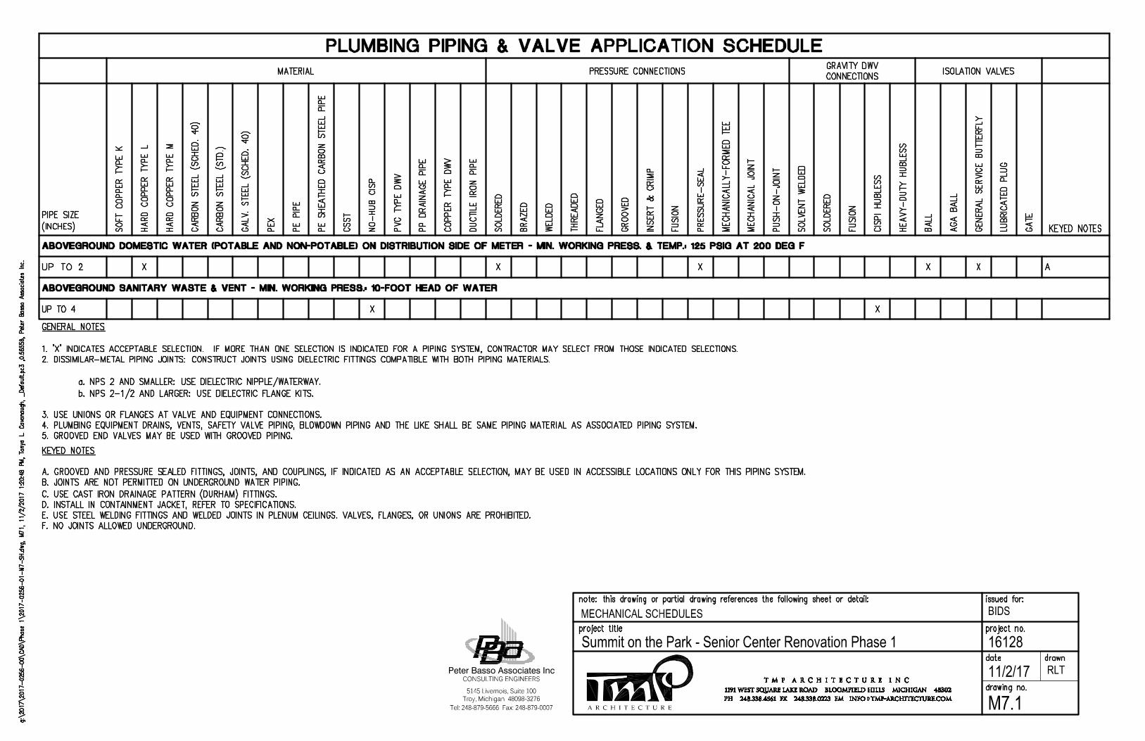
A R C H I T E C T U R E
BIDS
16128Summit on the Park - Senior Center Renovation Phase 1
Tel: 248-879-5666 Fax: 248-879-0007
Peter Basso Associates Inc
5145 Livernois, Suite 100
CONSULTING ENGINEERS
Troy, Michigan 48098-3276
11/2/17
MECHANICAL SCHEDULES
RLT
M7.1
AutoCAD SHX Text
PLUMBING PIPING & VALVE APPLICATION SCHEDULE
AutoCAD SHX Text
MATERIAL
AutoCAD SHX Text
PRESSURE CONNECTIONS
AutoCAD SHX Text
GRAVITY DWV CONNECTIONS
AutoCAD SHX Text
ISOLATION VALVES
AutoCAD SHX Text
PIPE SIZE (INCHES)
AutoCAD SHX Text
SOFT COPPER TYPE K
AutoCAD SHX Text
HARD COPPER TYPE L
AutoCAD SHX Text
HARD COPPER TYPE M
AutoCAD SHX Text
CARBON STEEL (SCHED. 40)
AutoCAD SHX Text
CARBON STEEL (STD.)
AutoCAD SHX Text
GALV. STEEL (SCHED. 40)
AutoCAD SHX Text
PEX
AutoCAD SHX Text
PE PIPE
AutoCAD SHX Text
PE SHEATHED CARBON STEEL PIPE
AutoCAD SHX Text
CSST
AutoCAD SHX Text
NO-HUB CISP
AutoCAD SHX Text
PVC TYPE DWV
AutoCAD SHX Text
PP DRAINAGE PIPE
AutoCAD SHX Text
COPPER TYPE DWV
AutoCAD SHX Text
DUCTILE IRON PIPE
AutoCAD SHX Text
SOLDERED
AutoCAD SHX Text
BRAZED
AutoCAD SHX Text
WELDED
AutoCAD SHX Text
THREADED
AutoCAD SHX Text
FLANGED
AutoCAD SHX Text
GROOVED
AutoCAD SHX Text
INSERT & CRIMP
AutoCAD SHX Text
FUSION
AutoCAD SHX Text
PRESSURE-SEAL
AutoCAD SHX Text
MECHANICALLY-FORMED TEE
AutoCAD SHX Text
MECHANICAL JOINT
AutoCAD SHX Text
PUSH-ON-JOINT
AutoCAD SHX Text
SOLVENT WELDED
AutoCAD SHX Text
SOLDERED
AutoCAD SHX Text
FUSION
AutoCAD SHX Text
CISPI HUBLESS
AutoCAD SHX Text
HEAVY-DUTY HUBLESS
AutoCAD SHX Text
BALL
AutoCAD SHX Text
AGA BALL
AutoCAD SHX Text
GENERAL SERVICE BUTTERFLY
AutoCAD SHX Text
LUBRICATED PLUG
AutoCAD SHX Text
GATE
AutoCAD SHX Text
KEYED NOTES
AutoCAD SHX Text
ABOVEGROUND DOMESTIC WATER (POTABLE AND NON-POTABLE) ON DISTRIBUTION SIDE OF METER - MIN. WORKING PRESS. & TEMP.: 125 PSIG AT 200 DEG F
AutoCAD SHX Text
UP TO 22
AutoCAD SHX Text
X
AutoCAD SHX Text
X
AutoCAD SHX Text
X
AutoCAD SHX Text
X
AutoCAD SHX Text
X
AutoCAD SHX Text
A
AutoCAD SHX Text
ABOVEGROUND SANITARY WASTE & VENT - MIN. WORKING PRESS.: 10-FOOT HEAD OF WATER
AutoCAD SHX Text
UP TO 4
AutoCAD SHX Text
X
AutoCAD SHX Text
X
AutoCAD SHX Text
GENERAL NOTES 1. 'X' INDICATES ACCEPTABLE SELECTION. IF MORE THAN ONE SELECTION IS INDICATED FOR A PIPING SYSTEM, CONTRACTOR MAY SELECT FROM THOSE INDICATED SELECTIONS. 2. DISSIMILAR-METAL PIPING JOINTS: CONSTRUCT JOINTS USING DIELECTRIC FITTINGS COMPATIBLE WITH BOTH PIPING MATERIALS. a. NPS 2 AND SMALLER: USE DIELECTRIC NIPPLE/WATERWAY. b. NPS 2-1/2 AND LARGER: USE DIELECTRIC FLANGE KITS. 3. USE UNIONS OR FLANGES AT VALVE AND EQUIPMENT CONNECTIONS. 4. PLUMBING EQUIPMENT DRAINS, VENTS, SAFETY VALVE PIPING, BLOWDOWN PIPING AND THE LIKE SHALL BE SAME PIPING MATERIAL AS ASSOCIATED PIPING SYSTEM. 5. GROOVED END VALVES MAY BE USED WITH GROOVED PIPING.
AutoCAD SHX Text
KEYED NOTES A. GROOVED AND PRESSURE SEALED FITTINGS, JOINTS, AND COUPLINGS, IF INDICATED AS AN ACCEPTABLE SELECTION, MAY BE USED IN ACCESSIBLE LOCATIONS ONLY FOR THIS PIPING SYSTEM. B. JOINTS ARE NOT PERMITTED ON UNDERGROUND WATER PIPING. C. USE CAST IRON DRAINAGE PATTERN (DURHAM) FITTINGS. D. INSTALL IN CONTAINMENT JACKET, REFER TO SPECIFICATIONS. E. USE STEEL WELDING FITTINGS AND WELDED JOINTS IN PLENUM CEILINGS. VALVES, FLANGES, OR UNIONS ARE PROHIBITED. F. NO JOINTS ALLOWED UNDERGROUND.
AutoCAD SHX Text
g:\2017\2017-0256-00\CAD\Phase 1\2017-0256-01-M7-SH.dwg, M71, 11/2/2017 1:20:48 PM, Tonya L. Cavanaugh, _Default.pc3 ,0.56558, Peter Basso Associates Inc., M71, 11/2/2017 1:20:48 PM, Tonya L. Cavanaugh, _Default.pc3 ,0.56558, Peter Basso Associates Inc.M71, 11/2/2017 1:20:48 PM, Tonya L. Cavanaugh, _Default.pc3 ,0.56558, Peter Basso Associates Inc., 11/2/2017 1:20:48 PM, Tonya L. Cavanaugh, _Default.pc3 ,0.56558, Peter Basso Associates Inc.11/2/2017 1:20:48 PM, Tonya L. Cavanaugh, _Default.pc3 ,0.56558, Peter Basso Associates Inc., Tonya L. Cavanaugh, _Default.pc3 ,0.56558, Peter Basso Associates Inc.Tonya L. Cavanaugh, _Default.pc3 ,0.56558, Peter Basso Associates Inc., _Default.pc3 ,0.56558, Peter Basso Associates Inc._Default.pc3 ,0.56558, Peter Basso Associates Inc. ,0.56558, Peter Basso Associates Inc.0.56558, Peter Basso Associates Inc., Peter Basso Associates Inc.
AutoCAD SHX Text
issued for:
AutoCAD SHX Text
note: this drawing or partial drawing references the following sheet or detail:
AutoCAD SHX Text
project title
AutoCAD SHX Text
drawing no.
AutoCAD SHX Text
project no.
AutoCAD SHX Text
date
AutoCAD SHX Text
drawn
AutoCAD SHX Text
T M P A R C H I T E C T U R E I N C
AutoCAD SHX Text
PH 248.338.4561 FX 248.338.0223 EM INFO TMP-ARCHITECTURE.COM
AutoCAD SHX Text
@
AutoCAD SHX Text
1191 WEST SQUARE LAKE ROAD BLOOMFIELD HILLS MICHIGAN 48302
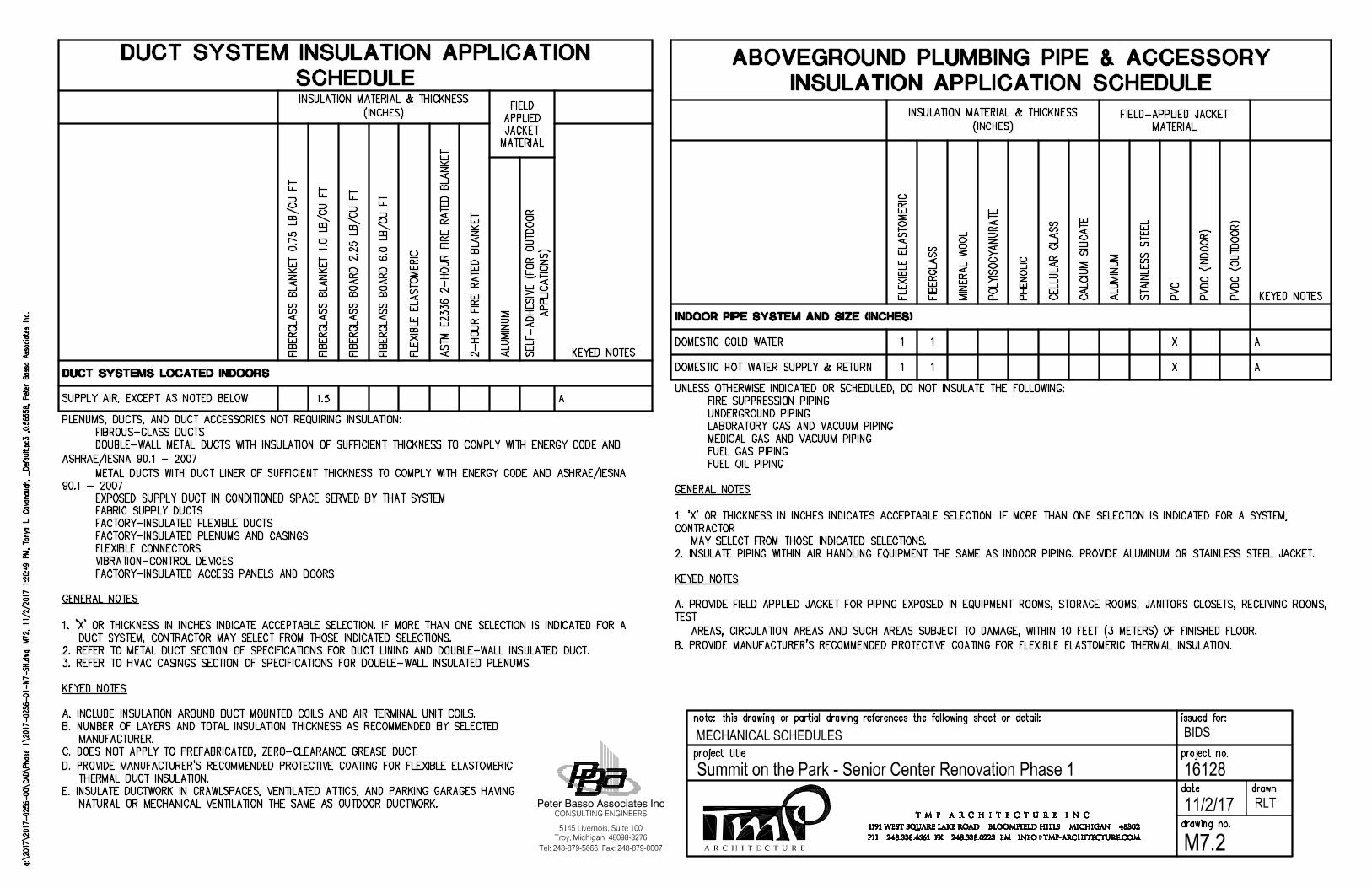
A R C H I T E C T U R E
BIDS
16128Summit on the Park - Senior Center Renovation Phase 1
Tel: 248-879-5666 Fax: 248-879-0007
Peter Basso Associates Inc
5145 Livernois, Suite 100
CONSULTING ENGINEERS
Troy, Michigan 48098-3276
11/2/17
MECHANICAL SCHEDULES
RLT
M7.2
AutoCAD SHX Text
ABOVEGROUND PLUMBING PIPE & ACCESSORY INSULATION APPLICATION SCHEDULE
AutoCAD SHX Text
INSULATION MATERIAL & THICKNESS (INCHES)
AutoCAD SHX Text
FIELD-APPLIED JACKET MATERIAL
AutoCAD SHX Text
FLEXIBLE ELASTOMERIC
AutoCAD SHX Text
FIBERGLASS
AutoCAD SHX Text
MINERAL WOOL
AutoCAD SHX Text
POLYISOCYANURATE
AutoCAD SHX Text
PHENOLIC
AutoCAD SHX Text
CELLULAR GLASS
AutoCAD SHX Text
CALCIUM SILICATE
AutoCAD SHX Text
ALUMINUM
AutoCAD SHX Text
STAINLESS STEEL
AutoCAD SHX Text
PVC
AutoCAD SHX Text
PVDC (INDOOR)
AutoCAD SHX Text
PVDC (OUTDOOR)
AutoCAD SHX Text
KEYED NOTES
AutoCAD SHX Text
INDOOR PIPE SYSTEM AND SIZE (INCHES)
AutoCAD SHX Text
DOMESTIC COLD WATER
AutoCAD SHX Text
1
AutoCAD SHX Text
1
AutoCAD SHX Text
X
AutoCAD SHX Text
A
AutoCAD SHX Text
DOMESTIC HOT WATER SUPPLY & RETURN
AutoCAD SHX Text
1
AutoCAD SHX Text
1
AutoCAD SHX Text
X
AutoCAD SHX Text
A
AutoCAD SHX Text
UNLESS OTHERWISE INDICATED OR SCHEDULED, DO NOT INSULATE THE FOLLOWING: FIRE SUPPRESSION PIPING UNDERGROUND PIPING LABORATORY GAS AND VACUUM PIPING MEDICAL GAS AND VACUUM PIPING FUEL GAS PIPING FUEL OIL PIPING GENERAL NOTES 1. 'X' OR THICKNESS IN INCHES INDICATES ACCEPTABLE SELECTION. IF MORE THAN ONE SELECTION IS INDICATED FOR A SYSTEM, CONTRACTOR MAY SELECT FROM THOSE INDICATED SELECTIONS. 2. INSULATE PIPING WITHIN AIR HANDLING EQUIPMENT THE SAME AS INDOOR PIPING. PROVIDE ALUMINUM OR STAINLESS STEEL JACKET. KEYED NOTES A. PROVIDE FIELD APPLIED JACKET FOR PIPING EXPOSED IN EQUIPMENT ROOMS, STORAGE ROOMS, JANITORS CLOSETS, RECEIVING ROOMS, TEST AREAS, CIRCULATION AREAS AND SUCH AREAS SUBJECT TO DAMAGE, WITHIN 10 FEET (3 METERS) OF FINISHED FLOOR. B. PROVIDE MANUFACTURER'S RECOMMENDED PROTECTIVE COATING FOR FLEXIBLE ELASTOMERIC THERMAL INSULATION.
AutoCAD SHX Text
DUCT SYSTEM INSULATION APPLICATION SCHEDULE
AutoCAD SHX Text
INSULATION MATERIAL & THICKNESS (INCHES)
AutoCAD SHX Text
FIELD APPLIED JACKET MATERIAL
AutoCAD SHX Text
FIBERGLASS BLANKET 0.75 LB/CU FT
AutoCAD SHX Text
FIBERGLASS BLANKET 1.0 LB/CU FT
AutoCAD SHX Text
FIBERGLASS BOARD 2.25 LB/CU FT
AutoCAD SHX Text
FIBERGLASS BOARD 6.0 LB/CU FT
AutoCAD SHX Text
FLEXIBLE ELASTOMERIC
AutoCAD SHX Text
ASTM E2336 2-HOUR FIRE RATED BLANKET
AutoCAD SHX Text
2-HOUR FIRE RATED BLANKET
AutoCAD SHX Text
KEYED NOTES
AutoCAD SHX Text
ALUMINUM
AutoCAD SHX Text
SELF-ADHESIVE (FOR OUTDOOR APPLICATIONS)
AutoCAD SHX Text
DUCT SYSTEMS LOCATED INDOORS
AutoCAD SHX Text
SUPPLY AIR, EXCEPT AS NOTED BELOW
AutoCAD SHX Text
1.5
AutoCAD SHX Text
A
AutoCAD SHX Text
PLENUMS, DUCTS, AND DUCT ACCESSORIES NOT REQUIRING INSULATION: FIBROUS-GLASS DUCTS DOUBLE-WALL METAL DUCTS WITH INSULATION OF SUFFICIENT THICKNESS TO COMPLY WITH ENERGY CODE AND ASHRAE/IESNA 90.1 - 2007 METAL DUCTS WITH DUCT LINER OF SUFFICIENT THICKNESS TO COMPLY WITH ENERGY CODE AND ASHRAE/IESNA 90.1 - 2007 EXPOSED SUPPLY DUCT IN CONDITIONED SPACE SERVED BY THAT SYSTEM FABRIC SUPPLY DUCTS FACTORY-INSULATED FLEXIBLE DUCTS FACTORY-INSULATED PLENUMS AND CASINGS FLEXIBLE CONNECTORS VIBRATION-CONTROL DEVICES FACTORY-INSULATED ACCESS PANELS AND DOORS
AutoCAD SHX Text
GENERAL NOTES 1. 'X' OR THICKNESS IN INCHES INDICATE ACCEPTABLE SELECTION. IF MORE THAN ONE SELECTION IS INDICATED FOR A DUCT SYSTEM, CONTRACTOR MAY SELECT FROM THOSE INDICATED SELECTIONS. 2. REFER TO METAL DUCT SECTION OF SPECIFICATIONS FOR DUCT LINING AND DOUBLE-WALL INSULATED DUCT. 3. REFER TO HVAC CASINGS SECTION OF SPECIFICATIONS FOR DOUBLE-WALL INSULATED PLENUMS. KEYED NOTES A. INCLUDE INSULATION AROUND DUCT MOUNTED COILS AND AIR TERMINAL UNIT COILS. B. NUMBER OF LAYERS AND TOTAL INSULATION THICKNESS AS RECOMMENDED BY SELECTED MANUFACTURER. C. DOES NOT APPLY TO PREFABRICATED, ZERO-CLEARANCE GREASE DUCT. D. PROVIDE MANUFACTURER'S RECOMMENDED PROTECTIVE COATING FOR FLEXIBLE ELASTOMERIC THERMAL DUCT INSULATION. E. INSULATE DUCTWORK IN CRAWLSPACES, VENTILATED ATTICS, AND PARKING GARAGES HAVING NATURAL OR MECHANICAL VENTILATION THE SAME AS OUTDOOR DUCTWORK.
AutoCAD SHX Text
g:\2017\2017-0256-00\CAD\Phase 1\2017-0256-01-M7-SH.dwg, M72, 11/2/2017 1:20:49 PM, Tonya L. Cavanaugh, _Default.pc3 ,0.56558, Peter Basso Associates Inc., M72, 11/2/2017 1:20:49 PM, Tonya L. Cavanaugh, _Default.pc3 ,0.56558, Peter Basso Associates Inc.M72, 11/2/2017 1:20:49 PM, Tonya L. Cavanaugh, _Default.pc3 ,0.56558, Peter Basso Associates Inc., 11/2/2017 1:20:49 PM, Tonya L. Cavanaugh, _Default.pc3 ,0.56558, Peter Basso Associates Inc.11/2/2017 1:20:49 PM, Tonya L. Cavanaugh, _Default.pc3 ,0.56558, Peter Basso Associates Inc., Tonya L. Cavanaugh, _Default.pc3 ,0.56558, Peter Basso Associates Inc.Tonya L. Cavanaugh, _Default.pc3 ,0.56558, Peter Basso Associates Inc., _Default.pc3 ,0.56558, Peter Basso Associates Inc._Default.pc3 ,0.56558, Peter Basso Associates Inc. ,0.56558, Peter Basso Associates Inc.0.56558, Peter Basso Associates Inc., Peter Basso Associates Inc.
AutoCAD SHX Text
issued for:
AutoCAD SHX Text
note: this drawing or partial drawing references the following sheet or detail:
AutoCAD SHX Text
project title
AutoCAD SHX Text
drawing no.
AutoCAD SHX Text
project no.
AutoCAD SHX Text
date
AutoCAD SHX Text
drawn
AutoCAD SHX Text
T M P A R C H I T E C T U R E I N C
AutoCAD SHX Text
PH 248.338.4561 FX 248.338.0223 EM INFO TMP-ARCHITECTURE.COM
AutoCAD SHX Text
@
AutoCAD SHX Text
1191 WEST SQUARE LAKE ROAD BLOOMFIELD HILLS MICHIGAN 48302
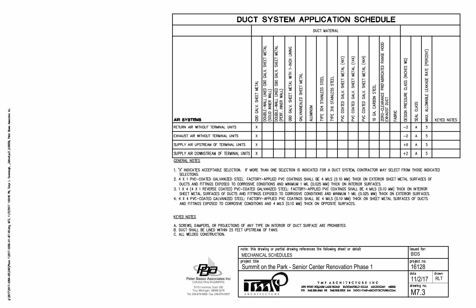
A R C H I T E C T U R E
BIDS
16128Summit on the Park - Senior Center Renovation Phase 1
Tel: 248-879-5666 Fax: 248-879-0007
Peter Basso Associates Inc
5145 Livernois, Suite 100
CONSULTING ENGINEERS
Troy, Michigan 48098-3276
11/2/17
MECHANICAL SCHEDULES
RLT
M7.3
AutoCAD SHX Text
DUCT SYSTEM APPLICATION SCHEDULE
AutoCAD SHX Text
DUCT MATERIAL
AutoCAD SHX Text
AIR SYSTEMS
AutoCAD SHX Text
G90 GALV. SHEET METAL
AutoCAD SHX Text
DOUBLE-WALL LINED G90 GALV. SHEET METAL (SOLID INNER WALL)
AutoCAD SHX Text
DOUBLE-WALL LINED G90 GALV. SHEET METAL (PERF. INNER WALL)
AutoCAD SHX Text
G90 GALV. SHEET METAL WITH 1-INCH LINING
AutoCAD SHX Text
GALVANNEALED SHEET METAL
AutoCAD SHX Text
ALUMINUM
AutoCAD SHX Text
TYPE 304 STAINLESS STEEL
AutoCAD SHX Text
TYPE 316 STAINLESS STEEL
AutoCAD SHX Text
PVC COATED GALV. SHEET METAL (4X1)
AutoCAD SHX Text
PVC COATED GALV. SHEET METAL (1X4)
AutoCAD SHX Text
PVC COATED GALV. SHEET METAL (4X4)
AutoCAD SHX Text
16 GA. CARBON STEEL
AutoCAD SHX Text
ZERO-CLEARANCE PREFABRICATED RANGE HOOD EXHAUST DUCT
AutoCAD SHX Text
FABRIC
AutoCAD SHX Text
DESIGN PRESSURE CLASS (INCHES WG)
AutoCAD SHX Text
SEAL CLASS
AutoCAD SHX Text
MAX. ALLOWABLE LEAKAGE RATE (PERCENT)
AutoCAD SHX Text
KEYED NOTES
AutoCAD SHX Text
RETURN AIR WITHOUT TERMINAL UNITS
AutoCAD SHX Text
X
AutoCAD SHX Text
-2
AutoCAD SHX Text
A
AutoCAD SHX Text
5
AutoCAD SHX Text
EXHAUST AIR WITHOUT TERMINAL UNITS
AutoCAD SHX Text
X
AutoCAD SHX Text
-2
AutoCAD SHX Text
A
AutoCAD SHX Text
5
AutoCAD SHX Text
SUPPLY AIR UPSTREAM OF TERMINAL UNITS
AutoCAD SHX Text
X
AutoCAD SHX Text
+6
AutoCAD SHX Text
A
AutoCAD SHX Text
5
AutoCAD SHX Text
SUPPLY AIR DOWNSTREAM OF TERMINAL UNITS
AutoCAD SHX Text
X
AutoCAD SHX Text
+2
AutoCAD SHX Text
A
AutoCAD SHX Text
5
AutoCAD SHX Text
GENERAL NOTES 1. 'X' INDICATES ACCEPTABLE SELECTION. IF MORE THAN ONE SELECTION IS INDICATED FOR A DUCT SYSTEM, CONTRACTOR MAY SELECT FROM THOSE INDICATED SELECTIONS. 2. 4 X 1 PVC-COATED GALVANIZED STEEL: FACTORY-APPLIED PVC COATINGS SHALL BE 4 MILS (0.10 MM) THICK ON EXTERIOR SHEET METAL SURFACES OF DUCTS AND FITTINGS EXPOSED TO CORROSIVE CONDITIONS AND MINIMUM 1 MIL (0.025 MM) THICK ON INTERIOR SURFACES. 3. 1 X 4 (4 X 1 REVERSE COATED) PVC-COATED GALVANIZED STEEL: FACTORY-APPLIED PVC COATINGS SHALL BE 4 MILS (0.10 MM) THICK ON INTERIOR SHEET METAL SURFACES OF DUCTS AND FITTINGS EXPOSED TO CORROSIVE CONDITIONS AND MINIMUM 1 MIL (0.025 MM) THICK ON EXTERIOR SURFACES. 4. 4 X 4 PVC-COATED GALVANIZED STEEL: FACTORY-APPLIED PVC COATINGS SHALL BE 4 MILS (0.10 MM) THICK ON SHEET METAL SURFACES OF DUCTS AND FITTINGS EXPOSED TO CORROSIVE CONDITIONS AND 4 MILS (0.10 MM) THICK ON OPPOSITE SURFACES. KEYED NOTES A. SCREWS, DAMPERS, OR PROJECTIONS OF ANY TYPE ON INTERIOR OF DUCT SURFACE ARE PROHIBITED. B. DUCT SHALL BE LINED WITHIN 25 FEET UPSTREAM OF FANS. C. ALL WELDED CONSTRUCTION.
AutoCAD SHX Text
g:\2017\2017-0256-00\CAD\Phase 1\2017-0256-01-M7-SH.dwg, M73, 11/2/2017 1:20:49 PM, Tonya L. Cavanaugh, _Default.pc3 ,0.56558, Peter Basso Associates Inc., M73, 11/2/2017 1:20:49 PM, Tonya L. Cavanaugh, _Default.pc3 ,0.56558, Peter Basso Associates Inc.M73, 11/2/2017 1:20:49 PM, Tonya L. Cavanaugh, _Default.pc3 ,0.56558, Peter Basso Associates Inc., 11/2/2017 1:20:49 PM, Tonya L. Cavanaugh, _Default.pc3 ,0.56558, Peter Basso Associates Inc.11/2/2017 1:20:49 PM, Tonya L. Cavanaugh, _Default.pc3 ,0.56558, Peter Basso Associates Inc., Tonya L. Cavanaugh, _Default.pc3 ,0.56558, Peter Basso Associates Inc.Tonya L. Cavanaugh, _Default.pc3 ,0.56558, Peter Basso Associates Inc., _Default.pc3 ,0.56558, Peter Basso Associates Inc._Default.pc3 ,0.56558, Peter Basso Associates Inc. ,0.56558, Peter Basso Associates Inc.0.56558, Peter Basso Associates Inc., Peter Basso Associates Inc.
AutoCAD SHX Text
issued for:
AutoCAD SHX Text
note: this drawing or partial drawing references the following sheet or detail:
AutoCAD SHX Text
project title
AutoCAD SHX Text
drawing no.
AutoCAD SHX Text
project no.
AutoCAD SHX Text
date
AutoCAD SHX Text
drawn
AutoCAD SHX Text
T M P A R C H I T E C T U R E I N C
AutoCAD SHX Text
PH 248.338.4561 FX 248.338.0223 EM INFO TMP-ARCHITECTURE.COM
AutoCAD SHX Text
@
AutoCAD SHX Text
1191 WEST SQUARE LAKE ROAD BLOOMFIELD HILLS MICHIGAN 48302

A R C H I T E C T U R E
BIDS
16128Summit on the Park - Senior Center Renovation Phase 1
Tel: 248-879-5666 Fax: 248-879-0007
Peter Basso Associates Inc
5145 Livernois, Suite 100
CONSULTING ENGINEERS
Troy, Michigan 48098-3276
11/2/17
MECHANICAL SCHEDULES
RLT
M7.4
AutoCAD SHX Text
PLUMBING CONNECTION SCHEDULE
AutoCAD SHX Text
UNIT IDENTIFICATION
AutoCAD SHX Text
CW INCHES
AutoCAD SHX Text
HW INCHES
AutoCAD SHX Text
SAN INCHES
AutoCAD SHX Text
VENT INCHES
AutoCAD SHX Text
REMARKS
AutoCAD SHX Text
SK-1
AutoCAD SHX Text
3/4
AutoCAD SHX Text
3/4
AutoCAD SHX Text
1 1/2
AutoCAD SHX Text
1 1/2
AutoCAD SHX Text
remarks
AutoCAD SHX Text
NOTE: INDIVIDUAL WATER LINE BRANCHES, WASTE LINES, VENTS, AND TRAPS FOR INDIVIDUAL WATER LINE BRANCHES, WASTE LINES, VENTS, AND TRAPS FOR CONNECTION TO INDIVIDUAL FIXTURES, FIXTURE FITTINGS, AND SPECIALTIES SHALL BE IN ACCORDANCE WITH THE FOLLOWING SCHEDULE OR AS INDICATED ON DRAWINGS, WHICHEVER IS GREATER.
AutoCAD SHX Text
GRILLE, REGISTER, AND DIFFUSER SCHEDULE
AutoCAD SHX Text
UNIT IDENTIFICATION
AutoCAD SHX Text
TYPE
AutoCAD SHX Text
FACE SIZE
AutoCAD SHX Text
NECK SIZE
AutoCAD SHX Text
FRAME TYPE
AutoCAD SHX Text
ACCESSORY
AutoCAD SHX Text
CONSTRUCTION
AutoCAD SHX Text
FINISH
AutoCAD SHX Text
MODEL NUMBER
AutoCAD SHX Text
REMARKS
AutoCAD SHX Text
S-1
AutoCAD SHX Text
DIFFUSER
AutoCAD SHX Text
24x24
AutoCAD SHX Text
SEE PLANS
AutoCAD SHX Text
NOTE 2
AutoCAD SHX Text
---
AutoCAD SHX Text
STEEL
AutoCAD SHX Text
NOTE 3
AutoCAD SHX Text
TMSA
AutoCAD SHX Text
R-1
AutoCAD SHX Text
GRILLE
AutoCAD SHX Text
24x12
AutoCAD SHX Text
SEE PLANS
AutoCAD SHX Text
NOTE 2
AutoCAD SHX Text
---
AutoCAD SHX Text
ALUMINUM
AutoCAD SHX Text
NOTE 3
AutoCAD SHX Text
50F
AutoCAD SHX Text
E-1
AutoCAD SHX Text
GRILLE
AutoCAD SHX Text
NECK SIZE + 1-3/4"
AutoCAD SHX Text
SEE PLANS
AutoCAD SHX Text
NOTE 2
AutoCAD SHX Text
---
AutoCAD SHX Text
ALUMINUM
AutoCAD SHX Text
NOTE 3
AutoCAD SHX Text
50F
AutoCAD SHX Text
NOTE: 1. MODEL NUMBERS ARE TITUS UNLESS OTHERWISE NOTED. 2. CONTRACTOR SHALL COORDINATE EXACT FRAME TYPE WITH ARCHITECTURAL CONSTRUCTION. PROVIDE OPTIONAL PLASTER MOUNTING FRAME IN PLASTER CEILINGS. 3. CONTRACTOR SHALL COORDINATE AND COLOR WITH ARCHITECT PRIOR TO INSTALLATION.
AutoCAD SHX Text
PLUMBING FIXTURE SCHEDULE
AutoCAD SHX Text
UNIT IDENTIFICATION
AutoCAD SHX Text
LAVATORIES/SINKS
AutoCAD SHX Text
FAUCET MANUFACTURER/ MODEL
AutoCAD SHX Text
MANUFACTURER/MODEL
AutoCAD SHX Text
REMARKS
AutoCAD SHX Text
FIXTURE MATERIAL
AutoCAD SHX Text
MOUNTING STYLE
AutoCAD SHX Text
BOWL DIMENSIONS L x W x D INCHES
AutoCAD SHX Text
NUMBER OF BOWLS
AutoCAD SHX Text
OVERALL DIMENSIONS L x W x D INCHES
AutoCAD SHX Text
SK-1
AutoCAD SHX Text
STAINLESS STEEL
AutoCAD SHX Text
COUNTER
AutoCAD SHX Text
12 x 12 x 6
AutoCAD SHX Text
1
AutoCAD SHX Text
15 x 17-1/2 x 6
AutoCAD SHX Text
CHICAGO FAUCETS/ 201-G8AE3
AutoCAD SHX Text
ELKAY / LUSTERTONE LRAD1517
AutoCAD SHX Text
remarks
AutoCAD SHX Text
APPROVED MANUFACTURERS: LAVATORIES - AMERICAN STANDARD, FERGUSON, KOHLER, SLOAN, TICOR, ZURN SINKS - ELKAY, FRANKE, JUST, MOEN FAUCETS - AMERICAN STANDARD, CHICAGO, DELTA, GEBERIT, KOHLER, MOEN, SLOAN, SPEAKMAN, T&S, ZURN
AutoCAD SHX Text
UNIT IDENTIFICATION
AutoCAD SHX Text
DISPOSAL
AutoCAD SHX Text
DESCRIPTION/REMARKS
AutoCAD SHX Text
RPM
AutoCAD SHX Text
VOLTAGE
AutoCAD SHX Text
HORSE POWER
AutoCAD SHX Text
MANUFACTURER/MODEL
AutoCAD SHX Text
CONTINUOUS-FEED, HOUSEHOLD TYPE FOOD-WASTE DISPOSER. INCLUDE RESET BUTTON; WALL SWITCH; CORROSION-RESISTANT CHAMBER WITH JAM-RESISTANT, CUTLERY- OR STAINLESS-STEEL GRINDER OR SHREDDER; NPS 1-1/2 (DN 40) OUTLET; QUICK-MOUNTING, STAINLESS-STEEL SINK FLANGE; ANTISPLASH GUARD; AND COMBINATION COVER/STOPPER
AutoCAD SHX Text
D-1
AutoCAD SHX Text
1725
AutoCAD SHX Text
115
AutoCAD SHX Text
3/4
AutoCAD SHX Text
IN-SINK- ERATOR
AutoCAD SHX Text
APPROVED MANUFACTURERS: DISPOSERS - IN-SINK-ERATOR.
AutoCAD SHX Text
NOTE: 1. ALL PLUMBING FIXTURES, EQUIPMENT, TRIM AND FITTINGS SHALL COMPLY WITH LOCAL, STATE AND FEDERAL REGULATIONS AND CODES, INCLUDING, BUT NOT LIMITED TO, WATER AND ENERGY CONSERVATION CODES. THE SCHEDULED AND/OR SPECIFIC PLUMBING FIXTURES AND EQUIPMENT REPRESENT THE MINIMUM CRITERIA AND SHALL BE THE BASIS FOR THE CONTRACTOR'S BASE BID. IF THE SCHEDULED OR SPECIFIED FIXTURES OR EQUIPMENT DO NOT COMPLY WITH GOVERNING CODES OR REGULATIONS IN ALL RESPECTS, THE CONTRACTOR SHALL PROVIDE AN ALTERNATE BID FOR COMPLYING FIXTURES, EQUIPMENT, TRIM OR FITTINGS. THE ABSENCE OF AN ALTERNATE BID SHALL BE CONSTRUED TO MEAN THAT THE CONTRACTOR'S BID INCLUDES ALL COSTS NECESSARY TO MEET ALL REGULATIONS AND CODES. 2. PROVIDE ALL FIXTURE SUPPORTS AS REQUIRED.
AutoCAD SHX Text
g:\2017\2017-0256-00\CAD\Phase 1\2017-0256-01-M7-SH.dwg, M74, 11/2/2017 1:20:50 PM, Tonya L. Cavanaugh, _Default.pc3 ,0.56558, Peter Basso Associates Inc., M74, 11/2/2017 1:20:50 PM, Tonya L. Cavanaugh, _Default.pc3 ,0.56558, Peter Basso Associates Inc.M74, 11/2/2017 1:20:50 PM, Tonya L. Cavanaugh, _Default.pc3 ,0.56558, Peter Basso Associates Inc., 11/2/2017 1:20:50 PM, Tonya L. Cavanaugh, _Default.pc3 ,0.56558, Peter Basso Associates Inc.11/2/2017 1:20:50 PM, Tonya L. Cavanaugh, _Default.pc3 ,0.56558, Peter Basso Associates Inc., Tonya L. Cavanaugh, _Default.pc3 ,0.56558, Peter Basso Associates Inc.Tonya L. Cavanaugh, _Default.pc3 ,0.56558, Peter Basso Associates Inc., _Default.pc3 ,0.56558, Peter Basso Associates Inc._Default.pc3 ,0.56558, Peter Basso Associates Inc. ,0.56558, Peter Basso Associates Inc.0.56558, Peter Basso Associates Inc., Peter Basso Associates Inc.
AutoCAD SHX Text
issued for:
AutoCAD SHX Text
note: this drawing or partial drawing references the following sheet or detail:
AutoCAD SHX Text
project title
AutoCAD SHX Text
drawing no.
AutoCAD SHX Text
project no.
AutoCAD SHX Text
date
AutoCAD SHX Text
drawn
AutoCAD SHX Text
T M P A R C H I T E C T U R E I N C
AutoCAD SHX Text
PH 248.338.4561 FX 248.338.0223 EM INFO TMP-ARCHITECTURE.COM
AutoCAD SHX Text
@
AutoCAD SHX Text
1191 WEST SQUARE LAKE ROAD BLOOMFIELD HILLS MICHIGAN 48302
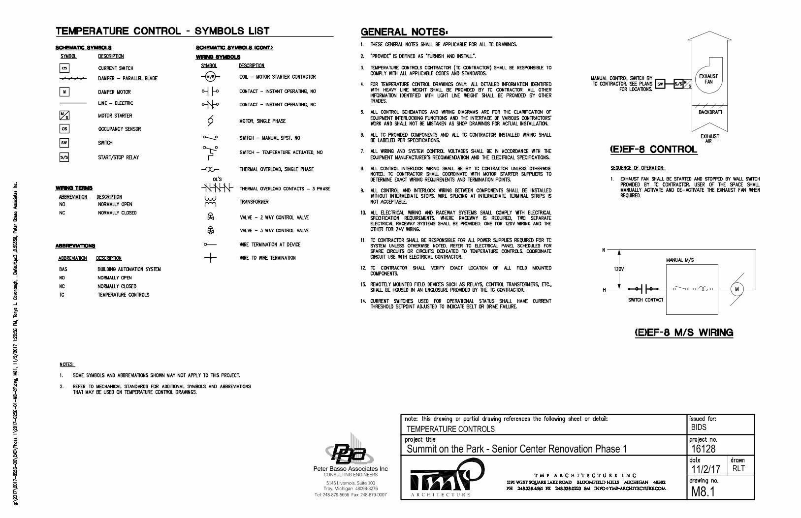
A R C H I T E C T U R E
BIDS
16128Summit on the Park - Senior Center Renovation Phase 1
Tel: 248-879-5666 Fax: 248-879-0007
Peter Basso Associates Inc
5145 Livernois, Suite 100
CONSULTING ENGINEERS
Troy, Michigan 48098-3276
11/2/17
TEMPERATURE CONTROLS
RLT
M8.1
AutoCAD SHX Text
NORMALLY CLOSED
AutoCAD SHX Text
NC
AutoCAD SHX Text
NO
AutoCAD SHX Text
NORMALLY OPEN
AutoCAD SHX Text
%%uABBREVIATION
AutoCAD SHX Text
%%UABBREVIATIONS
AutoCAD SHX Text
%%UDESCRIPTION
AutoCAD SHX Text
TEMPERATURE CONTROLS
AutoCAD SHX Text
TC
AutoCAD SHX Text
BAS
AutoCAD SHX Text
BUILDING AUTOMATION SYSTEM
AutoCAD SHX Text
GENERAL NOTES:
AutoCAD SHX Text
SWITCH
AutoCAD SHX Text
SW
AutoCAD SHX Text
THERMAL OVERLOAD, SINGLE PHASE
AutoCAD SHX Text
THERMAL OVERLOAD CONTACTS - 3 PHASE
AutoCAD SHX Text
WIRE TO WIRE TERMINATION
AutoCAD SHX Text
WIRE TERMINATION AT DEVICE
AutoCAD SHX Text
TRANSFORMER
AutoCAD SHX Text
OL'S
AutoCAD SHX Text
SWITCH - TEMPERATURE ACTUATED, NO
AutoCAD SHX Text
TEMPERATURE CONTROL - SYMBOLS LIST
AutoCAD SHX Text
OCCUPANCY SENSOR
AutoCAD SHX Text
LINE - ELECTRIC
AutoCAD SHX Text
MOTOR STARTER
AutoCAD SHX Text
OS
AutoCAD SHX Text
S
AutoCAD SHX Text
M
AutoCAD SHX Text
DAMPER - PARALLEL BLADE
AutoCAD SHX Text
DAMPER MOTOR
AutoCAD SHX Text
M
AutoCAD SHX Text
%%UDESCRIPTION
AutoCAD SHX Text
CURRENT SWITCH
AutoCAD SHX Text
CS
AutoCAD SHX Text
%%uSCHEMATIC SYMBOLS
AutoCAD SHX Text
%%uSYMBOL
AutoCAD SHX Text
MOTOR, SINGLE PHASE
AutoCAD SHX Text
CONTACT - INSTANT OPERATING, NO
AutoCAD SHX Text
CONTACT - INSTANT OPERATING, NC
AutoCAD SHX Text
COIL - MOTOR STARTER CONTACTOR
AutoCAD SHX Text
M/S
AutoCAD SHX Text
%%uSCHEMATIC SYMBOLS (CONT.)
AutoCAD SHX Text
%%uWIRING SYMBOLS
AutoCAD SHX Text
%%uSYMBOL
AutoCAD SHX Text
%%UDESCRIPTION
AutoCAD SHX Text
SWITCH - MANUAL SPST, NO
AutoCAD SHX Text
NORMALLY CLOSED
AutoCAD SHX Text
NC
AutoCAD SHX Text
NO
AutoCAD SHX Text
NORMALLY OPEN
AutoCAD SHX Text
%%uABBREVIATION
AutoCAD SHX Text
%%uWIRING TERMS
AutoCAD SHX Text
%%UDESCRIPTION
AutoCAD SHX Text
VALVE - 3 WAY CONTROL VALVE
AutoCAD SHX Text
VALVE - 2 WAY CONTROL VALVE
AutoCAD SHX Text
(E)EF-8 CONTROL
AutoCAD SHX Text
EXHAUST
AutoCAD SHX Text
AIR
AutoCAD SHX Text
BACKDRAFT
AutoCAD SHX Text
S
AutoCAD SHX Text
M
AutoCAD SHX Text
EXHAUST
AutoCAD SHX Text
FAN
AutoCAD SHX Text
(E)EF-8 M/S WIRING
AutoCAD SHX Text
M
AutoCAD SHX Text
MANUAL M/S
AutoCAD SHX Text
N
AutoCAD SHX Text
120V
AutoCAD SHX Text
H
AutoCAD SHX Text
SWITCH CONTACT
AutoCAD SHX Text
SEQUENCE OF OPERATION: 1. EXHAUST FAN SHALL BE STARTED AND STOPPED BY WALL SWITCH EXHAUST FAN SHALL BE STARTED AND STOPPED BY WALL SWITCH FAN SHALL BE STARTED AND STOPPED BY WALL SWITCH FAN SHALL BE STARTED AND STOPPED BY WALL SWITCH SHALL BE STARTED AND STOPPED BY WALL SWITCH SHALL BE STARTED AND STOPPED BY WALL SWITCH BE STARTED AND STOPPED BY WALL SWITCH BE STARTED AND STOPPED BY WALL SWITCH STARTED AND STOPPED BY WALL SWITCH STARTED AND STOPPED BY WALL SWITCH AND STOPPED BY WALL SWITCH AND STOPPED BY WALL SWITCH STOPPED BY WALL SWITCH STOPPED BY WALL SWITCH BY WALL SWITCH BY WALL SWITCH WALL SWITCH WALL SWITCH SWITCH SWITCH PROVIDED BY TC CONTRACTOR. USER OF THE SPACE SHALL BY TC CONTRACTOR. USER OF THE SPACE SHALL BY TC CONTRACTOR. USER OF THE SPACE SHALL TC CONTRACTOR. USER OF THE SPACE SHALL TC CONTRACTOR. USER OF THE SPACE SHALL CONTRACTOR. USER OF THE SPACE SHALL CONTRACTOR. USER OF THE SPACE SHALL USER OF THE SPACE SHALL USER OF THE SPACE SHALL OF THE SPACE SHALL OF THE SPACE SHALL THE SPACE SHALL THE SPACE SHALL SPACE SHALL SPACE SHALL SHALL SHALL MANUALLY ACTIVATE AND DE-ACTIVATE THE EXHAUST FAN WHEN ACTIVATE AND DE-ACTIVATE THE EXHAUST FAN WHEN ACTIVATE AND DE-ACTIVATE THE EXHAUST FAN WHEN AND DE-ACTIVATE THE EXHAUST FAN WHEN AND DE-ACTIVATE THE EXHAUST FAN WHEN DE-ACTIVATE THE EXHAUST FAN WHEN DE-ACTIVATE THE EXHAUST FAN WHEN THE EXHAUST FAN WHEN THE EXHAUST FAN WHEN EXHAUST FAN WHEN EXHAUST FAN WHEN FAN WHEN FAN WHEN WHEN WHEN REQUIRED.
AutoCAD SHX Text
S/S
AutoCAD SHX Text
NOTES: 1. SOME SYMBOLS AND ABBREVIATIONS SHOWN MAY NOT APPLY TO THIS PROJECT. SOME SYMBOLS AND ABBREVIATIONS SHOWN MAY NOT APPLY TO THIS PROJECT. 2. REFER TO MECHANICAL STANDARDS FOR ADDITIONAL SYMBOLS AND ABBREVIATIONS REFER TO MECHANICAL STANDARDS FOR ADDITIONAL SYMBOLS AND ABBREVIATIONS TO MECHANICAL STANDARDS FOR ADDITIONAL SYMBOLS AND ABBREVIATIONS TO MECHANICAL STANDARDS FOR ADDITIONAL SYMBOLS AND ABBREVIATIONS MECHANICAL STANDARDS FOR ADDITIONAL SYMBOLS AND ABBREVIATIONS MECHANICAL STANDARDS FOR ADDITIONAL SYMBOLS AND ABBREVIATIONS STANDARDS FOR ADDITIONAL SYMBOLS AND ABBREVIATIONS STANDARDS FOR ADDITIONAL SYMBOLS AND ABBREVIATIONS FOR ADDITIONAL SYMBOLS AND ABBREVIATIONS FOR ADDITIONAL SYMBOLS AND ABBREVIATIONS ADDITIONAL SYMBOLS AND ABBREVIATIONS ADDITIONAL SYMBOLS AND ABBREVIATIONS SYMBOLS AND ABBREVIATIONS SYMBOLS AND ABBREVIATIONS AND ABBREVIATIONS AND ABBREVIATIONS ABBREVIATIONS ABBREVIATIONS THAT MAY BE USED ON TEMPERATURE CONTROL DRAWINGS.
AutoCAD SHX Text
1. THESE GENERAL NOTES SHALL BE APPLICABLE FOR ALL TC DRAWINGS. THESE GENERAL NOTES SHALL BE APPLICABLE FOR ALL TC DRAWINGS. 2. "PROVIDE" IS DEFINED AS "FURNISH AND INSTALL". "PROVIDE" IS DEFINED AS "FURNISH AND INSTALL". 3. TEMPERATURE CONTROLS CONTRACTOR (TC CONTRACTOR) SHALL BE RESPONSIBLE TO TEMPERATURE CONTROLS CONTRACTOR (TC CONTRACTOR) SHALL BE RESPONSIBLE TO CONTROLS CONTRACTOR (TC CONTRACTOR) SHALL BE RESPONSIBLE TO CONTROLS CONTRACTOR (TC CONTRACTOR) SHALL BE RESPONSIBLE TO CONTRACTOR (TC CONTRACTOR) SHALL BE RESPONSIBLE TO CONTRACTOR (TC CONTRACTOR) SHALL BE RESPONSIBLE TO (TC CONTRACTOR) SHALL BE RESPONSIBLE TO (TC CONTRACTOR) SHALL BE RESPONSIBLE TO CONTRACTOR) SHALL BE RESPONSIBLE TO CONTRACTOR) SHALL BE RESPONSIBLE TO SHALL BE RESPONSIBLE TO SHALL BE RESPONSIBLE TO BE RESPONSIBLE TO BE RESPONSIBLE TO RESPONSIBLE TO RESPONSIBLE TO TO TO COMPLY WITH ALL APPLICABLE CODES AND STANDARDS. 4. FOR TEMPERATURE CONTROL DRAWINGS ONLY: ALL DETAILED INFORMATION IDENTIFIED FOR TEMPERATURE CONTROL DRAWINGS ONLY: ALL DETAILED INFORMATION IDENTIFIED TEMPERATURE CONTROL DRAWINGS ONLY: ALL DETAILED INFORMATION IDENTIFIED TEMPERATURE CONTROL DRAWINGS ONLY: ALL DETAILED INFORMATION IDENTIFIED CONTROL DRAWINGS ONLY: ALL DETAILED INFORMATION IDENTIFIED CONTROL DRAWINGS ONLY: ALL DETAILED INFORMATION IDENTIFIED DRAWINGS ONLY: ALL DETAILED INFORMATION IDENTIFIED DRAWINGS ONLY: ALL DETAILED INFORMATION IDENTIFIED ONLY: ALL DETAILED INFORMATION IDENTIFIED ONLY: ALL DETAILED INFORMATION IDENTIFIED ALL DETAILED INFORMATION IDENTIFIED ALL DETAILED INFORMATION IDENTIFIED DETAILED INFORMATION IDENTIFIED DETAILED INFORMATION IDENTIFIED INFORMATION IDENTIFIED INFORMATION IDENTIFIED IDENTIFIED IDENTIFIED WITH HEAVY LINE WEIGHT SHALL BE PROVIDED BY TC CONTRACTOR. ALL OTHER HEAVY LINE WEIGHT SHALL BE PROVIDED BY TC CONTRACTOR. ALL OTHER HEAVY LINE WEIGHT SHALL BE PROVIDED BY TC CONTRACTOR. ALL OTHER LINE WEIGHT SHALL BE PROVIDED BY TC CONTRACTOR. ALL OTHER LINE WEIGHT SHALL BE PROVIDED BY TC CONTRACTOR. ALL OTHER WEIGHT SHALL BE PROVIDED BY TC CONTRACTOR. ALL OTHER WEIGHT SHALL BE PROVIDED BY TC CONTRACTOR. ALL OTHER SHALL BE PROVIDED BY TC CONTRACTOR. ALL OTHER SHALL BE PROVIDED BY TC CONTRACTOR. ALL OTHER BE PROVIDED BY TC CONTRACTOR. ALL OTHER BE PROVIDED BY TC CONTRACTOR. ALL OTHER PROVIDED BY TC CONTRACTOR. ALL OTHER PROVIDED BY TC CONTRACTOR. ALL OTHER BY TC CONTRACTOR. ALL OTHER BY TC CONTRACTOR. ALL OTHER TC CONTRACTOR. ALL OTHER TC CONTRACTOR. ALL OTHER CONTRACTOR. ALL OTHER CONTRACTOR. ALL OTHER ALL OTHER ALL OTHER OTHER OTHER INFORMATION IDENTIFIED WITH LIGHT LINE WEIGHT SHALL BE PROVIDED BY OTHER IDENTIFIED WITH LIGHT LINE WEIGHT SHALL BE PROVIDED BY OTHER IDENTIFIED WITH LIGHT LINE WEIGHT SHALL BE PROVIDED BY OTHER WITH LIGHT LINE WEIGHT SHALL BE PROVIDED BY OTHER WITH LIGHT LINE WEIGHT SHALL BE PROVIDED BY OTHER LIGHT LINE WEIGHT SHALL BE PROVIDED BY OTHER LIGHT LINE WEIGHT SHALL BE PROVIDED BY OTHER LINE WEIGHT SHALL BE PROVIDED BY OTHER LINE WEIGHT SHALL BE PROVIDED BY OTHER WEIGHT SHALL BE PROVIDED BY OTHER WEIGHT SHALL BE PROVIDED BY OTHER SHALL BE PROVIDED BY OTHER SHALL BE PROVIDED BY OTHER BE PROVIDED BY OTHER BE PROVIDED BY OTHER PROVIDED BY OTHER PROVIDED BY OTHER BY OTHER BY OTHER OTHER OTHER TRADES. 5. ALL CONTROL SCHEMATICS AND WIRING DIAGRAMS ARE FOR THE CLARIFICATION OF ALL CONTROL SCHEMATICS AND WIRING DIAGRAMS ARE FOR THE CLARIFICATION OF CONTROL SCHEMATICS AND WIRING DIAGRAMS ARE FOR THE CLARIFICATION OF CONTROL SCHEMATICS AND WIRING DIAGRAMS ARE FOR THE CLARIFICATION OF SCHEMATICS AND WIRING DIAGRAMS ARE FOR THE CLARIFICATION OF SCHEMATICS AND WIRING DIAGRAMS ARE FOR THE CLARIFICATION OF AND WIRING DIAGRAMS ARE FOR THE CLARIFICATION OF AND WIRING DIAGRAMS ARE FOR THE CLARIFICATION OF WIRING DIAGRAMS ARE FOR THE CLARIFICATION OF WIRING DIAGRAMS ARE FOR THE CLARIFICATION OF DIAGRAMS ARE FOR THE CLARIFICATION OF DIAGRAMS ARE FOR THE CLARIFICATION OF ARE FOR THE CLARIFICATION OF ARE FOR THE CLARIFICATION OF FOR THE CLARIFICATION OF FOR THE CLARIFICATION OF THE CLARIFICATION OF THE CLARIFICATION OF CLARIFICATION OF CLARIFICATION OF OF OF EQUIPMENT INTERLOCKING FUNCTIONS AND THE INTERFACE OF VARIOUS CONTRACTORS' INTERLOCKING FUNCTIONS AND THE INTERFACE OF VARIOUS CONTRACTORS' INTERLOCKING FUNCTIONS AND THE INTERFACE OF VARIOUS CONTRACTORS' FUNCTIONS AND THE INTERFACE OF VARIOUS CONTRACTORS' FUNCTIONS AND THE INTERFACE OF VARIOUS CONTRACTORS' AND THE INTERFACE OF VARIOUS CONTRACTORS' AND THE INTERFACE OF VARIOUS CONTRACTORS' THE INTERFACE OF VARIOUS CONTRACTORS' THE INTERFACE OF VARIOUS CONTRACTORS' INTERFACE OF VARIOUS CONTRACTORS' INTERFACE OF VARIOUS CONTRACTORS' OF VARIOUS CONTRACTORS' OF VARIOUS CONTRACTORS' VARIOUS CONTRACTORS' VARIOUS CONTRACTORS' CONTRACTORS' CONTRACTORS' WORK AND SHALL NOT BE MISTAKEN AS SHOP DRAWINGS FOR ACTUAL INSTALLATION. 6. ALL TC PROVIDED COMPONENTS AND ALL TC CONTRACTOR INSTALLED WIRING SHALL ALL TC PROVIDED COMPONENTS AND ALL TC CONTRACTOR INSTALLED WIRING SHALL TC PROVIDED COMPONENTS AND ALL TC CONTRACTOR INSTALLED WIRING SHALL TC PROVIDED COMPONENTS AND ALL TC CONTRACTOR INSTALLED WIRING SHALL PROVIDED COMPONENTS AND ALL TC CONTRACTOR INSTALLED WIRING SHALL PROVIDED COMPONENTS AND ALL TC CONTRACTOR INSTALLED WIRING SHALL COMPONENTS AND ALL TC CONTRACTOR INSTALLED WIRING SHALL COMPONENTS AND ALL TC CONTRACTOR INSTALLED WIRING SHALL AND ALL TC CONTRACTOR INSTALLED WIRING SHALL AND ALL TC CONTRACTOR INSTALLED WIRING SHALL ALL TC CONTRACTOR INSTALLED WIRING SHALL ALL TC CONTRACTOR INSTALLED WIRING SHALL TC CONTRACTOR INSTALLED WIRING SHALL TC CONTRACTOR INSTALLED WIRING SHALL CONTRACTOR INSTALLED WIRING SHALL CONTRACTOR INSTALLED WIRING SHALL INSTALLED WIRING SHALL INSTALLED WIRING SHALL WIRING SHALL WIRING SHALL SHALL SHALL BE LABELED PER SPECIFICATIONS. 7. ALL WIRING AND SYSTEM CONTROL VOLTAGES SHALL BE IN ACCORDANCE WITH THE ALL WIRING AND SYSTEM CONTROL VOLTAGES SHALL BE IN ACCORDANCE WITH THE WIRING AND SYSTEM CONTROL VOLTAGES SHALL BE IN ACCORDANCE WITH THE WIRING AND SYSTEM CONTROL VOLTAGES SHALL BE IN ACCORDANCE WITH THE AND SYSTEM CONTROL VOLTAGES SHALL BE IN ACCORDANCE WITH THE AND SYSTEM CONTROL VOLTAGES SHALL BE IN ACCORDANCE WITH THE SYSTEM CONTROL VOLTAGES SHALL BE IN ACCORDANCE WITH THE SYSTEM CONTROL VOLTAGES SHALL BE IN ACCORDANCE WITH THE CONTROL VOLTAGES SHALL BE IN ACCORDANCE WITH THE CONTROL VOLTAGES SHALL BE IN ACCORDANCE WITH THE VOLTAGES SHALL BE IN ACCORDANCE WITH THE VOLTAGES SHALL BE IN ACCORDANCE WITH THE SHALL BE IN ACCORDANCE WITH THE SHALL BE IN ACCORDANCE WITH THE BE IN ACCORDANCE WITH THE BE IN ACCORDANCE WITH THE IN ACCORDANCE WITH THE IN ACCORDANCE WITH THE ACCORDANCE WITH THE ACCORDANCE WITH THE WITH THE WITH THE THE THE EQUIPMENT MANUFACTURER'S RECOMMENDATION AND THE ELECTRICAL SPECIFICATIONS. 8. ALL CONTROL INTERLOCK WIRING SHALL BE BY TC CONTRACTOR UNLESS OTHERWISE ALL CONTROL INTERLOCK WIRING SHALL BE BY TC CONTRACTOR UNLESS OTHERWISE CONTROL INTERLOCK WIRING SHALL BE BY TC CONTRACTOR UNLESS OTHERWISE CONTROL INTERLOCK WIRING SHALL BE BY TC CONTRACTOR UNLESS OTHERWISE INTERLOCK WIRING SHALL BE BY TC CONTRACTOR UNLESS OTHERWISE INTERLOCK WIRING SHALL BE BY TC CONTRACTOR UNLESS OTHERWISE WIRING SHALL BE BY TC CONTRACTOR UNLESS OTHERWISE WIRING SHALL BE BY TC CONTRACTOR UNLESS OTHERWISE SHALL BE BY TC CONTRACTOR UNLESS OTHERWISE SHALL BE BY TC CONTRACTOR UNLESS OTHERWISE BE BY TC CONTRACTOR UNLESS OTHERWISE BE BY TC CONTRACTOR UNLESS OTHERWISE BY TC CONTRACTOR UNLESS OTHERWISE BY TC CONTRACTOR UNLESS OTHERWISE TC CONTRACTOR UNLESS OTHERWISE TC CONTRACTOR UNLESS OTHERWISE CONTRACTOR UNLESS OTHERWISE CONTRACTOR UNLESS OTHERWISE UNLESS OTHERWISE UNLESS OTHERWISE OTHERWISE OTHERWISE NOTED. TC CONTRACTOR SHALL COORDINATE WITH MOTOR STARTER SUPPLIERS TO TC CONTRACTOR SHALL COORDINATE WITH MOTOR STARTER SUPPLIERS TO TC CONTRACTOR SHALL COORDINATE WITH MOTOR STARTER SUPPLIERS TO CONTRACTOR SHALL COORDINATE WITH MOTOR STARTER SUPPLIERS TO CONTRACTOR SHALL COORDINATE WITH MOTOR STARTER SUPPLIERS TO SHALL COORDINATE WITH MOTOR STARTER SUPPLIERS TO SHALL COORDINATE WITH MOTOR STARTER SUPPLIERS TO COORDINATE WITH MOTOR STARTER SUPPLIERS TO COORDINATE WITH MOTOR STARTER SUPPLIERS TO WITH MOTOR STARTER SUPPLIERS TO WITH MOTOR STARTER SUPPLIERS TO MOTOR STARTER SUPPLIERS TO MOTOR STARTER SUPPLIERS TO STARTER SUPPLIERS TO STARTER SUPPLIERS TO SUPPLIERS TO SUPPLIERS TO TO TO DETERMINE EXACT WIRING REQUIREMENTS AND TERMINATION POINTS. 9. ALL CONTROL AND INTERLOCK WIRING BETWEEN COMPONENTS SHALL BE INSTALLED ALL CONTROL AND INTERLOCK WIRING BETWEEN COMPONENTS SHALL BE INSTALLED CONTROL AND INTERLOCK WIRING BETWEEN COMPONENTS SHALL BE INSTALLED CONTROL AND INTERLOCK WIRING BETWEEN COMPONENTS SHALL BE INSTALLED AND INTERLOCK WIRING BETWEEN COMPONENTS SHALL BE INSTALLED AND INTERLOCK WIRING BETWEEN COMPONENTS SHALL BE INSTALLED INTERLOCK WIRING BETWEEN COMPONENTS SHALL BE INSTALLED INTERLOCK WIRING BETWEEN COMPONENTS SHALL BE INSTALLED WIRING BETWEEN COMPONENTS SHALL BE INSTALLED WIRING BETWEEN COMPONENTS SHALL BE INSTALLED BETWEEN COMPONENTS SHALL BE INSTALLED BETWEEN COMPONENTS SHALL BE INSTALLED COMPONENTS SHALL BE INSTALLED COMPONENTS SHALL BE INSTALLED SHALL BE INSTALLED SHALL BE INSTALLED BE INSTALLED BE INSTALLED INSTALLED INSTALLED WITHOUT INTERMEDIATE STOPS. WIRE SPLICING AT INTERMEDIATE TERMINAL STRIPS IS INTERMEDIATE STOPS. WIRE SPLICING AT INTERMEDIATE TERMINAL STRIPS IS INTERMEDIATE STOPS. WIRE SPLICING AT INTERMEDIATE TERMINAL STRIPS IS STOPS. WIRE SPLICING AT INTERMEDIATE TERMINAL STRIPS IS STOPS. WIRE SPLICING AT INTERMEDIATE TERMINAL STRIPS IS WIRE SPLICING AT INTERMEDIATE TERMINAL STRIPS IS WIRE SPLICING AT INTERMEDIATE TERMINAL STRIPS IS SPLICING AT INTERMEDIATE TERMINAL STRIPS IS SPLICING AT INTERMEDIATE TERMINAL STRIPS IS AT INTERMEDIATE TERMINAL STRIPS IS AT INTERMEDIATE TERMINAL STRIPS IS INTERMEDIATE TERMINAL STRIPS IS INTERMEDIATE TERMINAL STRIPS IS TERMINAL STRIPS IS TERMINAL STRIPS IS STRIPS IS STRIPS IS IS IS NOT ACCEPTABLE. 10. ALL ELECTRICAL WIRING AND RACEWAY SYSTEMS SHALL COMPLY WITH ELECTRICAL ALL ELECTRICAL WIRING AND RACEWAY SYSTEMS SHALL COMPLY WITH ELECTRICAL ELECTRICAL WIRING AND RACEWAY SYSTEMS SHALL COMPLY WITH ELECTRICAL ELECTRICAL WIRING AND RACEWAY SYSTEMS SHALL COMPLY WITH ELECTRICAL WIRING AND RACEWAY SYSTEMS SHALL COMPLY WITH ELECTRICAL WIRING AND RACEWAY SYSTEMS SHALL COMPLY WITH ELECTRICAL AND RACEWAY SYSTEMS SHALL COMPLY WITH ELECTRICAL AND RACEWAY SYSTEMS SHALL COMPLY WITH ELECTRICAL RACEWAY SYSTEMS SHALL COMPLY WITH ELECTRICAL RACEWAY SYSTEMS SHALL COMPLY WITH ELECTRICAL SYSTEMS SHALL COMPLY WITH ELECTRICAL SYSTEMS SHALL COMPLY WITH ELECTRICAL SHALL COMPLY WITH ELECTRICAL SHALL COMPLY WITH ELECTRICAL COMPLY WITH ELECTRICAL COMPLY WITH ELECTRICAL WITH ELECTRICAL WITH ELECTRICAL ELECTRICAL ELECTRICAL SPECIFICATION REQUIREMENTS. WHERE RACEWAY IS REQUIRED, TWO SEPARATE REQUIREMENTS. WHERE RACEWAY IS REQUIRED, TWO SEPARATE REQUIREMENTS. WHERE RACEWAY IS REQUIRED, TWO SEPARATE WHERE RACEWAY IS REQUIRED, TWO SEPARATE WHERE RACEWAY IS REQUIRED, TWO SEPARATE RACEWAY IS REQUIRED, TWO SEPARATE RACEWAY IS REQUIRED, TWO SEPARATE IS REQUIRED, TWO SEPARATE IS REQUIRED, TWO SEPARATE REQUIRED, TWO SEPARATE REQUIRED, TWO SEPARATE TWO SEPARATE TWO SEPARATE SEPARATE SEPARATE ELECTRICAL RACEWAY SYSTEMS SHALL BE PROVIDED: ONE FOR 120V WIRING AND THE RACEWAY SYSTEMS SHALL BE PROVIDED: ONE FOR 120V WIRING AND THE RACEWAY SYSTEMS SHALL BE PROVIDED: ONE FOR 120V WIRING AND THE SYSTEMS SHALL BE PROVIDED: ONE FOR 120V WIRING AND THE SYSTEMS SHALL BE PROVIDED: ONE FOR 120V WIRING AND THE SHALL BE PROVIDED: ONE FOR 120V WIRING AND THE SHALL BE PROVIDED: ONE FOR 120V WIRING AND THE BE PROVIDED: ONE FOR 120V WIRING AND THE BE PROVIDED: ONE FOR 120V WIRING AND THE PROVIDED: ONE FOR 120V WIRING AND THE PROVIDED: ONE FOR 120V WIRING AND THE ONE FOR 120V WIRING AND THE ONE FOR 120V WIRING AND THE FOR 120V WIRING AND THE FOR 120V WIRING AND THE 120V WIRING AND THE 120V WIRING AND THE WIRING AND THE WIRING AND THE AND THE AND THE THE THE OTHER FOR 24V WIRING. 11. TC CONTRACTOR SHALL BE RESPONSIBLE FOR ALL POWER SUPPLIES REQUIRED FOR TC TC CONTRACTOR SHALL BE RESPONSIBLE FOR ALL POWER SUPPLIES REQUIRED FOR TC CONTRACTOR SHALL BE RESPONSIBLE FOR ALL POWER SUPPLIES REQUIRED FOR TC CONTRACTOR SHALL BE RESPONSIBLE FOR ALL POWER SUPPLIES REQUIRED FOR TC SHALL BE RESPONSIBLE FOR ALL POWER SUPPLIES REQUIRED FOR TC SHALL BE RESPONSIBLE FOR ALL POWER SUPPLIES REQUIRED FOR TC BE RESPONSIBLE FOR ALL POWER SUPPLIES REQUIRED FOR TC BE RESPONSIBLE FOR ALL POWER SUPPLIES REQUIRED FOR TC RESPONSIBLE FOR ALL POWER SUPPLIES REQUIRED FOR TC RESPONSIBLE FOR ALL POWER SUPPLIES REQUIRED FOR TC FOR ALL POWER SUPPLIES REQUIRED FOR TC FOR ALL POWER SUPPLIES REQUIRED FOR TC ALL POWER SUPPLIES REQUIRED FOR TC ALL POWER SUPPLIES REQUIRED FOR TC POWER SUPPLIES REQUIRED FOR TC POWER SUPPLIES REQUIRED FOR TC SUPPLIES REQUIRED FOR TC SUPPLIES REQUIRED FOR TC REQUIRED FOR TC REQUIRED FOR TC FOR TC FOR TC TC TC SYSTEM UNLESS OTHERWISE NOTED. REFER TO ELECTRICAL PANEL SCHEDULES FOR UNLESS OTHERWISE NOTED. REFER TO ELECTRICAL PANEL SCHEDULES FOR UNLESS OTHERWISE NOTED. REFER TO ELECTRICAL PANEL SCHEDULES FOR OTHERWISE NOTED. REFER TO ELECTRICAL PANEL SCHEDULES FOR OTHERWISE NOTED. REFER TO ELECTRICAL PANEL SCHEDULES FOR NOTED. REFER TO ELECTRICAL PANEL SCHEDULES FOR NOTED. REFER TO ELECTRICAL PANEL SCHEDULES FOR REFER TO ELECTRICAL PANEL SCHEDULES FOR REFER TO ELECTRICAL PANEL SCHEDULES FOR TO ELECTRICAL PANEL SCHEDULES FOR TO ELECTRICAL PANEL SCHEDULES FOR ELECTRICAL PANEL SCHEDULES FOR ELECTRICAL PANEL SCHEDULES FOR PANEL SCHEDULES FOR PANEL SCHEDULES FOR SCHEDULES FOR SCHEDULES FOR FOR FOR SPARE CIRCUITS OR CIRCUITS DEDICATED TO TEMPERATURE CONTROLS. COORDINATE CIRCUITS OR CIRCUITS DEDICATED TO TEMPERATURE CONTROLS. COORDINATE CIRCUITS OR CIRCUITS DEDICATED TO TEMPERATURE CONTROLS. COORDINATE OR CIRCUITS DEDICATED TO TEMPERATURE CONTROLS. COORDINATE OR CIRCUITS DEDICATED TO TEMPERATURE CONTROLS. COORDINATE CIRCUITS DEDICATED TO TEMPERATURE CONTROLS. COORDINATE CIRCUITS DEDICATED TO TEMPERATURE CONTROLS. COORDINATE DEDICATED TO TEMPERATURE CONTROLS. COORDINATE DEDICATED TO TEMPERATURE CONTROLS. COORDINATE TO TEMPERATURE CONTROLS. COORDINATE TO TEMPERATURE CONTROLS. COORDINATE TEMPERATURE CONTROLS. COORDINATE TEMPERATURE CONTROLS. COORDINATE CONTROLS. COORDINATE CONTROLS. COORDINATE COORDINATE COORDINATE CIRCUIT USE WITH ELECTRICAL CONTRACTOR. 12. TC CONTRACTOR SHALL VERIFY EXACT LOCATION OF ALL FIELD MOUNTED TC CONTRACTOR SHALL VERIFY EXACT LOCATION OF ALL FIELD MOUNTED CONTRACTOR SHALL VERIFY EXACT LOCATION OF ALL FIELD MOUNTED CONTRACTOR SHALL VERIFY EXACT LOCATION OF ALL FIELD MOUNTED SHALL VERIFY EXACT LOCATION OF ALL FIELD MOUNTED SHALL VERIFY EXACT LOCATION OF ALL FIELD MOUNTED VERIFY EXACT LOCATION OF ALL FIELD MOUNTED VERIFY EXACT LOCATION OF ALL FIELD MOUNTED EXACT LOCATION OF ALL FIELD MOUNTED EXACT LOCATION OF ALL FIELD MOUNTED LOCATION OF ALL FIELD MOUNTED LOCATION OF ALL FIELD MOUNTED OF ALL FIELD MOUNTED OF ALL FIELD MOUNTED ALL FIELD MOUNTED ALL FIELD MOUNTED FIELD MOUNTED FIELD MOUNTED MOUNTED MOUNTED COMPONENTS. 13. REMOTELY MOUNTED FIELD DEVICES SUCH AS RELAYS, CONTROL TRANSFORMERS, ETC., REMOTELY MOUNTED FIELD DEVICES SUCH AS RELAYS, CONTROL TRANSFORMERS, ETC., MOUNTED FIELD DEVICES SUCH AS RELAYS, CONTROL TRANSFORMERS, ETC., MOUNTED FIELD DEVICES SUCH AS RELAYS, CONTROL TRANSFORMERS, ETC., FIELD DEVICES SUCH AS RELAYS, CONTROL TRANSFORMERS, ETC., FIELD DEVICES SUCH AS RELAYS, CONTROL TRANSFORMERS, ETC., DEVICES SUCH AS RELAYS, CONTROL TRANSFORMERS, ETC., DEVICES SUCH AS RELAYS, CONTROL TRANSFORMERS, ETC., SUCH AS RELAYS, CONTROL TRANSFORMERS, ETC., SUCH AS RELAYS, CONTROL TRANSFORMERS, ETC., AS RELAYS, CONTROL TRANSFORMERS, ETC., AS RELAYS, CONTROL TRANSFORMERS, ETC., RELAYS, CONTROL TRANSFORMERS, ETC., RELAYS, CONTROL TRANSFORMERS, ETC., CONTROL TRANSFORMERS, ETC., CONTROL TRANSFORMERS, ETC., TRANSFORMERS, ETC., TRANSFORMERS, ETC., ETC., ETC., SHALL BE HOUSED IN AN ENCLOSURE PROVIDED BY THE TC CONTRACTOR. 14. CURRENT SWITCHES USED FOR OPERATIONAL STATUS SHALL HAVE CURRENT CURRENT SWITCHES USED FOR OPERATIONAL STATUS SHALL HAVE CURRENT SWITCHES USED FOR OPERATIONAL STATUS SHALL HAVE CURRENT SWITCHES USED FOR OPERATIONAL STATUS SHALL HAVE CURRENT USED FOR OPERATIONAL STATUS SHALL HAVE CURRENT USED FOR OPERATIONAL STATUS SHALL HAVE CURRENT FOR OPERATIONAL STATUS SHALL HAVE CURRENT FOR OPERATIONAL STATUS SHALL HAVE CURRENT OPERATIONAL STATUS SHALL HAVE CURRENT OPERATIONAL STATUS SHALL HAVE CURRENT STATUS SHALL HAVE CURRENT STATUS SHALL HAVE CURRENT SHALL HAVE CURRENT SHALL HAVE CURRENT HAVE CURRENT HAVE CURRENT CURRENT CURRENT THRESHOLD SETPOINT ADJUSTED TO INDICATE BELT OR DRIVE FAILURE.
AutoCAD SHX Text
SW
AutoCAD SHX Text
MANUAL CONTROL SWITCH BY TC CONTRACTOR. SEE PLANS FOR LOCATIONS.
AutoCAD SHX Text
START/STOP RELAY
AutoCAD SHX Text
S/S
AutoCAD SHX Text
g:\2017\2017-0256-00\CAD\Phase 1\2017-0256-01-M8-CP.dwg, M81, 11/2/2017 1:20:56 PM, Tonya L. Cavanaugh, _Default.pc3 ,0.56558, Peter Basso Associates Inc., M81, 11/2/2017 1:20:56 PM, Tonya L. Cavanaugh, _Default.pc3 ,0.56558, Peter Basso Associates Inc.M81, 11/2/2017 1:20:56 PM, Tonya L. Cavanaugh, _Default.pc3 ,0.56558, Peter Basso Associates Inc., 11/2/2017 1:20:56 PM, Tonya L. Cavanaugh, _Default.pc3 ,0.56558, Peter Basso Associates Inc.11/2/2017 1:20:56 PM, Tonya L. Cavanaugh, _Default.pc3 ,0.56558, Peter Basso Associates Inc., Tonya L. Cavanaugh, _Default.pc3 ,0.56558, Peter Basso Associates Inc.Tonya L. Cavanaugh, _Default.pc3 ,0.56558, Peter Basso Associates Inc., _Default.pc3 ,0.56558, Peter Basso Associates Inc._Default.pc3 ,0.56558, Peter Basso Associates Inc. ,0.56558, Peter Basso Associates Inc.0.56558, Peter Basso Associates Inc., Peter Basso Associates Inc.
AutoCAD SHX Text
issued for:
AutoCAD SHX Text
note: this drawing or partial drawing references the following sheet or detail:
AutoCAD SHX Text
project title
AutoCAD SHX Text
drawing no.
AutoCAD SHX Text
project no.
AutoCAD SHX Text
date
AutoCAD SHX Text
drawn
AutoCAD SHX Text
T M P A R C H I T E C T U R E I N C
AutoCAD SHX Text
PH 248.338.4561 FX 248.338.0223 EM INFO TMP-ARCHITECTURE.COM
AutoCAD SHX Text
@
AutoCAD SHX Text
1191 WEST SQUARE LAKE ROAD BLOOMFIELD HILLS MICHIGAN 48302

A R C H I T E C T U R E
BIDS
16128Summit on the Park - Senior Center Renovation Phase 1
Tel: 248-879-5666 Fax: 248-879-0007
Peter Basso Associates Inc
5145 Livernois, Suite 100
CONSULTING ENGINEERS
Troy, Michigan 48098-3276
11/2/17
ELECTRICAL DEMOLITION PLAN
ECD
ED1.1
AutoCAD SHX Text
1. VISIT THE SITE PRIOR TO SUBMISSION OF BID TO EXAMINE THE EXISTING CONDITIONS VISIT THE SITE PRIOR TO SUBMISSION OF BID TO EXAMINE THE EXISTING CONDITIONS AND THE EXTENT OF DEMOLITION WORK. 2. EXAMINE THE DRAWINGS OF OTHER TRADES AND BE FAMILIAR WITH THE DEMOLITION EXAMINE THE DRAWINGS OF OTHER TRADES AND BE FAMILIAR WITH THE DEMOLITION REQUIRED BY OTHER TRADES. PERFORM ALL INCIDENTAL ELECTRICAL DEMOLITION AND/OR RELOCATION REQUIRED TO FACILITATE THE DEMOLITION WORK OF OTHER TRADES, WHETHER OR NOT SPECIFICALLY INDICATED. 3. REMOVE LIGHTING FIXTURES AND ELECTRICAL DEVICES AS INDICATED ON PLAN WITH REMOVE LIGHTING FIXTURES AND ELECTRICAL DEVICES AS INDICATED ON PLAN WITH CROSS HATCHING. DEMOLITION SHALL INCLUDE, BUT NOT BE LIMITED TO, THOSE DEVICES SHOWN. 4. COORDINATE WITH NEW WORK PLANS FOR EXTENT OF DEMOLITION WORK. COORDINATE WITH NEW WORK PLANS FOR EXTENT OF DEMOLITION WORK. 5. PROVIDE PROPER SUPPORT FOR EXISTING TO REMAIN CONDUITS AND BOXES WHERE PROVIDE PROPER SUPPORT FOR EXISTING TO REMAIN CONDUITS AND BOXES WHERE EXISTING SUPPORT IS TO BE REMOVED. RE-ROUTE BRANCH CIRCUIT CONDUITS AND RELOCATE JUNCTION BOXES AS REQUIRED TO FACILITATE INSTALLATION OF NEW EQUIPMENT AND SYSTEMS IN CEILING SPACES. 6. REMOVE ALL CONDUIT AND WIRE BACK TO THE SOURCE OR NEAREST UPSTREAM REMOVE ALL CONDUIT AND WIRE BACK TO THE SOURCE OR NEAREST UPSTREAM DEVICE REMAINING IN SERVICE. 7. MAINTAIN ELECTRICAL SERVICE TO ALL LIGHTING FIXTURES, DEVICES AND EQUIPMENT MAINTAIN ELECTRICAL SERVICE TO ALL LIGHTING FIXTURES, DEVICES AND EQUIPMENT THAT ARE TO REMAIN. EXTEND CONDUIT AND WIRE AS REQUIRED WHERE DEMOLITION WORK AFFECTS ELECTRICAL SERVICE TO DOWNSTREAM LOADS THAT ARE TO REMAIN. 8. DISPOSE OF ALL MATERIALS OFF SITE AND INCLUDE ALL COSTS FOR DISPOSAL IN DISPOSE OF ALL MATERIALS OFF SITE AND INCLUDE ALL COSTS FOR DISPOSAL IN BID. ALL MATERIALS SHALL BE DISPOSED OF IN ACCORDANCE WITH ALL FEDERAL, STATE, AND LOCAL REGULATIONS, INCLUDING TCLP TESTING, PROPER DISPOSAL AND/OR RECYCLING OF FLUORESCENT LAMPS. 9. PROVIDE BLANK COVER PLATES WHERE SWITCHES AND DEVICES ARE REMOVED BUT PROVIDE BLANK COVER PLATES WHERE SWITCHES AND DEVICES ARE REMOVED BUT EXISTING WALLS REMAIN INTACT. 10. RING OUT AND TAG ALL CIRCUITS AFFECTED BY THIS ALTERATION AT BOTH ENDS. RING OUT AND TAG ALL CIRCUITS AFFECTED BY THIS ALTERATION AT BOTH ENDS. MARK ALL UNUSED CIRCUIT BREAKERS "SPARE". 11. PROVIDE UPDATED TYPED-IN DIRECTORIES FOR ALL PANELS AFFECTED BY THIS PROVIDE UPDATED TYPED-IN DIRECTORIES FOR ALL PANELS AFFECTED BY THIS ALTERATION.
AutoCAD SHX Text
%%UGENERAL NOTES:
AutoCAD SHX Text
S
AutoCAD SHX Text
S
AutoCAD SHX Text
S
AutoCAD SHX Text
S
AutoCAD SHX Text
S
AutoCAD SHX Text
S
AutoCAD SHX Text
OFFICE
AutoCAD SHX Text
104
AutoCAD SHX Text
-
AutoCAD SHX Text
SENIOR
AutoCAD SHX Text
CENTER
AutoCAD SHX Text
101
AutoCAD SHX Text
-
AutoCAD SHX Text
OFFICE
AutoCAD SHX Text
106
AutoCAD SHX Text
-
AutoCAD SHX Text
OFFICE
AutoCAD SHX Text
107
AutoCAD SHX Text
-
AutoCAD SHX Text
STORAGE
AutoCAD SHX Text
105
AutoCAD SHX Text
-
AutoCAD SHX Text
EXISTING
AutoCAD SHX Text
CORRIDOR
AutoCAD SHX Text
-
AutoCAD SHX Text
-
AutoCAD SHX Text
EXISTING
AutoCAD SHX Text
LAV.
AutoCAD SHX Text
108
AutoCAD SHX Text
-
AutoCAD SHX Text
EXISTING
AutoCAD SHX Text
STORAGE
AutoCAD SHX Text
103
AutoCAD SHX Text
-
AutoCAD SHX Text
EXISTING
AutoCAD SHX Text
KITCHENETTE
AutoCAD SHX Text
109
AutoCAD SHX Text
-
AutoCAD SHX Text
RECEPTIONIST
AutoCAD SHX Text
AREA
AutoCAD SHX Text
102
AutoCAD SHX Text
-
AutoCAD SHX Text
%%ULP-C
AutoCAD SHX Text
%%URP-1E
AutoCAD SHX Text
SCALE: 1/8" = 1' - 0"
AutoCAD SHX Text
%%UELECTRICAL DEMOLITION PLAN
AutoCAD SHX Text
g:\2017\2017-0256-00\CAD\Phase 1\2017-0256-01-ED1-DP1.dwg, ED1.1, 11/2/2017 1:20:02 PM, Tonya L. Cavanaugh, _Default.pc3 ,0.56558, Peter Basso Associates Inc., ED1.1, 11/2/2017 1:20:02 PM, Tonya L. Cavanaugh, _Default.pc3 ,0.56558, Peter Basso Associates Inc.ED1.1, 11/2/2017 1:20:02 PM, Tonya L. Cavanaugh, _Default.pc3 ,0.56558, Peter Basso Associates Inc., 11/2/2017 1:20:02 PM, Tonya L. Cavanaugh, _Default.pc3 ,0.56558, Peter Basso Associates Inc.11/2/2017 1:20:02 PM, Tonya L. Cavanaugh, _Default.pc3 ,0.56558, Peter Basso Associates Inc., Tonya L. Cavanaugh, _Default.pc3 ,0.56558, Peter Basso Associates Inc.Tonya L. Cavanaugh, _Default.pc3 ,0.56558, Peter Basso Associates Inc., _Default.pc3 ,0.56558, Peter Basso Associates Inc._Default.pc3 ,0.56558, Peter Basso Associates Inc. ,0.56558, Peter Basso Associates Inc.0.56558, Peter Basso Associates Inc., Peter Basso Associates Inc.
AutoCAD SHX Text
issued for:
AutoCAD SHX Text
note: this drawing or partial drawing references the following sheet or detail:
AutoCAD SHX Text
project title
AutoCAD SHX Text
drawing no.
AutoCAD SHX Text
project no.
AutoCAD SHX Text
date
AutoCAD SHX Text
drawn
AutoCAD SHX Text
T M P A R C H I T E C T U R E I N C
AutoCAD SHX Text
PH 248.338.4561 FX 248.338.0223 EM INFO TMP-ARCHITECTURE.COM
AutoCAD SHX Text
@
AutoCAD SHX Text
1191 WEST SQUARE LAKE ROAD BLOOMFIELD HILLS MICHIGAN 48302
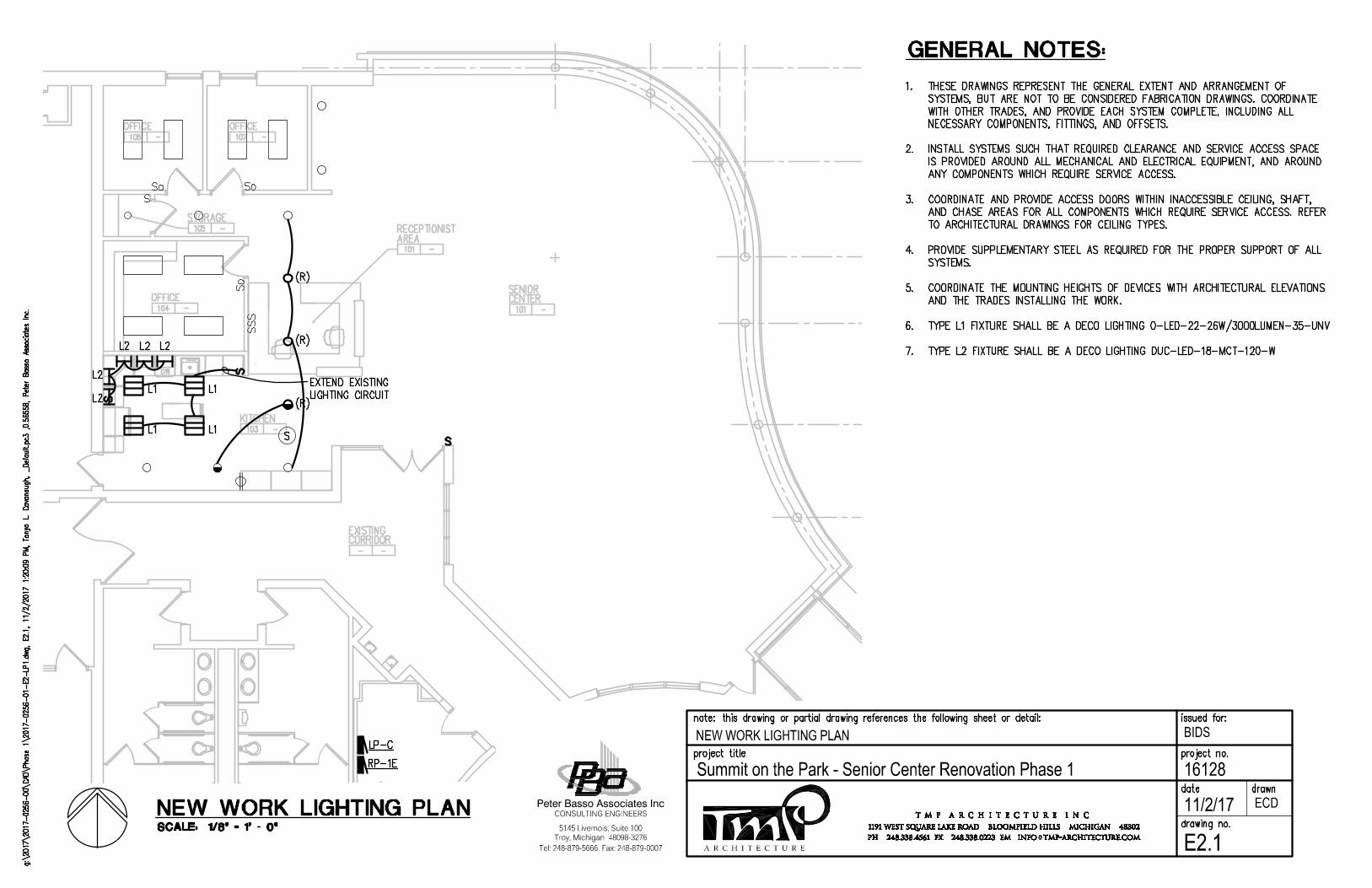
NEW WORK LIGHTING PLAN
ECD
E2.1A R C H I T E C T U R E
BIDS
16128Summit on the Park - Senior Center Renovation Phase 1
Tel: 248-879-5666 Fax: 248-879-0007
Peter Basso Associates Inc
5145 Livernois, Suite 100
CONSULTING ENGINEERS
Troy, Michigan 48098-3276
11/2/17
AutoCAD SHX Text
%%UGENERAL NOTES:
AutoCAD SHX Text
1. THESE DRAWINGS REPRESENT THE GENERAL EXTENT AND ARRANGEMENT OF THESE DRAWINGS REPRESENT THE GENERAL EXTENT AND ARRANGEMENT OF SYSTEMS, BUT ARE NOT TO BE CONSIDERED FABRICATION DRAWINGS. COORDINATE WITH OTHER TRADES, AND PROVIDE EACH SYSTEM COMPLETE, INCLUDING ALL NECESSARY COMPONENTS, FITTINGS, AND OFFSETS. 2. INSTALL SYSTEMS SUCH THAT REQUIRED CLEARANCE AND SERVICE ACCESS SPACE INSTALL SYSTEMS SUCH THAT REQUIRED CLEARANCE AND SERVICE ACCESS SPACE IS PROVIDED AROUND ALL MECHANICAL AND ELECTRICAL EQUIPMENT, AND AROUND ANY COMPONENTS WHICH REQUIRE SERVICE ACCESS. 3. COORDINATE AND PROVIDE ACCESS DOORS WITHIN INACCESSIBLE CEILING, SHAFT, COORDINATE AND PROVIDE ACCESS DOORS WITHIN INACCESSIBLE CEILING, SHAFT, AND CHASE AREAS FOR ALL COMPONENTS WHICH REQUIRE SERVICE ACCESS. REFER TO ARCHITECTURAL DRAWINGS FOR CEILING TYPES. 4. PROVIDE SUPPLEMENTARY STEEL AS REQUIRED FOR THE PROPER SUPPORT OF ALL PROVIDE SUPPLEMENTARY STEEL AS REQUIRED FOR THE PROPER SUPPORT OF ALL SYSTEMS. 5. COORDINATE THE MOUNTING HEIGHTS OF DEVICES WITH ARCHITECTURAL ELEVATIONS COORDINATE THE MOUNTING HEIGHTS OF DEVICES WITH ARCHITECTURAL ELEVATIONS AND THE TRADES INSTALLING THE WORK. 6. TYPE L1 FIXTURE SHALL BE A DECO LIGHTING O-LED-22-26W/3000LUMEN-35-UNV TYPE L1 FIXTURE SHALL BE A DECO LIGHTING O-LED-22-26W/3000LUMEN-35-UNV 7. TYPE L2 FIXTURE SHALL BE A DECO LIGHTING DUC-LED-18-MCT-120-WTYPE L2 FIXTURE SHALL BE A DECO LIGHTING DUC-LED-18-MCT-120-W
AutoCAD SHX Text
%%ULP-C
AutoCAD SHX Text
%%URP-1E
AutoCAD SHX Text
DW
AutoCAD SHX Text
SENIOR
AutoCAD SHX Text
CENTER
AutoCAD SHX Text
101
AutoCAD SHX Text
-
AutoCAD SHX Text
OFFICE
AutoCAD SHX Text
104
AutoCAD SHX Text
-
AutoCAD SHX Text
OFFICE
AutoCAD SHX Text
106
AutoCAD SHX Text
-
AutoCAD SHX Text
OFFICE
AutoCAD SHX Text
107
AutoCAD SHX Text
-
AutoCAD SHX Text
STORAGE
AutoCAD SHX Text
105
AutoCAD SHX Text
-
AutoCAD SHX Text
KITCHEN
AutoCAD SHX Text
103
AutoCAD SHX Text
-
AutoCAD SHX Text
EXISTING
AutoCAD SHX Text
CORRIDOR
AutoCAD SHX Text
-
AutoCAD SHX Text
-
AutoCAD SHX Text
RECEPTIONIST
AutoCAD SHX Text
AREA
AutoCAD SHX Text
101
AutoCAD SHX Text
-
AutoCAD SHX Text
EXTEND EXISTING LIGHTING CIRCUIT
AutoCAD SHX Text
L2
AutoCAD SHX Text
L2
AutoCAD SHX Text
L2
AutoCAD SHX Text
L2
AutoCAD SHX Text
L2
AutoCAD SHX Text
SCALE: 1/8" = 1' - 0"
AutoCAD SHX Text
%%UNEW WORK LIGHTING PLAN
AutoCAD SHX Text
g:\2017\2017-0256-00\CAD\Phase 1\2017-0256-01-E2-LP1.dwg, E2.1, 11/2/2017 1:20:09 PM, Tonya L. Cavanaugh, _Default.pc3 ,0.56558, Peter Basso Associates Inc., E2.1, 11/2/2017 1:20:09 PM, Tonya L. Cavanaugh, _Default.pc3 ,0.56558, Peter Basso Associates Inc.E2.1, 11/2/2017 1:20:09 PM, Tonya L. Cavanaugh, _Default.pc3 ,0.56558, Peter Basso Associates Inc., 11/2/2017 1:20:09 PM, Tonya L. Cavanaugh, _Default.pc3 ,0.56558, Peter Basso Associates Inc.11/2/2017 1:20:09 PM, Tonya L. Cavanaugh, _Default.pc3 ,0.56558, Peter Basso Associates Inc., Tonya L. Cavanaugh, _Default.pc3 ,0.56558, Peter Basso Associates Inc.Tonya L. Cavanaugh, _Default.pc3 ,0.56558, Peter Basso Associates Inc., _Default.pc3 ,0.56558, Peter Basso Associates Inc._Default.pc3 ,0.56558, Peter Basso Associates Inc. ,0.56558, Peter Basso Associates Inc.0.56558, Peter Basso Associates Inc., Peter Basso Associates Inc.
AutoCAD SHX Text
issued for:
AutoCAD SHX Text
note: this drawing or partial drawing references the following sheet or detail:
AutoCAD SHX Text
project title
AutoCAD SHX Text
drawing no.
AutoCAD SHX Text
project no.
AutoCAD SHX Text
date
AutoCAD SHX Text
drawn
AutoCAD SHX Text
T M P A R C H I T E C T U R E I N C
AutoCAD SHX Text
PH 248.338.4561 FX 248.338.0223 EM INFO TMP-ARCHITECTURE.COM
AutoCAD SHX Text
@
AutoCAD SHX Text
1191 WEST SQUARE LAKE ROAD BLOOMFIELD HILLS MICHIGAN 48302
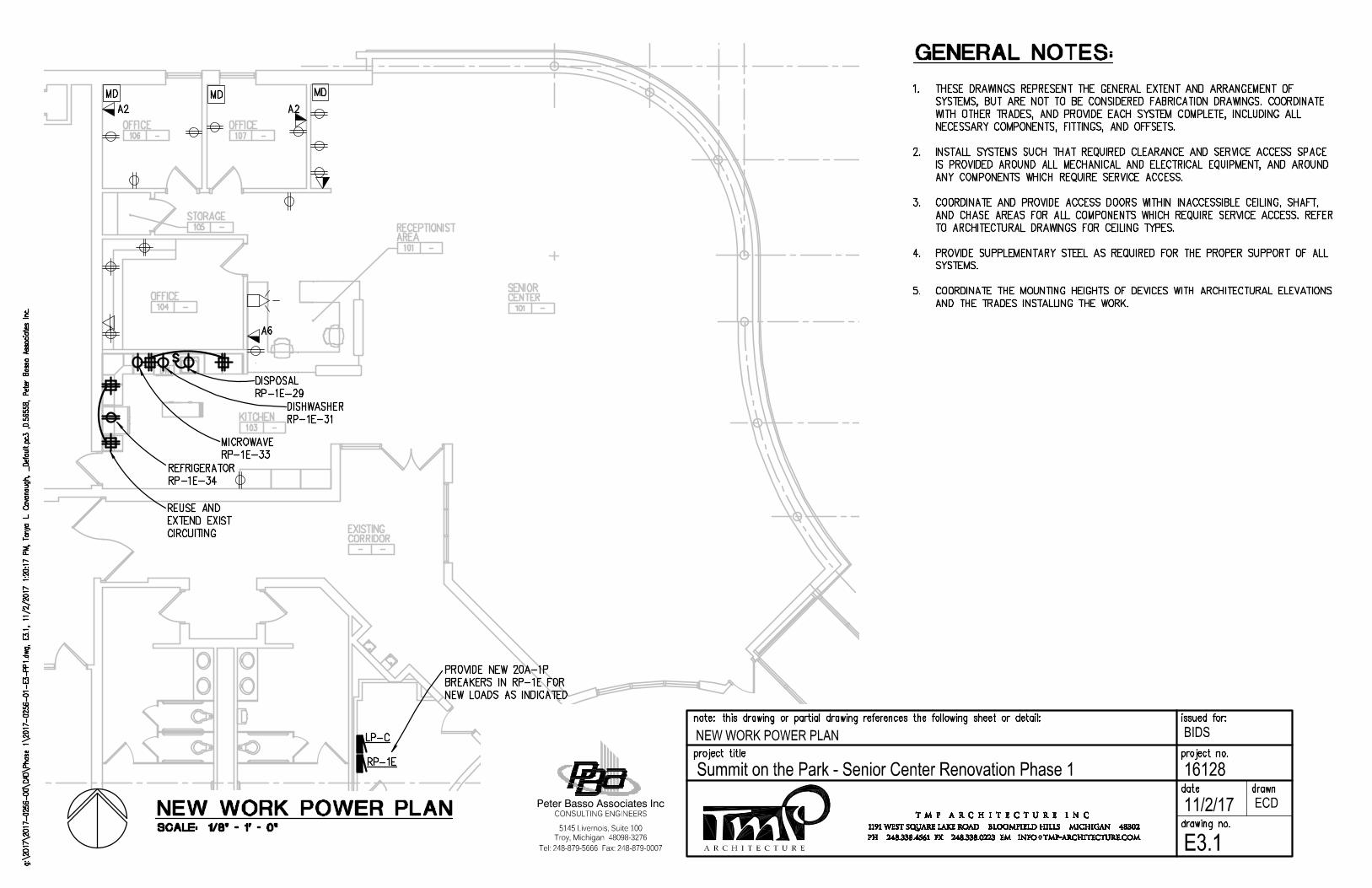
A R C H I T E C T U R E
BIDS
16128Summit on the Park - Senior Center Renovation Phase 1
Tel: 248-879-5666 Fax: 248-879-0007
Peter Basso Associates Inc
5145 Livernois, Suite 100
CONSULTING ENGINEERS
Troy, Michigan 48098-3276
11/2/17
NEW WORK POWER PLAN
ECD
E3.1
AutoCAD SHX Text
%%UGENERAL NOTES:
AutoCAD SHX Text
1. THESE DRAWINGS REPRESENT THE GENERAL EXTENT AND ARRANGEMENT OF THESE DRAWINGS REPRESENT THE GENERAL EXTENT AND ARRANGEMENT OF SYSTEMS, BUT ARE NOT TO BE CONSIDERED FABRICATION DRAWINGS. COORDINATE WITH OTHER TRADES, AND PROVIDE EACH SYSTEM COMPLETE, INCLUDING ALL NECESSARY COMPONENTS, FITTINGS, AND OFFSETS. 2. INSTALL SYSTEMS SUCH THAT REQUIRED CLEARANCE AND SERVICE ACCESS SPACE INSTALL SYSTEMS SUCH THAT REQUIRED CLEARANCE AND SERVICE ACCESS SPACE IS PROVIDED AROUND ALL MECHANICAL AND ELECTRICAL EQUIPMENT, AND AROUND ANY COMPONENTS WHICH REQUIRE SERVICE ACCESS. 3. COORDINATE AND PROVIDE ACCESS DOORS WITHIN INACCESSIBLE CEILING, SHAFT, COORDINATE AND PROVIDE ACCESS DOORS WITHIN INACCESSIBLE CEILING, SHAFT, AND CHASE AREAS FOR ALL COMPONENTS WHICH REQUIRE SERVICE ACCESS. REFER TO ARCHITECTURAL DRAWINGS FOR CEILING TYPES. 4. PROVIDE SUPPLEMENTARY STEEL AS REQUIRED FOR THE PROPER SUPPORT OF ALL PROVIDE SUPPLEMENTARY STEEL AS REQUIRED FOR THE PROPER SUPPORT OF ALL SYSTEMS. 5. COORDINATE THE MOUNTING HEIGHTS OF DEVICES WITH ARCHITECTURAL ELEVATIONS COORDINATE THE MOUNTING HEIGHTS OF DEVICES WITH ARCHITECTURAL ELEVATIONS AND THE TRADES INSTALLING THE WORK.
AutoCAD SHX Text
SENIOR
AutoCAD SHX Text
CENTER
AutoCAD SHX Text
101
AutoCAD SHX Text
-
AutoCAD SHX Text
OFFICE
AutoCAD SHX Text
104
AutoCAD SHX Text
-
AutoCAD SHX Text
OFFICE
AutoCAD SHX Text
106
AutoCAD SHX Text
-
AutoCAD SHX Text
OFFICE
AutoCAD SHX Text
107
AutoCAD SHX Text
-
AutoCAD SHX Text
STORAGE
AutoCAD SHX Text
105
AutoCAD SHX Text
-
AutoCAD SHX Text
KITCHEN
AutoCAD SHX Text
103
AutoCAD SHX Text
-
AutoCAD SHX Text
EXISTING
AutoCAD SHX Text
CORRIDOR
AutoCAD SHX Text
-
AutoCAD SHX Text
-
AutoCAD SHX Text
RECEPTIONIST
AutoCAD SHX Text
AREA
AutoCAD SHX Text
101
AutoCAD SHX Text
-
AutoCAD SHX Text
DW
AutoCAD SHX Text
%%ULP-C
AutoCAD SHX Text
%%URP-1E
AutoCAD SHX Text
PROVIDE NEW 20A-1P BREAKERS IN RP-1E FOR NEW LOADS AS INDICATED
AutoCAD SHX Text
DISPOSAL RP-1E-29
AutoCAD SHX Text
DISHWASHER RP-1E-31
AutoCAD SHX Text
MICROWAVE RP-1E-33
AutoCAD SHX Text
REUSE AND EXTEND EXIST CIRCUITING
AutoCAD SHX Text
REFRIGERATOR RP-1E-34
AutoCAD SHX Text
SCALE: 1/8" = 1' - 0"
AutoCAD SHX Text
%%UNEW WORK POWER PLAN
AutoCAD SHX Text
g:\2017\2017-0256-00\CAD\Phase 1\2017-0256-01-E3-PP1.dwg, E3.1, 11/2/2017 1:20:17 PM, Tonya L. Cavanaugh, _Default.pc3 ,0.56558, Peter Basso Associates Inc., E3.1, 11/2/2017 1:20:17 PM, Tonya L. Cavanaugh, _Default.pc3 ,0.56558, Peter Basso Associates Inc.E3.1, 11/2/2017 1:20:17 PM, Tonya L. Cavanaugh, _Default.pc3 ,0.56558, Peter Basso Associates Inc., 11/2/2017 1:20:17 PM, Tonya L. Cavanaugh, _Default.pc3 ,0.56558, Peter Basso Associates Inc.11/2/2017 1:20:17 PM, Tonya L. Cavanaugh, _Default.pc3 ,0.56558, Peter Basso Associates Inc., Tonya L. Cavanaugh, _Default.pc3 ,0.56558, Peter Basso Associates Inc.Tonya L. Cavanaugh, _Default.pc3 ,0.56558, Peter Basso Associates Inc., _Default.pc3 ,0.56558, Peter Basso Associates Inc._Default.pc3 ,0.56558, Peter Basso Associates Inc. ,0.56558, Peter Basso Associates Inc.0.56558, Peter Basso Associates Inc., Peter Basso Associates Inc.
AutoCAD SHX Text
issued for:
AutoCAD SHX Text
note: this drawing or partial drawing references the following sheet or detail:
AutoCAD SHX Text
project title
AutoCAD SHX Text
drawing no.
AutoCAD SHX Text
project no.
AutoCAD SHX Text
date
AutoCAD SHX Text
drawn
AutoCAD SHX Text
T M P A R C H I T E C T U R E I N C
AutoCAD SHX Text
PH 248.338.4561 FX 248.338.0223 EM INFO TMP-ARCHITECTURE.COM
AutoCAD SHX Text
@
AutoCAD SHX Text
1191 WEST SQUARE LAKE ROAD BLOOMFIELD HILLS MICHIGAN 48302